International Journal of Engineering & Technology IJET-IJENS Vol:19 No:01 1 S I J E N IJENS © February 2019 IJENS - IJET - 6464 - 01 1910 Abstract-- In general, the objective of suspension systems of automobiles is to isolate the vibrations produced due to road disturbances from transfer to driver and passengers. The design of a hydraulic control valve to improve the performance of the damper of automobile suspension system is focused in this paper. . The proposed control valve makes the damper of suspension system to behave as a smart damper. A quarter automobile model of two degrees of freedom is adopted.. The parameters of the proposed control valve are optimized according to settling time and peak overshoot. The efficiency of this valve is tested by evaluating the response of the sprung mass when the automobile excited by step and impulse functions. The results show that the smart damper attenuates the vibrations of the sprung mass in a short period when compared with other types of dampers. Index Term-- Suspension system, smart damper, control valve, ride comfort, control strategy. I- INTRODUCTION One of the most important problems in automobile suspension design is the vibration control which depends on the damping system. The study of automobile dynamics has special importance since it helps automobile designers to produce an automobile that capable of achieving ride comfort to passengers according to the international standards. The main purpose of the vehicle suspension system is to support and separate automobile body from the wheels and relatively allows for movement between the components. It is certainly rated by its ability to achieve suitable ride comfort and good automotive holding from road disturbance and improve passenger comfort. There are many reasons cause the disturbance such as road surface unevenness, aerodynamic forces, non-uniformity of the wheel, tire assembly, and even or braking forces [1]. The study of the vibration control of automobile suspension has been treated by many investigators using different methods for passive, active and semi-active suspension system types of control technique. All the studies in this field pointed to how providing best comfort of riding, and /or stability of riding. G. Verros et. al [2] presented the optimization of suspension parameters, damping factor and spring stiffness for non-linear quarter –car model when excited by random input from road profile. Firstly, the study starts with passive damping, then involving the selection of damping coefficient to produce results which approximated to that for active suspension. The suspension characteristic was optimized with respect to passenger comfort and automobile handling. The method is to select the optimal damping factor and stiffness constant of the suspension. P. Sharma et. al [3] used a two degree of freedom system for a quarter car model. The ordinary differential equations were solved by Mat lab program to compute the displacement of sprung mass and unsprung mass. The solution of the mathematical model also gives the velocities for suspension and travel response when the vehicle passes over bump with damping ratio of 0.078. It was found that the overshoot was about 70% and the amplitude of acceleration was found to be 1.7m/s 2 . This value of acceleration of the spring mass is very high and undesirable for the automobile. With respect unsprung mass, the maximum overshoot is 30% and the acceleration is reduced from 4 to 0.7 m/s 2 and it is undesirable. V. Popovic et. al [4] studied a quarter automobile suspension system through two stages. They investigated the passive suspension system as a first stage, then studied the active suspension system with external actuator excitation. They used Mat lab program to solve the state space model. A. Krishnan [5] solved the equations of motion of the mathematical model of passive suspension system and the control strategies that used for semi-active suspension system, for 2DOFquarter automobile model. The solution was performed by using the Simulink program. This paper concluded that skyhook control can achieve more reduction of resonant peak of the body mass than of passive suspension and gives good ride comfort. Gabor Licsko et. al [6] dealt with the study of single stage relief valve embedded within a simple hydraulic circuit. The goal is to catch the mechanism of instability of such valves, taking into account both fluid compressibility and the chattering behavior that can occur when the valve poppet impacts with its seat. This study concluded that these systems may lose their stability in case of self-excited limit cycle vibrations. From this study and when using linear stability analysis, it was obtained a criterion for stability related with flow rate and damping coefficient. It was also found that an increasing of damping coefficient makes the system to be more stable, and if the damping is moderate, it leads to avoidance of unstable limit cycle. X. Xu, et. al [7] focused their study on modeling and analysis of solenoid valve to improve performance of shifting control system. The energy loss and dynamic characteristics of this system are the important parameters to improve the performance and operation of this valve. The valve was considered as a potential component applied in the shifting control system. The study presented a numerical approach for solving the multi –domain problem of the valve. The results of simulation agreed with that picked from experimental data thus the mathematical model was accurate and effective. Both the viscous and magnetic forces were found to be influenced on the pressure response, when the magnetic force responded quickly or the viscous force Vibration Control of Automobile Suspension System using Smart Damper Abdulkareem Abdulrazzaq Alhumdany Ahmed Abdullah Hassan Al-Rajihy/University of Babylon, College of Engineering/Almussyab, Ali T. Hassan / University of Kerbala/ College of Engineering

Welcome message from author
This document is posted to help you gain knowledge. Please leave a comment to let me know what you think about it! Share it to your friends and learn new things together.
Transcript

International Journal of Engineering & Technology IJET-IJENS Vol:19 No:01 1
SI J E N IJENS © February 2019 IJENS -IJET-6464-011910
Abstract-- In general, the objective of suspension systems of
automobiles is to isolate the vibrations produced due to road
disturbances from transfer to driver and passengers. The
design of a hydraulic control valve to improve the performance
of the damper of automobile suspension system is focused in
this paper. . The proposed control valve makes the damper of
suspension system to behave as a smart damper. A quarter
automobile model of two degrees of freedom is adopted.. The
parameters of the proposed control valve are optimized
according to settling time and peak overshoot. The efficiency of
this valve is tested by evaluating the response of the sprung
mass when the automobile excited by step and impulse
functions. The results show that the smart damper attenuates
the vibrations of the sprung mass in a short period when
compared with other types of dampers.
Index Term-- Suspension system, smart damper, control
valve, ride comfort, control strategy.
I- INTRODUCTION
One of the most important problems in automobile
suspension design is the vibration control which depends on
the damping system. The study of automobile dynamics has
special importance since it helps automobile designers to
produce an automobile that capable of achieving ride
comfort to passengers according to the international
standards. The main purpose of the vehicle suspension
system is to support and separate automobile body from the
wheels and relatively allows for movement between the
components. It is certainly rated by its ability to achieve
suitable ride comfort and good automotive holding from
road disturbance and improve passenger comfort. There are
many reasons cause the disturbance such as road surface
unevenness, aerodynamic forces, non-uniformity of the
wheel, tire assembly, and even or braking forces [1].
The study of the vibration control of automobile
suspension has been treated by many investigators using
different methods for passive, active and semi-active
suspension system types of control technique. All the studies
in this field pointed to how providing best comfort of riding,
and /or stability of riding.
G. Verros et. al [2] presented the optimization of
suspension parameters, damping factor and spring stiffness
for non-linear quarter –car model when excited by random
input from road profile. Firstly, the study starts with passive
damping, then involving the selection of damping
coefficient to produce results which approximated to that for
active suspension. The suspension characteristic was
optimized with respect to passenger comfort and automobile
handling. The method is to select the optimal damping
factor and stiffness constant of the suspension.
P. Sharma et. al [3] used a two degree of freedom
system for a quarter car model. The ordinary differential
equations were solved by Mat lab program to compute the
displacement of sprung mass and unsprung mass. The
solution of the mathematical model also gives the velocities
for suspension and travel response when the vehicle passes
over bump with damping ratio of 0.078. It was found that
the overshoot was about 70% and the amplitude of
acceleration was found to be 1.7m/s2. This value of
acceleration of the spring mass is very high and undesirable
for the automobile. With respect unsprung mass, the
maximum overshoot is 30% and the acceleration is reduced
from 4 to 0.7 m/s2 and it is undesirable.
V. Popovic et. al [4] studied a quarter automobile
suspension system through two stages. They investigated
the passive suspension system as a first stage, then studied
the active suspension system with external actuator
excitation. They used Mat lab program to solve the state
space model.
A. Krishnan [5] solved the equations of motion of
the mathematical model of passive suspension system and
the control strategies that used for semi-active suspension
system, for 2DOFquarter automobile model. The solution
was performed by using the Simulink program. This paper
concluded that skyhook control can achieve more reduction
of resonant peak of the body mass than of passive
suspension and gives good ride comfort.
Gabor Licsko et. al [6] dealt with the study of
single stage relief valve embedded within a simple hydraulic
circuit. The goal is to catch the mechanism of instability of
such valves, taking into account both fluid compressibility
and the chattering behavior that can occur when the valve
poppet impacts with its seat. This study concluded that these
systems may lose their stability in case of self-excited limit
cycle vibrations. From this study and when using linear
stability analysis, it was obtained a criterion for stability
related with flow rate and damping coefficient. It was also
found that an increasing of damping coefficient makes the
system to be more stable, and if the damping is moderate, it
leads to avoidance of unstable limit cycle.
X. Xu, et. al [7] focused their study on modeling
and analysis of solenoid valve to improve performance of
shifting control system. The energy loss and dynamic
characteristics of this system are the important parameters to
improve the performance and operation of this valve. The
valve was considered as a potential component applied in
the shifting control system. The study presented a numerical
approach for solving the multi –domain problem of the
valve. The results of simulation agreed with that picked
from experimental data thus the mathematical model was
accurate and effective. Both the viscous and magnetic forces
were found to be influenced on the pressure response, when
the magnetic force responded quickly or the viscous force
Vibration Control of Automobile Suspension
System using Smart Damper
Abdulkareem Abdulrazzaq Alhumdany Ahmed Abdullah Hassan Al-Rajihy/University of Babylon, College
of Engineering/Almussyab, Ali T. Hassan / University of Kerbala/ College of Engineering
International Journal of Engineering & Technology IJET-IJENS Vol:19 No:01 2
SI J E N IJENS © February 2019 IJENS -IJET-6464-011910
was increased, the pressure response time would be
decreased.
I. Mihai and F. Andronic [8] studied the semi-
active suspension system to remove undesirable oscillations.
Different kinds of control system have been developed
lately in order to obtain adjustable suspension. The
viscosity of the working fluid is altered using magneto
rheological or electro-rheological liquids. This study
concluded that, using semi-active system instead of passive
system leads to an almost total elimination of the system
oscillations. A reduction in the amplitude of the oscillatory
phenomenon and a reduction in the disruptive time,
constitutes a great advantage.
Barbara Zardin, et. al [9] proposed a two-stage
On/Off cartridge valves for automobile applications,
because of simplicity of this valve. The goal of this study is
for improving the performance characteristics of the valve,
allowing the managing of increased pressure and flow rate
levels, without changing the valve size. This study proposed
a new geometry to reduce the flow forces. The dynamic
behavior of the valve has been studied with a lumped
parameters model.
G.K. Sinha and U. Prasad [10] studied the quarter –
automobile model to investigate the response of suspension
system and to improve the vehicle handling, ride comfort for
large automobile such as bus. The improvement of
performance was done by using many controllers such as PI,
PID and H∞, based on step input signal. The study
concluded that for passive suspension system, the overshoot
observed as 0.08m from 0.1 m and settling time is 35 sec,
which means that the passengers feel low oscillation for
long time. Using PI controller, the overshoot reduced to
0.0058m and the settling time to 6 sec. Using PID controller,
the overshoot reduced to 0.0039 and the settling time to 2
sec.
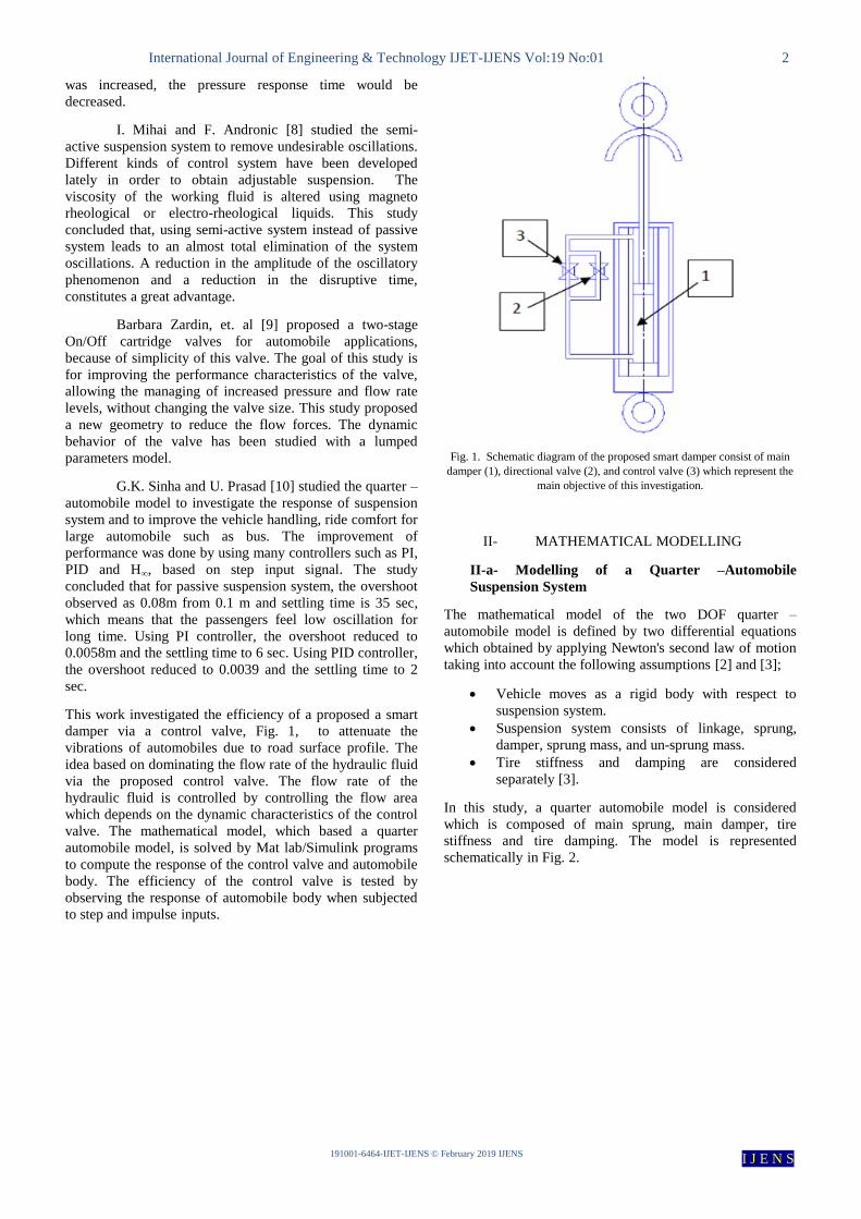
This work investigated the efficiency of a proposed a smart
damper via a control valve, Fig. 1, to attenuate the
vibrations of automobiles due to road surface profile. The
idea based on dominating the flow rate of the hydraulic fluid
via the proposed control valve. The flow rate of the
hydraulic fluid is controlled by controlling the flow area
which depends on the dynamic characteristics of the control
valve. The mathematical model, which based a quarter
automobile model, is solved by Mat lab/Simulink programs
to compute the response of the control valve and automobile
body. The efficiency of the control valve is tested by
observing the response of automobile body when subjected
to step and impulse inputs.
Fig. 1. Schematic diagram of the proposed smart damper consist of main
damper (1), directional valve (2), and control valve (3) which represent the
main objective of this investigation.
II- MATHEMATICAL MODELLING
II-a- Modelling of a Quarter –Automobile
Suspension System
The mathematical model of the two DOF quarter –
automobile model is defined by two differential equations
which obtained by applying Newton's second law of motion
taking into account the following assumptions [2] and [3];
Vehicle moves as a rigid body with respect to
suspension system.
Suspension system consists of linkage, sprung,
damper, sprung mass, and un-sprung mass.
Tire stiffness and damping are considered
separately [3].
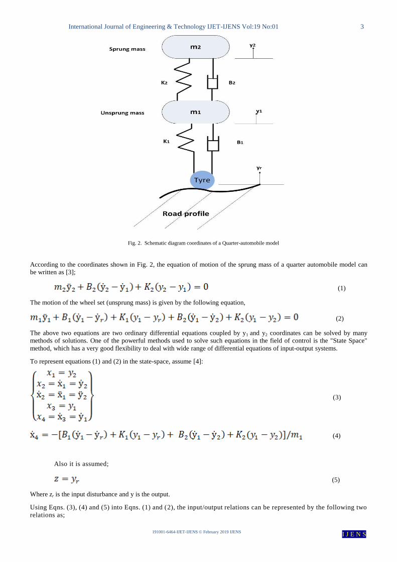
In this study, a quarter automobile model is considered
which is composed of main sprung, main damper, tire
stiffness and tire damping. The model is represented
schematically in Fig. 2.
International Journal of Engineering & Technology IJET-IJENS Vol:19 No:01 3
SI J E N IJENS © February 2019 IJENS -IJET-6464-011910
According to the coordinates shown in Fig. 2, the equation of motion of the sprung mass of a quarter automobile model can
be written as [3];
(1)
The motion of the wheel set (unsprung mass) is given by the following equation,
(2)
The above two equations are two ordinary differential equations coupled by y1 and y2 coordinates can be solved by many
methods of solutions. One of the powerful methods used to solve such equations in the field of control is the "State Space"
method, which has a very good flexibility to deal with wide range of differential equations of input-output systems.
To represent equations (1) and (2) in the state-space, assume [4]:
(3)
(4)
Also it is assumed;
(5)
Where zr is the input disturbance and y is the output.
Using Eqns. (3), (4) and (5) into Eqns. (1) and (2), the input/output relations can be represented by the following two
relations as;
Fig. 2. Schematic diagram coordinates of a Quarter-automobile model
International Journal of Engineering & Technology IJET-IJENS Vol:19 No:01 4
SI J E N IJENS © February 2019 IJENS -IJET-6464-011910
(6a)
) (6b)
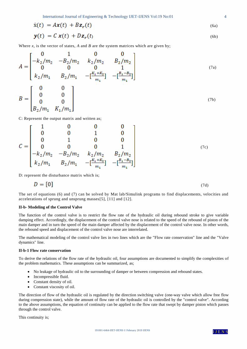
Where x, is the vector of states, A and B are the system matrices which are given by;
(7a)
(7b)
C: Represent the output matrix and written as;
(7c)
D: represent the disturbance matrix which is;
(7d)
The set of equations (6) and (7) can be solved by Mat lab/Simulink programs to find displacements, velocities and
accelerations of sprung and unsprung masses[5], [11] and [12].
II-b- Modeling of the Control Valve
The function of the control valve is to restrict the flow rate of the hydraulic oil during rebound stroke to give variable
damping effect. Accordingly, the displacement of the control valve nose is related to the speed of the rebound of piston of the
main damper and in turn the speed of the main damper affected by the displacement of the control valve nose. In other words,
the rebound speed and displacement of the control valve nose are interrelated.
The mathematical modeling of the control valve lies in two lines which are the "Flow rate conservation" line and the "Valve
dynamics" line.
II-b-1 Flow rate conservation
To derive the relations of the flow rate of the hydraulic oil, four assumptions are documented to simplify the complexities of
the problem mathematics. These assumptions can be summarized, as;
No leakage of hydraulic oil to the surrounding of damper or between compression and rebound states.
Incompressible fluid.
Constant density of oil.
Constant viscosity of oil.
The direction of flow of the hydraulic oil is regulated by the direction switching valve (one-way valve which allow free flow
during compression state), while the amount of flow rate of the hydraulic oil is controlled by the "control valve". According
to the above assumptions, the equation of continuity can be applied to the flow rate that swept by damper piston which passes
through the control valve.
This continuity is;

International Journal of Engineering & Technology IJET-IJENS Vol:19 No:01 5
SI J E N IJENS © February 2019 IJENS -IJET-6464-011910
(8)
Where represent the flow rate swept by damper piston during rebound, and is the flow rate passes through the
control valve.
The flow rate that swept by damper piston through the rebound stroke is given by the following equation;
(9)
Where, represent the annual area of damper, and Cf is the ratio between the area of the piston to the area of
flow and taken to be 0.8 [13].
The swept flow rate given by (9) is the same that passes through the control valve, thus the flow rate through the control valve
is written as:
(10)
According to the assumption of density constancy, the solution of Navies-Stoke equation gives the flow drag force created by
oil flow faced to the valve nose. This drag force is given by [7, 9]:
(11)
The flow velocity through the control valve is given by:
(12)
Where, is the area of flow through the control valve which it is given by;
(13)
Substituting Eq. (12) in Eq. (11) results in;
(14)
The face of the control valve nose also subjected to a force (Fh) delivered from the hydraulic pressure equal to;
(15)
Where is the projected area of valve nose that faced to hydraulic flow, and P is the hydraulic pressure.
Now, the nose of the control valve will be subjected to both the flow drag force given by Eq. (14), and the pressure force
given by Eq.(15). The summation of these two forces gives the total force that generated on the face of the valve nose which
is written as;
(16)
The effective area of hydraulic flow through the control valve according the geometry shown in Fig. 3 is given by;
(17)
The area Ap is given by:
(18)
The pressure delivered in the main damper during rebound state is;
(19)
Now, the pressure force, Fh is;

International Journal of Engineering & Technology IJET-IJENS Vol:19 No:01 6
SI J E N IJENS © February 2019 IJENS -IJET-6464-011910
(20)
The total force generated on the face of the valve nose, Eq. (16), will take the force;
(21)
II-b-2 Dynamics of the Control Valve:
The equation of motion of the control valve nose can be derived by using Newton's second law based on the coordinates
shown in Fig. (3);
(22)
The right hand side of Eq. (22) is the total force applied on the face of valve nose that given by Eq. (21).The interaction
between Eqns. (1), (2) and (22) relate the dynamics of the control valve and the motion of suspension system.
Fig. 3. Schematic diagram coordinates of a Quarter-automobile model
III-Vibration Control of Automobile Suspension Strategies
The vibration control strategy is the technique that used to achieve the controlling for automobile suspension. When the
automobile match over different road profile, the disturbance transmitted to the sprung mass and then transmitted to the
passengers inside the automobile. To get the suitable ride comfort for the passengers and good road handling for the vehicle
and high stability, it must reduce the vibration of sprung mass to be minimum. This can be achieved by choosing one strategy
of control figure (4) illustrated the diagram of system control.

International Journal of Engineering & Technology IJET-IJENS Vol:19 No:01 7
SI J E N IJENS © February 2019 IJENS -IJET-6464-011910
Fig. 4. Vibration Control of Automobile Suspension Strategies
IV- Optimization of Control Valve Parameters
The process of optimization is applied to the parameters of
the control valve in order to obtain the best damping effect
to the suspension system. This process includes the moving
mass of the control valve, stiffness of valve spring, and
diameter of valve throat.
The optimization process is done by solving the governing
equation of the control valve, Eq. (22), using unit step input.
The optimization process of the parameters of the control
valve is based on time response of the control valve. The
optimum value for each parameter is selected when the time
response of the control valve reaches minimum overshoot,
minimum steady state error and settling time [2], [14].
The response of the moving part (nose) of the control valve
is plotted in Fig. 5 as a function of its mass. From this figure
the optimum mass of the moving part of the control value is
found to be (70) grams. This value is taken when the settling
time reach unnotable change with changing mass value. The
optimum value of valve spring stiffness is estimated from
Fig. 6 by drawing the displacement and settling time of the
moving part of the control valve as a function of valve
spring stiffness. From this figure one can select the optimum
value of the valve spring stiffness at the point of intersection
between the displacement curve and settling time curve. The
intersection point show that the valve spring stiffness is
11000 N/m. The best value of the control valve orifice is
drawn from Fig. 7 when the displacement and settling time
reach maximum values.
Fig. 5. Optimization process of Mass of the control valve nose.

International Journal of Engineering & Technology IJET-IJENS Vol:19 No:01 8
SI J E N IJENS © February 2019 IJENS -IJET-6464-011910
Fig. 6. Spring constant optimization of control valve
The performance of the control valve affects on the efficiency of the suspension system. This can be illustrated by the
response of the sprung mass to the road profile (bumps), compared with other published work. The response of the suspension
system is performed according to the optimized parameters of the control valve which are listed in Table 1. The values of the
parameters of the suspension system are given in table 2.
Fig. 7. Diameter optimization of control valve.

International Journal of Engineering & Technology IJET-IJENS Vol:19 No:01 9
SI J E N IJENS © February 2019 IJENS -IJET-6464-011910
Table I
Optimum values of the control valve parameters.
No. Parameters Value Unit
1 Diameter of control valve 0.015 m
2 Spring stiffness of control valve 9768 N/m
3 Damping coefficient of control valve 10 N.s/m
4 Mass of moving part of the control valve 70 Gr
5 Density of hydraulic oil 890 kg/m3
6 Angle of control valve nose, θ 45 Degrees
7 Area factor, Cf 0.7 -
Table II
Parameters of suspension system [3]
No. Parameters Value Unit
1 Sprung mass, m1 275 kg
2 Unsprung mass, m2 27 kg
3 Spring stiffness of suspension, K1 150000 N/m
4 Damping coefficient of suspension, B1 1120 N.s/m
5 Tire stiffness, K2 310000 N /m
6 Tire damping coefficient, B2 3100 N.s/m
7 Annual area, (AP-AR) 7E-7 m2
V- RESULTS AND DISCUSSIONS
The results of the analysis of the suspension system of the
quarter automobile represent the response of the sprung
mass based on the optimized parameters of the control
valve. The optimized parameters of the control valve and
others are listed in table 1, and the parameters of the
suspension system are listed in table 2.
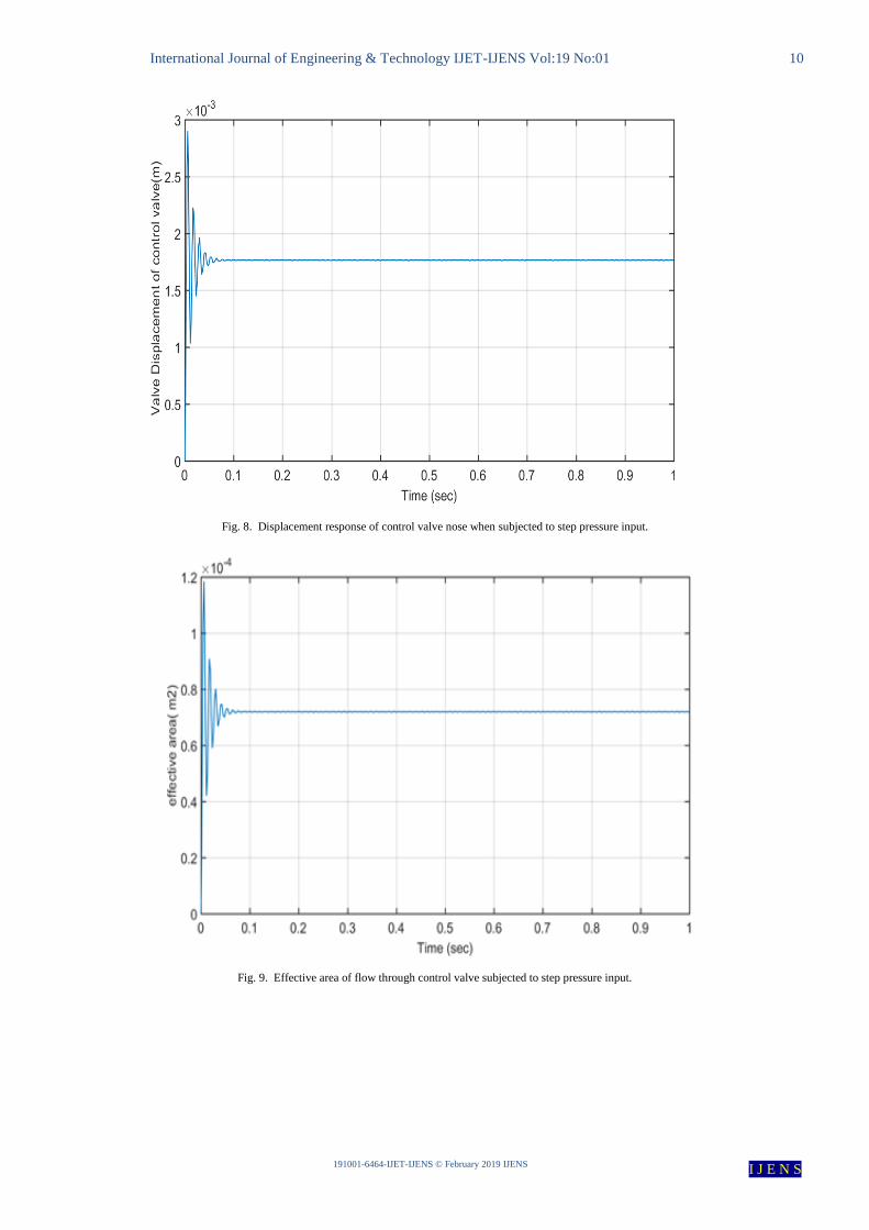
Figure 8 shows the response of the control valve nose when
subjected to a step pressure input delivered from the main
damper of suspension system during the rebound stroke. It is
seen that the settling of the control valve nose is about 0.07
sec. This value of settling time reflects the fast steady state
damping control for the suspension system. The effective
area of flow of the hydraulic oil through the valve is plotted
in Fig. 9. When the valve nose subjected to the same input
used in Fig. 8. It can be deduced from Figs. 8 and 9 that the
effective area of flow is proportional to the displacement of
the control valve nose.
The displacement of the control valve nose and the
corresponding effective area of hydraulic oil flow are shown
in Figs. 10 and 11 respectively when the valve subjected to
pressure impulse input. These two figures show that the
valve return to its initial state in a short period after input
termination. The fast response of the control valve and its
short settling time reflects the efficiency of the control valve
in controlling the hydraulic oil flow which in turn reflects in
turn an efficient vibration control to the sprung mass.
Figures 12 and 13 show the response of the sprung mass
(body of automobile) when the tire of automobile excited by
a 0.1m step input and 0.1m impulse input respectively.
These results represent the present work (smart damper)
and those for the traditional passive damper given by[3].
From these figures it can be seen that the smart damper
presented in this work, makes a notable improvement for
the response of the sprung mass by the fast and hard
attenuation compared with that for passive damper.
The fast attenuation of response of the sprung mass to the
external excitation is due to the smart resrtriction of
hydraulic oil flow through the control valve. The smart
restriction of the hydraulic oil flow makes the damping of
the suspension system to be varied in strength and softness
as the input excitation strengthed or softened. Figure 14
shows the response of the sprung mass to random excitation
for both the traditional passive damper given by [8] and the
smart damper presented in this work.
From the ride comfort point of view, the fast attenuation of
the sprung mass to the external excitation gives an
indication for ride comfort for both driver and
passengerswhich is the main objective of this investigation.
International Journal of Engineering & Technology IJET-IJENS Vol:19 No:01 10
SI J E N IJENS © February 2019 IJENS -IJET-6464-011910
Fig. 8. Displacement response of control valve nose when subjected to step pressure input.
Fig. 9. Effective area of flow through control valve subjected to step pressure input.

International Journal of Engineering & Technology IJET-IJENS Vol:19 No:01 11
SI J E N IJENS © February 2019 IJENS -IJET-6464-011910
Fig. 10. Displacement response of control valve nose when subjected to impulse pressure input.
+
Fig. 11. Effective area of control nose valve subjected to impulse pressure input.

International Journal of Engineering & Technology IJET-IJENS Vol:19 No:01 12
SI J E N IJENS © February 2019 IJENS -IJET-6464-011910
Fig. 12. Response of sprung mass to step input of 0.1 m amplitude.
Fig. 13. Response of sprung mass to impulse input of 0.1 m amplitude.

International Journal of Engineering & Technology IJET-IJENS Vol:19 No:01 13
SI J E N IJENS © February 2019 IJENS -IJET-6464-011910
Fig. 14. Response of sprung mass to random input.
VI- CONCLUSIONS
In this paper, the performance of a proposed smart
damper used to control vibrations of automobiles is
investigated. The mathematical model is based on a
quarter automobile model. From the simulation
results, the following important conclusions can be
withdrawn:
Fast attenuation of vibrations induced by
disturbance excitations due to irregular
road surface.
A total elimination of the system
oscillations.
The proposed smart damper satisfy ride
comfort to the driver and passengers.
The damping which is controlled by the
control valve is not constant as that for
traditional passive damper, but it is a
function of disturbance excitation.
REFERENCES
[1] O. Ghasemalizadeh, S. Taheri, A. Singh, and J. Goryca, “Semi-
active Suspension Control using Modern Methodology: A
Comprehensive Comparison Study,” in 2014 NDIA GROUND VEHICLE SYSTEMS ENGINEERING AND TECHNOLOGY
SYMPOSIUM MODELING & SIMULATION, TESTING AND
VALIDATION (MSTV) TECHNICAL SESSION, 2014, no. August, pp. 1–24.
[2] G. Verros, S. Natsiavas, and C. Papadimitriou, “Design
optimization of quarter-car models with passive and semi-active
suspensions under random road excitation,” JVC/Journal Vib.
Control, vol. 11, no. 5, pp. 581–606, 2005. [3] P. Sharma, N. Saluja, D. Saini, and P. Saini, “Analysis of
Automotive Passive Suspension System with Matlab Program Generation,” Int. J. Adv. Technol., vol. 4, no. 2, pp. 115–119,
2013.
[4] V. Popovic, B. Vasic, M. Petrovic, and S. Mitic, “System approach to vehicle suspension system control in CAE
environment,” Stroj. Vestnik/Journal Mech. Eng., vol. 57, no. 2,
pp. 100–109, 2011. [5] A. Rijumon K, Murtaza M A, Krishnan, “a Comparison Between
Passive & Semi Active Suspension Systems,” Int. J. Innov. Res.
Sci. Eng. Technol., vol. 2, no. 6, pp. 2412–2416, 2013. [6] Gábor Licskó, Alan Champneys and Gsaba Hos, “Dynamical
Analysis of a Hydraulic Pressure Relief Valve,” in Proceedings
of the World Congress on Engineering 2009 Vol II WCE 2009, July 1 - 3, 2009, London, U.K., 2009.
[7] X. Xu, X. Han, Y. Liu, Y. Liu, and Y. Liu, “Modeling and
Dynamic Analysis on the Direct Operating Solenoid Valve for
Improving the Performance of the Shifting Control System,”
Appl. Sci., vol. 7, no. 12, p. 1266, 2017.
[8] I. Mihai and F. Andronic, “Behavior of a semi-active suspension system versus a passive suspension system on an uneven road
surface,” Mechanika, vol. 20, no. 1, pp. 64–69, 2014.
[9] B. Zardin, M. Borghi, G. Cillo, C. Alberto Rinaldini, and E. Mattarelli, “Design of Two-Stage On/Off Cartridge Valves for
Mobile Applications,” Energy Procedia, vol. 126, pp. 1123–
1130, 2017. [10] G. K. Sinha and U. Prasad, “Vibration Control of Car Suspension
System Using Different Controllers,” in International conference
on Emerging Trends in Engineering, Technology, Science and Management, pp. 20–30.
[11] R. Herman, S O LV I N G D I F F E R E N T I A L E QUAT I O N
International Journal of Engineering & Technology IJET-IJENS Vol:19 No:01 14
SI J E N IJENS © February 2019 IJENS -IJET-6464-011910
S U S I N G S IMU L I N K. 2017.
[12] D. I. Wilson, Advanced Control using MATLAB or Stabilising the unstabilisable. 2016.
[13] Csaba Bazso Csaba Hos, “On the Static Instability Of Liquid Popet Valves,” Periodical Polytechnica Mechanical
Engineering,59(1), pp. 1-7, 2015.
[14] Sung Won Kum, Youngmin Seo, Manjin Ahnaand and Yoonseok Jang, “Optimization of Poppet Shape to Minimize Override on
Direct acting Relief Valve,” Proceedings of the 9th JFPS
International Symposium on Fluid Power, Matsu, 2014, Oct. 28-31, 2014, 2014, vol. l, pp. 254–260.
Professor Ahmed Abdullah Hassan Al-Rajihy, Staff member in University of Babylon, College of Engineering-Almusayab. PhD. In
Mechanical Engineering, Applied mechanics. Interested in system
dynamics, vibrations, and dynamics of fluid-structure system interaction. Official E-mail;
[email protected]&[email protected]
m
Assistant Professor Abdulkareem Abdulrazzaq Alhumdany Staff member
in University of Babylon, College of Engineering-Almusayab. PhD. In Mechanical Engineering, Applied mechanics. Interested in
vibrations and tribology. E-mail;
[email protected] [email protected]
Ali T. Hassan, Mechanical Engineering, Applied Mechanics.
Related Documents


![TOPIC: 191001 KNOWLEDGE: K1.01 [3.3/3.4] QID: …...-6- Valves TOPIC: 191001 KNOWLEDGE: K1.01 [3.3/3.4] QID: P4401 (B4401) Given the following pressure specifications for a safety](https://static.cupdf.com/doc/110x72/5ed79ec39661ae43ff66a232/topic-191001-knowledge-k101-3334-qid-6-valves-topic-191001-knowledge.jpg)