machines Article Vibration and Stability Analysis of a Bearing–Rotor System with Transverse Breathing Crack and Initial Bending Yuehua Wang 1 , Xin Xiong 2 and Xiong Hu 1, * Citation: Wang, Y.; Xiong, X.; Hu, X. Vibration and Stability Analysis of a Bearing–Rotor System with Transverse Breathing Crack and Initial Bending. Machines 2021, 9, 79. https://doi.org/10.3390/machines 9040079 Academic Editor: Davide Astolfi Received: 1 March 2021 Accepted: 4 April 2021 Published: 8 April 2021 Publisher’s Note: MDPI stays neutral with regard to jurisdictional claims in published maps and institutional affil- iations. Copyright: © 2021 by the authors. Licensee MDPI, Basel, Switzerland. This article is an open access article distributed under the terms and conditions of the Creative Commons Attribution (CC BY) license (https:// creativecommons.org/licenses/by/ 4.0/). 1 Logistics Engineering College, Shanghai Maritime University, Shanghai 201306, China; [email protected] 2 School of Mechatronic Engineering and Automation, Shanghai University, Shanghai 200072, China; [email protected] * Correspondence: [email protected] Abstract: This paper focuses on the stability and nonlinear response of a bearing-rotor system affected by a transverse crack and initial bending which was thought to be part of an unbalance or had been neglected before. The differences of breathing functions for the transverse breathing crack caused by initial bending is presented here, and the calculation of time-varying finite elements stiffness matrix of the cracked shaft is improved by replacing traditional the approximate crack segment with an exact area. After establishing the dynamic model of the cracked rotor with initial bending, vibrational characteristics such as amplitude-speed diagram, frequency spectrogram and bifurcations are investigated in detail. The eigenvalues of the transition matrix are calculated and analyzed as an indicator of dynamic stability with the growths of crack depth and initial bending. Many differences are found between the two cases of dynamic response of rotor system by numerical simulation. The frequency change with the growth of initial bending is opposite to the change with the growth of crack depth, and the shapes of amplitude-speed also having great different features. Stable regions are reduced and extended laterally by initial bending. All these results obtained in this paper will contribute to identify the bending fault and assess the stability of the bearing-rotor systems. Keywords: bearing-rotor system; breathing crack; initial bending; dynamic response; stability analysis 1. Introduction The bearing-rotor system is widely used in many rotating machineries, such as indus- trial compressors, steam turbines and aero engines. These shafts are usually composed of several sections which may not reach the proper design state due to structural characteris- tics or insufficient machining during the installation process [1,2]. As a result, the initial bending is inevitably generated and dynamic vibration of the rotor system is increased together with mass eccentricity. It has been proven to have an important influence on the dynamic response of rotor systems, and more alternating stresses acting on the shaft may increase the probability of unpredicted crack or rubbing faults [3,4]. Crack monitoring using vibrations is always the hot topic in fault diagnosis of mechanical equipment. De Lacalle proposed an assessment method of reliability and failure probability by comparing numerical simulation and experimental results [5]. Copo developed an inspection schedul- ing method of gas turbine based on a probabilistic crack propagation. When the model was established, many uncertainties in material properties, defect inspection capabilities, weld geometry and loads have also been taken into consideration [6]. Recently, great attentions have focused on the time-varying stiffness of a cracked rotor in vibration analysis and fault diagnosis [7,8]. Three different models of fatigue crack are widely adopted in the stability analysis of rotor system at present, namely, the open model, the switching model and the breathing model. The switching crack model believes that the transition of crack state is completed immediately and has many applications in rotor crack fault and dynamic parameter identification [9,10]. For the Machines 2021, 9, 79. https://doi.org/10.3390/machines9040079 https://www.mdpi.com/journal/machines

Welcome message from author
This document is posted to help you gain knowledge. Please leave a comment to let me know what you think about it! Share it to your friends and learn new things together.
Transcript
machines
Article
Vibration and Stability Analysis of a Bearing–Rotor Systemwith Transverse Breathing Crack and Initial Bending
Yuehua Wang 1 , Xin Xiong 2 and Xiong Hu 1,*
Citation: Wang, Y.; Xiong, X.; Hu, X.
Vibration and Stability Analysis of a
Bearing–Rotor System with
Transverse Breathing Crack and
Initial Bending. Machines 2021, 9, 79.
https://doi.org/10.3390/machines
9040079
Academic Editor: Davide Astolfi
Received: 1 March 2021
Accepted: 4 April 2021
Published: 8 April 2021
Publisher’s Note: MDPI stays neutral
with regard to jurisdictional claims in
published maps and institutional affil-
iations.
Copyright: © 2021 by the authors.
Licensee MDPI, Basel, Switzerland.
This article is an open access article
distributed under the terms and
conditions of the Creative Commons
Attribution (CC BY) license (https://
creativecommons.org/licenses/by/
4.0/).
1 Logistics Engineering College, Shanghai Maritime University, Shanghai 201306, China;[email protected]
2 School of Mechatronic Engineering and Automation, Shanghai University, Shanghai 200072, China;[email protected]
* Correspondence: [email protected]
Abstract: This paper focuses on the stability and nonlinear response of a bearing-rotor system affectedby a transverse crack and initial bending which was thought to be part of an unbalance or had beenneglected before. The differences of breathing functions for the transverse breathing crack causedby initial bending is presented here, and the calculation of time-varying finite elements stiffnessmatrix of the cracked shaft is improved by replacing traditional the approximate crack segmentwith an exact area. After establishing the dynamic model of the cracked rotor with initial bending,vibrational characteristics such as amplitude-speed diagram, frequency spectrogram and bifurcationsare investigated in detail. The eigenvalues of the transition matrix are calculated and analyzed as anindicator of dynamic stability with the growths of crack depth and initial bending. Many differencesare found between the two cases of dynamic response of rotor system by numerical simulation. Thefrequency change with the growth of initial bending is opposite to the change with the growth ofcrack depth, and the shapes of amplitude-speed also having great different features. Stable regionsare reduced and extended laterally by initial bending. All these results obtained in this paper willcontribute to identify the bending fault and assess the stability of the bearing-rotor systems.
Keywords: bearing-rotor system; breathing crack; initial bending; dynamic response; stability analysis
1. Introduction
The bearing-rotor system is widely used in many rotating machineries, such as indus-trial compressors, steam turbines and aero engines. These shafts are usually composed ofseveral sections which may not reach the proper design state due to structural characteris-tics or insufficient machining during the installation process [1,2]. As a result, the initialbending is inevitably generated and dynamic vibration of the rotor system is increasedtogether with mass eccentricity. It has been proven to have an important influence on thedynamic response of rotor systems, and more alternating stresses acting on the shaft mayincrease the probability of unpredicted crack or rubbing faults [3,4]. Crack monitoringusing vibrations is always the hot topic in fault diagnosis of mechanical equipment. DeLacalle proposed an assessment method of reliability and failure probability by comparingnumerical simulation and experimental results [5]. Copo developed an inspection schedul-ing method of gas turbine based on a probabilistic crack propagation. When the modelwas established, many uncertainties in material properties, defect inspection capabilities,weld geometry and loads have also been taken into consideration [6].
Recently, great attentions have focused on the time-varying stiffness of a crackedrotor in vibration analysis and fault diagnosis [7,8]. Three different models of fatiguecrack are widely adopted in the stability analysis of rotor system at present, namely,the open model, the switching model and the breathing model. The switching crackmodel believes that the transition of crack state is completed immediately and has manyapplications in rotor crack fault and dynamic parameter identification [9,10]. For the
Machines 2021, 9, 79. https://doi.org/10.3390/machines9040079 https://www.mdpi.com/journal/machines

Machines 2021, 9, 79 2 of 14
large rotors running at low speed, crack state changes gradually during rotation. As thecrack section is subjected to the alternating tensile and compressive stresses, there is acontinuous variation between the open and closed state of the crack. Just like the humanbreathing process, the contact area of the crack segment decreases gradually when theclosed crack begins to open, and the contact area increases when the open crack begins toclose. Mayes used a continuous first-order cosine model to describe the change of crackstate, and formed a simple breathing model which was considered to be closer to the actualsituation and accepted by researchers [11]. An improved breathing mechanism proposedby Al-Shudeifat has been widely applied to crack detection and nonlinear behavior analysisof cracked rotor systems in recent years [12]. Many assumptions and approximations intraditional breathing functions are removed and the harmonic balance method is employedto solve vibration [13]. The semi discretization method is also extensively used to solvethe differential equations, and Urbikain believes that this method is more effective toobtain a dynamic response [14,15]. This mechanism is developed for the large and heavyshaft of rotating machines of a breathing crack. In these cases, the horizontal line passingthrough the centroid of a closed section is taken as the neutral axis if the shaft diameter islarge enough.
As for the non-gravity dominant rotors with transverse cracks, several modifiedbreathing models were explored to avoid the influence of mass [16]. The breathing mech-anism may be dominated by unbalanced force or other forces, and calculating the areamoment of inertia of the uncracked segment becomes more complicated. Especially, detect-ing the change of dynamic response becomes very difficult if the direction of unbalancehappens to be the same as the direction of the crack [17,18]. Subsequently, many breathingfunctions dominated by different dynamic loadings are continuously developed due todifferent types of cracked rotors or operating conditions [19,20]. In order to obtain a moreaccurate time-varying stiffness, the stress intensity factors and strain energy density areemployed to determine crack state and neutral axis [21,22]. Rubio proposed a methodbased on the stress intensity factor of an open crack with sickle shape to determine therelative depth and front position of the crack [23]. However, these methods are establishedin an ideal state and the initial bending is taken as one part of mass imbalance or neglectedfor simplification [24].
The current studies on initial bending deformation of a rotor system are mostlyaimed at its effect on the dynamic response. Identification of bending faults are basedon the difference in the dynamic response of bearing and shaft [25,26]. Yang found if theinitial bending and geometrical nonlinearity coexist in a rotor system, the vibrations areobviously increased by the initial bending’s degree and the jump phenomenon appears [27].Dynamical results confirmed that obvious changes in both vibration equation and breathingfunctions of the crack are taking place due to initial bending. The tension stress field andcompression stress field change with the bending response of rotating shaft, and theoverall closed area is also different from that calculated by the traditional models [28,29].Deviations are inevitably generated when calculating the moments of inertia of the closedarea and the time-varying stiffness using these functions. Thus, an important problem tobe solved firstly for crack fault diagnosis is to obtain the accurate time-stiffness functionsof the rotor system with initial bending. That is one important reason that the stability ofcracked rotor obtained in previous studies is different from the actual situation and it is farfrom enough to assess engineering machinery conditions using previous models [30].
Hence, accurate breathing functions and dynamical responses of cracked rotors withinitial bending are presented here. Firstly, the influence of initial bending on dynamicresponse of a rotating shaft is analyzed based on the finite element equations. The differencefrom previous studies is that the initial bending and mass imbalance are separated indynamic modeling and state transition of the crack. Then, the neutral axis position andarea moment of inertia of overall closed portion are calculated accurately by integraltechnology. After the time-varying stiffness matrix is obtained, vibration equation of thesystem is established and the stability is investigated. Finally, numerical simulation is
Machines 2021, 9, 79 3 of 14
employed to compare the results with traditional ones. It is found that the initial bendingis an important factor influencing the breathing mechanism and stability regions of thecrack rotor.
2. Stability and Improved Breathing Function
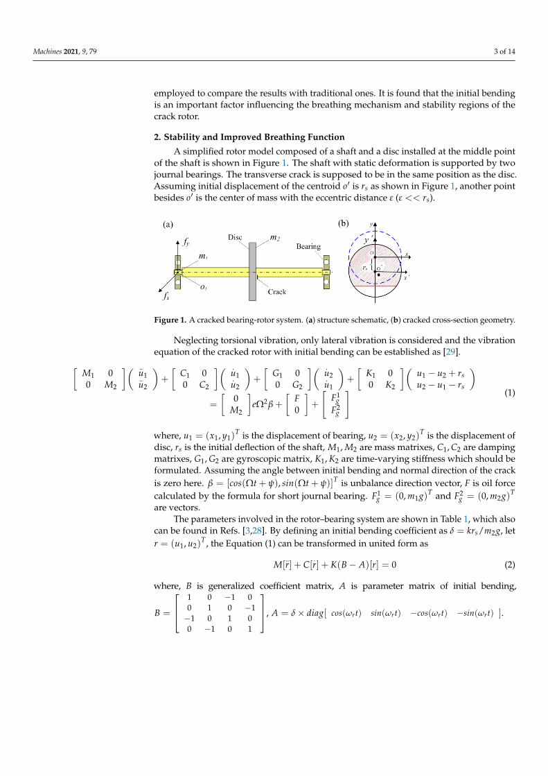
A simplified rotor model composed of a shaft and a disc installed at the middle pointof the shaft is shown in Figure 1. The shaft with static deformation is supported by twojournal bearings. The transverse crack is supposed to be in the same position as the disc.Assuming initial displacement of the centroid o′ is rs as shown in Figure 1, another pointbesides o′ is the center of mass with the eccentric distance ε (ε << rs).
Machines 2021, 9, x FOR PEER REVIEW 3 of 15
difference from previous studies is that the initial bending and mass imbalance are sep-
arated in dynamic modeling and state transition of the crack. Then, the neutral axis posi-
tion and area moment of inertia of overall closed portion are calculated accurately by
integral technology. After the time-varying stiffness matrix is obtained, vibration equa-
tion of the system is established and the stability is investigated. Finally, numerical sim-
ulation is employed to compare the results with traditional ones. It is found that the ini-
tial bending is an important factor influencing the breathing mechanism and stability
regions of the crack rotor.
2. Stability and Improved Breathing Function
A simplified rotor model composed of a shaft and a disc installed at the middle
point of the shaft is shown in Figure 1. The shaft with static deformation is supported by
two journal bearings. The transverse crack is supposed to be in the same position as the
disc. Assuming initial displacement of the centroid o is sr as shown in Figure 1, an-
other point besides o is the center of mass with the eccentric distance ε ( sr ).
Figure 1. A cracked bearing-rotor system. (a) structure schematic, (b) cracked cross-section geom-
etry.
Neglecting torsional vibration, only lateral vibration is considered and the vibration
equation of the cracked rotor with initial bending can be established as [29].
2
12
2
12
21
2
1
1
2
2
1
2
1
2
1
2
1
2
1
0
0
0
0
0
0
0
0
0
0
g
g
s
s
F
FFe
M
ruu
ruu
K
K
u
u
G
G
u
u
C
C
u
u
M
M
(1)
where, Tyxu ),( 111 is the displacement of bearing, Tyxu ),( 222 is the displacement of
disc, sr is the initial deflection of the shaft, 21,MM are mass matrixes, 21,CC are
damping matrixes, 21,GG are gyroscopic matrix, 21,KK are time-varying stiffness
which should be formulated. Assuming the angle between initial bending and normal
direction of the crack is zero here. Ttsintcos )](),([ is unbalance direction
vector, F is oil force calculated by the formula for short journal bearing. T
g gmF ),0( 11
and T
g gmF ),0( 22 are vectors.
The parameters involved in the rotor–bearing system are shown in Table 1, which
also can be found in Refs. [3,28]. By defining an initial bending coefficient as
gmkrs 2/ , let T21 ),( uur , the Equation (1) can be transformed in united form as
0])[(][][ rABKrCrM (2)
where, B is generalized coefficient matrix, A is parameter matrix of initial bending,
1010
0101
1010
0101
B , [ ( ) ( ) ( ) ( )]r r r rA diag cos t sin t cos t sin t .
Figure 1. A cracked bearing-rotor system. (a) structure schematic, (b) cracked cross-section geometry.
Neglecting torsional vibration, only lateral vibration is considered and the vibrationequation of the cracked rotor with initial bending can be established as [29].[
M1 00 M2
]( ..u1..u2
)+
[C1 00 C2
]( .u1.u2
)+
[G1 00 G2
]( .u2.u1
)+
[K1 00 K2
](u1 − u2 + rsu2 − u1 − rs
)=
[0
M2
]eΩ2β +
[F0
]+
[F1
gF2
g
] (1)
where, u1 = (x1, y1)T is the displacement of bearing, u2 = (x2, y2)
T is the displacement ofdisc, rs is the initial deflection of the shaft, M1, M2 are mass matrixes, C1, C2 are dampingmatrixes, G1, G2 are gyroscopic matrix, K1, K2 are time-varying stiffness which should beformulated. Assuming the angle between initial bending and normal direction of the crackis zero here. β = [cos(Ωt + ψ), sin(Ωt + ψ)]T is unbalance direction vector, F is oil forcecalculated by the formula for short journal bearing. F1
g = (0, m1g)T and F2g = (0, m2g)T
are vectors.The parameters involved in the rotor–bearing system are shown in Table 1, which also
can be found in Refs. [3,28]. By defining an initial bending coefficient as δ = krs/m2g, letr = (u1, u2)
T , the Equation (1) can be transformed in united form as
M[..r] + C[
.r] + K(B− A)[r] = 0 (2)
where, B is generalized coefficient matrix, A is parameter matrix of initial bending,
B =
1 0 −1 00 1 0 −1−1 0 1 00 −1 0 1
, A = δ× diag[ cos(ωrt) sin(ωrt) −cos(ωrt) −sin(ωrt) ].

Machines 2021, 9, 79 4 of 14
Table 1. Parameter values of the rotor–bearing system.
Description Value Description Value
Mass of bearing, m1 1.0 kg Mass of disk, m2 32.1 kgBearing radius, Rc 10 mm Disk damping, c2 2100 N·s/mBearing Length, Lc 12 mm Disk stiffness, k 2.5 × 10⁷ N/m
Bearing damping, c1Friction coefficient, f
1050 N·s/m0.1
Bearing stiffness, kcRadial clearance, c
3.6 × 10⁶ N/m0.11 mm
Shaft Length, L 1 m Shaft radius, R 0.025 m
The displacement of point o′ is calculated as ro′ = rs + rd, where rd is the dynamicresponse due to unbalanced forces.
According to the traditional rotor dynamics, the homogeneous equation of Equation (2)is transformed as
..r + 2ζωn
.r + ω2
nr = ω2nrs +
..ε (3)
where, ω2n = k(B− A)/m, 2ζωn = c/m. As ε << rs, Equation (1) can be solved as
r = rs/√(1− λ2)2 + 4ζ2λ2 (4)
ϕr = ϕ + tan−1 rssin(ϕs) + λ2εsin(ϕm)
rscos(ϕs) + λ2εcos(ϕm)(5)
λ = Ω/ωn, Ω is rotating speed. ϕm is response phase of unbalance force. ϕ is theangle between initial bending and displacement vector calculated as
ϕ = arccos1− λ2√
(1− λ2)2 + 4ζ2λ2(6)
If eccentricity of the disc is not considered, Equation (5) can be written asϕr = ϕ + ϕs [31]. It can be seen that the displacement of rotating shaft is the unbal-ance response base on the initial bending. Initial bending amplitude does not affect thecalculation of ϕ which can be seen from Equation (6).
Assuming crack edge is parallel to the fixed X axis at the beginning, and the neutral axisrotates after the shaft starts to rotate as shown in Figure 2. The angle between displacementvector and rotating y′-axis is an important parameter to determine the crack state, which isdenoted as θ1 and calculated as [27]
θ1 = tan−1 sinαcos2α + 2sinα + 3πcosα− 3αcosα
3sinα(π − α + cosαsinα)(7)
The crack state is usually determined by the angle difference between rotation and whirlcalculated as ∆ϕ = Ωt− ϕr or ∆ϕ = Ωt− ϕs − ϕ, where Ωt is the rotation angle of theshaft. However, this difference in the current literature is due to the displacement ofrotating shaft which can be obtained only after establishing the complete dynamic modelof a rotor system. Thus, the effect of whirl motion is mostly not considered or calculated bya simplified stiffness matrix based on former breathing functions. As the initial bendingwas taken as one part of the unbalance, the angle ϕ was not considered in previous studies.Hence, the breathing functions used before are approximate or simplified models. As aresult, the dynamic response calculated by these approximate models is inconsistent withthe actual situation.
Machines 2021, 9, 79 5 of 14Machines 2021, 9, x FOR PEER REVIEW 5 of 15
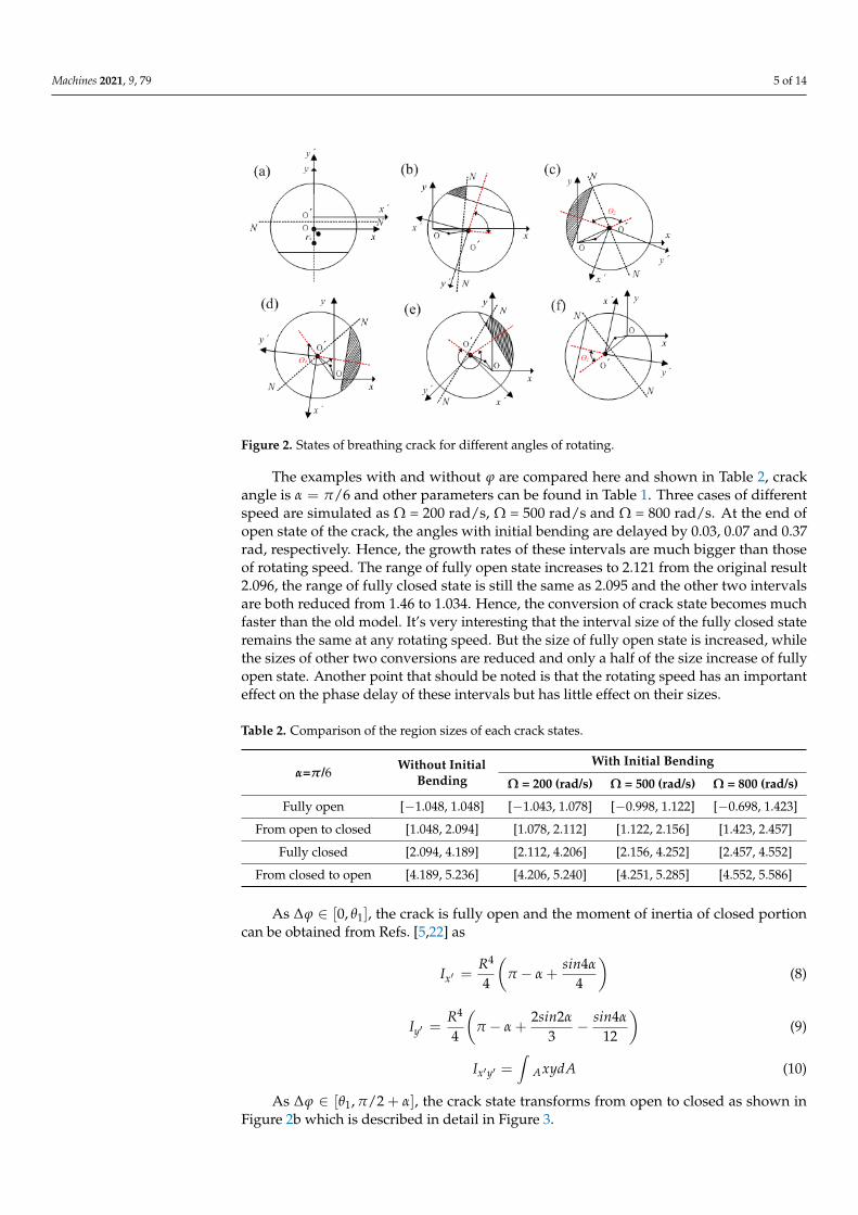
Figure 2. States of breathing crack for different angles of rotating.
The crack state is usually determined by the angle difference between rotation and
whirl calculated as rt or st , where t is the rotation angle of
the shaft. However, this difference in the current literature is due to the displacement of
rotating shaft which can be obtained only after establishing the complete dynamic model
of a rotor system. Thus, the effect of whirl motion is mostly not considered or calculated
by a simplified stiffness matrix based on former breathing functions. As the initial
bending was taken as one part of the unbalance, the angle was not considered in
previous studies. Hence, the breathing functions used before are approximate or simpli-
fied models. As a result, the dynamic response calculated by these approximate models
is inconsistent with the actual situation.
The examples with and without are compared here and shown in Table 2,
crack angle is 6/ and other parameters can be found in Table 1. Three cases of
different speed are simulated as Ω = 200 rad/s, Ω = 500 rad/s and Ω = 800 rad/s. At the
end of open state of the crack, the angles with initial bending are delayed by 0.03, 0.07
and 0.37 rad, respectively. Hence, the growth rates of these intervals are much bigger
than those of rotating speed. The range of fully open state increases to 2.121 from the
original result 2.096, the range of fully closed state is still the same as 2.095 and the other
two intervals are both reduced from 1.46 to 1.034. Hence, the conversion of crack state
becomes much faster than the old model. It’s very interesting that the interval size of the
fully closed state remains the same at any rotating speed. But the size of fully open state
is increased, while the sizes of other two conversions are reduced and only a half of the
size increase of fully open state. Another point that should be noted is that the rotating
speed has an important effect on the phase delay of these intervals but has little effect on
their sizes.
Table 2. Comparison of the region sizes of each crack states.
6/ Without Initial
Bending
With Initial Bending
Ω = 200
(rad/s)
Ω = 500
(rad/s) Ω = 800 (rad/s)
Fully open [−1.048, 1.048] [−1.043, 1.078] [−0.998, 1.122] [−0.698, 1.423]
From open to closed [1.048, 2.094] [1.078, 2.112] [1.122, 2.156] [1.423, 2.457]
Fully closed [2.094, 4.189] [2.112, 4.206] [2.156, 4.252] [2.457, 4.552]
From closed to open [4.189, 5.236] [4.206, 5.240] [4.251, 5.285] [4.552, 5.586]
Figure 2. States of breathing crack for different angles of rotating.
The examples with and without ϕ are compared here and shown in Table 2, crackangle is α = π/6 and other parameters can be found in Table 1. Three cases of differentspeed are simulated as Ω = 200 rad/s, Ω = 500 rad/s and Ω = 800 rad/s. At the end ofopen state of the crack, the angles with initial bending are delayed by 0.03, 0.07 and 0.37rad, respectively. Hence, the growth rates of these intervals are much bigger than thoseof rotating speed. The range of fully open state increases to 2.121 from the original result2.096, the range of fully closed state is still the same as 2.095 and the other two intervalsare both reduced from 1.46 to 1.034. Hence, the conversion of crack state becomes muchfaster than the old model. It’s very interesting that the interval size of the fully closed stateremains the same at any rotating speed. But the size of fully open state is increased, whilethe sizes of other two conversions are reduced and only a half of the size increase of fullyopen state. Another point that should be noted is that the rotating speed has an importanteffect on the phase delay of these intervals but has little effect on their sizes.
Table 2. Comparison of the region sizes of each crack states.
α=π/6 Without InitialBending
With Initial Bending
Ω = 200 (rad/s) Ω = 500 (rad/s) Ω = 800 (rad/s)
Fully open [−1.048, 1.048] [−1.043, 1.078] [−0.998, 1.122] [−0.698, 1.423]
From open to closed [1.048, 2.094] [1.078, 2.112] [1.122, 2.156] [1.423, 2.457]
Fully closed [2.094, 4.189] [2.112, 4.206] [2.156, 4.252] [2.457, 4.552]
From closed to open [4.189, 5.236] [4.206, 5.240] [4.251, 5.285] [4.552, 5.586]
As ∆ϕ ∈ [0, θ1], the crack is fully open and the moment of inertia of closed portioncan be obtained from Refs. [5,22] as
Ix′ =R4
4
(π − α +
sin4α
4
)(8)
Iy′ =R4
4
(π − α +
2sin2α
3− sin4α
12
)(9)
Ix′y′ =∫
AxydA (10)
As ∆ϕ ∈ [θ1, π/2 + α], the crack state transforms from open to closed as shown inFigure 2b which is described in detail in Figure 3.
Machines 2021, 9, 79 6 of 14
Machines 2021, 9, x FOR PEER REVIEW 6 of 15
As ],0[ 1 , the crack is fully open and the moment of inertia of closed portion
can be obtained from Ref. [5,22] as
4
4
4
4
'
sinRI
x (8)
12
4
3
22
4
4
'
sinsinRI
y (9)
xydAI Ayx (10)
As ]2/,[ 1 , the crack state transforms from open to closed as shown in
Figure 2b which is described in detail in Figure 3.
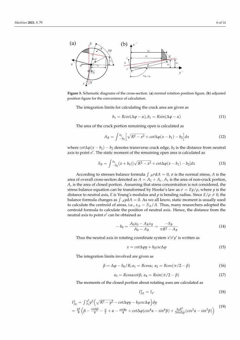
Figure 3. Schematic diagrams of the cross-section. (a) normal rotation position figure, (b) adjusted
position figure for the convenience of calculation.
The integration limits for calculating the crack area are given as
)(1 Rcosb , )(1 Rsinb (11)
The area of the crack portion remaining open is calculated as
dxbbxcotxRAb
bB
21
22 )(1
0 (12)
where 21)( bbxcot denotes transverse crack edge, 0b is the distance from neutral
axis to point o . The static moment of the remaining open area is calculated as
dxbbxcotxRbxSb
bB ])([)( 2122
01
0
(13)
According to stresses balance formula 0d AA , σ is the normal stress, A is the
area of overall cross-section denoted as cAAA 1 . 1A is the area of non-crack por-
tion, Ac is the area of closed portion. Assuming that stress concentration is not consid-
ered, the stress balance equation can be transformed by Hooke’s law as /Ey ,
where y is the distance to neutral axis, E is Young’s modulus and ρ is bending radius.
Since 0/ E , the balance formula changes as 0d AyA . As we all know, static mo-
ment is usually used to calculate the centroid of areas, i.e., ASx AA / . Thus, many re-
searchers adopted the centroid formula to calculate the position of neutral axis. Hence,
the distance from the neutral axis to point o can be obtained as
B
B
B
BB
AR
S
AA
xAxAb
20
000
(14)
Thus the neutral axis in rotating coordinate system yox is written as
Figure 3. Schematic diagrams of the cross-section. (a) normal rotation position figure, (b) adjustedposition figure for the convenience of calculation.
The integration limits for calculating the crack area are given as
b1 = Rcos(∆ϕ− α), b1 = Rsin(∆ϕ− α) (11)
The area of the crack portion remaining open is calculated as
AB =∫
b1−b0
[√R2 − x2 + cot∆ϕ(x− b1)− b2
]dx (12)
where cot∆ϕ(x− b1)− b2 denotes transverse crack edge, b0 is the distance from neutralaxis to point o′. The static moment of the remaining open area is calculated as
SB =∫
b1−b0
(x + b0)[√
R2 − x2 + cot∆ϕ(x− b1)− b2]dx (13)
According to stresses balance formula∫
AσdA = 0, σ is the normal stress, A is thearea of overall cross-section denoted as A = A1 + Ac. A1 is the area of non-crack portion,Ac is the area of closed portion. Assuming that stress concentration is not considered, thestress balance equation can be transformed by Hooke’s law as σ = Ey/ρ, where y is thedistance to neutral axis, E is Young’s modulus and ρ is bending radius. Since E/ρ 6= 0, thebalance formula changes as
∫AydA = 0. As we all know, static moment is usually used
to calculate the centroid of areas, i.e., xA = SA/A. Thus, many researchers adopted thecentroid formula to calculate the position of neutral axis. Hence, the distance from theneutral axis to point o′ can be obtained as
− b0 =A0x0 − ABxB
A0 − AB=
−SB
πR2 − AB(14)
Thus the neutral axis in rotating coordinate system x′o′y′ is written as
x = cot∆ϕy + b0csc∆ϕ (15)
The integration limits involved are given as
β = ∆ϕ− b0/R; a1 = Rcosα; a2 = Rcos(π/2− β) (16)
a3 = Rcosαcotβ; a4 = Rsin(π/2− β) (17)
The moments of the closed portion about rotating axes are calculated as
IxA1 = Ix′ (18)
IxAc =
∫ a2a1
y2(√
R2 − y2 − cot∆ϕy− b0csc∆ϕ)
dy
= R4
8
(β− sin4β
4 − π2 + α− sin4α
4 + cot∆ϕ(cos4α− sin4β) + b0R3
3sin∆ϕ (cos3α− sin3β)) (19)

Machines 2021, 9, 79 7 of 14
Hence, the overall moment of inertia is given as
IxA = Ix
A1 + IxAc (20)
IyA = Iy
A1 + IyAc (21)
IxyA =
∫RRcosαcosθ
∫r3sinθcosθdθdr =
R4
16
[cos2α + cos2β +
12
sin22α− 2cos4αcot2β
](22)
where,IyA1 = Iy′ (23)
IyAc =
∫ Rsinαa4
x2(√
R2 − x2 − a1
)dx +
∫ a4a3 x2(tan∆ϕx− b0sec∆ϕ− a1)dx
= R4
4
(β2 −
sin4β3 − π
4 + α2 −
sin2α3 + sin4α
24 + cos4αcos3β3 + cos3βsin∆ϕ
− b0R3
3cos∆ϕ (cos3β− cos3αcot3β)) (24)
Although the change of neutral axis is taken into consideration in a traditional breath-ing model, the moment of inertia and area of closed portion are not calculated accu-rately. −b0R3(cos3β− cos3αcot3β)/3cos∆ϕ in Equation (24) is the moment loss because theclosed area is reduced by the shift of neutral axis. A similar difference can be found inEquation (21). As a result, the moment of inertia about the rotating axis is smaller than theprevious results in the transformation of crack state from open to closed.
As ∆ϕ ∈ [π/2 + α, 3π/2− α], the crack is fully closed and the moments of inertia arethe same as the case without a crack, given as
IxA = Iy
A =πR2
4(25)
IxyA = 0 (26)
As ∆ϕ ∈ [3π/2− α, 2π − θ1], the area and static moment of open portion can becalculated as
A2 =∫ [√
R2 − x2 + cot∆ϕ(x− b1) + b2
]dx (27)
SA2 =∫
(−b0 − x)[√
R2 − x2 + cot∆ϕ(x− b1) + b2
]dx (28)
Hence, the displacement of the centroid is xA2 = SA2/A2, and the neutral axis can beobtained as
− b0 =A0x0 − ABxB
A0 − AB=
−SB
πR2 − AB(29)
Similar to the second stage, the angle between rotating y′ and neutral axis changesfrom π/2− ∆ϕ to 3π/2− ∆ϕ. The moments of inertia are calculated as
IxA =
∫ −a2a0 y2
(√R2 − y2 − cot∆ϕx− b0csc∆ϕ
)dy
= R4
4
(7π4 −
β2 + sin4β
8 − α2 + α + sin4α
8 − cot∆ϕ(cos4α− sin4β)
− b0R3
3sin∆ϕ (cos3α− sin3β)) (30)
IyA = I −
∫ Rsinα−a4
x2(√
R2 − x2 − a1
)dx−
∫ a4a3 x2(tan∆ϕx + b0sec∆ϕ− a1)dx
= R4
4
(7π4 −
β2 + sin4β
8 − α2 −
sin2α3 − sin4α
24 −cos4αcos3β
3 − cos3βsin∆ϕ
+ b0R3
3cos∆ϕ (cos3β− cos3αcot3β ))
(31)
IxyA =
R4
16
(cos2α + cos2β +
12
sin22α− 2cos4αcot2β
)(32)
Machines 2021, 9, 79 8 of 14
As an open portion of the crack region increases, neutral axis gradually moves awayfrom point o. Therefore, the area still remaining closed is larger than the previous resultsand the last terms in Equations (27) and (28) are the increases of the moment of inertia. Tillthen, the moments of inertia about rotating axes are calculated in a whole rotating period.Hence, the moments of inertia about fixed axes can be calculated as [24]
IXA = Ix
Acos2Ωt + IyA sin2 Ωt− Ixy
A sin 2Ωt (33)
IYA = Ix
A sin2 Ωt + IyAcos2Ωt + Ixy
A sin 2Ωt (34)
IXA = (Ix
A − IyA) sin ΩtcosΩt + Ixy
A cos2Ωt (35)
Then, the area moments of inertia about the centroidal axes which are parallel tothe fixed x and y axes during rotation can be calculated by the parallel axis theorem.The displacement of neutral axis is simply calculated as x(t) = b0 cos(π/2−ωnt− ϕ),y(t) = b0 sin(π/2−ωnt− ϕ). Hence, the stiffness matrix of the crack cross-section isgiven by
K(t) =48El3
[IX
A IXYA
IYXA IY
A
](36)
where, l is length of the shaft. Many applications of Equation (36) can be found in theliterature of dynamical modeling of the crack shaft, and the coupling stiffness is notconsidered before because it is too small compared with other two stiffness matrices.
Therefore, it can be seen that the initial bending changes the position of the neutralaxis and the area of closed portion, playing an important role in determining the breathingfunctions of a cracked rotor. It should be taken into consideration in vibrational characteris-tics and stability analysis of rotor systems. As the stability of solution of Equation (1) is thesame as that of Equation (2) according to the theory of nonlinear system stability, the solu-tion of Equation (2) is expressed as the product of exponential and periodic componentsand expanded into the Fourier series by Floquet theory as
r = eψtb0 + ∑ ∞k=1[aksin(kωt) + bkcos(kωt)]
(37)
where, ψ is Floquet exponent, b0, ak, bk are coefficient vectors. Substitute Equation (37) intoEquation (2) and the coefficient vector equation is obtained as
ψ2P2 + ψP1 + P0
R = 0 (38)
where R =[· · · bk · · · b1 b0 a1 · · · b1 · · ·
]T is coefficient matrix of harmonics, P2, P1, P0are constant matrix calculated by
P2,k = diag[M, M, M] (39)
P2,k+1 = diag[M, P2,k M], (k = 1, 2, 3, · · · ) (40)
P1,k =
C 0 2ωM0 C 0
−2ωM 0 C
(41)
P1,k+1 =
C 0 2kωM0 P1,k 0
−2kωM 0 C
, (k = 1, 2, 3, · · · ) (42)
P0,k =
K(B− A)−ω2M 0 ωC0 K(B− A) 0−ωC 0 K(B− A)−ω2M
(43)
Machines 2021, 9, 79 9 of 14
P0,k+1 =
K(B− A)− k2ω2M 0 kωC0 P0,k 0
−kωC 0 K(B− A)− k2ω2M
(k = 1, 2, 3, · · · ) (44)
To ensure Equation (38) has nontrivial solutions, the determinant of coefficient matrixshould be equal to zero and is expressed as
|Z− ψI = 0| (45)
where I is a unit matrix, Z is transition matrix calculated by
Z = −[
0 IP0P−1
2 P1P−12
](46)
Hence, the eigenvalues of matrix Z are usually used as an indicator of the systemstability. If all real parts of these eigenvalues are negative, the system can be confirmedto be stable. Otherwise, if one or more of the real parts are greater than zero, the systemis unstable. Particularly, if some of these real parts are equal to zero while others areall negative, the system is in a critical state. This method has been widely applied instability analysis of cracked rotors, and proved to be useful for identification of crackshape parameters and prediction of stable regions. As initial bending is also an importantparameter affecting the breathing mechanism of the crack, it is appropriate and necessaryto investigate the stability of cracked rotor by this method.
3. Simulation and Discussion
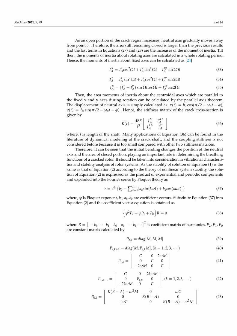
The influence of initial bending on vibrational characteristics obtained by the improvedfunctions is compared with that of a traditional model. Firstly, the displacement of theneutral axis and closed area of the crack region are calculated as δ = 0.3, Ω = 200 rad/s.Three cases of different crack angles α = π/6, α = π/3 and α = π/2 are plotted in Figure 4.Phase differences of neutral axis position and closed portion area are found to be similarbut reverse. In low speed with α = π/6, the phase delay is not obvious in the whole rotatingperiod. As the crack grows, the differences become bigger and bigger. When the crack statechanges from fully open to closed, the closed portion areas calculated by the improvedfunctions are much smaller than the results obtained by the previous method. Becausethe change of neutral axis was not considered and approximate arc area was adopted toreplace actual closed area in the simplified algorithm.
Machines 2021, 9, x FOR PEER REVIEW 10 of 15
rameter affecting the breathing mechanism of the crack, it is appropriate and necessary
to investigate the stability of cracked rotor by this method.
3. Simulation and Discussion
The influence of initial bending on vibrational characteristics obtained by the im-
proved functions is compared with that of a traditional model. Firstly, the displacement
of the neutral axis and closed area of the crack region are calculated as 3.0 , Ω = 200
rad/s. Three cases of different crack angles α = π/6, α = π/3 and α = π/2 are plotted in
Figure 4. Phase differences of neutral axis position and closed portion area are found to
be similar but reverse. In low speed with α = π/6, the phase delay is not obvious in the
whole rotating period. As the crack grows, the differences become bigger and bigger.
When the crack state changes from fully open to closed, the closed portion areas calcu-
lated by the improved functions are much smaller than the results obtained by the pre-
vious method. Because the change of neutral axis was not considered and approximate
arc area was adopted to replace actual closed area in the simplified algorithm.
Figure 4. Displacement of neutral axis and area of closed portion of the crack. (a) neural axis, (b)
closed portion of the crack.
The moments of inertia of overall closed area are plotted in Figure 5. As α = π/6, the
relative moment about X axis is delayed by a small phase, and the relative moment
about Y axis almost remains the same in the whole rotating period. When the crack an-
gle grows to π/3 or π/2, the delayed phase increases a lot because the crack portion is
much bigger than the first case. Especially, the delays in transition of crack state from
open to closed are much larger than the delays from closed to open in both X and Y
directions. The same trend can be found in the moments about fixed axes which are no
longer plotted here. Obviously, these varieties are not only a certain phase delay made
by the initial bending, but also the range of each crack state as exhibited in Table 2.
There’s an obvious difference between the relative moments about the X and Y axes, the
variation curves in the right figure is very closed to the original curves at the midpoint
of the both conversion processes. These differences will bring many changes to the dy-
namic response of the rotor system.
Figure 4. Displacement of neutral axis and area of closed portion of the crack. (a) neural axis,(b) closed portion of the crack.
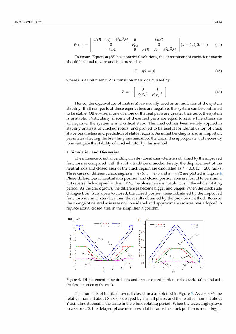
The moments of inertia of overall closed area are plotted in Figure 5. As α = π/6, therelative moment about X axis is delayed by a small phase, and the relative moment aboutY axis almost remains the same in the whole rotating period. When the crack angle growsto π/3 or π/2, the delayed phase increases a lot because the crack portion is much bigger
Machines 2021, 9, 79 10 of 14
than the first case. Especially, the delays in transition of crack state from open to closedare much larger than the delays from closed to open in both X′ and Y′ directions. Thesame trend can be found in the moments about fixed axes which are no longer plotted here.Obviously, these varieties are not only a certain phase delay made by the initial bending,but also the range of each crack state as exhibited in Table 2. There’s an obvious differencebetween the relative moments about the X and Y axes, the variation curves in the rightfigure is very closed to the original curves at the midpoint of the both conversion processes.These differences will bring many changes to the dynamic response of the rotor system.
Machines 2021, 9, x FOR PEER REVIEW 11 of 15
Figure 5. The moments of inertia about the rotating and fixed axes. (a) about X axis, (b) about Y
axis.
The amplitude-speed diagram with the growth of crack angle and initial bending
are plotted in Figure 6. Figure 6a shows the change of amplitude along with the growth
of speed and crack angle, and the initial bending is not considered in this case. If a value
bigger than 0.16 is taken as excessive vibration, the dangerous region is [1780, 2360]
when crack is not occurred. The first critical speed of the rotor system is around 2080,
and the critical speed should be higher than 1.2 times the working speed to maintain
normal operation in practical engineering. Hence, the safe speed of this rotor should be
lower than 1730 or higher than 2500 for a flexible shaft. As the crack angle grows to π/8,
there is no obvious change. The resonant region changes to [1640, 2120] and [1500, 2260]
when the crack angle grows to 2π/8 and 3π/8, respectively. Obviously, the rotating
speed entering the resonance region became lower due to the decrease of stiffness, and
the vibration amplitude also increases a little. The safe speed of the rotor system is also
reduced to 1580 and 1470, and it is easier to become a flexible rotor above the first critical
speed. Of course, the safe rotating speed should also be lower than 70% of the next criti-
cal speed. Especially, the overall rotating range becomes dangerous region if the crack
angle grows to π/2.
When the working speed of rotor system is higher than the critical speed, the rotor
has to pass through the resonant region. Thus, many measures are developed to limit
the amplitude of the resonant region in project, such as increasing damping, changing
the flexible connection and active control device. These issues are not discussed here, but
a simple damping program is used to limit the larger amplitude in the resonance area in
the numerical simulation. Figure 6b shows the vibrations of a rotor system with the
growth of initial bending and rotating speed, all the results are obtained as the crack an-
gle is π/6. The first curve is almost the same as the first curve in Figure 6a, because a
small crack has little effect on the amplitude. The resonant regions of the other four cases
are [1420, 1980], [1320, 2040], [1240, 2120] and [1160, 2160], respectively. A great differ-
ence can be found by comparing the vibration amplitudes changing with the growth of
crack angle and initial bending. The position of resonant regions has hardly changed
while the interval size of the resonant region is enlarged.
Figure 5. The moments of inertia about the rotating and fixed axes. (a) about X axis, (b) about Y axis.
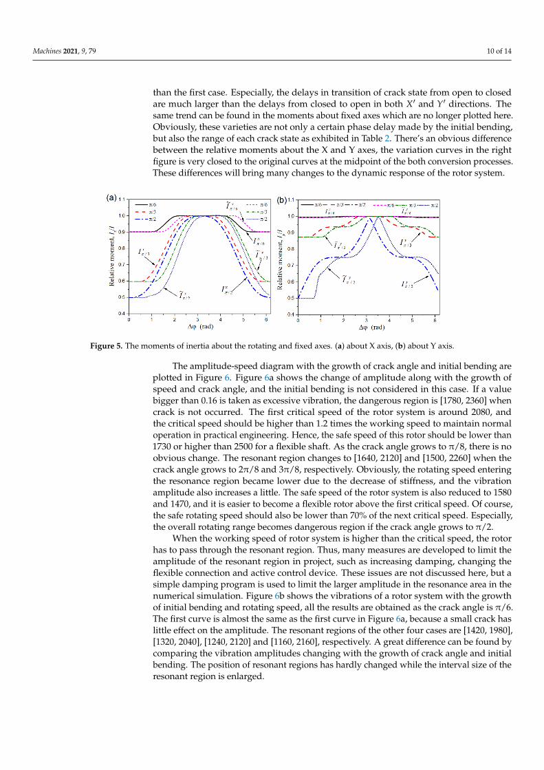
The amplitude-speed diagram with the growth of crack angle and initial bending areplotted in Figure 6. Figure 6a shows the change of amplitude along with the growth ofspeed and crack angle, and the initial bending is not considered in this case. If a valuebigger than 0.16 is taken as excessive vibration, the dangerous region is [1780, 2360] whencrack is not occurred. The first critical speed of the rotor system is around 2080, andthe critical speed should be higher than 1.2 times the working speed to maintain normaloperation in practical engineering. Hence, the safe speed of this rotor should be lower than1730 or higher than 2500 for a flexible shaft. As the crack angle grows to π/8, there is noobvious change. The resonant region changes to [1640, 2120] and [1500, 2260] when thecrack angle grows to 2π/8 and 3π/8, respectively. Obviously, the rotating speed enteringthe resonance region became lower due to the decrease of stiffness, and the vibrationamplitude also increases a little. The safe speed of the rotor system is also reduced to 1580and 1470, and it is easier to become a flexible rotor above the first critical speed. Of course,the safe rotating speed should also be lower than 70% of the next critical speed. Especially,the overall rotating range becomes dangerous region if the crack angle grows to π/2.
When the working speed of rotor system is higher than the critical speed, the rotorhas to pass through the resonant region. Thus, many measures are developed to limit theamplitude of the resonant region in project, such as increasing damping, changing theflexible connection and active control device. These issues are not discussed here, but asimple damping program is used to limit the larger amplitude in the resonance area in thenumerical simulation. Figure 6b shows the vibrations of a rotor system with the growthof initial bending and rotating speed, all the results are obtained as the crack angle is π/6.The first curve is almost the same as the first curve in Figure 6a, because a small crack haslittle effect on the amplitude. The resonant regions of the other four cases are [1420, 1980],[1320, 2040], [1240, 2120] and [1160, 2160], respectively. A great difference can be found bycomparing the vibration amplitudes changing with the growth of crack angle and initialbending. The position of resonant regions has hardly changed while the interval size of theresonant region is enlarged.
Machines 2021, 9, 79 11 of 14Machines 2021, 9, x FOR PEER REVIEW 12 of 15
Figure 6. Amplitude–speed diagram along with the growth of crack angle and initial bending. (a)
crack angle, (b) initial bending as α = π/6.
It is interesting to compare the spectrogram of the dynamic response affected by
crack angle and initial bending as shown in Figure 7. As the crack grows, many new
frequency components appear continuously besides the excitation frequency. For exam-
ple, the natural frequency and combined components appears when the crack angle
grows to π/4. The natural frequency drops due to the decrease of time-varying stiffness,
while the combined and multiple frequencies rise. On the contrary, these frequency
components decrease gradually with the increase of initial bending. Finally, only the ex-
citation frequency component remains obvious, which is consistent with the case of un-
balanced excitation. Furthermore, the natural frequency increases slightly while the
combined frequency drops a little.
Figure 7. Spectrogram of dynamic response affected by crack angle and initial bending. (a) spec-
trogram with growth of crack, (b) spectrogram with growth of initial bending.
The bifurcations of the two models are plotted in Figure 8. The biggest difference of
the two figures is that the motion of rotor undergoes two period double bifurcations in
[600, 800] rad/s when initial bending is not taken into considered. Only the first bifurca-
tion remains and the second bifurcation disappears, then the motion of rotor goes di-
rectly into a chaotic response in the right case. This indicates the nonlinearity of the rotor
system is increased by the initial bending.
Figure 6. Amplitude–speed diagram along with the growth of crack angle and initial bending. (a) crack angle, (b) initialbending as α = π/6.
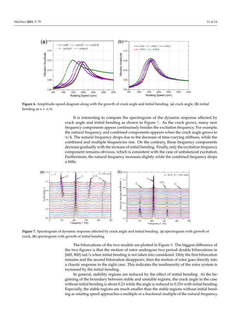
It is interesting to compare the spectrogram of the dynamic response affected bycrack angle and initial bending as shown in Figure 7. As the crack grows, many newfrequency components appear continuously besides the excitation frequency. For example,the natural frequency and combined components appears when the crack angle grows toπ/4. The natural frequency drops due to the decrease of time-varying stiffness, while thecombined and multiple frequencies rise. On the contrary, these frequency componentsdecrease gradually with the increase of initial bending. Finally, only the excitation frequencycomponent remains obvious, which is consistent with the case of unbalanced excitation.Furthermore, the natural frequency increases slightly while the combined frequency dropsa little.
Machines 2021, 9, x FOR PEER REVIEW 12 of 15
Figure 6. Amplitude–speed diagram along with the growth of crack angle and initial bending. (a)
crack angle, (b) initial bending as α = π/6.
It is interesting to compare the spectrogram of the dynamic response affected by
crack angle and initial bending as shown in Figure 7. As the crack grows, many new
frequency components appear continuously besides the excitation frequency. For exam-
ple, the natural frequency and combined components appears when the crack angle
grows to π/4. The natural frequency drops due to the decrease of time-varying stiffness,
while the combined and multiple frequencies rise. On the contrary, these frequency
components decrease gradually with the increase of initial bending. Finally, only the ex-
citation frequency component remains obvious, which is consistent with the case of un-
balanced excitation. Furthermore, the natural frequency increases slightly while the
combined frequency drops a little.
Figure 7. Spectrogram of dynamic response affected by crack angle and initial bending. (a) spec-
trogram with growth of crack, (b) spectrogram with growth of initial bending.
The bifurcations of the two models are plotted in Figure 8. The biggest difference of
the two figures is that the motion of rotor undergoes two period double bifurcations in
[600, 800] rad/s when initial bending is not taken into considered. Only the first bifurca-
tion remains and the second bifurcation disappears, then the motion of rotor goes di-
rectly into a chaotic response in the right case. This indicates the nonlinearity of the rotor
system is increased by the initial bending.
Figure 7. Spectrogram of dynamic response affected by crack angle and initial bending. (a) spectrogram with growth ofcrack, (b) spectrogram with growth of initial bending.
The bifurcations of the two models are plotted in Figure 8. The biggest difference ofthe two figures is that the motion of rotor undergoes two period double bifurcations in[600, 800] rad/s when initial bending is not taken into considered. Only the first bifurcationremains and the second bifurcation disappears, then the motion of rotor goes directly intoa chaotic response in the right case. This indicates the nonlinearity of the rotor system isincreased by the initial bending.
In general, stability regions are reduced by the effect of initial bending. At the be-ginning of the boundary between stable and unstable regions, the crack angle in the casewithout initial bending is about 0.2π while the angle is reduced to 0.15π with initial bending.Especially, the stable regions are much smaller than the stable regions without initial bend-ing as rotating speed approaches a multiple or a fractional multiple of the natural frequency.

Machines 2021, 9, 79 12 of 14
The original tortuous boundary becomes smooth and extends laterally as rotating speedexceeds the natural frequency in Figure 9b.
Machines 2021, 9, x FOR PEER REVIEW 13 of 15
Figure 8. Bifurcations as α = π/3. (a) without initial bending, (b) with initial bending.
In general, stability regions are reduced by the effect of initial bending. At the be-
ginning of the boundary between stable and unstable regions, the crack angle in the case
without initial bending is about 0.2π while the angle is reduced to 0.15π with initial
bending. Especially, the stable regions are much smaller than the stable regions without
initial bending as rotating speed approaches a multiple or a fractional multiple of the
natural frequency. The original tortuous boundary becomes smooth and extends later-
ally as rotating speed exceeds the natural frequency in Figure 9b.
Figure 9. Stability regions. (a) without initial bending, (b) with initial bending.
Therefore, the rotor system with initial bending or dynamic bending may cause an
unstable response or even rubbing fault. Hence, the dynamics of a rotor system with
rubbing fault caused by shaft bending has attracted a lot of attentions in recent years. By
comparing the dynamic characteristics between the results calculated by the improved
model with initial bending and former model, many differences can be found and used
for vibration detection, stability analysis and fault diagnosis of rotor systems.
4. Conclusions
An improved breathing mechanism of a transverse crack in rotor systems with ini-
tial bending is introduced in this study. The change of the moment of inertia of the
closed portion and the position of neutral axis encased by the initial bending are calcu-
lated and discussed in detail. After the accurate dynamic model of the bearing rotor sys-
tem is established, many differences of the vibration response are found as:
1. The intervals of crack state are delayed by the initial bending, but the changes of
interval size of each crack state are different. The size of fully open state is in-
creased, the size of the fully closed one remains unchanged, and the two other in-
terval sizes are reduced.
Figure 8. Bifurcations as α = π/3. (a) without initial bending, (b) with initial bending.
Machines 2021, 9, x FOR PEER REVIEW 13 of 15
Figure 8. Bifurcations as α = π/3. (a) without initial bending, (b) with initial bending.
In general, stability regions are reduced by the effect of initial bending. At the be-
ginning of the boundary between stable and unstable regions, the crack angle in the case
without initial bending is about 0.2π while the angle is reduced to 0.15π with initial
bending. Especially, the stable regions are much smaller than the stable regions without
initial bending as rotating speed approaches a multiple or a fractional multiple of the
natural frequency. The original tortuous boundary becomes smooth and extends later-
ally as rotating speed exceeds the natural frequency in Figure 9b.
Figure 9. Stability regions. (a) without initial bending, (b) with initial bending.
Therefore, the rotor system with initial bending or dynamic bending may cause an
unstable response or even rubbing fault. Hence, the dynamics of a rotor system with
rubbing fault caused by shaft bending has attracted a lot of attentions in recent years. By
comparing the dynamic characteristics between the results calculated by the improved
model with initial bending and former model, many differences can be found and used
for vibration detection, stability analysis and fault diagnosis of rotor systems.
4. Conclusions
An improved breathing mechanism of a transverse crack in rotor systems with ini-
tial bending is introduced in this study. The change of the moment of inertia of the
closed portion and the position of neutral axis encased by the initial bending are calcu-
lated and discussed in detail. After the accurate dynamic model of the bearing rotor sys-
tem is established, many differences of the vibration response are found as:
1. The intervals of crack state are delayed by the initial bending, but the changes of
interval size of each crack state are different. The size of fully open state is in-
creased, the size of the fully closed one remains unchanged, and the two other in-
terval sizes are reduced.
Figure 9. Stability regions. (a) without initial bending, (b) with initial bending.
Therefore, the rotor system with initial bending or dynamic bending may cause anunstable response or even rubbing fault. Hence, the dynamics of a rotor system withrubbing fault caused by shaft bending has attracted a lot of attentions in recent years. Bycomparing the dynamic characteristics between the results calculated by the improvedmodel with initial bending and former model, many differences can be found and used forvibration detection, stability analysis and fault diagnosis of rotor systems.
4. Conclusions
An improved breathing mechanism of a transverse crack in rotor systems with initialbending is introduced in this study. The change of the moment of inertia of the closedportion and the position of neutral axis encased by the initial bending are calculated anddiscussed in detail. After the accurate dynamic model of the bearing rotor system isestablished, many differences of the vibration response are found as:
1. The intervals of crack state are delayed by the initial bending, but the changes ofinterval size of each crack state are different. The size of fully open state is increased,the size of the fully closed one remains unchanged, and the two other interval sizesare reduced.
2. The growth of crack reduces the natural frequency of the rotor system and increasesthe vibration amplitude, while the growth of the initial bending increases the ampli-tude and the range of resonance area.
Machines 2021, 9, 79 13 of 14
3. Many frequency components gradually appear as the crack grows, such as the naturalfrequency, combined frequency and multiple frequencies. On the contrary, initialbending gradually reduces these frequency components and makes them disappear.Stable regions are reduced, smoothed and extended laterally when rotating speedexceeds twice the natural frequency.
Author Contributions: Conceptualization, Y.W. and X.X.; methodology, Y.W.; software and valida-tion, Y.W., supervision, X.H.; All authors have read and agreed to the published versionof the manuscript.
Funding: This research was funded by the National Natural Science Foundation of China, grantnumber 51705302.
Institutional Review Board Statement: Not applicable.
Informed Consent Statement: Not applicable.
Data Availability Statement: Not applicable.
Conflicts of Interest: The authors declare no conflict of interest.
References1. Wen, L.; Yang, Z.C.; Cao, Y.Y. The nonlinear dynamic characteristics of a cracked rotor-bearing system with initial bend
deformation. In International Conference on Intelligent Human-Machine Systems & Cybernetics; IEEE: Hangzhou, China, 2015;pp. 341–344.
2. Hu, L.; Liu, Y.B.; Teng, W.; Zhou, C. Nonlinear coupled dynamics of a rod fastening rotor under rub-impact and initial permanentdeflection. Energies 2016, 9, 883. [CrossRef]
3. Jia, J.H.; Hang, T.Q. Effect of the initial deflection on vibration characteristics of the rub-impact rotor system. Math. Comput. Appl.2010, 15, 768–775. [CrossRef]
4. Spagnol, J.; Wu, H.; Yang, C. Application of non-symmetric bending principles on modelling fatigue crack behaviour andvibration of a cracked rotor. Appl. Sci. 2020, 10, 717. [CrossRef]
5. Lacalle, L.N.L.D.; Viadero, F.; Hernandez, J.M. Applications of dynamic measurements to structural reliability updating.Probabilistic Eng. Mech. 1996, 11, 97–105. [CrossRef]
6. Coro, A.; Abasolo, M.; Aguirrebeitia, J.; López de Lacalle, L.N. Inspection scheduling based on reliability updating of gas turbinewelded structures. Adv. Mech. Eng. 2019, 11, 168781401881928. [CrossRef]
7. Mobarak, H.M.; Wu, H.; Spagnol, J.P.; Xiao, K. New crack breathing mechanism under the influence of unbalance force.Arch. Appl. Mech. 2017, 88, 341–372. [CrossRef]
8. Liong, R.T.; Proppe, C. Application of the cohesive zone model for the evaluation of stiffness losses in a rotor with a transversebreathing crack. J. Sound Vib. 2013, 332, 2098–2110. [CrossRef]
9. Roy, D.K.; Tiwari, R. Estimation of the internal and external damping from the forward and backward spectrum of a rotor with afatigue crack. Propuls. Power Res. 2020, 9, 62–74. [CrossRef]
10. Yang, Y.; Yang, Y.R.; Cao, D.Q.; Chen, G.; Jin, Y.L. Response evaluation of imbalance- rub–pedestal looseness coupling fault on ageometrically nonlinear rotor system. Mech. Syst. Signal Process. 2019, 118, 423–442. [CrossRef]
11. Mayes, I.J.; Davis, W.G.R. Analysis of the response of a multi-rotor-bearing system containing a transverse crack in a rotor.J. Vib. Acoust. 1984, 160, 139–145. [CrossRef]
12. Al-Shudeifat, M.A.; Butcher, E.A. New breathing functions for the transverse breathing crack of the cracked rotor system:Approach for critical and subcritical harmonic analysis. J. Sound Vib. 2011, 330, 526–544. [CrossRef]
13. Al-Shudeifat, M.A. Stability analysis and backward whirl investigation of cracked rotors with time-varying stiffness. J. Sound Vib.2015, 348, 365–380. [CrossRef]
14. Urbikain, G.; Olvera, D.; de Lacalle, L.N.L.; Elías-Zúñiga, A. Stability and vibrational behaviour in turning processes with lowrotational speeds. Int. J. Adv. Manuf. Technol. 2015, 80, 871–885. [CrossRef]
15. Urbikain, G.; Campa, F.-J.; Zulaikab, J.-J.; de Lacallea, L.-N.; Alonsoa, M.-A.; Colladob, V. Preventing chatter vibrations inheavy-duty turning operations in large horizontal lathes. J. Sound Vib. 2015, 340, 317–330. [CrossRef]
16. He, Q.; Peng, H.C.; Zhai, P.C.; Zhen, Y.X. The effects of unbalance orientation angle on the stability of the lateral torsion couplingvibration of an accelerated rotor with a transverse breathing crack. Mech. Syst. Signal Process. 2016, 75, 330–344. [CrossRef]
17. Sekhar, A.S. Identification of unbalance and crack acting simultaneously in a rotor system: Modal expansion versus reducedbasis dynamic expansion. J. Vib. Control 2005, 11, 1125–1145. [CrossRef]
18. Sinou, J.J. Detection of cracks in rotor based on the 2× and 3× super-harmonic frequency components and the crack–unbalanceinteractions. Commun. Nonlinear Sci. Numer. Simul. 2008, 13, 2024–2040. [CrossRef]
19. Singh, S.; Tiwari, R. Model based identification of crack and bearing dynamic parameters in flexible rotor systems supportedwith an auxiliary active magnetic bearing. Mech. Mach. Theory 2018, 122, 292–307. [CrossRef]
Machines 2021, 9, 79 14 of 14
20. Spagnol, J.P.; Wu, H. Breathing mechanism of a cracked rotor subject to non-trivial mass unbalance. In Proceedings of theInternoise 2014: 43rd International Congress on Noise Control Engineering: Improving the World through Noise Control,Melbourne, Australia, 16–19 November 2014; pp. 6404–6410.
21. Rubio, P.; Rubio, L.; Muñoz-Abella, B.; Montero, L. Determination of the Stress Intensity Factor of an elliptical breathing crack ina rotating shaft. Int. J. Fatigue 2015, 77, 216–231. [CrossRef]
22. Gayen, D.; Tiwari, R.; Chakraborty, D. Finite element based stability analysis of a rotor–bearing system having a functionallygraded shaft with transverse breathing cracks. Int. J. Mech. Sci. 2019, 157, 403–414. [CrossRef]
23. Rubio, P.; Sanz, Y.; Rubio, L.; Muñoz-Abella, B. Stress Intensity Factor and propagation of an open sickle shaped crack in a shaftunder bending. Theor. Appl. Fract. Mech. 2018, 96, 688–698. [CrossRef]
24. Rubio, P.; Rubio, L.; Muñoz-abella, B. Propagation of surface breathing cracks in shafts under quasi-static rotary bending.Nonlinear Dyn. 2017, 90, 1987–2000. [CrossRef]
25. Zhao, B.X.; Yuan, Q.; Li, P. Improvement of the vibration performance of rod-fastened rotor by multioptimization on thedistribution of original bending and unbalance. J. Mech. Sci. Technol. 2020, 34, 83–95. [CrossRef]
26. Mokhtar, M.A.; Darpe, A.K.; Gupta, K. Investigations on bending-torsional vibrations of rotor during rotor-stator rub usinglagrange multiplier method. J. Sound Vib. 2017, 401, 94–113. [CrossRef]
27. Yang, Y.; Yang, Y.R.; Ouyang, H.J.; Li, X.; Cao, D.Q. Dynamic performance of a rotor system with an initial bow and couplingfaults of imbalance-rub during whirling motion. J. Mech. Sci. Technol. 2019, 33, 4645–4657. [CrossRef]
28. Xia, Y.L.; Zhang, W.T.; Lu, Y.B.; Yang, J.G. Rotor Vibration analysis under the coupled effect of shaft bend and unbalance. DongliGongcheng Xuebao/J. Chin. Soc. Power Eng. 2018, 38, 815–819.
29. Yang, D.; Gan, C.B.; Yang, S.X.; Wang, Y.H. Analysis on response of a rotor with initial bend deformation under coupling fault ofcrack and rub-impact. J. Zhejiang Univ. (Eng. Sci.) 2014, 48, 1496–1501.
30. Guo, C.; Al-Shudeifat, M.A.; Yan, J.; Bergman, L.A.; Mcfarland, D.M.; Butcher, E.A. Stability analysis for transverse breathingcracks in rotor systems. Eur. J. Mech. 2013, 42, 27–34. [CrossRef]
31. Wang, Z.Y.; Lin, W.; Wen, B.C. Analysis of the rotor system with a switching crack. J. Vib. Shock. 2010, 29, 69–72.
Related Documents