Sign of Contractor / Developer Page 1 CHAPTER ‐VI VADODARA MAHANAGAR SEVA SADAN VOLI Part2 TECHNICAL SPECIFICATION

Welcome message from author
This document is posted to help you gain knowledge. Please leave a comment to let me know what you think about it! Share it to your friends and learn new things together.
Transcript
Sign of Contractor / Developer Page 1
CHAPTER ‐VI
VADODARA MAHANAGAR SEVA SADAN
VOLI
Part2
TECHNICAL SPECIFICATION
Sign of Contractor / Developer Page 2
MATERIALS
M1 Water:
1.1. Water shall not be salty or brackish and shall be clean, reasonably clear and free objectionable quantities of silt and traces of oil and injurious alkalis, salts, organic matter and other deleterious material which will either weaken the mortar or concrete or cause efflorescence or attack the steel in R.C.C Container for transport, storage and handling of water shall be clean. Water shall conform to the standards specified in I.S.456‐1978.
1.2. If required by the Engineer‐in‐charge it shall be tested by comparison with distilled water. Comparison shall be made by means of standard cement tests for soundness, time of setting and mortar strength as specified in I.S.269‐1976. Any indication of unsoundness, change in time of setting by 30 minutes or more or decrease of more than 10 per cent in strength of mortar prepared with water sample when compared with the results obtained with mortar prepared with distilled water shall be sufficient cause for rejection of water under test.
1.3. Water for curing mortar, concrete or masonry should not be too acidic or too alkaline. It shall be free of elements which significantly affect the hydration reaction or otherwise interfere with the hardening of concrete during curing or those which produce objectionable stains or other unsightly deposits on concrete or mortar surfaces.
1.4. Hard and bitter water shall not be used for curing. 1.5. Portable water will be generally found suitable for curing mortar or concrete. M2.Lime: 2.1. Lime shall be hydraulic lime as per I.S. 712‐1973. Necessary test shall be carried
out as per I.S. 6932 (Parts I to X), 1973. 2.2. The following field tests for limes are to be carried out: (1) A very rough idea can be formed about the type of lime by its visual
examination i.e. fat lime bears pure white color, lime in form of porous lumps of dirty while color indicates quick lime, and solid lumps are the unburnt lime stone.
(2) Acid tests for determining the carbonate content in lime, Excessive amount of impurities and rough determination of class of lime.
2.3. Storage shall comply with I.S. 712‐1973. The slaked lime, if stored, shall be kept in a weather proof and damp‐proof shed with impervious floor and sides to protect it against rain, moisture, weather and extraneous materials mixing with it. All lime that has been damaged in any way shall be rejected and all rejected materials shall be removed from site of work.
2.4. Field testing shall be done according to I.S. 1624‐1974 to show the acceptability of materials.
Sign of Contractor / Developer Page 3
M3.Cement : 3.1 Cement shall be ordinary Portland slag cement as per I.S. 269‐1976 or Portland
slag cement as per I.S. 455‐1976.
M4.White Cement : 4.1 The white cement shall conform to I.S. 80412‐E 1978.
M5.Colored Cement: 5.1 Colored cement shall be with white or gray Portland cement as specified in the
item of the work. 5.2 The pigments used for colored cement shall be of approved quality and shall
not exceed 10% of cement used in the Mix. The mixture of pigment shall be properly grounded to have a uniform color and shade. The pigments shall have such properties to provide for durability under exposure to sunlight and weather.
5.3 The pigment shall have the property such that it is neither by the cement nor detrimental to it.
M6.Sand: 6.1. Sand shall be natural sand, clean, well graded, hard strong durable and gritty
particle free from injurious amounts of dust clay, kankar nodules, soft or flaky particles shale, alkali, salts organic matter, loam, mica or another deleterious substance and shall be got approved from the Engineer‐in‐charge. The sand shall not contain more than 8 percent of silt as determined by field test. If necessary the sand shall be washed to make it clean.
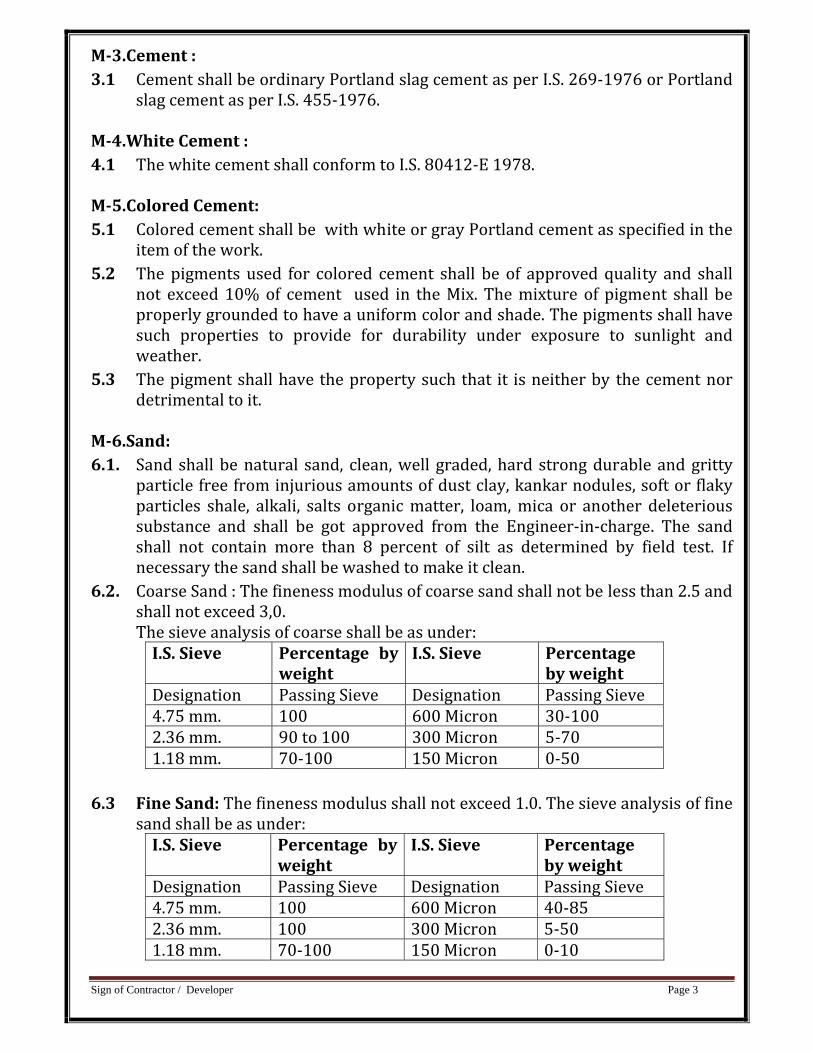
6.2. Coarse Sand : The fineness modulus of coarse sand shall not be less than 2.5 and shall not exceed 3,0. The sieve analysis of coarse shall be as under: I.S. Sieve Percentage by
weight I.S. Sieve Percentage
by weight Designation Passing Sieve Designation Passing Sieve 4.75 mm. 100 600 Micron 30‐100 2.36 mm. 90 to 100 300 Micron 5‐70 1.18 mm. 70‐100 150 Micron 0‐50
6.3 Fine Sand: The fineness modulus shall not exceed 1.0. The sieve analysis of fine
sand shall be as under: I.S. Sieve Percentage by
weight I.S. Sieve Percentage
by weight Designation Passing Sieve Designation Passing Sieve 4.75 mm. 100 600 Micron 40‐85 2.36 mm. 100 300 Micron 5‐50 1.18 mm. 70‐100 150 Micron 0‐10
Sign of Contractor / Developer Page 4
M7.Stone Dust : 7.1. This shall be obtained from crushing hard black trap or equivalent. It shall not
contain more than 8% of silt as determined by field test with measuring cylinder. The method of determining silt contents by field test is given as under :
7.2. A sample of stone dust to be tested shall be placed without drying in 200 mm. measuring cylinder. The quantity of the sample shall be such that it fills the cylinder up to100 mm. mark. The clean water shall be added up to 150 mm. mark. The mixture shall be stiffed vigorously and the content allowed to settle for 3 hours.
7.3. The height of silt visible as settled layer above the stone dust shall be expressed as percentage of the height of the stone dust below. The stone dust containing more than 8% silt shall be washed so as lowering the silt content within the allowable limit.
7.4. The fineness modulus of stone dust shall not be less than 1.80.
M8.Stone Grit: 8.1. Grit shall consist of crushed or broken stone and be hard strong, dense, durable,
clean, of proper gradation and free from skin or coating likely to prevent adhesion of mortar Grit shall generally be cubical in shape and as far as possible flaky elongated pieces shall be avoided. It shall generally comply with the provisions of I.S. 383‐1970. Unless special stone of particular quarries is mentioned, grit shall be obtained from the best black trap or equivalent hard stone as approved by the Engineer‐in‐charge. The grit shall have no deleterious reaction with cement.
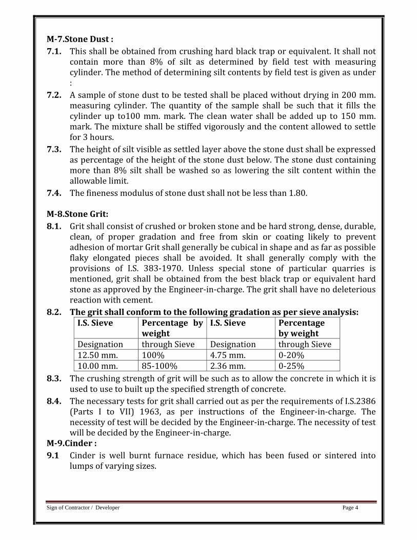
8.2. The grit shall conform to the following gradation as per sieve analysis: I.S. Sieve Percentage by
weight I.S. Sieve Percentage
by weight Designation through Sieve Designation through Sieve 12.50 mm. 100% 4.75 mm. 0‐20% 10.00 mm. 85‐100% 2.36 mm. 0‐25%
8.3. The crushing strength of grit will be such as to allow the concrete in which it is used to use to built up the specified strength of concrete.
8.4. The necessary tests for grit shall carried out as per the requirements of I.S.2386 (Parts I to VII) 1963, as per instructions of the Engineer‐in‐charge. The necessity of test will be decided by the Engineer‐in‐charge. The necessity of test will be decided by the Engineer‐in‐charge.
M9.Cinder : 9.1 Cinder is well burnt furnace residue, which has been fused or sintered into
lumps of varying sizes.
Sign of Contractor / Developer Page 5
9.2 Cinder aggregates shall be well burnt furnace residue obtained from furnace using coal fuel only. it shall be sound clean free from clay, dirt ash or other deleterious matter.
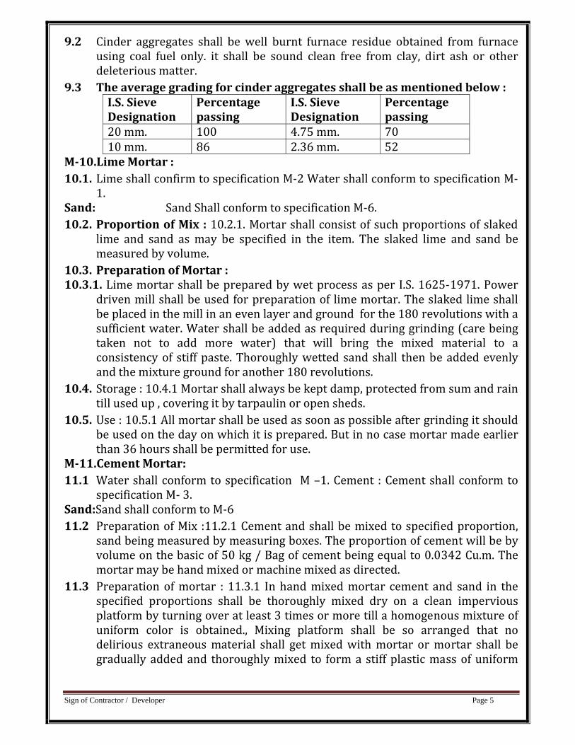
9.3 The average grading for cinder aggregates shall be as mentioned below : I.S. Sieve Designation
Percentage passing
I.S. Sieve Designation
Percentage passing
20 mm. 100 4.75 mm. 7010 mm. 86 2.36 mm. 52
M10.Lime Mortar : 10.1. Lime shall confirm to specification M‐2 Water shall conform to specification M‐
1. Sand: Sand Shall conform to specification M‐6. 10.2. Proportion of Mix : 10.2.1. Mortar shall consist of such proportions of slaked
lime and sand as may be specified in the item. The slaked lime and sand be measured by volume.
10.3. Preparation of Mortar : 10.3.1. Lime mortar shall be prepared by wet process as per I.S. 1625‐1971. Power
driven mill shall be used for preparation of lime mortar. The slaked lime shall be placed in the mill in an even layer and ground for the 180 revolutions with a sufficient water. Water shall be added as required during grinding (care being taken not to add more water) that will bring the mixed material to a consistency of stiff paste. Thoroughly wetted sand shall then be added evenly and the mixture ground for another 180 revolutions.
10.4. Storage : 10.4.1 Mortar shall always be kept damp, protected from sum and rain till used up , covering it by tarpaulin or open sheds.
10.5. Use : 10.5.1 All mortar shall be used as soon as possible after grinding it should be used on the day on which it is prepared. But in no case mortar made earlier than 36 hours shall be permitted for use.
M11.Cement Mortar: 11.1 Water shall conform to specification M –1. Cement : Cement shall conform to
specification M‐ 3. Sand:Sand shall conform to M‐6 11.2 Preparation of Mix :11.2.1 Cement and shall be mixed to specified proportion,
sand being measured by measuring boxes. The proportion of cement will be by volume on the basic of 50 kg / Bag of cement being equal to 0.0342 Cu.m. The mortar may be hand mixed or machine mixed as directed.
11.3 Preparation of mortar : 11.3.1 In hand mixed mortar cement and sand in the specified proportions shall be thoroughly mixed dry on a clean impervious platform by turning over at least 3 times or more till a homogenous mixture of uniform color is obtained., Mixing platform shall be so arranged that no delirious extraneous material shall get mixed with mortar or mortar shall be gradually added and thoroughly mixed to form a stiff plastic mass of uniform
Sign of Contractor / Developer Page 6
color so that each particle of sand shall be completely covered with a film of wet cement. The water cement ratio shall be adopted as directed.
11.3.1 The mortar so prepared shall be used within 30 minutes of adding water Only such quantity of mortar shall be prepared as can be used within 30 minutes.
M12Stone Coarse Aggregate For nominal Mix Concrete : 12.1 Coarse aggregate shall be machine crushed stone of black trap or equivalent
and be hard, strong m dense, durable clean and free form skin and coating likely to prevent proper adhesion for mortar.
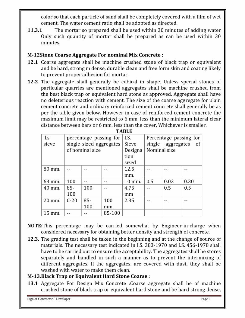
12.2 The aggregate shall generally be cubical in shape. Unless special stones of particular quarries are mentioned aggregates shall be machine crushed from the best black trap or equivalent hard stone as approved. Aggregate shall have no deleterious reaction with cement. The size of the coarse aggregate for plain cement concrete and ordinary reinforced cement concrete shall generally be as per the table given below. However in case of reinforced cement concrete the maximum limit may be restricted to 6 mm. less than the minimum lateral clear distance between bars or 6 mm. less than the cover, Whichever is smaller.
TABLE l.s. sieve
percentage passing for single sized aggregates of nominal size
I.S. Sieve Designation sized
Percentage passing for single aggregates of Nominal size
80 mm. ‐‐ ‐‐ ‐‐ 12.5 mm.
‐‐ ‐‐ ‐‐
63 mm. 100 ‐‐ ‐‐ 10 mm. 0.5 0.02 0.30 40 mm. 85‐
100 100 ‐‐ 4.75
mm ‐‐ 0.5 0.5
20 mm. 0‐20 85‐100
100 mm.
2.35 ‐‐ ‐‐ ‐‐
15 mm. ‐‐ ‐‐ 85‐100 NOTE:This percentage may be carried somewhat by Engineer‐in‐charge when
considered necessary for obtaining better density and strength of concrete. 12.3. The grading test shall be taken in the beginning and at the change of source of
materials. The necessary test indicated in I.S. 383‐1970 and I.S. 456‐1978 shall have to be carried out to ensure the acceptability. The aggregates shall be stores separately and handled in such a manner as to prevent the intermixing of different aggregates. If the aggregates. are covered with dust, they shall be washed with water to make them clean.
M13.Black Trap or Equivalent Hard Stone Coarse : 13.1 Aggregate For Design Mix Concrete :Coarse aggregate shall be of machine
crushed stone of black trap or equivalent hard stone and be hard strong dense,
Sign of Contractor / Developer Page 7
durable clean and free skin and coating likely to prevent proper adhesion of mortar.
13.2 The aggregates shall generally be cubical in shape. Unless special stones of particular quarries are mentioned, aggregates shall be machine crushed from the best, black trap or equivalent hard stones as approved. Aggregate shall have no deleterious reaction with cement.
13.3 The necessary tests indicated in I.S. 383‐1970 and I.S. 456‐1978 shall have to be carried out to ensure the acceptability of the material.
13.4 If aggregate is covered with dust it shall be washed with water to make it clean. M14.Brick Bats Aggregate : 14.1 Brick bat aggregate shall be broken from well burnt or slightly over burnt and
dies brick. It shall be homogeneous in texture roughly cubical shape, clean and free from dirt of any other foreign material. The brick bats shall be of 40 mm. to 50 mm. size unless otherwise specified in the item. The unburnt or over burnt brick bats shall not be allowed.
14.2 The brick bats shall be measured by volume by suitable boxes or as directed. M15 Bricks : 15.1 The bricks shall be hand or machine molded and made from suitable soils and
kiln‐burnt. They shall be free from crack and nodules of free lime. They shall have smooth rectangular faces with sharp corners and shall be of uniform color. The bricks shall be molded with a frog of 100 mm. X 40 mm. and 10 mm. to 20 mm. deep on one of its flat sides. The bricks shall not break when thrown on the ground from a height of 600 mm.
15.2 The size of modular bricks shall be 190 mm. X 90 mm. X 90 mm.
15.3 The size of the conventional bricks shall be as under : (9”x438 ” x 2
34 ”)225 x 110
x 75 mm. 15.4 Only bricks of one standard size shall be used on one work. The following
tolerances shall be permitted in the conventional size adopted in a particular work. Length : 1.8 (3.0 mm.) Width : 1/6 “ (1.51 mm.) Height : 1/6” 1.50 mm.)
15.5 The crushing strength of the bricks shall not be less than 35 Kg./Sq.Cm. The average water abscriptics shall not be more than 20 prevent by weight. Necessary tests for crushing strength and water absorption etc. shall be carried out as per I.S. .3493 (Part‐I to IV) 1976.
M16 Stone : 16.1 The stone shall be of the specified variety such as Granite/Trap Stone. Quartzite
or any other type of good hard stones. The stones shall be obtained only from the approved quarry and shall be hard, sound, durable and free from defects like cavities, cracks, sand holes, flaws, injurious veins, patches of loose or soft materials etc. and weathered portions and other structural defects or imperfections tending to affect their soundness and strength. The stone with
Sign of Contractor / Developer Page 8
round surface shall not be used. The percentage of water absorption shall not be more that 5% of dry weight, When tested in accordance with I.S. 1134‐1974. The minimum crushing strength of the stone shall be 200 kg./Sq. Cm. unless otherwise specified.
16.2 The samples of the stone to be used shall be got approved before the work is started.
16.3 The Khanki facing stone shall be dressed by chisel as specified in the item for Khanki facing in required shape and size. The face of stone shall be so dressed that the bushing on the exposed ace shall not project by more than 40 mm. from the general wall surface and on face to be plastered it shall not project by more than 19 mm. nor shall it have depressions more than 10 mm. from the average wall surface.
M17.Laterite Stone : 17.1 Laterite stone shall be obtained from the approved quarry. It shall be
compacted in texture, sound, durable and free from soft patches. It shall have a minimum crushing strength of 100 K.G/S.q. Cm. in its dry condition. It shall not absorb water more than 20% of its own weight, When immersed for 24 hours in water. After quarrying the stone shall be allowed to weather for some time before using in work.
17.2 The stone shall be dressed into regular rectangular blocks so that all faces are free from waviness and unevenness, edges true and square.
17.3 Those types of stone in which white clay occur, should not be used. 17.4 special corner stones shall be provided where so directed. M18.Mild Steel Bars : 18.1 Mild steel bars reinforcement for R.C.C work shall conform to I.S. 432(Part‐II)
1966 and shall be tested quality. It shall also comply with relevant part of I.S. 456‐1978.
18.2 All the reinforcement shall be clean and free from dirt, paint, grease, mile scale or loose or thick rust at the time of placing.
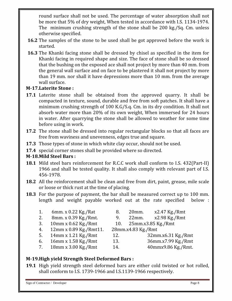
18.3 For the purpose of payment, the bar shall be measured correct up to 100 mm. length and weight payable worked out at the rate specified below : 1. 6mm. x 0.22 Kg./Rat 8. 20mm. x2.47 Kg./Rmt
2. 8mm. x 0.39 Kg./Rmt. 9. 22mm. x2.98 Kg./Rmt 3. 10mm x 0.62 Kg./Rmt 10. 25mm.x3.85 Kg./Rmt
4. 12mm x 0.89 Kg./Rmt11. 28mm.x4.83 Kg./Rmt 5. 14mm x 1.21 Kg./Rmt 12. 32mm.x6.31 Kg./Rmt 6. 16mm x 1.58 Kg./Rmt 13. 36mm.x7.99 Kg./Rmt 7. 18mm x 3.00 Kg./Rmt 14. 40mmx9.86 Kg./Rmt.
M19.High yield Strength Steel Deformed Bars : 19.1 High yield strength steel deformed bars are either cold twisted or hot rolled,
shall conform to I.S. 1739‐1966 and I.S.1139‐1966 respectively.
Sign of Contractor / Developer Page 9
19.2 Other provision and requirements shall conform to specification NO. M‐18 for Mild steel bars.
M20.High Tensile Steel Wire: 20.1 The high tensile wires for the use in pre‐stressed concrete work shall conform
to I.S. 2090‐1962. 20.2 The tensile strength of the high tensile steel bars shall be as specified in the
item. In absence of the given strength, the minimum strength shall be taken as per para 6.1 of I.S. 1785‐1962. Testing shall be done as per I.S. requirements.
20.3 The high tensile steel shall be free from loose mill scale, rust oil, grease, or any other harmful matter, Cleaning of steel bars may be carried out by immersion in solvent solution, wire brushing or passing through a pressure box containing carborundum.
20.4 The high tensile wire shall be obtained from manufactures in coil having diameter not less than 350 times the diameter of wire itself so that wire springs back straight back straight on being uncoiled.
M21.Mild Steel Binding Wire : 21.1. The mild steel wire shall be of 1.63 mm or 1.22 mm. (16 or 18 gauge) diameter
and shall conform to I.S. 280‐197. 21.2. The use of black wire be permitted for binding reinforcement bars. It shall be
free from rust, Oil paint, grease, looser mile scale or any other undesirable coating which may prevent adhesion of cement mortar.
M22.Structural Steel : 22.1. All structural steel shall conform to I.S. 226‐1965. The steel shall be free from
the defects mentioned in I.S. 226‐1975 and shall have a smooth finish. The material shall have a smooth finish. The material shall be free from loose mile scale, rust pits or other defects affecting the strength and durability. Rivet bars shall conform to I.S. 1148‐1973.
22.2. When the steel is supplied by the Contractor test certificates of the manufactures shall be obtained according to I.S. 226‐1975 and other relevant Indian Standards.
M23.Galvanized Iron Sheets : 23.1 The galvanized iron sheets shall be plain or corrugated sheets of specified in
item. The G.I. sheets shall conform it I.S. 217‐1977. The sheets shall be undamaged in carriage and handling either by rubbing off of zinc coating or otherwise they shall have clean and bright surface and shall be as directed as per site condition.
23.2 The length and width of G.I. sheet shall be as directed as per site condition. M23 (A) G.I Valleys gutter ridges : 23.A.1.The G.I. ridges and hips shall be of plain galvanized sheets class‐3 of the
thickness as specified in item. These shall be 600 mm. in width and properly bent up to shape without damage to the sheets in process of bending.
23.A.2.Valleys gutters and flashings shall also be galvanized sheet of thickness as specified in item. Valleys shall be 900 mm. Wide overall and flashing shall be

Sign of Contractor / Developer Page 10
380 mm. wide overall. They shall be bent to the required shape without damage to the sheet in the process of bending.
M24. Asbestos Cement Sheets : 24.1. Asbestos cement sheets plain, corrugated or semi corrugated shall conform to
I.S. 459‐1970. 24.2. Ridges & Hips : 24.2.1 Ridges and hips shall be same thickness at that of A.C. sheets. The types of
ridges suitable for the type of sheets and locations. 24.2.2 Other accessories to be used in roof such as flashing pieces, caves filler
pieces valley gutters, north light and ventilator curves, barge boards etc. shall be standard manufacture and shall be suitable for the type of sheets and location.
M25.Mangalore Pattern Roof Tiles : 1.1 The Mangalore pattern tiles shall conform to I.S. 654‐1972 for Class AA or Class
“A” type as specified in item. Samples of the tiles to be provided shall be got approved from the Engineer‐in‐charge. Necessary tests shall be carried out as directed.
M26.Shuttering : 26.1. The shuttering shall be either of widen planking of 30 mm. minimum thickness
with or without steel lining roof steel plates stiffened by steel angles. The shuttering shall be supported on battens and beams and props of vertical bellies properly cross braced together so as to make the centering rigid. In places of bully props, brick pillar of adequate section built in mud mortar may be used.
26.2. The form work shall be sufficiently strong and shall have camber, so that it assumes correct shape after deposition of the concrete and shall be able to resist forces caused by vibration of live load of men working over it and other incidental loads associated with it. The shuttering shall have smooth and even surface and its joints shall not permit leakage of cement grout.
26.3. If at any stage of work during or after placing concrete in the structure, the form work sags or bulges out beyond the required shape of the structure, the concrete shall be removed and work redone with fresh concrete and adequately rigid form work. The complete from work shall be got inspected by and got approved from the engineer‐in‐charge, before the reinforcement bars are placed in position.
26.4. The props shall consist of bullies having 100 mm. minimum diameter measured at mix length and 80 mm, at thin end and shall be placed as per design requirement. These shall rest squarely on wooden sole plates 40 mm. thick and minimum bearing area if 0‐10 sq. m. laid on sufficiently hard base.
26.5. Double wedges shall further be provided between the sole plate and the wooden props so as to facilitate tightening and easing of shuttering without jerking the concrete.
Sign of Contractor / Developer Page 11
26.6. The timber used in shuttering shall not be so dry as to absorb water from concrete and swell or bulge nor so green or wet as to shrink after erection. The timber shall be properly sawn and planed on the sides and surface coming in contact with concrete. Wooden from work with metal sheet lining or steel plates stiffened by steel angles shall be permitted.
26.7. As far as practicable, clamps shall be used to hold the forms together and use of nails and spikes avoided.
26.8. The surface of timber shuttering that would come in contact with concrete shall be well wetted and coated with soap solutions before the concreting is done. Alternatively coat of raw linseed oil or oil of approved manufacturer may be applied in place of soap solution. In case of steel shuttering either soap solution or raw linseed oil shall be applied after thoroughly cleaning the surface. Under no circumstances black or burnt oil shall be permitted.
26.9. The shuttering for beams and slabs shall have camber of 4 mm. per meter (1 to 250) or as directed by the Engineer‐in‐charge so as to offset the subsequent deflection. For cantilevers, The camber at free end shall be 1/50 of the projected length or as directed by the Engineer‐in‐charge.
M27.Expansion jointsPremoulded filter : 27.1 The item provides for expansion joints in R.C.C frame structures for internal
joints, as well as exposed joints, with the use of pre‐moulded bituminous joint filler.
27.2 Premoulded bituminous joint filler, i.e. performed strip of expansion joint filler shall not get deformed or broken by twisting, bending or other handling when exposed to atmospheric condition. Pieces of joint filler that have been damaged shall be rejected.
27.3 Thickness of the pre‐molded joint filler shall otherwise specified. 27.4 Premoulded bituminous joint filler shall conform to I.S. 1838‐1961. M28 Expansion jointsCopper strips & hold fasts : 28.1 The item provide for expansion joints in R.C.C frame structure for internal
joints as well as for exposed joints with the use of necessary copper strip and hold fasts.
28.2 Copper sheet shall be of 1.25 mm. thick and of 1.25 mm. width when the ‘U’ shape in middle. Copper strips shall have hold fast of 3 mm. diameter copper rod fixed to the plate soldered on strip at intervals of about 30 cm. or as shown in the drawing or as directed. The width of each flange (horizontal side) of the copper plate to be embedded in the concrete work shall be 25 mm. Depth of ‘U’ to be provide in the expansion joint, in the copper plate shall be of 25 mm.
M29.Teak wood : 29.1 The teak wood shall be of good quality as required for the item to be executed.
When the kind of wood is not specifically mentioned, good Indian teak wood as approved shall be used.
29.2 Teak wood shall generally be free from large, loose, dead or cluster knots, flaws, shakes, warps, twists bends or any other defects. It shall generally be uniform in
Sign of Contractor / Developer Page 12
substance and of straight fibers as far as possible. It shall be free from rot, decay, harmful fungi and other defects of harmful nature which will affect the strength durability of its usefulness for the purpose for which it is required. The color shall be uniform as far as possible. Any effort like painting, using any adhesive or resins materials made to hide the defects shall render the pieces liable to rejection by the Engineer‐in‐charge.
29.3 All scantlings, planks etc. shall be sawn in straight lines and planes in the direction of grains and of uniform thickness.
29.4 The tolerances in the dimensions shall be allowed at the rate of 1.5 m.m. per face to be planed.
29.5 First class teak wood : 29.5.1. First class teak wood shall have no individual hard and sound knots, more than 6 sq. cm. size and the aggregate area of such knots shall not be more than 1% of area of piece. The timber shall be closed grained.
29.6 Second Class Teak Wood :29.6.1. No individual hard and sound knots shall be more than 15 Sq. cms. in size and aggregate area of such knots shall not‐exceed 2% of the area of piece.
M29.(A) Nonteak wood :
The non teak‐wood shall be chemically treated, seasoned as per IS Specifications and of good quality. The type of wood shall be got approved before collecting the same on site. Fabrication of wooden members shall be started only after approval. For this purpose wood of Bio, Kalali, Siras, Behda, Jamun, Sisoo will be used for door frames where as only Kalali, Siras, Halda, Kalam etc. will be permitted for shutters after proper seasoning and chemical treatment. The non‐teak wood shall be free from large, loose, dead of cluster knots, flows, shakes warps bends or any other defect. It shall be uniform in substance and of straight fibers as far as possible. It shall be free rots, decay harmful fungi and other defects of nature which effect the strength, durability or its usefulness for the purpose for which it is required. The color of wood shall be uniform as far as possible. The scantlings planks etc. shall be sawn in straight lines and planes in the direction of grain and uniform thickness. The department will use the Agency to produce certificate from forest Department in event of Disputes and the decision of the Department shall be final and binding to the contractor. The tolerance in the dimension shall be allowed as 1.5 mm. per face to be planed.
M30.Wooden flush door shutters (solid core) : 30.1 The solid core type flush door shutters shall be decorative or non‐decorative
type as specified in the drawing. The size and thickness of the shutter shall be as specified in drawings or as directed. The timber species for core shall be
Sign of Contractor / Developer Page 13
used as per I.S. 2202‐ (Part‐I) 1980. The timber shall be free from decay and insect attack. Knots and knot holes less than half the width of cross‐section of the members in which they occur may be permitted. Pitch pockets, Pitch streaks and harmless pin holes shall be permissible except in the exposed edges of the core members. The commercial plywood, cross‐bands shall conform to I.S. 303‐1275.
30.2 The face panel of the shutters shall be formed by gluing by the hot press process on both faces of the core with either plywood or cross‐bands and face veneers. The hopping rebating opening of glazing, Venetian etc. shall be provided if specified in the drawing.
30.3 All edges of the door shutters shall be square. The shutters shall be free twist or warp in its plane. Both faces of the shutters shall be sand papered to smooth even texture.
30.4 The shutters shall be tested for (1) End immersion test : The test shall be carried out as per I.S. 2202 (part‐I)
1980. There shall be no de‐lamination at the end of the test. (2) Knife test : The face panel when tested in accordance with I.S. 1659‐1979 shall
pass the test. (3) Glue adhesion Test : The flush door shall be tested for glue adhesive test in
accordance with I.S. 2202 (Part‐I) 1980. The shutters shall be considered to have passed the test if no de‐lamination occurs in the glue lines in the plywood and if no single desalination more than 80 mm. in length and more than 3 mm. in depth has occurred in the assembly glue lines between the plywood face and the style and rail. Delaminating at the corner shall be measured continuously around the corner. Delaminating at the knots, knots holes and other permissible wood defects shall not be considered in assessing the sample.
30.5 The tolerance in size of solid core type flush door shall be as under : In Normal thickness + 1.2 mm.In Normal height + 3 mm.
30.6 The thick of the shutters shall be uniform throughout with a permissible variation of not more than 0.8 mm. when measured at any two points.
M31.Aluminum doors, Windows, Ventilators. 31.1 Aluminum alloy used in the manufacture of extruded window sections shall
conform to I.S. designation HEA‐WP of I.S. :733‐1975 and also to I.S. Designation WVG‐WP of I.S. 1285‐1975. The Section shall be as specified in the drawing and design. The fabrication shall be done as directed.
31.2 The hinges shall be cast or extruded aluminum hinges of same type as in windows but of large size.
31.3 The hinges shall normal be of 50 mm. projecting type. Non‐projecting type of hinges may also be used if directed. The handles of door shall be of specified in the drawing and design. The fabrication shall be done as directed.
M32.Rolling Shutters : 32.1 The rolling shutter shall conform to I.S. 6248‐1979. Rolling shutters shall be
supplied of specified type with accessories. The size of the rolling shutters shall
Sign of Contractor / Developer Page 14
be specified in the drawings. The shutters shall be constructed with interlocking lath sections formed from cold rolled steel strips not less than 0.9 mm. thick and 80 mm. wide for shutters up to 3.5 mm., width not less than 1.25 mm. thick and 80 mm. wide for shutters 3.5 mm in width and above unless otherwise specified.
32.2 Guide channels shall be of mild steel deep channel section and of rolled pressed or built up (fabricated) jointures construction. The thickness of sheet used shall not be less than 3.15 mm.
32.3 Hood covers shall be made of M.S. Sheets not less than 0.92 mm. thickness For shutters having width 3.5 Meter and above the thickness of M.S. Sheet for the hood cover shall be not less than 1.25 mm.
32.4 The spring shall be of best quality and shall be manufactured from tested high tensile spring steel wire or strip of adequate strength to balance the shutters in all position. The spring pipe shaft etc. shall be supported on strong M.S. or malleable C.I. brackets. The brackets shall be fixed on or under the lintel as specified with raw plugs and screws bolts etc.
32.5 The rolling shutters shall be of self rolling type up to 8 Sq.m. clear area without ball bearing and p to 12 Sq.m. clear area with ball bearing. If the rolling shutters are larger, then gear operated type shutters shall be used.
32.6 The locking arrangement shall be provided at the bottom of shutter at both ends. The shutters shall be opened from outside.
32.7 The shutters shall be completed with door suspension shafts, locking arrangements pulling hooks, handles and other accessories.
M33.Collapsible Steel Gate : 33.1 The collapsible steel gate shall be in one or two leaves and size as per approved
drawings or as specified. The gate, shall be fabricated from best‐ quality mild steel channels, flats etc. Either steel pulleys or ball bearing shall be provided in every double channel. Unless otherwise specified the particulars of collapsible gate shall be as under :
(a) Pickets : These shall be of 20 mm. M.S., channels of heavy sections unless otherwise shown on drawings. The distance center to center of pickets shall be 12 cms. with an opening of 10 Cms.
(b) Pivoted M.S. flats shall be 20 mm x 6 mm. (c) Top and bottom guides shall be from tee or flat iron of approved size. (d) The fittings like stoppers, fixing hold fasts, locking cleats, brass handles and cast
iron rollers shall be of approved design and size. M34.Welded Steel Wire Fabric : 34.1. Welded steel wire fabric for general purpose shall be manufactures from cold
drawn steel wire “as drawn” or galvanized steel conforming to I.S. 226‐1975 with longitudinal and transverse wire securw4ely connected at every intersection by a process of electrical resistance welding and conforming to I.S.
Sign of Contractor / Developer Page 15
4948‐1974. It shall be fabricated and finished in workmanlike manner and shall be free from injurious defects and shall be rust proof. The type of mesh shall be oblong or square as directed. The mesh sizes and size of wire for square as well as oblong welded steel wire fabric shall be as directed. The steel wire fabric in panels shall be in one whole piece in each panel as far as stock size permit.
M35.Expanded Metal Sheets : 35.1. The expanded metal sheets shall be free from flaws, joints, broken strands,
laminations and other harmful surface Expanded metal steel sheet shall conform to I.S. 412‐1975, Except that blank sheets need not be with guaranteed mechanical properties. The size of the diamond mesh of expended metal and dimensions of strands (width and thickness) shall be as specified. The tolerance in nominal weight of expended metal sheets shall be of + 10 percent.
35.2. Expanded metal in panels shall be in one whole piece panel each as far as stock size permit. The expanded metal sheets shall be coated with suitable protective coating to prevent corrosion.
M36.Mild Steel Wire (Wire ) : 36.1 Mild steel wire may be galvanized, as indicated All finished steel wire shall be
well cleanly drawn to the dimensions and size of wire as specified in item. The wire shall be sound, free from splits, surface flaws, rough jagged and imperfect edges and other harmful surface defects and shall conform to I.S. 280‐1978.
M37.Plywood : 37.1 The plywood for general purpose shall conform I.S. 303‐1975. Plywood is
made by cementing together thin boards or sheets of wood into panels. There are always an odd number of layers 3,5,7,9 ply etc. The plies are placed so that grain of each layer is right angle to the grain in the adjacent layer.
37.2 The Chief advantages of plywood over a signal board of the same thickness is the more uniform strength of the plywood, along the length and width of the plywood and grater resistance to cracking and splitting with change in moisture content.
37.3 Usually synthetic resins are used for gluing, pherolic resins are usually cured in a hot press which compresses and simultaneously heats the plies between hot plates which maintain a temperature of 90 degrees C. to 140 degrees C. and a pressure of 11 to 14 kg/sq.cm. on the wood. The time of heating may be anything from 2 to 69 minutes depending upon thickness.
37.4 When water glue are used , the wood absorbs so much water that the finished plywood must be dried carefully. When synthetic resins are used as adhesive finished by plywood must be exposed to an atmosphere of controlled humidity until the proper amount of moisture has been absorbed.
37.5 According to I.S. 303‐1975 the plywood for general purpose shall be of three grades BWR, WWR and CWR, depending upon the adhesives used for bonding and veneers, and it will be further classified into six types namely AA,AB,AC,BB,BC and CC based on the quality of the two faces, each face being of three kinds namely, A,B and C, After pressing, the finished plywood should be
Sign of Contractor / Developer Page 16
reconditioned to a moisture content not less than 8 percent and not more than 16 percent.
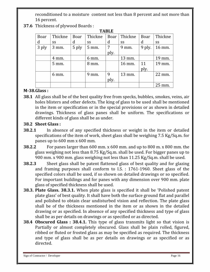
37.6 Thickness of plywood Boards : TABLE
Board
Thickness
Board
Thickness
Board
Thickness
Board
Thickness
3 ply 3 mm. 5 ply 5 mm. 7 ply.
9 mm. 9 ply. 16 mm.
4 mm. 6 mm. 13 mm. 19 mm. 5 mm. 8 mm. 16 mm. 11
ply. 19 mm.
6 mm. 9 mm. 9 ply.
13 mm. 22 mm.
25 mm. M38.Glass : 38.1 All glass shall be of the best quality free from specks, bubbles, smokes, veins, air
holes blisters and other defects. The king of glass to be used shall be mentioned in the item or specification or in the special provisions or as shown in detailed drawings. Thickness of glass panes shall be uniform. The specifications or different kinds of glass shall be as under.
38.2 Sheet Glass : 38.2.1 In absence of any specified thickness or weight in the item or detailed
specifications of the item of work, sheet glass shall be weighing 7.5 Kg/Sq.m. for panes up to 600 mm x 600 mm.
38.2.2 For panes larger than 600 mm. x 600 mm. and up to 800 m. x 800 mm. the glass weighing not less than 8.75 Kg/Sq.m. shall be used. For bigger panes up to 900 mm. x 900 mm. glass weighing not less than 11.25 Kg/Sq.m. shall be used.
38.2.3 Sheet glass shall be patent flattened glass of best quality and for glazing and framing purposes shall conform to I.S. : 1761‐1960. Sheet glass of the specified colors shall be used, if so shown on detailed drawings or so specified. For important buildings and for panes with any dimension over 900 mm. plate glass of specified thickness shall be used.
38.3. Plate Glass. 38.3.1. When plate glass is specified it shall be ‘Polished patent plate glass’ of best quality. It shall have both the surface ground flat and parallel and polished to obtain clear undisturbed vision and reflection. The plate glass shall be of the thickness mentioned in the item or as shown in the detailed drawing or as specified. In absence of any specified thickness and type of glass shall be as per details on drawings or as specified or as directed.
38.4 Obscured Glass : 38.4.1. This type of glass transmits light so that vision is Partially or almost completely obscured. Glass shall be plain rolled, figured, ribbed or fluted or frosted glass as may be specified as required. The thickness and type of glass shall be as per details on drawings or as specified or as directed.
Sign of Contractor / Developer Page 17
38.5. Wired Glass : 38.5.1 Glass shall be with wire netting embedded in a sheet of plate glass electrically welded 13 mm. Georgian square mesh may be used. Thickness of glass shall not be less than 6 mm. Wired glass shall be of type and thickness as specified
M39.Acrylic Sheets : 39.1. Acrylic sheet be of thickness as specified in the item and of an specified shape
and size as the case may be. Panels may be flat or curved . It should be light in weight. It shall be colorless or colored or opaque as specified in the item. Colorless sheet shall be as transparent as the finest optical glass. Its light transmission rate shall be about 95%. Transparency shall not be affected for the sheets of larger thickness. It shall be extremely resistant to sunlight, weather and low temperatures. It shall not show any significant yellowing or change in physical properties or loss of light transmission over a longer period of use. The sheet shall be impact resistant also. Sheets should be available in complete range of standard transparent, translucent and opaque colors. Sheets shall be of such quality that they can be cut bent and jointed as desired. Solution for the joints shall be used as per the requirement of manufacturer.
M40. Particle board : 40.1. The particle boards used for face panels shall be of best quality free from any
defects. The particle boards shall be made with phenolmaldehyde adhesive. The particle boards shall conform to I.S. 3087‐1965. “Specification for wood particle board for general purpose”. The size and the thickness shall be as indicated.
M41. Expanded polystyrene of framed stopper slabs : 41.1 The expanded polystyrene ceiling boards and tiles shall be approved make and
shall be of size, thickness, finish and color as indicated. It shall be of high density and suitable for use as insulating material. The insulating material shall be like slab of Thermocol etc.
M42. Resin bonded fiber glass : 42.1 The resin bonded fiber glass tiles, or rolls shall be of approved make and shall
be of sizes, thickness and finish as indicated. 42.2. For test of Minerrak wool thermal insulation Blanket I.S. : 3144?1965 shall be
followed. 42.3. Insulation wool blanket shall be with following coverings on one or both sides
as indicated. (1) Bituminized hessian Kraft paper for keeping out dust. (2) Hessian cloth or Kraft paper for keeping out dust. (3) G.I. wire netting, suitable for surface to be plastered over. M43.Fixtures and fastenings : 43.1. General 43.1.1 The fixtures and fastenings, that is, butt, hinges, tee and strap hinges
sliding door bolts, tower bolts, door latch, bath room latch, handles, door stoppers, casement window fasteners, casement stays and ventilators catch shall be made of the metal as specified in the item or its specifications.
Sign of Contractor / Developer Page 18
43.1.2 They shall be of iron, bras, aluminum, chromium plated iron chromium plated brass, copper oxidized iron, copper oxidized brass or anodized aluminum as specified.
43.1.3 The fixtures shall be heavy, Medium or light type. The fixtures and fastenings shall be smooth finished and shall be such as will ensure ease of operation.
43.1.4 The samples of fixtures and fastenings shall be got approved as regards quality and shape before providing them in position.
43.1.5 Brass and anodized aluminum fixtures and fastenings shall be bright finished.
43.2. Holdfasts : 43.2.1. Holdfasts shall be made from mild steel flat 30 cm. length and one of the
holdfasts shall be bent at right angle and two nos. of 6 mm. diameter holes shall be made in it for fixing it to the frame with screws. At the other end. The holdfast shall be forked and bent at right angles n opposite directions.
43.3. Butt hinges : 43.3.1. Railway standard heavy type butt hinges shall be used when so specified. 43.3.2. The strap hinges shall be manufactured from M. S. Sheet. 43.4 Siding door bold (Aldrops): 43 The Aldrops as specified in the item shall be
used and shall be got be got approved. 43.5 Tower bolts (Barrel Type):43.5.1 : Tower bolts as specified in the item shall
be used as shall be used and shall be got approved. 43.6 Door Latch:43.7.1The size of door latch shall be taken as the length of latch. 43.7 Bathroom Latch :43.5.1 Bathroom latch shall be similar to tower bolt. 43.8 Handle : The size of the handles shall be determined by the inside grip length of
the handles. Handles shall have a base plate of length 50 mm more than size of the handle.
43.9 Door Stopper: 43.9.1 door stoppers shall be either floor door stopper type or door catch type floor stopper shall be of overall size as specified as shall have rubber cushion.
43.10 Door Catch :43.10.1 Door catch shall be fixed as height of about 900 mm from the floor level so that one part of the catch is fitted on the inside of the shutter and the other part is fixed in the wall with necessary wooden plug arrangements for appropriate fixate. The catch shall be fixed 20 mimesed the face of the door for easy operation of catch.
43.11 Wooden Door stop with highs : 43.11.1 wooden door stop of size 100mm X 60 mm X 40 mm shall be fixed on the
door frame with a high of 75 mm size at high of 900 mm from the floor level the wooden door stop shall be provided with 3 coats of approve oil paint.
43.12 Case meant window fastener :Casement window fastener for single leaf window shutter shall be left or right handled as directed.
43.13 Casement stays (straight peg stay) :
Sign of Contractor / Developer Page 19
43.13.1 The stays shall be made from a channel section having three holes at appropriate position so that the window can be opened either fully or partially as directed as directed. size of the stay shall be 250 mm to 300 mm as directed.
43.14 Ventilator catch : 43.14.1 The pattern and shape of the catch shall be as approved . 43.15 Pivot : 43.15.1 The base and socket plate shall be made from minimum 3 mm thick plate
and projected pivot shall not be less than 12 mm length and shall be firmly riveted to the base plate in case of brass pivot.
M44.Paints : 44.1 (A) Oil Paints : 44.1.1.Oil Paints shall be of the specified color and shade, and as approved. The ready
mixed paints shall only be used. However, if ready mixed paint or specific shade or tint is not available, white ready mixed paint with approved strainer will be allowed. In such a case, the contractor shall ensure that the shade of the paint so allowed shall be uniform.
44.1.2. All the paints shall meet following general requirements : (i) Paint shall not show excessive setting in a freshly opened full can and shall
easily be redispressed with a paddle to a smooth homogeneous state. The paint shall show no curing, levering, caking or color separation and shall be free from lumps and skins.
(ii) The paint as received shall brush easily, possess good leveling properties and show no running or sagging tendencies.
(iii) The paint shall not skin within 48 hours in a three quarters filled closed container.
(iv) The paint shall dry to a smooth uniform finish free from roughness, grit, unevenness and other imperfections.
44.1.3. Ready mixed paint shall be used exactly as received from the manufactures and generally according to their instructions and without any admixtures whatsoever.
44.2. (B) Enamel Paints : 44.2.1. The enamel paint shall satisfy in general requirements as mentioned in
specification of oil paints. Enamel paint shall conform to I.S. 2933‐1975. M45 French polish : 45.1. The French polish of requirement and shape shall be prepared with the below
mentioned ingredients and other necessary materials: (I)Denatured sprit of approved quality (ii) Chandras (iii) Shellac (iv) Pigment. 45.2. The French polish so prepared shall conform to I.S. : 348‐1968. M46 Marble chips for marble mosaic terrazzo : 46.1. The marble chips shall be of approved quality and shades. It shall be hard,
sound, dense and homogenous in texture with crystalline and coarse grains. It shall be uniform in color and free from stains, cracks decay and weathering.
Sign of Contractor / Developer Page 20
46.2. The size of various colors of marble chips of approved quality and colors only as per grading as decided by the Engineer‐in‐charge shall be used for marble mosaic tiles or works.
46.3. The marble chips shall be machine crushed. They shall be free from foreign matter, dust etc. Except as above, the chips shall conform to I.S. : 2114‐1962.
M47. Flooring Tiles : 47.1. (A) Plain Cement tiles : 47.1.1. The plain cement tiles shall be general purpose type. These are the tiles in
the manufacturer of which no pigments are used Cement used in the manufacturer of tiles shall be as per Indian Standards.
47.1.2. The tiles shall be manufactured from a mixture of cement and natural aggregates by pressure process. During manufacture, the tiles shall be subjected to a pressure of not less than 140 Kg/Sq. Cm. The proportion of cement to aggregate in the backing of the tiles shall be not less than 1:3 by weight. The wearing face through the tiles are of plain cement, shall be provided with stone chips of 1 to 2 mm. Size. The proportions of cement to the marble chips aggregate in the wearing layer of the tiles shall be three parts of cement to one part chips by weight. The minimum thickness Of wearing layer shall be 3 mm. The color and texture of wearing layer shall be uniform throughout its face and thickness. On removal from mould, the tiles shall be kept in moist conditions continuously at least for seven days and subsequently, if necessary, for such long period as would ensure their conformity to requirements of I.S. : 1237‐1980 regarding strength resistance to wear and water absorption.
47.1.3. The wearing face of the tiles shall be plain, free from projections, depressions and cracks and shall be reasonably parallel to the back face of the title. All angles shall be right and all edges shall be sharp and true.
47.1.4. The size of tiles shall generally be square shape 24.85 Cm. x 24.85 Cm. or 25 Cm. x25 Cm. The thickness of tiles shall be 20 mm.
47.1.5. Tolerance of length and breadth shall be plus or minus one millimeter, Tolerance or thickness shall be plus 5 mm.
47.1.6. The tiles shall satisfy the tests as regards transverse strength, resistance to wear and water absorption as per I.S.:1237‐1980.
47.2. (B) Plain Colored Tiles : 47.2.1. These tiles shall have the same specification as per plain cement tiles as
per (A) above except that they shall have a plain wearing surface where in pigments are used. They shall conform to I.S. 1237‐1980.
47.2.2. The pigment used for coloring cement shall not exceed 10 percent by weight of cement used in the mix. The pigments, synthetic or otherwise, used for coloring tiles shall have permanent color and shall not contain materials detrimental to concrete.
47.2.3. The color of the tiles shall be specified in the item or as directed. 47.3. (C) Marble mosaic tiles :
Sign of Contractor / Developer Page 21
47.3.1. These tiles have the same specifications as per plain cement tiles except the requirements as stated below:
47.3.2. The marble mosaic tiles shall conform to I.S. 1237‐1980. The wearing face of the tiles shall be mechanical ground and filled. The wearing face of tiles shall be free from projections, depressions and cracks and shall be reasonably parallel to the back face of the tiles. All angles shall be right angles and all edges shall be sharp and true.
47.3.3. Chips used in the tiles be from smallest up to 20 mm. size. The minimum thickness of wearing layer of tiles shall of 6 mm. For pattern of chips to be used on the wearing face, a few samples with or without their full size photographs as directed shall be presented to the Engineer‐in‐charge for approval.
47.3.4. Any particular samples, If found suitable shall be approved by the Engineer‐in‐charge, or he may ask for a few more samples to be prepared indicating roughly the particular sized chips to be more or less in the samples presented. The samples have to be made by the contractor till a suitable sample is finally approved for use in the work. The Contractor shall ensure that the tiles supplied for the work shall be in conformity with the approved sample only, in terms of its dimensions, thickness of backing layer and wearing surface, materials, ingredients, color shade, chips, distribution etc. required.
47.3.5. The tiles shall be prepared from cement conforming to Indian Standards or colored Portland cement generally depending upon the color of tiles to be used or as directed.
47.4. (D) Chequred Tiles: 47.4.1. Chequred tiles shall be plain cement tiles or marble mosaic tiles. The
former shall have the same specification as per (A) above and the letter as per marble mosaic tiles as per (C) except as mentioned below :
47.4.2. The tiles shall be of nominal size of 250 mm. x 250 mm. or as specified. The center to center distance of chequered shall not be less than 25 mm. and not more than 50 mm. The overall thickness of the tile shall be 22 mm.
47.4.3. The grooves in the chequers shall be uniform and straight. The depth of the grooves shall not be less than 3 mm. The chequred shall be plain, colored or mosaic as specified. The thickness of the upper layer measured from the top of the chequres shall not be less than 6 mm. The tiles shall be given the first grinding with machine before delivery to site.
47.4.4. Tiles shall conform to relevant I.S. 1237‐1980. 47.5 (E) Chequred Tiles for Stair cases : 47.5.1. The requirements of these tiles shall be the same as chequred as per (D)
above except in following respects; (1) The length of a tile including nose shall be 330 mm. (2) The minimum thickness shall be 28 mm. (3) The noising shall have also the same wearing layer as at the top. (4) The nosing edge shall be rounded.
Sign of Contractor / Developer Page 22
(5) The front portion of the tile for a minimum length of 75 mm. from and including the nosing shall grooves running parallel to noising and at center not exceeding 25 mm. Beyond that the tiles shall have normal chequer pattern.
M48.Rough Kotah Stone : 48.1. The kotah stones shall be hard, even, sound, and regular in shape and generally
be green. Brown color stones shall not be allowed for use. They shall be without any soft veins, cracks or flows.
48.2. The size of the stones to be used for flooring shall be of size 600 mm x 600 mm and/or size 600 mm x 450 mm, as directed. However smaller sizes will be allowed to be used to the extent of maintaining required pattern. Thickness shall be as specified.
48.3. Tolerance of minus 30 mm. on account of chisel dressing of edges shall be permitted for length as well as breadth. Tolerance in thickness shall be + 3 mm.
48.4. The edges of stones shall be truly chiseled and table rubbed with coarse sand before paving. All angles and edges of the stone shall be true, Square and free from chipping and the surface shall be true and plain.
48.5. When machine cut edges are specified, the exposed edges and the edges at joints shall be machine cut. The thickness of the exposed machine cut edges shall be uniform.
M49.Polished Kotah Stones 49.1. Polished kotah stone shall has same specifications as per rough kotah stone
except as mentioned below: 49.2. The stones shall have machine polished smooth surface. When brought on site,
the stones shall be single polished or double polished depending upon its use. The stones for paving shall generally be single polished. The stones to be used for dado, skirting, platforms, sink, veneering, sills, steps, etc. Where machine polishing after the stones are fixed in situ is not possible, shall be double polished.
M50.Dholpur Stone Slab : 50.1. Dholpur stone slab shall be of best quality as approved by the Engineer‐in‐
charge The stone slab shall be even, sound and durable, regular in shape and of uniform color.
50.2. The size of the stone shall be specified in the item or detailed drawings or as approved by the Engineer‐in‐charge. The thickness of the stone shall be as specified in the item of work with the permissible tolerance of plus or minus 2 mm. The provisions in respect of polishing as for polished Kotah stone shall apply to polished Dholpur stone also. All angles and edges of the face of the stone slab shall be fine chiseled or polished as specified in the item of work and all the four edges shall be machine cut. All angle and edges of the stone slab shall be true and plane.
50.3. The sample of stone shall be got approved form the Engineer‐in‐charge for shade and tint for a particular work. It shall be ensured that stones to be used in
Sign of Contractor / Developer Page 23
a particular work shall not differ much in shade or tint from the approved sample.
M51.Marble Slab : 51.1. Marble slab shall be while or of other color and of best quality as approved by
the Engineer‐in‐charge 51.2. Slabs shall be hard, uniform and homogeneous in texture. They shall have even
crystalline grain and free from defects and cracks. The surface shall be machine polished to an even and perfectly plant surface and edges machine cut true and square. The rear face shall be rough to provide key for the mortar.
51.3. Marble slabs with natural veins, if selected shall have to be laid as per the pattern given by the Engineer‐in‐charge. Size of the slab shall be minimum 450mm x 450mm. and preferable 300 mm x 600 mm. However, smaller sizes will be allowed to be used to the extent of maintaining required pattern.
51.4. The slab shall not be thinner than the specified thickness at its thinnest part. A few specimen of finished slab to be used shall be deposited by the Contractor in the office for reference.
51.5. Except as above, the marble slabs shall conform to I.S. 1130‐1969.
M52 Granite Stone Slab : 52.1 Granite shall be of approved color and quality. The stone shall be hard, even,
sound regular in shape and generally uniform in color. It shall be without any soft veins, cracks of flows.
52.2 The thickness of the stone shall be as specified in items. 52.3 All exposed face shall be double polished to tender truly smooth and the even
reflecting surface. The exposed edges and corners shall be rounded off as directed. The exposed edges shall be machine cut and shall have uniform thickness.
M53 P.V.C. Flooring : 53.1 P.V.C sheets for P.V.C. floor covering shall be homogenous flexible type,
conforming to I.S. 3452‐1966. The P.V.C covering shall neither develop any toxic effect while put to use nor shall give off any disagreeable order.
53.2 Thickness of flexible type covering tiles shall be as specified in the description of the item.
53.3 The flexible type shall be backed with Hussein or other woven fabric. The following tolerances shall be applicable on the nominal dimension of the sheet rolls or tiles :
(a) Thickness + 0.15 mm (b) Length or Width :
1. 300 mm. square tiles + 0.20 mm. 2. 390.0 mm. square tiles +0.30 mm. 3. 600 mm. square tiles + 0.40 mm.
Sign of Contractor / Developer Page 24
4. Sheets ad rolls +0.10 percent 53.4 Adhesive : 53.4.1 The adhesive for PVC flooring shall be of the type and make
recommended by the manufactures of PVC sheets/tiles. M54.Facing tiles : 54.1. The facing tiles (burnt clay facing bricks) shall be free from cracks, flaws and
nodules of free lime. They shall be thoroughly burnt and shall have plane rectangular faces with parallel sides and sharp straight right edged faces. The texture of the finished surface that will be exposed when in place, Shall conform to an approved sample consisting not less than four stretcher bricks each representing the texture desired. The facing tiles shall have a pleasing appearance, sufficient resistance to penetration by rain and greater durability than common bricks. The tiles shall conform to I.S. 2691‐1972.
54.2. The standard size of facing brick tiles shall be 19 x 9 x 4 cms. The facing brick tiles shall be provided with frog which shall conform to I.S. 1077‐1976.
54.3. The permissible tolerance in dimensions specified above shall be as follows : Size Tolerance for 1st class Brick 2nd class Brick 19 cm + 6 mm. + 10 mm. 9 cm. + 3 mm. + 7 mm. 4 cm. +1.5 mm + 3 mm. 54.4 The tolerance for distortion or war page of face or edges of individual brick
from a plane surface and from a straight line respectively shall be as follows : Facing dimensions Permissible tolerance Max. below 19 cms. Max. 2.5 mm. ‐do‐ above 19 cm. Max 3.0 mm.
54.5 The average compressive strength obtained as sample of five tiles when tested in accordance with the procedure laid as per I.S. 1077‐1976 shall be not less than 175 Kg./Sq. Cm. The average compressive strength of any individual bricks shall be not less than 160 Kg/Sq.Cm.
54.6 The average water absorption for five bricks tiles shall not exceed 12 percent of average weight of brick before testing. The absorption for each individual bricks shall not exceed 25 percent.
54.7 The brick tiles when tested in accordance with I.S. 1077‐1976, the rate of efflorescence shall not be more than ‘Slightly effloresced.
M55.White glazed tiles : 55.1 The tiles shall be of best quality as approved by the Engineer‐in‐charge. They
shall be flat and true to shape. They shall free from cracks , crazing, spots chipped edges and corners. The glazing shall be of uniform shade.
55.2 The tiles shall be nominal size of 150 mm x 150 mm. unless otherwise specified. The maximum variation from the stated sizes, other than the thickness of tile,
Sign of Contractor / Developer Page 25
shall be plus or minus 1.5 mm. The thickness of tile shall be 6 mm. Except as above the tiles shall conform to I.S. 777‐1970.
M56.Galvanized iron pipes and fittings : 56.1. Galvanized iron pipe shall be of the medium type and of required diameter and shall comply with I.S. 1239‐1979. The specified diameter of the pipes shall refer to the inside diameter of the bore, Clamps, screw and all galvanized iron fittings shall be of the standard ‘R’ or equivalent make.
M57.Bib cock and stop cock : 57.1 A bib cock is a draw off tap with a horizontal inlet and free outlet. A stop cock is
a valve with a suitable means of connection for insertion in a pipe line for controlling or stopping the flow.
57.2 They shall be of screw down type and of brass chromium plated and of diameter as specified in the description of the item. They shall conform to I.S. 781‐1977 and they shall be of best Indian make. They shall be polished bright.
57.3 The minimum finished weight of bib cock and stop cock shall be as given below :
DiameterBib cockStop cockDiameterBibcockStop cock 8 mm 0.25 Kg. 0.25 Kg.15 mm.0.40Kg.0.40 Kg. 10 mm.0.30 Kg. 0.35 Kg. 20 mm.0.75Kg.0.75 Kg. M58. Gun metal wheel valve : 58.1. The gun metal wheel valve be of approved quality. These shall be gun metal
fitted with wheel and shall be of gate valve opening full way and of the size as specified. These shall conform to I.S. 778‐1971.
M59.White glazed porcelain wash basin : 59.1. Wash basin shall be of white porcelain first quality best Indian make and it shall
conform it I.S. 2556 (Part‐IV) 1972 and I.S. 771‐1979. The size of the wash basin shall be as specified in the item, Wash basin shall be of one piece construction with continued over‐flow arrangements. All internal angles shall be designed so as to facilitate cleaning. Wash basin shall have single tap hole or two holes as specified. Each basin shall have a circular waste hole which is either rebated or beveled internally with 65 mm. diameter at top and 10 mm. depth to suit the waste fitting. The necessary stud slot to receive the bracket on the underside of the basin shall be provided. Basin shall have an internal soap holder recess which shall fully drain into the bowl.
59.2. White glazed pedestal of the quality and color as that of the basin shall be provided where specified in the item. it shall be completely recessed at the back for reception of supply and wash pipe. It shall be capable of supporting the basin rigidly and adequately and shall be so designed as to make the height from floor to top of basin 750mm. to 800 mm. as directed.
M60.European type water closet/with low level flushing : 60.1. The European type water closet shall be white glazed porcelain first quality and
shall be of wash down type conforming to I.S. 2556‐1973 and I.S. 771‐1979.
Sign of Contractor / Developer Page 26
60.2. ‘S’ trap shall be provided as required with water seal not less than 50 mm. The solid plastic seat and cover shall be of the best Indian make conforming to I.S. 2548‐1980. They shall be made of molded syntactic materials which shall be tough and hard with high resistance to solvents and shall be free from blisters and other surface defects and shall have chromium plated brass hinges and rubber buffer of suitable size.
M61. Orissa type water closet : 61.1. The specification of Orissa type white glazed water closet of first quality shall
conform to I.S. 2556 (Part‐III) 1981 and relevant specification of Indian type water closet except that pan will be with the integral squatting pan of size 580 mm x 440 mm. with raised footrest.
M62.Indian type water closet : 62.1. The Indian type white glazed water closet of first quality shall be of size as
specified in the item and conforming to I.S. 771‐1979 and I.S. 2556 (Part‐II) 1981. Each pan shall have integral flushing ring of suitable type with adequate number of holes alroung as directed to have satisfactory flushing. It shall also have inlet at back or front connecting flush pipe as directed. The inside of the bottom of the pan shall have sufficient slope from the front towards the outlet and surface shall be uniform and smooth. Pan shall be provided with 100 mm. diameter ‘P’ or ‘S’ trap with approximately 50 mm. water seal and 50 mm. diameter vent horn.
M62. (A) Foot Rests : 62A1A pair of white glazed earthen ware rectangular foot rests of minimum size
250 mm. x 130 mm 20 mm. shall be provided with water closet. M63.Glazed Earthen Ware Sink : 63.1. The glazed earthen‐ware sink shall be specified size color and quality. The sink
shall conform to I.S. 771 Part‐II‐1979 waste coupling of standard pattern with brass chain and rubber plug shall be provided with sink.
63.2. The pipes shall conform to I.S. 1239‐Part‐I 1973 and I.S. 404‐1962 for steel and lead pipes respectively 32 mm. brass waste coupling of standard pattern with brass chain and rubber plug shall be provided with sink.
M64.Glazed earthen ware Lipped type flat back urinal/corner type urinal : 64.1 The lipped type urinal shall be flat back or corner type as specified in the item
and shall conform to I.S. 771‐1979. It shall be of best Indian make and size as specified and approved by the Engineer‐in‐charge. The flat back or corer type urinal must be 1st quality free from any defects, cracks, etc.
M65. Low level enamel flushing tank : 65.1. The low level flushing tank shall be of 15 liters capacity. It shall conform to I.S.
774‐1971. The flushing vaster shall be of best quality and free from any defects. The flushing tank shall have outlet 32 mm. diameter The outlet shall be connected with W.C. Pan by lean pipe or P.V.C. pipe as specified. The flushing tank shall be provided with inlet and outlet for fixing G.I. inlet pies and over‐flow pipes. The flushing cistern shall be provided with chromium plated handle
Sign of Contractor / Developer Page 27
for flushing. The flushing tank shall be provided with brackets of cast iron so that it can be fixed on wall at specified height. The brackets shall Conform to I.S. 775‐1970.
M66. Cast iron flushing cistern : 66.1. The cast iron flushing cistern shall be of 15 liters capacity. It shall conform to
I.S. 774‐1971. The flushing cistern shall be of best quality free from any defects. The flushing cistern shall have outlet of 32 mm. diameter. The outlets shall be connected to lead pipe of 32 mm. diameter. The lead pipe shall conform to I.S. 404 (Part‐I) 1962. For fixing G.I. inlet pipes and overflow pipe 20 mm. diameter. inlet and outlet shall be provided. The flushing cistern shall be provided with galvanized iron chain and pull of sufficient length and shall be got approved from the Engineer‐in‐charge. The cast iron flushing cistern shall be painted with one coat of anticorrosive paint and two coats of paints. The flushing cistern shall be fixed on two C.I. brackets. The C.I. brackets shall conform to I.S. 775‐1970.
M67. Flush cock : 67.1. Half turn flash cock (Heavy Weight) shall be of gun metal chromium plated of
diameter as specified in the description of the item. The flush cock shall conform to relevant Indian Standard.
M68. Cast iron pipes and fittings : 68.1. All soil waster, vent and antisyphonage pipes and fittings shall conform to I.S.
1729‐1964. The pipe shall have spigot and socket ends with head on spigot end. The pipes and fittings shall be true to shape, smooth, cylindrical, their inner and outlet surfaces being as nearly as practicable concentric. They shall be sound and nicely cast and shall be free from cracks, laps, pinholes or other imperfection and shall be neatly dressed and carefully fettled.
68.2. The end of pipes and fittings shall be of reasonable square to their axis. 68.3. The sand cast iron pipes shall be of the diameter as specified in the description
and shall be in lengths of 1.5 M, 1.8 M. and 2 M. including socket ends of the pipe unless shorter lengths are either specified or required at junctions etc. The pipes and fittings shall be supplied without ears unless specified or directed otherwise.
68.4. Tolerances. 68.4.1. The Standard weights and thickness of pipes shall be as shown in the
following table : A tolerance up to minus 10 percent may however be against these standard weights.
Sr. no.
Nominal
Thickness
Overall Weight of pipe excluding ears
1.5 m. long
1.8m. long 2.m. long
1. 75 mm. 50 mm. 12.83 Kg. 16.52 Kg. 18.37 Kg.
Sign of Contractor / Developer Page 28
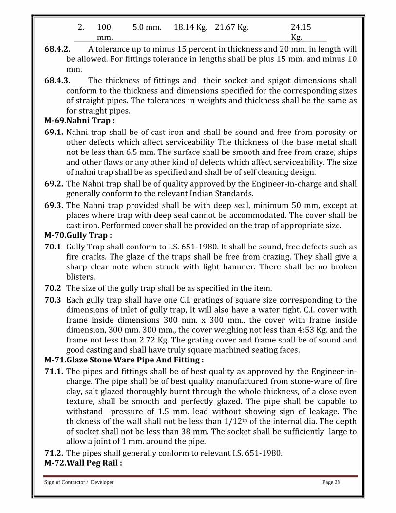
2. 100 mm.
5.0 mm. 18.14 Kg. 21.67 Kg. 24.15 Kg.
68.4.2. A tolerance up to minus 15 percent in thickness and 20 mm. in length will be allowed. For fittings tolerance in lengths shall be plus 15 mm. and minus 10 mm.
68.4.3. The thickness of fittings and their socket and spigot dimensions shall conform to the thickness and dimensions specified for the corresponding sizes of straight pipes. The tolerances in weights and thickness shall be the same as for straight pipes.
M69.Nahni Trap : 69.1. Nahni trap shall be of cast iron and shall be sound and free from porosity or
other defects which affect serviceability The thickness of the base metal shall not be less than 6.5 mm. The surface shall be smooth and free from craze, ships and other flaws or any other kind of defects which affect serviceability. The size of nahni trap shall be as specified and shall be of self cleaning design.
69.2. The Nahni trap shall be of quality approved by the Engineer‐in‐charge and shall generally conform to the relevant Indian Standards.
69.3. The Nahni trap provided shall be with deep seal, minimum 50 mm, except at places where trap with deep seal cannot be accommodated. The cover shall be cast iron. Performed cover shall be provided on the trap of appropriate size.
M70.Gully Trap : 70.1 Gully Trap shall conform to I.S. 651‐1980. It shall be sound, free defects such as
fire cracks. The glaze of the traps shall be free from crazing. They shall give a sharp clear note when struck with light hammer. There shall be no broken blisters.
70.2 The size of the gully trap shall be as specified in the item. 70.3 Each gully trap shall have one C.I. gratings of square size corresponding to the
dimensions of inlet of gully trap, It will also have a water tight. C.I. cover with frame inside dimensions 300 mm. x 300 mm., the cover with frame inside dimension, 300 mm. 300 mm., the cover weighing not less than 4:53 Kg. and the frame not less than 2.72 Kg. The grating cover and frame shall be of sound and good casting and shall have truly square machined seating faces.
M71.Glaze Stone Ware Pipe And Fitting : 71.1. The pipes and fittings shall be of best quality as approved by the Engineer‐in‐
charge. The pipe shall be of best quality manufactured from stone‐ware of fire clay, salt glazed thoroughly burnt through the whole thickness, of a close even texture, shall be smooth and perfectly glazed. The pipe shall be capable to withstand pressure of 1.5 mm. lead without showing sign of leakage. The thickness of the wall shall not be less than 1/12th of the internal dia. The depth of socket shall not be less than 38 mm. The socket shall be sufficiently large to allow a joint of 1 mm. around the pipe.
71.2. The pipes shall generally conform to relevant I.S. 651‐1980. M72.Wall Peg Rail :
Sign of Contractor / Developer Page 29
72.1. The aluminum wall peg rail shall have three aluminum pegs of approved quality and size. It shall be fixed on teakwood plant of size 450 mm. x 75 mm. x 20 mm. The teakwood shall be French polished or oil painted as specified.
M73.G.I. Water Spot : 73.1. The G.I. pipes of 40 mm. dia shall be of medium quality and specials shall be of
‘R’ brand or equivalent brand of best approved quality. 73.2. The pipe shall have length as required for the thickness of wall in which it is
fixed. and at the outside end tee and bend cut at half the length shall be provided and at other end coupling shall be provided to have better fixing. The water spout shall be provided as per detailed drawings or as directed.
M74.Asbestos Cement Pipe (A.C. Pipe): 74.1. The asbestos cement pipe of diameter as specified in the description of the item
shall conform to I.S. 1626‐1980. Specials like bends, shoes cowls, etc. shall conform to relevant Indian Standards. The interior of pipe shall have a smooth finish, regular surface and regular, internal diameter. The tolerance in all dimensions shall be as per I.S. 1626‐Part‐I 1980.
M75. Crydon Ball valve : 75.1. Ball valve of screwed type including polyethylene float and necessary lever etc.
shall be of the size as mentioned in the description of item and shall conform to I.S. 1703‐1977.
M76. Bitumen Felt For Water Proofing And Damp Proofing : 76.1 Bitumen felt shall be on the fiber bases and shall be type 2, self finished grade‐2
and shall conform to I.S. 1322‐1970. M77 Selected Earth : 77.1. The selected earth shall be hat obtained from excavated material or shall have
to brought from outside as indicated in the item. If item does not indicate anything, The selected earth shall have to be brought from outside.
77.2. The selected earth shall be good yellow soil and shall be got approved from the Engineer‐in‐charge. In no case black cotton soil or similar expansive and suitable soil shall be used. It shall be clean and free from all rubbish and perishable materials, stones or brick bats. The clods shall be broken to a size of 50. mm or less, Contractor shall make his own arrangement at his own cost for land for borrowing selected earth. The stacking of material shall be done as directed by the Engineer‐in‐charge in such a way as not to interfere with any constructional activities and in proper stacks.
77.3. When excavated material is to be used, only selected stuff got approved form the Engineer‐In‐Charge shall be used. It shall be stacked separately and shall comply with all the requirements of selected earth mentioned above :
M78.Barbed Wire : 78.1. The barbed wire shall be of galvanized steel and it shall generally conform to
I.S. 278‐1978. The barbed wire shall be if type‐I whose nominal diameter for line wire shall be 2.5 mm. and point wire 2.24 mm. The nominal distance between two bars shall be 75 mm. Unless otherwise specified in the item. The
Sign of Contractor / Developer Page 30
barbed wire shall be formed by twisting together two line wires, One containing the barbs. The size of the line and point wires and barb spacing shall be as specified above. The permissible deviation from the nominal diameter of the line wore and point wire shall not exceed + 0.08 mm.
78.2. The barbs shall carry four points shall be formed by twisting two point wires each two turns, lightly round one line wire, making altogether four complete turns. The barbs shall be so finished that the four points are set and locked at right angles to each other. The barbs shall have a length of not less than 13 mm. and not more than 13 mm. and not more18 MM. The points shall be sharp and cut at an angle not greater than 35 degree of the axis of the wire forming the barbs.
78.3. The lind and point wire shall be circular section free from scale and other defects and shall be uniformly galvanized. The line wire shall be in continuous length and shall not contain any weld other than those in the rod before it is drawn. The distance between two successive splices shall not be less than 15 meters.
78.4. The lengths per 100 Kg. of barbed wire I.S. type I shall be as under Nominal 1000 meter Minimum 834 Meter Maximum 1066 Meter.
Sign of Contractor / Developer Page 31
ITEM WISE SPECIFICATION CIVIL WORKS
Item No 1 Excavation for foundation upto 1.5 mt including sorting out and stacking of useful materials and disposing of the excavated stuff upto VMC Limit lead. Dense or Hard soil Details specification for this item shall be as per General Technical Specification for Building works booklet Page No 21 Item No. 4.0.0 (A) Before carrying out execution for the item of work, trial pit shall be taken and depth wise strata shall be got approved from Engineer‐in‐charge. Measurement should be consider as per drawing, It will not consider extra quantity due to collapse or loose volumn. Rate shall be for a unit of one cubic meter. Item No 2 Excavation for foundation for depth from 1.5 mt to 3.0 mt. including sorting out nd stacking of useful materials and dewateing, disposing of the excavated stuff upto VMC Limit lead. Dense or Hard soil Details specification for this item shall be as per General Technical Specification for Building works booklet Page No 25 Item No. 4.001 (B) Before carrying out execution for the item of work, trial pit shall be taken and depth wise strata shall be got approved from Engineer‐in‐charge. Measurement should be consider as per drawing, It will not consider extra quantity due to collapse or loose volumn. Rate shall be for a unit of one cubic metre. Item No 3 Providing and laying rubble for appron (each stone weighting not less than 40Kg.) including and packing and filing in the interestices with quarryspalls. 1.The rubble stones shall be black / dark grey in color, shall be hard, tough, sound durable and of close texture, free from cracks and it shall be obtained from the approved quarries. 2. The rubble obtained from the top surface of the quarry is soft one and hence such soft variety shall not be accepted. All unsound weathered or disintegrated stones obtained from the upper portion of the quarry shall be rejected.
Sign of Contractor / Developer Page 32
The quarry shall be well protected shall be dug by removing all the katcha and weathered stuff till approved quality of materials is available. 4. The length and breadth shall not exceed 1/t (f .2) times the thickness of the stones. 5. The rubble stacks shall be made on a fairly level ground and stacks shall be so made that rubble stones are stacked as close as possible so as to leave no excessive voids and no hollows are left out. 6. The tendency to prepare the stacks by keeping excessive voids or keeping hollow places shall not be tolerated. 7. The stacks shall be uniform in length and breadth and top portion shall be in level so that height at any point is uniform. B. All the stacks shall be of standard dimensions which shall be prescribed by the Executive Engineer deduction for voids shall not be made. 9. The rubble shall be got approved by the Executive engineer prior to collector on site or otherwise it is liable to rejection for which no claim shall be entertained. 10. The contractor shall maintain all stacks in regular and proper sizes till the whole material is collected Measured and finally accepted by the department. 15 percent spalls will be allowed for filling in interstices. 11. The rubble shall be stacked in quantities as per hectometer wise requirement as directed by the Executive Engineer or his agent. 12. Stacks shall be made as per actual requirements and any material in excess shall have to be transported by the contractor at the places directed by the Executive Engineer at the risk and cost of the contractor. Spreading of Rubble: 1.Rubble shall not be spread without permission of the Engineer‐in‐charge. Rubble should be spread under careful supervision by trained coolies. Contractor shall see theuniform spreading as per collection of rubble is done. The contractor shall spread therubble fully from the stacks without keeping any balance unless directed by the Engineer‐in‐charge to keep some stack in balance for making good unevenness or depressions during rolling works. To ensure that the material is spread to the requiredthickness, the road surface shall be marked out in to length over which the contents ofheaps are to be spread. The bounds of earth or murrum (one on either side) shall belaid with a distance between them equal to the width of road to be rubble and shall beenough to prevent the loose metal from spreading during consolidation as well as toretain water used for consolidation. Payment for bunds will be made in the respective Item. 2.0 The rubble (including old rubble) shall be screened and rubbish, dust, grass shall be removed and spread evenly on the prepared surface in grade and camber by using board etc. so as ensure that the surface is true to camber and grade. At least two camber by using camber boards shall be in use at site. The surface shall be checked at every 50 ft. by means of template while the correctness of the camber in between shall be tested by string corrected as required. Between the straight lengths and the

Sign of Contractor / Developer Page 33
curvesin camber of road to super elevation shall be made very gradually as may be directedby the Engineer‐in‐charge. 3.0 The spreading of rubble shall proceed only 200 meter (max.) advance of the rolling operations. The collection and spreading of the metal shall be carried out in oneand the same kilometer. 4.0 At the time of rolling all surface irregularities, hollows, depressions, humps etc. shall be straight. The spreading of metal the above operations with all lead and lift except consolidation. 5.0 Spreading of materials shall be started after the full supply in a particular Km. is collected, measured and recorded in the measurement books. Permission of the Engineer‐in‐charge shall be obtained before spreading. It shall be seen that the formation is dressed to the required camber and grade. Murrum is to be spread over the method surface then the spreading shall uniform and as it's has to act as binding surface, it shall be used for filling the interstices of rubble and forming a smooth running surface as far as possible. Murrum blindage shall be spread evenly with a twisting motion of the baskets. No more murrum shall be used then specified as blindage. The rate is for gross measurements and no deduction of voids shall be made.Murrum is to be spread over earthen embankment as a sub‐base or for side shouldersor as blindage; it shall be spread in a manner as directed by the Engineer‐in‐charge andas per required width and thickness. The contractor shall make good all unevenness,depression, projections etc, during consolidation work. Payment will be made on cum basis of the finished work and shall include cost of rubble, murrum, watering, rent of machinery cost fuel, wages of drivers and cleaners and murrum bund etc. Rate of this item includes all these operation including consolidation. Item No. 04 Providing and laying cement concrete 1:4:8 (1 cement: 4 coarse sand: 8 graded stone aggregate 40 mm. nominal size) and curing complete excluding cost of form work in foundations and plinth. Detailed specification for this item shall be as per General Technical Speciication for building works booklet page No 30 Item No 5.3.3(A). Rate shall be for a unit of one cubic metre. Item No. 5 To 5D Providing and laying controlled cement conceret M200 and curing complete excluding the cost of formwork, centering, shuttering, Scaffolding, stuting and propping etc. in shape and size and removal of the same etc. complete at all levels as directed by EIC. Foundation, Footing, base of column and Mass Concrete RCC Wall from top of foundation
Sign of Contractor / Developer Page 34
Columns, Pillars posts and struts Tie Beams, Girders and cantilever at ground level Materials and Workmanship
Water shall conform to M‐1. Cement shall conform to M‐3. Sand shall conform to M‐6. Grit shall conform to M‐8. Coarse aggregate shall conform M‐12 B. The shuttering to be provided shall be of ordinary timber planks and shall conform to M‐26. The dimensions of scantlings and battens shall conform to the design.The strength of the wood shall not be less than that assumed in the design.
1.0 General:
1.1 The relevant specifications of item no. 9 of ordinary concrete shall be followed
except that the concrete mix shall be designed from preliminary tests, the
proportioning of cement and aggregates shall be done by weight and necessary
precautions shall be taken in the production to ensure that the required work
cube strength is attained and maintained. The controlled concrete shall be in
grades of M‐100, M‐150, M‐200, M‐250, M‐300, M‐350, M‐400, with prefix
controlled added to it. The letter ‘M’ refers to mix and numbers specify 28 days
works cube compressive strength of 150 mm cubes of the mix expressed in Kg.
/ Cmt.
1.2 The porportion of cement, sand and coarse aggregates shall be determined by
weight. the weight batch machine shall be used for maintaining proper control
over the porportion of aggregates as per mix design.
The strength requirements of different grades of concrete shall be as under:
Grade of
Concrete Compressive strength
of 15 cms 28 days
conducted in
accordance
Preliminary test
cubes in Kg./Cmt. at
with I.S. 5161959
Min.
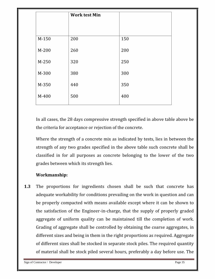
Sign of Contractor / Developer Page 35
Work test Min
M‐150
M‐200
M‐250
M‐300
M‐350
M‐400
200
260
320
380
440
500
150
200
250
300
350
400
In all cases, the 28 days compressive strength specified in above table above be
the criteria for acceptance or rejection of the concrete.
Where the strength of a concrete mix as indicated by tests, lies in between the
strength of any two grades specified in the above table such concrete shall be
classified in for all purposes as concrete belonging to the lower of the two
grades between which its strength lies.
Workmanship:
1.3 The proportions for ingredients chosen shall be such that concrete has
adequate workability for conditions prevailing on the work in question and can
be properly compacted with means available except where it can be shown to
the satisfaction of the Engineer‐in‐charge, that the supply of properly graded
aggregate of uniform quality can be maintained till the completion of work.
Grading of aggregate shall be controlled by obtaining the coarse aggregates, in
different sizes and being in them in the right proportions as required. Aggregate
of different sizes shall be stocked in separate stock piles. The required quantity
of material shall be stock piled several hours, preferably a day before use. The
Sign of Contractor / Developer Page 36
grading of coarse and fine aggregate shall be checked as frequently as possible,
the frequency for a given job being determined by the Engineer‐in‐charge to
ensure that the suppliers are maintaining the uniform grading as approved for
samples used in the preliminary tests.
1.4 In proportioning concrete, the quantity of both cement and aggregate shall be
determined by weight. Where the weight of cement is determined by accepting
the maker’s weight per bag a reasonable number of bags shall be weighted
separately to check the net weight. Water shall either be measured by volume
in calibrated tanks or weighed. All measuring equipments shall be maintained
in clean and serviceable condition. Their accuracy shall be periodically checked.
1.5 In is most important to keep the specified water cement ratio constant and at
its correct value. To this end, moisture content in both fine and coarse
aggregates shall be determined by the Engineer‐in‐charge, according to the
weather conditions. The amount of mixing water shall then be adjusted to
compensate for variations in the moisture content. For the determination of
moisture content in the aggregates, I.S. 2389(Part III) shall be referred to.
Suitable adjustments shall also be made in the weights of aggregates due to
variation in their moisture content. Minimum quantity of cement to be used in
concrete shall not be less than 220 Kgs./M 3 in plain concrete and not less than
250 Kg/M3 in reinforced concrete.
Centering:
1.0 The centering to be provided shall be got approved. It shall be sufficiently strong to ensure absolute safely of the form work and concrete work before, during and after pouring concrete. Watch should be kept to see that behavior of centering and form work is satisfactory during concreting. Erection should also be such that it would allow removal of forms in proper sequence without damaging either the concrete or the forms to be removed.
2.0 The props of centering shall be provided on firm foundation or base of sufficient strength to carry the loads without any settlement.
Sign of Contractor / Developer Page 37
3.0 The centering and form work shall be inspected and approved by the Engineer‐in‐charge before concreting. But this will not relieve the contractor of his responsibility for strength, adequacy and safety of form work and centering. If there is a failure of form work or centering, contractor shall be responsible for the damages to the work, injury to life and damage to property. Scaffolding:
1.0 All scaffolding, hoisting arrangements and ladders etc. required for the facilitating of concreting shall be provided and removed on completion work by contractor at his own expense. The scaffolding, hoisting arrangements and ladders etc. shall be strong enough to act and shall be subject to the approval of the Engineer‐in‐charge. However, contractor shall be solely responsible for the safety of the scaffolding, hoisting arrangement, ladders, work and workman etc.
2.0 The scaffolding, hoisting arrangements and ladders shall allow easy approach to the work spot and afford easy inspection.
3.0 The rate is applicable to all conditions of working and any height. The rate shall include the cost of materials and labour for various operations involved such as: (a) Splayed edges, notching, allowance for over laps and passing at angles, battens centering, shuttering, strutting, propping bolting, nailing, wedging, easing, striking and removal. (b) Filleting to form stop chamfered edges or splayed external angles not exceeding 20 mm. width to beams, columns and the like. (c) Temporary opening in the forms for pouring concrete, if required, removing rubbish etc. (d) Dressing with oil to prevent adhesion of concrete with shuttering, and (e) Raking or circular cutting.
ReUse: Before‐re‐use, all forms shall be inspected by Engineer‐in‐charge and their suitability ascertained. The forms shall be scarred, cleaned, and joints gone over, repaired where required. Inside surface shall be retreated to prevent adhesion of concrete.
4.0 Mode of measurement and payment:
4.1 The relevant specification NBO item No. 5.4.1 shall be followed except that the
controller concrete R.C.C. work for work as specified in item shall be measured
under this item. The rate including cost of form work.
The rate shall be for a unit of one cubic meter.
Sign of Contractor / Developer Page 38
Item No 06 Providing Thermo Mechanically Treated Bars (TMT Bars) reinforcement of approved make list for RCC Work including bending, binding and placing in position complete up to floor two level. Detailed specification for this item shall be as per General Technical Specifications for Building Works booklet page No 37 item No 5.4.11 except that T.M.T bar shall be used instead of H.Y.S.D bars. T.M.T bar shall conform to IS 1786/FC 415 for R.C.C work. It shall be purchased from approved manufacturer and necessary proof of purchase shall be submitted to Engineer‐in‐charge along with bill. Bars shall be tested in Government laboratory or Government approved laboratory prior to use. All necessary tests shall be carried out as per instruction of Engineer‐in‐charge. 415 TMT bar shall conform to min 415 Mpa yield strength. TMT bar shall have Tensile strength of minimum 600 Mpa and elongation percentage minimum 22. The chemical composition of TMT bar shall be as below as conducted in accordance with IS 1786 : 1985. Carbon : 0.25% Maximum Sulphur : 0.05% Maximum Phosphorus : 0.05% Maximum Sulphur & Phosphorus : 0.01% Maximum Rate shall be for a unit of one kilogram. All laps of reinforcement bars used on site will be considered as additional length (Only as per IS requirement of lap length), but any wastage of steel on site will not be paid. Item No. 07
P & L brickwork using common burnt clay building bricks having crushing strength not less than 35 kg/sq.cm in foundation and plinth in cement mortar 1:6 (B) Conventional
Details specification for this item shall be as per General Technical Specification for Building works booklet Page No 46 Item No. 6.19 (B) except that the work shall be carried out in cement mortar 1:6 (1 cement : 6 fine sand) instead of in cement mortar 1:5 (1 cement : 5 fine sand). Rate shall be for a unit of one cubic meter. Item No 08 Filling with available excavated earth (excluding rock) in trenches, plinth, sides of foundations etc. in layers not exceeding 20 cm, in depth consolidating each disposited layer by ramming and watering.
Sign of Contractor / Developer Page 39
Details specification for this item shall be as per General Technical Specification for Building works booklet Page No 27 Item No. 4.12 in addition the following specification shall also followed with all lead and lift Rate shall be for a unit of one cubic meter. Item No 09 Filling in foundation and plinth with murrum or selected good soil (from outside) in layers of 20 cm thickness including watering, ramming and consolidating etc. completed. Details specification for this item shall be as per General Technical Specification for Building works booklet Page No 28 Item No. 4.004 Rate shall be for a unit of one cubic metre. Item No 10 Filling in plinth or as directed with sand under floors including watering ramming, consolidating and dressing etc. complte. Details specification for this item shall be as per General Technical Specification for Building works booklet Page No 28 Item No. 4.24 Rate shall be for a unit of one cubic metre. Item No 11 Providing and laying preconstruction Anti termite treatment as per IS from standard and specified agency approved by ClerkOf Works with ten years guarantee in foundation, under floors and periphery as per the special agency's specifications and as per directions of ClerkofWork. For all levels and leads. (Plinth Area will be measured for payment purpose) 1.0 MATERIALS:
1.1 For Anti termite treatment 1.1.1 The Chemical for anti‐termite treatment shall be any one of the following :
Chemical Relevant IS Code
Concentration by Volume
a) Chlorpyrifes emulsify able concentrate
IS 8944 1.0%
Sign of Contractor / Developer Page 40
b) Heptachlor emulsify able concentrate
IS 6439 0.5%
c) Chlordane emulsify able concentrate
IS 2682 1.0%
1.1.2 Chemicals are available in concentrated form in the market & concentration is indicated on the sealed container. ADEN shall satisfy himself about the quality of material and appropriate sealing of containers. Further before accepting the supply of material required tests shall be conducted and proper certification shall be obtained.
1.1.3 To achieve specified % of concentration chemical should be diluted with water in required quantity. For example to dilute chemical of 30% concentration 59 parts of water shall be added to one part of chemical for achieving 0.5% concentration.
1.1.4 The material shall be taken over and accounted for as per extent rules in the ledgers/MAS and the same shall be issued to Contractor for day to day work on required basis.
2.0 WORKMANSHIP: 2.1 Chemicals: 2.1.1 The chemicals used for the soil treatment shall be any one or a combination of
the following with the concentration shown against each in aqueous emulsion: ‐
Chemicals Concentration (by weight)
Chlorpyriphosemlusifiable concentrates 1.00
Tyrabinemulsifiable concentratesAs per manufacturer's instructions
Dursbanemulsifiable concentrates Do
Endosulphanemulsifiable concentrates ‐Do‐conforming IS: 2682‐1966
2.1.2 The work of anti‐termite treatment shall be got executed by a specialist firm
which must be a member of IPCA and approved by Architect / Project Manager

Sign of Contractor / Developer Page 41
and shall be carried out as per IS:6313 (Part II) of 1981 for pre‐construction
soil treatment
3.0 MODE OF MEASUREMENTS & PAYMENTS : 3.1 The rate shall be for a unit of one sq. meter.
3.2 Only plan area will measure for the payment. However, contractor is supposed
to treat peripheral wall up to ground level. Item No. 12 Providing and laying of BBCC (Brick bat cement concrete) of 1:5:10 (cement:sand brickbat) including ramming/rolling watering etc, complete as per specification and instructed by engineer incharge 1.0 Materials: 1.1. Water shall conform to Ml, Cement shall conform to M3.
Sand shall conform to M6. Stone aggregate 40 mm. nominal size shall conform to M12.
2.0.Workmanship: 2.1. General: 2.1.1. Before starting concrete bed of foundation treaches shall be cleared of all loose materials, levelled, watered and rammed as directed. 2.2. Proportion of Mix : 2.2.1. The Proportion of cement, sand and coarse aggregate shall be one part of cement, 5 parts of sand, 10 parts of brick bats and shall so measured by volume. 3.0. Mode of measurement and payment: 3.1. The concrete shall be measured for its length, breadth and depth, limiting dimensions to those specified on plans or as directed. 3.2. The rate shall be for a unit of one cubic metre.
Item No. 13 Providing and laying Polishes 25mm thick Kota Stone slab flooring over 20mm (average) thick base of cement mortar 1:6 (1 cement : 6 coarse sand) laid over and jointed with grey cement slurry including rubbing and polishing etc. complete . Details specification for this item shall be as per General Technical Specification for Building works booklet Page No 87 Item No. 14.43 (B). Rate shall be for a unit of one square metre.
Sign of Contractor / Developer Page 42
Item No. 14 To 14 D Providing and laying controlled cement conceret M200 (Considering minimum cement content 340 Kg/Cumt.) and curing complete excluding the cost of formwork, centering, shuttering, Scaffolding, stuting and propping etc. in shape and size and removal of the same etc. complete at all floor and all levels as directed by EIC. Columns Slab Beams, Girders and cantilever at Slab Level Slabs, landing, Shelves, Balconies Lintels Weather Shed, Staircase excluding landing MATERIALS & WORKMANSHIP:
The relevant specifications of item No.11 to 14 shall be followed except that grade of concrete shall be M‐200.
MODE OF MEASUREMENT AND PAYMENT:
The relevant specifications of item No. 11 to 14 shall be followed except grade of concrete shall be M‐200.
The rate shall be for one cubic meter. Item No .15 to 15 F Providing form work of ordinary timber planking so as to give a rough finish including centering. Shuttering strutting and propping etc.Height of propping and centering below supporting floor to ceiling not exexceeding 4M. And removal of the same for in including reinforced concrete and plain concrete work in : Foundations, footings Bases of columns etc. and Mass concrete.
1.Details specification for this item shall be as per General Technical Specification for Building works booklet Page No 55 Item No. 9.1 (A) (I)
2.Rate shall be for a unit of one square metre.
Providing form work of ordinary timber planking so as to give a rough finish including centering. Shuttering strutting and propping etc.Height of propping and centering below supporting floor to ceiling not exexceeding 4M. And removal of the same for in including reinforced concrete and plain concrete work in : Flat surfaces such as so fits of slabs landings and the like
Sign of Contractor / Developer Page 43
(1) Floors etc. up to 200 mm. in thickness
1. Details specification for this item shall be as per General Technical Specification for Building works booklet Page No 56 Item No. 9.1 (B) (I)
2. Rate shall be for a unit of one square metre. Providing form work of ordinary timber planking so as to give a rough finish including centering. Shuttering strutting and propping etc.Height of propping and centering below supporting floor to ceiling not exexceeding 4M. And removal of the same for in including reinforced concrete and plain concrete work in : Flat surfaces such as so fits of slabs landings and the like
(1) Floors, etc. above 200 mm in thickness.
1. Details specification for this item shall be as per General Technical Specification for Building works booklet Page No 56 Item No. 9.1. (B) (II)
2. Rate shall be for a unit of one square metre. Providing form work of ordinary timber planking so as to give a rough finish including centering shuttering strutting and propping etc. Height of propping and centering below supporting floor to ceiling not exceeding 4 metre And removal of the same for in including reinforced concrete and plain concrete work in : Vertical surfaces such as walls (any thickness) partitions
Details specification for this item shall be as per General Technical Specification for Building works booklet Page No 56 Item No. 9.1 (C) Rate shall be for a unit of one square metre.
Providing form work of ordinary timber planking so as to give a rough finish including centering shuttering strutting and propping etc Height of propping and centering below supporting floor to ceiling not exceeding 4 metre and removal of the same for in including reinforced concrete and plain concrete work in : Columns, pillars, posts and struts
(1) Square, Rectangular, Polygonal plan
Details specification for this item shall be as per General Technical Specification for Building works booklet Page No 56 Item No. 9.1 (G) (i) Rate shall be for a unit of one square metre.
Sign of Contractor / Developer Page 44
Providing formwork of ordinary timber planking so as to give a rough finish including centering, shuttering, strutting and propping etc. height of propping and centering below supporting floor to celiling not exceeding 4 M. and removal of the same for in sity reinforced concrete and plain concrete work in. (G) Columns, Pillars,Posts and struts. (2) Circular or curved in Plan.
1.Details specification for this item shall be as per relevant General Technical Specification for Building works booklet. 2.Rate shall be for a unit of one square metre.
Providing form work of ordinary timber planking so as to give a rough finish including centering shuttering strutting and propping etc. Height of propping and centering below supporting floor to ceiling not exceeding 4 metre and removal of the same for in including reinforced concrete and plain concrete work in : (1) Sides and so fits of Beams, Beam, hunching, cantilever girders, bressumers and Lintels not exceeding 1 M. in depth
1.Details specification for this item shall be as per General Technical Specification for Building works booklet Page No 56 Item No. 9.1 (H) (1) 2.Rate shall be for a unit of one square meter. Providing formwork of ordinary timber planking so as to give a rough finish including centering, shuttering, strutting and propping etc. height of propping and centering below supporting floor to cealing not exceeding 4 M. and removal of the same for in sity reinforced concrete and plain concrete work in. (H) (2) Sides and soffits of Beams Beam Haunchings, cantilevers, Girders, Bressumers and Lintels exceeding 1M.in Depth.
1.Details specification for this item shall be as per General Technical Specification for Building works booklet Page No 56 Item No. 9.1 (H) (2) 2.Rate shall be for a unit of one square meter.
Providing formwork of ordinary timber planking so as to give a rough finish including centering, shuttering, strutting and propping etc. height of propping and centering below supporting floor to celiling not exceeding 4 M. and removal of the same for in sity reinforced concrete and plain concrete work in. (I) Edges of slabs and Breaks in floors and walls.
Sign of Contractor / Developer Page 45
1.Details specification for this item shall be as per General Technical Specification for Building works booklet Page No 57 Item No. 9.1 (I) 2.Rate shall be for a unit of one square meter.
Providing formwork of ordinary timber planking so as to give a rough finish including centering, shuttering, strutting and propping etc. height of propping and centering below supporting floor to celiling not exceeding 4 M. and removal of the same for in sity reinforced concrete and plain concrete work in. (K) Small surfaceas, such as cantiever ends of steps, caps and basses to pilasters and Columns and the like.
1.Details specification for this item shall be as per General Technical Specification for Building works booklet Page No 57 Item No. 9.1 (K) 2.Rate shall be for a unit of one square meter. Providing form work of ordinary timber planking so as to give a rough finish including centering shuttering strutting and propping etc Height of propping and centering below supporting floor to ceiling not exceeding 4 metre and removal of the same for in including reinforced concrete and plain concrete work in : Chullah hoods weather shadesm chhajjas, dorbels etc. including edges.
1.Details specification for this item shall be as per General Technical Specification for Building works booklet Page No 57 Item No. 9.1 (L) 2.Rate shall be for a unit of one square metre. Providing form work of ordinary timber planking so as to give a rough finish including centering shuttering strutting and propping etc Height of propping and centering below supporting floor to ceiling not exceeding 4 metre and removal of the same for in including reinforced concrete and plain concrete work in : Stair cases with slopping or stepped so fits including rise cans stringers excluding landing. 1.Details specification for this item shall be as per General Technical Specification for Building works booklet Page No 57 Item No. 9.1 (M) 2.Rate shall be for a unit of one square meter. Providing formwork of ordinary timber planking so as to give a rough finish including centering, shuttering, strutting and propping etc. height of propping and centering below supporting floor to celiling not exceeding 4 M. and removal of the same for in sity reinforced concrete and plain concrete work in. (Q) Vertical fins and vertical sun breakers.
Sign of Contractor / Developer Page 46
1.Details specification for this item shall be as per General Technical Specification for Building works booklet Page No 58 Item No. 9.1 (Q) 2.Rate shall be for a unit of one square meter. Item No 16 P & L brickwork using common burnt clay building bricks having crushing strength not less than 35 kg/sq.cm in super structure in cement mortar 1:6 for all floors and all levels including all lead and lift etc complete as directed by EIC. (B) Conventional Details specification for this item shall be as per General Technical Specification for Building works booklet Page No 46 Item No. 6.19 (B) & 6.20 except that the work shall be carried out in cement mortar 1:6 (1 cement : 6 fine sand) instead of in cement mortar 1:6 (1 cement : 5 fine sand). Rate shall be for a unit of one cubic meter. Item No 16 A P & L Half brickwork using common burnt clay building bricks having crushing strength not less than 35 kg/sq.cm in cement mortar 1:4 in superstructure above plinth level at all floor and all levels including all lead and lift including placing of 5cm thick Cement conrete bend 1:2:4 at every 1.5mt. equal distance in height etc complete as directed by EIC. (RCC Bend will be paid in respected items) Details specification for this item shall be as per General Technical Specification for Building works booklet Page No 46 Item No. 6.30. 1. (B). Rate shall be for a unit of one square metre. Item No: 17 Providing 15 mm. Thick cement plaster in double coat on fair side Brick/concrete walls for interior plastering up to floor two level and finished even and smooth in 1:4 (1 Cement : 4 Coarse Sand) for all floor any height etc. complete. Details specification for this item shall be as per General Technical specifications for Building Works Booklet Page No 106, & Item No 17.61 (II), except that the thickness of plaster shall be 15 mm instead of 20 mm. Rate shall be for a unit of one square meter.
Sign of Contractor / Developer Page 47
Item No. 18 20mmth. Sandface cement plaster on walls consisting of 12mm thk backing coat of C.M.1:3 (1 cement :3 sand) & 8mm thk finishing coat of CM(1:1)1 cement :1 sand at all levels etc complete as directed by EIC. WORKMANSHIP : Scaffolding: Wooden ballies, bamboos, planks, treatles and other scaffolding shall besound. These shall be properly examined before erection and use Stage scaffolding shall beprovided for ceiling plaster, which shall be independent of the walls. Preparation of background: The surface shall be cleaned of all dust, loose mortar droppings, traces of algae, afflorescence and other foreign matter by water or by brushing. Smooth surface shall beroughened by wire brushing if it is not hard and by racking if it is hard. In case of concretesurface, if a chemical retarder has been applied to the form work, the surface shall beroughened by wire brushing and all the resulting dust and loose particles cleaned off andcare shall be taken that none of the retarder is left on the surface. Trimming of projectionson brick/concrete surface where necessary shall be carried out to get an even surface.Raking of joints in case of masonry where necessary shall be allowed to dry out forsufficient period before carrying out the plaster work. The work shall not be soaked but only damped evenly before applying the plaster. If thesurface becomes dry such area shall be moistened again.For external plaster, the plastering operation shall be started from top floor and carrieddownwards. For internal plaster, the plastering operations may be started wherever thebuilding frame and cladding work are ready and the temporary supporting ceiling restingon the wall of the floor have been removed, Ceiling plaster shall be completed beforestarting plaster to walls. Applications of Plaster : The plaster about 15 x 15 cms.Shall be first applied horizontally and vertically at not morethan 2 metre intervals over the entire surface to serve as gauge. The surfaces of thesegauges shall be truly inplane of the finished plastered surface. The mortar shall then beapplied in uniform surface slightly more than the specified thickness, then brought to atrue surface by working a wooden straight edge reaching across the gauges with smallupward and sideways movement at a time. Finally, the surface shall be finished off truewith a trowel or wooden float according as a smooth or a sandy granular texture isrequired. Excessive trowelling or overworking the float shall be avoided. All corners,arrises, angles and junctions be truly vertical or horizontal as the case may be and shall becarefully finished. Rounding or chamfering corners, arrises junctions etc. shall be carriedout with proper templates to the size required.Cement plaster shall be used within half an hour after addition of water. Any mortar orplaster which is partially set shall be rejected and removed forthwith from the site :In suspending the work at the end of the day, the plaster shall be left out clean to the lineboth horizontally and vertically. When recommending the plaster, the edges of the oldwork shall be scraped clean and wetted with cement putty before plaster is
Sign of Contractor / Developer Page 48
applied to theadjacent area to enable the two to properly joint together. Plastering work shall be closedat the end of the day on the body of the wall and nearer than 15 cm. To any corners orarrises. Horizontal joints in plasterwork shall not also occur on parapet tops and copingsas these invariably lead to leakage. No portion of the surface shall be left out initially to bepacked up later on.Each coat shall be kept dam continuously till the next coat is applied or for a minimumperiod of 7 days. Moistening shall commence as soon as plaster is hardened sufficiently.Soaking of walls shall be avoided and only as much water as can be readily absorbed shallbe used excessive evaporation on the sunny or windward side of building in hot air or dryweather shall be prevented by handling mattings or gunny bags on the outside of theplaster and keeping them wet. MODE OF MEASUREMENT &PAYMENT : The rate shall include the cost of all materials, labour and scaffolding etc, involved in theoperations described under workmanship. All plastering shall be measured in square metres unless, otherwise specified length,breadth or height shall be measured correct to a centimeter. Thickness of the plaster shall be exclusive of the thickness of the key i.e. grooves or openjoints in brick work, stone work etc. or space between laths. Thickness of plaster shall beaverage thickness with minimum 15 mm. at any point on this surface. This item includes plastering upto floor two level. The measurement of wall plastering shall be taken between the walls or partition(dimensions before plastering being taken) for length and from the top of floor or skirtingto ceiling for height. Depth of cover of cornices if any shall be deducted. Soffits of stairs shall be measured as plastering on ceilings, Flowing soffits shall bemeasured separately. For jambs, soffits, sills etc. for openings not exceeding 0.5 sq. mt. each in area for ends ofjoints, beams, posts, girders, steps etc. not exceeding 0.5 sq. mt. each in area and foropenings exceeding 0.5 sq.mt. and not exceeding 3.0 sq. mt. in each area deductions andadditions shall be made in the following manner : (a) No deductions shall be made for ends joints, beams posts etc. and openings notexceeding 0.5 sq. mt. each and no addition shall be made for reveals, jambs, soffits,sills etc. of these opening for finish to plaster around ends of joints, beams, postsetc. (b) Deduction for openings exceeding 0.5 sq. mt. but not exceeding 3 sq. mt. each shallbe made as follows and no addition shall be made for reveals, jambs, soffits etc. sillsetc. of these openings. (i) When both faces of all wall are plastered with same plaster, deduction shall bemade for one face only. (ii) When two faces of wall are plastered with different types of plasters or if one facesis plastered and the other pointed, deductions shall be made from the plaster orpointing on the side of frame for door, window etc. on which width or reveals is lessthan that on the other side but no deductions shall be made on the other side.
Sign of Contractor / Developer Page 49
Where width of reveals on both faces of all are equal, deductions of 50% of area ofopening on each face shall be made from area of plaster and/or pointing as the casemay be. For openings having door frames equal to projecting beyond the thickness of wall, fulldeduction for opening shall be made from each plastered face of the wall. In case of openings of area above 3 sq. mt. each, deduction shall be made for opening butjambs, soffits and sills shall be measured. The rate shall be for a unit of one sq. metre Item No.19 Antiskid Vitrified Floor Tiles : P & L Full body Antiskid vitrified 10mm thick tile flooring over 20mm (average) base of cement mortar 1:6 (1 cement : 6 coarse sand) on new surface or fixing on existing flooring by adhesive material including dismentaling of existing flooring and jointed with color cement slurry including finished with flush pointing and cleaning the surface etc. complete. Materials:
Water shall conform to M‐1. Cement mortar shall conform to M‐11. Matt finished Vitrified tile of antiskid from the list of approved make and of first quality.
1.1 Vitrified floor tiles shall be of matt finish best quality like Granamite or equivalent, as approved by the Architect and Engineer‐in‐charge. They shall conform to the relevant IS Codes.
1.2 They shall be monolithic and available in smooth, mirror‐polished and anti‐skid finishes, in sizes 12"x12", 8"x8" and 8"x4". They shall have a size tolerance of + 0.5%, in length and width and + 5% in thickness. Allowable warpage shall be + 0.2%. Allowable square ness wedging shall be + 0.5%. Their water absorption rate shall be less than 0.5%. They shall offer hard‐working and hard‐wearing floors for homes, public buildings, apartments and airports. The tiles shall be of ASTM or DIN standards.
1.3 They shall be extremely strong, breaking strength of the tile being 1600 Kg/csqm., flexural strength, 200 Kg/cm2. and bonding strength of 2500 Kg/csqm. They shall offer good resistance to abrasion, i.e. greater than 100. They shall be scratch resistance; their hardness on the Moh's scale shall be min. 7. They shall be able to resist thermal shock upto 10 cycles. They shall have a bond strength of 2500 Kg/csqm. and shall have a density of greater than 2.2 gm/cc. They shall have 0.60 co‐efficient of friction for polished/unpolished surfaces.
Sign of Contractor / Developer Page 50
2.0Workmanship:
2.1Bedding:
2.1.1The sub‐grade shall be cleaned, wetted and mopped. The bedding shall then be laid evenly over the surface, as described above, tamped and corrected to desired level and allowed to harden enough to offer a rigid cushion to tiles and to enable the mason to place wooden planks across and squat on it.
2.1.2The white/coloured vitrified tiles shall be laid over a minimum 20 mm. thick cement mortar 1:6 bedding laid to proper slope and level. Fixing of vitrified tile with cement mortar is to be done over 35 to 40 mm thick screed 1:2:4 (1 cement : 2 sand : 4 stone aggregate). Finishing should be done with flush pointing in white cement and pigment with residue and skirting. The mortar shall have sufficient plasticity for laying and there shall be no hard lumps that would interfere with the evenness of the bedding. The base shall be cleaned and well wetted, before laying. The mortar shall then be spread in thickness not less than 18 mm. at any place and average 25 mm. thick. The proportion of the cement mortar shall be as specified in the item.
2.2Fixing tiles :
2.2.1The tiles before laying shall be soaked in water for atleast two hours. Neat grey cement grout at 3.3 Kg./Cement/m2.of honey‐like consistency shall be spread over the mortar bedding as directed. The edges of the tiles shall be smeared with neat cement slurry. The tiles shall then be well pressed and gently tapped with a wooden mallet till they are properly bedded and in level with the adjoining tiles. There shall be no hollows in bed or joints. The joints between the tiles shall be as thin as possible in straight line or as per pattern.
2.2.2The tiles shall not have staggered joints. The Nahni trap coming in the flooring shall be so positioned that its grating shall replace only one tile as far as possible. Where full size tiles cannot be fixed, they shall be cut (Sawn) to the required size and the edges rubbed smooth to ensure straight and true joints. The outlets for drainage shall be marked as per drawing and tile fixing shall be carried out accordingly after laying and testing the drainage lines. After the tiles are laid, the Finishing should be done with flush pointing in white cement and pigment with residue and skirting. The same cement slurry shall then be spread over the whole surface in a thin coat to protect the surface from abrasive damage and to fill up pinholes that may exist on the surface. White cement with or without matching pigment shall be used for pointing the joints. After fixing the tile finally in an even plane the flooring shall be kept wet and allowed to cure undisturbed for 7 days.
Sign of Contractor / Developer Page 51
2.2.3While laying, any chiseling which may be required for making the skirting or dado flush with the plaster and/or other finishes shall be done. Necessary grooves of required size in cm., between plaster and/or other finishes, dado or skirting (if required) shall be provided. Forming machine‐cut/rounded edges, gutters, sills, platforms, channels, curbing, etc. if any, if required shall be provided as per the drawing and design.
2.2.4All necessary slopes, gradients and levels shall be truly maintained as required and directed by the Architect and Engineer‐in‐charge.
2.3Cleaning:
2.3.1the surplus cement grout that may have come out of the joints shall be cleared off before it sets. Once the floor has set, it shall be carefully washed and cleaned by oxalic acid and dried. Proper precautions and measures shall be taken to ensure that the tiles are not damaged in any way till the completion of the construction.
2.3.2If any tile is disturbed or damaged it shall be refitted or replaced, properly jointed and polished.
3.0Mode of Measurements and Payment:
3.1The work done shall be measured in sqm. for the visible area of work done in floor . The length and width of the flooring shall be measured between the faces of skirting or dados or plastered face of walls as the case may be. The paving under dado or skirting shall not be measured. No deduction shall be made or extra paid for any opening in the floor of area upto 0.1 sqm. Nothing extra shall be paid for laying the floors at different levels in the same room. The dado will be measured from the finish floor level to the top of tile fixed.
3.2The rate shall include the cost of all materials (inclusive of all taxes, levies, and delivery at site), labour& sundry involved in all the operations, curing etc complete, at all floors, at any height and level, as described above. It shall also include for breakage and wastage. Floating materials and margin of profit shall also be included. All material samples shall be approved by the Architect/Engineer‐in‐charge before placing orders.
3.3No extra shall be paid for any small quantities like narrow widths, mitred& returned ends, rounds & cutting, fixing and making good upto& around pipes, fittings and fixtures etc.
Sign of Contractor / Developer Page 52
3.4The rate shall include for fixing the flooring in composite pattern as per the drawings, using different materials and sizes. The measurements of the different materials shall be taken category‐wise separately and paid accordingly.
3.5The rate shall be for a unit of one smt. Item No. 20 Wall Cladding Tiles : Providing, laying and fixing of exterior tiles cladding and dedo on wall including 10mm thick cement plaster 1:3 (1cement : 3coarse sand) and jointed with matching color pigment all including like cutting, fixing, curing, scaffolding, shuttering, necessary tools and tackle etc. completed as directed by E.I.C. (C1) Wall tiles 8 mm to 10 mm (Size as per Arhitecture detailing) Details specification for this item shall be as per relevant general technical specifications, I.S. codes & PWD manuals. Rate shall be for a unit of one square meter. Item No. 21 Providing and fixing FRP frame size 125x65 mm and 35mm thick FRP shutter with wood grain raised panneled design finish shutter having extra reinforcement on sides & edges in Gel coat finish. The core of the shutter & frame is to be filed up with injected polyurethene foam done in situ alongwith embedded wooden pieces for stiffening & also taking hinges & fixtures. The whole FRP frame & shutter is to be water proof weather proof, termite proof & resistance to mild acid/alkali. Rates are to be inclusive of S.S hinges with fastener sleeve & fixtures & fastenings. Details specification for this item shall be as per relevant general technical specifications, I.S. codes & PWD manuals. Rate shall be for a unit of one square meter. Item No. 22 Providing and fixing in position callapsible steel shutters with vertical channels 20 x 10 x 2 mm braced with flat iron diagonals 20 x 5 mm size with top and bottom rails of T_rin 40x 40 x 6 mm with 38mm dia, steel pulleys complete with bolts, nuts, locking arrangements, stoppers handles including applying a priming coat of read lead paint. Details specification for this item shall be as per relevant general technical specifications, I.S. codes & PWD manuals. Rate shall be for a unit of one square meter.
Sign of Contractor / Developer Page 53
Item No. 23 Providing & fixing M.S. grills of required pattern to wooden frames of windows etc. with M.S. flats at required spacing and frame allround square or round bars with round headed bolts and nuts or by screws. Plain Grill Details specification for this item shall be as per General Technical Specification for Building works booklet Page No 66 Item No. 10.100 (B) Rate shall be for a unit of one kg.
Item No. 24
Painting two coats (excluding priming coat) on new steel and other metal surface with enamel paint, brushing, interior to give and even shade including cleaning the surface of all dirt, dust and other forign matter. Details specification for this item shall be as per General Technical Specification for Building works booklet Page No 122 Item No. 19.7 Rate shall be for a unit of one square meter.
Item No. 25
Providing and fixing M.S. fan clamps at all floor levels type I of 16 mm dia, M.S. bar bend to shape with hooked ends to R.C.C. slabs curing , laying including painting the exposed portion of loops, all
Details specification for this item shall be as per General Technical Specification for Building works booklet . Rate shall be for a unit of one Number.
Item No. 26
Providing and fixing window having extruded aluminum colour anodized section frame main outer size 95mm X24mm 1.17mm( of jindal section no :2459@ wt.of 0.738 kg/mt),horizontal three track member size 92mmX 31.75mm X1.30mm ( of jindal section no :8688,@ wt.1.07 kg/mt), vertical member of size 92mm X31.75mm X 1.50mm ( of jindal section no : 8933,@ wt 1.06 kg/mt ) with sliding shutters of horizontal member size 40mm X 18mm X 1.29mm ( of jindal section no: 8947@ wt.of 0.456 kg/mt), vertical member of size 40mm X 18mm X 1.29 mm (of jindal section no : 8949 @ wt.of 0.456 kg/mt/ with 5 mm th transparent bronze colour tinted float glass with powder coate
Sign of Contractor / Developer Page 54
aluminum fittings & fixtures and transparent silicon sealant glass fixing to frame as per details etc.
Material & Workmanship: Aluminum alloy used in the manufacturing of extruded section for windows shall confirm to HE9‐WP of I.S 733 – 1956 and also hollow aluminum section confirm to IS designation HV9 – WP – IS – 1285 – 1958. Aluminum section of approved weight shall be procured at site. Fabrication shall be done as per I.S 1948 – 1961 & drawing or as directed. All aluminum sections to be used shall be as per description of item & shall be 15 – 20 micron color anodized. Fixed glazing for ventilator: Fabrication of windows with fixed glazing shall be done as per I.S 1948 – 1961 & drawing or as directed. 5 mm thick bronze tinted glass shall be used of the make Asahi / Modi / Saint Global or as approved by Engineer‐in‐charge. Necessary glzing plate with glazing of standard size & weight shall be used for fixing of glass. Size of glass for glazing at panels shall be as per drawing and shall be fixed in such a way so as to allow a clearance of 2.50 mm between the edges of glass and aluminum glazing clips surround clearance may be increased if directed. All stains from the surfaces of glass shall be removed and cleaned with thinner or spirit without any extra payment. Working of all hinges shall be smooth and free. If any hinges or locking arrangement found faulty, shall be replaced to the satisfaction of Engineer – in – Charge without claiming any extra charges. The entire work shall be executed to the satisfaction of Engineer – in ‐ Charge. The door/window/ventilator/fixed glazing shall be fully workable as per drawing or as directed by Engineer – in – Charge. Float Glass: 5 mm thick bronze tinted glass of the make MODI GUARD / ASAHI / SAINT GLOBAL shall be used & shall be conforming to relevant I.S code. Necessary color anodized aluminum glazing clips shall confirm to relevant IS code. Transparent Silicon Gasket and PVC track rubber shall confirm to quality approved by engineer in charge. Fixtures & fastenings: Fixtures and fastenings shall be provided as per requirement & as directed by Engineer in charge Section used shall be single or double type as per requirement. Window ‐ frame without shutter shall be prepared as per drawing or as directed by the Engineer – in – Charge. Whole framework shall be finished and erected in true line and level. The section shall be fixed with necessary screws & wooden peg nails required. Size of glass for glazing at panels shall be as per drawing and shall be fixed in such a way so as to allow a clearance of 2.50 mm between the edges of glass and aluminum glazing clips surround clearance may be increased if directed. All stains from the surfaces of glass shall be removed and cleaned with thinner or spirit without any extra payment. Working of all hinges shall be smooth and free. If any hinges or locking arrangement found faulty, shall be replaced to the satisfaction of Engineer – in
Sign of Contractor / Developer Page 55
– Charge without claiming any extra charges. If mosquitoes proof jali is provided, the size of mosquitoes proof jali at panels shall be as per drawing or as directed by Engineer‐in‐charge. It shall be provided on outer track and shall be fixed in such a way so as to allow a clearance of 2.50 mm between the edges of jali and aluminum glazing clips surround clearance may be increased if directed. All stains from the surfaces of mosquitoes proof jali shall be removed and cleaned with thinner or spirit without any extra payment. The entire work shall be executed to the satisfaction of Engineer – in ‐ Charge. The window shall be fully sliding as per drawing or as directed by Engineer – in ‐ Charge CONDITIONS FOR ALUMINUM WORKS (a) The glazing shall be fixed with the External finished surface (either stone cladding/external plaster) and hence all the necessary rubber strips, packing and polysulphide polymer (between the frame and concrete or other surface all around) shall be provided within the rate quoted so as to make the junctions fully water tight/air tight. (d) Approved make selected glass of thickness as specified shall be used in doors. Wired glass louvers shall be provided wherever shown on drawings. (e) Necessary locking arrangement of approved design (by Architect) shall be provided without any extra cost. (f) Wherever necessary, PVC lining (silver grey or white only) etc. shall be provided for air/water tightness. (g) Necessary operating device (as per design) for operation of louvers of windows, ventilators, sky lights, including necessary rods shall be provided without any extra cost. (h) The rates quoted shall be inclusive of manufacture, supply and installation at Site, and inclusive of all the necessary accessories rubber strips, locks, rods, excise duty, taxes, octroi, transport, labour charges, insurance, storage and safe custody, etc. complete. (i) The rates shall also be inclusive of providing and applying with gun as per latest I.S., of Dow Corning or equivalent and making the joints around glazing watertight, on the external periphery of the building at the junction of two different materials as directed by the Architect and site engineer. The Contractor shall have to give a guarantee bond, for water tightness, on appropriate Stamp paper for a period of FIVE years. In this period he shall attend to
Sign of Contractor / Developer Page 56
and rectify all complaints without causing any inconvenience to the Owners/Client. The form of Guarantee Bond shall be as prescribed below: "I/We ............... (Contractor) hereby guarantee that work shall remain unaffected and shall not be in any way damaged by atmospheric conditions, for a period of FIVE years after the completion of the work of applying sealant and making the joints around aluminum doors watertight, on the external periphery of the building at the junction of two different materials as per the terms and conditions of the Contract and guarantees to redo the affected work without claiming any extra cost." (j) Necessary provision for rain water disposal shall be done in the bottom guides/frames as directed and approved by Architect. (k) Work must be in accordance with detailed drawings with dimensions of aluminum sections in frames and shutters as shown in drawing. It shall be accompanied by the detailed drawing if any deviation is proposed. (l) All the door shutters shall have double action hydraulic floor springs/hinges as per approved shop drawings, of approved make with minimum one year guarantee. The floor springs shall be of least possible thickness. The Contractor shall have to give a guarantee bond, for the Hydraulic floor springs, on appropriate Stamp paper for a period of 1 year. In this period he shall attend to and rectify all complaints without causing any inconvenience to the Owners/Client. The form of Guarantee Bond shall be as prescribed below: "I/We ............... (Contractor) hereby guarantee that the floor springs shall remain unaffected and shall not be in any way damaged by normal usage, pulls and pushes, for a period of FIVE year after the completion of the work of supplying & fixing the Double Action Floor Springs to aluminum doors as per the terms and conditions of the Contract and guarantees to redo the affected work without claiming any extra cost." (m) Details/arrangements for after sales/maintenance services shall be furnished. (n) Work shall be carried out in co‐operation and in coordination with all other agencies working at Site. (o) The civil work as required for fixing of floor springs, hold fast or other works required for the erection and completion of doors/windows etc. shall be done by the Contractor without any extra cost. (p) Any damage, if caused to the existing work done by other agencies, shall be reinstated by the Contractor to its original condition without any extra cost.
Sign of Contractor / Developer Page 57
(q) During the course of work, the Contractor shall pay due care to avoid any stains on the powder coating work and if required, the Contractors shall provide necessary protective arrangement as directed by the Architects for which no extra payments shall be made. After the installation is completed, if required by the Architects, the aluminum work shall be washed with mild solution of non alkali soap and water. (r) The Contractor shall be responsible for the windows/doors/grills etc. being set straight, in plumb level and for their satisfactory operations after the fixing is completed. (s) Wherever required and as directed strengthening of members shall be done by providing steel/M.S. concealed members without extra cost. (t) The door shutters may have hydraulic door closer of approved make with minimum one year guarantee as and where shown in the drawings and as directed. The Contractor shall have to give a guarantee bond, for the Hydraulic door closer, on appropriate Stamp paper for a period of five year. In this period he shall attend to and rectify all complaints without causing any inconvenience to the Owners/Client. The form of Guarantee Bond shall be as prescribed below: "I/We ............... (Contractor) hereby guarantee that the hydraulic door closers shall remain unaffected and shall not be in any way damaged by normal usage, pulls and pushes, for a period of FIVE year after the completion of the work of supplying & fixing the Hydraulic Door Closers to aluminum doors as per the terms and conditions of the Contract and guarantees to redo the affected work without claiming any extra cost." Mode of measurement & payment: The rate for window shutter with frame shall include the cost of materials & labour involved to finish the work. The dimension of the window shall be measured clear size of the frame in closed position of shutter between the two outer edges of the frame. The payment shall be made on completion of work. The unit rate for the item shall be for a unit of one square meter.
Item No. 26. A
Providing and fixing standared extruded of alluminium section of size 63.mm X 38.10 X 1.2 mm (of jindal section no :2434,,@ wt 0.643 kg per mt with colour powder coated alluminium frame with 5 mm thick frosted glass as details etc complete for ventilation
Sign of Contractor / Developer Page 58
1. Materials: Aluminum alloy used in the manufacturing of extruded section for windows shall confirm to HE9‐WP of I.S 733 – 1956 and also hollow aluminum section confirm to IS designation HV9 – WP – IS – 1285 – 1958. Aluminum section of approved weight shall be procured at site. Fabrication shall be done as per I.S 1948 – 1961 & drawing or as directed. Details of the anodized powder coating section to be used are as under: 100 mm wide 15 – 20 micron color anodized aluminum louver in required width & numbers having dual controls. Hollow section frames: Workmanship: The item covers the requirement of frames for doors, windows, clerestory windows their supply and fixing. Frames: All members of the frames shall be exactly at right angles. The right angle shall be checked from inside surface of the respective members. All members of frames shall straight without any warp or bow and shall have smooth surface well planed on the three sides exposed at right angles to each other. The surface touching the wall shall be planed within the tolerances specified. The frame of JINDAL section 55 mm x 24 mm x 0.95 mm having weight 0.601 kg per metre shall be used. Before erection of frame, hollow section of frame shall be filled with country wood. After erection of frame, frame shall be checked by manually whether the frame is filled with country wood or not. Frame shall have screwed joints. When clerestory windows are included, it shall be provided by having full length one piece post for door or windows and clerestory window extending the frame on top at the head to the required extent. Horns shall not be provided in the head of the frame. Slight adjustment or spacing as necessary shall be done to have the position of screws in the joints of masonry course. The frame shall be erected in position and held plumb with strong support from both sides and built in masonry as it is being built. Sufficient numbers of numbers of screws shall be used on each side of door and windows frames. In case of windows and ventilators frames whose height is less 1 meter three screws, on each side shall be fixed at quarter points of the frames. Powder coating to aluminum louvers & rectangular tube section frame shall be carried out prior to erection of frame & fixing of louvers. The color & shade of powder coat shall be got approved from Engineer‐in‐charge prior to execute the item. Aluminum louvers shall be fixed in line and level to the satisfaction of Engineer‐in‐charge. Aluminum louvers shall be fixed with M.S hollow section frame by means of screws. All glazing blades shall have thickness of 5mm & shall be of frosted glass. The louvers shall be operated through smooth side handles & louvers shall be tilted at desired angles. Placing & holding of blades shall be easy & smooth without any interruption of aluminum louvers. Edges of the transparent float glass blades shall be

Sign of Contractor / Developer Page 59
grounded one to avoid any accident in operations and in replacing, maintaining & in cleaning of blades. Mode of measurements & payment: The rate for adjustable ventilator includes cost of aluminum rectangular tube section frame, cement mortar, aluminum louvers, 5 mm thick frosted glass, 15‐20 micron color anodizing to aluminum louvers & frame, all labours, tools & plants, incidental expenses, taxes, vat etc. for completing the item of work. The dimensions of the adjustable ventilator shall be measured clear size of the opening made for fixing of ventilator with frame. The rate shall be for a unit of one sq. meter. The rate shall be for a unit of one sq. meter.
Item No. 27
Applying two coats of Birla or Asian acrylic lappy (putty) and two coats of primer of approved brand and manufacture on new wall surface to give an even shade including thoroughly brushing the surface free from mortar dropping and other foreign matter and sand prepared smooth etc complete at all floors and all levels as directed by EIC. 1.0 Materials
1.1 The Wall putti shall be of approved brand and manufacture.
2.0 Workmanship
2.1 The surface shall be thoroughly cleaned of all dust, dirt, mortar cropping and
other foreign matter before white wash is to be applied.
2.2 The surface spoiled by smoke soot shall be scrapped with steel wire brushes or
steel scrapers or shall be rubbed with over –burnt surkhi or brick bats. The surface
shall be then broomed to remove all dust.
2.3 Oil or grease spots shall be removed by suitable chemical and smooth surface
shall be rubbed with wire brushes.
2.4 All unnecessary nails shall be removed,the holes,cracks,patches etc. shall be made
good with material similar in composition to the surface to be prepared.
Sign of Contractor / Developer Page 60
3.0 Mode of measurements & payment
3.1 The revevant specifications of building specification item no. 18.11 shall be
followed.
3.2 The rate shall be for a unit of One Square metre.
Item No. 28
Wall painting (three coats) with plastic emulsion paint of approved brand and manufacture on undecorated wall surface to give an even shade including throughly brushing the surface free from mortar dropping and other foreign matter and sand papered smooth etc complete at all floors and all levels as directed by EIC. Detailed specification for this item shall as per general Technical Specifications for Building works booklet page No 120,121 item No 18.57, 18.59 except that final coat shall be applied with roller instead of brush as directed by Engineer – in – charge & architect. The rate shall be for a unit of one sq. meter.
Item No. 29
Finishing wall with weather proof exterior emulsion paint (with 7yrs. warranty period) on plastered surface (two coats) to give an required shape even shade after thoroughly brushing the surface to remove all dirt and remains of loose powdered materiels etc complete at all floors and all levels as directed by EIC
Materials: The water shall conform to M‐1 of General Technical Specification for Building Works. Acrylic paint shall be of the make JOTUN / ASIAN / NEROLAC or as equivalent of approved by Engineer‐in‐charge. It shall be based on specially formulated 100% pure acrylic resins, light fast pigments and other special activities to give excellent protection against alkali and U.V. degradation. It shall forms a tough band with surface prevailing peeling fungus and algee growth for years and years. It shall have smooth and free flowing consistency and thinner ratio of paint: Water shall be 100: 40 by volume for each coat or as directed by the company brochure. The final finish shall be matt as per instruction of the Engineer in charge. It shall be of required shade as per offered by the Engineer in charge. General
Sign of Contractor / Developer Page 61
2.1.1 The materials required for work of painting work shall be obtained directly from approved manufacturers or approved dealer and brought to the site in maker's drums, cage etc. with seal unbroken. 2.1.2 All materials not in actual use shall be kept properly protected, lid of containers shall be kept closed and surface of paint in open or partially open containers covered with a thin layer of water to prevent formation of skin. The materials, which have become stale or flat due to improper and long storage shall not be used. The paint shall be stirred thoroughly in its container before pouring into small containers. While applying also, the paint shall be continuously stirred in smaller container. No left over paint shall be put back into stock tins when not in use. The paint shall be stirred thoroughly in its container before pouring into small containers. 2.1.3 If for any reasons, thinning is necessary, water shall be added as per supplier’s instructions 2.1.4 The surface to be painted shall be thoroughly cleaned and dusted. All rust, dirt and grease shall be thoroughly removed before painting is started. No painting on exterior or other exposed parts of the work shall be carried out in wet, damp or otherwise unfavourable weather and all the surfaces shall be thoroughly dry before painting work is started. Procurement of Materials: Materials to be used in this work shall be enough procured on site to maintain the progress of work. The materials required for the daily work shall be used by the agency in presence of Government representative. No advance payment shall be made for the procured materials. Workmanship: 2.3 Preparation of surface: All unnecessary nails, hooks etc. shall be removed. Pitting in plaster shall be made good with plaster again and papered with a fine grade sand paper and made smooth. The surface affected by moulds, moss, fungi, algae lichens, efflorescence etc. shall be treated in accordance with IS : 2395 (Part‐1)‐1966. The surface shall be thoroughly cleaned of all dust dirt mortar dropping and other foreign matter before paint applied The surface spoil by smoke root shall be scrapped with steel brushes of steel scrappers or shall be rubbed with over brunt surkhi or brickbats. The surface shall be then broomed to remove all dirt, dust and shall be washed with clean water.
Sign of Contractor / Developer Page 62
Oil and grease spot shall be removed by suitable chemical, smooth surface shall be rubbed with wire brushed. All unsound portion of the surface plaster shall be removed to full depth or plaster in rectangular and pasted again after racking the masonry. Such portion shall be wetted and allowed to dry. Any crevices at any level shall be cleaned and filled with the plaster mortar on curved as above. The surface shall be given one coat of paint. No. conventional Prime/ Putty is recommended on the exterior surface interior cement primer usage is to be strictly avoided for exterior. 2.2 Scaffolding: Wherever scaffolding is necessary, it shall be erected in such a way that as far as possible no part of scaffolding shall rest against the surface to be white or color washed. A properly secured, strong and well tied suspended platform (Zoola) may be used for white washing. Where ladders are used, pieces of old gunny bags shall be tied at top and bottom to prevent scratches to the floors and walls. For white washing of ceilings, proper stage scaffolding shall be erected where necessary. Also, while painting the ceiling, the floor area shall be covered properly with plastic so that the flooring is not spoiled. Where scaffolding is required it shall be erected in such a way that as far as possible no part of scaffolding shall rest against surface to be painted. A properly secured strong and well‐tied suspended platform (Zoola) may be used for painting. Where ladders are used places of old gunny bags shall br tied at top and bottom to prevent scratches to the walls and floors, for painting to ceiling proper stage scaffolding shall be erected where necessary and the floor area should be covered with plastic so that the flooring is not spoil. Mode of Measurements and Payment: For mode of measurement latest version of IS 1200 shall be followed. All the work shall be measured in the decimal system as under: (a)Dimensions shall be measured to the nearest 0.01 m. (b) Area in individual items shall be worked out to the nearest 0.01 sqm. All works shall be measured in sqm In jambs, soffits, sills etc. and for openings not exceeding 0.5 m2 each in area, for ends of joists, posts, beams, girders, steps etc. not exceeding 0.5 m2 each in area and for openings exceeding 0.5 m2 and not exceeding 3.0 m2 each in area, deductions and additions shall be made as under :‐ 1) No deductions shall be made for ends of joists, beams, posts, etc. and for openings not exceeding 0.5 m2 each. No addition shall be made for reveals, jambs, soffits, sills etc of these openings not for finish around ends of joists, beams, posts etc.
Sign of Contractor / Developer Page 63
2) Deductions for openings exceeding 0.5 sqm but not exceeding 3.0 sqm each shall be made as follows and no addition shall be made for reveals, jambs, soffits etc. of these openings: (a) When both the faces of walls are provided with the same finish, deduction shall be made for one face only. (b) When each face of wall is provided with a different finish, deduction shall be made for that side of frame for door, windows, etc. on which width of reveals is less than that of the other side. Where widths of reveals on both faces of wall are equal, deduction of 50% of area of opening on each face shall be made from total area of finish. (c) When only one face of wall is treated and the other face is not treated, full deduction shall be made if when width of reveal on the treated side is less than that on the untreated side, but if the width of reveals is equal or more than on the untreated side neither deductions nor additions to be made for reveals, jambs, soffits, sills etc. 3) In case of area of openings exceeding 3.0 sqm each, deduction shall be made for openings but jambs, soffits shall be measured. 4) No deductions shall be made for attachment such as casing, conduits, pipe, electric wiring and the like. Corrugated surfaces shall be measured flat as fixed and not girth. The quantities measured shall be increased by the following percentage and the resultant shall be included with the general areas: (a) Corrugated steel sheets ‐‐‐‐‐‐‐‐‐‐‐‐‐‐‐‐‐‐‐‐‐‐‐‐‐‐‐‐‐‐‐‐‐ 14% (b) Corrugated A.C. Sheets ‐‐‐‐‐‐‐‐‐‐‐‐‐‐‐‐‐‐‐‐‐‐‐‐‐‐‐‐‐‐‐‐ 20% (c) Semi corrugated A.C. Sheets ‐‐‐‐‐‐‐‐‐‐‐‐‐‐‐‐‐‐‐‐‐‐‐‐‐‐ 10% (d) Nainital pattern roof (Plain sheeting with rolls) ‐‐‐‐ 10% (e) Nainital pattern roof (with corrugated sheets) ‐‐‐‐‐ 25% Cornices and other wall features, when they are picked out in a different finish/color shall be girthed and included in the general area. The rate shall include the cost of all materials, labor, scaffolding, protective measures etc. required for the above specified operation, at all floors, at any height, in any position. Priming and Alkali resistant treatments, scrapping of surface washing etc. surface spoiled by smoke soot, removal of oil and grease spots, treatment for infection with efflorescence moulds, moss, fungi, algae and lichen and patch repairs to plaster wherever done shall not be paid extra. This shall also include conveyance, delivery, handling, unloading, storing work etc. The rate shall be for a unit of one square meter The Payment shall be made on square meter basis.
Sign of Contractor / Developer Page 64
Item No. 30 Providing and fixing 18 mm thick Granite gang saw cut, mirror polished,premoulded and prepolished, machine cut for kitchen platforms, vanitycounters, window sills , facias and similar locations of required size,approved shade, colour and texture laid over 20 mm thick base cementmortar 1:4 (1 cement : 4 coarse sand), joints treated with white cement,mixed with matching pigment, epoxy touch ups, including moulding, rubbing, curing,moulding and polishing to edges to give high gloss finish etc. completeat all levels. 8.2.2.2 Area of slab over 0.50 sqm Specification for this item shall conform to DSR Spec.Volume – I. Rate shall be for a unit of one Square Meter. Item No.31 Providing & Fixing Acrylic Sheet of required size including the cost of fixing by screws Providing & Fixing of Acrylic Sheet of 2‐3 mm in thickness to be fitted as per the instruction including the cost of transportation, taxes, Erection and fitting with bolting/Riveting of required size. Rate shall be measured and to be paid for a unit of one Square Meter. Item No.32 Providing & Laying of Radium in two layers
Providing & pasting of reflective self adhesive vinyl of thickness 80 – 100 microns and standard brand i.e. STAR, LG, HANAWA, AVERY in 2 layers as per the given design and shade in any colour or as directed by engineer‐in‐charge. MODE OF PAYMENT & MEASUREMENT :‐
‐ The payment & measurement should be done and paid as per 1 Sqmt.
Item No.33
Providing and fixing water closet sqatting pan (orissa type W.C. pan) at all floor levels size 580 mm inclu. 100 mm size "P" or "S" trap for water closet squatting pan joining the trap with the pan and soil in cement mortar 1:1 (1 cement : 1 fine sand) etc. comp. (A) Viterous china long pattern of approved colour
Sign of Contractor / Developer Page 65
1.0. Materials: 1.1. Water closet squatting pan (Orissa type W.C. Pan) shall conform to M‐62. Cement mortar shall conform to M‐11.
2.0. Workmanship : 2.1. The pan shall be sunk into the floor and embedded in a
cushion of average 15 cm. cement 1:5:10 (1 cement: 5 fine sand : 10 graded stone
aggregate or brick aggregate 40 mm. nominal size) or as specified. This concrete
shall be left 115 mm. below the lop level of the pan so as to allow for flooring and its
bed concrete. The floor should be suitably sloped so that the waste water is drained
into the pan. The pan shall be provided with 100 mm. ‘P’ or ‘S’ trap as specified in the
item No. 23.113 with approximately 50 mm. seal. The joints between the pan and the
trap shall be made leak‐proof with cement mortar 1 : 1 (1 cement: 1 fine sand).
3.0.Mode of measurements & payment:
3.1.The rate shall include the cost of all materials and labours involved in the
operations described under workmanship.
3.2.The rate shall be for a unit of one number. 3.3.The ‘P’ or ‘S’ stap shall be paid separately.
Item No. 34
Providing And Fixing urinal of approved quality (cera hindustan and
equivalent ) including connection with trap with integril longitudinal flush
pipe (A) Squatting pattern while earthenware 550mm X 300mm
1.0. Materials: 1.1. The white earthenware flat pack or comer type urinal of size 430 mm. 260 mm. x 350 mm. shall conform to M‐64.
2.0. Workmanship: 2.1. The urinals shall be fixed in position by using wooden plugs
and screws and shall be at a height 65 cms. from the floor level to the top of the lip or
urinal, unless otherwise directed. The wooden plugs shall be 50 mm. x 50 mm. at
base lappering to 38 mm. x 38 mm. at top and 50 mm. in length shall be fixed in wall
in cement mortar 1: 3 (1 cement : 3 coarse sand). The urinal shall be connected to 32
mm, dia. galvanised mild steel waste pipe which shall discharge in the channel or‐
floor trap. The connection between the urinal and flush or waste pipe shall be made
by means of putty or whit elead mixed with chopped hemp.
Sign of Contractor / Developer Page 66
3.0. Mode of measurements & payment: 3.1.The rate includes cost of all labours, materials, tools and plants etc. required for
satisfactory completion of this item.
3.2.The rate shall be for a unit of one number.
Item No. 35
Providing and fixing wash basin with C.I. brackets, 15 mm C.P. brasspillar taps, 32 mm C.P. brass waste of standard pattern, includingpainting of fittings and brackets, cutting and making good the wallswherever require : 17.7.3 White Vitreous China Wash basin size 550x400 mm of with a pair of 15 mm C.P. brass pillar taps Specification for this item shall conform to DSR Spec.Volume – I. Rate shall be for a unit of one Number.
Item No. 36 Providing & fixing 600mm x 750 mm bevelled edge mirror of superior glass mounted of 0.6 mm th. PVC sheet or plywood sheet and fixed to wooden pluge with C.P. brass screws and washers. Detail specification for this item shall be as per General Technical Specifications for Building works booklet page No 150 & item No 23.143. Rate shall be for a unit of one number.
Item No. 37 Providing and fixing S.S. towel rail complete with brackets fixed towooden cleats with CP brass screws with concealed fittingsarrangement of approved quality and colour. 17.73.2 600 mm long towel rail with total length of 645 mm, width78 mm and effective height of 88 mm, weighing not lessthan 190 gms Specification for this item shall conform to DSR Spec.Volume – I. Rate shall be for a unit of one No.
Sign of Contractor / Developer Page 67
Item No. 38 Providing and fixing P.V.C. nanhi trap 3.5" hight of prince, suprim, jain make at all floor level, of self cleaning design with screwed down or highed gratting including cost of cutting making good the walls and floors etc. for all floor. 69.1.Nahni trap shall be of PVC and shall be sound and free from porosity or other
defects which affect serviceability.
The thickness of the base metal shall not be less than 6.5 mm. The surface shall be
smooth and free from craze, ships nd
other flaws or any other kind of defects which affect serviceability. The size of nahni
trap shall be as specified and shall be of self cleansing design.
69.2.The nahni trap shall be of quality approved by the Engineer‐in‐charge and shall
generally conform to the relevant Indian Standards.
69.3.The Nahni trap provided shall be with deep seal, minimum 50 mm, except at
places where trap with deep seal can not
be accommodated. The cover shall be cast iron. Perforated cover shall be provided on
the trap of appropriate size.
Rate shall be for a unit of one No.
Item No. 39, 39 A, 39 B Providing & fixing to Wall Ceiling and Floor 10.0kg. F/Cm2 working pressure poluthene pipes of the following outside Dia. Low density, complete with Special flange compression type fittings, wall clipsetc. Including making good the wall ceiling and floor. Detailed specification for this item shall as per general Technical Specifications for Building works booklet The rate shall be for a unit of one meter. Item No. 40 Providing & fixing S.W. Gully trap with C.I. grating brick masonry chamber &water tight C.I. cover with frame of 300 mm x 300 mm size ( inside) with standard weight. (B) 150 mm x 100 mm size 'P' or 'R' type
Sign of Contractor / Developer Page 68
Details specification for this item shall be as per General Technical Specification for Building works booklet Item No. 24.19 Rate shall be for a unit of one No. Item No. 41 Constructing brick masonry chamber for underground C.I. inspection chamber and bends with brick having crushing strength not less than 35 Kg./Cm2. in C.M. 1 : 5 C.I. cover with frame (light duty) 455 x 610 mm. internal dimensions, total weight of cover with frame to be not less than 38 Kg. (Wt. or cover 23 Kg. and Wt. of frame 15 Kg.) R.C.C. top slab with C.C. 1 : 2 : 4 mix (1 cement : 2 coarse sand : 4 graded aggregate 20 mm. size) foundation concrete 1 : 5 : 10 inside plaster 15 mm. thick with C.M. 1 : 3 finished smooth with a finishing coat of neat cement on walls and bed concrete etc. complete. ( Inside Dimensions 500mm x 700 mm & 450 mm deep for single pipe lines with one or two inlets. Details specification for this item shall be as per General Technical Specification for Building works booklet Page No 163 Item No. 24.44 (II). Rate shall be for a unit of one number. Item No. 42 Construction Manhole with 150mm th. R.C.C. top slab in 1 : 2 : 4 mix (1 cement : 2 coarse sand : 4 graded stone aggregate 20 mm. nominal size) foundation concrete 1 : 3 : 6 (1 cement : 3 coarse sand : 6 brick bats 40 to 50 mm. size) inside plastering 15 mm. thick with C.M. 1 : 5 (1 cement : 5 coarse sand) finished with floating coat of neat cement and making channels in C.C. 1 : 2 : 4 (1 cement : 2 coarse sand : 4 stone aggregate 20 mm. nominal size) finished smooth complete incl. curing and testing (1) inside size 900 mm. x 1200 mm. and 1.5 mt. deep including C.I. cover with frame size.560 mm diameter total weith of cover & frame to be not less than 128 kg, (Wt. of cover 64 kg. & Wt. of frame 64 kg) (A) with 230 mm th. Walls of brick masonry using brick having crushing strength not less than 35 kg./Sq.cm in cement mortar 1 :5 (1cement : 5 coarse sand) . (2) A type depth 0.90 Meter for 150mm diameter sewer. Detail specification for this item shall be as per General Technical Specifications for Building works booklet page No 157 & item No 24.27 (iii). Rate shall be for a unit of one number. Item No. 43 Construction Manhole with 150mm th. R.C.C. top slab in 1 : 2 : 4 mix (1 cement : 2 coarse sand : 4 graded stone aggregate 20 mm. nominal size) foundation concrete 1 : 3 : 6 (1 cement : 3 coarse sand : 6 brick bats 40 to 50 mm. size)
Sign of Contractor / Developer Page 69
inside plastering 15 mm. thick with C.M. 1 : 5 (1 cement : 5 coarse sand) finished with floating coat of neat cement and making channels in C.C. 1 : 2 : 4 (1 cement : 2 coarse sand : 4 stone aggregate 20 mm. nominal size) finished smooth complete incl. curing and testing (1) inside size 900 mm. x 1200 mm. and 1.5 mt. deep including C.I. cover with frame size.560 mm diameter total weith of cover & frame to be not less than 128 kg, (Wt. of cover 64 kg. & Wt. of frame 64 kg) (A) with 230 mm th. Walls of brick masonry using brick having crushing strength not less than 35 kg./Sq.cm in cement mortar 1 :5 (1cement : 5 coarse sand) . (2) B type depth 1.50 Meter for 150mm diameter sewer. Detail specification for this item shall be as per General Technical Specifications for Building works booklet page No 157 & item No 24.27 (iii). Rate shall be for a unit of one number. Item No. 44 A,B,C Providing and jointing in true line and level UPVC pipe (SCH :40) including fitting make or equivalent as approved by Engineer In Charge Pipe shall be fixed on the wall with the help of clamp at every two meter c/c. or shall be concealed as directed including necessary fitting etc. including testing of pipe and joints and fixing the same with adhesive solvent, including cost of all materials. 32mm dia. 25mm dia. 15mm dia. Details specification for this item shall be as per General Technical Specification for Building works booklet Item No. 42.0.0 Rate shall be for a unit of one Running Meter. Item No. 45 A, B,C Providing and laying in trenches galvanized mild steel tubes (Medium. Grade) of the following nominal bore & tube fittings (Earth works in trenches) 80 mm Detailed specification for this item shall be as per General Technical Specifications for Building works booklet page No 143 item No 23.4 (F). Rate shall be for a unit of one Running meter.
Sign of Contractor / Developer Page 70
Item No. 46 Providing and fixing 15mm dia Brass Chromium Plated screws down Bib Tap etc. complete. Details specification for this item shall be as per General Technical Specification for Building works booklet Item No. 23.92. Rate shall be for a unit of one No. Item No.47, 48 Providing & fixing Gun metal check or nonreturn full wheel valve. 32mm dia. Wheel valve 40mm dia. Wheel Valve Details specification for this item shall be as per General Technical Specification for Building works booklet Item No. 23.99 Rate shall be for a unit of one No. Item No. 49 Providing and fixing chromium plated brass half turn flushcock (Ballcock) at
all floor level, of approved quality incl. fixing in pipe line etc. comp.
1.0. Materials: 1.1. Chromium plated brass half turn flush cock shall conform to M‐67.
2.0. Workmanship : The half turn flush cock of specified diameter shall be fixed as
directed. The flush cock shall be fixed in G.I. pipe line with necessary fillings. The
joints shall be made leak proof by using spun yarn and white zink. The fixing work
shall be carried out as per relevant specifications of item No. 23.2 (4).
3.0. Mode of measurements & payment:
3.1. The rate includes cost of all materials and labour required for satisfactory completion of this item including fittings.
3.2. The rate shall be for a unit of one number.
Item No. 50 Providing and jointing in true line and level UPVC pipe (SCH :40) including fitting make or equivalent as approved by Engineer In Charge Pipe shall be fixed on the wall with the help of clamp at every two meter c/c. or shall be concealed as directed including necessary fitting etc. including testing of pipe and joints and fixing the same with adhesive solvent, including cost of all materials.
Sign of Contractor / Developer Page 71
110 mm dia Details specification for this item shall be as per General Technical Specification for Building works booklet Item No. 42.0.0 Rate shall be for a unit of one Running Meter. Item No. 51 Preparing structural design of RCC Under Ground / Partially under ground / above high ground level Reservoir of required capacity as per relevant I.S.s and constructing the same, including excavation in all types of soil strata (including rock) including shoring strutting if required, for loose soil / to protect from collapse due to near by traffic load, casting 100 mm thick P.C.C., levelling course in M10, Refilling the pit with proper soil and disposing of the surplus stuff within a lead of VMC limit, Including cement plaster in CM 1:2 with approved water proofing compound to inside water touching surface to container. Including all types of labour and material charges of lowering, laying, erecting / hosting and jointing of pipe assembly to inlet, outlet overflow, washout and byepass arrangement as per hydraulic design. Providing and fixing accessories like MS / GI ladder, CI Manhole frame and cover, Water level indicator, adequate cowl type ventilators or lantern type ventilator with stainless steel jail. B.B. Masonry chambers for valves, Providing and applying three coats of cement paint / snowcem to the outside face of structure. It also includes satisfactory water tightness test as per relevant I.S. code and painting name of scheme and capacity on the tank as per direction of engineer in charge. Without water table Capacity of GSR / Sump (2) cost of above 50000 litre to 100000 litre Specification for this item shall conform to GWSSB SOR. Rate shall be for a unit of one litre Item No.52 Supplying & Erecting Rotationally moulded HDPE storage tank with ISI Mark of approved make incl. all taxes,transportation octroi etc. complete Providing and laying Sintex tank as required 5000 Ltr. Capacity Specification for this item shall conform to GWSSB SOR. Rate shall be for a unit of one Number. Item No.53 Providing and applying China Mosaic Water Proffing on Terrace with Galzed tiles pieces incl.40mm thick C.C.(1:2:4) bedding of top including 20 mm thick cement plaster in CM 1:6cement joint raking out and filling out the joint with white cement cleaning hte surface , finishing proper slope, curing etc. complete as directed by E.I.C
Sign of Contractor / Developer Page 72
Material and Workmanship: Water shall confirm to M‐1 cement shall confirm to M‐3. Stone aggregate shall confirm to M‐12. Sand shall confirm to M‐6. Bricks shall confirm to M‐2. Tiles shall be confirm to M 55. a) Finishing the surface with 20 mm thick joint less cement mortar of mix 1:3 ( 1 Cement : 3 coarse sand ) admixed finally finishing the surface with trowel with neat cement slurry .. b) The whole terrace so finished shall be flooded with water for a minimum period of two weeks for curing for final test. All above operations to done in order and as directed and specified by the engineer in charge. Material and Workmanship : The broken pieces shall be of china of white colour size and manufacturer and the same shall not be polished but cleaned with water. Design/pattern/borders like flowers etc. may be done as required/directed by Engineer in charge. Mode of Measurement and Payment. It is measured between two walls in Sq.M. It paid in Sq.M. The rate include the cost of all materials, labour, Scaffolding, etc. Item No.54 Providing & laying ( to level or slopes ) jointing reinforced concrete light duty Nonpressure pipes I.S. class NP3 of the following internal diameter with collars and butt ends prepared for collar joint incl. testing of joints complete. (D) 450mm Detail specification for this item shall be as per General Technical Specifications for Building works booklet. Rate shall be for a unit of running meter. Item No.55 Providing & Fixing kitchen sink with c.i or m.s brackets painted white including cutting holes in walls and making good the same but excluding fittings. ( C ) vitreous china sink 1 600mm X 450mm X 150mm size
Sign of Contractor / Developer Page 73
1.0. Materials : 1.1. While glazed vitreous china sink 600 mm. x 450 mm. x 150 mm.
size shall conform to M‐63.
2.0. Workmanship :
2.1.The kitchen sink shall be supported on a pair of M. S. or C. I. brackets fixded in
cement mortar 1:3 (1 cement: 3 coarse
sand). The M.S. or C.I. brackets shall conform to I.S. 775‐1972. The wall plaster on the
rear shall be cut to rest over the top edge of the sink. After fixing the sink plaster shall
be made good and the surface finished to match with the existing one.
2.2.The C.P. brass trap and union shall be connected to 40 mm. dia. nominal bore
galvanised miled steel waste pipe which
shall be suitably bent towards the wall and which shall discharge into an open drain
leading to a gully‐trap or direct into the gully‐ trap on the ground floor and shall be
connected to a waste pipe through a floor trap on the upper floors. C.P. brass trap and
union may not be provided where surface drain or a floor trap is placed directly
under the sink and the waste is discharged to it vertically.
2.3.2.3. The height to front edge of the wash basin from the floor level shall be 80 cms.
3.0.Mode of measurements & payment:
2.4.The rate includes cost of all labour, materials tools and plant and other equipment
required for satisfactory completion
of this item as described in workmanship.
2.5.The rate shall be for a unit of one number.
Item No.56 Painting two coats (excluding priming coat) on new steel and other metal surface with enamel paint, brushing, interior to give an even shade including cleaning the surface an even shade including cleanicn the surface of all dirt, dust and other foreign matter Item No.57 Finishing wall with weather proof exterior emulsion paint on wall surface (two coats) to give an required shape even shade after thoroughly brushing the
Sign of Contractor / Developer Page 74
surface to remove all dirt, and remains of loose powdered materials.etc complete. Relevant Specifications of Item No. 29 to be followed. Item No58a b Providing and fixing M.S. grills of required pattern to wooden frames of windows etc. with M.S. flats at required spacings and frame alround, square or round bars with round headed bolts and nuts or by screws. Relevant Specifications of Item No. 29 to be followe Item No. 59Providing and fixing precast Rubber moulded inter locking concrete block 80mm thick (Square shape) with grade of concrete M450 pnumatic compressed by mechanically pressed and as per approved design including 75mm sand layer for levelling and filling the joint with sand in proper line and level etc. complete and including cost of carting of debrises in out side of premises with all lead & lift as directed by engineer in charge.(Alcock,Vyara or equivalent make) 1.0 Description: The work shall consist of constructing a floor consisting of sub base layers, rubber die glossy finish C.C. paver blocks of required shape, size color & shade and precast C.C. kerb stones to proper line and level to the requirements of these specifications. 2.0 Materials: 2.1Excavation for Precast Block and floor shall be carried out as per Item No.4.0.0 (a) of G.T.S. for Building Works. 2.2 B.B.C.C for Precast Block and floor shall be carried out as per Item No.5.3.8 (a) of G.T.S. for Building Works 2.3 Paving Blocks. The paving Blocks shall be precast 65mm thick in M25 C.C. of shape and size and color as directed by Engineer in Charge. The paver blocks should be rubber die glossy finish machine cast in appropriate plant having facility for applying high pressure and controlled vibration. For normal paving work, the length of a paving block should ordinarily be not greater than twice the mean width; the thickness is a minimum 65mm; the maximum length generally not exceeding 280mm; the width generally in the range of 75 to 140mm with a maximum chamfer of 10mm (preferably chamfer should be in the range of 3‐5mm).The sides of the block should be perpendicular to the top and bottom faces except that the top edge may be chamfered. The blocks should have the following dimensional tolerances:

Sign of Contractor / Developer Page 75
Plan dimensions +\‐ 2mm Thickness +\‐ 3mm. The Cement used shall be any one of the following:
(a) 43 grade ordinary Portland cement conforming to IS 269 (b) 53 grade ordinary Portland cement conforming to IS 8112.
Coarse aggregates shall comply with the requirements of IS 383. As far as possible crushed /semi crushed aggregates shall be used. For ensuring adequate durability, the aggregate used for production of blocks shall be sound and free of soft or honeycombed particles. The nominal maximum size of coarse aggregate used in production of paver blocks shall be 12 mm. Fine aggregates shall conform to the requirements of IS 383.Both river/quarry sand and stone dust meeting the requirements can be used. Pigments: Synthetic or natural pigments may be used in concrete mix to obtain paver blocks with desired shades of colors. The pigment used should result in durable colors of paver blocks. It shall not contain matters detrimental to concrete. Pigments, either singly or in combination, conforming to the following I.S may preferably be used. (a) Black or Red or Brown pigment IS: 44 (b) Green pigment IS: 54 (c) Blue pigment IS: 55/56 (d) White pigment IS: 411 (e) Yellow pigment IS: 50 The pigment should be finer than the cement. The pigment shall not contain zinc compounds or organic dyes. The rubber die glossy finish paver blocks shall be of M‐25 grade having compressive strength at 28 days of 25N/mm2 and necessary testing shall be carried out to maintain the required compressive strength. To ensure durability, the average water absorption in a block should not exceed 5% .In situations, where parts of blocks are to be used e.g. around manholes, the block should be purpose cut at site. 2.4 Bedding Sand. The Bedding sand should be free of deleterious materials. The thickness of the bedding layer should be as shown in the drawing and should be of uniform thickness. The grading of the bedding sand should be as under:
IS Sieve Size Percent Passing9.52 mm 1004.75 mm 95‐100
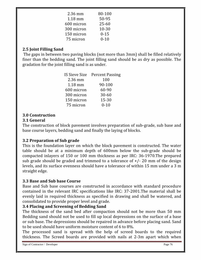
Sign of Contractor / Developer Page 76
2.36 mm 80‐1001.18 mm 50‐95 600 micron 25‐60 300 micron 10‐30 150 micron 0‐15 75 micron 0‐10
2.5 Joint Filling Sand The gaps in between two paving blocks (not more than 3mm) shall be filled relatively finer than the bedding sand. The joint filling sand should be as dry as possible. The gradation for the joint filling sand is as under.
IS Sieve Size Percent Passing2.36 mm 100 1.18 mm 90‐100 600 micron 60‐90 300 micron 30‐60150 micron 15‐30 75 micron 0‐10
3.0 Construction 3.1 General The construction of block pavement involves preparation of sub‐grade, sub base and base course layers, bedding sand and finally the laying of blocks. 3.2 Preparation of Sub grade This is the foundation layer on which the block pavement is constructed. The water table should be at a minimum depth of 600mm below the sub‐grade should be compacted inlayers of 150 or 100 mm thickness as per IRC: 36‐1970.The prepared sub grade should be graded and trimmed to a tolerance of +/‐ 20 mm of the design levels, and its surface evenness should have a tolerance of within 15 mm under a 3 m straight edge. 3.3 Base and Sub base Course Base and Sub base courses are constructed in accordance with standard procedure contained in the relevant IRC specifications like IRC: 37‐2001.The material shall be evenly laid in required thickness as specified in drawing and shall be watered, and consolidated to provide proper level and grade. 3.4 Placing and Screening of Bedding Sand The thickness of the sand bed after compaction should not be more than 50 mm Bedding sand should not be used to fill up local depressions on the surface of a base or sub base. The depressions should be repaired in advance before placing sand. Sand to be used should have uniform moisture content of 6 to 8%. The processed sand is spread with the help of screed boards to the required thickness. The Screed boards are provided with nails at 2‐3m apart which when
Sign of Contractor / Developer Page 77
dragged gives the desired thickness. The sand is subsequently compacted with plate vibrators weighing 0.6 tones or more. Level checks shall be carried out on a grid pattern to establish that the desired level is achieved. Local correction can be done either by removing or adding extra sand followed by leveling and compacting the layer. 3.5 Laying of Blocks Blocks should be laid commencing from the edge strip and proceed towards the inner side. The blocks can be placed to different bonds or patterns as directed by Engineer in Charge. With the help of gauges, the joint width specification (2 to 4mm) should be checked in the first few square meters, where it should be ensured that the block alignment is correct. To start with, full blocks should be used; only subsequently, cutting and in filling at edges be permitted. Under no Circumstances should the blocks be forced or hammered into the bedding at this stage of lying. For cutting paving blocks, hydraulic or mechanical block cutters, or power saws are used. Cut units less than 50mm minimum dimension should not be used. Where space does not permit use of a larger segment, use premixed concrete or sand – cement mortar instead. The blocks shall be laid in line and level and to required camber. 3.6 Compaction For compaction of the bedding sand and the blocks laid over it, vibratory plate compactors are used over the laid paving units; at least two passes of the vibratory plate compactor are needed. Such vibratory compaction should be continued till the top of each paving blocks is level with its adjacent blocks. 3.7 Joints filling The joints should be completely filled with dry sand. The operation of joint filling comprises of spreading a thin layer of the joint filling sand on the block surface and working the sand into each joint by brooming. Following this, passes of heavy plate compactor are applied to facilitate fine sand to fill the joints. The sand should be broomed or spread over the surface with a small surcharge. 3.8 Opening for use Until all the joints are completely filled, no usage should be permitted over the block pavement. The block pavement should be inspected frequently, to ensure that any incompletely filled joints, exposed by usage and/or weather are promptly filled. Such frequent inspection should be continued till dust and detritus from the roadway tightens the surface of the joints. 3.9 Arrangement for traffic The Contractor shall at all times carry out work on the site in a manner creating least interference to the flow traffic and pedestrians, while consistent with the satisfactory execution of the work. 4.0 Measurements for payments The work of footpath shall be measured as finished work in position in square meters and the rate shall include leveling and preparation of sub‐grade, procuring, spreading
Sign of Contractor / Developer Page 78
and compacting of sub base and base material, supplying and fixing of precast M25 CC supporting blocks in C.M.1:2, necessary excavation, and fixing paver blocks in required shape and pattern and filling the joints with sand and compacting using all tools, equipments materials and labour. Payment for B.B.C.C & sand bedding shall be paid separately under corresponding item of this work however filling the joints with sand shall not be paid separately but it is included in the payment of current item. Rate shall be for a unit of one square meter. Item No.60 Providing cement vata (10 cm x 10 cm size) quarter round in cement mortar 1:1 including neat cement finishing, watering etc complete at all floors and all levels as directed by EIC. Details specification for this item shall be as per General Technical Specification for Building works booklet Page No 109 Item No. 17.0.0.1. Rate shall be for a unit of one running meter. Item No.61 Providing & fixing at or near ground level precast/cast in situ cement concrete kerbs stone of grey cment based concrete block 30 cm length, 30 cm height and 15 cm thick of M 250 grade concrete as per approved design and including excavation for fixing in proper line and level, filling the joint with C. M. 1 : 3 ( 1 cement : 3 fine sand) etc. complete including the cost of centring and shuttering and finishing. 1.0 Materials:
1.1 Precast C.C. Block: (1) Water shall confirm to toM‐1, (2) Cement shall conform to M‐3, (3) Sand shall conform to M‐6, (4) Mortar shall conform to M‐11, (5) Aggregates shall conform to M‐12, (6) Shuttering shall conform to M‐26. 1.2 Construction of Precast C.C. Block: Precast C.C blocks shall be made from M‐25 grade of cement concrete. The concrete shall conform to relevant IS code and the size shall be as specified in drawing and the surface shall have fair finish. The strength of the C.C. Block shall have compressive strength of 25N/mm2 after 28 days. It shall fix on road surface/on ground with necessary excavation and shall be joined in C.M.1:3 to required line and level. The shape of blocks shall be of any shape / shapes approved by Engineer‐in‐charge. Cement concrete block of approved design of size 350 x 300 x 150 mm of the make ALCKOK or as equivalent approved by engineer‐in‐charge. Excavation:
Sign of Contractor / Developer Page 79
1.0. General: 1.l Any soil which generally yields to the application of pickaxes and shovels, phawaras, rakes or any such ordinary excavating implement or organic soil, gravel, silt, sand turf loam, clay, peat etc., fall under this category. 2.0. Clearing the site: 2.1 The site cm which the structure is to be built, shall be cleared and all obstructions, loose stone, materials and rubbish of all kind, bush, wood and trees shall be removed as directed. The materials so obtained shall be property of the Government and be conveyed and stacked as directed within 50 M. lead. The roots of the trees coming in the sides shall be cut and coated with hot asphalt. 2.2 The rate of site clearance is damaged be included in the rate of earthwork for which no extra will be paid. 3.0 Setting out: After clearing the site, the center lines will be given by the Engineer‐in‐e6arge. The contractor shall assume full responsibility for alignment, elevation and dimension of each and all parts of the tractor shall assume full responsibility for alignment elevation and dimension of each and all parts of the work. Contractor shall supply labourers, materials., etc. required for setting out the reference marks and bench marks and shall maintain them as long as required and directed. 4.0 Excavation: The excavation, in foundation shall be carried out in true line and level and shall have the width and depth as shown in the drawings or as directed. The contractor shall do the necessary shoring and strutting or providing necessary slopes to a safe angle, at his own cost. The payment for such precautionary measures shall be paid separately if not specified. The bottom of the excavated area shall be 1evelled both longitudinally and transversely as directed by removing and watering as required. No earth filling will be allowed for bringing it to level, if by mistake or any other reason excavation is made deeper or wider that shown on the plan or directed, The extra depth or width shall be made up with concrete of same proportion as specified for the foundation concrete at the cost of the contractor. The excavation up to 1.5 m. depth shall be measured under this item. 5.0. Disposal of the excavated stuff:5.1. The excavated stuff of the selected type shall be used in filling the trenches and plinth or leveling the ground in layers including ramming and watering etc. 5.2. The balance of the excavated quantity shall be removed by the contractor from the site of work to a place as directed with lead up to 50 M. and all lift. Fixing of Blocks: Cement concrete blocks of approved shape shall be fixed in line & level. The alignment of C.C blocks shall be got approved before fixing at site of work. Blocks should be laid commencing from one end of the edge strip and proceed towards the other end. The blocks can be placed to different bonds or patterns as
Sign of Contractor / Developer Page 80
directed by Engineer in Charge. With the help of gauges, the joint width specification (2 to 4mm) should be checked in the first few meters, where it should be ensured that the block alignment is correct. To start with, full blocks should be used; only subsequently, cutting and in filling at edges be permitted. Under no Circumstances should the blocks be forced or hammered into the bedding at this stage of lying. For cutting paving blocks, hydraulic or mechanical block cutters, or power saws are used. Cut units less than 50mm minimum dimension should not be used. Where space does not permit use of a larger segment, use premixed concrete or sand – cement mortar instead. The blocks shall be laid in line and level and to required gradient. The block shall be jointed with cement mortar 1:1 (1 cement : 1 coarse sand) as directed by Engineer‐in‐charge. White washing with lime on wall surfaces (Three coats) as below: Materials: The finished and fixed row of kerb drain shall be whitewashed with lime if required as directed by Engineerincharge. The clearcolle shall be made from glue arid boiling water by Mixing 1 kg mixture shall be suitable tinted where required for use under colored distemper if directed. Glue shall conform to I.S. 852 ‐ 1969 (Specifications for animal glue). Lime used shall he freshly burnt class ‘C’ Lime (fat lime) and white in color conforming to I.S. 712 ‐ 1973 / Water shall conform to M‐1 Best quality of gum shall be used in the preparation of white wash. Alternative blue or indigo: This shall conform to I.S. 55 ‐ 1970 for points, and shall be used for preparation of wash. Pigments: Mineral Colors, not affected by lime shall be used in preparing color wash. Workmanship: Preparation of white wash solution Surface already white or color. The fat lime shall be slaked at site and shall be mixed and stirred with about five liters of water for 1 kg of unslaked lime to make a. thin cream. This shall be allowed to stand for a period of 24 hours and then shall be screened through a clean coarse cloth; 4 Kg of gum dissolved in hot water shall be added to each cubic metre of lime cream. Small quantity of ultramarine blunt (Up to 3 gms per kg of lime) shall also be added to the last two coats of white wash solution and the whole solution shall be stirred thoroughly before use. Preparation of surface: The surface shall be thoroughly cleaned of all dust, dirt, mortar croppings and other foreign matter before white wash is to be applied. The surface spoiled by smoke soot shall be scraped with steel wire brusher or steel scrapers or shall be rubbed with over‐burnt surkhi or brick bats. The surface shall be then broomed to remove all dust, dirt and shall be washed with clean water. Oil or grease spots shall be removed by suitable chemical and smooth surface shall be rubbed with wire brushes.
Sign of Contractor / Developer Page 81
All unsound portion of the surface plaster shall be removed to full depth of plaster in rectangular patches and plastered again after raking the masonry joints properly. Such portion shall be wetted and allowed to dry. They stall then are given one coat of white wash. All unnecessary nails shall be removed; the holes cracks patches etc. shall be made good with materials similar in composition to the surface to be prepared. Application of white wash: On the surface so prepared the white wash shall be applied with ‘Moon’ brush. The first stoke of the brush shall be from top downwards, another from bottom upwards over the first stroke and similarly one stoke from the right another from the left, over the first stroke brush before it dries. This will from one coat. Each coat shall be allowed to dry before next coat is applied. Number of coats as specified in item shall be applied. It shall present smooth and uniform finish free from brush marks and it should not come off easily when rubbed with finger. Splashing and dropping if any on the doors and windows, ventilators etc. shall be removed and the surface cleaned. Priming and Alkali resistant treatments, scraping of surface washing etc. surface spoiled by smoke soot removed of oil and grease spots treatment for infection with efflorescence moulds moss, fungi, algae and litchen and patch repairs to plaster wherever done shall not be paid extra. Mode of Measurement and Payment: The rate shall include cost of all materials, formwork, labour, machinery for concreting, and fixing in required line and level as per drawing and as directed by Engineer in Charge. The rate shall be for a unit of one running meter of completed work. Item No.62 Filling in foundation and plinth with murrum or selected soil in layers of 20cm. thickness including watering, ramming and consolidating etc. completed. Relevant Specifications of Item No. 9 to be followed. Item No.63 Laying lawn preparing soil for planting by laying out carpet lawn including ssupplying and mixing farm yard manure at the rate of 5cum/100sqmt area and maintaining till well established etc. complete (about 45 days). Details specification for this item shall be as per VMC specifications. Rate shall be for a unit of one square meter. Item No.64 Raising Hedge: After Excavation soil upto 30cm. Depth and 30 cm in width , preparing soil for planting by supplying and mixing farm Yard Manure at the rate of 5 cu.mt. per 100 sqmt area. Providing and planting, cutting of
Sign of Contractor / Developer Page 82
cleredendron (Kadavi Mendi) in two rows roughly at 18 cm x 18 cm. distance and maintaining till well established (about 45 days ) complete Details specification for this item shall be as per VMC specifications. Rate shall be for a unit of one meter. Item No. 65 Planting Trees and shrubs: After excavating pits of the size 60cm x 60 cm 60 cm . Refilling the same of providing and mixing Farm Yard Manure at the rate of 0.06 cumt per pit, providing and planting well grown sapling of specified variety and maintaining till well established (About 45 days ) Details specification for this item shall be as per VMC specifications. Rate shall be for a unit of one meter Item No.66 Providing and fixing stainless steel ( Grade 304) railing made of Hollowtubes, channels, plates etc., including welding, grinding, buffing, polishingand making curvature (wherever required) and fitting the same withnecessary stainless steel nuts and bolts complete, i/c fixing the railingwith necessary accessories & stainless steel dash fasteners , stainlesssteel bolts etc., of required size, on the top of the floor or the side ofwaist slab with suitable arrangement as per approval of Engineerincharge,( for payment purpose only weight of stainless steel members shall beconsidered excluding fixing accessories such as nuts, bolts, fasteners etc.) Specification for this item shall conform to DSR Spec.Volume – I. Rate shall be for a unit of one KG. The weight of the work includes weight of all S.S. works including S.S. Nut Bolts, S.S. Plates etc. Item No.67 Providing and Laying polish kota stone slab 25mm thick in risers of steps, Dedo and pillars laid on 10mm thick cement mortar 1:3(1Cement : 3 Coarse sand) and jointed with grey cement slurry including rubbing and polishing etc. complete. Specification for this item shall conform to DSR Spec.Volume – I. Rate shall be for a unit of one square meter. Item No. 68
PROVIDING & FIXING 8 TO 10MM THICK FORM SHEET WITH VINYL FONT'S WRITING ON IT
Details specification for this item shall be as per VMC specifications.
Sign of Contractor / Developer Page 83
Rate shall be for a unit of one square meter. Item No.69 Demolation & Dismentaling of unserviceable materials with all lift & leads (ii) Unreinforced cement
1.0.Workmanship:
1.1.The demolition shall consist of demolition of one or more parts of the building as
specified or shown in the drawings.
Demolition implies taking up or down or breaking up. This shall consist of
demolishing whole or part of work including allrelevant item as specified or shown
in the drawings.
1.2.The demolition shall always be planned before hand and shall be done in reverse
order of the one in which the structure
was constructed. This scheme shall be got approved from the Engineer‐ in‐charge
before starting the work. This however willnot absolve the Contractor from the
responsibility of proper and safe demolition.
1.3.Necessary dropping, shoring and under pinning shall be provided for the safety of
the adjoining work or property, whichis to be left intact, before dismentaling and
demolishing is taken up and the work shall be carried out in such a way that
nodamages is caused to the adjoining property.
1.4.Wherever required, temporary enclosures or partitions shall also be provider.
Necessary precautions shall be taken tokeep the dust nuisance down as and where
necessary.
1.5.Dismantaling shall be commenced in a systematic manner. All materials which
are likely to be damaged by dropping from a height or demolishing roof, masonry etc.
shall be carefully dismantled first. The dismantled articles shall be properly stacked
as directed.
Sign of Contractor / Developer Page 84
1.6.AH materials obtained from demolition shall be the property o. Government
unless otherwise specified and shall be eptin safe custody untill handed over to the
Engineer‐in‐charge.
1.7.Any serviceable materials, obtained during dismantling or demolition shall be
separated out and stacked properly as directed, with all lead and lift. All
unserviceable materials, rubbish etc. shall be slacked as directed by the Engineer‐in‐
charge.
1.8.On completion of work, the site shall be cleared of all debris rubbish and cleaned
as directed.
2.0.Mode of measurements & payment:
2.1.Measurements of all work except hidden work shall be taken before demolition
or dismantaling and no allowance for increase in bulk shall be allowed. The
demolition of lime concrete shall be measured under this item. Specification for
deduction for voids, openings etc. shall be on same basis as that employed for
construction of work.
2.2.All work shall be measured in decimal system as fixed in its place subject to the
following limits, unless otherwise slated
hereinafter: (a) Dimensions shall be measured to the nearest 0.01 mt. (b) Area shall
be worked out to the nearest 0.01 sq. ml.
(c) Cubical connection shall be worked out to the nearest 0.01 Cu. m.
2.3.The rate shall include cost of all labour involved and tools used in demolishing
and dismantling including scaffolding.
The rate shall also include the charges far separating out and stacking the serviceable
materials properly and disposing the
unserviceable materials with all lead and lift. The rate also includes for temporary
storing for the safety of the portion not
required to be pulled down or of adjoining property and providing temporary
enclosures or partitions where considered
necessary.
Sign of Contractor / Developer Page 85
2.4.The rate shall be for a unit of one cubic metre..
Item No. 70
Demolition of brickwork and stone masonary including stacking of serviceable
materials and disposal of unserviceable materials with all lead and lift
1.0. Workmanship : 1.1. The relevant specifications of item No. 20.1 (I) shall be
followed except that demolition of brick or stone masonry in lime mortar is to be
done.
2.0.Mode of measurements & payment:
2.1.The relevant specifications of item No. 20.1 (I) shall be followed except that the
wall and independent piers of columns of brick or stone masonry shall be measured
in cubic metres. All copings, corbles, cornices and othe projections shall beincluded
with the wall measurements.
2.2.In measuring thickness plastered walls, the thickness of plaster shall be included.
The unserviceable materials shall be disposed off with all lead and lift Ashlar face
stones dressed stone etc. if required to be taken down intact shall be dismantled
and measured separately in cubic metres.
2.3.The rate is exclusive of cleaning of bricks or stones. Honey comb works or hollow
block walling shall be measured as solid.
2.4.The rate shall be for a unit of one cubic metre.
Item No. 71
Demolition including stacking of serviceable materilas and disposal of
unserviceable materials with all lead and lift.
Demolition and disposal of unserviceable materials with all leads and lifts.
Unreinforced cement concrete.
1.0. Workmanship: The relevant specifications of item 10.1 (i) shall be followed
except that the unrcinforced cement concrete work is to be demolished instead of
lime concrete.
Sign of Contractor / Developer Page 86
2.0.Mode of measurements & payment:
2.1.The relevant specifications of item No.20.1 (I)
shall be followed.
2.2. The rate shall be for a unit of one cubic metre.
Item No.72
Dismentaling of tiled of stone floors laid in mortar including stacking of
serviceable materials with all lead and lift
Dismantling tiled or stone floors laid in mortar including stacking of serviceable
materials and disposal of unserviceable
materials with all lead and lifts.
1.0. Workmanship: 1.1. The relevant specifications of item No. 20.1 (I) shall be
followed except the dismantling of tiled or stone floors laid on mortar shall be done.
Dismantling implies carefully taking up or down or these are fixed by nail, screws,
bolts etc. these shall be taken out with proper tools. .
2.0.Mode of measurements & payment:
2.1.The supporting materials such as joints, beams if any etc. shall be measured
separately, the relevant specification of item No.20.1 (I) shall be followed. The rate
shall include stacking the unserviceable materials as directed will lead and lift.
2.2.The rate shall be for a unit of one sq. metre.
Item No.73
Dismentaling wood work wrought framed and fixed in frames trusses including
stacking the materials with all lift and lead
1.0. Materials : 1.1. The relevant specifications of item No. 20.1 (I) shall be followed
except that wooden floors shall be dismantled.
2.0.Mode of measurements & payment:
2.1.The relevant specifications of item No. 20.1 (I) shall be followed. The supporting
Sign of Contractor / Developer Page 87
members such as joints, beams etc. shall be measured separately. The rate includes
disposal of unserviceable materials as directed with all lead and lift.
2.2.The rate shall be for a unit of one sq. metre.
Item No. 74
Dismentaling C.I pipes G.S.W pipes abd A.C rain water pipes with fittings and
clamps including stacking the materials with all lead and lift
1.0. Workmanship: 1.1. The relevant specifications of item No. 20.23 shall be followed
except that the dismentaling work of pipe lines of C.I., G.S.W. & A.C. Pipes with fitting
shall be carried out.
2.0.Mode of measurements & payment:
2.1.The relevant specifications of item No. 20.1 (I) shall be followed.
2.2.Water pipe lines, including rain water pipes; with clamps and specials, sewer pipe
lines, (Salt glazed ware or concrete)
etc. shall be measured in running metre inclusive of joints (The measurements shall
be taken along the centre line of pipe and fittings.)
2.3. The rate shall be for a unit of one running metre.
Item No. 75
Dismentling doors, windows, ventilators etc. (wood or steel) shutters including
chowkhats architraves, holdfasts and other attachment etc. complete and
stacking them within all lead and lift.
1.0. Workmanship : 1.1. The relevant specifications of item Not20.49 (I) shall be
followed except that the area of doors, windows, ventilators, exceeding 3 sq. metres
are to be dismantled under this item.
2.0.Mode of measurements & payment:
2.1.The relevant specifications of item No. 20.49 (I) above shall be followed.
2.2.The rate shall be for a unit of one number.
Item No. 76
Sign of Contractor / Developer Page 88
Dismantling sanitary fittings like wash basin W.C. pan indian and europian
type. Flushing tank etc. including stacking of material with lead & lift
1.0. Workmanship : 1.1. The relevant specifications of item No. 20.23 shall be
followed except that the dismantaling work of sanitary fittings such as wash basin,
W. C: Pan (all type of pans), flushing tanks etc. shall be carried out.
2.0.Mode of measurements & payment:
2.1.The relevant specifications of item No. 20.1 (I) shell be followed.
2.2.The‐rate shall be for a unit of one number.

Sign of Contractor / Developer Page 89
GENERAL MATERIAL SPECIFICATIONS FOR BRAND NAMES TO BE USED FOR
THE EXECUTION WORKS
LIST OF APPROVED MAKES
Sr. No. ITEMS APPROVED MAKE
1 CEMENT Ultra‐Tech, Ambuja, JK Laxshmi, Jaypee, Sanghee,
Binani,wonder
2 TMT REINFORCEMENT
Essar, NRE, Electrotherm, National, Tata, Jindal, Sail
3 STRUCTURAL STEEL TATA Structure, Sail, Vizag, Essar
4 BRICK Good quality bricks confirming relevant I.S.CODES
(I S :1077)
5 SAND For Masonry & Plaster work
Zone ‐ (Orsang River).
6 COURSE AGGREGATE SevaliyaTimba Region
10 ACRYLIC EMULSION PAINT (in
door) ASIAN,JOHNSON, BURGER, NEROLAC
11 ACRYLIC EMULSION PAINT ASIAN, JOHNSON, BURGER, NEROLAC
12 SYNTHETIC ENEMAL ASIAN, BURGER, NEROLAC
TEXTURE EXTERIOR PAINT REVA,NOVA,ASIAN OR EQUIVALENT
13 Putty ASIAN, BIRLA, J.K. WHITE
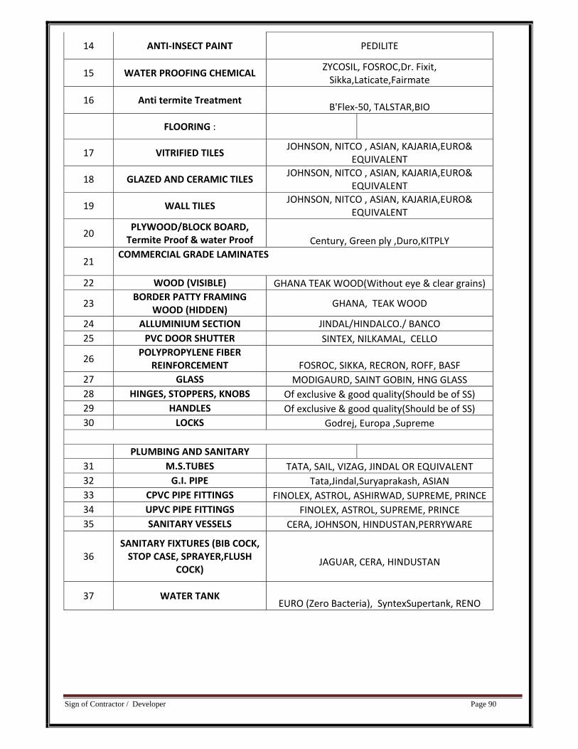
Sign of Contractor / Developer Page 90
14 ANTI‐INSECT PAINT PEDILITE
15 WATER PROOFING CHEMICAL ZYCOSIL, FOSROC,Dr. Fixit, Sikka,Laticate,Fairmate
16 Anti termite Treatment B'Flex‐50, TALSTAR,BIO
FLOORING :
17 VITRIFIED TILES JOHNSON, NITCO , ASIAN, KAJARIA,EURO&
EQUIVALENT
18 GLAZED AND CERAMIC TILES JOHNSON, NITCO , ASIAN, KAJARIA,EURO&
EQUIVALENT
19 WALL TILES JOHNSON, NITCO , ASIAN, KAJARIA,EURO&
EQUIVALENT
20 PLYWOOD/BLOCK BOARD, Termite Proof & water Proof Century, Green ply ,Duro,KITPLY
21 COMMERCIAL GRADE LAMINATES
22 WOOD (VISIBLE) GHANA TEAK WOOD(Without eye & clear grains)
23 BORDER PATTY FRAMING
WOOD (HIDDEN) GHANA, TEAK WOOD
24 ALLUMINIUM SECTION JINDAL/HINDALCO./ BANCO 25 PVC DOOR SHUTTER SINTEX, NILKAMAL, CELLO
26 POLYPROPYLENE FIBER
REINFORCEMENT FOSROC, SIKKA, RECRON, ROFF, BASF 27 GLASS MODIGAURD, SAINT GOBIN, HNG GLASS 28 HINGES, STOPPERS, KNOBS Of exclusive & good quality(Should be of SS) 29 HANDLES Of exclusive & good quality(Should be of SS) 30 LOCKS Godrej, Europa ,Supreme
PLUMBING AND SANITARY 31 M.S.TUBES TATA, SAIL, VIZAG, JINDAL OR EQUIVALENT 32 G.I. PIPE Tata,Jindal,Suryaprakash, ASIAN 33 CPVC PIPE FITTINGS FINOLEX, ASTROL, ASHIRWAD, SUPREME, PRINCE 34 UPVC PIPE FITTINGS FINOLEX, ASTROL, SUPREME, PRINCE 35 SANITARY VESSELS CERA, JOHNSON, HINDUSTAN,PERRYWARE
36 SANITARY FIXTURES (BIB COCK, STOP CASE, SPRAYER,FLUSH
COCK) JAGUAR, CERA, HINDUSTAN
37 WATER TANK EURO (Zero Bacteria), SyntexSupertank, RENO
Sign of Contractor / Developer Page 91
Note : If in case of non avaibility of Specified brand of Material, necessary approval is to be taken from concern authorities of VMC.
1) All the Material to be approved and tested as per latest relevant IS, prior to execution the work. Material not mentioned in above list should confirm to latest relevant IS revision.
Signature of Contractor Add. City Engineer
VMC,
Date Vadodara.
Related Documents