Instruction manual VEXTRA 03 - 2015 NA 15.33 A

Welcome message from author
This document is posted to help you gain knowledge. Please leave a comment to let me know what you think about it! Share it to your friends and learn new things together.
Transcript
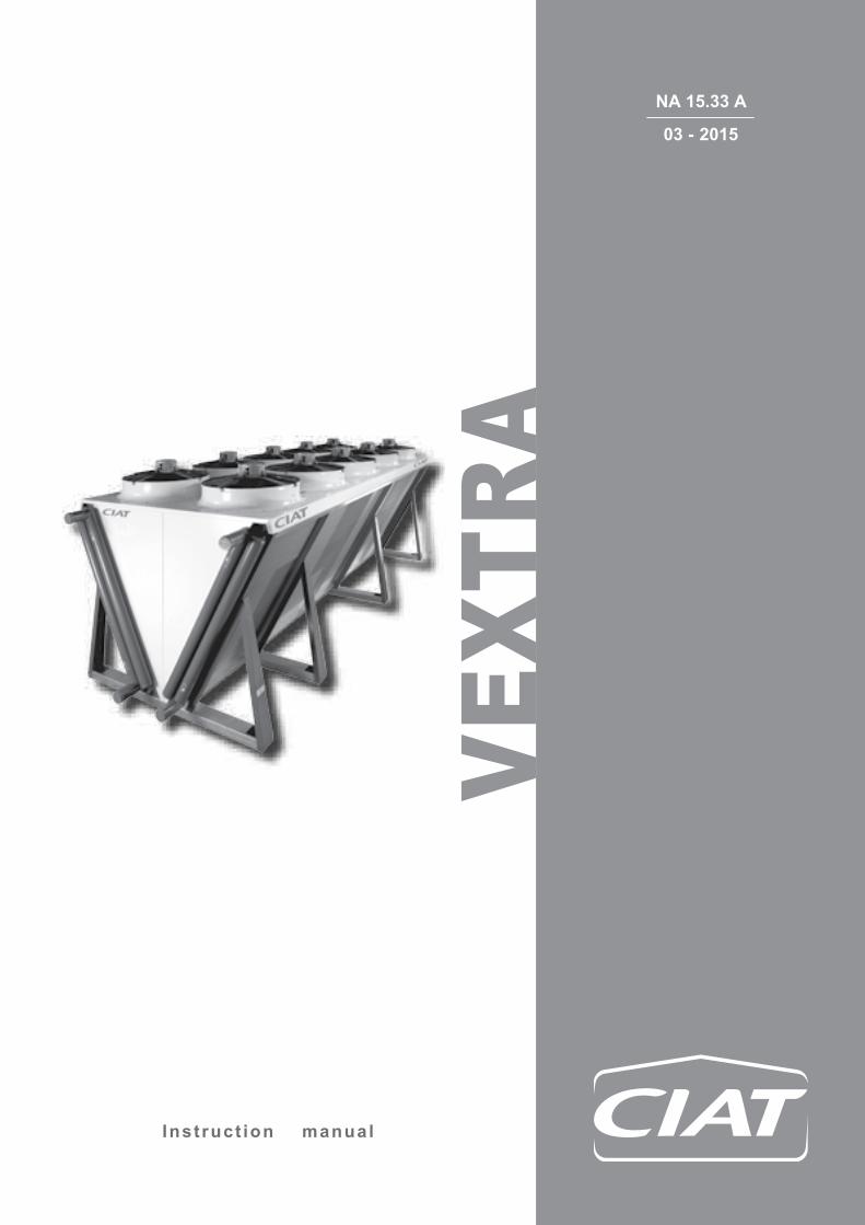
Inst ruct ion manual
VEXT
RA
03 - 2015
NA 15.33 A

EN - 1
EN
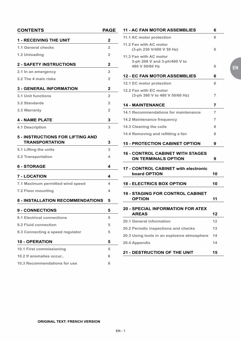
CONTENTS PAGE
1 - RECEIVING THE UNIT 2
1.1 General checks 2
1.2 Unloading 2
2 - SAFETY INSTRUCTIONS 2
2.1 In an emergency 2
2.2 The 4 main risks 2
3 - GENERAL INFORMATION 2
3.1 Unit functions 2
3.2 Standards 2
3.3 Warranty 2
4 - NAME PLATE 3
4.1 Description 3
5 - INSTRUCTIONS FOR LIFTING AND TRANSPORTATION 3
5.1 Lifting the units 3
5.2 Transportation 4
6 - STORAGE 4
7 - LOCATION 4
7.1 Maximum permitted wind speed 4
7.2 Floor mounting 4
8 - INSTALLATION RECOMMENDATIONS 5
9 - CONNECTIONS 5
9.1 Electrical connections 5
9.2 Fluid connection 5
9.3 Connecting a speed regulator 5
10 - OPERATION 5
10.1 First commissioning 5
10.2 If anomalies occur.. 6
10.3 Recommendations for use 6
11 - AC FAN MOTOR ASSEMBLIES 6
11.1 AC motor protection 6
11.2 Fan with AC motor (3-ph 230 V/400 V 50 Hz) 6
11.3 Fan with AC motor 3-ph 208 V and 3-ph/400 V to 480 V 50/60 Hz 6
12 - EC FAN MOTOR ASSEMBLIES 6
12.1 EC motor protection 6
12.2 Fan with EC motor (3-ph 380 V to 480 V 50/60 Hz) 7
14 - MAINTENANCE 7
14.1 Recommendations for maintenance 7
14.2 Maintenance frequency 7
14.3 Cleaning the coils 8
14.4 Removing and refitting a fan 8
15 - PROTECTION CABINET OPTION 9
16 - CONTROL CABINET WITH STAGES ON TERMINALS OPTION 9
17 - CONTROL CABINET with electronic board OPTION 10
18 - ELECTRICS BOX OPTION 10
19 - STAGING FOR CONTROL CABINET OPTION 11
20 - SPECIAL INFORMATION FOR ATEX AREAS 12
20.1 General information 12
20.2 Periodic inspections and checks 13
20.3 Using tools in an explosive atmosphere 14
20.4 Appendix 14
21 - DESTRUCTION OF THE UNIT 15
ORIGINAL TEXT: FRENCH VERSION
EN - 2
� Any operation must be carried out by qualified personnel using the appropriate Personal Protective Equipment (PPE).
� Before any operation, read this guide carefully and keep it in a safe place. Safety information must be adhered to. � The units must not be run under operating conditions which are more restrictive than those it was designed for
(pressure, temperature, type and circulation of fluids). � For units installed in European Community countries, ensure that the entire installation complies with the directives
and legislation in force. � Respect the instructions for using slings (see the labels on the unit). � To prevent any risk of accident, prohibit public access by clearly marking the work area.
2.1 In an emergency � Switch off the electrical supply. � The process should not be jeopardised if the emergency stop devices are activated. � Switch off the fans.
2.2 The 4 main risks � Lifting or positioning = Accident � Contact with the piping = Burns � Opening the electrics box = Electrocution � Removing the grilles = Injury
1 - RECEIVING THE UNIT
2 - SAFETY INSTRUCTIONS
3 - GENERAL INFORMATION
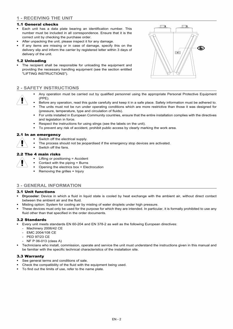
1.1 General checks � Each unit has a data plate bearing an identification number. This
number must be included in all correspondence. Ensure that it is the correct unit by checking the purchase order.
� After unpacking the unit, please inspect it for any damage. � If any items are missing or in case of damage, specify this on the
delivery slip and inform the carrier by registered letter within 3 days of delivery of the unit.
1.2 Unloading � The recipient shall be responsible for unloading the equipment and
providing the necessary handling equipment (see the section entitled "LIFTING INSTRUCTIONS").
3.1 Unit functions � Drycooler: Device in which a fluid in liquid state is cooled by heat exchange with the ambient air, without direct contact
between the ambient air and the fluid. � Misting option: System for cooling air by misting of water droplets under high pressure. � These devices must only be used for the purpose for which they are intended. In particular, it is formally prohibited to use any
fluid other than that specified in the order documents.
3.2 Standards � Every unit meets standards EN 60-204 and EN 378-2 as well as the following European directives:
- Machinery 2006/42 CE - EMC 2004/108 CE - PED 97/23 CE - NF P 06-013 (class A)
� Technicians who install, commission, operate and service the unit must understand the instructions given in this manual and be familiar with the specific technical characteristics of the installation site.
3.3 Warranty � See general terms and conditions of sale. � Check the compatibility of the fluid with the equipment being used. � To find out the limits of use, refer to the name plate.
�
EN - 3
EN
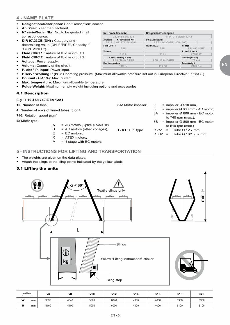
� Désignation\Description: See "Description" section. � An./Year: Year manufactured. � N° série\Serial Nbr: No. to be quoted in all
correspondence. � DIR 97.23CE (DN) : Category and
determining value (DN if "PIPE", Capacity if "CONTAINER").
� Fluid CIRC.1 : nature of fluid in circuit 1. � Fluid CIRC.2 : nature of fluid in circuit 2. � Voltage: Power supply. � Volume: Capacity of the circuit. � P. abs \ P. input: Power input. � P.serv.\ Working P (PS): Operating pressure. (Maximum allowable pressure set out in European Directive 97.23/CE). � Courant (+/-10%): Max. current. � Max. temperature: Maximum allowable temperature. � Poids-Weight: Maximum empty weight including options and accessories.
4.1 Description
E.g.: 1 10 4 UI 740 E 8A 12A1
Designation/DescriptionRef. produit\Item Ref.
An(Year) N. Serie/Serial Nbr DIR 97.23CE (DN)
Fluid CIRC. 1 Fluid CIRC. 2 Voltage
P. abs \ P. inputVolume
P.serv.\ working P (PS) Courant (+/-10%)
Poids-WeightMax. temperature
2015 022777238/0001
7225488.362873 1164 UI 89DE9 12A1
EAU EAU TRI 400 50HZ
47600 W311 L311 L
1.00 (10.0) BARS
110 °C
1.00 (10.0) BARS
110 °C
70.4 A
ART3.3-LIQ-GR2 (DN: 100)
3930 KG
4 - NAME PLATE
10: Number of fans:
4: Number of rows of finned tubes: 3 or 4
740: Rotation speed (rpm)
E: Motor type: A = AC motors (3-ph/400 V/50 Hz), B = AC motors (other voltages), E = EC motors, X = ATEX motors, M = 1 stage with EC motors.
8A: Motor impeller: 9 = impeller Ø 910 mm, 8 = impeller Ø 800 mm - AC motor, 8A = impeller Ø 800 mm - EC motor to 740 rpm (max.), 8B = impeller Ø 800 mm - EC motor to 510 rpm (max.)12A1: Fin type: 12A1 = Tube Ø 12.7 mm, 16B2 = Tube Ø 16/15.87 mm.
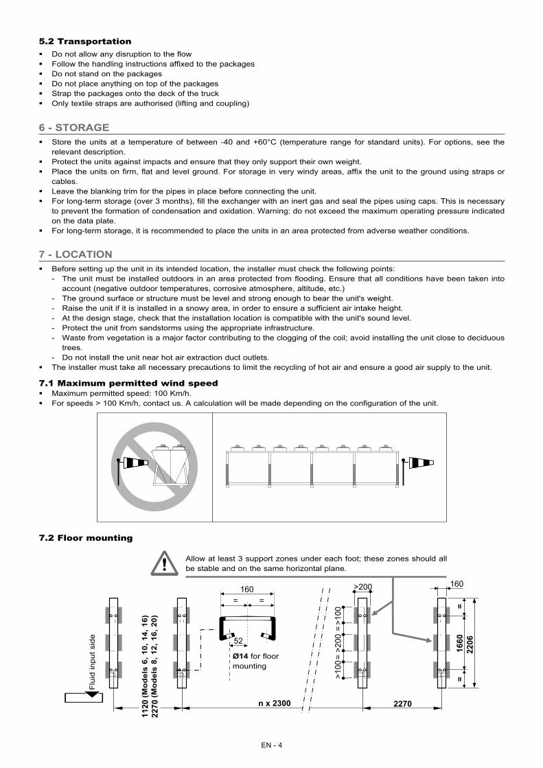
5 - INSTRUCTIONS FOR LIFTING AND TRANSPORTATION � The weights are given on the data plates. � Attach the slings to the sling points indicated by the yellow labels.
5.1 Lifting the units
α < 60°
kg
H m
in.
L
�
Textile slings only
Yellow "Lifting instructions" sticker
Slings
Sling stop
x6 x8 x10 x12 x14 x16 x18 x20
W mm 3390 4540 5690 6840 4600 4600 6900 6900
H mm 4100 4100 5000 6000 4100 4000 6100 6100
min
. H
EN - 4
5.2 Transportation � Do not allow any disruption to the flow � Follow the handling instructions affixed to the packages � Do not stand on the packages � Do not place anything on top of the packages � Strap the packages onto the deck of the truck � Only textile straps are authorised (lifting and coupling)
6 - STORAGE
7 - LOCATION
� Store the units at a temperature of between -40 and +60°C (temperature range for standard units). For options, see the relevant description.
� Protect the units against impacts and ensure that they only support their own weight. � Place the units on firm, flat and level ground. For storage in very windy areas, affix the unit to the ground using straps or
cables. � Leave the blanking trim for the pipes in place before connecting the unit. � For long-term storage (over 3 months), fill the exchanger with an inert gas and seal the pipes using caps. This is necessary
to prevent the formation of condensation and oxidation. Warning: do not exceed the maximum operating pressure indicated on the data plate.
� For long-term storage, it is recommended to place the units in an area protected from adverse weather conditions.
� Before setting up the unit in its intended location, the installer must check the following points: - The unit must be installed outdoors in an area protected from flooding. Ensure that all conditions have been taken into
account (negative outdoor temperatures, corrosive atmosphere, altitude, etc.) - The ground surface or structure must be level and strong enough to bear the unit's weight. - Raise the unit if it is installed in a snowy area, in order to ensure a sufficient air intake height. - At the design stage, check that the installation location is compatible with the unit's sound level. - Protect the unit from sandstorms using the appropriate infrastructure. - Waste from vegetation is a major factor contributing to the clogging of the coil; avoid installing the unit close to deciduous
trees. - Do not install the unit near hot air extraction duct outlets.
� The installer must take all necessary precautions to limit the recycling of hot air and ensure a good air supply to the unit.
7.1 Maximum permitted wind speed � Maximum permitted speed: 100 Km/h. � For speeds > 100 Km/h, contact us. A calculation will be made depending on the configuration of the unit.
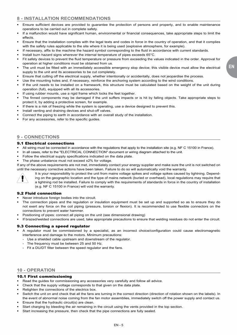
7.2 Floor mounting
1120
22
70
2206
1660
==
Ø14
160 = =
52
n x 2300 2270
160
==
>200
>100
>100
>200
Flu
id in
put s
ide
Ø14 for floor mounting
Allow at least 3 support zones under each foot; these zones should all be stable and on the same horizontal plane.
(Mod
els
6, 1
0, 1
4, 1
6)(M
odel
s 8,
12,
16,
20)
EN - 5
EN
8 - INSTALLATION RECOMMENDATIONS
9.1 Electrical connections � All wiring must be connected in accordance with the regulations that apply to the installation site (e.g. NF C 15100 in France). � In all cases, refer to the "ELECTRICAL CONNECTION" document or wiring diagram attached to the unit. � Follow the electrical supply specifications indicated on the data plate. � The phase unbalance must not exceed ±2% for voltage.
If any of the above requirements are not met, immediately contact your energy supplier and make sure the unit is not switched on until the necessary corrective actions have been taken. Failure to do so will automatically void the warranty.
It is your responsibility to protect the unit from mains voltage spikes and voltage spikes caused by lightning. Depend-ing on the geographic location and the type of mains network (buried or overhead), local regulations may require that a lightning rod be installed. Failure to comply with the requirements of standards in force in the country of installation (e.g. NF C 15100 in France) will void the warranty.
9.2 Fluid connection � Never introduce foreign bodies into the circuit. � The connection pipes and the regulation or insulation equipment must be set up and supported so as to ensure they do
not exert any force on the coil piping (pressure, torsion or flexion). It is recommended to use flexible connectors on the connections to prevent water hammer.
� Positioning of pipes: connect all piping on the unit (see dimensional drawing) � If brazed/welded connections are used, take appropriate precautions to ensure that welding residues do not enter the circuit.
9.3 Connecting a speed regulator � A regulator must be commissioned by a specialist, as an incorrect choice/configuration could cause electromagnetic
interference and damage to the motors. Minimum precautions: - Use a shielded cable upstream and downstream of the regulator. - The frequency must be between 25 and 50 Hz. - Fit a DU/DT filter between the speed regulator and the fans.
� Ensure sufficient devices are provided to guarantee the protection of persons and property, and to enable maintenance operations to be carried out in complete safety.
� If a malfunction would have significant human, environmental or financial consequences, take appropriate steps to limit the effects.
� Ensure that the installation complies with the legal texts and codes in force in the country of operation, and that it complies with the safety rules applicable to the site where it is being used (explosive atmosphere, for example).
� If necessary, affix to the machine the hazard symbol corresponding to the fluid in accordance with current standards. � Install burn hazard signs wherever the internal temperature of pipes exceeds 65°C. � Fit safety devices to prevent the fluid temperature or pressure from exceeding the values indicated in the order. Approval for
operation at higher conditions must be obtained from us. � The unit must be fitted with an immediately accessible emergency stop device; this visible device must allow the electrical
supply to the unit and its accessories to be cut completely. � Ensure that cutting off the electrical supply, whether intentionally or accidentally, does not jeopardise the process. � Use the mounting holes and, if necessary, reinforce the anchoring system according to the wind conditions. � If the unit needs to be installed on a framework, this structure must be calculated based on the weight of the unit during
operation (full), equipped with all its accessories. � If using rubber mounts, use a rigid frame which locks the feet together. � The finned components may be damaged if the unit suffers impacts or is hit by falling objects. Take appropriate steps to
protect it, by adding a protective screen, for example. � If there is a risk of freezing while the system is operating, use a device designed to prevent this. � Install venting and draining devices and shut-off valves. � Connect the piping to earth in accordance with an overall study of the installation. � For any accessories, refer to the specific guides.
9 - CONNECTIONS
10.1 First commissioning � Read the guides for commissioning any accessories very carefully and follow all advice. � Check that the supply voltage corresponds to that given on the data plate. � Retighten the connections of the electrics box. � Switch the unit on and check that all the fans are turning in the correct direction (direction of rotation shown on the labels). In
the event of abnormal noise coming from the fan motor assemblies, immediately switch off the power supply and contact us. � Ensure that the hydraulic circuit(s) are clean. � Start charging by bleeding the air remaining in the circuit using the vents provided in the top section. � Start increasing the pressure, then check that the pipe connections are fully sealed.
10 - OPERATION
EN - 6
10.2 If anomalies occur..We are at your disposal to bring you all the desired help. Previously, verify the following points:
- Are all fans turning in the correct direction? (check this against the labels) - Is the supply voltage correct? - Are the motors running at the correct speed? (check the input current) - Has the fluid direction been reversed during connection of the coil? - Are the fins of the coil clogged? - Are there any issues relating to air recycling or a poor air supply?
10.3 Recommendations for useScaling and corrosion have a very negative effect on the operation and service life of the units. Therefore, only use treated water or authorised fluids (check the compatibility of any additives with the drycooler's materials).
11.1 AC motor protection � All the motors are equipped with a thermal cut-out, which is available in the motor terminal box. Wiring for the thermal cut-out
is optional
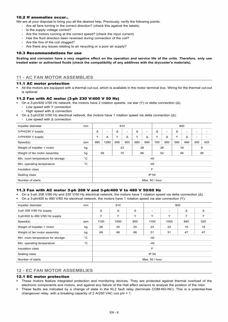
11.2 Fan with AC motor (3-ph 230 V/400 V 50 Hz) � On a 3-ph/400 V/50 Hz network, the motors have 2 rotation speeds, via star (Y) or delta connection (Δ).
- Low speed with Y connection - High speed with Δ connection
� On a 3-ph/230 V/50 Hz electrical network, the motors have 1 rotation speed via delta connection (Δ): - Low speed with Δ connection
Impeller diameter mm 910 800
3-PH/230 V supply Δ - Δ - Δ - Δ - Δ - - -
3-PH/400 V supply Y Δ Y Δ Y Δ Y Δ Y Δ - -
Speed(s) rpm 980 1280 690 900 680 890 700 900 560 690 300 425
Weight of impeller + motor kg - 23 28 28 19 9
Weight of fan motor assembly kg 59 70 66 52 48 38
Min. room temperature for storage °C -40
Min. operating temperature °C -40
Insulation class F
Sealing class IP 54
Number of starts Max. 50 / hour
11.3 Fan with AC motor 3-ph 208 V and 3-ph/400 V to 480 V 50/60 Hz � On a 3-ph 208 V/60 Hz and 230 V/50 Hz electrical network, the motors have 1 rotation speed via delta connection (Δ). � On a 3-ph/400 to 480 V/60 Hz electrical network, the motors have 1 rotation speed via star connection (Y):
Impeller diameter mm 910 800
3-ph 208 V/60 Hz supply Δ Δ Δ - - Δ Δ
3-ph/400 to 480 V/60 Hz supply Y Y Y Y Y Y Y
Speed(s) rpm 1100 1000 800 1100 1050 840 520
Weight of impeller + motor kg 28 25 25 23 23 19 19
Weight of fan motor assembly kg 69 66 66 51 51 47 47
Min. room temperature for storage °C -40
Min. operating temperature °C -40
Insulation class F
Sealing class IP 54
Number of starts Max. 50 / hour
11 - AC FAN MOTOR ASSEMBLIES
12.1 EC motor protection � These motors feature integrated protection and monitoring devices. They are protected against thermal overload of the
electronic components and motors, and against any failure of the Hall effect sensors to analyse the position of the rotor. � These faults are indicated by a change of state in the KL2 fault relay (terminals COM-NO-NC). This is a potential-free
changeover relay, with a breaking capacity of 2 A/250 VAC cos phi = 1.
12 - EC FAN MOTOR ASSEMBLIES
EN - 7
EN
� List of faults: - In the event of a thermal overload on the motor/electronic controls, or a Hall effect sensor fault:
The fan stops and cannot be restarted. The fault is indicated by a change of state on the KL2 relay. The fan can only be restarted by powering off for 20 seconds then powering back on again (after the source of the fault has disappeared, otherwise the cycle restarts).
- Rotor blockage: In the event of accidental rotor blockage, the fault is indicated by a change of state on the KL2 relay. When the blockage is cleared, the fan automatically restarts.
- Under voltage: The motor accepts a nominal voltage/frequency range of 380 to 480 V/50 to 60 Hz with no notable modification to a handling performance. Between 380 and 290 V, the fan continues to operate with degraded performance. If the voltage drops below 290 V for 5 seconds, the motor stops. The fault is indicated by a change of state on the KL2 relay. The motor will restart when the voltage returns to its nominal value.
- Absence of phase: If one of the 3 phases is absent for more than 5 seconds, the motor stops. The fault is indicated by a change of state on the KL2 relay. The motor will automatically restart 10 - 40 seconds after the 3 phases return. Phase inversion has no effect on the direction of rotation of the motor.
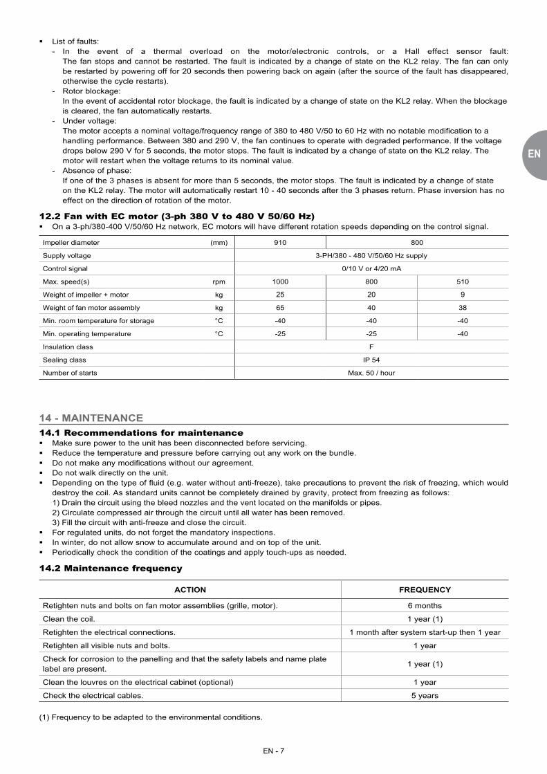
12.2 Fan with EC motor (3-ph 380 V to 480 V 50/60 Hz) � On a 3-ph/380-400 V/50/60 Hz network, EC motors will have different rotation speeds depending on the control signal.
Impeller diameter (mm) 910 800
Supply voltage 3-PH/380 - 480 V/50/60 Hz supply
Control signal 0/10 V or 4/20 mA
Max. speed(s) rpm 1000 800 510
Weight of impeller + motor kg 25 20 9
Weight of fan motor assembly kg 65 40 38
Min. room temperature for storage °C -40 -40 -40
Min. operating temperature °C -25 -25 -40
Insulation class F
Sealing class IP 54
Number of starts Max. 50 / hour
14.1 Recommendations for maintenance � Make sure power to the unit has been disconnected before servicing. � Reduce the temperature and pressure before carrying out any work on the bundle. � Do not make any modifications without our agreement. � Do not walk directly on the unit. � Depending on the type of fluid (e.g. water without anti-freeze), take precautions to prevent the risk of freezing, which would
destroy the coil. As standard units cannot be completely drained by gravity, protect from freezing as follows:1) Drain the circuit using the bleed nozzles and the vent located on the manifolds or pipes.2) Circulate compressed air through the circuit until all water has been removed.3) Fill the circuit with anti-freeze and close the circuit.
� For regulated units, do not forget the mandatory inspections. � In winter, do not allow snow to accumulate around and on top of the unit. � Periodically check the condition of the coatings and apply touch-ups as needed.
14.2 Maintenance frequency
ACTION FREQUENCY
Retighten nuts and bolts on fan motor assemblies (grille, motor). 6 months
Clean the coil. 1 year (1)
Retighten the electrical connections. 1 month after system start-up then 1 year
Retighten all visible nuts and bolts. 1 year
Check for corrosion to the panelling and that the safety labels and name plate label are present.
1 year (1)
Clean the louvres on the electrical cabinet (optional) 1 year
Check the electrical cables. 5 years
(1) Frequency to be adapted to the environmental conditions.
14 - MAINTENANCE
EN - 8
14.3 Cleaning the coils � Switch off the unit. � If the unit is fitted with a "protective screen" option, remove this to access the coils. � If the fins are damaged, straighten them using a comb. � In the event of minor fouling (non-clogging dry residue or dust, leaves, wires, etc.):
- Counter-flow supply air: dry air up to 30 bar. - Where possible, periodically reversing the flow of air generated by the fans can prevent this. This operation is not possible
if the unit is equipped with EC motors. � In the event of moderate fouling (moderate clogging due to dry residues, damp dust or grass, insects, etc.):
- Use a high-pressure (HP) steam cleaner with a flat jet nozzle (25°). - Max. pressure 100 bar - Steam: max. 140°C - Min. distance between the nozzle and the fins = 200 mm - Cleaning fluid: municipal water with pH neutral detergent (pH 7). Avoid alkaline detergents. - Flushing with clean water using the same adjustment parameters.
� IMPORTANT: the use of detergent is prohibited for cleaning fins with a BLYGOLD®, ALTENA® or HERESITE® coating.
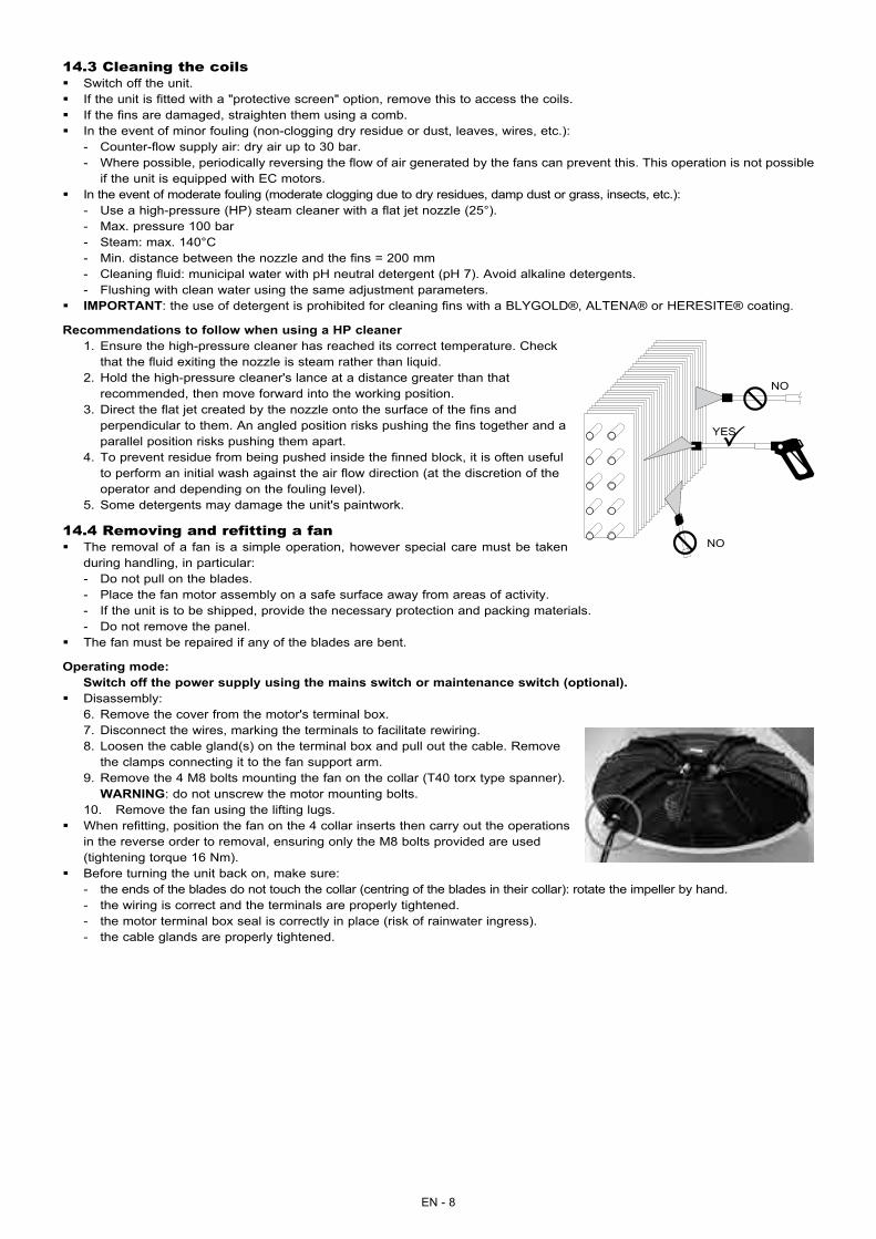
Recommendations to follow when using a HP cleaner1. Ensure the high-pressure cleaner has reached its correct temperature. Check
that the fluid exiting the nozzle is steam rather than liquid.2. Hold the high-pressure cleaner's lance at a distance greater than that
recommended, then move forward into the working position.3. Direct the flat jet created by the nozzle onto the surface of the fins and
perpendicular to them. An angled position risks pushing the fins together and a parallel position risks pushing them apart.
4. To prevent residue from being pushed inside the finned block, it is often useful to perform an initial wash against the air flow direction (at the discretion of the operator and depending on the fouling level).
5. Some detergents may damage the unit's paintwork.
14.4 Removing and refitting a fan � The removal of a fan is a simple operation, however special care must be taken
during handling, in particular: - Do not pull on the blades. - Place the fan motor assembly on a safe surface away from areas of activity. - If the unit is to be shipped, provide the necessary protection and packing materials. - Do not remove the panel.
� The fan must be repaired if any of the blades are bent.
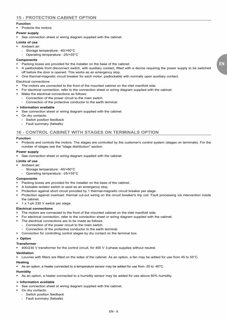
Operating mode: Switch off the power supply using the mains switch or maintenance switch (optional). � Disassembly:
6. Remove the cover from the motor's terminal box.7. Disconnect the wires, marking the terminals to facilitate rewiring.8. Loosen the cable gland(s) on the terminal box and pull out the cable. Remove
the clamps connecting it to the fan support arm.9. Remove the 4 M8 bolts mounting the fan on the collar (T40 torx type spanner).
WARNING: do not unscrew the motor mounting bolts.10. Remove the fan using the lifting lugs.
� When refitting, position the fan on the 4 collar inserts then carry out the operations in the reverse order to removal, ensuring only the M8 bolts provided are used (tightening torque 16 Nm).
� Before turning the unit back on, make sure: - the ends of the blades do not touch the collar (centring of the blades in their collar): rotate the impeller by hand. - the wiring is correct and the terminals are properly tightened. - the motor terminal box seal is correctly in place (risk of rainwater ingress). - the cable glands are properly tightened.
�
��
NO
NO
YES
EN - 9
EN
15 - PROTECTION CABINET OPTIONFunction � Protects the motors
Power supply � See connection sheet or wiring diagram supplied with the cabinet.
Limits of use � Ambient air:
- Storage temperature: -40/+60°C - Operating temperature: -25/+55°C
Components � Packing boxes are provided for the installer on the base of the cabinet. � A padlockable front disconnect switch, with auxiliary contact, fitted with a device requiring the power supply to be switched
off before the door is opened. This works as an emergency stop. � One thermal-magnetic circuit breaker for each motor, padlockable with normally open auxiliary contact.
Electrical connections � The motors are connected to the front of the mounted cabinet on the inlet manifold side. � For electrical connection, refer to the connection sheet or wiring diagram supplied with the cabinet. � Make the electrical connections as follows:
- Connection of the power circuit to the main switch. - Connection of the protective conductor to the earth terminal.
Information available � See connection sheet or wiring diagram supplied with the cabinet. � On dry contacts:
- Switch position feedback - Fault summary (failsafe)
16 - CONTROL CABINET WITH STAGES ON TERMINALS OPTIONFunction � Protects and controls the motors. The stages are controlled by the customer's control system (stages on terminals). For the
number of stages see the "stage distribution" section.
Power supply � See connection sheet or wiring diagram supplied with the cabinet.
Limits of use � Ambient air:
- Storage temperature: -40/+60°C - Operating temperature: -25/+55°C
Components � Packing boxes are provided for the installer on the base of the cabinet. � A lockable isolator switch is used as an emergency stop. � Protection against short circuit provided by 1 thermal-magnetic circuit breaker per stage. � Protection against overload: thermal cut-out wiring on the circuit breaker's trip coil. Fault processing via intervention inside
the cabinet. � 1 x 1-ph 230 V switch per stage.
Electrical connections � The motors are connected to the front of the mounted cabinet on the inlet manifold side. � For electrical connection, refer to the connection sheet or wiring diagram supplied with the cabinet. � The electrical connections are to be made as follows:
- Connection of the power circuit to the main switch. - Connection of the protective conductor to the earth terminal.
� Connection for controlling control stages by dry contact on the terminal box.
OptionTransformer � 400/230 V transformer for the control circuit, for 400 V 3-phase supplies without neutral.
Ventilation � Louvres with filters are fitted on the sides of the cabinet. As an option, a fan may be added for use from 45 to 55°C.
Heating � As an option, a heater connected to a temperature sensor may be added for use from -20 to -40°C.
Humidity � As an option, a heater connected to a humidity sensor may be added for use above 60% humidity.
Information available � See connection sheet or wiring diagram supplied with the cabinet. � On dry contacts:
- Switch position feedback - Fault summary (failsafe)
EN - 10
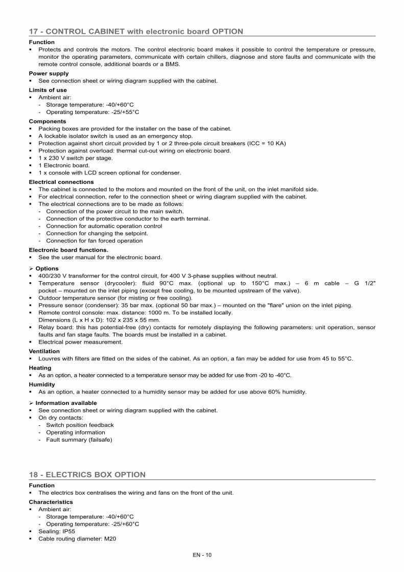
17 - CONTROL CABINET with electronic board OPTIONFunction � Protects and controls the motors. The control electronic board makes it possible to control the temperature or pressure,
monitor the operating parameters, communicate with certain chillers, diagnose and store faults and communicate with the remote control console, additional boards or a BMS.
Power supply � See connection sheet or wiring diagram supplied with the cabinet.
Limits of use � Ambient air:
- Storage temperature: -40/+60°C - Operating temperature: -25/+55°C
Components � Packing boxes are provided for the installer on the base of the cabinet. � A lockable isolator switch is used as an emergency stop. � Protection against short circuit provided by 1 or 2 three-pole circuit breakers (ICC = 10 KA) � Protection against overload: thermal cut-out wiring on electronic board. � 1 x 230 V switch per stage. � 1 Electronic board. � 1 x console with LCD screen optional for condenser.
Electrical connections � The cabinet is connected to the motors and mounted on the front of the unit, on the inlet manifold side. � For electrical connection, refer to the connection sheet or wiring diagram supplied with the cabinet. � The electrical connections are to be made as follows:
- Connection of the power circuit to the main switch. - Connection of the protective conductor to the earth terminal. - Connection for automatic operation control - Connection for changing the setpoint. - Connection for fan forced operation
Electronic board functions. � See the user manual for the electronic board.
Options � 400/230 V transformer for the control circuit, for 400 V 3-phase supplies without neutral. � Temperature sensor (drycooler): fluid 90°C max. (optional up to 150°C max.) – 6 m cable – G 1/2"
pocket – mounted on the inlet piping (except free cooling, to be mounted upstream of the valve). � Outdoor temperature sensor (for misting or free cooling). � Pressure sensor (condenser): 35 bar max. (optional 50 bar max.) – mounted on the "flare" union on the inlet piping. � Remote control console: max. distance: 1000 m. To be installed locally.
Dimensions (L x H x D): 102 x 235 x 55 mm. � Relay board: this has potential-free (dry) contacts for remotely displaying the following parameters: unit operation, sensor
faults and fan stage faults. The boards must be installed in a cabinet. � Electrical power measurement.
Ventilation � Louvres with filters are fitted on the sides of the cabinet. As an option, a fan may be added for use from 45 to 55°C.
Heating � As an option, a heater connected to a temperature sensor may be added for use from -20 to -40°C.
Humidity � As an option, a heater connected to a humidity sensor may be added for use above 60% humidity.
Information available � See connection sheet or wiring diagram supplied with the cabinet. � On dry contacts:
- Switch position feedback - Operating information - Fault summary (failsafe)
18 - ELECTRICS BOX OPTIONFunction � The electrics box centralises the wiring and fans on the front of the unit.
Characteristics � Ambient air:
- Storage temperature: -40/+60°C - Operating temperature: -25/+60°C
� Sealing: IP55 � Cable routing diameter: M20
EN - 11
EN
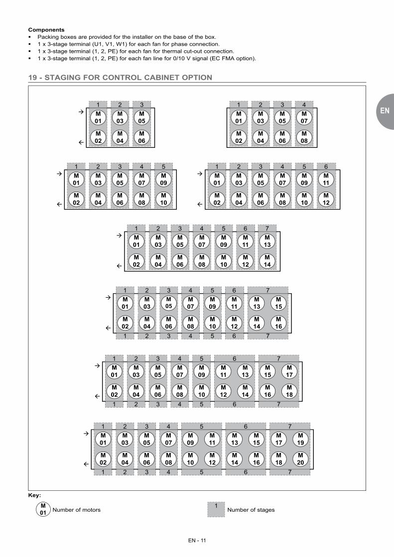
19 - STAGING FOR CONTROL CABINET OPTION
�
�
M01
M03
M05
M07
M09
M11
M13
M04
M06
M08
M10
M12
M14
M02
1 32 4 5 6 7
�
�
M01
M03
M05
M04
M06
M02
1 32� M
01M03
M05
M07
M04
M06
M08
M02
1 32 4
�
�
M01
M03
M05
M07
M09
M04
M06
M08
M02
M10
1 32 4 5�
�
M01
M03
M05
M07
M09
M11
M04
M06
M08
M10
M12
M02
1 32 4 5 6
M01
M03
M05
M07
M09
M11
M04
M06
M08
M10
M12
M02
1 32 4 5 6
1 32 4 5 6
M13
M15
M14
M16
7
7
M01
M03
M05
M07
M09
M11
M13
M04
M06
M08
M10
M12
M14
M02
1 32 4 5 6
1 32 4 5 6
M15
M17
M16
M18
7
7
M01
M03
M05
M07
M09
M11
M04
M06
M08
M10
M12
M02
1 32 4 5
1 32 4 5
M13
M15
M14
M16
6
6
M17
M19
M18
M20
7
7
�
�
�
�
�
�
Key:
M01 Number of motors
1 Number of stages
Components � Packing boxes are provided for the installer on the base of the box. � 1 x 3-stage terminal (U1, V1, W1) for each fan for phase connection. � 1 x 3-stage terminal (1, 2, PE) for each fan for thermal cut-out connection. � 1 x 3-stage terminal (1, 2, PE) for each fan line for 0/10 V signal (EC FMA option).
EN - 12
in accordance with directive 94/9/EC (explosive atmospheres)20 - SPECIAL INFORMATION FOR ATEX AREAS
20.1 General informationEvaluation of the level of danger of explosion established in accordance with standards EN 13463-1 (2009) and EN 1127-1 (2011).
The units are certified as complying with the recommendations in standard EN 13463-5 (2011) "Protection by constructional safety 'c'.The user must classify the various potentially explosive areas in accordance with directive 1999/92/EC.The units are selected and manufactured according to the type of area defined by the user.
A unit must never be operated under conditions other than those for which it was designed.
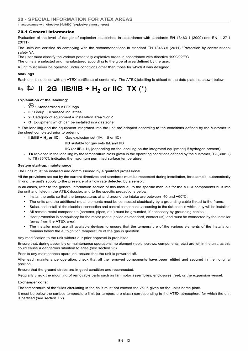
MarkingsEach unit is supplied with an ATEX certificate of conformity. The ATEX labelling is affixed to the data plate as shown below:
E.g.: II 2G IIB/IIB + H2 or IIC TX (*)Explanation of the labelling:
- : Standardised ATEX logo - II:: Group II = surface industries - 2: Category of equipment = installation area 1 or 2 - G: Equipment which can be installed in a gas zone
*: The labelling and the equipment integrated into the unit are adapted according to the conditions defined by the customer in the sheet completed prior to ordering:
- IIB/IIB + H2 or IIC: Gas explosion set (IIA, IIB or IIC)
IIB suitable for gas sets IIA and IIB
IIC (or IIB + H2 [depending on the labelling on the integrated equipment] if hydrogen present) - TX replaced in the labelling by the temperature class given in the operating conditions defined by the customer, T2 (300°C)
to T6 (85°C), indicates the maximum permitted surface temperature.
System start-up, maintenanceThe units must be installed and commissioned by a qualified professional.
All the provisions set out by the current directives and standards must be respected during installation, for example, automatically linking the unit's supply to the presence of a flow rate detected by a sensor.
In all cases, refer to the general information section of this manual, to the specific manuals for the ATEX components built into the unit and listed in the ATEX dossier, and to the specific precautions below:
� Install the units so that the temperatures at and around the intake are between -40 and +60°C. � The units and the additional metal elements must be connected electrically by a grounding cable linked to the frame. � Select and install all the electrical connection and control components according to the risk zone in which they will be installed. � All remote metal components (screens, pipes, etc.) must be grounded, if necessary by grounding cables. � Heat protection is compulsory for the motor (not supplied as standard, contact us), and must be connected by the installer
(away from the ATEX area). � The installer must use all available devices to ensure that the temperature of the various elements of the installation
remains below the autoignition temperature of the gas in question.
Any modification to the unit without our prior approval is prohibited.
Ensure that, during assembly or maintenance operations, no element (tools, screws, components, etc.) are left in the unit, as this could cause a dangerous situation to arise (see section 25).
Prior to any maintenance operation, ensure that the unit is powered off.
After each maintenance operation, check that all the removed components have been refitted and secured in their original position.
Ensure that the ground straps are in good condition and reconnected.
Regularly check the mounting of removable parts such as fan motor assemblies, enclosures, feet, or the expansion vessel.
Exchanger coils:The temperature of the fluids circulating in the coils must not exceed the value given on the unit's name plate.
It must be below the surface temperature limit (or temperature class) corresponding to the ATEX atmosphere for which the unit is certified (see section 7.2).
EN - 13
EN
Electrical connections:All electrical connections must be performed by qualified, ATEX-approved personnel. Under no circumstances may we be held liable for the performance of these connections, which are outside the scope of our services.
Prevention of corrosion:
If any rust appears, sand the corroded surface with an emery cloth, clean, then protect with rustproof, anti-electrostatic paint.
20.2 Periodic inspections and checks
Unit vibrationDANGERS � The vibration check detects:
- Any wear to rotating parts. Any significant discrepancy in the vibration speeds may cause parts to come into contact with each other, which may spark an explosion; it may even cause certain parts to break with the same result.
- An increase in the vibration speeds may also indicate that there is an accumulation of dust and an imbalance has been created. An accumulation of dust can spark an explosion, by creating areas of contact or by reducing the ignition temperature of the gas.
CHECKUsers must ensure that the vibration levels of the fan remain below the standardised levels, and that there are no deviations in the vibration speed values.
Application category BV3 according to standard ISO 14694.
FREQUENCY OF CHECKDepending on the use (room temperature, and hourly rate of rotation of the device) and the fluid circulated (from highly charged with particles, to very clean), users must check the vibration speeds so that any discrepancy in the speed levels can be detected.
� The frequency of checks must be as follows: - Every 150 hours, or weekly, during the first month of installation. - Every 2000 hours, or every 3 months thereafter.
CORRECTIVE ACTIONSIf a deviation in the vibration speed values is noted, the fan must be stopped and the impeller inspected. If dust is found, all the areas affected must be thoroughly cleaned. If the vibration speed level is still compliant with the standardised thresholds, the fan may return to normal operation.
If the alarm level is reached, schedule a 2nd inspection and return to checking every 150 hours, or weekly.
If the maximum standardised vibration thresholds are exceeded, the fan must be stopped, a record must be made, and a 2nd inspection must be performed.
In all cases, a vibration check must be performed after the fan is returned to normal operation.
Checking the ground continuityDANGERS � There is a risk of electrostatic discharge.
CHECK � For fans fitted with straps:
- Perform a visual inspection of the ground straps (check they are present) and check that the ground strap terminal retaining screws are correctly tightened.
- With the fan switched off, measure the resistance between one ground strap terminal on the intake section and the connection terminal to the customer ground with a supply of 12 Volts. During the first check, this measurement must be noted on the maintenance sheet (see section 26 - Appendix, next page) as well as the reference resistance. The resistance must not exceed 25% of the reference resistance.
� If the resistance check exceeds 25% of the reference resistance: - Dismantle each ground strap terminal individually. Only one terminal must be disconnected at a time (this operation must
be performed with the fan switched off). - Check that there is no area of pitting corrosion on the grounding lug or strap terminal. - Repeat the resistance measurement.
FREQUENCY OF CHECK � Elements ensuring ground continuity must be checked at the following intervals:
- Every 150 hours, or weekly, during the first month of installation.
� If any irregularity is detected during this period of observation: - Every 5000 hours, or annually thereafter.
EN - 14
CORRECTIVE ACTIONSIn the following cases: � Ground strap terminal retaining screws incorrectly tightened:
- Retighten the screws, if the problem persists. � Areas of pitting corrosion detected on the grounding lug
- Lightly grind the surface of the lug and carefully check the condition of the ground strap terminal. � Areas of pitting corrosion detected on the ground strap
- Replace the ground strap.
20.3 Using tools in an explosive atmosphereThe operating managers for the installations and processes which include explosive atmospheres must provide all persons working on a site with information relating to using manual tools in complete safety. There are two different types to be taken into consideration:
- Type A: Tools liable to only produce single sparks when used, such as screwdrivers, spanners or impacts wrenches, for example;
- Type B: Tools that generate a plume of sparks, which may be used during grinding or sawing operations.
In zones 1 and 2, only type A tools are permitted; use of type B tools can only be authorised if no dangerous explosive atmosphere is present within the working area.
In zone 1, and in the presence of substances belonging to group IIC (acetylene, carbon disulphide, hydrogen) and hydrogen sulphide, ethylene oxide, carbon monoxide, if there is a risk of explosion due to the presence of these substances, the use of steel tools is prohibited unless it can be assured that no dangerous explosive atmosphere remains in the place of work whilst these tools are being used.
The use of tools in zones 1 and 2 must be subject to the "work permit" system.
All other types of tools or equipment required for maintenance operations (vacuum cleaners, etc) must be compatible with use in the ATEX zone in question. Otherwise, it must be ensured that, prior to and for the duration of any maintenance operation, the place of work is sufficiently ventilated to prevent the presence or formation of an explosive atmosphere.
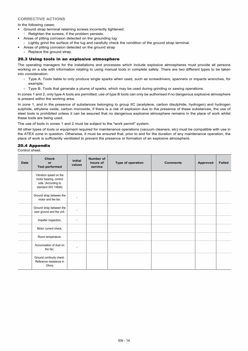
20.4 AppendixControl sheet.
DateCheck
or Test performed
Initial values
Number of hours of service
Type of operation Comments Approved Failed
Vibration speed on the motor bearing, control
side. (According to standard ISO 14694)
Ground strap between the motor and the fan. -
Ground strap between the user ground and the unit. -
Impeller inspection. -
Motor current check.
Room temperature.
Accumulation of dust on the fan. -
Ground continuity check.Reference resistance in
Ohms
EN - 15
EN
Shutting down � Separate the units from their energy sources, allow them to cool then drain them completely.
Recommendations for disassembly � Handling operations must be carried out by qualified personnel using PPE. The PPE must comply with the safety
rules. � Use the original lifting equipment.
- If the signs relating to lifting have been removed (anchoring points, slinging instructions, weight) you must find out this information.
� Sort the components according to their material for recycling or disposal, in accordance with regulations in force. � Check whether any part of the unit can be recycled for another purpose.
Materials to be recovered for recycling - Galvanised carbon steel - Stainless steel - Copper - Aluminium - Plastics - Polyurethane foam (insulation) - Electrical equipment. - The electronic board can be recycled by a recovery company (gold, silver).
Materials to be recovered for recycling - Drycoolers: MEG, MPG. Thermal fluid
- Refrigerant fluid: R404, R407A, R407C, R410A, R134a, R22 depending on the condenser type
- Compressor oil
Waste electrical and electronic equipment (WEEE) � At the end of its life, this equipment must be disassembled and contaminated fluids removed by professionals and
processed via approved channels for electrical and electronic equipment (WEEE). - In France, a partnership has been established with companies for the collection and recovery of professional
waste governed by European Directive WEEE 2012/19/EU. This partnership simplifies the mandatory administrative procedures and ensures that old equipment is recovered via an official, structured channel. In terms of renovation work in France (mainland and overseas), for every new unit installed, our partner will collect and dismantle your existing equipment. Contact us for details of our partners.
- For other countries, please refer to the legislation in force and the specific solutions available to ensure your waste is processed legally.
21 - DESTRUCTION OF THE UNIT


Head officeAvenue Jean Falconnier B.P. 14
01350 Culoz - France Tel. : +33 (0)4 79 42 42 42Fax: +33 (0)4 79 42 42 [email protected] - www.ciat.com
Compagnie Industrielled’Applications Thermiques
Corporation with a capital of €26,728,480R.C.S. Bourg-en-Bresse B 545.620.114
With Ecofolio,all papers can be recycled
Non-contractual document. As part of its policy of continual product improvement, CIAT reserves the right to make any technical
modifications it feels appropriate without prior notification.
CIAT ServiceTel.: 08 11 65 98 98 - Fax: 08 26 10 13 63
(€0.15/min)
Imp.
: 74
4003
4-00
Related Documents