14 September 2016 Verifying the completeness of Building Information Models Enhancing information completeness and control over BIM development processes Author: J. J. W. (Jesse) Weerink 0780179 [email protected] University: Eindhoven University of Technology Master Construction Management & Engineering In collaboration with: Royal HaskoningDHV Industry and Buildings Graduation committee: Prof.dr.ir. B. (Bauke) de Vries University supervisor (chairman graduation committee) Dr.dipl.‐ing. J. (Jakob) Beetz University supervisor Msc. C. (Chi) Zhang University supervisor Ing. Y. (Yves) Scholtes Company supervisor

Welcome message from author
This document is posted to help you gain knowledge. Please leave a comment to let me know what you think about it! Share it to your friends and learn new things together.
Transcript

14 September 2016
Verifying the completeness of Building Information Models
Enhancing information completeness and control over BIM development processes
Author:
J. J. W. (Jesse) Weerink
0780179
University:
Eindhoven University of Technology
Master Construction Management & Engineering
In collaboration with:
Royal HaskoningDHV
Industry and Buildings
Graduation committee:
Prof.dr.ir. B. (Bauke) de Vries University supervisor (chairman graduation committee)
Dr.dipl.‐ing. J. (Jakob) Beetz University supervisor
Msc. C. (Chi) Zhang University supervisor
Ing. Y. (Yves) Scholtes Company supervisor

2 | P a g e

3 | P a g e
Preface
I am proud to present my master thesis as final project of the master track Construction
Management and Engineering at the Eindhoven University of Technology. During this project, I
have met inspiring people, and learned a lot in the field of Building Information Modelling.
The thesis is developed under company supervision of Yves Scholtes from Royal Haskoning
DHV. Yves helped me gaining insight into the practice of Building Information Modeling, gave
me feedback and supported me throughout the process. Chi Zhang was my university
supervisor, who supported me a lot with developing the application with his advice and
knowledge. Jakob Beetz guided me throughout the whole research. I would like to thank Yves,
Chi and Jakob for their help.
I hope you will enjoy reading this thesis.
Jesse Weerink

4 | P a g e

5 | P a g e
Management summary
The implementation of building information modelling affects the design phase of a
construction project. In order to control the quality of the building information model (BIM), it
is key to ensure that the BIM satisfies all predefined requirements for each phase. For instance,
all doors should have a fire rating in the approximate design phase. However, an suitable
method to verify if all objects in the BIM comply with the predefined requirements is lacking.
This thesis aims to support domain end‐users to control the BIM development process by
enabling domain end‐users to verify if the BIM satisfies all requirements.
The literature review identified that prior to the start of developing a BIM, it is key to
distinguish phases, responsibilities, and specify requirements. Standardized formats, such as a
BIM Management Plan, can be used to specify requirements, responsibilities and phases in a
consistent and high quality manner. An additional tool to specify requirements for commonly
used objects is the NATSPEC BIM Object/Element Matrix. Most importantly, the
Object/Element matrix contains an IFC Support syntax. With this syntax, requirements could be
converted to rulesets automatically. Although a method to achieve automated generation of
rulesets is lacking, the purpose of this concept has significant added value in the verification
process of a BIM. In addition to the specification of requirements, also methods to verify if the
BIM complies to all requirements is important. The first identified verification method is manual
verification. Manual verification is time consuming and an error prone method. The second
identified method is model checking software. Two types of model checking software can be
distinguished; proprietary and non‐proprietary model checking applications. Proprietary model
checkers are effective, reliable and easy‐to‐use for domain end‐users. However proprietary
model checker are often expensive, black box methods in which domain end‐user become
dependent on the software vendor. Non‐proprietary model checkers, such as the mvdXML
Checker, solves these thresholds of proprietary model checkers.
Currently the mvdXML Checker is not easy to use, therefore two adjustments are required.
Firstly, in order to operate the mvdXML checker knowledge of Java programming language and
Eclipse IDE software for java developers is required. Therefore, the mvdXML checker is difficult
to operate for domain end‐users. The application should make it easier to operate the mvdXML
Checker. Secondly, the mvdXML Checker uses mvdXML ruleset to check IFC building models.
The mvdXML rulesets are developed with the IfcDoc tool which requires the domain end‐user
to have knowledge about IFC, mvdXML and IfcDoc. The development of a syntax, similar to the
IFC Support syntax from NATSPEC, simplifies the development of mvdXML rulesets for domain
end‐users.

6 | P a g e
This study extends the mvdXML Checker with a mvdXML Generator and user interface to make
it more user friendly for domain end‐users. The mvdXML Generator enables domain end‐users
to specify requirements and generate mvdXML rulesets in the same spreadsheet template. The
mvdXML Generator is based on the NATSPEC Object/Element matrix. The user interface is
developed to operate the mvdXML Generator and mvdXML Checker. In the future, more free‐
to‐use model checkers based on open standards, such as the mvdXML Checker, should be
developed. Similar incentives offer domain end‐users the possibility freely exchange
information between applications, make adjustment to applications, and reduce the threshold
for SMEs to make use of automated model checking software. Ultimately, the extension of the
mvdXML Checker aims to enhance the quality of data in building information models.

7 | P a g e
Samenvatting (Dutch)
De implementatie van bouw informatie modellering heeft effect op de manier van
samenwerken in een bouwproject. Om de kwaliteit van het bouw informatie model (BIM) te
waarborgen, dient het BIM te voldoen aan vooraf gespecificeerde eisen voor elke fase.
Bijvoorbeeld alle deuren dienen een waarde te hebben voor de parameter brandwerendheid in
de voorlopig ontwerp fase. Echter ontbreekt een geschikte methode om te verifiëren of een
BIM voldoet aan alle eisen. Het doel van dit onderzoek is partijen in het BIM ontwikkelproces te
ondersteunen door een methode te ontwikkelen die verifieert of het BIM aan alle opgestelde
eisen voldoet.
In de literatuur studie is vastgesteld dat het essentieel is om fasen te onderscheiden,
verantwoordelijkheden vast te leggen en eisen te specificeren voordat gestart wordt met het
ontwikkelen van een BIM. BIM standaarden dienen gebruikt te worden om eisen,
verantwoordelijkheden en fasen op consistente en kwalitatief hoogwaardige wijze te
specificeren. De NATSPEC BIM Object/ Element matrix is een gestandaardiseerd template om
eisen per object te definiëren in een spreadsheet. Het belangrijkste onderdeel van de matrix is
de “IFC Support” syntax. Met behulp van deze syntax is het mogelijk om eisen automatisch om
te zetten in een regelset. Echter ontbreekt een applicatie om het daadwerkelijk automatisch
genereren van regelsets mogelijk te maken. Naast het specificeren van eisen, zijn BIM
verificatie methoden van belang. Een BIM verificatie methode controleert of het BIM voldoet
aan alle gespecificeerde eisen. De eerste verificatie methode is handmatige verificatie. Echter is
het handmatig verifiëren van bouw informatie modellen tijdrovend en foutgevoelig. De tweede
methode is BIM verificatie middels model checking software. Er wordt onderscheid gemaakt
tussen twee soorten model checking software; gepatenteerde en niet gepatenteerde model
checking software. Gepatenteerde model checkers zijn effectief, betrouwbaar en
gebruiksvriendelijk. Echter is dit type model checker vaak duur en heeft de eindgebruiker geen
toegang tot de broncode van de software, waardoor de eindgebruiker afhankelijk is van de
softwareleverancier. Bij niet gepatenteerde model checkers, zoals de mvdXML Checker, zijn
deze nadelen niet van toepassing. Echter is de mvdXML Checker is niet gemakkelijk te
gebruiken. Vaak beschikken eindgebruikers niet over de benodigde kennis van Java Eclipse IDE
software en Javascript. De mvdXML Checker dient gebruiksvriendelijker te worden. Daarnaast
gebruikt de mvdXML Checker regelsets in mvdXML formaat om IFC modellen te verifiëren. De
mvdXML regelsets worden ontwikkeld met de IfcDoc tool. Echter is kennis vereist van IFC,
mvdXML en IfcDoc om mvdXML regelsets met IfcDoc te kunnen genereren. Het ontwikkelen
van een syntax en applicatie die eisen automatisch omzetten in regelsets, vereenvoudigt de
ontwikkeling van mvdXML regelsets voor de eindgebruiker.

8 | P a g e
In dit onderzoek is de mvdXML Checker gebruiksvriendelijker gemaakt voor eindgebruikers
door een mvdXML Generator en een user interface te ontwikkelen. De mvdXML Generator stelt
eindgebruikers in staat om eisen te specificeren en mvdXML regelsets te genereren uit één
spreadsheet. De mvdXML Generator is gebaseerd op de NATSPEC Object/Element matrix. De
user interface is ontwikkeld om de mvdXML Generator en mvdXML Checker te bedienen. In de
toekomst dienen meer niet gepatenteerde model checkers gebaseerd op open standaarden te
worden ontwikkeld. Soortgelijke applicaties stellen eindgebruikers in staat om informatie uit te
wisselen tussen applicaties, applicaties naar eigen behoefte aan te passen, en alle organisaties
in staat te stellen om gebruik te maken van geautomatiseerde model checking software.
Uiteindelijk dienen niet gepatenteerde model checkers de data kwaliteit van bouw informatie
modellen te verbeteren.

9 | P a g e
Table of contents
Preface ............................................................................................................................................ 3
Management summary ................................................................................................................... 5
Samenvatting (Dutch) ..................................................................................................................... 7
Table of contents ............................................................................................................................ 9
Table of figures ............................................................................................................................. 11
1. Introduction ........................................................................................................................... 13
1.1 Problem definition ......................................................................................................... 13
1.2 Research questions ........................................................................................................ 16
1.3 Research design .............................................................................................................. 17
1.4 Expected results ............................................................................................................. 18
2. Literature review ................................................................................................................... 19
2.1 Introduction to BIM ........................................................................................................ 19
2.2 Applications of BIM ........................................................................................................ 19
2.3 Advantages of BIM ......................................................................................................... 20
2.4 Workflow ........................................................................................................................ 21
2.5 Interoperability............................................................................................................... 29
2.6 BuildingSMART Basic Methodology Standards .............................................................. 31
2.7 Information completeness of a Building Information Model ........................................ 38
2.8 Model Checking .............................................................................................................. 39
2.8.1 MvdXML Checker .................................................................................................... 40
2.9 Conclusion literature review .......................................................................................... 44
3. Proposed Workflow ............................................................................................................... 47

10 | P a g e
4. Application development ...................................................................................................... 51
4.1 Results ............................................................................................................................ 51
4.1.1 MvdXML Generator ................................................................................................ 51
4.1.2 MvdXML Checker .................................................................................................... 55
4.1.3 Source code application .......................................................................................... 57
4.2 Validation ....................................................................................................................... 60
4.3 Discussion application .................................................................................................... 64
5. Conclusion ............................................................................................................................. 65
5.1 Research questions ........................................................................................................ 65
5.2 Conclusion ...................................................................................................................... 69
5.3 Recommendations and future research ........................................................................ 69
6. Bibliography ........................................................................................................................... 71
7. Appendices ............................................................................................................................ 75

11 | P a g e
Table of figures
Figure 1.1 ‐ Management effort vs. form of collaboration (van Ruijven, 2014) .......................... 13
Figure 1.2 ‐ Loss of Data (Eastman, Liston & Wiley, 2008) ........................................................... 14
Figure 1.3 ‐ Research framework .................................................................................................. 17
Figure 2.1 ‐ BIM throughout lifecycle of an asset (Aero, 2015) .................................................... 20
Figure 2.2 ‐ Traditional vs BIM (BuildingSMART, 2015) ................................................................ 21
Figure 2.3 ‐ Macleamy curve traditional vs BIM workflow (MacLeamy, 2004) ............................ 22
Figure 2.4 ‐ NATSPEC BIM Object/Element Matrix ....................................................................... 23
Figure 2.5 – Level of Development example column according to AIA ........................................ 24
Figure 2.6 ‐ BIM Maturity Levels (BSI, 2013) ................................................................................ 26
Figure 2.7 – Interoperability structures of software applications (Laakso & Kiviniemi, 2012) .... 30
Figure 2.8 ‐ Data schema IFC 2x3 architecture (BuildingSMART, 2013) ....................................... 33
Figure 2.9 ‐ Example Concept Template in mvdXML .................................................................... 35
Figure 2.10 ‐ Example Concept in mvdXML .................................................................................. 36
Figure 2.11 – Graphical representation buildingSMART standards (BuildingSMART, 2010) ....... 37
Figure 2.12 ‐ The role of IDM & MVD in Integrated Process(See et al., 2012) ............................. 38
Figure 2.13 ‐ Example: Assign Concept to Concept Template(Strien, 2015) ................................ 42
Figure 2.14 ‐ Overview mvdXML Checker Eclipse ......................................................................... 43
Figure 2.15 ‐ MvdXML TemplateRule Adjustment (van Strien, 2015) .......................................... 44
Figure 3.1 ‐ NATSPEC BIM Object/Element Matrix ....................................................................... 47
Figure 4.1 ‐ Overview mvdXML Generator and Checker .............................................................. 51
Figure 4.2 ‐ Template mvdXML Generator ................................................................................... 52
Figure 4.3 ‐ Example of IFC Support String ................................................................................... 53

12 | P a g e
Figure 4.4‐ Example HTML documentation of IFC4 ...................................................................... 53
Figure 4.5‐ Shortcut IFC Support String ........................................................................................ 54
Figure 4.6 – Interface run mvdXML Generator ............................................................................. 54
Figure 4.7 ‐ Interface run mvdXML Checker ................................................................................. 55
Figure 4.8 ‐ BCF file in Solibri Model Checker ............................................................................... 56
Figure 4.9 ‐ Flowchart mvdXML Generator .................................................................................. 57
Figure 4.10 ‐ Processing IFC Support String .................................................................................. 58
Figure 4.11 ‐ IFC model Schependomlaan .................................................................................... 60
Figure 4.12 ‐ Extended Template mvdXML Generator ................................................................. 61
Figure 4.13 ‐ Interface mvdXML Checker and Generator ............................................................. 62
Figure 4.14 – Example issue BCF Report ....................................................................................... 63

13 | P a g e
1. Introduction
1.1 Problem definition
Construction projects take too long, are expensive, and do not function as they should. In order
to exclude these risks, clients often prefer more extensive forms of contracting that move
liabilities into the contracting organizations. These extensive collaboration forms, such as Public
Private Partnerships, result in more requirements, disciplines and involved actors. Therefore
the complexity and management effort of construction projects increases significantly in more
extensive forms of collaboration. This relationship between required management effort of a
construction project and the collaboration form is schematically described in Figure 1.1.
Figure 1.1 ‐ Management effort vs. form of collaboration (van Ruijven, 2014)
The increased complexity of construction projects results in an urge to exchange information
more efficiently. The information exchange in a traditional collaboration form is characterized
by many bilateral relationships between stakeholders. Often 2D drawings are handed over
directly to a stakeholder, adjustments to the drawings are made, and the adjusted drawings are
exchanged with another involved party. Mistakes are easily made in this repeatable handover
process, for instance: not all parties have the most recent version of a drawing. Inadequate
exchange of information causes over 25% of the failure costs in construction projects (Busker,

14 | P a g e
2011). Figure 1.2 schematically describes the information losses occur in the handover process
between phases. The line with vertical gaps illustrates the information losses that occur in the
traditional collaboration form.
Figure 1.2 ‐ Loss of Data (Eastman, Liston & Wiley, 2008)
The demand for a different way of working has been growing in the AEC industry (Smith, 2012).
Instead of the traditional collaboration form, the application of Building Information Modelling
(BIM) is identified as a collaboration form in the Architecture, Engineering and Construction
(AEC) industry. Implementation of BIM has the potential to increase the efficiency of the design
and construction process, reduce design errors and to increase the quality of the project. The
BIM workflow is schematically described by the smooth flowing line above the traditional line,
in Figure 1.2. The BIM workflow reduces information losses between phases significantly. In
addition, BIM has many other advantages over the traditional collaboration process. However,
implementation of a BIM workflow requires a different performance of stakeholders, and a
different collaboration between stakeholders.
The implementation of BIM affects the way the design phase of a construction project is
managed, in terms of cost, time planning and team members. Traditionally a project manager
controls the time planning of a design project based on the amount of delivered drawings and
personal experience. In contrast to the traditional workflow, a BIM workflow transforms the
program of requirements into a conceptual design, and ultimately to a detailed design. A
conceptual Building Information Model (BIM) mostly visualizes the design. If the conceptual

15 | P a g e
design is approved by the client and other stakeholders, more detailed objects and information
is added to the BIM. Before the conceptual, approximate and detailed BIM is developed, all
requirements for each design phase should be specified. The objects in the building information
model should satisfy the specified requirements for a certain phase. For instance, all doors
should have specified a fire rating in the approximate design. However, currently an
(automated) application that verifies if all objects in the building information model comply
with the predefined requirements is lacking. The development process of the design cannot be
controlled using the traditional methods. Therefore, this thesis focusses on developing a
method which enhances control over BIM development processes in the design phase. The
method aims to support stakeholders to control the development process of a building
information model.

16 | P a g e
1.2 Research questions
The problem definition reveals a lack of methods to verify the completeness of a building
information model, during the design process. Therefore, the aim of this research is to examine
how the completeness of a BIM in the development process can be controlled. This results in
the following main research question:
How can the completeness of a Building Information Model be controlled during its development process?
Several sub research questions are developed to support the main research question. The sub
questions are categorized in three categories; BIM development process, information
completeness, and application development. The sub questions in the category BIM
Development process are answered through a literature review, each questions is briefly
discussed below:
1. Which key concepts of the BIM can be identified?
Answering this sub question gives insight and knowledge in the fundamentals of BIM. It
examines the workflow of a BIM, the stakeholders that are involved, and their relationship.
2. How can information from the BIM be captured?
The objects in a BIM have to satisfy predefined requirements. The answer to this questions
gives insight in the capturing of BIM data in order to verify requirements.
3. Which phases can be distinguished in a BIM design process?
Several concepts have been developed to express different phases in BIM design process. This
sub questions clarifies the phases of a BIM development process and examines these concepts.
The sub questions described in the category information completeness aim to clarify factors
that influence the completeness of object in a BIM. As the previous category, these sub
questions are answered through a literature review.
4. How should the information completeness of a building information model be verified?
5. What methods exist to verify the information completeness of a building information
model?
6. How and when should the required object information be specified in a BIM project?

17 | P a g e
The category application development answers the sub questions below, through developing
an application. This category identifies suitable verification solutions, and clarify how to
visualize the output of the application.
7. How can the information completeness of a BIM be automatically verified?
8. In which way can the results of the information completeness verification be visualized?
The next subchapter describes the methods that are used to answer the research questions.
1.3 Research design
A research design is developed to answer the described research questions. The research
consists of three different elements; a literature review, application development and use case.
The relationship between these elements is schematically described in Figure 1.3.
Figure 1.3 ‐ Research framework
First an extensive literature review is conducted which is described in chapter 3. The literature
review includes the state‐of‐the‐ art applications, workflow, benefits and thresholds of BIM. It
also describes standards and organizations that aim to overcome these thresholds.
Subsequently, model checking is described and examined as a concept to check the quality of a
building information model. Also the fundamental concepts and functions of the applications
are discussed. If it is possible to answer all described sub questions, an application is developed
that is able to support the automatic verification of the quality of a building information model

18 | P a g e
in the design process. At the same time, a suitable pilot project should be found. The pilot
project is used to test the developed application, and to validate the results. The final steps of
the research design include discussing the results, answer the main research question, and
formulate a research conclusion.
1.4 Expected results
This research aims to develop a method to enable automated verification of the completeness
of building information models, during its development process. It is expected that the
literature review identifies key performance indicators that represent the quality of a building
information model. Subsequently an application is developed to enable the automated
verification process. It is expected that the development of an application is the most
challenging part of this research. Therefore, the application is ought to be a proof of concept. In
addition, it is important to make the application user friendly. Therefore, next to the source
code of the application, also a user manual is provided. The use case describes a pilot project to
test the method and application, and validate the results.

19 | P a g e
2. Literature review
The literature review aims to give understanding in the current situation of the research topic
controlling BIM development processes and elaborate state‐of‐the‐art methods. The literature
review elaborates on state‐of‐the‐art applications, workflow, benefits and thresholds of BIM. It
also describes standards and organizations that aim to overcome these thresholds.
Subsequently, model checking applications are described and examined as a concept to check
the quality of a building information model.
2.1 Introduction to BIM
Over the past ten years, BIM is acknowledged as one of the most promising developments in
the AEC industry. Major investments by research institutions, software developers and
companies have led to the rapid development and implementation of BIM technology. BIM is
defined by the US National Building Information Model Standard Project Committee as
(Melorose, Perroy, & Careas, 2015):
‘Building Information Modelling (BIM) is a digital representation of physical and functional
characteristics of a facility. A BIM is a shared knowledge resource for information about a
facility during its life‐cycle; defined as existing from earliest conception to demolition.’
2.2 Applications of BIM
As schematically described in Figure 2.1, BIM delivers added value for varying stakeholders
throughout the complete lifecycle of an asset. Often the BIM lifecycle is initialized by a
customer with a problem or need. The need of the customer is translated into a program of
requirements. The program of requirements serves as a basis for the development a 3D model
for the conceptual and detailed design. The developed 3D model is analyzed in order to verify
its compliance to the program requirements. The detailed design contains architectural, MEP,
structural and many other objects that are fundamental elements of BIM. Each object is defined
and could be enriched with information. For instance, a door is an object in a 3D model that
could contain information about its geometry, material type, fire resistance, location, and so
on. Ultimately, the 3D model becomes a virtual representation of the actual building.
The final building information model is used by stakeholders to extract information for
fabrication. For instance, a manufacturer of windows extracts information of all windows from
the BIM. In addition, stakeholders can add more detailed information to the BIM. During the
construction phase BIM is used for coordination purposes, scheduling, and construction
logistics in order to construct the building. After completion, the building is used in the
operation and maintenance phase. In order to make sure the building functions are fulfilled
according to the design, maintenance on HVAC systems, elevators, and other building elements

20 | P a g e
has to be performed on regular basis. The information stored in the BIM can be accessed and
adjusted to coordinate operation and maintenance activities. Ultimately, the BIM can be used
as reliable basis during extensions and renovations to the building.
Figure 2.1 ‐ BIM throughout lifecycle of an asset (Aero, 2015)
2.3 Advantages of BIM
Applying BIM technology in the design phase has multiple advantages. Firstly, accurate and
comprehensive 3D models visualizations of the design can be made (Eastman & Liston, 2008).
These visualizations can be used for communication purposes within the design team and to
the client. Secondly, the BIM can be used to extract data for cost estimations, and verifying the
design to the program of requirements. Thirdly, a BIM workflow stimulates collaboration
between disciplines and decision making in the early design phases. The more intensive
collaboration process shortens the design time and reduces design errors significantly. For
instance clash detections with model checkers can be used to reduce design errors between
disciplines.

21 | P a g e
2.4 Workflow
The use of BIM in a project team affects more than just one process or a single party, moreover
it affects several parties and their processes, therefore, BIM can be seen as a process instead of
a single software tool (Eadie, Browne, Odeyinka, McKeown, & McNiff, 2013). Thus BIM requires
a different way of collaboration between stakeholders. The BIM collaboration form is
schematically compared to the traditional collaboration form in Figure 2.2. In the traditional
collaboration form, information is exchanged between two team members. Whereas in the BIM
collaboration form, information is stored, accessed and adjusted in a common data
environment.
Figure 2.2 ‐ Traditional vs BIM (BuildingSMART, 2015)
The transformation from traditional towards BIM collaboration affects the workflow of a
project. Figure 2.3 describes a traditional (drafting‐centric) and BIM workflow, related to cost,
effort and effect. Basically, line number 1 represents the ability to impact costs and
performance, which is high in the early stages of the project and decreases as the project
evolves. Line number 2 describes the cost of design changes; it is relatively cheap to implement
changes in the early design phases. As the project proceeds, more of the design is documented,
and making changes becomes more difficult. Line number 3, the traditional workflow, describes
a workflow in which most efforts are made when it is relatively costly to make design changes.
Line number 4, the BIM workflow, aims to reduce costs of design changes by shifting design
efforts to the earlier phases in the project. The added value of BIM is clearly represented in the
workflow, by making design changes in the early phases of a project, with less documentation.

22 | P a g e
The importance of the design phase in a BIM workflow is clearly described by its ‘peak’ in Figure
2.3.
Figure 2.3 ‐ Macleamy curve traditional vs BIM workflow (MacLeamy, 2004)
BIM Implementation and standardization
The benefits of BIM are recognized various governments. For instance by the Australian
National Building Specification System (NATSPEC). This is a not‐for‐profit organization whose
objective is to improve the construction quality of the built environment through leadership of
information(NATSPEC, 2016). NATSPEC has developed a coordinated set of documents to
enhance methods of design, construction and communication through digital information
(including BIM) for the AEC industry.
The NATSPEC National BIM Guide is to assist clients, consultants and stakeholders to clarify
their BIM requirements in a nationally consistent manner(NATSPEC, 2011a). This guide serves
as a reference document that defines roles and responsibilities, collaboration procedures,
approved software, modelling requirements, digital deliverables and documentation standards.
A key element of this guide is its requirement for a BIM Management Plan (BMP, also referred
to as BIM Execution Plan). The BMP describes into detail how a project should be executed,
monitored, and controlled in order to satisfy requirements of the Project BIM Brief. The Project
BIM Brief defines specific project requirements. In this document the members of the project
team are identified, BIM uses for the project are specified, and applicable standards are stated
from the NATSPEC BIM Reference Schedule. The NATSPEC BIM Reference Schedule is a list of

23 | P a g e
documents and standards provided for considerations as references that can be cited in the
National BIM Guide(NATSPEC, 2011a). The last document is the NATSPEC BIM Object/Element
Matrix which defines commonly used objects and elements with properties. It uses Uniformat
or OmniClass classification and implements the Level of Development concept. The matrix can
be used as a decision support tool in regard to what information should be included in the
model at different stages and by whom. In addition, the BIM Object/Element Matrix can be
used as a reference to assure consistent naming. An example of a Door object of the BIM
Object/Element matrix is described in Figure 2.4.
Figure 2.4 ‐ NATSPEC BIM Object/Element Matrix
The worksheet specifies several information items for the door on each level of development.
Each information item is categorized. For instance, Overall Height is part of the Information
Category “Physical Properties of BIM Objects & Elements”. The user of the matrix can select
which information is required by the client in the “Selection Agent” column. The strings
described in the column “IFC Support” could be converted to rulesets. Although a method to
achieve automated generation of rulesets is lacking. The purpose of this concept is clear;
automatically converting requirements into rulesets by developing a computer interpretable
syntax. The development of a syntax for converting requirements to rulesets enables domain
end‐users to verify if a BIM satisfies all requirements.
NATSPEC implements the Level of Development concept developed by the American Institute
of Architects (AIA). The AIA defined Document E202‐2008 Building Information Modeling

24 | P a g e
protocol Exhibit defines Level of Development as follows: “The level(s) of Development
describes the level of completeness to which a Model Element is developed”. Thus Level of
Developments describes the process from a low conceptual level to a highly detailed level BIM
object. The information in a model with high Level of Development is ought to be more reliable
and detailed, and therefore less subject to change. The AIA developed the following five levels:
LOD 100 Conceptual: Overall building massing indicative area, height, volume, location
and orientation may be modelled in three dimensions or represented by other data.
LOD 200 Approximate geometry: Model Elements are modelled as generalized systems
or assemblies with approximate quantities, size, shape, location and orientation. Non‐
geometric information may also be attached to Model Elements.
LOD 300 Precise geometry: Model Elements are modelled specific assemblies accurate
in terms of quantity, size, shape, location and orientation. Non‐geometric information
may also be attached to Model Elements.
LOD 400 Fabrication: Model Elements are modelled as specific assemblies accurate in
terms of quantity, size, shape, location and orientation with complete fabrication,
assembly and detailing information. Non‐geometric information may also be attached to
Model Elements.
LOD 500 As‐built: Model Elements are modelled as constructed assemblies actual and
accurate in terms of quantity, size, shape, location and orientation. Non‐geometric
information may also be attached to Model Elements.
The concept of Level of Development gives an impression of the BIM development in the
process. A visualization of this concept on a column is described in Figure 2.5.
Figure 2.5 – Level of Development example column according to AIA

25 | P a g e
The problem is that the industry has run of with the concept of Level of Development, without
defining it properly. Every person has an individual opinion on what a Level of Development
model is or should be( Berlo, Bomhof, & Korpershoek, 2014). Therefore, the Level of
Development concept developed by AIA is considered a rough method to assess the
completeness of a model.
The UK Government has done great effort to specify the Level of Development concept further
in their Construction Strategy. This strategy defines objectives that ought to overcome
problems with the procurement of public assets. The BIM Maturity Model, described in Figure
2.6 is used as a schematic representation to measure the maturity of BIM adoption by an
organization or industry. A brief description of each level is described below.
Level 0. Unmanaged CAD probably 2D, with paper (or electronic paper) as the most likely data
exchange mechanism (BSI, 2013).
Level 1. Managed CAD in 2 or 3D format using BS 1192:2007 with a collaboration tool providing
a common data environment, possibly some standard data structures and formats. Commercial
data managed by standalone finance and cost management packages with no integration (BSI,
2013).
Level 2. Managed 3D environment held in separate discipline “BIM” tools with attached data.
Commercial data managed by an ERP. Integration on the basis of proprietary interfaces or
bespoke middleware could be regarded as “pBIM” (proprietary). The approach may utilize 4D
program data and 5D cost elements (BSI, 2013).
Level 3. Fully open process and data integration enabled by IFC / IFD. Managed by a
collaborative model server. Could be regarded as iBIM or integrated BIM potentially (BSI, 2013).

26 | P a g e
Figure 2.6 ‐ BIM Maturity Levels (BSI, 2013)
At the time of developing the Construction Strategy, most organizations in the AEC industry had
already adopted BIM UK Level 1. The UK Government stimulates the AEC industry to evolve by
mandating to use BIM UK Level 2 for public projects from 2016 (Eadie, Browne, Odeyinka,
McKeown, & McNiff, 2015). And in 2020, the UK Government mandates the AEC industry to use
BIM UK Level 3 for all public projects.
To support organizations to comply with the BIM maturity levels, a comprehensive set of
standards is developed for the implementation of the Construction Strategy. These standards
are described in the lower part of Figure 2.6. A corner stone in for the implementation of the
Construction Strategy is the BIM project execution plan published under PAS 1992‐2
(Specification for information management for the capital/delivery phase of construction
projects using BIM). This plan defines appropriate uses for BIM on a project (e.g. design
authoring, design review, and 3D coordination), along with a detailed design and
documentation of the process for executing BIM throughout a facility’s lifecycle(Computer
Integrated Construction Research Program, 2011). The PAS 1192‐3 extends PAS 1992‐2 by

27 | P a g e
focusing on the creation and storing of Asset Information Models and Project Information
Models to support for asset management purposes. The British Standard (BS) 1992‐4:2014 is a
code of practice for fulling the information exchange requirements by using Construction
Operations Building Information Exchange (COBIE). The BIM protocol is one of the major
documents for the implementation of BIM UK Level 2. The primary objective of the BIM
Protocol is to enable the production of Building Information Models at defined stages of a
project (Construction Industry Council, 2013). This is achieved by identifying the Building
Information Models that are required to be produced by members of the project team. The BIM
protocol represents agreements between the client and development team, describes
milestones, and specifies deliverables per stakeholder. It is key to enforce the BIM protocol. If
not, developing a project according to BIM principles have many pitfalls.
In this set of standards, the completeness of Model Elements is not described by the Level of
Development Concept of the AIA. Instead, a more sophisticated concept is developed; the Level
of Definition concept. The Level of Definition consists of a Level of Detail and a Level of
Definition. The Level of Detail represents the graphical representation of an object. The Level of
Information represents the non‐graphical information related to an object. This (non‐) graphical
separation prevents that a visually accurate object without any non‐geometric information
acquires a high Level of Definition.
In addition, two phases are added to the phases defined by AIA. The first phase that is added by
BSI is the Brief phase. The Brief phase defines performance requirements and site constraints,
and is added before the Conceptual phase. The second phase that is added is the Asset
Information Model phase. The Asset Information Model is developed for facility management
purposes. An overview of the differences between the standard developed by BSI and AIA can
be found in Table 2.1.

28 | P a g e
Table 2.1 – Comparison LOD BSI vs LOD AIA
BSI AIA Description
LOD 1 Brief: a model communicating the performance requirements and site
constraints.
LOD 2 LOD 100 Conceptual: Overall building massing indicative area, height, volume,
location and orientation may be modelled in three dimensions or
represented by other data.
LOD 3 LOD 200 Approximate geometry: Model Elements are modelled as generalized
systems or assemblies with approximate quantities, size, shape, location
and orientation. Non‐geometric information may also be attached to
Model Elements.
LOD 4 LOD 300 Precise geometry: Model Elements are modelled specific assemblies
accurate in terms of quantity, size, shape, location and orientation. Non‐
geometric information may also be attached to Model Elements.
LOD 5 LOD 400 Fabrication: Model Elements are modelled as specific assemblies
accurate in terms of quantity, size, shape, location and orientation with
complete fabrication, assembly and detailing information. Non‐
geometric information may also be attached to Model Elements.
LOD 6 LOD 500 As‐built: Model Elements are modelled as constructed assemblies actual
and accurate in terms of quantity, size, shape, location and orientation.
Non‐geometric information may also be attached to Model Elements.
LOD 7 Asset Information Model used for ongoing operations, maintenance and
performance monitoring.

29 | P a g e
2.5 Interoperability
BIM technology can be seen as collaboration between the construction sector and the software
industry. The advanced features of BIM software have contributed that IT can be used to
develop integrated semantic product and process models. Several organizations, representing
different disciplines, collaborate intensively in a project. Each discipline is supported by its own
software applications, such as applications for energy analyses, architecture, construction,
fabrication, and cost estimation. Widely accepted and mature technical platforms, preferably
based on open standards, are required to enable communication and collaboration among
project participants without requiring them to have specific proprietary applications (Laakso &
Kiviniemi, 2012). Interoperability identifies the need to pass data between applications, and for
multiple applications jointly contribute to the work at hand (Eastman & Liston, 2008).
Interoperability supports the exchange of information between software applications. In BIM,
different ways of exchanging data between software applications exist. The most commonly
applied ways are described below:
‐ Direct proprietary links provide and integrated connection between two BIM tools. The
direct links relies on middleware software interfacing capabilities such as OBDC or COM
or proprietary interfaces, such as ArchiCad’s GDL or Bentley’s MDL(Eastman & Liston,
2008).
‐ Proprietary file exchange formats are developed by commercial organizations for
interfacing with that company’s application. An often used proprietary exchange format
is the Data eXchange Format (DXF), developed by Autodesk.
‐ Public product data model exchange formats involves using open BIM standards. A well‐
known non‐proprietary format is the Industry Foundation Classes (IFC).
‐ eXtensible Markup Language (XML) based exchange formats allows definition of the
structure (i.e. schema) and meaning of data. Different XML schemas support exchange
of many types of data between applications (Eastman & Liston, 2008).
The exchange of BIM data is dominated by proprietary solutions, meaning most integrated
construction projects are based on a solution in which all collaborators have software from the
same or compatible vendors (Laakso & Kiviniemi, 2012). Direct proprietary links provide the
most solid information exchange, however, users are highly dependent on the software
companies. In addition, software applications must develop a mapping for each software
applications it aims to communicate with. This would result in a very complex system of
software applications.

30 | P a g e
With the development and implementation of an open standard, each software application has
to develop a bi‐directional mapping to the open interoperability standard. An open standard
makes the software application compatible to all related software applications. This is
schematically described in Figure 2.7. Therefore, scientific institutions and the public sector
wish to avoid proprietary solutions by developing a non‐proprietary, open data format.
Figure 2.7 – Interoperability structures of software applications (Laakso & Kiviniemi, 2012)
The mapping that has to be made between the Open Interoperability Standard and the
software applications depend on the entities available in both applications. The mapping of
entities with identical semantics is relatively simple. However, mapping of entities between
applications can be very complex when there is no corresponding entity. In this case, it is very
hard to map all information between entities. This causes information losses in the information
exchange between applications.

31 | P a g e
2.6 BuildingSMART Basic Methodology Standards
BuildingSMART is an organization that aims to create a digital language that allows advanced IT
to openly exchange structured information throughout the lifecycle of a project. Therefore,
buildingSMART developed a comprehensive set of open standards. These standards have been
developed to reduce ambiguity and strengthen internal communication. A standard can be
defined as (De Vries, 2005): “A standard is an approved specification of a limited set of
solutions to actual or potential matching problems, prepared for the benefits of the party or
parties involved, balancing their needs, and intended and expected to be used repeatedly or
continuously, during a certain period, by a substantial number of the parties for whom they are
meant.”
Table 2.2 describes an overview of the major standards developed by buildingSMART. Some of
these standards have already been implemented by the International Organization for
Standardization (ISO). The details of these standards and the relationship between standards is
elaborated below.
Table 2.2 ‐ Overview buildingSMART standards (BuildingSMART, 2010)
What it does Name Standard
Transports data IFC ISO 16739
Mapping of terms IFD ISO 12006‐3 buildingSMART Data Dictionary
Describes processes IDM ISO 29481‐1 ISO 29481‐2
Translates processes in technical requirements MVD buildingSMART MVD
Change Coordination BCF buildingSMART BCF
Data Standard ‐ Industry Foundation Classes (IFC)
As a general data model, the Industry Foundation Classes (IFC) standard supports a full range of
data exchanges among heterogeneous applications (Zhang, Beetz, & Weise, 2014). Thus IFC
enables project team members to share information across software applications by describing
a set of agreements how building elements can be stored digitally. With the development of IFC
as an open standard, interoperability is improved. IFC‐based construction could lead to a
significant increase in productivity due to open interoperability for BIM. This enables the
seamless flow of design, cost, project, production and maintenance information, thereby
reducing redundancy and increasing efficiency throughout the lifecycle of the building (Laakso
& Kiviniemi, 2012).
IFC represents an object‐based data structure. Specifications of IFC are determined in an
EXPRESS schema or XML schema. The schema describes a collection of entities, attributes and

32 | P a g e
relationships between entities(Schaijk, 2016). The data schema architecture of IFC consist of
four layers, as described in Figure 2.8 (BuildingSMART, 2013). The resource definition data
schema layer contains supporting data structures. Entities and types defined in this layer can be
referenced by all entities in the layers above. These definitions do contain a Globally Unique ID
(GUID), and therefore, are not be used independently at a higher level. The core data schema
layer contains general entity definitions. Entities defined in this layer include a GUID, and can
be referenced and specialized by all above layers. The interoperability data schema layer
contains intermediate specializations of entities. The schemas of entity definitions those are
specific for a general product, process, or resource. Entities defined in this layer can be
referenced and specialized by the layer above (i.e. domain layer). Typically the definitions are
utilized for exchange between disciplines. The domain specific data schema layer contains the
final specializations of entity definitions, such as products, processes or resources. These
definitions are utilized for exchange within a discipline.
An IFC model is a population of the schema, following the patterns, templates and constraints
stipulated by the schema (Liebich, 2009).The IFC model represents both tangible building
elements (e.g. walls, doors, beams) and more abstract concepts (e.g. schedules, activities,
spaces, organization, and construction costs) in the form of entities (Motamedi, Setayeshgar,
Soltani, & Hammad, 2016). Each entity can contain different types of properties, for instance
location, geometry and materials.

33 | P a g e
Figure 2.8 ‐ Data schema IFC 2x3 architecture (BuildingSMART, 2013)
Terms Standard – International Framework for Dictionaries (IFD)
The International Framework for Dictionaries (IFD) is a mapping mechanism of terms. IFD
describes what is exchanged by allowing the creation of dictionaries to connect information
from databases to IFD models(BuildingSMART, 2010). Global Unique IDs (GUIDs) are used to tag
IFD information in IFC models. Ultimately, when all tags should be stored a unified library.
The buildingSmart Data Dictionary (bSDD) is a library of objects and their attributes used to
identify objects in the built environment and their specific properties. Thus bSDD is an IFD
mapping tool that links parameters in IFC to parameters in databases in order to ensure that
stakeholders shares the same language. For instance, ensure that a “door” means the same
thing in India and England. Ultimately, the building process becomes more efficient when bSDD
is applied by all stakeholders.

34 | P a g e
Process Standard – Information Delivery Manual (IDM)
An Information Delivery Manual (IDM) aims to provide an integrated reference for process and
data required by BIM by identifying the discrete processes undertaken within building
construction, the information required for the execution the results for that activity
(BuildingSMART, 2010). Thus, in an IDM specifies where a process fits, its relevance, which
actors are involved, the information required and how software solutions are involved. IDMs
includes multiple primary deliverables: (1) Process Maps which define the industry process, (2)
Exchange Requirements which define the information to be exchanged, (3) Exchange
Requirement Models which organizes information and enable verification of all requirements,
(4) a generic BIM Guide which deliver guidance to the end user about what objects and data
must be included in BIM(See, Karlshoej, & Davis, 2012). IDMs can be applied when information
has to be exchanged between at least two types of software applications in an industry process.
BuildingSMART aims to enable the development of IDMs by the development of a
methodology. The ISO 29481 – 1: 2010 “Building information modelling – Information delivery
manual – Part 1: Methodology and format” standard has been developed by buildingSMART in
order to have a methodology to capture and specify processes and information flows during the
lifecycle of a facility (Karlshoj, 2011).
Process Standard ‐ Model View Definition (MVD)
MVD defines a subset of the IFC schema that is needed to satisfy one or many Exchange
Requirements of the AEC industry (BuildingSmart, n.d.). In which the Exchange Requirements
are defined as “the common data needed between two processes, described in non‐technical
terms”. A MVD can be applied to validate if the provided data conforms to the Exchange
Requirements, which are described in the IDM. For instance a supplier of doors is not interested
in a detailed foundation plan. The MVDs can be applied in order to automatically validate if the
provided data conforms to the exchange requirements. These requirements are described in an
Information Delivery Manual (IDM).
The mvdXML format is an open standard used to define model subsets and validation rulesets.
The purposes of mvdXML are (1) to limit IFC scopes to subsets, (2) to generate MVD
documentations and (3) to define validation rules (Zhang, Beetz, & Weise, 2015). MvdXML can
be used by software applications statically or dynamically. In case mvdML is implemented
statically, it is designed to support a particular modal view. Dynamic implementation this
format supports any model view, such as: automated data export, validating of data, or filtering
data.

35 | P a g e
A mvdXML file consists of Concept Templates and Concepts. A Concept Template is a graph that
starts with a root entity and consists of attribute and other entity definitions, all are required to
represent a functional unit required to exchange specific data(Chipman et al., 2016). An
example of the Concept Template is described in Figure 2.99.
Figure 2.9 ‐ Example Concept Template in mvdXML
The Concept Template defines the structure that related Concepts should comply to. The
Concept Template in this example defines rules for the entity IfcObject, and applies to data
schema IFC2X3. The elements between the element “<Rules>” define the path to the
applicableEntity (i.e. IfcPropertySingleValueName). This path consists of two types of rules.
Another essential element of the ConceptTemplate is the universally unique identifier (uuid)
which is generates to relate Concepts to the Concept Template.
A Concept applies the structure of the Concept Template for a specific entity. The Concept
should have the same structure as the Concept Template it refers to. A Concept can represent a
single entity (e.g. IfcDoor). However, the entity can be checked for multiple rules within the
Concept (e.g. Each IfcDoor should have the parameters SelfClosing and FireRating). An example
of a Concept is described in Figure 2.100. The ConceptRoot specifies the entity that should be
checked, in this case the ApplicableRootEntity is IfcDoor. This entity is checked on one element;
the TemplateRule which states that an IfcDoor should have a parameter SelfClosing. The
Concept refers to the Concept Template using the “ref” parameter in the “Template” element.
This string is similar to the uuid specified in the Concept Template.

36 | P a g e
Figure 2.10 ‐ Example Concept in mvdXML
A mvdXML file can contain a broad set of entities and types of rulesets. This because a mvdXML
can contain multiple Concept Templates. And each Concept Template can have multiple
referring Concepts. This allows integrating a variety of rules and entities in one mvdXML file.
Model Checking Standard ‐ BIM Collaboration Format (BCF)
Multiple disciplines collaborate in BIM. Issues in the model can be identified through clash
detections of model checking software (e.g. Solibri Model Checker). Subsequently should be
determined who solves the issues. The BIM Collaboration Format (BCF) introduces a workflow
communication capability connected to IFC models(Stangeland, 2011). The format, based on
XML, aims to separate the communication between parties from the actual model.
Relation between standards
The Industry Foundation Classes (IFC) standard, developed by the Building SMART Alliance (BSI),
is a vendor‐neutral and open standard to capture and exchange data. IFC is closely related to
two other buildingSMART standards; International Framework for Dictionaries (IFD) and the
Information Delivery Manual (IDM). IFD describes what is exchanged by providing a mechanism
that allows the creation of dictionaries or ontologies, to connect information from existing
databases to IFC data models (Bell & Bjorkhaug, 2006). IDMs aim serve the technical
implementation needs of software developers and to provide role‐based process workflows for
end‐users (Laakso & Kiviniemi, 2012). The relation between these buildingSMART standards is
graphically described in Figure 2.11.

37 | P a g e
Figure 2.11 – Graphical representation buildingSMART standards (BuildingSMART, 2010)
This study focusses on the BIM process, therefore the integrated process is elaborated further
into detail, see Figure 2.122. The process begins when a working group of AEC industry experts
is formed to develop an IDM (Requirements Definition) for a specific process. After the four
primary IDM deliverables (i.e. Process Maps, Exchange Requirements, Exchange Requirement
Models, and Generic BIM Guide) are developed, MVDs (Solution Design) can be applied to
verify the Exchange Requirements described in the IDM. As described in the previous
paragraph, an MVD can be seen as a filter to examine only certain parts of the IFC model.
Reliable exchange of data, described in the Exchange Requirements of an IDM, is only possible
when it is supported by involved software applications. After these phases, BIM validation in
projects is possible by checking Exchange Requirements with MVDs.

38 | P a g e
Figure 2.12 ‐ The role of IDM & MVD in Integrated Process(See et al., 2012)
2.7 Information completeness of a Building Information Model
The implementation of BIM can increase the efficiency, reduce errors and increase the quality
of a construction project. Before a conceptual design is developed, the requirements and
liabilities of the building information model are specified for each phase(NATSPEC, 2011b). For
instance, an Object/Element matrix in the BIM Execution Plan specifies that all door objects in
the building information model are required to have a fire rating in the detailed design. The
requirements do not only deal with (geometric) properties, but also with more abstract and
semantically rich information that are not always present in drawings(Solihin & Eastman, 2015).
After all requirements for each phase of the Building Information Model are specified, a
conceptual 3D model is developed for visualization purposes. As the design process evolves
from conceptual to detailed design, more detailed information is added to the instances in the
model. This thesis aims to support stakeholders to control this development process, in the
design phase. The goal is achieved by ensuring that the building information model contains the
required information for each phase. This chapter identifies possible verification methods to
check the completeness of a building information model.
The first identified method to check if the building information model complies to all specified
requirements is manual verification. A BIM engineer has to manually examine if the objects in
the building information model comply to the requirements. This process of manual verification
is time consuming and error prone. In practice, often the completeness of objects in a building

39 | P a g e
information model is verified globally through sampling, if at all verified. The second identified
method to verify if a building information model is complete, in regard to specified
requirements is model checking software. Model checking is mostly applied to support the
users developing a design, and code compliance checking to validate if the design complies to
the requirements, codes, regulations and standards(Uhm et al., 2015). However, significant
financial resources are required to use these applications. With proprietary solutions, users
become dependent on the vendor for information exchange between software applications
(Zhang et al., 2014). More information on model checking can be found in subchapter 3.8.
Currently, no suitable methods exist to verify the information completeness of objects in the
building information model. However, the Object/Element Matrix, developed by NATSPEC, has
the purpose to enhance automated verification of object parameters in a BIM. Therefore, the
Object/Element matrix can be used as point of reference to specify the required information of
objects per phase. Therefore, a method has to be developed to verify the information
completeness of objects in a building information model during the design phase. The method
should verify if objects in a building information model contain all required parameters.
Parameters are assigned to individual objects, therefore, the method should verify on instance
level if objects contain all required information. Preferably, the method is user friendly and
verifies the completeness of a building information model automatically.
2.8 Model Checking
As described in the introduction, the complexity of building projects is increasing. As much as
40% of the defects can be related to blunders in the design process, according to Ingvaldsen
(Hjelseth & Nisbet, 2010). Automated rule checking has been identified as potentially providing
significant value to the AEC industry from both regulatory and industry perspectives(Solihin &
Eastman, 2015). A broad range of model checking concepts exist for building information
models, two often used concepts are described below.
Validation model checking is the most often used model checking concept. Different types of
model validation exist. Geometry based checking validates intersections between objects and
detects clashes. For instance, to check if walls intersect with a floor in the IFC building model.
Compliance checking is a different type of validation model checking. The purpose of
compliance checking is to check if solutions in the model are in accordance with codes,
regulations, standards, and so on (Hjelseth & Nisbet, 2010). For example, to check if the width
of the doors are according to the codes of accessibility.
Guiding model checking is a different type of model checking. The purpose of guiding model
checking is to expand the realistic solutions for a designer. This can support the designer in

40 | P a g e
developing an optimal performing building. This checking is based on (1) identify rules for error
prone situations, and (2) a list of possible solutions. It can be applied in all stages and by all
actors in the design process. Guiding model checking can be extended by pre‐defined solution
checking. This means that the checking software identifies a situation and suggests a pre‐
defined solution. The last type of guiding model checking is search based solution checking
using IFD. A search in the IFD library compliant product databases will list the possible
products(Hjelseth & Nisbet, 2010).
Model checking is mostly applied to support the users developing a design, and code
compliance checking to validate if the design complies to the requirements, codes, regulations
and standards. However, process oriented model checking is often neglected. This thesis uses
validation model checking to control the process of developing a building information model.
For this type of model checking, several model checking vendors such as Solibri Model Checker,
Tekla Bimsight and Navisworks, already have implemented automated building model checking
technologies. However, these vendors use proprietary, “black box” methods, which cannot be
accessed by third parties(Zhang et al., 2014). Significant financial resources are required to
make use of these software applications, which is often problematic for SMEs. In addition,
enterprises those are able to make use of these proprietary applications become dependent on
the vendor in regard to the exchange of information between applications. Therefore, Zhang et
al. developed the mvdXML checker, which is a non‐proprietary model view checker based on
open standards to validate IFC building models.
2.8.1 MvdXML Checker
The mvdXML checker consists of three parts; the first part generates rulesets in mvdXML
format, the second part executes the mvdXML ruleset on the IFC building model, and the third
part generates output of the check.
MvdXML Generation
The first part of the mvdXML Checker is to transform Exchange Requirements to rulesets, and
structure the validation rulesets(Zhang et al., 2014). This is achieved by generating rulesets in
mvdXML format. This standardized format, based on the open standards of BuildingSmart,
enables the definition and exchange of MVDs with Exchange Requirements and validation
rulesets. MvdXML Generators provides users a tool for creating and editing rules in mvdXML
format.
For example the IfcDoc tool, which preloads and access all IFC releases and specifications when
developing mvdXML concepts and constraints(Chipman, Liebich, & Weise, 2016). The IfcDoc
tool is able to validate value and type MVDs. The value checking includes (1) the accuracy of an

41 | P a g e
attribute value, which primarily addresses the semantics of a building information model
required for data exchange for a scoped domain. These exchanges allow users to declare
(mandatory and optional) values for attributes of entities (e.g. name, object type). The values of
these attributes become criteria for validation of an IFC instance and influence the accuracy of
mandatory values for data exchange. Another type of value checking that is included is (2)
checking the existence of values in attributes, entities, and relationships. An user should
evaluate whether the corresponding values are relevant. Accordingly could be decided to
include or exclude building data from a model view. The type checking includes (1) checking the
correct type of an entity and the subtype entity. Each IFC instance file must comply to
predefined types of the IFC specifications. Users can adjust these entity data types within the
range of the IFC specifications (e.g. narrowing the scope for an attribute). In particular user‐
defined entity data types of instances should be evaluated to ensure accuracy and
interoperability of data models. A different form of type checking is (2) relationships. An IFC
instance file allows various references and relationships. This check ensures that attribute refer
to the correct entity, which is defined in the model view. The (3) cardinality checking evaluates
lower bounds of values of an attribute(Lee & Eastman, 2015). The cardinality for all attributes is
defined in IFC schema.
An example model view, generated with IfcDoc, is described in Figure 2.13. A model view
ModelViewExample is created with exchange requirement ExchangeRequirementExample.
Subsequently a Concept Template should be created in “Fundamental concepts and
assumptions”. The Concept Template defines the structure that related Concepts should
comply to. For instance, to create rule in a Concept Template that is able to assign
SinglePropertyValues to all subtype of an IfcObject. The Properties tab enables users to define
the structure of the Concept Template, within the range of IFC2X3. The structure consists
always of an applicable entity and multiple attribute and entity rules. Each attribute and entity
rule can be enriched with additional parameters and cardinality. The completed Concept
Template should be added to at least one subtype of IfcObject (e.g. IfcWall or IfcDoor). A
Concept is created that can develop rules within the range of the Concept Template and
IfcDoor. In this example, a rule is created that verifies if an IfcDoor has a propertyname called
“SelfClosing”. When all rules are added to the Concept, the file can be exported from IfcDoc to
mvdXML format.

42 | P a g e
Figure 2.13 ‐ Example: Assign Concept to Concept Template(Strien, 2015)
In order to generate mvdXML rulesets with IfcDoc, profound knowledge on IFC, mvdXML and
the IfcDoc tool is required. Therefore, the IfcDoc tool is not easy to use. In order to enhance the
use of non‐proprietary model checkers it mvdXML generation should be simplified.
Execute mvdXML Checker
After the mvdXML ruleset is completed, the mvdXML checker is able to check te ruleset on the
IFC building model. The mvdXML checker converts the EXPRESS schema of the IFC file and
converts it to an Eclipse Modelling Framework (EMF). Subsequently the EMF is used to generate
corresponding Java classes for IFC entities and types(Beetz, Berlo, Laat, & Helm, 2010). The IFC
objects and attributes from the instance file can be extracted by the developed mvdXML file.
Depending on rule types in mvdXML, these values are checked to evaluate whether their
existence, quantities, contents, uniqueness and conditional dependencies fulfil requirements or
not(Chipman et al., 2016).
Operating the mvdXML Checker requires multiple software applications. First Eclipse IDE for
java developers is required to operate the mvdXML Checker. The mvdXML Checker application,
including libraries have to be imported into Eclipse . Subsequently Eclipse can be used to link
the mvdXML Checker to the mvdXML ruleset and IFC building model. In addition, in Eclipse
should be specified where the output of the mvdXML Checker should be stored. In order to
operate the mvdXML checker basic knowledge of Java programming language and Eclipse IDE
software for java developers is required. Figure 2.14 gives an overview of the complexity of the

43 | P a g e
mvdXML Checker in Eclipse IDE for Java developers.
Figure 2.14 ‐ Overview mvdXML Checker Eclipse
Secondly, the mvdXML Checker is not able to directly apply the mvdXML ruleset on the IFC
building model. Adjustments have to be made manually to the mvdXML file using a source code
editor. The source code editor is used to adjust the TemplateRule. For example the mvdXML
Concept states that each IfcDoor should contain a value for the parameter SelfClosing,
described in Figure 2.15. Before the mvdXML checker can use this mvdXML file, the
TemplateRule has to be adjusted. The PropertyName should be extended with
[Value],[Size],[Unique] or [Type]. This requires basic knowledge of mvdXML and source code
editing software.

44 | P a g e
Figure 2.15 ‐ MvdXML TemplateRule Adjustment (van Strien, 2015)
The knowledge that is required to operate the mvdXML Checker in Eclipse IDE for Java
developers and additional proceedings required to adjust the mvdXML file can be a significant
threshold to make use of the mvdXML checker. It is likely that user encounters difficulties when
trying to use the mvdXML Checker.
Output check
After the check has been executed, the mvdXML checker captures the generated issues in a
BIM Collaboration Format (BCF) report. BIM analysis software (e.g. Solibri Model Viewer or
Tekla BIMSight) can be used to find and analyze the generated issues from the mvdXML
checker, divide responsibilities, and communicate with other stakeholders. The BCF report
includes a markup file and viewpoint file (Stangeland, 2011). All issues are stored in the markup
file, which also contains the Concept, defined in the mvdXML file. The viewpoint file gives
insight in the location of the issue by basing a camera on the object’s locations(Zhang et al.,
2014). It is important to notice that the BCF schema is a ‘read only’ ’to do list’ of issues(Léon
van Berlo & Krijnen, 2014). Therefore, issues should be solved by adjusting the IFC instance file.
Most convenient way to adjust the IFC instance file is by adjusting the native file (e.g. Revit or
Tekla) and generate a new IFC file.
2.9 Conclusion literature review
BIM technology can be seen as a collaboration between the construction sector and the
software industry. Several organizations, representing different disciplines, collaborate
intensively in a project. Each discipline is supported by its own software applications, such as
applications for energy analyses, architecture, construction, fabrication, and cost estimation.
Widely accepted and mature shared data platforms, preferably based on open standards, are
required to enable communication and collaboration among project participants. Identified

45 | P a g e
advantages of BIM technology in the design phase are accurate 3D model visualization,
integrated collaboration which results in decreases the amount of errors, easy extraction of
data.
An identified threshold is that all involved stakeholders should be willing to freely exchange
data through a common data platform. If not, there is a risk of information losses in
construction projects. Secondly, software applications should be able to exchange data with
each other without any information losses. Therefore, mapping between the native software
applications or preferably an open standard is essential. The third identified threshold is that
organizations tend to make use BIM in all different ways. Standards are developed, consisting
of a coordinated set of documents, to assist stakeholders to clarify their BIM requirements in a
consistent manner.
It is key for the quality of the building information model, to ensure that it contains the
prescribed information for each phase. Often a BIM Management Plan or BIM execution plan
describes into detail how a project should be executed, monitored, and controlled in order to
satisfy requirements. In addition, a BIM Object/Element Matrix can be used to specify
properties for commonly used objects and elements. The matrix can be used as a decision
support tool in regard to what information should be included in the model at different stages
and by whom. The stages of a building information model are indicated with the Level of
Development concept. Two methods have been identified to verify if objects in the building
information model contain the prescribed information. The building information model could
be verified manually, which is time consuming and error prone. Alternatively, model checking
software could be applied. However, users of proprietary model checkers are dependent on
the vendor for information exchange between software applications and need to have
significant financial resources. The mvdXML Checker, a non‐proprietary model checker, solves
the thresholds of proprietary model checkers. However, the mvdXML Checker is not easy to
use and requires knowledge about IFC, mvdXML and IfcDoc.
It can be concluded that currently no suitable method exists to verify the information
completeness of objects in the building information model. However, an extended and more
user friendly version of the mvdXML Checker has the potential to reach this. The next chapter
describes into detail how the mvdXML Checker should be extended and made more user
friendly.

46 | P a g e

47 | P a g e
3. Proposed Workflow
Domain end‐users should be able to verify Building Information Models by developing rules
according to the specified requirements. The mvdXML Checker is identified as most suitable
model checking application. However, the mvdXML Checker requires two adjustments. Firstly,
in order to operate the mvdXML checker, knowledge of Java programming language and Eclipse
IDE software for java developers is required. Therefore, the mvdXML checker is difficult to
operate for domain end‐users. The application should make it easier to use the mvdXML
Checker. An user interface would make the mvdXML Checker a lot easier to operate.
Secondly, the mvdXML Checker uses mvdXML ruleset to check IFC building models. The IfcDoc
tool is used to support domain end‐users with the development of mvdXML rulesets by
navigating and extracting elements and relationships from IFC schema. Applying the IfcDoc tool
requires the domain end‐user to have knowledge about IFC, mvdXML and IfcDoc. This makes it
difficult to generate mvdXML ruleset for domain end‐users, the application aims to simplify the
development of such mvdXML rulesets. The NATSPEC BIM Object/Element Matrix is used as a
point of reference to specify requirements of objects. The matrix enhances consistent
specification of requirements at each Level of Development (LOD). An example of the matrix is
described in Figure 3.1.
Figure 3.1 ‐ NATSPEC BIM Object/Element Matrix

48 | P a g e
The left column specifies the applicable object, in this case a door. In addition, phases are
distinguished according to the Level of Development concept according to the American
Institute of Architects (AIA). The second column “BIM Object or Element” specifies information
items of the applicable objects and categorizes each information item. For instance the
information item Overall length is part of the information category physical properties of BIM
objects. The third column “General Information Use” specifies the responsible author of the
model element, and which information items are required. The last, and most important part of
the “General Information Use” and the NATSPEC Object/Element matrix is the IFC Support. The
strings described in the column IFC Support could be converted to rulesets. Although a method
to achieve automated generation of rulesets is lacking, the purpose of this concept has
significant added value in the verification process of a BIM. Therefore, a IFC Support syntax has
to be developed which can be processed by the mvdXML Checker and be handled by domain
end‐users. The mvdXML Checker is based on IFC 2X3, therefore, the syntax should be able to
satisfy all possible requirements for objects specified in IFC 2X3. The to be developed syntax
aims to simplify the development of mvdXML rulesets for all requirements. Table 3.1 gives an
overview of all requirements categories identified by NATSPEC.
Table 3.1 ‐ Overview categorized requirements (NATSPEC, 2011)
Requirement category Information Item
Project meta data Facility ID, Facility Name, Facility Description
Physical properties Length, Width, Height, Area, Volume, Thickness
Geospatial and spatial location Story Number, Room Name, Floor Elevation
Manufacturer specific information Type, material, Availability, Component ID
Costing Assembly Based Cost, Shipping, Tax
Sustainable material LEED, Material Type, Carbon Footprint, Recycled
Energy analysis R‐Value, U‐Value
Program compliance or validation Fire Resistance, Acoustic Rating, Required Finishes
Specifications Finish, Sill Dimensions, Frame Material, Capacity
Construction logistics Transmittal ID, Installation ID, Task Number
Asset management Warranty ID, Spare Description, Replacement Cost

49 | P a g e
In order to simplify the generation of mvdXML ruleset further, shortcuts in the syntax are
developed for often used requirements. This study focuses on the design phase, therefore
information categories such as manufacturer specific information, costing, sustainable material,
energy analysis, construction logistics, and asset management are considered to be out of the
scope of this thesis. Although it is possible to develop rulesets and shortcuts for these
requirement categories. In contrary, the requirement categories physical properties and
program compliance or validation are frequently used requirements in the design phase.
Therefore, shortcuts are developed for these categories as a proof of concept in this study.
Thus the mvdXML Checker is extended with a spreadsheet template, based on the NATSPEC
Object/Element matrix. The spreadsheet enables domain end‐users to specify requirements. In
addition an IFC Support syntax is developed to convert the requirements into mvdXML rulesets.
The generation of mvdXML files from the spreadsheet and mvdXML Checker can be operated
from a user‐interface. The next chapter describes the developed application into detail.

50 | P a g e

51 | P a g e
4. Application development
The developed application is called the mvdXML Generator and Checker, which is a non‐
proprietary model view checker based on open standards to validate IFC building models. This
application has two functions. The first function is the mvdXML Generator, which includes the
blue section of Figure 4.1. The mvdXML Generator enables generation of mvdXML rules from an
Excel template. The second function is the mvdXML Checker, developed by C. Zhang, which
includes the red section of Figure 4.1. The mvdXML Checker enables IFC model checking with
mvdXML rulesets. The output of the mvdXML Checker is a BCF file which can be read by model
checkers.
Figure 4.1 ‐ Overview mvdXML Generator and Checker
4.1 Results
This section elaborates how the mvdXML Generator and Checker functions. A more detailed
description can be found in the user manual, described in Appendix A. In addition, the structure
of the source code is described.
4.1.1 MvdXML Generator
The mvdXML Generator is a tool for the generation of mvdXML rulesets. MvdXML rules are
based on the open mvdXML standard. The open mvdXML standard ensures easy access and
extensions of the rulesets by the end‐users. The mvdXML generator is able to generate rules for
all rule types defined in mvdXML schema. The mvdXML schema classifies value checking and
type checking. Value checking includes the accuracy of an attribute value and the existence of
values in attributes. Type checking can validate if the entity type and subtypes are according to

52 | P a g e
IFC schema specifications, checking the relationships between IFC instances, and the
cardinality. A more detailed description about the specification of the mvdXML format can be
found on the website of buildingSMART.
The input of the mvdXML generator is a template, developed in an Excel spreadsheet. Figure
4.2 gives an overview on the template. The template contains rules that validate if an IfcObject
(e.g. IfcWindow) contains certain value, such as property or quantity parameters. The template
consists of three columns. The first column “Information Item”, classifies the rule type and can
be used to append a name to each rule. The second column “Required”, specifies whether the
rule should be converted by the mvdXML Generator. For each row should be specified if the
rule should be written into mvdXML format. Thus, “Yes” means that the mvdXML Generator
should converted the rule to mvdXML. And “No” means that the rule should not be converted
to mvdXML. The third column is “IFC Support”, is a string that is transformed into mvdXML
format by the mvdXML Generator.
Figure 4.2 ‐ Template mvdXML Generator
The mvdXML Generator processes strings from the IFC Support column and writes it into
mvdXML format. An example of an IFC Support string is described in Figure 4.3. The strings
consists of an (1) applicable object, (2) IFC 2X3 specification and (3) a required parameter value.
The elements are separated with operators. The applicable IfcObject is located in front of the “‐
>” operator. Between the “‐>” operator and “=” operator the path according to IFC 2X3 is

53 | P a g e
specified. Each instance within the IFC 2X3 specification path is separated using a “.”. After the
“=” operator the required parameter value is specified.
Figure 4.3 ‐ Example of IFC Support String
The first element of IFC Support is the applicable IfcObject. The IfcObject can be any IFC 2X3
object, such as IfcWall, IfcColumn, IfcWindow, and so on. In addition, a rule can easily be
applied on other objects by adjusting the applicable IfcObject, for instance replacing IfcWindow
with IfcWall.
The second element of the IFC Support is (2) the specification path according to IFC 2X3.
Despite the mvdXML Generator is based on IFC2X3, the IFC4 documentation from
buildingSMART is very helpful for the creation of the IFC 2X3 specification path. An example of
HTML documentation can be found in Figure 4.4. This example specifies a specification path for
the property sets of IfcObjects.
Figure 4.4‐ Example HTML documentation of IFC4
Alternatively, the mvdXML Generator includes shortcuts for the specification path of property
and quantity rule types. A shortcut includes the same elements and structure as the IFC Support
string described in Figure 4.3. However, specification of the full IFC 2X3 path is not required for
property and quantity rules. The last two elements of IFC 2X3 path are required. The example in
Figure 4.5 describes the structure of a shortcut.

54 | P a g e
Figure 4.5‐ Shortcut IFC Support String
The third element specifies the required parameter value for the applicable IfcObject. Examples
of required parameter values are: SelfClosing, IsExternal, Area. The rule can be adjusted by
replacing the required value by a different required value from the same rule type, for instance
replace SelfClosing with FireRating. After all rules have been created, the Excel Template should
be saved. The Excel template should be browsed in the user interface of the mvdXML
Generator and Checker, as described in Figure 4.6. And the location and name of the mvdXML
file should be browsed. Subsequently the mvdXML Generator can be launched by clicking the
“Create mvdXML” button.
Figure 4.6 – Interface run mvdXML Generator
The output of the mvdXML generator is a mvdXML file, consisting of Concepts and Concept
Templates. A Concept Template defines the structure that related Concepts should comply to.
A Concept applies the structure of the Concept Template for a specific entity. The Concept
should have the same structure as the Concept Template it refers to. A Concept can represent
one or more rules of a single entity (e.g. IfcDoor). A more detailed description on the structure
of mvdXML rulesets can be found in the literature review.

55 | P a g e
4.1.2 MvdXML Checker
The mvdXML Checker, developed by Chi Zhang, is a non‐proprietary model view checker based
on open standards to validate IFC building models. The IFC model can be checked with mvdXML
rulesets. The IFC objects and attributes from the instance file can be extracted by the
developed mvdXML file. Depending on rule types in mvdXML, these values are checked to
evaluate whether their existence, quantities, contents, uniqueness and conditional
dependencies fulfil requirements or not(Chipman et al., 2016).
The mvdXML ruleset and IFC model should be browsed in the user interface of the mvdXML
Generator and Checker, as described in Figure 4.7. In addition, the user should browse the
location and name where the BCF output report should be saved. Subsequently the mvdXML
Checker can be launched by clicking the “Check IFC model” button.
After the check has been executed, the mvdXML checker captures each generated issue in a
BCF report. BIM analysis software (e.g. Solibri Model Viewer or Tekla BIMSight) can be used to
find and analyze the generated issues from the mvdXML checker, divide responsibilities, and
communicate with other stakeholders. All issues are stored in the markup file, which also
contains the Concept, defined in the mvdXML file. The viewpoint file gives insight in the
location of the issue by basing a camera on the object’s locations(Zhang et al., 2014). It is
important to notice that the BCF schema is a ‘read only’ ’to do list’ of issues(Léon van Berlo &
Krijnen, 2014). Therefore, issues should be solved by adjusting the IFC instance file. Most
convenient way to adjust the IFC instance file is by adjusting the native file (e.g. Revit or Tekla)
and generate a new IFC file.
Figure 4.7 ‐ Interface run mvdXML Checker

56 | P a g e
The BCF report can be opened by opening the IFC file and BCF file in a model checker. In case
the MVD Checker reports 3 errors on a rule, 3 different camera views are created of 3 different
elements. By clicking on these views you go to the specific view of this element with a report of
the error. When no specific camera view can be created it creates a general overview of the
complete project. An example of a generated BCF file in Solibri Model Checker, is described in
Figure 4.8.
Figure 4.8 ‐ BCF file in Solibri Model Checker

57 | P a g e
4.1.3 Source code application
The workflow of the mvdXML Generator is described by the flowchart of Figure 4.9. The source
code itself can be found in appendix B.
Figure 4.9 ‐ Flowchart mvdXML Generator

58 | P a g e
A comprehensive set of java classes are used to generate a mvdXML file out of the Excel
Template, as described in Figure 4.9. First, Excel2MVD uses the ImportExcel class to retrieve the
a worksheet from the Excel spreadsheet. ImportExcel also specifies the allowed cell type values,
such as numeric values and strings. Excel2MVD extracts rows from the Template with a “Yes” in
the column Required. Only these rows are processed by the mvdXML Generator. Subsequently,
the IfcSupportRule class is used to parse the IFC Support strings of the extracted rows into
tokens. The Rule class classifies each parsed tokens as applicableEntity, operator,
templateElements or Value. For instance IFC Support string:
“IfcWindow‐> IfcObject.IsDefinedBy.IfcRelDefinesByProperties.RelatingPropertyDefinition.
IfcPropertySet.HasProperties.IfcPropertySingleValue.Name=FireRating”
The results of parsing and classifying with IfcSupportRule and Rule is described in Figure 4.10.
Parsed tokens IfcWindow ‐> IfcObject . IsDefinedBy . IfcRelDefinesByProperties . RelatingPropertyDefinition . IfcPropertySet . HasProperties . IfcPropertySingleValue . Name = FireRating
Classified tokens applicableEntity: IfcWindow Operators: ‐> …… = templateElements: IfcObject IsDefinedBy IfcRelDefinesByProperties RelatingPropertyDefinition IfcPropertySet HasProperties IfcPropertySingleValue Name Value: FireRating
Figure 4.10 ‐ Processing IFC Support String
AdjustmvdXML class examines the classified tokens, if the IFC Support string is fully specified or
a shortcut. If the string is fully specified (such as the example IFC Support string above), a
Concept and Concept Template are generated. The Concept Template defines the structure
that related Concepts should comply to. A Concept applies the structure of the Concept

59 | P a g e
Template for a specific entity. A Concept can represent a one or more rules for a single entity
(e.g. IfcDoor). The Concept refers to the Concept Template using a Universally Unique Identifier
(UUID). If the IFC Support string is a shortcut, only a Concept is generated. Concepts that are
generated with shortcuts refer to a predefined Concept Template. Each shortcut has a
predefined Concept Template. All predefined Concept Templates are located in the
basis.mvdxml file, which is used as a fixed input source for the mvdXML Generator. Shortcuts
exist for IFC Support strings that include the instances: IfcPropertySingleValue, IfcQuantityArea,
IfcQuantityVolume, and IfcQuantityLength.

60 | P a g e
4.2 Validation
The mvdXML Generator and Checker tool is validated through a case study. The case is an IFC
2X3 project developed with ArchiCAD software. The Dutch contractor Hendriks Bouw en
Ontwikkeling designed and build the residential Schependomlaan building in 2015. The original
building is designed in 2D CAD software. However, the 2D design is converted to a 3D high
quality Building Information Model using ArchiCAD. The 3D Building Information Model is used
as a design model, Figure 4.11 describes a 3D view of the IFC model. The completeness of the
model and its full compliance to IFC 2X3 schema makes it a suitable use case for the validation
of the mvdXML Generator and Checker.
Figure 4.11 ‐ IFC model Schependomlaan
Windows and door objects are be used to validate the mvdXML Generator and Checker tool. In
Building Information Models, windows and doors are often used objects that contain detailed
properties and geometric information. A property of an object can be created by adding a
property parameter to the object. A property parameter (incl. value) can specify for instance
the swing direction and fire resistance of a door. Geometric information is described by

61 | P a g e
quantity parameters. Quantity parameters specify the dimensions of an object. For instance the
width, thickness and area of a window element.
A template is developed that specifies often used property and quantity parameters for
window and door objects. The template is extended with Level of Development (LOD) stages to
verify if all required information is included in the Building Information Model at different
stages. In this case, mvdXML property and quantity rules are generated for windows and doors
for Level of Development 200. Figure 4.12 describes the extended template.
Figure 4.12 ‐ Extended Template mvdXML Generator
The mvdXML Generator produces a mvdXML ruleset from the Excel Template. The mvdXML
ruleset contains four parameter rules for all windows in the IFC Model. Each window should

62 | P a g e
contain a value for the following parameters: SelfClosing, FireRating, IsExternal, and area.
Secondly, the mvdXML ruleset contains five parameter rules for all doors in the IFC Model. At
LOD 200, each door should include a value for the following parameters: SelfClosing,
AcousticRating, FireRating, IsExternal, and Area.
Figure 4.13 ‐ Interface mvdXML Checker and Generator
The generated mvdXML ruleset and IFC model are used as input for the mvdXML Checker, as
described in Figure 4.13. Checking the IFC model with the mvdXML ruleset results in a BCF
report of issues. Each issues can be analyzed using BIM analysis software, in this case Solibri
Model Checker is used. The issues contain information about the object, the parameter it is
lacking, and the viewpoint gives insight in the location of the object. In this case the BCF Report
contains 1597 issues of the Schependomlaan IFC model, for instance the issue described in
Figure 4.14. The BCF Report can be used to find and analyze the generated issues from the
mvdXML checker, divide responsibilities, and communicate with other stakeholders. Elements
can easily be separated from each other with the Universally Unique identifiers. The viewpoint
is used to describe the location of the applicable object in the model. The information that is
lacking is described in the Comment section. It is important to notice that the BCF schema is a
‘read only’ ’to do list’ of issues(Léon van Berlo & Krijnen, 2014). Therefore, issues should be
solved by adjusting the IFC instance file. Most convenient way to adjust the IFC instance file is
by adjusting the native file (e.g. Revit or Tekla) and generate a new IFC file.

63 | P a g e
Figure 4.14 – Example issue BCF Report
Companies are continuously trying to improve processes. The mvdXML Generator and Checker
can be seen as a proof of concept to automatically verify if objects in a Building Information
Model contains all required information. The checker does not validate if the parameter values
are correct, however, it does give a clear identification on the completeness of a Building
Information Model.

64 | P a g e
4.3 Discussion application
The case study is a proof of concept to check the existence of parameters, to verify the
information completeness of objects in the IFC building model. In the case study, an Excel
template is added to the BIM Execution Plan(BEP). The BEP describes into detail how a project
is executed, monitored, and controlled in order to satisfy requirements according to the brief.
The spreadsheet template enables stakeholders to specify required parameters and parameter
values for objects for different phases in the design process. The mvdXML Generator and
Checker enables users to (1) generate mvdXML rulesets from a spreadsheet template and (2) to
check IFC building models with mvdXML rulesets. The mvdXML Generator and Checker can be
used to verify if the BIM contains the required object parameters. In the case study, the tool is
applied in LOD200, however, the tool can be applied at any phase of the BIM development
process. The output of the mvdXML Checker, a BCF report consisting of a set of issues, supports
the project manager in controlling the BIM development process. The amount and type of
issues gives the project manager an indication of the information completeness of a BIM at a
certain phase. The detailed set of issues should be examines and resolved by the BIM engineer
through adding object parameters and parameter values. Therefore, the mvdXML Generator
and Checker enhances the quality of a BIM.

65 | P a g e
5. Conclusion
5.1 Research questions
The problem definition reveals a lack of methods to verify the completeness of a building
information model, during the design process. This study examines examine how the
completeness of a BIM in the development process can be controlled. Therefore, the following
main research question has been developed: “How can the completeness of a Building
Information Model be controlled, during its development process?”. Several sub‐questions have
been developed to support the main research question. This section discusses the answers of
the associated sub‐questions, and finally discuss the main research question.
1. Which key concepts of the BIM can be identified?
BIM technology can be seen as a collaboration between the construction sector and the
software industry. Several organizations, representing different disciplines, collaborate
intensively in a project. Each discipline is supported by its own software applications, such as
applications for energy analyses, architecture, construction, fabrication, and cost estimation.
Widely accepted and mature shared data platforms, preferably based on open standards, are
required to enable communication and collaboration among project participants. Applying BIM
technology in the design phase has multiple advantages. Firstly, accurate and comprehensive
3D models visualizations of the design can be made (Eastman & Liston, 2008). Secondly, BIM
can be used to extract data for cost estimations, and verifying the design to the program of
requirements. Thirdly, a BIM workflow stimulates collaboration between disciplines and
decision making in the early design phases. The more intensive collaboration process shortens
the design time and reduces design errors significantly.
BIM requires a different workflow and relationship between stakeholders. The first identified
threshold is that all involved stakeholders should be willing to freely exchange data through a
common data platform. If not, there is a risk of information losses in construction projects.
These information losses increase the amount of errors, costs, and ultimately reduce the quality
of the construction project. Secondly, full collaboration between involved parties is only
possible when all used software is fully interoperable. This means, that all software applications
should be able to exchange data with each other without any information losing. The mapping
between the native software application, to preferably and open standard is essential. This can
be achieved by optimizing the mapping from native software applications to an open standard,
such as the buildingSMART standards. The third identified threshold is that organizations tend
to make use BIM in all different ways. Governmental institutions try to resolve these

66 | P a g e
inefficiencies through developing standards. These standards consist of a coordinated set of
documents, to assist clients, consultants and stakeholders to clarify their BIM requirements in a
consistent manner.
2. How can information from the BIM be captured?
A Model View Definition (MVD) can extract a subset of the IFC schema to verify if exchange
requirements are satisfied. Objects in a BIM have to satisfy predefined requirements. MVD can
be seen as a filter of the IFC data schema, in which invaluable data is filtered out. For instance a
supplier of doors is not interested in a detailed foundation plan. The MVDs can be applied in
order to automatically validate if the provided data conforms to the exchange requirements.
These requirements are described in an Information Delivery Manual (IDM). In addition, the
mvdXML format is developed to define model subsets and validation rulesets. The purposes of
mvdXML are (1) to limit IFC scopes to subsets, (2) to generate MVD documentations and (3) to
define validation rules (Zhang, Beetz, & Weise, 2015).
3. Which phases can be distinguished in a BIM design process?
Standards developed by governmental institutions often implement the Level of Development
(LOD) concept to distinguish phases. Several variants of the LOD concept exist, basically LOD
describes the completeness of objects in the building information model. A low LOD described
conceptual design level of an object, a high LOD describes a detailed object in a building
information model. The information in a model with high LOD is ought to be more reliable and
detailed, and therefore less subject to change. This research focusses on the phase between
program of requirements and detailed design, also referred to as the design phase of the BIM
development process. Therefore, the following three phase are distinguished:
LOD 100 Conceptual: Overall building massing indicative area, height, volume, location
and orientation may be modelled in three dimensions or represented by other data.
LOD 200 Approximate geometry: Model Elements are modelled as generalized systems
or assemblies with approximate quantities, size, shape, location and orientation. Non‐
geometric information may also be attached to Model Elements.
LOD 300 Precise geometry: Model Elements are modelled specific assemblies accurate
in terms of quantity, size, shape, location and orientation. Non‐geometric information
may also be attached to Model Elements.

67 | P a g e
4. What methods exist to verify the information completeness of a building information
model?
This thesis aims to support stakeholders to control the BIM development process, in the design
phase. Ensuring that the building information model contains the required information for
each phase is considered as an essential factor. The first identified method to check if the
building information model complies to all specified requirements is manual verification, which
is time consuming and error prone. The second identified method is model checking software.
However, users become dependent on the vendor for information exchange between software
applications and need to have significant financial resources. Therefore, it can be concluded
that currently no suitable method exists to verify the information completeness of objects in
the building information model.
5. How should the information completeness of a building information model be verified?
A method has to be developed to verify the information completeness of objects in a building
information model during the design phase. The method should verify if objects in a building
information model contain all required parameters. Parameters are assigned to individual
objects, therefore, the method should verify on instance level if objects contain all required
information. Preferably, the method is user friendly and verify the completeness of a building
information model automatically.
6. How and when should the required object information be specified in a BIM project?
Often standards refer to a BIM Management Plan or BIM Execution Plan which describes into
detail how a project should be executed, monitored, and controlled in order to satisfy
requirements which are described in a project brief. The project brief contains specific project
requirements. In this document the members of the project team are identified, BIM uses for
the project are specified, and applicable standards are stated. Last, NATSPEC developed a BIM
Object/Element Matrix which defines commonly used objects and elements with properties.
The matrix can be used as a decision support tool in regard to what information should be
included in the model at different stages and by whom.
7. How can the information completeness of a BIM be automatically verified?
The developed application, mvdXML Generator and Checker, is a non‐proprietary model view
checker based on open standards to verify the information completeness of objects in IFC
building models. The mvdXML Generator and Checker enables users to (1) generate mvdXML
rulesets from an Excel template and (2) to check IFC building models with mvdXML rulesets.
The mvdXML Generator and Checker can be used to verify if a BIM contains the required object

68 | P a g e
parameters. The output of the mvdXML Checker is a BCF file which can be read by model
checking software. This enables stakeholders to specify required object parameters, generate
rulesets, and verify the IFC model. A more detailed description of the mvdXML Generator and
Checker application can be found in chapter 5.
8. In which way can the results of the information completeness verification be visualized?
The output of the mvdXML Generator and Checker is a BIM Collaboration Format file (BCF).
This open, non‐proprietary standard aims to separate the communication between parties
from the actual model. The mvdXML checker captures each generated issue in a BCF report.
BIM analysis software (e.g. Solibri Model Viewer or Tekla BIMSight) can be used to find and
analyze the generated issues from the mvdXML checker, divide responsibilities, and
communicate with other stakeholders.
The answers of the associated sub‐questions are used to discuss the answer of the main
research question: How can the completeness of a Building Information Model be controlled,
during its development process?
Prior to the start of developing a Building Information Model, it is key to specify when the BIM
is complete. Therefore, phases in the BIM development process should be distinguished and
associated requirements for each phase should be specified. Standardized formats, such as a
BIM Management Plan in association with a BIM Object/Element Matrix, can be used as a tool
to describe into detail which parameters the objects in the Building Information Model contain.
After the requirements of completing a Building Information Model are clearly specified, the
BIM development process can start. To control the BIM development process and enhance the
quality of the BIM, checking to what extends objects in the BIM comply to the specified
requirements is essential. Therefore, a non‐proprietary application, the mvdXML Generator
and Checker, has been developed to automatically verify if all objects in the Building
Information Model comply to the requirements. The mvdXML Generator and Checker enables
users to (1) generate mvdXML rulesets from an Excel template and (2) to check IFC building
models with mvdXML rulesets. The output of the mvdXML Checker is a BCF file which contains
a list of objects in the BIM that do not satisfy the requirements. Model checking software can
be used to read, and analyze the BCF file. Adjustments to the Building Information Model
should be made in the native software packages.

69 | P a g e
5.2 Conclusion
BIM can be seen as a form of collaboration between multiple organizations, representing
different disciplines. Each discipline is supported by its own software applications, therefore,
shared data platforms based on open standards are required to enable communication
amongst stakeholders. Identified advantages of BIM technology in the design phase are
accurate 3D model visualization, integrated collaboration which results in decreases the
amount of errors, easy extraction of data. In order to control the quality of the building
information model, it is key to ensure that the BIM contains the required information for each
phase.
The literature review identified proprietary and manual methods to verify the completeness of
a BIM. However, the identified methods are not suitable to verify the completeness of objects
in a BIM. This because the proprietary methods are expensive, black box methods that lack
flexibility. And manual verification of the BIM is time consuming and error prone. Therefore, a
new method is developed that verifies the information completeness of objects in a building
information model automatically. The method should be user friendly, verify the completeness
of objects on instance level, and make use of open standards.
It is essential to fully specify the requirements of the BIM at distinguished, prior to developing a
BIM. Standardized formats, such as a BIM Management Plan, can be used to describe the
requirements of the BIM. A tool is developed, the mvdXML Generator and Checker, to
automatically verify if the BIM contains all required information. The tool enables users to
transform requirements into rulesets that can be applied on associated on IFC building models.
The output of the mvdXML Generator and Checker is a BCF report with all objects that do not
satisfy the requirements. A BIM engineer can make the BIM complete by adjusting the BIM.
5.3 Recommendations and future research
The mvdXML Generator and Checker should be further developed in the future. Firstly, the
mvdXML Generator and Checker is based on IFC 2X3 schema. To make the tool future proof, it
should be based on IFC 2X4, which is the most recent version of IFC schema. Secondly, the
mapping from native CAD software packages to IFC is often not completely according to IFC
schema (e.g. Revit). Therefore, the mvdXML Generator and Checker tool should be able to
handle these different mapping versions. For instance by extending the Excel Template with IFC
Support columns for each software application. The current output is a BCF report, which
contains unclassified sets of issues. The BIM engineer has to examine and solve each issue
manually. A classification method that makes the solving of issues more convenient has to be
developed. For instance, by directing the output to the objects in the Excel template. The rules
in the use case only verify the existence of object parameters and its values. Future research

70 | P a g e
should, examine methods to validate the correctness object parameters and parameter values.
For instance, the reliability of object parameters can be indicated adding a LOD parameter, in
which the BIM engineer manually describes the reliability of the parameter values.
The quality of data in Building Information Models (BIM) is key to increase the efficiency of
construction processes. The completeness, consistency and usability of information have a
great effect on the quality of BIMs. Embracing standards developed by organizations (e.g. BSI or
NATSPEC) positively affect the quality of BIMs. Validating the quality of BIMs in a reliable and
efficient manner is essential. Therefore, the added value of automated model checking
methods is significant. In the future, more free‐to‐use model checkers based on open
standards, such as the mvdXML Checker, should be developed. Similar incentives offer domain
end‐users the possibility freely exchange information between applications, make adjustment
to applications, and reduce the threshold for SMEs to make use of automated model checking
software.

71 | P a g e
6. Bibliography
Beetz, J., Berlo, L., Laat, R. de, & Helm, P. van den. (2010). BIMserver.org ‐ an open source IFC model server. In Proceedings of 27th International Conference on Applications of IT in the AEC Industry CIB‐W78 (pp. 1–8). Cairo.
Bell, H., & Bjorkhaug, L. (2006). A buildingSMART ontology. In Proceedings of the 2006 ECPPM Conference (pp. 185–190).
BSI. (2013). PAS 1192‐2:2007 ‐ Specification for information management for the capital / delivery phase of construction projects using building information modelling, (1), 54. http://doi.org/Published by the British Standard Institute. British Standard Limited. ISSN9780580781360. /BIM TASK GROUP
BuildingSmart. (n.d.). MVD overview summary. Retrieved March 29, 2016, from http://www.buildingsmart‐tech.org/specifications/mvd‐overview/mvd‐overview‐summary
BuildingSMART. (2010). Information Delivery Manual Guide to Components and Development Methods. buildingSMART, 1–84.
BuildingSMART. (2013). Industry Foundation Classes Release 4 (IFC4). Retrieved March 30, 2016, from http://www.buildingsmart‐tech.org/ifc/IFC4/final/html/index.htm
Busker, H. (2011). Faalkosten in de GWW sector dalen lichtUSP. Retrieved February 11, 2016, from http://www.usp‐mc.nl/nieuws/bouw‐infra/faalkosten‐in‐de‐gww‐sector‐dalen‐licht/
Chipman, T., Liebich, T., & Weise, M. (2016). mvdXML (Vol. 1.1).
Computer Integrated Construction Research Program. (2011). BIM Project Execution planning guide. The Pennsylvania State …, 135. http://doi.org/10.1017/CBO9781107415324.004
Construction Industry Council. (2013). CIC BIM Protocol: BUILDING INFORMATION MODEL (BIM) PROTOCOL. Standard Protocol for use in projects using Building Information Models, 15.
De Vries, P. (2005). IT Standards Typology. Advanced Topics in In‐ formation Technology Standards and Standardization Research (Vol. 1).
Eadie, R., Browne, M., Odeyinka, H., McKeown, C., & McNiff, S. (2013). BIM implementation throughout the UK construction project lifecycle: An analysis. Automation in Construction, 36, 145–151. http://doi.org/10.1016/j.autcon.2013.09.001
Eadie, R., Browne, M., Odeyinka, H., McKeown, C., & McNiff, S. (2015). A survey of current status of and perceived changes required for BIM adoption in the UK. Built Environment Project and Asset Management, 5(1), 4–21. http://doi.org/10.1108/BEPAM‐07‐2013‐0023
Eastman, C., & Liston, K. (2008). BIM Handbook Paul Teicholz Rafael Sacks. http://doi.org/2007029306

72 | P a g e
Hjelseth, E., & Nisbet, N. (2010). (1) Overview of concepts for model checking | Eilif Hjelseth ‐ Academia.edu. In Proceedings of the CIB W78 2010. Cairo. Retrieved from https://www.academia.edu/873824/Overview_of_concepts_for_model_checking
Karlshoj, J. (2011). Information Delivery Manuals. Retrieved from http://iug.buildingsmart.org/idms/
Laakso, M., & Kiviniemi, A. (2012). the Ifc Standard ‐ a Review of History , Development , and Standardization, 17(May), 134–161.
Lee, Y., & Eastman, C. M. (2015). The Validation Logic and Structures of a Building Information Model Pertaining to the Model View Definition. Proc. of the 32nd CIB W78 Conference 2015, 27th‐29th October 2015, Eindhoven, The Netherlands, 450–459.
Liebich, T. (2009). IFC Model Implementation Guide.
Melorose, J., Perroy, R., & Careas, S. (2015). BIM Planning Guide for Facility Owners. Statewide Agricultural Land Use Baseline 2015 (Vol. 1). http://doi.org/10.1017/CBO9781107415324.004
Motamedi, A., Setayeshgar, S., Soltani, M. M., & Hammad, A. (2016). Extending BIM to incorporate information of RFID tags attached to building assets. Advanced Engineering Informatics, 30(1), 39–53. http://doi.org/10.1016/j.aei.2015.11.004
NATSPEC. (2011a). NATSPEC National BIM Guide, (September), 27. Retrieved from http://bim.natspec.org/
NATSPEC. (2011b). NATSPEC National BIM Guide, 27. Retrieved from http://bim.natspec.org/
NATSPEC. (2016). NATSPEC Construction Information.
Schaijk, S. (2016). BIM based process mining. Eindhoven.
See, R., Karlshoej, J., & Davis, D. (2012). An Integrated Process for Delivering IFC Based Data Exchange, (1), 53. Retrieved from http://iug.buildingsmart.org/idms/
Smith, A. (2012). BIM en de projectmanager, 1–298.
Solihin, W., & Eastman, C. (2015). Classification of rules for automated BIM rule checking development. Automation in Construction, 53, 69–82. http://doi.org/10.1016/j.autcon.2015.03.003
Stangeland, B. (2011). BIM Collaboration Format. buildingSMART, 1, 1–3.
Strien, E. Van. (2015). MVD Checker Guide. Eindhoven.
Uhm, M., Lee, G., Park, Y., Kim, S., Jung, J., & Lee, J. (2015). Requirements for computational rule checking of requests for proposals (RFPs) for building designs in South Korea.

73 | P a g e
Advanced Engineering Informatics, 29(3), 602–615. http://doi.org/10.1016/j.aei.2015.05.006
van Berlo, L., Bomhof, F., & Korpershoek, G. (2014). Creating the Dutch National BIM Levels of Development. Computing in Civil and Building Engineering (2014), 129–136. http://doi.org/10.1061/9780784413616.017
van Berlo, L., & Krijnen, T. (2014). Using the BIM Collaboration Format in a Server Based Workflow. Procedia Environmental Sciences, 22, 325–332. http://doi.org/10.1016/j.proenv.2014.11.031
Zhang, C., Beetz, J., & Weise, M. (2014). Model view checking: automated validation for IFC building models. eWork and eBusiness in Architecture, Engineering and Construction: ECPPM 2014, 123. Retrieved from http://books.google.com/books?hl=en&lr=&id=tw7NBQAAQBAJ&oi=fnd&pg=PA123&dq=“models+are+the+pre‐condition+for”+“supports+a+full+range+of+data+exchanges”+“dominant+citizens,+and+the+model+instances”+“needed+for+these+processes+is+contained+in”+&ots=1edn5mhe
Zhang, C., Beetz, J., & Weise, M. (2015). Interoperable validation for IFC building models using open standards. ITcon Vol. 20, Special Issue ECPPM 2014 ‐ 10th European Conference on Product and Process Modelling\n, Pg. 24‐39, http://www.itcon.org/2015/2, 20(November 2014), 24–39.

74 | P a g e

75 | P a g e
7. Appendices
Appendix A – User manual
Appendix B – Source code mvdXML Generator and Checker

AppendixA‐MvdXMLGeneratorandCheckerGuide
J. J. W. (Jesse) Weerink
Msc. C. (Chi) Zhang
Dr. Dipl. –ing. J. (Jakob) Beetz
Eindhoven University of Technology
13‐07‐2016
Table of contents
Appendix A ‐ MvdXML Generator and Checker Guide ................................................................... 1
Table of contents ......................................................................................................................... 2
Table of Figures ........................................................................................................................... 3
1. Introduction ................................................................................................................................ 4
2. Installation .................................................................................................................................. 5
3. MvdXML Generator .................................................................................................................... 6
3.1 Template ............................................................................................................................... 6
3.2 MvdXML output .................................................................................................................... 8
3.3 IFC Support .......................................................................................................................... 10
4. MvdXML Checker ...................................................................................................................... 12
4.1 Run mvdXML Checker BCF .................................................................................................. 12
4.2 Analyze BCF Output ............................................................................................................. 13
5. Bibliography .............................................................................................................................. 15

Table of Figures
Figure 1 ‐ Workflow mvdXML Checker and Generator ................................................................... 4
Figure 2 ‐ Interface mvdXML Generator and Checker .................................................................... 5
Figure 3 ‐ Example Template mvdXML Generator ......................................................................... 6
Figure 4 – Interface run mvdXML Generator .................................................................................. 7
Figure 5 ‐ Example Concept Template in mvdXML ......................................................................... 8
Figure 6 ‐ Example Concept in mvdXML ........................................................................................ 9
Figure 7 ‐ Example of IFC Support String ...................................................................................... 10
Figure 8‐ Example HTML documentation of IFC4 ......................................................................... 10
Figure 9‐ Shortcut IFC Support String ........................................................................................... 11
Figure 10 ‐ Interface run mvdXML Checker ................................................................................. 12
Figure 11 ‐ Open IFC model with Solibri Model Checker .............................................................. 13
Figure 12 ‐ Add presentation from BCF File .................................................................................. 14
Figure 13 ‐ BCF file in Solibri Model Checker ................................................................................ 14

1. Introduction
This document is created as a guide for anyone who wants to use the mvdXML Generator and Checker.
The mvdXML Generator and Checker is a non‐proprietary model view checker based on open standards
to validate IFC building models. This application has two functions, which are schematically described in
Figure 1. The first function is the mvdXML Generator, which enables generation of mvdXML rules from
an Excel template. The second function is the mvdXML Checker, developed by Chi Zhang, which enables
IFC model checking with mvdXML rulesets. The output of the mvdXML Checker is a BCF file which can be
read by model checkers such as Solibri Model Checker.
Figure 1 ‐ Workflow mvdXML Checker and Generator
The next chapter will explain how to install the mvdXML Generator and Checker. Subsequently the
MvdXML Generator and MvdXML Checker are described further into detail. Together with the
documents stored in the Github repository, this guide enables users to create mvdXML rules and check
IFC models.

2. Installation
The release from the Github repository is required to use the mvdXML Checker and Generator, it can be
accessed with this link. Download the ‘MvdXMLGeneratorChecker.zip’ file, subsequently extract the
MvdXMLGeneratorChecker folder. This folder consists of the Interface and Example folder. The user
interface of the mvdXML Checker and Generator can be launched by opening the
‘RunGeneratorChecker.bat’ file from the Interface folder. The interface is launched, described in Figure
2. The example folder contains an Excel Spreadsheet, IFC model and mvdXML ruleset that can be used as
input for the mvdXML Checker and Generator. It is important to note that the mvdXML Generator and
Checker tool is based on IFC2X3 as data schema.
Figure 2 ‐ Interface mvdXML Generator and Checker
Additional software could be installed for (1) generating IFC models using CAD software (e.g. Revit,
Archicad or Tekla), (2) as an alternative method to generate mvdXML rulesets using ifcDoc 6.0, (3) to
evaluate and adjust IFC and mvdXML files with Notepad++, or similar applications, and (4) to read the
BCF output of the mvdXML Checker using model checking software (e.g. Solibri Model Checker).

3. MvdXML Generator
The mvdXML Generator is a tool for the generation of mvdXML rulesets. MvdXML rules are based on the
open mvdXML standard. The open mvdXML standard ensures easy access and extensions of the rulesets
by the end‐users. The mvdXML generator is able to generate rules for all rule types defined in mvdXML
schema. The mvdXML schema classifies value checking and type checking. Value checking includes the
accuracy of an attribute value and the existence of values in attributes. Type checking can validate if the
entity type and subtypes are according to IFC schema specifications, checking the relationships between
IFC instances, and the cardinality. A more detailed description about the specification of the mvdXML
format can be found on the website of buildingSMART.
3.1 Template
The input of the mvdXML generator is a template, developed in an Excel spreadsheet. The template
‘Example_Template_mvdXML_Generator.xls’ can be found in the Example folder. Figure 3 gives an
overview on the template. The example template contains rules that validate if an object (e.g. Window)
contains certain property and quantity parameters (e.g. SelfClosing). The property and quantity rules
are often used in this example because they are often applied in model checks.
Figure 3 ‐ Example Template mvdXML Generator
The template described consists of three columns. The first column “Information Item”, classifies the
rule type and can be used to append a name to each rule. The second column “Required”, specifies
whether the rule should be converted by the mvdXML Generator. For each row should be specified if
the rule should be written into mvdXML format. Thus, “Yes” means that the mvdXML Generator should
converted the rule to mvdXML. And “No” means that the rule will not be converted to mvdXML. The

third column is “IFC Support”, which is a string that is interpreted by the mvdXML Generator. The
section “IFC Support” will elaborate how to create and adjust these strings for IFC Support. After all rules
have been created, the Excel Template should be saved. Subsequently, launch the user interface of the
mvdXML Generator and Checker by opening the ‘RunGeneratorChecker.bat’ file from the Interface
folder. Browse the Template in the mvdXML Generator part of the User Interface, as described in Figure
4Error! Reference source not found.. Browse the location and name where the mvdXML file should be
saved. Subsequently the mvdXML Generator can be launched by clicking the “Create mvdXML” button.
Figure 4 – Interface run mvdXML Generator

3.2 MvdXML output
In order to use the mvdXML generator, knowledge of the structure of mvdXML is not required.
However, basic knowledge on the structure of mvdXML files is recommended. Therefore, this section
will elaborate briefly on the structure of mvdXML files.
The created mvdXML file consists of Concept Templates and Concepts. The Concept Template defines
the structure that related Concepts should comply to. For instance, to create rule in a Concept Template
that is able to assign IfcPropertySingleValues to all subtype of an IfcObject. An example of the Concept
Template is described in Figure 5. The Concept Template defines rules for the entity IfcObject, and
applies to data schema IFC2X3. The elements between the element “<Rules>” define the path to the
applicableEntity (i.e. IfcPropertySingleValueName). This path consists of two types of rules. Another
essential element of the ConceptTemplate is the universally unique identifier (uuid) which is generate to
relate Concepts to the Concept Template.
Figure 5 ‐ Example Concept Template in mvdXML
A Concept applies the structure of the Concept Template for a specific entity. For example, a rule
verifies if an IfcDoor has a propertyname called SelfClosing. A concept can represent a single entity (e.g.
IfcDoor). However, the entity can be checked for multiple rules within the Concept (e.g. each IfcDoor
should have the parameters SelfClosing and FireRating). An example of a Concept is described in Figure
6. The ConceptRoot specifies the entity that should be checked, in this case the ApplicableRootEntity is
IfcDoor. This entity is checked on one element; the TemplateRule which states that an IfcDoor should
have a parameter SelfClosing. The Concept refers to the Concept Template using the “ref” parameter in
the “Template” element. This string is similar to the uuid specified in the Concept Template.

Figure 6 ‐ Example Concept in mvdXML
A mvdXML file can contain a broad set of entities and types of rulesets. This because a mvdXML can
contain multiple Concept Templates. And each Concept Template can have multiple referring Concepts.
This allows integrating a variety of rules and entities in one mvdXML file. After the mvdXML ruleset is
completed, the mvdXML checker is able to check te ruleset on the IFC building model.

3.3 IFC Support
The string for IFC Support is essential for the creation of rulesets. The mvdXML Generator processes
strings similar to the string described in Figure 7. The strings consists of an applicable object, IFC 2X3
specification and a required parameter value. The applicable IfcObject can be an object described in IFC
2X3 Schema, for instance: IfcDoor, IfcWindow, IfcWall, IfcColumn. The rule can easily be applied on a
different object by changing the applicable IfcObject, for instance replacing IfcWindow with IfcDoor.
Figure 7 ‐ Example of IFC Support String
The second element of the IFC Support is (2) the specification path according to IFC 2X3. Despite the
mvdXML Generator is based on IFC2X3, the IFC4 documentation from buildingSmart website is very
helpful for the creating the IFC 2X3 specification path. An example of HTML documentation can be
found in Figure 8. The example specifies property sets for IfcObjects.
Figure 8‐ Example HTML documentation of IFC4
Alternatively, the mvdXML Generator includes shortcuts for the IFC Support of property and quantity
rule types. A shortcut includes the same elements and structure as the IFC Support string described in
Figure 7Error! Reference source not found.. However, specification of the full IFC 2X3 path is not
required for property and quantity rules. The last two elements of IFC 2X3 path are required. The
example in Figure 9 describes the structure of a shortcut.

Figure 9‐ Shortcut IFC Support String
The third element specifies the required parameter value for the applicable IfcObject. Examples of
required parameter values are: SelfClosing, IsExternal, Area. The rule can be adjusted by replacing the
required value by a different required value from the same rule type, for instance replace SelfClosing
with FireRating.
The elements are separated with operators. The applicable IfcObject is located in front of the “‐>”
operator. Between the “‐>” operator and “=” operator the path according to IFC 2X3 is specified. Each
instance within the IFC 2X3 specification path is separated using a “.”. After the “=” operator the
required parameter value is specified.

4. MvdXML Checker
The second function is the mvdXML Checker, developed by Chi Zhang, which is a non‐proprietary model
view checker based on open standards to validate IFC building models. The IFC model can be checked
with mvdXML rulesets. The IFC objects and attributes from the instance file can be extracted by the
developed mvdXML file. Depending on rule types in mvdXML, these values are checked to evaluate
whether their existence, quantities, contents, uniqueness and conditional dependencies fulfil
requirements or not(Chipman, Liebich, & Weise, 2016). The mvdXML checker consists of rulesets in
mvdXML format, executes the mvdXML ruleset on the IFC building model, and the third part generates
BCF files for each error during the check.
4.1 Run mvdXML Checker BCF
MvdXML rulesets can be created using the mvdXML Generator. The mvdXML Generator ensures easy
access and extensions of the rulesets by the end‐users. It is able to generate mvdXML rules for all rule
types defined in mvdXML schema. The mvdXML Generator is described further in to detail, in the
previous chapter. An alternative tool for the generation of mvdXML files is the IFC Documentation
Generator (IfcDoc). More information on IfcDoc can be found on the buildingSMART website. IFC
models can be generated using CAD software packages, for instance Revit or Archicad. It is key to make
sure that the mapping from the proprietary software package to IFC is according to IFC2X3. After all
rules and the IFC model has been created and saved, the user interface of the mvdXML Generator and
Checker should be launched. This is possible by opening the ‘RunGeneratorChecker.bat’ file from the
Interface folder. Browse the mvdXML file and IFC model in the mvdXML Checker part of the User
Interface, as described in Error! Reference source not found.Figure 10. Subsequently, browse the
location and name where the BCF report should be saved. Subsequently the mvdXML Checker can be
launched by clicking the “Check IFC model”
button.
Figure 10 ‐ Interface run mvdXML Checker

4.2 Analyze BCF Output
After the check has been executed, the mvdXML checker captures each generated issue in a BIM
Collaboration Format (BCF) report. BIM analysis software (e.g. Solibri Model Viewer or Tekla BIMSight)
can be used to find and analyze the generated issues from the mvdXML checker, divide responsibilities,
and communicate with other stakeholders. All issues are stored in the markup file, which also contains
the Concept, defined in the mvdXML file. The viewpoint file gives insight in the location of the issue by
basing a camera on the object’s locations(Zhang, Beetz, & Weise, 2014). It is important to notice that the
BCF schema is a ‘read only’ ’to do list’ of issues(van Berlo & Krijnen, 2014). Therefore, issues should be
solved by adjusting the IFC instance file. Most convenient way to adjust the IFC instance file is by
adjusting the native file (e.g. Revit or Tekla) and generate a new IFC file.
The BCF report can be opened with model checking software. This section, is based on the MVD Checker
Guide developed by E. Van Strien, which will explain how to open the BCF report using Solibri Model
Checker. First, the IFC file has to be opened in Solibri Model Checker, as described in Figure 11.
Figure 11 ‐ Open IFC model with Solibri Model Checker

Subsequently select the Communication tab and Click to Add New Presentation. Here you can select a
New Presentation From BCF File, see Figure 12. Subsequently navigate to the BCF file.
Figure 12 ‐ Add presentation from BCF File
In case the MVD Checker reports 3 errors on a rule, 3 different camera views are created of 3 different
elements. By clicking on these views you go to the specific view of this element with a report of the
error. When no specific camera view can be created it creates a general overview of the complete
project, as described in Figure 13.
Figure 13 ‐ BCF file in Solibri Model Checker

5. Bibliography
Chipman, T., Liebich, T., & Weise, M. (2016). mvdXML (Vol. 1.1).
van Berlo, L., & Krijnen, T. (2014). Using the BIM Collaboration Format in a Server Based Workflow. Procedia Environmental Sciences, 22, 325–332.
Zhang, C., Beetz, J., & Weise, M. (2014). Model view checking: automated validation for IFC building models. eWork and eBusiness in Architecture, Engineering and Construction: ECPPM 2014, 123.

Appendix B – Source code mvdXML Generator and Checker
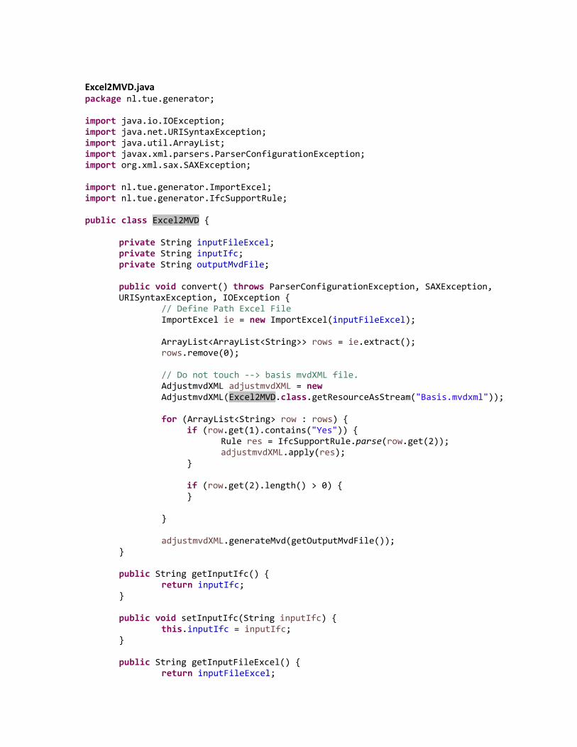
Excel2MVD.java package nl.tue.generator;
import java.io.IOException; import java.net.URISyntaxException; import java.util.ArrayList; import javax.xml.parsers.ParserConfigurationException; import org.xml.sax.SAXException;
import nl.tue.generator.ImportExcel; import nl.tue.generator.IfcSupportRule;
public class Excel2MVD {
private String inputFileExcel; private String inputIfc; private String outputMvdFile;
public void convert() throws ParserConfigurationException, SAXException, URISyntaxException, IOException {
// Define Path Excel File ImportExcel ie = new ImportExcel(inputFileExcel);
ArrayList<ArrayList<String>> rows = ie.extract(); rows.remove(0);
// Do not touch ‐‐> basis mvdXML file. AdjustmvdXML adjustmvdXML = new AdjustmvdXML(Excel2MVD.class.getResourceAsStream("Basis.mvdxml"));
for (ArrayList<String> row : rows) {
if (row.get(1).contains("Yes")) { Rule res = IfcSupportRule.parse(row.get(2)); adjustmvdXML.apply(res);
}
if (row.get(2).length() > 0) { }
}
adjustmvdXML.generateMvd(getOutputMvdFile());
}
public String getInputIfc() { return inputIfc;
}
public void setInputIfc(String inputIfc) { this.inputIfc = inputIfc;
}
public String getInputFileExcel() { return inputFileExcel;

}
public void setInputFileExcel(String inputFileExcel) { this.inputFileExcel = inputFileExcel;
}
public String getOutputMvdFile() { return outputMvdFile;
}
public void setOutputMvdFile(String outputMvdFile) { this.outputMvdFile = outputMvdFile;
}
}

ImportExcel.java package nl.tue.generator;
import java.io.File; import java.io.FileInputStream; import java.io.IOException; import java.util.ArrayList;
import org.apache.poi.hssf.usermodel.HSSFSheet; import org.apache.poi.hssf.usermodel.HSSFWorkbook; import org.apache.poi.ss.usermodel.Cell; import org.apache.poi.ss.usermodel.FormulaEvaluator; import org.apache.poi.ss.usermodel.Row;
public class ImportExcel {
private String document;
public ImportExcel(String file_path) {
this.document = file_path; }
ArrayList<ArrayList<String>> extract2() {
ArrayList<ArrayList<String>> return_list = new ArrayList<ArrayList<String>>(); return return_list;
}
ArrayList<ArrayList<String>> extract() throws IOException { FileInputStream fis = new FileInputStream(new File(this.document)); ArrayList<ArrayList<String>> return_list = new ArrayList<ArrayList<String>>();
// Create workbook HSSFWorkbook wb = new HSSFWorkbook(fis);
// create a sheet object to retrieve the sheet HSSFSheet sheet = wb.getSheetAt(0);
// that is for evaluate the cell type FormulaEvaluator formulaEvaluator = wb.getCreationHelper().createFormulaEvaluator();
for (Row row : sheet) {
ArrayList<String> aRow = new ArrayList<String>(); for (Cell cell : row) {
switch (formulaEvaluator.evaluateInCell(cell).getCellType()) { case Cell.CELL_TYPE_NUMERIC:
break;
case Cell.CELL_TYPE_STRING: aRow.add(cell.getStringCellValue()); break;

case Cell.CELL_TYPE_BLANK: aRow.add(""); break;
}
} return_list.add(aRow);
} return return_list;
} }

IfcSupportRule.java package nl.tue.generator;
import java.util.regex.*;
public class IfcSupportRule {
public static Rule parse(String s) {
Rule rule = new Rule(); if (s.contains("‐>")) {
Pattern arrow = Pattern.compile("(‐>)"); String[] token = arrow.split(s);
rule.setApplicableEntity(token[0]); String templateElements = token[1];
if (templateElements.contains(".")) {
Pattern dot = Pattern.compile("\\."); String[] token2 = dot.split(templateElements);
for (int i = 0; i < token2.length; i++) {
if (i < token2.length ‐ 1) { rule.getTemplateElements().add(token2[i]);
} else {
if (token2[i].contains("=")) { rule.setOperator("="); Pattern operator = Pattern.compile("="); String[] token3 = operator.split(token2[i]);
rule.getTemplateElements().add(token3[0]); rule.setValue(token3[1]);
}
} }
}
}
return rule; }
}

Rule.java package nl.tue.generator;
import java.util.ArrayList;
public class Rule {
private String applicableEntity; private ArrayList<String> templateElements = new ArrayList<String>(); private String operator; private String value;
public String getApplicableEntity() {
return applicableEntity; }
public void setApplicableEntity(String applicableEntity) {
this.applicableEntity = applicableEntity; }
public ArrayList<String> getTemplateElements() {
return templateElements; }
public void setTemplateElements(ArrayList<String> templateElements) {
this.templateElements = templateElements; }
public String getOperator() {
return operator; }
public void setOperator(String operator) {
this.operator = operator; }
public String getValue() {
return value; }
public void setValue(String value) {
this.value = value; }
}

AdjustmvdXML.java package nl.tue.generator;
import java.io.File; import java.io.IOException; import java.io.InputStream; import java.util.ArrayList; import javax.xml.parsers.DocumentBuilder; import javax.xml.parsers.DocumentBuilderFactory; import javax.xml.parsers.ParserConfigurationException; import javax.xml.transform.OutputKeys; import javax.xml.transform.Transformer; import javax.xml.transform.TransformerConfigurationException; import javax.xml.transform.TransformerException; import javax.xml.transform.TransformerFactory; import javax.xml.transform.dom.DOMSource; import javax.xml.transform.stream.StreamResult; import org.w3c.dom.*; import org.xml.sax.SAXException; import java.util.UUID;
public class AdjustmvdXML {
private File file; private Document doc;
public AdjustmvdXML(File file) throws ParserConfigurationException, SAXException, IOException {
this.file = file; DocumentBuilderFactory docFactory = DocumentBuilderFactory.newInstance(); DocumentBuilder docBuilder = docFactory.newDocumentBuilder(); this.doc = docBuilder.parse(file);
}
public AdjustmvdXML(InputStream input) throws ParserConfigurationException, SAXException, IOException {
DocumentBuilderFactory docFactory = DocumentBuilderFactory.newInstance(); DocumentBuilder docBuilder = docFactory.newDocumentBuilder(); this.doc = docBuilder.parse(input);
}
public void apply(Rule rule) {
NodeList list = doc.getElementsByTagName("Templates");
Element templates = (Element) list.item(0);
Element Roots = (Element) doc.getElementsByTagName("Roots").item(0);
UUID uuid = UUID.randomUUID(); String randomUUIDCTT = uuid.toString();

if (rule.getTemplateElements().contains("IfcPropertySingleValue")) {
createConcept("7a13d17c‐20a0‐4117‐8abc‐050d0c67e6ec", doc, Roots, rule); // System.out.println(rule.getTemplateElements().contains("IfcPropertySingleValue"));
}
else if (rule.getTemplateElements().contains("IfcQuantityArea")) { createConcept("46fba748‐b6c7‐48a3‐b81a‐af259c83aaa4", doc, Roots, rule);
}
else if (rule.getTemplateElements().contains("IfcQuantityVolume")) {
createConcept("0f7f7621‐dc0a‐4ab8‐8118‐64ead2ee3cca", doc, Roots, rule);
}
else if (rule.getTemplateElements().contains("IfcQuantityLength")) {
createConcept("6816f366‐c607‐43f4‐a96a‐b57be006ff6d", doc, Roots, rule);
System.out.println(rule.getTemplateElements().contains("IfcQuantityLength"));
}
else { createTemplate(randomUUIDCTT, doc, templates, rule); createConcept(randomUUIDCTT, doc, Roots, rule);
}
}
public void generateMvd(String outputPath) { TransformerFactory transformerFactory = TransformerFactory.newInstance(); Transformer transformer; try {
transformer = transformerFactory.newTransformer();
transformer.setOutputProperty(OutputKeys.INDENT, "yes"); transformer.setOutputProperty("{http://xml.apache.org/xslt}indent‐amount", "2");
DOMSource source = new DOMSource(doc); File newFile = new File(outputPath); StreamResult result = new StreamResult(newFile); transformer.transform(source, result);
} catch (TransformerConfigurationException e) { // TODO Auto‐generated catch block e.printStackTrace();
} catch (TransformerException e) { // TODO Auto‐generated catch block e.printStackTrace();

} }
public File getFile() {
return file; }
public void setFile(File file) {
this.file = file; }
public void createTemplate(String randomUUIDCTT, Document doc, Element Templates, Rule rule) {
Element ConceptTemplate = doc.createElement("ConceptTemplate"); Templates.appendChild(ConceptTemplate);
ConceptTemplate.setAttribute("applicableEntity", rule.getTemplateElements().get(0)); ConceptTemplate.setAttribute("applicableSchema", "IFC4"); ConceptTemplate.setAttribute("name", ""); ConceptTemplate.setAttribute("uuid", randomUUIDCTT);
Element Rules = doc.createElement("Rules"); ConceptTemplate.appendChild(Rules);
ArrayList<Element> rules = new ArrayList<Element>(); for (int i = 1; i < rule.getTemplateElements().size(); i++) {
int d = rule.getTemplateElements().size() ‐ 1; int e = d ‐ 1;
if (i == 1) {
Element attributeRule = doc.createElement("AttributeRule"); attributeRule.setAttribute("AttributeName", rule.getTemplateElements().get(i)); attributeRule.setAttribute("Cardinality", "_asSchema"); rules.add(attributeRule);
}
else if (i == d) {
Element attributeRules = doc.createElement("AttributeRules"); rules.add(attributeRules); Element attributeRule = doc.createElement("AttributeRule"); attributeRule.setAttribute("AttributeName", rule.getTemplateElements().get(i)); attributeRule.setAttribute("Cardinality", "_asSchema"); attributeRule.setAttribute("RuleID",
rule.getTemplateElements().get(e) + rule.getTemplateElements().get(d));
rules.add(attributeRule); }

else if (i % 2 == 1) {
Element attributeRules = doc.createElement("AttributeRules"); rules.add(attributeRules); Element attributeRule = doc.createElement("AttributeRule"); attributeRule.setAttribute("AttributeName", rule.getTemplateElements().get(i)); attributeRule.setAttribute("Cardinality", "_asSchema"); rules.add(attributeRule);
}
else if (i % 2 == 0) { Element entityRules = doc.createElement("EntityRules"); rules.add(entityRules); Element entityRule = doc.createElement("EntityRule"); entityRule.setAttribute("EntityName", rule.getTemplateElements().get(i)); rules.add(entityRule); entityRule.setAttribute("Cardinality", "_asSchema");
} }
for (int i = 0; i < rules.size(); i++) {
if (i == 0) { Rules.appendChild(rules.get(i));
} else { rules.get(i ‐ 1).appendChild(rules.get(i));
}
}
System.out.println("ConceptTemplate added to mvdXML"); }
public Document getDoc() {
return doc; }
public void setDoc(Document doc) {
this.doc = doc; }
public void createConcept(String randomUUIDCTT, Document doc, Element Roots, Rule rule) {
UUID uuid = UUID.randomUUID(); String randomUUIDConceptRoot = uuid.toString();
Element ConceptRoot = doc.createElement("ConceptRoot"); Roots.appendChild(ConceptRoot); ConceptRoot.setAttribute("uuid", randomUUIDConceptRoot); ConceptRoot.setAttribute("name", "");

ConceptRoot.setAttribute("applicableRootEntity", rule.getApplicableEntity());
Element Concepts = doc.createElement("Concepts"); ConceptRoot.appendChild(Concepts);
UUID uuid1 = UUID.randomUUID(); String randomUUIDConcept = uuid1.toString(); Element Concept = doc.createElement("Concept"); Concepts.appendChild(Concept); Concept.setAttribute("uuid", randomUUIDConcept); Concept.setAttribute("name", ""); Concept.setAttribute("override", "false");
Element Definitions = doc.createElement("Definitions"); Concept.appendChild(Definitions);
Element Definition = doc.createElement("Definition"); Definitions.appendChild(Definition);
Element Body = doc.createElement("Body"); Definition.appendChild(Body);
Element Template = doc.createElement("Template"); Concept.appendChild(Template); Template.setAttribute("ref", randomUUIDCTT);
Element Requirements = doc.createElement("Requirements"); Concept.appendChild(Requirements);
Element Requirement = doc.createElement("Requirement"); Requirements.appendChild(Requirement);
Element Rules = doc.createElement("Rules"); Concept.appendChild(Rules);
Element TemplateRule = doc.createElement("TemplateRule"); Rules.appendChild(TemplateRule);
int d = rule.getTemplateElements().size() ‐ 1; int e = d ‐ 1;
String te = rule.getTemplateElements().get(e) + rule.getTemplateElements().get(d); String v = "[Value]='"; String gv = rule.getValue(); String a = "'"; String tr = te + v + gv + a; TemplateRule.setAttribute("Parameters", tr);
System.out.println("Concept added to mvdXML");
}
}

Interface.java package nl.tue;
import java.awt.EventQueue; import nl.tue.generator.*; import nl.tue.ddss.ifc_check.*; import java.io.File; import java.io.IOException; import java.net.URISyntaxException; import javax.swing.JFrame; import javax.swing.JButton; import javax.swing.JFileChooser; import javax.swing.JTextField; import javax.swing.filechooser.FileFilter; import javax.xml.parsers.ParserConfigurationException; import org.xml.sax.SAXException; import javax.swing.JLabel; import javax.swing.JOptionPane;
import java.awt.event.ActionListener; import java.awt.event.ActionEvent; import java.awt.Font;
public class Interface {
private JFrame frame; private JTextField textFieldExcel; private JTextField textFieldIfc; private JTextField textFieldBcf; private JTextField textFieldMvdXMLGenerator; private JTextField textFieldMvdXMLChecker;
/**
Launch the application. */ public static void main(String[] args) {
EventQueue.invokeLater(new Runnable() { public void run() {
try { Interface window = new Interface(); window.frame.setVisible(true);
} catch (Exception e) { e.printStackTrace();
} }
}); }
/**
Create the application. */ public Interface() {
initialize(); }

/** Initialize the contents of the frame.
*/ private void initialize() {
frame = new JFrame(); frame.setBounds(100, 100, 628, 553); frame.setDefaultCloseOperation(JFrame.EXIT_ON_CLOSE); frame.getContentPane().setLayout(null);
JButton btnUploadExcel = new JButton("Browse"); btnUploadExcel.addActionListener(new ActionListener() {
public void actionPerformed(ActionEvent e) { JFileChooser fileChooser = new JFileChooser(); fileChooser.setFileFilter(new FileFilter() {
public boolean accept(File f) { if (f.isDirectory()) {
return true; } final String name = f.getName(); return name.endsWith(".xls") || name.endsWith(".xlsx");
}
public String getDescription() { return "*.xls, *.xlsx";
}
}); if (fileChooser.showOpenDialog(btnUploadExcel) == JFileChooser.APPROVE_OPTION) {
File excelFile = fileChooser.getSelectedFile(); textFieldExcel.setText(excelFile.getAbsolutePath()); System.out.println("Excel file is added"); // load from file
} }
}); btnUploadExcel.setBounds(424, 72, 174, 25); frame.getContentPane().add(btnUploadExcel);
JButton btnUploadIfcModel = new JButton("Browse"); btnUploadIfcModel.addActionListener(new ActionListener() {
public void actionPerformed(ActionEvent e) { JFileChooser fileChooser = new JFileChooser(); fileChooser.setFileFilter(new FileFilter() {
public boolean accept(File f) { if (f.isDirectory()) {
return true; } final String name = f.getName(); return name.endsWith(".ifc");
}

public String getDescription() { return "*.ifc";
}
});
if (fileChooser.showOpenDialog(btnUploadIfcModel) == JFileChooser.APPROVE_OPTION) {
File ifcFile = fileChooser.getSelectedFile(); textFieldIfc.setText(ifcFile.getAbsolutePath()); System.out.println("IFC file is added");
}
}
}); btnUploadIfcModel.setBounds(424, 301, 174, 25); frame.getContentPane().add(btnUploadIfcModel);
JButton btnCreateMVDXML = new JButton("Create mvdXML\r\n"); btnCreateMVDXML.setFont(new Font("Tahoma", Font.BOLD, 15)); btnCreateMVDXML.addActionListener(new ActionListener() {
public void actionPerformed(ActionEvent e) { runGenerator();
}
}); btnCreateMVDXML.setBounds(231, 156, 156, 25); frame.getContentPane().add(btnCreateMVDXML);
JButton btnSaveBcfFile = new JButton("Browse"); btnSaveBcfFile.addActionListener(new ActionListener() {
public void actionPerformed(ActionEvent e) { JFileChooser fileChooser = new JFileChooser(); fileChooser.setFileFilter(new FileFilter() {
public boolean accept(File f) { if (f.isDirectory()) {
return true; } final String name = f.getName(); return name.endsWith(".bcf");
}
public String getDescription() { return "*.bcf";
}
}); if (fileChooser.showSaveDialog(btnSaveBcfFile) == JFileChooser.APPROVE_OPTION) {
File bcfFile = fileChooser.getSelectedFile(); textFieldBcf.setText(bcfFile.getAbsolutePath() + ".bcf");

} }
});
btnSaveBcfFile.setBounds(424, 339, 174, 25); frame.getContentPane().add(btnSaveBcfFile);
JLabel lblInput = new JLabel("Excel"); lblInput.setFont(new Font("Tahoma", Font.BOLD, 13)); lblInput.setBounds(129, 75, 56, 16); frame.getContentPane().add(lblInput);
JLabel lblOutput = new JLabel("Output"); lblOutput.setFont(new Font("Tahoma", Font.BOLD, 13)); lblOutput.setBounds(22, 113, 56, 16); frame.getContentPane().add(lblOutput);
textFieldExcel = new JTextField();
textFieldExcel.setText("D:\\Documents\\mvdXML_Generator_Checker\\01_Excel\\ProofOfConcept.xls");
textFieldExcel.setBounds(223, 73, 189, 22); frame.getContentPane().add(textFieldExcel); textFieldExcel.setColumns(10);
JLabel lblIfc = new JLabel("IFC"); lblIfc.setFont(new Font("Tahoma", Font.BOLD, 13)); lblIfc.setBounds(129, 304, 56, 16); frame.getContentPane().add(lblIfc);
textFieldIfc = new JTextField();
textFieldIfc.setText("D:\\Documents\\mvdXML_Generator_Checker\\03_IFC_Model\\Duplex_A_20110505_modified.ifc");
textFieldIfc.setBounds(223, 302, 189, 22); frame.getContentPane().add(textFieldIfc); textFieldIfc.setColumns(10);
textFieldBcf = new JTextField();
textFieldBcf.setText("D:\\Documents\\mvdXML_Generator_Checker\\04_BCF_Report\\Checker report.bcf");
textFieldBcf.setBounds(223, 340, 189, 22); frame.getContentPane().add(textFieldBcf); textFieldBcf.setColumns(10);
JLabel lblInput_1 = new JLabel("Input"); lblInput_1.setFont(new Font("Tahoma", Font.BOLD, 13)); lblInput_1.setBounds(22, 75, 56, 16); frame.getContentPane().add(lblInput_1);
JLabel lblBcf = new JLabel("BCF"); lblBcf.setFont(new Font("Tahoma", Font.BOLD, 13)); lblBcf.setBounds(129, 342, 56, 16); frame.getContentPane().add(lblBcf);
textFieldMvdXMLGenerator = new JTextField();

textFieldMvdXMLGenerator.setText("D:\\Documents\\mvdXML_Generator_Checker\\02_mvdXML_Rulesets\\Test.mvdxml");
textFieldMvdXMLGenerator.setBounds(221, 111, 191, 22); frame.getContentPane().add(textFieldMvdXMLGenerator); textFieldMvdXMLGenerator.setColumns(10);
JLabel lblNewLabel = new JLabel("MvdXML"); lblNewLabel.setFont(new Font("Tahoma", Font.BOLD, 13)); lblNewLabel.setBounds(129, 113, 79, 16); frame.getContentPane().add(lblNewLabel);
JButton btnSaveMvdxmlGenerator = new JButton("Browse"); btnSaveMvdxmlGenerator.addActionListener(new ActionListener() {
public void actionPerformed(ActionEvent e) { JFileChooser fileChooser = new JFileChooser(); fileChooser.setFileFilter(new FileFilter() {
public boolean accept(File f) { if (f.isDirectory()) {
return true; } final String name = f.getName(); return name.endsWith(".mvdxml");
}
public String getDescription() { return "*.mvdxml";
}
}); if (fileChooser.showSaveDialog(btnSaveMvdxmlGenerator) == JFileChooser.APPROVE_OPTION) {
File mvdFile = fileChooser.getSelectedFile(); textFieldMvdXMLGenerator.setText(mvdFile.getAbsolutePath() + ".mvdxml");
}
}
}); btnSaveMvdxmlGenerator.setBounds(424, 110, 174, 25); frame.getContentPane().add(btnSaveMvdxmlGenerator);
JButton btnCheckIfcModel = new JButton("Check IFC model\r\n"); btnCheckIfcModel.setFont(new Font("Tahoma", Font.BOLD, 15)); btnCheckIfcModel.addActionListener(new ActionListener() {
public void actionPerformed(ActionEvent e) { runChecker();
} }); btnCheckIfcModel.setBounds(241, 387, 166, 25); frame.getContentPane().add(btnCheckIfcModel);
JLabel label = new JLabel("Input"); label.setFont(new Font("Tahoma", Font.BOLD, 13)); label.setBounds(22, 304, 56, 16); frame.getContentPane().add(label);

JLabel label_1 = new JLabel("MvdXML"); label_1.setFont(new Font("Tahoma", Font.BOLD, 13)); label_1.setBounds(129, 271, 79, 16); frame.getContentPane().add(label_1);
textFieldMvdXMLChecker = new JTextField(); textFieldMvdXMLChecker.setText(
"D:\\Documents\\mvdXML_Generator_Checker\\02_mvdXML_Rulesets\\mvdxml_test_Proof of Concept.mvdxml");
textFieldMvdXMLChecker.setColumns(10); textFieldMvdXMLChecker.setBounds(221, 269, 191, 22); frame.getContentPane().add(textFieldMvdXMLChecker);
JButton btnUploadMvdXMLChecker = new JButton("Browse"); btnUploadMvdXMLChecker.addActionListener(new ActionListener() {
public void actionPerformed(ActionEvent e) { JFileChooser fileChooser = new JFileChooser(); fileChooser.setFileFilter(new FileFilter() {
public boolean accept(File f) { if (f.isDirectory()) {
return true; } final String name = f.getName(); return name.endsWith(".mvdxml");
}
public String getDescription() { return "*.mvdxml";
} }); if (fileChooser.showOpenDialog(btnUploadMvdXMLChecker) == JFileChooser.APPROVE_OPTION) {
File mvdxmlFile = fileChooser.getSelectedFile();
textFieldMvdXMLChecker.setText(mvdxmlFile.getAbsolutePath()); }
} }); btnUploadMvdXMLChecker.setBounds(424, 268, 174, 25); frame.getContentPane().add(btnUploadMvdXMLChecker);
btnUploadExcel.setBounds(424, 72, 174, 25); frame.getContentPane().add(btnUploadExcel);
JLabel label_2 = new JLabel("Input"); label_2.setFont(new Font("Tahoma", Font.BOLD, 13)); label_2.setBounds(22, 272, 56, 16); frame.getContentPane().add(label_2);
JLabel label_3 = new JLabel("Output"); label_3.setFont(new Font("Tahoma", Font.BOLD, 13)); label_3.setBounds(22, 343, 56, 16); frame.getContentPane().add(label_3);

JLabel lblMvdxmlGenerator = new JLabel("MvdXML Generator"); lblMvdxmlGenerator.setFont(new Font("Tahoma", Font.BOLD, 15)); lblMvdxmlGenerator.setBounds(22, 28, 156, 34); frame.getContentPane().add(lblMvdxmlGenerator);
JLabel lblMvdxmlChecker = new JLabel("MvdXML Checker"); lblMvdxmlChecker.setFont(new Font("Tahoma", Font.BOLD, 15)); lblMvdxmlChecker.setBounds(22, 227, 156, 34); frame.getContentPane().add(lblMvdxmlChecker);
}
public void runGenerator() {
Excel2MVD excel2mvd = new Excel2MVD(); excel2mvd.setInputFileExcel(textFieldExcel.getText()); excel2mvd.setOutputMvdFile(textFieldMvdXMLGenerator.getText()); try {
excel2mvd.convert(); JOptionPane.showMessageDialog(this.frame, "Done");
} catch (ParserConfigurationException | SAXException | URISyntaxException | IOException e) {
// TODO Auto‐generated catch block e.printStackTrace(); JOptionPane.showMessageDialog(this.frame, e.getMessage(), "Error", JOptionPane.ERROR_MESSAGE);
} }
public void runChecker() {
try {
new MVDCheckerTest(textFieldIfc.getText(), textFieldMvdXMLChecker.getText(), textFieldBcf.getText());
JOptionPane.showMessageDialog(this.frame, "Done");
} catch (Exception e) { // TODO Auto‐generated catch block e.printStackTrace(); JOptionPane.showMessageDialog(this.frame, e.getMessage(), "Error", JOptionPane.ERROR_MESSAGE);
}
} }

Basis.mvdxml <?xml version="1.0" encoding="UTF-8" standalone="no"?> <mvdXML xmlns="http://buildingsmart-tech.org/mvdXML/mvdXML1-1" xmlns:xsd="http://www.w3.org/2001/XMLSchema" xmlns:xsi="http://www.w3.org/2001/XMLSchema-instance" name="" uuid="00000000-0000-0000-0000-000000000000"> <Templates> <ConceptTemplate uuid="7a13d17c-20a0-4117-8abc-050d0c67e6ec" name="SingleValueProperty" applicableSchema="IFC4" applicableEntity="IfcObject"> <Rules> <AttributeRule AttributeName="IsDefinedBy" Cardinality="_asSchema"> <EntityRules> <EntityRule EntityName="IfcRelDefinesByProperties" Cardinality="_asSchema"> <AttributeRules> <AttributeRule AttributeName="RelatingPropertyDefinition" Cardinality="_asSchema"> <EntityRules> <EntityRule EntityName="IfcPropertySet" Cardinality="_asSchema"> <AttributeRules> <AttributeRule AttributeName="HasProperties" Cardinality="_asSchema"> <EntityRules> <EntityRule EntityName="IfcPropertySingleValue" Cardinality="_asSchema"> <AttributeRules> <AttributeRule RuleID="IfcPropertySingleValueName" AttributeName="Name" Cardinality="_asSchema" /> <AttributeRule RuleID="NominalValue" AttributeName="NominalValue" Cardinality="_asSchema" /> <AttributeRule RuleID="Unit" AttributeName="Unit" Cardinality="_asSchema" /> </AttributeRules> </EntityRule> </EntityRules> </AttributeRule> <AttributeRule RuleID="IfcPropertySingleValueName" AttributeName="Name" Cardinality="_asSchema" /> </AttributeRules> </EntityRule> </EntityRules> </AttributeRule> </AttributeRules> </EntityRule> </EntityRules> </AttributeRule> </Rules> </ConceptTemplate> <ConceptTemplate applicableEntity="IfcObject" applicableSchema="IFC4" name="" uuid="6816f366-c607-43f4-a96a-b57be006ff6d"> <Rules> <AttributeRule AttributeName="IsDefinedBy" Cardinality="_asSchema"> <EntityRules> <EntityRule Cardinality="_asSchema" EntityName="IfcRelDefinesByProperties"> <AttributeRules> <AttributeRule AttributeName="RelatingPropertyDefinition" Cardinality="_asSchema"> <EntityRules> <EntityRule Cardinality="_asSchema" EntityName="IfcElementQuantity"> <AttributeRules> <AttributeRule AttributeName="Quantities" Cardinality="_asSchema"> <EntityRules> <EntityRule Cardinality="_asSchema" EntityName="IfcQuantityLength"> <AttributeRules> <AttributeRule AttributeName="Name" Cardinality="_asSchema" RuleID="IfcQuantityLengthName"/> </AttributeRules> </EntityRule> </EntityRules> </AttributeRule> </AttributeRules> </EntityRule> </EntityRules> </AttributeRule> </AttributeRules>

</EntityRule> </EntityRules> </AttributeRule> </Rules> </ConceptTemplate> <ConceptTemplate applicableEntity="IfcObject" applicableSchema="IFC4" name="" uuid="46fba748-b6c7-48a3-b81a-af259c83aaa4"> <Rules> <AttributeRule AttributeName="IsDefinedBy" Cardinality="_asSchema"> <EntityRules> <EntityRule Cardinality="_asSchema" EntityName="IfcRelDefinesByProperties"> <AttributeRules> <AttributeRule AttributeName="RelatingPropertyDefinition" Cardinality="_asSchema"> <EntityRules> <EntityRule Cardinality="_asSchema" EntityName="IfcElementQuantity"> <AttributeRules> <AttributeRule AttributeName="Quantities" Cardinality="_asSchema"> <EntityRules> <EntityRule Cardinality="_asSchema" EntityName="IfcQuantityArea"> <AttributeRules> <AttributeRule AttributeName="Name" Cardinality="_asSchema" RuleID="IfcQuantityAreaName"/> </AttributeRules> </EntityRule> </EntityRules> </AttributeRule> </AttributeRules> </EntityRule> </EntityRules> </AttributeRule> </AttributeRules> </EntityRule> </EntityRules> </AttributeRule> </Rules> </ConceptTemplate> <ConceptTemplate applicableEntity="IfcObject" applicableSchema="IFC4" name="" uuid="0f7f7621-dc0a-4ab8-8118-64ead2ee3cca"> <Rules> <AttributeRule AttributeName="IsDefinedBy" Cardinality="_asSchema"> <EntityRules> <EntityRule Cardinality="_asSchema" EntityName="IfcRelDefinesByProperties"> <AttributeRules> <AttributeRule AttributeName="RelatingPropertyDefinition" Cardinality="_asSchema"> <EntityRules> <EntityRule Cardinality="_asSchema" EntityName="IfcElementQuantity"> <AttributeRules> <AttributeRule AttributeName="Quantities" Cardinality="_asSchema"> <EntityRules> <EntityRule Cardinality="_asSchema" EntityName="IfcQuantityVolume"> <AttributeRules> <AttributeRule AttributeName="Name" Cardinality="_asSchema" RuleID="IfcQuantityVolumeName"/> </AttributeRules> </EntityRule> </EntityRules> </AttributeRule> </AttributeRules> </EntityRule> </EntityRules> </AttributeRule> </AttributeRules> </EntityRule> </EntityRules> </AttributeRule>

</Rules> </ConceptTemplate> </Templates> <Views> <ModelView uuid="a3713e64-6251-4569-b8c6-934fa6acfb25" name="DEMO" applicableSchema="IFC4"> <ExchangeRequirements> <ExchangeRequirement uuid="139cd9af-7874-4c62-aab8-9ca39dc25dd2" name="Example" applicability="both" /> </ExchangeRequirements> <Roots> <ConceptRoot uuid="8101d3e8-afe0-448c-b803-f80874ab63a5" name="" applicableRootEntity="IfcWindow"> <Concepts> <Concept uuid="6ca5d3a3-ae77-49a3-9012-96180d68810b" name="SingleValueProperty" override="false"> <Definitions> <Definition> <Body></Body> </Definition> </Definitions> <Template ref="7aaad17c-20a0-4117-8abc-050d0c67e6ec" /> <Requirements> <Requirement applicability="import" requirement="mandatory" exchangeRequirement="139cd9af-7874-4c62-aab8-9ca39dc25dd2" /> <Requirement applicability="export" requirement="mandatory" exchangeRequirement="139cd9af-7874-4c62-aab8-9ca39dc25dd2" /> </Requirements> <Rules> <TemplateRule Parameters="PropertyName[Value]='FireRating'" /> </Rules> </Concept> </Concepts> </ConceptRoot> </Roots> </ModelView> </Views> </mvdXML>
Related Documents