SAND80-2646 Unlimited Release UC-60 Vertical Axis Wind Turbine Drive Train Transient Dynamics David B. Clauss, Thomas G. Carrie SF 2900 -Q(3-80)

Welcome message from author
This document is posted to help you gain knowledge. Please leave a comment to let me know what you think about it! Share it to your friends and learn new things together.
Transcript

SAND80-2646UnlimitedReleaseUC-60
Vertical Axis Wind Turbine DriveTrain Transient Dynamics
David B. Clauss, Thomas G. Carrie
SF 2900 -Q(3-80)
Issued by Smdia Natmnal Laboratories, operated for the United States Department ofEnergy by Sandia Corporation,NOTICE , Th>s report was prePart-d as an account of work sPcmsomd by an agency of theUnited States Government. Neither the United States Government nor any agency thereof,nor any of the,, employees. nor any of t!mr mntract cm. mbcontmctors, or theiremployees, makes anY wammty. express o. mplmd m assumq any legal fiability orreswmmbibty for the c+cum.y, completeness. or usefulness of my mfonnatmu, apparatus,Product,, or Process dlsclose$ or remesents that m me would not in frizge privatelyowned rw$ht.. Reference hemm to any $pec,f,c commercial product, Proms., or serv,ceby trade name. trademark, manufacturer. m otherwise does not necessarily constitute orLrnply its endorsement, recommendation, or favoring by the United States G..wemment,any agency thereof C.Zany of their contractors or s“bcontractom. The mews and opinionsexpressed herein do not necessmify state m reflect those of the United StatesGovernment, any agency thereof or any of their contractors or subcontractors.
Printed in the United States of America
Available from:
National Technical Information Serviceu. s. Department of Commerce5285 Port Royal RoadSpringfield, VA 22161
NTIS Price Codes:
Printed Copy $7.00; Microfiche: A04
SAND80-2646
Vertical Axis Wind TurbineDrive Train Transient Dynamics*
David B. ClaussThomas G. CarrieDivision 5523
Sandia National Laboratories**Albuquerque, New Mexico 87185
Abstract
Start-up of a vertical axis wind turbine causes transienttorque oscillations in the drive train with peak torques whichmay be over two and one-half times the rated torque of theturbine. These peak torques are of sufficient magnitude topossibly damage the drive train; safe and reliable operationrequires that mechanical components be overdesigned to carrythe peak torques caused by transient events. A computer code,based on a lumped parameter model of the drive train, has beendeveloped and tested for the Low Cost 17-Meter turbine; theresults show excellent agreement with field data. The code hassubsequently been used to predict the effect of a slip clutchon transient torque oscillations. It has been demonstratedthat a slip clutch located between the motor and brake canreduce peak torques by thirty eight percent.
—* This work was supported by the U.S. Department of Energy
Contract DE-AC094-76DPO0789
** A. U.S. Department of Energy Facility
3

Contents
Introduction. . . . . . . . . . . . . . . . . . . . . .
The DriveTrainModel... . . . . . . . . . . . . . . .
Experimental Record - Base Case. . . . . . . . . . . . .
Control of Transients with a Slip Clutch . . . . . . . .
Conclusions. . . . . . . . . . . . . . . . . . . . . . .
Acknowledgement. . . . . . . . . . . . . . . . . . . . .
References
Figure
1
2
3
4
5
6
7-8
9-1o
11
● ☛✎☛☛ ✎ ✎ ✎ ✎ ✎ ✎☛✎☛✎ ✎☛✎✎☛ ● ✎ ✎
Illustrations
DOE/ALCOA Low Cost 17M vertical axis windturbine installed at Rocky Flats, Colorado.
Physical representation of VAWT drive trainwith numerical values for Low Cost turbine.
Free body diagrams for writing equations ofmotion.
Torque vs. speed characteristic of an idealclutch .
System representation during slipping of theclutch .
Torque vs. speed characteristic for atypical induction motor/generator.
System Representation with clutch slipping.
Simplified representations of drive trainsystem for free vibration.
Experimental record of low speed shafttorque vs. time on the Low Cost turbine forstart-up in zero wind.
!?s9s
● 6
. 8
. 21
. 28
. 36
. 36
. 36
-
7
9
10
12
14
16
18
19-20
22
4
r
,
4

12--15 Model prediction for Low Cost turbine start-upin zero wind speed.
Low speed shaft torque vs. time.
Motor torque vs. time.
Motor speed vs. time.
Rotor speed vs. time.
Model prediction with slip clutch set totransmit a maximum torque of 475 ft-lbs for LowCost turbine start-up in zero wind.
Low speed shaft torque vs. time.
Torque transmitted through clutch vs. time.
Motor torque vs. time.
Motor speed vs. time.
Clutch speed vs. time.
Power dissipated in clutch vs. time.
23
24
25
26
30
31
32
33
34
35
5

Introduction
Transient events during operation of Darrieus vertical-axis
wind turbines can cause torque levels in the drive line which
are unacceptable for many components. Start-up and braking in
various ambient conditions are typical events during which peak
torques may reach excessive magnitudes. Experience with
research vertical axis wind turbines (VAWT) indicates that peak
torques of 2 to 3 times rated torque are typical during
starting and braking, which implies an undesired overdesign of
drive-line compon~nts. The objective of the present
investigation is to develop an analytical tool which can be
used to predict drive-train behavior for several different
loading conditions.
Analysis is needed to determine which starting and braking
methods are most effective in reducing the peak torques seen in
the drive-line. Areas deserving investigation include start-up
in high winds, as well as electrical and mechanical methods
(clutches) designed to achieve a softer start. The relative
effectiveness of low speed vs. high speed braking, and
definition of a braking rate which will decrease dynamic
amplification to an acceptable level also merit study.
Although this paper will deal primarily with turbine start-up
in zero ambient wind speed and the effects of a slip clutch on
transient response, the model can easily be adapted to study
the problems mentioned above.
The model and the numerical results as well are based on
experimental data obtained on the Low Cost 17M VAWT installed
at Rocky Flats, CO, Figur= 1. The method, however, is
essentially general to all VAW’T’S. A Fortran program called
DYDTA (DYnamic Drive Train Analysis) numerically evaluates the
differential equations of motion and plots results. The
program is briefly described in Appendix A.

Figure 1. DOE/ALCOA Low Cost 17M Vertical Axis Wind Turbineinstalled at Rocky Flats, CO.
7
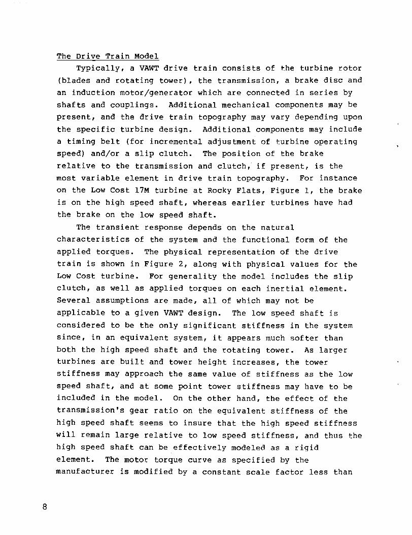
The Drive Train Model
Typically, a VAWT drive train consists of the turbine rotor
(blades and rotating tower), the transmission, a brake disc and
an induction motor/generator which are connected in series by
shafts and couplings. Additional mechanical components may be
present, and the drive train topography may vary depending upon
the specific turbine design. Additional components may include
a timing belt (for incremental adjustment of turbine operating
speed) and/or a slip clutch. The position of the brake
relative to the transmission and clutch, if present, is the
most variable element in drive train topography. For instance
on the Low Cost 17M turbine at Rocky Flats, Figure 1, the brake
is on the high speed shaft, whereas earlier turbines have had
the brake on the low speed shaft.
The transient response depends on the natural
characteristics of the system and the functional form of the
applied torques. The physical representation of the drive
train is shown in Figure 2, along with physical values for the
Low Cost turbine. For generality the model includes the slip
clutch, as well as applied torques on each inertial element.
Several assumptions are made, all of which may not be
applicable to a given VAWT design. The low speed shaft is
considered to be the only significant stiffness in the system
since, in an equivalent system, it appears much softer than
both the high speed shaft and the rotating tower. As larger
turbines are built and tower height increases, the tower
stiffness may approach the same value of stiffness as the low
speed shaft, and at some point tower stiffness may have to be
included in the model. On the other hand, the effect of the
transmission’s gear ratio on the equivalent stiffness of the
high speed shaft seems to insure that the high speed stiffness
will remain large relative to low speed stiffness, and thus the
high speed shaft can be effectively modeled as a rigid
element. The motor torque curve as specified by the
manufacturer is modified by a constant scale factor less than

ROTOR
-+
‘MO1’ BRAKE rT##lTG
‘M ‘
‘B =
‘R =c=
‘L =
‘1 =
‘2 =
‘MOT =
‘BRK =
TROT =
TRANSMISSION
LJR
motor inertia = 1.291 lb-ft-s2
brake inertia = 1.598 lb-ft-s2
rotor inertia = 4.042 X 10⁴ lb-ft-s2
Viscousdamping = 1.1 X 10³ lb~ft-s
low speed shaft stiffness = 8.626 X 10⁵ lb-ft
timing belt ratio = 1, 40/38, 44/38
transmissionratio = 35.07
motor torque,‘MOT(u)
brake torque,TBRK(t)
aerodynamictorque,TROT(W,t)
TROT
Figure 2. PhysicalRepresentationof VAWT Drive Train.

one, which is related to the voltage drop in the line. For an
induction motor\generator, torque is proportional to voltage
squared, so that a 20% drop in voltage will cause a 36%
reduction in motor torque. The assumption of a constant motor
scale factor implies that the voltage drop, and thus the
current drawn by the motor are independent of motor speed,
which is only approximately true. Also, nonlinear effects such
as Coulomb friction, aerodynamic damping, and drive slack are
not treated. All losses are represented by viscous damping.
The equations of motions describing the torsional response
of the drive train can be easily written by drawing free body
diagrams for each inertial element, Figure 3, and equating the
torque on each to zero. This method is preferred because it
+“-el
‘MOT Tc/m
3(a)
Ts
-’0-(i$ ‘Bf3K
TC ~sinz
JB
3(b)
JR
3(c)
Figure 3. Free Body Diagrams for writing equationsof motion.
10
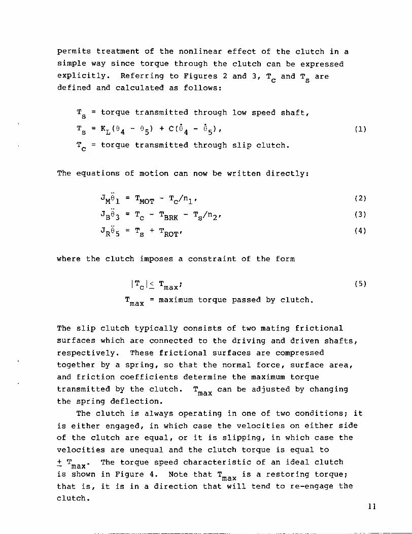
permits treatment of the nonlinear effect of the clutch in a
simple way since torque through the clutch can be expressed
explicitly. Referring to Figures 2 and 3, Tc and Ts are
defined and calculated as follows:
Ts = torque transmitted through low speed shaft,
Ts = KL(f34 - 65) +C(G4 - fQr
Tc = torque transmitted through slip clutch.
The equations of motion can now be written directly:
..
‘M”l = ‘MOT - Tc\nl,
JBe3 = Tc - TBRK - Ts\n2,
JR8~ = Ts + TROT,
where the clutch imposes a constraint of the form
ITC[< Tmax;—
Tmax = maximum torque passed by clutch.
(1)
(2)
(3)
(4)
(5)
The slip clutch typically consists of two mating frictional
surfaces which are connected to the driving and driven shafts,
respectively. These frictional surfaces are compressed
together by a spring, so that the normal force, surface area,
and friction coefficients determine the maximum torque
tra~nsmitted by the clutch. Tmax can be adjusted by changing
the spring deflection.
The clutch is always operating in one of two conditions; it
is either engaged, in which case the velocities on either side
of the clutch are equal, or it is slipping, in which case the
velocities are unequal and the clutch torque is equal to
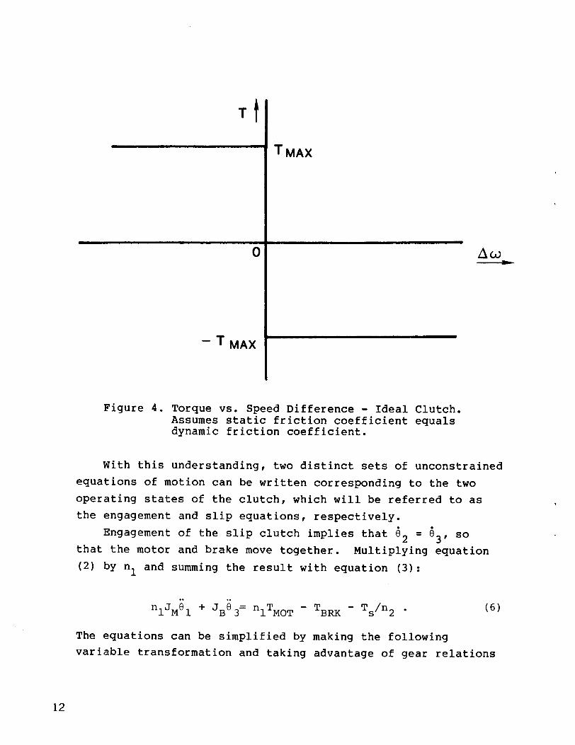
+ Tmax” The torque speed characteristic of an ideal clutch—
is shown in Figure 4. Note that Tmax is a restoring torque;
that is, it is in a direction that will tend to re-engage the
clutch.11
Tt
4 T MA)(
o
– T MAX r
Figure 4. Torque vs. Speed Difference - Ideal Clutch.Assumes static friction coefficient equalsdynamic friction coefficient.
With this understanding, two distinct sets of unconstrained
equations of motion can be written corresponding to the two
operating states of the clutch, which will be referred to as
the engagement and slip equations, respectively.
Engagement of the slip clutch implies that 62 = 53, so
that the motor and brake move together. Multiplying equation
(2) by nl and summing the result with equation (3):
..
‘lJMo 1+J6=nT
B3 1 MOT - ‘BRK - T~/n2 . (6)
The equations can be simplified by
variable transformation and taking
making the following
advantage of gear relations
12
$1 = fJ2 = f31\nl, (7)
$2 = 83= ‘264’ (8)
$3 = ‘265” (9)
Thlusthe complete set of engagement equations can be written
(JME + JB)~l.
= ‘lTMOT - ‘BRK - ‘LE($2-V3) - cE(i2-V3)’ ’10)
J2 = i~r (11)
.*JRE;3 = KLE(~2-~3) + CE($2-~3) + TROT\n2; (12)
whlere
2‘ME = nlJM,
JRE = JR\n~,
‘LE = KL\n~,
CE = C\n~.
Slipping of the clutch decouples the motor
and rotor, so that the slip equations describe
(13)
(14)
(15)
(16)
from the brake
two independent
systems as shown in Figure 5. Slip implies a velocity
difference across the clutch and that the torque transmitted
thmough the clutch is a constant ~ Tmaxo Again taking
advantage of equations (7) - (9) and equations (13) - (16), and
ma~king the substitution
Tc = + Tmax (17)—
13

+
T MOT T MAX
JM
5(a) - motor system
Figure 5.
the final
‘ME;1
JB~~
JREi3
where
~TBRK
TMAX KL,C T ROT—JB
bJR
5(b) - brake rotor system
Representation of Drive Train forclutch slipping.
form of the slip equations becomes
—
= ‘lTMOT + ‘max’(18)
(“= + Tmax - TBM - KLE($2 -$3) - Ce V2 -$3) , (19)—
= KLE(iJ2 ‘*3) + CE($2 ‘~3) + TROT/n2, (20)
Tmax is positive for motor overspeed.
The conditions for initiation of slip and for re-engagement are
somewhat more subtle, although intuitively simple. Assume
that, at time equal zero, the clutch is engaged. Slip
initiates when the clutch torque equals Tmax and continued
engagement would tend to violate the constraint, equation (5).
Stated more rigorously the initiation of slip occurs when
‘Ce = Tmax (21)
and
dT--=>0dt
(22)
14

where the subscript e indicates the result obtained from the
engagement equations. If TCe is negative, then inequality
(Z!2)is directed in the opposite sense. Now assume that the
clutch is slipping, so that 62 ~ 63. Re-engagement occurs
when the velocities across the clutch become equal again:
62s = 63s (23)
and if
lTcel <T— max”
At re-engagement there must be a discontinuity in acceleration,
which implies a discontinuity in the clutch torque. This is
consistent with the characteristics of the clutch as shown in
Figure 4, since when Au = O (as it is at re-engagement), the
clutch torque may be any value between positive Tmax and
negative Tmax. A more complete description of the behavior
of a slip clutch is given in Appendix B, with the consequences
of the clutch illustrated.
Thus, a basic algorithm would be to use the engagement
equations until equations (21) and (22) are satisfied (slip
initiates) , and then to apply the slip equations until equation
(23) is met (re-engagement), at which point the algorithm is
applied recursively.
A great deal of insight can be gained from an examination
of the natural characteristics of the system, especially in the
case of start-up. The remainder of this paper will focus on
start-up in a zero ambient wind speed. The motor torque-speed
characteristic has a significant impact on the natural
characteristics of the system. A typical induction motor curve
is shown in Figure 6. It is important to realize
15

1200
1000
800
600
400
200
0
-200
BREAKDOWN
- LOCKED// ROTOR
y-
4.
RATED -
PULLUP
IDLE
o 200 400 600 800 1000 1200 1400 1600 1800 2000
SPEED-RPM
Figure 6. Torque-Speed characteristic of an induction motor.
that motor torque is a function of motor speed, not of time.
Torque ripple models developedl by Reuter have treated the
induction motorlgenerator mechanically as an inertia connected
to ground through a linear viscous damper. Referring to Figure
6 ithe torque-speed relationship is indeed linear for steady
Sti3te operation (1740 < u < 1860 rpm). However, during
sti~rt-up the motor speed goes from O to 1800 rpm and the
torque-speed relationship cannot be represented as a linear
element. From an intuitive standpoint, it is most clear to
think of the motor torque characteristic as a non-linear
damper, which has a coefficient dependent on rpm, superimposed
on a step torque, though in the code and model it is treated as
an applied torque. To be clear, the motor torque should not be
considered to be an external torque because it is not
independent of the state of the system. With this in mind, the
free vibration characteristics of the drive train during
start-up can be considered.
The natural characteristics of the system also depend on
the operating state of the slip clutch. When the clutch is
engaged, there is an effectively rigid connection between the
motor and the brake so their respective inertias may be lumped
together, and the system can be represented as shown in Figure
7. On the other hand, slipping decouples the motor and creates
twc)independent systems, Figure 8. The latter case will not be
treated in detail, however, it is apparent that the fundamental
frequency of the decoupled system in 8(b) will be higher than
that of coupled system in Figure (7), and that the isolated
motor, Figure 8(a) moves as a rigid body.
Due to the nonlinearity introduced into the system by the
motor and clutch, a linear eigenvalue analysis is not truly
applicable. The equivalent motor damping changes continually
so that the natural frequencies and mode shapes are a function
of speed. However, an approximate analysis can be done by
considering two subcases based on motor speed less than or
17
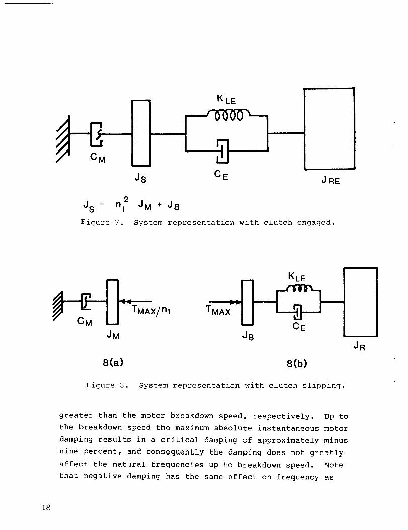
J~ ‘ n12 J~ + JB
Figure 7. System representation with clutch engaged.
JM
8(a]
Figure 8.
$“:}=x/nl‘MA■
~B
8(b)
System representation with clutch slipping.
greater than the motor breakdown speed, respectively. up to
the breakdown speed the maximum absolute instantaneous motor
damping results in a critical damping of approximately minus
nine percent, and consequently the damping does not greatly
affect the natural frequencies up to breakdown speed. Note
that negative damping has the same effect on frequency as
JR
18

positive damping (1 d.o.f., Ud = ~. ), blltthen
oppclsite effect on mode shape (in Figure 7, negative damping
from the motor tends to increase the oscillations of the motor
and brake relative to the rotor) . Thus, up to breakdown,
damping is negligible and the system can be viewed as shown in
Figure 9(a). The natural frequencies and mode shapes of the
JRE
9(a) 9(b)
Figure 9. System representation with clutch engagedand motor speed < 1720 rpm.
system in Figure 9(a) are easily determined. The results are
d (J +JRE)o, ‘LE S=
‘SJRE
= o, 2.586 HZ
1.000I J2)=1.000 ‘
●
1.000
1- JS+JRE
1.000-0.083
(24)
(25)
19
The mode shape indicates that the generator/brake is moving
with much greater amplitude than the rotor, so that the mode
basically represents the motor/brake winding up about the low
speed shaft, Figure 9(b). Indeed, if JRE >> J~ (typically
the case for VAWT’S), equation (24)can be approximatedby
dKLEu=— (26)
‘s
which corresponds to the frequency of the system in Figure 9(b).
As previously discussed, when the motor speed is greater
than the breakdown speed, the torque is nearly a linear
function of speed, with a very large negative slope. This
slope, and thus the effective damping, is a function of the
rated power, the synchronous speed, and the slip at rating for
an induction motor/generator:
Pc= ratedM t (27)
fi2s
as given in [2].
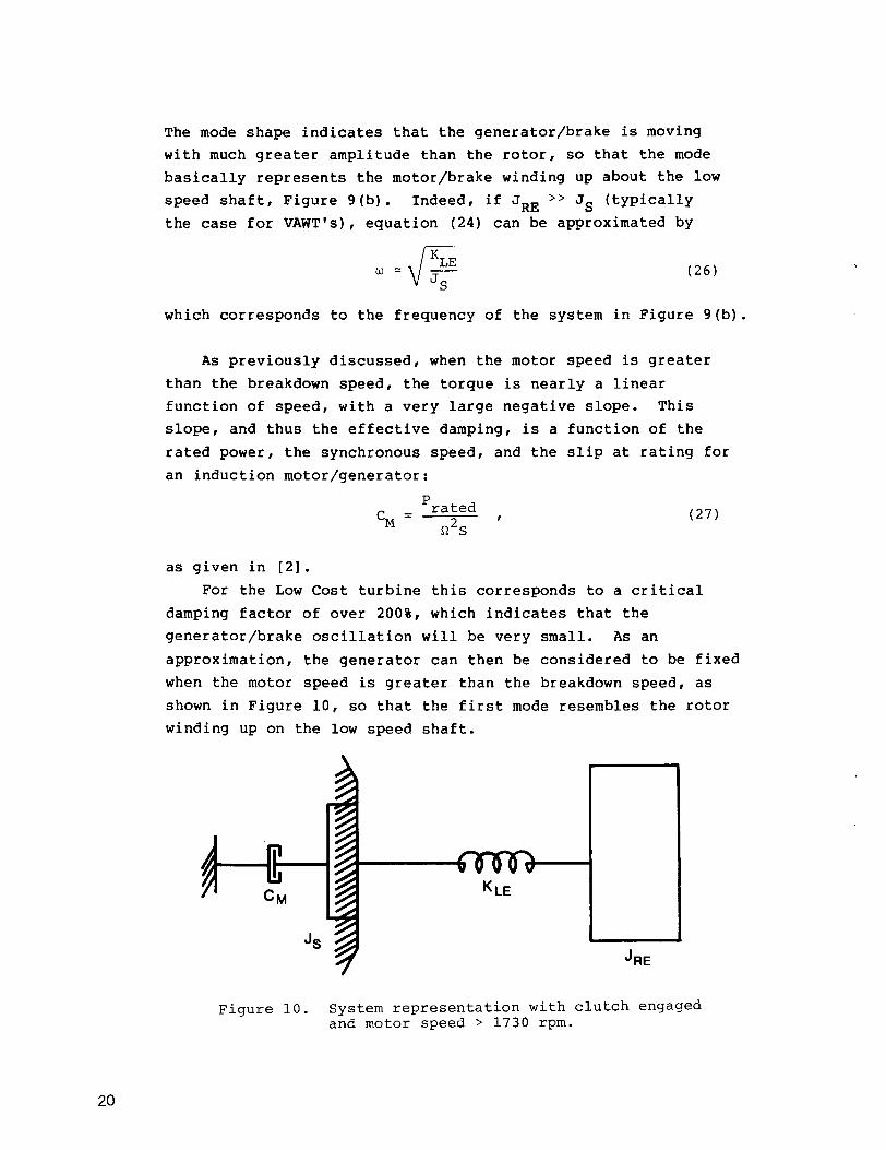
For the Low Cost turbine this corresponds to a critical
damping factor of over 200%, which indicates that the
generator/brake oscillation will be very small. As an
approximation, the generator can then be considered to be fixed
when the motor speed is greater than the breakdown speed, as
shown in Figure 10, so that the first mode resembles the rotor
winding up on the low speed shaft.
‘RE
J~
Figure 10. System representation with clutch engageda;d motor-speed > 1730 rpm.
20

The frequency for the system in Figure 10 is simply
4‘LEus—.‘RE
(28)
~Jerimental Record - Base Case
The Low Cost 17M turbine at Rocky Flats is instrumented
with a torque sensor located on the low speed shaft. A typical
start-up record taken in zero ambient wind speed is shown in
Figure 11. The experimental record was used to develop a base
case which could be used to verify the predictive capabilities
of the model, as well as to fix certain parameters that could
not accurately be calculated analytically or experimentally.
The parameters which were varied were the viscous damping
coefficient and the motor scale factor. There are several
characteristics which are typical of a start-up record: the
initial overshoot and subsequent decay, and then the growth of
torque oscillations to the largest peak torque, and the
frequency shift that occurs just after the peak is reached.
Note that the maximum torque (40,000 ft-lb) is over 2.5 times
the rated turbine torque (15,000 ft-lb). The time to start is
also an important characteristic. Several non-linear effects
are apparent in the record as well; the decay envelope is not
smc)oth,which indicates non-viscous damping, and gear slack is
evident (note the ‘notch’ when the sign of the torque changes
near the end of the record). The model does not attempt to
explain or predict these non-linear effects.
DYDTA results for this base case are shown in Figures 12-15.
Varying the motor scale factor changes the starting time and
the magnitude of torque, while varying the viscous damping
coefficient primarily affects the initial rate of decay and to
a lesser extent the magnitude of torque oscillations. The
final value for the motor scale factor is 0.665, which
21

come
10
.
:o“
o0
0,
00
mo
u)
U3
Ny
oco
oOo
o“y
.i-ll-l
22

x
2.0
1.0
0.0
-1.0
-2.0
-3.0
-4.0
-5.0
-6.00.0
I I I I I I 1 I I
29,300
.
I I I I 1 I I I 1
2.0 4.0 6.0 8.0
12. DYDTA prediction -during start-up in
10.0 12.0 14.0
TIME(SEC)
Low speed shaft torquezero wind - no clutch.
16.0 18.0 20.0
vs. time
NLA)

o0al ...
co
1=
.*“IIn
.m
.
Io00
\
I
o0co
o0
o0ol
00,00o*wo*om0.0
●
mr+a)
L15.5’i%
24

2000
1800
1600
1400
1200
1000
0.0 2.0 4.0 6.0 8.0 10.0 12.0 14.0 16.0 18.0 20.0
TIME-SEC
Figure 14. DYDTA prediction - Motor speed vs. time for start-upin zero wind - no clutch.
800
600
400
200
0
60
50
40
30
20
10
00.0
I 1 I 1 I I I 1 I
2.0 4.0 6.0 8.0 10.0 12.0 14.0 16.0 18.0 20.0
TIME-SEC
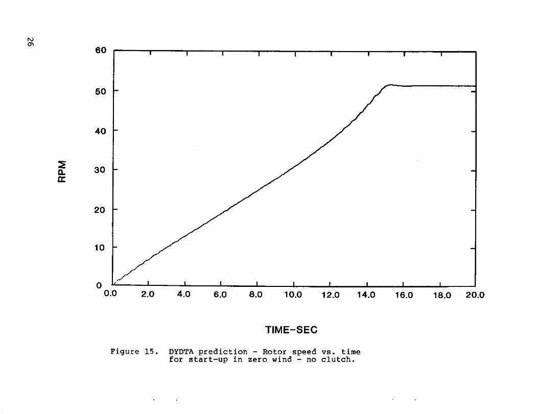
Figure 15. DYDTA prediction - Rotor speed vs. timefor start-up in zero wind - no clutch.

corresponds to an 18% voltage drop in the line. This is not
unreasonable as the current drawn by the motor is rather high
and the line is fairly long at the Rocky Flats site. obviously
the?scale factor depends on the particular motor and electrical
arrangement for a given VAWT design. The viscous damping
coefficient was determined to be 1.1 x 10³ lb-ft-see,
corresponding to a damping factor of approximately one
percent. This is insignificant compared to damping provided by
the motor and thus the influence of viscous damping due to the
structure on the response is negligible.
The results from DYDTA, after adjustment of the scale
factor and viscous damping coefficient, show excellent
agreement with the field data (Figure 11), and the simple drive
tralinmodel can be used to explain the characteristics typical
of a VAWT start-up in zero wind. DYDTA correctly predicts the
magnitude of the initial overshoot and the subsequent decay.
The initial overshoot is due to the step in torque which occurs
when the motor is turned on; the amplitude should be
approximately twice the initial motor torque (locked rotor
torque). When the motor speed is less than the pull-up speed
(725 rpm) the motor contributes a small amount of positive
damlping, and together with the viscous damping due to the
structure it causes the oscillations to decay in the typical
envelope fashion. However, the rate of decay constantly
decreases and eventually becomes zero as the damping from the
motor goes from positive at locked rotor to zero at pull-up and
becomes negative beyond that.
The growth of torque oscillations occurs when the damping
produced by the motor becomes negative, an effect also
predicted by DYDTA, Figure 12. Negative damping results in
energy addition to the system, which causes an unstable growth
in the amplitude of the torque oscillations. The maximum
torque seen by the low speed shaft occurs at approximately the
time the motor breakdown speed is reached, when the motor
damping changes rapidly from negative to positive. As

explained earlier, there is a frequency shift at this point as
well: prior to breakdown, the total damping is relatively
small, and thus it does not significantly affect the 1st
fundamental frequency. Since the rotor inertia is much larger
than the motorlbrake inertia, the vibrational mode basically
consists of the motorlbrake winding up on the low speed shaft.
Past breakdown the large positive damping produced by the motor
effectively reduces the motor\brake vibration to zero, so that
the first mode shape becomes the rotor oscillating about the
low speed shaft. There is a significant decrease in the
fundamental vibrational frequency past breakdown due to the
large size of the rotor inertia relative to that of the
motor\brake. Again, DYDTA is in very good agreement with field
data with regard to these phenomena. DYDTA also matches
experimental records on starting times, which essentially
depends on rotor inertia and mean motor torque.
Figure 13 demonstrates the variation of motor torque as a
function of time, which is another critical aspect of VAWT
start-up. Up until breakdown the motor draws very high levels
of current, and the motor can draw high power for only a short
period of time. Past breakdown the current is reduced, so it
is clearly advantageous to reduce the time to breakdown (tBD)
as much as possible. For the base case tBD is about 14.7
seconds. Figures 14 and 15 show the speeds of the motor\brake
and rotor, respectively as functions of time. They serve to
verify that the turbine successfully comes up to speed, as well
as to substantiate what has been said earlier in regard to the
mode shapes (the rotor motion is almost entirely a rigid body
mode whereas the motor contains a significant amount of
oscillation about the rigid body mode).
Control of Transients with a Slip Clutch
High torques experienced in the low speed shaft of the Low
Cost 17M turbine resulted in the investigation of a slip clutch
28
as a possibility for reducing peak torques. DYDTA has been
used to analyze the effect of a slip clutch on torque levels
during start-up. The results indicate a clutch could
significantly lower the peak torques seen by the low speed
shaft, with the following secondary benefit. The clutch also
reduces the time to breakdown for the motor (t~D), which
reduces the current drawn by the motor and protects it from
overload. It appears that an appropriately chosen clutch would
be well within margins of safety with respect to heat
dissipation and power absorption capabilities.
The characteristics of a typical slip clutch were discussed
earlier; recall that the clutch passes torque uniformly up to
sc)memaximum value (Tmax) which can be adjusted by changing
the deflection of a compression spring. With this in mind a
parametric study was done using DYDTA to determine what value
or’range of Tmax would best reduce torque levels. Obviously
T~laxshould be above the rated turbine torque, which is 427
ft-lbs (15,000 ft-lbs referred to the low speed shaft), or else
pc)wercould be absorbed by the clutch during normal operation.
The optimum value for Tmax for the Low Cost turbine
appears to be 475 ft-lbs (16?700 ft-lbs referred to the low
speed shaft), for which the results predicted by DYDTA are
shown in Figures 16-21. With the clutch present, the maximum
tc)rquein the low speed shaft occurs during the initial
overshoot, and its magnitude has been reduced 38% from 40,000
ft-lbs to 25,000 ft-lbs. The growth of torque oscillations
dc)esnot occur because slipping of the clutch decouples the
mc~tor from the drive train, thereby isolating the low speed
shaft from the negative damping produced by the motor. Note
that the torque in the low speed shaft can exceed Tmax,
de!spite the clutch, because of the inertial reaction of the
brake. This implies that the slip clutch should be located as
close to the component needing protection as is physically
pc~ssible.
The clipping action of the clutch is demonstrated in Figure
17; the torque transmitted through the clutch cannot exceed
29

(do
2.0
1.0
x-1.0
-2.0
-3.0
-4.0
-5.0
-6.00.0
15.@s—
——. . ——. ——— — TMAX
(REFERRED TO LOW
25,100 SPEED SHAFT)
Figure
2.0 4.0 6.0 8.0 10.0 12.0 14.0 16.0
TIME(SEC)
16. DYDTA prediction - Low speed shaft torqueduring start-up in zero wind with clutch.
vs. time
18.0 20.0

500
250
0
-250
-500
-750
-1000
-1250
-1500
0.0 2.0 4.0 6.O 8.0 10.0 12.0 14.0 16.0 18.0 20.0
TIME(SEC)
Figure 17. DYDTA prediction - Torque transmitted through clutchvs. time during start-up in zero wind with clutch.

L.dN
1200
1000
800
600
400
200
0
-200
.
.
1 I I 1 1 I 1 1 I
0.0 2.0 4.0 6.0 8.0 10.0 12.0 14.0 16.0 18.0 20.0
TIME-SEC
Figure 18. DYDTA prediction - Motor tOrque vs. time forstart-up in zero wind with clutch.

zna
I‘1
I
1
2000
1800
1600
1400 ~
1200
1000
800 iI
600
400
200 ,
I 1 I 1 1 I I I I
o I 1 I 1 I 1 1 I I I
0.0 2.0 4.0 6.0 8.0 10.0 12.0 14.0 16.0 18.0 20.0
TIME-SEC
Figure 19. DYDTA prediction - Motor speed vs. time forstart-up in zero wind with clutch.

2000
1800
1600
1400
1200
1000
800
600
400
200
00.0- 2.0 4.0 6.0
Figure 20. DYDTA prediction
start-up in zero
8.0 10.0 12.0 14.0 16.0 18.0 20.0
TIME-SEC
- Clutch speed (rotor side) vs. time for
wind.
@ 40.00-
x 35.0
30.00
#> 25.0y
mJ 20.0a
$: 15.0
10.0
5.0
0.0
CLUTCH POWER DISSIPATION VS. TIMETMAX=475
HEAT DISSIPATED 27 X 103 LB-FT
(OBTAINED By INTEGRATING pOwER CURVE)
CLUTCH LIMITS FOR 30 SEC SLIPMAX p0wER=56 x @ LB-FT/sECMAX HEAT =17 x 105 LB-FT
0.0 2.0 4.0 6.0 8.0 10.0 12.0t
14.0 16.0 18.0 20.0
TIME(SEC)
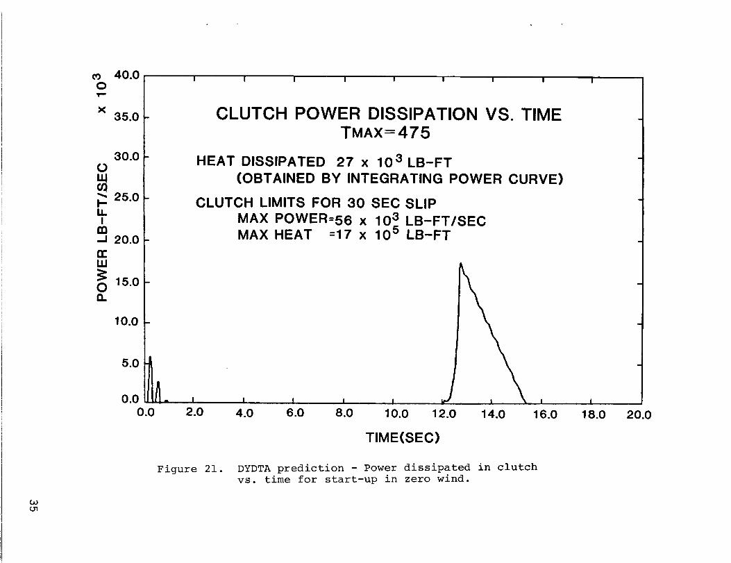
Figure 21. DYDTA prediction - Power dissipated in clutchvs. time for start-up in zero wind.

T As discussed previously, a secondary benefit is thatmax”the clutch reduces tBD for the motor. Figure 18 shows that
the high torque part of the motor curve is sped through very
rapidly, and tBD is reduced to 12.6s from 14.7s for no
clutch. Figures 19 and 20 can be compared to determine at what
times the clutch is slipping. The power dissipated in the
clutch as a function of time, and the total heat dissipated
(obtained by integrating the power curve) are shown in Figure
21.
Conclusions
DYDTA represents an initial step towards understanding and
analyzing methods of controlling transient behavior in VAWT
drive trains. Results for start-up in zero wind speed show
exceptional agreement with experimental records on the Low Cost
17M turbine, thus providing verification of modeling accuracy.
DYDTA is currently being used to predict responses for several
different transient operations and possible design
modifications intended to reduce transient torque levels. It
is expected to become a versatile, easily implemented drive
train design tool.
Acknowledgments
The assistance of the following is gratefully
acknowledged: T. M. Leonard for his programming ideas and
support, P. S. Veers and K. W. Schuler for their help towards
understanding and describing the slip clutch, and W. N.
Sullivan for the initiation of this project.
References
1. Reuter, R. C., “Torque Ripple in a Darrieus Vertical AxisWind Turbine,” Sandia National Laboratories Report No.SAND80-0475, September 1980.
2. Mirandy, L. P., “Rotor/Generator Isolation for WindTurbines,” Journal of Energy, Vol. 1, No. 3, May-June, 1977.

Appendix A
Description of Computer Code DYDTA
DYDTA, DYnamic Drive Train Analysis, is a Fortran code which is
intended primarily for solution of the transient dynamics
problems associated with VAWT drive trains. The inherent
phenomenon associated with steady state operation of a VAWT
called torque ripple can also be studied with the coder
although at this time the method developed by Reuter [1] is
recommended. The code is presently in a state of development,
and complete documentation will be published at a later date.
DYDTA is capable of obtaining the solution for any feasible
drive train topology, whereas the solution approach taken in
this paper is a special case. The number of different
configurations of a VAWT drive train are relatively small
because the locations of the rotor and generator are
essentially fixed. The capability to solve different
topc>logies is a very powerful tool because it enables
comparative studies of high speed vs. low speed brakes, as well
as the relative effectiveness of a clutch in differing
locations in the drive train. The equations of motion are
written based on a lumped parameter model of the structure, and
solved using ODE (Ordinary Differential Equations) , a library
subroutine which performs numerical integration. A slip clutch
and timing belt are included in the model for generality,
however, the user can negate the effect of these components
with appropriate choice of input. For example, by inputting a
very large value for the maximum torque transmitted by the slip
clutch its effect will be negated, since the maximum torque
will.not be reached and the clutch will not slip.
37

The code is written to be fully user-interactive; the user
is prompted for all input. Required input includes mechanical
properties of the system (inertia, damping and stiffness), gear
ratios, and a code number for the desired drive train
topology. The user must also input information which
characterizes the applied torques (motor, brake, and/or
aerodynamic) which are to be considered. Typically this
consists of inputting several points of torque vs. speed and/or
time data. Optional input includes the initial conditions and
the integration parameters, although default values exist.
Output can be in either tabular or plot form, and the amount of
information is controlled by user input. Available output
includes speed, torque, and power as functions of time in all
relevant mechanical components.
38
Appendix B
Behavior of a Slip Clutch
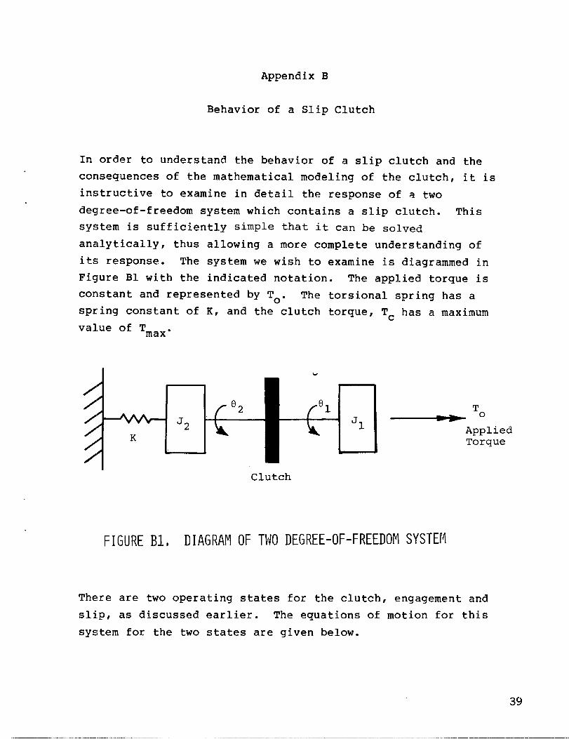
In order to understand the behavior of a slip clutch and the
consequences of the mathematical modeling of the clutch, it is
instructive to examine in detail the response of a two
degree-of-freedom system which contains a slip clutch. This
system is sufficiently simple that it can be solved
analytically, thus allowing a more complete understanding of
its response. The system we wish to examine is diagrammed in
Figure B1 with the indicated notation. The applied torque is
constant and represented by To. The torsional spring has a
spring constant of K, and the clutch torque, T- has a maximum
value of Tmax.
/’/“/“ ~/’ ~ ‘2
/;/
●
‘1To
AppliedTorque
Clutch
FIGUREB1, DIAGRAMOF TWO DEGREE-OF-FREEDOPISYSTEM
There are two operating states for the clutch, engagement and
slip, as discussed earlier. The equations of motion for this
system for the two states are given below.
39
Engagement Equations
(Jl + J2)62 + Kf32 = T0’
. .
01 = ‘2 ‘
ITCI < Tmax ,.
..Tc = To - J181
(Bl)
(B2)
(B3)
(B4)
Slip Equations
..
‘A = ‘o - ‘c ‘ (B5)
..
‘2e2 + ‘e2 = ‘c ‘
‘rc = + T— max “
(B6)
(B7)
In order to solve these equations in a simple form so as to
observe the behavior of the clutch, we can use the homogeneous
initial conditions
6,(0) =6a(0) =0 and 6,(0) =6-(O) =0 , (B8)L L
and let Tmax = 1.25 To
and set Jl = J2 .
At t=O there is no slipping
equations apply. Equations
conditions (B8) produce the
J- L
(B9)
(B1O)
of the clutch and the engagement
(Bl), (B2) and the initial
solution
‘1 = > (l-coswlt), LOl =
6’
(Bll)
40
These solutions apply
point in time, ts, at
ever, can be computed
Using (Bll) and (B1O)
as long as the clutch stays engaged. The
which the clutch starts to slip, if
from the clutch torque equation (B4),..
Tc =To - ’161 “
Tc = To(l - + Cosult) . (B12)
We see in (B12) that the clutch torque initially has a value of
Toj’2and then increases with time. The clutch torque would
have a maximum value of 1.5 To except that it exceeds Tmax,
so the clutch will start to slip before that point. To find
the time at which the clutch slips, ts, we use (B9) in the
abc~veequation to find
ts=; IT/w1“
(B13)
Thus, the clutch starts to slip when t = @l. If the clutch
did not exist, then 01 and f32would continue to be equal and
increase as in (Bll), reaching their maximum value of 2To/K
at t = n/w”.1
However, for t > ts the slip equations apply
until reengagement occurs when ~c~Oand~1=~2.
Using (Bll) and (B13), new initial conditions can be computed
for the slip equations of motion.m
el(ts) = e2(ts) = ;: , and
;l(ts) = 62(ts) =6 ‘oZwl-l?”
Now applying the slip equations (B5), (B6), and (B7) with
Tc = + Tmax, we find
..IT
‘1°1 = - 4 0, and
..
‘2°2 + ’02=;To.
(B14)
(B15)
These equations show a key behavior of the clutch. Up to this
point of time, ts, 01 = e2. However, when the clutch is
41
slipping, {l + ~z, consequently the velocities and angles no
longer remain equal. Solving the equations (B15) with the
initial conditions (B14), we find
To
‘1 ‘ir-and
r
f
(B16)-1
4for all t, ts : t < te , where LIJ2= #—2
and te indicates the time when reengagement occurs, if ever.
The algebra at this point in the analysis is getting
sufficiently involved so as to obscure the physics.
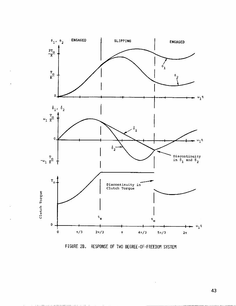
Consequently, it is best to turn now to a plot of the
solution. Figure B2 shows the two angles, the two angular
velocities, and the clutch torque all plotted as functions of
time. Examining the figure, one can see the point at which the
clutch starts to slip and when it reengages. When the clutch
is slipping, the angular velocities are no longer equal.
However, the clutch is applying a torque in the direction so as
to equalize the velocities again. This happens at te when
the velocities are again equal and the clutch engages. Notealso the behavior of the clutch torque. While the clutch is
slipping, Tc = Tmax; when the clutch is engaged,
TC<T One can also observe from the figure themax”discontinuity in 61 and G2when the clutch reengages.
42
To
r
oT–
0 ENGAGED1’ ‘2
I In 1 * (JJt
I1
. .‘1’ ’92
1
SLIPPING
I
I
ENGAGED
,1
1
.
I ‘2
IDiscontinuityin ?$land g
2
Tov I Discontinuity inClutch Torque
I r’I
It5
te
o a 1 1
v1 , 1 P- ut1 1
0 lT/3 2?T/3 n 471/3 5n/3 2n
FIGURE2B, RESPONSEOF TWO DEGREE-OF-FREEDOMSYSTEM
43

DISTRIBUTION: Kevin Austin
TID-4500-R66 UC-60 (283)Consolidated Edison Company ofNew York, Inc.
Aero Engineering Department (2)4 IrvingPlace
hichita State UniversityNew York, NY 10003
Wichita, KS 67208Attn: M. Snyder
B. H. Barksdale, Jr.Hayesr Seay, Mattern, and Mattern
W. Wentz 1315 Franklin Road SWRoanoke, VA 24016
R. E. Akins, Assistant ProfessorDepartment of Engineering Science Dr. P. J. Baum
and NechanicsVirginia Polytechnic Institute and
Institute of Geophysics
State Universityand Planetary Physics
Blacksburg, VA 24060University of CaliforniaRiverside, CA 92521
Alcoa Laboratories (5)Alcoa Technical CenterAluminum Company of AmericaAlcoa Center, PA 15069Attn: D. K. Ai
A. C. CraigJ. T. HuangJ. R. JombockP. N. Vosburgh
Mr . Robert B. AllenGeneral ManagerDynergy CorporationP.O. BOX 4281269 Union AvenueLaconia, NH 03246
American Kind Energy Association1609 Connecticut Avenue NWWashington, EC 20009
E. E. AndersonSouth Dakota School of Mines
and TechnologyDepartment of Mechanical
EngineeringRapid City, SD 57701
Scott Anderson “318 Minis HallUniversity of VermontBurlington, VT 05405
G. T. AnkrumDOE/Office of Commercialization20 Massachusetts Avenue NWMail Station 2221CWashington, DC 20585
HOlt AshleyStanford UniversityDepartment of Aeronautics and
Astronautics Mechanical EngStanford, CA 94305
F. K. BechtelWashington State UniversityDepartment of Electrical EngCollege’of EngineeringPullman, WA 99163
M. E. BeecherArizona State UniversitySolar Energy CollectionUniversity LibraryTempe, AZ 85281
Leon BjervigCivilingenior, MCIF“Osterbyhus”, 6990 UlfborgDK6990EENMARK
K. BergeyUniversity of OklahomaAero Engineering DepartmentNorman, OK 73069
Steve BlakeWind Energy SystemsRoute 1, Box 93-AOskaloosa, KS 66066
Robert BrulleMcDonnell-Douglas Aircraft CorpP.O. BOX 516Department 341, Building 32/2St. Louis, MO 63166
R. CamereroFaculty of Applied ScienceUniversity of SherbrookeSherbrooke, QuebecCANADA JIK 2R1
44

CERCEM49 Rue du Commandant Rolland93350 Le BourgetFRANCEAttn: G. Darrieus
J. Delassus
Professor V. A. L. ChasteauSchool of EngineeringUniversity of AucklandPrivate BagAuclkland, NEW ZEALAND
Howi~rd T. ClarkMcDonnell Aircraft CorporationP.O. BOX 516Department 337, Building 32St. Louis, MO 63166
Dr. R. N. ClarkUSDA, Agricultural Research ServiceSouthwest Great Plains Research
CenterBushland, TX 79012
Joan D. CohenConsumer Outreach CoordinatorState of New YorkExecutive DepartmentState Consumer Protection Board99 WashingtonAvenueAlbany,NY 12210
Dr. D. E. CromackAssociate ProfessorMechanical and Aerospace Eng
DepartmentUniversity of MassachusettsAmherst, MA 01003
Gale B. CurtisTumac Industries650 Ford StreetColorado Springs, CO 60915
DOE/ALO (2)Albuquerque, NM 87115Attn: G. P. Tennyson
D. W. King
DOE Iieadquarters/WESD (20)600 E Street NWWashington, DC 20545Attn: D. F. Ancona
C. E. AsplidenL. V. DivoneW. C. Reddick
C. W. DoddSchool of EngineeringSouthern Illinois UniversityCarbondale, IL 62901
D. D. DoerrKaiser Aluminum
Sales, Inc.6177 Sunol Blvd.P.O. BOX 877Pleasonton, CA
and Chemical
94566
Dominion Aluminum Fabricating
Ltd. (2)
3570 Hawkestone RoadMississauga, OntarioCANADA L5C 2u8Attn: L. Schienbein
C. Wood
D. P. DouganHamilton Standard1730 NASA BoulevardRoom 207Houston, TX 77058
J. B. DragtNederlands Enerqy Research
Foundation (E.C.N. )Physics DepartmentWesterduinweg 3 Patten (nh)THE NETHERLANDS
C. E. ElderkinBattelle-Pacific Northwest
LaboratoryP.O. Box 999Richland, WA 99352
Frank R. Eldridge, Jr.The Mitre Corporation1820 Dolley Madison Blvd.McLean, VA 22102
Electric Power Research Institute3412 Hillview AvenuePalo Alto, CA 94304Attn: E. Demeo
Richard G. Ferreira, ChiefThe Resources AgencyDepartment of Water ResourcesEnergy Division1416 9th StreetP.O. BOX 388Sacramento, CA 95802
D. R. FinleyNew England GeosystemsP.O. BOX 128East Berry, NH 03041
45
——..———..—._._ ——

James D. Fock, Jr.Department of Aerospace
Engineering SciencesUniversity of ColoradoBoulder, CO 80309
Dr . Lawrence C. FrederickPublic, Service Company of
New Hampshire1000 Elm StreetManchester, NH 03105
H. GerardinMechanical Engineering DepartmentFaculty of Sciences and Eng.Universite Laval-QuebecCANADA GIK 7P4
E. GilmoreAmarillo CollegeAmarillo, TX 79100
Paul GipeWind Power DigestP.O. Box 539Harrisburg, PA 17108
Roger T. GriffithsUniversity College of SwanseaDepartment of Mechanical Eng,Singleton ParkSwansea SA2 8PPUNITED KINGDOM
A. A. HagmanKaiser Aluminum and Chemical
Sales, Inc.14200 Cottage Grove AvenueDolton, IL 60419
Martin L. Hally, Section ManagerProject DepartmentElectricity Supply18 St. Stephen’s GreenDublin 2, IRELAND
Professor N. B. HamMassachusetts Institute
of Technology77 Massachusetts AvenueCambridge, MA 02139
Sam HansenDOE/DST20 Massachusetts AvenueWashington, DC 20545
C. F. HarrisWind Engineering Corporation
of TechnologyAirport Industrial AreaBOX 5936Lubbock, TX 79415
W. L. HarrisAero/Astro DepartmentMassachusetts InstituteCambridge, MA 02139
Terry Healy (2)Rockwell InternationalRocky Flats PlantP.O. BOX 464Golden, CO 80401
Hel ionP.O. Box 4301Sylmar, CA 91342
Don HinrichsenAssociate EditorAMBIOKVAFack, S-10405StockholmSWEDEN
Sven HugossonBOX 21048S. 100 31 Stockholm 21SWEDEN
O. IgraDepartment of Mechanical EngBen-Gurion University of the NegevBeer-Sheva, ISRAEL
Indian Oil Co”rporation, Ltd.Marketing Division254-C, Dr. Annie Besant RoadPrabhadevi, Bombay-400025INDIA
JBF Scientific Corporation2 Jewel DriveWilmington, MA 01867Attn: E. E. Johanson
Dr . Gary L. Johnson, P.E.Electrical Engineering DepartmentKansas State UniversityManhattan, KS 66506
B. C. Kaddy, Jr.Box 35331 Union StreetHillsboro, NH 03244
46

Karnan Aerospace CorporationOld Windsor RoadBloornfield, CT 06002Att:n: W. 13atesol
R. L. Katzenberg2820 Upton St. NWWashington, DC 20008
Robert E. KellandThe College of Trades and
TechnologyP.(). BOX 1693Prince Philip DriveSt.,John’s, NewfoundlandCANADA AIC 5P7
S. KingNatural Power, Inc.New Boston, NH 03070
Larry Kinnettp.o. Box 6593Santa Barbara, CA 93111
Samual H. Kohler272 Old Delp RoadLancaster, PA 17602
0. KraussMichigan State UniversityDivision of Engineering ResearchEast Lansing, MI 48824
Carol Lamb2584 East Geddes AvenueLittleton, CO 80122
Lawrence Livermore LaboratoryP.O. BOX 808 L-340Livermore,CA 94550Attn: D. w. Dorn
M. LechnerPublic Service Company
of New Mexicop.o. BOX 2267Albuquerque, NM 87103
Kalman Nagy LehoczkyCort Adelers GT. 300s10 2NORWAY
George E. LennoxIndustry DirectorMill Products DivisionReynolds Metals Company6601 best Broad StreetRichmond, VA 23261
J. LernerState Energy CommissionResearchand DevelopmentDivision1111 Howe AvenueSacramento,CA 95825
L. LiljidahlBuilding 303Agriculture Research CenterUSDABeltsville, MD 20705
P. B. S. LissamanAeroenvironment, Inc.660 South Arroyo ParkwayPasadena, CA 91105
One LjungstromFFA, The Aeronautical Research
Institute
Box 11021S-16111BrommaSWEDEN
T. H. LoganU.S. Turbine CorporationOlde Courthouse BuildingCanfield, OH 44406
J. B. LongendyckSiltex7 Capitol DriveMoonachie, NJ 07074
Los Alamos Scientific LaboratoriesP.O. BOX 1663Los Alamos, NM 87544Attn: J. D. Balcomb Q-DO-T
Beatrice de Saint LouventEstablissement d’Etudes et de
Meteorologigues77, Rue de Serves92106 Boulogne-Billancourt Cedex
RecherchesFRANCE
Ernel L. LutherSenior AssociatePRC Energy Analysis Co.7600 Old Springhouse Rd.McLean, VA 22101
L. H. J. Maile48 York Mills Rd.Willowdale, OntarioCANADA M2P 1B4

E. L. MarkowskiMOtOIOla, Inc.G.E.D.Mail Drop 14298201 E. McDowell Rd.P.O. Box 1417Scottsdale, AZ 85252
Jacques R. MaroniFord Motor CompanyEnvironmental Research and Energy
Planning DirectorEnvironmental and Safety
Engineering StaffThe American RoadDearborn, MI 48121
Frank MatanzoDardalen Associates15110 Frederick RoadWoodbine, MD 21797
H. S. Matsuda, ManagerComposite Materials LaboratoryPioneering R&D LaboratoriesToray Industries, Inc.Sonoyama, Otsu, ShigaJAPAN 520
J. R. ltcConnellTumac Industries, Inc.650 Ford St.Colorado Springs, CO 80915
James MeiggsKaman Sciences CorporationP.O. BOX 7463Colorado Springs, CC 80933
R. N. MeroneyColorado State UniversityDepartment of Civil EngineeringFort Collins, CG 80521
G. N. MonssonDepartment of Economic Planning
and DevelopmentBarrett BuildingCheyenne, WY 82602
NASA Lewis Research Center (4)21OOO Brookpark RoadCleveland, OH 44135Attn: J. Savino
R. L. Thomasw. RobbinsK. Kaza
Anthony A. NeddThe Power Company, Inc.P.O. Box 221Genesee Depot, WI 53217
V. NelsonWest Texas State UniversityDepartment of PhysicsP.O. ~OX 248Canyon,TX 79016
LeanderNicholsNaturalPower, Inc.New Boston,NH 03070
Fred Nitzche1 B AbramsEscondido Village
Ronald NousainP.O. Box 111Rome 1132Los Angeles, CA 90051
Oklahoma State University (2)Stillwater, OK 76074Attn: W. L. hughes
EE DepartmentD. K. McLaughlin
ME Department
Oregon State UniversityCorvallis, OR 97331Attn: R. E. Wilson
ME DepartmentR. W. Thresher
ME Department
Pat F. O’RourkePrecinct 4County CommissionerCity-County BuildingEl Paso, TX 79901
H. H. PaalmanDow Chemical USAResearch Center2800 Mitchell Drive
(2)
Walnut Creek, CA 94598
R. A. ParmeleeNorthwestern UniversityDepartment of Civil EngineeringEvanston, IL 60201
Helge PetersenRiso National LaboratoryDK-4000 RoskildeDENMARK
48

Wilson Prichett, IIINational Rural ElectricCooperative Association
1800 Massachusetts AvenueWashington, DC 20036
Dr. Barry Rawlinqs, Chief
Dr . Horst SeizerDipl. -Phys .Wehrtechnik und Energieforschung
NW ERNO-Raumfahrttechnik GmbHHunefeldstr. 1-5Postfach 10 59 092800 Bremen 1
Division of Mechailical Enqineerinq GERMANY
Commonwealth Scientific aid -F/esearch Organi-zation Industrial
Graham Road, HighettVictoria, 3190AUSTRALIA
Thomas W. ReddochAssociate ProfessorDepartment of Electrical EngineeringThe University of TennesseeKnoxville, TN 37916
Ray G. RichardsAtlantic Wind Test SiteP.O. BOX 18!3Tignish P.E.I.COB 2B0 CANAEA
A. RobbMemorial University of
NewfoundlandFaculty of Engineering
and Applied SciencesSt; Johnis NewfoundlandCANADA AIC 5S7
Dr. -Ing. Cans RuscheweyhInstitut fur LeichbauTechnische Hochschule AachenWullnerstrasse 7GERMANY
Gwen SchreinerLibrarianNational Atomic MuseumAlbuquerque, NM 87185
Douglas B. Seely, P.E.U.S. Department of EnergyP.O. BOX 362110:2NE HolladayPortland, CR 97208
Arnan SeginerPrclfessor of AerodynamicsTechnion-Israel Institute of
TechnologyDepartment of Aeronautical
EngineeringHaifa, ISRAEL
H. SevierRocket and Space DivisionBristol Aerospace Ltd.P.O. BOX 874viinnipeg, ManitobaCANADA R3C 2S4
P. N. ShankarAerodynamics EivisionNational Aeronautical LaboratoryBangalore 560017INDIA
David SharpeKingston PolytechnicCanbury Park RoadKingston, SurreyUNITED KINGDOM
D. G. ShepherdCornell UniversitySibley School of Mechanical and
Aerospace EngineeringIthaca, NY 14853
Dr. Fred SmithMechanical Engineering Department
HeadColorado State UniversityFt. Collins, CO 80521
Kent SmithInstituto Technologico Costa RicaApartado 159 CartagoCOSTA RICA
Leo H. SoderholmIowa State UniversityAgricultural Engineering, Room 213Ames, IA 50010
Bent SorensonRoskilde University CenteryEnergy JGroup, Bldg. 17.2IMFUFAP.O. BOX 260DK-400 RoskildeDENMARK
●

Southwest Research Institute (2)P.G. Drawer 28501San Antonio, TX 78284Attn: W. L. Donaldson,
R. K. Swanson
Rick StevensonRoute 2EIOX 85Springfield, MO 65802
Dale T. Stjernholm, P.E.Mechanical Design EngineerMorey\Stjernholm and Associates1050 Magnolia StreetColorado Springs, CO 80507
G. W. Stricker383 Van Gordon 30-559Lakewood, CO 80228
C. J. SwetRoute 4BOX 358Mt. Airy, MD 21771
John TaylorNational Research CouncilASEB2101 Constitution AvenueWashington, EC 20418
R. J. Templin (3)Low Speed Aerodynamics SectionNRC-National AeronauticalEstablishment
Ottawa 7, OntarioCANADA KIA 0R6
Texas Tech University (3)P.O. BOX 4389Lubbock, TX 79409Attn: K. C. Mehta, CE Department
J. Strickland, ME DepartmentJ. Lawrence, ME Department
Fred ThompsonAtari, Inc.155 Moffett Park DriveSunnyvale, CA 94086
J. M. Turner, Croup LeaderTerrestrial Energy Technology
Program OfficeEnergy Conversion BranchAerospace Power DivisionAero Propulsion LaboratoryDepartment of the Air ForceAir Force Wright Aeronautical
Laboratories (AFSC)Wright-Patterson Air Force Base, CH
45433
United Engineers andConstructorsr Inc.
Advanced Engineering Department30 South 17th StreetPhiladelphia, PA 19101Attn: A. J. Karalis
University of New Mexico (2)New Mexico Engineering Research
Institute
Campus, P.O. Box 25Albuquerque, N.M. 87131Attn: G. G. Leigh
University of New Mexico (2)Albuquerque, NM 87106Attn: K. T. Feldman
Energy Research CenterV. Sloglund
ME Department
Jan VacekEolienne experimentalC.P. 279, Cap-aux-MeulesIles de la Madeleine, QuebecCANADA
Irwin E. VasSolar Energy Research Institute1617 Cole Blvd.Golden, CO 80401
Otto de VriesNational Aerospace LaboratoryAnthony Fokkerweg 2Amsterdam 1017THE NETHERLANDS
R. WaltersWest Virginia UniversityDepartment of Aero Engineering1062 Kountz AvenueMorgantown, WV 26505
●
.
E. J. WarcholBonneville Power AdministrationP.O. BOX 3621Portland, OR 97225
50

D. F. Warne, ManagerEn(ergy and Power SystemsERA Ltd.Cleeve Rd.LeatherheadSurrey KT22 7SAENGLAND
G. R. hatson, Project ManagerThe Energy CenterPen,nine House4 C~sborne TerraceNewcastle upon Tyne tiE2 lNEUNITED KINGDOM
R. J. KatsonWatson Bowman Associates, Inc.1280 Niagara St.Buffalo, NY 14213
R. G. WattsTulane UniversityDepartment of Mechanical EngineeringNew Orleans, LA 70018
w. G. Wells, P.E.Associate ProfessorMechanical Engineering DepartmentMississippi State UniversityMississippi State, MS 39762
T. Wentink, Jr.University of AlaskaGeophysical InstituteFairbanks, AK 99701
West Texas State UniversityGovernment Depository LibraryNumber 613Canyon, TX 79015
Wind Energy ReportBox 14102 S. Village Ave.Rockville Centre, NY 11571Attn; Farrell Smith Seiler
Wind Program ManagerWisconsin Division of State Energy8th Floor101 South Webster StreetMadison, WI 53702
Richard E. WongAssistant DirectorCentral Solar Energy Research Corp.1200 Sixth Street328 Executive PlazaDetroit, MI 48226
1000 G. A. Fowler1200 L. D. Smith3141 T. L. Werner (5)3151 W. L. Garner (3)
For DOE/TIC (UnlimitedRelease)
Y161 J. E. Mitchell (15)3161 P. S. Wilson4533 J. W. Reed4700 J. H. Scott4710 G. E. Brandvold4715 R. H. Braasch (200)4715 J. D. Cyrus4715 R. L. Grover4715 E. G. Kadlec4715 P. C. Klimas4715 M. T. Mattison4715 R. O. Nellums4715 W. N. Sullivan4715 R. A. hatson4715 D. F. Wolf4715 M. H. Worstell
5500 0. E. Jones5510 D. B. Hayes5520 T. B. Lane5523 R. C. Reuterr Jr.5523 T. G. Carrie5523 D. B. Clauss (25)5523 D. W. Lobitz5523 D. A. Popelka5523 P. S. Veers5530 W. Herrmann5600 D. E. Schuster5620 M. M. Newsom5630 R. C. Maydew5633 R. E. Sheldahl5636 J. K. Cole5636 D. E. Berg5636 W. H. Curry8266 E. A. AasDOE/TIC (25)
(R. P. Campbell, 3172-3)
51ti~.~.GoVERNMENT PRINTING OFFICE: 1981-0-777-023/558
Related Documents