Installation guide Multimedia Adapter www.kufatec.de Kufatec GmbH • Dahlienstr. 15 • 23795 Bad Segeberg • Tel: +49(0)4551 80810-0 • Fax: +49(0)4551 80810- 50 • e-mail: [email protected] * Depending on equipment (FIS) ** Only for head unit RNS 510 Version 1.30 Multimedia Adapter Basic Plus - 35538 control version Multimedia Adapter Basic - 35537 without control Audi head unit RNS-E, RNS-D Volkswagen head unit MFD, MFD 2, RNS 2, RNS 510 Mercedes head unit Comand 2.0, 2.5 guided setup* Control lines have to be ordered separatly depending on the device you want to control. wiring - article-ID 35543 wiring - article-ID 35542 wiring - article-ID 35543 wiring - article-ID 35544 wiring - article-ID 35951*** wiring - article-ID 35546 wiring - article-ID 35579 Touchscreen operation** wiring - article-ID 35658 wiring - article-ID 35951***

Welcome message from author
This document is posted to help you gain knowledge. Please leave a comment to let me know what you think about it! Share it to your friends and learn new things together.
Transcript
Installation guideMultimedia Adapter
www.kufatec.de
Kufatec GmbH • Dahlienstr. 15 • 23795 Bad Segeberg
• Tel: +49(0)4551 80810-0 • Fax: +49(0)4551 80810- 50 • e-mail: [email protected]
* Depending on equipment (FIS)
** Only for head unit RNS 510
Version 1.30
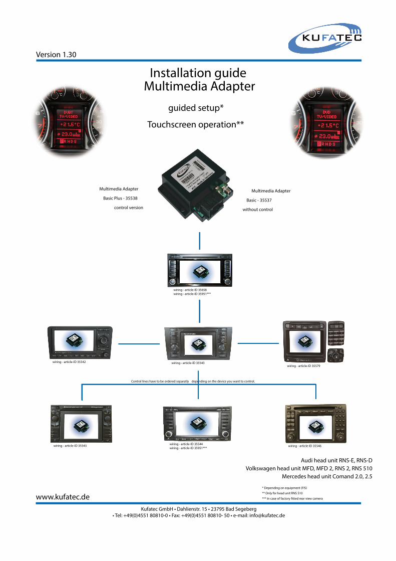
Multimedia Adapter
Basic Plus - 35538
control version
Multimedia Adapter
Basic - 35537
without control
Audi head unit RNS-E, RNS-D
Volkswagen head unit MFD, MFD 2, RNS 2, RNS 510
Mercedes head unit Comand 2.0, 2.5
guided setup*
Control lines have to be ordered separatly depending on the device you want to control.
wiring - article-ID 35543wiring - article-ID 35542
wiring - article-ID 35543wiring - article-ID 35544
wiring - article-ID 35951***wiring - article-ID 35546
wiring - article-ID 35579
Touchscreen operation**
wiring - article-ID 35658
wiring - article-ID 35951***
www.kufatec.de
Kufatec GmbH • Dahlienstr. 15 • 23795 Bad Segeberg
• Tel: +49(0)4551 80810-0 • Fax: +49(0)4551 80810- 50 • e-mail: [email protected]
Content
Safety Instructions 01
Connection diagram 02
Specifi cation 03
Control lines specifi c to devices 04
Installation instruction in case of factory fi tted (OEM) Rear view cam 05
Installation instruction Navigation RNS 510 06
Installation instruction Navigation RNS-E / MFD 2 07
Navigation RNS-D / MFD 08
Mercedes Navigation Comand 2.0 09
Guided setup RNS-E, RNS-D, MFD, MFD 2, RNS 2, Comand 2.0, Comand 2.5 10
Operating instruction Navigation RNS-E 12
Navigation MFD 2 13
Navigation MFD, RNS-D 14
Navigation Comand 2.0 15
Navigation Comand 2.5 16
Guided setup RNS 510 17
Operating instruction Navigation RNS 510 18

safety Instructions
Congratulations to your new
Multimedia Adapter. Thank you for choosing
a product of Kufatec GmbH.
Please take note that the installation can only be done by vehicles which are using a 12V battery. In
particular trucks, all-terrain vehicles and commercial diesel cars including taxis are running often with 24V
batteries and an installationis not possible in these kind of vehicles.
Take care to ensure no devices are affected or damaged that are relevant to security or safe operation of
the vehicle.
This unit is only for use in the following vehicles. Only connections described within this instruction guide
are allowed or required to use for installation.
For damage impact caused by faulty installation, unsuitable connections inappropriate vehicles Kufatec
GmbH assumes no liability.
We advise you that these units process datas out of the CAN - protocol from the vehicle. As the supplier
of this device we don‘t know the overall system you are working with. If our device causes damage due to
other changes made by to the vehicle Kufatec GmbH assumes no liability.
If the car manufaturer‘s don‘t agree with the installation of our device by reason of warranty the Kufatec
GmbH assumes no liability. Please check conditions and warranty before you begin the installation.
Kufatec GmbH supplier reserves the right to change the device specifi cations without notice.
1
2
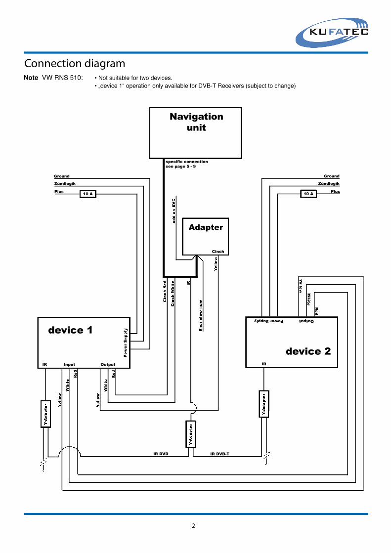
Connection diagram
Input OutputIR
PowerSupply
Ground
Zündlogik
Plus10 A
Ground
Zündlogik
Plus10 A
Adapter
Cinch
Navigation
unit
device 1
Output
IR
IR DVD IR DVB-T
device 2
specifi c connectionsee page 5 - 9
Note VW RNS 510: • Not suitable for two devices.
• „device 1“ operation only available for DVB-T Receivers (subject to change)

Technical details Multimedia Adapter
power supply - 12 Volt (10 - 15 Volts)
power input - 170 - 190 mA
standby current - 4 - 6 mA
dimensions in mm - 99 x 96,5 x 23
weight - 100 g
video signals - PAL / NTSC
RVC signal - NTSC
Title: Multimedia Adapter
circuit board
99
68
cover
connection
18-pole
8
June 2007
page 1/1
3

4
Control lines
In order to control the multimedia devices by OEM Navigation you need to have a specifi c control line which has to be connected between the main wiring and the multimedia device (DVD, DVB-T ...)
device version control line article-ID
DVD Player MP410U
DVD Player MP412U
DVD Player AIV
DVD Player Ampire DVX 50/ 100
DVD Player Bullit CDVD12
DVD Player JD2605
DVD Player 500 U
DVD Player BOSS 2500/ BV2600UA
DVD Changer 6-fach DVC62
DVD Changer 10-fach DVC10
DVD Player Roadstar 3202XUS
Alpine video interface KCE 425i
DVD Changer 6-fach Alpine DHA - S690
DVD Player Alpine DVE 5207
DVD Player DVD145
DVD Player Yamakawa MP28
DVD Player Directed Video DV 2602
USB Player Zemex
DVD Player Zemex MP20U
DVB-T Receiver Ampire100SL
DVB-T Receiver Ampire DVBT 400-2G/3G
DVB-T Receiver CKO 1080
DVB-T Receiver Bullit DVB-T
DVB-T Receiver Ampire DVBT200/ 400-1G
DVB-T Receiver Alpine TUE T150DV
USB Video Interface Alpine KCE-635UB
DVB-T Receiver Alpine TUE T-252TX
DVB-T Receiver Alpine TUE T200
DVB-T Receiver Hirschmann DVBT 2.0
DVB-T Receiver Eastern SE863-T
DVB-T Receiver Dietz 1491
DVB-T Receiver DVB2T
DVB-T Receiver D80
DVB-T Receiver DVB 600
DVB-T Zemex D90-2G
HDD Rapsody RSH 100
HDD Rapsody RSH 300
HDD Rapsody RSH 250
HDD ellion HMR-350H
HomeDock Deluxe DLO
DVD changer Zemex DVC62
in case of two devices
jack 3,5 version 1
jack 3,5 version 1
jack 3,5 version 1
jack 3,5 version 1
jack 3,5 version 1
jack 3,5 version 1
jack 3,5 version 1
jack 3,5 version 2
jack 3,5 version 2
jack 3,5 version 2
jack 3,5 version 2
jack 3,5 version 2
jack 2,5 version 2
jack 2,5 version 2
jack 3,5 version 2
jack 3,5 version 2
jack 3,5 version 2
jack 3,5 version 2
jack 3,5 version 2
jack 3,5 version 4
Westernstecker version 7
Westernstecker version 1
Westernstecker version 1
Westernstecker version 1
jack 2,5 version 1
jack 2,5 version 1
jack 2,5 version 1
S-Video connector
S-Video connector
Westernstecker version 2
Westernstecker version 2
Westernstecker version 4
Westernstecker version 5
jack 3,5 version 2
S-Video connector
jack 3,5 version 3
jack 3,5 version 3
jack 2,5 version 3
jack 3,5 version 1
specifi c connectionjack 2,5 version 6
Y - junction
35550
35550
35550
35550
35550
35550
35550
35552
35552
35552
35552
35552
35613
35613
35552
35552
35552
35552
35552
35602
35549-1
35549
35549
35549
35547
35547
35547
36247
36247
35553
35553
35689
36783
35552
38265
35574
35574
35678
35550
36044
38505
35551
DVD Player MP410U jack 3,5 version 1 35550D
DVD Player AIV jack 3,5 version 1 35550D
DVD Player Bullit CDVD12 jack 3,5 version 1 35550D
DVD Player 500 U jack 3,5 version 1 35550D
DVD Changer 6-fach DVC62 jack 3,5 version 2 35552D
DVD Player Roadstar 3202XUS jack 3,5 version 2 35552D
DVD Changer 6-fach Alpine DHA - S690 jack 2,5 version 2 35613D
DVD Player DVD145 jack 3,5 version 2 35552D
DVD Player Directed Video DV 2602 jack 3,5 version 2 35552D
DVD Player Zemex MP20U jack 3,5 version 2 35552D
DVB-T Receiver Ampire DVBT 400-2G/3G Westernstecker version 7 35549-1D
DVB-T Receiver Bullit DVB-T Westernstecker version 1 35549D
DVB-T Receiver Alpine TUE T150DV jack 2,5 version 1 35547D
DVB-T Receiver Alpine TUE T-252TX jack 2,5 version 1 35547D
DVB-T Receiver Hirschmann DVBT 2.0 S-Video connector 36247D
DVB-T Receiver Dietz 1491 Westernstecker version 2 35553D
DVB-T Receiver D80 Westernstecker version 5 36783D
DVB-T Zemex D90-2G S-Video connector 38265D
HDD Rapsody RSH 300 jack 3,5 version 3 35574H
HDD ellion HMR-350H jack 3,5 version 1 35550H
DVD changer Zemex DVC62 jack 2,5 version 6 38505D
5
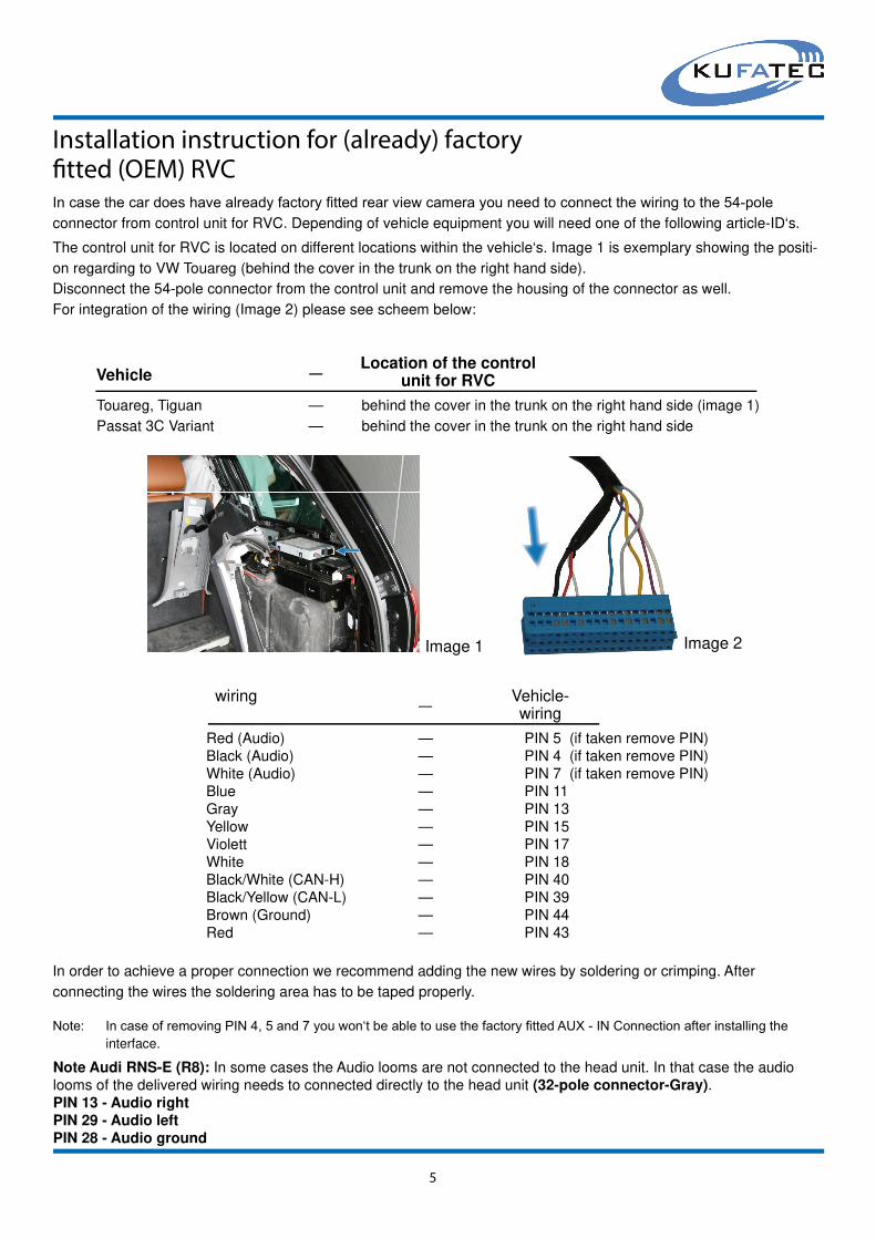
Installation instruction for (already) factory
The control unit for RVC is located on different locations within the vehicle‘s. Image 1 is exemplary showing the positi-
on regarding to VW Touareg (behind the cover in the trunk on the right hand side).
Disconnect the 54-pole connector from the control unit and remove the housing of the connector as well.
For integration of the wiring (Image 2) please see scheem below:
Red (Audio) — PIN 5 (if taken remove PIN)
Black (Audio) — PIN 4 (if taken remove PIN)
White (Audio) — PIN 7 (if taken remove PIN)
Blue — PIN 11
Gray — PIN 13
Yellow — PIN 15
Violett — PIN 17
White — PIN 18
Black/White (CAN-H) — PIN 40
Black/Yellow (CAN-L) — PIN 39
Brown (Ground) — PIN 44
Red — PIN 43
wiring Vehicle-wiring
—
In order to achieve a proper connection we recommend adding the new wires by soldering or crimping. After
connecting the wires the soldering area has to be taped properly.
Image 1 Image 2
Note: In case of removing PIN 4, 5 and 7 you won‘t be able to use the factory fi tted AUX - IN Connection after installing theinterface.
In case the car does have already factory fi tted rear view camera you need to connect the wiring to the 54-poleconnector from control unit for RVC. Depending of vehicle equipment you will need one of the following article-ID‘s.
Touareg, Tiguan — behind the cover in the trunk on the right hand side (image 1)
Passat 3C Variant — behind the cover in the trunk on the right hand side
VehicleLocation of the control
unit for RVC—
Note Audi RNS-E (R8): In some cases the Audio looms are not connected to the head unit. In that case the audio
looms of the delivered wiring needs to connected directly to the head unit (32-pole connector-Gray).
PIN 13 - Audio right
PIN 29 - Audio left
PIN 28 - Audio ground

Installation instruction RNS 510 -WITHOUT OEM RVC - High
In order to identify the softwareindex please push the „Setup“ - button of the head unit by turning on thedevice for about 20 seconds. Another screem will appear which is showing the softwareindex of the headunit.
• Tiguan, Golf 5, Touran, - Address 19 - Byte 3 - Bit 4 (Gateway Index F, K)EOS, Jetta
Byte 4 - Bit 7 (Gateway Index L)
• Touareg (08), T5 (08) - Address 19 - Byte 4 - Bit 4
• Passat 3C (08) - Address 19 - Byte 3 - Bit 7
6
FUSE
1
4
5 9
10
12
13
QUAD-LOCK
Find a suitable position for the interface within the vehicle (glove box). If everything is installed in the correct way, the
navigation will show an additional „TV“-button under menu „Media“. By choosing this source the navigation will display
the screen of the connected DVB-T Receiver. Make sure the DVB-T Receiver is connected properly to the interface.
In case of version „Basic“ (without control) you need to install an IR-connection in order to control the DVB-T Recei-
ver with the remote. The location of the DVB-T within the vehicle is up to the customer.
Black/White - Can High Pin 9
Black/Yellow - Can Low Pin 10
Brown - Ground Pin 12
Red - staedy plus source specifi c to the vehicle
Please remove the navigation unit using suitable tools, then disconnect the wiring harness from the navigation unit.
With the connection of 4 new wires you will complete the fi tting of the interface. Please see scheme below (blue mar-ked fi gures). In order to achieve a proper connection we recommend both crimping and solding the new wires.
NOTE: Is the car already equipped with factory fi tted RVC you need to complete the installation byusing wiring article-ID 35951.
NOTE: In case the navigation unit does have a software index higher then 522 the CAN-
Gateway need to be coded to TV-Tuner. Please contact your local VW Audi dealer.
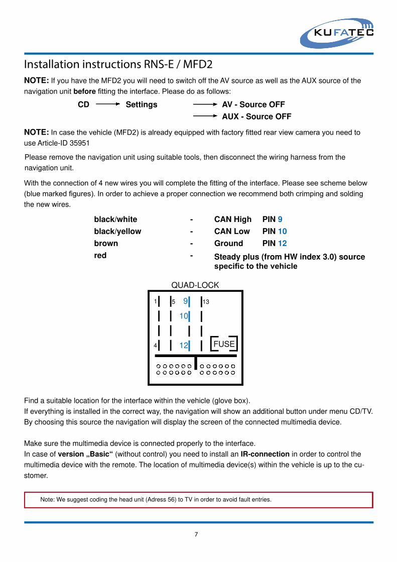
Installation instructions RNS-E / MFD2
NOTE: If you have the MFD2 you will need to switch off the AV source as well as the AUX source of the
navigation unit before fi tting the interface. Please do as follows:
7
FUSE
1
4
5 9
10
12
13
QUAD-LOCK
Find a suitable location for the interface within the vehicle (glove box).
If everything is installed in the correct way, the navigation will show an additional button under menu CD/TV.
By choosing this source the navigation will display the screen of the connected multimedia device.
Make sure the multimedia device is connected properly to the interface.
In case of version „Basic“ (without control) you need to install an IR-connection in order to control the
multimedia device with the remote. The location of multimedia device(s) within the vehicle is up to the cu-
stomer.
black/white - CAN High PIN 9
black/yellow - CAN Low PIN 10
brown - Ground PIN 12
red - Steady plus (from HW index 3.0) sourcespecifi c to the vehicle
Please remove the navigation unit using suitable tools, then disconnect the wiring harness from the
navigation unit.
With the connection of 4 new wires you will complete the fi tting of the interface. Please see scheme below (blue marked fi gures). In order to achieve a proper connection we recommend both crimping and solding the new wires.
CD Settings AV - Source OFF
AUX - Source OFF
NOTE: In case the vehicle (MFD2) is already equipped with factory fi tted rear view camera you need to use Article-ID 35951
Note: We suggest coding the head unit (Adress 56) to TV in order to avoid fault entries.
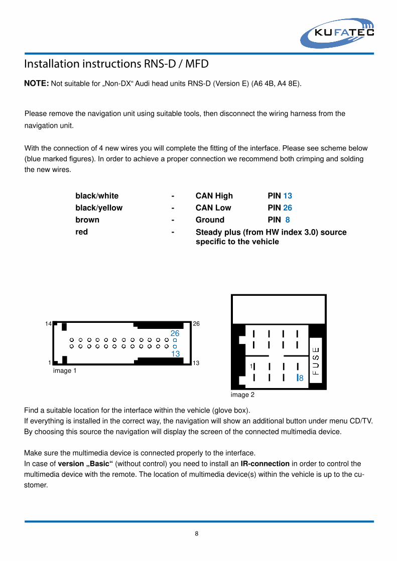
Installation instructions RNS-D / MFD
8
Please remove the navigation unit using suitable tools, then disconnect the wiring harness from the
navigation unit.
With the connection of 4 new wires you will complete the fi tting of the interface. Please see scheme below (blue marked fi gures). In order to achieve a proper connection we recommend both crimping and solding the new wires.
black/white - CAN High PIN 13
black/yellow - CAN Low PIN 26
brown - Ground PIN 8
red -
1
1313
14 26
26
1
8image 1
image 2
Find a suitable location for the interface within the vehicle (glove box).
If everything is installed in the correct way, the navigation will show an additional button under menu CD/TV.
By choosing this source the navigation will display the screen of the connected multimedia device.
Make sure the multimedia device is connected properly to the interface.
In case of version „Basic“ (without control) you need to install an IR-connection in order to control the
multimedia device with the remote. The location of multimedia device(s) within the vehicle is up to the cu-
stomer.
NOTE: Not suitable for „Non-DX“ Audi head units RNS-D (Version E) (A6 4B, A4 8E).
Steady plus (from HW index 3.0) sourcespecifi c to the vehicle
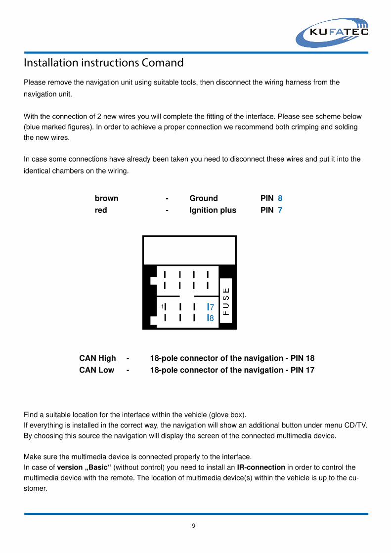
Installation instructions Comand
9
Please remove the navigation unit using suitable tools, then disconnect the wiring harness from the
navigation unit.
With the connection of 2 new wires you will complete the fi tting of the interface. Please see scheme below (blue marked fi gures). In order to achieve a proper connection we recommend both crimping and solding the new wires.
1
8
7
In case some connections have already been taken you need to disconnect these wires and put it into the
identical chambers on the wiring.
Find a suitable location for the interface within the vehicle (glove box).
If everything is installed in the correct way, the navigation will show an additional button under menu CD/TV.
By choosing this source the navigation will display the screen of the connected multimedia device.
Make sure the multimedia device is connected properly to the interface.
In case of version „Basic“ (without control) you need to install an IR-connection in order to control the
multimedia device with the remote. The location of multimedia device(s) within the vehicle is up to the cu-
stomer.
brown - Ground PIN 8
red - Ignition plus PIN 7
CAN High - 18-pole connector of the navigation - PIN 18
CAN Low - 18-pole connector of the navigation - PIN 17

10
Guided Setup RNS-E, RNS-D, MFD, MFD 2, RNS 2, Comand 2.0, 2.5
RNS-E MFD2/ RNS2 MFD RNS-D Command 2.0 Command 2.5
By pushing the „SETUP“-button of the head unit for about 6 Seconds you will step into the menu.
Note: The Setup menu will not appear on the screen of the head unit. The confi guration will only be displayed through the instru-ment cluster - passenger information system (if available) in case of head unit RNS-E as well as MFD2 / RNS2.
CON
BRI
COL
XPO
RVC RV00
RV01
1C 1C00
1C01
1Cxx
2C 2C00
2C01
2Cxx
BRI: brightness adjustment (range 0 - 63)
CON: contrast adjustment (range 0 - 63)
COL: colour adjustment (range 0 - 63)
XPO: Adjustment of the horizontal image position (range 0 - 63)
RVC: rear view camera mode
Activation (RV01) or Deactivation (RV00) of RVC mode.
1C: Confi guration Single - or Dualcontrol1C00: Control of one device. Dual-control is deactivated. The device has to be selected
by menu 2C.
In case of two devices please select the fi rst device through menu 1C01 to 1Cxx.
2C: Multimedia devices for Dual-control
This mode allows you to select the devices under menu 2C01 to 2Cxx.
CON
„SETUP“- button
BRI
„SETUP“- button
COL
„SETUP“- button
RVC
Adjustment by knob (right hand side)
Adjustment by knob (right hand side)
Adjustment by knob (right hand side)
RV00 Turn knob to the left
RV01 1 X Click to the right = RV01
„SETUP“- button
Setup
XPO
„SETUP“- button
Adjustment by knob (right hand side)

11
1C 1C00 Turn knob to the left
1C01 1 X Click to the right = 1C01
1C02 2 X Click to the right = 1C02
1Cxx xx X Click to the right = 1Cxx
2C 2C00 Turn knob to the left
2C01 1 X Click to the right = 2C01
2C02 2 X Click to the right = 2C02
2Cxx xx X Click to the right = 2Cxx
„SETUP“- button
„SETUP“- button - SETUP completed
NOTE: adjustment of 1C00 in case of only
one device. Dual-control is deactivated. The
device has to be selected by menu item 2C.
See table below
1C01 - DVD Player MP410U/ Ampire DVX 100
1C02 - DVD Player AIV/ BOA 85700
1C03 - DVD Changer 6-fach DVC62
1C04 - DVD Player DVD145
1C05 - DVB-T Receiver Alpine TUE T150DV
1C06 - DVB-T Receiver Ampire 100 SL
1C07 - DVD Player Directed Video DV 2602
1C08 - DVD Player MP412U
1C09 - DVD Player Bullit CDVD12
1C10 - Video Switch
1C11 - DVB-T Alpine TUE T-252 TX (from SW 2.76)
1C12 - DVD Player Ampire DVX50/ 51 (from SW 2.89)
1C13 - HDD ellion HMR-350 (from SW 2.89)
1C14 - DVB-T Receiver DVB 600 (from SW 2.92)
1C15 - USB Player Zemex
1C16 - DVD Player Zemex MP20U
Devices
2C01 - DVD Player MP410U/ JD2605/Ampire DVX100
2C02 - DVB-T Receiver Dietz 1491/ Receiver DVB2T
2C03 - DVB-T Receiver Eastern SE863-T
2C04 - DVD Player Yamakawa MP28
2C05 - DVD Player Xoro
2C06 - DVB-T 200T
2C07 - DVD Player BOSS 2500/ BV2600UA
2C08 - HDD Rapsody RSH 100
2C09 - DVD Player CKO MP83SE
2C10 - DVB-T Alpine TUE T150DV / TUE T200
2C11 - DVB-T Receiver CKO 1080/ BULLIT DVB-T
2C12 - Video Switch
2C13 - DVD Player AIV/ BOA 85700
2C14 - DVD Player MP412U
2C15 - DVD Changer Ampire DVC62
DVD Changer Zemex DVC62 (from SW 2.98)
2C16 - DVD Changer 10-fach DVC10
2C17 - DVD Player DVD145
2C18 - Homedock deluxe/ iPod vehicledock/iPod Video Interface Alpine KCE 425i
2C19 - DVB-T Receiver Dietz 1490 (blue housing)
2C20 - HDD Rapsody RSH 300
2C21 - DVB-T Receiver Ampire 100 SL
2C22 - DVD Player Directed Video DV 2602
2C23 - HDD Rapsody RSH 250
2C24 - customized
2C25 - DVD Changer Alpine DHA S690
2C26 - DVD Player Roadstar 3202XUS
2C27 - DVD Player Alpine DVE 5207
2C28 - DVD Player BULLIT CDVD12
2C29 - DVB-T Ampire DVBT 50/ 51/ 200/ 400 / 400 CI
2C30 - DVD Player 500U (ab SW-Stand 2.48)
2C31 - DVB-T Hirschmann CAR-TV (from SW 2.52)
2C32 - DVB-T Alpine TUE T-252 TX (from SW 2.76)
2C33 - DVB-T D80 (from SW 2.76)
2C34 - DVD Player Ampire DVX50/ 51 (from SW 2.89)
2C35 - HDD ellion HMR-350 (from SW 2.89)
2C36 - DVB-T DVB 600 (from SW 2.92)
2C37 - USB Player Zemex
2C38 - DVD Player Zemex MP20U
2C39 - USB Video Interface Alpine KCE-635UB
2C40 - DVB-T Kufatec HR-5A, 5AX/ DVB-T Ampire DVBT 52/
Ampire 55-HD/ Bullit HD 4G/ ASUKA ARA-HD
2C41 - DVB-T Zemex D90 - 2G
1Cxx 2Cxx
NOTE: For selscting device 2Cxx please
see table below

Operating instruction RNS-E
12
Operation DVD-Player-Changer
(1) „Track back“: Track back
(1) „Track back“ (4 seconds): arrow left remote
(2) „Track forward“: Track forward
(2) „Track forward“ (4 seconds): arrow right remote
(3) „Source“ (4 seconds): source switching
(4) „Rotate controller“: OK or Enter
(4) „Rotate controller (4 seconds)“: On/OFF
(4) „Rotate controller fast right“: fast-forward
(4) „Rotate controller fast left“: rewind
(4) „Rotate controller left“: arrow upwards remote
(4) „Rotate controller right“: arrow downwards remote
(5) „Return“: Play / Break
(6) DVD - menu
(6) Button 4 seconds: USB-button remote
(6) Disc-button DVD-Changer
(7) „Setup“: Setup DVD - Player
(7) „Setup“ (4 seconds): Setup Multimedia Adapter
Operation DVB-T Receiver
(1) „Track back“: sound down
(2) „Track forward“: sound louder
(3) Info button of the remote
(3) „Source“ (4 seconds): source switching
(4) „Rotate controller“: OK or Enter
(4) „Rotate controller left“: channel upwards
(4) „Rotate controller right“: channel downwards
(4) „Rotate controller“ (4 seconds): ON/ OFF DVB-T
(5) „Return“: Exit
(5) „Return“: For Ampire DVB-T 400 2G („Home“ button)
(6) EPG button remote
(7) „Setup“: menu DVB-T Receiver (Setup)
(7) „Setup“ (4 seconds): Setup Multimedia Adapter
Operation HDD-Player
(1) „Track back“: Track back
(1) „Track back“ (4 seconds): rewind
(2) „Track forward“: Track forward
(2) „Track forward“ (4 seconds): fast-forward
(3) Bookmark
(4) „Rotate controller“: OK or Enter
(4) „Rotate controller right“: arrow downwards remote
(4) „Rotate controller left“: arrow upwards remote
(5) „Return“: Stop / Exit
(6) Menu
(7) „Setup“: Setup HDD - Player
(7) „Setup“ (4 seconds): Setup Multimedia Adapter
By pushing the „SETUP“- button (7) for about 6 seconds of navigation unit you will come to the setup - menu of the interface.
(see guided setup Multimedia Adapter).
In case of installing two devices (dual-control) you can switch the video sources by pushing the button (3) for about 4 seconds.
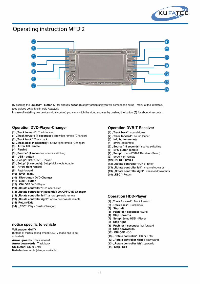
Operating instruction MFD 2
13
Operation DVD-Player-Changer(1) „Track forward“: Track forward
(1) „Track forward (4 seconds)“: arrow left remote (Changer)
(2) „Track back“: Track back
(2) „Track back (4 seconds)“: arrow right remote (Changer)
(3) Arrow left remote
(4) Rewind
(5) „Source“ (4 seconds): source switching
(6) USB - button
(7) „Setup“: Setup DVD - Player
(7) „Setup“ (4 seconds): Setup Multimedia Adapter
(8) Arrow right remote
(9) Fast-forward
(10) DVD - menu
(10) Disc-button DVD-Changer
(11) Eject - button
(12) ON/ OFF DVD-Player
(13) „Rotate controller“: OK oder Enter
(13) „Rotate controller (4 seconds): On/OFF DVD-Changer
(13) „Rotate controller left“: arrow upwards remote
(13) „Rotate controller right“: arrow downwards remote
(14) Return/Exit
(14) „ESC“: Play / Break (Changer)
Operation DVB-T Receiver(1) „Track back“: sound down
(2) „Track forward“: sound louder
(3) Info button remote
(4) arrow left remote
(5) „Source“ (4 seconds): source switching
(6) EPG button remote
(7) „Setup“: menu DVB-T Receiver (Setup)
(9) arrow right remote
(12) ON/ OFF DVB-T
(13) „Rotate controller“: OK or Enter
(13) „Rotate controller left“: channel upwards
(13) „Rotate controller right“: channel downwards
(14) „ESC“: Return
Operation HDD-Player
(1) „Track forward“: Track forward
(2) „Track back“: Track back
(3) Step left
(3) Push for 4 seconds: rewind
(4) Step upwards
(7) Setup: Setup HDD - Player
(8) Step right
(8) Push for 4 seconds: fast-forward
(8) Step downwards
(12) ON/ OFF HDD
(13) „Rotate controller“: OK or Enter
(13) „Rotate controller right“: downwards
(13) „Rotate controller left“: upwards
(14) Stop / Exit
By pushing the „SETUP“- button (7) for about 6 seconds of navigation unit you will come to the setup - menu of the interface.
(see guided setup Multimedia Adapter).
In case of installing two devices (dual-control) you can switch the video sources by pushing the button (5) for about 4 seconds.
Arrow upwards: Track forward
Arrow downwards: Track back
OK-button: OK or Enter
Mute-button: mute (always available)
notice specifi c to vehicleVolkswagen Golf V
Buttons of multi steering wheel (CD/TV mode has to be
activated):
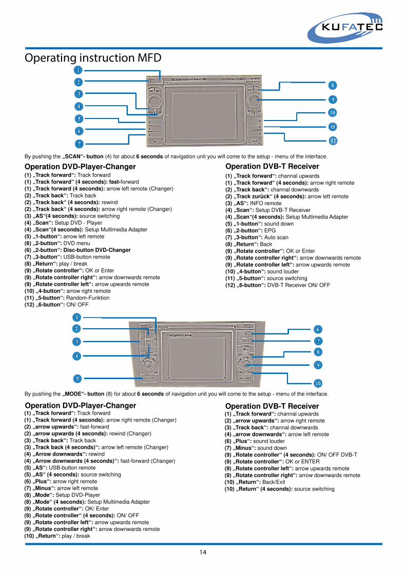
Operating instruction MFD
14
Operation DVD-Player-Changer(1) „Track forward“: Track forward
(1) „Track forward“ (4 seconds): fast-forward
(1) „Track forward (4 seconds): arrow left remote (Changer)
(2) „Track back“: Track back
(2) „Track back“ (4 seconds): rewind
(2) „Track back“ (4 seconds): arrow right remote (Changer)
(3) „AS“(4 seconds): source switching
(4) „Scan“: Setup DVD - Player
(4) „Scan“(4 seconds): Setup Multimedia Adapter
(5) „1-button“: arrow left remote
(6) „2-button“: DVD menu
(6) „2-button“: Disc-button DVD-Changer
(7) „3-button“: USB-button remote
(8) „Return“: play / break
(9) „Rotate controller“: OK or Enter
(9) „Rotate controller right“: arrow downwards remote
(9) „Rotate controller left“: arrow upwards remote
(10) „4-button“: arrow right remote
(11) „5-button“: Random-Funktion
(12) „6-button“: ON/ OFF
Operation DVB-T Receiver(1) „Track forward“: channal upwards
(1) „Track forward“ (4 seconds): arrow right remote
(2) „Track back“: channal downwards
(2) „Track zurück“ (4 seconds): arrow left remote
(3) „AS“: INFO remote
(4) „Scan“: Setup DVB-T Receiver
(4) „Scan“(4 seconds): Setup Multimedia Adapter
(5) „1-button“: sound down
(6) „2-button“: EPG
(7) „3-button“: Auto scan
(8) „Return“: Back
(9) „Rotate controller“: OK or Enter
(9) „Rotate controller right“: arrow downwards remote
(9) „Rotate controller left“: arrow upwards remote
(10) „4-button“: sound louder
(11) „5-button“: source switching
(12) „6-button“: DVB-T Receiver ON/ OFF
By pushing the „SCAN“- button (4) for about 6 seconds of navigation unit you will come to the setup - menu of the interface.
By pushing the „MODE“- button (8) for about 6 seconds of navigation unit you will come to the setup - menu of the interface.
Operation DVD-Player-Changer(1) „Track forward“: Track forward
(1) „Track forward (4 seconds): arrow right remote (Changer)
(2) „arrow upwards“: fast-forward
(2) „arrow upwards (4 seconds): rewind (Changer)
(3) „Track back“: Track back
(3) „Track back (4 seconds)“: arrow left remote (Changer)
(4) „Arrow downwards“: rewind
(4) „Arrow downwards (4 seconds)“: fast-forward (Changer)
(5) „AS“: USB-button remote
(5) „AS“ (4 seconds): source switching
(6) „Plus“: arrow right remote
(7) „Minus“: arrow left remote
(8) „Mode“: Setup DVD-Player
(8) „Mode“ (4 seconds): Setup Multimedia Adapter
(9) „Rotate controller“: OK/ Enter
(9) „Rotate controller“ (4 seconds): ON/ OFF
(9) „Rotate controller left“: arrow upwards remote
(9) „Rotate controller right“: arrow downwards remote
(10) „Return“: play / break
Operation DVB-T Receiver(1) „Track forward“: channal upwards
(2) „arrow upwards“: arrow right remote
(3) „Track back“: channal downwards
(4) „arrow downwards“: arrow left remote
(6) „Plus“: sound louder
(7) „Minus“: sound down
(9) „Rotate controller“ (4 seconds): ON/ OFF DVB-T
(9) „Rotate controller“: OK or ENTER
(9) „Rotate controller left“: arrow upwards remote
(9) „Rotate controller right“: arrow downwards remote
(10) „Return“: Back/Exit
(10) „Return“ (4 seconds): source switching

Operating instruction Comand
15
Operation DVB-T Receiver
(1) „Mute button“: Mute
(2) „Track back“: channel back
(2) „Track back (4 seconds)“: arrow left remote
(3) „Track forward“: channel forward
(3) „Track forward (4 seconds)“: arrow right remote
(4) „4-button“: sound down
(5) „6-button“: sound louder
(6) „8-button“: EPG
(7) „9-button“: Info
(8) „Star -button“: ON/ OFF DVB-T Receiver
(9) „#-button“: Setup DVB-T Receiver
(9) „#-button (4 seconds)“: Setup Mutimedia Adapter
(10) „Return/Exit remote“
(11) „Rotate controller“: OK or Enter
(11) „Rotate controller right“: arrow downwards remote
(11) „Rotate controller left“: arrow upwards remote
(12) „1-button“: Auto scan
(13) „2-button“: source switching
Operation DVD-Player-Changer
(1) „Mute button“: Mute
(2) „Track back“: Track back
(2) „Track back (4 seconds)“: arrow left remote (Changer)
(3) „Track forward“: Track forward
(3) „Track forward (4 seconds)“: arrow right remote (Changer)
(4) „4-button“: arrow left remote
(5) „6-button“: arrow right remote
(6) „8-button“: DVD menu
(6) „8-button“: Disc-button DVD-Changer
(7) „9-button“: source switching
(8) „Star-button“: ON/ OFF
(9) „#-button“: Setup DVD - Player
(9) „#-button (4 seconds)“: Setup Multimedia Adapter
(10) „Ret“: Return/Exit remote
(10) „Ret“: Play / Break (Changer)
(11) „Rotate controller“: OK or Enter
(11) „Rotate controller right“: arrow downwards remote
(11) „Rotate controller left“: arrow upwards remote
(12) „1-button“: USB-button remote
(13) „2-button“: Random
By pushing the „#“- button (9) for about 6 seconds of navigation unit you will come to the setup - menu of the interface.
(see guided setup Multimedia Adapter).
In case of installing two devices (dual-control) you can switch the video sources by pushing the „9-button“ (7) for about 4 seconds.

Operating instruction Comand
16
Operation DVB-T Receiver
(1) „Mute button“: Mute
(2) „Track back“: channel back
(2) „Track back (4 seconds)“: arrow left remote
(3) „Track forward“: channel forward
(3) „Track forward (4 seconds)“: arrow right remote
(4) „4-button“: sound down
(5) „6-button“: sound louder
(6) „8-button“: EPG
(7) „9-button“: Info
(8) „Star -button“: ON/ OFF DVB-T Receiver
(9) „#-button“: Setup DVB-T Receiver
(9) „#-button (4 seconds)“: Setup Mutimedia Adapter
(10) „Return/Exit remote“
(11) „Rotate controller“: OK or Enter
(11) „Rotate controller right“: arrow downwards remote
(11) „Rotate controller left“: arrow upwards remote
(12) „1-button“: Auto scan
(13) „2-button“: source switching
Operation DVD-Player-Changer
By pushing the „#“- button (9) for about 6 seconds of navigation unit you will come to the setup - menu of the interface.
(see guided setup Multimedia Adapter).
In case of installing two devices (dual-control) you can switch the video sources by pushing the „9-button“ (7) for about 4 seconds.
(1) „Mute button“: Mute
(2) „Track back“: Track back
(2) „Track back (4 seconds)“: arrow left remote (Changer)
(3) „Track forward“: Track forward
(3) „Track forward (4 seconds)“: arrow right remote (Changer)
(4) „4-button“: arrow left remote
(5) „6-button“: arrow right remote
(6) „8-button“: DVD menu
(6) „8-button“: Disc-button DVD-Changer
(7) „9-button“: source switching
(8) „Star-button“: ON/ OFF
(9) „#-button“: Setup DVD - Player
(9) „#-button (4 seconds)“: Setup Multimedia Adapter
(10) „Ret“: Return/Exit remote
(10) „Ret“: Play / Break (Changer)
(11) „Rotate controller“: OK or Enter
(11) „Rotate controller right“: arrow downwards remote
(11) „Rotate controller left“: arrow upwards remote
(12) „1-button“: USB-button remote
(13) „2-button“: Random

17
Guided setup RNS 510By entering the key sequence „Extras“---“V-Text“---“Zoom“ you will come to the setup. By pushing the „Back“ button (image 2) as
well as touching the screen again you will reach image 3. Now you are in the fi rst setting (Contrast). By using the rotate-controller as well as the „arrow left, right“ button you have got the possibility for individual set up. In order to reach the next setting you need to enter the key
sequence „Extras“---“V-Text“---“Zoom“---“Zurück“ again. Please see menu structure below.
In order to leave the setup please enter „Extras“---“EPG“.
In order to complete the „Fast-Setup“ you need to use the „Arrow up, down“ buttons (Image 2) just after entering the „Zoom“ button.
By entering the „Zoom“ button again you will reach the next setting (step by step). With this procedure you will complete the setup without
the display of image 3.
BRI: Adjustment of the brightness (range 0 - 63)
CON: Adjustment of the contrast (range 0 - 63)
COL: Adjustment of the colour (range 0 - 63)
XPO: Adjustment of the horizontal image position (range 0 - 63)
RVC not possible for RNS 510
Menu
1C: Confi guration Single - or Dualcontrol1C00: Control of one device. Dual-control is deactivated. The device has to be
selected by menu item 2C.In case of two devices you can choose between devices below for the fi rst devicein the circute. Choose the device under menu item 1C01 to 1Cxx.
2C: Selection DVB-T Receiver
This mode allows you to select between different devices, which you can control
by OEM head unit. Select the devices under menu item 2C01 to 2Cxx.
Image 1 Image 2 Image 3
1C01 - DVD Player MP410U/ Ampire DVX 100 1C07 - DVD Player Directed Video DV 2602
1C02 - DVD Player AIV/ BOA 85700 1C08 - DVD Player MP412U
1C03 - not available 1C09 - not available
1C04 - DVD Player DVD145 1C10 - not available
1C05 - DVB-T Receiver Alpine TUE T150DV 1C11 - DVB-T Alpine TUE T-252 TX (ab SW 2.76)
1C06 - DVB-T Receiver Ampire 100 SL 1C14 - DVB-T Receiver DVB 600 (from SW 2.92)
2C01 - DVD Player MP410U/ Ampire DVX 100
/ JD2605 (from SW-Stand 2.77)
2C02 - DVB-T Receiver Dietz 1491
2C03 - DVB-T Eastern SE863-T (from SW 2.47)
2C04 - not available
2C05 - not available
2C06 - not available
2C07 - not available
2C08 - HDD Rapsody RSH 100
2C09 - not available
2C10 - DVB-T Receiver Alpine TUE T150DV
2C11 - DVB-T Receiver CKO 1080/ BULLIT DVB-T
2C12 - not available
2C13 - DVD Player AIV/ BOA 85700 (from SW-2.77)
2C14 - DVD Player MP412U (from SW-2.77)
2C15 - not available
2C16 - not available
2C17 - DVD Player DVD 145 (from SW-2.77)
2C18 - Homedock deluxe/ iPod vehicledock/
iPod Video Interface Alpine KCE 425i (SW 2.80)
2C19 - not available
2C20 - HDD Rapsody RSH 300
2C21 - DVB-T Receiver Ampire 100 SL
2C22 - DVD Player Directed DV 2602 (from SW-2.77)
2C23 - HDD Rapsody RSH 250
2C24 - not available
2C25 - DVD Changer Alpine DHA S690 (from SW 2.77)
2C26 - DVD Player Roadstar 3202XUS (from SW-2.77)
2C27 - DVD Player Alpine DVE 5207 (from SW-2.77)
2C28 - not available
2C29 - DVB-T Receiver Ampire DVBT200
2C30 - DVD Player 500U (from SW-Stand 2.77)
2C31 - DVB-T Hirschmann CAR-TV (from SW 2.52)
2C32 - DVB-T Alpine TUE T-252 TX (from SW 2.76)
2C33 - DVB-T D80 (from SW 2.76)
2C36 - DVB-T Receiver DVB 600 (from SW 2.92)

18
Operating instruction RNS 510
Video modeIn order to choose the video-mode please enter the key sequence „Media“---“Video“.
Channel list/ additional featuresFor choosing a channel (DVB-T) enter the button „Senderliste“. You can choose between 65 channels
(depends on the DVB-T Receiver).
Furthermore you can choose the following remote options regarding to the devices:
80 - Power - ON/ OFF80 - Radio/ TV - Switching between TV-mode and digital radio (only available in specifi c regions)80 - Search - Channel scanning80 - Video Input - Choosing video-input AV1/ AV280 - Setup - Menu- button remote90 - Down - Arrow downwards- button remote90 - Exit - Exit- button remote90 - Left - Arrow left- button remote90 - OK - OK- button remote90 - Right - Arrow right- button remote90 - Up - Pfeil-Taste oben FB90 - Next - Next track90 - Previous - Previous track
AV- InputsIn order to choose the video-inputs AV1/ AV2 you need to enter the key sequence „Senderliste“---„Video
Input“. Before you need to activate the video-inputs through the menu „Setup - Medien“.
19
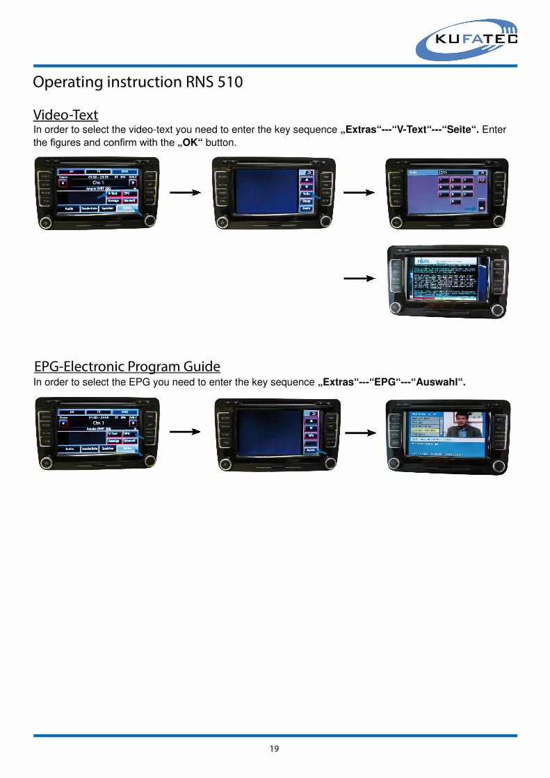
Operating instruction RNS 510
Video-TextIn order to select the video-text you need to enter the key sequence „Extras“---“V-Text“---“Seite“. Enter
the fi gures and confi rm with the „OK“ button.
EPG-Electronic Program GuideIn order to select the EPG you need to enter the key sequence „Extras“---“EPG“---“Auswahl“.

20
Operating instruction RNS 510
Operation by stalk
By pushing the upper part of the multifunctional stalk about 4 seconds you will reach
the main menu of the driver information system. Please choose the menu „Audio“
and confi rm by pushing the button underneath the stalk. Now you can switch between the Channels by using the up and down button of the
multifunctional stalk.
Note: Please switch the channels in a steady pace. Fast channel switching could cause time delays
during channel display.
Related Documents


