JTLS Version Description Document February 2006 JOINT THEATER LEVEL SIMULATION (JTLS 3.1.0.0) U.S. Joint Forces Command Joint Warfighting Center 116 Lake View Parkway Suite 100 Suffolk, VA 23435-2697 JTLS Document 17

Welcome message from author
This document is posted to help you gain knowledge. Please leave a comment to let me know what you think about it! Share it to your friends and learn new things together.
Transcript
JTLS Document 17
JTLS
Version Description Document
February 2006
JOINT THEATER LEVEL SIMULATION(JTLS 3.1.0.0)
U.S. Joint Forces CommandJoint Warfighting Center116 Lake View Parkway
Suite 100Suffolk, VA 23435-2697


February 2006 JTLS Document 17
ABSTRACT
This JTLS Version Description Document (VDD) describes Version 3.1.0.0 of the configuredsoftware suite identified as the Joint Theater Level Simulation (JTLS). JTLS 3.1.0.0 is a Majorrelease.
As a Major release, JTLS 3.1.0.0 includes a modified and enhanced Standard Database, as well asextensive model functionality changes implemented as Enhancement Change Proposals (ECPs).These ECPs are described in Chapter 2. Chapter 3 of this document describes the code modificationsthat represent corrections to Software Trouble Reports (STRs). The remaining outstanding STRs aredescribed in Chapter 4.
This publication is updated and revised for each version release of the JTLS model. User corrections,additions, or constructive recommendations for improvement must include justification and bereferenced to specific sections, pages, and paragraphs. Submissions must be written in Model ChangeRequest (MCR) format and forwarded to:
JTLS Configuration Management AgentJFCOM/JWFC116 Lake View ParkwayTest Bay 28Suffolk, VA 23435-2697
Copyright 2005, ROLANDS & ASSOCIATES Corporation
JTLS 3.1.0.0 iii Version Description Document
JTLS Document 17 February 2006
[Blank Page]
Version Description Document iv JTLS 3.1.0.0
February 2006 JTLS Document 17
TABLE of CONTENTS
1.0 INTRODUCTION 1.1 SCOPE .......................................................................................................................... 1-1 1.2 INVENTORY OF MATERIALS ................................................................................. 1-1
1.2.1 Obsolete/Outdated Documents ............................................................................ 1-1 1.2.2 Unchanged Documents ........................................................................................ 1-2 1.2.3 Updated Documents ............................................................................................. 1-2 1.2.4 New Documents ................................................................................................... 1-2 1.2.5 Released Software ................................................................................................ 1-2 1.2.6 Released Databases .............................................................................................. 1-3
1.3 INTERFACE COMPATIBILITY ................................................................................ 1-4 1.3.1 Support Software ................................................................................................. 1-4 1.3.2 HLA Compliance ................................................................................................. 1-5 1.3.3 Web Enabled Interface ......................................................................................... 1-6
1.4 INSTALLATION CONSIDERATIONS ...................................................................... 1-6 1.5 DATABASE MODIFICATIONS ................................................................................. 1-6
1.5.1 Interactive Database Upgrade .............................................................................. 1-6 1.5.2 Data Elements .................................................................................................... 1-10 1.5.3 Standard Database Changes ............................................................................... 1-17
1.6 INSTALLATION NOTES .......................................................................................... 1-17 1.6.1 Installation Instructions ...................................................................................... 1-17 1.6.2 GIAC Compatibility .......................................................................................... 1-18 1.6.3 Oracle Compatibility and Installation ................................................................ 1-18
2.0 ENHANCEMENT CHANGE PROPOSALS 2.1 JTLS-0028 NAMED MAP VIEWS .............................................................................. 2-1
2.1.1 Summary of Model Change Request ................................................................... 2-1 2.1.2 Design Summary .................................................................................................. 2-1
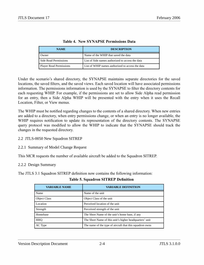
2.2 JTLS-0050 NEW SQUADRON SITREP ..................................................................... 2-4 2.2.1 Summary of Model Change Request ................................................................... 2-4 2.2.2 Design Summary .................................................................................................. 2-4
2.3 JTLS-0051 MULTIPLE ACO PROCESSING ............................................................. 2-5 2.3.1 Summary of Model Change Request ................................................................... 2-5 2.3.2 Design Summary .................................................................................................. 2-5
2.4 JTLS-0082 PASS AIRCRAFT TYPE CHANGES TO PLAYER GIACS .................. 2-6 2.4.1 Summary of Model Change Request ................................................................... 2-6 2.4.2 Design Summary .................................................................................................. 2-6
2.5 JTLS-0124 CHANGE CEP PORT WITHIN ICP ........................................................ 2-6 2.5.1 Summary of Model change Request .................................................................... 2-6 2.5.2 Design Summary .................................................................................................. 2-6
2.6 JTLS-0150 IFF IMPROVEMENT ............................................................................... 2-6
JTLS 3.1.0.0 v Version Description Document
JTLS Document 17 February 2006
2.6.1 Summary of Model Change Request ................................................................... 2-6 2.6.2 Design Summary .................................................................................................. 2-7
2.7 JTLS-0154 TARGET FILTERING ............................................................................ 2-15 2.7.1 Summary of Model Change Request ................................................................. 2-15 2.7.2 Design Summary ................................................................................................ 2-15 2.7.3 Data Changes ..................................................................................................... 2-23
2.8 JTLS-0277 TARGET UNDERGROUND FLAG ...................................................... 2-24 2.8.1 Summary of Model Change Request ................................................................. 2-24 2.8.2 Design Summary ................................................................................................ 2-24 2.8.3 Data Changes ..................................................................................................... 2-27 2.8.4 Order Changes ................................................................................................... 2-27 2.8.5 FOM Changes .................................................................................................... 2-28
2.9 JTLS-0312 USER LINES ON MAP DISPLAYS ...................................................... 2-28 2.10 JTLS-0320 UTM/MGRS CONVERSION UTILITY ............................................... 2-29
2.10.1 Summary of Model Change Request ............................................................... 2-29 2.10.2 Design Summary .............................................................................................. 2-29
2.11 JTLS-0333 SEND GROUP ORDERS ...................................................................... 2-30 2.11.1 Summary of Model Change Request ............................................................... 2-30 2.11.2 Design Summary .............................................................................................. 2-30
2.12 JTLS-0334 DISPLAY COMPLETED MISSIONS .................................................. 2-33 2.12.1 Summary of Model Change Request ............................................................... 2-33 2.12.2 Design Summary .............................................................................................. 2-34
2.13 JTLS-0343 SORT MESSAGES BY UNIT /FACTION ........................................... 2-34 2.13.1 Summary of Model Change Request ............................................................... 2-34 2.13.2 Design Summary .............................................................................................. 2-35
2.14 JTLS-0347 UNITS IN COMBAT FLAG ................................................................. 2-36 2.14.1 Summary of Model Change Request ............................................................... 2-36 2.14.2 Design Summary .............................................................................................. 2-36
2.15 JTLS-0358 COLOR UNITS BY SUPPLY LEVEL ................................................. 2-37 2.15.1 Summary of Model Change Request ............................................................... 2-37 2.15.2 Design Summary .............................................................................................. 2-37
2.16 JTLS-0397 AIR MISSION SPEED FLEXIBILITY ................................................. 2-40 2.16.1 Summary of Model Change Request ............................................................... 2-40 2.16.2 Design Summary .............................................................................................. 2-40 2.16.3 Data Changes ................................................................................................... 2-43 2.16.4 Order Changes ................................................................................................. 2-43
2.17 JTLS-0398 PROCESS ATO-T CHANGES ............................................................. 2-43 2.17.1 Summary of Model Change Request ............................................................... 2-43 2.17.2 Design Summary .............................................................................................. 2-44
2.18 JTLS-0403 EXTERNAL GRAPHICS FILE ............................................................ 2-45 2.18.1 Summary of Model Change Request ............................................................... 2-45 2.18.2 Design Summary .............................................................................................. 2-45
2.19 JTLS-0411 MANUAL PAIR PROTECTION RADIUS OVERRIDE ..................... 2-46
Version Description Document vi JTLS 3.1.0.0
February 2006 JTLS Document 17
2.19.1 Summary of Model Change Request ............................................................... 2-46 2.20 JTLS-0442 DETACHED SQUADRON MAINTENANCE .................................... 2-46
2.20.1 Summary of Model Change Request ............................................................... 2-46 2.20.2 Malfunction Maintenance Model ..................................................................... 2-47 2.20.3 Data Changes ................................................................................................... 2-50 2.20.4 Order Changes ................................................................................................. 2-50
2.21 JTLS-0501 AAR IMPROVEMENTS ....................................................................... 2-50 2.21.1 Summary of Model Change Request ............................................................... 2-50
2.22 JTLS-0521 LINK JTLS TO TBMCS ....................................................................... 2-51 2.22.1 Summary of Model Change Request ............................................................... 2-51 2.22.2 Available Data ................................................................................................. 2-52
2.23 JTLS-0522 LINK JTLS TO JDLM ........................................................................... 2-52 2.23.1 Summary of Model Change Request ............................................................... 2-52 2.23.2 Design Summary .............................................................................................. 2-54
2.24 JTLS-0525 ENTITY LEVEL SIMULATION .......................................................... 2-55 2.24.1 Summary of Model Change Request ............................................................... 2-55 2.24.2 Design Summary .............................................................................................. 2-57
2.25 JTLS-0540 MAGIC REPLENISH AIR MISSION .................................................. 2-58 2.25.1 Summary of Model Change Request ............................................................... 2-58 2.25.2 Design Summary .............................................................................................. 2-58 2.25.3 Order Changes ................................................................................................. 2-59
2.26 JTLS-0554 MULTIPLE UNITS OF MEASURE ..................................................... 2-59 2.26.1 Summary of Model Change Request ............................................................... 2-59 2.26.2 Design Summary .............................................................................................. 2-59
2.27 JTLS-2005-1409 LINK JTLS TO MDST ................................................................. 2-61 2.27.1 Summary of Model Change Request ............................................................... 2-61 2.27.2 Design Summary .............................................................................................. 2-62 2.27.3 Data Changes ................................................................................................... 2-65
2.28 JTLS-2005-1480 LIFEBOAT REPRESENTATION ............................................... 2-66 2.28.1 Summary of Model Change Request ............................................................... 2-66 2.28.2 Design Summary .............................................................................................. 2-66 2.28.3 Data Changes ................................................................................................... 2-69 2.28.4 Order Changes ................................................................................................. 2-69
2.29 JTLS-2005-1484 TANKER STAY ON ORBIT ....................................................... 2-70 2.29.1 Design Summary .............................................................................................. 2-70
2.30 JTLS-2005-1535 WHIP ICON SIZE SELECTION ................................................. 2-70 2.30.1 Summary of Model Change Request ............................................................... 2-70 2.30.2 Design Summary .............................................................................................. 2-70 2.30.3 Order Changes ................................................................................................. 2-76
2.31 JTLS-2005-1536 MODEL RUNWAY DIRECTION .............................................. 2-76 2.31.1 Summary of Model Change Request ............................................................... 2-76 2.31.2 Publishing Supply Commitment Information .................................................. 2-79 2.31.3 Data Changes ................................................................................................... 2-79
JTLS 3.1.0.0 vii Version Description Document
JTLS Document 17 February 2006
2.31.4 Order Changes ................................................................................................. 2-80 2.32 JTLS-2005-1537 TEMPLATE CREATION TOOL ................................................ 2-80
2.32.1 Summary of Model Change Request ............................................................... 2-80 2.33 JTLS-2005-1538 IMPROVED NAVAL DAMAGE ................................................ 2-80
2.33.1 Summary of Model Change Request ............................................................... 2-80 2.33.2 Data Changes ................................................................................................... 2-86 2.33.3 Order Changes ................................................................................................. 2-86
2.34 JTLS-2005-1539 IMPROVE FUEL REQUIRED DECISION ................................ 2-86 2.34.1 Summary of Model Change Request ............................................................... 2-86
2.35 JTLS-2005-1540 IMT SEARCH CAPABILITY ..................................................... 2-86 2.35.1 Summary of Model Change Request ............................................................... 2-86
2.36 JTLS-2005-1549 JTLS-RTM INTEGRATION ....................................................... 2-88 2.36.1 Summary of Model Change Request ............................................................... 2-88 2.36.2 Design Summary .............................................................................................. 2-88
2.37 JTLS-2005-1551 TBMCS IMPROVEMENTS ........................................................ 2-89 2.37.1 Design Summary .............................................................................................. 2-89 2.37.2 Order Changes ................................................................................................. 2-95
2.38 JTLS-2005-1552 REDUCE LANCHESTER DATA ............................................... 2-96 2.38.1 Summary of Model Change Request ............................................................... 2-96 2.38.2 Design Summary .............................................................................................. 2-96 2.38.3 Data Changes ................................................................................................. 2-100
2.39 JTLS-2005-1556 WEAPON LOAD RECOGNITION ........................................... 2-101 2.40 JTLS-2005-1557 MAINTAIN FEDERATION IF CEP GOES DOWN ................ 2-102
2.40.1 Design Summary ............................................................................................ 2-102 2.41 JTLS-2005-1578 PASSING CONTROL OF PROBLEMATIC ARUS ................. 2-107
2.41.1 Summary of Model Change Request ............................................................. 2-107 2.41.2 Design Summary ............................................................................................ 2-107
2.42 JTLS-2005-1596 CORRECT USMTF AIR MISSION REPORTS ....................... 2-109 2.42.1 Summary of Model Change Request ............................................................. 2-109 2.42.2 Design Summary ............................................................................................ 2-109 2.42.3 Data Changes ................................................................................................. 2-109
2.43 JTLS-0011 DEFAULT STATUS FOR HRU: COVERT UNIT REPORT ........... 2-109 2.44 JTLS-0065 INCLUDE WHETHER STATION IS TRUE OR RELATIVE ......... 2-110 2.45 JTLS-0122 SEARCH MPP MESSAGE TEXT FOR STRINGS .......................... 2-110 2.46 JTLS-0146 SETTING DESERT COLOR ............................................................. 2-110 2.47 JTLS-0164 VARIABLES AND JTLS RESTRICTED TERRAIN COLORS ...... 2-110 2.48 JTLS-0183 GENIS CLIENT REPORT HOST NAME REPORT ......................... 2-111 2.49 JTLS-0188 PROVIDE MPP ERROR MESSAGES FOR BAD STRINGS .......... 2-111 2.50 JTLS-0292 EXPAND COMMAND AUTHORITY REPORT ............................. 2-111 2.51 JTLS-0303 ALLOW MODEL TO REFUSE CLIENT CONNECTIONS ............ 2-111 2.52 JTLS-0319 JTLS PLAYBOX OUTLINE .............................................................. 2-112 2.53 JTLS-0444 UOM DISTANCE OPTION ............................................................... 2-112 2.54 JTLS-2005-1639 ADD SPEED TO HRU IMT PANEL ....................................... 2-112
Version Description Document viii JTLS 3.1.0.0
February 2006 JTLS Document 17
3.0 SOFTWARE TROUBLE REPORTS 3.1 INTRODUCTION ........................................................................................................ 3-1 3.2 ERRORS CORRECTED FOR THIS RELEASE ......................................................... 3-1
3.2.1 JTLS-0951 Air Missions Flying Backwards ........................................................ 3-1 3.2.2 JTLS-2006-1641 Unable To Cancel Holding Posture Missions .......................... 3-2 3.2.3 JTLS-2006-1663 NFS-Mounted File System Makefile Errors ............................ 3-2 3.2.4 JTLS-2006-1684 Crash Changing Air Mission Package Ingress Route .............. 3-2 3.2.5 JTLS-2006-1687 Incorrect Associated Unit On Air-Ground Attack Mission ..... 3-2 3.2.6 JTLS-2006-1688 Inconsistent Track ID Between JODA And GENIS ............... 3-3 3.2.7 JTLS-2006-1689 Aircraft Maintenance Records Not Deleted From IMT .......... 3-3 3.2.8 JTLS-2006-1690 Unable To Extend Aircraft Maintenance Times ...................... 3-3 3.2.9 JTLS-2006-1691 Missing Spaces In Message Strings ......................................... 3-4 3.2.10 JTLS-2006-1692 Unable To Change Transfer Aircraft Egress Route ............... 3-4 3.2.11 JTLS-2006-1693 Situation Report Truncated Location Coordinates ................ 3-4 3.2.12 JTLS-2006-1694 Missing Convoy Problem Report Sylesheet .......................... 3-4 3.2.13 JTLS-2006-1695 JODA Version SDC Used Modified Table Names ............... 3-5 3.2.14 JTLS-2006-1722 Improper Argument Modes In Routine Calls ........................ 3-5
4.0 REMAINING ERRORS 4.1 INTRODUCTION ........................................................................................................ 4-1 4.2 REMAINING ERRORS ............................................................................................... 4-1
4.2.1 JTLS-0639 Error Determining When Engineering Task Completed .................. 4-1 4.2.2 JTLS-0695 Shadow Distance Of Zero Overriding Protection Radius ................. 4-1 4.2.3 JTLS-0696 Missions Ignoring Assigned Altitude on Egress ............................... 4-2 4.2.4 JTLS-0697 Missions On The Ground With Invalid Destination ......................... 4-2 4.2.5 JTLS-0698 Cannot Re-Activate Destroyed Targets ............................................ 4-2 4.2.6 JTLS-0699 Targets That Require An Owner Are Disassociated ......................... 4-2 4.2.7 JTLS-0700 GIAC Not Displaying Current Runway Length ............................... 4-2 4.2.8 JTLS-0701 Air Movement Report Does Not Consider Hold Points ................... 4-2 4.2.9 JTLS-0702 Mission Waiting For Delayed Mission ............................................. 4-2 4.2.10 JTLS-0703 Periodic Report Other Side Airbases Lists No Activity ................. 4-3 4.2.11 JTLS-0704 Immediate Cancel Of Air Mission in Delay Status ........................ 4-3 4.2.12 JTLS-0705 Missions Launching With Fewer Aircraft Than Available ............. 4-3 4.2.13 JTLS-0843 Error 427 ......................................................................................... 4-3 4.2.14 JTLS-0846 Naval Unit Distance Calculation .................................................... 4-3 4.2.15 JTLS-0865 Incorrect External Program Order .................................................. 4-4 4.2.16 JTLS-0869 Continue Engage Determination ..................................................... 4-4 4.2.17 JTLS-0870 Number of Air-to-Air Combat Kills Allowed ................................ 4-4 4.2.18 JTLS-0871 AC Mission Weapon Drop Determination ..................................... 4-4 4.2.19 JTLS-0906 Change ADA pE To Per-Element pE ............................................. 4-4 4.2.20 JTLS-0907 Scud-Like SSM Representation ...................................................... 4-5 4.2.21 JTLS-0908 Naval IADS Link Representation ................................................... 4-5 4.2.22 JTLS-0909 Display Moderate And Severe Attrition Level ............................... 4-5
JTLS 3.1.0.0 ix Version Description Document
JTLS Document 17 February 2006
4.2.23 JTLS-0910 HRU Patrol Intel Reports ................................................................ 4-6 4.2.24 JTLS-0911 Fire Artillery Wait Time Between Missions ................................... 4-6 4.2.25 JTLS-0928 Weapons Selection By Aircraft ...................................................... 4-6 4.2.26 JTLS-0929 Ship Changes Sides ......................................................................... 4-6 4.2.27 JTLS-0934 HRU Overwatch .............................................................................. 4-7 4.2.28 JTLS-0942 Air Transport Cannot Combine Wet And Dry Supplies ................. 4-7 4.2.29 JTLS-0948 Lanchester Double Kills ................................................................. 4-7 4.2.30 JTLS-0949 Destroyed Target SITREP Strength Incorrect ................................ 4-7 4.2.31 JTLS-0950 JTLS Radius Of Effects .................................................................. 4-7 4.2.32 JTLS-0952 Air Report ....................................................................................... 4-8 4.2.33 JTLS-0953 All Sides Informed About Supply Dump Error .............................. 4-8 4.2.34 JTLS-0954 Multiple Supply Storage Targets .................................................... 4-8 4.2.35 JTLS-0955 Air Lift Drop Report Message ........................................................ 4-8 4.2.36 JTLS-0956 MPP Messages For Canceled Missions In Error ............................ 4-8 4.2.37 JTLS-0957 Can’t Take Control Of Unowned Runways .................................... 4-8 4.2.38 JTLS-0958 Withdrawing Units Cannot Destroy Supply Targets ...................... 4-8 4.2.39 JTLS-0959 Logistics Report Problem ............................................................... 4-9 4.2.40 JTLS-0960 Can’t Magic Move Airbase To Existing Airbase Location ............ 4-9 4.2.41 JTLS-0961 Group Ground Move Delayed To Lead Unit .................................. 4-9 4.2.42 JTLS-0962 Pass Unit Intelligence Does Not Include Update Information ........ 4-9 4.2.43 JTLS-0963 IMT Supply Category Line Disappears When Value Is Zero ......... 4-9 4.2.44 JTLS-0964 Reporting Bridge Damage ............................................................ 4-10 4.2.45 JTLS-0965 Error In Time Report For SET SP CONVOY DELAYS ............. 4-10 4.2.46 JTLS-0966 Incorrect Mission Report Locations .............................................. 4-10 4.2.47 JTLS-0967 Fire Mission Not Deleted From GENIS ....................................... 4-10 4.2.48 JTLS-0968 Inconsistency Between Regular Run And Pusher ........................ 4-10 4.2.49 JTLS-0969 Changing Mission On Alert .......................................................... 4-11 4.2.50 JTLS-0970 Availability Of Aircraft ................................................................. 4-11 4.2.51 JTLS-0971 Ship Continuous Tracking Not Working ...................................... 4-11 4.2.52 JTLS-0972 Air Mission Find In Middle Of Ocean .......................................... 4-11 4.2.53 JTLS-0973 Periodic Report Air Supplies And Fuel Not Correct .................... 4-11 4.2.54 JTLS-0974 Submarine Detection By Ground Sensors .................................... 4-11 4.2.55 JTLS-0975 GDS Target Update Error ............................................................. 4-11 4.2.56 JTLS-0976 Manual Pairing And Protection Radius ........................................ 4-12 4.2.57 JTLS-0977 Slightly Inaccurate Runway Length Sometimes Used .................. 4-12 4.2.58 JTLS-0978 Air Missions Don't Completely Comply With Egress .................. 4-12 4.2.59 JTLS-0979 Halted Helo Squadrons Show “Mission” As MOVING ............... 4-12 4.2.60 JTLS-0980 SVP Warning 22 ........................................................................... 4-12 4.2.61 JTLS-0981 Formation With No Posture .......................................................... 4-12 4.2.62 JTLS-0982 GIAC Shows HRU Mission Moving After Move Complete ........ 4-13 4.2.63 JTLS-0983 IMT/GIAC Show Insert/Extract Mission Flying .......................... 4-13 4.2.64 JTLS-0984 IMT Doesn’t Add Unit Names ..................................................... 4-13 4.2.65 JTLS-0985 PSYOP Results Multiplier ............................................................ 4-13
Version Description Document x JTLS 3.1.0.0
February 2006 JTLS Document 17
4.2.66 JTLS-0987 Set Periodic Report Times ............................................................ 4-13 4.2.67 JTLS-0988 Can’t Repair Naval Catapults ....................................................... 4-14 4.2.68 JTLS-0989 Controller Damaged Aircraft Not In Periodic Reports ................. 4-14 4.2.69 JTLS-0993 Weapons Report on Mission Report ............................................. 4-14 4.2.70 JTLS-0994 HRU Creation Target Requirements Assessed Incorrectly .......... 4-14 4.2.71 JTLS-0999 Cancel Naval Mission Fails When A Unit Is Specified ................ 4-14 4.2.72 JTLS-1006 Clearing Player Orders Also Clears User Lines ........................... 4-14 4.2.73 JTLS-1010 Controller Cannot MM NEUTRAL Unit Onto Formation ........... 4-14 4.2.74 JTLS-1017 Airlift Mission Problem ................................................................ 4-15 4.2.75 JTLS-1090 GIAC Fields Allow Spaces ........................................................... 4-15 4.2.76 JTLS-1258 RECCE Mission Heading Off The Board ..................................... 4-15 4.2.77 JTLS-1260 EMCON Order Problem Subordinates of Embarked Units .......... 4-15 4.2.78 JTLS-1328 SAM/AAA Initial Issue ................................................................ 4-15 4.2.79 JTLS-1341 Assign Multi Attack Order ............................................................ 4-16 4.2.80 JTLS-1351 Air Missions Refuel And Fly At Zero Altitude ............................ 4-16 4.2.81 JTLS-1364 ROE Setting Unstable ................................................................... 4-16 4.2.82 JTLS-1368 Orbiting OAS Assign Target ........................................................ 4-16 4.2.83 JTLS-1375 Orbit Location In Ingress Route ................................................... 4-17 4.2.84 JTLS-1376 Fuel Chits ...................................................................................... 4-17 4.2.85 JTLS-1377 Attack Posture Heading Home ...................................................... 4-17 4.2.86 JTLS-1378 Mission Refuel Chit Retrieval Button Does Not Work ................ 4-17 4.2.87 JTLS-1379 Improve Mission Splitting Capability ........................................... 4-17 4.2.88 JTLS-1380 Intercept Stopped for Refuel Chit Time ........................................ 4-17 4.2.89 JTLS-1381 Mission Stops Moving After Break-off Intercept ......................... 4-17 4.2.90 JTLS-1382 TBMCS ATO ID Problems .......................................................... 4-17 4.2.91 JTLS-1383 Alert Missions Display On COP ................................................... 4-18 4.2.92 JTLS-1384 Area, Target, And Unit Report Documentation ............................ 4-18 4.2.93 JTLS-1385 Update Detection Time Error ........................................................ 4-18 4.2.94 JTLS-1386 Accept Ownership And Use For New Runway ............................ 4-18 4.2.95 JTLS-1387 TBMCS Not Updating ATO Change Missions ............................ 4-18 4.2.96 JTLS-1390 Orbiting OAS ................................................................................ 4-18 4.2.97 JTLS-1395 External Fuel Tank Refueling ....................................................... 4-18 4.2.98 JTLS-1402 HRU SAM/AAA Targets Remain When Unit Destroyed ............ 4-19 4.2.99 JTLS-1404 Crash While Computing WDC Impact ......................................... 4-19 4.2.100 JTLS-2005-1454 WSM Terminates When Xterm Closes ............................ 4-19 4.2.101 JTLS-2005-1455 Changing Support Unit Via Naval Move Incorrect .......... 4-19 4.2.102 JTLS-2005-1456 Improper Formation Arrive Time Message ...................... 4-19 4.2.103 JTLS-2005-1457 Target Auto Assign Errors In Orbiting OAS .................... 4-19 4.2.104 JTLS-2005-1458 CAS Damage Errors From Orbiting OAS ........................ 4-20 4.2.105 JTLS-2005-1459 Delay Order Not Executed Properly ................................. 4-20 4.2.106 JTLS-2005-1460 Ship Heading Inconsistency ............................................. 4-20 4.2.107 JTLS-2005-1461 Intercepting Escort Mission Keeps Intercept Speed ......... 4-20 4.2.108 JTLS-2005-1462 Chemical Cloud Ring Not Shown .................................... 4-20
JTLS 3.1.0.0 xi Version Description Document
JTLS Document 17 February 2006
4.2.109 JTLS-2005-1463 Units in Combat While Embarked .................................... 4-20 4.2.110 JTLS-2005-1464 Location Fields Allow Invalid Location Formats ............. 4-21 4.2.111 JTLS-2005-1466 Incoming Messages Not In Correct Order ......................... 4-21 4.2.112 JTLS-2005-1467 Amphib Assault Attached Unit Listed As Detached ........ 4-21 4.2.113 JTLS-2005-1468 Perceived Aircraft Vectors Point In Wrong Direction ..... 4-21 4.2.114 JTLS-2005-1469 Shooting Side Has No Perception Of Shot Missile .......... 4-21 4.2.115 JTLS-2005-1470 Cannot Print From Solaris Machine ................................. 4-21 4.2.116 JTLS-2005-1471 Utilities Should Alter Group When Row Is Edited .......... 4-21 4.2.117 JTLS-2005-1472 Wrong IMT Screen Appears On Right Click Of Unit ...... 4-22 4.2.118 JTLS-2005-1473 Utilities Should Be Available For Deletion ...................... 4-22 4.2.119 JTLS-2005-1474 Weather Fronts Do Not Move .......................................... 4-22 4.2.120 JTLS-2005-1475 Improper Depiction Of Unit Transported By Convoy ...... 4-22 4.2.121 JTLS-2005-1476 Aircraft Orders Allowed After JCATS Has Control ........ 4-22 4.2.122 JTLS-2005-1477 WHIP Holds Open Socket Which Cannot Be Closed ...... 4-23 4.2.123 JTLS-2005-1478 Order Lines Change Position on Map .............................. 4-23 4.2.124 JTLS-2005-1479 Messages Not Deleted on Start or Restart ........................ 4-23 4.2.125 JTLS-2005-1582 OPFOR Planner ................................................................ 4-23 4.2.126 JTLS-2005-1598 Strip Alert Missions Unusable In Quick Manual Pair ...... 4-23
APPENDIX A. ABBREVIATIONS AND ACRONYMS ....................................................... A-1
APPENDIX B. COMBAT SYSTEM CATEGORY DEFINITIONS........................................B-1
APPENDIX C . VERSION 3.1 STANDARD DATABASE CHANGES..................................C-1 C.1 GENERAL MODIFICATIONS ...................................................................................C-1 C.2 ATLANTIS SCENARIO .............................................................................................C-3 C.3 EXTENDED COMBAT SYSTEM SUPPORT ...........................................................C-5 C.4 MODEL PARAMETERS ............................................................................................C-6 C.5 SCENARIO-SPECIFIC DATA ...................................................................................C-7 C.6 COMBAT SYSTEM UPGRADES ..............................................................................C-8 C.7 SUPPORTING EXISTING COMBAT SYSTEMS ...................................................C-13 C.8 REMAINING ENHANCEMENTS ...........................................................................C-14
Version Description Document xii JTLS 3.1.0.0
February 2006 JTLS Document 17
1.0 INTRODUCTION
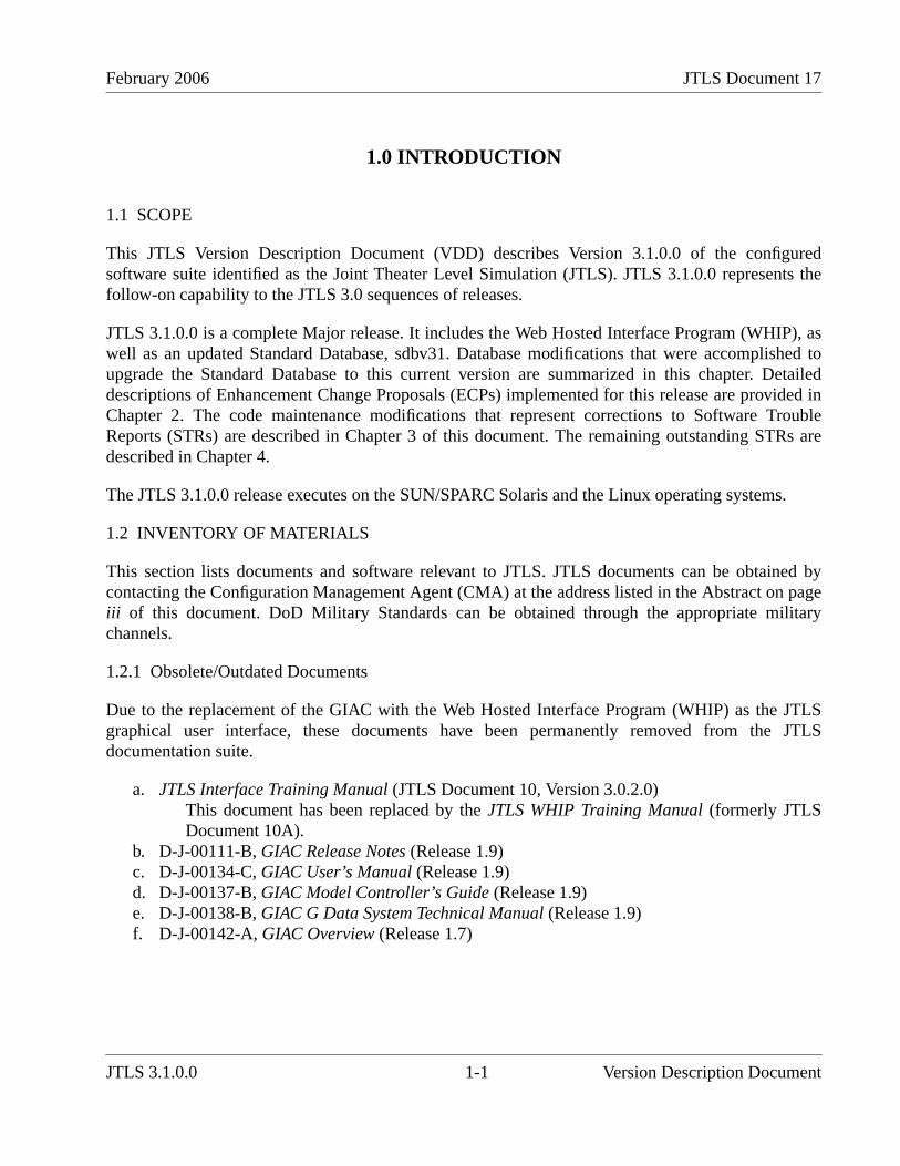
1.1 SCOPE
This JTLS Version Description Document (VDD) describes Version 3.1.0.0 of the configuredsoftware suite identified as the Joint Theater Level Simulation (JTLS). JTLS 3.1.0.0 represents thefollow-on capability to the JTLS 3.0 sequences of releases.
JTLS 3.1.0.0 is a complete Major release. It includes the Web Hosted Interface Program (WHIP), aswell as an updated Standard Database, sdbv31. Database modifications that were accomplished toupgrade the Standard Database to this current version are summarized in this chapter. Detaileddescriptions of Enhancement Change Proposals (ECPs) implemented for this release are provided inChapter 2. The code maintenance modifications that represent corrections to Software TroubleReports (STRs) are described in Chapter 3 of this document. The remaining outstanding STRs aredescribed in Chapter 4.
The JTLS 3.1.0.0 release executes on the SUN/SPARC Solaris and the Linux operating systems.
1.2 INVENTORY OF MATERIALS
This section lists documents and software relevant to JTLS. JTLS documents can be obtained bycontacting the Configuration Management Agent (CMA) at the address listed in the Abstract on pageiii of this document. DoD Military Standards can be obtained through the appropriate militarychannels.
1.2.1 Obsolete/Outdated Documents
Due to the replacement of the GIAC with the Web Hosted Interface Program (WHIP) as the JTLSgraphical user interface, these documents have been permanently removed from the JTLSdocumentation suite.
a. JTLS Interface Training Manual (JTLS Document 10, Version 3.0.2.0)This document has been replaced by the JTLS WHIP Training Manual (formerly JTLSDocument 10A).
b. D-J-00111-B, GIAC Release Notes (Release 1.9)c. D-J-00134-C, GIAC User’s Manual (Release 1.9)d. D-J-00137-B, GIAC Model Controller’s Guide (Release 1.9)e. D-J-00138-B, GIAC G Data System Technical Manual (Release 1.9)f. D-J-00142-A, GIAC Overview (Release 1.7)
JTLS 3.1.0.0 1-1 Version Description Document

JTLS Document 17 February 2006
1.2.2 Unchanged Documents
Due to the extensive changes made as part of JTLS 3.1.0.0, all remaining JTLS documents have beenrevised as a part of this release.
1.2.3 Updated Documents
The documents listed in this section have been updated for JTLS 3.1.0.0 to reflect functionalenhancements or requirements to the JTLS system included in this release.
a. JTLS Analyst’s Guide (JTLS Document 01, Version 3.1.0.0)b. JTLS ATOG User’s Guide (JTLS Document 02, Version 3.1.0.0)c. JTLS ATOT User’s Guide (JTLS Document 03, Version 3.1.0.0)d. JTLS Controller’s Guide (JTLS Document 04, Version 3.1.0.0)e. JTLS Data Requirements Manual (JTLS Document 05, Version 3.1.0.0)f. JTLS DDS User’s Guide (JTLS Document 06, Version 3.1.0.0)g. JTLS Director’s Guide (JTLS Document 07, Version 3.1.0.0)h. JTLS Executive Overview (JTLS Document 08, Version 3.1.0.0)i. JTLS Installation Manual (JTLS Document 09, Version 3.1.0.0)j. JTLS WHIP Training Manual (JTLS Document 10, Version 3.1.0.0)k. JTLS Player’s Guide (JTLS Document 12, Version 3.1.0.0)l. JTLS PPS User’s Guide (JTLS Document 13, Version 3.1.0.0)m. JTLS Standard Database Description (JTLS Document 14, Version 3.1.0.0)n. JTLS Software Maintenance Manual (JTLS Document 15, Version 3.1.0.0)o. JTLS Technical Coordinator’s Guide (JTLS Document 16, Version 3.1.0.0)p. JTLS Version Description Document (JTLS Document 17, Version 3.1.0.0)
1.2.4 New Documents
JTLS 3.1.0.0 includes the Entity Level Server, a new program designed to independently model themovement of entities represented by aggregate JTLS units. The JTLS ELS User’s Manual (JTLSDocument 19, Version 3.1.0.0), which describes the functional requirements and user proceduresimplemented for the JTLS Entity Level Server, is provided with this release.
1.2.5 Released Software
The JTLS Version 3.1.0.0 may be delivered either on a CD, or as a set of compressed tar files to bedownloaded. Either method includes the complete suite of software executable code and commandprocedures. The following software elements are included in this release:
a. Combat Events Program (CEP)b. Information Management Tool (IMT)c. Message Processor Program (MPP)d. Scenario Initialization Program (SIP)
Version Description Document 1-2 JTLS 3.1.0.0

February 2006 JTLS Document 17
e. Interface Configuration Program (ICP)f. Interface Configuration Program Login (IPCLogin)g. Order Preprocessor Program (OPP)h. Reformat Spreadsheet Program (RSP)i. Database Development System (DDS)j. Terrain Modification Utility (TMU)k. Lanchester Development Tool (LDT)l. ATO Generator Program (ATOG)m. ATO Translator Program (ATOT)n. ATO Retrieval Program (ATORET)o. Convert Location Program (XCONVERT)p. Count Critical Order Program (CCO)q. Graphical Database Program (GDP)r. HLA Interface Program (HIP)s. Post-Processor System (PPS)t. Scenario Data Client (SDC)u. Order Verification Tool (OVT)v. JTLS Object Distribution Authority (JODA)w. Web-Hosted Interface Program (WHIP) and its component programs:
1. Apache Server (APACHE)2. JTLS XML Serial Repository (JXSR)3. Order Management Authority (OMA)4. Synchronized Authentication and Preferences Service (SYNAPSE)5. Web Services Manager (WSM)6. XML Message Service (XMS)
x. Entity Level Server (ELS)y. Template Building Tool (TBT)
Instructions for installing JTLS 3.1.0.0 are provided in the JTLS Installation Manual. It is notnecessary to install any previous version of JTLS prior to installing JTLS 3.1.0.0. No other upgradebeyond installation of the compressed tar files (or CD) is required. The software that is provided is acomplete release that includes all files and code required to execute JTLS. therefor
1.2.6 Released Databases
This release includes two sample unclassified databases:
The scenario named sdbv31 is a large, seven-sided, completely notional scenario database whereinthe forces are deployed on a fictitious island landmass and in the surrounding ocean. This examplescenario, developed and maintained for the Joint Warfighting Center (JWFC), is called StandardDatabase Version 3.1.
JTLS 3.1.0.0 1-3 Version Description Document

JTLS Document 17 February 2006
The scenario blank31 is the sdbv31 database with all force structure data removed. It can be used asthe foundation to build your own database.
1.3 INTERFACE COMPATIBILITY
1.3.1 Support Software
JTLS 3.1.0.0 requires the following versions of support software, including operating systems,compilers, scripting utilities, database tools, transfer protocols, and display managers.
a. Operating system for the model (one of the following):1. Solaris 8 for use on Sun/SPARC Workstations2. Solaris 9 for use on Sun/SPARC Workstations3. Red Hat Linux Enterprise Edition Version 3.0 (ES)4. Red Hat Linux Enterprise Edition Version 4.0 (ES)
b. Operating system for workstations (one of the following):1. Solaris 8 for use on Sun/SPARC Workstations2. Solaris 9 for use on Sun/SPARC Workstations3. Red Hat Linux Enterprise Edition Version 3.0 (WS)4. Red Hat Linux Enterprise Edition Version 4.0 (WS)5. Windows 20006. Windows XP
c. Operating system for Support Software, such as HIP, SIP, etc:1. Solaris 8 for use on Sun/SPARC Workstations (except for all HLA programs)2. Solaris 9 for use on Sun/SPARC Workstations3. Red Hat Linux Enterprise Edition Version 3.0 (ES)4. Red Hat Linux Enterprise Edition Version 4.0 (ES)
d. Perl is used by the scripts that perform the DDS and PPS load/download functions. Perl isdelivered as part of the Solaris 8 OS, and is located in the /usr/bin directory. If Perl is installedin a location other than /usr/bin, a link should be created from the /usr/bin directory to the Perlprogram.
e. SIMSCRIPT II.5 Version 3.0.3 (SIMSCRIPT to C) translator/compiler: SIMSCRIPT isrequired for recompiling JTLS code. It is not necessary to have a SIMSCRIPT compiler toexecute JTLS, because all JTLS software executables are statically linked with theSIMSCRIPT libraries. The compiler is needed only if you are a U.S. Governmentorganization that can obtain source code and plan to re-compile JTLS SIMSCRIPT code. Toobtain a SIMSCRIPT compiler, contact CACI Inc.
Note: Although Solaris 8 and Solaris 9 are fully supported to operate JTLSworkstations, the Java-based Web-Hosted Interface Program(WHIP) is noticeably more efficient on Linux-based or Windows-based operating system machines.
Version Description Document 1-4 JTLS 3.1.0.0
February 2006 JTLS Document 17
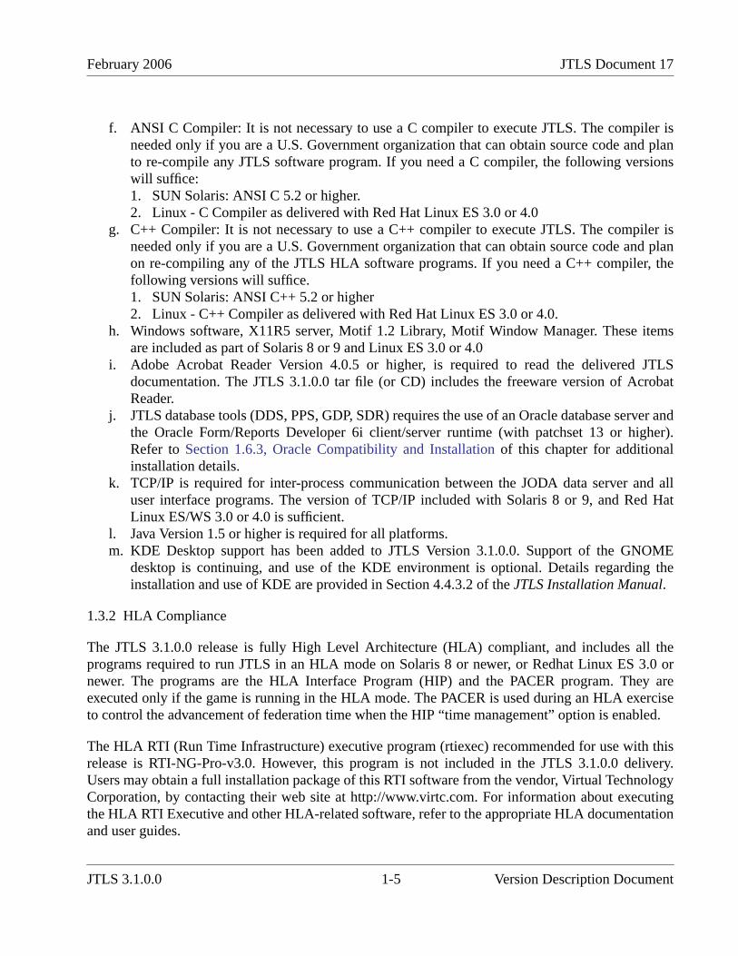
f. ANSI C Compiler: It is not necessary to use a C compiler to execute JTLS. The compiler isneeded only if you are a U.S. Government organization that can obtain source code and planto re-compile any JTLS software program. If you need a C compiler, the following versionswill suffice:1. SUN Solaris: ANSI C 5.2 or higher.2. Linux - C Compiler as delivered with Red Hat Linux ES 3.0 or 4.0
g. C++ Compiler: It is not necessary to use a C++ compiler to execute JTLS. The compiler isneeded only if you are a U.S. Government organization that can obtain source code and planon re-compiling any of the JTLS HLA software programs. If you need a C++ compiler, thefollowing versions will suffice.1. SUN Solaris: ANSI C++ 5.2 or higher2. Linux - C++ Compiler as delivered with Red Hat Linux ES 3.0 or 4.0.
h. Windows software, X11R5 server, Motif 1.2 Library, Motif Window Manager. These itemsare included as part of Solaris 8 or 9 and Linux ES 3.0 or 4.0
i. Adobe Acrobat Reader Version 4.0.5 or higher, is required to read the delivered JTLSdocumentation. The JTLS 3.1.0.0 tar file (or CD) includes the freeware version of AcrobatReader.
j. JTLS database tools (DDS, PPS, GDP, SDR) requires the use of an Oracle database server andthe Oracle Form/Reports Developer 6i client/server runtime (with patchset 13 or higher).Refer to Section 1.6.3, Oracle Compatibility and Installation of this chapter for additionalinstallation details.
k. TCP/IP is required for inter-process communication between the JODA data server and alluser interface programs. The version of TCP/IP included with Solaris 8 or 9, and Red HatLinux ES/WS 3.0 or 4.0 is sufficient.
l. Java Version 1.5 or higher is required for all platforms.m. KDE Desktop support has been added to JTLS Version 3.1.0.0. Support of the GNOME
desktop is continuing, and use of the KDE environment is optional. Details regarding theinstallation and use of KDE are provided in Section 4.4.3.2 of the JTLS Installation Manual.
1.3.2 HLA Compliance
The JTLS 3.1.0.0 release is fully High Level Architecture (HLA) compliant, and includes all theprograms required to run JTLS in an HLA mode on Solaris 8 or newer, or Redhat Linux ES 3.0 ornewer. The programs are the HLA Interface Program (HIP) and the PACER program. They areexecuted only if the game is running in the HLA mode. The PACER is used during an HLA exerciseto control the advancement of federation time when the HIP “time management” option is enabled.
The HLA RTI (Run Time Infrastructure) executive program (rtiexec) recommended for use with thisrelease is RTI-NG-Pro-v3.0. However, this program is not included in the JTLS 3.1.0.0 delivery.Users may obtain a full installation package of this RTI software from the vendor, Virtual TechnologyCorporation, by contacting their web site at http://www.virtc.com. For information about executingthe HLA RTI Executive and other HLA-related software, refer to the appropriate HLA documentationand user guides.
JTLS 3.1.0.0 1-5 Version Description Document

JTLS Document 17 February 2006
The HIP and PACER programs can be started by selecting their corresponding option buttons on theICPLogin Program. The HIP includes the capability to dynamically modify the lookahead time.Lookahead time is an offset to future time from current time, and is the value used by each federate asthe earliest possible Time-Stamp-Ordered event it can generate. For information about procedures torun the HIP and PACER programs using the ICPLogin Program, refer to the JTLS TechnicalCoordinator’s Guide, Chapter 10.
1.3.3 Web Enabled Interface
The JTLS 3.1.0.0 release supports the WHIP and Web Enabled functionality only. The workstation-based Graphical Input Aggregate Control (GIAC) is no longer supported and cannot be used as aPlayer or Controller interface for this version of JTLS.
1.4 INSTALLATION CONSIDERATIONS
The procedures for installing JTLS 3.1.0.0 depend on the hardware configuration at the installationsite. All installation considerations are addressed in the JTLS Installation Manual.
1.5 DATABASE MODIFICATIONS
This release includes the most current version of Standard Database (SDB), named sdbv31.Significant database changes were made in conjunction with the upgrade from JTLS Version 3.0.0.0to Version 3.1.0.0. These include the implementation of an interactive database modification process,new data elements, and generic changes made to the previous Standard Database version Thefollowing sections provide a detailed description of these changes.
1.5.1 Interactive Database Upgrade
The JTLS Database Modify process has been enhanced to include an interactive feature that requiresuser input while the upgrade process executes. This feature of the Database Development System(DDS) process is accessed by a sequence of three JTLS Menu options: 1. Prepare or Alter a ScenarioDatabase > 1. Access the Database Development System Menu > 2. Access an Existing Database.
When the user selects and accesses a database that does not conform to the Standard Database 3.1format, a Warning dialog box (Figure 1.1) queries the JTLS user to begin the upgrade process.
Version Description Document 1-6 JTLS 3.1.0.0
February 2006 JTLS Document 17
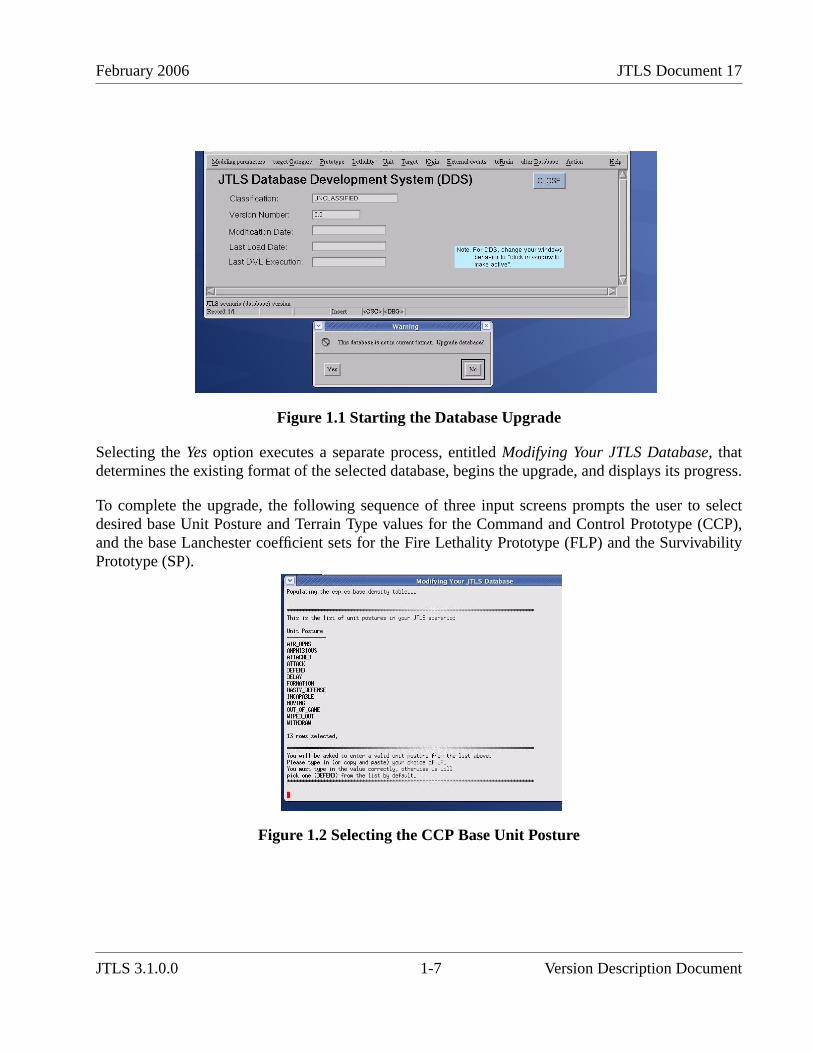
Figure 1.1 Starting the Database Upgrade
Selecting the Yes option executes a separate process, entitled Modifying Your JTLS Database, thatdetermines the existing format of the selected database, begins the upgrade, and displays its progress.
To complete the upgrade, the following sequence of three input screens prompts the user to selectdesired base Unit Posture and Terrain Type values for the Command and Control Prototype (CCP),and the base Lanchester coefficient sets for the Fire Lethality Prototype (FLP) and the SurvivabilityPrototype (SP).
Figure 1.2 Selecting the CCP Base Unit Posture
JTLS 3.1.0.0 1-7 Version Description Document
JTLS Document 17 February 2006
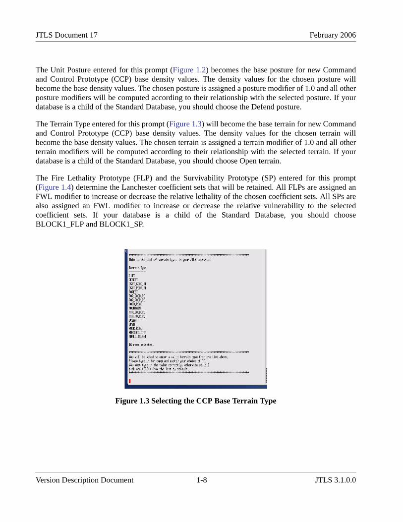
The Unit Posture entered for this prompt (Figure 1.2) becomes the base posture for new Commandand Control Prototype (CCP) base density values. The density values for the chosen posture willbecome the base density values. The chosen posture is assigned a posture modifier of 1.0 and all otherposture modifiers will be computed according to their relationship with the selected posture. If yourdatabase is a child of the Standard Database, you should choose the Defend posture.
The Terrain Type entered for this prompt (Figure 1.3) will become the base terrain for new Commandand Control Prototype (CCP) base density values. The density values for the chosen terrain willbecome the base density values. The chosen terrain is assigned a terrain modifier of 1.0 and all otherterrain modifiers will be computed according to their relationship with the selected terrain. If yourdatabase is a child of the Standard Database, you should choose Open terrain.
The Fire Lethality Prototype (FLP) and the Survivability Prototype (SP) entered for this prompt(Figure 1.4) determine the Lanchester coefficient sets that will be retained. All FLPs are assigned anFWL modifier to increase or decrease the relative lethality of the chosen coefficient sets. All SPs arealso assigned an FWL modifier to increase or decrease the relative vulnerability to the selectedcoefficient sets. If your database is a child of the Standard Database, you should chooseBLOCK1_FLP and BLOCK1_SP.
Figure 1.3 Selecting the CCP Base Terrain Type
Version Description Document 1-8 JTLS 3.1.0.0
February 2006 JTLS Document 17
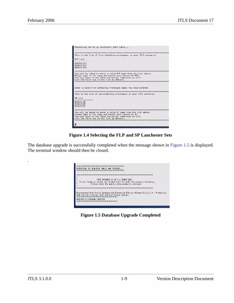
Figure 1.4 Selecting the FLP and SP Lanchester Sets
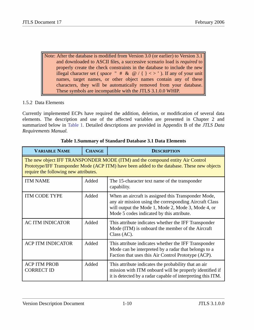
The database upgrade is successfully completed when the message shown in Figure 1.5 is displayed.The terminal window should then be closed.
.
Figure 1.5 Database Upgrade Completed
JTLS 3.1.0.0 1-9 Version Description Document
JTLS Document 17 February 2006
1.5.2 Data Elements
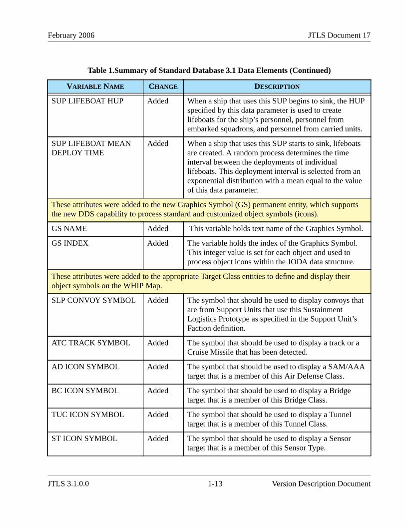
Currently implemented ECPs have required the addition, deletion, or modification of several dataelements. The description and use of the affected variables are presented in Chapter 2 andsummarized below in Table 1. Detailed descriptions are provided in Appendix B of the JTLS DataRequirements Manual.
Note: After the database is modified from Version 3.0 (or earlier) to Version 3.1and downloaded to ASCII files, a successive scenario load is required toproperly create the check constraints in the database to include the newillegal character set ( space " # & @ / { } < > ’ ). If any of your unitnames, target names, or other object names contain any of thesecharacters, they will be automatically removed from your database.These symbols are incompatible with the JTLS 3.1.0.0 WHIP.
Table 1.Summary of Standard Database 3.1 Data Elements
VARIABLE NAME CHANGE DESCRIPTION
The new object IFF TRANSPONDER MODE (ITM) and the compound entity Air ControlPrototype/IFF Transponder Mode (ACP ITM) have been added to the database. These new objectsrequire the following new attributes.
ITM NAME Added The 15-character text name of the transpondercapability.
ITM CODE TYPE Added When an aircraft is assigned this Transponder Mode,any air mission using the corresponding Aircraft Classwill output the Mode 1, Mode 2, Mode 3, Mode 4, orMode 5 codes indicated by this attribute.
AC ITM INDICATOR Added This attribute indicates whether the IFF TransponderMode (ITM) is onboard the member of the AircraftClass (AC).
ACP ITM INDICATOR Added This attribute indicates whether the IFF TransponderMode can be interpreted by a radar that belongs to aFaction that uses this Air Control Prototype (ACP).
ACP ITM PROBCORRECT ID
Added This attribute indicates the probability that an airmission with ITM onboard will be properly identified ifit is detected by a radar capable of interpreting this ITM.
Version Description Document 1-10 JTLS 3.1.0.0

February 2006 JTLS Document 17
These attributes were added to each Target Subcategory entity object, as appropriate, to indicate itsstatus as Underground or Open.
ST UNDERGROUNDFLAG
Added This indicator is used to determine whether the SensorType target is located underground.
SSA UNDERGROUNDFLAG
Added This indicator is used to determine whether the SupplyStorage Area target is located underground.
SSM UNDERGROUNDFLAG
Added This indicator is used to determine whether the SSMlauncher target is located underground.
FAT UNDERGROUNDFLAG
Added This indicator is used to determine whether the Facilitytarget is located underground.
PS UNDERGROUNDFLAG
Added This indicator is used to determine whether the PumpingStation target is located underground.
JT UNDERGROUNDFLAG
Added This indicator is used to determine whether the JammerType target is located underground.
CC UNDERGROUNDFLAG
Added This indicator is used to determine whether theCommunications Center target is located underground.
SSA OPEN FLAG Added This indicator is used to determine whether the SupplyStorage Area target is open and an overhead imagerysensor can view its contents.
AS OPEN FLAG Added This indicator is used to determine whether the AircraftShelter target is open and an overhead imagery sensorcan view its contents.
To improve the flexibility of the air mission speed specification and allow a user to manuallycontrol the speed of an air mission during its flight profile, these attributes were added to theAircraft Class (AC) permanent entity.
AC STALL SPEED Added The slowest speed a member of this Aircraft Class cansafely fly.
AC STALL FUELMODIFIER
Added This data parameter is a modifier for the amount of fuelan air mission will consume per kilometers traveledwhen the aircraft is flying at AC STALL SPEED.
Table 1.Summary of Standard Database 3.1 Data Elements (Continued)
VARIABLE NAME CHANGE DESCRIPTION
JTLS 3.1.0.0 1-11 Version Description Document

JTLS Document 17 February 2006
AC MAX FUELMODIFIER
Added This data parameter is a modifier for the amount of fuelan air mission will consume per kilometers traveledwhen the aircraft flies at AC MAX SPEED.
These Air Defense (AD) and Aircraft Class (AC) entity variables provide the specific USMTFnames by which all external USMTF programs and reports will refer to the objects defined by theseentities.
AD USMTF NAME Added This variable holds the United States Message TextFormat (USMTF) text name of the Air Defense objecttype.
AC USMTF NAME Modified This variable holds the United States Message TextFormat (USMTF) text name of the Aircraft object type.
These Aircraft Class (AC) variables support enhancements to an aircraft malfunction maintenancetime algorithm that allows the average time for malfunction maintenance to be the same at both thehome base and at the detached squadron. The algorithm retains the current JTLS routinemaintenance computation as well as the status of preventive maintenance.
AC AVGMALFUNCTION REPAIRTIME
Added The average time required to repair an aircraft that hasexperienced a mechanical malfunction for which theplane must be grounded and cannot fly until repaired.
AC AVG COMBATREPAIR TIME
Modified The average time required to repair an aircraft that hasexperienced combat damage for which the plane mustbe grounded and cannot fly until repaired.
This database parameter was added to the Surface-to Surface Missile (SSM) prototype structure toindicate whether an external model, such as MDST, will handle flight management. Based on thisparameter, an interface file can be prepared for MDST that lists all of the Targetable Weapons thatcan be fired within JTLS and passed to MDST for flight.
SSM EXTERNALFLIGHT FLAG
Added This flag indicates whether an external model,presumably MDST, is responsible for the flight of themissile from the time of launch to the time of impact.
These Ship Unit Prototype (SUP) attributes were added to support the representation of deployingpersonnel onto lifeboats while a ship is sinking in a manner similar to the method used to representa downed JTLS aircrew.
Table 1.Summary of Standard Database 3.1 Data Elements (Continued)
VARIABLE NAME CHANGE DESCRIPTION
Version Description Document 1-12 JTLS 3.1.0.0
February 2006 JTLS Document 17
SUP LIFEBOAT HUP Added When a ship that uses this SUP begins to sink, the HUPspecified by this data parameter is used to createlifeboats for the ship’s personnel, personnel fromembarked squadrons, and personnel from carried units.
SUP LIFEBOAT MEANDEPLOY TIME
Added When a ship that uses this SUP starts to sink, lifeboatsare created. A random process determines the timeinterval between the deployments of individuallifeboats. This deployment interval is selected from anexponential distribution with a mean equal to the valueof this data parameter.
These attributes were added to the new Graphics Symbol (GS) permanent entity, which supportsthe new DDS capability to process standard and customized object symbols (icons).
GS NAME Added This variable holds text name of the Graphics Symbol.
GS INDEX Added The variable holds the index of the Graphics Symbol.This integer value is set for each object and used toprocess object icons within the JODA data structure.
These attributes were added to the appropriate Target Class entities to define and display theirobject symbols on the WHIP Map.
SLP CONVOY SYMBOL Added The symbol that should be used to display convoys thatare from Support Units that use this SustainmentLogistics Prototype as specified in the Support Unit’sFaction definition.
ATC TRACK SYMBOL Added The symbol that should be used to display a track or aCruise Missile that has been detected.
AD ICON SYMBOL Added The symbol that should be used to display a SAM/AAAtarget that is a member of this Air Defense Class.
BC ICON SYMBOL Added The symbol that should be used to display a Bridgetarget that is a member of this Bridge Class.
TUC ICON SYMBOL Added The symbol that should be used to display a Tunneltarget that is a member of this Tunnel Class.
ST ICON SYMBOL Added The symbol that should be used to display a Sensortarget that is a member of this Sensor Type.
Table 1.Summary of Standard Database 3.1 Data Elements (Continued)
VARIABLE NAME CHANGE DESCRIPTION
JTLS 3.1.0.0 1-13 Version Description Document
JTLS Document 17 February 2006
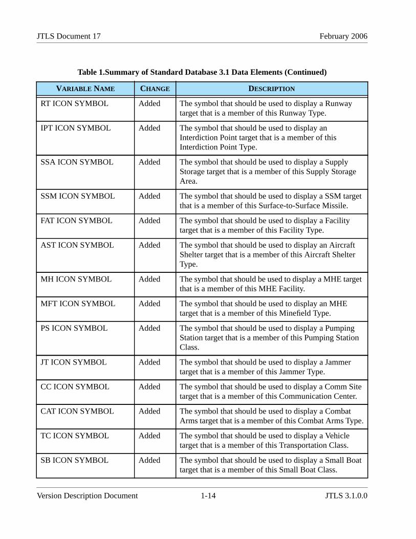
RT ICON SYMBOL Added The symbol that should be used to display a Runwaytarget that is a member of this Runway Type.
IPT ICON SYMBOL Added The symbol that should be used to display anInterdiction Point target that is a member of thisInterdiction Point Type.
SSA ICON SYMBOL Added The symbol that should be used to display a SupplyStorage target that is a member of this Supply StorageArea.
SSM ICON SYMBOL Added The symbol that should be used to display a SSM targetthat is a member of this Surface-to-Surface Missile.
FAT ICON SYMBOL Added The symbol that should be used to display a Facilitytarget that is a member of this Facility Type.
AST ICON SYMBOL Added The symbol that should be used to display an AircraftShelter target that is a member of this Aircraft ShelterType.
MH ICON SYMBOL Added The symbol that should be used to display a MHE targetthat is a member of this MHE Facility.
MFT ICON SYMBOL Added The symbol that should be used to display an MHEtarget that is a member of this Minefield Type.
PS ICON SYMBOL Added The symbol that should be used to display a PumpingStation target that is a member of this Pumping StationClass.
JT ICON SYMBOL Added The symbol that should be used to display a Jammertarget that is a member of this Jammer Type.
CC ICON SYMBOL Added The symbol that should be used to display a Comm Sitetarget that is a member of this Communication Center.
CAT ICON SYMBOL Added The symbol that should be used to display a CombatArms target that is a member of this Combat Arms Type.
TC ICON SYMBOL Added The symbol that should be used to display a Vehicletarget that is a member of this Transportation Class.
SB ICON SYMBOL Added The symbol that should be used to display a Small Boattarget that is a member of this Small Boat Class.
Table 1.Summary of Standard Database 3.1 Data Elements (Continued)
VARIABLE NAME CHANGE DESCRIPTION
Version Description Document 1-14 JTLS 3.1.0.0
February 2006 JTLS Document 17
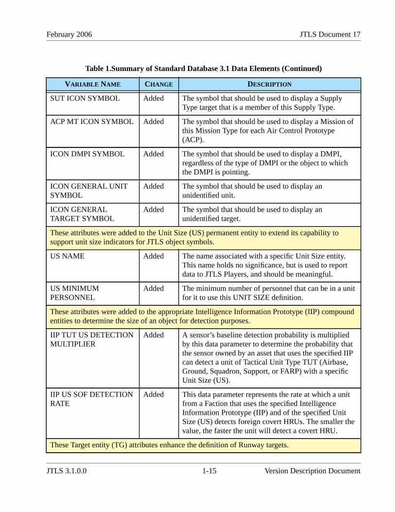
SUT ICON SYMBOL Added The symbol that should be used to display a SupplyType target that is a member of this Supply Type.
ACP MT ICON SYMBOL Added The symbol that should be used to display a Mission ofthis Mission Type for each Air Control Prototype(ACP).
ICON DMPI SYMBOL Added The symbol that should be used to display a DMPI,regardless of the type of DMPI or the object to whichthe DMPI is pointing.
ICON GENERAL UNITSYMBOL
Added The symbol that should be used to display anunidentified unit.
ICON GENERALTARGET SYMBOL
Added The symbol that should be used to display anunidentified target.
These attributes were added to the Unit Size (US) permanent entity to extend its capability tosupport unit size indicators for JTLS object symbols.
US NAME Added The name associated with a specific Unit Size entity.This name holds no significance, but is used to reportdata to JTLS Players, and should be meaningful.
US MINIMUMPERSONNEL
Added The minimum number of personnel that can be in a unitfor it to use this UNIT SIZE definition.
These attributes were added to the appropriate Intelligence Information Prototype (IIP) compoundentities to determine the size of an object for detection purposes.
IIP TUT US DETECTIONMULTIPLIER
Added A sensor’s baseline detection probability is multipliedby this data parameter to determine the probability thatthe sensor owned by an asset that uses the specified IIPcan detect a unit of Tactical Unit Type TUT (Airbase,Ground, Squadron, Support, or FARP) with a specificUnit Size (US).
IIP US SOF DETECTIONRATE
Added This data parameter represents the rate at which a unitfrom a Faction that uses the specified IntelligenceInformation Prototype (IIP) and of the specified UnitSize (US) detects foreign covert HRUs. The smaller thevalue, the faster the unit will detect a covert HRU.
These Target entity (TG) attributes enhance the definition of Runway targets.
Table 1.Summary of Standard Database 3.1 Data Elements (Continued)
VARIABLE NAME CHANGE DESCRIPTION
JTLS 3.1.0.0 1-15 Version Description Document
JTLS Document 17 February 2006
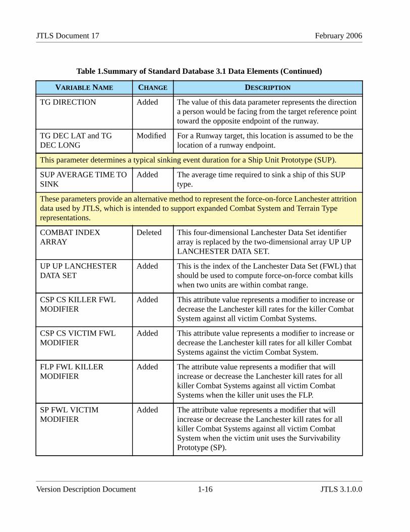
TG DIRECTION Added The value of this data parameter represents the directiona person would be facing from the target reference pointtoward the opposite endpoint of the runway.
TG DEC LAT and TGDEC LONG
Modified For a Runway target, this location is assumed to be thelocation of a runway endpoint.
This parameter determines a typical sinking event duration for a Ship Unit Prototype (SUP).
SUP AVERAGE TIME TOSINK
Added The average time required to sink a ship of this SUPtype.
These parameters provide an alternative method to represent the force-on-force Lanchester attritiondata used by JTLS, which is intended to support expanded Combat System and Terrain Typerepresentations.
COMBAT INDEXARRAY
Deleted This four-dimensional Lanchester Data Set identifierarray is replaced by the two-dimensional array UP UPLANCHESTER DATA SET.
UP UP LANCHESTERDATA SET
Added This is the index of the Lanchester Data Set (FWL) thatshould be used to compute force-on-force combat killswhen two units are within combat range.
CSP CS KILLER FWLMODIFIER
Added This attribute value represents a modifier to increase ordecrease the Lanchester kill rates for the killer CombatSystem against all victim Combat Systems.
CSP CS VICTIM FWLMODIFIER
Added This attribute value represents a modifier to increase ordecrease the Lanchester kill rates for all killer CombatSystems against the victim Combat System.
FLP FWL KILLERMODIFIER
Added The attribute value represents a modifier that willincrease or decrease the Lanchester kill rates for allkiller Combat Systems against all victim CombatSystems when the killer unit uses the FLP.
SP FWL VICTIMMODIFIER
Added The attribute value represents a modifier that willincrease or decrease the Lanchester kill rates for allkiller Combat Systems against all victim CombatSystem when the victim unit uses the SurvivabilityPrototype (SP).
Table 1.Summary of Standard Database 3.1 Data Elements (Continued)
VARIABLE NAME CHANGE DESCRIPTION
Version Description Document 1-16 JTLS 3.1.0.0

February 2006 JTLS Document 17
1.5.3 Standard Database Changes
The JTLS 3.1.0.0 Standard Database (SDB) includes extensive data item modifications implementedsince the SDB Version 3.0 release. If you have used sdbv30 has a basis for your existing scenarios,you should review and evaluate the modifications included in sdbv31, the newest version of theStandard Database. A significant enhancement included in sdbv31 is the addition of 57 new CombatSystems, which enables the SDB to represent a total of 100 Combat Systems, which are described inAPPENDIX B. of this document. Reviewing your existing SDB-derived databases and upgradingthem to the new SDB format is strongly recommended. The detailed procedures required to upgradesdbv30 to sdbv31 are provided in APPENDIX C.
1.6 INSTALLATION NOTES
1.6.1 Installation Instructions
The JTLS Installation Manual (included in the documents compressed tar file that is part of this JTLSrelease) provides detailed instructions for installing a new version of JTLS.
CCP CS UP TT DENSITY Deleted This four-dimensional array is replaced by the followingCommand Control Prototype (CCP) entity attributes.
CCP CS BASE DENSITY Added The baseline density with which a unit that uses thespecified CCP places its Combat Systems, regardless ofthe unit’s current Terrain Type and Posture.
CCP CS TT DENSITYMODIFER
Added This data parameter is the multiplicative modifier thatshould be applied to the base case density value whenthe unit is located in the specified Terrain Type.
CCP CS UP DENSITYMODIFIER
Added The value held in this array is the multiplicative modifierthat should be applied to the base case density valuewhen the unit is in the specified Posture.
UT NIGHTEFFECTIVENESS
Added An attribute of the Unit entity, this multiplier is used inLanchester attrition calculations for combat during nightconditions.
Table 1.Summary of Standard Database 3.1 Data Elements (Continued)
VARIABLE NAME CHANGE DESCRIPTION
JTLS 3.1.0.0 1-17 Version Description Document
JTLS Document 17 February 2006
1.6.2 GIAC Compatibility
The Web Hosted Interface Program (WHIP) has replaced the GIAC in its entirety as the primaryJTLS Player and Controller graphical user interface. However, GIAC version 2.1.5+2 is provided aspart of this JTLS release to support the Graphical Database Program (GDP) capability. It is deliveredin the compressed tar files named GIAC.2.1.5.<platform_name>.tar.bz2. This version executes inboth Solaris and Linux environments.
1.6.3 Oracle Compatibility and Installation
This release of JTLS requires a complete installation of Oracle Forms/Reports Developer 6i client/server runtime.
Developer 6i is the final version of the client/server development and deployment of Oracle Forms,Reports, and Graphics. Oracle Corporation will provide only limited support for this Developerversion until January 2008, and Oracle10g will become the final certified database server compatiblewith Developer 6i. Beginning with this release of JTLS 3.1.0.0, Oracle 10g iAS EE (InternetApplication Server Enterprise Edition) will be implemented to deploy JTLS database applications,such as DDS Forms. The compatible database server version is Oracle 10g Standard Edition One ornewer. If these requirements are updated prior to a future JTLS release, they will be described in theappropriate JTLS Version Description Document.
Utilizing the framework of iAS EE, which includes Forms Services, Reports Services, Portal, SingleSign-On, Java, and other components, will enable the delivery of JTLS-specific data from a centrallocation. This will also allow the development of more scalable JTLS database applications, such asthe SDR and AAR.
Currently, the following combinations of Forms 6i runtime and the Oracle Server are approved for usewith JTLS:
a. Oracle database server 9.2.0.6, or 10g (Standard Edition One) for any platformb. Forms 6i client/server runtime (with patch 13 or higher) for Solaris and/or Linuxc. iAS EE 10.1.2.0.2 full stack for Linux (optional)
Refer to Chapter 3, Section 3.6 of the JTLS Installation Manual for additional details regarding thegeneric Solaris or Linux Oracle Forms/Reports Developer 6i client/server custom runtimeinstallation.
Version Description Document 1-18 JTLS 3.1.0.0

February 2006 JTLS Document 17
2.0 ENHANCEMENT CHANGE PROPOSALS
This chapter of the JTLS Version Description Document describes the model enhancement changesimplemented in JTLS Version 3.1.0.0. This version is a Major JTLS release that includes theseimplemented Enhancement Change Proposals (ECPs).
2.1 JTLS-0028 Named Map Views
2.1.1 Summary of Model Change Request
This MCR requests the capability to save WHIP MAP configurations for later recall. The Mapcomponent of the Web Hosted Interface Program (WHIP) provides a variety of configuration optionsthat permit the user to tailor the Map window to display simulation information of specific interest.The configuration options include filters for Units, Terrain, OPAREAs, Networks, and NationalBoundaries.
The Map component needs a capability to save the current location view and scale as well as the user-selected filter configuration.
2.1.2 Design Summary
This design includes these proposed map display capabilities:
• Saved views
• Back/Forward views
• Synchronized Authentication and Preferences (SYNAPSE) data-sharing enhancements
2.1.2.1 Saved Views
Users require the capability to save three types of information with respect to the current map display:
• Location. Saved locations consist of the location center, current scale, and currentprojection. Currently, the Map component has the capability to display Mercator, LambertConformal, and Orthographic projections. The projection must be saved in conjunction withthe map location and scale to return the map view to a previous configuration. When a userrecalls a named and saved location setting, the location, scale, and projection of the map,but not the filters, are altered.
• Filters. Saved filters consist of all filter settings provided in the filter panel, including but notlimited to icon display filters, terrain filters, and icon size settings. If a map displaycharacteristic can be altered via the filter configuration panel, the current setting of thecharacteristic are saved. When a user recalls a named and saved filter setting, all filters andicon sizes are reset to the saved information, but the location of the map is not altered.
JTLS 3.1.0.0 2-1 Version Description Document
JTLS Document 17 February 2006
• Views. A saved view consists of the union of the saved data for a saved location and a savedfilter. Thus, recalling a named and saved view will relocate the map to the saved locationand the reset the filters to the saved filter specification.
2.1.2.2 Back and Forward Scrolling
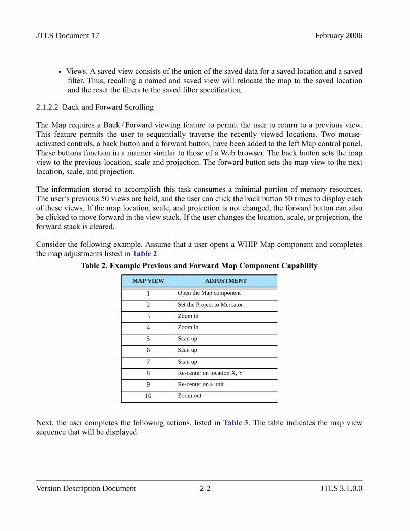
The Map requires a Back / Forward viewing feature to permit the user to return to a previous view.This feature permits the user to sequentially traverse the recently viewed locations. Two mouse-activated controls, a back button and a forward button, have been added to the left Map control panel.These buttons function in a manner similar to those of a Web browser. The back button sets the mapview to the previous location, scale and projection. The forward button sets the map view to the nextlocation, scale, and projection.
The information stored to accomplish this task consumes a minimal portion of memory resources.The user’s previous 50 views are held, and the user can click the back button 50 times to display eachof these views. If the map location, scale, and projection is not changed, the forward button can alsobe clicked to move forward in the view stack. If the user changes the location, scale, or projection, theforward stack is cleared.
Consider the following example. Assume that a user opens a WHIP Map component and completesthe map adjustments listed in Table 2.
Next, the user completes the following actions, listed in Table 3. The table indicates the map viewsequence that will be displayed.
Table 2. Example Previous and Forward Map Component Capability
MAP VIEW ADJUSTMENT
1 Open the Map component
2 Set the Project to Mercator
3 Zoom in
4 Zoom in
5 Scan up
6 Scan up
7 Scan up
8 Re-center on location X, Y
9 Re-center on a unit
10 Zoom out
Version Description Document 2-2 JTLS 3.1.0.0

February 2006 JTLS Document 17
2.1.2.3 SYNAPSE Modifications
The SYNAPSE Web service required design modifications to support saving locations, filters, andviews. In previous versions, the SYNAPSE provides three modes to the WHIP for storinginformation. The WHIP could save data either privately for the named login (private data), shared tothe WHIP’s Side (Side-shared data), or shared to all WHIP users (world-shared data). This datastorage model is inadequate for managing saved data, since it is necessary that WHIP user has thecapability to specify multiple Sides permitted to access the data. Although not specifically required,we decided to provide more flexibility by allowing the WHIP user to also limit access to saved dataaccording to specific WHIP names.
The new SYNAPSE data storage model implemented two storage types. Private storage is reservedfor data used only by a named WHIP, and Shared storage is used for data potentially available to beshared among all WHIPs. These two storage areas are held in different directories under the$JGAME/scenario_name directory.
• Private storage functions as it did in previous versions of JTLS. Only the WHIP that ownsthe private data is permitted to access it. Private data can never be shared.
• Data intended or required to be shared must be placed in Shared storage to be accessible toother WHIPs. This new Shared data area replaces the concepts of Side-shared data andworld-shared data. The named location, filter, and view files are all included in this Sharedstorage area, even if the file can be viewed only by the owner or creator of the file. Each filesaved by a WHIP will require that permissions information be included to allow theSYNAPSE to determine whether a specific WHIP is authorized to access the data. Table 4describes this new permissions information.
Table 3. Use and Restriction of Forward and Back Button
USER ACTION RESULTING MAP VIEW
Click back button 9
Click back button 8
Click back button 7
Click forward button 8
Click back button 7
Click back button 6
Zoom in on the display This view replaces the previous map view 7and the map views 8, 9, 10 are discarded.
JTLS 3.1.0.0 2-3 Version Description Document
JTLS Document 17 February 2006
Under the scenario’s shared directory, the SYNAPSE maintains separate directories for the savedlocations, the saved filters, and the saved views. Each saved location will have associated permissionsinformation. The permissions information is used by the SYNAPSE to filter the directory contents foreach requesting WHIP. For example, if the permissions are set to allow Side Alpha read permissionfor an entry, then a Side Alpha WHIP will be presented with the entry when it uses the RecallLocation, Filter, or View menus.
The WHIP must be notified regarding changes to the contents of a shared directory. When new entriesare added to a directory, when entry permissions change, or when an entry is no longer available, theWHIP requires notification to update its representation of the directory contents. The SYNAPSEquery protocol was modified to allow the WHIP to indicate that the SYNAPSE should track thechanges in the requested directory.
2.2 JTLS-0050 New Squadron SITREP
2.2.1 Summary of Model Change Request
This MCR requests the number of available aircraft be added to the Squadron SITREP.
2.2.2 Design Summary
The JTLS 3.1 Squadron SITREP definition now contains the following information:
Table 4. New SYNAPSE Permissions Data
NAME DESCRIPTION
Owner Name of the WHIP that saved the data
Side Read Permissions List of Side names authorized to access the data
Player Read Permissions List of WHIP names authorized to access the data
Table 5. Squadron SITREP Definition
VARIABLE NAME VARIABLE DEFINITION
Name Name of the unit
Object Class Object Class of the unit
Location Perceived location of the unit
Strength Perceived strength of the unit
Homebase The Short Name of the unit’s home base, if any
HHQ The Short Name of this unit’s higher headquarters’ unit
AC Type The name of the type of aircraft that this squadron owns
Version Description Document 2-4 JTLS 3.1.0.0

February 2006 JTLS Document 17
2.3 JTLS-0051 Multiple ACO Processing
2.3.1 Summary of Model Change Request
The purpose of this design is to enhance the representation and storage of Air Control Order (ACO)data in the Air Tasking Order (ATO) Translation (ATO-T). Currently, processing a JTLS ATOinvolves loading an appropriate ACO to properly define the mission locations. Due to operator erroror oversight, it is common for ACOs to omit mission location information for the current ATO.Therefore, reading in multiple ACOs is a desirable user capability. This model enhancement allowsthe user to gather mission location information from different ACOs into the ATO translation process.
2.3.2 Design Summary
Implementation of this design required a simple process to continuously read in successive ACOs. Aseach ACO is read in, each mission location is compared to those currently stored in memory. If alocation that has the same name already exists within the program, that instance will be destroyed and
AC TOE The number of aircraft authorized on the Table of Organizationand Equipment
AC Available The number of aircraft currently available for us
Command Level The level of the command assigned to the unit
Speed The current speed of the unit
Destination The last known location of the unit in latitude/longitude
Mission The name of the unit’s ordered mission
Posture The name of the current unit Posture
Side The name of the Force Side to which the unit belongs
Faction The name of the Faction to which the unit belongs
In Combat Indicates if the unit is currently in combat
Support Unit The name of the unit to support this squadron
Range The maximum of the ranges of this units Direct/Indirect Fireweapons
Maximum Speed The unit’s maximum possible speed
Branch The branch of the military to which the unit belongs
Max Sortie/cycle The maximum number of sorties that the unit can sustain over aprolonged period of time
AVN Fuel on Hand The amount of fuel on available at this unit
Homebase AVN Fuel The amount of fuel on available at the homebase
Table 5. Squadron SITREP Definition
VARIABLE NAME VARIABLE DEFINITION
JTLS 3.1.0.0 2-5 Version Description Document

JTLS Document 17 February 2006
replaced with a new entry consisting of location information from the ACO currently being read. Thisprocess continues until the user has read in all desired ACOs.
This process implies that the user must read in the ACOs from earliest to latest to ensure that the mostcurrent location information is accessed.
2.4 JTLS-0082 Pass Aircraft Type Changes to Player GIACs
2.4.1 Summary of Model Change Request
If a controller changed the type of aircraft owned by a squadron, the GIAC did not have the capabilityto alter its internal representation of the squadron. Thus many of the check made by the GIAC wereincorrectly being made based on the old vice the new squadron’s characteristics. The desire of thisECP was to implement the WHIP so it could properly represent the adjusted squadron aircraft type.
2.4.2 Design Summary
When the Controller changes a squadron’s aircraft type, all programs including the JODA, WHIP, andOMA are notified of the change. All internal representation of the squadron’s capabilities are properlyupdated.
2.5 JTLS-0124 Change CEP Port Within ICP
2.5.1 Summary of Model change Request
This MCR requests the capability to change the service port number of the CEP.
2.5.2 Design Summary
The ICP now allows the user to edit the CEP port number. The default CEP port of 4244 is no longerthe mandatory port over which the CEP must communicate with the JODA. The port number is savedto the .oex file of the scenario. When the CEP starts, it reads the specified port number from the .oexfile and uses it, rather than the default CEP port number.
2.6 JTLS-0150 IFF Improvement
2.6.1 Summary of Model Change Request
In previous versions, JTLS published a Mode 1, Mode 2, and Mode 3 squawk for all missions. Thisinformation was published to real-world Command, Control, Communication, Computers, andInformation (C4I) systems, such as the Global Command Control System (GCCS), for reportingpurposes only. The representation of Identification Friend or Foe (IFF) was accomplished withinJTLS, but was unrelated to the existence or ability of the IFF hardware associated with the mission’saircraft.
Version Description Document 2-6 JTLS 3.1.0.0
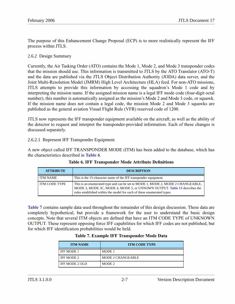
February 2006 JTLS Document 17
The purpose of this Enhancement Change Proposal (ECP) is to more realistically represent the IFFprocess within JTLS.
2.6.2 Design Summary
Currently, the Air Tasking Order (ATO) contains the Mode 1, Mode 2, and Mode 3 transponder codesthat the mission should use. This information is transmitted to JTLS by the ATO Translator (ATO-T)and the data are published via the JTLS Object Distribution Authority (JODA) data server, and theJoint Multi-Resolution Model (JMRM) High Level Architecture (HLA) feed. For non-ATO missions,JTLS attempts to provide this information by accessing the squadron’s Mode 1 code and byinterpreting the mission name. If the assigned mission name is a legal IFF mode code (four-digit octalnumber), this number is automatically assigned as the mission’s Mode 2 and Mode 3 code, or squawk.If the mission name does not contain a legal code, the mission Mode 2 and Mode 3 squawks arepublished as the general aviation Visual Flight Rule (VFR) reserved code of 1200.
JTLS now represents the IFF transponder equipment available on the aircraft, as well as the ability ofthe detector to request and interpret the transponder-provided information. Each of these changes isdiscussed separately.
2.6.2.1 Represent IFF Transponder Equipment
A new object called IFF TRANSPONDER MODE (ITM) has been added to the database, which hasthe characteristics described in Table 6.
Table 7 contains sample data used throughout the remainder of this design discussion. These data arecompletely hypothetical, but provide a framework for the user to understand the basic designconcepts. Note that several ITM objects are defined that have an ITM CODE TYPE of UNKNOWNOUTPUT. These represent opposing force IFF capabilities for which IFF codes are not published, butfor which IFF identification probabilities would be held.
Table 6. IFF Transponder Mode Attribute Definitions
ATTRIBUTE DESCRIPTION
ITM NAME This is the 15-character name of the IFF transponder equipment.
ITM CODE TYPE This is an enumerated type and can be set to MODE 1, MODE 2, MODE 2 CHANGEABLE,MODE 3, MODE 3C, MODE 4, MODE 5, or UNNOWN OUTPUT. Table 13 describes therules established within the model for each of these enumerated types.
Table 7. Example IFF Transponder Mode Data
ITM NAME ITM CODE TYPE
IFF MODE 1 MODE 1
IFF MODE 2 MODE 2 CHANGEABLE
IFF MODE 2 OLD MODE 2
JTLS 3.1.0.0 2-7 Version Description Document
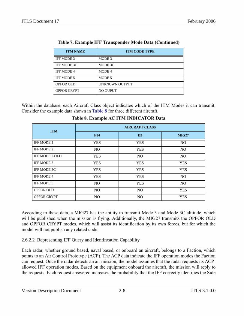
JTLS Document 17 February 2006
Within the database, each Aircraft Class object indicates which of the ITM Modes it can transmit.Consider the example data shown in Table 8 for three different aircraft.
According to these data, a MIG27 has the ability to transmit Mode 3 and Mode 3C altitude, whichwill be published when the mission is flying. Additionally, the MIG27 transmits the OPFOR OLDand OPFOR CRYPT modes, which will assist its identification by its own forces, but for which themodel will not publish any related code.
2.6.2.2 Representing IFF Query and Identification Capability
Each radar, whether ground based, naval based, or onboard an aircraft, belongs to a Faction, whichpoints to an Air Control Prototype (ACP). The ACP data indicate the IFF operation modes the Factioncan request. Once the radar detects an air mission, the model assumes that the radar requests its ACP-allowed IFF operation modes. Based on the equipment onboard the aircraft, the mission will reply tothe requests. Each request answered increases the probability that the IFF correctly identifies the Side
IFF MODE 3 MODE 3
IFF MODE 3C MODE 3C
IFF MODE 4 MODE 4
IFF MODE 5 MODE 5
OPFOR OLD UNKNOWN OUTPUT
OPFOR CRYPT NO OUPUT
Table 8. Example AC ITM INDICATOR Data
ITMAIRCRAFT CLASS
F14 B2 MIG27
IFF MODE 1 YES YES NO
IFF MODE 2 NO YES NO
IFF MODE 2 OLD YES NO NO
IFF MODE 3 YES YES YES
IFF MODE 3C YES YES YES
IFF MODE 4 YES YES NO
IFF MODE 5 NO YES NO
OPFOR OLD NO NO YES
OPFOR CRYPT NO NO YES
Table 7. Example IFF Transponder Mode Data (Continued)
ITM NAME ITM CODE TYPE
Version Description Document 2-8 JTLS 3.1.0.0

February 2006 JTLS Document 17
that owns the aircraft. If the aircraft is correctly identified, the radar’s perception of the aircraft withrespect to owning Side and owning Faction is correctly set.
To implement this logic, another new compound entity similar to the Aircraft Class and IFFTransponder Mode compound entity was added to the database. This new compound entity is the AirControl Prototype and IFF Transponder Mode entity, which has two attributes described in Table 9.Table 10 contains example data for this new compound entity.
Assume a NATO radar (Side Alpha) detects a US (Side Charlie) F14 returning from escort duty aspart of a deep interdiction strike. Table 11 traces the calculation steps that are accomplished.
Table 9. Summary of ACP ITM Compound Entity Attributes
ACP ITM ATTRIBUTE MEANING
ACP ITM INDICATOR This indicator determines that the Air Control Prototype (ACP) canrequest the ITM when its detects an aircraft.
ACP ITM PROB CORRECT ID This probability indicates whether a correct reply to the request willresult in a correct identification.
Table 10. Sample ACP ITM Compound Data
ITM
ACP
ACP_NATO ACP_OPFOR
INDICATOR PROBABILITY INDICATOR PROBABILITY
IFF MODE 1 YES 0.01 NO
IFF MODE 2 YES 0.01 NO
IFF MODE 2 OLD YES 0.01 NO
IFF MODE 3 YES 0.02 YES 0.10
IFF MODE 3C YES 0.05 YES 0.10
IFF MODE 4 YES 0.95 NO
IFF MODE 5 YES 1.0 NO
OPFOR OLD NO YES 0.05
OPFOR CRYPT NO YES 0.95
Table 11. Example of NATO Detecting F-14
MODE MODE REQUEST MODE REPLYCUMULATIVE
PROBABILITY ID
IFF MODE 1 YES YES 0.01
IFF MODE 2 YES NO 0.01
JTLS 3.1.0.0 2-9 Version Description Document

JTLS Document 17 February 2006
Following this computation, the model will draw a random variate to determine that the mission isproperly identified, which is highly likely. Next, consider the computation trace in Table 13, whichrepresents the OPFOR aircraft detecting the F14 during the deep interdiction strike.
Following this computation, the model will draw a random variate to determine whether the missionis properly identified. Assume that a value of 0.65 is drawn. The model will not permit the OPFOR toobtain a correct identification of this aircraft. Next, the model examines the IFF Friend or Foe statechange array that has existed in previous versions of JTLS. The correct identity of the air mission isSide Charlie, and the probability that OPFOR will correctly “guess” this identity is 60%. Theprobability that it will be labeled as a Side Delta air mission is 20%, and the probability that it will belabeled as Unknown is 20%. If the mission is incorrectly identified, the IFF process is repeated whenthe mission enters an adjacent hex. Once the mission is labeled correctly, the IFF procedure isskipped.
IFF MODE 2 OLD YES YES 0.0199
IFF MODE 3 YES YES 0.039502
IFF MODE 3C YES YES 0.0875269
IFF MODE 4 YES YES 0.954376345
IFF MODE 5 YES NO 0.954376345
OPFOR OLD NO NO 0.954376345
OPFOR CRYPT NO NO 0.954376345
Table 12. Example Of OPFOR Detecting F-14
MODE MODE REQUEST MODE REPLYCUMULATIVE
PROBABILITY ID
IFF MODE 1 NO NO 0.0
IFF MODE 2 NO NO 0.0
IFF MODE 2 OLD NO NO 0.0
IFF MODE 3 YES YES 0.1
IFF MODE 3C YES YES 0.19
IFF MODE 4 NO NO 0.19
IFF MODE 5 NO NO 0.19
OPFOR OLD YES NO 0.19
OPFOR CRYPT YES NO 0.19
Table 11. Example of NATO Detecting F-14 (Continued)
MODE MODE REQUEST MODE REPLYCUMULATIVE
PROBABILITY ID
Version Description Document 2-10 JTLS 3.1.0.0

February 2006 JTLS Document 17
Regarding these results, we recommend that database personnel observe the following:
• As shown in the previous example, the IFF transponder equipment is primarily used by aSide to determine whether it properly identifies its own aircraft. Because of this additionalcomputation, we recommend that database developers review their existing IFF Arrays andreduce the probability that a Side properly identifies its own aircraft; this redundantprobability is determined after the detection fails the IFF computation. The result thatcorrect identification is 60% likely after this failure is unrealistic.
• The database builder should note that if no ITM objects are present on an aircraft, itsprobability of being correctly detected is zero, and the original IFF Array continues tofunction as in previous JTLS versions. To quickly perform an update, the database buildermay consider only those IFF operation modes that will be reported to external C4I systems.
2.6.2.3 Mode Publishing Rules
The JODA data structure and the High Level Architecture (HLA) Run Time Infrastructure (RTI)Federation Object Model (FOM) each have several air mission attributes used to represent the IFFmode information transmitted by aircraft. These attributes and the rules that are used to evaluate themare listed in Table 13.
Table 13. JODA and FOM Air Mission IFF Attributes
ENUMERATEDTYPE
RULES
MODE 1 This text attribute holds the two-digit code of the mission’s Mode 1 reply.
If the aircraft have an assigned ITM with an ITM CODE TYPE of MODE 1, the mission’s assignedMODE 1 code us output to the JODA data structure and the HLA FOM.
If the mission order specified a Mode 1 IFF operation code, this code is passed to the JODA Mode 1attribute for the output when the mission takes off and is cleared when the mission lands.
If the mission order did not include a Mode 1 IFF operation code, the operation code held by thesquadron is used.
If the squadron’s code is blank, a blank is passed to the JODA and the HLA FOM.
If the aircraft does not have an assigned ITM with an ITM CODE TYPE of MODE 1, the mission’sMODE 1 code is left blank.
JTLS 3.1.0.0 2-11 Version Description Document
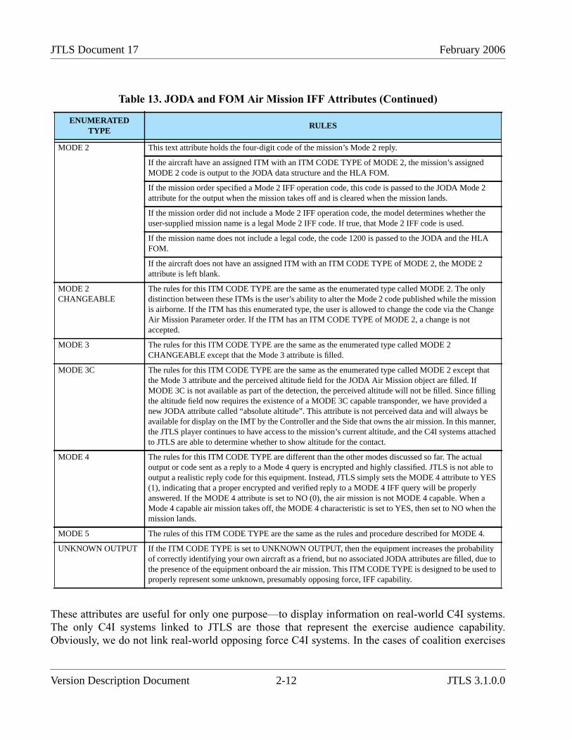
JTLS Document 17 February 2006
These attributes are useful for only one purpose—to display information on real-world C4I systems.The only C4I systems linked to JTLS are those that represent the exercise audience capability.Obviously, we do not link real-world opposing force C4I systems. In the cases of coalition exercises
MODE 2 This text attribute holds the four-digit code of the mission’s Mode 2 reply.
If the aircraft have an assigned ITM with an ITM CODE TYPE of MODE 2, the mission’s assignedMODE 2 code is output to the JODA data structure and the HLA FOM.
If the mission order specified a Mode 2 IFF operation code, this code is passed to the JODA Mode 2attribute for the output when the mission takes off and is cleared when the mission lands.
If the mission order did not include a Mode 2 IFF operation code, the model determines whether theuser-supplied mission name is a legal Mode 2 IFF code. If true, that Mode 2 IFF code is used.
If the mission name does not include a legal code, the code 1200 is passed to the JODA and the HLAFOM.
If the aircraft does not have an assigned ITM with an ITM CODE TYPE of MODE 2, the MODE 2attribute is left blank.
MODE 2CHANGEABLE
The rules for this ITM CODE TYPE are the same as the enumerated type called MODE 2. The onlydistinction between these ITMs is the user’s ability to alter the Mode 2 code published while the missionis airborne. If the ITM has this enumerated type, the user is allowed to change the code via the ChangeAir Mission Parameter order. If the ITM has an ITM CODE TYPE of MODE 2, a change is notaccepted.
MODE 3 The rules for this ITM CODE TYPE are the same as the enumerated type called MODE 2CHANGEABLE except that the Mode 3 attribute is filled.
MODE 3C The rules for this ITM CODE TYPE are the same as the enumerated type called MODE 2 except thatthe Mode 3 attribute and the perceived altitude field for the JODA Air Mission object are filled. IfMODE 3C is not available as part of the detection, the perceived altitude will not be filled. Since fillingthe altitude field now requires the existence of a MODE 3C capable transponder, we have provided anew JODA attribute called “absolute altitude”. This attribute is not perceived data and will always beavailable for display on the IMT by the Controller and the Side that owns the air mission. In this manner,the JTLS player continues to have access to the mission’s current altitude, and the C4I systems attachedto JTLS are able to determine whether to show altitude for the contact.
MODE 4 The rules for this ITM CODE TYPE are different than the other modes discussed so far. The actualoutput or code sent as a reply to a Mode 4 query is encrypted and highly classified. JTLS is not able tooutput a realistic reply code for this equipment. Instead, JTLS simply sets the MODE 4 attribute to YES(1), indicating that a proper encrypted and verified reply to a MODE 4 IFF query will be properlyanswered. If the MODE 4 attribute is set to NO (0), the air mission is not MODE 4 capable. When aMode 4 capable air mission takes off, the MODE 4 characteristic is set to YES, then set to NO when themission lands.
MODE 5 The rules of this ITM CODE TYPE are the same as the rules and procedure described for MODE 4.
UNKNOWN OUTPUT If the ITM CODE TYPE is set to UNKNOWN OUTPUT, then the equipment increases the probabilityof correctly identifying your own aircraft as a friend, but no associated JODA attributes are filled, due tothe presence of the equipment onboard the air mission. This ITM CODE TYPE is designed to be used toproperly represent some unknown, presumably opposing force, IFF capability.
Table 13. JODA and FOM Air Mission IFF Attributes (Continued)
ENUMERATEDTYPE
RULES
Version Description Document 2-12 JTLS 3.1.0.0

February 2006 JTLS Document 17
to date, we believe that only one coalition partner has a C4I system linked to the game. For example,we know of no situation in which US C4I systems and Japanese C4I systems are attached to the sameJTLS game. This is likely not true in the real world. During a coalition operation, the US, coalitionpartners, and possibly the OPFOR will each have access to their separate real-world C4I system.
Thus, these IFF detections should realistically be considered perceived information. We have avoidedthis definition, due to the modeling implications of sharing detections and sharing IFF information,which are beyond the scope of this ECP. Thus, we define the IFF attributes shown in Table 13 ascommon knowledge attributes. Detecting an air mission implies unlimited access to information heldin the common knowledge portion of the object data structure. By convention, we rely on theinterface programs to limit the access to this common knowledge information to realistic levels.
For example, Mission Type and Aircraft Type are two common knowledge air mission attributes. AllJTLS-delivered interface programs do not provide Mission Type information to a foreign Side upondetection, but Aircraft Type is provided. We expect that the IFF common knowledge data isjudiciously provided to C4I systems in a similar and realistic manner. The US ability to query theMode 4 capability of an aircraft does not imply that Japan has the same capability; therefore, onlythose interfaces that represent the US perception should access the Mode 4 common knowledgeattribute in the JODA and FOM. If Japan detects the mission, this information should not be madeavailable.
2.6.2.4 Rules for Turning Transponders On and Off
There are several reasons to justify a necessity to represent the ability to turn on and turn off the IFFoperation mode equipment represented by this design. Consider the following illustration:
1. As the design has been explained so far, having your transponder on will assist your ownSide to determine that you are a friendly mission, but there is no advantage to your enemy.We are not aware of any disadvantage to keeping the transponder on in an encrypted IFFoperation mode. For non-encrypted IFF operation modes, especially MODE 3C, theopposing force could obtain important information, especially your altitude. The problem isthat there are times when you would want the opposing force to know your altitude andtimes when that would not be the desired circumstance. For example, consider the followingsituations:
a. You are flying through an altitude-restricted no-fly zone area on a legal mission. TheSide enforcing the zone would need to know your altitude to ensure that the no-flyconstraints are observed. For this situation, you would want to transmit your altitude foridentification purposes. Currently, JTLS represents the enforcement of such no-flyzones, but assumes that the enforcer can obtain altitude information for aircraft flyingthrough the area. How this altitude information is obtained is not considered.
b. You are an attack mission approaching a deep interdiction target. Any informationtransmitted will facilitate the opposing force’s effort to intercept your mission andrealize your intentions prior to reaching the target. Currently, JTLS does not representaltitude-related intercepting logic. Knowing the altitude of the intercepted track does notaffect an interceptor’s ability to conduct the intercept.
JTLS 3.1.0.0 2-13 Version Description Document

JTLS Document 17 February 2006
2. As we believe is correct, we assume that an encrypted IFF operation mode is an accurateindicator of a friendly mission. We must represent malfunctioning IFF operation modes toproperly represent mis-identification within the exercise environment. The result of such amalfunction would be that air defenses are required to follow different procedures to obtaina confident assessment of the identification result. Currently, JTLS identification proceduresare not explicitly modeled. These procedures are assumed as part of the random processrepresented by the IFF Probability Array.
Within the context of these examples, it is difficult to derive a reasonable and consistent set of rules toautomatically determine whether the IFF transponder equipment should be activated for a specificsituation. To represent some of these situations, we have provide the user an order capability tomanually turn on and turn off the equipment., However, we have maintain our current detectionassumptions in the majority of the JTLS air logic. If these are inappropriate, we recommend thatsolutions be developed within other ECPs that address those assumptions explicitly. Table 14summarizes the effect of each of these ITM CODE TYPEs within JTLS.
Table 14. Effect of ITM CODE TYPE Equipment Activation
ITM CODE TURNED ON TURNED OFF
MODE 1 Mode 1 Code is transmitted. Mode 1 Code is not transmitted.
Own Side is allowed to use itsassociated probability of properidentification.
Own Side is not allowed to use itsassociated probability of properidentification.
MODE 2 Mode 2 Code is transmitted. Mode 2 Code is not transmitted.
Own Side is allowed to use itsassociated probability of properidentification.
Own Side is not allowed to use itsassociated probability of properidentification.
MODE 2 CHANGEABLE Mode 2 Code is transmitted. Mode 2 Code is not transmitted.
Own Side is allowed to use itsassociated probability of properidentification.
Own Side is not allowed to use itsassociated probability of properidentification.
MODE 3 Mode 3 Code is transmitted. Mode 3 Code is not transmitted.
Own Side is allowed to use itsassociated probability of properidentification.
Own Side is not allowed to use itsassociated probability of properidentification.
MODE 3C Mode 3 Code is transmitted. Mode 3 Code is not transmitted.
Own Side is allowed to use itsassociated probability of properidentification.
Own Side is not allowed to use itsassociated probability of properidentification.
Altitude is transmitted. Aircrafttraveling through altitude-restricted no-fly OPAREAs will cause aninterception only if the altituderestrictions are violated.
Altitude is not transmitted. Suchaircraft will be identified as violatingaltitude-restricted no-fly zones, causingan interception. The track’s altitude willbe obtained upon visual identification.
Ability to intercept the mission is notaffected.
Ability to intercept the mission is notaffected.
Version Description Document 2-14 JTLS 3.1.0.0
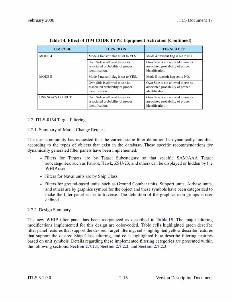
February 2006 JTLS Document 17
2.7 JTLS-0154 Target Filtering
2.7.1 Summary of Model Change Request
The user community has requested that the current static filter definition be dynamically modifiedaccording to the types of objects that exist in the database. These specific recommendations fordynamically generated filter panels have been implemented:
• Filters for Targets are by Target Subcategory so that specific SAM/AAA Targetsubcategories, such as Patriot, Hawk, ZSU-23, and others can be displayed or hidden by theWHIP user.
• Filters for Naval units are by Ship Class.
• Filters for ground-based units, such as Ground Combat units, Support units, Airbase units,and others are by graphics symbol for the object and these symbols have been categorized tomake the filter panel easier to traverse. The definition of the graphics icon groups is userdefined.
2.7.2 Design Summary
The new WHIP filter panel has been reorganized as described in Table 15. The major filteringmodifications implemented for this design are color-coded. Table cells highlighted green describefilter panel features that support the desired Target filtering, cells highlighted yellow describe featuresthat support the desired Ship Class filtering, and cells highlighted blue describe filtering featuresbased on unit symbols. Details regarding these implemented filtering categories are presented withinthe following sections: Section 2.7.2.1, Section 2.7.2.2, and Section 2.7.2.3.
MODE 4 Mode 4 transmit flag is set to YES. Mode 4 transmit flag is set to NO.
Own Side is allowed to use itsassociated probability of properidentification.
Own Side is not allowed to use itsassociated probability of properidentification.
MODE 5 Mode 5 transmit flag is set to YES. Mode 5 transmit flag set to NO.
Own Side is allowed to use itsassociated probability of properidentification.
Own Side is not allowed to use itsassociated probability of properidentification.
UNKNOWN OUTPUT Own Side is allowed to use itsassociated probability of properidentification.
Own Side is not allowed to use itsassociated probability of properidentification.
Table 14. Effect of ITM CODE TYPE Equipment Activation (Continued)
ITM CODE TURNED ON TURNED OFF
JTLS 3.1.0.0 2-15 Version Description Document

JTLS Document 17 February 2006
Table 15. WHIP Filter Panel Organization
LEVEL 1 LEVEL 2 LEVEL 3 LEVEL 4
Object Type Ground
Support
Airbase
...
Unidentified Target
General Characteristics Strength 75% - 100%
50% - 74%
25% - 49%
0% - 24%
Unit Posture Attack
Defend
Delay
...
Wiped Out
HLA Controlled
Land UnitsApplies only to land-basedunits, Ground Combat Units,Airbases, Squadrons, FARPs,Support, and High ResolutionUnits (HRUs).
In Combat
Command Level Squad
Section
Platoon
...
Army Group
Unit Symbol Command HQ_AIR_DEFENSE
JOINT_TF_HQ
HEADQUARTERS
...
HQ_CORPS
Version Description Document 2-16 JTLS 3.1.0.0
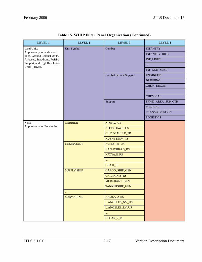
February 2006 JTLS Document 17
Land UnitsApplies only to land-basedunits, Ground Combat Units,Airbases, Squadrons, FARPs,Support, and High ResolutionUnits (HRUs).
Unit Symbol Combat INFANTRY
INFANTRY_BIFB
INF_LIGHT
...
INF_MOTORIZE
Combat Service Support ENGINEER
BRIDGING
CHEM_DECON
...
CHEMICAL
Support FRWD_AREA_SUP_CTR
MEDICAL
TRANSPORTATION
LOGISTICS
NavalApplies only to Naval units.
CARRIER NIMITZ_US
KITTY.HAWK_US
CH.DEGAULLE_FR
KUZNETSOV_RS
COMBATANT AVENGER_US
NANUCHKA.3_RS
NATYA.II_RS
...
OSA.II_IR
SUPPLY SHIP CARGO_SHIP_GEN
CHILIKIN.B_RS
MERCHANT_GEN
TANKERSHIP_GEN
...
SUBMARINE AKULA_2_RS
L.ANGELES_NV_US
L.ANGELES_LV_US
...
OSCAR_2_RS
Table 15. WHIP Filter Panel Organization (Continued)
LEVEL 1 LEVEL 2 LEVEL 3 LEVEL 4
JTLS 3.1.0.0 2-17 Version Description Document
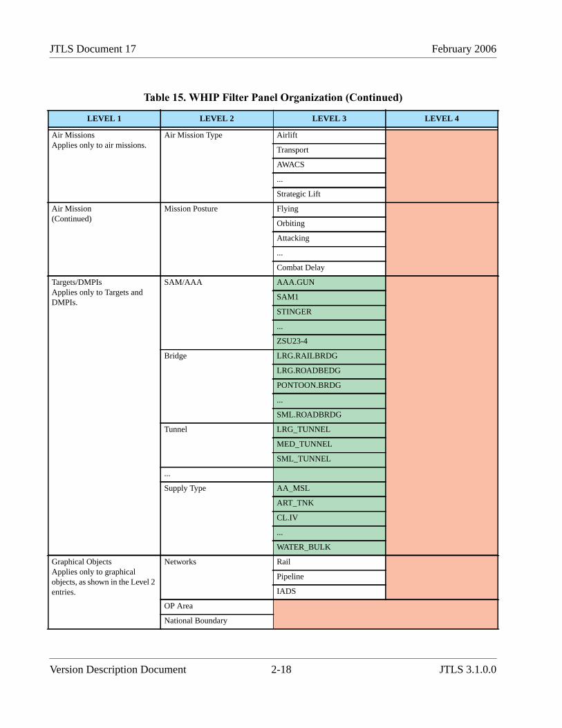
JTLS Document 17 February 2006
Air MissionsApplies only to air missions.
Air Mission Type Airlift
Transport
AWACS
...
Strategic Lift
Air Mission(Continued)
Mission Posture Flying
Orbiting
Attacking
...
Combat Delay
Targets/DMPIsApplies only to Targets andDMPIs.
SAM/AAA AAA.GUN
SAM1
STINGER
...
ZSU23-4
Bridge LRG.RAILBRDG
LRG.ROADBEDG
PONTOON.BRDG
...
SML.ROADBRDG
Tunnel LRG_TUNNEL
MED_TUNNEL
SML_TUNNEL
...
Supply Type AA_MSL
ART_TNK
CL.IV
...
WATER_BULK
Graphical ObjectsApplies only to graphicalobjects, as shown in the Level 2entries.
Networks Rail
Pipeline
IADS
OP Area
National Boundary
Table 15. WHIP Filter Panel Organization (Continued)
LEVEL 1 LEVEL 2 LEVEL 3 LEVEL 4
Version Description Document 2-18 JTLS 3.1.0.0
February 2006 JTLS Document 17
Some additional refinements are also a part of this reorganization:
• Since unit Posture applies to all land-based and naval units, this filter category wassubsumed within a new General Characteristics filter item in conjunction with Strength. TheHLA Controlled filter, which applies to several different object types, such as Land-basedunits, Naval units, Targets, and Air Missions; is also appropriately included within theGeneral Characteristics Level 1 category. The remaining Level 1 categories can now beviewed as specific object type filters. The applicable object types are indicated under thedescription of the meaning of the Level 1 filter category.
• The graphics objects, such as Networks, OPAREAs, and National Boundaries werecombined within a Graphics Object Level 1 category to reduce the number of Level 1categories and create a more compact and usable filter panel.The current Map Componentfilter configuration file will be separated into two files; a static filter configuration file($JGAME/data/mapfilters-conf.xml) and a dynamic filter configuration file ($JGAME/<scenario>/webroot/mapfilters-dynamic.xml). The dynamic filter file must be generatedaccording to the contents of the scenario that is being run. For example, if there are noTargets of type category SAM/AAA and Subcategory of SAM1, the corresponding filteroption should not appear in the filter panel. This allows the filter panel to be adaptable to thespecific scenario without becoming overburdened with options that do not exist in thescenario.
The dynamic filter file is automatically generated as part of the scenario setup function for theScenario Initialization Program. Additionally, the dynamic filter file is regenerated if the existing filterpanel is no longer complete due to Player or Controller action.
The static Map filter configuration file contains the filter configurations for all filters except those thatare dynamic. The static filter file contains placeholders or indicators to designate placement of thedynamic filter configuration data. When the WHIP reads the mapfilters-conf.xml and the mapfilters-dynamic.xml files, the WHIP splices the dynamic filters into these placeholders and then creates thefilter panel for the map component.
The user interface behavior for the Map Component filters has not change with the implementation ofthis design. The user will still manipulate the filter setting in the same manner. At each Level, theWHIP user has two options:
• Change the filter setting for all options under the level. This is a global level filter alteration.
• Open up the level to reveal the sub-level and change any one or multiple options within thenewly revealed sub-level. This is a specific filter alteration.
The only modification to the filter interface a WHIP user will notice is the additional options andlevels of filter detail that can be changed.
JTLS 3.1.0.0 2-19 Version Description Document
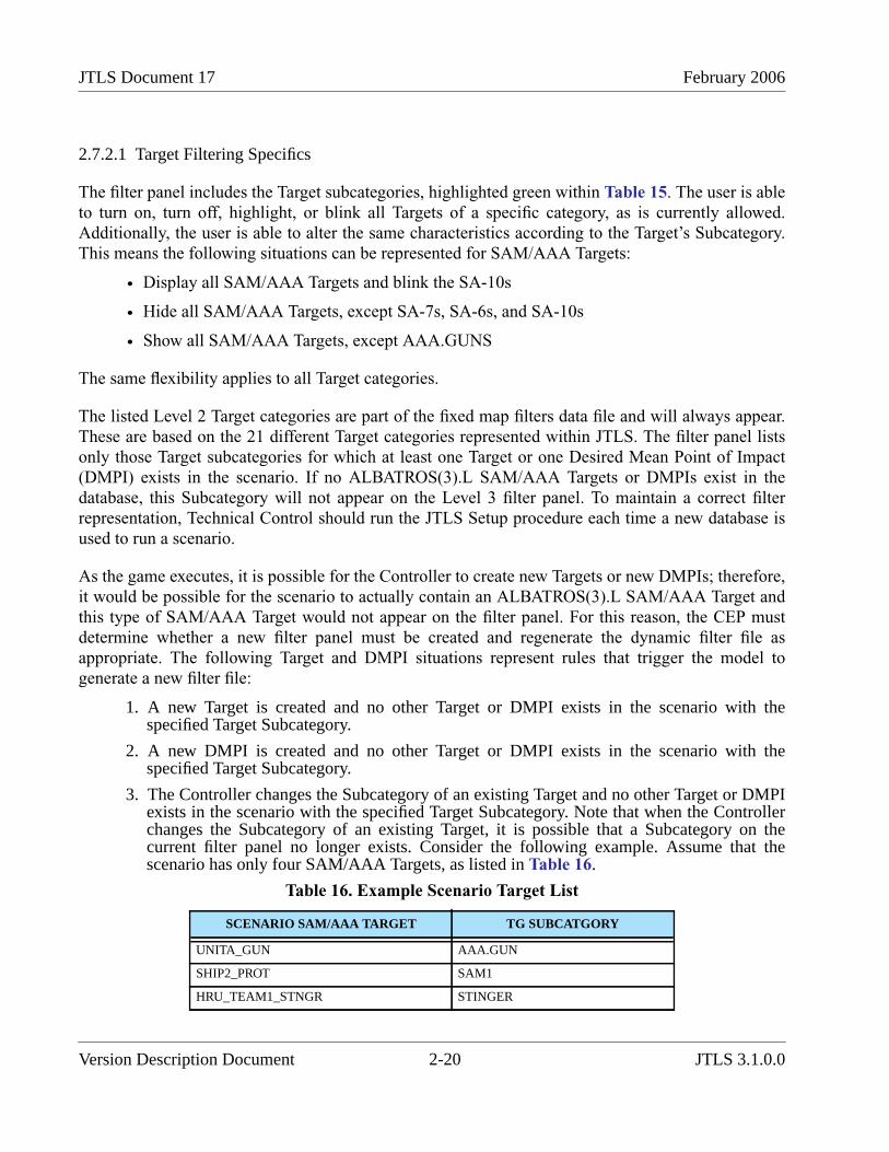
JTLS Document 17 February 2006
2.7.2.1 Target Filtering Specifics
The filter panel includes the Target subcategories, highlighted green within Table 15. The user is ableto turn on, turn off, highlight, or blink all Targets of a specific category, as is currently allowed.Additionally, the user is able to alter the same characteristics according to the Target’s Subcategory.This means the following situations can be represented for SAM/AAA Targets:
• Display all SAM/AAA Targets and blink the SA-10s
• Hide all SAM/AAA Targets, except SA-7s, SA-6s, and SA-10s
• Show all SAM/AAA Targets, except AAA.GUNS
The same flexibility applies to all Target categories.
The listed Level 2 Target categories are part of the fixed map filters data file and will always appear.These are based on the 21 different Target categories represented within JTLS. The filter panel listsonly those Target subcategories for which at least one Target or one Desired Mean Point of Impact(DMPI) exists in the scenario. If no ALBATROS(3).L SAM/AAA Targets or DMPIs exist in thedatabase, this Subcategory will not appear on the Level 3 filter panel. To maintain a correct filterrepresentation, Technical Control should run the JTLS Setup procedure each time a new database isused to run a scenario.
As the game executes, it is possible for the Controller to create new Targets or new DMPIs; therefore,it would be possible for the scenario to actually contain an ALBATROS(3).L SAM/AAA Target andthis type of SAM/AAA Target would not appear on the filter panel. For this reason, the CEP mustdetermine whether a new filter panel must be created and regenerate the dynamic filter file asappropriate. The following Target and DMPI situations represent rules that trigger the model togenerate a new filter file:
1. A new Target is created and no other Target or DMPI exists in the scenario with thespecified Target Subcategory.
2. A new DMPI is created and no other Target or DMPI exists in the scenario with thespecified Target Subcategory.
3. The Controller changes the Subcategory of an existing Target and no other Target or DMPIexists in the scenario with the specified Target Subcategory. Note that when the Controllerchanges the Subcategory of an existing Target, it is possible that a Subcategory on thecurrent filter panel no longer exists. Consider the following example. Assume that thescenario has only four SAM/AAA Targets, as listed in Table 16.
Table 16. Example Scenario Target List
SCENARIO SAM/AAA TARGET TG SUBCATGORY
UNITA_GUN AAA.GUN
SHIP2_PROT SAM1
HRU_TEAM1_STNGR STINGER
Version Description Document 2-20 JTLS 3.1.0.0
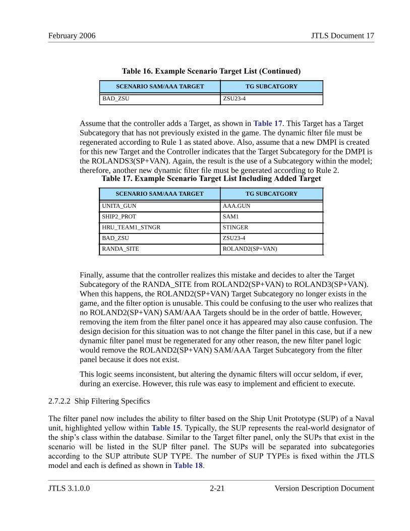
February 2006 JTLS Document 17
Assume that the controller adds a Target, as shown in Table 17. This Target has a TargetSubcategory that has not previously existed in the game. The dynamic filter file must beregenerated according to Rule 1 as stated above. Also, assume that a new DMPI is createdfor this new Target and the Controller indicates that the Target Subcategory for the DMPI isthe ROLANDS3(SP+VAN). Again, the result is the use of a Subcategory within the model;therefore, another new dynamic filter file must be generated according to Rule 2.
Finally, assume that the controller realizes this mistake and decides to alter the TargetSubcategory of the RANDA_SITE from ROLAND2(SP+VAN) to ROLAND3(SP+VAN).When this happens, the ROLAND2(SP+VAN) Target Subcategory no longer exists in thegame, and the filter option is unusable. This could be confusing to the user who realizes thatno ROLAND2(SP+VAN) SAM/AAA Targets should be in the order of battle. However,removing the item from the filter panel once it has appeared may also cause confusion. Thedesign decision for this situation was to not change the filter panel in this case, but if a newdynamic filter panel must be regenerated for any other reason, the new filter panel logicwould remove the ROLAND2(SP+VAN) SAM/AAA Target Subcategory from the filterpanel because it does not exist.
This logic seems inconsistent, but altering the dynamic filters will occur seldom, if ever,during an exercise. However, this rule was easy to implement and efficient to execute.
2.7.2.2 Ship Filtering Specifics
The filter panel now includes the ability to filter based on the Ship Unit Prototype (SUP) of a Navalunit, highlighted yellow within Table 15. Typically, the SUP represents the real-world designator ofthe ship’s class within the database. Similar to the Target filter panel, only the SUPs that exist in thescenario will be listed in the SUP filter panel. The SUPs will be separated into subcategoriesaccording to the SUP attribute SUP TYPE. The number of SUP TYPEs is fixed within the JTLSmodel and each is defined as shown in Table 18.
BAD_ZSU ZSU23-4
Table 17. Example Scenario Target List Including Added Target
SCENARIO SAM/AAA TARGET TG SUBCATGORY
UNITA_GUN AAA.GUN
SHIP2_PROT SAM1
HRU_TEAM1_STNGR STINGER
BAD_ZSU ZSU23-4
RANDA_SITE ROLAND2(SP+VAN)
Table 16. Example Scenario Target List (Continued)
SCENARIO SAM/AAA TARGET TG SUBCATGORY
JTLS 3.1.0.0 2-21 Version Description Document
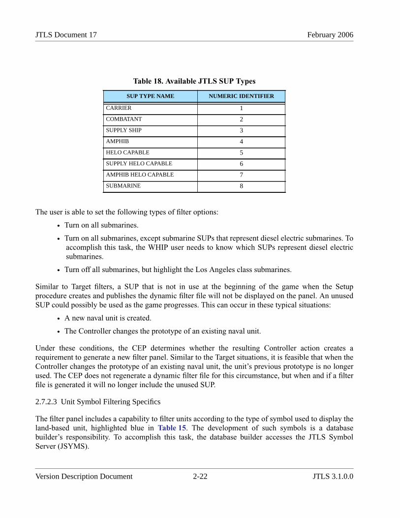
JTLS Document 17 February 2006
The user is able to set the following types of filter options:
• Turn on all submarines.
• Turn on all submarines, except submarine SUPs that represent diesel electric submarines. Toaccomplish this task, the WHIP user needs to know which SUPs represent diesel electricsubmarines.
• Turn off all submarines, but highlight the Los Angeles class submarines.
Similar to Target filters, a SUP that is not in use at the beginning of the game when the Setupprocedure creates and publishes the dynamic filter file will not be displayed on the panel. An unusedSUP could possibly be used as the game progresses. This can occur in these typical situations:
• A new naval unit is created.
• The Controller changes the prototype of an existing naval unit.
Under these conditions, the CEP determines whether the resulting Controller action creates arequirement to generate a new filter panel. Similar to the Target situations, it is feasible that when theController changes the prototype of an existing naval unit, the unit’s previous prototype is no longerused. The CEP does not regenerate a dynamic filter file for this circumstance, but when and if a filterfile is generated it will no longer include the unused SUP.
2.7.2.3 Unit Symbol Filtering Specifics
The filter panel includes a capability to filter units according to the type of symbol used to display theland-based unit, highlighted blue in Table 15. The development of such symbols is a databasebuilder’s responsibility. To accomplish this task, the database builder accesses the JTLS SymbolServer (JSYMS).
Table 18. Available JTLS SUP Types
SUP TYPE NAME NUMERIC IDENTIFIER
CARRIER 1
COMBATANT 2
SUPPLY SHIP 3
AMPHIB 4
HELO CAPABLE 5
SUPPLY HELO CAPABLE 6
AMPHIB HELO CAPABLE 7
SUBMARINE 8
Version Description Document 2-22 JTLS 3.1.0.0

February 2006 JTLS Document 17
In addition to building these symbols, the database developer is also responsible for categorizingthem. The primary purpose of this categorization is to make the Map filter capability more useful.Currently, JTLS utilizes more than 100 symbols, many of which do not apply to land-based units.Therefore, there was a need to specify which symbols should be classified in the Level 3 filter for landunits.
The JTLS 3.1.0.0 delivery includes a default symbol categorization scheme. Users who choose tomodify the selected categories are fully capable of creating their own category scheme, which willautomatically be applied to the Map filter panel via the dynamic filter file. Each scenario can have itsown categorization scheme as desired. When a new scenario is created, the default scheme is used forthe scenario, but the database builder can alter the new scenario’s scheme specifically for thatscenario, or generally for all of a organization’s existing scenarios.
The Scenario Verification Program (SVP) checks for consistency and ensure that the symbol assignedfor each land unit, i.e. Ground Combat Unit, Airbase, Squadron, FARP, Support Unit, or HRU, hasbeen assigned a category. If the symbol is not included in a category, a Warning is generated toindicate that control of the object by means of its symbol cannot be accomplished.
2.7.2.4 WHIP Filter File Notification
Another delivered ECP entitled JTLS-0028 Named Map Views defines a requirement for saving andrecalling map filter settings, as well as locations and views (combinations of a location and filtersettings). This design considers the dynamic nature of some of the filter configuration data and savesthe dynamic filter settings concurrently with the static filter settings when the user performs a save offilters.
Because part of the map filter configuration is dynamic, a problem potentially exists if the savedfilters do not match the current dynamic filter configuration file as it was most recently written by theSIP or the CEP. This problem is avoided by first loading the default filter settings prior to each recallof save filters. This ensures that any new Target Subcategory filters are set to the default settings andwill not have an undetermined value after the save filters are recalled. If a Target Subcategory filter isno longer in the dynamic filters, a possible but rare occurrence, the filter will be ignored by the filterloading algorithm.
2.7.3 Data Changes
No Database Development System (DDS) data changes are required to support this ECP. Minormodifications were made to the data file generated by the JTLS Symbol Server (JSYMS) that is usedby the DDS.
JTLS 3.1.0.0 2-23 Version Description Document
JTLS Document 17 February 2006
2.8 JTLS-0277 Target Underground Flag
2.8.1 Summary of Model Change Request
Within JTLS, military units, ships, small teams of personnel (High Resolution Units), air missions,and convoys are modeled or represented as physical objects. The model also represents an additionalphysical object referred to as a target. A JTLS target is defined as a militarily significant object notincluded in any other physical object category. Unfortunately, the term target can confuse uninitiatedmodel users because all JTLS physical objects can be targeted. For example, a Player has the abilityto attack a specific military unit, such as an airbase or support depot. Ships can be attacked by variousmeans, including ship-to-ship gunfire or torpedoes. High Resolution Units (HRUs) can engage incombat with each other and be killed by aggregate-level military units with which they come incontact. The same is true for air missions and convoys. As their names suggest, targets can also betargeted or attacked within JTLS.
The detection of targets in JTLS is currently determined by using the Target Category andSubcategory multiplier held in the IIP TGC PROB DETECTION MULT ARRAY to adjust thebaseline PD of the sensor that attempts the detection. For a Target Subcategory that represents anunderground facility, the database is built in such a manner that value of the Target Subcategorydetection multiplier is very small. Thus, detecting and reporting the status of these targets in JTLS isdifficult.
This method has worked well for JTLS in the past, but within the Joint Multi-Resolution Model(JMRM) other intelligence collection models such as Tactical Simulation (TACSIM) and MultipleUnified Simulated Environment / Air Force Synthetic Environment for Reconnaissance andSurveillance (MUSE/AFSERS) are linked to JTLS. For TACSIM and MUSE/AFSERS to properlyinterpret an underground target, a specific attribute must be attached to the object within the FOM.The JTLS representation of an underground target based on the PD is subject to undesirableinterpretation. For this reason, adding a dedicated attribute that indicates whether the target isunderground is desirable.
In addition there was a desire to add an attribute indicating whether an imagery collection sensor can“see” or obtain information regarding the contents of the target. An illustrative example of thisconcept is the Aircraft Shelter target, which can contain aircraft. Some Aircraft Shelter targetsrepresent concrete hangars and others can represent outdoor revetments which protect aircraft fromadjacent bomb damage. An overhead imagery sensor may or may not be able to determine whetherthe Aircraft Shelter contains any aircraft, but it would be easy for the sensor to obtain informationregarding the aircraft held within a revetment.
2.8.2 Design Summary
Like many JTLS designs, this simple improvement concept can create opportunities for additionalimprovements and expand the scope of the associated ECP. Due to time constraints, we have refrained
Version Description Document 2-24 JTLS 3.1.0.0
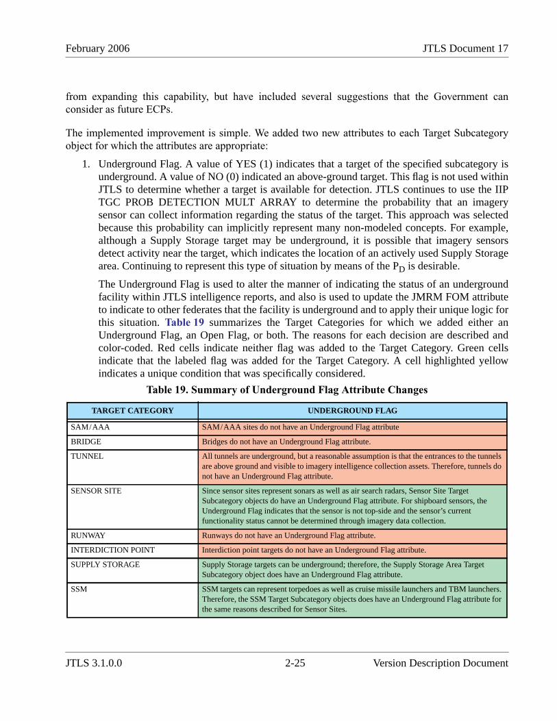
February 2006 JTLS Document 17
from expanding this capability, but have included several suggestions that the Government canconsider as future ECPs.
The implemented improvement is simple. We added two new attributes to each Target Subcategoryobject for which the attributes are appropriate:
1. Underground Flag. A value of YES (1) indicates that a target of the specified subcategory isunderground. A value of NO (0) indicated an above-ground target. This flag is not used withinJTLS to determine whether a target is available for detection. JTLS continues to use the IIPTGC PROB DETECTION MULT ARRAY to determine the probability that an imagerysensor can collect information regarding the status of the target. This approach was selectedbecause this probability can implicitly represent many non-modeled concepts. For example,although a Supply Storage target may be underground, it is possible that imagery sensorsdetect activity near the target, which indicates the location of an actively used Supply Storagearea. Continuing to represent this type of situation by means of the PD is desirable.
The Underground Flag is used to alter the manner of indicating the status of an undergroundfacility within JTLS intelligence reports, and also is used to update the JMRM FOM attributeto indicate to other federates that the facility is underground and to apply their unique logic forthis situation. Table 19 summarizes the Target Categories for which we added either anUnderground Flag, an Open Flag, or both. The reasons for each decision are described andcolor-coded. Red cells indicate neither flag was added to the Target Category. Green cellsindicate that the labeled flag was added for the Target Category. A cell highlighted yellowindicates a unique condition that was specifically considered.
Table 19. Summary of Underground Flag Attribute Changes
TARGET CATEGORY UNDERGROUND FLAG
SAM/AAA SAM/AAA sites do not have an Underground Flag attribute
BRIDGE Bridges do not have an Underground Flag attribute.
TUNNEL All tunnels are underground, but a reasonable assumption is that the entrances to the tunnelsare above ground and visible to imagery intelligence collection assets. Therefore, tunnels donot have an Underground Flag attribute.
SENSOR SITE Since sensor sites represent sonars as well as air search radars, Sensor Site TargetSubcategory objects do have an Underground Flag attribute. For shipboard sensors, theUnderground Flag indicates that the sensor is not top-side and the sensor’s currentfunctionality status cannot be determined through imagery data collection.
RUNWAY Runways do not have an Underground Flag attribute.
INTERDICTION POINT Interdiction point targets do not have an Underground Flag attribute.
SUPPLY STORAGE Supply Storage targets can be underground; therefore, the Supply Storage Area TargetSubcategory object does have an Underground Flag attribute.
SSM SSM targets can represent torpedoes as well as cruise missile launchers and TBM launchers.Therefore, the SSM Target Subcategory objects does have an Underground Flag attribute forthe same reasons described for Sensor Sites.
JTLS 3.1.0.0 2-25 Version Description Document
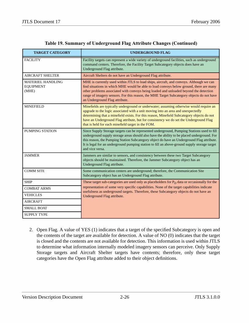
JTLS Document 17 February 2006
2. Open Flag. A value of YES (1) indicates that a target of the specified Subcategory is open andthe contents of the target are available for detection. A value of NO (0) indicates that the targetis closed and the contents are not available for detection. This information is used within JTLSto determine what information internally modeled imagery sensors can perceive. Only SupplyStorage targets and Aircraft Shelter targets have contents; therefore, only these targetcategories have the Open Flag attribute added to their object definitions.
FACILITY Facility targets can represent a wide variety of underground facilities, such as undergroundcommand centers. Therefore, the Facility Target Subcategory objects does have anUnderground Flag attribute.
AIRCRAFT SHELTER Aircraft Shelters do not have an Underground Flag attribute.
MATERIEL HANDLINGEQUIPMENT(MHE)
MHE is currently used within JTLS to load ships, aircraft, and convoys. Although we canfind situations in which MHE would be able to load convoys below ground, there are manyother problems associated with convoys being loaded and unloaded beyond the detectionrange of imagery sensors. For this reason, the MHE Target Subcategory objects do not havean Underground Flag attribute.
MINEFIELD Minefields are typically underground or underwater; assuming otherwise would require anupgrade to the logic associated with a unit moving into an area and unexpectedlydetermining that a minefield exists. For this reason, Minefield Subcategory objects do nothave an Underground Flag attribute, but for consistency we do set the Underground Flagthat is held for each minefield target in the FOM.
PUMPING STATION Since Supply Storage targets can be represented underground, Pumping Stations used to fillunderground supply storage areas should also have the ability to be placed underground. Forthis reason, the Pumping Station Subcategory object do have an Underground Flag attribute.It is legal for an underground pumping station to fill an above-ground supply storage targetand vice versa.
JAMMER Jammers are similar to sensors, and consistency between these two Target Subcategoryobjects should be maintained. Therefore, the Jammer Subcategory object has anUnderground Flag attribute.
COMM SITE Some communication centers are underground; therefore, the Communication SiteSubcategory object has an Underground Flag attribute.
SHIP These target sub-categories are used only as placeholders for PD data or occasionally for the
representation of some very specific capabilities. None of the target capabilities indicateusefulness as underground targets. Therefore, these Subcategory objects do not have anUnderground Flag attribute.
COMBAT ARMS
VEHICLES
AIRCRAFT
SMALL BOAT
SUPPLY TYPE
Table 19. Summary of Underground Flag Attribute Changes (Continued)
TARGET CATEGORY UNDERGROUND FLAG
Version Description Document 2-26 JTLS 3.1.0.0
February 2006 JTLS Document 17
The Open Flag attribute information is made available to all JMRM federates by placing thisinformation on the appropriate Target Subcategory objects within the FOM. This attribute willnot benefit a federate if the FOM does not include information regarding the contents of thetarget. This information is already available for Supply Storage targets, but is much moredifficult to access for Aircraft Shelters.
The JODA does not hold the information regarding the aircraft currently in each aircraftshelter. This information is not made available for two reasons:
• JTLS tracks the aircraft contents of Aircraft Shelters only prior to computing damage to anairbase, squadron, or aircraft shelter. Continually updating this information each instance anaircraft takes off or comes out of maintenance is not accomplished. This problem isrelatively easy to overcome.
• An Aircraft Shelter target can have several individual shelters within a given target. JTLSinternally tracks the aircraft located within each shelter sub-element, but the model does nothave an object structure established to track this object within the JODA or the FOM. Forexample, no efficient method exists for the CEP to pass to the JODA that Revetment 1 in theAircraft Shelter target has two B2s and Revetment 2 has three B2s, and Revetment 3 has sixFA18s.
Considering the implementation schedule time constraints, Aircraft Shelter contents couldnot be published. This improvement has been placed on the work plan and is expected to bedelivered as part of JTLS 3.2.0.0.
2.8.3 Data Changes
Several database objects must be modified to support this ECP: ST UNDERGROUND FLAG, SSAUNDERGROUND FLAG, SSM UNDERGROUND FLAG, FAT UNDERGROUND FLAG, PSUNDERGROUND FLAG, JT UNDERGROUND FLAG, CC UNDERGROUND FLAG, SSA OPENFLAG, AS OPEN FLAG
2.8.4 Order Changes
The Set orders for the following objects were modified to allow the Controller to set the new objectattributes:
• Sensor Type
• Supply Storage Area
• Surface Surface Missile
• Facility Type
• Pumping Station
• Jammer Type
JTLS 3.1.0.0 2-27 Version Description Document
JTLS Document 17 February 2006
• Communication Center
• Aircraft Shelter
2.8.5 FOM Changes
A new Boolean attribute, Underground_Flag, was added to these objects:
• Sensor_Site
• Supply_Storage
• Surface_To_Surface_Missile
• Facility
• Pumping_Station
• Jammer
• Communications_Site
A new Boolean attribute, Open_Flag, was added to these objects:
• Supply_Storage
• Aircraft_Shelter
2.9 JTLS-0312 User Lines On Map Displays
An improved set of graphics tools is provided in the WHIP to draw user lines and operationalgraphics on the WHIP map display. This set of tools provides the user with typical drawing toolfunctions, such as drawing lines, polygons, and circles. The majority of work accomplished in thisECP was focussed upon the proper saving and recalling of saved graphics slides. These savedgraphics slides are formatted in documented Extensible Markup Language (XML). This means thatusers have the ability to write their own programs to create and register their own graphics files.
The JTLS ATO-T operates in this manner, and reads the Air Control Order (ACO), developed by theAir Operations Center (AOC). The ATO-T uses this information to create several XML graphicsslides that the user can choose to display. This fully automates the process of displaying the currentACO.
The format of the XML slides is described in the JTLS Software Maintenance Manual.
Version Description Document 2-28 JTLS 3.1.0.0

February 2006 JTLS Document 17
2.10 JTLS-0320 UTM/MGRS Conversion Utility
2.10.1 Summary of Model Change Request
Although the MCR specified only a conversion utility, we believed that the underlying requirementwas to allow the WHIP user the ability to enter a location in either a latitude and longitude format oras a Military Grid Reference System (MGRS) coordinates.
This ECP resulted in a built-in location field conversion capability that allows users to enter either aLat/Long coordinate or an MGRS coordinate. In addition, a separate utility component was developedto provide the user the capability to perform as needed coordinate conversion between Lat/Lon andMGRS.
2.10.2 Design Summary
The user’s location format preference is set within the Preferences Manager. Figure 1 depicts thepreference as it appears in the Preferences Manager. The Coordinate Format Preference is applied toall places in the WHIP where a coordinate is displayed, such as the IMT, Message Browser, andSitrep.
FIGURE 1. Coordinate Format Preference
When entering coordinates into a location field, the user may enter either a Lat/Lon or a MGRScoordinate. The location field converts the coordinate into an internal storage format. After thecoordinate is accepted the coordinate is displayed in the order field based on the "Coordinate Format"preference. If the preference is "MilGrid" the coordinate is displayed in MGRS format (i.e.32UNA7166639110), if the preference is "Lat/Lon" the coordinate is displayed in "Lat/Lon" format.(i.e. 10-00-00N 50-00-00E).
JTLS 3.1.0.0 2-29 Version Description Document
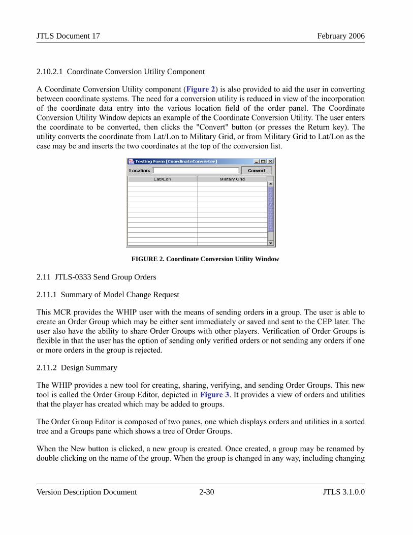
JTLS Document 17 February 2006
2.10.2.1 Coordinate Conversion Utility Component
A Coordinate Conversion Utility component (Figure 2) is also provided to aid the user in convertingbetween coordinate systems. The need for a conversion utility is reduced in view of the incorporationof the coordinate data entry into the various location field of the order panel. The CoordinateConversion Utility Window depicts an example of the Coordinate Conversion Utility. The user entersthe coordinate to be converted, then clicks the "Convert" button (or presses the Return key). Theutility converts the coordinate from Lat/Lon to Military Grid, or from Military Grid to Lat/Lon as thecase may be and inserts the two coordinates at the top of the conversion list.
FIGURE 2. Coordinate Conversion Utility Window
2.11 JTLS-0333 Send Group Orders
2.11.1 Summary of Model Change Request
This MCR provides the WHIP user with the means of sending orders in a group. The user is able tocreate an Order Group which may be either sent immediately or saved and sent to the CEP later. Theuser also have the ability to share Order Groups with other players. Verification of Order Groups isflexible in that the user has the option of sending only verified orders or not sending any orders if oneor more orders in the group is rejected.
2.11.2 Design Summary
The WHIP provides a new tool for creating, sharing, verifying, and sending Order Groups. This newtool is called the Order Group Editor, depicted in Figure 3. It provides a view of orders and utilitiesthat the player has created which may be added to groups.
The Order Group Editor is composed of two panes, one which displays orders and utilities in a sortedtree and a Groups pane which shows a tree of Order Groups.
When the New button is clicked, a new group is created. Once created, a group may be renamed bydouble clicking on the name of the group. When the group is changed in any way, including changing
Version Description Document 2-30 JTLS 3.1.0.0
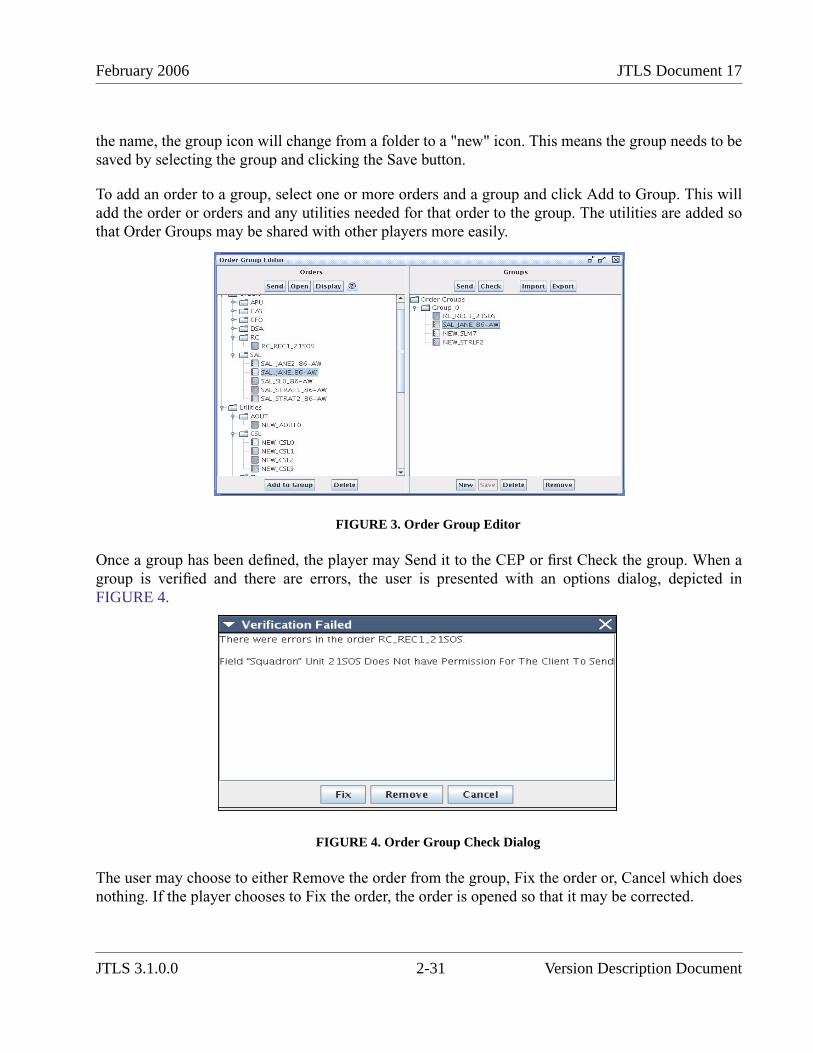
February 2006 JTLS Document 17
the name, the group icon will change from a folder to a "new" icon. This means the group needs to besaved by selecting the group and clicking the Save button.
To add an order to a group, select one or more orders and a group and click Add to Group. This willadd the order or orders and any utilities needed for that order to the group. The utilities are added sothat Order Groups may be shared with other players more easily.
FIGURE 3. Order Group Editor
Once a group has been defined, the player may Send it to the CEP or first Check the group. When agroup is verified and there are errors, the user is presented with an options dialog, depicted inFIGURE 4.
FIGURE 4. Order Group Check Dialog
The user may choose to either Remove the order from the group, Fix the order or, Cancel which doesnothing. If the player chooses to Fix the order, the order is opened so that it may be corrected.
JTLS 3.1.0.0 2-31 Version Description Document
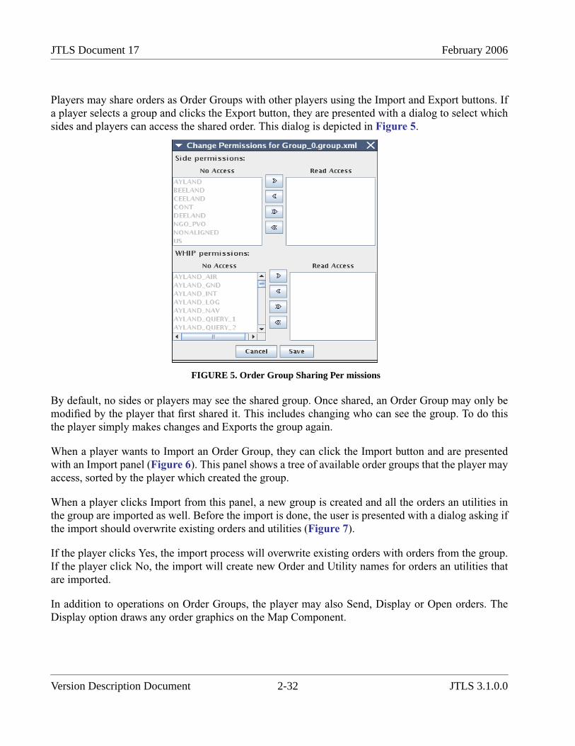
JTLS Document 17 February 2006
Players may share orders as Order Groups with other players using the Import and Export buttons. Ifa player selects a group and clicks the Export button, they are presented with a dialog to select whichsides and players can access the shared order. This dialog is depicted in Figure 5.
FIGURE 5. Order Group Sharing Per missions
By default, no sides or players may see the shared group. Once shared, an Order Group may only bemodified by the player that first shared it. This includes changing who can see the group. To do thisthe player simply makes changes and Exports the group again.
When a player wants to Import an Order Group, they can click the Import button and are presentedwith an Import panel (Figure 6). This panel shows a tree of available order groups that the player mayaccess, sorted by the player which created the group.
When a player clicks Import from this panel, a new group is created and all the orders an utilities inthe group are imported as well. Before the import is done, the user is presented with a dialog asking ifthe import should overwrite existing orders and utilities (Figure 7).
If the player clicks Yes, the import process will overwrite existing orders with orders from the group.If the player click No, the import will create new Order and Utility names for orders an utilities thatare imported.
In addition to operations on Order Groups, the player may also Send, Display or Open orders. TheDisplay option draws any order graphics on the Map Component.
Version Description Document 2-32 JTLS 3.1.0.0
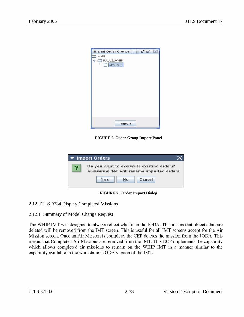
February 2006 JTLS Document 17
FIGURE 6. Order Group Import Panel
FIGURE 7. Order Import Dialog
2.12 JTLS-0334 Display Completed Missions
2.12.1 Summary of Model Change Request
The WHIP IMT was designed to always reflect what is in the JODA. This means that objects that aredeleted will be removed from the IMT screen. This is useful for all IMT screens accept for the AirMission screen. Once an Air Mission is complete, the CEP deletes the mission from the JODA. Thismeans that Completed Air Missions are removed from the IMT. This ECP implements the capabilitywhich allows completed air missions to remain on the WHIP IMT in a manner similar to thecapability available in the workstation JODA version of the IMT.
JTLS 3.1.0.0 2-33 Version Description Document

JTLS Document 17 February 2006
2.12.2 Design Summary
The IMT Screen definition file format was enhanced to indicate that a screen should keep deletedentries. This new capability can be applied to any IMT screen definition, but has been applied only tothe Air Mission IMT screen in response to this MCR. This has the effect of the Air Mission screenkeeping completed missions. The deleted missions do not appear on newly opened IMT screens andare removed if the player modifies the filters or if an open Air Mission IMT screen receives adownload from the JXSR. The IMT could receive a download from the JXSR if the CEP, JODA, orJXSR is restarted.
2.13 JTLS-0343 Sort Messages By Unit /Faction
2.13.1 Summary of Model Change Request
The JTLS Combat Events Program (CEP) sends two basic types of user messages, directed andbroadcast. A directed message is routed to a specific Web-Hosted Interface Program (WHIP) and istypically a reply to a specific user’s WHIP request for information or a response to an order that wasentered from the WHIP. A broadcast message is available to any WHIP that indicates interest in thepurpose of the message. The WHIP Message Browser component provides user access to all messagetypes.
The Message Browser allows flexibility to indicate which types of messages are of interest andprovides a capability to request and display messages according to three characteristics:
• Type. This is the most robust retrieval constraint. The user has the ability to request anycombination of messages based on the following attributes:
a. Number. Each message generated by the CEP is assigned a numeric identifier. Forexample, a Mission Report is a message numbered 3680. A user can retrieve allavailable Mission Reports by selecting the Mission Report message name from adisplayed list of available messages and transfer it to a list of requested messages.
b. Destination.
• .Time. To establish these retrieval constraints, the user can select from one of these separatetime specifications:
a. All messages. If the user selects this option, all messages from the beginning of thegame and all future messages will pass the time constraint filter.
b. Specific period. The user enters a starting time and ending time as a retrieval contestant.For example, the user can choose to view messages generated from 1200Z 25AUG05 to2200Z 25AUG05. If the message time is equal to or between these two values, themessage will pass the time constraint filter.
c. Rolling period. The user specifies a time interval between a selected past or future timeand the current time. As the game progresses, messages generated within this period areremoved from the display and replaced by new messages. For example, if the userchooses to view messages generated during the previous six hours, beginning at 1200Z
Version Description Document 2-34 JTLS 3.1.0.0
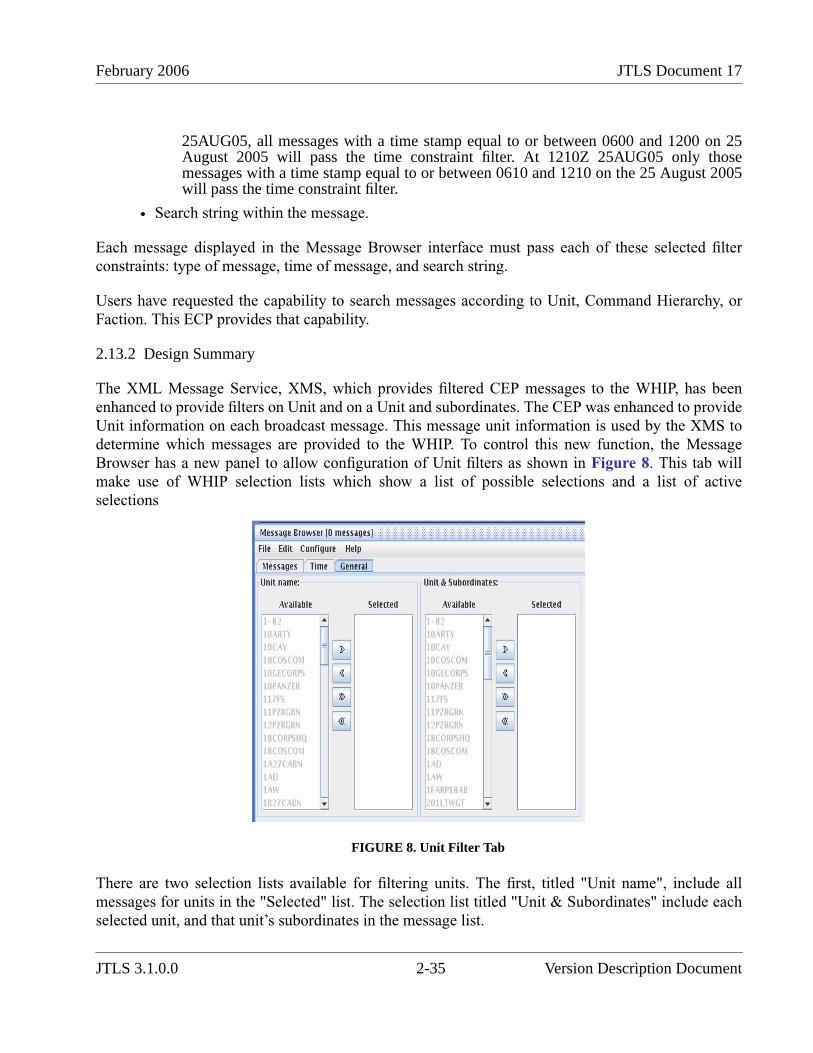
February 2006 JTLS Document 17
25AUG05, all messages with a time stamp equal to or between 0600 and 1200 on 25August 2005 will pass the time constraint filter. At 1210Z 25AUG05 only thosemessages with a time stamp equal to or between 0610 and 1210 on the 25 August 2005will pass the time constraint filter.
• Search string within the message.
Each message displayed in the Message Browser interface must pass each of these selected filterconstraints: type of message, time of message, and search string.
Users have requested the capability to search messages according to Unit, Command Hierarchy, orFaction. This ECP provides that capability.
2.13.2 Design Summary
The XML Message Service, XMS, which provides filtered CEP messages to the WHIP, has beenenhanced to provide filters on Unit and on a Unit and subordinates. The CEP was enhanced to provideUnit information on each broadcast message. This message unit information is used by the XMS todetermine which messages are provided to the WHIP. To control this new function, the MessageBrowser has a new panel to allow configuration of Unit filters as shown in Figure 8. This tab willmake use of WHIP selection lists which show a list of possible selections and a list of activeselections
FIGURE 8. Unit Filter Tab
There are two selection lists available for filtering units. The first, titled "Unit name", include allmessages for units in the "Selected" list. The selection list titled "Unit & Subordinates" include eachselected unit, and that unit’s subordinates in the message list.
JTLS 3.1.0.0 2-35 Version Description Document

JTLS Document 17 February 2006
The message filtering algorithm with the unit filtering applies the following criteria:
1. Check the message time such that it is within the specified time range, otherwise, reject themessage.
2. Check if the type of the message such that it is in the list of message types, otherwise rejectthe message.
3. If the message is a broadcast message, ensure broadcast type is in the specified broadcastbits, otherwise reject the message.
4. If the message has a UNIT attribute, see if that unit is included in unit filters. If the unit isnot listed and is not a subordinate, reject the message.
5. Check for keywords in the message data. If none of the specified keywords are found, rejectthe message.
6. If the above checks have passed, include the message.
2.14 JTLS-0347 Units In Combat Flag
2.14.1 Summary of Model Change Request
This ECP adds the capability to quickly and easily identify which units are in combat and which unitsare not in combat by looking at the Command Hierarchy Tree.
2.14.2 Design Summary
The combat status of a unit is a Boolean value. The unit is either in combat or not in combat. If a unitis in combat, the background of "in-combat" units in the color red, as in shown in Figure 9.
FIGURE 9. Unit in Combat
Version Description Document 2-36 JTLS 3.1.0.0

February 2006 JTLS Document 17
2.15 JTLS-0358 Color Units By Supply Level
2.15.1 Summary of Model Change Request
This ECP is intended to increase the logistics information readily available to the Player on the WHIPnterface. It adds a color-coding capability to the Logistics Tree component that indicates whether aunit has an On Hand supply level less than its Basic Load, Stockage Objective, or Reorder Level inspecific supply categories.
This new Logistics Tree component allows the user to organize units based on a supply chain andmonitor which units are low on supplies. The Logistics Tree is similar in style and function to theexisting Command Tree but it also include color-coded badges that indicate supplies are low. Themeaning of the colors and the threshold at which supplies are considered low is configurable by theuser. Color coding focuses on a limited number of supplies, but a complete list of shortages is also beavailable to the user in the same tree.
2.15.2 Design Summary
The organization of the Logistics Tree can be divided into two general categories, based on thescenario units routine support change and the support chain specified for a specific supply category.By default, the Logistics Tree is organized according to the routine support unit. Once the unithierarchy is displayed in this manner, the user may reconfigure the tree to be sorted according to aspecific supply category by using the selection menu depicted in Figure 10.
FIGURE 10. Fig 1 Supply Category Selection
When the Routine Support option is selected, the routine support unit is used to determine a unit’sparent in the Logistics Tree. A unit that has no routine support unit and has no supported unitssubordinate to it in the supply chain is placed in an Independent node. If a supply category option is
JTLS 3.1.0.0 2-37 Version Description Document
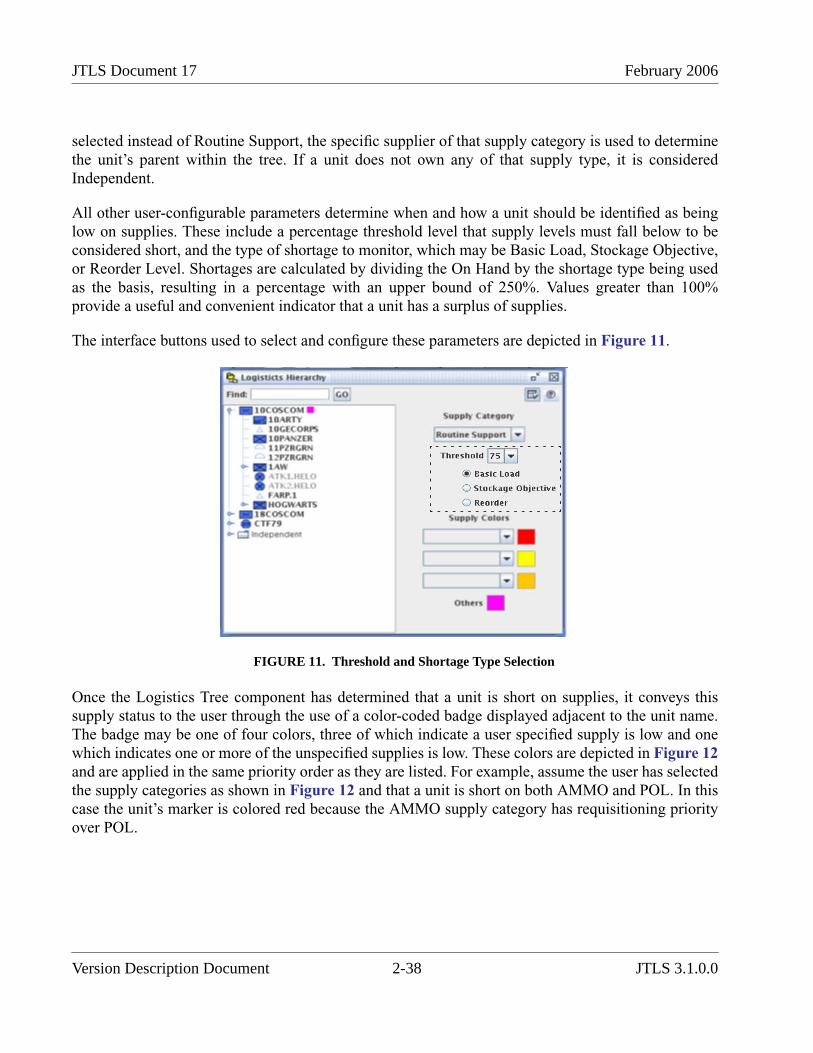
JTLS Document 17 February 2006
selected instead of Routine Support, the specific supplier of that supply category is used to determinethe unit’s parent within the tree. If a unit does not own any of that supply type, it is consideredIndependent.
All other user-configurable parameters determine when and how a unit should be identified as beinglow on supplies. These include a percentage threshold level that supply levels must fall below to beconsidered short, and the type of shortage to monitor, which may be Basic Load, Stockage Objective,or Reorder Level. Shortages are calculated by dividing the On Hand by the shortage type being usedas the basis, resulting in a percentage with an upper bound of 250%. Values greater than 100%provide a useful and convenient indicator that a unit has a surplus of supplies.
The interface buttons used to select and configure these parameters are depicted in Figure 11.
FIGURE 11. Threshold and Shortage Type Selection
Once the Logistics Tree component has determined that a unit is short on supplies, it conveys thissupply status to the user through the use of a color-coded badge displayed adjacent to the unit name.The badge may be one of four colors, three of which indicate a user specified supply is low and onewhich indicates one or more of the unspecified supplies is low. These colors are depicted in Figure 12and are applied in the same priority order as they are listed. For example, assume the user has selectedthe supply categories as shown in Figure 12 and that a unit is short on both AMMO and POL. In thiscase the unit’s marker is colored red because the AMMO supply category has requisitioning priorityover POL.
Version Description Document 2-38 JTLS 3.1.0.0
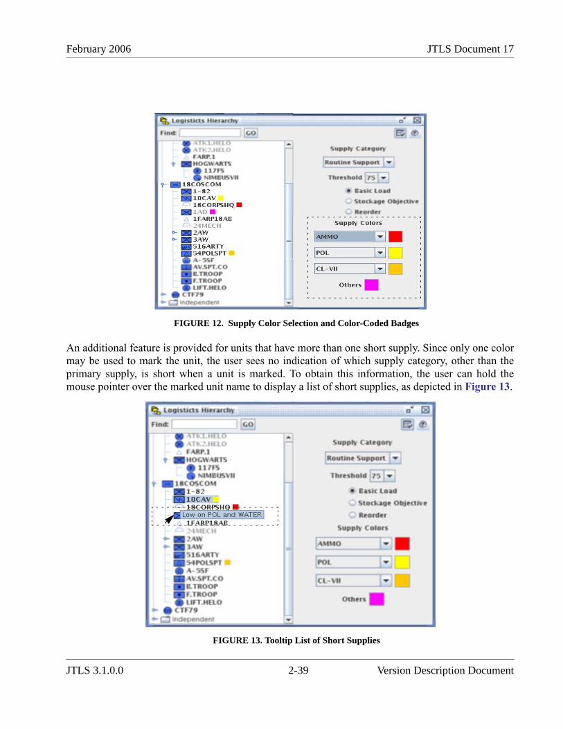
February 2006 JTLS Document 17
FIGURE 12. Supply Color Selection and Color-Coded Badges
An additional feature is provided for units that have more than one short supply. Since only one colormay be used to mark the unit, the user sees no indication of which supply category, other than theprimary supply, is short when a unit is marked. To obtain this information, the user can hold themouse pointer over the marked unit name to display a list of short supplies, as depicted in Figure 13.
FIGURE 13. Tooltip List of Short Supplies
JTLS 3.1.0.0 2-39 Version Description Document

JTLS Document 17 February 2006
2.16 JTLS-0397 Air Mission Speed Flexibility
2.16.1 Summary of Model Change Request
In previous versions the JTLS user has the ability to order an air mission to travel at a speed fasterthan its normal cruising speed, but does not have the ability to order a slower cruising speed. Thepurpose of this ECP is to improve the flexibility of the air mission speed specification and allow a userto manually control the speed of an air mission at any time during its flight profile.
2.16.2 Design Summary
Allowing the user to reduce the speed of an air mission to less than its normal cruise speed was nottechnically difficult, and is an obvious feature of this ECP. Aspects of this improvement whichrequired further consideration were the fuel consumption implications of altering the speed of an airmission.
Providing the user with speed flexibility without considering fuel consumption is contrary to theevent-oriented philosophy that has guided the development of JTLS. For every user decision, themodel incorporates the positive result of that decision with its significant consequences. For example,if a user decides to fly an air mission into a target area at low altitude, the air mission is more difficultto detect, but will experience a greater fuel consumption rate at the reduced altitude. Thus, the modelpresents the user with a decision for which a concession must be considered.
If JTLS provides no negative consequence to offset the positive effect of a decision, the need to makethat particular decision is eliminated. When we implemented the capability to increase the speed of anair mission, we did not incorporate a negative consequence, primarily due to associated timeconstraints. In the current model paradigm, an experienced user will direct all air missions to travel attheir allowed maximum speed knowing that the real-world fuel consumption restrictions of thisdecision are not modeled.
Therefore, this ECP implemented two separate modeling concepts, which are discussed below:
• The ability to alter the speed of an air mission, either greater or less than this rationale willapply any speed adjustment capabilities we develop for JTLS. he mission’s database-specified cruise speed
• The representation of an aircraft’s fuel consumption profile as a function of speed
2.16.2.1 Altering Speed Flexibility
In previous versions, a JTLS Aircraft Class represented speed by means of two database parameters,AC SPEED representing the cruise speed of the aircraft and AC MAX SPEED representing the full-power speed of the aircraft. For complete speed flexibility, we added a minimum speed dataparameter to the Aircraft Class structure definition. This new lower-bound speed is called AC STALLSPEED.
Version Description Document 2-40 JTLS 3.1.0.0

February 2006 JTLS Document 17
The AC STALL SPEED data parameter definition includes a minimum acceptable value of 100kilometers per hour (Km/H). Special consideration was given to helicopters, which have the ability to“hover” at zero Km/H. Since AC STALL SPEED is also used to determine the time the air missionmoves into the next hex, allowing zero as a lower bound will cause logical inconsistencies in themodel. Each time an air mission enters a hex, the model allows the mission to be detected, consumefuel, and be hit by enemy air defenses. As the minimum flight speed approaches zero, the logicalrepresentation of these processes is distorted, because a long time elapses between missionmovements. To represent a hovering helicopter, users must avoid flight speeds equal to orapproaching zero. Instead, users must place the mission in an orbiting posture either by assigning themission to an orbit location, or to a route that has a specified hold point.
JTLS players continue to manually change the speed of a mission using the Change Air MissionParameter order. If the user specifies a speed less than the new AC STALL SPEED or greater than theexisting AC MAX SPEED, the order is rejected and the user informed. Once a mission has accepted anew manually-adjusted speed, that speed is maintained until any of the JTLS automatic change speedrules are triggered.
Table 20 outlines the set of automatic change speed rules. JTLS rules that existed in previousversions are indicated by cells highlighted green. New rules based on the new AC STALL SPEEDdata parameter are indicated by cells highlighted yellow.
Table 20. JTLS Automatic Speed Adjustment Rules
SET SPEED VALUE MODEL USE
AC SPEED JTLS performs all timing computations for an air mission using the AC SPEED parameter.For example, if an aircraft’s AC SPEED is set to 750 kilometers per hour (Km/H), and themission must travel 1500 kilometers to reach its assigned target area, and is directed to beover the target area at 0900, the model determines that the flight time is 2.0 hours and themission must launch at 0700. After launch, this setting is the default speed for the air missionduring its flight
Between AC SPEED and AC MAXSPEED
The only instance the model automatically changes the mission’s speed to a value betweenAC SPEED and AC MAX SPEED is when an air mission package is heading into the targetarea. The speeds of the component missions are adjusted individually to allow the entirepackage to leave the rendezvous point and still arrive at their target location at the same time.
AC MAX SPEED The model never automatically sets the speed of an air mission to its AC MAX SPEED exceptfor the rule specified above when computing the speed of individual air missions within anAir Mission Package.
Between AC SPEED and ACSTALL SPEED
The adjustment of fuel consumption according to the air mission’s cruising speed is discussedin a following section. New data was added to the Aircraft Class definition to describe the fuelconsumption rate, but restrictions on this data establish AC STALL SPEED as the aircraft’smost fuel efficient or maximum endurance speed. For this reason, when an air mission headshome due to a low fuel level, the mission automatically decreases its speed. If it enters anenemy air-defended hex, it will compute the maximum amount of fuel that it can consume inthis hex and still reach its next refuel location. Considering the fuel it has available and theremaining distance it must travel, the mission automatically adjusts its speed to a maximumno greater than its cruise speed.
JTLS 3.1.0.0 2-41 Version Description Document
JTLS Document 17 February 2006
2.16.2.2 Fuel Consumption As a Function of Speed
In previous versions of JTLS only altitude was considered by the fuel consumption algorithm. Inreality altitude is only one of several factors needed to realistically determine aircraft fuelconsumption. Other relevant parameters are temperature and power. Power is directly related to fuelflow and to speed. To fly faster, more power must be applied, which increases the fuel flow rate.Aircraft fuel flow charts are complex and impossible to accurately represent within JTLS. Our goalwas to represent the effects of significant fuel consumption factors without burdening the databasebuilder or the model with time-consuming computations. For this reason, we eliminated the conceptof temperature effects on fuel consumption, and considered only the effects of speed.
We realize that fuel consumption is not necessarily directly correlated to speed. For example, as theaircraft approaches stall speed, more fuel is required to keep the aircraft flying. The design teamdecided to disregard this concept to simplify an already complex representation.
The resulting algorithm retains the altitude-based fuel consumption function and modifies the resultof that algorithm based on the aircraft’s current speed. The existing altitude-based fuel consumptionnumbers now represent the aircraft fuel consumption algorithm at the aircraft’s cruising speed. Forfuel consumption at other speeds, the model determines whether the aircraft is traveling faster orslower than its cruising speed. To represent this simplified function, the data parameters AC STALLFUEL MODIFIER and AC MAX FUEL MODIFIER were added to the Aircraft Class definition andused to define our modifier function for fuel consumption, as shown in Figure 14.
Since the current fuel consumption function definition represents the desired fuel consumption of amission traveling at its cruise speed AC SPEED, the model assumes a corresponding speed modifiervalue of 1.0, which results in no modification of the fuel consumption value. If the mission travels atless than its cruise speed, the model will interpolate a fuel consumption modifier within the StallSpeed interval of the function graph. Consistently with the data parameter definition, AC STALLFUEL MODIFIER must be less than or equal to 1.0. The result is that the mission will reduce its fuelconsumption by this determined modifier. Likewise, if the air mission’s speed is greater than ACSPEED, the model will interpolate within the Max Speed interval to determine a modifier value. Theassumption remains that as the mission increasingly exceeds its cruise speed, more fuel will beconsumed. For this reason, the AC MAX FUEL MODIFIER must be greater than or equal to 1.0.
AC STALL SPEED For a mission heading home due to a low fuel level, the model automatically adjusts themission’s speed to AC STALL SPEED within a hex that contain no active enemy air defense.
Table 20. JTLS Automatic Speed Adjustment Rules (Continued)
SET SPEED VALUE MODEL USE
Version Description Document 2-42 JTLS 3.1.0.0

February 2006 JTLS Document 17
FIGURE 14. Fuel Consumption Modifier as a Function of Speed
2.16.3 Data Changes
This ECP requires these new data elements: AC STALL SPEED, AC STALL FUEL MODIFIER, ACMAX FUEL MODIFIER.
2.16.4 Order Changes
These minor order changes must be implemented to support this ECP:
• Update the Set Order for Aircraft Class.
• Updating the Change Air Mission Parameter order may be necessary to ensure that the orderallows the entry of appropriately small speed values.
2.17 JTLS-0398 Process ATO-T Changes
2.17.1 Summary of Model Change Request
In previous versions of JTLS, the JTLS Air Tasking Order (ATO) Translator (ATO-T) only had theability to process original ATOs. During normal military operations it is not uncommon for the AirStaff to issue changes to the day’s ATO. Each changes specified in the ATO change order can beeither a complete new mission, a change to a previously defined mission or the cancellation of anexisting mission. The ATO-T could not handle the change or cancellation capabilities associated with
AC STALL SPEED AC SPEED AC MAX SPEED
1.0
2.0
3.0
AC STALLMODIFIER
AC MAX SPEEDMODIFIER
Speed
FuelConsumption
Modifier
JTLS 3.1.0.0 2-43 Version Description Document
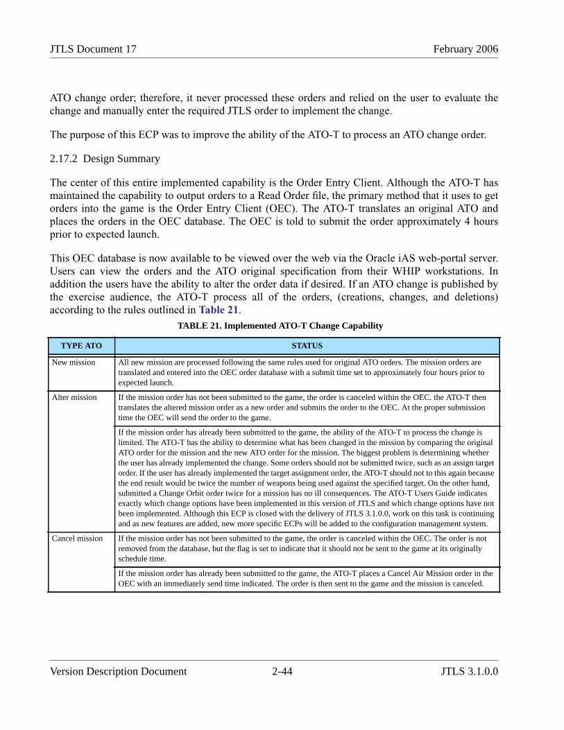
JTLS Document 17 February 2006
ATO change order; therefore, it never processed these orders and relied on the user to evaluate thechange and manually enter the required JTLS order to implement the change.
The purpose of this ECP was to improve the ability of the ATO-T to process an ATO change order.
2.17.2 Design Summary
The center of this entire implemented capability is the Order Entry Client. Although the ATO-T hasmaintained the capability to output orders to a Read Order file, the primary method that it uses to getorders into the game is the Order Entry Client (OEC). The ATO-T translates an original ATO andplaces the orders in the OEC database. The OEC is told to submit the order approximately 4 hoursprior to expected launch.
This OEC database is now available to be viewed over the web via the Oracle iAS web-portal server.Users can view the orders and the ATO original specification from their WHIP workstations. Inaddition the users have the ability to alter the order data if desired. If an ATO change is published bythe exercise audience, the ATO-T process all of the orders, (creations, changes, and deletions)according to the rules outlined in Table 21.
TABLE 21. Implemented ATO-T Change Capability
TYPE ATO STATUS
New mission All new mission are processed following the same rules used for original ATO orders. The mission orders aretranslated and entered into the OEC order database with a submit time set to approximately four hours prior toexpected launch.
Alter mission If the mission order has not been submitted to the game, the order is canceled within the OEC. the ATO-T thentranslates the altered mission order as a new order and submits the order to the OEC. At the proper submissiontime the OEC will send the order to the game.
If the mission order has already been submitted to the game, the ability of the ATO-T to process the change islimited. The ATO-T has the ability to determine what has been changed in the mission by comparing the originalATO order for the mission and the new ATO order for the mission. The biggest problem is determining whetherthe user has already implemented the change. Some orders should not be submitted twice, such as an assign targetorder. If the user has already implemented the target assignment order, the ATO-T should not to this again becausethe end result would be twice the number of weapons being used against the specified target. On the other hand,submitted a Change Orbit order twice for a mission has no ill consequences. The ATO-T Users Guide indicatesexactly which change options have been implemented in this version of JTLS and which change options have notbeen implemented. Although this ECP is closed with the delivery of JTLS 3.1.0.0, work on this task is continuingand as new features are added, new more specific ECPs will be added to the configuration management system.
Cancel mission If the mission order has not been submitted to the game, the order is canceled within the OEC. The order is notremoved from the database, but the flag is set to indicate that it should not be sent to the game at its originallyschedule time.
If the mission order has already been submitted to the game, the ATO-T places a Cancel Air Mission order in theOEC with an immediately send time indicated. The order is then sent to the game and the mission is canceled.
Version Description Document 2-44 JTLS 3.1.0.0
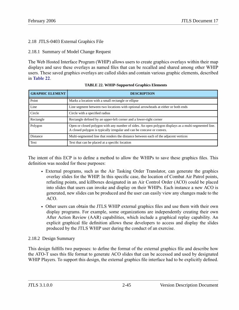
February 2006 JTLS Document 17
2.18 JTLS-0403 External Graphics File
2.18.1 Summary of Model Change Request
The Web Hosted Interface Program (WHIP) allows users to create graphics overlays within their mapdisplays and save these overlays as named files that can be recalled and shared among other WHIPusers. These saved graphics overlays are called slides and contain various graphic elements, describedin Table 22.
The intent of this ECP is to define a method to allow the WHIPs to save these graphics files. Thisdefinition was needed for these purposes:
• External programs, such as the Air Tasking Order Translator, can generate the graphicsoverlay slides for the WHIP. In this specific case, the location of Combat Air Patrol points,refueling points, and killboxes designated in an Air Control Order (ACO) could be placedinto slides that users can invoke and display on their WHIPs. Each instance a new ACO isgenerated, new slides can be produced and the user can easily view any changes made to theACO.
• Other users can obtain the JTLS WHIP external graphics files and use them with their owndisplay programs. For example, some organizations are independently creating their ownAfter Action Review (AAR) capabilities, which include a graphical replay capability. Anexplicit graphical file definition allows these developers to access and display the slidesproduced by the JTLS WHIP user during the conduct of an exercise.
2.18.2 Design Summary
This design fulfills two purposes: to define the format of the external graphics file and describe howthe ATO-T uses this file format to generate ACO slides that can be accessed and used by designatedWHIP Players. To support this design, the external graphics file interface had to be explicitly defined.
TABLE 22. WHIP-Supported Graphics Elements
GRAPHIC ELEMENT DESCRIPTION
Point Marks a location with a small rectangle or ellipse
Line Line segment between two locations with optional arrowheads at either or both ends
Circle Circle with a specified radius
Rectangle Rectangle defined by an upper-left corner and a lower-right corner
Polygon Open or closed polygon with any number of sides. An open polygon displays as a multi-segmented line.A closed polygon is typically irregular and can be concave or convex.
Distance Multi-segmented line that renders the distance between each of the adjacent vertices
Text Text that can be placed at a specific location
JTLS 3.1.0.0 2-45 Version Description Document

JTLS Document 17 February 2006
The format of an externally-created graphics file is the same XML format used by the WHIP to saveMap Component graphics. The Map Graphic file format is defined in its entirety in the SoftwareMaintenance Manual.
The ATO-T creates WHIP slide files for every ACO that it processes. The information in the ACO,such as planned routes, orbit locations, intelligence collection paths are all placed into individual slidefiles. The ATO-T determines what sides should be allowed to view the new slides and then notifies theSYNAPSE that new slide files exist. The WHIPs that have permission to view this new data arenotified and the users can then request to view the ATO-T created slides.
Again the JTLS Software Maintenance Manual describes the format of the SML file along with therules concerning where to place the files and method that should be used to inform the SYNAPSE ofthe existence of the external created graphics files.
2.19 JTLS-0411 Manual Pair Protection Radius Override
2.19.1 Summary of Model Change Request
Users complained that they wanted air missions that were manually paired against an enemy track toignore their protection radius. After discussion with the users, they understood why this was probablya poor idea. Instead we reviewed the logic used by the model to assign a protection radius to missionsthat were manually paired to determine if a better algorithm could be derived.
The algorithm that the model now uses to automatically set a manually paired mission’s protectionradius can be summarized by the following equations.
The most significant change in this algorithm is that the mission takes into account its location whenthe manual pair order is received. If the mission is currently outside of its protection range, theautomatically adjusts the protection radius so it will not immediately break-off its assigned intercept.
2.20 JTLS-0442 Detached Squadron Maintenance
2.20.1 Summary of Model Change Request
Within JTLS, it is possible to move air assets from one location to another. This can be done either bycreating a Transfer air mission or by ordering any other mission type to return to a location other than
Protection_RadiusREF Dis cetan Track Reference_Point,( ) 2.0( HexSizeAvg )×+=
Protection_RadiusNow Dis cetan Track Mission,( ) 2.0( HexSizeAvg )×+=
Protection_Radius Max Protection_RadiusRef Protection_RadiusNow,( )=
Version Description Document 2-46 JTLS 3.1.0.0
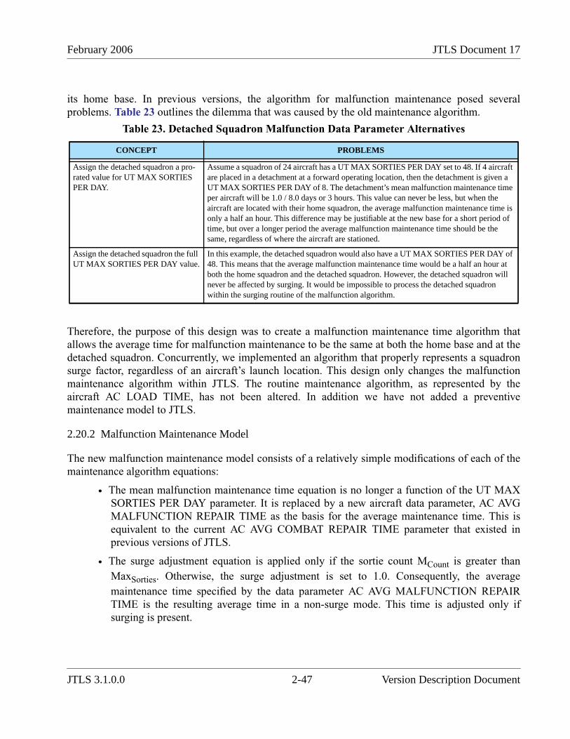
February 2006 JTLS Document 17
its home base. In previous versions, the algorithm for malfunction maintenance posed severalproblems. Table 23 outlines the dilemma that was caused by the old maintenance algorithm.
Therefore, the purpose of this design was to create a malfunction maintenance time algorithm thatallows the average time for malfunction maintenance to be the same at both the home base and at thedetached squadron. Concurrently, we implemented an algorithm that properly represents a squadronsurge factor, regardless of an aircraft’s launch location. This design only changes the malfunctionmaintenance algorithm within JTLS. The routine maintenance algorithm, as represented by theaircraft AC LOAD TIME, has not been altered. In addition we have not added a preventivemaintenance model to JTLS.
2.20.2 Malfunction Maintenance Model
The new malfunction maintenance model consists of a relatively simple modifications of each of themaintenance algorithm equations:
• The mean malfunction maintenance time equation is no longer a function of the UT MAXSORTIES PER DAY parameter. It is replaced by a new aircraft data parameter, AC AVGMALFUNCTION REPAIR TIME as the basis for the average maintenance time. This isequivalent to the current AC AVG COMBAT REPAIR TIME parameter that existed inprevious versions of JTLS.
• The surge adjustment equation is applied only if the sortie count MCount is greater thanMaxSorties. Otherwise, the surge adjustment is set to 1.0. Consequently, the averagemaintenance time specified by the data parameter AC AVG MALFUNCTION REPAIRTIME is the resulting average time in a non-surge mode. This time is adjusted only ifsurging is present.
Table 23. Detached Squadron Malfunction Data Parameter Alternatives
CONCEPT PROBLEMS
Assign the detached squadron a pro-rated value for UT MAX SORTIESPER DAY.
Assume a squadron of 24 aircraft has a UT MAX SORTIES PER DAY set to 48. If 4 aircraftare placed in a detachment at a forward operating location, then the detachment is given aUT MAX SORTIES PER DAY of 8. The detachment’s mean malfunction maintenance timeper aircraft will be 1.0 / 8.0 days or 3 hours. This value can never be less, but when theaircraft are located with their home squadron, the average malfunction maintenance time isonly a half an hour. This difference may be justifiable at the new base for a short period oftime, but over a longer period the average malfunction maintenance time should be thesame, regardless of where the aircraft are stationed.
Assign the detached squadron the fullUT MAX SORTIES PER DAY value.
In this example, the detached squadron would also have a UT MAX SORTIES PER DAY of48. This means that the average malfunction maintenance time would be a half an hour atboth the home squadron and the detached squadron. However, the detached squadron willnever be affected by surging. It would be impossible to process the detached squadronwithin the surging routine of the malfunction algorithm.
JTLS 3.1.0.0 2-47 Version Description Document
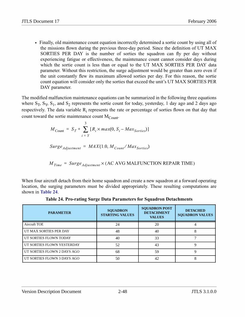
JTLS Document 17 February 2006
• Finally, old maintenance count equation incorrectly determined a sortie count by using all ofthe missions flown during the previous three-day period. Since the definition of UT MAXSORTIES PER DAY is the number of sorties the squadron can fly per day withoutexperiencing fatigue or effectiveness, the maintenance count cannot consider days duringwhich the sortie count is less than or equal to the UT MAX SORTIES PER DAY dataparameter. Without this restriction, the surge adjustment would be greater than zero even ifthe unit constantly flew its maximum allowed sorties per day. For this reason, the sortiecount equation will consider only the sorties that exceed the unit’s UT MAX SORTIES PERDAY parameter.
The modified malfunction maintenance equations can be summarized in the following three equationswhere ST, SY, S1, and S2 represents the sortie count for today, yesterday, 1 day ago and 2 days agorespectively. The data variable Ri represents the rate or percentage of sorties flown on that day thatcount toward the sortie maintenance count MCount.
When four aircraft detach from their home squadron and create a new squadron at a forward operatinglocation, the surging parameters must be divided appropriately. These resulting computations areshown in Table 24.
Table 24. Pro-rating Surge Data Parameters for Squadron Detachments
PARAMETERSQUADRON
STARTING VALUES
SQUADRON POSTDETACHMENT
VALUES
DETACHEDSQUADRON VALUES
Aircraft TOE 24 20 4
UT MAX SORTIES PER DAY 48 40 8
UT SORTIES FLOWN TODAY 40 33 7
UT SORTIES FLOWN YESTERDAY 52 43 9
UT SORTIES FLOWN 2 DAYS AGO 68 59 9
UT SORTIES FLOWN 3 DAYS AGO 50 42 8
M Count ST Ri max 0 Si MaxSorties–,( )×[ ]i Y=
3
∑+=
SurgeAdjustment MAX 1.0 M Count MaxSorties⁄,( )=
M Time SurgeAdjustment AC AVG MALFUNCTION REPAIR TIME( )×=
Version Description Document 2-48 JTLS 3.1.0.0
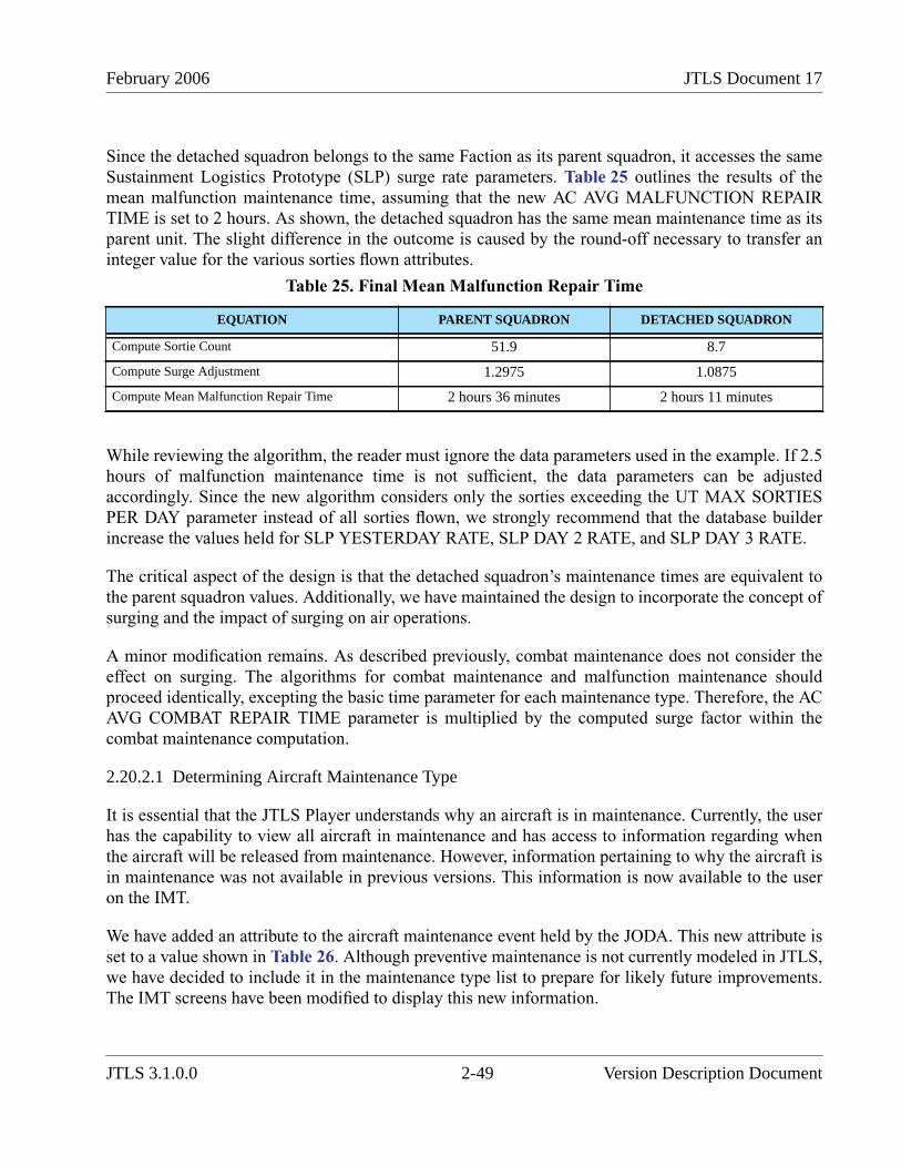
February 2006 JTLS Document 17
Since the detached squadron belongs to the same Faction as its parent squadron, it accesses the sameSustainment Logistics Prototype (SLP) surge rate parameters. Table 25 outlines the results of themean malfunction maintenance time, assuming that the new AC AVG MALFUNCTION REPAIRTIME is set to 2 hours. As shown, the detached squadron has the same mean maintenance time as itsparent unit. The slight difference in the outcome is caused by the round-off necessary to transfer aninteger value for the various sorties flown attributes.
While reviewing the algorithm, the reader must ignore the data parameters used in the example. If 2.5hours of malfunction maintenance time is not sufficient, the data parameters can be adjustedaccordingly. Since the new algorithm considers only the sorties exceeding the UT MAX SORTIESPER DAY parameter instead of all sorties flown, we strongly recommend that the database builderincrease the values held for SLP YESTERDAY RATE, SLP DAY 2 RATE, and SLP DAY 3 RATE.
The critical aspect of the design is that the detached squadron’s maintenance times are equivalent tothe parent squadron values. Additionally, we have maintained the design to incorporate the concept ofsurging and the impact of surging on air operations.
A minor modification remains. As described previously, combat maintenance does not consider theeffect on surging. The algorithms for combat maintenance and malfunction maintenance shouldproceed identically, excepting the basic time parameter for each maintenance type. Therefore, the ACAVG COMBAT REPAIR TIME parameter is multiplied by the computed surge factor within thecombat maintenance computation.
2.20.2.1 Determining Aircraft Maintenance Type
It is essential that the JTLS Player understands why an aircraft is in maintenance. Currently, the userhas the capability to view all aircraft in maintenance and has access to information regarding whenthe aircraft will be released from maintenance. However, information pertaining to why the aircraft isin maintenance was not available in previous versions. This information is now available to the useron the IMT.
We have added an attribute to the aircraft maintenance event held by the JODA. This new attribute isset to a value shown in Table 26. Although preventive maintenance is not currently modeled in JTLS,we have decided to include it in the maintenance type list to prepare for likely future improvements.The IMT screens have been modified to display this new information.
Table 25. Final Mean Malfunction Repair Time
EQUATION PARENT SQUADRON DETACHED SQUADRON
Compute Sortie Count 51.9 8.7
Compute Surge Adjustment 1.2975 1.0875
Compute Mean Malfunction Repair Time 2 hours 36 minutes 2 hours 11 minutes
JTLS 3.1.0.0 2-49 Version Description Document
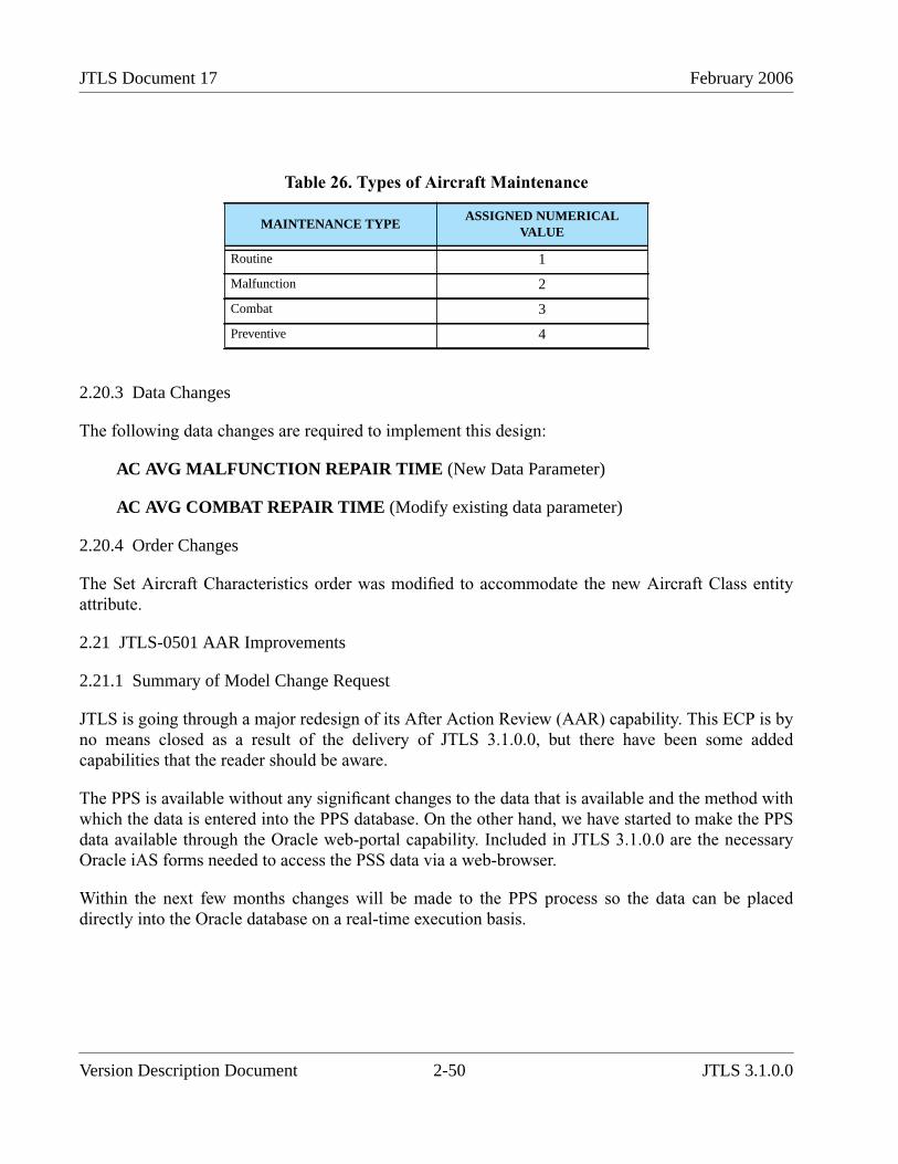
JTLS Document 17 February 2006
2.20.3 Data Changes
The following data changes are required to implement this design:
AC AVG MALFUNCTION REPAIR TIME (New Data Parameter)
AC AVG COMBAT REPAIR TIME (Modify existing data parameter)
2.20.4 Order Changes
The Set Aircraft Characteristics order was modified to accommodate the new Aircraft Class entityattribute.
2.21 JTLS-0501 AAR Improvements
2.21.1 Summary of Model Change Request
JTLS is going through a major redesign of its After Action Review (AAR) capability. This ECP is byno means closed as a result of the delivery of JTLS 3.1.0.0, but there have been some addedcapabilities that the reader should be aware.
The PPS is available without any significant changes to the data that is available and the method withwhich the data is entered into the PPS database. On the other hand, we have started to make the PPSdata available through the Oracle web-portal capability. Included in JTLS 3.1.0.0 are the necessaryOracle iAS forms needed to access the PSS data via a web-browser.
Within the next few months changes will be made to the PPS process so the data can be placeddirectly into the Oracle database on a real-time execution basis.
Table 26. Types of Aircraft Maintenance
MAINTENANCE TYPEASSIGNED NUMERICAL
VALUE
Routine 1
Malfunction 2
Combat 3
Preventive 4
Version Description Document 2-50 JTLS 3.1.0.0
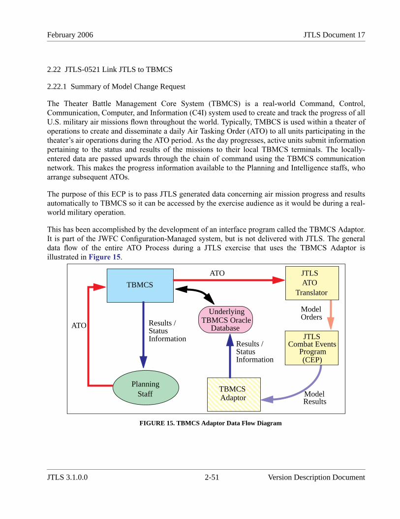
February 2006 JTLS Document 17
2.22 JTLS-0521 Link JTLS to TBMCS
2.22.1 Summary of Model Change Request
The Theater Battle Management Core System (TBMCS) is a real-world Command, Control,Communication, Computer, and Information (C4I) system used to create and track the progress of allU.S. military air missions flown throughout the world. Typically, TMBCS is used within a theater ofoperations to create and disseminate a daily Air Tasking Order (ATO) to all units participating in thetheater’s air operations during the ATO period. As the day progresses, active units submit informationpertaining to the status and results of the missions to their local TBMCS terminals. The locally-entered data are passed upwards through the chain of command using the TBMCS communicationnetwork. This makes the progress information available to the Planning and Intelligence staffs, whoarrange subsequent ATOs.
The purpose of this ECP is to pass JTLS generated data concerning air mission progress and resultsautomatically to TBMCS so it can be accessed by the exercise audience as it would be during a real-world military operation.
This has been accomplished by the development of an interface program called the TBMCS Adaptor.It is part of the JWFC Configuration-Managed system, but is not delivered with JTLS. The generaldata flow of the entire ATO Process during a JTLS exercise that uses the TBMCS Adaptor isillustrated in Figure 15.
FIGURE 15. TBMCS Adaptor Data Flow Diagram
TBMCS
ATO Results /StatusInformation
StaffPlanning
JTLSATO
Translator
JTLSCombat Events
Program(CEP)
ModelResults
ATO
ModelOrders
UnderlyingTBMCS Oracle
Database
TBMCSAdaptor
Results /StatusInformation
JTLS 3.1.0.0 2-51 Version Description Document

JTLS Document 17 February 2006
The TBMCS Adaptor operates within the Joint Multi-Resolution Model (JMRM)Federation and communicates with JTLS through the High Level Architecture (HLA). Theoperational details of this interface are illustrated in Figure 16.
FIGURE 16. Detailed Communication Design: Connected Network Mode
2.22.2 Available Data
Three types of data are passed from JTLS to TBMCS. These data types, and the primary method withwhich they will be passed to TBMCS, are outlined in Table 27.
2.23 JTLS-0522 Link JTLS to JDLM
2.23.1 Summary of Model Change Request
The Joint Deployment Logistics Model (JDLM) is a strategic logistics simulation which obtainsoperational data from several real-world Command and Control (C2) logistics systems and
Table 27. Summary of Data Available to TBMCS
DATA TYPE DELIVERY METHOD
Estimated Take-off, Actual Take-Off,Estimated Return, and Actual ReturnTime information
These are delivered via an HLA interaction as the information becomesavailable.
Mission Status Information Inferred from the posture of the air mission and from the information held in anew FOM attribute called the air mission divert code.
Final Mission Reports (MISREP) JTLS produces USMTF MISREPs. These MISREPs must be e-maileddirectly to the TBMCS Adaptor, which will pass them to TBMCS.
TBMCS JTLSATO
TranslatorJTLS
Combat EventsProgram
(CEP)
UnderlyingTBMCS Oracle
Database
TBMCSAdaptor
Results /StatusInformation
ATOACO
HLA
Order Verification
JHIP JODA
ATOACOFile
AvailabilityMessage
Version Description Document 2-52 JTLS 3.1.0.0
February 2006 JTLS Document 17
simultaneously feeds other real-world logistics C2 systems. The JTLS audience desired access tothese C2 systems during an exercise, and the best way to accomplish this goal was to link the JointTheater Level Simulation (JTLS) to JDLM.
JDLM is an asset to JTLS exercises for the following reasons:
• The term Dynamic Force Flow (DFF) represents the Time Phased Force Deployment Data(TPFDD) execution decisions that are continually being made, re-evaluated, and changed tosupport the implementation of a military plan requiring a large-scale deployment of U.S.forces and equipment. JDLM has the ability to translate a command staff’s DFF decisionsinto a movement plan without requiring the support staff typically required to link theequipment, personnel, and supplies being moved with the available transport assets. Thismeans that during an exercise, the DFF decision process can be conducted without thehundreds of Transportation Command (TRANSCOM) support personnel typically requiredto support it. This aspect of a theater of deployment operation could not be exercisedwithout JDLM.
• JDLM is designed to interpret a TPFDD and simulate the movement of its forces andsupplies using strategic aircraft and naval assets. The movement of the forces and suppliescan be represented from their origins at the forces’ home stations and supply manufacturingpoints. Although JTLS has the ability to represent the movement of units and supplies into atheater of operations from anywhere in the world, it is unable to model port operations ordetailed loading and off-loading tasks outside the theater of operations.
• The logistics staff’s task is to monitor an ongoing operation from two different points ofview, the status of the combat operation, and the status of the TPFDD movement whichsupports the combat operation. The staff has several real-world C2 systems available toaccomplish this task. These include logistics systems capable of reporting the current statusof each TPFDD entry and the Common Operational Picture (COP). JTLS can feed the COPwith the status of the combat forces within the theater of operations, but JDLM is desired to
concurrently feed the logistics C2 systems to reflect the status of the simulated movement ofequipment, personnel, and supplies. JDLM is also able to feed the COP with the requiredlocation information for strategic lift aircraft and the naval assets.
Thus, a JTLS/JDLM federation potentially can create a seamless decision environment with respectto the DFF process. Decision makers will be able to monitor the status of the conflict situation and theTPFDD’s movement into the theater, adjust the plan’s TPFDD in response to movement problems andto changes in the conflict situation, and view the results of those decisions using their real-world C2systems.
Conceptual illustrations of the real-world DFF decision process and the desired DFF decision processas used in an exercise supported by a JTLS/JDLM federation appear in Figure 17 and Figure 18,respectively.
JTLS 3.1.0.0 2-53 Version Description Document

JTLS Document 17 February 2006
FIGURE 17. Real-World DFF Decision Process
FIGURE 18. JTLS/JDLM Supported Exercise DFF Decision Process
2.23.2 Design Summary
Communication between JTLS and JDLM uses the High Level Architecture (HLA). JDLM modelsand controls naval vessels and lift aircraft participating in the movement of TPFDD resources untilthe next scheduled leg of the object is due to enter the JTLS playbox. For example, consider that theTPFDD calls for a C-5 to depart Travis Air Force Base in California with troops destined to a conflictarea. The aircraft is scheduled to stop at Hickam Air Force Base in Hawaii to pick up supplies andthen fly to Okinawa, which is in the JTLS playbox. At Okinawa, the plan off-loads a portion of the
COP
CommandStaff
LogisticsStaff
LogC2
LogisticsSupport
Staff
Real-
World
Forces
COP
CommandStaff
LogisticsStaff
LogC2
JTLS
JDLM
ResponseCell
Version Description Document 2-54 JTLS 3.1.0.0
February 2006 JTLS Document 17
personnel and supplies. The TPFDD schedule then directs the mission to Korea to off-load theremainder of the personnel and supplies. The aircraft is then scheduled to return to Hickam and endthe mission at Travis.
In this situation, JDLM models the movement of the troops from their Continental US (CONUS)station to Travis AFB, loads the strategic lift aircraft, flies the aircraft to Hickam, loads the supplies atHickam, and has the mission take off from Hickam. Since the next leg of the mission takes it into theJTLS playbox, the mission is passed to JTLS at this point in time. JTLS flies the mission from itscurrent off-board location over Hickam onto the game board. It models the mission landing inOkinawa, off-loading the supplies and personnel as ordered, and then continues to Korea. In Korea,the mission again off-loads per order and returns to Hickam. There the mission lands and control isreturned to JDLM, which would take the mission from Hickam back to Travis to complete its TPFDDresponsibilities.
From the JTLS perspective, this example Strategic Lift mission does not exist in the game until itdeparts from Hickam on its in-bound journey, and no longer exist in JTLS when it returns to Hickamon its out-bound journey.
Strategic sealift are handled in a similar manner except for the representation of the naval object inJTLS. The naval vessel always exist in JTLS and always is viewable by the JTLS user. JTLS owns allnaval units at game initialization. As soon as game initialization is complete and JDLM joins thefederation, JTLS passes attribute control of all designated JDLM ships to JDLM. This means thatJTLS does not own the location, speed, or bearing attributes until JDLM passes control of theseattributes back to JTLS. JDLM can move the naval unit at will, and the location of the unit is reflectedon the JTLS graphics display.
JTLS, as part of the continued JTLS and Joint Conflict And Tactical Simulation (JCATS) link, hasadded a database parameter used to indicate whether JTLS or JCATS owns the unit at the completionof game initialization. This same data parameter has been expanded to include JDLM as an option. Ifa naval unit’s location is under the control of JDLM at game start, then this new data parameter shouldbe set to JDLM as part of the database build procedure.
2.24 JTLS-0525 Entity Level Simulation
2.24.1 Summary of Model Change Request
Several entity-level simulations, such as the JCATS, the Extended Air Defense Simulation(EADSIM), and the intelligence representation system known as JQUAD are all members of themodeling federation known as the Joint Multi-Resolution Model (JMRM). The Joint Theater LevelSimulation (JTLS) is also a member of the JMRM federation and is responsible for the representationof the combat operations area from a theater level, aggregate unit perspective. Several other entity-level simulations, such as Tactical Simulation (TACSIM), have also developed links to the JMRM.Each simulation has or will develop a method to translate JTLS Aggregate Resolution Unit (ARU)
JTLS 3.1.0.0 2-55 Version Description Document
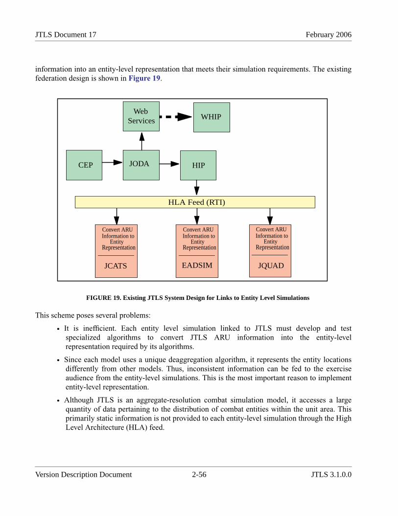
JTLS Document 17 February 2006
information into an entity-level representation that meets their simulation requirements. The existingfederation design is shown in Figure 19.
FIGURE 19. Existing JTLS System Design for Links to Entity Level Simulations
This scheme poses several problems:
• It is inefficient. Each entity level simulation linked to JTLS must develop and testspecialized algorithms to convert JTLS ARU information into the entity-levelrepresentation required by its algorithms.
• Since each model uses a unique deaggregation algorithm, it represents the entity locationsdifferently from other models. Thus, inconsistent information can be fed to the exerciseaudience from the entity-level simulations. This is the most important reason to implemententity-level representation.
• Although JTLS is an aggregate-resolution combat simulation model, it accesses a largequantity of data pertaining to the distribution of combat entities within the unit area. Thisprimarily static information is not provided to each entity-level simulation through the HighLevel Architecture (HLA) feed.
CEP JODA
Web
HIP
HLA Feed (RTI)
Convert ARUInformation to
EntityRepresentation
JCATS
Convert ARUInformation to
EntityRepresentation
EADSIM
Convert ARUInformation to
EntityRepresentation
JQUAD
Services WHIP
Version Description Document 2-56 JTLS 3.1.0.0

February 2006 JTLS Document 17
This ECP concerns the development of a JTLS Entity-Level Simulation (ELS) to determine andpublish the location and movement patterns of individual entities contained in the JTLS ARUs, via anindependent JODA server. Although this ECP is not considered closed with the release of JTLS3.1.0.0, the first release of the ELS is included. To say the least ELS is in its infancy, but it doespublish individual combat system location information and moves these entities on the battlefield inresponse of JTLS aggregate unit movement, posture changes, and attrition. We have started to modeltarget placement and attrition too.
2.24.2 Design Summary
The ultimate design concept for the JTLS Entity Level Server (ELS) is depicted in Figure 20.
FIGURE 20. Desired JTLS System Links to Entity-Level Simulations
Currently the ELS publishes information to the EODA, which operates identically to the JTLSaggregate-level data server (JODA). The EODA is the same software as the JODA it only uses adifferent object model definition. Other than that any organization that want to connect to the EODAcan do so by following the same instructions for connecting to the JODA and requesting the desiredinformation.
In this version of JTLS, we have experimented with having the ELS directly feed the HLA RTI vicedeveloping another JTLS process to handle the communication between the ELS and the RTI. Given
CEP
Web
WHIP
HIP
JCATS
JODA
EntityLevelSimulation(ELS)
EntityLevel
(EODA)JODA
Aggregate Level HLA Feed (RTI)
Services
EADSIM JQUAD TACSIMMUSE /
AFSERS
Entity HLA
(EHIP)
InterfaceProgram
JTLS 3.1.0.0 2-57 Version Description Document
JTLS Document 17 February 2006
that the Government has not officially published their desired RTI FOM object structure, we have notdecided which method will be included in the final ELS configuration.
The ELS Users Guide is a new document designed to explain how to use and setup the new ELS.
2.25 JTLS-0540 Magic Replenish Air Mission
2.25.1 Summary of Model Change Request
This ECP has implemented a capability to replenish JTLS Air Missions with fuel and weapons duringthe execution of their mission. This is intended to be a Magic replenishment similar to other JTLSMagic orders that are executed immediately.
2.25.2 Design Summary
A new order was created to allow a Controller or "Trusted Player” to instantly or “magically”replenish an Air Mission with fuel and weapons. A Trusted Player is a Side Player assignedpermission to send a Magic Replenishment order. The elements of the order and its logisticsimplications are discussed below.
2.25.2.1 Order Components
Fuel and Weapons are the major components of the Magic Replenish order. The Player is providedtwo options to replenish either fuel or weapons. These options are:
• fill to capacity ("Top Off") or
• add a specified quantity.
2.25.2.2 Logistics Draw Options
For the implementation of this MCR, three options are available to model the drawing of therequested fuel or weapons supplies:
• Magically extract these supplies with no logistics and resupply implications.
• Requisition these supplies from the designated supplying unit, e.g. squadron or airbase.Then, the Player must decide to requisition the appropriate Supply Categories either fromthose Available for Issue or Available as Supplies.
• Requisition these supplies from another unit on the same Side as the Air Mission. ThePlayer must then make the same requisitioning decision.
Although the magic draw of supplies is implemented, it can create a game artificiality and isinconsistent with the fidelity with which JTLS models logistics. Supplies requisitioned from themission’s supplying unit, are drawn from Available as Supplies. If requisitioned from another unit,
Version Description Document 2-58 JTLS 3.1.0.0
February 2006 JTLS Document 17
the supplies are drawn from Available for Issue. This decision model is consistent with existing JTLSconventions for managing supplies drawn from designated supply units or other units.
2.25.3 Order Changes
A new MAGIC REPLENISH AIR MISSION order has been created, which includes these fields:
• Mission Name: This Mandatory field contains the name of the mission to be replenished.
• Fuel (Requested Quantity or “Top Off”): This Optional field displays selection buttons foreach choice. If Top Off is selected, a flag is sent to the CEP to refuel the mission to itsmaximum capacity. If a Requested Quantity is selected, a field appear to allow the user toenter a specific quantity of fuel.
• Weapons (Requested Quantity or “Top Off”): This Optional field displays selection buttonsfor each choice. If Top Off is selected, a flag is sent to the CEP to resupply the weapon loadto its maximum capacity with an appropriate weapon type. If Requested Quantity isselected, a Utility window appears to allow the user to enter the weapon name and quantity.
• Draw from Unit (Designated Supplying Unit or Another Unit): This Mandatory fieldappears if either Fuel or Weapons is selected. This field displays selection buttons for eachchoice. If Draw From Unit is selected, a flag is sent to the CEP indicating that the requestedsupplies are to be drawn from the designated supply unit. If Another Unit is selected, a fieldappears to allow the user to enter a unit name.
2.26 JTLS-0554 Multiple Units of Measure
2.26.1 Summary of Model Change Request
The WHIP now has a consistent unit of measure selection capability over all informationcomponents: the IMT Component, Message Browser, and Sitrep tools. In addition the order panelsmake use of units of measure defined in the database. This allow users to convert supply categoryvalues in order panels. Finally, unit of measure settings are saved to the Synapse when a player logsout of the WHIP.
2.26.2 Design Summary
The WHIP provides a panel where the player may specify the preferred unit of measure for basicunits of measure categories, such as distance, speed, and wet weight. The unit of measurespecification panel also allows the selection of the desired unit of measure for each supply category.The supply category capability allows users to view information on the WHIP is terms of items andnot just weight. Given a properly built database that includes information such as 1 AIM.9 weaponweighs 0.89 short tons, the user can not ask to view the supply category from which AIM.9 weaponsare drawn in a unit of measure called AIM.9. In this manner the user can determine that a unit has 15AIM.9 weapons available, which is easier to assimilate than 13.35 short tons.
JTLS 3.1.0.0 2-59 Version Description Document
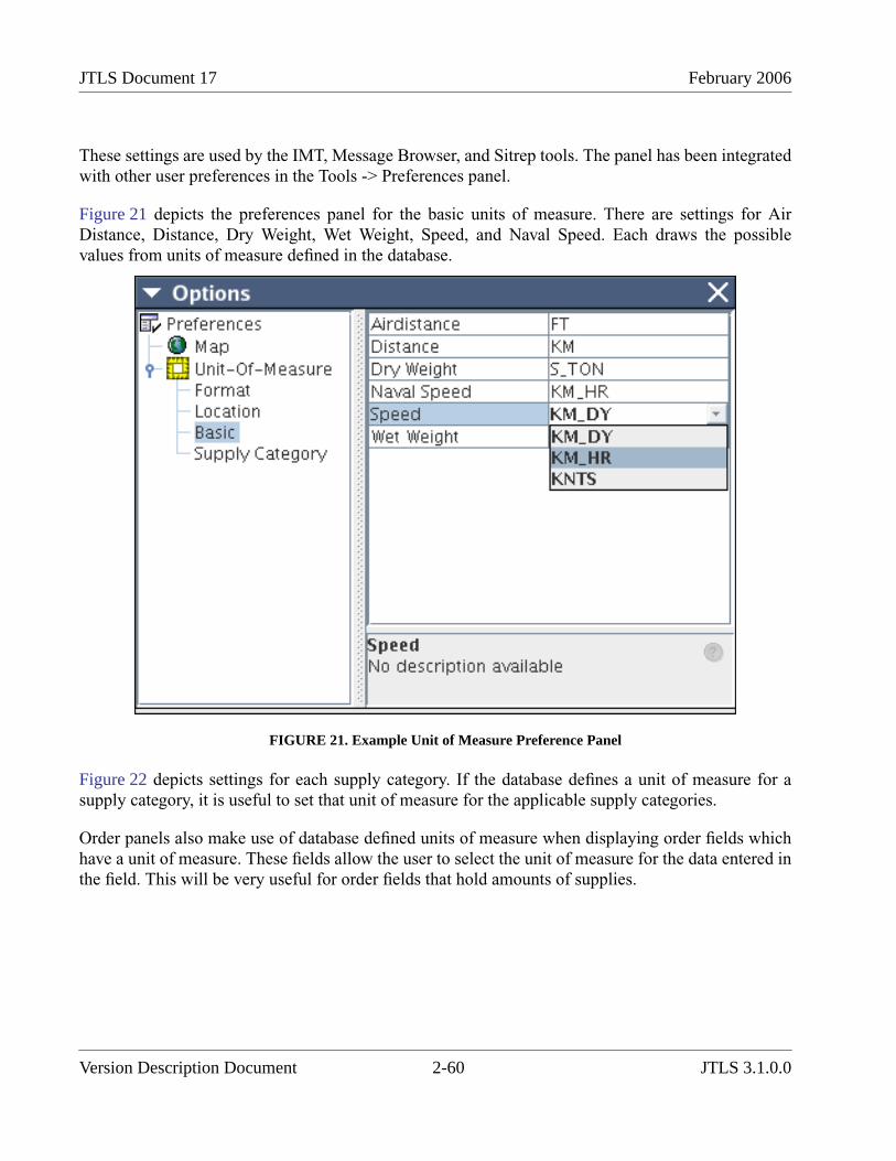
JTLS Document 17 February 2006
These settings are used by the IMT, Message Browser, and Sitrep tools. The panel has been integratedwith other user preferences in the Tools -> Preferences panel.
Figure 21 depicts the preferences panel for the basic units of measure. There are settings for AirDistance, Distance, Dry Weight, Wet Weight, Speed, and Naval Speed. Each draws the possiblevalues from units of measure defined in the database.
FIGURE 21. Example Unit of Measure Preference Panel
Figure 22 depicts settings for each supply category. If the database defines a unit of measure for asupply category, it is useful to set that unit of measure for the applicable supply categories.
Order panels also make use of database defined units of measure when displaying order fields whichhave a unit of measure. These fields allow the user to select the unit of measure for the data entered inthe field. This will be very useful for order fields that hold amounts of supplies.
Version Description Document 2-60 JTLS 3.1.0.0
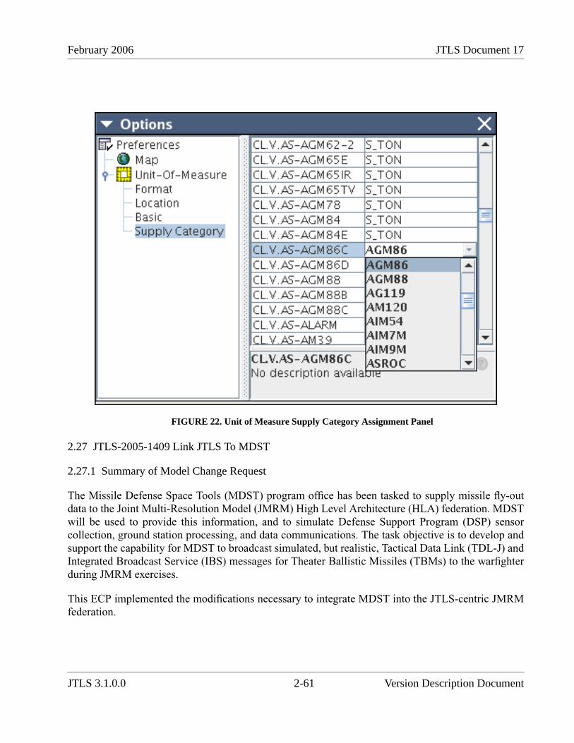
February 2006 JTLS Document 17
FIGURE 22. Unit of Measure Supply Category Assignment Panel
2.27 JTLS-2005-1409 Link JTLS To MDST
2.27.1 Summary of Model Change Request
The Missile Defense Space Tools (MDST) program office has been tasked to supply missile fly-outdata to the Joint Multi-Resolution Model (JMRM) High Level Architecture (HLA) federation. MDSTwill be used to provide this information, and to simulate Defense Support Program (DSP) sensorcollection, ground station processing, and data communications. The task objective is to develop andsupport the capability for MDST to broadcast simulated, but realistic, Tactical Data Link (TDL-J) andIntegrated Broadcast Service (IBS) messages for Theater Ballistic Missiles (TBMs) to the warfighterduring JMRM exercises.
This ECP implemented the modifications necessary to integrate MDST into the JTLS-centric JMRMfederation.
JTLS 3.1.0.0 2-61 Version Description Document

JTLS Document 17 February 2006
2.27.2 Design Summary
MDST’s role in the JMRM federation is to detect and report the eminent impact of a ballistic missilewithin the combat operations theater. The following discussion illustrates the elements of thisinteraction with JTLS as an example:
1. The interaction process begins when a JTLS Player launches a missile within JTLS byentering a Fire Missile order. If the launcher is in its “hiding” position, JTLS changes thislauncher status and initiates the missile setup procedure. The amount of time required isbased on database information and the status of the launching unit with respect to thecurrent environment and unit training.
Information pertaining to whether a missile launcher is “hiding” (NOT_PREPARED),setting up (PREPARING), or set up (PREPARED) is held by the Target_Status attribute ofthe HLA Target object that represents the missile launcher. If necessary, the missilelauncher proceeds through the status changes from NOT_PREPARED, to PREPARING, toPREPARED. Once the launcher achieves a PREPARED status, the JTLS model ensures thatthe target is within range, that the unit has the supplies necessary to fire the selected missile,and that the missile launcher is still completely functional.
2. When JTLS determines that the missile can be fired, the model creates a Missile object.When the missile is successfully interdicted or impacts on the ground, JTLS publishes aninteraction explaining status of the missile (this process is described in further detail below),then delete the object.
3. Immediately after the Missile object is published, JTLS publishes aDirect_Fire_Engagement interaction. The attributes of this interaction are described inTable 28. (The parameter highlighted green is new and has been added to the previousinteraction definition.)
Table 28. Direct Fire Engagement Interaction
PARAMETER NAME MEANING
Client_Name The name of the client
Sending_Federate The federation handle for the federate sending this interaction.
Reference Unique reference name for this interaction. This reference must be retained as the keyvalue in a local table within the HIP for future missile lookups. If the MDST modelsends an Order_Reply containing this reference, the HIP can determine which missilethe reply pertains to.
Firing Unit The object reference to the JTLS unit that owned the fired Surface-to-Surface missile.This Firing Unit can be either a Unit object or a High Resolution object.
Firing Unit Location Latitude and longitude from which the missile was fired.
Targeted Object The object at which the missile was aimed. When this interaction is sent due to the firingof a missile, the Targeted Object can be a Unit object, Target object, or DMPI object.This field may be empty if the Player did not aim at a specific object, but instead enteredthe latitude and longitude of the desired impact point.
Aim Point The latitude and longitude of the aim point. When JTLS fires the missile, it aims themissile at the location specified by the Player or at the most recent known location(perceived location) of the targeted object. This interaction field is always specified andshould be treated as the JTLS Player’s desired point of impact for the missile.
Version Description Document 2-62 JTLS 3.1.0.0
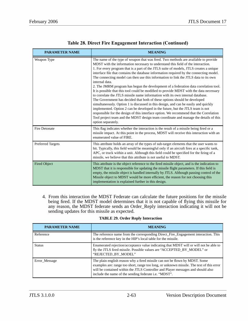
February 2006 JTLS Document 17
4. From this interaction the MDST Federate can calculate the future positions for the missilebeing fired. If the MDST model determines that it is not capable of flying this missile forany reason, the MDST federate sends an Order_Reply interaction indicating it will not besending updates for this missile as expected.
Weapon Type The name of the type of weapon that was fired. Two methods are available to provideMDST with the information necessary to understand this field of the interaction.1. For every program that is a part of the JTLS suite of models, JTLS creates a uniqueinterface file that contains the database information required by the connecting model.The connecting model can then use this information to link the JTLS data to its owninternal data.2. The JMRM program has begun the development of a federation data correlation tool.It is possible that this tool could be modified to provide MDST with the data necessaryto correlate the JTLS missile name information with its own internal database.The Government has decided that both of these options should be developedsimultaneously. Option 1 is discussed in this design, and can be easily and quicklyimplemented. Option 2 can be developed in the future, but the JTLS team is notresponsible for the design of this interface option. We recommend that the CorrelationTool project team and the MDST design team coordinate and manage the details of thisoption separately.
Fire Detonate This flag indicates whether the interaction is the result of a missile being fired or amissile impact. At this point in the process, MDST will receive this interaction with anenumerated value of FIRE.
Preferred Targets This attribute holds an array of the types of sub-target elements that the user wants tohit. Typically, this field would be meaningful only if an aircraft fires at a specific tank,APC, or truck within a unit. Although this field could be specified for the firing of amissile, we believe that this attribute is not useful to MDST.
Fired Object This attribute is the object reference to the fired missile object, and is the indication toMDST that it is responsible for updating the missile flight parameters. If this field isempty, the missile object is handled internally by JTLS. Although passing control of theMissile object to MDST would be more efficient, the reason for not choosing thisimplementation is explained further in this design.
TABLE 29. Order Reply Interaction
PARAMETER NAME MEANING
Reference The reference name from the corresponding Direct_Fire_Engagement interaction. Thisis the reference key in the HIP’s local table for the missile.
Status Enumerated rejection/acceptance value indicating that MDST will or will not be able tofly the JTLS fired missile. Possible values are “ACCEPTED_BY_MODEL” or“REJECTED_BY_MODEL”
Error_Message The plain english reason why a fired missile can not be flown by MDST. Someexamples are: range too short, range too long, or unknown missile. The text of this errorwill be contained within the JTLS Controller and Player messages and should alsoinclude the name of the sending federate i.e. “MDST”.
Table 28. Direct Fire Engagement Interaction (Continued)
PARAMETER NAME MEANING
JTLS 3.1.0.0 2-63 Version Description Document
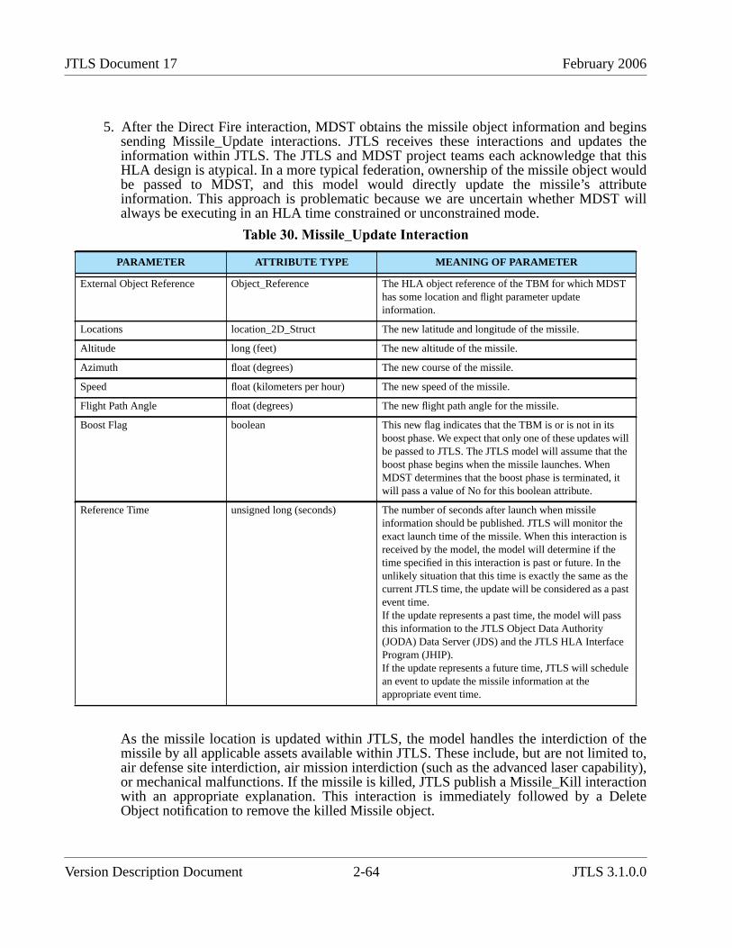
JTLS Document 17 February 2006
5. After the Direct Fire interaction, MDST obtains the missile object information and beginssending Missile_Update interactions. JTLS receives these interactions and updates theinformation within JTLS. The JTLS and MDST project teams each acknowledge that thisHLA design is atypical. In a more typical federation, ownership of the missile object wouldbe passed to MDST, and this model would directly update the missile’s attributeinformation. This approach is problematic because we are uncertain whether MDST willalways be executing in an HLA time constrained or unconstrained mode.
As the missile location is updated within JTLS, the model handles the interdiction of themissile by all applicable assets available within JTLS. These include, but are not limited to,air defense site interdiction, air mission interdiction (such as the advanced laser capability),or mechanical malfunctions. If the missile is killed, JTLS publish a Missile_Kill interactionwith an appropriate explanation. This interaction is immediately followed by a DeleteObject notification to remove the killed Missile object.
Table 30. Missile_Update Interaction
PARAMETER ATTRIBUTE TYPE MEANING OF PARAMETER
External Object Reference Object_Reference The HLA object reference of the TBM for which MDSThas some location and flight parameter updateinformation.
Locations location_2D_Struct The new latitude and longitude of the missile.
Altitude long (feet) The new altitude of the missile.
Azimuth float (degrees) The new course of the missile.
Speed float (kilometers per hour) The new speed of the missile.
Flight Path Angle float (degrees) The new flight path angle for the missile.
Boost Flag boolean This new flag indicates that the TBM is or is not in itsboost phase. We expect that only one of these updates willbe passed to JTLS. The JTLS model will assume that theboost phase begins when the missile launches. WhenMDST determines that the boost phase is terminated, itwill pass a value of No for this boolean attribute.
Reference Time unsigned long (seconds) The number of seconds after launch when missileinformation should be published. JTLS will monitor theexact launch time of the missile. When this interaction isreceived by the model, the model will determine if thetime specified in this interaction is past or future. In theunlikely situation that this time is exactly the same as thecurrent JTLS time, the update will be considered as a pastevent time.If the update represents a past time, the model will passthis information to the JTLS Object Data Authority(JODA) Data Server (JDS) and the JTLS HLA InterfaceProgram (JHIP).If the update represents a future time, JTLS will schedulean event to update the missile information at theappropriate event time.
Version Description Document 2-64 JTLS 3.1.0.0
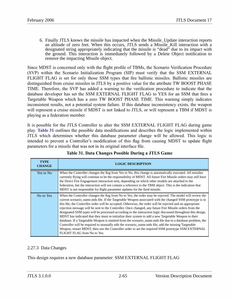
February 2006 JTLS Document 17
6. Finally JTLS knows the missile has impacted when the Missile_Update interaction reportsan altitude of zero feet. When this occurs, JTLS sends a Missile_Kill interaction with adesignated string appropriately indicating that the missile is “dead” due to its impact withthe ground. This interaction is immediately followed by a Delete Object notification toremove the impacting Missile object.
Since MDST is concerned only with the flight profile of TBMs, the Scenario Verification Procedure(SVP) within the Scenario Initialization Program (SIP) must verify that the SSM EXTERNALFLIGHT FLAG is set for only those SSM types that fire ballistic missiles. Ballistic missiles aredistinguished from cruise missiles in JTLS by a positive value for the attribute TW BOOST PHASETIME. Therefore, the SVP has added a warning to the verification procedure to indicate that thedatabase developer has set the SSM EXTERNAL FLIGHT FLAG to YES for an SSM that fires aTargetable Weapon which has a zero TW BOOST PHASE TIME. This warning simply indicatesinconsistent results, not a potential system failure. If this database inconsistency exists, the weaponwill represent a cruise missile if MDST is not linked to JTLS, or will represent a TBM if MDST isplaying as a federation member.
It is possible for the JTLS Controller to alter the SSM EXTERNAL FLIGHT FLAG during gameplay. Table 31 outlines the possible data modifications and describes the logic implemented withinJTLS which determines whether this database parameter change will be allowed. This logic isintended to prevent a Controller’s modification of this flag from causing MDST to update flightparameters for a missile that was not in its original interface file.
2.27.3 Data Changes
This design requires a new database parameter: SSM EXTERNAL FLIGHT FLAG
Table 31. Data Changes Possible During a JTLS Game
TYPECHANGE
LOGIC DESCRIPTION
Yes to No When the Controller changes the flag from Yes to No, this change is automatically executed. All missilescurrently flying will continue to be the responsibility of MDST. All future Fire Missile orders may still havethe Direct Fire Engagement interaction sent, depending on which other models are attached to thefederation, but the interaction will not contain a reference to the TBM object. This is the indication thatMDST is not responsible for flight parameter updates for the fired missile.
No to Yes When the Controller changes the flag from No to Yes, the order may be rejected. The model will review thecurrent scenario_name.mds file. If the Targetable Weapon associated with the changed SSM prototype is inthis file, the Controller order will be accepted. Otherwise, the order will be rejected and an appropriaterejection message will be sent to the Controller. Once changed, any future Fire Missile orders from thedesignated SSM types will be processed according to the interaction logic discussed throughout this design.MDST has indicated that they must re-initialize their system to add a new Targetable Weapon to theirdatabase. If a Targetable Weapon is omitted from the scenario_name.mds file due to a database problem, theController will be required to manually edit the scenario_name.mds file, add the missing TargetableWeapon, restart MDST, then use the Controller order to set the required SSM prototype SSM EXTERNALFLIGHT FLAG from No to Yes.
JTLS 3.1.0.0 2-65 Version Description Document
JTLS Document 17 February 2006
2.28 JTLS-2005-1480 Lifeboat Representation
2.28.1 Summary of Model Change Request
As a result of the implemented ECP JTLS-2005-1538 Improved Naval Damage, which provides thefoundation necessary to represent the deployment of lifeboats, ships no longer sink instantaneously.The purpose of the current ECP is to deploy personnel onto lifeboats while a ship is sinking in amanner similar to the method used to represent a downed aircrew. Other ships or aircraft can thenmove to the area and rescue these personnel. Although personnel could be “rescued” by enemy orsuspect assets, this is not possible as a result of implementing this ECP. That capability must bepostponed until a JTLS capture-and-surrender model is implemented. The same limitation exists forthe current representation of downed aircrews.
2.28.2 Design Summary
A new attribute has been added to the Ship Unit Prototype (SUP) definition. This attribute, SUPLIFEBOAT HUP, holds the reference ID to the HUP that should be used to represent all lifeboatsdeployed when a ship begins to sink.
No limitations is imposed on the HUP selection, but the Scenario Verification Program (SVP) ensuresthat the specified lifeboat HUP has a designated small boat. The concept of “small boat” is not limitedto a literal boat. Within JTLS, the Small Boat object can represent a boat, a raft, or even a lifepreserver if the database builder so chooses. In the latter case, it is possible to represent only the lifepreservers onboard a specific ship. Finally, the database builder may leave this parameter empty,which indicates that the sinking ship will have no lifeboat survivors.
After assigning a Lifeboat HUP to a SUP, the database builder must provide the assets necessary tocreate the HRUs in case of an emergency. This means that if you want to deploy 15 HRUs when aspecific ship sinks, you must provide the SUP with enough small boats to create the 15 HRUs.
The time required to deploy each lifeboat is another required data parameter. For simplicity, themodel assumes that only one lifeboat can deploy at a time. This data parameter, SUP LIFEBOATMEAN DEPLOY TIME, is also a SUP attribute and is used to compute the random deployment timefor each lifeboat. Some lifeboats deploy more quickly than this specified mean and some deploy moreslowly. The number of lifeboats deployed is therefore a function of this data parameter and the timeelapsed while the ship sinks. The details regarding this portion of the algorithm are provided in theremainder of this design discussion.
2.28.2.1 Algorithm Details
When deploying lifeboats, the model follows this sequence of logic steps:
1. The process begins when the ship receives its final hull hit and is determined to be severelydamaged and destined to sink. At this time, a random variate is drawn from an exponential
Version Description Document 2-66 JTLS 3.1.0.0
February 2006 JTLS Document 17
distribution with a mean equal to the data parameter SUP AVERAGE TIME TO SINK,which is then used to schedule the sinking event.
2. If the ship’s SUP LIFEBOAT HUP is null, the following computation sequence is omittedand no lifeboats are deployed. If this HUP is specified, the sequence continues. For allequations, assume that the HUP is the specified lifeboat HUP and that the SUP is thesinking ship’s prototype.
3. The time to execute the abandon ship order is determined. The time to begin the abandonship process is based on the expected time to sink and the expected time required toabandon the ship. This design assumes that the ship’s Captain determines these expectedvalues and makes decisions accordingly. Therefore, the following sequence of computationsis performed to determine the start time for the abandon ship process.
The personnel count includes the personnel from the ship, all embarked squadrons, and anyembarked units.
It is possible that the computed abandon ship process start time is less than zero; thisindicates that the process starts immediately. If the computed parameter value is positive, anevent is scheduled to begin the process when the computed period of time elapses.
4. When the abandon ship process is started, the model creates the needed HRUs, which areautomatically named by combining the ship name and a unique identifying number. Forexample, the first lifeboat HRU from ship ALPHA is called ALPHA_S_1, which signifiesship Alpha’s first surviving lifeboat. The second lifeboat HRU is named ALPHA_S_2, andothers are named in ordinal sequence.
5. The specified personnel are taken from the ship’s personnel and the lifeboat is automaticallydeployed. The small boat is also removed from the inventory.
Removing specified personnel from the ship’s personnel is not a simple process. Personnelonboard the ship will likely be represented among several Combat Systems. The lifeboatHUP will specify a typical load-out capacity. As more lifeboats are deployed, it is possiblethat the HUP’s personnel count does not match the ship’s personnel count. The modelassumes that each personnel Combat System is equivalent to all other personnel systems.The HUP load-out is considered the preferred load for the HUP, but when the specifiedpersonnel Combat Systems are not available, other personnel are substituted.
For example, assume that the HUP indicates that 5 Infantry, 10 women, and 15 children areallowed in each lifeboat. Also assume that the ship has 50 Infantry, 50 women, and 50children on board. Table 32 summarizes the number and type of personnel that are assignedto the five lifeboats needed by the 150 people onboard the sinking ship.
BoatsDeployed Min BoatsAvailable PersonnelShip PersonnelHUP⁄,( )=
Time Until Abandon Ship Starts Avg Sink TimeSUP Full Deployment Time–( )=
JTLS 3.1.0.0 2-67 Version Description Document
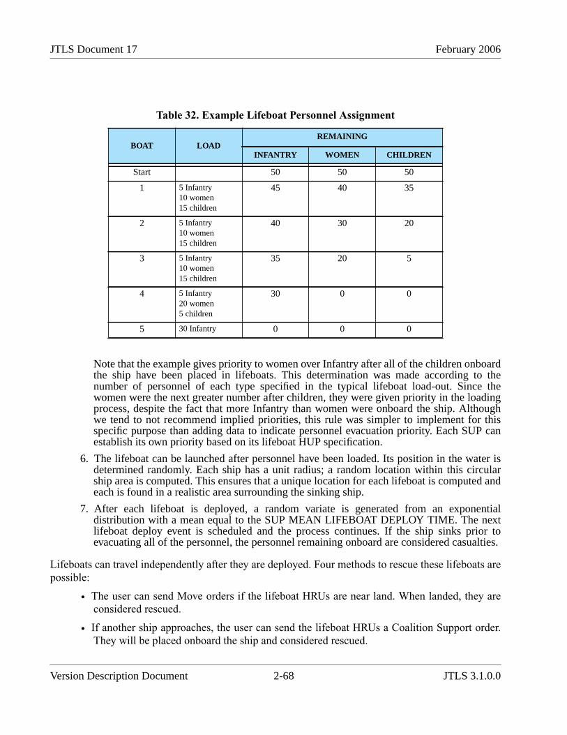
JTLS Document 17 February 2006
Note that the example gives priority to women over Infantry after all of the children onboardthe ship have been placed in lifeboats. This determination was made according to thenumber of personnel of each type specified in the typical lifeboat load-out. Since thewomen were the next greater number after children, they were given priority in the loadingprocess, despite the fact that more Infantry than women were onboard the ship. Althoughwe tend to not recommend implied priorities, this rule was simpler to implement for thisspecific purpose than adding data to indicate personnel evacuation priority. Each SUP canestablish its own priority based on its lifeboat HUP specification.
6. The lifeboat can be launched after personnel have been loaded. Its position in the water isdetermined randomly. Each ship has a unit radius; a random location within this circularship area is computed. This ensures that a unique location for each lifeboat is computed andeach is found in a realistic area surrounding the sinking ship.
7. After each lifeboat is deployed, a random variate is generated from an exponentialdistribution with a mean equal to the SUP MEAN LIFEBOAT DEPLOY TIME. The nextlifeboat deploy event is scheduled and the process continues. If the ship sinks prior toevacuating all of the personnel, the personnel remaining onboard are considered casualties.
Lifeboats can travel independently after they are deployed. Four methods to rescue these lifeboats arepossible:
• The user can send Move orders if the lifeboat HRUs are near land. When landed, they areconsidered rescued.
• If another ship approaches, the user can send the lifeboat HRUs a Coalition Support order.They will be placed onboard the ship and considered rescued.
Table 32. Example Lifeboat Personnel Assignment
BOAT LOADREMAINING
INFANTRY WOMEN CHILDREN
Start 50 50 50
1 5 Infantry10 women15 children
45 40 35
2 5 Infantry10 women15 children
40 30 20
3 5 Infantry10 women15 children
35 20 5
4 5 Infantry20 women5 children
30 0 0
5 30 Infantry 0 0 0
Version Description Document 2-68 JTLS 3.1.0.0
February 2006 JTLS Document 17
• An Insert/Extract mission can be sent to pick up the lifeboat HRUs and move them to arescue location. When onboard the air mission, they are considered rescued.
• The lifeboat HRUs can remain in the water indefinitely, and will not affect the game.
2.28.2.2 Stopping the Sinking Process
The sinking process can be halted. Either the Controller can stop the ship from sinking or the crewcan repair the hull hit that caused the ship to sink. In either case, the lifeboats deployed since thesinking event began must be restored to their parent ship unit. The method to accomplish this dependson which event stopped the sinking process:
• If the Controller stops the sinking, the model automatically rejoins the lifeboat HRUs totheir parent unit. The user is not required to enter the orders.
• If the ship stops sinking due to normal repairs, the lifeboats remain in the water. The playercan submit the orders to rejoin the deployed lifeboats to their parent unit.
One remaining rule must be enforced to support the logic required for a lifeboats to rejoin its parentunder these conditions. When a lifeboat is created, only one unit’s personnel are allowed onboard aspecific HRU. Thus, personnel from an embarked squadron cannot be combined with personnel fromthe ship, nor with the personnel from an carried unit. This rule is required to properly rejoin the unit toits parent when the ship stops sinking.
Loading personnel on ships is accomplished according to this priority:
1. Carried units
2. Embarked units, such as squadrons and other HRUs
3. Ship personnel
No loading order is established within each group, except that an entire unit is placed on lifeboatsbefore the next unit is loaded.
2.28.3 Data Changes
Two new data elements are created to implement this design: SUP LIFEBOAT HUP, SUP LIFEBOATMEAN DEPLOY TIME.
2.28.4 Order Changes
The SUP Set order was modified to allow the new attributes to be set.
JTLS 3.1.0.0 2-69 Version Description Document
JTLS Document 17 February 2006
2.29 JTLS-2005-1484 Tanker Stay On Orbit
2.29.1 Design Summary
The purpose of this ECP is to later the logic used by a tanker to determine when it should go home.When a tanker reaches its end orbit time, the model automatically looks at the Refuel Chits that thetanker owns and finds new available tankers to take on the responsibility. This sometimes led toproblem in that the select tankers may not be in the proper position to meet all of the receivingmission requirements.
The decision was to alter the logic used by the tanker when determining whether it should go home. Ifthe tanker has any remaining Refuel Chits to fill, the tanker will not leave. It will notify the player thatit is time to go home, but it is waiting for the designated missions. The player can then decide whetherto submit a change to the current Refuel Chits for the mission or continue to extend the tankermission’s orbit time.
2.30 JTLS-2005-1535 WHIP Icon Size Selection
2.30.1 Summary of Model Change Request
In JTLS 3.1.0.0, the WHIP now has the ability to select the size of all map icons. Each JTLS objecttype can be assigned its own icon size specification.
2.30.2 Design Summary
This improvement required the development of a new symbol specification for the WHIP that permitsthe user to define an augmented unit symbol set, and also provides the capability to define new unitsymbols. We selected to implement the object icon symbols as TrueType fonts, which is a standardWindows font format and universally available on Unix. These fonts provide excellent renderingperformance.
One of the major advantages of this new methodology is the ability to create and define your ownJTLS icon symbols. The definition of the JTLS symbol set consists of two parts—a TrueType fontand a symbol composition file:
• The TrueType font contains glyphs, or graphical building blocks. These are used to build aJTLS symbol.
• The symbol composition file links the JTLS object symbol number with a list of the glyphsused to render a symbol. A JTLS symbol is constructed from glyphs representing thebackground, strength indicator, unit size indicator, and symbol. When building the completeobject symbol, the user is free to choose any available glyphs. This mapping is not limitedto the static JTLS Symbol enumeration, but it also includes user-defined symbols that canbe specified. In previous versions of JTLS, when assigning a JTLS symbol to a unit objectas part of the database build process, the database builder chooses symbols from a non-
Version Description Document 2-70 JTLS 3.1.0.0

February 2006 JTLS Document 17
changeable list. For some objects, such as air missions, targets, and convoys, the databasebuilder could not choose a desired symbol. The symbol assignment was hard-coded into theJTLS software.
With the implementation of this design, the database developer is now able to define a newsymbol, name the symbol, indicate the glyphs used to compile the symbol, and assign thatsymbol to the prototypes in the database which are used to create the object while the gameexecutes.
2.30.2.1 Tools for Symbol Set Management
Two tools are provided to configure JTLS symbols—a font editor and a new program that views andconfigures the symbol composition file:
• We use an open-source font editor to edit and add symbol glyphs to the TrueType symbolfont. This font editor is provided within the bin_support directory for both Solaris andLinux platforms, and is accessible from the JTLS database menu program. Using the opensource font editor, the database developer or user can add symbol glyphs to the TrueTypesymbol font.
• The new JTLS Symbol Management System (JSYMS) program provides a composed viewof the symbol as it appear on the map, and an interface that allow a user to compose thesymbol from the set of glyphs available in the TrueType font. This allows the databasedeveloper to compose, name, and access a new symbol using glyphs that were added to theTrueType symbol font.
2.30.2.2 Example of Symbol Creation
Assume that the glyphs shown in Table 33 have been developed with the open-source font editorprovided with the JTLS system.
Table 33. Example TrueType Font Set With Available Glyphs
GLYPHS NAME GLYPH FONT
Rectangle
Rectangle Background
Right Line
JTLS 3.1.0.0 2-71 Version Description Document
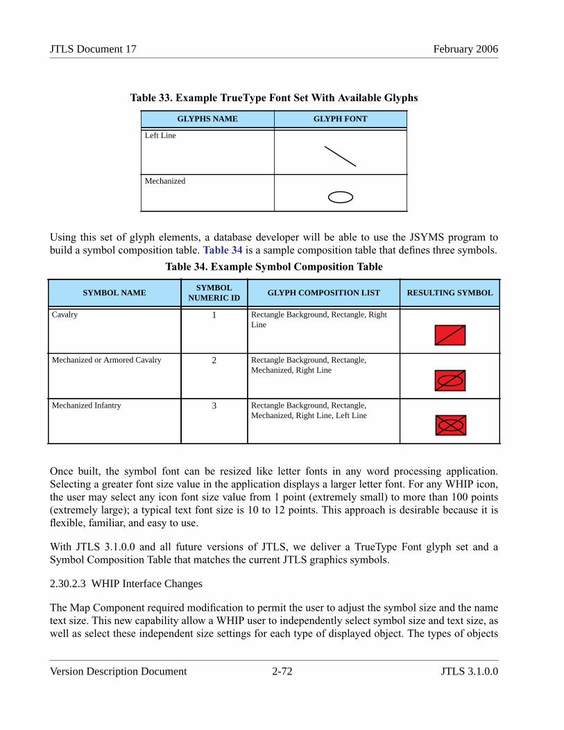
JTLS Document 17 February 2006
Using this set of glyph elements, a database developer will be able to use the JSYMS program tobuild a symbol composition table. Table 34 is a sample composition table that defines three symbols.
Once built, the symbol font can be resized like letter fonts in any word processing application.Selecting a greater font size value in the application displays a larger letter font. For any WHIP icon,the user may select any icon font size value from 1 point (extremely small) to more than 100 points(extremely large); a typical text font size is 10 to 12 points. This approach is desirable because it isflexible, familiar, and easy to use.
With JTLS 3.1.0.0 and all future versions of JTLS, we deliver a TrueType Font glyph set and aSymbol Composition Table that matches the current JTLS graphics symbols.
2.30.2.3 WHIP Interface Changes
The Map Component required modification to permit the user to adjust the symbol size and the nametext size. This new capability allow a WHIP user to independently select symbol size and text size, aswell as select these independent size settings for each type of displayed object. The types of objects
Left Line
Mechanized
Table 34. Example Symbol Composition Table
SYMBOL NAMESYMBOL
NUMERIC IDGLYPH COMPOSITION LIST RESULTING SYMBOL
Cavalry 1 Rectangle Background, Rectangle, RightLine
Mechanized or Armored Cavalry 2 Rectangle Background, Rectangle,Mechanized, Right Line
Mechanized Infantry 3 Rectangle Background, Rectangle,Mechanized, Right Line, Left Line
Table 33. Example TrueType Font Set With Available Glyphs
GLYPHS NAME GLYPH FONT
Version Description Document 2-72 JTLS 3.1.0.0
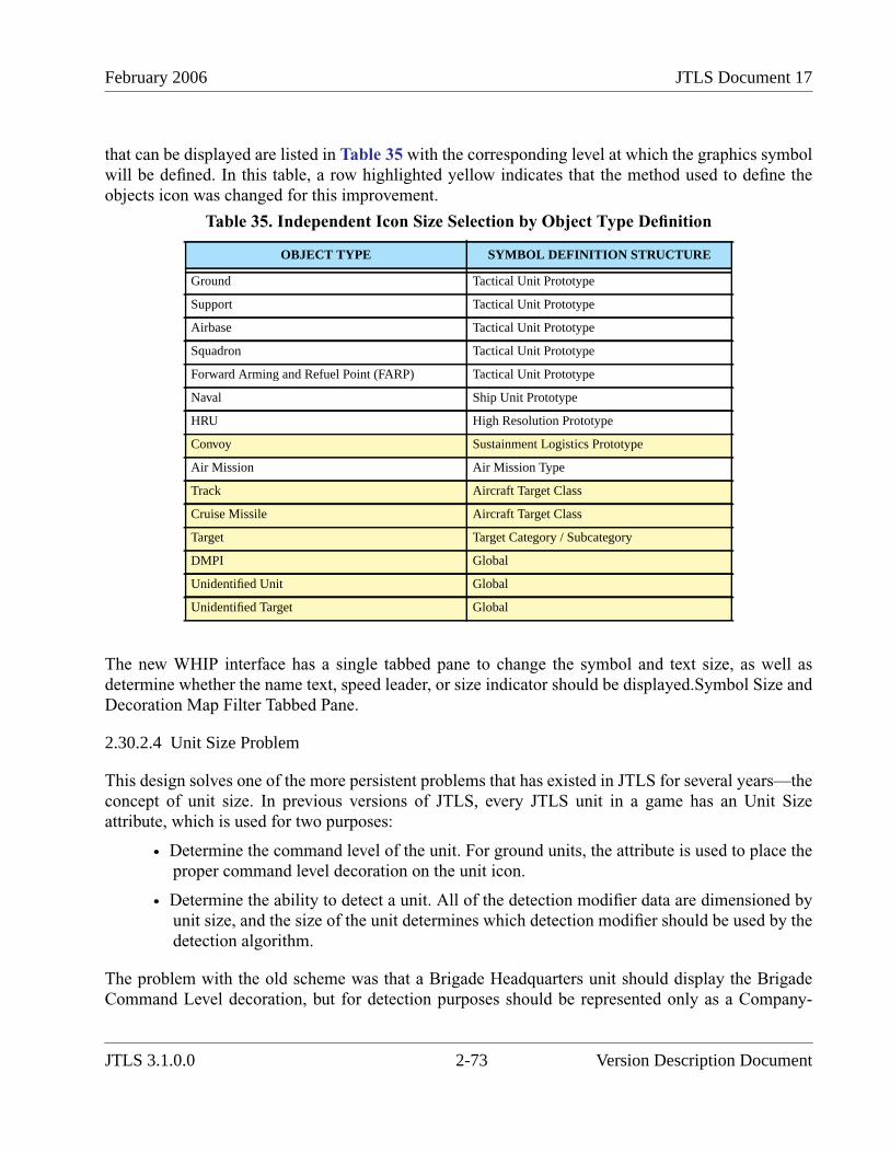
February 2006 JTLS Document 17
that can be displayed are listed in Table 35 with the corresponding level at which the graphics symbolwill be defined. In this table, a row highlighted yellow indicates that the method used to define theobjects icon was changed for this improvement.
The new WHIP interface has a single tabbed pane to change the symbol and text size, as well asdetermine whether the name text, speed leader, or size indicator should be displayed.Symbol Size andDecoration Map Filter Tabbed Pane.
2.30.2.4 Unit Size Problem
This design solves one of the more persistent problems that has existed in JTLS for several years—theconcept of unit size. In previous versions of JTLS, every JTLS unit in a game has an Unit Sizeattribute, which is used for two purposes:
• Determine the command level of the unit. For ground units, the attribute is used to place theproper command level decoration on the unit icon.
• Determine the ability to detect a unit. All of the detection modifier data are dimensioned byunit size, and the size of the unit determines which detection modifier should be used by thedetection algorithm.
The problem with the old scheme was that a Brigade Headquarters unit should display the BrigadeCommand Level decoration, but for detection purposes should be represented only as a Company-
Table 35. Independent Icon Size Selection by Object Type Definition
OBJECT TYPE SYMBOL DEFINITION STRUCTURE
Ground Tactical Unit Prototype
Support Tactical Unit Prototype
Airbase Tactical Unit Prototype
Squadron Tactical Unit Prototype
Forward Arming and Refuel Point (FARP) Tactical Unit Prototype
Naval Ship Unit Prototype
HRU High Resolution Prototype
Convoy Sustainment Logistics Prototype
Air Mission Air Mission Type
Track Aircraft Target Class
Cruise Missile Aircraft Target Class
Target Target Category / Subcategory
DMPI Global
Unidentified Unit Global
Unidentified Target Global
JTLS 3.1.0.0 2-73 Version Description Document
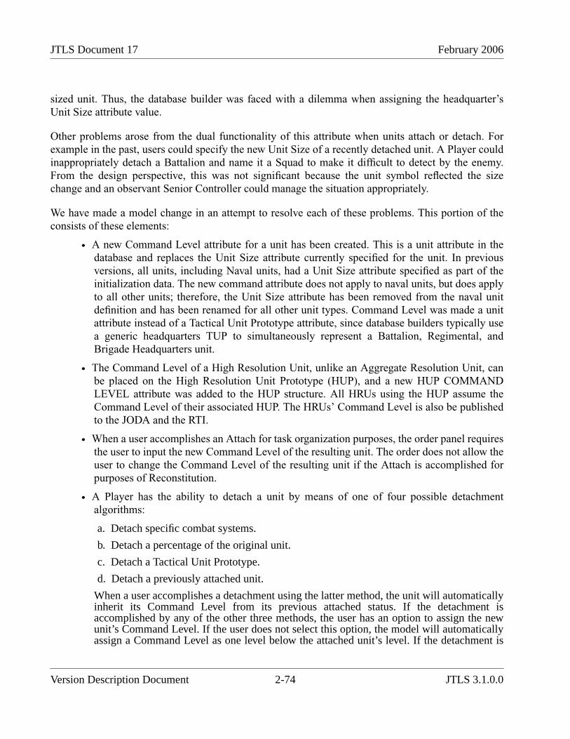
JTLS Document 17 February 2006
sized unit. Thus, the database builder was faced with a dilemma when assigning the headquarter’sUnit Size attribute value.
Other problems arose from the dual functionality of this attribute when units attach or detach. Forexample in the past, users could specify the new Unit Size of a recently detached unit. A Player couldinappropriately detach a Battalion and name it a Squad to make it difficult to detect by the enemy.From the design perspective, this was not significant because the unit symbol reflected the sizechange and an observant Senior Controller could manage the situation appropriately.
We have made a model change in an attempt to resolve each of these problems. This portion of theconsists of these elements:
• A new Command Level attribute for a unit has been created. This is a unit attribute in thedatabase and replaces the Unit Size attribute currently specified for the unit. In previousversions, all units, including Naval units, had a Unit Size attribute specified as part of theinitialization data. The new command attribute does not apply to naval units, but does applyto all other units; therefore, the Unit Size attribute has been removed from the naval unitdefinition and has been renamed for all other unit types. Command Level was made a unitattribute instead of a Tactical Unit Prototype attribute, since database builders typically usea generic headquarters TUP to simultaneously represent a Battalion, Regimental, andBrigade Headquarters unit.
• The Command Level of a High Resolution Unit, unlike an Aggregate Resolution Unit, canbe placed on the High Resolution Unit Prototype (HUP), and a new HUP COMMANDLEVEL attribute was added to the HUP structure. All HRUs using the HUP assume theCommand Level of their associated HUP. The HRUs’ Command Level is also be publishedto the JODA and the RTI.
• When a user accomplishes an Attach for task organization purposes, the order panel requiresthe user to input the new Command Level of the resulting unit. The order does not allow theuser to change the Command Level of the resulting unit if the Attach is accomplished forpurposes of Reconstitution.
• A Player has the ability to detach a unit by means of one of four possible detachmentalgorithms:
a. Detach specific combat systems.
b. Detach a percentage of the original unit.
c. Detach a Tactical Unit Prototype.
d. Detach a previously attached unit.
When a user accomplishes a detachment using the latter method, the unit will automaticallyinherit its Command Level from its previous attached status. If the detachment isaccomplished by any of the other three methods, the user has an option to assign the newunit’s Command Level. If the user does not select this option, the model will automaticallyassign a Command Level as one level below the attached unit’s level. If the detachment is
Version Description Document 2-74 JTLS 3.1.0.0
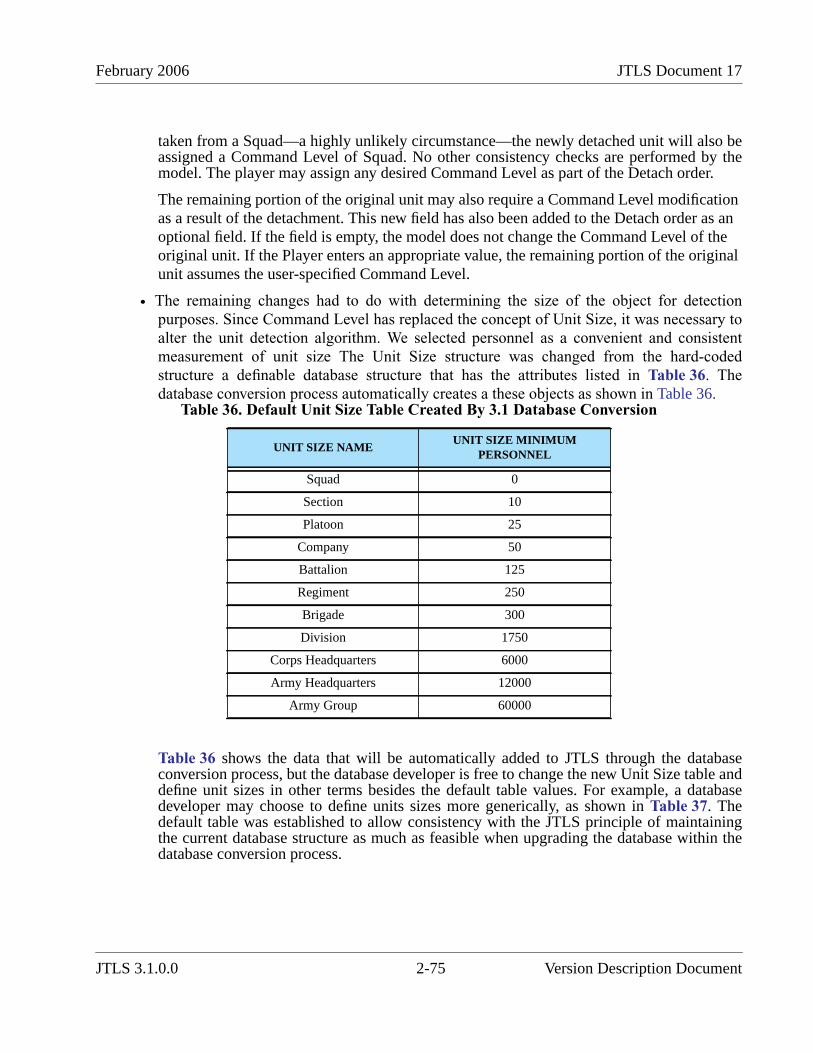
February 2006 JTLS Document 17
taken from a Squad—a highly unlikely circumstance—the newly detached unit will also beassigned a Command Level of Squad. No other consistency checks are performed by themodel. The player may assign any desired Command Level as part of the Detach order.
The remaining portion of the original unit may also require a Command Level modificationas a result of the detachment. This new field has also been added to the Detach order as anoptional field. If the field is empty, the model does not change the Command Level of theoriginal unit. If the Player enters an appropriate value, the remaining portion of the originalunit assumes the user-specified Command Level.
• The remaining changes had to do with determining the size of the object for detectionpurposes. Since Command Level has replaced the concept of Unit Size, it was necessary toalter the unit detection algorithm. We selected personnel as a convenient and consistentmeasurement of unit size The Unit Size structure was changed from the hard-codedstructure a definable database structure that has the attributes listed in Table 36. Thedatabase conversion process automatically creates a these objects as shown in Table 36.
Table 36 shows the data that will be automatically added to JTLS through the databaseconversion process, but the database developer is free to change the new Unit Size table anddefine unit sizes in other terms besides the default table values. For example, a databasedeveloper may choose to define units sizes more generically, as shown in Table 37. Thedefault table was established to allow consistency with the JTLS principle of maintainingthe current database structure as much as feasible when upgrading the database within thedatabase conversion process.
Table 36. Default Unit Size Table Created By 3.1 Database Conversion
UNIT SIZE NAMEUNIT SIZE MINIMUM
PERSONNEL
Squad 0
Section 10
Platoon 25
Company 50
Battalion 125
Regiment 250
Brigade 300
Division 1750
Corps Headquarters 6000
Army Headquarters 12000
Army Group 60000
JTLS 3.1.0.0 2-75 Version Description Document
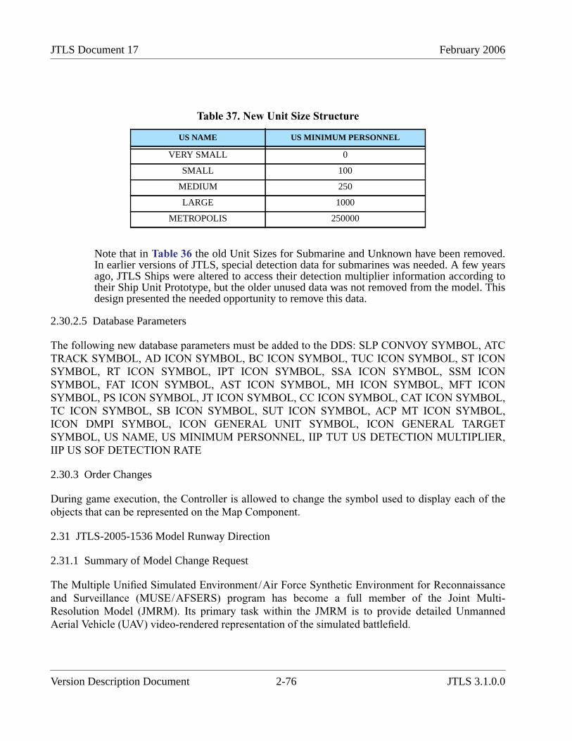
JTLS Document 17 February 2006
Note that in Table 36 the old Unit Sizes for Submarine and Unknown have been removed.In earlier versions of JTLS, special detection data for submarines was needed. A few yearsago, JTLS Ships were altered to access their detection multiplier information according totheir Ship Unit Prototype, but the older unused data was not removed from the model. Thisdesign presented the needed opportunity to remove this data.
2.30.2.5 Database Parameters
The following new database parameters must be added to the DDS: SLP CONVOY SYMBOL, ATCTRACK SYMBOL, AD ICON SYMBOL, BC ICON SYMBOL, TUC ICON SYMBOL, ST ICONSYMBOL, RT ICON SYMBOL, IPT ICON SYMBOL, SSA ICON SYMBOL, SSM ICONSYMBOL, FAT ICON SYMBOL, AST ICON SYMBOL, MH ICON SYMBOL, MFT ICONSYMBOL, PS ICON SYMBOL, JT ICON SYMBOL, CC ICON SYMBOL, CAT ICON SYMBOL,TC ICON SYMBOL, SB ICON SYMBOL, SUT ICON SYMBOL, ACP MT ICON SYMBOL,ICON DMPI SYMBOL, ICON GENERAL UNIT SYMBOL, ICON GENERAL TARGETSYMBOL, US NAME, US MINIMUM PERSONNEL, IIP TUT US DETECTION MULTIPLIER,IIP US SOF DETECTION RATE
2.30.3 Order Changes
During game execution, the Controller is allowed to change the symbol used to display each of theobjects that can be represented on the Map Component.
2.31 JTLS-2005-1536 Model Runway Direction
2.31.1 Summary of Model Change Request
The Multiple Unified Simulated Environment/Air Force Synthetic Environment for Reconnaissanceand Surveillance (MUSE/AFSERS) program has become a full member of the Joint Multi-Resolution Model (JMRM). Its primary task within the JMRM is to provide detailed UnmannedAerial Vehicle (UAV) video-rendered representation of the simulated battlefield.
Table 37. New Unit Size Structure
US NAME US MINIMUM PERSONNEL
VERY SMALL 0
SMALL 100
MEDIUM 250
LARGE 1000
METROPOLIS 250000
Version Description Document 2-76 JTLS 3.1.0.0

February 2006 JTLS Document 17
JTLS is responsible for providing details required by MUSE/AFSERS regarding the types, location,and condition of entities on the battlefield. This is a large-scale task, which also involves additionalJTLS functional enhancements. The entire JTLS Entity Level Server design addresses a wide range ofissues related to providing detailed entity level information to MUSE/AFSERS.
Some of the data MUSE/AFSERS requires to properly render the battlefield is currently availablefrom the JTLS aggregate-level data server, and can be obtained either from the JTLS ObjectDistribution Authority (JODA) or the JMRM High Level Architecture (HLA) data feed. Theexistence and status of runways is a representative example of previously available JODA or HLAdata required by MUSE/AFSERS.
Although basic runway data was available to MUSE/AFSERS, the program developers requestedadditional detailed runway information, including craters or runway cuts placed by enemy activity.The purpose of this ECP was to add more detailed runway information so JTLS could meet theMUSE/AFSERS runway detail requirement.
2.31.1.1 Runway Direction Information
The JTLS database was altered to include the direction that the runway is aligned. As illustrated inFigure 23, this is defined as the compass direction originating from the target’s reference latitude andlongitude location to the terminal end of the runway. This direction is specified in integer degrees tobe consistent with data that is readily available for existing runways throughout the world.Considering a runway’s reference point, direction, and length, JTLS is able to compute a preciselatitude and longitude for any position of the runway.
FIGURE 23. Runway Data Definitions
N
E
S
W
TG DEC LATTG DEC LONG TG RANGE (Length)
TG DIRECTION
(Reference Location)
JTLS 3.1.0.0 2-77 Version Description Document
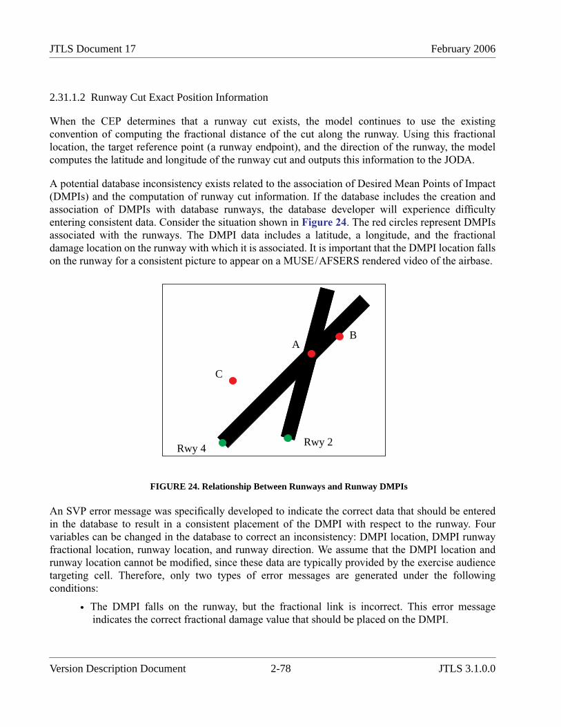
JTLS Document 17 February 2006
2.31.1.2 Runway Cut Exact Position Information
When the CEP determines that a runway cut exists, the model continues to use the existingconvention of computing the fractional distance of the cut along the runway. Using this fractionallocation, the target reference point (a runway endpoint), and the direction of the runway, the modelcomputes the latitude and longitude of the runway cut and outputs this information to the JODA.
A potential database inconsistency exists related to the association of Desired Mean Points of Impact(DMPIs) and the computation of runway cut information. If the database includes the creation andassociation of DMPIs with database runways, the database developer will experience difficultyentering consistent data. Consider the situation shown in Figure 24. The red circles represent DMPIsassociated with the runways. The DMPI data includes a latitude, a longitude, and the fractionaldamage location on the runway with which it is associated. It is important that the DMPI location fallson the runway for a consistent picture to appear on a MUSE/AFSERS rendered video of the airbase.
FIGURE 24. Relationship Between Runways and Runway DMPIs
An SVP error message was specifically developed to indicate the correct data that should be enteredin the database to result in a consistent placement of the DMPI with respect to the runway. Fourvariables can be changed in the database to correct an inconsistency: DMPI location, DMPI runwayfractional location, runway location, and runway direction. We assume that the DMPI location andrunway location cannot be modified, since these data are typically provided by the exercise audiencetargeting cell. Therefore, only two types of error messages are generated under the followingconditions:
• The DMPI falls on the runway, but the fractional link is incorrect. This error messageindicates the correct fractional damage value that should be placed on the DMPI.
Rwy 4Rwy 2
AB
C
Version Description Document 2-78 JTLS 3.1.0.0

February 2006 JTLS Document 17
DMPI B is an example of this error. Note that DMPI B does not fall directly on the runwaycenter. This must be considered by the error reporting algorithm. Although we strive toavoid hard-coded data in the model, for the verification process we propose that a defaultvalue of 50 feet from the center line be used by the SVP to determine whether the DMPI isor is not on the runway. Creating a runway width data parameter simply to ensure that theverification procedure is sufficiently accurate for video rendering of the crater location isnot justified.
The DMPI B warning message reads: “WARNING XXX: DMPI B’s location does notmatch fractional location on Runway RWY.4. Set frac loc to 0.80."
• If the DMPI does not fall on the runway, the second error message indicates the runwaydirection required to locate the DMPI on the runway.
DMPI C is an example of this error. Note that two runways are within close proximity to theDMPI, but the DMPI indicates the runway with which it is associated. The warningmessage reflects the assumption that the DMPI is intended for the runway specified withinits data structure.
The DMPI C warning message reads: “WARNING XXX: DMPI C is not located on itsassociated runway RWY.4. Change runway direction to 010."
The design team is aware that if the user changes the direction of RWY 4 in the previous example,new error messages are generated for DMPI A and DMPI B. Considering the assumption that DMPIand runway locations cannot be changed, this design cannot influence or simplify the process ofcoordinating DMPI locations, associated runway locations, and the runway directional informationfor the database building process. The database building team must conduct an evaluation to create aconsistent DMPI and runway representation for a particular scenario.
2.31.2 Publishing Supply Commitment Information
We now publish an indicator used to determine whether the supplies needed to repair the runway cuthave already been committed. A runway cut can have committed supplies, but no scheduled repairtime. If the crew has been relocated to repair a more critical runway cut, supplies committed to repaira specific runway cut are not available to support other cuts. This information is used by MUSE/AFSERS to determine whether they should display supplies next to the runway cut indicating thatwork to repair the cut can be started.
2.31.3 Data Changes
The TG.DIRECTION data parameter was added to the target definition for all runway targets in theDDS.
JTLS 3.1.0.0 2-79 Version Description Document
JTLS Document 17 February 2006
2.31.4 Order Changes
These order changes were implement as part of this design:
• The Controller has the capability to alter the direction of an existing runway target by usingthe SET TARGET PARAMETER order.
• The Controller has the ability to specify the facing direction for a new target. This required amodification to the CREATE RUNWAY order.
2.32 JTLS-2005-1537 Template Creation Tool
2.32.1 Summary of Model Change Request
The Template Creation Tool provides an efficient method for users to build the Tactical UnitPrototype, Command Object, and Combat System templates. Templates are required for the EntityLevel Server to describe the relationship between the Tactical Unit Prototypes, Command Objects,and Combat Systems for each game scenario. This includes, but is not limited to, ranking theCommand Objects, locations of Command Objects and Combat Systems, and posture for theCommand Objects. The Template Creation Tool is intended to allow users to design the templatesquickly and with flexibility.
The Entity Level Server User’s Guide has complete instructions on how to use the new TemplateBuilding Tool.
2.33 JTLS-2005-1538 Improved Naval Damage
2.33.1 Summary of Model Change Request
JTLS ships and the objects embarked on them can be damaged both by Controller action and also as aresult of Player-generated tactical operations. JTLS models the reduced operational capabilities ofdamaged ships. If the damage is sufficient, these ships may be sunk and removed from the game. Thefundamental problem was that the sinking event was instantaneous. One moment the naval unit was inthe game and the next moment it had been removed. If a UAV was overhead, the video imagerendered by MUSE/AFSERS was unrealistic, due to the immediate disappearance of the naval asset.
When JTLS determines that a ship has been “killed”, the model places the ship in a posture ofINCAPABLE. Then, a random variate is drawn from an exponential distribution with a mean equal tothe ship’s prototype SUP AVERAGE TIME TO SINK data parameter. After that specified duration oftime, the ship sinks and is removed from the game board. While in an INCAPABLE posture, the shipaccepts no orders other than request for a report, such as a Situation Report or a Logistics Report.
When the ship assumes the INCAPABLE posture, it sends a MAYDAY message. This messagenotifies Players that the ship is disabled and is requesting assistance, and that it cannot accept tacticalorders. The message also includes an estimated time before the ship sinks. The ship does not know
Version Description Document 2-80 JTLS 3.1.0.0
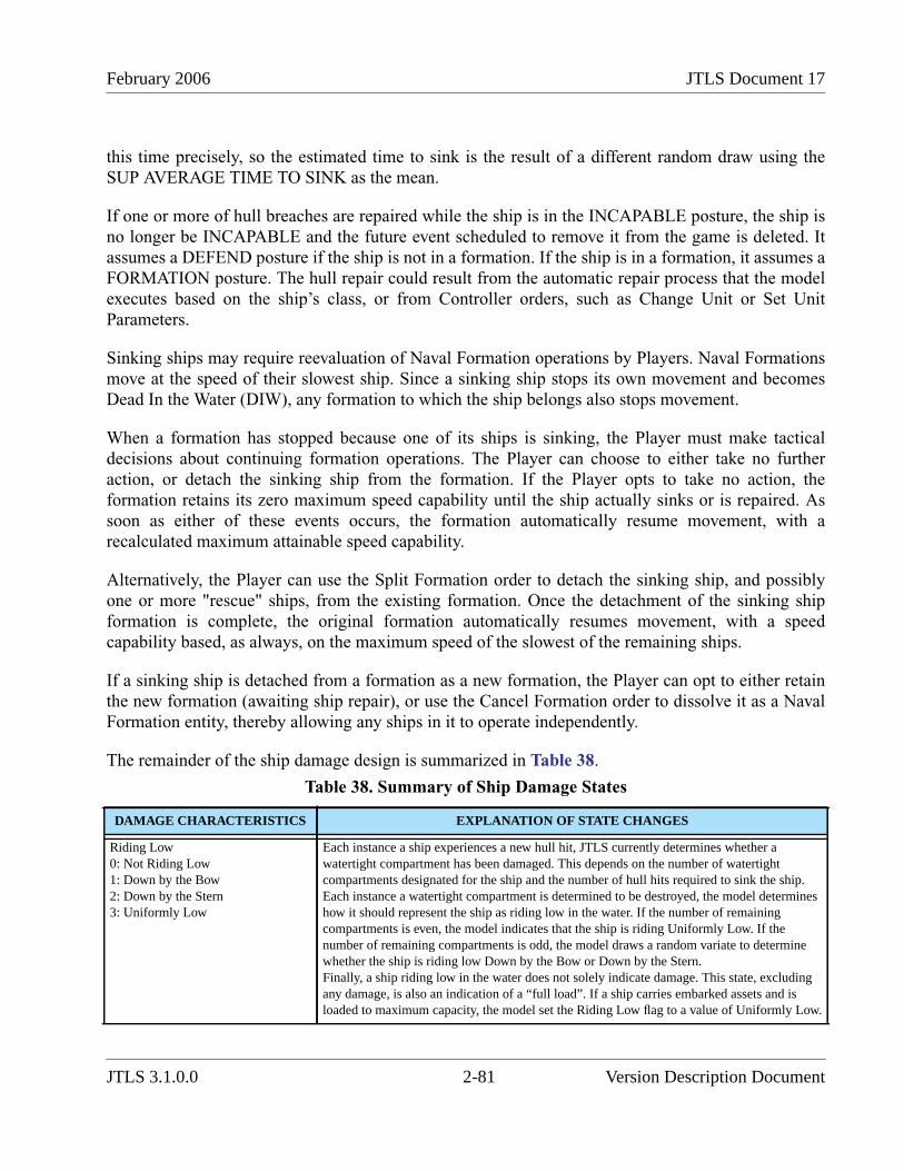
February 2006 JTLS Document 17
this time precisely, so the estimated time to sink is the result of a different random draw using theSUP AVERAGE TIME TO SINK as the mean.
If one or more of hull breaches are repaired while the ship is in the INCAPABLE posture, the ship isno longer be INCAPABLE and the future event scheduled to remove it from the game is deleted. Itassumes a DEFEND posture if the ship is not in a formation. If the ship is in a formation, it assumes aFORMATION posture. The hull repair could result from the automatic repair process that the modelexecutes based on the ship’s class, or from Controller orders, such as Change Unit or Set UnitParameters.
Sinking ships may require reevaluation of Naval Formation operations by Players. Naval Formationsmove at the speed of their slowest ship. Since a sinking ship stops its own movement and becomesDead In the Water (DIW), any formation to which the ship belongs also stops movement.
When a formation has stopped because one of its ships is sinking, the Player must make tacticaldecisions about continuing formation operations. The Player can choose to either take no furtheraction, or detach the sinking ship from the formation. If the Player opts to take no action, theformation retains its zero maximum speed capability until the ship actually sinks or is repaired. Assoon as either of these events occurs, the formation automatically resume movement, with arecalculated maximum attainable speed capability.
Alternatively, the Player can use the Split Formation order to detach the sinking ship, and possiblyone or more "rescue" ships, from the existing formation. Once the detachment of the sinking shipformation is complete, the original formation automatically resumes movement, with a speedcapability based, as always, on the maximum speed of the slowest of the remaining ships.
If a sinking ship is detached from a formation as a new formation, the Player can opt to either retainthe new formation (awaiting ship repair), or use the Cancel Formation order to dissolve it as a NavalFormation entity, thereby allowing any ships in it to operate independently.
The remainder of the ship damage design is summarized in Table 38.
Table 38. Summary of Ship Damage States
DAMAGE CHARACTERISTICS EXPLANATION OF STATE CHANGES
Riding Low0: Not Riding Low1: Down by the Bow2: Down by the Stern3: Uniformly Low
Each instance a ship experiences a new hull hit, JTLS currently determines whether awatertight compartment has been damaged. This depends on the number of watertightcompartments designated for the ship and the number of hull hits required to sink the ship.Each instance a watertight compartment is determined to be destroyed, the model determineshow it should represent the ship as riding low in the water. If the number of remainingcompartments is even, the model indicates that the ship is riding Uniformly Low. If thenumber of remaining compartments is odd, the model draws a random variate to determinewhether the ship is riding low Down by the Bow or Down by the Stern.Finally, a ship riding low in the water does not solely indicate damage. This state, excludingany damage, is also an indication of a “full load”. If a ship carries embarked assets and isloaded to maximum capacity, the model set the Riding Low flag to a value of Uniformly Low.
JTLS 3.1.0.0 2-81 Version Description Document
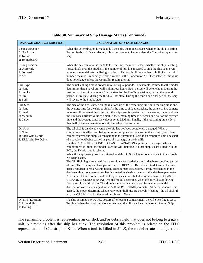
JTLS Document 17 February 2006
The remaining problem is representing an oil slick and/or debris field that does not belong to a navalunit, but remains after the ship has sunk. The resolution of this problem is related to the JTLSrepresentation of Catastrophic Kills. When a tank is killed in JTLS, the model creates an object that
Listing Direction0: Not Listing1: To Port2: To Starboard
When the determination is made to kill the ship, the model selects whether the ship is listingPort or Starboard. Once selected, this value does not change unless the Controller repairs theship.
Listing Position0: Uniformly1: Forward2: Aft
When the determination is made to kill the ship, the model selects whether the ship is listingforward, aft, or at the middle. If the number of hull hits incurred to sink the ship is an evennumber, the model sets the listing position to Uniformly. If the number of hull hits is an oddnumber, the model randomly selects a value of either Forward or Aft. Once selected, this valuedoes not change unless the Controller repairs the ship.
Fire Type0: None1: Smoke2: Fire3: Both
The actual sinking time is divided into four equal periods. For example, assume that the modeldetermines that a naval unit will sink in four hours. Each period will be one hour. During thefirst period, the ship assumes a Smoke state for the Fire Type attribute; during the secondperiod, a Fire state; during the third, a Both state. During the fourth and final period, the shipwill revert to the Smoke state.
Fire Size0: None1: Small2: Medium3: Large
The size of the fire is based on the relationship of the remaining time until the ship sinks andthe average time for the ship to sink. As the time to sink approaches, the extent of fire damageincreases. If the remaining time until the ship sinks is greater than the average, the model setsthe Fire Size attribute value to Small. If the remaining time is between one-half of the averagetime and the average time, the value is set to Medium. Finally, if the remaining time is lessthan half of the average time to sink, the value is set to Large.
Oil Slick0: None1: Slick With Debris2: Slick With No Debris
The oil slick is displayed even if the ship has not been completely damaged. When acompartment is killed, combat systems and supplies for the naval unit are destroyed. Thesecombat systems and supplies can belong to the naval unit itself, to an embarked unit, or as partof a supply load being carried as part of a strategic or tactical lift.If either CLASS III GROUND or CLASS III AVIATION supplies are destroyed when acompartment is killed, the model is set the Oil Slick flag. If other supplies are killed with thePOL, the Debris state is selected.When the ship sinking process is started, and the Oil Slick flag is not already set, it is set to theNo Debris state.The Oil Slick flag is removed from the ship’s characteristics after a database-specified periodof time. The existing database parameter SUP REPAIR TIME is used to determine the timeperiod required to repair a ship target. These targets are seldom, if ever, represented in thedatabase; thus, no apparent problem is created by sharing the use of this database parameter.After a hull hit is recorded, and the hit produces an oil slick due to the release of CLASS IIIGROUND or CLASS II AVIATION, the model determines when the oil will stop flowingfrom the ship and dissipate. This time is a random variate drawn from an exponentialdistribution with a mean equal to the SUP REPAIR TIME parameter. After that random timeperiod, the model determine whether any other hull hits are actively “feeding” the oil slick. Ifnot, the Oil Slick flag for the naval unit is set to None.
Oil Slick Location0: Around Ship1: Trailing
If a ship assumes a MOVING posture after losing a compartment, the Oil Slick flag is set toTrailing. When the naval unit stops movement, the oil slick location is set to Around Ship.
Table 38. Summary of Ship Damage States (Continued)
DAMAGE CHARACTERISTICS EXPLANATION OF STATE CHANGES
Version Description Document 2-82 JTLS 3.1.0.0

February 2006 JTLS Document 17
represents the remains of the Combat System. The HLA FOM represents these Catastrophic Kills asWreckage objects. The object attributes include a pointer to the object that owned the wreckage, thetime the wreckage was created, and the numerical identifier for the Combat System that the wreckagerepresents.
When a JTLS ship sinks, a Wreckage object representing the oil slick and debris field is created. Afterthe random sinking time has elapsed, the model removes the ship from the game. At that instant intime, the model generates the Wreckage object, which holds the identifier of the ship that it representsand the time the ship actually sunk. No Combat system is specified in this Wreckage object, whichMUSE/AFSERS should interpret to represent an oil slick with debris.
Wreckage objects are automatically removed from the game after a set period of time represented bythe database parameter CATASTROPHIC KILL TIME. Admittedly, this is not the best representationfor the removal of the oil slick representation, since the actual time period is most likely a function ofweather, sea state, size of the ship that sunk, and the cargo that the ship was carrying. Each of thesefactors could eventually be built into the JTLS oil slick dispersal model. However, for consistency wecurrently remove the oil slick from the game board in the same manner as all other Wreckage objectswithin JTLS.
Table 39 provides a detailed numerical example of the changing ship damage status characteristics.The subject of this example is a ship with a SUP that has a SUP AVERAGE TIME TO SINK set tofive hours and a SUP REPAIR TIME of one hour. Also, assume that the CATASTROPHIC KILLTIME is set to six hours. A cell highlighted green indicates a change to the damage statecharacteristic. A cell highlighted yellow indicates a change in the meaning of the state value due tostatus dependencies.
Table 39. Numerical Example of Ship Damage Status
TIME EXPLANATION
NEW CHARACTERISTIC VALUES
LOWLISTD
IRLISTP
OSFIRETYPE
FIRESIZE
OILTYPE
OILLOC
0800 The ship arrives in theater and is undamaged. Arandom draw determines it will require 3 hull hits tosink. The ship has 2 watertight compartments.
0 0 0 0 0 0 0
0830 The ship loads supplies from a port. The ship isdetermined to be loaded to 50% capacity. No statuschange occurs. The ship is still fully capable.
0 0 0 0 0 0 0
1000 The ship completes loading supplies at the nextport. The ship is loaded to 100% of its carrycapacity. The ship will now appear to be riding lowin the water. Its Riding Low flag is set to a value of3, indicating that the ship is riding Uniformly Low.
3 0 0 0 0 0 0
JTLS 3.1.0.0 2-83 Version Description Document
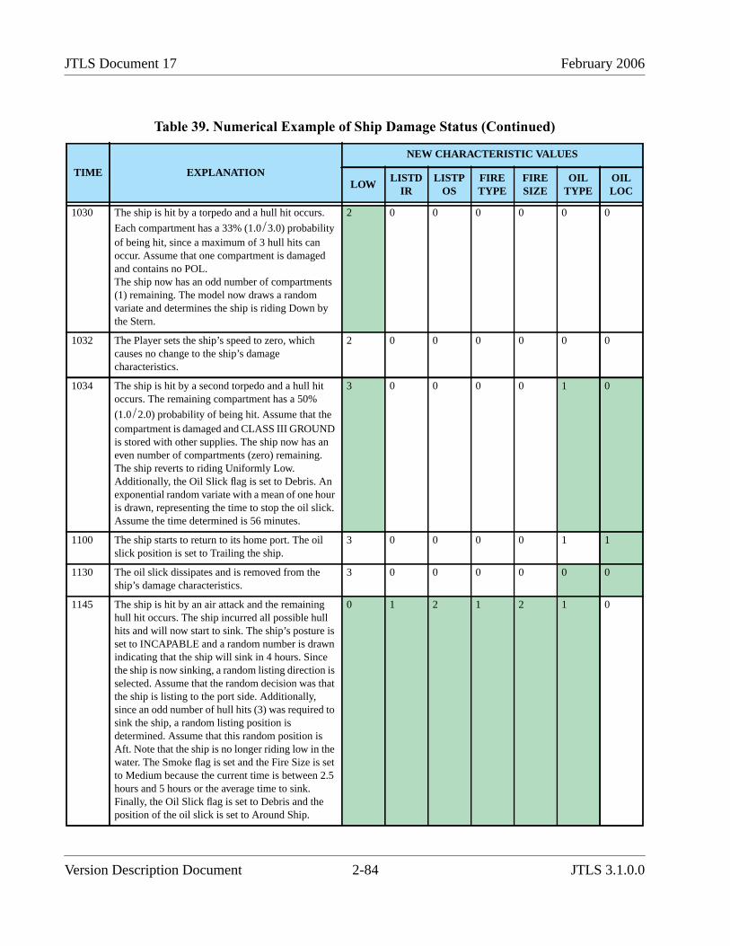
JTLS Document 17 February 2006
1030 The ship is hit by a torpedo and a hull hit occurs.
Each compartment has a 33% (1.0/3.0) probabilityof being hit, since a maximum of 3 hull hits canoccur. Assume that one compartment is damagedand contains no POL.The ship now has an odd number of compartments(1) remaining. The model now draws a randomvariate and determines the ship is riding Down bythe Stern.
2 0 0 0 0 0 0
1032 The Player sets the ship’s speed to zero, whichcauses no change to the ship’s damagecharacteristics.
2 0 0 0 0 0 0
1034 The ship is hit by a second torpedo and a hull hitoccurs. The remaining compartment has a 50%
(1.0/2.0) probability of being hit. Assume that thecompartment is damaged and CLASS III GROUNDis stored with other supplies. The ship now has aneven number of compartments (zero) remaining.The ship reverts to riding Uniformly Low.Additionally, the Oil Slick flag is set to Debris. Anexponential random variate with a mean of one houris drawn, representing the time to stop the oil slick.Assume the time determined is 56 minutes.
3 0 0 0 0 1 0
1100 The ship starts to return to its home port. The oilslick position is set to Trailing the ship.
3 0 0 0 0 1 1
1130 The oil slick dissipates and is removed from theship’s damage characteristics.
3 0 0 0 0 0 0
1145 The ship is hit by an air attack and the remaininghull hit occurs. The ship incurred all possible hullhits and will now start to sink. The ship’s posture isset to INCAPABLE and a random number is drawnindicating that the ship will sink in 4 hours. Sincethe ship is now sinking, a random listing direction isselected. Assume that the random decision was thatthe ship is listing to the port side. Additionally,since an odd number of hull hits (3) was required tosink the ship, a random listing position isdetermined. Assume that this random position isAft. Note that the ship is no longer riding low in thewater. The Smoke flag is set and the Fire Size is setto Medium because the current time is between 2.5hours and 5 hours or the average time to sink.Finally, the Oil Slick flag is set to Debris and theposition of the oil slick is set to Around Ship.
0 1 2 1 2 1 0
Table 39. Numerical Example of Ship Damage Status (Continued)
TIME EXPLANATION
NEW CHARACTERISTIC VALUES
LOWLISTD
IRLISTP
OSFIRETYPE
FIRESIZE
OILTYPE
OILLOC
Version Description Document 2-84 JTLS 3.1.0.0
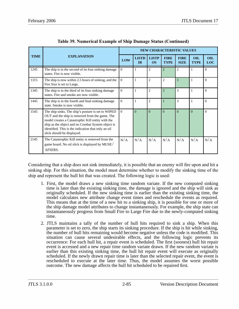
February 2006 JTLS Document 17
Considering that a ship does not sink immediately, it is possible that an enemy will fire upon and hit asinking ship. For this situation, the model must determine whether to modify the sinking time of theship and represent the hull hit that was created. The following logic is used:
1. First, the model draws a new sinking time random variate. If the new computed sinkingtime is later than the existing sinking time, the damage is ignored and the ship will sink asoriginally scheduled. If the new sinking time is earlier than the existing sinking time, themodel calculates new attribute change event times and reschedule the events as required.This means that at the time of a new hit to a sinking ship, it is possible for one or more ofthe ship damage model attributes to change instantaneously. For example, the ship state caninstantaneously progress from Small Fire to Large Fire due to the newly-computed sinkingtime.
2. JTLS maintains a tally of the number of hull hits required to sink a ship. When thisparameter is set to zero, the ship starts its sinking procedure. If the ship is hit while sinking,the number of hull hits remaining would become negative unless the code is modified. Thissituation can cause several undesirable effects, and the following logic prevents itsoccurrence: For each hull hit, a repair event is scheduled. The first (soonest) hull hit repairevent is accessed and a new repair time random variate drawn. If the new random variate isearlier than this existing sinking time, the hull hit repair event will execute as originallyscheduled. If the newly drawn repair time is later than the selected repair event, the event isrescheduled to execute at the later time. Thus, the model assumes the worst possibleoutcome. The new damage affects the hull hit scheduled to be repaired first.
1245 The ship is in the second of its four sinking damagestates. Fire is now visible.
0 1 2 2 2 1 0
1315 The ship is now within 2.5 hours of sinking, and theFire Size is set to Large.
0 1 2 2 3 1 0
1345 The ship is in the third of its four sinking damagestates. Fire and smoke are now visible.
0 1 2 3 3 1 0
1445 The ship is in the fourth and final sinking damagestate. Smoke is now visible.
0 1 2 1 3 1 0
1545 The ship sinks. The ship’s posture is set to WIPEDOUT and the ship is removed from the game. Themodel creates a Catastrophic Kill entity with theship as the object and no Combat System object isidentified. This is the indication that only an oilslick should be displayed.
0 0 0 0 0 0 0
2145 The Catastrophic Kill entity is removed from the
game board. No oil slick is displayed by MUSE/AFSERS.
N/A N/A N/A N/A N/A N/A N/A
Table 39. Numerical Example of Ship Damage Status (Continued)
TIME EXPLANATION
NEW CHARACTERISTIC VALUES
LOWLISTD
IRLISTP
OSFIRETYPE
FIRESIZE
OILTYPE
OILLOC
JTLS 3.1.0.0 2-85 Version Description Document
JTLS Document 17 February 2006
The user is not able to alter the Naval Damage attributes, but is allowed to view the current status ofthese attributes via the Information Management Tool.
2.33.2 Data Changes
This design required adding the SUP AVERAGE TIME TO SINK parameter to the Ship UnitPrototype (SUP) entity.
2.33.3 Order Changes
The Set order for Ship Unit Prototypes must be modified to allow the Controller to alter the SUPAVERAGE TIME TO SINK parameter.
2.34 JTLS-2005-1539 Improve Fuel Required Decision
2.34.1 Summary of Model Change Request
A new decision rule used to determine when and where to obtain fuel was implemented. Theimproved logic is primarily used for orbiting air missions that are operating at long distances fromhome. Basically, an orbiting air mission in this situation usually has an abundance of fuel available,but it believes that it determines that it needs fuel to complete its mission and make it home. Theresult is that the mission decides it needs fuel and gets fuel too often. For example, assume that anaircraft can hold 1000 lbs of fuel and needs 950 lbs of fuel to get home. If it burns fuel at a rate of 5lbs per minute, after ten minutes the mission decides it needs fuel. It see a tanker in close proximity,loads the fuel it can take, which is 50 lbs. It goes back on orbit and ten minutes later it decides that itneeds fuel again and the process continues throughout the mission’s assigned orbit time.
The new rule is a two step process. When the mission decides that it needs fuel, it selects anappropriate tanker. Once selected the mission is given knowledge of the tanker’s location and themodel now asks how much fuel do I need to get to the tanker. Continuing the numerical exampleabove, the mission decides it only needs 50 lbs of fuel to get to the tanker and still have its databasespecified reserve. Given this the mission decides it does not need fuel and stays orbiting, a tanker isselected based on the parameters of fuel availability, the ability of the needing mission to reach thetanker, and the proximity of the tanker to the orbit location. Once a tanker is assigned, the mission nolonger heads for the tanker immediately. Instead, the air mission is now given the ability to use thenewly selected tanker as its next refuel location. The mission can now continue orbiting for just over3 hours before heading for fuel.
2.35 JTLS-2005-1540 IMT Search Capability
2.35.1 Summary of Model Change Request
The IMT was enhanced to include a search capability for all screens with a Unique Name column.These screens display a new Search option in the right-click menu of the Name column (Figure 25)
Version Description Document 2-86 JTLS 3.1.0.0
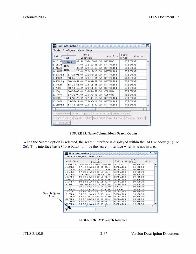
February 2006 JTLS Document 17
.
FIGURE 25. Name Column Menu Search Option
When the Search option is selected, the search interface is displayed within the IMT window (Figure26). This interface has a Close button to hide the search interface when it is not in use.
FIGURE 26. IMT Search Interface
Search QueryArea
JTLS 3.1.0.0 2-87 Version Description Document
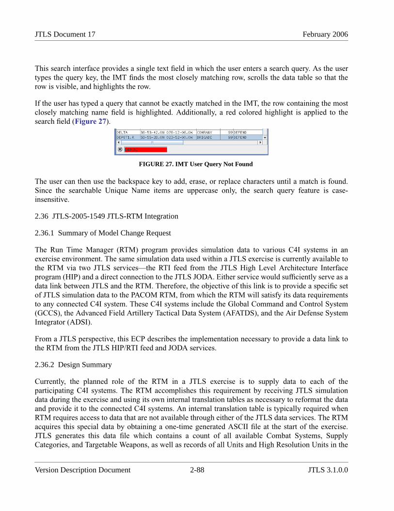
JTLS Document 17 February 2006
This search interface provides a single text field in which the user enters a search query. As the usertypes the query key, the IMT finds the most closely matching row, scrolls the data table so that therow is visible, and highlights the row.
If the user has typed a query that cannot be exactly matched in the IMT, the row containing the mostclosely matching name field is highlighted. Additionally, a red colored highlight is applied to thesearch field (Figure 27).
FIGURE 27. IMT User Query Not Found
The user can then use the backspace key to add, erase, or replace characters until a match is found.Since the searchable Unique Name items are uppercase only, the search query feature is case-insensitive.
2.36 JTLS-2005-1549 JTLS-RTM Integration
2.36.1 Summary of Model Change Request
The Run Time Manager (RTM) program provides simulation data to various C4I systems in anexercise environment. The same simulation data used within a JTLS exercise is currently available tothe RTM via two JTLS services—the RTI feed from the JTLS High Level Architecture Interfaceprogram (HIP) and a direct connection to the JTLS JODA. Either service would sufficiently serve as adata link between JTLS and the RTM. Therefore, the objective of this link is to provide a specific setof JTLS simulation data to the PACOM RTM, from which the RTM will satisfy its data requirementsto any connected C4I system. These C4I systems include the Global Command and Control System(GCCS), the Advanced Field Artillery Tactical Data System (AFATDS), and the Air Defense SystemIntegrator (ADSI).
From a JTLS perspective, this ECP describes the implementation necessary to provide a data link tothe RTM from the JTLS HIP/RTI feed and JODA services.
2.36.2 Design Summary
Currently, the planned role of the RTM in a JTLS exercise is to supply data to each of theparticipating C4I systems. The RTM accomplishes this requirement by receiving JTLS simulationdata during the exercise and using its own internal translation tables as necessary to reformat the dataand provide it to the connected C4I systems. An internal translation table is typically required whenRTM requires access to data that are not available through either of the JTLS data services. The RTMacquires this special data by obtaining a one-time generated ASCII file at the start of the exercise.JTLS generates this data file which contains a count of all available Combat Systems, SupplyCategories, and Targetable Weapons, as well as records of all Units and High Resolution Units in the
Version Description Document 2-88 JTLS 3.1.0.0
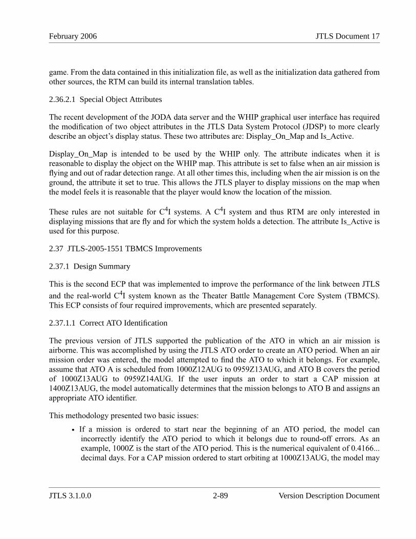
February 2006 JTLS Document 17
game. From the data contained in this initialization file, as well as the initialization data gathered fromother sources, the RTM can build its internal translation tables.
2.36.2.1 Special Object Attributes
The recent development of the JODA data server and the WHIP graphical user interface has requiredthe modification of two object attributes in the JTLS Data System Protocol (JDSP) to more clearlydescribe an object’s display status. These two attributes are: Display_On_Map and Is_Active.
Display_On_Map is intended to be used by the WHIP only. The attribute indicates when it isreasonable to display the object on the WHIP map. This attribute is set to false when an air mission isflying and out of radar detection range. At all other times this, including when the air mission is on theground, the attribute it set to true. This allows the JTLS player to display missions on the map whenthe model feels it is reasonable that the player would know the location of the mission.
These rules are not suitable for C4I systems. A C4I system and thus RTM are only interested indisplaying missions that are fly and for which the system holds a detection. The attribute Is_Active isused for this purpose.
2.37 JTLS-2005-1551 TBMCS Improvements
2.37.1 Design Summary
This is the second ECP that was implemented to improve the performance of the link between JTLS
and the real-world C4I system known as the Theater Battle Management Core System (TBMCS).This ECP consists of four required improvements, which are presented separately.
2.37.1.1 Correct ATO Identification
The previous version of JTLS supported the publication of the ATO in which an air mission isairborne. This was accomplished by using the JTLS ATO order to create an ATO period. When an airmission order was entered, the model attempted to find the ATO to which it belongs. For example,assume that ATO A is scheduled from 1000Z12AUG to 0959Z13AUG, and ATO B covers the periodof 1000Z13AUG to 0959Z14AUG. If the user inputs an order to start a CAP mission at1400Z13AUG, the model automatically determines that the mission belongs to ATO B and assigns anappropriate ATO identifier.
This methodology presented two basic issues:
• If a mission is ordered to start near the beginning of an ATO period, the model canincorrectly identify the ATO period to which it belongs due to round-off errors. As anexample, 1000Z is the start of the ATO period. This is the numerical equivalent of 0.4166...decimal days. For a CAP mission ordered to start orbiting at 1000Z13AUG, the model may
JTLS 3.1.0.0 2-89 Version Description Document
JTLS Document 17 February 2006
determine that the mission start time is prior to the ATO period start time and assign themission to ATO A instead of ATO B.
• If a user forgets to create the ATO period prior to submitting a mission order, the missioncannot be assigned an ATO identifier (ID). For example, assume that a user submitted theorder for the CAP mission to occur at 1400Z14AUG. The model would not find anapplicable ATO, the mission would not be assigned to the ATO period, and the TBMCSAdaptor would not be able to locate and update the proper TBMCS record.
Three improvements were implemented to ensure that all possible occurrences and combinations ofthese problems were addressed:
• We originally proposed that the model determine the ATO period to which a missionbelongs to minimize the time required to create an air mission, and to reduce the size of theair mission order panels. Since the determination of the ATO period can be troublesome andnot completely accurate, we added the ATO period as a silent field to each of the air missionorders. This allows the ATO-Translator to directly fill the ATO period for the missionwithout requiring the user to do so while manually entering an order. Thus, the missionparameter is always accurate for ATO-generated missions.
• It is still possible that manually created orders can be assigned to incorrect ATO periods. Weadded the ATO ID to the Change Air Mission Parameter order. Thus, this problem can besolved easily if the incorrect period is assigned.
• The ATO ID has also be made available on the Information Management Tool (IMT). Thus,problems to be solved can be easily identified.
2.37.1.2 ATO Change ID
When an air mission is included in an ATO change, a new record for that air mission is created inTBMCS. The TBMCS Adaptor must update the new record, not the original record that existed whenthe mission was first planned. To accomplish this, the TBMCS Adaptor must know the ATO Changeto which the mission currently belongs, which means that JTLS must publish this information.Typically, ATO periods are identified alphabetically and changes are identified numerically. Forexample, B3 means that the mission belongs to the third change for ATO Bravo. The ATO periodidentification may contain more than one character. For example ATO AB is followed by ATO AC,and ATO AZ is followed by ATO BA.
Within the ATO, this message is transmitted from TBMCS to the TBMCS Adaptor and within JTLSthe message is identified by its MSGID record. This record has the following format: MSGID/ATO/CENTAF CAOC/ATOK/NOV/CHG//
The ATO name in this example is Kilo (K), and no Change Number is associated with this message.A Change Number would appear in the last field labeled “CHG”.
Version Description Document 2-90 JTLS 3.1.0.0

February 2006 JTLS Document 17
To properly convey the information needed TBMCS to update the proper user record, we have madethe following changes:
• A new attribute was added to the ATO period structure in the CEP. This attribute is thenumber of the most recently published ATO change during the period. To set this newattribute, the ATO Period order has been upgraded to allow the user to alter the most recentATO Change number. The ATO-T submits this order each time it process an ATO Changeorder.
• The ATO-T sets both the ATO ID and the ATO Change number for each air mission orderthat it submits to the game.
• The model automatically assigns the proper ATO ID to an air mission, according to theperiod in which the mission is placed and the most recent ATO Change number for thatATO period. If the model’s automatically assigned value is incorrect, the user will have theability to change the ATO ID or ATO Change number via the Change Air MissionParameter order. This order perform the necessary checks to ensure that only proper ATOIDs and ATO Change numbers are accepted.
• In addition to the existing ATO_ID air mission attribute, a new JODA attribute,ATO_Change, is assigned to this number.
• The same changes were made to the FOM.
• Two IMT Air Mission screen columns are available to display the ATO ID and ATO ChangeNumber if the user selects the fields for display.
2.37.1.3 Mission Success Flag
Each mission within TBMCS has a flag to indicate whether it is successful or not. This improvementwill create a similar JTLS capability and pass that information to the TBMCS Adaptor to properlyupdate the mission’s TBMCS record. The concept of success is well-defined for Air-to-GroundAttack missions. Missions that deliver their weapons on the intended target, regardless of the damagecaused, are considered successful. The criteria of success for other mission types are not as clear.
Table 40 outlines rules for setting the Success Flag for each mission type currently modeled withinJTLS. These rules define when and why the mission’s success flag is set. Since the flag is reportedonly when the final mission message is sent to TBMCS, how frequently or why the setting occurs isinsignificant. TBMCS is notified regarding success or failure when the mission is complete.
Table 40. Rules to Determine Air Mission Success or Failure
MISSION TYPE RULES
AIRLIFT A mission that starts the pickup of the assigned unit is marked as successful. A mission that waits for thearrival of the unit and never begins the pickup is marked as unsuccessful
TRANSPORT A mission that begins its assigned flight profile is marked as successful. Whether it starts to pickupsupplies or not is not considered. This rule is selected because it is not unusual to use the transportmission to represent VIP and other flights, and we want them to show up as successful just for starting.
JTLS 3.1.0.0 2-91 Version Description Document
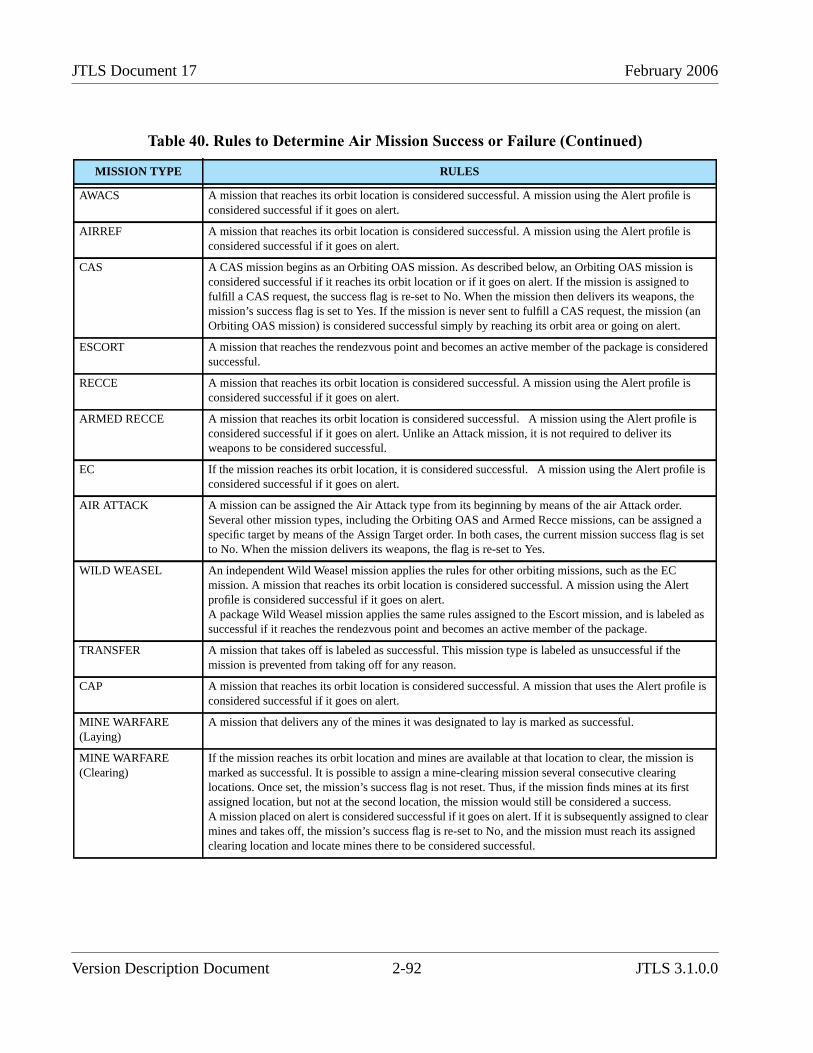
JTLS Document 17 February 2006
AWACS A mission that reaches its orbit location is considered successful. A mission using the Alert profile isconsidered successful if it goes on alert.
AIRREF A mission that reaches its orbit location is considered successful. A mission using the Alert profile isconsidered successful if it goes on alert.
CAS A CAS mission begins as an Orbiting OAS mission. As described below, an Orbiting OAS mission isconsidered successful if it reaches its orbit location or if it goes on alert. If the mission is assigned tofulfill a CAS request, the success flag is re-set to No. When the mission then delivers its weapons, themission’s success flag is set to Yes. If the mission is never sent to fulfill a CAS request, the mission (anOrbiting OAS mission) is considered successful simply by reaching its orbit area or going on alert.
ESCORT A mission that reaches the rendezvous point and becomes an active member of the package is consideredsuccessful.
RECCE A mission that reaches its orbit location is considered successful. A mission using the Alert profile isconsidered successful if it goes on alert.
ARMED RECCE A mission that reaches its orbit location is considered successful. A mission using the Alert profile isconsidered successful if it goes on alert. Unlike an Attack mission, it is not required to deliver itsweapons to be considered successful.
EC If the mission reaches its orbit location, it is considered successful. A mission using the Alert profile isconsidered successful if it goes on alert.
AIR ATTACK A mission can be assigned the Air Attack type from its beginning by means of the air Attack order.Several other mission types, including the Orbiting OAS and Armed Recce missions, can be assigned aspecific target by means of the Assign Target order. In both cases, the current mission success flag is setto No. When the mission delivers its weapons, the flag is re-set to Yes.
WILD WEASEL An independent Wild Weasel mission applies the rules for other orbiting missions, such as the ECmission. A mission that reaches its orbit location is considered successful. A mission using the Alertprofile is considered successful if it goes on alert.A package Wild Weasel mission applies the same rules assigned to the Escort mission, and is labeled assuccessful if it reaches the rendezvous point and becomes an active member of the package.
TRANSFER A mission that takes off is labeled as successful. This mission type is labeled as unsuccessful if themission is prevented from taking off for any reason.
CAP A mission that reaches its orbit location is considered successful. A mission that uses the Alert profile isconsidered successful if it goes on alert.
MINE WARFARE(Laying)
A mission that delivers any of the mines it was designated to lay is marked as successful.
MINE WARFARE(Clearing)
If the mission reaches its orbit location and mines are available at that location to clear, the mission ismarked as successful. It is possible to assign a mine-clearing mission several consecutive clearinglocations. Once set, the mission’s success flag is not reset. Thus, if the mission finds mines at its firstassigned location, but not at the second location, the mission would still be considered a success.A mission placed on alert is considered successful if it goes on alert. If it is subsequently assigned to clearmines and takes off, the mission’s success flag is re-set to No, and the mission must reach its assignedclearing location and locate mines there to be considered successful.
Table 40. Rules to Determine Air Mission Success or Failure (Continued)
MISSION TYPE RULES
Version Description Document 2-92 JTLS 3.1.0.0

February 2006 JTLS Document 17
2.37.1.4 Mission Divert Codes
If a mission diverts from its original plan for any reason, the AOC is notified by means of a divertcode entry into the mission’s TBMCS record. The TBMCS Adaptor requires a capability to simulatethis divert code entry and alter the appropriate TBMCS mission record, based on the mission’ssituation within JTLS. To accomplish this task, a new Air_Mission object attribute calledDeviation_Code was added. Table 41 lists the divert codes that TBMCS recognizes. The tablesummarizes air mission situations or events for which JTLS will set the mission’s deviation code tothe indicated enumeration.
ORBITING OAS A mission that reaches its orbit location is considered successful. A mission using the Alert profile isconsidered successful if it goes on alert. An Orbiting OAS mission can become a CAS mission if used tofulfill a CAS request. When this is accomplished, the mission applies the CAS mission rules. Similarly, itcan become an Air Attack mission if assigned a specific target by means of the Assign Target order.When this is accomplished, the mission applies the Air Attack mission rules.
PATROL A mission that reaches its orbit location is considered successful. A mission using the Alert profile isconsidered successful if it goes on alert.
INSERT/EXTRACT An Insert / Extract mission that fails to insert or extract any of the teams it has been assigned is marked asunsuccessful. The importance of inserting or extracting a covert team justifies the severity andrestrictiveness of this rule.
STRATEGIC LIFT The mission success flag is always set to Yes.
Table 41. Divert Code Design Summary
DIVERT CODE DIVERT CODE EVENT
Airfield Limited If an air mission enters a Runway Delay posture, the divert code is set. The divert code is cleared and set toInvalid (0) as soon as the mission is no longer in a Runway Delay posture.Note that the model does not automatically cancel missions in a Runway Delay posture. To cancel themission, the user must enter a Cancel Air Mission order. After doing so, the divert code shown in TBMCSwill indicate the reason provided with the order.
Base Weather If a air mission cannot take off due to inclement weather, the divert code is set. The divert code is clearedand set to Invalid (0) as soon as the mission is no longer delayed by inclement weather.As with the Airfield Limited diversion, the model does not automatically cancel missions holding for aweather delay. To cancel the mission, the user must enter a Cancel Air Mission order and specify theExcessive Delay option, which will cause the model to not alter the mission’s divert code. A user reviewingmissions results on TBMCS will then be able to discern that the delay was due to the weather limitation.
Ground Defenses If a mission is fired upon by enemy air defenses, the mission is given this divert code.
Ordinance or WeaponSystems
If an air mission enters a Weapons Delay posture, the divert code is set. The divert code is cleared and set toInvalid (0) as soon as the mission is no longer in a Weapons Delay posture. If the mission is automaticallycanceled by the model due to an excessive launch delay, the divert code will appropriately remain listed inTBMCS as Ordinance or Weapon Systems.
Table 40. Rules to Determine Air Mission Success or Failure (Continued)
MISSION TYPE RULES
JTLS 3.1.0.0 2-93 Version Description Document
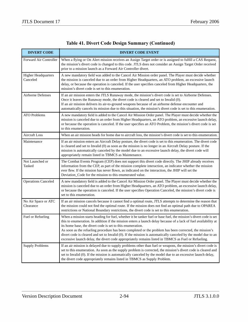
JTLS Document 17 February 2006
Forward Air Controller When a flying or On Alert mission receives an Assign Target order or is assigned to fulfill a CAS Request,the mission’s divert code is changed to this code. JTLS does not consider an Assign Target Order receivedprior to a mission launch as a Forward Air Controller divert.
Higher HeadquartersCanceled
A new mandatory field was added to the Cancel Air Mission order panel. The Player must decide whetherthe mission is canceled due to an order from Higher Headquarters, an ATO problem, an excessive launchdelay, or because the operation is canceled. If the user specifies canceled from Higher Headquarters, themission’s divert code is set to this enumeration.
Airborne Defenses If an air mission enters the JTLS Runaway mode, the mission’s divert code is set to Airborne Defenses.Once it leaves the Runaway mode, the divert code is cleared and set to Invalid (0).If an air mission delivers its air-to-ground weapons because of an airborne defense encounter andautomatically cancels its mission due to this situation, the mission’s divert code is set to this enumeration.
ATO Problems A new mandatory field is added to the Cancel Air Mission Order panel. The Player must decide whether themission is canceled due to an order from Higher Headquarters, an ATO problem, an excessive launch delay,or because the operation is canceled. If the user specifies an ATO Problem, the mission’s divert code is setto this enumeration.
Aircraft Loss When an air mission heads for home due to aircraft loss, the mission’s divert code is set to this enumeration.
Maintenance If an air mission enters an Aircraft Delay posture, the divert code is set to this enumeration. The divert codeis cleared and set to Invalid (0) as soon as the mission is no longer in an Aircraft Delay posture. If themission is automatically canceled by the model due to an excessive launch delay, the divert code willappropriately remain listed in TBMCS as Maintenance.
Not Launched orTasked
The Combat Events Program (CEP) does not support this divert code directly. The JHIP already receivesinformation from the CEP, as part of the mission complete interaction, an indicator whether the missionever flew. If the mission has never flown, as indicated on the interaction, the JHIP will set theDeviation_Code for the mission to this enumerated value.
Operations Canceled A new mandatory field is added to the Cancel Air Mission Order panel. The Player must decide whether themission is canceled due to an order from Higher Headquarters, an ATO problem, an excessive launch delay,or because the operation is canceled. If the user specifies Operation Canceled, the mission’s divert code isset to this enumeration.
No Air Space or ATCClearance
If an air mission cancels because it cannot find a optimal route, JTLS attempts to determine the reason thatthe mission could not find the optimal route. If the mission does not find an optimal path due to OPAREArestrictions or National Boundary restrictions, the divert code is set to this enumeration.
Fuel or Refueling When a mission starts heading for fuel, whether it be tanker fuel or base fuel, the mission’s divert code is setthis to enumeration. In addition if the mission enters a launch delay because of a lack of fuel availability atits home base, the divert code is set to this enumeration.As soon as the refueling procedure has been completed or the problem has been corrected, the mission’sdivert code is cleared and set to Invalid (0). If the mission is automatically canceled by the model due to anexcessive launch delay, the divert code appropriately remains listed in TBMCS as Fuel or Refueling.
Supply Problems If an air mission is delayed due to supply problems other than fuel or weapons, the mission’s divert code isset to this enumeration. As soon as the supply problem is corrected, the mission’s divert code is cleared andset to Invalid (0). If the mission is automatically canceled by the model due to an excessive launch delay,the divert code appropriately remains listed in TBMCS as Supply Problem.
Table 41. Divert Code Design Summary (Continued)
DIVERT CODE DIVERT CODE EVENT
Version Description Document 2-94 JTLS 3.1.0.0
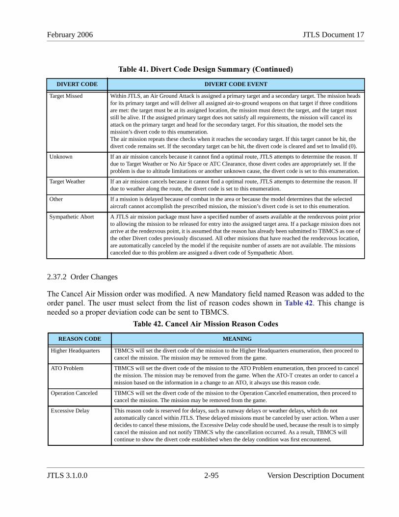
February 2006 JTLS Document 17
2.37.2 Order Changes
The Cancel Air Mission order was modified. A new Mandatory field named Reason was added to theorder panel. The user must select from the list of reason codes shown in Table 42. This change isneeded so a proper deviation code can be sent to TBMCS.
Target Missed Within JTLS, an Air Ground Attack is assigned a primary target and a secondary target. The mission headsfor its primary target and will deliver all assigned air-to-ground weapons on that target if three conditionsare met: the target must be at its assigned location, the mission must detect the target, and the target muststill be alive. If the assigned primary target does not satisfy all requirements, the mission will cancel itsattack on the primary target and head for the secondary target. For this situation, the model sets themission’s divert code to this enumeration.The air mission repeats these checks when it reaches the secondary target. If this target cannot be hit, thedivert code remains set. If the secondary target can be hit, the divert code is cleared and set to Invalid (0).
Unknown If an air mission cancels because it cannot find a optimal route, JTLS attempts to determine the reason. Ifdue to Target Weather or No Air Space or ATC Clearance, those divert codes are appropriately set. If theproblem is due to altitude limitations or another unknown cause, the divert code is set to this enumeration.
Target Weather If an air mission cancels because it cannot find a optimal route, JTLS attempts to determine the reason. Ifdue to weather along the route, the divert code is set to this enumeration.
Other If a mission is delayed because of combat in the area or because the model determines that the selectedaircraft cannot accomplish the prescribed mission, the mission’s divert code is set to this enumeration.
Sympathetic Abort A JTLS air mission package must have a specified number of assets available at the rendezvous point priorto allowing the mission to be released for entry into the assigned target area. If a package mission does notarrive at the rendezvous point, it is assumed that the reason has already been submitted to TBMCS as one ofthe other Divert codes previously discussed. All other missions that have reached the rendezvous location,are automatically canceled by the model if the requisite number of assets are not available. The missionscanceled due to this problem are assigned a divert code of Sympathetic Abort.
Table 42. Cancel Air Mission Reason Codes
REASON CODE MEANING
Higher Headquarters TBMCS will set the divert code of the mission to the Higher Headquarters enumeration, then proceed tocancel the mission. The mission may be removed from the game.
ATO Problem TBMCS will set the divert code of the mission to the ATO Problem enumeration, then proceed to cancelthe mission. The mission may be removed from the game. When the ATO-T creates an order to cancel amission based on the information in a change to an ATO, it always use this reason code.
Operation Canceled TBMCS will set the divert code of the mission to the Operation Canceled enumeration, then proceed tocancel the mission. The mission may be removed from the game.
Excessive Delay This reason code is reserved for delays, such as runway delays or weather delays, which do notautomatically cancel within JTLS. These delayed missions must be canceled by user action. When a userdecides to cancel these missions, the Excessive Delay code should be used, because the result is to simplycancel the mission and not notify TBMCS why the cancellation occurred. As a result, TBMCS willcontinue to show the divert code established when the delay condition was first encountered.
Table 41. Divert Code Design Summary (Continued)
DIVERT CODE DIVERT CODE EVENT
JTLS 3.1.0.0 2-95 Version Description Document

JTLS Document 17 February 2006
Each Air Mission order was modified to include a new silent field for the ATO Change Number underwhich the air mission is covered.
The Change Air Mission Parameter order was modified to allow the user to change the ATO ID or theATO Change Number for the mission.
2.38 JTLS-2005-1552 Reduce Lanchester Data
2.38.1 Summary of Model Change Request
2.38.2 Design Summary
2.38.2.1 Previous JTLS Force-on-Force Combat Data
Within JTLS, two data structures previously held the Lanchester coefficients (the data used todetermine the results of force-on-force combat):
• Lanchester Coefficient Data Sets. The user can define as many of these sets as desired. Eachset was an array dimensioned by the number of Combat Systems (CS) by CS. Within theprevious SDB version, each Lanchester Data Set was an array dimensioned 43 by 43. Withthe new standard 100 Combat System definition, the Lanchester Data Set became an arraydimensioned 100 by 100. Each set was assigned a number from 1 to the total number of setsdefined by the database builder.
• Combat Index Array. This data structure had four dimensions:
Fire Lethality Prototype (FLP)
Survivability Prototype (SP)
Killer Unit’s Posture (UPK)
Victim Unit’s Posture (UPV)
This array held the numeric identifier of the Lanchester Data Set that was to be used underthe specified combat conditions. For example, assume that the Combat Index Array (1, 2, 3,4) contains the value 5. This means that when a unit assigned FLP number 1 and a Postureof 3 (Delay) engages in combat with a unit assigned SP 2 and a Posture of 4 (Withdraw), themodel was suppose to use Lanchester Data Set number 5 to compute the number of CombatSystems the first unit will kill in the second unit during one hour of combat.
2.38.2.2 New Force-on-Force Combat Data
The new Combat Index Array was changed from a four-dimensional array to a two-dimensional arraydimensioned by Killer Posture and Victim Posture. To maintain consistency in the JTLS data namingconvention, the data name of the new Combat Index Array has been changed to UP UPLANCHESTER DATA SET. This data name indicates an array dimensioned by the number of Unit
Version Description Document 2-96 JTLS 3.1.0.0
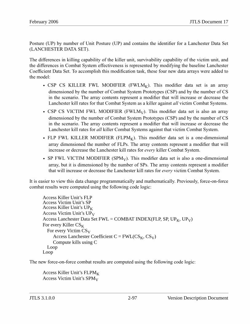
February 2006 JTLS Document 17
Posture (UP) by number of Unit Posture (UP) and contains the identifier for a Lanchester Data Set(LANCHESTER DATA SET).
The differences in killing capability of the killer unit, survivability capability of the victim unit, andthe differences in Combat System effectiveness is represented by modifying the baseline LanchesterCoefficient Data Set. To accomplish this modification task, these four new data arrays were added tothe model:
• CSP CS KILLER FWL MODIFIER (FWLMK). This modifier data set is an arraydimensioned by the number of Combat System Prototypes (CSP) and by the number of CSin the scenario. The array contents represent a modifier that will increase or decrease theLanchester kill rates for that Combat System as a killer against all victim Combat Systems.
• CSP CS VICTIM FWL MODIFIER (FWLMV). This modifier data set is also an arraydimensioned by the number of Combat System Prototypes (CSP) and by the number of CSin the scenario. The array contents represent a modifier that will increase or decrease theLanchester kill rates for all killer Combat Systems against that victim Combat System.
• FLP FWL KILLER MODIFIER (FLPMK). This modifier data set is a one-dimensionalarray dimensioned the number of FLPs. The array contents represent a modifier that willincrease or decrease the Lanchester kill rates for every killer Combat System.
• SP FWL VICTIM MODIFIER (SPMV). This modifier data set is also a one-dimensionalarray, but it is dimensioned by the number of SPs. The array contents represent a modifierthat will increase or decrease the Lanchester kill rates for every victim Combat System.
It is easier to view this data change programmatically and mathematically. Previously, force-on-forcecombat results were computed using the following code logic:
Access Killer Unit’s FLPAccess Victim Unit’s SPAccess Killer Unit’s UPKAccess Victim Unit’s UPVAccess Lanchester Data Set FWL = COMBAT INDEX(FLP, SP, UPK, UPV)For every Killer CSK
For every Victim CSVAccess Lanchester Coefficient C = FWL(CSK, CSV)Compute kills using C
LoopLoop
The new force-on-force combat results are computed using the following code logic:
Access Killer Unit’s FLPMKAccess Victim Unit’s SPMV
JTLS 3.1.0.0 2-97 Version Description Document
JTLS Document 17 February 2006
Access Killer Unit’s CSP (CSPK)Access Victim Unit’s CSP (CSPV)Access Killer Unit’s UPKAccess Victim Unit’s UPVAccess Lanchester Data Set FWL = UP UP LANCHESTER DATA SET(UPK, UPV)For every Killer CSK
Access killer modifier FWLMK = CSP.CS.KILLER.FWL.MODIFIER(CSPK, CSK)For every Victim CSV
Access Lanchester Coefficient C = FWL(CSK, CSV)Access victim modifier FWLMVModify CM = C * FWLMK * FWLMV * FLPMK * SPMVCompute kills using CM
LoopLoop
Although this computation algorithm is more complex, it reduces the number of Lanchester cases. Anadditional benefit of this design is that the FLPMK and SPMV data sets can be used as convenienttuning parameters to adjust the kills obtained from Lanchestrian force-on-force combat. An entireFaction or Side could be made more or less effective by modifying a single FLPMK or SPMV dataparameter.
2.38.2.3 Additional Force-on-Force Combat Refinements
We also improved this algorithm with respect to representing a combat unit’s ability to operate undernight conditions. Previously, every JTLS unit has a unit effectiveness (UT EFFECTIVENESS) value.This data parameter represents the unit’s ability to conduct combat operations. It is designed torepresent the unit’s readiness level, and also their training and the reliability of their equipment.However, this singular number does not account for the critical factor of light conditions during thetime of the operation. It is desirable to represent a unit as a well-trained and effective combat force(high UT EFFECTIVENESS value) during the day, but also as ineffective at night due to lack oftraining and general support equipment (low UT EFFECTIVENESS value).
A new unit effectiveness parameter for night conditions, UT NIGHT EFFECTIVENSS, was added tothe database. For every instance the model currently accesses UT EFFECTIVENESS, additional codewould determine whether the combat operation is taking place during daylight or night. If the lightcondition is daylight, the UT EFFECTVENESS parameter would be used to modify the results of thecombat action. For night conditions, UT NIGHT EFFECTIVENESS would be used to modify thecombat action results.
The new CSP-CS, FLP and SP data fields, in conjunction with the new unit effectiveness parameters,greatly increase the model’s flexibility to represent various scenarios. Factions and Sides can be madeas robust or as weak in Lanchester combat as the scenario requires without directly adjusting theLanchester table rates—always a difficult recourse.
Version Description Document 2-98 JTLS 3.1.0.0
February 2006 JTLS Document 17
2.38.2.4 Combat System Density Data
Previously, the Combat System density array contains 6880 data entries for each of the three CCPs inSDB. To support 100 Combat Systems, this will increase to 160,000 entries per array. The structure ofthe density array was also changed.
Previously, Combat System density data is held in an array that has four dimensions:
• Command Control Prototype (CCP)
• Combat System (CS)
• Unit Posture (UP)
• Terrain Type (TT)
When the model needed the density of a specific Combat System within a given unit, it accessed theCSP CS UP TT DENSITY array using the unit’s CCP, the Combat System index CS, the unit’sPosture (UP), and the type of Terrain (TT) in which the unit is currently located.
To reduce the quantity of data, we replaced this four-dimensional array with to these dimensionedarrays:
• CCP CS BASE DENSITY. The value held in this array is the square meters each CombatSystem of type CS occupies in a unit that has a Command Control Prototype of CCP. Thedatabase builder will choose which Posture and Terrain type represent the base case, andenter a value in the array that represents the desired density of the Combat System under thebase case conditions.
• CCP CS UP DENSITY MODIFIER. The value held in this array is the multiplicativemodifier that should be applied to the base case density value when the unit is in a specifiedPosture. For example, assume that the database builder selected the DEFEND Posture as thebase Posture for density. The CCP CS UP DENSITY MODIFIER array for the PostureDEFEND would then be expected to have a value of 1.0. If the database builder intended theCombat Systems in the WITHDRAW Posture to be positioned in a less dense configuration,the WITHDRAW positions in the array should hold a modification value greater than 1.0.Considering that this modifier is also dimensioned by CS, the database builder can representone Combat System type as more dense than the base density under these conditions andanother Combat System as less densely positioned under a specific unit Posture.
• CCP CS TT DENSITY MODIFER. The value held in this array is the multiplicativemodifier that should be applied to the base case density value when the unit is located in aspecified Terrain. If the database builder selected OPEN terrain as the baseline case forCombat System density, then the expected value of the CCP CS TT DENSITY MODIFIERin the OPEN Terrain position in the array would be 1.0. If the database builder intended theCombat Systems to be in a highly dense configuration in Terrain MOUNTAIN, theMOUNTAIN position in the array should hold a modification value less than 1.0.
JTLS 3.1.0.0 2-99 Version Description Document
JTLS Document 17 February 2006
Considering that this modifier is also dimensioned by CS, the database builder can representone Combat System type as more densely positioned than the base density under theseconditions and another Combat System as less densely positioned in a specific Terrain Type.
Thus, a unit’s Combat System density is no longer be a simple table lookup, but is computedaccording to the following equation:
The total number of Combat System density entries in each CCP is reduced to 2700 from the 160,000required by the previous structure. This is a reduction of approximately 83%.
2.38.3 Data Changes
These data parameters were removed from the database and the documentation: COMBAT INDEXARRAY, CCP CS UP TT DENSITY.
The following data was added to the JTLS initialization database. Each new parameter has notesconcerning the conversion rules that are used by the DDS when converting your JTLS 3.0 database tothe JTLS 3.1 database format.
• UP UP LANCHESTER DATA SET - Conversion Rule:Retrieve all Combat Index Arrayrecords for the selected FLP and SP combination. Delete the FLP and SP attributes fromthe record and place the remaining attributes in a new record within the UP UP Table.Several unused Lanchester Data Sets will be created. Alterdata tools accessible from theDDS Menu will be added to remove any unused Lanchester Data Sets. Note: Usersconverting their existing database to the 100 Combat System standard must apply thesetools prior to using the converted database.
• CSP CS KILLER FWL MODIFIER - Conversion Rule:No conversion is necessary. JTLSwill apply the default value of 1.0 unless it is modified by a database record.
• CSP CS VICTIM FWL MODIFIER - Conversion Rule:No conversion is necessary. JTLSwill assume that the value is 1.0 unless modified by a database record.
• FLP FWL KILLER MODIFIER - Conversion Rule:Set the value to the default of 1.0. Weconsidered creating an algorithm to compare the old data with the new data, but the modeltypically uses only a few FLP objects. The SDB represents only three FLPs; therefore,saving fewer than ten data parameters is not justified.
• SP FWL VICTIM MODIFIER - Conversion Rule:Set the value to the default of 1.0. Weconsidered creating an algorithm to compare the old data with the new data, but the modeltypically uses only a few SP objects. The SDB represents only three SPs; therefore, savingfewer than ten data parameters is not justified.
DensityCS Base DensityCCP CS, ModifierCCP CS UP, ,× ModifierCCP CS TT, ,×=
Version Description Document 2-100 JTLS 3.1.0.0

February 2006 JTLS Document 17
• UT NIGHT EFFECTIVENESS - Conversion Rule:The conversion procedure will copythe value of UT EFFECTIVENESS into the new attribute UT NIGHT EFFECTIVENESS.
• CCP CS BASE DENSITY - Conversion Rule:The conversion procedure will select all ofthe records currently held in the CCP CS UP TT table as the selected standard UP and TT.The retrieved records will become the new records for the CCP CS table, but the attributesthat specify the UP and TT will be removed.
• CCP CS UP DENSITY MODIFIER - Conversion Rule:Set the value to the default of 1.0.We considered creating an algorithm to compare the old data with the new data, but JTLSrepresents only ten unit Postures; therefore, the effort to save these ten data parameters isnot justified.
• CCP CS TT DENSITY MODIFER - Conversion Rule:Set the value to the default of 1.0.We considered creating an algorithm to compare the old data with the new data, but JTLSrepresents only 16 Terrain Types; therefore, the effort to save these 16 data parameters isnot justified.
2.39 JTLS-2005-1556 Weapon Load Recognition
JTLS supports three separate methods to specify the Mission Load that should be placed on a specificair mission, identified as Model Determined, Player Altered, and Player Specified.
• Model Determined Load. This method allows the model to determine the most appropriateload to place on an air mission while considering the aircraft type and the mission’s tasking.
• Player Altered Load. This method provides the Player the ability to specify a list of desiredweapons as part of the mission order. Provided with the Aircraft Class and Mission Taskinformation used for the previous method, the model selects the BEST weapon load andreplaces this load with the listed weapons specified by the Player.
• Player Specified Load. This recently-developed capability allows the JTLS Player tospecify a named load to assign to an air mission. If this method is selected, the specifiedload (weapons, sensors, jammers, extra fuel, and supplies) is placed on the mission and theLOAD ASSIGNMENT array is not accessed. However, the ATO-T was not adapted to usethis new method to specify the desired mission load.
The Air Tasking Order Translator (ATO-T) has been improved to use the Player Specified Loadcapability built into JTLS. The ATO-T receives a list of all JTLS loads held in the initializationdatabase. If the weapon load name provided in the Air Tasking Order matches one of the JTLSdefined loads, the ATO-T uses the Player Specified Load option when creating the order that shouldbe sent to JTLS.
JTLS 3.1.0.0 2-101 Version Description Document

JTLS Document 17 February 2006
2.40 JTLS-2005-1557 Maintain Federation If CEP Goes Down
When the JMRM federation initializes, the CEP begins to execute. After reading its initializationdatabase, the CEP downloads data to the JODA. During a data download, all of the informationcurrently held in the JODA is discarded and the CEP passes to the JODA all required information forall objects represented in the scenario. After this download is complete, the JODA performs adownload to all of its clients, including the JHIP.
The JHIP, in a similar manner, clears all objects from its internal database when it receives notice thata JODA download is pending. After this download is complete, JHIP passes the received informationto the HLA RTI, using the HLA protocol to publish the objects and object attributes. All federateslinked to the RTI will receive this information. Thus, the transfer of information from the JTLS CEPto the JMRM federates is complete.
A major distinction between the JODA and JHIP download methods should be noted. When theJODA receives notification that a download of data from the CEP is pending, it clears all objects heldwithin its internal database, but it does not pass that information to its clients. After the CEPdownload is complete, the JODA then delivers a “Start Download” notification to its clients. Eachclient then determines how to process the download and whether to update its currently held internaldatabase.
Previously, the JHIP interprets a JODA download as an indication to initialize the game and re-initialize the federation. Therefore, if it receives a “Start Download” notification while executing, theJHIP use to halt and wait for the JHIP operator and Technical Control to bring down the entirefederation and prepare for the re-initialization procedure. Unfortunately, it was possible for the JODAto send a “Start Download” notification even when the game is not re-initialized. The impact of thisaction during an exercise is obvious.
2.40.1 Design Summary
Precisely describing the internal logic of a program such as the JHIP is difficult. Thus, the newlydesigned JHIP logic is depicted by high-level flowchart. Following a discussion of this flowchart,representative situations are described that illustrate how the new logic allows the JHIP and theJMRM federation to continue executing in a hold mode until the CEP is ready to resume execution inrepresented time.
Figure 28 depicts the new expanded logic for the JHIP. Instead of halting when it receives a new“Start Download” notification from the JODA, the JHIP determines how to handle each objectreceived from the JODA. Execution of the expanded logic, shown in Figure 29 and Figure 30,enables the JHIP to maintain a federation connection whether a JODA download command isunintentionally sent, or sent concurrently with a CEP or JODA restart.
Version Description Document 2-102 JTLS 3.1.0.0
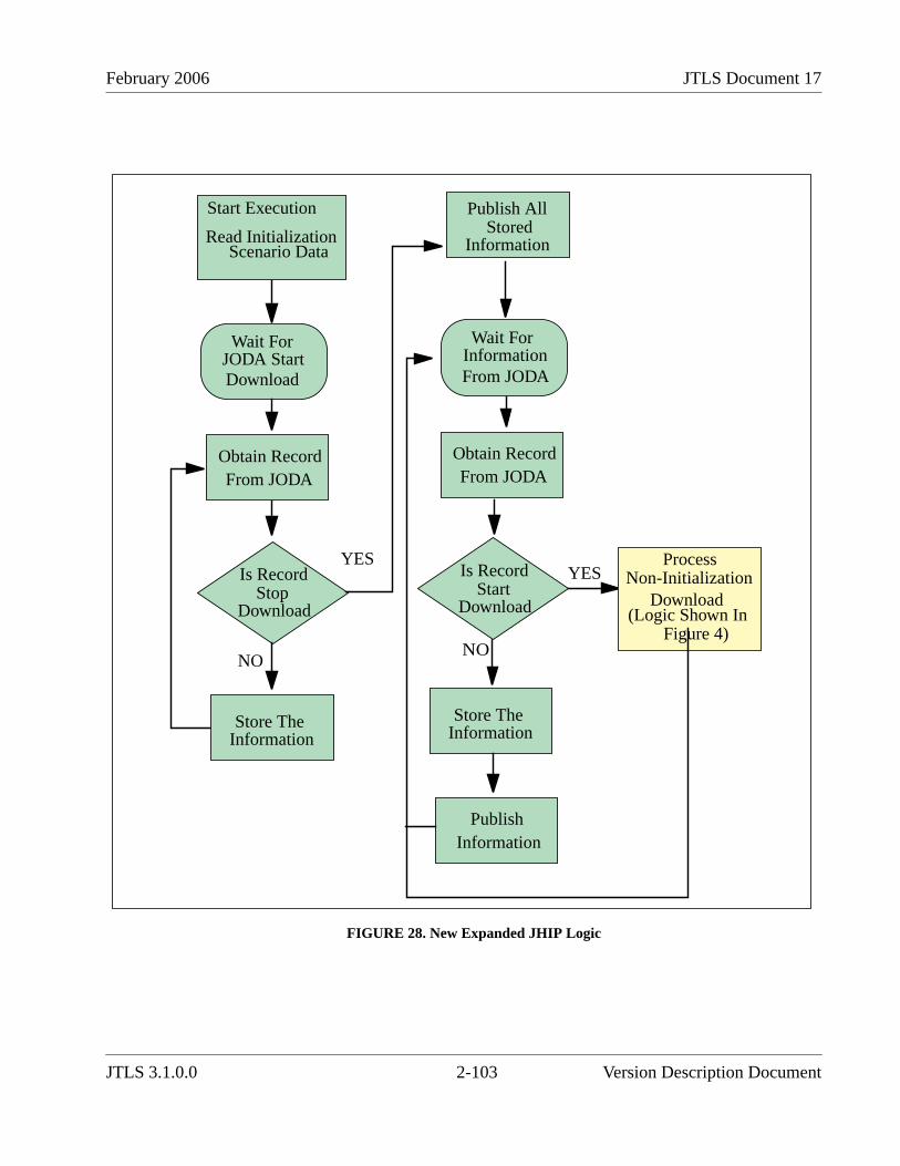
February 2006 JTLS Document 17
FIGURE 28. New Expanded JHIP Logic
Start Execution
Read Initialization Scenario Data
Wait ForJODA StartDownload
Obtain RecordFrom JODA
Is RecordStop
Download
NO
Store TheInformation
YES
Wait For
From JODAInformation
Obtain RecordFrom JODA
NO
YES
PublishInformation
Store TheInformation
Is RecordStart
Download
Publish AllStored
Information
(Logic Shown InFigure 4)
ProcessNon-Initialization
Download
JTLS 3.1.0.0 2-103 Version Description Document
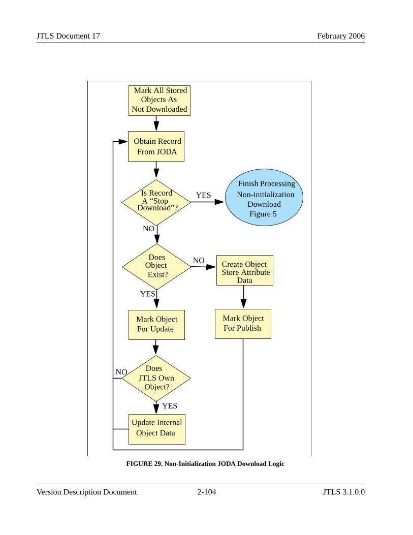
JTLS Document 17 February 2006
FIGURE 29. Non-Initialization JODA Download Logic
Obtain RecordFrom JODA
NO
Is RecordA “Stop
Download”?
DoesObjectExist?
Mark All StoredObjects As
Not Downloaded
YES
Mark ObjectFor Update
Update InternalObject Data
NO Create ObjectStore Attribute
Data
YES
DoesJTLS Own
Object?
YES
NO
Mark ObjectFor Publish
Finish ProcessingNon-initialization
DownloadFigure 5
Version Description Document 2-104 JTLS 3.1.0.0

February 2006 JTLS Document 17
FIGURE 30. Non-Initialization JODA Download Completed Logic
The underlying requirement of this logic is that the JHIP must intelligently process informationreceived from the JODA when its download starts during JHIP execution. Consequently, the JHIPmust determine how to manage this new information. When a download is received as part of theinitialization, the JHIP decision is relatively simple. If JTLS owns the object, the JHIP publishes thedata. If JTLS does not own the object, the JHIP holds the data and waits for the appropriate federateto publish the required information.
For EveryHeld Object
ReturnTo Main
JHIP Logic
How IsObject
Marked?
Does
Object?
PublishPublish TheObject
LeaveLoop
NotDownloaded
JTLS Own
Does
Object?JTLS Own
YES
Print outError
Message
RTIDeleteObject
Update
YES
NO
NO
SubmitUpdate To
CEP
SubmitUpdate To
RTI
Situation 1
Situation 5
Situation 2
Situation 4
Situation 3
JTLS 3.1.0.0 2-105 Version Description Document

JTLS Document 17 February 2006
Problems are indicated if the JHIP obtains a JODA download during execution. Table 43 summarizessome of the possible situations that could result in a non-initialization JODA download to the JHIPand plausible reasons that the JODA data and JHIP data may not be identical.
Table 43. JHIP Logic Alternatives
REASON FOR DOWNLOAD LIKELY DATA CONSISTENCY PROBLEMS
An operator starts a JODA download. This could be done by anunintentional JODA command line entry or as a deliberateattempt to correct a problem such as missing or incorrect data inthe JODA.
Assume that a JODA error occurs and the data held in the CEPdo not match the data served by the JODA. Although no causehas been specifically identified, this contingency is consideredin this design. As a corrective action, Technical Control canforce a CEP download to the JODA. After obtaining thedownload, the JODA will re-create all of its internal databasestructures, then initiate a download to all clients, including theJHIP. The JHIP will receive this information, presumably withnew data for some objects, and publish updates on all objects tothe RTI. In Figure 30, this is identified as Situation 1.
The CEP halts due to a logic error or hardware error. Assume that the CEP halts due to a logic error involving an airmission. A technique available to the JTLS team to quicklyresume model execution involves manually editing the logicerror checkpoint file and removing the offending mission. Themodel is then restarted from the modified checkpoint filewithout any loss of game time. In this case, the JHIP wouldcontinue executing, but would not obtain a download for theobject. After the download, the deleted air mission wouldrepresent Situation 2 identified in Figure 30, and the deletewould be passed on to the federation.
The JODA halts due to a logic error or hardware error. Assume that the JODA halts while processing a create objectmessage from the CEP. When the JODA is restarted, it obtains anew download from the CEP, which includes the new object.After the download is complete, the mid-execution downloadwill be passed to the JHIP. This download will include an objectthat the JHIP does not perceive, since the JODA stoppedexecuting prior to notifying the JHIP that the object exists. Inthis case, when the JHIP receives the new object, it will publishthe object to the remainder of the federation. This is identifiedas Situation 3 in Figure 30.
The network connection is lost between the CEP and JODA orbetween the JODA and JHIP.
Assume that the network connection between JODA and theCEP is lost. Prior to this event, the JHIP passed an ExternalUpdate to a federate owned object. The JODA could not sendthis update to the CEP. When the network connection is re-established, the CEP conducts a download to the JODA and theJODA sends a mid-execution download to the JHIP. For JHIP,the non-JTLS owned object has one set of attribute values. ForJTLS, the object has a different set of attribute values because itdid not receive the External Update. For this reason, the JHIPwill discard the CEP-delivered attributes and will return anupdate to the CEP containing the current value of all attributesfor the federation owned object. This is identified as Situation 4in Figure 30.
Version Description Document 2-106 JTLS 3.1.0.0
February 2006 JTLS Document 17
The remaining error condition depicted in Figure 30 is identified as Situation 5. In this situation,JTLS loses contact with a federation object. The federation and the JHIP perceive that the objectexists, but the CEP perceives that it does not exist. Currently, a design to adequately manage this errorcondition has not been developed. Therefore, we generate an error message into the JHIP log file, andrecommend that operators review this file immediately after a non-initialization JODA downloadoccurs. If any resultant problems are identified, completely stopping and re-starting the federation isthe only available recourse.
Another problem may result from restarting the CEP, such as from a previous checkpoint. If the CEPis restarted at a game time different from its previous connection with the JODA, those objects thatare different from the previous run will begin to assume object ID numbers that previously belongedto different objects. This is called object ID number reuse and occurs because object ID numbers areassigned sequentially as they are created.
2.41 JTLS-2005-1578 Passing Control of Problematic ARUs
2.41.1 Summary of Model Change Request
The High Level Architecture (HLA) and Joint Multi-Resolution Model (JMRM) federation currentlyallows model control of game objects to pass between participating federates. With this capability, ajoined federate can acquire the necessary permission to control attributes of a passed object, such asLocation, Destination Location, and Posture. When the receiving federate assumes control of anattribute, it is allowed to change the attribute to a value that is appropriate for the simulation model itis feeding. The federate that previously controlled the object will relinquish control of these passedattributes and can only reflect external updates to these attributes. When this occurs, the simulationmodel associated with the previous owning federate will attempt to reflect these attribute updates as itis capable.
Several conditional problems were discovered within JTLS when control of a particular type and stateof Aggregate Resolution Unit (ARU) is passed among the JMRM federation models. The problembecomes apparent in several cases as described below. In certain cases, having control of an object’sattributes can cause logic problems within other federated simulations attempting to model the object.This Enhancement Change Proposal (ECP) describes the modifications that were necessary toidentify and manage specific ARUs by type and unit state that could potentially cause JTLS logicerrors.
2.41.2 Design Summary
Table 44 lists the combinations of unit types and specific unit states that would likely contradict CEPassumptions about the units involved and cause a logic error. These errors can occur after thereceiving model accepts control of the unit and updates its attributes.
JTLS 3.1.0.0 2-107 Version Description Document
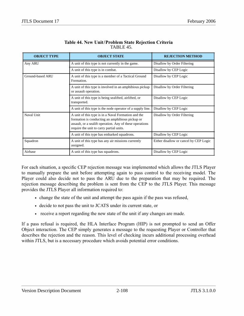
JTLS Document 17 February 2006
Table 44. New Unit/Problem State Rejection Criteria
For each situation, a specific CEP rejection message was implemented which allows the JTLS Playerto manually prepare the unit before attempting again to pass control to the receiving model. ThePlayer could also decide not to pass the ARU due to the preparation that may be required. Therejection message describing the problem is sent from the CEP to the JTLS Player. This messageprovides the JTLS Player all information required to:
• change the state of the unit and attempt the pass again if the pass was refused,
• decide to not pass the unit to JCATS under its current state, or
• receive a report regarding the new state of the unit if any changes are made.
If a pass refusal is required, the HLA Interface Program (HIP) is not prompted to send an OfferObject interaction. The CEP simply generates a message to the requesting Player or Controller thatdescribes the rejection and the reason. This level of checking incurs additional processing overheadwithin JTLS, but is a necessary procedure which avoids potential error conditions.
TABLE 45.
OBJECT TYPE OBJECT STATE REJECTION METHOD
Any ARU A unit of this type is not currently in the game. Disallow by Order Filtering
A unit of this type is in combat. Disallow by CEP Logic
Ground-based ARU A unit of this type is a member of a Tactical GroundFormation.
Disallow by CEP Logic
A unit of this type is involved in an amphibious pickupor assault operation.
Disallow by Order Filtering
A unit of this type is being sealifted, airlifted, ortransported.
Disallow by CEP Logic
A unit of this type is the node operator of a supply line. Disallow by CEP Logic
Naval Unit A unit of this type is in a Naval Formation and theformation is conducting an amphibious pickup orassault, or a sealift operation. Any of these operationsrequire the unit to carry partial units.
Disallow by Order Filtering
A unit of this type has embarked squadrons. Disallow by CEP Logic
Squadron A unit of this type has any air missions currentlyassigned.
Either disallow or cancel by CEP Logic
Airbase A unit of this type has squadrons. Disallow by CEP Logic
Version Description Document 2-108 JTLS 3.1.0.0

February 2006 JTLS Document 17
2.42 JTLS-2005-1596 Correct USMTF Air Mission Reports
2.42.1 Summary of Model Change Request
External United States Message Text Format (USMTF) programs and reports required an additionaldata element to identify Air Defense objects that are members of the AIR DEFENSE CLASS entity.These identifiers are needed to pass Mission Report (MISREP) data among external programs,including members of the JMRM federation.
2.42.2 Design Summary
The SAFIRE set of the MISREP message requires that the type of Air Defense asset that fired at themission must be specified and the asset type must exist in an specific USMTF table. A new dataparameter was added to the model to solve this problem, but this solution does not resolve the issuefor future systems. For example, the JWFC scenario used to test the MISREP contains an enemy AirDefense site for which the USMTF table has no entry. Listing the asset type as UNK or Unknown isthe only available option.
Although a user-specified name for the AIR DEFENSE CLASS entity may be stored in the ADNAME attribute, the AD USMTF NAME attribute provides the specific USMTF name by which allexternal USMTF programs and reports will reference the Air Defense object defined by this entity.
2.42.3 Data Changes
To support this design, a new attribute, AD USMTF NAME, was be added to the Air Defense Classpermanent entity.
2.43 JTLS-0011 Default Status for HRU: Covert Unit Report
This ECP requests that the covert status of an HRU be available on the GIAC SITREP, and wasduplicated by the model functionality requested by JTLS-2005-1715 SITREP Provides Covert HRUInformation.
The GIAC and GENIS have been removed from the JTLS system. However, the WHIP includes aSITREP component that performs the same function as the GIAC SITREP. When his ECP wassubmitted, the HRU IMT screen provided the only means to determine the covert status of an HRU.
The WHIP SITREP definition file for HRUs was modified to include the HRU Covert status.
Table 46. HRU Definition File for WHIP SITREP
ATTRIBUTE DESCRIPTION
Name Name of the unit
Object Class Object Class of the unit
Location The last known location of the unit
JTLS 3.1.0.0 2-109 Version Description Document
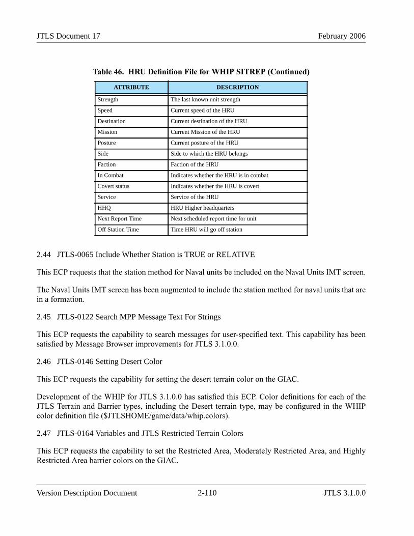
JTLS Document 17 February 2006
2.44 JTLS-0065 Include Whether Station is TRUE or RELATIVE
This ECP requests that the station method for Naval units be included on the Naval Units IMT screen.
The Naval Units IMT screen has been augmented to include the station method for naval units that arein a formation.
2.45 JTLS-0122 Search MPP Message Text For Strings
This ECP requests the capability to search messages for user-specified text. This capability has beensatisfied by Message Browser improvements for JTLS 3.1.0.0.
2.46 JTLS-0146 Setting Desert Color
This ECP requests the capability for setting the desert terrain color on the GIAC.
Development of the WHIP for JTLS 3.1.0.0 has satisfied this ECP. Color definitions for each of theJTLS Terrain and Barrier types, including the Desert terrain type, may be configured in the WHIPcolor definition file ($JTLSHOME/game/data/whip.colors).
2.47 JTLS-0164 Variables and JTLS Restricted Terrain Colors
This ECP requests the capability to set the Restricted Area, Moderately Restricted Area, and HighlyRestricted Area barrier colors on the GIAC.
Strength The last known unit strength
Speed Current speed of the HRU
Destination Current destination of the HRU
Mission Current Mission of the HRU
Posture Current posture of the HRU
Side Side to which the HRU belongs
Faction Faction of the HRU
In Combat Indicates whether the HRU is in combat
Covert status Indicates whether the HRU is covert
Service Service of the HRU
HHQ HRU Higher headquarters
Next Report Time Next scheduled report time for unit
Off Station Time Time HRU will go off station
Table 46. HRU Definition File for WHIP SITREP (Continued)
ATTRIBUTE DESCRIPTION
Version Description Document 2-110 JTLS 3.1.0.0
February 2006 JTLS Document 17
Development of the WHIP for JTLS 3.1.0.0 has satisfied this ECP. Color definitions for each of theJTLS Terrain and Barrier types, including the Restricted Area barrier type, may be configured in theWHIP color definition file ($JTLSHOME/game/data/whip.colors).
2.48 JTLS-0183 GENIS Client Report Host Name Report
This ECP is a request for a GENIS improvement. The GIAC and GENIS have been removed from theJTLS system. However, the intent of this ECP was addressed during the implementation of the JTLSData System Protocol (JDSP) and the JDS Object Distribution Authority (JODA). The JODAimplements a show peers command that lists the connected peers, previously known as GENISclients. This listing includes the peer name, peer class, routing socket, and the name of the host that isexecuting the peer. From the Web Services Manager, simply open a telnet session to the JODA. Onthe telnet session screen, enter the command "show peers". A list of lists is then provided.
2.49 JTLS-0188 Provide MPP Error Messages for Bad Strings
This ECP requests a Message Processor Program improvement to display an error message to the userwhen an error is encountered while transforming a message. Previously, no error indication wasdisplayed and the previous message remained in the message display.
The implementation of the WHIP Message Viewer and the XML Message Service (XMS), hasovercome problem identified in this ECP. The XMS and Message Viewer are designed to displayindications when an error is encountered while a message is transformed from XML format to thedesired displayed form (currently English or MTF).
2.50 JTLS-0292 Expand Command Authority Report
This ECP requests that the Command Authority report be modified to provide additional capabilityfor the user to view which WHIPs have Command Authority over units, including the WHIP thatissues the report.
The Command Authority data in JTLS 3.1.0.0 is defined in the JDSP protocol as persistent data. TheCommand Authority information is therefore available for display from an IMT screen.
A IMT screen was created to permit the Player to view the current Command Authority for units onthe Player’s side. The IMT screen has three Quick buttons that display the Command Authority forthe same Unit, Side, and WHIP. The Controller as well as the side Player has access to the CommandAuthority IMT screen.
2.51 JTLS-0303 Allow Model to Refuse Client Connections
This ECP requests a Generic Data System (GDS) protocol and GENIS capability to allow the modelto refuse a connection request from a client. The GDS and GENIS have been removed from the JTLSsystem.
JTLS 3.1.0.0 2-111 Version Description Document

JTLS Document 17 February 2006
The intent of this ECP is incorporated in the design of the JTLS Data System Protocol. The JDSPdefines a client as a peer. The model can refuse a peer’s registration and the peer will be notified thatits registration has been denied.
2.52 JTLS-0319 JTLS Playbox Outline
This ECP requests that an outline of the JTLS terrain be rendered on the map when the WHIP Map isset to a scale that does not show the terrain hexes. This capability provide a user reference to the edgeof the map when zoomed out to large scales.
The requested capability was delivered with JTLS 3.0.0.0.
2.53 JTLS-0444 UOM Distance Option
This ECP requests corrections to the GIAC UOM selection and data entry. The Unit Of Measurebutton for the Radius field on the GIAC Fire Artillery order template can select kilometers, nauticalmiles, feet, meters, and miles. This filed allowed a minimum value of 10, which is appropriate onlyfor feet and meters. Selecting the other optional units would specify a large fire mission radius thatpermitted virtually no damage. In this case, and probably in others, another distance selection isrequired that only includes feet and meters.
This ECP has been satisfied by implementing JTLS-0554 Multiple Units of Measure.
2.54 JTLS-2005-1639 Add Speed To HRU IMT Panel
This ECP requests that the current speed of an HRU be added the HRU SITREP. This capability wasdelivered with JTLS 3.0.0.0.
Version Description Document 2-112 JTLS 3.1.0.0
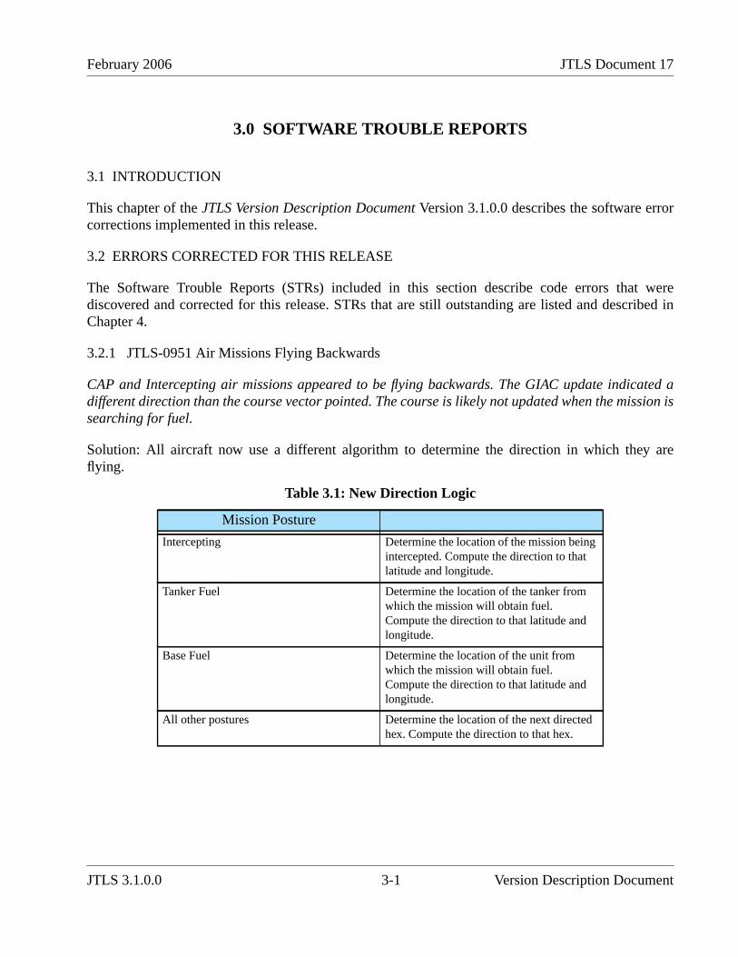
February 2006 JTLS Document 17
3.0 SOFTWARE TROUBLE REPORTS
3.1 INTRODUCTION
This chapter of the JTLS Version Description Document Version 3.1.0.0 describes the software errorcorrections implemented in this release.
3.2 ERRORS CORRECTED FOR THIS RELEASE
The Software Trouble Reports (STRs) included in this section describe code errors that werediscovered and corrected for this release. STRs that are still outstanding are listed and described inChapter 4.
3.2.1 JTLS-0951 Air Missions Flying Backwards
CAP and Intercepting air missions appeared to be flying backwards. The GIAC update indicated adifferent direction than the course vector pointed. The course is likely not updated when the mission issearching for fuel.
Solution: All aircraft now use a different algorithm to determine the direction in which they areflying.
Table 3.1: New Direction Logic
Mission Posture
Intercepting Determine the location of the mission beingintercepted. Compute the direction to thatlatitude and longitude.
Tanker Fuel Determine the location of the tanker fromwhich the mission will obtain fuel.Compute the direction to that latitude andlongitude.
Base Fuel Determine the location of the unit fromwhich the mission will obtain fuel.Compute the direction to that latitude andlongitude.
All other postures Determine the location of the next directedhex. Compute the direction to that hex.
JTLS 3.1.0.0 3-1 Version Description Document

JTLS Document 17 February 2006
3.2.2 JTLS-2006-1641 Unable To Cancel Holding Posture Missions
An Insert/Extract mission was ordered to pick up an HRU and wait at the pickup point until aspecified time. Prior to the departure time, the Player canceled the mission. The mission assumed aHeading Home posture, but remained on the ground. Additionally, the Load Offload Complete eventassociated with the original departure time was not modified. At the original departure time, theoriginal event executed, but could not handle the new posture of Heading Home, and an errormessage was printed. The mission remained on the ground at its original pickup point with a postureof Heading Home. Due to this posture, other attempts to cancel the mission were ignored.
Solution: Code was added to find, reschedule, and immediately execute the associated Load OffloadComplete event for an Insert/Extract mission in a Holding posture. This causes the mission to lift off,and assume the proper posture of Heading Home. Additionally, the code that produced the errormessage was modified to access the Logic Error module, which is the current methodology forhandling such situations.
3.2.3 JTLS-2006-1663 NFS-Mounted File System Makefile Errors
The makefiles for the $JSOURCE/wej/jds_protocol, $JSOURCE/wej/cpp_util, and he $JSOURCE/wej/jds_cpp directories contained errors when the directory was held on an NFS-mounted file system.This occurred when the source directories were held on a Linux file system and NFS-mounted to aSparc machine, on which a compile was performed. The makefiles move the header files to the$JTLSHOME/include directory when a push of the headers is performed. A makefile command thatchanged permissions on the original files caused the makefile to fail.
Solution: The makefiles were modified by removing the offending command, which was notnecessary to accomplish the operation.
3.2.4 JTLS-2006-1684 Crash Changing Air Mission Package Ingress Route
A segmentation violation occurred when a JTLS 3.1 air mission package Ingress Route was changed,which indicated a corrupted stack. The stack was corrupted by passing an integer to a subroutine thatexpected a double variable. The error existed in JTLS 3.0, but did not manifesting itself as a crash.However, other unnoticed JTLS 3.0 problems may have occurred due to this error.
Solution: The code was modified to apply the proper mode to variables used in the subroutine calls.
3.2.5 JTLS-2006-1687 Incorrect Associated Unit On Air-Ground Attack Mission
An Air-Ground Attack mission instructed to attack an enemy unit listed its homebase as the associatedunit within the IMT Air Mission screen. The Help text for this field clearly stated that the enemy unitshould be listed.
Version Description Document 3-2 JTLS 3.1.0.0

February 2006 JTLS Document 17
Solution: The Help text did not reflect changes to the manner in which an air mission’s associated unitis currently used within JTLS. For an Air Ground Attack mission, the value of associated unit will bedetermined by the following criteria: (1) the alternate airbase/emergency refuel unit if specified on theorder, (2) the mission’s home base, if one exists, and (3) the mission’s squadron. The IMT screenHelp text was updated to reflect this new convention.
3.2.6 JTLS-2006-1688 Inconsistent Track ID Between JODA And GENIS
An inconsistency existed in the method that Track IDs, which are derived from the Force Siderelationship, were handled between the packets sent to the JODA and the GENIS. The JODA andGENIS interface codes received the same packets from the CEP. When the GENIS received a track IDupdate, it expected the CEP to also send a Side relationship, which it translated to a Track ID. TheJODA expected the CEP to send a translated Track ID. Therefore, one of these programs wouldperform an incorrect translation. In some cases, the CEP sent these data correctly for the JODA; inother cases they were correct for the GENIS.
Solution: The CEP code was modified to send the Side relationship to both the GENIS and JODAinterface codes. The JODA interface code was modified to perform the translation from the Siderelationship to track ID. This problem existed only in JTLS 3.0, due to the introduction of the JODA.This error was not evident in JTLS 3.1 versions because the interface code was redesigned.
3.2.7 JTLS-2006-1689 Aircraft Maintenance Records Not Deleted From IMT
Owning Side aircraft maintenance records were not deleted from the WHIP IMT, and Controllerrecords were deleted. Thus, the owning Side perceived all aircraft maintenance records since gamestart, including those records for which the aircraft had already left maintenance.
Solution: When the JODA Interface encodes a packet for the JODA, it also encodes the perception(which Sides should receive the packet). The perception was set after the delete packet was encoded.Thus, the perception was omitted from the packet and defaulted to Controller Only. The code wasmodified to set the perception before the packet was encoded.
3.2.8 JTLS-2006-1690 Unable To Extend Aircraft Maintenance Times
An order was sent to extend the maintenance time of aircraft in maintenance. The order was accepted,but the IMT did not reflect the change. The aircraft were removed from maintenance at the originalEnd Maintenance time.
Solution: The underlying logic of the routine that adjusts the maintenance times was correct. Use ofthe event global variable caused this error. This variable can be changed by the system when theattributes of an event are accessed. The code used the global variable to schedule an event, access anattribute of another event (which could reset the variable), then initialize the event for the JODA. Thiscode was modified to use local variables.
JTLS 3.1.0.0 3-3 Version Description Document
JTLS Document 17 February 2006
3.2.9 JTLS-2006-1691 Missing Spaces In Message Strings
Query Delivery List and HRU Logistics Report orders generated a bad message for the Player. Due tothe error in the message string, the message was not delivered to the Player, but was written to adebug file and included the error message.
Solution: Both messages were due to missing spaces between data items within the message string.The code was corrected to properly format the message string.
3.2.10 JTLS-2006-1692 Unable To Change Transfer Aircraft Egress Route
A Transfer Mission order can specify an Egress Route for the mission. This is the route that themission follows to its new home squadron. A Change Air Mission Parameter order that changed theEgress Route was ignored. Also, changing the mission’s Ingress Route, which is not specified on theorder, deleted the original Egress Route, and the new Ingress Route was used to return to the newhome squadron.
Solution: The Egress Route specified on the order is used by the code as an Ingress Route, whichcauses Player confusion. The Transfer Mission order panel was modified to identify this route as anIngress Route. Although this convention does not match real-world terminology for this mission type,preventing Player confusion is a priority.
3.2.11 JTLS-2006-1693 Situation Report Truncated Location Coordinates
The English language version of the Situation Report message truncated location coordinates to 20characters. Locations are expressed to the nearest tenth of a second, which requires 24 characters inthe JTLS format.
Solution: The English message definition file was modified to use 24 characters for the location. Theheader for the message and the formatting of the other columns were modified to limit each line to 80characters.
3.2.12 JTLS-2006-1694 Missing Convoy Problem Report Sylesheet
The XMS generated an error indicating a missing stylesheet for Message 4110, a Convoy ProblemReport. This report is generated to indicate problems moving a unit by truck convoy.
Solution: The message was defined in the English message definition file, but not in the MTF messagedefinition file. The stylesheets used by the XMS to format a message are derived from the MTFmessage definition file. The message was added to the MTF version.
Version Description Document 3-4 JTLS 3.1.0.0
February 2006 JTLS Document 17
3.2.13 JTLS-2006-1695 JODA Version SDC Used Modified Table Names
JTLS 3.0 supports two Scenario Data Clients (SDCs). One version obtains data from the JODA, theother from the GENIS. This allowed users to maintain functionality during the transition from theGENIS to the JODA. However, to maintain these versions and execute them simultaneously, the JODAversion was written with modified Oracle table names (such as railroad_jds_data instead of theGENIS version railroad_data). To facilitate the transition to JTLS 3.1, the JODA version should usethe historical names.
Solution: The table names were changed to historical names. Simultaneously running both versions ofthe SDC on the same Oracle tablespace is unnecessary and should be avoided.
3.2.14 JTLS-2006-1722 Improper Argument Modes In Routine Calls
When a Simscript routine is called, the passed and yielded arguments are placed on a memory stack.The called routine accesses data from the stack based on its expected arguments. If the mode of anargument in the calling routine does not match the mode within the called routine, it is possible thatother data within memory will be corrupted, which can cause a crash or improper logic sequenceswithin the model. The Simscript compiler does not detect instances of this situation, and the numberof calls within the CEP makes manual verification difficult. However, several instances of impropercalling modes have been discovered within the CEP.
Solution: The solution to this problem is twofold: the discovered errors have been fixed, andprocedures are being developed to automatically check for this problem. We plan to incorporate theseprocedures into our pre-release checking. The problems were identified with a prototype version ofthis tool.
JTLS 3.1.0.0 3-5 Version Description Document

JTLS Document 17 February 2006
Version Description Document 3-6 JTLS 3.1.0.0
February 2006 JTLS Document 17
4.0 REMAINING ERRORS
4.1 INTRODUCTION
Every effort has been made to correct known errors in the model. All reproducible errors that resultedin a CEP catastrophic software failure (Crash) have been corrected. Other corrections were prioritizedand completed according to their resource cost-to-benefit relationship.
Correction of the remaining STRs, however, must be postponed to a later version due to time andresource constraints. These problems may be corrected prior to the next release of JTLS. If animmediate need arises for a code correction to any of these outstanding STRs (i.e., for an exerciseplanned to occur before the next release), contact the JTLS Configuration Management Agent. (Referto the Abstract of this document for the current address.)
Note that all STR tracking numbers reported with previous JTLS version deliveries have beenreplaced to reflect the JTLS Project ID numbers used by the JWFC Rational Unified Platform (RUP)database. This software change management system was implemented in June 2005, and containsrecords of functional enhancements and errors for JTLS versions 2.5 and later.
4.2 REMAINING ERRORS
The errors described in this section should be noted specifically because they affect the basicfunctionality of JTLS. Information is provided regarding the extent of the error, as well as suggestionsto avoid or minimize the effects of the problem.
4.2.1 JTLS-0639 Error Determining When Engineering Task Completed
When a Unit starts a directed Engineering Task, the time to complete the task is based on the Unitbeing at 100%. The time to complete a task is adjusted for the Unit’s COMBINEDEFFECTIVENESS. Stronger units complete tasks faster than do weaker units. The task completionevent is then scheduled at the computed time. At this scheduled completion time, the code checkswhether enough time has actually elapsed to complete the task. If the Unit was at more than 100%COMBINED EFFECTIVENESS when the task started (meaning the task completed earlier than ifthe Unit were at 100%), it appears to the model that not enough time has passed and the task is notcredited as complete.
4.2.2 JTLS-0695 Shadow Distance Of Zero Overriding Protection Radius
In the routine SEND INTERCEPTOR, the model is determining which interceptor to send. If this is aprotection radius CAP mission, it gets the minimum of PROTECTION RADIUS and SHADOWDISTANCE. If this is zero, then the logic says there is really an infinite protection radius. This seemsodd. If someone forgets to set SHADOW DISTANCE, then protection radius is ignored. As a
JTLS 3.1.0.0 4-1 Version Description Document

JTLS Document 17 February 2006
minimum, this needs to be either documented or changed so that a zero SHADOW DISTANCEmeans ignore shadow, not make protection radius infinite.
4.2.3 JTLS-0696 Missions Ignoring Assigned Altitude on Egress
Why aren’t missions observing their assigned altitudes on a egress path? Somewhere the posture ofthe mission was changed to HEADING HOME when it is on its egress route. This causes the missionto automatically set its altitude to avoid air defense.
4.2.4 JTLS-0697 Missions On The Ground With Invalid Destination
Missions on strip alert report a next destination latitude/longitude on the IMT. The destinationcoordinates should be cleared for missions on strip alert.
4.2.5 JTLS-0698 Cannot Re-Activate Destroyed Targets
Some facility targets are 0% capable and not displayed on the GIAC. They need to be reactivated forthe ATO. Activation cannot be done with Controller Change Target because their GDS active flag isset to zero.
4.2.6 JTLS-0699 Targets That Require An Owner Are Disassociated
Targets owned by an HRU that die in combat are disassociated from the HRU and from theirassociated unit. When a checkpoint is taken, both fields are written as NONE. On restart, this causes acrash for ADA targets.
4.2.7 JTLS-0700 GIAC Not Displaying Current Runway Length
A runway has 21% strength, but the GIAC displays the maximum length and current length as equalto the maximum length. In the GENIS, the percent capable is reduced, but the range and currentlength values are the same. The model does not appear to update the current length to the GDS whenit changes.
4.2.8 JTLS-0701 Air Movement Report Does Not Consider Hold Points
When an air movement report is requested, it does not take into consideration scheduled delays in thedelivery instructions. As a result, it indicates an earlier departure time at each point, and an earliercompletion time for the mission.
4.2.9 JTLS-0702 Mission Waiting For Delayed Mission
An air mission package had an attack mission that went into weapons delay. The user told anotherattack mission to join the package, but did not cancel the old mission. The new mission launched,dropped its weapons, and then turned into an Escort and waited for the old Attack mission that wasstill in Weapons Delay. The logic needs to be improved.
Version Description Document 4-2 JTLS 3.1.0.0
February 2006 JTLS Document 17
4.2.10 JTLS-0703 Periodic Report Other Side Airbases Lists No Activity
The Periodic Report Other Side Airbase Summary lists all the airbases but for each one says there areno squadrons operating there. On the GIAC, you can click on the enemy airbase and see squadronsthere. Click on the squadron and it says that the home base is the expected home base. Discrepancy isthat the periodic report in BUILD FOREIGN BASE SQUADRON REPORT looks for squadrons atthe airbase, and perceived combat system aircraft for that squadron. If no aircraft have beenperceived, then it does not count as an operational squadron. There is no check whether the squadronsare actually perceived to be associated with the airbase; truth is used instead. This provides freeintelligence. The discrepancy is that GIAC reports the home base but it does not show on the periodicreport.
4.2.11 JTLS-0704 Immediate Cancel Of Air Mission in Delay Status
During a recent exercise, the air cell sent an Air Transport Order in which the aircraft was directed toremain on the ground at its home base until a certain time. This was a error, and the controllercancelled the mission. The mission did not cancel immediately, but waited until the “holding posture”time was complete and then cancelled. The Controllers stated that the mission should have cancelledimmediately.
4.2.12 JTLS-0705 Missions Launching With Fewer Aircraft Than Available
A mission that cannot get its resources goes into the UT AWAITING LAUNCH SET CAN YOULAUNCH looks only at missions in this set. If CAN YOU LAUNCH assigns enough aircraft to meetthe acceptable launch fraction, the mission is removed from the UT AWAITING LAUNCH SET anda launch event is scheduled. Thus, once a mission gets the aircraft to launch, it will not fill up to itsfull complement even if aircraft become available.
4.2.13 JTLS-0843 Error 427
When a ship and formation was in a dual capable hex, this error message appeared in the verify:“Error 427: Formation, <name>, has been placed at hex location ###,###. This location is notspecified as water.” No error was recorded for the ship, which was located in a dual capable hex. Anerror message should not be generated if the ship and formation are in a water, dual capable, or smallisland hex.
4.2.14 JTLS-0846 Naval Unit Distance Calculation
A Player ordered naval Unit A to arrive at a point due west 100 nautical miles away at a time 12 hourslater with a speed of 10 knots. Naval Unit B was ordered at the same speed and direction to a arrive24 hours later at a destination 200 nautical miles away. Unit A arrived 1.5 hours late and Unit Barrived 3.0 hours late. The orders were repeated for both units to arrive at points 100 and 200 nauticalmiles due north. The units arrived within 15 minutes of their expected arrival time. Although a speedof 10 knots was ordered, the speed displayed for each unit in the SITREP window was 9.7 knots. The
JTLS 3.1.0.0 4-3 Version Description Document
JTLS Document 17 February 2006
model appears to not calculate the additional distance required when a unit follows an irregular pathfrom hex center to center. The problem does not appear when a unit follows a direct path from hexcenter to center in any direction.
4.2.15 JTLS-0865 Incorrect External Program Order
If a non-GIAC program sends an incorrect order to the CEP, the CEP attempts to detect the error andgenerate a Player message reporting it. The model crashed generating this message while executingan order generated by the JTLS HLA Interface Program (JHIP).
The CEP code was modified to be stable under this specific circumstance. This does not guaranteethat another erroneous order sent to the model will not cause a different problem in another portion ofthe code. Processing an order through the Order Verification Tool before submitting it to the model isthe only procedure which assures that such errors and crashes will not occur.
The JHIP condition which initially caused the problem was not a code error, but a mismatch betweenthe JHIP version in use and the version of the External Update order used by the CEP. The orderversion was updated to match the JHIP version. This problem is not considered an STR because itwas discovered in a delivered non-official interim release of JTLS.
4.2.16 JTLS-0869 Continue Engage Determination
The A CONTINUE ENGAGE parameter is not used in JTLS 3.0. Due to the complete change of theair-to-air algorithm in this version, the determination of when and how an air mission decides tocontinue the engagement needed to be redone.This was not completed prior to the release of v3.0. It isthe desire and intent of the design team to restore this capability to the model.
4.2.17 JTLS-0870 Number of Air-to-Air Combat Kills Allowed
The code allows the weapons from a firing aircraft to kill only one enemy aircraft. A specific aircraftshould be able to target and kill multiple enemy aircraft up to its weapon control capability. This iscalculated as the number of weapons fired by the aircraft divided by the maximum number ofweapons allowed per enemy.
4.2.18 JTLS-0871 AC Mission Weapon Drop Determination
Currently, an air mission drops all of its air-to-ground weapons when an aircraft is killed in air-to-aircombat if the AC Weapon Drop Flag is YES. This flag value should also allow a mission to dropsnon-precision guided weapons when it is fired upon in air-to-air combat.
4.2.19 JTLS-0906 Change ADA pE To Per-Element pE
An Air Defense Class has a Probability of Engagement (pE) against each of the Aircraft TargetClasses. If detection by a sensor on an IADS network is prompting the engagement, then the pE is
Version Description Document 4-4 JTLS 3.1.0.0
February 2006 JTLS Document 17
assumed to be 1. The following applies only to non-IADS detection and engagement attempts. Eachtime an air mission enters a hex within the SAM-AAA target altitude-range criteria, the SAM-AAAtarget attempts to detect the air mission with its fire control sensor. If the detection is successful thenthe SAM-AAA target makes a pE attempt. It doesn’t matter how many elements are in the target, onlyone detection attempt and one pE attempt are made per hex. But each element, by definition, has anindependent fire control ability.
Each fire control sensor in the multi-element target should conduct a detection attempt. For eachsuccessful attempt, a separate pE attempt should be made. Assuming there is some form of commandand control within the elements of a specific SAM-AAA target, the actual firing can still be limited toone element.
4.2.20 JTLS-0907 Scud-Like SSM Representation
It is difficult to represent the effects of long-range ballistic missiles. Different missile types havevarious levels of accuracy in the CEP. However, in JTLS the missile will always hit its aimpoint. Toreflect the inaccuracy of these missiles, it is typical to assign them an unrealistically large TW Radiusof Effects. This usually results in very low damage effects from these weapons.
A new measure of the missile’s accuracy could be added to the CEP as a new database value, and usedto randomly determine the impact point of the weapon in a region surrounding the aimpoint. Thus, theactual weapon impact effects could be properly represented within the model.
4.2.21 JTLS-0908 Naval IADS Link Representation
The IADS network for ship units is computed during the exercise as needed, based on the currentlocation of ships which have Comm Sites. In some cases this can be CPU-intensive. Currently, allship-owned Comm Sites can serve as hubs, i.e., these sites can send and receive all information. Inreality, only a few ships serve as hubs or air defense control centers for the Task Force. The otherships’ Comm Sites are used only to pass detection information to the hubs, and receive detectioninformation and fire guidance.
A new Comm Site data parameter should be added to designate that a Comm Site subcategory is ahub. A ship with a Comm Site target that is not hub-capable can link only to a ship with a Comm Sitetarget that is hub-capable. A ship with a hub-capable Comm Site target can link to any other ship withany Comm Site target, within current side and distance restrictions.
4.2.22 JTLS-0909 Display Moderate And Severe Attrition Level
There is no capability to query whether a unit is suffering Moderate or Severe Attrition Level effects.This capability should be added to the Unit Situation Report.
JTLS 3.1.0.0 4-5 Version Description Document

JTLS Document 17 February 2006
4.2.23 JTLS-0910 HRU Patrol Intel Reports
Typically, many HRUs are conducting intelligence gathering patrols simultaneously during anexercise. Too frequently, they are collecting on “ANY UNIT”. These messages are all broadcastmessages, controlled by the Intelligence selection of the Broadcast Options menu. A workstationoperator has no capability to limit received intelligence reports to only those of interest. The HRUPatrol Intelligence message should be modified from a Broadcast message to a Sending Workstationmessage.
4.2.24 JTLS-0911 Fire Artillery Wait Time Between Missions
Artillery can be fired continuously within the simulation. Ammo constraints can be played throughsupply category quantities, but frequently aren’t because logistics is not a training objective. Artillerycannot realistically fire continuously without a cool-down period and maintenance time. The crewalso needs to eat and rest at some point. The overuse of artillery during exercises has been an issue forseveral years.
Enforcing a minimum time between fire missions is a recommended capability. This could beaccomplished with a fixed database value, a database percent of the previous fire mission time, or aFLP value. As a fixed value, 10 minutes would mean no new fire mission could start until at least 10minutes after the completion of the previous fire mission. As a percentage, 25% would mean waiting2.5 minutes if the previous fire mission time was 10 minutes, or waiting 15 minutes if the previous firemission time was one hour. Fire missions that are broken up because of the combat assess or the maxfire mission time should not be subject to the wait time between the split parts of the mission. PriorityCounter-battery missions should not be subject to the wait time because they are priority missions andvery time-dependent. Just as the number of hours a day that a unit can move is limited, a similar limitcould be put on the number of hours a day that a unit can fire.
4.2.25 JTLS-0928 Weapons Selection By Aircraft
A P-3C, launched with MK 46 torpedoes and Harpoons, detected a submerged OPFOR sub andattacked with the Harpoon. No errors were noted in submarine unit characteristics and SUP. Hexdepth was 9999 ft.
4.2.26 JTLS-0929 Ship Changes Sides
A Thailand ship changed sides when a Mandatory Transfer order was given to a US ship. The ship(FFG-456) was ordered to join an AOE-2.f formation. The Mandatory Transfer order to AOE-2 togive FFG-456 50,000 gal of Cl.III Navy was rejected for the reason that FFG-456 appeared to havechanged sides.
Version Description Document 4-6 JTLS 3.1.0.0
February 2006 JTLS Document 17
4.2.27 JTLS-0934 HRU Overwatch
An HRU was created and assigned overwatch of a flying squadron. The model refused the overwatchand reported “Unit is already in land combat, and not eligible for new overwatchers.” The flyingsquadron had been attacked by terrorist HRU, which was no longer present in the area, as shown onboth U.S. and Controller views. Unit was at 84% strength. IMT showed flying squadron as being incombat. When HRU broke off, flying unit should have come out of “In Combat” posture. The HRUshould have accepted overwatch responsibilities.
4.2.28 JTLS-0942 Air Transport Cannot Combine Wet And Dry Supplies
When both wet and dry supply categories are included in the same Transport Instructions List for anAir Transport mission, they will not be transported at the same time. The first supply categoryshipment type will be loaded, but the second will not. If both are included in the same Supply List, thewet category is preferred. The aircraft go through the motions as if loading and delivering the deniedcategory, including MISREP confirmation. No pickup or delivery is made, although an empty storagearea may be created. There is no documentation to support this situation, and the user is not notifiedof the problem.
4.2.29 JTLS-0948 Lanchester Double Kills
When two opposing units’ centers are within DECISIVELY ENGAGED DISTANCE of each other,100% of the combat systems are eligible to kill each other. The combat power distribution of the unitsis used to determine which combat systems are eligible to kill units in the same or adjacent hexes thatare not co-located. This can lead to some combat systems being allocated to kill twice in a singleAssess Combat period.
4.2.30 JTLS-0949 Destroyed Target SITREP Strength Incorrect
When a target is destroyed, such as a bridge or pumper station, the GIAC SITREP still has thestrength of the target as 100. GENIS also displays strength as 100. Apparently, the percent capable isbeing updated in GENIS from JTLS, but not the strength which is used to fill the GIAC SITREP. Thisis a problem in both 1.85B and the 2.0 versions
4.2.31 JTLS-0950 JTLS Radius Of Effects
The radius of effects for air missions is not being calculated correctly. The analyst guide states thatthe radius of effects is determined by the TW.RADIUS.OF.EFFECTS of the area weapons employedand the delivery altitude of the air mission. At the max altitude for the aircraft type, the covered areais the total area for all area weapons fired. Testing has shown that the max radius of effects occurswhen the aircraft’s mission altitude is anywhere between one half the max aircraft altitude and maxaircraft altitude. In the routine, Determine Covered Radius, the area overlap calculation statementshows the max altitude multiplied by 0.5. As such, the radius of effects is not calculated correctly.
JTLS 3.1.0.0 4-7 Version Description Document

JTLS Document 17 February 2006
4.2.32 JTLS-0952 Air Report
JTLS 1.85 provided the ability to obtain the report for one squadron or all squadrons. JTLS 2.0 onlyprovides capability to get one unit at a time.
4.2.33 JTLS-0953 All Sides Informed About Supply Dump Error
Created a supply dump using the Cache Order. Looking at the GDS shows that all sides are informedabout the dump; they show up on all sides IMT. Only the controller and the side that created the dumpshould be initially informed about the dump.
4.2.34 JTLS-0954 Multiple Supply Storage Targets
A supply storage target should not be allowed to be created in the same hex as another one on thesame side. A user was able to create several open storage supply targets right on top of each other.
4.2.35 JTLS-0955 Air Lift Drop Report Message
The subject line of the message received when a player requests an air lift drop report for a missionthat has completed the lift or drop, or is not conducting a lift or drop, reads “Air Order Received,<mission name>, Cannot Comply”. It should be titled, “Air Lift/Drop Report Cannot Comply”.
4.2.36 JTLS-0956 MPP Messages For Canceled Missions In Error
If an airbase is magic moved with several squadrons on active missions that need to be canceled orwith squadrons in the middle of a self lift, the subsequent message generated for the situation hasseveral errors. The changes required are too risky during the exercise. The problem will not cause acrash, but will cause the MPP to incorrectly display the message contents.
4.2.37 JTLS-0957 Can’t Take Control Of Unowned Runways
It is impossible for anyone to take control of an unowned runway in the hex it is already in. To do thisthe controller must enter the order, but the order is not on the controller’s menu. We have tested thison a sample menu, it doesn’t crash but the runway’s owner is not set.
4.2.38 JTLS-0958 Withdrawing Units Cannot Destroy Supply Targets
There appears to be an error in the interface between the CEP routines DESTROY CACHES ONLEAVING and IS TARGET SAFE. The first calls for supply targets that are another side or BLACK,but the second always says BLACK targets are safe. This means that a unit withdrawing will neverdestroy BLACK SUPPLY TARGETS, even if they could do so. The code needs to be updated, acomplicated fix.
Version Description Document 4-8 JTLS 3.1.0.0
February 2006 JTLS Document 17
4.2.39 JTLS-0959 Logistics Report Problem
The Logistics Report will report amounts as single decimal points (e.g., “.”). This is caused by formatD(8,0), and an amount smaller than 1 ton. To correct this situation, all of the Logrep files need to bechecked to determine if it is feasible to change the D(N,0) format specifications to at least D(N,1).
4.2.40 JTLS-0960 Can’t Magic Move Airbase To Existing Airbase Location
One cannot Magic Move an airbase into a hex wherein there is a runway that is on the same side asthe airbase, and is part of the initialization database. The airbase will not automatically assumecontrol of the runway. If the runway is one that was created by Controller action, the airbase willassume control of it. If this error is causing problems for upcoming exercises, the ConfigurationManager should be contacted for a code fix to solve this problem
4.2.41 JTLS-0961 Group Ground Move Delayed To Lead Unit
There is a problem when a group ground move is sent. The directive is delayed to the lead unit. Whenthe lead unit learns about the move, it immediately tells the units in the follow-on group. This couldlead to directives being received out of order. Assume the user sends a directive at 0100 and the CEPdetermines the lead unit should receive the message at 0200. The lead unit cannot receive any otherdirectives until after 0200. The CEP ensures that directive receipt is in the same order as the user sentthe directives. This is not true for the follow-on units. If the user sent an order at 0115 directly to oneof the follow-on units, the follow-on unit could receive the 0115 directive prior to the order sent at0100. If this error is causing problems for upcoming exercises, the Configuration Manager should becontacted for a code fix to solve this problem.
4.2.42 JTLS-0962 Pass Unit Intelligence Does Not Include Update Information
Pass Unit Intelligence does not follow any of the Update Information logic, so we are not goingthrough routines such as Alter Launch New Information procedure. This can cause Air Missions tohead toward old perceived information locations if they rely totally on the information obtainedthrough Pass Unit and Pass Target Intelligence capability. If your scenario involves a side whichdepends solely on this intelligence collection methodology and the side will be sending attackmissions, the Configuration Management Agent should be contacted immediately to obtain a properfix to this problem prior to your exercise.
4.2.43 JTLS-0963 IMT Supply Category Line Disappears When Value Is Zero
Recommend that a Unit’s IMT On-Hand Supplies (OHS) specific category line remain when suppliesare gone and no Due-Ins are established.
When a unit runs out of a supply category and no Due-Ins are scheduled, the unit’s IMT On-Handsupply line for that specific category disappears from the menu. This makes it very difficult for aplayer who is controlling 40 or more unit icons and being overwhelmed at times with MPP messages
JTLS 3.1.0.0 4-9 Version Description Document
JTLS Document 17 February 2006
to keep track of exactly what supply categories need his attention or thwarts his attempts to trouble-shoot a supply problem. The constant presence of the supply category line, even if empty, will savethe Player wasted time either making early printed copies of all his unit OHS for later comparison orreferring unnecessarily to the OPM TUP/SUP to determine what empty supply categories his unitshave that require resupply. Certain supplies (i.e. fuel/targetable weapons) are critical andunnecessarily impede game execution, if not maintained at required levels for play in an automatedlogistics scenario.
4.2.44 JTLS-0964 Reporting Bridge Damage
When an aircraft conducts an air-to-ground mission against a highway bridge, damage reporting isnot consistent. When the aircraft returns and the mission report says the bridge is at 0% capability, theIMT and SITREP still report the bridge capability as 100%. When another aircraft is sent against thebridge, it flies over and doesn’t drop any munition because, according to the mission report, the targetisn’t there (it’s destroyed). When this aircraft returns, the IMT and SITREP still report the bridge at100%. Much later, although not consistently, the bridge status changes in the IMT and SITREP to 0%.If the bridge is destroyed, the IMT and SITREP should reflect the information provided in theMission Report. The problem reported is being investigated. If this is causing a problem for anupcoming exercise, the Configuration Manager should be contacted to implement a fix to the problemas soon as possible.
4.2.45 JTLS-0965 Error In Time Report For SET SP CONVOY DELAYS
When a time value of 2 hours 0 minutes is entered into any field of the SET SP CONVOY DELAYSwindow and then sent to the CEP, the MPP returns a message that shows a time of 1 hour 0 minutesinstead. This is a known round-off error. A solution is being investigated.
4.2.46 JTLS-0966 Incorrect Mission Report Locations
Some mission report locations appear to be incorrect. The ADA engagement location is an example.The problem is being investigated.
4.2.47 JTLS-0967 Fire Mission Not Deleted From GENIS
It appears that, in some circumstances, an Artillery Fire Mission that has been reported to the IMT isdeleted from the CEP without the GENIS being informed. This happened in the case of a unit thatwas moving when it was supposed to fire the mission. The Fire Mission still showed on the IMTseveral hours later.
4.2.48 JTLS-0968 Inconsistency Between Regular Run And Pusher
There is a major inconsistency between a regular run and a run created using pusher. When an orderwith ASAP is sent, the READ KEYWORD routine sets the data parameter to TIME.V. When pusherreads in the order, TIME.V is much earlier than it was when the order arrived in the first place. For
Version Description Document 4-10 JTLS 3.1.0.0
February 2006 JTLS Document 17
orbiting missions and alert missions, this alters when they will go off alert by a great deal. This mustbe fixed and made consistent. It appears that both TIME.V and order receipt time must be saved to theci1 file to accomplish this task.
4.2.49 JTLS-0969 Changing Mission On Alert
When a ship moves, it changes the attributes of missions that are on alert. It also needs to change alerthex for those missions that are not currently on alert, but still have their alert hex pointing to the ship’slocation.
4.2.50 JTLS-0970 Availability Of Aircraft
When a unit loses a fraction of an aircraft to Area Fire or Lanchester combat, the whole aircraftbecomes unavailable for air missions. However, the report of Available Aircraft on the IMT isexpressed in whole numbers. This may result in a unit incorrectly showing a damaged aircraft asavailable.
4.2.51 JTLS-0971 Ship Continuous Tracking Not Working
The new unidentified object design indicates that ships which are continuously tracked will not haveunidentified objects created. A continuously tracked Naval unit and all of its targets are creatingunidentified objects. They should not be doing this.
4.2.52 JTLS-0972 Air Mission Find In Middle Of Ocean
A user does a find on a pre-launched air mission that is home based on a moving Naval unit. The Xmarking the location of the pre-launch mission is where the Naval ship was when the order enteredthe system. As the ship is moving, the new location of the pre-launch mission is not being sent toGENIS and thus GIAC.
4.2.53 JTLS-0973 Periodic Report Air Supplies And Fuel Not Correct
The arrays which hold air supply usage are not being maintained correctly given the new MISSIONRESOURCE ALLOCATION event.
4.2.54 JTLS-0974 Submarine Detection By Ground Sensors
A moving submarine does not get full credit for coverage time by sonars on board other ships orsubmarines. It gets full coverage time for airborne sensors but not ground based sensors.
4.2.55 JTLS-0975 GDS Target Update Error
When the CEP accomplishes a GDS Target Update, the GENIS ends up knowing about the re-initialized target, but the GIAC does not.
JTLS 3.1.0.0 4-11 Version Description Document

JTLS Document 17 February 2006
4.2.56 JTLS-0976 Manual Pairing And Protection Radius
The JTLS 2.1 Analyst’s Guide, Section 8.4.8.2, second paragraph discusses the rules for manualpairing of CAP missions. The paragraph states that the manual pair order will only check todetermine if the new interceptor has enough fuel and appropriate weapons before sending it.
In the model however, a manual paired mission will do the following if the intercepted mission is outof the protection radius of the interceptor. The interceptor will move one hex towards the interceptedmission, and then return to its orbit location.
4.2.57 JTLS-0977 Slightly Inaccurate Runway Length Sometimes Used
When AIRCRAFT.CLASS data are read, the takeoff and landing lengths are read in integer format.These are then assigned to the double real attributes of AIRCRAFT.CLASS. However, sometimes thedouble attributes become values slightly larger than the actual version of the integer in the database.
4.2.58 JTLS-0978 Air Missions Don't Completely Comply With Egress
Each assigned point on an air route has an associated altitude. The mission should climb (or descend)to that altitude upon reaching the point and attempt to maintain that altitude until another altitude isassigned. Air missions that have egress routes should fly from the last egress route point to home baseat the altitude assigned for the last egress route point. They are not doing so. Instead, they fly from thelast egress route point home at their Most Efficient altitude.
4.2.59 JTLS-0979 Halted Helo Squadrons Show “Mission” As MOVING
A helicopter squadron can be ordered to conduct a ground move to a new location. A helicoptersquadron that is moving will accept orders to launch aircraft. However, when it begins air operations,it stops. After the completion of air operations, the squadron does NOT resume its ordered movement.Its posture reverts to DEFEND, but its “Mission” remains “MOVING”. Since the squadron does notresume its move, its “Mission” should also revert to “DEFEND”.
4.2.60 JTLS-0980 SVP Warning 22
SVP Warning 22 reports aircraft loads whose extra fuel exceeds the aircraft’s wet carry capacity. Ibelieve the check should be changed to see if the extra fuel (carried in pods/tanks) when added to theother weapons exceeds either the aircraft’s dry carry capacity or total dry/wet carry capacity. Granted,there are other supply loads that might carry wet supplies, but in the case of extra fuel, I don’t believeit should be considered wet weight.
4.2.61 JTLS-0981 Formation With No Posture
The model crashed when a formation reached a Destination Two hex and the formation no longer hada posture. Therefore it did not know what to do. A Destination Two hex indicates that the Formation
Version Description Document 4-12 JTLS 3.1.0.0
February 2006 JTLS Document 17
should conduct its assigned Amphibious Operation, drop off its Sealifted supplies or clear mines froma minefield. The posture of the formation is used to tell the formation which of these three tasksshould be accomplished.
When the formation reached its Destination Two hex, the posture of the formation was zero;therefore, the formation did not know which of the three tasks should be accomplished.
4.2.62 JTLS-0982 GIAC Shows HRU Mission Moving After Move Complete
The GIAC Message Box Unit SITREP for an HRU continues to show a Mission of MOVING whenmovement is complete. Unit Posture changes to DEFEND. ARU SITREPs are displayed with both aMission and Posture of DEFEND.
4.2.63 JTLS-0983 IMT/GIAC Show Insert/Extract Mission Flying
IMT and GIAC show Insert/Extract Mission flying at zero feet from Insert/Extract to next TransitPoint. Also between some Transit points. Radar detection reports correct altitude.
4.2.64 JTLS-0984 IMT Doesn’t Add Unit Names
IMT - Intelligence - Foreign Units will display the current list of identified Foreign Units and willupdate information about them while the Foreign Unit Information window remains open. However,if a new Foreign Unit is identified, that unit does not get added to the list in the open window. A newForeign Unit Information Window must be selected to obtain the current list of identified units.
4.2.65 JTLS-0985 PSYOP Results Multiplier
The PSYOP Results Multiplier was referred to as the PSYOP Effects Multiplier four times in the DataRequirements Manual (DRM) and three times in the Analyst’s Guide. Although listed in the DRM,the PSYOP Results Multiplier could not be accessed in the DDS. It appeared to default to 1.0 in thegame for all units. Controller - Set Individual Unit Parameters permitted entries from 0.00 to 1.00, butall entries below 0.50 were converted to 0.50. The DRM showed aUT.PSYOP.RESULTS.MULTIPLIER range from 0.001 to 999999.99.
4.2.66 JTLS-0987 Set Periodic Report Times
The Controller has the ability to change both the frequency of Periodic Reports and the number ofPeriodic Reports between Summary Reports. However, there exists no ability to specify when thenext Periodic Report should be, or which of the next reports should be a Summary Report. As anexample, if the Controller wishes the blue side to receive Periodic Reports every 8 hours starting at0600, and wants the Summary Report to be produced at 1400, then they must set the time betweenperiodic reports to 6 hours, and reset it to 8 hours after the 0600 report. Additionally, the number ofPeriodic Reports between Summary Reports must be set to 2, and then reset to 3 after the 1400reports. An easier method should exist to accomplish such a task.
JTLS 3.1.0.0 4-13 Version Description Document

JTLS Document 17 February 2006
4.2.67 JTLS-0988 Can’t Repair Naval Catapults
Naval Units cannot repair their catapults because they do not know they have a repair capability.
4.2.68 JTLS-0989 Controller Damaged Aircraft Not In Periodic Reports
When a Controller kills an Aircraft, the model does not tally, therefore the current periodic reportdoes not report the kill. The categories of kills do not logically cover the Controller killed aircraft.The Post Processor Reports do include the Controller killed aircraft. This improvement can be madein at least two ways. First the current Aircraft Kill Periodic and Summary Reports can be expanded toinclude a category for Controller killed aircraft. A second solution is to remove the Periodic andSummary Aircraft Kill Periodic and Summary reports, and get the data from the Post Processor.
4.2.69 JTLS-0993 Weapons Report on Mission Report
When a Player uses the Change Air Mission Parameter order to modify a mission’s weapon load priorto takeoff and the order is implemented, the Mission Report does not always reflect the change. In atleast one case, when the final Mission Report was received, the only weapon listed was the newweapon that was added. The report also incorrectly showed that zero of those weapons were returnedwhen none were actually fired. The mission fired several weapons from the original load, but none ofthose weapons were listed in the final report, even though they were fired.
4.2.70 JTLS-0994 HRU Creation Target Requirements Assessed Incorrectly
If an HRU that is to be created and extract targets from its parent unit cannot find a target that is 100%capable, it will refuse creation, even if the parent has a 12-element target that is 97% capable and theHRU needs only one element.
4.2.71 JTLS-0999 Cancel Naval Mission Fails When A Unit Is Specified
The Cancel Naval Mission order allows either a unit or a formation to be entered. However, ifanything other than a formation is entered, the order is rejected on the grounds that the formation doesnot exist.
4.2.72 JTLS-1006 Clearing Player Orders Also Clears User Lines
If orders are cleared while Starting a scenario, both private and shared user lines are cleared.
4.2.73 JTLS-1010 Controller Cannot MM NEUTRAL Unit Onto Formation
The Controller cannot Magic Move a unit onto a Formation unless both FS FS RELATIONSHIPs areFriendly. A player can pick up a unit via AMPHIBIOUS PICKUP as long as the relationships are noworse than Neutral. The Controller should have the same capability. However, all implications mustbe considered before implementing this solution.
Version Description Document 4-14 JTLS 3.1.0.0
February 2006 JTLS Document 17
4.2.74 JTLS-1017 Airlift Mission Problem
An airlift mission was created to pick up a NEO icon. The mission did not have the lift capacity to liftthe entire icon, so a second mission was created to pick up the same icon. The second mission wentinto unit delay when it arrived at the pickup location. The first mission picked up then dropped off thefirst load, then returned for the second load. The second mission should not have gone into unit delaystatus.
4.2.75 JTLS-1090 GIAC Fields Allow Spaces
Most GIAC fields are forbidden from having spaces in them. There are a few text fields that do havespaces, generally free format read fields. It is possible to cut text with spaces from one of these fieldsand place it in a field that does not permit spaces. The resulting order, if sent, is not recognized by theCEP and is rejected. An example of this is the Controller Kill Aircraft order which contains aREFERENCE field that should not have blank spaces and a REASON field that is permitted blankspaces. Cutting and pasting from the REASON field to the REFERENCE field will allow theintroduction of blanks into the REFERENCE field.
4.2.76 JTLS-1258 RECCE Mission Heading Off The Board
When a Player submitted a Change Mission Parameter for a RECCE Mission, and clicked the new oradd on route button, but did not send a new or add on route or location, the Mission headed forLatitude/longitude 0.00, 0.00. The problem was caused by the Player error. Correcting the errorrequires changing the structure of the order, because the New-Add-on Flag is used for either a newsearch location or a new search route. A new flag will probably need to be added.
4.2.77 JTLS-1260 EMCON Order Problem Subordinates of Embarked Units
If the primary Unit specified on an EMCON order is embarked on a ship, the CEP rejects the order,even if the order is supposed to apply to subordinates as well. A possible solution is to take the UNITCHECKS off the order itself, and put them in the code that turns the emitter on and off. The only timethat the order should be denied is for a unit that has been wiped out, and it has no subordinates, and isnot in anyone’s UT SUBORD SET. If this is done a possible problem is having the IMT show thesensor/jammer turned on while the unit is still not arrived, or is embarked on a formation. Thereappears to be no problem inside the CEP, but the IMT bit is the reason that it has not been fixed. Theplayers have a work-around—Magic Move the unit ashore, send the order, and then MM back ontothe formation.
4.2.78 JTLS-1328 SAM/AAA Initial Issue
Currently, when a SAM/AAA target comes into the game, either at game start, TPFDD arrival aftergame start, or target create; the owning unit or associated unit sends the initial issue of ammo to thetarget site by an implicit resupply action. This implicit resupply convoy requires time to dispatch,time to travel, and time to receive. In Standard Database this means it is 2.5 to 3.5 hours after a SAM/
JTLS 3.1.0.0 4-15 Version Description Document
JTLS Document 17 February 2006
AAA target arrives in the game before it has any ammo and is able to engage an air object; even if it’sin the same hex as the owning unit. There is no reason for this restriction. A SAM/AAA target shouldbe given its initial issue of ammo instantaneously upon arrival in the game. The owning or associatedunit should still have its supply levels decremented based on the supplies that it passes to the SAM/AAA target.
4.2.79 JTLS-1341 Assign Multi Attack Order
An OAS mission was assigned a set of targets using Assign Multi Attack order. After the order wassent, that set of targets was deleted and a new set was assigned. The mission proceeded to the areawhere the old targets were located, then headed toward the new targets. and not drop on either set oftargets. The mission should have headed toward new target area immediately after targets wereassigned.
4.2.80 JTLS-1351 Air Missions Refuel And Fly At Zero Altitude
When specifying ingress and egress routes for an air mission, it is possible to specify refuel points andtransit points. A transit point requires an altitude. A refuel point does not have an associated altitude.However, both types of points are filed with the air mission with their associated altitudes, which iszero for the refuel point. After a mission reaches a refuel point, it will adopt the altitude of the point,zero feet, for its next leg.
When a refuel point is filed in the air mission’s route set, the Player should assign it the same altitudeas the previous Player-designated route point. This is only useful only if such a point exists. This is apartial solution only, and this STR should not be considered closed.
4.2.81 JTLS-1364 ROE Setting Unstable
During exercise TF05, nine Navy P3C squadrons were set to an ROE of HOLD FIRE. The first ninemissions returned and reported launching all of their Harpoon missiles. The Player observed that theROE appeared to reset itself to FIRE. The opposite change occurred when the Player set the ROE toFIRE, and used the IMT to confirm the setting. Thus, several attacks were required to cause theaircraft to launch a Harpoon or torpedo.
4.2.82 JTLS-1368 Orbiting OAS Assign Target
During exercise TF05, an Orbiting OAS mission was assigned to strike a SAM target. The Sideperception was bad, and the SAM target was not in the hex indicated by the Blue side perception.Receiving an Assign Target order, the mission went to the hex and searched for the target. It remainedin the hex until almost out of fuel, then went to a tanker. After refueling, the mission returned to thehex to search for the target again. This continued until the mission off-station time. The missionshould have determined that the target was not in the hex and returned to its home squadron.
Version Description Document 4-16 JTLS 3.1.0.0

February 2006 JTLS Document 17
4.2.83 JTLS-1375 Orbit Location In Ingress Route
If an air mission is tasked by the ATOT and flies toward an orbit point, the mission cannot be divertedto a new location until the aircraft reaches its ATOT-assigned orbit point. Assigning a new orbitlocation should be possible at any time and the mission should immediately comply.
4.2.84 JTLS-1376 Fuel Chits
During exercise TF05, fuel chit data fields for individual receiver or supplier air missions were notpopulated. The fuel conversion factor is incorrect, and should be 6.5 pounds per gallon.
4.2.85 JTLS-1377 Attack Posture Heading Home
In several instances during exercise TF05, an air mission displayed an Attack posture while theaircraft headed home. The aircraft received an Assign Target order, and either did not find the targetand held its munitions, or released them and headed back to the base. The attack mission could not bere-flight planned, and should have displayed a Heading Home posture.
4.2.86 JTLS-1378 Mission Refuel Chit Retrieval Button Does Not Work
Refuel chits do not appear when the Refuel Chit retrieval button on the IMT screen is used. However,they appear when the user requests a retrieval of all refuel chits.
4.2.87 JTLS-1379 Improve Mission Splitting Capability
When the ATO-T splits missions automatically, the program changes the missions’ Mode 2 and Mode3 squawk, call sign number, and mission number. It is preferable to concatenate an alphabeticidentifier to the original mission number. Also, we must develop a method to inform TBMCS thatonly a portion of the mission has returned to the base.
4.2.88 JTLS-1380 Intercept Stopped for Refuel Chit Time
An intercepting mission will break off its intercept to refuel from a tanker on time according to itsrefuel plan.
4.2.89 JTLS-1381 Mission Stops Moving After Break-off Intercept
An air mission stops moving after receiving a Break-off Intercept order. When a mission in this modereceives a change Orbit Location order, the missions bar points in the wrong direction.
4.2.90 JTLS-1382 TBMCS ATO ID Problems
These problems arise from assigning an air mission a specific ATO ID. ATO time round-off resultscause many missions designated to start immediately at the beginning of an ATO period to beassigned to the wrong ATO period. Additionally, the ATO periods were not continuous within the
JTLS 3.1.0.0 4-17 Version Description Document
JTLS Document 17 February 2006
model. For example, when an ATO period was designated to end at 1.333 days, the following periodwas started at 1.334 days. Any missions designated a mission time of 1.3335 days were not includedin an ATO period.
4.2.91 JTLS-1383 Alert Missions Display On COP
Alert missions displayed on the GIAC causes them to display on the COP, which is inappropriate. Themissions were placed on the GIAC display to solve another problem, but the implemented solutioncaused these unacceptable consequences.
4.2.92 JTLS-1384 Area, Target, And Unit Report Documentation
Some users have indicated that the documentation of Area Report, Unit Report, and Target Reportsimilarities and differences are incomplete or inaccurate. A review of this documentation is needed.
4.2.93 JTLS-1385 Update Detection Time Error
Users have indicated that they believe an object’s detection time is not updated if the detected objector the perceived status of the object has not changed.
4.2.94 JTLS-1386 Accept Ownership And Use For New Runway
If you create a new runway during the game, the runway cannot be assigned to an airbase and used bythe airbase. The Controller must Magic Move the airbase in and out of the hex to accomplish the task.
4.2.95 JTLS-1387 TBMCS Not Updating ATO Change Missions
If a mission exists in an ATO Change, the TBMCS Adaptor does not update the proper TBMCSrecord.
4.2.96 JTLS-1390 Orbiting OAS
During a recent training class, an Orbiting OAS was sent to an orbit point. En route to the orbit point,the mission was assigned a target to strike. Instead of proceeding directly to the target, the missionwent to the orbit first, then to the target. When an mission receives an Assign Target or Assign Multi-Target order, it should immediately head toward the target.
4.2.97 JTLS-1395 External Fuel Tank Refueling
External Fuel Tanks loaded on aircraft in a default load, or any other weapon load, do not refill whenthe aircraft stops at a refueling point along a route. It is likely they also do not fill when tanking on anairborne tanker. Refill capability of external fuel tanks should be available for each instance anaircraft lands.
Version Description Document 4-18 JTLS 3.1.0.0
February 2006 JTLS Document 17
4.2.98 JTLS-1402 HRU SAM/AAA Targets Remain When Unit Destroyed
When an HRU is destroyed and removed from the game, its targets are not properly processed to beremoved from the game. For HRU SAM/AAA targets, their associated unit is the HRU parent, but thetarget is removed from its associated unit set. Unlike Aggregate Unit SAM/AAA targets, when theassociated unit dies a new associated unit is found for the target. When a checkpoint is taken, theSAM/AAA targets of a destroyed HRU are not members of any unit’s associated target set.Consequently, the CEP crashes when it attempts to initialize a SAM/AAA target which does not havean associated unit. Targets of destroyed HRUs should be modeled in the same manner as targets ofdestroyed ARUs.
4.2.99 JTLS-1404 Crash While Computing WDC Impact
Subscript out of range, line 37, Compute WDC Impact. Attempted to send a Multi-Target Attackorder for an off-board unit with a launch location on the board. Programmer note: The problem is inASSES HEX DAMAGE lines 159-181. the code is using the off-board location of the home squadroninstead of the launch location.
4.2.100 JTLS-2005-1454 WSM Terminates When Xterm Closes
The WSM will terminate on startup from the JTLS Menu if the xterm is closed while the JTLS Menuis waiting for user input.
4.2.101 JTLS-2005-1455 Changing Support Unit Via Naval Move Incorrect
A naval unit was ordered to move, and then ordered to change it’s support unit to another boat. Theorders were accepted and the boat moved, but the designated support unit did not change. If the samemove and change-support orders were used, then it worked properly when the boat was ordered to usea ground unit as its new support unit.
4.2.102 JTLS-2005-1456 Improper Formation Arrive Time Message
A naval formation was ordered to follow a route to a location, and to arrive at a future time. Thefollowing message was received in reply: “Formation NAV.FORM has been ordered to move. It willstart this move at Time format {15.926929} is wrong it does not contain with ‘T’ separator in order tocomply with the specified arrival time.” The message should properly report the time that theformation will depart in order to arrive at the specified time. Some message output errors werecorrected in the CEP, and the WHIP message now gives the proper time, but the title of the messagestates that the formation cannot comply.
4.2.103 JTLS-2005-1457 Target Auto Assign Errors In Orbiting OAS
An Orbiting OAS mission was created with Auto Assigned allowed and search target category asSSM. An SSM was magic moved to the area of the orbit. Perception of the SSM was given to the
JTLS 3.1.0.0 4-19 Version Description Document

JTLS Document 17 February 2006
mission’s side using the controller Target Report order. The mission saw the target and immediatelyattacked it. When the OAS mission returned, the Mission Report said it was assigned to attack targetUI011816U but the target could not be found. It appears that mission was previously holding thetarget as unidentified and it was not found after it was assigned a specific target number.
4.2.104 JTLS-2005-1458 CAS Damage Errors From Orbiting OAS
In this example, Ayland and Ceeland units were in combat. Ceeland attacked an Ayland Engineerunit. An order was sent for an Orbiting OAS mission with CAS allowed. This mission was ordered tosupport the engineer unit that was under attack. The mission immediately attacked, but it onlydamaged the Ayland unit and not the Ceeland unit. In the ACP prototype, the fratricide was set to 10percent. The fratricide was changed to 1 percent and re-tested. In this instance, it produced the sameresults, but another iteration of this test resulted in damage to Ceeland, but not to Ayland.
4.2.105 JTLS-2005-1459 Delay Order Not Executed Properly
A unit was given a delay order time of several days in the future and 70% strength. The unit delayedat contact with an attacking unit. Unit was still at 96% strength.
4.2.106 JTLS-2005-1460 Ship Heading Inconsistency
The IMT reports an incorrect ship Heading. The SITREP heading always indicates a value of 000.The Map heading is never correct; it is usually 180 degrees off.
4.2.107 JTLS-2005-1461 Intercepting Escort Mission Keeps Intercept Speed
An escort mission changed its speed to a faster intercept speed. After the intercept, the escort missiondidn’t return to its cruise speed. This is a CEP model problem, not associated with the WHIP.
4.2.108 JTLS-2005-1462 Chemical Cloud Ring Not Shown
Chemical rounds were fired at a unit. A circle portraying the radius of the chemical cloud should beindicated. No circle is visible.
4.2.109 JTLS-2005-1463 Units in Combat While Embarked
A ground unit was embarked on a naval formation via the database build. The IMT and CommandHierarchy lists this unit as “in combat”. The naval formation was moved away from any enemyground units, but the status still indicates “in combat”. There are two issues: units embarked on navalformations cannot be “in combat”, and the “in combat” status is never cleared when the unit is movedaway from any enemy units. The “in combat” status can be forcibly changed by magic moving theunit into a legitimate “in combat” position, and then magic moving it back aboard the boat.
Version Description Document 4-20 JTLS 3.1.0.0

February 2006 JTLS Document 17
4.2.110 JTLS-2005-1464 Location Fields Allow Invalid Location Formats
When sending or checking an order, the location fields allow invalid location formats. The user willclick Send or Check and nothing will happen. The Lat/Lon class throws an error when parsing. Thiscan be fixed by not allowing invalid formats or marking the order field as having an error.
4.2.111 JTLS-2005-1466 Incoming Messages Not In Correct Order
Messages do not always appear on the message browser in the correct order. Example: a mission oftwo aircraft were engaged and killed by SAMs. The messages appears as follows: Aircraft fromAREC-010007 Lost (ID: 359) Mission Report AREC-010007 - Completed (ID: 369) MissionCommander Trouble Report - Mission AREC-010007 (ID: 363) Aircraft from AREC-010007 Lost(ID: 359) Mission Commander Trouble Report - Mission AREC-010007 (ID: 363) The MissionReport should appear last in the sequence. In the same manner, a fire missile order responded with a“complied” message prior to the order acknowledgement. A secondary sort on the messageidentification number is required to resolve this issue.
4.2.112 JTLS-2005-1467 Amphib Assault Attached Unit Listed As Detached
An amphibious assault was performed. The detachment was properly created as it went throughcombat assess prior to the entire unit coming ashore. Once the entire unit landed, it attached to theparent unit. However, on the Command Tree, the detached unit was listed with a mission and postureof attached. This unit should have been removed from the tree when it was reattached.
4.2.113 JTLS-2005-1468 Perceived Aircraft Vectors Point In Wrong Direction
The speed leaders on perceived aircraft do not point in the direction they are heading. This is true forall sides. The controller WHIP shows all sides correctly.
4.2.114 JTLS-2005-1469 Shooting Side Has No Perception Of Shot Missile
An SSM was fired by red at a blue boat, but it was never seen by the red (shooting) side. The blue sidedid have perception of it. All sides, based on sensor capability, should see SSMs.
4.2.115 JTLS-2005-1470 Cannot Print From Solaris Machine
Attempts to print data on an IMT window from a Solaris machine failed. Based on all of theappropriate indicators, print jobs had been created and processed, but there was no output at theprinter. Windows and a Linux machines appear to print properly.
4.2.116 JTLS-2005-1471 Utilities Should Alter Group When Row Is Edited
When a row is selected, it is made available for editing in the utility fields. While the data ispopulated, the group configuration is not changed to match the row. For example, a row in an air route
JTLS 3.1.0.0 4-21 Version Description Document
JTLS Document 17 February 2006
may be a route or refuel point. The group configuration may be changed by hand, so this has beenassigned a lower priority.
4.2.117 JTLS-2005-1472 Wrong IMT Screen Appears On Right Click Of Unit
IMT screens appear when a right mouse click is performed on a unit. These screens are of specificinterest to that unit type. However, when a right click is made on a foreign unit, access to IMT screensis given as if the unit is owned by the user. It is suggested that intel screens be created for foreign unitsand their targets.
4.2.118 JTLS-2005-1473 Utilities Should Be Available For Deletion
An Assign Multi-Target order was created with the appropriate weapon assignment utility. The orderwas sent, and it executed properly. However, the order cannot be deleted because it did not appear onthe pull-down list.
4.2.119 JTLS-2005-1474 Weather Fronts Do Not Move
A weather front was created, but it never moved in accordance with it’s create order. Also, it will notdisappear from GUI when time has expired. The earthquake objects (which include weather fronts)are sent from the CEP to the JODA. This must be a Map issue with rendering changes. After somemodifications, the weather fronts now move, but they leave behind a trail. This is probably a CEPproblem. Leaving this issue open.
4.2.120 JTLS-2005-1475 Improper Depiction Of Unit Transported By Convoy
When a convoy reaches the location of a unit that it is going to ship to another location, the strength ofthe unit that is going to be lifted goes to zero. The SITREP window shows the lifted unit with astrength of 0%, a speed of 0 KPH and a destination of 00-00-00n 00-00-00e with a mission andposture of defend. The strength of a unit should not change, the destination of the unit should be thedrop-off location of the convoy. It is suggested that an additional posture should be added to informIC that the unit is being moved via air, rail, barge, or truck.
4.2.121 JTLS-2005-1476 Aircraft Orders Allowed After JCATS Has Control
Control of an orbiting RECCE mission was transferred to JCATS. It was accepted by and was underthe control of JCATS. The quick change orbit order was used to give the same mission a differentorbit point after JCATS assumed control of it. JTLS accepted the order and the MPP delivered amessage stating that the mission would optimize a route to the new location. The mission flew to itsoriginal orbit point and ignored the orbit point change. Also, missions transferred to JCATS stillappeared in various pull-down lists. Authority should be removed from the controlling JTLS stationonce transferred and the IC should receive the same response as he does when he tries to give an orderto a unit or mission he does not have authority over. When transferred back to JTLS, the sendingJTLS station should be the one who gains authority over it.
Version Description Document 4-22 JTLS 3.1.0.0
February 2006 JTLS Document 17
4.2.122 JTLS-2005-1477 WHIP Holds Open Socket Which Cannot Be Closed
When the Apache server and all other services are down, the attached WHIPs that cannot be closed.They hold a socket open while waiting for the receiving side to close it.
4.2.123 JTLS-2005-1478 Order Lines Change Position on Map
When a route is built, the order lines will change position after the Player has added a new point.When a new point is added, the route erases itself and redraws all the points to where they should be,and then moves all the points again. This occurred on a Windows box, and has not been reproducedunder Netbeans.
4.2.124 JTLS-2005-1479 Messages Not Deleted on Start or Restart
The Javamenu does not delete the message files on a start or a restart. This includes the files with the“.ndx” and “.xms” name extensions. This can be very confusing and wastes disk space. It does causeerrors in the message indexing since the XMS uses the “.ndx” file. This file only contains informationthat the CEP has output since it started. The JTLS Menu script works as it should.
4.2.125 JTLS-2005-1582 OPFOR Planner
During the KE06 Event Test, it was noted that the OPM for a Side that used very few aircraft typesdisplayed a large number of Aircraft Loads—many more than the number of loads used by the Side’saircraft. This may or may not be an error. However, since aircraft loads can now be assigned by name,there is justification for printing more than only those used by the side at the time the Manuals weregenerated. This STR should remain open for the present time.
4.2.126 JTLS-2005-1598 Strip Alert Missions Unusable In Quick Manual Pair
Request GIAC display of air tracks on the ground. This would allow the quick Manual Pair order tobe used for strip alert missions, and include all launchable alert aircraft. Currently, a mission has aflag called the Active flag. This flag is set by the combat model and indicates to the GIAC whether themission should be displayed on graphics or not. This flag is also used to inform the COP interfaceprograms whether the mission is flying and should be displayed on the COP or not. Alert missionsshould not be displayed on the COP. This means that the single Active flag cannot be used. TheActive flag should tell the COP whether the mission is flying or not. In addition, the user interfaceshould be allowed to indicate whether Active missions and/or Alert missions should be displayed.This should be independent of the COP feed.
JTLS 3.1.0.0 4-23 Version Description Document

JTLS Document 17 February 2006
Version Description Document 4-24 JTLS 3.1.0.0

February 2006 JTLS Document 17
APPENDIX A. ABBREVIATIONS AND ACRONYMS
AAA Anti-Aircraft Artillery
AADC Area Air Defense Commander
AAL Air-to-Air Lethality
A/C Aircraft
ACP Air Control Prototype
ADA Air Defense Artillery
AEW Airborne Early Warning
AFB Air Force Base
AG Air Ground (Air-to-Ground)
AI Air Interdiction
AIM Air Intercept Missile
AIREF Air Refueling
AKL Area Kill Lethality
AMMO Ammunition
AO Area of Operations
AOC Air Operations Center
Apache Open-source Web server used by Web Enabled JTLS.
APC Armored Personnel Carrier
ARECCE Armed Reconnaissance
ARTE Air Route
ARTY Artillery
ASCII American Standard Code for Information Interchange
ASW Anti-Submarine Warfare
ATC Aircraft Target Category
ATGM Antitank Guided Missile
ATK Attack
ATO Air Tasking Order
ATOG Air Tasking Order Generator
JTLS 3.1.0.0 A-1 Version Description Document
JTLS Document 17 February 2006
ATORET Air Tasking Order Retrieve Program
ATOT Air Tasking Order Translator
Attribute Data item belonging to an entity, such as name, size, or number of subentities.
AWACS Airborne Warning and Control System
AZ Altitude Zone
BADGE Bilateral Air Defense Ground Environment (Used by JDA)
BAI Battlefield Air Interdiction
BDA Battle Damage Assessment
BDE Brigade
BN Battalion
C3 Command, Control, & Communications
C3I Command, Control, Communications, & Intelligence
C4I Command, Control, Communications, Computers, & Intelligence
CA Civil Affairs
CAP Combat Air Patrol
CAS Close Air Support
CAT Category
CCF Central Control Facility
CCP Command Control Prototype
CCU Controller Change Unit
CEP Combat Events Program. The combat model in JTLS that simulates execution ofground, naval, air, logistics, and intelligence activities.
Checkpoint A temporary halt in the game initiated either manually by the Controller orautomatically by the CEP.
CMDR Commander
CP Combat Power
CS Combat System
CSP Combat System Prototype
CTAPS Contingency Tactical Air Planning System
CTG Commander Task Group
CTRL Control. A keystroke as in “CTRL-C”.
Version Description Document A-2 JTLS 3.1.0.0

February 2006 JTLS Document 17
DCA Defense Counter Air
DCL Digital Command Language. The standard operating system user interface for DECcomputer systems.
DDS Database Development System
DEC Digital Equipment Corporation. The manufacturer of VAX/VMS computers.
DEMSDB Demonstration Standard Database. A 5-sided database delivered with the current JTLSrelease.
DISA Defense Information Systems Agency
DIV Division
DMA Defense Mapping Agency
DoD Department of Defense
DOS Days of Supply
DPICM Dual Purpose Improved Conventional Munitions
DS Direct Support
DSA Directed Search Area
DTG Date Time Group
EC Electronic Combat
ECM Electronic Counter Measures
ECP Engineering Change Proposal
ELINT Electronic Intelligence
ELS Entity Level Server
EODA Entity Level JTLS Object Data Authority. Distributes data to ELS clients.
ETA Estimated Time of Arrival
FARP Forward Arming and Refueling Point
FLP Fire Lethality Prototype
FOL Forward Operating Location
FWL Initials of Frederick W. Lanchester, generally credited with origination of thedifferential equation model of attrition, hence Lanchestrian attrition.
GAL Gallon
GAWS GIAC Analyst Workstation
GCCS Global Command and Control System
JTLS 3.1.0.0 A-3 Version Description Document
JTLS Document 17 February 2006
GDS Generic Data System or G-Data System
GDP Graphical Database Program
GENIS Generic Information Server; data repository/server process. This data system has beenreplaced by the JTLS Object Distribution Authority (JODA)
GIAC Graphical Input Aggregate Control. This interface between the Player or Controllerand the CEP has been replaced by the Web Hosted Interface Program (WHIP).
GRTE Ground Route
GS General Support
GSR General Support Reinforcing
GUI Graphical User Interface
HARM High-speed Anti-Radiation Missile
HE High Explosive
Hectare 10,000 square meters
HELO Helicopter
Hex Hexagon
HMMWV High Mobility Multipurpose Wheeled Vehicle
HQ Headquarters
HRU High Resolution Unit
HTML Hypertext Markup Language
HUP High Resolution Unit Prototype
ICM Improved Conventional Munitions
ICP Interface Configuration Program. An interactive program that allows the user to definethe specifications for each game process that can be started for a particular scenario.
ICPLogin Interface Login Program
ID Identifier
IFF Identification Friend or Foe
IIP Intel/Information Prototype
IMT Information Management Tool. The JTLS program that provides real-time tabularscenario information.
INFO Information
Initialization Phase of game during which data sets are read and the game is configured for Players.
Version Description Document A-4 JTLS 3.1.0.0

February 2006 JTLS Document 17
INTEL Intelligence
JDA Japan Defense Agency
JDS JTLS Data System
JMCIS Joint Maritime Combat Information System
JMEM Joint Munitions Effectiveness Manuals
JODA JTLS Object Distribution Authority. Distributes data to JTLS Data System clients.
JPL Jet Propulsion Laboratory
JSDF Japanese Self-Defense Force
JTLS Joint Theater Level Simulation
JWFC Joint Warfighting Center
JXSR JTLS XML Serial Repository. A Web service which obtains data from a JODA andprovides it as XML to the Web Hosted Interface Program through the Apache WebServer.
KIA Killed in Action (aka “Remains”)
KM Kilometer
KNOTS Nautical miles per hour
LA Lethal Area
LAN Local Area Network
LAT Latitude
LB Login Build. A JTLS order type.
LDT Lanchester Coefficient Development Tool. This program assists in the development ofLanchester coefficients, which are used to assess the results of force-on-force landcombat in JTLS.
LOG Logistics
LOGIN Logistics Input. Arrival of supplies in the theater.
LOGREP Logistics Report
LONG Longitude
LOTS Logistics Over The Shore
LR Long Range
M&S Modeling and Simulation
MAPP Modern Aids to Planning Program
JTLS 3.1.0.0 A-5 Version Description Document
JTLS Document 17 February 2006
MB Megabyte
MCP Mobility Counter; Mobility Prototype
MCR Model Change Request. A form submitted by users and developers to report problemsor desired enhancements to the JTLS model.
MG Machine Gun
MHE Materiel Handling Equipment
MIP Model Interface Program. A generic term for GIAC, MPP, IMT, etc.
MOGAS Motor gasoline
MOPP Mission-Oriented Protective Posture
MOSAIC NCSA user interface software
MOTIF An X-Window System graphical interface
MP Maneuver Prototype
MPP Message Processor Program. This message processing and display utility has beenreplaced by the XML Message Service and the WHIP Message Browser.
MSC Major Subordinate Command
MSG Message
MTF Message Text Formats
MUREP Munitions Report
NCSA National Center for Supercomputing Applications (University of Illinois)
NEO Noncombatant Evacuation Operations
NFS Network File Server
NM Nautical Mile
NTSC Naval Telecommunications System Center
OAS Offensive Air Support
OCA Offensive Counter-Air
OJCS Organization of the Joint Chiefs of Staff
OMA Order Management Authority. Provides an order verification and forwarding service tothe WHIP.
ONC Operational Navigation Chart
OPM Online Players Manual
OPP Order Preprocessing Program
Version Description Document A-6 JTLS 3.1.0.0
February 2006 JTLS Document 17
Oracle A relational database management system and name of the company.
OTH Over the Horizon
OTH Gold OTH Message Specification
OTH-T Over the Horizon-Targeting
pD Probability of Detection
pE Probability of Engage
pH Probability of Hit
pK Probability of Kill
PKL Point Kill Lethality
POL Petroleum, Oil, and Lubricants
POSIX International operating system standard based on System V and BSD.
PP Postprocessor Program (a JTLS component)
PSYOPS Psychological Operations
QRA Quick Reaction Alert
QRA.DCA Quick Reaction Alert, Defensive Counter Air
QRA.OAS Quick Reaction Alert, Offensive Air Support
RAM Random Access Memory
RDMS Relational Database Management System
RECCE Reconnaissance. Usually refers to Air Missions.
RECON Reconnaissance. Usually refers to Ground Missions.
REGT Regiment
RNS Random Number Seed
ROE Rules of Engagement
RPT Report
RSP Reformat Spreadsheet Program
SAL Surface-to-Air Lethality
SAM Surface-to-Air Missile
SAM/AAA Surface-to-Air Missile/Anti-Air Artillery
SC Supply Category
SCP Simulation Control Plan
JTLS 3.1.0.0 A-7 Version Description Document

JTLS Document 17 February 2006
SDB Standard Database
SEAD Suppression of Enemy Air Defense
SIMSCRIPT Computer programming language (product of CACI, Inc.). A multiple-pass compiler.
SIP Scenario Initialization Program
SITREP Situation Report
SLP Sustainment Log Prototype
SOF Special Operations Forces
Solaris Sun Microsystems’ proprietary operating system.
SP Survivability Prototype
SQL Structured Query Language
SR Short Range
SRP Start/Restart Program (a JTLS component)
SRTE Sea Route
SSM Surface-to-Surface Missile
STR Software Trouble Report
SUN Sun Microsystems, Inc.
SUP Ship Unit Prototype
SVP Scenario Verification Program. Verifies consistency of data entered for a givenscenario.
SYNAPSE Synchronized Authentication and Preferences Service. Provides a user data sharingservice in a central location and allows a WHIP configuration to be independent of thelocal machine.
TADIL Tactical Digital Interface Link
TCP/IP Transmission Control Protocol/Internet Protocol. A set of computer networkingstandards that specify the protocol for two or more computers to communicate witheach other. TCP/IP was developed by the Department of Defense to support itsDefense Data Network.
TEL Transporter Erector Launcher
TG Prefix for Target Attributes.
TGT Target
TMU Terrain Modification Utility. A utility program used to modify JTLS hex-based terrainfiles.
Version Description Document A-8 JTLS 3.1.0.0

February 2006 JTLS Document 17
TOE Table of Organization and Equipment
TOT Time on Target
TOW Tube-launched Optically-tracked Wire-guided missile
TPFDD Time-Phased Force Deployment Data
TPS Terrain Preparation System
TTG Target Type Group
TTL Target Types List
TUP Tactical Unit Prototype
TW Targetable Weapon
UBL Unit Basic Load
UIM/X GUI Builder Tool
UNIX A computer operating system.
UNK Unknown
UOM Unit of Measure
USA United States Army
USAF United States Air Force
USCG United States Coast Guard
USMC United States Marine Corps
USMTF U.S. Message Text Format
USN United States Navy
UT Prefix for Unit Attributes
UTM Universal Transverse Mercator
VAX A family of minicomputers developed by Digital Equipment Corporation.
VIFRED Visual Forms Editor
VMS Virtual Memory System
VTOL Vertical Takeoff and Landing aircraft
WAN Wide Area Network
WDRAW Withdraw
WEJ Web Enabled JTLS. Composed of several Web services which interface with theWHIP through an HTTP Web server.
JTLS 3.1.0.0 A-9 Version Description Document

JTLS Document 17 February 2006
WHIP Web Hosted Interface Program. An integrated Web interface to JTLS.
WIA Wounded in Action
WPC Warrior Preparation Center
WPN Weapon
WT Weight
WW Wild Weasel
XMS XML Message Service. Provides a JTLS message indexing service.
Version Description Document A-10 JTLS 3.1.0.0

February 2006 JTLS Document 17
APPENDIX B. COMBAT SYSTEM CATEGORY DEFINITIONS
This Appendix provides definitions of the 100 Combat System categories used in the StandardDatabase.
INFANTRY
(INFANTRY)
Cause attrition via direct fire Lanchester equations and point lethality high resolution combatalgorithms. Armed with pistols, rifles, submachine guns, 5.56mm squad automatic weapons, riflegrenade launchers, single round grenade launchers, LAWs, hand grenades, bayonets, hasty mines.Effective ranges 400m to 800m. These are soldiers primarily trained to fight dismounted or with asignificant secondary mission of fighting as infantry. Includes dismount teams in mechanized infantryunits. A significant portion (70%) of combat engineer units and a smaller portion (50%) of militarypolice units should probably be counted as infantry. Artillery units might have a lesser portion (25%)counted as infantry. This is a personnel combat system.
ELITE INFANTRY
(ELITE-INF)
Cause attrition via direct fire Lanchester equations and point lethality high resolution combatalgorithms. Armed with pistols, rifles, submachine guns, 5.56mm squad automatic weapons, riflegrenade launchers, LAWs, single round grenade launchers, hand grenades, bayonets, and hasty mines.Have more automatic weapons, grenade launchers and LAWs than INFANTRY. Effective ranges outto 400m to 800m. ELITE-INFANTRY are about 150 to 200% as effective in Lanchester combat asINFANTRY. These are well trained, highly motivated soldiers primarily trained to fight dismounted.These soldiers are primarily found in specialized units: SF, Ranger, Airborne, Commando, etc. This isa personnel combat system.
INFANTRY/ENGINEER SPECIAL WEAPONS
(INFENG-SPWPN)
Cause attrition via direct fire Lanchester equations and point lethality high resolution combatalgorithms. Armed with a personal weapon such as pistols, rifles, submachine guns, hand grenades,and bayonets; but their primary lethality comes from the special weapon they operate. These weaponsare primarily anti-fortification weapons although they may be used in the anti-armor role. Theseinclude SMAW, Wasp, Bunkerfaust, T67 and other flamethrowers, various short range recoillessrifles, 90mm M67 or TYPE 51; 82mm B10, M60A or M79; 89mm M69; 120mm M43; 107mm B11;128mm M71, and satchel charges. Effective ranges out to 500m. These are soldiers primarily trainedto fight using a special weapon. A portion (20%) of combat engineer units should probably be
JTLS 3.1.0.0 B-1 Version Description Document

JTLS Document 17 February 2006
counted as INFENG-SPWPN. HUPs which had explosives combat systems should replace anexplosives combat system and a personnel combat system for one INFENG-SPWPN combat system.This is a personnel combat system.
OTHER TROOPS
(OTHER-TROOPS)
Cause attrition via direct fire Lanchester equations and point lethality high resolution combatalgorithms. Armed with weapons similar to infantry, but not armed as extensively. OTHER-TROOPSare about 25 to 33% as effective in Lanchester combat as INFANTRY. These are soldiers whoseprimary role is other than fighting dismounted. Includes headquarters and support troops in infantryunits. Generally all troops in units other than infantry, engineer or military police; however you maygive any unit some percent of its troops as INFANTRY, based on your evaluation of the unit's ability(training) to engage in ground combat. This is a personnel combat system.
SNIPER
(SNIPER)
Cause attrition via direct fire Lanchester equations and point lethality high resolution combatalgorithms. Armed with sniper rifles of various caliber, up to 12.7mm. Effective ranges out to 1500m.More effective in Lanchester combat than INFANTRY against most soft and lightly armored combatsystems. Especially lethal against C3I. More survivable than INFANTRY. These are soldiersspecifically trained and armed as snipers. This is a personnel combat system.
CREW
(CREW)
Cause attrition via direct fire Lanchester equations and point lethality high resolution combatalgorithms when not manning another combat system. Armed with weapons similar to infantry, butnot armed as extensively. These are soldiers whose primary role is operating another combat system:vehicle drivers, gunners, loaders and commanders; gun crews and operators of any other crewedcombat system. It is the specified Crew combat system. This means you must have enough combatsystem CREW to man all the combat systems that require crews. The Combat System Prototype(CSP) data identifies which combat systems require crews and how many of the Crew combat systemare required.
CREW-SERVED WEAPONS
(CREW-WEAPON)
Cause attrition via direct fire Lanchester equations and point lethality high resolution combatalgorithms. Machineguns of caliber 7.62mm or larger and automatic grenade launchers. Effectiveranges 600m to 1500m. Examples: 7.62mm M60/E3/E4, M240B/G, FN MAG, RPD, PK/PKS/PKM,
Version Description Document B-2 JTLS 3.1.0.0

February 2006 JTLS Document 17
RPK, RP46, Pecheneg, SG43/SGM/Type 57, Type 67/672C/74/80/81, WQ112, AAT F1, HK21/11,MG42/59, MG1/2/3, MG4, MGM1, M52, Model 62, Model 68, L4A4/L7A2, SS77, T74 and M53/M72/M77/M84; 12.7mm DShK-38/Type 54/59, NSV/NSW, Type 77/85, QJZ89, M2HB, 50MG,GAU19A; 14.5mm Type 75-1, KPV, Pirat; 30mm AGS17, AGS30; 35mm W87, QLZ87; 40mmMK19, GMG, and Striker. This is not a crewed combat system. Do not include weapons that aremounted on combat vehicles modeled separately as combat systems (i.e. coaxial or turret mountedmachineguns).
MEDIUM ANTI-TANK WEAPON - LONG RANGE
(AT-MAW-LR)
Cause attrition via direct fire Lanchester equations and point lethality high resolution combatalgorithms. Antitank rocket/missile launcher with max effective anti-tank ranges greater than 800mbut less than 1500m. Armor penetration generally greater than 400mm but less than 800mm. Thesesystems are used primarily in the anti-tank role. Examples: Dragon, Dragon 2, AT-7 (Saxhorn), AT-13, Shipon 2, Folgore 80mm, and Type 87 Chu-MAT. This is a crewed combat system. May be firedfrom vehicles, but usually employed from a ground mount.
MEDIUM ANTI-TANK WEAPON - SHORT RANGE - MEDIUM LETHALITY
(AT-MAW-SR-ML)
Cause attrition via direct fire Lanchester equations and point lethality high resolution combatalgorithms. Antitank rocket/missile launcher with max effective anti-tank ranges greater than 500mbut less than 800m. Armor penetration greater than 400mm but less than 800mm. These systems areused primarily in the anti-tank role. Examples: Dragon 2T, LAW 80, M2/M3 Carl Gustav, andRPG29. This is not a crewed combat system. May be fired from vehicles, but usually employed froma ground mount or shoulder launched.
MEDIUM ANTI-TANK WEAPON - SHORT RANGE - HIGH LETHALITY
(AT-MAW-SR-HL)
Cause attrition via direct fire Lanchester equations and point lethality high resolution combatalgorithms. Antitank rocket/missile launcher with max effective anti-tank ranges greater than 500mbut less than 800m. Armor penetration greater than or equal to 800mm. These systems are usedprimarily in the anti-tank role. Examples: Eryx, Alcotan 100, Bumble Bee and Shipon 1. This is not acrewed combat system. May be fired from vehicles, but usually employed from a ground mount orshoulder launched.
MEDIUM ANTI-TANK WEAPON - SHORT RANGE - TOP ATTACK
(AT-MAW-SR-TA)
JTLS 3.1.0.0 B-3 Version Description Document
JTLS Document 17 February 2006
Cause attrition via direct fire Lanchester equations and point lethality high resolution combatalgorithms. Antitank rocket/missile launcher with max effective anti-tank ranges greater than 500mbut less than 800m. Top attack capability allows it to defeat most armor. These systems are usedprimarily in the anti-tank role. Examples: Predator (SRAW) and MBT LAW. This is not a crewedcombat system. May be fired from vehicles, but usually employed from a ground mount or shoulderlaunched.
HEAVY ANTI-TANK WEAPON - SHORT RANGE - MEDIUM LETHALITY
(AT-HAW-SR-ML)
Cause attrition via direct fire Lanchester equations and point lethality high resolution combatalgorithms. Antitank gun or rocket/missile launcher with max effective anti-tank range of 2000m to3000m. Armor penetration greater than 400mm but less than 700mm. Examples: Milan,SuperDragon, RAAD, AT-3(Sagger) (Malyutka) (Malyutka-M), AT-4(Spigot) (Fagot) and MAF. Thisis a crewed combat system. Crew should be modeled as combat system CREW. Do not includeweapons that are mounted on combat vehicles modeled separately as combat systems (i.e. M2Bradley, BRDM-2 Sagger). Do include non-armored vehicle mounted weapons (i.e. unarmoredHMMWV/jeep mounted tow). The vehicle of the non-armored vehicle mounted weapons should bemodeled separately as a combat system: UTIL-VEH-NA or EQUIP-OTH-SP as appropriate.
HEAVY ANTI-TANK WEAPON - SHORT RANGE - HIGH LETHALITY
(AT-HAW-SR-HL)
Cause attrition via direct fire Lanchester equations and point lethality high resolution combatalgorithms. Antitank gun or rocket/missile launcher with max effective anti-tank range of 2000m to3000m. Armor penetration greater than or equal to 700mm. Examples: Milan 2, Milan 2T/3, Flame,AT-3(Sagger) (Malyutka2) (Malyutka2M), Red Arrow 8A/C, Baktar Shikan and Gill. This is acrewed combat system. Crew should be modeled as combat system CREW. Do not include weaponsthat are mounted on combat vehicles modeled separately as combat systems (i.e. M2 Bradley,BRDM-2 Sagger). Do include non-armored vehicle mounted weapons (i.e. unarmored HMMWV/jeep mounted tow). The vehicle of the non-armored vehicle mounted weapons should be modeledseparately as a combat system: UTIL-VEH-NA or EQUIP-OTH-SP as appropriate.
HEAVY ANTI-TANK WEAPON - SHORT RANGE - TOP ATTACK
(AT-HAW-SR-TA)
Cause attrition via direct fire Lanchester equations and point lethality high resolution combatalgorithms. Antitank gun or rocket/missile launcher with max effective anti-tank range of 2000m to3000m. Top attack capability allows it to defeat most armor. Examples: Javelin, TRIGAN, RBS 56BILL 1/BILL 2 and MACAM. This is a crewed combat system. Crew should be modeled as combatsystem CREW. Do not include weapons that are mounted on combat vehicles modeled separately ascombat systems (i.e. M2 Bradley, BRDM-2 Sagger). Do include non-armored vehicle mounted
Version Description Document B-4 JTLS 3.1.0.0
February 2006 JTLS Document 17
weapons (i.e. unarmored HMMWV/jeep mounted tow). The vehicle of the non-armored vehiclemounted weapons should be modeled separately as a combat system: UTIL-VEH-NA or EQUIP-OTH-SP as appropriate.
HEAVY ANTI-TANK WEAPON - LONG RANGE - HIGH LETHALITY
(AT-HAW-LR-HL)
Cause attrition via direct fire Lanchester equations and point lethality high resolution combatalgorithms. Antitank gun or rocket/missile launcher with max effective anti-tank range of 3500m orgreater. Armor penetration greater than or equal to 600mm. Examples: TOW, ITOW, TOW2A, AT-5(Spandrel) (Konkurs) (Konkurs-M), Red Arrow 8E, Toophan 1 and 2, Spike-MR, MAPATS andType 79 Jyu-MAT (KAM-9). This is a crewed combat system. Crew should be modeled as combatsystem CREW. Do not include weapons that are mounted on combat vehicles modeled separately ascombat systems (i.e. M2 Bradley, BRDM-2 Sagger). Do include non-armored vehicle mountedweapons (i.e. unarmored HMMWV/jeep mounted tow). The vehicle of the non-armored vehiclemounted weapons should be modeled separately as a combat system: UTIL-VEH-NA or EQUIP-OTH-SP as appropriate.
HEAVY ANTI-TANK WEAPON - LONG RANGE - TOP ATTACK
(AT-HAW-LR-TA)
Cause attrition via direct fire Lanchester equations and point lethality high resolution combatalgorithms. Antitank gun or rocket/missile launcher with max effective anti-tank range of 3500m orgreater. Top attack capability allows it to defeat most armor. Although not a top attack weapon, theAT-14 is best modeled as this combat system because of its extremely high penetration ability.Examples: TOW2B and AT-14. This is a crewed combat system. Crew should be modeled as combatsystem CREW. Do not include weapons that are mounted on combat vehicles modeled separately ascombat systems (i.e. M2 Bradley, BRDM-2 Sagger). Do include non-armored vehicle mountedweapons (i.e. unarmored HMMWV/jeep mounted tow). The vehicle of the non-armored vehiclemounted weapons should be modeled separately as a combat system: UTIL-VEH-NA or EQUIP-OTH-SP as appropriate.
ANTI-TANK GUN 73 TO 106MM - NOT MISSILE CAPABLE
(ATG73-106NMC)
Cause attrition via direct fire Lanchester equations and point lethality high resolution combatalgorithms. Multi-purpose weapon used primarily in anti-tank role, but also in anti-bunker or anti-personnel role. Max effective anti-tank range greater than or equal to 700m. Examples: 73mm SPG-9,100mm T12/MT12/Type 73 (CHI)/M87 (YUG), 90mm PV-1110 and 106mm M40/T126/T173. Thisis a crewed combat system. Crew should be modeled as combat system CREW. May be ground or
JTLS 3.1.0.0 B-5 Version Description Document

JTLS Document 17 February 2006
non-armored vehicle mounted. Armored vehicle mounted recoilless rifles are better modeled as anarmored gun system or a tank. If non-armored vehicle mounted, the vehicle should be modeledseparately as a combat system: UTIL-VEH-NA or EQUIP-OTH-SP as appropriate.
ANTI-TANK GUN 100 TO 125MM - MISSILE CAPABLE
(ATG100-125MC)
Cause attrition via direct fire Lanchester equations and point lethality high resolution combatalgorithms. Used primarily in the anti-tank role. Capable of firing an anti-tank guided missile fromthe gun tube. Max effective anti-tank range greater than or equal to 4000m. Examples: 100mm T12/MT12 and 125mm 2A45M (Sprut-B). This is a crewed combat system. Crew should be modeled ascombat system CREW. This is a ground mounted weapon; vehicle mounted variants are modeled aseither tanks or armored gun systems.
MORTAR DISMOUNTED 50MM TO 60MM
(MTRDISM50-60)
Cause attrition via indirect fire Lanchester equations and point lethality high resolution combatalgorithms. The standard database discourages explicit fire of light mortars, although the data is thereto support the area lethality explicit fire algorithms. Includes 60mm and smaller mortars. Examples:50mm M-8; 51mm L10A1, TN8111, E1; 52mm IMI 52 Cdo; 60mm commando: C6, M60D, Antos,Elis, Vammas, MO60C, FMK-1/2, HM12/13, C03, Model 87, M4/M4MK1, LM60K, M4L3, XT81,M70; 60mm standard: M2 (USA), M19, M1 (SAF), M6 (SAF), KM181, LM-60D, Soltam C576/C08/C06, M-57, M-90, M-94, HM14, Al-Jaleel, FMK-3, M6-111/M6-211 (AUS), Model L/LL-M86,Model 87, M224, M84, M/965, Vammas, TDA Proximity, NR 493, M60, MO 60L/LP, T75, Type M-83A, Type 63-1, Type WX90 and Type WW90L/M. This is not a crewed combat system. This is aground mounted weapon. Ground mount systems may be transported in vehicles. If transported byvehicle the vehicle should be modeled as a separate combat system as appropriate: UTIL-VEH-LA,UTIL-VEH-NA or EQUIP-OTH-SP.
MORTAR DISMOUNTED 81MM TO 82MM
(MTRDISM81-82)
Cause attrition via indirect fire Lanchester equations and point lethality high resolution combatalgorithms. The standard database discourages explicit fire of light mortars, although the data is thereto support the area lethality explicit fire algorithms. Includes 81mm mortars and 82mm mortars.Examples: 81mm M29A1, M252, M29 (SWE), NR475A1, M8-111/211/522, 1MT81, E1/E1Imp,KM187, M81, Model 1972, Vammas STD/LR, FMK-2, AWPC, Type W87, Type W91, HP SB/LBModel LN/LL, Model LN-M86/LL-M86, M-68, M3 (SAF), MO81LC/LL/LP/LLR, E44, HM15,L16A2, MO81-61L, Soltam B433/B449/B455/B502, Otobreda 81, M1, T75, UT-1/NT-1, ZTS; 82mmM-36, M-37, M-41, 2B9, 2B14, M-69A/B (YUG), 1MT82, Model M69 (EGY), Model 77, Model 94,Al-Jaleel, M93, M96 LM/LRLM (CRO), Type 67, Type W84 and Type W99. This is a crewed combat
Version Description Document B-6 JTLS 3.1.0.0
February 2006 JTLS Document 17
system. Crew should be modeled as combat system CREW. This is a ground mounted weapon. Iftransported by vehicle the vehicle should be modeled as a separate combat system as appropriate:UTIL-VEH-LA, UTIL-VEH-NA or EQUIP-OTH-SP.
MORTAR SELF PROPELLED LIGHT - LIGHT ARMOR - OPEN WEAPON
(MTRSPLT-LAO)
Cause attrition via indirect fire Lanchester equations and point lethality high resolution combatalgorithms. The standard database discourages explicit fire of light mortars, although the data is thereto support the area lethality explicit fire algorithms. Includes 81mm and 82mm mortars, generallymounted in lightly armored vehicles. Protected from small arms fire and shell splinters. May bedismounted, but generally fired from the vehicle mounting. The weapon is usually protected duringmovement but exposed while firing. Many vehicle types have been used to mount various mortars.Examples: 81mm M125 and LAV-M. This is a crewed combat system. Crew should be modeled ascombat system CREW. Vehicle mounted machineguns should not be modeled separately; they areincluded in the lethality values of the MTRSPLT-LAO.
MORTAR DISMOUNTED HEAVY
(MTRDISMHVY)
Cause attrition via indirect fire Lanchester equations, point lethality high resolution combatalgorithms, and area lethality explicit fire algorithms. Includes mortars larger than 82mm. Examples:98mm M98, Model 1997; 100mm Type 71; 107mm M30, M38, M107; 120mm M-43, 2B11, NonaSVK-M, Type W86, XT86, Model L, Model M86SB/LB, M12-1111/2222/3222, M41D, Model 82,Model 87, M120, MO120AM50, UBM52, M74, M75, FMK-2, Al-Jaleel, Vammas STD/LR, SoltamK5/K6/A7A2/M-65/M66, Model UK2, HM16, E56, AWPC M132, MO 120 LT/RT, E1/E1Imp,HY12, Type 55; 160mm M1943, M160, M58, M66; and 240mm M240. This is a crewed combatsystem. Crew should be modeled as combat system CREW. This is a ground mounted weapon.Almost always transported or towed by vehicle. Prime movers should be modeled separately as acombat system: UTIL-VEH-LA, UTIL-VEH-NA or EQUIP-OTH-SP as appropriate.
MORTAR SELF PROPELLED HEAVY - LIGHT ARMOR - OPEN WEAPON
(MTRSPHVY-LAO)
Cause attrition via indirect fire Lanchester equations, point lethality high resolution combatalgorithms, and area lethality explicit fire algorithms. Includes mortars larger than 82mm, generallymounted in lightly armored vehicles. Protected from small arms fire and shell splinters. May bedismounted, but generally fired from the vehicle mounting. The weapon is usually protected duringmovement but exposed while firing. Many vehicle types have been used to mount various mortars.Turreted 120mm mortars are modeled as combat system MTRSP120-LAT. Examples: 107mm M106;
JTLS 3.1.0.0 B-7 Version Description Document
JTLS Document 17 February 2006
120mm M12-2330, M121 (USA); and 240mm 2S4. This is a crewed combat system. Crew should bemodeled as combat system CREW. Vehicle mounted machineguns should not be modeled separately;they are included in the lethality values of the MTRSPHVY-LAO.
MORTAR SELF PROPELLED 120MM - LIGHT ARMOR - TURRETED WEAPON
(MTRSP120-LAT)
Cause attrition via indirect fire Lanchester equations, point lethality high resolution combatalgorithms, and area lethality explicit fire algorithms. Includes turreted 120mm mortars, generallymounted in lightly armored vehicles. Protected from small arms fire and shell splinters. Examples:120mm 2S9, 2S23, 2S31, AMS, AMOS, WIESEL2, PRAM-S and WZ551. This is a crewed combatsystem. Crew should be modeled as combat system CREW. Vehicle mounted machineguns should notbe modeled separately; they are included in the lethality values of the MTRSP120-LAT.
ARTILLERY TOWED - VERY LIGHT
(ARTYTOW-VLT)
Cause attrition via direct fire Lanchester equations and point lethality high resolution combatalgorithms. Towed howitzers/guns of caliber up to and including 95mm. These guns are primarilyused in the anti-tank role. Max effective anti-tank range greater than or equal to 1000m. Examples:75mm M116; 76mm M1966 (RUS), M48 (YUG), M1943/ZIS-3/Type 54; 76.2mm Model 1984(ROM); 85mm D44/M52 (CZ)/Type 56 (CHI) and D48. This is a crewed combat system. Crewshould be modeled as combat system CREW. Prime movers should be modeled separately as acombat system: UTIL-VEH-LA, UTIL-VEH-NA or EQUIP-OTH-SP as appropriate.
ARTILLERY TOWED - LIGHT
(ARTYTOW-LT)
Cause attrition via indirect fire Lanchester equations and area lethality explicit fire algorithms. Do notcause attrition via high resolution combat. Towed howitzers/guns of caliber greater than 95mm butless than 125mm. Examples: 98mm Model 93; 100mm M1944, M53 (CZ), M1977 (ROM); 105mmLight Gun, LFG, KH178, M56, M101, M102, M119, M425; 120mm 2B16 (RUS); 122mm D-30, D-74, M1938/M-30 and Type 54-1 (CHI). This is a crewed combat system. Crew should be modeled ascombat system CREW. Prime movers should be modeled separately as a combat system: UTIL-VEH-LA, UTIL-VEH-NA or EQUIP-OTH-SP as appropriate.
ARTILLERY SELF-PROPELLED - LIGHT - TURRETED WEAPON
(ARTYSP-LT-T)
Cause attrition via indirect fire Lanchester equations, point lethality high resolution combatalgorithms and area lethality explicit fire algorithms. Self propelled howitzers/guns of caliber lessthan or equal to 125mm with the gun in an enclosed turret. 120mm combined howitzer/mortars are
Version Description Document B-8 JTLS 3.1.0.0
February 2006 JTLS Document 17
modeled as combat system MTRSP120-LAT. Protected from small arms fire and shell splinters.Examples: 105mm M7, M52, M108, FV433, AMX MK51,Type 74;122mm 2S1, Model 89, SP122,Thunder-1, Type 89 and 122-T55. This is a crewed combat system. Crew should be modeled ascombat system CREW. Vehicle mounted machineguns should not be modeled separately; they areincluded in the lethality values of the ARTYSP-LT-T
ARTILLERY SELF-PROPELLED - LIGHT - OPEN WEAPON
(ARTYSP-LT-O)
Cause attrition via indirect fire Lanchester equations, point lethality high resolution combatalgorithms and area lethality explicit fire algorithms. Self propelled howitzers/guns of caliber lessthan or equal to 125mm with the gun in an open turret or un-turreted. Protected from small arms fireand shell splinters when not in action. Examples: 75mm DN5 Bufalo (MEX); 100mm M1944-T34;122mm D30-T34, D30-T55, Type 54-1, Type 70-1, Type 85, M1981, M1985, M1991 and M1997.This is a crewed combat system. Crew should be modeled as combat system CREW. Vehicle mountedmachineguns should not be modeled separately; they are included in the lethality values of theARTYSP-LT-O.
ARTILLERY TOWED - MEDIUM LIGHT
(ARTYTOW-MLT)
Cause attrition via indirect fire Lanchester equations and area lethality explicit fire algorithms. Do notcause attrition via high resolution combat. Towed howitzers/guns of caliber greater than 125mm butless than 145mm. Examples: 130mm M46, M59-1M (EGY), M1982 (ROM) and Type 59-1 (CHI).This is a crewed combat system. Crew should be modeled as combat system CREW. Prime moversshould be modeled separately as a combat system: UTIL-VEH-LA, UTIL-VEH-NA or EQUIP-OTH-SP as appropriate.
ARTILLERY SELF-PROPELLED - MEDIUM LIGHT
(ARTYSP-MLT)
Cause attrition via indirect fire Lanchester equations, point lethality high resolution combatalgorithms, and area lethality explicit fire algorithms. All self propelled howitzers/guns of calibergreater than 125mm but less than 145mm regardless of turret. Protected from small arms fire and shellsplinters. Examples: 130mm Catapult, Type 83 (CHI), M1975, M1991 and M1992. This is a crewedcombat system. Crew should be modeled as combat system CREW. Vehicle mounted machinegunsshould not be modeled separately; they are included in the lethality values of the ARTYSP-MLT.
ARTILLERY TOWED- MEDIUM HEAVY
(ARTYTOW-MHV)
JTLS 3.1.0.0 B-9 Version Description Document
JTLS Document 17 February 2006
Cause attrition via indirect fire Lanchester equations and area lethality explicit fire algorithms. Do notcause attrition via high resolution combat. Towed howitzers/guns of caliber greater than 145mm butless than 170mm. Examples: 152mm D1/Type 54, D20/Type 66, 2A65(M1987), 2A36(M1976),2A61, M1937/M1938, Model 1985 (ROM), M1981 (ROM), Type 83/Type 86 (CHI), M84; 155mmM114/T65, Model 50, M59, M65, M198, FH-70, FH-77A/B, FH-88, FH-2000, GM45, GC45,GHN45, EH52, HM41, KH179, WAC21(WA021), G5, M777, M83, TIG 2000, M68/M71, M46S,M46/84 (YUG), TR-F1, Model 845 and M139. This is a crewed combat system. Crew should bemodeled as combat system CREW. Prime movers should be modeled separately as a combat system:UTIL-VEH-LA, UTIL-VEH-NA or EQUIP-OTH-SP as appropriate.
ARTILLERY SELF-PROPELLED - MEDIUM HEAVY- TURRETED WEAPON
(ARTYSP-MHV-T)
Cause attrition via indirect fire Lanchester equations, point lethality high resolution combatalgorithms, and area lethality explicit fire algorithms. Self propelled howitzers/guns of caliber greaterthan 145mm but less than 170mm with the gun in an enclosed turret. Protected from small arms fireand shell splinters. Examples: 152mm 2S3, 2S19, Dana, Type 83; 155mm M109, M52T, GCT, AS90,FH-77, G6, PzH 2000, K9 Thunder, Palmaria, Bandkanon 1A, L33, Doher, Zuzana, Thunder-2,PLZ45, Type 75, Type 99 and VCA 155. This is a crewed combat system. Crew should be modeled ascombat system CREW. Vehicle mounted machineguns should not be modeled separately; they areincluded in the lethality values of the ARTYSP-MHV-T.
ARTILLERY SELF-PROPELLED - MEDIUM HEAVY - OPEN WEAPON
(ARTYSP-MHV-O)
Cause attrition via indirect fire Lanchester equations, point lethality high resolution combatalgorithms, and area lethality explicit fire algorithms. Self propelled howitzers/guns of caliber greaterthan 145mm but less than 170mm with the gun in an open turret or un-turreted. Protected from smallarms fire and shell splinters when not in action. Examples: 152mm 2S5, M1974, M1977, M1991;155mm MK F3, CAESAR, 155/52 APU SBT, M44T, 155 GH 52 APU, XT69 and XT69A1. This is acrewed combat system. Crew should be modeled as combat system CREW. Vehicle mountedmachineguns should not be modeled separately; they are included in the lethality values of theARTYSP-MHV-O.
ARTILLERY TOWED - HEAVY
(ARTYTOW-HVY)
Cause attrition via indirect fire Lanchester equations and area lethality explicit fire algorithms. Do notcause attrition via high resolution combat. Towed howitzers/guns of caliber 170mm and greater.Examples: 180mm S23 and 203mm M115. This is a crewed combat system. Crew should be modeledas combat system CREW. Prime movers should be modeled separately as a combat system: UTIL-VEH-LA, UTIL-VEH-NA or EQUIP-OTH-SP as appropriate.
Version Description Document B-10 JTLS 3.1.0.0
February 2006 JTLS Document 17
ARTILLERY SELF-PROPELLED - HEAVY - OPEN WEAPON
(ARTYSP-HV-O)
Cause attrition via indirect fire Lanchester equations, point lethality high resolution combatalgorithms, and area lethality explicit fire algorithms. Self propelled howitzers/guns of caliber 170mmand greater with the gun in an open turret or un-turreted. Protected from small arms fire and shellsplinters when not in action. Examples: 170mm M1978 Koksan; 175mm M107, Romach; 203mmM110, 2S7 and NORINCO 203 SP. This is a crewed combat system. Crew should be modeled ascombat system CREW. Vehicle mounted machineguns should be modeled separately; they are notincluded in the lethality values of the ARTYSP-HV-O.
MULTIPLE ROCKET LAUNCHER - SHORT RANGE - TOWED
(MRL-SR-TOWED)
Cause attrition via indirect fire Lanchester equations and area lethality explicit fire algorithms. Do notcause attrition via high resolution combat. Max range of 15 km or less. Examples: 60mm M91; 70mmM93A3, NDL40, RA7040; 107mm Type 63, FADGR1, RO107; 126mm Kung Feng 3; 128mm M63and M91A3. This is a crewed combat system. Crew should be modeled as combat system CREW.Prime movers should be modeled separately as a combat system: UTIL-VEH-LA, UTIL-VEH-NA orEQUIP-OTH-SP as appropriate.
MULTIPLE ROCKET LAUNCHER - SHORT RANGE - VEHICLE
(MRL-SR-VEH)
Cause attrition via indirect fire Lanchester equations and area lethality explicit fire algorithms. Do notcause attrition via high resolution combat. Max ranges of 15 km or less. Contains a mix of lightlyarmored and unarmored vehicles. Examples: 60mm LOV M93A1; 70mm LAU97; 107mm M1992,M1992/2,Type 81, FADGR1; 117mm Kung Feng 6; 126mm Kung Feng 4; 128mm LOV RAK24,M85; 130mm Type 75 (JPN), Type82/Type 85(CHI); and 220mm TOS-1. This is a crewed combatsystem. Crew should be modeled as combat system CREW. Vehicle mounted machineguns should notbe modeled separately; they are included in the lethality values of the MRL-SR-VEH.
MULTIPLE ROCKET LAUNCHER - MEDIUM RANGE - VEHICLE
(MRL-MR-VEH)
Cause attrition via indirect fire Lanchester equations, point lethality high resolution combatalgorithms, and area lethality explicit fire algorithms. Minimum range less than 15 km and maximumrange greater than 15km. Only a part of the full lethality of these systems is applied to Lanchestercombat. Contains a mix of lightly armored and unarmored vehicles. Examples: 110mm LARS;117mm RT2000 Thunder; 122mm BM11, Dr Khan, RM70, BM21 GRAD/GRAD1/GRAD-V,BM22(9P140), Type 81/83/89/90 (CHI), RL21, SR114, M96 Typhoon, HM20, ZIL Sakr, M1977/M1985 (NKO), Firos30, T122, Valkiri MK2, APR40; 127mm SS30 Astros2, Valkiri MK1; 128mm
JTLS 3.1.0.0 B-11 Version Description Document
JTLS Document 17 February 2006
Teruel, M77 Oganj; 130mm Kooryong; and 180mm Type 71. This is a crewed combat system. Crewshould be modeled as combat system CREW. Vehicle mounted machineguns should be modeledseparately; they are not included in the lethality values of the MRL-MR-VEH.
MULTIPLE ROCKET LAUNCHER - LONG RANGE - VEHICLE
(MRL-LR-VEH)
Non-attritor, do not cause attrition via indirect fire Lanchester equations, since the minimum range ofthese systems is greater than the minimum range for Lanchester combat. Cause attrition via arealethality explicit fire algorithms. Minimum range greater than 15 km. Contains a mix of lightlyarmored and unarmored vehicles. Examples: 160mm LAROM; 214mm Pinacha, 227mm M270MLRS; 230mm Oghab; 240mm FADJR3, M1985/M1989, M1991; 262mm M87 Orkan; 273mmWM80, Type 83; 300mm 9A52/A100 Smerch; 320mm WS1; and 333mm FADJR5. This is a crewedcombat system. Crew should be modeled as combat system CREW. Vehicle mounted machinegunsshould be modeled separately; they are not included in the lethality values of the MRL-LR-VEH.
TANK 120MM - ADVANCED FIRE CONTROL - HIGH SURVIVABILITY
(TANK120-AFHS)
Cause attrition via direct fire Lanchester equations and point lethality high resolution combatalgorithms. Tanks with main guns of caliber 120mm or 125mm, advanced fire control systems, andthe highest level of survivability. Examples: M1A1/A2, T-90 (RUS), Challenger II, Type 90 (JPN),Leclerc, and Leopard2A5/2A6. Vehicle crew should be modeled as combat system CREW. Coaxial,bow and turret mounted machineguns should not be modeled separately; they are included in thelethality values of the TANK120-AFHS.
TANK 120MM - ADVANCED FIRE CONTROL - ENHANCED SURVIVABILITY
(TANK120-AFES)
Cause attrition via direct fire Lanchester equations and point lethality high resolution combatalgorithms. Tanks with main guns of caliber 120mm or 125mm, advanced fire control systems, and anenhanced level of survivability. Examples: T-80U, T-64U, Challenger I, Leopard II, Merkava Mk3,Ariete, T-84/T84U (UKR), and K1A1. Vehicle crew should be modeled as combat system CREW.Coaxial, bow and turret mounted machineguns should not be modeled separately; they are included inthe lethality values of the TANK120-AFES.
TANK 120MM - LIMITED FIRE CONTROL - ENHANCED SURVIVABILITY
(TANK120-LFES)
Cause attrition via direct fire Lanchester equations and point lethality high resolution combatalgorithms. Tanks with main guns of caliber 120mm or 125mm, limited fire control systems, and anenhanced level of survivability. Examples: 125mm T72B/T72S, T72BM, T72M1V, T64BV, T80BV,
Version Description Document B-12 JTLS 3.1.0.0
February 2006 JTLS Document 17
Type 90-2/Khalid (CHI) and Type 98 (CHI). Vehicle crew should be modeled as combat systemCREW. Coaxial, bow and turret mounted machineguns should not be modeled separately; they areincluded in the lethality values of the TANK120-LFES.
TANK 120MM - LIMITED FIRE CONTROL - MEDIUM SURVIVABILITY
(TANK120-LFMS)
Cause attrition via direct fire Lanchester equations and point lethality high resolution combatalgorithms. Tanks with main guns of caliber 120mm or 125mm, limited fire control systems, and amedium level of survivability. Examples: 120mm Chieftain MK5, Type 89 SPATG (CHI); 125mmType 85-2M (CHI), T72A, T72M1, M84, T64B, T80B, Al Zarrar (PAK), Zulfiqar (IRN) and 2S25SPATG. Vehicle crew should be modeled as combat system CREW. Coaxial, bow and turret mountedmachineguns should not be modeled separately; they are included in the lethality values of theTANK120-LFMS.
TANK 105MM - ADVANCED FIRE CONTROL - ENHANCED SURVIVABILITY
(TANK105-AFES)
Cause attrition via direct fire Lanchester equations and point lethality high resolution combatalgorithms. Tanks with main guns of caliber 105mm or 115mm, advanced fire control systems, and anenhanced level of survivability. Examples: 105mm Merkava MK1/MK2 and Magach7. Vehicle crewshould be modeled as combat system CREW. Coaxial, bow and turret mounted machineguns shouldnot be modeled separately; they are included in the lethality values of the TANK105-AFES.
TANK 105MM - ADVANCED FIRE CONTROL - MEDIUM SURVIVABILITY
(TANK105-AFMS)
Cause attrition via direct fire Lanchester equations and point lethality high resolution combatalgorithms. Tanks with main guns of caliber 105mm or 115mm, advanced fire control systems, and amedium level of survivability. Examples: 105mm M60A3TTS and Leopard 1A5. Vehicle crew shouldbe modeled as combat system CREW. Coaxial, bow and turret mounted machineguns should not bemodeled separately; they are included in the lethality values of the TANK105-AFMS.
TANK 105MM - ADVANCED FIRE CONTROL - LOW SURVIVABILITY
(TANK105-AFLS)
Cause attrition via direct fire Lanchester equations and point lethality high resolution combatalgorithms. Tanks with main guns of caliber 105mm or 115mm, advanced fire control systems, and alow level of survivability. Examples: 105mm AMX30B2, SK105[AFC] and Stingray2. Vehicle crewshould be modeled as combat system CREW. Coaxial, bow and turret mounted machineguns shouldnot be modeled separately; they are included in the lethality values of the TANK105-AFLS.
JTLS 3.1.0.0 B-13 Version Description Document
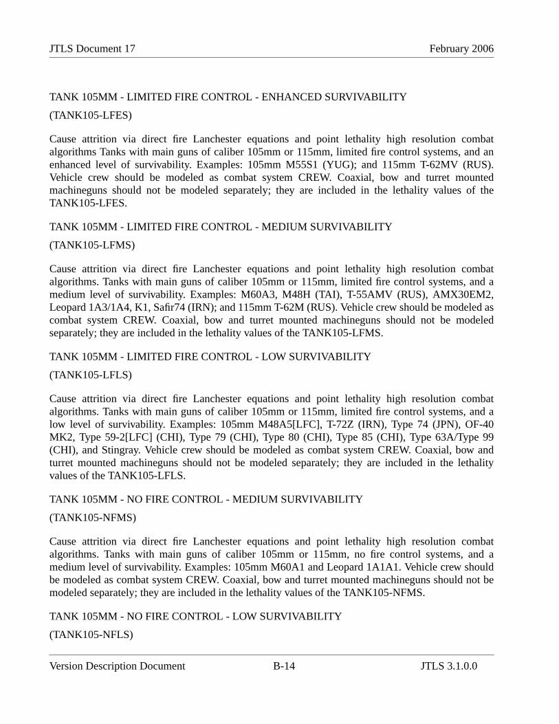
JTLS Document 17 February 2006
TANK 105MM - LIMITED FIRE CONTROL - ENHANCED SURVIVABILITY
(TANK105-LFES)
Cause attrition via direct fire Lanchester equations and point lethality high resolution combatalgorithms Tanks with main guns of caliber 105mm or 115mm, limited fire control systems, and anenhanced level of survivability. Examples: 105mm M55S1 (YUG); and 115mm T-62MV (RUS).Vehicle crew should be modeled as combat system CREW. Coaxial, bow and turret mountedmachineguns should not be modeled separately; they are included in the lethality values of theTANK105-LFES.
TANK 105MM - LIMITED FIRE CONTROL - MEDIUM SURVIVABILITY
(TANK105-LFMS)
Cause attrition via direct fire Lanchester equations and point lethality high resolution combatalgorithms. Tanks with main guns of caliber 105mm or 115mm, limited fire control systems, and amedium level of survivability. Examples: M60A3, M48H (TAI), T-55AMV (RUS), AMX30EM2,Leopard 1A3/1A4, K1, Safir74 (IRN); and 115mm T-62M (RUS). Vehicle crew should be modeled ascombat system CREW. Coaxial, bow and turret mounted machineguns should not be modeledseparately; they are included in the lethality values of the TANK105-LFMS.
TANK 105MM - LIMITED FIRE CONTROL - LOW SURVIVABILITY
(TANK105-LFLS)
Cause attrition via direct fire Lanchester equations and point lethality high resolution combatalgorithms. Tanks with main guns of caliber 105mm or 115mm, limited fire control systems, and alow level of survivability. Examples: 105mm M48A5[LFC], T-72Z (IRN), Type 74 (JPN), OF-40MK2, Type 59-2[LFC] (CHI), Type 79 (CHI), Type 80 (CHI), Type 85 (CHI), Type 63A/Type 99(CHI), and Stingray. Vehicle crew should be modeled as combat system CREW. Coaxial, bow andturret mounted machineguns should not be modeled separately; they are included in the lethalityvalues of the TANK105-LFLS.
TANK 105MM - NO FIRE CONTROL - MEDIUM SURVIVABILITY
(TANK105-NFMS)
Cause attrition via direct fire Lanchester equations and point lethality high resolution combatalgorithms. Tanks with main guns of caliber 105mm or 115mm, no fire control systems, and amedium level of survivability. Examples: 105mm M60A1 and Leopard 1A1A1. Vehicle crew shouldbe modeled as combat system CREW. Coaxial, bow and turret mounted machineguns should not bemodeled separately; they are included in the lethality values of the TANK105-NFMS.
TANK 105MM - NO FIRE CONTROL - LOW SURVIVABILITY
(TANK105-NFLS)
Version Description Document B-14 JTLS 3.1.0.0

February 2006 JTLS Document 17
Cause attrition via direct fire Lanchester equations and point lethality high resolution combatalgorithms. Tanks with main guns of caliber 105mm or 115mm, no fire control systems, and a lowlevel of survivability. Examples: 105mm, AMX13, AMX30/AMX30S/AMX30ER, M48A5[NFC],SK105[NFC], Type 59-2[NFC] (CHI), Oliphant, Tariq, Vickers MK1; and 115mm T62. Vehicle crewshould be modeled as combat system CREW. Coaxial, bow and turret mounted machineguns shouldnot be modeled separately; they are included in the lethality values of the TANK105-NFLS.
TANK 85MM TO 100MM - LIMITED FIRE CONTROL - LOW SURVIVABILITY
(TANK100-LFLS)
Cause attrition via direct fire Lanchester equations and point lethality high resolution combatalgorithms. Tanks with main guns of caliber 85mm to 100mm, limited fire control systems, and a lowlevel of survivability. Example: 90mm M48A3; 100mm T-55AM (RUS) and Type 69-2 (CHI).Vehicle crew should be modeled as combat system CREW. Coaxial, bow and turret mountedmachineguns should not be modeled separately; they are included in the lethality values of theTANK100-LFLS.
TANK 85MM TO 100MM - NO FIRE CONTROL - LOW SURVIVABILITY
(TANK100-NFLS)
Cause attrition via direct fire Lanchester equations and point lethality high resolution combatalgorithms. Tanks with main guns of caliber 85mm to 100mm, no fire control systems, and a low levelof survivability. Example: 85mm T34-85, Type 63 (CHI), Type 62 (CHI), and M1985(PT85) (NK),90mm AMX13, M47, M48A1/A2, M24, M36, Scorpion90 and Tosan; 100mm TR-85, TR580, T54,T55, Type 59, and Type 69. Vehicle crew should be modeled as combat system CREW. Coaxial, bowand turret mounted machineguns should not be modeled separately; they are included in the lethalityvalues of the TANK100-NFLS.
TANK 76MM - NO FIRE CONTROL - LOW SURVIVABILITY
(TANK76-NFLS)
Cause attrition via direct fire Lanchester equations and point lethality high resolution combatalgorithms. All vehicles with main guns of caliber 75 or 76mm, whether wheeled or tracked. Mosthave no fire control system and low survivability. Example: 75mm AMX13; 76mm Rooikat,Scorpion, Saladin, Cougar, M41, Type 74, PT76, and M18TD. Vehicle crew should be modeled ascombat system CREW. Coaxial, bow and turret mounted machineguns should not be modeledseparately; they are included in the lethality values of the TANK76-NFLS.
ARMORED GUN SYSTEM 105MM - LIGHT ARMOR
(AGS105-LF-HA)
JTLS 3.1.0.0 B-15 Version Description Document

JTLS Document 17 February 2006
Cause attrition via direct fire Lanchester equations and point lethality high resolution combatalgorithms. Generally wheeled armored vehicles mounting 105mm tank guns, most with limited firecontrol systems. Protected across their frontal arc from heavy machineguns. Examples: NORINCO105mm and 120mm TD, AMX10RC, Centauro B1, R400, Rooikat 105mm, VEXTRA, PiranhaTML105, 105mm LPT AG and LAV-III MGS. Vehicle crew should be modeled as combat systemCREW. Coaxial, bow and turret mounted machineguns should not be modeled separately; they areincluded in the lethality values of the AGS105-LF-HA.
ARMORED GUN SYSTEM 90MM - LIGHT ARMOR
(AGS90-LA)
Cause attrition via direct fire Lanchester equations and point lethality high resolution combatalgorithms. Generally wheeled armored vehicles mounting 90mm tank guns, most with no fire controlsystems. Protected from small arms fire and shell splinters. Examples: AML90, ERC90, VBC90,EE9, Eland90, BMR-VEC 90, Simba CM90, Ratel FSV90, Piranha 90mm, LAV-150 90mm, Pandur90mm, Dragoon LFV-90, Scorpion 90, LAV-AG and Pizarro 90. Vehicle crew should be modeled ascombat system CREW. Coaxial, bow and turret mounted machineguns should not be modeledseparately; they are included in the lethality values of the AGS90-LA.
ANTI-TANK GUIDED MISSILE SYSTEM SELF-PROPELLED - LONG RANGE - TOP ATTACK- LIGHT ARMOR - TURRETED WEAPON
(ATGMSP-LT-LT)
Cause attrition via direct fire Lanchester equations and point lethality high resolution combatalgorithms. Tracked or wheeled armored vehicle mounting an ATGM but no gun and dedicated to theanti-tank role. Max effective anti-tank range of 3500m or greater. Some vehicles may havemachineguns. Vehicles are generally lightly armored although some are more heavily armored. Topattack capability allows it to defeat most armor. Gunner protected while firing. Although not a topattack weapon, the AT-14 is best modeled as this combat system because of its extremely highpenetration ability. Examples: VAB HOT[Mephisto], LAV-III TOW and BMP3-TD AT14. Vehiclecrew should be modeled as combat system CREW. ATGM and machinegun should not be modeledseparately; they are included in the lethality values of the ATGMSP-LT-LT.
ANTI-TANK GUIDED MISSILE SYSTEM SELF-PROPELLED - LONG RANGE - HIGHLETHALITY - LIGHT ARMOR - TURRETED WEAPON
(ATGMSP-LH-LT)
Cause attrition via direct fire Lanchester equations and point lethality high resolution combatalgorithms. Tracked or wheeled armored vehicle mounting an ATGM but no gun and dedicated to theanti-tank role. Max effective anti-tank range of 3500m or greater. Some vehicles may havemachineguns. Vehicles are generally lightly armored although some are more heavily armored.Armor penetration greater than or equal to 800mm. Gunner protected while firing. Examples: M901
Version Description Document B-16 JTLS 3.1.0.0
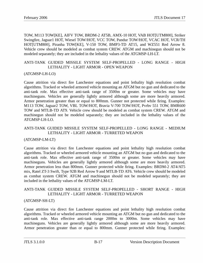
February 2006 JTLS Document 17
TOW, M113 TOW[KE], AIFV TOW, BRDM-2 AT5B, AMX-10 HOT, VAB HOT[UTM800], StrikerSwingfire, Jaguar1 HOT, Wiesel TOW/HOT, VCC TOW, Pandur TOW/HOT, VCAC HOT, VCR/THHOT[UTM800], Piranha TOW[KE], V-150 TOW, BMP3-TD AT15, and WZ551 Red Arrow 8.Vehicle crew should be modeled as combat system CREW. ATGM and machinegun should not bemodeled separately; they are included in the lethality values of the ATGMSP-LH-LT.
ANTI-TANK GUIDED MISSILE SYSTEM SELF-PROPELLED - LONG RANGE - HIGHLETHALITY - LIGHT ARMOR - OPEN WEAPON
(ATGMSP-LH-LO)
Cause attrition via direct fire Lanchester equations and point lethality high resolution combatalgorithms. Tracked or wheeled armored vehicle mounting an ATGM but no gun and dedicated to theanti-tank role. Max effective anti-tank range of 3500m or greater. Some vehicles may havemachineguns. Vehicles are generally lightly armored although some are more heavily armored.Armor penetration greater than or equal to 800mm. Gunner not protected while firing. Examples:M113 TOW, Jaguar2 TOW, VBL TOW/HOT, Bravia V-700 TOW/HOT, Pvrbv 551 TOW, BMR600TOW and MTLB-TD AT9. Vehicle crew should be modeled as combat system CREW. ATGM andmachinegun should not be modeled separately; they are included in the lethality values of theATGMSP-LH-LO.
ANTI-TANK GUIDED MISSILE SYSTEM SELF-PROPELLED - LONG RANGE - MEDIUMLETHALITY - LIGHT ARMOR - TURRETED WEAPON
(ATGMSP-LM-LT)
Cause attrition via direct fire Lanchester equations and point lethality high resolution combatalgorithms. Tracked or wheeled armored vehicle mounting an ATGM but no gun and dedicated to theanti-tank role. Max effective anti-tank range of 3500m or greater. Some vehicles may havemachineguns. Vehicles are generally lightly armored although some are more heavily armored.Armor penetration less than 800mm. Gunner protected while firing. Examples: BRDM-2 AT4/AT5mix, Ratel ZT-3 Swift, Type 92B Red Arrow 9 and MTLB-TD AT6. Vehicle crew should be modeledas combat system CREW. ATGM and machinegun should not be modeled separately; they areincluded in the lethality values of the ATGMSP-LM-LT.
ANTI-TANK GUIDED MISSILE SYSTEM SELF-PROPELLED - SHORT RANGE - HIGHLETHALITY - LIGHT ARMOR - TURRETED WEAPON
(ATGMSP-SH-LT)
Cause attrition via direct fire Lanchester equations and point lethality high resolution combatalgorithms. Tracked or wheeled armored vehicle mounting an ATGM but no gun and dedicated to theanti-tank role. Max effective anti-tank range 2000m to 3000m. Some vehicles may havemachineguns. Vehicles are generally lightly armored although some are more heavily armored.Armor penetration greater than or equal to 800mm. Gunner protected while firing. Examples:
JTLS 3.1.0.0 B-17 Version Description Document
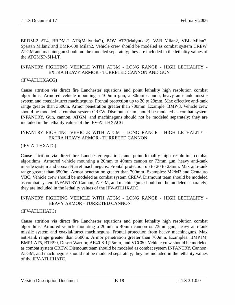
JTLS Document 17 February 2006
BRDM-2 AT4, BRDM-2 AT3(Malyutka2), BOV AT3(Malyutka2), VAB Milan2, VBL Milan2,Spartan Milan2 and BMR-600 Milan2. Vehicle crew should be modeled as combat system CREW.ATGM and machinegun should not be modeled separately; they are included in the lethality values ofthe ATGMSP-SH-LT.
INFANTRY FIGHTING VEHICLE WITH ATGM - LONG RANGE - HIGH LETHALITY -EXTRA HEAVY ARMOR - TURRETED CANNON AND GUN
(IFV-ATLHXACG)
Cause attrition via direct fire Lanchester equations and point lethality high resolution combatalgorithms. Armored vehicle mounting a 100mm gun, a 30mm cannon, heavy anti-tank missilesystem and coaxial/turret machineguns. Frontal protection up to 20 to 23mm. Max effective anti-tankrange greater than 3500m. Armor penetration greater than 700mm. Example: BMP-3. Vehicle crewshould be modeled as combat system CREW. Dismount team should be modeled as combat systemINFANTRY. Gun, cannon, ATGM, and machineguns should not be modeled separately; they areincluded in the lethality values of the IFV-ATLHXACG.
INFANTRY FIGHTING VEHICLE WITH ATGM - LONG RANGE - HIGH LETHALITY -EXTRA HEAVY ARMOR - TURRETED CANNON
(IFV-ATLHXATC)
Cause attrition via direct fire Lanchester equations and point lethality high resolution combatalgorithms. Armored vehicle mounting a 20mm to 40mm cannon or 73mm gun, heavy anti-tankmissile system and coaxial/turret machineguns. Frontal protection up to 20 to 23mm. Max anti-tankrange greater than 3500m. Armor penetration greater than 700mm. Examples: M2/M3 and CentauroVBC. Vehicle crew should be modeled as combat system CREW. Dismount team should be modeledas combat system INFANTRY. Cannon, ATGM, and machineguns should not be modeled separately;they are included in the lethality values of the IFV-ATLHXATC.
INFANTRY FIGHTING VEHICLE WITH ATGM - LONG RANGE - HIGH LETHALITY -HEAVY ARMOR - TURRETED CANNON
(IFV-ATLHHATC)
Cause attrition via direct fire Lanchester equations and point lethality high resolution combatalgorithms. Armored vehicle mounting a 20mm to 40mm cannon or 73mm gun, heavy anti-tankmissile system and coaxial/turret machineguns. Frontal protection from heavy machineguns. Maxanti-tank range greater than 3500m. Armor penetration greater than 700mm. Examples: BMP1M,BMP1 AT5, BTR90, Desert Warrior, AF40-8-1[25mm] and VCC80. Vehicle crew should be modeledas combat system CREW. Dismount team should be modeled as combat system INFANTRY. Cannon,ATGM, and machineguns should not be modeled separately; they are included in the lethality valuesof the IFV-ATLHHATC.
Version Description Document B-18 JTLS 3.1.0.0

February 2006 JTLS Document 17
INFANTRY FIGHTING VEHICLE WITH ATGM - LONG RANGE - HIGH LETHALITY - LIGHTARMOR - TURRETED CANNON
(IFV-ATLHLATC)
Cause attrition via direct fire Lanchester equations and point lethality high resolution combatalgorithms. Armored vehicle mounting a 20mm to 40mm cannon or 73mm gun, heavy anti-tankmissile system and coaxial/turret machineguns. Frontal protection from small arms and shellsplinters. Max anti-tank range greater than 3500m. Armor penetration greater than 700mm.Examples: BMP2 AT5, BMD2 AT5, BMD3 AT5, BMP30, Fahd30, Sarath and Type 89 (JPN).Vehicle crew should be modeled as combat system CREW. Dismount team should be modeled ascombat system INFANTRY. Cannon, ATGM, and machineguns should not be modeled separately;they are included in the lethality values of the IFV-ATLHLATC.
INFANTRY FIGHTING VEHICLE WITH ATGM - SHORT RANGE - HIGH LETHALITY -EXTRA HEAVY ARMOR - TURRETED CANNON
(IFV-ATSHXATC)
Cause attrition via direct fire Lanchester equations and point lethality high resolution combatalgorithms. Armored vehicle mounting a 20mm to 40mm cannon or 73mm gun, heavy anti-tankmissile system and coaxial/turret machineguns. Frontal protection up to 20 to 23mm. Max anti-tankrange 2000m to 3000m. Armor penetration greater than 700mm. Examples: M80/M80A, and MarderMilan2. Vehicle crew should be modeled as combat system CREW. Dismount team should bemodeled as combat system INFANTRY. Cannon, ATGM, and machineguns should not be modeledseparately; they are included in the lethality values of the IFV-ATSHXATC.
INFANTRY FIGHTING VEHICLE WITH ATGM - SHORT RANGE - HIGH LETHALITY -HEAVY ARMOR - TURRETED CANNON
(IFV-ATSHHATC)
Cause attrition via direct fire Lanchester equations and point lethality high resolution combatalgorithms. Armored vehicle mounting a 20mm to 40mm cannon or 73mm gun, heavy anti-tankmissile system and coaxial/turret machineguns. Frontal protection from heavy machineguns. Maxanti-tank range 2000m to 3000m. Armor penetration greater than 700mm. Examples: BMP1AT3(Malyutka2), WZ501 AT3(Malyutka2), MLI-84 AT3(Malyutka2), MLVM[IFV]AT3(Malyutka2), Warrior Milan2, and BMP23. Vehicle crew should be modeled as combat systemCREW. Dismount team should be modeled as combat system INFANTRY. Cannon, ATGM, andmachineguns should not be modeled separately; they are included in the lethality values of the IFV-ATSHHATC.
INFANTRY FIGHTING VEHICLE WITH ATGM - SHORT RANGE - MEDIUM LETHALITY -HEAVY ARMOR - TURRETED CANNON
(IFV-ATSMHATC)
JTLS 3.1.0.0 B-19 Version Description Document

JTLS Document 17 February 2006
Cause attrition via direct fire Lanchester equations and point lethality high resolution combatalgorithms. Armored vehicle mounting a 20mm to 40mm cannon or 73mm gun, heavy anti-tankmissile system and coaxial/turret machineguns. Frontal protection from heavy machineguns. Maxanti-tank range 2000m to 3000m. Armor penetration less than 700mm. Examples: BMP1AT3(Malyutka) and BMP1 AT4. Vehicle crew should be modeled as combat system CREW.Dismount team should be modeled as combat system INFANTRY. Cannon, ATGM, and machinegunsshould not be modeled separately; they are included in the lethality values of the IFV-ATSMHATC.
INFANTRY FIGHTING VEHICLE WITH ATGM - SHORT RANGE - MEDIUM LETHALITY -LIGHT ARMOR - TURRETED CANNON
(IFV-ATSMLATC)
Cause attrition via direct fire Lanchester equations and point lethality high resolution combatalgorithms. Armored vehicle mounting a 20mm to 40mm cannon or 73mm gun, heavy anti-tankmissile system and coaxial/turret machineguns. Frontal protection from small arms and shellsplinters. Max anti-tank range 2000m to 3000m. Armor penetration less than 700mm. Examples:WZ501 AT3(Malyutka), BMP2 AT4, WZ551[IFV] AT3(Malyutka), Type85[IFV] AT3(Malyutka),BMD1 AT3(Malyutka) BMD1P AT4, BMD2 AT4 and BMD3 AT4. Vehicle crew should be modeledas combat system CREW. Dismount team should be modeled as combat system INFANTRY. Cannon,ATGM, and machineguns should not be modeled separately; they are included in the lethality valuesof the IFV-ATSMLATC.
INFANTRY FIGHTING VEHICLE - EXTRA HEAVY ARMOR
(IFV-XHA-TC)
Cause attrition via direct fire Lanchester equations and point lethality high resolution combatalgorithms. Armored vehicle mounting a 20 to 40mm cannon or 73mm gun, and machineguns; butgenerally not mounting an integrated anti-tank missile system. Max effective anti-armor range 1500mto 2000m. Frontal protection up to 20mm to 23mm. Examples: Marder, Luchs, Kentaurus,Pizarro[EA], VCTP, BRM-3K, AB14 Temsah (JOR), CV9030 and CV9040. Vehicle crew should bemodeled as combat system CREW. Dismount team should be modeled as combat systemINFANTRY. Cannon and machineguns should not be modeled separately; they are included in thelethality values of the IFV-XHA.
INFANTRY FIGHTING VEHICLE - HEAVY ARMOR
(IFV-HA-TC)
Cause attrition via direct fire Lanchester equations and point lethality high resolution combatalgorithms. Armored vehicle mounting a 20 to 40mm cannon or 73mm gun, and machineguns; butgenerally not mounting an integrated anti-tank missile system. Max effective anti-armor range 1500mto 2000m. Frontal protection from heavy machineguns. Examples: Warrior, AMX10P, Pizarro/ASCOD, Pandur[25mm], Ratel20 IFV, Simba[25mm], Bionix, VBCI, VEC-2[25mm], BTR80A,
Version Description Document B-20 JTLS 3.1.0.0
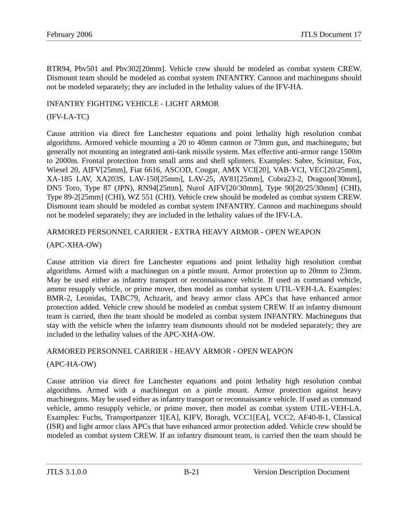
February 2006 JTLS Document 17
BTR94, Pbv501 and Pbv302[20mm]. Vehicle crew should be modeled as combat system CREW.Dismount team should be modeled as combat system INFANTRY. Cannon and machineguns shouldnot be modeled separately; they are included in the lethality values of the IFV-HA.
INFANTRY FIGHTING VEHICLE - LIGHT ARMOR
(IFV-LA-TC)
Cause attrition via direct fire Lanchester equations and point lethality high resolution combatalgorithms. Armored vehicle mounting a 20 to 40mm cannon or 73mm gun, and machineguns; butgenerally not mounting an integrated anti-tank missile system. Max effective anti-armor range 1500mto 2000m. Frontal protection from small arms and shell splinters. Examples: Sabre, Scimitar, Fox,Wiesel 20, AIFV[25mm], Fiat 6616, ASCOD, Cougar, AMX VCI[20], VAB-VCI, VEC[20/25mm],XA-185 LAV, XA203S, LAV-150[25mm], LAV-25, AV81[25mm], Cobra23-2, Dragoon[30mm],DN5 Toro, Type 87 (JPN), RN94[25mm], Nurol AIFV[20/30mm], Type 90[20/25/30mm] (CHI),Type 89-2[25mm] (CHI), WZ 551 (CHI). Vehicle crew should be modeled as combat system CREW.Dismount team should be modeled as combat system INFANTRY. Cannon and machineguns shouldnot be modeled separately; they are included in the lethality values of the IFV-LA.
ARMORED PERSONNEL CARRIER - EXTRA HEAVY ARMOR - OPEN WEAPON
(APC-XHA-OW)
Cause attrition via direct fire Lanchester equations and point lethality high resolution combatalgorithms. Armed with a machinegun on a pintle mount. Armor protection up to 20mm to 23mm.May be used either as infantry transport or reconnaissance vehicle. If used as command vehicle,ammo resupply vehicle, or prime mover, then model as combat system UTIL-VEH-LA. Examples:BMR-2, Leonidas, TABC79, Achzarit, and heavy armor class APCs that have enhanced armorprotection added. Vehicle crew should be modeled as combat system CREW. If an infantry dismountteam is carried, then the team should be modeled as combat system INFANTRY. Machineguns thatstay with the vehicle when the infantry team dismounts should not be modeled separately; they areincluded in the lethality values of the APC-XHA-OW.
ARMORED PERSONNEL CARRIER - HEAVY ARMOR - OPEN WEAPON
(APC-HA-OW)
Cause attrition via direct fire Lanchester equations and point lethality high resolution combatalgorithms. Armed with a machinegun on a pintle mount. Armor protection against heavymachineguns. May be used either as infantry transport or reconnaissance vehicle. If used as commandvehicle, ammo resupply vehicle, or prime mover, then model as combat system UTIL-VEH-LA.Examples: Fuchs, Transportpanzer 1[EA], KIFV, Boragh, VCC1[EA], VCC2, AF40-8-1, Classical(ISR) and light armor class APCs that have enhanced armor protection added. Vehicle crew should bemodeled as combat system CREW. If an infantry dismount team, is carried then the team should be
JTLS 3.1.0.0 B-21 Version Description Document
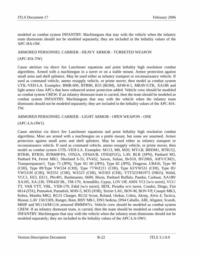
JTLS Document 17 February 2006
modeled as combat system INFANTRY. Machineguns that stay with the vehicle when the infantryteam dismounts should not be modeled separately; they are included in the lethality values of theAPC-HA-OW.
ARMORED PERSONNEL CARRIER - HEAVY ARMOR - TURRETED WEAPON
(APC-HA-TW)
Cause attrition via direct fire Lanchester equations and point lethality high resolution combatalgorithms. Armed with a machinegun in a turret or on a stable mount. Armor protection againstsmall arms and shell splinters. May be used either as infantry transport or reconnaissance vehicle. Ifused as command vehicle, ammo resupply vehicle, or prime mover, then model as combat systemUTIL-VEH-LA. Examples: BMR-600, BTR80, B33 (ROM), AF40-8-1, MRAV/GTK, XA186 andlight armor class APCs that have enhanced armor protection added. Vehicle crew should be modeledas combat system CREW. If an infantry dismount team is carried, then the team should be modeled ascombat system INFANTRY. Machineguns that stay with the vehicle when the infantry teamdismounts should not be modeled separately; they are included in the lethality values of the APC-HA-TW.
ARMORED PERSONNEL CARRIER - LIGHT ARMOR - OPEN WEAPON - ONE
(APC-LA-OW1)
Cause attrition via direct fire Lanchester equations and point lethality high resolution combatalgorithms. Most are armed with a machinegun on a pintle mount, but some are unarmed. Armorprotection against small arms and shell splinters. May be used either as infantry transport orreconnaissance vehicle. If used as command vehicle, ammo resupply vehicle, or prime mover, thenmodel as combat system UTIL-VEH-LA. Examples: M113, M8, M20, MT-LB, BRDM1, BTR152,BTR40, BTR50, BTR60P/PA, OT62A, OT64A/B, OT65(FUG), LAV, BLR (SPN), Panhard M3,Panhard P4, Ferret MK1, Shorland S-55, FV432, Saxon, Sultan, BvS10, BV206S, AIFV/CM21,Transportpanzer1, Type 73 (JPN), Type SU 60 (JPN), Type 82 (JPN), Dragoon, UR416, Type 90(CHI), Type 89/Type YW534 (CHI), Type 77/WZ211 (CHI), Type 63/YW531 (CHI), Type 85/YW531H (CHI), WZ551 (CHI), WZ523 (CHI), WZ503 (CHI), VTT323/M1973 (NKO), Walid,VCC1, EE3, EE11, Pbv401, Bushmaster, S600, Bison, Panhard Buffalo, Pandur, Cashuat, XA180/XA185, XA-230, TPK420 BL, TM-170, Armadillo, Gypsy, LOV OP, AMX VCI [w/o turret], VCC/TT, VAB VTT, VBL, VXB-170, Fahd [w/o turret], BDX, Piranha w/o turret, Condor, Dingo, Fiat6614 (ITA), Puma4x4, Puma6x6, MAV-5, M35 (JOR), Terrier LAU, BOV-M, BOV-VP, Casspir MK3,Kobra, Mamba MK2, RG31 Charger, RG32 Scout, Roland, Otokar, Cobra, Akrep, Alvis 4, Tactica,Hussar, LAV 150/150S, Ranger, Ram, RBY MK1, DN3 Sedena, DN4 Caballo, ABI, Aligator, Scarab,M60P and M1114/M1116 armored HMMWVs. Vehicle crew should be modeled as combat systemCREW. If an infantry dismount team, is carried, then the team should be modeled as combat systemINFANTRY. Machineguns that stay with the vehicle when the infantry team dismounts should not bemodeled separately; they are included in the lethality values of the APC-LA-OW1.
Version Description Document B-22 JTLS 3.1.0.0
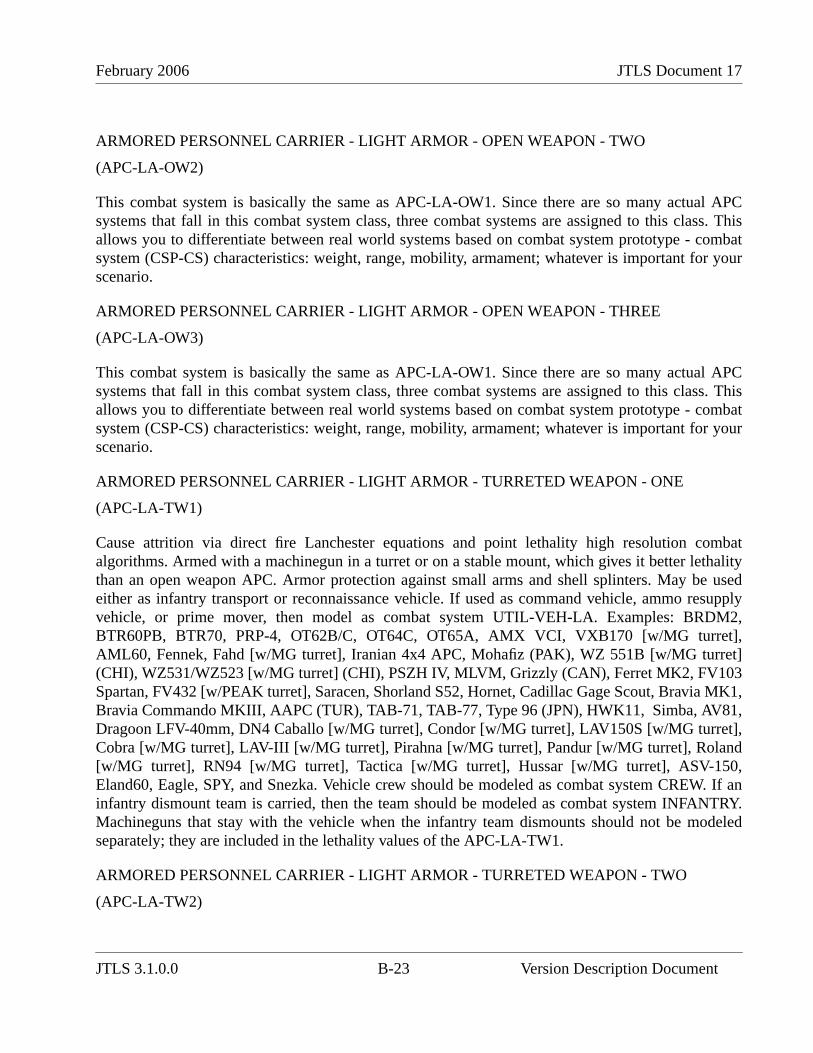
February 2006 JTLS Document 17
ARMORED PERSONNEL CARRIER - LIGHT ARMOR - OPEN WEAPON - TWO
(APC-LA-OW2)
This combat system is basically the same as APC-LA-OW1. Since there are so many actual APCsystems that fall in this combat system class, three combat systems are assigned to this class. Thisallows you to differentiate between real world systems based on combat system prototype - combatsystem (CSP-CS) characteristics: weight, range, mobility, armament; whatever is important for yourscenario.
ARMORED PERSONNEL CARRIER - LIGHT ARMOR - OPEN WEAPON - THREE
(APC-LA-OW3)
This combat system is basically the same as APC-LA-OW1. Since there are so many actual APCsystems that fall in this combat system class, three combat systems are assigned to this class. Thisallows you to differentiate between real world systems based on combat system prototype - combatsystem (CSP-CS) characteristics: weight, range, mobility, armament; whatever is important for yourscenario.
ARMORED PERSONNEL CARRIER - LIGHT ARMOR - TURRETED WEAPON - ONE
(APC-LA-TW1)
Cause attrition via direct fire Lanchester equations and point lethality high resolution combatalgorithms. Armed with a machinegun in a turret or on a stable mount, which gives it better lethalitythan an open weapon APC. Armor protection against small arms and shell splinters. May be usedeither as infantry transport or reconnaissance vehicle. If used as command vehicle, ammo resupplyvehicle, or prime mover, then model as combat system UTIL-VEH-LA. Examples: BRDM2,BTR60PB, BTR70, PRP-4, OT62B/C, OT64C, OT65A, AMX VCI, VXB170 [w/MG turret],AML60, Fennek, Fahd [w/MG turret], Iranian 4x4 APC, Mohafiz (PAK), WZ 551B [w/MG turret](CHI), WZ531/WZ523 [w/MG turret] (CHI), PSZH IV, MLVM, Grizzly (CAN), Ferret MK2, FV103Spartan, FV432 [w/PEAK turret], Saracen, Shorland S52, Hornet, Cadillac Gage Scout, Bravia MK1,Bravia Commando MKIII, AAPC (TUR), TAB-71, TAB-77, Type 96 (JPN), HWK11, Simba, AV81,Dragoon LFV-40mm, DN4 Caballo [w/MG turret], Condor [w/MG turret], LAV150S [w/MG turret],Cobra [w/MG turret], LAV-III [w/MG turret], Pirahna [w/MG turret], Pandur [w/MG turret], Roland[w/MG turret], RN94 [w/MG turret], Tactica [w/MG turret], Hussar [w/MG turret], ASV-150,Eland60, Eagle, SPY, and Snezka. Vehicle crew should be modeled as combat system CREW. If aninfantry dismount team is carried, then the team should be modeled as combat system INFANTRY.Machineguns that stay with the vehicle when the infantry team dismounts should not be modeledseparately; they are included in the lethality values of the APC-LA-TW1.
ARMORED PERSONNEL CARRIER - LIGHT ARMOR - TURRETED WEAPON - TWO
(APC-LA-TW2)
JTLS 3.1.0.0 B-23 Version Description Document
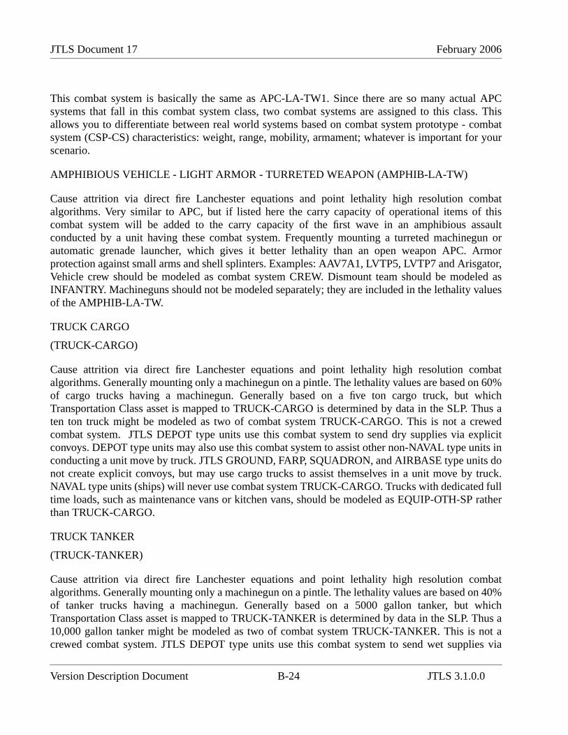
JTLS Document 17 February 2006
This combat system is basically the same as APC-LA-TW1. Since there are so many actual APCsystems that fall in this combat system class, two combat systems are assigned to this class. Thisallows you to differentiate between real world systems based on combat system prototype - combatsystem (CSP-CS) characteristics: weight, range, mobility, armament; whatever is important for yourscenario.
AMPHIBIOUS VEHICLE - LIGHT ARMOR - TURRETED WEAPON (AMPHIB-LA-TW)
Cause attrition via direct fire Lanchester equations and point lethality high resolution combatalgorithms. Very similar to APC, but if listed here the carry capacity of operational items of thiscombat system will be added to the carry capacity of the first wave in an amphibious assaultconducted by a unit having these combat system. Frequently mounting a turreted machinegun orautomatic grenade launcher, which gives it better lethality than an open weapon APC. Armorprotection against small arms and shell splinters. Examples: AAV7A1, LVTP5, LVTP7 and Arisgator,Vehicle crew should be modeled as combat system CREW. Dismount team should be modeled asINFANTRY. Machineguns should not be modeled separately; they are included in the lethality valuesof the AMPHIB-LA-TW.
TRUCK CARGO
(TRUCK-CARGO)
Cause attrition via direct fire Lanchester equations and point lethality high resolution combatalgorithms. Generally mounting only a machinegun on a pintle. The lethality values are based on 60%of cargo trucks having a machinegun. Generally based on a five ton cargo truck, but whichTransportation Class asset is mapped to TRUCK-CARGO is determined by data in the SLP. Thus aten ton truck might be modeled as two of combat system TRUCK-CARGO. This is not a crewedcombat system. JTLS DEPOT type units use this combat system to send dry supplies via explicitconvoys. DEPOT type units may also use this combat system to assist other non-NAVAL type units inconducting a unit move by truck. JTLS GROUND, FARP, SQUADRON, and AIRBASE type units donot create explicit convoys, but may use cargo trucks to assist themselves in a unit move by truck.NAVAL type units (ships) will never use combat system TRUCK-CARGO. Trucks with dedicated fulltime loads, such as maintenance vans or kitchen vans, should be modeled as EQUIP-OTH-SP ratherthan TRUCK-CARGO.
TRUCK TANKER
(TRUCK-TANKER)
Cause attrition via direct fire Lanchester equations and point lethality high resolution combatalgorithms. Generally mounting only a machinegun on a pintle. The lethality values are based on 40%of tanker trucks having a machinegun. Generally based on a 5000 gallon tanker, but whichTransportation Class asset is mapped to TRUCK-TANKER is determined by data in the SLP. Thus a10,000 gallon tanker might be modeled as two of combat system TRUCK-TANKER. This is not acrewed combat system. JTLS DEPOT type units use this combat system to send wet supplies via
Version Description Document B-24 JTLS 3.1.0.0
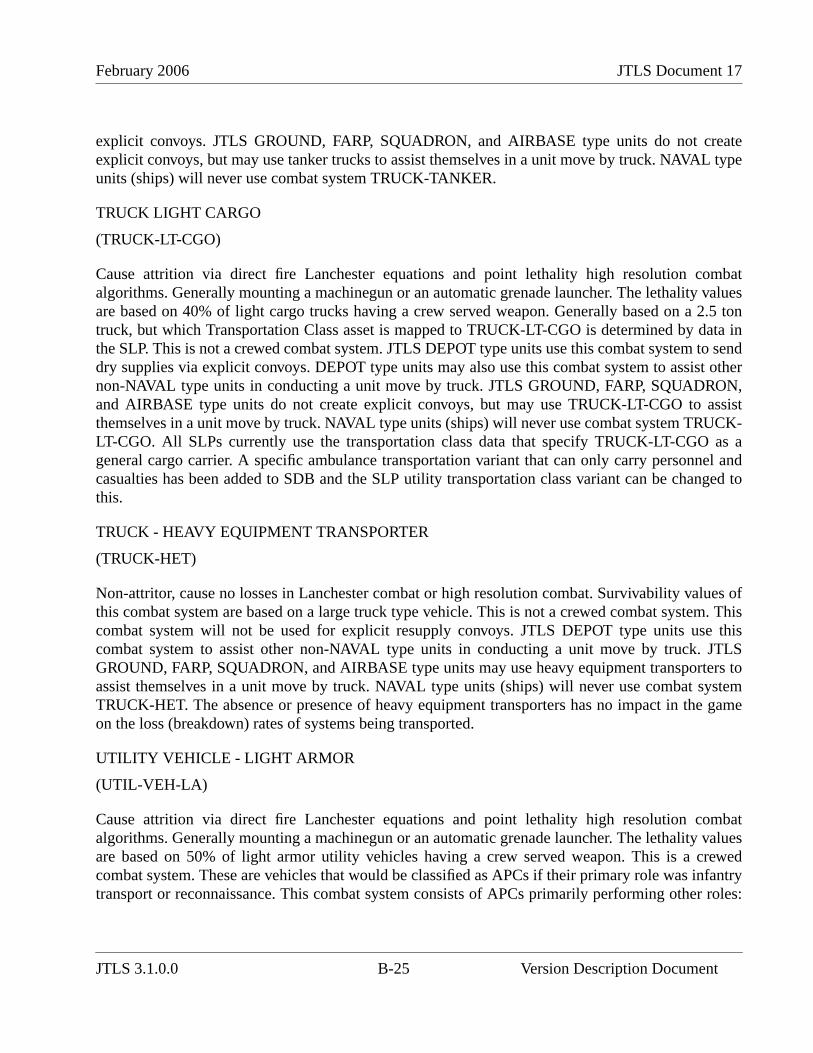
February 2006 JTLS Document 17
explicit convoys. JTLS GROUND, FARP, SQUADRON, and AIRBASE type units do not createexplicit convoys, but may use tanker trucks to assist themselves in a unit move by truck. NAVAL typeunits (ships) will never use combat system TRUCK-TANKER.
TRUCK LIGHT CARGO
(TRUCK-LT-CGO)
Cause attrition via direct fire Lanchester equations and point lethality high resolution combatalgorithms. Generally mounting a machinegun or an automatic grenade launcher. The lethality valuesare based on 40% of light cargo trucks having a crew served weapon. Generally based on a 2.5 tontruck, but which Transportation Class asset is mapped to TRUCK-LT-CGO is determined by data inthe SLP. This is not a crewed combat system. JTLS DEPOT type units use this combat system to senddry supplies via explicit convoys. DEPOT type units may also use this combat system to assist othernon-NAVAL type units in conducting a unit move by truck. JTLS GROUND, FARP, SQUADRON,and AIRBASE type units do not create explicit convoys, but may use TRUCK-LT-CGO to assistthemselves in a unit move by truck. NAVAL type units (ships) will never use combat system TRUCK-LT-CGO. All SLPs currently use the transportation class data that specify TRUCK-LT-CGO as ageneral cargo carrier. A specific ambulance transportation variant that can only carry personnel andcasualties has been added to SDB and the SLP utility transportation class variant can be changed tothis.
TRUCK - HEAVY EQUIPMENT TRANSPORTER
(TRUCK-HET)
Non-attritor, cause no losses in Lanchester combat or high resolution combat. Survivability values ofthis combat system are based on a large truck type vehicle. This is not a crewed combat system. Thiscombat system will not be used for explicit resupply convoys. JTLS DEPOT type units use thiscombat system to assist other non-NAVAL type units in conducting a unit move by truck. JTLSGROUND, FARP, SQUADRON, and AIRBASE type units may use heavy equipment transporters toassist themselves in a unit move by truck. NAVAL type units (ships) will never use combat systemTRUCK-HET. The absence or presence of heavy equipment transporters has no impact in the gameon the loss (breakdown) rates of systems being transported.
UTILITY VEHICLE - LIGHT ARMOR
(UTIL-VEH-LA)
Cause attrition via direct fire Lanchester equations and point lethality high resolution combatalgorithms. Generally mounting a machinegun or an automatic grenade launcher. The lethality valuesare based on 50% of light armor utility vehicles having a crew served weapon. This is a crewedcombat system. These are vehicles that would be classified as APCs if their primary role was infantrytransport or reconnaissance. This combat system consists of APCs primarily performing other roles:
JTLS 3.1.0.0 B-25 Version Description Document
JTLS Document 17 February 2006
command vehicles, fire direction center, maintenance, ammo resupply, ambulances, prime movers,etc. The utility vehicle combat system is no longer used for explicit convoys; either for movingsupplies or for moving a unit. Example: M577
UTILITY VEHICLE - NO ARMOR
(UTIL-VEH-NA)
Cause attrition via direct fire Lanchester equations and point lethality high resolution combatalgorithms. Generally mounting a machinegun or an automatic grenade launcher. The lethality valuesare based on 25% of non-armored utility vehicles having a crew served weapon. This is a crewedcombat system. The utility vehicle combat system is no longer used for explicit convoys; either formoving supplies or for moving a unit. Example: Jeep, HMMWV, Land Rover, GAZ-69, unarmoredambulances.
AIRCRAFT
(AIRCRAFT)
Non-attritor, cause no losses in Lanchester combat or high resolution combat. Used to represent thenumber of fixed wing aircraft in fixed wing squadrons, the number of rotary wing aircraft in rotarywing squadrons, or the number of UAV's in UAV squadrons. This is not a crewed combat system. Hasno impact in any unit other than a JTLS SQUADRON type unit. Causes air to air and/or air to groundattrition through the air algorithms within the model.
C3I
(C3I)
Non-attritor, cause no losses in Lanchester combat or high resolution combat. This is not a crewedcombat system. Generally one combat system C3I is assigned per unit. One C3I represents that 100%of the command and control capability exists within the unit. Reduced C3I levels increase the time formessages/orders to pass to/from the unit. It also affects the rate at which the unit may reorient itscombat systems about its six sides. Higher echelon headquarters or fixed site units like airbases maybe represented as having redundant command and control systems by assigning two or three C3Isystems. Generally should not assign more than three C3I to a unit. In the standard database, C3I is90% (Block3) to 98% (Block1) recoverable and has a return to duty rate of 4% (Block3) to 6%(Block1). At the Block1 rate this will return 22.5% of the C3I lost in 12 hours and 50% in 24 hours.What this means is that C3I losses represent a temporary loss of command and control that iseventually restored by putting in new communications links, shifting control to a new headquarterslocation, a new commander familiarizing with and assuming control of the battle, etc. Every unitexcept HRUs must have C3I or it will not be able to receive any orders. The command and controlability of an HRU is automatic and not subject to degradation. High Resolution Unit Prototypes(HUPs) should not have C3I included in their TOE. In standard database C3I does not reflect thenumber of command posts (TOCs) a unit has.
Version Description Document B-26 JTLS 3.1.0.0
February 2006 JTLS Document 17
EQUIPMENT - CHEMICAL
(EQUIP-CHEM)
Cause attrition via direct fire Lanchester equations. Do not cause attrition via high resolution combat.Some systems mount a machinegun on a pintle mount. The lethality values are based on 15% ofchemical related equipment having a machinegun. Survivability values of this combat system arebased on 80% truck type vehicles and 20% trailers. The absence or presence of chemical relatedequipment combat systems has no impact on the limited chemical play within the game. Examples:various decontamination vehicles. Crew should be modeled as combat system CREW. This combatsystem is primarily intended to enhance intelligence play.
EQUIPMENT - OTHER - SELF-PROPELLED
(EQUIP-OTH-SP)
Causes attrition via direct fire Lanchester equations and via point lethality high resolution combatalgorithms. Generally mounting a machinegun on a pintle mount. The lethality values are based on25% of other equipment having a machinegun. Survivability values of this combat system are basedon 50% truck type vehicles and 50% lightly armored vehicles. This is a crewed combat system. Crewshould be modeled as combat system CREW. Used to represent any piece of equipment that you maywant to track that doesn't match another combat system. Any truck that is not a general cargo carriercould be modeled as EQUIP-OTH-SP. Examples: kitchen trucks, recovery vehicles. This combatsystem is no longer used to represent explosives in the SOF_CSP or OTHER_SF_CSP. The combatsystem INFENG-SPWPN is now used to represent someone using hand placed explosive charges, C4,satchel charges, demolition devices, etc.
EQUIPMENT - OTHER - TOWED
(EQUIP-OTH-TO)
Non-attritor, causes no losses in Lanchester combat or high resolution combat. Survivability values ofthis combat system are based on unarmored trailers or vans. This is a not a crewed combat system.Used to represent any piece of towed or carried equipment that you may want to track that doesn'tmatch another combat system. Any trailer, with or without equipment mounted in it. This combatsystem will not be used for explicit convoys. If you want to use the carry capacity of cargo trailers inthe model they will have to be modeled as TRUCK-CARGO, TRUCK-LT-CGO, or TRUCK-TANKER. Examples: kitchen trailers, trailers with maintenance or parts vans, water or fuel trailers,trailers with signal or FDC vans, generators, radar equipment (if not modeled as a sensor target), etc.This combat system is no longer used to represent explosives in the SOF_CSP or OTHER_SF_CSP.The combat system INFENG-SPWPN is now used to represent someone using hand placed explosivecharges, C4, satchel charges, demolition devices, etc.
EQUIPMENT - ENGINEER1
(EQUIP-ENG1)
JTLS 3.1.0.0 B-27 Version Description Document
JTLS Document 17 February 2006
Cause attrition via direct fire Lanchester equations and point lethality high resolution combatalgorithms. Some systems mount a machinegun on a pintle mount. The lethality values are based on30% of engineer equipment having a machinegun. Survivability values of this combat system arebased on 55% truck type vehicles and 45% armored vehicles. Engineer squad vehicles should becounted as APC's unless they are significantly different. Dump trucks may be counted as cargo trucks,utility vehicles or as engineer equipment. Vehicle crew should be modeled as combat system CREW.The absence or presence of engineer equipment combat systems currently has no impact in the gameon a unit's ability to conduct the limited engineering functions within the game. This will change infuture versions of the model. Examples: bulldozers, plows, tractors, digging machines, mine layingequipment, mine clearing equipment, cranes, and combat engineer vehicles. Some mine laying andmine clearing equipment may be better represented by the SSM target types MCLC.TRAILER (MineClearing Line Charge), VOLCANO(APC), and VOLCANO(TRUCK).
EQUIPMENT - ENGINEER2
(EQUIP-ENG2)
This combat system is basically the same as EQUIP-ENG1. Since there are many different types ofengineer systems, three combat systems are assigned to this class. This allows you to differentiatebetween real world systems based on combat system prototype - combat system (CSP-CS)characteristics: weight, range, mobility, armament and digging rate(future); whatever is important foryour scenario.
EQUIPMENT - ENGINEER3
(EQUIP-ENG3)
This combat system is basically the same as EQUIP-ENG1. Since there are many different types ofengineer systems, three combat systems are assigned to this class. This allows you to differentiatebetween real world systems based on combat system prototype - combat system (CSP-CS)characteristics: weight, range, mobility, armament and digging rate(future); whatever is important foryour scenario. In future versions when digging rate becomes a CSP-CS characteristic, this combatsystem could be used to represent dozer blades mounted on other combat systems. In this case theCSP data should show that this combat system is a non-attritor and is not a crewed combat system.
ELDERLY CIVILIANS
(ELDERLY-CIVILNS)
Non-attritor, cause no losses in Lanchester combat or high resolution combat. Also suffer no losses inLanchester combat. Are subject to area lethality and point lethality algorithms. This represents non-combatant men and women 65 years old or older. This is a personnel combat system.
CIVILIAN MEN - 15 YEARS AND UP
(MEN.15.UP)
Version Description Document B-28 JTLS 3.1.0.0
February 2006 JTLS Document 17
Non-attritor, cause no losses in Lanchester combat or high resolution combat. Also suffer no losses inLanchester combat. Are subject to area lethality and point lethality algorithms. This represents non-combatant men between 15 and 64 years old. This is a personnel combat system.
CIVILIAN WOMEN - 15 YEARS AND UP
(WOMEN.15.UP)
Non-attritor, cause no losses in Lanchester combat or high resolution combat. Also suffer no losses inLanchester combat. Are subject to area lethality and point lethality algorithms. This represents non-combatant women between 15 and 64 years old. This is a personnel combat system.
CIVILIAN YOUTH - 6 TO 14 YEARS OLD
(YOUTH_6-14YO)
Non-attritor, cause no losses in Lanchester combat or high resolution combat. Also suffer no losses inLanchester combat. Are subject to area lethality and point lethality algorithms. This represents non-combatant boys and girls between 6 and 14 years old. This is a personnel combat system.
CIVILIAN INFANTS 0 TO 5 YEARS OLD
(INFANTS_0-5YO)
Non-attritor, cause no losses in Lanchester combat or high resolution combat. Also suffer no losses inLanchester combat. Are subject to area lethality and point lethality algorithms. This represents non-combatant boys and girls between birth and 5 years old. This is a personnel combat system.
JTLS 3.1.0.0 B-29 Version Description Document

JTLS Document 17 February 2006
Version Description Document B-30 JTLS 3.1.0.0
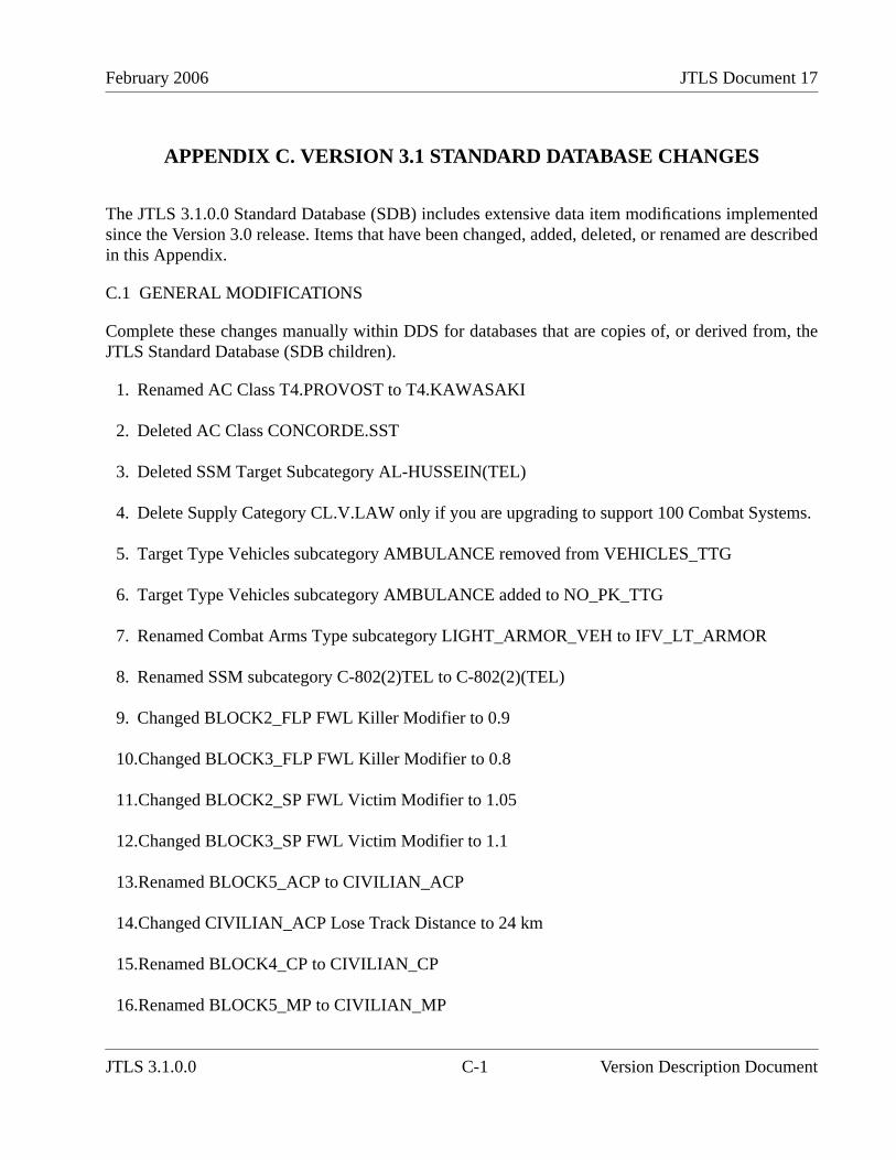
February 2006 JTLS Document 17
APPENDIX C. VERSION 3.1 STANDARD DATABASE CHANGES
The JTLS 3.1.0.0 Standard Database (SDB) includes extensive data item modifications implementedsince the Version 3.0 release. Items that have been changed, added, deleted, or renamed are describedin this Appendix.
C.1 GENERAL MODIFICATIONS
Complete these changes manually within DDS for databases that are copies of, or derived from, theJTLS Standard Database (SDB children).
1. Renamed AC Class T4.PROVOST to T4.KAWASAKI
2. Deleted AC Class CONCORDE.SST
3. Deleted SSM Target Subcategory AL-HUSSEIN(TEL)
4. Delete Supply Category CL.V.LAW only if you are upgrading to support 100 Combat Systems.
5. Target Type Vehicles subcategory AMBULANCE removed from VEHICLES_TTG
6. Target Type Vehicles subcategory AMBULANCE added to NO_PK_TTG
7. Renamed Combat Arms Type subcategory LIGHT_ARMOR_VEH to IFV_LT_ARMOR
8. Renamed SSM subcategory C-802(2)TEL to C-802(2)(TEL)
9. Changed BLOCK2_FLP FWL Killer Modifier to 0.9
10.Changed BLOCK3_FLP FWL Killer Modifier to 0.8
11.Changed BLOCK2_SP FWL Victim Modifier to 1.05
12.Changed BLOCK3_SP FWL Victim Modifier to 1.1
13.Renamed BLOCK5_ACP to CIVILIAN_ACP
14.Changed CIVILIAN_ACP Lose Track Distance to 24 km
15.Renamed BLOCK4_CP to CIVILIAN_CP
16.Renamed BLOCK5_MP to CIVILIAN_MP
JTLS 3.1.0.0 C-1 Version Description Document
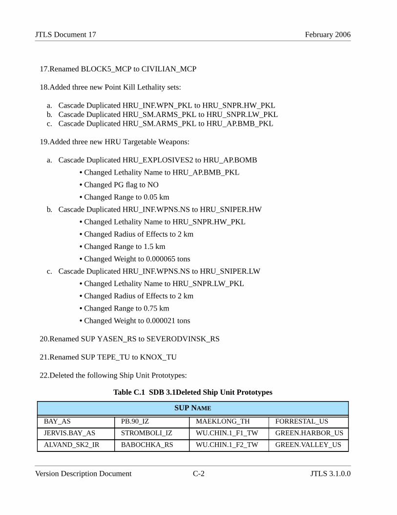
JTLS Document 17 February 2006
17.Renamed BLOCK5_MCP to CIVILIAN_MCP
18.Added three new Point Kill Lethality sets:
a. Cascade Duplicated HRU_INF.WPN_PKL to HRU_SNPR.HW_PKLb. Cascade Duplicated HRU_SM.ARMS_PKL to HRU_SNPR.LW_PKLc. Cascade Duplicated HRU_SM.ARMS_PKL to HRU_AP.BMB_PKL
19.Added three new HRU Targetable Weapons:
a. Cascade Duplicated HRU_EXPLOSIVES2 to HRU_AP.BOMB
• Changed Lethality Name to HRU_AP.BMB_PKL
• Changed PG flag to NO
• Changed Range to 0.05 km
b. Cascade Duplicated HRU_INF.WPNS.NS to HRU_SNIPER.HW
• Changed Lethality Name to HRU_SNPR.HW_PKL
• Changed Radius of Effects to 2 km
• Changed Range to 1.5 km
• Changed Weight to 0.000065 tons
c. Cascade Duplicated HRU_INF.WPNS.NS to HRU_SNIPER.LW
• Changed Lethality Name to HRU_SNPR.LW_PKL
• Changed Radius of Effects to 2 km
• Changed Range to 0.75 km
• Changed Weight to 0.000021 tons
20.Renamed SUP YASEN_RS to SEVERODVINSK_RS
21.Renamed SUP TEPE_TU to KNOX_TU
22.Deleted the following Ship Unit Prototypes:
Table C.1 SDB 3.1Deleted Ship Unit Prototypes
SUP NAME
BAY_AS PB.90_IZ MAEKLONG_TH FORRESTAL_US
JERVIS.BAY_AS STROMBOLI_IZ WU.CHIN.1_F1_TW GREEN.HARBOR_US
ALVAND_SK2_IR BABOCHKA_RS WU.CHIN.1_F2_TW GREEN.VALLEY_US
Version Description Document C-2 JTLS 3.1.0.0

February 2006 JTLS Document 17
C.2 ATLANTIS SCENARIO
These changes are specific to the SDB Atlantis scenario only. The release version of SDB includesthese changes.
1. Deleted Squadron Units FRANCE.1 and FRANCE.2
2. Deleted Sensor Site Target 0004SS0010_SVRN.NB
3. Deleted Supply Storage Target 0007SA0011_SVRN.NB
4. Deleted Supply Storage Target 0007SA0012_SVRN.NB
5. Deleted Supply Storage Target 0007SA0013_SVRN.NB
6. Deleted Supply Storage Target 0007SA0014_SVRN.NB
7. Deleted Facility Target 0009FA0006_SVRN.NB
8. Deleted Facility Target 0009FA0007_SVRN.NB
9. Deleted Facility Target 0009FA0008_SVRN.NB
10.Deleted Aircraft Shelter Target 0010AS0001_SVRN.NB
11.Deleted Aircraft Shelter Target 0010AS0003_SVRN.NB
12.Deleted Aircraft Shelter Target 0010AS0004_SVRN.NB
BABR_IR GRISHA.I_RS WU.CHIN.2_F1_TW INCHON_US
MSC.292_IR MOD.KASHIN_RS WU.CHIN.2_F2_TW IWO.JIMA_US
WINCHESTER_IR MOD.KIEV_RS ARDENNES_UK JEB.STUART_US
YUGO_IR PETYA_2_RS NORTHELLA_UK NARWHAL_US
ASSAD_IZ TARANTUL_I_RS A.CORMORANT_US SILAS.BENT_US
NESTIN_IZ TURYA_RS BEN.FRANKLIN_US SPRUANCE_NVL_US
OSA.I_IZ DSM.501_SR CALIFORNIA_US VIRGINIA_US
Table C.1 SDB 3.1Deleted Ship Unit Prototypes (Continued)
SUP NAME
JTLS 3.1.0.0 C-3 Version Description Document
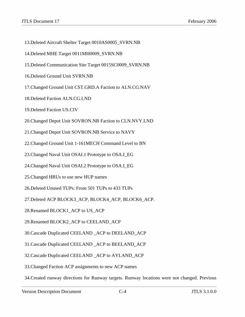
JTLS Document 17 February 2006
13.Deleted Aircraft Shelter Target 0010AS0005_SVRN.NB
14.Deleted MHE Target 0011MH0009_SVRN.NB
15.Deleted Communication Site Target 0015SC0009_SVRN.NB
16.Deleted Ground Unit SVRN.NB
17.Changed Ground Unit CST.GRD.A Faction to ALN.CG.NAV
18.Deleted Faction ALN.CG.LND
19.Deleted Faction US.CIV
20.Changed Depot Unit SOVRON.NB Faction to CLN.NVY.LND
21.Changed Depot Unit SOVRON.NB Service to NAVY
22.Changed Ground Unit 1-161MECH Command Level to BN
23.Changed Naval Unit OSAI.1 Prototype to OSA.I_EG
24.Changed Naval Unit OSAI.2 Prototype to OSA.I_EG
25.Changed HRUs to use new HUP names
26.Deleted Unused TUPs: From 501 TUPs to 433 TUPs
27.Deleted ACP BLOCK3_ACP, BLOCK4_ACP, BLOCK6_ACP.
28.Renamed BLOCK1_ACP to US_ACP
29.Renamed BLOCK2_ACP to CEELAND_ACP
30.Cascade Duplicated CEELAND _ACP to DEELAND_ACP
31.Cascade Duplicated CEELAND _ACP to BEELAND_ACP
32.Cascade Duplicated CEELAND _ACP to AYLAND_ACP
33.Changed Faction ACP assignments to new ACP names
34.Created runway directions for Runway targets. Runway locations were not changed. Previous
Version Description Document C-4 JTLS 3.1.0.0
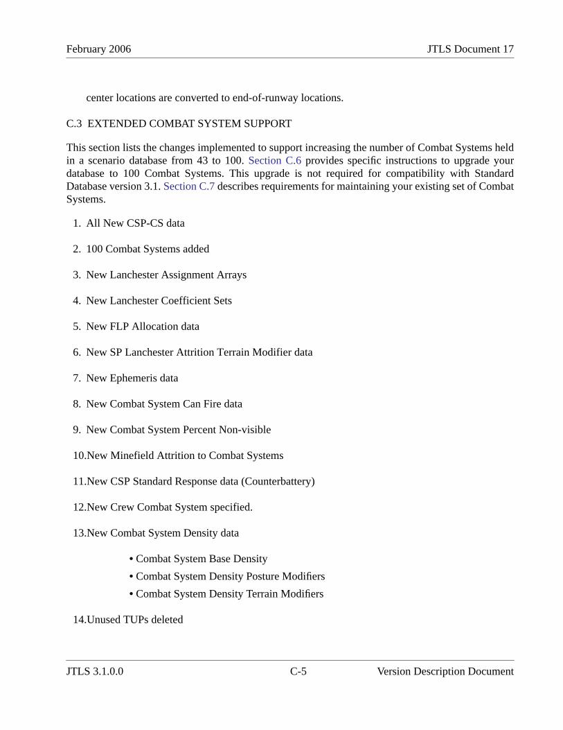
February 2006 JTLS Document 17
center locations are converted to end-of-runway locations.
C.3 EXTENDED COMBAT SYSTEM SUPPORT
This section lists the changes implemented to support increasing the number of Combat Systems heldin a scenario database from 43 to 100. Section C.6 provides specific instructions to upgrade yourdatabase to 100 Combat Systems. This upgrade is not required for compatibility with StandardDatabase version 3.1. Section C.7 describes requirements for maintaining your existing set of CombatSystems.
1. All New CSP-CS data
2. 100 Combat Systems added
3. New Lanchester Assignment Arrays
4. New Lanchester Coefficient Sets
5. New FLP Allocation data
6. New SP Lanchester Attrition Terrain Modifier data
7. New Ephemeris data
8. New Combat System Can Fire data
9. New Combat System Percent Non-visible
10.New Minefield Attrition to Combat Systems
11.New CSP Standard Response data (Counterbattery)
12.New Crew Combat System specified.
13.New Combat System Density data
• Combat System Base Density
• Combat System Density Posture Modifiers
• Combat System Density Terrain Modifiers
14.Unused TUPs deleted
JTLS 3.1.0.0 C-5 Version Description Document
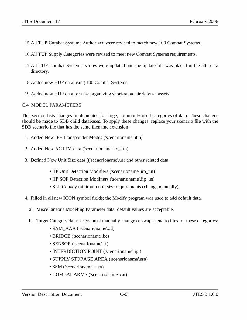
JTLS Document 17 February 2006
15.All TUP Combat Systems Authorized were revised to match new 100 Combat Systems.
16.All TUP Supply Categories were revised to meet new Combat Systems requirements.
17.All TUP Combat Systems' scores were updated and the update file was placed in the alterdatadirectory.
18.Added new HUP data using 100 Combat Systems
19.Added new HUP data for task organizing short-range air defense assets
C.4 MODEL PARAMETERS
This section lists changes implemented for large, commonly-used categories of data. These changesshould be made to SDB child databases. To apply these changes, replace your scenario file with theSDB scenario file that has the same filename extension.
1. Added New IFF Transponder Modes ('scenarioname'.itm)
2. Added New AC ITM data ('scenarioname'.ac_itm)
3. Defined New Unit Size data (('scenarioname'.us) and other related data:
• IIP Unit Detection Modifiers ('scenarioname'.iip_tut)
• IIP SOF Detection Modifiers ('scenarioname'.iip_us)
• SLP Convoy minimum unit size requirements (change manually)
4. Filled in all new ICON symbol fields; the Modify program was used to add default data.
a. Miscellaneous Modeling Parameter data: default values are acceptable.
b. Target Category data: Users must manually change or swap scenario files for these categories:
• SAM_AAA ('scenarioname'.ad)
• BRIDGE ('scenarioname'.bc)
• SENSOR ('scenarioname'.st)
• INTERDICTION POINT ('scenarioname'.ipt)
• SUPPLY STORAGE AREA ('scenarioname'.ssa)
• SSM ('scenarioname'.ssm)
• COMBAT ARMS ('scenarioname'.cat)
Version Description Document C-6 JTLS 3.1.0.0

February 2006 JTLS Document 17
• TRANSPORTATION CLASS ('scenarioname'.tc)
• AIRCRAFT TARGET CLASS ('scenarioname'.atc)
• SUPPLY TYPE ('scenarioname'.sut)
• Other Target Categories: default OK
• SLP Convoy data: default OK
• ACP Air Mission data: default values are acceptable
5. Added new Aircraft Class data: (’scenarioname’.ac)
• AC Stall Speed, Stall Speed Fuel Mod, Max Speed Fuel Mod
6. Adjusted existing Aircraft Class data for some aircraft:
• AC Cruise Speed, AC Max Speed: (’scenarioname’.ac)
7. Adjusted AC Prob Detection data for aircraft with the lowest values;
• Some AC in v3.0 had a zero AC Prob Detection: (’scenarioname’.ac)
8. Added new AC Average Malfunction Repair Time: (’scenarioname’.ac)
9. Reduced AC Damage Repair Time for AC with larger values: (’scenarioname’.ac)
10.AC Number of Weapons Control limited to 2 for all aircraft: (’scenarioname’.ac)
11.Added AC USMTF Name: (’scenarioname’.ac)
12.Added new SUP Average Time to Sink values (’scenarioname’.sup)
13.Added lethalities for AGM114.HELLFIRE against all ships: (’scenarioname’.pkl_tgc)
C.5 SCENARIO-SPECIFIC DATA
This section describes data that are specific to a particular scenario. You must change these valuesbased on your scenario.
1. Air Control Prototype IFF Transponder Mode data
2. Air Control Prototype IFF data
3. With the new IFF/ITM data, consider having a unique ACP for each side
JTLS 3.1.0.0 C-7 Version Description Document
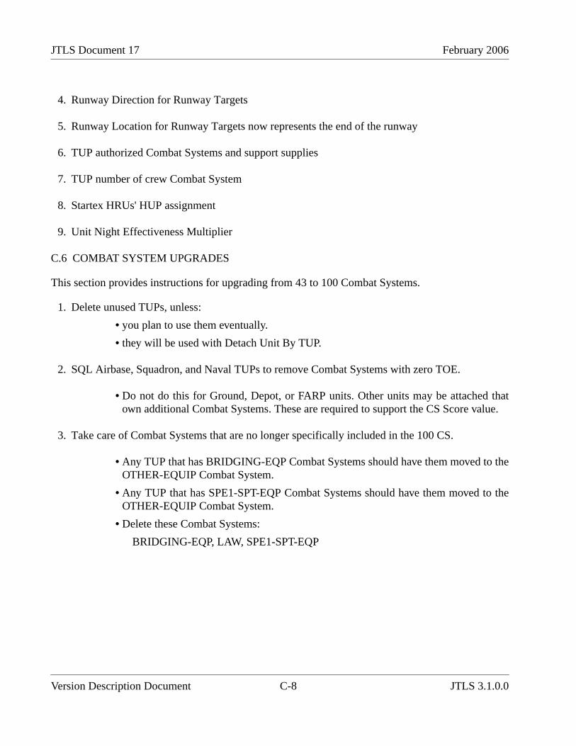
JTLS Document 17 February 2006
4. Runway Direction for Runway Targets
5. Runway Location for Runway Targets now represents the end of the runway
6. TUP authorized Combat Systems and support supplies
7. TUP number of crew Combat System
8. Startex HRUs' HUP assignment
9. Unit Night Effectiveness Multiplier
C.6 COMBAT SYSTEM UPGRADES
This section provides instructions for upgrading from 43 to 100 Combat Systems.
1. Delete unused TUPs, unless:
• you plan to use them eventually.
• they will be used with Detach Unit By TUP.
2. SQL Airbase, Squadron, and Naval TUPs to remove Combat Systems with zero TOE.
• Do not do this for Ground, Depot, or FARP units. Other units may be attached thatown additional Combat Systems. These are required to support the CS Score value.
3. Take care of Combat Systems that are no longer specifically included in the 100 CS.
• Any TUP that has BRIDGING-EQP Combat Systems should have them moved to theOTHER-EQUIP Combat System.
• Any TUP that has SPE1-SPT-EQP Combat Systems should have them moved to theOTHER-EQUIP Combat System.
• Delete these Combat Systems:
BRIDGING-EQP, LAW, SPE1-SPT-EQP
Version Description Document C-8 JTLS 3.1.0.0

February 2006 JTLS Document 17
4. Rename the 43 Combat Systems to their new 100 CS names.
Table C.2 Renamed SDB 31 Combat Systems
43 CS NAME 100 CS NAME
AIRCRAFT AIRCRAFT
AMPHIB-VEH AMPHIB-LA-TW
APC APC-LA-OW1
ARMR-GUN-SYS AGS90-LA
ATGM-AFV ATGMSP-LT-LT
C3I C3I
CHEM-REL-EQP EQUIP-CHEM
COMD-SIG-VEH UTIL-VEH-LA
CREW-WEAPONS CREW-WEAPON
ELDERLY-CIVILNS ELDERLY
ENGINEER-EQP EQUIP-ENG2
HAW-ATGM AT-HAW-LR-HL
HV-HOWTZ-GUN ARTYTOW-MHV
HV-SP-HOWTZ ARTYSP-MHV-T
HVY-EQP-TRAN TRUCK-HET
IFV IFV-HA-TC
IFV-W-ATGM IFV-ATLHXATC
INFANTRY INFANTRY
INFANTS_0-5YO INFANTS
LAV IFV-LA-TC
LR-MLRS MRL-LR-VEH
LT-HOWTZ-GUN ARTYTOW-LT
LT-SP-HOWTZ ARTYSP-LT-T
MAW AT-MAW-LR
MD-HOWTZ-GUN ARTYTOW-MLT
MEN.15.UP MEN
LT-MORTARS MTRDISM81-82
HV-MORTARS MTRDISMHVY
JTLS 3.1.0.0 C-9 Version Description Document
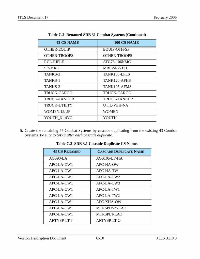
JTLS Document 17 February 2006
5. Create the remaining 57 Combat Systems by cascade duplicating from the existing 43 CombatSystems. Be sure to SAVE after each cascade duplicate.
OTHER-EQUIP EQUIP-OTH-SP
OTHER-TROOPS OTHER-TROOPS
RCL-RIFLE ATG73-106NMC
SR-MRL MRL-SR-VEH
TANKS-3 TANK100-LFLS
TANKS-1 TANK120-AFHS
TANKS-2 TANK105-AFMS
TRUCK-CARGO TRUCK-CARGO
TRUCK-TANKER TRUCK-TANKER
TRUCK-UTILTY UTIL-VEH-NA
WOMEN.15.UP WOMEN
YOUTH_6-14YO YOUTH
Table C.3 SDB 3.1 Cascade Duplicate CS Names
43 CS RENAMED CASCADE DUPLICATE NAME
AGS90-LA AGS105-LF-HA
APC-LA-OW1 APC-HA-OW
APC-LA-OW1 APC-HA-TW
APC-LA-OW1 APC-LA-OW2
APC-LA-OW1 APC-LA-OW3
APC-LA-OW1 APC-LA-TW1
APC-LA-OW1 APC-LA-TW2
APC-LA-OW1 APC-XHA-OW
APC-LA-OW1 MTRSPHVY-LAO
APC-LA-OW1 MTRSPLT-LAO
ARTYSP-LT-T ARTYSP-LT-O
Table C.2 Renamed SDB 31 Combat Systems (Continued)
43 CS NAME 100 CS NAME
Version Description Document C-10 JTLS 3.1.0.0

February 2006 JTLS Document 17
ARTYSP-LT-T ARTYSP-MLT
ARTYSP-LT-T MTRSP120-LAT
ARTYSP-MHV-T ARTYSP-HV-O
ARTYSP-MHV-T ARTYSP-MHV-O
ARTYTOW-LT ARTYTOW-VLT
ARTYTOW-LT ATG100-125MC
ARTYTOW-MHV ARTYTOW-HVY
ATGMSP-LT-LT ATGMSP-LH-LO
ATGMSP-LT-LT ATGMSP-LH-LT
ATGMSP-LT-LT ATGMSP-LM-LT
ATGMSP-LT-LT ATGMSP-SH-LT
AT-HAW-LR-HL AT-HAW-LR-TA
AT-HAW-LR-HL AT-HAW-SR-HL
AT-HAW-LR-HL AT-HAW-SR-ML
AT-HAW-LR-HL AT-HAW-SR-TA
AT-MAW-LR AT-MAW-SR-HL
AT-MAW-LR AT-MAW-SR-ML
AT-MAW-LR AT-MAW-SR-TA
EQUIP-ENG2 EQUIP-ENG1
EQUIP-ENG2 EQUIP-ENG3
EQUIP-OTH-SP EQUIP-OTH-TO
IFV-ATLHXATC IFV-ATLHHATC
IFV-ATLHXATC IFV-ATLHLATC
IFV-ATLHXATC IFV-ATLHXACG
IFV-ATLHXATC IFV-ATSHHATC
IFV-ATLHXATC IFV-ATSHXATC
IFV-ATLHXATC IFV-ATSMHATC
IFV-ATLHXATC IFV-ATSMLATC
IFV-HA-TC IFV-XHA-TC
Table C.3 SDB 3.1 Cascade Duplicate CS Names (Continued)
43 CS RENAMED CASCADE DUPLICATE NAME
JTLS 3.1.0.0 C-11 Version Description Document
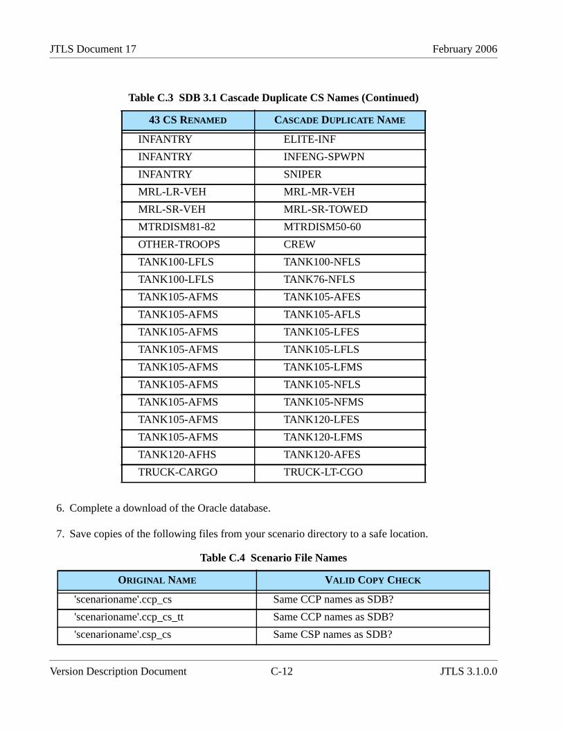
JTLS Document 17 February 2006
6. Complete a download of the Oracle database.
7. Save copies of the following files from your scenario directory to a safe location.
INFANTRY ELITE-INF
INFANTRY INFENG-SPWPN
INFANTRY SNIPER
MRL-LR-VEH MRL-MR-VEH
MRL-SR-VEH MRL-SR-TOWED
MTRDISM81-82 MTRDISM50-60
OTHER-TROOPS CREW
TANK100-LFLS TANK100-NFLS
TANK100-LFLS TANK76-NFLS
TANK105-AFMS TANK105-AFES
TANK105-AFMS TANK105-AFLS
TANK105-AFMS TANK105-LFES
TANK105-AFMS TANK105-LFLS
TANK105-AFMS TANK105-LFMS
TANK105-AFMS TANK105-NFLS
TANK105-AFMS TANK105-NFMS
TANK105-AFMS TANK120-LFES
TANK105-AFMS TANK120-LFMS
TANK120-AFHS TANK120-AFES
TRUCK-CARGO TRUCK-LT-CGO
Table C.4 Scenario File Names
ORIGINAL NAME VALID COPY CHECK
'scenarioname'.ccp_cs Same CCP names as SDB?
'scenarioname'.ccp_cs_tt Same CCP names as SDB?
'scenarioname'.csp_cs Same CSP names as SDB?
Table C.3 SDB 3.1 Cascade Duplicate CS Names (Continued)
43 CS RENAMED CASCADE DUPLICATE NAME
Version Description Document C-12 JTLS 3.1.0.0
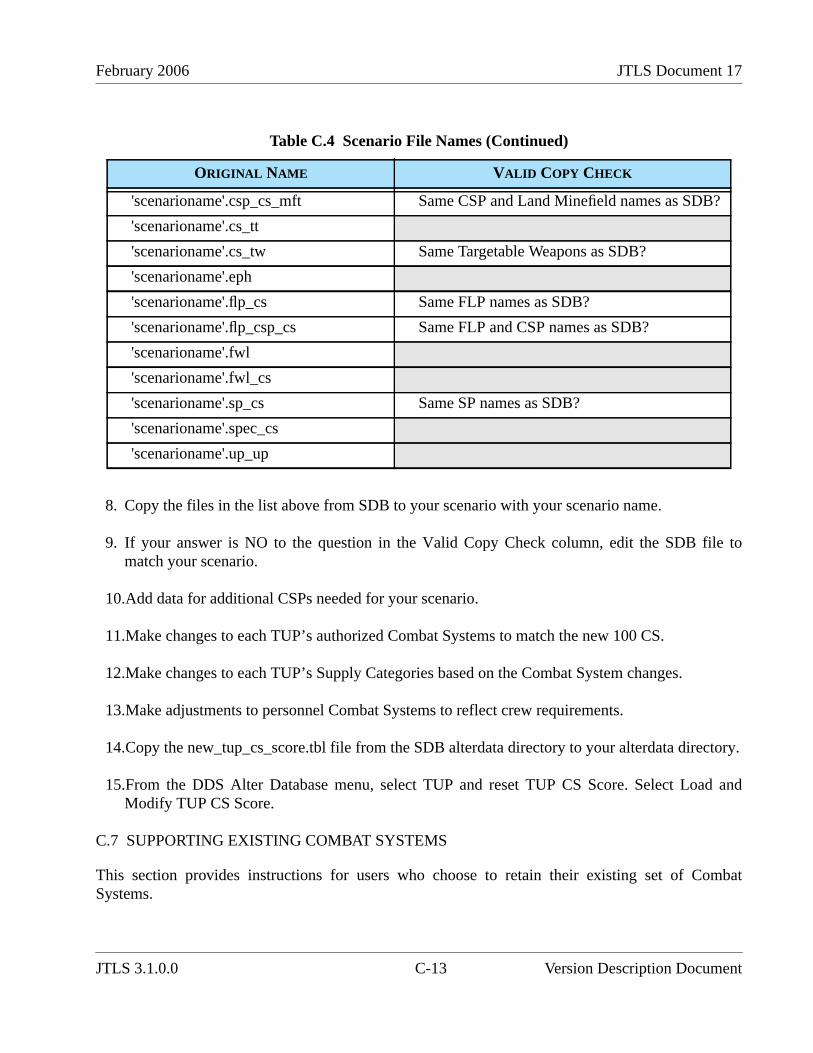
February 2006 JTLS Document 17
8. Copy the files in the list above from SDB to your scenario with your scenario name.
9. If your answer is NO to the question in the Valid Copy Check column, edit the SDB file tomatch your scenario.
10.Add data for additional CSPs needed for your scenario.
11.Make changes to each TUP’s authorized Combat Systems to match the new 100 CS.
12.Make changes to each TUP’s Supply Categories based on the Combat System changes.
13.Make adjustments to personnel Combat Systems to reflect crew requirements.
14.Copy the new_tup_cs_score.tbl file from the SDB alterdata directory to your alterdata directory.
15.From the DDS Alter Database menu, select TUP and reset TUP CS Score. Select Load andModify TUP CS Score.
C.7 SUPPORTING EXISTING COMBAT SYSTEMS
This section provides instructions for users who choose to retain their existing set of CombatSystems.
'scenarioname'.csp_cs_mft Same CSP and Land Minefield names as SDB?
'scenarioname'.cs_tt
'scenarioname'.cs_tw Same Targetable Weapons as SDB?
'scenarioname'.eph
'scenarioname'.flp_cs Same FLP names as SDB?
'scenarioname'.flp_csp_cs Same FLP and CSP names as SDB?
'scenarioname'.fwl
'scenarioname'.fwl_cs
'scenarioname'.sp_cs Same SP names as SDB?
'scenarioname'.spec_cs
'scenarioname'.up_up
Table C.4 Scenario File Names (Continued)
ORIGINAL NAME VALID COPY CHECK
JTLS 3.1.0.0 C-13 Version Description Document
JTLS Document 17 February 2006
1. Lanchester coefficient data are still reduced. Since they are no longer indexed by FLP and SP,you must use the FLP and SP FWL modifiers to account for those differences. Typically, theOpposing Force FLP and SP resulted in the Opposing Force causing less attrition to other forceswhile taking more attrition from other forces. Using the same FLP and SP FWL modifier valueslisted in Section C.1. is recommended.
2. The CSP-CS data now include a Killer FWL Modifier and a Victim FWL Modifier. You mayprefer to change these MODIFIERS for less-capable systems in some CSPs. Note that a VictimFWL Modifier greater than 1.0 means that the associated Combat System will suffer morelosses.
C.8 REMAINING ENHANCEMENTS
This section describes data that have not been added or updated for this release.
SUP Combat Systems have not been changed to the new 100 Combat Systems. Minimal changeswere made to the NAVY_CSP that allow existing SUPs to function. SUP changes that include a newNAVY_CSP will be provided for a future JTLS release.
The ECP JTLS-2005-1480 Lifeboat Representation has not been fully implemented or tested for thisrelease. Therefore, no SUP has been assigned a Lifeboat HUP. If you choose to use this functionality,you must assign a Lifeboat HUP to the SUP of interest and change the SUP Lifeboat Mean Time ToDeploy, which is currently set to the default time of 1.0 minutes. Lifeboat HUPs have been addded;Lifeboat HUP names are identified by the inital characters LB.
Version Description Document C-14 JTLS 3.1.0.0
Related Documents