Verilog HDL Basics

Welcome message from author
This document is posted to help you gain knowledge. Please leave a comment to let me know what you think about it! Share it to your friends and learn new things together.
Transcript
Verilog HDL Basics
Verilog HDL Basics2
What is Verilog
• Hardware Description Language (HDL)
• Developed in 1984
• Standard: IEEE 1364, Dec 1995

Verilog HDL Basics3
Verilog vs. VHDL
• VHDL– Used throughout Europe, Japan and IBM– More strict syntax
• Verilog– Preferred in commercial product design– Easy to learn and use– C-like language
• Reality– Impossible to say which is better: matter of taste

Verilog HDL Basics4
Description of digital systems only
Basic Limitation of Verilog
Verilog HDL Basics5
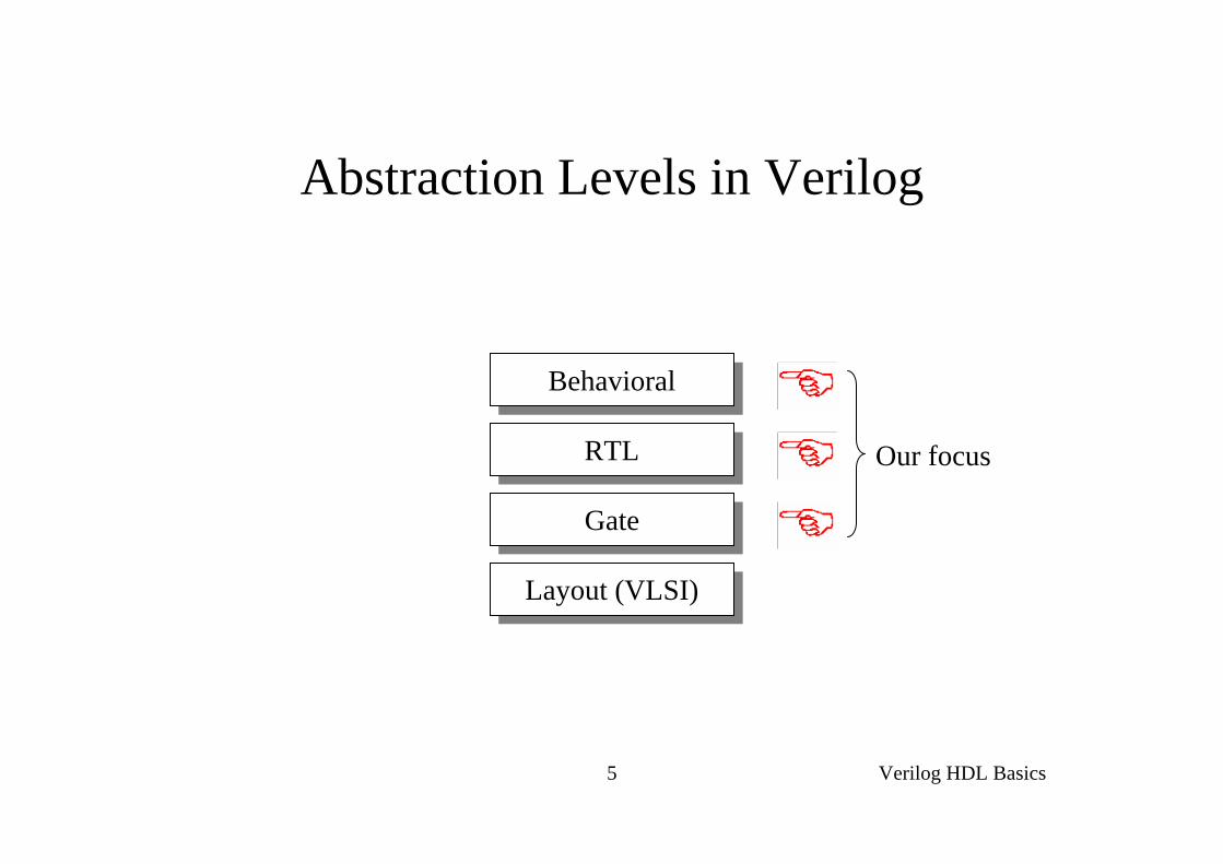
Abstraction Levels in Verilog
BehavioralBehavioral
RTLRTL
GateGate
Layout (VLSI)Layout (VLSI)
Our focus
Verilog HDL Basics6
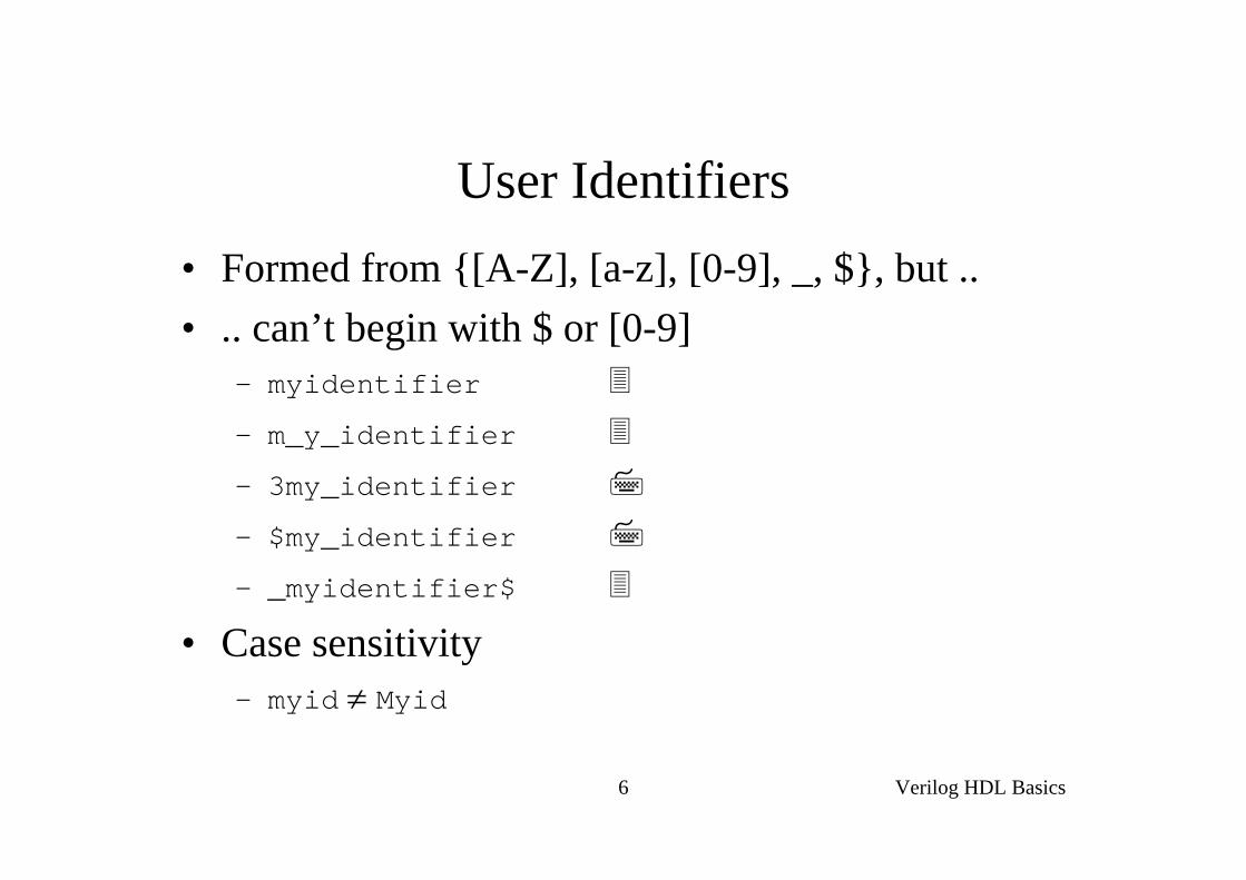
User Identifiers• Formed from {[A-Z], [a-z], [0-9], _, $}, but .. • .. can’t begin with $ or [0-9]
– myidentifier
– m_y_identifier
– 3my_identifier
– $my_identifier
– _myidentifier$
• Case sensitivity– myid ≠ Myid
Verilog HDL Basics7
Comments
• // The rest of the line is a comment
• /* Multiple linecomment */
• /* Nesting /* comments */ do NOT work */

Verilog HDL Basics8
Verilog Value Set
• 0 represents low logic level or false condition
• 1 represents high logic level or true condition
• x represents unknown logic level
• z represents high impedance logic level

Verilog HDL Basics9
Nets (i)
• Can be thought as hardware wires driven by logic• Equal z when unconnected• Various types of nets
– wire
– wand (wired-AND)– wor (wired-OR)– tri (tri-state)
• In following examples: Y is evaluated, automatically, every time A or B changes

Verilog HDL Basics10
Nets (ii)AB Y
wire Y; // declaration
assign Y = A & B;
B
AY
wand Y; // declaration
assign Y = A;assign Y = B;
wor Y; // declaration
assign Y = A;assign Y = B;
A Ydr
tri Y; // declaration
assign Y = (dr) ? A : z;

Verilog HDL Basics11
Registers• Variables that store values• Do not represent real hardware but ..• .. real hardware can be implemented with registers• Only one type: reg
reg A, C; // declaration// assignments are always done inside a procedureA = 1;
C = A; // C gets the logical value 1A = 0; // C is still 1C = 0; // C is now 0
• Register values are updated explicitly!!
Verilog HDL Basics12
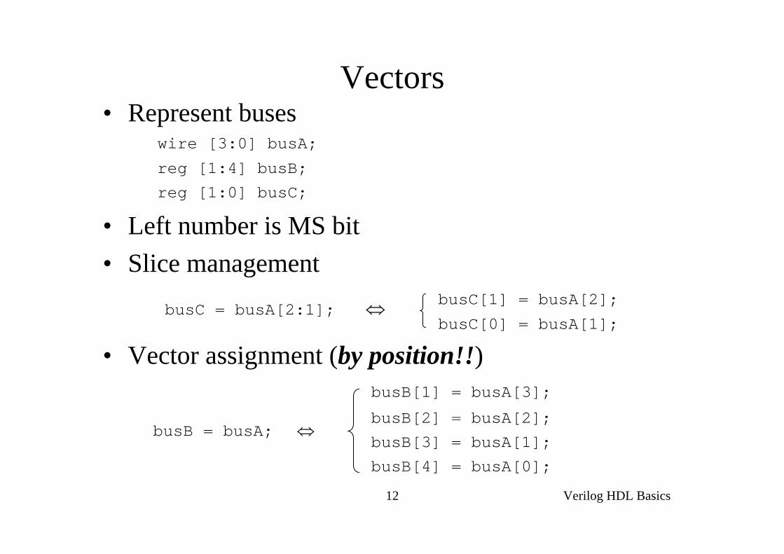
Vectors• Represent buses
wire [3:0] busA;
reg [1:4] busB;
reg [1:0] busC;
• Left number is MS bit• Slice management
busC[1] = busA[2];
busC[0] = busA[1];
• Vector assignment (by position!!)busB[1] = busA[3];
busB[2] = busA[2];busB[3] = busA[1];
busB[4] = busA[0];
busB = busA; ⇔
busC = busA[2:1]; ⇔
Verilog HDL Basics13
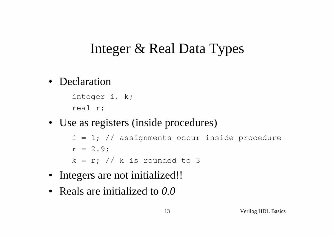
Integer & Real Data Types
• Declarationinteger i, k;real r;
• Use as registers (inside procedures)i = 1; // assignments occur inside procedurer = 2.9;k = r; // k is rounded to 3
• Integers are not initialized!!• Reals are initialized to 0.0
Verilog HDL Basics14
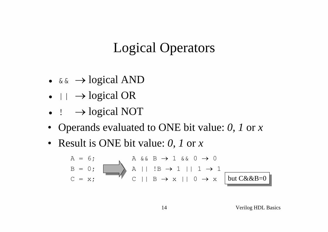
Logical Operators
• && → logical AND• || → logical OR• ! → logical NOT• Operands evaluated to ONE bit value: 0, 1 or x• Result is ONE bit value: 0, 1 or x
A = 6; A && B → 1 && 0 → 0
B = 0; A || !B → 1 || 1 → 1C = x; C || B → x || 0 → x but C&&B=0but C&&B=0

Verilog HDL Basics15
Bitwise Operators (i)
• & → bitwise AND• | → bitwise OR• ~ → bitwise NOT• ^ → bitwise XOR• ~^ or ^~ → bitwise XNOR
• Operation on bit by bit basis

Verilog HDL Basics16
Bitwise Operators (ii)c = ~a; c = a & b;
• a = 4’b1010;b = 4’b1100;
• a = 4’b1010;
b = 2’b11;
c = a ^ b;
Verilog HDL Basics17
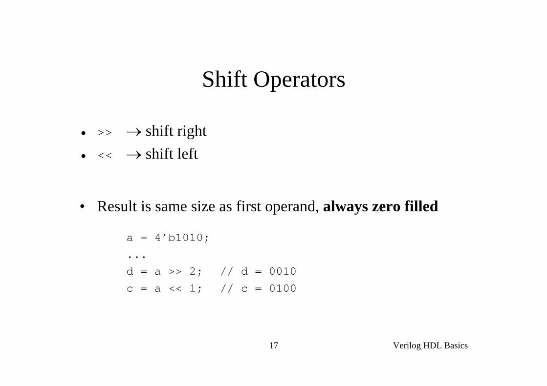
Shift Operators
• >> → shift right• << → shift left
• Result is same size as first operand, always zero filled
a = 4’b1010;...
d = a >> 2; // d = 0010
c = a << 1; // c = 0100

Verilog HDL Basics18
Conditional Operator
• cond_expr ? true_expr : false_expr
• Like a 2-to-1 mux ..
A
BY
sel
Y = (sel)? A : B;0
1
Verilog HDL Basics19
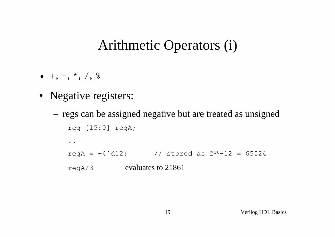
Arithmetic Operators (i)
• +, -, *, /, %
• Negative registers:– regs can be assigned negative but are treated as unsigned
reg [15:0] regA;
..
regA = -4’d12; // stored as 216-12 = 65524
regA/3 evaluates to 21861
Verilog HDL Basics20
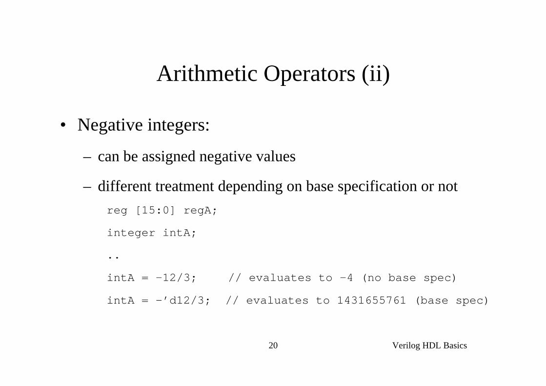
Arithmetic Operators (ii)
• Negative integers:
– can be assigned negative values
– different treatment depending on base specification or notreg [15:0] regA;
integer intA;
..
intA = -12/3; // evaluates to -4 (no base spec)
intA = -’d12/3; // evaluates to 1431655761 (base spec)
Verilog HDL Basics21
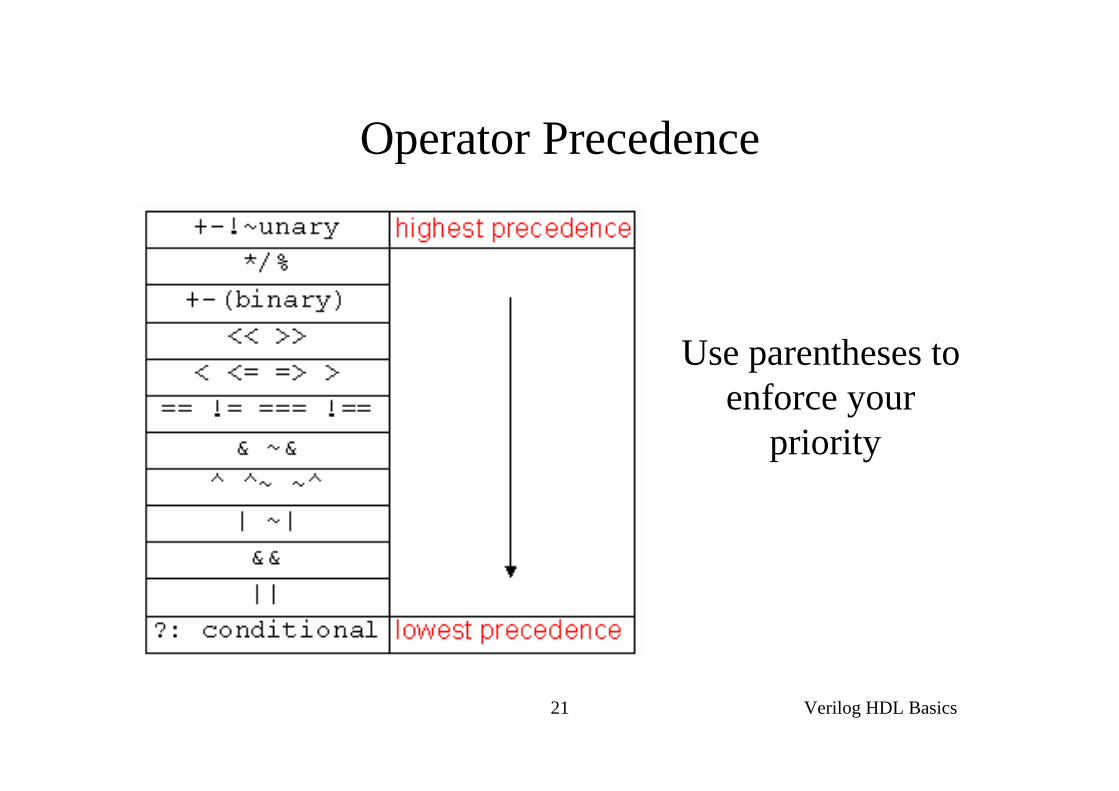
Operator Precedence
Use parentheses to enforce your
priority

Verilog HDL Basics22
Hierarchical Design
Top LevelModule
Top LevelModule
Sub-Module1
Sub-Module1
Sub-Module2
Sub-Module2
Basic Module3
Basic Module3
Basic Module2
Basic Module2
Basic Module1
Basic Module1
Full AdderFull Adder
Half AdderHalf Adder Half AdderHalf Adder
E.g.

Verilog HDL Basics23
Module
f
in1in2
inN
out1out2
outM
my_module
module my_module(out1, .., inN);
output out1, .., outM;
input in1, .., inN;
.. // declarations
.. // description of f (maybe
.. // sequential)
endmodule
Everything you write in Verilog must be inside a moduleexception: compiler directives

Verilog HDL Basics24
Example: Half Adder
module half_adder(S, C, A, B);output S, C;input A, B;
wire S, C, A, B;
assign S = A ^ B;assign C = A & B;
endmodule
HalfAdderHalf
Adder
A
B
S
C
A
B
S
C
Verilog HDL Basics25
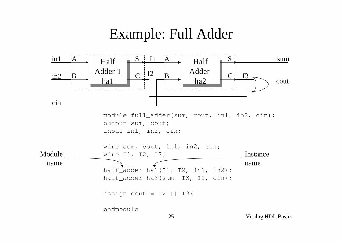
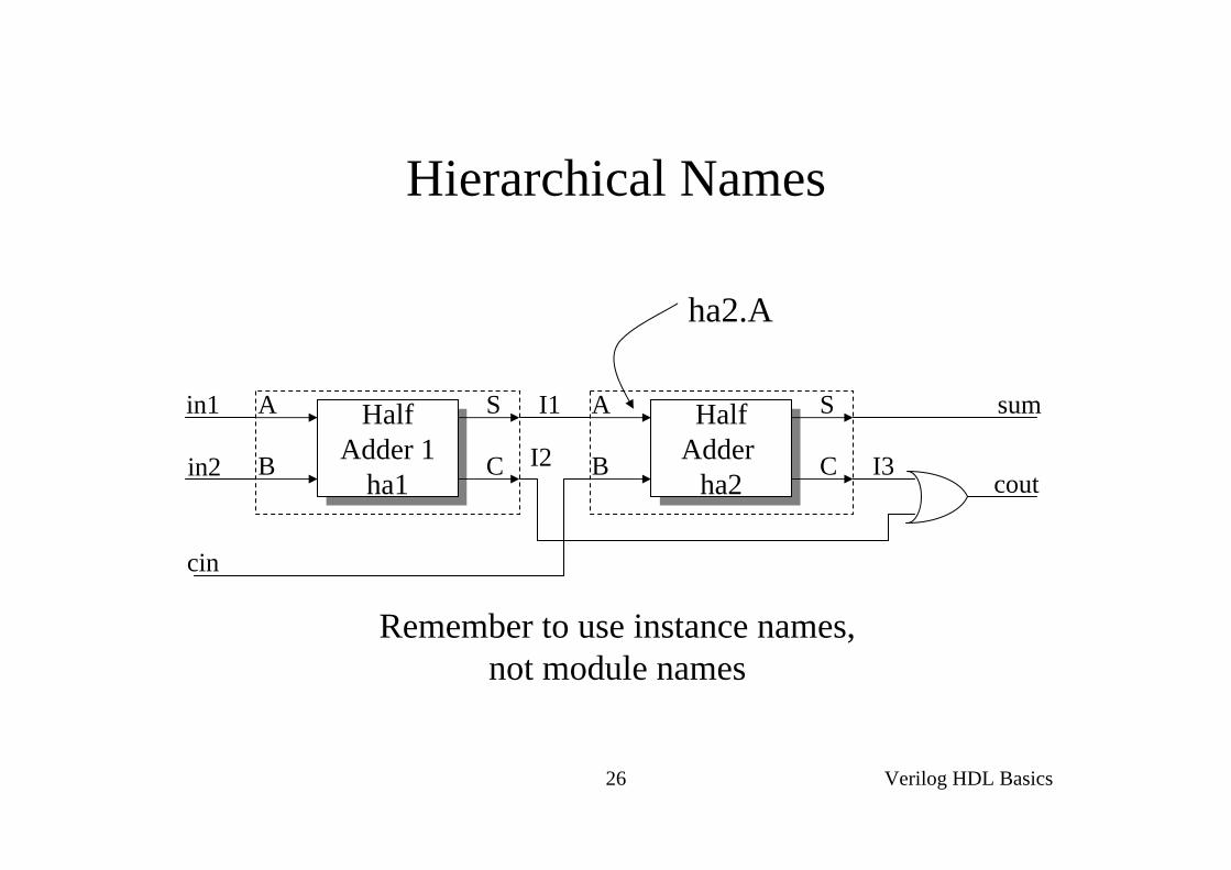
Example: Full Adder
module full_adder(sum, cout, in1, in2, cin);output sum, cout;input in1, in2, cin;
wire sum, cout, in1, in2, cin;wire I1, I2, I3;
half_adder ha1(I1, I2, in1, in2);half_adder ha2(sum, I3, I1, cin);
assign cout = I2 || I3;
endmodule
Instancename
Modulename
HalfAdder
ha2
HalfAdder
ha2
A
B
S
CHalf
Adder 1ha1
HalfAdder 1
ha1
A
B
S
C
in1
in2
cin
cout
sumI1
I2 I3
Verilog HDL Basics26
Hierarchical Names
ha2.A
Remember to use instance names,not module names
HalfAdder
ha2
HalfAdder
ha2
A
B
S
CHalf
Adder 1ha1
HalfAdder 1
ha1
A
B
S
C
in1
in2
cin
cout
sumI1
I2 I3

Verilog HDL Basics27
Port Assignments
module
reg or net net
module
reg or net net
module
net net
• Inputs
• Outputs
• Inouts
Verilog HDL Basics28
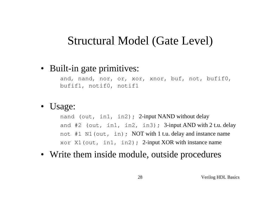
Structural Model (Gate Level)
• Built-in gate primitives:and, nand, nor, or, xor, xnor, buf, not, bufif0, bufif1, notif0, notif1
• Usage:nand (out, in1, in2); 2-input NAND without delayand #2 (out, in1, in2, in3); 3-input AND with 2 t.u. delaynot #1 N1(out, in); NOT with 1 t.u. delay and instance namexor X1(out, in1, in2); 2-input XOR with instance name
• Write them inside module, outside procedures

Verilog HDL Basics29
Example: Half Adder, 2nd Implementation
Assuming:• XOR: 2 t.u. delay• AND: 1 t.u. delay
module half_adder(S, C, A, B);output S, C;input A, B;
wire S, C, A, B;
xor #2 (S, A, B);and #1 (C, A, B);
endmodule
A
B
S
C

Verilog HDL Basics30
Behavioral Model - Procedures (i)
• Procedures = sections of code that we know they execute sequentially
• Procedural statements = statements inside a procedure (they execute sequentially)
• e.g. another 2-to-1 mux implem:begin
if (sel == 0)Y = B;
elseY = A;
end
ExecutionFlow Procedural assignments:
Y must be reg !!Procedural assignments:
Y must be reg !!

Verilog HDL Basics31
Behavioral Model - Procedures (ii)
• Modules can contain any number of procedures
• Procedures execute in parallel (in respect to each other) and ..
• .. can be expressed in two types of blocks:– initial → they execute only once
– always → they execute for ever (until simulation finishes)
Verilog HDL Basics32
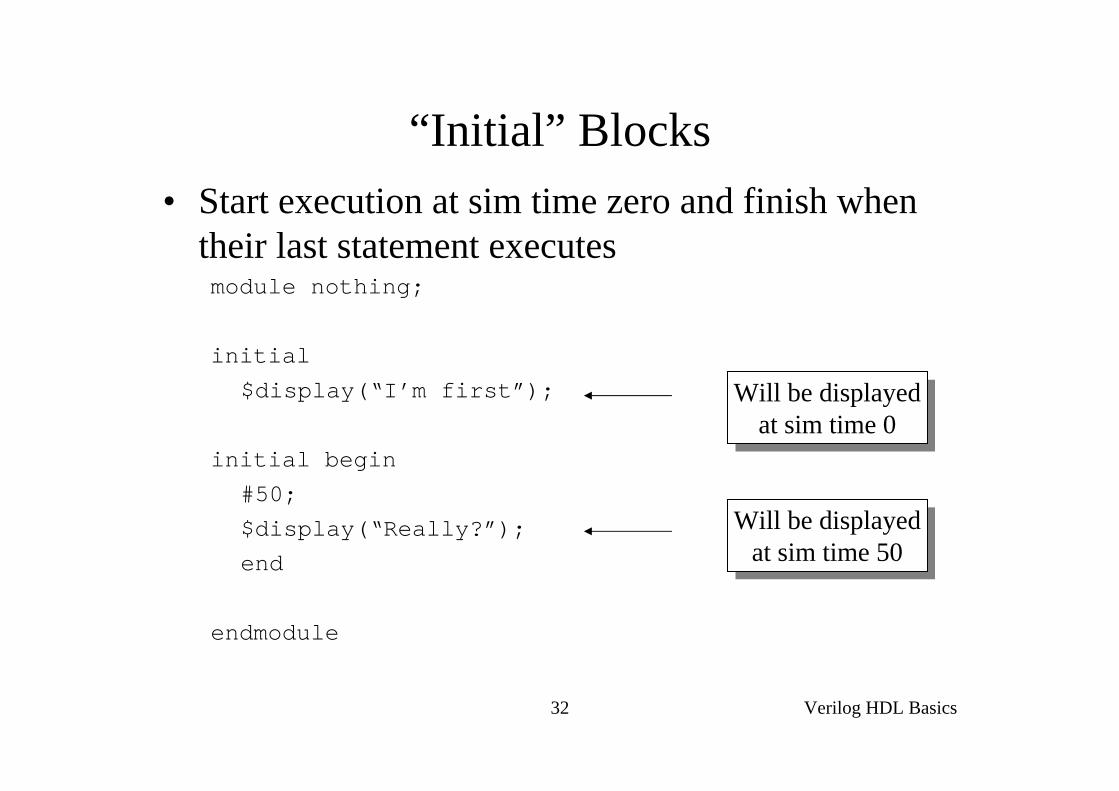
“Initial” Blocks• Start execution at sim time zero and finish when
their last statement executesmodule nothing;
initial
$display(“I’m first”);
initial begin
#50;$display(“Really?”);end
endmodule
Will be displayedat sim time 0
Will be displayedat sim time 0
Will be displayedat sim time 50
Will be displayedat sim time 50

Verilog HDL Basics33
“Always” Blocks• Start execution at sim time zero and continue until
sim finishes
Verilog HDL Basics34
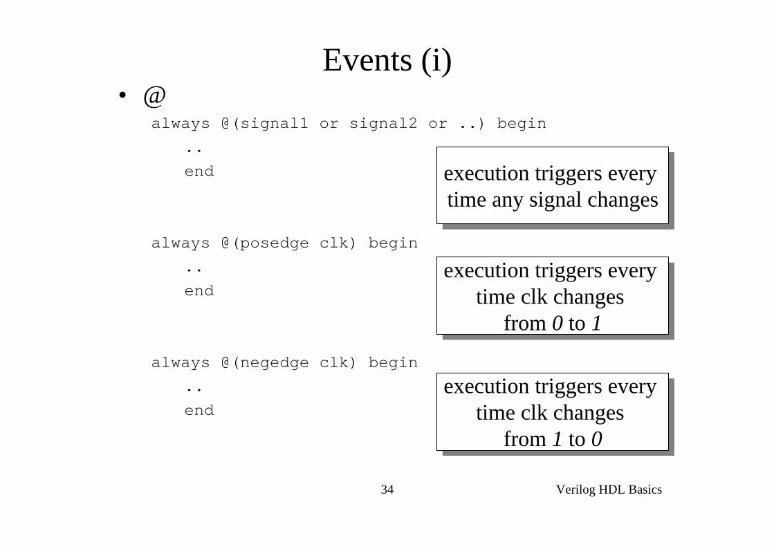
Events (i)• @
always @(signal1 or signal2 or ..) begin
..end
always @(posedge clk) begin..
end
always @(negedge clk) begin..end
execution triggers every time any signal changes
execution triggers every time any signal changes
execution triggers every time clk changes
from 0 to 1
execution triggers every time clk changes
from 0 to 1
execution triggers every time clk changes
from 1 to 0
execution triggers every time clk changes
from 1 to 0
Verilog HDL Basics35
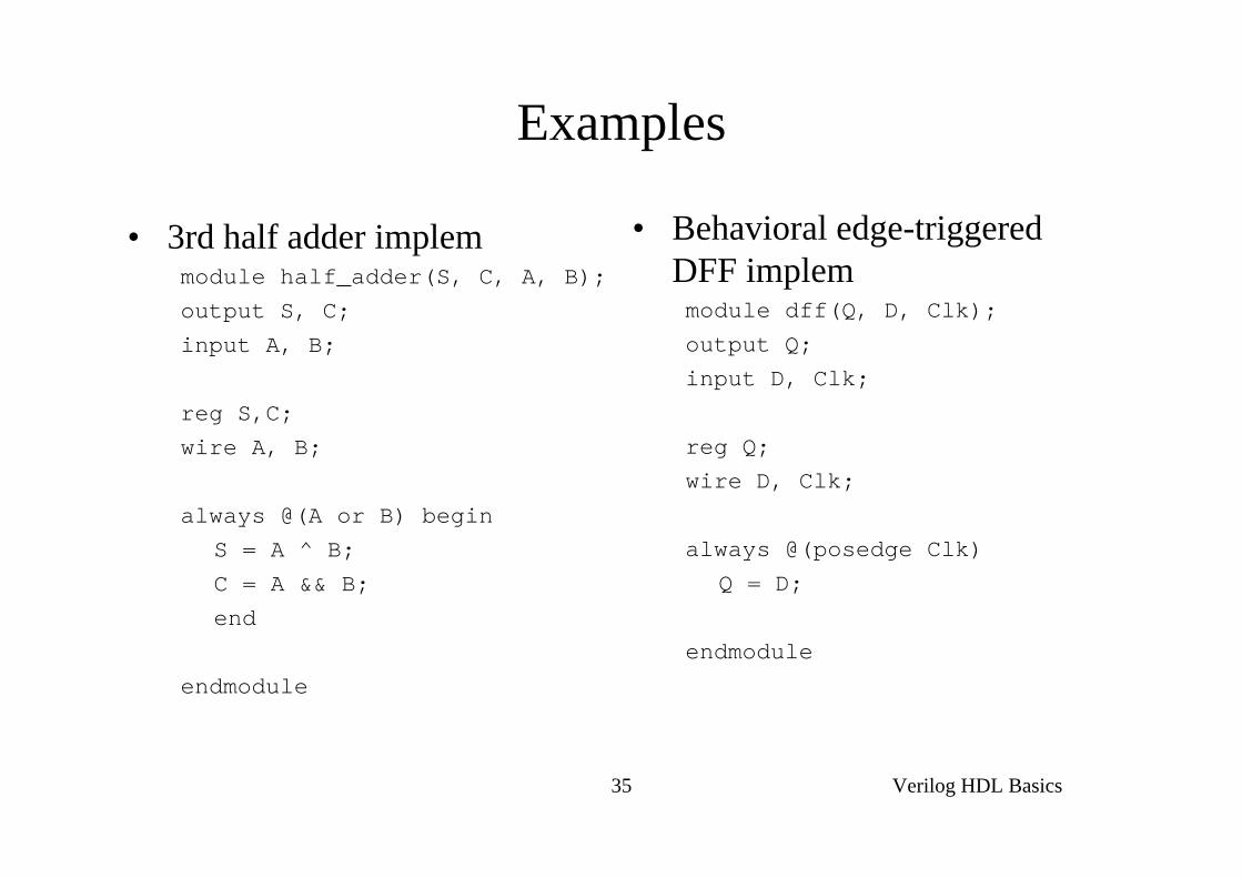
Examples
• 3rd half adder implemmodule half_adder(S, C, A, B);output S, C;
input A, B;
reg S,C;wire A, B;
always @(A or B) beginS = A ^ B;
C = A && B;end
endmodule
• Behavioral edge-triggered DFF implemmodule dff(Q, D, Clk);
output Q;input D, Clk;
reg Q;wire D, Clk;
always @(posedge Clk)
Q = D;
endmodule

Verilog HDL Basics36
Events (ii)
• wait (expr)always begin
wait (ctrl)#10 cnt = cnt + 1;#10 cnt2 = cnt2 + 2;
end
• e.g. Level triggered DFF ?
execution loops every time ctrl = 1 (level
sensitive timing control)
execution loops every time ctrl = 1 (level
sensitive timing control)

Verilog HDL Basics37
Example
ab
c
Y
W
clk
resalways @(res or posedge clk) begin
if (res) beginY = 0;W = 0;end
else beginY = a & b;W = ~c;end
end
Verilog HDL Basics38
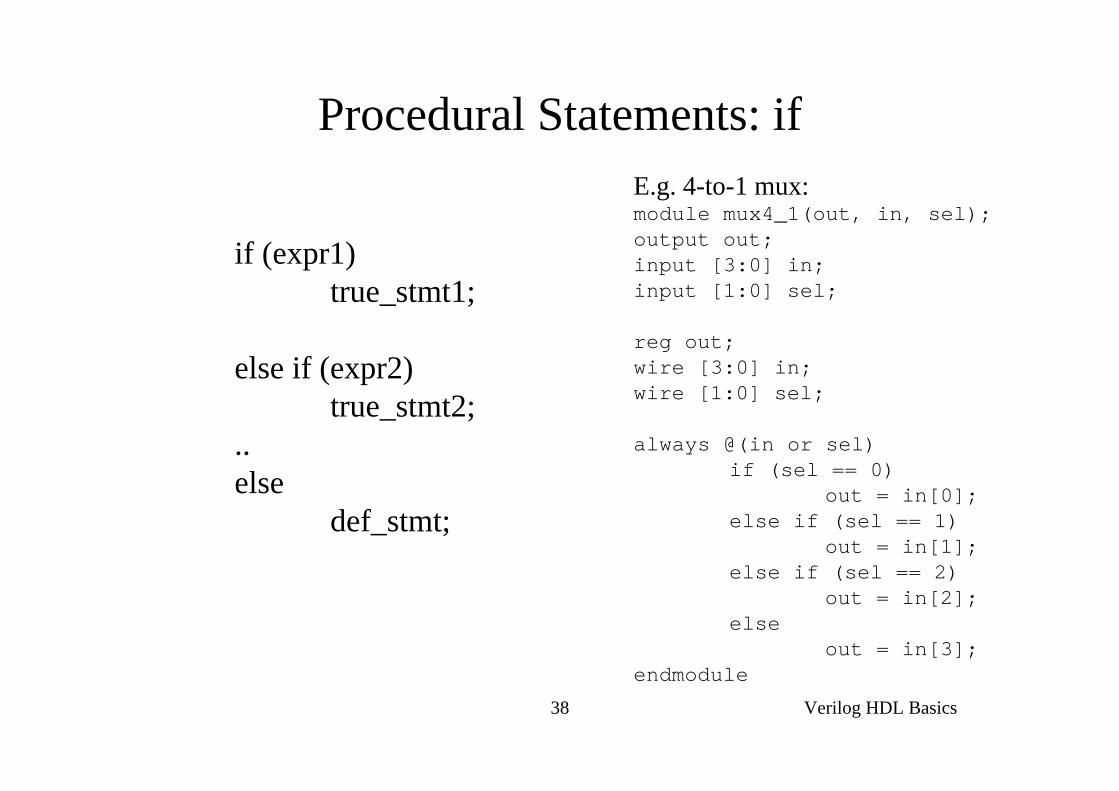
Procedural Statements: if
if (expr1)true_stmt1;
else if (expr2)true_stmt2;
..else
def_stmt;
E.g. 4-to-1 mux:module mux4_1(out, in, sel);output out;input [3:0] in;input [1:0] sel;
reg out;wire [3:0] in;wire [1:0] sel;
always @(in or sel)if (sel == 0)
out = in[0];else if (sel == 1)
out = in[1];else if (sel == 2)
out = in[2];else
out = in[3];endmodule
Verilog HDL Basics39
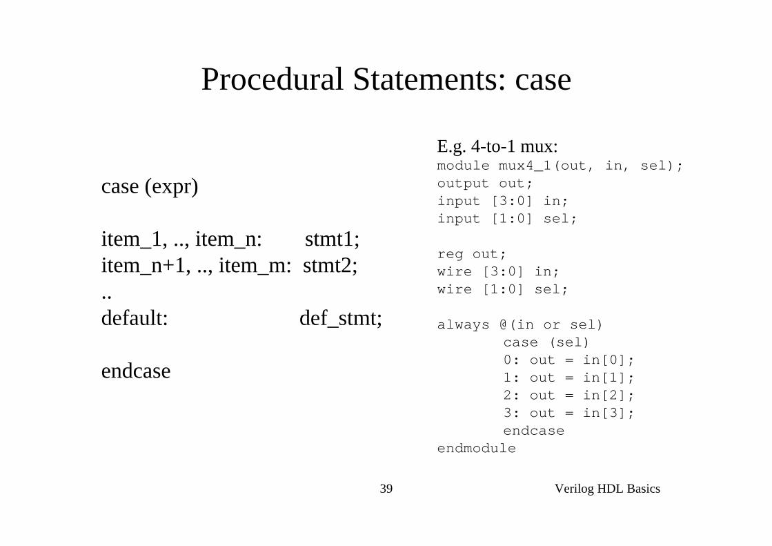
Procedural Statements: case
case (expr)
item_1, .., item_n: stmt1;item_n+1, .., item_m: stmt2;..default: def_stmt;
endcase
E.g. 4-to-1 mux:module mux4_1(out, in, sel);output out;input [3:0] in;input [1:0] sel;
reg out;wire [3:0] in;wire [1:0] sel;
always @(in or sel)case (sel)0: out = in[0];1: out = in[1];2: out = in[2];3: out = in[3];endcase
endmodule
Verilog HDL Basics40
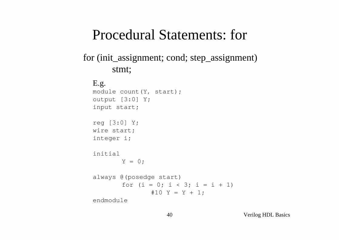
Procedural Statements: forfor (init_assignment; cond; step_assignment)
stmt;E.g.module count(Y, start);output [3:0] Y;input start;
reg [3:0] Y;wire start;integer i;
initialY = 0;
always @(posedge start)for (i = 0; i < 3; i = i + 1)
#10 Y = Y + 1;endmodule
Verilog HDL Basics41
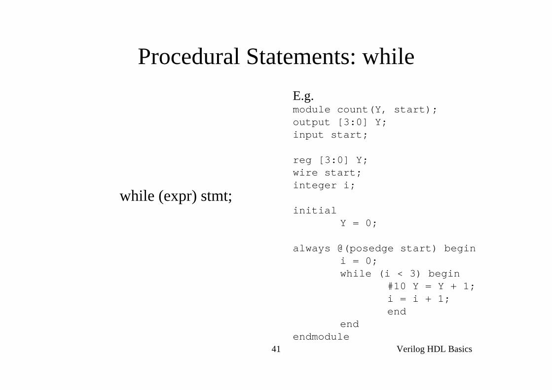
Procedural Statements: while
while (expr) stmt;
E.g.module count(Y, start);output [3:0] Y;input start;
reg [3:0] Y;wire start;integer i;
initialY = 0;
always @(posedge start) begini = 0;while (i < 3) begin
#10 Y = Y + 1;i = i + 1;end
endendmodule
Verilog HDL Basics42
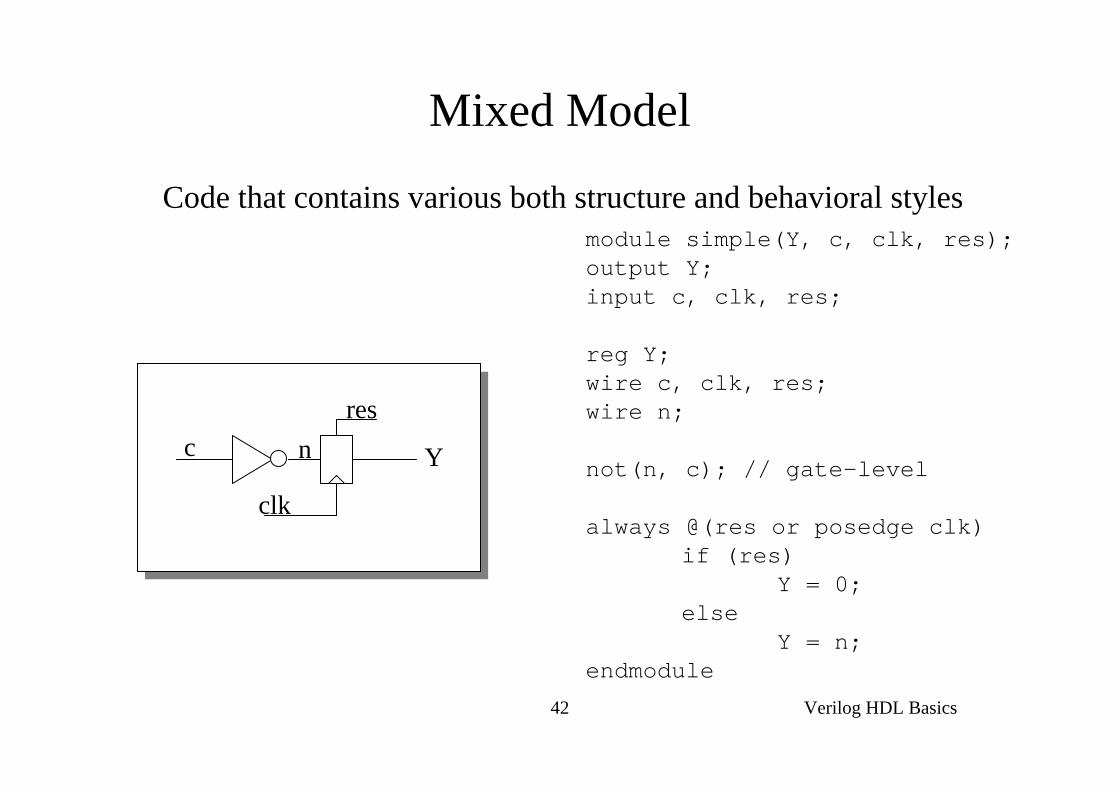
Mixed Model
Code that contains various both structure and behavioral stylesmodule simple(Y, c, clk, res);output Y;input c, clk, res;
reg Y;wire c, clk, res;wire n;
not(n, c); // gate-level
always @(res or posedge clk)if (res)
Y = 0;else
Y = n;endmodule
c Y
clk
resn
Related Documents