Verification Test Report J11458-Val Page 1 of 33 ANT002 Report Template Issue 4.0 Verification Test Report J11458-Val Product Tested: VCCM600 Power Supplies Test Type: Verification Testing Standard: Customer Specified Environmental Testing – Non-operational and operational EN60068-2-27 Mechanical Shock EN60068-2-6 Sinusoidal Vibration EN60068-2-64 Random Vibration MIL STD 810G Method 514.6, Procedure I (General Vibration) Category 4, 7 and 24 MIL STD 810G Method 503.5 Procedure I-C Multicycle 3 shocks Job #: J11458-7814 Date Received: 21 st Jul 2016 Test Dates: 21 st Jul 2016 – 17 th Jan 2017 Report Date: 14 th Feb 2017 Authorization Michael Farragher Laboratory Technician Test Performed By Date Michael Farragher Laboratory Technician Test Report Written By Date Noel Murphy Laboratory Supervisor Test Report Approved By Date

Welcome message from author
This document is posted to help you gain knowledge. Please leave a comment to let me know what you think about it! Share it to your friends and learn new things together.
Transcript

Verification Test Report J11458-Val
Page 1 of 33
ANT002 Report Template Issue 4.0
Verification Test Report J11458-Val
Product Tested: VCCM600 Power Supplies Test Type: Verification Testing
Standard: Customer Specified Environmental Testing
– Non-operational and operational EN60068-2-27 Mechanical Shock EN60068-2-6 Sinusoidal Vibration EN60068-2-64 Random Vibration MIL STD 810G Method 514.6, Procedure I (General Vibration) Category 4, 7 and 24 MIL STD 810G Method 503.5 Procedure I-C Multicycle 3 shocks
Job #: J11458-7814 Date Received: 21st Jul 2016 Test Dates: 21st Jul 2016 – 17th Jan 2017 Report Date: 14th Feb 2017 Authorization
Michael Farragher Laboratory Technician
Test Performed By Date
Michael Farragher Laboratory Technician
Test Report Written By Date
Noel Murphy Laboratory Supervisor
Test Report Approved By Date

Verification Test Report J11458-Val
Page 2 of 33
ANT002 Report Template Issue 4.0
Client(s): Brian McDonald Phone +353(1)4591161
Vox Power Ltd, Unit 2, Redcow Interchange Estate, Balymount, Dublin 22, D22 Y8H2
Test Site: Anecto Ltd. Phone: (353)-91-757404 Product Test Centre Fax: (353)-91-757387 Ballybrit Business Park Ballybrit Galway Ireland
Testing at Anecto’s Test Centre is performed in accordance with standard test procedures. Reported test results are accurate within generally accepted commercial ranges of accuracy, unless a specific measure of greater accuracy has been agreed to in writing by Anecto Ltd. Anecto’s Test Centre reports apply only to the specific samples tested under stated test conditions using functional test routines provided by the client. It is the manufacturer’s responsibility to assure that additional production units of this model are manufactured with identical electrical and mechanical components. Anecto Ltd. shall have no liability for any deductions, inferences or generalizations drawn by the client or others from Anecto’s issued reports. This report is the confidential property of the client. As a mutual protection to our clients, the public and ourselves, extracts from the test report shall not be reproduced except in full without Anecto’s prior written approval.

Verification Test Report J11458-Val
Page 3 of 33
ANT002 Report Template Issue 4.0
Table of Contents
1.0 INTRODUCTION ........................................................................................................................ 5
1.1 Description ..................................................................................................................... 5
1.2 Test Product Details ....................................................................................................... 5
1.3 References..................................................................................................................... 6
1.4 Observations .................................................................................................................. 6
1.5 Fixturing ......................................................................................................................... 7
1.6 Equipment ...................................................................................................................... 7
2.0 NON-OPERATIONAL TEMPERATURE AND HUMIDITY PROFILE ........................................... 9
2.1 Description ..................................................................................................................... 9
2.2 Observations .................................................................................................................. 9
3.0 OPERATIONAL TEMPERATURE AND HUMIDITY PROFILE .................................................. 10
3.1 Description ................................................................................................................... 10
3.2 Observations ................................................................................................................ 10
4.0 OPERATIONAL SINUSOIDAL VIBRATION ............................................................................. 11
4.1 Description ................................................................................................................... 11
4.2 Observations ................................................................................................................ 11
5.0 NON-OPERATIONAL RANDOM VIBRATION .......................................................................... 12
5.1 Description ................................................................................................................... 12
5.2 Observations ................................................................................................................ 12
6.0 OPERATIONAL RANDOM VIBRATION ................................................................................... 14
6.1 Description ................................................................................................................... 14
6.2 Observations ................................................................................................................ 14
7.0 NON-OPERATIONAL RANDOM VIBRATION – CATEGORY 4 ................................................ 16
7.1 Description ................................................................................................................... 16
7.2 Observations ................................................................................................................ 17
8.0 NON-OPERATIONAL RANDOM VIBRATION – CATEGORY 7 ................................................ 20
8.1 Description ................................................................................................................... 20
8.2 Observations ................................................................................................................ 20
9.0 NON-OPERATIONAL RANDOM VIBRATION – CATEGORY 24 .............................................. 22
9.1 Description ................................................................................................................... 22
9.2 Observations ................................................................................................................ 22
10.0 NON-OPERATIONAL THERMAL SHOCK IN AIR .................................................................... 24
10.1 Description ................................................................................................................... 24
10.2 Observations ................................................................................................................ 24
11.0 NON-OPERATIONAL TRANSIT DROP .................................................................................... 25
11.1 Description ................................................................................................................... 25
11.2 Observations ................................................................................................................ 25

Verification Test Report J11458-Val
Page 4 of 33
ANT002 Report Template Issue 4.0
12.0 NON-OPERATIONAL MECHANICAL SHOCK ......................................................................... 27
12.1 Description ................................................................................................................... 27
12.2 Observations ................................................................................................................ 27
13.0 OPERATIONAL MECHANICAL SHOCK .................................................................................. 29
13.1 Description ................................................................................................................... 29
13.2 Observations ................................................................................................................ 29
14.0 NON-OPERATIONAL ATMOSPHERIC ALTITUDE TESTING .................................................. 31
14.1 Description ................................................................................................................... 31
14.2 Observations ................................................................................................................ 31
15.0 OPERATIONAL ATMOSPHERIC ALTITUDE TESTING ........................................................... 32
15.1 Description ................................................................................................................... 32
15.2 Observations ................................................................................................................ 32

Verification Test Report J11458-Val
Page 5 of 33
ANT002 Report Template Issue 4.0
1.0 Introduction
1.1 Description
The purpose of this test report is to verify the Vox Power VCCM600M medical AC/DC conduction cooled configurable power supply (UUT). Validation testing was carried out on 7 Vox Power VCCM600M medical AC/DC conduction cooled configurable power supply (UUT).
During the validation testing the UUT were exposed to operational and non-operational environmental testing (temperature and humidity), operational and non-operational altitude and non-operational thermal shock testing. The UUT were also subjected to operational and non-operational mechanical testing (vibration and mechanical shock) and a non-operational freefall shock test as outlined in the test product details table.
1.2 Test Product Details
Model Test Description Qty Result
VC
CM
600
PS
U
Non-operational temperature and humidity 3 Passed Operational temperature and humidity 1 Passed Non-operational low pressure altitude testing 3 Passed Non-operational high pressure altitude testing 3 Passed Operational low pressure altitude testing 1 Passed Operational high pressure altitude testing 1 Passed IEC Sinusoidal Vibration - Operational 1 Passed IEC Random Vibration – Operational 1 Passed IEC Random Vibration – Non Operational 2 Passed IEC Mechanical Shock – Operational 1 Passed IEC Mechanical Shock – Non Operational 1 Passed MIL STD 810G Category 4 – Non Operational 2 Passed MIL STD 810G Category 7 – Non Operational 2 Passed MIL STD 810G Category 24 – Non Operational 2 Passed MIL STD 810G Method 503.5 Procedure 1-C Multi-Cycle 3 Shocks – Non Operational
3 Passed
810G: Method 516.6, Procedure IV, Transit Drop 2 Passed

Verification Test Report J11458-Val
Page 6 of 33
ANT002 Report Template Issue 4.0
1.3 References
Test Standard *Temperature & Humidity Customer Specified *Altitude Testing Customer Specified Sinusoidal Vibration IEC 60068-2-6, 2007, Test Fc Random Vibration IEC 60068-2-64, 2008, Test Fh *Random Vibration 810G Method 514.6 Procedure 1 (General Vibration)
Category 4 Trucks and Trailers, (composite wheeled vehicle) Figure 514.6C-3 Category 7 (Aircraft, Helicopter), Figure 514.6C-8, Table 514.6X General Category 24 (All minimum Integrity) Figure 514.6E-1
Thermal Shock MIL-STD-810G Method 503.5 Procedure 1-C Multicycle 3 shocks Mechanical Shock IEC 60068-2-27, 2008, Test Ea Transit Drop 810G: Method 516.6, Procedure IV,
*denotes test or test parameters outside scope of ISO17025 accreditation
1.4 Observations
Non-operational Temperature and Humidity Testing A functional and visual test was performed before and after the non-operational environmental temperature and humidity non-operational and there were no issues noted. Operational Temperature and Humidity Testing A functional and visual test was performed before and after the operational environmental temperature and humidity non-operational and there were no issues noted. Vibration Profiles A visual and functional test was performed before and after the various sinusoidal and random vibration profiles and there were no issues noted. Mechanical Shock A visual and functional test was performed before and after the mechanical shock test and there were no issues noted. Mechanical Shock – Transit Drop The UUT was powered after every drop and visually inspected for any issues. During the testing a second UUT and package was used as the carton original carton began to deteriorate following 6 freefall impacts, after a total of 17 impacts the UUT and the packaging was replaced, following a drop on the front top left (AC power side (front)) had been completed it was observed that RT1 and C1 were pushed in and the epoxy securing the components had broken off. There were no other visual issues and the UUT powered up without any issues after every transit drop test. The UUT were returned to for further evaluation following completion of the testing.

Verification Test Report J11458-Val
Page 7 of 33
ANT002 Report Template Issue 4.0
Altitude Testing A functional and visual test was performed before and after the non-operational altitude test and there was no issue noted. Thermal shock A functional and visual test was performed before and after the thermal shock in air profile test and there were no issues noted. The UUT were returned to the customer following completion of the environmental testing for further evaluation.
1.5 Fixturing
During the environmental testing the UUT were placed on shelves and free air allowed to move about them. During the vibration and shock the UUT were secured with overhead clamps and vertical threaded bars. The UUT were using 230VAC and the load modules were connected to electronic loads during the operational temperature and humidity, operational altitude, and operational vibration tests. During the operational mechanical shock test the UUT was not loaded but powered at 230VAC.
1.6 Equipment
Equipment Make/ Model Asset No. Cal Due Date
Thermotron SM32CE-2 environmental chamber ANO1139 01 Apr 2017 Votsch VCS 7048-20 environmental chamber ANO2450 05 Sep 2017 Votsch VT7012S2 thermal shock ANO0905 23 Jun 2017 Vacuum tank ANO1325 N/A Altitude high pressure controller ANO1858 11 May 2017 Altitude low box ANO1524 08 Mar 2017 Negative pressure transducer ANO1259 08 Mar 2017 Crystal pressure calibrator IS33-2 ANO1360 04 Apr 2017 Quantum Countdown timer ANO1722 20 Dec 2017 Array 3710A electronic load ANO2410 14 Jul 2017 Array 3710A electronic load ANO2411 14 Jul 2017 Array 3710A electronic load ANO2412 14 Jul 2017 Array 3710A electronic load ANO2413 14 Jul 2017 Temma 72-8345 DC power supply ANO2397 08 Mar 2017 Type T Thermocouple ANO1731 01 Nov 2017 Type T Thermocouple ANO2200 01 Nov 2017 Type T Thermocouple ANO1315 01 Nov 2017 Type T Thermocouple ANO1345 01 Nov 2017 Type T Thermocouple ANO1336 01 Nov 2017 Type T Thermocouple ANO1759 01 Nov 2017 Type T Thermocouple ANO2001 01 Nov 2017 Type T Thermocouple ANO1343 01 Nov 2017 Type T Thermocouple ANO1881 01 Nov 2017

Verification Test Report J11458-Val
Page 8 of 33
ANT002 Report Template Issue 4.0
Type T Thermocouple ANO2232 01 Nov 2017 Type T Thermocouple ANO2251 01 Nov 2017 Type T Thermocouple ANO1343 01 Nov 2017 Type T Thermocouple ANO1336 01 Nov 2017 HP34970 ANO2139 14 Jul 2017 Lansmont TP3 drop test software ANO1085 01 Nov 2017 Lansmont PDT226 drop tester ANO1065 N/A 5m Stanley measuring tape ANO2345 01 Aug 2017 Avco SM110-2 mechanical shock ANO1044 N/A Dytran 350M42 shock accelerometer ANO1622 04 April 2017 Dactron Dual DSP shaker control system ANO2352 28 Sep 2016 CMR Charge Amplifier C/A2 ANO0793 15 Jan 2017 DJB A/20 Accelerometer ANO1491 28 Sep 2016 Spectral dynamics vibration table ANO1844 12 May 2017 PCB piezotronics accelerometer 357B03 ANO1844C 13 Jan 2017 PCB piezotronics charge amplifier 422E12 ANO1844D 14 Jan 2017 PCB piezotronics accelerometer 357B03 ANO1844E 15 Jan 2017 PCB piezotronics charge amplifier 422E12 ANO1844F 18 Jan 2017 PCB piezotronics accelerometer 357B03 ANO1844G 13 Jan 2017 PCB piezotronics charge amplifier 422E12 ANO1844H 14 Jan 2017

Verification Test Report J11458-Val
Page 9 of 33
ANT002 Report Template Issue 4.0
2.0 Non-operational Temperature and Humidity Profile
2.1 Description
Three UUT were exposed to a temperature and humidity profile as described in the table below. The UUT were not operational throughout testing.
Step Temperature Humidity Time
1 -51°C -% 6 hrs 2 20°C 95% 6 hrs 3 20°C 5% 6 hrs 4 85°C 5% 6 hrs 5 85°C 50% 6 hrs 6 50°C 95% 6 hrs
Test parameters
2.2 Observations
A functional and visual test was performed before and after the non-operational environmental temperature and humidity non-operational and there were no issues noted. The UUT were returned to the customer following completion of the environmental testing for further evaluation.
Environmental chamber setup for the non-operational temperature and humidity

Verification Test Report J11458-Val
Page 10 of 33
ANT002 Report Template Issue 4.0
3.0 Operational Temperature and Humidity Profile
3.1 Description
A UUT was exposed to temperature and humidity profile as described in the table below. The UUT was operational throughout testing.
Step Temperature Humidity Electronic Load Time 1 -40°C+2°C Uncontrolled % 600W 6 hrs 2 20°C+2°C 95%+5% 600W 6 hrs 3 20°C+2°C 5%+5% 600W 6 hrs 4 70°C+2°C 5%+5% 300W 6 hrs 5 70°C+2°C 50%+5% 300W 6 hrs 6 50°C+2°C 95%+5% 300W 6 hrs
Test parameters
3.2 Observations
A functional and visual test was performed before and after the operational environmental temperature and humidity non-operational and there were no issues noted. The UUT were returned to the customer following completion of the environmental testing for further evaluation.

Verification Test Report J11458-Val
Page 11 of 33
ANT002 Report Template Issue 4.0
4.0 Operational Sinusoidal Vibration
4.1 Description
A UUT was subjected to a sinusoidal vibration test according to EN60068-2-6 Test Fc as described in the table below. The UUT was powered throughout the testing.
Description Values 10Hz – 500Hz 2G Rate / Duration 1 Oct / min Number of Sweeps 20 Test Duration
Z Axis X Axis Y Axis
1hr 53 minutes 1hr 53 minutes 1hr 53 minutes
Sinusoidal vibration test parameters
4.2 Observations
During the sinusoidal vibration testing the UUT was monitored for functionality. A functional and visual test was performed before and after the sinusoidal operational test and there was no issue noted. Throughout the testing the load modules were at maximum load while connected to electronic loads located adjacent to the vibration table. The UUT were returned to the customer following completion of the operational random vibration testing for further evaluation.
x: 10, y: 1.98008
5 10 20 50 100 200 500 1000
0.1
0.2
0.5
1
2
5
10
g (
Lo
g)
Hz (Log)
A Sine g [Control]
CTRL: 1.9801 g
Frequency: 10.0000
Sweep #: 20.0000
Sweeps Remaining: 0.0000
Start Date: 10/13/16
Start Time: 15:45:21
Spectral Dynamics
Stop Date: 10/13/16
Stop Time: 17:39:11 IEC60068-2-6 - Typical sinusoidal vibration profile

Verification Test Report J11458-Val
Page 12 of 33
ANT002 Report Template Issue 4.0
5.0 Non-Operational Random Vibration
5.1 Description
Two UUT were subjected to a random vibration test according to EN60068-2-64 Test Fh as described in the table below. The UUT was not powered throughout the testing.
Description Values 5Hz – 500Hz 0.02G
2 /Hz
Acceleration Spectral Density 3.15Grms Test Duration
Z Axis X Axis Y Axis
30 minutes 30 minutes 30 minutes
Random vibration test parameters
5.2 Observations
A functional and visual test was performed before and after the non-operational random vibration profiles and there were no issues noted. The UUT were returned to the customer following completion of the environmental testing for further evaluation.
IEC60068-2-64 Typical non-operational random vibration setup (Y Setup)

Verification Test Report J11458-Val
Page 13 of 33
ANT002 Report Template Issue 4.0
x: 0, y: 3.52273e-020 Locked
2 5 10 20 50 100 200 500 1000 2000
1e-005
5e-005
0.0002
0.0005
0.002
0.005
0.02
0.05
0.2
0.5
5g
²/H
z (
Lo
g)
Hz (Log)
A PSD g²/Hz [Control]
Test Level: 0.0000 dB
CTRL: 3.1601 gRMS
Ctrl DOF: 120
Resolution: 1600
Level Time: 0000:30:00
Level Time Remaining: 0000:00:00
Start Date: 10/13/16
Start Time: 08:37:00
Spectral Dynamics
Stop Date: 10/13/16
Stop Time: 09:20:34
IEC60068-2-64 Typical non operational random vibration profile - IEC

Verification Test Report J11458-Val
Page 14 of 33
ANT002 Report Template Issue 4.0
6.0 Operational Random Vibration
6.1 Description
A UUT were subjected to a random vibration test according to EN60068-2-64 Test Fh as described in the table below. The UUT was powered throughout the testing.
Description Values 5Hz – 500Hz 0.0122G
2 /Hz
Acceleration Spectral Density 2.45Grms Test Duration
Z Axis X Axis Y Axis
30 minutes 30 minutes 30 minutes
Random vibration test parameters
6.2 Observations
During the random vibration testing the UUT was monitored for functionality. A functional and visual test was performed before and after the random operational test and there was no issue noted. Throughout the testing the load modules were at maximum load while connected to electronic loads located adjacent to the vibration table. The UUT were returned to the customer following completion of the operational random vibration testing for further evaluation.
IEC60068-2-64 Typical random operational setup

Verification Test Report J11458-Val
Page 15 of 33
ANT002 Report Template Issue 4.0
x: 0, y: 3.52273e-020 Locked
2 5 10 20 50 100 200 500 1000 2000
1e-005
5e-005
0.0002
0.0005
0.002
0.005
0.02
0.05
0.2
0.5
5
g²/
Hz (
Lo
g)
Hz (Log)
A PSD g²/Hz [Control]
Test Level: 0.0000 dB
CTRL: 2.5023 gRMS
Ctrl DOF: 120
Resolution: 1600
Level Time: 0000:30:00
Level Time Remaining: 0000:00:00
Start Date: 10/13/16
Start Time: 13:52:57
Spectral Dynamics
Stop Date: __/__/__
Stop Time: __:__:__
IEC60068-2-64 - Typical operational random vibration profile

Verification Test Report J11458-Val
Page 16 of 33
ANT002 Report Template Issue 4.0
7.0 Non-Operational Random Vibration – Category 4
7.1 Description
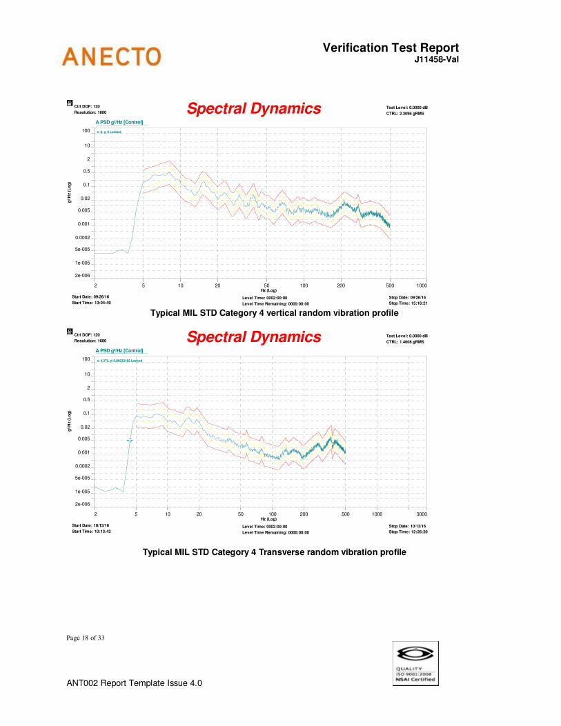
Two UUT were subjected to a random vibration according to MIL STD 810G Table 514.6C-VI Category 4 Composite wheeled vehicle vibration exposure, breakpoints shown in figure 514.6C-3 for 2 hours per axis as described in the table below. The UUT were not operational throughout testing.
Typical MIL STD Category 4 - Random vibration test profile

Verification Test Report J11458-Val
Page 17 of 33
ANT002 Report Template Issue 4.0
Typical MIL STD Category 4 - Random vibration test parameters
7.2 Observations
There were no visual or functional issues as a result of the random vibration testing. The UUT was powered on using 90VAC without load after every axis and no issues were recorded. The UUT was returned to the customer for further evaluation following completion of the testing.
Verification Test Report J11458-Val
Page 18 of 33
ANT002 Report Template Issue 4.0
x: 0, y: 0 Locked
2 5 10 20 50 100 200 500 1000
2e-006
1e-005
5e-005
0.0002
0.001
0.005
0.02
0.1
0.5
2
10
100
g²/
Hz (
Lo
g)
Hz (Log)
A PSD g²/Hz [Control]
Test Level: 0.0000 dB
CTRL: 2.3096 gRMS
Ctrl DOF: 120
Resolution: 1600
Level Time: 0002:00:00
Level Time Remaining: 0000:00:00
Start Date: 09/26/16
Start Time: 13:04:49
Spectral Dynamics
Stop Date: 09/26/16
Stop Time: 15:18:21
Typical MIL STD Category 4 vertical random vibration profile
x: 4.375, y: 0.00532192 Locked
2 5 10 20 50 100 200 500 1000 3000
2e-006
1e-005
5e-005
0.0002
0.001
0.005
0.02
0.1
0.5
2
10
100
g²/
Hz (
Lo
g)
Hz (Log)
A PSD g²/Hz [Control]
Test Level: 0.0000 dB
CTRL: 1.4608 gRMS
Ctrl DOF: 120
Resolution: 1600
Level Time: 0002:00:00
Level Time Remaining: 0000:00:00
Start Date: 10/13/16
Start Time: 10:13:42
Spectral Dynamics
Stop Date: 10/13/16
Stop Time: 12:26:20
Typical MIL STD Category 4 Transverse random vibration profile

Verification Test Report J11458-Val
Page 19 of 33
ANT002 Report Template Issue 4.0
x: 117.5, y: 0.00200148 Locked
2 5 10 20 50 100 200 500 1000 3000
2e-006
5e-005
0.0005
0.005
0.05
0.5
5
100
g²/
Hz (
Lo
g)
Hz (Log)
A PSD g²/Hz [Control]
Test Level:
CTRL:
Ctrl DOF: 120
Resolution: 1600
Level Time:
Level Time Remaining:
Start Date: 09/29/2016
Start Time: 14:10:16
Spectral Dynamics
Stop Date: 09/29/2016
Stop Time: 16:23:14
Typical MIL STD Category 4 Longitudinal random vibration profile

Verification Test Report J11458-Val
Page 20 of 33
ANT002 Report Template Issue 4.0
8.0 Non-Operational Random Vibration – Category 7
8.1 Description
Two UUT were subjected to a random vibration according to MIL STD 810G Category 7 Method 514.6 Procedure I (General Vibration) as described in the table below. The UUT were not operational throughout testing.
MIL STD 810G Category 7 Jet aircraft cargo method 514.6C-5 procedure I (general exposure)
Description Values 15Hz – 105.94Hz 105.94Hz - 150Hz 150.00Hz - 500Hz 500Hz – 2000Hz
0.01G2 /Hz
6db 0.02G
2 /Hz
-6db Acceleration Spectral Density 4.02Grms Test Duration
Z Axis X Axis Y Axis
120 minutes 120 minutes 120 minutes
Typical MIL STD Category 7 -Random vibration test parameters
8.2 Observations
There were no visual or functional issues as a result of the random vibration testing. The UUT was powered on using 90VAC without load after every axis and no issues were recorded. The UUT was returned to the customer for further evaluation following completion of the testing.

Verification Test Report J11458-Val
Page 21 of 33
ANT002 Report Template Issue 4.0
x: 0, y: 0 Locked
2 5 10 20 50 100 200 500 1000 2000 5000
2e-006
1e-005
5e-005
0.0002
0.001
0.005
0.02
0.1
0.5
2
10
100
g²/
Hz (
Lo
g)
Hz (Log)
A PSD g²/Hz [Control]
Test Level: 0.0000 dB
CTRL: 4.0178 gRMS
Ctrl DOF: 120
Resolution: 1600
Level Time: 0002:00:00
Level Time Remaining: 0000:00:00
Start Date: 09/26/16
Start Time: 16:54:35
Spectral Dynamics
Stop Date: 09/26/16
Stop Time: 18:58:56
Typical MIL STD Category 7 - Typical random vibration profile

Verification Test Report J11458-Val
Page 22 of 33
ANT002 Report Template Issue 4.0
9.0 Non-Operational Random Vibration – Category 24
9.1 Description
Two UUT were subjected to a random vibration test according to MIL STD Category 24 General Exposure Figure 514.6E-1 as described in the table below. The UUT was not powered throughout the testing.
Description Values 20Hz – 1000Hz 1000Hz – 2000Hz
0.04G2 /Hz
-6db Acceleration Spectral Density 7.7Grms Test Duration
Z Axis X Axis Y Axis
60 minutes 60 minutes 60 minutes
Typical MIL STD Category 24 - Random vibration test parameters
9.2 Observations
There were no visual or functional issues as a result of the random vibration testing. The UUT was powered on using 90VAC without load after every axis and no issues were recorded. The UUT was returned to the customer for further evaluation following completion of the testing.

Verification Test Report J11458-Val
Page 23 of 33
ANT002 Report Template Issue 4.0
x: 525, y: 0.0387795 Locked
10 20 50 100 200 500 1000 2000
1e-005
5e-005
0.0002
0.0005
0.002
0.005
0.02
0.05
0.2
0.5
2
5
20
100
g²/
Hz (
Lo
g)
Hz (Log)
A PSD g²/Hz [Control]
Test Level: 0.0000 dB
CTRL: 7.7181 gRMS
Ctrl DOF: 120
Resolution: 800
Level Time: 0001:00:00
Level Time Remaining: 0000:00:00
Start Date: 09/27/16
Start Time: 15:42:41
Spectral Dynamics
Stop Date: 09/27/16
Stop Time: 16:45:13
Typical MIL STD Category 24 random vibration profile
Typical MIL STD Category 24 random vibration test setup image

Verification Test Report J11458-Val
Page 24 of 33
ANT002 Report Template Issue 4.0
10.0 Non-Operational Thermal Shock in Air
10.1 Description
A UUT was exposed to a thermal shock in air profile according to MIL STD 810G Method 503.5 Procedure - IC as described in the table below. The thermal shock in air cycle was started in the cold chamber.
Description Value Hot Temperature 85°C Cold Temperature -51°C Dwell Time 60 minutes Number of Cycles 3 Operational No
Test parameters
10.2 Observations
A functional and visual test was performed before and after the thermal shock in air profile test and there were no issues noted. The UUT were returned to the customer following completion of the environmental testing for further evaluation.
Environmental chamber setup for the thermal shock in air profile

Verification Test Report J11458-Val
Page 25 of 33
ANT002 Report Template Issue 4.0
11.0 Non-Operational Transit Drop
11.1 Description
Two packaged UUT were subjected to a freefall drop test according to MIL STD 810G Method 516.6 Procedure IV Transit Drop as described in the table below. The UUT were not powered during the testing and was placed in its packaged form surrounded by the outer cover. The packaged UUT was dropped onto a 2” plywood over concrete surface from a height of 48”.
Drop Drop Orientation Packaged UUT
1 Left 1 2 Right 1 3 Front 1 4 Back 1 5 Bottom 1 6 Top 1 7 Top left edge 1 8 Top right edge 1 9 Bottom right edge 1
10 Bottom Left edge 1 11 Top Front edge 1 12 Top Back edge 1 13 Bottom Back edge 1 14 Bottom Front edge 1 15 Front Left edge 1 16 Front Right edge 1 17 Bottom Right edge 1 18 Bottom Left edge 1 19 *Front Top left corner (Repeated again) 1 - *Front Top left corner 2
20 Front Left Bottom corner 2 21 Front Right Top corner 2 22 Front Right Bottom corner 2 23 Bottom Left Top corner 2 24 Bottom Back Top corner 2 25 Bottom Right Bottom corner 2 26 Bottom left Bottom corner 2
Mechanical Shock – Freefall test parameters *Changed UUT from UUT1 to UUT2 as packaging deteriorated.
11.2 Observations
The UUT was powered after every drop and visually inspected for any issues. Following the 19th impact on the first UUT (drop on the front top left corner (AC power side (front)) it was observed that RT1 and C1 were pushed in and the epoxy securing the components had broken off. At this point a second UUT and package was used to complete the testing. The packaged UUT was powered up after every drop and there were no visual or functional issues as a result of the freefall drop test. The UUT were returned to for further evaluation following completion of the testing.

Verification Test Report J11458-Val
Page 26 of 33
ANT002 Report Template Issue 4.0
Typical freefall drop test RT1 and C1 pushed in following Front top left drop
Internal packaging following 17 / 26 freefall impacts

Verification Test Report J11458-Val
Page 27 of 33
ANT002 Report Template Issue 4.0
12.0 Non-Operational Mechanical Shock
12.1 Description
A UUT was subjected to a mechanical shock test according to IEC60068-2-27 as described in the table below. The UUT was not powered throughout the testing.
Description Values Peak Acceleration 30G Pulse Width 18mS Pulse Shape Half Sine No.of Shocks per axis 6 (+/-X, +/-Y, +/-Z) Total No of Shocks 18
Mechanical shock test parameters
12.2 Observations
There were no visual or functional issues as a result of the mechanical shock testing. The UUT was powered on using 230VAC without load and no issues were recorded. The UUT was returned to the customer for further evaluation following completion of the testing.
Typical mechanical shock test setup (Z Axis)

Verification Test Report J11458-Val
Page 28 of 33
ANT002 Report Template Issue 4.0
Acceleration vs Time
Channel Description: G's msec In/S Filter Hz Max G's Min G's
Ch1 Channel 1 35.08 18.05 122.69 500.00 35.08 -4.81
Mechanical shock non operational profile

Verification Test Report J11458-Val
Page 29 of 33
ANT002 Report Template Issue 4.0
13.0 Operational Mechanical Shock
13.1 Description
A UUT was subjected to a mechanical shock test according to IEC60068-2-27 as described in the table below. The UUT was powered throughout the testing.
Description Values Peak Acceleration 50G Pulse Width 11mS Pulse Shape Half Sine No.of Shocks per axis 6 (+/-X, +/-Y, +/-Z) Total No of Shocks 18
Mechanical shock test parameters
13.2 Observations
There were no visual or functional issues as a result of the mechanical shock testing. The UUT was powered on using 230VAC without load and no issues were recorded. The UUT was returned to the customer for further evaluation following completion of the testing.
Typical mechanical shock test setup (Z Axis)

Verification Test Report J11458-Val
Page 30 of 33
ANT002 Report Template Issue 4.0
Acceleration vs Time
Channel Description: G's msec In/S Filter Hz Max G's Min G's
Ch1 Channel 1 52.40 11.00 109.43 500.00 52.40 -6.82
Mechanical shock operational profile

Verification Test Report J11458-Val
Page 31 of 33
ANT002 Report Template Issue 4.0
14.0 Non-Operational Atmospheric Altitude Testing
14.1 Description
Three UUT was subjected to a non-operational atmospheric altitude test as described in the table below. The UUT was not powered throughout the testing.
Description High Pressure Low Pressure Setpoint -200m Min (+24mbar(g)) +5000m (-475mbar(g)) Dwell 4 hrs 4 hrs Ramp Time 10 minutes 10 minutes
Test parameters
14.2 Observations
A functional and visual test was performed before and after the non-operational altitude test and there was no issue noted. The UUT were returned to the customer following completion of the altitude testing for further evaluation.
Atmospheric non-operational setup

Verification Test Report J11458-Val
Page 32 of 33
ANT002 Report Template Issue 4.0
15.0 Operational Atmospheric Altitude Testing
15.1 Description
A UUT was subjected to an atmospheric altitude test according as described in the table below. The UUT was powered throughout the testing.
Description High Pressure Low Pressure Setpoint -200m Min (+24mbar(g)) +3000m (-316mbar) Dwell 4 hrs 4 hrs Ramp Time 10 minutes 10 minutes
Test parameters
15.2 Observations
During the altitude testing the UUT was monitored for functionality and that its baseplate temperature did not increase above 85C A functional and visual test was performed before and after the operational altitude test and there was no issue noted. Throughout the testing the load modules were at maximum load while connected to electronic loads located adjacent to the atmospheric chamber. The UUT were returned to the customer following completion of the operational altitude testing for further evaluation.

Verification Test Report J11458-Val
Page 33 of 33
ANT002 Report Template Issue 4.0
Atmospheric operational setup
Baseplate internal temperature during test Baseplate cooled using 12VDC psu.
Related Documents