HYDRORANGER I PROCESS MEASUREMENTS PROGRAMMABLE LEVEL SYSTEM Instruction Manual PL-399 May 1993 33453990

Welcome message from author
This document is posted to help you gain knowledge. Please leave a comment to let me know what you think about it! Share it to your friends and learn new things together.
Transcript

HYDRORANGER I
PROCESS MEASUREMENTS
PROGRAMMABLE LEVEL SYSTEM
Instruction Manual
PL-399
May 1993
33453990
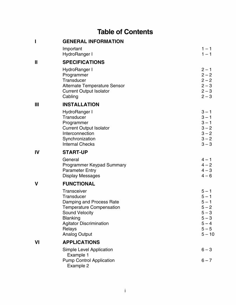
Table of ContentsI GENERAL INFORMATION
Important 1 – 1HydroRanger I 1 – 1
II SPECIFICATIONSHydroRanger I 2 – 1Programmer 2 – 2Transducer 2 – 2Alternate Temperature Sensor 2 – 3Current Output Isolator 2 – 3Cabling 2 – 3
III INSTALLATIONHydroRanger I 3 – 1Transducer 3 – 1Programmer 3 – 1Current Output Isolator 3 – 2Interconnection 3 – 2Synchronization 3 – 2Internal Checks 3 – 3
IV START-UPGeneral 4 – 1Programmer Keypad Summary 4 – 2Parameter Entry 4 – 3Display Messages 4 – 6
V FUNCTIONALTransceiver 5 – 1Transducer 5 – 1Damping and Process Rate 5 – 1Temperature Compensation 5 – 2Sound Velocity 5 – 3Blanking 5 – 3Agitator Discrimination 5 – 4Relays 5 – 5Analog Output 5 – 10
VI APPLICATIONSSimple Level Application 6 – 3
Example 1Pump Control Application 6 – 7
Example 2
i

Pump Run-on 6 – 10Pump Totalizer Application 6 – 13
Example 3Volume Application 6 – 17
Example 4Differential Level Application 6 – 25
Example 5OCM Application 6 – 29
Example 6aOther 6 – 41
Example 6bApplications with Standpipes 6 – 44
Example 7
VII PARAMETER DESCRIPTIONParameters 7 – 1
VIII TROUBLESHOOTINGOscilloscope 8 – 1Troubleshooting guide 8 – 4
IX MAINTENANCE AND SPARE PARTSMaintenance 9 – 1
X APPENDICESSound Velocities 10 – 1Glossary 10 – 2Alphabetical Parameter Listing 10 – 4
IllustrationsFig. 1 HydroRanger I Outline and Mounting DiagramFig. 2 Circuit Board Layout
ii

SECTION I
GENERAL INFORMATION
IMPORTANT
First and foremost, it is essential that this manual be read and understood beforeinstallation and start-up of the HydroRanger I.
Section VI, Applications, provides a general description of the common applicationsfound in industry and illustrates them with examples. It is suggested that you refer tothe sub-section which most suits your application. The calibration may be furtheroptimized by referring to Section VII, Parameter Description or Appendix III, Parameter Listing.
The HydroRanger I
The Milltronics HydroRanger I is a multi-purpose level monitoring system consisting of aHydroRanger I in a watertight enclosure, a programmer and a transducer.
The HydroRanger I emits an ultrasonic pulse via the transducer. The echo is reflectedfrom the material and received by the transducer. The echo is processed by theHydroRanger I and the time at which the ultrasonic pulse hits the level or target isextracted and compared to the time at which it was sent. This time differential is thenconverted into distance, material level, volume flow or differential level as a basis fordisplay, relay control, analog output and totalizing.
As well as simple level measurement, the HydroRanger I was designed to handlespecific applications such as: pump control, pumped volume totaling, differential leveland open channel flow measurement.
�
PL-399 1 – 1

SECTION II
SPECIFICATIONS
HydroRanger I
Power » 100/115/200/230 V ±15%, stab selectable» 50/60 Hz, 15 VA
» optional : » 12 V DC model, 10 to 18 V DC» 24 V DC model, 18 to 36 V DC
Fuse » 1/4 amp MDL Slo-Blo or equivalent
Range » 0.3 to 10 m (1 to 33 ft.)
Accuracy » 0.25% of range or 6 mm (0.24"), whichever is greater
Resolution » 0.1% of range or 2 mm (0.08"), whichever is greater
Memory » EEPROM (non-volatile) no back-up battery required
Display » Liquid Crystal Display 4 digits - 18 mm (0.7") high
Operating Temp. » -20 to 60 °C (range in which electronics will (-5 to 140 °F)operate within specs, includes temperature rise above ambient due to operation in enclosure.)
Ambient Temp. » -20 to 50 °C (range outside of (-5 to 122 °F)HydroRanger I enclosure)
OUTPUTS:transducer drive » 41 KHz, 400 V peak pulses of 1 mSec. max.
duration at a max. repetition rate of 300 mSec.
analog » 0 - 20 or 4 - 20 mA
» max. loading: 350 ohms, return to ground 750 ohms, return to -12 V
» resolution: 0.1% of range
» optional mA isolator
PL-399 2 – 1

relays » 5 multi-purpose relays (for alarms, pump control, ...)
» 1 Form ’C’ SPDT contact per relay, rated 5 A at 220 V AC non-inductive
» adjustable deadband
NOTE:All relays are certified for use in equipment where the short circuit capacity of the circuits in which they are connected is limited by fuseshaving ratings not exceeding the rating of the relays.
Enclosure » CSA type 4 (NEMA 4/ IP 65 style)
» 160 mm W x 240 mm H x 82 mm D (6.3" W x 9.5" H x 3.2" D)
» polycarbonate
Weight » 1.8 Kg (4 lb)
Programmer
Enclosure » general purpose
» 67 mm W x 100 mm H x 25 mm D (2.6" W x 4" H x 1" D)
» ABS plastic
Operating Temp. » -20 to 50 °C (-5 to 122 °F)
Battery » 9 V (ANSI/NEDA 1604, PP3 or equivalent)
Transducer
Model » ST-H with integral temperature sensor
Construction » 1" NPT conduit thread with standard 10 m (33 ft) of neoprene jacketed cable.
» 2" NPT, 2" BSP or PF2 mounting thread
» Tefzel® encapsulated
Operating Temperature » -40 to 73 °C (-40 to 165 °F)
Pressure (vessel) » 200 kPa (2 bar or 30 psi) max.
Beam Angle » 12°
PL-399 2 – 2

Options » Flange Adapter Kit. Refer to PL-397.
» Submergence Coupling. Refer to PL-403
Temperature Sensor (Optional)
Model: » TS-3
Refer to associated Temperature Sensor Manual, PL-401.
Current Output Isolator (Optional)
Model: » LIs-1 loop isolator
Refer to associated Current Output Isolator manual, PL-293.
Cabling (Optional)
Transducer » RG-62U coax » max. distance to electronics: 336 m (1200 ft.)» must be run in grounded metal conduit
Temp. Sensor » Belden 8760, 2 wire shielded» max. distance to electronics: 336 m (1200 ft.)» can be run with transducer cable.
TEFZEL
Tefzel is a fluoropolymer inert to most chemicals. For exposure to specificenvironments, check with chemical compatibility charts before installing and operatingthe HydroRanger I in your application.
Tefzel is a registered trade mark of Dupont.
�
PL-399 2 – 3

SECTION III
INSTALLATION
HydroRanger I
The HydroRanger I should be mounted in an area that is within the unit’s ambienttemperature range and is suitable for the specified enclosure. The front cover should beaccessible for calibrating and viewing.
It is advisable to keep the HydroRanger I away from high voltage or current runs,contactors and SCR control drives.
DO NOT MOUNT THE HydroRanger IIN DIRECT SUNLIGHT
WITHOUT THE USE OF A SUN SHIELD
Refer to Figure 1 for outline and mounting dimensions.
Transducer
NOTE: Wiring of transducer cable must be done in conjunction with approved conduit, boxes and fittings and to procedures in accordance with allgoverning regulations. All transducer cabling must be run in groundedmetal conduit for optimum noise rejection. Refer to Figure 4 for outlineand wiring.
1. Mount the transducer above the highest anticipated material level by at least30 cm (1 ft).
2. Install the transducer so that it can have a clear sound path perpendicular tothe liquid surface.
3. To avoid false echoes, install the transducer such that the sound path willnot intersect vessel fill spouts, rough vessel walls, ladders ... etc. Wherepossible, the transducer should be mounted 0.3 m (1 ft) from the closestvessel wall for every 3 m (10 ft) of depth.
Example: if the vessel is 10 m deep, the transducer should be mounted at least 0.3 m/3 m x 10 m = 1.0 m from the closest vessel wall.
Programmer
In order to calibrate the HydroRanger I, a programmer must be set into the recess onthe HydroRanger I front cover. It can be removed when operating in the RUN mode.(Note: since a programmer need not be ordered with each unit, check your order if youthink that the programmer is missing).
PL-399 3 – 1

Current Output Isolator
The isolator is mounted onto the upper left hand corner of the motherboard using thetwo long machine screws provided. It is then interconnected from its input terminals tothe motherboard output terminals, TB-1, using twisted pair maximum 16 ga. wire. Referto Figure 2 and 3.
Proper shielding and grounding are required in order to minimize noise levels that couldotherwise affect weak receiver signals by introducing false echoes.
The isolator enclosure is grounded by the mounting bolts to the motherboard. This canbe checked with an ohmmeter if a poor connection is suspected.
THE ISOLATOR OUTPUT WIRING MUST BE A SHIELDED TWISTED PAIR. THE SHIELD MUST BEINTACT UP TO THE ISOLATOR AND THE SHIELD GROUNDED AT THE ISOLATOR MOUNTINGSCREW ONLY. DO NOT GROUND SHIELD AT ANY OTHER POINT AS THIS WILL VOID ISOLATION.
Interconnection
NOTE: All wiring must be done in conjunction with approved conduit, boxes and fittings and to procedures in accordance with all governing regulations.
Refer to Figure 2 for wiring of power, analog output, transducer and temperature sensorto the main electronics.
Synchronization
In applications where more than one HydroRanger I, up to a maximum of 8, are goingto be used or where their transducers will be sharing a common conduit,synchronization is required. When synchronized no HydroRanger I(s) will transmitwithin 180 mSec. of the prior one(s).
To synchronize HydroRanger I’s, interconnect the SYNC terminals TB1-4 of allmotherboards and ensure that there is a common hydro ground interconnecting all units.
To synchronize HydroRanger Is and MultiRanger Plus’s interconnect the SYNCterminals TB1-4 of all motherboards and ensure that there is a common groundinterconnecting all units.
To synchronize HydroRanger I’s and MultiRangers, interconnect the SYNC terminalTB1-4 of the HydroRanger I to the SYNC terminal TB1-9 of the MultiRanger.
To synchronize more than 8 MultiRangers or MultiRangers with other Milltronicsultrasonic level detection models (e.g. MicroRanger, AiRanger, etc. ...), consultMilltronics or your distributor.
Refer to Figure 3 for details on synchronization wiring.
PL-399 3 – 2

Internal Checks• If the integral ST-H temperature sensor is not used, jumper ‘J2’ must be
set to ‘TS/P65’.
• Make sure that voltage stab connector, ‘J9’, is properly set for either 100,115, 200 or 230 V AC operation.
• One fuse, 1/4 Amp, must be installed.
• Make power connection. Be sure that wires are securely fastened and toproper terminals, do not operate with grounding (earthing) wire disconnected.
�
PL-399 3 – 3

SECTION IV
START-UP
General
The HydroRanger I has two modes of operation: RUN and CALIBRATE. When the unitis powered up, after installation procedures have been completed, it is factory set tostart-up in the run mode, to detect the distance from the transducer face to the target inmeters. This is the normal mode of operation, which can be programmed to displaylevel, volume, totals or flow readings and yield corresponding mA output and relayclosures for alarms, pump controls, etc.
The CALIBRATE mode is selected by pressing the RUN/CAL keypad switch. Thismode will enable the user to calibrate the HydroRanger I to suit his preferences and tothe particular application to which the HydroRanger I is being be applied.
NOTE
The first step when calibrating is to reset all parameters to theirfactory setting by using the master reset P-99.
After having entered all the required parameters, the HydroRanger I can be made tosimulate its operation within the particular application giving display, relay operation andanalog output. Refer to parameters P-76 through P-78.
When calibration has been completed, the HydroRanger I can be put into normaloperation by pressing the RUN/CAL keypad switch.
Unsatisfactory response in the run mode, after calibrating, may indicate that thetransducer aiming requires adjustment.
PL-399 4 – 1

Programmer Keypad Summary
—
Calibrate mode: numeric entries
Run mode: 1 = H.TOT; press to view high total, P-2 = 4 or 5 (P-55) press to view level at DLD transducer #1, P-2 =32 = L.TOT; press to view low total, P-2 = 4 or 5 (P-54)
press to view level at DLD transducter #2, P-2 =33 = HEAD; press to view head reading, P-2 = 54 = FLOW; press to view flow rate, P-2 = 55 = mA; press to view mA output6 = TEMP; press to view temperature (P-65)7 = RATE; press to view rate of level change (P-70)8 = CONF; press to view echo confidence (P-80)9 = HRS 1; press to view pump 1 running time (P-24)0 = HRS 2; press to view pump 2 running time (P-25)
Calibrate mode: decimal point entry
Run mode: HRS 3; press to view pump 3 running time (P-26)
Calibrate mode: negative entry
Run mode: HRS 4; press to view pump 4 running time (P-27)
Calibrate mode: clears display
Run mode: HRS 5; press to view pump 5 running time (P-28)
Calibrate mode: used to initiate parameter display after having entered the calibrate mode or used to calibrate for percent reading
Run mode: READ; press to view reading (P-76)
Alternates operating modes
Calibrate mode: press to take a measurement
Run mode: press to view distance (P-78)
advance to next parameter
go back to previous parameter
1 9
.
—
CLR
*
RUNCAL
MEAS
↑
↓
PL-399 4 – 2

alternates display to show either the parameter number or parameter contents
enters display as contents of selected parameter
Parameter Entry
Initial Start-Up
NOTE All entries are made via the calibrator keypad. All calibrators areinterchangeable, thus any calibrator can be used in conjunction with anyHydroRanger I. The term “key” refers to any keypad switch of thecalibrator.
1)Apply power to the HydroRanger I and place the calibrator in its front coverrecess
run will be momentarily displayed and then a distance reading corresponding to the parameter factory settings will appear. This is a space or distancereading of up to approximately 12 m.
If ’CAbL’/’LOE’ is alternately displayed, an open, short circuited or reversedpolarity transducer connection is being indicated.
If LOE is displayed rather than a continuous numeric reading the actual material distance may be beyond 12 m. Proceed with the calibration and ifLOE persists, consult the troubleshooting guide, Section VIII.
2)press
CAL will be displayed
3)press
P-1 will appear
NOTE: the CAL display will revert to the run mode if is not pressed within a minute and a half of initially pressing the CAL switch.
The user may now program the HydroRanger I.
ALTDSP
ENTER
RUNCAL
*
*
PL-399 4 – 3

Parameters are entered as follows:
With ’P-#’ displayed, the user may increment or decrement the displayed parameteruntil the desired parameter is obtained or access the desired parameter directly bypressing the appropriate numbers on the keypad.
e.g.’P-1’ is displayed, P-27 is desired.
Press and then .
P-27 will be displayed.
If the wrong switch is depressed, press to clear the parameter display and thedesired numbers again selected.
Setting Parameters:
Once the desired parameter has been obtained on the display,
Press
this will cause the display to show the contents of the selected parameter. The contents may be changed to a new value or code by pressing the de-
sired numbers and then .
NOTE: after a minute and a half, the contents display will revert to the parameter
number if the keypad is not further used. Press again if desired toreturn to display of contents.
e.g. P-1, units, is displaying a value of ’2’ (cm); 1-% (% meters) is desired
press
and then
1P will be displayed
press
1P will momentarily flash off to indicate that it has been entered.
2 7
CLR
ALTDSP
ENTER
ALTDSP
1 *
ENTER
PL-399 4 – 4

To set the next parameter:
press
the next parameter will be displayed momentarily, followed by a display of its contents. The contents may be changed as previously described.
To directly access a parameter:
press
P-#
will be displayed
enter desired parameter number
press
the contents of this parameter are now displayed and may be changed as previously described.
To reset a parameter to its factory value:
select the desired parameter
press
present contents will be displayed
press
display will go blank
press
factory setting of selected parameter is displayed and automatically entered.
↑
ALTDSP
ALTDSP
ALTDSP
CLR
ENTER
PL-399 4 – 5

Display Messages
Display MessageComment
cable loss of echo » messages CAbL and LOE will alternately flash, indicatingopen, short circuited orreversed transducer connection
have entered calibratemode
» appears after pressing“RUN/CAL” switch
clear all parameters - return factory setting
» P-99
overflow » reading is larger than displaycapabilities
loss of echo » displayed in run mode toindicate loss of echo
percent » appears when calibrating unitsof measurement in percent
parameter number » indicates which parameter isbeing displayed
have entered run mode » appears after pressing“RUN/CAL” switch
no value » contents of parameter emptyor no reading display
invalid request » application does not yieldrequested reading option orspare parameter
CAbL LOE
CAL
C.ALL
EEEE
LOE
#P
P-#
run
- - - - -
PL-399 4 – 6

SECTION V
FUNCTIONAL
Transceiver
The HydroRanger I transceiver will transmit a set of long and/or short pulses permeasurement. The number and duration of the pulses is dependent upon P-88.
A short pulse has a maximum measurement range of 2 m (6.6 ft) from the transducerface and the CABLE LOE message does not work.
A long pulse has a measurement range of 2 m (6.6 ft) from the transducer face out to itsmaximum setting (P-3, empty distance to transducer plus P-87, range extension).Submergence detection (P-23) does not work with a long pulse.
Transducer
The HydroRanger I is designed to work in conjunction with the ST-H series oftransducers with integral temperature sensor.
The transducer converts the electrical energy of the transmit pulse from the transceiverinto acoustical energy and converts the acoustical energy of the echo back intoelectrical energy for the transceiver receive period.
The effective acoustical energy is generated from the face of the transducer and isradiated outward, decreasing in amplitude at a rate inversely proportional to the squareof the distance. Maximum power is radiated axially (perpendicular) from the transducerface in a line referred to as the axis of transmission. Where power is reduced by half(-3 dB), a conical boundary defining the sound beam, centered about the axis oftransmission is established. The diametric measurement of the cone in degreesdefines the beam angle and varies according to the transducer type.
Impedance matching is used to optimize the transfer of power from the transducer intoair and from the air back into the transducer.
Damping and Process Rate
The HydroRanger I provides damping to control the maximum rate of change of thedisplayed material level, volume or flowrate and of the mA output signal. As most relayfunctions respond to the dampened level reading, they indirectly fall under the control ofthe damping function. Damping may be set within the range of 0.001 to 9999 in unitsselected per minute (e.g. if P-1 = 3 and P-68 = 15, then the fill damping rate is 15ft/min). P-68 is set to provide damping specifically for filling conditions while P-69 is setto provide damping specifically for emptying conditions.
The required damping may be estimated by filling and emptying the vessel at its normalrate. The rate of material level change can be viewed via process rate display
PL-399 5 – 1

parameter, P-70 or by pressing the “7" calibrator key while in the RUN mode. Theamount of P-68 and P-69 damping should be equal to or greater than the rates of levelchange encountered in P-70. The process rate averaging parameter P-71 selects themethod of averaging used to determine the process rate display, however it has nobearing on the damping function.
Damping is often used to slow down the rate of response of the display especiallywhere liquid surfaces are in agitation or material falls into the sound path during filling.
When in the calibrate mode, the damping is automatically overridden to give fastresponse when “MEAS” is pressed. In the RUN mode, the response can be furtherincreased by turning the fuzz filter (P-72) and agitator discriminator (P-73) OFF - ONLYif they are not required.
If the transducer aiming is being adjusted while in the run mode, it is suggested thatdamping be at its factory setting of 10 to start. The damping can later be changed tosuit prevailing conditions.
Upon a loss of echo condition and after the fail-safe timer (P-75) expires, the display willgo to fail-safe high at the fill damping rate if P-74 = 1 or to fail-safe low at the emptydamping rate if P-74 = 2.
Temperature Compensation
In order to provide compensation for uniform temperature variances of the soundmedium, temperature compensation is provided. Temperature compensation consistsof on board circuitry in the HydroRanger I and the integral ST-H temperature sensor.The integral temperature sensor uses the transducer’s wiring and input terminals (TB1 -8/9) to interface with the on board circuitry. Note: jumper ‘J2’ must be set to ‘TRANS’.
Optionally, the alternate TS-3 Temperature Sensor can be used to provide atemperature input, rather than by using the integral temperature sensor. In order to do this:
» set jumper ‘J2’ to ‘TS/P65’
» optional TS-3 Temperature Sensor must be connected to TB1 - 5/6/7
If the temperature of the sound medium is to remain constant, compensation may beprogrammed into the HydroRanger I instead of using the remote sensor input by one ofthe following methods:
1. » set jumper ‘J2’ to ‘TS/P65’
» insure that the temperature sensor input TB1 - 5/6 is left open/unconnected
» select P - 65
» enter temperature in °C
2. » set jumper ‘J2’ to ‘TS/P65’
» insure that the temperature sensor input TB1 - 5/6 is left open/unconnected
PL-399 5 – 2

» select P - 61
» perform an empty calibration
The following temperature functions (in °C) can be viewed:
P-65 air temperature: » present temperature at sensor or
» preset temperature, if sensor not used
P-66 max. air temperature: » highest temperature encountered during operation
P-67 min. air temperature: » lowest temperature encountered during operation
Sound Velocity
The HydroRanger I can be calibrated to compensate for transducer operation inhomogenous vapours with sound velocities other than that of air.
The basis is to physically measure the level (measuring tape or sight glass) and enterthis value via P-61. The HydroRanger I then calculates the sound velocity bycomparing the entered physical measurement to its own ultrasonic measurement(empty calibration, P-61).
P-63, velocity at 20°C, can be used to enter the known velocity at 20°C of sound in aparticular gas or vapour or to view the resultant velocity of a sound velocitycompensation, normalized to 20°C.
P-64, velocity at P-65, can be used to enter the known velocity at the temperature ofP-65 of sound in a particular gas or vapour or to view the resultant velocity of a soundvelocity compensation, at the temperature of P-65.
Refer to Appendix I, for typical sound velocities in various gases and vapours.
Blanking
Near blanking (P-5) is used to ignore the zone in front of the transducer where ringingor other false echo is at a level that interferes with the processing of the true echo.
Ringing is the inherent nature of the transducer mass to continue vibrating after thetransmit pulse has ceased. The amount of ringing varies with the type of transducerused and decays to acceptable levels in the order of milliseconds. Excessive cold andovertightening of the transducer mounting (refer to Figure 6) will increase the ring timesuch that it may appear as an echo during the receive cycle. This is usually indicatedby an incorrect high level reading. This condition may be verified with the use of an oscilloscope (refer to Section VIII) and may be overcome by increasing the near blanking.
PL-399 5 – 3

Far end blanking is a design function that ignores the zone below the zero or emptylevel where false echoes may appear at levels that interfere with the processing of thetrue echo.
In applications where the zero level is above the bottom of the vessel and it is desiredto monitor the zone below the normal zero, range extension (P-87) may be used toextend the range into the far end blanking. Range extension is entered as a percent ofP-3. As range extension reduces the protection afforded by the far end blanking,it should be used judiciously. Avoid excessive range extension as this mayreduce the measurement’s reliability and accuracy. As range extension is factoryset for 20% of P-3, if it is found that false echoes are appearing ahead of the blankingzone, P-87 should be reduced accordingly.
Blanking is automatically corrected for sound velocity change where temperature and/or velocity compensation are used, keeping the blanking at the distance at which it was entered.
Agitator Discrimination
In applications where there is an agitator operating in the vessel, the blades mayinterfere with level readings when the material level is lower than the blades. In such acase, the agitator discriminator (P-73) can be turned on (factory setting).
With the agitator turned on, the reading will not change unless the echo is closer for atleast 5 consecutive measurements nor will it change unless the echo is farther for atleast 2 consecutive measurements.
This feature allows the HydroRanger I to remain locked on the true echo, even if thereare occasional false echoes due to the agitator blades, electrical noise or crosstalk fromother ultrasonic units.
ringing true echo(level)
false echo
typical receiver signal
P-5near blanking
far endblanking
typical processed signal
0 level
end oftransmit
range extension (P-87)as % P-3
empty distance to transducerP -3
range
PL-399 5 – 4

Agitator discrimination, however, slows down the HydroRanger I’s speed of response.Therefore, if fast response is required, especially when aiming the transducer while inthe run mode, and there is no agitator involved, the discriminator should be turned off.
Note: Agitator discrimination will not work if the blades are stationary and in the transducer’s beam path.
Relays
GeneralFive on board multi-purpose relays are provided on each HydroRanger I. Each relaymay be assigned to one out of thirteen functions, except relay 5 which has the addedscanner function for differential level operation. Each relay has a corresponding statusLED which is visible through the front cover. For ease of reference, the functions havebeen divided into three groups:
• alarm: alarm ON = LED ON = relay coil de-energized
• pump: pump ON = LED ON = relay coil energized
• miscellaneous: contact closed = LED ON = relay coil energized
Complete programming of each relay requires two steps. Refer to the RelayProgramming Chart at the end of this sub-section.
1. select a relay function.
2. enter relay ON/OFF setpoints for function options 1 - 6 and 8 - 10. OR set control parameters for function options 7, 11, 12, 13 and 14.
Functionslevel: » in high alarm or pump down, the function goes on when
level rises to the ON setpoint and goes off when the levellowers to the OFF setpoint. In low alarm or pump up, thefunction goes on when the level lowers to the ON setpointand goes off when the level rises to the OFF setpoint.
in bounds: » the relay will be in alarm if the level is inside the zone be-tween the setpoints.
out of bounds: » the relay will be in alarm if the level is outside of the zonebetween the setpoints.
differential: » the high alarm or pump down function goes on when differ-ential level increases to the ON setpoint and goes offwhen the differential level decreases to OFF setpoint.The low alarm or pump up function goes on when the dif-ferential level decreases to the ON setpoint and goes offwhen the differential level increases to the OFF setpoint.
PL-399 5 – 5

pump control: » refer to Section VI, Pump Control Application. Select func-tion option 8, 9 or 10 and press “*” to scroll through theloss of echo defaults. For options 9, pressing “*” will alsoscroll through the cumulative, ratio or duty/back-up modeof pump operation.
totalizer and samplers:
» refer to Section VI, Pump Totalizer and OCM applications.Relays are normally de-energized, contact closure is ap-proximately 200 mSec duration.
scanner: » this function is specific to relay 5 and the DLD mode of op-eration. The transducer hot is wired to the common termi-nal of the relay so that when switched, the transceivermay alternately access transducer #1 and #2. Refer toSection VI, Differential Level application and Figure 3.
Setpoints
If the ON setpoint is higher than the OFF setpoint, the relay will function as a:
• high alarm
• pump down control
• high differential alarm
If the ON setpoint is lower than the OFF setpoint, the relay will function as a:
• low alarm
LCD display
loss of echo defaultEn = energized, pump ON after P-75 expiresdE = de-energized, pump OFF after P-75 expiresHo = hold prior relay status after P-75 expires
sequential loop, optional to function 9blank = cumulative‘ = duty/back-upA = ratio
function8 = level, fixed roster9 = level, sequential10 = differential
e.g. dE:‘9 = duty/back-up sequential pumping, de-energized under loss of echo
PL-399 5 – 6

• pump up control
• low differential alarm
The ON and OFF setpoints can not be the same on an individual relay but may becommon to other relays. The deadband or hysteresis is the difference between the ONand OFF setpoints. For ‘in bound’ and ‘out of bounds’ relay functions, the hysteresis is ± 2 % of span from each setpoint.
The setpoints for level alarm functions 1 - 4 and pump control functions 8 - 10 arealways entered in the P-1 units of measurement selected (but not %). The setpoints aremeasured from the bottom up, referenced to zero or empty except for the differentialfunctions, 4 and 10. There the setpoints represent the absolute differential betweenlevels, regardless of the level with respect to zero.
Relay status - non run modes
When the fail-safe timer expires, pump control relays respond as previously described.However, alarm relays will respond in the following manner.
Upon entering the CALIBRATE mode, all pump control relays will be turned OFF.Alarm relays will hold their prior status, but will respond to measurements take when“MEAS” is pressed.
Simulation
Parameters P-76 through P-78 can be used to simulate relay operation in theCALIBRATE mode. Pump relays will be held OFF during simulation, however theircorresponding LED’s will respond. Remote totalizer and flow sampler relay operationdo not apply to simulation. Refer to Section VII.
NOTEIf the relay status can affect plant operation or personnel safety, it is advis-able to override the relay functions or disconnect the relay wiring duringcalibration or simulation.
KEEP POWER DISCONNECTEDAT MAIN BREAKER WHEN
HydroRanger I COVER IS OPENED
fail-safe hold hold
FAIL-SAFE MODEP-74
RELAY STATUS
fail-safe high on
fail-safe low off
high alarm low alarm
off
on
hold
PL-399 5 – 7

It should be noted that some relay functions can not be used in certain modes ofoperation. The following table shows the valid relay functions for the five modes ofoperation.
Relay Function Vs Mode Of Operation
Mode of Operation
Function Material Space DLD Pump Vol. OCM
(P2 = 1) (P2 = 2) (P2 = 3) (P2 = 4) (P2 = 5)
0 off off off off off
1 level level level level level
2 in bounds in bounds off in bounds in bounds
3 out of bounds
out ofbounds
off out ofbounds
out ofbounds
4 off off differentiallevel
off off
5 rate rate off rate rate
6 temp. temp. temp. temp. temp.
7 L.O.E. L.O.E. L.O.E. L.O.E. L.O.E.
8 pump pump pump pump pump
9 sequential sequential off sequential sequential
10 off off pump ondifferential
off off
11 off off off totalizer totalizer
12 off off off flowsampler
flowsampler
13 time sampler
timesampler
timesampler
timesampler
timesampler
14 off off scanner off off
PL-399 5 – 8

PL-399 5 – 9

Analog Output
The HydroRanger I can be programmed to provide an analog output (P-6) of 0 or 4 - 20mA, proportional or inverse span.
The 4 and 20 mA levels can be trimmed slightly via P-97 and P-98 respectively tocompensate for any offset between the HydroRanger I and the customer’s equipment.
The analog output feature may be turned OFF by setting P-6 = 0. The output and
alternate displays ( & P-92) will immediately drop to 0 mA after a new
measurement is processed. The output will remain disabled during simulation (P-76, 77
& 78). However, the test routine of P-92 and the trim parameters will remain active. IfP-60 ≠ 0, then the analog output will return to its programmed output after a newmeasurement is processed.
If the analog output must be isolated, the optional mA isolator Model LIs-1 must bemounted on the motherboard and wired per Figures 2 and 3. When using the isolatorthe load adjust can be done via P-97 and 98 rather than via the load adjustpotentiometer as mentioned on the isolator instruction sheet, PL-293.
The current output responds in the following manner:
5
CURRENTOUTPUT
Respondsto
if P-6=1 or 2,reads 20 mA
when
if P-6=3 or 4,reads 20 mA
when
differential(if P-32 = 1 )orlevel on xdcr 1
(if P-32 =2)
materiallevel
materialdistance
head 1(if P-50=1)
flow(if P-50=2)
full
empty
empty
full
maximumdifferential
or level
0differential
or level
at max.head
or flow
at 0head
or flow
level(if P-34=0)or volume(if P-34≠0)
full
empty
volume
full
empty
P2=1LEVEL
P2=2SPACE
P2=2VOLUME
P2=5OCM
P2=3DLD.
P2=4PUMP TOTAL
MODES
PL-399 5 – 10

SECTION VI
APPLICATIONSApplication PageSimple Level 6 — 2Pump Control 6 — 6Pump Totalizer 6 — 12Volume 6 — 16Differential Level 6 — 24OCM 6 — 28Standpipes 6 — 44
This section highlights the most common applications for which the HydroRanger I is designed. When calibrating, refer to the application which most suits yourrequirements.
A practical example has been given to further illustrate the calibrating features used foran application. In actual practice, however, the example may not cover all facets of theparticular application. Therefore, the user should become familiar with all of theavailable parameters.
For ease of reference and programming, parameters have been organized into groupsrelating to their function or application.
P-0 securityP-1 to P-7 generalP-8 to P-22 relaysP-23 to P-33 pump controlP-34 to P-39 volume and display conversionP-40 to P-50 OCMP-51 to P-59 OCM and pump totalizerP-60 to P-67 custom calibrationP-68 to P-75 filtersP-76 to P-78 measurement and displayP-79 to P-88 echo processing and analysisP-89 to P-98 testingP-99 master reset
Parameter information can be obtained through Section VII, Parameter Description orvia Appendix III, Parameter Listing.
As the minimum distance from the transducer face to the targetis approx. 30 cm (1 ft.), near blanking (P-5) can be set up to a
minimum distance of 30 cm (1 ft.).
PL-399 6 – 1

Simple Level Application
The most common application of the Milltronics ultrasonic level measuring systems isfor simple level monitoring, whereby the material level or space measurement isdisplayed. This may or may not include alarms and mA output.
When in the calibrate mode, alarm relays will remain in their prior state. However, theywill respond to measurements taken when “MEAS” is pressed.
Example 1The application is to obtain a level measurement and corresponding 4 - 20 mA output ofa 30 ft. high vessel. The transducer face is level to the top of the vessel, the emptylevel will be at 0 ft. (bottom) and the full level will be at 28 ft. from the bottom (span). Ahigh alarm is required at 4 ft. from the top (26 ft. from the bottom) and a low alarm isrequired at 5 ft. from the bottom. The maximum filling rate is 1 ft./min. The maximumemptying rate is 1 ft/min, a rate greater than this should set an alarm. In the event of aloss of echo, the HydroRanger I is to go into fail-safe hold after 2 minutes.
select: P-1 enter option “3”, units in feet
advance to:P-2 enter option “1”, material level
P-3 enter “30”, empty distance to transducer
P-4 enter “28”, span
P-5 enter “2”, blanking distance, 30’ - 28’ = 2’
P-6 enter option “2”, 4 - 20 mA output
P-7 enter “2”, display max. 2 digits after decimal
P-8 enter option “1”, relay 1 - alarm function
P-9 enter “26”, relay 1 - alarm ON(30’ - 4’ = 26’)
P-10 enter “25.5”, relay 1 - alarm OFFdeadband = 0.5’, arbitrary setting
P-11 enter option “1”, relay 2 - alarm function
P-12 enter “5”, relay 2 - alarm ONP-13 enter “5.5”, relay 2 - alarm OFF
PL-399 6 – 3

P-14 enter option “5”, relay 3 - rate of change function
P-15 enter “-1”, relay 3 - alarm ON
P-16 enter “-0.9”, relay 3 - alarm OFF
P-37 enter “1”, convert display (x1)
P-68 enter “1”, max. fill damping 1 ft/min
P-69 enter “1”, max. empty damping 1 ft/min
P-74 enter option “3”, fail-safe hold
P-75 enter “2”, fail-safe timer - 2 min.
press:
to re-enter run modeRUNCAL
PL-399 6 – 4

Pump Control Application
The basic difference between a simple level application and a pump control applicationis that the relays assigned to pump functions are normally in a de-energized state andare energized when pumping is required.
The HydroRanger I can be programmed to control up to 5 pumps, each in one of thefollowing ways.
1. fixed roster: (P-8,11,14,17 & 20 = 8)
selected pump relays 1 - 5 always operate in conjunction with their respectiverelay setpoints. i.e. relay 1’s operation is always subject to relay 1 setpoints(P-9 & P-10). Any combination of the selected pumps can be operating at atime.
2. sequential operation:
• cumulative (P-8,11,14,17 & 20 = 9)
selected pump relays 1 - 5 sequentially rotate through the associated relaysetpoints changing pump/setpoint assignment each time the lead pump isturned off. The lead pump is defined as the pump responding to the first on setpoint.
• duty/back-up: (P-8,11,14,17 & 20 = ’9)
similar the to cumulative sequential loop except that only one of the pumpsdesignated as duty/back-up can be on at a time. This feature is useful inolder installations where the discharge main can not tolerate excessivepressure. If the lead pump, through wear or blockage, can not keep up withthe inflow, the next pump in sequence will come on and the lead pump willbe turned off. The ON setpoints are generally in close proximity, but theOFF setpoints must be common for all pumps on the loop.
• ratio: (P8, 11 14 17 & 20 = A9)
assignment of a pump/relay contact to a setpoint parameter is done by ratio ofthe logged service hours relative to the allocated ratio as set by parameterP-24 through P-28. When a pump is required, the pump with the leastamount of service hours (C-24 to 28) is started. When a pump is notrequired, the pump with the most hours of service is stopped.
e.g. relay 1,2 and 3 control three pumps by service ratio. It is required that pump 1 operate 60% of the time, pump 2 operate 10% of the time and pump 3 operate 30% of the time. set the relay function : P-8, 11, 14 = dE:A9 set the relay setpoints : P-9/10, 12/13, 15/16 set the P-24, 25, 26 ratios : A-24 = 60, A-25 = 10, A-26 = 30
PL-399 6 – 7

NOTE: sequential operation can be programmed as either cumulative, duty/back-up or ratio, but not more than one The HydroRanger I will takethe last mode entered as the common choice for all sequenced relays.
Relays assigned to pump control operation are software set that no two pumps canstart up within 10 seconds of each other, a power failure or return to the RUN mode.
When in the calibrate mode, pump relays will be held de-energized (OFF). In the eventof a loss of echo condition, the pump relays can be individually programmed to be:
• de-energized (dE)
• energized (En)
• hold (Ho)
when the fail-safe timer P-75 expires. Refer to Section V, relays.
The mA output, however, will remain at its prior value but will respond to measurementstaken when “MEAS” is pressed.
In applications where flooding is possible, the transducer should be fitted with theoptional submergence coupling. The coupling creates a cavity of trapped air thatinsures that a high level reading will be maintained rather than a loss of echo conditionwhen the liquid level reaches the transducer. In addition, parameter P-23 must be setto accommodate this feature.
P-24 through P-28 are multi-level parameters related to the respective relays (1-5)when assigned to a pump control function. The parameter levels are accessed bypressing "*" and are identified in the display as ‘P’, ‘C’ and ‘A’.
P - : log of the pump service hoursC - : log of the number of pump starts
The ‘P’ and ‘C’ levels may also be viewed while in the run mode by pressingthe respective "PUMP" keys. The initial pressing of the key causes the display to show the service hours. Holding the key in for at least five seconds causes the number of starts to be displayed. Each log may be resetto 0 by pressing "CLR" and then "ENTER" or preset to a particular value. The preset value is immediately stored in memory, however subsequentvalues are only stored every 4 hours. Thus, after a power failure, the logs will display last value stored. The logs automatically reset to 0 after reaching a value 9,999.
A - : ratio setting for sequential / ratio pump control.
Refer to Figure 6.
Example 2The application is to control the level in a wet well 3 meters deep. It is required that:
• the level be displayed in meters
PL-399 6 – 8

• to start/stop two constant speed pumps -start pump 1 at 1 m level start pump 2 at 2 m level stop both pumps at 0.5 m level
• two pumps operate on a cumulative sequential loop, de-energized underloss of echo
• low alarm be set at 0.4 m to protect the two pumps from cavitating
• the transducer be mounted 3.3 meters from the bottom of the wet well
• the span of level in the well be 3 m
• max. fill rate be 1 m/min, max. draw rate be 0.2 m/min
• in the event of loss of echo, go into fail-safe low after 30 seconds to protectpumps
• the transducer be the submersible type as there is possibility of flooding
select:P-1 enter option “1”, units in meters
advance to:P-2 enter option “1”, material levelP-3 enter “3.3”, empty distance to transducerP-4 enter “3”, spanP-5 enter “0.3”, near blanking distance, 3.3 m - 3.0 m = 0.3 mP-7 enter “2”, display max. 2 digits after decimal
P-8 press and then until “ d E 9” is displayedenter option “dE 9”, relay 1 - pump function
P-9 enter “1”, relay 1 - pump ONP-10 enter “.5”, relay 1 - pump OFF
P-11 press and then until “dE 9" is displayed enter option “dE 9”, relay 2 - pump function
P-12 enter “2”, relay 2 - pump ONP-13 enter “0.5”, relay 2 - pump OFFP-14 enter option “1”, relay 3 - alarm functionP-15 enter “0.4”, relay 3 - alarm ONP-16 enter “0.45”, relay 3 - alarm OFF
deadband = 0.05 m, arbitrary settingP-23 enter option “1”, using submersible transducerP-37 enter “1”, convert display (x1)P-68 enter “1”, fill damping 1 m/min
9 *
9 *
PL-399 6 – 9

P-69 enter “0.2”, empty damping 0.2 m/minP-74 enter option “2”, fail-safe low to protect pumpsP-75 enter “.5”, fail-safe timer
at a max. draw rate of 0.2 m/min, this would protect pumps. If a loss of echo occurred at 0.5 m, after 30 sec. level would equal that of acceptable low level alarm and pump would shut off.
press:
to re-enter run mode
Pump Run-on
Pump run-on is a special feature designed to allow the pump assigned, temporarily(sequential loop) or permanently (fixed roster), to the lowest OFF setpoint to continuepumping after it has reached that OFF setpoint. The duration of run-on is set by P-30.Only one run-on duration is allowed per interval. The interval is the time period set byP-29 which begins upon return to the run mode or resumption of power. No run-on isallowed during the first interval.
CAUTIONEXTENDED PUMP RUN-ON CAN LEAD TO CAVITATION,
CAUSING AIR LOCK OR PUMP DAMAGE
Conditions of use:
• Do not use run-on feature during pump-up operation as an overflowcondition may occur. Set P-29 and 30 to 0.
• Select the loss of echo default “dE” to protect pumps from cavitating in theevent of loss of echo.
• The run-on interval must be greater than the run-on duration.
e.g. P-29 = 24 and P-30 = 15
After 24 hours from going into the run mode, the HydroRanger I enters the secondrun-on interval allowing only one pump run-on cycle of 15 seconds, at the first time thelead pump turns off. If the lead pump turns off a second time during that 24 hourinterval, no run-on will occur. After the 24 hour interval has elapsed, whether a pumprun-on has occurred or not, the next run-on interval will begin, allowing one run-on cycle.
RUNCAL
PL-399 6 – 10

Pump Totalizer Application
This type of application is an extension of the pump control application, accessed bysetting P-2 = 4. Unlike a pump application, in which the mode of the measurement(P-2) can be of material or space, the pumped volume totalizer mode is a measurementof the liquid volume pumped with reference to the material level.
The material level must be converted to volume using volume conversion parametersP-34, 35 and 36 and/or convert display P-37. The HydroRanger I in pump-down, willrecord the volume being pumped out. Alternately, the HydroRanger I will record thevolume pumped in if the pump setpoints are set for pump-up.
When the pump(s) is OFF, the HydroRanger I estimates the volume of the inflow ordischarge by recording the rate at which the liquid level changes. When the pump(s) isoperating, the estimated inflow or discharge volume may be added (P-33 = 1) to thepumped volume to obtain the net volume pumped during the pump cycle or omitted(P-33 = 2) from the pumped volume total, such as in batch processing.
When the pump(s) stops, the pumped volume of the previous pump cycle is added tothe total volume pumped in the 8 digit totalizer.
The totalizer contents are stored in RAM and will be lost in the event of a power failure.However, after every 1 hour of continuous operation, the totalizer contents are stored inthe EEPROM. Thus, after a power failure, the totalizer will be loaded with the last valuestored.
In the event of a loss of echo, the totalizer will continue being incremented by theflowrate established from the last valid echo. If the fail-safe timer expires (’LOE’ isdisplayed) or when in the calibrate mode, the totalizer will stop being incremented andhold its last updated value. Once the totalizer has been filled (99999999), it willautomatically reset itself to zero and resume totaling.
The HydroRanger I can be calibrated (P-39) to normally display one of the followingreadings:
• enter option “0”, hold last reading selected in run mode
• enter option “1”, high total: 4 highest digits of the 8 digit totalizer
• enter option “2”, low total: 4 lowest digits of the 8 digit totalizer
• enter option “5”, level
It must be noted that only half of the totalizer digits can be accessed or viewed atone time.
e.g. high total low totalP-54 P-55
8 digit total 1 3 2 5 4 7 6 9
PL-399 6 – 13

If it is wished to momentarily view an alternate reading while in the RUN mode and P-39≠ 0, press the desired calibrator key (3 - HEAD and 4 - FLOW are not applicable to thepumped volume totaling)
e.g. - normal reading is high total, P-39 = 1
- to momentarily view low total, press
#### low total, is momentarily displayed
#### normal reading, high total is returned
If P-39 = 0, alternate readings cannot be momentarily displayed. Pressing the desiredkey will change the display and hold it there until the next alternate reading is selected.
In the calibrate mode, the high and low totals can be viewed or preset to any value byP-54 and P-55 respectively.
The pumped volume readings (high and low total) may be scaled down by factors of 10(P-52) to slow down the totalizer’s rate of fill and its decimal point (P-53) positioned forthe resolution required. If it is desired to change the scaling factor or decimal pointlocation after totaling has begun, record the high and low totals and reset the totalizer tozero.
Further to alarm and pump functions, relays may be programmed to act as amomentary contact closure for a remote totalizer, flow sampler or time sampler (refer tosection V, Relays). The duration of a momentary contact closure is 200 mSec for whichthe corresponding relay status LED will flash. As a remote totalizer relay, the contact isclosed each time the displayed total is increased by the amount entered into P-56. As aflow sampler relay, the contact is closed each time the volume of liquid as set by P-57and P-58 is pumped. As a time sampler relay, the contact is closed at the rate of thetime period entered into P-59.
The mA output responds to the liquid reading (level, if P-34 = 0 or volume, if P-34 ≠ 0)only. In the event of fail-safe due to loss of echo, the mA output will respond asprogrammed by P-6 and P-74, but the totalized volume will hold its last reading.
Refer to Figure 6.
2
PL-399 6 – 14

Example 3Further to example 2 it is required that the volume pumped be totalized. A daily flowtotal of 1,200 cubic meters is expected and a contact closure is required every 10 cu.m. The full level of the well is equal to 42 cu. m. The following parameters should beset.
select:
P-2 enter option “4”, volume totalizer
P-17 enter option “11”, relay 4 - remote totalizer contact
P-33 enter option “1”, estimated inflow volume is added to pumped volume
P-37 enter “14”, convert display (x14)42/3 = 14
P-39 enter option “2”, display low total
P-52 enter “1”, totalizer convert display, totalized volume will read as tens of cubic meters or 1 count per 10 cubic meters.
P-53 enter option “0”, totalizer decimal point no decimal digits or resolution equals 100% of a count
P-54 press enter “0”, totalizer preset value, arbitrarily chosen
P-55 press enter “0”, totalizer preset value arbitrarily chosen
P-56 enter “1”, totalizer contact control - closure every 10 cu. m
press
to re-enter run mode.
CLR
CLR
RUNCAL
PL-399 6 – 15

Volume Application
In addition to simple liquid level and pump applications, volume conversions can beincluded in the calibration.
Common Tank ShapesVolume conversion is provided for 8 common tank shapes, (P-34). Dimensions areentered using P-4, 35 and 36. Volume is displayed as 0 - 100% and may be convertedto volume units using P-37.
Note that P-4, span, must equal 100% (full) level of tank.
Example 4The application is to measure the volume of glue in a horizontal tank with parabolicends. The tank manufacturer’s specifications state that the total volume is 40.6 cubic meters.
The maximum fill/draw rate is 0.35 cu. m/min. In the event of a loss of echo, theHydroRanger I is to go into fail-safe high after 30 sec.
select:
P-1 enter option “1”, units in meters
advance to:
P-2 enter option “1”, material level
P-3 enter “3.5”, empty distance to transducer
man hole
transducer
3 m = Span, P-4(must equal height of tank)
0.5 m
1 m
L = 5 mA = 0.75 m
PL-399 6 – 17

P-4 enter “3”, span (inside diameter of tank)
P-5 enter “.5”, near blanking distance, 3.5 m - 3.0 m = 0.5 m
P-7 enter “1”, display max. 1 digit after decimal
P-34 enter option “7”, tank shape for volumetric conversion
P-35 enter “.75”, tank dimension A
P-36 enter “5”, tank dimension L
P-37 enter “.5”, convert (x 0.5) automatically show the levels in %. As 100% full = 40.6 cubic meters, a conversion factor of .406 must be entered.actual volume = conversion factorpercentage
P-68 enter “10”, fill damping 10 m/min
50 cu. m = 143 min total fill time0.35 m/min.
3 m = 0.021 m/min average fill rate143 min.However, because of the tank’s shape, the top and bottom levels will fill faster than the middle section. Therefore the actual P-68 value should begreater than the average value. Typically, the factory set damping of “10”can be used.
P-69 enter “10”, empty damping - same as fill damping rate
P-74 enter option “1”, fail-safe high
P-75 enter “0.5”, fail-safe timer, 30 sec.
press:
to re-enter run mode.RUNCAL
PL-399 6 – 18

Custom Design Tanks
Where the tank design does not match one of the eight common tank shapes, P-34may be programmed for level versus volume characterization.
Characterization is achieved by entering the level and corresponding volume for theelevations where there is a change in the tank profile. Where curves are involved, themore breakpoints that are defined, the more accurate will be the volume measurement.A maximum of eleven breakpoints can be defined.
Level data is entered in the linear units selected (P-1) and volume data is entered in thedesired volumetric units. Both of these are referenced to the bottom to the tank.
By setting P-34=9, the H-# and F-# co-ordinates, where:
H = level data
F = volume data
# = breakpoint 1 to 11
may be alternately accessed for the selected breakpoint by successively pressing .
Breakpoints are selected by entering the desired breakpoint number or by pressing
the or key. When the desired coordinate has been selected, the entry field
is accessed by pressing . and the level or volume is entered.
To end programming of H and F co-ordinates, press CLR while H-# or F-# is beingdisplayed.
Example 4aThe application is to measure the level of liquid in a custom design tank. The tankmanufacturer specifies the following level vs. volume data.
select:
P-1 enter option "1", units in metres
transducer
158.9 m3 @ 6 m
58.42 m3 @ 4 m
29.12 m3 @ 3 m
4 m3 @ 1 m
0 m3 @ 0 m
ALT
DISP
↓↑
∗
P-36.5 m
P-46 m
PL-399 6 – 19

advance to:
P-2 enter option "1", material level
P-3 enter "6.5", empty distance to transducer
P-4 enter "6", span
P-5 enter ".5" near blanking distance
P-34 enter option "9" universal level vs. volume
press display will showor enter* H-1ALT. DISP. ----0 0ENTER 0.000
H-2↑ ----1 1ENTER 1.000↑ H-3 ----3 3ENTER 3.000↑ H-4 ----4 4ENTER 4.000↑ H-5 ----6 6ENTER 6.000* F-5 ----ALT. DISP. F-51 F-1ALT. DISP. ----
PL-399 6 – 20

0 0ENTER 0.000 F-2 ----4 4ENTER 4.000↑ F-3 ----29.12 29.12ENTER 29.12↑ F-4
----58.42 58.42ENTER 58.42↑ F-5
----158.9 158.9ENTER 158.9ALT. DISP. F-5CLR P-40
press:
to re-enter run mode
CompensationIn many volume applications, the ambient atmosphere is other than air or at atemperature other than 20°C. Refer back to Temperature or Sound Velocity, Section V,for details on compensating for such circumstances.
If it is noted that the HydroRanger I reading is consistently off by a constant amount ascompared to the physical reading, this may be compensated for by P-62. Thismeasurement offset might occur when P-3 or P-4 does not exactly match the tankdimensions referenced for volume conversion. If the cause of the offset appears belowthe relay setpoints, the setpoint parameters may need to be reset as these will haveshifted accordingly.
Refer to Figure 7.
Example 4b
NOTE Further to Example 4 or 4a, the liquid is a glue giving off formaldehyde vapor. A velocity compensation will be required.
As the next two steps involve physical level measurements, for convenience sake, P-60 can be done before P-61.
RUN
CAL
PL-399 6 – 21

select:
P-62 (optional to P-60) record present offset for reference
P-60 (optional)with the tank as full as permissible, without going into the blanking zone,
press
the HydroRanger I will take a measurement and display the level. Press “MEAS” at least 5 times and insure that a stable reading is being obtained.enter the “physical measurement”, the HydroRanger I will now calculate the measurement offset to beused in future level measurements. The offset reading will be automatically entered into P-62, and can now be viewed.
P-63 record present sound velocity for reference
P-61 with the tank as empty as permissible and filled with its normal vapor and at its normal temperature (refer to Figure 7),
press
the HydroRanger I will take a measurement and display the level in the units selected, regardless that percent, volume or convert display areused. Press “MEAS” at least 5 times and insure that a stable reading isbeing obtained
enter the “physical measurement”. The HydroRanger I will now calculate the correct sound velocity to be used in future level measurements. Thenew sound velocity will be automatically entered into P-63 and P-64, andcan now be viewed.
press:
to re-enter run mode
MEAS
MEAS
RUN
CAL
PL-399 6 – 22

Differential Level Application
This type of application monitors the difference between two liquid levels, hence twotransducers are required. The HydroRanger I monitors the two levels, calculates thedifference and displays the differential as the reading. The following parameters shouldbe left at their factory setting:
• volume conversion (P-34)
• display conversion (P-37)
• offset (P-62)
• velocity compensation (P-63)
• temperature compensation (P-65)
In the run mode, the reading display will show the absolute difference between thelevels, hence there are no negative readings. The level at transducer 1 or 2 may beviewed individually by pressing "PT 1" or "PT 2" respectively.
When calibrating as a differential level detector:
• P-2, mode: option 3 must be selected for DLD operation
• P-3, empty distance to transducer: represents the lowest or common level
• P-4, span: represents differential level corresponding to the 20 mA value
• P-6, mA output: select range
• P-20, function: option 14 must be selected for relay 5 to operate as scanner
• P-32, mA output: may be dedicated to correspond to differential or levelunder transducer # 1
On alarm and pump relay functions with setpoints referenced to zero, the setpoints arecommon to both levels. The in bounds, out of bounds, rate of change and sequentialrelay functions are not allowed.
In the event that the echo on either transducer is lost:
• if set for fail-safe high: the differential reading will display the maximumdifferential level (P-4)
• if set for fail-safe low: the differential reading will display zero
• if set for fail-safe hold: the display will hold its present reading after thefail-safe timer has expired
In order to use the HydroRanger I as a differential level detector, TB-1 must be wired asin Figure 3 and both transducers must be installed at the same level.
Refer to Figure 6 for application notes.
PL-399 6 – 25

Example 5The application is to monitor the differential level across a sewage bar screen. When adifferential level of greater than 12” is obtained, it is required that a rake be started. Ifthe water level on either side rises above 20", a high level alarm is required.
The height from the common (low) level to the transducer face is 4 ft. A 4 - 20 mAoutput corresponding to the differential is required and the 20 mA level has beenarbitrarily set to correspond to a 24" differential (span). In the event of a loss of echo,the HydroRanger I should go into fail-safe high after 5 minutes.
select:P-1 enter option “4”, units in inchesP-2 enter option “3”, differential levelP-3 enter “48”, empty distance to transducerP-4 enter “24”, spanP-5 enter “16”, near blanking distance, 48" - (12" + 20") = 16"P-6 enter option “2”, 4 - 20 mA outputP-7 enter “1”, display max. 1 digit after decimalP-8 enter option “4”, relay 1 - differential alarmP-9 enter “12”, relay 1 - rake on
NOTE: This would be used only to initiate the rake control circuitry.
P-10 enter “6”, relay 1 - reset this value can be arbitrarily setP-11 enter option “1”, relay 2 - alarm functionP-12 enter “20”, relay 2 - alarm ONP-13 enter “19”, relay 2 - alarm OFFP-20 enter option “14”, relay 5 - scannerP-32 enter option “1”, mA output on differentialP-68 enter “393.7”, fill damping 393.7 in/min. Normally this level would rise over
a period of days or weeks, therefore damping requirements would be fairly low. Typically, the factory set damping of 32.81 can be used.
P-69 enter “393.7”, empty damping - same as fill damping P-74 enter option “1”, fail-safe highP-75 enter “5”, fail-safe timer
press:to re-enter run modeRUN
CAL
PL-399 6 – 26

OCM Application
This application is specific to monitoring the flowrate in one of the four followingcategories of primary measuring devices. Refer to the respective drawings at the endof this section for weir and flume outlines and transducer location.
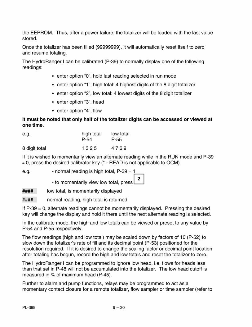
Single Exponential, these are flumes and weirs that can be characterized bya single exponential term (P-40 = 1).
i.e.: Q = K HX
where Q = flowK = constantH = headX = exponent, characteristic to the primary
measuring device (flume or weir)
Examples:Primary measuring device exponentSuppressed rectangular, Cipolletti weir, or Venturi flume 1.50Parshall Flume, or Leopold Lagco 1.55V-notch weir 2.50etc.......
NOTE: Refer to manufacturers specifications for the exact exponent. The exponents listed above are for reference only.
Palmer-Bowlus flumes, specifically those manufactured by Plasti-Fab orWarminster Fiberglass (P-40 = 2).
H-flumes, excluding HS and HL sizes, as developed by the U.S. Departmentof Agriculture, Soil Conservation Service (P-40 = 3).
Other, these are primary measuring devices that do not fit the first threecategories (P-40 = 4).
As most OCM applications are outdoors, the use of a temperature sensor is stronglyrecommended for optimum accuracy. If a temperature sensor is not used, the expectederror due to temperature variations will increase from 0.01 to 0.17% per celsius degreeover the operating range (P-3).
Flow readings are calculated by the HydroRanger I as a function of the head under thetransducer, installed upstream from the primary measuring device (P-40). The flowsare then accumulated in the arbitrary volume units chosen per the time units of P-41 inan 8 digit totalizer. In the event of a loss of echo, the totalizer will continue beingincremented by the flowrate established from the last valid echo. If the fail-safe timerexpires (’LOE’ is displayed) or when in the calibrate mode, the totalizer will stop beingincremented and hold its last updated value.
The totalizer contents are stored in RAM and will be lost in the event of a power failure.However, after every 1 hour of continuous operation, the totalizer contents are stored in
PL-399 6 – 29
the EEPROM. Thus, after a power failure, the totalizer will be loaded with the last valuestored.
Once the totalizer has been filled (99999999), it will automatically reset itself to zeroand resume totaling.
The HydroRanger I can be calibrated (P-39) to normally display one of the followingreadings:
• enter option “0”, hold last reading selected in run mode
• enter option “1”, high total: 4 highest digits of the 8 digit totalizer
• enter option “2”, low total: 4 lowest digits of the 8 digit totalizer
• enter option “3”, head
• enter option “4”, flow
It must be noted that only half of the totalizer digits can be accessed or viewed atone time.
e.g. high total low totalP-54 P-55
8 digit total 1 3 2 5 4 7 6 9
If it is wished to momentarily view an alternate reading while in the RUN mode and P-39≠ 0, press the desired calibrator key (* - READ is not applicable to OCM).
e.g. - normal reading is high total, P-39 = 1
- to momentarily view low total, press
#### low total, is momentarily displayed
#### normal reading, high total is returned
If P-39 = 0, alternate readings cannot be momentarily displayed. Pressing the desiredkey will change the display and hold it there until the next alternate reading is selected.
In the calibrate mode, the high and low totals can be viewed or preset to any value byP-54 and P-55 respectively.
The flow readings (high and low total) may be scaled down by factors of 10 (P-52) toslow down the totalizer’s rate of fill and its decimal point (P-53) positioned for theresolution required. If it is desired to change the scaling factor or decimal point locationafter totaling has begun, record the high and low totals and reset the totalizer to zero.
The HydroRanger I can be programmed to ignore low head, i.e. flows for heads lessthan that set in P-48 will not be accumulated into the totalizer. The low head cutoff ismeasured in % of maximum head (P-45).
Further to alarm and pump functions, relays may be programmed to act as amomentary contact closure for a remote totalizer, flow sampler or time sampler (refer to
2
PL-399 6 – 30

Section V, Relays). The duration of a momentary contact closure is 200 mSec forwhich the corresponding relay status LED will flash. As a remote totalizer relay, thecontact is closed each time the displayed total is increased by the amount entered intoP-56. As a flow sampler relay, the contact is closed each time the volume of liquid asset by P-57 and P-58 is pumped. As a time sampler relay, the contact is closed at therate of the time period entered into P-59.
The mA output responds to the head or flow (P-50). In the event of fail-safe due to lossof echo, the mA output will respond as programmed by P-6 and P-74.
When calibrating the HydroRanger I for the OCM function, the empty distance totransducer (P-3) may be considered and entered as the distance from the transducerface to the 0 head or no flow reference level. If this measurement is not easilyobtained, P-3 can be estimated and corrected via P-47 . This is referred to as the AutoZero calibration and requires the HydroRanger I to compare a physical measurement(from wall gauge, dipstick or stilling well) to the ultrasonic measurement via P-47. Referto Example 6a.
It should also be noted that when operating in the OCM function: percent display,volume conversion (P-34) and convert display (P-37) are inoperative. Empty calibration(P-61) must be clear, i.e. 4 hyphens in the display.
Example 6
9" Parshall Flume
Q = 1.98 H1.53
where Q = flow rate, MGD (million gallons per day)H = head, feet
- max. flow rate - Q max. = 4.112 MGD= 4,112,000 gal./day
- max. head - H max. = 1.61
- transducer is mounted 3 ft above the zero flow level
- max. flow rate display = 4,112i.e.: one count = 1000 gal.
select:P-1 enter option “3”, units in inches
P-2 enter option “5”, OCM
P-3 enter “3”, zero level distance to transducer
P-4 enter “1.61”, max. head
PL-399 6 – 31

P-5 enter “1”, near blanking distance, minimum allowable
P-39 enter option “4”, display flowrate in units per day
P-40 enter option “1”, primary measuring device - exponential
P-41 enter option “4”, flowrate time units - per day
P-42 enter “1.53”, exponent from manufacturer’s specs. for 9" Parshall Flume
P-46 enter “4112”, max. flow in thousand gal./day
P-49 enter option “3”, flowrate decimal point display max. 3 digits after decimal
P-52 enter option “0”, totalizer convert display total is divided by 1 before being displayed or 1 count per thousand gallons
P-53 enter option “2”, totalizer decimal point display 2 digits after decimal or resolution equals 1/100th of a count
P-68 enter “32.81”, fill damping 32.81 ft/min As the head would fluctuate over a period of hours, damping requirements would be fairly low. Typically, the factory set damping of 32.81 can be used.
P-69 enter “32.81”, empty damping - same as fill damping
Example 6a
(Auto Zero)
Further to Example 6, the following is required:
• alarms at 10% overflow (approx. = 1.8 ft) and 0 head
• in the event of loss of echo, the HydroRanger I is to go into low alarm after45 sec.
• head to read to 1 decimal place
• sampler contact every hour
• head under 1" (40 thousand gal./day) not be totalized
• 4-20 mA output to respond to flow
PL-399 6 – 32

select:
P-3 enter “3.33” estimated empty distance to transducer
P-6 enter option “2”, 4 to 20 mA
P-7 enter option “1”, decimal location for head display max. 1 digit after decimal
P-8 enter option “1”, relay 1 - alarm function
P-9 enter “1.8”, relay 1 - alarm ON
P-10 enter “1.5”, relay 1 - alarm OFF
P-11 enter option “1”, relay 2 - alarm function
P-12 enter “0”, relay 2 - alarm ON
P-13 enter “.3”, relay 2 - alarm OFF
P-14 enter option “13”, relay 3 - time sampler contact
P-47 Auto Zero
press
and then 4 hyphens must appear in the display
press
at least 5 times to insure that the HydroRanger I will obtain a stable ultrasonic measurement. The resultant reading will be the apparent headwith respect to the estimated P-3 = 3.33 ft.Enter “physical head measurement”, over the displayed value previously obtained. This is the true head measurement from a wall gauge, dipstick orstilling well, taken at the same time as the ultrasonic measurement and rep-resenting the same head measurement point as seen by the transducer.The physical head measurement must not be in the near blanking zone. Anoffset value, which is the apparent head minus the true head, is automat-ically calculated and entered into P-62. P-62 can only be cleared by P-47.
P-48 enter “5.2”, low head cutoff is 5.2% of P-45. Flow for head below 1" (40 thousand gal./day) will not be totalized
1" = 0.052 = 5.2% 12"/ft x 1.61 ft
CLR ENTER
MEAS
PL-399 6 – 33

P-50 enter option “2”, mA output responds to flow
P-59 enter “1”, time sampler control closure once every hour
P-74 enter option “2”, fail-safe low
P-75 enter option “.75”, fail-safe timer, 45 sec.
PL-399 6 – 34
suppressedrectangular
v-notch ortriangular
cipolleti ortrapezoidal sutro or
proportional
Flows through these weirs may be measured using the universal head vs.flow characterization, P-40=4
contractedrectangular
compound approximateexponential
Poebing
near blanking (P-5) min. 0.3 m (11.81")
crest profile
transducer location
SINGLE EXPONENTIAL, P-40 = 1
Weirs
3 to 4hmax
Applicable Weir Profiles
Non-Applicable Weir Profiles
PL-399 6 – 35

Parshall Flume
• sized by throat width
• set on solid foundation
• general free flow equation is Q = KHx
where Q = flow rateK = constantH = headx = exponent
• for rated flows under free flow conditions,the head is measured at 2/3 the length ofthe converging section from the beginning ofthe throat section
• position the transducer such that it iscentered over the flow at a minimum heightof 30 cm (12") above the maximum head.
plan
side
• for related flows under freeflow conditions, the head ismeasured 15 cm (6")upstream from thebeginning of the convergingsection
• position the transducer suchthat it is centered over theflow at a minimum height of30 cm (12") above themaximum head.
Khafagi Venturi
15 cm
convergingthroat
diverging
Q
0 head
side
transducer
0 head
c 2/3 CQ
SINGLE EXPONENTIAL, P-40 = 1 (cont’d)
FLUMES
front
plan
transducer
PL-399 6 – 36

SINGLE EXPONENTIAL, P-40 = 1 (cont’d)
FLUMES (cont’d)
Leopold Lagco(as manufactured by Leopold Co., Inc.)
• designed to be installed directlyinto pipelines and manholes
• Leopold Lagco may be classedas a rectangular Palmer-Bowlusflume
• sized by pipe (sewer) diameter
• for rated flows under free flowconditions, the head ismeasured at a point upstreamreferenced to the beginning ofthe converging section. Refer tothe following table.
Flume Size Point of Measurement(pipe dia. in inches) cm Inches
4 — 12 2.5 115 3.2 1-1/418 4.4 1-3/421 5.1 224 6.4 2-1/230 7.6 342 8.9 3-1/248 10.2 454 11.4 4-1/260 12.7 566 14.0 5-1/272 15.2 6
• general free flow equation is Q = KHx
where Q = flow rateK = constantH = headx = exponent
• position the transducer such that it is centered over the flow ata minimum height of 30 cm (12") above the maximum head.
convergingthroat diverging
Q
plan
point of measurement
sidefront
0 head
transducer
PL-399 6 – 37

Flows through the following flumes may be measured using the universal headvs. flow characterization, P-40=4.
Cuthroat Flume
• similar to Parshall flume except thatthe floor is flat bottomed and throathas no virtual length.
• refer to manufacturer’sspecifications for flow equation andpoint of head measurement.
Dual range (nested) Parshall Flume
• two flumes, a larger on top of the smaller, in order tohandle a larger range of flows
SINGLE EXPONENTIAL , P-40 = 1(cont’d)
FLUMES (cont’d)
plan
plan
front
Trapezoidal Flume
• similar to Parshall flume except thatfloor is flat bottomed and walls aresloped outward
isometric
PL-399 6 – 38

PALMER-BOWLUS FLUME, P-40 = 1
(as manufactured by Warminster Fiberglass or Plasti-Fab)
• sized by pipe diameter
• flume relief is trapezoidal
• designed to install directly into pipelines and manholes
• head is referenced to bottom of the throat not to bottom of pipe.
• for rated flows under free flow conditions, the head is measured at a distance of D/2upstream from the beginning of the converging section.
• position the transducer such that it is centered over the flow at a minimum height of 30 cm (12") above the maximum head.
Q
plan
D/2 point of measurement
transducer
side
0 head
D = pipe or sewer diameterfront
PL-399 6 – 39

transducer
• sized by max. depth of flume
• approach is preferably rectangular, matching width and depth for distance 3 to 5times the depth of the flume.
• flow range 100:1
• may be installed in channels under partial submergence (ratio of downstream level tohead). Typically: -1% error @ 30% submergence
-3% error @ 50% submergence
• for rated flows under free flow conditions, the head is measured at a pointdownstream for the flume entrance. Refer to the following table.
Flume Size Point of Measurement(D ft) cm Inches
0.5 5 1-3/40.75 7 2-3/41.0 9 3-3/41.5 14 5-1/22.0 18 7-1/42.5 23 93.0 28 10-3/44.5 41 16-1/4
• H flumes come with flat or sloping floor. Same flow table can be used as error is lessthan 1%.
• position the transducer such that it is centered over the flow at a minimum height of30 cm (12") above the maximum head
point ofmeasurement
plan
front side
D
Q
H FLUMES, P-40 = 3
(as developed by the U.S. Department of Agriculture, Soil Conservation Service)
PL-399 6 – 40

∗
↑ ↓ALTDISP
Flow
Head P-40 = 4, curved
OTHER, P-40 = 4 or 5
Where the primary measuring device does not fit one of the three other categories, P-40may be programmed for one or two head versus flow characterizations.
- P-40 = 4 : curved- P-40 = 5 : linear
Select the method which best fits the flow characteristics of the primary measuring element.
Characterization is achieved by entering the head (H parameter) and correspondingflow (F parameter) either from empirical measurement or from the manufacturer’sspecification. The more breakpoints that are defined, the more accurate will be the flowmeasurement. Breakpoints should be concentrated in areas exhibiting the higherdegrees of non linear flow. A maximum of eleven breakpoints can be defined.
Head data is entered in the linear units selected (P-1) and flow data is entered in thedesired units of flowrate.
By setting P-40 = 4 or 5, the H-# and F-# co-ordinates, where:
H = head data
F = flow data
# = breakpoint 1 to 11
may be alternately accessed for the selected breakpoint by successively
pressing . Breakpoints are selected by entering the desired breakpoint number
or by pressing the or key. When the desired co-ordinate has been selected,
the entry field is accessed by pressing and the head or flow is entered.
To end programming of H and F co-ordinates, press CLR while H-# or F-# is beingdisplayed.
Flow
HeadP-40 = 5, linear
PL-399 6 – 41

P-39 enter option "4", display flowrate
P-40 enter option "4", universal head vs. flow
press display will showor enter
* H-1ALT. DISP. ----0 0ENTER 0.000↑ H-2
----ENTER 0.300↑ H-3
----ENTER 0.600↑ H-10
----2.7 2.7ENTER 2.700↑ H-11
----3 3ENTER 3.000
Example 6bThe application is to measure the flow across a 4 ft. rectangular weir with endcontractions. The flow is characterized by the following formula:
cfs = 3.33 (L - 0.2H) H1.5
select:
P-1 enter option "3", units in feet
advance to:
P-2 enter option "5", OCM
P-3 enter "4", empty distance to transducer
P-4 enter "3", span
P-5 enter "1" near blanking distance
where cfs = flow in cu ft/secL = length of crestH = head
PL-399 6 – 42

RUN
CAL
58.83 58.83ENTER 58.83ALT. DISP. F-12CLR P-40
P-41 enter option "4", flowrate time units - per day
P-46 enter option :"58.83", maximum flowrate in ft3/sec
P-49 enter option "3", flowrate decimal point display max. 3 digits after decimal
P-52 enter option "0", totalizer convert display is divided by 1 before being displayed or 1 count per thousand ft3
P-53 enter option "2", totalizer decimal point display 2 digits after decimal or resolution equals 1/100th of a count
press:
to re-enter run mode
* F-11----
ALT. DISP. F-111 F-1ALT. DISP. ----0 0ENTER 0.0000↑ F-2
----2.156 2.156ENTER 2.156↑ F-3
----6.005 6.005ENTER 6.005↑ F-10
----51.12 51.12ENTER 51.12
PL-399 6 – 43

RUN
CAL
Applications with Standpipes
In many solids and liquid applications, access to the vessel must be made via astandpipe. In such cases, Milltronics can provide flange mounted transducers that willreadily mate to the standpipe (refer to Figure 4).
The maximum standpipe length that can be used without additional near blanking (P-5not greater than 0.3 m) is 200 mm (8"). For greater standpipe lengths, up to 30" long,near blanking must be extended to 150 mm (6") beyond the end of the pipe.
The preferred dimension when selecting a standpipe arrangement is a 100 mm (4") dia.pipe, 300 mm (12") long. Near blanking would be set at 460 mm (18").
Example 7Referring to Example 4, if the transducer were mounted to a 150 mm dia. flangedstandpipe 0.5 m long, instead of a 1 m dia. manhole, the following will be required:
select:P-5 enter “.65”, near blanking
0.50 m (standpipe length)+0.15 m (blanking past pipe) 0.65 m total blanking distance
press:
to re-enter run mode.
�
PL-399 6 – 44

SECTION VII
PARAMETER DESCRIPTIONNOTE:
• (F) indicates the parameter’s factory setting, where applicable. For reference only - factory set values may change with software revisions.
• (V) indicates that parameter can be viewed only, not entered.
P-0 security
This parameter can be used to lock out the calibrator such that the content of parameters P-1 through P-99 can not be changed. This however doesnot prevent the parameters from being selected and viewed. The calibrator is locked out if the content of P-0 is of any value other than 1954. P-0 can only be direct accessed.content = 1954, calibrator functional (F) ≠ 1954, calibrator locked out = – 1, pumps active during simulation
P-1 units of calibration and display
enter 1 = meters (F) 1* = calibrate in meters, display in %2 = centimeters 2* = calibrate in centimeters, display in %3 = feet 3* = calibrate in feet, display in %4 = inches 4* = calibrate in inches, display in %
NOTE: For % display, entry must be made as and will bedisplayed as “#P”
e.g. : press keypad switches and then , display will appear as “3P”’
# *
3 *
PL-399 7 – 1

P-2 mode of measurement
enter 1 = liquid level2 = space (F)3 = differential level4 = volume totalizer (pump totalizer)5 = OCM (open channel measurement)
P-3 empty distance to transducer
enter desired amount (F=10.00 m)
P-4 span
- distance between full (high) and empty (low) levels- max. level differential if DLD (P-2 = 3) is selected- max. head if OCM (P-2 = 5) is selected
enter desired amount (F=10.00 m)
P-5 near blanking
enter distance required, in units as set in P-1. Note that entry must be slightly larger than distance to end of standpipe or to far side of obstruc-tion. (F=0.300 m)
P-6 milliamp output
enter 0 = off1 = 0 to 20 mA2 = 4 to 20 mA (F)3 = 20 to 0 mA4 = 20 to 4 mA
P-7 decimal point location
Sets the maximum number of digits after the decimal. The number of digits after the decimal will automatically reduce to avoid display overflow.
enter 0 = no digits after decimal1 = one digit after decimal2 = two digits after decimal (F)3 = three digits after decimal
P-8 relay 1 function
Refer to Section V, Relays.enter desired option (F=0)
P-9/10 relay 1 - ON/OFF setpoints
enter level in units as selected in P-1 or °C (F=----)
PL-399 7 – 2

P-11 relay 2 function
Refer to Section V, Relays.enter desired option (F=0)
P-12/13 relay 2 - ON/OFF setpoints
enter level in units as selected in P-1 or °C (F=----)
P-14 relay 3 function
Refer to Section V, Relays.enter desired option (F=0)
P-15/16 relay 3 - ON/OFF setpoints
enter level in units as selected in P-1 or °C (F=----)
P-17 relay 4 function
Refer to Section V, Relays.enter desired option (F=0)
P-18/19 relay 4 - ON/OFF setpoints
enter level in units as selected in P-1 or °C (F=----)
P-20 relay 5 function
Refer to Section V, Relays.enter desired option (F=0)
P-21/22 relay 5 - ON/OFF setpoints
enter level in units as selected in P-1 or °C (F=----)
Parameters P-23 through P-33 are used specifically for pump applications. Referto Section VI.
P-23 submersible transducer
enter 0 = normal ST-series transducer (F)1 = submersible transducer
P-24 relay 1 pump log *
PL-399 7 – 3

P-25 relay 2 pump log *
P-26 relay 3 pump log *
P-27 relay 4 pump log *
P-28 relay 5 pump log *
* these are multi-level parameters related to the respective relays when assignedto a pump control function. Access to the levels is made by pressing .
e.g. P - 24 ‘ running hours ’ log
C - 24 ‘ starts ’ log
A - 24 pumping ratio
P - 24 ‘ running hours ’ log
The running hours are displayed by pressingwhile viewing P - 24 through P - 28.
P - 24 ‘ running hours ’ log
1 2 3 4 1,234 hours of runningtime ( F = 0.000 )
The number of starts is displayed by pressingwhile viewing C - 24 through C - 28.
C - 24 ‘ starts ’ log
321 321 pump starts ( F = 0 )
The ratio settings are entered by pressing while viewing A-24 through A-28.
e.g. A-24 pump ratio
20 20 % (F=20)
5 5 %
5.000
*
*
ALTDISP
*
5
ALTDISP
Enter
ALTDISP
ALTDISP
*
ALTDISP
ALTDISP
PL-399 7 – 4

The ‘ running hours ’ and ‘ starts ’ may also be viewed in the run mode. Refer to Application \ Pump Control Application.
P-29 pump run-on interval
the cyclical period in hours, in which a pump run-on duration may occur. The initial interval begins upon return to the run mode or resumption ofpower to the HydroRanger I. Subsequent intervals begin at the end of theprevious interval. Intervals end after the time entered has expired or whenthe power or run mode is interrupted.
enter interval in hours (F=0.000)
P-30 pump run-on duration
the amount of time which the lead pump will continue pumping after it has reached its OFF setpoint.
enter duration is seconds (F=0)
P-31 spare
P-32 DLD milliamp output
when operating in the DLD mode, the milliamp output can be set to correspond either to the differential or to the level under transducer #1(refer to Figure 3)enter 1 = differential (F)
2 = level
P-33 inflow/discharge totalling
refer to Section V, Pump Totalizer Application
enter 1 = estimated inflow or discharge volume is added to the pumped volume total (F)2 = estimated inflow or discharge volume is omitted from the pumped volume total
PL-399 7 – 5

Parameters P-34 through P-39 are used for volume and display conversion.
P-34 tank shape for volumetric conversion
enter 0 = non volume - linear level measurement (F)1 = flat bottom2 = conic or pyramidic bottom3 = parabolic bottom4 = half sphere bottom5 = flat slope bottom6 = horizontal cylinder, flat ends7 = horizontal cylinder, parabolic ends8 = sphere9 = universal level vs volume (refer to Section VI, Volume Application)
if P-34 ≠ 0, reading will be in percent of P-04. For volumetric reading, setconversion factoring into P-37
P-35 tank dimension A
the height of the bottom section of tank shapes 2, 3, 4, 5 or the length of one end section in tank shape 7 (not required for other tank shapes).enter “dimension A”, in units selected per P-1 (F=0.000)
P4
P4
P4
P4
P4
1 = Flat Bottom
2 = Conic or Pyramidic Bottom 6 = Horizontal Cylinder, flatends
8 = Sphere
5 = Flat Sloped Bottom
7 = Horizontal Cylinder, parabolic ends
"
3 = Parabolic Bottomor
4 = Half Sphere
A
A
A L
A
P4P4
PL-399 7 – 6

P-36 tank dimension L
horizontal length of tank shape 7 excluding parabolic ends (not required for other tank shapes). enter “dimension L”, in units selected per P-1 (F=0.000)
P-37 convert display
parameter value is the factor by which the measurement is to be multiplied by before being displayed. Range is 0.001 to 9999.enter desired factor (F=1)
P-38 display offset
this value is added to material, space, volume or ullage measurement before being displayed (P-39, P-76 or programmer key “*”). The mAoutput and alarms are not affected by the offset. The display offset isentered in the units programmed, subject to P-1, P-34 and P-37.enter offset required (F=0.000)
P-39 display reading options
in the run mode, programmer keys can be pressed to view alternate readings. Refer to Section IV, Programmer Keypad. The display will return to thereading option selected (except option 0) after momentarily displaying thealternate reading.
enter 0 = hold last alternate reading selected (F)
1 = high total: 4 highest digits of the 8 digit totalizer (pumped volume and OCM only) = point 1: DLD level / transducer #1
2 = low total: 4 lowest digits of the 8 digit totalizer (pumped volume and OCM only) = point 2: DLD level / transducer #2
3 = head (OCM only)
4 = flowrate (OCM only)
5 = reading: level, space, differential, volume or ullage
1
3
4
*
2
PL-399 7 – 7

Parameters P-40 through P-50 are used specifically for OCM applications. Referto section VI.
P-40 primary measuring device
enter option 1 = exponential (F)2 = Palmer-Bowlus 3 = H-flume4 = universal head vs flow (refer to Section VI, Volume Application)
P-41 flowrate time units
enter option 1 = per second2 = per minute3 = per hour4 = per day (F)
P-42 OCM exponent
exponent for primary measuring devices, P-40 =1 where Q = KH x. Obtain from manufacturer’s specifications.enter “required number” (F=1.550)
P-43 flume dimension
enter “D”, flume size (P-40 = 2 or 3) in units of P-1 (F=1.000)
P-44 spare
P-45 maximum head
this is the head corresponding to the max. flowrate. This parameter is identical to P-4, span. A change to either parameter will simultaneouslychange the other. (F=10.00 m)
Palmer BowlusD = pipe or sewer dia.
D
D
H Flume
P-40 = 3P-40 = 2
PL-399 7 – 8

P-46 maximum flowrate
this is the flowrate which occurs at maximum head and determines the mA output span (refer to Section V, Analog Output). Obtain from manufacturer’s specifications.
enter “max. flowrate”, volume units are arbitrary (F=1000)
P-47 auto zero
this parameter allows automatic zero calibration for the empty distanceto transducer parameter (P-3) when that physical measurement is not ob-tainable.
P-3 is the estimated empty distance to the transducer face
with the transducer aimed at the proper portion of the crest in the open channel and at a height of at least 1 ft above maximum head
press at least five times and until a stable reading is obtained on the display. The reading, regardless of the height of the transducer, will bethe apparent head with respect to the estimated empty distance, P-3.enter the actual physical measurement of head at a point beneath the transducer
press , the HydroRanger I will then calculate the correct zero reference level, the offset will be automatically entered into P-62.
P-48 OCM low head cutoff
flows for head below this level will not be totalled. Unit of cutoff is percent of maximum head (P-45) enter “percentage required” (F=5.000)
P-49 OCM decimal point
sets the maximum number of digits after the decimal for display of flowrate (P-39 = 4). The number of digits after the decimal will automaticallyreduce to avoid display overflow.
enter 0 = no digits after decimal1 = one digit after decimal2 = two digits after decimal (F)3 = three digits after decimal
P-50 OCM mA output
refer to Section V, Analog Outputenter 1 = mA responds to head (F)
2 = mA responds to flow
MEAS
ENTER
PL-399 7 – 9

P-51 OCM simulation
press , display will show previous flow
enter head in units programmed, display will show head
press , display will show corresponding flow
Parameters P-52 through P-59 are used specifically for OCM and pump totalizer applications. Refer to Section VI.
P-52 totalizer display factor
totalizer display of flow or volume pumped is factored by a power of 10 to determine the count per flow. The factor is selected as follows:
enter -3 = multiply by 1000 -2 = 100 -1 = 10 0 = divide by 1 (F) 1 = 10 2 = 100 3 = 1,000 4 = 10,000 5 = 100,000 6 = 1,000,000 7 = 10,000,000
e.g. present flow rate is 450 gal./secif P-52 = 0, totalizer is incremented at a rate of 1 count per gallonif P-52 = 3, totalizer is incremented at a rate of 1 count per thousand gal-lons
P-53 totalizer decimal point location
sets the number of digits after the decimal point for the low total only. The decimal point will not float.
enter 0 = no digit after decimal1 = one digit after decimal2 = two digits after decimal (F)3 = three digits after decimal
P-54 low total
this parameter will display the 4 lowest digits of the 8 digit totalizer used in pump totalizer or OCM applications. The parameter will also allow thedisplay to be reset to any value. (F=00.00)
ALTDISP
ENTER
PL-399 7 – 10

P-55 high total
this parameter will display the 4 highest digits of the 8 digit totalizer used in pump totalizer or OCM applications. The parameter will also allow thedisplay to be reset to any value. (F=0000)
P-56 remote totalizer contact control
a momentary closure of the remote totalizer contact occurs once each time the entered flow or pumped volume has passed
enter option -3 = 0.001-2 = 0.01-1 = 0.1 0 = 1 (F) 1 = 10 2 = 100 3 = 1,000 4 = 10,000 5 = 100,000 6 = 1,000,000 7 = 10,000,000
P-57 & P-58 flow sampler control
a momentary closure of the flow sampler contact occurs once each time a volume of y x 10x, as defined by P-57 (x) and P-58 (y), flows or is pumped. enter P-57 (x) = base 10 exponent, -3 to 7 (F=0)enter P-58 (y) = mantissa, 0.001 to 9999 (F=1.000)
e.g. if P-57 = 3 and P-58 = 5, then a sampler contact closure will occur each time 5 x 103 = 5000 units of volume has passed
P-59 time sampler control
a momentary closure of the time sampler contact occurs each time the entered amount of time in hours has elapsed (F=----)
Parameters P-60 through P-67 are used to achieve specialized or customcalibration.
P-60 full calibration
this provides measurement offset compensation on a full tank. A measurement offset might occur when parameters 3 and 4 do not exactlymatch the tank dimensions referenced for volume conversion. (F=----) fill tank as much as permissible, but without going into the blanking zone
PL-399 7 – 11

press , the HydroRanger I will take a measurement and display the level in the linear units chosen regardless if percent, volume or convertdisplay is used. Press “MEAS” at least 5 times and insure that a stablereading is being obtained
enter the actual physical measurement or level
press , the HydroRanger I will now calculate the correct measurement offset to be used in future measurements and automaticallyenter it into P-62.
P-61 empty calibration
this provides sound velocity compensation on an empty tank. This is required on a volume application where the atmosphere in the tank isother than air or the atmospheric temperature is constant but other than20°C and no temperature sensor is being used. (F=-----)
empty tank as much as permissible. Leave filled with normal vapour and at normal operating temperature. Refer to Figure 7.
press , the HydroRanger I will take a measurement and display the level in the linear units chosen regardless if percent, volume or convertdisplay is used. Press “MEAS” at least 5 times and insure that a stablereading is being obtained.
enter the actual physical measurement or level
press , the HydroRanger I will now calculate the correct sound velocity to be used in future measurements and automatically enters it intoP-63 and P-64.
P-62 measurement offset
this displays the measurement offset; used in conjunction with a full tank calibration, P-60, or an offset value may be entered directly. The offset isadded to the ultrasonic measurement such that its effect will be carried
through the reading (P-39, P-76 or ) mA output and relay setpoints.(F=0.000)
MEAS
ENTER
MEAS
ENTER
*
PL-399 7 – 12

P-63 sound velocity at 20°C
can be used to enter the known velocity, at 20°C, of sound in a particular gas or vapour or to view the resultant velocity of an empty calibration(P-61), normalized to 20°C. (F=344.1)
the units of velocity are assumed to be:meters/sec if P-1= 1 (meters)
2 (centimeters)feet/sec if P-1= 3 (feet)
4 (inches)
P-64 velocity at P-65
can be used to enter the known velocity, at the temperature of P-65, of sound in a particular gas or vapour or to view the resultant velocity of anempty calibration, at the temperature of P-65. (F=344.1)
the units of velocity are assumed to be:meters/sec if P-1 = 1 (meters)
2 (centimeters)
feet/sec if P-1 = 3 (feet) 4 (inches)
P-65 air temperature in °C, as measured by temperature sensor or preset transducer operating temperature, if sensor is not used, enter temperaturerequired in °C (F=20C)
P-66 maximum air temperature in °C
records max. temp. measured by
temperature sensor. Press then to reset (F=-99C)
P-67 minimum air temperature in °Crecords the min. air temp. measured by temperature sensor. Press
then to reset (F=150C)
CLR ENTER
CLR ENTER
PL-399 7 – 13

Parameters P-68 through P-75 are used to stabilize the reading. These are generalpurpose parameters, suitable for all applications.
P-68 fill damping
is the maximum rate at which the display reading and analog output will change under filling conditions. The damping rate is measured in P-1 units per minute and has a range of 0.001 to 9999. Thus the smaller thenumber entered, the greater the damping.enter desired amount (F=10.00 m/min)
P-69 empty damping
is the maximum rate at which the display reading and analog output will change under emptying conditions. The damping rate is measured in P-1units per minute and has a range of 0.001 to 9999. Thus the smaller thenumber entered, the greater the damping.enter desired amount (F=10.00 m/min)
P-70 process rate display (V)
display the rate of filling (+) or emptying (—) in P-1 units/minute. Press to view while in RUN mode.
P-71 process rate filter
controls the response of the rate display
enter option 0 = continually averaged rate1 = update rate every minute or 50 mm (F)2 = update rate every 5 minutes or 100 mm3 = update rate every 10 minutes or 300 mm99 = arbitrary settings
this option allows the time or distance variables to be arbitrarilyset via the ‘s’ and ‘d’ sub-parameters.
P-71
1 factory setting option
99
99 arbitrary settings selected
s - 71 ‘seconds’ sub-parameter
7
ENTER
ALTDISP
*
9 9
PL-399 7 – 14

10 factory setting, 10 sec
5
5 change to 5 seconds
d-71 ‘distance’ sub-parameter
0.010 distance in m (units of P-1)
0.005
0.005 change to 0.005
P-72 fuzz filter
the fuzz filter is designed to keep the display constant when minor changes on the liquid surface (ripples), electrical noise or air movements in thevessel are occurring.
enter 0 = OFF1 = ON (F)
P-73 agitator discrimination
enter 0 = OFF1 = ON (F)
P-74 fail-safe mode
in the event of a loss of echo, the HydroRanger I will flash ’LOE’ and go into one of the following fail-safe modes after the timer (P-75) expires
enter 1 = high2 = low3 = hold last entry (F)
P-75 fail-safe timer
the amount of time delay before going into fail-safe mode enter “desired amount of time”, in minutes (F=15.00) e.g.: for 30 sec. time delay, enter ’0.5’
ENTER
ENTER
ALTDISP
ALTDISP
*
5
0 0 . 5
PL-399 7 – 15

Parameters P-76 through P-78 are used for measurement and simulation.
DISPLAY:
select desired parameter
P-76, 77 OR 78
press ,the display will show the reading of the last ultrasonic measurement
press to update ultrasonic measurement
SIMULATION:
select desired parameter
P-76, 77 OR 78
press ,the display will show the simulated rise and fall of the material level
The simulation will raise and lower the material level through the calibrated span, P-4, at a rate of 1% of the span per second. In the DLD application,one side (relay/LED 5 ON) is kept at a constant level, while the other side(relay/LED 5 OFF) is varied. The DLD simulation will alternate every 6seconds.
Pressing the key during simulation causes the apparent level to rise.
Holding the key in, increases the rate of filling. Pressing the key
causes the level to fall. Holding the in, increases the rate of emptying.During simulation, relay LED’s, alarm relays and mA output are all enabled to allow full response of the HydroRanger I. Pump relays are maintainedin a de-energized state throughout simulation (unless P-0 = – 1), howeverthe corresponding relay LED’s will respond. Relay LED’s for pumps willnot be illuminated within 1 second, simulating the 10 second start delayunder actual operation. As damping, fuzz filtering and agitatordiscrimination are not required, they are turned off.
To end simulation program, press twice.
ALTDISP
ENTER
ENTER
ALT
DISP
↓
↑ ↓
↑
PL-399 7 – 16

P-76 reading
this is one of the optional displays selected in the display options parameter, P-39, and may also be obtained by pressing .
This reading incorporates both the measurement and display offsets.
MODE READING(P-2) (linear, %, volume)
material materialspace spaceDLD differentialvol. tot. material OCM head
P-77 liquid level
this is the actual liquid level referenced to zero or empty level in m, cm, ft or in.
P-78 space or distance
this is the actual distance from the transducer face to the liquid level in m, cm, ft or in.
Parameters P-79 through P-88 are used for echo processing and analysis.
P-79 scope display LCD display
windowmarkerCurve - TVTProfile
select any combination of scope displays0 = scope display off (display ‘_’) (F=_ _ _ _)1 = scope display on (display‘u’, n, C or P)
presse.g. to display the marker and the curve on the oscilloscope :
press , enter “0011"
press ,display will show _ _CP
ALTDISP
ENTER
ENTER
u n C P
∗
S DC IO SP PE L
AYS
PL-399 7 – 17

P-80 echo confidence (V)
a measure of echo reliability. Press “MEAS” to make an ultrasonic measurement and the updated echo confidence will be displayed. Thisfeature is useful when aiming the transducer.
LCD displayshort pulselong pulse
display:
## :## = display of confidence in dB
## : - - = no long pulses transmitted
0 : E = pulses transmitted, but no echo - check for faulty
transducer or wiring
H : - - = submersible transducer submerged (P-23 = 1)
P-81 confidence threshold for short measurement
minimum echo confidence for echoes within 1 meter of transducer. If echoes are beyond 1 meter or have a confidence under the thresholdlevel, the short measurement will be ignored and the long measurementswill become valid.
enter threshold (F=10)
Typical usage; if transducer were picking up small unwanted echoes from close in, increase threshold to a value above that of the echo confidence(P-80) so that close in echoes are no longer detectable.
P-82 confidence threshold for long measurement
minimum echo confidence for long measurements. If no echo confidences meet this threshold, a loss of echo condition will prevail.
enter threshold (F=5)
Typical usage; during filling of vessel, material intersects beam path. Instead of displaying wrong level, increasing threshold to a value abovethat of the echo confidence (P-80) will force the HydroRanger I intofail-safe.
_ _:_ _
PL-399 7 – 18

P-83 echo strength (V)
displays the absolute strength of the selected echo in dB above 1 uV rms
P-84 noise
average and peak ambient noise, in dB above 1 uV rmsambient noise includes acoustical and electrical noise being picked up by the transducer/receiver circuit when the transmit/receive cycles have beendisabled during the CALIBRATE mode
LCD display average peak
P-85 echo processing algorithms
enter 1 = best echo of first and largest (F)2 = first echo3 = largest echo
P-86 TVT curve
enter 1 = standard (F)2 = flat
typical usage; solids applications where low confidence is obtained, using flat echo extraction may yield higher confidence.
P-87 range extension
used to extend the measurement range into the far end blanking.
In applications where the zero level does not correspond to the bottom of the vessel and it is desired to monitor this zone, the far end blanking mayneed to be reduced. This is accomplished by entering a range extensionvalue as the percentage of P-3 which equals the extra distance required.If it is found that false echoes are appearing ahead of the far end blankingzone, the range extension should be decreased by reducing the factoryset value of 20%.
enter, as percent of P-3, distance below 0 not blanked (F=20)
P-88 number of transmit pulses
this parameter is used to select the number and duration of the pulses to be transmitted per measurement.
:
PL-399 7 – 19

enter 1 = one short pulse only2 = one long pulse only 3 = two long pulses and one short pulse 4 = one short pulse if target is within 1 m, or (F) one short pulse and two long pulses if target is beyond 1 m
Parameters P-89 through P-98 for testing.
P-89 software revision number (V)
P-90 memory test (V)
press display will show: ’PASS’ = memory test passed’1’ = RAM failure’2’ = EPROM failure’3’ = EEPROM failure
P-91 LCD, LED and relay test (V)
Note: as this test will cause the relays to change state be sure to lock out all applicable alarms, pumps and machinery
before pressing “enter”
press - all LCD segments should flash- all relays should turn on and off sequentially- all LED’s should flash sequentially- press any key to stop
P-92 mA output test
HydroRanger I will output to terminal board, TB1, the displayed mA value
(also by pressing ). Range is approximately 0 to 20. Upon entering the CAL mode, the prior mA out value will be displayed.
A new test value may be entered or the mA value from pressing canbe viewed. Upon returning to the RUN mode, the parameter value willassume the actual mA output level. (F=0.000)enter desired mA value
P-93 temperature sensor ADC counts (V)
P-94 transmitter test (V)
ENTER
5
MEAS
ENTER
PL-399 7 – 20

press ,the transmitter will fire at a regular rate and the transmit neon Ll will flash correspondingly. Press any other key to stop. (F=----)
P-95 programmer test (V)
press ,then press each key from left to right starting with the top row.The display will acknowledge each key pressed:
if any key is pushed out of sequence or malfunctions, the display will show ’FAIL’
P-96 watchdog reset test (V)
press , hyphens will flash for 5 seconds or less and then the HydroRanger I goes into the run mode. Should the test fail, theHydroRanger I will not go back into the run mode.
P-97 trim for 4 mA
ENTER
ENTER
ENTER
KEY DISPLAY KEY DISPLAY
1
9
3
6
5
8
2
0
4
7
2
3
4
5
6
7
8
9
0
1 .
ALT
CLEAR
MEAS
RUN
↓
–
ENTER
*
↑
10
11
12
13
14
15
16
17
18
PASS
PL-399 7 – 21

when this parameter is selected, the mA output goes to 4 mA. The display however, will show a typical value of 200. By increasing or decreasing thisvalue, the mA output can be slightly varied to make external equipmentread 4 mA. This parameter is not reset by P-99.
e.g.: “P-97" is selected’200’ is displayedexternal meter reads 3.8 mA
enter ’202’ or increase by pressing , meter reads 3.9 mAenter ’205’, meter reads 4.0 mA
P-98 trim for 20 mA
when this parameter is selected, the mA output goes to 20 mA. The display, however, will show a typical value of 3490. By increasing ordecreasing this value, the mA output can be slightly varied to makeexternal equipment read 20 mA. This parameter is not reset by P-99.
e.g.: P-98 is selected’3490’ is displayedexternal meter reads 20.1 mA
enter ’3480’ or decrease by pressing , meter reads 20 mA
P-99 master reset
used to reset ALL parameter to their factory setting.
press , display will go blank
press , "C.ALL" will momentarily appear after a few seconds,then "----" will be displayed. All parameters are now in their factory setting.
•
--
CLR
ENTER
PL-399 7 – 22

SECTION VIII
TROUBLESHOOTING
General
There are few adjustments for echo processing and they should be used judiciously.Transducer location and aiming are the most important factors affecting the reliability ofthe HydroRanger I. Location and aiming of the transducer may be optimized by
pressing to view the confidence level while in the RUN mode. In the CALIBRATEmode, the same can be achieved by observing the echo confidence, P-80 and
pressing .
Oscilloscope
An oscilloscope can be used to view the transmit, receive and processed echo signals.
Connect as follows:
oscilloscope location description
probe - J1, RCVR, board A - amplified receiver signal- J2, SCOPE, board A - processed echo - TB1-8, board B - raw transmit/receive signal
external trigger - J3, SYNC, board A - oscilloscope synchronizationground - J4, COM, board A - ground
The transmit and receive signals are best viewed while in the run mode or with P-94,transmitter test, set to fire automatically in the calibrate mode. This may be useful whenaiming the transducer to obtain the best echo.
To view the processed echo, P-79 must be set for the desired display. If theCALIBRATE mode is exited for more than 10 minutes, P-79 will have to be reset to viewthe displays on the oscilloscope.
The processed echo can be viewed and updated by pressing . This must be done while in the calibrate mode, but can be done while viewing any parameter. Forexample, echo analysis parameters 79-84 or echo processing parameters 85-87 can be viewed or changed while monitoring results on both the HydroRanger I display andon the oscilloscope.
8
MEAS
MEAS
PL-399 8 — 1

The processed echo display (P-79) can be made to show not only the processed echoprofile, but also the:
• echo marker
• window
• TVT curve or auxiliary window
Typical scope settings for viewing the processed echo are:
• gain - 1 v/div
• sweep - 1 mSec/div
Note: - the following is restricted to transmission in air at 20°C.
• to obtain a time measurement of the processed echo, the sweep time mustbe multiplied by a factor of 10.
• to obtain a time measurement of the transmit or receive signal, use theactual sweep setting.
• to obtain a distance measurement of either of the above types of echoes,divide the respective time measurement by 1.8 mSec/ft or 5.9 mSec/m.
PL-399 8 — 2

TVT curve window
echo profile
(far end blanking)
Scope display LCD display (P-79)Window uMarker nCurve - TVT cProfile p
echo marker(near blanking)
PL-399 8 — 3

Troubleshooting guideThe following is a list of operating symptoms, their probable cause and action to be taken.
SYMPTOM CAUSE ACTION
Loss Of Echo (LOE)
display will flashCAbL/LOE, neon L1 willflash but no pulsing isfelt on transducer face
open circuit - check transducer wiring. Referto fig. 2, 3 & 4
defective transducer - check max. temp. P-66 againsttransducer rating
- try a substitute
display will flashCAbL/LOE, neon L1 willbe continuously off andno pulsing is felt ontransducer face
short circuit - check transducer wiring. Referto fig. 2, 3 & 4
defective transducer orcircuit board
- check max. temp. P-66 againsttransducer rating
- try substitute
display will flash LOE,neon L1 will flash, puls-ing is felt on transducerface
level or target out ofrange. Under normalconditions max. rangeis 10 m plus 20% of P-3(far blanking)
- check transducer specifications
- check calibration parameters
application too steamy.Under these conditionsrange may be adverselyaffected
- re-locate transducer.Refer to transducer installationpage 3 – 1.
if condition occurs onlyduring filling
- increase fail-safe timer, P-75.
transducer face - cleancovered
- move transducer to better location
material build-up on face
- mount in standpipe
PL-399 8 — 4

SYMPTOM CAUSE ACTION
transducer location oraiming:- poor installation - moved by material or vibration - flanging not level
- re-locate or insure thattransducer is aimed perpen-dicular to liquid surface for max. echo confidence,P-80.
- refer to transducer installationpage 3 — 1 & fig. 4 & 5.
transducer malfunction temp. too high or low physical damage
- check P-65, 66 & 67 inspect
- excessive foam on liquid surface
- use foam deflector or stillingwell
display will flash CAbl/LOE, neon L1 will flash, pulsing is felt on transducer face
- ensure that polarity is correct
Reading Does NotChange, But Level Does
HydroRanger I process-ing wrong echo, i.e. ves-sel wall, structural mem-ber, stationary agitator.
- check transducer aim. Refer totransducer installation page 3 — 1.
- check echoes with oscilloscope
transducer ringing, reading high level
- transducer must not be in contact with metal
- mounting need only be handtight. Refer to fig. 5.
- increase blanking P-5
- check echoes with oscilloscope
- raise short measurement confi-dence threshold, P-81
transducer or TS-3polarity incorrect
PL-399 8 — 5

SYMPTOM CAUSE ACTION
Measurement Consis-tently Off By ConstantAmount
measurement offset - refer to P-60 & 62 & e.g. 4
Reading Error Progres-sively Worsens WithDistance
temp. compensation - insure that J2 is properly set,refer to fig. 2
sound velocity compen-sation
- P-61 & 63, e.g. 4
Screen Blank, Neon L1Not Flashing
loss of power - check power wiring jumpers &fuse. Refer to fig. 2.
Screen Will Not Re-spond To Programmer
programmer improperlypositioned
- refer to installation page 3 — 1
infra-red window ob-structed
- clean
calibrator defective - test programmer P-95
Reading Erratic echo confidence weak - refer to P-85, 86, 87 & 88
liquid surface agitated - increase damping, P-68 & 69 turn on fuzz filter P-72
material filling - relocate transducer increase damping, P-68 & 69
electrical noise - check P-84 under quiescentconditions, noise should be un-der 15 dB.
- transducer cable must be ingrounded metal conduit andcable grounded only at TB-1.Refer to fig. 4.
- increase damping, P-68 & 69
agitator blades - set P-73 to 1
Reading ’EEEE’ reading to large - re-calibrate, i.e. P-3, 4, 37, 52& 53
PL-399 8 — 6

SYMPTOM CAUSE ACTION
Reading Response Slow damping too high - increase P-68 & 69
agitator on - turn off P-73
fuzz filter on - turn off P-72
Reads correctly butoccasionally reads highwhen vessel is not full
detecting close rangeecho or ringing
- increase blanking - increase short measurement threshold, P-81 - transducer mounting, refer to fig. 5
High level reading lowerthan material level
material is within nearblanking zone (P-5). Echo multiple beinglevel processed
- decrease blanking limit material high
PL-399 8 — 7

SECTION IX
MAINTENANCE AND SPARE PARTS
Maintenance
The HydroRanger I requires no maintenance, however a program of periodic checkswould be beneficial.
The enclosure and circuit boards should be cleaned if necessary, but only when thepower is disconnected at the main breaker and using a vacuum cleaner and a clean,dry paint brush. Check all electrical contacts in the HydroRanger I enclosure as well asthose in junction boxes, for corrosion and arcing.
If the HydroRanger I is mounted in dusty or oily environment, make sure that theprogrammer and front cover is kept clean, otherwise it may impede the infrared signaltransmission required for programming.
It is also a good idea to periodically check the face of the transducer. It should be freeof material build-up corrosion or deformation.
PL-399 9 – 1

APPENDIX I
SOUND VELOCITIESGASES (0° C) m/sec ft/sec
air, dry 331 1086ammonia 415 1362argon 308 1010carbon dioxide 259 850carbon monoxide 338 1109chlorine 206 676deuterium 890 2920ethane (10° C) 308 1010ethylene 317 1040helium 965 3166hydrogen 1284 4213hydrogen bromide 200 656hydrogen chloride 206 676hrydrogen iodide 157 515hydrogen sulfide 289 948illuminating (coal gas) 453 1486methane 430 1411neon 435 1427nitric oxide (10° C) 324 1063nitrogen 334 1096nitrous oxide 263 863oxygen 316 1037sulfur dioxide 213 699
VAPOURS (97° C)
acetone 230 755benzene 202 663carbon tetrachloride 145 476chloroform 171 561ethanol 269 883ethyl ether 206 676methanol 335 1099water vapour (134° C) 494 1621
PL-399 10 – 1

APPENDIX II
GLOSSARYAeration: - air gap between nappe and weir.
Beam angle: - angle between the opposing one-half powerlimits (-3dB) of the sound beam
Blanking: - zone in which received echoes are ignored.
Crest: - the edge (sharp-crested weir) or surface(broad crested weir) over which the flowpasses.
EEPROM: - electrically erasable programmable readonly memory.
EPROM: - erasable programmable read only memory.
Flume: - a 3 part hydraulic structure, consisting ofconverging, throat and diverging sections, toconstrict the flow through the throat, therebyincreasing the head in the converging sec-tion. The change in head is proportional tothe change in flow.
Free flow: - downstream liquid level is low enough or thedischarge flow is fast enough, so as not toimpede flow through the flume or weir.
Gauge well: - same as stilling well.
Head: - liquid level above zero (static) referencelevel.
LCD: - liquid crystal display.
Max. head: - head at max. flowrate.
Measurement: - each time a transmit pulse or set number ofpulses is sent to the transducer.
Nappe: - the jet of liquid leaving the weir crest.
OCM: - open channel measurement
Primary measuring device: - hydraulic structure of a open channel formeasuring liquid flow. e.g. weirs and flumes.
Pl-399 10 – 2

Ringing: - the inherent nature of the transducer to con-tinue vibrating after the transmit pulse hasceased.
Secondary measuring device: - any instrument for measuring the head orflow related to the primary measuring device.
Stilling well: - a well separate from but adjacent to the pri-mary measuring device and interconnectedby a small duct to provide an ideal point ofmeasurement.
Subcritical flow: - same as submerged flow.
Submerged flow: - when the downstream level rises or the dis-charge flow is so slow that it impedes thefree flow of liquid through the primary meas-uring device.
Ullage: - the remaining spatial volume of a vessel orthe volume required to fill a vessel.
Weir: - a dam with or without flow notch across anopen channel to produce a crest in the liquidupstream. The head of the crest is propor-tional to the flow.
PL-399 10 – 3

agitator discrimination P-73air temperature P-65air temperature, maximum P-66air temperature, minimum P-67algorithms P-85analog output P-6analog output, DLD P-32analog output, OCM P-50analog output, trim, 20 mA P-98analog output, trim, 4 mA P-97auto zero (OCM) P-47blanking P-5confidence P-80confidence threshold, short P-81confidence threshold, long P-82convert display P-37convert display, totalizer P-52damping, empty P-69damping, fill P-68decimal point P-7decimal point, OCM P-49decimal point, totalizer P-53display reading options P-39echo strength P-83empty calibration P-61empty distance P-3exponent, OCM P-42fail-safe mode P-74fail-safe timer P-75flume dimension P-43full calibration P-60fuzz filter P-72high total P-55inflow/discharge totalling (Pump) P-33low head cutoff (OCM) P-48low total P-54maximum flowrate P-46maximum head P-45measurement, distance P-78measurement, liquid level P-77measurement, reading P-76mode of measurement P-2noise P-84number of transmit pulses P-88offset, display P-38offset, measurement P-62primary measuring device P-40pump 1, hours P-24pump 2, hours P-25pump 3, hours P-26pump 4, hours P-27
pump 5, hours P-28pump, run-on, duration P-30pump, run-on, interval P-29range extension P-87rate display P-70rate filter P-71relay 1, function P-8relay 2, function P-11relay 3, function P-14relay 4, function P-17relay 5, function P-20relay 1, setpoint, off P-10relay 2, setpoint, off P-13relay 3, setpoint, off P-16relay 4, setpoint, off P-19relay 5, setpoint, off P-22relay 1, setpoint, on P-9relay 2, setpoint, on P-12relay 3, setpoint, on P-15relay 4, setpoint, on P-18relay 5, setpoint, on P-21relay, flow sampler, exponent P-57relay, flow sampler, mantissa P-58relay, time sampler P-59remote totalizer P-56reset P-99scope displays P-79security P-0simulation, distance P-78simulation, material level P-77simulation, OCM P-51simulation, reading P-76software revision P-89sound velocity at 20 °C P-63sound velocity at air temperature P-64span P-4tank dimension A P-35tank dimension L P-36tank shape P-34test, analog output P-92test, calibrator P-95test, memory P-90test, temperature sensor P-93test, transmitter P-94test, watchdog reset P-96test, LCD, LED and relay P-91transducer, submersible P-23TVT curve P-86units P-1units, flowrate time P-41
APPENDIX III
ALPHABETICAL PARAMETER LISTINGPARAMETER # PARAMETER #
PL-399 10 — 4

HYDRORANGEROUTLINE AND MOUNTING
lid screws6 places
240 mm(9.5")
228 mm(9")
97 mm(3.8")
82 mm(3.2")
programmer
customer mounting screws
CSA enclosure 4polycarbonate
lid, clearpolycarbonate
suitable location forconduit entrances
mounting holes(accessed under lid4.3 mm (0.17") dia.4 places
160 mm(6.3")
131 mm(5.1")
FIG. 1
PL-399 11 – 1

MOTHERBOARD
18 to 36 V DC operation24 V DC model
10 to 18 V DC operation12 V DC model
OPTIONAL ISOLATOR
CIRCUIT BOARD LAYOUT
DAUGHTERBOARD
FIG. 2
PL-399 11 – 2

duty
/
back
up
Ala
rm L
evel
In b
ou
nd
sO
ut
of
bo
un
ds
Dif
fere
nti
alR
ate
of
Ch
ang
eT
emp
erat
ure
Lo
ss o
f E
cho
Pu
mp
Lev
elE
ndE H
oS
equ
enti
alE
ndE H
oE
n’dE
’H
o’D
iffe
ren
tial
En
dE Ho
Mis
cella
neo
us
To
taliz
erF
low
Sam
ple
r
Tim
e S
amp
ler
Sca
nn
er
1P
-9P
-10
2"
"3
""
4"
"5
""
6"
"7
SE
T P
-75
8*P
-9P
-10
8*"
"8*
""
*"
"9*
""
9*"
"9*
""
*"
"9*
""
10*
""
10*
""
10*
""
11S
ET
P-5
612
SE
T P
-57
&
P-5
813
SE
T P
-59
n/a
n/a
1P
-18
P-1
92
""
3"
"4
""
5"
"6
""
7
SE
T P
-75
8*P
-18
P-1
98*
""
8*"
"9*
""
9*"
"9*
""
9*"
"9*
""
9*"
"10
*"
"10
*"
"10
*"
"
11S
ET
P-5
612
SE
T P
-57
&
P-5
813
SE
T P
-59
n/a
n/a
1P
-21
P-2
22
""
3"
"4
""
5"
"6
""
7
SE
T P
-75
8*P
-21
P-2
28*
""
8*"
"9*
""
9*"
"9*
""
9*"
"9*
""
9*"
"10
*"
"10
*"
"10
*"
"
11S
ET
P-5
612
SE
T P
-57
&
P-5
813
SE
T P
-59
14S
ET
P-2
P-1 " " "
P-1
/min
n/a
P-1 " " " " " " " " " " "
VO
L. P
-43
VO
LUM
E
HR
n/a
Fct
nS
etp
oin
tsF
ctn
Set
po
ints
P-1
1O
nO
ffF
ctn
Set
po
ints
P-1
4O
nO
ffF
ctn
Set
po
ints
P-1
7O
nO
ffF
ctn
Set
po
ints
P-2
0O
nO
ffU
nit
s
Ch
ang
ed u
se N
EW
CH
P--
-RE
LA
Y f
or
this
ch
art.
=
Pre
ss
to
sel
ect L
OE
def
ault
( E
n, d
E &
Ho
) an
d se
quen
tial o
ptio
n (
cum
ulat
ive
or d
uty
/ bac
kup
).
**cu
mul
ativ
e

Gen
eral
P-1
un
its
P-2
mo
de
P-3
em
pty
dis
t.P
-4 s
pan
P-5
nea
r bl
ank
P-6
mA
out
P-7
dec
imal
Filt
er
P-6
8fil
l dam
pP
-69
empt
y da
mp
P-7
0ra
te d
isp.
P-7
1ra
te a
vg.
P-7
2fu
zz fi
lter
P-7
3ag
itato
rP
-74
F.S
. mod
eP
-75
F.S
. tim
er
Cu
sto
m
P-6
0fu
llP
-61
empt
yP
-62
offs
etP
-63
vel.
20°C
P-6
4ve
l. P
-65
P-6
5te
mp.
P-6
6m
ax. t
emp.
P-6
7m
in. t
emp.
To
taliz
er
P-5
1O
CM
sim
.P
-52
fact
orP
-53
deci
mal
P-5
4lo
w to
t.P
-55
high
tot.
P-5
6re
mot
e to
t.P
-57
flow
sam
p.P
-58
flow
sam
p.P
-59
time
sam
p.
OC
M
P-4
0pr
imar
yP
-41
time
P-4
2ex
pon.
P-4
3flu
me
dim
.P
-44
spar
eP
-45
max
. hea
dP
-46
max
. flo
wP
-47
auto
zer
oP
-48
cuto
ffP
-49
deci
mal
P-5
0m
A o
ut
Vo
l. &
Dis
p.
Co
nve
rsio
n
P-3
4ta
nkP
-35
Dim
. AP
-36
Dim
. LP
-37
conv
ert
P-3
8di
sp. o
ffset
P-3
9di
sp. o
pt’n
Pu
mp
Co
ntr
ol
P-2
3su
bmer
s.P
-24
1 hr
s.P
-25
2 hr
s.P
-26
3 hr
s.P
-27
4 hr
s.P
-28
5 hr
s.P
-29
run-
onP
-30
run-
onP
-31
spar
eP
-32
DLD
mA
out
P-3
3to
talin
g
Rel
ays
P-8
1 fu
nctio
nP
-91
onP
-10
1 of
fP
-11
2 fu
nctio
nP
-12
2 on
P-1
32
off
P-1
43
func
tion
P-1
53
onP
-16
3 of
fP
-17
4 fu
nctio
nP
-18
4 on
P-1
94
off
P-2
05
func
tion
P-2
15
onP
-22
5 of
f
SIM
PL
E L
EV
EL
AP
PL
ICA
TIO
N P
AR
AM
ET
ER
S
P-#
requ
ired
para
met
ers
P-#
optio
nal p
aram
eter
s
P-#
para
met
ers
not r
equi
red

Gen
eral
P-1
un
its
P-2
mo
de
P-3
em
pty
dis
t.P
-4 s
pan
P-5
nea
r bl
ank
P-6
mA
out
P-7
dec
imal
Filt
er
P-6
8fil
l dam
pP
-69
empt
y da
mp
P-7
0ra
te d
isp.
P-7
1ra
te a
vg.
P-7
2fu
zz fi
lter
P-7
3ag
itato
rP
-74
F.S
. mod
eP
-75
F.S
. tim
er
Cu
sto
m
P-6
0fu
llP
-61
empt
yP
-62
offs
etP
-63
vel.
20°C
P-6
4ve
l. P
-65
P-6
5te
mp.
P-6
6m
ax. t
emp.
P-6
7m
in. t
emp.
To
taliz
er
P-5
1O
CM
sim
.P
-52
fact
orP
-53
deci
mal
P-5
4lo
w to
t.P
-55
high
tot.
P-5
6re
mot
e to
t.P
-57
flow
sam
p.P
-58
flow
sam
p.P
-59
time
sam
p.
OC
M
P-4
0pr
imar
yP
-41
time
P-4
2ex
pon.
P-4
3flu
me
dim
.P
-44
spar
eP
-45
max
. hea
dP
-46
max
. flo
wP
-47
auto
zer
oP
-48
cuto
ffP
-49
deci
mal
P-5
0m
A o
ut
Vo
l. &
Dis
p.
Co
nve
rsio
n
P-3
4ta
nkP
-35
Dim
. AP
-36
Dim
. LP
-37
conv
ert
P-3
8di
sp. o
ffset
P-3
9di
sp. o
pt’n
Pu
mp
Co
ntr
ol
P-2
3su
bmer
s.P
-24
1 hr
s.P
-25
2 hr
s.P
-26
3 hr
s.P
-27
4 hr
s.P
-28
5 hr
s.P
-29
run-
onP
-30
run-
onP
-31
spar
eP
-32
DLD
mA
out
P-3
3to
talin
g
Rel
ays
P-8
1 fu
nct
ion
P-9
1 o
nP
-10
1 o
ffP
-11
2 fu
nctio
nP
-12
2 on
P-1
32
off
P-1
43
func
tion
P-1
53
onP
-16
3 of
fP
-17
4 fu
nctio
nP
-18
4 on
P-1
94
off
P-2
05
func
tion
P-2
15
onP
-22
5 of
f
PU
MP
CO
NT
RO
LA
PP
LIC
AT
ION
PA
RA
ME
TE
RS
P-#
requ
ired
para
met
ers
P-#
optio
nal p
aram
eter
s
P-#
para
met
ers
not r
equi
red

Gen
eral
P-1
un
its
P-2
mo
de
P-3
em
pty
dis
t.P
-4 s
pan
P-5
nea
r bl
ank
P-6
mA
out
P-7
dec
imal
Filt
er
P-6
8fil
l dam
pP
-69
empt
y da
mp
P-7
0ra
te d
isp.
P-7
1ra
te a
vg.
P-7
2fu
zz fi
lter
P-7
3ag
itato
rP
-74
F.S
. mod
eP
-75
F.S
. tim
er
Cu
sto
m
P-6
0fu
llP
-61
empt
yP
-62
offs
etP
-63
vel.
20°C
P-6
4ve
l. P
-65
P-6
5te
mp.
P-6
6m
ax. t
emp.
P-6
7m
in. t
emp.
To
taliz
er
P-5
1O
CM
sim
.P
-52
fact
orP
-53
deci
mal
P-5
4lo
w to
t.P
-55
high
tot.
P-5
6re
mot
e to
t.P
-57
flow
sam
p.P
-58
flow
sam
p.P
-59
time
sam
p.
OC
M
P-4
0pr
imar
yP
-41
time
P-4
2ex
pon.
P-4
3flu
me
dim
.P
-44
spar
eP
-45
max
. hea
dP
-46
max
. flo
wP
-47
auto
zer
oP
-48
cuto
ffP
-49
deci
mal
P-5
0m
A o
ut
Vo
l. &
Dis
p.
Co
nve
rsio
n
P-3
4ta
nkP
-35
Dim
. AP
-36
Dim
. LP
-37
conv
ert
P-3
8di
sp. o
ffset
P-3
9di
sp. o
pt’n
Pu
mp
Co
ntr
ol
P-2
3su
bmer
s.P
-24
1 hr
s.P
-25
2 hr
s.P
-26
3 hr
s.P
-27
4 hr
s.P
-28
5 hr
s.P
-29
run-
onP
-30
run-
onP
-31
spar
eP
-32
DLD
mA
out
P-3
3to
talin
g
Rel
ays
P-8
1 fu
nct
ion
P-9
1 o
nP
-10
1 o
ffP
-11
2 fu
nctio
nP
-12
2 on
P-1
32
off
P-1
43
func
tion
P-1
53
onP
-16
3 of
fP
-17
4 fu
nctio
nP
-18
4 on
P-1
94
off
P-2
05
func
tion
P-2
15
onP
-22
5 of
f
PU
MP
TO
TAL
IZE
RA
PP
LIC
AT
ION
PA
RA
ME
TE
RS
P-#
requ
ired
para
met
ers
P-#
optio
nal p
aram
eter
s
P-#
para
met
ers
not r
equi
red
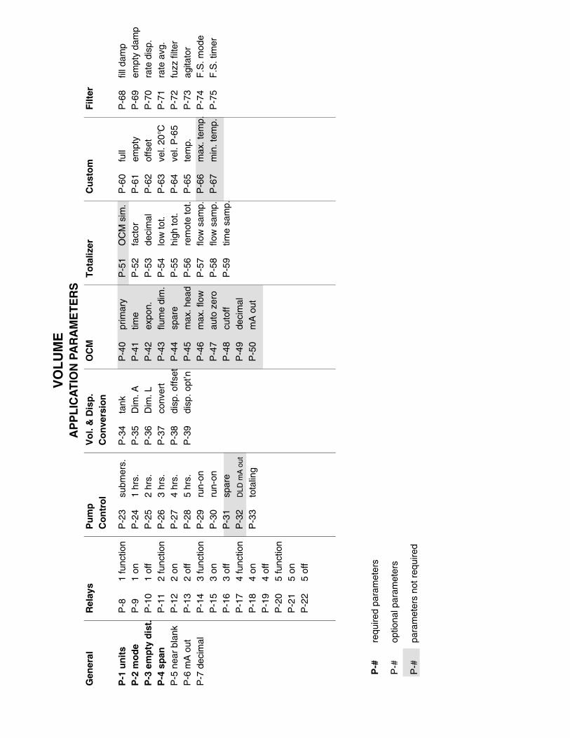
Gen
eral
P-1
un
its
P-2
mo
de
P-3
em
pty
dis
t.P
-4 s
pan
P-5
nea
r bl
ank
P-6
mA
out
P-7
dec
imal
Filt
er
P-6
8fil
l dam
pP
-69
empt
y da
mp
P-7
0ra
te d
isp.
P-7
1ra
te a
vg.
P-7
2fu
zz fi
lter
P-7
3ag
itato
rP
-74
F.S
. mod
eP
-75
F.S
. tim
er
Cu
sto
m
P-6
0fu
llP
-61
empt
yP
-62
offs
etP
-63
vel.
20°C
P-6
4ve
l. P
-65
P-6
5te
mp.
P-6
6m
ax. t
emp.
P-6
7m
in. t
emp.
To
taliz
er
P-5
1O
CM
sim
.P
-52
fact
orP
-53
deci
mal
P-5
4lo
w to
t.P
-55
high
tot.
P-5
6re
mot
e to
t.P
-57
flow
sam
p.P
-58
flow
sam
p.P
-59
time
sam
p.
OC
M
P-4
0pr
imar
yP
-41
time
P-4
2ex
pon.
P-4
3flu
me
dim
.P
-44
spar
eP
-45
max
. hea
dP
-46
max
. flo
wP
-47
auto
zer
oP
-48
cuto
ffP
-49
deci
mal
P-5
0m
A o
ut
Vo
l. &
Dis
p.
Co
nve
rsio
n
P-3
4ta
nkP
-35
Dim
. AP
-36
Dim
. LP
-37
conv
ert
P-3
8di
sp. o
ffset
P-3
9di
sp. o
pt’n
Pu
mp
Co
ntr
ol
P-2
3su
bmer
s.P
-24
1 hr
s.P
-25
2 hr
s.P
-26
3 hr
s.P
-27
4 hr
s.P
-28
5 hr
s.P
-29
run-
onP
-30
run-
onP
-31
spar
eP
-32
DLD
mA
out
P-3
3to
talin
g
Rel
ays
P-8
1 fu
nctio
nP
-91
onP
-10
1 of
fP
-11
2 fu
nctio
nP
-12
2 on
P-1
32
off
P-1
43
func
tion
P-1
53
onP
-16
3 of
fP
-17
4 fu
nctio
nP
-18
4 on
P-1
94
off
P-2
05
func
tion
P-2
15
onP
-22
5 of
f
VO
LU
ME
AP
PL
ICA
TIO
N P
AR
AM
ET
ER
S
P-#
requ
ired
para
met
ers
P-#
optio
nal p
aram
eter
s
P-#
para
met
ers
not r
equi
red

Gen
eral
P-1
un
its
P-2
mo
de
P-3
em
pty
dis
t.P
-4 s
pan
P-5
nea
r bl
ank
P-6
mA
out
P-7
dec
imal
Filt
er
P-6
8fil
l dam
pP
-69
empt
y da
mp
P-7
0ra
te d
isp.
P-7
1ra
te a
vg.
P-7
2fu
zz fi
lter
P-7
3ag
itato
rP
-74
F.S
. mod
eP
-75
F.S
. tim
er
Cu
sto
m
P-6
0fu
llP
-61
empt
yP
-62
offs
etP
-63
vel.
20°C
P-6
4ve
l. P
-65
P-6
5te
mp.
P-6
6m
ax. t
emp.
P-6
7m
in. t
emp.
To
taliz
er
P-5
1O
CM
sim
.P
-52
fact
orP
-53
deci
mal
P-5
4lo
w to
t.P
-55
high
tot.
P-5
6re
mot
e to
t.P
-57
flow
sam
p.P
-58
flow
sam
p.P
-59
time
sam
p.
OC
M
P-4
0pr
imar
yP
-41
time
P-4
2ex
pon.
P-4
3flu
me
dim
.P
-44
spar
eP
-45
max
. hea
dP
-46
max
. flo
wP
-47
auto
zer
oP
-48
cuto
ffP
-49
deci
mal
P-5
0m
A o
ut
Vo
l. &
Dis
p.
Co
nve
rsio
n
P-3
4ta
nkP
-35
Dim
. AP
-36
Dim
. LP
-37
conv
ert
P-3
8di
sp. o
ffset
P-3
9di
sp. o
pt’n
Pu
mp
Co
ntr
ol
P-2
3su
bmer
s.P
-24
1 hr
s.P
-25
2 hr
s.P
-26
3 hr
s.P
-27
4 hr
s.P
-28
5 hr
s.P
-29
run-
onP
-30
run-
onP
-31
spar
eP
-32
DLD
mA
out
P-3
3to
talin
g
Rel
ays
P-8
1 fu
nctio
nP
-91
onP
-10
1 of
fP
-11
2 fu
nctio
nP
-12
2 on
P-1
32
off
P-1
43
func
tion
P-1
53
onP
-16
3 of
fP
-17
4 fu
nctio
nP
-18
4 on
P-1
94
off
P-2
05
fun
ctio
nP
-21
5 on
P-2
25
off
DIF
FE
RE
NT
IAL
LE
VE
LA
PP
LIC
AT
ION
PA
RA
ME
TE
RS
P-#
requ
ired
para
met
ers
P-#
optio
nal p
aram
eter
s
P-#
para
met
ers
not r
equi
red

Gen
eral
P-1
un
its
P-2
mo
de
P-3
em
pty
dis
t.†P
-4 s
pan
P-5
nea
r bl
ank
P-6
mA
out
P-7
dec
imal
Filt
er
P-6
8fil
l dam
pP
-69
empt
y da
mp
P-7
0ra
te d
isp.
P-7
1ra
te a
vg.
P-7
2fu
zz fi
lter
P-7
3ag
itato
rP
-74
F.S
. mod
eP
-75
F.S
. tim
er
Cu
sto
m
P-6
0fu
llP
-61
empt
yP
-62
offs
etP
-63
vel.
20°C
P-6
4ve
l. P
-65
P-6
5te
mp.
P-6
6m
ax. t
emp.
P-6
7m
in. t
emp.
To
taliz
er
P-5
1O
CM
sim
.P
-52
fact
orP
-53
deci
mal
P-5
4lo
w to
t.P
-55
high
tot.
P-5
6re
mot
e to
t.P
-57
flow
sam
p.P
-58
flow
sam
p.P
-59
time
sam
p.
OC
M
P-4
0p
rim
ary
P-4
1ti
me
*P-4
2ex
po
n.
*P-4
3fl
um
e d
im.
P-4
4sp
are
†P-4
5m
ax. h
ead
P-4
6m
ax. f
low
P-4
7au
to z
ero
P-4
8cu
toff
P-4
9de
cim
alP
-50
mA
out
Vo
l. &
Dis
p.
Co
nve
rsio
n
P-3
4ta
nkP
-35
Dim
. AP
-36
Dim
. LP
-37
conv
ert
P-3
8di
sp. o
ffset
P-3
9di
sp. o
pt’n
Pu
mp
Co
ntr
ol
P-2
3su
bmer
s.P
-24
1 hr
s.P
-25
2 hr
s.P
-26
3 hr
s.P
-27
4 hr
s.P
-28
5 hr
s.P
-29
run-
onP
-30
run-
onP
-31
spar
eP
-32
DLD
mA
out
P-3
3to
talin
g
Rel
ays
P-8
1 fu
nctio
nP
-91
onP
-10
1 of
fP
-11
2 fu
nctio
nP
-12
2 on
P-1
32
off
P-1
43
func
tion
P-1
53
onP
-16
3 of
fP
-17
4 fu
nctio
nP
-18
4 on
P-1
94
off
P-2
05
func
tion
P-2
15
onP
-22
5 of
f
OP
EN
CH
AN
NE
L M
EA
SU
RE
ME
NT
AP
PL
ICA
TIO
N P
AR
AM
ET
ER
S
P-#
requ
ired
para
met
ers
P-#
optio
nal p
aram
eter
s
P-#
para
met
ers
not r
equi
red
*ei
ther
par
amet
er, d
epen
ding
on
P-4
0
†sa
me

RE
LA
Y P
RO
GR
AM
CH
AR
T
ratio
cum
ulat
ive
Rel
ay 1
Rel
ay 2
Rel
ay 3
Rel
ay 4
Rel
ay 5
Rel
ay F
un
ctio
nF
ctn
Set
po
ints
Fct
nS
etp
oin
tsF
ctn
Set
po
ints
Fct
nS
etp
oin
tsF
ctn
Set
po
ints
P-8
On
Off
P-1
1O
nO
ffP
-14
On
Off
P-1
7O
nO
ffP
-20
On
Off
Un
its
Ala
rm L
evel
1P
-9P
-10
1P
-12
P-1
31
P-1
5P
-16
1P
-18
P-1
91
P-2
1P
-22
P-1
In b
ou
nd
s2
""
2"
"2
""
2"
"2
""
"
Ou
t o
f b
ou
nd
s3
""
3"
"3
""
3"
"3
""
"
Dif
fere
nti
al4
""
4"
"4
""
4"
"4
""
"
Rat
e o
f C
han
ge
5"
"5
""
5"
"5
""
5"
"P
-1/m
in
Tem
per
atu
re6
""
6"
"6
""
6"
"6
""
°C
Lo
ss o
f E
cho
7S
ET
P-7
57
SE
TP
-75
7S
ET
P-7
57
SE
TP
-75
7S
ET
P-7
5n/
a
Pu
mp
Lev
elE
n:8*
P-9
P-1
08*
P-1
2P
-13
8*P
-15
P-1
68*
P-1
8P
-19
8*P
-21
P-2
2P
-1
dE:
8*"
"8*
""
8*"
"8*
""
8*"
""
Ho:
8*"
"8*
""
8*"
"8*
""
8*"
""
Seq
uen
tial
En:
9*"
"9*
""
9*"
"9*
""
9*"
""
dE:
9*"
"9*
""
9*"
"9*
""
9*"
""
Ho:
9*"
"9*
""
9*"
"9*
""
9*"
""
En:
’9*
""
9*"
"9*
""
9*"
"9*
""
"
dE:’
9*"
"9*
""
9*"
"9*
""
9*"
""
Ho:
’9*
""
9*"
"9*
""
9*"
"9*
""
"
En:
A9*
""
9*"
"9*
""
9*"
"9*
""
"
dE:A
9*"
"9*
""
9*"
"9*
""
9*"
""
Ho:
A9*
""
9*"
"9*
""
9*"
"9*
""
"
Dif
fere
nti
alE
n:10
*"
"10
*"
"10
*"
"10
*"
"10
*"
""
dE:
10*
""
10*
""
10*
""
10*
""
10*
""
"
Ho:
10*
""
10*
""
10*
""
10*
""
10*
""
"
Mis
cella
neo
us
To
taliz
er11
SE
TP
-56
11S
ET
P-5
611
SE
TP
-56
11S
ET
P-5
611
SE
TP
-56
VO
L. P
-43
Flo
w S
amp
ler
12S
ET
P-5
7&
P-5
8
12S
ET
P-5
7&
P-5
8
12S
ET
P-5
7&
P-5
8
12S
ET
P-5
7&
P-5
8
12S
ET
P-5
7&
P
-58
VO
LUM
E
Tim
e S
amp
ler
13S
ET
P-5
913
SE
TP
-59
13S
ET
P-5
913
SE
TP
-59
13S
ET
P-5
9H
R
Sca
nn
ern/
an/
an/
an/
an/
an/
an/
an/
a14
SE
TP
-2n/
a
* =
Pre
ss
*
to s
elec
t LO
E d
efau
lt (E
n, d
E &
Ho
) an
d se
quen
tial o
ptio
n (c
umul
ativ
e, d
uty
/ bac
kup
or r
atio
).
duty
/ ba
ckup
Related Documents