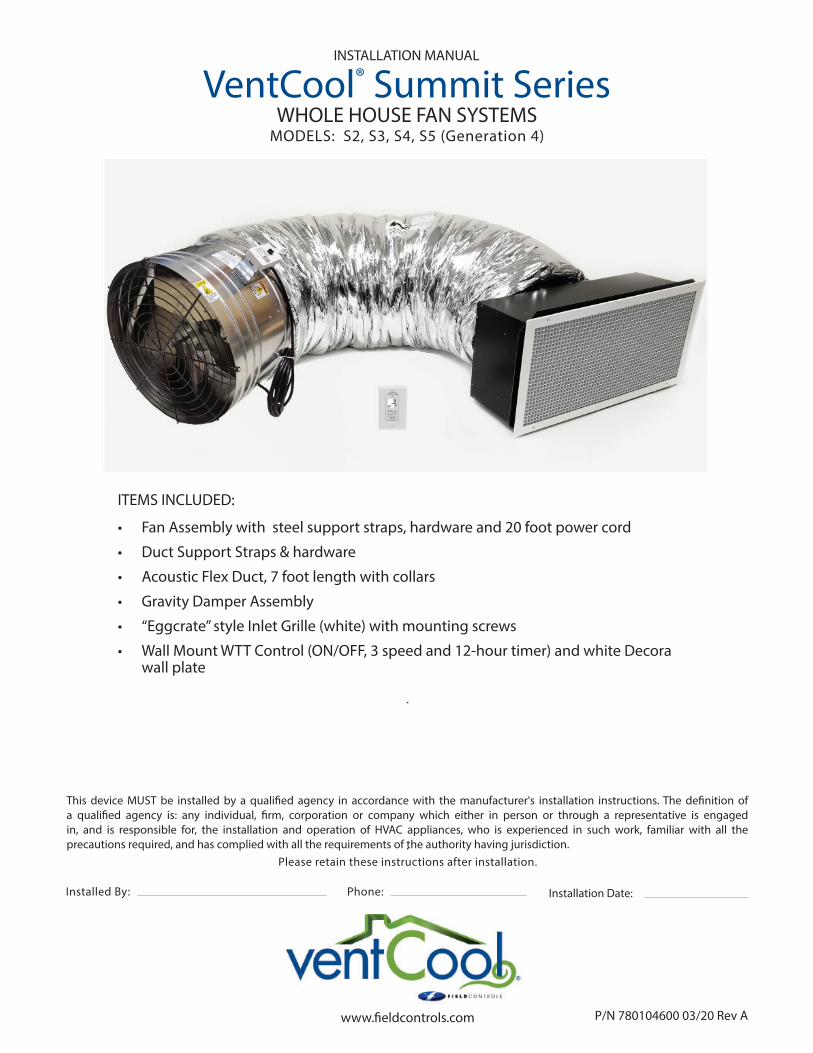
www.fieldcontrols.com Please retain these instructions after installation. This device MUST be installed by a qualified agency in accordance with the manufacturer's installation instructions. The definition of a qualified agency is: any individual, firm, corporation or company which either in person or through a representative is engaged in, and is responsible for, the installation and operation of HVAC appliances, who is experienced in such work, familiar with all the precautions required, and has complied with all the requirements of the authority having jurisdiction. Installation Date: Installed By: Phone: P/N 780104600 03/20 Rev A VentCool ® Summit Series WHOLE HOUSE FAN SYSTEMS MODELS: S2, S3, S4, S5 (Generation 4) INSTALLATION MANUAL ITEMS INCLUDED: • Fan Assembly with steel support straps, hardware and 20 foot power cord • Duct Support Straps & hardware • Acoustic Flex Duct, 7 foot length with collars • Gravity Damper Assembly • “Eggcrate” style Inlet Grille (white) with mounting screws • Wall Mount WTT Control (ON/OFF, 3 speed and 12-hour timer) and white Decora wall plate

Welcome message from author
This document is posted to help you gain knowledge. Please leave a comment to let me know what you think about it! Share it to your friends and learn new things together.
Transcript
www.fi eldcontrols.com
Please retain these instructions after installation.
This device MUST be installed by a qualifi ed agency in accordance with the manufacturer's installation instructions. The defi nition of a qualifi ed agency is: any individual, fi rm, corporation or company which either in person or through a representative is engaged in, and is responsible for, the installation and operation of HVAC appliances, who is experienced in such work, familiar with all the precautions required, and has complied with all the requirements of the authority having jurisdiction.
Installation Date:Installed By: Phone:
P/N 780104600 03/20 Rev A
VentCool® Summit SeriesWHOLE HOUSE FAN SYSTEMS
MODELS: S2, S3, S4, S5 (Generation 4)
INSTALLATION MANUAL
ITEMS INCLUDED:
• Fan Assembly with steel support straps, hardware and 20 foot power cord
• Duct Support Straps & hardware
• Acoustic Flex Duct, 7 foot length with collars
• Gravity Damper Assembly
• “Eggcrate” style Inlet Grille (white) with mounting screws
• Wall Mount WTT Control (ON/OFF, 3 speed and 12-hour timer) and white Decora wall plate
page 2 of 20P/N 780104600 03/20 Rev A
(THIS PAGE LEFT INTENTIONALLY BLANK)
page 3 of 20
SAFETY CONSIDERATIONS
• • Never Never operate this fan without a window or door opened.operate this fan without a window or door opened.
• • This fan is meant for general ventilation. This fan is meant for general ventilation. It has NOT been designed to ventilate particle laden and/or It has NOT been designed to ventilate particle laden and/or explosive mixtures of air and must NOT be used for such.explosive mixtures of air and must NOT be used for such.
• • This fan is NOT for use in kitchensThis fan is NOT for use in kitchens
• • Before installing or servicing this fan, switch power off at the home’s electrical panel to reduce the risk Before installing or servicing this fan, switch power off at the home’s electrical panel to reduce the risk of damaging circuit boards, fi re, electrical shock, or injury.of damaging circuit boards, fi re, electrical shock, or injury.
• • Install this fan in accordance with this manual and all local codes and standards.Install this fan in accordance with this manual and all local codes and standards.
Some of the principles of safe installation and operation of this product are not immediately obvious. Some of the principles of safe installation and operation of this product are not immediately obvious. Read the following safety information before continuing further:Read the following safety information before continuing further:
Thank you for purchasing a VentCool ® ducted Whole House Fan by Field Controls. This fan has been designed to provide many years of natural, quiet, and energy-effi cient cooling.
Please take a few minutes to read over this manual and its accompanying documents to make sure you areprepared to install the Whole House Fan system. In particular:
• • The homeowner/resident should read the WHERE TO LOCATE section so that the fan will be correctly lo-The homeowner/resident should read the WHERE TO LOCATE section so that the fan will be correctly lo-cated to maximize its eff ectiveness and effi ciency.cated to maximize its eff ectiveness and effi ciency.
• • The VENTILATION REQUIREMENTS section is also particularly important, as it describes the minimum attic The VENTILATION REQUIREMENTS section is also particularly important, as it describes the minimum attic ventilation neccessary to operate the fan.ventilation neccessary to operate the fan.
• • The INSTALLATION: GRAVITY DAMPER section contains important information regarding the constraints The INSTALLATION: GRAVITY DAMPER section contains important information regarding the constraints within which this fan’s gravity damper must be installed.within which this fan’s gravity damper must be installed.
The Eggcrate Inlet Grille and Gravity Damper Assemblies come in diff erent size openings. Verify which The Eggcrate Inlet Grille and Gravity Damper Assemblies come in diff erent size openings. Verify which gravity gravity damper component design is part of your Whole House Fan Assembly by actual measurement of the gravity damper component design is part of your Whole House Fan Assembly by actual measurement of the gravity damper opening section before beginning installation of gravity damper section.damper opening section before beginning installation of gravity damper section.
Before installing this fan, inspect it and all of its parts for any damage it may have sustained during shipping. Before installing this fan, inspect it and all of its parts for any damage it may have sustained during shipping. DO NOT INSTALL DAMAGED EQUIPMENT.DO NOT INSTALL DAMAGED EQUIPMENT. If you suspect this fan has been damaged during shipping, contact If you suspect this fan has been damaged during shipping, contact Field Controls technical support by phone at 1.800.742.8368, or email at fi eldtec@fi eldcontrols.com.Field Controls technical support by phone at 1.800.742.8368, or email at fi eldtec@fi eldcontrols.com.
Whole House Fans are designed to be installed within a home’s attic, which makes them and their sub-Whole House Fans are designed to be installed within a home’s attic, which makes them and their sub-components diffi cult to access once installed. components diffi cult to access once installed. TEST THIS FAN OUTSIDE OF THE ATTIC BEFORE INSTALLING IT TEST THIS FAN OUTSIDE OF THE ATTIC BEFORE INSTALLING IT PERMANENTLY.PERMANENTLY.
P/N 780104600 03/20 Rev A
page 4 of 20
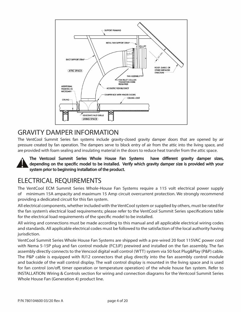
GRAVITY DAMPER INFORMATION
ELECTRICAL REQUIREMENTSThe VentCool ECM Summit Series Whole-House Fan Systems require a 115 volt electrical power supply of minimum 15A ampacity and maximum 15 Amp circuit overcurrent protection. We strongly recommendproviding a dedicated circuit for this fan system.All electrical components, whether included with the VentCool system or supplied by others, must be rated for the fan system’s electrical load requirements; please refer to the VentCool Summit Series specifi cations table for the electrical load requirements of the specifi c model to be installed.All wiring and connections must be made according to this manual and all applicable electrical wiring codesand standards. All applicable electrical codes must be followed to the satisfaction of the local authority having jurisdiction.VentCool Summit Series Whole House Fan Systems are shipped with a pre-wired 20 foot 115VAC power cord with Nema 5-15P plug and fan control module (FC3JF) prewired and installed on the fan assembly. The fan assembly directly connects to the Vencool digital wall control (WTT) system via 50 foot Plug&Play (P&P) cable. The P&P cable is equipped with RJ12 connectors that plug directly into the fan assembly control module and backside of the wall control display. The wall control display is mounted in the living space and is used for fan control (on/off , timer operation or temperature operation) of the whole house fan system. Refer toINSTALLATION: Wiring & Controls section for wiring and connection diagrams for the Ventcool Summit Series Whole House Fan (Generation 4) product line.
The Ventcool Summit Series Whole House Fan Systems have diff erent gravity damper sizes,The Ventcool Summit Series Whole House Fan Systems have diff erent gravity damper sizes,depending on the specifi c model to be installed. Verify which gravity damper size is provided with yourdepending on the specifi c model to be installed. Verify which gravity damper size is provided with yoursystem prior to beginning installation of the product.system prior to beginning installation of the product.
The VentCool Summit Series fan systems include gravity-closed gravity damper doors that are opened by airpressure created by fan operation. The dampers serve to block entry of air from the attic into the living space, and are provided with foam sealing and insulating material in the doors to reduce heat transfer from the attic space.
P/N 780104600 03/20 Rev A
page 5 of 20
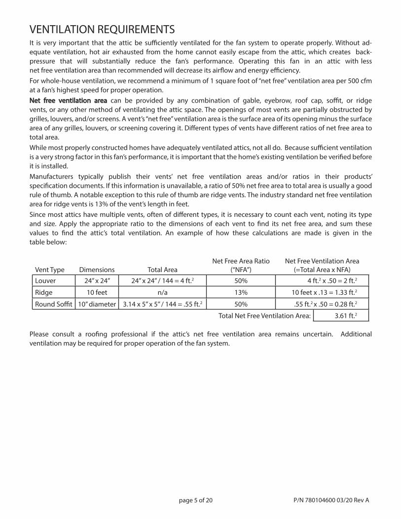
VENTILATION REQUIREMENTSIt is very important that the attic be suffi ciently ventilated for the fan system to operate properly. Without ad-equate ventilation, hot air exhausted from the home cannot easily escape from the attic, which creates back-pressure that will substantially reduce the fan’s performance. Operating this fan in an attic with less net free ventilation area than recommended will decrease its airfl ow and energy effi ciency.For whole-house ventilation, we recommend a minimum of 1 square foot of “net free” ventilation area per 500 cfm at a fan’s highest speed for proper operation.NetNet free ventilation area free ventilation area can be provided by any combination of gable, eyebrow, roof cap, soffi t, or ridgevents, or any other method of ventilating the attic space. The openings of most vents are partially obstructed by grilles, louvers, and/or screens. A vent’s “net free” ventilation area is the surface area of its opening minus the surface area of any grilles, louvers, or screening covering it. Diff erent types of vents have diff erent ratios of net free area to total area.While most properly constructed homes have adequately ventilated attics, not all do. Because suffi cient ventilation is a very strong factor in this fan’s performance, it is important that the home’s existing ventilation be verifi ed before it is installed.Manufacturers typically publish their vents’ net free ventilation areas and/or ratios in their products’specifi cation documents. If this information is unavailable, a ratio of 50% net free area to total area is usually a good rule of thumb. A notable exception to this rule of thumb are ridge vents. The industry standard net free ventilation area for ridge vents is 13% of the vent’s length in feet.Since most attics have multiple vents, often of diff erent types, it is necessary to count each vent, noting its type and size. Apply the appropriate ratio to the dimensions of each vent to fi nd its net free area, and sum thesevalues to fi nd the attic’s total ventilation. An example of how these calculations are made is given in thetable below:
Vent Type Dimensions Total AreaNet Free Area Ratio
(“NFA”)Net Free Ventilation Area
(=Total Area x NFA)
Louver 24” x 24” 24” x 24” / 144 = 4 ft.2 50% 4 ft.2 x .50 = 2 ft.2
Ridge 10 feet n/a 13% 10 feet x .13 = 1.33 ft.2
Round Soffi t 10” diameter 3.14 x 5” x 5” / 144 = .55 ft.2 50% .55 ft.2 x .50 = 0.28 ft.2
Total Net Free Ventilation Area: 3.61 ft.2
Please consult a roofi ng professional if the attic’s net free ventilation area remains uncertain. Additional ventilation may be required for proper operation of the fan system.
P/N 780104600 03/20 Rev A
page 6 of 20
• Locate this fan in a central location, away from windows that will be opened during its operation. Installing this fan centrally promotes an even replacement of air through-out the home, and the longer the path of air travels from an open window to the fan, the greater the cooling eff ect.
• The damper provided with this fan can only be installed in a horizontal orientation, thereby requiring the unit to be installed in the ceiling.
• Locate this fan at the highest point possible. This exploits natural convection and helps the fan exhaust the hottest indoor air from the home.
• Typically, the ideal location for this fan in a two-story home is in the open area at the top of the stairs.
• Avoid locating this fan in a narrow space or over hard fl ooring as sound refl ecting off of hard surfaces can amplify its perceived noise.
• Even though the Tahoe series fan systems are engineered to be extremely quiet, we specifi cally recommend against installing it in a bedroom as humans’ perception of noise is far greater when the surrounding environment is quiet (such as within a bed-room at night).
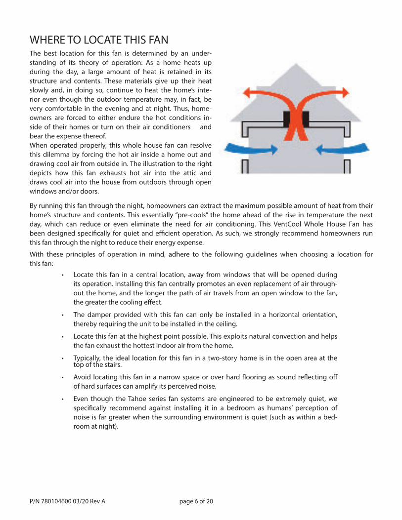
By running this fan through the night, homeowners can extract the maximum possible amount of heat from their home’s structure and contents. This essentially “pre-cools” the home ahead of the rise in temperature the next day, which can reduce or even eliminate the need for air conditioning. This VentCool Whole House Fan has been designed specifi cally for quiet and effi cient operation. As such, we strongly recommend homeowners run this fan through the night to reduce their energy expense.
With these principles of operation in mind, adhere to the following guidelines when choosing a location for this fan:
WHERE TO LOCATE THIS FANThe best location for this fan is determined by an under-standing of its theory of operation: As a home heats up during the day, a large amount of heat is retained in its structure and contents. These materials give up their heat slowly and, in doing so, continue to heat the home’s inte-rior even though the outdoor temperature may, in fact, be very comfortable in the evening and at night. Thus, home-owners are forced to either endure the hot conditions in-side of their homes or turn on their air conditioners and bear the expense thereof.When operated properly, this whole house fan can resolve this dilemma by forcing the hot air inside a home out and drawing cool air from outside in. The illustration to the right depicts how this fan exhausts hot air into the attic and draws cool air into the house from outdoors through open windows and/or doors.
P/N 780104600 03/20 Rev A
page 7 of 20
The ideal orientation of unit’s gravity damper is in a level position. If necessary, however, the damper can be installed at a slight angle. Before beginning the installation, make sure that the fan assembly is undamaged, and that the Before beginning the installation, make sure that the fan assembly is undamaged, and that the fan blade rotates freely. Brace or clamp the fan assembly to a secure object, and temporarily plug in the fan’s power fan blade rotates freely. Brace or clamp the fan assembly to a secure object, and temporarily plug in the fan’s power cord into a grounded power outlet to verify smooth and correct operation. cord into a grounded power outlet to verify smooth and correct operation.
Be aware that the fan is quite powerful and will draw in loose objects or deBe aware that the fan is quite powerful and will draw in loose objects or debris, and will blow dirt, bris, and will blow dirt, debris and other objects with force! debris and other objects with force!
Use eye protection when operating the fan to avoid injury from blowing sand or debris! Keep hands Use eye protection when operating the fan to avoid injury from blowing sand or debris! Keep hands and other objects away from the rotating fan blade! and other objects away from the rotating fan blade!
TIP: Before beginning the installation, verify that the damper assembly is undamaged, and that the damper TIP: Before beginning the installation, verify that the damper assembly is undamaged, and that the damper doors doors operate freely, opening and closing fully without binding or restriction. operate freely, opening and closing fully without binding or restriction.
INSTALLATION: GRAVITY DAMPERGRAVITY DAMPER ORIENTATION NOTE
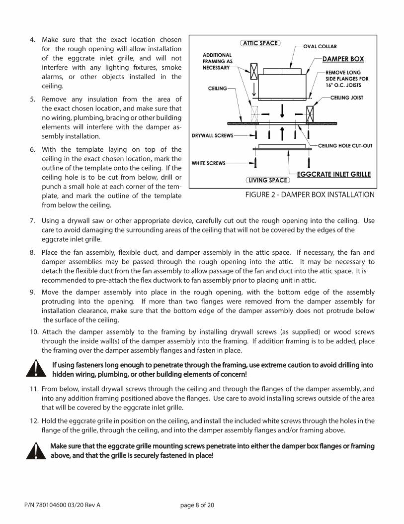
1. From consideration of the principles of whole-house fan operation, determine the best general area for installation of the gravity damper assembly. The damper assembly is to be mounted in the attic with its bottom edge opening into and fl ush with the ceiling of the living space. The eggcrate inlet grille is to be mounted on the ceiling of the living space, covering and engaging with the opening of the damper assembly.
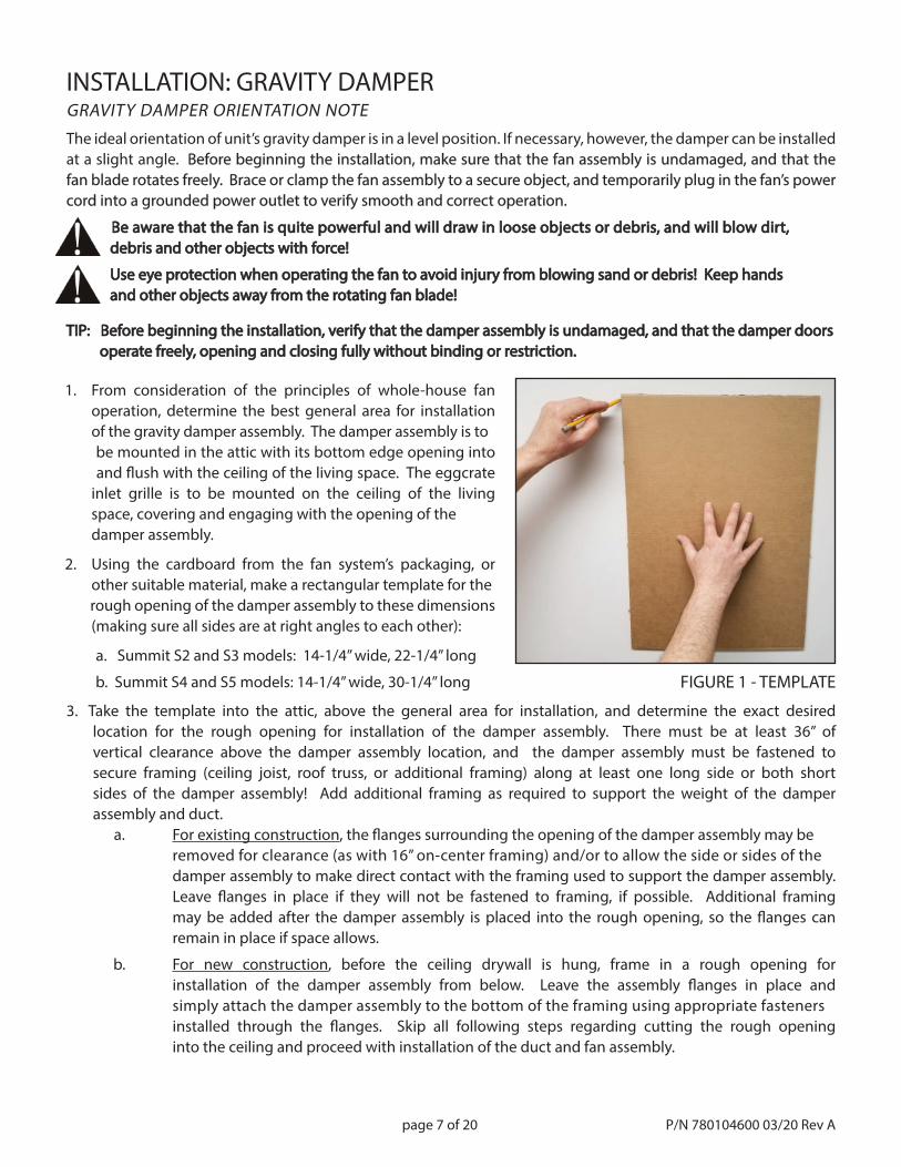
2. Using the cardboard from the fan system’s packaging, or other suitable material, make a rectangular template for the rough opening of the damper assembly to these dimensions (making sure all sides are at right angles to each other):
a. Summit S2 and S3 models: 14-1/4” wide, 22-1/4” long
b. Summit S4 and S5 models: 14-1/4” wide, 30-1/4” long FIGURE 1 - TEMPLATE
3. Take the template into the attic, above the general area for installation, and determine the exact desired location for the rough opening for installation of the damper assembly. There must be at least 36” of vertical clearance above the damper assembly location, and the damper assembly must be fastened to secure framing (ceiling joist, roof truss, or additional framing) along at least one long side or both short sides of the damper assembly! Add additional framing as required to support the weight of the damper assembly and duct. a. For existing construction, the fl anges surrounding the opening of the damper assembly may be removed for clearance (as with 16” on-center framing) and/or to allow the side or sides of the damper assembly to make direct contact with the framing used to support the damper assembly. Leave fl anges in place if they will not be fastened to framing, if possible. Additional framing may be added after the damper assembly is placed into the rough opening, so the fl anges can remain in place if space allows.
b. For new construction, before the ceiling drywall is hung, frame in a rough opening for installation of the damper assembly from below. Leave the assembly fl anges in place and simply attach the damper assembly to the bottom of the framing using appropriate fasteners installed through the fl anges. Skip all following steps regarding cutting the rough opening into the ceiling and proceed with installation of the duct and fan assembly.
P/N 780104600 03/20 Rev A
page 8 of 20
7. Using a drywall saw or other appropriate device, carefully cut out the rough opening into the ceiling. Use care to avoid damaging the surrounding areas of the ceiling that will not be covered by the edges of the eggcrate inlet grille.
8. Place the fan assembly, fl exible duct, and damper assembly in the attic space. If necessary, the fan and damper assemblies may be passed through the rough opening into the attic. It may be necessary todetach the fl exible duct from the fan assembly to allow passage of the fan and duct into the attic space. It is recommended to pre-attach the fl ex ductwork to fan assembly prior to placing unit in attic.
9. Move the damper assembly into place in the rough opening, with the bottom edge of the assemblyprotruding into the opening. If more than two fl anges were removed from the damper assembly forinstallation clearance, make sure that the bottom edge of the damper assembly does not protrude below the surface of the ceiling.
10. Attach the damper assembly to the framing by installing drywall screws (as supplied) or wood screws through the inside wall(s) of the damper assembly into the framing. If addition framing is to be added, placethe framing over the damper assembly fl anges and fasten in place.
If using fasteners long enough to penetrate through the framing, use extreme caution If using fasteners long enough to penetrate through the framing, use extreme caution to avoid drilling into to avoid drilling into hidden wiring, plumbing, or other building elements of concern! hidden wiring, plumbing, or other building elements of concern!
11. From below, install drywall screws through the ceiling and through the fl anges of the damper assembly, and into any addition framing positioned above the fl anges. Use care to avoid installing screws outside of the area that will be covered by the eggcrate inlet grille.
12. Hold the eggcrate grille in position on the ceiling, and install the included white screws through the holes in the fl ange of the grille, through the ceiling, and into the damper assembly fl anges and/or framing above.
Make sure that the eggcrate grille mounting screws penetrate into either the damper box fl anges or framingMake sure that the eggcrate grille mounting screws penetrate into either the damper box fl anges or framing above, and that the grille is securely fastened in place! above, and that the grille is securely fastened in place!
FIGURE 2 - DAMPER BOX INSTALLATION
4. Make sure that the exact location chosenfor the rough opening will allow installationof the eggcrate inlet grille, and will notinterfere with any lighting fi xtures, smoke alarms, or other objects installed in theceiling.
5. Remove any insulation from the area ofthe exact chosen location, and make sure that no wiring, plumbing, bracing or other building elements will interfere with the damper as-sembly installation.
6. With the template laying on top of theceiling in the exact chosen location, mark the outline of the template onto the ceiling. If the ceiling hole is to be cut from below, drill or punch a small hole at each corner of the tem-plate, and mark the outline of the template from below the ceiling.
P/N 780104600 03/20 Rev A
page 9 of 20
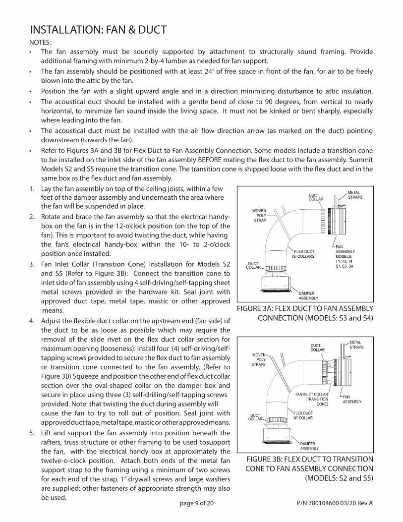
INSTALLATION: FAN & DUCTNOTES: • The fan assembly must be soundly supported by attachment to structurally sound framing. Provide additional framing with minimum 2-by-4 lumber as needed for fan support.• The fan assembly should be positioned with at least 24” of free space in front of the fan, for air to be freely blown into the attic by the fan.• Position the fan with a slight upward angle and in a direction minimizing disturbance to attic insulation.• The acoustical duct should be installed with a gentle bend of close to 90 degrees, from vertical to nearly horizontal, to minimize fan sound inside the living space. It must not be kinked or bent sharply, especially where leading into the fan.• The acoustical duct must be installed with the air fl ow direction arrow (as marked on the duct) pointing downstream (towards the fan).• Refer to Figures 3A and 3B for Flex Duct to Fan Assembly Connection. Some models include a transition cone to be installed on the inlet side of the fan assembly BEFORE mating the fl ex duct to the fan assembly. Summit Models S2 and S5 require the transition cone. The transition cone is shipped loose with the fl ex duct and in the same box as the fl ex duct and fan assembly.1. Lay the fan assembly on top of the ceiling joists, within a few feet of the damper assembly and underneath the area where the fan will be suspended in place.2. Rotate and brace the fan assembly so that the electrical handy- box on the fan is in the 12-o’clock position (on the top of the fan). This is important to avoid twisting the duct, while having the fan’s electrical handy-box within the 10- to 2-o’clock position once installed.3. Fan Inlet Collar (Transition Cone) Installation for Models S2 and S5 (Refer to Figure 3B): Connect the transition cone to inlet side of fan assembly using 4 self-driving/self-tapping sheet metal screws provided in the hardware kit. Seal joint with approved duct tape, metal tape, mastic or other approved means.4. Adjust the fl exible duct collar on the upstream end (fan side) of the duct to be as loose as possible which may require the removal of the slide rivet on the fl ex duct collar section for maximum opening (looseness). Install four (4) self-driving/self- tapping screws provided to secure the fl ex duct to fan assembly or transition cone connected to the fan assembly. (Refer to Figure 3B) Squeeze and position the other end of fl ex duct collar section over the oval-shaped collar on the damper box and secure in place using three (3) self-drilling/self-tapping screws provided. Note: that twisting the duct during assembly will cause the fan to try to roll out of position. Seal joint with approved duct tape, metal tape, mastic or other approved means. 5. Lift and support the fan assembly into position beneath the rafters, truss structure or other framing to be used tosupport the fan, with the electrical handy box at approximately the twelve-o-clock position. Attach both ends of the metal fan support strap to the framing using a minimum of two screws for each end of the strap. 1” drywall screws and large washers are supplied; other fasteners of appropriate strength may also be used.
FIGURE 3A: FLEX DUCT TO FAN ASSEMBLY CONNECTION (MODELS: S3 and S4)
P/N 780104600 03/20 Rev A
FIGURE 3B: FLEX DUCT TO TRANSITION CONE TO FAN ASSEMBLY CONNECTION
(MODELS: S2 and S5)
page 10 of 20
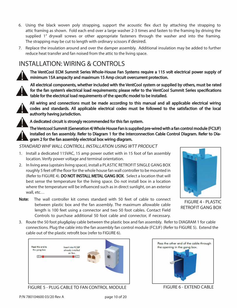
STANDARD WHF WALL CONTROLL INSTALLATION USING WTT PRODUCT1. Install a dedicated 115VAC, 15 amp power outlet with in 15 foot of fan assembly location. Verify power voltage and terminal orientation.2. In living area (upstairs living space), install a PLASTIC RETROFIT SINGLE GANG BOX
roughly 5 feet off the fl oor for the whole house fan wall controller to be mounted in (Refer to FIGURE 4). DO NOT INSTALL METAL GANG BOXDO NOT INSTALL METAL GANG BOX. Select a location that will best sense the temperature for the living space. Do not install box in a location where the temperature will be infl uenced such as in direct sunlight, on an exterior wall, etc…
Note: Note: The wall controller kit comes standard with 50 feet of cable to connectbetween plastic box and the fan assembly. The maximum allowable cable length is 100 feet using a connector and two 50 foot cables. Contact Field Controls to purchase additional 50 foot cable and connector, if necessary.
INSTALLATION: WIRING & CONTROLSThe VentCool ECM Summit Series Whole-House Fan Systems require a 115 volt electrical power supply of The VentCool ECM Summit Series Whole-House Fan Systems require a 115 volt electrical power supply of minimum 15A ampacity and maximum 15 Amp circuit overcurrent protection. minimum 15A ampacity and maximum 15 Amp circuit overcurrent protection.
All electrical components, whether included with the VentCool system or supplied by others, must be rated All electrical components, whether included with the VentCool system or supplied by others, must be rated for the fan system’s electrical load requirements; please refer to the VentCool Summit Series specifi cations for the fan system’s electrical load requirements; please refer to the VentCool Summit Series specifi cations table for the electrical load requirements of the specifi c model to be installed.table for the electrical load requirements of the specifi c model to be installed.
All wiring and connections must be made according to this manual and all applicable electrical wiring All wiring and connections must be made according to this manual and all applicable electrical wiring codes and standards. All applicable electrical codes must be followed to the satisfaction of the localcodes and standards. All applicable electrical codes must be followed to the satisfaction of the localauthority having jurisdiction.authority having jurisdiction.
A dedicated circuit is strongly recommended for this fan system.A dedicated circuit is strongly recommended for this fan system.
P/N 780104600 03/20 Rev A
7. Replace the insulation around and over the damper assembly. Additional insulation may be added to further reduce heat transfer and fan noised from the attic to the living space.
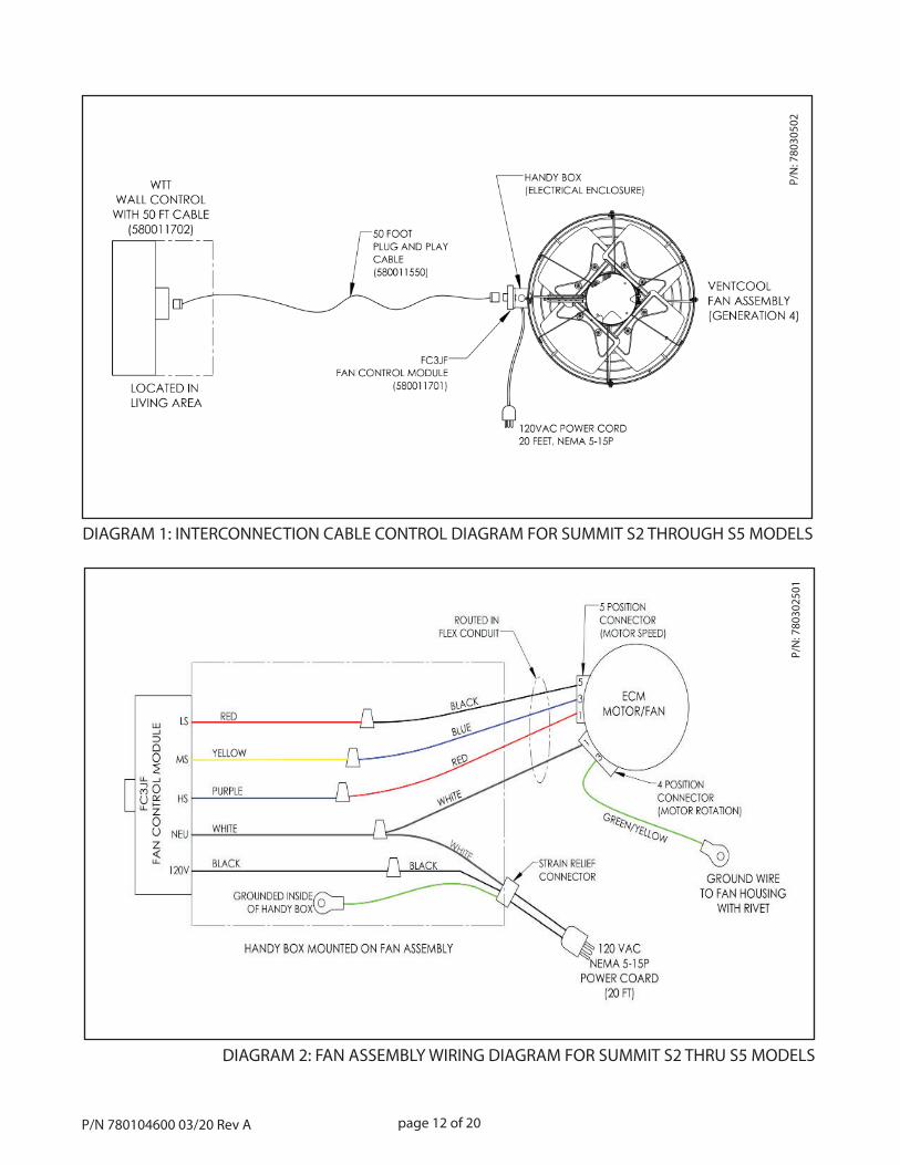
The Ventcool Summit (Generation 4) Whole House Fan is supplied pre-wired with a fan control module (FC3JF) The Ventcool Summit (Generation 4) Whole House Fan is supplied pre-wired with a fan control module (FC3JF) installed on fan assembly. Refer to Diagram 1 for the Interconnection Cable Control Diagram. Refer to Dia-installed on fan assembly. Refer to Diagram 1 for the Interconnection Cable Control Diagram. Refer to Dia-gram 2 for the fan assembly electrical box wiring diagram.gram 2 for the fan assembly electrical box wiring diagram.
FIGURE 4 - PLASTICRETROFIT GANG BOX
FIGURE 5 - PLUG CABLE TO FAN CONTROL MODULE
3. Route the 50 foot plug&play cable between the plastic box and fan assembly. Refer to DIAGRAM 1 for cable connections. Plug the cable into the fan assembly fan control module (FC3JF) (Refer to FIGURE 5). Extend the cable out of the plastic retrofi t box (refer to FIGURE 6).
FIGURE 6 - EXTEND CABLE
6. Using the black woven poly strapping, support the acoustic fl ex duct by attaching the strapping to attic framing as shown. Fold each end over a large washer 2-3 times and fasten to the framing by driving the supplied 1” drywall screws or other appropriate fasteners through the washer and into the framing. The strapping may be cut to length with ordinary scissors if desired.
page 11 of 20
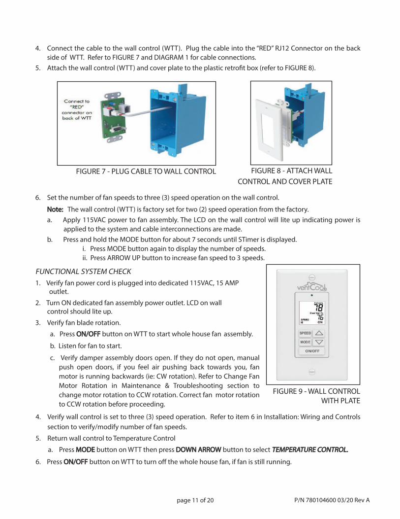
4. Connect the cable to the wall control (WTT). Plug the cable into the “RED” RJ12 Connector on the back side of WTT. Refer to FIGURE 7 and DIAGRAM 1 for cable connections.5. Attach the wall control (WTT) and cover plate to the plastic retrofi t box (refer to FIGURE 8).
FIGURE 7 - PLUG CABLE TO WALL CONTROL FIGURE 8 - ATTACH WALLCONTROL AND COVER PLATE
6. Set the number of fan speeds to three (3) speed operation on the wall control.
Note: Note: The wall control (WTT) is factory set for two (2) speed operation from the factory.a. Apply 115VAC power to fan assembly. The LCD on the wall control will lite up indicating power is
applied to the system and cable interconnections are made.b. Press and hold the MODE button for about 7 seconds until STimer is displayed. i. Press MODE button again to display the number of speeds. ii. Press ARROW UP button to increase fan speed to 3 speeds.
FIGURE 9 - WALL CONTROL WITH PLATE
FUNCTIONAL SYSTEM CHECK1. Verify fan power cord is plugged into dedicated 115VAC, 15 AMP outlet.
2. Turn ON dedicated fan assembly power outlet. LCD on wall control should lite up.
3. Verify fan blade rotation.
a. Press ON/OFFON/OFF button on WTT to start whole house fan assembly.
b. Listen for fan to start.
c. Verify damper assembly doors open. If they do not open, manualpush open doors, if you feel air pushing back towards you, fanmotor is running backwards (ie: CW rotation). Refer to Change FanMotor Rotation in Maintenance & Troubleshooting section to change motor rotation to CCW rotation. Correct fan motor rotationto CCW rotation before proceeding.
4. Verify wall control is set to three (3) speed operation. Refer to item 6 in Installation: Wiring and Controls section to verify/modify number of fan speeds.
5. Return wall control to Temperature Control
a. Press MODEMODE button on WTT then press DOWNDOWN ARROWARROW button to select TEMPERATURE TEMPERATURE CONTROL.CONTROL.
6. Press ON/OFFON/OFF button on WTT to turn off the whole house fan, if fan is still running.
P/N 780104600 03/20 Rev A
page 12 of 20
DIAGRAM 1: INTERCONNECTION CABLE CONTROL DIAGRAM FOR SUMMIT S2 THROUGH S5 MODELS
P/N
: 780
3050
2P/
N: 7
8030
2501
DIAGRAM 2: FAN ASSEMBLY WIRING DIAGRAM FOR SUMMIT S2 THRU S5 MODELS
P/N 780104600 03/20 Rev A
page 13 of 20
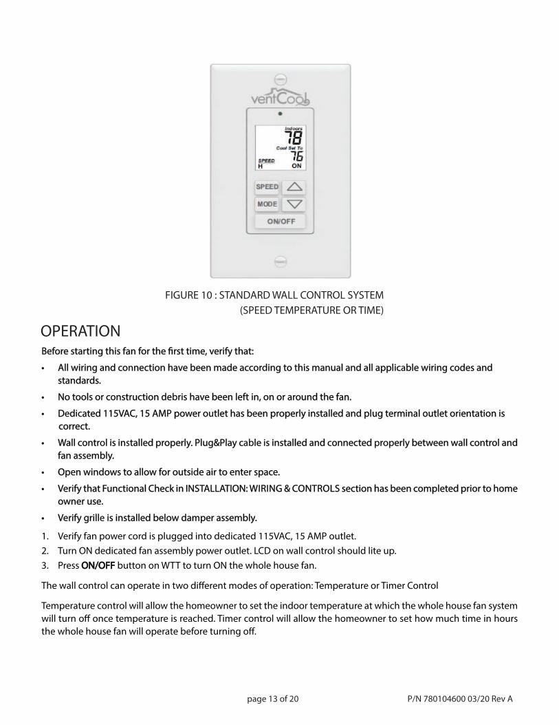
FIGURE 10 : STANDARD WALL CONTROL SYSTEM(SPEED TEMPERATURE OR TIME)
OPERATIONBefore starting this fan for the fi rst time, verify that:Before starting this fan for the fi rst time, verify that:
• All wiring and connection have been made according to this manual and all applicable wiring codes and• All wiring and connection have been made according to this manual and all applicable wiring codes and standards. standards.
• No tools or construction debris have been left in, on or around the fan.• No tools or construction debris have been left in, on or around the fan.
• Dedicated 115VAC, 15 AMP power outlet has been properly installed and plug terminal outlet orientation is • Dedicated 115VAC, 15 AMP power outlet has been properly installed and plug terminal outlet orientation is correct. correct.
• Wall control is installed properly. Plug&Play cable is installed and connected properly between wall control and • Wall control is installed properly. Plug&Play cable is installed and connected properly between wall control and fan assembly. fan assembly.
• Open windows to allow for outside air to enter space.• Open windows to allow for outside air to enter space.
• Verify that Functional Check in INSTALLATION: • Verify that Functional Check in INSTALLATION: WIRING & CONTROLS WIRING & CONTROLS section has been completed prior to homesection has been completed prior to home owner use. owner use.
• Verify grille is installed below damper assembly.• Verify grille is installed below damper assembly.
1. Verify fan power cord is plugged into dedicated 115VAC, 15 AMP outlet.2. Turn ON dedicated fan assembly power outlet. LCD on wall control should lite up.3. Press ON/OFFON/OFF button on WTT to turn ON the whole house fan.
The wall control can operate in two diff erent modes of operation: Temperature or Timer Control
Temperature control will allow the homeowner to set the indoor temperature at which the whole house fan system will turn off once temperature is reached. Timer control will allow the homeowner to set how much time in hours the whole house fan will operate before turning off .
P/N 780104600 03/20 Rev A
page 14 of 20
Switching wall control between Temperature and Timer Control Modes:Switching wall control between Temperature and Timer Control Modes:1. Switch wall control to Temperature Control from Timer Control mode: a. Press MODEMODE button on WTT then press DOWN ARROWDOWN ARROW button to select TEMPERATURE CONTROL.TEMPERATURE CONTROL.
2. Switch wall control to Timer Control from Temperature Control mode: a. Press MODEMODE button on WTT then press UP ARROW UP ARROW button to select TIMER CONTROL.TIMER CONTROL.
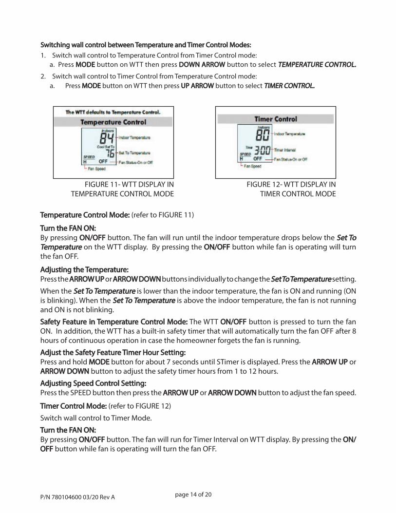
FIGURE 11- WTT DISPLAY INTEMPERATURE CONTROL MODE
FIGURE 12- WTT DISPLAY INTIMER CONTROL MODE
Temperature Control Mode: Temperature Control Mode: (refer to FIGURE 11)
Turn the FAN ON:Turn the FAN ON:By pressing ON/OFFON/OFF button. The fan will run until the indoor temperature drops below the Set To Set To TemperatureTemperature on the WTT display. By pressing the ON/OFFON/OFF button while fan is operating will turn the fan OFF.
Adjusting the Temperature:Adjusting the Temperature:Press the ARROW UPARROW UP or ARROW DOWNARROW DOWN buttons individually to change the Set To Temperature Set To Temperature setting.
When the Set To TemperatureSet To Temperature is lower than the indoor temperature, the fan is ON and running (ON is blinking). When the Set To TemperatureSet To Temperature is above the indoor temperature, the fan is not running and ON is not blinking.
Safety Feature in Temperature Control Mode: Safety Feature in Temperature Control Mode: The WTT ON/OFFON/OFF button is pressed to turn the fan ON. In addition, the WTT has a built-in safety timer that will automatically turn the fan OFF after 8 hours of continuous operation in case the homeowner forgets the fan is running.
Adjust the Safety Feature Timer Hour Setting:Adjust the Safety Feature Timer Hour Setting:Press and hold MODEMODE button for about 7 seconds until STimer is displayed. Press the ARROW UPARROW UP or ARROW DOWNARROW DOWN button to adjust the safety timer hours from 1 to 12 hours.
Adjusting Speed Control Setting:Adjusting Speed Control Setting:Press the SPEED button then press the ARROW UPARROW UP or ARROW DOWNARROW DOWN button to adjust the fan speed.
Timer Control Mode:Timer Control Mode: (refer to FIGURE 12)
Switch wall control to Timer Mode.
Turn the FAN ON:Turn the FAN ON:By pressing ON/OFFON/OFF button. The fan will run for Timer Interval on WTT display. By pressing the ON/ON/OFFOFF button while fan is operating will turn the fan OFF.
P/N 780104600 03/20 Rev A
page 15 of 20
IMPORTANT OPERATING TIPSThe following important tips for operating this fan have also been provided.
• NEVER operate this fan without also opening a window or door. Doing so can excessively depressurize the home.
• Only operate this fan when the outdoor air temperature is cooler than the indoor temperature.
• Make sure the home’s air conditioner and furnace are OFF before turning on this fan. Running either of these together with this whole house fan wastes money because the fan will force expensively conditioned or heated air out of the home.
• We recommend running this fan through the night. The goal of using a whole house fan is to cool the entire home, not just the air inside it. Once heated, the home’s structure and contents continue to radiate heat until reaching the temperature of the surrounding air. Running this fan through the night speeds up this cool ing process and can then further “pre-cool” the home, reducing or eliminating the need to use air conditioning the next day.
• If the home has a basement, extra cooling can be achieved by drawing in air through the basement windows.
• This fan’s cooling eff ect can be increased or concentrated in particular areas by adjusting the location of open windows. Visualize the path air will travel from the windows to your fan’s opening. Generally, the longer the path, the more cooling.
Adjusting the Timer Setting:Adjusting the Timer Setting:Press the ARROW UPARROW UP or ARROW DOWNARROW DOWN buttons individually to adjust current Timer Interval Timer Interval setting. Note: If fan is operating, the new Timer Intervalimer Interval setting adjustment is temporary. Once time period times out, Timer Interval will revert back to original Timer IntervalTimer Interval setting. But if fan is OFF and you adjust the Timer Timer IntervalInterval, the new Timer IntervalTimer Interval is saved as the permanent setting.
Adjusting Speed Control Setting:Adjusting Speed Control Setting:Press the SPEEDSPEED button then press the ARROW UPARROW UP or ARROW DOWNARROW DOWN button to adjust the fan speed.
P/N 780104600 03/20 Rev A
page 16 of 20
MAINTENANCE & TROUBLESHOOTINGMake sure the appropriate circuit breaker(s) at the homes’ electrical panel are turned OFF before servicing your whole house fan product(s).
Verify the fan assembly is securely mounted and straps are not wearing prematurely. Repair and replace as appli-cable.
Blocking of fan exhaust can cause it to fail prematurely and/or reduce the amount of air the fan can move. Keep the area in front of the fan exhaust unobstructed. No object should be closer than 24 inches to the face of the fan grille.
This fan has been factory tested. If problems are encountered, please take a few moments to run through the fol-lowing troubleshooting procedures before calling for assistance:
• If the fan does not turn on and wall control (WTT) display is blank, check power to the unit and the verify that fan power cord is plugged in to active 115VAC outlet. Verify the 4 pin and 5 pin cable harnesses
are connected to the ECM motor. Refer to Figure 14 showing proper installation of two motor cable harnesses.
• If the damper doors fl ap during operation, verify that appropriate windows are open in the home and that there is enough attic exhaust free space available. Either or both conditions will reduce whole house fan performance air fl ow.
• If the damper doors do not open or close, visually inspect the damper for any debris obstructing their movement. Inspect fan exhaust for obstruction.
• If Wall Control (WTT) display does not lite up. Verify fan power cord is plugged in to active 115VAC outlet. Verify 50 foot plug&play cable is completely plugged into fan control module and “red” RJ connector on back side of wall control device.
• The Wall Control (WTT) display indicates ON but the fan is not running. If ON is blinking and the WTT is in Temperature Control mode, make sure the Set To Temperature is a few degrees lower than indoor temperature. ON will blink when the fan is running.
• Fan is running but damper doors are not opening. Manually push open damper doors, if you feel excessive amount of air blower back towards you, the fan motor is running in CW rotation. Change motor rotation to CCW rotation. Refer to Change Fan Motor Rotation instructions in this section.
• The Wall Control (WTT) only allows for 1 or 2 speed operation and your system is a 3 speed system. Refer to Step 6 Set the Number of Fan Speeds in the INSTALLATION: WIRING AND CONTROL section to change number of fan speeds of the wall control (WTT) device.
If the suggestions above do not work, contact Field Controls technical support at 800.742.8368 or by email at fi eldtec@fi eldcontrols.com for further assistance. Technical manuals are available on our website atwww.fi eldcontrols.com.
P/N 780104600 03/20 Rev A
page 17 of 20 P/N 780104600 03/20 Rev A
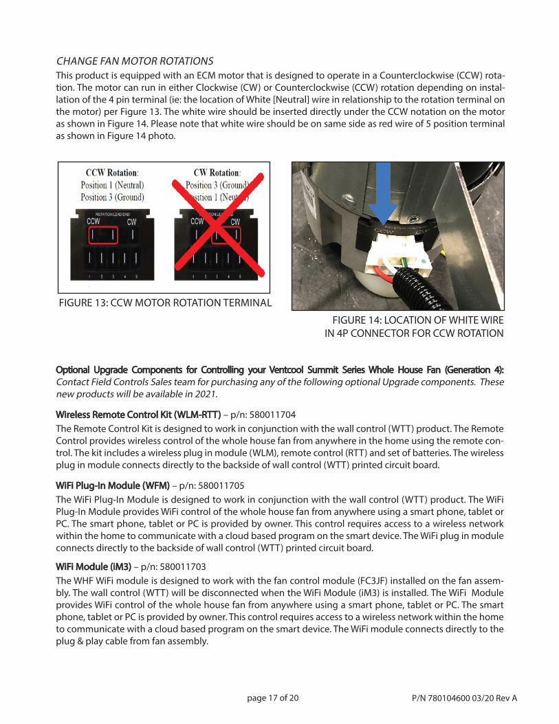
CHANGE FAN MOTOR ROTATIONSThis product is equipped with an ECM motor that is designed to operate in a Counterclockwise (CCW) rota-tion. The motor can run in either Clockwise (CW) or Counterclockwise (CCW) rotation depending on instal-lation of the 4 pin terminal (ie: the location of White [Neutral] wire in relationship to the rotation terminal on the motor) per Figure 13. The white wire should be inserted directly under the CCW notation on the motor as shown in Figure 14. Please note that white wire should be on same side as red wire of 5 position terminal as shown in Figure 14 photo.
FIGURE 13: CCW MOTOR ROTATION TERMINAL
FIGURE 14: LOCATION OF WHITE WIRE IN 4P CONNECTOR FOR CCW ROTATION
Optional Upgrade Components for Controlling your Ventcool Summit Series Whole House Fan (Generation 4):Optional Upgrade Components for Controlling your Ventcool Summit Series Whole House Fan (Generation 4):Contact Field Controls Sales team for purchasing any of the following optional Upgrade components. These new products will be available in 2021.
Wireless Remote Control Kit (WLM-RTT) Wireless Remote Control Kit (WLM-RTT) – p/n: 580011704The Remote Control Kit is designed to work in conjunction with the wall control (WTT) product. The Remote Control provides wireless control of the whole house fan from anywhere in the home using the remote con-trol. The kit includes a wireless plug in module (WLM), remote control (RTT) and set of batteries. The wireless plug in module connects directly to the backside of wall control (WTT) printed circuit board.
WiFi Plug-In Module (WFM)WiFi Plug-In Module (WFM) – p/n: 580011705The WiFi Plug-In Module is designed to work in conjunction with the wall control (WTT) product. The WiFi Plug-In Module provides WiFi control of the whole house fan from anywhere using a smart phone, tablet or PC. The smart phone, tablet or PC is provided by owner. This control requires access to a wireless network within the home to communicate with a cloud based program on the smart device. The WiFi plug in module connects directly to the backside of wall control (WTT) printed circuit board.
WiFi Module (iM3) WiFi Module (iM3) – p/n: 580011703The WHF WiFi module is designed to work with the fan control module (FC3JF) installed on the fan assem-bly. The wall control (WTT) will be disconnected when the WiFi Module (iM3) is installed. The WiFi Module provides WiFi control of the whole house fan from anywhere using a smart phone, tablet or PC. The smart phone, tablet or PC is provided by owner. This control requires access to a wireless network within the home to communicate with a cloud based program on the smart device. The WiFi module connects directly to the plug & play cable from fan assembly.
page 18 of 20P/N 780104600 03/20 Rev A
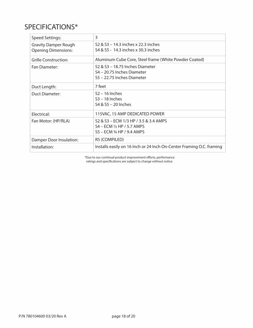
Speed Settings: 3
Gravity Damper RoughOpening Dimensions:
S2 & S3 – 14.3 inches x 22.3 inchesS4 & S5 - 14.3 inches x 30.3 inches
Grille Construction: Aluminum Cube Core, Steel frame (White Powder Coated)
Fan Diameter: S2 & S3 – 18.75 Inches DiameterS4 – 20.75 Inches DiameterS5 – 22.75 Inches Diameter
Duct Length: 7 feet
Duct Diameter: S2 – 16 InchesS3 – 18 InchesS4 & S5 – 20 Inches
Electrical: 115VAC, 15 AMP DEDICATED POWER
Fan Motor: (HP/RLA) S2 & S3 – ECM 1/3 HP / 3.5 & 3.4 AMPSS4 – ECM ½ HP / 5.7 AMPSS5 – ECM ¾ HP / 9.4 AMPS
Damper Door Insulation: R5 (COMPILED)
Installation: Installs easily on 16 Inch or 24 Inch On-Center Framing O.C. framing
SPECIFICATIONS*
*Due to our continual product improvement eff orts, performanceratings and specifi cations are subject to change without notice.
page 19 of 20 P/N 780104600 03/20 Rev A
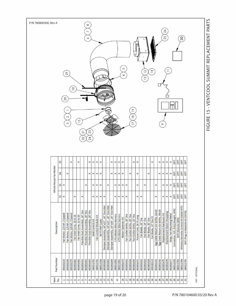
FIG
URE
15
- VEN
TCO
OL
SUM
MIT
REP
LAC
EMEN
T PA
RTS
P/N 780800300, Rev A
OPT
- O
PTIO
NA
L

© Field Controls, LLC
This manual may be downloaded and printed from the Field Controls website (www.fi eldcontrols.com)This manual may be downloaded and printed from the Field Controls website (www.fi eldcontrols.com)
WARRANTYWARRANTYFor warranty information about this or any Field Controls product, visit:For warranty information about this or any Field Controls product, visit:
www.fi eldcontrols.com/ventCoolwww.fi eldcontrols.com/ventCool
Field Controls Technical SupportField Controls Technical Support1.800.742.83681.800.742.8368
fi eldtec@fi eldcontrols.comfi eldtec@fi eldcontrols.com
P/N 780104600 03/20 Rev A
Phone: 252.522.3031 • Fax: 252.522.0214www.fieldcontrols.com
Related Documents