Venkon Fan Coils, Recirculating air. Heating, cooling and filtering for the ultimate in comfort Technical Catalogue Venkon Fan Coils

Welcome message from author
This document is posted to help you gain knowledge. Please leave a comment to let me know what you think about it! Share it to your friends and learn new things together.
Transcript

VenkonFan Coils, Recirculating air. Heating, cooling and filtering for the ultimate in comfort Technical Catalogue
Venkon Fan Coils


01 Product Information 6
Overview 7 Product data 8 Selection assistance: Overview of models 9 Venkon at a glance 10
02 Technical Data 12
Information on measuring conditions 13 Venkon AC, Models 1 – 7, stage-controlled AC fans, 2-pipe 14 Venkon AC, Models 1 – 7, stage-controlled AC fans, 4-pipe 16 Venkon EC, Models 1 – 7, stage-controlled EC fans, 2-pipe 18 Venkon EC, Models 1 – 7, stage-controlled EC fans, 4-pipe 20
03 Design Information 22
Information on design and layout 23 Casing selection 24 Air discharge direction and connections 26
04 Controls 28
KaControl – The All-inclusive Solution 28 Layout plan Venkon with KaControl 29 Venkon with AC fans, electromechanical control 30 Venkon with EC fans, electromechanical control 32
05 Ordering Information 34
Venkon AC 34 Venkon EC 35 Accessories 36
Contents
3Kampmann Technical Catalogue – Venkon

Venkon: Market-leading silent.
4 Kampmann Technical Catalogue – Venkon

With the Venkon, you are opting for a decentralised air treatment unit, at the same time as meeting all the expectations of a peaceful environment.
5Kampmann Technical Catalogue – Venkon

01
01 Product Information
Schlosshotel Bad Wilhelmshöhe Conference & Spa, Kassel
6 Kampmann Technical Catalogue – VenkonProduct Information

Venkon – So you get the right solution for every challenge!
Heating example
Cross-section, wall-mounted without intake grille Cross-section Ceiling-mounted with intake grille
Cooling example
Fan coils are used in buildings of all types with high heating and cooling requirements as well as exacting user requirements. Venkon AC and EC models are based on the same construction and can be enhanced with a comprehensive range of accessories and controls.
Venkon AC was developed specifically for spaces that require low noise emissions, such as residential spaces and bedrooms. The Venkon EC combines the benefits of the Venkon AC with up to 70% energy-savings with the use of EC technology.
EC technologyEC fans can be operated infinitely variably within a low fan speed range even at low air volumes with intelligent, integrated electronics on demand and thus energy-efficiently. Low fan speeds have a positive impact on noise development in areas, such as hotels and offices, which is far below the threshold or the usual range.
Intelligent motor management permanently detects the operating state of the fans and keeps the pre-set speed constant, regardless of the fan length and external influences. All EC fans are fitted with a motor thermal contact.
Kampmann relies on ebm-papst’s innovative knowledge and expertise with its GreenTech EC fans,in terms of efficient, cost-saving technology.
03 D
esig
n In
form
atio
n04
Con
trol
s05
Ord
erin
g In
form
atio
n02
Tec
hnic
al D
ata
01 P
rodu
ct In
form
atio
n
7Kampmann Technical Catalogue – Venkon Product Information | Overview

01
Product Data
hygiene-certified to VDI 6022 market-leading quiet short delivery times easy to install fully automatic KaControl
networking possible with an existing external building automation system
Product Features
1) at CPW 7 / 12 °C and tL1 = 27 °C, 50 % relative humidity2) at LPHW 75 / 65, tL= 20 °C
Features
seven models flexible combination with base unit
and casing staged fans or continuously variable
EC fans optional fresh air connection 2 or 3-way valves as accessories comprehensive range of accessories
Heating LPHWCooling CHW Installation wall and ceiling-mountedHeat exchanger 2-pipe 4-pipeKaControl optional
Condensation pump Head up to 5 m at 5 l / h
Condensate connection: Outside diameter 15 mm
Casing designs: wall-mounted wall-standing free-standing ceiling
Uses
Buildings of all kinds that areto be cooled and / or heatedwith a visually discreet design of unit.
Performance data
Cooling output 1) [kW] 0.88 – 9.52
Heat output 2) [kW] 1.82 – 22.12
Operating limits Max. operating pressure: 10 bar Min. entering water temperature 5 °C Max. entering water temperature: 110 °C Min. entering air temperature: 15 °C Max. entering air temperature: 40 °C Relative humidity: 20 – 60 %
Hotels Exhibition rooms and showrooms
Offices andcommercial buildings
Restaurants and cafés
8 Kampmann Technical Catalogue – VenkonProduct Information | Product Data

Selection Guide: Overview of Models
Model Model Width 2/4-pipe Cooling outputs1) Heat outputs2)
Moreinformation
[mm] Qk [W] Qh [W]
1
AC
850
2-pipe 907 – 2779 2020 – 7313 Page 14 – 15
4-pipe 875 – 2484 1820 – 4841 Page 16 – 17
EC2-pipe 999 – 2162 2250 – 5404 Page 18 – 19
4-pipe 960 – 1979 1996 – 3928 Page 20 – 21
2
AC
1000
2-pipe 1076 – 3273 2290 – 7876 Page 14 – 15
4-pipe 1049 – 2999 2117 – 5647 Page 16 – 17
EC2-pipe 1110 – 2708 2369 – 6330 Page 18 – 19
4-pipe 1081 – 2520 2182 – 4827 Page 20 – 21
3
AC
1150
2-pipe 1819 – 4388 3887 – 10297 Page 14 – 15
4-pipe 1761 – 4024 3487 – 7340 Page 16 – 17
EC2-pipe 1547 – 3684 3265 – 8430 Page 18 – 19
4-pipe 1507 – 3428 2988 – 6365 Page 20 – 21
4
AC
1300
2-pipe 2023 – 4925 4239 – 11189 Page 14 – 15
4-pipe 1971 – 4565 3856 – 8254 Page 16 – 17
EC2-pipe 1740 – 4132 3609 – 9185 Page 18 – 19
4-pipe 1702 – 3882 3344 – 7152 Page 20 – 21
5
AC
1450
2-pipe 2064 – 4969 4473 – 11910 Page 14 – 15
4-pipe 2001 – 4593 4082 – 8904 Page 16 – 17
EC2-pipe 1829 – 4234 3925 – 9910 Page 18 – 19
4-pipe 1781 – 3961 3633 – 7777 Page 20 – 21
6
AC
1600
2-pipe 2631 – 7242 5679 – 17647 Page 14 – 15
4-pipe 2549 – 6585 5132 – 12281 Page 16 – 17
EC2-pipe 2827 – 6175 6142 – 14653 Page 18 – 19
4-pipe 2732 – 5695 5491 – 10778 Page 20 – 21
7
AC
2000
2-pipe 3555 – 9515 7496 – 22122 Page 14 – 15
4-pipe 3460 – 8740 6820 – 15819 Page 16 – 17
EC2-pipe 3347 – 8137 7026 – 18510 Page 18 – 19
4-pipe 3263 – 7573 6442 – 13936 Page 20 – 21
1) at CPW 7 / 12, tL = 27 °C, 50 % relative humidity2) at LPHW 75 / 65, tL= 20 °C
Dimensions
Venkon recirculating air unit, standard casing, wall model
Front view Front view
Top view View from below
Venkon recirculating air unit, standard casing, ceiling model
628 - 1778
850 - 2000
628 - 1778
850 - 2000
628 - 1778
850 - 2000
628 - 1778
850 - 2000
Ansicht von unten
Vorderansicht
Draufsicht
Vorderansicht
Venkon Umluft, Standardverkleidung Deckenausführung
Venkon Umluft, Standardverkleidung Wandausführung
628 - 1778
850 - 2000
628 - 1778
850 - 2000
628 - 1778
850 - 2000
628 - 1778
850 - 2000
Ansicht von unten
Vorderansicht
Draufsicht
Vorderansicht
Venkon Umluft, Standardverkleidung Deckenausführung
Venkon Umluft, Standardverkleidung Wandausführung
628 - 1778
850 - 2000
628 - 1778
850 - 2000
628 - 1778
850 - 2000
628 - 1778
850 - 2000
Ansicht von unten
Vorderansicht
Draufsicht
Vorderansicht
Venkon Umluft, Standardverkleidung Deckenausführung
Venkon Umluft, Standardverkleidung Wandausführung
628 - 1778
850 - 2000
628 - 1778
850 - 2000
628 - 1778
850 - 2000
628 - 1778
850 - 2000
Ansicht von unten
Vorderansicht
Draufsicht
Vorderansicht
Venkon Umluft, Standardverkleidung Deckenausführung
Venkon Umluft, Standardverkleidung Wandausführung
There are wall- and ceiling-mounted versions of all models available.
03 D
esig
n In
form
atio
n04
Con
trol
s05
Ord
erin
g In
form
atio
n02
Tec
hnic
al D
ata
01 P
rodu
ct In
form
atio
n
9Kampmann Technical Catalogue – Venkon Product Information | Selection Guide

01
1
6
42
75
Features
3
8
Venkon at a Glance
3
8
7
Anti-twist device for heating connection
Filter
AC- oder EC-Fan
1 Control in the elec. housing
2 High-output convector
4 Valve kit
5 Condensation tray
6 Condensation pump
10 Kampmann Technical Catalogue – VenkonProduct Information | Venkon at a Glance

1 Control in the elec. housing: wired ready for connection
easily accessible for service by removing the side panel
2 High-output convector: the proven combination of
copper/aluminium optimised for enhanced air flow
and heat/cooling discharge
3 Anti-twist device for heating connection: prevents damage to the
convector when installing the valves
valves optional (accessories)
4 Valve kit, optional (accessories): for ease of installation on the
water-side
5 Condensation tray: can be easily removed for
maintenance
6 Condensation pump, optional (accessories): for discharge of the
condensate with float switch
7 Fan: for an even airflow through the
convector, providing high heat outputs with low noise emissions
8 Filter: absolutely maintenance-friendly
access
03 D
esig
n In
form
atio
n04
Con
trol
s05
Ord
erin
g In
form
atio
n02
Tec
hnic
al D
ata
01 P
rodu
ct In
form
atio
n
11Kampmann Technical Catalogue – Venkon Product Information | Venkon at a Glance

02 Technical Data
628 – 1778
850 – 2000
628 – 1778
850 – 2000
628 – 1778
850 – 2000
628 – 1778
850 – 2000
12 Kampmann Technical Catalogue – VenkonTechnical Data

The cooling and heat output have been calculated in line with DIN EN 1397: 1998 „Water-air fan convectors, test methods for establishing the performance“.
The specific requirements for cooling and heating mode are taken into account in DIN EN 1397. They are also based on Eurovent Certification.
References to standardsThe standard refers to:: EN 23741; Determining the sound power levels of
noise sources EN 45001; General criteria for the operation of test
laboratories ISO 5801; Industrial fans; Performance testing
using standardised airways ISO 5221; Air distribution and air diffusion; Rules
and methods of measuring air flow rate in an air handling duct
The entering air temperature of the fan convector is selected as the reference/air temperature, which should not be confused with the ambient temperature.
In practice, fan convectors are positioned within a suspended ceiling or as sill units along the façade. Due to the temperature stratification that occurs, the entering air temperature differs from the air temperature in the room (measured at a height of 1.5 m).
Advice on Measuring Conditions
Sound measurement laboratory
628 – 1778
850 – 2000
628 – 1778
850 – 2000
AcousticsFan convectors are very often used in acoustically sensitive areas. The sound levels of the fan convectors have been optimised accordingly. The sound power and sound energy levels of sources of sound are taken from sound pressure measurements – enveloping measurement surface (accuracy class 2) for an essentially free sound field over a reflective plane.The sound power level is measured according to DIN EN ISO 3744 (TW) in a semi-low reflective sound measuring chamber.
03 D
esig
n In
form
atio
n04
Con
trol
s05
Ord
erin
g In
form
atio
n01
Pro
duct
Info
rmat
ion
02 T
echn
ical
Dat
a
13Kampmann Technical Catalogue – Venkon Technical Data | Advice on Measuring Conditions

Specifications
Technical Drawings (Dimensions in mm)
Water resistance diagram
Use our online calculation programs to quicklycalculate heat outputs and flow rates at the click of a button! Kampmann.co.uk/venkon/calculation Kampmann.eu/venkon/calculation
Water connections
Technology
FrontblechVerkleidungsbreite
HauptkondensatwanneWandbefestigung
Rückwand Ausblasöffnung
Baugröße
1 2 3 4 5 6 7
628 778 928 1078 1228 1378 1778850 1000 1150 1300 1450 1600 2000620 770 920 1070 1220 1370 1770560 710 860 1010 1160 1310 1710590 740 890 1040 1190 1340 1740524 674 824 974 1124 1274 1674
Bsp. Ausführung Wand
Bsp. Ausführung Decke
Venkon ACModels 1 – 7, stage-controlled AC fans, 2-pipe
Model 1 – 4
Model 5 – 7
Element C/H C/H
Connection 1 / 2" 3 / 4"
ModelBasic unit
Number of impellers
Numberof motors
[kg]
1 18.5 1 1
2 21.0 1 1
3 24.0 2 1
4 27.0 2 1
5 32.0 2 1
6 36.0 3 2
7 46.0 4 2
Top view
ModelFront panel
Casingwidth
Main condensate
trayWall
fixingRear wall
Discharge opening
[mm] [mm] [mm] [mm] [mm] [mm]
1 628 850 620 560 590 524
2 778 1000 770 710 740 674
3 928 1150 920 860 890 824
4 1078 1300 1070 1010 1040 974
5 1228 1450 1220 1160 1190 1124
6 1378 1600 1370 1310 1340 1274
7 1778 2000 1770 1710 1740 1674
Front view (wall-mounted model) Cross-section
Main condensate tray
Discharge opening
Controller housing
(Not required with electro-mechanical model)
Wall mounting
Rear wall
Main condensate tray
Wal
l m
ount
ing
Pres
sure
loss
[kPa
]
100
100 500 1000 3000
2
1
3
4
7
6
5
8
Water volume [l/h]
1
10
50
Cooling element:1 Models 1 / 22 Models 3 / 43 Models 5 / 64 Models 7
Heating element:5 Models 1 / 26 Models 3 / 47 Models 5 / 68 Models 7
14 Kampmann Technical Catalogue – VenkonTechnical Data | Venkon AC, Models 1 – 7, stage-controlled AC fans, 2-pipe

Design: 2-pipe cooling (4 pipe rows),AC fans
1) at CPW 7 / 12, tL = 27 °C, 50 % relative humidity2) at an room air temperature of tL1 = 20 °C3) The sound pressure levels were calculated with an assumed room insulation of 8 dB(A). This corresponds to a distance of 2 m, a room volume of 100 m3 and a reverberation time of 0.5 s (in accordance with VDI 2081).
Mo
del
Fan
sta
ge
Air
vo
lum
e
Co
olin
g o
utp
uts
1)
Ou
tlet
air
te
mp
erat
ure
1)
Wat
er v
olu
me,
co
olin
g
Pres
sure
loss
, co
olin
g
Heating output2)
Wat
er v
olu
me,
h
eati
ng
Pres
sure
loss
, h
eati
ng
Pow
er c
on
sum
pti
on
Cu
rren
t
con
sum
pti
on
Sou
nd
pre
ssu
re
leve
l 3)
Sou
nd
po
wer
le
velat LPHW
75 / 65 °Cat LPHW 82 / 71 °C
V[m³ / h] Qkg [W] Qks [W] tL2 [°C] [l / h] [kPa] Qh[W] tL2 [°C] Qh[W] tL2 [°C] [l / h] [kPa] P[W] I[A] [dB(A)] [dB(A)]
1
1 125 907 635 11.6 156 0.6 2020 68.0 2288 74,3 177 0.5 13 0.13 < 20 27
2 175 1205 858 12.1 207 0.9 2763 66.8 3131 73,1 242 0.9 19 0.08 23 31
3 255 1632 1191 12.8 281 1.5 3894 65.3 4416 71,4 341 1.6 29 0.12 30 38
4 410 2327 1773 13.9 400 2.9 5897 62.7 6696 68,5 517 3.4 47 0.20 43 51
5 530 2779 2179 14.5 478 4.0 7313 60.9 8303 66,5 641 4.9 62 0.27 49 57
2
1 140 1076 737 11.0 185 0.9 2290 68.5 2592 74,9 201 0.8 13 0.13 <20 26
2 190 1409 976 11.4 242 1.5 3068 67.9 3473 74,2 269 1.3 19 0.08 20 28
3 260 1840 1294 11.9 316 2.3 4102 66.8 4646 73,0 360 2.2 28 0.12 27 35
4 410 2658 1922 12.8 457 4.4 6196 64.8 7023 70,8 543 4.5 46 0.20 40 48
5 540 3273 2418 13.4 563 6.4 7876 63.3 8931 69,1 690 6.8 64 0.28 47 55
3
1 240 1819 1250 11.2 313 2.7 3887 68.1 4399 74,4 341 2.3 12 0.15 <20 28
2 300 2207 1530 11.5 379 3.8 4782 67.3 5413 73,5 419 3.3 20 0.09 29 37
3 400 2813 1976 12.0 484 5.8 6234 66.2 7060 72,4 546 5.3 30 0.14 35 43
4 570 3734 2682 12.7 642 9.5 8562 64.6 9702 70,5 751 9.3 49 0.23 43 51
5 705 4388 3201 13.2 754 12.6 10297 63.3 11671 69,1 903 12.8 68 0.34 47 55
4
1 260 2023 1378 10.9 348 3.7 4239 68.4 4797 74,7 372 3.1 13 0.15 <20 27
2 310 2366 1620 11.1 407 4.9 5014 68.0 5674 74,3 439 4.2 21 0.10 28 36
3 420 3077 2132 11.6 529 7.8 6641 66.9 7518 73,1 582 6.8 31 0.14 33 41
4 600 4132 2916 12.2 710 13.1 9185 65.4 10404 71,4 805 12.1 51 0.24 36 44
5 750 4925 3523 12.7 847 17.8 11189 64.3 12676 70,1 981 17.1 73 0.36 46 54
5
1 275 2064 1426 11.3 355 0.6 4473 68.3 5064 74,6 392 0.6 13 0.15 <20 26
2 325 2387 1660 11.5 410 0.8 5247 67.9 5941 74,2 460 0.7 21 0.10 27 35
3 440 3087 2179 12.0 531 1.3 6948 66.9 7871 73,1 609 1.2 31 0.14 32 40
4 635 4157 3002 12.7 715 2.1 9705 65.3 11001 71,4 851 2.2 52 0.24 39 47
5 800 4969 3650 13.1 854 2.9 11910 64.2 13506 70,1 1044 3.1 73 0.36 45 53
6
1 350 2631 1815 11.3 452 1.1 5679 68.1 6428 74,5 498 0.9 26 0.28 25 33
2 480 3455 2416 11.7 594 1.7 7627 67.1 8638 73,4 669 1.6 39 0.17 29 37
3 655 4471 3178 12.3 769 2.7 10149 66.0 11499 72,1 890 2.6 58 0.26 35 43
4 970 6081 4443 13.1 1045 4.7 14395 64.0 16320 69,9 1262 4.8 94 0.42 43 51
5 1230 7242 5402 13.7 1245 6.4 17647 62.6 20014 68,3 1547 6.9 129 0.59 50 58
7
1 460 3555 2428 11.0 611 2.3 7496 68.4 8482 74,7 657 2.0 26 0.30 26 34
2 620 4623 3190 11.4 795 3.7 9922 67.5 11231 73,7 870 3.2 42 0.19 31 39
3 840 5985 4185 11.9 1029 5.8 13141 66.4 14881 72,6 1152 5.3 62 0.28 36 44
4 1210 8034 5739 12.6 1381 9.8 18244 64.7 20671 70,7 1599 9.4 103 0.47 41 49
5 1510 9515 6907 13.1 1636 13.2 22122 63.5 25072 69,3 1939 13.2 145 0.71 50 58
03 D
esig
n In
form
atio
n04
Con
trol
s05
Ord
erin
g In
form
atio
n01
Pro
duct
Info
rmat
ion
02 T
echn
ical
Dat
a
15Kampmann Technischer Katalog – Venkon Technical Data | Venkon AC, Models 1 – 7, stage-controlled AC fans, 2-pipe

Specifications
Technical Drawings (Dimensions in mm)
Water resistance diagram
Use our online calculation programs to quicklycalculate heat outputs and flow rates at the click of a button! Kampmann.co.uk/venkon/calculation Kampmann.eu/venkon/calculation
Water connections
Technology
Cross-sectionFront view (ceiling-mounted model)
Venkon ACModels 1 – 7, stage-controlled AC fans, 4-pipe
FrontblechVerkleidungsbreite
HauptkondensatwanneWandbefestigung
Rückwand Ausblasöffnung
Baugröße
1 2 3 4 5 6 7
628 778 928 1078 1228 1378 1778850 1000 1150 1300 1450 1600 2000620 770 920 1070 1220 1370 1770560 710 860 1010 1160 1310 1710590 740 890 1040 1190 1340 1740524 674 824 974 1124 1274 1674
Bsp. Ausführung Wand
Bsp. Ausführung Decke
Top view
ModelFront panel
Casingwidth
Main condensate
trayWall
fixingRear wall
Discharge opening
[mm] [mm] [mm] [mm] [mm] [mm]
1 628 850 620 560 590 524
2 778 1000 770 710 740 674
3 928 1150 920 860 890 824
4 1078 1300 1070 1010 1040 974
5 1228 1450 1220 1160 1190 1124
6 1378 1600 1370 1310 1340 1274
7 1778 2000 1770 1710 1740 1674
Main condensate tray
Discharge opening
Controller housing
(Not required with electro-mechanical model)
Wall mounting
Rear wall
Main condensate tray
Wal
l m
ount
ing
100
100 500 1000 3000
2 1
3
4
6 5 8 7
1
10
50
ModelBasic unit
Number of impellers
Numberof motors
[kg]
1 18.5 1 1
2 21.0 1 1
3 24.0 2 1
4 27.0 2 1
5 32.0 2 1
6 36.0 3 2
7 46.0 4 2
Pres
sure
loss
[kPa
]
Water volume [l/h]
Cooling element:1 Models 1 / 22 Models 3 / 43 Models 5 / 64 Models 7
Heating element:5 Models 1 / 26 Models 3 / 47 Models 5 / 68 Models 7
Model 1 – 4
Model 5 – 7
Element C/H C H
Connection 1 / 2" 3 / 4" 1 / 2“
16 Kampmann Technical Catalogue – VenkonTechnical Data | Venkon AC, Models 1 – 7, stage-controlled AC fans, 4-pipe

1) at CPW 7 / 12, tL = 27 °C, 50 % relative humidity2) at an room air temperature of tL1 = 20 °C3) The sound pressure levels were calculated with an assumed room insulation of 8 dB(A). This corresponds to a distance of 2 m, a room volume of 100 m3 and a reverberation time of 0.5 s (in accordance with VDI 2081).
Design: 4-pipe cooling (4 pipe rows),AC fans
Mo
del
Fan
sta
ge
Air
vo
lum
e
Co
olin
g o
utp
uts
1)
Ou
tlet
air
te
mp
erat
ure
1)
Wat
er v
olu
me,
co
olin
g
Pres
sure
loss
, co
olin
g
Heating output2)
Wat
er v
olu
me,
h
eati
ng
Pres
sure
loss
, h
eati
ng
Pow
er c
on
sum
pti
on
Cu
rren
t
con
sum
pti
on
Sou
nd
pre
ssu
re
leve
l 3)
Sou
nd
po
wer
le
velat LPHW
75 / 65 °Cat LPHW 82 / 71 °C
V[m³ / h] Qkg [W] Qks [W] tL2 [°C] [l / h] [kPa] Qh[W] tL2 [°C] Qh[W] tL2 [°C] [l / h] [kPa] P[W] I[A] [dB(A)] [dB(A)]
1
1 125 875 621 11.9 150 0.9 1820 63.2 2065 69,0 160 4.9 13 0.13 < 20 27
2 175 1148 834 12.5 197 1.4 2357 60.0 2676 65,4 207 7.7 19 0.08 23 31
3 255 1526 1148 13.3 262 2.3 3088 55.9 3509 60,8 271 12.3 29 0.12 30 38
4 410 2117 1689 14.5 364 4.1 4178 50.2 4751 54,4 366 21.0 47 0.20 43 51
5 530 2484 2064 15.2 427 5.4 4841 47.1 5506 50,8 424 27.2 62 0.27 49 57
2
1 140 1049 726 11.3 180 1.4 2117 64.9 2400 70,9 186 7.7 13 0.13 < 20 26
2 190 1360 956 11.7 234 2.3 2737 62.7 3103 68,5 240 12.1 19 0.08 20 28
3 260 1755 1258 12.3 302 3.5 3461 59.5 3927 64,8 303 18.3 28 0.12 27 35
4 410 2477 1848 13.3 426 6.5 4752 54.4 5395 59,0 417 32.0 46 0.20 40 48
5 540 2999 2309 14.0 516 9.1 5647 51.0 6413 55,2 495 43.4 64 0.28 47 55
3
1 240 1761 1225 11.5 303 4.2 3478 63.0 3942 68,7 305 21.8 12 0.15 <20 28
2 300 2120 1493 11.9 365 5.8 4113 60.7 4664 66,1 361 29.2 20 0.09 29 37
3 400 2667 1915 12.5 459 8.7 5078 57.7 5760 62,7 445 42.4 30 0.14 35 43
4 570 3472 2573 13.3 597 13.9 6437 53.5 7305 58,0 564 64.3 49 0.23 43 51
5 705 4024 3055 13.8 692 18.0 7340 50.9 8330 55,1 643 81.0 68 0.34 47 55
4
1 260 1971 1356 11.2 339 5.9 3856 64.0 4369 69,9 338 30.0 13 0.15 <20 27
2 310 2291 1588 11.4 394 7.7 4450 62.6 5043 68,3 390 38.6 21 0.10 28 36
3 420 2944 2075 12.0 506 11.9 5575 59.4 6320 64,6 489 57.4 31 0.14 33 41
4 600 3882 2811 12.8 667 19.4 7152 55.4 8110 60,1 627 89.0 51 0.24 36 44
5 750 4565 3376 13.3 785 25.9 8254 52.7 9362 57,0 724 114.6 73 0.36 46 54
5
1 275 2001 1400 11.5 344 1.0 4082 64.0 4630 70,0 358 5.4 13 0.15 <20 26
2 325 2303 1625 11.8 396 1.3 4692 62.8 5323 68,6 411 6.9 21 0.10 27 35
3 440 2944 2120 12.4 506 1.9 5897 59.8 6693 65,1 517 10.3 31 0.14 32 40
4 635 3894 2894 13.2 669 3.2 7655 55.8 8694 60,6 671 16.3 52 0.24 39 47
5 800 4593 3499 13.7 790 4.2 8904 53.0 10115 57,5 781 21.2 73 0.36 45 53
6
1 350 2549 1780 11.6 438 1.7 5132 63.5 5819 69,3 450 9.0 26 0.28 25 33
2 480 3309 2355 12.1 569 2.7 6546 60.5 7427 65,9 574 13.8 39 0.17 29 37
3 655 4221 3076 12.7 726 4.1 8210 57.2 9318 62,2 720 20.6 58 0.26 35 43
4 970 5615 4256 13.7 965 6.8 10642 52.6 12084 57,0 933 32.5 94 0.42 43 51
5 1230 6585 5143 14.3 1132 8.9 12281 49.6 13948 53,6 1076 41.8 129 0.59 50 58
7
1 460 3460 2387 11.3 595 3.7 6820 64.0 7728 69,8 598 19.1 26 0.30 26 34
2 620 4453 3117 11.7 765 5.8 8609 61.2 9759 66,7 755 28.8 42 0.19 31 39
3 840 5689 4062 12.3 978 8.9 10779 58.1 12224 63,2 945 42.7 62 0.28 36 44
4 1210 7485 5514 13.2 1287 14.4 13791 53.8 15645 58,4 1209 65.9 103 0.47 41 49
5 1510 8740 6594 13.7 1503 18.9 15819 51.1 17949 55,3 1387 83.9 145 0.71 50 58
03 D
esig
n In
form
atio
n04
Con
trol
s05
Ord
erin
g In
form
atio
n01
Pro
duct
Info
rmat
ion
02 T
echn
ical
Dat
a
17Kampmann Technical Catalogue – Venkon Technical Data | Venkon AC, Models 1 – 7, stage-controlled AC fans, 4-pipe

Specifications
Technical Drawings (Dimensions in mm)
Water resistance diagram
Use our online calculation programs to quicklycalculate heat outputs and flow rates at the click of a button! Kampmann.co.uk/venkon/calculation Kampmann.eu/venkon/calculation
Water connections
Technology
FrontblechVerkleidungsbreite
HauptkondensatwanneWandbefestigung
Rückwand Ausblasöffnung
Baugröße
1 2 3 4 5 6 7
628 778 928 1078 1228 1378 1778850 1000 1150 1300 1450 1600 2000620 770 920 1070 1220 1370 1770560 710 860 1010 1160 1310 1710590 740 890 1040 1190 1340 1740524 674 824 974 1124 1274 1674
Bsp. Ausführung Wand
Bsp. Ausführung Decke
Venkon ECModels 1 – 7, 0-100% adjustable EC fans, 2-pipe
FrontblechVerkleidungsbreite
HauptkondensatwanneWandbefestigung
Rückwand Ausblasöffnung
Baugröße
1 2 3 4 5 6 7
628 778 928 1078 1228 1378 1778850 1000 1150 1300 1450 1600 2000620 770 920 1070 1220 1370 1770560 710 860 1010 1160 1310 1710590 740 890 1040 1190 1340 1740524 674 824 974 1124 1274 1674
Bsp. Ausführung Wand
Bsp. Ausführung Decke
ModelFront panel
Casingwidth
Main condensate
trayWall
fixingRear wall
Discharge opening
[mm] [mm] [mm] [mm] [mm] [mm]
1 628 850 620 560 590 524
2 778 1000 770 710 740 674
3 928 1150 920 860 890 824
4 1078 1300 1070 1010 1040 974
5 1228 1450 1220 1160 1190 1124
6 1378 1600 1370 1310 1340 1274
7 1778 2000 1770 1710 1740 1674
Main condensate tray
Discharge opening
Controller housing
(Not required with electro-mechanical model)
Wall mounting
Rear wall
Main condensate tray
Wal
l m
ount
ing
Top view
Front view (wall-mounted model) Cross-section
100
100 500 1000 3000
21
3
4
7
65
8
1
10
50
ModelBasic unit
Number of impellers
Numberof motors
[kg]
1 18.5 1 1
2 21.0 1 1
3 24.0 2 1
4 27.0 2 1
5 32.0 2 1
6 36.0 3 2
7 46.0 4 2
Pres
sure
loss
[kPa
]
Water volume [l/h]
Cooling element:1 Models 1 / 22 Models 3 / 43 Models 5 / 64 Models 7
Heating element:5 Models 1 / 26 Models 3 / 47 Models 5 / 68 Models 7
Model 1 – 4
Model 5 – 7
Element C/H C/H
Connection 1 / 2" 3 / 4"
18 Kampmann Technical Catalogue – VenkonTechnical Data | Venkon EC, Models 1 – 7, continuously variable EC fans, 2-pipe

1) at CPW 7 / 12, tL = 27 °C, 50 % relative humidity2) at an room air temperature of tL1 = 20 °C3) The sound pressure levels were calculated with an assumed room insulation of 8 dB(A). This corresponds to a distance of 2 m, a room volume of 100 m3 and a reverberation time of 0.5 s (in accordance with VDI 2081).
Design: 2-pipe cooling (4 pipe rows),EC fans
Mo
del
Fan
sta
ge
Air
vo
lum
e
Co
olin
g o
utp
uts
1)
Ou
tlet
air
te
mp
erat
ure
1)
Wat
er v
olu
me,
co
olin
g
Pres
sure
loss
, co
olin
g
Heating output2)
Wat
er v
olu
me,
h
eati
ng
Pres
sure
loss
, h
eati
ng
Pow
er c
on
sum
pti
on
Cu
rren
t
con
sum
pti
on
Sou
nd
pre
ssu
re
leve
l 3)
Sou
nd
po
wer
le
velat LPHW
75 / 65 °Cat LPHW 82 / 71 °C
[V] V[m³ / h] Qkg [W] Qks [W] tL2 [°C] [l / h] [kPa] Qh[W] tL2 [°C] Qh[W] tL2 [°C] [l / h] [kPa] P[W] I[A] [dB(A)] [dB(A)]
1
1.5 140 999 703 11.8 172 0.7 2250 67.7 2548 74,0 197 0.6 3 0.04 < 20 27
2 150 1060 748 11.9 182 0.7 2401 67.5 2719 73,8 210 0.7 4 0.05 21 29
4 230 1504 1090 12.6 259 1.3 3548 65.8 4023 71,9 311 1.4 5 0.06 28 36
6 290 1802 1329 13.1 310 1.8 4367 64.7 4953 70,7 383 2.0 8 0.08 35 43
8 335 2009 1500 13.4 345 2.2 4958 63.9 5625 69,8 435 2.5 11 0.10 39 47
10 370 2162 1629 13.6 372 2.5 5404 63.3 6132 69,2 474 2.9 14 0.12 41 49
2
1.5 145 1110 762 11.1 191 1.0 2369 68.5 2681 74,9 208 0.8 3 0.04 < 20 27
2 180 1344 929 11.3 231 1.3 2914 68 3299 74,4 255 1.2 4 0.05 21 29
4 250 1781 1250 11.8 306 2.2 3956 67 4480 73,2 347 2.0 5 0.06 28 36
6 315 2156 1532 12.2 371 3.1 4890 66.1 5541 72,2 429 2.9 8 0.08 35 43
8 375 2479 1781 12.6 426 3.9 5723 65.3 6485 71,3 502 3.9 11 0.10 39 47
10 420 2708 1961 12.8 466 4.6 6330 64.7 7175 70,7 555 4.6 14 0.12 41 49
3
1.5 200 1547 1057 11.0 266 2.0 3265 67.7 3694 74,8 286 1.7 3 0.04 20 28
2 240 1819 1250 11.2 313 2.7 3887 67.5 4399 74,4 341 2.3 4 0.05 21 29
4 325 2363 1644 11.6 406 4.3 5151 65.8 5832 73,2 452 3.8 5 0.06 28 36
6 410 2871 2021 12.0 494 6.0 6375 64.7 7221 72,3 559 5.5 7 0.08 33 41
8 505 3397 2419 12.5 584 8.0 7691 63.9 8714 71,2 674 7.7 11 0.10 37 45
10 560 3684 2642 12.7 633 9.3 8430 63.3 9552 70,6 739 9.0 14 0.12 39 47
4
1.5 220 1740 1180 10.7 299 2.9 3609 68.7 4083 75,1 316 2.3 3 0.04 20 28
2 260 2023 1378 10.9 348 3.7 4239 68.4 4797 74,7 372 3.1 4 0.05 21 29
4 350 2631 1810 11.3 452 5.9 5605 67.5 6344 73,8 491 5.1 5 0.06 28 36
6 450 3261 2267 11.7 561 8.6 7076 66.7 8012 72,8 620 7.6 7 0.08 33 41
8 560 3851 2704 12.1 662 11.6 8494 65.8 9620 71,9 745 10.5 11 0.10 37 45
10 600 4132 2916 12.2 710 13.1 9185 65.4 10404 71,4 805 12.1 14 0.12 39 47
5
1.5 240 1829 1257 11.1 314 0.5 3925 67.7 4442 74,9 344 0.4 3 0.04 20 28
2 280 2096 1450 11.3 360 0.6 4551 67.5 5152 74,6 399 0.6 4 0.05 21 29
4 375 2698 1890 11.7 464 1.0 6005 65.8 6801 73,8 526 0.9 5 0.06 28 36
6 475 3289 2331 12.1 565 1.4 7456 64.7 8448 72,8 654 1.4 7 0.08 33 41
8 590 3922 2818 12.5 674 1.9 9084 63.9 10296 71,8 796 1.9 11 0.10 37 45
10 650 4234 3062 12.7 728 2.2 9910 63.3 11234 71,3 869 2.2 14 0.12 39 47
6
1.5 380 2827 1957 11.4 486 1.2 6142 68 6953 74,3 538 1.1 6 0.08 23 31
2 420 3083 2143 11.5 530 1.4 6752 67.7 7644 74,0 592 1.3 8 0.09 24 32
4 585 4076 2878 12.1 701 2.3 9156 66.4 10372 72,6 803 2.2 10 0.12 31 39
6 745 4957 3554 12.5 852 3.3 11398 65.4 12917 71,4 999 3.2 15 0.15 37 45
8 900 5744 4173 12.9 987 4.2 13482 64.4 15283 70,4 1182 4.3 22 0.20 41 49
10 990 6175 4518 13.1 1062 4.8 14653 63.9 16613 69,8 1284 5.0 28 0.24 43 51
7
1.5 430 3347 2281 10.9 575 2.1 7026 68.5 7950 74,9 616 1.8 6 0.08 23 31
2 500 3829 2621 11.1 658 2.7 8119 68.2 9188 74,5 712 2.3 8 0.09 24 32
4 680 5008 3468 11.5 861 4.3 10815 67.2 12243 73,4 948 3.7 9 0.12 31 39
6 860 6103 4272 11.9 1049 6.1 13426 66.3 15205 72,5 1177 5.5 15 0.15 36 44
8 1070 7290 5169 12.3 1253 8.3 16356 65.4 18528 71,4 1434 7.8 23 0.21 40 48
10 1230 8137 5819 12.6 1399 10.0 18510 64.7 20972 70,6 1623 9.6 28 0.25 42 50
03 D
esig
n In
form
atio
n04
Con
trol
s05
Ord
erin
g In
form
atio
n01
Pro
duct
Info
rmat
ion
02 T
echn
ical
Dat
a
19Kampmann Technical Catalogue – Venkon Technical Data | Venkon EC, Models 1 – 7, continuously variable EC fans, 2-pipe

Specifications
Technical Drawings (Dimensions in mm)
Water resistance diagram
Use our online calculation programs to quicklycalculate heat outputs and flow rates at the click of a button! Kampmann.co.uk/venkon/calculation Kampmann.eu/venkon/calculation
Water connections
Technology
Venkon ECModels 1 – 7, 0-100% adjustable EC fans, 4-pipe
FrontblechVerkleidungsbreite
HauptkondensatwanneWandbefestigung
Rückwand Ausblasöffnung
Baugröße
1 2 3 4 5 6 7
628 778 928 1078 1228 1378 1778850 1000 1150 1300 1450 1600 2000620 770 920 1070 1220 1370 1770560 710 860 1010 1160 1310 1710590 740 890 1040 1190 1340 1740524 674 824 974 1124 1274 1674
Bsp. Ausführung Wand
Bsp. Ausführung Decke
ModelFront panel
Casingwidth
Main condensate
trayWall
fixingRear wall
Discharge opening
[mm] [mm] [mm] [mm] [mm] [mm]
1 628 850 620 560 590 524
2 778 1000 770 710 740 674
3 928 1150 920 860 890 824
4 1078 1300 1070 1010 1040 974
5 1228 1450 1220 1160 1190 1124
6 1378 1600 1370 1310 1340 1274
7 1778 2000 1770 1710 1740 1674
Cross-sectionFront view (ceiling-mounted model)
Top view
Main condensate tray
Discharge opening
Controller housing
(Not required with electro-mechanical model)
Wall mounting
Rear wall
Main condensate tray
Wal
l m
ount
ing
100
100 500 1000 3000
2 1
3
4
6 5 8 7
1
10
50Model 1 – 4
Model 5 – 7
Element C/H C H
Connection 1 / 2" 3 / 4" 1 / 2“
ModelBasic unit
Number of impellers
Numberof motors
[kg]
1 18.5 1 1
2 21.0 1 1
3 24.0 2 1
4 27.0 2 1
5 32.0 2 1
6 36.0 3 2
7 46.0 4 2
Pres
sure
loss
[kPa
]
Water volume [l/h]
Cooling element:1 Models 1 / 22 Models 3 / 43 Models 5 / 64 Models 7
Heating element:5 Models 1 / 26 Models 3 / 47 Models 5 / 68 Models 7
20 Kampmann Technical Catalogue – VenkonTechnical Data | Venkon EC, Models 1 – 7, continuously variable EC fans, 4-pipe

1) at CPW 7 / 12, tL = 27 °C, 50 % relative humidity2) at an room air temperature of tL1 = 20 °C3) The sound pressure levels were calculated with an assumed room insulation of 8 dB(A). This corresponds to a distance of 2 m, a room volume of 100 m3 and a reverberation time of 0.5 s (in accordance with VDI 2081).
Design: 4-pipe,EC fans
Mo
del
Fan
sta
ge
Air
vo
lum
e
Co
olin
g o
utp
uts
1)
Ou
tlet
air
te
mp
erat
ure
1)
Wat
er v
olu
me,
co
olin
g
Pres
sure
loss
, co
olin
g
Heating output2)
Wat
er v
olu
me,
h
eati
ng
Pres
sure
loss
, h
eati
ng
Pow
er c
on
sum
pti
on
Cu
rren
t
con
sum
pti
on
Sou
nd
pre
ssu
re
leve
l 3)
Sou
nd
po
wer
le
velat LPHW
75 / 65 °Cat LPHW 82 / 71 °C
V[m³ / h] Qkg [W] Qks [W] tL2 [°C] [l / h] [kPa] Qh[W] tL2 [°C] Qh[W] tL2 [°C] [l / h] [kPa] P[W] I[A] [dB(A)] [dB(A)]
1
1,5 140 960 687 12,1 165 1,0 1996 62,3 2266 68,0 175 5,7 3 0.04 < 20 27
2 150 1015 730 12,2 175 1,1 2108 61,7 2393 67,3 185 6,3 4 0.05 21 29
4 230 1415 1053 13,1 243 2,0 2875 57,1 3267 62,1 252 10,9 5 0.06 28 36
6 290 1674 1277 13,6 288 2,7 3365 54,4 3825 59,1 295 14,3 8 0.08 35 43
8 335 1851 1437 14,0 318 3,2 3693 52,7 4198 57,2 324 16,9 11 0.10 39 47
10 370 1979 1557 14,2 340 3,6 3928 51,5 4465 55,8 344 18,8 14 0.12 41 49
2
1,5 145 1081 749 11,3 186 1,5 2182 64,7 2474 70,6 191 8,1 3 0.04 < 20 27
2 180 1300 910 11,6 223 2,1 2619 63,2 2970 69,0 230 11,2 4 0.05 21 29
4 250 1701 1217 12,2 292 3,4 3362 59,9 3814 65,3 295 17,4 5 0.06 28 36
6 315 2037 1483 12,7 350 4,6 3975 57,4 4512 62,5 348 23,4 8 0.08 35 43
8 375 2321 1716 13,1 399 5,8 4480 55,4 5086 60,2 393 28,9 11 0.10 39 47
10 420 2520 1885 13,4 433 6,7 4827 54,1 5481 58,7 423 32,9 14 0.12 41 49
3
1,5 200 1507 1040 11,2 259 3,2 2988 64,3 3387 70,2 262 16,7 3 0.04 20 28
2 240 1761 1225 11,5 303 4,2 3478 63,0 3942 68,7 305 21,8 4 0.05 21 29
4 325 2263 1601 12,0 389 6,5 4369 59,9 4954 65,2 383 32,5 5 0.06 28 36
6 410 2719 1957 12,5 467 9,0 5167 57,4 5860 62,4 453 43,7 7 0.08 33 41
8 505 3180 2329 13,0 547 11,9 5952 55,0 6753 59,7 522 56,0 11 0.10 37 45
10 560 3428 2537 13,2 589 13,6 6365 53,7 7222 58,3 558 63,0 14 0.12 39 47
4
1,5 220 1702 1164 10,9 293 4,6 3344 65,1 3788 71,1 293 23,4 3 0.04 20 28
2 260 1971 1356 11,2 339 5,9 3856 64,0 4369 69,9 338 30,0 4 0.05 21 29
4 350 2536 1770 11,7 436 9,2 4861 61,2 5510 66,7 426 45,1 5 0.06 28 36
6 450 3110 2204 12,1 535 13,2 5861 58,6 6645 63,8 514 62,7 7 0.08 33 41
8 560 3635 2615 12,6 625 17,3 6745 56,4 7649 61,3 591 80,3 11 0.10 37 45
10 600 3882 2811 12,8 667 19,4 7152 55,4 8110 60,1 627 89,0 14 0.12 39 47
5
1,5 240 1781 1237 11,4 306 0,8 3633 64,9 4119 70,9 318 4,4 3 0.04 20 28
2 280 2032 1422 11,6 349 1,0 4145 63,9 4701 69,8 363 5,5 4 0.05 21 29
4 375 2590 1844 12,1 445 1,5 5252 61,6 5958 67,1 460 8,4 5 0.06 28 36
6 475 3126 2265 12,5 537 2,2 6240 59,0 7084 64,2 547 11,4 7 0.08 33 41
8 590 3688 2723 13,0 634 2,9 7281 56,6 8267 61,6 638 14,9 11 0.10 37 45
10 650 3961 2951 13,2 681 3,3 7777 55,5 8832 60,3 682 16,7 14 0.12 39 47
6
1,5 380 2732 1917 11,7 470 1,9 5491 62,9 6227 68,6 481 10,1 6 0.08 23 31
2 420 2968 2094 11,9 510 2,2 5944 62,0 6740 67,6 521 11,7 8 0.09 24 32
4 585 3870 2793 12,5 665 3,5 7578 58,4 8599 63,6 664 17,9 10 0.12 31 39
6 745 4649 3426 13,0 799 4,8 8968 55,7 10180 60,5 786 24,1 15 0.15 37 45
8 900 5329 4004 13,5 916 6,2 10151 53,5 11526 58,0 890 29,9 22 0.20 41 49
10 990 5695 4327 13,7 979 6,9 10778 52,3 12239 56,7 945 33,3 28 0.24 43 51
7
1,5 430 3263 2245 11,2 561 3,3 6442 64,4 7298 70,4 565 17,3 6 0.08 23 31
2 500 3716 2574 11,4 639 4,2 7310 63,4 8283 69,2 641 21,6 8 0.09 24 32
4 680 4806 3384 11,9 826 6,6 9236 60,3 10471 65,7 810 32,5 9 0.12 31 39
6 860 5794 4145 12,4 996 9,2 10960 57,8 12430 62,9 961 44,0 15 0.15 36 44
8 1070 6841 4983 12,9 1176 12,3 12729 55,3 14439 60,0 1116 57,2 23 0.21 40 48
10 1230 7573 5588 13,2 1302 14,7 13936 53,6 15810 58,1 1222 67,1 28 0.25 42 50
03 D
esig
n In
form
atio
n04
Con
trol
s05
Ord
erin
g In
form
atio
n01
Pro
duct
Info
rmat
ion
02 T
echn
ical
Dat
a
21Kampmann Technical Catalogue – Venkon Technical Data | Venkon EC, Models 1 – 7, continuously variable EC fans, 4-pipe

03 Design Information
22 Kampmann Technical Catalogue – VenkonDesign Information

Venkons are suitable for use in all kinds of buildings in which there is a cooling load owing to internal loads and the effects of sunlight and/or a heating load in winter.
Cooling loadThe cooling load required is calculated in line with VDI 2078 (VDI Regulations Governing Cooling Loads).
The usual cold water temperature spread is approximately 5K. Take into account the effective unit outputs in line with the technical conditions of installation and use. Check that the suitability of all components (recirculating pump etc.) for use with cold water is in compliance with the minimum temperatures.
Heating loadThe required heating load is calculated in accordance with DIN EN 12831.
Choice of the installation siteTake into account the following requirements when choosing your installation location:
no obstacles to air distribution and air intake option to inspect the entire unit wall-mounted minimum distance in occupied zone 1 m position the Venkon to suit the
architecture and building services design
Acoustics When designing a system, note that disruptive noise may occur at higher fan speeds. The respective sound power levels of a Venkon are indicated in the tables (see „Technical Data“). The sound pressure levels were calculated with an assumed room insulation of8 dB(A). This corresponds to a distance of 2 m, a room volume of 100 m³ and a reverberation time of 0.5 s (in accordance with VDI 2081).
As the sound pressure level comes from the Venkon as well as from the number of units and is also influenced very strongly from the acoustic properties of the room, the stated value can deviate in practice. We would recommend designing Venkon units taking into account the respective permitted sound pressure level in the room.
ComfortThe comfort was calculated taking into consideration DIN EN ISO 7730 (May 2006) „Ergonomics of the thermal environment – analytical determination and interpretation of thermal comfort by calculation of the PMV and the PDB indexes and criteria of local thermal comfort (ISO 7730: 2005). A detailed optimisation of the air outlet and air flows is calculated in accordance with this standard.
Information on Planning and Design
04 C
ontr
ols
05 O
rder
ing
Info
rmat
ion
02 T
echn
ical
Dat
a01
Pro
duct
Info
rmat
ion
03 D
esig
n In
form
atio
n
23Kampmann Technical Catalogue – Venkon Design Information | Information on Planning and Design

Casing, wall-mounted without intake grille
Casing, wall-mounted with intake grille
Panel Selection
Dimensions
Model B C
[mm] [mm]
1 850 628
2 1000 778
3 1150 928
4 1300 1078
5 1450 1228
6 1600 1378
7 2000 1778
Free-standing casingwithout intake grille with rear panel
Ceiling-mounted casingwith intake grille and end panel
24 Kampmann Technical Catalogue – VenkonDesign Information | Panel Selection
Air discharge direction
The air flow direction is defined by the mounting position of the ventilation grille. As standard, air blows vertically out of the ventilation grille. The air can also be discharged on the room side by rotating the ventilation grille.
Vertical air discharge direction
Wall model
Room-side air discharge direction
Ceiling model
= Water connection on left = Water connection on right
Connections Definition of the water connection side
04 C
ontr
ols
05 O
rder
ing
Info
rmat
ion
02 T
echn
ical
Dat
a01
Pro
duct
Info
rmat
ion
03 D
esig
n In
form
atio
n
25Kampmann Technical Catalogue – Venkon Design Information | Air discharge direction and Connections
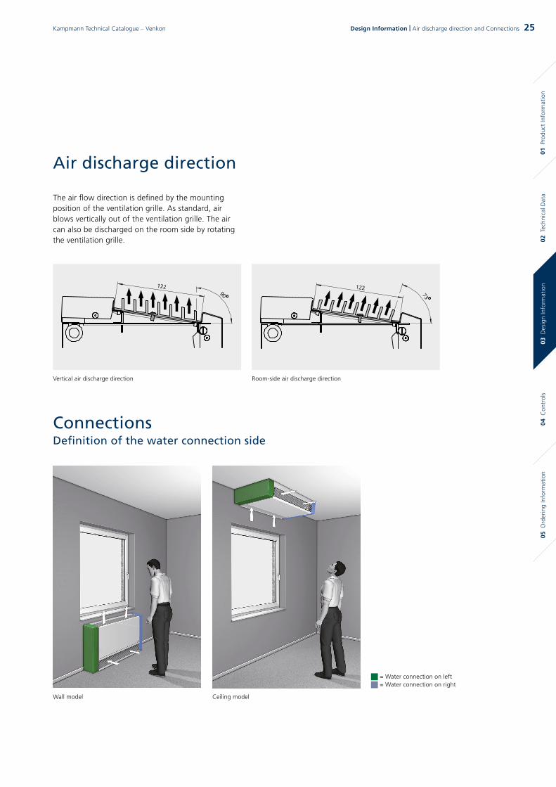
Heat exchanger versions, water connection dimensions
Vorlauf 1/2“Heizen
Rücklauf 1/2“Heizen
Rücklauf *Kühlen
Vorlauf *Kühlen
Vorlauf *
Rücklauf *
2-pipe, 4-row
Valve kit 422 wall-mounted
Valve kit 442 wall-mounted
Valve kit 222 wall-mounted
Valve kit 242 wall-mounted
4-pipe, 4-row(All dimensions in mm)
* Models 1 – 4: 1 / 2“, Models 5 – 7: 3 / 4“
Vorlauf 1/2“Heizen
Rücklauf 1/2“Heizen
Rücklauf *Kühlen
Vorlauf *Kühlen
Vorlauf *
Rücklauf *
Water connection accessories, selection of valve kit based on the example of the Venkon AC
Please note that the flow/return is provided on the top of bottom of the unit depending on the valve kit.
Flow *1/2“ flow
pipe for heating
for cooling
for cooling
for heating
Flow pipe *
Return pipe *
1/2“ return pipe
Ritorno*
26 Kampmann Technical Catalogue – Venkon26 Design Information | Connections

max
. 500
0 m
m
Provide the following service hatch dimensions for maintenance and inspection of suspended ceiling units.
Condensation is produced if Venkons are operated at a temperature below the dew point. The condensation from the heat exchanger drips into the condensation tray underneath. You will need a condensation pump (optional accessories) should a natural gradient be impossible on site.This is used to pump the condensation into higher collection or discharge equipment.
The condensation to be disposed of from the Venkon, directly from the condensation tray or from the condensation pump, but has to have a minimum 2% gradient. The condensation has to be collected in a pool pump on site if it has to be drained higher than the integrated pump allows.
Service hatch
Condensation drain
Schematic diagram
ModelService hatch
width
[mm]
1 900
2 1050
3 1200
4 1350
5 1500
6 1650
7 2050
Revisionsö�nung (900 - 2050)
Revi
sion
sö�n
ung
(700
)
BG 1 - 900BG 2 - 1050BG 3 - 1200BG 4 - 1350BG 5 - 1500BG 6 - 1650BG 7 - 2050
Service hatch (900 - 2050)
Serv
ice
hatc
h (7
00)
04 C
ontr
ols
05 O
rder
ing
Info
rmat
ion
02 T
echn
ical
Dat
a01
Pro
duct
Info
rmat
ion
03 D
esig
n In
form
atio
n
27Kampmann Technical Catalogue – Venkon Design Information | Connections

04 Controls
KaController operating unit
The „face“ of the KaControl building automation system is the KaController unit.
Product features high-quality designed wall-mounted room
operating units with or without side function keys plastic housing colour similar to RAL 9010 communication interface to Kampmann
T-LAN bus system push-turn navigator with endless turn/lock function integrated weekly switching program password-protected parameter level
KaControl –The all-inclusive solution
Kampmann Venkon units complete with KaControl operating units are supplied fully wired and factory-fitted with all electrical parts ready for connection.
Each Venkon unit is fitted with an electrical fuse. A high-performance parameterisable microprocessor is designed to carry out all the necessary functions. That way, every fan convector is equipped with its own “intelligence” and can be operated in groups via Kampmann-T-LAN or Modbus networks in groups.
Connection to building automation systemsVenkon units configured for use with KaControl can be equipped with plug-in communication interfaces for controlled operation in individual rooms or for linking into higher-order control systems: BACnet, CANbus, LON, KNX and Modbus.
KaControlThe parameterisable KaControl offers a wide range of functions: optional: three fan stages or automatic fan mode valve control for 2-pipe/ 4-pipe applications
(heating/cooling) for thermoelectric valve actuators integrated timer program for programming day
and week switching functions in the KaController unit
motor monitoring with fault signal processing
Motor protectionAny malfunction of the motor, e.g. from overloading, is evaluated by the integral control, which then switches the fan off.
28 Kampmann Technical Catalogue – VenkonControls | KaControl and Electromechanical control

KaControl group formation, max. 6 units
Accessories: Operating unit with temperature measurement: 196003210001 or 196003210002
Total per group, max. 6 units
230V / 50Hz
230V / 50Hz 3
3
3 ** 2 *
2 ** 2 **
2 *
max. 30 m
max
. 30
m
Master Slave
Stand-alone unit, KaControl
Accessories: Operating unit with temperature measurement: 196003210001 or 196003210002
230V / 50Hz
Accessories: Room sensor, 196003250110
Accessories: Clip-on pipe sensor, 196003250115
3
2 *
max
. 30
m
Potential-free input and H/C sensors canbe used for the master unit.
If required, the temperature can be measured separately by a room or air intake sensor for each unit.
3 **
Layout Plan – Venkon with KaControl
* Connection e.g. as NYM, sized according to cable length.** CAT5 connection (AWG 23 or equivalent), linear wiring.
03 D
esig
n In
form
atio
n05
Ord
erin
g In
form
atio
n02
Tec
hnic
al D
ata
01 P
rodu
ct In
form
atio
n04
Con
trol
s
29Kampmann Technical Catalogue – Venkon Controls | Layout Plan (Venkon with KaControl)
KaControl group formation, max. 30 units
Accessories: Operating unit with temperature measurement: 196003210001 or 196003210002
Total per group, max. 30 units
230V / 50Hz
230V / 50Hz 3
3
3 **
3 ** 3 *
max. 300 m
max
. 30
m
Master SlaveC
C C Accessories: Canbus card, 196003260301
The master unit and final slave unit have to befitted with a 120-ohm resistor on site.
If required, the temperature can be measured separately by a room or air intake sensor for each unit.
* CAT5 connection (AWG 23 or equivalent), linear wiring.
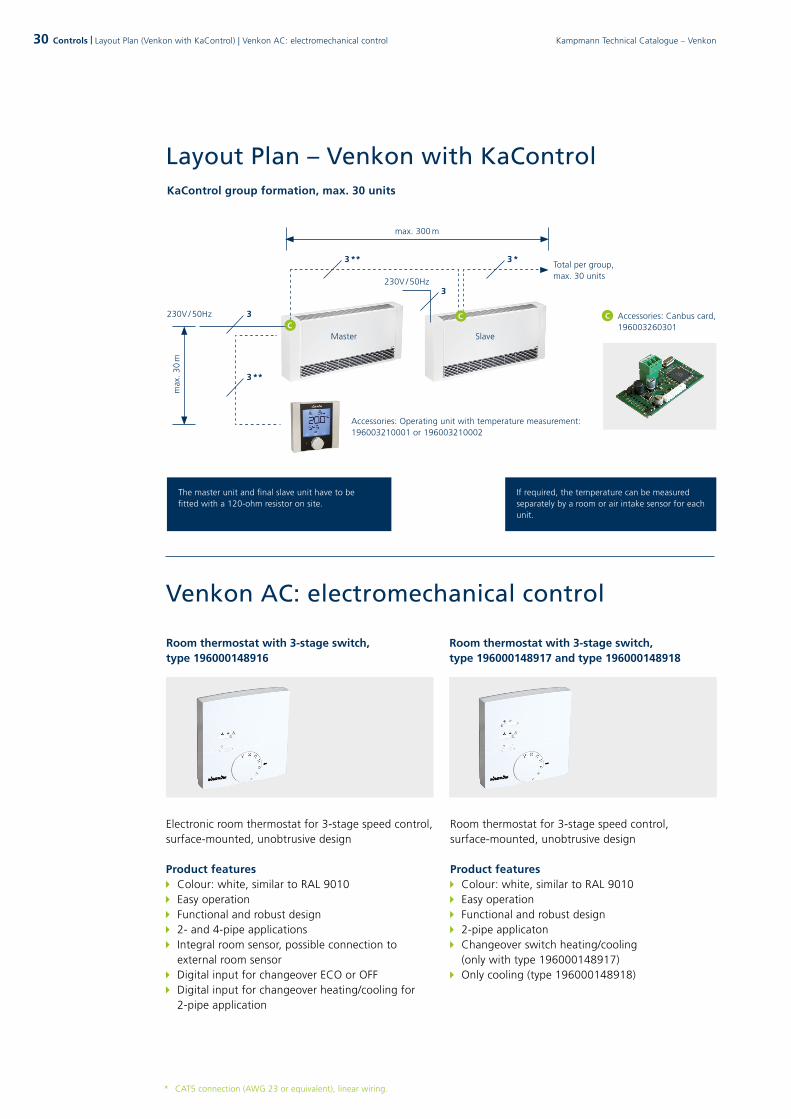
Controls | Layout Plan (Venkon with KaControl) | Venkon AC: electromechanical control
Electronic room thermostat for 3-stage speed control, surface-mounted, unobtrusive design
Product features Colour: white, similar to RAL 9010 Easy operation Functional and robust design 2- and 4-pipe applications Integral room sensor, possible connection to
external room sensor Digital input for changeover ECO or OFF Digital input for changeover heating/cooling for
2-pipe application
Room thermostat for 3-stage speed control, surface-mounted, unobtrusive design
Product features Colour: white, similar to RAL 9010 Easy operation Functional and robust design 2-pipe applicaton Changeover switch heating/cooling
(only with type 196000148917) Only cooling (type 196000148918)
Room thermostat with 3-stage switch, type 196000148916
Room thermostat with 3-stage switch,type 196000148917 and type 196000148918
Venkon AC: electromechanical control
Layout Plan – Venkon with KaControl
30 Kampmann Technical Catalogue – Venkon

Control engineering | Venkon AC, electromechanical control
Information on cable laying:* Shielded cable to be used, e.g. J-Y(St)Y 2 x 2 x 0,8 mm or equivalent, to be laid separately from high voltage lines.
Layout drawing for Venkon AC, 2- and 4-pipe system, electromechanical, control via room thermostat, type 196000148916
Layout drawing for Venkon AC, 2- and 4-pipe system, electromechanical, control via room thermostat, type 196000148917 and 196000148918
3
8
8
Room thermostat with 3-stage switch,type 196000148916 (2- and 4-pipe systems)
Maximum two fan convectors in parallel!
Mains 230V/50HzFuses by others
Optionally:Room sensor,
type 196000148921
Optionally: Activation
ECO or OFF
Optionally: Changeover
heating/cooling
max. 50 m
2*
max. 50 m
2*
max. 50 m
2*
3
7
7
Room thermostat with 3-stage switch,type 196000148917 (with changeover switch heating/cooling),type 196000148918 (only cooling)
Maximum two fan convectors in parallel!
Mains 230V/50HzFuses by others
03 D
esig
n In
form
atio
n05
Ord
erin
g In
form
atio
n02
Tec
hnic
al D
ata
01 P
rodu
ct In
form
atio
n04
Con
trol
s
31Kampmann Technical Catalogue – Venkon 31

Climate controller for 3-stage speed control, surface-mounted, unobtrusive design
Product features Colour: white, similar to RAL9010 Easy operation Functional and robust design 2- and 4-pipe applications Operating mode Day/Eco/Off with room frost
protection function Integral room sensor, possible connection to
external room sensors Digital input for changeover ECO or OFF Digital input for changeover heating/cooling for
2-pipe application
Climate controller for 10-stepped speed control, surface-mounted, unobtrusive design
Product features Colour: white, similar to RAL 9010 Mounted onto a flush-mounted box, can be
installed in switch range with grid dimensions 50 x 50 mm
2- and 4-pipe applications Display with adjustable background lighting 4 operating touch keys Time switch with automatic changeover switch
summer/winter time Operating mode Day/ECO/Off with room frost
protection function Integral room sensor, possible connection to
external room sensor Digital input for changeover ECO or OFF Digital input for changeover heating/cooling for
2-pipe applications
Climate controller, type 196000030155 Climate controller, type 19600030256
Venkon EC: electromechanical control
32 Regelungstechnik | Control engineering Venkon EC: electromechanical control32 Kampmann Technical Catalogue – Venkon

Layout drawing for Venkon EC, 2- and 4-pipe system, electromechanical, control via climate controller, type 196000030155
Layout drawing for Venkon EC, 2- and 4-pipe system, electromechanical, control via climate controller, type 196000030256
3
2*
2*
5
5
Climate controller,type 196000030155
Maximum two fan convectors in parallel!
Mains 230V/50HzFuses by others
Optionally: Room sensor,
type 196000148921
Optionally: Activation
ECO or OFF
Optionally: Changeover
heating/cooling
max. 30 m
max. 30 m
2*
max. 50 m
2*
max. 50 m
2*
3
2*
2*
5
5
Climate controller with time switch, type 196000030256
Maximum two fan convectors in parallel!
Mains 230V/50HzFuses by others
Optionally: Room sensor,
type 196000148921
Optionally: Activation
ECO or OFF
Optionally: Changeover
heating/cooling
max. 30 m
max. 30 m
2*
max. 50 m
2*
max. 50 m
2*
33Control engineering | Venkon EC: electromechanical control
Information on cable laying:* Shielded cable to be used, e.g. J-Y(St)Y 2 x 2 x 0,8 mm or equivalent, to be laid separately from high voltage lines.
03 D
esig
n In
form
atio
n05
Ord
erin
g In
form
atio
n02
Tec
hnic
al D
ata
01 P
rodu
ct In
form
atio
n04
Con
trol
s
33Kampmann Technical Catalogue – Venkon
Mo
del
Air
vo
lum
e
SSo
un
d
pre
ssu
re
leve
l 1)
2-/ 4
-ro
ws
Hea
t o
utp
ut
QH
2)
Co
olin
g o
ut-
pu
t Q
K 3)
Co
ntr
ol
op
tio
ns*
No. Art.
[m³/h] [dB(A)] [kW] [kW]
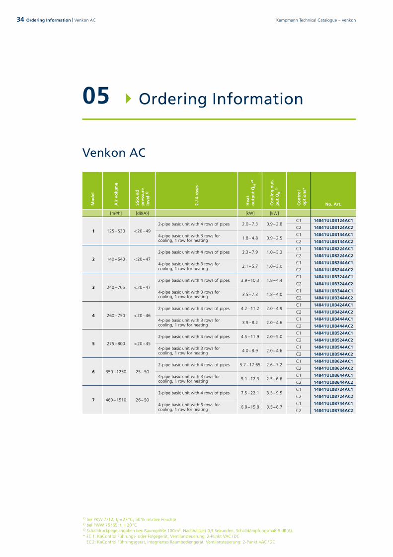
1 125 – 530 < 20 – 49
2-pipe basic unit with 4 rows of pipes 2.0 – 7.3 0.9 – 2.8C1 14841UL0B124AC1
C2 14841UL0B124AC2
4-pipe basic unit with 3 rows for cooling, 1 row for heating 1.8 – 4.8 0.9 – 2.5
C1 14841UL0B144AC1
C2 14841UL0B144AC2
2 140 – 540 < 20 – 47
2-pipe basic unit with 4 rows of pipes 2.3 – 7.9 1.0 – 3.3C1 14841UL0B224AC1
C2 14841UL0B224AC2
4-pipe basic unit with 3 rows for cooling, 1 row for heating 2.1 – 5.7 1.0 – 3.0
C1 14841UL0B244AC1
C2 14841UL0B244AC2
3 240 – 705 < 20 – 47
2-pipe basic unit with 4 rows of pipes 3.9 – 10.3 1.8 – 4.4C1 14841UL0B324AC1
C2 14841UL0B324AC2
4-pipe basic unit with 3 rows for cooling, 1 row for heating 3.5 – 7.3 1.8 – 4.0
C1 14841UL0B344AC1
C2 14841UL0B344AC2
4 260 – 750 < 20 – 46
2-pipe basic unit with 4 rows of pipes 4.2 – 11.2 2.0 – 4.9C1 14841UL0B424AC1
C2 14841UL0B424AC2
4-pipe basic unit with 3 rows for cooling, 1 row for heating 3.9 – 8.2 2.0 – 4.6
C1 14841UL0B444AC1
C2 14841UL0B444AC2
5 275 – 800 < 20 – 45
2-pipe basic unit with 4 rows of pipes 4.5 – 11.9 2.0 – 5.0C1 14841UL0B524AC1
C2 14841UL0B524AC2
4-pipe basic unit with 3 rows for cooling, 1 row for heating 4.0 – 8.9 2.0 – 4.6
C1 14841UL0B544AC1
C2 14841UL0B544AC2
6 350 – 1230 25 – 50
2-pipe basic unit with 4 rows of pipes 5.7 – 17.65 2.6 – 7.2C1 14841UL0B624AC1
C2 14841UL0B624AC2
4-pipe basic unit with 3 rows for cooling, 1 row for heating 5.1 – 12.3 2.5 – 6.6
C1 14841UL0B644AC1
C2 14841UL0B644AC2
7 460 – 1510 26 – 50
2-pipe basic unit with 4 rows of pipes 7.5 – 22.1 3.5 – 9.5C1 14841UL0B724AC1
C2 14841UL0B724AC2
4-pipe basic unit with 3 rows for cooling, 1 row for heating 6.8 – 15.8 3.5 – 8.7
C1 14841UL0B744AC1
C2 14841UL0B744AC2
05 Ordering Information
Venkon AC
1) bei PKW 7 / 12, tL = 27 °C, 50 % relative Feuchte2) bei PWW 75 / 65, tL = 20 °C3) Schalldruckpegelangaben bei: Raumgröße 100 m3, Nachhallzeit 0,5 Sekunden, Schalldämpfungsmaß 9 dB(A).* EC 1: KaControl Führungs- oder Folgegerät, Ventilansteuerung: 2-Punkt VAC / DC
EC 2: KaControl Führungsgerät, integriertes Raumbediengerät, Ventilansteuerung: 2-Punkt VAC / DC
34 Kampmann Technical Catalogue – VenkonOrdering Information | Venkon AC
Venkon EC
Mo
del
Air
vo
lum
e
SSo
un
d
pre
ssu
re
leve
l 1)
2-/ 4
-ro
ws
Hea
t o
utp
ut
QH
2)
Co
olin
g o
ut-
pu
t Q
K 3)
Co
ntr
ol
op
tio
ns*
No. Art.
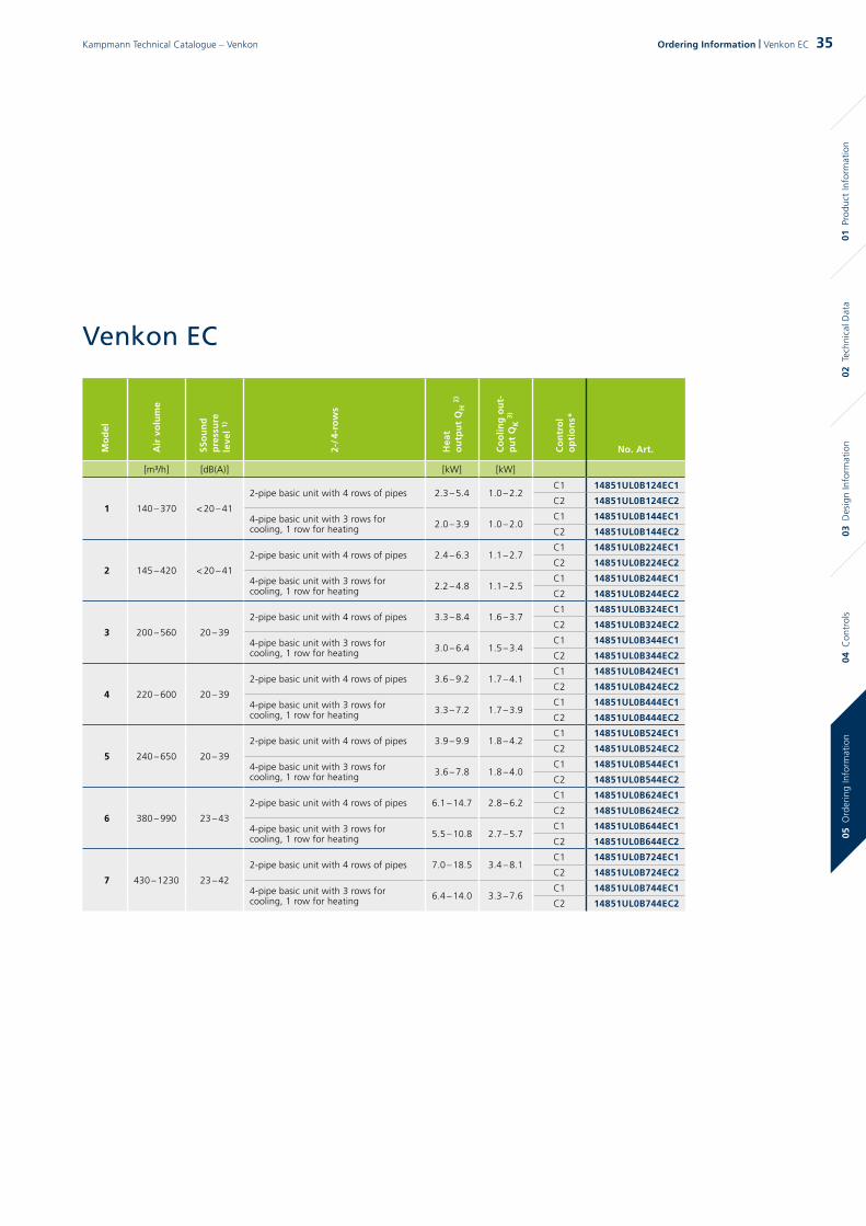
[m³/h] [dB(A)] [kW] [kW]
1 140 – 370 < 20 – 41
2-pipe basic unit with 4 rows of pipes 2.3 – 5.4 1.0 – 2.2C1 14851UL0B124EC1
C2 14851UL0B124EC2
4-pipe basic unit with 3 rows for cooling, 1 row for heating 2.0 – 3.9 1.0 – 2.0
C1 14851UL0B144EC1
C2 14851UL0B144EC2
2 145 – 420 < 20 – 41
2-pipe basic unit with 4 rows of pipes 2.4 – 6.3 1.1 – 2.7C1 14851UL0B224EC1
C2 14851UL0B224EC2
4-pipe basic unit with 3 rows for cooling, 1 row for heating 2.2 – 4.8 1.1 – 2.5
C1 14851UL0B244EC1
C2 14851UL0B244EC2
3 200 – 560 20 – 39
2-pipe basic unit with 4 rows of pipes 3.3 – 8.4 1.6 – 3.7C1 14851UL0B324EC1
C2 14851UL0B324EC2
4-pipe basic unit with 3 rows for cooling, 1 row for heating 3.0 – 6.4 1.5 – 3.4
C1 14851UL0B344EC1
C2 14851UL0B344EC2
4 220 – 600 20 – 39
2-pipe basic unit with 4 rows of pipes 3.6 – 9.2 1.7 – 4.1C1 14851UL0B424EC1
C2 14851UL0B424EC2
4-pipe basic unit with 3 rows for cooling, 1 row for heating 3.3 – 7.2 1.7 – 3.9
C1 14851UL0B444EC1
C2 14851UL0B444EC2
5 240 – 650 20 – 39
2-pipe basic unit with 4 rows of pipes 3.9 – 9.9 1.8 – 4.2C1 14851UL0B524EC1
C2 14851UL0B524EC2
4-pipe basic unit with 3 rows for cooling, 1 row for heating 3.6 – 7.8 1.8 – 4.0
C1 14851UL0B544EC1
C2 14851UL0B544EC2
6 380 – 990 23 – 43
2-pipe basic unit with 4 rows of pipes 6.1 – 14.7 2.8 – 6.2C1 14851UL0B624EC1
C2 14851UL0B624EC2
4-pipe basic unit with 3 rows for cooling, 1 row for heating 5.5 – 10.8 2.7 – 5.7
C1 14851UL0B644EC1
C2 14851UL0B644EC2
7 430 – 1230 23 – 42
2-pipe basic unit with 4 rows of pipes 7.0 – 18.5 3.4 – 8.1C1 14851UL0B724EC1
C2 14851UL0B724EC2
4-pipe basic unit with 3 rows for cooling, 1 row for heating 6.4 – 14.0 3.3 – 7.6
C1 14851UL0B744EC1
C2 14851UL0B744EC2
03 D
esig
n In
form
atio
n04
Con
trol
s02
Tec
hnic
al D
ata
01 P
rodu
ct In
form
atio
n05
Ord
erin
g In
form
atio
n
35Kampmann Technical Catalogue – Venkon Ordering Information | Venkon EC

Accessories
Figure Article Properties Suitable for Art. No.
Casings
Casing, wall-mounted without intake grille
Model 1 14832UB0W102
Model 2 14832UB0W202
Model 3 14832UB0W302
Model 4 14832UB0W402
Model 5 14832UB0W502
Model 6 14832UB0W602
Model 7 14832UB0W702
Casing, wall-standing with intake grille
Model 1 14832UB1W102
Model 2 14832UB1W202
Model 3 14832UB1W302
Model 4 14832UB1W402
Model 5 14832UB1W502
Model 6 14832UB1W602
Model 7 14832UB1W702
Free-standing casing with rear panel, without intake grille
Model 1 14832UB0S102
Model 2 14832UB0S202
Model 3 14832UB0S302
Model 4 14832UB0S402
Model 5 14832UB0S502
Model 6 14832UB0S602
Model 7 14832UB0S702
Ceiling-mounted casing with intake grille and end panel
Model 1 14832UB1D102
Model 2 14832UB1D202
Model 3 14832UB1D302
Model 4 14832UB1D402
Model 5 14832UB1D502
Model 6 14832UB1D602
Model 7 14832UB1D702
more »
Dimensions
Model B C
[mm] [mm]
1 850 628
2 1000 778
3 1150 928
4 1300 1078
5 1450 1228
6 1600 1378
7 2000 1778
36 Kampmann Technical Catalogue – VenkonOrdering Information | Accessories

Figure Article Properties Suitable for Art. No.
Accessories for recirculating air basic unit, water-side, pre-fitted
Valve kit 222
Wall-mounted water connection on left
2-pipe model with adjustable 2-way valve with 2-point actuator 24 V AC/DC Open/Close with return shut-off valve
all models, combinable controls:-00, -C1, -C2
14833AL2W1202
Wall-mounted water connection on right
14833AR2W1202
Ceiling-mounted water connection on left
14833AL2D1202
Ceiling-mounted water connection on right
14833AR2D1202
Valve kit 242
Wall-mounted water connection on left
4-pipe model with adjustable 2-way valve with 2-point actuator 24 V AC/DC Open/Close with return shut-off valve
all models, combinable controls:-00, -C1, -C2
14833AL2W1402
Wall-mounted water connection on right
14833AR2W1402
Ceiling-mounted water connection on left
14833AL2D1402
Ceiling-mounted water connection on right
14833AR2D1402
Valve kit 422
Wall-mounted water connection on left
2-pipe unit with 4-way valvewith 2-point actuator 24 V AC/DC Open/Close
all models, combinable controls:-00, -C1, -C2
14833AL4W1202
Wall-mounted water connection on right
14833AR4W1202
Ceiling-mounted water connection on left
14833AL4D1202
Ceiling-mounted water connection on right
14833AR4D1202
Valve kit 442
Wall-mounted water connection on left
4-pipe unit with 4-way valvewith 2-point actuator 24 V AC/DC Open/Close
all models, combinable controls:-00, -C1, -C2
14833AL4W1402
Wall-mounted water connection on right
14833AR4W1402
Ceiling-mounted water connection on left
14833AL4D1402
Ceiling-mounted water connection on right
14833AR4D1402
more »
Article key Model (Example of art. no.)
14833AL2W1202 Model 1 Model 2 Model 3 Model 4 Model 5 Model 6 Model 7
2 3 4 5 6 7
Please note that the flow/return is provided on the top of bottom of the unit.
03 D
esig
n In
form
atio
n04
Con
trol
s02
Tec
hnic
al D
ata
01 P
rodu
ct In
form
atio
n05
Ord
erin
g In
form
atio
n
37Kampmann Technical Catalogue – Venkon Ordering Information | Accessories
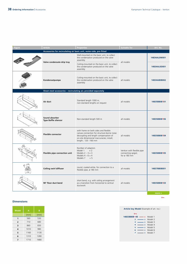
Figure Article Properties Suitable for Art. No.
Accessories for recirculating air basic unit, water-side, pre-fitted
Valve condensate drip tray
Wall-mounted on the basic unit, to collect the condensation produced on the valve assembly
all models
14834AL0W001
Ceiling-mounted on the basic unit, to collect the condensation produced on the valve assembly
14834AL0D001
KondensatpumpeCeiling-mounted on the basic unit, to collect the condensation produced on the valve assembly
all models 14834AB0B002
Sheet steel accessories – recirculating air, provided separately
Seite 8 Seite 9
Seite 10
Abstand zur Decke 15 mm bei Verwendung des Mauerrahmes Typ 14833B70B*00
Wanddurchbruch Rahmenanschlussmaße
50
Air ductStandard length 1000 m, non-standard lengths on request
all models 14835BB0B101
Seite 8 Seite 9
Seite 10
Abstand zur Decke 15 mm bei Verwendung des Mauerrahmes Typ 14833B70B*00
Wanddurchbruch Rahmenanschlussmaße
50
Sound absorberType Baffle silencer
Non-standard length 500 m all models 14835BB0B106
Seite 8 Seite 9
Seite 10
Abstand zur Decke 15 mm bei Verwendung des Mauerrahmes Typ 14833B70B*00
Wanddurchbruch Rahmenanschlussmaße
50
Flexible connector
with frame on both sides and flexible canvas connection for structure-borne noise decoupling and length compensation of on-site dimensional inaccuracies; install, length.: 120 –160 mm
all models 14835BB0B104
Seite 8 Seite 9
Seite 10
Abstand zur Decke 15 mm bei Verwendung des Mauerrahmes Typ 14833B70B*00
Wanddurchbruch Rahmenanschlussmaße
50 Flexible pipe connection unit
Number of adaptors Model 1 = 2Models 2 – 3 = 3Models 4 – 6 = 4Models 7 = 5
Venkon with flexible pipe connecting spigot; for ø 180 mm
14835BB0B105
Seite 8 Seite 9
Seite 10
Abstand zur Decke 15 mm bei Verwendung des Mauerrahmes Typ 14833B70B*00
Wanddurchbruch Rahmenanschlussmaße
50
Ceiling swirl diffuserround, coated white, for connection to a flexible pipe, ø 180 mm
all models 14837BB0B001
Seite 8 Seite 9
Seite 10
Abstand zur Decke 15 mm bei Verwendung des Mauerrahmes Typ 14833B70B*00
Wanddurchbruch Rahmenanschlussmaße
50
90° floor duct bendshort bend, e.g. with ceiling arrangement as a transition from horizontal to vertical ductwork
all models 14835BB0B103
more »
Article key Model (Example of art. no.)
14833BB0B100 Model 1 Model 2 Model 3 Model 4 Model 5 Model 6 Model 7
2 3 4 5 6 7
Dimensions
Model A B
[mm] [mm]
1 560 530
2 710 680
3 860 830
4 1010 980
5 1160 1130
6 1310 1280
7 1710 1680
38 Kampmann Technical Catalogue – VenkonOrdering Information | Accessories

Figure Article Properties Suitable for Art. No.
Sheet steel accessories – recirculating air, provided separately
Seite 8 Seite 9
Seite 10
Abstand zur Decke 15 mm bei Verwendung des Mauerrahmes Typ 14833B70B*00
Wanddurchbruch Rahmenanschlussmaße
50
Internal air grille,with frame
for air intake and outletHeight when installed H = 32 mmColour: natural aluminiumfree cross-section: 65 %
all models 14837BB0B102
Seite 8 Seite 9
Seite 10
Abstand zur Decke 15 mm bei Verwendung des Mauerrahmes Typ 14833B70B*00
Wanddurchbruch Rahmenanschlussmaße
50
Replacement filter G2 (EU2) grade dry layer filter all models 14839BB0B102
Seite 8 Seite 9
Seite 10
Abstand zur Decke 15 mm bei Verwendung des Mauerrahmes Typ 14833B70B*00
Wanddurchbruch Rahmenanschlussmaße
50
Intake box withprimary air spigots
Unit for installation onto the air intake of the Venkon unit, dimensions of connection pieces DN 100
all models 14835BB0B107
Seite 8 Seite 9
Seite 10
Abstand zur Decke 15 mm bei Verwendung des Mauerrahmes Typ 14833B70B*00
Wanddurchbruch Rahmenanschlussmaße
50
Discharge box withprimary air spigots
Unit for installation onto the air discharge of the Venkon unit, dimensions of connection pieces DN 100
all models 14835BB0B108
more »
Article key Model (Example of art. no.)
14833BB0B100 Model 1 Model 2 Model 3 Model 4 Model 5 Model 6 Model 7
2 3 4 5 6 7
Seite 8 Seite 9
Seite 10
Abstand zur Decke 15 mm bei Verwendung des Mauerrahmes Typ 14833B70B*00
Wanddurchbruch Rahmenanschlussmaße
50
Dimensions / Frame mounting dimensions
Model A B C D M
[mm] [mm] [mm] [mm] [mm]
1 560 530 272,5 – 580
2 710 680 347,5 – 730
3 860 830 422,5 – 880
4 1010 980 497,5 – 1030
5 1160 1130 572,5 – 1180
6 1310 1280 647,5 – 1330
7 1710 1680 427,5 420 1730
Frame connecting dimensions
03 D
esig
n In
form
atio
n04
Con
trol
s02
Tec
hnic
al D
ata
01 P
rodu
ct In
form
atio
n05
Ord
erin
g In
form
atio
n
39Kampmann Technical Catalogue – Venkon Ordering Information | Accessories

Figure Article Properties Suitable for Art. No.
RegelungsAccessories KaControl
KaController room control unit with one-key operation
Room control panel for wall mounting, high-quality design, plastic housing, colour similar to RAL 9010, large multifunctional display, integral room temperature sensor, communication interface to Kampmann-T-LAN bus system, automatic LED background lighting, press/push navigator dial with endless turn/lock function, individually changeable basic display, integral day, night and week switching program, password-protected parametrisable level for control configuration C1
all models 196003210001
KaController room control unit with side operating keys
for quick access to fan setting,operating modes, Eco mode, time and timer program, otherwise as art. no. 196003210001
all models 196003210002
KaControl room temperature sensor
for wall-mounting, IP30 surface-mounted, white RAL 9010alternative to the temperature sensor in the KaController
all models 196003250110
Pipe clip-on sensor
(changeover) for decentralised heating/cooling changeover with 2-pipe systemsThe sensor can only be used in conjunction with a 3-way
all models 196003250115
Intake air sensor for room temperature measurement all models 196003250151
Serial CANBus cardto increase the number of units in a single-circuit control system
all models 196003260101
Serial Modbus card for connection to Modbus networks all models 196003260101
more »
40 Kampmann Technical Catalogue – Venkon40 Ordering Information | Accessories
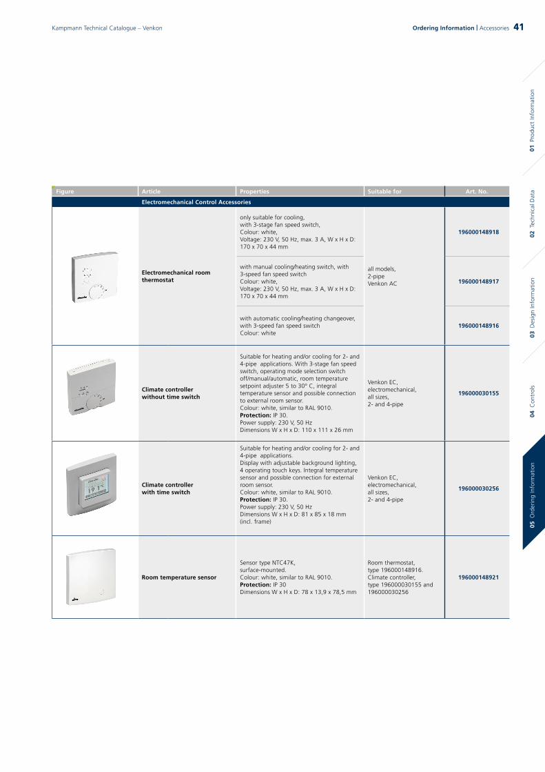
Figure Article Properties Suitable for Art. No.
Electromechanical Control Accessories
Electromechanical room thermostat
only suitable for cooling,with 3-stage fan speed switch, Colour: white,Voltage: 230 V, 50 Hz, max. 3 A, W x H x D: 170 x 70 x 44 mm
all models,2-pipeVenkon AC
196000148918
with manual cooling/heating switch, with 3-speed fan speed switch Colour: white,Voltage: 230 V, 50 Hz, max. 3 A, W x H x D: 170 x 70 x 44 mm
196000148917
with automatic cooling/heating changeover, with 3-speed fan speed switch Colour: white
196000148916
Climate controllerwithout time switch
Suitable for heating and/or cooling for 2- and 4-pipe applications. With 3-stage fan speed switch, operating mode selection switch off/manual/automatic, room temperature setpoint adjuster 5 to 30° C, integral temperature sensor and possible connection to external room sensor.Colour: white, similar to RAL 9010.Protection: IP 30.Power supply: 230 V, 50 HzDimensions W x H x D: 110 x 111 x 26 mm
Venkon EC,electromechanical,all sizes,2- and 4-pipe
196000030155
Climate controllerwith time switch
Suitable for heating and/or cooling for 2- and 4-pipe applications.Display with adjustable background lighting, 4 operating touch keys. Integral temperature sensor and possible connection for external room sensor.Colour: white, similar to RAL 9010.Protection: IP 30.Power supply: 230 V, 50 HzDimensions W x H x D: 81 x 85 x 18 mm (incl. frame)
Venkon EC,electromechanical,all sizes,2- and 4-pipe
196000030256
Room temperature sensor
Sensor type NTC47K,surface-mounted.Colour: white, similar to RAL 9010.Protection: IP 30Dimensions W x H x D: 78 x 13,9 x 78,5 mm
Room thermostat,type 196000148916.Climate controller, type 196000030155 and196000030256
196000148921
03 D
esig
n In
form
atio
n04
Con
trol
s02
Tec
hnic
al D
ata
01 P
rodu
ct In
form
atio
n05
Ord
erin
g In
form
atio
n
41Kampmann Technical Catalogue – Venkon 41Ordering Information | Accessories


43

Kampmann.co.uk/venkonKampmann.eu/venkon
Kampmann GmbHFriedrich-Ebert-Str. 128 - 13049811 Lingen (Ems)Germany
T +49 591 7108-660F +49 591 7108-173 E [email protected] Kampmann.eu
Kampmann UK Ltd.Dial House, Govett Avenue Shepperton, Middlesex, TW17 8AG Great Britain
T +44 (0)1932 228592 F +44 (0)1932 228949E [email protected] Kampmann.co.uk 38
3/11
/18
EN
Related Documents


![Langer–Schwartz–Kampmann–Wagner precipitation ......capillary effects and diffusion fluxes couplings [33]. Prior works using LSKW precipitation modelling have been performed](https://static.cupdf.com/doc/110x72/61339b45dfd10f4dd73b3283/langeraschwartzakampmannawagner-precipitation-capillary-effects-and.jpg)