*Correspondent: M. V. Karwe, Department of Food Science, PO Box 231, Cook College, Rutgers, The State University of New Jersey, New Brunswick, New Jersey 08903–0231, US. Fax: 1 1 732 932–8690. e-mail: [email protected] Velocity field in a twin-screw extruder Serafim Bakalis & Mukund V. Karwe* Department of Food Science, The State University of New Jersey, US Summary Velocity measurements inside the screw channels of a co-rotating, self-wiping, twin-screw extruder were carried out. A laser Doppler anemometer (LDA) system was used to mea- sure tangential and axial velocity components in the translational region of one of the screws of a twin-screw extruder. The velocity measurements were carried out using heavy corn syrup at different screw speeds and for two forwards conveying elements differing in their pitch. It was found that velocity profiles in the translational region were sub- stantially affected by the pitch of the screw element, however, screw speed (30–90 r.p.m.) did not have a significant effect on the shape of the velocity profiles. The range of veloc- ity values in a 14 mm pitch screw element was wider than that in a 28 mm pitch screw element. Experimentally measured velocity profiles were compared with predictions of a one-dimensional model, which showed that the model underpredicted the velocity values, for the 14 mm pitch element. Keywords Corn syrup, laser Doppler anemometry, Newtonian fluid. Introduction The use of the twin-screw extrusion process in the manufacture of food, plastics and pharmaceutical products has increased substantially in the last decade. Substantial efforts have been devoted to develop mathematical models of twin-screw extrusion processes. The solution of these mathe- matical models is usually obtained using different discretizaton methods. Due to the complicated geometry of a twin-screw extruder and complex rheological behaviour of many of the materials that are extruded, the numerical simulations of three-dimensional flow in the screw channels is carried out using a variety of methods after employing some simplifying assumptions. These simulations are usually computational resource intensive. The flow in a co-rotating twin-screw extruder has been simulated using numerical methods by several investigators (Sastrohartono et al., 1992; Tayeb et al., 1992; Yacu, 1985; Van Zuilichem et al., 1992). It must be pointed out that all of the models that are developed to describe the trans- port phenomena in an extruder must be validated with experimental data. Very often the compari- son is made in terms of quantities such as die pressure and die temperature due to ease of mea- surement of these quantities. Comparison of experimental results with numerical predictions on a local scale has been attempted by only a few investigators. For example, Esseghir & Sernas (1994) measured the radial temperature distribu- tions in the screw channel of a single-screw extruder, using a cam-driven thermocouple syn- chronized with the screw shaft rotation. Another way of making local comparisons would be in terms of velocity distribution at various locations in an extruder. Most of the data for measured velocity distrib- utions reported in the literature are for single- screw extruders. Velocity distributions in the International Journal of Food Science and Technology 1997, 32, 241–253 © 1997 Blackwell Science Ltd 241

Welcome message from author
This document is posted to help you gain knowledge. Please leave a comment to let me know what you think about it! Share it to your friends and learn new things together.
Transcript
*Correspondent: M. V. Karwe, Department of FoodScience, PO Box 231, Cook College, Rutgers, The StateUniversity of New Jersey, New Brunswick, New Jersey08903–0231, US. Fax: 1 1 732 932–8690. e-mail: [email protected]
Velocity field in a twin-screw extruder
Serafim Bakalis & Mukund V. Karwe*
Department of Food Science, The State University of New Jersey, US
Summary Velocity measurements inside the screw channels of a co-rotating, self-wiping, twin-screwextruder were carried out. A laser Doppler anemometer (LDA) system was used to mea-sure tangential and axial velocity components in the translational region of one of thescrews of a twin-screw extruder. The velocity measurements were carried out using heavycorn syrup at different screw speeds and for two forwards conveying elements differingin their pitch. It was found that velocity profiles in the translational region were sub-stantially affected by the pitch of the screw element, however, screw speed (30–90 r.p.m.)did not have a significant effect on the shape of the velocity profiles. The range of veloc-ity values in a 14 mm pitch screw element was wider than that in a 28 mm pitch screwelement. Experimentally measured velocity profiles were compared with predictions of aone-dimensional model, which showed that the model underpredicted the velocity values,for the 14 mm pitch element.
Keywords Corn syrup, laser Doppler anemometry, Newtonian fluid.
Introduction
The use of the twin-screw extrusion process in themanufacture of food, plastics and pharmaceuticalproducts has increased substantially in the lastdecade. Substantial efforts have been devoted todevelop mathematical models of twin-screwextrusion processes. The solution of these mathe-matical models is usually obtained using differentdiscretizaton methods. Due to the complicatedgeometry of a twin-screw extruder and complexrheological behaviour of many of the materialsthat are extruded, the numerical simulations ofthree-dimensional flow in the screw channels iscarried out using a variety of methods afteremploying some simplifying assumptions. Thesesimulations are usually computational resourceintensive.
The flow in a co-rotating twin-screw extruderhas been simulated using numerical methods byseveral investigators (Sastrohartono et al., 1992;Tayeb et al., 1992; Yacu, 1985; Van Zuilichem etal., 1992). It must be pointed out that all of themodels that are developed to describe the trans-port phenomena in an extruder must be validatedwith experimental data. Very often the compari-son is made in terms of quantities such as diepressure and die temperature due to ease of mea-surement of these quantities. Comparison ofexperimental results with numerical predictionson a local scale has been attempted by only a fewinvestigators. For example, Esseghir & Sernas(1994) measured the radial temperature distribu-tions in the screw channel of a single-screwextruder, using a cam-driven thermocouple syn-chronized with the screw shaft rotation. Anotherway of making local comparisons would be interms of velocity distribution at various locationsin an extruder.
Most of the data for measured velocity distrib-utions reported in the literature are for single-screw extruders. Velocity distributions in the
International Journal of Food Science and Technology 1997, 32, 241–253
© 1997 Blackwell Science Ltd
241
screw channels of a single-screw extruder wereobtained either by tracing particles or ink inject-ed in the flow (Choo et al., 1980; Eccher &Valentinotti, 1958) or by using a non-invasivetechnique such as NMR (McCarthy et al., 1992).Eccher & Valentinotti, using photographic tech-niques, reported some cross-wise circulatorymotion within the screw channel. The correctnessof the shallow-channel theory in a single-screwextruder was confirmed by Mohr et al. (1961).Numerical results obtained using a finite-difference method were found to be in reasonablygood agreement with velocity measurements per-formed in deep-channel screw elements by Chooet al. (1980).
Few data for experimentally measured velocitypatterns have been published for a twin-screwextruder. Karwe & Sernas (1996) showed thatlaser Doppler anemometry (LDA) can be used tomeasure velocity distributions in a twin-screwextruder using model fluids. They measured axialand tangential velocity profiles in the translation-al region of a twin-screw extruder using cornsyrup for a 28 mm screw element at a fixed screwspeed of 30 r.p.m. The tangential velocity pat-terns were compared with numerically predictedprofiles of Chiruvella et al. (1996). The measuredvalues were higher than the numerically predictedvalues.
Karwe et al. (1997) have reported velocity mea-surements in the nip region of a twin-screwextruder. The measured velocity distributionsindicated a three dimensional flow. Leakage flowbetween the two screws, sometimes referred to as
transfer flow, was also detected with the LDAtechnique.
This paper reports velocity measurementsunder isothermal conditions for a Newtonianfluid in the translational region of a co-rotatingtwin-screw extruder, for two different forwards-conveying screw elements, differing in their pitch.The effect of screw speed on the measured veloc-ity distribution was also examined. Althoughmost food materials have a non-Newtonianbehaviour, a Newtonian fluid was chosen as amodel fluid for the initial investigation reportedin this paper. Future investigations will includemodel non-Newtonian fluids.
Materials and methods
Experimental set up
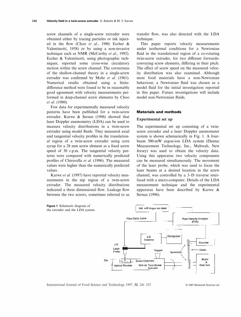
The experimental set up consisting of a twin-screw extruder and a laser Doppler anemometersystem is shown schematically in Fig. 1. A four-beam 300-mW argon-ion LDA system (DantecMeasurement Technology, Inc., Mahwah, NewJersey) was used to obtain the velocity data.Using this apparatus two velocity componentscan be measured simultaneously. The movementof the laser probe, which was used to focus thelaser beams at a desired location in the screwchannel, was controlled by a 3–D traverse inter-faced with a micro-computer. Details of the LDAmeasurement technique and the experimentalapparatus have been described by Karwe &Sernas (1996).
Velocity field in a twin-screw extruder S. Bakalis & M. V. Karwe
International Journal of Food Science and Technology 1997, 32, 241–253
242
© 1997 Blackwell Science Ltd
Figure 1 Schematic diagram ofthe extruder and the LDA system.
Velocity measurements were made in the screwchannels of a ZSK-30 twin-screw extruder(Werner & Pfleiderer Corp., Ramsey, New Jersey).This is a co-rotating, self-wiping, twin-screwextruder. The internal diameter of each of the bar-rel bores (D) was 30.85 mm and the L/D ratio was29, where L is the total length of the screws. Themaximum channel depth for the screws is 4.77mm. A Plexiglas window was constructed andfitted into the vent port of the extruder to accessthe flow in the screw channels for velocity mea-surements (see Fig. 1). The screw configurationused in these experiments was assembled by usingforwards-conveying elements (low shear) only.The die used had two 5-mm long holes of 3.6 mmdiameter each. The hopper through which thescrews were fed was always kept full. The screwelements in the feed section had wider screw chan-nels as compared with the rest of the screw ele-ments. This ensured that the two screws werecompletely filled with syrup. This also resulted indifferent mass flow rates at different screw speeds,like a single-screw extruder.
LDA measurements require optically transpar-ent materials for laser beams to penetrate andscattered light to come out. Therefore, heavy cornsyrup (Globe corn syrup 1132, Corn-ProductsInternational, Summit-Argo, Illinois), which is aNewtonian fluid of 1425 kg m23 density, 1.49refractive index and shear viscosities of 74.0, 17.5and 0.54 Pas at 26.6, 37.8 and 48.9i8C, respec-tively, was selected as the working fluid.
Screw elements
Velocity profiles were measured for two forwards-
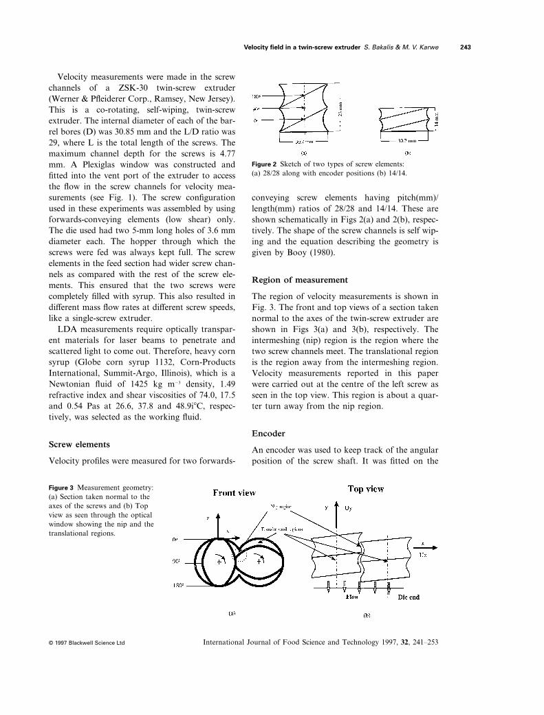
conveying screw elements having pitch(mm)/length(mm) ratios of 28/28 and 14/14. These areshown schematically in Figs 2(a) and 2(b), respec-tively. The shape of the screw channels is self wip-ing and the equation describing the geometry isgiven by Booy (1980).
Region of measurement
The region of velocity measurements is shown inFig. 3. The front and top views of a section takennormal to the axes of the twin-screw extruder areshown in Figs 3(a) and 3(b), respectively. Theintermeshing (nip) region is the region where thetwo screw channels meet. The translational regionis the region away from the intermeshing region.Velocity measurements reported in this paperwere carried out at the centre of the left screw asseen in the top view. This region is about a quar-ter turn away from the nip region.
Encoder
An encoder was used to keep track of the angularposition of the screw shaft. It was fitted on the
Velocity field in a twin-screw extruder S. Bakalis & M. V. Karwe
International Journal of Food Science and Technology 1997, 32, 241–253
243
© 1997 Blackwell Science Ltd
Figure 3 Measurement geometry:(a) Section taken normal to theaxes of the screws and (b) Topview as seen through the opticalwindow showing the nip and thetranslational regions.
Figure 2 Sketch of two types of screw elements:(a) 28/28 along with encoder positions (b) 14/14.
back end of the left screw shaft. The encoder gavea 2.5 VDC pulse for every 0.72 degrees of shaftrotation (500 pulses per revolution) and a 5 VDCpulse at every full rotation. This signal wasreceived by the flow velocity analyser (FVA, inFig. 1) and it was combined with the measuredvelocity data. A reference position of 08 was setwhen the left screw lobe was vertical, as shown inFigs 2(a) and 3(a). This was arbitrary. However,it was not important where the 08 position wasselected as it did not affect the results. From theencoder position, the axial location in the screwchannel where velocity data were obtained wasknown. The right screw shaft had a phasedifference of 908 with respect to the left shaft.Hence, the orientation of one screw lobe auto-matically defined the orientation of the otherscrew lobe.
Correction for refraction
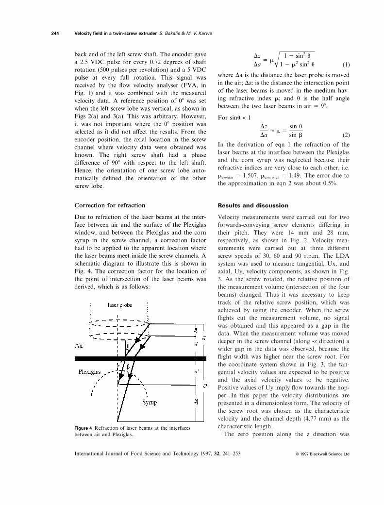
Due to refraction of the laser beams at the inter-face between air and the surface of the Plexiglaswindow, and between the Plexiglas and the cornsyrup in the screw channel, a correction factorhad to be applied to the apparent location wherethe laser beams meet inside the screw channels. Aschematic diagram to illustrate this is shown inFig. 4. The correction factor for the location ofthe point of intersection of the laser beams wasderived, which is as follows:
where Da is the distance the laser probe is movedin the air; Dz: is the distance the intersection pointof the laser beams is moved in the medium hav-ing refractive index m; and u is the half anglebetween the two laser beams in air 5 98.
For sinu « 1
Velocity field in a twin-screw extruder S. Bakalis & M. V. Karwe
International Journal of Food Science and Technology 1997, 32, 241–253
244
© 1997 Blackwell Science Ltd
Figure 4 Refraction of laser beams at the interfacesbetween air and Plexiglas.
DzDa
5 m! 1 2 sin2 u1 2 m2 sin2 u (1)
DzDa
< m 5sin usin b (2)
In the derivation of eqn 1 the refraction of thelaser beams at the interface between the Plexiglasand the corn syrup was neglected because theirrefractive indices are very close to each other, i.e.mplexiglas 5 1.507, mcorn syrup 5 1.49.. The error due tothe approximation in eqn 2 was about 0.5%.
Results and discussion
Velocity measurements were carried out for twoforwards-conveying screw elements differing intheir pitch. They were 14 mm and 28 mm,respectively, as shown in Fig. 2. Velocity mea-surements were carried out at three differentscrew speeds of 30, 60 and 90 r.p.m. The LDAsystem was used to measure tangential, Ux, andaxial, Uy, velocity components, as shown in Fig.3. As the screw rotated, the relative position ofthe measurement volume (intersection of the fourbeams) changed. Thus it was necessary to keeptrack of the relative screw position, which wasachieved by using the encoder. When the screwflights cut the measurement volume, no signalwas obtained and this appeared as a gap in thedata. When the measurement volume was moveddeeper in the screw channel (along -z direction) awider gap in the data was observed, because theflight width was higher near the screw root. Forthe coordinate system shown in Fig. 3, the tan-gential velocity values are expected to be positiveand the axial velocity values to be negative.Positive values of Uy imply flow towards the hop-per. In this paper the velocity distributions arepresented in a dimensionless form. The velocity ofthe screw root was chosen as the characteristicvelocity and the channel depth (4.77 mm) as thecharacteristic length.
The zero position along the z direction was
taken at the point where the four beams focusedon the inner surface of the barrel. The error in thedetermination of z 5 0 position was estimated tobe about 0.4 mm which is about half the size ofthe measurement volume formed by the intersec-tion of the four laser beams. This will cause someuncertainty or shift in the z direction. The top ofthe screw flight has a finite width (0.5 mm) whichis larger than the width of the intersection volume(≈ 0.2 mm). Therefore, the zero encoder positionmay get slightly shifted to left or right withindifferent data sets. This was corrected by shiftingall the data sets by an appropriate phase shift. Tocalculate the phase shift, the position of the screwflight in each data set was identified at the encoderangle where the first data point was obtained. Thisposition was slightly different in different repeti-tions. An average encoder position was taken asthe correct position of the screw flight and all thedata set were shifted so that the first data pointappeared at the same encoder position.
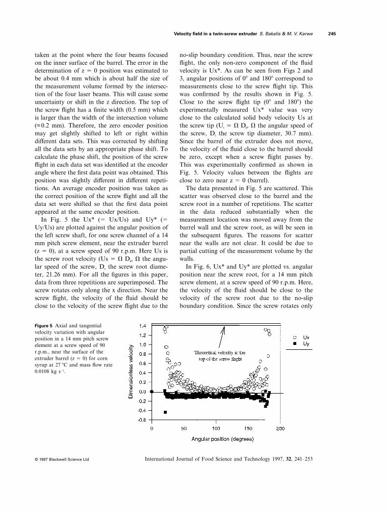
In Fig. 5 the Ux* (5 Ux/Us) and Uy* (5Uy/Us) are plotted against the angular position ofthe left screw shaft, for one screw channel of a 14mm pitch screw element, near the extruder barrel(z 5 0), at a screw speed of 90 r.p.m. Here Us isthe screw root velocity (Us 5 V Ds, V the angu-lar speed of the screw, Ds the screw root diame-ter, 21.26 mm). For all the figures in this paper,data from three repetitions are superimposed. Thescrew rotates only along the x direction. Near thescrew flight, the velocity of the fluid should beclose to the velocity of the screw flight due to the
no-slip boundary condition. Thus, near the screwflight, the only non-zero component of the fluidvelocity is Ux*. As can be seen from Figs 2 and3, angular positions of 08 and 1808 correspond tomeasurements close to the screw flight tip. Thiswas confirmed by the results shown in Fig. 5.Close to the screw flight tip (08 and 1808) theexperimentally measured Ux* value was veryclose to the calculated solid body velocity Us atthe screw tip (Ut 5 V Dt, V the angular speed ofthe screw, Dt the screw tip diameter, 30.7 mm).Since the barrel of the extruder does not move,the velocity of the fluid close to the barrel shouldbe zero, except when a screw flight passes by.This was experimentally confirmed as shown inFig. 5. Velocity values between the flights areclose to zero near z 5 0 (barrel).
The data presented in Fig. 5 are scattered. Thisscatter was observed close to the barrel and thescrew root in a number of repetitions. The scatterin the data reduced substantially when themeasurement location was moved away from thebarrel wall and the screw root, as will be seen inthe subsequent figures. The reasons for scatternear the walls are not clear. It could be due topartial cutting of the measurement volume by thewalls.
In Fig. 6, Ux* and Uy* are plotted vs. angularposition near the screw root, for a 14 mm pitchscrew element, at a screw speed of 90 r.p.m. Here,the velocity of the fluid should be close to thevelocity of the screw root due to the no-slipboundary condition. Since the screw rotates only
Velocity field in a twin-screw extruder S. Bakalis & M. V. Karwe
International Journal of Food Science and Technology 1997, 32, 241–253
245
© 1997 Blackwell Science Ltd
Figure 5 Axial and tangentialvelocity variation with angularposition in a 14 mm pitch screwelement at a screw speed of 90r.p.m., near the surface of theextruder barrel (z 5 0) for cornsyrup at 27i8C and mass flow rate0.0108 kg s21.
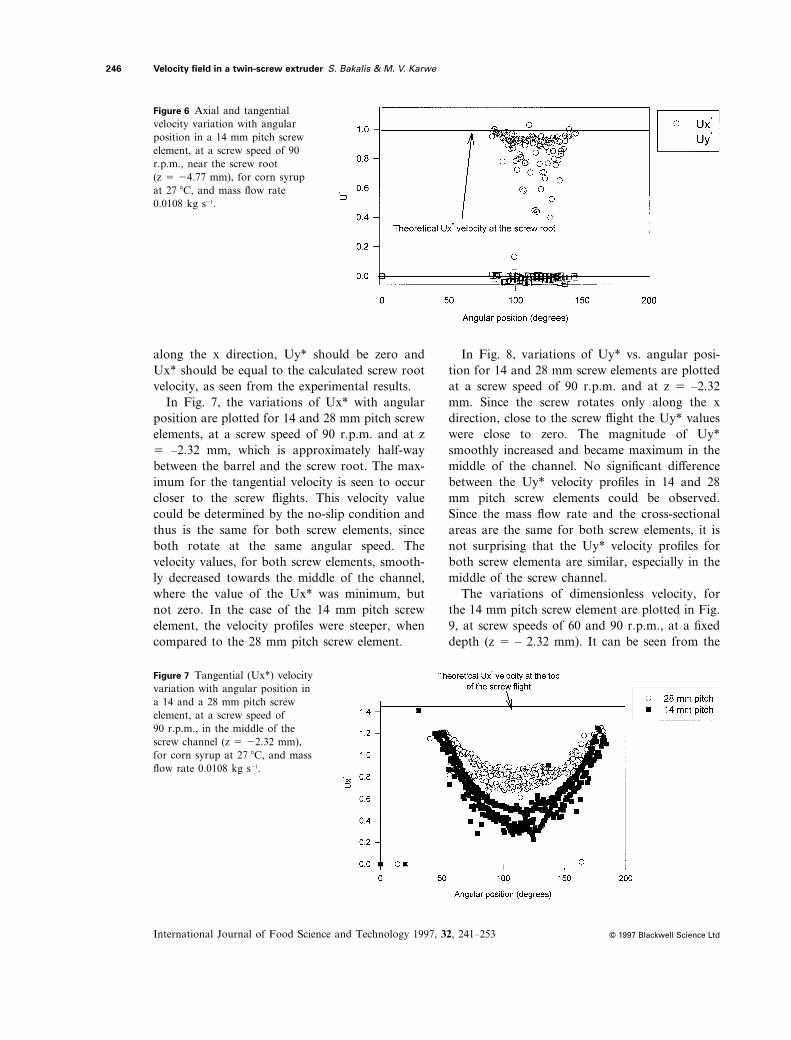
along the x direction, Uy* should be zero andUx* should be equal to the calculated screw rootvelocity, as seen from the experimental results.
In Fig. 7, the variations of Ux* with angularposition are plotted for 14 and 28 mm pitch screwelements, at a screw speed of 90 r.p.m. and at z5 –2.32 mm, which is approximately half-waybetween the barrel and the screw root. The max-imum for the tangential velocity is seen to occurcloser to the screw flights. This velocity valuecould be determined by the no-slip condition andthus is the same for both screw elements, sinceboth rotate at the same angular speed. Thevelocity values, for both screw elements, smooth-ly decreased towards the middle of the channel,where the value of the Ux* was minimum, butnot zero. In the case of the 14 mm pitch screwelement, the velocity profiles were steeper, whencompared to the 28 mm pitch screw element.
In Fig. 8, variations of Uy* vs. angular posi-tion for 14 and 28 mm screw elements are plottedat a screw speed of 90 r.p.m. and at z 5 –2.32mm. Since the screw rotates only along the xdirection, close to the screw flight the Uy* valueswere close to zero. The magnitude of Uy*smoothly increased and became maximum in themiddle of the channel. No significant differencebetween the Uy* velocity profiles in 14 and 28mm pitch screw elements could be observed.Since the mass flow rate and the cross-sectionalareas are the same for both screw elements, it isnot surprising that the Uy* velocity profiles forboth screw elementa are similar, especially in themiddle of the screw channel.
The variations of dimensionless velocity, forthe 14 mm pitch screw element are plotted in Fig.9, at screw speeds of 60 and 90 r.p.m., at a fixeddepth (z 5 – 2.32 mm). It can be seen from the
Velocity field in a twin-screw extruder S. Bakalis & M. V. Karwe
International Journal of Food Science and Technology 1997, 32, 241–253
246
© 1997 Blackwell Science Ltd
Figure 6 Axial and tangentialvelocity variation with angularposition in a 14 mm pitch screwelement, at a screw speed of 90r.p.m., near the screw root (z 5 24.77 mm), for corn syrupat 27i8C, and mass flow rate 0.0108 kg s21.
Figure 7 Tangential (Ux*) velocityvariation with angular position ina 14 and a 28 mm pitch screwelement, at a screw speed of 90 r.p.m., in the middle of thescrew channel (z 5 22.32 mm),for corn syrup at 27i8C, and massflow rate 0.0108 kg s21.
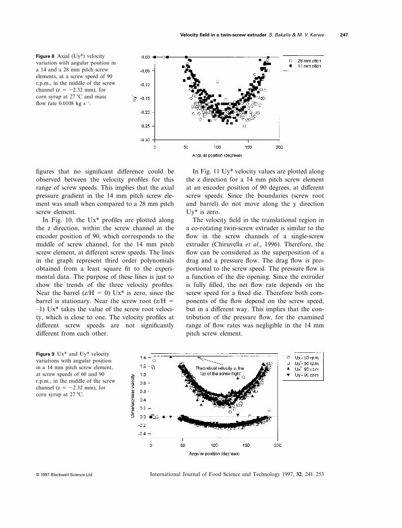
figures that no significant difference could beobserved between the velocity profiles for thisrange of screw speeds. This implies that the axialpressure gradient in the 14 mm pitch screw ele-ment was small when compared to a 28 mm pitchscrew element.
In Fig. 10, the Ux* profiles are plotted alongthe z direction, within the screw channel at theencoder position of 90, which corresponds to themiddle of screw channel, for the 14 mm pitchscrew element, at different screw speeds. The linesin the graph represent third order polynomialsobtained from a least square fit to the experi-mental data. The purpose of these lines is just toshow the trends of the three velocity profiles.Near the barrel (z/H 5 0) Ux* is zero, since thebarrel is stationary. Near the screw root (z/H 5
–1) Ux* takes the value of the screw root veloci-ty, which is close to one. The velocity profiles atdifferent screw speeds are not significantlydifferent from each other.
In Fig. 11 Uy* velocity values are plotted alongthe z direction for a 14 mm pitch screw elementat an encoder position of 90 degrees, at differentscrew speeds. Since the boundaries (screw rootand barrel) do not move along the y directionUy* is zero.
The velocity field in the translational region ina co-rotating twin-screw extruder is similar to theflow in the screw channels of a single-screwextruder (Chiruvella et al., 1996). Therefore, theflow can be considered as the superposition of adrag and a pressure flow. The drag flow is pro-portional to the screw speed. The pressure flow isa function of the die opening. Since the extruderis fully filled, the net flow rate depends on thescrew speed for a fixed die. Therefore both com-ponents of the flow depend on the screw speed,but in a different way. This implies that the con-tribution of the pressure flow, for the examinedrange of flow rates was negligible in the 14 mmpitch screw element.
Velocity field in a twin-screw extruder S. Bakalis & M. V. Karwe
International Journal of Food Science and Technology 1997, 32, 241–253
247
© 1997 Blackwell Science Ltd
Figure 8 Axial (Uy*) velocityvariation with angular position ina 14 and a 28 mm pitch screwelements, at a screw speed of 90r.p.m., in the middle of the screwchannel (z 5 22.32 mm), forcorn syrup at 27i8C and massflow rate 0.0108 kg s21.
Figure 9 Ux* and Uy* velocityvariations with angular positionin a 14 mm pitch screw element,at screw speeds of 60 and 90r.p.m., in the middle of the screwchannel (z 5 22.32 mm), forcorn syrup at 27i8C.
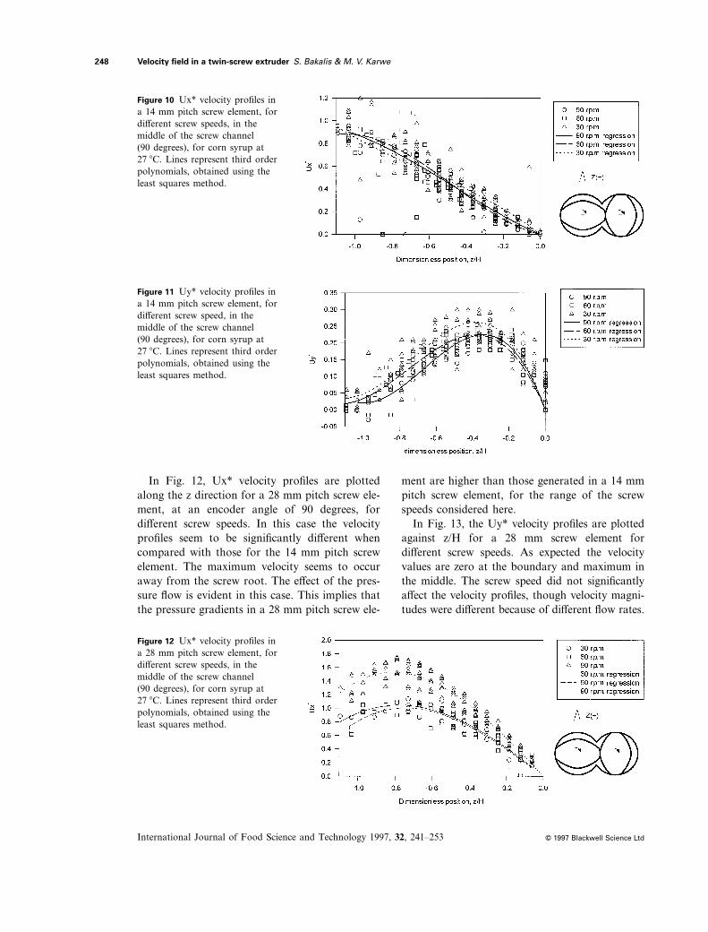
In Fig. 12, Ux* velocity profiles are plottedalong the z direction for a 28 mm pitch screw ele-ment, at an encoder angle of 90 degrees, fordifferent screw speeds. In this case the velocityprofiles seem to be significantly different whencompared with those for the 14 mm pitch screwelement. The maximum velocity seems to occuraway from the screw root. The effect of the pres-sure flow is evident in this case. This implies thatthe pressure gradients in a 28 mm pitch screw ele-
ment are higher than those generated in a 14 mmpitch screw element, for the range of the screwspeeds considered here.
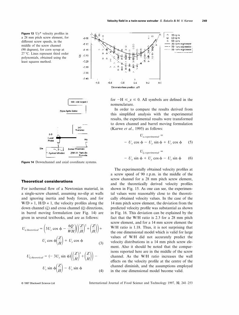
In Fig. 13, the Uy* velocity profiles are plottedagainst z/H for a 28 mm screw element fordifferent screw speeds. As expected the velocityvalues are zero at the boundary and maximum inthe middle. The screw speed did not significantlyaffect the velocity profiles, though velocity magni-tudes were different because of different flow rates.
Velocity field in a twin-screw extruder S. Bakalis & M. V. Karwe
International Journal of Food Science and Technology 1997, 32, 241–253
248
© 1997 Blackwell Science Ltd
Figure 10 Ux* velocity profiles ina 14 mm pitch screw element, fordifferent screw speeds, in themiddle of the screw channel (90 degrees), for corn syrup at27i8C. Lines represent third orderpolynomials, obtained using theleast squares method.
Figure 11 Uy* velocity profiles ina 14 mm pitch screw element, fordifferent screw speed, in themiddle of the screw channel (90 degrees), for corn syrup at27i8C. Lines represent third orderpolynomials, obtained using theleast squares method.
Figure 12 Ux* velocity profiles ina 28 mm pitch screw element, fordifferent screw speeds, in themiddle of the screw channel (90 degrees), for corn syrup at27i8C. Lines represent third orderpolynomials, obtained using theleast squares method.
Theoretical considerations
For isothermal flow of a Newtonian material, ina single-screw channel, assuming no-slip at wallsand ignoring inertia and body forces, and forW/D » 1, H/D « 1, the velocity profiles along thedown channel (z) and cross channel (j) directions,in barrel moving formulation (see Fig. 14) aregiven in several textbooks, and are as follows:
for 2H #_z # 0. All symbols are defined in thenomenclature.
In order to compare the results derived fromthis simplified analysis with the experimentalresults, the experimental results were transformedto down channel and barrel moving formulation(Karwe et al., 1995) as follows:
Velocity field in a twin-screw extruder S. Bakalis & M. V. Karwe
International Journal of Food Science and Technology 1997, 32, 241–253
249
© 1997 Blackwell Science Ltd
Figure 13 Uy* velocity profiles ina 28 mm pitch screw element, fordifferent screw speeds, in themiddle of the screw channel(90 degrees), for corn syrup at27i8C. Lines represent third orderpolynomials, obtained using theleast squares method.
Figure 14 Downchannel and axial coordinate systems.
2 Ux cos f 2 Uy sin f 1 Us cos f
U§ experimental 5
U§ theoretical 5 13Us cos f 26QWH211ZH22
11ZH221
Us cos f1ZH2 1 Us cos f
Uj theoretical 5 s2 3Us sin fd11ZH2211ZH22 2
Us sin f1ZH2 2 Us sin f
(3)
(4)
(5)
2 Ux sin f 1 Uy cos f 2 Us sin f
Uj experimental 5
(6)
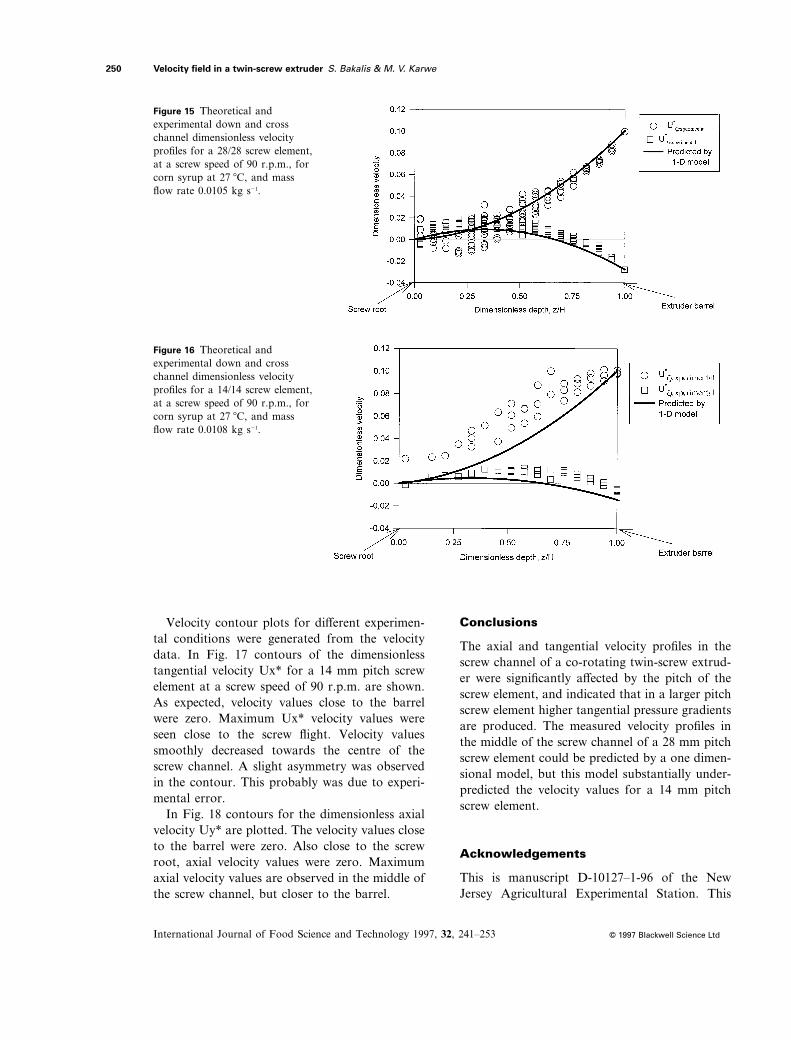
The experimentally obtained velocity profiles ata screw speed of 90 r.p.m. in the middle of thescrew channel for a 28 mm pitch screw element,and the theoretically derived velocity profilesshown in Fig. 15. As one can see, the experimen-tal values were reasonably close to the theoreti-cally obtained velocity values. In the case of the14 mm pitch screw element, the deviation from thepredicted velocity profile was substantial as shownin Fig. 16. This deviation can be explained by thefact that the W/H ratio is 2.3 for a 28 mm pitchscrew element, and for a 14 mm screw element theW/H ratio is 1.18. Thus, it is not surprising thatthe one dimensional model which is valid for largevalues of W/H did not accurately predict thevelocity distributions in a 14 mm pitch screw ele-ment. Also it should be noted that the compar-isons reported here are in the middle of the screwchannel. As the W/H ratio increases the walleffects on the velocity profile at the centre of thechannel diminish, and the assumptions employedin the one dimensional model become valid.
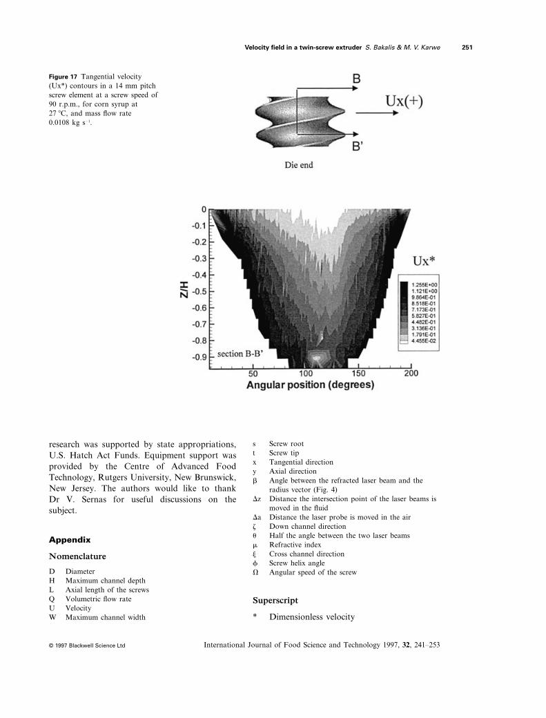
Velocity contour plots for different experimen-tal conditions were generated from the velocitydata. In Fig. 17 contours of the dimensionlesstangential velocity Ux* for a 14 mm pitch screwelement at a screw speed of 90 r.p.m. are shown.As expected, velocity values close to the barrelwere zero. Maximum Ux* velocity values wereseen close to the screw flight. Velocity valuessmoothly decreased towards the centre of thescrew channel. A slight asymmetry was observedin the contour. This probably was due to experi-mental error.
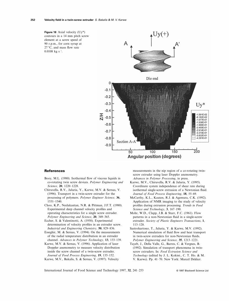
In Fig. 18 contours for the dimensionless axialvelocity Uy* are plotted. The velocity values closeto the barrel were zero. Also close to the screwroot, axial velocity values were zero. Maximumaxial velocity values are observed in the middle ofthe screw channel, but closer to the barrel.
Conclusions
The axial and tangential velocity profiles in thescrew channel of a co-rotating twin-screw extrud-er were significantly affected by the pitch of thescrew element, and indicated that in a larger pitchscrew element higher tangential pressure gradientsare produced. The measured velocity profiles inthe middle of the screw channel of a 28 mm pitchscrew element could be predicted by a one dimen-sional model, but this model substantially under-predicted the velocity values for a 14 mm pitchscrew element.
Acknowledgements
This is manuscript D-10127–1-96 of the NewJersey Agricultural Experimental Station. This
Velocity field in a twin-screw extruder S. Bakalis & M. V. Karwe
International Journal of Food Science and Technology 1997, 32, 241–253
250
© 1997 Blackwell Science Ltd
Figure 15 Theoretical andexperimental down and crosschannel dimensionless velocityprofiles for a 28/28 screw element,at a screw speed of 90 r.p.m., forcorn syrup at 27i8C, and massflow rate 0.0105 kg s21.
Figure 16 Theoretical andexperimental down and crosschannel dimensionless velocityprofiles for a 14/14 screw element,at a screw speed of 90 r.p.m., forcorn syrup at 27i8C, and massflow rate 0.0108 kg s21.
research was supported by state appropriations,U.S. Hatch Act Funds. Equipment support wasprovided by the Centre of Advanced FoodTechnology, Rutgers University, New Brunswick,New Jersey. The authors would like to thankDr V. Sernas for useful discussions on thesubject.
Appendix
Nomenclature
D DiameterH Maximum channel depthL Axial length of the screwsQ Volumetric flow rateU VelocityW Maximum channel width
s Screw roott Screw tipx Tangential directiony Axial directionb Angle between the refracted laser beam and the
radius vector (Fig. 4)Dz Distance the intersection point of the laser beams is
moved in the fluidDa Distance the laser probe is moved in the airz Down channel directionu Half the angle between the two laser beamsm Refractive indexj Cross channel directionf Screw helix angleV Angular speed of the screw
Superscript
* Dimensionless velocity
Velocity field in a twin-screw extruder S. Bakalis & M. V. Karwe
International Journal of Food Science and Technology 1997, 32, 241–253
251
© 1997 Blackwell Science Ltd
Figure 17 Tangential velocity(Ux*) contours in a 14 mm pitchscrew element at a screw speed of90 r.p.m., for corn syrup at27i8C, and mass flow rate 0.0108 kg s21.
References
Booy, M.L. (1980). Isothermal flow of viscous liquids inco-rotating twin screw devices. Polymer Engineering andScience, 20, 1220–1228.
Chiruvella, R.V., Jaluria, Y., Karwe, M.V. & Sernas, V.(1996). Transport in a twin-screw extruder for theprocessing of polymers. Polymer Engineer Science, 36,1531–1540.
Choo, K.P., Neelakantan, N.R. & Pittman, J.F.T. (1980).Experimental deep channel velocity profiles andoperating characteristics for a single screw extruder.Polymer Engineering and Science, 20, 349–365.
Eccher, S. & Valentinotti, A. (1958). Experimentaldetermination of velocity profiles in an extruder screw.Industrial and Engineering Chemistry, 50, 829–836.
Esseghir, M. & Sernas, V. (1994). On the measurementsof the radial temperature distribution in an extruderchannel. Advances in Polymer Technology, 13, 133–139.
Karwe, M.V. & Sernas, V. (1996). Application of laserDoppler anemometry to measure velocity distributioninside the screw channel of a twin-screw extruder,Journal of Food Process Engineering, 19, 135–152.
Karwe, M.V., Bakalis, S. & Sernas, V. (1997). Velocity
measurements in the nip region of a co-rotating twin-screw extruder using laser Doppler anemometry.Advances in Polymer Processing, in press.
Karwe, M.V., Chiruvella, R.V. & Jaluria, Y. (1995).Coordinate system independence of shear rate duringisothermal single-screw extrusion of a Newtonian fluid.Journal of Food Process Engineering, 18, 55–69.
McCarthy, K.L., Kauten, R.J. & Agemura, C.K. (1992).Application of NMR imaging to the study of velocityprofiles during extrusion processing. Trends in FoodScience and Technology, 3, 167–190.
Mohr, W.D., Clapp, J.B. & Starr, F.C. (1961). Flowpatterns in a non-Newtonian fluid in a single-screwextruder. Society of Plastic Engineers Transactions, 1,113–120.
Sastrohartono, T., Jaluria, Y. & Karwe, M.V. (1992).Numerical simulation of fluid flow and heat transportin twin-screw extruders for non-Newtonian fluids.Polymer Engineering and Science, 35, 1213–1221.
Tayeb, J., Della Valle, G., Barres, C. & Vergnes, B.(1992). Simulation of transport phenomena in twin-screw extruders. In: Food Extrusion Science andTechnology (edited by J. L. Kokini., C. T. Ho. & M.V. Karwe). Pp. 41–70. New York: Marcel Dekker.
Velocity field in a twin-screw extruder S. Bakalis & M. V. Karwe
International Journal of Food Science and Technology 1997, 32, 241–253
252
© 1997 Blackwell Science Ltd
Figure 18 Axial velocity (Uy*)contours in a 14 mm pitch screwelement at a screw speed of 90 r.p.m., for corn syrup at27i8C, and mass flow rate 0.0108 kg s21.
Van Zuilichem, D.J., Van Der Laan, E., Stolp, W. &Van’t Riet, K. (1992). Modelling of heat transfer in aco-rotating twin-screw-extruder. In: Food ExtrusionScience and Technology (edited by J. L. Kokini, C. T.
Ho & M. V. Karwe). Pp. 149–164. New York: MarcelDekker.
Yacu, W.A. (1985). Modelling a twin screw co-rotatingextruder. Journal of Food Engineering, 8, 1–21.
Velocity field in a twin-screw extruder S. Bakalis & M. V. Karwe
International Journal of Food Science and Technology 1997, 32, 241–253
253
© 1997 Blackwell Science Ltd
Received 24 August 1996, revised and accepted 25 June 1997
Related Documents