1 Vehicular Visible Light Communications: A Survey Agon Memedi Student Member, IEEE and Falko Dressler Fellow, IEEE Abstract—Visible Light Communications (VLC) is becoming a mature communication technology, particularly for indoor usage. The application in outdoor environments is particularly interest- ing in the scope of Vehicular VLC (V-VLC), however, there are some critical challenges remaining. In general, VLC is a good complement to Radio Frequency (RF)-based communication. For automotive use cases, V-VLC is benefiting from the huge available spectrum and the readily available Light Emitting Diode (LED)- based lighting systems of modern cars. Its Line Of Sight (LOS) characteristics, the directionality of the light, and the smaller collision domain substantially reduces interference. In this survey paper, we study the state of the art of V-VLC and identify open issues and challenges. We study the V-VLC communication system as a whole and also dig into the characteristics of the VLC channel. For the beginner in the field, this review acts as a guide to the most relevant literature to quickly catch up with current trends and achievements. For the expert, we identify open research questions and also introduce the V-VLC research community as a whole. Index Terms—Vehicular visible light communication, V-VLC, visible light communication, VLC, vehicular networking, channel modeling, transmitter and receiver design. I. I NTRODUCTION Transportation systems of today are closer than ever bound to experience a major technological transformation. Vehicles on roads have come a long way from the bare metal-on- wheels they used to be, to the sensing and computation capable machines they are today. High-end models of last generation vehicles nowadays are equipped with hundreds of embedded computers and sensors which allow them to perceive their surroundings, and interact with it in semi-autonomous, and eventually, fully-autonomous fashion. Although at a slower pace, the road infrastructure has evolved as well, as adaptive traffic lights and communication capable pay tolls are being deployed on roads. An anticipated next step in the evolution course of trans- portation systems is to adopt the concept of communication and enable information exchange between vehicles and with infrastructure. This will unleash the full potential of next generation transportation systems while shifting the paradigm from autonomous driving to cooperative driving. The newly acquired capabilities of vehicles and infrastructure pave the way for a set of new applications. As a result, numerous agencies and regulatory bodies worldwide have come forward with standards and strategies to deploy such applications, oftentimes referred to as Intelligent Transportation Systems (ITS) [1], [2]. In essence, the main goal of ITS is to improve road safety, traffic efficiency, and comfort of driving by taking advantage of Vehicle-to-Everything (V2X) communications [3], [4]. A. Memedi and F. Dressler are with the School for Electrical Engineering and Computer Science, TU Berlin, Germany. A. Memedi is also affiliated with the University of California, Los Angeles, USA in the scope of his Fulbright Fellowship, e-mail: {memedi,dressler}@ccs-labs.org. The majority of ITS applications proposed until now rely on Radio Frequency (RF) communication. For instance, the ETSI ITS-G5 [5] and the IEEE 1609 WAVE [6] families of standards, which propose full ITS stacks for Europe and U.S., respectively, are built upon WLAN, i.e., the IEEE 802.11p protocol [7]. Also cellular networking solutions have been realized using LTE technologies [8], [9]. In follow-up works, 5G-based approaches have been standardized, most prominently, the current 5G Cellular V2X (C-V2X) solution [10], [11]. This activity is currently further pushed in the scope of the Tactile Internet initiative [12], which also includes ITS applications [13]. WLAN and C-V2X can of course also be used in combination, complementing each other [14], [15]. Another field that has seen major transformation in the last decade is that of lighting technologies. Stimulated by major breakthroughs in Solid State Lighting (SSL) technology and the mass adoption of Light Emitting Diodes (LEDs) for indoor and outdoor illumination, Visible Light Communications (VLC) has emerged as a viable communication technology. VLC is an emerging technology that enables data communication by modulating information on the intensity of the light emitted by LEDs. In recent years, VLC has sparked the interest of the research community and the industry [16]. Namely, the number of publications on VLC has been growing exponentially [17], and multiple comprehensive surveys have been recently published on this topic [17]–[22]. Furthermore, standardization efforts have been taking place in the scope of IEEE Standards Association (IEEE-SA) [23] 1 and Japan Electronics and Infor- mation Technology Industries Association (JEITA) [24]–[26]. In the meanwhile, VLC-enabling front-ends, from companies like pureLiFi, Philips, Oledcomm, are already present in the marketplace and are being deployed in homes and industrial buildings. 2 Based on the application scenario, VLC can be classified into indoor and outdoor applications. Indoor VLC has attracted more traction and growth, fueled by the success of the Li- Fi [27] concept. Whereas, outdoor VLC has progressed at a slower pace, mainly owing to the more challenging environment and other constraints (e.g., mobility, weather, regulations), but yet with substantial results. Today, ITS are one of the most promising outdoor applications for VLC. Vehicular networking applications can take advantage of the LED-equipped lighting modules and transportation infrastructure to realize V-VLC [22], [28]–[31]. As V-VLC uses the visible light portion of the electromag- netic spectrum, the different characteristics of the light waves 1 Task groups 7 and 13 within IEEE 802.15 working group; Task group “bb” within IEEE 802.11 working group. 2 http://purelifi.com/case-studies/

Welcome message from author
This document is posted to help you gain knowledge. Please leave a comment to let me know what you think about it! Share it to your friends and learn new things together.
Transcript
1
Vehicular Visible Light Communications: A SurveyAgon Memedi Student Member, IEEE and Falko Dressler Fellow, IEEE
Abstract—Visible Light Communications (VLC) is becoming amature communication technology, particularly for indoor usage.The application in outdoor environments is particularly interest-ing in the scope of Vehicular VLC (V-VLC), however, there aresome critical challenges remaining. In general, VLC is a goodcomplement to Radio Frequency (RF)-based communication. Forautomotive use cases, V-VLC is benefiting from the huge availablespectrum and the readily available Light Emitting Diode (LED)-based lighting systems of modern cars. Its Line Of Sight (LOS)characteristics, the directionality of the light, and the smallercollision domain substantially reduces interference. In this surveypaper, we study the state of the art of V-VLC and identifyopen issues and challenges. We study the V-VLC communicationsystem as a whole and also dig into the characteristics of theVLC channel. For the beginner in the field, this review acts asa guide to the most relevant literature to quickly catch up withcurrent trends and achievements. For the expert, we identifyopen research questions and also introduce the V-VLC researchcommunity as a whole.
Index Terms—Vehicular visible light communication, V-VLC,visible light communication, VLC, vehicular networking, channelmodeling, transmitter and receiver design.
I. INTRODUCTION
Transportation systems of today are closer than ever boundto experience a major technological transformation. Vehicleson roads have come a long way from the bare metal-on-wheels they used to be, to the sensing and computation capablemachines they are today. High-end models of last generationvehicles nowadays are equipped with hundreds of embeddedcomputers and sensors which allow them to perceive theirsurroundings, and interact with it in semi-autonomous, andeventually, fully-autonomous fashion. Although at a slowerpace, the road infrastructure has evolved as well, as adaptivetraffic lights and communication capable pay tolls are beingdeployed on roads.
An anticipated next step in the evolution course of trans-portation systems is to adopt the concept of communicationand enable information exchange between vehicles and withinfrastructure. This will unleash the full potential of nextgeneration transportation systems while shifting the paradigmfrom autonomous driving to cooperative driving. The newlyacquired capabilities of vehicles and infrastructure pave the wayfor a set of new applications. As a result, numerous agenciesand regulatory bodies worldwide have come forward withstandards and strategies to deploy such applications, oftentimesreferred to as Intelligent Transportation Systems (ITS) [1], [2].In essence, the main goal of ITS is to improve road safety,traffic efficiency, and comfort of driving by taking advantageof Vehicle-to-Everything (V2X) communications [3], [4].
A. Memedi and F. Dressler are with the School for Electrical Engineeringand Computer Science, TU Berlin, Germany. A. Memedi is also affiliated withthe University of California, Los Angeles, USA in the scope of his FulbrightFellowship, e-mail: memedi,[email protected].
The majority of ITS applications proposed until now rely onRadio Frequency (RF) communication. For instance, the ETSIITS-G5 [5] and the IEEE 1609 WAVE [6] families of standards,which propose full ITS stacks for Europe and U.S., respectively,are built upon WLAN, i.e., the IEEE 802.11p protocol [7]. Alsocellular networking solutions have been realized using LTEtechnologies [8], [9]. In follow-up works, 5G-based approacheshave been standardized, most prominently, the current 5GCellular V2X (C-V2X) solution [10], [11]. This activity iscurrently further pushed in the scope of the Tactile Internetinitiative [12], which also includes ITS applications [13].WLAN and C-V2X can of course also be used in combination,complementing each other [14], [15].
Another field that has seen major transformation in the lastdecade is that of lighting technologies. Stimulated by majorbreakthroughs in Solid State Lighting (SSL) technology and themass adoption of Light Emitting Diodes (LEDs) for indoor andoutdoor illumination, Visible Light Communications (VLC)has emerged as a viable communication technology. VLC isan emerging technology that enables data communication bymodulating information on the intensity of the light emittedby LEDs.
In recent years, VLC has sparked the interest of the researchcommunity and the industry [16]. Namely, the number ofpublications on VLC has been growing exponentially [17], andmultiple comprehensive surveys have been recently publishedon this topic [17]–[22]. Furthermore, standardization effortshave been taking place in the scope of IEEE StandardsAssociation (IEEE-SA) [23]1 and Japan Electronics and Infor-mation Technology Industries Association (JEITA) [24]–[26].In the meanwhile, VLC-enabling front-ends, from companieslike pureLiFi, Philips, Oledcomm, are already present in themarketplace and are being deployed in homes and industrialbuildings.2
Based on the application scenario, VLC can be classifiedinto indoor and outdoor applications. Indoor VLC has attractedmore traction and growth, fueled by the success of the Li-Fi [27] concept. Whereas, outdoor VLC has progressed at aslower pace, mainly owing to the more challenging environmentand other constraints (e.g., mobility, weather, regulations), butyet with substantial results. Today, ITS are one of the mostpromising outdoor applications for VLC. Vehicular networkingapplications can take advantage of the LED-equipped lightingmodules and transportation infrastructure to realize V-VLC [22],[28]–[31].
As V-VLC uses the visible light portion of the electromag-netic spectrum, the different characteristics of the light waves
1Task groups 7 and 13 within IEEE 802.15 working group; Task group “bb”within IEEE 802.11 working group.
2http://purelifi.com/case-studies/
2
d) Head to Head
e) Tail to Tail
a) Infrasturucture to Vehicle
c) Tail to Headb) Head to
Tail
Figure 1. Vehicular VLC communication patterns and selected potential applications. a) Infrastructure to Vehicle communication: can be used for informationexchange between VLC-enabled vehicles and intelligent traffic lights, traffic signs, or road lighting. Potential applications include intersection assistance andTIS. Communication patterns between vehicles include: b) Head to Tail and c) Tail to Head communication: possible in car following situations; can be usedfor emergency electronic brake light and platooning applications, respectively. d) Head to Head communication: possible if vehicles face each other; can beused for intersection coordination and maneuver coordination between vehicles; e) Tail to Tail communication: possible if two vehicles are opposed to eachother; plausible in parking situation. Note that, bidirectional communication is possible in all vehicle to vehicle cases. However, to maintain clarity, the beamsof the taillamp and the headlamp are not illustrated in cases b) Head to Tail and c) Tail to Head, respectively. Additionally, the size of the head- and taillamplight beams in this figure does not represent the real range and asymmetric shape of these lighting modules. (This figure has been designed using resourcesfrom Freepik.com).
can help to complement RF technologies, such as IEEE 802.11pand Long Term Evolution (LTE).
Advantages/disadvantages of RF: In general, RF technologiesin the sub-6 GHz-band as used for vehicular networking havenon-directional propagation, relatively long communicationrange, and can penetrate objects. RF has been very wellinvestigated over the last decades and the technology is quitemature. At the same time, the limited available radio spectrumas well as the congestion level in medium and high node densityscenarios are limiting the scalability of RF-based solutions.Finally, potential security attacks, like jamming, eavesdropping,and man-in-the-middle attacks have raised concerns about itsusage in safety-critical vehicular networking applications.
Advantages/disadvantages of V-VLC: The Line Of Sight(LOS) property of V-VLC, its directionality, and the smallercollision domain substantially reduce interference. At the sametime, the massive bandwidth available in the visible lightspectrum allows huge potential data rates. At the same time,V-VLC requires LOS, which might not always be available inoutdoor scenarios, e.g., due to mobility and also environmentalimpact such as heavy snow. Nevertheless, V-VLC needs asignificant amount of further research in order to enable reliablenetworking complementing RF-based solutions.
The truth is likely to be found in the complementary nature ofboth RF and V-VLC. RF can make up for VLC’s shortcomings,such as short communication range and inability to propagatethrough opaque objects and V-VLC can offer high data rateswith very low interference in LOS scenarios. Such hybridconcepts have already been proposed in the literature [32],[33].
In this survey paper, we review the current state of the art
of V-VLC. We consider it the first all-inclusive paper lookingat the complete V-VLC protocol stack, which considers bothPhotodiode (PD) and camera-based receivers. We aim to helpbeginners to quickly get into the concept of V-VLC as wellas its applications and properties. For experts, we provide anin-depth discussion of research issues related to transmitter andreceiver characteristics, channel modeling, and simulation tools.We also identify the main stake holders, relevant publicationvenues, and standardization bodies.
The remainder of this paper is organized as follows: InSection II, we introduce the field of Vehicular VLC includ-ing applications, properties, security aspects, and regulatoryrequirements for automotive lighting systems. This is followedby a discussion of the core components of a V-VLC system inSection III. Among others, we discuss the system architecture,transmitter front-end characteristics, VLC modulation concepts,as well as typical LED lighting modules used in cars. InSection IV, we introduce important properties of the V-VLCcommunication channel such as light distribution, Non-LineOf Sight (NLOS) communication, as well as the impact ofmobility, ambient light, and weather conditions. In Section V,we look more closely on modeling issues of the V-VLCchannel. In Section VI, we introduce both PD and cameraimage sensor-based VLC receiver. We discuss the state ofthe art in simulation-based performance evaluation of V-VLCsystems in Section VII. Finally, we conclude this survey onV-VLC with a discussion of research directions, the researchcommunity, and current standardization efforts in Section VIIIas well as with some concluding remarks in Section IX.
3
II. VEHICULAR VISIBLE LIGHT COMMUNICATION
V-VLC, which is based on the concept of VLC, is usedin vehicular networking applications. In this section, we firstbriefly outline conceptual and architectural aspects of V-VLC.Next, we discuss the feasibility of this technology for certainvehicular networking applications, and lastly we introduce someof V-VLC’s most prominent characteristics.
A. Concept and Architecture
VLC is a medium range optical wireless communicationtechnology which uses the 380–780 nm wavelengths of theelectromagnetic spectrum [34]. In vehicles, VLC is enabled byLED-based headlamps and taillamps as transmitters and PDs orcamera image sensors as receivers. Figure 1 depicts a typicaltraffic scenario where V-VLC can be deployed. As illustrated,vehicles can realize Vehicle-to-Vehicle (V2V) communicationwith the vehicles in their direct vicinity, therefore, establishinghead to tail and tail to head links when driving, or head tohead links when facing each other, for example, at intersections.Tail to tail links are also possible, however not common intypical driving scenarios. Figure 1 also illustrates Vehicle-to-Infrastructure (V2I) communication, where LED-basedinfrastructure elements, such as traffic lights, road-side signage,and street lighting, can convey visual information to the driverand digital information to the VLC-enabled vehicles [35], [36].Originally, V2I applications were the earliest type of V-VLCapplications, considered for traffic information systems in late1990s [37]–[39].
For V-VLC, to support these different communicationscenarios (and corresponding applications) careful designdecisions need to be made on the system level. This raises amultitude of research questions, in particular regarding PhysicalLayer (PHY) aspects of the system. For instance, spectrallyefficient Modulation and Coding Schemes (MCSs), such asOrthogonal Frequency Division Multiplexing (OFDM), arefavorable and have been implemented for V-VLC [40]–[42].However, hardware limitations of the V-VLC transmitters andreceivers (e.g., nonlinearity of the electronics), coupled with thechallenging outdoor conditions and restrictive safety regulations,hugely impact the achievable performance. Nonlinear transferfunctions, limited dynamic range, and the limited bandwidthof the LEDs used for exterior automotive lighting are someof the major challenges on the transmitting side. On thereceiving side, it is the “square law” property of the DirectDetection (DD) receivers and the hardware induced noise whichaffect the communication. These challenges and correspondingsolutions are discussed in more detail in Sections III-B and VI,respectively.
In the following we discuss the feasibility of V-VLC fordifferent vehicular networking applications and identify thescenarios where it can be beneficial for communication.
B. Applications
Generally, vehicular networking applications can be classifiedinto two major categories: safety and non-safety applications.
Safety applications have very stringent requirements for relia-bility metrics, such as latency and packet delivery, whereas non-safety applications can require high data rates, but have morerelaxed reliability requirements. Depending on the applicationtype, a set of communication requirements needs to be satisfiedby the deployed communication technology for the applicationto perform as desired.
RF-based communication technologies such as IEEE 802.11pand C-V2X have been developed specifically for vehicularnetworking applications. However, the aforementioned RFtechnologies might not always be able to support all typesof applications, especially those which require frequent trans-missions in dense scenarios, where safety-critical metricscan suffer due to channel congestion, e.g., in challengingplatooning scenarios [44]. In such cases V-VLC can be usedto complement RF to decrease the RF channel load andimproving the overall system reliability. Besides offloadingtraffic from the RF channel, V-VLC can also provide aredundant communication channel to improve robustness. Inthis regard, we see V-VLC as a complementary technologyin the scope of a heterogeneous vehicular networking system,and not as a replacement for RF-based vehicular networkingcommunications [32], [33], [45]. The presence of multiplecommunication technologies that can complement each otheris an imperative for advanced vehicular networking systems,which will be supporting multiple applications in parallelcompeting for the same communication resources.
In the following, we assess the feasibility of V-VLC fordifferent vehicular networking applications evaluating it interms of the communication requirements introduced by Willkeet al. [43]. This allows us to establish a generic outlook ofV-VLC’s capabilities, compare it against other communicationtechnologies, and identify suitable applications. Communicationrequirements for different vehicular networking applicationsinclude: communication latency, communication reliability,scaling, communication scope, and communication groupstructure [43].
Considering V-VLC’s short communication range and di-rected transmission, it emerges as a viable communicationtechnology for applications whose scope requires communica-tion with nearby peers (e.g., platooning, emergency electronicbrake light), or with a small region (e.g., intersection assistance).V-VLC can also be used for communication beyond this scope(e.g., along a trajectory, or throughout the entire network),however in that case messages need to be forwarded via multi-hop communication, which increases latency, thus renderingV-VLC infeasible if the considered application has real-timerequirements. For applications that require communicationbeyond the local scope, heterogeneous communication tech-nologies with longer communication range like RF can beused.
The scope requirement implicitly affects the scaling require-ment (i.e., the number of vehicles that need to communicate) foran application. Therefore, V-VLC can support applications thatrequire communication among a limited number of vehicles,all in LOS. Regarding the group structure requirement, V-VLC can support applications that require both long term (i.e.,persistent) and short term (i.e., non-persistent) relationship
4
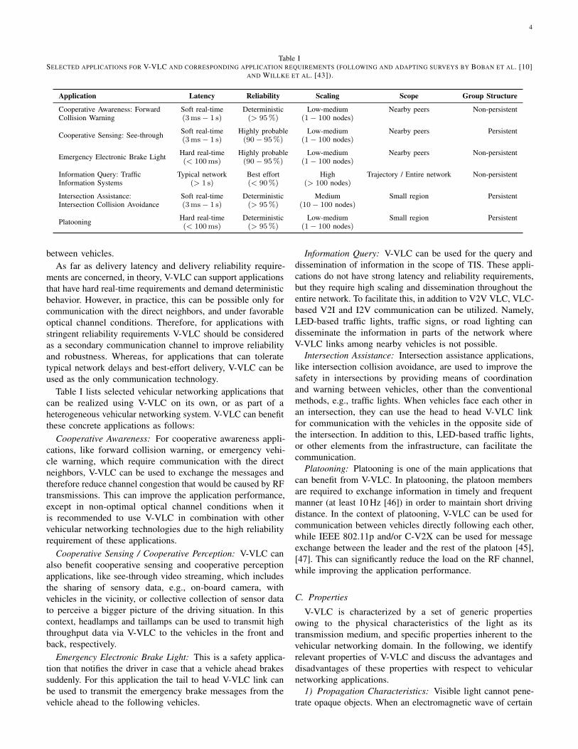
Table ISELECTED APPLICATIONS FOR V-VLC AND CORRESPONDING APPLICATION REQUIREMENTS (FOLLOWING AND ADAPTING SURVEYS BY BOBAN ET AL. [10]
AND WILLKE ET AL. [43]).
Application Latency Reliability Scaling Scope Group Structure
Cooperative Awareness: ForwardCollision Warning
Soft real-time Deterministic Low-medium Nearby peers Non-persistent(3ms− 1 s) (> 95%) (1− 100 nodes)
Cooperative Sensing: See-through Soft real-time Highly probable Low-medium Nearby peers Persistent(3ms− 1 s) (90− 95%) (1− 100 nodes)
Emergency Electronic Brake Light Hard real-time Highly probable Low-medium Nearby peers Non-persistent(< 100ms) (90− 95%) (1− 100 nodes)
Information Query: TrafficInformation Systems
Typical network Best effort High Trajectory / Entire network Non-persistent(> 1 s) (< 90%) (> 100 nodes)
Intersection Assistance:Intersection Collision Avoidance
Soft real-time Deterministic Medium Small region Persistent(3ms− 1 s) (> 95%) (10− 100 nodes)
Platooning Hard real-time Deterministic Low-medium Small region Persistent(< 100ms) (> 95%) (1− 100 nodes)
between vehicles.As far as delivery latency and delivery reliability require-
ments are concerned, in theory, V-VLC can support applicationsthat have hard real-time requirements and demand deterministicbehavior. However, in practice, this can be possible only forcommunication with the direct neighbors, and under favorableoptical channel conditions. Therefore, for applications withstringent reliability requirements V-VLC should be consideredas a secondary communication channel to improve reliabilityand robustness. Whereas, for applications that can toleratetypical network delays and best-effort delivery, V-VLC can beused as the only communication technology.
Table I lists selected vehicular networking applications thatcan be realized using V-VLC on its own, or as part of aheterogeneous vehicular networking system. V-VLC can benefitthese concrete applications as follows:
Cooperative Awareness: For cooperative awareness appli-cations, like forward collision warning, or emergency vehi-cle warning, which require communication with the directneighbors, V-VLC can be used to exchange the messages andtherefore reduce channel congestion that would be caused by RFtransmissions. This can improve the application performance,except in non-optimal optical channel conditions when itis recommended to use V-VLC in combination with othervehicular networking technologies due to the high reliabilityrequirement of these applications.
Cooperative Sensing / Cooperative Perception: V-VLC canalso benefit cooperative sensing and cooperative perceptionapplications, like see-through video streaming, which includesthe sharing of sensory data, e.g., on-board camera, withvehicles in the vicinity, or collective collection of sensor datato perceive a bigger picture of the driving situation. In thiscontext, headlamps and taillamps can be used to transmit highthroughput data via V-VLC to the vehicles in the front andback, respectively.
Emergency Electronic Brake Light: This is a safety applica-tion that notifies the driver in case that a vehicle ahead brakessuddenly. For this application the tail to head V-VLC link canbe used to transmit the emergency brake messages from thevehicle ahead to the following vehicles.
Information Query: V-VLC can be used for the query anddissemination of information in the scope of TIS. These appli-cations do not have strong latency and reliability requirements,but they require high scaling and dissemination throughout theentire network. To facilitate this, in addition to V2V VLC, VLC-based V2I and I2V communication can be utilized. Namely,LED-based traffic lights, traffic signs, or road lighting candisseminate the information in parts of the network whereV-VLC links among nearby vehicles is not possible.
Intersection Assistance: Intersection assistance applications,like intersection collision avoidance, are used to improve thesafety in intersections by providing means of coordinationand warning between vehicles, other than the conventionalmethods, e.g., traffic lights. When vehicles face each other inan intersection, they can use the head to head V-VLC linkfor communication with the vehicles in the opposite side ofthe intersection. In addition to this, LED-based traffic lights,or other elements from the infrastructure, can facilitate thecommunication.
Platooning: Platooning is one of the main applications thatcan benefit from V-VLC. In platooning, the platoon membersare required to exchange information in timely and frequentmanner (at least 10 Hz [46]) in order to maintain short drivingdistance. In the context of platooning, V-VLC can be used forcommunication between vehicles directly following each other,while IEEE 802.11p and/or C-V2X can be used for messageexchange between the leader and the rest of the platoon [45],[47]. This can significantly reduce the load on the RF channel,while improving the application performance.
C. Properties
V-VLC is characterized by a set of generic propertiesowing to the physical characteristics of the light as itstransmission medium, and specific properties inherent to thevehicular networking domain. In the following, we identifyrelevant properties of V-VLC and discuss the advantages anddisadvantages of these properties with respect to vehicularnetworking applications.
1) Propagation Characteristics: Visible light cannot pene-trate opaque objects. When an electromagnetic wave of certain
5
frequency encounters an object, the wave can be absorbed,reflected, scattered, or transmitted through the object. Theinteraction between the wave and the object depends on thewavelength and the amplitude of the wave as well as on thephysical and chemical properties of the encountered object.This defines to what extent an object is opaque or transparentto specific wavelengths. For instance, white light consist of acontinuous range of wavelengths. Some of these wavelengthsare absorbed as they interact with the pigments in the surfaceof an object. Other wavelengths are scattered or reflected,determining the color of that object as we see it.
In general, signals transmitted via VLC cannot penetratethrough objects, which are opaque to the human eye such aswood, metal, and plastic. As these materials are common inmost indoor and outdoor setups, the interaction of visible lightwavelengths with those materials largely impacts the designdecisions for VLC-based applications, including V-VLC. Theobject can also be transparent (to certain wavelengths), meaningthat the light easily passes through it.
2) Directionality of Lighting Function: VLC is highlydirectional. The directionality of V-VLC is governed mainly bythe design of the transmitter lighting modules and the Field OfView (FOV) of the receiving PD. Generally speaking, lightingmodules for indoor or outdoor illumination are designed toprovide optimal illumination in a certain area of interest.Therefore, they mostly focus the light towards that area. In thecase of exterior automotive lighting, the directionality is causedby the use of optical components inside the lighting moduleswhich focus the light beams in the desired direction. Thedirectionality of the light beams impacts many other propertiesof VLC. For instance, it results in a small collision domain,and allows high spatial reuse of the modulation bandwidth fordevices in close proximity.
3) Asymmetric Power Distribution: A unique property ofV-VLC is the asymmetry of different lighting modules [48]–[50]. More specifically, as vehicle headlamps and taillampsserve different purposes: illumination vs. signaling, there aresubstantial differences in their design [51, Chapter 6.1]. Thus,the light emitted by the headlamps is much more stronger thanthe one emitted by the taillamps. In turn, this results in anasymmetric link between two vehicles communicating withthese lighting modules.
Furthermore, the light distribution of the headlight is notuniform. The idea is to illuminate more areas towards the curbside in order not to glare oncoming traffic. These propertiesof the V-VLC collision domain should be carefully taken inconsideration when designing Medium Access Control (MAC)protocols for V-VLC.
4) LOS vs. NLOS: Propagation characteristics of the lightand its directionality usually require a LOS link between thetransmitter and the receiver in V-VLC. Maintaining such astable LOS link under the dynamic mobility conditions of thevehicular traffic is one of the main challenges in V-VLC. Inaddition to this, in the outdoor environment the light beamsare not spatially confined: they travel far distances, therefore,the reflected components cannot maintain sufficient energy fordetection and reliable communication.
Although a LOS link is preferred, initial research hasshown that NLOS communication via ground reflections canbe beneficial for V-VLC [52]. Nevertheless, this depends onweather conditions and ground surface material, as they impactthe reflectivity of the ground. Regarding NLOS reflections,V-VLC does not suffer from multipath fading, because ofthe inherent spatial diversity resulting from the significantlyshorter carrier wavelength of visible light waves compared tothe detection area of typical receivers [53]. This simplifies thedesign of V-VLC links.
5) Outdoor Environment: Some of the biggest challengesfor V-VLC come from its outdoor operation. Meteorologicalphenomena like fog, rain, snow, and other particles in theatmosphere degrade the transmitted signal by absorbing andscattering the light waves [54]–[57]. Similarly, dirt or icingaccumulated around the lighting modules (or receivers) canhinder the signal. This heavily influences the range andreliability of V-VLC. Icing on the ground, on the other hand,can cause stronger reflections (cf. Section IV-B).
Natural and artificial light sources impose a challenge forthe system. Sunlight causes shot noise at the receiver, whileoutdoor LED-based light sources (e.g., roadside illumination,advertisement boards) can cause interference [58]–[61]. Furtherdiscussion on this topic can be found in Sections IV-D and IV-E.
6) Full-Duplex MIMO Communication: A car can transmitand receive at the same time as the directional transmitter doesnot create self-interference for the local receiver. Thus, full-duplex operation can easily be integrated. As the transmissionchain and the reception chain are separated anyhow, consistingof two separate signal processing chains, respectively, thereis no additional hardware needed for realizing full-duplexcommunication.
A pair of head- and taillamps can transmit the same signalin parallel [62]. They can also be used individually to transmitseparate multiple output streams concurrently [63]. This canalso be realized in smaller scale using different groups ofLEDs within a lighting module [64]. Assuming that multiplereceivers are used on the receiving side too, Multiple-InputMultiple-Output (MIMO) communication is possible at minimaladditional hardware cost. This property can be exploited toimprove the robustness and throughput of V-VLC [65].
D. Security Aspects
For any wireless communication technology, security aspectsare in general more critical compared to wired networks. Ma-licious attackers can easily overhear wireless communicationsand replay those at any point in time. Cryptographic solutionshave become the standard solution. Another attack vector isjamming of the wireless channel. This can be done even on aper-packet basis to render all communication impossible [66],[67].
In general, the more directional the wireless channel becomes,the less critical is the security issue. For eavesdropping,replaying, and jamming, the attacker needs to get into LOS.V-VLC benefits here from the directional and confined natureof the light compared to RF-based solutions in the sub-6 GHzband. Security attacks now require precise targeting of the link

6
between the transmitter and receiver. However, this cannot gounnoticed considering the relatively short distance between thetransmitter and the receiver. Therefore, carrying out securityattacks against VLC is nontrivial. Thus, V-VLC mitigates manysecurity issues that are typical for the vehicular networks basedon omni-directional RF communications [32], [33], [45].
Even more important, the use of V-VLC in combination withRF would enable a completely new set of protocols benefitingfrom each other to further improve security of the overallsystem. The resilience of VLC to security attacks has beendiscussed, e.g., in [32], [68]–[70]. Our main focus in this paper,however, is on the concept of V-VLC, we therefore decidednot to dig deeper into general security issues of VLC andRF-based communication systems.
E. Regulatory Requirements for Automotive Lighting Systems
As visible light can be perceived by the human eye thereare multiple standards related to eye-safety, illumination, andautomotive industry that entail V-VLC [71]. For instance, theIEC 62471:2006 standard [72] regulates the brightness of allLED-based devices [73]. As such, vehicle lighting modules,traffic lights, and other road signage that deploy LEDs have tocomply with the standard.
Regarding vehicle safety, there are two major standards thatcan impact V-VLC. The US NHTSA standard 571.108 [74],which is used as basis for multiple standards in NorthAmerica, and United Nations Economic Commission forEurope (UNECE) Regulation No. 112 [75], which has beeninternationalized through the United Nations (UN) and isadopted mostly in the rest of the world (with few exceptionssuch as China, India, and Taiwan, which have their own safetystandards [76]).
Both NHTSA standard 571.108 and UNECE regulation 112regulate multiple aspects of vehicle lighting modules, includingplacement, minimum and maximum luminous intensity, andlight distribution (i.e., the shape of the radiation pattern) [51,Chapter 6.3]. They also mandate the deployment of a highbeam and a low beam in the headlamps. The low beam isrequired to implement a cutoff, resulting in an asymmetriclight distribution. This has been shown to have nontrivialeffects on the performance of V-VLC [48]–[50]. Although thetwo standards comply with each other, they are not identical:UNECE regulation 112 [75] has a sharper cutoff thereforeemphasizes glare control, while NHTSA standard 571.108 [74]emphasizes forward visibility.
Other, more generic characteristics of VLC, not pertainingto the vehicular applications have been discussed in detail byKarunatilaka et al. [18].
III. VEHICULAR VISIBLE LIGHT COMMUNICATION SYSTEM
In this section, we study the core components of a V-VLC system from sender to receiver. This is quite similarto an RF-based communication system but also includesoptical components, which have a strong influence on thecommunication characteristics.
A. System Architecture
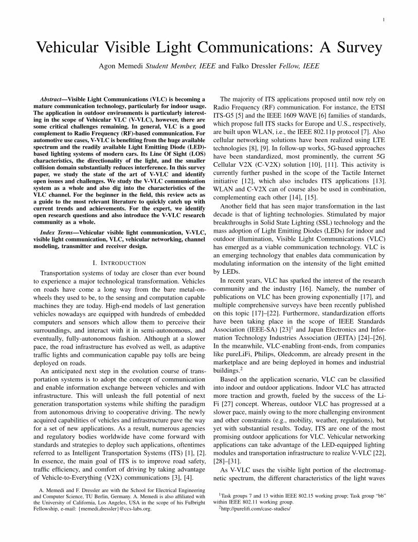
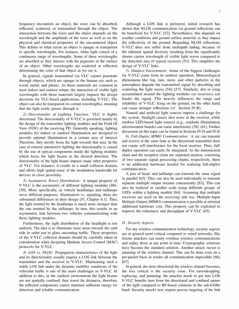
Figure 2 shows a generic representation of the main buildingblocks of a V-VLC system. The transmitter consists of a signalprocessing block including the modulator, and the transmitterfront-end (i.e., LED-based headlamps and taillamps). Thereceiver side consists of optical elements, which can be usedoptionally in front of the receiver, the actual receiver device, andthe receiver-specific signal processing block for demodulationand decoding. The space between the transmitter and receiveris referred to as the optical channel.
Modulation and digital-to-analog conversion of the informa-tion bits is done in the scope of the signal processing block [19].The exact structure and functioning of the signal processingblock depends on the actual deployed platform. Popularapproaches include Software Defined Radio (SDR)-basedplatforms [77], [78], FPGAs [79], and custom developmentplatforms [80]. However, commercially available VLC-enablingdevices, like Li-1st have also been deployed [62]. Since V-VLCis in an early stage of development, most of the platforms fromthe literature, including the aforementioned, are used for rapidprototyping and small-scale field tests.
The LED driving circuit combines the modulated signal withthe bias current required to drive the high-power LEDs [18](as opposed to low-power LEDs used for indoor VLC). Thisway, information gets modulated onto the intensity of the lightthat is emitted by the transmitter front-end [81, Chapter 2.2].The design of the driver circuit is crucial for VLC as it has toprovide correct biasing to ensure that the LEDs are driven atoptimal operating point, and there is no signal clipping beforemodulation. A low operating point of the LED causes clippingof the negative parts of the signal, whereas a high operatingpoint might exceed the linear region of the LED, distortingthe signal and possibly damaging the LED. Open Sourceimplementations of the driving circuit have been presented, forexample, in [82], [83].
Once the light is emitted by the LEDs, it interacts withthe optical elements within the lighting module that controlthe shape of the emitted beam according to automotiveregulations [75]. Optical elements have a strong influenceon the resulting signal. For example, lenses can be used tofocus the light on a certain point in the distance, and matrixlights even allow spatial separation of multiple transmissionsusing the different LEDs pointing in different (but overlapping)directions [64].
As the signal is propagating through the optical channel,it is subject to different propagation phenomena. Also, itis attenuated due to path loss and further degraded due todisturbances of the outdoor channel. A detailed discussionabout the characteristics of the V-VLC channel and its modelingis presented in Sections IV and V, respectively.
If not attenuated below the sensitivity threshold of thereceiver, the signal arrives at the receiver on the direct link orvia reflections. On the receiving side, an optical filter can beused in front of the receiver. This helps increasing the Signal-to-Noise Ratio (SNR) of the system by filtering out opticalchannels that are not of interest and may contain noise. Inaddition, other optical elements (e.g., lenses) can be used to
7
Output bitsInput bits Signal
processing
Signal
processing
CCS Labs
Optical
channel
Transmitter front-end
(with embedded optics)
Receiver front-end
(with optional optics)
Artificial light
sources
Natural light sources
and weather conditions
LED driver
Figure 2. Building blocks of a generic V-VLC system. The illustration shows, from left to right, the sender including signal processing (encoding, modulation),the LED driver logic, and the optical transmitter front-end; the channel which is influenced by interference from other light sources, weather effects, andreflections; and the receiver, including optical front-end, and the signal processing (demodulation, decoding).
focus the light towards receiver’s aperture, therefore, improvingthe received signal strength via optical pre-amplification (cf.Section VI-C) [29], [77], [84], [85].
At the receiver, a PD or a camera image sensor is usedto convert the optical signal to an electrical current. Atransimpedance circuit can be used to convert the generatedphotocurrent to a voltage [34]. For camera image sensors, thisis done by the readout circuit [86, Chapter 8.3.2].
The final step is the signal processing block at the receiver.Due to substantial architectural differences between PD andimage sensor-based receivers, the signal processing steps differas well. For instance, camera image sensor-based VLC requiresan image processing step, which does not apply to PD-basedVLC (cf. Section VI-B). In general, during the signal processingthe analog current signal is converted back to digital signal andthe information bits are decoded. We discuss the differencesbetween the PDs and camera image sensors and their propertiesin more detail in Section VI.
B. Transmitter Front-End CharacteristicsThe LED is an optoelectronic device that transduces electrical
energy to optical energy by emitting incoherent light whendriven under forward current. Electrical and optical properties(e.g., current-voltage (I-V) characteristic, capacitance, color)of the LEDs can directly impact communication performance.
There are two conventional techniques to produce white lightusing LEDs. One technique requires the proper combinationof two or more LEDs of different color in a single chip [87].The most common implementation of this technique is thecombination of red, green, and blue LEDs to obtain a tri-chromatic White LED (WLED). From the communicationperspective, the presence of multiple LEDs in a single chipis advantageous as it allows the use of modulation techniquesthat can modulate each of the individual LEDs, hence providehigher data rates [23], [88]. On the other hand, having multipleLEDs increases the complexity and the cost of such devices.
The other technique for producing WLEDs uses phosphorcoating with one or more monochromatic or ultravioletLEDs [87]. The most popular implementation of phosphor-coated WLED is the coating of a blue LED with yellowphosphor layer. In this configuration, some of the blue photonsemitted by the LED are converted to yellow photons as theyinteract with the phosphor layer, whereas other photons escapeunaltered. The mix of blue and yellow photons results in whitelight. The thickness of the phosphor coating determines thecolor temperature of the resulting white light: the thicker theyellow phosphor, the warmer the color temperature. Vehicleheadlamps typically have a cold color temperature between4000–6000 K [75].
During the blue-to-yellow conversion the converted photonsare subject to Stokes shift [87], i.e., the loss of photon energydue to shift from shorter wavelength to longer wavelength. Thisaffects the luminous efficiency of phosphor-coated WLEDs.Nevertheless, because of the simpler design, lower manufactur-ing costs, and better color rendering, phosphor-coated WLEDsare preferred over multi-chip WLEDs.
The modulation bandwidth of phosphor-coated WLEDs isaffected by the slow response time of the phosphor coating,which introduces delays and deteriorates the communicationperformance. To mitigate this issue, one could use a transmis-sive blue optical filter on the receiving side to filter out theyellow light and to focus on the blue component, which can bemodulated faster. This approach can increase the modulationbandwidth to tens of MHz and to support higher data rates [89].However, it does so at the expense of decreased SNR, as a largeportion of the received optical power from the yellow bands isfiltered out [90]. This, in turn, can degrade the performance ofmulti-carrier modulation schemes [91].
One of the main problems on the transmitting end of VLCsystems is the distortion caused by front-end nonlinearities.LEDs have a nonlinear I-V characteristic [92], which resultsin a nonlinear relation between the forward current and the

8
radiated optical power [93]. This presents a major challengein VLC, in particular when multi-carrier modulation schemesare used [94, Chapter 8.3.3]. In such cases, the intensity ofthe different subcarriers can be added constructively resultingin values beyond the linear range of the transmitter, thus, thesignal gets distorted. A typical example of this is OFDM andits high Peak-to-Average Power Ratio (PAPR) [95].
A multitude of different techniques have been used to addresschallenges like nonlinearities and bandwidth limitations inVLC. We focus on V-VLC, therefore, a discussion regardingfundamental system-level VLC performance challenges andcorresponding solutions is beyond the scope of this work. Verygood discussions on this matter can be found in [18], [96].
C. Intensity Modulation / Direct Detection
LEDs are incoherent light sources that emit optical waveswith random phase relationship. As such, in the absenceof a consistent carrier phase [97], it is impractical to use(angle-based) modulation techniques like phase or frequencymodulation. Therefore, different from conventional RF com-munications, where the signal can be modulated in phase,frequency, and amplitude, VLC systems rely on modulatingthe intensity of the optical wave [98, Chapter 2.1]. In opticalwireless communications, this is known as Intensity Modulation(IM). Once the signal is intensity modulated, it is transducedvia the LEDs from the electrical domain to the optical domain,and it passes through the optical channel. Since the intensitycannot be negative, IM imposes that the modulating signalhas to be non-negative unipolar and real valued, as opposedto the bipolar complex valued RF signal [40], [81]. Afterthe signal is adjusted appropriately, many MCSs originallydesigned for RF communications can be used for VLC too.Popular choices in the literature include, On-Off Keying (OOK),OFDM, and Direct Sequence Spread Spectrum (DSSS) [77],[79], [99]. Color-based MCSs, like Color Shift Keying (CSK)or Wavelength Division Multiplexing (WDM), can also be usedfor V-VLC, given that the lighting module deploys multi-colorLEDs [100]. A crucial point to consider when designing anddeploying MCSs for V-VLC is that, they should be sprectrallyefficient to accommodate application’s requirements (e.g.,throughput, delay, robustness) within the limited bandwidth ofLEDs used in exterior automotive lighting (cf. Section III-E).A detailed discussion regarding MCSs for VLC can be foundin [17]–[19].
As the light emitted by the optical emitters is perceivable bythe human eye, the modulated signal has to adhere to variousrather restrictive regulations [72], [74], [75]. These regulationsimpact important properties of the emitted signal, such asthe average optical power [72] or the minimum modulationfrequency.3 Furthermore, any modulation carried out on thetransmitted signal should not impact optical front-end’s primaryfunctionality, which is illumination and/or signaling.
On the receiving side, Direct Detection (DD) is usedto demodulate an IM modulated optical signal. DD is an
3Minimum modulation frequency is defined according to the CriticalFusion Frequency (CFF) [101]. It should be higher than 200 Hz to avoidflickering [102].
Table IISELECTED MILESTONES IN LED TECHNOLOGY FOR EXTERIOR
AUTOMOTIVE LIGHTING IN PRODUCTION CARS.
Milestone Year Model
First use of LEDs for exterior lighting(central high-mount stop lamp) [105]
1980s –
First full-LED taillights 2004 Cadillac DTSFirst use of LEDs in headlamps (daytimerunning lamp) [105], [106]
2004 Audi A8 W12
First use of LEDs for multiple functionsin headlamps
2007 Lexus LS 600h
First full-LED headlamps (North Americasegment)
2007 Cadillac Escalade
First full-LED headlamps [106] 2008 Audi R8
incoherent detection technique, where the data-carrying signalis extracted from the optical intensity incident on the PD.
Due to the square law nature of the PD, the electrical SNRfor an IM/DD VLC link is calculated as the square of theaverage received optical power [96, Chapter 2.4], whereas forRF links it is proportional to the average received electricalpower. As a result, a VLC system requires more optical powerto deliver the same performance as in RF. This imposes achallenging constraint given the restrictive standards limitingthe average optical power for LED-based devices.
D. LED-based Exterior Automotive Lighting
Traditionally, exterior lighting systems in vehicles facilitateactive safety by providing proper forward illumination andsignaling. The former helps for seeing, while the latter forbeing seen [103]. The signaling functionality also conveysinformation to the traffic regarding the presence, dimensions,as well as the current maneuver of the vehicle (e.g., turning,breaking, stopping, reversing). Advanced applications like glare-free high beam, Adaptive Front-Lighting System (AFS) [104],and, most recently, matrix LED-based AFS [64], have beenfurther developed to improve the signaling and illuminationfunctions.
The initial use of LEDs for exterior automotive lighting datesback to 1980s, when red LEDs were first used in vehicles’ rearlighting system, more specifically in the central high-mountstop lamp. By mid-2000s LEDs debuted in the headlamps ofhigh-end models of different car manufacturers, while todaythey are becoming commonplace in all cars [105]–[107]. Aselection of first application of LED lamps in cars is shown inTable II.
There are numerous advantages to using LEDs for exteriorautomotive lighting. For instance, improved robustness againstvibrations extends the lifespan of the lighting modules, evenbeyond the lifetime of a typical vehicle. Improved energyefficiency of the LEDs results in lower fuel consumption,and the smaller form factor allows more space and designfreedom. Most importantly, the quick raise time of LEDs hassafety implications: It provokes quicker reaction from otherdrivers [108] and, therefore, can extend the stopping distancein safety-critical situations [109].
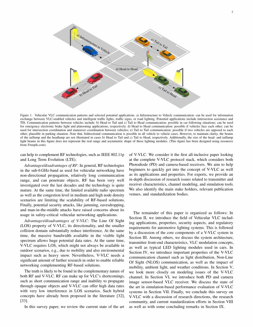
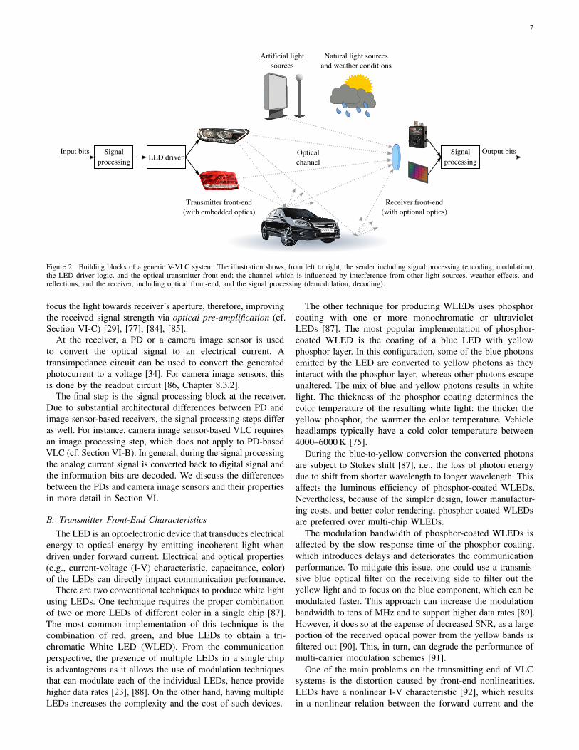
Figure 3 shows the CIE chromacity diagram for vehicles’lighting modules. Historically, specific colors required in traffic
9
Red
Amber
Selective-Yellow
White
0.90.80.70.60.50.40.30.20.0 0.1CIE x
0.9
0.8
0.7
0.6
0.5
0.4
0.3
0.2
0.0
0.1
CIE
y
Figure 3. CIE 1931 color space diagram with annotations for chromacity areasof colors emitted by automotive lighting modules. Trichromatic coordinatesfor the color boundaries are specified in [75] and [110]. Intersection pointsfor the chromacity areas are taken from [111].
lights and in automotive lighting, such as red, amber, andgreen, were obtained by using lenses and bulbs coated with thedesired color. Nowadays, the lenses can be transparent whereasthe desired color is obtained by using colored LEDs.
Although active safety remains the main application forexterior automotive lighting, the presence of LEDs in thesedevices makes them readily available for V-VLC.
E. Head and Taillamps as V-VLC Transmitters
Repurposing of existing vehicle headlamps and taillampsfor communication is technically possible, however, their useas V-VLC transmitters must not hinder the primary functionof illumination. There are many architectural and system-levelfeatures of automotive lighting modules that can positivelyor negatively impact the communication aspect. For instance,even simple manufacturing technicalities, like series or parallelconnection of the LEDs have an impact [112].
One of the main V-VLC performance bottlenecks comes fromthe high-brightness LEDs that are used in exterior automotivelighting. These are high power LEDs with high capacitance(therefore slow raise time), which limits the modulationbandwidth (and therefore the effective communication time)only to a few MHz [48], [84], [112], [113]. Still, it has beendemonstrated in the literature that certain LEDs have an almostlinear frequency response beyond the 3 dB bandwidth, whichcan be exploited if the modulating waveform is optimized togenerate a flat response for the bandwidth beyond the 3 dBbandwidth [112].
Another system-level feature of vehicle lighting modulesthat largely impacts the communication aspect is the functioncarried out by the optical elements within the lighting module:A complex optical system (consisting of, e.g., projection
Motorwayhigh beam
High beam Low beamBendlighting
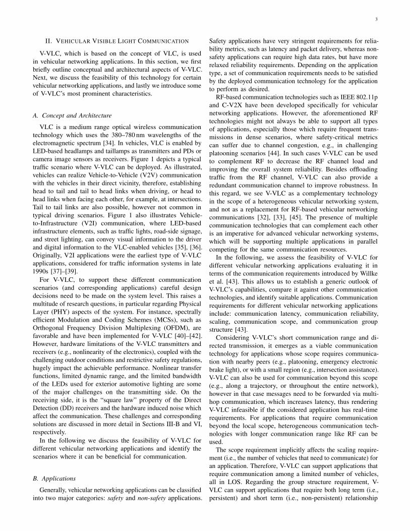
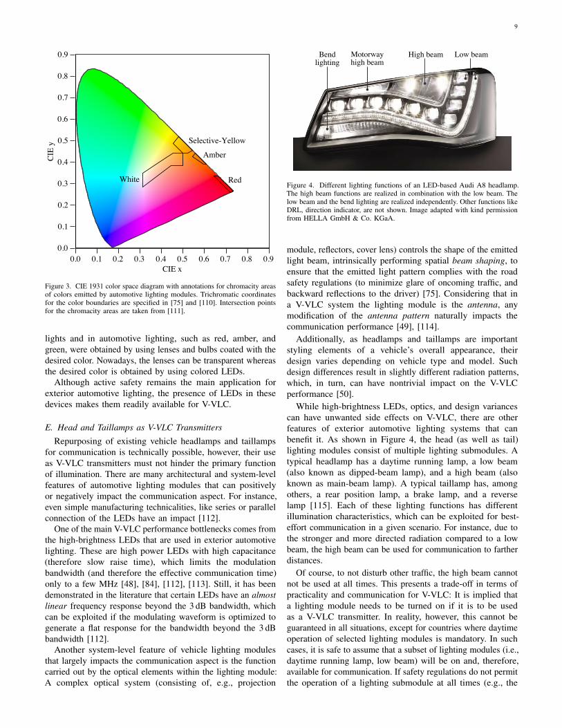
Figure 4. Different lighting functions of an LED-based Audi A8 headlamp.The high beam functions are realized in combination with the low beam. Thelow beam and the bend lighting are realized independently. Other functions likeDRL, direction indicator, are not shown. Image adapted with kind permissionfrom HELLA GmbH & Co. KGaA.
module, reflectors, cover lens) controls the shape of the emittedlight beam, intrinsically performing spatial beam shaping, toensure that the emitted light pattern complies with the roadsafety regulations (to minimize glare of oncoming traffic, andbackward reflections to the driver) [75]. Considering that ina V-VLC system the lighting module is the antenna, anymodification of the antenna pattern naturally impacts thecommunication performance [49], [114].
Additionally, as headlamps and taillamps are importantstyling elements of a vehicle’s overall appearance, theirdesign varies depending on vehicle type and model. Suchdesign differences result in slightly different radiation patterns,which, in turn, can have nontrivial impact on the V-VLCperformance [50].
While high-brightness LEDs, optics, and design variancescan have unwanted side effects on V-VLC, there are otherfeatures of exterior automotive lighting systems that canbenefit it. As shown in Figure 4, the head (as well as tail)lighting modules consist of multiple lighting submodules. Atypical headlamp has a daytime running lamp, a low beam(also known as dipped-beam lamp), and a high beam (alsoknown as main-beam lamp). A typical taillamp has, amongothers, a rear position lamp, a brake lamp, and a reverselamp [115]. Each of these lighting functions has differentillumination characteristics, which can be exploited for best-effort communication in a given scenario. For instance, due tothe stronger and more directed radiation compared to a lowbeam, the high beam can be used for communication to fartherdistances.
Of course, to not disturb other traffic, the high beam cannotnot be used at all times. This presents a trade-off in terms ofpracticality and communication for V-VLC: It is implied thata lighting module needs to be turned on if it is to be usedas a V-VLC transmitter. In reality, however, this cannot beguaranteed in all situations, except for countries where daytimeoperation of selected lighting modules is mandatory. In suchcases, it is safe to assume that a subset of lighting modules (i.e.,daytime running lamp, low beam) will be on and, therefore,available for communication. If safety regulations do not permitthe operation of a lighting submodule at all times (e.g., the
10
high beam), modulation techniques with a very low duty cycle,such as the DarkLight concept [83] where the frequency ofthe pulses is so low that the light is not visible to the humaneye, can be used. Such a low duty cycle, however, comes atthe expense of lower data rate.
One important advantage of exterior automotive lightingis that the lighting modules come in pairs. This enables theimplementation of MIMO techniques, like transmit diversityor spatial multiplexing, for V-VLC at no cost for additionalantenna deployment. Initial simulative [116] and empirical [62],[63] studies on this matter have demonstrated the feasibilityof MIMO for V-VLC. However, as shown by Turan et al.[62] and Narmanlioglu et al. [63], it is important to carefullychoose the system parameters and transmitter combinations forsuch techniques to be beneficial for V-VLC, else they can becounterproductive.
V-VLC can also benefit from state of the art adaptive front-lighting technologies used for forward illumination. Thesesystems adjust the illumination characteristics of the headlampsfor best visibility and comfort in different driving situations,based on sensory feedback (e.g., camera). Some features ofAFS include automatic switch between low beam and highbeam mode depending on oncoming traffic, weather conditions,and road curvature.
Most recent AFSs use matrix-LED technology, where asubgroup of LEDs from the LED matrix can be selectivelyturned on and off, for example, to avoid shining light onthe windshield of oncoming traffic. Since individual LEDshave sharply separated radiation beams, it is possible toselect subgroups of LEDs to communicate with multiplecommunication partners [64]. As a result, spatial multiplexingcan be implemented at a more granular level, i.e., groupsof LEDs within a module, instead of whole modules. Insome first work, Tebruegge et al. [64] have shown that SpaceDivision Multiple Access (SDMA) implemented using matrixLED-based Adaptive Front-Lighting System can effectivelyreduce multiuser interference and help medium access for V-VLC. Similarly, Segata et al. [117] and Schettler et al. [118]demonstrated its benefits for platooning. It is worth noting thatadvanced lighting technologies, like matrix LED-based AFS,are only implemented for headlamps, however, they would alsobe helpful for taillamps (e.g., for tail to head communicationsas in the case of V-VLC-based platooning [118]).
While architectural and system-level features of lightingmodules can impact V-VLC, it is also possible that V-VLCimpacts them. As stated initially, using exterior automotivelighting for communication must not affect their illuminationfunction. However, the frequent switching of the LEDs candegrade the illumination quality and shorten their service lifeover time. The reason for this is junction temperature variationdue to increased current density [119]–[121]. In the currentliterature there is no comprehensive research on the impact ofV-VLC on the deployed LEDs and/or on the overall exteriorlighting performance.
IV. FACTORS THAT INFLUENCE V-VLC COMMUNCIATION
Generic V-VLC properties, which derive from the physicalcharacteristics of the light waves, have been briefly discussed
0
20
40
60
80
100
120
140
160
180
-50 -40 -30 -20 -10 0 10 20 30 40 50
Latitudinal distance in m
Lon
gitu
dina
l di
stan
ce i
n m
-125 -100 -75 -50 -25
Electrical power in dBm
(a) Radiation pattern
-5
0
5
-10 -5 0 5 10
Horizontal angle in degrees
Ver
tica
l an
gle
in d
egre
es
10000 20000 30000 40000
Light intensity in candela
(b) Isocandela plot from photometric measurements
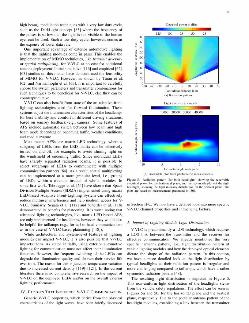
Figure 5. Radiation pattern (for both headlights) showing the receivableelectrical power for the horizontal plane, and the isocandela plot (of the rightheadlight) showing the light intensity distribution on the vertical plane. Theplots are based on measurements presented in [50].
in Section II-C. We now have a detailed look into more specificV-VLC channel properties and influencing factors.
A. Impact of Lighting Module Light Distribution
V-VLC is predominantly a LOS technology, which requiresa LOS link between the transmitter and the receiver foreffective communication. We already mentioned the veryspecific “antenna pattern,” i.e., light distribution pattern ofvehicle lighting modules and how the deployed optical elementsdictate the shape of the radiation pattern. In this section,we have a more detailed look at the light distribution bytypical headlights as their radiation pattern is irregular andmore challenging compared to taillamps, which have a rathersymmetric radiation pattern [48].
The resulting light distribution is depicted in Figure 5.This non-uniform light distribution of the headlights stemsfrom the vehicle safety regulations. The effect can be seen inFigures 5a and 5b, for the horizontal plane and the verticalplane, respectively. Due to the peculiar antenna pattern of theheadlight modules, establishing a link between the transmitter

11
and the receiver and, therefore, the channel conditions in V-VLC, largely depend on the radiation pattern of the lightingmodule and the position of the receiver within that radiationpattern. In the literature, it has been shown that even dirtdeposits in front of the lighting modules can influence theshape of the radiation pattern [30].
The asymmetric and non-uniform property of headlights’radiation pattern poses a challenge in terms of modeling of V-VLC communication. We deepen this discussion in Section Vwhen introducing the mathematical modeling background.
B. Impact of NLOS Communication
Besides LOS communication, in V-VLC there also existNLOS links via reflections from the ground, vehicles, buildings,and other objects in the environment. However, reliablecommunication via those links cannot be guaranteed as thereceived signal strength largely depends on the reflectioncharacteristics of the building material of the object [29],[30], [52], [112], [122]. In V-VLC, the ground surface areabetween a transmitter and receiver provides the strongest NLOScomponents. These reflections are typically characterized asa mix of specular and diffuse [30]. Besides the pavementmaterial, also the weather conditions influence the strengthof the reflections. For example, rain, ice, and snow affect thesurface conditions of the road, which, in turn influence thereflectivity, hence, the strength of the NLOS links [30], [123].
The NLOS components can have comparable signal strengthto the LOS component [112] in scenarios with highly reflectiveroad conditions (cf. [52], where a wet road is emulated bya shiny linoleum indoor pavement), and certain transmitter-receiver distance, where the reflections from the ground arestronger due to convenient reflection angle.
In general, NLOS communication can be beneficial in V-VLC, as the NLOS links of the signal contribute as constructiveinterference: Assuming typical V-VLC LED bandwidth andmodulation and coding schemes, the maximum delay from thereflection paths is orders of magnitude smaller than the symbolduration, hence, the symbols are not negatively affected [52].Besides the NLOS links from the ground, nearby vehicles canalso cause constructive interference in V-VLC [112]. Moreextended discussion about small-scale effects in the V-VLCchannel, regarding the frequency response, time dispersioncharacteristics, and multipath effects in different scenarios canbe found in [112], [122], [124].
Due to the complexity of capturing all of the impactingfactors, and the infeasibility of conducting correspondingexperiments, there is only sporadic work in the literaturefocusing on modeling NLOS V-VLC. Some approaches, havemodeled the NLOS V-VLC links similar to the two-ray ground-reflection model, where the reflective area on the ground ismodeled as a secondary light source [30]. Other approacheshave used Computer-Aided Design (CAD) and simulationtools [122], [124].
C. Impact of the Vehicular Environment
1) Mobility: Assuming no disturbances in the channel, thegeometry between the sender and the receiver (i.e., relative
distance and orientation) and the corresponding hardware char-acteristics (e.g., receiver’s Field Of View and active collectionarea, transmitter’s radiation pattern) have the largest impacton the large-scale channel conditions [125]. The geometricparameters are mainly influenced by vehicles’ mobility, which,in turn, impacts the temporal characteristics of the channel.
The optical channel, characterized by the Channel ImpulseResponse (CIR), does not change significantly if the transmitter-receiver pair move in the order of a wavelength [125]. Inthe vehicular environment, however, typical displacements areorders of magnitude larger than the VLC wavelengths, makingthe V-VLC channel a highly dynamic one. In the V-VLCliterature, temporal characteristics of the channel have beendescribed using coherence time and link duration [114], [126],[127].
Typical driving maneuvers, such as left/right turning, stop-and-go situations, overtaking, and red light stopping, contributeto the channel variation in time. It has been demonstratedthat there is a large variance in the received optical powerwhen vehicles perform turning maneuvers [126]. Althoughthis variation depends highly on the driving maneuver, it isrelatively slow compared to the communication speed. Thus,it can be effectively addressed with adaptive gain control atthe receiver.
2) Road Conditions: Besides the driving maneuvers, whichmainly introduce horizontal movement, the road conditions alsohave an impact on temporal characteristics of the channel. Roadirregularities can introduce vibration and vertical movementthat impacts the transmitter-receiver alignment and, in turn,causes intermittent variation in the optical power. The likelihoodfor this type of variations is smaller in freeways, due to themore regular road structure, as compared to urban roads [126].In general, also due to the more stable driving behavior onhighways, the V-VLC channel varies slower in time (i.e., haslonger coherence time) and the link duration is longer than inthe urban scenarios [114], [126].
D. Impact of Ambient Light
Natural and artificial light sources and interference arethe main factors in the outdoor channel that can impact V-VLC. This includes ambient light from sunlight and skylight(i.e., natural light sources), and light from artificial lightsources, like incandescent and fluorescent lamps, which aredeployed outdoors, e.g., for road illumination, advertisementboards [53], [128]. If the background radiation is strong, i.e.,the average optical power from natural and artificial lightsources is stronger than the desired signal, the communicationis impaired. Under certain conditions (e.g., direct sunlight),the background radiation can be too high and the receiver iscompletely saturated.
Since natural light sources, like sunlight and skylight, arenot modulated, the electrical signal generated at the PD outputis essentially DC current, which can be mostly mitigatedby a low-pass filter and by using higher frequencies forcommunication [18], [95]. In addition to this, the backgroundradiation induces photogenerated noise, characterized as shotnoise, caused by the statistical fluctuation of the number of
12
photons randomly arriving at the PD [19], [96, Section 2.6].The main cause of shot noise is the solar irradiance, whileartificial light sources contribute to the variance in the shotnoise, which can further deteriorate the communication [53].The shot noise is a limiting factor in V-VLC systems in daytime,particularly during sunset and sunrise when the sun is at anglesthat can saturate the PD [29], [58], [128]. Sunny weather alsoreduces the effective bandwidth of the LEDs [112].
Apart from the techniques mentioned above, optics-basedapproaches can be utilized to address ambient light inducednoise. One potential solution is to use highly directionalreceivers that can separate the desired signal from the noisesource. However, this can impact the system’s tolerance tomobility due to a reduced FOV at the receiver [29]. Also,optical filtering of particular wavelengths (e.g., blue filtering)has been explored [129]. Yet, with this technique, besides thenoise, substantial amounts of signal power can be left out onthe blocked wavelengths [90], [91].
In terms of receiver hardware, image sensor receivers areadvantageous in dealing with ambient noise as they enablethe separation of the signal source from the noise sourceby isolating the pixels which contain noise. Further, verythorough discussion about the outdoor channel for opticalcommunications can be found in [95, Chapter 5] [96, Chapter3.3].
E. Impact of Weather Conditions
Other factors in the outdoor channel that heavily affect theV-VLC channel are the challenging weather conditions likefog, rain, and snow. Normally, molecules and particles in theatmosphere interact with the light (via absorption, scattering,diffraction) thus, diverging the beams and attenuating thetransmitted signal. Under bad weather conditions these effectsare much more severe, as fog, rain, and snow consist of largerparticles which have large-scale impact on V-VLC. This, inturn, affects the range and reliability of the V-VLC system.
Initial studies characterizing the impact of weather conditionson V-VLC performance have considered different weatherphenomena, including fog [54]–[58], rain [55], [57], [130],[131], snow [59], turbulence [57], [61], [130], and solarirradiance [58], [128]. Empirical and simulation-based studieshave demonstrated that fog has the biggest impact on V-VLCcompared to rain and snow [55], [57], [131], while a fewanalytical studies show that dry snow can be more detrimentalto the system performance than fog [58], [59]. According toempirical measurements, for the most challenging scenario,that is dense fog, reliable communication up to 20 m withimage sensor receiver, and up to 15 m with PD for the highestpermissible modulation scheme is possible [55]–[57], [131].
V. CHANNEL MODELING
A. Modeling Channel DC Gain
Since visible light and infrared have comparable wavelength,they share similar properties. As a result, multiple modelsand techniques for characterizing the VLC channel havebeen directly adopted from the results published on infraredcommunication [21], [53]. One of the most widely used models
for calculating path loss in VLC channels is based on thechannel DC gain H(0), introduced by Kahn and Barry [53]for IM/DD-based indoor infrared communications. H(0) relatesreceived optical power P and transmitted optical power Pt as
P = H(0)Pt. (1)
H(0) does not consider any frequency dependent effects,since infrared channels have a relatively flat frequency re-sponse near DC [132], [133], which also holds true for VLCchannels [86, Chapter 2.4.1] [112].
B. Transmitter and Receiver Modeling using Channel DC Gain
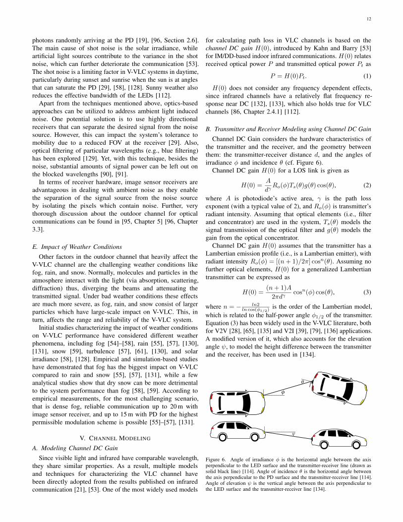
Channel DC Gain considers the hardware characteristics ofthe transmitter and the receiver, and the geometry betweenthem: the transmitter-receiver distance d, and the angles ofirradiance φ and incidence θ (cf. Figure 6).
Channel DC gain H(0) for a LOS link is given as
H(0) =A
dγRo(φ)Ts(θ)g(θ) cos(θ), (2)
where A is photodiode’s active area, γ is the path lossexponent (with a typical value of 2), and Ro(φ) is transmitter’sradiant intensity. Assuming that optical elements (i.e., filterand concentrator) are used in the system, Ts(θ) models thesignal transmission of the optical filter and g(θ) models thegain from the optical concentrator.
Channel DC gain H(0) assumes that the transmitter has aLambertian emission profile (i.e., is a Lambertian emitter), withradiant intensity Ro(φ) = [(n+ 1)/2π] cosn(θ). Assuming nofurther optical elements, H(0) for a generalized Lambertiantransmitter can be expressed as
H(0) =(n+ 1)A
2πdγcosn(φ) cos(θ), (3)
where n = − ln2ln cos(φ1/2) is the order of the Lambertian model,
which is related to the half-power angle φ1/2 of the transmitter.Equation (3) has been widely used in the V-VLC literature, bothfor V2V [28], [65], [135] and V2I [39], [79], [136] applications.A modified version of it, which also accounts for the elevationangle ψ, to model the height difference between the transmitterand the receiver, has been used in [134].
θ
φ
ψ
Figure 6. Angle of irradiance φ is the horizontal angle between the axisperpendicular to the LED surface and the transmitter-receiver line (drawn assolid black line) [114]. Angle of incidence θ is the horizontal angle betweenthe axis perpendicular to the PD surface and the transmitter-receiver line [114].Angle of elevation ψ is the vertical angle between the axis perpendicular tothe LED surface and the transmitter-receiver line [134].
13
Even though the Lambertian emission profile might bea good approximation for transmitters with a regular andsymmetric emission profile, this does not hold true for exteriorautomotive lighting, which use beam shaping components [137].Automotive headlamps use complex optical systems to imple-ment an asymmetric radiation pattern with non-uniform lightdistribution (cf. Figure 5) as required by automotive regulations(cf. Section II-C). This characteristic cannot be captured bythe Lambertian emission based models, which is one of themain challenges for accurate V-VLC channel modeling.
C. More Realistic V-VLC Transmitter and Receiver Modeling
Since the Lambertian emission profile is not the idealapproach for modeling V-VLC transmitters’ radiation pattern,more realistic approaches have been considered in the liter-ature. Some approaches use empirically measured radiationpatterns from vehicles’ actual lighting modules, which areanalytically fitted and used for vehicular networking simulationframeworks [49], [138]. These models can rather accuratelymodel the difference in light distribution within a lightingmodule’s radiation pattern, but they are limited to the par-ticular measurement setup (e.g., lighting module, photodiode,geometry) and cannot always be generalized. This can bea shortcoming, having in mind the design variances amongvehicle manufacturers and models [114], which has significantimpact on V-VLC performance [50]. A more realistic modelingof the transmitter is possible when using CAD models [122],[124] or high resolution measurements of the light distributionof lighting modules provided by the vendors [50].
One factor that can impact transmitter’s radiation pattern butis seldom considered in the literature is the presence of particles,i.e., dirt or other formations, in front of the lenses. This factorshould be considered in conjunction with the modeled weatherconditions, as the type of deposits in front of the lenseswill largely depend on the weather and the resulting roadconditions [30], [139].
Modeling of the V-VLC receiver is easier compared tothe transmitters, because the hardware characteristics of thereceiver do not have any peculiar characteristics (e.g., as thenon-uniform radiation pattern of the headlights). The simplestway to model a PD receiver is to account for simple hardwarespecifications, such as detector’s active area, and the optionaloptical elements in front of the receiver (as in Equation (2)).However, for a more realistic modeling of the system furtherparameters, including but not limited to, the FOV, responsivitycurve, and amplifier gain should be considered. In [50], theauthors use the responsivity curve of the PD to calculate thephotocurrent IPD for a particular LED and PD combination:
IPD =
∫ ∞0
dΦV,Ω(λ) · R(λ)
Km · V (λ) dλdλ, (4)
where ΦV,Ω(λ) is the luminous flux on the receiver surface,R is the responsivity curve, which describes the wavelength-dependent current output of the PD, Km is the maximumvalue of the photometric radiation equivalent, and V (λ) is theluminosity function representing the sensitivity of the humaneye. A highly descriptive analytical model considering multipleparameters of a V-VLC system is presented in [30].
D. Modeling Noise
There are two types of noise usually considered in the V-VLC literature: Shot noise induced by the background radiationfrom ambient light sources (cf. Section IV-D) and thermal noisefrom the thermal fluctuation of the electrons in receiver (pre-amplification) circuits [96, Chapter 2.4.6]. This is the dominanttype of noise in the absence of ambient light. Both, shot andthermal noise are signal-independent and can be modeled asGaussian noise. The total noise variance for a typical V-VLCsystem is given as
σ2total = σ2
shot + σ2thermal. (5)
According to Luo et al. [30], the variance of the shot noisecan be expressed as
σ2shot = 2eBs(RPr + IbI2), (6)
where e = 1.602× 10⁻¹⁹ C is the elementary positive charge,Bs is the system bandwidth, R is the average responsivity ofthe PD, Pr is the average received optical power, Ib is noisecurrent from received background radiation, and I2 = 0.562 isthe noise bandwidth factor for the background noise [140].
Considering a resistor of resistance R at absolute temperatureT , the variance of the thermal noise for a system bandwidthBs is expressed as [141]
σ2thermal =
4kBT
RBs, (7)
where kB = 1.380649× 10⁻²³ J/K is the Boltzmann constant.In the literature R is modeled as load resistance at 50 Ω [48],[50].
More elaborate equations of shot and thermal noise, ac-counting for receiver’s hardware specifics (e.g., PIN/FETtransimpedance receiver, feedback resistor noise, FET channelnoise), can be found in [61], [140]. Note that, the noisecharacteristics of the system will vary depending on theparticular receiver, as well as receiver type (PD, camera imagesensor) [96, Chapter 2.6] [86, Chapter 8.3.3]. However, as thepredominant types of noise, shot noise and thermal noise aregenerally sufficient to model the channel.
E. Modeling of Atmospheric Attenuation
There is only sporadic work in the V-VLC literature thatmodels the impact of weather phenomena (e.g., fog, rain, orsnow) for V-VLC. This is due to the difficulty of conductingempirical experiments to characterize V-VLC under differentweather conditions.
The existing V-VLC literature on this topic adopts well-established models (e.g., Mie theory [142], Kim model [143])from the field of (laser-based) optical wireless communications.These models allow the calculation of an atmospheric attenua-tion coefficient for foggy weather. As this coefficient is relatedto atmospheric visibility parameter it has been generalizedfor rain and snow [56], [59]. The main challenge when usingthis models is to find the correct physical parameters (e.g.,liquid water content, particle size distribution, average particlesize, visibility reduction), which describe the particular weatherphenomena. Further elaboration of the aforementioned models
14
is out of the scope of our work, but thorough discussion canbe found in [96, Chapter 3.3] [144].
When modeling the weather conditions one should considerthe indirect effects that they can have on communication. Whilebad weather conditions certainly impair the LOS link, in certaincases they can impact the reflectivity of the ground (e.g., wetroad due to rain or snow) and, thus, improve the NLOS links.This aspect has been considered in [55], where a CAD toolis used to model reflective characteristics of the environment(e.g., road surface, cars), as well as the physical propertiesrequired to represent fog and rain (according to Mie scatteringtheory). Besides road reflectivity, weather conditions impactthe type of deposits that are accumulated in front of a lightingmodule, which in turn influence the light output of that lightingmodule.
VI. VEHICULAR VLC RECEIVERS
A V-VLC system can deploy a PD or a camera image sensorto receive the optical signal transmitted by the LED-basedhead- and taillamps. The intensity-modulated optical signal isconverted to an electrical current signal and passed for decodingand demodulation to the rest of the receiver chain.
Both, PD and camera-based receivers have been widelyconsidered for V-VLC [22], [28], [29], [145], [146]. Asthese two types of receivers differ fundamentally in termsof hardware architecture and design, the way how they “see”the optical signal and process it differs as well. Basically, thisarchitectural difference determines the overall design of theV-VLC system and its performance: Modulation and codingschemes, mitigation of noise and interference, medium accesscontrol, etc. are all designed differently depending on whethera PD or an image sensor receiver is used. In the following,we discuss PD receivers, camera-based V-VLC, and potentialoptical enhancements for V-VLC.
A. Photodiode-based Receivers
The PD is an optical-to-electrical transducer that generatesan electron for each impinging photon [96, Chapter 2.4]. Thegenerated photocurrent is proportional to the optical poweron the PD’s surface (i.e., irradiance) [98, Chapter 2.1]. Theelectrical power, being proportional to the square of the current,is proportional to the square of the optical power. This makesthe PD a square law device. As mentioned previously, thisproperty is a limiting factor in V-VLC, as the electrical SNRfor an IM/DD link is calculated as the square of the averagereceived optical power. In contrast, in RF communicationsystems, it is proportional to the average received electricalpower.
There are two types of PDs that are typically used for V-VLCsystems: PIN (p-n diode) and Avalanche Photodiode (APD).APDs have higher sensitivity and provide better gain comparedto PIN PDs. There exist high-sensitivity APDs, like the Single-Photon Avalanche Diode (SPAD), which, in simulation, havebeen demonstrated to perform better than conventional APDs,even in adverse weather conditions [147]. Despite this, PINPDs are more favorable for V-VLC due to the better linearityperformance, high temperature tolerance, and lower cost [18].
When choosing the PD receiver for a V-VLC system, oneshould aim for optimal performance while considering hardwareproperties, such as size of the active area, adequate bandwidth,high sensitivity, low noise, and broad linearity range. Theseparameters can greatly impact the performance of the V-VLCapplication. For instance, a PD with a large FOV will havehigher tolerance to horizontal and vertical movement in realdriving scenarios, however, it allows the reception of undesiredsignals, which can reduce the SNR [29], [126].
Most setups described in the V-VLC literature prefer com-mercially available off-the-shelf products to demonstrate thefeasibility of implementing the system both in terms of cost andeffort [77]. However, custom-built solutions are used wheneverthe system uses more advanced techniques [148]. The designof low cost PD-based V-VLC systems is important as, unlikeimage sensor-based V-VLC, which can potentially be realizedusing the front and rear view cameras readily available inmodern vehicles, PD-based V-VLC requires the installationof new devices on the vehicle, which, in turn, increases theoverall vehicle cost.
Further discussion regarding PIN PDs and APDs, includingthe technical differences and comparison between them, canbe found in [96, Chapter 2.4] [98, Chapter 2.2.2].
B. Camera Image Sensor-based V-VLC
V-VLC based on camera image sensor receiver falls in thedomain of Optical Camera Communication (OCC) [149], [150].A substantial amount of work in the V-VLC literature hasfocused on the use of camera image sensors as receivers [151].Cameras are already deployed in modern vehicles for safetyapplications, like pedestrian detection, lane detection, andparking assist. Therefore, such cameras are ready to use for V-VLC [145], [152]. There are many advantages of using camerasfor V-VLC: The rather high spatial resolution of camerasallows separation of noise and signal sources and detection ofmultiple transmitters and, therefore, enabling efficient MIMOV-VLC [150].
A typical OCC receiver consists of an imaging lens, animage sensor, and a readout circuit. The image sensor consistsof multiple micron sized PD pixels, which generate voltageproportional to the number of impinging photons. The lightfrom the imaging lens projected onto the image sensor isconverted to binary data by the readout circuit [86, Chapter8.1.2]. Based on the readout circuit configuration, image sensorscan be classified into rolling shutter and global shutter imagesensors [153]. The global shutter technology, typically usedwith Charge Coupled Device (CCD) image sensors, exposesall of the pixel at once, whereas the rolling shutter technology,typically used with CMOS image sensors, reads pixels onerow/column at a time. This allows comparatively higher datarate. Due to this property, rolling shutter image sensors arepreferred for VLC.
An important limitation of typical CMOS image sensors istheir low frame rate (typically 30–100 fps), which limits thethroughput to tens of bits per second – a fairly low data ratefor vehicular networking applications [154]. As an alternative,high frame rate cameras can be used, however, they are quite
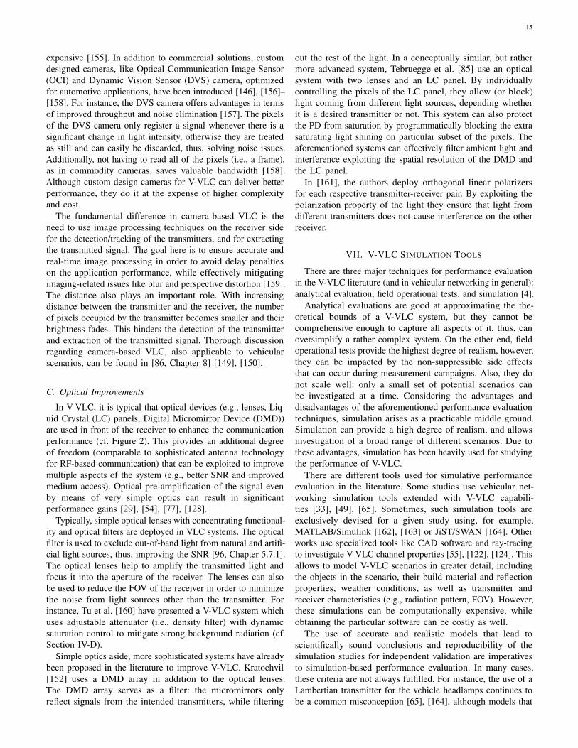
15
expensive [155]. In addition to commercial solutions, customdesigned cameras, like Optical Communication Image Sensor(OCI) and Dynamic Vision Sensor (DVS) camera, optimizedfor automotive applications, have been introduced [146], [156]–[158]. For instance, the DVS camera offers advantages in termsof improved throughput and noise elimination [157]. The pixelsof the DVS camera only register a signal whenever there is asignificant change in light intensity, otherwise they are treatedas still and can easily be discarded, thus, solving noise issues.Additionally, not having to read all of the pixels (i.e., a frame),as in commodity cameras, saves valuable bandwidth [158].Although custom design cameras for V-VLC can deliver betterperformance, they do it at the expense of higher complexityand cost.
The fundamental difference in camera-based VLC is theneed to use image processing techniques on the receiver sidefor the detection/tracking of the transmitters, and for extractingthe transmitted signal. The goal here is to ensure accurate andreal-time image processing in order to avoid delay penaltieson the application performance, while effectively mitigatingimaging-related issues like blur and perspective distortion [159].The distance also plays an important role. With increasingdistance between the transmitter and the receiver, the numberof pixels occupied by the transmitter becomes smaller and theirbrightness fades. This hinders the detection of the transmitterand extraction of the transmitted signal. Thorough discussionregarding camera-based VLC, also applicable to vehicularscenarios, can be found in [86, Chapter 8] [149], [150].
C. Optical Improvements
In V-VLC, it is typical that optical devices (e.g., lenses, Liq-uid Crystal (LC) panels, Digital Micromirror Device (DMD))are used in front of the receiver to enhance the communicationperformance (cf. Figure 2). This provides an additional degreeof freedom (comparable to sophisticated antenna technologyfor RF-based communication) that can be exploited to improvemultiple aspects of the system (e.g., better SNR and improvedmedium access). Optical pre-amplification of the signal evenby means of very simple optics can result in significantperformance gains [29], [54], [77], [128].
Typically, simple optical lenses with concentrating functional-ity and optical filters are deployed in VLC systems. The opticalfilter is used to exclude out-of-band light from natural and artifi-cial light sources, thus, improving the SNR [96, Chapter 5.7.1].The optical lenses help to amplify the transmitted light andfocus it into the aperture of the receiver. The lenses can alsobe used to reduce the FOV of the receiver in order to minimizethe noise from light sources other than the transmitter. Forinstance, Tu et al. [160] have presented a V-VLC system whichuses adjustable attenuator (i.e., density filter) with dynamicsaturation control to mitigate strong background radiation (cf.Section IV-D).
Simple optics aside, more sophisticated systems have alreadybeen proposed in the literature to improve V-VLC. Kratochvil[152] uses a DMD array in addition to the optical lenses.The DMD array serves as a filter: the micromirrors onlyreflect signals from the intended transmitters, while filtering
out the rest of the light. In a conceptually similar, but rathermore advanced system, Tebruegge et al. [85] use an opticalsystem with two lenses and an LC panel. By individuallycontrolling the pixels of the LC panel, they allow (or block)light coming from different light sources, depending whetherit is a desired transmitter or not. This system can also protectthe PD from saturation by programmatically blocking the extrasaturating light shining on particular subset of the pixels. Theaforementioned systems can effectively filter ambient light andinterference exploiting the spatial resolution of the DMD andthe LC panel.
In [161], the authors deploy orthogonal linear polarizersfor each respective transmitter-receiver pair. By exploiting thepolarization property of the light they ensure that light fromdifferent transmitters does not cause interference on the otherreceiver.
VII. V-VLC SIMULATION TOOLS
There are three major techniques for performance evaluationin the V-VLC literature (and in vehicular networking in general):analytical evaluation, field operational tests, and simulation [4].
Analytical evaluations are good at approximating the the-oretical bounds of a V-VLC system, but they cannot becomprehensive enough to capture all aspects of it, thus, canoversimplify a rather complex system. On the other end, fieldoperational tests provide the highest degree of realism, however,they can be impacted by the non-suppressible side effectsthat can occur during measurement campaigns. Also, they donot scale well: only a small set of potential scenarios canbe investigated at a time. Considering the advantages anddisadvantages of the aforementioned performance evaluationtechniques, simulation arises as a practicable middle ground.Simulation can provide a high degree of realism, and allowsinvestigation of a broad range of different scenarios. Due tothese advantages, simulation has been heavily used for studyingthe performance of V-VLC.
There are different tools used for simulative performanceevaluation in the literature. Some studies use vehicular net-working simulation tools extended with V-VLC capabili-ties [33], [49], [65]. Sometimes, such simulation tools areexclusively devised for a given study using, for example,MATLAB/Simulink [162], [163] or JiST/SWAN [164]. Otherworks use specialized tools like CAD software and ray-tracingto investigate V-VLC channel properties [55], [122], [124]. Thisallows to model V-VLC scenarios in greater detail, includingthe objects in the scenario, their build material and reflectionproperties, weather conditions, as well as transmitter andreceiver characteristics (e.g., radiation pattern, FOV). However,these simulations can be computationally expensive, whileobtaining the particular software can be costly as well.
The use of accurate and realistic models that lead toscientifically sound conclusions and reproducibility of thesimulation studies for independent validation are imperativesto simulation-based performance evaluation. In many cases,these criteria are not always fulfilled. For instance, the use of aLambertian transmitter for the vehicle headlamps continues tobe a common misconception [65], [164], although models that
16
can reasonably approximate [138] or realistically model [49]the headlamp characteristics exist in the literature. Regardingreproducibility, in some studies the simulation models arenot available to the public. Examples include the VENTOSextension by Ucar et al. [33], the SHINE extension by Masiniet al. [65], the simulator used by Ishihara et al. [32], whichhave been developed to investigate V-VLC but, despite theimportant findings reported in the related research papers, werenot made Open Source for re-use in our research community.
More recently, Veins VLC4 has been published, which, to thebest of our knowledge, is the only Open Source approach to V-VLC. The tool makes use of channel models based on realistichead- and taillamp radiation patterns obtained via empiricalmeasurements [48] or provided by vendors [50] and, therefore,accurately models the light distribution of different vehicles.Being based on the Veins simulation framework [165], it canreadily be used for investigating heterogeneous communicationapproaches combining V-VLC and RF-based communication.
VIII. FURTHER DISCUSSION
In this section, we discuss a range of relevant topics for V-VLC, including future research directions, the V-VLC researchcommunity, and standardization efforts.
A. Future Research
Since V-VLC is a rather novel technology, the V-VLCresearch community has mainly focused on the understandingand characterization of the V-VLC channel and, more recently,the development of first prototypes for V-VLC. There are stillmany open questions regarding physical layer aspects of thistechnology, in particular regarding the performance of V-VLCin the outdoor channel and the development of more realisticchannel models. Nonetheless, experimental studies in real-driving scenarios have shown promising results with respectto the feasibility of this technology for vehicular networkingapplications [84], [99].
While the fundamental physical layer aspects of V-VLC arebeing addressed in the literature, as a natural next step, researchwill now also focus on higher layer protocols. Medium accessis one topic that has not been investigated in depth so far.Initial results have shown that in certain scenarios (e.g., closeto intersections) interference from headlamps of vehicles thatface each other can cause substantial packet loss [166] – aproblem which can be addressed by a MAC protocol [65]. Thedesign of a MAC, however, needs to take in consideration V-VLC specific properties, such as headlamp/taillamp asymmetryand the directional collision domain, that can greatly impactthe protocol design. The advantage of V-VLC is that a potentialMAC protocol can be designed not only to solve the mediumaccess problem as in traditional RF directional communications,but also by taking advantage of the specific receiver hardwareused in V-VLC, e.g., an onboard camera can be used todetect different transmitters and coordinate medium accessaccordingly.
Another interesting research topic that requires furtherinvestigation is the integration (and coexistence) of V-VLC
4https://ccs-labs.org/software/veins-vlc/
with other vehicular communication technologies such as IEEE802.11p and C-V2X. In such a heterogeneous system, differenttechnologies can compensate for the drawbacks of each otherand improve the overall application performance. Initial resultshave shown that a V-VLC and RF heterogeneous system canhighly benefit platooning application, both in highway andurban scenarios [45], [47], [118], as well as improve platoonsecurity [32], [33].
Considering the dynamic nature of the vehicular environment,V-VLC can benefit from adaptive techniques both in physicallayer and receiver design. For instance, a variable gain controlcan be deployed at the receiver to address the problem ofchannel fluctuation when the transmitter-receiver distance variesslowly. In addition to this, it is possible to design a systemwhich dynamically adapts the MCS based on the availableSNR [167]. On the hardware level, the V-VLC receiver canbe modified to enable dynamic adaptation of its FOV, or usean adjustable optical attenuator [160], to minimize incomingnoise, while an electronic system, which allows real-timetracking of the transmitters for improved signal reception, canbe incorporated with the receiver [168].
Another potential future research direction is the explorationof novel automotive lighting technologies for V-VLC. Forinstance, the SmartCorner headlamp system with V-VLCcapabilities, which also integrates a LIDAR, infrared camera,and a PD has been presented in [169]. We have alreadyshown the benefits of matrix LED-based AFS for V-VLC [64].This, for example, can be extended to MIMO systems, wheresubsets of the LEDs from the LED matrix can be used totransmit different streams of data in parallel. This can becomplemented by receive diversity techniques to overcomeinterference scenarios [170]. AFS can further be exploitedfor best effort communication, where the most fitting lightingfunction is chosen for communication (cf. Section III-E).
The use of exterior automotive lighting for novel applicationsin addition to V-VLC is an interesting topic to look into.Potential alternatives in the literature include positioning [28],speed estimation [171], distance measurement [162].
B. V-VLC Research Community
The V-VLC research community is at the intersection be-tween the vehicular networking community and the VLC / OCCcommunity from the field of optical wireless communications.Due to this diversity, research in this field has been producedby researchers of different backgrounds and published ina wide range of conferences and journals from the fieldsof optics, photonics, and wireless (vehicular) networking.Many articles have been published on journals and conferenceproceedings from the Society of Photo-Optical InstrumentationEngineers (SPIE), the IEEE Communications Society, andthe IEEE Photonics Society. Recently, the IEEE VehicularNetworking Conference (VNC) has played a particular roleas a preferred publication venue for many impactful worksin the field. Unfortunately, the V-VLC community is stillrather scattered. However, some prominent stakeholders arealready collaborating together, for example, in the scope ofthe Horizon 2020 Visible light based Interoperability and

17
Networking (VisIoN) project, which focuses on research onVLC for different scenarios, including smart transportation.
As the V-VLC reseaerch landscape is constantly evolving, wehave created a website5 to keep track of recent developmentsin the field.
C. Standardization Efforts
Although multiple VLC-related standards have been pub-lished so far (and others are in preparation in the meanwhile),these standards are mostly not tailored specifically for vehic-ular applications. The first VLC-related standards have beenpublished by JEITA [24]–[26], whereas IEEE has publishedthe IEEE 802.15.7 standard [23], which defines a PHY andMAC for VLC. These standards are generally intended forindoor VLC. The IEEE 802.15.7 standard proposes threedifferent PHYs – one of them for outdoor communications,therefore, potentially applicable to V-VLC. However, there arenot many prototypes in the V-VLC literature that follow theIEEE 802.15.7 standard (a few systems have been presentedin [172]–[174]), mainly because the standard was not designedwith vehicular applications in mind, and its specificationrather increases the complexity (and cost) of the system. Anexhaustive discussion regarding the feasibility of the IEEE802.15.7 standard for V-VLC is provided by Cailean andDimian [175]. Currently, there is a task group in the scope ofIEEE 802.15 working on the revision of the standard [23] byfocusing on OCC and LED-based identification, but there areno particular efforts to adapt it for V-VLC.
In addition to IEEE 802.15.7 standard, there are two ongoingstandardization efforts in the scope of IEEE: Task group 13,within the IEEE 802.15 working group; and task group “bb”,within the IEEE 802.11 working group. IEEE 802.15.13 isa revision of IEEE 802.15.7 focusing on high-rate PD-basedVLC. It defines a PHY and a MAC capable of deliveringdata rates up to 10 Gbit/s at distances up to 200 m for LOScommunication. Standard compliant V-VLC systems have beenpresented in [174], [176]. Given the target data rate and itscapabilities, the IEEE 802.15.13 standard might be a better fitfor V-VLC applications, although it is not explicitly designedfor this purpose.
The IEEE 802.11bb task group works on another VLC-related standard. The goal of this task group is to developan amendment for base IEEE 802.11 standards which wouldallow communication via the light medium. By introducingchanges to the PHY and the MAC, the idea is to take advantageof already established protocols for IEEE 802.11 and ensureinteroperability with IEEE 802.11 compliant devices. This strat-egy might have many benefits for indoor VLC and consumerelectronics, however its implications for V-VLC need to beinvestigated. In that regard, a potential interoperability betweenV-VLC and IEEE 802.11p can be particularly interesting. Veryrecently, Amjad et al. [77] presented an IEEE 802.11 compliantV-VLC system, which can likely be adapted to IEEE 802.11bb.
5https://www.v-vlc.org/
IX. CONCLUSION
In conclusion, it can be said that the V-VLC research domainis catching more and more momentum, both in the academicresearch community as well as in the automotive industry.Building upon concept, methods, and technologies known fromindoor VLC as well as from IEEE 802.11 WLAN, substantialprogress has been made recently. This ranges from earlyconceptual studies to simulation experiments and now to firstprototypes. Nevertheless, there are still many open questionsthat need to be investigated in order to mature the technology.In this survey, we revisited the state of the art in V-VLCcommunication systems and highlighted open challenges to bestudied by our research community. We see this survey as areference as well as a guide for both experts and beginners inthe field.
REFERENCES
[1] J. E. Siegel, D. C. Erb, and S. E. Sarma, “A Survey of the ConnectedVehicle Landscape—Architectures, Enabling Technologies, Applica-tions, and Development Areas,” IEEE Transactions on IntelligentTransportation Systems (TITS), vol. 19, no. 8, Aug. 2018.
[2] N.-E. El Faouzi, H. Leung, and A. Kurian, “Data fusion in intelligenttransportation systems: Progress and challenges – A survey,” ElsevierInformation Fusion, vol. 12, no. 1, pp. 4–10, Jan. 2011.
[3] G. Karagiannis, O. Altintas, E. Ekici, G. Heijenk, B. Jarupan, K.Lin, and T. Weil, “Vehicular Networking: A Survey and Tutorial onRequirements, Architectures, Challenges, Standards and Solutions,”IEEE Communications Surveys & Tutorials, vol. 13, no. 4, pp. 584–616,Nov. 2011.
[4] C. Sommer and F. Dressler, Vehicular Networking. CambridgeUniversity Press, 2014.
[5] ETSI, “Intelligent Transport Systems (ITS); Vehicular Communica-tions; GeoNetworking; Part 4: Geographical addressing and forwardingfor point-to-point and point-to-multipoint communications; Sub-part 2:Media-dependent functionalities for ITS-G5,” ETSI, TS 102 636-4-2V1.1.1, Oct. 2013.
[6] IEEE, “IEEE Guide for Wireless Access in Vehicular Environments(WAVE) - Architecture,” IEEE, Std 1609.0-2013, Mar. 2014.
[7] ——, “Wireless Access in Vehicular Environments,” IEEE, Std802.11p-2010, Jul. 2010.
[8] G. Araniti, C. Campolo, M. Condoluci, A. Iera, and A. Molinaro,“LTE for Vehicular Networking: A Survey,” IEEE CommunicationsMagazine (COMMAG), vol. 51, no. 5, pp. 148–157, May 2013.
[9] S. H. Sun, J. L. Hu, Y. Peng, X. M. Pan, L. Zhao, and J. Y. Fang,“Support for vehicle-to-everything services based on LTE,” IEEEWireless Communications, vol. 23, no. 3, Jun. 2016.
[10] M. Boban, A. Kousaridas, K. Manolakis, J. Eichinger, and W. Xu,“Connected Roads of the Future: Use Cases, Requirements, and DesignConsiderations for Vehicle-to-Everything Communications,” IEEEVehicular Technology Magazine (VTMag), vol. 13, no. 3, pp. 110–123,Sep. 2018.
[11] S. Chen, J. Hu, Y. Shi, Y. Peng, J. Fang, R. Zhao, and L. Zhao, “Vehicle-to-Everything (V2X) Services Supported by LTE-based Systems and5G,” IEEE Communications Standards Magazine, vol. 1, no. 2, pp. 70–76, Jul. 2017.
[12] M. Simsek, A. Aijaz, M. Dohler, J. Sachs, and G. P. Fettweis,“5G-Enabled Tactile Internet,” IEEE Journal on Selected Areas inCommunications (JSAC), vol. 34, no. 3, pp. 460–473, Mar. 2016.
[13] F. Dressler, F. Klingler, M. Segata, and R. Lo Cigno, “CooperativeDriving and the Tactile Internet,” Proceedings of the IEEE, vol. 107,no. 2, pp. 436–446, Feb. 2019.
[14] K. Zheng, Q. Zheng, P. Chatzimisios, W. Xiang, and Y. Zhou, “Hetero-geneous Vehicular Networking: A Survey on Architecture, Challenges,and Solutions,” IEEE Communications Surveys & Tutorials, vol. 17,no. 4, pp. 2377–2396, Jun. 2015.
[15] G. Naik, B. Choudhury, and J.-M. Park, “IEEE 802.11bd & 5G NRV2X: Evolution of Radio Access Technologies for V2X Communica-tions,” IEEE Access, 2019.
[16] R. Zhang, “Localisation, Communication and Networking with VLC:Challenges and Opportunities,” arXiv, cs.IT 1709.01899, Sep. 2017.[Online]. Available: https://arxiv.org/abs/1709.01899.
18
[17] L. E. M. Matheus, A. B. Vieira, L. F. M. Vieira, M. A. M. Vieira, andO. Gnawali, “Visible Light Communication: Concepts, Applicationsand Challenges,” IEEE Communications Surveys & Tutorials, vol. 21,no. 4, pp. 3204–3237, 2019.
[18] D. Karunatilaka, F. Zafar, V. Kalavally, and R. Parthiban, “LEDBased Indoor Visible Light Communications: State of the Art,” IEEECommunications Surveys & Tutorials, vol. 17, no. 3, pp. 1649–1678,Mar. 2015.
[19] P. H. Pathak, X. Feng, P. Hu, and P. Mohapatra, “Visible LightCommunication, Networking, and Sensing: A Survey, Potential andChallenges,” IEEE Communications Surveys & Tutorials, vol. 17,no. 4, pp. 2047–2077, Feb. 2015.
[20] N. Cen, J. Jagannath, S. Moretti, Z. Guan, and T. Melodia, “LANET:Visible-light ad hoc networks,” Elsevier Ad Hoc Networks, pp. 107–123, Mar. 2019.
[21] Y. Qiu, H.-H. Chen, and W.-X. Meng, “Channel modeling for visiblelight communications—a survey,” Wiley Wireless Communicationsand Mobile Computing (WCMC), pp. 2016–2034, Dec. 2016.
[22] A.-M. Cailean and M. Dimian, “Current Challenges for Visible LightCommunications Usage in Vehicle Applications: A Survey,” IEEECommunications Surveys & Tutorials, vol. 4, no. 19, pp. 2681–2703,2017.
[23] “IEEE Standard for Local and metropolitan area networks – Part 15.7:Short-Range Wireless Optical Communication Using Visible Light,”IEEE, Std 802.15.7-2011, Sep. 2011.
[24] “Visible Light Communications System,” JEITA, Std CP-1221, Mar.2007.
[25] “Visible Light ID System,” JEITA, Std CP-1222, Jun. 2007.[26] “Visible Light Beacon Systems,” JEITA, Std CP-1223, Mar. 2013.[27] H. Haas, L. Yin, Y. Wang, and C. Chen, “What is LiFi?” Journal of
Lightwave Technology, vol. 34, no. 6, pp. 1533–1544, Mar. 2016.[28] S.-H. Yu, O. Shih, H.-M. Tsai, N. Wisitpongphan, and R. Roberts,
“Smart automotive lighting for vehicle safety,” IEEE CommunicationsMagazine (COMMAG), vol. 51, no. 12, pp. 50–59, Dec. 2013.
[29] C. B. Liu, B. Sadeghi, and E. W. Knightly, “Enabling Vehicular VisibleLight Communication (V2LC) Networks,” in 8th ACM InternationalWorkshop on Vehicular Internetworking (VANET 2011), Las Vegas,NV: ACM, Sep. 2011, pp. 41–50.
[30] P. Luo, Z. Ghassemlooy, H. Le Minh, E. Bentley, A. Burton,and X. Tang, “Performance analysis of a car-to-car visible lightcommunication system,” Applied Optics, vol. 54, no. 7, pp. 1696–1706,Mar. 2015.
[31] M. Uysal, Z. Ghassemlooy, A. Bekkali, A. Kadri, and H. Menouar,“Visible Light Communication for Vehicular Networking: PerformanceStudy of a V2V System Using a Measured Headlamp Beam PatternModel,” IEEE Vehicular Technology Magazine (VTMag), vol. 10, no. 4,pp. 45–53, Dec. 2015.
[32] S. Ishihara, R. V. Rabsatt, and M. Gerla, “Improving Reliability ofPlatooning Control Messages Using Radio and Visible Light HybridCommunication,” in 7th IEEE Vehicular Networking Conference (VNC2015), Kyoto, Japan: IEEE, Dec. 2015, pp. 96–103.
[33] S. Ucar, S. Coleri Ergen, and O. Ozkasap, “IEEE 802.11p and VisibleLight Hybrid Communication based Secure Autonomous Platoon,”IEEE Transactions on Vehicular Technology (TVT), vol. 67, no. 9,pp. 8667–8681, Sep. 2018.
[34] M. A. Khalighi and M. Uysal, “Survey on Free Space OpticalCommunication: A Communication Theory Perspective,” IEEE Com-munications Surveys & Tutorials, vol. 16, no. 4, pp. 2231–2257, Jun.2014.
[35] M. Vieira, M. A. Vieira, P. Louro, and P. Vieira, “Connected cars:road-to-vehicle communication through visible light,” in SPIE OPTO2019, San Francisco, CA, Feb. 2019.
[36] E. Eso, Z. Ghassemlooy, S. Zvanovec, A. Gholami, A. Burton, N. B.Hassan, and O. I. Younus, “Experimental Demonstration of Vehicle toRoad Side Infrastructure Visible Light Communications,” in 2nd WestAsian Colloquium on Optical Wireless Communications (WACOWC2019), Tehran, Iran, Apr. 2019.
[37] P. A. Hochstein, “Traffic Information System Using Light EmittingDiodes,” US Patent Office, design US005633629, May 1997.
[38] G. Pang, C.-h. Chan, H. Liu, and T. Kwan, “Dual use of LEDs:Signaling and Communications in ITS,” in 5th World Congress onIntelligent Transport Systems (ITS 1998), Seoul, South Korea, Oct.1998.
[39] M. Akanegawa, Y. Tanaka, and M. Nakagawa, “Basic study on trafficinformation system using LED traffic lights,” IEEE Transactions onIntelligent Transportation Systems (TITS), vol. 2, no. 4, pp. 197–203,Dec. 2001.
[40] J. Armstrong, “OFDM for Optical Communications,” Journal ofLightwave Technology, vol. 27, no. 3, pp. 189–204, Feb. 2009.
[41] M. Z. Afgani, H. Haas, H. Elgala, and D. Knipp, “Visible LightCommunication Using OFDM,” in 2nd International Conference onTestbeds and Research Infrastructures for the Development of Networksand Communities (TRIDENTCOM 2006), Barcelona, Spain: IEEE,Mar. 2006.
[42] Z. Wang, T. Mao, and Q. Wang, “Optical OFDM for visible lightcommunications,” in 13th International Wireless Communications andMobile Computing Conference (IWCMC 2017), Valencia, Spain: IEEE,Jun. 2017, pp. 1190–1194.
[43] T. L. Willke, P. Tientrakool, and N. F. Maxemchuk, “A Survey ofInter-Vehicle Communication Protocols and Their Applications,” IEEECommunications Surveys & Tutorials, vol. 11, no. 2, pp. 3–20, Jun.2009.
[44] M. Segata, B. Bloessl, S. Joerer, C. Sommer, M. Gerla, R. Lo Cigno,and F. Dressler, “Towards Communication Strategies for Platooning:Simulative and Experimental Evaluation,” IEEE Transactions onVehicular Technology (TVT), vol. 64, no. 12, pp. 5411–5423, Dec.2015.
[45] M. Schettler, A. Memedi, and F. Dressler, “Deeply Integrating VisibleLight and Radio Communication for Ultra-High Reliable Platooning,”in 15th IEEE/IFIP Conference on Wireless On demand NetworkSystems and Services (WONS 2019), Wengen, Switzerland: IEEE,Jan. 2019, pp. 36–43.
[46] J. Ploeg, B. Scheepers, E. van Nunen, N. van de Wouw, andH. Nijmeijer, “Design and Experimental Evaluation of CooperativeAdaptive Cruise Control,” in 14th IEEE International Conference onIntelligent Transportation Systems (ITSC 2011), Washington, D.C.:IEEE, Oct. 2011, pp. 260–265.
[47] T. Hardes and C. Sommer, “Towards Heterogeneous CommunicationStrategies for Urban Platooning at Intersections,” in 11th IEEEVehicular Networking Conference (VNC 2019), Los Angeles, CA:IEEE, Dec. 2019, pp. 322–329.
[48] H.-Y. Tseng, Y.-L. Wei, A.-L. Chen, H.-P. Wu, H. Hsu, and H.-M. Tsai,“Characterizing link asymmetry in vehicle-to-vehicle Visible LightCommunications,” in 7th IEEE Vehicular Networking Conference(VNC 2015), Kyoto, Japan: IEEE, Dec. 2015, pp. 88–95.
[49] A. Memedi, H.-M. Tsai, and F. Dressler, “Impact of Realistic LightRadiation Pattern on Vehicular Visible Light Communication,” in IEEEGlobal Communications Conference (GLOBECOM 2017), Singapore,Singapore: IEEE, Dec. 2017.
[50] A. Memedi, C. Tebruegge, J. Jahneke, and F. Dressler, “Impactof Vehicle Type and Headlight Characteristics on Vehicular VLCPerformance,” in 10th IEEE Vehicular Networking Conference (VNC2018), Taipei, Taiwan: IEEE, Dec. 2018.
[51] P. R. Boyce, Lighting for Driving: Roads, Vehicles, Signs, and Signals,1st ed. Boca Raton, FL: CRC Press, 2008.
[52] C. Tebruegge, A. Memedi, and F. Dressler, “Empirical Characterizationof the NLOS Component for Vehicular Visible Light Communication,”in 11th IEEE Vehicular Networking Conference (VNC 2019), LosAngeles, CA: IEEE, Dec. 2019, pp. 64–67.
[53] J. Kahn and J. R. Barry, “Wireless Infrared Communications,”Proceedings of the IEEE, vol. 85, no. 2, pp. 265–298, Feb. 1997.
[54] Y. H. Kim, W. A. Cahyadi, and Y. H. Chung, “ExperimentalDemonstration of VLC-Based Vehicle-to-Vehicle CommunicationsUnder Fog Conditions,” IEEE Photonics Journal, vol. 7, no. 6, pp. 1–9,Oct. 2015.
[55] M. Elamassie, M. Karbalayghareh, F. Miramirkhani, R. C. Kizilirmak,and M. Uysal, “Effect of Fog and Rain of the Performance of VehicularVisible Light Communications,” in 87th IEEE Vehicular TechnologyConference (VTC 2018-Spring), Porto, Portugal: IEEE, Jun. 2018.
[56] E. Eso, A. Burton, N. B. Hassan, M. M. Abadi, Z. Ghassemlooy, andS. Zvanovec, “Experimental Investigation of the Effects of Fog onOptical Camera-based VLC for a Vehicular Environment,” in 15thInternational Conference on Telecommunications (ConTEL 2019),Graz, Austria, Jul. 2019.
[57] R. Martinek, L. Danys, and R. Jaros, “Visible Light CommunicationSystem Based on Software Defined Radio: Performance Studyof Intelligent Transportation and Indoor Applications,” Electronics,Visible Light Communication and Positioning, vol. 8, no. 4, 2019.
[58] G. Singh, A. Srivastava, and V. A. Bohara, “On Feasibility of VLCBased Car-to-Car Communication Under Solar Irradiance and FogConditions,” in 1st International Workshop on Communication andComputing in Connected Vehicles and Platooning (C3VP 2018), NewDelhi, India, Oct. 2018.
19
[59] ——, “Impact of Weather Conditions and Interference on the Perfor-mance of VLC based V2V Communication,” in 21st InternationalConference on Transparent Optical Networks (ICTON 2019), Angers,France, Jul. 2019.
[60] M. S. Islim, S. Videv, M. Safari, E. Xie, J. J. McKendry, E. Gu,M. D. Dawson, and H. Haas, “The Impact of Solar Irradiance onVisible Light Communications,” Journal of Lightwave Technology,vol. 36, no. 12, pp. 2376–2386, 2018.
[61] S.-H. Lin, J.-Y. Wang, X. Bao, and Y. Li, “Outage PerformanceAnalysis for Outdoor Vehicular Visible Light Communications,”in Wireless Communications and Signal Processing (WCSP 2017),Nanjing, China, Aug. 2017.
[62] B. Turan, S. Ucar, S. Coleri Ergen, and O. Ozkasap, “Dual ChannelVisible Light Communications for Enhanced Vehicular Connectivity,”in 7th IEEE Vehicular Networking Conference (VNC 2015), Kyoto,Japan: IEEE, Dec. 2015, pp. 84–87.
[63] O. Narmanlioglu, B. Turan, S. Coleri Ergen, and M. Uysal, “Coopera-tive MIMO-OFDM based inter-vehicular visible light communicationusing brake lights,” Elsevier Computer Communications, vol. 120,no. C, pp. 138–146, May 2018.
[64] C. Tebruegge, A. Memedi, and F. Dressler, “Reduced Multiuser-Interference for Vehicular VLC using SDMA and Matrix Headlights,”in IEEE Global Communications Conference (GLOBECOM 2019),Waikoloa, HI: IEEE, Dec. 2019.
[65] B. M. Masini, A. Bazzi, and A. Zanella, “Vehicular Visible Light Net-works with Full Duplex Communications,” in 5th IEEE InternationalConference on Models and Technologies for Intelligent TransportationSystems (MT-ITS 2017), Naples, Italy: IEEE, Jun. 2017, pp. 98–103.
[66] T. X. Brown, J. E. James, and A. Sethi, “Jamming and Sensing ofEncrypted Wireless Ad Hoc Networks,” in 7th ACM InternationalSymposium on Mobile Ad Hoc Networking and Computing (MobiHoc2006), Florence, Italy: ACM, May 2006.
[67] F. Klingler and F. Dressler, “Jamming WLAN Data Frames andAcknowledgments using Commodity Hardware,” in 38th IEEE Confer-ence on Computer Communications (INFOCOM 2019), Poster Session,Paris, France: IEEE, Apr. 2019.
[68] C. Rohner, S. Raza, D. Puccinelli, and T. Voigt, “Security in VisibleLight Communication: Novel Challenges and Opportunities,” Sensors& Transducers, vol. 192, no. 9, pp. 9–15, 2015.
[69] R. Prasad, A. Mihovska, E. Cianca, and S. Mukherjee, “Comparativeoverview of UWB and VLC for data-intensive and security-sensitiveapplications,” in IEEE International Conference on Ultra-Wideband(ICUWB 2012), Syracuse, NY: IEEE, Sep. 2012.
[70] A. Mostafa and L. Lampe, “Physical-Layer Security for MISO VisibleLight Communication Channels,” IEEE Journal on Selected Areas inCommunications (JSAC), vol. 33, no. 9, pp. 1806–1818, Sep. 2015.
[71] D. C. O’Brien, L. Zeng, H. Le-Minh, G. Faulkner, J. W. Walewski,and S. Randel, “Visible Light Communications: Challenges andPossibilities,” in 19th IEEE International Symposium on Personal,Indoor and Mobile Radio Communications (PIMRC 2008), Cannes,France: IEEE, Sep. 2008.
[72] “Photobiological Safety of Lamps and Lamp Systems,” IEC, Std IEC62471:2006, Sep. 2006. [Online]. Available: https://webstore.iec.ch/publication/7076.
[73] R. E. Levin, “Photobiological Safety and Risk—ANSI/IESNA RP-27Series,” Journal of the Illuminating Engineering Society, vol. 27, no. 1,pp. 136–143, 1998.
[74] “Lamps, reflective devices, and associated equipment,” NHTSA,Federal Motor Vehicle Safety Standards 571.108, Oct. 2004. [Online].Available: https://www.govinfo.gov/content/pkg/CFR-2005-title49-vol6/pdf/CFR-2005-title49-vol6-sec571-108.pdf.
[75] “Regulation No 112 of the Economic Commission for Europe ofthe United Nations (UN/ECE) — Uniform provisions concerning theapproval of motor vehicle headlamps emitting an asymmetrical passingbeam or a driving beam or both and equipped with filament lamps,”Official Journal of the European Union (OJEU), vol. 48, pp. 169–213,Dec. 2005. [Online]. Available: https : / / eur - lex . europa . eu / legal -content/EN/TXT/?uri=CELEX%3A42005X1216%2806%29.
[76] J. Kobbert, “Optimization of Automotive Light Distributions forDifferent Real Life Traffic Situations,” PhD Thesis, Departmentof Electrical Engineering and Information Technology, Darmstadt,Germany, Dec. 2018.
[77] M. S. Amjad, C. Tebruegge, A. Memedi, S. Kruse, C. Kress, C. Scheytt,and F. Dressler, “An IEEE 802.11 Compliant SDR-based Systemfor Vehicular Visible Light Communications,” in IEEE InternationalConference on Communications (ICC 2019), Shanghai, China: IEEE,May 2019.
[78] S.-H. You, S.-H. Chang, H.-M. Lin, and H.-M. Tsai, “Demo: VisibleLight Communications for Scooter Safety,” in 11th ACM InternationalConference on Mobile Systems, Applications, and Services (MobiSys2013), Taipei, Taiwan: ACM, Jun. 2013, p. 509.
[79] N. Kumar, D. Terra, N. Lourenço, L. N. Alves, and R. L. Aguiar,“Visible Light Communication for Intelligent Transportation in RoadSafety Applications,” in 7th International Wireless Communicationsand Mobile Computing Conference (IWCMC 2011), Istanbul, Turkey:IEEE, Jul. 2011.
[80] A. Galisteo, D. Juara, and D. Giustiniano, “Research in Visible LightCommunication Systems with OpenVLC1.3,” arXiv, cs.NI 1812.06788,Mar. 2019. [Online]. Available: https://arxiv.org/abs/1812.06788.
[81] S. Dimitrov and H. Haas, Principles of LED Light Communications:Towards Networked Li-Fi. Cambridge University Press, 2015.
[82] S. Kruse, C. Kress, A. Memedi, C. Tebruegge, M. S. Amjad, C.Scheytt, and F. Dressler, “Design of an Automotive Visible LightCommunications Link using an Off-The-Shelf LED Headlight,” in16th GMM/ITG-Symposium ANALOG 2018, Munich, Germany: VDE,Sep. 2018.
[83] Z. Tian, K. Wright, and X. Zhou, “The DarkLight Rises: Visible LightCommunication in the Dark,” in 22nd ACM International Conferenceon Mobile Computing and Networking (MobiCom 2016), New YorkCity, NY: ACM, Oct. 2016.
[84] W.-H. Shen and H.-M. Tsai, “Testing Vehicle-to-Vehicle Visible LightCommunications in Real-World Driving Scenarios,” in 9th IEEEVehicular Networking Conference (VNC 2017), Turin, Italy: IEEE,Nov. 2017, pp. 187–194.
[85] C. Tebruegge, Q. Zhang, and F. Dressler, “Optical InterferenceReduction with Spatial Filtering Receiver for Vehicular Visible LightCommunication,” in 22nd IEEE International Conference on IntelligentTransportation Systems (ITSC 2019), Auckland, New Zealand: IEEE,Oct. 2019.
[86] Z. Wang, Q. Wang, W. Huang, and Z. Xu, Visible Light Communica-tions: Modulation and Signal Processing. Wiley-IEEE Press, 2017.
[87] E. F. Schubert and J. K. Kim, “Solid-state light sources getting smart,”Science, vol. 308, no. 5726, pp. 1274–1278, May 2005.
[88] K.-I. Ahn and J. K. Kwon, “Color Intensity Modulation for Multi-colored Visible Light Communications,” IEEE Photonics TechnologyLetters, vol. 24, no. 24, Oct. 2012.
[89] H. L. Minh, D. O’Brien, G. Faulkner, L. Zeng, K. Lee, D. Jung, Y. Oh,and E. T. Won, “100-Mb/s NRZ Visible Light Communications Usinga Postequalized White LED,” IEEE Photonics Technology Letters,vol. 21, no. 15, pp. 1063–1065, Aug. 2009.
[90] G. Stepniak, M. Schüppert, and C.-A. Bunge, “Advanced ModulationFormats in Phosphorous LED VLC Links and the Impact of BlueFiltering,” Journal of Lightwave Technology, vol. 33, no. 21, pp. 4413–4423, Nov. 2015.
[91] J.-Y. Sung, C.-W. Chow, and C.-H. Yeh, “Is blue optical filternecessary in high speed phosphor-based white light LED visible lightcommunications?” Optics Express, vol. 22, no. 17, pp. 20 646–20 651,Aug. 2014.
[92] H. Elgala, R. Mesleh, and H. Haas, “A Study of LED Nonlin-earity Effects on Optical Wireless Transmission using OFDM,” in6th IEEE/IFIP International Conference on Wireless and OpticalCommunications Networks (WOCN 2009), Cairo, Egypt: IEEE, Apr.2009.
[93] S. Dimitrov and H. Haas, “Information Rate of OFDM-Based OpticalWireless Communication Systems With Nonlinear Distortion,” Journalof Lightwave Technology, vol. 31, no. 6, pp. 918–929, Mar. 2013.
[94] S. Arnon, Visible Light Communication. Cambridge University Press,2015.
[95] K. Cui, “Physical Layer Characteristics and Techniques for VisibleLight Communications,” PhD Thesis, Graduate Program in ElectricalEngineering, Sep. 2012.
[96] Z. Ghassemlooy, W. Popoola, and S. Rajbhandari, Optical WirelessCommunications: System and Channel Modelling with MATLAB®.Boca Raton, FL: CRC Press, 2012.
[97] J. Classen, J. Chen, D. Steinmetzer, M. Hollick, and E. Knightly,“The Spy Next Door: Eavesdropping on High Throughput VisibleLight Communications,” in 2nd ACM Workshop on Visible LightCommunication Systems (VLCS 2015), Paris, France: ACM, Sep. 2015.
[98] S. Hranilovic, Wireless Optical Communication Systems. Springer,2005.
[99] B. Béchadergue, W.-H. Shen, and H.-M. Tsai, “Comparison ofOFDM and OOK modulations for vehicle-to-vehicle visible lightcommunication in real-world driving scenarios,” Elsevier Ad HocNetworks, vol. 94, Nov. 2019.

20
[100] M. A. Vieira, M. Vieira, P. Vieira, and P. Louro, “Optical signal pro-cessing for a smart vehicle lighting system using a-SiCH technology,”in SPIE SPIE Optics + Optoelectronics 2017, F. Baldini, J. Homola,and R. A. Lieberman, Eds., vol. 10231, Prague, Czechia: SPIE, Apr.2017, pp. 282–291.
[101] S. Berman M., D. S. Greenhouse, I. L. Bailey, R. D. Clear, andT. W. Raasch, “Human Electroretinogram Responses to Video Displays,Fluorescent Lighting, and Other High Frequency Sources,” Optometryand Vision Science, vol. 68, no. 8, pp. 645–662, Aug. 1991.
[102] S. Rajagopal, R. D. Roberts, and S.-K. Lim, “IEEE 802.15.7 VisibleLight Communication: Modulation Schemes and Dimming Support,”IEEE Communications Magazine (COMMAG), vol. 50, no. 3, pp. 72–82, Mar. 2012.
[103] “Road Transport Lighting for Developing Countries,” InternationalCommission on Illumination (CIE), Technical Report CIE 180, 2007.[Online]. Available: http://www.cie.co.at/publications/road-transport-lighting-developing-countries.
[104] Y. Akashi, J. Van Derlofske, J. Watkinson, and C. Fay, “Assessment ofHeadlamp Glare and Potential Countermeasures: Survey of AdvancedFront Lighting System (AFS),” U.S. Department of Transportation,Technical Report DOT HS 809 973, Dec. 2005.
[105] S. Landau and J. Erion, “Car makers embrace LED signals,” NaturePhotonics, vol. 1, pp. 31–32, Jan. 2007.
[106] J. Brida, “More than a few bright ideas,” Audi Magazine, pp. 44–48,Nov. 2014.
[107] B. Wördenweber, J. Wallaschek, P. R. Boyce, and D. D. Hoffman,Automotive Lighting and Human Vision. Springer, 2007.
[108] M. Sivak, M. J. Flannagan, T. Sato, E. C. Traube, and M. Aoki,“Reaction times to neon, LED, and fast incandescent brake lamps,”Ergonomics, vol. 37, no. 6, pp. 989–994, Jun. 1994.
[109] N. K. Greenwell, “Effectiveness of LED Stop Lamps for ReducingRear-End Crashes: Analyses of State Crash Data,” National HighwayTraffic Safety Administration, Report DOT HS 811 712, Feb. 2013.
[110] “Council Directive 76/758/EEC of 27 July 1976 on the approximationof the laws of the Member States relating to end-outline marker lamps,front position (side) lamps, rear position (side) lamps and stop lampsfor motor vehicles and their trailers,” Official Journal of the EuropeanUnion (OJEU), vol. 19, pp. 54–70, Sep. 1976. [Online]. Available:https : / / eur - lex . europa . eu / legal - content / EN / ALL / ?uri = uriserv :OJ.L_.1976.262.01.0054.01.ENG.
[111] “Proposal for collective amendments regarding colour specifications,”United Nations, Tech. Rep. GRE-52-14, Mar. 2004. [Online]. Available:https://www.unece.org/fileadmin/DAM/trans/doc/2004/wp29gre/TRANS-WP29-GRE-52-14e.pdf.
[112] B. Turan, G. Gurbilek, A. Uyrus, and S. Coleri Ergen, “VehicularVLC Frequency Domain Channel Sounding and Characterization,”in 10th IEEE Vehicular Networking Conference (VNC 2018), Taipei,Taiwan: IEEE, Dec. 2018.
[113] B. Béchadergue, L. Chassagne, and H. Guan, “Suitability of visiblelight communication for platooning applications: An experimentalstudy,” in IEEE Global LIFI Congress (GLC 2018), Paris, France:IEEE, Feb. 2018.
[114] L. Cheng, W. Viriyasitavat, M. Boban, and H.-M. Tsai, “Comparison ofRadio Frequency and Visible Light Propagation Channels for VehicularCommunications,” IEEE Access, vol. 6, pp. 2634–2644, May 2018.
[115] “Council Directive 76/756/EEC of 27 July 1976 on the approximationof the laws of the Member States relating to the installation of lightingand light-signalling devices on motor vehicles and their trailers,”Official Journal of the European Union (OJEU), vol. 19, pp. 1–31,Sep. 1976. [Online]. Available: https://eur-lex.europa.eu/legal-content/EN/TXT/?qid=1605263897058&uri=CELEX%3A31976L0756.
[116] P. Luo, Z. Ghassemlooy, H. L. Minh, E. Bentley, A. Burton, andX. Tang, “Bit-error-rate performance of a car-to-car vlc system using2×2 mimo,” The Mediterranean Journal of Computers and Networks(MEDJCN), vol. 11, no. 2, pp. 400–407, Apr. 2015.
[117] M. Segata, R. Lo Cigno, H.-M. Tsai, and F. Dressler, “On PlatooningControl using IEEE 802.11p in Conjunction with Visible Light Com-munications,” in 12th IEEE/IFIP Conference on Wireless On demandNetwork Systems and Services (WONS 2016), Cortina d’Ampezzo,Italy: IEEE, Jan. 2016, pp. 124–127.
[118] M. Schettler, A. Memedi, and F. Dressler, “The Chosen One:Combating VLC Interference in Platooning using Matrix Headlights,”in 11th IEEE Vehicular Networking Conference (VNC 2019), LosAngeles, CA: IEEE, Dec. 2019, pp. 56–59.
[119] C. Ma, H. Zhang, K. Cui, M. Yao, and Z. Xu, “Effects of LED LightingDegradation and Junction Temperature Variation on the Performanceof Visible Light Communication,” in IEEE International Conference
on Systems and Informatics (ICSAI 2012), Yantai, China: IEEE, May2012.
[120] R. Mesleh, H. Elgala, and T. D. C. Little, “On the PerformanceDegradation of Optical Wireless OFDM Communication Systems Dueto Changes in the LED Junction Temperature,” in 20th InternationalConference on Telecommunications (ICT 2013), Casablanca, Morocco:IEEE, May 2013.
[121] H. Chen, A. T. L. Lee, S.-C. Tan, and S. Y. R. Hui, “Electrical andThermal Effects of Light-Emitting Diodes on Signal-to-Noise Ratioin Visible Light Communication,” IEEE Transactions on IndustrialElectronics, vol. 66, no. 4, pp. 2785–2794, Apr. 2019.
[122] S. Lee, J. K. Kwon, S.-Y. Jung, and Y.-H. Kwon, “Evaluation ofvisible light communication channel delay profiles for automotiveapplications,” EURASIP Journal on Wireless Communications andNetworking, vol. 9, no. 1, Dec. 2012.
[123] S. Köhler and C. Neumann, “Luminance coefficients of road surfacesfor low angles of illumination,” Lighting Research & Technology,vol. 45, no. 5, pp. 599–613, 2013.
[124] F. Miramirkhani, “Channel modeling and characterization for visiblelight communications: indoor, vehicular and underwater channels,”PhD Thesis, Özyegin University, Çekmeköy, Istanbul, Turkey, Jun.2018.
[125] R. Green and M. Leeson, “The optical wireless channel,” in AdvancedOptical Wireless Communication Systems, S. Arnon, J. R. Barry,G. K. Karagiannidis, R. Schober, and M. Uysal, Eds., Cambridge,United Kingdom: Cambridge University Press, 2012, pp. 240–272.
[126] A.-L. Chen, H.-P. Wu, Y.-L. Wei, and H.-M. Tsai, “Time variation invehicle-to-vehicle visible light communication channels,” in 8th IEEEVehicular Networking Conference (VNC 2016), Columbus, OH, Dec.2016.
[127] L.-C. Wu and H.-M. Tsai, “Modeling Vehicle-to-Vehicle VisibleLight Communication Link Duration with Empirical Data,” in IEEEGlobal Communications Conference (GLOBECOM 2013), Workshopon Optical Wireless Communications, Atlanta, GA: IEEE, Dec. 2013,pp. 1103–1109.
[128] K. Cui, G. Chen, Z. Xu, and R. D. Roberts, “Traffic light to vehiclevisible light communication channel characterization,” Applied Optics,vol. 51, no. 27, 2012.
[129] J.-H. Yoo, R. Lee, J.-K. Oh, H.-W. Seo, J.-Y. Kim, H.-C. Kim, and S.-Y.Jung, “Demonstration of vehicular visible light communication basedon LED headlamp,” in 5th International Conference on Ubiquitousand Future Networks (ICUFN 2013), Da Nang, Vietnam: IEEE, Jul.2013, pp. 465–467.
[130] Y. H. Kim, W. A. Cahyadi, and Y. H. Chung, “Experimentaldemonstration of LED-based vehicle to vehicle communication underatmospheric turbulence,” in International Conference on Informationand Communication Technology Convergence (ICTC 2015), Jeju City,South Korea, Oct. 2015.
[131] L. Danys, R. Martinek, Z. Slanina, J. Kolarik, and R. Jaros, “Theimpact of rain on performance of visible light communication,” inPhotonics Applications in Astronomy, Communications, Industry, andHigh-Energy Physics Experiments 2019, Wilga, Poland, Nov. 2019.
[132] H. Hashemi, G. Yun, M. Kavehrad, and F. Behbahani, “Frequencyresponse measurements of the wireless indoor channel at infraredfrequencies,” in IEEE International Conference on Communications(ICC 1994), New Orleans, LA: IEEE, May 1994.
[133] M. R. Pakravan and M. Kavehrad, “Indoor Wireless Infrared ChannelCharacterization by Measurements,” IEEE Transactions on VehicularTechnology (TVT), vol. 50, no. 4, pp. 1053–1073, 2001.
[134] Z. Cui, C. Wang, and H.-M. Tsai, “Characterizing Channel Fadingin Vehicular Visible Light Communications with Video Data,” in6th IEEE Vehicular Networking Conference (VNC 2014), Paderborn,Germany: IEEE, Dec. 2014, pp. 226–229.
[135] M. Y. Abualhoul, O. Shagdar, and F. Nashashibi, “Visible Light inter-vehicle Communication for platooning of autonomous vehicles,” inIEEE Intelligent Vehicles Symposium (IV 2016), Göteborg, Sweden:IEEE, Jun. 2016, pp. 508–513.
[136] H. Binti Che Wook, T. Komine, S. Haruyama, and M. Nakagawa,“Visible Light Communication with LED-based Traffic Lights Using 2-Dimensional Image Sensor,” in 3rd IEEE Consumer Communicationsand Networking Conference (CCNC 2006), Las Vegas, NV, Jan. 2006.
[137] K. Cui, G. Chen, Z. Xu, and R. D. Roberts, “Line-of-sight VisibleLight Communication System Design and Demonstration,” in 7thInternational Symposium on Communication Systems, Networks &Digital Signal Processing (CSNDSP 2010), Z. Ghassemlooy and P. N.Wai, Eds., Newcastle upon Tyne, United Kingdom: IEEE, Jul. 2010.
21
[138] W. Viriyasitavat, S.-H. Yu, and H.-M. Tsai, “Channel Model for VisibleLight Communications Using Off-the-shelf Scooter Taillight,” in 5thIEEE Vehicular Networking Conference (VNC 2013), Boston, MA:IEEE, Dec. 2013, pp. 170–173.
[139] M. Sivak, M. J. Flannagan, E. C. Traube, S. Kojima, and M. Aoki,“Effects of realistic levels of dirt on light distribution of low-beamheadlamps,” University of Michigan, Ann Arbor, TransportationResearch Institute, Technical Report UMTRI-96-10, Mar. 1996.
[140] T. Komine and M. Nakagawa, “Fundamental analysis for visible-lightcommunication system using LED lights,” IEEE Transactions onConsumer Electronics, vol. 50, no. 1, pp. 100–107, Feb. 2004.
[141] G. Keiser, Optical Communications Essentials. New York City, NY:McGraw-Hill Companies, 2003.
[142] G. Mie, “Beiträge zur Optik trüber Medien, speziell kolloidalerMetallösungen,” Annalen der Physik, vol. 330, no. 3, pp. 377–445,1908.
[143] I. I. Kim, B. McArthur, and E. J. Korevaar, “Comparison of laserbeam propagation at 785 nm and 1550 nm in fog and haze for opticalwireless communications,” in Optical Wireless Communications III,vol. 4214, SPIE, 2001, pp. 26–37.
[144] M. C. Al Naboulsi, H. Sizun, and F. de Fornel, “Fog attenuationprediction for optical and infrared waves,” Optical Engineering, vol. 43,no. 2, Feb. 2004.
[145] T. Yamazato, I. Takai, H. Okada, T. Fujii, T. Yendo, S. Arai, M. Andoh,T. Harada, K. Yasutomi, K. Kagawa, and S. Kawahito, “Image-Sensor-Based Visible Light Communication for Automotive Applications,”IEEE Communications Magazine (COMMAG), vol. 52, no. 7, pp. 88–97, Jul. 2014.
[146] Y. Goto, I. Takai, T. Yamazato, H. Okada, T. Fujii, S. Kawahito,S. Arai, T. Yendo, and K. Kamakura, “A New Automotive VLCSystem Using Optical Communication Image Sensor,” IEEE PhotonicsJournal, vol. 8, no. 3, pp. 1–17, Jun. 2016.
[147] M. Karbalayghareh, F. Miramirkhani, M. Safari, and M. Uysal,“Vehicular Visible Light Communications with SPAD Receivers,” inIEEE Wireless Communications and Networking Conference (WCNC2019), Marrakesh, Morocco, Apr. 2019.
[148] A.-M. Cailean and M. Dimian, “Toward Environmental-AdaptiveVisible Light Communications Receivers for Automotive Applications:A Review,” IEEE Sensors Journal, vol. 16, no. 9, May 2016.
[149] N. Saeed, S. Guo, K.-H. Park, T. Y. Al-Naffouri, and M.-S. Alouini,“Optical camera communications: Survey, use cases, challenges, andfuture trends,” Elsevier Physical Communication, vol. 37, Dec. 2019.
[150] N. T. Le, M. A. Hossain, and Y. M. Jang, “A survey of design andimplementation for optical camera communication,” Signal Processing:Image Communication, vol. 53, Apr. 2017.
[151] H. Liu and G. Pang, “Positioning Beacon System Using DigitalCameraand LEDs,” IEEE Transactions on Vehicular Technology (TVT),vol. 52, no. 2, 2003.
[152] J. Kratochvil, “Exterior lighting used for C2C communication – HighSpeed & High Resolution Smart Detector,” in 12th InternationalSymposium on Automotive Lighting (ISAL 2017), Darmstadt, Germany:Herbert Utz Verlag GmbH, Sep. 2017, pp. 575–578.
[153] T. Nguyen, A. Islam, H. Tanvir, and Y. M. Jang, “Current Status andPerformance Analysis of Optical Camera Communication Technolo-gies for 5G Networks,” IEEE Access, vol. 5, Jun. 2017.
[154] P. Ji, H.-M. Tsai, C. Wang, and F. Liu, “Vehicular Visible LightCommunications with LED Taillight and Rolling Shutter Camera,”in 79th IEEE Vehicular Technology Conference (VTC 2014-Spring),Seoul, South Korea, May 2014.
[155] C. Premachandra, T. Yendo, M. P. Tehrani, T. Yamazato, H. Okada,T. Fujii, and M. Tanimoto, “Outdoor Road-to-Vehicle Visible LightCommunication Using On-Vehicle High-Speed Camera,” InternationalJournal of Intelligent Transportation Systems Research, vol. 13, no. 1,Jan. 2015.
[156] I. Takai, S. Ito, K. Yasutomi, K. Kagawa, M. Andoh, and S.Kawahito, “LED and CMOS Image Sensor Based Optical WirelessCommunication System for Automotive Applications,” IEEE PhotonicsJournal, vol. 5, no. 5, pp. 6 801 418–6 801 418, Oct. 2013.
[157] W.-H. Shen, P. W. Chen, and H.-M. Tsai, “Vehicular Visible LightCommunication with Dynamic Vision Sensor: A Preliminary Study,”in 10th IEEE Vehicular Networking Conference (VNC 2018), Taipei,Taiwan: IEEE, Dec. 2018.
[158] W.-H. Shen, “Vehicular Visible Light Communication with DynamicVision Sensor,” in 17th ACM International Conference on MobileSystems, Applications, and Services (MobiSys 2019), Rising StarsForum, Seoul, South Korea, Jun. 2019.
[159] Y. Ohira, S. Arai, T. Yendo, T. Yamazato, H. Okada, T. Fujii, and K.Kamakura, “Novel Demodulation Scheme Based on Blurred Images forImage-Sensor-Based Visible Light Communication,” in IEEE GlobalCommunications Conference (GLOBECOM 2015), Optical WirelessCommunication Workshop, San Diego, CA, Dec. 2015.
[160] C. Tu, W. Liu, and Z. Xu, “Mitigation of Strong BackgroundRadiation with Attenuation Diversity for Vehicular Visible LightCommunication,” in Wireless Communications and Signal Processing(WCSP 2019), Xi’an, China, Dec. 2019.
[161] M. Ahmed and A. Bermak, “A CMOS Current Mirroring IntegrationBased Visible Light Receiver for Intelligent Transport Systems,” in62nd IEEE International Midwest Symposium on Circuits and Systems(MWSCAS 2019), Dallas, TX, Aug. 2019.
[162] B. Bechadergue, L. Chassagne, and H. Guan, “Simultaneous VisibleLight Communication and Distance Measurement Based on theAutomotive Lighting,” IEEE Transactions on Intelligent Vehicles (T-IV), vol. 4, no. 4, pp. 532–547, Dec. 2019.
[163] M. Abualhoul, M. Marouf, O. Shagdar, and N. Fawzi, “PlatooningControl Using Visible Light Communications: A Feasibility Study,”in 16th IEEE Intelligent Transportation Systems Conference (ITSC2013), The Hague, Netherlands: IEEE, Oct. 2013.
[164] B. Tomas, H.-M. Tsai, and M. Boban, “Simulating Vehicular VisibleLight Communication: Physical Radio and MAC Modeling,” in 6thIEEE Vehicular Networking Conference (VNC 2014), Paderborn,Germany: IEEE, Dec. 2014, pp. 222–225.
[165] C. Sommer, R. German, and F. Dressler, “Bidirectionally CoupledNetwork and Road Traffic Simulation for Improved IVC Analysis,”IEEE Transactions on Mobile Computing (TMC), vol. 10, no. 1,pp. 3–15, Jan. 2011.
[166] A. Memedi, C. Sommer, and F. Dressler, “On the Need for CoordinatedAccess Control for Vehicular Visible Light Communication,” in 14thIEEE/IFIP Conference on Wireless On demand Network Systemsand Services (WONS 2018), Isola 2000, France: IEEE, Feb. 2018,pp. 121–124.
[167] G. Gurbilek, M. Koca, A. Uyrus, B. Soner, E. Basar, and S. Coleri,“Location-Aware Adaptive Physical Layer Design for VehicularVisible Light Communication,” in 11th IEEE Vehicular NetworkingConference (VNC 2019), Los Angeles, CA: IEEE, Dec. 2019.
[168] V. Jungnickel, A. Forck, T. Haustein, U. Krüger, V. Pohl, and C. vonHelmolt, “Electronic Tracking for Wireless Infrared Communications,”IEEE Transactions on Wireless Communications (TWC), vol. 2, no. 5,pp. 989–999, 2003.
[169] B. Béchadergue, C. Dominguez, A. Pesala, P. Chandra, G. Allegretto,and S. Richer, “Vehicle-to-Vehicle Optical Wireless Communicationwith the Smart Corner™ Automotive Headlamp,” in IEEE GlobalLIFI Congress (GLC 2019), Paris, France, Jun. 2019.
[170] I. E. Lee, M. L. Sim, and F. W. L. Kung, “Performance enhancement ofoutdoor visible-light communication system using selective combiningreceiver,” IET Optoelectronics, vol. 3, no. 1, Feb. 2009.
[171] H. Abuella, F. Miramirkhani, S. Ekin, M. Uysal, and S. Ahmed,“ViLDAR—Visible Light Sensing-Based Speed Estimation UsingVehicle Headlamps,” IEEE Transactions on Vehicular Technology(TVT), vol. 68, no. 11, pp. 10 406–10 417, Nov. 2019.
[172] B. Turan, O. Narmanlioglu, S. Coleri Ergen, and M. Uysal, “PhysicalLayer Implementation of Standard Compliant Vehicular VLC,” in 84thIEEE Vehicular Technology Conference (VTC 2016-Fall), Montréal,Canada, Sep. 2016.
[173] A. Belle, M. Falcitelli, M. Petracca, and P. Pagano, “Development ofIEEE802.15.7 based ITS services using low cost embedded systems,”in 13th International Conference on Intelligent Transportation SystemsTelecommunications (ITST 2013), Tampere, Finland: IEEE, Nov. 2013.
[174] T. Nawaz, M. Seminara, S. Caputo, L. Mucchi, F. S. Cataliotti, andJ. Catani, “IEEE 802.15.7-Compliant Ultra-Low Latency RelayingVLC System for Safety-Critical ITS,” IEEE Transactions on VehicularTechnology (TVT), vol. 68, no. 12, pp. 12 040–12 051, Dec. 2019.
[175] A.-M. Cailean and M. Dimian, “Impact of IEEE 802.15.7 Standard onVisible Light Communications Usage in Automotive Applications,”IEEE Communications Magazine (COMMAG), 2017.
[176] B. Turan, S. Coleri Ergen, O. Narmanlioglu, and M. Uysal, “IEEE802.15.13-Compliant Visible Light Communications in VehicularNetworks,” in Vehicle-to-Vehicle and Vehicle-to-Infrastructure Com-munications, F. Hu, Ed., 1st ed., Boca Raton, FL: CRC Press, 2018,pp. 125–140.
22
Agon Memedi ([email protected]) is a Re-searcher/PhD student in the Telecommunication Net-works Group (TKN) at TU Berlin. He received hisM.Sc. in Computer Science from Paderborn Univer-sity in 2015, and his B.Sc. in Computer Engineeringfrom South East European University (SEEU) in2011. His research focuses on the development ofcommunication protocols and realistic simulationmodels for Vehicular Visible Light Communications(V-VLC). He is the author of Veins VLC, the V-VLC extension for the vehicular network simulation
framework Veins. Agon has contributed in the organization of internationalconferences, such as IEEE VNC 2014, ACM MobiHoc 2016, and IEEE VNC2019. For the 2019/2020 academic year, he was a Fulbright visiting scholarwith the research group of Prof. Danijela Cabric in the Electrical and ComputerEngineering Department at University of California, Los Angeles (UCLA).
Falko Dressler ([email protected]) is full pro-fessor and Chair for Data Communications andNetworking at the School of Electrical Engineeringand Computer Science, TU Berlin. He received hisM.Sc. and Ph.D. degrees from the Dept. of ComputerScience, University of Erlangen in 1998 and 2003,respectively. Dr. Dressler has been associate editor-in-chief for IEEE Trans. on Mobile Computing andElsevier Computer Communications as well as aneditor for journals such as IEEE/ACM Trans. onNetworking, IEEE Trans. on Network Science and
Engineering, Elsevier Ad Hoc Networks, and Elsevier Nano CommunicationNetworks. He has been chairing conferences such as IEEE INFOCOM, ACMMobiSys, ACM MobiHoc, IEEE VNC, IEEE GLOBECOM. He authoredthe textbooks Self-Organization in Sensor and Actor Networks published byWiley & Sons and Vehicular Networking published by Cambridge UniversityPress. He has been an IEEE Distinguished Lecturer as well as an ACMDistinguished Speaker. Dr. Dressler is an IEEE Fellow as well as an ACMDistinguished Member. He is a member of the German National Academy ofScience and Engineering (acatech). He has been serving on the IEEE COMSOCConference Council and the ACM SIGMOBILE Executive Committee. Hisresearch objectives include adaptive wireless networking (radio, visible light,molecular communications) and embedded system design (from microcontrollerto Linux kernel) with applications in ad hoc and sensor networks, the Internetof Things, and cooperative autonomous driving systems.
Related Documents