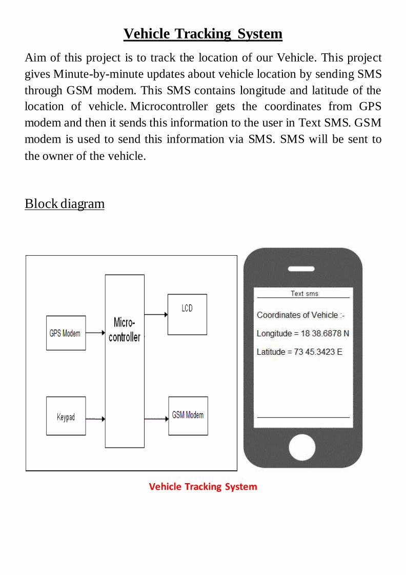
Vehicle Tracking System Aim of this project is to track the location of our Vehicle. This project gives Minute-by-minute updates about vehicle location by sending SMS through GSM modem. This SMS contains longitude and latitude of the location of vehicle. Microcontroller gets the coordinates from GPS modem and then it sends this information to the user in Text SMS. GSM modem is used to send this information via SMS. SMS will be sent to the owner of the vehicle. Block diagram Vehicle Tracking System

Vehicle tracting system
Jul 16, 2015
Welcome message from author
This document is posted to help you gain knowledge. Please leave a comment to let me know what you think about it! Share it to your friends and learn new things together.
Transcript
Vehicle Tracking System
Aim of this project is to track the location of our Vehicle. This project
gives Minute-by-minute updates about vehicle location by sending SMS
through GSM modem. This SMS contains longitude and latitude of the
location of vehicle. Microcontroller gets the coordinates from GPS
modem and then it sends this information to the user in Text SMS. GSM
modem is used to send this information via SMS. SMS will be sent to
the owner of the vehicle.
Block diagram
Vehicle Tracking System
This project consists of following blocks:
1. GPS Modem
2. GSM Modem
3. Microcontroller (Arduino UNO)
4. LCD display
5. Power Adopter
GPS Modem: A GPS navigation device is a device that accurately
calculates geographical location by receiving information from
GPS satellites. GPS modems need to be connected to a computer in
order to work. This computer can be a home computer, laptop,
PDA, digital camera, or smart phones. Depending on the type of
computer and available connectors, connections can be made
through a serial or USB cable.
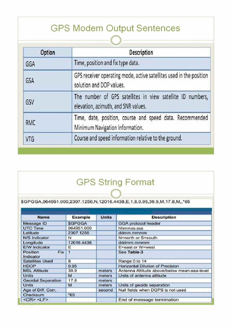
GPS receiver communication is defined within NMEA
specification. Most computer programs that provide real time
position information understand and expect data to be in this
standard.
Each sentence begins with a '$' and ends with a carriage return/line
feed sequence and can be no longer than 80 characters of visible
text. The data is contained within this single line with data items
separated by commas. The data itself is just ASCII text and may
extend over multiple sentences in certain specialized instances but
is normally fully contained in one variable length sentence.

GSM Modem: A GSM modem is a wireless modem that works
with a GSM wireless network. A wireless modem behaves like a
dial-up modem. The main difference between them is that a dial-up
modem sends and receives data through a fixed telephone line
while a wireless modem sends and receives data through radio
waves. An external GSM modem is connected to a computer
through a serial cable or a USB cable. Like a GSM mobile phone, a
GSM modem requires a SIM card from a wireless carrier in order
to operate.
Computers use AT commands to control modems. Both GSM
modems and dial-up modems support
a common set of standard AT
commands. In addition to the
standard AT commands, GSM
modems support an extended set of
AT commands. These extended AT
commands are defined in the GSM
standards. With the extended AT
commands, you can do things like:
Reading, writing and deleting SMS
messages.
Sending SMS messages.
Monitoring the signal strength.
Monitoring the charging status and charge level of the battery.
Reading, writing and searching phone book entries.
SIM900 GSM Modem
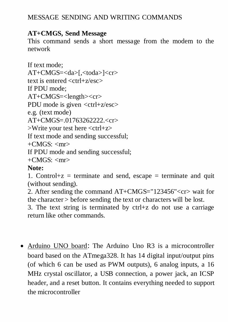
MESSAGE SENDING AND WRITING COMMANDS
AT+CMGS, Send Message
This command sends a short message from the modem to the network
Command Possible Response
If text mode; AT+CMGS=<da>[,<toda>]<cr>
text is entered <ctrl+z/esc> If PDU mode;
AT+CMGS=<length><cr>
PDU mode is given <ctrl+z/esc> e.g. (text mode)
AT+CMGS=.01763262222.<cr> >Write your test here <ctrl+z>
If text mode and sending successful;
+CMGS: <mr> If PDU mode and sending successful;
+CMGS: <mr>
Note:
1. Control+z = terminate and send, escape = terminate and quit
(without sending). 2. After sending the command AT+CMGS="123456"<cr> wait for
the character > before sending the text or characters will be lost. 3. The text string is terminated by ctrl+z do not use a carriage
return like other commands.
Arduino UNO board: The Arduino Uno R3 is a microcontroller
board based on the ATmega328. It has 14 digital input/output pins
(of which 6 can be used as PWM outputs), 6 analog inputs, a 16
MHz crystal oscillator, a USB connection, a power jack, an ICSP
header, and a reset button. It contains everything needed to support
the microcontroller
Power adopter: This is used to give appropriate dc power supply
to microcontroller, driver IC sensors and the other passive
components of the robot.
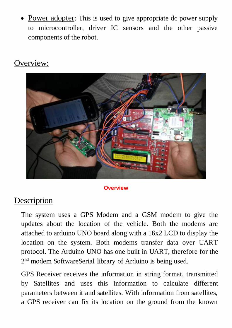
Overview:
Overview
Description
The system uses a GPS Modem and a GSM modem to give the
updates about the location of the vehicle. Both the modems are
attached to arduino UNO board along with a 16x2 LCD to display the
location on the system. Both modems transfer data over UART
protocol. The Arduino UNO has one built in UART, therefore for the
2nd modem SoftwareSerial library of Arduino is being used.
GPS Receiver receives the information in string format, transmitted
by Satellites and uses this information to calculate different
parameters between it and satellites. With information from satellites,
a GPS receiver can fix its location on the ground from the known
position of the satellites. The GPS modem has an antenna which
receives the satellite signals and transfers them to the modem. The
modem in turn converts the data into useful information and sends the
output in serial RS232 logic level format.
The program burnt into the microcontroller extracts the location
information from the data received from the GPS modem and sends
this information to GSM modem using the specified command so that
this information is sent to the destination mobile phone over the GSM
network in form of text message.
Program:
#include <SoftwareSerial.h>
#include <LiquidCrystal.h>
SoftwareSerial mySerial(10, 11); // using digital i/o pins for serial commnication
/*RX is digital pin 10 (connect to TX of other device)
TX is digital pin 11 (connect to RX of other device)*/
LiquidCrystal lcd(7, 6, 5, 4, 3, 2);
char str[70];
char *test="$GPGGA";
char logitude[10];
char latitude[10];
int i,j,k;
int temp;
int c=0;
void setup()
{
mySerial.begin(9600);
Serial.begin(9600);
lcd.begin(16, 2);

lcd.print("GPS Besed Vehicle");
lcd.setCursor(0, 1);
char a[]="Tracking System";
lcd.print(a);
delay(10000);
lcd.clear();
}
void loop()
{
if (temp==1)
{
for(i=18;i<27;i++) //extract latitude from string
{
latitude[j]=str[i];
j++;
}
for(i=32;i<40;i++) //extract longitude from string
{
logitude[k]=str[i];
k++;
}
lcd.setCursor(0,0); //display latitude and longitude on 16X2 lcd display
lcd.print("Lat(N)");
lcd.print(latitude);
lcd.setCursor(0,1);
lcd.print("Lon(E)");
lcd.print(logitude);
delay(100);
if(c<5)
{
delay(100);
mySerial.print("AT+CMGS=");
mySerial.print('"');
mySerial.print("07503904632");
mySerial.print('"');
mySerial.print(' \r');
mySerial.print("Latitude(N): "); //enter latitude in msg
mySerial.println(latitude);
mySerial.print("Longitude(E): "); //enter Longitude in Msg
mySerial.println(logitude);
mySerial.write(26);
c++;
}}
temp=0;
i=0;
j=0;
k=0;
delay(2000); // next reading within 20 seconds
}
}
void serialEvent()
{
while (Serial.available()) //Serial incomming data from GPS
{
char inChar = (char)Serial.read();
str[i]= inChar; //store incomming data from GPS to temparary string str[]
i++;
if (i < 7)
{
if(str[i-1] != test[i-1]) //check for right string
{
i=0;
}
}
if(i >=60)
{
temp=1;
}
}
}
Using Digital I/O pins of Arduino UNO board for serial
communication:
The Arduino hardware has built-in support for serial communication on
pins 0 and 1 (which also goes to the computer via the USB connection). The native serial support happens via a piece of hardware (built into the
chip) called a UART. This hardware allows the Atmega chip to receive
serial communication even while working on other tasks, as long as there room in the 64 byte serial buffer.
The SoftwareSerial library has been developed to allow serial
communication on other digital pins of the Arduino, using software to
replicate the functionality (hence the name "SoftwareSerial"). It is possible to have multiple software serial ports with speeds up to 115200
bps.
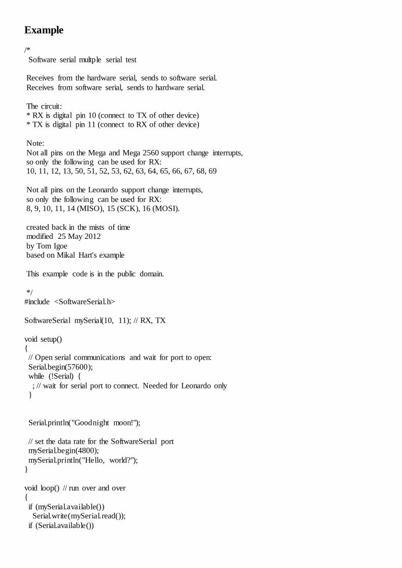
Example
/*
Software serial multple serial test Receives from the hardware serial, sends to software serial.
Receives from software serial, sends to hardware serial.
The circuit: * RX is digital pin 10 (connect to TX of other device) * TX is digital pin 11 (connect to RX of other device)
Note:
Not all pins on the Mega and Mega 2560 support change interrupts, so only the following can be used for RX: 10, 11, 12, 13, 50, 51, 52, 53, 62, 63, 64, 65, 66, 67, 68, 69
Not all pins on the Leonardo support change interrupts,
so only the following can be used for RX: 8, 9, 10, 11, 14 (MISO), 15 (SCK), 16 (MOSI).
created back in the mists of time modified 25 May 2012
by Tom Igoe based on Mikal Hart's example
This example code is in the public domain.
*/ #include <SoftwareSerial.h>
SoftwareSerial mySerial(10, 11); // RX, TX
void setup() { // Open serial communications and wait for port to open:
Serial.begin(57600); while (!Serial) {
; // wait for serial port to connect. Needed for Leonardo only }
Serial.println("Goodnight moon!");
// set the data rate for the SoftwareSerial port mySerial.begin(4800);
mySerial.println("Hello, world?"); }
void loop() // run over and over {
if (mySerial.available()) Serial.write(mySerial.read());
if (Serial.available())
mySerial.write(Serial.read()); }
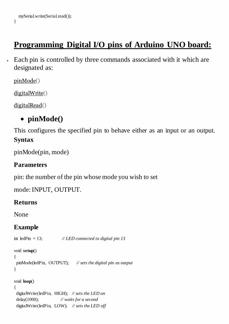
Programming Digital I/O pins of Arduino UNO board:
Each pin is controlled by three commands associated with it which are
designated as:
pinMode()
digitalWrite()
digitalRead()
pinMode()
This configures the specified pin to behave either as an input or an output.
Syntax
pinMode(pin, mode)
Parameters
pin: the number of the pin whose mode you wish to set
mode: INPUT, OUTPUT.
Returns
None
Example
int ledPin = 13; // LED connected to digital pin 13
void setup()
{
pinMode(ledPin, OUTPUT); // sets the digital pin as output
}
void loop()
{
digitalWrite(ledPin, HIGH); // sets the LED on
delay(1000); // waits for a second
digitalWrite(ledPin, LOW); // sets the LED off
delay(1000); // waits for a second
}
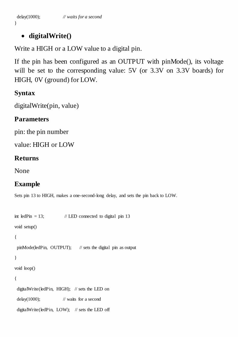
digitalWrite()
Write a HIGH or a LOW value to a digital pin.
If the pin has been configured as an OUTPUT with pinMode(), its voltage
will be set to the corresponding value: 5V (or 3.3V on 3.3V boards) for
HIGH, 0V (ground) for LOW.
Syntax
digitalWrite(pin, value)
Parameters
pin: the pin number
value: HIGH or LOW
Returns
None
Example
Sets pin 13 to HIGH, makes a one-second-long delay, and sets the pin back to LOW.
int ledPin = 13; // LED connected to digital pin 13
void setup()
{
pinMode(ledPin, OUTPUT); // sets the digital pin as output
}
void loop()
{
digitalWrite(ledPin, HIGH); // sets the LED on
delay(1000); // waits for a second
digitalWrite(ledPin, LOW); // sets the LED off
delay(1000); // waits for a second
}
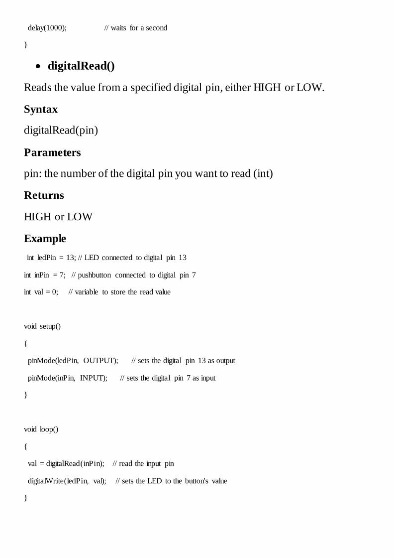
digitalRead()
Reads the value from a specified digital pin, either HIGH or LOW.
Syntax
digitalRead(pin)
Parameters
pin: the number of the digital pin you want to read (int)
Returns
HIGH or LOW
Example
int ledPin = 13; // LED connected to digital pin 13
int inPin = 7; // pushbutton connected to digital pin 7
int val = 0; // variable to store the read value
void setup()
{
pinMode(ledPin, OUTPUT); // sets the digital pin 13 as output
pinMode(inPin, INPUT); // sets the digital pin 7 as input
}
void loop()
{
val = digitalRead(inPin); // read the input pin
digitalWrite(ledPin, val); // sets the LED to the button's value
}
Related Documents