NREL is a national laboratory of the U.S. Department of Energy, Office of Energy Efficiency and Renewable Energy, operated by the Alliance for Sustainable Energy, LLC. Vehicle Thermal System Modeling in Simulink® P.I. : Jason A. Lustbader Team: Tibor Kiss National Renewable Energy Laboratory June 16, 2014 Project ID #: VSS134 This presentation does not contain any proprietary, confidential, or otherwise restricted information.

Welcome message from author
This document is posted to help you gain knowledge. Please leave a comment to let me know what you think about it! Share it to your friends and learn new things together.
Transcript
NREL is a national laboratory of the U.S. Department of Energy, Office of Energy Efficiency and Renewable Energy, operated by the Alliance for Sustainable Energy, LLC.
Vehicle Thermal System Modeling in Simulink®
P.I. : Jason A. Lustbader Team: Tibor Kiss National Renewable Energy Laboratory June 16, 2014 Project ID #: VSS134
This presentation does not contain any proprietary, confidential, or otherwise restricted information.
2
Overview – New Project
Project Start Date: FY14 Project End Date: FY15 Percent Complete: 25%
• Cost – Timely evaluation of vehicle thermal systems to assist with R&D
• Computational models, design and simulation methodologies – Develop tool to help with optimization of future vehicle thermal system designs and prediction of impacts on fuel economy
• Constant advances in technology – Help industry to advance technology with improved tools
Total Project Funding: o DOE Share: $225K o Contractor Share: $0K
Funding Received in FY13: $0K Funding for FY14: $225K
Timeline
Budget
Barriers
• Collaborations o Halla Visteon Climate Control o Delphi o Daimler Trucks o VTO Advanced Power Electronics and Electric
Motors (APEEM) Team o In discussion with others
• Project lead: NREL
Partners

3
Relevance THE CHALLENGE
• Heating has a large impact on electric vehicle range, larger than air conditioning (A/C) systems
• Electrified heavy-duty A/C systems may provide necessary infrastructure to add heating at limited additional cost
• With increasing electrification, vehicle thermal systems are increasingly important for effective and efficient light- and heavy-duty vehicle design
• Autonomie lacks tools for vehicle thermal systems modeling based on 1st principles
THE OPPORTUNITY • Tools will assist with evaluation of
advanced thermal management and heating solutions using flexible, freely available tools for the MATLAB®/ Simulink environment that can co-simulate with Autonomie
• Leverage NREL’s vehicle thermal management expertise o Energy storage thermal management o APEEM thermal management o Integrated vehicle thermal
management project o Heating, ventilating, and air
conditioning (HVAC) expertise, building on the A/C system model developed previously
4
Relevance/Objectives
Goal By 2015, develop flexible, publically available tools in MATLAB/Simulink for vehicle thermal systems modeling that can co-simulate with Autonomie and apply these tools with industry partners for R&D on advanced thermal systems.
Objectives • Develop analysis tools to assess the impact of technologies that reduce
thermal load, improve climate control efficiency, and reduce vehicle fuel consumption
• Connect climate control, thermal systems, and vehicle-level models to assess the impacts of advanced thermal management technologies on fuel use and range
• Develop an open, accurate, and transient thermal system modeling framework using the MATLAB/Simulink environment for co-simulation with Autonomie

5
Approach – Milestones and Go/No-Go’s FY 2014 FY 2015
Q1 Q2 Q3 Q4 Q1 Q2 Q3 Q4
Milestones: M1. Complete initial modeling framework. Run system simulation with basic cooling system components and demonstrate
feasibility. Go/No-Go: Model of concept demonstration system predicts reasonable trends. M2. Validated single-phase model built from building blocks, allowing for easy modification. Release beta version of model.
Go/No-Go: Confirm that model can be successfully validated and is predicting performance with acceptable accuracy (20%) M3. Improve component models, adding detail. Validate model to within 15% of available data. M4. Improve model capabilities expanding on the single-phase, energy storage, and power electronics thermal models and
validate. Apply developed Simulink tools with industry partners to look at system tradeoffs in co-simulation with Autonomie. Release updated code with expanded capabilities.
Improve and add detail to modeling blocks
Write and improve “Getting Started” guide
M2 Validate and apply model to system
M4 Investigate system tradeoffs applying model with industry partners
Develop flexible, publically available tools in MATLAB/Simulink for vehicle thermal systems modeling that can co-simulate with Autonomie. Investigate advanced thermal system tradeoffs
Develop single-phase model blocks
Add simple energy storage and power electronics thermal models
Add improved energy storage and power electronics models and validate
M1
M3
6
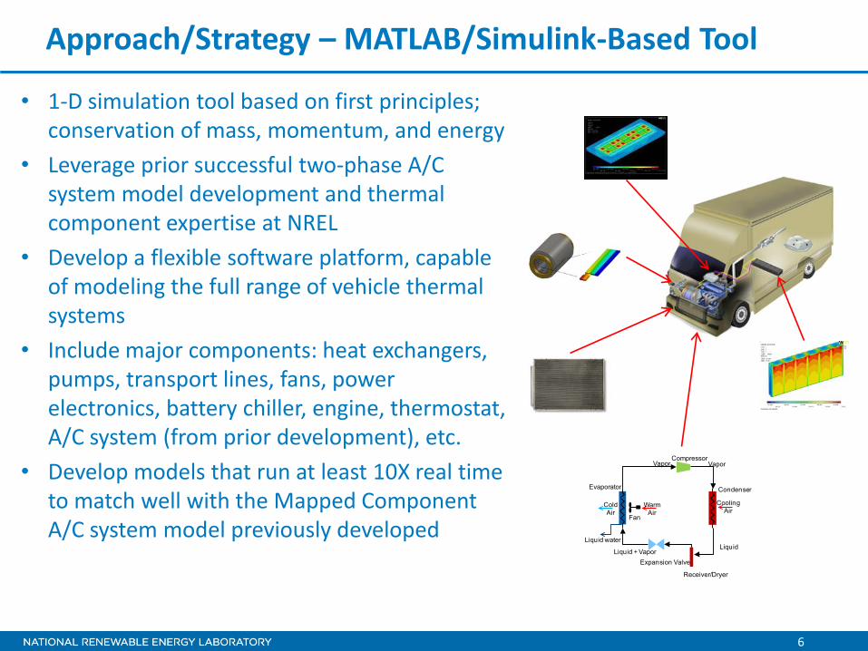
• 1-D simulation tool based on first principles; conservation of mass, momentum, and energy
• Leverage prior successful two-phase A/C system model development and thermal component expertise at NREL
• Develop a flexible software platform, capable of modeling the full range of vehicle thermal systems
• Include major components: heat exchangers, pumps, transport lines, fans, power electronics, battery chiller, engine, thermostat, A/C system (from prior development), etc.
• Develop models that run at least 10X real time to match well with the Mapped Component A/C system model previously developed
Approach/Strategy – MATLAB/Simulink-Based Tool
Evaporator
Compressor
Condenser
Expansion Valve
Liquid
Vapor
Liquid + Vapor
Vapor
WarmAir
ColdAir
Fan
Receiver/Dryer
Liquid water
CoolingAir
7
Approach/Strategy – Key Features
• The model will be flexible and capable of modeling a wide range of system configurations and components
• The model will be switchable between varying levels of accuracy an execution speed, e.g., useful for predicting both short (pump RPM) and long (engine warmup) transients
• For fast execution of the model, a method that works with relatively high simulation time step is needed therefore, o Incompressible flow for coolant is assumed o Solid thermal masses will have a limited level of spatial distribution o Coolant thermal mass will have varying levels of spatial distribution o Heat transfer calculations will have varying levels of speed and accuracy by using the
Effectiveness-NTU method, Distributed Parameter component models, and Mapped Performance component models as appropriate
• For accuracy, temperature-dependent coolant viscosity and specific heat are needed
8
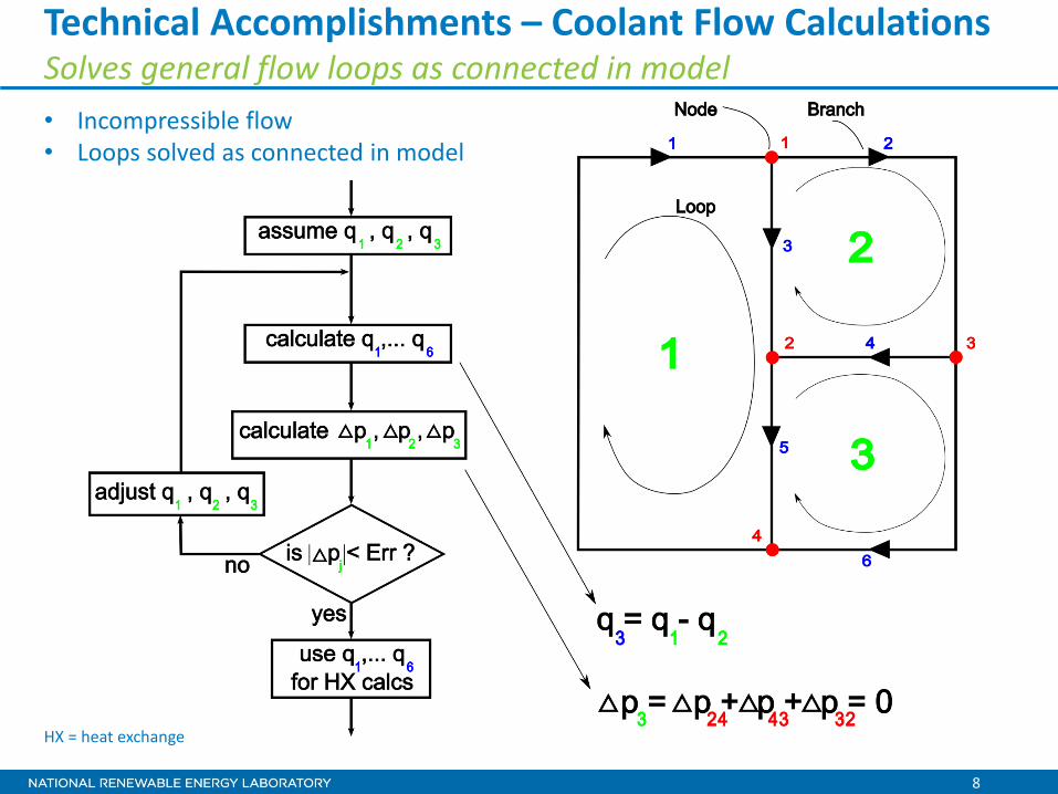
Technical Accomplishments – Coolant Flow Calculations Solves general flow loops as connected in model • Incompressible flow • Loops solved as connected in model
HX = heat exchange

9
Technical Accomplishments and Progress Completed initial representative component models
Component Status
Coolant 50/50 ethylene glycol/water temperature-dependent properties
Water pump 2-D lookup table for flow rate vs. pressure rise and RPM
Plenum model Enthalpy in plenum is the integral of incoming minus outgoing enthalpy flow rates
Thermostat 1-D lookup table for position vs. coolant temperature, and 2-D lookup table for flow rate vs. position and pressure differential
Radiator Switchable between Mapped Performance sub-model and Distributed Parameter sub-model
Low-temperature heat exchanger, space heater, transport lines
Use assumed effectiveness
Oil cooler Use assumed effectiveness
Battery cooler Simple 1-node model, Effectiveness-NTU method, use UA to calculate effectiveness
Engine Simple 1-node model, Effectiveness-NTU method, use UA to calculate effectiveness
Non-capacitive junction
Mix out incoming coolant mass and enthalpy flow rates
10
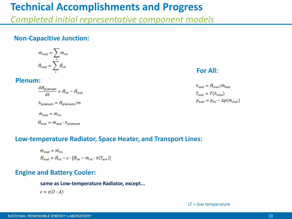
Technical Accomplishments and Progress Completed initial representative component models
Non-Capacitive Junction:
Plenum:
Low-temperature Radiator, Space Heater, and Transport Lines:
Engine and Battery Cooler: same as Low-temperature Radiator, except...
For All:
LT = low temperature
11
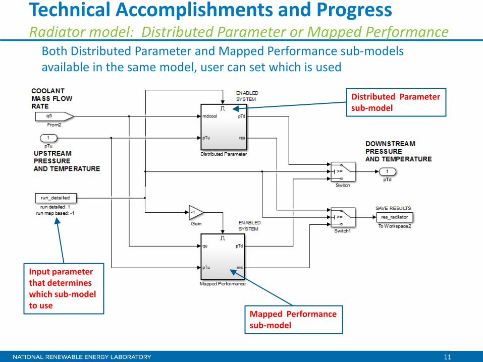
Technical Accomplishments and Progress Radiator model: Distributed Parameter or Mapped Performance
Both Distributed Parameter and Mapped Performance sub-models available in the same model, user can set which is used
Input parameter that determines which sub-model to use
Distributed Parameter sub-model
Mapped Performance sub-model

12
Technical Accomplishments and Progress Radiator model: Distributed Parameter sub-model option
• Allows user flexibility to define heat exchanger design
• Airside compact heat exchanger model from literature
Single-plate models, each representing one pass
Number of plates per pass multipliers
double pass
13
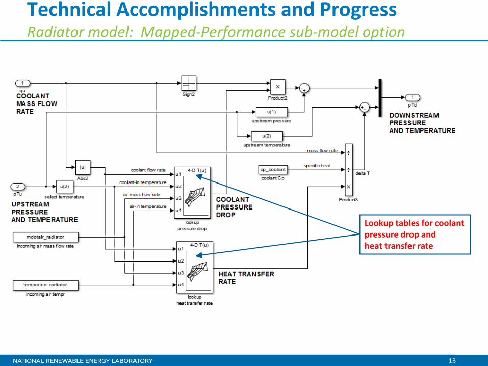
Technical Accomplishments and Progress Radiator model: Mapped-Performance sub-model option
Lookup tables for coolant pressure drop and heat transfer rate
14
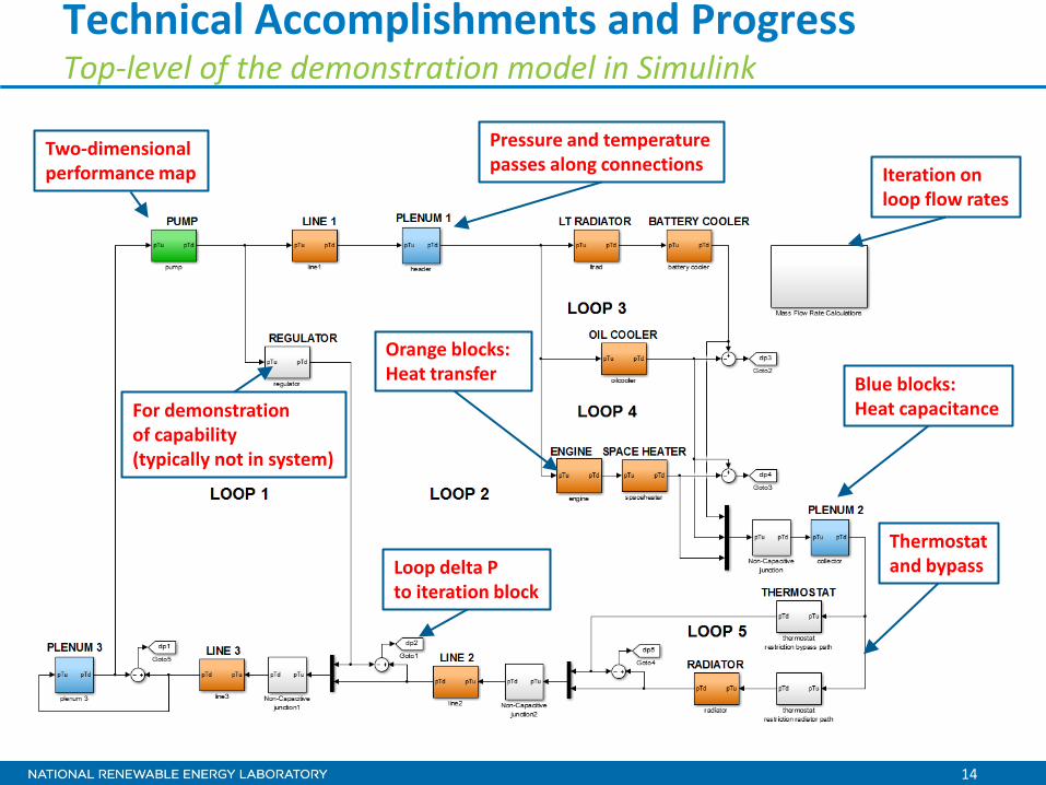
Technical Accomplishments and Progress Top-level of the demonstration model in Simulink
Blue blocks: Heat capacitance
Iteration on loop flow rates
Thermostat and bypass
For demonstration of capability (typically not in system)
Pressure and temperature passes along connections
Orange blocks: Heat transfer
Two-dimensional performance map
Loop delta P to iteration block
15
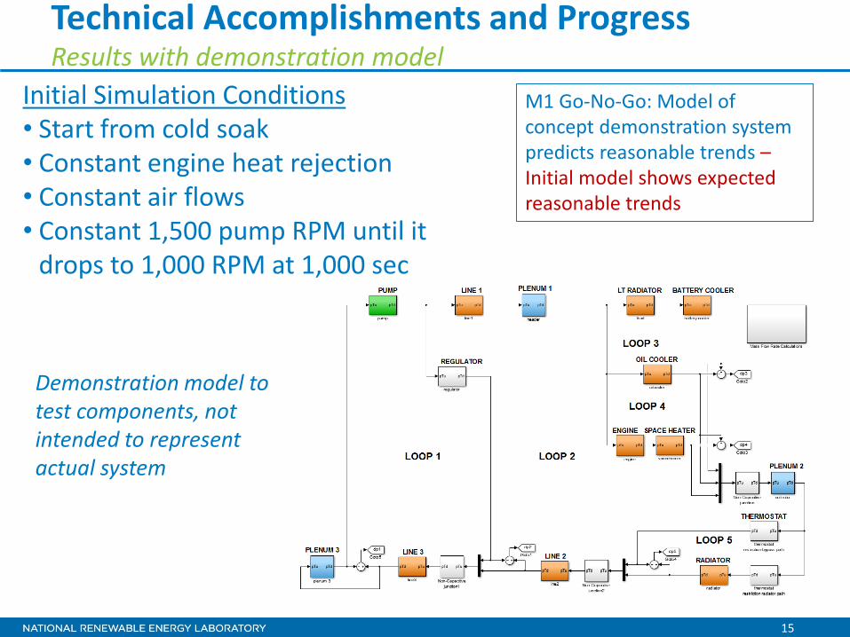
Technical Accomplishments and Progress Results with demonstration model
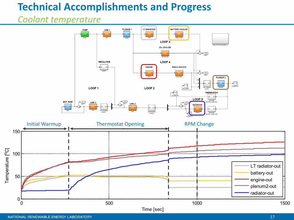
Initial Simulation Conditions • Start from cold soak • Constant engine heat rejection • Constant air flows • Constant 1,500 pump RPM until it
drops to 1,000 RPM at 1,000 sec
Demonstration model to test components, not intended to represent actual system
M1 Go-No-Go: Model of concept demonstration system predicts reasonable trends – Initial model shows expected reasonable trends

16
0 500 1000 1500100
150
200
250
300
time [sec]
Pre
ssur
e [k
Pa]
y
pump-outengine-outplenum2radiator-outline2-out
Technical Accomplishments and Progress Coolant pressure
Due to X Initial Warmup Thermostat Opening RPM Change
17
0 500 1000 15000
50
100
150 p y
Time [sec]
Tem
pera
ture
[o C]
LT radiator-outbattery-outengine-outplenum2-outradiator-out
Technical Accomplishments and Progress Coolant temperature
Due to X Initial Warmup Thermostat Opening RPM Change
18
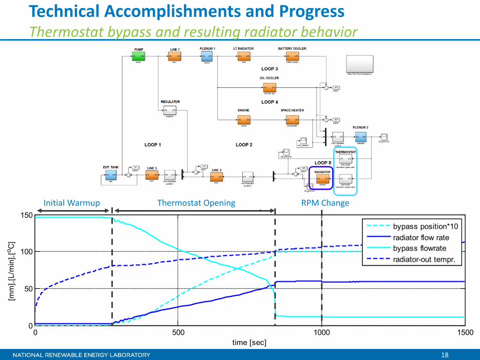
Technical Accomplishments and Progress Thermostat bypass and resulting radiator behavior
Due to X
0 500 1000 15000
50
100
150
time [sec]
[mm
],[L/
min
],[o C
]
y
bypass position*10radiator flow ratebypass flowrateradiator-out tempr.
Initial Warmup Thermostat Opening RPM Change
19
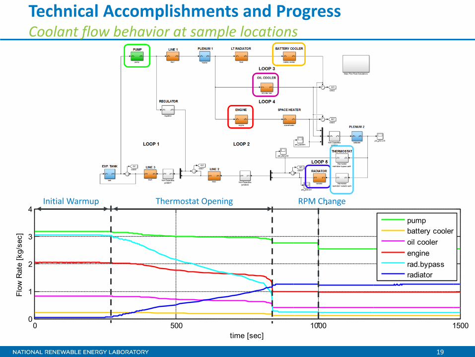
0 500 1000 15000
1
2
3
4
time [sec]
Flow
Rat
e [k
g/se
c]
Coo a t ass o ates at a ous aces t e Syste
pumpbattery cooleroil coolerenginerad.bypassradiator
Technical Accomplishments and Progress Coolant flow behavior at sample locations
Due to X Initial Warmup Thermostat Opening RPM Change

20
Technical Accomplishments and Progress Heat transfer in and out of the system balances
0 500 1000 1500-50
0
50
100
150Heat Transfer Rates Nominally to Coolant
Time [sec]
HX
Rat
e [k
W]
engineoil coolerbattery coolertotal
0 500 1000 15000
20
40
60
80
100
120Heat Transfer Rates Nominally From Coolant
Time [sec]
HX
Rat
e [k
W]
LT radiatorspace heaterradiatortotal
Total heat transfer in and out of coolant balances
21
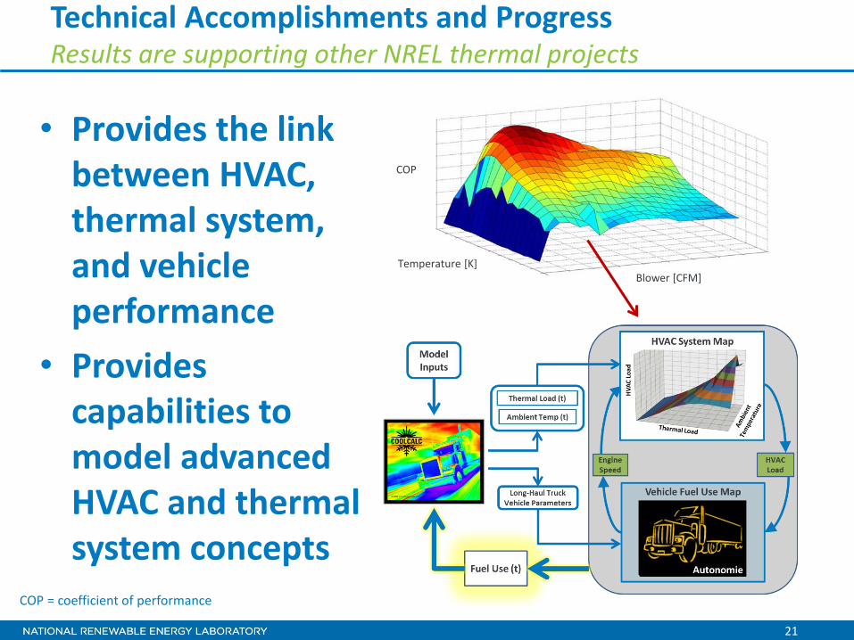
Technical Accomplishments and Progress Results are supporting other NREL thermal projects
• Provides the link between HVAC, thermal system, and vehicle performance
• Provides capabilities to model advanced HVAC and thermal system concepts
Blower [CFM] Temperature [K]
COP
COP = coefficient of performance
22
Proposed Future Work • Continue model development
o Create Distributed Parameter sub-models for all components with heat exchange o Create Mapped Performance-based sub-models for all components with heat exchange o Make sub-models of components with heat exchange switchable between Distributed
Parameter and Mapped Performance versions o Develop process of mapping the performance of all such components with the same model
(eliminate the need for a suite of models) o Incorporate existing A/C system model o Collaborate with NREL Advanced Power Elections and Energy Storage groups to incorporate
component thermal models
• Build vehicle thermal system using component data and validate to system-level measured performance
• Model application with industry partners o Model advanced light-duty vehicle thermal systems
– Heat pump system – Advanced heat recovery concepts
o Heavy-duty hybrid cooling systems o Build validated idle-off long-haul truck A/C system model
• Leverage model results for the CoolCab project impact estimation
23
Collaboration and Coordination with Other Institutions
• Halla Visteon Climate Control o Provided data for A/C system model and validation o Funding Opportunity Announcement award partner, assisting
with models o Technical advice and discussion
• Delphi o Advanced concept modeling
• Daimler Trucks o Assisting with SuperTruck project
• NREL Advanced Power Electronics and Energy Storage Teams o Leveraging expertise and models o Enabling analysis of vehicle level impacts of power electronic
thermal system changes • Argonne National Laboratory
o Autonomie integration o Vehicle-level system data
• Other collaboration discussion in progress
24
Summary
• With increasing electrification, vehicle thermal systems are increasingly important for effective and efficient light- and heavy-duty vehicle design • Tools are being developed for evaluation of advanced thermal
management and heating solutions using flexible, freely available tools for the MATLAB/Simulink environment that can co-simulate with Autonomie • An initial thermal system modeling framework has been
developed and the results are reasonable; the next step will be to model and validate models of specific vehicle thermal management systems • Developed several initial partnerships and several other
collaborations are being discussed
Technical Back-Up Slides
(Note: please include this “separator” slide if you are including back-up technical slides (maximum of five). These back-up technical slides will be available for your presentation and will be included in the DVD and Web PDF files released to the public.)
26
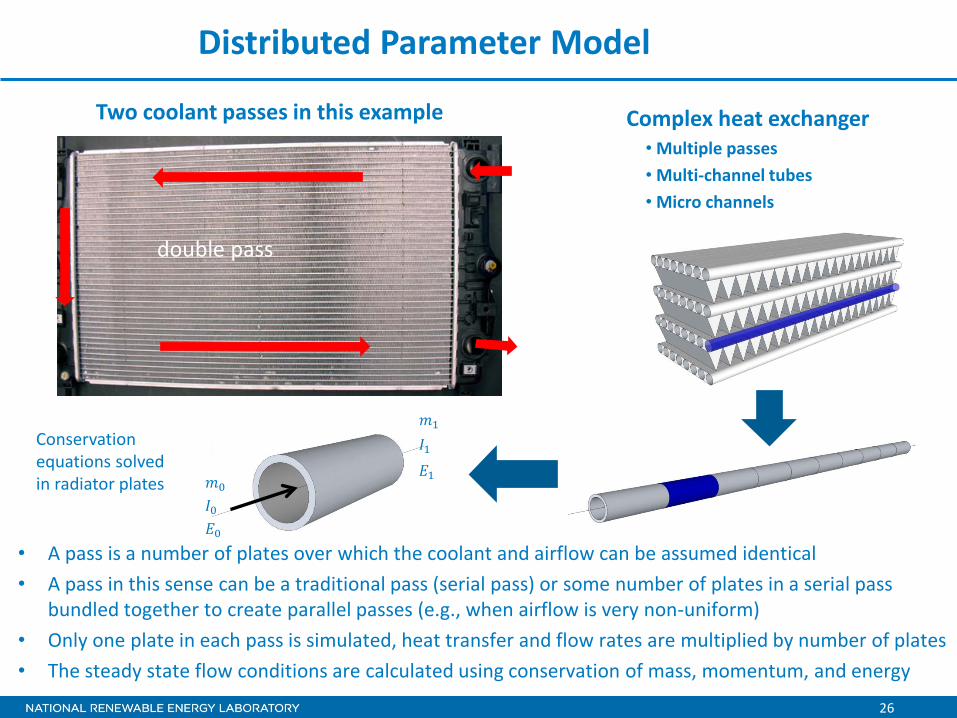
Complex heat exchanger • Multiple passes • Multi-channel tubes • Micro channels
• A pass is a number of plates over which the coolant and airflow can be assumed identical • A pass in this sense can be a traditional pass (serial pass) or some number of plates in a serial pass
bundled together to create parallel passes (e.g., when airflow is very non-uniform) • Only one plate in each pass is simulated, heat transfer and flow rates are multiplied by number of plates • The steady state flow conditions are calculated using conservation of mass, momentum, and energy
Conservation equations solved in radiator plates
Two coolant passes in this example
Distributed Parameter Model
double pass

27
Condenser wall to refrigerant:
where the film coefficient is calculated with the Dittus-Boelter equation:
The coefficient n can be modified for a particular geometry.
Coolant to Wall Heat Transfer – Distributed Parameter Model
28
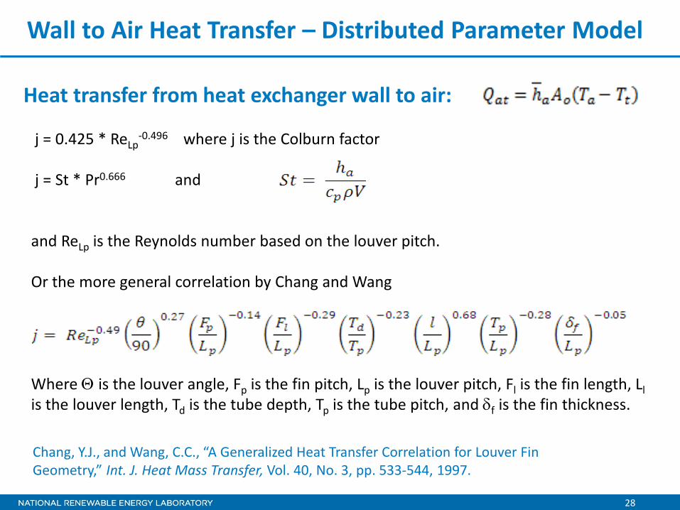
Chang, Y.J., and Wang, C.C., “A Generalized Heat Transfer Correlation for Louver Fin Geometry,” Int. J. Heat Mass Transfer, Vol. 40, No. 3, pp. 533-544, 1997.
Heat transfer from heat exchanger wall to air:
Wall to Air Heat Transfer – Distributed Parameter Model
j = 0.425 * ReLp-0.496 where j is the Colburn factor
j = St * Pr0.666 and and ReLp is the Reynolds number based on the louver pitch. Or the more general correlation by Chang and Wang Where Θ is the louver angle, Fp is the fin pitch, Lp is the louver pitch, Fl is the fin length, Ll is the louver length, Td is the tube depth, Tp is the tube pitch, and δf is the fin thickness.
Related Documents