See discussions, stats, and author profiles for this publication at: https://www.researchgate.net/publication/330082173 Vehicle ride comfort optimization based on Magneto-rheological damper Article · January 2018 CITATIONS 0 READS 28 3 authors, including: Some of the authors of this publication are also working on these related projects: Research on vehicle suspension View project Sosthene Kazima Wuhan University of Technology 3 PUBLICATIONS 1 CITATION SEE PROFILE All content following this page was uploaded by Sosthene Kazima on 02 January 2019. The user has requested enhancement of the downloaded file.

Welcome message from author
This document is posted to help you gain knowledge. Please leave a comment to let me know what you think about it! Share it to your friends and learn new things together.
Transcript
See discussions, stats, and author profiles for this publication at: https://www.researchgate.net/publication/330082173
Vehicle ride comfort optimization based on Magneto-rheological damper
Article · January 2018
CITATIONS
0READS
28
3 authors, including:
Some of the authors of this publication are also working on these related projects:
Research on vehicle suspension View project
Sosthene Kazima
Wuhan University of Technology
3 PUBLICATIONS 1 CITATION
SEE PROFILE
All content following this page was uploaded by Sosthene Kazima on 02 January 2019.
The user has requested enhancement of the downloaded file.
1
INTERNATIONAL JOURNAL OF AUTOMOTIVE SCIENCE AND TECHNOLOGY 2018, VOL. 2, NO: 4, 1-8
www.dergipark.gov.tr/ijastech
Vehicle ride comfort optimization based on Magneto-rheological damper
Kazima Sosthene1*, Karangwa Emmanuel1 and Musabyimana Josee2
1 Rwanda Polytechnic (IPRC GISHARI), Mechanical Department, Automobile Technology
2University of Rwanda, College of Science and Technology, P.O Box 3900 Kigali, Rwanda
----------------------------------------------------------------------------------------------------------------------------------------------------------------------------------------------------------------------------------------------------------------------------------------------
1. Introduction
In design of automotive dynamic system, there are two im-
portant systems need to be emphasized on; the comfort of
vehicle occupants and vehicle stability. Suspension systems
are ones of the most important dynamic subsystems in pas-
senger and transportation vehicles. Suspension systems pro-
vide comfort to occupants and avoid the damage of chassis
and freight. They are normally constituted by springs and
dampers which reduce the shock and absorb the frequencies
vibrations during the vehicle ride. Road cracks, clays, debris,
bad pavement, bumps are the most disturbances of vehicle
drive where the driver is subjected to drive over them at a
reduced speed in order to mitigate vibrations of vehicle, in
order to give a comfort to occupants as well as preventing the
wear and damage of the car components especially the sus-
pension system (shock absorbers), freight and chassis. The
big challenges in vehicle suspension design many time's
leads in a compromise between the flagging demands of rid-
ing comfort and road holding. Automobiles owning soft sus-
pension separate the vehicle body from the higher vibrations
in suspension but decrease the capacity of the dampers to
monitor the wheel movements which result the poor road
holding. Inversely, hard suspension generates the best road
holding but transfers more suspension vibration to the
body[1]. The design of a better quality suspension system re-
mains an important development objective for the automo-
tive industry. Effective vehicle suspension system must have
the ability to minimize as possible the displacement, jounce
of the vehicle body, and maximizing ride comfort. It must
also aim to reduce the dynamic deflection of the tire to main-
tain road tire contact. The stability control of automobile is
based on different subsystems which work together to
achieve the same goal those subsystems are steering system,
anti-lock braking system (ABS) and vehicle suspension con-
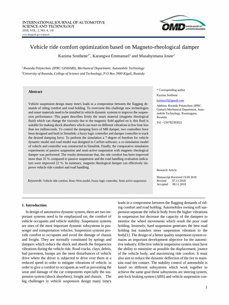
Abstract
Vehicle suspension design many time's leads in a compromise between the flagging de-
mands of riding comfort and road holding. To overcome this challenge new technologies
and smart materials need to be installed in vehicle dynamic systems to improve the suspen-
sion performance. This paper describes firstly the smart material (magneto rheological
fluid) which can change the viscosity due to the magnetic field applied on it, this fluid is
suitable for making shock absorbers which can react on different vibrations in few time less
than ten milliseconds. To control the damping force of MR damper, two controllers have
been designed and built in Simulink: a fuzzy logic controller and damper controller to track
the desired damping force. To perform the simulation a 7 degree of freedom for vehicle
dynamic model and road model was designed in CarSim software; a co-simulation model
of vehicle and controller was constructed in Simulink. Finally, the comparative simulation
experiments of passive suspension and semi-active suspension with magneto rheological
damper was performed. The results demonstrate that, the ride comfort has been improved
more than 35 % compared to passive suspension and the road handling evaluation indica-
tors were improved 22 %. In summary, magneto rheological damper can effectively im-
prove vehicle ride comfort and road handling.
Keywords: Vehicle ride comfort, Bouc-Wen model, Fuzzy logic controller, Semi active suspension
* Corresponding author
Kazima Sosthene
Address: Rwanda Polytechnic (IPRC
Gishari) Mechanical Department, Auto-
mobile Technology, Rwamagana,
Rwanda.
Tel: +250782383022
Research Article
Manuscript Received 19.09.2018 Revised 07.11.2018
Accepted 08.11.2018
K.sosthene et al. / International Journal of Automotive Science and Technology 2 (4): 1-8, 2018
2
trol system. Presently intelligent vehicle comfort and stabil-
ity subsystems are being raised to enhance driver to monitor
the car, vehicle operators become more indirectly in control
of their vehicles. To reach the intelligent control of car sub-
system, fused sensors and vehicle control strategies must be
put in consideration. To reduce the vibration caused by the
unven road, many suspension researches are emphasizing on
finding methods to optimize both issues at the same time, but
problems arise because comfort and stability are opposite
goals, thereby a fixed type of suspension has to be chosen,
based on certain application. The smart materials like, mag-
neto-rheological damper which change the viscosity in little
time has showed the ability to mitigate the tradeoff between
comfort and stability. To improve damping force and reduce
response time of magneto rheological (MR) damper, Some
researches like CHEN Bing[2] made the control of vehicle
semi-active suspension with the use of double fuzzy control-
lers, and the results of simulation demonstrate that the fuzzy
control mentioned above can not only improve the ride com-
fort, however decrease the probability of suspension broke
up. To solve the problem of complex nonlinear vehicle semi-
active suspension, YAN Wen-Jun[3]established a fuzzy con-
trol strategy to determine the current of MR damper. The
simulation results show that the strategy can improve the rid-
ing comfortless, driving safety and operating stability re-
markably. In summary the intelligent suspension is being ex-
panded in automotive era. In this paper an independent sus-
pension system of full vehicle model composed by magneto-
rheological dampers, and IF-THEN rules of fuzzy logic con-
troller has been developed through the joint simulation of
Matlab/Simulink and CarSim has been used. The output re-
sults are suspension deflection, body velocity, vertical body
displacement which are the index of vehicle stability and
comfort.
2. Magneto-rheological damper
Magneto-rheological (MR) materials are smart materials
which are being applied in many field like, automotive,
building and industrial era. They are materials where physi-
cal properties can be modified or changed by external phys-
ical properties like as, pH, magnetic field, moisture, stress,
temperature or electricity. Magneto-rheological material has
various forms of fluids; it can be a gel or even a solid material
like elastomers. It is composed by micron-sized iron part that
is plunged in carrier oil. Magneto rheological fluids shows
the ability of changing from free-moving liquid state into a
semi-solid state with resistance on fluid movement in fast re-
action within some milliseconds when applied to magnetic
field, it means that their viscosity changes in few time which
is less than ten milliseconds. Since its invention the yield
stress and viscosity varies when magnetic field is subjected
on it; the application of MR fluid have been studied, investi-
gated and applied in different field like automotive clutches,
engine mounts, dampers (vehicle damper or building
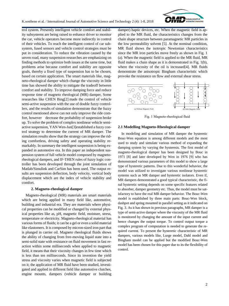
damper) haptic devices, etc. When the magnetic field is ap-
plied to the MR fluid, the characteristics changes from the
chain shape structure between paramagnetic MR particles in
the low permeability solvent [5]. At the nominal condition,
MR fluid shows the isotropic Newtonian characteristics
since the MR iron particles move freely as shown in Fig. 1
(a). When the magnetic field is applied to the MR fluid, MR
fluid makes a chain shape as it is demonstrated in Fig. 1(b),
where the viscosity of the oil is increased[4]. MR fluids
demonstrate the anisotropic Bingham characteristic which
provoke the resistance on flow and external shear stress.
(a) Without Magnetic Field (b) With Magnetic Field
Fig. 1 Magneto-rheological fluid
2.1 Modelling Magneto-Rheological damper
In modeling and simulation of MR damper the hysteretic
Bouc-Wen equation is among different models and the most
used to study and simulate various method of expanding the
damping system by varying the hysteresis. The first model of
magneto-rheological damper has been designed by Bouc in
1971 [8] and later developed by Wen in 1976 [9] who has
demonstrated various parameters of this model to show a large
type of hysteretic patterns. Due to this wonderful behavior, the
model was utilized to investigate various nonlinear hysteretic
systems such as MR damper and hysteretic isolators. Even if,
MR dampers demonstrated a good typical characteristic, the fi-
nal hysteretic setting depends on some specific features related
to absorber, damper geometry etc. Thus, the model must be sat-
isfactory to have the real MR damper behavior. The Bouc-Wen
model is established by three main parts: Bouc-Wen block,
dashpot and spring mounted in parallel setting as it indicated on
Fig. 3. As it has shown in previous paragraphs, MR damper is a
type of semi-active damper where the viscosity of the MR fluid
is monitored by changing the amount of the input current and
hence changes the output torque. To control output torque a
complex program of computation is needed to generate the re-
quired current. To present the hysteretic characteristic of MR
dampers, various models like, Lurge model, Dahl model and
Bingham model can be applied but the modified Bouc-Wen
model has been chosen for this paper due to its the flexibility of
control.

K.sosthene et al. / International Journal of Automotive Science and Technology 2 (4): 1-8, 2018
3
x
f
Bouc-Wen
y
c0
c1
k1
k0
Fig. 3 Bouc-Wen model
𝑓 = 𝑐1�� + 𝑘1(𝑥 − 𝑥0) (1)
�� = −𝑦 ∣ �� − �� ∣ 𝑧 ∣ 𝑧 ∣𝑛−1− 𝛽(�� − ��) ∣ 𝑧 ∣𝑛+ 𝐴(�� − ��) (2)
�� = [𝛼𝑧 + 𝑐0�� + 𝑘0(𝑥 − 𝑦)]/(𝑐0 + 𝑐1) (3)
As shown in the Fig. 3, 𝑓 defines the output damping force
of magneto-rheological damper, 𝑐1 denotes viscous damping
coefficient at low velocity, k0 is spring stiffness coefficient at
high velocity, c0 is viscous damping at high speed, k1 is stiffness
of shock absorber, x is relative displacement of spring (i.e, rela-
tive displacement of unsprung and sprung mass), x0 is initial rel-
ative displacement. Where z is defined as evolution variable, is
scale factor of Bouc-Wen hysteresis. Operator, γ, β, A, are cor-
relation coefficients of hysteresis parameters, n is index coeffi-
cient, typically is 2. y is denoted as internal displacement, pa-
rameters c0, k0, k1, x0, γ, β, A and n are constant coefficient, pa-
rameters α and c1 are functions of input current. Through curve
fitting with linear function according to experimental data (table
1)[5].
{𝑐1 = 𝑐1𝑎 + 𝑐1𝑏𝑖𝛼 = 𝛼𝑏 + 𝛼𝑏𝑖
(4)
Table 1 Bouc-Wen model characteristics
Parameters/Unit Values
C0 (N.S.mm-1) 1333
C1a (N.S.mm-1) 8.168
C1b (N.S.mm-1.A-1) 2.725
αa ( N. mm-1) 0
αb ( N.mm-1) 1.723
k0 ( N.mm-1) 0.01072
k1 (N.mm-1) 0.134
x0 ( mm) 114.9
β (mm-2) 0.07
A 300
γ/mm2 0.07
n 2
MR damper is a hysteretic and non-linear component due to
big non-linear parameters of the magneto-rheological fluid. This
non-linearity explains the relationship between the input and
output. Meanwhile the output (force) Fig. 4 is the non-linear
function of the electrical current supplied to the damper coil and
the mechanical input which is displacement of damper piston
one end of damper cylinder to the other end. The simulation pro-
cess was carried out with a sinusoidal frequency of 5Hz and am-
plitude of 10 mm and displacement for a specific current apply
and we repeated this process for every parameter combination.
The responses of the MR damper for the variable input current
simulation are indicated in Fig. 5. In this case: the MR damper
response was obtained by changing the input current while the
amplitude and frequency are kept constant. The damping force
augmented along with the input current value applied on MR
damper and the hysteretic characteristic is increased as shown in
Fig. 6. If the damper is operating without input current, the
damper response shows a reduced hysteretic loop while operat-
ing with a non-zero constant input current level the damper rep-
resents a huge important hysteretic characteristic.
Fig. 4 Damping force (N)
Fig. 5 Damping force vs Displacement
Fig. 6 Damping force versus Velocity
3. Full vehicle model
Semi-active suspension model for quarter car model can
be extended to full car, as it is indicated on the Fig. 8 below,
to model a full car dynamic model; CarSim environment
software has been used. CarSim is software which models

K.sosthene et al. / International Journal of Automotive Science and Technology 2 (4): 1-8, 2018
4
automotive dynamic systems via various mathematic models
embedded in it. The CarSim has many feature such as vali-
dation and testing of different parameters of model[7]. it is
incorporated by different models such as road input, driver
aerodynamics and so on. It uses a high calculation speed of
many mathematical models[8].
Fig.8 vehicle model
{
𝑍𝑓𝑙 = 𝑍 + 𝑙𝑓 sin(Ø) − 𝑡 sin(𝜃)
𝑍𝑓𝑙 = 𝑍 + 𝑙𝑓 sin(Ø) + 𝑡 sin(𝜃)
𝑍𝑟𝑙 = 𝑍 − 𝑙𝑟 sin(Ø) − sin(𝜃)
𝑍𝑟𝑟 = 𝑍 − 𝑙𝑟 sin Ø + 𝑡 sin 𝜃
��𝑓𝑙 = �� + Ø𝑙𝑓 cos(Ø) − 𝜃�� cos(𝜃)
��𝑓𝑟 = Z + Ø𝑙𝑓 cos(Ø) + 𝜃�� cos(𝜃)
��𝑟𝑙 = �� − Ø𝑙𝑟 cos(Ø) − 𝜃�� cos(𝜃)
��𝑟𝑟 = �� − Ø𝑙𝑟 cos(Ø) + 𝜃�� cos(𝜃)
(6)
Where z defines chassis mass gravity center, φ (resp. θ)
denoted as the pitch angle of the sprung mass at the gravity
center. t, 𝑙𝑓 , and 𝑙𝑟 denote the vehicle geometrical charac-
teristics. On this model, a notice is given to the full vertical
vehicle model description which is the concatenation of the
two previously introduced half models, including vertical,
pitch and roll dynamics. Primo, assumptions under which the
model is analyzed are introduced, then, according to the car
geometry properties the kinematic equations are generated,
and lastly, hereinafter are the nonlinear vertical dynamical
equations
{
𝑀z = −𝐹𝑠𝑧𝑓𝑙 − 𝐹𝑠𝑧𝑓𝑟 − 𝐹𝑠𝑧𝑟𝑙 − 𝐹𝑠𝑧𝑟𝑟
𝑚𝑡𝑖𝑗��𝑡𝑖𝑗 = 𝐹𝑠𝑧𝑖𝑗 − 𝐹𝑡𝑧𝑖𝑗
𝐼𝑥�� = (𝐹𝑠𝑧𝑟𝑙 − 𝐹𝑠𝑧𝑟𝑟)𝑡 + (𝐹𝑠𝑧𝑓𝑙 − 𝐹𝑠𝑧𝑓𝑟) 𝑡 + 𝑀𝑑𝑥
𝐼𝑦Ø = (𝐹𝑠𝑧𝑟𝑟 + 𝐹𝑠𝑧𝑟𝑙)𝑙𝑟 − (𝐹𝑠𝑧𝑓𝑟 + 𝐹𝑠𝑧𝑓𝑙) 𝑙𝑓 + 𝑀𝑑𝑦
(7)
where the vertical tire and suspension forces are defined as
{𝐹𝑡𝑖𝑗 = 𝐾𝑡 (𝐾𝑡𝑖𝑗 − 𝑍𝑟𝑖𝑗)
𝐹𝑠𝑖𝑗 = 𝐾 (𝑍𝑖𝑗 − 𝑍𝑡𝑖𝑗) + 𝐶𝑖𝑗 (��𝑖𝑗 − ��𝑡𝑖𝑗) (8)
Where 𝑚𝑡𝑖𝑗 and M hold for the unsprung masses and
body mass (sprung mass). The inertia of vehicle in the x-axis
(resp. y-axis) is denoted as Ix (resp. Iy). FL (resp. 𝑀𝑑𝑥 and
𝑀𝑑𝑦) are external forces (resp. moments) disturbances on the
x (resp. y and z} axes[9]. Fig.9 shows the vehicle dynamic
parameters used in this model where every MR damper is
modeled and simulated by a nonlinear model.
Fig. 9 CarSim full vehicle suspension parameters
4. Simulation procedure
The model is composed by vehicle model (CarSim model),
Bouc-wen model, current driver model and 2 controllers: a
system controller and a damper controller. The main purpose
of system controller is to generate the required damping force.
The second controller serves on controlling the voltage to be
applied to the current driver to track the desired damping
force. The damping force provided by MR damper is fed to
the vehicle dynamics to attenuate the vibration caused by un-
even road [10] Fig. 10.
Vehicle model
MR damper
model
Current Driver
Damper
controller
System
Controller
Outputs
Road Disturbance
Damping force
Current(A)
Voltage(V)
Desired Damping Force (N)
Road Disturbance detected
Fig. 10 Block diagram of semi-active suspension system
4.1 System controller
To achieve the desired damping force, fuzzy logic control-
ler has been utilized. Here it is used to control damping force
of suspension system. Fuzzy logic algorithm controls many
loops variation in various non-linear systems. On this model
(Fig. 11) it has two inputs, suspension deflection and suspen-
sion velocity the controller computes those inputs and pro-
vides the desired damping force based on inference rules sub-
jected on it, the figures below explain the process of fuzzy
logic, these control systems embed the human as thinking
through the application of fuzzy configurations and linguistic
variables related by a configuration of IF-THEN fuzzy rules
t
lf
lr
krlcrl
mtrl
ktrl
zrrl
mtrr
krr
zrfl
zrrr
ktrr
ktfr
zrfr
Φ
z θ
mtfr
cfr
kfrkfl
mtfl
ktfl
cfl
crr
{M,Ix,Iy}
K.sosthene et al. / International Journal of Automotive Science and Technology 2 (4): 1-8, 2018
5
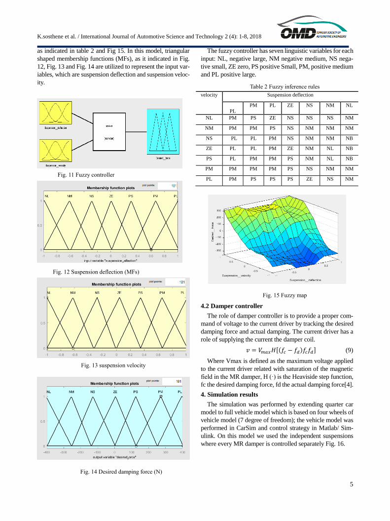
as indicated in table 2 and Fig 15. In this model, triangular
shaped membership functions (MFs), as it indicated in Fig.
12, Fig. 13 and Fig. 14 are utilized to represent the input var-
iables, which are suspension deflection and suspension veloc-
ity.
Fig. 11 Fuzzy controller
Fig. 12 Suspension deflection (MFs)
Fig. 13 suspension velocity
Fig. 14 Desired damping force (N)
The fuzzy controller has seven linguistic variables for each
input: NL, negative large, NM negative medium, NS nega-
tive small, ZE zero, PS positive Small, PM, positive medium
and PL positive large.
Table 2 Fuzzy inference rules
velocity Suspension deflection
PL PM PL ZE NS NM NL
NL PM PS ZE NS NS NS NM
NM PM PM PS NS NM NM NM
NS PL PL PM NS NM NM NB
ZE PL PL PM ZE NM NL NB
PS PL PM PM PS NM NL NB
PM PM PM PM PS NS NM NM
PL PM PS PS PS ZE NS NM
Fig. 15 Fuzzy map
4.2 Damper controller
The role of damper controller is to provide a proper com-
mand of voltage to the current driver by tracking the desired
damping force and actual damping. The current driver has a
role of supplying the current the damper coil.
𝑣 = 𝑉𝑚𝑎𝑥𝐻[(𝑓𝑐 − 𝑓𝑑)𝑓𝑐𝑓𝑑] (9)
Where Vmax is defined as the maximum voltage applied
to the current driver related with saturation of the magnetic
field in the MR damper, H (·) is the Heaviside step function,
fc the desired damping force, fd the actual damping force[4].
4. Simulation results
The simulation was performed by extending quarter car
model to full vehicle model which is based on four wheels of
vehicle model (7 degree of freedom); the vehicle model was
performed in CarSim and control strategy in Matlab/ Sim-
ulink. On this model we used the independent suspensions
where every MR damper is controlled separately Fig. 16.

K.sosthene et al. / International Journal of Automotive Science and Technology 2 (4): 1-8, 2018
6
Fig. 16 CarSim full vehicle suspension model
The simulation tests made are based on the comparison of
four MR dampers and passive damper. MATLAB/Simulink
software has been utilized to model the control strategy and
full vehicle dynamic model was modeled in CarSim software
shown in Fig. 16. The rough road model and E-class Sedan
vehicle has been selected to model and test the semi-active
suspension system of full car model. The real-time simula-
tion has been performed. The vehicle measurements were ac-
quired from CarSim and Simulink implements the control al-
gorithm and generates semi-active damping forces for every
damper. The damping forces of each damper transmitted to
the vehicle model in CarSim. The whole simulation has been
analyzed in Simulink. To test the model; the road mode with
a shaped bump of 3.4 cm of height has been selected to per-
form the simulation as it is indicated on the Fig. 17.
Fig. 17 Road model for full car model
As result of simulation, we observed that whenever the ve-
hicle passes on road irregularities the damper controller gen-
erates more current pulses to increase the damping force in
order to produce the stability and comfort of vehicle occu-
pants as it shown on fig. 18.
Fig. 18 Current pulse subjected to the damper in Ampere
The Fig. 19, shows four dampers forces, the variation of
damping force depends on road disturbance subjected on it.
More damping forces determine high road handling; in-
versely low damping force provides a good comfort for ve-
hicle occupants.
Fig. 19 MR damper damping forces
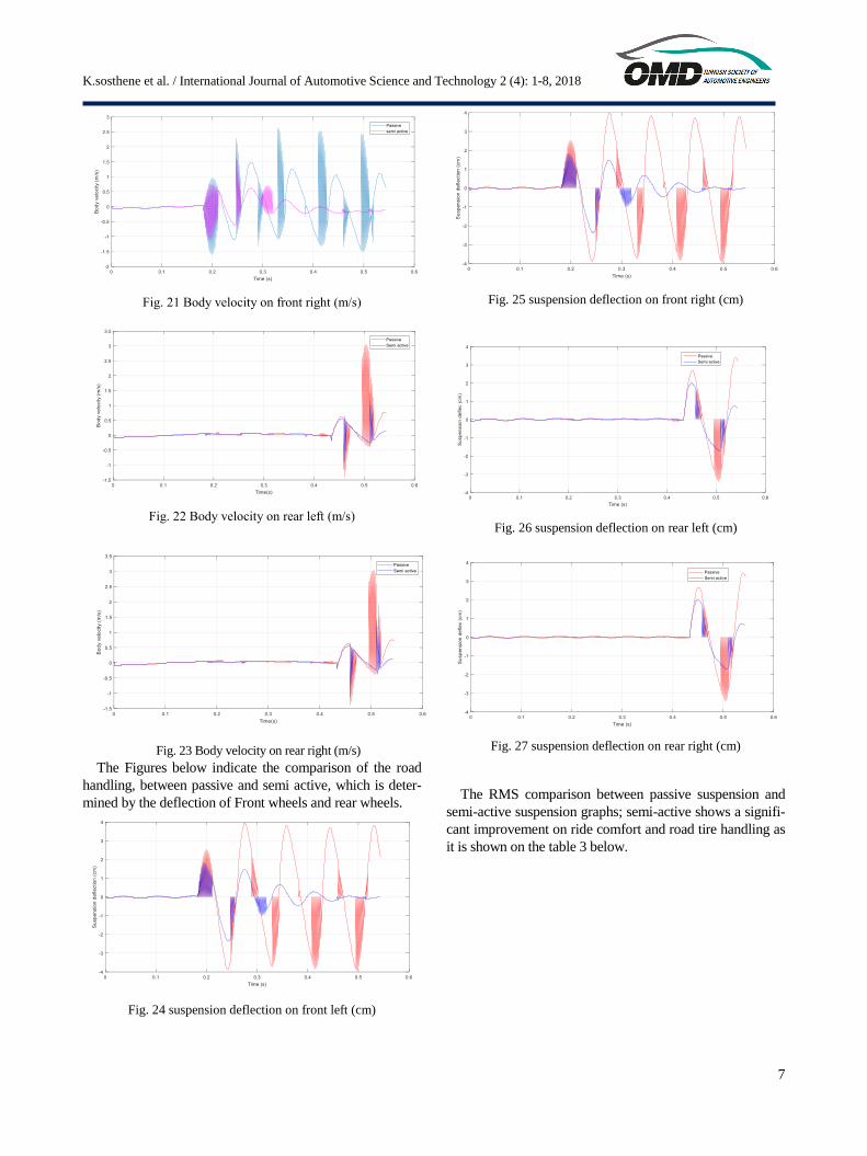
The Fig. 20, fig. 21, fig. 22 and fig. 23 indicate body ve-
locity which are the index of ride comfort, the low variation
of velocity defines the ride comfort; in this figure the semi
active suspension amplitude is lower than passive one.
Fig. 20 Body velocity front left (m/s)
K.sosthene et al. / International Journal of Automotive Science and Technology 2 (4): 1-8, 2018
7
Fig. 21 Body velocity on front right (m/s)
Fig. 22 Body velocity on rear left (m/s)
Fig. 23 Body velocity on rear right (m/s)
The Figures below indicate the comparison of the road
handling, between passive and semi active, which is deter-
mined by the deflection of Front wheels and rear wheels.
Fig. 24 suspension deflection on front left (cm)
Fig. 25 suspension deflection on front right (cm)
Fig. 26 suspension deflection on rear left (cm)
Fig. 27 suspension deflection on rear right (cm)
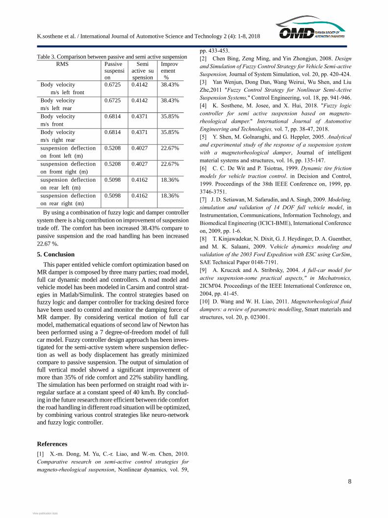
The RMS comparison between passive suspension and
semi-active suspension graphs; semi-active shows a signifi-
cant improvement on ride comfort and road tire handling as
it is shown on the table 3 below.
K.sosthene et al. / International Journal of Automotive Science and Technology 2 (4): 1-8, 2018
8
Table 3. Comparison between passive and semi active suspension
RMS Passive
suspensi
on
Semi
active su
spension
Improv
ement
%
Body velocity
m/s left front
0.6725 0.4142 38.43%
Body velocity
m/s left rear
0.6725 0.4142 38.43%
Body velocity
m/s front
0.6814 0.4371 35.85%
Body velocity
m/s right rear
0.6814 0.4371 35.85%
suspension deflection
on front left (m)
0.5208 0.4027 22.67%
suspension deflection
on fromt right (m)
0.5208 0.4027 22.67%
suspension deflection
on rear left (m)
0.5098 0.4162 18.36%
suspension deflection
on rear right (m)
0.5098 0.4162 18.36%
By using a combination of fuzzy logic and damper controller
system there is a big contribution on improvement of suspension
trade off. The comfort has been increased 38.43% compare to
passive suspension and the road handling has been increased
22.67 %.
5. Conclusion
This paper entitled vehicle comfort optimization based on
MR damper is composed by three many parties; road model,
full car dynamic model and controllers. A road model and
vehicle model has been modeled in Carsim and control strat-
egies in Matlab/Simulink. The control strategies based on
fuzzy logic and damper controller for tracking desired force
have been used to control and monitor the damping force of
MR damper. By considering vertical motion of full car
model, mathematical equations of second law of Newton has
been performed using a 7 degree-of-freedom model of full
car model. Fuzzy controller design approach has been inves-
tigated for the semi-active system where suspension deflec-
tion as well as body displacement has greatly minimized
compare to passive suspension. The output of simulation of
full vertical model showed a significant improvement of
more than 35% of ride comfort and 22% stability handling.
The simulation has been performed on straight road with ir-
regular surface at a constant speed of 40 km/h. By conclud-
ing in the future research more efficient between ride comfort
the road handling in different road situation will be optimized,
by combining various control strategies like neuro-network
and fuzzy logic controller.
References
[1] X.-m. Dong, M. Yu, C.-r. Liao, and W.-m. Chen, 2010.
Comparative research on semi-active control strategies for
magneto-rheological suspension, Nonlinear dynamics, vol. 59,
pp. 433-453.
[2] Chen Bing, Zeng Ming, and Yin Zhongjun, 2008. Design
and Simulation of Fuzzy Control Strategy for Vehicle Semi-active
Suspension, Journal of System Simulation, vol. 20, pp. 420-424.
[3] Yan Wenjun, Dong Dan, Wang Weirui, Wu Shen, and Liu
Zhe,2011 "Fuzzy Control Strategy for Nonlinear Semi-Active
Suspension Systems," Control Engineering, vol. 18, pp. 941-946.
[4] K. Sosthene, M. Josee, and X. Hui, 2018. "Fuzzy logic
controller for semi active suspension based on magneto-
rheological damper." International Journal of Automotive
Engineering and Technologies, vol. 7, pp. 38-47, 2018.
[5] Y. Shen, M. Golnaraghi, and G. Heppler, 2005. Analytical
and experimental study of the response of a suspension system
with a magnetorheological damper, Journal of intelligent
material systems and structures, vol. 16, pp. 135-147.
[6] C. C. De Wit and P. Tsiotras, 1999. Dynamic tire friction
models for vehicle traction control. in Decision and Control,
1999. Proceedings of the 38th IEEE Conference on, 1999, pp.
3746-3751.
[7] J. D. Setiawan, M. Safarudin, and A. Singh, 2009. Modeling,
simulation and validation of 14 DOF full vehicle model, in
Instrumentation, Communications, Information Technology, and
Biomedical Engineering (ICICI-BME), International Conference
on, 2009, pp. 1-6.
[8] T. Kinjawadekar, N. Dixit, G. J. Heydinger, D. A. Guenther,
and M. K. Salaani, 2009. Vehicle dynamics modeling and
validation of the 2003 Ford Expedition with ESC using CarSim,
SAE Technical Paper 0148-7191.
[9] A. Kruczek and A. Stribrsky, 2004. A full-car model for
active suspension-some practical aspects," in Mechatronics,
2ICM'04. Proceedings of the IEEE International Conference on,
2004, pp. 41-45.
[10] D. Wang and W. H. Liao, 2011. Magnetorheological fluid
dampers: a review of parametric modelling, Smart materials and
structures, vol. 20, p. 023001.
View publication statsView publication stats
Related Documents