1 Vega Series Vega Series Medical 450W - 900W Modular power supply. www.uk.tdk-lambda.com/vega Features Benefits • Industry Leading Flexibility Suits your application • Screw, Fast-on or IEC connection Simplifies design into system • Worldwide Safety Approvals Supports global use • Up to 11 outputs Eliminates need for additional supplies • 3 Year Warranty Low cost of ownership Industrial Test Broadcast Comms Renewable Input Vega 450, 650 and 900 Vega dc (450W) Input Voltage / Frequency 90-264Vac / 47 - 63 Hz (440Hz with reduced PFC) 900W version is 150-264Vac only, 650W below 150Vac 34 - 75Vdc derate linearly below 44V to 340W at 34V Input Fuse 16A / 250Vac HBC Fast acting (not user accessible) 20A Fast acting (not user accessible) Inrush Current <40A at 25°C and 264Vac (cold start) <40A at 25°C, ETSI EN300 132-2 Leakage Current See ‘How To Create A Product Description’ for details n/a Power Factor 0.99 typical n/a How To Create A Product Description a) Not available for Vega 900 b) Thermocoupled sample recommended to ensure adequate cooling - consult sales c) xFX and xEW options increase leakage current by 90µA. Re- place ‘x’ with required output voltage (5FW = 5V standby supply) d) Not available for Vega dc The extensive range of output modules and options make it possible to achieve almost any combination of Volts and Amps. You can create your own Vega configuration online at http://vega.emea.tdk-lambda.com/ . This method checks your configuration and offers the optimum solu- tion. Alternatively, you can do this manually by using the guide below. 1. Calculate total output power to select the appropriate converter, then select required Cooling, Connection, Leakage Current and Controls/ Signals from the following table: 2. Select Output Modules and options from the output voltages tables. Example - if you require 5.2V / 18A with output inhibit :- a) Select B1H as closest match for voltage & current and prefix with voltage (eg 5.2B1H) b) add suffix ‘S’ or ‘F’ for Screw or Fast-on output connection (eg 5.2B1HS) c) add suffix ‘N’ for output inhibit if required (eg 5.2B1HSN) d) Repeat for other outputs. Ensure you do not select more than a total of 5 slots width of modules. This will create a complete product description eg V6FSSF 5L1SN 12/12H3/3S 24C5S which represents a four output 650W Vega with Forward air, Screw terminal input, 1.5mA leakage, ac Fail, Global inhibit & 5V/100mA standby supply with the following outputs: Output 1 = 5V/35A (with output inhibit, module good and current share option). Output 2 = 12V / 10A, Output 3 = 12V / 6A, Output 4 = 24V / 10A, all with screw terminal outputs. 3. Contact TDK-Lambda to validate configuration and issue a part number. Converter V0 450W (dc in) V4 450W V6 650W V9 900W V4 F S S F Cooling F Forward air - standard Q d Forward air - Quiet R a Reverse air P ad Reverse air - Quiet fan C b Customer air - no fan Input Connection S Screw F d Fast-on terminal I d IEC320 with switch Primary Option F ac fail, psu+fan inhibit, 5V/100mA standby FV ac fail, psu+fan inhibit, 5V/300mA standby xFW cd ac fail, psu+fan inhibit, 5-15V/1A standby E ac fail, psu+fan enable, 5V/100mA standby EV ac fail, psu+fan enable, 5V/300mA standby xEW cd ac fail, psu+fan enable, 5-15V/1A standby Leakage Current (max leakage current at 264Vac, 63Hz) S Standard 1.5mA M 650µA L 290µA R 175µA T 60µA

Welcome message from author
This document is posted to help you gain knowledge. Please leave a comment to let me know what you think about it! Share it to your friends and learn new things together.
Transcript

1Vega Series
Vega Series
Medical
450W - 900WModular power supply.
www.uk.tdk-lambda.com/vega
Features Benefits• Industry Leading Flexibility Suits your application•Screw, Fast-on or IEC connection Simplifiesdesignintosystem•Worldwide Safety Approvals Supports global use•Up to 11 outputs Eliminates need for additional supplies•3 Year Warranty Low cost of ownership
Industrial Test Broadcast Comms Renewable
InputVega 450, 650 and 900 Vega dc (450W)
Input Voltage / Frequency
90-264Vac / 47 - 63 Hz (440Hz with reduced PFC)900W version is 150-264Vac only, 650W below 150Vac
34 - 75Vdcderate linearly below 44V to 340W at 34V
Input Fuse 16A / 250Vac HBC Fast acting (not user accessible) 20A Fast acting (not user accessible)Inrush Current <40A at 25°C and 264Vac (cold start) <40A at 25°C, ETSI EN300 132-2Leakage Current See ‘How To Create A Product Description’ for details n/aPower Factor 0.99 typical n/a
How To Create A Product Description
a) Not available for Vega 900b) Thermocoupled sample recommended to ensure adequate cooling - consult salesc) xFX and xEW options increase leakage current by 90µA. Re-place ‘x’ with required output voltage (5FW = 5V standby supply)d) Not available for Vega dc
The extensive range of output modules and options make it possible to achieve almost any combination of Volts and Amps. You can create your own Vega configuration online at http://vega.emea.tdk-lambda.com/ . This method checks your configuration and offers the optimum solu-tion. Alternatively, you can do this manually by using the guide below.
1. Calculate total output power to select the appropriate converter, then select required Cooling, Connection, Leakage Current and Controls/Signals from the following table:
2. Select Output Modules and options from the output voltages tables. Example - if you require 5.2V / 18A with output inhibit :- a) Select B1H as closest match for voltage & current and prefix with voltage (eg 5.2B1H) b) add suffix ‘S’ or ‘F’ for Screw or Fast-on output connection (eg 5.2B1HS) c) add suffix ‘N’ for output inhibit if required (eg 5.2B1HSN) d) Repeat for other outputs. Ensure you do not select more than a total of 5 slots width of modules. This will create a complete product description eg V6FSSF 5L1SN 12/12H3/3S 24C5S which represents a four output 650W Vega with Forward air, Screw terminal input, 1.5mA leakage, ac Fail, Global inhibit & 5V/100mA standby supply with the following outputs: Output 1 = 5V/35A (with output inhibit, module good and current share option). Output 2 = 12V / 10A, Output 3 = 12V / 6A, Output 4 = 24V / 10A, all with screw terminal outputs.
3. Contact TDK-Lambda to validate configuration and issue a part number.
Converter
V0 450W (dc in)V4 450WV6 650WV9 900W
V4 F S S F
Cooling
F Forward air - standardQd Forward air - QuietRa Reverse airPad Reverse air - Quiet fanCb Customer air - no fan
InputConnection
S ScrewFd Fast-on terminalId IEC320 with switch
PrimaryOption
F ac fail, psu+fan inhibit, 5V/100mA standbyFV ac fail, psu+fan inhibit, 5V/300mA standby
xFWcd ac fail, psu+fan inhibit, 5-15V/1A standbyE ac fail, psu+fan enable, 5V/100mA standby
EV ac fail, psu+fan enable, 5V/300mA standbyxEWcd ac fail, psu+fan enable, 5-15V/1A standby
LeakageCurrent(max leakage current at 264Vac, 63Hz)
S Standard 1.5mAM 650µAL 290µAR 175µAT 60µA

2 Vega Series
a) F1, F2 and W2 modules not for Vega 900b) 38V max for 900Wc) Only available for Vega 900d) 5.1V max for 900We) 3.4V max for 900Wf) 8V max for 900Wg) 15V max for 900Wh) 28V max for 900W
i) 18V max for 900Wj) 30V max for 900Wk) 7.5V max for 900Wl) 12.5V max for 900Wm) 19V max for 900Wn) 3.4V max for 900Wo) ‘N’ option not availablep) 24V max for 900W
OUTPUT VOLTAGES (single output modules) OUTPUT VOLTAGES (twin output modules)Module Adjustment Range
(Volts)Current (Amps) Slots Module V1 Adjustment Range
(Volts) Current V2 Adjustment Range (Volts)
Current (Amps) Slots
B1L 1.8 - 3.8e 20 1 H1L/1L
1.8 - 3.8n 12
1.8 - 3.8n 8 1C1 1.8 - 4.1e 35 1 H1L/1H 3.9 - 5.5d 8 1
C1Y 1.8 - 4.1e 40 1 H1L/2 5.6 - 9f 6 1D1L 1.8 - 3.8 50 1.5 H1L/3 9.1 - 16.2u 6 1E1 1.8 - 3.8e 60 2 H1L/4 16.3 - 25p 4.5 1F1a 1.8 - 3.8 80 2 H1H/1L
3.9 - 5.5d 12
1.8 - 3.8n 8 1Z2 1.8 - 3.8e 95 3 H1H/1H 3.9 - 5.5d 8 1Z3 1.8 - 3.8e 114 4 H1H/2 5.6 - 9f 6 1
B1H 3.9 - 5.5d 20 1 H1H/3 9.1 - 16.2u 6 1L1 4.2 - 5.5d 35 1 H1H/4 16.3 - 25p 4.5 1D2 3.8 - 9k 45 1.5 H2/1L
5.6 - 9f 10
1.8 - 3.8n 8 1D1H 3.9 - 5.5d 50 1.5 H2/1H 3.9 - 5.5d 8 1E2 3.8 - 8k 60 2 H2/2 5.6 - 9f 6 1Z18 4.2 - 5.5 66 2 H2/3 9.1 - 16.2u 6 1F2a 3.8 - 8 75 2 H2/4 16.3 - 25p 4.5 1Z4 3.9 - 5.5d 95 3 H3/1L
9.1 - 16.2u 10
1.8 - 3.8n 8 1Z6 3.9 - 5.5d 104 3.5 H3/1H 3.9 - 5.5d 8 1B2 5 - 9f 25 1 H3/2 5.6 - 9f 6 1B3 9.1 - 16.2g 12 1 H3/3 9.1 - 16.2u 6 1C3 9.1 - 16.2g 18 1 H3/4 16.3 - 25p 4.5 1D3 8 - 16.5g 24 1.5 H5/1L
16.2 - 28 5
1.8 - 3.8n 8 1E3L 8 - 13.9l 40 2 H5/1H 3.9 - 5.5d 8 1Z7 8 - 16.5g 45 3 H5/2 5.6 - 9f 6 1
EE2 7.6 - 16g 45 4 H5/3 9.1 - 16.2u 6 1D4 14 - 21.5i 18 1.5 H5/4 16.3 - 25p 4.5 1E4 14 - 19.9m 30 2 Wide Range Programmable Modules
E3H 14 - 15 36 2 Module Voltage Range Current SlotsC4 16.3 - 21.5i 14 1 W2a 1 - 7.5 30 1
Select features from table belowCC3 18.2 - 32.4j 18 2 W5 0.5 - 32 8.5 1E5Lv 20 - 24 27 2B5 21.6 - 31h 6 1 Follow by F or T Fixed or Tracking Overvoltage protectionC5 21.6 - 31j 10 1 F or S Fast-on or Screw output terminalsD5 21 - 28 15 1.5 R or V Resistance (0-32kΩ) or Voltage (0-5V) programming
E5Hv 24 - 28 25 2
1, 2, 3 or 4
1 Inhibit, Fixed Current LimitZ19co 24 - 28 36 3.5 2 Inhibit, Programmable Current Limit (0-5V)HH5/3 25.3 - 44.2b 5 1 3 Enable, Fixed Current LimitDD4 28 - 43s 18 3 4 Enable, Programmable Current Limit (0-5V)EE4c 28 - 38 22.5 4
HH5/4 32.5 - 53t 4.5 1 Follow non wide range modules by F (Fast-on) or S (Screw) output terminalsBB4 32.6 - 43q 10 2
EE5Lco 40 - 48 18 4 Options - Single output Modules* Options - Twin output Modules*C5B4 43 - 48 10 2
N Output Inhibit, Module Good & Current Sharing
N Output Inhibit, Module Good & Remote SenseEE5Ho 48 - 56 18 4
CC5 48.1 - 62r 10 2 R Remote Sense onlyDD5 42 - 56 15 3 * see configuring guide
q) 40V max for 900Wr) 60V max for 900Ws) 36V max for 900Wt) 52V max for 900Wu) 15.5V max for 900Wv) ‘N’ option not available if morethan1modulefitted
3Vega Series
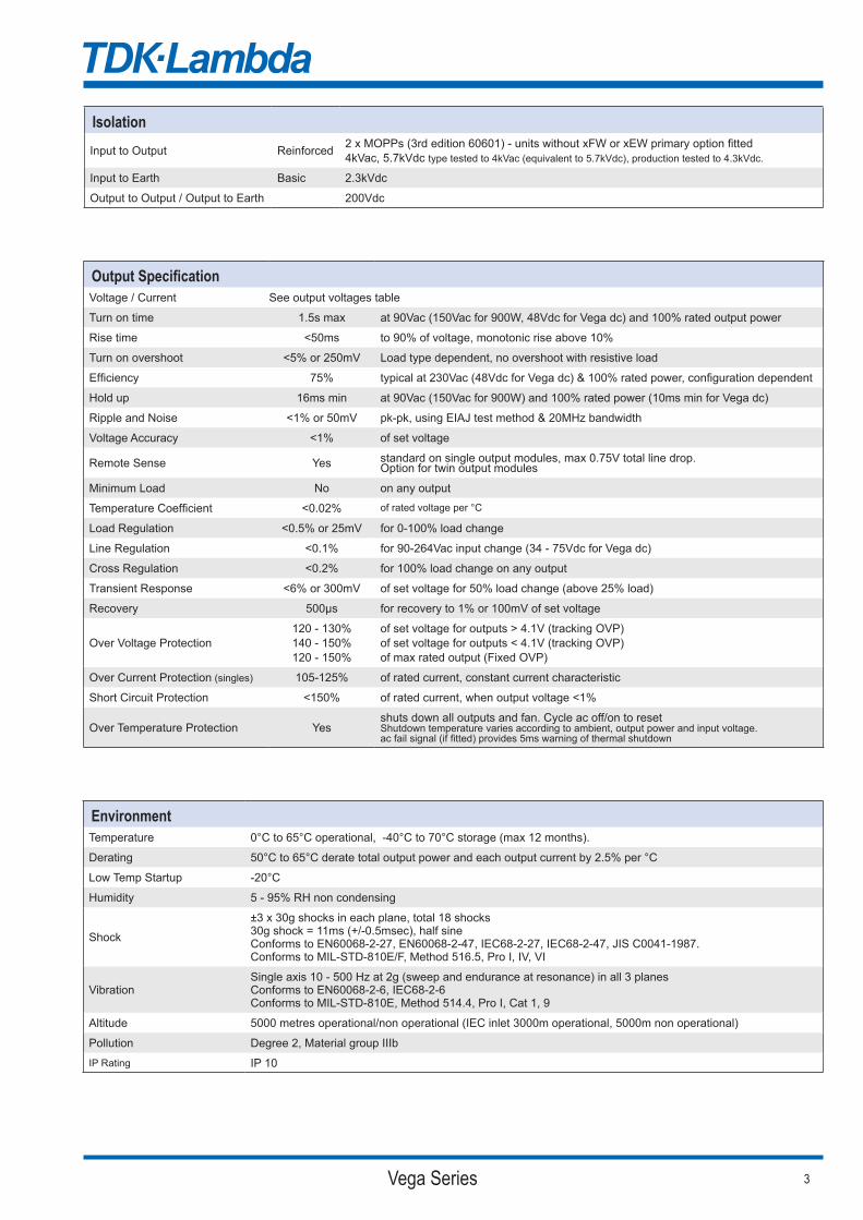
IsolationInput to Output Reinforced 2 x MOPPs (3rd edition 60601) - units without xFW or xEW primary option fitted
4kVac, 5.7kVdc type tested to 4kVac (equivalent to 5.7kVdc), production tested to 4.3kVdc.
Input to Earth Basic 2.3kVdc
Output to Output / Output to Earth 200Vdc
Output SpecificationVoltage / Current See output voltages table
Turn on time 1.5s max at 90Vac (150Vac for 900W, 48Vdc for Vega dc) and 100% rated output power
Rise time <50ms to 90% of voltage, monotonic rise above 10%
Turn on overshoot <5% or 250mV Load type dependent, no overshoot with resistive load
Efficiency 75% typical at 230Vac (48Vdc for Vega dc) & 100% rated power, configuration dependent
Hold up 16ms min at 90Vac (150Vac for 900W) and 100% rated power (10ms min for Vega dc)
Ripple and Noise <1% or 50mV pk-pk, using EIAJ test method & 20MHz bandwidth
Voltage Accuracy <1% of set voltage
Remote Sense Yes standard on single output modules, max 0.75V total line drop.Option for twin output modules
Minimum Load No on any output
Temperature Coefficient <0.02% of rated voltage per °C
Load Regulation <0.5% or 25mV for 0-100% load change
Line Regulation <0.1% for 90-264Vac input change (34 - 75Vdc for Vega dc)
Cross Regulation <0.2% for 100% load change on any output
Transient Response <6% or 300mV of set voltage for 50% load change (above 25% load)
Recovery 500µs for recovery to 1% or 100mV of set voltage
Over Voltage Protection120 - 130%140 - 150%120 - 150%
of set voltage for outputs > 4.1V (tracking OVP)of set voltage for outputs < 4.1V (tracking OVP)of max rated output (Fixed OVP)
Over Current Protection (singles) 105-125% of rated current, constant current characteristic
Short Circuit Protection <150% of rated current, when output voltage <1%
Over Temperature Protection Yesshuts down all outputs and fan. Cycle ac off/on to resetShutdown temperature varies according to ambient, output power and input voltage.ac fail signal (if fitted) provides 5ms warning of thermal shutdown
EnvironmentTemperature 0°C to 65°C operational, -40°C to 70°C storage (max 12 months).
Derating 50°C to 65°C derate total output power and each output current by 2.5% per °C
Low Temp Startup -20°C
Humidity 5 - 95% RH non condensing
Shock
±3 x 30g shocks in each plane, total 18 shocks30g shock = 11ms (+/-0.5msec), half sineConforms to EN60068-2-27, EN60068-2-47, IEC68-2-27, IEC68-2-47, JIS C0041-1987.Conforms to MIL-STD-810E/F, Method 516.5, Pro I, IV, VI
VibrationSingle axis 10 - 500 Hz at 2g (sweep and endurance at resonance) in all 3 planesConforms to EN60068-2-6, IEC68-2-6Conforms to MIL-STD-810E, Method 514.4, Pro I, Cat 1, 9
Altitude 5000 metres operational/non operational (IEC inlet 3000m operational, 5000m non operational)
Pollution Degree 2, Material group IIIb
IP Rating IP 10

4 Vega Series
Immunity EN61000-6-2:2005, EN60601-1-2:2001 CriteriaElectrostatic Discharge EN61000-4-2 Level 4 Air discharge 15kV, Contact discharge 8kV A
Electromagnetic Field EN61000-4-3 Level 3 12V/m A
Fast / Burst Transient EN61000-4-4 Level 4Level 3 for Vega dc
ac input tested to 4.4kV (2kV for Vega dc)dc output tested to 2.2kV (1kV for Vega dc)Tested at 5kHz and 100kHz
A
Surge Immunity EN61000-4-5 Level 3Level 2 for Vega dc
Common mode - 2.2kV (1.1kV for Vega dc)Differential - 1.1kV (0.55kV for Vega dc) A
Conducted RF Immunity EN61000-4-6 Level 3 12V A
Power Frequency Magnetic Field EN61000-4-8 Level 4 30A/m A
Voltage Dips, Variations, Interruptions EN61000-4-11 Class 3na - Vega dc
AB for 5s interruptions
Approvals / AccreditationsIEC/EN 60950-1, UL60950-1 / CSA 22.2 No 60950-1 File E135494
IEC/EN 60601-1, UL/CSA 60601-1, ANSI/AAMI ES60601-1CAN/CSA-C22.2 No 60601-1-08 File E349607 (not Vega dc, only for L, R and T leakage variants)
IEC/EN 61010-1 File E331788
CE Mark (EN60950-1) LV Directive 2006/95/EC
CB certificate and Report available on request Please check with technical sales for status of approvals
Designed and manufactured under the control of ISO9001 and ISO13485 (including risk management).
Emissions EN61000-6-3:2007, EN60601-1-2:2001
Radiated Electric Field EN55011, EN55022(as per CISPR.11/22) Class B (Class A for Vega dc), FCC47 part 15 subpart Bsee application note for details. Additional filtering required for IEC inlet version.Only for ‘S’ type leakage variants.
Conducted Emissions EN55011, EN55022 (as per CISPR.11/22) Class B (Class A for Vega dc), FCC47 part 15 subpart BOnly for ‘S’ type leakage variants. ‘M’ and ‘L’ types meet Class A
Conducted Harmonics EN61000-3-2 Class A - not applicable to Vega dc
Flicker EN61000-3-3 Compliant - dmax only - not applicable to Vega dc


6 Vega Series
Vega_Datasheet_69537-17www.emea.tdk-lambda.com
TDK-Lambda France SASZAC des DelachesCS 410779 rue Thuillere91978 Villebon CourtaboeufFranceTel: +33 1 60 12 71 65Fax: +33 1 60 12 71 [email protected]
Italy Sales OfficeVia dei Lavoratori 128/13020092 Cinisello Balsamo (MI)ItalyTel: +39 02 61 29 38 63Fax: +39 02 61 29 09 [email protected]
TDK-Lambda Germany GmbHKarl-Bold-Strasse 4077855 AchernGermanyTel: +49 7841 666 0Fax: +49 7841 [email protected]
Austria Sales Office Aredstrasse 222544 LeobersdorfAustriaTel: +43 2256 655 84Fax: +43 2256 645 [email protected]
Scandinavia Sales Office Valdemarsgade 7 4100 Ringsted Denmark Tel: +45 24 63 95 65Fax: +45 69 80 44 [email protected]
Switzerland Sales OfficeBahnhofstrasse 508305 DietlikonSwitzerlandTel: +41 44 850 53 53Fax: +41 44 850 53 [email protected]
TDK-Lambda UK Ltd.Kingsley AvenueIlfracombeDevon EX34 8ESUnited KingdomTel: +44 (0) 12 71 85 66 66Fax: +44 (0) 12 71 86 48 [email protected]
TDK-Lambda Ltd.Kibbutz Givat Hashlosha 48800IsraelTel: +9 723 902 4333Fax: +9 723 902 [email protected]
RussiaTechnical Support:St PetersburgTel: +7 (812) 6580463Sales:[email protected]
Local Distribution
Related Documents


![· [ymxpp \opvk]g s wxynyp o[^nyp lpr bpny [s\^xyu xp wyqp] lf]g n[kwy]xfw 7o^wki jxpyoxk]kukj ^ ukqoyny bpvympuk p\]g \myt xkly[\wf\vym \vymk *n[kwy]xy\]g+ s h]s](https://static.cupdf.com/doc/110x72/5c90c8a909d3f2213e8cc3a2/-ymxpp-opvkg-s-wxynyp-onyp-lpr-bpny-sxyu-xp-wyqp-lfg-nkwyxfw-7owki.jpg)