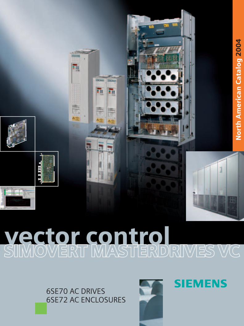
North American Catalog 2004 6SE70 AC DRIVES 6SE72 AC ENCLOSURES vector control SIMOVERT MASTERDRIVES VC SIMOVERT MASTERDRIVES VC SIMOVERT MASTERDRIVES VC

Welcome message from author
This document is posted to help you gain knowledge. Please leave a comment to let me know what you think about it! Share it to your friends and learn new things together.
Transcript
No
rth
Am
eri
can
Ca
talo
g 2
00
4
6SE70 AC DRIVES6SE72 AC ENCLOSURES
vector controlSIMOVERT MASTERDRIVES VCSIMOVERT MASTERDRIVES VCSIMOVERT MASTERDRIVES VC
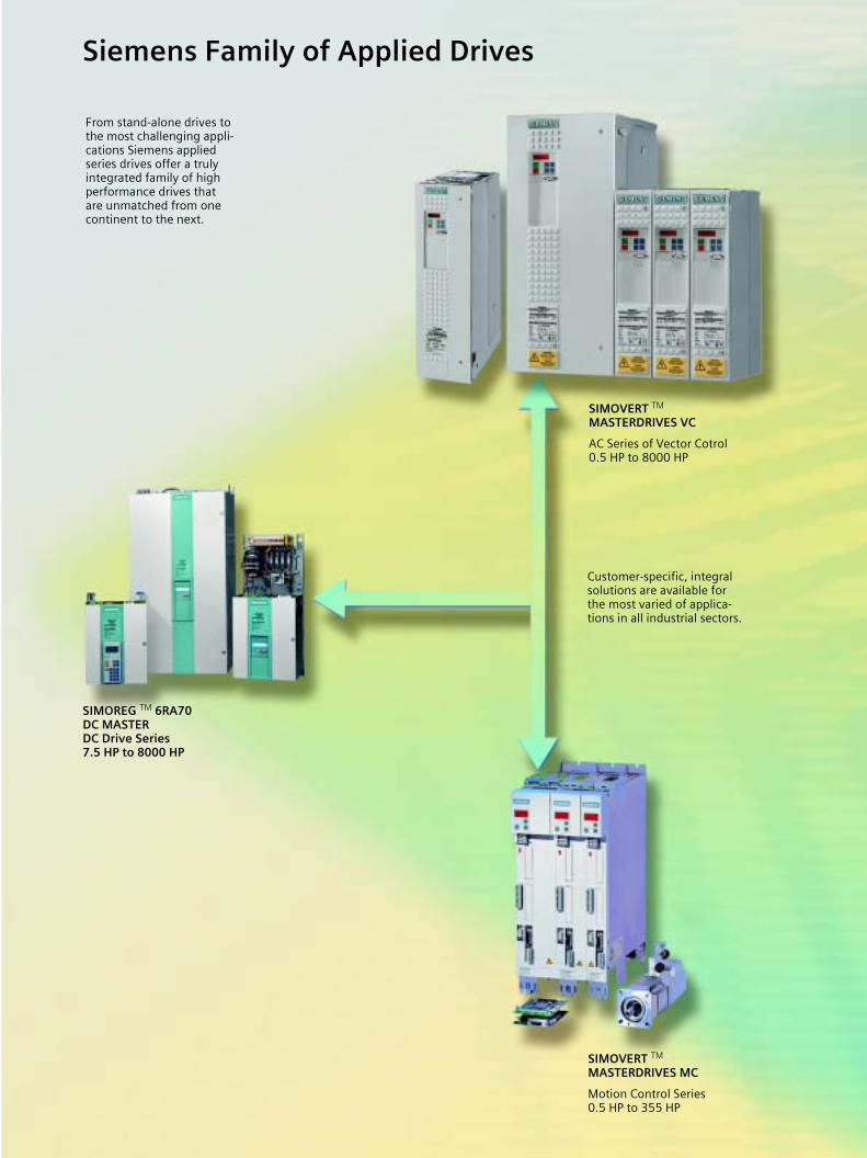
Siemens Family of Applied Drives
From stand-alone drives to the most challenging appli-cations Siemens applied series drives offer a truly integrated family of high performance drives that are unmatched from one continent to the next.
SIMOREG TM 6RA70DC MASTERDC Drive Series7.5 HP to 8000 HP
SIMOVERT TM MASTERDRIVES VC
AC Series of Vector Cotrol 0.5 HP to 8000 HP
Customer-specific, integral solutions are available for the most varied of applica-tions in all industrial sectors.
SIMOVERT TM MASTERDRIVES MC
Motion Control Series0.5 HP to 355 HP
s
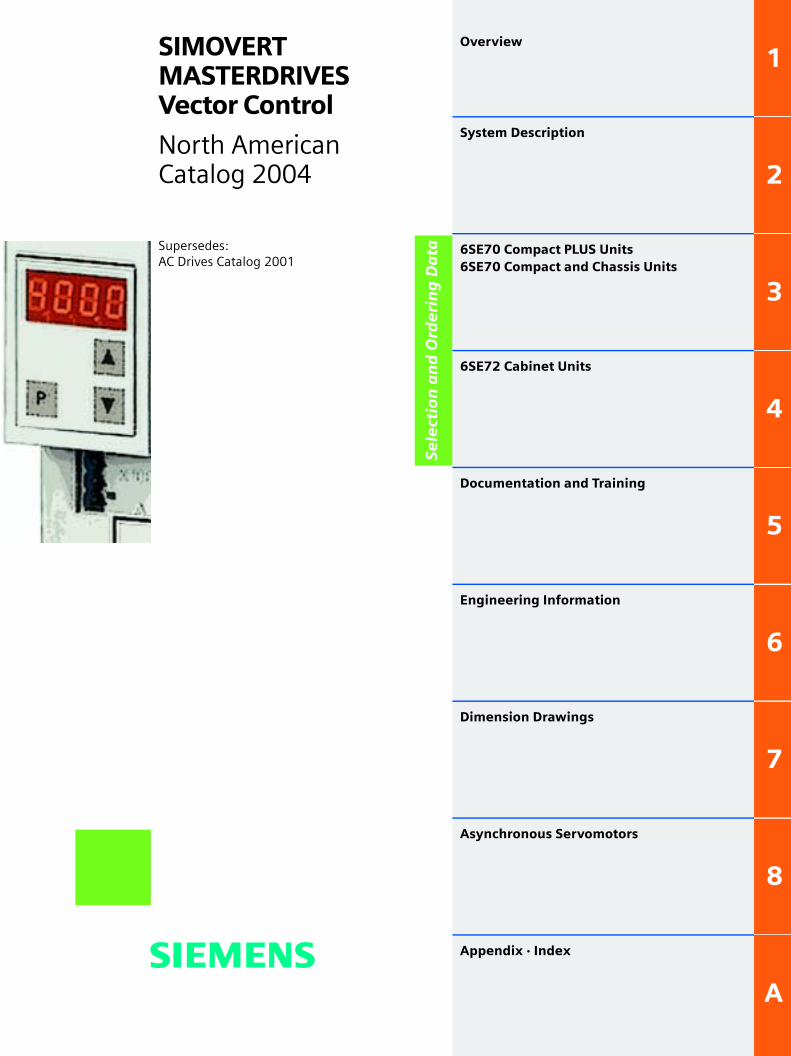
Supersedes:AC Drives Catalog 2001
SIMOVERT MASTERDRIVES Vector Control
North American Catalog 2004
Overview
1
System Description
2
6SE70 Compact PLUS Units 6SE70 Compact and Chassis Units
3
6SE72 Cabinet Units
4
Documentation and Training
5
Engineering Information
6
Dimension Drawings
7
Asynchronous Servomotors
8
Appendix · Index
A
Se
lect
ion
an
d O
rde
rin
g D
ata

Note!
The technical data is intended for general information.Please observe the operating instructions and the references indicated on the products for installation, operation andmaintenance.
� SIMADYN, SIMATIC, SIMATIC HMI, SIMODRIVE, SIMOLINK, SIMOREG, SIMOVERT, SITOR, STEP, STRUC and USS areSiemens registered trademarks.All other products and system names in this catalog are (registered) trademarks of their respective owners and must betreated accordingly.
� The technical data, selection and ordering data (Order Nos.), accessories and availability are subject to alteration.
� All dimensions in this catalog are stated in inches (mm).
� Siemens AG 2004
Siemens North American Catalog · 2004 1/1
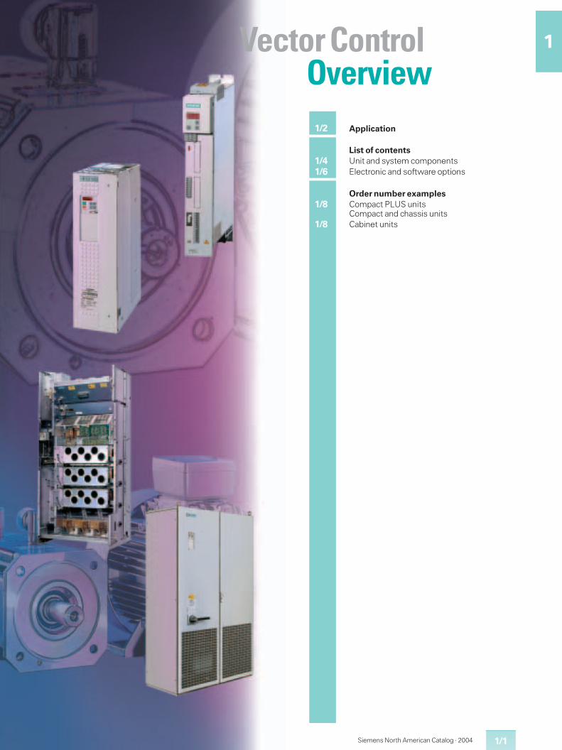
1Vector ControlOverview
1/2 Application
List of contents1/4 Unit and system components1/6 Electronic and software options
Order number examples1/8 Compact PLUS units
Compact and chassis units1/8 Cabinet units
Applications Applications
SIMOVERT MASTERDRIVES Vector ControlOverview
SIMOVERTr MASTERDRIVES Vector ControlOverview
Compact PLUS/compact andchassis units · cabinet units
1 1Compact PLUS/compact andchassis units · cabinet units
Siemens North American Catalog � 2004 Siemens North American Catalog � 20041/2 1/3
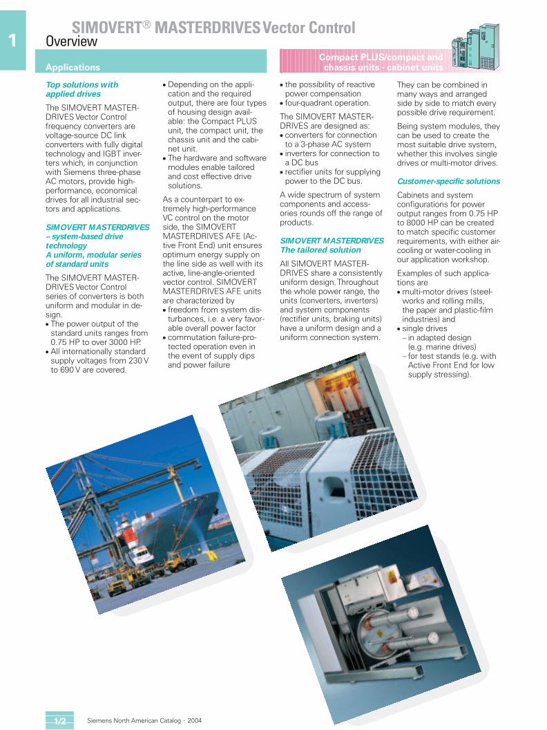
Top solutions with applied drives
The SIMOVERT MASTER-DRIVES Vector Control frequency converters arevoltage-source DC link converters with fully digitaltechnology and IGBT inver-ters which, in conjunctionwith Siemens three-phaseAC motors, provide high-performance, economicaldrives for all industrial sec-tors and applications.
SIMOVERT MASTERDRIVES– system-based drivetechnologyA uniform, modular seriesof standard units
The SIMOVERT MASTER-DRIVES Vector Control series of converters is bothuniform and modular in de-sign.� The power output of the
standard units ranges from0.75 HP to over 3000 HP.
� All internationally standardsupply voltages from 230 Vto 690 V are covered.
� Depending on the appli-cation and the requiredoutput, there are four typesof housing design avail-able: the Compact PLUSunit, the compact unit, thechassis unit and the cabi-net unit.
� The hardware and softwaremodules enable tailoredand cost effective drive solutions.
As a counterpart to ex-tremely high-performanceVC control on the motorside, the SIMOVERTMASTERDRIVES AFE (Ac-tive Front End) unit ensuresoptimum energy supply onthe line side as well with itsactive, line-angle-orientedvector control. SIMOVERTMASTERDRIVES AFE unitsare characterized by� freedom from system dis-
turbances, i.e. a very favor-able overall power factor
� commutation failure-pro-tected operation even inthe event of supply dipsand power failure
� the possibility of reactivepower compensation
� four-quadrant operation.
The SIMOVERT MASTER-DRIVES are designed as:� converters for connection
to a 3-phase AC system� inverters for connection to
a DC bus� rectifier units for supplying
power to the DC bus.
A wide spectrum of systemcomponents and access-ories rounds off the range ofproducts.
SIMOVERT MASTERDRIVESThe tailored solution
All SIMOVERT MASTER-DRIVES share a consistentlyuniform design.Throughoutthe whole power range, theunits (converters, inverters)and system components(rectifier units, braking units)have a uniform design and auniform connection system.
They can be combined inmany ways and arrangedside by side to match every possible drive requirement.
Being system modules, theycan be used to create themost suitable drive system,whether this involves singledrives or multi-motor drives.
Customer-specific solutions
Cabinets and system configurations for poweroutput ranges from 0.75 HPto 8000 HP can be createdto match specific customerrequirements, with either air-cooling or water-cooling inour application workshop.
Examples of such applica-tions are� multi-motor drives (steel-
works and rolling mills,the paper and plastic-filmindustries) and
� single drives – in adapted design
(e.g. marine drives)– for test stands (e.g. with
Active Front End for low supply stressing).
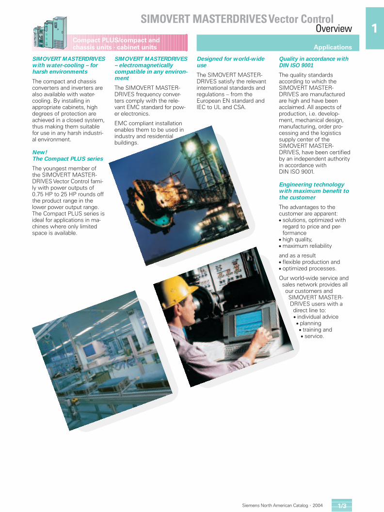
SIMOVERT MASTERDRIVESwith water-cooling – forharsh environments
The compact and chassisconverters and inverters arealso available with water-cooling. By installing inappropriate cabinets, highdegrees of protection areachieved in a closed system,thus making them suitablefor use in any harsh industri-al environment.
New!The Compact PLUS series
The youngest member ofthe SIMOVERT MASTER-DRIVES Vector Control fami-ly with power outputs of0.75 HP to 25 HP rounds offthe product range in thelower power output range.The Compact PLUS series isideal for applications in ma-chines where only limitedspace is available.
SIMOVERT MASTERDRIVES– electromagneticallycompatible in any environ-ment
The SIMOVERT MASTER-DRIVES frequency conver-ters comply with the rele-vant EMC standard for pow-er electronics.
EMC compliant installationenables them to be used inindustry and residentialbuildings.
Designed for world-wideuse
The SIMOVERT MASTER-DRIVES satisfy the relevantinternational standards andregulations – from the European EN standard andIEC to UL and CSA.
Quality in accordance withDIN ISO 9001
The quality standards according to which theSIMOVERT MASTER-DRIVES are manufacturedare high and have been acclaimed. All aspects ofproduction, i.e. develop-ment, mechanical design,manufacturing, order pro-cessing and the logisticssupply center of theSIMOVERT MASTER-DRIVES, have been certifiedby an independent authorityin accordance withDIN ISO 9001.
Engineering technologywith maximum benefit tothe customer
The advantages to the customer are apparent:� solutions, optimized with
regard to price and per-formance
� high quality,� maximum reliability
and as a result� flexible production and� optimized processes.
Our world-wide service and sales network provides all our customers and SIMOVERT MASTER-DRIVES users with a direct line to:� individual advice � planning� training and� service.
Applications Applications
SIMOVERT MASTERDRIVES Vector ControlOverview
SIMOVERTr MASTERDRIVES Vector ControlOverview
Compact PLUS/compact andchassis units · cabinet units
1 1Compact PLUS/compact andchassis units · cabinet units
Siemens North American Catalog � 2004 Siemens North American Catalog � 20041/2 1/3
Top solutions with applied drives
The SIMOVERT MASTER-DRIVES Vector Control frequency converters arevoltage-source DC link converters with fully digitaltechnology and IGBT inver-ters which, in conjunctionwith Siemens three-phaseAC motors, provide high-performance, economicaldrives for all industrial sec-tors and applications.
SIMOVERT MASTERDRIVES– system-based drivetechnologyA uniform, modular seriesof standard units
The SIMOVERT MASTER-DRIVES Vector Control series of converters is bothuniform and modular in de-sign.� The power output of the
standard units ranges from0.75 HP to over 3000 HP.
� All internationally standardsupply voltages from 230 Vto 690 V are covered.
� Depending on the appli-cation and the requiredoutput, there are four typesof housing design avail-able: the Compact PLUSunit, the compact unit, thechassis unit and the cabi-net unit.
� The hardware and softwaremodules enable tailoredand cost effective drive solutions.
As a counterpart to ex-tremely high-performanceVC control on the motorside, the SIMOVERTMASTERDRIVES AFE (Ac-tive Front End) unit ensuresoptimum energy supply onthe line side as well with itsactive, line-angle-orientedvector control. SIMOVERTMASTERDRIVES AFE unitsare characterized by� freedom from system dis-
turbances, i.e. a very favor-able overall power factor
� commutation failure-pro-tected operation even inthe event of supply dipsand power failure
� the possibility of reactivepower compensation
� four-quadrant operation.
The SIMOVERT MASTER-DRIVES are designed as:� converters for connection
to a 3-phase AC system� inverters for connection to
a DC bus� rectifier units for supplying
power to the DC bus.
A wide spectrum of systemcomponents and access-ories rounds off the range ofproducts.
SIMOVERT MASTERDRIVESThe tailored solution
All SIMOVERT MASTER-DRIVES share a consistentlyuniform design.Throughoutthe whole power range, theunits (converters, inverters)and system components(rectifier units, braking units)have a uniform design and auniform connection system.
They can be combined inmany ways and arrangedside by side to match every possible drive requirement.
Being system modules, theycan be used to create themost suitable drive system,whether this involves singledrives or multi-motor drives.
Customer-specific solutions
Cabinets and system configurations for poweroutput ranges from 0.75 HPto 8000 HP can be createdto match specific customerrequirements, with either air-cooling or water-cooling inour application workshop.
Examples of such applica-tions are� multi-motor drives (steel-
works and rolling mills,the paper and plastic-filmindustries) and
� single drives – in adapted design
(e.g. marine drives)– for test stands (e.g. with
Active Front End for low supply stressing).
SIMOVERT MASTERDRIVESwith water-cooling – forharsh environments
The compact and chassisconverters and inverters arealso available with water-cooling. By installing inappropriate cabinets, highdegrees of protection areachieved in a closed system,thus making them suitablefor use in any harsh industri-al environment.
New!The Compact PLUS series
The youngest member ofthe SIMOVERT MASTER-DRIVES Vector Control fami-ly with power outputs of0.75 HP to 25 HP rounds offthe product range in thelower power output range.The Compact PLUS series isideal for applications in ma-chines where only limitedspace is available.
SIMOVERT MASTERDRIVES– electromagneticallycompatible in any environ-ment
The SIMOVERT MASTER-DRIVES frequency conver-ters comply with the rele-vant EMC standard for pow-er electronics.
EMC compliant installationenables them to be used inindustry and residentialbuildings.
Designed for world-wideuse
The SIMOVERT MASTER-DRIVES satisfy the relevantinternational standards andregulations – from the European EN standard andIEC to UL and CSA.
Quality in accordance withDIN ISO 9001
The quality standards according to which theSIMOVERT MASTER-DRIVES are manufacturedare high and have been acclaimed. All aspects ofproduction, i.e. develop-ment, mechanical design,manufacturing, order pro-cessing and the logisticssupply center of theSIMOVERT MASTER-DRIVES, have been certifiedby an independent authorityin accordance withDIN ISO 9001.
Engineering technologywith maximum benefit tothe customer
The advantages to the customer are apparent:� solutions, optimized with
regard to price and per-formance
� high quality,� maximum reliability
and as a result� flexible production and� optimized processes.
Our world-wide service and sales network provides all our customers and SIMOVERT MASTER-DRIVES users with a direct line to:� individual advice � planning� training and� service.
Applications Applications
SIMOVERT MASTERDRIVES Vector ControlOverview
SIMOVERT MASTERDRIVES Vector ControlOverview
Compact PLUS/compact andchassis units · cabinet units
1 1Compact PLUS/compact andchassis units · cabinet units
Siemens North American Catalog � 2004 Siemens North American Catalog � 20041/2 1/31/4
List of contents
1/5
List of contents
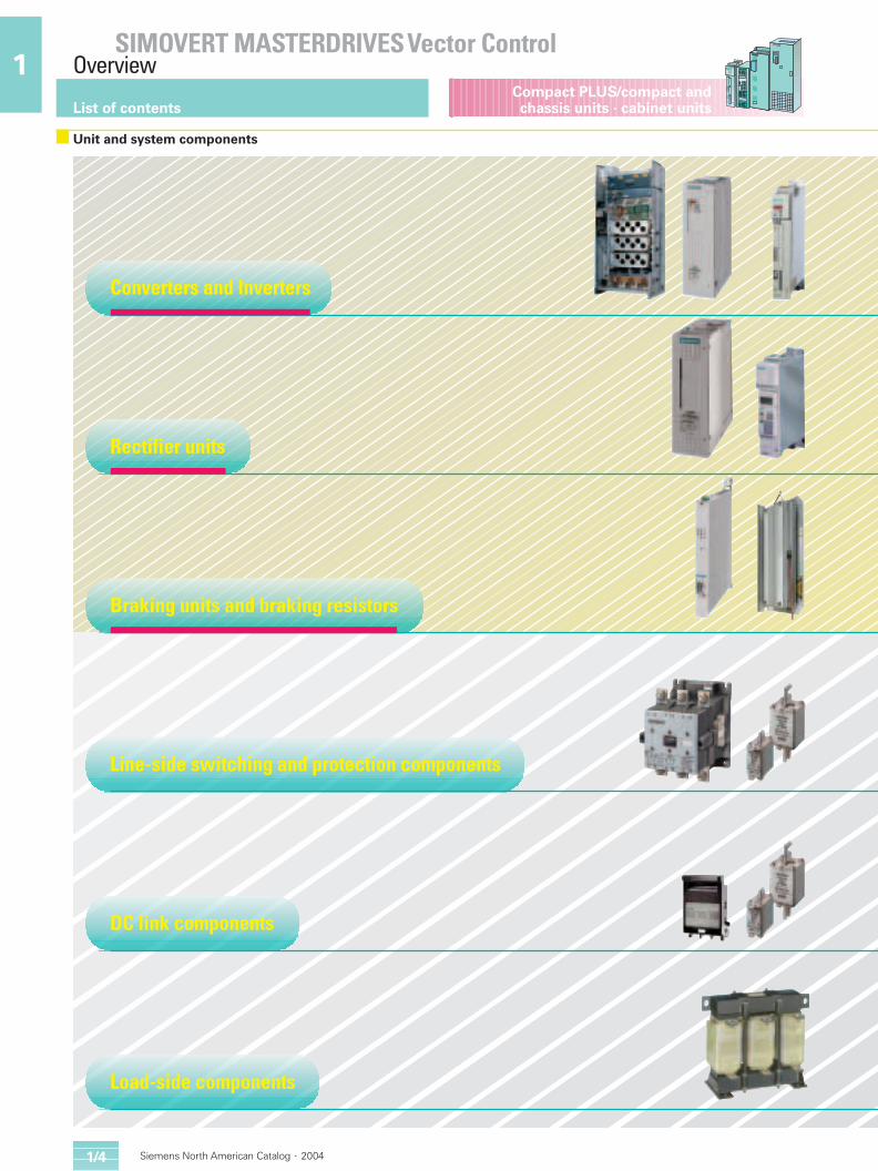
Unit and system components
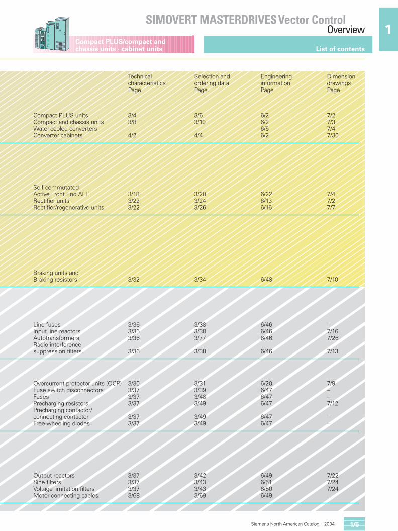
Technical Selection and Engineering Dimension characteristics ordering data information drawingsPage Page Page Page
Compact PLUS units 3/4 3/6 6/2 7/2Compact and chassis units 3/8 3/10 6/2 7/3Water-cooled converters – – 6/5 7/4Converter cabinets 4/2 4/4 6/2 7/30
Self-commutated Active Front End AFE 3/18 3/20 6/22 7/4Rectifier units 3/22 3/24 6/13 7/2Rectifier/regenerative units 3/22 3/26 6/16 7/7
Braking units and Braking resistors 3/32 3/34 6/48 7/10
Line fuses 3/36 3/38 6/46 –Input line reactors 3/36 3/38 6/46 7/16Autotransformers 3/36 3/77 6/46 7/26Radio-interference suppression filters 3/36 3/38 6/46 7/13
Overcurrent protector units (OCP) 3/30 3/31 6/20 7/9Fuse switch disconnectors 3/37 3/39 6/47 –Fuses 3/37 3/48 6/47 –Precharging resistors 3/37 3/49 6/47 7/12Precharging contactor/connecting contactor 3/37 3/49 6/47 –Free-wheeling diodes 3/37 3/49 6/47 –
Output reactors 3/37 3/42 6/49 7/22Sine filters 3/37 3/43 6/51 7/24Voltage limitation filters 3/37 3/43 6/50 7/24Motor connecting cables 3/68 3/69 6/49 –
Line-side switching and protection components
Rectifier units
Braking units and braking resistors
DC link components
Converters and Inverters
Load-side components
Applications Applications
SIMOVERT MASTERDRIVES Vector ControlOverview
SIMOVERT MASTERDRIVES Vector ControlOverview
Compact PLUS/compact andchassis units · cabinet units
1 1Compact PLUS/compact andchassis units · cabinet units
Siemens North American Catalog � 2004 Siemens North American Catalog � 20041/2 1/31/4
List of contents
1/5
List of contents
Unit and system components
Technical Selection and Engineering Dimension characteristics ordering data information drawingsPage Page Page Page
Compact PLUS units 3/4 3/6 6/2 7/2Compact and chassis units 3/8 3/10 6/2 7/3Water-cooled converters – – 6/5 7/4Converter cabinets 4/2 4/4 6/2 7/30
Self-commutated Active Front End AFE 3/18 3/20 6/22 7/4Rectifier units 3/22 3/24 6/13 7/2Rectifier/regenerative units 3/22 3/26 6/16 7/7
Braking units and Braking resistors 3/32 3/34 6/48 7/10
Line fuses 3/36 3/38 6/46 –Input line reactors 3/36 3/38 6/46 7/16Autotransformers 3/36 3/77 6/46 7/26Radio-interference suppression filters 3/36 3/38 6/46 7/13
Overcurrent protector units (OCP) 3/30 3/31 6/20 7/9Fuse switch disconnectors 3/37 3/39 6/47 –Fuses 3/37 3/48 6/47 –Precharging resistors 3/37 3/49 6/47 7/12Precharging contactor/connecting contactor 3/37 3/49 6/47 –Free-wheeling diodes 3/37 3/49 6/47 –
Output reactors 3/37 3/42 6/49 7/22Sine filters 3/37 3/43 6/51 7/24Voltage limitation filters 3/37 3/43 6/50 7/24Motor connecting cables 3/68 3/69 6/49 –
Line-side switching and protection components
Rectifier units
Braking units and braking resistors
DC link components
Converters and Inverters
Load-side components
Applications Applications
SIMOVERT MASTERDRIVES Vector ControlOverview
SIMOVERT MASTERDRIVES Vector ControlOverview
Compact PLUS/compact andchassis units · cabinet units
1 1Compact PLUS/compact andchassis units · cabinet units
Siemens North American Catalog � 2004 Siemens North American Catalog � 20041/2 1/31/6
List of contents
1/7
List of contents
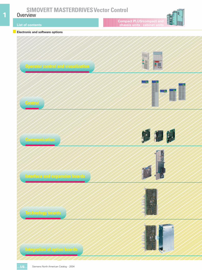
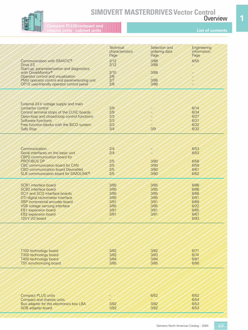
Electronic and software options
Operator control and visualization
Control
Communication
Interface and expansion boards
Technology boards
Integration of option boards
Technical Selection and Engineering characteristics ordering data informationPage Page Page
Communication with SIMATICr 2/12 3/88 6/55Drive ES 2/12 3/88 –Start-up, parameterization and diagnostics with DriveMonitorr 2/10 3/88 –Operator control and visualization 2/6 – –PMU operator control and parameterizing unit 2/7 3/86 –OP1S user-friendly operator control panel 2/8 3/86 –
External 24 V voltage supply and main contactor control 2/9 – 6/14Control terminal strips of the CUVC boards 2/9 – 6/34Open-loop and closed-loop control functions 2/3 – 6/27Software functions 2/3 – 6/31Free function blocks with the BICO system 2/3 – 6/32Safe Stop 3/4 3/9 6/32
Communication 2/4 – 6/53Serial interfaces on the basic unit 2/4 – 6/53CBP2 communication board forPROFIBUS DP 2/5 3/80 6/56CBC communication board for CAN 2/5 3/80 6/59CBD communication board DeviceNet 2/5 3/80 6/61SLB communication board for SIMOLINKr 2/5 3/80 6/62
SCB1 interface board 3/85 3/85 6/86SCB2 interface board 3/85 3/85 6/86SCI1 and SCI2 interface boards 3/85 3/85 6/88DTI digital tachometer interface 3/85 3/85 6/91SBP incremental encoder board 3/81 3/81 6/69VSB voltage sensing interface 3/85 3/85 6/22EB1 expansion board 3/81 3/81 6/65EB2 expansion board 3/81 3/81 6/67120 V I/O board – – 6/93
T100 technology board 3/82 3/82 6/71T300 technology board 3/82 3/83 6/74T400 technology board 3/84 3/84 6/81TSY synchronizing board 3/85 3/85 6/90
Compact PLUS units – 6/52 6/52Compact and chassis units – – 6/54Bus adapter for the electronics box LBA 3/82 3/82 6/53ADB adapter board 3/82 3/82 6/53
Applications Applications
SIMOVERT MASTERDRIVES Vector ControlOverview
SIMOVERT MASTERDRIVES Vector ControlOverview
Compact PLUS/compact andchassis units · cabinet units
1 1Compact PLUS/compact andchassis units · cabinet units
Siemens North American Catalog � 2004 Siemens North American Catalog � 20041/2 1/31/6
List of contents
1/7
List of contents
Electronic and software options
Operator control and visualization
Control
Communication
Interface and expansion boards
Technology boards
Integration of option boards
Technical Selection and Engineering characteristics ordering data informationPage Page Page
Communication with SIMATICr 2/12 3/88 6/55Drive ES 2/12 3/88 –Start-up, parameterization and diagnostics with DriveMonitorr 2/10 3/88 –Operator control and visualization 2/6 – –PMU operator control and parameterizing unit 2/7 3/86 –OP1S user-friendly operator control panel 2/8 3/86 –
External 24 V voltage supply and main contactor control 2/9 – 6/14Control terminal strips of the CUVC boards 2/9 – 6/34Open-loop and closed-loop control functions 2/3 – 6/27Software functions 2/3 – 6/31Free function blocks with the BICO system 2/3 – 6/32Safe Stop 3/4 3/9 6/32
Communication 2/4 – 6/53Serial interfaces on the basic unit 2/4 – 6/53CBP2 communication board forPROFIBUS DP 2/5 3/80 6/56CBC communication board for CAN 2/5 3/80 6/59CBD communication board DeviceNet 2/5 3/80 6/61SLB communication board for SIMOLINKr 2/5 3/80 6/62
SCB1 interface board 3/85 3/85 6/86SCB2 interface board 3/85 3/85 6/86SCI1 and SCI2 interface boards 3/85 3/85 6/88DTI digital tachometer interface 3/85 3/85 6/91SBP incremental encoder board 3/81 3/81 6/69VSB voltage sensing interface 3/85 3/85 6/22EB1 expansion board 3/81 3/81 6/65EB2 expansion board 3/81 3/81 6/67120 V I/O board – – 6/93
T100 technology board 3/82 3/82 6/71T300 technology board 3/82 3/83 6/74T400 technology board 3/84 3/84 6/81TSY synchronizing board 3/85 3/85 6/90
Compact PLUS units – 6/52 6/52Compact and chassis units – – 6/54Bus adapter for the electronics box LBA 3/82 3/82 6/53ADB adapter board 3/82 3/82 6/53
Siemens North American Catalog · 20041/8
1Compact PLUS/compact and
chassis units · cabinet units
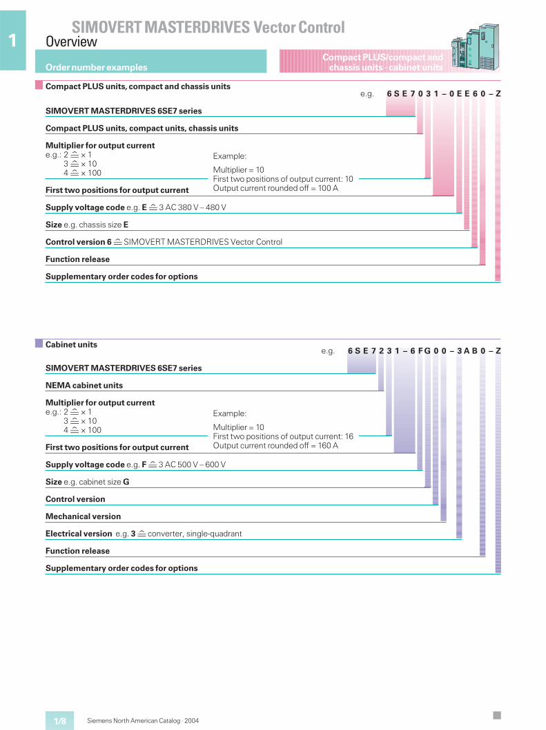
e.g. 6 S E 7 2 3 1 – 6 F G 0 0 – 3 A B 0 – Z
SIMOVERT MASTERDRIVES 6SE7 series
NEMA cabinet units
Multiplier for output currente.g.: 2 × 1
3 × 104 × 100
First two positions for output current
Supply voltage code e.g. F 3 AC 500 V – 600 V
Size e.g. cabinet size G
Control version
Mechanical version
Electrical version e.g. 3 converter, single-quadrant
Function release
Supplementary order codes for options
e.g. 6 S E 7 0 3 1 – 0 E E 6 0 – Z
SIMOVERT MASTERDRIVES 6SE7 series
Compact PLUS units, compact units, chassis units
Multiplier for output currente.g.: 2 × 1
3 × 104 × 100
First two positions for output current
Supply voltage code e.g. E 3 AC 380 V – 480 V
Size e.g. chassis size E
Control version 6 SIMOVERT MASTERDRIVES Vector Control
Function release
Supplementary order codes for options
Example:
Multiplier = 10First two positions of output current: 16Output current rounded off = 160 A
Example:
Multiplier = 10First two positions of output current: 10Output current rounded off = 100 A
Order number examples
Compact PLUS units, compact and chassis units
Cabinet units
SIMOVERT MASTERDRIVES Vector ControlOverview
Siemens North American Catalog · 2004 2/1
2
System layout2/2 Converters and inverters2/2 Rectifier units and rectifier/regenerative units2/3 Self-commutated Active Front End AFE2/3 System components
2/3 Overcurrent protector units (OCP)
Control functions2/3 Control types2/3 Software functions2/3 Free function blocks
Communication via serial interfaces2/4 Interfaces on the basic unit2/5 Options: communication and
interface boards2/5 Transmission protocols and fieldbus systems
Operator control and visualization2/7 PMU operator control and parameterizing unit2/8 OP1S user-friendly operator control panel2/9 Control terminal strip2/9 External 24 V voltage supply and main
contactor control
2/10 Start-up,parameterization and diagnosticswith DriveMonitor
SIMOVERT MASTERDRIVES in the worldof automation
2/11 Link-up to automation systems2/12 Integrating drives in SIMATIC S7
with Drive ES
2/13 Configuration program Drive ES
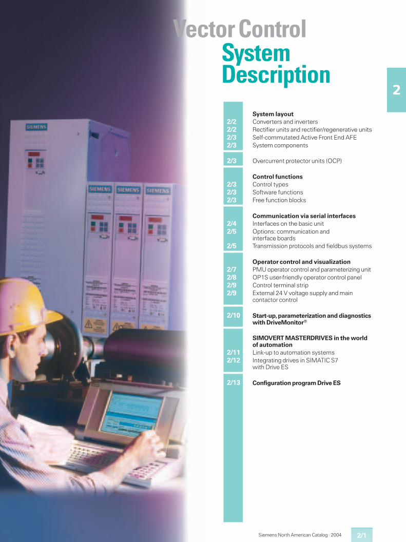
Vector ControlSystemDescription
2/2
SIMOVERT MASTERDRIVES Vector ControlSystem Description
2
Compact PLUS/compact andchassis units · cabinet units
Siemens North American Catalog · 2004
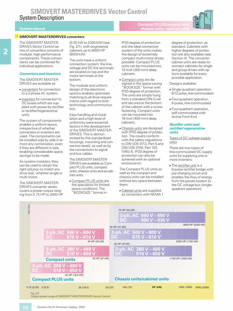
The SIMOVERT MASTER-DRIVES Vector Control se-ries of converters consists ofmodular, high-performancecomponents. These compo-nents can be combined forindividual applications.
Converters and inverters
The SIMOVERT MASTER-DRIVES are available as:
� converters for connectionto a 3-phase AC system.
� inverters for connection toDC buses which are sup-plied with power by rectifieror rectifier/regenerativeunits.
The system of componentsenables a uniform layout,irrespective of whetherconverters or inverters areused. The components canbe installed side by side in al-most any combination, evenif they are different in size,enabling considerable spacesavings to be made.
As system modules, theycan be used to obtain theright solution to match anydrive task, whether single ormulti-motor.
The SIMOVERT MASTER-DRIVES converter seriescovers a power output rang-ing from 0.75 HP to 3000 HP
(0.55 kW to 2300 kW) (seeFig. 2/1), with engineeredcabinets up to 8000 HP(6000 kW).
The units have a uniformconnection system: the line-voltage and DC link terminalsare located on top and themotor terminals at thebottom.
The modular and uniformdesign of the electronicoptions enables optimizedmatching to all drive require-ments with regard to bothtechnology and communica-tion.
Easy handling and instal-lation and a high level ofuniformity were essentialfactors in the developmentof the SIMOVERT MASTER-DRIVES. This is demon-strated by the standardizedhousings, mounting and con-nection levels, as well as bythe connections to signaland bus cables.
The SIMOVERTMASTER-DRIVES are available as Com-pact PLUS units, compactunits, chassis units and as cab-inet units.
� Compact PLUS units arethe specialists for limitedspace conditions. The“BOOKSIZE”format in
IP20 degree of protectionand the ideal connectionsystem of the units makesthe design of extremelycompact multi-motor drivespossible. Compact PLUSunits can be mounted into12-inch (300 mm) deepcabinets.
� Compact units are de-signed in the space-saving“BOOKSIZE”format withIP20 degree of protection .The units are simply hungfrom a standard DIN G railand secured at the bottomof the cabinet with a screwfastening. Compact unitscan be mounted into16-inch (400 mm) deepcabinets.
� Chassis units are designedwith IP00 degree of protec-tion. The covers conformwith the safety regulationsto DIN VDE 0113, Part 5 andDIN VDE 0106, Part 100(VBG 4). IP20 degree ofprotection can also beachieved with an optionalenclosure kit.
The Compact PLUS units aswell as the compact andchassis units can be installedwithout any space betweenthem.
� Cabinet units are suppliedas converters with NEMA 1
degree of protection asstandard. Cabinets withhigher degrees of protec-tion are also available (seeSection 4). The convertercabinet units are ready-to-connect cabinets for singleand group drives with op-tions available for everypossible application.
Designs available:
� Single-quadrant operation,6/12 pulse, line-commutated
� Four-quadrant operation,6-pulse, line-commutated
� Four-quadrant operation,self-commutated withActive Front End.
Rectifier units andrectifier/regenerativeunits
Types of DC voltage supplyunits
There are two types ofline-commutated DC supplyunits for supplying one ormore inverters:
� The rectifier unit is a6-pulse rectifier bridge withpre-charging circuit andenables the flow of energyfrom the power system tothe DC voltage bus (single-quadrant operation).
System layout
SIMOVERT MASTERDRIVES converters
0.75 (0.55) 3 (2.2) 25 (18.5) 100 (75) 1200 (1000) 3000 (2300)
GM
C-5
155a
50 (37)
75 HP (55 kW)
50 HP (37 kW)
60 HP (45 kW)
1750 HP (1300 kW)
2300 HP (1700 kW)
50 HP (37 kW)
40 HP (30 kW)
25 HP (18.5 kW)
3000 HP (2300 kW)
�������
Chassis units/cabinet units
3-ph. AC 380 V – 480 VDC 510 V – 650 V
3-ph. AC 500 V – 600 VDC 675 V – 810 V
3-ph. AC 500 V – 600 VDC 675 V – 810 V
3-ph. AC 380 V – 480 VDC 510 V – 650 V
3-ph. AC 660 V – 690 VDC 890 V – 930 V
Compact PLUS units
3-ph. AC 380 V – 480 VDC 510 V – 650 V
Compact units
Fig. 2/1Output power range of SIMOVERT MASTERDRIVES Vector Control
Compact PLUS/compact andchassis units · cabinet units
Siemens North American Catalog · 2004 2/3
SIMOVERT MASTERDRIVES Vector ControlSystem Description
2� The rectifier/regenerative
unit consists of two anti-parallel 6-pulse thyristorbridges and enables theflow of energy in bothdirections, i.e. energy canbe fed back into the powersystem (4-quadrant opera-tion). The regeneratingbridge is connected via anautotransformer (option).
12-pulse operation
Converters for 12-pulseoperation are supplied bytwo parallel-connected recti-fier or rectifier/regenerativeunits with the same outputrating.
They are connected to thesupply via a three-windingtransformer with two sec-ondary windings electricallydisplaced by 30 °. In this way,system disturbances areconsiderably reduced. Therelevant harmonic currentsof the fifth and seventh orderare almost eliminated whencompared to 6-pulse opera-tion.
Optimum power infeed is en-sured by the self-commutat-ed, AFE (Active Front End)
unit. Its core components arean inverter with a CUSA con-trol unit and it generates aregulated DC voltage from athree-phase supply. On thethree-phase side, rapid vec-tor control subordinate tothis DC voltage control im-presses an almost sinusoidalcurrent towards the supplyso that, with the help of theline-side clean power filter,system disturbances arekept to a minimum. Vectorcontrol also enables powerfactor (cos �) setting and en-abling reactive power com-pensation as well, wherebythe drive's power require-ment has priority. A biggeradvantage is that, due to theunderlying principle of thismethod, inverter shoot-through with fuse trippingcannot occur when there is apower failure, even during re-generative operation.
Single-quadrant operation,four-quadrant operation
Units for single-quadrantoperation can only work inmotoring mode. For regener-ative mode, a braking unit/braking resistor is necessary.
Units for four-quadrant opera-tion can return regenerativeenergy to the three-phasesupply. This may be neces-sary, for example, whendrives with a large rotatingmass have to be braked fre-quently or rapidly.
System components
In addition to the converter,inverter and rectifier basicunits, the system compo-nents enable tailor-madesolutions to meet the driverequirements.
The system components canbe broken down as follows:
� Overcurrent protector units(OCP) for rectifier/regenera-tive units
In the case of line-commu-tating rectifier/regenerativeunits, the occurrence ofundervoltages or voltagedips can cause the inverterto stall and the fuse to tripduring regenerative mode.This can mean that theequipment may have to beshut down for a longer pe-riod.
In order to avoid this, theovercurrent protector unit(OCP) can be used incombination with the line-commutated rectifier/re-generative unit (R/R unit)for four-quadrant operation.It prevents fuse tripping bytriggering an IGBT in theDC link so that the IGBTcuts off the power. This isof particular advantage inthe case of large groupdrives.
As soon as the fault hasbeen acknowledged, theequipment is ready foroperation.
� Braking units and brakingresistors
� Electronic options e.g.technology, communica-tion and interface boards
� Other system componentssuch asswitching and protectiondevices,line reactors and outputreactors andradio-interference suppres-sion filters.
Control types
The SIMOVERT MASTER-DRIVES Vector Control stan-dard software contains twoprincipal control types:
� Frequency control bymeans of the V/f-character-istic curvewith or without speedfeedback and for textileapplications. Frequencycontrol is suitable for sim-ple applications and for highlevel synchronism withingroup drives.
� Vector control (field-oriented control)for dynamic applications inthe form of frequencycontrol (without encoder)or speed/torque control(with encoder). The vectorcontrol method achieves adynamic performancewhich is comparable to thatof a DC drive. This is basedon precise modeling of the
motor and two currentcomponents which influ-ence the flux and thetorque with a control fre-quency of 2.5 kHz. Usingthis vector control method,torque setpoints can beheld and limited.
In the 1:10 speed range,the field-oriented controlsystem of SIMOVERTMASTERDRIVES VectorControl does not require aspeed encoder and islargely independent ofmotor parameters.
The following uses ofSIMOVERT MASTER-DRIVES Vector Control re-quire a speed encoder:
� High dynamic performancerequirements
� Torque control in the con-trol range > 1:10
� Low speeds
� Maximum speed accuracy.
The different types of controlare described in detail in Sec-tion 6.
Software functions
The basic software containsa wide range of standardfunctions. These functionsprovide maximum user-friendliness regarding opera-tor control and the highestdegree of flexibility (setpointselection, changeover be-tween data sets, etc.). Theyalso ensure universal operat-ing conditions and a highlevel of operational safety(automatic restart, flyingrestart, DC injection braking,synchronization betweenconverters, wobble genera-tor, motor brake control,etc.).
These functions aredescribed in Section 6.
Free function blocks
Using the free functionblocks contained in the basicsoftware, the drives can beadapted to the most variedof applications. Simplecontrol systems can thusbe created and technologyrequirements can be dealtwith in a decentralized man-ner.
The function blocks availablein SIMOVERT MASTER-DRIVES Vector Control canbe classified as follows:
� Control blocks
� Signal conversion blocks
� Computing blocks
� Logic blocks
� Signalling blocks
� Timers.
For a detailed description,see Section 6.
Control functions
System layout
2/4
SIMOVERT MASTERDRIVES Vector ControlSystem Description
2
Compact PLUS/compact andchassis units · cabinet units
Siemens North American Catalog · 2004
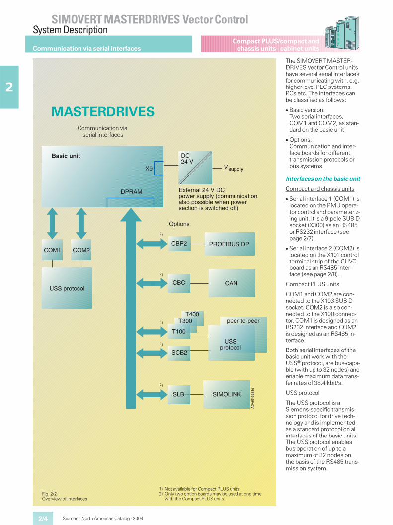
The SIMOVERT MASTER-DRIVES Vector Control unitshave several serial interfacesfor communicating with, e.g.higher-level PLC systems,PCs etc. The interfaces canbe classified as follows:
� Basic version:Two serial interfaces,COM1 and COM2, as stan-dard on the basic unit
� Options:Communication and inter-face boards for differenttransmission protocols orbus systems.
Interfaces on the basic unit
Compact and chassis units
� Serial interface 1 (COM1) islocated on the PMU opera-tor control and parameteriz-ing unit. It is a 9-pole SUB Dsocket (X300) as an RS485or RS232 interface (seepage 2/7).
� Serial interface 2 (COM2) islocated on the X101 controlterminal strip of the CUVCboard as an RS485 inter-face (see page 2/8).
Compact PLUS units
COM1 and COM2 are con-nected to the X103 SUB Dsocket. COM2 is also con-nected to the X100 connec-tor. COM1 is designed as anRS232 interface and COM2is designed as an RS485 in-terface.
Both serial interfaces of thebasic unit work with theUSSr protocol, are bus-capa-ble (with up to 32 nodes) andenable maximum data trans-fer rates of 38.4 kbit/s.
USS protocol
The USS protocol is aSiemens-specific transmis-sion protocol for drive tech-nology and is implementedas a standard protocol on allinterfaces of the basic units.The USS protocol enablesbus operation of up to amaximum of 32 nodes onthe basis of the RS485 trans-mission system.
Fig. 2/2Overview of interfaces
����
���
����
�������
���
��
��
����� �
�����
����������
��
�����
���� ����
���� ! " #
��!$ %&
���'������
���������
��� ! " #
�((��! ��((�
�
)*!(�%+#�������� ,(��&-��#.�/" 00-%$"+!$ %+#& �� &&$1#(�,2(%�� ,(�&("!$ %�$&�&,$!"2(�� 334
&-��#.�
MASTERDRIVESCommunication via
serial interfaces
Communication via serial interfaces
1) Not available for Compact PLUS units.2) Only two option boards may be used at one time
with the Compact PLUS units.
2)
2)
1)
1)
2)
Siemens North American Catalog · 2004 2/5
SIMOVERT MASTERDRIVES Vector ControlSystem Description
2
Compact PLUS/compact andchassis units · cabinet units
Data is exchanged in accor-dance with the master-slaveaccess procedure. The USSprotocol only allows mono-master operation. Thismeans one master and 31slaves. Masters can behigher-level systems such asthe SIMATIC S5, S7 and PCsor non-Siemens automationsystems. SIMOVERTMASTERDRIVES are alwaysslaves.
From an application point ofview, the USS protocol isused for the following twoapplications:
– Data transmission be-tween a PC and one orseveral MASTERDRIVESfor start-up and parame-terization of the unitsusing the Drive ES andDriveMonitor engineeringtools. The user-friendlyoperator control panelOP1S also communicatesto the SIMOVERTMASTERDRIVES usingthe USS protocol. COM1is used for linking up to thePC or the OP1S.
– Communication via theUSS protocol to higher-level automation systemssuch as the SIMATIC S5,SIMATIC S7 or to non-Siemens systems. For thislink, COM2 is usuallyused.
Parallel operation of COM1and COM2 is possible with-out any restrictions.
See also documentation:“SIMOVERTMASTERDRIVES, Serial in-terface with USS protocol”,Order No.:6SE7087-6CX87-4KB0.
Options:Communication andinterface boards
The PROFIBUS DP,DeviceNet and CAN serialfieldbus systems can belinked up by means of thecommunication boardsCBP (Communication BoardPROFIBUS DP), CBD(Communication BoardDeviceNet) or CBC(Communication Board CAN).
Fast data exchange betweenthe MASTERDRIVES units ispossible by means of thefiber-optic SLB (SIMOLINKBoard) communicationboard.
In addition to this, the SCB1and SCB2 interface boards(Serial CommunicationBoard) are available for theUSS protocol and peer-to-peer protocol.
The SCB1 and SCB2 are onlyavailable for compact andchassis units (not availablefor Compact PLUS units).
The communication andinterface boards can beintegrated as options intothe electronics box. How theoption boards may be in-stalled and combined in theelectronics box is describedin Section 6 „Integrating theoptions in the electronicsbox“.
SIMOLINK
SIMOLINK (Siemens MotionLink) is a company-specificdevelopment for Siemensdrive technology.
SIMOLINK is mainly used forextremely fast and strictlycyclical exchange of processdata (control information,setpoints, actual values andadditional information) be-tween individual MASTER-DRIVES units or betweenMASTERDRIVES units and ahigher-level control systemwith synchronization of allconnected nodes to acommon system clock pulse.
SIMOLINK is a digital, serialdata transmission protocolusing fiber-optic cables asthe transmission medium(plastic or glass).
Peer-to-peer protocol
The peer-to-peer protocol isalso a company-specificaddition to Siemens drivetechnology.
The difference betweenpeer-to-peer and SIMOLINKis that peer-to-peer does notallow synchronization of thedrives. The transmissionspeed is also considerablyslower than with SIMOLINK.
A peer-to-peer connectionmeans a “connectionbetween equal partners”.In contrast to the classicmaster-slave bus systems(e.g. PROFIBUS DP), oneand the same converter canbe both the master (setpointsource) and the slave(setpoint sink).
Peer-to-peer connection isvia the RS485 interface. Aspecial high-speed protocolis used requiring little man-agement. The transmissionrate is up to 187.5 kbit/s.
Each drive can receivesetpoints and actual valuesfrom the preceding drive viaits peer receive terminal andtransmit data to the subse-quent drive via its transmitterminal.
Transmission protocolsand fieldbus systems
PROFIBUS DP
For Siemens drive technol-ogy, PROFIBUS DP is thestandard bus system for allfield applications.
PROFIBUS is the worldmarket leader in field-bustechnology, and enablescyclical data exchange be-tween the MASTERDRIVESunits and higher-level sys-tems such as the SIMATICS7.
In addition to process controldata, PROFIBUS DP alsocarries information for para-meterization and diagnosisof the drives.
The extended functionalityof Motion Control withPROFIBUS DP (e.g.slave-to-slave communica-tion between drives) is sup-ported by the CBP2 board.
CBD DeviceNet
The CBD board supports thetransfer of process data andparameter data using“DeviceNet Explicit Mes-sages”and “DeviceNet I/OMessages”.
With DeviceNet, ExplicitMessage Connections pro-vide generic, multi-use com-munication paths betweentwo units. This allows typicalrequirements-oriented or re-sponse-oriented functions(e.g. board configuration) tobe implemented.
In contrast, DeviceNet I/OMessage Connections pro-vide communication pathsfor special purposes be-tween the transmitting andreceiving units. Applica-tion-specific I/O data aretransferred via an I/O con-nection. The significance ofthe data within an “I/O mes-sage”is determined by theassociated “Connection ID”.
CAN according to CiA
The CAN protocol (ControllerArea Network) is specified inthe international proposalISO DIS 11898 where, how-ever, only the electrical partsof the physical layer and thedata link layer (Layers 1 and 2in the ISO/OSI layers refer-ence model) are specified.In their recommendationDS 102-1, the CiA (CAN inAutomation, an internationalassociation of users andmanufacturers) defined thebus interface and the busmedium for use as an indus-trial fieldbus.
The specifications in ISO-DIS11898 and in DS 102-1 arecomplied with by the CBCcommunication board.
The CBC communicationboard only supports CANLayers 1 and 2. Higher-leveladditional communicationspecifications of the differ-ent user organizations suchas CAN open of the CiA arenot supported.
Communication via serial interfaces
2/6
SIMOVERT MASTERDRIVES Vector ControlSystem Description
2
Compact PLUS/compact andchassis units · cabinet units
Siemens North American Catalog · 2004
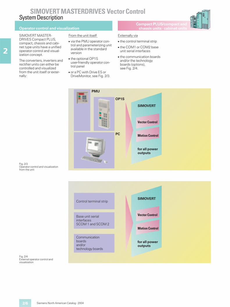
SIMOVERT MASTER-DRIVES Compact PLUS,compact, chassis and cabi-net type units have a unifiedoperator control and visual-ization concept.
The converters, inverters andrectifier units can either becontrolled and visualizedfrom the unit itself or exter-nally:
From the unit itself
� via the PMU operator con-trol and parameterizing unitavailable in the standardversion
� the optional OP1Suser-friendly operator con-trol panel
� or a PC with Drive ES orDriveMonitor, see Fig. 2/3.
Externally via
� the control terminal strip
� the COM1 or COM2 baseunit serial interfaces
� the communication boardsand/or the technologyboards (options),see Fig. 2/4.
Fig. 2/3Operator control and visualizationfrom the unit
Fig. 2/4External operator control andvisualization
for all poweroutputs
Motion Control
Vector Control
SIMOVERT
for all poweroutputs
Motion Control
Vector Control
SIMOVERT
PC
OP1S
PMU
Communicationboardsand/ortechnology boards
Base unit serialinterfacesSCOM 1 and SCOM 2
Control terminal strip
Operator control and visualization
2/7
SIMOVERT MASTERDRIVES Vector ControlSystem Description
2
Compact PLUS/compact andchassis units · cabinet units
Siemens North American Catalog · 2004
Operator control and visualization
Fig. 2/6PMU operator control and parameterization unit for compact and chassis units
�
�
�
�
�
�
5
�+�������+
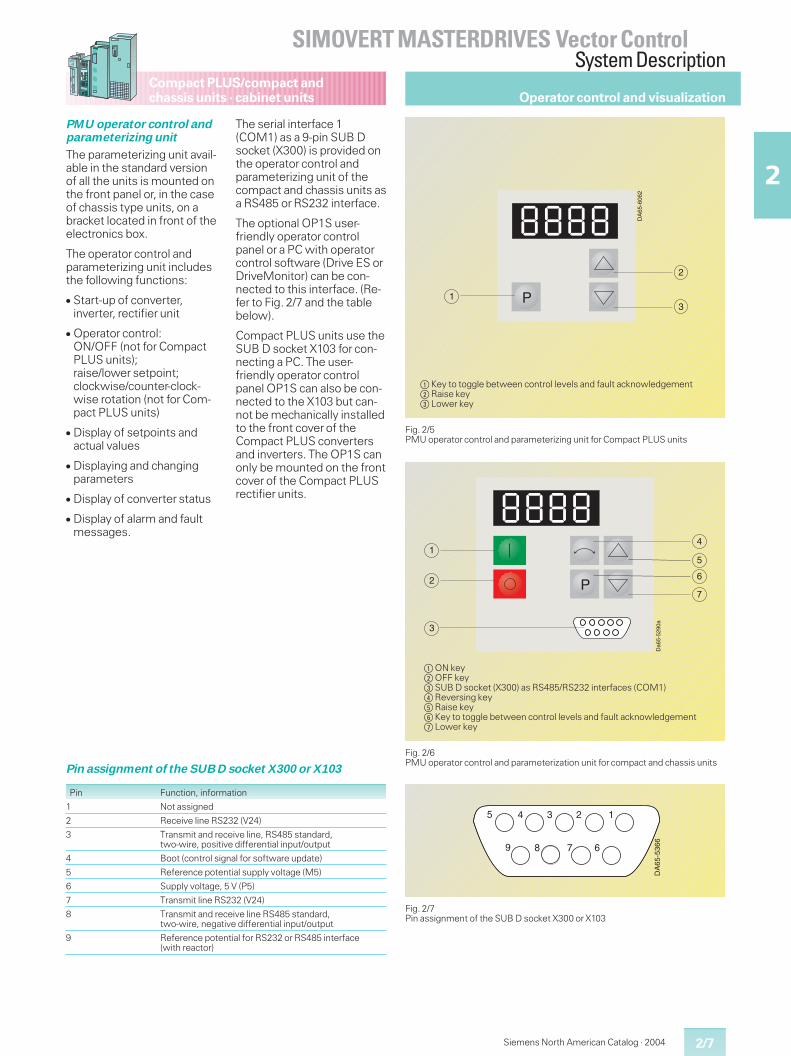
$ON key%OFF key&SUB D socket (X300) as RS485/RS232 interfaces (COM1)(Reversing key)Raise key*Key to toggle between control levels and fault acknowledgement+Lower key
PMU operator control andparameterizing unit
The parameterizing unit avail-able in the standard versionof all the units is mounted onthe front panel or, in the caseof chassis type units, on abracket located in front of theelectronics box.
The operator control andparameterizing unit includesthe following functions:
� Start-up of converter,inverter, rectifier unit
� Operator control:ON/OFF (not for CompactPLUS units);raise/lower setpoint;clockwise/counter-clock-wise rotation (not for Com-pact PLUS units)
� Display of setpoints andactual values
� Displaying and changingparameters
� Display of converter status
� Display of alarm and faultmessages.
The serial interface 1(COM1) as a 9-pin SUB Dsocket (X300) is provided onthe operator control andparameterizing unit of thecompact and chassis units asa RS485 or RS232 interface.
The optional OP1S user-friendly operator controlpanel or a PC with operatorcontrol software (Drive ES orDriveMonitor) can be con-nected to this interface. (Re-fer to Fig. 2/7 and the tablebelow).
Compact PLUS units use theSUB D socket X103 for con-necting a PC. The user-friendly operator controlpanel OP1S can also be con-nected to the X103 but can-not be mechanically installedto the front cover of theCompact PLUS convertersand inverters. The OP1S canonly be mounted on the frontcover of the Compact PLUSrectifier units.
Fig. 2/7Pin assignment of the SUB D socket X300 or X103
DA
65-5
366
5 4 3 2 1
9 8 7 6
Pin assignment of the SUB D socket X300 or X103
Pin Function, information
1 Not assigned
2 Receive line RS232 (V24)
3 Transmit and receive line, RS485 standard,two-wire, positive differential input/output
4 Boot (control signal for software update)
5 Reference potential supply voltage (M5)
6 Supply voltage, 5 V (P5)
7 Transmit line RS232 (V24)
8 Transmit and receive line RS485 standard,two-wire, negative differential input/output
9 Reference potential for RS232 or RS485 interface(with reactor)
Fig. 2/5PMU operator control and parameterizing unit for Compact PLUS units
���������
��
�
�
$Key to toggle between control levels and fault acknowledgement%Raise key&Lower key
2/8
SIMOVERT MASTERDRIVES Vector ControlSystem Description
2
Compact PLUS/compact andchassis units · cabinet units
Siemens North American Catalog · 2004
Fig. 2/9OP1S point-to-point connection up to a cable length of 16 ft (5 m)
����
��5�
����
��5�
����
���������
����
Fig. 2/8View of the OP1S
P
7 8 9
4 5 6
1 2 3
0 +/- Reset
Jog
FaultRun
50.000 Hz50.000 Hz
8.2 A 25 V
*#
DA
65-5
288a
LED redLED green
ON key
OFF key
LC display(4 lines x16 characters)
Jog key
9-pin SUB Dconnector onrear of unit
Reversing key
Raise key
Lower key
Key for togglingbetween controllevels
0 to 9:numerical keys
Reset key
Sign key
Run
OP1S connections via RS485
USS via RS485
Connecting cable
OP1S side:9-pin SUB D socket
Unit side:9-pin SUB D connector
Pin Designation Description
1
2
3 RS485 P Data via RS485 interface
4
5 M 5 Ground
6 P 5 5 V voltage supply
7
8 PS485 N Data via RS485 interface
9 Reference potential
OP1S user-friendlyoperator control panel
The OP1S operator controlpanel is an optional input/output device which can beused for parameterizing theunits. Parameterization ismenu-guided and is per-formed by selecting theparameter number and thenentering the parametervalue. Plain-text displaysgreatly facilitate parameteri-zation.
Parameter and parametervalue descriptions, as well astext displays in English, Ger-man, Spanish, French andItalian, are included in thestandard version.
The OP1S is capable of per-manently storing parametersets. It can therefore be usedfor archiving parameter set-tings and for transferring pa-rameter sets from one unit toanother.Its storage capacity is suffi-cient to store 5 CUVC boardparameter sets. It is not pos-sible to store data sets of thetechnology boards (e.g.T100, T300).
On the rear of the OP1S isa 9-pin SUB D connector viawhich power is supplied andcommunication with theconnected units takes place.
The OP1S operator controlpanel may be plugged di-rectly onto the SUB D socketof the PMU operator controland parameterizing unit andscrewed into the front panel.The OP1S operator panel canalso be used as a remote-control device. The cablebetween the PMU and theOP1S must not exceed164 ft (50 m). If longer than16 ft (5 m), a 5 V voltage sup-ply with a current capabilityof at least 400 mA must beincluded on the OP1S end asshown in Fig. 2/10.
Operator control and visualization
2/9
SIMOVERT MASTERDRIVES Vector ControlSystem Description
2
Compact PLUS/compact andchassis units · cabinet units
Siemens North American Catalog · 2004
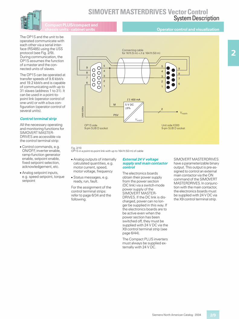
The OP1S and the unit to beoperated communicate witheach other via a serial inter-face (RS485) using the USSprotocol (see Fig. 2/9).During communication, theOP1S assumes the functionof a master and the con-nected units of slaves.
The OP1S can be operated attransfer speeds of 9.6 kbit/sand 19.2 kbit/s and is capableof communicating with up to31 slaves (address 1 to 31). Itcan be used in a point-to-point link (operator control ofone unit) or with a bus con-figuration (operator control ofseveral units).
Control terminal strip
All the necessary operatingand monitoring functions forSIMOVERT MASTER-DRIVES are accessible viathe control terminal strip:
� Control commands, e.g.ON/OFF, inverter enable,ramp-function generatorenable, setpoint enable,fixed setpoint selection,acknowledgement, etc.
� Analog setpoint inputs,e.g. speed setpoint, torquesetpoint
Fig. 2/10OP1S in a point-to-point link with up to 164 ft (50 m) of cable
���������+
�
�
�
�
�
�
5
�
�
�
�
�
�
�
5
�
�
���
�
67
������8�9�
Connecting cablefor 16 ft (5 m) < I � 164 ft (50 m)
OP1S side9-pin SUB D socket
Unit side X3009-pin SUB D socket
Vsupply
Vsupply
Operator control and visualization
� Analog outputs of internallycalculated quantities, e.g.motor current, speed,motor voltage, frequency
� Status messages, e.g.ready, run, fault.
For the assignment of thecontrol terminal strips:refer to page 6/34 and thefollowing.
External 24 V voltagesupply and main contactorcontrol
The electronics boardsobtain their power supplyfrom the power section(DC link) via a switch-modepower supply of theSIMOVERT MASTER-DRIVES. If the DC link is dis-charged, power can no lon-ger be supplied in this way. Ifthe electronics boards are tobe active even when thepower section has beenswitched off, they must besupplied with 24 V DC via theX9 control terminal strip (seepage 6/44).
The Compact PLUS invertersmust always be supplied ex-ternally with 24 V DC.
SIMOVERT MASTERDRIVEShave a parameterizable binaryoutput. This output is pre-as-signed to control an externalmain contactor via the ONcommand of the SIMOVERTMASTERDRIVES. In conjunc-tion with the main contactor,the electronics boards mustbe supplied with 24 V DC viathe X9 control terminal strip.
2/10
SIMOVERT MASTERDRIVES Vector ControlSystem Description
2
Compact PLUS/compact andchassis units · cabinet units
Siemens North American Catalog · 2004
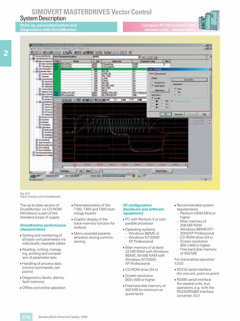
The up-to-date version ofDriveMonitor on CD-ROM(Windows) is part of thestandard scope of supply
DriveMonitor performancecharacteristics
� Setting and monitoring ofall basic-unit parameters viaindividually creatable tables
� Reading, writing, manag-ing, printing and compari-son of parameter sets
� Handling of process data(control commands, set-points)
� Diagnostics (faults, alarms,fault memory)
� Offline and online operation
� Parameterization of theT100, T300 and T400 tech-nology boards
� Graphic display of thetrace-memory function foranalysis
� Menu-assisted parame-terization during commis-sioning.
PC configuration(hardware and softwareequipment)
� PC with Pentium II or com-parable processor
� Operating systems– Windows 98/ME or– Windows NT/2000/
XP Professional
� Main memory of at least32 MB RAM with Windows98/ME, 64 MB RAM withWindows NT/2000/XP Professional
� CD-ROM drive (24 x)
� Screen resolution800 x 600 or higher
� Free hard-disk memory of200 MB for minimum re-quirements
� Recommended systemrequirements– Pentium II/500 MHz or
higher– Main memory of
256 MB RAM– Windows 98/ME/NT/
2000/XP Professional– CD-ROM drive (24 x)– Screen resolution
800 x 600 or higher– Free hard-disk memory
of 500 MB
For stand-alone operation(USS)
� RS232 serial interface(for one unit, point-to-point)
� RS485 serial interface(for several units, busoperation), e.g. with theRS232/RS485 interfaceconverter, SU1.
Fig. 2/11Trace Function with DriveMonitor
Start-up,parameterization anddiagnostics with DriveMonitor
Siemens North American Catalog · 2004 2/11
SIMOVERT MASTERDRIVES Vector ControlSystem Description
2
Compact PLUS/compact andchassis units · cabinet units
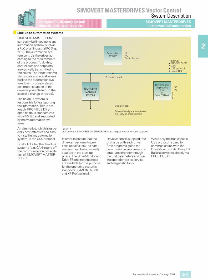
Fig. 2/12Link between SIMOVERT MASTERDRIVES and a higher-level automation system
Link-up to automation systems
SIMOVERT MASTERDRIVESin the world of automation
SIMOVERT MASTERDRIVEScan easily be linked up to anyautomation system, such asa PLC or an industrial PC (Fig.2/12). The automation sys-tem controls the drives ac-cording to the requirementsof the process. To do this,control data and setpointsare cyclically transmitted tothe drives. The latter transmitstatus data and actual valuesback to the automation sys-tem. Even process-relatedparameter adaption of thedrives is possible (e.g. in thecase of a change in recipe).
The fieldbus system isresponsible for transportingthe information. This is pre-ferably PROFIBUS DP, anopen fieldbus standardizedin EN 50 170 and supportedby many automation sys-tems.
An alternative, which is espe-cially cost-effective and easyto install in any automationsystem, is the USS protocol.
Finally, links to other fieldbussystems (e.g. CAN) round offthe communication possibili-ties of SIMOVERT MASTER-DRIVES.
In order to ensure that thedrive can perform its pro-cess-specific task, its para-meters must be individuallyadapted in the start-upphase. The DriveMonitor andDrive ES engineering toolsare available for this purposefor the operating systemsWindows 98/ME/NT/2000and XP Professional.
DriveMonitor is supplied freeof charge with each drive.Both programs guide thecommissioning engineer in astructured manner throughthe unit parameters and dur-ing operation act as serviceand diagnostic tools.
While only the bus-capableUSS protocol is used forcommunication with theDriveMonitor units, Drive ESBasic also works directly viaPROFIBUS DP.
������������������
��
���
��
DriveMonitorengineering
toolor
Drive ES Basic
Field bus:� PROFIBUS DP� CAN� USS protocol� DeviceNet
Process control
Drive-related parameterizatione.g. service and diagnosis
PLCPCControl system
Automationsystem
USS protocol
PCPG
2/12
SIMOVERT MASTERDRIVES Vector ControlSystem Description
2
Compact PLUS/compact andchassis units · cabinet units
Siemens North American Catalog · 2004
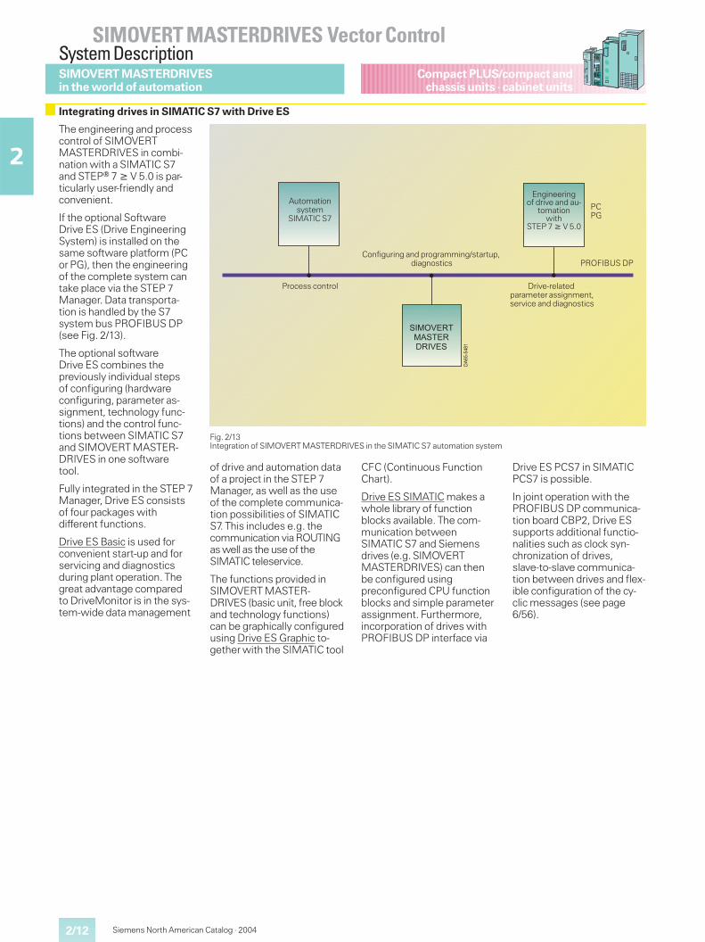
The engineering and processcontrol of SIMOVERTMASTERDRIVES in combi-nation with a SIMATIC S7and STEPr 7 � V 5.0 is par-ticularly user-friendly andconvenient.
If the optional SoftwareDrive ES (Drive EngineeringSystem) is installed on thesame software platform (PCor PG), then the engineeringof the complete system cantake place via the STEP 7Manager. Data transporta-tion is handled by the S7system bus PROFIBUS DP(see Fig. 2/13).
The optional softwareDrive ES combines thepreviously individual stepsof configuring (hardwareconfiguring, parameter as-signment, technology func-tions) and the control func-tions between SIMATIC S7and SIMOVERT MASTER-DRIVES in one softwaretool.
Fully integrated in the STEP 7Manager, Drive ES consistsof four packages withdifferent functions.
Drive ES Basic is used forconvenient start-up and forservicing and diagnosticsduring plant operation. Thegreat advantage comparedto DriveMonitor is in the sys-tem-wide data management
Fig. 2/13Integration of SIMOVERT MASTERDRIVES in the SIMATIC S7 automation system
������������������
��
���
�
Engineeringof drive and au-
tomationwith
STEP 7 � V 5.0
Process control Drive-relatedparameter assignment,service and diagnostics
PROFIBUS DP
Automationsystem
SIMATIC S7
Configuring and programming/startup,diagnostics
PCPG
of drive and automation dataof a project in the STEP 7Manager, as well as the useof the complete communica-tion possibilities of SIMATICS7. This includes e.g. thecommunication via ROUTINGas well as the use of theSIMATIC teleservice.
The functions provided inSIMOVERT MASTER-DRIVES (basic unit, free blockand technology functions)can be graphically configuredusing Drive ES Graphic to-gether with the SIMATIC tool
CFC (Continuous FunctionChart).
Drive ES SIMATIC makes awhole library of functionblocks available. The com-munication betweenSIMATIC S7 and Siemensdrives (e.g. SIMOVERTMASTERDRIVES) can thenbe configured usingpreconfigured CPU functionblocks and simple parameterassignment. Furthermore,incorporation of drives withPROFIBUS DP interface via
Drive ES PCS7 in SIMATICPCS7 is possible.
In joint operation with thePROFIBUS DP communica-tion board CBP2, Drive ESsupports additional functio-nalities such as clock syn-chronization of drives,slave-to-slave communica-tion between drives and flex-ible configuration of the cy-clic messages (see page6/56).
SIMOVERT MASTERDRIVESin the world of automation
Integrating drives in SIMATIC S7 with Drive ES
2/13
SIMOVERT MASTERDRIVES Vector ControlSystem Description
2
Compact PLUS/compact andchassis units · cabinet units
Siemens North American Catalog · 2004
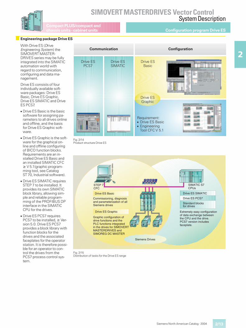
Configuration program Drive ES
With Drive ES (DriveEngineering System) theSIMOVERT MASTER-DRIVES series may be fullyintegrated into the SIMATICautomation world withregard to communication,configuring and data ma-nagement.
Drive ES consists of fourindividually available soft-ware packages: Drive ESBasic, Drive ES Graphic,Drive ES SIMATIC and DriveES PCS7.
� Drive ES Basic is the basicsoftware for assigning pa-rameters to all drives onlineand offline, and the basisfor Drive ES Graphic soft-ware.
� Drive ES Graphic is the soft-ware for the graphical on-line and offline configuringof BICO function blocks.Requirements are an in-stalled Drive ES Basic andan installed SIMATIC CFC� V 5.1(graphic program-ming tool, see CatalogST 70, Industrial software).
� Drive ES SIMATIC requiresSTEP 7 to be installed. Itprovides its own SIMATICblock library, allowing sim-ple and reliable program-ming of the PROFIBUS DPinterface in the SIMATICCPU for the drives.
� Drive ES PCS7 requiresPCS7 to be installed, � Ver-sion 5.0. Drive ES PCS7provides a block library withfunction blocks for thedrives and the associatedfaceplates for the operatorstation. It is therefore possi-ble for an operator to con-trol the drives from thePCS7 process control sys-tem.
Engineering package Drive ES
����������
���������� ���
�������������
������������� ��������������� �������������������� !"
��������#��$%��
������������ �����������
Fig. 2/14Product structure Drive ES
Fig. 2/15Distribution of tasks for the Drive ES range
���������+
�������5���&
�)��5�'�
��$:(�)��+&$" ��$:(�)�������
��$:(�)���5
$(0(%&���$:(&
��$:(�)�;�+�2$"
� 00$&&$ %$%<=��$+<% &$&+%���+�+0(!(�$>+!$ %� 3�+##$(0(%&���$:(&
;�+�2$"�" %3$<-�+!$ %� 3��$:(�3-%"!$ %&�+%��!2(����3-%"!$ %&�$%!(<�+!(�$%�!2(���$:(&�3 ������)�����)�����)�+%�����);�������)�
!+%�+���1# "?&3 ����$:(&
)*!�(0(#.�(+&.�" %3$<-�+!$ % 3��+!+�(*"2+%<(�1(!,((%!2(�����+%��!2(���$:(@��5�:(�&$ %�$%"#-�(&3+"(�#+!(@
�
2/14
SIMOVERT MASTERDRIVES Vector ControlSystem Description
2
Compact PLUS/compact andchassis units · cabinet units
Siemens North American Catalog · 2004
Configuration program Drive ES
Drive ES Graphic
� Function charts are saveddrive specific in SIMATICCFC format.
� Configuring of drive func-tions in BICO technologywith SIMATIC CFC.
� Offline functionality.
� Test mode (online function-ality) with Change connec-tion, Change value, Activateblock.
� Readback and reversedocumentation.
� For SIMOVERT MASTER-DRIVES vector controlsoftware version � 3.2 andmotion control softwareversion � 1.3.
� Provides function blocksand examples of projectsfor the SIMATIC CPU whichhandle communication viaPROFIBUS DP or USS withSiemens drives.
� Communication set-up viaparameters as opposed toprogramming.
Features
� Blocks in STEP 7 design;symbolic addressing;function blocks with entitydata, online help.
� Can be used in all SIMATICprogramming and configur-ing environments such asLAD, CSF, STL, SCL, CFC.
� New block structure:modular individualfunctions for runtime-optimized programming.
Block functions
� Writing and reading ofprocess data of freelyconfigurable length andconsistency.
� Cyclic and acyclic exchangeof parameters, monitoringof communication, readingout of fault memory fromSIMOVERT MASTER-DRIVES.
� Parameter download viathe CPU to the drive.
Drive ES SIMATIC
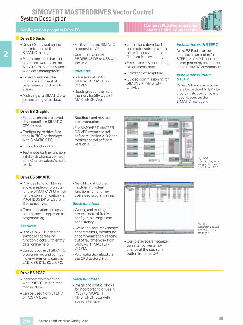
Fig. 2/16Graphic program-ming with Drive ESGraphic and CFC
Fig. 2/17Integrating drivesinto the STEP 7manager
Drive ES PCS7
� Incorporates the driveswith PROFIBUS DP inter-face in PCS7.
� Can be used from STEP 7or PCS7 V 5 on.
Block functions
� Image and control blocksfor incorporating drives inPCS7 (SIMOVERTMASTERDRIVES withspeed interface).
Drive ES Basic
� Drive ES is based on theuser interface of theSIMATIC manager.
� Parameters and charts ofdrives are available in theSIMATIC manager (system-wide data management).
� Drive ES ensures theunique assignment ofparameters and charts toa drive.
� Archiving of a SIMATIC pro-ject including drive data.
� Facility for using SIMATICTeleservice (V 5).
� Communication viaPROFIBUS DP or USS withthe drive.
Functions
� Trace evaluation forSIMOVERT MASTER-DRIVES.
� Reading out of the faultmemory for SIMOVERTMASTERDRIVES.
� Upread and download ofparameter sets (as a com-plete file or as differencefile from factory setting).
� Free assembly and editingof parameter sets.
� Utilization of script files.
� Guided commissioning forSIMOVERT MASTER-DRIVES.
Installation with STEP 7
Drive ES Basic can beinstalled as an option forSTEP 7 � V 5.0, becominghomogeneously integratedin the SIMATIC environment.
Installation withoutSTEP 7
Drive ES Basic can also beinstalled without STEP 7, byproviding its own drive ma-nager (based on theSIMATIC manager).
� Complete reparameteriza-tion after converter ex-change at the push of abutton from the CPU.
Siemens North American Catalog · 2004 3/1
3
Vector ControlCompact PLUS,Compact and Chassis Units
3/3 General technical data
Air-cooled converters and inverters
3/4� Compact PLUS units
Technical characteristics, technical data3/6 Selection and ordering data
� Compact and chassis units3/8 Technical characteristics, technical data3/10 Selection and ordering data
Self-commutated Active Front End AFE3/18 Technical characteristics, technical data3/20 Selection and ordering data
Rectifier units and rectifier/regenerative units3/22 Technical characteristics, technical data3/24 Selection and ordering data
Overcurrent protector units (OCP)3/30 Technical characteristics, technical data3/31 Selection and ordering data
Braking units and braking resistors3/32 Technical characteristics, technical data3/34 Selection and ordering data
System components3/36 Technical characteristics
Selection and ordering data, recommendedsystem components for :
3/38 Converters3/42 Converters and inverters3/48 Inverters3/54 Active Front End (AFE)3/58 Rectifier units3/62 Rectifier/regenerative units3/66 Braking units and braking resistors3/66 Capacitor module, DC link module3/67 Mechanical system components3/68 Motor connection cables3/73 NEMA reactor selection charts3/77 NEMA autotransformer selection chart3/78 NEMA isolation transformer selection chart
Electronics options3/80 Communication boards CBP2, CBC, CBD, SLB3/81 Expansion Boards EB1 and EB23/81 SBP incremental encoder board3/82 LBA bus adapter, ADA adapter board3/82 T100 and T300 technology boards3/84 T400 Technology board3/85 SCB1 and SCB2 interface boards3/85 TSY synchronizing board3/85 SCI1 and SCI2 interface boards3/85 DTI digital tachometer interface3/85 VSB voltage sensing board
Operator control and visualization3/86 APMU adapter for cabinet-door mounting3/86 OP1S user-friendly operator control panel3/87 Drive ES3/88 Communication package for SIMATIC S53/88 DriveMonitor
Other options3/89 Options with code and description
3/2
SIMOVERT MASTERDRIVES Vector ControlCompact PLUS,Compact and Chassis Units
3
Compact PLUS unitsCompact and chassis units
Siemens North American Catalog · 2004
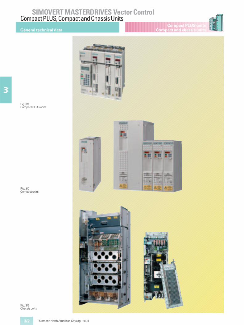
General technical data
Fig. 3/2Compact units
Fig. 3/3Chassis units
Fig. 3/1Compact PLUS units
3/3
SIMOVERT MASTERDRIVES Vector ControlCompact PLUS,Compact and Chassis Units
3
Compact PLUS unitsCompact and chassis units
Siemens North American Catalog · 2004
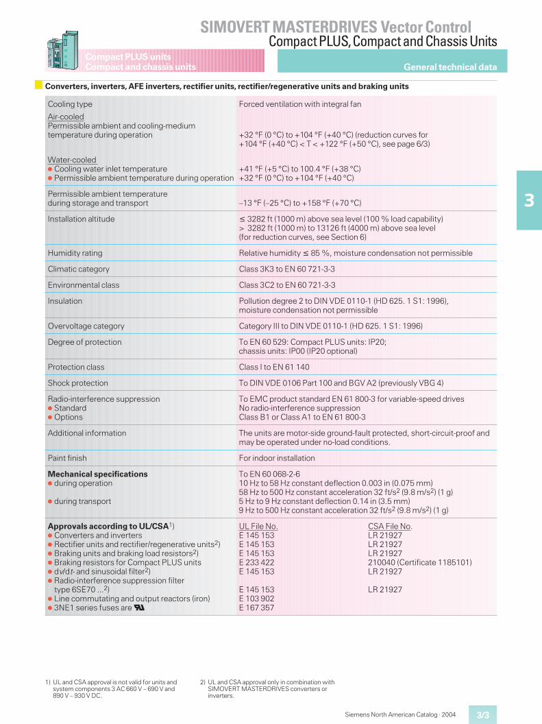
Cooling type Forced ventilation with integral fan
Air-cooledPermissible ambient and cooling-mediumtemperature during operation +32 °F (0 °C) to +104 °F (+40 °C) (reduction curves for
+104 °F (+40 °C) < T < +122 °F (+50 °C), see page 6/3)
Water-cooled� Cooling water inlet temperature� Permissible ambient temperature during operation
+41 °F (+5 °C) to 100.4 °F (+38 °C)+32 °F (0 °C) to +104 °F (+40 °C)
Permissible ambient temperatureduring storage and transport –13 °F (–25 °C) to +158 °F (+70 °C)
Installation altitude � 3282 ft (1000 m) above sea level (100 % load capability)> 3282 ft (1000 m) to 13126 ft (4000 m) above sea level(for reduction curves, see Section 6)
Humidity rating Relative humidity � 85 %, moisture condensation not permissible
Climatic category Class 3K3 to EN 60 721-3-3
Environmental class Class 3C2 to EN 60 721-3-3
Insulation Pollution degree 2 to DIN VDE 0110-1 (HD 625. 1 S1: 1996),moisture condensation not permissible
Overvoltage category Category III to DIN VDE 0110-1 (HD 625. 1 S1: 1996)
Degree of protection To EN 60 529: Compact PLUS units: IP20;chassis units: IP00 (IP20 optional)
Protection class Class I to EN 61 140
Shock protection To DIN VDE 0106 Part 100 and BGV A2 (previously VBG 4)
Radio-interference suppression� Standard� Options
To EMC product standard EN 61 800-3 for variable-speed drivesNo radio-interference suppressionClass B1 or Class A1 to EN 61 800-3
Additional information The units are motor-side ground-fault protected, short-circuit-proof andmay be operated under no-load conditions.
Paint finish For indoor installation
Mechanical specifications� during operation
� during transport
To EN 60 068-2-610 Hz to 58 Hz constant deflection 0.003 in (0.075 mm)58 Hz to 500 Hz constant acceleration 32 ft/s2 (9.8 m/s2) (1 g)5 Hz to 9 Hz constant deflection 0.14 in (3.5 mm)9 Hz to 500 Hz constant acceleration 32 ft/s2 (9.8 m/s2) (1 g)
Approvals according to UL/CSA1)� Converters and inverters� Rectifier units and rectifier/regenerative units2)� Braking units and braking load resistors2)� Braking resistors for Compact PLUS units� dv/dt- and sinusoidal filter2)� Radio-interference suppression filter
type 6SE70 ...2)� Line commutating and output reactors (iron)� 3NE1 series fuses areU
UL File No.E 145 153E 145 153E 145 153E 233 422E 145 153
E 145 153E 103 902E 167 357
CSA File No.LR 21927LR 21927LR 21927210040 (Certificate 1185101)LR 21927
LR 21927
1) UL and CSA approval is not valid for units andsystem components 3 AC 660 V – 690 V and890 V – 930 V DC.
2) UL and CSA approval only in combination withSIMOVERT MASTERDRIVES converters orinverters.
General technical data
Converters, inverters, AFE inverters, rectifier units, rectifier/regenerative units and braking units
Siemens North American Catalog · 20043/4
SIMOVERT MASTERDRIVES Vector ControlCompact PLUS Units
3
Compact PLUS unitsAir-cooled converters and inverters
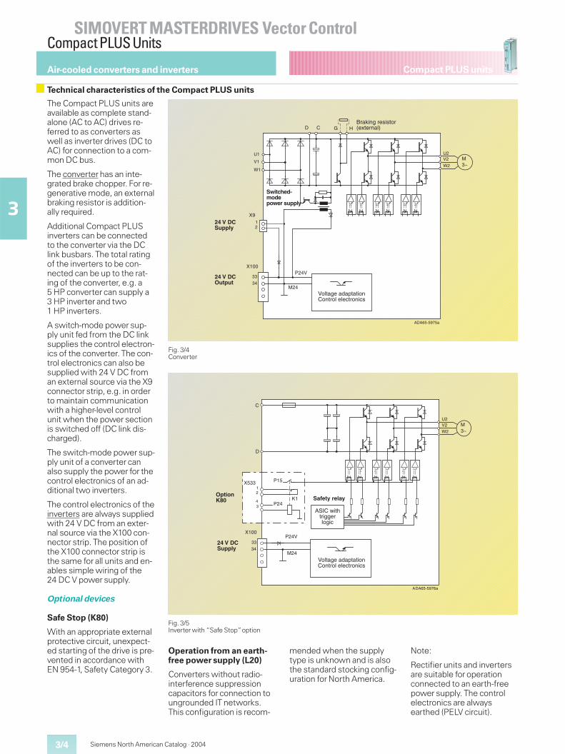
Technical characteristics of the Compact PLUS units
Fig. 3/4Converter
Fig. 3/5Inverter with “Safe Stop”option
The Compact PLUS units areavailable as complete stand-alone (AC to AC) drives re-ferred to as converters aswell as inverter drives (DC toAC) for connection to a com-mon DC bus.
The converter has an inte-grated brake chopper. For re-generative mode, an externalbraking resistor is addition-ally required.
Additional Compact PLUSinverters can be connectedto the converter via the DClink busbars. The total ratingof the inverters to be con-nected can be up to the rat-ing of the converter, e.g. a5 HP converter can supply a3 HP inverter and two1 HP inverters.
A switch-mode power sup-ply unit fed from the DC linksupplies the control electron-ics of the converter. The con-trol electronics can also besupplied with 24 V DC froman external source via the X9connector strip, e.g. in orderto maintain communicationwith a higher-level controlunit when the power sectionis switched off (DC link dis-charged).
The switch-mode power sup-ply unit of a converter canalso supply the power for thecontrol electronics of an ad-ditional two inverters.
The control electronics of theinverters are always suppliedwith 24 V DC from an exter-nal source via the X100 con-nector strip. The position ofthe X100 connector strip isthe same for all units and en-ables simple wiring of the24 DC V power supply.
Optional devices
Safe Stop (K80)
With an appropriate externalprotective circuit, unexpect-ed starting of the drive is pre-vented in accordance withEN 954-1, Safety Category 3.
Operation from an earth-free power supply (L20)
Converters without radio-interference suppressioncapacitors for connection toungrounded IT networks.This configuration is recom-
mended when the supplytype is unknown and is alsothe standard stocking config-uration for North America.
Note:
Rectifier units and invertersare suitable for operationconnected to an earth-freepower supply. The controlelectronics are alwaysearthed (PELV circuit).
������
���
�
�
����
����
���
�
�
�
�
� � � �
������ ���
��������������� �!��!�"������#�"�! #$
����������
����������
��������������������
%"�& !��"�$ $��"'�(��"!��)
�
������
���
��
�
�
���
�
�����
��
����
����
���
������ ����
�*+��, �-�" ���"��� #
��������������� �!��!�"������#�"�! #$
����������
.��������������� ����� �������
3/5
SIMOVERT MASTERDRIVES Vector ControlCompact PLUS Units
3
Compact PLUS units
Siemens North American Catalog · 2004
Air-cooled converters and inverters
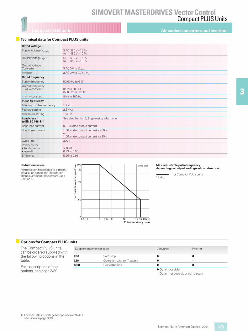
Technical data for Compact PLUS units
Max. adjustable pulse frequencydepending on output and type of construction:
16 kHzfor Compact PLUS units
63 ���
100
�
DA65-6066
0
75
9 12
50
15 16 181.7 7.5
A
Pulse frequency
Per
mis
sibl
e ra
ted
curr
ent
Reduction curves
For reduction factors due to differentinstallation conditions (installationaltitude, ambient temperature), seeSection 6.
Options for Compact PLUS units
The Compact PLUS unitscan be ordered supplied withthe following options in thetable.
For a description of theoptions, see page 3/89.
Supplementary order code Converter Inverter
K80 Safe Stop � �
L20 Operation with an IT supply � –
M08 Coated boards � �
� Option possible– Option not possible or not relevant
Rated voltage
Supply voltage Vsupply 3 AC 380 V – 15 %to 480 V +10 %
DC link voltage VD1) DC 510 V – 15 %
to 650 V +10 %
Output voltageConverter 3 AC 0 V to Vsupply
Inverter 3 AC 0 V to 0.75 x VD
Rated frequency
Supply frequency 50/60 Hz (± 6 %)
Output frequency– V/f = constant 0 Hz to 200 Hz
(500 Hz for textile)
– V = constant 8 Hz to 300 Hz
Pulse frequency
Minimum pulse frequency 1.7 kHz
Factory setting 2.5 kHz
Maximum setting 16 kHz
Load class IIto EN 60 146-1-1
See also Section 6, Engineering Information
Base load current 0.91 x rated output current
Short-time current 1.36 x rated output current for 60 sor1.60 x rated output current for 30 s
Cycle time 300 s
Power factor� fundamental� overall
� 0.980.93 to 0.96
Efficiency 0.96 to 0.98
1) For max. DC link voltage for operation with AFE,see table on page 3/19.
Siemens North American Catalog · 20043/6
SIMOVERT MASTERDRIVES Vector ControlCompact PLUS Units
3
Compact PLUS unitsAir-cooled converters and inverters
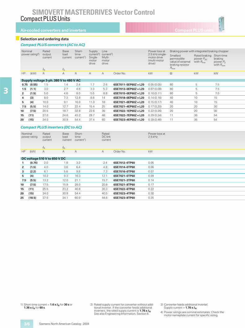
Selection and ordering data
Compact PLUS converters (AC to AC)
Nominalpower rating4)
Ratedoutputcurrent
Baseloadcurrent
Short-timecurrent1)
Supplycurrent2)Single-motordrive
Linecurrent3)Multi-motordrive
Power loss at2.5 kHz single-motor drive(multi-motordrive)
Braking power with integrated braking chopper
Smallestpermissiblevalue of externalbraking resistorRmin
Rated brakingpower P20with Rmin
Short-timebrakingpower P3with Rmin
IN IG
HP (kW) A A A A A Order No. kW � kW kW
Supply voltage 3-ph. 380 V to 480 V AC0.75 (0.55) 1.5 1.4 2.4 1.7 2.6 6SE7011–5EP60Z + L20 0.05 (0.05) 80 5 7.5
1.5 (1.1) 3.0 2.7 4.8 3.3 5.3 6SE7013–0EP60Z + L20 0.07 (0.08) 80 5 7.5
2 (1.5) 5.0 4.6 8.0 5.5 8.8 6SE7015–0EP60Z + L20 0.10 (0.11) 80 5 7.5
4 (3) 8.0 7.3 12.8 8.8 14 6SE7018–0EP60Z + L20 0.14 (0.16) 40 10 15
5 (4) 10.0 9.1 16.0 11.0 18 6SE7021–0EP60Z + L20 0.15 (0.17) 40 10 15
7.5 (5.5) 14.0 12.7 22.4 15.4 25 6SE7021–4EP60Z + L20 0.17 (0.20) 20 20 30
10 (7.5) 20.5 18.7 32.8 22.6 36 6SE7022–1EP60Z + L20 0.22 (0.26) 20 20 30
15 (11) 27.0 24.6 43.2 29.7 48 6SE7022–7EP60Z + L20 0.29 (0.34) 11 36 54
20 (15) 34.0 30.9 54.4 37.4 60 6SE7023–4EP60Z + L20 0.39 (0.46) 11 36 54
Compact PLUS inverters (DC to AC)
Nominalpower rating
Ratedoutputcurrent
Baseloadcurrent
Short-timecurrent1)
RatedDC linkcurrent
Power loss at2.5 kHz
IN IG
HP (kW) A A A A Order No. kW
DC voltage 510 V to 650 V DC1 (0.75) 2.0 1.8 3.2 2.4 6SE7012–0TP60 0.05
2 (1.5) 4.0 3.6 6.4 4.8 6SE7014–0TP60 0.06
3 (2.2) 6.1 5.6 9.8 7.3 6SE7016–0TP60 0.07
5 (4) 10.2 9.3 16.3 12.1 6SE7021–0TP60 0.09
7.5 (5.5) 13.2 12.0 21.1 15.7 6SE7021–3TP60 0.14
10 (7.5) 17.5 15.9 28.0 20.8 6SE7021–8TP60 0.17
15 (11) 25.5 23.2 40.8 30.3 6SE7022–6TP60 0.22
20 (15) 34.0 30.9 54.4 40.5 6SE7023–4TP60 0.30
25 (18.5) 37.5 34.1 60.0 44.6 6SE7023–8TP60 0.35
1) Short-time current = 1.6 x IN for 30 s or1.36 x IN for 60 s.
2) Rated supply current for converter without addi-tional inverter. If the converter feeds additionalinverters, the rated supply current is 1.76 x IN.See also Engineering Information, Section 6.
3) Converter feeds additional inverter;Supply current = 1.76 x IN.
4) Power ratings are nominal estimates. Check themotor nameplate current for specific sizing.
3/7
SIMOVERT MASTERDRIVES Vector ControlCompact PLUS Units
3
Compact PLUS units
Siemens North American Catalog · 2004
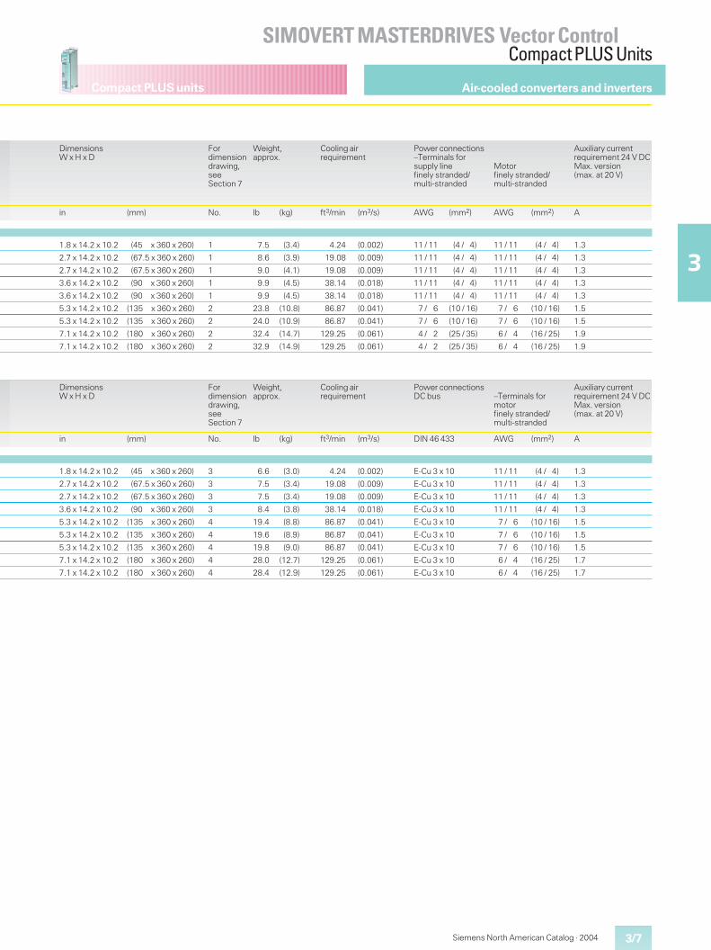
Air-cooled converters and inverters
DimensionsW x H x D
Fordimensiondrawing,seeSection 7
Weight,approx.
Cooling airrequirement
Power connections–Terminals forsupply linefinely stranded/multi-stranded
Motorfinely stranded/multi-stranded
Auxiliary currentrequirement 24 V DCMax. version(max. at 20 V)
in (mm) No. lb (kg) ft3/min (m3/s) AWG (mm2) AWG (mm2) A
1.8 x 14.2 x 10.2 (45 x 360 x 260) 1 7.5 (3.4) 4.24 (0.002) 11 / 11 (4 / 4) 11 / 11 (4 / 4) 1.3
2.7 x 14.2 x 10.2 (67.5 x 360 x 260) 1 8.6 (3.9) 19.08 (0.009) 11 / 11 (4 / 4) 11 / 11 (4 / 4) 1.3
2.7 x 14.2 x 10.2 (67.5 x 360 x 260) 1 9.0 (4.1) 19.08 (0.009) 11 / 11 (4 / 4) 11 / 11 (4 / 4) 1.3
3.6 x 14.2 x 10.2 (90 x 360 x 260) 1 9.9 (4.5) 38.14 (0.018) 11 / 11 (4 / 4) 11 / 11 (4 / 4) 1.3
3.6 x 14.2 x 10.2 (90 x 360 x 260) 1 9.9 (4.5) 38.14 (0.018) 11 / 11 (4 / 4) 11 / 11 (4 / 4) 1.3
5.3 x 14.2 x 10.2 (135 x 360 x 260) 2 23.8 (10.8) 86.87 (0.041) 7 / 6 (10 / 16) 7 / 6 (10 / 16) 1.5
5.3 x 14.2 x 10.2 (135 x 360 x 260) 2 24.0 (10.9) 86.87 (0.041) 7 / 6 (10 / 16) 7 / 6 (10 / 16) 1.5
7.1 x 14.2 x 10.2 (180 x 360 x 260) 2 32.4 (14.7) 129.25 (0.061) 4 / 2 (25 / 35) 6 / 4 (16 / 25) 1.9
7.1 x 14.2 x 10.2 (180 x 360 x 260) 2 32.9 (14.9) 129.25 (0.061) 4 / 2 (25 / 35) 6 / 4 (16 / 25) 1.9
DimensionsW x H x D
Fordimensiondrawing,seeSection 7
Weight,approx.
Cooling airrequirement
Power connectionsDC bus –Terminals for
motorfinely stranded/multi-stranded
Auxiliary currentrequirement 24 V DCMax. version(max. at 20 V)
in (mm) No. lb (kg) ft3/min (m3/s) DIN 46 433 AWG (mm2) A
1.8 x 14.2 x 10.2 (45 x 360 x 260) 3 6.6 (3.0) 4.24 (0.002) E-Cu 3 x 10 11 / 11 (4 / 4) 1.3
2.7 x 14.2 x 10.2 (67.5 x 360 x 260) 3 7.5 (3.4) 19.08 (0.009) E-Cu 3 x 10 11 / 11 (4 / 4) 1.3
2.7 x 14.2 x 10.2 (67.5 x 360 x 260) 3 7.5 (3.4) 19.08 (0.009) E-Cu 3 x 10 11 / 11 (4 / 4) 1.3
3.6 x 14.2 x 10.2 (90 x 360 x 260) 3 8.4 (3.8) 38.14 (0.018) E-Cu 3 x 10 11 / 11 (4 / 4) 1.3
5.3 x 14.2 x 10.2 (135 x 360 x 260) 4 19.4 (8.8) 86.87 (0.041) E-Cu 3 x 10 7 / 6 (10 / 16) 1.5
5.3 x 14.2 x 10.2 (135 x 360 x 260) 4 19.6 (8.9) 86.87 (0.041) E-Cu 3 x 10 7 / 6 (10 / 16) 1.5
5.3 x 14.2 x 10.2 (135 x 360 x 260) 4 19.8 (9.0) 86.87 (0.041) E-Cu 3 x 10 7 / 6 (10 / 16) 1.5
7.1 x 14.2 x 10.2 (180 x 360 x 260) 4 28.0 (12.7) 129.25 (0.061) E-Cu 3 x 10 6 / 4 (16 / 25) 1.7
7.1 x 14.2 x 10.2 (180 x 360 x 260) 4 28.4 (12.9) 129.25 (0.061) E-Cu 3 x 10 6 / 4 (16 / 25) 1.7
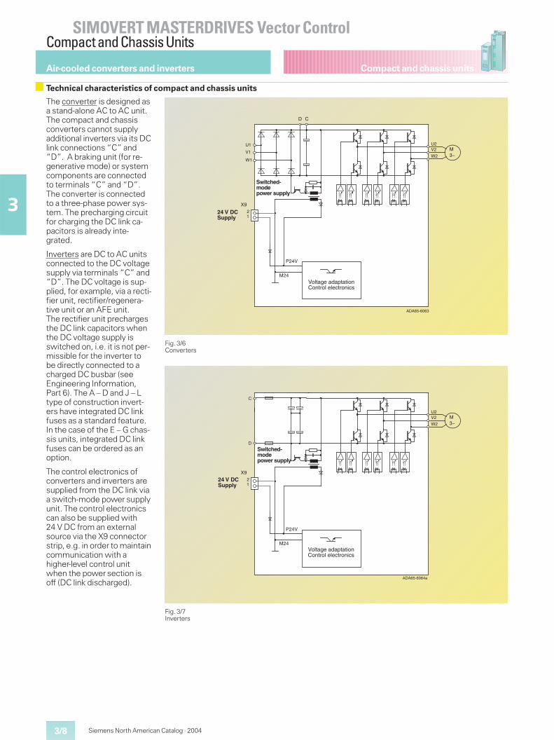
Compact and chassis units
SIMOVERT MASTERDRIVES Vector ControlCompact and Chassis Units
3/8
3
Siemens North American Catalog · 2004
Technical characteristics of compact and chassis units
Fig. 3/6Converters
Fig. 3/7Inverters
The converter is designed asa stand-alone AC to AC unit.The compact and chassisconverters cannot supplyadditional inverters via its DClink connections “C” and“D”. A braking unit (for re-generative mode) or systemcomponents are connectedto terminals “C” and “D”.The converter is connectedto a three-phase power sys-tem. The precharging circuitfor charging the DC link ca-pacitors is already inte-grated.
Inverters are DC to AC unitsconnected to the DC voltagesupply via terminals “C” and“D”. The DC voltage is sup-plied, for example, via a recti-fier unit, rectifier/regenera-tive unit or an AFE unit.The rectifier unit prechargesthe DC link capacitors whenthe DC voltage supply isswitched on, i.e. it is not per-missible for the inverter tobe directly connected to acharged DC busbar (seeEngineering Information,Part 6). The A – D and J – Ltype of construction invert-ers have integrated DC linkfuses as a standard feature.In the case of the E – G chas-sis units, integrated DC linkfuses can be ordered as anoption.
The control electronics ofconverters and inverters aresupplied from the DC link viaa switch-mode power supplyunit. The control electronicscan also be supplied with24 V DC from an externalsource via the X9 connectorstrip, e.g. in order to maintaincommunication with ahigher-level control unitwhen the power section isoff (DC link discharged).
Air-cooled converters and inverters
������
���
�
����
���
�
�
�
�
� �
���������
��������������� �!��!�"������#�"�! #$
����������
��������������������
������
���
�
����
���
�
�
���������
�
�
��������������� �!��!�"������#�"�! #$
����������
��������������������
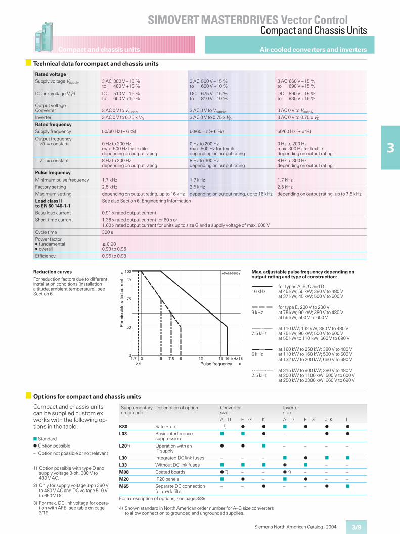
Compact and chassis units
3/9
SIMOVERT MASTERDRIVES Vector ControlCompact and Chassis Units
3
Siemens North American Catalog · 2004
63 kHz
100
%
DA65-5385a
0
75
9 12
50
15 16 18
2.5
1.7 7.5
A
Pulse frequency
Per
mis
sibl
e ra
ted
curr
ent
Technical data for compact and chassis units
Rated voltage
Supply voltage Vsupply 3 AC 380 V – 15 %to 480 V +10 %
3 AC 500 V – 15 %to 600 V +10 %
3 AC 660 V – 15 %to 690 V +15 %
DC link voltage VD3) DC 510 V – 15 %
to 650 V +10 %DC 675 V – 15 %to 810 V +10 %
DC 890 V – 15 %to 930 V +15 %
Output voltageConverter 3 AC 0 V to Vsupply 3 AC 0 V to Vsupply 3 AC 0 V to Vsupply
Inverter 3 AC 0 V to 0.75 x VD 3 AC 0 V to 0.75 x VD 3 AC 0 V to 0.75 x VD
Rated frequency
Supply frequency 50/60 Hz (± 6 %) 50/60 Hz (± 6 %) 50/60 Hz (± 6 %)
Output frequency– V/f = constant 0 Hz to 200 Hz
max. 500 Hz for textiledepending on output rating
0 Hz to 200 Hzmax. 500 Hz for textiledepending on output rating
0 Hz to 200 Hzmax. 300 Hz for textiledepending on output rating
– V = constant 8 Hz to 300 Hzdepending on output rating
8 Hz to 300 Hzdepending on output rating
8 Hz to 300 Hzdepending on output rating
Pulse frequency
Minimum pulse frequency 1.7 kHz 1.7 kHz 1.7 kHz
Factory setting 2.5 kHz 2.5 kHz 2.5 kHz
Maximum setting depending on output rating, up to 16 kHz depending on output rating, up to 16 kHz depending on output rating, up to 7.5 kHz
Load class IIto EN 60 146-1-1
See also Section 6. Engineering Information
Base load current 0.91 x rated output current
Short-time current 1.36 x rated output current for 60 s or1.60 x rated output current for units up to size G and a supply voltage of max. 600 V
Cycle time 300 s
Power factor� fundamental� overall
� 0.980.93 to 0.96
Efficiency 0.96 to 0.98
Reduction curves
For reduction factors due to differentinstallation conditions (installationaltitude, ambient temperature), seeSection 6.
Options for compact and chassis units
Compact and chassis unitscan be supplied custom exworks with the following op-tions in the table.
■ Standard
� Option possible
– Option not possible or not relevant
Supplementaryorder code
Description of option Convertersize
Invertersize
A – D E – G K A – D E – G J, K L
K80 Safe Stop – 1) � � ■ � � �
L03 Basic interferencesuppression
■ ■ � – – � �
L204) Operation with anIT supply
� � ■ – – – –
L30 Integrated DC link fuses – – – ■ � ■ ■
L33 Without DC link fuses ■ ■ ■ � ■ – –
M08 Coated boards �2) – – �
2) – – –
M20 IP20 panels ■ � – ■ � – –
M65 Separate DC connectionfor dv/dt filter
– – � – – � ■
For a description of options, see page 3/89.
Air-cooled converters and inverters
Max. adjustable pulse frequency depending onoutput rating and type of construction:
16 kHzfor types A, B, C and Dat 45 kW; 55 kW; 380 V to 480 Vat 37 kW; 45 kW; 500 V to 600 V
9 kHzfor type E, 200 V to 230 Vat 75 kW; 90 kW; 380 V to 480 Vat 55 kW; 500 V to 600 V
7.5 kHzat 110 kW; 132 kW; 380 V to 480 Vat 75 kW; 90 kW; 500 V to 600 Vat 55 kW to 110 kW; 660 V to 690 V
6 kHzat 160 kW to 250 kW; 380 V to 480 Vat 110 kW to 160 kW; 500 V to 600 Vat 132 kW to 200 kW; 660 V to 690 V
2.5 kHzat 315 kW to 900 kW; 380 V to 480 Vat 200 kW to 1100 kW; 500 V to 600 Vat 250 kW to 2300 kW; 660 V to 690 V
1) Option possible with type D andsupply voltage 3-ph. 380 V to480 V AC.
2) Only for supply voltage 3-ph 380 Vto 480 V AC and DC voltage 510 Vto 650 V DC.
3) For max. DC link voltage for opera-tion with AFE, see table on page3/19.
4) Shown standard in North American order number for A–G size convertersto allow connection to grounded and ungrounded supplies.
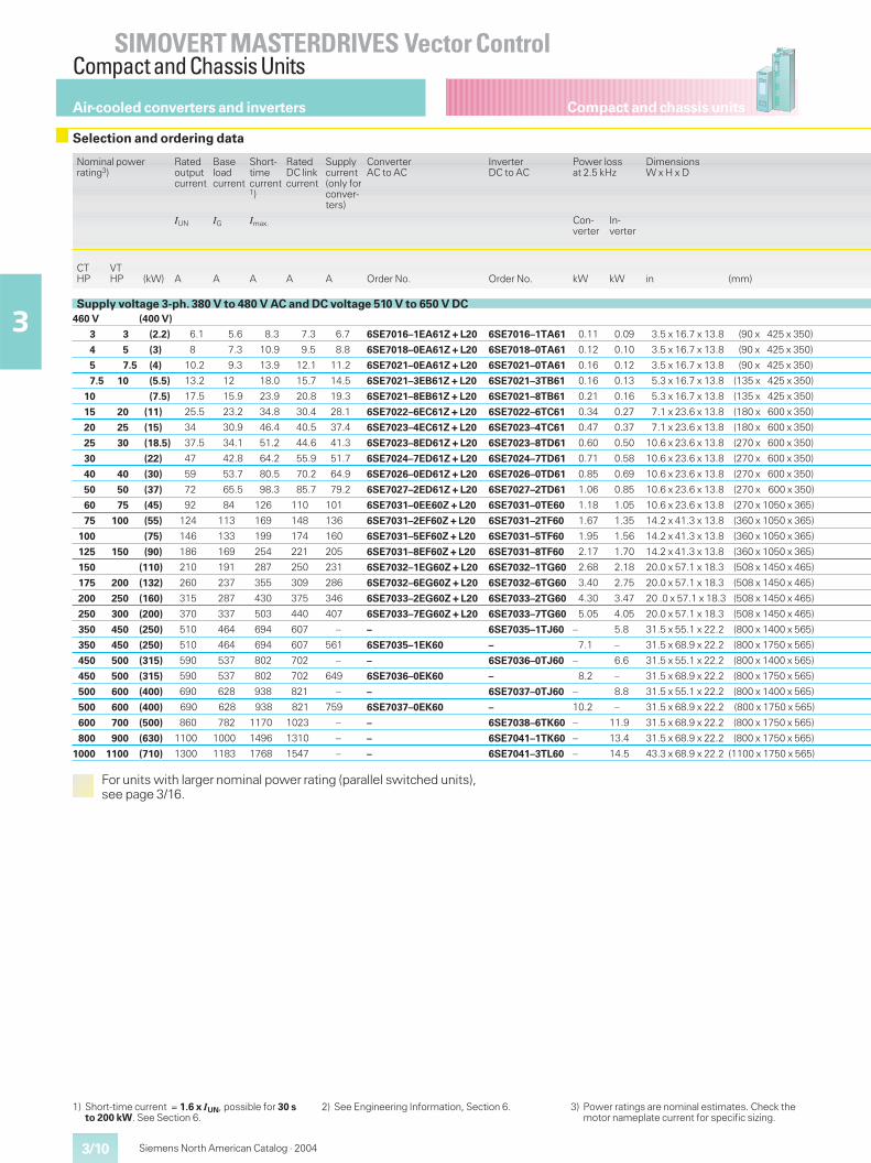
Compact and chassis units
SIMOVERT MASTERDRIVES Vector ControlCompact and Chassis Units
3/10
3
Siemens North American Catalog · 2004
Air-cooled converters and inverters
Nominal powerrating3)
Ratedoutputcurrent
Baseloadcurrent
Short-timecurrent1)
RatedDC linkcurrent
Supplycurrent(only forconver-ters)
ConverterAC to AC
InverterDC to AC
Power lossat 2.5 kHz
DimensionsW x H x D
IUN IG Imax. Con-verter
In-verter
CTHP
VTHP (kW) A A A A A Order No. Order No. kW kW in (mm)
Supply voltage 3-ph. 380 V to 480 V AC and DC voltage 510 V to 650 V DC460 V (400 V)
3 3 (2.2) 6.1 5.6 8.3 7.3 6.7 6SE7016–1EA61Z + L20 6SE7016–1TA61 0.11 0.09 3.5 x 16.7 x 13.8 (90 x 425 x 350)
4 5 (3) 8 7.3 10.9 9.5 8.8 6SE7018–0EA61Z + L20 6SE7018–0TA61 0.12 0.10 3.5 x 16.7 x 13.8 (90 x 425 x 350)
5 7.5 (4) 10.2 9.3 13.9 12.1 11.2 6SE7021–0EA61Z + L20 6SE7021–0TA61 0.16 0.12 3.5 x 16.7 x 13.8 (90 x 425 x 350)
7.5 10 (5.5) 13.2 12 18.0 15.7 14.5 6SE7021–3EB61Z + L20 6SE7021–3TB61 0.16 0.13 5.3 x 16.7 x 13.8 (135 x 425 x 350)
10 (7.5) 17.5 15.9 23.9 20.8 19.3 6SE7021–8EB61Z + L20 6SE7021–8TB61 0.21 0.16 5.3 x 16.7 x 13.8 (135 x 425 x 350)
15 20 (11) 25.5 23.2 34.8 30.4 28.1 6SE7022–6EC61Z + L20 6SE7022–6TC61 0.34 0.27 7.1 x 23.6 x 13.8 (180 x 600 x 350)
20 25 (15) 34 30.9 46.4 40.5 37.4 6SE7023–4EC61Z + L20 6SE7023–4TC61 0.47 0.37 7.1 x 23.6 x 13.8 (180 x 600 x 350)
25 30 (18.5) 37.5 34.1 51.2 44.6 41.3 6SE7023–8ED61Z + L20 6SE7023–8TD61 0.60 0.50 10.6 x 23.6 x 13.8 (270 x 600 x 350)
30 (22) 47 42.8 64.2 55.9 51.7 6SE7024–7ED61Z + L20 6SE7024–7TD61 0.71 0.58 10.6 x 23.6 x 13.8 (270 x 600 x 350)
40 40 (30) 59 53.7 80.5 70.2 64.9 6SE7026–0ED61Z + L20 6SE7026–0TD61 0.85 0.69 10.6 x 23.6 x 13.8 (270 x 600 x 350)
50 50 (37) 72 65.5 98.3 85.7 79.2 6SE7027–2ED61Z + L20 6SE7027–2TD61 1.06 0.85 10.6 x 23.6 x 13.8 (270 x 600 x 350)
60 75 (45) 92 84 126 110 101 6SE7031–0EE60Z + L20 6SE7031–0TE60 1.18 1.05 10.6 x 23.6 x 13.8 (270 x 1050 x 365)
75 100 (55) 124 113 169 148 136 6SE7031–2EF60Z + L20 6SE7031–2TF60 1.67 1.35 14.2 x 41.3 x 13.8 (360 x 1050 x 365)
100 (75) 146 133 199 174 160 6SE7031–5EF60Z + L20 6SE7031–5TF60 1.95 1.56 14.2 x 41.3 x 13.8 (360 x 1050 x 365)
125 150 (90) 186 169 254 221 205 6SE7031–8EF60Z + L20 6SE7031–8TF60 2.17 1.70 14.2 x 41.3 x 13.8 (360 x 1050 x 365)
150 (110) 210 191 287 250 231 6SE7032–1EG60Z + L20 6SE7032–1TG60 2.68 2.18 20.0 x 57.1 x 18.3 (508 x 1450 x 465)
175 200 (132) 260 237 355 309 286 6SE7032–6EG60Z + L20 6SE7032–6TG60 3.40 2.75 20.0 x 57.1 x 18.3 (508 x 1450 x 465)
200 250 (160) 315 287 430 375 346 6SE7033–2EG60Z + L20 6SE7033–2TG60 4.30 3.47 20 .0 x 57.1 x 18.3 (508 x 1450 x 465)
250 300 (200) 370 337 503 440 407 6SE7033–7EG60Z + L20 6SE7033–7TG60 5.05 4.05 20.0 x 57.1 x 18.3 (508 x 1450 x 465)
350 450 (250) 510 464 694 607 – – 6SE7035–1TJ60 – 5.8 31.5 x 55.1 x 22.2 (800 x 1400 x 565)
350 450 (250) 510 464 694 607 561 6SE7035–1EK60 – 7.1 – 31.5 x 68.9 x 22.2 (800 x 1750 x 565)
450 500 (315) 590 537 802 702 – – 6SE7036–0TJ60 – 6.6 31.5 x 55.1 x 22.2 (800 x 1400 x 565)
450 500 (315) 590 537 802 702 649 6SE7036–0EK60 – 8.2 – 31.5 x 68.9 x 22.2 (800 x 1750 x 565)
500 600 (400) 690 628 938 821 – – 6SE7037–0TJ60 – 8.8 31.5 x 55.1 x 22.2 (800 x 1400 x 565)
500 600 (400) 690 628 938 821 759 6SE7037–0EK60 – 10.2 – 31.5 x 68.9 x 22.2 (800 x 1750 x 565)
600 700 (500) 860 782 1170 1023 – – 6SE7038–6TK60 – 11.9 31.5 x 68.9 x 22.2 (800 x 1750 x 565)
800 900 (630) 1100 1000 1496 1310 – – 6SE7041–1TK60 – 13.4 31.5 x 68.9 x 22.2 (800 x 1750 x 565)
1000 1100 (710) 1300 1183 1768 1547 – – 6SE7041–3TL60 – 14.5 43.3 x 68.9 x 22.2 (1100 x 1750 x 565)
For units with larger nominal power rating (parallel switched units),see page 3/16.
Selection and ordering data
1) Short-time current = 1.6 x IUN, possible for 30 sto 200 kW. See Section 6.
2) See Engineering Information, Section 6. 3) Power ratings are nominal estimates. Check themotor nameplate current for specific sizing.
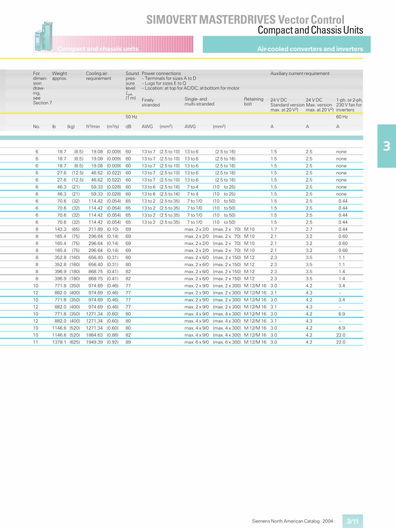
Compact and chassis units
3/11
SIMOVERT MASTERDRIVES Vector ControlCompact and Chassis Units
3
Siemens North American Catalog · 2004
Fordimen-siondraw-ing,seeSection 7
Weightapprox.
Cooling airrequirement
Soundpres-surelevelLpA(1 m)
Power connections– Terminals for sizes A to D– Lugs for sizes E to Q– Location: at top for AC/DC, at bottom for motor
Auxiliary current requirement
Finelystranded
Single- andmulti-stranded
Retainingbolt
24 V DCStandard versionmax. at 20 V2)
24 V DCMax. versionmax. at 20 V2)
1-ph. or 2-ph.230 V fan forinverters
No. lb (kg) ft3/min (m3/s)
50 Hz
dB AWG (mm2) AWG (mm2) A A
60 Hz
A
6 18.7 (8.5) 19.08 (0.009) 60 13 to 7 (2.5 to 10) 13 to 6 (2.5 to 16) 1.5 2.5 none
6 18.7 (8.5) 19.08 (0.009) 60 13 to 7 (2.5 to 10) 13 to 6 (2.5 to 16) 1.5 2.5 none
6 18.7 (8.5) 19.08 (0.009) 60 13 to 7 (2.5 to 10) 13 to 6 (2.5 to 16) 1.5 2.5 none
6 27.6 (12.5) 46.62 (0.022) 60 13 to 7 (2.5 to 10) 13 to 6 (2.5 to 16) 1.5 2.5 none
6 27.6 (12.5) 46.62 (0.022) 60 13 to 7 (2.5 to 10) 13 to 6 (2.5 to 16) 1.5 2.5 none
6 46.3 (21) 59.33 (0.028) 60 13 to 6 (2.5 to 16) 7 to 4 (10 to 25) 1.5 2.5 none
6 46.3 (21) 59.33 (0.028) 60 13 to 6 (2.5 to 16) 7 to 4 (10 to 25) 1.5 2.5 none
6 70.6 (32) 114.42 (0.054) 65 13 to 2 (2.5 to 35) 7 to 1/0 (10 to 50) 1.5 2.5 0.44
6 70.6 (32) 114.42 (0.054) 65 13 to 2 (2.5 to 35) 7 to 1/0 (10 to 50) 1.5 2.5 0.44
6 70.6 (32) 114.42 (0.054) 65 13 to 2 (2.5 to 35) 7 to 1/0 (10 to 50) 1.5 2.5 0.44
6 70.6 (32) 114.42 (0.054) 65 13 to 2 (2.5 to 35) 7 to 1/0 (10 to 50) 1.5 2.5 0.44
8 143.3 (65) 211.89 (0.10) 69 max. 2 x 2/0 (max. 2 x 70) M 10 1.7 2.7 0.44
8 165.4 (75) 296.64 (0.14) 69 max. 2 x 2/0 (max. 2 x 70) M 10 2.1 3.2 0.60
8 165.4 (75) 296.64 (0.14) 69 max. 2 x 2/0 (max. 2 x 70) M 10 2.1 3.2 0.60
8 165.4 (75) 296.64 (0.14) 69 max. 2 x 2/0 (max. 2 x 70) M 10 2.1 3.2 0.60
8 352.8 (160) 656.40 (0.31) 80 max. 2 x 6/0 (max. 2 x 150) M 12 2.3 3.5 1.1
8 352.8 (160) 656.40 (0.31) 80 max. 2 x 6/0 (max. 2 x 150) M 12 2.3 3.5 1.1
8 396.9 (180) 868.75 (0.41) 82 max. 2 x 6/0 (max. 2 x 150) M 12 2.3 3.5 1.4
8 396.9 (180) 868.75 (0.41) 82 max. 2 x 6/0 (max. 2 x 150) M 12 2.3 3.5 1.4
10 771.8 (350) 974.69 (0.46) 77 max. 2 x 9/0 (max. 2 x 300) M 12/M 16 3.0 4.2 3.4
12 882.0 (400) 974.69 (0.46) 77 max. 2 x 9/0 (max. 2 x 300) M 12/M 16 3.1 4.3 –
10 771.8 (350) 974.69 (0.46) 77 max. 2 x 9/0 (max. 2 x 300) M 12/M 16 3.0 4.2 3.4
12 882.0 (400) 974.69 (0.46) 77 max. 2 x 9/0 (max. 2 x 300) M 12/M 16 3.1 4.3 –
10 771.8 (350) 1271.34 (0.60) 80 max. 4 x 9/0 (max. 4 x 300) M 12/M 16 3.0 4.2 6.9
12 882.0 (400) 1271.34 (0.60) 80 max. 4 x 9/0 (max. 4 x 300) M 12/M 16 3.1 4.3 –
10 1146.6 (520) 1271.34 (0.60) 80 max. 4 x 9/0 (max. 4 x 300) M 12/M 16 3.0 4.2 6.9
10 1146.6 (520) 1864.63 (0.88) 82 max. 4 x 9/0 (max. 4 x 300) M 12/M 16 3.0 4.2 22.0
11 1378.1 (625) 1949.39 (0.92) 89 max. 6 x 9/0 (max. 6 x 300) M 12/M 16 3.0 4.2 22.0
Air-cooled converters and inverters
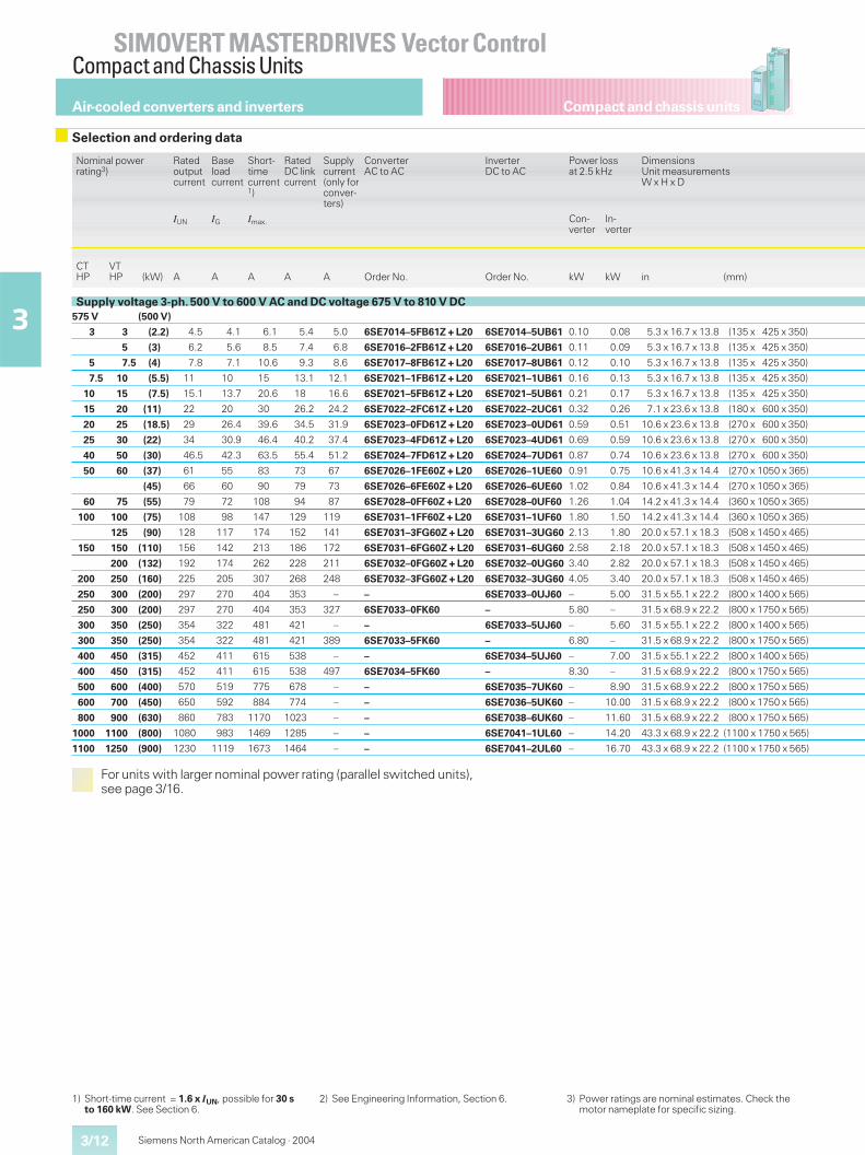
Compact and chassis units
SIMOVERT MASTERDRIVES Vector ControlCompact and Chassis Units
3/12
3
Siemens North American Catalog · 2004
1) Short-time current = 1.6 x IUN, possible for 30 sto 160 kW. See Section 6.
2) See Engineering Information, Section 6. 3) Power ratings are nominal estimates. Check themotor nameplate for specific sizing.
Air-cooled converters and inverters
Selection and ordering data
Nominal powerrating3)
Ratedoutputcurrent
Baseloadcurrent
Short-timecurrent1)
RatedDC linkcurrent
Supplycurrent(only forconver-ters)
ConverterAC to AC
InverterDC to AC
Power lossat 2.5 kHz
DimensionsUnit measurementsW x H x D
IUN IG Imax. Con-verter
In-verter
CTHP
VTHP (kW) A A A A A Order No. Order No. kW kW in (mm)
Supply voltage 3-ph. 500 V to 600 V AC and DC voltage 675 V to 810 V DC575 V (500 V)
3 3 (2.2) 4.5 4.1 6.1 5.4 5.0 6SE7014–5FB61Z + L20 6SE7014–5UB61 0.10 0.08 5.3 x 16.7 x 13.8 (135 x 425 x 350)
5 (3) 6.2 5.6 8.5 7.4 6.8 6SE7016–2FB61Z + L20 6SE7016–2UB61 0.11 0.09 5.3 x 16.7 x 13.8 (135 x 425 x 350)
5 7.5 (4) 7.8 7.1 10.6 9.3 8.6 6SE7017–8FB61Z + L20 6SE7017–8UB61 0.12 0.10 5.3 x 16.7 x 13.8 (135 x 425 x 350)
7.5 10 (5.5) 11 10 15 13.1 12.1 6SE7021–1FB61Z + L20 6SE7021–1UB61 0.16 0.13 5.3 x 16.7 x 13.8 (135 x 425 x 350)
10 15 (7.5) 15.1 13.7 20.6 18 16.6 6SE7021–5FB61Z + L20 6SE7021–5UB61 0.21 0.17 5.3 x 16.7 x 13.8 (135 x 425 x 350)
15 20 (11) 22 20 30 26.2 24.2 6SE7022–2FC61Z + L20 6SE7022–2UC61 0.32 0.26 7.1 x 23.6 x 13.8 (180 x 600 x 350)
20 25 (18.5) 29 26.4 39.6 34.5 31.9 6SE7023–0FD61Z + L20 6SE7023–0UD61 0.59 0.51 10.6 x 23.6 x 13.8 (270 x 600 x 350)
25 30 (22) 34 30.9 46.4 40.2 37.4 6SE7023–4FD61Z + L20 6SE7023–4UD61 0.69 0.59 10.6 x 23.6 x 13.8 (270 x 600 x 350)
40 50 (30) 46.5 42.3 63.5 55.4 51.2 6SE7024–7FD61Z + L20 6SE7024–7UD61 0.87 0.74 10.6 x 23.6 x 13.8 (270 x 600 x 350)
50 60 (37) 61 55 83 73 67 6SE7026–1FE60Z + L20 6SE7026–1UE60 0.91 0.75 10.6 x 41.3 x 14.4 (270 x 1050 x 365)
(45) 66 60 90 79 73 6SE7026–6FE60Z + L20 6SE7026–6UE60 1.02 0.84 10.6 x 41.3 x 14.4 (270 x 1050 x 365)
60 75 (55) 79 72 108 94 87 6SE7028–0FF60Z + L20 6SE7028–0UF60 1.26 1.04 14.2 x 41.3 x 14.4 (360 x 1050 x 365)
100 100 (75) 108 98 147 129 119 6SE7031–1FF60Z + L20 6SE7031–1UF60 1.80 1.50 14.2 x 41.3 x 14.4 (360 x 1050 x 365)
125 (90) 128 117 174 152 141 6SE7031–3FG60Z + L20 6SE7031–3UG60 2.13 1.80 20.0 x 57.1 x 18.3 (508 x 1450 x 465)
150 150 (110) 156 142 213 186 172 6SE7031–6FG60Z + L20 6SE7031–6UG60 2.58 2.18 20.0 x 57.1 x 18.3 (508 x 1450 x 465)
200 (132) 192 174 262 228 211 6SE7032–0FG60Z + L20 6SE7032–0UG60 3.40 2.82 20.0 x 57.1 x 18.3 (508 x 1450 x 465)
200 250 (160) 225 205 307 268 248 6SE7032–3FG60Z + L20 6SE7032–3UG60 4.05 3.40 20.0 x 57.1 x 18.3 (508 x 1450 x 465)
250 300 (200) 297 270 404 353 – – 6SE7033–0UJ60 – 5.00 31.5 x 55.1 x 22.2 (800 x 1400 x 565)
250 300 (200) 297 270 404 353 327 6SE7033–0FK60 – 5.80 – 31.5 x 68.9 x 22.2 (800 x 1750 x 565)
300 350 (250) 354 322 481 421 – – 6SE7033–5UJ60 – 5.60 31.5 x 55.1 x 22.2 (800 x 1400 x 565)
300 350 (250) 354 322 481 421 389 6SE7033–5FK60 – 6.80 – 31.5 x 68.9 x 22.2 (800 x 1750 x 565)
400 450 (315) 452 411 615 538 – – 6SE7034–5UJ60 – 7.00 31.5 x 55.1 x 22.2 (800 x 1400 x 565)
400 450 (315) 452 411 615 538 497 6SE7034–5FK60 – 8.30 – 31.5 x 68.9 x 22.2 (800 x 1750 x 565)
500 600 (400) 570 519 775 678 – – 6SE7035–7UK60 – 8.90 31.5 x 68.9 x 22.2 (800 x 1750 x 565)
600 700 (450) 650 592 884 774 – – 6SE7036–5UK60 – 10.00 31.5 x 68.9 x 22.2 (800 x 1750 x 565)
800 900 (630) 860 783 1170 1023 – – 6SE7038–6UK60 – 11.60 31.5 x 68.9 x 22.2 (800 x 1750 x 565)
1000 1100 (800) 1080 983 1469 1285 – – 6SE7041–1UL60 – 14.20 43.3 x 68.9 x 22.2 (1100 x 1750 x 565)
1100 1250 (900) 1230 1119 1673 1464 – – 6SE7041–2UL60 – 16.70 43.3 x 68.9 x 22.2 (1100 x 1750 x 565)
For units with larger nominal power rating (parallel switched units),see page 3/16.
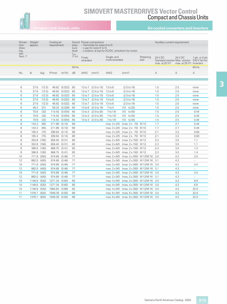
Compact and chassis units
3/13
SIMOVERT MASTERDRIVES Vector ControlCompact and Chassis Units
3
Siemens North American Catalog · 2004
Air-cooled converters and inverters
Dimen-siondraw-ing,seeSect. 7
Weightapprox.
Cooling airrequirement
Soundpres-surelevelLpA(1 m)
Power connections– Terminals for sizes A to D– Lugs for sizes E to Q– Location: at top for AC/DC, at bottom for motor
Auxiliary current requirement
Finelystranded
Single- andmulti-stranded
Retainingbolt
24 V DCStandard versionmax. at 20 V2)
24 V DCMax. versionmax. at 20 V2)
1-ph. or 2-ph.230 V fan forinverters
No. lb (kg) ft3/min (m3/s)
50 Hz
dB AWG (mm2) AWG (mm2) A A
60 Hz
A
6 27.6 (12.5) 46.62 (0.022) 60 13 to 7 (2.5 to 10) 13 to 6 (2.5 to 16) 1.5 2.5 none
6 27.6 (12.5) 46.62 (0.022) 60 13 to 7 (2.5 to 10) 13 to 6 (2.5 to 16) 1.5 2.5 none
6 27.6 (12.5) 46.62 (0.022) 60 13 to 7 (2.5 to 10) 13 to 6 (2.5 to 16) 1.5 2.5 none
6 27.6 (12.5) 46.62 (0.022) 60 13 to 7 (2.5 to 10) 13 to 6 (2.5 to 16) 1.5 2.5 none
6 27.6 (12.5) 46.62 (0.022) 60 13 to 7 (2.5 to 10) 13 to 6 (2.5 to 16) 1.5 2.5 none
6 46.3 (21) 59.33 (0.028) 60 13 to 6 (2.5 to 16) 7 to 4 (10 to 25) 1.5 2.5 none
6 70.6 (32) 114.42 (0.054) 65 13 to 3 (2.5 to 35) 7 to 1/0 (10 to 50) 1.5 2.5 0.44
6 70.6 (32) 114.42 (0.054) 65 13 to 3 (2.5 to 35) 7 to 1/0 (10 to 50) 1.5 2.5 0.44
6 70.6 (32) 114.42 (0.054) 65 13 to 3 (2.5 to 35) 7 to 1/0 (10 to 50) 1.5 2.5 0.44
8 143.3 (65) 211.89 (0.10) 69 max. 2 x 2/0 (max. 2 x 70) M 10 1.7 2.7 0.44
8 143.3 (65) 211.89 (0.10) 69 max. 2 x 2/0 (max. 2 x 70) M 10 1.7 2.7 0.44
8 165.4 (75) 296.64 (0.14) 69 max. 2 x 2/0 (max. 2 x 70) M 10 2.1 3.2 0.60
8 165.4 (75) 296.64 (0.14) 80 max. 2 x 2/0 (max. 2 x 70) M 10 2.1 3.2 0.60
8 352.8 (160) 656.40 (0.31) 80 max. 2 x 6/0 (max. 2 x 150) M 12 2.3 3.5 1.1
8 352.8 (160) 656.40 (0.31) 80 max. 2 x 6/0 (max. 2 x 150) M 12 2.3 3.5 1.1
8 396.9 (180) 868.75 (0.41) 82 max. 2 x 6/0 (max. 2 x 150) M 12 2.3 3.5 1.4
8 396.9 (180) 868.75 (0.41) 82 max. 2 x 6/0 (max. 2 x 150) M 12 2.3 3.5 1.4
10 771.8 (350) 974.69 (0.46) 77 max. 2 x 9/0 (max. 2 x 300) M 12/M 16 3.0 4.2 3.4
12 882.0 (400) 974.69 (0.46) 77 max. 2 x 9/0 (max. 2 x 300) M 12/M 16 3.1 4.3 –
10 771.8 (350) 974.69 (0.46) 77 max. 2 x 9/0 (max. 2 x 300) M 12/M 16 3.0 4.2 3.4
12 882.0 (400) 974.69 (0.46) 77 max. 2 x 9/0 (max. 2 x 300) M 12/M 16 3.1 4.3 –
10 771.8 (350) 974.69 (0.46) 77 max. 2 x 9/0 (max. 2 x 300) M 12/M 16 3.0 4.2 3.4
12 882.0 (400) 974.69 (0.46) 77 max. 2 x 9/0 (max. 2 x 300) M 12/M 16 3.1 4.3 –
10 1146.6 (520) 1271.34 (0.60) 80 max. 4 x 9/0 (max. 4 x 300) M 12/M 16 3.0 4.2 6.9
10 1146.6 (520) 1271.34 (0.60) 80 max. 4 x 9/0 (max. 4 x 300) M 12/M 16 3.0 4.2 6.9
10 1146.6 (520) 1864.63 (0.88) 82 max. 4 x 9/0 (max. 4 x 300) M 12/M 16 3.0 4.2 22.0
11 1378.1 (625) 1949.39 (0.92) 89 max. 6 x 9/0 (max. 6 x 300) M 12/M 16 3.0 4.2 22.0
11 1378.1 (625) 1949.39 (0.92) 89 max. 6 x 9/0 (max. 6 x 300) M 12/M 16 3.0 4.2 22.0
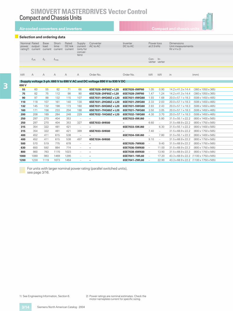
Compact and chassis units
SIMOVERT MASTERDRIVES Vector ControlCompact and Chassis Units
Siemens North American Catalog · 20043/14
3
Nominalpowerrating2)
Ratedoutputcurrent
Baseloadcurrent
Short-timecurrent
RatedDC linkcurrent
Supplycurrent(only forconver-ters)
ConverterAC to AC
InverterDC to AC
Power lossat 2.5 kHz
DimensionsUnit measurementsW x H x D
IUN IG Imax. Con-verter
In-verter
kW A A A A A Order No. Order No. kW kW in (mm)
Supply voltage 3-ph. 660 V to 690 V AC and DC voltage 890 V to 930 V DC690 V
55 60 55 82 71 66 6SE7026–0HF60Z + L20 6SE7026–0WF60 1.05 0.90 14.2 x 41.3 x 14.4 (360 x 1050 x 365)
75 82 75 112 98 90 6SE7028–2HF60Z + L20 6SE7028–2WF60 1.47 1.24 14.2 x 41.3 x 14.4 (360 x 1050 x 365)
90 97 88 132 115 107 6SE7031–0HG60Z + L20 6SE7031–0WG60 1.93 1.68 20.0 x 57.1 x 18.3 (508 x 1450 x 465)
110 118 107 161 140 130 6SE7031–2HG60Z + L20 6SE7031–2WG60 2.33 2.03 20.0 x 57.1 x 18.3 (508 x 1450 x 465)
132 145 132 198 173 160 6SE7031–5HG60Z + L20 6SE7031–5WG60 2.83 2.43 20.0 x 57.1 x 18.3 (508 x 1450 x 465)
160 171 156 233 204 188 6SE7031–7HG60Z + L20 6SE7031–7WG60 3.50 3.05 20.0 x 57.1 x 18.3 (508 x 1450 x 465)
200 208 189 284 248 229 6SE7032–1HG60Z + L20 6SE7032–1WG60 4.30 3.70 20.0 x 57.1 x 18.3 (508 x 1450 x 465)
250 297 270 404 353 – – 6SE7033–0WJ60 – 5.80 31.5 x 55.1 x 22.2 (800 x 1400 x 565)
250 297 270 404 353 327 6SE7033–0HK60 – 6.60 – 31.5 x 68.9 x 22.2 (800 x 1750 x 565)
315 354 322 481 421 – – 6SE7033–5WJ60 – 6.30 31.5 x 55.1 x 22.2 (800 x 1400 x 565)
315 354 322 481 421 389 6SE7033–5HK60 – 7.40 – 31.5 x 68.9 x 22.2 (800 x 1750 x 565)
400 452 411 615 538 – – 6SE7034–5WJ60 – 7.80 31.5 x 55.1 x 22.2 (800 x 1400 x 565)
400 452 411 615 538 497 6SE7034–5HK60 – 9.10 – 31.5 x 68.9 x 22.2 (800 x 1750 x 565)
500 570 519 775 678 – – 6SE7035–7WK60 – 9.40 31.5 x 68.9 x 22.2 (800 x 1750 x 565)
630 650 592 884 774 – – 6SE7036–5WK60 – 11.00 31.5 x 68.9 x 22.2 (800 x 1750 x 565)
800 860 783 1170 1023 – – 6SE7038–6WK60 – 13.90 31.5 x 68.9 x 22.2 (800 x 1750 x 565)
1000 1080 983 1469 1285 – – 6SE7041–1WL60 – 17.20 43.3 x 68.9 x 22.2 (1100 x 1750 x 565)
1200 1230 1119 1673 1464 – – 6SE7041–2WL60 – 22.90 43.3 x 68.9 x 22.2 (1100 x 1750 x 565)
For units with larger nominal power rating (parallel switched units),see page 3/16.
Air-cooled converters and inverters
Selection and ordering data
1) See Engineering Information, Section 6. 2) Power ratings are nominal estimates. Check themotor nameplate current for specific sizing.
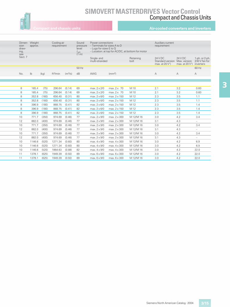
Compact and chassis units
3/15
SIMOVERT MASTERDRIVES Vector ControlCompact and Chassis Units
3
Siemens North American Catalog · 2004
Dimen-siondraw-ing,seeSect. 7
Weightapprox.
Cooling airrequirement
SoundpressurelevelLpA(1 m)
Power connections– Terminals for sizes A to D– Lugs for sizes E to Q– Location: at top for AC/DC, at bottom for motor
Auxiliary currentrequirement
Single- andmulti-stranded
Retainingbolt
24 V DCStandard versionmax. at 20 V1)
24 V DCMax. versionmax. at 20 V1)
1-ph. or 2-ph.230 V fan forinverters
No. lb (kg) ft3/min (m3/s)
50 Hz
dB AWG (mm2) A A
60 Hz
A
8 165.4 (75) 296.64 (0.14) 69 max. 2 x 2/0 max. 2 x 70 M 10 2.1 3.2 0.60
8 165.4 (75) 296.64 (0.14) 69 max. 2 x 2/0 max. 2 x 70 M 10 2.1 3.2 0.60
8 352.8 (160) 656.40 (0.31) 80 max. 2 x 6/0 max. 2 x 150 M 12 2.3 3.5 1.1
8 352.8 (160) 656.40 (0.31) 80 max. 2 x 6/0 max. 2 x 150 M 12 2.3 3.5 1.1
8 396.9 (180) 868.75 (0.41) 82 max. 2 x 6/0 max. 2 x 150 M 12 2.3 3.5 1.4
8 396.9 (180) 868.75 (0.41) 82 max. 2 x 6/0 max. 2 x 150 M 12 2.3 3.5 1.4
8 396.9 (180) 868.75 (0.41) 82 max. 2 x 6/0 max. 2 x 150 M 12 2.3 3.5 1.4
10 771.7 (350) 974.69 (0.46) 77 max. 2 x 9/0 max. 2 x 300 M 12/M 16 3.0 4.2 3.4
12 882.0 (400) 974.69 (0.46) 77 max. 2 x 9/0 max. 2 x 300 M 12/M 16 3.1 4.3 –
10 771.7 (350) 974.69 (0.46) 77 max. 2 x 9/0 max. 2 x 300 M 12/M 16 3.0 4.2 3.4
12 882.0 (400) 974.69 (0.46) 77 max. 2 x 9/0 max. 2 x 300 M 12/M 16 3.1 4.3 –
10 771.7 (350) 974.69 (0.46) 77 max. 2 x 9/0 max. 2 x 300 M 12/M 16 3.0 4.2 3.4
12 882.0 (400) 974.69 (0.46) 77 max. 2 x 9/0 max. 2 x 300 M 12/M 16 3.1 4.3 –
10 1146.6 (520) 1271.34 (0.60) 80 max. 4 x 9/0 max. 4 x 300 M 12/M 16 3.0 4.2 6.9
10 1146.6 (520) 1271.34 (0.60) 80 max. 4 x 9/0 max. 4 x 300 M 12/M 16 3.0 4.2 6.9
10 1146.6 (520) 1864.63 (0.88) 82 max. 4 x 9/0 max. 4 x 300 M 12/M 16 3.0 4.2 22.0
11 1378.1 (625) 1949.39 (0.92) 89 max. 6 x 9/0 max. 6 x 300 M 12/M 16 3.0 4.2 22.0
11 1378.1 (625) 1949.39 (0.92) 89 max. 6 x 9/0 max. 6 x 300 M 12/M 16 3.0 4.2 22.0
Air-cooled converters and inverters
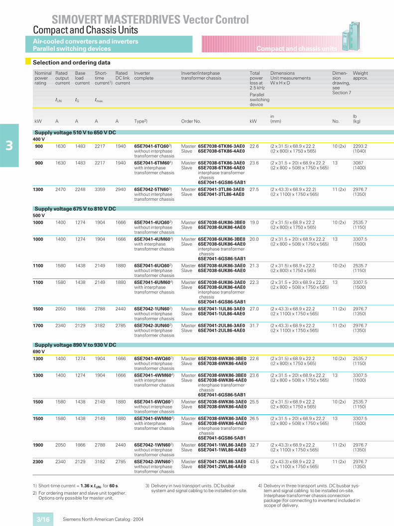
Compact and chassis units
SIMOVERT MASTERDRIVES Vector ControlCompact and Chassis Units
3/16
3
Siemens North American Catalog · 2004
1) Short-time current = 1.36 x IUN, for 60 s.
2) For ordering master and slave unit together.Options only possible for master unit.
3) Delivery in two transport units. DC busbarsystem and signal cabling to be installed on-site.
4) Delivery in three transport units. DC busbar sys-tem and signal cabling to be installed on-site.Interphase transformer chassis connectionpackage (for connecting to inverters) included inscope of delivery.
Selection and ordering data
Nominalpowerrating
Ratedoutputcurrent
Baseloadcurrent
Short-timecurrent1)
RatedDC linkcurrent
Invertercomplete
Inverter/interphasetransformer chassis
Totalpowerloss at2.5 kHz
DimensionsUnit measurementsW x H x D
Dimen-siondrawing,seeSection 7
Weightapprox.
IUN IG Imax.
Parallelswitchingdevice
kW A A A A Type2) Order No. kWin(mm) No.
lb(kg)
Supply voltage 510 V to 650 V DC400 V
900 1630 1483 2217 1940 6SE7041-6TQ603)without interphasetransformer chassis
Master 6SE7038-6TK86-3AE0Slave 6SE7038-6TK86-4AE0
22.6 (2 x 31.5) x 68.9 x 22.2((2 x 800) x 1750 x 565)
10 (2x) 2293.2(1040)
900 1630 1483 2217 1940 6SE7041-6TM604)with interphasetransformer chassis
Master 6SE7038-6TK86-3AE0Slave 6SE7038-6TK86-4AE0
interphase transformerchassis6SE7041-6GS86-5AB1
23.6 (2 x 31.5 + 20) x 68.9 x 22.2((2 x 800 + 508) x 1750 x 565)
13 3087(1400)
1300 2470 2248 3359 2940 6SE7042-5TN603)without interphasetransformer chassis
Master 6SE7041-3TL86-3AE0Slave 6SE7041-3TL86-4AE0
27.5 (2 x 43.3) x 68.9 x 22.2)((2 x 1100) x 1750 x 565)
11 (2x) 2976.7(1350)
Supply voltage 675 V to 810 V DC500 V
1000 1400 1274 1904 1666 6SE7041-4UQ603)without interphasetransformer chassis
Master 6SE7038-6UK86-3BE0Slave 6SE7038-6UK86-4AE0
19.0 (2 x 31.5) x 68.9 x 22.2((2 x 800) x 1750 x 565)
10 (2x) 2535.7(1150)
1000 1400 1274 1904 1666 6SE7041-4UM604)with interphasetransformer chassis
Master 6SE7038-6UK86-3BE0Slave 6SE7038-6UK86-4AE0
interphase transformerchassis6SE7041-6GS86-5AB1
20.0 (2 x 31.5 + 20) x 68.9 x 22.2((2 x 800 + 508) x 1750 x 565)
13 3307.5(1500)
1100 1580 1438 2149 1880 6SE7041-6UQ603)without interphasetransformer chassis
Master 6SE7038-6UK86-3AE0Slave 6SE7038-6UK86-4AE0
21.3 (2 x 31.5) x 68.9 x 22.2((2 x 800) x 1750 x 565)
10 (2x) 2535.7(1150)
1100 1580 1438 2149 1880 6SE7041-6UM604)with interphasetransformer chassis
Master 6SE7038-6UK86-3AE0Slave 6SE7038-6UK86-4AE0
interphase transformerchassis6SE7041-6GS86-5AB1
22.3 (2 x 31.5 + 20) x 68.9 x 22.2((2 x 800 + 508) x 1750 x 565)
13 3307.5(1500)
1500 2050 1866 2788 2440 6SE7042-1UN603)without interphasetransformer chassis
Master 6SE7041-1UL86-3AE0Slave 6SE7041-1UL86-4AE0
27.0 (2 x 43.3) x 68.9 x 22.2((2 x 1100) x 1750 x 565)
11 (2x) 2976.7(1350)
1700 2340 2129 3182 2785 6SE7042-3UN603)without interphasetransformer chassis
Master 6SE7041-2UL86-3AE0Slave 6SE7041-2UL86-4AE0
31.7 (2 x 43.3) x 68.9 x 22.2((2 x 1100) x 1750 x 565)
11 (2x) 2976.7(1350)
Supply voltage 890 V to 930 V DC690 V
1300 1400 1274 1904 1666 6SE7041-4WQ603)without interphasetransformer chassis
Master 6SE7038-6WK86-3BE0Slave 6SE7038-6WK86-4AE0
22.6 (2 x 31.5) x 68.9 x 22.2((2 x 800) x 1750 x 565)
10 (2x) 2535.7(1150)
1300 1400 1274 1904 1666 6SE7041-4WM604)with interphasetransformer chassis
Master 6SE7038-6WK86-3BE0Slave 6SE7038-6WK86-4AE0
interphase transformerchassis6SE7041-6GS86-5AB1
23.6 (2 x 31.5 + 20) x 68.9 x 22.2((2 x 800 + 508) x 1750 x 565)
13 3307.5(1500)
1500 1580 1438 2149 1880 6SE7041-6WQ603)without interphasetransformer chassis
Master 6SE7038-6WK86-3AE0Slave 6SE7038-6WK86-4AE0
25.5 (2 x 31.5) x 68.9 x 22.2((2 x 800) x 1750 x 565)
10 (2x) 2535.7(1150)
1500 1580 1438 2149 1880 6SE7041-6WM604)with interphasetransformer chassis
Master 6SE7038-6WK86-3AE0Slave 6SE7038-6WK86-4AE0
interphase transformerchassis6SE7041-6GS86-5AB1
26.5 (2 x 31.5 + 20) x 68.9 x 22.2((2 x 800 + 508) x 1750 x 565)
13 3307.5(1500)
1900 2050 1866 2788 2440 6SE7042-1WN603)without interphasetransformer chassis
Master 6SE7041-1WL86-3AE0Slave 6SE7041-1WL86-4AE0
32.7 (2 x 43.3) x 68.9 x 22.2((2 x 1100) x 1750 x 565)
11 (2x) 2976.7(1350)
2300 2340 2129 3182 2785 6SE7042-3WN603)without interphasetransformer chassis
Master 6SE7041-2WL86-3AE0Slave 6SE7041-2WL86-4AE0
43.5 (2 x 43.3) x 68.9 x 22.2((2 x 1100) x 1750 x 565)
11 (2x) 2976.7(1350)
Air-cooled converters and invertersParallel switching devices
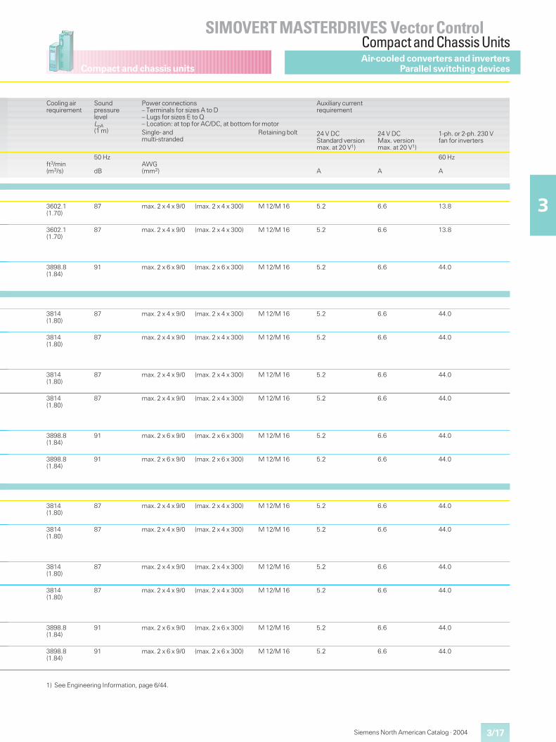
Compact and chassis units
3/17
SIMOVERT MASTERDRIVES Vector ControlCompact and Chassis Units
3
Siemens North American Catalog · 2004
Cooling airrequirement
SoundpressurelevelLpA(1 m)
Power connections– Terminals for sizes A to D– Lugs for sizes E to Q– Location: at top for AC/DC, at bottom for motor
Auxiliary currentrequirement
Single- andmulti-stranded
Retaining bolt 24 V DCStandard versionmax. at 20 V1)
24 V DCMax. versionmax. at 20 V1)
1-ph. or 2-ph. 230 Vfan for inverters
ft3/min(m3/s)
50 Hz
dBAWG(mm2) A A
60 Hz
A
3602.1(1.70)
87 max. 2 x 4 x 9/0 (max. 2 x 4 x 300) M 12/M 16 5.2 6.6 13.8
3602.1(1.70)
87 max. 2 x 4 x 9/0 (max. 2 x 4 x 300) M 12/M 16 5.2 6.6 13.8
3898.8(1.84)
91 max. 2 x 6 x 9/0 (max. 2 x 6 x 300) M 12/M 16 5.2 6.6 44.0
3814(1.80)
87 max. 2 x 4 x 9/0 (max. 2 x 4 x 300) M 12/M 16 5.2 6.6 44.0
3814(1.80)
87 max. 2 x 4 x 9/0 (max. 2 x 4 x 300) M 12/M 16 5.2 6.6 44.0
3814(1.80)
87 max. 2 x 4 x 9/0 (max. 2 x 4 x 300) M 12/M 16 5.2 6.6 44.0
3814(1.80)
87 max. 2 x 4 x 9/0 (max. 2 x 4 x 300) M 12/M 16 5.2 6.6 44.0
3898.8(1.84)
91 max. 2 x 6 x 9/0 (max. 2 x 6 x 300) M 12/M 16 5.2 6.6 44.0
3898.8(1.84)
91 max. 2 x 6 x 9/0 (max. 2 x 6 x 300) M 12/M 16 5.2 6.6 44.0
3814(1.80)
87 max. 2 x 4 x 9/0 (max. 2 x 4 x 300) M 12/M 16 5.2 6.6 44.0
3814(1.80)
87 max. 2 x 4 x 9/0 (max. 2 x 4 x 300) M 12/M 16 5.2 6.6 44.0
3814(1.80)
87 max. 2 x 4 x 9/0 (max. 2 x 4 x 300) M 12/M 16 5.2 6.6 44.0
3814(1.80)
87 max. 2 x 4 x 9/0 (max. 2 x 4 x 300) M 12/M 16 5.2 6.6 44.0
3898.8(1.84)
91 max. 2 x 6 x 9/0 (max. 2 x 6 x 300) M 12/M 16 5.2 6.6 44.0
3898.8(1.84)
91 max. 2 x 6 x 9/0 (max. 2 x 6 x 300) M 12/M 16 5.2 6.6 44.0
Air-cooled converters and invertersParallel switching devices
1) See Engineering Information, page 6/44.
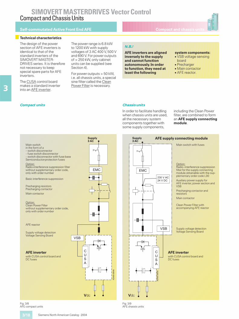
Compact and chassis units
SIMOVERT MASTERDRIVES Vector ControlCompact and Chassis Units
Siemens North American Catalog · 20043/18
3
Self-commutated Active Front End AFE
Technical characteristics
The design of the powersection of AFE inverters isidentical to that of thestandard inverters of theSIMOVERT MASTER-DRIVES series. It is thereforenot necessary to keepspecial spare parts for AFEinverters.
The CUSA control boardmakes a standard inverterinto an AFE inverter.
The power range is 6.8 kWto 1200 kW with supplyvoltages of 3 AC 400 V, 500 Vand 690 V. For power outputsof > 250 kW, only cabinetunits can be supplied (seeSection 4).
For power outputs > 50 kW,i.e. all chassis units, a specialsine filter called the CleanPower Filter is necessary.
N.B.!
AFE inverters are alignedinversely to the supplyand cannot functionautonomously. In orderto function, they need atleast the following
system components:� VSB voltage sensing
board� Precharger� Main contactor� AFE reactor.
Compact units Chassis units
In order to facilitate handlingwhen chassis units are used,all the necessary systemcomponents together withsome supply components,
including the Clean Powerfilter, are combined to forman AFE supply connectingmodule.
Fig. 3/8AFE compact units
��
����
��
��
��
��
��
�
Supply3 AC
Main switchin the form of a– switch disconnector– fuse switch disconnector– switch disconnector with fuse-baseSemiconductor-protection fuses
Option:Radio-interference suppression filterwithout supplementary order code,only with order number
Basic interference suppression
Precharging resistorsPrecharging contactor
Main contactor
Option:Clean Power Filterwithout supplementary order code,only with order number
AFE reactor
Supply voltage detectionVoltage Sensing Board
Vdc
AFE inverterwith CUSA control board andDC fuses
Fig. 3/9AFE chassis units
��
����
��
��
��
��
��
�������������
�
Supply3 AC
Vdc
AFE inverterwith CUSA control board andDC fuses
Main switch with fuses
Option:Radio- interference suppressionfilter for the supply connectingmodule obtainable with the sup-plementary order code L00
Auxiliary power supply forAFE inverter, power section andVSB
Precharging contactor andresistors
Main contactor
Clean Power Filter withaccompanying AFE reactor
Supply voltage detectionVoltage Sensing Board
AFE supply connecting module
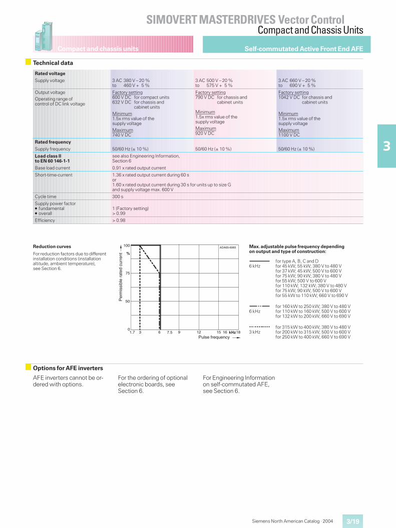
Compact and chassis units
3/19
SIMOVERT MASTERDRIVES Vector ControlCompact and Chassis Units
3
Siemens North American Catalog · 2004
Self-commutated Active Front End AFE
Technical data
Rated voltage
Supply voltage 3 AC 380 V – 20 %to 460 V + 5 %
3 AC 500 V – 20 %to 575 V + 5 %
3 AC 660 V – 20 %to 690 V + 5 %
Output voltageOperating range ofcontrol of DC link voltage
Factory setting600 V DC for compact units632 V DC for chassis and
cabinet unitsMinimum1.5x rms value of thesupply voltageMaximum740 V DC
Factory setting790 V DC for chassis and
cabinet units
Minimum1.5x rms value of thesupply voltageMaximum920 V DC
Factory setting1042 V DC for chassis and
cabinet units
Minimum1.5x rms value of thesupply voltageMaximum1100 V DC
Rated frequency
Supply frequency 50/60 Hz (± 10 %) 50/60 Hz (± 10 %) 50/60 Hz (± 10 %)
Load class IIto EN 60 146-1-1
see also Engineering Information,Section 6
Base load current 0.91 x rated output current
Short-time-current 1.36 x rated output current during 60 sor1.60 x rated output current during 30 s for units up to size Gand supply voltage max. 600 V
Cycle time 300 s
Supply power factor� fundamental� overall
1 (Factory setting)> 0.99
Efficiency > 0.98
63 ���
100
�
DA65-6065
0
75
9 12
50
15 16 181.7 7.5
A
Pulse frequency
Per
mis
sibl
e ra
ted
curr
ent
Reduction curves
For reduction factors due to differentinstallation conditions (installationaltitude, ambient temperature),see Section 6.
Max. adjustable pulse frequency dependingon output and type of construction:
6 kHzfor type A, B, C and Dfor 45 kW; 55 kW; 380 V to 480 Vfor 37 kW; 45 kW; 500 V to 600 Vfor 75 kW; 90 kW; 380 V to 480 Vfor 55 kW; 500 V to 600 Vfor 110 kW; 132 kW; 380 V to 480 Vfor 75 kW; 90 kW; 500 V to 600 Vfor 55 kW to 110 kW; 660 V to 690 V
6 kHzfor 160 kW to 250 kW; 380 V to 480 Vfor 110 kW to 160 kW; 500 V to 600 Vfor 132 kW to 200 kW; 660 V to 690 V
3 kHzfor 315 kW to 400 kW; 380 V to 480 Vfor 200 kW to 315 kW; 500 V to 600 Vfor 250 kW to 400 kW; 660 V to 690 V
Options for AFE inverters
AFE inverters cannot be or-dered with options.
For the ordering of optionalelectronic boards, seeSection 6.
For Engineering Informationon self-commutated AFE,see Section 6.
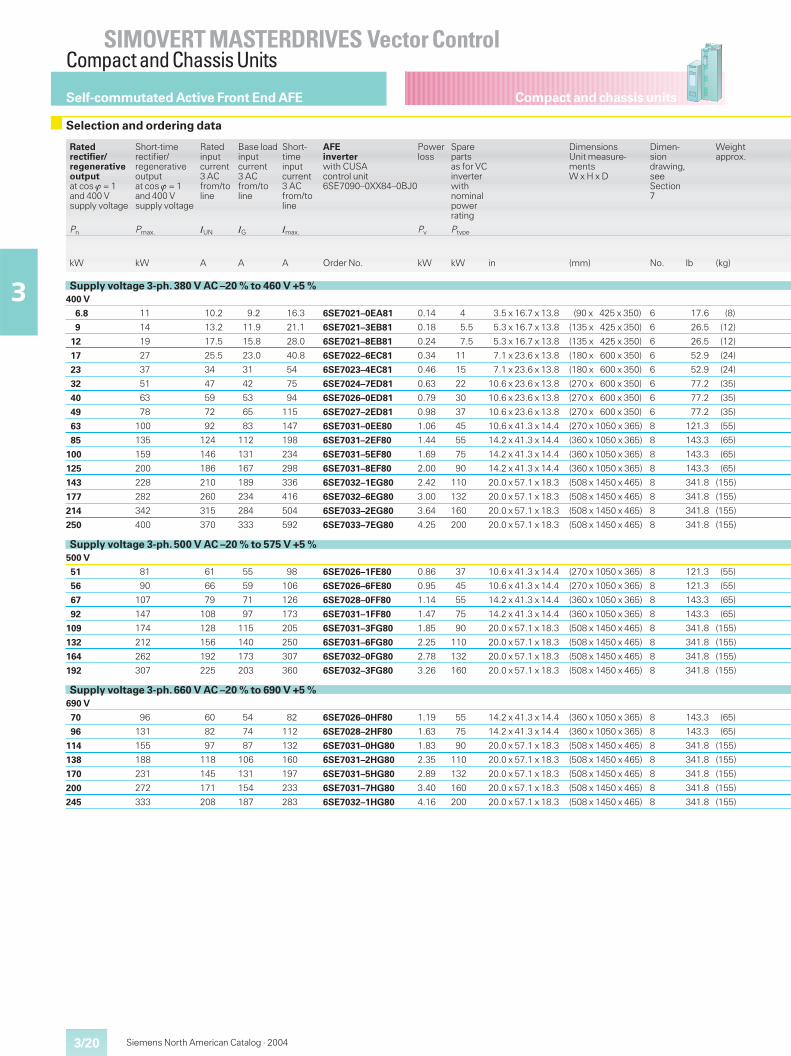
Compact and chassis units
SIMOVERT MASTERDRIVES Vector ControlCompact and Chassis Units
3/20
3
Siemens North American Catalog · 2004
Self-commutated Active Front End AFE
Selection and ordering data
Ratedrectifier/regenerativeoutputat cos � = 1and 400 Vsupply voltage
Short-timerectifier/regenerativeoutputat cos � = 1and 400 Vsupply voltage
Ratedinputcurrent3 ACfrom/toline
Base loadinputcurrent3 ACfrom/toline
Short-timeinputcurrent3 ACfrom/toline
AFEinverterwith CUSAcontrol unit6SE7090–0XX84–0BJ0
Powerloss
Sparepartsas for VCinverterwithnominalpowerrating
DimensionsUnit measure-mentsW x H x D
Dimen-siondrawing,seeSection7
Weightapprox.
Pn Pmax. IUN IG Imax. Pv Ptype
kW kW A A A Order No. kW kW in (mm) No. lb (kg)
Supply voltage 3-ph. 380 V AC –20 % to 460 V +5 %400 V
6.8 11 10.2 9.2 16.3 6SE7021–0EA81 0.14 4 3.5 x 16.7 x 13.8 (90 x 425 x 350) 6 17.6 (8)
9 14 13.2 11.9 21.1 6SE7021–3EB81 0.18 5.5 5.3 x 16.7 x 13.8 (135 x 425 x 350) 6 26.5 (12)
12 19 17.5 15.8 28.0 6SE7021–8EB81 0.24 7.5 5.3 x 16.7 x 13.8 (135 x 425 x 350) 6 26.5 (12)
17 27 25.5 23.0 40.8 6SE7022–6EC81 0.34 11 7.1 x 23.6 x 13.8 (180 x 600 x 350) 6 52.9 (24)
23 37 34 31 54 6SE7023–4EC81 0.46 15 7.1 x 23.6 x 13.8 (180 x 600 x 350) 6 52.9 (24)
32 51 47 42 75 6SE7024–7ED81 0.63 22 10.6 x 23.6 x 13.8 (270 x 600 x 350) 6 77.2 (35)
40 63 59 53 94 6SE7026–0ED81 0.79 30 10.6 x 23.6 x 13.8 (270 x 600 x 350) 6 77.2 (35)
49 78 72 65 115 6SE7027–2ED81 0.98 37 10.6 x 23.6 x 13.8 (270 x 600 x 350) 6 77.2 (35)
63 100 92 83 147 6SE7031–0EE80 1.06 45 10.6 x 41.3 x 14.4 (270 x 1050 x 365) 8 121.3 (55)
85 135 124 112 198 6SE7031–2EF80 1.44 55 14.2 x 41.3 x 14.4 (360 x 1050 x 365) 8 143.3 (65)
100 159 146 131 234 6SE7031–5EF80 1.69 75 14.2 x 41.3 x 14.4 (360 x 1050 x 365) 8 143.3 (65)
125 200 186 167 298 6SE7031–8EF80 2.00 90 14.2 x 41.3 x 14.4 (360 x 1050 x 365) 8 143.3 (65)
143 228 210 189 336 6SE7032–1EG80 2.42 110 20.0 x 57.1 x 18.3 (508 x 1450 x 465) 8 341.8 (155)
177 282 260 234 416 6SE7032–6EG80 3.00 132 20.0 x 57.1 x 18.3 (508 x 1450 x 465) 8 341.8 (155)
214 342 315 284 504 6SE7033–2EG80 3.64 160 20.0 x 57.1 x 18.3 (508 x 1450 x 465) 8 341.8 (155)
250 400 370 333 592 6SE7033–7EG80 4.25 200 20.0 x 57.1 x 18.3 (508 x 1450 x 465) 8 341.8 (155)
Supply voltage 3-ph. 500 V AC –20 % to 575 V +5 %500 V
51 81 61 55 98 6SE7026–1FE80 0.86 37 10.6 x 41.3 x 14.4 (270 x 1050 x 365) 8 121.3 (55)
56 90 66 59 106 6SE7026–6FE80 0.95 45 10.6 x 41.3 x 14.4 (270 x 1050 x 365) 8 121.3 (55)
67 107 79 71 126 6SE7028–0FF80 1.14 55 14.2 x 41.3 x 14.4 (360 x 1050 x 365) 8 143.3 (65)
92 147 108 97 173 6SE7031–1FF80 1.47 75 14.2 x 41.3 x 14.4 (360 x 1050 x 365) 8 143.3 (65)
109 174 128 115 205 6SE7031–3FG80 1.85 90 20.0 x 57.1 x 18.3 (508 x 1450 x 465) 8 341.8 (155)
132 212 156 140 250 6SE7031–6FG80 2.25 110 20.0 x 57.1 x 18.3 (508 x 1450 x 465) 8 341.8 (155)
164 262 192 173 307 6SE7032–0FG80 2.78 132 20.0 x 57.1 x 18.3 (508 x 1450 x 465) 8 341.8 (155)
192 307 225 203 360 6SE7032–3FG80 3.26 160 20.0 x 57.1 x 18.3 (508 x 1450 x 465) 8 341.8 (155)
Supply voltage 3-ph. 660 V AC –20 % to 690 V +5 %690 V
70 96 60 54 82 6SE7026–0HF80 1.19 55 14.2 x 41.3 x 14.4 (360 x 1050 x 365) 8 143.3 (65)
96 131 82 74 112 6SE7028–2HF80 1.63 75 14.2 x 41.3 x 14.4 (360 x 1050 x 365) 8 143.3 (65)
114 155 97 87 132 6SE7031–0HG80 1.83 90 20.0 x 57.1 x 18.3 (508 x 1450 x 465) 8 341.8 (155)
138 188 118 106 160 6SE7031–2HG80 2.35 110 20.0 x 57.1 x 18.3 (508 x 1450 x 465) 8 341.8 (155)
170 231 145 131 197 6SE7031–5HG80 2.89 132 20.0 x 57.1 x 18.3 (508 x 1450 x 465) 8 341.8 (155)
200 272 171 154 233 6SE7031–7HG80 3.40 160 20.0 x 57.1 x 18.3 (508 x 1450 x 465) 8 341.8 (155)
245 333 208 187 283 6SE7032–1HG80 4.16 200 20.0 x 57.1 x 18.3 (508 x 1450 x 465) 8 341.8 (155)
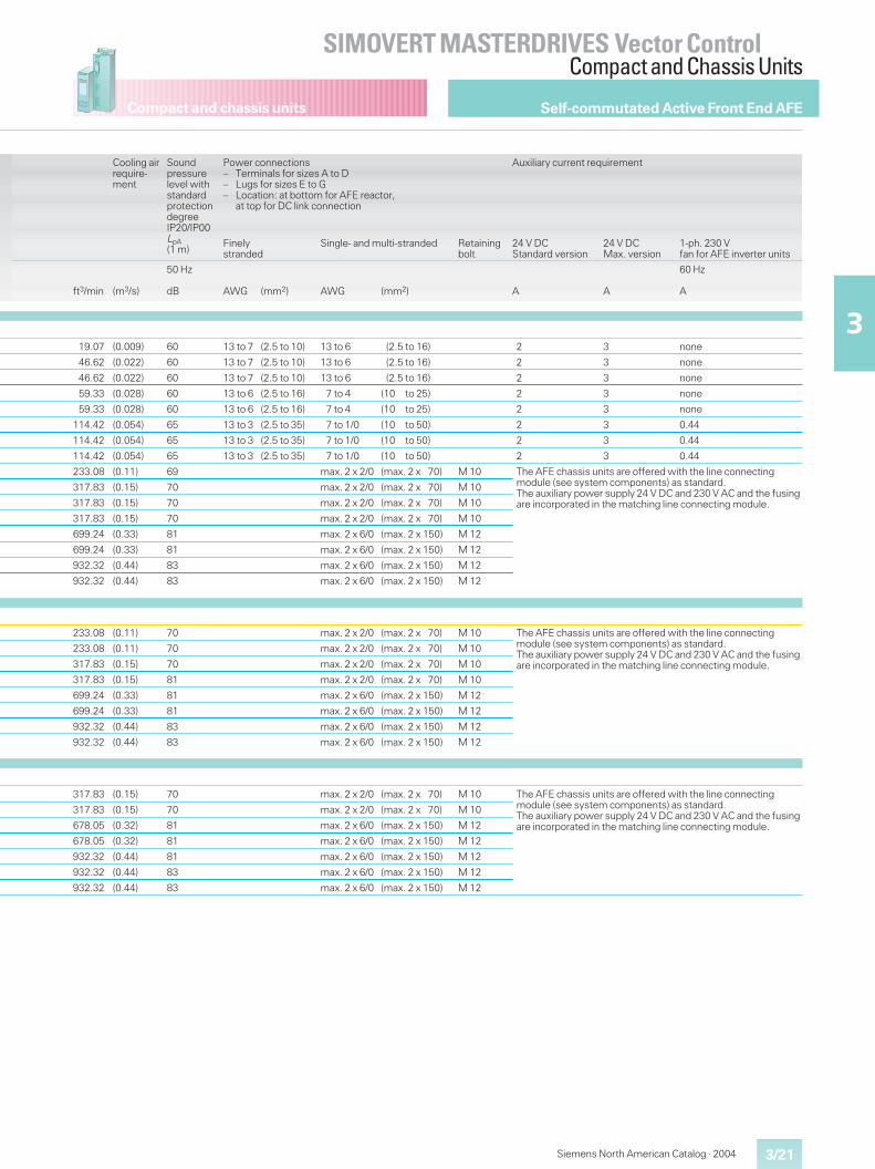
Compact and chassis units
3/21
SIMOVERT MASTERDRIVES Vector ControlCompact and Chassis Units
3
Siemens North American Catalog · 2004
Cooling airrequire-ment
Soundpressurelevel withstandardprotectiondegreeIP20/IP00LpA(1 m)
Power connections– Terminals for sizes A to D– Lugs for sizes E to G– Location: at bottom for AFE reactor,
at top for DC link connection
Auxiliary current requirement
Finelystranded
Single- and multi-stranded Retainingbolt
24 V DCStandard version
24 V DCMax. version
1-ph. 230 Vfan for AFE inverter units
ft3/min (m3/s)
50 Hz
dB AWG (mm2) AWG (mm2) A A
60 Hz
A
19.07 (0.009) 60 13 to 7 (2.5 to 10) 13 to 6 (2.5 to 16) 2 3 none
46.62 (0.022) 60 13 to 7 (2.5 to 10) 13 to 6 (2.5 to 16) 2 3 none
46.62 (0.022) 60 13 to 7 (2.5 to 10) 13 to 6 (2.5 to 16) 2 3 none
59.33 (0.028) 60 13 to 6 (2.5 to 16) 7 to 4 (10 to 25) 2 3 none
59.33 (0.028) 60 13 to 6 (2.5 to 16) 7 to 4 (10 to 25) 2 3 none
114.42 (0.054) 65 13 to 3 (2.5 to 35) 7 to 1/0 (10 to 50) 2 3 0.44
114.42 (0.054) 65 13 to 3 (2.5 to 35) 7 to 1/0 (10 to 50) 2 3 0.44
114.42 (0.054) 65 13 to 3 (2.5 to 35) 7 to 1/0 (10 to 50) 2 3 0.44
233.08 (0.11) 69 max. 2 x 2/0 (max. 2 x 70) M 10 The AFE chassis units are offered with the line connectingmodule (see system components) as standard.The auxiliary power supply 24 V DC and 230 V AC and the fusingare incorporated in the matching line connecting module.
317.83 (0.15) 70 max. 2 x 2/0 (max. 2 x 70) M 10
317.83 (0.15) 70 max. 2 x 2/0 (max. 2 x 70) M 10
317.83 (0.15) 70 max. 2 x 2/0 (max. 2 x 70) M 10
699.24 (0.33) 81 max. 2 x 6/0 (max. 2 x 150) M 12
699.24 (0.33) 81 max. 2 x 6/0 (max. 2 x 150) M 12
932.32 (0.44) 83 max. 2 x 6/0 (max. 2 x 150) M 12
932.32 (0.44) 83 max. 2 x 6/0 (max. 2 x 150) M 12
233.08 (0.11) 70 max. 2 x 2/0 (max. 2 x 70) M 10 The AFE chassis units are offered with the line connectingmodule (see system components) as standard.The auxiliary power supply 24 V DC and 230 V AC and the fusingare incorporated in the matching line connecting module.
233.08 (0.11) 70 max. 2 x 2/0 (max. 2 x 70) M 10
317.83 (0.15) 70 max. 2 x 2/0 (max. 2 x 70) M 10
317.83 (0.15) 81 max. 2 x 2/0 (max. 2 x 70) M 10
699.24 (0.33) 81 max. 2 x 6/0 (max. 2 x 150) M 12
699.24 (0.33) 81 max. 2 x 6/0 (max. 2 x 150) M 12
932.32 (0.44) 83 max. 2 x 6/0 (max. 2 x 150) M 12
932.32 (0.44) 83 max. 2 x 6/0 (max. 2 x 150) M 12
317.83 (0.15) 70 max. 2 x 2/0 (max. 2 x 70) M 10 The AFE chassis units are offered with the line connectingmodule (see system components) as standard.The auxiliary power supply 24 V DC and 230 V AC and the fusingare incorporated in the matching line connecting module.
317.83 (0.15) 70 max. 2 x 2/0 (max. 2 x 70) M 10
678.05 (0.32) 81 max. 2 x 6/0 (max. 2 x 150) M 12
678.05 (0.32) 81 max. 2 x 6/0 (max. 2 x 150) M 12
932.32 (0.44) 81 max. 2 x 6/0 (max. 2 x 150) M 12
932.32 (0.44) 83 max. 2 x 6/0 (max. 2 x 150) M 12
932.32 (0.44) 83 max. 2 x 6/0 (max. 2 x 150) M 12
Self-commutated Active Front End AFE
3/22
SIMOVERT MASTERDRIVES Vector ControlCompact PLUS,Compact and Chassis Units
3
Compact PLUS unitsCompact and chassis units
Siemens North American Catalog · 2004
Rectifier units supply the DCbus for inverters with motor-ing energy and enable opera-tion of a multi-motor system.
The Compact PLUS rectifierunits have an integratedbraking chopper. For regen-erative mode, these rectifierunits require only an externalbraking resistor.
Rectifier/regenerative unitssupply the DC bus forinverters with motoringenergy from a three-phasesystem and return regenera-tive energy from the DC busto the power system. This isachieved using two inde-pendent thyristor bridges.The regenerating bridge isconnected via an auto-transformer.
The advantages of using anautotransformer are as fol-lows:
� maximum motor torque,even during regenerativemode
� improved availability withweak supply systems orduring voltage dips.
Rectifier and rectifier/regen-erative units are suitable asstandard for operation with ITsupply systems.
In order to increase the out-put current, up to 2 additional“parallel units”of the recti-fier or rectifier/regenerativeunit type K (“base unit”) withthe same rated current maybe connected in parallel (seeEngineering Information,page 6/16).
Rectifier units and rectifier/regenerative units
Technical characteristics
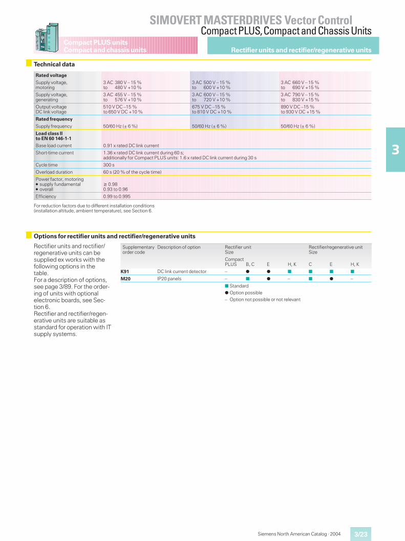
Siemens North American Catalog · 2004 3/23
SIMOVERT MASTERDRIVES Vector ControlCompact PLUS,Compact and Chassis Units
3
Compact PLUS unitsCompact and chassis units Rectifier units and rectifier/regenerative units
Technical data
Rated voltage
Supply voltage,motoring
3 AC 380 V – 15 %to 480 V +10 %
3 AC 500 V – 15 %to 600 V +10 %
3 AC 660 V – 15 %to 690 V +15 %
Supply voltage,generating
3 AC 455 V – 15 %to 576 V +10 %
3 AC 600 V – 15 %to 720 V +10 %
3 AC 790 V – 15 %to 830 V +15 %
Output voltageDC link voltage
510 V DC –15 %to 650 V DC +10 %
675 V DC –15 %to 810 V DC +10 %
890 V DC –15 %to 930 V DC +15 %
Rated frequency
Supply frequency 50/60 Hz (± 6 %) 50/60 Hz (± 6 %) 50/60 Hz (± 6 %)
Load class IIto EN 60 146-1-1
Base load current 0.91 x rated DC link current
Short-time current 1.36 x rated DC link current during 60 s;additionally for Compact PLUS units: 1.6 x rated DC link current during 30 s
Cycle time 300 s
Overload duration 60 s (20 % of the cycle time)
Power factor, motoring� supply fundamental� overall
� 0.980.93 to 0.96
Efficiency 0.99 to 0.995
For reduction factors due to different installation conditions(installation altitude, ambient temperature), see Section 6.
Options for rectifier units and rectifier/regenerative units
Rectifier units and rectifier/regenerative units can besupplied ex works with thefollowing options in thetable.For a description of options,see page 3/89. For the order-ing of units with optionalelectronic boards, see Sec-tion 6.Rectifier and rectifier/regen-erative units are suitable asstandard for operation with ITsupply systems.
Supplementaryorder code
Description of option Rectifier unitSize
Rectifier/regenerative unitSize
CompactPLUS B, C E H, K C E H, K
K91 DC link current detector – � � ■ ■ ■ ■
M20 IP20 panels – ■ � – ■ � –
■ Standard
� Option possible– Option not possible or not relevant
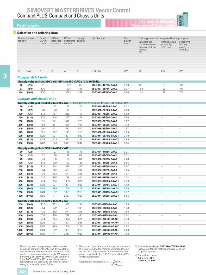
Siemens North American Catalog · 20043/24
SIMOVERT MASTERDRIVES Vector ControlCompact PLUS,Compact and Chassis Units
3
Compact PLUS unitsCompact and chassis units
1) Nominal power ratings are quoted for ease ofassigning components only. The drive outputsare dependent on the inverters connected andare to be dimensioned accordingly. When recti-fier units 3-ph. 380 V to 480 V AC are used on a3-ph. 200 V to 230 V AC supply, the rated cur-rents remain the same and the nominal powerrating is reduced to about 50 %.
2) The current data refer to a line supply inductanceof 3 % referred to the rectifier unit impedance Z,i.e. the ratio of the system fault level to the con-verter output is 33:1 or 100:1 if an additional 2 %line reactor is used.
Rectifier unit impedance:
3) An interface adapter 6SE7090–0XX85–1TA0is required if these rectifier units are used for12-pulse system.
4) Short-time current:1.6 x IN for 30 s1.36 x IN for 60 s
Rectifier units
Selection and ordering data
Nominal powerrating1)
RatedDC linkcurrent
DC linkbase loadcurrent
DC linkshort-timecurrent
Supplycurrent2)
Rectifier unit Max.powerloss
Braking power with integrated braking chopper
Smallest per-missible value ofexternal brakingresistorRmin
Rated brakingpower P20with Rmin
Short-timebrakingpower P3with Rmin
HP (kW) A A A A Order No. kW � kW kW
Compact PLUS units
Supply voltage 3-ph. 380 V AC –15 % to 480 V AC +10 % 50/60 Hz20 (15) 41 – 664) 36 6SE7024–1EP85–0AA0 0.13 19 20 30
67 (50) 120 – 1924) 108 6SE7031–2EP85–0AA0 0.27 6.5 60 90
134 (100) 230 – 3684) 207 6SE7032–3EP85–0AA0 0.60 3.4 116 174
Compact and chassis units
Supply voltage 3-ph. 380 V to 480 V AC Can also be connected to 3-ph. 200 V to 230 V20 (15) 41 37 56 36 6SE7024–1EB85–0AA0 0.12 – – –
50 (37) 86 78 117 75 6SE7028–6EC85–0AA0 0.26 – – –
100 (75) 173 157 235 149 6SE7031–7EE85–0AA0 0.62 – – –
150 (110) 270 246 367 233 6SE7032–7EE85–0AA0 0.86 – – –
200 (160) 375 341 510 326 6SE7033–8EE85–0AA0 1.07 – – –
250 (200) 463 421 630 403 6SE7034–6EE85–0AA0 1.32 – – –
300 (250) 605 551 823 526 6SE7036–1EE85–0AA0 1.67 – – –
525 (400) 821 747 1117 710 6SE7038–2EH85–0AA03) 3.29 – – –
650 (500) 1023 931 1391 888 6SE7041–0EH85–0AA03) 3.70 – – –
825 (630) 1333 1213 1813 1156 6SE7041–3EK85–0AA03) 4.85 – – –
1000 (800) 1780 1620 2421 1542 6SE7041–8EK85–0AA03) 6.24 – – –
Supply voltage 3-ph. 500 V to 600 V AC30 (22) 41 37 56 36 6SE7024–1FB85–0AA0 0.21 – – –
50 (37) 72 66 98 63 6SE7027–2FC85–0AA0 0.22 – – –
75 (55) 94 86 128 81 6SE7028–8FC85–0AA0 0.28 – – –
100 (75) 142 129 193 123 6SE7031–4FE85–0AA0 0.65 – – –
175 (132) 235 214 320 203 6SE7032–4FE85–0AA0 0.97 – – –
250 (200) 354 322 481 307 6SE7033–5FE85–0AA0 1.25 – – –
300 (250) 420 382 571 366 6SE7034–2FE85–0AA0 1.27 – – –
400 (315) 536 488 729 465 6SE7035–4FE85–0AA0 1.74 – – –
600 (400) 774 704 1053 671 6SE7037–7FH85–0AA03) 3.30 – – –
800 (630) 1023 931 1391 888 6SE7041–0FH85–0AA03) 4.03 – – –
1000 (800) 1285 1169 1748 1119 6SE7041–3FK85–0AA03) 5.40 – – –
1200 (900) 1464 1332 1991 1269 6SE7041–5FK85–0AA03) 5.87 – – –
1400 (1100) 1880 1711 2557 1633 6SE7041–8FK85–0AA03) 6.65 – – –
Supply voltage 3-ph. 660 V to 690 V AC200 (160) 222 202 302 194 6SE7032–2HE85–0AA0 1.08 – – –
300 (250) 354 322 481 308 6SE7033–5HE85–0AA0 1.33 – – –
400 (315) 420 382 571 366 6SE7034–2HE85–0AA0 1.58 – – –
600 (400) 536 488 729 465 6SE7035–4HE85–0AA0 2.02 – – –
800 (630) 774 704 1053 671 6SE7037–7HH85–0AA03) 3.70 – – –
1000 (800) 1023 931 1391 888 6SE7041–0HH85–0AA03) 4.15 – – –
1300 (1000) 1285 1169 1748 1119 6SE7041–3HK85–0AA03) 5.54 – – –
1400 (1100) 1464 1332 1991 1269 6SE7041–5HK85–0AA03) 6.00 – – –
2000 (1500) 1880 1711 2557 1633 6SE7041–8HK85–0AA03) 7.62 – – –
supply
supply
3 V
VZ �
� I
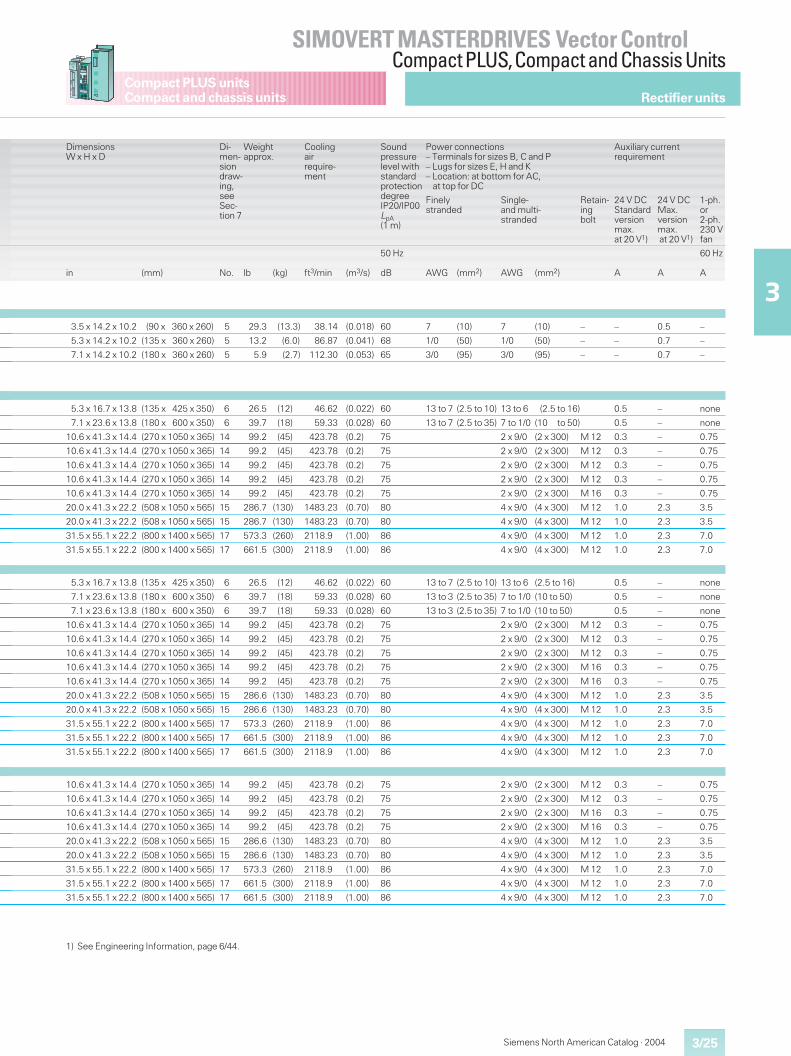
Siemens North American Catalog · 2004 3/25
SIMOVERT MASTERDRIVES Vector ControlCompact PLUS,Compact and Chassis Units
3
Compact PLUS unitsCompact and chassis units
DimensionsW x H x D
Di-men-siondraw-ing,seeSec-tion 7
Weightapprox.
Coolingairrequire-ment
Soundpressurelevel withstandardprotectiondegreeIP20/IP00LpA(1 m)
Power connections– Terminals for sizes B, C and P– Lugs for sizes E, H and K– Location: at bottom for AC,
at top for DC
Auxiliary currentrequirement
Finelystranded
Single-and multi-stranded
Retain-ingbolt
24 V DCStandardversionmax.at 20 V1)
24 V DCMax.versionmax.at 20 V1)
1-ph.or2-ph.230 Vfan
in (mm) No. lb (kg) ft3/min (m3/s)
50 Hz
dB AWG (mm2) AWG (mm2) A A
60 Hz
A
3.5 x 14.2 x 10.2 (90 x 360 x 260) 5 29.3 (13.3) 38.14 (0.018) 60 7 (10) 7 (10) – – 0.5 –
5.3 x 14.2 x 10.2 (135 x 360 x 260) 5 13.2 (6.0) 86.87 (0.041) 68 1/0 (50) 1/0 (50) – – 0.7 –
7.1 x 14.2 x 10.2 (180 x 360 x 260) 5 5.9 (2.7) 112.30 (0.053) 65 3/0 (95) 3/0 (95) – – 0.7 –
5.3 x 16.7 x 13.8 (135 x 425 x 350) 6 26.5 (12) 46.62 (0.022) 60 13 to 7 (2.5 to 10) 13 to 6 (2.5 to 16) 0.5 – none
7.1 x 23.6 x 13.8 (180 x 600 x 350) 6 39.7 (18) 59.33 (0.028) 60 13 to 7 (2.5 to 35) 7 to 1/0 (10 to 50) 0.5 – none
10.6 x 41.3 x 14.4 (270 x 1050 x 365) 14 99.2 (45) 423.78 (0.2) 75 2 x 9/0 (2 x 300) M 12 0.3 – 0.75
10.6 x 41.3 x 14.4 (270 x 1050 x 365) 14 99.2 (45) 423.78 (0.2) 75 2 x 9/0 (2 x 300) M 12 0.3 – 0.75
10.6 x 41.3 x 14.4 (270 x 1050 x 365) 14 99.2 (45) 423.78 (0.2) 75 2 x 9/0 (2 x 300) M 12 0.3 – 0.75
10.6 x 41.3 x 14.4 (270 x 1050 x 365) 14 99.2 (45) 423.78 (0.2) 75 2 x 9/0 (2 x 300) M 12 0.3 – 0.75
10.6 x 41.3 x 14.4 (270 x 1050 x 365) 14 99.2 (45) 423.78 (0.2) 75 2 x 9/0 (2 x 300) M 16 0.3 – 0.75
20.0 x 41.3 x 22.2 (508 x 1050 x 565) 15 286.7 (130) 1483.23 (0.70) 80 4 x 9/0 (4 x 300) M 12 1.0 2.3 3.5
20.0 x 41.3 x 22.2 (508 x 1050 x 565) 15 286.7 (130) 1483.23 (0.70) 80 4 x 9/0 (4 x 300) M 12 1.0 2.3 3.5
31.5 x 55.1 x 22.2 (800 x 1400 x 565) 17 573.3 (260) 2118.9 (1.00) 86 4 x 9/0 (4 x 300) M 12 1.0 2.3 7.0
31.5 x 55.1 x 22.2 (800 x 1400 x 565) 17 661.5 (300) 2118.9 (1.00) 86 4 x 9/0 (4 x 300) M 12 1.0 2.3 7.0
5.3 x 16.7 x 13.8 (135 x 425 x 350) 6 26.5 (12) 46.62 (0.022) 60 13 to 7 (2.5 to 10) 13 to 6 (2.5 to 16) 0.5 – none
7.1 x 23.6 x 13.8 (180 x 600 x 350) 6 39.7 (18) 59.33 (0.028) 60 13 to 3 (2.5 to 35) 7 to 1/0 (10 to 50) 0.5 – none
7.1 x 23.6 x 13.8 (180 x 600 x 350) 6 39.7 (18) 59.33 (0.028) 60 13 to 3 (2.5 to 35) 7 to 1/0 (10 to 50) 0.5 – none
10.6 x 41.3 x 14.4 (270 x 1050 x 365) 14 99.2 (45) 423.78 (0.2) 75 2 x 9/0 (2 x 300) M 12 0.3 – 0.75
10.6 x 41.3 x 14.4 (270 x 1050 x 365) 14 99.2 (45) 423.78 (0.2) 75 2 x 9/0 (2 x 300) M 12 0.3 – 0.75
10.6 x 41.3 x 14.4 (270 x 1050 x 365) 14 99.2 (45) 423.78 (0.2) 75 2 x 9/0 (2 x 300) M 12 0.3 – 0.75
10.6 x 41.3 x 14.4 (270 x 1050 x 365) 14 99.2 (45) 423.78 (0.2) 75 2 x 9/0 (2 x 300) M 16 0.3 – 0.75
10.6 x 41.3 x 14.4 (270 x 1050 x 365) 14 99.2 (45) 423.78 (0.2) 75 2 x 9/0 (2 x 300) M 16 0.3 – 0.75
20.0 x 41.3 x 22.2 (508 x 1050 x 565) 15 286.6 (130) 1483.23 (0.70) 80 4 x 9/0 (4 x 300) M 12 1.0 2.3 3.5
20.0 x 41.3 x 22.2 (508 x 1050 x 565) 15 286.6 (130) 1483.23 (0.70) 80 4 x 9/0 (4 x 300) M 12 1.0 2.3 3.5
31.5 x 55.1 x 22.2 (800 x 1400 x 565) 17 573.3 (260) 2118.9 (1.00) 86 4 x 9/0 (4 x 300) M 12 1.0 2.3 7.0
31.5 x 55.1 x 22.2 (800 x 1400 x 565) 17 661.5 (300) 2118.9 (1.00) 86 4 x 9/0 (4 x 300) M 12 1.0 2.3 7.0
31.5 x 55.1 x 22.2 (800 x 1400 x 565) 17 661.5 (300) 2118.9 (1.00) 86 4 x 9/0 (4 x 300) M 12 1.0 2.3 7.0
10.6 x 41.3 x 14.4 (270 x 1050 x 365) 14 99.2 (45) 423.78 (0.2) 75 2 x 9/0 (2 x 300) M 12 0.3 – 0.75
10.6 x 41.3 x 14.4 (270 x 1050 x 365) 14 99.2 (45) 423.78 (0.2) 75 2 x 9/0 (2 x 300) M 12 0.3 – 0.75
10.6 x 41.3 x 14.4 (270 x 1050 x 365) 14 99.2 (45) 423.78 (0.2) 75 2 x 9/0 (2 x 300) M 16 0.3 – 0.75
10.6 x 41.3 x 14.4 (270 x 1050 x 365) 14 99.2 (45) 423.78 (0.2) 75 2 x 9/0 (2 x 300) M 16 0.3 – 0.75
20.0 x 41.3 x 22.2 (508 x 1050 x 565) 15 286.6 (130) 1483.23 (0.70) 80 4 x 9/0 (4 x 300) M 12 1.0 2.3 3.5
20.0 x 41.3 x 22.2 (508 x 1050 x 565) 15 286.6 (130) 1483.23 (0.70) 80 4 x 9/0 (4 x 300) M 12 1.0 2.3 3.5
31.5 x 55.1 x 22.2 (800 x 1400 x 565) 17 573.3 (260) 2118.9 (1.00) 86 4 x 9/0 (4 x 300) M 12 1.0 2.3 7.0
31.5 x 55.1 x 22.2 (800 x 1400 x 565) 17 661.5 (300) 2118.9 (1.00) 86 4 x 9/0 (4 x 300) M 12 1.0 2.3 7.0
31.5 x 55.1 x 22.2 (800 x 1400 x 565) 17 661.5 (300) 2118.9 (1.00) 86 4 x 9/0 (4 x 300) M 12 1.0 2.3 7.0
Rectifier units
1) See Engineering Information, page 6/44.
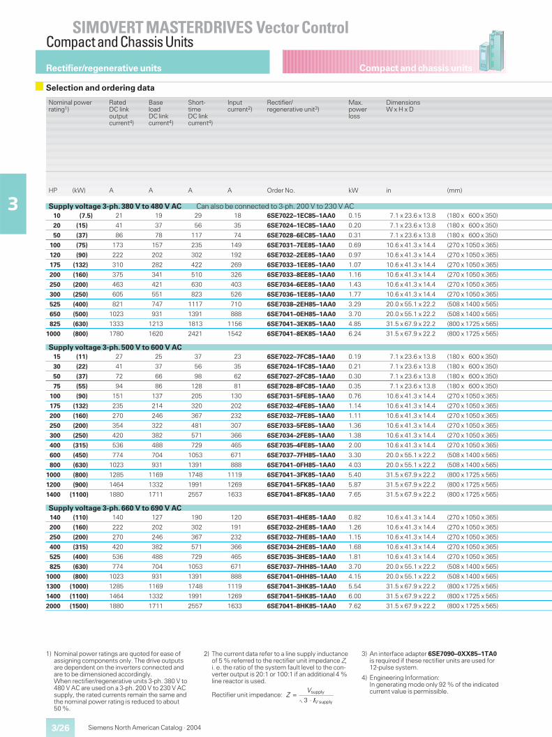
Compact and chassis units
SIMOVERT MASTERDRIVES Vector ControlCompact and Chassis Units
Siemens North American Catalog · 20043/26
3
Nominal powerrating1)
RatedDC linkoutputcurrent4)
BaseloadDC linkcurrent4)
Short-timeDC linkcurrent4)
Inputcurrent2)
Rectifier/regenerative unit3)
Max.powerloss
DimensionsW x H x D
HP (kW) A A A A Order No. kW in (mm)
Supply voltage 3-ph. 380 V to 480 V AC Can also be connected to 3-ph. 200 V to 230 V AC10 (7.5) 21 19 29 18 6SE7022–1EC85–1AA0 0.15 7.1 x 23.6 x 13.8 (180 x 600 x 350)
20 (15) 41 37 56 35 6SE7024–1EC85–1AA0 0.20 7.1 x 23.6 x 13.8 (180 x 600 x 350)
50 (37) 86 78 117 74 6SE7028–6EC85–1AA0 0.31 7.1 x 23.6 x 13.8 (180 x 600 x 350)
100 (75) 173 157 235 149 6SE7031–7EE85–1AA0 0.69 10.6 x 41.3 x 14.4 (270 x 1050 x 365)
120 (90) 222 202 302 192 6SE7032–2EE85–1AA0 0.97 10.6 x 41.3 x 14.4 (270 x 1050 x 365)
175 (132) 310 282 422 269 6SE7033–1EE85–1AA0 1.07 10.6 x 41.3 x 14.4 (270 x 1050 x 365)
200 (160) 375 341 510 326 6SE7033–8EE85–1AA0 1.16 10.6 x 41.3 x 14.4 (270 x 1050 x 365)
250 (200) 463 421 630 403 6SE7034–6EE85–1AA0 1.43 10.6 x 41.3 x 14.4 (270 x 1050 x 365)
300 (250) 605 551 823 526 6SE7036–1EE85–1AA0 1.77 10.6 x 41.3 x 14.4 (270 x 1050 x 365)
525 (400) 821 747 1117 710 6SE7038–2EH85–1AA0 3.29 20.0 x 55.1 x 22.2 (508 x 1400 x 565)
650 (500) 1023 931 1391 888 6SE7041–0EH85–1AA0 3.70 20.0 x 55.1 x 22.2 (508 x 1400 x 565)
825 (630) 1333 1213 1813 1156 6SE7041–3EK85–1AA0 4.85 31.5 x 67.9 x 22.2 (800 x 1725 x 565)
1000 (800) 1780 1620 2421 1542 6SE7041–8EK85–1AA0 6.24 31.5 x 67.9 x 22.2 (800 x 1725 x 565)
Supply voltage 3-ph. 500 V to 600 V AC15 (11) 27 25 37 23 6SE7022–7FC85–1AA0 0.19 7.1 x 23.6 x 13.8 (180 x 600 x 350)
30 (22) 41 37 56 35 6SE7024–1FC85–1AA0 0.21 7.1 x 23.6 x 13.8 (180 x 600 x 350)
50 (37) 72 66 98 62 6SE7027–2FC85–1AA0 0.30 7.1 x 23.6 x 13.8 (180 x 600 x 350)
75 (55) 94 86 128 81 6SE7028–8FC85–1AA0 0.35 7.1 x 23.6 x 13.8 (180 x 600 x 350)
100 (90) 151 137 205 130 6SE7031–5FE85–1AA0 0.76 10.6 x 41.3 x 14.4 (270 x 1050 x 365)
175 (132) 235 214 320 202 6SE7032–4FE85–1AA0 1.14 10.6 x 41.3 x 14.4 (270 x 1050 x 365)
200 (160) 270 246 367 232 6SE7032–7FE85–1AA0 1.11 10.6 x 41.3 x 14.4 (270 x 1050 x 365)
250 (200) 354 322 481 307 6SE7033–5FE85–1AA0 1.36 10.6 x 41.3 x 14.4 (270 x 1050 x 365)
300 (250) 420 382 571 366 6SE7034–2FE85–1AA0 1.38 10.6 x 41.3 x 14.4 (270 x 1050 x 365)
400 (315) 536 488 729 465 6SE7035–4FE85–1AA0 2.00 10.6 x 41.3 x 14.4 (270 x 1050 x 365)
600 (450) 774 704 1053 671 6SE7037–7FH85–1AA0 3.30 20.0 x 55.1 x 22.2 (508 x 1400 x 565)
800 (630) 1023 931 1391 888 6SE7041–0FH85–1AA0 4.03 20.0 x 55.1 x 22.2 (508 x 1400 x 565)
1000 (800) 1285 1169 1748 1119 6SE7041–3FK85–1AA0 5.40 31.5 x 67.9 x 22.2 (800 x 1725 x 565)
1200 (900) 1464 1332 1991 1269 6SE7041–5FK85–1AA0 5.87 31.5 x 67.9 x 22.2 (800 x 1725 x 565)
1400 (1100) 1880 1711 2557 1633 6SE7041–8FK85–1AA0 7.65 31.5 x 67.9 x 22.2 (800 x 1725 x 565)
Supply voltage 3-ph. 660 V to 690 V AC140 (110) 140 127 190 120 6SE7031–4HE85–1AA0 0.82 10.6 x 41.3 x 14.4 (270 x 1050 x 365)
200 (160) 222 202 302 191 6SE7032–2HE85–1AA0 1.26 10.6 x 41.3 x 14.4 (270 x 1050 x 365)
250 (200) 270 246 367 232 6SE7032–7HE85–1AA0 1.15 10.6 x 41.3 x 14.4 (270 x 1050 x 365)
400 (315) 420 382 571 366 6SE7034–2HE85–1AA0 1.68 10.6 x 41.3 x 14.4 (270 x 1050 x 365)
525 (400) 536 488 729 465 6SE7035–3HE85–1AA0 1.81 10.6 x 41.3 x 14.4 (270 x 1050 x 365)
825 (630) 774 704 1053 671 6SE7037–7HH85–1AA0 3.70 20.0 x 55.1 x 22.2 (508 x 1400 x 565)
1000 (800) 1023 931 1391 888 6SE7041–0HH85–1AA0 4.15 20.0 x 55.1 x 22.2 (508 x 1400 x 565)
1300 (1000) 1285 1169 1748 1119 6SE7041–3HK85–1AA0 5.54 31.5 x 67.9 x 22.2 (800 x 1725 x 565)
1400 (1100) 1464 1332 1991 1269 6SE7041–5HK85–1AA0 6.00 31.5 x 67.9 x 22.2 (800 x 1725 x 565)
2000 (1500) 1880 1711 2557 1633 6SE7041–8HK85–1AA0 7.62 31.5 x 67.9 x 22.2 (800 x 1725 x 565)
1) Nominal power ratings are quoted for ease ofassigning components only. The drive outputsare dependent on the inverters connected andare to be dimensioned accordingly.When rectifier/regenerative units 3-ph. 380 V to480 V AC are used on a 3-ph. 200 V to 230 V ACsupply, the rated currents remain the same andthe nominal power rating is reduced to about50 %.
2) The current data refer to a line supply inductanceof 5 % referred to the rectifier unit impedance Z,i. e. the ratio of the system fault level to the con-verter output is 20:1 or 100:1 if an additional 4 %line reactor is used.
Rectifier unit impedance:
3) An interface adapter 6SE7090–0XX85–1TA0is required if these rectifier units are used for12-pulse system.
4) Engineering Information:In generating mode only 92 % of the indicatedcurrent value is permissible.
Rectifier/regenerative units
Selection and ordering data
ZV
V=
⋅supply
supply3 I
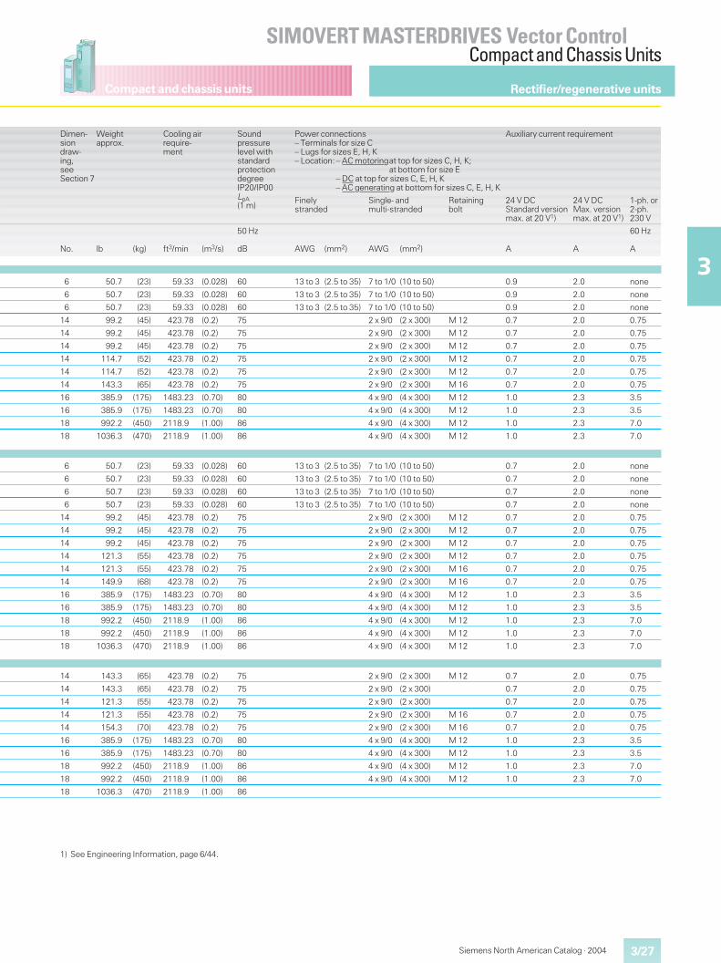
Compact and chassis units
3/27
SIMOVERT MASTERDRIVES Vector ControlCompact and Chassis Units
3
Siemens North American Catalog · 2004
Dimen-siondraw-ing,seeSection 7
Weightapprox.
Cooling airrequire-ment
Soundpressurelevel withstandardprotectiondegreeIP20/IP00LpA(1 m)
Power connections– Terminals for size C– Lugs for sizes E, H, K– Location: – AC motoringat top for sizes C, H, K;
at bottom for size E– DC at top for sizes C, E, H, K– AC generating at bottom for sizes C, E, H, K
Auxiliary current requirement
Finelystranded
Single- andmulti-stranded
Retainingbolt
24 V DCStandard versionmax. at 20 V1)
24 V DCMax. versionmax. at 20 V1)
1-ph. or2-ph.230 V
No. lb (kg) ft3/min (m3/s)
50 Hz
dB AWG (mm2) AWG (mm2) A A
60 Hz
A
6 50.7 (23) 59.33 (0.028) 60 13 to 3 (2.5 to 35) 7 to 1/0 (10 to 50) 0.9 2.0 none
6 50.7 (23) 59.33 (0.028) 60 13 to 3 (2.5 to 35) 7 to 1/0 (10 to 50) 0.9 2.0 none
6 50.7 (23) 59.33 (0.028) 60 13 to 3 (2.5 to 35) 7 to 1/0 (10 to 50) 0.9 2.0 none
14 99.2 (45) 423.78 (0.2) 75 2 x 9/0 (2 x 300) M 12 0.7 2.0 0.75
14 99.2 (45) 423.78 (0.2) 75 2 x 9/0 (2 x 300) M 12 0.7 2.0 0.75
14 99.2 (45) 423.78 (0.2) 75 2 x 9/0 (2 x 300) M 12 0.7 2.0 0.75
14 114.7 (52) 423.78 (0.2) 75 2 x 9/0 (2 x 300) M 12 0.7 2.0 0.75
14 114.7 (52) 423.78 (0.2) 75 2 x 9/0 (2 x 300) M 12 0.7 2.0 0.75
14 143.3 (65) 423.78 (0.2) 75 2 x 9/0 (2 x 300) M 16 0.7 2.0 0.75
16 385.9 (175) 1483.23 (0.70) 80 4 x 9/0 (4 x 300) M 12 1.0 2.3 3.5
16 385.9 (175) 1483.23 (0.70) 80 4 x 9/0 (4 x 300) M 12 1.0 2.3 3.5
18 992.2 (450) 2118.9 (1.00) 86 4 x 9/0 (4 x 300) M 12 1.0 2.3 7.0
18 1036.3 (470) 2118.9 (1.00) 86 4 x 9/0 (4 x 300) M 12 1.0 2.3 7.0
6 50.7 (23) 59.33 (0.028) 60 13 to 3 (2.5 to 35) 7 to 1/0 (10 to 50) 0.7 2.0 none
6 50.7 (23) 59.33 (0.028) 60 13 to 3 (2.5 to 35) 7 to 1/0 (10 to 50) 0.7 2.0 none
6 50.7 (23) 59.33 (0.028) 60 13 to 3 (2.5 to 35) 7 to 1/0 (10 to 50) 0.7 2.0 none
6 50.7 (23) 59.33 (0.028) 60 13 to 3 (2.5 to 35) 7 to 1/0 (10 to 50) 0.7 2.0 none
14 99.2 (45) 423.78 (0.2) 75 2 x 9/0 (2 x 300) M 12 0.7 2.0 0.75
14 99.2 (45) 423.78 (0.2) 75 2 x 9/0 (2 x 300) M 12 0.7 2.0 0.75
14 99.2 (45) 423.78 (0.2) 75 2 x 9/0 (2 x 300) M 12 0.7 2.0 0.75
14 121.3 (55) 423.78 (0.2) 75 2 x 9/0 (2 x 300) M 12 0.7 2.0 0.75
14 121.3 (55) 423.78 (0.2) 75 2 x 9/0 (2 x 300) M 16 0.7 2.0 0.75
14 149.9 (68) 423.78 (0.2) 75 2 x 9/0 (2 x 300) M 16 0.7 2.0 0.75
16 385.9 (175) 1483.23 (0.70) 80 4 x 9/0 (4 x 300) M 12 1.0 2.3 3.5
16 385.9 (175) 1483.23 (0.70) 80 4 x 9/0 (4 x 300) M 12 1.0 2.3 3.5
18 992.2 (450) 2118.9 (1.00) 86 4 x 9/0 (4 x 300) M 12 1.0 2.3 7.0
18 992.2 (450) 2118.9 (1.00) 86 4 x 9/0 (4 x 300) M 12 1.0 2.3 7.0
18 1036.3 (470) 2118.9 (1.00) 86 4 x 9/0 (4 x 300) M 12 1.0 2.3 7.0
14 143.3 (65) 423.78 (0.2) 75 2 x 9/0 (2 x 300) M 12 0.7 2.0 0.75
14 143.3 (65) 423.78 (0.2) 75 2 x 9/0 (2 x 300) 0.7 2.0 0.75
14 121.3 (55) 423.78 (0.2) 75 2 x 9/0 (2 x 300) 0.7 2.0 0.75
14 121.3 (55) 423.78 (0.2) 75 2 x 9/0 (2 x 300) M 16 0.7 2.0 0.75
14 154.3 (70) 423.78 (0.2) 75 2 x 9/0 (2 x 300) M 16 0.7 2.0 0.75
16 385.9 (175) 1483.23 (0.70) 80 4 x 9/0 (4 x 300) M 12 1.0 2.3 3.5
16 385.9 (175) 1483.23 (0.70) 80 4 x 9/0 (4 x 300) M 12 1.0 2.3 3.5
18 992.2 (450) 2118.9 (1.00) 86 4 x 9/0 (4 x 300) M 12 1.0 2.3 7.0
18 992.2 (450) 2118.9 (1.00) 86 4 x 9/0 (4 x 300) M 12 1.0 2.3 7.0
18 1036.3 (470) 2118.9 (1.00) 86
Rectifier/regenerative units
1) See Engineering Information, page 6/44.
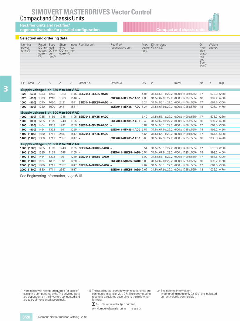
Compact and chassis units
SIMOVERT MASTERDRIVES Vector ControlCompact and Chassis Units
3/28
3
Siemens North American Catalog · 2004
Nominalpowerrating1)
RatedDC linkoutputcurrent2)3)
BaseloadDC linkcur-rent3)
Short-timeDC linkcurrent3)
Inputcur-rent
Rectifier unit Rectifier/regenerative unit
Max.powerloss
DimensionsW x H x D
Di-men-siondraw-ing,seeSec-tion 7
Weightapprox.
HP (kW) A A A A Order No. Order No. kW in (mm) No. lb (kg)
Supply voltage 3-ph. 380 V to 480 V AC825 (630) 1333 1213 1813 1146 6SE7041–3EK85–0AD0 – 4.85 31.5 x 55.1 x 22.2 (800 x 1400 x 565) 17 573.3 (260)
825 (630) 1333 1213 1813 1146 – 6SE7041–3EK85–1AD0 4.85 31.5 x 67.9 x 22.2 (800 x 1725 x 565) 18 992.2 (450)
1000 (800) 1780 1620 2421 1531 6SE7041–8EK85–0AD0 – 6.24 31.5 x 55.1 x 22.2 (800 x 1400 x 565) 17 661.5 (300)
1000 (800) 1780 1620 2421 1531 – 6SE7041–8EK85–1AD0 6.24 31.5 x 67.9 x 22.2 (800 x 1725 x 565) 18 1036.3 (470)
Supply voltage 3-ph. 500 V to 600 V AC1000 (800) 1285 1169 1748 1105 6SE7041–3FK85–0AD0 – 5.40 31.5 x 55.1 x 22.2 (800 x 1400 x 565) 17 573.3 (260)
1000 (800) 1285 1169 1748 1105 – 6SE7041–3FK85–1AD0 5.40 31.5 x 67.9 x 22.2 (800 x 1725 x 565) 18 992.2 (450)
1200 (900) 1464 1332 1991 1259 6SE7041–5FK85–0AD0 – 5.87 31.5 x 55.1 x 22.2 (800 x 1400 x 565) 17 661.5 (300)
1200 (900) 1464 1332 1991 1259 – 6SE7041–5FK85–1AD0 5.87 31.5 x 67.9 x 22.2 (800 x 1725 x 565) 18 992.2 (450)
1400 (1100) 1880 1711 2557 1617 6SE7041–8FK85–0AD0 – 6.65 31.5 x 55.1 x 22.2 (800 x 1400 x 565) 17 661.5 (300)
1400 (1100) 1880 1711 2557 1617 – 6SE7041–8FK85–1AD0 6.65 31.5 x 67.9 x 22.2 (800 x 1725 x 565) 18 1036.3 (470)
Supply voltage 3-ph. 660 V to 690 V AC1300 (1000) 1285 1169 1748 1105 6SE7041–3HK85–0AD0 – 5.54 31.5 x 55.1 x 22.2 (800 x 1400 x 565) 17 573.3 (260)
1300 (1000) 1285 1169 1748 1105 – 6SE7041–3HK85–1AD0 5.54 31.5 x 67.9 x 22.2 (800 x 1725 x 565) 18 992.2 (450)
1400 (1100) 1464 1332 1991 1259 6SE7041–5HK85–0AD0 – 6.00 31.5 x 55.1 x 22.2 (800 x 1400 x 565) 17 661.5 (300)
1400 (1100) 1464 1332 1991 1259 – 6SE7041–5HK85–1AD0 6.00 31.5 x 67.9 x 22.2 (800 x 1725 x 565) 18 992.2 (450)
2000 (1500) 1880 1711 2557 1617 6SE7041–8HK85–0AD0 – 7.62 31.5 x 55.1 x 22.2 (800 x 1400 x 565) 17 661.5 (300)
2000 (1500) 1880 1711 2557 1617 – 6SE7041–8HK85–1AD0 7.62 31.5 x 67.9 x 22.2 (800 x 1725 x 565) 18 1036.3 (470)
See Engineering Information, page 6/16.
1) Nominal power ratings are quoted for ease ofassigning components only. The drive outputsare dependent on the inverters connected andare to be dimensioned accordingly.
2) The rated output current when rectifier units areconnected in parallel via a 2 % line commutatingreactor is calculated according to the followingformula:
� I = 0.9 x n x rated output current
n = Number of parallel units 1 � n � 3.
3) Engineering Information:In generating mode only 92 % of the indicatedcurrent value is permissible .
Selection and ordering data
Rectifier units and rectifier/regenerative units for parallel configuration
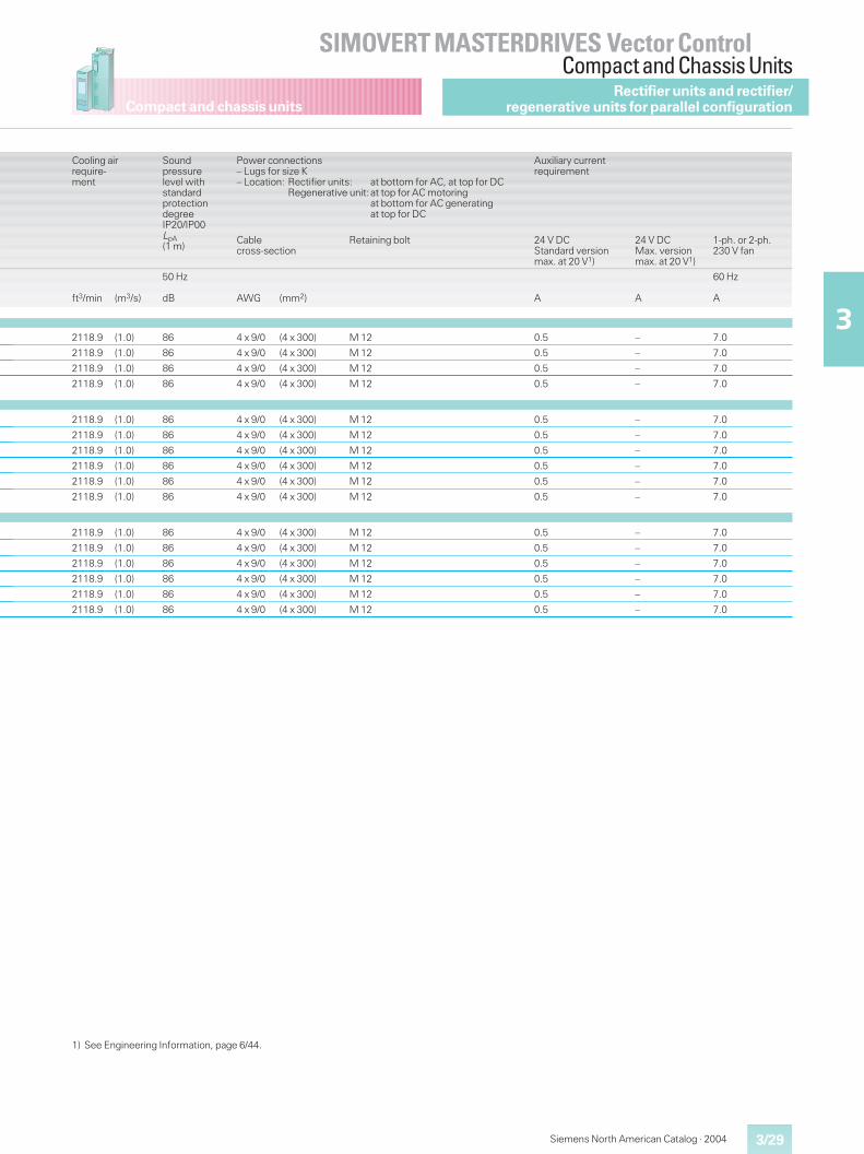
Compact and chassis units
3/29
SIMOVERT MASTERDRIVES Vector ControlCompact and Chassis Units
3
Siemens North American Catalog · 2004
Cooling airrequire-ment
Soundpressurelevel withstandardprotectiondegreeIP20/IP00LpA(1 m)
Power connections– Lugs for size K– Location: Rectifier units: at bottom for AC, at top for DC
Regenerative unit:at top for AC motoringat bottom for AC generatingat top for DC
Auxiliary currentrequirement
Cablecross-section
Retaining bolt 24 V DCStandard versionmax. at 20 V1)
24 V DCMax. versionmax. at 20 V1)
1-ph. or 2-ph.230 V fan
ft3/min (m3/s)
50 Hz
dB AWG (mm2) A A
60 Hz
A
2118.9 (1.0) 86 4 x 9/0 (4 x 300) M 12 0.5 – 7.0
2118.9 (1.0) 86 4 x 9/0 (4 x 300) M 12 0.5 – 7.0
2118.9 (1.0) 86 4 x 9/0 (4 x 300) M 12 0.5 – 7.0
2118.9 (1.0) 86 4 x 9/0 (4 x 300) M 12 0.5 – 7.0
2118.9 (1.0) 86 4 x 9/0 (4 x 300) M 12 0.5 – 7.0
2118.9 (1.0) 86 4 x 9/0 (4 x 300) M 12 0.5 – 7.0
2118.9 (1.0) 86 4 x 9/0 (4 x 300) M 12 0.5 – 7.0
2118.9 (1.0) 86 4 x 9/0 (4 x 300) M 12 0.5 – 7.0
2118.9 (1.0) 86 4 x 9/0 (4 x 300) M 12 0.5 – 7.0
2118.9 (1.0) 86 4 x 9/0 (4 x 300) M 12 0.5 – 7.0
2118.9 (1.0) 86 4 x 9/0 (4 x 300) M 12 0.5 – 7.0
2118.9 (1.0) 86 4 x 9/0 (4 x 300) M 12 0.5 – 7.0
2118.9 (1.0) 86 4 x 9/0 (4 x 300) M 12 0.5 – 7.0
2118.9 (1.0) 86 4 x 9/0 (4 x 300) M 12 0.5 – 7.0
2118.9 (1.0) 86 4 x 9/0 (4 x 300) M 12 0.5 – 7.0
2118.9 (1.0) 86 4 x 9/0 (4 x 300) M 12 0.5 – 7.0
Rectifier units and rectifier/regenerative units for parallel configuration
1) See Engineering Information, page 6/44.
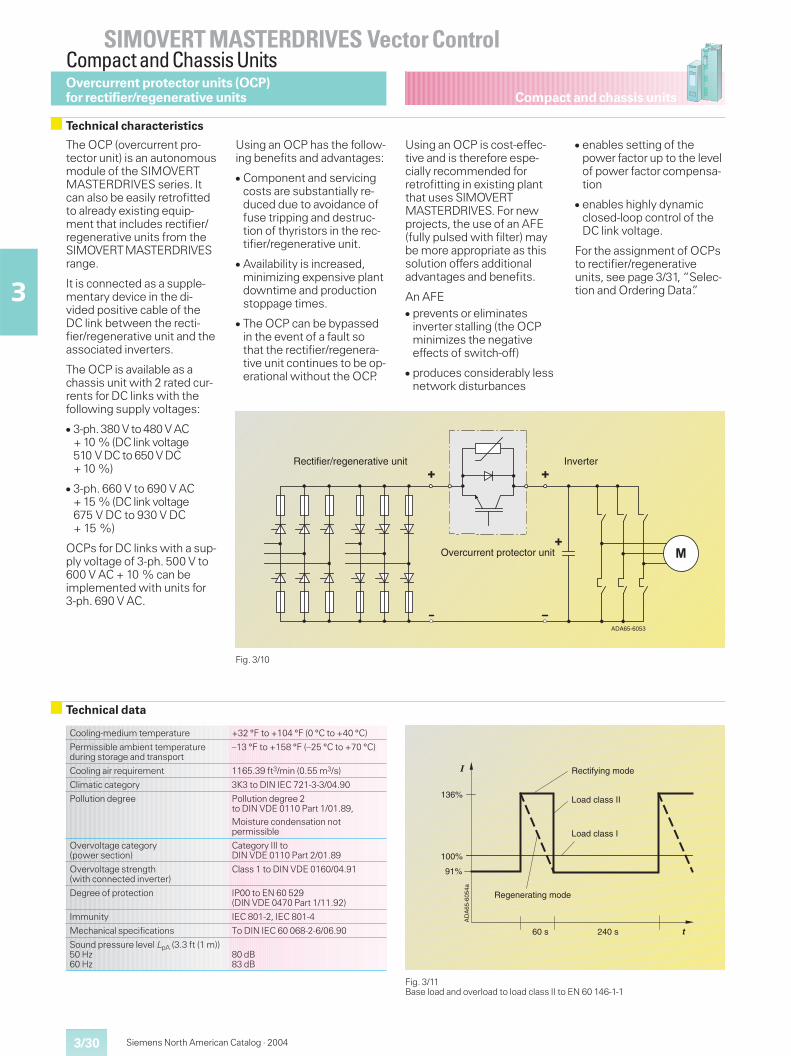
Compact and chassis units
SIMOVERT MASTERDRIVES Vector ControlCompact and Chassis Units
3/30
3
Siemens North American Catalog · 2004
The OCP (overcurrent pro-tector unit) is an autonomousmodule of the SIMOVERTMASTERDRIVES series. Itcan also be easily retrofittedto already existing equip-ment that includes rectifier/regenerative units from theSIMOVERTMASTERDRIVESrange.
It is connected as a supple-mentary device in the di-vided positive cable of theDC link between the recti-fier/regenerative unit and theassociated inverters.
The OCP is available as achassis unit with 2 rated cur-rents for DC links with thefollowing supply voltages:
� 3-ph.380 V to 480 V AC+ 10 % (DC link voltage510 V DC to 650 V DC+ 10 %)
� 3-ph. 660 V to 690 V AC+ 15 % (DC link voltage675 V DC to 930 V DC+ 15 %)
OCPs for DC links with a sup-ply voltage of 3-ph. 500 V to600 V AC + 10 % can beimplemented with units for3-ph. 690 V AC.
Using an OCP has the follow-ing benefits and advantages:
� Component and servicingcosts are substantially re-duced due to avoidance offuse tripping and destruc-tion of thyristors in the rec-tifier/regenerative unit.
� Availability is increased,minimizing expensive plantdowntime and productionstoppage times.
� The OCP can be bypassedin the event of a fault sothat the rectifier/regenera-tive unit continues to be op-erational without the OCP.
Using an OCP is cost-effec-tive and is therefore espe-cially recommended forretrofitting in existing plantthat uses SIMOVERTMASTERDRIVES. For newprojects, the use of an AFE(fully pulsed with filter) maybe more appropriate as thissolution offers additionaladvantages and benefits.
An AFE� prevents or eliminates
inverter stalling (the OCPminimizes the negativeeffects of switch-off)
� produces considerably lessnetwork disturbances
� enables setting of thepower factor up to the levelof power factor compensa-tion
� enables highly dynamicclosed-loop control of theDC link voltage.
For the assignment of OCPsto rectifier/regenerativeunits, see page 3/31, “Selec-tion and Ordering Data”.
Technical data
Cooling-medium temperature +32 °F to +104 °F (0 °C to +40 °C)
Permissible ambient temperatureduring storage and transport
–13 °F to +158 °F (–25 °C to +70 °C)
Cooling air requirement 1165.39 ft3/min (0.55 m3/s)
Climatic category 3K3 to DIN IEC 721-3-3/04.90
Pollution degree Pollution degree 2to DIN VDE 0110 Part 1/01.89,Moisture condensation notpermissible
Overvoltage category(power section)
Category III toDIN VDE 0110 Part 2/01.89
Overvoltage strength(with connected inverter)
Class 1 to DIN VDE 0160/04.91
Degree of protection IP00 to EN 60 529(DIN VDE 0470 Part 1/11.92)
Immunity IEC 801-2, IEC 801-4
Mechanical specifications To DIN IEC 60 068-2-6/06.90
Sound pressure level LpA (3.3 ft (1 m))50 Hz60 Hz
80 dB83 dB
Fig. 3/11Base load and overload to load class II to EN 60 146-1-1
Fig. 3/10
�
DA65-6053
Rectifier/regenerative unit Inverter
Overcurrent protector unit
A
100%
91%
136%
240 s60 s
DA
65-6
054a
Load class II
Load class I
Rectifying mode
Regenerating mode
A
Overcurrent protector units (OCP)for rectifier/regenerative units
Technical characteristics
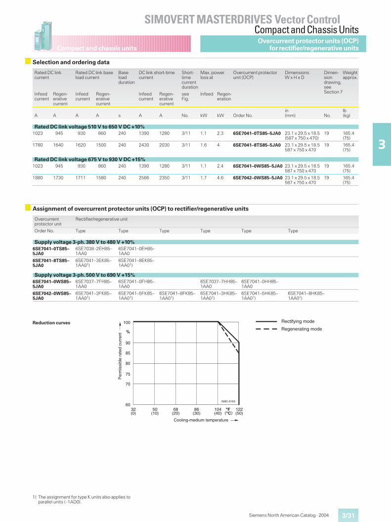
Compact and chassis units
3/31
SIMOVERT MASTERDRIVES Vector ControlCompact and Chassis Units
3
Siemens North American Catalog · 2004
Selection and ordering data
Rated DC linkcurrent
Rated DC link baseload current
Baseloadduration
DC link short-timecurrent
Short-timecurrentduration
Max. powerloss at
Overcurrent protectorunit (OCP)
DimensionsW x H x D
Dimen-siondrawing,seeSection 7
Weightapprox.
Infeedcurrent
Regen-erativecurrent
Infeedcurrent
Regen-erativecurrent
Infeedcurrent
Regen-erativecurrent
seeFig.
Infeed Regen-eration
A A A A s A A No. kW kW Order No.in(mm) No.
lb(kg)
Rated DC link voltage 510 V to 650 V DC +10%1023 945 930 860 240 1390 1280 3/11 1.1 2.3 6SE7041–0TS85–5JA0 23.1 x 29.5 x 18.5
(587 x 750 x 470)19 165.4
(75)
1780 1640 1620 1500 240 2430 2030 3/11 1.6 4 6SE7041–8TS85–5JA0 23.1 x 29.5 x 18.5587 x 750 x 470
19 165.4(75)
Rated DC link voltage 675 V to 930 V DC +15%1023 945 930 860 240 1390 1280 3/11 1.1 2.4 6SE7041–0WS85–5JA0 23.1 x 29.5 x 18.5
587 x 750 x 47019 165.4
(75)
1880 1730 1711 1580 240 2566 2350 3/11 1.7 4.6 6SE7042–0WS85–5JA0 23.1 x 29.5 x 18.5587 x 750 x 470
19 165.4(75)
Assignment of overcurrent protector units (OCP) to rectifier/regenerative units
Overcurrentprotector unit
Rectifier/regenerative unit
Order No. Type Type Type Type Type Type
Supply voltage 3-ph. 380 V to 480 V +10%6SE7041–0TS85–5JA0
6SE7038–2EH85–1AA0
6SE7041–0EH85–1AA0
6SE7041–8TS85–5JA0
6SE7041–3EK85–1AA01)
6SE7041–8EK85–1AA01)
Supply voltage 3-ph. 500 V to 690 V +15%6SE7041–0WS85–5JA0
6SE7037–7FH85–1AA0
6SE7041–0FH85–1AA0
6SE7037–7HH85–1AA0
6SE7041–0HH85–1AA0
6SE7042–0WS85–5JA0
6SE7041–3FK85–1AA01)
6SE7041–5FK85–1AA01)
6SE7041–8FK85–1AA01)
6SE7041–3HK85–1AA01)
6SE7041–5HK85–1AA01)
6SE7041–8HK85–1AA01)
Reduction curves 100
90
80
70
60
75
85
�
GMC-5163
32(0) ��
50(10)
68(20)
��������
86(30)
104(40)
122(50)
Cooling-medium temperature
Per
mis
sibl
e ra
ted
curr
ent
Rectifying mode
Regenerating mode
1) The assignment for type K units also applies toparallel units (–1AD0).
Overcurrent protector units (OCP)for rectifier/regenerative units
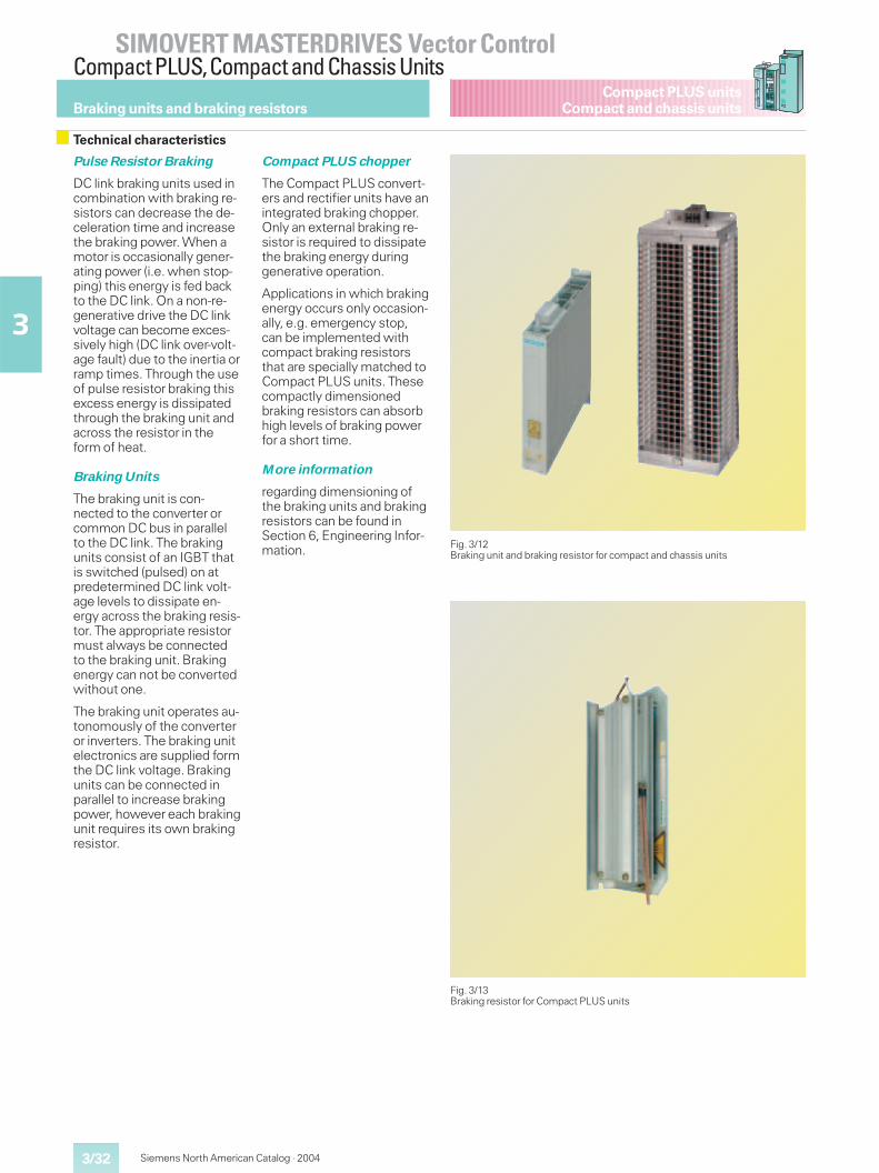
3/32
SIMOVERT MASTERDRIVES Vector ControlCompact PLUS,Compact and Chassis Units
3
Compact PLUS unitsCompact and chassis units
Siemens North American Catalog · 2004
Pulse Resistor Braking
DC link braking units used incombination with braking re-sistors can decrease the de-celeration time and increasethe braking power. When amotor is occasionally gener-ating power (i.e. when stop-ping) this energy is fed backto the DC link. On a non-re-generative drive the DC linkvoltage can become exces-sively high (DC link over-volt-age fault) due to the inertia orramp times. Through the useof pulse resistor braking thisexcess energy is dissipatedthrough the braking unit andacross the resistor in theform of heat.
Braking Units
The braking unit is con-nected to the converter orcommon DC bus in parallelto the DC link. The brakingunits consist of an IGBT thatis switched (pulsed) on atpredetermined DC link volt-age levels to dissipate en-ergy across the braking resis-tor. The appropriate resistormust always be connectedto the braking unit. Brakingenergy can not be convertedwithout one.
The braking unit operates au-tonomously of the converteror inverters. The braking unitelectronics are supplied formthe DC link voltage. Brakingunits can be connected inparallel to increase brakingpower, however each brakingunit requires its own brakingresistor.
Compact PLUS chopper
The Compact PLUS convert-ers and rectifier units have anintegrated braking chopper.Only an external braking re-sistor is required to dissipatethe braking energy duringgenerative operation.
Applications in which brakingenergy occurs only occasion-ally, e.g. emergency stop,can be implemented withcompact braking resistorsthat are specially matched toCompact PLUS units. Thesecompactly dimensionedbraking resistors can absorbhigh levels of braking powerfor a short time.
More information
regarding dimensioning ofthe braking units and brakingresistors can be found inSection 6, Engineering Infor-mation.
Braking units and braking resistors
Technical characteristics
Fig. 3/12Braking unit and braking resistor for compact and chassis units
Fig. 3/13Braking resistor for Compact PLUS units
Siemens North American Catalog · 2004 3/33
SIMOVERT MASTERDRIVES Vector ControlCompact PLUS,Compact and Chassis Units
3
Compact PLUS unitsCompact and chassis units
Rated voltage
DC link voltage 280 V DC –15 %to 340 V DC +10 %
510 V DC –15 %to 650 V DC +10 %
675 V DC –15 %to 810 V DC +10 %
890 V DC –15 %to 930 V DC +15 %
Thresholds
Upper threshold 1Lower threshold 2 NA
774 V673 V
967 V841 V
1158 V1070 V
Load class IIto EN 60 146-1-1
Rated power P20 P20 power at the upper threshold: The duration is a function of the internal or external resistor
Continuous power PDB Continuous power at the upper threshold: The value is dependent on the internal and external resistor
Short-time power P3 1.5 x P20 power at the upper threshold: The duration is a function of the internal and external resistor
Cycle time 90 s
Overload duration 20 s (22 % of the cycle time)
Braking units cannot be ordered with options.
Braking units and braking resistors
Technical data
Note: At the time of thispublication the size S and Abraking units ending in ordernumber ...–2DA0 werescheduled to be superseded.The newer type units havesmaller envelope dimen-sions and do not contain aninternal braking resistor. If anewer type unit is to replacea superseded braking unitwhich was only operatingwith the internal brakingresistor, an appropriateCompact PLUS brakingresistor can be used.
When a superseded unit isbeing replaced and signalsare connected to control ter-minal X38, then the controlterminal strip must bere-wired.Ensure the ground X38/Pin 2is connected to the groundon the receiver so the signallevel of the electronic switchis detected.
Superseded units Newer type S units
Order No. Order No.
6SE7021–6CS87–2DA0 6SE7021–6CS87–2DA1
6SE7023–2CA87–2DA0 6SE7023–2CS87–2DA1
6SE7026–3CA87–2DA0 6SE7026–3CS87–2DA1
6SE7018–0ES87–2DA0 6SE7018–0ES87–2DA1
6SE7021–6ES87–2DA0 6SE7021–6ES87–2DA1
6SE7023–2EA87–2DA0 6SE7023–2ES87–2DA1
6SE7028–0EA87–2DA0 6SE7028–0ES87–2DA1
6SE7016–4FS87–2DA0 6SE7016–4FS87–2DA1
6SE7021–3FS87–2DA0 6SE7021–3FS87–2DA1
6SE7026–4FA87–2DA0 6SE7026–4FS87–2DA1
Fig. 3/14Adapter plate 6SX7010–0KC01 is required for mounting on G-Type railfor size S newer type braking units
��
���
/�
���0��1�2!� !��"� �
������"������
Siemens North American Catalog · 20043/34
SIMOVERT MASTERDRIVES Vector ControlCompact PLUS,Compact and Chassis Units
3
Compact PLUS unitsCompact and chassis units
1) For power definition, see Section 6.
2) Permits the braking power forswitch-on application threshold = 774 V(q supply voltage 3 AC 460 V)switch-on application threshold = 967 V(q supply voltage 3 AC 575 V)switch-on application threshold = 1158 V(q supply voltage 3 AC 690 V)
3) Braking resistor in type Compact PLUS for occa-sionally incurring braking energy, e. g.emergency stop.
4) CSA rating 240 W.
5) CSA rating 720 W.
Braking units and braking resistors
Selection and ordering data
Braking resistors for Compact PLUS units
Braking power1) Braking resistor
P20 P3 PDB Resistance Cycle time T
kW kW kW � s Order No.
23) 3 0.15 200 3200 6SE7013–2ES87–2DC0
43) 6 0.34) 100 6400 6SE7016–3ES87–2DC0
5 7.5 1.25 80 90 6SE7018–0ES87–2DC0
10 15 2.5 40 90 6SE7021–6ES87–2DC0
123) 18 0.95) 33.3 6400 6SE7022–0ES87–2DC0
20 30 5 20 90 6SE7023–2ES87–2DC0
50 75 12.5 8 90 6SE7028–0ES87–2DC0
100 150 25 4 90 6SE7031–6ES87–2DC0
Braking units and braking resistors for compact and chassis units
Braking power1) Braking unit Braking resistor, external
Dimensions Weight Resist-ance2)
P20 P3 PDB W x H x D
kW kW kW Order No. in (mm) lb (kg) Order No. �
DC link voltage 280 V to 310 V DC5 7.5 1.25 6SE7021–6CS87–2DA1 1.8 x 14.2 x 9.7 (45 x 360 x 247) 6.6 (3) 6SE7021–6CS87–2DC0 20
10 15 2.5 6SE7023–2CS87–2DA1 1.8 x 14.2 x 9.7 (45 x 360 x 247) 7.3 (3.3) 6SE7023–2CS87–2DC0 10
20 30 5 6SE7026–3CS87–2DA1 1.8 x 14.2 x 9.7 (45 x 360 x 247) 9.0 (4.1) 6SE7026–3CS87–3DC0 5
DC link voltage 510 V to 650 V DC2)5 7.5 1.25 6SE7018–0ES87–2DA1 1.8 x 14.2 x 9.7 (45 x 360 x 247) 6.6 (3) 6SE7018–0ES87–2DC0 80
10 15 2.5 6SE7021–6ES87–2DA1 1.8 x 14.2 x 9.7 (45 x 360 x 247) 6.8 (3.1) 6SE7021–6ES87–2DC0 40
20 30 5 6SE7023–2ES87–2DA1 1.8 x 14.2 x 9.7 (45 x 360 x 247) 7.3 (3.3) 6SE7023–2ES87–2DC0 20
50 75 12.5 6SE7028–0ES87–2DA1 1.8 x 14.2 x 9.7 (45 x 360 x 247) 9.0 (4.1) 6SE7028–0ES87–2DC0 8
100 150 25 6SE7031–6EB87–2DA0 5.3 x 16.7 x 13.8 (135 x 425 x 350) 9.7 (18) 6SE7031–6ES87–2DC0 4
170 255 42.5 6SE7032–7EB87–2DA0 5.3 x 16.7 x 13.8 (135 x 425 x 350) 39.7 (18) 6SE7032–7ES87–2DC0 2.35
DC link voltage 675 V to 810 V DC2)5 7.5 1.25 6SE7016–4FS87–2DA1 1.8 x 14.2 x 9.7 (45 x 360 x 247) 6.6 (3) 6SE7016–4FS87–2DC0 124
10 15 2.5 6SE7021–3FS87–2DA1 1.8 x 14.2 x 9.7 (45 x 360 x 247) 6.8 (3.1) 6SE7021–3FS87–2DC0 62
50 75 12.5 6SE7026–4FS87–2DA1 1.8 x 14.2 x 9.7 (45 x 360 x 247) 9.0 (4.1) 6SE7026–4FS87–2DC0 12.4
100 150 25 6SE7031–3FB87–2DA0 5.3 x 16.7 x 13.8 (135 x 425 x 350) 39.7 (18) 6SE7031–3FS87–2DC0 6.2
200 300 50 6SE7032–5FB87–2DA0 5.3 x 16.7 x 13.8 (135 x 425 x 350) 39.7 (18) 6SE7032–5FS87–2DC0 3.1
DC link voltage 890 V to 930 V DC2)50 75 12.5 6SE7025–3HS87–2DA1 1.8 x 14.2 x 9.7 (45 x 360 x 247) 9.0 (4.1) 6SE7025–3HS87–2DC0 17.8
200 300 50 6SE7032–1HB87–2DA0 5.3 x 16.7 x 13.8 (135 x 425 x 350) 39.7 (18) 6SE7032–1HS87–2DC0 4.45
See Section 6 for information on paralleling braking units for additional braking capacity.
Siemens North American Catalog · 2004 3/35
SIMOVERT MASTERDRIVES Vector ControlCompact PLUS,Compact and Chassis Units
3
Compact PLUS unitsCompact and chassis units Braking units and braking resistors
recommended for connection to converter recommended for connection to rectifier unit
Dimensions Weight Dimen-siondrawing,seeSection 7
W x H x D
in (mm) lb (kg) No.
1.7 x 9.8 x 4.7 (44 x 250 x 120) 3.1 (1.4) 23 6SE7011–5EP60; 6SE7013–0EP60;6SE7015–0EP60
1.7 x 9.8 x 4.7 (44 x 250 x 120) 4.2 (1.9) 23 6SE7018–0EP60; 6SE7021–0EP60
5.7 x 7.1 x 21.2 (145 x 180 x 540) 13.2 (6) 24 6SE7011–5EP60; 6SE7013–0EP60;6SE7015–0EP60
5.7 x 14.2 x 21.2 (145 x 360 x 540) 26.5 (12) 24 6SE7018–0EP60; 6SE7021–0EP60
5.3 x 13.8 x 8.0 (134 x 350 x 203) 15.0 (6.8) 25 6SE7021–4EP60; 6SE7022–1EP60
17.7 x 12.0 x 19.1 (450 x 305 x 485) 37.5 (17) 26 6SE7021–4EP60; 6SE7022–1EP60;6SE7022–7EP60; 6SE7023–4EP60
6SE7024–1EP85–0AA0
29.3 x 12.0 x 19.1 (745 x 305 x 485) 59.5 (27) 26 6SE7031–2EP85–0AA0
29.3 x 23.8 x 19.1 (745 x 605 x 485) 103.6 (47) 27 6SE7032–3EP85–0AA0
Power connections: Terminals Power connections: Lugs
Dimensions Weight Dimen-siondrawing,seeSection 7
DC voltage: TopExternal resistor: Bottom
DC voltage: TopExternal resistor: Bottom
Connectable cable cross-section Cable cross-section Retaining bolt
W x H x D Finely stranded Single- andmulti-stranded
in (mm) lb (kg) No. AWG (mm2) AWG (mm2) AWG (mm2)
5.7 x 7.1 x 21.2 (145 x 180 x 540) 13.2 (6) 20; 24 16 to 6 (1.5 to 16) 16 to 6 (1.5 to 16) – – –
5.7 x 14.2 x 21.2 (145 x 360 x 540) 25.4 (11.5) 20; 24 16 to 6 (1.5 to 16) 16 to 6 (1.5 to 16) – – –
16.9 x 12.0 x 19.1 (430 x 305 x 485) 37.5 (17) 20; 26 16 to 6 (1.5 to 16) 16 to 6 (1.5 to 16) – – –
5.7 x 7.1 x 21.2 (145 x 180 x 540) 13.2 (6) 20; 24 16 to 6 (1.5 to 16) 16 to 6 (1.5 to 16) – – –
5.7 x 14.2 x 21.2 (145 x 360 x 540) 25.4 (11.5) 20; 24 16 to 6 (1.5 to 16) 16 to 6 (1.5 to 16) – – –
16.9 x 12.0 x 19.1 (430 x 305 x 485) 37.5 (17) 20; 26 16 to 6 (1.5 to 16) 16 to 6 (1.5 to 16) – – –
29.1 x 12.0 x 19.1 (740 x 305 x 485) 59.5 (27) 20; 26 16 to 6 (1.5 to 16) 16 to 6 (1.5 to 16) – – –
29.1 x 23.8 x 19.1 (740 x 605 x 485) 103.6 (47) 22; 27 – – – – max. 1 x 3/0 (max. 1 x 95) M 8
29.1 x 52.2 x 19.1 (740 x 1325 x 485) 227.1 (103) 22; 28 – – – max. 1 x 3/0 (max. 1 x 95) M 8
5.7 x 7.1 x 21.2 (145 x 180 x 540) 13.2 (6) 20; 24 16 to 6 (1.5 to 16) 16 to 6 (1.5 to 16) – – –
5.7 x 14.2 x 21.2 (145 x 360 x 540) 25.4 (11.5) 20; 24 16 to 6 (1.5 to 16) 16 to 6 (1.5 to 16) – – –
29.1 x 12.0 x 19.1 (740 x 305 x 485) 59.5 (27) 20; 26 16 to 6 (1.5 to 16) 16 to 6 (1.5 to 16) – – –
29.1 x 23.8 x 19.1 (740 x 605 x 485) 94.8 (43) 22; 27 – – – – max. 1 x 3/0 (max. 1 x 95) M 8
29.1 x 52.2 x 19.1 (740 x 1325 x 485) 209.5 (95) 22; 28 – – – – max. 1 x 3/0 (max. 1 x 95) M 8
29.1 x 12.0 x 19.1 (740 x 305 x 485) 61.7 (28) 20; 26 16 to 6 (1.5 to 16) 16 to 6 (1.5 to 16) – – –
29.1 x 52.2 x 19.1 (740 x 1325 x 485) 222.7 (101) 22; 28 – – – – max. 1 x 3/0 (max. 1 x 95) M 8
3/36
SIMOVERT MASTERDRIVES Vector ControlCompact PLUS,Compact and Chassis Units
3
Compact PLUS unitsCompact and chassis units
Siemens North American Catalog · 2004
Line fuses
The 3NE1 SITORr fuse pro-tects both cables and semi-conductors in one fuse. Thisresults in considerable costsavings and shorter installa-tion times.
For Order No. and equipmentassignments, see page 3/38onwards.
Input line reactor
The input line reactor re-duces the harmonic currentsand the commutating dips ofthe converters, rectifier unitsand rectifier/regenerativeunits. The effect of the reac-tor depends on the ratio ofthe system fault power tothe drive’s power.
Recommendation for theratio of system fault powerto drive’s power > 33 : 1:
� A 2 – 3 % input line reactorshould be used for conver-ters and rectifier units.
� A 4 – 5 % input line reactoris recommended for recti-fier/regenerative units.
For Order No. and equipmentassignments, see page 3/38onwards.
An input line reactor alsolimits current peaks causedby potential dips of thesupply voltage (e.g. due tocompensation equipment orground faults).
Autotransformer for therectifier/regenerativeunits
In regenerating mode, recti-fier/regenerative units needa 20 % higher supply voltageat the antiparallel inverterbridge. The voltage can bestepped up using an auto-transformer. The autotrans-formers are rated for 100 %duty cycle. They comply withthe necessary technical re-quirements and cannot bereplaced by any other type.
For Order No. and equipmentassignments, see page 3/65.
For dimensions, see Sec-tion 7.
Radio-interferencesuppression filters (linefilters)
For power ratings of up to50 HP (37 kW), the line filtersreduce the interference volt-ages produced by converter,rectifier and rectifier/regen-erative units to the limits per-missible for residential sup-ply systems according toEN 55 011, Class B1. Thesefilters also comply to thelimit values for Class A1.
For units with larger outputratings, the line filters reducethe radio-interference volt-ages of the converters, recti-fier units and rectifier/regen-erative units to the limits ap-plicable to industrial supplysystems.
For Order No. and equipmentassignments, see page 3/38onwards.
For dimensions, see Sec-tion 7.
The radio-interference sup-pression filters with OrderNo. 6SE70 can be used for amaximum supply voltage of3-ph. 480 V AC and with TTand TN power systems(earthed systems) only.
The radio-interference sup-pression filters with OrderNo. B84143 are available fora supply voltage of up to3-ph. 690 V AC. Their use inTT, TN or IT systems (insu-lated systems) must be indi-cated by the order numbersupplement.
For IT systems, these filterscan also be used in the 3-ph.380 V to 480 V AC as well asin the 3-ph. 500 V to600 V AC voltage range.
Notes regarding use offilters
� The limit values in the caseof converters, rectifier unitsand rectifier/regenerativeunits are complied withonly in conjunction with aninput line reactor of 2 – 5 %vK. The input line reactorsare to be mounted in ametal cabinet.
� Line filters for earthed andnon-earthed systems areavailable.The concept of a non-earthed system is violatedby use of a radio-interfer-ence suppression filter. Formore information, see theEMC product standard,EN 61 800-3.The use of a radio-interfer-ence suppression filter ina non-earthed system istherefore only a compro-mise between radio-inter-ference suppression andinterference-free operationwhen an earth fault occurs.
� In the case of units of sizesA to D, a connecting adap-ter for cable shields is to beused, see page 3/67.
� For the use of power cablefor motor connection, seepage 3/72.
� The cabinet design, theequipment layout and thewiring are to be carried outin accordance with EMCguidelines.
Information
For installation of SIMOVERTMASTERDRIVES accordingto EMC guidelines, see page6/45.
Technical characteristics of line-side components
System components
Siemens North American Catalog · 2004 3/37
SIMOVERT MASTERDRIVES Vector ControlCompact PLUS,Compact and Chassis Units
3
Compact PLUS unitsCompact and chassis units
Components forconnecting inverters andbraking units
The inverters and brakingunits can be connected tothe DC bus in three ways:
1. Direct connection
As standard, the neces-sary fuses are integratedin the inverters, except forinverters sizes E to G (inte-grated fuses for theseunits available with optioncode L30), see page 3/89.
2. Electromechanical con-nection
The electromechanicalconnection consists of afuse switch disconnector,with fuses or disconnectorlugs.
Note:This connection must notbe activated with a livesystem.
3. Electrical connection
The electrical connectionbasically consists of fuseswitch disconnectors,precharging resistors, aprecharging contactor anda connecting contactor.
With Compact PLUS units,the DC links are connectedby means of a special con-necting system. There are nofurther components requiredexcept for the 0.1 x 0.4 in(3 x 10 mm) buses (Cu tinnedto DIN 46 433).
For Engineering Information,see Section 6.
For selection and orderingdata of the components, seepage 3/48 onwards.
Free-wheeling diode
The free-wheeling diode pre-vents consequential damageto braking units and loweroutput rating inverters whenthe DC fuses on a higherpower rating inverter blow orwhen, with a rectifier/regen-erative unit, the fuses blowin the event of commutationfailure.
For Engineering Information,see Section 6.
Technical characteristics of DC link components
System components
Output reactors
Output reactors compensatecapacitive charging/discharg-ing currents when long mo-tor cables are connected andlimit the dv/dt at the motorterminals.
For the maximum cablelengths which can beconnected with and withoutreactors, see page 6/49.
Voltage limitation filters(output dv/dt filters)
Voltage limitation filters areto be used together withmotors where the dielectricstrength of the insulatingsystem is unknown or insuffi-cient.
Sine filters
The use of sine filtersensures that the motors aresupplied with a practicallysinusoidal voltage andcurrent waveform. Thedistortion factor for a motorvoltage frequency of 60 Hzwith a sine filter is approxi-mately 5 %. The stress onthe motors which are sup-plied via sine filters is belowthe level according to DINVDE 0530.
Technical characteristics of load-side components and cables
Engineering Information
On the load-side compo-nents, see Section 6.
For selection and orderingdata, see page 3/38 andonwards.
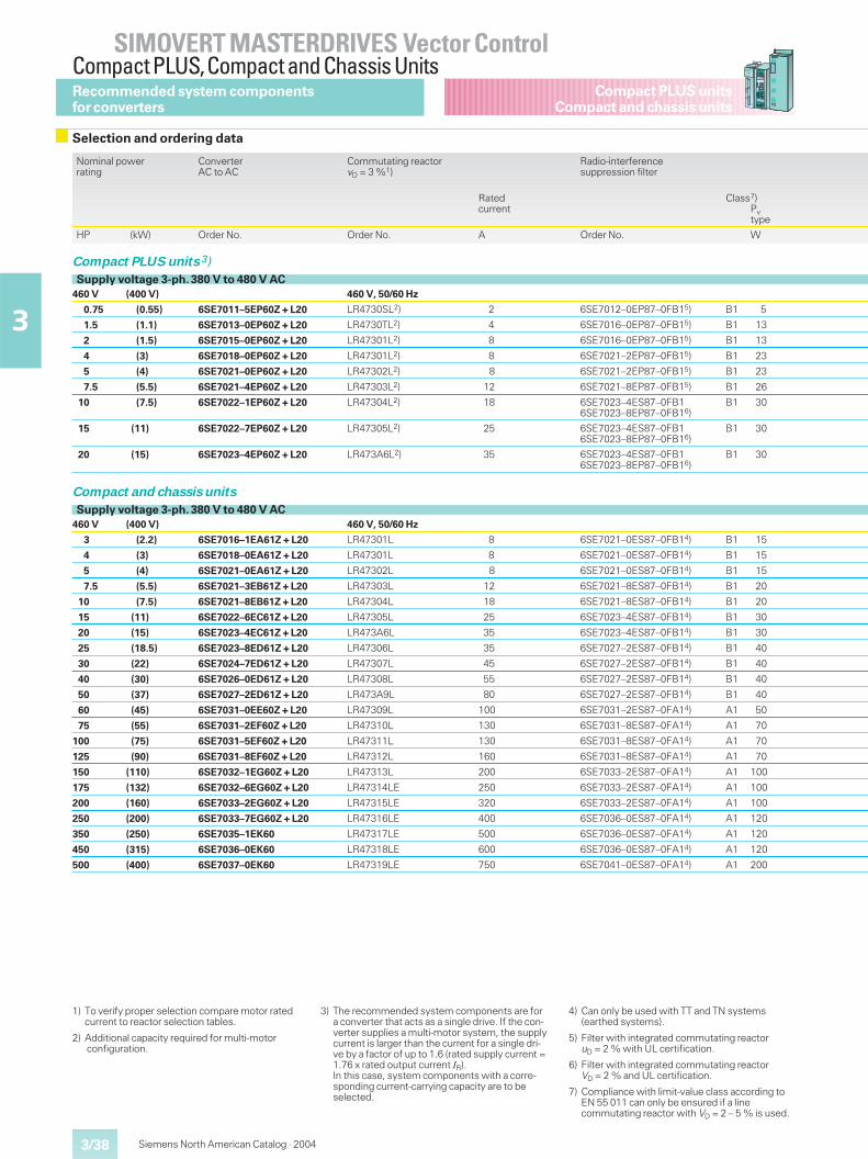
3/38
SIMOVERT MASTERDRIVES Vector ControlCompact PLUS,Compact and Chassis Units
3
Compact PLUS unitsCompact and chassis units
Siemens North American Catalog · 2004
1) To verify proper selection compare motor ratedcurrent to reactor selection tables.
2) Additional capacity required for multi-motorconfiguration.
3) The recommended system components are fora converter that acts as a single drive. If the con-verter supplies a multi-motor system, the supplycurrent is larger than the current for a single dri-ve by a factor of up to 1.6 (rated supply current =1.76 x rated output current IR).In this case, system components with a corre-sponding current-carrying capacity are to beselected.
4) Can only be used with TT and TN systems(earthed systems).
5) Filter with integrated commutating reactoruD = 2 % with UL certification.
6) Filter with integrated commutating reactorVD = 2 % and UL certification.
7) Compliance with limit-value class according toEN 55 011 can only be ensured if a linecommutating reactor with VD = 2 – 5 % is used.
Recommended system componentsfor converters
Selection and ordering data
Nominal powerrating
ConverterAC to AC
Commutating reactorvD = 3 %1)
Radio-interferencesuppression filter
Ratedcurrent
Class7)Pvtype
HP (kW) Order No. Order No. A Order No. W
Compact PLUS units 3)Supply voltage 3-ph. 380 V to 480 V AC
460 V (400 V) 460 V, 50/60 Hz
0.75 (0.55) 6SE7011–5EP60Z + L20 LR4730SL2) 2 6SE7012–0EP87–0FB15) B1 5
1.5 (1.1) 6SE7013–0EP60Z + L20 LR4730TL2) 4 6SE7016–0EP87–0FB15) B1 13
2 (1.5) 6SE7015–0EP60Z + L20 LR47301L2) 8 6SE7016–0EP87–0FB15) B1 13
4 (3) 6SE7018–0EP60Z + L20 LR47301L2) 8 6SE7021–2EP87–0FB15) B1 23
5 (4) 6SE7021–0EP60Z + L20 LR47302L2) 8 6SE7021–2EP87–0FB15) B1 23
7.5 (5.5) 6SE7021–4EP60Z + L20 LR47303L2) 12 6SE7021–8EP87–0FB15) B1 26
10 (7.5) 6SE7022–1EP60Z + L20 LR47304L2) 18 6SE7023–4ES87–0FB16SE7023–8EP87–0FB16)
B1 30
15 (11) 6SE7022–7EP60Z + L20 LR47305L2) 25 6SE7023–4ES87–0FB16SE7023–8EP87–0FB16)
B1 30
20 (15) 6SE7023–4EP60Z + L20 LR473A6L2) 35 6SE7023–4ES87–0FB16SE7023–8EP87–0FB16)
B1 30
Compact and chassis units
Supply voltage 3-ph. 380 V to 480 V AC460 V (400 V) 460 V, 50/60 Hz
3 (2.2) 6SE7016–1EA61Z + L20 LR47301L 8 6SE7021–0ES87–0FB14) B1 15
4 (3) 6SE7018–0EA61Z + L20 LR47301L 8 6SE7021–0ES87–0FB14) B1 15
5 (4) 6SE7021–0EA61Z + L20 LR47302L 8 6SE7021–0ES87–0FB14) B1 15
7.5 (5.5) 6SE7021–3EB61Z + L20 LR47303L 12 6SE7021–8ES87–0FB14) B1 20
10 (7.5) 6SE7021–8EB61Z + L20 LR47304L 18 6SE7021–8ES87–0FB14) B1 20
15 (11) 6SE7022–6EC61Z + L20 LR47305L 25 6SE7023–4ES87–0FB14) B1 30
20 (15) 6SE7023–4EC61Z + L20 LR473A6L 35 6SE7023–4ES87–0FB14) B1 30
25 (18.5) 6SE7023–8ED61Z + L20 LR47306L 35 6SE7027–2ES87–0FB14) B1 40
30 (22) 6SE7024–7ED61Z + L20 LR47307L 45 6SE7027–2ES87–0FB14) B1 40
40 (30) 6SE7026–0ED61Z + L20 LR47308L 55 6SE7027–2ES87–0FB14) B1 40
50 (37) 6SE7027–2ED61Z + L20 LR473A9L 80 6SE7027–2ES87–0FB14) B1 40
60 (45) 6SE7031–0EE60Z + L20 LR47309L 100 6SE7031–2ES87–0FA14) A1 50
75 (55) 6SE7031–2EF60Z + L20 LR47310L 130 6SE7031–8ES87–0FA14) A1 70
100 (75) 6SE7031–5EF60Z + L20 LR47311L 130 6SE7031–8ES87–0FA14) A1 70
125 (90) 6SE7031–8EF60Z + L20 LR47312L 160 6SE7031–8ES87–0FA14) A1 70
150 (110) 6SE7032–1EG60Z + L20 LR47313L 200 6SE7033–2ES87–0FA14) A1 100
175 (132) 6SE7032–6EG60Z + L20 LR47314LE 250 6SE7033–2ES87–0FA14) A1 100
200 (160) 6SE7033–2EG60Z + L20 LR47315LE 320 6SE7033–2ES87–0FA14) A1 100
250 (200) 6SE7033–7EG60Z + L20 LR47316LE 400 6SE7036–0ES87–0FA14) A1 120
350 (250) 6SE7035–1EK60 LR47317LE 500 6SE7036–0ES87–0FA14) A1 120
450 (315) 6SE7036–0EK60 LR47318LE 600 6SE7036–0ES87–0FA14) A1 120
500 (400) 6SE7037–0EK60 LR47319LE 750 6SE7041–0ES87–0FA14) A1 200
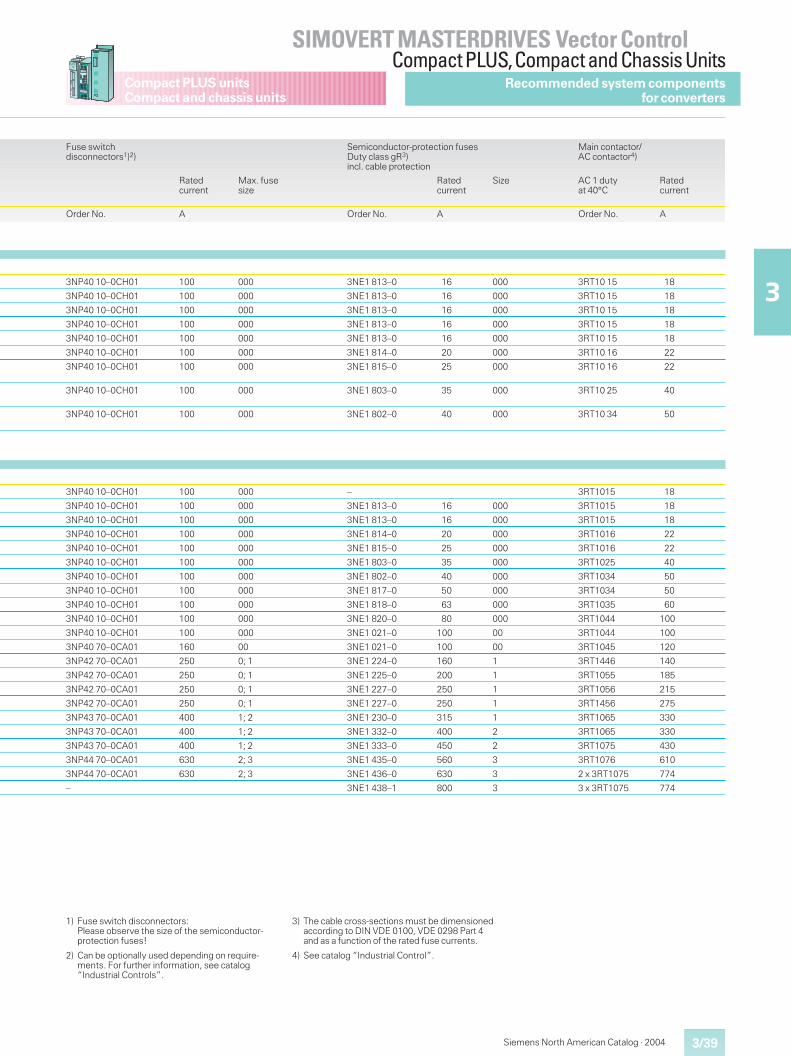
3/39
SIMOVERT MASTERDRIVES Vector ControlCompact PLUS,Compact and Chassis Units
3
Compact PLUS unitsCompact and chassis units
Siemens North American Catalog · 2004
1) Fuse switch disconnectors:Please observe the size of the semiconductor-protection fuses!
2) Can be optionally used depending on require-ments. For further information, see catalog“Industrial Controls”.
3) The cable cross-sections must be dimensionedaccording to DIN VDE 0100, VDE 0298 Part 4and as a function of the rated fuse currents.
4) See catalog “Industrial Control”.
Recommended system componentsfor converters
Fuse switchdisconnectors1)2)
Semiconductor-protection fusesDuty class gR3)incl. cable protection
Main contactor/AC contactor4)
Ratedcurrent
Max. fusesize
Ratedcurrent
Size AC 1 dutyat 40°C
Ratedcurrent
Order No. A Order No. A Order No. A
3NP40 10–0CH01 100 000 3NE1 813–0 16 000 3RT10 15 18
3NP40 10–0CH01 100 000 3NE1 813–0 16 000 3RT10 15 18
3NP40 10–0CH01 100 000 3NE1 813–0 16 000 3RT10 15 18
3NP40 10–0CH01 100 000 3NE1 813–0 16 000 3RT10 15 18
3NP40 10–0CH01 100 000 3NE1 813–0 16 000 3RT10 15 18
3NP40 10–0CH01 100 000 3NE1 814–0 20 000 3RT10 16 22
3NP40 10–0CH01 100 000 3NE1 815–0 25 000 3RT10 16 22
3NP40 10–0CH01 100 000 3NE1 803–0 35 000 3RT10 25 40
3NP40 10–0CH01 100 000 3NE1 802–0 40 000 3RT10 34 50
3NP40 10–0CH01 100 000 – 3RT1015 18
3NP40 10–0CH01 100 000 3NE1 813–0 16 000 3RT1015 18
3NP40 10–0CH01 100 000 3NE1 813–0 16 000 3RT1015 18
3NP40 10–0CH01 100 000 3NE1 814–0 20 000 3RT1016 22
3NP40 10–0CH01 100 000 3NE1 815–0 25 000 3RT1016 22
3NP40 10–0CH01 100 000 3NE1 803–0 35 000 3RT1025 40
3NP40 10–0CH01 100 000 3NE1 802–0 40 000 3RT1034 50
3NP40 10–0CH01 100 000 3NE1 817–0 50 000 3RT1034 50
3NP40 10–0CH01 100 000 3NE1 818–0 63 000 3RT1035 60
3NP40 10–0CH01 100 000 3NE1 820–0 80 000 3RT1044 100
3NP40 10–0CH01 100 000 3NE1 021–0 100 00 3RT1044 100
3NP40 70–0CA01 160 00 3NE1 021–0 100 00 3RT1045 120
3NP42 70–0CA01 250 0; 1 3NE1 224–0 160 1 3RT1446 140
3NP42 70–0CA01 250 0; 1 3NE1 225–0 200 1 3RT1055 185
3NP42 70–0CA01 250 0; 1 3NE1 227–0 250 1 3RT1056 215
3NP42 70–0CA01 250 0; 1 3NE1 227–0 250 1 3RT1456 275
3NP43 70–0CA01 400 1; 2 3NE1 230–0 315 1 3RT1065 330
3NP43 70–0CA01 400 1; 2 3NE1 332–0 400 2 3RT1065 330
3NP43 70–0CA01 400 1; 2 3NE1 333–0 450 2 3RT1075 430
3NP44 70–0CA01 630 2; 3 3NE1 435–0 560 3 3RT1076 610
3NP44 70–0CA01 630 2; 3 3NE1 436–0 630 3 2 x 3RT1075 774
– 3NE1 438–1 800 3 3 x 3RT1075 774
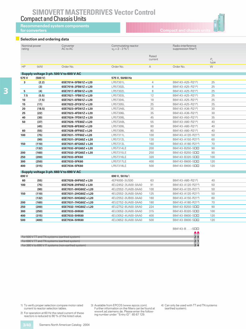
Compact and chassis units
SIMOVERT MASTERDRIVES Vector ControlCompact and Chassis Units
3/40
3
Siemens North American Catalog · 2004
Nominal powerrating
ConverterAC to AC
Commutating reactorvD = 2 – 3 %1)
Radio-interferencesuppression filter3)
Ratedcurrent Pv
type
HP (kW) Order No. Order No. A Order No. W
Supply voltage 3-ph. 500 V to 600 V AC575 V (500 V) 575 V, 50/60 Hz
3 (2.2) 6SE7014–5FB61Z + L20 LR57301L 4 B84143–A25–R214) 25
(3) 6SE7016–2FB61Z + L20 LR57302L 8 B84143–A25–R214) 25
5 (4) 6SE7017–8FB61Z + L20 LR57302L 8 B84143–A25–R214) 25
7.5 (5.5) 6SE7021–1FB61Z + L20 LR57303L 12 B84143–A25–R214) 25
10 (7.5) 6SE7021–5FB61Z + L20 LR57304L 18 B84143–A25–R214) 25
15 (11) 6SE7022–2FC61Z + L20 LR57305L 25 B84143–A25–R214) 25
20 (18.5) 6SE7023–0FD61Z + L20 LR573A6L 35 B84143–A36–R214) 30
25 (22) 6SE7023–4FD61Z + L20 LR57306L 35 B84143–A36–R214) 30
40 (30) 6SE7024–7FD61Z + L20 LR57308L 45 B84143–A50–R214) 35
50 (37) 6SE7026–1FE60Z + L20 LR573A9L 55 B84143–A80–R214) 40
(45) 6SE7026–6FE60Z + L20 LR57309L 80 B84143–A80–R214) 40
60 (55) 6SE7028–0FF60Z + L20 LR57309L 80 B84143–A80–R214) 40
100 (75) 6SE7031–1FF60Z + L20 LR57311L 100 B84143–A120–R214) 50
(90) 6SE7031–3FG60Z + L20 LR57312L 130 B84143–A150–R214) 60
150 (110) 6SE7031–6FG60Z + L20 LR57313L 160 B84143–A180–R214) 70
(132) 6SE7032–0FG60Z + L20 LR57314LE 200 B84143–B250–S@@ 90
200 (160) 6SE7032–3FG60Z + L20 LR57315LE 250 B84143–B250–S@@ 90
250 (200) 6SE7033–0FK60 LR57316LE 320 B84143–B320–S@@ 100
300 (250) 6SE7033–5FK60 LR57317LE 400 B84143–B600–S@@ 120
400 (315) 6SE7034–5FK60 LR57318LE 500 B84143–B600–S@@ 120
Supply voltage 3-ph. 660 V to 690 V AC690 V 690 V, 50 Hz2)
60 (55) 6SE7026–0HF60Z + L20 4EP4000–3US00 63 B84143–A80–R214) 40
100 (75) 6SE7028–2HF60Z + L20 4EU2452–3UA00–0AA0 91 B84143–A120–R214) 50
(90) 6SE7031–0HG60Z + L20 4EU2552–7UA00–0AA0 100 B84143–A120–R214) 50
150 (110) 6SE7031–2HG60Z + L20 4EU2552–3UA00–0AA0 125 B84143–A120–R214) 50
(132) 6SE7031–5HG60Z + L20 4EU2552–0UB00–0AA0 160 B84143–A150–R214) 60
200 (160) 6SE7031–7HG60Z + L20 4EU2752–5UA00–0AA0 180 B84143–A180–R214) 70
250 (200) 6SE7032–1HG60Z + L20 4EU2752–6UA00–0AA0 224 B84143–B250–S@@ 90
300 (250) 6SE7033–0HK60 4EU3052–3UA00–0AA0 315 B84143–B320–S@@ 100
400 (315) 6SE7033–5HK60 4EU3052–4UA00–0AA0 400 B84143–B600–S@@ 120
500 (400) 6SE7034–5HK60 4EU3652–5UA00–0AA0 500 B84143–B600–S@@ 120
B84143–B . . . –S@@��
For 500 V TT and TN systems (earthed system) 2 0
For 690 V TT and TN systems (earthed system) 2 1
For 380 V to 690 V IT systems (non-earthed system) 2 4
1) To verify proper selection compare motor ratedcurrent to reactor selection tables.
2) For operation at 60 Hz the rated current of thesereactors is reduced to 90 % of the listed value.
3) Available from EPCOS (www.epcos.com).Further information on the filters can be found atwww4.ad.siemens.de. Please enter the follow-ing number under “Entry ID”: 65 67 129.
4) Can only be used with TT and TN systems(earthed system).
Recommended system componentsfor converters
Selection and ordering data
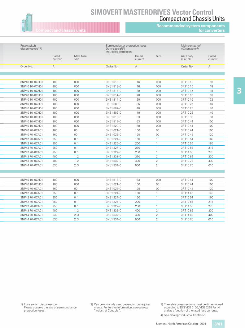
Compact and chassis units
3/41
SIMOVERT MASTERDRIVES Vector ControlCompact and Chassis Units
3
Siemens North American Catalog · 2004
1) Fuse switch disconnectors:Please observe the size of semiconductor-protection fuses!
2) Can be optionally used depending on require-ments. For further information, see catalog“Industrial Controls”.
3) The cable cross-sections must be dimensionedaccording to DIN VDE 0100, VDE 0298 Part 4and as a function of the rated fuse currents.
4) See catalog “Industrial Controls”.
Fuse switchdisconnectors1)2)
Semiconductor-protection fusesDuty class gR3)incl. cable protection
Main contactor/AC contactor4)
Ratedcurrent
Max. fusesize
Ratedcurrent
Size AC 1 dutyat 40 °C
Ratedcurrent
Order No. A Order No. A Order No. A
3NP40 10–0CH01 100 000 3NE1 813–0 16 000 3RT10 15 18
3NP40 10–0CH01 100 000 3NE1 813–0 16 000 3RT10 15 18
3NP40 10–0CH01 100 000 3NE1 814–0 20 000 3RT10 15 18
3NP40 10–0CH01 100 000 3NE1 814–0 20 000 3RT10 15 18
3NP40 10–0CH01 100 000 3NE1 814–0 20 000 3RT10 16 22
3NP40 10–0CH01 100 000 3NE1 803–0 35 000 3RT10 25 40
3NP40 10–0CH01 100 000 3NE1 802–0 40 000 3RT10 25 40
3NP40 10–0CH01 100 000 3NE1 802–0 40 000 3RT10 25 40
3NP40 10–0CH01 100 000 3NE1 818–0 63 000 3RT10 35 60
3NP40 10–0CH01 100 000 3NE1 818–0 63 000 3RT10 44 100
3NP40 10–0CH01 100 000 3NE1 820–0 80 000 3RT10 44 100
3NP40 70–0CA01 160 00 3NE1 021–0 100 00 3RT10 44 100
3NP40 70–0CA01 160 00 3NE1 022–0 125 00 3RT10 45 120
3NP42 70–0CA01 250 0; 1 3NE1 224–0 160 1 3RT10 54 160
3NP42 70–0CA01 250 0; 1 3NE1 225–0 200 1 3RT10 55 185
3NP42 70–0CA01 250 0; 1 3NE1 227–0 250 1 3RT10 56 215
3NP42 70–0CA01 250 0; 1 3NE1 227–0 250 1 3RT14 56 275
3NP43 70–0CA01 400 1; 2 3NE1 331–0 350 2 3RT10 65 330
3NP43 70–0CA01 400 1; 2 3NE1 332–0 400 2 3RT10 75 430
3NP44 70–0CA01 630 2; 3 3NE1 334–0 500 2 3RT10 75 610
3NP40 10–0CH01 100 000 3NE1 818–0 63 000 3RT10 44 100
3NP40 10–0CH01 100 000 3NE1 021–0 100 00 3RT10 44 100
3NP40 70–0CA01 160 00 3NE1 022–0 125 00 3RT10 45 120
3NP42 70–0CA01 250 0; 1 3NE1 224–0 160 1 3RT14 46 140
3NP42 70–0CA01 250 0; 1 3NE1 224–0 160 1 3RT10 54 160
3NP42 70–0CA01 250 0; 1 3NE1 225–0 200 1 3RT10 56 215
3NP42 70–0CA01 250 0; 1 3NE1 227–0 250 1 3RT14 56 275
3NP43 70–0CA01 400 1; 2 3NE1 332–0 400 2 3RT10 65 330
3NP44 70–0CA01 630 2; 3 3NE1 332–0 400 2 3RT14 66 400
3NP44 70–0CA01 630 2; 3 3NE1 334–0 500 2 3RT10 76 610
Recommended system componentsfor converters
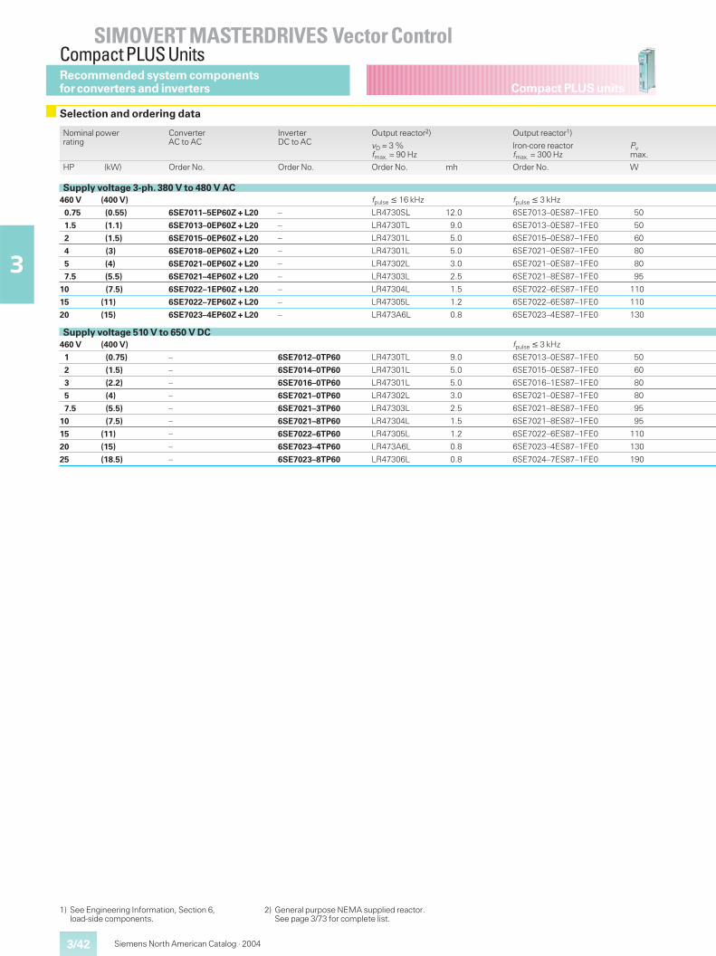
3/42
SIMOVERT MASTERDRIVES Vector ControlCompact PLUS Units
3
Compact PLUS units
Siemens North American Catalog · 2004
Recommended system componentsfor converters and inverters
Selection and ordering data
Nominal powerrating
ConverterAC to AC
InverterDC to AC
Output reactor2) Output reactor1)
vD = 3 %fmax. = 90 Hz
Iron-core reactorfmax. = 300 Hz
Pvmax.
HP (kW) Order No. Order No. Order No. mh Order No. W
Supply voltage 3-ph. 380 V to 480 V AC460 V (400 V) fpulse � 16 kHz fpulse � 3 kHz
0.75 (0.55) 6SE7011–5EP60Z + L20 – LR4730SL 12.0 6SE7013–0ES87–1FE0 50
1.5 (1.1) 6SE7013–0EP60Z + L20 – LR4730TL 9.0 6SE7013–0ES87–1FE0 50
2 (1.5) 6SE7015–0EP60Z + L20 – LR47301L 5.0 6SE7015–0ES87–1FE0 60
4 (3) 6SE7018–0EP60Z + L20 – LR47301L 5.0 6SE7021–0ES87–1FE0 80
5 (4) 6SE7021–0EP60Z + L20 – LR47302L 3.0 6SE7021–0ES87–1FE0 80
7.5 (5.5) 6SE7021–4EP60Z + L20 – LR47303L 2.5 6SE7021–8ES87–1FE0 95
10 (7.5) 6SE7022–1EP60Z + L20 – LR47304L 1.5 6SE7022–6ES87–1FE0 110
15 (11) 6SE7022–7EP60Z + L20 – LR47305L 1.2 6SE7022–6ES87–1FE0 110
20 (15) 6SE7023–4EP60Z + L20 – LR473A6L 0.8 6SE7023–4ES87–1FE0 130
Supply voltage 510 V to 650 V DC460 V (400 V) fpulse � 3 kHz
1 (0.75) – 6SE7012–0TP60 LR4730TL 9.0 6SE7013–0ES87–1FE0 50
2 (1.5) – 6SE7014–0TP60 LR47301L 5.0 6SE7015–0ES87–1FE0 60
3 (2.2) – 6SE7016–0TP60 LR47301L 5.0 6SE7016–1ES87–1FE0 80
5 (4) – 6SE7021–0TP60 LR47302L 3.0 6SE7021–0ES87–1FE0 80
7.5 (5.5) – 6SE7021–3TP60 LR47303L 2.5 6SE7021–8ES87–1FE0 95
10 (7.5) – 6SE7021–8TP60 LR47304L 1.5 6SE7021–8ES87–1FE0 95
15 (11) – 6SE7022–6TP60 LR47305L 1.2 6SE7022–6ES87–1FE0 110
20 (15) – 6SE7023–4TP60 LR473A6L 0.8 6SE7023–4ES87–1FE0 130
25 (18.5) – 6SE7023–8TP60 LR47306L 0.8 6SE7024–7ES87–1FE0 190
1) See Engineering Information, Section 6,load-side components.
2) General purpose NEMA supplied reactor.See page 3/73 for complete list.
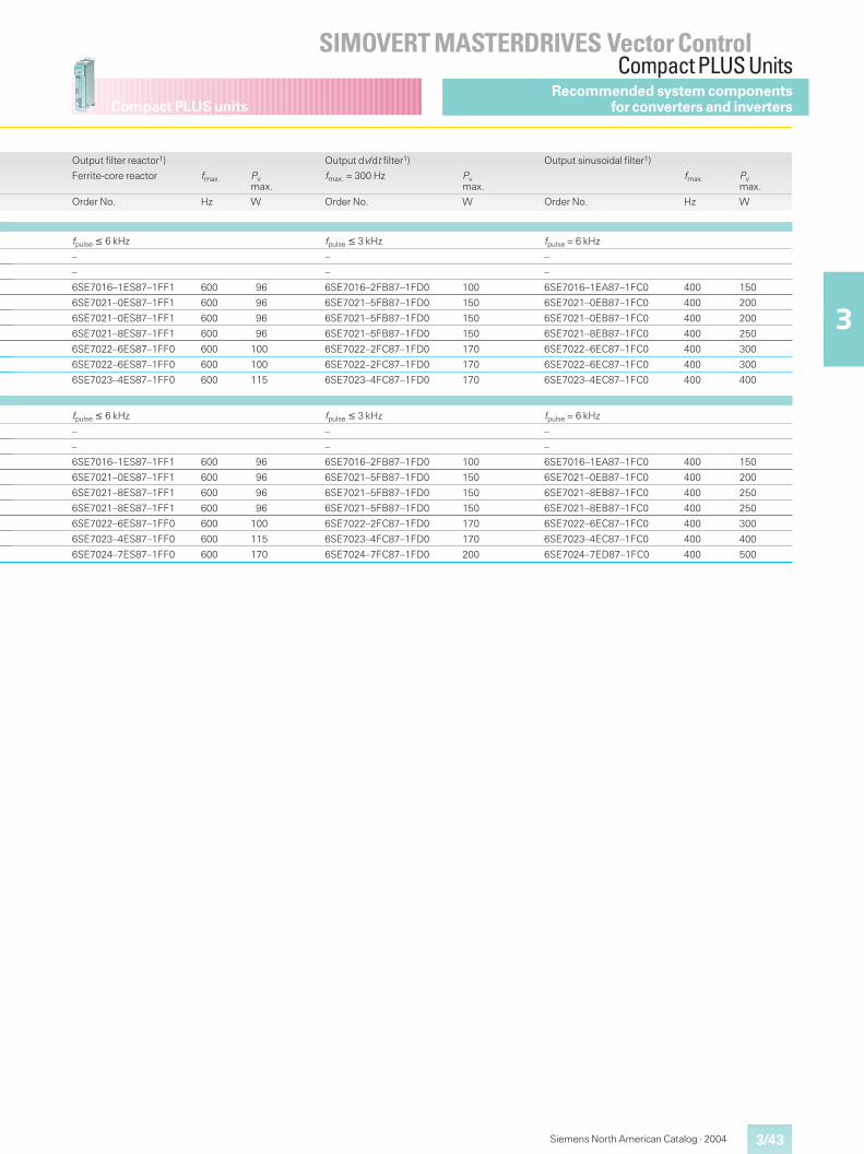
3/43
SIMOVERT MASTERDRIVES Vector ControlCompact PLUS Units
3
Compact PLUS units
Siemens North American Catalog · 2004
Recommended system componentsfor converters and inverters
Output filter reactor1) Output dv/dt filter1) Output sinusoidal filter1)
Ferrite-core reactor fmax. Pvmax.
fmax. = 300 Hz Pvmax.
fmax. Pvmax.
Order No. Hz W Order No. W Order No. Hz W
fpulse � 6 kHz fpulse � 3 kHz fpulse = 6 kHz
– – –
– – –
6SE7016–1ES87–1FF1 600 96 6SE7016–2FB87–1FD0 100 6SE7016–1EA87–1FC0 400 150
6SE7021–0ES87–1FF1 600 96 6SE7021–5FB87–1FD0 150 6SE7021–0EB87–1FC0 400 200
6SE7021–0ES87–1FF1 600 96 6SE7021–5FB87–1FD0 150 6SE7021–0EB87–1FC0 400 200
6SE7021–8ES87–1FF1 600 96 6SE7021–5FB87–1FD0 150 6SE7021–8EB87–1FC0 400 250
6SE7022–6ES87–1FF0 600 100 6SE7022–2FC87–1FD0 170 6SE7022–6EC87–1FC0 400 300
6SE7022–6ES87–1FF0 600 100 6SE7022–2FC87–1FD0 170 6SE7022–6EC87–1FC0 400 300
6SE7023–4ES87–1FF0 600 115 6SE7023–4FC87–1FD0 170 6SE7023–4EC87–1FC0 400 400
fpulse � 6 kHz fpulse � 3 kHz fpulse = 6 kHz
– – –
– – –
6SE7016–1ES87–1FF1 600 96 6SE7016–2FB87–1FD0 100 6SE7016–1EA87–1FC0 400 150
6SE7021–0ES87–1FF1 600 96 6SE7021–5FB87–1FD0 150 6SE7021–0EB87–1FC0 400 200
6SE7021–8ES87–1FF1 600 96 6SE7021–5FB87–1FD0 150 6SE7021–8EB87–1FC0 400 250
6SE7021–8ES87–1FF1 600 96 6SE7021–5FB87–1FD0 150 6SE7021–8EB87–1FC0 400 250
6SE7022–6ES87–1FF0 600 100 6SE7022–2FC87–1FD0 170 6SE7022–6EC87–1FC0 400 300
6SE7023–4ES87–1FF0 600 115 6SE7023–4FC87–1FD0 170 6SE7023–4EC87–1FC0 400 400
6SE7024–7ES87–1FF0 600 170 6SE7024–7FC87–1FD0 200 6SE7024–7ED87–1FC0 400 500
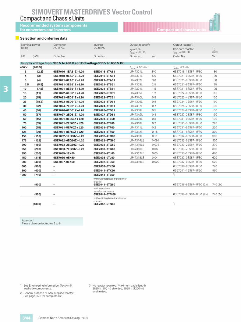
Compact and chassis units
SIMOVERT MASTERDRIVES Vector ControlCompact and Chassis Units
3/44
3
Siemens North American Catalog · 2004
1) See Engineering Information, Section 6,load-side components.
2) General purpose NEMA supplied reactor.See page 3/73 for complete list.
3) No reactor required. Maximum cable length2625 ft (800 m) shielded, 3938 ft (1200 m)unshielded.
Nominal powerrating
ConverterAC to AC
InverterDC to AC
Output reactor2) Output reactor1)
vD = 3 %fmax. = 90 Hz
Iron-core reactorfmax. = 300 Hz
Pvmax.
HP (kW) Order No. Order No. Order No. mh Order No. W
Supply voltage 3-ph. 380 V to 480 V and DC voltage 510 V to 650 V DC460 V (400 V) fpulse � 16 kHz fpulse � 3 kHz
3 (2.2) 6SE7016–1EA61Z + L20 6SE7016–1TA61 LR47301L 5.0 6SE7016–1ES87–1FE0 80
4 (3) 6SE7018–0EA61Z + L20 6SE7018–0TA61 LR47301L 5.0 6SE7021–0ES87–1FE0 80
5 (4) 6SE7021–0EA61Z + L20 6SE7021–0TA61 LR47302L 3.0 6SE7021–0ES87–1FE0 80
7.5 (5.5) 6SE7021–3EB61Z + L20 6SE7021–3TB61 LR47303L 2.5 6SE7021–8ES87–1FE0 95
10 (7.5) 6SE7021–8EB61Z + L20 6SE7021–8TB61 LR47304L 1.5 6SE7021–8ES87–1FE0 95
15 (11) 6SE7022–6EC61Z + L20 6SE7022–6TC61 LR47305L 1.2 6SE7022–6ES87–1FE0 110
20 (15) 6SE7023–4EC61Z + L20 6SE7023–4TC61 LR473A6L 0.8 6SE7023–4ES87–1FE0 130
25 (18.5) 6SE7023–8ED61Z + L20 6SE7023–8TD61 LR47306L 0.8 6SE7024–7ES87–1FE0 190
30 (22) 6SE7024–7ED61Z + L20 6SE7024–7TD61 LR47307L 0.7 6SE7024–7ES87–1FE0 190
40 (30) 6SE7026–0ED61Z + L20 6SE7026–0TD61 LR47308L 0.5 6SE7027–2ES87–1FE0 130
50 (37) 6SE7027–2ED61Z + L20 6SE7027–2TD61 LR473A9L 0.4 6SE7027–2ES87–1FE0 130
60 (45) 6SE7031–0EE60Z + L20 6SE7031–0TE60 LR47309L 0.3 6SE7031–0ES87–1FE0 190
75 (55) 6SE7031–2EF60Z + L20 6SE7031–2TF60 LR47310L 0.2 6SE7031–5ES87–1FE0 220
100 (75) 6SE7031–5EF60Z + L20 6SE7031–5TF60 LR47311L 0.2 6SE7031–5ES87–1FE0 220
125 (90) 6SE7031–8EF60Z + L20 6SE7031–8TF60 LR47312L 0.15 6SE7031–8ES87–1FE0 300
150 (110) 6SE7032–1EG60Z + L20 6SE7032–1TG60 LR47313L 0.11 6SE7032–6ES87–1FE0 300
175 (132) 6SE7032–6EG60Z + L20 6SE7032–6TG60 LR47314LE 0.091 6SE7032–6ES87–1FE0 300
200 (160) 6SE7033–2EG60Z + L20 6SE7033–2TG60 LR47315LE 0.075 6SE7033–2ES87–1FE0 370
250 (200) 6SE7033–7EG60Z + L20 6SE7033–7TG60 LR47316LE 0.06 6SE7033–7ES87–1FE0 380
350 (250) 6SE7035–1EK60 6SE7035–1TJ60 LR47317LE 0.05 6SE7035–1ES87–1FE0 460
450 (315) 6SE7036–0EK60 6SE7036–0TJ60 LR47318LE 0.04 6SE7037–0ES87–1FE0 620
500 (400) 6SE7037–0EK60 6SE7037–0TJ60 LR47319LE 0.029 6SE7037–0ES87–1FE0 620
600 (500) – 6SE7038–6TK60 6SE7038–6ES87–1FE0 740
800 (630) – 6SE7041–1TK60 6SE7041–1ES87–1FE0 860
1000 (710) – 6SE7041–3TL60 3)
(900) –
without interphase transformerchassis6SE7041–6TQ60 6SE7038–6ES87–1FE0 (2x) 740 (2x)
(900) –
with interphasetransformer chassis6SE7041–6TM60 6SE7038–6ES87–1FE0 (2x) 740 (2x)
(1300) –
without interphase transformerchassis6SE7042–5TN60 3)
Recommended system componentsfor converters and inverters
Selection and ordering data
Attention!Please observe footnotes 2 to 6.
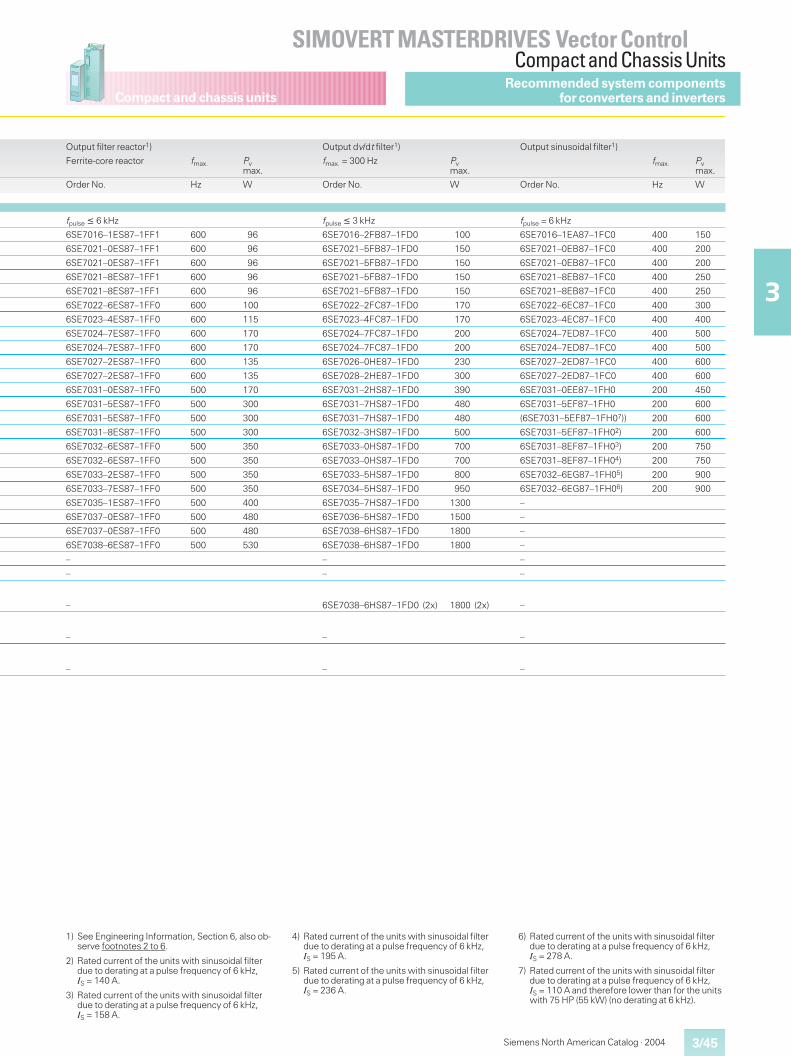
Compact and chassis units
3/45
SIMOVERT MASTERDRIVES Vector ControlCompact and Chassis Units
3
Siemens North American Catalog · 2004
Output filter reactor1) Output dv/dt filter1) Output sinusoidal filter1)
Ferrite-core reactor fmax. Pvmax.
fmax. = 300 Hz Pvmax.
fmax. Pvmax.
Order No. Hz W Order No. W Order No. Hz W
fpulse � 6 kHz fpulse � 3 kHz fpulse = 6 kHz
6SE7016–1ES87–1FF1 600 96 6SE7016–2FB87–1FD0 100 6SE7016–1EA87–1FC0 400 150
6SE7021–0ES87–1FF1 600 96 6SE7021–5FB87–1FD0 150 6SE7021–0EB87–1FC0 400 200
6SE7021–0ES87–1FF1 600 96 6SE7021–5FB87–1FD0 150 6SE7021–0EB87–1FC0 400 200
6SE7021–8ES87–1FF1 600 96 6SE7021–5FB87–1FD0 150 6SE7021–8EB87–1FC0 400 250
6SE7021–8ES87–1FF1 600 96 6SE7021–5FB87–1FD0 150 6SE7021–8EB87–1FC0 400 250
6SE7022–6ES87–1FF0 600 100 6SE7022–2FC87–1FD0 170 6SE7022–6EC87–1FC0 400 300
6SE7023–4ES87–1FF0 600 115 6SE7023–4FC87–1FD0 170 6SE7023–4EC87–1FC0 400 400
6SE7024–7ES87–1FF0 600 170 6SE7024–7FC87–1FD0 200 6SE7024–7ED87–1FC0 400 500
6SE7024–7ES87–1FF0 600 170 6SE7024–7FC87–1FD0 200 6SE7024–7ED87–1FC0 400 500
6SE7027–2ES87–1FF0 600 135 6SE7026–0HE87–1FD0 230 6SE7027–2ED87–1FC0 400 600
6SE7027–2ES87–1FF0 600 135 6SE7028–2HE87–1FD0 300 6SE7027–2ED87–1FC0 400 600
6SE7031–0ES87–1FF0 500 170 6SE7031–2HS87–1FD0 390 6SE7031–0EE87–1FH0 200 450
6SE7031–5ES87–1FF0 500 300 6SE7031–7HS87–1FD0 480 6SE7031–5EF87–1FH0 200 600
6SE7031–5ES87–1FF0 500 300 6SE7031–7HS87–1FD0 480 (6SE7031–5EF87–1FH07)) 200 600
6SE7031–8ES87–1FF0 500 300 6SE7032–3HS87–1FD0 500 6SE7031–5EF87–1FH02) 200 600
6SE7032–6ES87–1FF0 500 350 6SE7033–0HS87–1FD0 700 6SE7031–8EF87–1FH03) 200 750
6SE7032–6ES87–1FF0 500 350 6SE7033–0HS87–1FD0 700 6SE7031–8EF87–1FH04) 200 750
6SE7033–2ES87–1FF0 500 350 6SE7033–5HS87–1FD0 800 6SE7032–6EG87–1FH05) 200 900
6SE7033–7ES87–1FF0 500 350 6SE7034–5HS87–1FD0 950 6SE7032–6EG87–1FH06) 200 900
6SE7035–1ES87–1FF0 500 400 6SE7035–7HS87–1FD0 1300 –
6SE7037–0ES87–1FF0 500 480 6SE7036–5HS87–1FD0 1500 –
6SE7037–0ES87–1FF0 500 480 6SE7038–6HS87–1FD0 1800 –
6SE7038–6ES87–1FF0 500 530 6SE7038–6HS87–1FD0 1800 –
– – –
– – –
– 6SE7038–6HS87–1FD0 (2x) 1800 (2x) –
– – –
– – –
1) See Engineering Information, Section 6, also ob-serve footnotes 2 to 6.
2) Rated current of the units with sinusoidal filterdue to derating at a pulse frequency of 6 kHz,IS = 140 A.
3) Rated current of the units with sinusoidal filterdue to derating at a pulse frequency of 6 kHz,IS = 158 A.
4) Rated current of the units with sinusoidal filterdue to derating at a pulse frequency of 6 kHz,IS = 195 A.
5) Rated current of the units with sinusoidal filterdue to derating at a pulse frequency of 6 kHz,IS = 236 A.
6) Rated current of the units with sinusoidal filterdue to derating at a pulse frequency of 6 kHz,IS = 278 A.
7) Rated current of the units with sinusoidal filterdue to derating at a pulse frequency of 6 kHz,IS = 110 A and therefore lower than for the unitswith 75 HP (55 kW) (no derating at 6 kHz).
Recommended system componentsfor converters and inverters
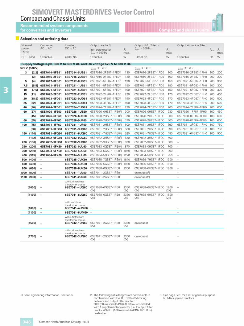
Compact and chassis units
SIMOVERT MASTERDRIVES Vector ControlCompact and Chassis Units
3/46
3
Siemens North American Catalog · 2004
Nominalpowerrating
ConverterAC to AC
InverterDC to AC
Output reactor1) Output dv/dt filter1)fmax. = 300 Hz
Output sinusoidal filter1)
Iron-core reactorfmax. = 300 Hz
Pvmax.
Pvmax.
fmax. Pvmax.
HP (kW) Order No. Order No. Order No. W Order No. W Order No. Hz W
Supply voltage 3-ph. 500 V to 600 V AC and DC voltage 675 V to 810 V DC575 V (500 V) fpulse � 3 kHz fpulse � 3 kHz fpulse � 3 kHz
3 (2.2) 6SE7014–5FB61 6SE7014–5UB61 6SE7016–2FS87–1FE03) 130 6SE7016–2FB87–1FD0 100 6SE7016–2FB87–1FH0 200 200
(3) 6SE7016–2FB61 6SE7016–2UB61 6SE7016–2FS87–1FE03) 130 6SE7016–2FB87–1FD0 100 6SE7016–2FB87–1FH0 200 200
5 (4) 6SE7017–8FB61 6SE7017–8UB61 6SE7021–5FS87–1FE03) 190 6SE7021–5FB87–1FD0 150 6SE7021–5FC87–1FH0 200 300
7.5 (5.5) 6SE7021–1FB61 6SE7021–1UB61 6SE7021–5FS87–1FE03) 190 6SE7021–5FB87–1FD0 150 6SE7021–5FC87–1FH0 200 300
10 (7.5) 6SE7021–5FB61 6SE7021–5UB61 6SE7021–5FS87–1FE03) 190 6SE7021–5FB87–1FD0 150 6SE7021–5FC87–1FH0 200 300
15 (11) 6SE7022–2FC61 6SE7022–2UC61 6SE7022–2FS87–1FE03) 220 6SE7022–2FC87–1FD0 170 6SE7022–2FD87–1FH0 200 400
20 (18.5) 6SE7023–0FD61 6SE7023–0UD61 6SE7023–4FS87–1FE03) 190 6SE7023–4FC87–1FD0 170 6SE7023–4FD87–1FH0 200 500
25 (22) 6SE7023–4FD61 6SE7023–4UD61 6SE7023–4FS87–1FE03) 190 6SE7023–4FC87–1FD0 170 6SE7023–4FD87–1FH0 200 500
40 (30) 6SE7024–7FD61 6SE7024–7UD61 6SE7024–7FS87–1FE03) 220 6SE7024–7FC87–1FD0 200 6SE7024–7FE87–1FH0 200 600
50 (37) 6SE7026–1FE60 6SE7026–1UE60 6SE7026–0HS87–1FE03) 300 6SE7026–0HE87–1FD0 230 6SE7026–1FF87–1FH0 100 450
(45) 6SE7026–6FE60 6SE7026–6UE60 6SE7028–2HS87–1FE03) 370 6SE7028–2HE87–1FD0 300 6SE7028–0FF87–1FH0 100 600
60 (55) 6SE7028–0FF60 6SE7028–0UF60 6SE7028–2HS87–1FE03) 370 6SE7028–2HE87–1FD0 300 6SE7028–0FF87–1FH0 100 600
100 (75) 6SE7031–1FF60 6SE7031–1UF60 6SE7031–2HS87–1FE03) 500 6SE7031–2HS87–1FD0 390 6SE7031–3FG87–1FH0 100 750
(90) 6SE7031–3FG60 6SE7031–3UG60 6SE7031–2HS87–1FE03) 500 6SE7031–2HS87–1FD0 390 6SE7031–3FG87–1FH0 100 750
150 (110) 6SE7031–6FG60 6SE7031–6UG60 6SE7031–7HS87–1FE03) 620 6SE7031–7HS87–1FD0 480 6SE7031–6FG87–1FH0 100 900
(132) 6SE7032–0FG60 6SE7032–0UG60 6SE7032–3HS87–1FE03) 620 6SE7032–3HS87–1FD0 500 –
200 (160) 6SE7032–3FG60 6SE7032–3UG60 6SE7032–3HS87–1FE03) 620 6SE7032–3HS87–1FD0 500 –
250 (200) 6SE7033–0FK60 6SE7033–0UJ60 6SE7033–0GS87–1FE03) 870 6SE7033–0HS87–1FD0 700 –
300 (250) 6SE7033–5FK60 6SE7033–5UJ60 6SE7033–5GS87–1FE03) 1050 6SE7033–5HS87–1FD0 800 –
400 (315) 6SE7034–5FK60 6SE7034–5UJ60 6SE7034–5GS87–1FE03) 1270 6SE7034–5HS87–1FD0 950 –
500 (400) – 6SE7035–7UK60 6SE7035–7GS87–1FE03) 1840 6SE7035–7HS87–1FD0 1300 –
600 (450) – 6SE7036–5UK60 6SE7036–5GS87–1FE03) 1980 6SE7036–5HS87–1FD0 1500 –
800 (630) – 6SE7038–6UK60 6SE7038–6GS87–1FE0 2350 6SE7038–6HS87–1FD0 1800 –
1000 (800) – 6SE7041–1UL60 6SE7041–2GS87–1FE0 on request2) –
1100 (900) – 6SE7041–2UL60 6SE7041–2GS87–1FE0 on request2) –
(1000) –
without interphasetransformer chassis6SE7041–4UQ60 6SE7038–6GS87–1FE0
(2x)2350(2x)
6SE7038–6HS87–1FD0(2x)
1800(2x)
–
(1100) – 6SE7041–6UQ60 6SE7038–6GS87–1FE0(2x)
2350(2x)
6SE7038–6HS87–1FD0(2x)
1800(2x)
–
(1000) –
with interphasetransformer chassis6SE7041–4UM60 – –
(1100) – 6SE7041–6UM60 – –
(1500) –
without interphasetransformer chassis6SE7042–1UN60 6SE7041–2GS87–1FE0
(2x)2350(2x)
on request –
(1700) –
without interphasetransformer chassis6SE7042–3UN60 6SE7041–2GS87–1FE0
(2x)2350(2x)
on request –
1) See Engineering Information, Section 6. 2) The following cable lengths are permissible incombination with the TG 31024-05 limitingnetwork and output filter reactor:98 ft (30 m) shielded/164 ft (50 m) unshielded;with 1 supplementary reactor (i.e. 2 output filterreactors) 328 ft (100 m) shielded/492 ft (150 m)unshielded.
3) See page 3/73 for a list of general purposeNEMA supplied reactors.
Recommended system componentsfor converters and inverters
Selection and ordering data
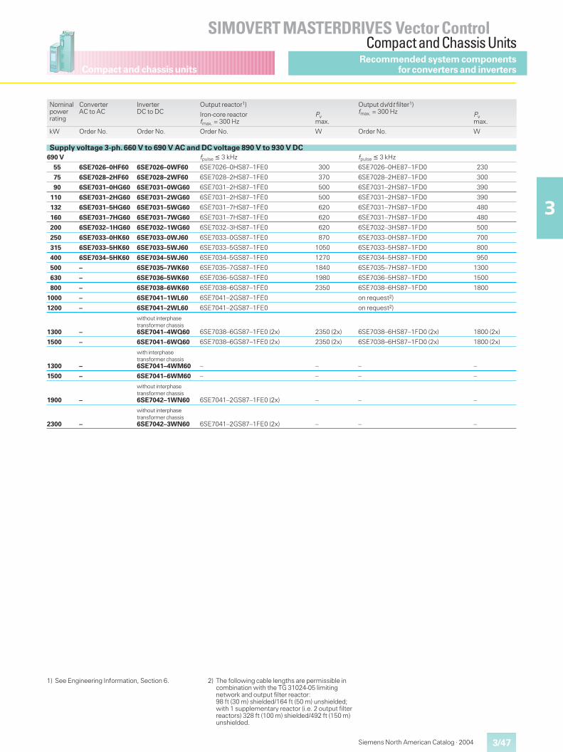
Compact and chassis units
3/47
SIMOVERT MASTERDRIVES Vector ControlCompact and Chassis Units
3
Siemens North American Catalog · 2004
Nominalpowerrating
ConverterAC to AC
InverterDC to DC
Output reactor1) Output dv/dt filter1)fmax. = 300 HzIron-core reactor
fmax. = 300 HzPvmax.
Pvmax.
kW Order No. Order No. Order No. W Order No. W
Supply voltage 3-ph. 660 V to 690 V AC and DC voltage 890 V to 930 V DC690 V fpulse � 3 kHz fpulse � 3 kHz
55 6SE7026–0HF60 6SE7026–0WF60 6SE7026–0HS87–1FE0 300 6SE7026–0HE87–1FD0 230
75 6SE7028–2HF60 6SE7028–2WF60 6SE7028–2HS87–1FE0 370 6SE7028–2HE87–1FD0 300
90 6SE7031–0HG60 6SE7031–0WG60 6SE7031–2HS87–1FE0 500 6SE7031–2HS87–1FD0 390
110 6SE7031–2HG60 6SE7031–2WG60 6SE7031–2HS87–1FE0 500 6SE7031–2HS87–1FD0 390
132 6SE7031–5HG60 6SE7031–5WG60 6SE7031–7HS87–1FE0 620 6SE7031–7HS87–1FD0 480
160 6SE7031–7HG60 6SE7031–7WG60 6SE7031–7HS87–1FE0 620 6SE7031–7HS87–1FD0 480
200 6SE7032–1HG60 6SE7032–1WG60 6SE7032–3HS87–1FE0 620 6SE7032–3HS87–1FD0 500
250 6SE7033–0HK60 6SE7033–0WJ60 6SE7033–0GS87–1FE0 870 6SE7033–0HS87–1FD0 700
315 6SE7033–5HK60 6SE7033–5WJ60 6SE7033–5GS87–1FE0 1050 6SE7033–5HS87–1FD0 800
400 6SE7034–5HK60 6SE7034–5WJ60 6SE7034–5GS87–1FE0 1270 6SE7034–5HS87–1FD0 950
500 – 6SE7035–7WK60 6SE7035–7GS87–1FE0 1840 6SE7035–7HS87–1FD0 1300
630 – 6SE7036–5WK60 6SE7036–5GS87–1FE0 1980 6SE7036–5HS87–1FD0 1500
800 – 6SE7038–6WK60 6SE7038–6GS87–1FE0 2350 6SE7038–6HS87–1FD0 1800
1000 – 6SE7041–1WL60 6SE7041–2GS87–1FE0 on request2)
1200 – 6SE7041–2WL60 6SE7041–2GS87–1FE0 on request2)
1300 –
without interphasetransformer chassis6SE7041–4WQ60 6SE7038–6GS87–1FE0 (2x) 2350 (2x) 6SE7038–6HS87–1FD0 (2x) 1800 (2x)
1500 – 6SE7041–6WQ60 6SE7038–6GS87–1FE0 (2x) 2350 (2x) 6SE7038–6HS87–1FD0 (2x) 1800 (2x)
1300 –
with interphasetransformer chassis6SE7041–4WM60 – – – –
1500 – 6SE7041–6WM60 – – – –
1900 –
without interphasetransformer chassis6SE7042–1WN60 6SE7041–2GS87–1FE0 (2x) – – –
2300 –
without interphasetransformer chassis6SE7042–3WN60 6SE7041–2GS87–1FE0 (2x) – – –
Recommended system componentsfor converters and inverters
1) See Engineering Information, Section 6. 2) The following cable lengths are permissible incombination with the TG 31024-05 limitingnetwork and output filter reactor:98 ft (30 m) shielded/164 ft (50 m) unshielded;with 1 supplementary reactor (i.e. 2 output filterreactors) 328 ft (100 m) shielded/492 ft (150 m)unshielded.
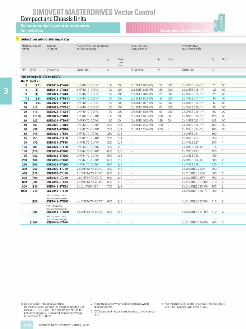
Compact and chassis units
SIMOVERT MASTERDRIVES Vector ControlCompact and Chassis Units
3/48
3
Siemens North American Catalog · 2004
Nominal powerrating
InverterDC to AC
Fuse switch disconnectorfor DC coupling1)2)
Inverter fuseDuty class gR2)
Inverter fuseDuty class aR2)
IS Max.fusesize
IS Size IS Size
HP (kW) Order No. Order No. A Order No. A Order No. A
DC voltage 510 V to 650 V460 V (400 V)
3 (2.2) 6SE7016–1TA613) 3NP40 10–0CH01 100 000 2 x 3NE1 814–04) 20 000 2 x 3NE8 015–14) 25 00
4 (3) 6SE7018–0TA613) 3NP40 10–0CH01 100 000 2 x 3NE1 815–04) 25 000 2 x 3NE8 015–14) 25 00
5 (4) 6SE7021–0TA613) 3NP40 10–0CH01 100 000 2 x 3NE1 815–04) 25 000 2 x 3NE8 015–14) 25 00
7.5 (5.5) 6SE7021–3TB613) 3NP40 10–0CH01 100 000 2 x 3NE1 803–04) 35 000 2 x 3NE8 017–14) 50 00
10 (7.5) 6SE7021–8TB613) 3NP40 10–0CH01 100 000 2 x 3NE1 817–04) 50 000 2 x 3NE8 017–14) 50 00
15 (11) 6SE7022–6TC613) 3NP40 10–0CH01 100 000 2 x 3NE1 818–04) 63 000 2 x 3NE8 020–14) 80 00
20 (15) 6SE7023–4TC613) 3NP40 10–0CH01 100 000 2 x 3NE1 820–04) 80 000 2 x 3NE8 020–14) 80 00
25 (18.5) 6SE7023–8TD613) 3NP40 70–0CA01 160 00 2 x 3NE1 021–04) 100 00 2 x 3NE8 022–14) 125 00
30 (22) 6SE7024–7TD613) 3NP40 70–0CA01 160 00 2 x 3NE1 022–04) 125 00 2 x 3NE8 022–14) 125 00
40 (30) 6SE7026–0TD613) 3NP42 70–0CA01 250 0; 1 2 x 3NE1 224–04) 160 0 2 x 3NE8 024–14) 160 00
50 (37) 6SE7027–2TD613) 3NP42 70–0CA01 250 0; 1 2 x 3NE1 224–04) 160 0 2 x 3NE8 024–14) 160 00
60 (45) 6SE7031–0TE60 3NP42 70–0CA01 250 0; 1 – 2 x 3NE3 224 160 1
75 (55) 6SE7031–2TF60 3NP42 70–0CA01 250 0; 1 – 2 x 3NE3 227 250 1
100 (75) 6SE7031–5TF60 3NP42 70–0CA01 250 0; 1 – 2 x 3NE3 227 250 1
125 (90) 6SE7031–8TF60 3NP43 70–0CA01 400 1; 2 – 2 x 3NE3 230–0B 315 1
150 (110) 6SE7032–1TG60 3NP44 70–0CA01 630 2; 3 – 2 x 3NE3 233 450 1
175 (132) 6SE7032–6TG60 3NP44 70–0CA01 630 2; 3 – 2 x 3NE3 233 450 1
200 (160) 6SE7033–2TG60 3NP44 70–0CA01 630 2; 3 – 2 x 3NE3 334–0B 500 2
250 (200) 6SE7033–7TG60 3NP44 70–0CA01 630 2; 3 – 2 x 3NE3 336 630 2
350 (250) 6SE7035–1TJ60 2 x 3NP43 70–0CA01 400 1; 2 – 2 x 2 x 3NE3 2333) 450 1
450 (315) 6SE7036–0TJ60 2 x 3NP44 70–0CA01 630 2; 3 – 2 x 2 x 3NE3 3353) 560 2
500 (400) 6SE7037–0TJ60 2 x 3NP44 70–0CA01 630 2; 3 – 2 x 2 x 3NE3 3353) 560 2
600 (500) 6SE7038–6TK60 2 x 3NP44 70–0CA01 630 2; 3 – 2 x 2 x 3NE3 337–83) 710 2
800 (630) 6SE7041–1TK60 2 x 2 x 3NH3 330 700 2; 3 – 2 x 2 x 3NE3 338–83) 800 2
1000 (710) 6SE7041–3TL60 2 x 2 x 3NE3 340-83) 900 2
(900)
without interphasetransformer chassis6SE7041–6TQ60 4 x 3NP44 70–0CA01 630 2; 3 – 4 x 2 x 3NE3 337–83) 710 2
(900)
with interphasetransformer chassis6SE7041–6TM60 4 x 3NP44 70–0CA01 630 2; 3 – 4 x 2 x 3NE3 337–83) 710 2
(1300)
without interphasetransformer chassis6SE7042–5TN60 – – – – 4 x 2 x 3NE3 340–83) 900 2
1) See catalog “Industrial Controls”.Rated insulation voltage for pollution degree 3 toDIN VDE 0110, Part 1, but conditions of use topollution degree 2. The rated insulation voltageis therefore � 1000 V.
2) Note fuse sizes when selecting fuse switchdisconnectors.
3) DC fuses are integral components of the inverterunit.
4) For the fusing of inverters without integrated DClink fuse (inverter with option L33).
Recommended system componentsfor inverters
Selection and ordering data
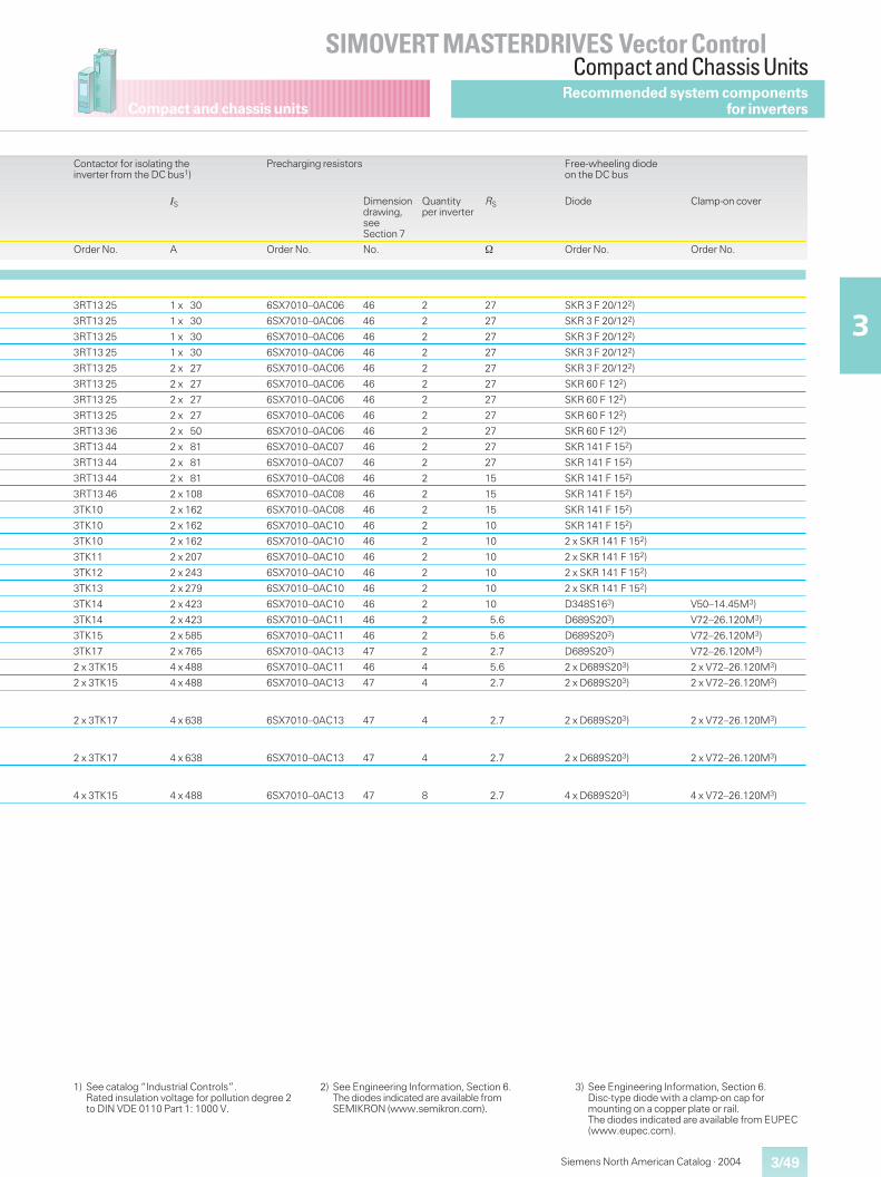
Compact and chassis units
3/49
SIMOVERT MASTERDRIVES Vector ControlCompact and Chassis Units
3
Siemens North American Catalog · 2004
Contactor for isolating theinverter from the DC bus1)
Precharging resistors Free-wheeling diodeon the DC bus
IS Dimensiondrawing,seeSection 7
Quantityper inverter
RS Diode Clamp-on cover
Order No. A Order No. No. � Order No. Order No.
3RT13 25 1 x 30 6SX7010–0AC06 46 2 27 SKR 3 F 20/122)
3RT13 25 1 x 30 6SX7010–0AC06 46 2 27 SKR 3 F 20/122)
3RT13 25 1 x 30 6SX7010–0AC06 46 2 27 SKR 3 F 20/122)
3RT13 25 1 x 30 6SX7010–0AC06 46 2 27 SKR 3 F 20/122)
3RT13 25 2 x 27 6SX7010–0AC06 46 2 27 SKR 3 F 20/122)
3RT13 25 2 x 27 6SX7010–0AC06 46 2 27 SKR 60 F 122)
3RT13 25 2 x 27 6SX7010–0AC06 46 2 27 SKR 60 F 122)
3RT13 25 2 x 27 6SX7010–0AC06 46 2 27 SKR 60 F 122)
3RT13 36 2 x 50 6SX7010–0AC06 46 2 27 SKR 60 F 122)
3RT13 44 2 x 81 6SX7010–0AC07 46 2 27 SKR 141 F 152)
3RT13 44 2 x 81 6SX7010–0AC07 46 2 27 SKR 141 F 152)
3RT13 44 2 x 81 6SX7010–0AC08 46 2 15 SKR 141 F 152)
3RT13 46 2 x 10⁸ 6SX7010–0AC08 46 2 15 SKR 141 F 152)
3TK10 2 x 162 6SX7010–0AC08 46 2 15 SKR 141 F 152)
3TK10 2 x 162 6SX7010–0AC10 46 2 10 SKR 141 F 152)
3TK10 2 x 162 6SX7010–0AC10 46 2 10 2 x SKR 141 F 152)
3TK11 2 x 207 6SX7010–0AC10 46 2 10 2 x SKR 141 F 152)
3TK12 2 x 243 6SX7010–0AC10 46 2 10 2 x SKR 141 F 152)
3TK13 2 x 279 6SX7010–0AC10 46 2 10 2 x SKR 141 F 152)
3TK14 2 x 423 6SX7010–0AC10 46 2 10 D348S163) V50–14.45M3)
3TK14 2 x 423 6SX7010–0AC11 46 2 5.6 D689S203) V72–26.120M3)
3TK15 2 x 585 6SX7010–0AC11 46 2 5.6 D689S203) V72–26.120M3)
3TK17 2 x 765 6SX7010–0AC13 47 2 2.7 D689S203) V72–26.120M3)
2 x 3TK15 4 x 488 6SX7010–0AC11 46 4 5.6 2 x D689S203) 2 x V72–26.120M3)
2 x 3TK15 4 x 488 6SX7010–0AC13 47 4 2.7 2 x D689S203) 2 x V72–26.120M3)
2 x 3TK17 4 x 638 6SX7010–0AC13 47 4 2.7 2 x D689S203) 2 x V72–26.120M3)
2 x 3TK17 4 x 638 6SX7010–0AC13 47 4 2.7 2 x D689S203) 2 x V72–26.120M3)
4 x 3TK15 4 x 488 6SX7010–0AC13 47 8 2.7 4 x D689S203) 4 x V72–26.120M3)
1) See catalog “Industrial Controls”.Rated insulation voltage for pollution degree 2to DIN VDE 0110 Part 1: 1000 V.
2) See Engineering Information, Section 6.The diodes indicated are available fromSEMIKRON (www.semikron.com).
3) See Engineering Information, Section 6.Disc-type diode with a clamp-on cap formounting on a copper plate or rail.The diodes indicated are available from EUPEC(www.eupec.com).
Recommended system componentsfor inverters
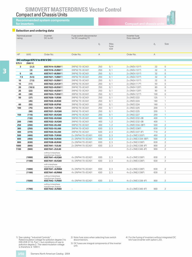
Compact and chassis units
SIMOVERT MASTERDRIVES Vector ControlCompact and Chassis Units
3/50
3
Siemens North American Catalog · 2004
1) See catalog “Industrial Controls”.Rated insulation voltage for pollution degree 3 toDIN VDE 0110, Part 1, but conditions of use topollution degree 2. The rated insulation voltageis therefore � 1000 V.
2) Note fuse sizes when selecting fuse switchdisconnectors.
3) DC fuses are integral components of the inverterunit.
4) For the fusing of inverters without integrated DClink fuse (inverter with option L33).
Recommended system componentsfor inverters
Selection and ordering data
Nominal powerrating
InverterDC to AC
Fuse switch disconnectorfor DC coupling1)2)
Inverter fuseDuty class aR
IS Max.fusesize
IS Size
HP (kW) Order No. Order No. A Order No. A
DC voltage 675 V to 810 V DC575 V (500 V)
3 (2.2) 6SE7014–5UB613) 3NP42 70–0CA01 250 0; 1 2 x 3NE4 1014) 32 0
(3) 6SE7016–2UB613) 3NP42 70–0CA01 250 0; 1 2 x 3NE4 1014) 32 0
5 (4) 6SE7017–8UB613) 3NP42 70–0CA01 250 0; 1 2 x 3NE4 1014) 32 0
7.5 (5.5) 6SE7021–1UB613) 3NP42 70–0CA01 250 0; 1 2 x 3NE4 1014) 32 0
10 (7.5) 6SE7021–5UB613) 3NP42 70–0CA01 250 0; 1 2 x 3NE4 1014) 32 0
15 (11) 6SE7022–2UC613) 3NP42 70–0CA01 250 0; 1 2 x 3NE4 1174) 50 0
20 (18.5) 6SE7023–0UD613) 3NP42 70–0CA01 250 0; 1 2 x 3NE4 1204) 80 0
25 (22) 6SE7023–4UD613) 3NP42 70–0CA01 250 0; 1 2 x 3NE4 1204) 80 0
40 (30) 6SE7024–7UD613) 3NP42 70–0CA01 250 0; 1 2 x 3NE4 1214) 100 0
50 (37) 6SE7026–1UE60 3NP42 70–0CA01 250 0; 1 2 x 3NE3 222 125 1
(45) 6SE7026–6UE60 3NP42 70–0CA01 250 0; 1 2 x 3NE3 224 160 1
60 (55) 6SE7028–0UF60 3NP42 70–0CA01 250 0; 1 2 x 3NE3 224 160 1
100 (75) 6SE7031–1UF60 3NP42 70–0CA01 250 0; 1 2 x 3NE3 225 200 1
(90) 6SE7031–3UG60 3NP42 70–0CA01 250 0; 1 2 x 3NE3 225 200 1
150 (110) 6SE7031–6UG60 3NP42 70–0CA01 250 0; 1 2 x 3NE3 227 250 1
(132) 6SE7032–0UG60 3NP43 70–0CA01 400 1; 2 2 x 3NE3 232–0B 400 1
200 (160) 6SE7032–3UG60 3NP43 70–0CA01 400 1; 2 2 x 3NE3 232–0B 400 1
250 (200) 6SE7033–0UJ60 3NP43 70–0CA01 400 1; 2 2 x 3NE3 334–0B3) 500 2
300 (250) 6SE7033–5UJ60 3NP44 70–0CA01 630 2; 3 2 x 3NE3 3363) 630 2
400 (315) 6SE7034–5UJ60 3NP44 70–0CA01 630 2; 3 2 x 3NE3 337–83) 710 2
500 (400) 6SE7035–7UK60 2 x 3NP44 70–0CA01 630 2; 3 2 x 2 x 3NE3 3333) 450 2
600 (450) 6SE7036–5UK60 2 x 3NP44 70–0CA01 630 2; 3 2 x 2 x 3NE3 334–0B3) 500 2
800 (630) 6SE7038–6UK60 2 x 3NP44 70–0CA01 630 2; 3 2 x 2 x 3NE3 3363) 630 2
1000 (800) 6SE7041–1UL60 2 x 3NP44 70–0CA01 630 2; 3 2 x 2 x 3NE3 338–83) 800 2
1100 (900) 6SE7041–2UL60 2 x 2 x 3NE3 340–83) 900 2
(1000)
without interphasetransformer chassis6SE7041–4UQ60 4 x 3NP44 70–0CA01 630 2; 3 4 x 2 x 3NE3 3363) 630 2
(1100) 6SE7041–6UQ60 4 x 3NP44 70–0CA01 630 2; 3 4 x 2 x 3NE3 3363) 630 2
(1000)
with interphasetransformer chassis6SE7041–4UM60 4 x 3NP44 70–0CA01 630 2; 3 4 x 2 x 3NE3 3363) 630 2
(1100) 6SE7041–6UM60 4 x 3NP44 70–0CA01 630 2; 3 4 x 2 x 3NE3 3363) 630 2
(1500)
without interphasetransformer chassis6SE7042–1UN60 4 x 3NP44 70–0CA01 630 2; 3 4 x 2 x 3NE3 338–83) 800 2
(1700)
without interphasetransformer chassis6SE7042–3UN60 – – – 4 x 2 x 3NE3 340–83) 900 2
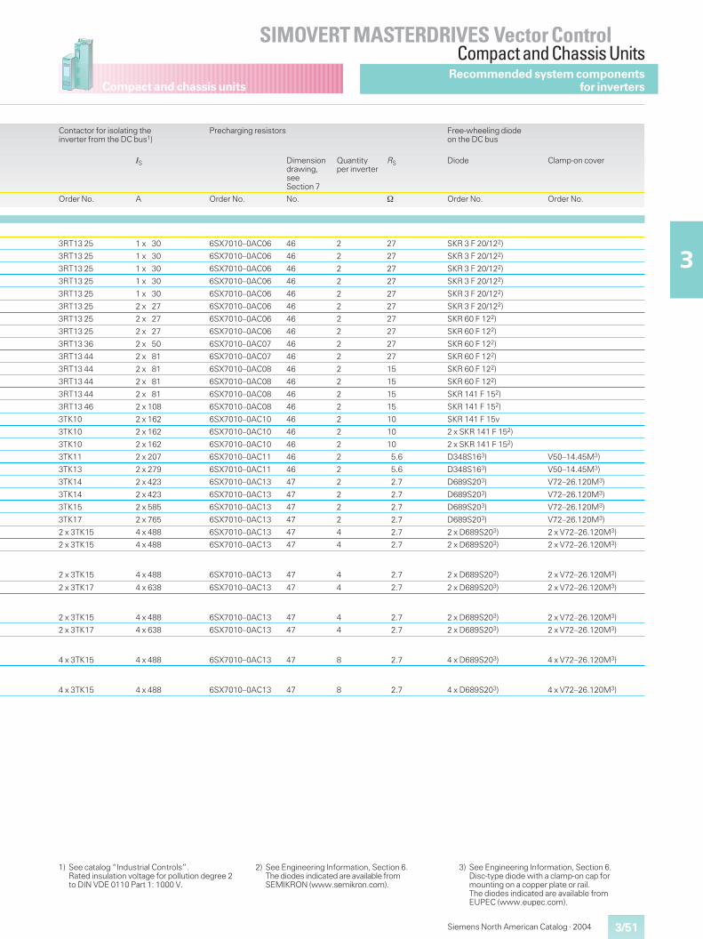
Compact and chassis units
3/51
SIMOVERT MASTERDRIVES Vector ControlCompact and Chassis Units
3
Siemens North American Catalog · 2004
1) See catalog “Industrial Controls”.Rated insulation voltage for pollution degree 2to DIN VDE 0110 Part 1: 1000 V.
2) See Engineering Information, Section 6.The diodes indicated are available fromSEMIKRON (www.semikron.com).
3) See Engineering Information, Section 6.Disc-type diode with a clamp-on cap formounting on a copper plate or rail.The diodes indicated are available fromEUPEC (www.eupec.com).
Recommended system componentsfor inverters
Contactor for isolating theinverter from the DC bus1)
Precharging resistors Free-wheeling diodeon the DC bus
IS Dimensiondrawing,seeSection 7
Quantityper inverter
RS Diode Clamp-on cover
Order No. A Order No. No. � Order No. Order No.
3RT13 25 1 x 30 6SX7010–0AC06 46 2 27 SKR 3 F 20/122)
3RT13 25 1 x 30 6SX7010–0AC06 46 2 27 SKR 3 F 20/122)
3RT13 25 1 x 30 6SX7010–0AC06 46 2 27 SKR 3 F 20/122)
3RT13 25 1 x 30 6SX7010–0AC06 46 2 27 SKR 3 F 20/122)
3RT13 25 1 x 30 6SX7010–0AC06 46 2 27 SKR 3 F 20/122)
3RT13 25 2 x 27 6SX7010–0AC06 46 2 27 SKR 3 F 20/122)
3RT13 25 2 x 27 6SX7010–0AC06 46 2 27 SKR 60 F 122)
3RT13 25 2 x 27 6SX7010–0AC06 46 2 27 SKR 60 F 122)
3RT13 36 2 x 50 6SX7010–0AC07 46 2 27 SKR 60 F 122)
3RT13 44 2 x 81 6SX7010–0AC07 46 2 27 SKR 60 F 122)
3RT13 44 2 x 81 6SX7010–0AC08 46 2 15 SKR 60 F 122)
3RT13 44 2 x 81 6SX7010–0AC08 46 2 15 SKR 60 F 122)
3RT13 44 2 x 81 6SX7010–0AC08 46 2 15 SKR 141 F 152)
3RT13 46 2 x 10⁸ 6SX7010–0AC08 46 2 15 SKR 141 F 152)
3TK10 2 x 162 6SX7010–0AC10 46 2 10 SKR 141 F 15v
3TK10 2 x 162 6SX7010–0AC10 46 2 10 2 x SKR 141 F 152)
3TK10 2 x 162 6SX7010–0AC10 46 2 10 2 x SKR 141 F 152)
3TK11 2 x 207 6SX7010–0AC11 46 2 5.6 D348S163) V50–14.45M3)
3TK13 2 x 279 6SX7010–0AC11 46 2 5.6 D348S163) V50–14.45M3)
3TK14 2 x 423 6SX7010–0AC13 47 2 2.7 D689S203) V72–26.120M3)
3TK14 2 x 423 6SX7010–0AC13 47 2 2.7 D689S203) V72–26.120M3)
3TK15 2 x 585 6SX7010–0AC13 47 2 2.7 D689S203) V72–26.120M3)
3TK17 2 x 765 6SX7010–0AC13 47 2 2.7 D689S203) V72–26.120M3)
2 x 3TK15 4 x 488 6SX7010–0AC13 47 4 2.7 2 x D689S203) 2 x V72–26.120M3)
2 x 3TK15 4 x 488 6SX7010–0AC13 47 4 2.7 2 x D689S203) 2 x V72–26.120M3)
2 x 3TK15 4 x 488 6SX7010–0AC13 47 4 2.7 2 x D689S203) 2 x V72–26.120M3)
2 x 3TK17 4 x 638 6SX7010–0AC13 47 4 2.7 2 x D689S203) 2 x V72–26.120M3)
2 x 3TK15 4 x 488 6SX7010–0AC13 47 4 2.7 2 x D689S203) 2 x V72–26.120M3)
2 x 3TK17 4 x 638 6SX7010–0AC13 47 4 2.7 2 x D689S203) 2 x V72–26.120M3)
4 x 3TK15 4 x 488 6SX7010–0AC13 47 8 2.7 4 x D689S203) 4 x V72–26.120M3)
4 x 3TK15 4 x 488 6SX7010–0AC13 47 8 2.7 4 x D689S203) 4 x V72–26.120M3)
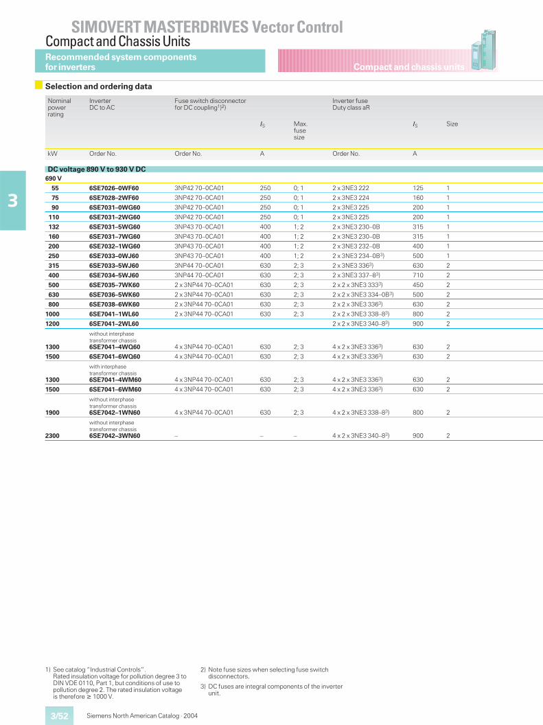
Compact and chassis units
SIMOVERT MASTERDRIVES Vector ControlCompact and Chassis Units
3/52
3
Siemens North American Catalog · 2004
Nominalpowerrating
InverterDC to AC
Fuse switch disconnectorfor DC coupling1)2)
Inverter fuseDuty class aR
IS Max.fusesize
IS Size
kW Order No. Order No. A Order No. A
DC voltage 890 V to 930 V DC690 V
55 6SE7026–0WF60 3NP42 70–0CA01 250 0; 1 2 x 3NE3 222 125 1
75 6SE7028–2WF60 3NP42 70–0CA01 250 0; 1 2 x 3NE3 224 160 1
90 6SE7031–0WG60 3NP42 70–0CA01 250 0; 1 2 x 3NE3 225 200 1
110 6SE7031–2WG60 3NP42 70–0CA01 250 0; 1 2 x 3NE3 225 200 1
132 6SE7031–5WG60 3NP43 70–0CA01 400 1; 2 2 x 3NE3 230–0B 315 1
160 6SE7031–7WG60 3NP43 70–0CA01 400 1; 2 2 x 3NE3 230–0B 315 1
200 6SE7032–1WG60 3NP43 70–0CA01 400 1; 2 2 x 3NE3 232–0B 400 1
250 6SE7033–0WJ60 3NP43 70–0CA01 400 1; 2 2 x 3NE3 234–0B3) 500 1
315 6SE7033–5WJ60 3NP44 70–0CA01 630 2; 3 2 x 3NE3 3363) 630 2
400 6SE7034–5WJ60 3NP44 70–0CA01 630 2; 3 2 x 3NE3 337–83) 710 2
500 6SE7035–7WK60 2 x 3NP44 70–0CA01 630 2; 3 2 x 2 x 3NE3 3333) 450 2
630 6SE7036–5WK60 2 x 3NP44 70–0CA01 630 2; 3 2 x 2 x 3NE3 334–0B3) 500 2
800 6SE7038–6WK60 2 x 3NP44 70–0CA01 630 2; 3 2 x 2 x 3NE3 3363) 630 2
1000 6SE7041–1WL60 2 x 3NP44 70–0CA01 630 2; 3 2 x 2 x 3NE3 338–83) 800 2
1200 6SE7041–2WL60 2 x 2 x 3NE3 340–83) 900 2
1300
without interphasetransformer chassis6SE7041–4WQ60 4 x 3NP44 70–0CA01 630 2; 3 4 x 2 x 3NE3 3363) 630 2
1500 6SE7041–6WQ60 4 x 3NP44 70–0CA01 630 2; 3 4 x 2 x 3NE3 3363) 630 2
1300
with interphasetransformer chassis6SE7041–4WM60 4 x 3NP44 70–0CA01 630 2; 3 4 x 2 x 3NE3 3363) 630 2
1500 6SE7041–6WM60 4 x 3NP44 70–0CA01 630 2; 3 4 x 2 x 3NE3 3363) 630 2
1900
without interphasetransformer chassis6SE7042–1WN60 4 x 3NP44 70–0CA01 630 2; 3 4 x 2 x 3NE3 338–83) 800 2
2300
without interphasetransformer chassis6SE7042–3WN60 – – – 4 x 2 x 3NE3 340–83) 900 2
1) See catalog “Industrial Controls”.Rated insulation voltage for pollution degree 3 toDIN VDE 0110, Part 1, but conditions of use topollution degree 2. The rated insulation voltageis therefore � 1000 V.
2) Note fuse sizes when selecting fuse switchdisconnectors.
3) DC fuses are integral components of the inverterunit.
Recommended system componentsfor inverters
Selection and ordering data
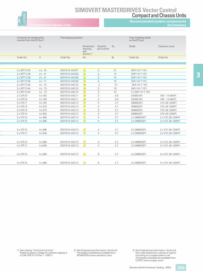
Compact and chassis units
3/53
SIMOVERT MASTERDRIVES Vector ControlCompact and Chassis Units
3
Siemens North American Catalog · 2004
Contactor for isolating theinverter from the DC bus1)
Precharging resistors Free-wheeling diodeon the DC bus
IS Dimensiondrawing,seeSection 7
Quantityper inverter
RS Diode Clamp-on cover
Order No. A Order No. No. � Order No. Order No.
2 x 3RT13 25 4 x 22 6SX7010–0AC07 30 2 27 SKR 141 F 152)
2 x 3RT13 36 4 x 41 6SX7010–0AC08 30 2 15 SKR 141 F 152)
2 x 3RT13 36 4 x 41 6SX7010–0AC08 30 2 15 SKR 141 F 152)
2 x 3RT13 36 4 x 71 6SX7010–0AC08 30 2 15 SKR 141 F 152)
2 x 3RT13 44 4 x 73 6SX7010–0AC10 30 2 10 SKR 141 F 152)
2 x 3RT13 44 4 x 73 6SX7010–0AC10 30 2 10 SKR 141 F 152)
2 x 3RT13 44 4 x 73 6SX7010–0AC10 30 2 10 2 x SKR 141 F 152)
2 x 3TK10 3 x 162 6SX7010–0AC11 30 2 5.6 D348S163) V50 – 14.45M3)
2 x 3TK10 4 x 146 6SX7010–0AC11 30 2 5.6 D348S163) V50 – 14.45M3)
2 x 3TK11 4 x 183 6SX7010–0AC13 31 2 2.7 D689S203) V72–26.120M3)
2 x 3TK12 4 x 219 6SX7010–0AC13 31 2 2.7 D689S203) V72–26.120M3)
2 x 3TK12 4 x 219 6SX7010–0AC13 31 2 2.7 D689S203) V72–26.120M3)
2 x 3TK14 4 x 402 6SX7010–0AC13 31 2 2.7 D689S203) V72–26.120M3)
2 x 3TK15 4 x 488 6SX7010–0AC13 31 4 2.7 2 x D689S203) 2 x V72–26.120M3)
2 x 3TK15 4 x 488 6SX7010–0AC13 31 4 2.7 2 x D689S203) 2 x V72–26.120M3)
2 x 3TK15 4 x 488 6SX7010–0AC13 31 4 2.7 2 x D689S203) 2 x V72–26.120M3)
2 x 3TK17 4 x 638 6SX7010–0AC13 31 4 2.7 2 x D689S203) 2 x V72–26.120M3)
2 x 3TK15 4 x 488 6SX7010–0AC13 31 4 2.7 2 x D689S203) 2 x V72–26.120M3)
2 x 3TK17 4 x 638 6SX7010–0AC13 31 4 2.7 2 x D689S203) 2 x V72–26.120M3)
4 x 3TK15 4 x 488 6SX7010–0AC13 31 8 2.7 4 x D689S203) 4 x V72–26.120M3)
4 x 3TK15 4 x 488 6SX7010–0AC13 31 8 2.7 4 x D689S203) 4 x V72–26.120M3)
1) See catalog “Industrial Controls”.Rated insulation voltage for pollution degree 2to DIN VDE 0110 Part 1: 1000 V.
2) See Engineering Information, Section 6.The diodes indicated are available fromSEMIKRON (www.semikron.com).
3) See Engineering Information, Section 6.Disc-type diode with a clamp-on cap formounting on a copper plate or rail.The diodes indicated are available fromEUPEC (www.eupec.com).
Recommended system componentsfor inverters
nelsco
Highlight
nelsco
Highlight
nelsco
Highlight
nelsco
Highlight
nelsco
Highlight
nelsco
Highlight
nelsco
Highlight
nelsco
Highlight
nelsco
Highlight
nelsco
Highlight
nelsco
Highlight
nelsco
Highlight
nelsco
Highlight
nelsco
Highlight
nelsco
Highlight
nelsco
Highlight
nelsco
Highlight
nelsco
Highlight
nelsco
Highlight
nelsco
Highlight
nelsco
Highlight
nelsco
Highlight
nelsco
Highlight
nelsco
Highlight
nelsco
Highlight
nelsco
Highlight
nelsco
Highlight
nelsco
Highlight
nelsco
Highlight
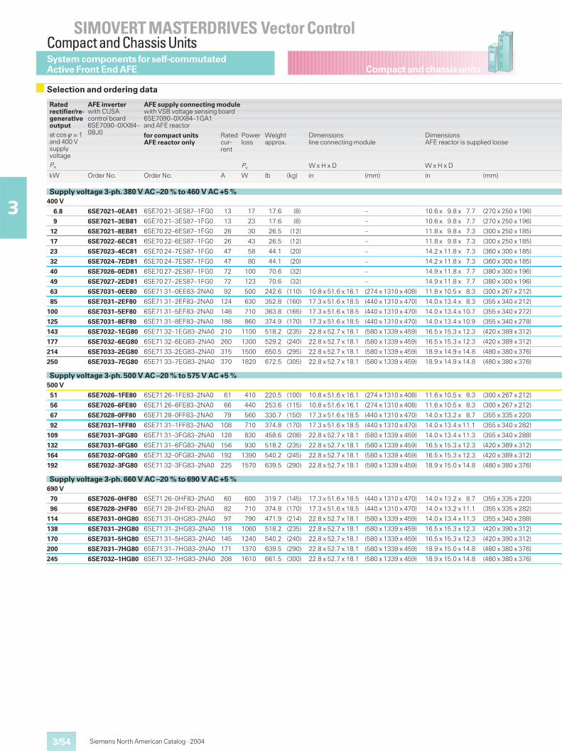
Compact and chassis units
SIMOVERT MASTERDRIVES Vector ControlCompact and Chassis Units
3/54
3
Siemens North American Catalog · 2004
System components for self-commutatedActive Front End AFE
Selection and ordering data
Ratedrectifier/re-generativeoutputat cos � = 1and 400 VsupplyvoltagePn
AFE inverterwith CUSAcontrol board6SE7090–0XX84–0BJ0
AFE supply connecting modulewith VSB voltage sensing board6SE7090–0XX84–1GA1and AFE reactor
for compact unitsAFE reactor only
Ratedcur-rent
Powerloss
Pv
Weightapprox.
Dimensionsline connecting module
W x H x D
DimensionsAFE reactor is supplied loose
W x H x D
kW Order No. Order No. A W lb (kg) in (mm) in (mm)
Supply voltage 3-ph. 380 V AC –20 % to 460 V AC +5 %400 V
6.8 6SE7021–0EA81 6SE70 21–3ES87–1FG0 13 17 17.6 (8) – 10.6 x 9.8 x 7.7 (270 x 250 x 196)
9 6SE7021–3EB81 6SE70 21–3ES87–1FG0 13 23 17.6 (8) – 10.6 x 9.8 x 7.7 (270 x 250 x 196)
12 6SE7021–8EB81 6SE70 22–6ES87–1FG0 26 30 26.5 (12) – 11.8 x 9.8 x 7.3 (300 x 250 x 185)
17 6SE7022–6EC81 6SE70 22–6ES87–1FG0 26 43 26.5 (12) – 11.8 x 9.8 x 7.3 (300 x 250 x 185)
23 6SE7023–4EC81 6SE70 24–7ES87–1FG0 47 58 44.1 (20) – 14.2 x 11.8 x 7.3 (360 x 300 x 185)
32 6SE7024–7ED81 6SE70 24–7ES87–1FG0 47 80 44.1 (20) – 14.2 x 11.8 x 7.3 (360 x 300 x 185)
40 6SE7026–0ED81 6SE70 27–2ES87–1FG0 72 100 70.6 (32) – 14.9 x 11.8 x 7.7 (380 x 300 x 196)
49 6SE7027–2ED81 6SE70 27–2ES87–1FG0 72 123 70.6 (32) – 14.9 x 11.8 x 7.7 (380 x 300 x 196)
63 6SE7031–0EE80 6SE71 31–0EE83–2NA0 92 500 242.6 (110) 10.8 x 51.6 x 16.1 (274 x 1310 x 408) 11.8 x 10.5 x 8.3 (300 x 267 x 212)
85 6SE7031–2EF80 6SE71 31–2EF83–2NA0 124 630 352.8 (160) 17.3 x 51.6 x 18.5 (440 x 1310 x 470) 14.0 x 13.4 x 8.3 (355 x 340 x 212)
100 6SE7031–5EF80 6SE71 31–5EF83–2NA0 146 710 363.8 (165) 17.3 x 51.6 x 18.5 (440 x 1310 x 470) 14.0 x 13.4 x 10.7 (355 x 340 x 272)
125 6SE7031–8EF80 6SE71 31–8EF83–2NA0 186 860 374.9 (170) 17.3 x 51.6 x 18.5 (440 x 1310 x 470) 14.0 x 13.4 x 10.9 (355 x 340 x 278)
143 6SE7032–1EG80 6SE71 32–1EG83–2NA0 210 1100 518.2 (235) 22.8 x 52.7 x 18.1 (580 x 1339 x 459) 16.5 x 15.3 x 12.3 (420 x 389 x 312)
177 6SE7032–6EG80 6SE71 32–6EG83–2NA0 260 1300 529.2 (240) 22.8 x 52.7 x 18.1 (580 x 1339 x 459) 16.5 x 15.3 x 12.3 (420 x 389 x 312)
214 6SE7033–2EG80 6SE71 33–2EG83–2NA0 315 1500 650.5 (295) 22.8 x 52.7 x 18.1 (580 x 1339 x 459) 18.9 x 14.9 x 14.8 (480 x 380 x 376)
250 6SE7033–7EG80 6SE71 33–7EG83–2NA0 370 1820 672.5 (305) 22.8 x 52.7 x 18.1 (580 x 1339 x 459) 18.9 x 14.9 x 14.8 (480 x 380 x 376)
Supply voltage 3-ph. 500 V AC –20 % to 575 V AC +5 %500 V
51 6SE7026–1FE80 6SE71 26–1FE83–2NA0 61 410 220.5 (100) 10.8 x 51.6 x 16.1 (274 x 1310 x 408) 11.6 x 10.5 x 8.3 (300 x 267 x 212)
56 6SE7026–6FE80 6SE71 26–6FE83–2NA0 66 440 253.6 (115) 10.8 x 51.6 x 16.1 (274 x 1310 x 408) 11.6 x 10.5 x 8.3 (300 x 267 x 212)
67 6SE7028–0FF80 6SE71 28–0FF83–2NA0 79 560 330.7 (150) 17.3 x 51.6 x 18.5 (440 x 1310 x 470) 14.0 x 13.2 x 8.7 (355 x 335 x 220)
92 6SE7031–1FF80 6SE71 31–1FF83–2NA0 108 710 374.8 (170) 17.3 x 51.6 x 18.5 (440 x 1310 x 470) 14.0 x 13.4 x 11.1 (355 x 340 x 282)
109 6SE7031–3FG80 6SE71 31–3FG83–2NA0 128 830 458.6 (208) 22.8 x 52.7 x 18.1 (580 x 1339 x 459) 14.0 x 13.4 x 11.3 (355 x 340 x 288)
132 6SE7031–6FG80 6SE71 31–6FG83–2NA0 156 930 518.2 (235) 22.8 x 52.7 x 18.1 (580 x 1339 x 459) 16.5 x 15.3 x 12.3 (420 x 389 x 312)
164 6SE7032–0FG80 6SE71 32–0FG83–2NA0 192 1390 540.2 (245) 22.8 x 52.7 x 18.1 (580 x 1339 x 459) 16.5 x 15.3 x 12.3 (420 x 389 x 312)
192 6SE7032–3FG80 6SE71 32–3FG83–2NA0 225 1570 639.5 (290) 22.8 x 52.7 x 18.1 (580 x 1339 x 459) 18.9 x 15.0 x 14.8 (480 x 380 x 376)
Supply voltage 3-ph. 660 V AC –20 % to 690 V AC +5 %690 V
70 6SE7026–0HF80 6SE71 26–0HF83–2NA0 60 600 319.7 (145) 17.3 x 51.6 x 18.5 (440 x 1310 x 470) 14.0 x 13.2 x 8.7 (355 x 335 x 220)
96 6SE7028–2HF80 6SE71 28–2HF83–2NA0 82 710 374.8 (170) 17.3 x 51.6 x 18.5 (440 x 1310 x 470) 14.0 x 13.2 x 11.1 (355 x 335 x 282)
114 6SE7031–0HG80 6SE71 31–0HG83–2NA0 97 790 471.9 (214) 22.8 x 52.7 x 18.1 (580 x 1339 x 459) 14.0 x 13.4 x 11.3 (355 x 340 x 288)
138 6SE7031–2HG80 6SE71 31–2HG83–2NA0 118 1060 518.2 (235) 22.8 x 52.7 x 18.1 (580 x 1339 x 459) 16.5 x 15.3 x 12.3 (420 x 390 x 312)
170 6SE7031–5HG80 6SE71 31–5HG83–2NA0 145 1240 540.2 (240) 22.8 x 52.7 x 18.1 (580 x 1339 x 459) 16.5 x 15.3 x 12.3 (420 x 390 x 312)
200 6SE7031–7HG80 6SE71 31–7HG83–2NA0 171 1370 639.5 (290) 22.8 x 52.7 x 18.1 (580 x 1339 x 459) 18.9 x 15.0 x 14.8 (480 x 380 x 376)
245 6SE7032–1HG80 6SE71 32–1HG83–2NA0 208 1610 661.5 (300) 22.8 x 52.7 x 18.1 (580 x 1339 x 459) 18.9 x 15.0 x 14.8 (480 x 380 x 376)
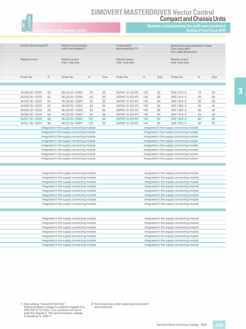
Compact and chassis units
3/55
SIMOVERT MASTERDRIVES Vector ControlCompact and Chassis Units
3
Siemens North American Catalog · 2004
System components for self-commutatedActive Front End AFE
Switch disconnector2)
Rated current
Switch disconnectorwith fuse holders2)
Rated currentmax. fuse size
Fuse switchdisconnectors1)2)
Rated currentmax. fuse size
Semiconductor-protection fusesDuty class gR2)incl. cable protection
Rated currentmax. fuse size
Order No. A Order No. A Size Order No. A Size Order No. A Size
3KA50 30–1EE01 63 3KL50 30–1EB01 63 00 3NP40 10–0CH01 100 00 3NE1 813–0 16 00
3KA50 30–1EE01 63 3KL50 30–1EB01 63 00 3NP40 10–0CH01 100 00 3NE1 814–0 20 00
3KA50 30–1EE01 63 3KL50 30–1EB01 63 00 3NP40 10–0CH01 100 00 3NE1 815–0 25 00
3KA50 30–1EE01 63 3KL50 30–1EB01 63 00 3NP40 10–0CH01 100 00 3NE1 803–0 35 00
3KA50 30–1EE01 63 3KL50 30–1EB01 63 00 3NP40 10–0CH01 100 00 3NE1 802–0 40 00
3KA50 30–1EE01 63 3KL50 30–1EB01 63 00 3NP40 10–0CH01 100 00 3NE1 818–0 63 00
3KA51 30–1EE01 80 3KL52 30–1EB01 125 00 3NP40 10–0CH01 100 00 3NE1 820–0 80 00
3KA51 30–1EE01 80 3KL52 30–1EB01 125 00 3NP40 10–0CH01 100 00 3NE1 820–0 80 00
integrated in the supply connecting module integrated in the supply connecting module
integrated in the supply connecting module integrated in the supply connecting module
integrated in the supply connecting module integrated in the supply connecting module
integrated in the supply connecting module integrated in the supply connecting module
integrated in the supply connecting module integrated in the supply connecting module
integrated in the supply connecting module integrated in the supply connecting module
integrated in the supply connecting module integrated in the supply connecting module
integrated in the supply connecting module integrated in the supply connecting module
integrated in the supply connecting module integrated in the supply connecting module
integrated in the supply connecting module integrated in the supply connecting module
integrated in the supply connecting module integrated in the supply connecting module
integrated in the supply connecting module integrated in the supply connecting module
integrated in the supply connecting module integrated in the supply connecting module
integrated in the supply connecting module integrated in the supply connecting module
integrated in the supply connecting module integrated in the supply connecting module
integrated in the supply connecting module integrated in the supply connecting module
integrated in the supply connecting module integrated in the supply connecting module
integrated in the supply connecting module integrated in the supply connecting module
integrated in the supply connecting module integrated in the supply connecting module
integrated in the supply connecting module integrated in the supply connecting module
integrated in the supply connecting module integrated in the supply connecting module
integrated in the supply connecting module integrated in the supply connecting module
integrated in the supply connecting module integrated in the supply connecting module
1) See catalog “Industrial Controls”.Rated insulation voltage for pollution degree 3 toDIN VDE 0110, Part 1, but conditions of use topollution degree 2. The rated insulation voltageis therefore � 1000 V.
2) Note fuse sizes when selecting fuse switchdisconnectors.
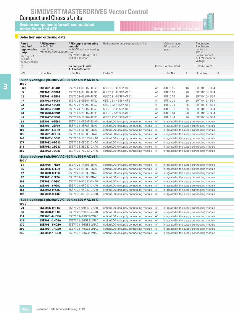
Compact and chassis units
SIMOVERT MASTERDRIVES Vector ControlCompact and Chassis Units
3/56
3
Siemens North American Catalog · 2004
Selection and ordering data
System components for self-commutatedActive Front End AFE
Ratedrectifier/regenerativeoutputat cos � = 1and 400 Vsupply voltage
AFE inverterwith CUSAcontrol board6SE7090–0XX84–0BJ0
AFE supply connectingmodulewith VSB voltage sensingboard6SE7090–0XX84–1GA1and AFE reactor
Radio-interference suppression filter Main contactor/AC contactor230 V
PrechargingPrechargingcontactor230 V(with compactAFE 24 V controlvoltage)
Pn for compact unitsAFE reactor only
Class Rated current Rated current
kW Order No. Order No. Order No. Order No. A Order No. A
Supply voltage 3-ph. 380 V AC –20 % to 460 V AC +5 %400 V
6.8 6SE7021–0EA81 6SE70 21–3ES87–1FG0 6SE70 21–0ES87–0FB1 A1 3RT10 15 16 3RT10 16–. BB4 .
9 6SE7021–3EB81 6SE70 21–3ES87–1FG0 6SE70 21–8ES87–0FB1 A1 3RT10 16 20 3RT10 16–. BB4 .
12 6SE7021–8EB81 6SE70 22–6ES87–1FG0 6SE70 21–8ES87–0FB1 A1 3RT10 16 20 3RT10 16–. BB4 .
17 6SE7022–6EC81 6SE70 22–6ES87–1FG0 6SE70 23–4ES87–0FB1 A1 3RT10 25 35 3RT10 16–. BB4 .
23 6SE7023–4EC81 6SE70 24–7ES87–1FG0 6SE70 23–4ES87–0FB1 A1 3RT10 34 45 3RT10 16–. BB4 .
32 6SE7024–7ED81 6SE70 24–7ES87–1FG0 6SE70 27–2ES87–0FB1 A1 3RT10 35 55 3RT10 16–. BB4 .
40 6SE7026–0ED81 6SE70 27–2ES87–1FG0 6SE70 27–2ES87–0FB1 A1 3RT10 44 90 3RT10 16–. BB4 .
49 6SE7027–2ED81 6SE70 27–2ES87–1FG0 6SE70 27–2ES87–0FB1 A1 3RT10 44 90 3RT10 16–. BB4 .
63 6SE7031–0EE80 6SE71 31–0EE83–2NA0 option L00 for supply connecting module A1 integrated in the supply connecting module
85 6SE7031–2EF80 6SE71 31–2EF83–2NA0 option L00 for supply connecting module A1 integrated in the supply connecting module
100 6SE7031–5EF80 6SE71 31–5EF83–2NA0 option L00 for supply connecting module A1 integrated in the supply connecting module
125 6SE7031–8EF80 6SE71 31–8EF83–2NA0 option L00 for supply connecting module A1 integrated in the supply connecting module
143 6SE7032–1EG80 6SE71 32–1EG83–2NA0 option L00 for supply connecting module A1 integrated in the supply connecting module
177 6SE7032–6EG80 6SE71 32–6EG83–2NA0 option L00 for supply connecting module A1 integrated in the supply connecting module
214 6SE7033–2EG80 6SE71 33–2EG83–2NA0 option L00 for supply connecting module A1 integrated in the supply connecting module
250 6SE7033–7EG80 6SE71 33–7EG83–2NA0 option L00 for supply connecting module A1 integrated in the supply connecting module
Supply voltage 3-ph. 500 V AC –20 % to 575 V AC +5 %500 V
51 6SE7026–1FE80 6SE71 26–1FE83–2NA0 option L00 for supply connecting module A1 integrated in the supply connecting module
56 6SE7026–6FE80 6SE71 26–6FE83–2NA0 option L00 for supply connecting module A1 integrated in the supply connecting module
67 6SE7028–0FF80 6SE71 28–0FF83–2NA0 option L00 for supply connecting module A1 integrated in the supply connecting module
92 6SE7031–1FF80 6SE71 31–1FF83–2NA0 option L00 for supply connecting module A1 integrated in the supply connecting module
109 6SE7031–3FG80 6SE71 31–3FG83–2NA0 option L00 for supply connecting module A1 integrated in the supply connecting module
132 6SE7031–6FG80 6SE71 31–6FG83–2NA0 option L00 for supply connecting module A1 integrated in the supply connecting module
164 6SE7032–0FG80 6SE71 32–0FG83–2NA0 option L00 for supply connecting module A1 integrated in the supply connecting module
192 6SE7032–3FG80 6SE71 32–3FG83–2NA0 option L00 for supply connecting module A1 integrated in the supply connecting module
Supply voltage 3-ph. 660 V AC –20 % to 690 V AC +5 %690 V
70 6SE7026–0HF80 6SE71 26–0HF83–2NA0 option L00 for supply connecting module A1 integrated in the supply connecting module
96 6SE7028–2HF80 6SE71 28–2HF83–2NA0 option L00 for supply connecting module A1 integrated in the supply connecting module
114 6SE7031–0HG80 6SE71 31–0HG83–2NA0 option L00 for supply connecting module A1 integrated in the supply connecting module
138 6SE7031–2HG80 6SE71 31–2HG83–2NA0 option L00 for supply connecting module A1 integrated in the supply connecting module
170 6SE7031–5HG80 6SE71 31–5HG83–2NA0 option L00 for supply connecting module A1 integrated in the supply connecting module
200 6SE7031–7HG80 6SE71 31–7HG83–2NA0 option L00 for supply connecting module A1 integrated in the supply connecting module
245 6SE7032–1HG80 6SE71 32–1HG83–2NA0 option L00 for supply connecting module A1 integrated in the supply connecting module
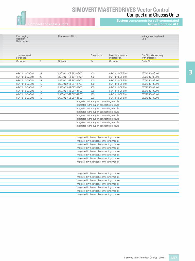
Compact and chassis units
3/57
SIMOVERT MASTERDRIVES Vector ControlCompact and Chassis Units
3
Siemens North American Catalog · 2004
System components for self-commutatedActive Front End AFE
PrechargingResistorRated value
Clean power filter Voltage sensing boardVSB
1 unit requiredper phase
Power loss Basic interferencesuppression
For DIN rail mountingwith enclosure
Order No. � Order No. W Order No. Order No.
6SX70 10–0AC81 22 6SE70 21–0EB87–1FC0 200 6SX70 10–0FB10 6SX70 10–0EJ00
6SX70 10–0AC81 22 6SE70 21–8EB87–1FC0 250 6SX70 10–0FB10 6SX70 10–0EJ00
6SX70 10–0AC81 22 6SE70 21–8EB87–1FC0 250 6SX70 10–0FB10 6SX70 10–0EJ00
6SX70 10–0AC80 10 6SE70 22–6EC87–1FC0 300 6SX70 10–0FB10 6SX70 10–0EJ00
6SX70 10–0AC80 10 6SE70 23–4EC87–1FC0 400 6SX70 10–0FB10 6SX70 10–0EJ00
6SX70 10–0AC80 10 6SE70 24–7ED87–1FC0 500 6SX70 10–0FB10 6SX70 10–0EJ00
6SX70 10–0AC80 10 6SE70 27–2ED87–1FC0 600 6SX70 10–0FB10 6SX70 10–0EJ00
6SX70 10–0AC80 10 6SE70 27–2ED87–1FC0 600 6SX70 10–0FB10 6SX70 10–0EJ00
integrated in the supply connecting module
integrated in the supply connecting module
integrated in the supply connecting module
integrated in the supply connecting module
integrated in the supply connecting module
integrated in the supply connecting module
integrated in the supply connecting module
integrated in the supply connecting module
integrated in the supply connecting module
integrated in the supply connecting module
integrated in the supply connecting module
integrated in the supply connecting module
integrated in the supply connecting module
integrated in the supply connecting module
integrated in the supply connecting module
integrated in the supply connecting module
integrated in the supply connecting module
integrated in the supply connecting module
integrated in the supply connecting module
integrated in the supply connecting module
integrated in the supply connecting module
integrated in the supply connecting module
integrated in the supply connecting module
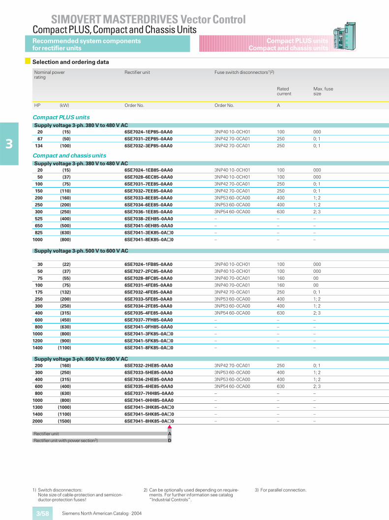
3/58
SIMOVERT MASTERDRIVES Vector ControlCompact PLUS,Compact and Chassis Units
3
Compact PLUS unitsCompact and chassis units
Siemens North American Catalog · 2004
1) Switch disconnectors:Note size of cable-protection and semicon-ductor-protection fuses!
2) Can be optionally used depending on require-ments. For further information see catalog“Industrial Controls”.
3) For parallel connection.
Recommended system componentsfor rectifier units
Selection and ordering data
Nominal powerrating
Rectifier unit Fuse switch disconnectors1)2)
Ratedcurrent
Max. fusesize
HP (kW) Order No. Order No. A
Compact PLUS units
Supply voltage 3-ph. 380 V to 480 V AC20 (15) 6SE7024–1EP85–0AA0 3NP40 10–0CH01 100 000
67 (50) 6SE7031–2EP85–0AA0 3NP42 70–0CA01 250 0; 1
134 (100) 6SE7032–3EP85–0AA0 3NP42 70–0CA01 250 0; 1
Compact and chassis units
Supply voltage 3-ph. 380 V to 480 V AC20 (15) 6SE7024–1EB85–0AA0 3NP40 10–0CH01 100 000
50 (37) 6SE7028–6EC85–0AA0 3NP40 10–0CH01 100 000
100 (75) 6SE7031–7EE85–0AA0 3NP42 70–0CA01 250 0; 1
150 (110) 6SE7032–7EE85–0AA0 3NP42 70–0CA01 250 0; 1
200 (160) 6SE7033–8EE85–0AA0 3NP53 60–0CA00 400 1; 2
250 (200) 6SE7034–6EE85–0AA0 3NP53 60–0CA00 400 1; 2
300 (250) 6SE7036–1EE85–0AA0 3NP54 60–0CA00 630 2; 3
525 (400) 6SE7038–2EH85–0AA0 – – –
650 (500) 6SE7041–0EH85–0AA0 – – –
825 (630) 6SE7041–3EK85–0A@0 – – –
1000 (800) 6SE7041–8EK85–0A@0 – – –
Supply voltage 3-ph. 500 V to 600 V AC
30 (22) 6SE7024–1FB85–0AA0 3NP40 10–0CH01 100 000
50 (37) 6SE7027–2FC85–0AA0 3NP40 10–0CH01 100 000
75 (55) 6SE7028–8FC85–0AA0 3NP40 70–0CA01 160 00
100 (75) 6SE7031–4FE85–0AA0 3NP40 70–0CA01 160 00
175 (132) 6SE7032–4FE85–0AA0 3NP42 70–0CA01 250 0; 1
250 (200) 6SE7033–5FE85–0AA0 3NP53 60–0CA00 400 1; 2
300 (250) 6SE7034–2FE85–0AA0 3NP53 60–0CA00 400 1; 2
400 (315) 6SE7035–4FE85–0AA0 3NP54 60–0CA00 630 2; 3
600 (450) 6SE7037–7FH85–0AA0 – – –
800 (630) 6SE7041–0FH85–0AA0 – – –
1000 (800) 6SE7041–3FK85–0A@0 – – –
1200 (900) 6SE7041–5FK85–0A@0 – – –
1400 (1100) 6SE7041–8FK85–0A@0 – – –
Supply voltage 3-ph. 660 V to 690 V AC200 (160) 6SE7032–2HE85–0AA0 3NP42 70–0CA01 250 0; 1
300 (250) 6SE7033–5HE85–0AA0 3NP53 60–0CA00 400 1; 2
400 (315) 6SE7034–2HE85–0AA0 3NP53 60–0CA00 400 1; 2
600 (400) 6SE7035–4HE85–0AA0 3NP54 60–0CA00 630 2; 3
800 (630) 6SE7037–7HH85–0AA0 – – –
1000 (800) 6SE7041–0HH85–0AA0 – – –
1300 (1000) 6SE7041–3HK85–0A@0 – – –
1400 (1100) 6SE7041–5HK85–0A@0 – – –
2000 (1500) 6SE7041–8HK85–0A@0 – – –�
Rectifier unit A
Rectifierunit with powersection3) D
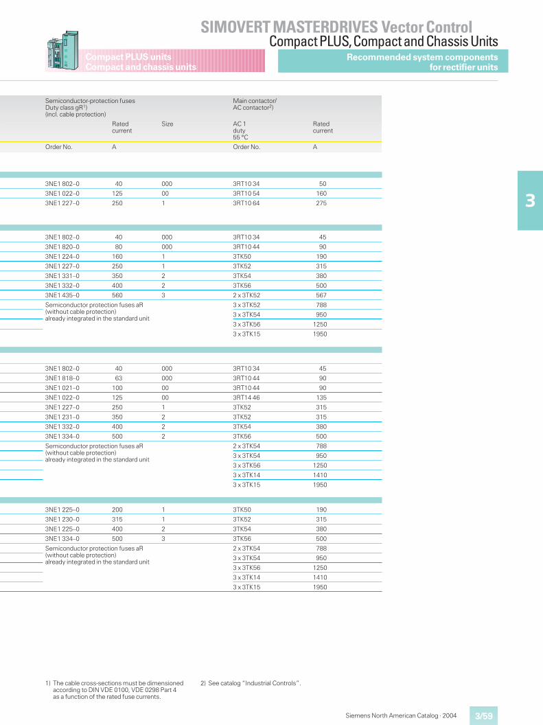
Siemens North American Catalog · 2004 3/59
SIMOVERT MASTERDRIVES Vector ControlCompact PLUS,Compact and Chassis Units
3
Compact PLUS unitsCompact and chassis units
1) The cable cross-sections must be dimensionedaccording to DIN VDE 0100, VDE 0298 Part 4as a function of the rated fuse currents.
2) See catalog “Industrial Controls”.
Recommended system componentsfor rectifier units
Semiconductor-protection fusesDuty class gR1)(incl. cable protection)
Main contactor/AC contactor2)
Ratedcurrent
Size AC 1duty55 °C
Ratedcurrent
Order No. A Order No. A
3NE1 802–0 40 000 3RT10 34 50
3NE1 022–0 125 00 3RT10 54 160
3NE1 227–0 250 1 3RT10 64 275
3NE1 802–0 40 000 3RT10 34 45
3NE1 820–0 80 000 3RT10 44 90
3NE1 224–0 160 1 3TK50 190
3NE1 227–0 250 1 3TK52 315
3NE1 331–0 350 2 3TK54 380
3NE1 332–0 400 2 3TK56 500
3NE1 435–0 560 3 2 x 3TK52 567
Semiconductor protection fuses aR(without cable protection)already integrated in the standard unit
3 x 3TK52 788
3 x 3TK54 950
3 x 3TK56 1250
3 x 3TK15 1950
3NE1 802–0 40 000 3RT10 34 45
3NE1 818–0 63 000 3RT10 44 90
3NE1 021–0 100 00 3RT10 44 90
3NE1 022–0 125 00 3RT14 46 135
3NE1 227–0 250 1 3TK52 315
3NE1 231–0 350 2 3TK52 315
3NE1 332–0 400 2 3TK54 380
3NE1 334–0 500 2 3TK56 500
Semiconductor protection fuses aR(without cable protection)already integrated in the standard unit
2 x 3TK54 788
3 x 3TK54 950
3 x 3TK56 1250
3 x 3TK14 1410
3 x 3TK15 1950
3NE1 225–0 200 1 3TK50 190
3NE1 230–0 315 1 3TK52 315
3NE1 225–0 400 2 3TK54 380
3NE1 334–0 500 3 3TK56 500
Semiconductor protection fuses aR(without cable protection)already integrated in the standard unit
2 x 3TK54 788
3 x 3TK54 950
3 x 3TK56 1250
3 x 3TK14 1410
3 x 3TK15 1950
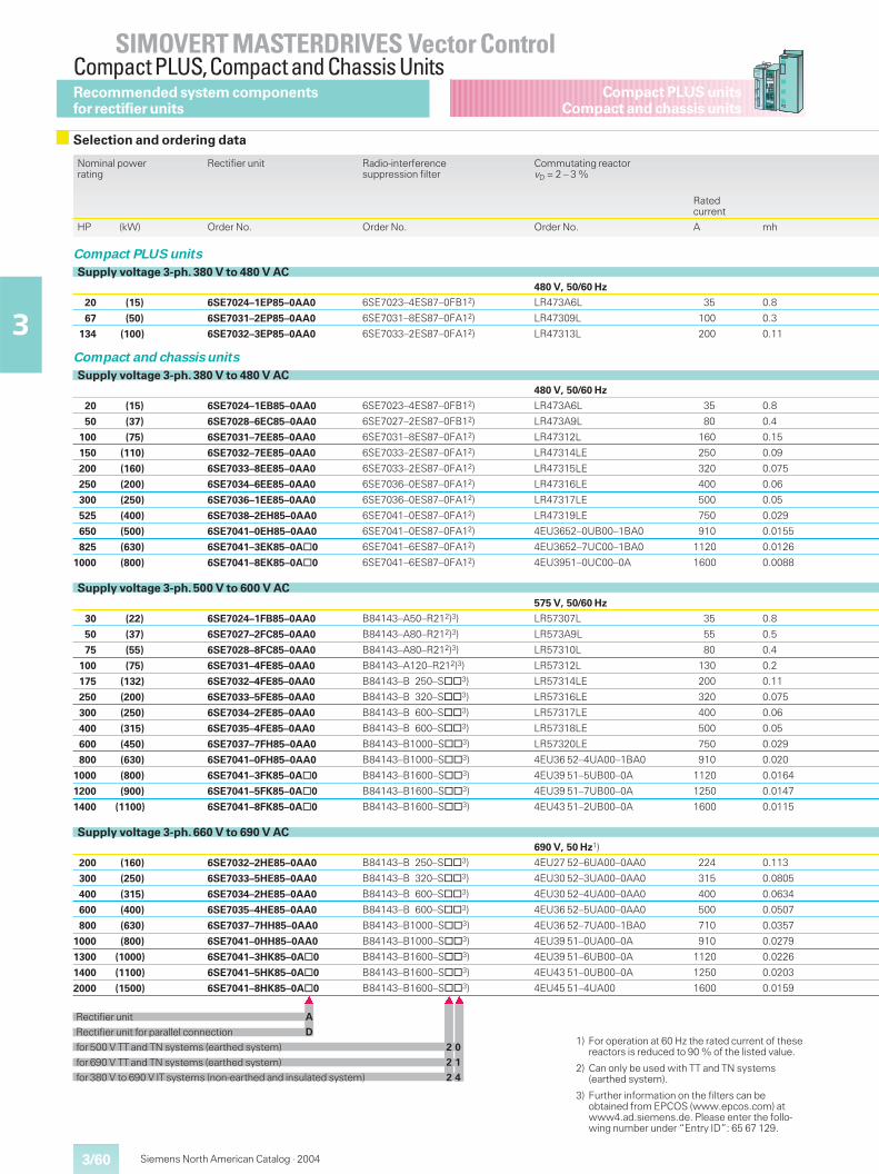
3/60
SIMOVERT MASTERDRIVES Vector ControlCompact PLUS,Compact and Chassis Units
3
Compact PLUS unitsCompact and chassis units
Siemens North American Catalog · 2004
1) For operation at 60 Hz the rated current of thesereactors is reduced to 90 % of the listed value.
2) Can only be used with TT and TN systems(earthed system).
3) Further information on the filters can beobtained from EPCOS (www.epcos.com) atwww4.ad.siemens.de. Please enter the follo-wing number under “Entry ID”: 65 67 129.
Recommended system componentsfor rectifier units
Selection and ordering data
Nominal powerrating
Rectifier unit Radio-interferencesuppression filter
Commutating reactorvD = 2 – 3 %
Ratedcurrent
HP (kW) Order No. Order No. Order No. A mh
Compact PLUS units
Supply voltage 3-ph. 380 V to 480 V AC480 V, 50/60 Hz
20 (15) 6SE7024–1EP85–0AA0 6SE7023–4ES87–0FB12) LR473A6L 35 0.8
67 (50) 6SE7031–2EP85–0AA0 6SE7031–8ES87–0FA12) LR47309L 100 0.3
134 (100) 6SE7032–3EP85–0AA0 6SE7033–2ES87–0FA12) LR47313L 200 0.11
Compact and chassis units
Supply voltage 3-ph. 380 V to 480 V AC480 V, 50/60 Hz
20 (15) 6SE7024–1EB85–0AA0 6SE7023–4ES87–0FB12) LR473A6L 35 0.8
50 (37) 6SE7028–6EC85–0AA0 6SE7027–2ES87–0FB12) LR473A9L 80 0.4
100 (75) 6SE7031–7EE85–0AA0 6SE7031–8ES87–0FA12) LR47312L 160 0.15
150 (110) 6SE7032–7EE85–0AA0 6SE7033–2ES87–0FA12) LR47314LE 250 0.09
200 (160) 6SE7033–8EE85–0AA0 6SE7033–2ES87–0FA12) LR47315LE 320 0.075
250 (200) 6SE7034–6EE85–0AA0 6SE7036–0ES87–0FA12) LR47316LE 400 0.06
300 (250) 6SE7036–1EE85–0AA0 6SE7036–0ES87–0FA12) LR47317LE 500 0.05
525 (400) 6SE7038–2EH85–0AA0 6SE7041–0ES87–0FA12) LR47319LE 750 0.029
650 (500) 6SE7041–0EH85–0AA0 6SE7041–0ES87–0FA12) 4EU3652–0UB00–1BA0 910 0.0155
825 (630) 6SE7041–3EK85–0A@0 6SE7041–6ES87–0FA12) 4EU3652–7UC00–1BA0 1120 0.0126
1000 (800) 6SE7041–8EK85–0A@0 6SE7041–6ES87–0FA12) 4EU3951–0UC00–0A 1600 0.0088
Supply voltage 3-ph. 500 V to 600 V AC575 V, 50/60 Hz
30 (22) 6SE7024–1FB85–0AA0 B84143–A50–R212)3) LR57307L 35 0.8
50 (37) 6SE7027–2FC85–0AA0 B84143–A80–R212)3) LR573A9L 55 0.5
75 (55) 6SE7028–8FC85–0AA0 B84143–A80–R212)3) LR57310L 80 0.4
100 (75) 6SE7031–4FE85–0AA0 B84143–A120–R212)3) LR57312L 130 0.2
175 (132) 6SE7032–4FE85–0AA0 B84143–B 250–S@@3) LR57314LE 200 0.11
250 (200) 6SE7033–5FE85–0AA0 B84143–B 320–S@@3) LR57316LE 320 0.075
300 (250) 6SE7034–2FE85–0AA0 B84143–B 600–S@@3) LR57317LE 400 0.06
400 (315) 6SE7035–4FE85–0AA0 B84143–B 600–S@@3) LR57318LE 500 0.05
600 (450) 6SE7037–7FH85–0AA0 B84143–B1000–S@@3) LR57320LE 750 0.029
800 (630) 6SE7041–0FH85–0AA0 B84143–B1000–S@@3) 4EU36 52–4UA00–1BA0 910 0.020
1000 (800) 6SE7041–3FK85–0A@0 B84143–B1600–S@@3) 4EU39 51–5UB00–0A 1120 0.0164
1200 (900) 6SE7041–5FK85–0A@0 B84143–B1600–S@@3) 4EU39 51–7UB00–0A 1250 0.0147
1400 (1100) 6SE7041–8FK85–0A@0 B84143–B1600–S@@3) 4EU43 51–2UB00–0A 1600 0.0115
Supply voltage 3-ph. 660 V to 690 V AC690 V, 50 Hz1)
200 (160) 6SE7032–2HE85–0AA0 B84143–B 250–S@@3) 4EU27 52–6UA00–0AA0 224 0.113
300 (250) 6SE7033–5HE85–0AA0 B84143–B 320–S@@3) 4EU30 52–3UA00–0AA0 315 0.0805
400 (315) 6SE7034–2HE85–0AA0 B84143–B 600–S@@3) 4EU30 52–4UA00–0AA0 400 0.0634
600 (400) 6SE7035–4HE85–0AA0 B84143–B 600–S@@3) 4EU36 52–5UA00–0AA0 500 0.0507
800 (630) 6SE7037–7HH85–0AA0 B84143–B1000–S@@3) 4EU36 52–7UA00–1BA0 710 0.0357
1000 (800) 6SE7041–0HH85–0AA0 B84143–B1000–S@@3) 4EU39 51–0UA00–0A 910 0.0279
1300 (1000) 6SE7041–3HK85–0A@0 B84143–B1600–S@@3) 4EU39 51–6UB00–0A 1120 0.0226
1400 (1100) 6SE7041–5HK85–0A@0 B84143–B1600–S@@3) 4EU43 51–0UB00–0A 1250 0.0203
2000 (1500) 6SE7041–8HK85–0A@0 B84143–B1600–S@@3) 4EU45 51–4UA00 1600 0.0159� ��
Rectifier unit A
Rectifier unit for parallel connection D
for 500 V TT and TN systems (earthed system) 2 0
for 690 V TT and TN systems (earthed system) 2 1
for 380 V to 690 V IT systems (non-earthed and insulated system) 2 4
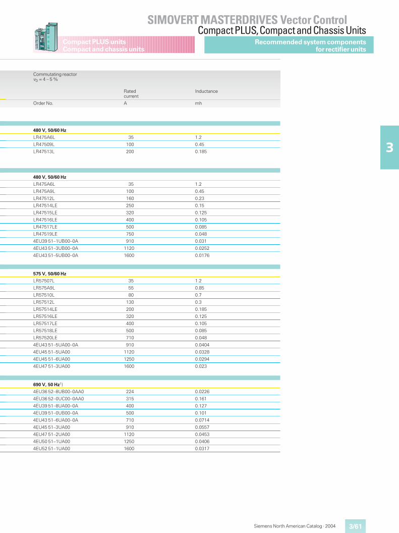
3/61
SIMOVERT MASTERDRIVES Vector ControlCompact PLUS,Compact and Chassis Units
3
Compact PLUS unitsCompact and chassis units
Siemens North American Catalog · 2004
Commutating reactorvD = 4 – 5 %
Ratedcurrent
Inductance
Order No. A mh
480 V, 50/60 Hz
LR475A6L 35 1.2
LR47509L 100 0.45
LR47513L 200 0.185
480 V, 50/60 Hz
LR475A6L 35 1.2
LR475A9L 100 0.45
LR47512L 160 0.23
LR47514LE 250 0.15
LR47515LE 320 0.125
LR47516LE 400 0.105
LR47517LE 500 0.085
LR47519LE 750 0.048
4EU39 51–1UB00–0A 910 0.031
4EU43 51–3UB00–0A 1120 0.0252
4EU43 51–5UB00–0A 1600 0.0176
575 V, 50/60 Hz
LR57507L 35 1.2
LR575A9L 55 0.85
LR57510L 80 0.7
LR57512L 130 0.3
LR57514LE 200 0.185
LR57516LE 320 0.125
LR57517LE 400 0.105
LR57518LE 500 0.085
LR57520LE 710 0.048
4EU43 51–5UA00–0A 910 0.0404
4EU45 51–5UA00 1120 0.0328
4EU45 51–6UA00 1250 0.0294
4EU47 51–3UA00 1600 0.023
690 V, 50 Hz1)
4EU36 52–8UB00–0AA0 224 0.0226
4EU36 52–0UC00–0AA0 315 0.161
4EU39 51–8UA00–0A 400 0.127
4EU39 51–0UB00–0A 500 0.101
4EU43 51–6UA00–0A 710 0.0714
4EU45 51–3UA00 910 0.0557
4EU47 51–2UA00 1120 0.0453
4EU50 51–1UA00 1250 0.0406
4EU52 51–1UA00 1600 0.0317
Recommended system componentsfor rectifier units
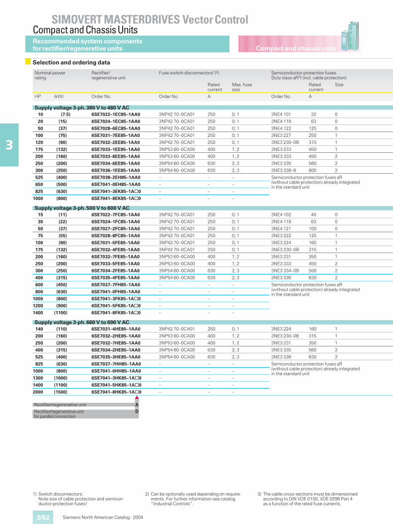
Compact and chassis units
SIMOVERT MASTERDRIVES Vector ControlCompact and Chassis Units
3/62
3
Siemens North American Catalog · 2004
Nominal powerrating
Rectifier/regenerative unit
Fuse switch disconnectors1)2) Semiconductor-protection fusesDuty class aR3) (incl. cable protection)
Ratedcurrent
Max. fusesize
Ratedcurrent
Size
HP (kW) Order No. Order No. A Order No. A
Supply voltage 3-ph. 380 V to 480 V AC10 (7.5) 6SE7022–1EC85–1AA0 3NP42 70–0CA01 250 0; 1 3NE4 101 32 0
20 (15) 6SE7024–1EC85–1AA0 3NP42 70–0CA01 250 0; 1 3NE4 118 63 0
50 (37) 6SE7028–6EC85–1AA0 3NP42 70–0CA01 250 0; 1 3NE4 122 125 0
100 (75) 6SE7031–7EE85–1AA0 3NP42 70–0CA01 250 0; 1 3NE3 227 250 1
120 (90) 6SE7032–2EE85–1AA0 3NP42 70–0CA01 250 0; 1 3NE3 230–0B 315 1
175 (132) 6SE7033–1EE85–1AA0 3NP53 60–0CA00 400 1; 2 3NE3 233 450 1
200 (160) 6SE7033–8EE85–1AA0 3NP53 60–0CA00 400 1; 2 3NE3 333 450 2
250 (200) 6SE7034–6EE85–1AA0 3NP54 60–0CA00 630 2; 3 3NE3 335 560 2
300 (250) 6SE7036–1EE85–1AA0 3NP54 60–0CA00 630 2; 3 3NE3 338–8 800 2
525 (400) 6SE7038–2EH85–1AA0 – – – Semiconductor protection fuses aR(without cable protection) already integratedin the standard unit650 (500) 6SE7041–0EH85–1AA0 – – –
825 (630) 6SE7041–3EK85–1A@0 – – –
1000 (800) 6SE7041–8EK85–1A@0 – – –
Supply voltage 3-ph. 500 V to 600 V AC15 (11) 6SE7022–7FC85–1AA0 3NP42 70–0CA01 250 0; 1 3NE4 102 40 0
30 (22) 6SE7024–1FC85–1AA0 3NP42 70–0CA01 250 0; 1 3NE4 118 63 0
50 (37) 6SE7027–2FC85–1AA0 3NP42 70–0CA01 250 0; 1 3NE4 121 100 0
75 (55) 6SE7028–8FC85–1AA0 3NP42 70–0CA01 250 0; 1 3NE3 222 125 1
100 (90) 6SE7031–5FE85–1AA0 3NP42 70–0CA01 250 0; 1 3NE3 224 160 1
175 (132) 6SE7032–4FE85–1AA0 3NP42 70–0CA01 250 0; 1 3NE3 230–0B 315 1
200 (160) 6SE7032–7FE85–1AA0 3NP53 60–0CA00 400 1; 2 3NE3 231 350 1
250 (200) 6SE7033–5FE85–1AA0 3NP53 60–0CA00 400 1; 2 3NE3 333 450 2
300 (250) 6SE7034–2FE85–1AA0 3NP54 60–0CA00 630 2; 3 3NE3 334–0B 500 2
400 (315) 6SE7035–4FE85–1AA0 3NP54 60–0CA00 630 2; 3 3NE3 336 630 2
600 (450) 6SE7037–7FH85–1AA0 – – – Semiconductor protection fuses aR(without cable protection) already integratedin the standard unit800 (630) 6SE7041–0FH85–1AA0 – – –
1000 (800) 6SE7041–3FK85–1A@0 – – –
1200 (900) 6SE7041–5FK85–1A@0 – – –
1400 (1100) 6SE7041–8FK85–1A@0 – – –
Supply voltage 3-ph. 660 V to 690 V AC140 (110) 6SE7031–4HE85–1AA0 3NP42 70–0CA01 250 0; 1 3NE3 224 160 1
200 (160) 6SE7032–2HE85–1AA0 3NP53 60–0CA00 400 1; 2 3NE3 230–0B 315 1
250 (200) 6SE7032–7HE85–1AA0 3NP53 60–0CA00 400 1; 2 3NE3 231 350 1
400 (315) 6SE7034–2HE85–1AA0 3NP54 60–0CA00 630 2; 3 3NE3 335 560 2
525 (400) 6SE7035–3HE85–1AA0 3NP54 60–0CA00 630 2; 3 3NE3 336 630 2
825 (630) 6SE7037–7HH85–1AA0 – – – Semiconductor protection fuses aR(without cable protection) already integratedin the standard unit1000 (800) 6SE7041–0HH85–1AA0 – – –
1300 (1000) 6SE7041–3HK85–1A@0 – – –
1400 (1100) 6SE7041–5HK85–1A@0 – – –
2000 (1500) 6SE7041–8HK85–1A@0 – – –�
Rectifier/regenerative unit A
Rectifier/regenerative unit Dforparallel connection
1) Switch disconnectors:Note size of cable-protection and semicon-ductor-protection fuses!
2) Can be optionally used depending on require-ments. For further information see catalog“Industrial Controls”.
3) The cable cross-sections must be dimensionedaccording to DIN VDE 0100, VDE 0298 Part 4as a function of the rated fuse currents.
Selection and ordering data
Recommended system componentsfor rectifier/regenerative units
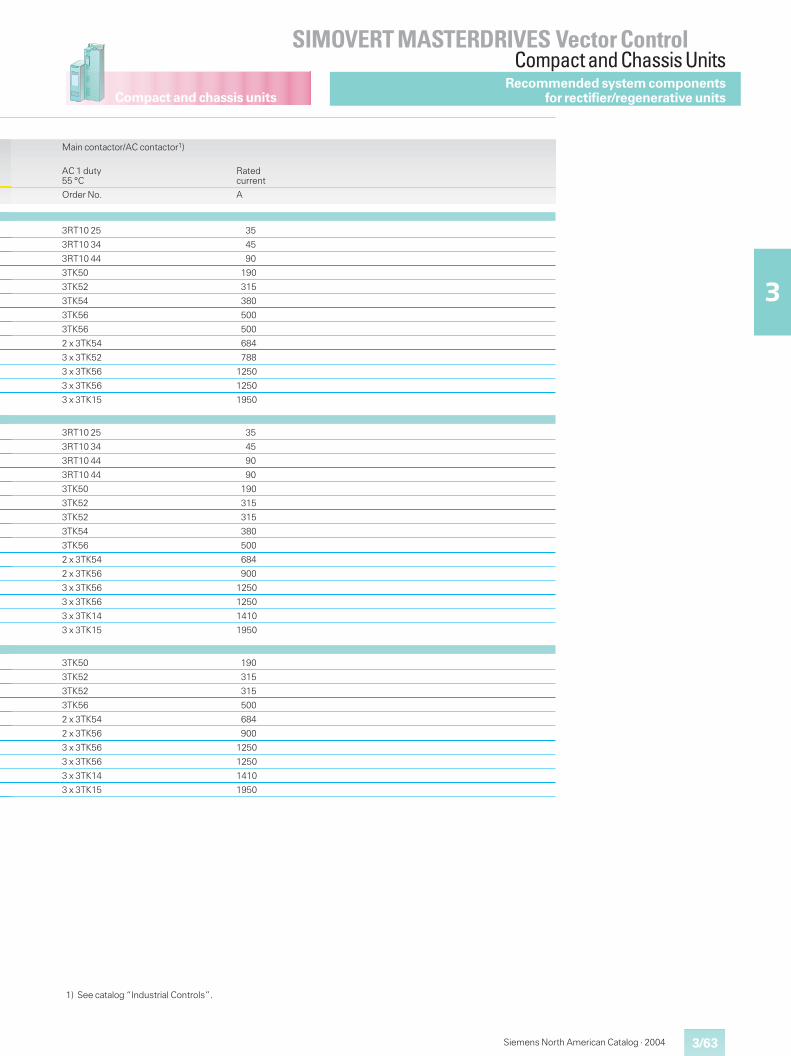
Compact and chassis units
3/63
SIMOVERT MASTERDRIVES Vector ControlCompact and Chassis Units
3
Siemens North American Catalog · 2004
Main contactor/AC contactor1)
AC 1 duty55 °C
Ratedcurrent
Order No. A
3RT10 25 35
3RT10 34 45
3RT10 44 90
3TK50 190
3TK52 315
3TK54 380
3TK56 500
3TK56 500
2 x 3TK54 684
3 x 3TK52 788
3 x 3TK56 1250
3 x 3TK56 1250
3 x 3TK15 1950
3RT10 25 35
3RT10 34 45
3RT10 44 90
3RT10 44 90
3TK50 190
3TK52 315
3TK52 315
3TK54 380
3TK56 500
2 x 3TK54 684
2 x 3TK56 900
3 x 3TK56 1250
3 x 3TK56 1250
3 x 3TK14 1410
3 x 3TK15 1950
3TK50 190
3TK52 315
3TK52 315
3TK56 500
2 x 3TK54 684
2 x 3TK56 900
3 x 3TK56 1250
3 x 3TK56 1250
3 x 3TK14 1410
3 x 3TK15 1950
1) See catalog “Industrial Controls”.
Recommended system componentsfor rectifier/regenerative units
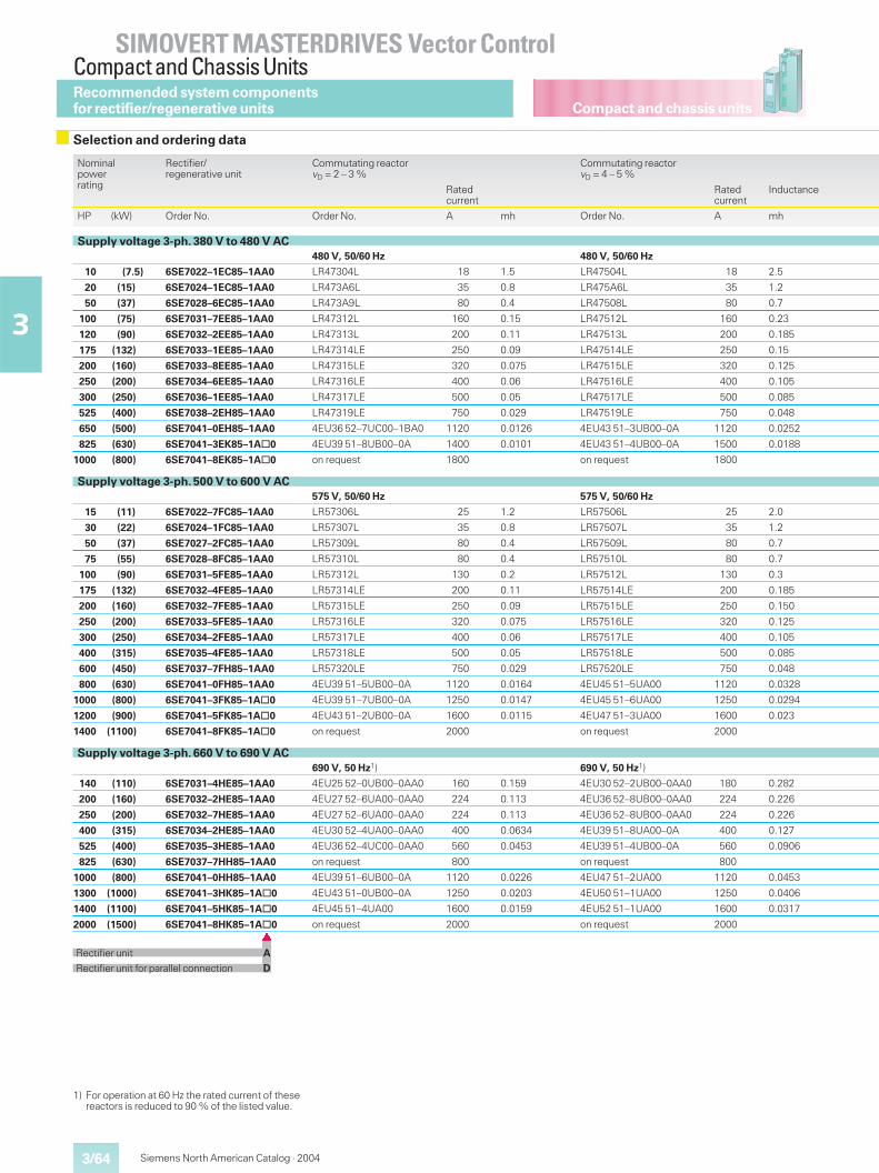
Compact and chassis units
SIMOVERT MASTERDRIVES Vector ControlCompact and Chassis Units
3/64
3
Siemens North American Catalog · 2004
Nominalpowerrating
Rectifier/regenerative unit
Commutating reactorvD = 2 – 3 %
Commutating reactorvD = 4 – 5 %
Ratedcurrent
Ratedcurrent
Inductance
HP (kW) Order No. Order No. A mh Order No. A mh
Supply voltage 3-ph. 380 V to 480 V AC480 V, 50/60 Hz 480 V, 50/60 Hz
10 (7.5) 6SE7022–1EC85–1AA0 LR47304L 18 1.5 LR47504L 18 2.5
20 (15) 6SE7024–1EC85–1AA0 LR473A6L 35 0.8 LR475A6L 35 1.2
50 (37) 6SE7028–6EC85–1AA0 LR473A9L 80 0.4 LR47508L 80 0.7
100 (75) 6SE7031–7EE85–1AA0 LR47312L 160 0.15 LR47512L 160 0.23
120 (90) 6SE7032–2EE85–1AA0 LR47313L 200 0.11 LR47513L 200 0.185
175 (132) 6SE7033–1EE85–1AA0 LR47314LE 250 0.09 LR47514LE 250 0.15
200 (160) 6SE7033–8EE85–1AA0 LR47315LE 320 0.075 LR47515LE 320 0.125
250 (200) 6SE7034–6EE85–1AA0 LR47316LE 400 0.06 LR47516LE 400 0.105
300 (250) 6SE7036–1EE85–1AA0 LR47317LE 500 0.05 LR47517LE 500 0.085
525 (400) 6SE7038–2EH85–1AA0 LR47319LE 750 0.029 LR47519LE 750 0.048
650 (500) 6SE7041–0EH85–1AA0 4EU36 52–7UC00–1BA0 1120 0.0126 4EU43 51–3UB00–0A 1120 0.0252
825 (630) 6SE7041–3EK85–1A@0 4EU39 51–8UB00–0A 1400 0.0101 4EU43 51–4UB00–0A 1500 0.0188
1000 (800) 6SE7041–8EK85–1A@0 on request 1800 on request 1800
Supply voltage 3-ph. 500 V to 600 V AC575 V, 50/60 Hz 575 V, 50/60 Hz
15 (11) 6SE7022–7FC85–1AA0 LR57306L 25 1.2 LR57506L 25 2.0
30 (22) 6SE7024–1FC85–1AA0 LR57307L 35 0.8 LR57507L 35 1.2
50 (37) 6SE7027–2FC85–1AA0 LR57309L 80 0.4 LR57509L 80 0.7
75 (55) 6SE7028–8FC85–1AA0 LR57310L 80 0.4 LR57510L 80 0.7
100 (90) 6SE7031–5FE85–1AA0 LR57312L 130 0.2 LR57512L 130 0.3
175 (132) 6SE7032–4FE85–1AA0 LR57314LE 200 0.11 LR57514LE 200 0.185
200 (160) 6SE7032–7FE85–1AA0 LR57315LE 250 0.09 LR57515LE 250 0.150
250 (200) 6SE7033–5FE85–1AA0 LR57316LE 320 0.075 LR57516LE 320 0.125
300 (250) 6SE7034–2FE85–1AA0 LR57317LE 400 0.06 LR57517LE 400 0.105
400 (315) 6SE7035–4FE85–1AA0 LR57318LE 500 0.05 LR57518LE 500 0.085
600 (450) 6SE7037–7FH85–1AA0 LR57320LE 750 0.029 LR57520LE 750 0.048
800 (630) 6SE7041–0FH85–1AA0 4EU39 51–5UB00–0A 1120 0.0164 4EU45 51–5UA00 1120 0.0328
1000 (800) 6SE7041–3FK85–1A@0 4EU39 51–7UB00–0A 1250 0.0147 4EU45 51–6UA00 1250 0.0294
1200 (900) 6SE7041–5FK85–1A@0 4EU43 51–2UB00–0A 1600 0.0115 4EU47 51–3UA00 1600 0.023
1400 (1100) 6SE7041–8FK85–1A@0 on request 2000 on request 2000
Supply voltage 3-ph. 660 V to 690 V AC690 V, 50 Hz1) 690 V, 50 Hz1)
140 (110) 6SE7031–4HE85–1AA0 4EU25 52–0UB00–0AA0 160 0.159 4EU30 52–2UB00–0AA0 180 0.282
200 (160) 6SE7032–2HE85–1AA0 4EU27 52–6UA00–0AA0 224 0.113 4EU36 52–8UB00–0AA0 224 0.226
250 (200) 6SE7032–7HE85–1AA0 4EU27 52–6UA00–0AA0 224 0.113 4EU36 52–8UB00–0AA0 224 0.226
400 (315) 6SE7034–2HE85–1AA0 4EU30 52–4UA00–0AA0 400 0.0634 4EU39 51–8UA00–0A 400 0.127
525 (400) 6SE7035–3HE85–1AA0 4EU36 52–4UC00–0AA0 560 0.0453 4EU39 51–4UB00–0A 560 0.0906
825 (630) 6SE7037–7HH85–1AA0 on request 800 on request 800
1000 (800) 6SE7041–0HH85–1AA0 4EU39 51–6UB00–0A 1120 0.0226 4EU47 51–2UA00 1120 0.0453
1300 (1000) 6SE7041–3HK85–1A@0 4EU43 51–0UB00–0A 1250 0.0203 4EU50 51–1UA00 1250 0.0406
1400 (1100) 6SE7041–5HK85–1A@0 4EU45 51–4UA00 1600 0.0159 4EU52 51–1UA00 1600 0.0317
2000 (1500) 6SE7041–8HK85–1A@0 on request 2000 on request 2000�
Rectifier unit A
Rectifier unit for parallel connection D
1) For operation at 60 Hz the rated current of thesereactors is reduced to 90 % of the listed value.
Selection and ordering data
Recommended system componentsfor rectifier/regenerative units
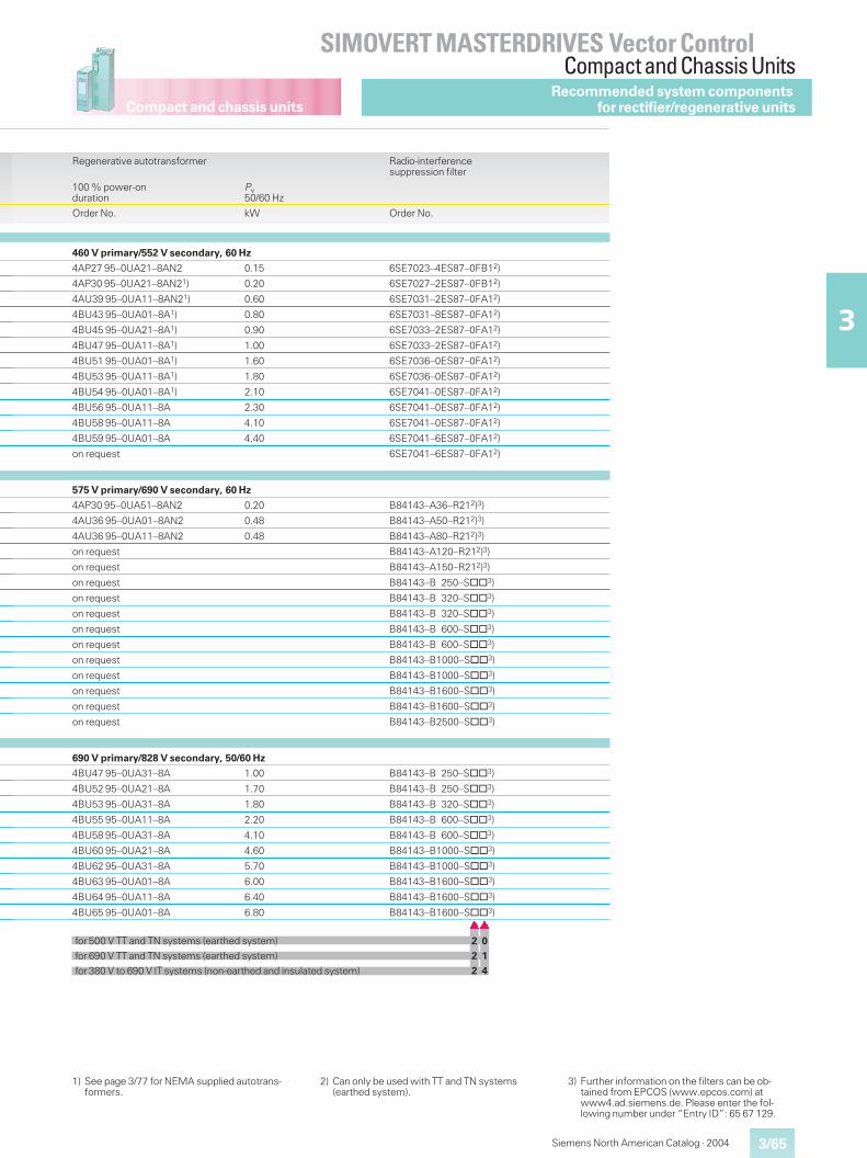
Compact and chassis units
3/65
SIMOVERT MASTERDRIVES Vector ControlCompact and Chassis Units
3
Siemens North American Catalog · 2004
Recommended system componentsfor rectifier/regenerative units
Regenerative autotransformer Radio-interferencesuppression filter
100 % power-onduration
Pv50/60 Hz
Order No. kW Order No.
460 V primary/552 V secondary, 60 Hz
4AP27 95–0UA21–8AN2 0.15 6SE7023–4ES87–0FB12)
4AP30 95–0UA21–8AN21) 0.20 6SE7027–2ES87–0FB12)
4AU39 95–0UA11–8AN21) 0.60 6SE7031–2ES87–0FA12)
4BU43 95–0UA01–8A1) 0.80 6SE7031–8ES87–0FA12)
4BU45 95–0UA21–8A1) 0.90 6SE7033–2ES87–0FA12)
4BU47 95–0UA11–8A1) 1.00 6SE7033–2ES87–0FA12)
4BU51 95–0UA01–8A1) 1.60 6SE7036–0ES87–0FA12)
4BU53 95–0UA11–8A1) 1.80 6SE7036–0ES87–0FA12)
4BU54 95–0UA01–8A1) 2.10 6SE7041–0ES87–0FA12)
4BU56 95–0UA11–8A 2.30 6SE7041–0ES87–0FA12)
4BU58 95–0UA11–8A 4.10 6SE7041–0ES87–0FA12)
4BU59 95–0UA01–8A 4.40 6SE7041–6ES87–0FA12)
on request 6SE7041–6ES87–0FA12)
575 V primary/690 V secondary, 60 Hz
4AP30 95–0UA51–8AN2 0.20 B84143–A36–R212)3)
4AU36 95–0UA01–8AN2 0.48 B84143–A50–R212)3)
4AU36 95–0UA11–8AN2 0.48 B84143–A80–R212)3)
on request B84143–A120–R212)3)
on request B84143–A150–R212)3)
on request B84143–B 250–S@@3)
on request B84143–B 320–S@@3)
on request B84143–B 320–S@@3)
on request B84143–B 600–S@@3)
on request B84143–B 600–S@@3)
on request B84143–B1000–S@@3)
on request B84143–B1000–S@@3)
on request B84143–B1600–S@@3)
on request B84143–B1600–S@@3)
on request B84143–B2500–S@@3)
690 V primary/828 V secondary, 50/60 Hz
4BU47 95–0UA31–8A 1.00 B84143–B 250–S@@3)
4BU52 95–0UA21–8A 1.70 B84143–B 250–S@@3)
4BU53 95–0UA31–8A 1.80 B84143–B 320–S@@3)
4BU55 95–0UA11–8A 2.20 B84143–B 600–S@@3)
4BU58 95–0UA31–8A 4.10 B84143–B 600–S@@3)
4BU60 95–0UA21–8A 4.60 B84143–B1000–S@@3)
4BU62 95–0UA31–8A 5.70 B84143–B1000–S@@3)
4BU63 95–0UA01–8A 6.00 B84143–B1600–S@@3)
4BU64 95–0UA11–8A 6.40 B84143–B1600–S@@3)
4BU65 95–0UA01–8A 6.80 B84143–B1600–S@@3)��
for 500 V TT and TN systems (earthed system) 2 0
for 690 V TT and TN systems (earthed system) 2 1
for 380 V to 690 V IT systems (non-earthed and insulated system) 2 4
1) See page 3/77 for NEMA supplied autotrans-formers.
2) Can only be used with TT and TN systems(earthed system).
3) Further information on the filters can be ob-tained from EPCOS (www.epcos.com) atwww4.ad.siemens.de. Please enter the fol-lowing number under “Entry ID”: 65 67 129.
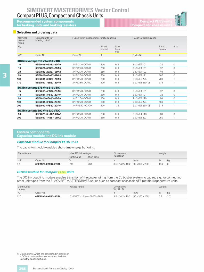
3/66
SIMOVERT MASTERDRIVES Vector ControlCompact PLUS,Compact and Chassis Units
3
Compact PLUS unitsCompact and chassis units
Siemens North American Catalog · 2004
Nominalpowerrating
Components forbraking units1)
Fuse switch disconnector for DC coupling Fuses for braking units
P20 Ratedcurrent
Max.fusesize
Ratedcurrent
Size
kW Order No. Order No. A Order No. A
DC link voltage 510 V to 650 V DC5 6SE7018–0ES87–2DA0 3NP42 70–0CA01 250 0; 1 2 x 3NE4 101 32 0
10 6SE7021–6ES87–2DA0 3NP42 70–0CA01 250 0; 1 2 x 3NE4 101 32 0
20 6SE7023–2EA87–2DA0 3NP42 70–0CA01 250 0; 1 2 x 3NE4 102 40 0
50 6SE7028–0EA87–2DA0 3NP42 70–0CA01 250 0; 1 2 x 3NE4 121 100 0
100 6SE7031–6EB87–2DA0 3NP42 70–0CA01 250 0; 1 2 x 3NE3 225 200 1
170 6SE7032–7EB87–2DA0 3NP53 60–0CA00 400 0; 1 2 x 3NE3 230–0B 315 1
DC link voltage 675 V to 810 V DC5 6SE7016–4FS87–2DA0 3NP42 70–0CA01 250 0; 1 2 x 3NE4 101 32 0
10 6SE7021–3FS87–2DA0 3NP42 70–0CA01 250 0; 1 2 x 3NE4 101 32 0
50 6SE7026–4FA87–2DA0 3NP42 70–0CA01 250 0; 1 2 x 3NE4 120 80 0
100 6SE7031–3FB87–2DA0 3NP42 70–0CA01 250 0; 1 2 x 3NE3 224 160 1
200 6SE7032–5FB87–2DA0 3NP 53 60–0CA00 400 1; 2 2 x 3NE3 230–0B 315 1
DC link voltage 890 V to 930 V DC50 6SE7025–3HA87–2DA0 3NP42 70–0CA01 250 0; 1 2 x 3NE4 118 63 0
200 6SE7032–1HB87–2DA0 3NP42 70–0CA01 250 0; 1 2 x 3NE3 227 250 1
Recommended system componentsfor braking units and braking resistors
Selection and ordering data
System componentsCapacitor module and DC link module
Capacitor module for Compact PLUS units
The capacitor module enables short-time energy buffering.
Capacitance Max. DC link voltage DimensionsW x H x D
Weight
continuous short-time
mF Order No. V V in (mm) lb (kg)
5.1 6SE7025–0TP87–2DD0 715 780 3.5 x 14.2 x 10.2 (90 x 360 x 260) 13.2 (6)
DC link module for Compact PLUS units
The DC link coupling module enables transition of the power wiring from the Cu busbar system to cables, e.g. for connectingother unit types from the SIMOVERT MASTERDRIVES series such as compact or chassis AFE rectifier/regenerative units.
Continuouscurrent
Voltage range DimensionsW x H x D
Weight
A Order No. in (mm) lb (kg)
120 6SE7090–0XP87–3CR0 510 V DC –15 % to 650 V +10 % 3.5 x 14.2 x 10.2 (90 x 360 x 260) 5.9 (2.7)
1) Braking units which are connected in parallel ona DC bus or several converters must be fusedusing the specified fuses.
nelsco
PLUS
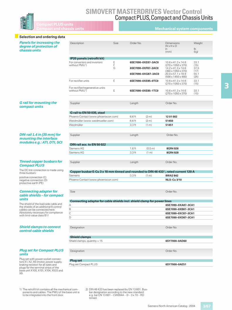
3/67
SIMOVERT MASTERDRIVES Vector ControlCompact PLUS,Compact and Chassis Units
3
Compact PLUS unitsCompact and chassis units
Siemens North American Catalog · 2004
Mechanical system components
Description Size Order No. DimensionsW x H x Din(mm)
Weight
lb(kg)
IP20 panels (retrofit kit)For converters and inverterswithout PMU1)
EFG
6SE7090–0XE87–3AC0
6SE7090–0XF87–3AC0
6SE7090–0XG87–3AC0
10.6 x 41.3 x 14.6(270 x 1050 x 370)14.2 x 41.3 x 14.6(360 x 1050 x 370)20.0 x 57.1 x 18.9(508 x 1450 x 480)
33.1(15)37.5(17)55.1(25)
For rectifier units E 6SE7090–0XE85–0TC0 10.6 x 41.3 x 14.6(270 x 1050 x 370)
33.1(15)
For rectifier/regenerative unitswithout PMU1) E 6SE7090–0XE85–1TC0 10.6 x 41.3 x 14.6
(270 x 1050 x 370)33.1(15)
Panels for increasing thedegree of protection ofchassis units
Supplier Length Order No.
DIN rail acc. to EN 50 022Siemens AG 1.6 ft (0.5 m) 8GR4 926
Siemens AG 3.3 ft (1 m) 8GR4 928
DIN rail 1.4 in (35 mm) formounting the interfacemodules e.g.: ATI, DTI, SCI
Supplier Length Order No.
Copper busbar E-Cu 3 x 10 mm tinned and rounded to DIN 46 4332), rated current 120 ASiemens 3.3 ft (1 m) 8WA2 842
Phoenix Contact (www.phoenixcon.com) NLS–Cu 3/10
Tinned copper busbars forCompact PLUS
The DC link connection is made usingthree busbars:
positive connection (C)negative connection (D)protective earth (PE)
Supplier Length Order No.
G rail to EN 50 035, steelPhoenix Contact (www.phoenixcon.com) 6.6 ft (2 m) 12 01 002
Weidmüller (www.weidmueller.com) 6.6 ft (2 m) 51450
Weidmüller 3.3 ft (1 m) 51451
G rail for mounting thecompact units
Selection and ordering data
Designation Order No.
Plug setPlug set Compact PLUS 6SY7000–0AE51
Plug set for Compact PLUSunits
Plug set with power socket connec-tors X1, X2, X6 (motor, power supply,braking resistor) for all sizes andplugs for the terminal strips of thebase unit X100, X101, X104, X533 andX9.
Designation Order No.
Shield clampsShield clamps, quantity = 15 6SY7000–0AD60
Shield clamps to connectcontrol-cable shields
Size Order No.
Connecting adapter for cable shields incl. shield clamp for power linesA 6SE7090–0XA87–3CA1
B 6SE7090–0XB87–3CA1
C 6SE7090–0XC87–3CA1
D 6SE7090–0XD87–3CA1
Connecting adapter forcable shields – for compactunits
The shield of the load-side cable andthe shields of an additional 8 controlcables can be connected here.Absolutely necessary for compliancewith limit-value class B1!
1) The retrofit kit contains all the mechanical com-ponents and cables. The PMU of the base unit isto be integrated into the front door.
2) DIN 46 433 has been replaced by EN 13 601. Bus-bar designation according to the new standard:e.g. bar EN 13 601 – CW004A – D – 3 x 10 – RDtinned.
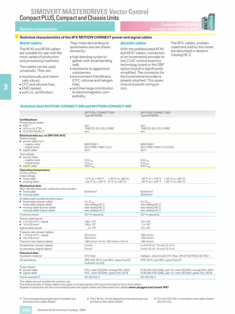
3/68
SIMOVERT MASTERDRIVES Vector ControlCompact PLUS,Compact and Chassis Units
3
Compact PLUS unitsCompact and chassis units
Siemens North American Catalog · 2004
System components
Motor cables
The 6FX5 and 6FX8 cablesare suitable for use with themost varied of productionand processing machines.
The cables can be useduniversally. They are:
� mechanically and chemi-cally robust,
� CFC and silicone free,� EMC-tested,� with UL certification.
They meet demanding re-quirements and are charac-terized by:
� high bending cycles to-gether with small bendingradii,
� resistance to aggressivesubstances,
� environment-friendliness(CFC, silicone and halogenfree),
� and their large contributionto electromagnetic com-patibility.
Encoder cables
With the prefabricated 6FX5and 6FX7 cables, connectionof an incremental encoder tothe CUVC control board (ortechnology board or the SBPoption board) is significantlysimplified. The connector forthe incremental encoder isalready attached. This savestime and avoids wiring er-rors.
The 6FX. cables, prefabri-cated and sold by the meter,are described in detail inCatalog NC Z.
Technical Data MOTION CONNECT 500 and MOTION CONNECT 800
MOTION CONNECT 500Type 6FX5008– . . . . . – . . . .
MOTION CONNECT 800Type 6FX8008– . . . . . – . . . .
CertificationsPower/signal cables� VDE1)� c/UL or UL/CSA� UL/CSA File No.2)
yes758/C22.2N.210.2–M9Cyes
yes758/C22.2N.210.2–M9Cyes
Electrical data acc. to DIN VDE 0472Rated voltage� power cable V0/V
– supply cores– signal cores
� signal cable
600/1000 V24 V (VDE) 1000 V (UL)30 V
600/1000 V24 V (VDE) 1000 V (UL/CSA)30 V
Test voltage� power cable
– supply cores– signal cores
� signal cable
4 kVrms2 kVrms500 Vrms
4 kVrms2 kVrms500 Vrms
Operating temperatureon the surfacerated voltage� fixed cable� moving cable
–4 °F to +176 °F (–20 °C to +80 °C)+32 °F to +140 °F (0 °C to +60 °C)
–58 °F to +176 °F (–50 °C to +80 °C)–40 °F to +140 °F (–20 °C to +60 °C)
Mechanical dataMax. tensile stress per conductor cross-section� fixed cable� moving cable
50 N/mm2
–50 N/mm2
20 N/mm2
Smallest permissible bending radius� fixed cable (power cable)
fixed cable (signal cable)� moving cable (power cable)
moving cable (signal cable)
5 x Dmaxsee catalog NC Zsee catalog NC Zsee catalog NC Z
6 x Dmaxsee catalog NC Zsee catalog NC Zsee catalog NC Z
Torsional stress 30 °/m absolute 30 °/m absolute
Power cable bends� 1.5 to 6 mm2 + signal� 10 to 50 mm2
Signal cable bends
100 x 103
100 x 103
2 x 10⁶
10 x 106
3 x 10⁶
10 x 106
Traverse rate (power cables)� 1.5 to 6 mm2 + signal� 10 to 50 mm2
Traverse rate (signal cables)
30 m/min.30 m/min.180 m/min. (5 m); 100 m/min. (15 m)
180 m/min.100 m/min.180 m/min.
Acceleration (power cables)Acceleration (signal cables)
2 m/s2
5 m/s25 m/s2 (5 m); 10 m/s2 (2.5 m)5 m/s2 (5 m); 10 m/s2 (2.5 m)
Chemical dataInsulation material CFC-free Halogen, silicone and CFC-free, DIN 47 2815/IEC 60 754-1
Oil resistance DIN VDE 0472, part 803, type of test Bhydraulic oil only
VDE 0472, part 803, type of test B
Outer sheath� power cable� signal cable
PVC, color DESINA: orange RAL 2003PVC, color DESINA: green RAL 6018
PUR DIN VDE 0282, part 10, color DESINA: orange RAL 2003PUR DIN VDE 0282, part 10, color DESINA: green RAL 6018
Flame-resistant3) IEC 60 332.3 IEC 60 332.3
The cables are not suitable for outdoor use.The technical data of these cables only apply to simple bends with horizontal travel of up to five meters.Degree of protection for the customized power and signal cables and their extension cables when plugged and closed: IP67
Technical characteristics of the 6FX MOTION CONNECT power and signal cables
1) The corresponding registration numbers areprinted on the cable sheath.
2) The File No. of the respective manufacturers areprinted on the cable sheath.
3) For UL/CSA VW1 is printed on the cable sheath.Not for c/UL.
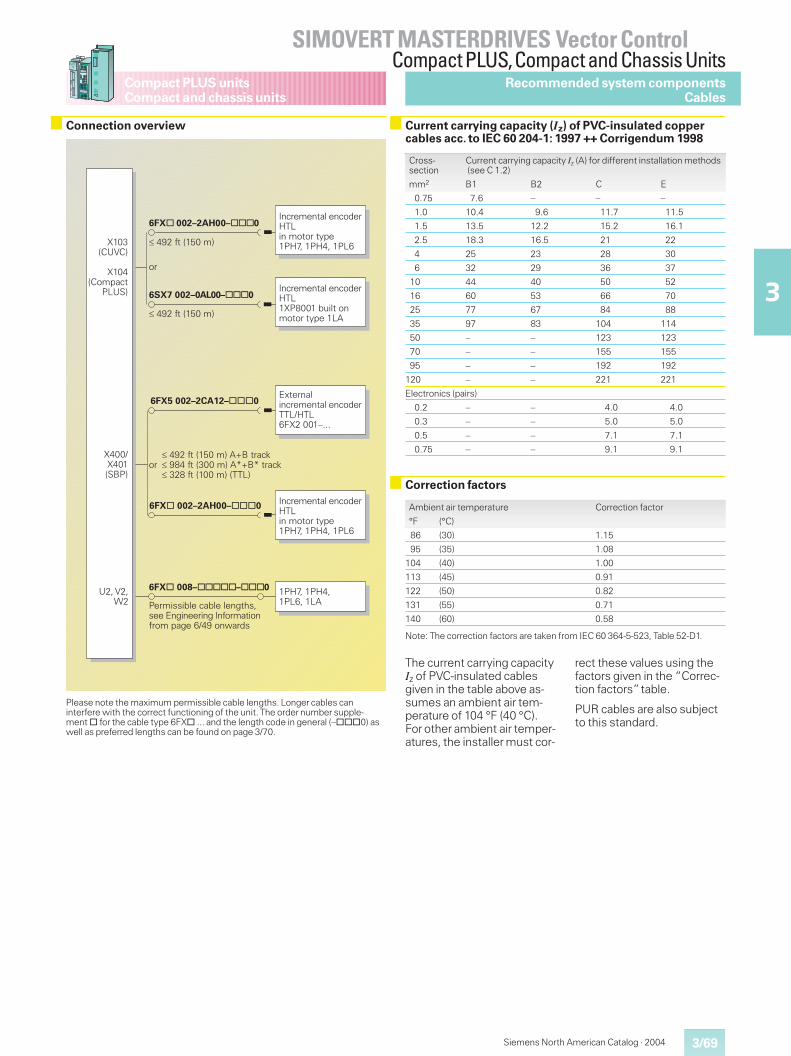
3/69
SIMOVERT MASTERDRIVES Vector ControlCompact PLUS,Compact and Chassis Units
3
Compact PLUS unitsCompact and chassis units
Siemens North American Catalog · 2004
Recommended system componentsCables
Connection overview Current carrying capacity (Iz) of PVC-insulated coppercables acc. to IEC 60 204-1: 1997 ++ Corrigendum 1998
Please note the maximum permissible cable lengths. Longer cables caninterfere with the correct functioning of the unit. The order number supple-ment@ for the cable type 6FX@ ... and the length code in general (–@@@0) aswell as preferred lengths can be found on page 3/70.
Cross-section
Current carrying capacity Iz (A) for different installation methods(see C 1.2)
mm2 B1 B2 C E
0.75 7.6 – – –
1.0 10.4 9.6 11.7 11.5
1.5 13.5 12.2 15.2 16.1
2.5 18.3 16.5 21 22
4 25 23 28 30
6 32 29 36 37
10 44 40 50 52
16 60 53 66 70
25 77 67 84 88
35 97 83 104 114
50 – – 123 123
70 – – 155 155
95 – – 192 192
120 – – 221 221
Electronics (pairs)
0.2 – – 4.0 4.0
0.3 – – 5.0 5.0
0.5 – – 7.1 7.1
0.75 – – 9.1 9.1
Correction factors
Ambient air temperature Correction factor
°F (°C)
86 (30) 1.15
95 (35) 1.08
104 (40) 1.00
113 (45) 0.91
122 (50) 0.82
131 (55) 0.71
140 (60) 0.58
Note: The correction factors are taken from IEC 60 364-5-523, Table 52-D1.
The current carrying capacityIz of PVC-insulated cablesgiven in the table above as-sumes an ambient air tem-perature of 104 °F (40 °C).For other ambient air temper-atures, the installer must cor-
rect these values using thefactors given in the “Correc-tion factors”table.
PUR cables are also subjectto this standard.
���������
�������������������
������ ����� ������������������������������������������������������
�!"�� �!�� �#��� #$
�����������������
�
���������% &'�(
) '*%+��+(
) '�%+�����
�#�,( ����������������!-# )�.'' � /�����������0��� #$
��������� �������
���������% &'�(
����������������!-#��������0�� �!"�� �!��� �#�
)�''�)�' %,1�(
����������������
���������% &'�(�$21����3� ���.�����%*''�(�$4214����3
��*�.����% ''�(�%--#(
����������������!-#��������0�� �!"�� �!��� �#�
�5���������������������--#�!-#�6)��'' 7888
��������� �������
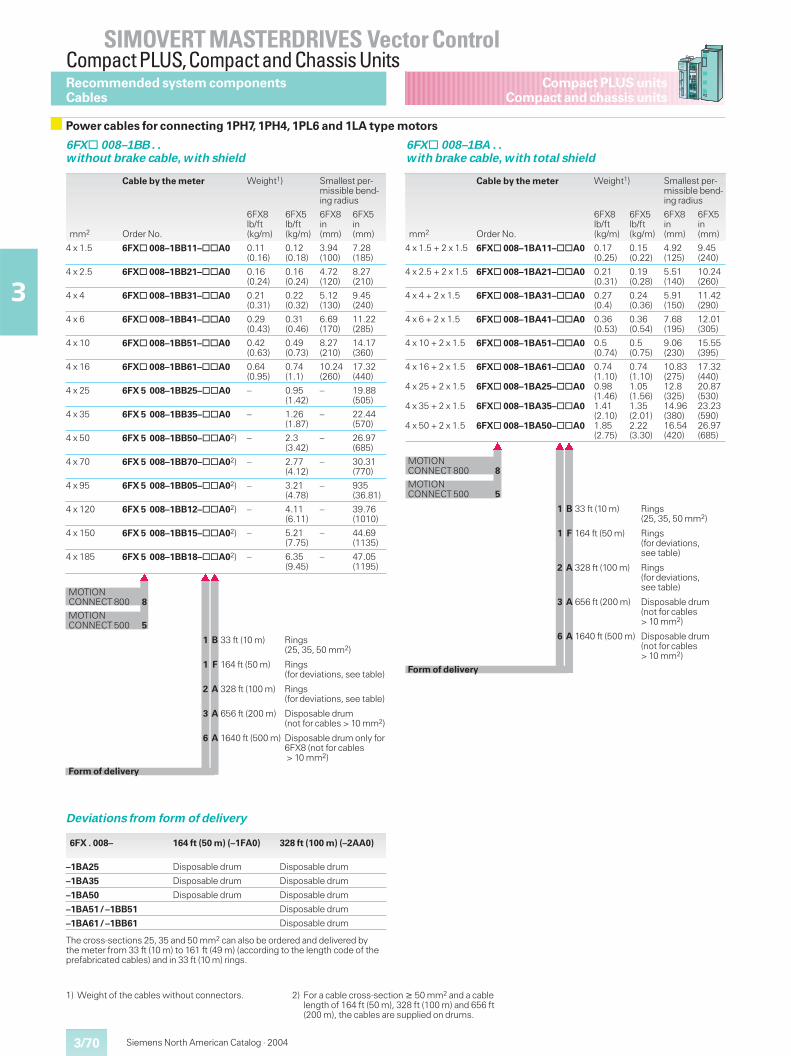
3/70
SIMOVERT MASTERDRIVES Vector ControlCompact PLUS,Compact and Chassis Units
3
Compact PLUS unitsCompact and chassis units
Siemens North American Catalog · 2004
Power cables for connecting 1PH7, 1PH4, 1PL6 and 1LA type motors
6FX@ 008–1BB . .without brake cable, with shield
6FX@ 008–1BA . .with brake cable, with total shield
1) Weight of the cables without connectors. 2) For a cable cross-section � 50 mm2 and a cablelength of 164 ft (50 m), 328 ft (100 m) and 656 ft(200 m), the cables are supplied on drums.
Recommended system componentsCables
Deviations from form of delivery
6FX . 008– 164 ft (50 m) (–1FA0) 328 ft (100 m) (–2AA0)
–1BA25 Disposable drum Disposable drum
–1BA35 Disposable drum Disposable drum
–1BA50 Disposable drum Disposable drum
–1BA51 / –1BB51 Disposable drum
–1BA61 / –1BB61 Disposable drum
The cross-sections 25, 35 and 50 mm2 can also be ordered and delivered bythe meter from 33 ft (10 m) to 161 ft (49 m) (according to the length code of theprefabricated cables) and in 33 ft (10 m) rings.
Cable by the meter Weight1) Smallest per-missible bend-ing radius
mm2 Order No.
6FX8lb/ft(kg/m)
6FX5lb/ft(kg/m)
6FX8in(mm)
6FX5in(mm)
4 x 1.5 6FX@ 008–1BB11–@@A0 0.11(0.16)
0.12(0.18)
3.94(100)
7.28(185)
4 x 2.5 6FX@ 008–1BB21–@@A0 0.16(0.24)
0.16(0.24)
4.72(120)
8.27(210)
4 x 4 6FX@ 008–1BB31–@@A0 0.21(0.31)
0.22(0.32)
5.12(130)
9.45(240)
4 x 6 6FX@ 008–1BB41–@@A0 0.29(0.43)
0.31(0.46)
6.69(170)
11.22(285)
4 x 10 6FX@ 008–1BB51–@@A0 0.42(0.63)
0.49(0.73)
8.27(210)
14.17(360)
4 x 16 6FX@ 008–1BB61–@@A0 0.64(0.95)
0.74(1.1)
10.24(260)
17.32(440)
4 x 25 6FX 5 008–1BB25–@@A0 – 0.95(1.42)
– 19.88(505)
4 x 35 6FX 5 008–1BB35–@@A0 – 1.26(1.87)
– 22.44(570)
4 x 50 6FX 5 008–1BB50–@@A02) – 2.3(3.42)
– 26.97(685)
4 x 70 6FX 5 008–1BB70–@@A02) – 2.77(4.12)
– 30.31(770)
4 x 95 6FX 5 008–1BB05–@@A02) – 3.21(4.78)
– 935(36.81)
4 x 120 6FX 5 008–1BB12–@@A02) – 4.11(6.11)
– 39.76(1010)
4 x 150 6FX 5 008–1BB15–@@A02) – 5.21(7.75)
– 44.69(1135)
4 x 185 6FX 5 008–1BB18–@@A02) – 6.35(9.45)
– 47.05(1195)
� ��
MOTIONCONNECT 800 8
MOTIONCONNECT 500 5
1 B 33 ft (10 m) Rings(25, 35, 50 mm2)
1 F 164 ft (50 m) Rings(for deviations, see table)
2 A 328 ft (100 m) Rings(for deviations, see table)
3 A 656 ft (200 m) Disposable drum(not for cables > 10 mm2)
6 A 1640 ft (500 m) Disposable drum only for6FX8 (not for cables> 10 mm2)
Form of delivery
Cable by the meter Weight1) Smallest per-missible bend-ing radius
mm2 Order No.
6FX8lb/ft(kg/m)
6FX5lb/ft(kg/m)
6FX8in(mm)
6FX5in(mm)
4 x 1.5 + 2 x 1.5 6FX@ 008–1BA11–@@A0 0.17(0.25)
0.15(0.22)
4.92(125)
9.45(240)
4 x 2.5 + 2 x 1.5 6FX@ 008–1BA21–@@A0 0.21(0.31)
0.19(0.28)
5.51(140)
10.24(260)
4 x 4 + 2 x 1.5 6FX@ 008–1BA31–@@A0 0.27(0.4)
0.24(0.36)
5.91(150)
11.42(290)
4 x 6 + 2 x 1.5 6FX@ 008–1BA41–@@A0 0.36(0.53)
0.36(0.54)
7.68(195)
12.01(305)
4 x 10 + 2 x 1.5 6FX@ 008–1BA51–@@A0 0.5(0.74)
0.5(0.75)
9.06(230)
15.55(395)
4 x 16 + 2 x 1.5
4 x 25 + 2 x 1.5
4 x 35 + 2 x 1.5
4 x 50 + 2 x 1.5
6FX@ 008–1BA61–@@A0
6FX@ 008–1BA25–@@A0
6FX@ 008–1BA35–@@A0
6FX@ 008–1BA50–@@A0
0.74(1.10)0.98(1.46)1.41(2.10)1.85(2.75)
0.74(1.10)1.05(1.56)1.35(2.01)2.22(3.30)
10.83(275)12.8(325)14.96(380)16.54(420)
17.32(440)20.87(530)23.23(590)26.97(685)
� ��
MOTIONCONNECT 800 8
MOTIONCONNECT 500 5
1 B 33 ft (10 m) Rings(25, 35, 50 mm2)
1 F 164 ft (50 m) Rings(for deviations,see table)
2 A 328 ft (100 m) Rings(for deviations,see table)
3 A 656 ft (200 m) Disposable drum(not for cables> 10 mm2)
6 A 1640 ft (500 m) Disposable drum(not for cables> 10 mm2)
Form of delivery
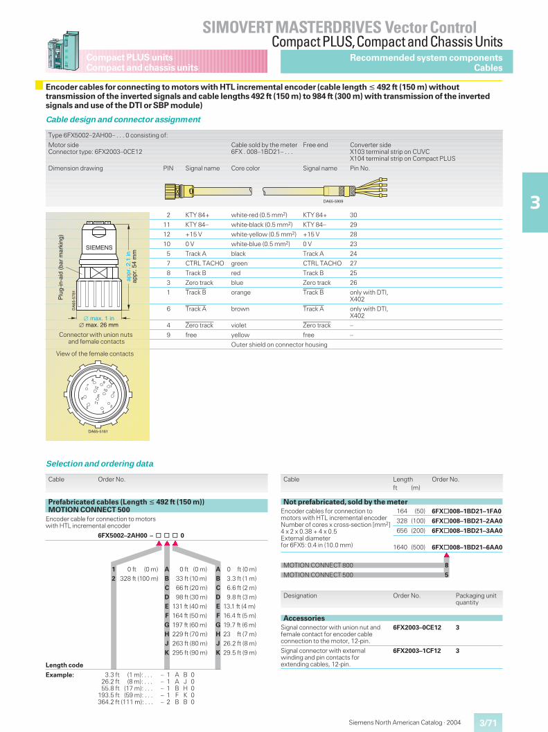
3/71
SIMOVERT MASTERDRIVES Vector ControlCompact PLUS,Compact and Chassis Units
3
Compact PLUS unitsCompact and chassis units
Siemens North American Catalog · 2004
Encoder cables for connecting to motors with HTL incremental encoder (cable length � 492 ft (150 m) withouttransmission of the inverted signals and cable lengths 492 ft (150 m) to 984 ft (300 m) with transmission of the invertedsignals and use of the DTI or SBP module)
Cable design and connector assignment
Type 6FX5002–2AH00– . . . 0 consisting of:
Motor sideConnector type: 6FX2003–0CE12
Cable sold by the meter6FX . 008–1BD21– . . .
Free end Converter sideX103 terminal strip on CUVCX104 terminal strip on Compact PLUS
Dimension drawing PIN Signal name Core color Signal name Pin No.
2 KTY 84+ white-red (0.5 mm2) KTY 84+ 30
11 KTY 84– white-black (0.5 mm2) KTY 84– 29
12 +15 V white-yellow (0.5 mm2) +15 V 28
10 0 V white-blue (0.5 mm2) 0 V 23
5 Track A black Track A 24
7 CTRL TACHO green CTRL TACHO 27
8 Track B red Track B 25
3 Zero track blue Zero track 26
1 Track B orange Track B only with DTI,X402
6 Track A brown Track A only with DTI,X402
4 Zero track violet Zero track –
9 free yellow free –
Outer shield on connector housing
Selection and ordering data
Designation Order No. Packaging unitquantity
AccessoriesSignal connector with union nut andfemale contact for encoder cableconnection to the motor, 12-pin.
6FX2003–0CE12 3
Signal connector with externalwinding and pin contacts forextending cables, 12-pin.
6FX2003–1CF12 3
Cable Length Order No.ft (m)
Not prefabricated, sold by the meterEncoder cables for connection tomotors with HTL incremental encoderNumber of cores x cross-section [mm2]4 x 2 x 0.38 + 4 x 0.5External diameterfor 6FX5: 0.4 in (10.0 mm)
164 (50) 6FX@008–1BD21–1FA0
328 (100) 6FX@008–1BD21–2AA0
656 (200) 6FX@008–1BD21–3AA0
1640 (500) 6FX@008–1BD21–6AA0�
MOTION CONNECT 800 8
MOTION CONNECT 500 5
Cable Order No.
Prefabricated cables (Length � 492 ft (150 m))MOTION CONNECT 500
Encoder cable for connection to motorswith HTL incremental encoder
6FX5002–2AH00 – @ @ @ 0���
1 0 ft (0 m) A 0 ft (0 m) A 0 ft (0 m)2 328 ft (100 m) B 33 ft (10 m) B 3.3 ft (1 m)
C 66 ft (20 m) C 6.6 ft (2 m)D 98 ft (30 m) D 9.8 ft (3 m)E 131 ft (40 m) E 13.1 ft (4 m)F 164 ft (50 m) F 16.4 ft (5 m)G 197 ft (60 m) G 19.7 ft (6 m)H 229 ft (70 m) H 23 ft (7 m)J 263 ft (80 m) J 26.2 ft (8 m)K 295 ft (90 m) K 29.5 ft (9 m)
Length code
Example: 3.3 ft (1 m): . . . – 1 A B 026.2 ft (8 m): . . . – 1 A J 055.8 ft (17 m): . . . – 1 B H 0
193.5 ft (59 m): . . . – 1 F K 0364.2 ft (111 m): . . . – 2 B B 0
������
DA
65-5
781
SIEMENS
Plu
g-in
-aid
(ba
r m
arki
ng)
appr
. 2.1
in
max. 1 in
appr
. 54
mm
max. 26 mm��
Connector with union nutsand female contacts
DA65-5161
8
7
6
54
3
19
E
11
12 102
View of the female contacts
Recommended system componentsCables
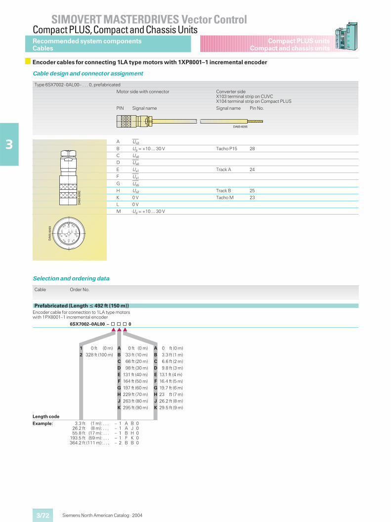
3/72
SIMOVERT MASTERDRIVES Vector ControlCompact PLUS,Compact and Chassis Units
3
Compact PLUS unitsCompact and chassis units
Siemens North American Catalog · 2004
Encoder cables for connecting 1LA type motors with 1XP8001–1 incremental encoder
Cable design and connector assignment
Type 6SX7002–0AL00– . . . 0, prefabricated
Motor side with connector Converter sideX103 terminal strip on CUVCX104 terminal strip on Compact PLUS
PIN Signal name Signal name Pin No.
A Ua2
B Up = +10 ... 30 V Tacho P15 28
C Ua0
D Ua0
E Ua1 Track A 24
F Ua1
G Ua5
H Ua2 Track B 25
K 0 V Tacho M 23
L 0 V
M Up = +10 ... 30 V
Selection and ordering data
DA
65-6
092
DA
65-6
093
A B
CL
D
EF
J
K
MH
G
Recommended system componentsCables
DA65-6095
Cable Order No.
Prefabricated (Length � 492 ft (150 m))Encoder cable for connection to 1LA type motorswith 1PX8001–1 incremental encoder
6SX7002–0AL00 – @ @ @ 0���
1 0 ft (0 m) A 0 ft (0 m) A 0 ft (0 m)2 328 ft (100 m) B 33 ft (10 m) B 3.3 ft (1 m)
C 66 ft (20 m) C 6.6 ft (2 m)D 98 ft (30 m) D 9.8 ft (3 m)E 131 ft (40 m) E 13.1 ft (4 m)F 164 ft (50 m) F 16.4 ft (5 m)G 197 ft (60 m) G 19.7 ft (6 m)H 229 ft (70 m) H 23 ft (7 m)J 263 ft (80 m) J 26.2 ft (8 m)K 295 ft (90 m) K 29.5 ft (9 m)
Length code
Example: 3.3 ft (1 m): . . . – 1 A B 026.2 ft (8 m): . . . – 1 A J 055.8 ft (17 m): . . . – 1 B H 0
193.5 ft (59 m): . . . – 1 F K 0364.2 ft (111 m): . . . – 2 B B 0
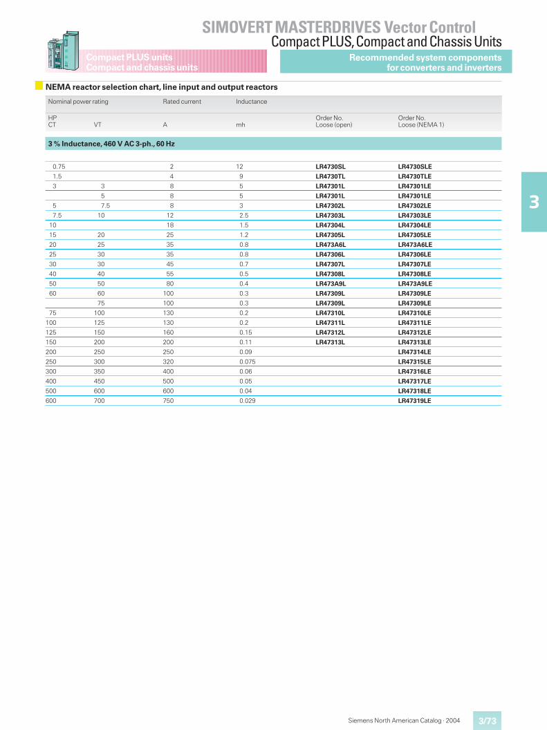
3/73
SIMOVERT MASTERDRIVES Vector ControlCompact PLUS,Compact and Chassis Units
3
Compact PLUS unitsCompact and chassis units
Siemens North American Catalog · 2004
Recommended system componentsfor converters and inverters
Nominal power rating Rated current Inductance
HPCT VT A mh
Order No.Loose (open)
Order No.Loose (NEMA 1)
3 % Inductance, 460 V AC 3-ph., 60 Hz
0.75 2 12 LR4730SL LR4730SLE
1.5 4 9 LR4730TL LR4730TLE
3 3 8 5 LR47301L LR47301LE
5 8 5 LR47301L LR47301LE
5 7.5 8 3 LR47302L LR47302LE
7.5 10 12 2.5 LR47303L LR47303LE
10 18 1.5 LR47304L LR47304LE
15 20 25 1.2 LR47305L LR47305LE
20 25 35 0.8 LR473A6L LR473A6LE
25 30 35 0.8 LR47306L LR47306LE
30 30 45 0.7 LR47307L LR47307LE
40 40 55 0.5 LR47308L LR47308LE
50 50 80 0.4 LR473A9L LR473A9LE
60 60 100 0.3 LR47309L LR47309LE
75 100 0.3 LR47309L LR47309LE
75 100 130 0.2 LR47310L LR47310LE
100 125 130 0.2 LR47311L LR47311LE
125 150 160 0.15 LR47312L LR47312LE
150 200 200 0.11 LR47313L LR47313LE
200 250 250 0.09 LR47314LE
250 300 320 0.075 LR47315LE
300 350 400 0.06 LR47316LE
400 450 500 0.05 LR47317LE
500 600 600 0.04 LR47318LE
600 700 750 0.029 LR47319LE
NEMA reactor selection chart, line input and output reactors
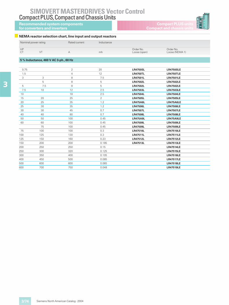
3/74
SIMOVERT MASTERDRIVES Vector ControlCompact PLUS,Compact and Chassis Units
3
Compact PLUS unitsCompact and chassis units
Siemens North American Catalog · 2004
Recommended system componentsfor converters and inverters
NEMA reactor selection chart, line input and output reactors
Nominal power rating Rated current Inductance
HPCT VT A mh
Order No.Loose (open)
Order No.Loose (NEMA 1)
5 % Inductance, 460 V AC 3-ph., 60 Hz
0.75 2 20 LR4750SL LR4750SLE
1.5 4 12 LR4750TL LR4750TLE
3 3 8 7.5 LR47501L LR47501LE
5 8 5 LR47502L LR47502LE
5 7.5 8 5 LR47502L LR47502LE
7.5 10 12 2.5 LR47503L LR47503LE
10 18 2.5 LR47504L LR47504LE
15 20 25 2 LR47505L LR47505LE
20 25 35 1.2 LR475A6L LR475A6LE
25 30 35 1.2 LR47506L LR47506LE
30 30 45 0.7 LR47507L LR47507LE
40 40 80 0.7 LR47508L LR47508LE
50 50 100 0.45 LR475A9L LR475A9LE
60 60 100 0.45 LR47509L LR47509LE
75 100 0.45 LR47509L LR47509LE
75 100 100 0.3 LR47510L LR47510LE
100 125 130 0.3 LR47511L LR47511LE
125 150 160 0.23 LR47512L LR47512LE
150 200 200 0.185 LR47513L LR47513LE
200 250 250 0.15 LR47514LE
250 300 320 0.125 LR47515LE
300 350 400 0.105 LR47516LE
400 450 500 0.085 LR47517LE
500 600 600 0.065 LR47518LE
600 700 750 0.048 LR47519LE
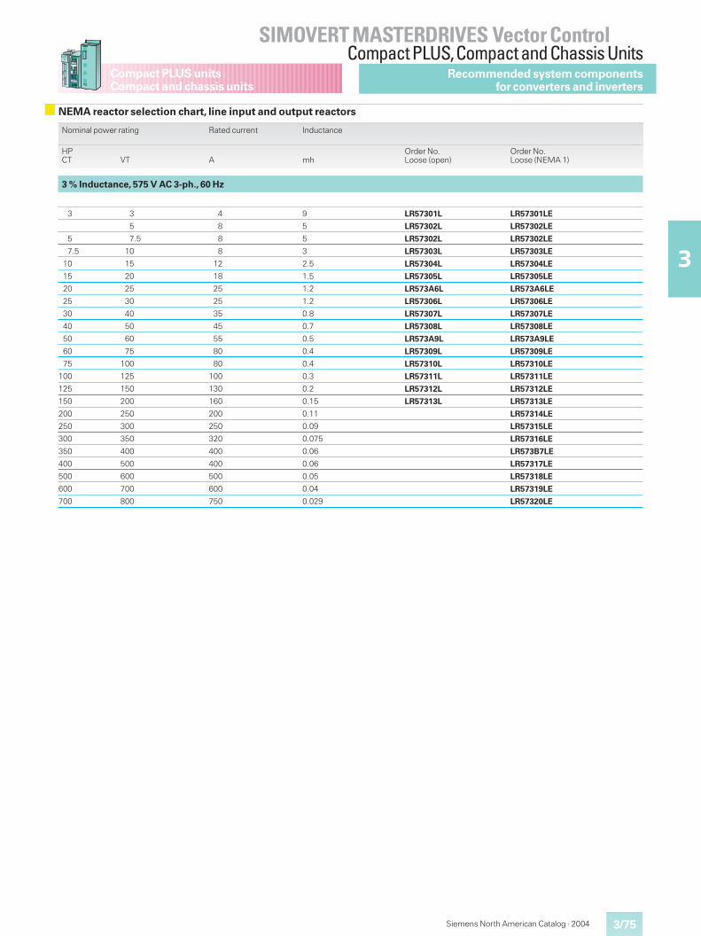
3/75
SIMOVERT MASTERDRIVES Vector ControlCompact PLUS,Compact and Chassis Units
3
Compact PLUS unitsCompact and chassis units
Siemens North American Catalog · 2004
Recommended system componentsfor converters and inverters
NEMA reactor selection chart, line input and output reactors
Nominal power rating Rated current Inductance
HPCT VT A mh
Order No.Loose (open)
Order No.Loose (NEMA 1)
3 % Inductance, 575 V AC 3-ph., 60 Hz
3 3 4 9 LR57301L LR57301LE
5 8 5 LR57302L LR57302LE
5 7.5 8 5 LR57302L LR57302LE
7.5 10 8 3 LR57303L LR57303LE
10 15 12 2.5 LR57304L LR57304LE
15 20 18 1.5 LR57305L LR57305LE
20 25 25 1.2 LR573A6L LR573A6LE
25 30 25 1.2 LR57306L LR57306LE
30 40 35 0.8 LR57307L LR57307LE
40 50 45 0.7 LR57308L LR57308LE
50 60 55 0.5 LR573A9L LR573A9LE
60 75 80 0.4 LR57309L LR57309LE
75 100 80 0.4 LR57310L LR57310LE
100 125 100 0.3 LR57311L LR57311LE
125 150 130 0.2 LR57312L LR57312LE
150 200 160 0.15 LR57313L LR57313LE
200 250 200 0.11 LR57314LE
250 300 250 0.09 LR57315LE
300 350 320 0.075 LR57316LE
350 400 400 0.06 LR573B7LE
400 500 400 0.06 LR57317LE
500 600 500 0.05 LR57318LE
600 700 600 0.04 LR57319LE
700 800 750 0.029 LR57320LE
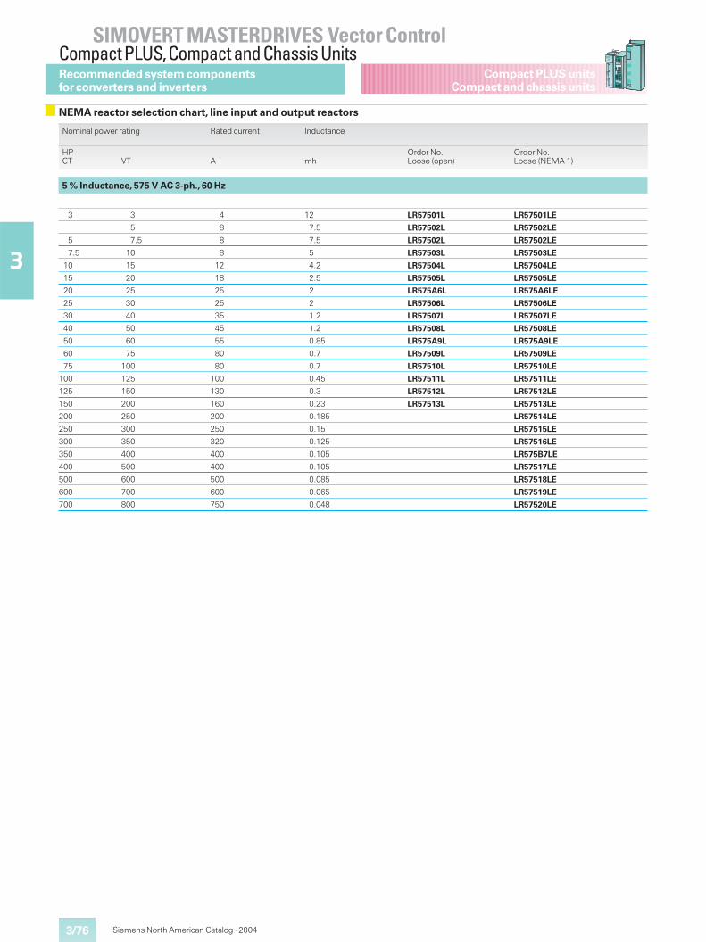
3/76
SIMOVERT MASTERDRIVES Vector ControlCompact PLUS,Compact and Chassis Units
3
Compact PLUS unitsCompact and chassis units
Siemens North American Catalog · 2004
Recommended system componentsfor converters and inverters
NEMA reactor selection chart, line input and output reactors
Nominal power rating Rated current Inductance
HPCT VT A mh
Order No.Loose (open)
Order No.Loose (NEMA 1)
5 % Inductance, 575 V AC 3-ph., 60 Hz
3 3 4 12 LR57501L LR57501LE
5 8 7.5 LR57502L LR57502LE
5 7.5 8 7.5 LR57502L LR57502LE
7.5 10 8 5 LR57503L LR57503LE
10 15 12 4.2 LR57504L LR57504LE
15 20 18 2.5 LR57505L LR57505LE
20 25 25 2 LR575A6L LR575A6LE
25 30 25 2 LR57506L LR57506LE
30 40 35 1.2 LR57507L LR57507LE
40 50 45 1.2 LR57508L LR57508LE
50 60 55 0.85 LR575A9L LR575A9LE
60 75 80 0.7 LR57509L LR57509LE
75 100 80 0.7 LR57510L LR57510LE
100 125 100 0.45 LR57511L LR57511LE
125 150 130 0.3 LR57512L LR57512LE
150 200 160 0.23 LR57513L LR57513LE
200 250 200 0.185 LR57514LE
250 300 250 0.15 LR57515LE
300 350 320 0.125 LR57516LE
350 400 400 0.105 LR575B7LE
400 500 400 0.105 LR57517LE
500 600 500 0.085 LR57518LE
600 700 600 0.065 LR57519LE
700 800 750 0.048 LR57520LE
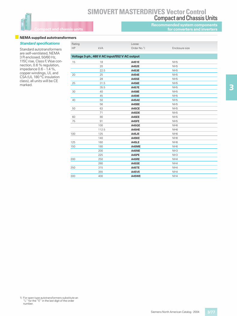
Compact and chassis units
3/77
SIMOVERT MASTERDRIVES Vector ControlCompact and Chassis Units
3
Siemens North American Catalog · 2004
Recommended system componentsfor converters and inverters
NEMA supplied autotransformers
Rating Loose
HP kVA Order No.1) Enclosure size
Voltage 3-ph., 460 V AC input/552 V AC output
15 18 A451E NH5
20 A452E NH5
22.5 A453E NH5
20 25 A454E NH5
28 A455E NH5
25 31.5 A456E NH5
35.5 A457E NH5
30 40 A458E NH5
45 A459E NH5
40 50 A45AE NH5
56 A45BE NH5
50 63 A45CE NH5
71 A45DE NH5
60 80 A45EE NH5
75 91 A45FE NH5
100 A45GE NH6
112.5 A45HE NH6
100 125 A45JE NH6
140 A45KE NH6
125 160 A45LE NH6
150 180 A45ME NH6
200 A45NE NH3
225 A45PE NH3
200 250 A45RE NH4
280 A45SE NH4
250 315 A45TE NH4
355 A45VE NH4
300 400 A45WE NH4
Standard specifications
Standard autotransformersare self-ventilated, NEMA3 R enclosed, 50/60 Hz,115C rise, Class F, Wye con-nection, 0.6 % regulation,impedance 0.6 – 1.4 %,copper windings, UL andCSA (UL 180 °C insulationclass), all units will be CEmarked.
1) For open type autotransformers substitute an“L” for the “E” in the last digit of the ordernumber.
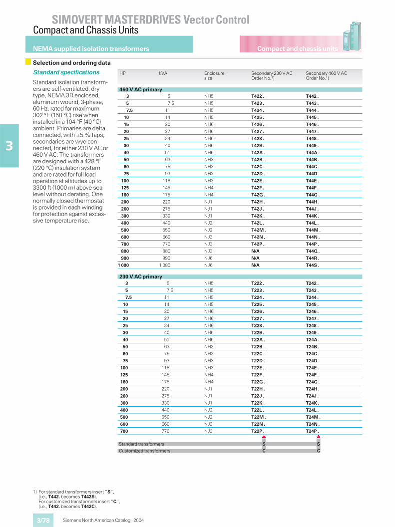
Compact and chassis units
SIMOVERT MASTERDRIVES Vector ControlCompact and Chassis Units
3/78
3
Siemens North American Catalog · 2004
NEMA supplied isolation transformers
Selection and ordering data
Standard specifications
Standard isolation transform-ers are self-ventilated, drytype, NEMA 3R enclosed,aluminum wound, 3-phase,60 Hz, rated for maximum302 °F (150 °C) rise wheninstalled in a 104 °F (40 °C)ambient. Primaries are deltaconnected, with ±5 % taps;secondaries are wye con-nected, for either 230 V AC or460 V AC. The transformersare designed with a 428 °F(220 °C) insulation systemand are rated for full loadoperation at altitudes up to3300 ft (1000 m) above sealevel without derating. Onenormally closed thermostatis provided in each windingfor protection against exces-sive temperature rise.
HP kVA Enclosuresize
Secondary 230 V ACOrder No.1)
Secondary 460 V ACOrder No.1)
460 V AC primary3 5 NH5 T422 . T442 .
5 7.5 NH5 T423 . T443 .
7.5 11 NH5 T424 . T444 .
10 14 NH5 T425 . T445 .
15 20 NH6 T426 . T446 .
20 27 NH6 T427 . T447 .
25 34 NH6 T428 . T448 .
30 40 NH6 T429 . T449 .
40 51 NH6 T42A . T44A .
50 63 NH3 T42B . T44B .
60 75 NH3 T42C . T44C .
75 93 NH3 T42D . T44D .
100 118 NH3 T42E . T44E .
125 145 NH4 T42F . T44F .
160 175 NH4 T42G . T44G .
200 220 NJ1 T42H . T44H .
260 275 NJ1 T42J . T44J .
300 330 NJ1 T42K . T44K .
400 440 NJ2 T42L . T44L .
500 550 NJ2 T42M . T44M .
600 660 NJ3 T42N . T44N .
700 770 NJ3 T42P . T44P .
800 880 NJ3 N/A T44Q .
900 990 NJ6 N/A T44R .
1 000 1 080 NJ6 N/A T44S .
230 V AC primary3 5 NH5 T222 . T242 .
5 7.5 NH5 T223 . T243 .
7.5 11 NH5 T224 . T244 .
10 14 NH5 T225 . T245 .
15 20 NH6 T226 . T246 .
20 27 NH6 T227 . T247 .
25 34 NH6 T228 . T248 .
30 40 NH6 T229 . T249 .
40 51 NH6 T22A . T24A .
50 63 NH3 T22B . T24B .
60 75 NH3 T22C . T24C .
75 93 NH3 T22D . T24D .
100 118 NH3 T22E . T24E .
125 145 NH4 T22F . T24F .
160 175 NH4 T22G . T24G .
200 220 NJ1 T22H . T24H .
260 275 NJ1 T22J . T24J .
300 330 NJ1 T22K . T24K .
400 440 NJ2 T22L . T24L .
500 550 NJ2 T22M . T24M .
600 660 NJ3 T22N . T24N .
700 770 NJ3 T22P . T24P .� �
Standard transformers S S
Customized transformers C C
1) For standard transformers insert “S”,(i.e., T442. becomes T442S).For customized transformers insert “C”,(i.e., T442. becomes T442C).
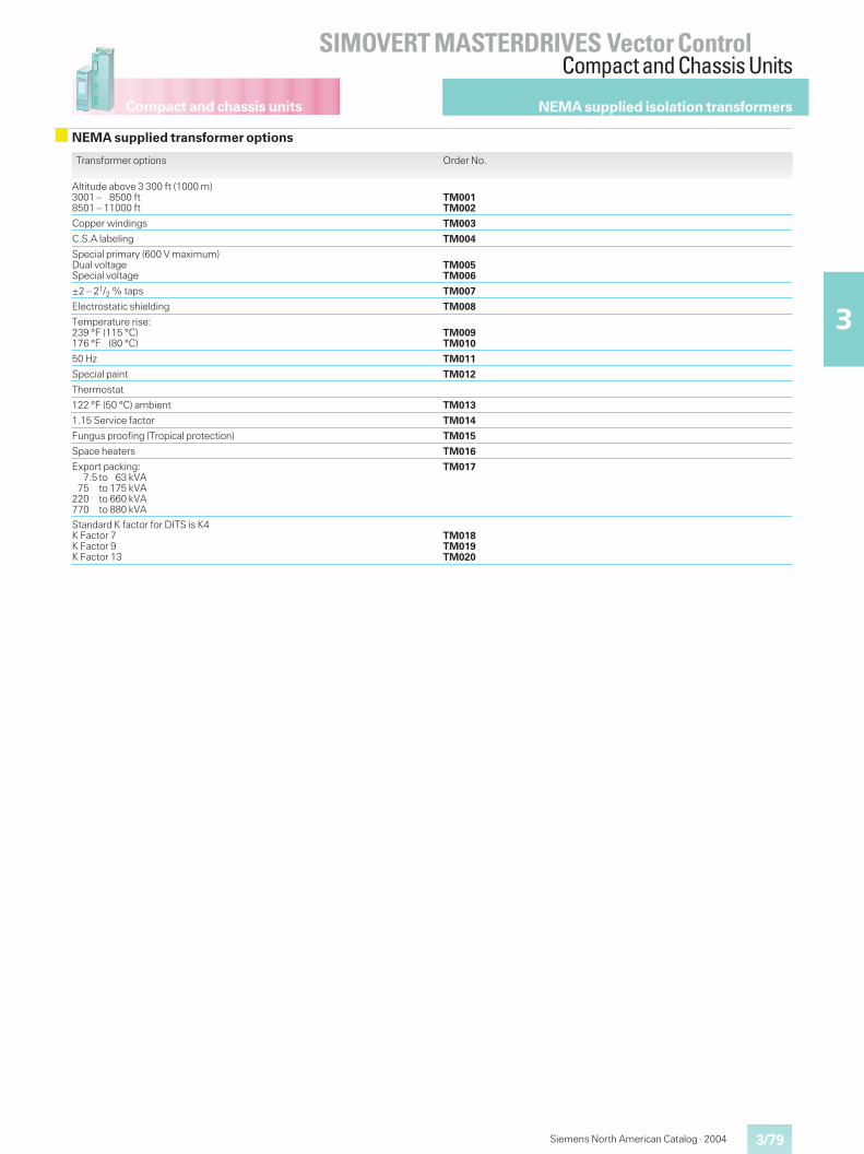
Compact and chassis units
3/79
SIMOVERT MASTERDRIVES Vector ControlCompact and Chassis Units
3
Siemens North American Catalog · 2004
NEMA supplied isolation transformers
NEMA supplied transformer options
Transformer options Order No.
Altitude above 3 300 ft (1000 m)3001 – 8500 ft8501 – 11000 ft
TM001TM002
Copper windings TM003
C.S.A labeling TM004
Special primary (600 V maximum)Dual voltageSpecial voltage
TM005TM006
±2 – 21/2 % taps TM007
Electrostatic shielding TM008
Temperature rise:239 °F (115 °C)176 °F (80 °C)
TM009TM010
50 Hz TM011
Special paint TM012
Thermostat
122 °F (50 °C) ambient TM013
1.15 Service factor TM014
Fungus proofing (Tropical protection) TM015
Space heaters TM016
Export packing:7.5 to 63 kVA
75 to 175 kVA220 to 660 kVA770 to 880 kVA
TM017
Standard K factor for DITS is K4K Factor 7K Factor 9K Factor 13
TM018TM019TM020
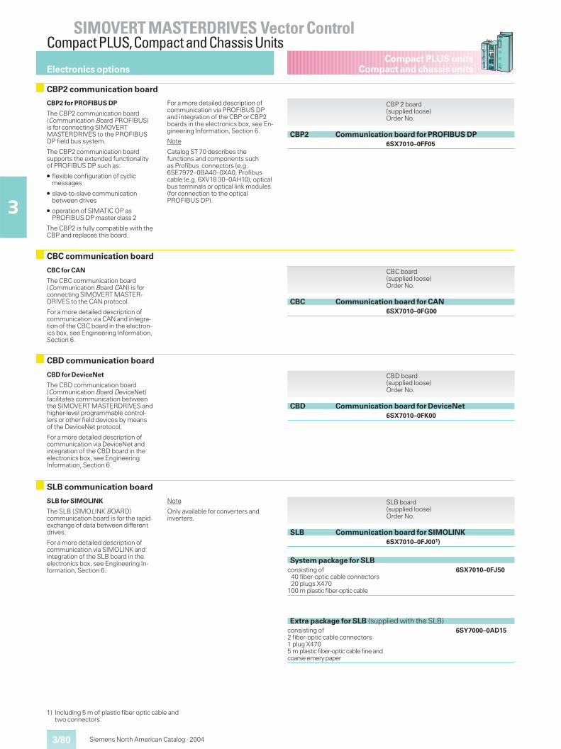
3/80
SIMOVERT MASTERDRIVES Vector ControlCompact PLUS,Compact and Chassis Units
3
Compact PLUS unitsCompact and chassis units
Siemens North American Catalog · 2004
CBP2 for PROFIBUS DP
The CBP2 communication board(Communication Board PROFIBUS)is for connecting SIMOVERTMASTERDRIVES to the PROFIBUSDP field bus system.
The CBP2 communication boardsupports the extended functionalityof PROFIBUS DP such as:
� flexible configuration of cyclicmessages
� slave-to-slave communicationbetween drives
� operation of SIMATIC OP asPROFIBUS DP master class 2
The CBP2 is fully compatible with theCBP and replaces this board.
For a more detailed description ofcommunication via PROFIBUS DPand integration of the CBP or CBP2boards in the electronics box, see En-gineering Information, Section 6.
Note
Catalog ST 70 describes thefunctions and components suchas Profibus connectors (e.g.6SE7972–0BA40–0XA0, Profibuscable (e.g. 6XV18 30–0AH10), opticalbus terminals or optical link modules(for connection to the opticalPROFIBUS DP).
CBP 2 board(supplied loose)Order No.
CBP2 Communication board for PROFIBUS DP6SX7010–0FF05
SLB for SIMOLINK
The SLB (SIMOLINK BOARD)communication board is for the rapidexchange of data between differentdrives.
For a more detailed description ofcommunication via SIMOLINK andintegration of the SLB board in theelectronics box, see Engineering In-formation, Section 6.
Note
Only available for converters andinverters.
SLB communication board
SLB board(supplied loose)Order No.
SLB Communication board for SIMOLINK6SX7010–0FJ001)
System package for SLBconsisting of40 fiber-optic cable connectors20 plugs X470
100 m plastic fiber-optic cable
6SX7010–0FJ50
Extra package for SLB (supplied with the SLB)consisting of2 fiber-optic cable connectors1 plug X4705 m plastic fiber-opticcable fineandcoarseemerypaper
6SY7000–0AD15
Electronics options
CBP2 communication board
CBC for CAN
The CBC communication board(Communication Board CAN) is forconnecting SIMOVERT MASTER-DRIVES to the CAN protocol.
For a more detailed description ofcommunication via CAN and integra-tion of the CBC board in the electron-ics box, see Engineering Information,Section 6.
CBC board(supplied loose)Order No.
CBC Communication board for CAN6SX7010–0FG00
CBC communication board
1) Including 5 m of plastic fiber optic cable andtwo connectors.
CBD for DeviceNet
The CBD communication board(Communication Board DeviceNet)facilitates communication betweenthe SIMOVERT MASTERDRIVES andhigher-level programmable control-lers or other field devices by meansof the DeviceNet protocol.
For a more detailed description ofcommunication via DeviceNet andintegration of the CBD board in theelectronics box, see EngineeringInformation, Section 6.
CBD board(supplied loose)Order No.
CBD Communication board for DeviceNet6SX7010–0FK00
CBD communication board
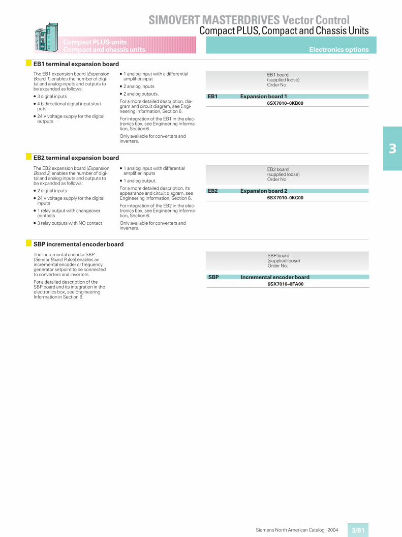
3/81
SIMOVERT MASTERDRIVES Vector ControlCompact PLUS,Compact and Chassis Units
3
Compact PLUS unitsCompact and chassis units
Siemens North American Catalog · 2004
The EB2 expansion board (ExpansionBoard 2) enables the number of digi-tal and analog inputs and outputs tobe expanded as follows:
� 2 digital inputs
� 24 V voltage supply for the digitalinputs
� 1 relay output with changeovercontacts
� 3 relay outputs with NO contact
� 1 analog input with differentialamplifier inputs
� 1 analog output.
For a more detailed description, itsappearance and circuit diagram, seeEngineering Information, Section 6.
For integration of the EB2 in the elec-tronics box, see Engineering Informa-tion, Section 6.
Only available for converters andinverters.
EB2 terminal expansion board
The EB1 expansion board (ExpansionBoard 1) enables the number of digi-tal and analog inputs and outputs tobe expanded as follows:
� 3 digital inputs
� 4 bidirectional digital inputs/out-puts
� 24 V voltage supply for the digitaloutputs
� 1 analog input with a differentialamplifier input
� 2 analog inputs
� 2 analog outputs.
For a more detailed description, dia-gram and circuit diagram, see Engi-neering Information, Section 6.
For integration of the EB1 in the elec-tronics box, see Engineering Informa-tion, Section 6.
Only available for converters andinverters.
EB1 board(supplied loose)Order No.
EB1 Expansion board 16SX7010–0KB00
EB1 terminal expansion board
Electronics options
SBP incremental encoder board
The incremental encoder SBP(Sensor Board Pulse) enables anincremental encoder or frequencygenerator setpoint to be connectedto converters and inverters.
For a detailed description of theSBP board and its integration in theelectronics box, see EngineeringInformation in Section 6.
EB2 board(supplied loose)Order No.
EB2 Expansion board 26SX7010–0KC00
SBP board(supplied loose)Order No.
SBP Incremental encoder board6SX7010–0FA00
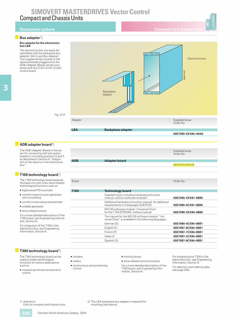
Compact and chassis units
SIMOVERT MASTERDRIVES Vector ControlCompact and Chassis Units
3/82
3
Siemens North American Catalog · 2004
Bus adapter for the electronicsbox LBA
The electronics box can easily beretrofitted with the backplane busadapter LBA (Local Bus Adapter).Two supplementary boards or theoptional boards plugged onto theADB (Adapter Board) can be com-bined with the CUVC (CUR, CUSA)control board.
Adapter Supplied looseOrder No.
LBA Backplane adapter6SE7090–0XX84–4HA0
DA
65-5
437
Backplaneadapter
Electronics box
The ADB (Adapter Board) is the car-rier for connecting half-size optionboards in mounting positions 2 and 3as described in Section 6 “Integra-tion of the options in the electronicsbox”.
Supplied looseOrder No.
ADB Adapter board6SX7010-0KA00
ADB adapter board1)
The T100 technology board expandsthe base unit with many drive-relatedtechnological functions such as:
� higher-level PID controller
� comfort ramp-function generatorwith smoothing
� comfort motorized potentiometer
� wobble generator
� drive-related control.
For a more detailed description of theT100 board, see Engineering Informa-tion, Section 6.
For integration of the T100 in theelectronics box, see EngineeringInformation, Section 6.
Board Order No.
T100 Technology boardSupplied loose, including hardware instructionmanual, without software module2) 6SE7090–0XX87–0BB0
Additional hardware instruction manual, for additionalrequirements in 5 languages (G/E/F/I/S) 6SE7080–0CX87–0BB0
MS100 software module “Universal Drive”for the T100 (EPROM), without manual 6SE7098–0XX84–0BB0
The manual for the MS100 software module “Uni-versal Drive” is available in the following languages:
German (G) 6SE7080–0CX84–0BB1
English (E) 6SE7087–6CX84–0BB1
French (F) 6SE7087–7CX84–0BB1
Italian (I) 6SE7087–2CX84–0BB1
Spanish (S) 6SE7087–8CX84–0BB1
T100 technology board1)
1) Attention!Only for compact and chassis units.
2) The LBA backplane bus adapter is required formounting (see above).
Electronics options
Bus adapter1)
The T300 technology board can beused to create technologicalfunctions for various applicationssuch as:
� closed-loop tension and positioncontrol
� winders
� coilers
� synchronous and positioningcontrol
� hoisting drives
� drive-related control functions.
For a more detailed description of theT300 board, see Engineering Infor-mation, Section 6.
For integrating the T300 in theelectronics box, see EngineeringInformation, Section 6.
For selection and ordering data,see page 3/83.
T300 technology board1)
Fig. 3/14
nelsco
Highlight
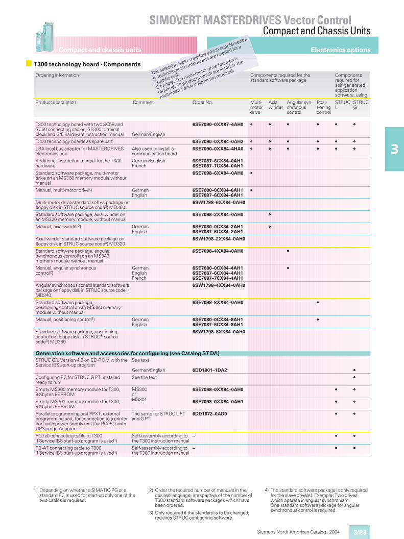
Compact and chassis units
3/83
SIMOVERT MASTERDRIVES Vector ControlCompact and Chassis Units
3
Siemens North American Catalog · 2004
Ordering information Components required for thestandard software package
Componentsrequired forself-generatedapplicationsoftware, using
Product description Comment Order No. Multi-motordrive
Axialwinder
Angular syn-chronouscontrol
Posi-tioningcontrol
STRUCL
STRUCG
T300 technology board with two SC58 andSC60 connecting cables, SE300 terminalblock and G/E hardware instruction manual German/English
6SE7090–0XX87–4AH0 � � � � � �
T300 technology boards as spare part 6SE7090–0XX84–0AH2 � � � � � �
LBA local bus adapter for MASTERDRIVESelectronics box
Also used to install acommunication board
6SE7090–0XX84–4HA0 � � � � � �
Additional instruction manual for the T300hardware
German/EnglishFrench
6SE7087–6CX84–0AH16SE7087–7CX84–0AH1
Standard software package, multi-motordrive on an MS360 memory module withoutmanual
6SE7098–6XX84–0AH0 �
Manual, multi-motor drive2) GermanEnglish
6SE7080–0CX84–6AH16SE7087–6CX84–6AH1
�
Multi-motor drive standard softw. package onfloppy disk in STRUC source code3) MD360
6SW1798–6XX84–0AH0
Standard software package, axial winder onan MS320 memory module, without manual
6SE7098–2XX84–0AH0 �
Manual, axial winder2) GermanEnglish
6SE7080–0CX84–2AH16SE7087–6CX84–2AH1
�
Axial winder standard software package onfloppy disk in STRUC source code3) MD320
6SW1798–2XX84–0AH0
Standard software package, angularsynchronous control4) on an MS340memory module without manual
6SE7098–4XX84–0AH0 �
Manual, angular synchronouscontrol2)
GermanEnglishFrench
6SE7080–0CX84–4AH16SE7087–6CX84–4AH16SE7087–7CX84–4AH1
�
Angular synchronous control standard softwarepackage on floppy disk in STRUC source code3)MD340
6SW1798–4XX84–0AH0
Standard software package,positioning control on an MS380 memorymodule without manual
6SE7098–8XX84–0AH0 �
Manual, positioning control2) GermanEnglish
6SE7080–0CX84–8AH16SE7087–6CX84–8AH1
�
Standard software package, positioningcontrol on floppy disk in STRUCr sourcecode3) MD380
6SW1798–8XX84–0AH0
Generation software and accessories for configuring (see Catalog ST DA)STRUC G/L Version 4.2 on CD-ROM with theService IBS start-up program
See text
German/English 6DD1801–1DA2 �
Configuring PC for STRUC G PT, installedready to run
See the text �
Empty MS300 memory module for T300,8 Kbytes EEPROM
MS300orMS301
6SE7098–0XX84–0AH0 � �
Empty MS301 memory module for T300,8 Kbytes EEPROM
6SE7098–0XX84–0AH1 � �
Parallel programming unit PPX1, externalprogramming unit, for connection to a printerport with power supply unit (for PC/PG) withUP3 progr. Adapter
The same for STRUC L PTand G PT
6DD1672–0AD0 � �
PG7x0 connecting cable to T300if Service IBS start-up program is used1)
Self-assembly according tothe T300 instruction manual
– � �
PC-AT connecting cable to T300if Service IBS start-up program is used1)
Self-assembly according tothe T300 instruction manual
– � �
1) Depending on whether a SIMATIC-PG or astandard PC is used for start-up only one of thetwo cables is required.
2) Order the required number of manuals in thedesired language, irrespective of the number ofT300 standard software packages which havebeen ordered.
3) Only required if the standard is to be changed;requires STRUC configuring software.
4) The standard software package is only requiredfor the slave drive(s). Example: Two driveswhich operate in angular synchronism:One standard software package for angularsynchronous control is required.
Electronics options
T300 technology board · ComponentsThe selection table specifies which supplementa-
ry technological components are needed for a
specific task.
Example: The multi-motor drive function is
required. All products which are listed in the
multi-motor drive column are required.
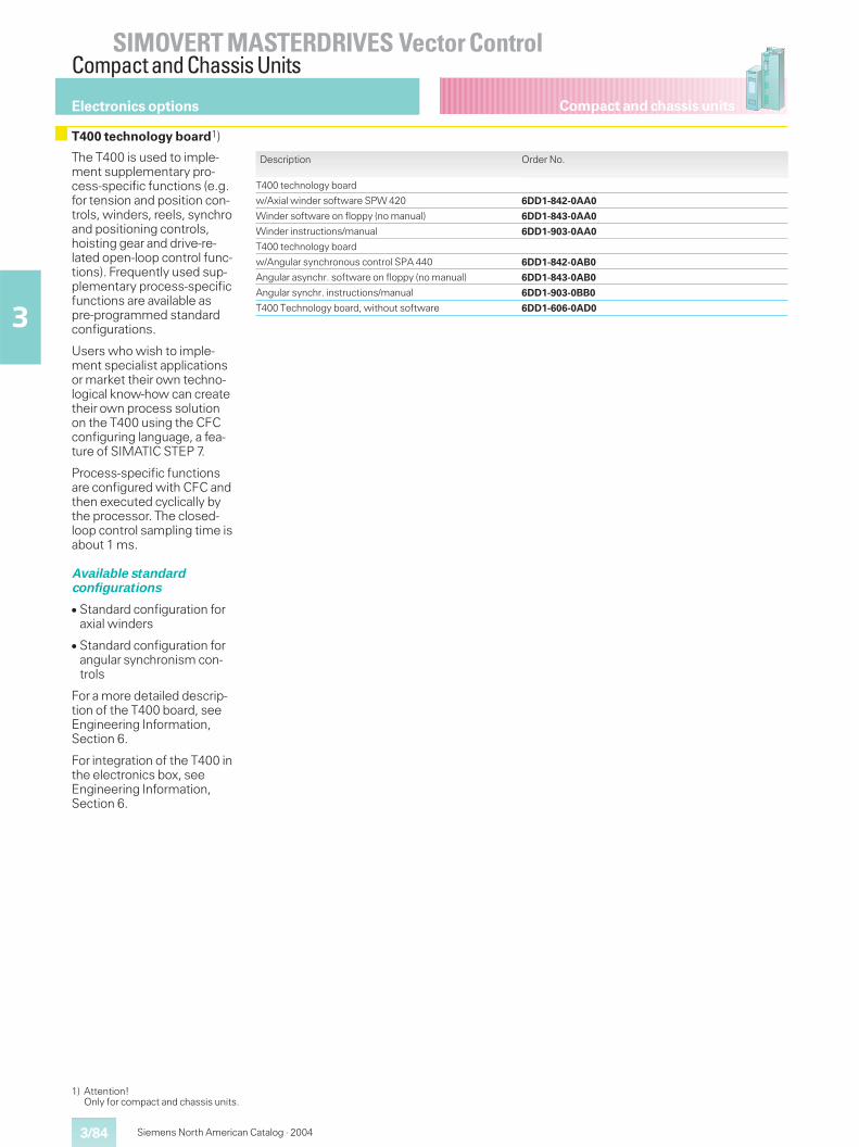
Compact and chassis units
SIMOVERT MASTERDRIVES Vector ControlCompact and Chassis Units
3/84
3
Siemens North American Catalog · 2004
Electronics options
T400 technology board1)
1) Attention!Only for compact and chassis units.
The T400 is used to imple-ment supplementary pro-cess-specific functions (e.g.for tension and position con-trols, winders, reels, synchroand positioning controls,hoisting gear and drive-re-lated open-loop control func-tions). Frequently used sup-plementary process-specificfunctions are available aspre-programmed standardconfigurations.
Users who wish to imple-ment specialist applicationsor market their own techno-logical know-how can createtheir own process solutionon the T400 using the CFCconfiguring language, a fea-ture of SIMATIC STEP 7.
Process-specific functionsare configured with CFC andthen executed cyclically bythe processor. The closed-loop control sampling time isabout 1 ms.
Available standardconfigurations
� Standard configuration foraxial winders
� Standard configuration forangular synchronism con-trols
For a more detailed descrip-tion of the T400 board, seeEngineering Information,Section 6.
For integration of the T400 inthe electronics box, seeEngineering Information,Section 6.
Description Order No.
T400 technology board
w/Axial winder software SPW 420 6DD1-842-0AA0
Winder software on floppy (no manual) 6DD1-843-0AA0
Winder instructions/manual 6DD1-903-0AA0
T400 technology board
w/Angular synchronous control SPA 440 6DD1-842-0AB0
Angular asynchr. software on floppy (no manual) 6DD1-843-0AB0
Angular synchr. instructions/manual 6DD1-903-0BB0
T400 Technology board, without software 6DD1-606-0AD0
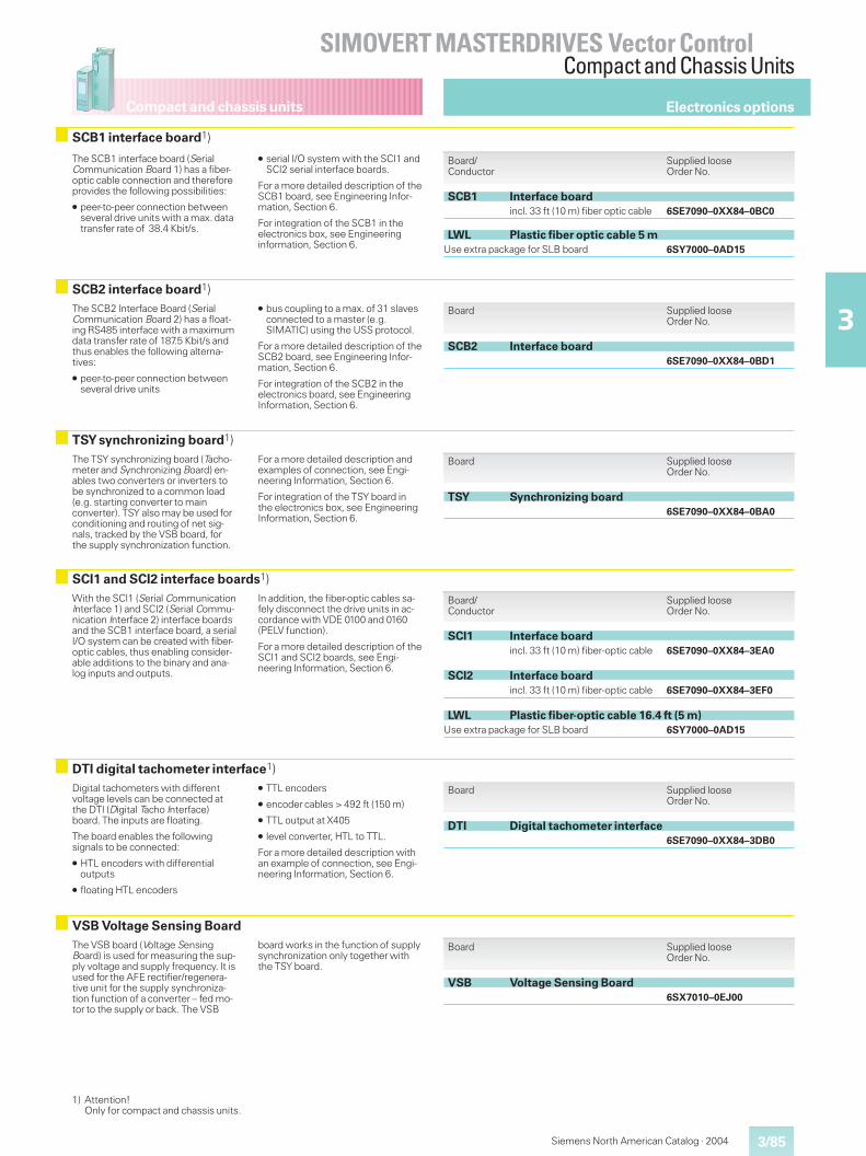
Compact and chassis units
3/85
SIMOVERT MASTERDRIVES Vector ControlCompact and Chassis Units
3
Siemens North American Catalog · 2004
VSB Voltage Sensing BoardThe VSB board (Voltage SensingBoard) is used for measuring the sup-ply voltage and supply frequency. It isused for the AFE rectifier/regenera-tive unit for the supply synchroniza-tion function of a converter – fed mo-tor to the supply or back. The VSB
board works in the function of supplysynchronization only together withthe TSY board.
Board Supplied looseOrder No.
VSB Voltage Sensing Board6SX7010–0EJ00
Digital tachometers with differentvoltage levels can be connected atthe DTI (Digital Tacho Interface)board. The inputs are floating.
The board enables the followingsignals to be connected:
� HTL encoders with differentialoutputs
� floating HTL encoders
� TTL encoders
� encoder cables > 492 ft (150 m)
� TTL output at X405
� level converter, HTL to TTL.
For a more detailed description withan example of connection, see Engi-neering Information, Section 6.
Board Supplied looseOrder No.
DTI Digital tachometer interface6SE7090–0XX84–3DB0
DTI digital tachometer interface1)
With the SCI1 (Serial CommunicationInterface 1) and SCI2 (Serial Commu-nication Interface 2) interface boardsand the SCB1 interface board, a serialI/O system can be created with fiber-optic cables, thus enabling consider-able additions to the binary and ana-log inputs and outputs.
In addition, the fiber-optic cables sa-fely disconnect the drive units in ac-cordance with VDE 0100 and 0160(PELV function).
For a more detailed description of theSCI1 and SCI2 boards, see Engi-neering Information, Section 6.
Board/Conductor
Supplied looseOrder No.
SCI1 Interface boardincl. 33 ft (10 m) fiber-optic cable 6SE7090–0XX84–3EA0
SCI2 Interface boardincl. 33 ft (10 m) fiber-optic cable 6SE7090–0XX84–3EF0
LWL Plastic fiber-optic cable 16.4 ft (5 m)Use extra package for SLB board 6SY7000–0AD15
SCI1 and SCI2 interface boards1)
The TSY synchronizing board (Tacho-meter and Synchronizing Board) en-ables two converters or inverters tobe synchronized to a common load(e.g. starting converter to mainconverter). TSY also may be used forconditioning and routing of net sig-nals, tracked by the VSB board, forthe supply synchronization function.
For a more detailed description andexamples of connection, see Engi-neering Information, Section 6.
For integration of the TSY board inthe electronics box, see EngineeringInformation, Section 6.
Board Supplied looseOrder No.
TSY Synchronizing board6SE7090–0XX84–0BA0
TSY synchronizing board1)
The SCB2 Interface Board (SerialCommunication Board 2) has a float-ing RS485 interface with a maximumdata transfer rate of 187.5 Kbit/s andthus enables the following alterna-tives:
� peer-to-peer connection betweenseveral drive units
� bus coupling to a max. of 31 slavesconnected to a master (e.g.SIMATIC) using the USS protocol.
For a more detailed description of theSCB2 board, see Engineering Infor-mation, Section 6.
For integration of the SCB2 in theelectronics board, see EngineeringInformation, Section 6.
Board Supplied looseOrder No.
SCB2 Interface board6SE7090–0XX84–0BD1
SCB2 interface board1)
The SCB1 interface board (SerialCommunication Board 1) has a fiber-optic cable connection and thereforeprovides the following possibilities:
� peer-to-peer connection betweenseveral drive units with a max. datatransfer rate of 38.4 Kbit/s.
� serial I/O system with the SCI1 andSCI2 serial interface boards.
For a more detailed description of theSCB1 board, see Engineering Infor-mation, Section 6.
For integration of the SCB1 in theelectronics box, see Engineeringinformation, Section 6.
Board/Conductor
Supplied looseOrder No.
SCB1 Interface boardincl. 33 ft (10 m) fiber optic cable 6SE7090–0XX84–0BC0
LWL Plastic fiber optic cable 5 mUse extra package for SLB board 6SY7000–0AD15
SCB1 interface board1)
Electronics options
1) Attention!Only for compact and chassis units.
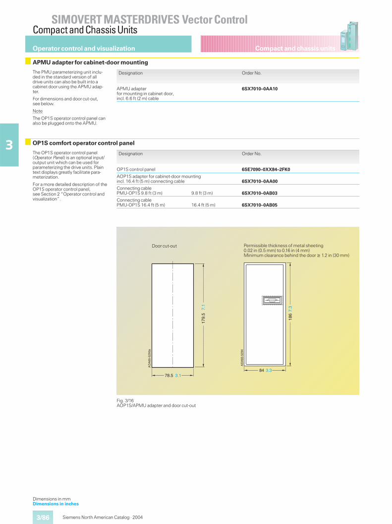
Compact and chassis units
SIMOVERT MASTERDRIVES Vector ControlCompact and Chassis Units
3/86
3
Siemens North American Catalog · 2004
The PMU parameterizing unit inclu-ded in the standard version of alldrive units can also be built into acabinet door using the APMU adap-ter.
For dimensions and door cut-out,see below.
Note
The OP1S operator control panel canalso be plugged onto the APMU.
The OP1S operator control panel(Operator Panel) is an optional input/output unit which can be used forparameterizing the drive units. Plaintext displays greatly facilitate para-meterization.
For a more detailed description of theOP1S operator control panel,see Section 2 “Operator control andvisualization”.
Designation Order No.
APMU adapterfor mounting in cabinet door,incl. 6.6 ft (2 m) cable
6SX7010–0AA10
Designation Order No.
OP1S control panel 6SE7090–0XX84–2FK0
AOP1S adapter for cabinet-door mountingincl. 16.4 ft (5 m) connecting cable 6SX7010–0AA00
Connecting cablePMU-OP1S 9.8 ft (3 m) 9.8 ft (3 m) 6SX7010–0AB03
Connecting cablePMU-OP1S 16.4 ft (5 m) 16.4 ft (5 m) 6SX7010–0AB05
Fig. 3/16AOP1S/APMU adapter and door cut-out
DA
65-5
293a
A
3.1
179.
57.
1
78.5
Door cut-outD
A65
-529
4A
84
7.3
3.3
186
Permissible thickness of metal sheeting0.02 in (0.5 mm) to 0.16 in (4 mm)Minimum clearance behind the door � 1.2 in (30 mm)
Operator control and visualization
APMU adapter for cabinet-door mounting
OP1S comfort operator control panel
Dimensions in mmDimensions in inches
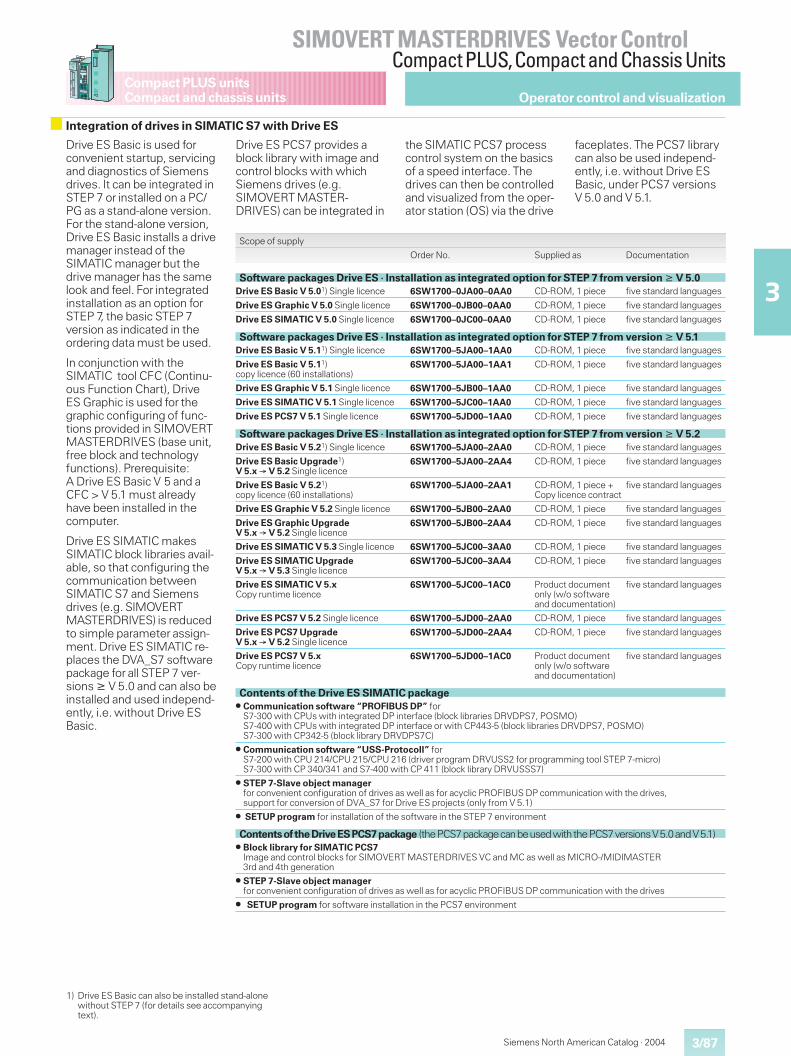
3/87
SIMOVERT MASTERDRIVES Vector ControlCompact PLUS,Compact and Chassis Units
3
Compact PLUS unitsCompact and chassis units
Siemens North American Catalog · 2004
Operator control and visualization
Drive ES Basic is used forconvenient startup, servicingand diagnostics of Siemensdrives. It can be integrated inSTEP 7 or installed on a PC/PG as a stand-alone version.For the stand-alone version,Drive ES Basic installs a drivemanager instead of theSIMATIC manager but thedrive manager has the samelook and feel. For integratedinstallation as an option forSTEP 7, the basic STEP 7version as indicated in theordering data must be used.
In conjunction with theSIMATIC tool CFC (Continu-ous Function Chart), DriveES Graphic is used for thegraphic configuring of func-tions provided in SIMOVERTMASTERDRIVES (base unit,free block and technologyfunctions). Prerequisite:A Drive ES Basic V 5 and aCFC > V 5.1 must alreadyhave been installed in thecomputer.
Drive ES SIMATIC makesSIMATIC block libraries avail-able, so that configuring thecommunication betweenSIMATIC S7 and Siemensdrives (e.g. SIMOVERTMASTERDRIVES) is reducedto simple parameter assign-ment. Drive ES SIMATIC re-places the DVA_S7 softwarepackage for all STEP 7 ver-sions � V 5.0 and can also beinstalled and used independ-ently, i.e. without Drive ESBasic.
Integration of drives in SIMATIC S7 with Drive ES
Drive ES PCS7 provides ablock library with image andcontrol blocks with whichSiemens drives (e.g.SIMOVERT MASTER-DRIVES) can be integrated in
the SIMATIC PCS7 processcontrol system on the basicsof a speed interface. Thedrives can then be controlledand visualized from the oper-ator station (OS) via the drive
faceplates. The PCS7 librarycan also be used independ-ently, i.e. without Drive ESBasic, under PCS7 versionsV 5.0 and V 5.1.
Scope of supply
Order No. Supplied as Documentation
Software packages Drive ES · Installation as integrated option for STEP 7 from version � V 5.0Drive ES Basic V 5.01) Single licence 6SW1700–0JA00–0AA0 CD-ROM, 1 piece five standard languages
Drive ES Graphic V 5.0 Single licence 6SW1700–0JB00–0AA0 CD-ROM, 1 piece five standard languages
Drive ES SIMATIC V 5.0 Single licence 6SW1700–0JC00–0AA0 CD-ROM, 1 piece five standard languages
Software packages Drive ES · Installation as integrated option for STEP 7 from version � V 5.1Drive ES Basic V 5.11) Single licence 6SW1700–5JA00–1AA0 CD-ROM, 1 piece five standard languages
Drive ES Basic V 5.11)copy licence (60 installations)
6SW1700–5JA00–1AA1 CD-ROM, 1 piece five standard languages
Drive ES Graphic V 5.1 Single licence 6SW1700–5JB00–1AA0 CD-ROM, 1 piece five standard languages
Drive ES SIMATIC V 5.1 Single licence 6SW1700–5JC00–1AA0 CD-ROM, 1 piece five standard languages
Drive ES PCS7 V 5.1 Single licence 6SW1700–5JD00–1AA0 CD-ROM, 1 piece five standard languages
Software packages Drive ES · Installation as integrated option for STEP 7 from version � V 5.2Drive ES Basic V 5.21) Single licence 6SW1700–5JA00–2AA0 CD-ROM, 1 piece five standard languages
Drive ES Basic Upgrade1)V 5.x � V 5.2 Single licence
6SW1700–5JA00–2AA4 CD-ROM, 1 piece five standard languages
Drive ES Basic V 5.21)copy licence (60 installations)
6SW1700–5JA00–2AA1 CD-ROM, 1 piece +Copy licence contract
five standard languages
Drive ES Graphic V 5.2 Single licence 6SW1700–5JB00–2AA0 CD-ROM, 1 piece five standard languages
Drive ES Graphic UpgradeV 5.x � V 5.2 Single licence
6SW1700–5JB00–2AA4 CD-ROM, 1 piece five standard languages
Drive ES SIMATIC V 5.3 Single licence 6SW1700–5JC00–3AA0 CD-ROM, 1 piece five standard languages
Drive ES SIMATIC UpgradeV 5.x � V 5.3 Single licence
6SW1700–5JC00–3AA4 CD-ROM, 1 piece five standard languages
Drive ES SIMATIC V 5.xCopy runtime licence
6SW1700–5JC00–1AC0 Product documentonly (w/o softwareand documentation)
five standard languages
Drive ES PCS7 V 5.2 Single licence 6SW1700–5JD00–2AA0 CD-ROM, 1 piece five standard languages
Drive ES PCS7 UpgradeV 5.x � V 5.2 Single licence
6SW1700–5JD00–2AA4 CD-ROM, 1 piece five standard languages
Drive ES PCS7 V 5.xCopy runtime licence
6SW1700–5JD00–1AC0 Product documentonly (w/o softwareand documentation)
five standard languages
Contents of the Drive ES SIMATIC package� Communication software “PROFIBUS DP” for
S7-300 with CPUs with integrated DP interface (block libraries DRVDPS7, POSMO)S7-400 with CPUs with integrated DP interface or with CP443-5 (block libraries DRVDPS7, POSMO)S7-300 with CP342-5 (block library DRVDPS7C)
� Communication software “USS-Protocoll” forS7-200 with CPU 214/CPU 215/CPU 216 (driver program DRVUSS2 for programming tool STEP 7-micro)S7-300 with CP 340/341 and S7-400 with CP 411 (block library DRVUSSS7)
� STEP 7-Slave object managerfor convenient configuration of drives as well as for acyclic PROFIBUS DP communication with the drives,support for conversion of DVA_S7 for Drive ES projects (only from V 5.1)
� SETUP program for installation of the software in the STEP 7 environment
ContentsoftheDriveESPCS7package (thePCS7packagecanbeusedwiththePCS7versionsV5.0andV5.1)� Block library for SIMATIC PCS7
Image and control blocks for SIMOVERT MASTERDRIVES VC and MC as well as MICRO-/MIDIMASTER3rd and 4th generation
� STEP 7-Slave object managerfor convenient configuration of drives as well as for acyclic PROFIBUS DP communication with the drives
� SETUP program for software installation in the PCS7 environment
1) Drive ES Basic can also be installed stand-alonewithout STEP 7 (for details see accompanyingtext).
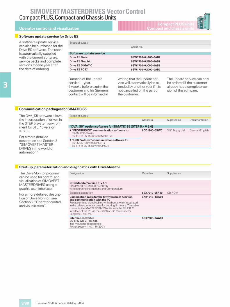
3/88
SIMOVERT MASTERDRIVES Vector ControlCompact PLUS,Compact and Chassis Units
3
Compact PLUS unitsCompact and chassis units
Siemens North American Catalog · 2004
Operator control and visualization
Software update service for Drive ES
Scope of supply
Order No.
Software update serviceDrive ES Basic 6SW1700–0JA00–0AB2
Drive ES Graphic 6SW1700–0JB00–0AB2
Drive ES SIMATIC 6SW1700–0JC00–0AB2
Drive ES PCS7 6SW1700–0JD00–0AB2
Duration of the updateservice: 1 year.6 weeks before expiry, thecustomer and his Siemenscontact will be informed in
writing that the update ser-vice will automatically be ex-tended by another year if it isnot cancelled on the part ofthe customer.
The update service can onlybe ordered if the customeralready has a complete ver-sion of the software.
A software update servicecan also be purchased for theDrive ES software. The useris automatically suppliedwith the current software,service packs and completeversions for one year afterthe date of ordering.
The DVA_S5 software allowsthe incorporation of drives inthe STEP 5 system environ-ment for STEP 5 version� 6.0.
For a more detaileddescription see Section 2“SIMOVERT MASTER-DRIVES in the world ofautomation”.
Communication packages for SIMATIC S5
Scope of supply
Order No. Supplied as Documentation
“DVA_S5” option software for SIMATIC S5 (STEP 5 > V 6.0)� “PROFIBUS DP” communication software for
S5-95U/DP-MasterS5-115 to S5-155U with IM308-B/C
6DD1800–0SW0 3.5“ floppy disk German/English
� “USS Protocol” communication software forS5-95/S5-100 with CP 521SiS5-115 to S5-155U with CP 524
The DriveMonitor programcan be used for control andvisualization of SIMOVERTMASTERDRIVES using agraphic user interface.
For a more detailed descrip-tion of DriveMonitor, seeSection 2 “Operator controland visualization”.
Start-up, parameterization and diagnostics with DriveMonitor
Designation Order No. Supplied as
DriveMonitor Version � V 5.1for SIMOVERT MASTERDRIVESwith operating instructions and Compendium
Supplied separately 6SX7010–0FA10 CD-ROM
Combination cable for the firmware boot functionand communication with the PCPre-assembled signal cables with a boot switch integratedin the cable connector case for booting firmware. The cableconnects the MASTERDRIVES units with the RS 232 Cinterface of the PC via the –X300 or –X103 connector.Length 9.8 ft (3 m).
9AK1012–1AA00 –
Interface converterSU1 RS 232 C – RS 485,incl. mounting accessories;Power supply: 1 AC 115/230 V
6SX7005–0AA00 –
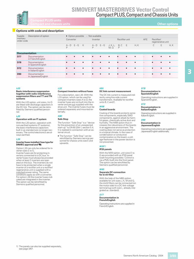
Siemens North American Catalog · 2004 3/89
SIMOVERT MASTERDRIVES Vector ControlCompact PLUS,Compact and Chassis Units
3
Compact PLUS unitsCompact and chassis units Other options
Options with code and description
Supple-mentaryorder code
Description of option � Option possible – Not available
Converter Inverter Rectifier unit AFE Rectifier/regenerative unit
A – DP
E – G K A – DP
E – G J, K, L,M, Q
B, CP
E H, K C E H, K
DocumentationD77 Documentation
in French/English� � � � � � � � � – � � �
D78 Documentationin Spanish/English
� � � � � � � � � – � � �
D72 Documentationin Italian/English
� � � � � � � � � – � � �
D90 Documentationin Japanese/English
� � � � � � � � � – � � �
L03
Basic-interference suppressiontogether with radio-interferencesuppression filters and TT and TNsystems
With the L03 option, unit sizes J to Qare fitted with discharge capacitors inthe DC link. The option can be retro-fitted by Siemens qualified person-nel.
L20
Operation with an IT system
With the L20 option, operation withnon-earthed systems (IT systems),the basic-interference capacitorsbuilt in as standard are no longer nec-essary. The control electronics are al-ways earthed.
L30
Inverter fuses installed,fuse type forDIN/IEC approval andU
Option L30 can only be ordered for in-verter sizes E to G.Inverter fuses are for protecting in-verters connected to a DC bus. In-verter fuses must always be providedwhen at least 2 inverters are oper-ated on this bus. The inverters do nothave to be protected when a singleinverter of a rectifier unit or a rectifier/regenerative unit is supplied with amatched power rating. The sameconditions apply as with a converter.For option L30 the inverter fuses indi-cated are integrated in the inverter.The option can be retrofitted bySiemens qualified personnel.
L33
Compact inverters without fuses
For a description, see L30. With theL33 option, which can be used forcompact inverters sizes A to D, theinverter fuses are not built into the in-verter and are not supplied with thedrive unit. The inverter fuses must beordered separately and mounted ex-ternally.
K80
Safe Stop
The function “Safe Stop”is a “devicefor the prevention of an unexpectedstart-up”to EN 60 204-1, section 5.4.It is realized in connection with an ex-ternal circuit.
� The function “Safe Stop”can beretrofitted by Siemens service per-sonnel for chassis units size E andupwards.
K91
DC link current measurement
The DC link current is measured indi-rectly using line-side currenttransformers. Available for rectifierunits B, C and E.
M08
Coated boards
Coating of the boards protects sensi-tive components, especially SMDcomponents, against attack by harm-ful gases, chemically active dust andhumidity. The M08 option thus in-creases the robustness of the boardsin an aggressive environment. Thecoating does not serve as protectionin a tropical climate. In the case ofcondensation or conductivecontamination on the board, a volt-age flashover in the power section isnot prevented.
M201)IP20 panels
With the M20 option, unit sizes E toG are provided with an IP20 panel(wall mounting possible). Control isvia a PMU built into the front panel.The option can be retrofitted bySiemens qualified personnel.
M65
Separate DC connectionfor dv/dt filter
With the help of the M65 option,available for unit sizes J, K, M and Q,the dv/dt filters can be connected (onthe motor side) to a DC-link-voltageterminal lug (with size L; already inte-grated as standard).
D77
Documentation inFrench/English
Operating instructions are supplied inFrench/English.
D78
Documentation inSpanish/English
Operating instructions are supplied inSpanish/English.
D72
Documentation inItalian/English
Operating instructions are supplied inItalian/English.
D90
Documentation inJapanese/English
Operating instructions are supplied inJapanese/English additionally.
1) The panels can also be supplied separately,see page 3/67.

3/90
SIMOVERT MASTERDRIVES Vector ControlCompact PLUS,Compact and Chassis Units
3
Compact PLUS unitsCompact and chassis units
Siemens North American Catalog · 2004
Notes
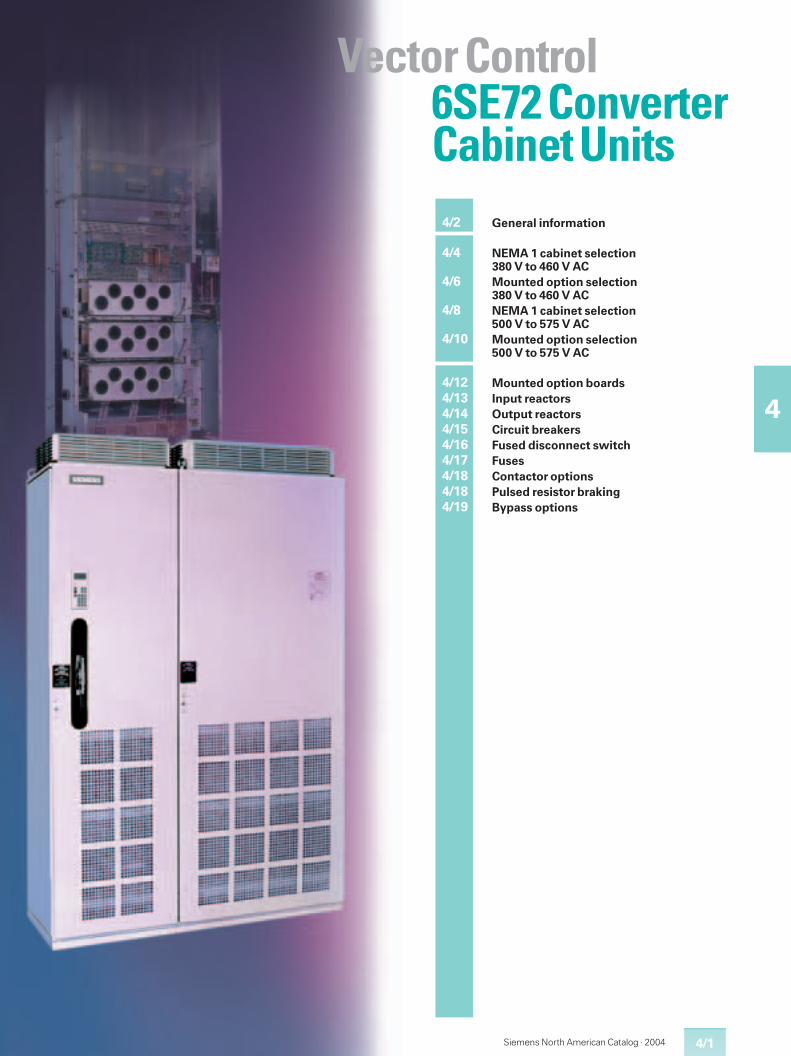
4/1
4
Siemens North American Catalog · 2004
4/2 General information
4/4 NEMA 1 cabinet selection380 V to 460 V AC
4/6 Mounted option selection380 V to 460 V AC
4/8 NEMA 1 cabinet selection500 V to 575 V AC
4/10 Mounted option selection500 V to 575 V AC
4/12 Mounted option boards4/13 Input reactors4/14 Output reactors4/15 Circuit breakers4/16 Fused disconnect switch4/17 Fuses4/18 Contactor options4/18 Pulsed resistor braking4/19 Bypass options
Vector Control6SE72 ConverterCabinet Units
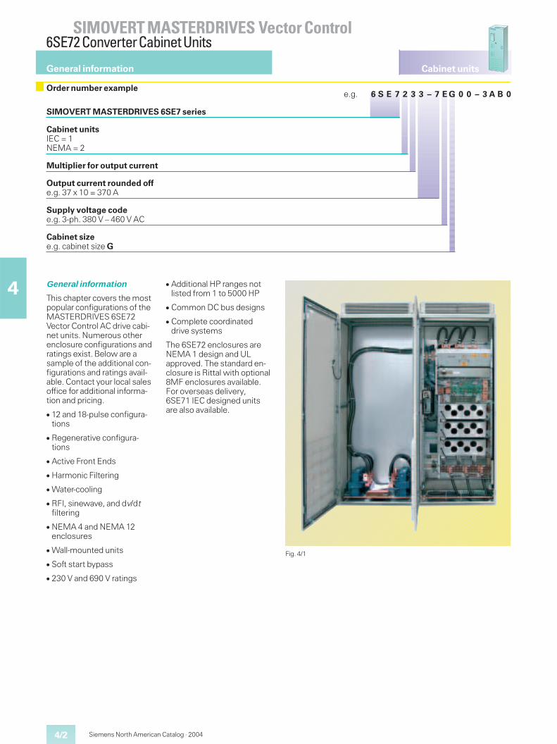
Cabinet units
4/2
SIMOVERT MASTERDRIVES Vector Control6SE72 ConverterCabinet Units
4
Siemens North American Catalog · 2004
General information
Order number examplee.g. 6 S E 7 2 3 3 – 7 E G 0 0 – 3 A B 0
SIMOVERT MASTERDRIVES 6SE7 series
Cabinet unitsIEC = 1NEMA = 2
Multiplier for output current
Output current rounded offe.g. 37 x 10 = 370 A
Supply voltage codee.g. 3-ph. 380 V – 460 V AC
Cabinet sizee.g. cabinet size G
Fig. 4/1
General information
This chapter covers the mostpopular configurations of theMASTERDRIVES 6SE72Vector Control AC drive cabi-net units. Numerous otherenclosure configurations andratings exist. Below are asample of the additional con-figurations and ratings avail-able. Contact your local salesoffice for additional informa-tion and pricing.
� 12 and 18-pulse configura-tions
� Regenerative configura-tions
� Active Front Ends
� Harmonic Filtering
� Water-cooling
� RFI, sinewave, and dv/dtfiltering
� NEMA 4 and NEMA 12enclosures
� Wall-mounted units
� Soft start bypass
� 230 V and 690 V ratings
� Additional HP ranges notlisted from 1 to 5000 HP
� Common DC bus designs
� Complete coordinateddrive systems
The 6SE72 enclosures areNEMA 1 design and ULapproved. The standard en-closure is Rittal with optional8MF enclosures available.For overseas delivery,6SE71 IEC designed unitsare also available.
4/3
Cabinet units
SIMOVERT MASTERDRIVES Vector Control6SE72 ConverterCabinet Units
4
Siemens North American Catalog · 2004
Ratings and selection
General information
6SE72 NEMA Cabinets
6SE72 model numbers de-fine pre-engineered NEMAdrive packages. 6SE72 drivepackages with a particularHP and voltage rating con-sists of an enclosure, a6SE70 chassis or combina-tion of chassis units, and adoor mounted text operatorpanel (OP1).
The 6SE72 drive packagescan be modified with addi-tional power options. Aswired and mounted poweroptions are added, the spacerequired to mount these op-tions increases. A simplesystem has been designedto aid in the selection of theproper size enclosure. Thissystem divides the 6SE72numbers into two catego-ries:
1. Basic enclosure:No space for any poweroptions.
2. Standard enclosure:Space for the followingselected power options.
� Line fuses� Disconnect switch or
circuit-breaker� Input reactor� Input contactor1)� Dynamic braking
chopper2)� Output contactor2)� Overload relay2)
1) Except for cabinet sizes K and L.
2) Not in all cases.Refer to factory.
Cabinet units
4/4
SIMOVERT MASTERDRIVES Vector Control6SE72 ConverterCabinet Units
4
Siemens North American Catalog · 2004
NEMA 1 cabinet selection380 V to 460 V AC
Selection and ordering data
Nominalpowerrating1)4)CT
Baseloadcurrent2)
IG
Nominalpowerrating1)4)5)VT
Ratedcurrent3)
IN
Nominalpowerrating
Standard Enclosure6) Dimensiondrawing,seeSection 7
NominaldimensionsW x H x D
Weightapprox.
HP(460 V AC) A
HP(460 V AC) A
kW(400 V AC) Order No. Cabinet size
inches(mm)
lb(kg)
Supply voltage 380 V to 460 V AC60 84 75 92 45 6SE7231–0EF00–3AB0 F 24 x 95 x 24
(600 x 2400 x 600)500(226.8)
75 113 100 124 55 6SE7231–2EF00–3AB0 F 24 x 95 x 24(600 x 2400 x 600)
525(238.1)
100 133 125 146 75 6SE7231–5EF00–3AB0 F 24 x 95 x 24(600 x 2400 x 600)
525(238.1)
125 169 150 186 90 6SE7231–8EF00–3AB0 F 24 x 95 x 24(600 x 2400 x 600)
525(238.1)
150 191 175 210 110 6SE7232–1EG00–3AB0 G 36 x 95 x 24(900 x 2400 x 600)
780(353.7)
175 237 200 260 132 6SE7232–6EG00–3AB0 G 36 x 95 x 24(900 x 2400 x 600)
780(353.7)
200 287 250 315 160 6SE7233–2EG00–3AB0 G 36 x 95 x 24(900 x 2400 x 600)
800(362.8)
250 337 300 370 200 6SE7233–7EG00–3AB0 G 36 x 95 x 24(900 x 2400 x 600)
840(380.9)
350 464 450 510 250 6SE7235–1EK00–3AB0 K 60 x 95 x 24(1500 x 2400 x 600)
1700(771.0)
450 537 500 590 315 6SE7236–0EK00–3AB0 K 60 x 95 x 24(1500 x 2400 x 600)
1700(771.0)
500 628 600 690 400 6SE7237–0EK00–3AB0 K 60 x 95 x 24(1500 x 2400 x 600)
1820(825.4)
600 783 700 860 500 6SE7238–6EL00–3AB0 L 72 x 95 x 24(1800 x 2400 x 600)
2300(1043.1)
700 875 800 1000 630 6SE7241–0EN00–3AB0 N 108 x 95 x 24(2700 x 2400 x 600)
3000(1360.5)
800 1000 900 1100 630 6SE7241–1EN00–3AB0 N 108 x 95 x 24(2700 x 2400 x 600)
3000(1360.5)
900 1075 1000 1183 710 6SE7241–2EU00–3AB0 U 144 x 95 x 24(3600 x 2400 x 600)
4000(1814.1)
1000 1183 1100 1300 710 6SE7241–3EU00–3AB0 U 144 x 95 x 24(3600 x 2400 x 600)
4000(1814.1)
1) Check the actual motor current before guaran-teeing final HP capability.
2) Units can run continuously at the listed IG ratingwith 50 % additional load capability available fora maximum of 1 minute.
3) The IN rating is 100 % continuous, with no antici-pated overload capability (typically fans, pumps,etc.). Drives running at current levels below INhave the capability to run 135 % current for upto one minute, with a maximum duty cycle of300 s.
4) HP ratings are based on 460 V AC.
5) Motor currents vary by type/speed and manu-facturer. Motor currents must be verified toensure variable torque rating is not exceeded.
6) NEMA 1 enclosure and door-mounted OP1S arestandard on all 6SE72 units.
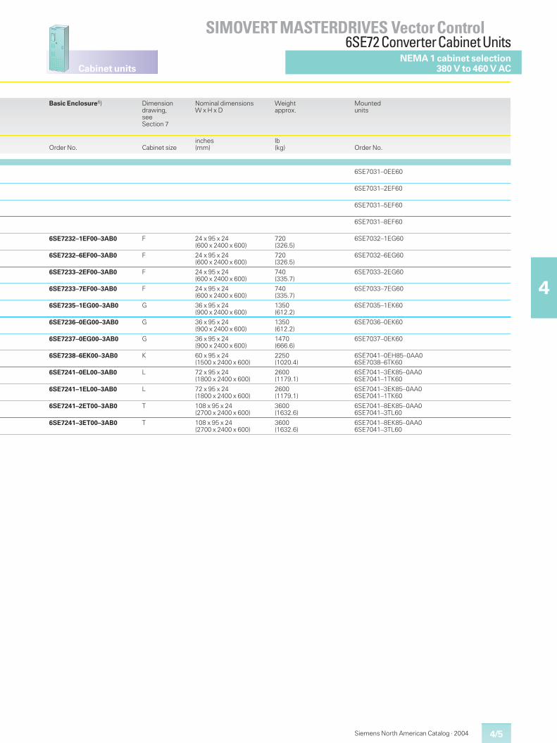
4/5
Cabinet units
SIMOVERT MASTERDRIVES Vector Control6SE72 ConverterCabinet Units
4
Siemens North American Catalog · 2004
NEMA 1 cabinet selection380 V to 460 V AC
Basic Enclosure6) Dimensiondrawing,seeSection 7
Nominal dimensionsW x H x D
Weightapprox.
Mountedunits
Order No. Cabinet sizeinches(mm)
lb(kg) Order No.
6SE7031–0EE60
6SE7031–2EF60
6SE7031–5EF60
6SE7031–8EF60
6SE7232–1EF00–3AB0 F 24 x 95 x 24(600 x 2400 x 600)
720(326.5)
6SE7032–1EG60
6SE7232–6EF00–3AB0 F 24 x 95 x 24(600 x 2400 x 600)
720(326.5)
6SE7032–6EG60
6SE7233–2EF00–3AB0 F 24 x 95 x 24(600 x 2400 x 600)
740(335.7)
6SE7033–2EG60
6SE7233–7EF00–3AB0 F 24 x 95 x 24(600 x 2400 x 600)
740(335.7)
6SE7033–7EG60
6SE7235–1EG00–3AB0 G 36 x 95 x 24(900 x 2400 x 600)
1350(612.2)
6SE7035–1EK60
6SE7236–0EG00–3AB0 G 36 x 95 x 24(900 x 2400 x 600)
1350(612.2)
6SE7036–0EK60
6SE7237–0EG00–3AB0 G 36 x 95 x 24(900 x 2400 x 600)
1470(666.6)
6SE7037–0EK60
6SE7238–6EK00–3AB0 K 60 x 95 x 24(1500 x 2400 x 600)
2250(1020.4)
6SE7041–0EH85–0AA06SE7038–6TK60
6SE7241–0EL00–3AB0 L 72 x 95 x 24(1800 x 2400 x 600)
2600(1179.1)
6SE7041–3EK85–0AA06SE7041–1TK60
6SE7241–1EL00–3AB0 L 72 x 95 x 24(1800 x 2400 x 600)
2600(1179.1)
6SE7041–3EK85–0AA06SE7041–1TK60
6SE7241–2ET00–3AB0 T 108 x 95 x 24(2700 x 2400 x 600)
3600(1632.6)
6SE7041–8EK85–0AA06SE7041–3TL60
6SE7241–3ET00–3AB0 T 108 x 95 x 24(2700 x 2400 x 600)
3600(1632.6)
6SE7041–8EK85–0AA06SE7041–3TL60
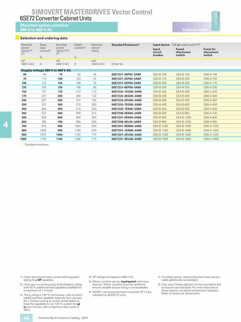
Cabinet units
4/6
SIMOVERT MASTERDRIVES Vector Control6SE72 ConverterCabinet Units
4
Siemens North American Catalog · 2004
Mounted option selection380 V to 460 V AC
Selection and ordering data
Standard enclosure
Nominalpowerrating1)4)CT
Baseloadcurrent2)
IG
Nominalpowerrating1)4)5)VT
Ratedcurrent3)
IN
Nominalpowerrating
Standard Enclosure6) Input device – C/B or fused switch7)8)
Inputcircuitbreaker
Fuseddisconnectswitch
Fuses fordisconnectswitch
HP(460 V AC) A
HP(460 V AC) A
kW(400 V AC) Order No.
Supply voltage 380 V to 460 V AC60 84 75 92 45 6SE7231–0EF00–3AB0 Q50-B-100 Q54-B-125 Q56-A-100
75 113 100 124 55 6SE7231–2EF00–3AB0 Q50-B-125 Q54-B-250 Q56-A-150
100 133 125 146 75 6SE7231–5EF00–3AB0 Q50-B-200 Q54-B-250 Q56-A-175
125 169 150 186 90 6SE7231–8EF00–3AB0 Q50-B-200 Q54-B-250 Q56-A-200
150 191 175 210 110 6SE7232–1EG00–3AB0 Q50-B-300 Q54-B-400 Q56-A-250
175 237 200 260 132 6SE7232–6EG00–3AB0 Q50-B-300 Q54-B-400 Q56-A-300
200 287 250 315 160 6SE7233–2EG00–3AB0 Q50-B-480 Q54-B-400 Q56-A-350
250 337 300 370 200 6SE7233–7EG00–3AB0 Q50-B-480 Q54-B-600 Q56-A-450
350 464 450 510 250 6SE7235–1EK00–3AB0 Q50-B-480 Q54-B-600 Q56-A-500
450 537 500 590 315 6SE7236–0EK00–3AB0 Q50-B-600 Q54-B-800 Q56-A-750
500 628 600 690 400 6SE7237–0EK00–3AB0 Q50-B-960 Q54-B-1200 Q56-A-800
600 782 700 860 500 6SE7238–6EL00–3AB0 Q50-B-960 Q54-B-1200 Q56-A-900
700 875 800 1000 630 6SE7241–0EN00–3AB0 Q50-B-1280 Q54-B-1600 Q56-A-1200
800 1000 900 1100 630 6SE7241–1EN00–3AB0 Q50-B-1280 Q54-B-1600 Q56-A-1350
900 1075 1000 1183 710 6SE7241–2EU00–3AB0 Q50-B-1280 Q54-B-1600 Q56-A-1350
1000 1183 1100 1300 710 6SE7241–3EU00–3AB0 Q50-B-1600 Q54-B-1600 Q56-A-1600
1) Check the actual motor current before guaran-teeing final HP capability.
2) Units can run continuously at the listed IG ratingwith 50 % additional load capability available fora maximum of 1 minute.
3) The IN rating is 100 % continuous, with no antici-pated overload capability (typically fans, pumps,etc.). Drives running at current levels below INhave the capability to run 135 % current for upto one minute, with a maximum duty cycle of300 s.
4) HP ratings are based on 460 V AC.
5) Motor currents vary by type/speed and manu-facturer. Motor currents must be verified toensure variable torque rating is not exceeded.
6) NEMA 1 enclosure and door-mounted OP1S arestandard on all 6SE72 units.
7) For either option, semiconductors fuses are pro-vided additionally as standard.
8) Only one of these options can be mounted in theenclosure size indicated. For more than one ofthese options, an add-on enclosure is required.Refer to factory for dimensions.
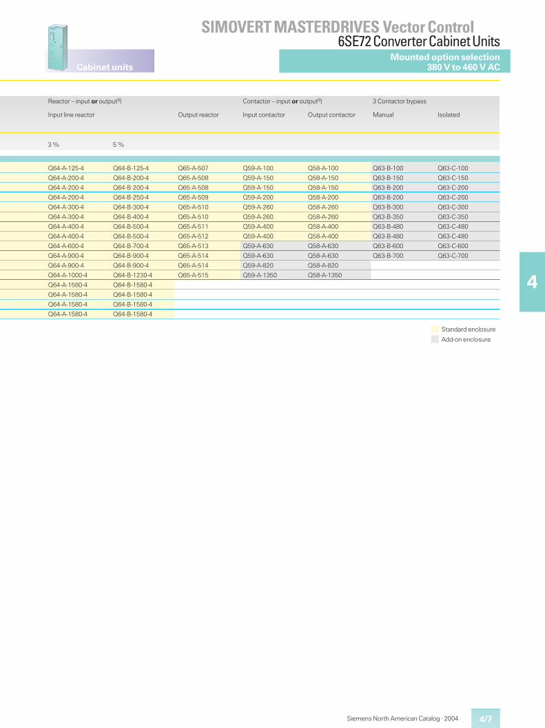
4/7
Cabinet units
SIMOVERT MASTERDRIVES Vector Control6SE72 ConverterCabinet Units
4
Siemens North American Catalog · 2004
Mounted option selection380 V to 460 V AC
Standard enclosure
Add-on enclosure
Reactor – input or output8)
Input line reactor Output reactor
Contactor – input or output8)
Input contactor Output contactor
3 Contactor bypass
Manual Isolated
3 % 5 %
Q64-A-125-4 Q64-B-125-4 Q65-A-507 Q59-A-100 Q58-A-100 Q63-B-100 Q63-C-100
Q64-A-200-4 Q64-B-200-4 Q65-A-508 Q59-A-150 Q58-A-150 Q63-B-150 Q63-C-150
Q64-A-200-4 Q64-B-200-4 Q65-A-508 Q59-A-150 Q58-A-150 Q63-B-200 Q63-C-200
Q64-A-200-4 Q64-B-250-4 Q65-A-509 Q59-A-200 Q58-A-200 Q63-B-200 Q63-C-200
Q64-A-300-4 Q64-B-300-4 Q65-A-510 Q59-A-260 Q58-A-260 Q63-B-300 Q63-C-300
Q64-A-300-4 Q64-B-400-4 Q65-A-510 Q59-A-260 Q58-A-260 Q63-B-350 Q63-C-350
Q64-A-400-4 Q64-B-500-4 Q65-A-511 Q59-A-400 Q58-A-400 Q63-B-480 Q63-C-480
Q64-A-400-4 Q64-B-500-4 Q65-A-512 Q59-A-400 Q58-A-400 Q63-B-480 Q63-C-480
Q64-A-600-4 Q64-B-700-4 Q65-A-513 Q59-A-630 Q58-A-630 Q63-B-600 Q63-C-600
Q64-A-900-4 Q64-B-900-4 Q65-A-514 Q59-A-630 Q58-A-630 Q63-B-700 Q63-C-700
Q64-A-900-4 Q64-B-900-4 Q65-A-514 Q59-A-820 Q58-A-820
Q64-A-1000-4 Q64-B-1230-4 Q65-A-515 Q59-A-1350 Q58-A-1350
Q64-A-1580-4 Q64-B-1580-4
Q64-A-1580-4 Q64-B-1580-4
Q64-A-1580-4 Q64-B-1580-4
Q64-A-1580-4 Q64-B-1580-4
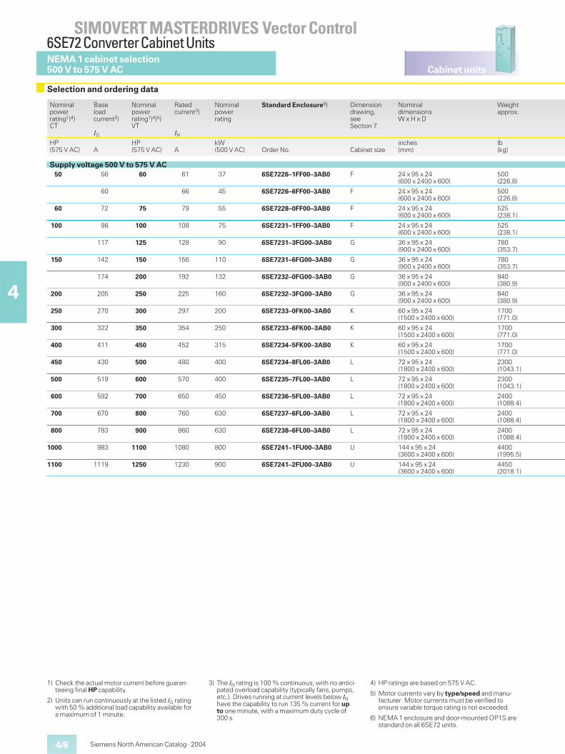
Cabinet units
4/8
SIMOVERT MASTERDRIVES Vector Control6SE72 ConverterCabinet Units
4
Siemens North American Catalog · 2004
NEMA 1 cabinet selection500 V to 575 V AC
Selection and ordering data
1) Check the actual motor current before guaran-teeing final HP capability.
2) Units can run continuously at the listed IG ratingwith 50 % additional load capability available fora maximum of 1 minute.
3) The IN rating is 100 % continuous, with no antici-pated overload capability (typically fans, pumps,etc.). Drives running at current levels below INhave the capability to run 135 % current for upto one minute, with a maximum duty cycle of300 s.
4) HP ratings are based on 575 V AC.
5) Motor currents vary by type/speed and manu-facturer. Motor currents must be verified toensure variable torque rating is not exceeded.
6) NEMA 1 enclosure and door-mounted OP1S arestandard on all 6SE72 units.
Nominalpowerrating1)4)CT
Baseloadcurrent2)
IG
Nominalpowerrating1)4)5)VT
Ratedcurrent3)
IN
Nominalpowerrating
Standard Enclosure6) Dimensiondrawing,seeSection 7
NominaldimensionsW x H x D
Weightapprox.
HP(575 V AC) A
HP(575 V AC) A
kW(500 V AC) Order No. Cabinet size
inches(mm)
lb(kg)
Supply voltage 500 V to 575 V AC50 56 60 61 37 6SE7226–1FF00–3AB0 F 24 x 95 x 24
(600 x 2400 x 600)500(226.8)
60 66 45 6SE7226–6FF00–3AB0 F 24 x 95 x 24(600 x 2400 x 600)
500(226.8)
60 72 75 79 55 6SE7228–0FF00–3AB0 F 24 x 95 x 24(600 x 2400 x 600)
525(238.1)
100 98 100 108 75 6SE7231–1FF00–3AB0 F 24 x 95 x 24(600 x 2400 x 600)
525(238.1)
117 125 128 90 6SE7231–3FG00–3AB0 G 36 x 95 x 24(900 x 2400 x 600)
780(353.7)
150 142 150 156 110 6SE7231–6FG00–3AB0 G 36 x 95 x 24(900 x 2400 x 600)
780(353.7)
174 200 192 132 6SE7232–0FG00–3AB0 G 36 x 95 x 24(900 x 2400 x 600)
840(380.9)
200 205 250 225 160 6SE7232–3FG00–3AB0 G 36 x 95 x 24(900 x 2400 x 600)
840(380.9)
250 270 300 297 200 6SE7233–0FK00–3AB0 K 60 x 95 x 24(1500 x 2400 x 600)
1700(771.0)
300 322 350 354 250 6SE7233–6FK00–3AB0 K 60 x 95 x 24(1500 x 2400 x 600)
1700(771.0)
400 411 450 452 315 6SE7234–5FK00–3AB0 K 60 x 95 x 24(1500 x 2400 x 600)
1700(771.0)
450 430 500 480 400 6SE7234–8FL00–3AB0 L 72 x 95 x 24(1800 x 2400 x 600)
2300(1043.1)
500 519 600 570 400 6SE7235–7FL00–3AB0 L 72 x 95 x 24(1800 x 2400 x 600)
2300(1043.1)
600 592 700 650 450 6SE7236–5FL00–3AB0 L 72 x 95 x 24(1800 x 2400 x 600)
2400(1088.4)
700 670 800 760 630 6SE7237–6FL00–3AB0 L 72 x 95 x 24(1800 x 2400 x 600)
2400(1088.4)
800 783 900 860 630 6SE7238–6FL00–3AB0 L 72 x 95 x 24(1800 x 2400 x 600)
2400(1088.4)
1000 983 1100 1080 800 6SE7241–1FU00–3AB0 U 144 x 95 x 24(3600 x 2400 x 600)
4400(1995.5)
1100 1119 1250 1230 900 6SE7241–2FU00–3AB0 U 144 x 95 x 24(3600 x 2400 x 600)
4450(2018.1)
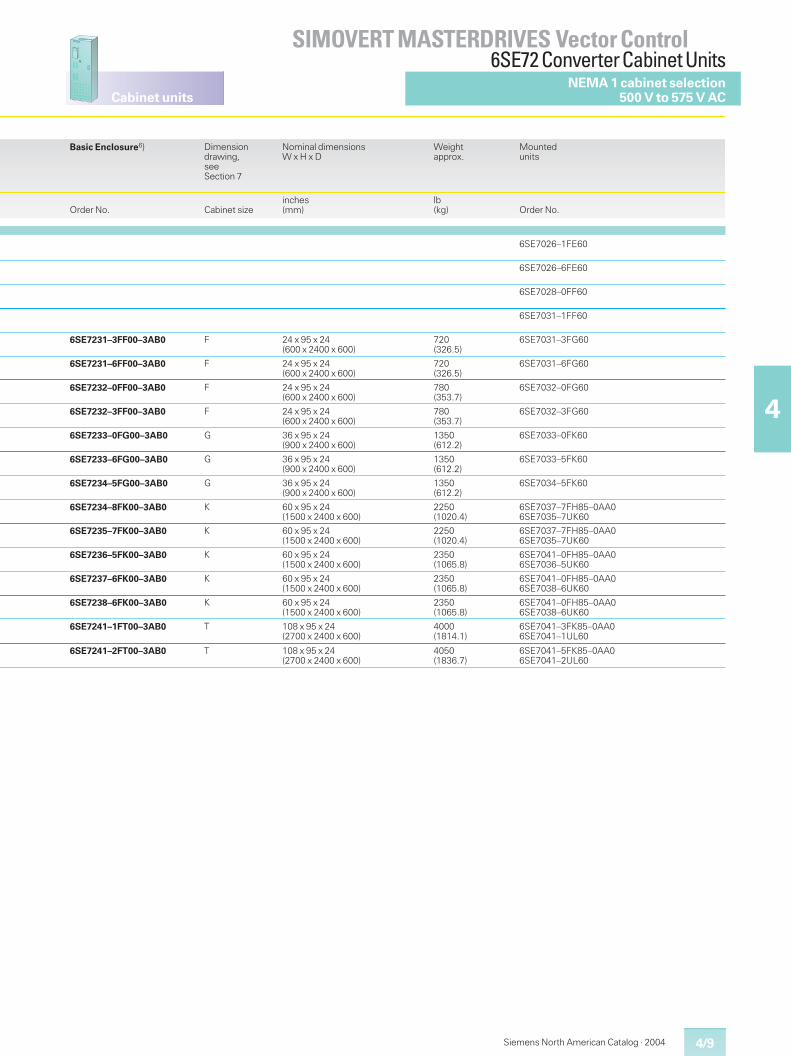
4/9
Cabinet units
SIMOVERT MASTERDRIVES Vector Control6SE72 ConverterCabinet Units
4
Siemens North American Catalog · 2004
NEMA 1 cabinet selection500 V to 575 V AC
Basic Enclosure6) Dimensiondrawing,seeSection 7
Nominal dimensionsW x H x D
Weightapprox.
Mountedunits
Order No. Cabinet sizeinches(mm)
lb(kg) Order No.
6SE7026–1FE60
6SE7026–6FE60
6SE7028–0FF60
6SE7031–1FF60
6SE7231–3FF00–3AB0 F 24 x 95 x 24(600 x 2400 x 600)
720(326.5)
6SE7031–3FG60
6SE7231–6FF00–3AB0 F 24 x 95 x 24(600 x 2400 x 600)
720(326.5)
6SE7031–6FG60
6SE7232–0FF00–3AB0 F 24 x 95 x 24(600 x 2400 x 600)
780(353.7)
6SE7032–0FG60
6SE7232–3FF00–3AB0 F 24 x 95 x 24(600 x 2400 x 600)
780(353.7)
6SE7032–3FG60
6SE7233–0FG00–3AB0 G 36 x 95 x 24(900 x 2400 x 600)
1350(612.2)
6SE7033–0FK60
6SE7233–6FG00–3AB0 G 36 x 95 x 24(900 x 2400 x 600)
1350(612.2)
6SE7033–5FK60
6SE7234–5FG00–3AB0 G 36 x 95 x 24(900 x 2400 x 600)
1350(612.2)
6SE7034–5FK60
6SE7234–8FK00–3AB0 K 60 x 95 x 24(1500 x 2400 x 600)
2250(1020.4)
6SE7037–7FH85–0AA06SE7035–7UK60
6SE7235–7FK00–3AB0 K 60 x 95 x 24(1500 x 2400 x 600)
2250(1020.4)
6SE7037–7FH85–0AA06SE7035–7UK60
6SE7236–5FK00–3AB0 K 60 x 95 x 24(1500 x 2400 x 600)
2350(1065.8)
6SE7041–0FH85–0AA06SE7036–5UK60
6SE7237–6FK00–3AB0 K 60 x 95 x 24(1500 x 2400 x 600)
2350(1065.8)
6SE7041–0FH85–0AA06SE7038–6UK60
6SE7238–6FK00–3AB0 K 60 x 95 x 24(1500 x 2400 x 600)
2350(1065.8)
6SE7041–0FH85–0AA06SE7038–6UK60
6SE7241–1FT00–3AB0 T 108 x 95 x 24(2700 x 2400 x 600)
4000(1814.1)
6SE7041–3FK85–0AA06SE7041–1UL60
6SE7241–2FT00–3AB0 T 108 x 95 x 24(2700 x 2400 x 600)
4050(1836.7)
6SE7041–5FK85–0AA06SE7041–2UL60
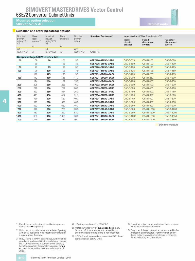
Cabinet units
4/10
SIMOVERT MASTERDRIVES Vector Control6SE72 ConverterCabinet Units
4
Siemens North American Catalog · 2004
Mounted option selection500 V to 575 V AC
Selection and ordering data for options
Standard enclosure
1) Check the actual motor current before guaran-teeing final HP capability.
2) Units can run continuously at the listed IG ratingwith 50 % additional load capability available fora maximum of 1 minute.
3) The IN rating is 100 % continuous, with no antici-pated overload capability (typically fans, pumps,etc.). Drives running at current levels below INhave the capability to run 135 % current for upto one minute, with a maximum duty cycle of300 s.
4) HP ratings are based on 575 V AC.
5) Motor currents vary by type/speed and manu-facturer. Motor currents must be verified toensure variable torque rating is not exceeded.
6) NEMA 1 enclosure and door-mounted OP1S arestandard on all 6SE72 units.
7) For either option, semiconductors fuses are pro-vided additionally as standard.
8) Only one of these options can be mounted in theenclosure size indicated. For more than one ofthese options, an add-on enclosure is required.Refer to factory for dimensions.
Nominalpowerrating1)4)CT
Baseloadcurrent2)
IG
Nominalpowerrating1)4)5)VT
Ratedcurrent3)
IN
Nominalpowerrating
Standard Enclosure6) Input device – C/B or fused switch7)8)
Inputcircuitbreaker
Fuseddisconnectswitch
Fuses fordisconnectswitch
HP(575 V AC) A
HP(575 V AC) A
kW(500 V AC) Order No.
Supply voltage 500 V to 575 V AC50 56 60 61 37 6SE7226–1FF00–3AB0 Q50-B-075 Q54-B-100 Q56-A-080
60 66 45 6SE7226–6FF00–3AB0 Q50-B-100 Q54-B-100 Q56-A-100
60 72 75 79 55 6SE7228–0FF00–3AB0 Q50-B-100 Q54-B-125 Q56-A-125
100 98 100 108 75 6SE7231–1FF00–3AB0 Q50-B-125 Q54-B-125 Q56-A-150
117 125 128 90 6SE7231–3FG00–3AB0 Q50-B-200 Q54-B-250 Q56-A-175
150 142 150 156 110 6SE7231–6FG00–3AB0 Q50-B-200 Q54-B-250 Q56-A-200
174 200 192 132 6SE7232–0FG00–3AB0 Q50-B-200 Q54-B-400 Q56-A-250
200 205 250 225 160 6SE7232–3FG00–3AB0 Q50-B-300 Q54-B-400 Q56-A-300
250 270 300 297 200 6SE7233–0FK00–3AB0 Q50-B-300 Q54-B-400 Q56-A-400
300 322 350 354 250 6SE7233–6FK00–3AB0 Q50-B-480 Q54-B-600 Q56-A-450
400 411 450 452 315 6SE7234–5FK00–3AB0 Q50-B-480 Q54-B-600 Q56-A-600
450 430 500 480 400 6SE7234–8FL00–3AB0 Q50-B-480 Q54-B-600 Q56-A-600
500 519 600 570 400 6SE7235–7FL00–3AB0 Q50-B-600 Q54-B-800 Q56-A-750
600 592 700 650 450 6SE7236–5FL00–3AB0 Q50-B-960 Q54-B-800 Q56-A-900
700 670 800 760 630 6SE7237–6FL00–3AB0 Q50-B-960 Q54-B-1200 Q56-A-1200
800 783 900 860 630 6SE7238–6FL00–3AB0 Q50-B-960 Q54-B-1200 Q56-A-1200
1000 983 1100 1080 800 6SE7241–1FU00–3AB0 Q50-B-1280 Q54-B-1600 Q56-A-1350
1100 1119 1250 1230 900 6SE7241–2FU00–3AB0 Q50-B-1280 Q54-B-1600 Q56-A-1600
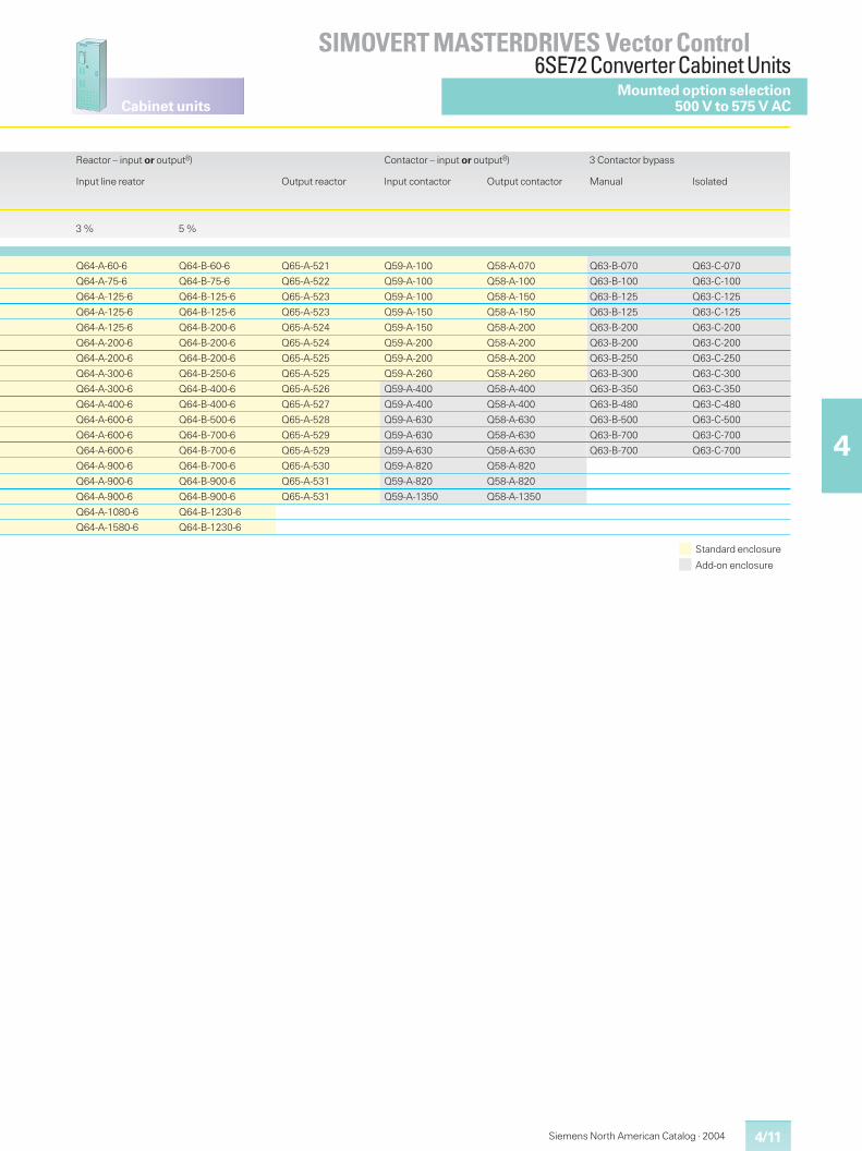
4/11
Cabinet units
SIMOVERT MASTERDRIVES Vector Control6SE72 ConverterCabinet Units
4
Siemens North American Catalog · 2004
Mounted option selection500 V to 575 V AC
Standard enclosure
Add-on enclosure
Reactor – input or output8)
Input line reator Output reactor
Contactor – input or output8)
Input contactor Output contactor
3 Contactor bypass
Manual Isolated
3 % 5 %
Q64-A-60-6 Q64-B-60-6 Q65-A-521 Q59-A-100 Q58-A-070 Q63-B-070 Q63-C-070
Q64-A-75-6 Q64-B-75-6 Q65-A-522 Q59-A-100 Q58-A-100 Q63-B-100 Q63-C-100
Q64-A-125-6 Q64-B-125-6 Q65-A-523 Q59-A-100 Q58-A-150 Q63-B-125 Q63-C-125
Q64-A-125-6 Q64-B-125-6 Q65-A-523 Q59-A-150 Q58-A-150 Q63-B-125 Q63-C-125
Q64-A-125-6 Q64-B-200-6 Q65-A-524 Q59-A-150 Q58-A-200 Q63-B-200 Q63-C-200
Q64-A-200-6 Q64-B-200-6 Q65-A-524 Q59-A-200 Q58-A-200 Q63-B-200 Q63-C-200
Q64-A-200-6 Q64-B-200-6 Q65-A-525 Q59-A-200 Q58-A-200 Q63-B-250 Q63-C-250
Q64-A-300-6 Q64-B-250-6 Q65-A-525 Q59-A-260 Q58-A-260 Q63-B-300 Q63-C-300
Q64-A-300-6 Q64-B-400-6 Q65-A-526 Q59-A-400 Q58-A-400 Q63-B-350 Q63-C-350
Q64-A-400-6 Q64-B-400-6 Q65-A-527 Q59-A-400 Q58-A-400 Q63-B-480 Q63-C-480
Q64-A-600-6 Q64-B-500-6 Q65-A-528 Q59-A-630 Q58-A-630 Q63-B-500 Q63-C-500
Q64-A-600-6 Q64-B-700-6 Q65-A-529 Q59-A-630 Q58-A-630 Q63-B-700 Q63-C-700
Q64-A-600-6 Q64-B-700-6 Q65-A-529 Q59-A-630 Q58-A-630 Q63-B-700 Q63-C-700
Q64-A-900-6 Q64-B-700-6 Q65-A-530 Q59-A-820 Q58-A-820
Q64-A-900-6 Q64-B-900-6 Q65-A-531 Q59-A-820 Q58-A-820
Q64-A-900-6 Q64-B-900-6 Q65-A-531 Q59-A-1350 Q58-A-1350
Q64-A-1080-6 Q64-B-1230-6
Q64-A-1580-6 Q64-B-1230-6
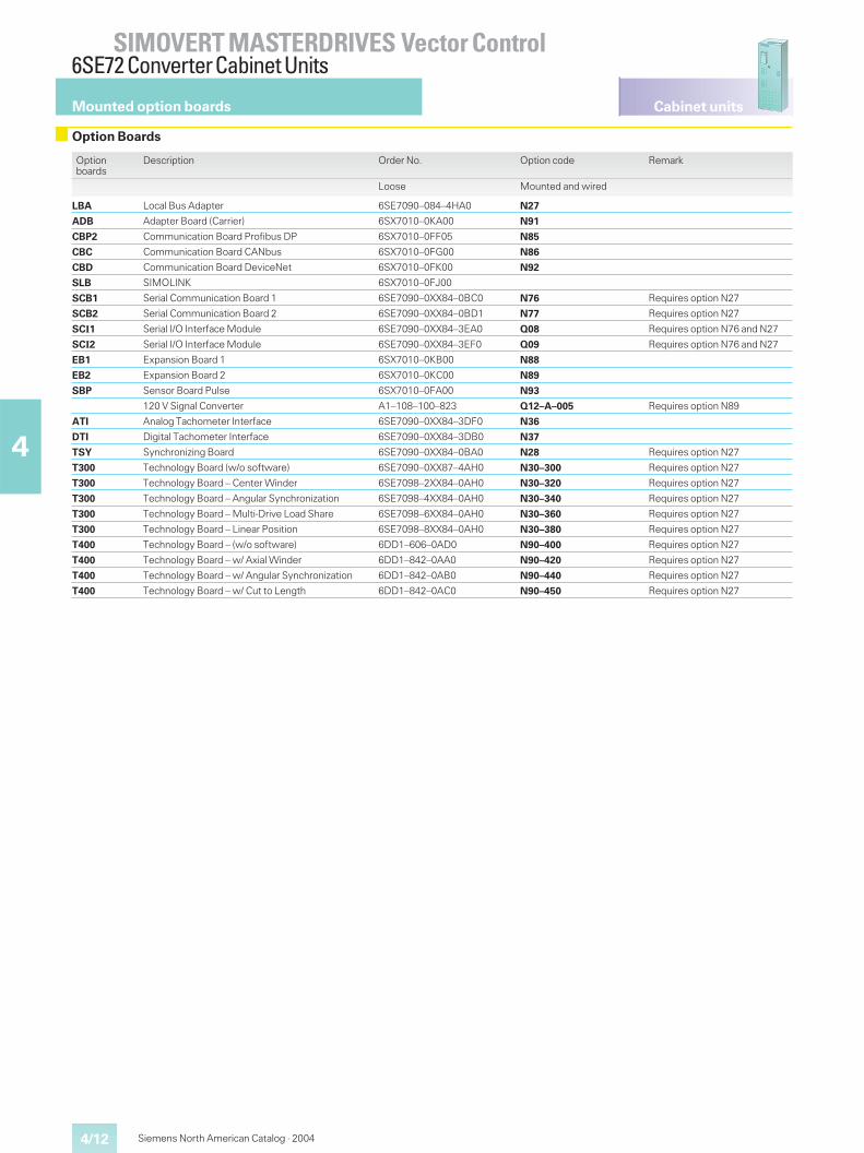
Cabinet units
4/12
SIMOVERT MASTERDRIVES Vector Control6SE72 ConverterCabinet Units
4
Siemens North American Catalog · 2004
Mounted option boards
Option Boards
Optionboards
Description Order No. Option code Remark
Loose Mounted and wired
LBA Local Bus Adapter 6SE7090–084–4HA0 N27
ADB Adapter Board (Carrier) 6SX7010–0KA00 N91
CBP2 Communication Board Profibus DP 6SX7010–0FF05 N85
CBC Communication Board CANbus 6SX7010–0FG00 N86
CBD Communication Board DeviceNet 6SX7010–0FK00 N92
SLB SIMOLINK 6SX7010–0FJ00
SCB1 Serial Communication Board 1 6SE7090–0XX84–0BC0 N76 Requires option N27
SCB2 Serial Communication Board 2 6SE7090–0XX84–0BD1 N77 Requires option N27
SCI1 Serial I/O Interface Module 6SE7090–0XX84–3EA0 Q08 Requires option N76 and N27
SCI2 Serial I/O Interface Module 6SE7090–0XX84–3EF0 Q09 Requires option N76 and N27
EB1 Expansion Board 1 6SX7010–0KB00 N88
EB2 Expansion Board 2 6SX7010–0KC00 N89
SBP Sensor Board Pulse 6SX7010–0FA00 N93
120 V Signal Converter A1–108–100–823 Q12–A–005 Requires option N89
ATI Analog Tachometer Interface 6SE7090–0XX84–3DF0 N36
DTI Digital Tachometer Interface 6SE7090–0XX84–3DB0 N37
TSY Synchronizing Board 6SE7090–0XX84–0BA0 N28 Requires option N27
T300 Technology Board (w/o software) 6SE7090–0XX87–4AH0 N30–300 Requires option N27
T300 Technology Board – Center Winder 6SE7098–2XX84–0AH0 N30–320 Requires option N27
T300 Technology Board – Angular Synchronization 6SE7098–4XX84–0AH0 N30–340 Requires option N27
T300 Technology Board – Multi-Drive Load Share 6SE7098–6XX84–0AH0 N30–360 Requires option N27
T300 Technology Board – Linear Position 6SE7098–8XX84–0AH0 N30–380 Requires option N27
T400 Technology Board – (w/o software) 6DD1–606–0AD0 N90–400 Requires option N27
T400 Technology Board – w/ Axial Winder 6DD1–842–0AA0 N90–420 Requires option N27
T400 Technology Board – w/ Angular Synchronization 6DD1–842–0AB0 N90–440 Requires option N27
T400 Technology Board – w/ Cut to Length 6DD1–842–0AC0 N90–450 Requires option N27
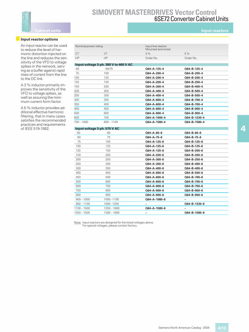
4/13
Cabinet units
SIMOVERT MASTERDRIVES Vector Control6SE72 ConverterCabinet Units
4
Siemens North American Catalog · 2004
Input reactors
Input reactor options
An input reactor can be usedto reduce the level of har-monic distortion injected onthe line and reduces the sen-sitivity of the VFD to voltagespikes in the network, serv-ing as a buffer against rapidrises of current from the lineto the DC link.
A 3 % inductor primarily im-proves the sensitivity of theVFD to voltage spikes, aswell as assuring the mini-mum current form factor.
A 5 % inductor provides ad-ditional effective harmonicfiltering, that in many casessatisfies the recommendedpractices and requirementsof IEEE 519-1992.
Nominal power rating Input line reactorMounted and wired
CT VT 3 % 5 %
HP HP Order No. Order No.
Input voltage 3-ph. 380 V to 460 V AC60 60/75 Q64–A–125–4 Q64–B–125–4
75 100 Q64–A–200–4 Q64–B–200–4
100 125 Q64–A–200–4 Q64–B–200–4
125 150 Q64–A–200–4 Q64–B–250–4
150 200 Q64–A–300–4 Q64–B–400–4
200 250 Q64–A–400–4 Q64–B–500–4
250 300 Q64–A–400–4 Q64–B–500–4
300 350 Q64–A–600–4 Q64–B–700–4
350 400 Q64–A–600–4 Q64–B–700–4
400 450 Q64–A–600–4 Q64–B–900–4
500 600 Q64–A–900–4 Q64–B–900–4
600 700 Q64–A–1000–4 Q64–B–1230–4
700 – 1000 800 – 1100 Q64–A–1580–4 Q64–B–1580–4
Input voltage 3-ph. 575 V AC50 60 Q64–A–60–6 Q64–B–60–6
60 75 Q64–A–75–6 Q64–B–75–6
75 100 Q64–A–125–6 Q64–B–125–6
100 125 Q64–A–125–6 Q64–B–125–6
125 150 Q64–A–125–6 Q64–B–200–6
150 200 Q64–A–200–6 Q64–B–200–6
200 250 Q64–A–300–6 Q64–B–250–6
250 300 Q64–A–300–6 Q64–B–400–6
300 350 Q64–A–400–6 Q64–B–400–6
400 450 Q64–A–600–6 Q64–B–500–6
450 500 Q64–A–600–6 Q64–B–700–6
500 600 Q64–A–600–6 Q64–B–700–6
600 700 Q64–A–900–6 Q64–B–700–6
700 800 Q64–A–900–6 Q64–B–900–6
800 900 Q64–A–900–6 Q64–B–900–6
900 – 1000 1000 –1100 Q64–A–1080–6 –
900 – 1100 1000 –1250 – Q64–B–1230–6
1100 – 1500 1250 – 1600 Q64–A–1580–6 –
1250 – 1500 1300 – 1600 – Q64–B–1580–6
Note: Input reactors are designed for the listed voltages above.For special voltages, please contact factory.
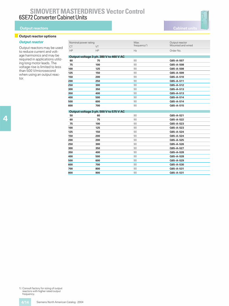
Cabinet units
4/14
SIMOVERT MASTERDRIVES Vector Control6SE72 ConverterCabinet Units
4
Siemens North American Catalog · 2004
Output reactors
Output reactor options
Output reactor
Output reactors may be usedto reduce current and volt-age harmonics and may berequired in applications utiliz-ing long motor leads. Thevoltage rise is limited to lessthan 500 V/microsecondwhen using an output reac-tor.
Nominal power rating Max.frequency1)
Output reactorMounted and wiredCT VT
HP HP Hz Order No.
Output voltage 3-ph. 380 V to 460 V AC60 75 90 Q65–A–507
75 100 90 Q65–A–508
100 125 90 Q65–A–508
125 150 90 Q65–A–509
150 200 90 Q65–A–510
200 250 90 Q65–A–511
250 300 90 Q65–A–512
300 350 90 Q65–A–513
350 400 90 Q65–A–513
400 500 90 Q65–A–514
500 600 90 Q65–A–514
600 700 90 Q65–A–515
Output voltage 3-ph. 500 V to 575 V AC50 60 90 Q65–A–521
60 75 90 Q65–A–522
75 100 90 Q65–A–523
100 125 90 Q65–A–523
125 150 90 Q65–A–524
150 200 90 Q65–A–524
200 200 90 Q65–A–525
250 300 90 Q65–A–526
300 350 90 Q65–A–527
350 400 90 Q65–A–528
400 500 90 Q65–A–528
500 600 90 Q65–A–529
600 700 90 Q65–A–530
700 800 90 Q65–A–531
800 900 90 Q65–A–531
1) Consult factory for sizing of outputreactors with higher rated outputfrequency.
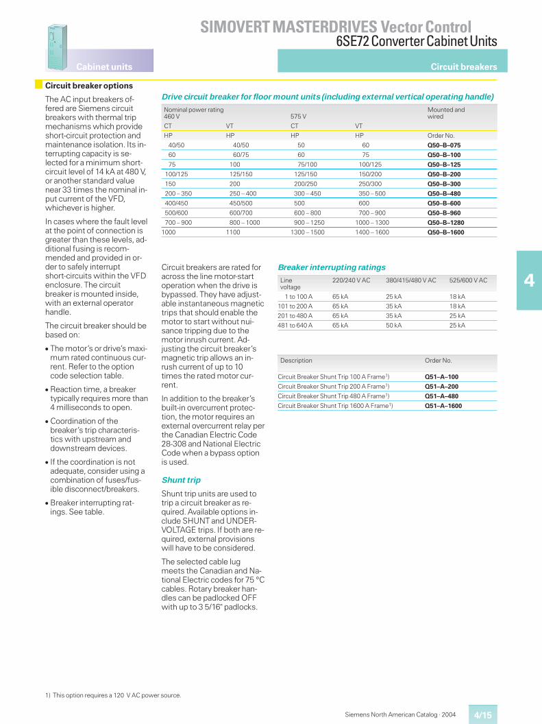
4/15
Cabinet units
SIMOVERT MASTERDRIVES Vector Control6SE72 ConverterCabinet Units
4
Siemens North American Catalog · 2004
Circuit breaker options
The AC input breakers of-fered are Siemens circuitbreakers with thermal tripmechanisms which provideshort-circuit protection andmaintenance isolation. Its in-terrupting capacity is se-lected for a minimum short-circuit level of 14 kA at 480 V,or another standard valuenear 33 times the nominal in-put current of the VFD,whichever is higher.
In cases where the fault levelat the point of connection isgreater than these levels, ad-ditional fusing is recom-mended and provided in or-der to safely interruptshort-circuits within the VFDenclosure. The circuitbreaker is mounted inside,with an external operatorhandle.
The circuit breaker should bebased on:
� The motor’s or drive’s maxi-mum rated continuous cur-rent. Refer to the optioncode selection table.
� Reaction time, a breakertypically requires more than4 milliseconds to open.
� Coordination of thebreaker’s trip characteris-tics with upstream anddownstream devices.
� If the coordination is notadequate, consider using acombination of fuses/fus-ible disconnect/breakers.
� Breaker interrupting rat-ings. See table.
Drive circuit breaker for floor mount units (including external vertical operating handle)
Nominal power rating460 V 575 V
Mounted andwired
CT VT CT VT
HP HP HP HP Order No.
40/50 40/50 50 60 Q50–B–075
60 60/75 60 75 Q50–B–100
75 100 75/100 100/125 Q50–B–125
100/125 125/150 125/150 150/200 Q50–B–200
150 200 200/250 250/300 Q50–B–300
200 – 350 250 – 400 300 – 450 350 – 500 Q50–B–480
400/450 450/500 500 600 Q50–B–600
500/600 600/700 600 – 800 700 – 900 Q50–B–960
700 – 900 800 – 1000 900 – 1250 1000 – 1300 Q50–B–1280
1000 1100 1300 – 1500 1400 – 1600 Q50–B–1600
Circuit breakers
Circuit breakers are rated foracross the line motor-startoperation when the drive isbypassed. They have adjust-able instantaneous magnetictrips that should enable themotor to start without nui-sance tripping due to themotor inrush current. Ad-justing the circuit breaker’smagnetic trip allows an in-rush current of up to 10times the rated motor cur-rent.
In addition to the breaker’sbuilt-in overcurrent protec-tion, the motor requires anexternal overcurrent relay perthe Canadian Electric Code28-308 and National ElectricCode when a bypass optionis used.
Shunt trip
Shunt trip units are used totrip a circuit breaker as re-quired. Available options in-clude SHUNT and UNDER-VOLTAGE trips. If both are re-quired, external provisionswill have to be considered.
The selected cable lugmeets the Canadian and Na-tional Electric codes for 75 °Ccables. Rotary breaker han-dles can be padlocked OFFwith up to 3 5/16" padlocks.
Breaker interrupting ratings
Linevoltage
220/240 V AC 380/415/480 V AC 525/600 V AC
1 to 100 A 65 kA 25 kA 18 kA
101 to 200 A 65 kA 35 kA 18 kA
201 to 480 A 65 kA 35 kA 25 kA
481 to 640 A 65 kA 50 kA 25 kA
Description Order No.
Circuit Breaker Shunt Trip 100 A Frame1) Q51–A–100
Circuit Breaker Shunt Trip 200 A Frame1) Q51–A–200
Circuit Breaker Shunt Trip 480 A Frame1) Q51–A–480
Circuit Breaker Shunt Trip 1600 A Frame1) Q51–A–1600
1) This option requires a 120 V AC power source.
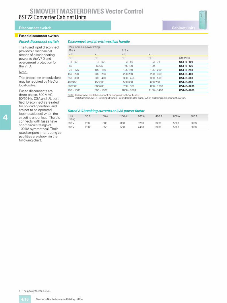
Cabinet units
4/16
SIMOVERT MASTERDRIVES Vector Control6SE72 ConverterCabinet Units
4
Siemens North American Catalog · 2004
Disconnect switch
Fused disconnect switch
Fused disconnect switch
The fused input disconnectprovides a mechanicalmeans of disconnectingpower to the VFD andovercurrent protection forthe VFD.
Note:
This protection or equivalentmay be required by NEC orlocal codes.
Fused disconnects arethree-phase, 600 V AC,50/60 Hz, CSA and UL-certi-fied. Disconnects are ratedfor no-load operation, andare not to be operated(opened/closed) when thecircuit is under load. The dis-connects with fuses haveshort-circuit ratings of100 kA symmetrical. Theirrated ampere interrupting ca-pabilities are shown in thefollowing chart.
Disconnect switch with vertical handle
Max. nominal power rating460 V 575 V
CT VT CT VT
HP HP HP HP Order No.
3 – 50 3 – 50 3 – 60 3 – 75 Q54–B–100
60 60/75 75/100 100 Q54–B–125
75 – 125 100 – 150 125/150 125 – 200 Q54–B–250
150 – 200 200 – 250 200/250 200 – 300 Q54–B–400
250 – 350 300 – 400 300 – 450 350 – 500 Q54–B–600
400/450 450/500 500/600 600/700 Q54–B–800
500/600 600/700 700 – 900 800 – 1000 Q54–B–1200
700 – 1000 800 – 1100 1000 – 1300 1100 – 1400 Q54–B–1600
Note: Disconnect switches cannot be supplied without fuses.ADD option Q56–A–xxx (input fuses – standard motor class) when ordering a disconnect switch.
Rated AC breaking currents at 0.35 power factor
Unitrating
30 A 60 A 100 A 200 A 400 A 600 A 800 A
500 V 256 500 800 3200 3200 5000 5000
600 V 2561) 350 500 2400 3200 5000 5000
1) The power factor is 0.45.
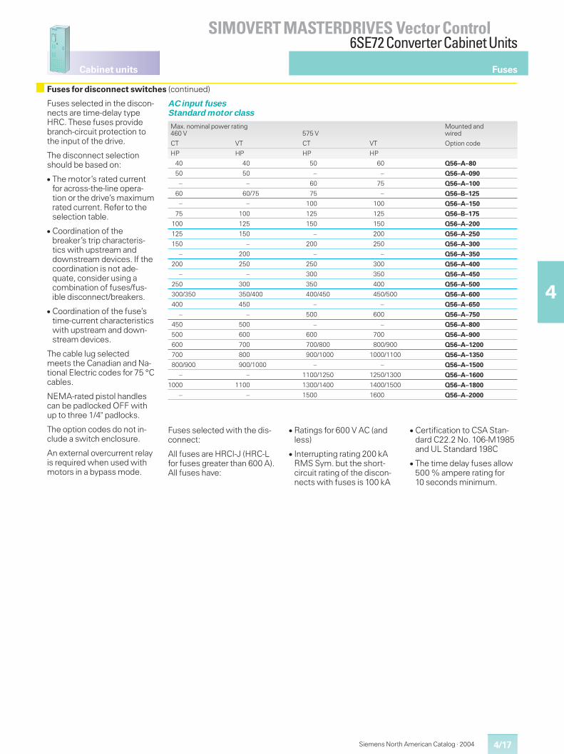
4/17
Cabinet units
SIMOVERT MASTERDRIVES Vector Control6SE72 ConverterCabinet Units
4
Siemens North American Catalog · 2004
Fuses
Fuses for disconnect switches (continued)
Fuses selected in the discon-nects are time-delay typeHRC. These fuses providebranch-circuit protection tothe input of the drive.
The disconnect selectionshould be based on:
� The motor’s rated currentfor across-the-line opera-tion or the drive’s maximumrated current. Refer to theselection table.
� Coordination of thebreaker’s trip characteris-tics with upstream anddownstream devices. If thecoordination is not ade-quate, consider using acombination of fuses/fus-ible disconnect/breakers.
� Coordination of the fuse’stime-current characteristicswith upstream and down-stream devices.
The cable lug selectedmeets the Canadian and Na-tional Electric codes for 75 °Ccables.
NEMA-rated pistol handlescan be padlocked OFF withup to three 1/4" padlocks.
The option codes do not in-clude a switch enclosure.
An external overcurrent relayis required when used withmotors in a bypass mode.
Fuses selected with the dis-connect:
All fuses are HRCI-J (HRC-Lfor fuses greater than 600 A).All fuses have:
� Ratings for 600 V AC (andless)
� Interrupting rating 200 kARMS Sym. but the short-circuit rating of the discon-nects with fuses is 100 kA
� Certification to CSA Stan-dard C22.2 No. 106-M1985and UL Standard 198C
� The time delay fuses allow500 % ampere rating for10 seconds minimum.
AC input fusesStandard motor class
Max. nominal power rating460 V 575 V
Mounted andwired
CT VT CT VT Option code
HP HP HP HP
40 40 50 60 Q56–A–80
50 50 – – Q56–A–090
– – 60 75 Q56–A–100
60 60/75 75 – Q56–B–125
– – 100 100 Q56–A–150
75 100 125 125 Q56–B–175
100 125 150 150 Q56–A–200
125 150 – 200 Q56–A–250
150 – 200 250 Q56–A–300
– 200 – – Q56–A–350
200 250 250 300 Q56–A–400
– – 300 350 Q56–A–450
250 300 350 400 Q56–A–500
300/350 350/400 400/450 450/500 Q56–A–600
400 450 – – Q56–A–650
– – 500 600 Q56–A–750
450 500 – – Q56–A–800
500 600 600 700 Q56–A–900
600 700 700/800 800/900 Q56–A–1200
700 800 900/1000 1000/1100 Q56–A–1350
800/900 900/1000 – – Q56–A–1500
– – 1100/1250 1250/1300 Q56–A–1600
1000 1100 1300/1400 1400/1500 Q56–A–1800
– – 1500 1600 Q56–A–2000
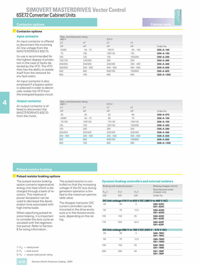
Cabinet units
4/18
SIMOVERT MASTERDRIVES Vector Control6SE72 ConverterCabinet Units
4
Siemens North American Catalog · 2004
Contactor options
Pulsed resistor braking
Pulsed resistor braking options
The pulsed resistor brakingoption converts regenerativeenergy into heat which is dis-charged through a bank of re-sistors. This method ofpower dissipation can beused to decrease the decel-eration time associated withhigh inertia loads.
When specifying pulsed re-sistor braking, it is importantto consider the duty cycle as-sociated with the regenera-tive period. Refer to Section6 for sizing information.
The pulsed resistor is con-trolled so that the increasingvoltage of the DC bus duringgenerator operation is lim-ited to the maximum permis-sible value.
The chopper transistor (DCcurrent controller) can bemounted in the drive enclo-sure or in the resistor enclo-sure, depending on the rat-ing.
Dynamic braking controllers and external resistors
Braking with external resistor Braking chopper control
P201) P3
2) PD3)
Mounted and wiredchopper only
kW kW kW Order No.
DC link voltage 510 V to 620 V DC (380 V to 460 V AC)20 30 5 Q60–620C
Q61–620C
50 75 12.5 Q60–620DQ61–620D
100 150 25 Q60–620EQ61–620E
170 255 42.5 Q60–620FQ61–620F
DC link voltage 680 V to 780 V DC (500 V – 575 V AC)20 30 5 Q60–780C
Q61–780C
50 75 12.5 Q60–780DQ61–780D
100 150 25 Q60–780EQ61–780E
200 300 50 Q61–780FQ61–780F
1) P20 = rated power
2) P3 = peak power
3) PD = steady state power rating
Contactor options
Input contactor
An input contactor is offeredto disconnect the incomingAC line voltage from theMASTERDRIVES 6SE70.
Its use is recommended forthe highest degree of protec-tion in the case of faults de-tected by the VFD. The VFDthen has the ability to isolateitself from the network forany fault event.
An input contactor is alsoemployed if a bypass optionis selected in order to electri-cally isolate the VFD fromthe energized bypass circuit.
Output contactor
An output contactor is of-fered to disconnect theMASTERDRIVES 6SE70from the motor.
Max. nominal power rating460 V 575 V
CT VT CT VT
HP HP HP HP Order No.
50/60 50 – 75 50/75 60 – 100 Q59–A–100
75 100 100/125 125 Q59–A–150
100 125 150 150/200 Q59–A–200
125/150 125/200 200 250 Q59–A–260
200/250 250/300 250/300 300 – 400 Q59–A–400
300/450 350 – 500 400 – 500 450 – 600 Q59–A–630
500 600 600/700 700/800 Q59–A–820
600 700 800 900 Q59–A–1350
Max. nominal power rating460 V 575 V
CT VT CT VT
HP HP HP HP Order No.
40 40 50 60 Q58–A–070
50/60 50 – 75 60 75 Q58–A–100
75/100 100/125 75/100 100/125 Q58–A–150
125 150 125/150 150/200 Q58–A–200
150 200 200 250 Q58–A–260
200/250 250/300 250/300 300/350 Q58–A–400
300 – 450 350 – 500 350 – 500 400 – 600 Q58–A–630
500 600 600/700 700/800 Q58–A–820
600 700 800 900 Q58–A–1350
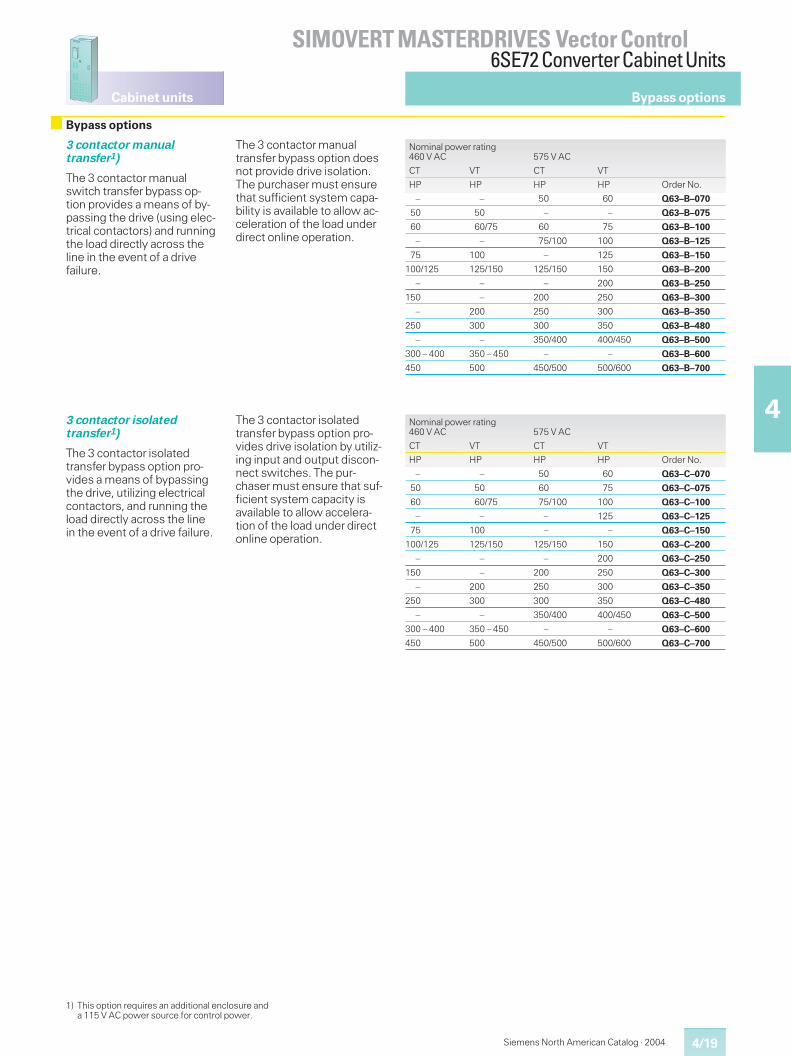
4/19
Cabinet units
SIMOVERT MASTERDRIVES Vector Control6SE72 ConverterCabinet Units
4
Siemens North American Catalog · 2004
Bypass options
3 contactor manualtransfer1)
The 3 contactor manualswitch transfer bypass op-tion provides a means of by-passing the drive (using elec-trical contactors) and runningthe load directly across theline in the event of a drivefailure.
The 3 contactor manualtransfer bypass option doesnot provide drive isolation.The purchaser must ensurethat sufficient system capa-bility is available to allow ac-celeration of the load underdirect online operation.
Nominal power rating460 V AC 575 V AC
CT VT CT VT
HP HP HP HP Order No.
– – 50 60 Q63–B–070
50 50 – – Q63–B–075
60 60/75 60 75 Q63–B–100
– – 75/100 100 Q63–B–125
75 100 – 125 Q63–B–150
100/125 125/150 125/150 150 Q63–B–200
– – – 200 Q63–B–250
150 – 200 250 Q63–B–300
– 200 250 300 Q63–B–350
250 300 300 350 Q63–B–480
– – 350/400 400/450 Q63–B–500
300 – 400 350 – 450 – – Q63–B–600
450 500 450/500 500/600 Q63–B–700
3 contactor isolatedtransfer1)
The 3 contactor isolatedtransfer bypass option pro-vides a means of bypassingthe drive, utilizing electricalcontactors, and running theload directly across the linein the event of a drive failure.
The 3 contactor isolatedtransfer bypass option pro-vides drive isolation by utiliz-ing input and output discon-nect switches. The pur-chaser must ensure that suf-ficient system capacity isavailable to allow accelera-tion of the load under directonline operation.
Nominal power rating460 V AC 575 V AC
CT VT CT VT
HP HP HP HP Order No.
– – 50 60 Q63–C–070
50 50 60 75 Q63–C–075
60 60/75 75/100 100 Q63–C–100
– – – 125 Q63–C–125
75 100 – – Q63–C–150
100/125 125/150 125/150 150 Q63–C–200
– – – 200 Q63–C–250
150 – 200 250 Q63–C–300
– 200 250 300 Q63–C–350
250 300 300 350 Q63–C–480
– – 350/400 400/450 Q63–C–500
300 – 400 350 – 450 – – Q63–C–600
450 500 450/500 500/600 Q63–C–700
1) This option requires an additional enclosure anda 115 V AC power source for control power.
Bypass options
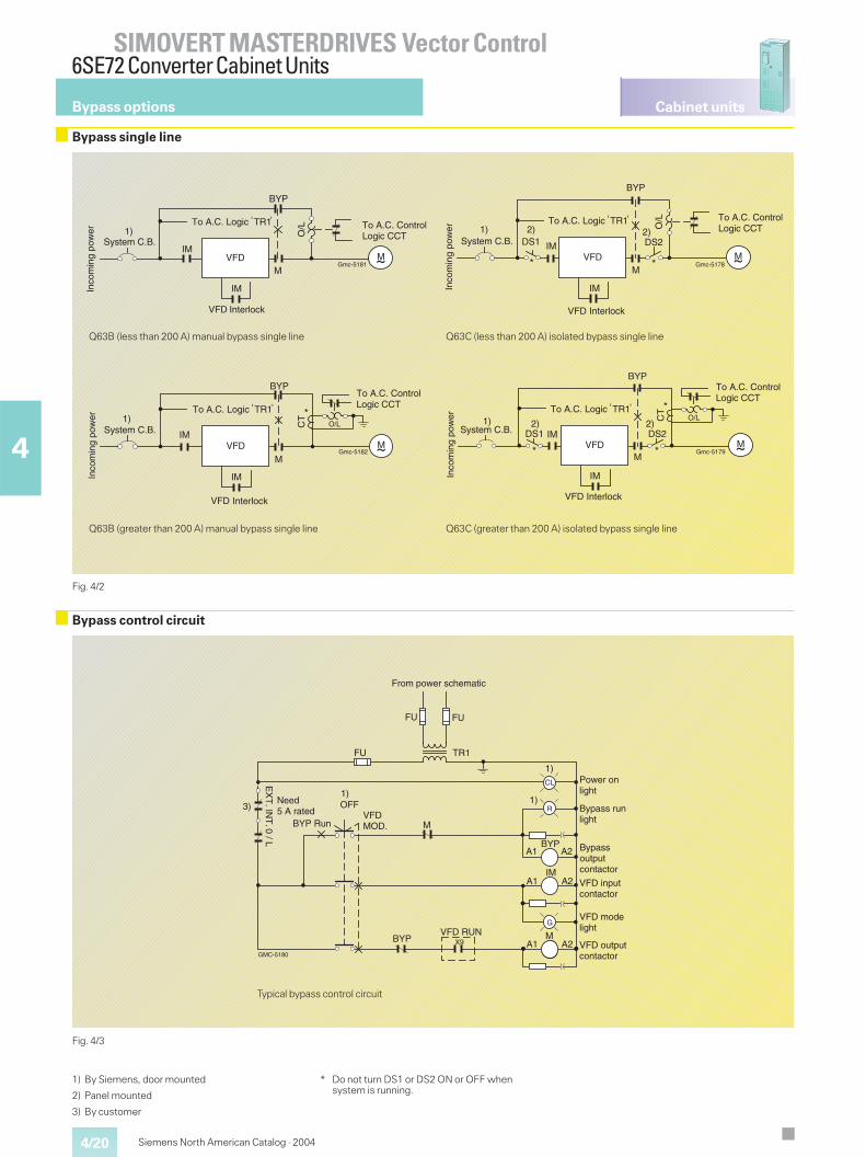
Cabinet units
4/20
SIMOVERT MASTERDRIVES Vector Control6SE72 ConverterCabinet Units
4
Siemens North American Catalog · 2004
Bypass single line
Fig. 4/2
Bypass control circuit
Fig. 4/3
Gmc-5181M
1)
IM
IM
BYP
VFD
O/L
VFD
M
To A.C. ControlLogic CCT
To A.C. Logic TR1
System C.B.
Inco
min
g po
wer
Interlock
GMC-5180
3)
TR1
FU FU
FU
1)CL
R
A1 A2
A1 A2
G
MA1 A2
1)1)
X9
VFDMOD.
From power schematic
Power onlight
Bypass runlight
BYP
IM
M
Bypass outputcontactor
VFD inputcontactor
VFD modelight
VFD outputcontactor
VFD RUNBYP
OFF
EX
T. IN
T. 0 / L
BYP Run
Need5 A rated
Bypass options
Typical bypass control circuit
Q63B (less than 200 A) manual bypass single line
Gmc-5178
1)DS12) O
/L
VFD
VFD
DS2IM
BYP
M
2)
IM
M
System C.B.
Inco
min
g po
wer
To A.C. ControlLogic CCT
To A.C. Logic TR1
Interlock
Gmc-5182
CT
BYP
VFD
VFD
M
IM
IM
M
O/L1)
System C.B.
Inco
min
g po
wer
To A.C. ControlLogic CCT
Interlock
To A.C. Logic TR1
Q63C (less than 200 A) isolated bypass single line
Q63B (greater than 200 A) manual bypass single line Q63C (greater than 200 A) isolated bypass single line
1) By Siemens, door mounted
2) Panel mounted
3) By customer
* Do not turn DS1 or DS2 ON or OFF whensystem is running.
Gmc-5179
CT
O/L1)DS1
2)DS22)
M
VFD
VFD M
System C.B.
Inco
min
g po
wer
IM
IM
BYP
To A.C. Logic TR1
To A.C. ControlLogic CCT
Interlock
5/1
5
Siemens North American Catalog · 2004
Documentation for Compact PLUS units/Compact and chassis units
5/2 Documentation overview
Operating instructions5/3 Converter and inverter units5/3 System components5/3 Rectifier units5/3 Rectifier/regenerative units5/3 Self-commutated Active Front End (AFE)5/3 Electronics options5/4 Operating instruction library5/4 Compendium
5/4 Siemens safety engineering
5/5 Training Center
5/6 CUVC training course
5/7 Demonstration units
5/7 Start-up box
Vector ControlDocumentationand Training
5/2
Compact PLUS unitsCompact and chassis units
SIMOVERT MASTERDRIVES Vector ControlDocumentation and Training
5
Siemens North American Catalog · 2004
The documentation for theSIMOVERTMASTERDRIVESunits (converters, inverters,rectifierunits and rectifier/re-generative units), along withoptions are supplied on aCD-ROM in electronic format.The most updated versionscan also be downloaded fromSiemens website.Printeddocumentation must be or-dered separately.
The detailed description ofthe parameter list and con-trol concepts as well as thecorresponding explanationson the additionally availablefree function blocks whichcan be combined and con-nected as required via theBICO system, necessitatethe documentation to besplit up into two parts asfollows:
� The operating instruc-tions containing theinformation necessary forstandard drives, withoutparameter list and withoutbinector/connector lists.The operating instructionsas printed version must beordered separately andvaries by individual unittype.
� The Compendium for con-verter and inverter unitscontains the detailed docu-mentation for the software,including parameter list andbinector/connector lists aswell as block circuit dia-grams for types ofopen-loop and closed-loopcontrol and function blocks.The Compendium asprinted version must be or-dered separately and ap-plies for all types of units.
The Compendium is neces-sary when
– additional signals, aboveand beyond those of thefactory settings, are to beprocessed, i.e. if accesshas to be made to the pa-rameter list
– the full range of functionsof the converter software,including communicationvia fieldbus systems, is tobe used
– additional inputs/outputsare used via the EB1 andEB2 expansion boards
– the free function blocksare to be used. See page6/32.
� The CD-ROM is included inthe factory packaging of theMASTERDRIVES.
This contains:
– all operating instructionsand the Compendium inthe form of PDF files in allavailable languages ex-cept Japanese
– parameterization anddiagnostics programDriveMonitor.
Documentation for Compact PLUS/compact and chassis units
Documentation overview
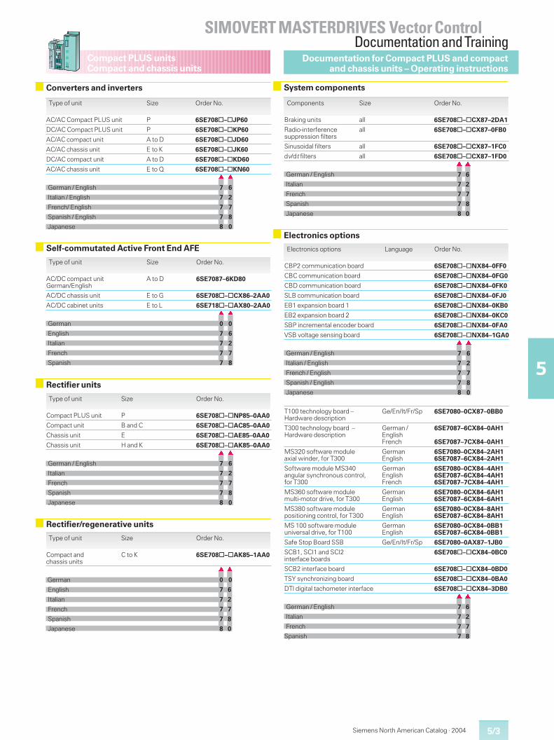
Siemens North American Catalog · 2004 5/3
Compact PLUS unitsCompact and chassis units
SIMOVERT MASTERDRIVES Vector ControlDocumentation and Training
5
System components
Self-commutated Active Front End AFE
Type of unit Size Order No.
AC/AC Compact PLUS unit P 6SE708 – JP60
DC/AC Compact PLUS unit P 6SE708 – KP60
AC/AC compact unit A to D 6SE708 – JD60
AC/AC chassis unit E to K 6SE708 – JK60
DC/AC compact unit A to D 6SE708 – KD60
AC/AC chassis unit E to Q 6SE708 – KN60� �
German / English 7 6
Italian / English 7 2
French/ English 7 7
Spanish / English 7 8
Japanese 8 0
Type of unit Size Order No.
AC/DC compact unitGerman/English
A to D 6SE7087–6KD80
AC/DC chassis unit E to G 6SE708 – CX86–2AA0
AC/DC cabinet units E to L 6SE718 – AX80–2AA0� �
German 0 0
English 7 6
Italian 7 2
French 7 7
Spanish 7 8
Type of unit Size Order No.
Compact PLUS unit P 6SE708 – NP85–0AA0
Compact unit B and C 6SE708 – AC85–0AA0
Chassis unit E 6SE708 – AE85–0AA0
Chassis unit H and K 6SE708 – AK85–0AA0� �
German / English 7 6
Italian 7 2
French 7 7
Spanish 7 8
Japanese 8 0
Type of unit Size Order No.
Compact andchassis units
C to K 6SE708 – AK85–1AA0
� �
German 0 0
English 7 6
Italian 7 2
French 7 7
Spanish 7 8
Japanese 8 0
Components Size Order No.
Braking units all 6SE708 – CX87–2DA1
Radio-interferencesuppression filters
all 6SE708 – CX87–0FB0
Sinusoidal filters all 6SE708 – CX87–1FC0
dv/dt filters all 6SE708 – CX87–1FD0� �
German / English 7 6
Italian 7 2
French 7 7
Spanish 7 8
Japanese 8 0
Electronics options Language Order No.
CBP2 communication board 6SE708 – NX84–0FF0
CBC communication board 6SE708 – NX84–0FG0
CBD communication board 6SE708 – NX84–0FK0
SLB communication board 6SE708 – NX84–0FJ0
EB1 expansion board 1 6SE708 – NX84–0KB0
EB2 expansion board 2 6SE708 – NX84–0KC0
SBP incremental encoder board 6SE708 – NX84–0FA0
VSB voltage sensing board 6SE708 – NX84–1GA0� �
German / English 7 6
Italian / English 7 2
French / English 7 7
Spanish / English 7 8
Japanese 8 0
T100 technology board –Hardware description
Ge/En/It/Fr/Sp 6SE7080–0CX87–0BB0
T300 technology board –Hardware description
German /EnglishFrench
6SE7087–6CX84–0AH1
6SE7087–7CX84–0AH1
MS320 software moduleaxial winder, for T300
GermanEnglish
6SE7080–0CX84–2AH16SE7087–6CX84–2AH1
Software module MS340angular synchronous control,for T300
GermanEnglishFrench
6SE7080–0CX84–4AH16SE7087–6CX84–4AH16SE7087–7CX84–4AH1
MS360 software modulemulti-motor drive, for T300
GermanEnglish
6SE7080–0CX84–6AH16SE7087–6CX84–6AH1
MS380 software modulepositioning control, for T300
GermanEnglish
6SE7080–0CX84–8AH16SE7087–6CX84–8AH1
MS 100 software moduleuniversal drive, for T100
GermanEnglish
6SE7080–0CX84–0BB16SE7087–6CX84–0BB1
Safe Stop Board SSB Ge/En/It/Fr/Sp 6SE7080–0AX87–1JB0
SCB1, SCI1 and SCI2interface boards
6SE708 – CX84–0BC0
SCB2 interface board 6SE708 – CX84–0BD0
TSY synchronizing board 6SE708 – CX84–0BA0
DTI digital tachometer interface 6SE708 – CX84–3DB0� �
German / English 7 6
Italian 7 2
French 7 7
Spanish 7 8
Documentation for Compact PLUS and compactand chassis units – Operating instructions
Converters and inverters
Rectifier units
Rectifier/regenerative units
Electronics options
5/4
Compact PLUS unitsCompact and chassis units
SIMOVERT MASTERDRIVES Vector ControlDocumentation and Training
5
Siemens North American Catalog · 20045/4
The file is to be regarded asreference documentationand includes operating in-structions for the followingcomponents:
� Converters� Inverters� Rectifier units1)� Rectifier/regenerative units� Braking units1)� Output filters1)� Radio-interference sup-
pression filters1)
� SCB/SCI/DTI/TSY/EB1/EB2interface boards
� SBP incremental encoderboard
� CBP/CBP2 communicationboards (PROFIBUS DP)
� CBC communication board(CAN)
� SLB communication board(SIMOLINK)
� OP1S operator controlpanel
The operating instructionscontain a description of thebasic functions and installa-tion and start-up instruc-tions.
The Compendium containsthe following:
� System description
� Configuration and connec-tion examples
� EMC guidelines
� Function blocks and para-meters
� Parameterization
� Parameterizing steps
� Functions
� Process data
� CommunicationSCOM 1/2 interfacesUSS protocolPROFIBUS DPCANSIMOLINK
� AnnexFunction diagramsBinector listConnector listParameter listFaults and alarms list.
Language Order No.
CompendiumEnglish 6SE7087–6QX60
German 6SE7080–0QX60
Italian 6SE7087–2QX60
French 6SE7087–7QX60
Spanish 6SE7087–8QX60
Compendium
Language Order No.
Collected operating instructionsGerman / English 6SE7087–6NX60
Italian / English 6SE7087–2NX60
French / English 6SE7087–7NX60
Spanish / English 6SE7087–8NX60
Documentation for Compact PLUS and compactand chassis units
Operating instruction library
1) This documentation is available in French,Spanish and Italian only, i.e. not French/English,Spanish/English, Italian/English.
Application manual“Safety Integrated”
The application manual“Safety Integrated”illus-trates using technical expla-nations and application ex-amples how dangers in theuse of electric and electronicdevices can be prevented oreliminated.
The complete CD-ROMabout the safety system
The CD-ROM “Safety Inte-grated”offers a comprehen-sive overview of safety tech-nology and the widest rangeof safety components, em-bedded at the same time inthe standard world of auto-mation.
Language Order No.
Application manualGerman 6ZB5000–0AA01–0BA0
English 6ZB5000–0AA02–0BA0
CD-ROM “Safety Integrated”German/English E20001–D10–M103–X–7400
Siemens safety engineering
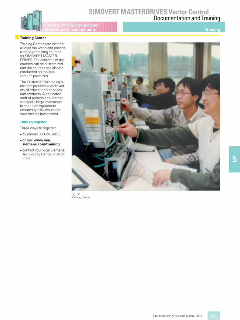
5/5
Compact PLUS/compact andchassis units · cabinet units
SIMOVERT MASTERDRIVES Vector ControlDocumentation and Training
5
Siemens North American Catalog · 2004
Training
Training Centers are locatedall over the world and providea range of training coursesfor SIMOVERTMASTER-DRIVES.The contents of thecourses can be customizedand the courses can also beconducted on the cus-tomer’s premises.
The Customer Training orga-nization provides a wide vari-ety of educational servicesand products. A dedicatedstaff of professional instruc-tors and a large investmentin hands-on equipmentensures quality results foryour training investment.
How to register
Three ways to register:
� by phone: 800.241.4453
� online: www.sea.siemens.com/training
� contact your local SiemensTechnology Center (distrib-utor)
Training Center
Fig. 5/1Training Center
5/6
Compact PLUS/compact andchassis units · cabinet units
SIMOVERT MASTERDRIVES Vector ControlDocumentation and Training
5
Siemens North American Catalog · 2004
Training
6SE70 CUVC Setup/Maintenance Training Course
General Information
Course code: DVS70M1CLength: 41/2 days
Audience
This course is for engineer-ing and maintenance person-nel responsible for installing,maintaining, and trouble-shooting drive systems thatutilize the 6SE70VC AC Drivebase unit.
Prerequisites
� STEP 2000 Basics ofAC Drives
For online STEP 2000courses see:http://www.sea.siemens.com/step
Profile
This course provides theknowledge and skills neces-sary to set up and maintainthe operation of the6SE70VC “Base Unit.” Ananalysis of the required hard-ware and the relationship be-tween the various opera-tional components is pre-sented at the beginning ofthe course. Standard AC mo-tor data and the relationshipof this information as appliedto the standard features ofthe drive are discussed. Theminimum required steps to
properly se tup the drive aswell as additional applicationdependent steps are alsopresented. The basic opera-tion of the converter andinverter with the correspond-ing input and output signalsare discussed. The coursecovers analog and digital I/Ousage and configuration. Aworking knowledge of the“Base Drive”communica-tions capabilities is provided.
The course also covers theextensive diagnostic capabil-ities of the drive. Interpreta-tion of fault/warning codesas well as the proper trouble-shooting steps will be dis-cussed. Demonstrations aregiven on the use standardsupport software as diagnos-tic/startup resources.
The course format is a com-bination of instruction andhands-on exercises aimed atdeveloping job-relatedknowledge and skills. Thehands-on activities are care-fully structured to providecourse participants with sig-nificant exposure to basicdrive operation and associ-ated operating characteris-tics.
Goals
Upon completion of thiscourse, the student shall beable to:
� Configure “base drive”logic and self-tune the drivefor proper operation.
� Identify the use of the avail-able fixed function and pro-grammable analog and bi-nary inputs/outputs.
� Effectively troubleshoot aninvalid configuration of thedrive by utilizing the func-tion diagrams; representingfirmware logic level prints.
� Identify hardware configu-rations and verify requiredconnections.
� State the basic use andoperation of the 6SE70VCregulators.
� Develop a logical and con-cise method of effectivelytroubleshooting indicateddrive FAULTS and WARN-INGS.
� Configure and operate the6SE70VC using the “USS”and SIMOLINK (Peer-to-Peer link) protocols.
� State the basic functionand/or use of the 6SE70VCoption boards.
� Use motor and drive datafor proper initialization ofthe 6SE70VC.
� Troubleshoot the converterand inverter hardware com-ponents.
Topics
1. Introduction to available“Base Unit”hardware
2. Power section connec-tions and signal flow
3. Parameter settings andlogical grouping
4. Motor data and relateddrive settings
5. Base Drive initial setuprequirements
6. Self-tuning capabilities
7. Overview of firmwarefunction logic diagrams
8. Analog and binary I/Oconfiguration
9. Usage of CONTROL andSTATUS words
10. Basic operation of CON-VERTER and INVERTER
11. Interpretation ofWARNING and FAULTcodes
12. Troubleshooting anddiagnostic features
13. Overview of “Base Unit”communication capabili-ties
14. Drive setup/diagnosticsoftware usage
15. Overview of 6SE70VCoptions
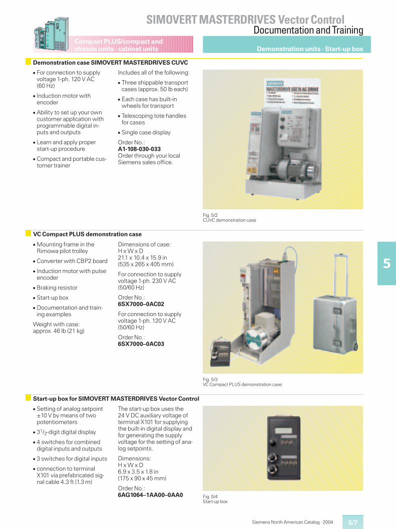
5/7
Compact PLUS/compact andchassis units · cabinet units
SIMOVERT MASTERDRIVES Vector ControlDocumentation and Training
5
Siemens North American Catalog · 2004
Demonstration units · Start-up box
Fig. 5/2CUVC demonstration case
Demonstration case SIMOVERT MASTERDRIVES CUVC
Fig. 5/3VC Compact PLUS demonstration case
VC Compact PLUS demonstration case
� Mounting frame in theRimowa pilot trolley
� Converter with CBP2 board
� Induction motor with pulseencoder
� Braking resistor
� Start-up box
� Documentation and train-ing examples
Weight with case:approx. 46 lb (21 kg)
Dimensions of case:H x W x D21.1 x 10.4 x 15.9 in(535 x 265 x 405 mm)
For connection to supplyvoltage 1-ph. 230 V AC(50/60 Hz)
Order No.:6SX7000–0AC02
For connection to supplyvoltage 1-ph. 120 V AC(50/60 Hz)
Order No.:6SX7000–0AC03
Start-up box for SIMOVERT MASTERDRIVES Vector Control
� Setting of analog setpoint±10 V by means of twopotentiometers
� 31/2-digit digital display
� 4 switches for combineddigital inputs and outputs
� 3 switches for digital inputs
� connection to terminalX101 via prefabricated sig-nal cable 4.3 ft (1.3 m)
The start-up box uses the24 V DC auxiliary voltage ofterminal X101 for supplyingthe built-in digital display andfor generating the supplyvoltage for the setting of ana-log setpoints.
Dimensions:H x W x D6.9 x 3.5 x 1.8 in(175 x 90 x 45 mm)
Order No.:6AG1064–1AA00–0AA0 Fig. 5/4
Start-up box
� For connection to supplyvoltage 1-ph. 120 V AC(60 Hz)
� Induction motor withencoder
� Ability to set up your owncustomer application withprogrammable digital in-puts and outputs
� Learn and apply properstart-up procedure
� Compact and portable cus-tomer trainer
Includes all of the following:
� Three shippable transportcases (approx. 50 lb each)
� Each case has built-inwheels for transport
� Telescoping tote handlesfor cases
� Single case display
Order No.:A1-108-030-033Order through your localSiemens sales office.
5/8
Compact PLUS/compact andchassis units · cabinet units
SIMOVERT MASTERDRIVES Vector ControlDocumentation and Training
5
Siemens North American Catalog · 2004
Notes
Siemens North American Catalog · 2004 6/1
6
Vector ControlEngineeringInformation
6/2 Dimensioning of the power sectionand drive
6/8 Stand-alone drives
6/10 Multi-motor drives (common DC bus)6/10 Inverters6/13 Rectifier units6/16 Rectifier/regenerative units6/20 Overcurrent protector units6/22 Self-commutated Active Front End (AFE)
6/26 Capacitor module
6/27 Vector Control open-loop and closed-loopcontrol functions
6/34 Compact PLUS unit control terminal strip
6/38 Compact and chassis unit control terminalstrip
6/44 24 V DC auxiliary power supply
6/45 Electromagnetic compatibility (EMC)
6/46 System components
6/52 Option boards for Compact PLUS units
6/53 Integrating of options in the electronicsbox of compact and chassis units
6/55 Communication
6/65 Terminal expansion boards
6/69 Evaluation boards for motor encoders
6/71 Technology
6/86 Supplementary electronic options
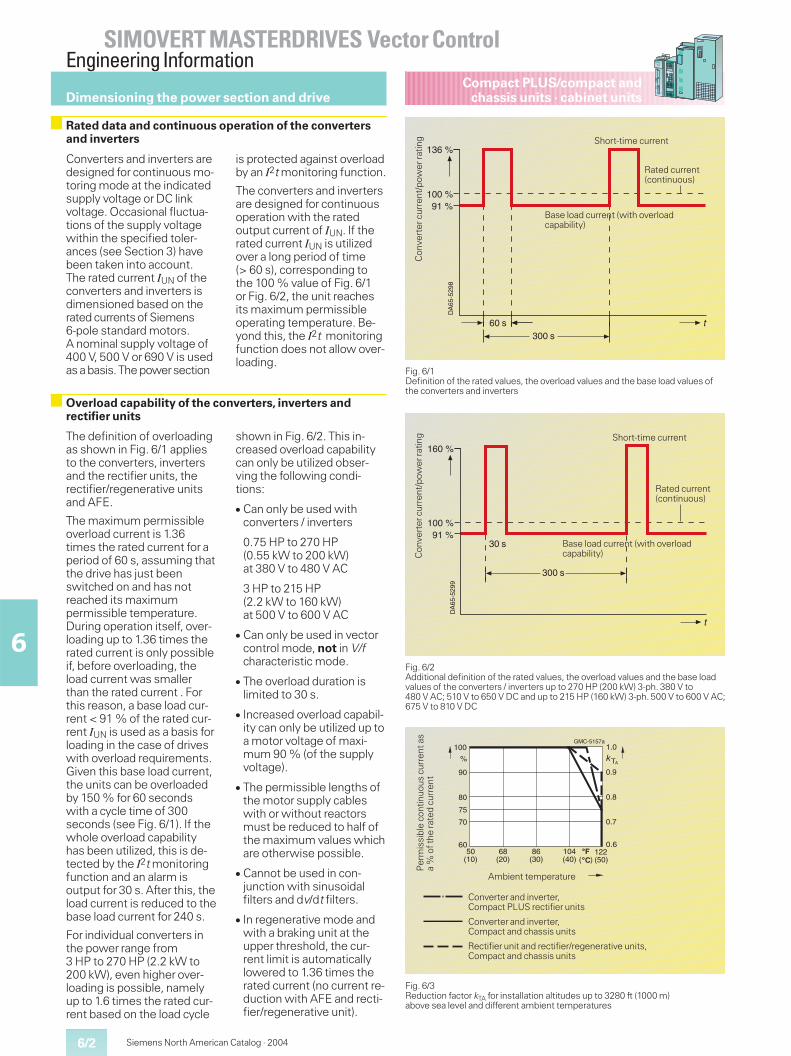
6/2
SIMOVERT MASTERDRIVES Vector ControlEngineering Information
6
Siemens North American Catalog · 2004
Compact PLUS/compact andchassis units · cabinet units
The definition of overloadingas shown in Fig. 6/1 appliesto the converters, invertersand the rectifier units, therectifier/regenerative unitsand AFE.
The maximum permissibleoverload current is 1.36times the rated current for aperiod of 60 s, assuming thatthe drive has just beenswitched on and has notreached its maximumpermissible temperature.During operation itself, over-loading up to 1.36 times therated current is only possibleif, before overloading, theload current was smallerthan the rated current . Forthis reason, a base load cur-rent < 91 % of the rated cur-rent IUN is used as a basis forloading in the case of driveswith overload requirements.Given this base load current,the units can be overloadedby 150 % for 60 secondswith a cycle time of 300seconds (see Fig. 6/1). If thewhole overload capabilityhas been utilized, this is de-tected by the I2t monitoringfunction and an alarm isoutput for 30 s. After this, theload current is reduced to thebase load current for 240 s.
For individual converters inthe power range from3 HP to 270 HP (2.2 kW to200 kW), even higher over-loading is possible, namelyup to 1.6 times the rated cur-rent based on the load cycle
shown in Fig. 6/2. This in-creased overload capabilitycan only be utilized obser-ving the following condi-tions:
� Can only be used withconverters / inverters
0.75 HP to 270 HP(0.55 kW to 200 kW)at 380 V to 480 V AC
3 HP to 215 HP(2.2 kW to 160 kW)at 500 V to 600 V AC
� Can only be used in vectorcontrol mode, not in V/fcharacteristic mode.
� The overload duration islimited to 30 s.
� Increased overload capabil-ity can only be utilized up toa motor voltage of maxi-mum 90 % (of the supplyvoltage).
� The permissible lengths ofthe motor supply cableswith or without reactorsmust be reduced to half ofthe maximum values whichare otherwise possible.
� Cannot be used in con-junction with sinusoidalfilters and dv/dt filters.
� In regenerative mode andwith a braking unit at theupper threshold, the cur-rent limit is automaticallylowered to 1.36 times therated current (no current re-duction with AFE and recti-fier/regenerative unit).
Fig. 6/1Definition of the rated values, the overload values and the base load values ofthe converters and inverters
Fig. 6/2Additional definition of the rated values, the overload values and the base loadvalues of the converters / inverters up to 270 HP (200 kW) 3-ph. 380 V to480 V AC; 510 V to 650 V DC and up to 215 HP (160 kW) 3-ph. 500 V to 600 V AC;675 V to 810 V DC
Fig. 6/3Reduction factor kTA for installation altitudes up to 3280 ft (1000 m)above sea level and different ambient temperatures
50(10)
122(50)��
100
90
80
70
%
60
GMC-5157a
75
1.0
0.9
0.8
0.7
0.6
�T
68(20)
86(30)
104(40)
��������
A
Per
mis
sibl
eco
ntin
uous
curr
enta
sa
%of
the
rate
dcu
rren
t
Ambient temperature
Converter and inverter,Compact PLUS rectifier units
Converter and inverter,Compact and chassis units
Rectifier unit and rectifier/regenerative units,Compact and chassis units
DA
65-5
298
136 %
100 %91 %
60 s300 s
t
Con
vert
ercu
rren
t/po
wer
ratin
g Short-time current
Rated current(continuous)
Base load current (with overloadcapability)
DA
65-5
299
160 %
100 %91 %
30 s
300 s
t
Short-time current
Rated current(continuous)
Base load current (with overloadcapability)C
onve
rter
curr
ent/
pow
erra
ting
Dimensioning the power section and drive
Rated data and continuous operation of the convertersand inverters
Converters and inverters aredesigned for continuous mo-toring mode at the indicatedsupply voltage or DC linkvoltage. Occasional fluctua-tions of the supply voltagewithin the specified toler-ances (see Section 3) havebeen taken into account.The rated current IUN of theconverters and inverters isdimensioned based on therated currents of Siemens6-pole standard motors.A nominal supply voltage of400 V, 500 V or 690 V is usedas a basis.The powersection
is protected against overloadby an I2t monitoring function.
The converters and invertersare designed for continuousoperation with the ratedoutput current of IUN. If therated current IUN is utilizedover a long period of time(> 60 s), corresponding tothe 100 % value of Fig. 6/1or Fig. 6/2, the unit reachesits maximum permissibleoperating temperature. Be-yond this, the I2t monitoringfunction does not allow over-loading.
Overload capability of the converters, inverters andrectifier units
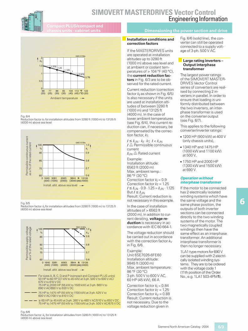
6/3
SIMOVERT MASTERDRIVES Vector ControlEngineering Information
6
Compact PLUS/compact andchassis units · cabinet units
Siemens North American Catalog · 2004
If the MASTERDRIVES unitsare operated at installationaltitudes up to 3280 ft(1000 m) above sea level andat ambient or coolant tem-peratures of > 104 °F (40 °C),the current reduction fac-tors in Fig. 6/3 are to be ob-served for the rated current.
Current reduction (correctionfactor kI as shown in Fig. 6/5)is also necessary if the unitsare used at installation alti-tudes of between 3280 ft(1000 m) and 13125 ft(4000 m). In the case oflower ambient temperatures(see Fig. 6/4), this current re-duction can, if necessary, becompensated by the correc-tion factor, kT.
I � IUN · kI · kT; I < IUNIq Permissible continuouscurrentIUNqRated current
Example:Installation altitude:6563 ft (2000 m)Max. ambient temp.:86 °F (30 °C)Correction factor kI = 0.9Correction factor kT = 1.25I � IUN · 0.9 · 1.25 = IUN · 1.125But I � IUNResult: Current reduction isnot necessary in this example.
In the case of installationaltitudes of > 6563 ft(2000 m), in addition to cur-rent derating, voltage re-duction is necessary in ac-cordance with IEC 60 664-1.
The voltage reduction shouldbe carried out in accordancewith the correction factor kVin Fig. 6/6.
Example:Unit 6SE7026-6FE60Installation altitude:9845 ft (3000 m)Max. ambient temperature:86 °F (30 °C)3-ph. 500 V to 600 V AC,60 HP (45 kW), 66 A
Correction factor kI = 0.84Correction factor kT = 1.25Correction factor kV = 0.88Result: Current reduction isnot necessary. Due to thevoltage reduction given in
Fig. 6/6 (solid line), the con-verter can still be operatedconnected to a supply volt-age of 3-ph. 500 V AC.
The largest power ratingsof the SIMOVERT MASTER-DRIVES Vector Controlseries of converters are real-ised by connecting 2 in-verters in parallel. In order toensure that loading is uni-formly distributed betweenthe two inverters, an inter-phase transformer is usedon the converter output(see Fig. 6/7).
This applies to the followingconverter/inverter ratings:
� 1200 HP (900 kW) at 400 V(only chassis units),
� 1340 HP and 1475 HP(1000 kW and 1100 kW)at 500 V,
� 1750 HP and 2000 HP(1300 kW and 1500 kW)at 690 V.
Operation withoutinterphase transformer
If the motor to be connectedhas 2 electrically isolatedwinding systems which havethe same voltage and thesame phase position, theoutputs of both invertersections can be connecteddirectly to the two windingsystems of the motor. Thetwo magnetically coupledwindings then have thesame effect as an interphasetransformer. An additionalinterphase transformer isthen no longer necessary.
1LA1 type motors for690 Vcan be supplied with 2 electri-cally isolated winding sys-tems. They are to be orderedwith the voltage code 1(11th position of the OrderNo.,e.g.1LA1 503-4PM1).
Fig. 6/4Reduction factor kT for installation altitudes from 3280 ft (1000 m) to 13125 ft(4000 m) above sea level
2
1.5
1
0
GMC-5158a
0.5
kT
0.76
1.3751.25
1.125
0.8791
68(20)
122(50)��
77(25)
86(30)
��������
95(35)
104(40)
113(45)
Ambient temperature
Fig. 6/5Reduction factor kI for installation altitudes from 3280 ft (1000 m) to 13125 ft(4000 m) above sea level
100
90
80
70
%
60
GMC-5159a1.0
0.9
0.8
0.7
0.6
k
0 13126(4000)
1640(500)
�����
9844(3000)
3281(1000)
6563(2000)
Install. altit. above sea level
Per
mis
sibl
eco
ntin
uous
curr
ent
asa
%of
the
rate
dcu
rren
t
Fig. 6/6Reduction factor kV for installation altitudes from 3280 ft (1000 m) to 13125 ft(4000 m) above sea level
100
90
80
70
%
60
GMC-5160a
75
1.0
0.9
0.8
0.7
0.6
k V
0 13126(4000)
1640(500)
�����
9844(3000)
3281(1000)
6563(2000)
Install. altit. above sea level
Per
mis
sibl
esu
pply
volta
geas
a%
ofth
era
ted
volta
ge
For sizes A, B, C, D and P (compact and Compact PLUS units)50 HP to 60 HP (37 kW to 45 kW) at 3-ph. 500 V to 600 V AC/675 V to 810 V DC75 HP to 2000 HP (55 kW to 1500 kW) at 3-ph. 660 V to690 V AC/890 V to 930 V DC
75 HP to 1475 HP (55 kW to 1100 kW) at 3-ph. 525 V to600 V AC/708 V to 810 V DC
� 60 HP (� 45 kW) at 3-ph. 380 V to 480 V AC/510 V to 650 V DC75 HP to 1475 HP (55 kW to 1100 kW) at 3-ph. 500 V AC/675 V DC
Dimensioning the power section and drive
Installation conditions andcorrection factors
Large rating inverters –Output interphasetransformer
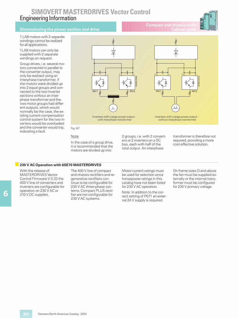
6/4
SIMOVERT MASTERDRIVES Vector ControlEngineering Information
6
Siemens North American Catalog · 2004
Compact and chassis unitsCabinet units
1 LA8 motors with 2 separatewindings cannot be realizedfor all applications.
1LA8 motors can only besupplied with 2 separatewindings on request.
Group drives, i.e. several mo-tors connected in parallel tothe converter output, mayonly be realized using aninterphase transformer, ifthe motors were divided upinto 2 equal groups and con-nected to the two invertersections without an inter-phase transformer and thetwo motor groups had differ-ent outputs, which wouldnormally be the case, the ex-isting current-compensationcontrol system for the two in-verters would be overloadedand the converter would trip,indicating a fault.
Fig. 6/7
�������
� � � �
�
��� ���
Inverters with a large power output –with interphase transformer
��������
� � � �
�
��� ���
Inverters with a large power output –without interphase transformer
Dimensioning the power section and drive
Note
In the case of a group drive,it is recommended that themotors are divided up into
2 groups, i.e. with 2 convert-ers or 2 inverters on a DCbus, each with half of thetotal output. An interphase
transformer is therefore notrequired, providing a morecost-effective solution.
230 V AC Operation with 6SE70 MASTERDRIVES
With the release ofMASTERDRIVES VectorControl Firmware V 3.33 the400 V line of converters andinverters are configurable foroperation on 230 V AC or310 V DC supplies.
The 400 V line of compactand chassis rectifiers and re-generative rectifiers con-tinue to be configurable for230 V AC three-phase sys-tems. Compact PLUS recti-fier are not configurable for230 V AC systems.
Motor current ratings mustbe used for selection sincehorsepower ratings in thiscatalog have not been listedfor 230 V AC operation.
Note: In addition to the cor-rect setting of P071 an exter-nal 24 V supply is required.
On frame sizes D and abovethe fan must be supplied ex-ternally or the internal trans-former must be configuredfor 230 V primary voltage.
6/5
SIMOVERT MASTERDRIVES Vector ControlEngineering Information
6
Siemens North American Catalog · 2004
Compact and chassis unitsCabinet units Dimensioning of the power section and drive
If a water-cooled SIMOVERTMASTERDRIVES unit isselected, it is necessaryto use water of a suitablequality for the cooling circuit.The following notes shouldhelp when engineering thecooling circuit.
Design of the cooler ofthe 6SE70 SIMOVERTMASTERDRIVES
The cooler consists of analuminium base plate for theconverter power semicon-ductors with internal coolingpipes or a cast aluminiumheatsink mounted on therear. The cooling water flowsthrough the cooling chan-nels.
In order to avoid mechanicaldistortion of this base plateand the loss involved on theIGBTs mounted on it, themax. permissible operatingpressure of the coolingcircuit must be < 1 bar forunits of sizes A to G and� 2.5 bar for units of size K.When the operating pres-sure is � 0.5 bar the require-ments of the guideline forpressure vessels are to beconsidered.
According to guidelines92/23/EG for pressurevessels, the risks arisingfrom cooling circuits arevery small. Certificationprocedures and CE labellingaccording to this guidelineare therefore normally notnecessary.
In order to avoid galvaniccorrosion and possibledestruction of the heat sink,the cooling-water connec-tions of the heat sink aremade of stainless steel.
Cooling systemrequirements
Open cooling systems mustnot be used. Only closedcooling systems should beinstalled, preferably withmonitoring of the waterquality of the cooling water.
The electrochemical proces-ses occurring in the coolingsystem must be minimizedby the choice of materials.Mixed installations, i.e. acombination of different ma-terials such as copper, brass,iron and plastics containinghalogens (PVC hoses andseals) should be avoided.Examples of materials re-commended for the coolingsystem piping are the stain-less steels V2A and V4A(NIROSTA austenite) and theelectrically non-conductivehoses EPDM/NBR (EPDMwater side).
To suppress the electrochem-ical processes, equipotentialbonding between the vari-ous components in the cool-ing system (SIMOVERTMASTERDRIVES, heatexchanger, piping system,pump, etc.) should be imple-mented using a copper busbar or stranded copper con-ductor of suitable cross-section.
Cooling waterrequirements
The cooling water mustsatisfy the following require-ments:� Chemically neutral, clean
water, free of solid matter.� Max. particle size of any
particles in water� 0.004 in (0.1 mm)
� pH value 6.0 to 8.0
� Chloride < 40 ppm
� Sulphate < 50 ppm
� Dissolved substances< 340 ppm
� Overall hardness< 170 ppm
� Use of a particle filter(100 �m).
If there is a danger of frost,frost-protection measuresmust be implementedduring operation, storageand transport. For example,emptying and blowing outwith air, additional heaters,etc.
Antifreeze additive
The use of Antifrogen Nantifreeze (available fromClariant;http://www.clariant.com) isrecommended. The mixingratio must be within therange 20 % < antifreeze< 30 %. This ensures protec-tion against frost down to atemperature of at least 14 °F(–10 °C).
Note!
If less than 20 % antifreeze isadded, the risk of corrosion isincreased. If more than 30 %antifreeze is added, the heatflow and therefore the func-tioning of the unit is affected.Care must always be takento ensure that the addition ofantifreeze does not alter thekinematic viscosity of thecooling water. It is necessaryto adapt the pump output.
Depending on conditions atinstallation location and onthe technical aspects, thecooling circuits described onpage 6/5 can be used.
Anti-corrosion agent
For the cooling circuit, werecommend using a corro-sion inhibitor, e.g. the anti-corrosion agent NALCO00GE056 available fromONDEO Nalco(www.ondeo-nalco.com).Concentration of corrosioninhibitor in the cooling water:0.1 to 0.14 %.
The cooling water should bechecked 3 months after thecooling circuit has been filledfor the first time and, afterthis, once a year.
If the cooling water becomesdetectably cloudy, discoloredor contaminated with bacte-ria, the cooling circuit mustbe flushed out and re-filled.
An inspection windowshould be fitted in the cool-ing circuit to facilitate inspec-tion of the cooling water.
Cabinet-unit earthing
In the case of water-cooledcabinets, special attentionmust be paid to earthing. Allcabinets must be bolted to-gether to ensure a good con-ductivity between them (e.g.cabinet brackets conduc-tively connected to eachother by screws). This is nec-essary to avoid differences inpotential and thus to preventthe danger of electro-chemi-cal corrosion. For this reason,a PE rail should always bemounted in all cabinets andin the re-cooling system.
Important!Operating pressuresabove1 bar/2.5 bardepending on thesize of the unitare not permissible!The heatsinks are notresistant againstsea-water (i.e. sea-watermust not be used forcooling)!
Water-cooled converters – Water-cooling circuit
Important!Moisture condensationon the converter due toundercooling is to beprevented. If necessary,the temperature of thecooling water mustbe controlled.
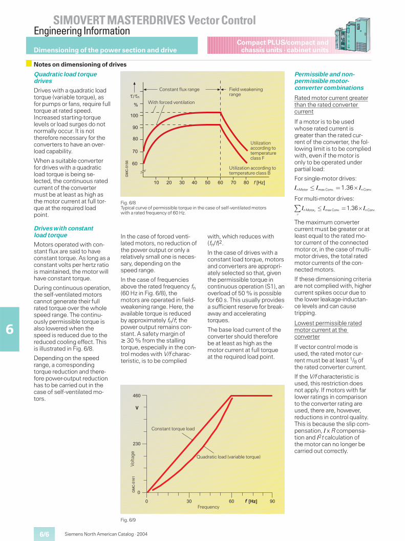
6/6
SIMOVERT MASTERDRIVES Vector ControlEngineering Information
6
Siemens North American Catalog · 2004
Compact PLUS/compact andchassis units · cabinet units
Quadratic load torquedrives
Drives with a quadratic loadtorque (variable torque), asfor pumps or fans, require fulltorque at rated speed.Increased starting-torquelevels or load surges do notnormally occur. It is nottherefore necessary for theconverters to have an over-load capability.
When a suitable converterfor drives with a quadraticload torque is being se-lected, the continuous ratedcurrent of the convertermust be at least as high asthe motor current at full tor-que at the required loadpoint.
Drives with constantload torque
Motors operated with con-stant flux are said to haveconstant torque. As long as aconstant volts per hertz ratiois maintained, the motor willhave constant torque.
During continuous operation,the self-ventilated motorscannot generate their fullrated torque over the wholespeed range. The continu-ously permissible torque isalso lowered when thespeed is reduced due to thereduced cooling effect. Thisis illustrated in Fig. 6/8.
Depending on the speedrange, a correspondingtorque reduction and there-fore power-output reductionhas to be carried out in thecase of self-ventilated mo-tors.
Fig. 6/8Typical curve of permissible torque in the case of self-ventilated motorswith a rated frequency of 60 Hz.
���
�� �� �� �� �� �� �� � ����
�
� �
��
��
��
�
�������
�
Utilization according totemperature class B
Utilizationaccording totemperatureclass F
With forced ventilation
Constant flux range Field weakeningrange
Dimensioning of the power section and drive
Notes on dimensioning of drives
In the case of forced venti-lated motors, no reduction ofthe power output or only arelatively small one is neces-sary, depending on thespeed range.
In the case of frequenciesabove the rated frequency fn(60 Hz in Fig. 6/8), themotors are operated in field-weakening range. Here, theavailable torque is reducedby approximately fn/f; thepower output remains con-stant. A safety margin of� 30 % from the stallingtorque, especially in the con-trol modes with V/f charac-teristic, is to be complied
with, which reduces with(fn/f)2.
In the case of drives with aconstant load torque, motorsand converters are appropri-ately selected so that, giventhe permissible torque incontinuous operation (S1), anoverload of 50 % is possiblefor 60 s. This usually providesa sufficient reserve for break-away and acceleratingtorques.
The base load current of theconverter should thereforebe at least as high as themotor current at full torqueat the required load point.
Permissible and non-permissible motor-converter combinations
Rated motor current greaterthan the rated convertercurrent
If a motor is to be usedwhose rated current isgreater than the rated cur-rent of the converter, the fol-lowing limit is to be compliedwith, even if the motor isonly to be operated underpartial load:
For single-motor drives:
For multi-motor drives:
The maximum convertercurrent must be greater or atleast equal to the rated mo-tor current of the connectedmotor or, in the case of multi-motor drives, the total ratedmotor currents of the con-nected motors.
If these dimensioning criteriaare not complied with, highercurrent spikes occur due tothe lower leakage-inductan-ce levels and can causetripping.
Lowest permissible ratedmotor current at theconverter
If vector control mode isused, the rated motor cur-rent must be at least 1/8 ofthe rated converter current.
If the V/f characteristic isused, this restriction doesnot apply. If motors with farlower ratings in comparisonto the converter rating areused, there are, however,reductions in control quality.This is because the slip com-pensation, I x R compensa-tion and I2t calculation ofthe motor can no longer becarried out correctly.
Fig. 6/9
� � �I I InMotor max Conv. n Conv.1.36
�
� � �� I I IvnMotor max Conv. n Conv.1.36
��� �� ��� ����
�
���
���
�
�������
�
Constant torque load
Frequency
Quadratic load (variable torque)
Volta
ge
6/7
SIMOVERT MASTERDRIVES Vector ControlEngineering Information
6
Compact PLUS/compact andchassis units · cabinet units
Siemens North American Catalog · 2004
Motor type
In addition to the standard1LA type motors, compactinduction motors, type1PH7/1PL6, can also beused.
1PH7/1PL6 compact induc-tion motors are to be recom-mended in the case of
� a high speed range withhigh maximum speeds
� speeds down to zero with-out a reduction in torque;
� restricted mounting con-ditions; 1PH7/1PL6 typemotors are, on average, upto two shaft heights smallerthan comparable standardinduction motors with thesame rated power output.
For further information anddetailed engineering infor-mation, see Motor Catalog.
Supply voltages > 500 Vfor 1LA1, 1LA5, 1LA6, 1LA7and 1LA8 motors
The standard insulation of1LA type motors is designedso that they can be operatedwith the converter at supplyvoltages of V � 500 V (or Vd� 740 V DC) without any re-strictions.
At V > 500 V, one of the fol-lowing is necessary:
� a voltage-limiting filterdv/dt,
� a sinusoidal filter,
� or a strengthened motor in-sulation system.
For 1LA8 type motors, a win-ding with a strengthenedinsulating system has beendeveloped for operating thedrive with the converter witha supply voltage of up to690 V. This winding does notrequire a filter. These motorsare identified with an “M” atthe 10th position of the Or-der No., e.g. 1LA8 315-2PM.
With the strengthened insu-lating system, there is lessroom in the slots for thesame number of windingturns compared to the nor-mal version. This results inthe slightly lower rated out-put for these motors.
Motor protection
Motor protection can be pro-vided by the converter soft-ware with I2t monitoring ofthe motor. Here, the currentmotor speed is also takeninto account. This monitoringfunction, however, is not100 % accurate because themotor temperature is onlycalculated and not meas-ured. In addition to this, theambient temperature is nottaken into account.
Precise motor protection ispossible using motor tem-perature sensors. In the caseof SIMOVERT MASTER-DRIVES Vector Control, it ispossible to connect a KTY84temperature sensor or a PTCthermistor directly in thebase unit.
� PTC thermistors with aknee in the characteristiccurve are evaluated for“Trip”or “Alarm”purposes.
� In the case of KTY84 motor-temperature sensors, thetemperature of the motor isevaluated. The temperaturevalue can be output via ananalog output.The values for “Alarm”and“Trip”can be parameter-ized and, when reached,this can be output via bi-nary outputs.
The measured temperatureof the motor is also evalu-ated for more precise closed-loop control of the torque.
1PH7/1PL6 type motorshave a KTY84 motor-temper-ature sensor in the statorwinding as standard. A sepa-rate evaluation unit is re-quired for monitoring withPT100 temperature sensors.
Bearing currents
The main causes of damag-ing bearing currents are cir-culating currents in the mo-tor as a result of convertersupply. They are also causedby currents flowing throughthe motor bearings due tounfavorable earthing condi-tions.
In order to provide protectionagainst damaging bearingcurrents due to circulatingcurrents, an insulated NDEbearing is used for certainmotor sizes.
For 1PH7 and 1PL6 typemotors, insulated NDE bear-ings are available as an op-tion for sizes 180 and above(code L27). For size 280, theinsulated bearing is stan-dard. For standard 1LG4 and1LG6 series motors, insu-lated NDE bearings for sizes225 to 315 are recommend-ed for converter operation(supplementary order codeL27). Insulated bearings arestandard for all 1LA1/PQ1/1LA8/1LL8 and 1PQ8 typemotors (size 315 and up-wards) that are marked assuitable for converter opera-tion.
If the machine connected tothe motor shaft is earthedbetter than the motor itself,damaging current can flowthrough the motor bearingsand through the bearings ofthe driven machine. In orderto avoid this kind of bearingcurrent, the motor housingmust be well earthed, e.g.by using a shielded motorcable.
Dimensioning the power section and drive
Notes on motor engineering
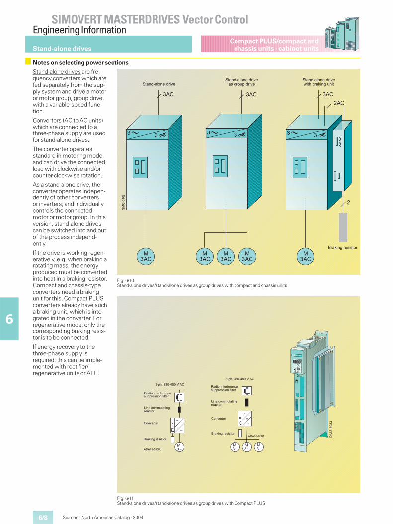
6/8
SIMOVERT MASTERDRIVES Vector ControlEngineering Information
6
Siemens North American Catalog · 2004
Compact PLUS/compact andchassis units · cabinet units
Stand-alone drives are fre-quency converters which arefed separately from the sup-ply system and drive a motoror motor group, group drive,with a variable-speed func-tion.
Converters (AC to AC units)which are connected to athree-phase supply are usedfor stand-alone drives.
The converter operatesstandard in motoring mode,and can drive the connectedload with clockwise and/orcounter-clockwise rotation.
As a stand-alone drive, theconverter operates indepen-dently of other convertersor inverters, and individuallycontrols the connectedmotor or motor group. In thisversion, stand-alone drivescan be switched into and outof the process independ-ently.
If the drive is working regen-eratively, e.g. when braking arotating mass, the energyproduced must be convertedinto heat in a braking resistor.Compact and chassis-typeconverters need a brakingunit for this. Compact PLUSconverters already have sucha braking unit, which is inte-grated in the converter. Forregenerative mode, only thecorresponding braking resis-tor is to be connected.
If energy recovery to thethree-phase supply isrequired, this can be imple-mented with rectifier/regenerative units or AFE.
Fig. 6/10Stand-alone drives/stand-alone drives as group drives with compact and chassis units
�������������� �
!���"��# ���"��$�!���"��# ���"��$������ %&�"��$�
!���"��# ���"��$�'��(�)�������%���
��*�
�������
�
�*�
� �
�
�*�
��*�
�*�
� �
��*�
�*�
� �
��*�
��*�
Stand-alone drives
Notes on selecting power sections
Fig. 6/11Stand-alone drives/stand-alone drives as group drives with Compact PLUS
��
�
���+*������)
,�"� ������-����.��%&&����� ��-�#���
/����. 00%���������.� �
� �$�����
�������������� �
��&(1�������2�*�
*���
��
�
���
���
+*������
,�"� ������-����.��%&&����� ��-�#���
/����. 00%���������.� �
� �$�����
�������������� �
��&(1�������2�*�
* +*������
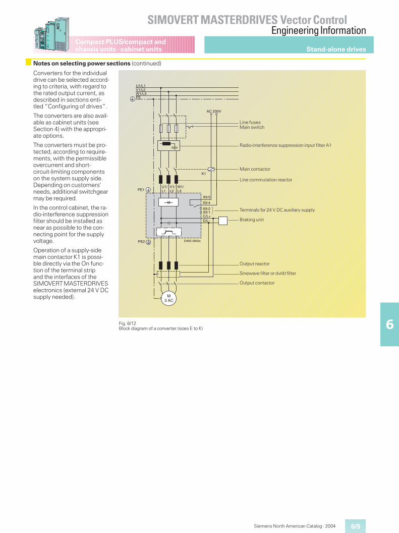
6/9
SIMOVERT MASTERDRIVES Vector ControlEngineering Information
6
Compact PLUS/compact andchassis units · cabinet units
Siemens North American Catalog · 2004
Stand-alone drives
Notes on selecting power sections (continued)
Converters for the individualdrive can be selected accord-ing to criteria, with regard tothe rated output current, asdescribed in sections enti-tled “Configuring of drives”.
The converters are also avail-able as cabinet units (seeSection 4) with the appropri-ate options.
The converters must be pro-tected, according to require-ments, with the permissibleovercurrent and short-circuit-limiting componentson the system supply side.Depending on customers’needs, additional switchgearmay be required.
In the control cabinet, the ra-dio-interference suppressionfilter should be installed asnear as possible to the con-necting point for the supplyvoltage.
Operation of a supply-sidemain contactor K1 is possi-ble directly via the On func-tion of the terminal stripand the interfaces of theSIMOVERT MASTERDRIVESelectronics (external 24 V DCsupply needed).
Fig. 6/12Block diagram of a converter (sizes E to K)
DA65-5842a
PE
U1/L1V1/L2W1/L3
PE1
X9:2
X9:4
X9:5
X9:1
W1/L3
V1/L2
U1/L1
AC 230V
PE2
M3 AC
C/L+D/L-
K1
Output contactor
Sinewave filter or dv/dt filter
Output reactor
Braking unit
Terminals for 24 V DC auxiliary supply
Line commutation reactor
Main contactor
Radio-interference suppression input filter A1
Main switchLine fuses
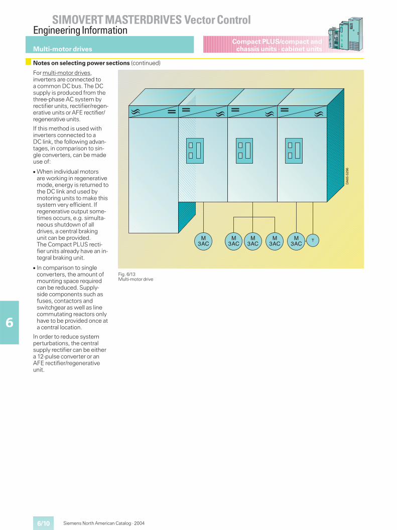
6/10
SIMOVERT MASTERDRIVES Vector ControlEngineering Information
6
Siemens North American Catalog · 2004
Compact PLUS/compact andchassis units · cabinet units
For multi-motor drives,inverters are connected toa common DC bus. The DCsupply is produced from thethree-phase AC system byrectifier units, rectifier/regen-erative units or AFE rectifier/regenerative units.
If this method is used withinverters connected to aDC link, the following advan-tages, in comparison to sin-gle converters, can be madeuse of:
� When individual motorsare working in regenerativemode, energy is returned tothe DC link and used bymotoring units to make thissystem very efficient. Ifregenerative output some-times occurs, e.g. simulta-neous shutdown of alldrives, a central brakingunit can be provided.The Compact PLUS recti-fier units already have an in-tegral braking unit.
� In comparison to singleconverters, the amount ofmounting space requiredcan be reduced. Supply-side components such asfuses, contactors andswitchgear as well as linecommutating reactors onlyhave to be provided once ata central location.
In order to reduce systemperturbations, the centralsupply rectifier can be eithera 12-pulse converter or anAFE rectifier/regenerativeunit.
Fig. 6/13Multi-motor drive
M3AC
M3AC
M3AC
M3AC
M3AC
T
DA
65-5
296
Multi-motor drives
Notes on selecting power sections (continued)
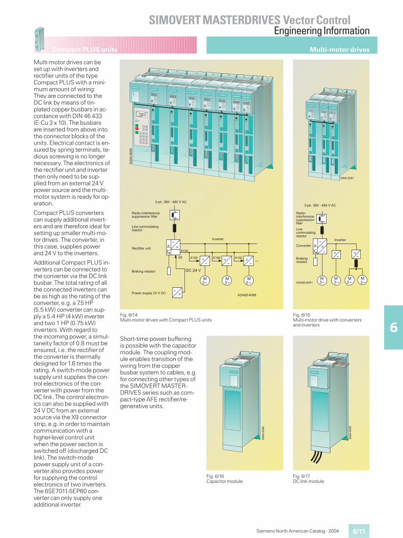
6/11
SIMOVERT MASTERDRIVES Vector ControlEngineering Information
6
Compact PLUS units
Siemens North American Catalog · 2004
Fig. 6/14Multi-motor drives with Compact PLUS units
Fig. 6/15Multi-motor drive with convertersand inverters
Fig. 6/16Capacitor module
Fig. 6/17DC link module
Multi-motor drives can beset up with inverters andrectifier units of the typeCompact PLUS with a mini-mum amount of wiring:They are connected to theDC link by means of tin-plated copper busbars in ac-cordance with DIN 46 433(E-Cu 3 x 10). The busbarsare inserted from above intothe connector blocks of theunits. Electrical contact is en-sured by spring terminals, te-dious screwing is no longernecessary. The electronics ofthe rectifier unit and inverterthen only need to be sup-plied from an external 24 Vpower source and the multi-motor system is ready for op-eration.
Compact PLUS converterscan supply additional invert-ers and are therefore ideal forsetting up smaller multi-mo-tor drives. The converter, inthis case, supplies powerand 24 V to the inverters.
Additional Compact PLUS in-verters can be connected tothe converter via the DC linkbusbar. The total rating of allthe connected inverters canbe as high as the rating of theconverter, e.g. a 7.5 HP(5.5 kW) converter can sup-ply a 5.4 HP (4 kW) inverterand two 1 HP (0.75 kW)inverters. With regard tothe incoming power, a simul-taneity factor of 0.8 must beensured, i.e. the rectifier ofthe converter is thermallydesigned for 1.6 times therating. A switch-mode powersupply unit supplies the con-trol electronics of the con-verter with power from theDC link. The control electron-ics can also be supplied with24 V DC from an externalsource via the X9 connectorstrip, e.g. in order to maintaincommunication with ahigher-level control unitwhen the power section isswitched off (discharged DClink). The switch-modepower supply unit of a con-verter also provides powerfor supplying the controlelectronics of two inverters.The 6SE7011-5EP60 con-verter can only supply oneadditional inverter.
Short-time power bufferingis possible with the capacitormodule. The coupling mod-ule enables transition of thewiring from the copperbusbar system to cables, e.g.for connecting other types ofthe SIMOVERT MASTER-DRIVES series such as com-pact-type AFE rectifier/re-generative units.
��
���
��
�
�� �� �
��
��
��
��������
��
�
�
�
�
�
�
����� ��
�� �� ��
� � �
3�$�����
,�"� ������-����.��%&&����� ��-�#���
��&(1���������2�*�
�
/����. 00%���������.� �
,�.��-����%���
�������������� �
4 '����%&����2�+�
+*������
+*�������
� �� �
��
�
���
���
��
��� �
,�"� ������-����.��%&&����� �-�#���
/���. 00%���������.� �
� �$�����
������������� �
��&(1���������2�*�
3�$�����
*
+*������
+*�������
Multi-motor drives
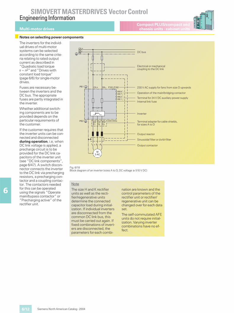
6/12
SIMOVERT MASTERDRIVES Vector ControlEngineering Information
6
Siemens North American Catalog · 2004
Compact PLUS/compact andchassis units · cabinet units
The inverters for the individ-ual drives of multi-motorsystems can be selectedaccording to the same crite-ria relating to rated outputcurrent as described in“Quadratic load torque� ~ n2”and ”Drives withconstant load torque”(page 6/6) for single-motordrives.
Fuses are necessary be-tween the inverters and theDC bus. The appropriatefuses are partly integrated inthe inverter.
Whether additional switch-ing components are to beprovided depends on theparticular requirements ofthe customer.
If the customer requires thatthe inverter units can be con-nected and disconnectedduring operation, i.e. whenDC link voltage is applied, aprecharge circuit is to beprovided for the DC link ca-pacitors of the inverter unit(see “DC link components”,page 6/47). A switch discon-nector connects the inverterto the DC link via prechargingresistors, a precharging con-tactor and a coupling contac-tor. The contactors neededfor this can be operatedusing the signals “Operatemain/bypass contactor” or“Precharging active” of therectifier unit.
Fig. 6/18Block diagram of an inverter (sizes A to D, DC voltage � 510 V DC)
��������
��
��������
���
���
��������
����
�����
�����
����
��������
���� ���� ��! ��
Output contactor
Operation of the main/bridging contactor
Output reactor
Terminal adapter for cable shields,for sizes A to D
Internal link fuseTerminal for 24 V DC auxiliary power supply
Sinusoidal filter or dv/dt-filter
Inverter
230 V AC supply for fans from size D upwards
Electrical or mechanicalcoupling to the DC link
Multi-motor drives
Notes on selecting power components
Note
The size H and K rectifierunits as well as the recti-fier/regenerative unitsdetermine the connectedcapacitor load during initial-ization. If individual invertersare disconnected from thecommon DC link bus, thismust be carried out again. Iffixed combinations of invert-ers are disconnected, theparameters for each combi-
nation are known and thecontrol parameters of therectifier unit or rectifier/regenerative unit can bechanged over for each dataset.
The self-commutated AFEunits do not require initial-ization. Varying invertercombinations have no ef-fect.
DC bus
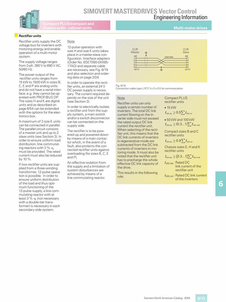
6/13
SIMOVERT MASTERDRIVES Vector ControlEngineering Information
6
Compact PLUS/compact andchassis units · cabinet units
Siemens North American Catalog · 2004
Rectifier units supply the DCvoltage bus for inverters withmotoring energy and enableoperation of a multi-motorsystem.
The supply voltage rangesfrom 3-ph. 380 V to 690 V AC,50/60 Hz.
The power output of therectifier units ranges from15 kW to 1500 kW in sizes B,C, E and P are analog unitsand do not have a serial inter-face, e.g. they cannot be op-erated with PROFIBUS DP.The sizes H and K are digitalunits and as described onpage 6/54 can be extendedwith the options for the elec-tronics box.
A maximum of 3 size K unitscan be connected in parallel.The parallel circuit consistsof a master unit and up to 2slave units (see Section 3). Inorder to ensure uniform loaddistribution, line commutat-ing reactors with 3 % vkmust be provided. The ratedcurrent must also be reducedby 10 %.
If two rectifier units are sup-plied from a three-windingtransformer, 12-pulse opera-tion is possible. In order toensure uniform distributionof the load and thus opti-mum functioning of the12-pulse supply, a line com-mutating reactor with atleast 3 % vk (not necessarywith a double-tier trans-former) is necessary in eachsecondary-side system.
Note
12-pulse operation withsize H and size K units takesplace in a master-slave con-figuration. Interface adapters(Order No. 6SE7090-0XX85-1TAO) and separate cableare necessary, see Fig. 6/19and also selection and order-ing data on page 3/24.
In order to operate the recti-fier units, an external 24 VDC power supply is neces-sary. The current required de-pends on the size of the unit(see Section 3).
In order to electrically isolatea rectifier unit from the sup-ply system, a main switchand/or a switch disconnectorcan be connected on thesupply side.
The rectifier is to be pow-ered-up and powered-downby means of a main contac-tor which, in the event of afault, also protects the con-nected rectifier units againstoverloading (for sizes B, C, Eand P).
An effective isolation fromthe supply and a limitation ofsystem disturbances areachieved by means of aline commutating reactor.
Multi-motor drives
Rectifier units
Fig. 6/19Connection cable type LiYCY 3 x 2 x 0.5 for communication
��� ������"�
�����
���
�����
��
��
��
��
CURMaster
CURSlave
Note
Rectifier units can onlysupply a certain number ofinverters. The total DC linkcurrent flowing on the in-verter side must not exceedthe rated output DC linkcurrent the rectifier unit.When selecting of the recti-fier unit, this means that theDC link currents of invertersin regenerative mode aresubtracted from the DC linkcurrents of inverters in mo-toring mode. It must also benoted that the rectifier unithas to precharge the wholeeffective DC link capacity ofthe drive.
This results in the followingrule:
Compact PLUSrectifier units
� 15 kW
� 50 kW and 100 kW
Compact sizes B and Crectifier units
Chassis sizes E, H and Krectifier units
Izkb ee: Rated DClink current of therectifier unit
Izkb wr: Rated DC link currentof the inverters
� �� �I Izkb ee zkb wrb0.3...1
� �I Izkb ee zkb wr0.5
� �I Izkb ee zkb wrb(0.3...1)
� �I Izkb ee zkb wr0.9
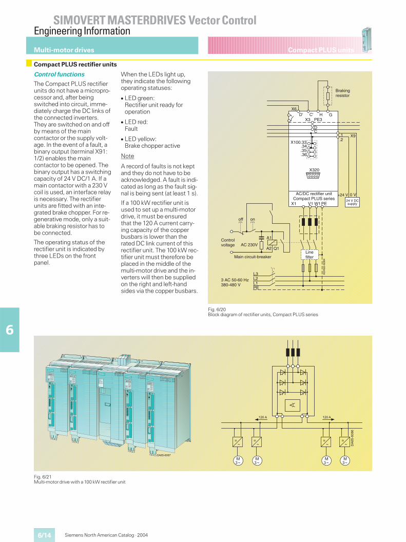
6/14
SIMOVERT MASTERDRIVES Vector ControlEngineering Information
6
Siemens North American Catalog · 2004
Compact PLUS unitsMulti-motor drives
Compact PLUS rectifier units
Fig. 6/20Block diagram of rectifier units, Compact PLUS series
Fig. 6/21Multi-motor drive with a 100 kW rectifier unit
Control functions
The Compact PLUS rectifierunits do not have a micropro-cessor and, after beingswitched into circuit, imme-diately charge the DC links ofthe connected inverters.They are switched on and offby means of the maincontactor or the supply volt-age. In the event of a fault, abinary output (terminal X91:1/2) enables the maincontactor to be opened. Thebinary output has a switchingcapacity of 24 V DC/1 A. If amain contactor with a 230 Vcoil is used, an interface relayis necessary. The rectifierunits are fitted with an inte-grated brake chopper. For re-generative mode, only a suit-able braking resistor has tobe connected.
The operating status of therectifier unit is indicated bythree LEDs on the frontpanel.
When the LEDs light up,they indicate the followingoperating statuses:
� LED green:Rectifier unit ready foroperation
� LED red:Fault
� LED yellow:Brake chopper active
Note
A record of faults is not keptand they do not have to beacknowledged. A fault is indi-cated as long as the fault sig-nal is being sent (at least 1 s).
If a 100 kW rectifier unit isused to set up a multi-motordrive, it must be ensuredthat the 120 A current carry-ing capacity of the copperbusbars is lower than therated DC link current of thisrectifier unit. The 100 kW rec-tifier unit must therefore beplaced in the middle of themulti-motor drive and the in-verters will then be suppliedon the right and left-handsides via the copper busbars.
V1 W1PE
X100.33.34.35.36
X320
CD
PE3X3
X6D' C' H G
Q1
A1
A2AC 230V
L3L2L1PE
3 AC 50-60 Hz380-480 V
+24 V 0 V
X1
.1
.2X9
DA
65-6
084
Brakingresistor
Controlvoltage
Linefilter
AC/DC rectifier unitCompact PLUS series
supply
off on
A
Main circuit-breaker
24 V DC
*!�
6���
6��� �
�
7� 849
*!�
6���
6��� �
�
7� 849
*!�
6���
6��� �
�
7� 849
*!�
6���
6��� �
�
7� 849
+*�������
��
���
��
�
�� �
�
���
��
���
��
���
��
���
�� �
6/15
SIMOVERT MASTERDRIVES Vector ControlEngineering Information
6
Siemens North American Catalog · 2004
Compact and chassis unitsCabinet units
Control functions
Rectifier units,sizes B, C and E
These rectifier units do nothave a processor board andcharge the DC link of theconnected inverter immedi-ately after it is powered up.They are powered up/downvia the main contactor orby turning on/off the supplyvoltage.
A binary output (terminalX9: 4, 5) with a switchingvoltage of 230 V AC enablesswitching of the main con-tactor in the event of a fault.The signalling contact (termi-nal X36: 1, 2) can be used tosignal “Overtemperature”or “Precharge enable” asrequired.
Rectifier units, sizes H and K
These rectifier units areequipped with a processorboard and an electronics box.Communication with a PLCvia PROFIBUS DP or withthe USS protocol is thereforepossible.
A binary output (terminalX9: 4, 5) with a switchingvoltage of 230 V AC can beused to operate the maincontactor (operation maincontactor rectifier/regenera-tive unit, see Fig. 6/22).
For the control terminal stripfunctionality, see page 6/42,“Control terminal strip onthe CUR control board”.
Fig. 6/22Block diagram of the rectifier unit(sizes B, C and E)
Terminal Function
X9: 1X9: 2
24 V DC power supplyGround
X9: 4
X9: 5
Contact material Ag CdOOperation of main contactor.Load capability: 230 V AC: 7.5 A (cos � = 0.4),L/R = 7 ms, 30 V DC: 5 A; DC 60 V: 1 A.Minimum load: 100 mA
X36: 1
X36: 2
Contact material AgPbAlarm: Overtemperature, Precharging fault.Load capability: 48 V AC, 60 VA (cos � =1) to160 VA (cos � = 0.8); 48 V DC, 24 WMinimum load: 5 mA
X19: 1X19: 2
Power supply for fans, sizes E, H, K230 V 50/60 Hz
Assignment of the control terminal strip on rectifier units sizeB, C, E and H, K (only X19)
�������#
��
��������������
���
���
����
����
����
����
����
�����
�����
����
����
�����
$�
$�
DC bus
Main switch
Off
Terminal for 24 V DC auxiliary power supplyalways necessary
Input filter B1 / A1Main contactor
Precharging
Line commutating reactor
Line fuses
Multi-motor drives
Rectifier units
Standard functions forrectifier units, sizes H and K
Basic setting/reserve setting
This function logically com-bines process data (set-points and control functions).In other words, it enables,for example, switching frommanual operation to auto-matic operation (internal/external) between twosources, e.g. between theoperator control panel (termi-nal strip, interfaces, dual portRAM) to the terminal strip(interfaces, dual port RAM,operator control panel).
Reserve data sets
This control function includes4 reserve data sets so thatthe control parameters canbe stored and selected forvarying numbers of con-nected inverters. Selectioncan also take place duringoperation. In this way, therectifier units are able to usemodified control data when
inverters are powered up/down.
Circuit identification
With this measurement, theparameter settings of the DClink controller for the rectifierunits are determined and op-timized.
Automatic restart
This restarts the drive whenthe power returns following apower failure.
Note:If a size H or K rectifier unitsupplies an inverter for whichthe kinetic buffering functionfor bridging power failures ordips is activated, the auto-matic-restart function mustbe enabled.
6/16
SIMOVERT MASTERDRIVES Vector ControlEngineering Information
6
Siemens North American Catalog · 2004
Compact and chassis unitsCabinet units
Rectifier/regenerative units
Rectifier/regenerative units(line-commutated) not onlysupply the DC bus for invert-ers with motor power from athree-phase supply, they alsoinject regenerative power1)back into the line supplyfrom the DC bus. This isdone by means of two inde-pendent thyristor bridges;the regenerative bridge isconnected via an auto-transformer (for selectionand ordering data, see Sec-tion 3).
The autotransformer for theregenerative bridge has thefollowing advantage:
� maximum motor torque atfull motor speed, evenwhen regenerating.
When a rapid changeoverfrom infeed to regenerationis carried out, a dead time of15 ms has to be taken intoaccount.
Rectifier/regenerative unitscan only be ordered as chas-sis units for mounting in con-trol cubicles.
The supply voltage rangesfrom 3-ph. 380 V AC to690 V AC, 50/60 Hz.
Rectifier units for3-ph. 50/60 Hz 380 V AC to3-ph. 50/60 Hz 480 V ACcan also be connected to3-ph. 50/60 Hz 200 V AC to3-ph. 50/60 Hz 230 V ACwith the same rated current;the output power is reducedaccording to the ratio of thesupply voltages.
The output range of the recti-fier/regenerative units isfrom 7.5 kW to 1500 kW insizes C, E, H and K.
Fig. 6/23Base and parallel units
Parallel switching of size K parallel units
Up to 2 units with the samerated current can be con-nected in parallel to thepower sections of rectifierunits or rectifier/regenerativeunits of type K (“base unit”)in order to increase outputcurrent.
The parallel circuit consistsof a master unit and up to2 slave units.
The parallel units are to bemounted on the left side ofthe base unit.
In the following table, theparallel units suitable for aparallel connection are as-signed to the respectivebase units.
Base unit (Master)Type
Parallel unit (Slave)Type
Rectifier units6SE7041-3EK85-0AA0 6SE7041-3EK85-0AD0
6SE7041-8EK85-0AA0 6SE7041-8EK85-0AD0
6SE7041-3FK85-0AA0 6SE7041-3FK85-0AD0
6SE7041-5FK85-0AA0 6SE7041-5FK85-0AD0
6SE7041-8FK85-0AA0 6SE7041-8FK85-0AD0
6SE7041-3HK85-0AA0 6SE7041-3HK85-0AD0
6SE7041-5HK85-0AA0 6SE7041-5HK85-0AD0
6SE7041-8HK85-0AA0 6SE7041-8HK85-0AD0
Rectifier/regenerative units6SE7041-3EK85-1AA0 6SE7041-3EK85-1AD0
6SE7041-8EK85-1AA0 6SE7041-8EK85-1AD0
6SE7041-3FK85-1AA0 6SE7041-3FK85-1AD0
6SE7041-5FK85-1AA0 6SE7041-5FK85-1AD0
6SE7041-8FK85-1AA0 6SE7041-8FK85-1AD0
6SE7041-3HK85-1AA0 6SE7041-3HK85-1AD0
6SE7041-5HK85-1AA0 6SE7041-5HK85-1AD0
6SE7041-8HK85-1AA0 6SE7041-8HK85-1AD0
Multi-motor drives
1) Generating mode is permissible with 92 % ofthe rated DC link current.
+*��������
6��
*��������*����
6�6�
6��6��
*��������*����
*��������*���
������ �� ����� �������� �� ,�0 $���1�����:���00;� -���%#��� ��-� 0��(����"� -��(�.�)#����"�. ���.��'��(��(��#"�.#�&
,�0 $���1�����:���00;� -���%#��� ��-� 0��(����"� -��(�.�)#����"�. ���.��'��(��(��#"�.#�&
*
6/17
SIMOVERT MASTERDRIVES Vector ControlEngineering Information
6
Siemens North American Catalog · 2004
Compact and chassis unitsCabinet units Multi-motor drives
Rectifier/regenerative units (continued)
When planning parallelswitching, it must be en-sured that (due to the distri-bution of current among thepower sections) the outputcurrent is 10 % less than thetotal of the rated currents ofthe individual power sec-tions.
For uniform distribution ofcurrent between the baseunit and parallel unit(s), thefollowing is necessary:
� Use of identical power sec-tions (for assignment ofbase unit and parallelunit(s), see table)
� Phase coincidence at therectifier/regenerativepower-section connectionsbetween base unit and par-allel unit(s)
� Separate commutatingreactors and (in the case ofrectifier/regenerative units),separate autotransformerwith the same technicaldata for base unit and paral-lel unit(s). Each individualparallel path must have aminimum vk value of 2 %.
Rectifier/regenerative units
In the case of very high vkvalues of the incomingpower supply (“soft powersupply“), primary connectionof the autotransformer mustbe directly at the point of in-coming power (before thecommutating reactors). Thisis necessary to ensure thatthe total vk value in the re-generative direction is nottoo high.
If the total vk value in the re-generative direction is veryhigh, the thyristor commu-tating time is increased, thusmaking it necessary to re-duce the inverter stabilitylimit (parameter P776). Thiscan make it necessary tolower Vd.
Preconditions:
� Same fuses for base unitand parallel unit(s)
� Same cable lengths to thepower-section terminals ofbase unit and parallel unit(s)
� Do not use any output reac-tors in the DC link
The maximum permissibletotal cable length betweenbasic unit and parallel unit 1or (if present) parallel unit 2 is49.2 ft (15 m).
The scope of supply of a par-allel unit includes a 13.1 ft(4 m) 50-pole shielded roundcable (Order No. as sparepart: 6SY7010-8AA00).Order No. for 32.8 ft (10 m)cable, round, shielded:6QX5368 (other lengths onrequest).
Up to 3 size K units can beconnected in parallel. Theparallel circuit consists of amaster unit and up to 2 slaveunits (see Section 3). For uni-form division of power, linecommutating reactors withat least 2 % vk must be pro-vided. In this case, the ratedcurrent must be reduced by10 %.
Fig. 6/24Parallel circuit with rectifier units
Fig. 6/25Arrangement of “rigid power supply“
Fig. 6/26Arrangement of “soft power supply”
X27
X28
X27
X28
DA
65-6
057
Line DC link
Base unit Infeed
Parallel unit 1Infeed
Parallel unit 2Infeed
A
X27
X28
X27
X28
DA
65-6
058
Line
DC link
Base unitInfeed Regeneration
Parallel unit 1InfeedRegeneration
Parallel unit 2InfeedRegeneration
A
X27
X28
X27
X28
DA
65-6
059
Parallel unit 1Infeed Regeneration
Parallel unit 2InfeedRegeneration
A
DC link
Base unit Infeed Regeneration
Line
6/18
SIMOVERT MASTERDRIVES Vector ControlEngineering Information
6
Siemens North American Catalog · 2004
Compact and chassis unitsCabinet unitsMulti-motor drives
12-pulse operation
Supplying two rectifier/regenerative units via athree-winding transformerenables 12-pulse operation.In order to enable a uniformload distribution for theserectifier/regenerative unitsand thus optimum workingof the 12-pulse system, a linecommutating reactor with atleast 2% vk (not required inthe case of a double-tiertransformer) is necessary ineach secondary-side system.
Note
12-pulse operation with sizeH and K units takes place in amaster-slave configuration.Interface adapters (Order No.6SE7090-0XX85-1TA0) andseparate cables are neces-sary, see Fig. 6/19 and alsoselection and ordering data,page 3/26.
Standard design
� supply connecting panel formotoring rectifier bridges
� supply connecting panelfor generating, anti-parallelrectifier bridges
� 6-pulse thyristor bridge forthe motor torque direction;6-pulse anti-parallel thyris-tor bridge for the generativetorque direction; earth-fault-proof precharging.
� PMU parameterizing andoperator control unit
� electronics box with CURcontrol board
� DC link connecting panel
Note
Rectifier/regenerative unitscan only supply a certainnumber of inverters. Thetotal DC link current flowingon the inverter side mustnot exceed the rated out-put DC link current of therectifier unit. When select-ing the rectifier unit, thismeans that the DC linkcurrents of inverters in re-generative mode are sub-tracted from the DC linkcurrents of inverters inmotoring mode. It mustalso be noted that the recti-fier unit has to prechargethe whole effective DC linkcapacity of the drive.This results in the followingruling regarding dimen-sions:
Izkb ee: Rated output DClink current of therectifier/regenera-tive unit
Izkb wr: Rated DC link cur-rent of the inverters
� �zkb ee zkb wrb0.3...1� �I I
Rectifier/regenerative units (continued)
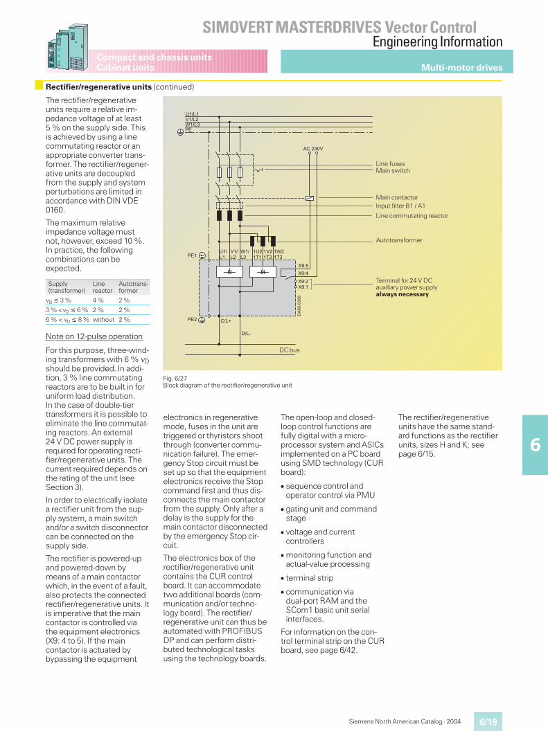
6/19
SIMOVERT MASTERDRIVES Vector ControlEngineering Information
6
Siemens North American Catalog · 2004
Compact and chassis unitsCabinet units Multi-motor drives
The rectifier/regenerativeunits require a relative im-pedance voltage of at least5 % on the supply side. Thisis achieved by using a linecommutating reactor or anappropriate converter trans-former. The rectifier/regener-ative units are decoupledfrom the supply and systemperturbations are limited inaccordance with DIN VDE0160.
The maximum relativeimpedance voltage mustnot, however, exceed 10 %.In practice, the followingcombinations can beexpected.
Supply(transformer)
Linereactor
Autotrans-former
vD � 3 % 4 % 2 %
3 % <vD � 6 % 2 % 2 %
6 % < vD � 8 % without 2 %
Note on 12-pulse operation
For this purpose, three-wind-ing transformers with 6 % vDshould be provided. In addi-tion, 3 % line commutatingreactors are to be built in foruniform load distribution.In the case of double-tiertransformers it is possible toeliminate the line commutat-ing reactors. An external24 V DC power supply isrequired for operating recti-fier/regenerative units. Thecurrent required depends onthe rating of the unit (seeSection 3).
In order to electrically isolatea rectifier unit from the sup-ply system, a main switchand/or a switch disconnectorcan be connected on thesupply side.
The rectifier is powered-upand powered-down bymeans of a main contactorwhich, in the event of a fault,also protects the connectedrectifier/regenerative units. Itis imperative that the maincontactor is controlled viathe equipment electronics(X9: 4 to 5). If the maincontactor is actuated bybypassing the equipment
Fig. 6/27Block diagram of the rectifier/regenerative unit
�������
��
��������������
���
���
����
����
����
����
�����
������
������
����
�����
�����
����
����
�����
DC bus
Main switch
Terminal for 24 V DCauxiliary power supplyalways necessary
Input filter B1 / A1Main contactor
Line commutating reactor
Line fuses
Autotransformer
Rectifier/regenerative units (continued)
electronics in regenerativemode, fuses in the unit aretriggered or thyristors shootthrough (converter commu-nication failure). The emer-gency Stop circuit must beset up so that the equipmentelectronics receive the Stopcommand first and thus dis-connects the main contactorfrom the supply. Only after adelay is the supply for themain contactor disconnectedby the emergency Stop cir-cuit.
The electronics box of therectifier/regenerative unitcontains the CUR controlboard. It can accommodatetwo additional boards (com-munication and/or techno-logy board). The rectifier/regenerative unit can thus beautomated with PROFIBUSDP and can perform distri-buted technological tasksusing the technology boards.
The open-loop and closed-loop control functions arefully digital with a micro-processor system and ASICsimplemented on a PC boardusing SMD technology (CURboard):
� sequence control andoperator control via PMU
� gating unit and commandstage
� voltage and currentcontrollers
� monitoring function andactual-value processing
� terminal strip
� communication viadual-port RAM and theSCom1 basic unit serialinterfaces.
For information on the con-trol terminal strip on the CURboard, see page 6/42.
The rectifier/regenerativeunits have the same stand-ard functions as the rectifierunits, sizes H and K; seepage 6/15.
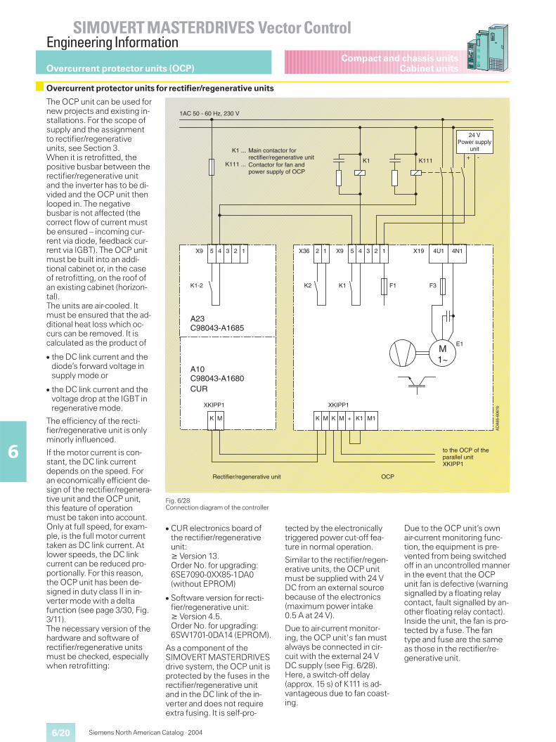
6/20
SIMOVERT MASTERDRIVES Vector ControlEngineering Information
6
Siemens North American Catalog · 2004
Compact and chassis unitsCabinet unitsOvercurrent protector units (OCP)
The OCP unit can be used fornew projects and existing in-stallations. For the scope ofsupply and the assignmentto rectifier/regenerativeunits, see Section 3.When it is retrofitted, thepositive busbar between therectifier/regenerative unitand the inverter has to be di-vided and the OCP unit thenlooped in. The negativebusbar is not affected (thecorrect flow of current mustbe ensured – incoming cur-rent via diode, feedback cur-rent via IGBT). The OCP unitmust be built into an addi-tional cabinet or, in the caseof retrofitting, on the roof ofan existing cabinet (horizon-tal).The units are air-cooled. Itmust be ensured that the ad-ditional heat loss which oc-curs can be removed. It iscalculated as the product of
� the DC link current and thediode’s forward voltage insupply mode or
� the DC link current and thevoltage drop at the IGBT inregenerative mode.
The efficiency of the recti-fier/regenerative unit is onlyminorly influenced.
If the motor current is con-stant, the DC link currentdepends on the speed. Foran economically efficient de-sign of the rectifier/regenera-tive unit and the OCP unit,this feature of operationmust be taken into account.Only at full speed, for exam-ple, is the full motor currenttaken as DC link current. Atlower speeds, the DC linkcurrent can be reduced pro-portionally. For this reason,the OCP unit has been de-signed in duty class II in in-verter mode with a deltafunction (see page 3/30, Fig.3/11).The necessary version of thehardware and software ofrectifier/regenerative unitsmust be checked, especiallywhen retrofitting:
Fig. 6/28Connection diagram of the controller
� CUR electronics board ofthe rectifier/regenerativeunit:� Version 13.Order No. for upgrading:6SE7090-0XX85-1DA0(without EPROM)
� Software version for recti-fier/regenerative unit:� Version 4.5.Order No. for upgrading:6SW1701-0DA14 (EPROM).
As a component of theSIMOVERT MASTERDRIVESdrive system, the OCP unit isprotected by the fuses in therectifier/regenerative unitand in the DC link of the in-verter and does not requireextra fusing. It is self-pro-
tected by the electronicallytriggered power cut-off fea-ture in normal operation.
Similar to the rectifier/regen-erative units, the OCP unitmust be supplied with 24 VDC from an external sourcebecause of the electronics(maximum power intake0.5 A at 24 V).
Due to air-current monitor-ing, the OCP unit's fan mustalways be connected in cir-cuit with the external 24 VDC supply (see Fig. 6/28).Here, a switch-off delay(approx. 15 s) of K111 is ad-vantageous due to fan coast-ing.
Due to the OCP unit’s ownair-current monitoring func-tion, the equipment is pre-vented from being switchedoff in an uncontrolled mannerin the event that the OCPunit fan is defective (warningsignalled by a floating relaycontact, fault signalled by an-other floating relay contact).Inside the unit, the fan is pro-tected by a fuse. The fantype and fuse are the sameas those in the rectifier/re-generative unit.
Overcurrent protector units for rectifier/regenerative units
+ -K1 K111
12 12345 4U1 4N1X19X9X3612345X9
K1-2 K2 K1 F1 F3
E1M1~
A23C98043-A1685
A10C98043-A1680
MK
XKIPP1
MK
XKIPP1
MK + M1K1
1AC 50 - 60 Hz, 230 V
K1 ...
K111 ...
DA
65-6
061b
CUR
Main contactor forrectifier/regenerative unitContactor for fan andpower supply of OCP
24 VPower supply
unit
to the OCP of theparallel unit XKIPP1
Rectifier/regenerative unit
A
OCP
6/21
SIMOVERT MASTERDRIVES Vector ControlEngineering Information
6
Siemens North American Catalog · 2004
Compact and chassis unitsCabinet units Overcurrent protector units (OCP)
A two-pole control cable(XKIPP1, see Fig. 6/28) mustbe laid between the CURelectronics board of the recti-fier/regenerative unit and thestall protection device.Apart from correct assign-ment of the OCP unit to therectifier/regenerative unit(rated current and rated volt-age) and correct connectionof the OCP unit, no furthersettings or adaptations haveto be carried out on the OCPunit.
Parallel connection ofsize K rectifier/regenera-tive units with OCP unit
� 6-pulse circuits:If rectifier/regenerativeunits are connected in par-allel, an OCP unit must beconnected between eachrectifier/regenerative unitand the DC link. Each of theparallel-connected unitsneeds its own OCP unit inthe cable leading to the DClink. The OCP units are tobe connected to each otherby means of control cablesbetween the XKIPP1 termi-nal strips.
� 12-pulse circuits:In the case of 12-pulse cir-cuits, it is also possible touse one OCP unit for bothrectifier/regenerative unitsprovided that the total ratedcurrent of the individualunits together does not ex-ceed the rated current ofthe OCP unit. In this case,however, it must be notedthat redundancy no longerexists if one rectifier/regen-erative unit fails, the reasonbeing that the failed unitswitches off the OCP unitvia terminals K and M.
Operation withnon-Siemens rectifier/regenerative units
The OCP unit was speciallydeveloped for line-commuta-ting rectifier/regenerativeunits of the SIMOVERTMASTERDRIVES drive sys-tem. A special advantage ofthe software of the recti-fier/regenerative unit is thatstalling of the inverter is de-tected at an early stage and aswitch-off signal is sent tothe OCP unit. In this way, for-mation of a high “stalling cur-rent“can be prevented innearly all cases.In exceptions, this signalmay be too slow. The IGBT isthen switched off by meansof its own VCE monitoringfunction, whereby higherovercurrents have to be han-dled which affect the voltagesurge suppressors and re-duces their lifetime.It can be assumed that, inthe case of non-Siemens rec-tifier/regenerative units, thisspecial software functiondoes not exist and there is ahigh switching load everytime the inverter stalls.Combination with anon-Siemens rectifier/regenerative unit is there-fore not advisable.
Overcurrent protector units for rectifier/regenerative units (continued)
6/22
SIMOVERT MASTERDRIVES Vector ControlEngineering Information
6
Siemens North American Catalog · 2004
Compact and chassis unitsSelf-commutated Active Front End AFE
AFE unit (Active Front End)
Function
The AFE unit's main compo-nents are a voltage sourceDC link converter with aCUSA control board. From athree-phase power supply, itgenerates a regulated DCvoltage, the so-called DC linkvoltage. This DC link voltageis kept almost constant irre-spective of the supply volt-age, even during regenera-tive operation.
On the three-phase side,a supply-angle-orientedhigh-speed vector controlleris subordinate to the DC linkvoltage controller. This vectorcontroller impresses analmost sinusoidal currenttowards the supply and, withthe help of the Clean Powerfilter, minimizes harmonics.
The vector controller also en-ables the power factor cos �and thus reactive powercompensation to be set,whereby the drive’s powerrequirement has priority.
The VSB board (VoltageSensing Board) functions asa supply-angle encoder andworks according to a princi-ple similar to that of an en-coder.
Caution!
AFE inverters are aligned in-versely to the supply and arenot capable of functioningautonomously. In order tofunction, they need at leastthe following system compo-nents:
For the compact units
� Precharger� Main contactor� AFE reactor� VSB voltage sensing board
For safety reasons, an AFErectifier/regenerative unitmust be connected to thesupply via a line contactor.An external 24 V powersupply is therefore alwaysnecessary for supplying theVSB board and the AFE in-verter.
For the chassis units
� AFE supply connectingmodule
This module contains aClean Power filter and alsomain circuit-breaker withfuses, the 230 V power sup-ply and 24 V power supply aswell as the VSB, prechargerand the main contactor.
Technical characteristics
Optimum infeed andregenerative feedback
SIMOVERT MASTERDRIVESAFE are 100 % capable ofregenerative power feedbackwithout the need for anauto-transformer. Even duringregenerative mode, powerlosses do not occur as is thecase with a braking resistor.The transition from motoringto regenerative mode is step-less, with pulse-frequencyresponse. The exactly regu-lated DC link voltage ensuresoptimum supply of the driveinverter, almost independ-ently of the supply voltage.
Minimal networkdisturbances thanks to AFEwith Clean Power technology
With SIMOVERTMASTERDRIVES AFE, har-monics and commutatingdips are avoided, except for avery small residue. Optimummatching between the elec-tronically controlled activesection (AFE inverter) andthe passive section (CleanPower filter) ensures that al-most sinusoidal voltages andcurrents are impressed inthe direction of the supply.Network disturbances practi-cally no longer occur.
Maximum availability even ifthe supply system is instable
With SIMOVERT MASTER-DRIVES AFE, it is possible tointentionally operate a drivesystem reliably irrespectiveof the properties displayedby the power supply, i.e.active protection againstpower outages, overvolt-ages, frequency and voltagefluctuations by means ofAFE vector control andhigh-speed electronic moni-toring. The downstreamClean Power filter providesoptimum passive protectionagainst transient powerpeaks.
If the voltage moves outsidethe permissible range or if itfails completely, the electron-ics reports the problem im-mediately and the AFE dis-connects the drive from thesupply by actively switching itoff. As a consequence, in-verter commutation failurewith fuse tripping can no lon-ger occur even during regen-erative mode. The back volt-age of the AFE inverter to thesupply is impressed with ahigh control and pulse fre-quency and tolerates evenvery short power interrup-tions in the millisecond range.In the case of single-phasepower dips, the controllerdistributes the power to theother two phases and cancontinue to work for seconds.
Power spectrum
AFE compact units AFE chassis units AFE cabinet units
Infeed rating 6.8 kW to 49 kW at 400 V 63 kW to 250 kW at 400 V51 kW to 192 kW at 500 V70 kW to 245 kW at 690 V
Standard cabinet unit37 kW to 1200 kWApplication1200 kW to 6000 kW
Design Compact A to D Chassis E to G –
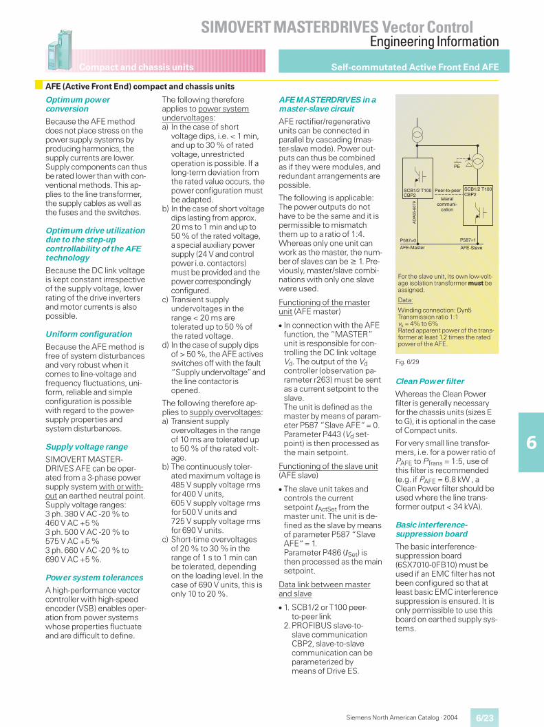
6/23
SIMOVERT MASTERDRIVES Vector ControlEngineering Information
6
Compact and chassis units
Siemens North American Catalog · 2004
Self-commutated Active Front End AFE
AFE (Active Front End) compact and chassis units
Optimum powerconversion
Because the AFE methoddoes not place stress on thepower supply systems byproducing harmonics, thesupply currents are lower.Supply components can thusbe rated lower than with con-ventional methods. This ap-plies to the line transformer,the supply cables as well asthe fuses and the switches.
Optimum drive utilizationdue to the step-upcontrollability of the AFEtechnology
Because the DC link voltageis kept constant irrespectiveof the supply voltage, lowerrating of the drive invertersand motor currents is alsopossible.
Uniform configuration
Because the AFE method isfree of system disturbancesand very robust when itcomes to line-voltage andfrequency fluctuations, uni-form, reliable and simpleconfiguration is possiblewith regard to the power-supply properties andsystem disturbances.
Supply voltage range
SIMOVERT MASTER-DRIVES AFE can be oper-ated from a 3-phase powersupply system with or with-out an earthed neutral point.Supply voltage ranges:3 ph. 380 V AC -20 % to460 V AC +5 %3 ph. 500 V AC -20 % to575 V AC +5 %3 ph. 660 V AC -20 % to690 V AC +5 %.
Power system tolerances
A high-performance vectorcontroller with high-speedencoder (VSB) enables oper-ation from power systemswhose properties fluctuateand are difficult to define.
The following thereforeapplies to power systemundervoltages:a) In the case of short
voltage dips, i.e. < 1 min,and up to 30 % of ratedvoltage, unrestrictedoperation is possible. If along-term deviation fromthe rated value occurs, thepower configuration mustbe adapted.
b) In the case of short voltagedips lasting from approx.20 ms to 1 min and up to50 % of the rated voltage,a special auxiliary powersupply (24 V and controlpower i.e. contactors)must be provided and thepower correspondinglyconfigured.
c) Transient supplyundervoltages in therange < 20 ms aretolerated up to 50 % ofthe rated voltage.
d) In the case of supply dipsof > 50 %, the AFE activesswitches off with the fault“Supply undervoltage”andthe line contactor isopened.
The following therefore ap-plies to supply overvoltages:a) Transient supply
overvoltages in the rangeof 10 ms are tolerated upto 50 % of the rated volt-age.
b) The continuously toler-ated maximum voltage is485 V supply voltage rmsfor 400 V units,605 V supply voltage rmsfor 500 V units and725 V supply voltage rmsfor 690 V units.
c) Short-time overvoltagesof 20 % to 30 % in therange of 1 s to 1 min canbe tolerated, dependingon the loading level. In thecase of 690 V units, this isonly 10 to 20 %.
AFE MASTERDRIVES in amaster-slave circuit
AFE rectifier/regenerativeunits can be connected inparallel by cascading (mas-ter-slave mode). Power out-puts can thus be combinedas if they were modules, andredundant arrangements arepossible.
The following is applicable:The power outputs do nothave to be the same and it ispermissible to mismatchthem up to a ratio of 1:4.Whereas only one unit canwork as the master, the num-ber of slaves can be � 1. Pre-viously, master/slave combi-nations with only one slavewere used.
Functioning of the masterunit (AFE master)
� In connection with the AFEfunction, the “MASTER”unit is responsible for con-trolling the DC link voltageVd. The output of the Vdcontroller (observation pa-rameter r263) must be sentas a current setpoint to theslave.The unit is defined as themaster by means of param-eter P587 “Slave AFE“= 0.Parameter P443 (Vd set-point) is then processed asthe main setpoint.
Functioning of the slave unit(AFE slave)
� The slave unit takes andcontrols the currentsetpoint IActSet from themaster unit. The unit is de-fined as the slave by meansof parameter P587 “SlaveAFE“= 1.Parameter P486 (ISet) isthen processed as the mainsetpoint.
Data link between masterand slave
� 1. SCB1/2 or T100 peer-to-peer link
2.PROFIBUS slave-to-slave communicationCBP2, slave-to-slavecommunication can beparameterized bymeans of Drive ES.
Clean Power filter
Whereas the Clean Powerfilter is generally necessaryfor the chassis units (sizes Eto G), it is optional in the caseof Compact units.
For very small line transfor-mers, i.e. for a power ratio ofPAFE to PTrans = 1:5, use ofthis filter is recommended(e.g. if PAFE = 6.8 kW , aClean Power filter should beused where the line trans-former output < 34 kVA).
Basic interference-suppression board
The basic interference-suppression board(6SX7010-0FB10) must beused if an EMC filter has notbeen configured so that atleast basic EMC interferencesuppression is ensured. It isonly permissible to use thisboard on earthed supply sys-tems.
Fig. 6/29
For the slave unit, its own low-volt-age isolation transformer must beassigned.
Data:
Winding connection: Dyn5Transmission ratio 1:1vk = 4% to 6%Rated apparent power of the trans-former at least 1.2 times the ratedpower of the AFE.
PE
CBP2SCB1/2 T100CBP2
P587=1P587=0
SCB1/2 T100
DA
65-6
079
Peer-to-peer
AFE-Master AFE-Slave
lateralcommuni-
cation
A
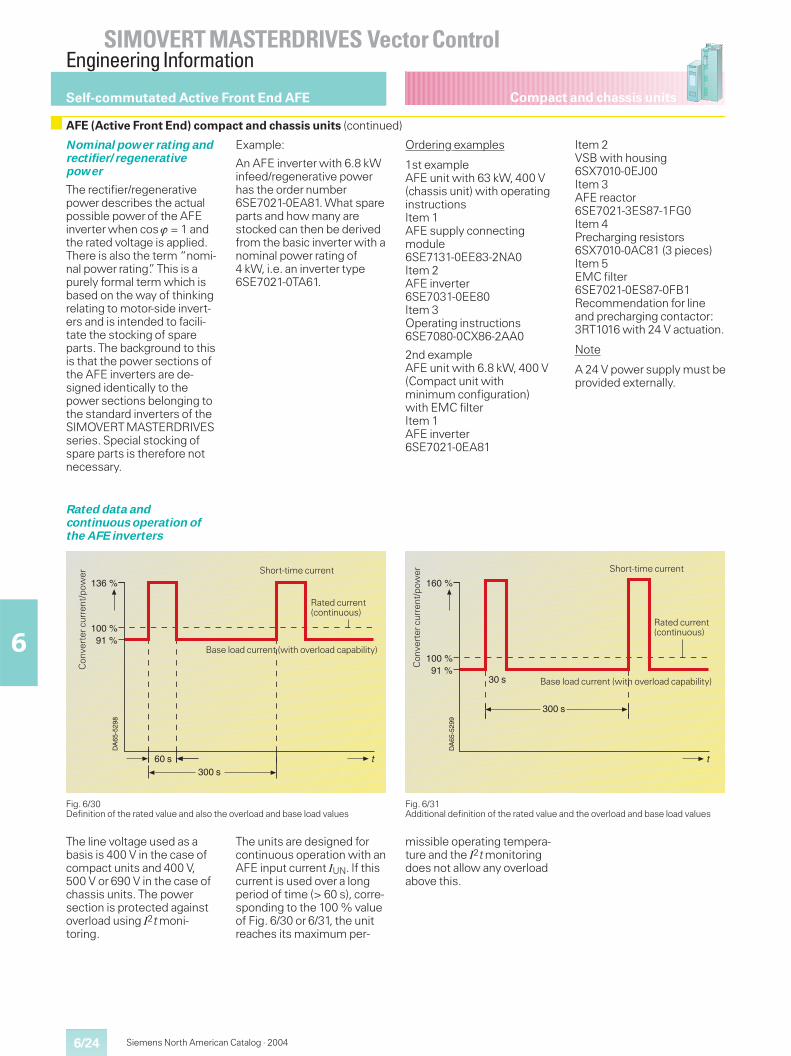
6/24
SIMOVERT MASTERDRIVES Vector ControlEngineering Information
6
Siemens North American Catalog · 2004
Compact and chassis unitsSelf-commutated Active Front End AFE
Nominal power rating andrectifier/regenerativepower
The rectifier/regenerativepower describes the actualpossible power of the AFEinverter when cos � = 1 andthe rated voltage is applied.There is also the term “nomi-nal power rating”. This is apurely formal term which isbased on the way of thinkingrelating to motor-side invert-ers and is intended to facili-tate the stocking of spareparts. The background to thisis that the power sections ofthe AFE inverters are de-signed identically to thepower sections belonging tothe standard inverters of theSIMOVERT MASTERDRIVESseries. Special stocking ofspare parts is therefore notnecessary.
Example:
An AFE inverter with 6.8 kWinfeed/regenerative powerhas the order number6SE7021-0EA81. What spareparts and how many arestocked can then be derivedfrom the basic inverter with anominal power rating of4 kW, i.e. an inverter type6SE7021-0TA61.
Ordering examples
1st exampleAFE unit with 63 kW, 400 V(chassis unit) with operatinginstructionsItem 1AFE supply connectingmodule6SE7131-0EE83-2NA0Item 2AFE inverter6SE7031-0EE80Item 3Operating instructions6SE7080-0CX86-2AA0
2nd exampleAFE unit with 6.8 kW, 400 V(Compact unit withminimum configuration)with EMC filterItem 1AFE inverter6SE7021-0EA81
Item 2VSB with housing6SX7010-0EJ00Item 3AFE reactor6SE7021-3ES87-1FG0Item 4Precharging resistors6SX7010-0AC81 (3 pieces)Item 5EMC filter6SE7021-0ES87-0FB1Recommendation for lineand precharging contactor:3RT1016 with 24 V actuation.
Note
A 24 V power supply must beprovided externally.
The line voltage used as abasis is 400 V in the case ofcompact units and 400 V,500 V or 690 V in the case ofchassis units. The powersection is protected againstoverload using I2t moni-toring.
The units are designed forcontinuous operation with anAFE input current IUN. If thiscurrent is used over a longperiod of time (> 60 s), corre-sponding to the 100 % valueof Fig. 6/30 or 6/31, the unitreaches its maximum per-
missible operating tempera-ture and the I2t monitoringdoes not allow any overloadabove this.
Rated data andcontinuous operation ofthe AFE inverters
Fig. 6/30Definition of the rated value and also the overload and base load values
Fig. 6/31Additional definition of the rated value and the overload and base load values
DA
65-5
298
136 %
100 %91 %
60 s300 s
t
Con
vert
ercu
rren
t/po
wer
Base load current (with overload capability)
Short-time current
Rated current(continuous)
DA
65-5
299
160 %
100 %91 %
30 s
300 s
t
Con
vert
ercu
rren
t/po
wer
Base load current (with overload capability)
Short-time current
Rated current(continuous)
AFE (Active Front End) compact and chassis units (continued)
6/25
SIMOVERT MASTERDRIVES Vector ControlEngineering Information
6
Compact and chassis units
Siemens North American Catalog · 2004
Self-commutated Active Front End AFE
AFE (Active Front End) compact and chassis units (continued)
Overload capability of theAFE inverters
For explanations, see “Over-load capability of the con-verter”(see page 6/2).
Installation conditions andcorrection factors
For explanations, seepage 6/3.
AFE inverters with a largepower output
AFE inverters can be con-nected in parallel for increas-ing the power output. Forconfiguration, please contactyour local sales office.The largest cabinet unit hasa nominal power rating of1200 kW at 690 V.The largest chassis unit hasa nominal power rating of200 kW at 690 V supply volt-age.The largest compact unithas a nominal power ratingof 37 kW at 400 V.
Water-cooled AFEinvertersCooling circuit
For explanations, see pages6/4 and 6/5.
Notes on dimensioning ofthe AFE power
Due to the sinusoidal, pre-cisely controlled voltagesand currents, SIMOVERTMASTERDRIVES AFE canbe designed very simply andreliably.
The following applies:PAFE = 1.73 · VSupply · IAFE =Pmech + PLosses
The power loss is deter-mined by the efficiency ofthe inverters and the motor.The mechanical power, i.e.the product of the motortorque and the motor speed,is defined by the application.What is decisive for dimen-sioning, therefore, is thepower and not the torque asis the case with drive invert-ers. One or several inverterscan be connected to the out-put. The maximum power ofthe connected inverters canbe 4 times the rated powerof the AFE inverter. The sumof the power taken from thesupply is not permitted tocontinuously exceed therated power of the AFE in-verter.
Methods of operation andcontrol
There are several ways ofoperating and controlling theunit:
� via the PMUparameterizing unit
� via an optional OP1Soperator panel
� via the terminal strip
� via a serial interface.
In combination with automa-tion systems, the unit is con-trolled via optional interfaces(e.g. PROFIBUS DP) or viatechnology boards (T100,T300).
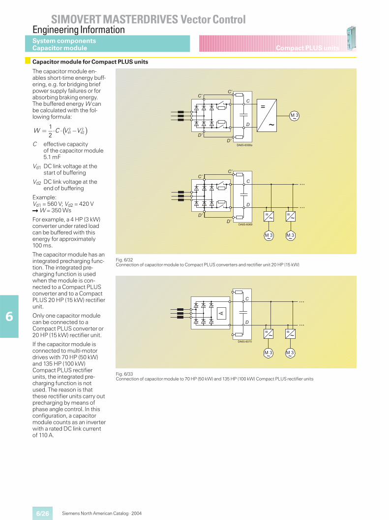
6/26
SIMOVERT MASTERDRIVES Vector ControlEngineering Information
6
Siemens North American Catalog · 2004
Compact PLUS unitsSystem componentsCapacitor module
Capacitor module for Compact PLUS units
The capacitor module en-ables short-time energy buff-ering, e.g. for bridging briefpower supply failures or forabsorbing braking energy.The buffered energy W canbe calculated with the fol-lowing formula:
C effective capacityof the capacitor module5.1 mF
Vd1 DC link voltage at thestart of buffering
Vd2 DC link voltage at theend of buffering
Example:Vd1 = 560 V; Vd2 = 420 V�W = 350 Ws
For example, a 4 HP (3 kW)converter under rated loadcan be buffered with thisenergy for approximately100 ms.
The capacitor module has anintegrated precharging func-tion. The integrated pre-charging function is usedwhen the module is con-nected to a Compact PLUSconverter and to a CompactPLUS 20 HP (15 kW) rectifierunit.
Only one capacitor modulecan be connected to aCompact PLUS converter or20 HP (15 kW) rectifier unit.
If the capacitor module isconnected to multi-motordrives with 70 HP (50 kW)and 135 HP (100 kW)Compact PLUS rectifierunits, the integrated pre-charging function is notused. The reason is thatthese rectifier units carry outprecharging by means ofphase angle control. In thisconfiguration, a capacitormodule counts as an inverterwith a rated DC link currentof 110 A.
Fig. 6/32Connection of capacitor module to Compact PLUS converters and rectifier unit 20 HP (15 kW)
Fig. 6/33Connection of capacitor module to 70 HP (50 kW) and 135 HP (100 kW) Compact PLUS rectifier units
� �� � � 2 2d1 d2
12
W C V V
+*�������
����
����
�
�
<=
���=
<=
���=
111
111
+*�������
�
�
<=
���=
<=
���=
111
111
����
����
�
�
<
=���=
+*�������
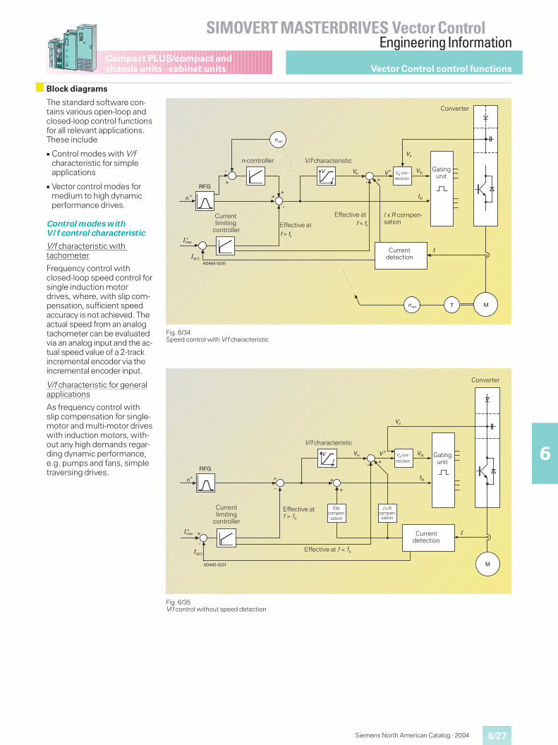
6/27
SIMOVERT MASTERDRIVES Vector ControlEngineering Information
6
Compact PLUS/compact andchassis units · cabinet units
Siemens North American Catalog · 2004
The standard software con-tains various open-loop andclosed-loop control functionsfor all relevant applications.These include
� Control modes with V/fcharacteristic for simpleapplications
� Vector control modes formedium to high dynamicperformance drives.
Control modes withV/f control characteristic
V/f characteristic withtachometer
Frequency control withclosed-loop speed control forsingle induction motordrives, where, with slip com-pensation, sufficient speedaccuracy is not achieved. Theactual speed from an analogtachometer can be evaluatedvia an analog input and the ac-tual speed value of a 2-trackincremental encoder via theincremental encoder input.
V/f characteristic for generalapplications
As frequency control withslip compensation for single-motor and multi-motor driveswith induction motors, with-out any high demands regar-ding dynamic performance,e.g. pumps and fans, simpletraversing drives.
Fig. 6/34Speed control with V/f characteristic
Fig. 6/35V/f control without speed detection
++
-
*
�
*
MT
+
-
-
*�max
+
act
DA65-5230
m
RFG
act
A
Iact.
Currentlimiting
controllerEffective at
Effective at
V/f characteristic
Vd cor-rection
I x R compen-sation
Currentdetection
Gatingunit
Converter
n-controller
+
+
*
*
M
-
*
+
-+
+
-
DA65-5231
RFG
A
Iact.
Currentlimiting
controller
Effective atf > fs
Effective at f < fs
V/f characteristic
Slipcompen-
sation
I x Rcompen-
sation
Currentdetection
Gatingunit
Vd cor-rection
Converter
Vector Control control functions
Block diagrams
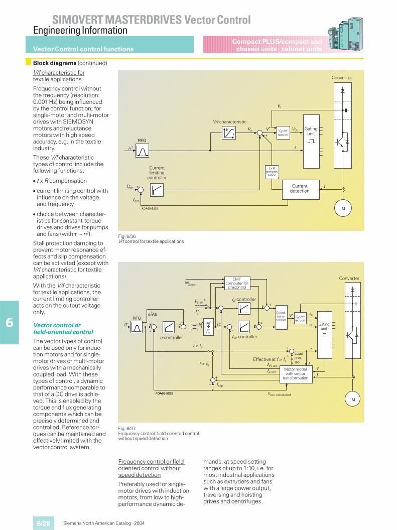
6/28
SIMOVERT MASTERDRIVES Vector ControlEngineering Information
6
Siemens North American Catalog · 2004
Compact PLUS/compact andchassis units · cabinet units
V/f characteristic fortextile applications
Frequency control withoutthe frequency (resolution:0.001 Hz) being influencedby the control function; forsingle-motor and multi-motordrives with SIEMOSYNmotors and reluctancemotors with high speedaccuracy, e.g. in the textileindustry.
These V/f characteristictypes of control include thefollowing functions:
� I x R compensation
� current limiting control withinfluence on the voltageand frequency
� choice between character-istics for constant-torquedrives and drives for pumpsand fans (with � ~ n²).
Stall protection damping toprevent motor resonance ef-fects and slip compensationcan be activated (except withV/f characteristic for textileapplications).
With the V/f characteristicfor textile applications, thecurrent limiting controlleracts on the output voltageonly.
Vector control orfield-oriented control
The vector types of controlcan be used only for induc-tion motors and for single-motor drives or multi-motordrives with a mechanicallycoupled load. With thesetypes of control, a dynamicperformance comparable tothat of a DC drive is achie-ved. This is enabled by thetorque and flux generatingcomponents which can beprecisely determined andcontrolled. Reference tor-ques can be maintained andeffectively limited with thevector control system.
Frequency control or field-oriented control withoutspeed detection
Preferably used for single-motor drives with inductionmotors, from low to high-performance dynamic de-
mands, at speed settingranges of up to 1:10, i.e. formost industrial applicationssuch as extruders and fanswith a large power output,traversing and hoistingdrives and centrifuges.
Fig. 6/36V/f control for textile applications
Fig. 6/37Frequency control: field-oriented controlwithout speed detection
+
*
*
M
-
*
-+
.
DA65-5232
RFG
A
Iact.
Currentlimiting
controller
V/f characteristic
Currentdetection
Gatingunit
Vd cor-rection
VSt
Converter
Vector Control control functions
M
++
*
-
+
+
+
+ +
-
-
+ +
+ *M *
*
*
*M*
M
+
DA65-5228
�
RFG
DA65-5228
*
A
EMFcomputer for
precontrol
n-controller
Effective at f > fs
Vd cor-rection
Coord.trans-former
Motor modelwith vector
transformation
Gatingunit
ConverterAccel.
fslip
Loadcon-trolIW act.
I� act.
IStart*
f < fs
f > fs
nact. calculated
VSt
Block diagrams (continued)
IW-controller
I�-controller
I x Rcompen-
sation
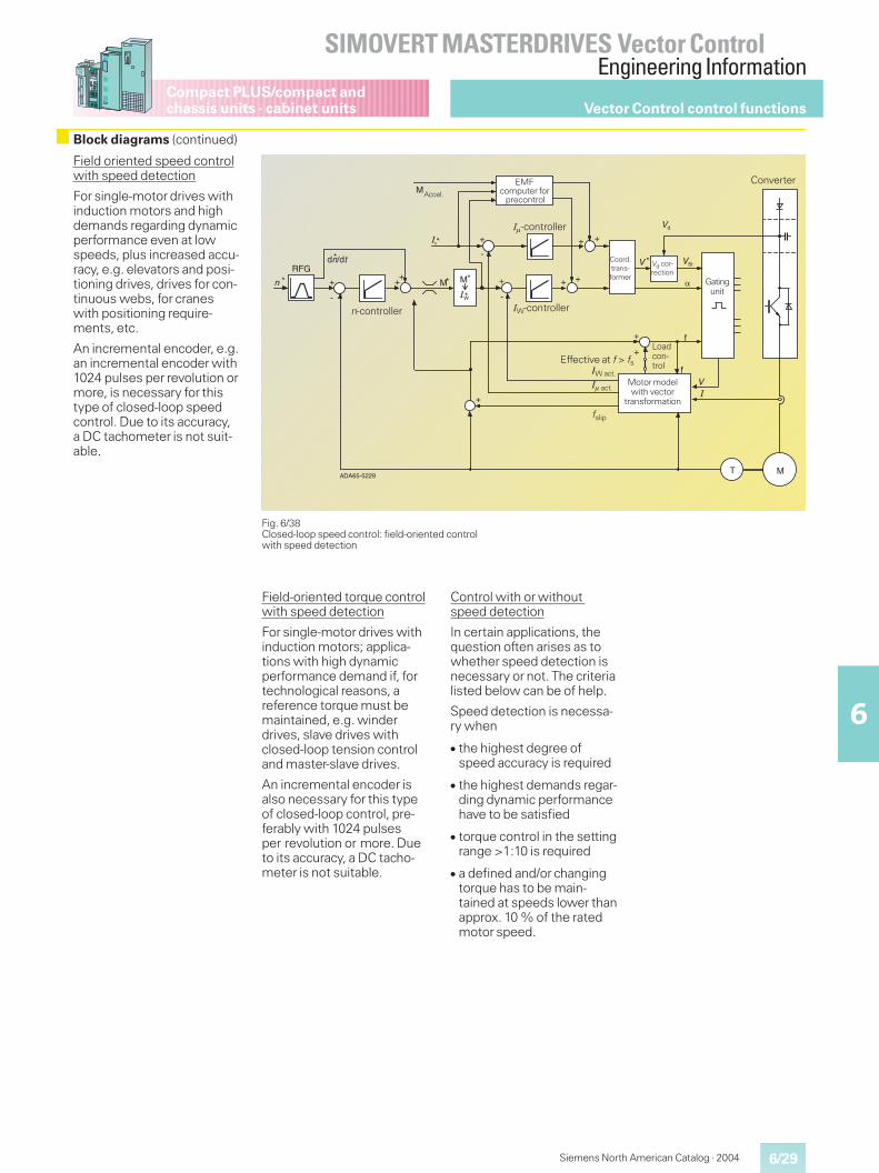
6/29
SIMOVERT MASTERDRIVES Vector ControlEngineering Information
6
Compact PLUS/compact andchassis units · cabinet units
Siemens North American Catalog · 2004
Field oriented speed controlwith speed detection
For single-motor drives withinduction motors and highdemands regarding dynamicperformance even at lowspeeds, plus increased accu-racy, e.g. elevators and posi-tioning drives, drives for con-tinuous webs, for craneswith positioning require-ments, etc.
An incremental encoder, e.g.an incremental encoder with1024 pulses per revolution ormore, is necessary for thistype of closed-loop speedcontrol. Due to its accuracy,a DC tachometer is not suit-able.
Field-oriented torque controlwith speed detection
For single-motor drives withinduction motors; applica-tions with high dynamicperformance demand if, fortechnological reasons, areference torque must bemaintained, e.g. winderdrives, slave drives withclosed-loop tension controland master-slave drives.
An incremental encoder isalso necessary for this typeof closed-loop control, pre-ferably with 1024 pulsesper revolution or more. Dueto its accuracy, a DC tacho-meter is not suitable.
Control with or withoutspeed detection
In certain applications, thequestion often arises as towhether speed detection isnecessary or not. The criterialisted below can be of help.
Speed detection is necessa-ry when
� the highest degree ofspeed accuracy is required
� the highest demands regar-ding dynamic performancehave to be satisfied
� torque control in the settingrange >1:10 is required
� a defined and/or changingtorque has to be main-tained at speeds lower thanapprox. 10 % of the ratedmotor speed.
Fig. 6/38Closed-loop speed control: field-oriented controlwith speed detection
++
*
-
+
+
+
+ +
-
-
+ +
+ *M
*
*
*M
f
f
* +
MT
M
+
DA65-5229
RFG
A
EMFcomputer for
precontrol
n-controller
Effective at f > fs
IW-controller
Coord.trans-former
Motor modelwith vector
transformation
Gatingunit
ConverterAccel.
fslip
I�-controller
Loadcon-trolIW act.
I� act.
Vector Control control functions
Block diagrams (continued)
Vd cor-rection
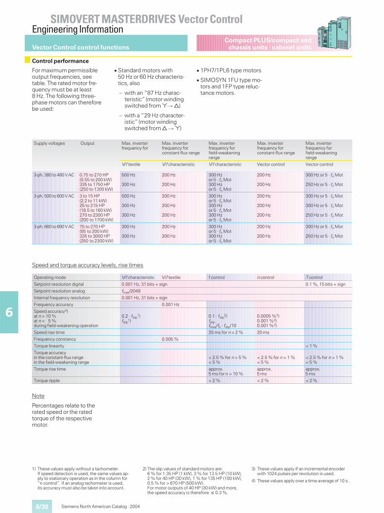
6/30
SIMOVERT MASTERDRIVES Vector ControlEngineering Information
6
Siemens North American Catalog · 2004
Compact PLUS/compact andchassis units · cabinet units
Supply voltages Output Max. inverterfrequency for
Max. inverterfrequency forconstant-flux range
Max. inverterfrequency forfield-weakeningrange
Max. inverterfrequency forconstant-flux range
Max. inverterfrequency forfield-weakeningrange
V/f textile V/f characteristic V/f characteristic Vector control Vector control
3-ph. 380 to 480 V AC 0.75 to 270 HP(0.55 to 200 kW)335 to 1750 HP(250 to 1300 kW)
500 Hz
300 Hz
200 Hz
200 Hz
300 Hzor 5 · fn Mot300 Hzor 5 · fn Mot
200 Hz
200 Hz
300 Hz or 5 · fn Mot
250 Hz or 5 · fn Mot
3-ph. 500 to 600 V AC 3 to 15 HP(2.2 to 11 kW)25 to 215 HP(18.5 to 160 kW)270 to 2300 HP(200 to 1700 kW)
500 Hz
300 Hz
300 Hz
200 Hz
200 Hz
200 Hz
300 Hzor 5 · fn Mot300 Hzor 5 · fn Mot300 Hzor 5 · fn Mot
200 Hz
200 Hz
200 Hz
300 Hz or 5 · fn Mot
300 Hz or 5 · fn Mot
250 Hz or 5 · fn Mot
3-ph. 660 to 690 V AC 75 to 270 HP(55 to 200 kW)335 to 3000 HP(250 to 2300 kW)
300 Hz
300 Hz
200 Hz
200 Hz
300 Hzor 5 · fn Mot300 Hzor 5 · fn Mot
200 Hz
200 Hz
300 Hz or 5 · fn Mot
250 Hz or 5 · fn Mot
Speed and torque accuracy levels, rise times
Operating mode V/f characteristic V/f textile f control n control T control
Setpoint resolution digital 0.001 Hz, 31 bits + sign 0.1 %, 15 bits + sign
Setpoint resolution analog fmax/2048
Internal frequency resolution 0.001 Hz, 31 bits + sign
Frequency accuracy 0.001 Hz
Speed accuracy4)at n > 10 %at n < 5 %during field-weakening operation
0.2 · fslip1)
fslip1)
0.1 · fslip2)
fslipfmax/fn · fslip/10
0.0005 %3)0.001 %3)0.001 %3)
Speed rise time 25 ms for n > 2 % 20 ms
Frequency constancy 0.005 %
Torque linearity < 1 %
Torque accuracyin the constant-flux rangein the field-weakening range
< 2.5 % for n > 5 %< 5 %
< 2.5 % for n > 1 %< 5 %
< 2.5 % for n > 1 %< 5 %
Torque rise time approx.5 ms for n > 10 %
approx.5 ms
approx.5 ms
Torque ripple < 2 % < 2 % < 2 %
Note
Percentages relate to therated speed or the ratedtorque of the respectivemotor.
For maximum permissibleoutput frequencies, seetable. The rated motor fre-quency must be at least8 Hz. The following three-phase motors can thereforebe used:
� Standard motors with50 Hz or 60 Hz characteris-tics, also
– with an “87 Hz charac-teristic”(motor windingswitched from*( B)
– with a “29 Hz character-istic”(motor windingswitched from B (*)
� 1PH7/1PL6 type motors
� SIMOSYN 1FU type mo-tors and 1FP type reluc-tance motors.
1) These values apply without a tachometer.If speed detection is used, the same values ap-ply to stationary operation as in the column for“n control”. If an analog tachometer is used,its accuracy must also be taken into account.
2) The slip values of standard motors are:6 % for 1.35 HP (1 kW), 3 % for 13.5 HP (10 kW),2 % for 40 HP (30 kW), 1 % for 135 HP (100 kW),0.5 % for > 670 HP (500 kW).For motor outputs of 40 HP (30 kW) and more,the speed accuracy is therefore � 0.3 %.
3) These values apply if an incremental encoderwith 1024 pulses per revolution is used.
4) These values apply over a time average of 10 s.
Vector Control control functions
Control performance
6/31
SIMOVERT MASTERDRIVES Vector ControlEngineering Information
6
Compact PLUS/compact andchassis units · cabinet units
Siemens North American Catalog · 2004
With SIMOVERT MASTER-DRIVES Vector Control units,an incremental encoder canbe evaluated in the standardunit.
Incremental encoders withthe following specificationscan be connected:
� HTL encoder with 2 tracksoffset by 90°
� Supply voltage V = 11 V to30 V
� HTL level: H � 8 V; L � 3 V
� Input current:approx. 3.5 mA at 15 V
� Number of incrementswhich can be evaluated60 – 10000 pulses perrevolution
� Limit frequency:fmax = 400 kHz.
The base unit has a supplyvoltage for the encoder witha load capability of 190 mA.
The SBP option board isused for evaluating TTLencoders. The SBP boardcan also evaluate unipolarand bipolar HTL levelencoders. The DTI adapterboard (can only be used to-gether with compact andchassis units) enables float-ing connection of the en-coder.
The following softwarefunctions are provided in thestandard unit:
BICO data sets(standard/reserve setting)
logically combine processdata (setpoints and open-loop control functions). Inother words, they enable,for example, switching frommanual operation to auto-matic operation (internal/external) between twosources, e.g. between theoperator control panel (termi-nal strip, interfaces, dual portRAM) and the terminal strip(interfaces, dual port RAM,operator control panel).
Setpoint input
The sum of the main set-points and the supplemen-tary setpoints can be used.The setpoints can beentered either internally orexternally. Internally as thefixed setpoint, motorized-potentiometer setpoint orinching setpoint, externallyvia the analog input, theserial interfaces or the optionboards. The internal fixedsetpoints and the motorized-potentiometer setpoint canbe toggled or adjusted bymeans of control commandsfrom all interfaces.
Function data sets FDS(setpoint data sets SDS)
The control function includes4 setpoint data sets whichcan be toggled. These datasets each include, for exam-ple, 4 fixed setpoints, asuppression bandwidth forresonance frequencies, aminimum frequency and aset of ramp-function genera-tor data. This allows the con-trol function to be adapted todifferent setpoints or othertechnical requirements. Theramp-function generator, forexample, provides separate-ly adjustable ramp-up andramp-down times, initial andfinal rounding-off times andadjustable waiting timesduring braking.
Technology controllers
e.g. for pressure or powercontrol.
Motor data set (MDS)
This control function includes4 motor data sets so that theopen-loop and closed-loopcontrol parameters canbe stored and selected fordifferent motors. One ormore different motors withdifferent control modes canthus be operated. When achangeover is made to the“Ready”status, the controldata are adapted to theparameterized operatingdata of the motor.
Motor identification
The open-loop and closed-loop control parameters arepre-assigned with the help ofthe parameterized converterand motor data. The sub-sequently executed DC andno-load measurementoptimizes the parametersettings using these mea-surement results. This func-tion allows the drives to beboth quickly and simply opti-mized.
Vd max controller
This controller adjusts thefrequency when the DC linkvoltage is too high, e.g. if theset ramp-down time is tooshort, the drive converterdoes not go into fault condi-tion but increases the ramp-down time.
Automatic restart
This restarts the drive whenthe power returns following apower failure; there is notime limit.
Kinetic buffering
This buffers power failures ordips as long as the drive ki-netic energy is large enough.
Restart-on-the-fly
This function allows theSIMOVERT MASTERDRIVESVector Control to be con-nected to a rotating motor.
DC current braking
This permits occasional brak-ing without the need for apulsed resistor or regenera-tive feedback. The DC brak-ing activation point can beparameterized along theramp-down ramp.
Converter-convertersynchronization(not for Compact PLUS)
enables motors or motorgroups to be switched fromone converter/inverter toanother. The overlappingchangeover is via an outputreactor. The TSY board isnecessary for this function.
Evaluation of motortemperature sensors
KTY84 for alarms andtripping or thermistor foralarms or tripping.
Wobble generator
with triangular wobble pat-tern, adjustable P steps anda synchronizing input andoutput for traversing drives inthe textile industry.
Brake operation
With this function, brakes fit-ted to the motor or externalbrakes can be operated.Parameterizable values aree.g. threshold values anddelay times for the closingand opening of the brakes.
Vector Control control functions
Software functionsIncremental encoderevaluation
6/32
SIMOVERT MASTERDRIVES Vector ControlEngineering Information
6
Siemens North American Catalog · 2004
Compact PLUS/compact andchassis units · cabinet units
Free function blocks with BICO system
Safe Stop
The “Safe Stop”function forSIMOVERT MASTER-DRIVES is a “device foravoiding unexpected start-ing”according to EN 60204-1, Section 5.4. In combi-nation with an external cir-cuit, the “Safe Stop”func-tion for SIMOVERT MASTER-DRIVES has been certifiedby the professional associa-tion in accordance withEN 954-1 Safety Category 3.With the “Safe Stop”func-tion, motor-side contactorsas a second switch-off pathcan be dispensed with.
The “Safe Stop” functionprevents unexpected star-ting of the connected motorfrom standstill. The “SafeStop” is only to be activatedwhen the drive is at standstillbecause, otherwise, it losesits ability to brake the motor.
The “Safe Stop” function isintegrated in compact invert-ers 510 V to 650 V DC and675 V to 810 V DC and isavailable for Compact PLUSand chassis units (convertersand inverters) as option K80.
Method of functioning
The safety relay with posi-tively driven contacts usesthe NO contact to interruptthe power supply to theoptocoupler/fiber-optic cableand thus prevents pulsing ofthe power section for buil-ding up a phase sequence.
The NC contact (= checkbackcontact) is used to report theswitching status of thesafety relay to the externalcontrol unit. The checkbackcontact of the safety relayalways has to be evaluatedand can be used for directlytriggering a second switch-off path as shown inFig. 6/40. The “Safe Stop”function is to be activatedbefore the protective deviceis opened. If the NO contactof the safety relay is stuck,the checkback contact of theK2 main contactor switchesoff. The circuit in Fig. 6/40assumes that the operatortriggers the protective de-vice at regular intervals. Thischecks the effectiveness ofthe switch-off paths.
Fig. 6/39Basic circuit of the “Safe Stop”function(terminal designation applies to chassis unit with option K80)
������
��
��
�
����
�%
� �
��
&����
���
$�
���
��
�
�
������"���
$ Triggering amplifier% Optocoupler or fiber-optic
cable
DE DI digital input
S1 NO contact for canceling the“Safe Stop”function (instal-lation side)
K1 Safety relay
In the software of the baseunits, there are functionblocks which can be“softwired”as required withthe help of the “BICO sys-tem”. The user is thereforeable to tailor theMASTERDRIVES exactly tothe task to be solved.
Data between the functionblocks as well as with theavailable control variablessuch as actual values andsetpoints is exchanged via“plug-in connectors”whichare designated either asbinectors (for binary signals)or connectors (for analog sig-nals as a 16 or 32 bit word),depending on the type ofsignal to be transmitted.BICO system = Binector-Connector system.
As freely usable functionblocks, the following areavailable (with influence onthe computing time):
� General function blocks
Fixed setpointsIndicator blocksConverter blocksDiagnostic blocks
� Arithmetic and controlblocks
Adders, subtractersMultipliers, dividersAbsolute-value generatorswith filteringSign invertersLimiters, limit-value monitorsMinimum, maximumselectionTimersPolygon curve characteristicsStorage elements
� Logic blocks
AND elementsOR elementsEXCLUSIVE OR elementsInvertersNAND elementsRS storage elementsD storage elementsTimers, pulse generator
� Complex blocks
Ramp-function generator,software counterPID controllerWobble generatorBrake control
Note
Refer to the Compendium fora complete list and descrip-tion of the blocks.
Control board
ASICwith
triggerlogic
Vector Control control functions
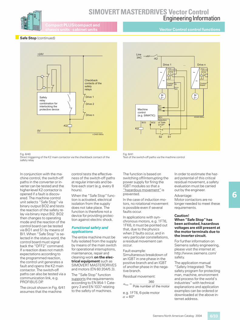
6/33
SIMOVERT MASTERDRIVES Vector ControlEngineering Information
6
Compact PLUS/compact andchassis units · cabinet units
Siemens North American Catalog · 2004
Safe Stop (continued)
Fig. 6/41Test of the switch-off paths via the machine control
Fig. 6/40Direct triggering of the K2 main contactor via the checkback contact of thesafety relay
In conjunction with the ma-chine control, the switch-offpaths in the converter or in-verter can be tested and thehigher-level K2 contactor isopened if a fault is discov-ered. The machine controlunit selects “Safe Stop”viabinary output BO2 and teststhe reaction of the safety re-lay via binary input BI2. BO2then changes to operatingmode and the reaction of thecontrol board can be testedvia BO1 and S1 by means ofBI1. When “Safe Stop”is se-lected in the status word, thecontrol board must signalback the “OFF2”command.If a reaction does not matchexpectations according tothe programmed reaction,the control unit generates afault and opens the K2 maincontactor. The switch-offpaths can also be tested via acommunication link, e.g.PROFIBUS DP.
The circuit shown in Fig. 6/41assumes that the machine
control tests the effective-ness of the switch-off pathsat regular intervals and be-fore each start (e.g. every 8hours).
When the “Safe Stop”func-tion is activated, electricalisolation from the supplydoes not take place. Thefunction is therefore not adevice for providing protec-tion against electric shock.
Functional safety andapplications
The entire machine must befully isolated from the supplyby means of the main switchfor operational interruptions,maintenance, repair andcleaning work on the elec-trical equipment such asSIMOVERT MASTERDRIVESand motors (EN 60 204/5.3).
The “Safe Stop”functionsupports the requirementsaccording to EN 954-1 Cate-gory 3 and EN 1037 relatingto the safety of machines.
The function is based onswitching off/interrupting thepower supply for firing theIGBT modules so that a“hazardous movement”isprevented.
In the case of induction mo-tors, no rotational movementis possible even if severalfaults occur.
In applications with syn-chronous motors, e.g. 1FT6,1FK6, it must be pointed outthat, due to the physicswhen 2 faults occur, and invery particular constellations,a residual movement canoccur.
Fault example:Simultaneous breakdown ofan IGBT in one phase in thepositive branch and an IGBTof another phase in the nega-tive branch.
Residual movement:
e.g. 1FT6, 6-pole motor� = 60°
In order to estimate the haz-ard potential of this criticalresidual movement, a safetyevaluation must be carriedout by the engineer.
Advantage:Motor contactors are nolonger needed to meet theserequirements.
Caution!When “Safe Stop” hasbeen activated, hazardousvoltages are still present atthe motor terminals due tothe inverter circuit.
For further information onSiemens safety engineering,please visit the internet at:http://www.siemens.com/safety.
The application manual“Safety Integrated: Thesafety program for protectingman, machine, environmentand process for the world'sindustries”with technicalexplanations and applicationexamples can be ordered ordownloaded at the above in-ternet address.
����
�
�$�
������""�
&�'()*+(,�*#-./01�)0-1�'-+01)(+,-#2013�)4(5+-)(#)06(�7(60#(
�4(#2/�#2#-1)�#)8�-'�)4(8�'()*+(,�*8
�+06(��
�+06(��
�+06(�1
�
999
�$���
�%
���
���
�%
���
���%
%
%
%
$�
&�&�
������""��
��+06(�� �+06(�1
�01(
�
��#401(#-1)+-,�(939�& ��� ��
�:
; �
; �
;:�;:&(,(#)0-1�-'�<&�'(�&�:�<
�-1)+-,/-�+7
�
�-1)+-,/-�+7
;:�
max360
Pole number of the motor� �
Vector Control control functions
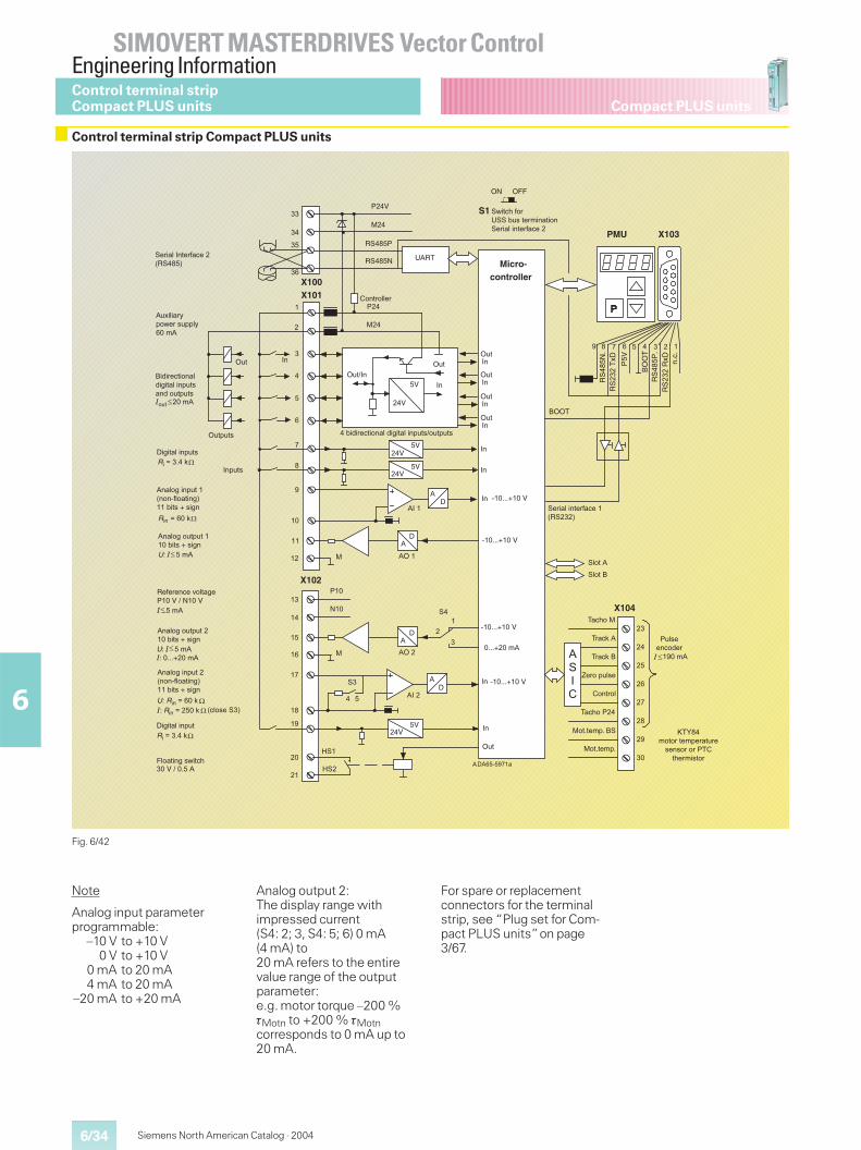
6/34
SIMOVERT MASTERDRIVES Vector ControlEngineering Information
6
Siemens North American Catalog · 2004
Compact PLUS unitsControl terminal stripCompact PLUS units
Control terminal strip Compact PLUS units
Fig. 6/42
Note
Analog input parameterprogrammable:
–10 V to +10 V0 V to +10 V
0 mA to 20 mA4 mA to 20 mA
–20 mA to +20 mA
Analog output 2:The display range withimpressed current(S4: 2; 3, S4: 5; 6) 0 mA(4 mA) to20 mA refers to the entirevalue range of the outputparameter:e.g. motor torque –200 %�Motn to +200 % �Motncorresponds to 0 mA up to20 mA.
For spare or replacementconnectors for the terminalstrip, see “Plug set for Com-pact PLUS units”on page3/67.
� %�������0*
����
�2
��2
3�>%�>%�
3�>%��3�
3�>%�
3�>%�
3�>%�
3�>%�
3�
4���2���?���2������0*
4��
���
�2��2
3��2��2
�
�
�
�
�
�
�
��
��
��
��
�������� ����
4�2
�>>@
,!����@A+
��������
,!����,A+
��� ����
��
��
4��
?��
!# ���
!# ��*
�>>@
�1.1
��
��
+*
+*
3��2��2
��
��
�
+*!�
� �
���1117���2
+* ���1117���2
�
�
����
3�
3�
*!3�
��
��
�
��
��
��
��
��
����
��������0*
*3��
*3���B�����<������B�����<������
�B�������0*
*>��
*>��
,!��4
1
��
,!��?
,!��4
C*,@
�
��
���!�
�!�
����<�����
��
��
4��2
���
����
>DD>?
��
��
>%�
�B�������0*�B��1117���0*
�1117���0*�
!�,!��?
1
���1117���2
���1117���2
+*��������
�
����
�
��
��"���.�� ��#"�����#���&%����"� %�&%��
��)�"���.�� ��#�"�����#���&%��� %�&%��>%�&%��
,�-����.��$ #����
*%A�#���5& '����%&���0*
+�����#���&%��
@��.��*
@��.���
@�.( ��
E�� �&%#��
� ��� #
@�.( �4��
� �1��0&1��!
� �1��0&1
4%#����. "��
F@G�0 � ����0&����%������ �� ��4@��(��0��� �
*��# ����&%���:� ��-# �����;���)����7�����
:.# ���!�;
*��# �� %�&%������)����7�����
*��# �� %�&%������)����7�����
!'��.(�- �C!!�)%�����0����� �!����#������-�.���
3�&%��
+�����#���&%�
*��# ����&%���:� ��-# �����;���)����7�����
!����#�3����-�.���:,!��;
!����#������-�.���:,!���;
D# �������'��.( *
� ��� ##��
���<��1���
���<��1���
���2����1��*
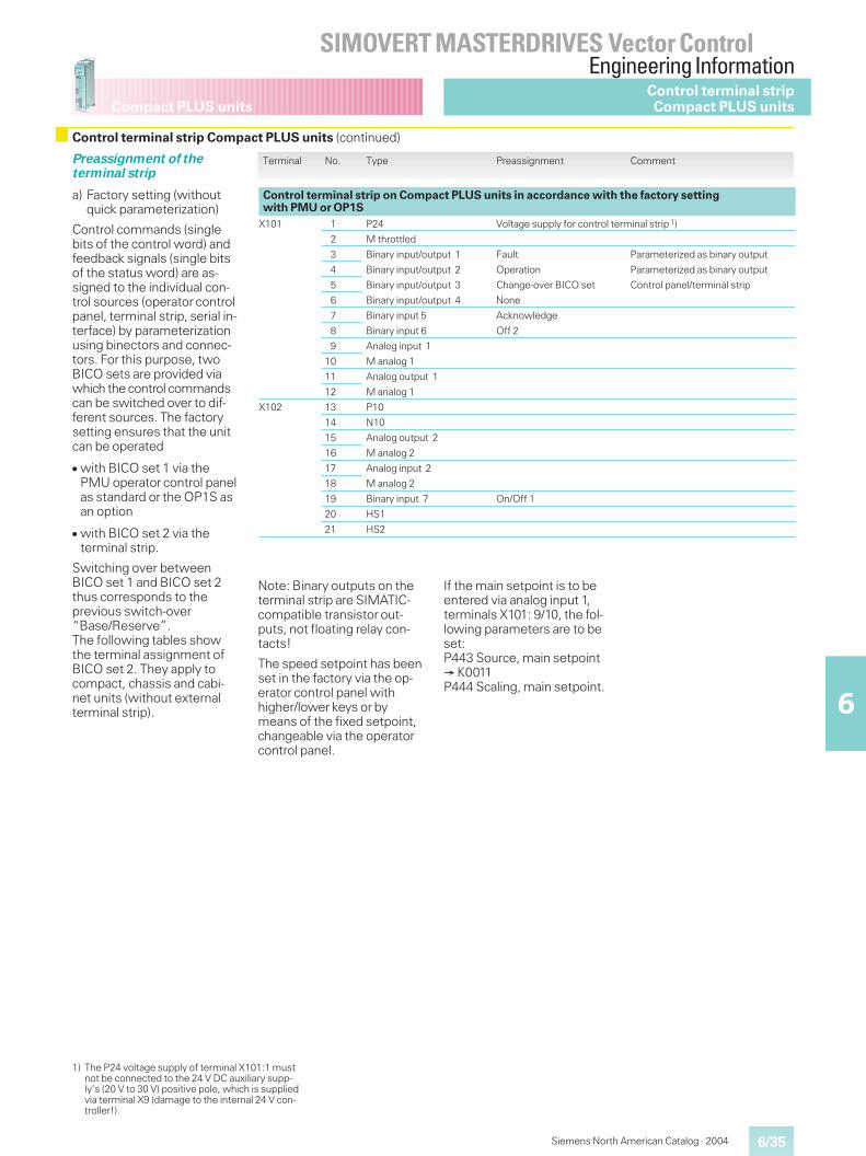
6/35
SIMOVERT MASTERDRIVES Vector ControlEngineering Information
6
Compact PLUS units
Siemens North American Catalog · 2004
Control terminal strip Compact PLUS units (continued)
1) The P24 voltage supply of terminal X101:1 mustnot be connected to the 24 V DC auxiliary supp-ly’s (20 V to 30 V) positive pole, which is suppliedvia terminal X9 (damage to the internal 24 V con-troller!).
Terminal No. Type Preassignment Comment
Control terminal strip on Compact PLUS units in accordance with the factory settingwith PMU or OP1S
X101 1 P24 Voltage supply for control terminal strip 1)
2 M throttled
3 Binary input/output 1 Fault Parameterized as binary output
4 Binary input/output 2 Operation Parameterized as binary output
5 Binary input/output 3 Change-over BICO set Control panel/terminal strip
6 Binary input/output 4 None
7 Binary input 5 Acknowledge
8 Binary input 6 Off 2
9 Analog input 1
10 M analog 1
11 Analog output 1
12 M analog 1
X102 13 P10
14 N10
15 Analog output 2
16 M analog 2
17 Analog input 2
18 M analog 2
19 Binary input 7 On/Off 1
20 HS1
21 HS2
Preassignment of theterminal strip
a) Factory setting (withoutquick parameterization)
Control commands (singlebits of the control word) andfeedback signals (single bitsof the status word) are as-signed to the individual con-trol sources (operator controlpanel, terminal strip, serial in-terface) by parameterizationusing binectors and connec-tors. For this purpose, twoBICO sets are provided viawhich the control commandscan be switched over to dif-ferent sources. The factorysetting ensures that the unitcan be operated
� with BICO set 1 via thePMU operator control panelas standard or the OP1S asan option
� with BICO set 2 via theterminal strip.
Switching over betweenBICO set 1 and BICO set 2thus corresponds to theprevious switch-over“Base/Reserve”.The following tables showthe terminal assignment ofBICO set 2. They apply tocompact, chassis and cabi-net units (without externalterminal strip).
Control terminal stripCompact PLUS units
Note: Binary outputs on theterminal strip are SIMATIC-compatible transistor out-puts, not floating relay con-tacts!
The speed setpoint has beenset in the factory via the op-erator control panel withhigher/lower keys or bymeans of the fixed setpoint,changeable via the operatorcontrol panel.
If the main setpoint is to beentered via analog input 1,terminals X101: 9/10, the fol-lowing parameters are to beset:P443 Source, main setpoint� K0011P444 Scaling, main setpoint.
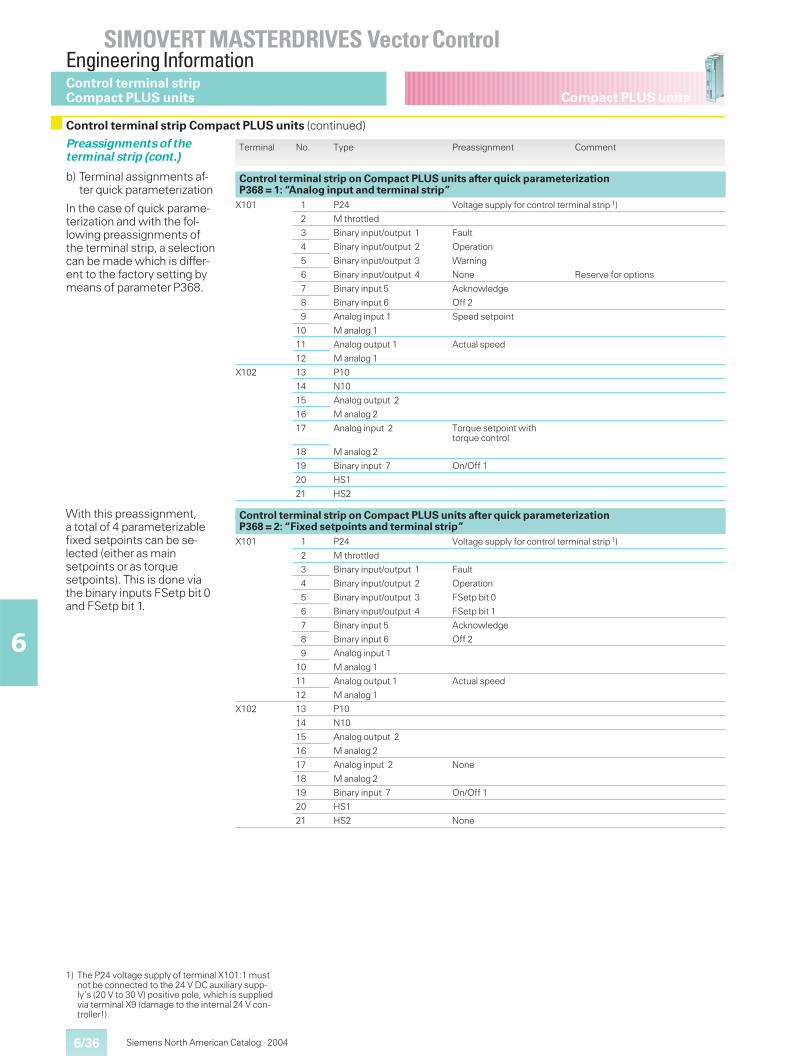
6/36
SIMOVERT MASTERDRIVES Vector ControlEngineering Information
6
Siemens North American Catalog · 2004
Compact PLUS units
Preassignments of theterminal strip (cont.)
b) Terminal assignments af-ter quick parameterization
In the case of quick parame-terization and with the fol-lowing preassignments ofthe terminal strip, a selectioncan be made which is differ-ent to the factory setting bymeans of parameter P368.
Terminal No. Type Preassignment Comment
Control terminal strip on Compact PLUS units after quick parameterizationP368 = 1: “Analog input and terminal strip”
X101 1 P24 Voltage supply for control terminal strip 1)
2 M throttled
3 Binary input/output 1 Fault
4 Binary input/output 2 Operation
5 Binary input/output 3 Warning
6 Binary input/output 4 None Reserve for options
7 Binary input 5 Acknowledge
8 Binary input 6 Off 2
9 Analog input 1 Speed setpoint
10 M analog 1
11 Analog output 1 Actual speed
12 M analog 1
X102 13 P10
14 N10
15 Analog output 2
16 M analog 2
17 Analog input 2 Torque setpoint withtorque control
18 M analog 2
19 Binary input 7 On/Off 1
20 HS1
21 HS2
Control terminal strip on Compact PLUS units after quick parameterizationP368 = 2: “Fixed setpoints and terminal strip”
X101 1 P24 Voltage supply for control terminal strip 1)
2 M throttled
3 Binary input/output 1 Fault
4 Binary input/output 2 Operation
5 Binary input/output 3 FSetp bit 0
6 Binary input/output 4 FSetp bit 1
7 Binary input 5 Acknowledge
8 Binary input 6 Off 2
9 Analog input 1
10 M analog 1
11 Analog output 1 Actual speed
12 M analog 1
X102 13 P10
14 N10
15 Analog output 2
16 M analog 2
17 Analog input 2 None
18 M analog 2
19 Binary input 7 On/Off 1
20 HS1
21 HS2 None
With this preassignment,a total of 4 parameterizablefixed setpoints can be se-lected (either as mainsetpoints or as torquesetpoints). This is done viathe binary inputs FSetp bit 0and FSetp bit 1.
Control terminal stripCompact PLUS units
Control terminal strip Compact PLUS units (continued)
1) The P24 voltage supply of terminal X101:1 mustnot be connected to the 24 V DC auxiliary supp-ly’s (20 V to 30 V) positive pole, which is suppliedvia terminal X9 (damage to the internal 24 V con-troller!).
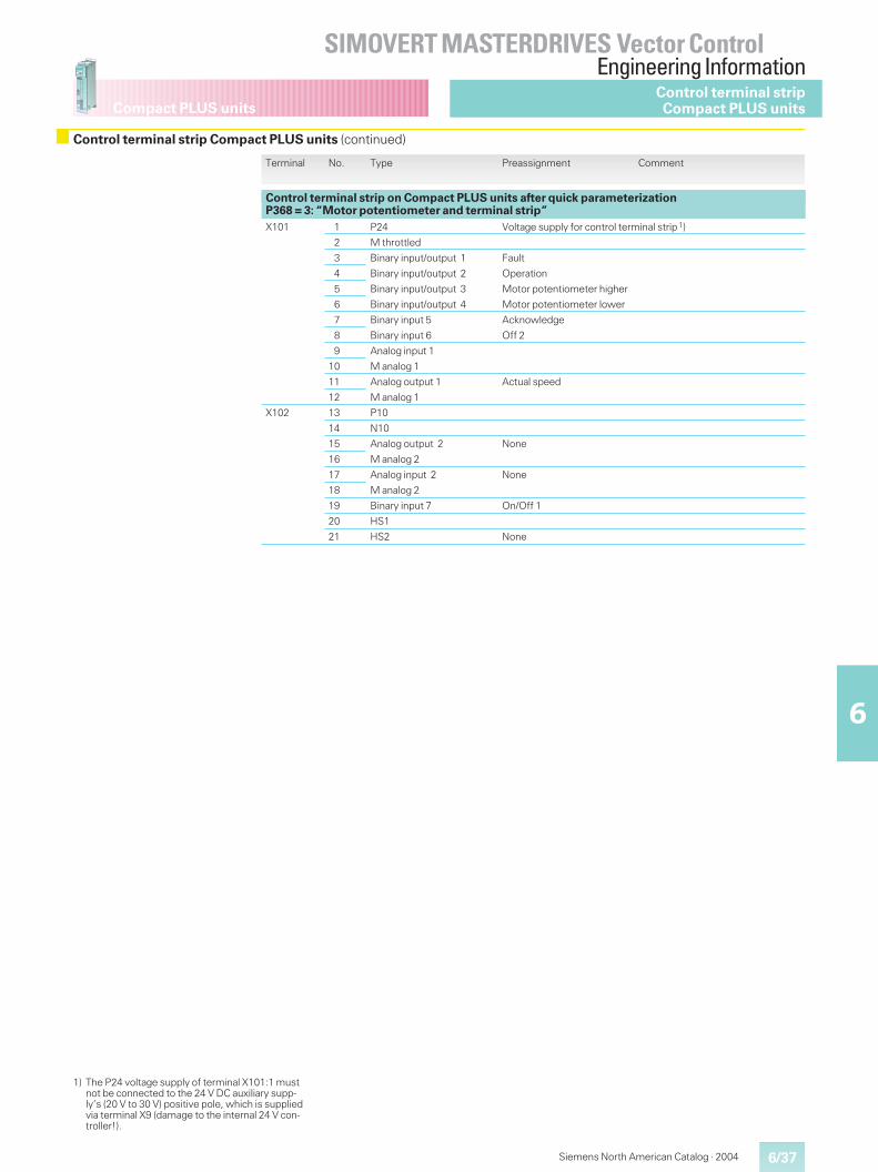
6/37
SIMOVERT MASTERDRIVES Vector ControlEngineering Information
6
Compact PLUS units
Siemens North American Catalog · 2004
Terminal No. Type Preassignment Comment
Control terminal strip on Compact PLUS units after quick parameterizationP368 = 3: “Motor potentiometer and terminal strip”X101 1 P24 Voltage supply for control terminal strip 1)
2 M throttled
3 Binary input/output 1 Fault
4 Binary input/output 2 Operation
5 Binary input/output 3 Motor potentiometer higher
6 Binary input/output 4 Motor potentiometer lower
7 Binary input 5 Acknowledge
8 Binary input 6 Off 2
9 Analog input 1
10 M analog 1
11 Analog output 1 Actual speed
12 M analog 1
X102 13 P10
14 N10
15 Analog output 2 None
16 M analog 2
17 Analog input 2 None
18 M analog 2
19 Binary input 7 On/Off 1
20 HS1
21 HS2 None
Control terminal stripCompact PLUS units
Control terminal strip Compact PLUS units (continued)
1) The P24 voltage supply of terminal X101:1 mustnot be connected to the 24 V DC auxiliary supp-ly’s (20 V to 30 V) positive pole, which is suppliedvia terminal X9 (damage to the internal 24 V con-troller!).
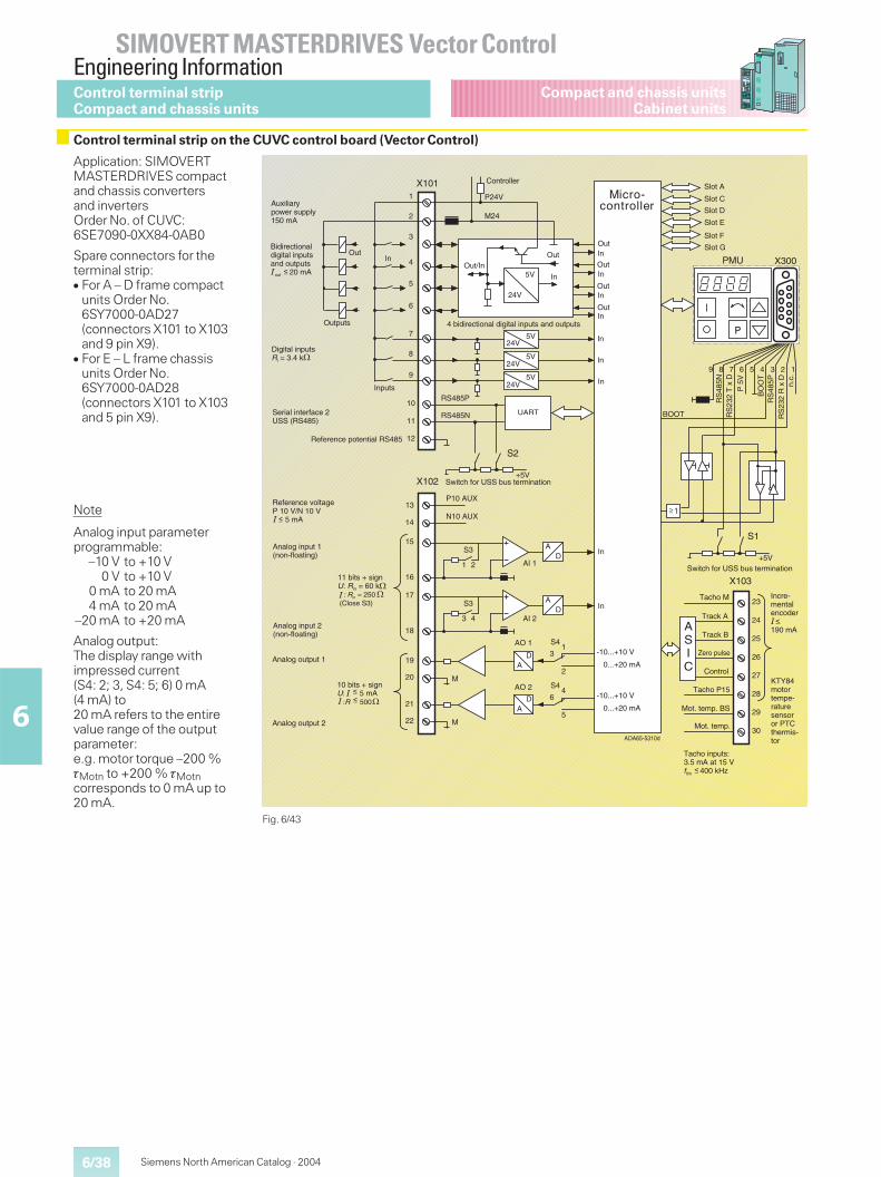
6/38
SIMOVERT MASTERDRIVES Vector ControlEngineering Information
6
Siemens North American Catalog · 2004
Compact and chassis unitsCabinet units
Application: SIMOVERTMASTERDRIVES compactand chassis convertersand invertersOrder No. of CUVC:6SE7090-0XX84-0AB0
Spare connectors for theterminal strip:� For A – D frame compact
units Order No.6SY7000-0AD27(connectors X101 to X103and 9 pin X9).
� For E – L frame chassisunits Order No.6SY7000-0AD28(connectors X101 to X103and 5 pin X9).
Fig. 6/43
X101
5V
24V
P24V
M24
5V24V
5V24V
2
1
3
4
5
6
7
8
9
10
11
12
123456789
13
14
P10 AUX
N10 AUX
+5V
S115
16
19
20
DA
DA
5V
+5V
S2
RS485N
RS485P
UART
S3
1 2
17
18
DAS3
3 4
S41
2
3 -10...+10 V
0...+20 mA
21
22
DA
S44
5
6 -10...+10 V
0...+20 mA
M
M
X102
ASIC
30
29
28
27
26
25
24
23
X103
AI 1
AI 2
AO 1
AO 2
X300PMU
1
DA65-5310d
P
24V
Micro-controllerAuxiliary
power supply150 mA
Bidirectionaldigital inputsand outputs out 20 mA
Digital inputsRi = 3.4 k
Inputs
Outputs
Serial interface 2USS (RS485)
Reference potential RS485
Reference voltageP 10 V/N 10 V 5 mA
Analog input 1(non-floating)
Analog input 2(non-floating)
11 bits + signU: Rin = 60 k : Rin = 250 (Close S3)
��
Analog output 1
Analog output 2
10 bits + signU: 5 mA :R 500
��
Tacho inputs:3.5 mA at 15 Vflim 400 kHz
A
Incre-mentalencoder
190 mA
KTY84motortempe-raturesensoror PTCthermis-tor
Tacho M
Track A
Track B
Zero pulse
Control
Tacho P15
Mot. temp. BS
Mot. temp.
Switch for USS bus termination
RS
485N
R
S23
2 T
x D
P 5
V
BO
OT
BOOT
RS
485P
R
S23
2 R
x D
n.
c.
Slot A
Slot C
Slot D
Slot E
Slot F
Slot G Out
Out
Out
Out
In
In
In
In
In
In
In
In
In
4 bidirectional digital inputs and outputs
Switch for USS bus termination
Out
Controller
Out/InOutIn
In
Note
Analog input parameterprogrammable:
–10 V to +10 V0 V to +10 V
0 mA to 20 mA4 mA to 20 mA
–20 mA to +20 mA
Analog output:The display range withimpressed current(S4: 2; 3, S4: 5; 6) 0 mA(4 mA) to20 mA refers to the entirevalue range of the outputparameter:e.g. motor torque –200 %�Motn to +200 % �Motncorresponds to 0 mA up to20 mA.
Control terminal stripCompact and chassis units
Control terminal strip on the CUVC control board (Vector Control)
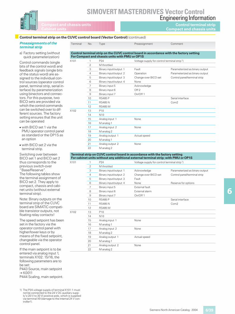
6/39
SIMOVERT MASTERDRIVES Vector ControlEngineering Information
6
Siemens North American Catalog · 2004
Compact and chassis unitsCabinet units
Preassignments of theterminal strip
a) Factory setting (withoutquick parameterization)
Control commands (singlebits of the control word) andfeedback signals (single bitsof the status word) are as-signed to the individual con-trol sources (operator controlpanel, terminal strip, serial in-terface) by parameterizationusing binectors and connec-tors. For this purpose, twoBICO sets are provided viawhich the control commandscan be switched over to dif-ferent sources. The factorysetting ensures that the unitcan be operated
� with BICO set 1 via thePMU operator control panelas standard or the OP1S asan option
� with BICO set 2 via theterminal strip.
Switching over betweenBICO set 1 and BICO set 2thus corresponds to theprevious switch-over“Base/Reserve”.The following tables showthe terminal assignment ofBICO set 2. They apply tocompact, chassis and cabi-net units (without externalterminal strip).
Note: Binary outputs on theterminal strip of the CUVCboard are SIMATIC-compati-ble transistor outputs, notfloating relay contacts!
The speed setpoint has beenset in the factory via theoperator control panel withhigher/lower keys or bymeans of the fixed setpoint,changeable via the operatorcontrol panel.
If the main setpoint is to beentered via analog input 1,terminals X102: 15/16, thefollowing parameters are tobe set:P443 Source, main setpoint� K0011P444 Scaling, main setpoint.
Terminal No. Type Preassignment Comment
Control terminal strip on the CUVC control board in accordance with the factory settingFor Compact and chassis units with PMU or OP1S
X101 1 P24 Voltage supply for control terminal strip 1)
2 M throttled
3 Binary input/output 1 Fault Parameterized as binary output
4 Binary input/output 2 Operation Parameterized as binary output
5 Binary input/output 3 Change-over BICO set Control panel/terminal strip
6 Binary input/output 4 None
7 Binary input 5 Acknowledge
8 Binary input 6 Off 2
9 Binary input 7 On/Off 1
10 RS485 P Serial interface
11 RS485 N Com2
12 RS485 M
X102 13 P10
14 N10
15 Analog input 1 None
16 M analog 1
17 Analog input 2 None
18 M analog 2
19 Analog output 1 Actual speed
20 M analog 1
21 Analog output 2 None
22 M analog 2
Terminal strip on CUVC control board in accordance with the factory settingFor cabinet units without any additional external terminal strip; with PMU or OP1S
X101 1 P24 Voltage supply for control terminal strip 1)
2 M throttled
3 Binary input/output 1 Acknowledge Parameterized as binary output
4 Binary input/output 2 Change-over BICO set Control panel/terminal strip
5 Binary input/output 3 Fault
6 Binary input/output 4 None Reserve for options
7 Binary input 5 External fault
8 Binary input 6 External alarm
9 Binary input 7 On/Off 1
10 RS485 P Serial interface
11 RS485 N Com2
12 RS485 M
X102 13 P10
14 N10
15 Analog input 1 None
16 M analog 1
17 Analog input 2 None
18 M analog 2
19 Analog output 1 Actual speed
20 M analog 1
21 Analog output 2 None
22 M analog 2
Control terminal stripCompact and chassis units
Control terminal strip on the CUVC control board (Vector Control) (continued)
1) The P24 voltage supply of terminal X101:1 mustnot be connected to the 24 V DC auxiliary supp-ly’s (20 V to 30 V) positive pole, which is suppliedvia terminal X9 (damage to the internal 24 V con-troller!).
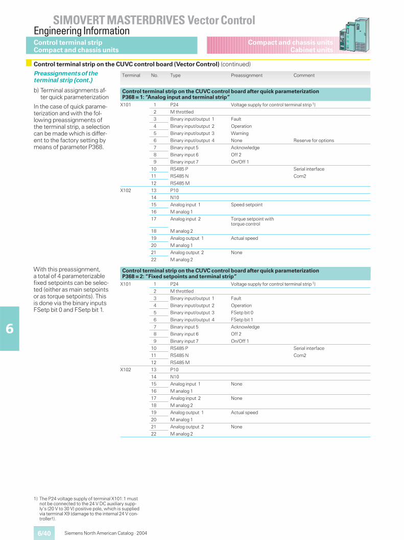
6/40
SIMOVERT MASTERDRIVES Vector ControlEngineering Information
6
Siemens North American Catalog · 2004
Compact and chassis unitsCabinet units
Preassignments of theterminal strip (cont.)
b) Terminal assignments af-ter quick parameterization
In the case of quick parame-terization and with the fol-lowing preassignments ofthe terminal strip, a selectioncan be made which is differ-ent to the factory setting bymeans of parameter P368.
Terminal No. Type Preassignment Comment
Control terminal strip on the CUVC control board after quick parameterizationP368 = 1: “Analog input and terminal strip”
X101 1 P24 Voltage supply for control terminal strip 1)
2 M throttled
3 Binary input/output 1 Fault
4 Binary input/output 2 Operation
5 Binary input/output 3 Warning
6 Binary input/output 4 None Reserve for options
7 Binary input 5 Acknowledge
8 Binary input 6 Off 2
9 Binary input 7 On/Off 1
10 RS485 P Serial interface
11 RS485 N Com2
12 RS485 M
X102 13 P10
14 N10
15 Analog input 1 Speed setpoint
16 M analog 1
17 Analog input 2 Torque setpoint withtorque control
18 M analog 2
19 Analog output 1 Actual speed
20 M analog 1
21 Analog output 2 None
22 M analog 2
Control terminal strip on the CUVC control board after quick parameterizationP368 = 2: “Fixed setpoints and terminal strip”
X101 1 P24 Voltage supply for control terminal strip 1)
2 M throttled
3 Binary input/output 1 Fault
4 Binary input/output 2 Operation
5 Binary input/output 3 FSetp bit 0
6 Binary input/output 4 FSetp bit 1
7 Binary input 5 Acknowledge
8 Binary input 6 Off 2
9 Binary input 7 On/Off 1
10 RS485 P Serial interface
11 RS485 N Com2
12 RS485 M
X102 13 P10
14 N10
15 Analog input 1 None
16 M analog 1
17 Analog input 2 None
18 M analog 2
19 Analog output 1 Actual speed
20 M analog 1
21 Analog output 2 None
22 M analog 2
With this preassignment,a total of 4 parameterizablefixed setpoints can be selec-ted (either as main setpointsor as torque setpoints). Thisis done via the binary inputsFSetp bit 0 and FSetp bit 1.
Control terminal stripCompact and chassis units
Control terminal strip on the CUVC control board (Vector Control) (continued)
1) The P24 voltage supply of terminal X101:1 mustnot be connected to the 24 V DC auxiliary supp-ly’s (20 V to 30 V) positive pole, which is suppliedvia terminal X9 (damage to the internal 24 V con-troller!).
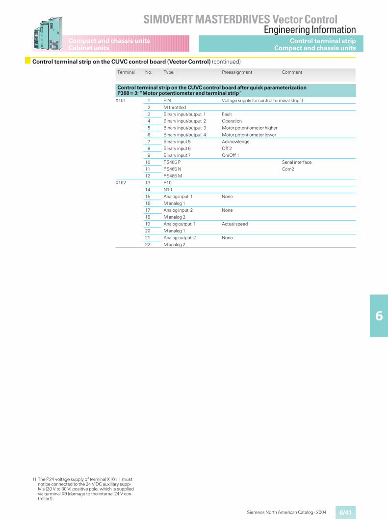
6/41
SIMOVERT MASTERDRIVES Vector ControlEngineering Information
6
Siemens North American Catalog · 2004
Compact and chassis unitsCabinet units
Terminal No. Type Preassignment Comment
Control terminal strip on the CUVC control board after quick parameterizationP368 = 3: “Motor potentiometer and terminal strip”
X101 1 P24 Voltage supply for control terminal strip 1)
2 M throttled
3 Binary input/output 1 Fault
4 Binary input/output 2 Operation
5 Binary input/output 3 Motor potentiometer higher
6 Binary input/output 4 Motor potentiometer lower
7 Binary input 5 Acknowledge
8 Binary input 6 Off 2
9 Binary input 7 On/Off 1
10 RS485 P Serial interface
11 RS485 N Com2
12 RS485 M
X102 13 P10
14 N10
15 Analog input 1 None
16 M analog 1
17 Analog input 2 None
18 M analog 2
19 Analog output 1 Actual speed
20 M analog 1
21 Analog output 2 None
22 M analog 2
Control terminal stripCompact and chassis units
1) The P24 voltage supply of terminal X101:1 mustnot be connected to the 24 V DC auxiliary supp-ly’s (20 V to 30 V) positive pole, which is suppliedvia terminal X9 (damage to the internal 24 V con-troller!).
Control terminal strip on the CUVC control board (Vector Control) (continued)
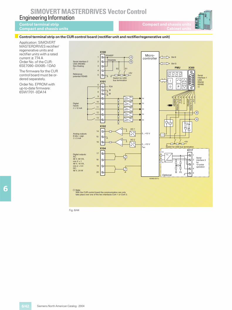
6/42
SIMOVERT MASTERDRIVES Vector ControlEngineering Information
6
Siemens North American Catalog · 2004
Compact and chassis unitsCabinet units
Application: SIMOVERTMASTERDRIVES rectifier/regenerative units andrectifier units with a ratedcurrent � 774 AOrder No. of the CUR:6SE7090–0XX85–1DA0
The firmware for the CURcontrol board must be or-dered separately.
Order No. EPROM withup-to-date firmware:6SW1701–0DA14
Fig. 6/44
��
������"�
�
� � ���
��
���
=&�"��
=&�"��
�:��
�
�
�
�
&�&�
��
�
"
�
�
���
�
�
�����
�����
�����
�����
�����
��
��
�
��
��
��
��
999����
��
�:��
999����
��
��
�"
��
�
���
�
�
�
�
�
����
����
���
=&�"�
���
�
;
�
;
DA65-5311c
1
1
1
1
1
1
Micro-controller
Serial Interface 2USS (RS485)Non-floating1
Referencepotential RS485
Digitalinputs:
12 mA
Analog outputs:8 bits + sign 5 mA
Digital outputs:AC:48 V, 60 VA,cos ��= 148 V, 16 VA,cos ��= 0.4DC:48 V, 24 W
1
Serialinterface 3for12-pulseoperation
Switch for USS bus termination
A
Serialinterface 1USSRS232RS485
1 Note:With the CUR control board the communication can onlytake place over one of the two interfaces Com 1 or Com 2.
Switch for USSbus termination
Slot G
Slot E
RS
485N
R
S23
2 T
x D
P
5V
RS
485P
R
S23
2 R
x D
n.
c.
Optional
act.
Control terminal stripCompact and chassis units
Control terminal strip on the CUR control board (rectifier unit and rectifier/regenerative unit)
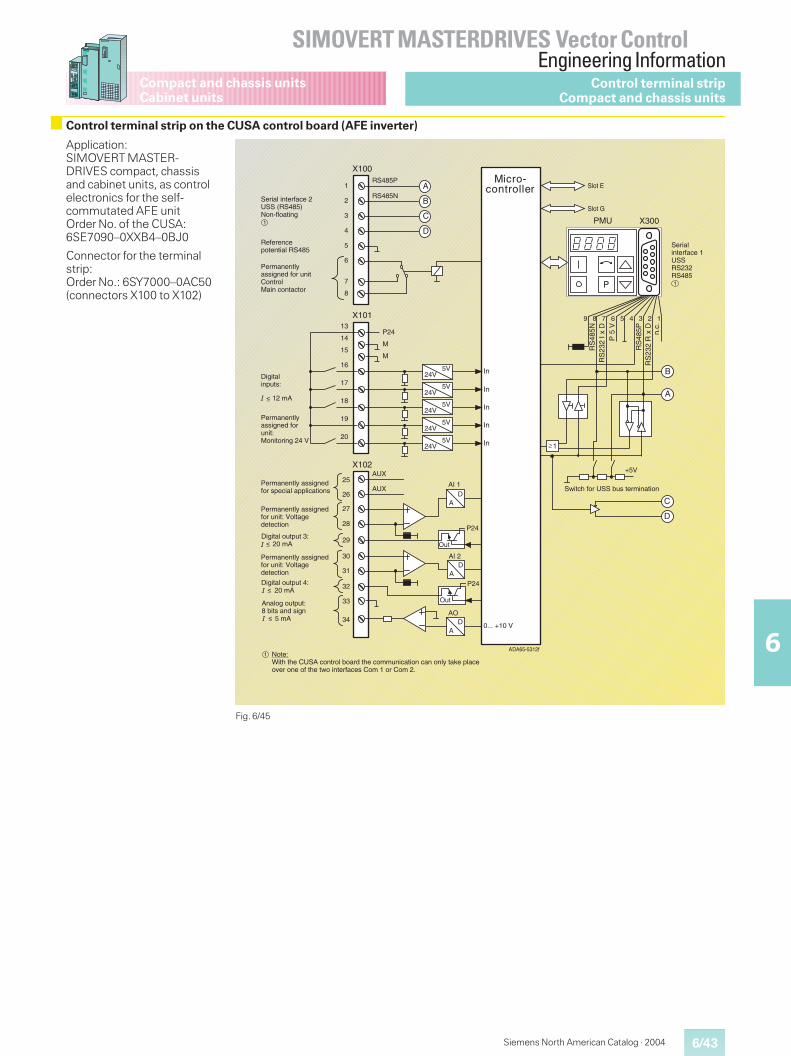
6/43
SIMOVERT MASTERDRIVES Vector ControlEngineering Information
6
Siemens North American Catalog · 2004
Compact and chassis unitsCabinet units
Application:SIMOVERT MASTER-DRIVES compact, chassisand cabinet units, as controlelectronics for the self-commutated AFE unitOrder No. of the CUSA:6SE7090–0XXB4–0BJ0
Connector for the terminalstrip:Order No.: 6SY7000–0AC50(connectors X100 to X102)
Fig. 6/45
Control terminal stripCompact and chassis units
Control terminal strip on the CUSA control board (AFE inverter)
X100
123456789
P
PMU X300
DA
RS485N
RS485P
AI 1
1
2
3
4
5
X10113
14
15
16
17
P24
M
M
5V24V
5V24V
5V24V
5V24V
5V24V
18
19
20
X102
25
33
34 DA
AO
0... +10 V
+5V
D
C
B
A
6
7
8
26
27
28
29
AUX
AUX
DA
AI 230
31
32
D
C
B
A
DA65-5312f
P24
Out
P24
Out
In
In
In
In
In
RS
485N
RS
232
I x D
P 5
V
RS
485P
RS
232
R x
Dn.
c.
1
Micro-controller
Serialinterface 1USSRS232RS4851
Switch for USS bus termination
Serial interface 2USS (RS485)Non-floating
1
Referencepotential RS485
Permanently assigned for unit ControlMain contactor
Digitalinputs:
12 mA
Permanentlyassigned forunit:Monitoring 24 V
Permanently assignedfor special applications
Permanently assignedfor unit: Voltagedetection
Digital output 4: 20 mA
Permanently assignedfor unit: Voltagedetection
Digital output 3: 20 mA
Note:With the CUSA control board the communication can only take place over one of the two interfaces Com 1 or Com 2.
A
Slot E
Slot G
1
Analog output:8 bits and sign 5 mA
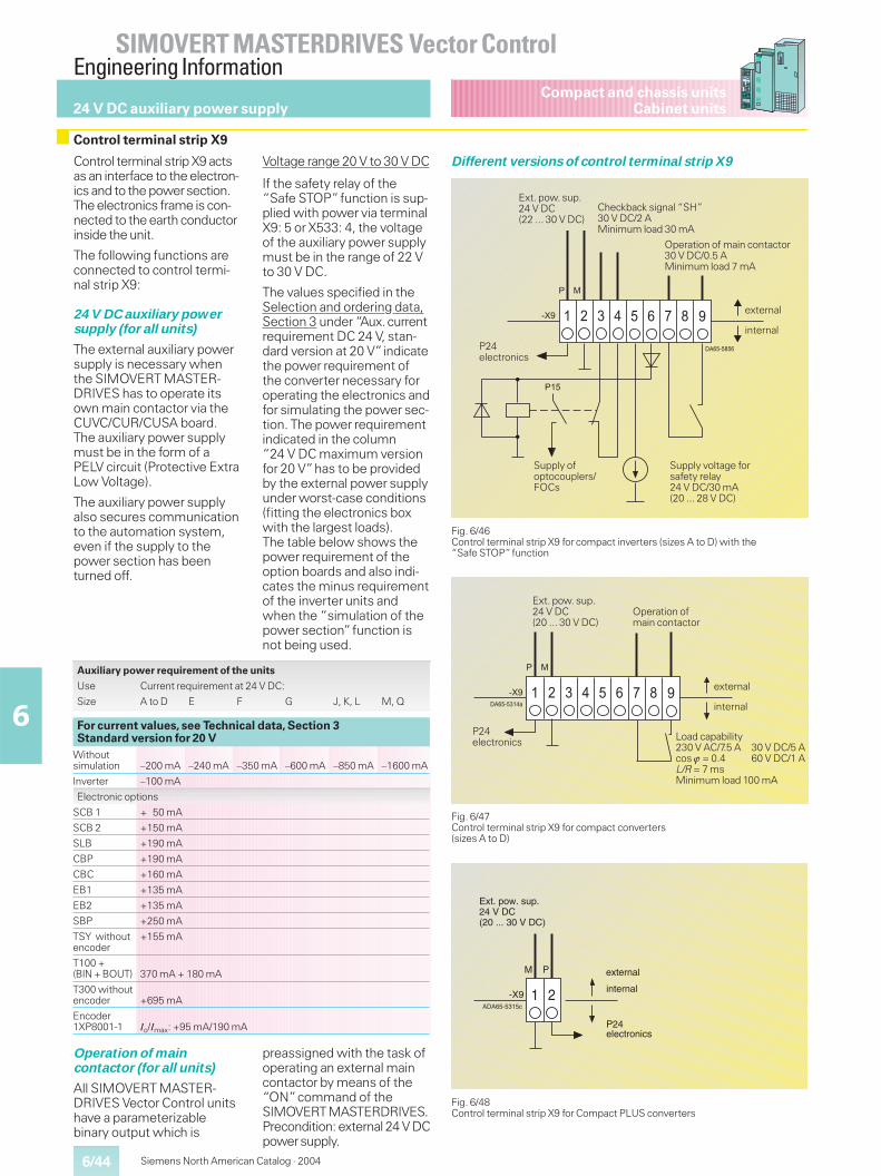
6/44
SIMOVERT MASTERDRIVES Vector ControlEngineering Information
6
Siemens North American Catalog · 2004
Compact and chassis unitsCabinet units24 V DC auxiliary power supply
Control terminal strip X9
Control terminal strip X9 actsas an interface to the electron-ics and to the powersection.The electronics frame is con-nected to the earth conductorinside the unit.
The following functions areconnected to control termi-nal strip X9:
24 V DC auxiliary powersupply (for all units)
The external auxiliary powersupply is necessary whenthe SIMOVERT MASTER-DRIVES has to operate itsown main contactor via theCUVC/CUR/CUSA board.The auxiliary power supplymust be in the form of aPELV circuit (Protective ExtraLow Voltage).
The auxiliary power supplyalso secures communicationto the automation system,even if the supply to thepower section has beenturned off.
Voltage range 20 V to 30 V DC
If the safety relay of the“Safe STOP”function is sup-plied with power via terminalX9: 5 or X533: 4, the voltageof the auxiliary power supplymust be in the range of 22 Vto 30 V DC.
The values specified in theSelection and ordering data,Section 3 under “Aux.currentrequirement DC 24 V, stan-dard version at 20 V”indicatethe power requirement ofthe converter necessary foroperating the electronics andfor simulating the power sec-tion. The power requirementindicated in the column“24 V DC maximum versionfor 20 V”has to be providedby the external power supplyunder worst-case conditions(fitting the electronics boxwith the largest loads).The table below shows thepower requirement of theoption boards and also indi-cates the minus requirementof the inverter units andwhen the “simulation of thepower section”function isnot being used.
Operation of maincontactor (for all units)
All SIMOVERT MASTER-DRIVES Vector Control unitshave a parameterizablebinary output which is
preassigned with the task ofoperating an external maincontactor by means of the“ON”command of theSIMOVERTMASTERDRIVES.Precondition: external 24 V DCpowersupply.
Fig. 6/46Control terminal strip X9 for compact inverters (sizes A to D) with the“Safe STOP”function
������"��
� � � � � � " �
� �
���
���
Ext. pow. sup.24 V DC(22 ... 30 V DC)
P24electronics
Checkback signal “SH”30 V DC/2 AMinimum load 30 mA
Operation of main contactor30 V DC/0.5 AMinimum load 7 mA
Supply voltage forsafety relay24 V DC/30 mA(20 ... 28 V DC)
Supply ofoptocouplers/FOCs
Fig. 6/48Control terminal strip X9 for Compact PLUS converters
1 2
M P
-X9DA65-5315c
Ext. pow. sup.24 V DC(20 ... 30 V DC)
external
internal
P24electronics
A
Fig. 6/47Control terminal strip X9 for compact converters(sizes A to D)
���������
� � � � � � " �
� �
���
internal
external
Load capability230 V AC/7.5 A 30 V DC/5 Acos � = 0.4 60 V DC/1 AL/R = 7 msMinimum load 100 mA
Operation ofmain contactor
Ext. pow. sup.24 V DC(20 ... 30 V DC)
P24electronics
Different versions of control terminal strip X9
internal
external
Auxiliary power requirement of the units
Use Current requirement at 24 V DC:
Size A to D E F G J, K, L M, Q
For current values, see Technical data, Section 3Standard version for 20 V
Withoutsimulation –200 mA –240 mA –350 mA –600 mA –850 mA –1600 mA
Inverter –100 mA
Electronic options
SCB 1 + 50 mA
SCB 2 +150 mA
SLB +190 mA
CBP +190 mA
CBC +160 mA
EB1 +135 mA
EB2 +135 mA
SBP +250 mA
TSY withoutencoder
+155 mA
T100 +(BIN + BOUT) 370 mA + 180 mA
T300 withoutencoder +695 mA
Encoder1XP8001-1 Io/Imax: +95 mA/190 mA
6/45
SIMOVERT MASTERDRIVES Vector ControlEngineering Information
6
Siemens North American Catalog · 2004
Compact and chassis unitsCabinet units
EMC stands for electromag-netic compatibility and,according to the definitionof the EMC directive, de-scribes the “ability of a de-vice to function satisfactorilyin an electromagnetic envi-ronment without itself caus-ing electromagnetic interfer-ence which is unacceptablefor other devices in this envi-ronment.”In order to ensurethat the relevant EMC stan-dards are complied with, thedevices must demonstratea sufficiently high immunity,on the one hand, and inter-ference emission must belimited to compatible values,on the other.
The product standard,EN 61 800-3, relevant to“variable-speed drives”describes the requirementsfor residential and industrialsectors.
Immunity
The units satisfy the require-ments of the EMC productstandard, EN 61 800-3, forthe industrial sector and thusthe lower values regardingimmunity required by theresidential sector as well.
Interference emission andradio-interferencesuppression
If converters are used in aresidential area, conductedinterference or electromag-netically emitted interfer-ence must not exceed thelimit values according to“B1”.
A residential area in thissense is a connection, i.e.an outgoing section of atransformer, to which privatehouseholds are also con-nected.
The EMC directive requiresthat an industrial system as awhole is electromagneticallycompatible with its environ-ment.
In order to limit the interfer-ence emission, the followingmeasures must be provided:
� Radio-interference sup-pression filters, includingline commutating reactorsfor reducing the conductedinterference
� Shielded cables for motorsupply cables and signalcables for reducing electro-magnetically emitted inter-ference
� Compliance with the instal-lation guidelines.
In systems with MASTER-DRIVES units and other com-ponents, e.g. contactors,switches, monitoring units,automation units etc., itmust be ensured that nointerference is emitted tothe outside and also that theindividual units do not causeany interference amongthemselves. In this respect,the measures described inthe Compendium, Section 3,“Design of Drives inConformance with EMCguidelines” are to be imple-mented (Compendium Or-der No., see Section 5 “Doc-umentation and Training”).
The most important of thesemeasures are as follows:
� The components of a sys-tem must be housed in acabinet which acts like aFaraday cage.
� Signal cables and motorsupply cables must beshielded. The shields mustbe connected to earth atboth ends.
� Signal cables should bespatially separated (atleast 0.7 ft (0.2 m)) from thepower cables. If necessary,screening plates are to beprovided.
For further measures anddetails, see the installationguidelines referred to.
Type of interference Level ofinterference
Comments
Electrostatic discharge up to 12 kV
Rapid transient interference (burst) up to 4 kV for power section
up to 2 kV for signal cables
Electromagnetic compatibility (EMC)
6/46
SIMOVERT MASTERDRIVES Vector ControlEngineering Information
6
Siemens North American Catalog · 2004
Compact and chassis unitsCabinet units
Line fuses
The 3NE1 SITOR fuse pro-vides both cable protectionand semiconductor protec-tion in one fuse. This resultsin significant cost savingsand reduced installationtimes.
For Order No. and assign-ment, see Section 3.
Line commutating reactor
The line commutating reac-tor reduces the harmonicsof the converter, the rectifierunit and the rectifier/regen-erative unit. The effect of thereactor depends on the ratioof the line short-circuit out-put to the drive output.Recommended ratio of lineshort-circuit output to driveoutput > 33 : 1:
� Use a 2–3 % linecommutating reactor forconverters and rectifierunits.
� Use a 4–5 % linecommutating reactor forrectifier/regenerative units.
A line commutating reactoralso limits current spikescaused by line-supply volt-age disturbances (e.g. dueto compensation equipmentor earth faults) or switchingoperations on the powersystem.
Reactors for supply voltagesof 380 V to 480 V and 50 Hzcan be used with 60 Hz with-out any restrictions. In thecase of supply voltages of690 V, the permissibleoperating current with 60 Hzmust be reduced to 90 % ofthe specified value and itmay be necessary to use areactor with the next highercurrent rating (see Selectionand ordering data, Section3).
Autotransformers forrectifier/regenerativeunits
Rectifier/regenerative unitsrequire a 20 % higher supplyvoltage at the anti-parallelinverter bridge for regenera-tive operation. An autotrans-former can be used to adaptthe voltage accordingly.
For Order No. and assign-ment, see Section 3;for dimension drawings,see Section 7.
Radio-interferencesuppression filters
When integrated in theinstallation in accordancewith EMC guidelines,SIMOVERT MASTERDRIVESapplications comply with theEMC product standard forelectrical drives, EN 61800-3.
The radio-interferencesuppression filters, inconjunction with the linecommutating reactor, reducethe interference voltages ofthe converters, the rectifierunits and the rectifier/regen-erative units – up to an out-put of 50 HP (37 kW) . Thespecified limits acc. toEN 55 011 Class B1 (residen-tial sector) for 3-ph. 200 V ACto 230 V AC and 3-ph. 380 Vto 480 V AC are adhered towith the suggested filters(TN systems).
Radio-interference sup-pression filters with ratedcurrents up to 2500 A andrated voltages of up to 690 Vare available for the differenttypes of power systems inthe industrial sector.
For Order No. and assign-ment, see Section 3;for dimension drawings,see Section 7.
For limit values, see “Elec-tromagnetic compatibility(EMC)”on page 6/45.
Note
If several converters are builtinto a drive cabinet or controlroom, a common sharedfilter with the total currentof the installed convertersis recommended in order toavoid exceeding the limitvalues. The individual con-verters are to be decoupledwith the corresponding linecommutation reactor.
System components
Supply-side components
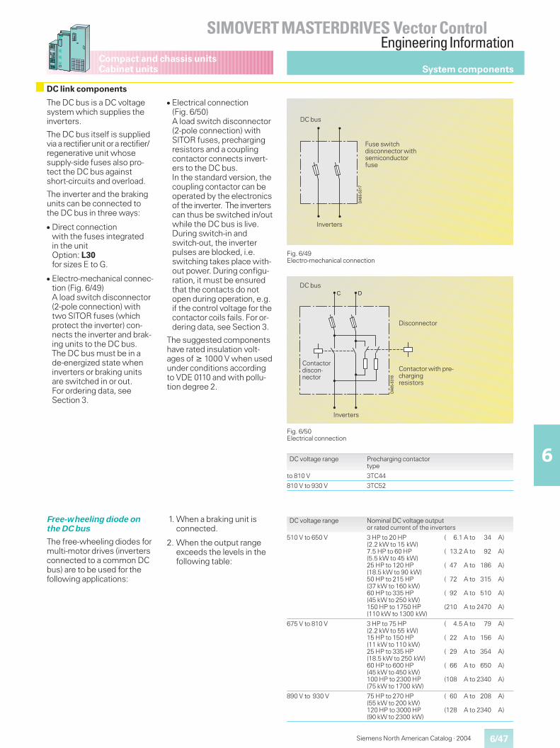
6/47
SIMOVERT MASTERDRIVES Vector ControlEngineering Information
6
Siemens North American Catalog · 2004
Compact and chassis unitsCabinet units
The DC bus is a DC voltagesystem which supplies theinverters.
The DC bus itself is suppliedvia a rectifierunit ora rectifier/regenerative unit whosesupply-side fuses also pro-tect the DC bus againstshort-circuits and overload.
The inverter and the brakingunits can be connected tothe DC bus in three ways:
� Direct connectionwith the fuses integratedin the unitOption: L30for sizes E to G.
� Electro-mechanical connec-tion (Fig. 6/49)A load switch disconnector(2-pole connection) withtwo SITOR fuses (whichprotect the inverter) con-nects the inverter and brak-ing units to the DC bus.The DC bus must be in ade-energized state wheninverters or braking unitsare switched in or out.For ordering data, seeSection 3.
� Electrical connection(Fig. 6/50)A load switch disconnector(2-pole connection) withSITOR fuses, prechargingresistors and a couplingcontactor connects invert-ers to the DC bus.In the standard version, thecoupling contactor can beoperated by the electronicsof the inverter. The inverterscan thus be switched in/outwhile the DC bus is live.During switch-in andswitch-out, the inverterpulses are blocked, i.e.switching takes place with-out power. During configu-ration, it must be ensuredthat the contacts do notopen during operation, e.g.if the control voltage for thecontactor coils fails. For or-dering data, see Section 3.
The suggested componentshave rated insulation volt-ages of � 1000 V when usedunder conditions accordingto VDE 0110 and with pollu-tion degree 2.
Fig. 6/49Electro-mechanical connection
Fig. 6/50Electrical connection
DC voltage range Precharging contactortype
to 810 V 3TC44
810 V to 930 V 3TC52
Free-wheeling diode onthe DC bus
The free-wheeling diodes formulti-motor drives (invertersconnected to a common DCbus) are to be used for thefollowing applications:
1. When a braking unit isconnected.
2. When the output rangeexceeds the levels in thefollowing table:
DC voltage range Nominal DC voltage outputor rated current of the inverters
510 V to 650 V 3 HP to 20 HP(2.2 kW to 15 kW)7.5 HP to 60 HP(5.5 kW to 45 kW)25 HP to 120 HP(18.5 kW to 90 kW)50 HP to 215 HP(37 kW to 160 kW)60 HP to 335 HP(45 kW to 250 kW)150 HP to 1750 HP(110 kW to 1300 kW)
( 6.1 A to 34 A)
( 13.2 A to 92 A)
( 47 A to 186 A)
( 72 A to 315 A)
( 92 A to 510 A)
(210 A to 2470 A)
675 V to 810 V 3 HP to 75 HP(2.2 kW to 55 kW)15 HP to 150 HP(11 kW to 110 kW)25 HP to 335 HP(18.5 kW to 250 kW)60 HP to 600 HP(45 kW to 450 kW)100 HP to 2300 HP(75 kW to 1700 kW)
( 4.5 A to 79 A)
( 22 A to 156 A)
( 29 A to 354 A)
( 66 A to 650 A)
(108 A to 2340 A)
890 V to 930 V 75 HP to 270 HP(55 kW to 200 kW)120 HP to 3000 HP(90 kW to 2300 kW)
( 60 A to 208 A)
(128 A to 2340 A)
��������
Inverters
Fuse switchdisconnector withsemiconductorfuse
DC bus
�������"
� �
Contactor with pre-chargingresistors
Inverters
DC bus
Disconnector
System components
DC link components
Contactordiscon-nector
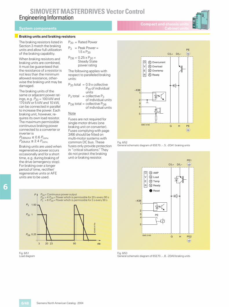
6/48
SIMOVERT MASTERDRIVES Vector ControlEngineering Information
6
Siemens North American Catalog · 2004
Compact and chassis unitsCabinet unitsSystem components
The braking resistors listed inSection 3 match the brakingunits and allow full utilizationof the braking capability.
When braking resistors andbraking units are combined,it must be guaranteed thatthe resistance of a resistor isnot less than the minimumallowed resistance, other-wise the braking unit may bedamaged.
The braking units of thesame or adjacent power rat-ings, e.g. P20 = 100 kW and170 kW or 5 kW and 10 kW,can be connected in parallelto increase the power. Eachbraking unit, however, re-quires its own load resistor.The maximum permissiblecontinuous braking powerconnected to a converter orinverter isPDBMAX � 0.6 Pconv.P20MAX � 2.4 Pconv.
Braking units are used whenregenerative power occursoccasionally and for a shorttime, e.g. during braking ofthe drive (emergency stop).For braking over a longerperiod of time, rectifier/regenerative units or AFEunits are to be used.
P20 = Rated Power
P3 = Peak Power =1.5 x P20
PDB = 0.25 x P20 =Steady Statepower rating
The following applies withrespect to paralleled brakingunits:
P20 total = 0.9 x collectiveP20 of individualunits
P3 total = collective P3of individual units
PDB total = collective PDBof individual units
Note
Fuses are not required forsingle-motor drives (onebraking unit on converter).Fuses complying with page3/66 should be fitted onmulti-motor systems withcommon DC bus. Thesefuses only provide protectionin “critical situations”. Theydo not protect the brakingunit or braking resistor.
Fig. 6/51Load diagram
���������#
� �����
�
�
�
�
�
9��
�9�
�
�
�;
PDB= Continuous power outputP20 = 4 PDB= Power which is permissible for 20 s every 90 sP3 = 6 PDB= Power which is permissible for 3 s every 90 s
Fig. 6/52General schematic diagram of 6SE70..-..S..-2DA1 braking units
Overcurrent
Overload
Overtemp
Ready
O
V
E
R
–X381
234
5
G H PE
C/L+ D/L–
PE
GMC-5192
Braking units and braking resistors
Fig. 6/53General schematic diagram of 6SE70..-..B..-2DA0 braking units
AMP
Load
Temp
Ready
O
V
E
R
–X381
234
5
G H PE2
C/L+ D/L–
PE1
Reset
PE
GMC-5193
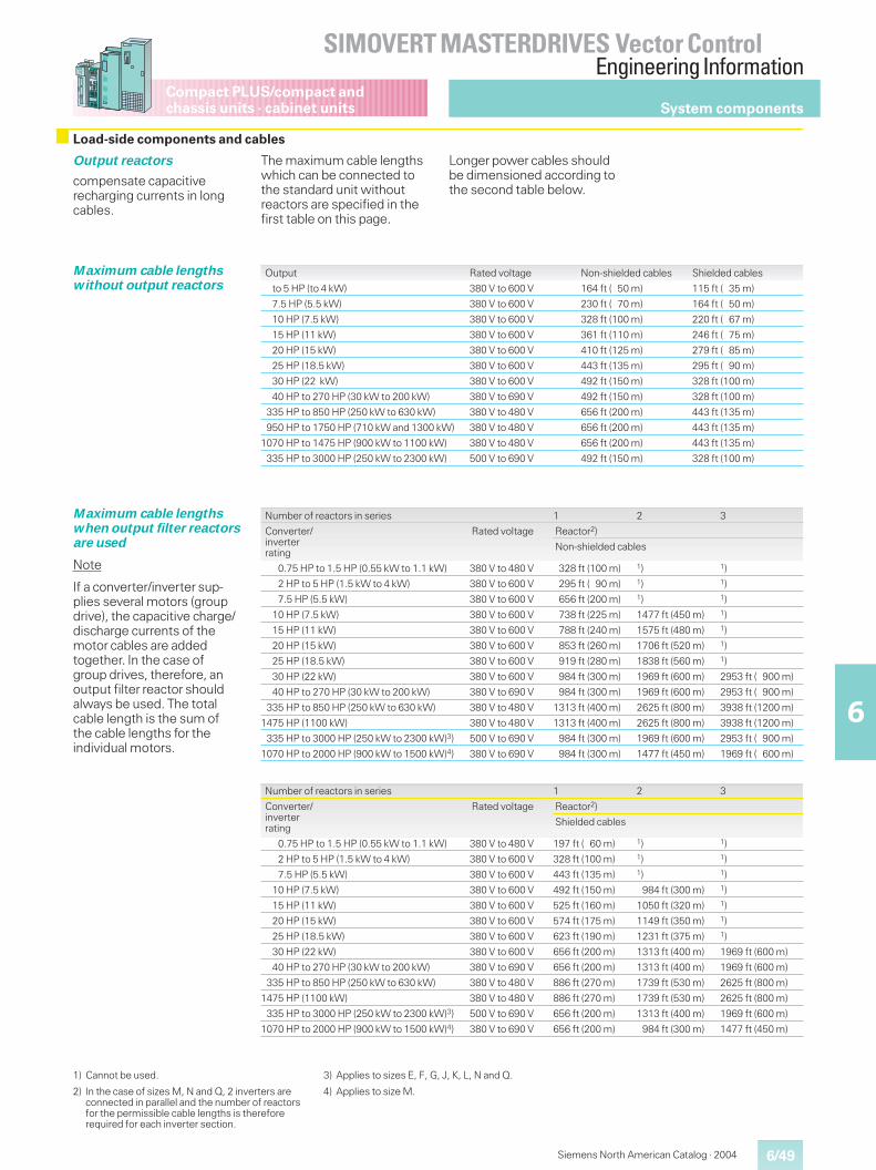
6/49
SIMOVERT MASTERDRIVES Vector ControlEngineering Information
6
Compact PLUS/compact andchassis units · cabinet units
Siemens North American Catalog · 2004
Output reactors
compensate capacitiverecharging currents in longcables.
The maximum cable lengthswhich can be connected tothe standard unit withoutreactors are specified in thefirst table on this page.
Longer power cables shouldbe dimensioned according tothe second table below.
Maximum cable lengthswithout output reactors
Output Rated voltage Non-shielded cables Shielded cables
to 5 HP (to 4 kW) 380 V to 600 V 164 ft ( 50 m) 115 ft ( 35 m)
7.5 HP (5.5 kW) 380 V to 600 V 230 ft ( 70 m) 164 ft ( 50 m)
10 HP (7.5 kW) 380 V to 600 V 328 ft (100 m) 220 ft ( 67 m)
15 HP (11 kW) 380 V to 600 V 361 ft (110 m) 246 ft ( 75 m)
20 HP (15 kW) 380 V to 600 V 410 ft (125 m) 279 ft ( 85 m)
25 HP (18.5 kW) 380 V to 600 V 443 ft (135 m) 295 ft ( 90 m)
30 HP (22 kW) 380 V to 600 V 492 ft (150 m) 328 ft (100 m)
40 HP to 270 HP (30 kW to 200 kW) 380 V to 690 V 492 ft (150 m) 328 ft (100 m)
335 HP to 850 HP (250 kW to 630 kW) 380 V to 480 V 656 ft (200 m) 443 ft (135 m)
950 HP to 1750 HP (710 kW and 1300 kW) 380 V to 480 V 656 ft (200 m) 443 ft (135 m)
1070 HP to 1475 HP (900 kW to 1100 kW) 380 V to 480 V 656 ft (200 m) 443 ft (135 m)
335 HP to 3000 HP (250 kW to 2300 kW) 500 V to 690 V 492 ft (150 m) 328 ft (100 m)
Maximum cable lengthswhen output filter reactorsare used
Note
If a converter/inverter sup-plies several motors (groupdrive), the capacitive charge/discharge currents of themotor cables are addedtogether. In the case ofgroup drives, therefore, anoutput filter reactor shouldalways be used. The totalcable length is the sum ofthe cable lengths for theindividual motors.
Number of reactors in series 1 2 3
Converter/inverterrating
Rated voltage Reactor2)
Non-shielded cables
0.75 HP to 1.5 HP (0.55 kW to 1.1 kW) 380 V to 480 V 328 ft (100 m) 1) 1)
2 HP to 5 HP (1.5 kW to 4 kW) 380 V to 600 V 295 ft ( 90 m) 1) 1)
7.5 HP (5.5 kW) 380 V to 600 V 656 ft (200 m) 1) 1)
10 HP (7.5 kW) 380 V to 600 V 738 ft (225 m) 1477 ft (450 m) 1)
15 HP (11 kW) 380 V to 600 V 788 ft (240 m) 1575 ft (480 m) 1)
20 HP (15 kW) 380 V to 600 V 853 ft (260 m) 1706 ft (520 m) 1)
25 HP (18.5 kW) 380 V to 600 V 919 ft (280 m) 1838 ft (560 m) 1)
30 HP (22 kW) 380 V to 600 V 984 ft (300 m) 1969 ft (600 m) 2953 ft ( 900 m)
40 HP to 270 HP (30 kW to 200 kW) 380 V to 690 V 984 ft (300 m) 1969 ft (600 m) 2953 ft ( 900 m)
335 HP to 850 HP (250 kW to 630 kW) 380 V to 480 V 1313 ft (400 m) 2625 ft (800 m) 3938 ft (1200 m)
1475 HP (1100 kW) 380 V to 480 V 1313 ft (400 m) 2625 ft (800 m) 3938 ft (1200 m)
335 HP to 3000 HP (250 kW to 2300 kW)3) 500 V to 690 V 984 ft (300 m) 1969 ft (600 m) 2953 ft ( 900 m)
1070 HP to 2000 HP (900 kW to 1500 kW)4) 380 V to 690 V 984 ft (300 m) 1477 ft (450 m) 1969 ft ( 600 m)
1) Cannot be used.
2) In the case of sizes M, N and Q, 2 inverters areconnected in parallel and the number of reactorsfor the permissible cable lengths is thereforerequired for each inverter section.
3) Applies to sizes E, F, G, J, K, L, N and Q.
4) Applies to size M.
System components
Load-side components and cables
Number of reactors in series 1 2 3
Converter/inverterrating
Rated voltage Reactor2)
Shielded cables
0.75 HP to 1.5 HP (0.55 kW to 1.1 kW) 380 V to 480 V 197 ft ( 60 m) 1) 1)
2 HP to 5 HP (1.5 kW to 4 kW) 380 V to 600 V 328 ft (100 m) 1) 1)
7.5 HP (5.5 kW) 380 V to 600 V 443 ft (135 m) 1) 1)
10 HP (7.5 kW) 380 V to 600 V 492 ft (150 m) 984 ft (300 m) 1)
15 HP (11 kW) 380 V to 600 V 525 ft (160 m) 1050 ft (320 m) 1)
20 HP (15 kW) 380 V to 600 V 574 ft (175 m) 1149 ft (350 m) 1)
25 HP (18.5 kW) 380 V to 600 V 623 ft (190 m) 1231 ft (375 m) 1)
30 HP (22 kW) 380 V to 600 V 656 ft (200 m) 1313 ft (400 m) 1969 ft (600 m)
40 HP to 270 HP (30 kW to 200 kW) 380 V to 690 V 656 ft (200 m) 1313 ft (400 m) 1969 ft (600 m)
335 HP to 850 HP (250 kW to 630 kW) 380 V to 480 V 886 ft (270 m) 1739 ft (530 m) 2625 ft (800 m)
1475 HP (1100 kW) 380 V to 480 V 886 ft (270 m) 1739 ft (530 m) 2625 ft (800 m)
335 HP to 3000 HP (250 kW to 2300 kW)3) 500 V to 690 V 656 ft (200 m) 1313 ft (400 m) 1969 ft (600 m)
1070 HP to 2000 HP (900 kW to 1500 kW)4) 380 V to 690 V 656 ft (200 m) 984 ft (300 m) 1477 ft (450 m)
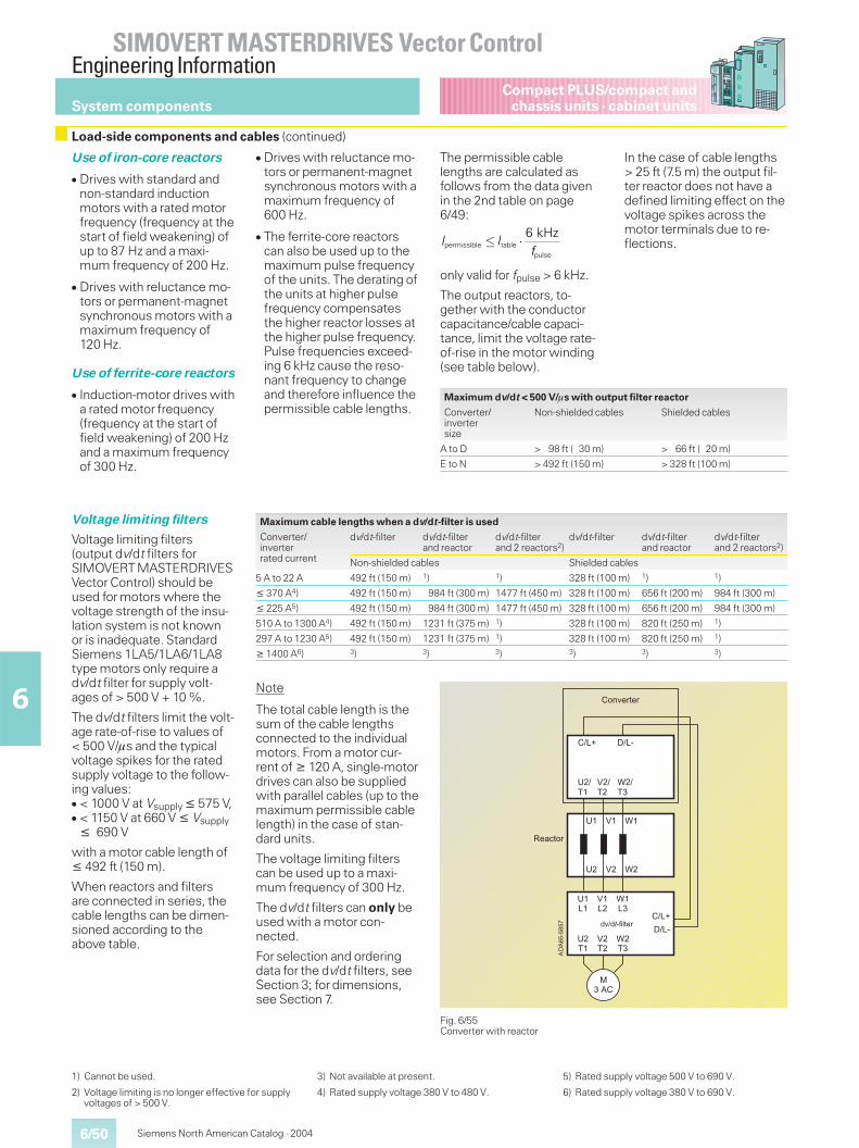
6/50
SIMOVERT MASTERDRIVES Vector ControlEngineering Information
6
Siemens North American Catalog · 2004
Compact PLUS/compact andchassis units · cabinet unitsSystem components
Use of iron-core reactors
� Drives with standard andnon-standard inductionmotors with a rated motorfrequency (frequency at thestart of field weakening) ofup to 87 Hz and a maxi-mum frequency of 200 Hz.
� Drives with reluctance mo-tors or permanent-magnetsynchronous motors with amaximum frequency of120 Hz.
Use of ferrite-core reactors
� Induction-motor drives witha rated motor frequency(frequency at the start offield weakening) of 200 Hzand a maximum frequencyof 300 Hz.
� Drives with reluctance mo-tors or permanent-magnetsynchronous motors with amaximum frequency of600 Hz.
� The ferrite-core reactorscan also be used up to themaximum pulse frequencyof the units. The derating ofthe units at higher pulsefrequency compensatesthe higher reactor losses atthe higher pulse frequency.Pulse frequencies exceed-ing 6 kHz cause the reso-nant frequency to changeand therefore influence thepermissible cable lengths.
The permissible cablelengths are calculated asfollows from the data givenin the 2nd table on page6/49:
only valid for fpulse > 6 kHz.
The output reactors, to-gether with the conductorcapacitance/cable capaci-tance, limit the voltage rate-of-rise in the motor winding(see table below).
In the case of cable lengths> 25 ft (7.5 m) the output fil-ter reactor does not have adefined limiting effect on thevoltage spikes across themotor terminals due to re-flections.
Voltage limiting filters
Voltage limiting filters(output dv/dt filters forSIMOVERT MASTERDRIVESVector Control) should beused for motors where thevoltage strength of the insu-lation system is not knownor is inadequate. StandardSiemens 1LA5/1LA6/1LA8type motors only require adv/dt filter for supply volt-ages of > 500 V + 10 %.
The dv/dt filters limit the volt-age rate-of-rise to values of< 500 V/�s and the typicalvoltage spikes for the ratedsupply voltage to the follow-ing values:� < 1000 V at Vsupply � 575 V,� < 1150 V at 660 V � Vsupply
� 690 V
with a motor cable length of� 492 ft (150 m).
When reactors and filtersare connected in series, thecable lengths can be dimen-sioned according to theabove table.
Note
The total cable length is thesum of the cable lengthsconnected to the individualmotors. From a motor cur-rent of � 120 A, single-motordrives can also be suppliedwith parallel cables (up to themaximum permissible cablelength) in the case of stan-dard units.
The voltage limiting filterscan be used up to a maxi-mum frequency of 300 Hz.
The dv/dt filters can only beused with a motor con-nected.
For selection and orderingdata for the dv/dt filters, seeSection 3; for dimensions,see Section 7.
Fig. 6/55Converter with reactor
����
����
����
���
����
����
���
�� �� ��
�� �� ��
�����
�����
����
���� ����
����
����
������"�� 76�7��'0,)(+
�-16(+)(+
=(�#)-+
�
permissible tablepulse
6 kHzI I
f� �
Maximum dv/dt < 500 V/�s with output filter reactor
Converter/invertersize
Non-shielded cables Shielded cables
A to D > 98 ft ( 30 m) > 66 ft ( 20 m)
E to N > 492 ft (150 m) > 328 ft (100 m)
Maximum cable lengths when a dv/dt-filter is used
Converter/inverterrated current
dv/dt-filter dv/dt-filterand reactor
dv/dt-filterand 2 reactors2)
dv/dt-filter dv/dt-filterand reactor
dv/dt-filterand 2 reactors2)
Non-shielded cables Shielded cables
5 A to 22 A 492 ft (150 m) 1) 1) 328 ft (100 m) 1) 1)
� 370 A4) 492 ft (150 m) 984 ft (300 m) 1477 ft (450 m) 328 ft (100 m) 656 ft (200 m) 984 ft (300 m)
� 225 A5) 492 ft (150 m) 984 ft (300 m) 1477 ft (450 m) 328 ft (100 m) 656 ft (200 m) 984 ft (300 m)
510 A to 1300 A4) 492 ft (150 m) 1231 ft (375 m) 1) 328 ft (100 m) 820 ft (250 m) 1)
297 A to 1230 A5) 492 ft (150 m) 1231 ft (375 m) 1) 328 ft (100 m) 820 ft (250 m) 1)
� 1400 A6) 3) 3) 3) 3) 3) 3)
1) Cannot be used.
2) Voltage limiting is no longer effective for supplyvoltages of > 500 V.
3) Not available at present.
4) Rated supply voltage 380 V to 480 V.
5) Rated supply voltage 500 V to 690 V.
6) Rated supply voltage 380 V to 690 V.
Load-side components and cables (continued)
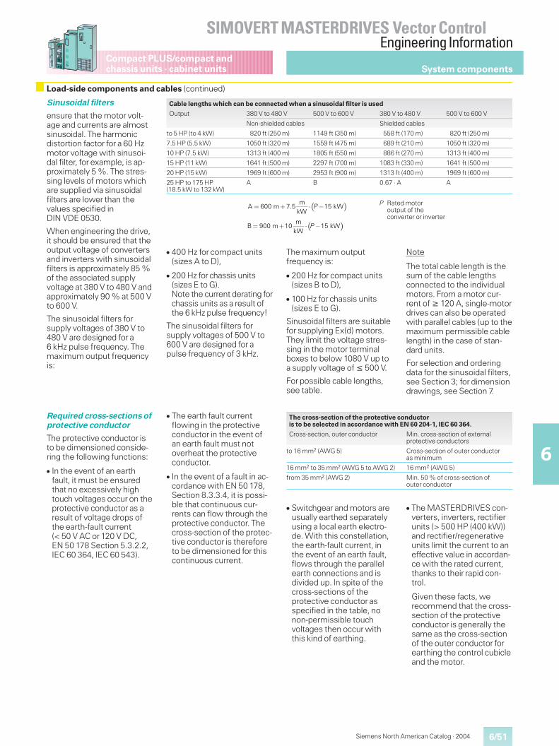
6/51
SIMOVERT MASTERDRIVES Vector ControlEngineering Information
6
Compact PLUS/compact andchassis units · cabinet units
Siemens North American Catalog · 2004
Sinusoidal filters
ensure that the motor volt-age and currents are almostsinusoidal. The harmonicdistortion factor for a 60 Hzmotor voltage with sinusoi-dal filter, for example, is ap-proximately 5 %. The stres-sing levels of motors whichare supplied via sinusoidalfilters are lower than thevalues specified inDIN VDE 0530.
When engineering the drive,it should be ensured that theoutput voltage of convertersand inverters with sinusoidalfilters is approximately 85 %of the associated supplyvoltage at 380 V to 480 V andapproximately 90 % at 500 Vto 600 V.
The sinusoidal filters forsupply voltages of 380 V to480 V are designed for a6 kHz pulse frequency. Themaximum output frequencyis:
Cable lengths which can be connected when a sinusoidal filter is used
Output 380 V to 480 V 500 V to 600 V 380 V to 480 V 500 V to 600 V
Non-shielded cables Shielded cables
to 5 HP (to 4 kW) 820 ft (250 m) 1149 ft (350 m) 558 ft (170 m) 820 ft (250 m)
7.5 HP (5.5 kW) 1050 ft (320 m) 1559 ft (475 m) 689 ft (210 m) 1050 ft (320 m)
10 HP (7.5 kW) 1313 ft (400 m) 1805 ft (550 m) 886 ft (270 m) 1313 ft (400 m)
15 HP (11 kW) 1641 ft (500 m) 2297 ft (700 m) 1083 ft (330 m) 1641 ft (500 m)
20 HP (15 kW) 1969 ft (600 m) 2953 ft (900 m) 1313 ft (400 m) 1969 ft (600 m)
25 HP to 175 HP(18.5 kW to 132 kW)
A B 0.67 · A A
Required cross-sections ofprotective conductor
The protective conductor isto be dimensioned conside-ring the following functions:
� In the event of an earthfault, it must be ensuredthat no excessively hightouch voltages occur on theprotective conductor as aresult of voltage drops ofthe earth-fault current(< 50 V AC or 120 V DC,EN 50 178 Section 5.3.2.2,IEC 60 364, IEC 60 543).
� The earth fault currentflowing in the protectiveconductor in the event ofan earth fault must notoverheat the protectiveconductor.
� In the event of a fault in ac-cordance with EN 50 178,Section 8.3.3.4, it is possi-ble that continuous cur-rents can flow through theprotective conductor. Thecross-section of the protec-tive conductor is thereforeto be dimensioned for thiscontinuous current.
� Switchgear and motors areusually earthed separatelyusing a local earth electro-de. With this constellation,the earth-fault current, inthe event of an earth fault,flows through the parallelearth connections and isdivided up. In spite of thecross-sections of theprotective conductor asspecified in the table, nonon-permissible touchvoltages then occur withthis kind of earthing.
� The MASTERDRIVES con-verters, inverters, rectifierunits (> 500 HP (400 kW))and rectifier/regenerativeunits limit the current to aneffective value in accordan-ce with the rated current,thanks to their rapid con-trol.
Given these facts, werecommend that the cross-section of the protectiveconductor is generally thesame as the cross-sectionof the outer conductor forearthing the control cubicleand the motor.
The cross-section of the protective conductoris to be selected in accordance with EN 60 204-1, IEC 60 364.
Cross-section, outer conductor Min. cross-section of externalprotective conductors
to 16 mm2 (AWG 5) Cross-section of outer conductoras minimum
16 mm2 to 35 mm2 (AWG 5 to AWG 2) 16 mm2 (AWG 5)
from 35 mm2 (AWG 2) Min. 50 % of cross-section ofouter conductor
P Rated motoroutput of theconverter or inverter
System components
� 400 Hz for compact units(sizes A to D),
� 200 Hz for chassis units(sizes E to G).Note the current derating forchassis units as a result ofthe 6 kHz pulse frequency!
The sinusoidal filters forsupply voltages of 500 V to600 V are designed for apulse frequency of 3 kHz.
The maximum outputfrequency is:
� 200 Hz for compact units(sizes B to D),
� 100 Hz for chassis units(sizes E to G).
Sinusoidal filters are suitablefor supplying Ex(d) motors.They limit the voltage stres-sing in the motor terminalboxes to below 1080 V up toa supply voltage of � 500 V.
For possible cable lengths,see table.
Note
The total cable length is thesum of the cable lengthsconnected to the individualmotors. From a motor cur-rent of � 120 A, single-motordrives can also be operatedwith parallel cables (up to themaximum permissible cablelength) in the case of stan-dard units.
For selection and orderingdata for the sinusoidal filters,see Section 3; for dimensiondrawings, see Section 7.
� �
� �
mA 600 m 7.5 15 kW
kW
mB 900 m 10 15 kW
kW
P
P
� �
� �
Load-side components and cables (continued)
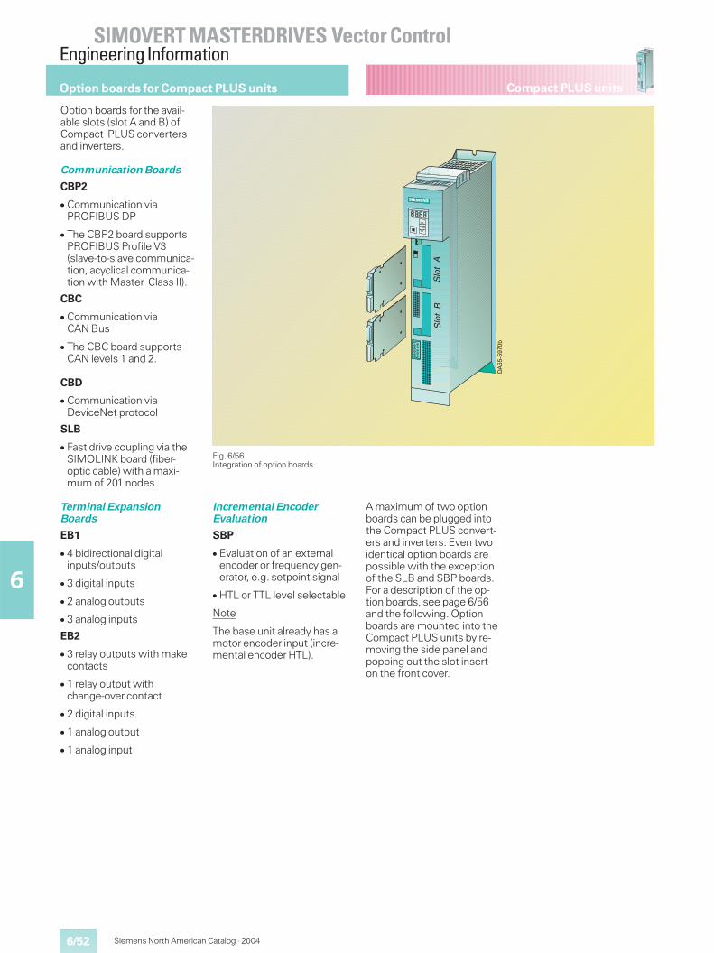
6/52
SIMOVERT MASTERDRIVES Vector ControlEngineering Information
6
Siemens North American Catalog · 2004
Compact PLUS unitsOption boards for Compact PLUS units
Option boards for the avail-able slots (slot A and B) ofCompact PLUS convertersand inverters.
Communication Boards
CBP2
� Communication viaPROFIBUS DP
� The CBP2 board supportsPROFIBUS Profile V3(slave-to-slave communica-tion, acyclical communica-tion with Master Class II).
CBC
� Communication viaCAN Bus
� The CBC board supportsCAN levels 1 and 2.
CBD
� Communication viaDeviceNet protocol
SLB
� Fast drive coupling via theSIMOLINK board (fiber-optic cable) with a maxi-mum of 201 nodes.
Terminal ExpansionBoards
EB1
� 4 bidirectional digitalinputs/outputs
� 3 digital inputs
� 2 analog outputs
� 3 analog inputs
EB2
� 3 relay outputs with makecontacts
� 1 relay output withchange-over contact
� 2 digital inputs
� 1 analog output
� 1 analog input
Fig. 6/56Integration of option boards
+*�������)
�
����
�
���
Incremental EncoderEvaluation
SBP
� Evaluation of an externalencoder or frequency gen-erator, e.g. setpoint signal
� HTL or TTL level selectable
Note
The base unit already has amotor encoder input (incre-mental encoder HTL).
A maximum of two optionboards can be plugged intothe Compact PLUS convert-ers and inverters. Even twoidentical option boards arepossible with the exceptionof the SLB and SBP boards.For a description of the op-tion boards, see page 6/56and the following. Optionboards are mounted into theCompact PLUS units by re-moving the side panel andpopping out the slot inserton the front cover.
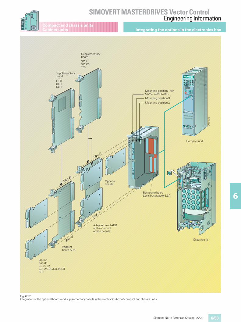
6/53
SIMOVERT MASTERDRIVES Vector ControlEngineering Information
6
Siemens North American Catalog · 2004
Compact and chassis unitsCabinet units
Fig. 6/57Integration of the optional boards and supplementary boards in the electronics box of compact and chassis units
+*��������
T100T300T400
SCB 1SCB 2TSY
Mounting position 1 forCUVC, CUR, CUSA
Mounting position 3
Mounting position 2
Optionalboards
Compact unit
Backplane boardLocal bus adapter LBA
Chassis unit
Adapter board ADBwith mountedoption boards
Adapterboard ADB
OptionboardsEB1/EB2CBP2/CBC/CBD/SLBSBP
Supplementaryboard
Supplementaryboard
Integrating the options in the electronics box
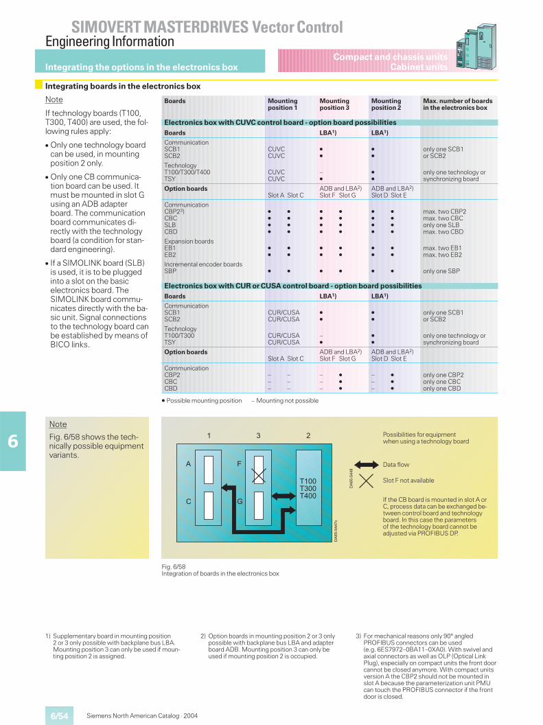
6/54
SIMOVERT MASTERDRIVES Vector ControlEngineering Information
6
Siemens North American Catalog · 2004
Compact and chassis unitsCabinet unitsIntegrating the options in the electronics box
1) Supplementary board in mounting position2 or 3 only possible with backplane bus LBA.Mounting position 3 can only be used if moun-ting position 2 is assigned.
2) Option boards in mounting position 2 or 3 onlypossible with backplane bus LBA and adapterboard ADB. Mounting position 3 can only beused if mounting position 2 is occupied.
3) For mechanical reasons only 90° angledPROFIBUS connectors can be used(e.g. 6ES7972–0BA11–0XA0). With swivel andaxial connectors as well as OLP (Optical LinkPlug), especially on compact units the front doorcannot be closed anymore. With compact unitsversion A the CBP2 should not be mounted inslot A because the parameterization unit PMUcan touch the PROFIBUS connector if the frontdoor is closed.
Fig. 6/58Integration of boards in the electronics box
+*��
����
�.
� � �
*
�
D
�
@���@���@���
Data flow
Slot F not available
+*������
If the CB board is mounted in slot A orC, process data can be exchanged be-tween control board and technologyboard. In this case the parametersof the technology board cannot beadjusted via PROFIBUS DP.
Possibilities for equipmentwhen using a technology board
Note
Fig. 6/58 shows the tech-nically possible equipmentvariants.
Boards Mountingposition 1
Mountingposition 3
Mountingposition 2
Max. number of boardsin the electronics box
Electronics box with CUVC control board - option board possibilitiesBoards LBA1) LBA1)
CommunicationSCB1SCB2
CUVCCUVC
�
�
�
�
only one SCB1or SCB2
TechnologyT100/T300/T400TSY
CUVCCUVC
–�
�
�
only one technology orsynchronizing board
Option boardsSlot A Slot C
ADB and LBA2)Slot F Slot G
ADB and LBA2)Slot D Slot E
CommunicationCBP23)CBCSLBCBD
� �
� �
� �
� �
� �
� �
� �
� �
� �
� �
� �
� �
max. two CBP2max. two CBConly one SLBmax. two CBD
Expansion boardsEB1EB2
� �
� �
� �
� �
� �
� �
max. two EB1max. two EB2
Incremental encoder boardsSBP � � � � � � only one SBP
Electronics box with CUR or CUSA control board - option board possibilitiesBoards LBA1) LBA1)
CommunicationSCB1SCB2
CUR/CUSACUR/CUSA
�
�
�
�
only one SCB1or SCB2
TechnologyT100/T300TSY
CUR/CUSACUR/CUSA
–�
�
�
only one technology orsynchronizing board
Option boardsSlot A Slot C
ADB and LBA2)Slot F Slot G
ADB and LBA2)Slot D Slot E
CommunicationCBP2CBCCBD
– –– –– –
– �
– �
– �
– �
– �
– �
only one CBP2only one CBConly one CBD
� Possible mounting position – Mounting not possible
Note
If technology boards (T100,T300, T400) are used, the fol-lowing rules apply:
� Only one technology boardcan be used, in mountingposition 2 only.
� Only one CB communica-tion board can be used. Itmust be mounted in slot Gusing an ADB adapterboard. The communicationboard communicates di-rectly with the technologyboard (a condition for stan-dard engineering).
� If a SIMOLINK board (SLB)is used, it is to be pluggedinto a slot on the basicelectronics board. TheSIMOLINK board commu-nicates directly with the ba-sic unit. Signal connectionsto the technology board canbe established by means ofBICO links.
Integrating boards in the electronics box
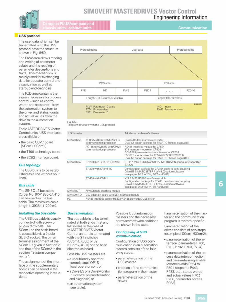
6/55
SIMOVERT MASTERDRIVES Vector ControlEngineering Information
6
Compact PLUS/compact andchassis units · cabinet units
Siemens North American Catalog · 2004
The user data which can betransmitted with the USSprotocol have the structureshown in Fig. 6/59.
The PKW area allows readingand writing of parametervalues and the reading ofparameter descriptions andtexts. This mechanism ismainly used for exchangingdata for operator control andvisualization as well asstart-up and diagnosis.
The PZD area contains thesignals necessary for processcontrol – such as controlwords and setpoints – fromthe automation system tothe drive, and status wordsand actual values from thedrive to the automationsystem.
For MASTERDRIVES VectorControl units, USS interfacesare available on
� the basic CUVC board(SCom1, SCom2)
� the T100 technology board
� the SCB2 interface board.
Bus topology
The USS bus is to be estab-lished as a line without spurlines.
Bus cable
The SINEC L2 bus cable(Order No. 6XV1830-0AH10)can be used as the buscable. The maximum cablelength is 3938 ft (1200 m).
Installing the bus cable
The USS bus cable is usuallyconnected with screw orplug-in terminals. TheSCom1 on the basic boardis accessible via a 9-poleSUB-D socket. The pin orterminal assignment of theSCom1 is given in Section 2and that of the SCom2 in thesection “System compo-nents”.
The assignment of the inter-face on the supplementaryboards can be found in therespective operating instruc-tions.
USS master Additional hardware/software
SIMATIC S5 AG95/AG100U with CP521 Sicommunication processor
RS232/RS485 interface converterDVA_S5 option package for SIMATIC S5 (see page 3/88)
AG115 to AG155U with CP524communication processor
RS485 interface module for CP524373 memory module for CP524COM 525 parameterization software for CP524S5R00T special driver for CP524 (6ES5897-2MB11)DVA_S5 option package for SIMATIC S5 (see page 3/88)
SIMATIC S7 S7-200 (CPU 214, 215 or 216) STEP 7-MICRO/DOS or STEP 7-MICRO/WIN configuration tool forS7-200
S7-300 with CP340-1C Configuration package for CP340, point-to-point couplingDrive ES SIMATIC (STEP 7 � V 5.0) option software(see pages 2/12 to 2/14, 3/87 and 3/88)
S7-400 with CP441 X27 RS422/RS485 interface moduleConfiguration package for CP441, point-to-point couplingDrive ES SIMATIC (STEP 7 � V 5.0) option software(see pages 2/12 to 2/14, 3/87 and 3/88)
SIMATIC TI FIM505 field interface module
SIMADYN D CS7 adaption board with SS4 interface module
PC RS485 interface card or RS232/RS485 converter, USS driver
Fig. 6/59Telegram structure with the USS protocol
��������
�������
IND: IndexPWE: Parameter value
PKW: Parameter ID valuePZD: Process dataPKE: Parameter ID
PZD 16PZD 1PWEIND
Protocol frame User data Protocol frame
PKW area PZD area
PKE
Length: 0 to 16 wordsLength: 0, 3, 4 words or variable
Communication
USS protocol
Bus termination
The bus cable is to be termi-nated at both ends (first andlast node). In the case ofMASTERDRIVES VectorControl units, it is terminatedwith the S1 switches(SCom1, X300) or S2(SCom2, X101) on the baseelectronics board.
Possible USS masters are� a user-friendly operator
control panel, OP1S(local operator control)
� a Drive ES or a DriveMonitorPC (central parameterizationand diagnosis) or
� an automation system(see table).
Possible USS automationmasters and the necessaryhardware/software additionsare shown in the table.
Configuring of USScommunication
Configuration of USS com-munication in an automationsystem consists of the follo-wing steps:
� parameterization of theUSS master
� creation of the communica-tion program in the master
� parameterization of thedrives.
Parameterization of the mas-ter and the communicationprogram is system-specific.
Parameterization of thedrives consists of two steps(example of SCom1/SCom2):
� parameterization of the in-terface (parameters P700,P701, P702, P703, P704)
� parameterization of the pro-cess data interconnectionand parameterizing enable(control words P554 toP591, setpoints P443,P433, etc., status wordsand actual values P707,P708, parameter accessP053).
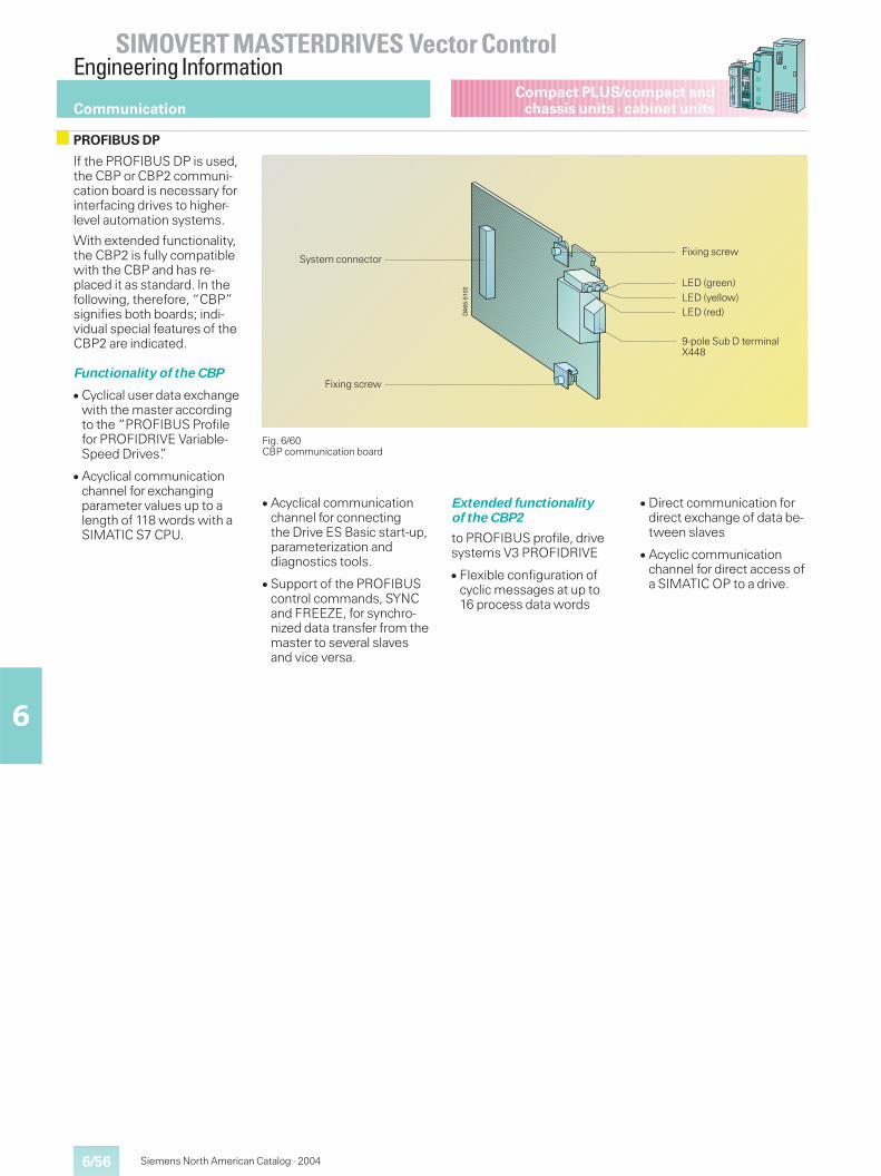
6/56
SIMOVERT MASTERDRIVES Vector ControlEngineering Information
6
Siemens North American Catalog · 2004
Compact PLUS/compact andchassis units · cabinet units
If the PROFIBUS DP is used,the CBP or CBP2 communi-cation board is necessary forinterfacing drives to higher-level automation systems.
With extended functionality,the CBP2 is fully compatiblewith the CBP and has re-placed it as standard. In thefollowing, therefore, “CBP”signifies both boards; indi-vidual special features of theCBP2 are indicated.
Functionality of the CBP
� Cyclical user data exchangewith the master accordingto the “PROFIBUS Profilefor PROFIDRIVE Variable-Speed Drives”.
� Acyclical communicationchannel for exchangingparameter values up to alength of 118 words with aSIMATIC S7 CPU.
Fig. 6/60CBP communication board
DA
65-5
102
System connector
Fixing screw
Fixing screw
LED (green)LED (yellow)LED (red)
9-pole Sub D terminalX448
Communication
PROFIBUS DP
� Acyclical communicationchannel for connectingthe Drive ES Basic start-up,parameterization anddiagnostics tools.
� Support of the PROFIBUScontrol commands, SYNCand FREEZE, for synchro-nized data transfer from themaster to several slavesand vice versa.
Extended functionalityof the CBP2
to PROFIBUS profile, drivesystems V3 PROFIDRIVE
� Flexible configuration ofcyclic messages at up to16 process data words
� Direct communication fordirect exchange of data be-tween slaves
� Acyclic communicationchannel for direct access ofa SIMATIC OP to a drive.
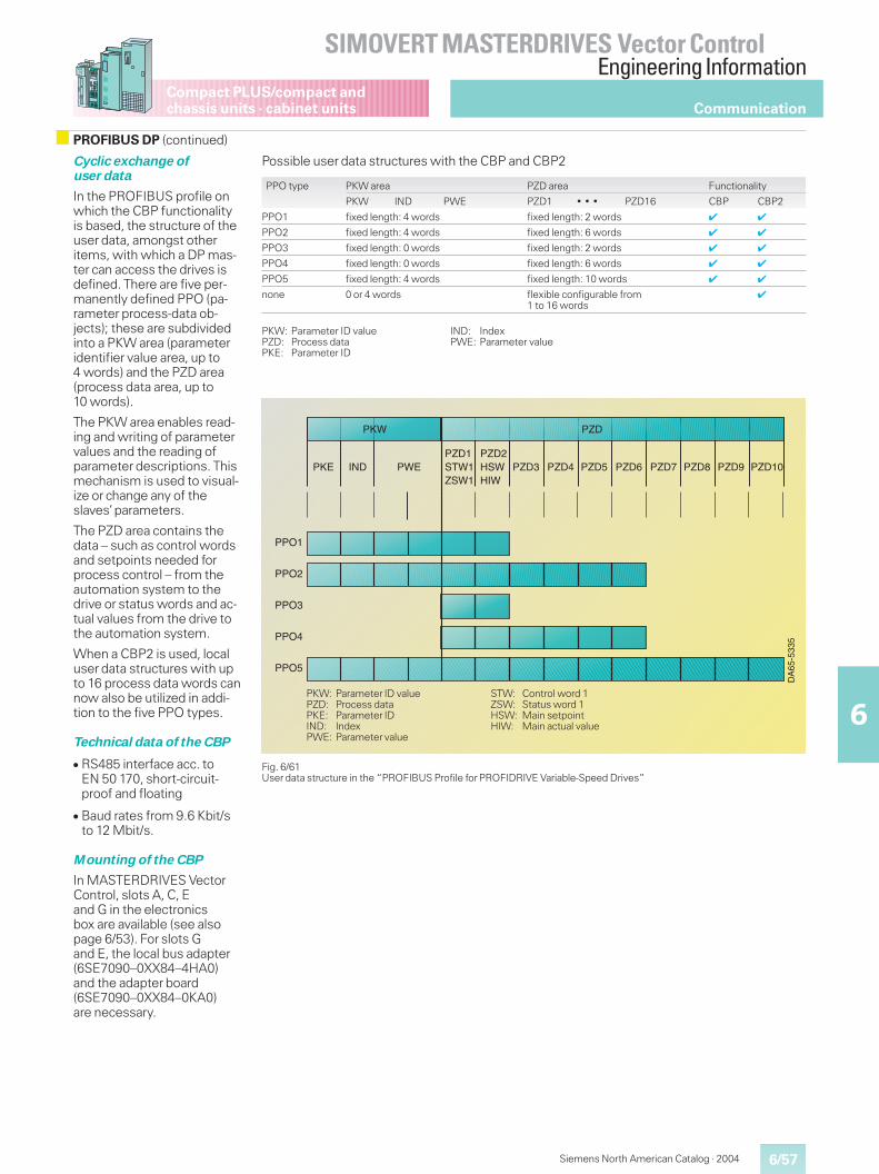
6/57
SIMOVERT MASTERDRIVES Vector ControlEngineering Information
6
Compact PLUS/compact andchassis units · cabinet units
Siemens North American Catalog · 2004
Communication
PROFIBUS DP (continued)
Cyclic exchange ofuser data
In the PROFIBUS profile onwhich the CBP functionalityis based, the structure of theuser data, amongst otheritems, with which a DP mas-ter can access the drives isdefined. There are five per-manently defined PPO (pa-rameter process-data ob-jects); these are subdividedinto a PKW area (parameteridentifier value area, up to4 words) and the PZD area(process data area, up to10 words).
The PKW area enables read-ing and writing of parametervalues and the reading ofparameter descriptions. Thismechanism is used to visual-ize or change any of theslaves’parameters.
The PZD area contains thedata – such as control wordsand setpoints needed forprocess control – from theautomation system to thedrive or status words and ac-tual values from the drive tothe automation system.
When a CBP2 is used, localuser data structures with upto 16 process data words cannow also be utilized in addi-tion to the five PPO types.
Technical data of the CBP
� RS485 interface acc. toEN 50 170, short-circuit-proof and floating
� Baud rates from 9.6 Kbit/sto 12 Mbit/s.
Mounting of the CBP
In MASTERDRIVES VectorControl, slots A, C, Eand G in the electronicsbox are available (see alsopage 6/53). For slots Gand E, the local bus adapter(6SE7090–0XX84–4HA0)and the adapter board(6SE7090–0XX84–0KA0)are necessary.
Possible user data structures with the CBP and CBP2
PPO type PKW area PZD area Functionality
PKW IND PWE PZD1 � � � PZD16 CBP CBP2
PPO1 fixed length: 4 words fixed length: 2 words ✔ ✔
PPO2 fixed length: 4 words fixed length: 6 words ✔ ✔
PPO3 fixed length: 0 words fixed length: 2 words ✔ ✔
PPO4 fixed length: 0 words fixed length: 6 words ✔ ✔
PPO5 fixed length: 4 words fixed length: 10 words ✔ ✔
none 0 or 4 words flexible configurable from1 to 16 words
✔
PKW: Parameter ID value IND: IndexPZD: Process data PWE: Parameter valuePKE: Parameter ID
Fig. 6/61User data structure in the “PROFIBUS Profile for PROFIDRIVE Variable-Speed Drives”
DA
65-5
335
PPO1
PPO2
PPO3
PPO4
PPO5
PKW PZD
PKE IND PWEPZD1STW1ZSW1
PZD2HSWHIW
PZD3 PZD4 PZD5 PZD6 PZD7 PZD8 PZD9 PZD10
PKW: Parameter ID value STW: Control word 1PZD: Process data ZSW: Status word 1PKE: Parameter ID HSW: Main setpointIND: Index HIW: Main actual valuePWE: Parameter value
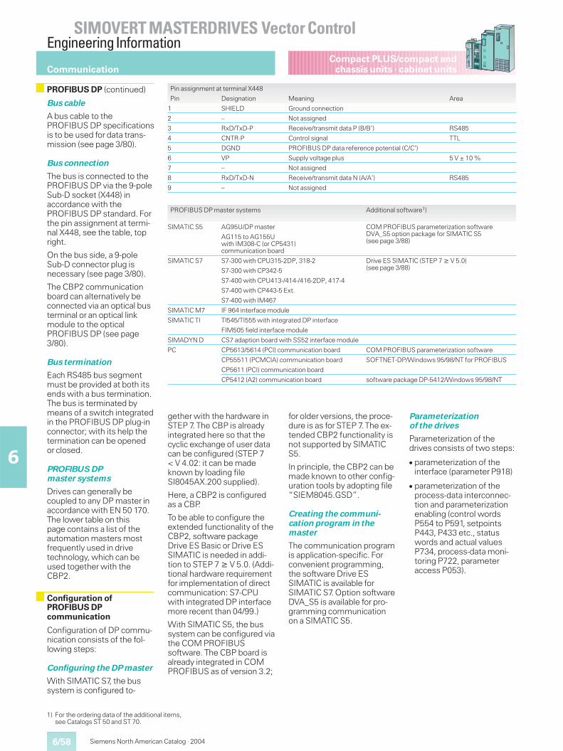
6/58
SIMOVERT MASTERDRIVES Vector ControlEngineering Information
6
Siemens North American Catalog · 2004
Compact PLUS/compact andchassis units · cabinet units
Bus cable
A bus cable to thePROFIBUS DP specificationsis to be used for data trans-mission (see page 3/80).
Bus connection
The bus is connected to thePROFIBUS DP via the 9-poleSub-D socket (X448) inaccordance with thePROFIBUS DP standard. Forthe pin assignment at termi-nal X448, see the table, topright.
On the bus side, a 9-poleSub-D connector plug isnecessary (see page 3/80).
The CBP2 communicationboard can alternatively beconnected via an optical busterminal or an optical linkmodule to the opticalPROFIBUS DP (see page3/80).
Bus termination
Each RS485 bus segmentmust be provided at both itsends with a bus termination.The bus is terminated bymeans of a switch integratedin the PROFIBUS DP plug-inconnector; with its help thetermination can be openedor closed.
PROFIBUS DPmaster systems
Drives can generally becoupled to any DP master inaccordance with EN 50 170.The lower table on thispage contains a list of theautomation masters mostfrequently used in drivetechnology, which can beused together with theCBP2.
Configuration of DP commu-nication consists of the fol-lowing steps:
Configuring the DP master
With SIMATIC S7, the bussystem is configured to-
1) For the ordering data of the additional items,see Catalogs ST 50 and ST 70.
Pin assignment at terminal X448
Pin Designation Meaning Area
1 SHIELD Ground connection
2 – Not assigned
3 RxD/TxD-P Receive/transmit data P (B/B’) RS485
4 CNTR-P Control signal TTL
5 DGND PROFIBUS DP data reference potential (C/C’)
6 VP Supply voltage plus 5 V ± 10 %
7 – Not assigned
8 RxD/TxD-N Receive/transmit data N (A/A’) RS485
9 – Not assigned
PROFIBUS DP master systems Additional software1)
SIMATIC S5 AG95U/DP master COM PROFIBUS parameterization softwareDVA_S5 option package for SIMATIC S5(see page 3/88)
AG115 to AG155Uwith IM308-C (or CP5431)communication board
SIMATIC S7 S7-300 with CPU315-2DP, 318-2 Drive ES SIMATIC (STEP 7 � V 5.0)(see page 3/88)S7-300 with CP342-5
S7-400 with CPU413-/414-/416-2DP, 417-4
S7-400 with CP443-5 Ext.
S7-400 with IM467
SIMATIC M7 IF 964 interface module
SIMATIC TI TI545/TI555 with integrated DP interface
FIM505 field interface module
SIMADYN D CS7 adaption board with SS52 interface module
PC CP5613/5614 (PCI) communication board COM PROFIBUS parameterization software
CP55511 (PCMCIA) communication board SOFTNET-DP/Windows 95/98/NT for PROFIBUS
CP5611 (PCI) communication board
CP5412 (A2) communication board software package DP-5412/Windows 95/98/NT
Communication
PROFIBUS DP (continued)
Configuration ofPROFIBUS DPcommunication
gether with the hardware inSTEP 7. The CBP is alreadyintegrated here so that thecyclic exchange of user datacan be configured (STEP 7< V 4.02: it can be madeknown by loading fileSI8045AX.200 supplied).
Here, a CBP2 is configuredas a CBP.
To be able to configure theextended functionality of theCBP2, software packageDrive ES Basic or Drive ESSIMATIC is needed in addi-tion to STEP 7 � V 5.0. (Addi-tional hardware requirementfor implementation of directcommunication: S7-CPUwith integrated DP interfacemore recent than 04/99.)
With SIMATIC S5, the bussystem can be configured viathe COM PROFIBUSsoftware. The CBP board isalready integrated in COMPROFIBUS as of version 3.2;
for older versions, the proce-dure is as for STEP 7. The ex-tended CBP2 functionality isnot supported by SIMATICS5.
In principle, the CBP2 can bemade known to other config-uration tools by adopting file“SIEM8045.GSD”.
Creating the communi-cation program in themaster
The communication programis application-specific. Forconvenient programming,the software Drive ESSIMATIC is available forSIMATIC S7. Option softwareDVA_S5 is available for pro-gramming communicationon a SIMATIC S5.
Parameterizationof the drives
Parameterization of thedrives consists of two steps:
� parameterization of theinterface (parameter P918)
� parameterization of theprocess-data interconnec-tion and parameterizationenabling (control wordsP554 to P591, setpointsP443, P433 etc., statuswords and actual valuesP734, process-data moni-toring P722, parameteraccess P053).
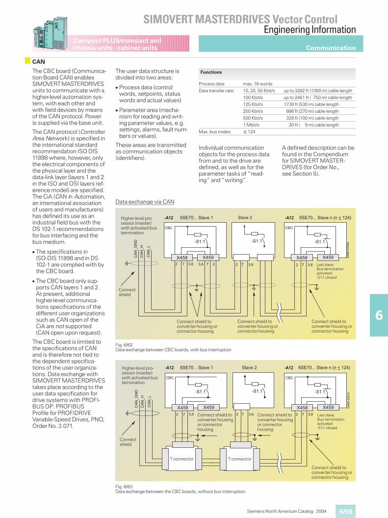
6/59
SIMOVERT MASTERDRIVES Vector ControlEngineering Information
6
Compact PLUS/compact andchassis units · cabinet units
Siemens North American Catalog · 2004
The CBC board (Communica-tion Board CAN) enablesSIMOVERTMASTERDRIVESunits to communicate with ahigher-level automation sys-tem, with each other andwith field devices by meansof the CAN protocol. Poweris supplied via the base unit.
The CAN protocol (ControllerArea Network) is specified inthe international standardrecommendation ISO DIS11898 where, however, onlythe electrical components ofthe physical layer and thedata-link layer (layers 1 and 2in the ISO and OSI layers ref-erence model) are specified.The CiA (CAN in Automation,an international associationof users and manufacturers)has defined its use as anindustrial field bus with theDS 102-1 recommendationsfor bus interfacing and thebus medium.
� The specifications inISO-DIS 11898 and in DS102-1 are complied with bythe CBC board.
� The CBC board only sup-ports CAN layers 1 and 2.At present, additionalhigher-level communica-tions specifications of thedifferent user organizationssuch as CAN open of theCiA are not supported(CAN open upon request).
The CBC board is limited tothe specifications of CANand is therefore not tied tothe dependent specifica-tions of the user organiza-tions. Data exchange withSIMOVERT MASTERDRIVEStakes place according to theuser data specification fordrive systems with PROFI-BUS DP: PROFIBUSProfile for PROFIDRIVEVariable-Speed Drives, PNO,Order No. 3.071.
The user data structure isdivided into two areas:
� Process data (controlwords, setpoints, statuswords and actual values)
� Parameter area (mecha-nism for reading and writ-ing parameter values, e.g.settings, alarms, fault num-bers or values).
These areas are transmittedas communication objects(identifiers).
Functions
Process data max. 16 words
Data transfer rate: 10, 20, 50 Kbit/s up to 3282 ft (1000 m) cable length
100 Kbit/s up to 2461 ft ( 750 m) cable length
125 Kbit/s 1739 ft (530 m) cable length
250 Kbit/s 886 ft (270 m) cable length
500 Kbit/s 328 ft (100 m) cable length
1 Mbit/s 30 ft ( 9 m) cable length
Max. bus nodes: � 124
Fig. 6/62Data exchange between CBC boards, with bus interruption
Data exchange via CAN
Fig. 6/63Data exchange between the CBC boards, without bus interruption
��������
���>?
���>�
�&��999�&,�6(�1��1�@��������&,�6(���&��999�&,�6(�����
�;�
�&�9�
���>A��
� �
���" ����
!� ��!�
�;�
�&�9�
���" ����
�&�9�
� � !� � � !� Last slave:Bus terminationactivated-S1.1 closed
Connect shield toconverter housing orconnector housing
Higher-level pro-cessor (master)with activated bustermination
Connectshield
Connect shield toconverter housing orconnector housing
Connect shield toconverter housing orconnector housing
��������
���>?
���>�
�&��999�&,�6(�1��1�@��������&,�6(���&��999�&,�6(�����
�;�
�&�9�
���>A��
� �
���" ����
!�
�;�
�&�9�
���" ����
�&�9�
� � !� � � !� Last slave:Bus terminationactivated-S1.1 closed
Connect shield toconverter housingor connectorhousing
Higher-level pro-cessor (master)with activated bustermination
Connectshield
Connect shield toconverter housingor connectorhousing
Connect shield toconverter housing orconnector housing
T connectorT connector
Communication
CAN
Individual communicationobjects for the process datafrom and to the drive aredefined, as well as for theparameter tasks of “read-ing” and “writing”.
A defined description can befound in the Compendiumfor SIMOVERT MASTER-DRIVES (for Order No.,see Section 5).
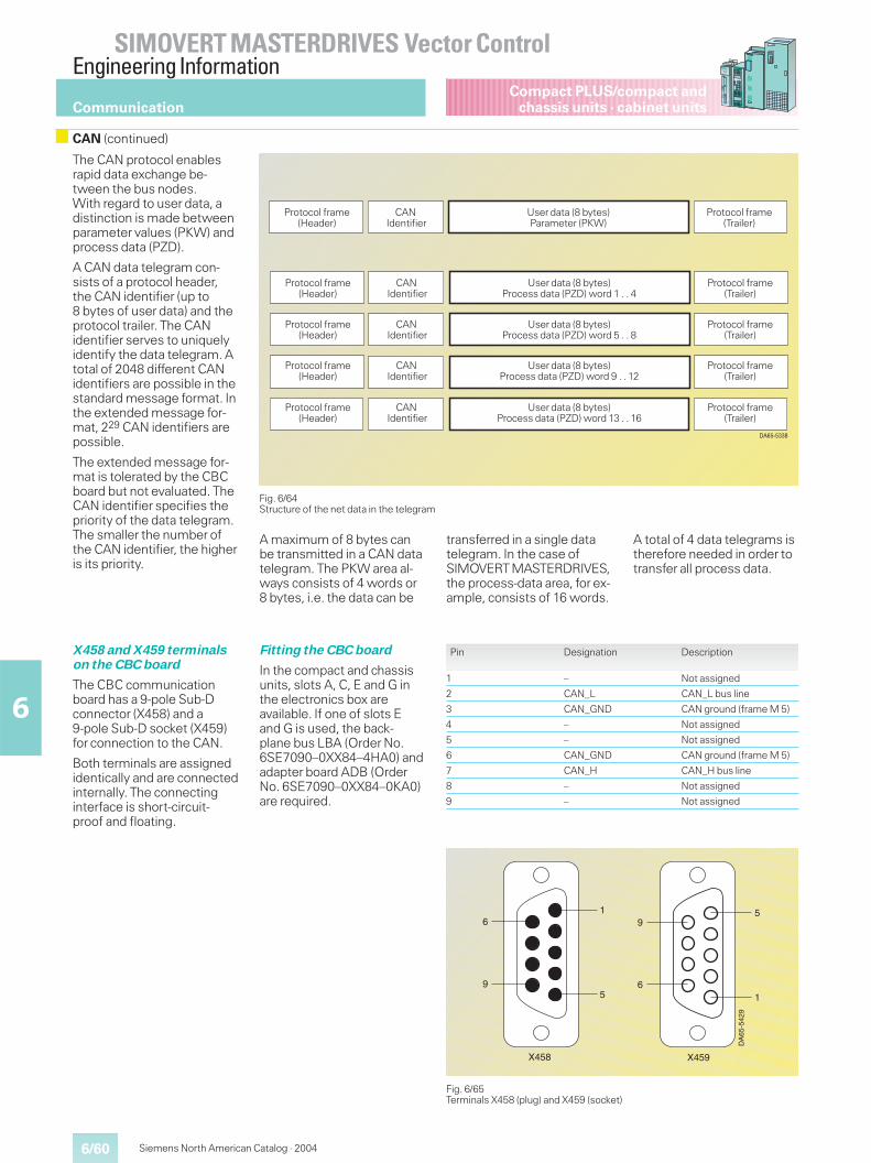
6/60
SIMOVERT MASTERDRIVES Vector ControlEngineering Information
6
Siemens North American Catalog · 2004
Compact PLUS/compact andchassis units · cabinet units
The CAN protocol enablesrapid data exchange be-tween the bus nodes.With regard to user data, adistinction is made betweenparameter values (PKW) andprocess data (PZD).
A CAN data telegram con-sists of a protocol header,the CAN identifier (up to8 bytes of user data) and theprotocol trailer. The CANidentifier serves to uniquelyidentify the data telegram. Atotal of 2048 different CANidentifiers are possible in thestandard message format. Inthe extended message for-mat, 229 CAN identifiers arepossible.
The extended message for-mat is tolerated by the CBCboard but not evaluated. TheCAN identifier specifies thepriority of the data telegram.The smaller the number ofthe CAN identifier, the higheris its priority.
A maximum of 8 bytes canbe transmitted in a CAN datatelegram. The PKW area al-ways consists of 4 words or8 bytes, i.e. the data can be
transferred in a single datatelegram. In the case ofSIMOVERTMASTERDRIVES,the process-data area, for ex-ample, consists of 16 words.
A total of 4 data telegrams istherefore needed in order totransfer all process data.
X458 and X459 terminalson the CBC board
The CBC communicationboard has a 9-pole Sub-Dconnector (X458) and a9-pole Sub-D socket (X459)for connection to the CAN.
Both terminals are assignedidentically and are connectedinternally. The connectinginterface is short-circuit-proof and floating.
Fitting the CBC board
In the compact and chassisunits, slots A, C, E and G inthe electronics box areavailable. If one of slots Eand G is used, the back-plane bus LBA (Order No.6SE7090–0XX84–4HA0) andadapter board ADB (OrderNo. 6SE7090–0XX84–0KA0)are required.
Fig. 6/64Structure of the net data in the telegram
Pin Designation Description
1 – Not assigned
2 CAN_L CAN_L bus line
3 CAN_GND CAN ground (frame M 5)
4 – Not assigned
5 – Not assigned
6 CAN_GND CAN ground (frame M 5)
7 CAN_H CAN_H bus line
8 – Not assigned
9 – Not assigned
Fig. 6/65Terminals X458 (plug) and X459 (socket)
6
9
1
5
X458 X459
9
6
5
1
DA
65-5
429
������"
Protocol frame(Header)
Protocol frame(Trailer)
User data (8 bytes)Parameter (PKW)
CANIdentifier
Protocol frame(Header)
CANIdentifier
User data (8 bytes)Process data (PZD) word 13 . . 16
Protocol frame(Trailer)
Protocol frame(Header)
CANIdentifier
User data (8 bytes)Process data (PZD) word 9 . . 12
Protocol frame(Trailer)
Protocol frame(Header)
CANIdentifier
User data (8 bytes)Process data (PZD) word 5 . . 8
Protocol frame(Trailer)
Protocol frame(Header)
CANIdentifier
User data (8 bytes)Process data (PZD) word 1 . . 4
Protocol frame(Trailer)
Communication
CAN (continued)
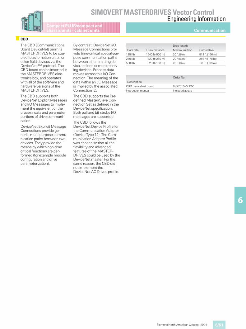
6/61
SIMOVERT MASTERDRIVES Vector ControlEngineering Information
6
Compact PLUS/compact andchassis units · cabinet units
Siemens North American Catalog · 2004
Communication
CBD
The CBD (CommunicationsBoard DeviceNet) permitsMASTERDRIVES to be cou-pled to automation units, orother field devices via theDeviceNetTM protocol. TheCBD board can be inserted inthe MASTERDRIVES elec-tronics box, and operateswith all of the software andhardware versions of theMASTERDRIVES.
The CBD supports bothDeviceNet Explicit Messagesand I/O Messages to imple-ment the equivalent of theprocess data and parameterportions of drive communi-cation.
DeviceNet Explicit MessageConnections provide ge-neric, multi-purpose commu-nication paths between twodevices. They provide themeans by which non-timecritical functions are per-formed (for example moduleconfiguration and driveparameterization).
By contrast, DeviceNet I/OMessage Connections pro-vide time-critical special-pur-pose communication pathsbetween a transmitting de-vice and one or more receiv-ing devices. Process datamoves across this I/O Con-nection. The meaning of thedata within an I/O Messageis implied by the associatedConnection ID.
The CBD supports the Pre-defined Master/Slave Con-nection Set as defined in theDeviceNet specification.Both poll and bit strobe I/Omessages are supported.
The CBD follows theDeviceNet Device Profile forthe Communication Adapter(Device Type 12). The Com-munication Adapter Profilewas chosen so that all theflexibility and advancedfeatures of the MASTER-DRIVES could be used by theDeviceNet master. For thesame reason, the CBD didnot implement theDeviceNet AC Drives profile.
Drop length
Data rate Trunk distance Maximum drop Cumulative
125 Kb 1640 ft (500 m) 20 ft (6 m) 512 ft (156 m)
250 Kb 820 ft (250 m) 20 ft (6 m) 256 ft ( 78 m)
500 Kb 328 ft (100 m) 20 ft (6 m) 128 ft ( 39 m)
Order No.
Description
CBD DeviceNet Board 6SX7010–0FK00
Instruction manual Included above
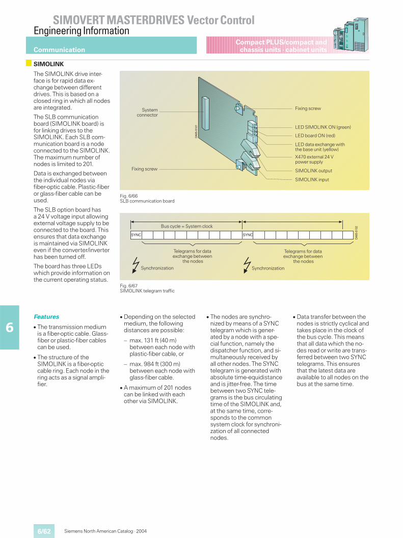
6/62
SIMOVERT MASTERDRIVES Vector ControlEngineering Information
6
Siemens North American Catalog · 2004
Compact PLUS/compact andchassis units · cabinet units
The SIMOLINK drive inter-face is for rapid data ex-change between differentdrives. This is based on aclosed ring in which all nodesare integrated.
The SLB communicationboard (SIMOLINK board) isfor linking drives to theSIMOLINK. Each SLB com-munication board is a nodeconnected to the SIMOLINK.The maximum number ofnodes is limited to 201.
Data is exchanged betweenthe individual nodes viafiber-optic cable. Plastic-fiberor glass-fiber cable can beused.
The SLB option board hasa 24 V voltage input allowingexternal voltage supply to beconnected to the board. Thisensures that data exchangeis maintained via SIMOLINKeven if the converter/inverterhas been turned off.
The board has three LEDswhich provide information onthe current operating status.
Fig. 6/66SLB communication board
Fig. 6/67SIMOLINK telegram traffic
&B�� &B��
��������Bus cycle = System clock
Telegrams for dataexchange between
the nodes
Synchronization Synchronization
Telegrams for dataexchange between
the nodes
DA
65-5
101
Systemconnector
Fixing screw
Fixing screw
LED SIMOLINK ON (green)
LED board ON (red)
LED data exchange withthe base unit (yellow)
X470 external 24 Vpower supply
SIMOLINK input
SIMOLINK output
Communication
SIMOLINK
Features
� The transmission mediumis a fiber-optic cable. Glass-fiber or plastic-fiber cablescan be used.
� The structure of theSIMOLINK is a fiber-opticcable ring. Each node in thering acts as a signal ampli-fier.
� Depending on the selectedmedium, the followingdistances are possible:
– max. 131 ft (40 m)between each node withplastic-fiber cable, or
– max. 984 ft (300 m)between each node withglass-fiber cable.
� A maximum of 201 nodescan be linked with eachother via SIMOLINK.
� The nodes are synchro-nized by means of a SYNCtelegram which is gener-ated by a node with a spe-cial function, namely thedispatcher function, and si-multaneously received byall other nodes. The SYNCtelegram is generated withabsolute time-equidistanceand is jitter-free. The timebetween two SYNC tele-grams is the bus circulatingtime of the SIMOLINK and,at the same time, corre-sponds to the commonsystem clock for synchroni-zation of all connectednodes.
� Data transfer between thenodes is strictly cyclical andtakes place in the clock ofthe bus cycle. This meansthat all data which the no-des read or write are trans-ferred between two SYNCtelegrams. This ensuresthat the latest data areavailable to all nodes on thebus at the same time.
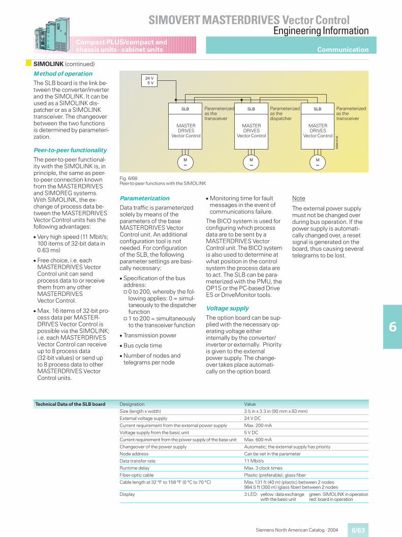
6/63
SIMOVERT MASTERDRIVES Vector ControlEngineering Information
6
Compact PLUS/compact andchassis units · cabinet units
Siemens North American Catalog · 2004
Method of operation
The SLB board is the link be-tween the converter/inverterand the SIMOLINK. It can beused as a SIMOLINK dis-patcher or as a SIMOLINKtransceiver. The changeoverbetween the two functionsis determined by parameteri-zation.
Peer-to-peer functionality
The peer-to-peer functional-ity with the SIMOLINK is, inprinciple, the same as peer-to-peer connection knownfrom the MASTERDRIVESand SIMOREG systems.With SIMOLINK, the ex-change of process data be-tween the MASTERDRIVESVector Control units has thefollowing advantages:
� Very high speed (11 Mbit/s;100 items of 32-bit data in0.63 ms)
� Free choice, i.e. eachMASTERDRIVES VectorControl unit can sendprocess data to or receivethem from any otherMASTERDRIVESVector Control.
� Max. 16 items of 32-bit pro-cess data per MASTER-DRIVES Vector Control ispossible via the SIMOLINK;i.e. each MASTERDRIVESVector Control can receiveup to 8 process data(32-bit values) or send upto 8 process data to otherMASTERDRIVES VectorControl units.
Technical Data of the SLB board
Fig. 6/68Peer-to-peer functions with the SIMOLINK
Designation Value
Size (length x width) 3.5 in x 3.3 in (90 mm x 83 mm)
External voltage supply 24 V DC
Current requirement from the external power supply Max. 200 mA
Voltage supply from the basic unit 5 V DC
Current requirement from the power supply of the base unit Max. 600 mA
Changeover of the power supply Automatic; the external supply has priority
Node address Can be set in the parameter
Data transfer rate 11 Mbit/s
Runtime delay Max. 3 clock times
Fiber-optic cable Plastic (preferable); glass fiber
Cable length at 32 °F to 158 °F (0 °C to 70 °C) Max.131 ft (40 m) (plastic) between 2 nodes984.5 ft (300 m) (glass fiber) between 2 nodes
Display 3 LED: yellow: data exchange green: SIMOLINK in operationwith the basic unit red: board in operation
&�; &�; &�;
�
%�
%�
%
���������
�������
Parameterizedas thedispatcher
Parameterizedas thetransceiver
MASTERDRIVES
Vector Control
MASTERDRIVES
Vector Control
MASTERDRIVES
Vector Control
Parameterizedas thetransceiver
Communication
SIMOLINK (continued)
Parameterization
Data traffic is parameterizedsolely by means of theparameters of the baseMASTERDRIVES VectorControl unit. An additionalconfiguration tool is notneeded. For configurationof the SLB, the followingparameter settings are basi-cally necessary:
� Specification of the busaddress:@ 0 to 200, whereby the fol-
lowing applies: 0 = simul-taneously to the dispatcherfunction
@ 1 to 200 = simultaneouslyto the transceiver function
� Transmission power
� Bus cycle time
� Number of nodes andtelegrams per node
� Monitoring time for faultmessages in the event ofcommunications failure.
The BICO system is used forconfiguring which processdata are to be sent by aMASTERDRIVES VectorControl unit.The BICO systemis also used to determine atwhat position in the controlsystem the process data areto act. The SLB can be para-meterized with the PMU, theOP1S or the PC-based DriveES or DriveMonitor tools.
Voltage supply
The option board can be sup-plied with the necessary op-erating voltage eitherinternally by the converter/inverter or externally. Priorityis given to the externalpower supply. The change-over takes place automati-cally on the option board.
Note
The external power supplymust not be changed overduring bus operation. If thepower supply is automati-cally changed over, a resetsignal is generated on theboard, thus causing severaltelegrams to be lost.
6/64
SIMOVERT MASTERDRIVES Vector ControlEngineering Information
6
Siemens North American Catalog · 2004
Compact PLUS/compact andchassis units · cabinet units
The following protocolconverters have been testedby and are sold by SiemensEnergy & Automation. Theybasically convert the datasent and received by USSProtocol into data locationsin the host. For example,there will be a separate dataword in the host correspond-ing to the control word foreach drive. Changing bit 0 ofthis data word (usually withladder logic) will start or stopthat individual drive. Anotherseparate data word for eachdrive would be the speedreference for each drive.
DTU-3006
The DTU-3006 is an intelli-gent PLC to Siemens DrivesCommunication InterfaceUnit. The DTU-3006 sup-ports over 25 PLC Protocols,including Schneider Automa-tion‘s Modbus, and convertsto USS Protocol.
MD-3006
The MD-3006 is an intelli-gent PLC to Siemens DriveCommunication InterfaceUnit. The MD-3006 convertsSchneider Automation‘sModbus Plus to USS Proto-col.
DN-3006
The DN-3006 is an intelligentPLC to Siemens DriveCommunication InterfaceUnit. The DN-3006 convertsDeviceNet to USS Protocol.It has slower communicationspeeds than CBD.
PD-3006
The PD-3006 is an intelligentPLC to Siemens DrivesCommunication InterfaceUnit. The PD-3006 convertsPROFIBUS DP to USS Proto-col. It has slower communi-cation speeds than CBP2.
SCI-PU
The 6SE70 MASTERDRIVEScan be interfaced to Allen-BradleyTM and ModiconTM
programmable controllers byutilizing the SCI-PU. TheSCI-PU performs the com-plex protocol conversions,transparent to the program-mer or operator.
The SCI-PU provides amulti-drop RS485 bus inter-face to up to 31 6SE70 drivecontrollers. The serial inter-face is fully functional formonitoring and control.
Port A (Host) supports:
� Allen-Bradley Data High-way+TM
� Modicon Modbus+ (viaModbus)TM
� Allen-Bradley Remote I/ONetwork
Port B (Drive Protocols)supports
� USS ProtocolRS485Variable telegram lengthto 187.5 KBaud
� Simple ProtocolRS48510 word telegram lengthto 38.4 KBaud
� DUST 6B ProtocolRS485Selectable telegram length117.6 KBaud
TMData Highway is a trade-mark of Allen-Bradley Com-pany, Inc.TMModbus is a trademark ofModicon, Inc.
Communication
Serial communication converters · Available protocol converters
Serial communication converter Order No.
DTU-3006 DTU-3006
MD-3006 MD-3006
DN-3006 DN-3006
PD-3006 PD-3006
SCI-PU A1-101-037-811
Selection and ordering data
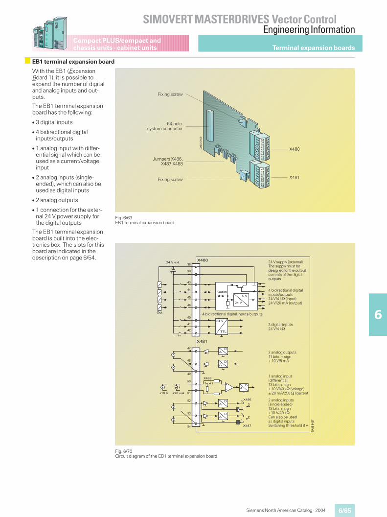
6/65
SIMOVERT MASTERDRIVES Vector ControlEngineering Information
6
Compact PLUS/compact andchassis units · cabinet units
Siemens North American Catalog · 2004
With the EB1 (ExpansionBoard 1), it is possible toexpand the number of digitaland analog inputs and out-puts.
The EB1 terminal expansionboard has the following:
� 3 digital inputs
� 4 bidirectional digitalinputs/outputs
� 1 analog input with differ-ential signal which can beused as a current/voltageinput
� 2 analog inputs (single-ended), which can also beused as digital inputs
� 2 analog outputs
� 1 connection for the exter-nal 24 V power supply forthe digital outputs
The EB1 terminal expansionboard is built into the elec-tronics box. The slots for thisboard are indicated in thedescription on page 6/54.
Fig. 6/69EB1 terminal expansion board
Fig. 6/70Circuit diagram of the EB1 terminal expansion board
DA
65-5
169
383940414243444546
4748495051525354
X487X486
1
1
1
X488
Fixing screw
64-polesystem connector
Jumpers X486,X487, X488
Fixing screw
X480
X481
��
��
�
� ��
��
��
�
�
����
���
:C)� 1
����
���
:C)
1
���� ���.���
� �
��""
�
��"�
��"�
�
�
�
���������
��
�"
��
�
��
��
�
��
��
��
��
�
��
��
�
�
"
��"�
��"�����(D)9
4 bidirectional digital inputs/outputs
24 V supply (external)The supply must bedesigned for the outputcurrents of the digitaloutputs
2 analog outputs11 bits + sign± 10 V/5 mA
3 digital inputs24 V/4 k
4 bidirectional digitalinputs/outputs24 V/4 k (input)24 V/20 mA (output)
2 analog inputs(single-ended)13 bits + sign±10 V/40 kCan also be usedas digital inputsSwitching threshold 8 V
1 analog input(differential)13 bits + sign± 10 V/40 k (voltage)± 20 mA/250 (current)
Terminal expansion boards
EB1 terminal expansion board
6/66
SIMOVERT MASTERDRIVES Vector ControlEngineering Information
6
Siemens North American Catalog · 2004
Compact PLUS/compact andchassis units · cabinet units
The following connectionsare provided on the terminalstrip:
� 3 digital inputs
� 4 bidirectional digitalinputs/outputs
The ground cables areprotected by a reactor.Terminal 46 is at the topwhen installed.
Note
The external 24 V power sup-ply is necessary and must bedimensioned for the currentsof the digital outputs.
Connection X480 Terminal Designation Description Range
38 M Ground digital 0 V
39 P24 ext. Ext. 24 V supply 20 V to 33 V
40 DI1 Digital input 1 24 V, Ri = 4 k
41 DI2 Digital input 2 24 V, Ri = 4 k
42 DI3 Digital input 3 24 V, Ri = 4 k
43 DIO1 Digital input/output 1 As input:24 V, 4 k
As output:Output voltageP24 ext. –2.5 V, 20 mA
44 DIO2 Digital input/output 2
45 DIO3 Digital input/output 3
46 DIO4 Digital input/output 4
Connectable cross-section: 0.14 mm2 to 1.5 mm2 (AWG 16)
The following connectionsare provided on the terminalstrip:
� 1 analog input with differen-tial signal, which can beused as a current and volt-age input
� 2 analog inputs (single-ended), can also be used asdigital inputs
� 2 analog outputs
The ground cables are pro-tected by a reactor. Terminal47 is at the top when in-stalled.
Connection X481 Terminal Designation Description Range
47 AO1 Analog output 1 ±10 V, 5 mA
48 AO2 Analog output 2 ±10 V, 5 mA
49 AOM Ground analog output 0 V
50 AI1P Analog input 1 + Voltage: ± 10 V, 40 k
51 AI1N Analog input 1 – Current: ± 20 mA, 250
52 AI2 Analog input 2 ±10 V, 40 k
53 AI3 Analog input 3 ±10 V, 40 k
54 AIM Ground analog input 0 V
Connectable cross-section: 0.14 mm2 to 1.5 mm2 (AWG 16)
Technical Data Designation Value
Digital inputs DI1, DI2, DI3
� Voltage range LOW� Voltage range HIGH� Input resistance� Smoothing� Electrical isolation
0 V (–33 V to +5 V)+24 V (13 V to 33 V)4 k250 �sNone
Bidirectional digital inputs/outputs DIO1, DIO2, DIO3, DIO4
As input� Voltage range LOW� Voltage range HIGH� Input resistanceAs output� Voltage range LOW� Voltage range HIGH
0 V (–33 V to +5 V)+24 V (13 V to 33 V)4 k
< 2 V> P24 ext. –2.5 V
Analog input (differential input) AI1P, AI1N
� Input rangeVoltageCurrent
� Input resistanceVoltageCurrent
� Hardware smoothing� Resolution
±11 V±20 mA
40 k to ground250 to ground220 �s13 bits + sign
Analog input (single-ended) AI2, AI3, AIM
� Input range� Input resistance� Hardware smoothing� Resolution
±11 V40 k to ground220 �s13 bits + sign
Analog output AO1, AO2, AOM
� Voltage range� Input resistance� Hardware smoothing� Resolution
±10 V40 k to ground10 �s11 bits + sign
Terminal expansion boards
EB1 terminal expansion board (continued)
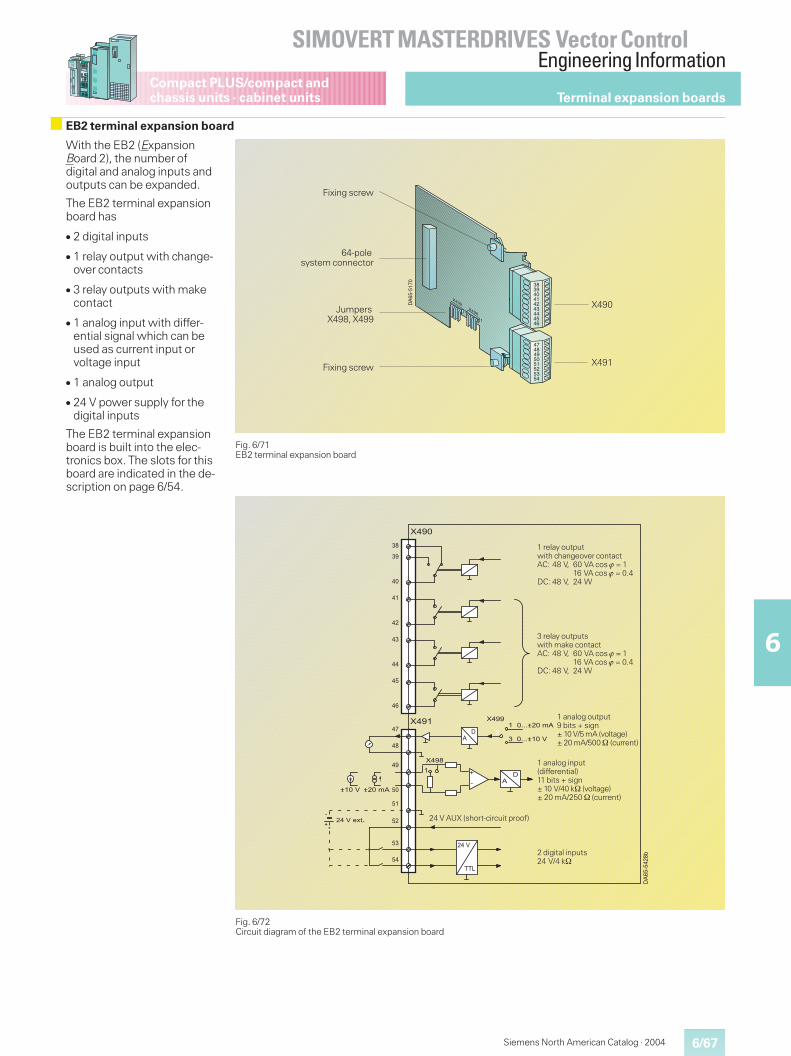
6/67
SIMOVERT MASTERDRIVES Vector ControlEngineering Information
6
Compact PLUS/compact andchassis units · cabinet units
Siemens North American Catalog · 2004
With the EB2 (ExpansionBoard 2), the number ofdigital and analog inputs andoutputs can be expanded.
The EB2 terminal expansionboard has
� 2 digital inputs
� 1 relay output with change-over contacts
� 3 relay outputs with makecontact
� 1 analog input with differ-ential signal which can beused as current input orvoltage input
� 1 analog output
� 24 V power supply for thedigital inputs
The EB2 terminal expansionboard is built into the elec-tronics box. The slots for thisboard are indicated in the de-scription on page 6/54.
Fig. 6/71EB2 terminal expansion board
Fig. 6/72Circuit diagram of the EB2 terminal expansion board
DA
65-5
170
X499X498
1
1
383940414243444546
4748495051525354
Fixing screw
64-polesystem connector
JumpersX498, X499
Fixing screw
X490
X491
����
�"
��
�
��
��
�
��
����
���
��
��
��
�
��
��
�
�
"
��������"/
�
� ��
�
���"
���� ���.���
��
����
999����
999���.��
�
����
���
�����(D)9�
�24 V AUX (short-circuit proof)
1 relay outputwith changeover contactAC: 48 V, 60 VA cos � = 1
16 VA cos � = 0.4DC: 48 V, 24 W
1 analog output9 bits + sign± 10 V/5 mA (voltage)± 20 mA/500 (current)
3 relay outputswith make contactAC: 48 V, 60 VA cos � = 1
16 VA cos � = 0.4DC: 48 V, 24 W
2 digital inputs24 V/4 k
1 analog input(differential)11 bits + sign± 10 V/40 k (voltage)± 20 mA/250 (current)
Terminal expansion boards
EB2 terminal expansion board
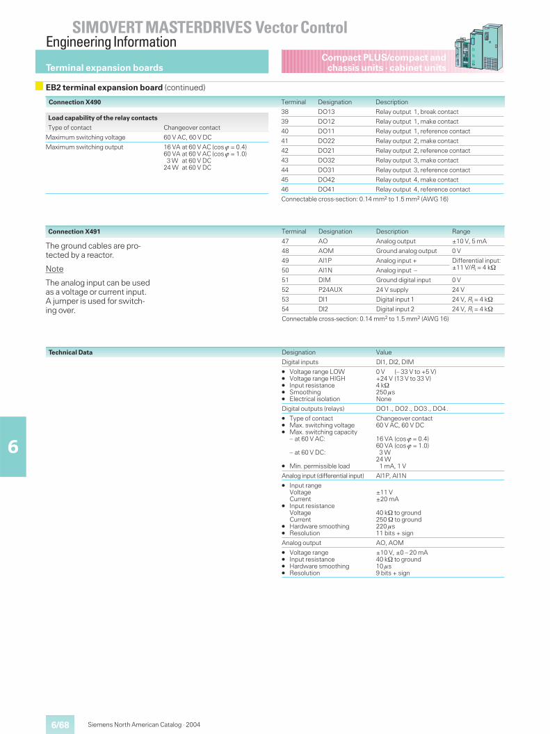
6/68
SIMOVERT MASTERDRIVES Vector ControlEngineering Information
6
Siemens North American Catalog · 2004
Compact PLUS/compact andchassis units · cabinet units
Connection X490
The ground cables are pro-tected by a reactor.
Note
The analog input can be usedas a voltage or current input.A jumper is used for switch-ing over.
Terminal Designation Description
38 DO13 Relay output 1, break contact
39 DO12 Relay output 1, make contact
40 DO11 Relay output 1, reference contact
41 DO22 Relay output 2, make contact
42 DO21 Relay output 2, reference contact
43 DO32 Relay output 3, make contact
44 DO31 Relay output 3, reference contact
45 DO42 Relay output 4, make contact
46 DO41 Relay output 4, reference contact
Connectable cross-section: 0.14 mm2 to 1.5 mm2 (AWG 16)
Technical Data Designation Value
Digital inputs Dl1, Dl2, DIM
� Voltage range LOW� Voltage range HIGH� Input resistance� Smoothing� Electrical isolation
0 V (– 33 V to +5 V)+24 V (13 V to 33 V)4 k250 �sNone
Digital outputs (relays) DO1., DO2., DO3., DO4.
� Type of contact� Max. switching voltage� Max. switching capacity
– at 60 V AC:
– at 60 V DC:
� Min. permissible load
Changeover contact60 V AC, 60 V DC
16 VA (cos � = 0.4)60 VA (cos � = 1.0)3 W
24 W1 mA, 1 V
Analog input (differential input) Al1P, Al1N
� Input rangeVoltageCurrent
� Input resistanceVoltageCurrent
� Hardware smoothing� Resolution
±11 V±20 mA
40 k to ground250 to ground220 �s11 bits + sign
Analog output AO, AOM
� Voltage range� Input resistance� Hardware smoothing� Resolution
±10 V, ±0 – 20 mA40 k to ground10 �s9 bits + sign
Connection X491 Terminal Designation Description Range
47 AO Analog output ±10 V, 5 mA
48 AOM Ground analog output 0 V
49 Al1P Analog input + Differential input:±11 V/Ri = 4 k50 Al1N Analog input –
51 DIM Ground digital input 0 V
52 P24AUX 24 V supply 24 V
53 Dl1 Digital input 1 24 V, Ri = 4 k
54 Dl2 Digital input 2 24 V, Ri = 4 k
Connectable cross-section: 0.14 mm2 to 1.5 mm2 (AWG 16)
Load capability of the relay contacts
Type of contact Changeover contact
Maximum switching voltage 60 V AC, 60 V DC
Maximum switching output 16 VA at 60 V AC (cos � = 0.4)60 VA at 60 V AC (cos � = 1.0)3 W at 60 V DC
24 W at 60 V DC
Terminal expansion boards
EB2 terminal expansion board (continued)
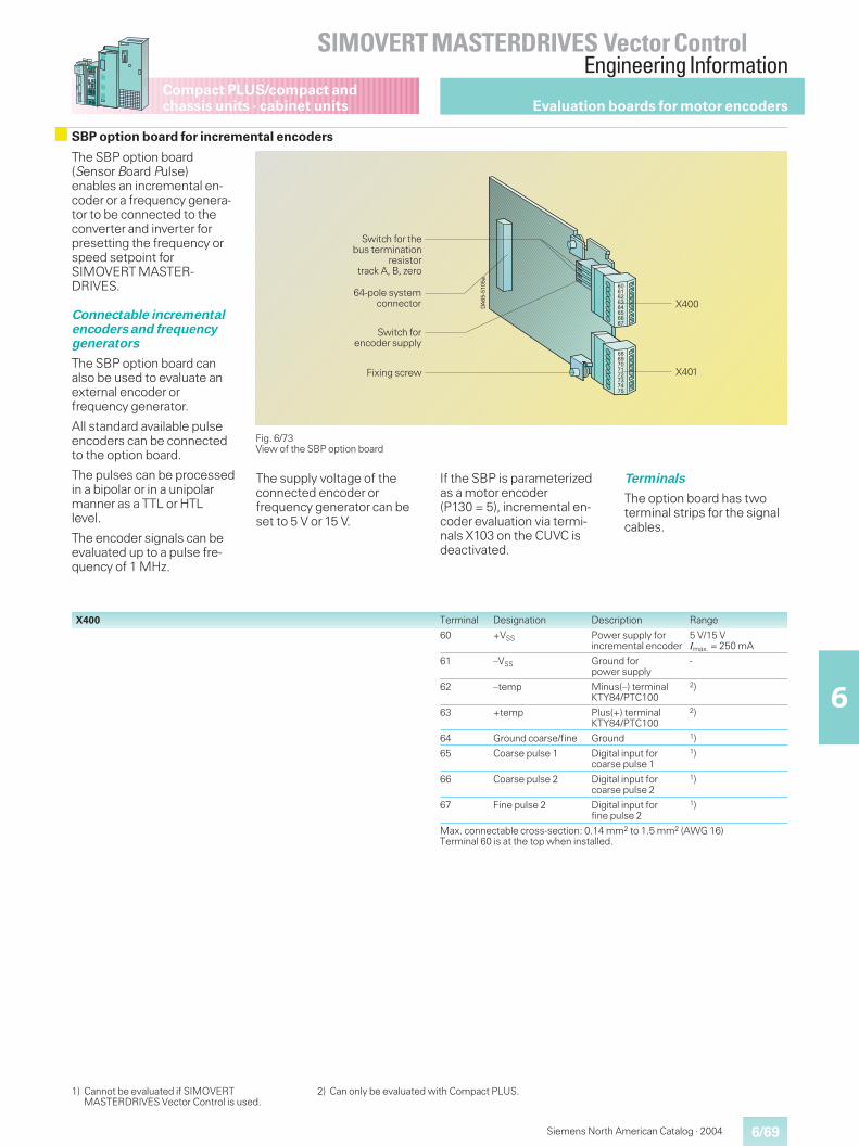
6/69
SIMOVERT MASTERDRIVES Vector ControlEngineering Information
6
Compact PLUS/compact andchassis units · cabinet units
Siemens North American Catalog · 2004
Evaluation boards for motor encoders
The SBP option board(Sensor Board Pulse)enables an incremental en-coder or a frequency genera-tor to be connected to theconverter and inverter forpresetting the frequency orspeed setpoint forSIMOVERT MASTER-DRIVES.
Connectable incrementalencoders and frequencygenerators
The SBP option board canalso be used to evaluate anexternal encoder orfrequency generator.
All standard available pulseencoders can be connectedto the option board.
The pulses can be processedin a bipolar or in a unipolarmanner as a TTL or HTLlevel.
The encoder signals can beevaluated up to a pulse fre-quency of 1 MHz.
Fig. 6/73View of the SBP option board
+*��������
���������������
����������������
Switch for thebus termination
resistortrack A, B, zero
Switch forencoder supply
64-pole systemconnector
Fixing screw X401
X400
X400 Terminal Designation Description Range
60 +VSS Power supply forincremental encoder
5 V/15 VImax. = 250 mA
61 –VSS Ground forpower supply
-
62 –temp Minus(–) terminalKTY84/PTC100
2)
63 +temp Plus(+) terminalKTY84/PTC100
2)
64 Ground coarse/fine Ground 1)
65 Coarse pulse 1 Digital input forcoarse pulse 1
1)
66 Coarse pulse 2 Digital input forcoarse pulse 2
1)
67 Fine pulse 2 Digital input forfine pulse 2
1)
Max. connectable cross-section: 0.14 mm2 to 1.5 mm2 (AWG 16)Terminal 60 is at the top when installed.
SBP option board for incremental encoders
The supply voltage of theconnected encoder orfrequency generator can beset to 5 V or 15 V.
If the SBP is parameterizedas a motor encoder(P130 = 5), incremental en-coder evaluation via termi-nals X103 on the CUVC isdeactivated.
Terminals
The option board has twoterminal strips for the signalcables.
1) Cannot be evaluated if SIMOVERTMASTERDRIVES Vector Control is used.
2) Can only be evaluated with Compact PLUS.
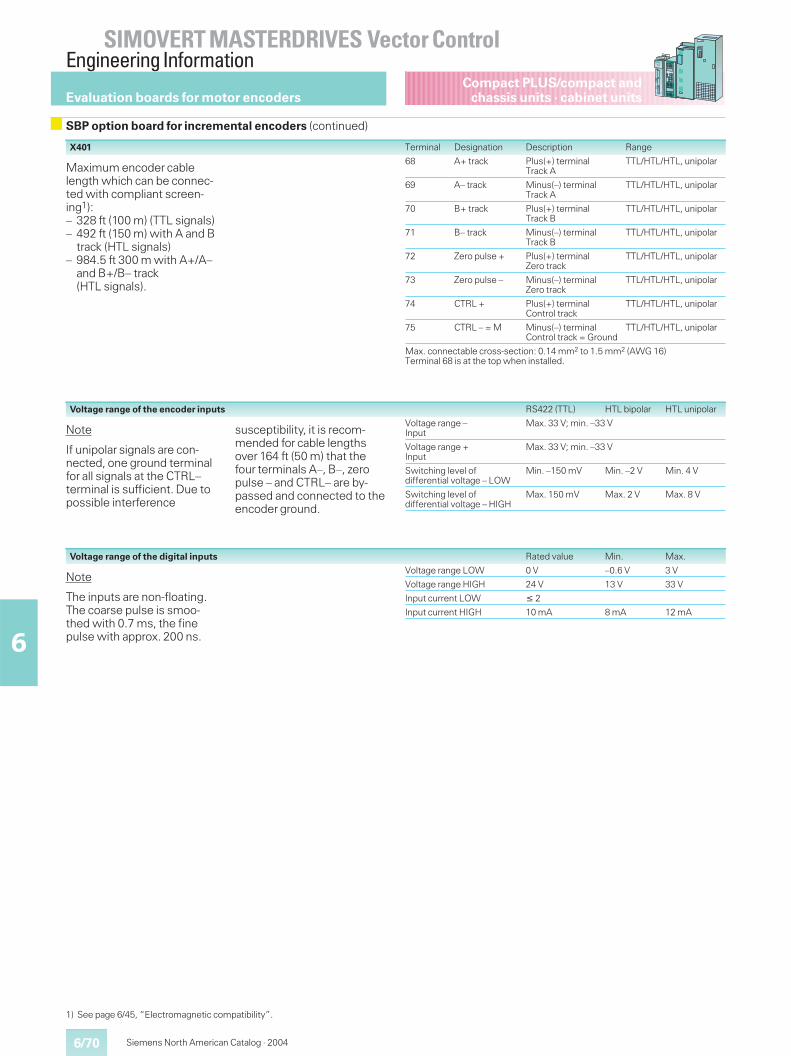
6/70
SIMOVERT MASTERDRIVES Vector ControlEngineering Information
6
Siemens North American Catalog · 2004
Compact PLUS/compact andchassis units · cabinet units
Note
If unipolar signals are con-nected, one ground terminalfor all signals at the CTRL–terminal is sufficient. Due topossible interference
susceptibility, it is recom-mended for cable lengthsover 164 ft (50 m) that thefour terminals A–, B–, zeropulse – and CTRL– are by-passed and connected to theencoder ground.
Note
The inputs are non-floating.The coarse pulse is smoo-thed with 0.7 ms, the finepulse with approx. 200 ns.
Voltage range of the encoder inputs RS422 (TTL) HTL bipolar HTL unipolar
Voltage range –Input
Max. 33 V; min. –33 V
Voltage range +Input
Max. 33 V; min. –33 V
Switching level ofdifferential voltage – LOW
Min. –150 mV Min. –2 V Min. 4 V
Switching level ofdifferential voltage – HIGH
Max. 150 mV Max. 2 V Max. 8 V
Voltage range of the digital inputs Rated value Min. Max.
Voltage range LOW 0 V –0.6 V 3 V
Voltage range HIGH 24 V 13 V 33 V
Input current LOW � 2
Input current HIGH 10 mA 8 mA 12 mA
Maximum encoder cablelength which can be connec-ted with compliant screen-ing1):– 328 ft (100 m) (TTL signals)– 492 ft (150 m) with A and B
track (HTL signals)– 984.5 ft 300 m with A+/A–
and B+/B– track(HTL signals).
X401 Terminal Designation Description Range
68 A+ track Plus(+) terminalTrack A
TTL/HTL/HTL, unipolar
69 A– track Minus(–) terminalTrack A
TTL/HTL/HTL, unipolar
70 B+ track Plus(+) terminalTrack B
TTL/HTL/HTL, unipolar
71 B– track Minus(–) terminalTrack B
TTL/HTL/HTL, unipolar
72 Zero pulse + Plus(+) terminalZero track
TTL/HTL/HTL, unipolar
73 Zero pulse – Minus(–) terminalZero track
TTL/HTL/HTL, unipolar
74 CTRL + Plus(+) terminalControl track
TTL/HTL/HTL, unipolar
75 CTRL – = M Minus(–) terminalControl track = Ground
TTL/HTL/HTL, unipolar
Max. connectable cross-section: 0.14 mm2 to 1.5 mm2 (AWG 16)Terminal 68 is at the top when installed.
1) See page 6/45, “Electromagnetic compatibility”.
Evaluation boards for motor encoders
SBP option board for incremental encoders (continued)
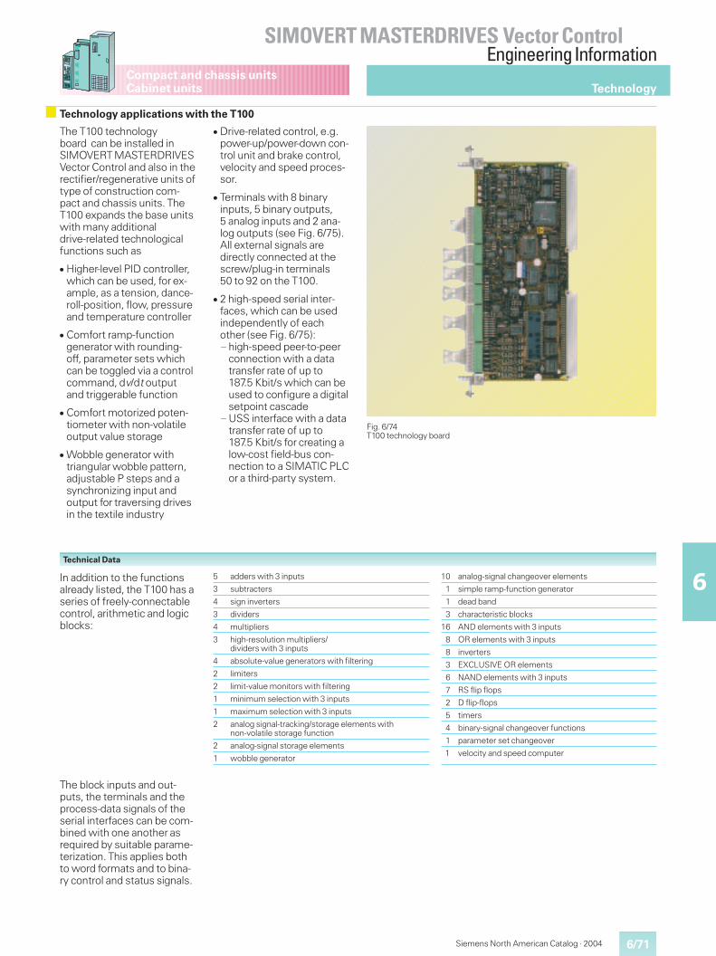
6/71
SIMOVERT MASTERDRIVES Vector ControlEngineering Information
6
Siemens North American Catalog · 2004
Compact and chassis unitsCabinet units
The T100 technologyboard can be installed inSIMOVERT MASTERDRIVESVector Control and also in therectifier/regenerative units oftype of construction com-pact and chassis units. TheT100 expands the base unitswith many additionaldrive-related technologicalfunctions such as
� Higher-level PID controller,which can be used, for ex-ample, as a tension, dance-roll-position, flow, pressureand temperature controller
� Comfort ramp-functiongenerator with rounding-off, parameter sets whichcan be toggled via a controlcommand, dv/dt outputand triggerable function
� Comfort motorized poten-tiometer with non-volatileoutput value storage
� Wobble generator withtriangular wobble pattern,adjustable P steps and asynchronizing input andoutput for traversing drivesin the textile industry
� Drive-related control, e.g.power-up/power-down con-trol unit and brake control,velocity and speed proces-sor.
� Terminals with 8 binaryinputs, 5 binary outputs,5 analog inputs and 2 ana-log outputs (see Fig. 6/75).All external signals aredirectly connected at thescrew/plug-in terminals50 to 92 on the T100.
� 2 high-speed serial inter-faces, which can be usedindependently of eachother (see Fig. 6/75):— high-speed peer-to-peer
connection with a datatransfer rate of up to187.5 Kbit/s which can beused to configure a digitalsetpoint cascade
— USS interface with a datatransfer rate of up to187.5 Kbit/s for creating alow-cost field-bus con-nection to a SIMATIC PLCor a third-party system.
Fig. 6/74T100 technology board
Technical Data
5 adders with 3 inputs
3 subtracters
4 sign inverters
3 dividers
4 multipliers
3 high-resolution multipliers/dividers with 3 inputs
4 absolute-value generators with filtering
2 limiters
2 limit-value monitors with filtering
1 minimum selection with 3 inputs
1 maximum selection with 3 inputs
2 analog signal-tracking/storage elements withnon-volatile storage function
2 analog-signal storage elements
1 wobble generator
10 analog-signal changeover elements
1 simple ramp-function generator
1 dead band
3 characteristic blocks
16 AND elements with 3 inputs
8 OR elements with 3 inputs
8 inverters
3 EXCLUSIVE OR elements
6 NAND elements with 3 inputs
7 RS flip flops
2 D flip-flops
5 timers
4 binary-signal changeover functions
1 parameter set changeover
1 velocity and speed computer
In addition to the functionsalready listed, the T100 has aseries of freely-connectablecontrol, arithmetic and logicblocks:
The block inputs and out-puts, the terminals and theprocess-data signals of theserial interfaces can be com-bined with one another asrequired by suitable parame-terization. This applies bothto word formats and to bina-ry control and status signals.
Technology
Technology applications with the T100
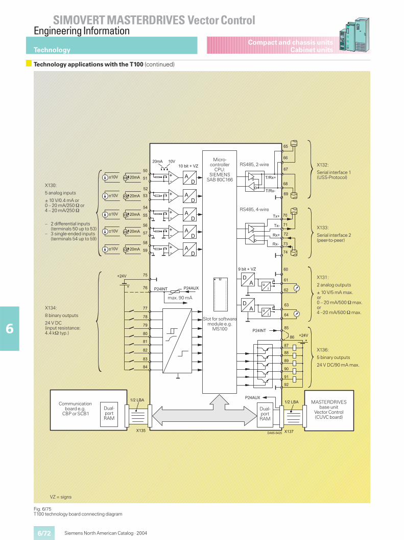
6/72
SIMOVERT MASTERDRIVES Vector ControlEngineering Information
6
Siemens North American Catalog · 2004
Compact and chassis unitsCabinet units
Fig. 6/75T100 technology board connecting diagram
=D�
��
��
��
�"
��
��
�
��
�
��
��
��
�"
��
"
"�
"�
"
"�
"�
�D�
=D�
�D�
��� ��
��
��
��
��
��
��
��
��
��
��
��/0)����E
������
��
��
��
��
��
�"
��
�
��
��
�
��
��=D�
��=D�
�
��
��
�
��
"�
"�
""
"�
�
��
��
��
��� ��
�
�
���.�
��/0)����E
F�� �.�
F�� �.�
F�� �.�
F�� �.�
F�� �.�
����
����
�����;������;�������
��� ������������
C0
0C
Slot for softwaremodule e.g.
MS100
max. 90 mA
X130:
5 analog inputs
± 10 V/0.4 mA or0 – 20 mA/250 or4 – 20 mA/250
X134:
8 binary outputs
24 V DC(input resistance:4.4 k typ.)
Communicationboard e.g.
CBP or SCB1Dual-portRAM
X131:
2 analog outputs
± 10 V/5 mA max.or0 – 20 mA/500 max.or4 –20 mA/500 max.
X133:
Serial interface 2(peer-to-peer)
X132:
Serial interface 1(USS-Protocol)
RS485, 2-wire
RS485, 4-wire
Micro-controller
CPU:SIEMENS
SAB 80C166
MASTERDRIVESbase unit
Vector Control(CUVC board)
Dual-portRAM
X136:
5 binary outputs
24 V DC/90 mA max.
VZ = signs
– 2 differential inputs(terminals 50 up to 53)
– 3 single-ended inputs(terminals 54 up to 59)
Technology
Technology applications with the T100 (continued)
6/73
SIMOVERT MASTERDRIVES Vector ControlEngineering Information
6
Siemens North American Catalog · 2004
Compact and chassis unitsCabinet units
The relevant internal signalsand parameters both of thebase unit and the T100 canbe accessed via the USSinterface of the T100.
The T100 has its own para-meter memory and can beparameterized via the PMUoperator control and para-meterizing unit, the optionalOP1S operator control unit ora PC loaded by means ofDrive ES or DriveMonitor(see pages 2/10 to 2/14).
The PC with Drive ES orDriveMonitor is connectedto the USS interface of theSIMOVERT MASTER-DRIVES.
All relevant internal T100signals can be monitored bymeans of display parameters(multimeter functions).The T100 has 3 diagnosticLEDs, which indicate thefollowing operating statuses:
1. The T100 is operatingerror-free in cyclical mode
2. Data exchange betweenthe T100 and SIMOVERTMASTERDRIVES is OK
3. Data exchange betweenthe T100 and the commu-nication board is OK
Note
All the software functionsdescribed here are con-tained in the MS100 soft-ware module “UniversalDrive”. The software mod-ule is a 40-pin EPROM de-vice, which must be orderedseparately and is inserted inthe dedicated plug-in socketon the T100. The T100 can-not be used without a soft-ware module.
For selection and orderingdata for the T100 technologyboard and its components,see Section 3.
Communication functions of the T100 technology board
Communication functions of the T100 technology board
1) The total load of the base unit and the techno-logy board must not exceed 150 mA. An external24 DC power supply must be used if this value isexceeded (to be connected at terminals 76 and86).
5 analog inputs � Possible input signal / level resistance@ –10 V to +10 V/24 k typ.@ 0 mA to ±20 mA/250 typ.@ 4 mA to 20 mA/250 typ.
� 2 differential inputs� 3 single-ended inputs� Non-floating� Resolution: 10 bits + sign
2 analog outputs � Possible output level / drive capability@ –10 V to +10 V/5 mA max.@ 0 mA to 20 mA/500 max.@ 4 mA to 20 mA/500 max.
� Non-floating� resolution: 9 bits + sign
8 binary inputs � Input level: 24 V DC, SIMATIC-compatible: LOW = –33 V to +5 V, HIGH = +13 V to +33 V� No electrical isolation� Input resistance: 4.4 k typ.� Signal status indication to PMU and OP1S
5 binary outputs � Transistor switch, switches 24 V DC (“open emitter”)� SIMATIC-compatible output level (LOW < +2 V, HIGH = +17.5 V to +33 V)� Switching capability: 90 mA max (continuously short-circuit-proof, can be connected in parallel)� Signal status indication to PMU and OP1S
24 V DC load power supplyfor the binary inputs / outputs
� From the MASTERDRIVES unit:A short-circuit-proof 24 V DC supply voltage is available at terminals 76 and 85, which can be loadedwith a maximum of 90 mA (see the dotted-line wiring in the connecting diagram on page 6/72)1)
� External 24 V DC supply. Permissible voltage range: +20 V to +30 V(see the continuous-line wiring in the connecting diagram on page 6/72)
1 peer-to-peer interface � Data transfer technique: RS485, 4-wire, full-duplex� Non-floating� Cable terminating resistors can be activated using plug-in jumpers� Baud rate can be adjusted up to 187.5 Kbit/s� Adjustable telegram length 1 to 5 words� Joint operation possible with SIMOREG 6RA24 and 6RA70 units and MASTERDRIVES with SCB2� Receive and transmit signals (also control/status bits) can be freely combined per parameter� Max. cable length: 1641 ft (500 m) at 187.5 Kbit/s, 3281.5 ft (1000 m) at other baud rates
1 serial USS interface � Data transfer technique: RS485, 2-wire, half-duplex� Non-floating� Bus terminating resistors can be activated by means of plug-in jumpers� Baud rate can be adjusted up to 187.5 Kbit/s� Max. cable length: 1641 ft (500 m) at 187.5 Kbit/s, 3281.5 ft (1000 m) at other baud rates
Technology
Technology applications with the T100 (continued)
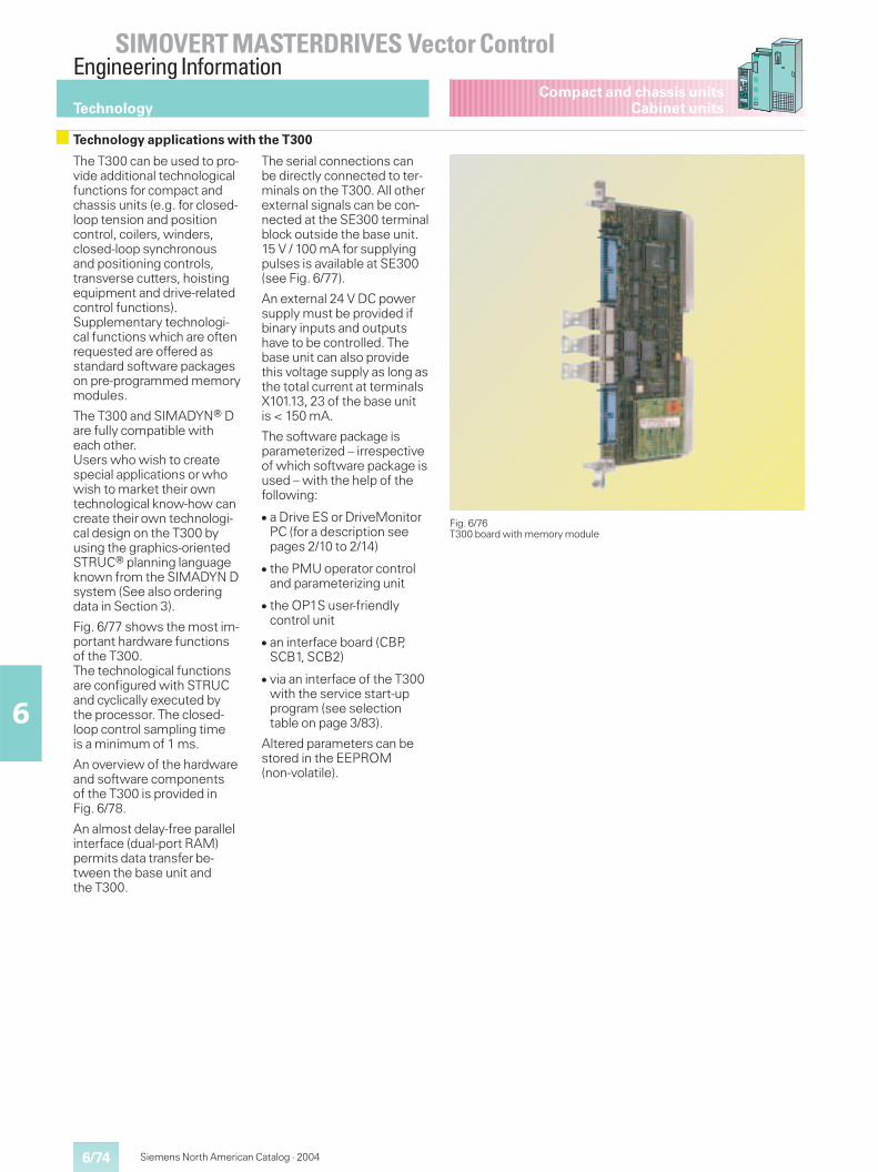
6/74
SIMOVERT MASTERDRIVES Vector ControlEngineering Information
6
Siemens North American Catalog · 2004
Compact and chassis unitsCabinet units
The T300 can be used to pro-vide additional technologicalfunctions for compact andchassis units (e.g. for closed-loop tension and positioncontrol, coilers, winders,closed-loop synchronousand positioning controls,transverse cutters, hoistingequipment and drive-relatedcontrol functions).Supplementary technologi-cal functions which are oftenrequested are offered asstandard software packageson pre-programmed memorymodules.
The T300 and SIMADYN Dare fully compatible witheach other.Users who wish to createspecial applications or whowish to market their owntechnological know-how cancreate their own technologi-cal design on the T300 byusing the graphics-orientedSTRUC planning languageknown from the SIMADYN Dsystem (See also orderingdata in Section 3).
Fig. 6/77 shows the most im-portant hardware functionsof the T300.The technological functionsare configured with STRUCand cyclically executed bythe processor. The closed-loop control sampling timeis a minimum of 1 ms.
An overview of the hardwareand software componentsof the T300 is provided inFig. 6/78.
An almost delay-free parallelinterface (dual-port RAM)permits data transfer be-tween the base unit andthe T300.
The serial connections canbe directly connected to ter-minals on the T300. All otherexternal signals can be con-nected at the SE300 terminalblock outside the base unit.15 V / 100 mA for supplyingpulses is available at SE300(see Fig. 6/77).
An external 24 V DC powersupply must be provided ifbinary inputs and outputshave to be controlled. Thebase unit can also providethis voltage supply as long asthe total current at terminalsX101.13, 23 of the base unitis < 150 mA.
The software package isparameterized – irrespectiveof which software package isused – with the help of thefollowing:
� a Drive ES or DriveMonitorPC (for a description seepages 2/10 to 2/14)
� the PMU operator controland parameterizing unit
� the OP1S user-friendlycontrol unit
� an interface board (CBP,SCB1, SCB2)
� via an interface of the T300with the service start-upprogram (see selectiontable on page 3/83).
Altered parameters can bestored in the EEPROM(non-volatile).
Fig. 6/76T300 board with memory module
Technology
Technology applications with the T300
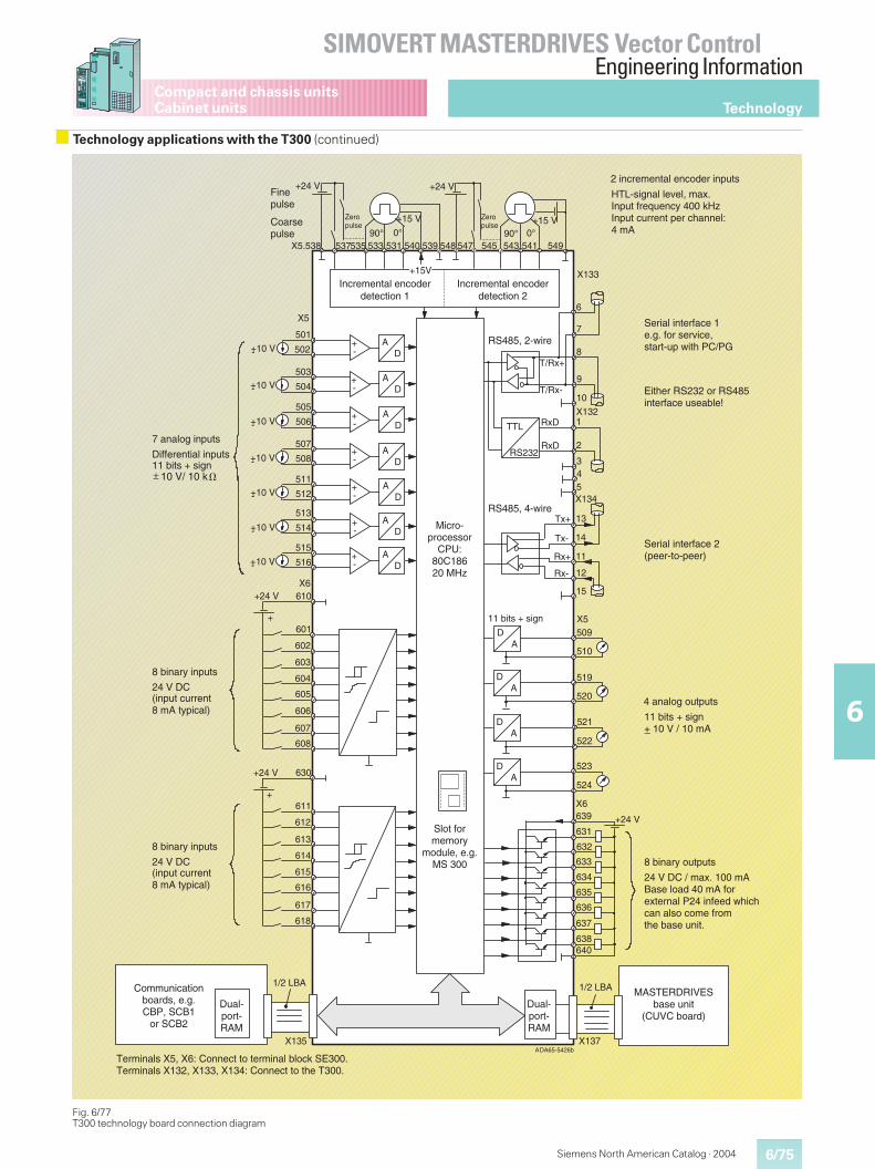
6/75
SIMOVERT MASTERDRIVES Vector ControlEngineering Information
6
Siemens North American Catalog · 2004
Compact and chassis unitsCabinet units
Fig. 6/77T300 technology board connection diagram
�
X5.538
501
53790°
535
+24 V
0°
+15 V
533 531 540 539 548 547 545 543 541 54990° 0°
+15 V
+24 V
+15V X133
AD
+-
X5
+-
+-
+-
AD
AD
AD
+-
+-
AD
AD
AD
502
503
504
505
506
507
508
511
512
513
514
515
516
610X6
+24 V
+601
602
603
604
605
606
607
+10 V-
+10 V-
+10 V-
+10 V-
+10 V-
+10 V-
+10 V-+-
+24 V
+
608
630
611
612
613
614
615
616
617
618
1/2 LBA
X135
1/2 LBA
X137
+24 V
640638
637
636
635
634
633
632
631
639X6
DA
DA
DA
DA
11 bits + sign
524
523
522
521
520
519
510
509X5
6
7
8
9
10
1X132
2
345
13
14
11
12
15
T/Rx+
T/Rx-
RxD
RxD
TTL
RS232
Tx+
Tx-
Rx+
Rx-
X134
DA65-5426bA
Finepulse
Coarsepulse
Incremental encoderdetection 1
10 V/ 10 k
7 analog inputs
Differential inputs11 bits + sign
8 binary inputs
24 V DC(input current8 mA typical)
8 binary inputs
24 V DC(input current8 mA typical)
Communicationboards, e.g.CBP, SCB1
or SCB2
Terminals X5, X6: Connect to terminal block SE300.Terminals X132, X133, X134: Connect to the T300.
Dual-port-RAM
Dual-port-RAM
MASTERDRIVESbase unit
(CUVC board)
8 binary outputs
24 V DC / max. 100 mABase load 40 mA forexternal P24 infeed whichcan also come fromthe base unit.
Serial interface 2(peer-to-peer)
11 bits + sign+ 10 V / 10 mA
Either RS232 or RS485interface useable!
Serial interface 1e.g. for service,start-up with PC/PG
4 analog outputs
HTL-signal level, max.Input frequency 400 kHzInput current per channel:4 mA
2 incremental encoder inputs
RS485, 2-wire
RS485, 4-wire
Micro-processor
CPU:80C18620 MHz
Slot formemory
module, e.g.MS 300
Zeropulse
Zeropulse
Incremental encoderdetection 2
_
Technology
Technology applications with the T300 (continued)
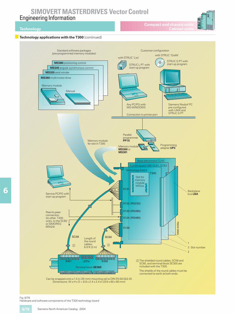
6/76
SIMOVERT MASTERDRIVES Vector ControlEngineering Information
6
Siemens North American Catalog · 2004
Compact and chassis unitsCabinet units
Fig. 6/78Hardware and software components of the T300 technology board
DA
65-5
435a
X131
X132 (RS232)
X133 (RS485)
X134 (RS485)
X136
T300
SC60SC58
X451 LEDs X456
Standard software packages(pre-programmed memory modules)
MS380 positioning control
MS340 angular synchronous control
MS320 axial winder
MS360 multi-motor drive
Memory module
Connection to printer port
Any PC/PG withMS-WINDOWS
STRUC L PT withstart-up program
with STRUC ‘List’
Customer configuration
Manual
Siemens Nixdorf PCpre-configuredwith UNIX andSTRUC G PT
STRUC G PT withstart-up program
with STRUC ‘Grafik’
Length ofthe roundcables:6.6 ft (2 m)
Peer-to-peer-connection(to other T300units, to the SCB2or SIMOREG6RA24)
ParallelprogrammerPP1X
Memory moduleMS300 orMS301
Base electronics CUVC
Comm.board CBP, SCB1, SCB2
Can be snapped onto a 1.4 in (35 mm) mounting rail to DIN EN 50 022-35Dimensions: W x H x D = 8.8 x 2.4 x 2.4 in (224 x 60 x 60 mm)
Terminal block SE300
$ The shielded round cables, SC58 andSC60, and terminal block SE300 areincluded with the T300.
The shields of the round cables must beconnected to earth at both ends.
Backplanebus LBA
Programmingadapter UP3
Slot formemorymoduleMS3xx
Technology board
Memory modulefor slot in T300
Service PC/PG withstart-up program
$ $
Technology
Technology applications with the T300 (continued)
1
3 Slot number
2
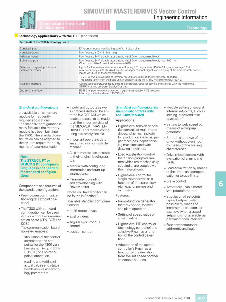
6/77
SIMOVERT MASTERDRIVES Vector ControlEngineering Information
6
Siemens North American Catalog · 2004
Compact and chassis unitsCabinet units
Terminals of the T300 technology board
7 analog inputs Differential inputs, non-floating, ±10 V, 11 bits + sign
4 analog outputs Non-floating, ±10 V, 11 bits + sign
16 binary inputs Non-floating, 24 V, signal status display via LEDs on the terminal block
8 binary outputs Non-floating, 24 V, signal status display via LEDs on the terminal block, max. 100 mA.When used: 40 mA base load at terminal 639.
Detection of speed, position andposition difference
Inputs for 2 incremental encoders, non-floating, HTL signal level (15 V to 24 V, rated voltage 15 V),max. frequency < 400 Hz, 4 mA input current per channel, signal status display of the incremental encoderinputs via LEDs on the terminal block.
15 V / 100 mA are available at terminal X5.540 for supplying the incremental encoders.This can be taken from the basic unit, in addition to the 15 V / 150 mA of terminal X103.40.
1st serial interface Can be toggled between RS232/ RS485, preferably used for service and start-up with the help of theSTRUC start-up program, Service Start-up
2nd serial interface RS485 for peer-to-peer connection (setpoint cascade) or USS protocolMax. adjustable baud rate: 115.2 Kbit/s
Standard configurations
are available on a memorymodule for frequentlyrequired applications.The standard configuration isready for use if the memorymodule has been built intothe T300. The standard con-figuration can be adapted tothe system requirements bymeans of parameterization.
Components and features ofthe standard configuration:
� Peer-to-peer communica-tion (digital setpoint cas-cade).
� The T300 with standardconfiguration can be usedwith or without a communi-cation board (CBx, SCB1 orSCB2).The communication board,however, enables:
– stipulation of the controlcommands and set-points for the T300 via abus system (e.g. PROFI-BUS DP) or a point-to-point connection,
– reading and writing ofactual values and statuswords as well as techno-logy parameters.
� Inputs and outputs as wellas process data can be en-tered in a DPRAM whichenables access to be madeto all the important data ofthe SIMOVERT MASTER-DRIVES. This makes config-uring extremely flexible.
� Important operating dataare stored in a non-volatilemanner.
� All parameters can be resetto their original loading sta-tus.
� Manual with configuringinformation and start-upinstructions.
� Parameter upreadingand downloading withDriveMonitor.
Notes on DriveMonitor canbe found in Section 2.
Available standard configura-tions for:
� multi-motor drives
� axial winders
� angular synchronouscontrol
� position control.
Standard configuration formulti-motor drives withthe T300 (MS360)
Applications:
� Higher-level tension or posi-tion control for multi-motordrives, which can includefoil production systems, pa-per machines, paper finish-ing machines and wiredrawing machines.
� Load equalization controlfor tension groups or mo-tors which are mechanicallycoupled or are coupled viathe material web.
� Higher-level control forsingle-motor drives as afunction of pressure, flowetc., e.g. for pumps andextruders.
Features:
� Ramp-function generatorfor rpm / speed, for localand plant operation.
� Setting of speed ratios orstretch ratios.
� Higher-level PID controller(technology controller) andadaptive P-gain as a func-tion of the control devia-tions.
� Adaptation of the speedcontroller’s P-gain as afunction of the deviationfrom the set speed or otherselectable sources.
� Flexible setting of severalinternal setpoints, such asinching, crawl and take-up/slack-off.
� Setting to web speed bymeans of a ramp-upgenerator.
� Smooth shutdown of thedrive, without overshoot,by means of the brakingcharacteristic.
� Drive-related control withevaluation of alarms andfaults.
� Load equalization by meansof the droop and compen-sation or torque limits.
� Brake control.
� Two freely-usable motor-ized potentiometers.
� Stipulation of setpoints(speed setpoint) alsopossible by means ofincremental encoder, forexample when a speedsetpoint is not available viaa terminal or an interface.
� Free components forarithmetic and logic.
Note:The STRUC L PT orSTRUC G PT configuringlanguage is not neededfor standard configura-tions.
Technology
Technology applications with the T300 (continued)
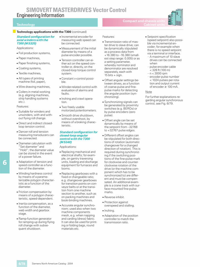
6/78
SIMOVERT MASTERDRIVES Vector ControlEngineering Information
6
Siemens North American Catalog · 2004
Compact and chassis unitsCabinet units
Standard configuration foraxial winders with theT300 (MS320)
Applications:
� Foil production systems,
� Paper machines,
� Paper finishing systems,
� Coating systems,
� Textile machines,
� All types of printingmachine (foil, paper),
� Wire drawing machines,
� Coilers in metal working(e.g. aligning machines,strip handling systemsetc.).
Features:
� Suitable for winders andunwinders, with and with-out flying roll change.
� Direct and indirect closed-loop tension control.
� Dancer roll and tensionmeasuring transducers canbe connected.
� Diameter calculation with“Set diameter”and“Hold”; the diameter valuecan be stored in the eventof a power failure.
� Adaptation of tension andspeed controller as a func-tion of the diameter.
� Winding hardness controlby means of a parame-terizable polygon character-istic as a function of thediameter.
� Friction compensation bymeans of a polygon charac-teristic, speed-dependent.
� Inertia compensation, as afunction of the diameter,web width and gearboxstage.
� Ramp-function generatorfor ramping-up during flyingroll change with subse-quent shutdown.
� Incremental encoder formeasuring web speed canbe connected.
� Measurement of the initialdiameter by means of apulse encoder possible.
� Tension controller can ei-ther act on the speed con-troller or, directly, on theclosed-loop torque controlsystem.
� Constant v-control possi-ble.
� Winder-related control withevaluation of alarms andfaults.
� Inching and crawl opera-tion.
� Two freely usablemotorized potentiometers.
� Smooth drive shutdown,without overshoot, bymeans of a braking charac-teristic.
Standard configuration forclosed-loop angularcontrol with the T300(MS340)
Applications:
� Replacing mechanical andelectrical shafts; for exam-ple, on gantry traversingunits, loading and dischargeequipment for furnaces andlooms.
� Replacing gearboxes with afixed or changeable ratio;e.g. changeover gearboxesfor transition points on con-veyor belts or at the transi-tion from one machinesection to another, such ason packing machines andbook-binding machines.
� Accurate angular synchro-nism; used also when twomachine componentsmesh, e.g. when nappingand carding (dress) fabric.It can also be used for print-ing or folding bags, roundmaterials etc.
Features:
� Transmission ratio of mas-ter drive to slave drive; canbe dynamically stipulatedas a process data from+16.380 to –16.380 (small-est step range: 0.005) or asa setting parameter,whereby nominator anddenominator are resolvedseparately, each with15 bits + sign.
� Offset angular settings be-tween drives, as a functionof coarse-pulse and fine-pulse marks for detectingthe angular position (syn-chronizing).
� Synchronizing signals canbe generated by proximityswitches (e.g. BEROs) orby pulse encoders (zeropulse).
� Offset angle can be setdynamically by means ofthe setpoint from –32768to +32767 pulse edges.
� Different offset angles canbe stipulated for both direc-tions of rotation (automaticchangeover for a changeddirection of rotation). This isrequired during synchroniz-ing if the switching posi-tions of the fine-pulse markfor clockwise and counter-clockwise rotation of thedrive (or the machine com-ponent which has to besynchronized to) are differ-ent and must be compen-sated. An additional exam-ple is a crane track with sur-face-mounted fine-pulsemarks.
� Reverse inhibit.
� Protection againstoverspeed and stalling.
� Inching.
� Adaptation of the positioncontroller to match thetransmission ratio.
� Setpoint specification(speed setpoint) also possi-ble via incremental en-coder; for example whenthere is no speed setpointvia a terminal or interface.— A maximum of 10 slave
drives can be connectedwhen
— pulse encoder cable< 328 ft (100 m)
— n < 3000 rpm— encoder pulse number
< 1024 pulses per rota-tion and output currentof encoder � 100 mA.
Note
For further explanations re-garding angular synchronouscontrol, see Fig. 6/79.
Technology
Technology applications with the T300 (continued)
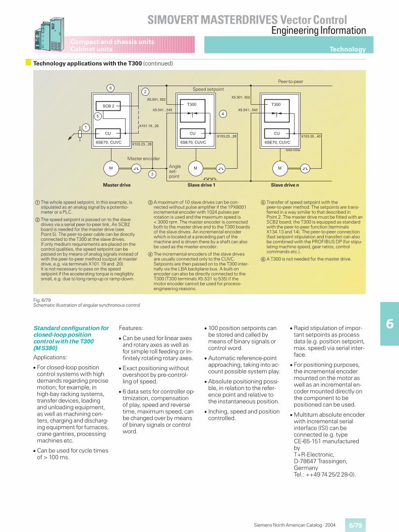
6/79
SIMOVERT MASTERDRIVES Vector ControlEngineering Information
6
Siemens North American Catalog · 2004
Compact and chassis unitsCabinet units
Standard configuration forclosed-loop positioncontrol with the T300(MS380)
Applications:
� For closed-loop positioncontrol systems with highdemands regarding precisemotion; for example, inhigh-bay racking systems,transfer devices, loadingand unloading equipment,as well as machining cen-ters, charging and discharg-ing equipment for furnaces,crane gantries, processingmachines etc.
� Can be used for cycle timesof > 100 ms.
Features:
� Can be used for linear axesand rotary axes as well asfor simple roll feeding or in-finitely rotating rotary axes.
� Exact positioning withoutovershoot by pre-control-ling of speed.
� 6 data sets for controller op-timization, compensationof play, speed and reversetime, maximum speed, canbe changed over by meansof binary signals or controlword.
� 100 position setpoints canbe stored and called bymeans of binary signals orcontrol word.
� Automatic reference-pointapproaching, taking into ac-count possible system play.
� Absolute positioning possi-ble, in relation to the refer-ence point and relative tothe instantaneous position.
� Inching, speed and positioncontrolled.
� Rapid stipulation of impor-tant setpoints as processdata (e.g. position setpoint,max. speed) via serial inter-face.
� For positioning purposes,the incremental encodermounted on the motor aswell as an incremental en-coder mounted directly onthe component to bepositioned can be used.
� Multiturn absolute encoderwith incremental serialinterface (ISI) can beconnected (e.g. typeCE-65-151 manufacturedbyT+R-Electronic,D-78647 Trassingen,GermanyTel.: ++49 74 25/2 28-0).
Fig. 6/79Schematic illustration of angular synchronous control
a The whole speed setpoint, in this example, isstipulated as an analog signal by a potentio-meter or a PLC.
s The speed setpoint is passed on to the slavedrives via a serial peer-to-peer link. An SCB2board is needed for the master drive (seePoint 5). The peer-to-peer cable can be directlyconnected to the T300 at the slave drives.If only medium requirements are placed on thecontrol qualities, the speed setpoint can bepassed on by means of analog signals instead ofwith the peer-to-peer method (output at masterdrive, e.g. via terminals X101.19 and .20).It is not necessary to pass on the speedsetpoint if the accelerating torque is negligiblysmall, e.g. due to long ramp-up or ramp-down.
d A maximum of 10 slave drives can be con-nected without pulse amplifier if the 1PX8001incremental encoder with 1024 pulses perrotation is used and the maximum speed is< 3000 rpm. The master encoder is connectedboth to the master drive and to the T300 boardsof the slave drives. An incremental encoderwhich is located at a preceding part of themachine and is driven there by a shaft can alsobe used as the master encoder.
f The incremental encoders of the slave drivesare usually connected only to the CUVC.Setpoints are then passed on to the T300 inter-nally via the LBA backplane bus. A built-onencoder can also be directly connected to theT300 (T300 terminals X5.531 to 535) if themotor encoder cannot be used for process-engineering reasons.
g Transfer of speed setpoint with thepeer-to-peer method: The setpoints are trans-ferred in a way similar to that described inPoint 2. The master drive must be fitted with anSCB2 board; the T300 is equipped as standardwith the peer-to-peer function (terminalsX134.13 and 14). The peer-to-peer connection(fast setpoint stipulation and transfer) can alsobe combined with the PROFIBUS DP (for stipu-lating machine speed, gear ratios, controlcommands etc.).
h A T300 is not needed for the master drive.
��������
�
�&��!�����
�
��
�
�&��!�����
�
��
�
�&��!�����
&�;��
��
�
�
��
�
��9�999���9�999�"
��9�999�"
��9���999�����9���999���
��9��!���
���9��999�
��9��!���
Master drive
Master encoder
Speed setpoint
Angleset-point
Slave drive 1
Peer-to-peer
Slave drive n
Technology
Technology applications with the T300 (continued)
6/80
SIMOVERT MASTERDRIVES Vector ControlEngineering Information
6
Siemens North American Catalog · 2004
Compact and chassis unitsCabinet units
Configurations created onthe T300 by the user
Configuring with STRUC:
Technology functions can beeasily created with the func-tion-block oriented STRUCconfiguring language. It hasmore than 250 functionblocks for open and closed-loop control and arithmeticoperations (e.g. PI control-lers, ramp-function genera-tors, multipliers and logicgates).
An easy-to-use start-up pro-gram which runs on a PG orPC supports start-up andservice.
Configuring tools
STRUC L PT, version 4.2.5and higher
is used to configure the T300in a list form (see Fig. 6/78).
It is supplied on a 3½" setof floppy disks, either withGerman or English menutexts as required.
The scope of supply includesthe Service start-up programwhich allows any 10 valuesin a software package to besimultaneously visualizedand any input values to bechanged at the functionblocks. Most of the connec-tions between the functionblocks can be changed anddisplayed.
System platform require-ments for STRUC L PT:
� AT-compatible PC, min.386 CPU, 4 Mbyte RAM
� parallel printer interface
� 31/2" floppy disk drive,8 Mbyte permanentWINDOWS virtual memorymust be set-up on the harddisk
� 8 Mbyte memory on thehard disk for STRUC L PT
� 4 Mbyte memory on thehard disk for applicationsoftware (experiencedvalue)
� MS-DOS, version 5.0 andhigher
� MS-WINDOWS,version 3.1 and higher orWINDOWS 95.
STRUC G PT, version 4.2.5and higher
graphically configures theT300 (see Fig. 6/78). It issupplied on CD-ROM, eitherwith German or Englishmenu texts as required.
We recommend ordering aSIEMENS-NIXDORF STRUCconfiguring PC with installedUNIX operating systemSCO-UNIX and a runtimeversion of STRUC PT (seeminimum SNI-PC require-ments). STRUC requiresapproximately 250 Mbyte onthe hard disk, including thereserve for STRUC G applica-tion software. The PC, pre-configured with STRUC G PT,has, in addition to the UNIXpartition, a DOS partition inwhich all of the DOS andWindows applications arerun.
The scope of supply includesthe Service start-up programwhich allows any 10 values(max.) in a software packageto be simultaneously visual-ized and any input values tobe changed at the functionblocks. Most of the connec-tions between the functionblocks can be changed anddisplayed.
Minimum SNI-PC require-ments
� the hardware must complywith the SCO hardwarecompatibility manual
� floppy disk drive 31/2",3-button mouse
� German or English key-board
� 16 Mbyte working memory
� graphics card compatibleto SCO V 5.0, 1280 · 1024pixels
� 520 Mbyte hard disk,CD-ROM drive
� color monitor, 43 cm (17").
MS300 or MS301 memorymodule
is empty and is plugged ontothe T300, is programmedwith a user application soft-ware created by the user.
The MS300 or MS301 arenot needed for standard soft-ware packages.
They differ from each otheronly with regard to the sizeof the EEPROM which isused for storing parametersin the case of standard soft-ware packages.
MS300: EEPROM 2 Kbytes,allows storage of 250 alteredparameters (experiencedvalue).
MS301: EEPROM 8 Kbytes,allows storage of 1000altered parameters (experi-enced value).
External, parallel PP1Xprogramming unit for PG7x0or PC
is connected to the printerinterface of a PG or PC. TheMS300 or MS301 memorymodule can be programmedwith the PP1X. For PG andPC hardware requirements,see STRUC L PT.
The scope of supply includesthe UP3 programmingadapter which is needed forprogramming the MS300 orMS301.
For selection and orderingdata of the T300 technologyboard and its components,see Section 3.
Technology
Technology applications with the T300 (continued)
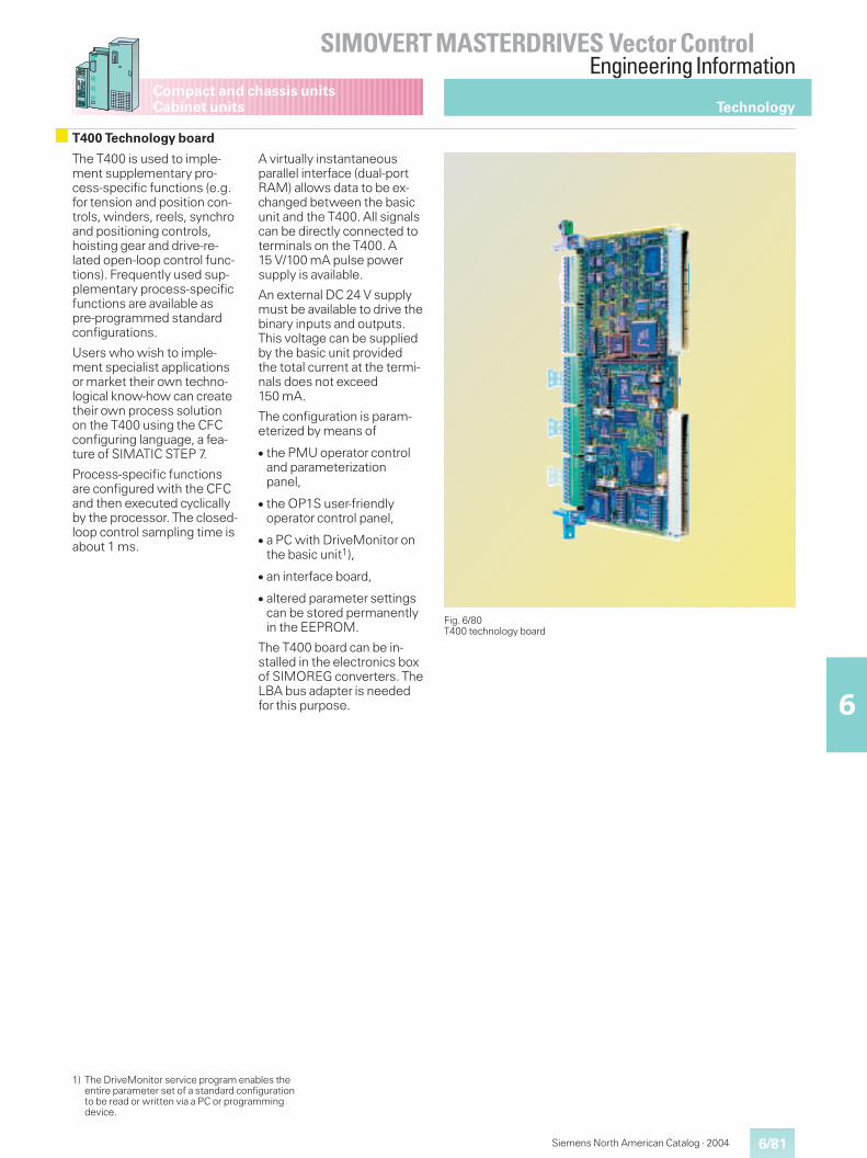
6/81
SIMOVERT MASTERDRIVES Vector ControlEngineering Information
6
Siemens North American Catalog · 2004
Compact and chassis unitsCabinet units
Fig. 6/80T400 technology board
Technology
T400 Technology board
The T400 is used to imple-ment supplementary pro-cess-specific functions (e.g.for tension and position con-trols, winders, reels, synchroand positioning controls,hoisting gear and drive-re-lated open-loop control func-tions). Frequently used sup-plementary process-specificfunctions are available aspre-programmed standardconfigurations.
Users who wish to imple-ment specialist applicationsor market their own techno-logical know-how can createtheir own process solutionon the T400 using the CFCconfiguring language, a fea-ture of SIMATIC STEP 7.
Process-specific functionsare configured with the CFCand then executed cyclicallyby the processor. The closed-loop control sampling time isabout 1 ms.
A virtually instantaneousparallel interface (dual-portRAM) allows data to be ex-changed between the basicunit and the T400. All signalscan be directly connected toterminals on the T400. A15 V/100 mA pulse powersupply is available.
An external DC 24 V supplymust be available to drive thebinary inputs and outputs.This voltage can be suppliedby the basic unit providedthe total current at the termi-nals does not exceed150 mA.
The configuration is param-eterized by means of
� the PMU operator controland parameterizationpanel,
� the OP1S user-friendlyoperator control panel,
� a PC with DriveMonitor onthe basic unit1),
� an interface board,
� altered parameter settingscan be stored permanentlyin the EEPROM.
The T400 board can be in-stalled in the electronics boxof SIMOREG converters. TheLBA bus adapter is neededfor this purpose.
1) The DriveMonitor service program enables theentire parameter set of a standard configurationto be read or written via a PC or programmingdevice.
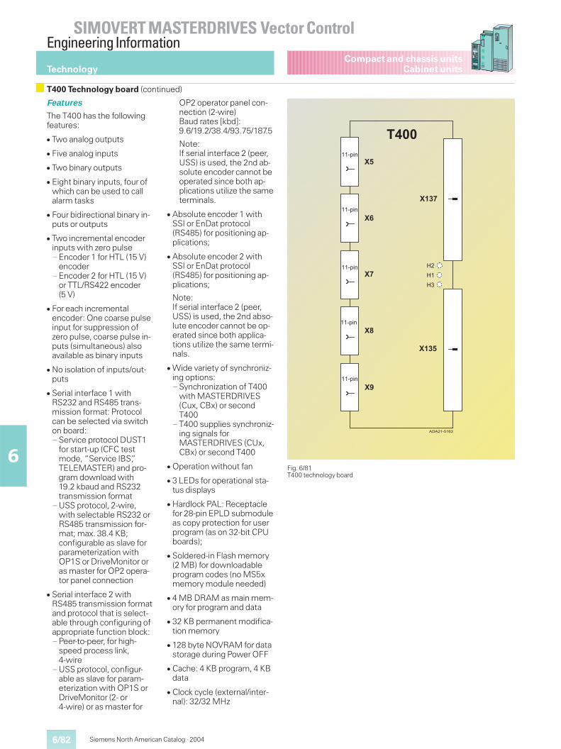
6/82
SIMOVERT MASTERDRIVES Vector ControlEngineering Information
6
Siemens North American Catalog · 2004
Compact and chassis unitsCabinet unitsTechnology
Features
The T400 has the followingfeatures:
� Two analog outputs
� Five analog inputs
� Two binary outputs
� Eight binary inputs, four ofwhich can be used to callalarm tasks
� Four bidirectional binary in-puts or outputs
� Two incremental encoderinputs with zero pulse— Encoder 1 for HTL (15 V)
encoder— Encoder 2 for HTL (15 V)
or TTL/RS422 encoder(5 V)
� For each incrementalencoder: One coarse pulseinput for suppression ofzero pulse, coarse pulse in-puts (simultaneous) alsoavailable as binary inputs
� No isolation of inputs/out-puts
� Serial interface 1 withRS232 and RS485 trans-mission format: Protocolcan be selected via switchon board:— Service protocol DUST1
for start-up (CFC testmode, “Service IBS”,TELEMASTER) and pro-gram download with19.2 kbaud and RS232transmission format
— USS protocol, 2-wire,with selectable RS232 orRS485 transmission for-mat; max. 38.4 KB;configurable as slave forparameterization withOP1S or DriveMonitor oras master for OP2 opera-tor panel connection
� Serial interface 2 withRS485 transmission formatand protocol that is select-able through configuring ofappropriate function block:— Peer-to-peer, for high-
speed process link,4-wire
— USS protocol, configur-able as slave for param-eterization with OP1S orDriveMonitor (2- or4-wire) or as master for
OP2 operator panel con-nection (2-wire)Baud rates [kbd]:9.6/19.2/38.4/93.75/187.5
Note:If serial interface 2 (peer,USS) is used, the 2nd ab-solute encoder cannot beoperated since both ap-plications utilize the sameterminals.
� Absolute encoder 1 withSSI or EnDat protocol(RS485) for positioning ap-plications;
� Absolute encoder 2 withSSI or EnDat protocol(RS485) for positioning ap-plications;
Note:If serial interface 2 (peer,USS) is used, the 2nd abso-lute encoder cannot be op-erated since both applica-tions utilize the same termi-nals.
� Wide variety of synchroniz-ing options:— Synchronization of T400
with MASTERDRIVES(Cux, CBx) or secondT400
— T400 supplies synchroniz-ing signals forMASTERDRIVES (CUx,CBx) or second T400
� Operation without fan
� 3 LEDs for operational sta-tus displays
� Hardlock PAL: Receptaclefor 28-pin EPLD submoduleas copy protection for userprogram (as on 32-bit CPUboards);
� Soldered-in Flash memory(2 MB) for downloadableprogram codes (no MS5xmemory module needed)
� 4 MB DRAM as main mem-ory for program and data
� 32 KB permanent modifica-tion memory
� 128 byte NOVRAM for datastorage during Power OFF
� Cache: 4 KB program, 4 KBdata
� Clock cycle (external/inter-nal): 32/32 MHz
T400 Technology board (continued)
Fig. 6/81T400 technology board
��������
�
�
�
�
�
��
��
?�
?�
?
����
���501
���501
���501
���501
���501
�
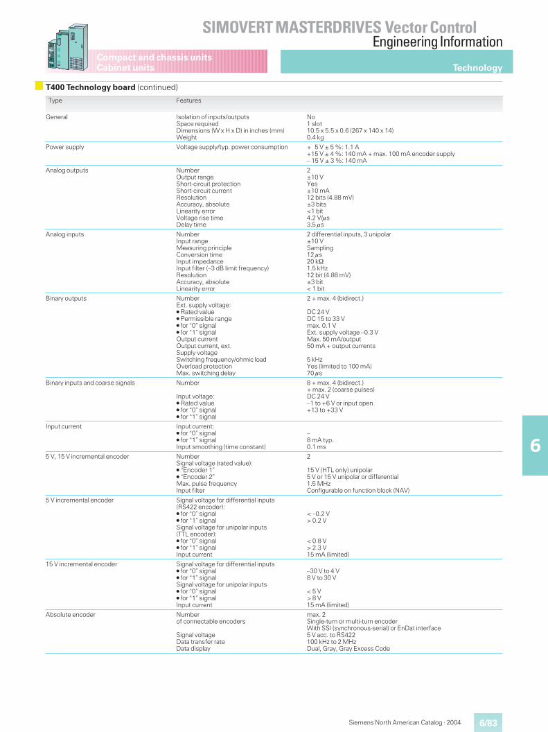
6/83
SIMOVERT MASTERDRIVES Vector ControlEngineering Information
6
Siemens North American Catalog · 2004
Compact and chassis unitsCabinet units Technology
Type Features
General Isolation of inputs/outputsSpace requiredDimensions (W x H x D) in inches (mm)Weight
No1 slot10.5 x 5.5 x 0.6 (267 x 140 x 14)0.4 kg
Power supply Voltage supply/typ. power consumption + 5 V ± 5 %: 1.1 A+15 V ± 4 %: 140 mA + max. 100 mA encoder supply– 15 V ± 3 %: 140 mA
Analog outputs NumberOutput rangeShort-circuit protectionShort-circuit currentResolutionAccuracy, absoluteLinearity errorVoltage rise timeDelay time
2±10 VYes±10 mA12 bits (4.88 mV)±3 bits<1 bit4.2 V/�s3.5 �s
Analog inputs NumberInput rangeMeasuring principleConversion timeInput impedanceInput filter (–3 dB limit frequency)ResolutionAccuracy, absoluteLinearity error
2 differential inputs, 3 unipolar±10 VSampling12 �s20 k1.5 kHz12 bit (4.88 mV)±3 bit< 1 bit
Binary outputs NumberExt. supply voltage:� Rated value� Permissible range� for “0” signal� for “1” signalOutput currentOutput current, ext.Supply voltageSwitching frequency/ohmic loadOverload protectionMax. switching delay
2 + max. 4 (bidirect.)
DC 24 VDC 15 to 33 Vmax. 0.1 VExt. supply voltage –0.3 VMax. 50 mA/output50 mA + output currents
5 kHzYes (limited to 100 mA)70 �s
Binary inputs and coarse signals Number
Input voltage:� Rated value� for “0” signal� for “1” signal
8 + max. 4 (bidirect.)+ max. 2 (coarse pulses)DC 24 V–1 to +6 V or input open+13 to +33 V
Input current Input current:� for “0” signal� for “1” signalInput smoothing (time constant)
–8 mA typ.0.1 ms
5 V, 15 V incremental encoder NumberSignal voltage (rated value):� “Encoder 1”� “Encoder 2”Max. pulse frequencyInput filter
2
15 V (HTL only) unipolar5 V or 15 V unipolar or differential1.5 MHzConfigurable on function block (NAV)
5 V incremental encoder Signal voltage for differential inputs(RS422 encoder):� for “0” signal� for “1” signalSignal voltage for unipolar inputs(TTL encoder):� for “0” signal� for “1” signalInput current
< –0.2 V> 0.2 V
< 0.8 V> 2.3 V15 mA (limited)
15 V incremental encoder Signal voltage for differential inputs� for “0” signal� for “1” signalSignal voltage for unipolar inputs� for “0” signal� for “1” signalInput current
–30 V to 4 V8 V to 30 V
< 5 V> 8 V15 mA (limited)
Absolute encoder Numberof connectable encoders
Signal voltageData transfer rateData display
max. 2Single-turn or multi-turn encoderWith SSI (synchronous-serial) or EnDat interface5 V acc. to RS422100 kHz to 2 MHzDual, Gray, Gray Excess Code
T400 Technology board (continued)
6/84
SIMOVERT MASTERDRIVES Vector ControlEngineering Information
6
Siemens North American Catalog · 2004
Compact and chassis unitsCabinet unitsTechnology
Standard configurations
Standard configurations forcommonly used applicationtypes are available as pre-in-stalled configurations. Thestandard configuration canbe adapted to suit a specificplant by means ofparameterization.
Components and featuresof standard configuration
� Peer-to-peer communica-tion (digital setpoint cas-cade)
� The T400 with standardconfiguration can be oper-ated with and without acommunication board (e.g.CBP2)
A communication boardcan be used to1. specify T400 control
commands andsetpoints via a bus sys-tem (e.g. PROFIBUS DP)or a point-to-point con-nection,
2. read actual values andstatus words and to readand write technologyparameters.
� Inputs, outputs and pro-cess data can be “wiredup”to the DPRAM to pro-vide access to all importantMASTERDRIVES data,thereby ensuring highlyflexible configuring
� Non-volatile storage of allimportant operating data
� All parameters can be resetto IPL status
� Parameters can be set viaPC with DriveMonitorlinked to basic unit inter-face
Available standardconfigurations
� Standard configuration foraxial winders
� Standard configuration forangular synchronism con-trols
Standard configuration foraxis winder with T400
Scope of applications:
� Foil plants
� Paper machines
� Paper finishing machines
� Coating machines
� Printing presses of all types(foil, paper)
� Wire-drawing machines
� Reels in metalworking (e.g.straightening machines,treatment plants, etc.)
Features:
� Suitable for wind-on andwind-off coils, with andwithout on-the-fly rollerchange
� Suitable for direct and indi-rect tension control
� Compensating roller or ten-sion capsule-typedynamometer can be con-nected
� Diameter calculation with”Set diameter”and ”Stop”,plus non-volatile storage ofdiameter measurement
� Adaptation of tension andspeed controllers as a func-tion of diameter
� Polygon-based frictioncompensation, speed-de-pendent
� Acceleration compensationas a function of diameter,material width and gearstage
� Ramp-function generatorfor acceleration on on-the-fly roller change followed byshutdown
� Pulse encoder for pathvelocity measurement canbe connected
� Initial diameter can be mea-sured via contact pulse en-coder
� Tension controller can beapplied either to the speedcontroller or directly to thetorque control
� V = constant control can beimplemented
� Winder-specific open-loopcontrol with alarm and faultevaluation
� Inching and crawling opera-tion
� Two motorized potentiom-eters for optional use
� Smooth, overshoot-freeshutdown via brakingcharacteristic
Standard configuration forangular synchronismcontrol with T400
Scope of application:
� Substitute for mechanicaland electrical shafts, e.g. ongantry traversing mecha-nisms, feed and dischargemachines on furnaces orlooms
� Substitute for gear unitswith fixed or variable gearratio, e.g. change-gearunits, installed at transitionpoints on conveyor belts orat transition point betweenone machine section andthe next, such as on pack-aging machines, bookspine gluing machines
� Phase-locked synchronism,also applicable for mutualengagement of two ma-chine parts. Also suitablefor printing or folding ofbags, round stock, etc.
Features:
� Angular synchronism withgear ratio adjustable withinwide limits
� Offset angle setting be-tween drives as a functionof coarse and fine pulsemarkers for angle sensing(synchronization)
� Synchronization signals canbe supplied by proximity-type switches (e.g.BEROs™) or pulseencoders (zero pulse)
� Modification of angle set-ting by setpoint input
� Different offset angles canbe specified for both direc-tions of rotation (automaticswitchover on direction re-versal). This option must beapplied for synchronizationif the switching positions ofthe fine pulse marker aredifferent for clockwise andanti-clockwise rotation ofdrive (or machine part act-ing as synchronization part-ner) and need to be com-pensated. Another exam-ple is a crane runway onwhich the fine pulse markeris two-dimensional.
� Backstop function
� Overspeed and blockingprotection
� Inching operation
� Adaptation of positioncontroller based on gearratio
� Setpoint (speed setpoint)can be supplied by pulseencoder, for example, incases where speedsetpoint is not available viaterminal or interface
� A maximum of ten slavedrives can be connected ifpulse encoder cable length< 328 ft (100 m), n < 3000rev/min
T400 Technology board (continued)

6/85
SIMOVERT MASTERDRIVES Vector ControlEngineering Information
6
Siemens North American Catalog · 2004
Compact and chassis unitsCabinet units Technology
T400 Technology board (continued)
T400 terminal assignments Connector Connector pin Terminal
+24 V external (for binary inputs and outputs)Bidirectional binary input and output 1Bidirectional binary input and output 2Bidirectional binary input and output 3Bidirectional binary input and output 4Ground for binary inputs and outputsBinary output 1Binary output 2Binary input 1 (alarm-capable)Binary input 2 (alarm-capable)Binary input 3 (alarm-capable)
X5 123456789
1011
4546474849505152535455
Binary input 4 (alarm-capable)Binary input 5Binary input 6Binary input 7Binary input 8Ground for binary inputs and outputsIncrem. encoder 2: Track A (HTL) Increm. encoder 2: Track A+ (with RS422)Increm. encoder 2: Track B (HTL) Increm. encoder 2: Track B+ (with RS422)Increm. encoder 2: Zero pulse (HTL) Increm. encoder 2: Zero pulse+ (with RS422)Increm. encoder 2: Coarse pulseGround for increm. encoder 2
X6 123456789
1011
5657585960616263646566
Ser. interface 1: Rx-RS232Ser. interface 1: Tx-RS232Ground for ser. interfaceSer. interface 1: Tx/Rx-RS485+Ser. interface 1: Tx/Rx-RS485–Ser. interface 2: Rx/RS485+ Absolute encoder 2: Data+Ser. interface 2: Rx/RS485– Absolute encoder 2: Data–Ser. interface 2: Tx/Rx-RS485+ Absolute endoder 2: Clock+Ser. interface 2: Tx/Rx-RS485+ Absolute encoder 2: Clock–Absolute encoder 1: Data+Absolute encoder 1: Data–
X7 123456789
1011
6768697071727374757677
Absolute encoder 1: Clock+Absolute encoder 1: Clock–+15 V encoder supply (max. 100 mA)Increm. encoder 1: Track AIncrem. encoder 1: Track BIncrem. encoder 1: Zero pulseIncrem. encoder 1: Coarse pulseGround for increm. encoder 1Increm. encoder 2: Track A– (with RS422)Increm. encoder 2: Track B– (with RS422)Increm. encoder 2: Zero pulse– (with RS422)
X8 123456789
1011
7879808182838485868788
Ground for analog inputs/outputsAnalog input 1 Analog input 1+
Analog input 1–Analog input 2 Analog input 2+
Analog input 2–Analog input 3Analog input 4Analog input 5Analog output 1Analog output 2Ground for analog inputs/outputs
X9 123456789
1011
8990919293949596979899
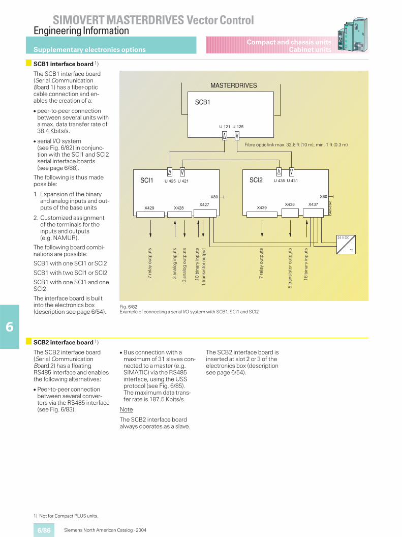
6/86
SIMOVERT MASTERDRIVES Vector ControlEngineering Information
6
Siemens North American Catalog · 2004
Compact and chassis unitsCabinet units
Fig. 6/82Example of connecting a serial I/O system with SCB1, SCI1 and SCI2
The SCB1 interface board(Serial CommunicationBoard 1) has a fiber-opticcable connection and en-ables the creation of a:
� peer-to-peer connectionbetween several units witha max. data transfer rate of38.4 Kbits/s.
� serial I/O system(see Fig. 6/82) in conjunc-tion with the SCI1 and SCI2serial interface boards(see page 6/88).
The following is thus madepossible:
1. Expansion of the binaryand analog inputs and out-puts of the base units
2. Customized assignmentof the terminals for theinputs and outputs(e.g. NAMUR).
The following board combi-nations are possible:
SCB1 with one SCI1 or SCI2
SCB1 with two SCI1 or SCI2
SCB1 with one SCI1 and oneSCI2.
The interface board is builtinto the electronics box(description see page 6/54).
The SCB2 interface board(Serial CommunicationBoard 2) has a floatingRS485 interface and enablesthe following alternatives:
� Peer-to-peer connectionbetween several conver-ters via the RS485 interface(see Fig. 6/83).
� Bus connection with amaximum of 31 slaves con-nected to a master (e.g.SIMATIC) via the RS485interface, using the USSprotocol (see Fig. 6/85).The maximum data trans-fer rate is 187.5 Kbits/s.
Note
The SCB2 interface boardalways operates as a slave.
The SCB2 interface board isinserted at slot 2 or 3 of theelectronics box (descriptionsee page 6/54).
�"
���� ����SCI2
���� ���"����
�����" ���
�"
����� �����SCI1
DA
65-5
340
����� �����
SCB1
~
MASTERDRIVES
Fibre optic link max. 32.8 ft (10 m), min. 1 ft (0.3 m)
24 V DC
7re
lay
outp
uts
3an
alog
inpu
ts
3an
alog
outp
uts
10bi
nary
inpu
ts
16bi
nary
inpu
ts
5tr
ansi
stor
outp
uts
7re
lay
outp
uts
1tr
ansi
stor
outp
ut
Supplementary electronics options
SCB1 interface board 1)
SCB2 interface board 1)
1) Not for Compact PLUS units.
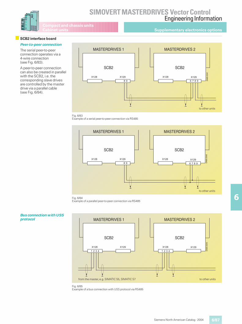
6/87
SIMOVERT MASTERDRIVES Vector ControlEngineering Information
6
Siemens North American Catalog · 2004
Compact and chassis unitsCabinet units
Peer-to-peer connection
The serial peer-to-peerconnection operates via a4-wire connection(see Fig. 6/83).
A peer-to-peer connectioncan also be created in parallelwith the SCB2, i.e. thecorresponding slave drivesare controlled by the masterdrive via a parallel cable(see Fig. 6/84).
Fig. 6/83Example of a serial peer-to-peer connection via RS485
Fig. 6/84Example of a parallel peer-to-peer connection via RS485
Fig. 6/85Example of a bus connection with USS protocol via RS485
DA
65-5
341
SCB2
MASTERDRIVES 1
���"
SCB2
MASTERDRIVES 2
���" ��������
" � " �� �
to other units
DA
65-5
342
SCB2
MASTERDRIVES 1
���"
SCB2
MASTERDRIVES 2
���" ��������
" � " �� �
to other units
DA
65-5
343
SCB2
MASTERDRIVES 1
���"
SCB2
MASTERDRIVES 2
���" ��������
�� � �� �
to other unitsfrom the master, e.g. SIMATIC S5, SIMATIC S7
Supplementary electronics options
SCB2 interface board
Bus connection with USSprotocol
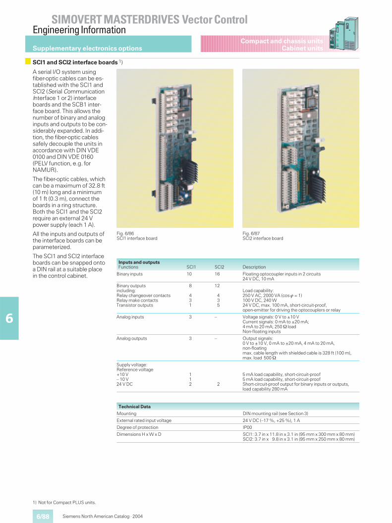
6/88
SIMOVERT MASTERDRIVES Vector ControlEngineering Information
6
Siemens North American Catalog · 2004
Compact and chassis unitsCabinet units
A serial I/O system usingfiber-optic cables can be es-tablished with the SCI1 andSCI2 (Serial CommunicationInterface 1 or 2) interfaceboards and the SCB1 inter-face board. This allows thenumber of binary and analoginputs and outputs to be con-siderably expanded. In addi-tion, the fiber-optic cablessafely decouple the units inaccordance with DIN VDE0100 and DIN VDE 0160(PELV function, e.g. forNAMUR).
The fiber-optic cables, whichcan be a maximum of 32.8 ft(10 m) long and a minimumof 1 ft (0.3 m), connect theboards in a ring structure.Both the SCI1 and the SCI2require an external 24 Vpower supply (each 1 A).
All the inputs and outputs ofthe interface boards can beparameterized.
The SCI1 and SCI2 interfaceboards can be snapped ontoa DIN rail at a suitable placein the control cabinet.
Fig. 6/86SCI1 interface board
Fig. 6/87SCI2 interface board
Inputs and outputsFunctions SCI1 SCI2 Description
Binary inputs 10 16 Floating optocoupler inputs in 2 circuits24 V DC, 10 mA
Binary outputsincluding:Relay changeover contactsRelay make contactsTransistor outputs
8
431
12
435
Load capability:250 V AC, 2000 VA (cos � = 1)100 V DC, 240 W24 V DC, max. 100 mA, short-circuit-proof,open-emitter for driving the optocouplers or relay
Analog inputs 3 – Voltage signals: 0 V to ±10 VCurrent signals: 0 mA to ±20 mA;4 mA to 20 mA; 250 loadNon-floating inputs
Analog outputs 3 – Output signals:0 V to ±10 V, 0 mA to ±20 mA, 4 mA to 20 mA,non-floatingmax. cable length with shielded cable is 328 ft (100 m),max. load 500
Supply voltage:Reference voltage+10 V– 10 V24 V DC
112 2
5 mA load capability, short-circuit-proof5 mA load capability, short-circuit-proofShort-circuit-proof output for binary inputs or outputs,load capability 280 mA
Technical Data
Mounting DIN mounting rail (see Section 3)
External rated input voltage 24 V DC (–17 %, +25 %), 1 A
Degree of protection IP00
Dimensions H x W x D SCI1: 3.7 in x 11.8 in x 3.1 in (95 mm x 300 mm x 80 mm)SCI2: 3.7 in x 9.8 in x 3.1 in (95 mm x 250 mm x 80 mm)
Supplementary electronics options
SCI1 and SCI2 interface boards 1)
1) Not for Compact PLUS units.
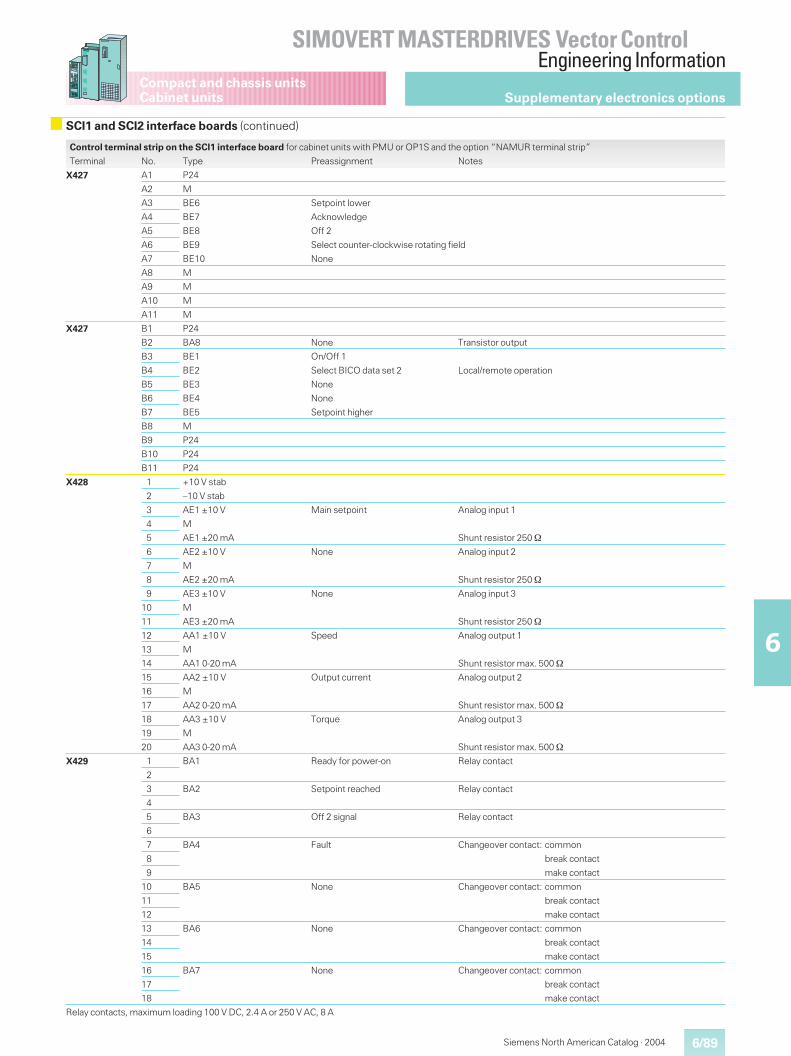
6/89
SIMOVERT MASTERDRIVES Vector ControlEngineering Information
6
Siemens North American Catalog · 2004
Compact and chassis unitsCabinet units
Control terminal strip on the SCI1 interface board for cabinet units with PMU or OP1S and the option “NAMUR terminal strip”
Terminal No. Type Preassignment Notes
X427 A1 P24
A2 M
A3 BE6 Setpoint lower
A4 BE7 Acknowledge
A5 BE8 Off 2
A6 BE9 Select counter-clockwise rotating field
A7 BE10 None
A8 M
A9 M
A10 M
A11 M
X427 B1 P24
B2 BA8 None Transistor output
B3 BE1 On/Off 1
B4 BE2 Select BICO data set 2 Local/remote operation
B5 BE3 None
B6 BE4 None
B7 BE5 Setpoint higher
B8 M
B9 P24
B10 P24
B11 P24
X428 1 +10 V stab
2 –10 V stab
3 AE1 ±10 V Main setpoint Analog input 1
4 M
5 AE1 ±20 mA Shunt resistor 250
6 AE2 ±10 V None Analog input 2
7 M
8 AE2 ±20 mA Shunt resistor 250
9 AE3 ±10 V None Analog input 3
10 M
11 AE3 ±20 mA Shunt resistor 250
12 AA1 ±10 V Speed Analog output 1
13 M
14 AA1 0-20 mA Shunt resistor max. 500
15 AA2 ±10 V Output current Analog output 2
16 M
17 AA2 0-20 mA Shunt resistor max. 500
18 AA3 ±10 V Torque Analog output 3
19 M
20 AA3 0-20 mA Shunt resistor max. 500
X429 1 BA1 Ready for power-on Relay contact
2
3 BA2 Setpoint reached Relay contact
4
5 BA3 Off 2 signal Relay contact
6
7 BA4 Fault Changeover contact: common
8 break contact
9 make contact
10 BA5 None Changeover contact: common
11 break contact
12 make contact
13 BA6 None Changeover contact: common
14 break contact
15 make contact
16 BA7 None Changeover contact: common
17 break contact
18 make contact
Relay contacts, maximum loading 100 V DC, 2.4 A or 250 V AC, 8 A
Supplementary electronics options
SCI1 and SCI2 interface boards (continued)
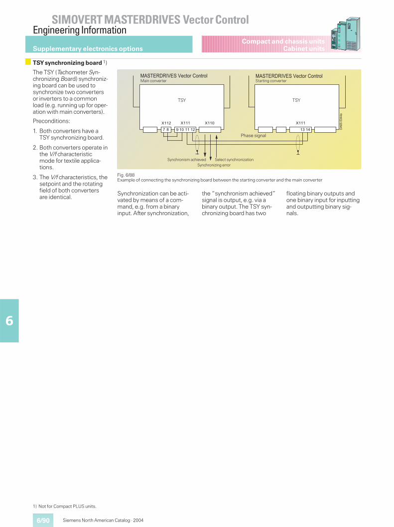
6/90
SIMOVERT MASTERDRIVES Vector ControlEngineering Information
6
Siemens North American Catalog · 2004
Compact and chassis unitsCabinet units
Fig. 6/88Example of connecting the synchronizing board between the starting converter and the main converter
���������
��&��=�= ��&��(#)-+��-1)+-,
���� ���
��&��=�= ��&��(#)-+��-1)+-,
����
� " �� ��� �
����
� ��
Main converter
TSY
Synchronism achievedSynchronizing error
Select synchronization
Starting converter
Phase signal
TSY
Supplementary electronics options
TSY synchronizing board 1)
The TSY (Tachometer Syn-chronizing Board) synchroniz-ing board can be used tosynchronize two convertersor inverters to a commonload (e.g. running up for oper-ation with main converters).
Preconditions:
1. Both converters have aTSY synchronizing board.
2. Both converters operate inthe V/f characteristicmode for textile applica-tions.
3. The V/f characteristics, thesetpoint and the rotatingfield of both convertersare identical.
Synchronization can be acti-vated by means of a com-mand, e.g. from a binaryinput. After synchronization,
the “synchronism achieved”signal is output, e.g. via abinary output. The TSY syn-chronizing board has two
floating binary outputs andone binary input for inputtingand outputting binary sig-nals.
1) Not for Compact PLUS units.
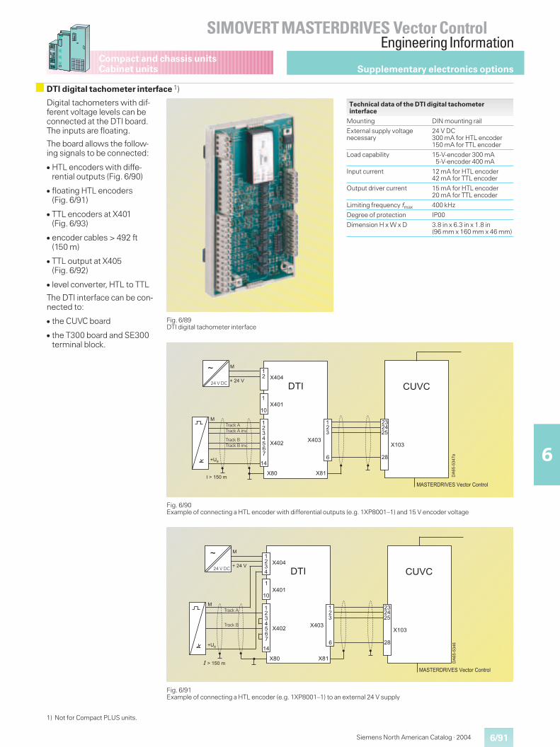
6/91
SIMOVERT MASTERDRIVES Vector ControlEngineering Information
6
Siemens North American Catalog · 2004
Compact and chassis unitsCabinet units
Digital tachometers with dif-ferent voltage levels can beconnected at the DTI board.The inputs are floating.
The board allows the follow-ing signals to be connected:
� HTL encoders with diffe-rential outputs (Fig. 6/90)
� floating HTL encoders(Fig. 6/91)
� TTL encoders at X401(Fig. 6/93)
� encoder cables > 492 ft(150 m)
� TTL output at X405(Fig. 6/92)
� level converter, HTL to TTL
The DTI interface can be con-nected to:
� the CUVC board
� the T300 board and SE300terminal block.
Fig. 6/89DTI digital tachometer interface
Technical data of the DTI digital tachometerinterface
Mounting DIN mounting rail
External supply voltagenecessary
24 V DC300 mA for HTL encoder150 mA for TTL encoder
Load capability 15-V-encoder 300 mA5-V-encoder 400 mA
Input current 12 mA for HTL encoder42 mA for TTL encoder
Output driver current 15 mA for HTL encoder20 mA for TTL encoder
Limiting frequency fmax 400 kHz
Degree of protection IP00
Dimension H x W x D 3.8 in x 6.3 in x 1.8 in(96 mm x 160 mm x 46 mm)
Fig. 6/90Example of connecting a HTL encoder with differential outputs (e.g. 1XP8001–1) and 15 V encoder voltage
Fig. 6/91Example of connecting a HTL encoder (e.g. 1XP8001–1) to an external 24 V supply
���������
��&��=�= ��&��(#)-+��-1)+-,
��
��
�"
���
�
���
�"
��
�"�
�� ����
���
��
�����
���
��
�%������
�
�
��;
�G����.
�
����
24 V DC
Track ATrack A inv.
Track BTrack B inv.
��������
��&��=�= ��&��(#)-+��-1)+-,
��
��
�"
���
�
���
�"
��
�"�
�� ����
���
��
�����
���
��
�%������
�
�
��;
��G����.
�
�
����
24 V DC
Track A
Track B
Supplementary electronics options
DTI digital tachometer interface 1)
1) Not for Compact PLUS units.
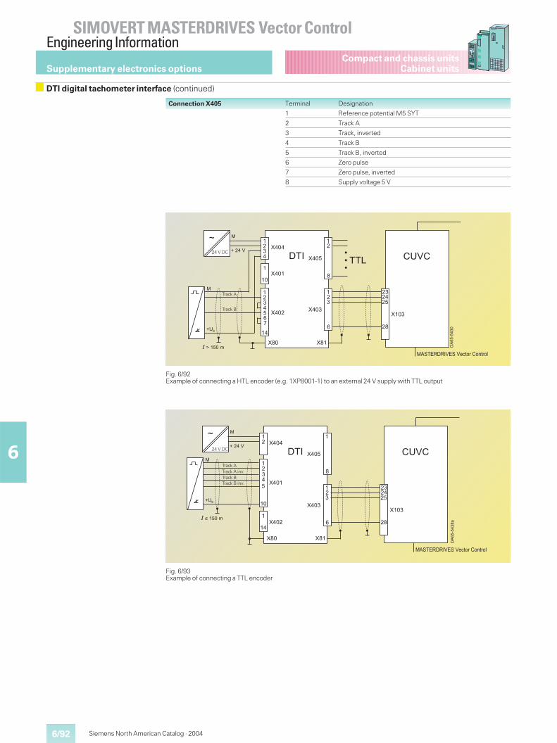
6/92
SIMOVERT MASTERDRIVES Vector ControlEngineering Information
6
Siemens North American Catalog · 2004
Compact and chassis unitsCabinet units
Fig. 6/92Example of connecting a HTL encoder (e.g. 1XP8001-1) to an external 24 V supply with TTL output
�������
��&��=�= ��&��(#)-+��-1)+-,
��
��
�"
���
�
���
�"
��
�"�
�� ����
���
��
�����
���
��
�%������
�
�
��;
��G����.
�
"
���
��
����
����
24 V DC
Track A
Track B
Connection X405 Terminal Designation
1 Reference potential M5 SYT
2 Track A
3 Track, inverted
4 Track B
5 Track B, inverted
6 Zero pulse
7 Zero pulse, inverted
8 Supply voltage 5 V
Fig. 6/93Example of connecting a TTL encoder
�������"�
��&��=�= ��&��(#)-+��-1)+-,
��
��
�"��� �
���
�"
��
�"�
�� ����
���
��
�����
�
�
�%������
�
�
��;
��@����.
"
���
�
��
���
�
24 V DC
Track A
Track BTrack A inv.
Track B inv.
Supplementary electronics options
DTI digital tachometer interface (continued)
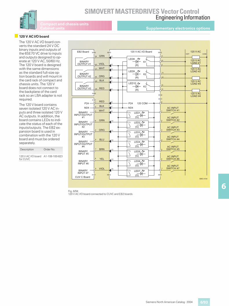
6/93
SIMOVERT MASTERDRIVES Vector ControlEngineering Information
6
Siemens North American Catalog · 2004
Compact and chassis unitsCabinet units Supplementary electronics options
120 V AC I/O board
Fig. 6/94120 V AC I/O board connected to CUVC and EB2 boards
9���� ��" 6��� 6���
�,?
����2�*��3�>�� ��" ����2�*�6����>@ �>�
����2�*�/>*+�H�
����2�*�/>*+�H�
����2�*�/>*+�H�
����2�*�/>*+�H�
��
*��3?4C@!I3@���H�
*��3?4C@!I3@���H�
*��3?4C@!I3@���H�
*��3?4C@!I3@���H�
*��3?4C@!I3@���H�
*��3?4C@!I3@���H�
*��3?4C@!I3@���H�
��
��
6���
6���
�
�
�
�
�
�
�
��
�
��
��
6���
:�;
/9+�
:�;
/9+�
:�;
:�;
/9+�
:�;
/9+�
:�;
/9+�
:�;
/9+�
4��
���
�����>�
/9+
:,;F�
/9+�
:,;F�
/9+��
:,;F�
�3?*,G>C@4C@�H� 23>/
�3?*,G>C@4C@�H�
�3?*,G>C@4C@�H�
6���
6���
4��
���
I�@
>,�
�/F
,9+
,9+
�/F
I�@
�,?
>,�
�/C
�,?
G9/
23>/
�3?*,G3?4C@�>C@4C@
H�
�3?*,G3?4C@�>C@4C@
H�
�3?*,G3?4C@�>C@4C@
H�
�3?*,G3?4C@�>C@4C@
H�
�3?*,G3?4C@�H�
�3?*,G3?4C@�H�
�3?*,G3?4C@�H�
�C2���� ��"
��
��
��
��
�
�
�
��
��
��
��
��
��
6���6���
��
��
�
�
�
�
�
�
�
�
/9+�
�
�
�
�
�
��������
The 120 V AC I/O board con-verts the standard 24 V DCbinary inputs and outputs ofthe 6SE70 VC drive to inputsand outputs designed to op-erate at 120 V AC, 50/60 Hz.The 120 V board is designedwith the same dimensionsas the standard full-size op-tion boards and will mount inthe card rack of compact andchassis units. The 120 Vboard does not connect tothe backplane of the cardrack so an LBA adapter is notrequired.
The 120 V board containsseven isolated 120 V AC in-puts and three isolated 120 VAC outputs. In addition, theboard contains LEDs to indi-cate the status of each of theinputs/outputs. The EB2 ex-pansion board is used incombination with the 120 Vboard and must be orderedseparately.
Description Order No.
120 V AC I/O boardfor CUVC
A1-108-100-823
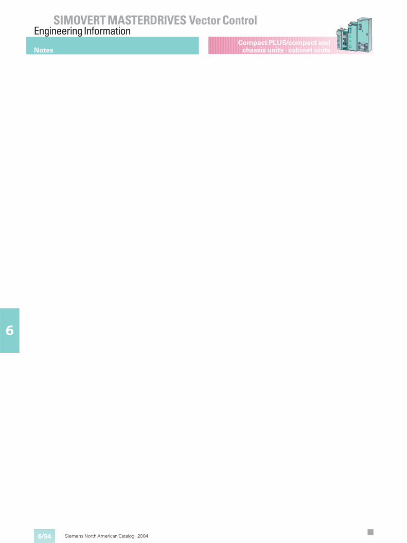
6/94
SIMOVERT MASTERDRIVES Vector ControlEngineering Information
6
Siemens North American Catalog · 2004
Compact PLUS/compact andchassis units · cabinet unitsNotes
7/1
7
Siemens North American Catalog · 2004
7/2 Compact PLUS units
7/3 Compact units
Chassis units7/4 Converters/inverters, AFE inverters7/7 Rectifier units and rectifier/regenerative units
7/9 Overcurrent protector units (OCP)
7/10 Braking units, braking resistors
7/12 DC link module,capacitor modulePrecharging resistors
7/13 Radio-interference suppression filters
7/16 Line reactors
7/22 AFE reactors,output reactors (iron)
7/23 Output reactors (ferrite)
7/24 Voltage limiting filters
7/26 Transformers
7/30 6SE72 Converter cabinet units
Vector ControlDimensionDrawings
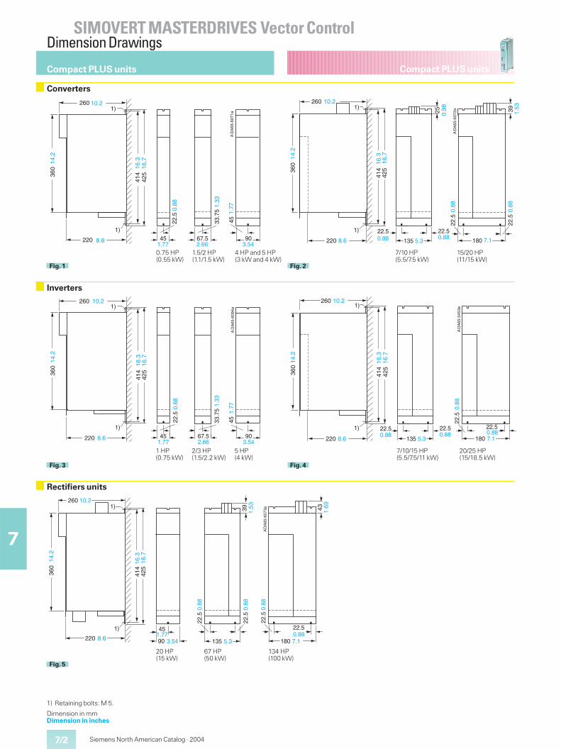
7/2
SIMOVERT MASTERDRIVES Vector ControlDimension Drawings
7
Compact PLUS units
Siemens North American Catalog · 2004
Compact PLUS units
Converters
Rectifiers units
DA
65-6
073a1)
1)
135 180
22.5
22.5
39 43
414
260
220
360
425
22.5
22.5
90
45
10.2
14.2
16.3
8.6 3.541.77
0.88
0.88
5.3
0.88
7.10.88
A
16.7
1.53
1.69
Fig. 5
20 HP 67 HP 134 HP(15 kW) (50 kW) (100 kW)
Inverters
DA
65-6
094a
1)
1)
A
22.5
67.5
33.7
5
45
414
10.2
360
45 90
425
220
260
14.2
16.3
16.7
8.61.77
0.88 1.33
1.77
2.66 3.54
Fig. 3D
A65
-545
3e
1)
1)
414
260
220
360
135 180
22.522.5
22.5
425
22.5
10.214
.2
8.6
16.3
16.7
0.88 0.885.3
0.88
7.10.88
A
Fig. 4
1 HP 2/3 HP 5 HP(0.75 kW) (1.5/2.2 kW) (4 kW)
7/10/15 HP 20/25 HP(5.5/7.5/11 kW) (15/18.5 kW)
DA
65-6
071a
1)
1)A
67.545
414
260
220
360
425
45 90
14.2
8.6
16.3
16.7
10.2
22.5
0.88
33.7
51.
33
1.77 2.66 3.54
1.77
Fig. 1
DA
65-6
072a
1)
1)
414
260
220
360
135 180
22.5
22.5
425
22.5
25 39
10.2
14.2
16.3
8.6 0.88
16.7
0.885.3
0.88
7.1
22.5
0.88
0.98
1.53
A
Fig. 2
1) Retaining bolts: M 5.
Dimension in mmDimension in inches
0.75 HP 1.5/2 HP 4 HP and 5 HP(0.55 kW) (1.1/1.5 kW) (3 kW and 4 kW)
7/10 HP 15/20 HP(5.5/7.5 kW) (11/15 kW)
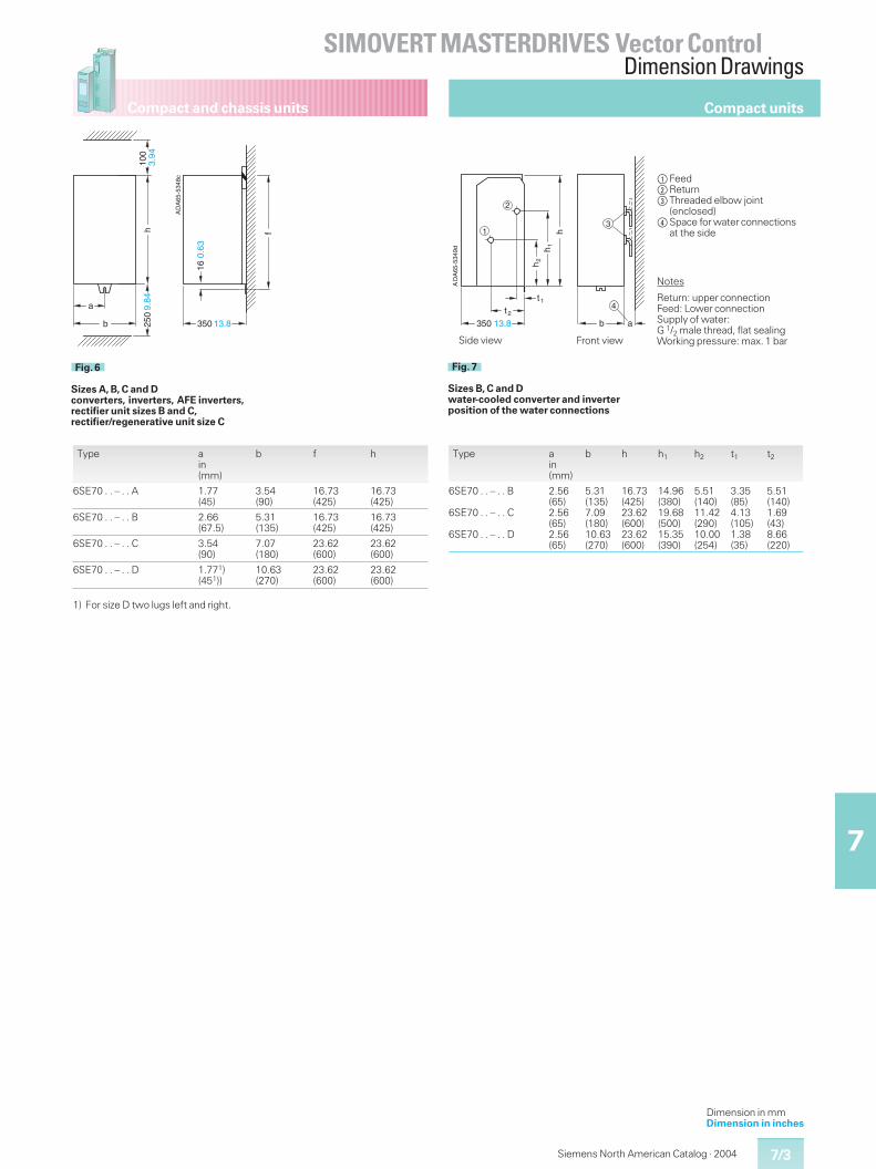
7/3
SIMOVERT MASTERDRIVES Vector ControlDimension Drawings
7
Compact and chassis units
Siemens North American Catalog · 2004
fh
a
b
DA
65-5
348c
16
350
9.84
100
3.94
250
13.8
0.63
A
Fig. 6
Sizes A, B, C and Dconverters, inverters, AFE inverters,rectifier unit sizes B and C,rectifier/regenerative unit size C
h2
h1
t 1
t 2
b a
h
3
2
1
4
DA
65-5
349d
350 13.8
A
Fig. 7
Sizes B, C and Dwater-cooled converter and inverterposition of the water connections
Front view
Notes
Return: upper connectionFeed: Lower connectionSupply of water:G 1/2 male thread, flat sealingWorking pressure: max. 1 barSide view
Type ain(mm)
b f h
6SE70 . . – . . A 1.77(45)
3.54(90)
16.73(425)
16.73(425)
6SE70 . . – . . B 2.66(67.5)
5.31(135)
16.73(425)
16.73(425)
6SE70 . . – . . C 3.54(90)
7.07(180)
23.62(600)
23.62(600)
6SE70 . . – . . D 1.771)(451))
10.63(270)
23.62(600)
23.62(600)
1) For size D two lugs left and right.
Compact units
Type ain(mm)
b h h1 h2 t1 t2
6SE70 . . – . . B
6SE70 . . – . . C
6SE70 . . – . . D
2.56(65)2.56(65)2.56(65)
5.31(135)7.09(180)10.63(270)
16.73(425)23.62(600)23.62(600)
14.96(380)19.68(500)15.35(390)
5.51(140)11.42(290)10.00(254)
3.35(85)4.13(105)1.38(35)
5.51(140)1.69(43)8.66(220)
$Feed%Return&Threaded elbow joint
(enclosed)(Space for water connections
at the side
Dimension in mmDimension in inches
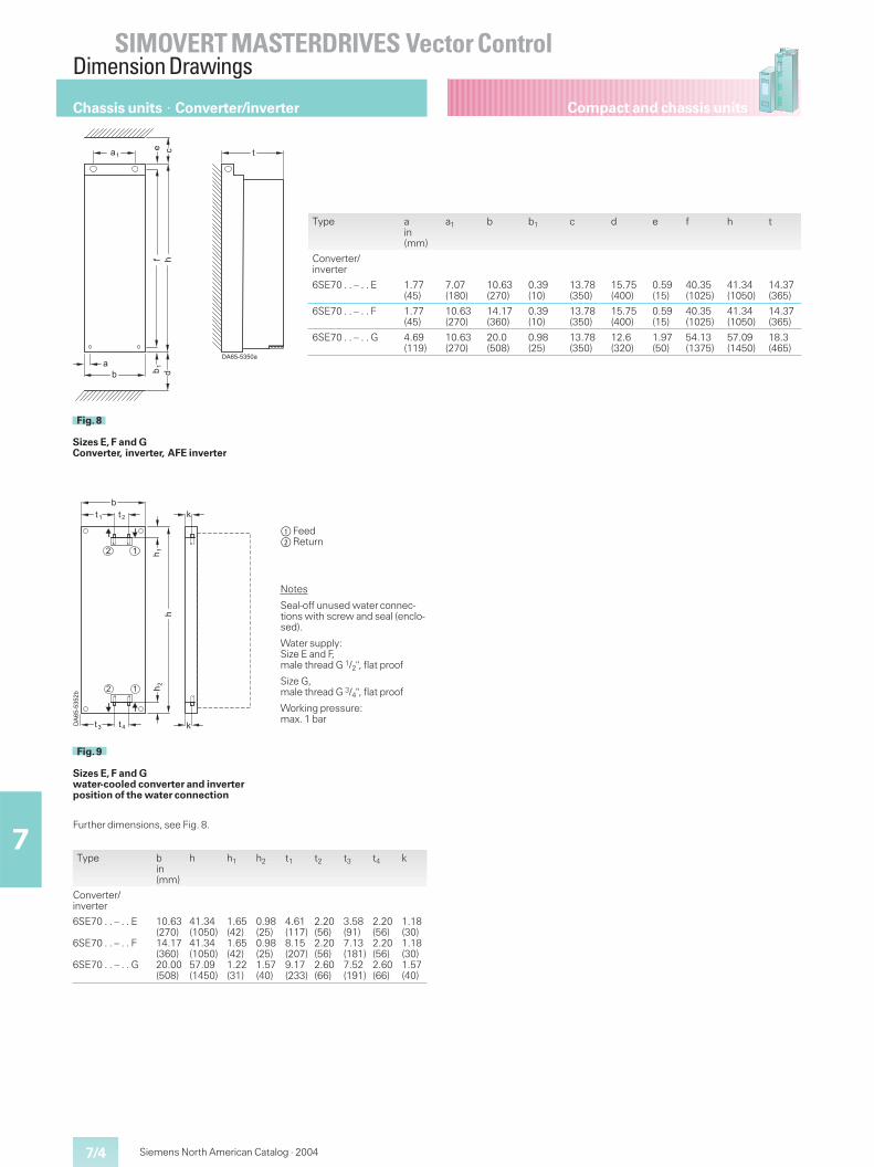
7/4
SIMOVERT MASTERDRIVES Vector ControlDimension Drawings
7
Compact and chassis units
Siemens North American Catalog · 2004
Chassis units � Converter/inverter
�
���������
�
�
�
��
�
Fig. 8
Sizes E, F and GConverter, inverter, AFE inverter
���������
� �
� �
� � � �
��
�
��
�
�
�
� �
�
Fig. 9
Sizes E, F and Gwater-cooled converter and inverterposition of the water connection
Notes
Seal-off unused water connec-tions with screw and seal (enclo-sed).
Water supply:Size E and F,male thread G 1/2", flat proof
Size G,male thread G 3/4", flat proof
Working pressure:max. 1 bar
$Feed%Return
Type bin(mm)
h h1 h2 t1 t2 t3 t4 k
Converter/inverter
6SE70 . . – . . E
6SE70 . . – . . F
6SE70 . . – . . G
10.63(270)14.17(360)20.00(508)
41.34(1050)41.34(1050)57.09(1450)
1.65(42)1.65(42)1.22(31)
0.98(25)0.98(25)1.57(40)
4.61(117)8.15(207)9.17(233)
2.20(56)2.20(56)2.60(66)
3.58(91)7.13(181)7.52(191)
2.20(56)2.20(56)2.60(66)
1.18(30)1.18(30)1.57(40)
Further dimensions, see Fig. 8.
Type ain(mm)
a1 b b1 c d e f h t
Converter/inverter
6SE70 . . – . . E 1.77(45)
7.07(180)
10.63(270)
0.39(10)
13.78(350)
15.75(400)
0.59(15)
40.35(1025)
41.34(1050)
14.37(365)
6SE70 . . – . . F 1.77(45)
10.63(270)
14.17(360)
0.39(10)
13.78(350)
15.75(400)
0.59(15)
40.35(1025)
41.34(1050)
14.37(365)
6SE70 . . – . . G 4.69(119)
10.63(270)
20.0(508)
0.98(25)
13.78(350)
12.6(320)
1.97(50)
54.13(1375)
57.09(1450)
18.3(465)
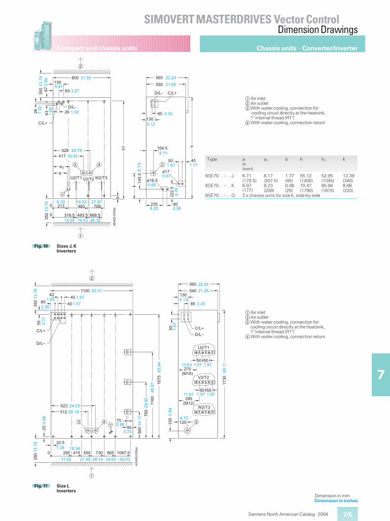
7/5
SIMOVERT MASTERDRIVES Vector ControlDimension Drawings
7
Compact and chassis units
Siemens North American Catalog · 2004
��
����
����
���
��� ����������
�
�
��
���
�
��� ���
�
�
�
�
�
��
� ��� ��� �����
��� � ���
�� ��
����
�� �
���
�
��� ��
� ���
����
�
����
� �
����
��� ���
��
����
������
��
����
��������� �
���
��� ������� ���� �����
����� ���� ����
���
�
�
� ���� �����
����
��
���
��� ��
�� ��
��
��������
����� ���
���
����
���
�
� ��� ����� �����
Fig. 10 Sizes J, KInverters
��
����
����
�
���
���
��
��
��� � � ��� ��� ���
��
��
�� ��
���
�� ��
�����
�����
������
�
� � �� ��
�
�����
�� ����
���
���
�� �����
�������
�� �� �
���
�
����
���� �
�������� �
���
���
����
� ��� ����� ����� �����
����
��
���
���
�
�
����
���� ���
���
��
���
����
�
����
�
����
�
��
�
��
��
�����
���
� ���
�����
������ �
���
��� ������
�� �
����
��� ������
�� �
��
����
���
���
����
Fig. 11 Size LInverters
Type ain(mm)
a1 b h h1 k
6SE70 . . – . . J
6SE70 . . – . . K
6.71(170.5)6.97(177)
8.17(207.5)8.23(209)
1.77(45)0.98(25)
55.12(1400)70.47(1790)
52.95(1345)65.94(1675)
13.39(340)8.66(220)
6SE70 . . – . . Q 2 x chassis units for size K, side-by-side
$Air inlet%Air outlet&With water cooling, connection for
cooling circuit directly at the heatsink,1" internal thread (R1")
(With water cooling, connection return
Chassis units � Converter/inverter
$Air inlet%Air outlet&With water cooling, connection for
cooling circuit directly at the heatsink,1" internal thread (R1")
(With water cooling, connection return
Dimension in mmDimension in inches
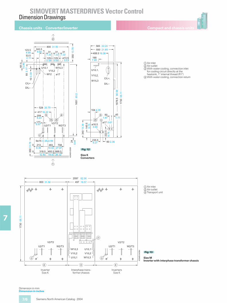
7/6
SIMOVERT MASTERDRIVES Vector ControlDimension Drawings
7
Compact and chassis units
Siemens North American Catalog · 2004
$Air inlet%Air outlet&With water cooling, connection inlet
for cooling circuit directly at theheatsink, 1" internal thread (R1")
(With water cooling, connection return
Chassis units � Converter/inverter
��� ����� ��� �����
�����
� ��
� ��
�
�
� ��
� ��
��
����
���!
�� �
�����
����
��� ���
�����
����� ���
���
���
�
Interphase trans-former chassis
InverterSize K
InvertersSize K
��
����
���"
�
���
���
� � ��
� ��
� �
� � ��� ���
��� ����������
�# �
� $
� ��$
� ��
��
� �
��
���$
���
���
�
�
� �
� ��
���
��
��������
� ����
����� ��� ��
� ���
��������
�� ���
� ���
� ���
���� ����
���
���
�
����
��
� �
�
�� �
����
���
��
��
���� �
��� �����
����
����
����
� ��� ����� ����� ���� ���� �����
���� ���� �����
����#����
���
���
�
���
����
��
����
���
�
�����
� ���
����
�
����
���
��
��� ���
����
����
���� ����
����
����
���
�
����
���
����
���
���
�����
��� ������ ���
����
����
Fig. 12
Size KConverters
Fig. 13
Size MInverter with interphase transformer chassis
$Air inlet%Air outlet(Transport unit
Dimension in mmDimension in inches
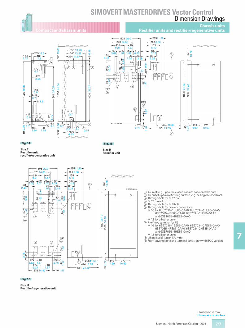
7/7
SIMOVERT MASTERDRIVES Vector ControlDimension Drawings
7
Compact and chassis units
Siemens North American Catalog · 2004
Chassis unitsRectifier units and rectifier/regenerative units
U1/ V1/ W1/L1 L2 L3
PE
C/L+ D/L-
3
PEDA
65-5
824d
4
6 2 7
5 1
180269
170
228
41
94.5
148
147
941
40.3
5
100
10
17
30
13
17
294340350
1000
70 30 13
17
168.5
9
PE
500
1050
44.5
�
17
13.7813.39
11.57
0.35
19.6
841
.34
39.3
7
37.0
5
1025
0.51
0.7
1.2
500
19.6
8
0.7
6.63
2.8
10.6
7.11.75
6.7
8.98
1.63.7
5.8
5.790.7
0.7
0.39
3.94 1.18
0.5
A
Fig. 14
Size ERectifier unit,rectifier/regenerative unit
DA65-5825c
255
50
PE1
5040
70
PE2
PE2
PE1
270119
D/L- C/L+D/L-C/L+
U1/L1 V1/L2 W1/L3
3
43
2
1
W1L3
V1L2
U1L1
61
92 40
234 40376
508
11926
26 63
20.014.80
2.40
3.62 1.57
9.21 1.57
1.02 4.69
1.02 2.48
6726
2.64
1.02
10.0
41.
97
A
1.57
1.97
2.76424
55116.69
21.69 4.69 10.63451.
77
1050
950
350
13.7
8
41.3
4
37.4
0
85
130
155225
285
3.35
5.12
6.10
8.86
11.22
401.57
250
9.84
501.
97Fig. 15
Size HRectifier unit
DA65-5826c
252
50
PE1
250
5050
PE2
PE2
PE1
270119
D/L- C/L+D/L-C/L+
U1/L1 V1/L2 W1/L3
3
43
2
1
3
4
1U2/1T1 1V2/1T2 1W2/1T3
W1L3
V1L2
U1L1
40
61
92 40
234 40376
508
11926
26 63
20.014.80
2.40
3.62 1.57
9.21 1.57
1.02 4.69
1.02 2.4885
130
155225
285
3.35
5.12
6.10
8.86
11.22
6726
2.64
1.029,92
1.97
1.57 9.84
1.97
40
3.6292 40
234 40
376 40
1.57
9.21 1.5714.80
80
70
3.15
2.76
1.57
1.57
1.97
296
551424
11.6516.69
21.69
4.69 10.63
451.
7714
0013
0051
.18
55.1
235
013
.78
A
Fig. 16
Size HRectifier/regenerative unit
$ Air inlet, e.g. up to the closed cabinet base or cable duct% Air outlet up to a reflecting surface, e.g. ceiling or closed roof& Through-hole for M 12 bolt( M 12 thread) Through-hole for M 8 bolt* Through-hole for power connections
M 16 for 6SE7036–1EE85–0AA0, 6SE7034–2FE85–0AA0,6SE7035–4FE85–0AA0, 6SE7034–2HE85–0AA0and 6SE7035–4HE85–0AA0
M 12 for all other units+ Pre-fitted terminal for PE
M 16 for 6SE7036–1EE85–0AA0, 6SE7034–2FE85–0AA0,6SE7035–4FE85–0AA0, 6SE7034–2HE85–0AA0and 6SE7035–4HE85–0AA0
M 12 for all other units, Lifting eye Ø 1.18 in (30 mm)- Front cover (doors) and terminal cover, only with IP20 version
Dimension in mmDimension in inches
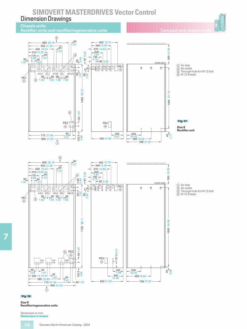
7/8
SIMOVERT MASTERDRIVES Vector ControlDimension Drawings
7
Compact and chassis units
Siemens North American Catalog · 2004
Chassis unitsRectifier units and rectifier/regenerative units
4
2
PE2
50
PE2
PE1
PE1
1
3
3
DA65-5827b
U1/L1 C/L+ V1/V2 D/L- W1/L3
U1L1
V1L2
W1L3
CL+
DL-
17540
310
40420555
26
665
40
40
50
26.1821.85
16.5412.20 1.57
1.57
6.89 1.57
1.0226
1.0226
1.02261.02
1.571.97 6250
1.97
2.44
85
130
200270
340400 15.7513.39
10.63
2687
1.02
3.43 7.87
5.123.35
1400
55.1
21.
974.
82
710800
40
122.
5
31.5027.95
1.57 8.07205
550 21.65
258
483708
10.1619.02
27.87
451.
7713
0035
013
.78
A
51.1
8
Fig. 17
Size KRectifier unit
4
PE2
5050
PE2
PE1
PE1
1
3
3
DA65-5828b
1U/L1 1C/L+ 1V/L2 1D/L- 1W/L3
1UL1
1VL2
1CL+
1DL-
1W21T3
1V21T2
1U21T1
62
17540
310
40420555
665
40
40
50
26.1821.85
16.5312.20 1.57
1.57
6.89 1.57
1.571.97
2
261.02
261.02
261.02
261.02
1.97
2.44
1730
68.1
1
90 50
33550
58050
800
3.54 1.9713.19 1.97
22.83710 27.95
31.50
1.9740 1.57
4.82
122.
51.
97
550
483
708
3407.48190 258
10.16
13.3921.65
19.02
27.87
137.
55.
41
250.
9835
016
5064
.96
A
13.7
8
2687
1.02
3.43
85
130
200270
340400 15.7513.39
10.63
7.87
5.123.35
Fig. 18
Size KRectifier/regenerative units
$ Air inlet% Air outlet& Through-hole for M 12 bolt( M 12 thread
$ Air inlet% Air outlet& Through-hole for M 12 bolt( M 12 thread
Dimension in mmDimension in inches
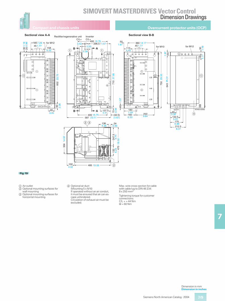
7/9
SIMOVERT MASTERDRIVES Vector ControlDimension Drawings
7
Compact and chassis units
Siemens North American Catalog · 2004
Overcurrent protector units (OCP)
XKIPP1
X9X301 X36X1940
V10
2 3
2
415
�
F1
X19 F3
1 1�
� �
F1
DA65-6056a
55
87
�������� �������Rectifier/regenerative unit C/L+
�������� ������� InverterC/L+
for M12
for M10 for M12
A
158 45
30
185
25
7.28 1.77
6.22
1.18
0.98
400296.515.75
11.670.20
0.20
3.42
710
27.
95
602
60
85
23.7
02.
36
3.35 400
587 (42.5)
137.5
(1.67)
5.4115.75
23.110.
59 160 250
1807.09
6.30 9.84
1.57
85
132.5
175
212.5
3.35
5.22
6.89
8.37
50 6
43
750
29
.53
25.3
1
50 360
113
14.17451.77
4.45
1.97
1.97
1.77
1.18
136 245.35 0.94
470
132
24
7.5
3045
9.74
5.20
18.5
0
356
485 102 19.094.02
14.0
2
Fig. 19
$ Air outlet% Optional mounting surfaces for
wall mounting& Optional mounting surfaces for
horizontal mounting
( Optional air duct(Mounting 5 x M 6)If operated without an air conduit,it must be ensured that air can es-cape unhindered.Circulation of exhaust air must beexcluded.
Max. wire cross-section for cablewith cable lug to DIN 46 234:8 x 250 mm2
Tightening torque for customerconnections:C/L + = 44 Nme= 60 Nm
Dimension in mmDimension in inches
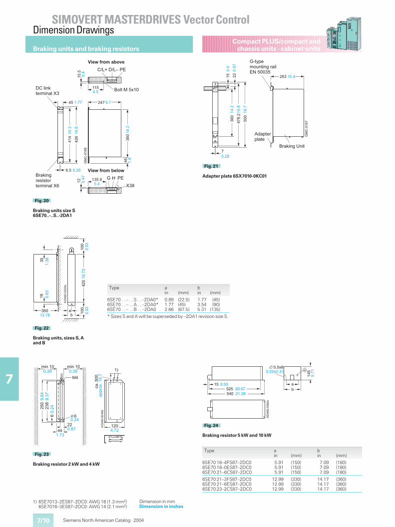
7/10
SIMOVERT MASTERDRIVES Vector ControlDimension Drawings
7
Compact PLUS/compact andchassis units · cabinet units
Siemens North American Catalog · 2004
Braking units and braking resistors
DA
65-5
320a
ab
16
350
425
100
35
100
1.38
0.63
13.78 3.93
3.93
A
16.7
3
Fig. 22
Braking units, sizes S, Aand B
DA
65-5
362c
ab
540525
145
15
5.5x8
21.2620.67
0.59
5.710.22x0.31
A
Fig. 24
Braking resistor 5 kW and 10 kW
Type ain (mm)
bin (mm)
6SE70 16–4FS87–2DC06SE70 18–0ES87–2DC06SE70 21–6CS87–2DC0
5.915.915.91
(150)(150)(150)
7.097.097.09
(180)(180)(180)
6SE70 21–3FS87–2DC06SE70 21–6ES87–2DC06SE70 23–2CS87–2DC0
12.9912.9912.99
(330)(330)(330)
14.1714.1714.17
(360)(360)(360)
Type ain (mm)
bin (mm)
6SE70 . . – . . S . . –2DA0*6SE70 . . – . . A . . –2DA0*6SE70 . . – . . B . . –2DA0
0.891.772.66
(22.5)(45)(67.5)
1.773.545.31
(45)(90)
(135)
* Sizes S and A will be superseded by –2DA1 revision size S.
1) 6SE7013–2ES87–2DC0: AWG 16 (1.3 mm2)6SE7016–3ES87–2DC0: AWG 14 (2.1 mm2)
��
����
����
��
%��&�
��
���
���
�
����
�
��
'()& �����
*
'()& �����
����
����
����
���� ���
����
����
��+
+,-#
�& ��
�
Fig. 23
Braking resistor 2 kW and 4 kW
Dimension in mmDimension in inches
��
.�
���
��
/-01&�&�# �
���
�
���&���&23
�������������
���
.
����������� ��
4��
���� ���
�
� �
��&0()�1�,'()�0&4�
/,��()5,�6(61-,1�,'()�0&4�
���
���
��
���
���
���
���
���
����
��
���� 7 23
���
���
���
Fig. 20
Braking units size S6SE70..-..S..-2DA1
��
.�
���
��
�!�+1�,+0�1�
.�18+�'-9)1()5&,�(03:&�����
/,��()5&)(1
��� ���
�
����
�
���
�
����
���
���
���
���
����
���
Fig. 21
Adapter plate 6SX7010-0KC01
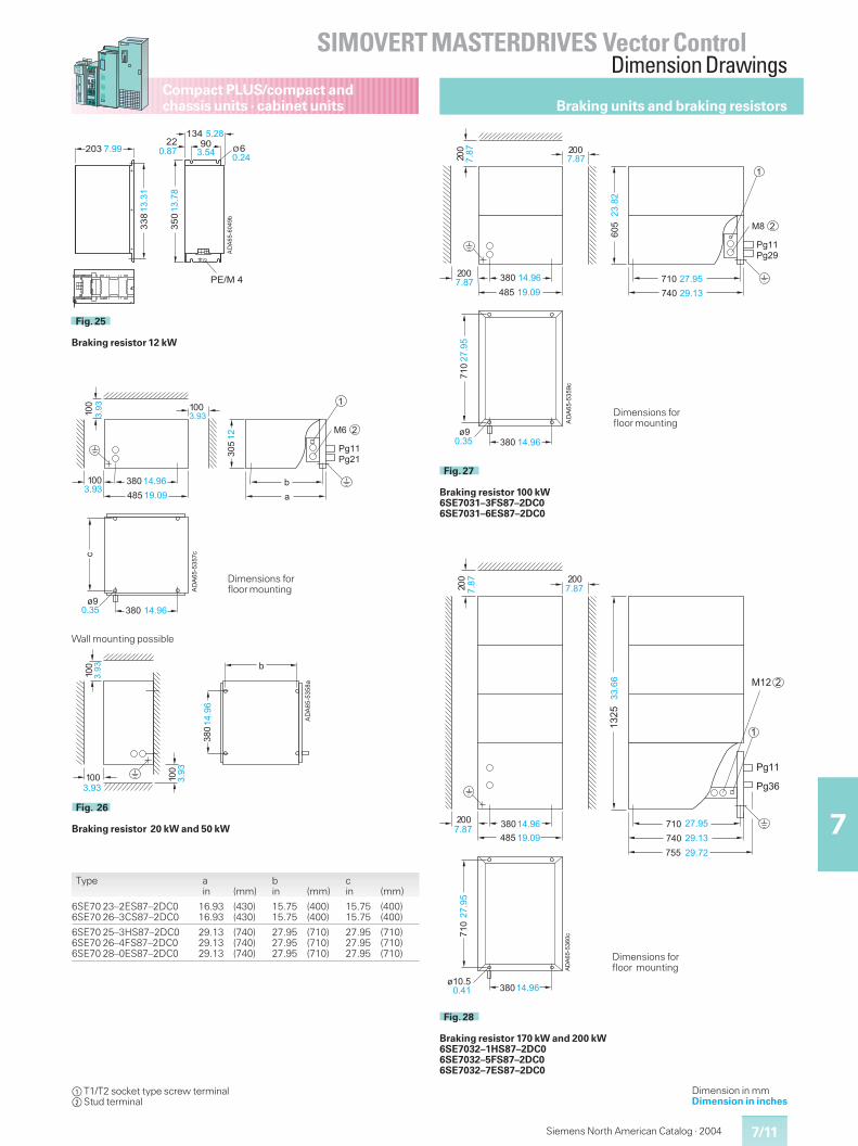
7/11
SIMOVERT MASTERDRIVES Vector ControlDimension Drawings
7
Compact PLUS/compact andchassis units · cabinet units
Siemens North American Catalog · 2004
��
����
���%
25 25��
���
���
���
���
���
���
� �
���
���
�����
� �
����
����
����
��������
����
�
��������
����
�
�����
��� �
�
Fig. 27
Braking resistor 100 kW6SE7031–3FS87–2DC06SE7031–6ES87–2DC0
Dimensions forfloor mounting
��
����
���%
25
25��
�� �
���
����
�
�
���
���
������
���
� �
���
� ���
� �
���
��������
���� ����
����
��� �������
����
�
�����
��� �
�����
Fig. 28
Braking resistor 170 kW and 200 kW6SE7032–1HS87–2DC06SE7032–5FS87–2DC06SE7032–7ES87–2DC0
Dimensions forfloor mounting
Braking units and braking resistors
$T1/T2 socket type screw terminal%Stud terminal
Dimension in mmDimension in inches
Type ain (mm)
bin (mm)
cin (mm)
6SE70 23–2ES87–2DC06SE70 26–3CS87–2DC0
16.9316.93
(430)(430)
15.7515.75
(400)(400)
15.7515.75
(400)(400)
6SE70 25–3HS87–2DC06SE70 26–4FS87–2DC06SE70 28–0ES87–2DC0
29.1329.1329.13
(740)(740)(740)
27.9527.9527.95
(710)(710)(710)
27.9527.9527.95
(710)(710)(710)
��
����
����
23��&�
�* �
��
���
�
�������
��
������
�
���
�
��������
����
����
Fig. 25
Braking resistor 12 kW
��
����
���%
�
�
25 25�
���
%
��
��
���
���
��
���
�����
����
����
����
����
����
��������
�
�
Dimensions forfloor mounting
��
����
����
�
��
��
��
���
����
����
����
���
�
�
Fig. 26
Braking resistor 20 kW and 50 kW
Wall mounting possible
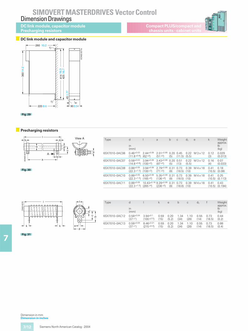
7/12
SIMOVERT MASTERDRIVES Vector ControlDimension Drawings
7
Compact PLUS/compact andchassis units · cabinet units
Siemens North American Catalog · 2004
DC link module,capacitor modulePrecharging resistors
DC link module and capacitor module
DA
65-5
071e
1)
1)
414
260
220
360
425
90
45
10.2
14.2
8.6
16.3
16.7
3.54
1.77
A
Fig. 29
Precharging resistors
l
c
k k
a
d 1d
A
e
DA
65-6
075
b
View A
A
Fig. 30
Type d
in(mm)
l a b c d1 e k Weightapprox.lb(kg)
6SX7010–0AC06 0.46±0.03
(11.8 ±0.8)2.44±0.08
(62 ±2)2.01±0.08
(51 ±2)0.20(5)
0.45(11.5)
0.22(5.5)
M 3 x 12 0.12(3)
0.029(0.013)
6SX7010–0AC07 0.58±0.03
(14.8 ±0.8)3.94±0.08
(100 ±2)3.43±0.08
(87 ±2)0.20(5)
0.51(13)
0.22(5.5)
M 3 x 12 0.16(4)
0.07(0.033)
6SX7010–0AC08 0.88±0.05
(22.3 ±1.3)3.94±0.08
(100 ±2)2.79±0.08
(71 ±2)0.31(8)
0.73(18.5)
0.39(10)
M 4 x 18 0.41(10.5)
0.18(0.08)
6SX7010–0AC10 0.88±0.05
(22.3 ±1.3)6.50±0.08
(165 ±2)5.35±0.08
(136 ±2)0.31(8)
0.73(18.5)
0.39(10)
M 4 x 18 0.41(10.5)
0.25(0.113)
6SX7010–0AC11 0.88±0.05
(22.3 ±1.3)10.43±0.16
(265 ±4)9.29±0.08
(236 ±2)0.31(8)
0.73(18.6)
0.39(10)
M 4 x 18 0.41(10.5)
0.43(0.194)
Type d
in(mm)
l k e b c d1 f Weightapprox.lb(kg)
6SX7010–0AC12 0.58±0.04
(37 ±1)3.94±0.1
(100 ±2.5)0.59(15)
0.20(5.2)
1.34(34)
1.10(28)
0.55(14)
0.73(18.5)
0.44(0.2)
6SX7010–0AC13 0.58±0.04
(37 ±1)8.46±0.21
(215 ±5.4)0.59(15)
0.20(5.2)
1.34(34)
1.10(28)
0.55(14)
0.73(18.5)
0.88(0.4)
l
k k
dc b
1
de
f
DA
65-6
076
Fig. 31
Dimension in mmDimension in inches
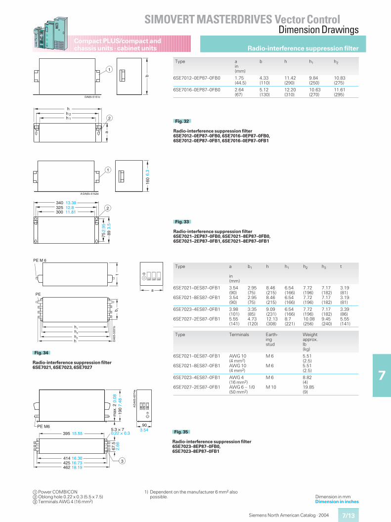
7/13
SIMOVERT MASTERDRIVES Vector ControlDimension Drawings
7
Compact PLUS/compact andchassis units · cabinet units
Siemens North American Catalog · 2004
Dimension in mmDimension in inches
Radio-interference suppression filter
t
a
DA
65-5
331bh1
b 1
h3
h2
h
PE
PE M 6
Fig. 34
Radio-interference suppression filter6SE7021, 6SE7023, 6SE7027
Type a
in(mm)
b1 h h1 h2 h3 t
6SE7021–0ES87–0FB1
6SE7021–8ES87–0FB1
3.54(90)3.54(90)
2.95(75)2.95(75)
8.46(215)8.46(215)
6.54(166)6.54(166)
7.72(196)7.72(196)
7.17(182)7.17(182)
3.19(81)3.19(81)
6SE7023–4ES87–0FB1
6SE7027–2ES87–0FB1
3.98(101)5.55(141)
3.35(85)4.73(120)
9.09(231)12.13(308)
6.54(166)8.7(221)
7.72(196)10.08(256)
7.17(182)9.45(240)
3.39(86)5.55(141)
Type Terminals Earth-ingstud
Weightapprox.lb(kg)
6SE7021–0ES87–0FB1
6SE7021–8ES87–0FB1
AWG 10(4 mm2)AWG 10(4 mm2)
M 6
M 6
5.51(2.5)5.51(2.5)
6SE7023–4ES87–0FB1
6SE7027–2ES87–0FB1
AWG 4(16 mm2)AWG 6 – 1/0(50 mm2)
M 6
M 10
8.82(4)19.85(9)
DA
65-6
074a
PE M6
max
. 2
3
395
90
190
414425462
67.5
5.3 × 7
16.3016.7318.19
15.55
2.66
0.22 × 0.3
0.08
7.48
3.54
A
Fig. 35
Radio-interference suppression filter6SE7023–8EP87–0FB0,6SE7023–8EP87–0FB1
DA65-5152d
325300
340
75 89
6.3
12.811.81
13.39
2.95 3.
5
160
A
2
1
Fig. 33
Radio-interference suppression filter6SE7021–2EP87–0FB0, 6SE7021–8EP87–0FB0,6SE7021–2EP87–0FB1, 6SE7021–8EP87–0FB1
$Power COMBICON%Oblong hole 0.22 x 0.3 (5.5 x 7.5)&Terminals AWG 4 (16 mm2)
1) Dependent on the manufacturer 6 mm2 alsopossible.
DA65-5151c
h
b
ha
1
22
h 1Fig. 32
Radio-interference suppression filter6SE7012–0EP87–0FB0, 6SE7016–0EP87–0FB0,6SE7012–0EP87–0FB1, 6SE7016–0EP87–0FB1
Type ain(mm)
b h h1 h2
6SE7012–0EP87–0FB0 1.75(44.5)
4.33(110)
11.42(290)
9.84(250)
10.83(275)
6SE7016–0EP87–0FB0 2.64(67)
5.12(130)
12.20(310)
10.63(270)
11.61(295)
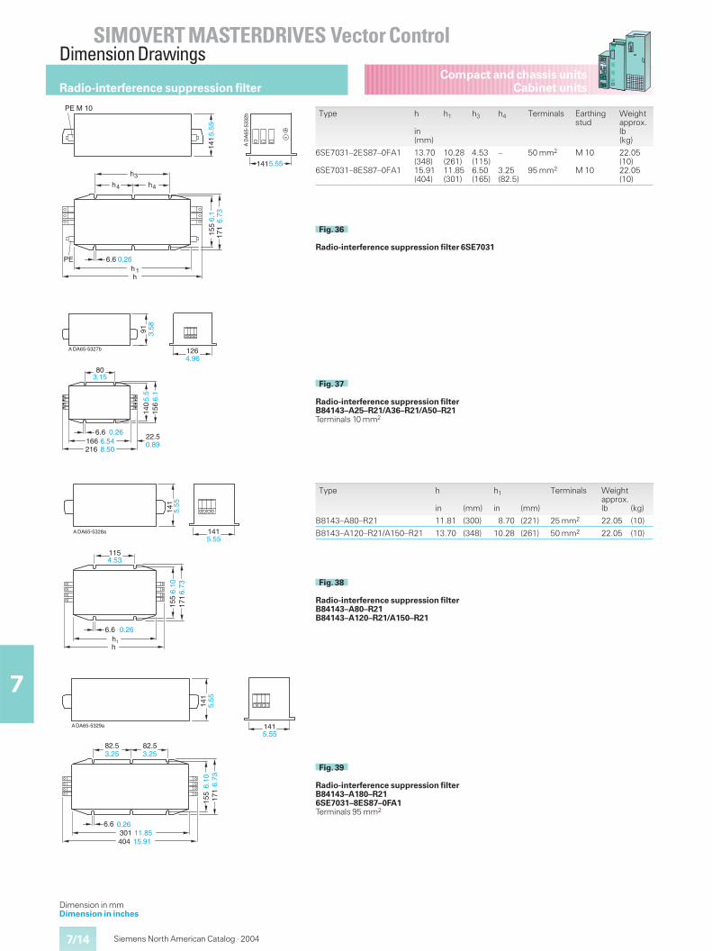
7/14
SIMOVERT MASTERDRIVES Vector ControlDimension Drawings
7
Compact and chassis unitsCabinet units
Siemens North American Catalog · 2004
Radio-interference suppression filter
DA65-5328a
h1
h
6.6
115
155
171
4.53
0.26
6.10
6.73
A
141
141
5.55
5.55
Fig. 38
Radio-interference suppression filterB84143–A80–R21B84143–A120–R21/A150–R21
DA65-5329a
141
141
6.6301404
82.5
155
82.53.25 3.25
0.2611.8515.91
A
5.55
5.55
6.73
171
6.10
Fig. 39
Radio-interference suppression filterB84143–A180–R216SE7031–8ES87–0FA1Terminals 95 mm2
Type h
in (mm)
h1
in (mm)
Terminals Weightapprox.lb (kg)
B8143–A80–R21 11.81 (300) 8.70 (221) 25 mm2 22.05 (10)
B8143–A120–R21/A150–R21 13.70 (348) 10.28 (261) 50 mm2 22.05 (10)
DA
65-5
332b
hh
h h
h
PE M 10
PE
3
4 4
1
6.6
155
171
1415.55
6.1
6.73
0.26
141
5.55
A
Fig. 36
Radio-interference suppression filter 6SE7031
DA65-5327b
6.6166
22.5
216
140
156
126
91 3.58
4.96
0.266.548.50
0.89
5.5
6.1
803.15
A
Fig. 37
Radio-interference suppression filterB84143–A25–R21/A36–R21/A50–R21Terminals 10 mm2
Type h
in(mm)
h1 h3 h4 Terminals Earthingstud
Weightapprox.lb(kg)
6SE7031–2ES87–0FA1
6SE7031–8ES87–0FA1
13.70(348)15.91(404)
10.28(261)11.85(301)
4.53(115)6.50(165)
–
3.25(82.5)
50 mm2
95 mm2
M 10
M 10
22.05(10)22.05(10)
Dimension in mmDimension in inches
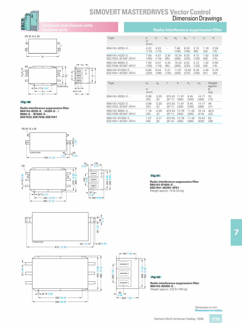
7/15
SIMOVERT MASTERDRIVES Vector ControlDimension Drawings
7
Compact and chassis unitsCabinet units
Siemens North American Catalog · 2004
Dimension in mmDimension in inches
Radio-interference suppression filter
160
DA65-5333b
10
PE M 12 x 30
PE
12 0.47
10.8
311
.81
0.63
A
550
50
61
166
220
250
340400
275
300
13516
21.65
1.97
20401.57 0.79
0.39
13.3915.75
5.31
6.30 8.
669.
84
2.406.53
Fig. 41
Radio-interference suppression filterB84143–B1600–S . .6SE7041–6ES87–0FA1Weight approx. 75 lb (34 kg)
DA65-5334c20
14
560
650
355
385
200
90
200
286
320
4080
40810
15
190
1.57
3.15
1.57 0.7931.89
22.05
25.60
0.55
13.9
815
.16
7.873.54
7.87
A
7.48
11.2
612
.60
0.59
Fig. 42
Radio-interference suppression filterB84143–B2500–S . .Weight approx. 232 lb (105 kg)
Type ain(mm)
b b1 b2 b3 c c1 e
B84143–B250–S . . 4.33(110)
4.53(115)
– 7.48(190)
6.50(165)
3.15(80)
1.18(30)
0.59(15)
B84143–A320–S . .6SE7033–2ES87–0FA1
7.09(180)
4.57(116)
3.35(85)
10.24(260)
9.25(235)
4.72(120)
1.42(36)
0.59(15)
B84143–B600–S . .6SE7036–0ES87–0FA1
7.09(180)
4.57(116)
3.35(85)
10.24(260)
9.25(235)
4.72(120)
1.42(36)
0.59(15)
B84143–B1000–S . .6SE7041–0ES87–0FA1
8.66(220)
6.54(166)
5.31(135)
11.81(300)
10.83(275)
6.30(160)
2.40(61)
0.79(20)
Type e1
in(mm)
e2 f h h1 h2 Weightapprox.lb(kg)
B84143–B250–S . . 0.98(25)
0.20(5)
Ø 0.43(Ø 11)
11.81(300)
9.45(240)
14.17(360)
33(15)
B84143–A320–S . .6SE7033–2ES87–0FA1
0.98(25)
0.20(5)
Ø 0.43(Ø 11)
11.81(300)
9.45(240)
14.17(360)
46(21)
B84143–B600–S . .6SE7036–0ES87–0FA1
1.18(30)
0.20(5)
Ø 0.43(Ø 11)
13.78(350)
11.42(290)
16.14(410)
48.5(22)
B84143–B1000–S . .6SE7041–0ES87–0FA1
1.57(40)
0.31(8)
Ø 0.55(Ø 14)
13.78(350)
11.42(290)
16.54(420)
62(28)
DA65-5330d
hh
b b
h
f
c a t
cb
e
b
PE M 10 x 30
PE
e
2
1
2 3 2
1
1
1
12 0.47A
Fig. 40
Radio-interference suppression filterB84143–B250–S . . /A320–S . . /B600–S . . /B1000–S . .6SE7033, 6SE7036, 6SE7041
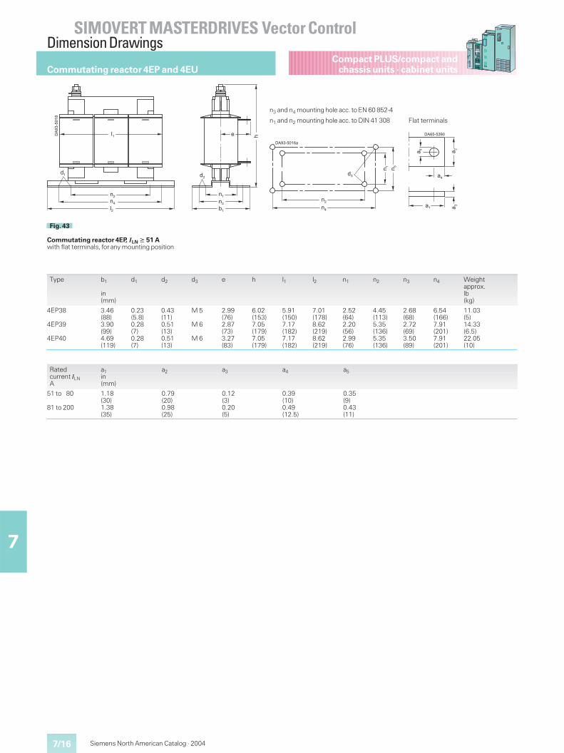
7/16
SIMOVERT MASTERDRIVES Vector ControlDimension Drawings
7
Compact PLUS/compact andchassis units · cabinet units
Siemens North American Catalog · 2004
Type b1
in(mm)
d1 d2 d3 e h l1 l2 n1 n2 n3 n4 Weightapprox.lb(kg)
4EP38
4EP39
4EP40
3.46(88)3.90(99)4.69(119)
0.23(5.8)0.28(7)0.28(7)
0.43(11)0.51(13)0.51(13)
M 5
M 6
M 6
2.99(76)2.87(73)3.27(83)
6.02(153)7.05(179)7.05(179)
5.91(150)7.17(182)7.17(182)
7.01(178)8.62(219)8.62(219)
2.52(64)2.20(56)2.99(76)
4.45(113)5.35(136)5.35(136)
2.68(68)2.72(69)3.50(89)
6.54(166)7.91(201)7.91(201)
11.03(5)14.33(6.5)22.05(10)
���������
��
��
��
��
��
��
�
��
����
Fig. 43
Commutating reactor 4EP, ILN � 51 Awith flat terminals, for any mounting position
���������
��
��
��
��
��
n3 and n4 mounting hole acc. to EN 60 852-4
n1 and n2 mounting hole acc. to DIN 41 308
���������
�
�
�
� �
Flat terminals
Ratedcurrent ILNA
a1in(mm)
a2 a3 a4 a5
51 to 80
81 to 200
1.18(30)1.38(35)
0.79(20)0.98(25)
0.12(3)0.20(5)
0.39(10)0.49(12.5)
0.35(9)0.43(11)
Commutating reactor 4EP and 4EU

7/17
SIMOVERT MASTERDRIVES Vector ControlDimension Drawings
7
Compact PLUS/compact andchassis units · cabinet units
Siemens North American Catalog · 2004
Commutating reactor 4EP and 4EU
���������
��
��
��
�
��
�� �
����
�
�� ��
Fig. 44
Commutating reactors 4EUwith flat terminals, for arrangement on horizontal surfaces
���������
�
�
�
� �
�
�
ILN 1001 A to 1600 A
��
��
���������
��
Mounting hole
���������
�
�
�
� �
ILN 45 A to 1000 A
Flat terminals
Type b1
in(mm)
d1 d2 d3 d4 emax.
hmax.
l1 l2 l4 n1 n2 Weightapprox.lb(kg)
4EU24
4EU25
4EU27
3.58(91)4.53(115)5.24(133)
0.27(7)0.27(7)0.39(10)
0.51(13)0.51(13)0.71(18)
M 6
M 6
M 8
M 6
M 6
M 6
4.02(102)4.69(119)5.59(142)
8.27(210)8.27(210)9.76(248)
8.86(225)8.86(225)10.24(260)
7.48(190)7.48(190)8.66(220)
–
–
10.63(270)
2.76(70)3.70(94)3.98(101)
6.93(176)6.93(176)7.87(200)
26.24(11.9)39.70(18)62.18(28.2)
4EU30
4EU36
4EU39
5.83(148)6.65(169)6.85(174)
0.39(10)0.39(10)0.47(12)
0.71(18)0.71(18)0.71(18)
M 8
M 8
M 10
M 6
M 6
M 6
5.79(147)7.75(197)7.75(197)
10.59(269)12.64(321)15.16(385)
11.61(295)14.05(357)15.94(405)
9.84(250)11.81(300)14.41(366)
11.81(300)13.78(350)16.14(410)
4.65(118)5.43(138)5.55(141)
8.82(224)10.39(264)12.44(316)
88.86(40.3)134.5(61)172(78)
4EU43
4EU45
4EU47
7.64(194)8.70(221)9.88(251)
0.59(15)0.59(15)0.59(15)
0.86(22)0.86(22)0.86(22)
M 12
M 12
M 12
M 6
M 6
M 6
8.35(212)8.31(211)9.09(231)
17.13(435)17.13(435)17.13(435)
18.03(458)18.03(458)18.03(458)
16.38(416)16.38(416)16.38(416)
18.11(460)18.11(460)18.11(460)
6.10(155)7.17(182)8.35(212)
14.02(356)14.02(356)14.02(356)
258(117)308.7(140)352.8(160)
4EU50
4EU52
7.68(195)8.66(220)
0.49(12.5)0.49(12.5)
0.49(12.5)0.49(12.5)
M 10
M 10
M 12
M 12
8.66(220)9.53(242)
22.24(565)22.24(565)
20.98(533)20.98(533)
18.50(470)18.50(470)
20.39(518)20.39(518)
6.22(158)7.20(183)
16.14(410)16.14(410)
401.3(182)476.3(216)
Ratedcurrent ILNA
a1in(mm)
a2 a3 a4 a5 a6 a7
45 to 80
81 to 200
201 to 315
316 to 800
801 to 1000
0.79(20)0.98(25)1.18(30)1.57(40)1.57(40)
0.79(20)0.98(25)1.18(30)1.57(40)1.57(40)
0.12(3)0.20(5)0.24(6)0.24(6)0.31(8)
0.39(10)0.49(12.5)0.59(15)0.79(20)0.79(20)
0.35(9)0.43(11)0.55(14)0.55(14)0.55(14)
–
–
–
–
–
–
–
–
–
–
1001 to 1600 2.36(60)
2.36(60)
0.47(12)
0.67(17)
0.55(14)
1.02(26)
1.02(26)
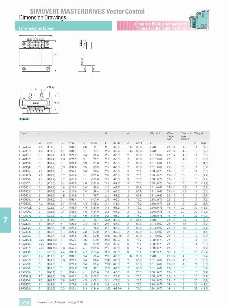
7/18
SIMOVERT MASTERDRIVES Vector ControlDimension Drawings
7
Compact PLUS/compact andchassis units · cabinet units
Siemens North American Catalog · 2004
Line reactors (open)
�
%�
�
� �� / /� � ��
!
.�
���
��
���0
�&;0-16
Fig. 45
Type a b c d e Mtg. slot WirerangeAWG
Terminalmax.torque
Weight
in (mm) in (mm) in (mm) in (mm) in (mm) in lb (kg)
LR4730SL 4.4 (111.8) 4.1 (104.1) 2.8 (71.1) 2 (50.8) 1.44 (36.6) 0.281 22 – 14 4.5 4 (1.8)
LR4730TL 4.4 (111.8) 4.1 (104.1) 3.1 (78.7) 2.35 (59.7) 1.44 (36.6) 0.281 22 – 14 4.5 5 (2.3)
LR47301L 6 (152.4) 4.8 (121.9) 3.4 (86.4) 2.5 (63.5) 2 (50.8) 0.31 x 0.62 22 – 14 4.5 11 (5.0)
LR47302L 6 (152.4) 4.8 (121.9) 3 (76.2) 2.1 (53.3) 2 (50.8) 0.31 x 0.62 22 – 5 4.5 8 (3.6)
LR47303L 6 (152.4) 5 (127.0) 3.3 (83.8) 2.1 (53.3) 2 (50.8) 0.31 x 0.62 22 – 5 16 10 (4.5)
LR47304L 6 (152.4) 5.3 (134.6) 3.5 (88.9) 2.5 (63.5) 2 (50.8) 0.31 x 0.62 22 – 5 16 12 (5.4)
LR47305L 7.2 (182.9) 6 (152.4) 3.4 (86.4) 2.3 (58.4) 3 (76.2) 0.38 x 0.75 22 – 5 16 14 (6.3)
LR473A6L 7.2 (182.9) 5.7 (144.8) 4 (101.6) 2.6 (66.0) 3 (76.2) 0.38 x 0.75 22 – 5 16 16 (7.2)
LR47306L 7.2 (182.9) 5.7 (144.8) 4 (101.6) 2.6 (66.0) 3 (76.2) 0.38 x 0.75 22 – 5 16 16 (7.2)
LR47307L 9 (228.6) 7.4 (188.0) 4.8 (121.9) 3.2 (81.3) 3 (76.2) 0.38 x 0.75 18 – 4 16 28 (12.7)
LR47501L 6 (152.6) 4.8 (121.9) 3.4 (86.4) 2.5 (63.5) 2 (50.8) 0.31 x 0.62 22 – 14 4.5 13 (5.9)
LR47502L 6 (152.6) 4.8 (121.9) 3.4 (86.4) 2.6 (66.0) 2 (50.8) 0.31 x 0.62 22 – 14 4.5 11 (5.0)
LR47503L 6 (152.6) 4.8 (121.9) 3.1 (78.7) 2.1 (53.3) 2 (50.8) 0.31 x 0.62 22 – 5 16 10 (4.5)
LR47504L 8 (203.2) 6 (152.4) 4 (101.6) 2.6 (66.0) 3 (76.2) 0.38 x 0.75 22 – 5 16 16 (7.2)
LR47505L 7.2 (182.9) 5.7 (144.8) 4.3 (109.2) 3.1 (78.7) 3 (76.2) 0.38 x 0.75 22 – 5 16 20 (9.1)
LR475A6L 9 (228.6) 7.4 (188.0) 4.8 (121.9) 3.2 (81.3) 3 (76.2) 0.38 x 0.75 18 – 4 20 30 (13.6)
LR47506L 9 (228.6) 7.4 (188.0) 4.8 (121.9) 3.2 (81.3) 3 (76.2) 0.38 x 0.75 18 – 4 20 30 (13.6)
LR47507L 9 (228.6) 7 (177.8) 4.8 (121.9) 3.2 (81.3) 3 (76.2) 0.38 x 0.75 18 – 4 16 28 (12.7)
LR57301L 4.4 (111.8) 4.1 (104.1) 3.1 (78.7) 2.35 (59.7) 1.44 (36.6) 0.281 22 – 14 4.5 5 (2.3)
LR57302L 6 (152.4) 5 (127.0) 3.4 (86.4) 2.6 (66.0) 2 (50.8) 0.31 x 0.62 22 – 14 4.5 11 (5.0)
LR57303L 6 (152.4) 4.8 (121.9) 3 (76.2) 2.1 (53.3) 2 (50.8) 0.31 x 0.62 22 – 14 4.5 8 (3.6)
LR57304L 6 (152.4) 5 (127.0) 3.3 (83.8) 2.1 (53.3) 2 (50.8) 0.31 x 0.62 22 – 5 16 10 (4.5)
LR57305L 6 (152.4) 5.3 (134.6) 3.5 (88.9) 2.48 (62.99) 2 (50.8) 0.31 x 0.62 22 – 5 16 12 (5.4)
LR573A6L 7.25 (184.15) 6 (152.4) 3.5 (88.9) 2.35 (59.7) 3 (76.2) 0.38 x 0.75 22 – 5 16 14 (6.3)
LR57306L 7.25 (184.15) 6 (152.4) 3.5 (88.9) 2.35 (59.7) 3 (76.2) 0.38 x 0.75 22 – 5 16 14 (6.3)
LR57307L 7.25 (184.15) 5.8 (147.3) 4 (101.6) 2.6 (66.0) 3 (76.2) 0.38 x 0.75 22 – 5 16 16 (7.2)
LR57308L 9 (228.6) 7.4 (188.0) 4.7 (119.4) 3.16 (80.3) 3 (76.2) 0.38 x 0.75 18 – 4 16 28 (12.7)
LR57501L 4.4 (111.8) 4.1 (104.1) 3.4 (86.4) 2.6 (66.0) 1.44 (36.6) 0.281 22 – 14 4.5 6 (2.7)
LR57502L 6 (152.4) 4.8 (121.9) 3.4 (86.4) 2.48 (63.0) 2 (50.8) 0.31 x 0.62 22 – 14 4.5 13 (5.9)
LR57503L 6 (152.4) 5 (127.0) 3.4 (86.4) 2.62 (66.6) 2 (50.8) 0.31 x 0.62 22 – 14 4.5 11 (5.0)
LR57504L 6 (152.4) 5 (127.0) 3.9 (99.1) 2.75 (69.8) 2 (50.8) 0.31 x 0.62 22 – 5 16 18 (8.2)
LR57505L 8 (203.2) 6 (152.4) 4 (101.6) 2.6 (66.0) 3 (76.2) 0.38 x 0.75 22 – 5 16 16 (7.2)
LR575A6L 7.2 (182.9) 5.8 (147.3) 4.3 (109.2) 3.1 (78.7) 3 (76.2) 0.38 x 0.75 22 – 5 16 20 (9.1)
LR57506L 7.2 (182.9) 5.8 (147.3) 4.3 (109.2) 3.1 (78.7) 3 (76.2) 0.38 x 0.75 22 – 5 16 20 (9.1)
LR57507L 9 (228.6) 7 (177.8) 4.8 (121.9) 3.2 (81.3) 3 (76.2) 0.38 x 0.75 18 – 4 16 30 (13.6)
LR57508L 9 (228.6) 7.3 (185.4) 5.3 (134.6) 3.66 (92.96) 3 (76.2) 0.38 x 0.75 18 – 4 16 39 (17.7)
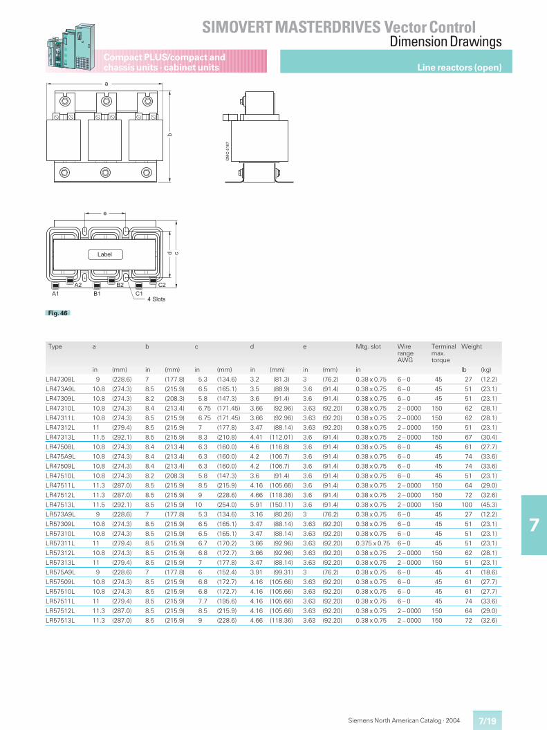
7/19
SIMOVERT MASTERDRIVES Vector ControlDimension Drawings
7
Compact PLUS/compact andchassis units · cabinet units
Siemens North American Catalog · 2004
Type a b c d e Mtg. slot WirerangeAWG
Terminalmax.torque
Weight
in (mm) in (mm) in (mm) in (mm) in (mm) in lb (kg)
LR47308L 9 (228.6) 7 (177.8) 5.3 (134.6) 3.2 (81.3) 3 (76.2) 0.38 x 0.75 6 – 0 45 27 (12.2)
LR473A9L 10.8 (274.3) 8.5 (215.9) 6.5 (165.1) 3.5 (88.9) 3.6 (91.4) 0.38 x 0.75 6 – 0 45 51 (23.1)
LR47309L 10.8 (274.3) 8.2 (208.3) 5.8 (147.3) 3.6 (91.4) 3.6 (91.4) 0.38 x 0.75 6 – 0 45 51 (23.1)
LR47310L 10.8 (274.3) 8.4 (213.4) 6.75 (171.45) 3.66 (92.96) 3.63 (92.20) 0.38 x 0.75 2 – 0000 150 62 (28.1)
LR47311L 10.8 (274.3) 8.5 (215.9) 6.75 (171.45) 3.66 (92.96) 3.63 (92.20) 0.38 x 0.75 2 – 0000 150 62 (28.1)
LR47312L 11 (279.4) 8.5 (215.9) 7 (177.8) 3.47 (88.14) 3.63 (92.20) 0.38 x 0.75 2 – 0000 150 51 (23.1)
LR47313L 11.5 (292.1) 8.5 (215.9) 8.3 (210.8) 4.41 (112.01) 3.6 (91.4) 0.38 x 0.75 2 – 0000 150 67 (30.4)
LR47508L 10.8 (274.3) 8.4 (213.4) 6.3 (160.0) 4.6 (116.8) 3.6 (91.4) 0.38 x 0.75 6 – 0 45 61 (27.7)
LR475A9L 10.8 (274.3) 8.4 (213.4) 6.3 (160.0) 4.2 (106.7) 3.6 (91.4) 0.38 x 0.75 6 – 0 45 74 (33.6)
LR47509L 10.8 (274.3) 8.4 (213.4) 6.3 (160.0) 4.2 (106.7) 3.6 (91.4) 0.38 x 0.75 6 – 0 45 74 (33.6)
LR47510L 10.8 (274.3) 8.2 (208.3) 5.8 (147.3) 3.6 (91.4) 3.6 (91.4) 0.38 x 0.75 6 – 0 45 51 (23.1)
LR47511L 11.3 (287.0) 8.5 (215.9) 8.5 (215.9) 4.16 (105.66) 3.6 (91.4) 0.38 x 0.75 2 – 0000 150 64 (29.0)
LR47512L 11.3 (287.0) 8.5 (215.9) 9 (228.6) 4.66 (118.36) 3.6 (91.4) 0.38 x 0.75 2 – 0000 150 72 (32.6)
LR47513L 11.5 (292.1) 8.5 (215.9) 10 (254.0) 5.91 (150.11) 3.6 (91.4) 0.38 x 0.75 2 – 0000 150 100 (45.3)
LR573A9L 9 (228.6) 7 (177.8) 5.3 (134.6) 3.16 (80.26) 3 (76.2) 0.38 x 0.75 6 – 0 45 27 (12.2)
LR57309L 10.8 (274.3) 8.5 (215.9) 6.5 (165.1) 3.47 (88.14) 3.63 (92.20) 0.38 x 0.75 6 – 0 45 51 (23.1)
LR57310L 10.8 (274.3) 8.5 (215.9) 6.5 (165.1) 3.47 (88.14) 3.63 (92.20) 0.38 x 0.75 6 – 0 45 51 (23.1)
LR57311L 11 (279.4) 8.5 (215.9) 6.7 (170.2) 3.66 (92.96) 3.63 (92.20) 0.375 x 0.75 6 – 0 45 51 (23.1)
LR57312L 10.8 (274.3) 8.5 (215.9) 6.8 (172.7) 3.66 (92.96) 3.63 (92.20) 0.38 x 0.75 2 – 0000 150 62 (28.1)
LR57313L 11 (279.4) 8.5 (215.9) 7 (177.8) 3.47 (88.14) 3.63 (92.20) 0.38 x 0.75 2 – 0000 150 51 (23.1)
LR575A9L 9 (228.6) 7 (177.8) 6 (152.4) 3.91 (99.31) 3 (76.2) 0.38 x 0.75 6 – 0 45 41 (18.6)
LR57509L 10.8 (274.3) 8.5 (215.9) 6.8 (172.7) 4.16 (105.66) 3.63 (92.20) 0.38 x 0.75 6 – 0 45 61 (27.7)
LR57510L 10.8 (274.3) 8.5 (215.9) 6.8 (172.7) 4.16 (105.66) 3.63 (92.20) 0.38 x 0.75 6 – 0 45 61 (27.7)
LR57511L 11 (279.4) 8.5 (215.9) 7.7 (195.6) 4.16 (105.66) 3.63 (92.20) 0.38 x 0.75 6 – 0 45 74 (33.6)
LR57512L 11.3 (287.0) 8.5 (215.9) 8.5 (215.9) 4.16 (105.66) 3.63 (92.20) 0.38 x 0.75 2 – 0000 150 64 (29.0)
LR57513L 11.3 (287.0) 8.5 (215.9) 9 (228.6) 4.66 (118.36) 3.63 (92.20) 0.38 x 0.75 2 – 0000 150 72 (32.6)
� / � �� /� ��
! %�
�
�
.�
���
��
���0
�&;0-16
Fig. 46
Line reactors (open)
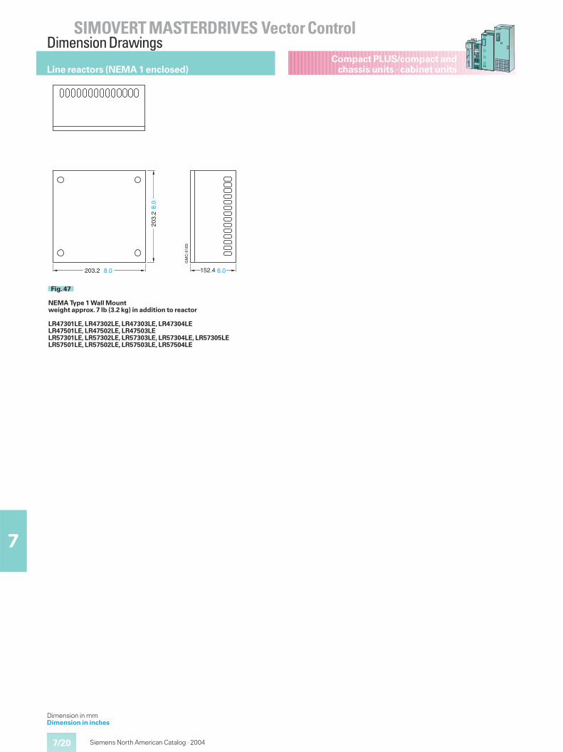
7/20
SIMOVERT MASTERDRIVES Vector ControlDimension Drawings
7
Compact PLUS/compact andchassis units · cabinet units
Siemens North American Catalog · 2004
Line reactors (NEMA 1 enclosed)
GM
C-5
165
203.
28.
0
152.4 6.0203.2 8.0
Fig. 47
NEMA Type 1 Wall Mountweight approx. 7 lb (3.2 kg) in addition to reactor
LR47301LE, LR47302LE, LR47303LE, LR47304LELR47501LE, LR47502LE, LR47503LELR57301LE, LR57302LE, LR57303LE, LR57304LE, LR57305LELR57501LE, LR57502LE, LR57503LE, LR57504LE
Dimension in mmDimension in inches
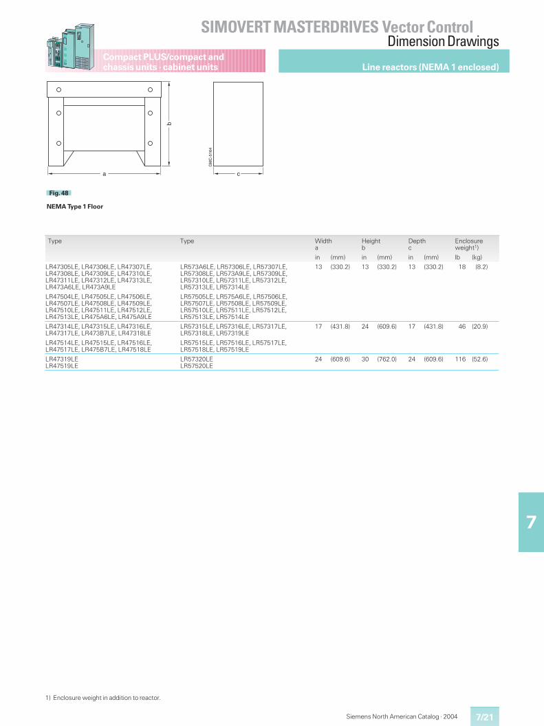
7/21
SIMOVERT MASTERDRIVES Vector ControlDimension Drawings
7
Compact PLUS/compact andchassis units · cabinet units
Siemens North American Catalog · 2004
Line reactors (NEMA 1 enclosed)
ba c
GM
C-5
164
Fig. 48
NEMA Type 1 Floor
Type Type Widtha
Heightb
Depthc
Enclosureweight1)
in (mm) in (mm) in (mm) lb (kg)
LR47305LE, LR47306LE, LR47307LE,LR47308LE, LR47309LE, LR47310LE,LR47311LE, LR47312LE, LR47313LE,LR473A6LE, LR473A9LE
LR573A6LE, LR57306LE, LR57307LE,LR57308LE, LR573A9LE, LR57309LE,LR57310LE, LR57311LE, LR57312LE,LR57313LE, LR57314LE
13 (330.2) 13 (330.2) 13 (330.2) 18 (8.2)
LR47504LE, LR47505LE, LR47506LE,LR47507LE, LR47508LE, LR47509LE,LR47510LE, LR47511LE, LR47512LE,LR47513LE, LR475A6LE, LR475A9LE
LR57505LE, LR575A6LE, LR57506LE,LR57507LE, LR57508LE, LR57509LE,LR57510LE, LR57511LE, LR57512LE,LR57513LE, LR57514LE
LR47314LE, LR47315LE, LR47316LE,LR47317LE, LR473B7LE, LR47318LE
LR57315LE, LR57316LE, LR57317LE,LR57318LE, LR57319LE
17 (431.8) 24 (609.6) 17 (431.8) 46 (20.9)
LR47514LE, LR47515LE, LR47516LE,LR47517LE, LR475B7LE, LR47518LE
LR57515LE, LR57516LE, LR57517LE,LR57518LE, LR57519LE
LR47319LELR47519LE
LR57320LELR57520LE
24 (609.6) 30 (762.0) 24 (609.6) 116 (52.6)
1) Enclosure weight in addition to reactor.
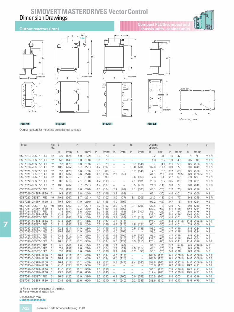
7/22
SIMOVERT MASTERDRIVES Vector ControlDimension Drawings
7
Compact PLUS/compact andchassis units · cabinet units
Siemens North American Catalog · 2004
DA65-5368b
hB
H
T
a 261.02
A
Fig. 50
��
�
���������
�
Fig. 49
Type Fig.No.
B H T a h Weightapprox.
n1 n2 d
in (mm) in (mm) in (mm) in (mm) in (mm) lb (kg) in (mm) in (mm)
6SE7013–0ES87–1FE0 52 4.9 (124) 4.8 (122) 2.8 (73) – – – – 2.2 (1) 1.6 (42) – 1) – 1) M 4 2)
6SE7015–0ES87–1FE0 52 5.8 (148) 5.8 (139) 3.1 (78) – – – – 4.8 (2.2) 1.9 (49) 3.5 (90) M 4 2)
6SE7016–1ES87–1FE06SE7016–2FS87–1FE0
5252
7.010.5
(178)(267)
6.08.7
(153)(221)
2.84.2
(73)(107)
––
––
5.78.0
(146)(204)
9.732.0
(4.4)(14.5)
2.13.0
(53)(77)
6.59.8
(166)(249)
M 5 2)M 6 2)
6SE7021–0ES87–1FE06SE7021–5FS87–1FE06SE7021–8ES87–1FE0
525052
7.08.18.6
(178)(207)(219)
6.08.67.1
(153)(220)(180)
3.54.13.9
(88)(104)(99)
–2.2–
–(55)
–
5.7–6.6
(146)–
(168)
12.144.117.6
(5.5)(20)(8)
2.72.82.7
(68)(70.5)(69)
6.56.97.9
(166)(176.5)(201)
M 5 2)M 6M 6 2)
6SE7022–6ES87–1FE0 52 8.6 (219) 7.1 (180) 4.7 (119) – – 7.1 (181) 20.3 (9.2) 3.5 (89) 7.9 (201) M 6 2)
6SE7023–4ES87–1FE0 52 10.5 (267) 8.7 (221) 4.2 (107) – – 8.5 (216) 24.3 (11) 3.0 (77) 9.8 (249) M 6 2)
6SE7024–7ES87–1FE0 51 7.8 (197) 8.6 (220) 4.1 (104) 2.7 (69) 4.1 (103) 44.1 (20) 2.7 (70) 6.9 (176) M 6
6SE7026–0HS87–1FE0 51 9.3 (235) 9.8 (250) 5.7 (146) 3.8 (98) – – 66.1 (30) 4.0 (101) 7.9 (200) M 8
6SE7027–2ES87–1FE0 49 10.5 (267) 8.7 (221) 4.2 (107) 3.0 (77) 8.1 (206) 24.3 (11) 3.0 (77) 9.8 (249) M 6 2)
6SE7028–2HS87–1FE0 51 10.4 (264) 11.0 (280) 6.1 (155) 4.0 (101) – – 99.2 (45) 0.7 (18) 8.8 (224) M 8
6SE7031–0ES87–1FE06SE7031–2HS87–1FE06SE7031–5ES87–1FE06SE7031–7HS87–1FE06SE7031–8ES87–1FE0
4951515151
10.512.47.8
12.411.1
(267)(314)(197)(314)(281)
8.713.28.6
13.29.8
(221)(335)(220)(335)(250)
4.26.75.06.75.7
(107)(169)(128)(169)(146)
3.04.33.24.33.9
(77)(109)(81)
(109)(98)
8.1–3.9–4.7
(206)–
(100)–
(119)
37.5132.355.1
132.366.1
(17)(60)(25)(60)(30)
3.05.43.75.44.0
(77)(138)(94)
(138)(101)
9.810.46.9
10.47.9
(249)(264)(176)(264)(200)
M 6M 8M 6M 8M 8
6SE7032–3HS87–1FE06SE7032–6ES87–1FE0
5151
14.411.1
(367)(281)
15.29.8
(385)(250)
6.85.7
(174)(146)
4.44.4
(112)(111)
–4.8
–(121)
176.466.1
(80)(30)
5.64.0
(141.5)(101)
12.57.9
(316.5)(200)
M 10M 8
6SE7033–2ES87–1FE06SE7033–7ES87–1FE0
5151
12.210.4
(311)(264)
11.011.0
(280)(280)
6.16.1
(155)(155)
4.54.0
(114)(101)
5.5–
(139)–
99.299.2
(45)(45)
4.74.7
(118)(118)
8.88.8
(224)(224)
M 8M 8
6SE7035–1ES87–1FE06SE7037–0ES87–1FE06SE7038–6ES87–1FE0
515151
12.214.216.1
(310)(360)(410)
11.013.215.2
(280)(335)(385)
6.16.76.8
(155)(169)(174)
4.24.55.0
(106)(114)(127)
5.97.18.3
(150)(180)(210)
99.2132.3176.4
(45)(60)(80)
4.75.45.5
(118)(138)(141)
8.810.412.4
(224)(264)(316)
M 8M 8M 10
6SE7022–2FS87–1FE06SE7023–4FS87–1FE06SE7024–7FS87–1FE0
515151
8.17.87.8
(207)(197)(197)
8.68.68.6
(220)(220)(220)
5.04.15.0
(128)(104)(128)
2.62.83.2
(66)(72)(81)
–4.53.7
–(114)(93)
55.144.155.1
(25)(20)(25)
3.72.85.0
(94.5)(70)
(128)
6.96.96.9
(176.5)(176)(176)
M 6M 6M 6
6SE7033–0GS87–1FE06SE7033–5GS87–1FE0
5151
16.416.4
(417)(417)
17.117.1
(435)(435)
7.67.6
(194)(194)
4.64.6
(118)(118)
––
––
264.6264.6
(120)(120)
6.16.1
(155.5)(155.5)
14.014.0
(356.5)(356.5)
M 12M 12
6SE7034–5GS87–1FE06SE7035–7GS87–1FE0
5151
16.421.0
(417)(533)
17.122.2
(435)(565)
9.98.1
(251)(207)
5.8–
(147)–
9.4–
(240)–
352.8374.8
(160)(170)
8.46.7
(212.5)(170.5)
14.016.2
(356.5)(411)
M 12M 10
6SE7036–5GS87–1FE06SE7038–6GS87–1FE0
5151
21.023.9
(533)(608)
22.225.6
(565)(650)
9.39.6
(235)(245)
––
––
––
––
485.1617.4
(220)(280)
7.87.7
(198.5)(195.5)
16.218.5
(411)(471)
M 10M 12
6SE7041–1ES87–1FE0 51 16.5 (420) 15.0 (380) 9.2 (233) 6.3 (160) 10.0 (255) 220.5 (100) 8.0 (203) 12.4 (316) M 10
6SE7041–2GS87–1FE0 51 23.9 (608) 25.6 (650) 12.2 (310) 9.4 (240) 15.2 (385) 683.6 (310) 8.4 (213) 18.5 (470) M 12
��
��
���������
�
Mounting hole
Output reactors (iron)
���������
��
�
�
Fig. 51
� ��
���������
�
Fig. 52
1) Fixing hole in the center of the foot.2) For any mounting position.
Output reactors for mounting on horizontal surfaces
Dimension in mmDimension in inches
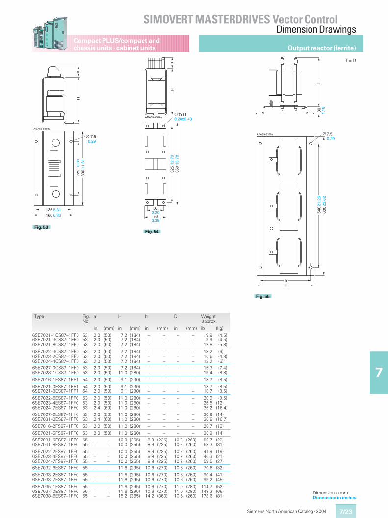
7/23
SIMOVERT MASTERDRIVES Vector ControlDimension Drawings
7
Compact PLUS/compact andchassis units · cabinet units
Siemens North American Catalog · 2004
Dimension in mmDimension in inches
aH
DA65-5363aA
135 5.31160 6.30
225
8.89
300
11.8
1
0.297.5
Fig. 53
h
DA65-5365a
T
H
3054
021
.26
600
23.6
2
0.29A
1.18
7.5
Fig. 55
aH
DA65-5364a7x11
A
562.20
0.28x0.43
325
12.7
935
013
.78
3.3986
Fig. 54
Type Fig.No.
a H h D Weightapprox.
in (mm) in (mm) in (mm) in (mm) lb (kg)
6SE7021–1CS87–1FF06SE7021–3CS87–1FF06SE7021–8CS87–1FF0
535353
2.02.02.0
(50)(50)(50)
7.27.27.2
(184)(184)(184)
–––
–––
–––
–––
9.99.9
12.8
(4.5)(4.5)(5.8)
6SE7022–3CS87–1FF06SE7023–2CS87–1FF06SE7024–4CS87–1FF0
535353
2.02.02.0
(50)(50)(50)
7.27.27.2
(184)(184)(184)
–––
–––
–––
–––
13.210.613.2
(6)(4.8)(6)
6SE7027–0CS87–1FF06SE7028–1CS87–1FF0
5353
2.02.0
(50)(50)
7.211.0
(184)(280)
––
––
––
––
16.319.4
(7.4)(8.8)
6SE7016–1ES87–1FF1 54 2.0 (50) 9.1 (230) – – – – 18.7 (8.5)
6SE7021–0ES87–1FF16SE7021–8ES87–1FF1
5454
2.02.0
(50)(50)
9.19.1
(230)(230)
––
––
––
––
18.718.7
(8.5)(8.5)
6SE7022–6ES87–1FF06SE7023–4ES87–1FF06SE7024–7ES87–1FF0
535353
2.02.02.4
(50)(50)(60)
11.011.011.0
(280)(280)(280)
–––
–––
–––
–––
20.926.536.2
(9.5)(12)(16.4)
6SE7027–2ES87–1FF06SE7031–0ES87–1FF0
5353
2.02.4
(50)(60)
11.011.0
(280)(280)
––
––
––
––
30.936.8
(14)(16.7)
6SE7016–2FS87–1FF0 53 2.0 (50) 11.0 (280) – – – – 28.7 (13)
6SE7021–5FS87–1FF0 53 2.0 (50) 11.0 (280) – – – – 30.9 (14)
6SE7031–5ES87–1FF06SE7031–8ES87–1FF0
5555
––
––
10.010.0
(255)(255)
8.98.9
(225)(225)
10.210.2
(260)(260)
50.768.3
(23)(31)
6SE7022–2FS87–1FF06SE7023–4FS87–1FF06SE7024–7FS87–1FF0
555555
–––
–––
10.010.010.0
(255)(255)(255)
8.98.98.9
(225)(225)(225)
10.210.210.2
(260)(260)(260)
41.946.359.5
(19)(21)(27)
6SE7032–6ES87–1FF0 55 – – 11.6 (295) 10.6 (270) 10.6 (260) 70.6 (32)
6SE7033–2ES87–1FF06SE7033–7ES87–1FF0
5555
––
––
11.611.6
(295)(295)
10.610.6
(270)(270)
10.610.6
(260)(260)
90.499.2
(41)(45)
6SE7035–1ES87–1FF06SE7037–0ES87–1FF06SE7038–6ES87–1FF0
555555
–––
–––
11.611.615.2
(295)(295)(385)
10.610.614.2
(270)(270)(360)
11.011.010.6
(280)(280)(260)
114.7143.3178.6
(52)(65)(81)
Output reactor (ferrite)
T = D
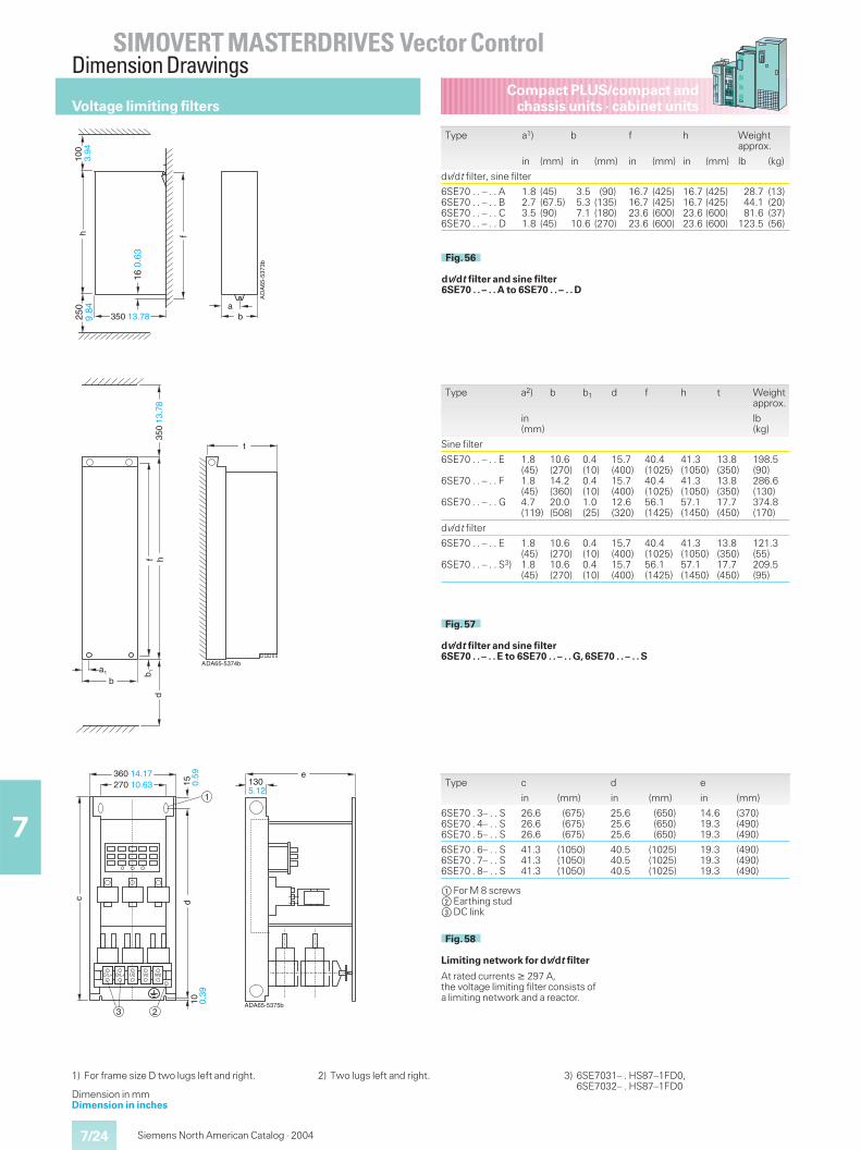
7/24
SIMOVERT MASTERDRIVES Vector ControlDimension Drawings
7
Compact PLUS/compact andchassis units · cabinet units
Siemens North American Catalog · 2004
Type a1) b f h Weightapprox.
in (mm) in (mm) in (mm) in (mm) lb (kg)
dv/dt filter, sine filter
6SE70 . . – . . A6SE70 . . – . . B6SE70 . . – . . C6SE70 . . – . . D
1.82.73.51.8
(45)(67.5)(90)(45)
3.55.37.1
10.6
(90)(135)(180)(270)
16.716.723.623.6
(425)(425)(600)(600)
16.716.723.623.6
(425)(425)(600)(600)
28.744.181.6
123.5
(13)(20)(37)(56)
DA
65-5
373b
f
a
h
b
16
350 13.78
0.63
A
100
3.94
250
9.84
hd
b 1f
a1
b
DA65-5374b
t
350
13.7
8
A
Type a2) b b1 d f h t Weightapprox.
in(mm)
lb(kg)
Sine filter
6SE70 . . – . . E
6SE70 . . – . . F
6SE70 . . – . . G
1.8(45)1.8(45)4.7(119)
10.6(270)14.2(360)20.0(508)
0.4(10)0.4(10)1.0(25)
15.7(400)15.7(400)12.6(320)
40.4(1025)40.4(1025)56.1(1425)
41.3(1050)41.3(1050)57.1(1450)
13.8(350)13.8(350)17.7(450)
198.5(90)286.6(130)374.8(170)
dv/dt filter
6SE70 . . – . . E
6SE70 . . – . . S3)
1.8(45)1.8(45)
10.6(270)10.6(270)
0.4(10)0.4(10)
15.7(400)15.7(400)
40.4(1025)56.1(1425)
41.3(1050)57.1(1450)
13.8(350)17.7(450)
121.3(55)209.5(95)
1) For frame size D two lugs left and right. 2) Two lugs left and right. 3) 6SE7031– . HS87–1FD0,6SE7032– . HS87–1FD0
Voltage limiting filters
Fig. 56
dv/dt filter and sine filter6SE70 . . – . . A to 6SE70 . . – . . D
Fig. 57
dv/dt filter and sine filter6SE70 . . – . . E to 6SE70 . . – . . G, 6SE70 . . – . . S
DA65-5375b
C/L+ U2 W2V2D/L+
e
dc
1
23
1015 130
5.12
0.39
0.59360 14.17
270 10.63
A
$For M 8 screws%Earthing stud&DC link
Fig. 58
Limiting network for dv/dt filter
At rated currents � 297 A,the voltage limiting filter consists ofa limiting network and a reactor.
Dimension in mmDimension in inches
Type c d e
in (mm) in (mm) in (mm)
6SE70 . 3– . . S6SE70 . 4– . . S6SE70 . 5– . . S
26.626.626.6
(675)(675)(675)
25.625.625.6
(650)(650)(650)
14.619.319.3
(370)(490)(490)
6SE70 . 6– . . S6SE70 . 7– . . S6SE70 . 8– . . S
41.341.341.3
(1050)(1050)(1050)
40.540.540.5
(1025)(1025)(1025)
19.319.319.3
(490)(490)(490)
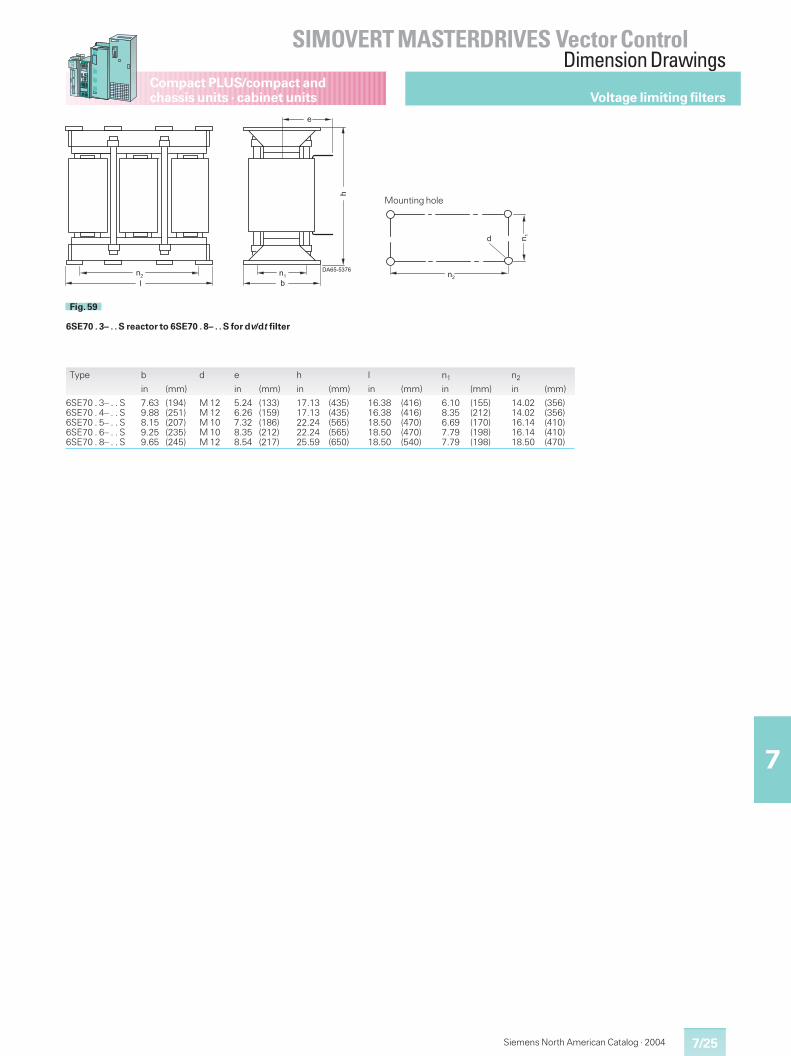
7/25
SIMOVERT MASTERDRIVES Vector ControlDimension Drawings
7
Compact PLUS/compact andchassis units · cabinet units
Siemens North American Catalog · 2004
Type b d e h l n1 n2
in (mm) in (mm) in (mm) in (mm) in (mm) in (mm)
6SE70 . 3– . . S6SE70 . 4– . . S6SE70 . 5– . . S6SE70 . 6– . . S6SE70 . 8– . . S
7.639.888.159.259.65
(194)(251)(207)(235)(245)
M 12M 12M 10M 10M 12
5.246.267.328.358.54
(133)(159)(186)(212)(217)
17.1317.1322.2422.2425.59
(435)(435)(565)(565)(650)
16.3816.3818.5018.5018.50
(416)(416)(470)(470)(540)
6.108.356.697.797.79
(155)(212)(170)(198)(198)
14.0214.0216.1416.1418.50
(356)(356)(410)(410)(470)
��
�
�
��
���������
�
��
�
��
Fig. 59
6SE70 . 3– . . S reactor to 6SE70 . 8– . . S for dv/dt filter
Mounting hole
Voltage limiting filters
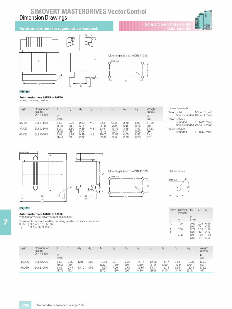
7/26
SIMOVERT MASTERDRIVES Vector ControlDimension Drawings
7
Compact and chassis unitsCabinet units
Siemens North American Catalog · 2004
Type Designationacc. toDIN 41 302
b1 b2 d1 d2 h1 l1 n1 n2 Weightapprox.
in(mm)
lb(kg)
4AP25
4AP27
4AP30
3UI 114/62
3UI 132/70
3UI 150/75
4.53(115)5.24(133)5.83(148)
3.35(85)3.50(89)3.62(92)
0.29(7.4)0.39(10)0.39(10)
M 6
M 8
M 8
8.43(214)9.49(241)10.63(270)
9.02(229)10.39(264)11.81(300)
3.70(94)3.98(101)4.65(118)
6.93(176)7.87(200)8.82(224)
41.89(19)57.33(26)1.46(37)
��
�
���������
��
��
��
��
�
Fig. 60
Autotransformers 4AP25 to 4AP30for any mounting position
���������
��
��
��
Mounting hole acc. to DIN 41 308
Screw terminals
24 A: solidfinely stranded
0.5 to 6 mm2
0.5 to 4 mm2
58 A: solid orstrandedfinely stranded
1 to 25 mm2
2.5 to 16 mm2
94 A: solid orstranded 4 to 50 mm2
Type Designationacc. toDIN 41 302
b1 d1 d2 d3 h1 h2 h3 l1 l2 l3 n1 n2 Weightapprox.
in(mm)
lb(kg)
4AU36
4AU39
3UI 180/75
3UI 210/70
6.65(169)6.85(174)
0.39(10)0.47(12)
M 8
M 10
M 6
M 6
12.60(320)14.57(370)
5.91(150)7.09(180)
2.36(60)2.60(66)
14.17(360)16.54(420)
12.36(314)14.41(366)
14.17(360)16.14(410)
5.43(138)5.55(141)
10.39(264)12.44(316)
130.01(59)178.61(81)
��
�
��
��
���������
��
����
��
��
��
��
Fig. 61
Autotransformers 4AU36 to 4AU39with flat terminals, for any mounting position
Permissible constant load for mounting position on vertical surfaces:0.95 · Ps at ta = 131 °F (55 °C)Ps at ta = 113 °F (45 °C)
���������
��
��
��
Mounting hole acc. to DIN 41 308
Form Nominalcurrent
b2 d4 l4
Ain(mm)
A
AA
100
200
400
0.63(16)0.79(20)0.98(25)
0.28(7)0.35(9)0.43(11)
0.98(25)1.38(35)1.38(35)
���������
�
��
��
Flat terminals
Autotransformers for regenerative feedback
7/27
SIMOVERT MASTERDRIVES Vector ControlDimension Drawings
7
Compact and chassis unitsCabinet units
Siemens North American Catalog · 2004
��
��
��
�
��
�
�
���������
��
����
�
Fig. 62
Autotransformers 4BUwith flat terminals, for arrangement on horizontal surfaces
���������
��
��
��
Mounting hole acc. to DIN 41 308
Type Designationacc. toDIN 41 302
b1 b2 d1 d2 d3 h l1 l2 n1 n2 Weightapprox.
in (mm) in (mm) in (mm) in (mm) in (mm) in (mm) in (mm) in (mm) lb (kg)
4BU434BU454BU47
3UI 240/ 803UI 240/1073UI 240/137
7.648.709.88
(194)(221)(251)
7.648.709.88
(194)(221)(251)
0.59 x 0.870.59 x 0.870.59 x 0.87
(15 x 22)(15 x 22)(15 x 22)
M 12M 12M 12
M 6M 6M 6
16.5416.5416.54
(420)(420)(420)
18.9018.9018.90
(480)(480)(480)
16.3816.3816.38
(416)(416)(416)
6.107.168.35
(155)(182)(212)
14.0214.0214.02
(356)(356)(356)
238.1297.7374.8
(108)(135)(170)
4BU514BU524BU53
3UIS 265/1073UIS 265/1203UIS 265/135
10.5111.0211.61
(267)(280)(295)
8.158.669.25
(207)(220)(235)
0.490.490.49
(12.5)(12.5)(12.5)
M 10M 10M 10
M 12M 12M 12
20.2820.2820.28
(515)(515)(515)
21.8521.8521.85
(555)(555)(555)
18.5018.5018.50
(470)(470)(470)
6.697.207.79
(170)(183)(198)
16.1416.1416.14
(410)(410)(410)
396.9441.0485.1
(180)(200)(220)
4BU544BU554BU56
3UIS 305/1253UIS 305/1403UIS 305/160
11.6112.2012.99
(295)(310)(330)
9.6510.2411.02
(245)(260)(280)
0.590.590.59
(15)(15)(15)
M 12M 12M 12
M 12M 12M 12
23.0323.0323.03
(585)(585)(585)
24.8024.8024.80
(630)(630)(630)
21.2621.2621.26
(540)(540)(540)
7.798.389.17
(198)(213)(233)
18.5018.5018.50
(470)(470)(470)
617.4683.6815.5
(280)(310)(370)
4BU584BU594BU60
3UIS 370/1503UIS 370/1703UIS 370/195
12.9913.7814.76
(330)(350)(375)
11.4212.2013.19
(290)(310)(335)
0.590.590.59
(15)(15)(15)
M 12M 12M 12
M 12M 12M 12
26.1826.1826.18
(665)(665)(665)
30.7130.7130.71
(780)(780)(780)
25.9825.9825.98
(660)(660)(660)
9.4910.2711.26
(241)(261)(286)
22.8322.8322.83
(580)(580)(580)
970.21058.41323.0
(440)(480)(600)
4BU624BU634BU644BU65
3UIS 455/1753UIS 455/2003UIS 455/2303UIS 455/260
15.9416.9318.1119.29
(405)(430)(460)(490)
12.4013.3914.5715.75
(315)(340)(370)(400)
0.830.830.830.83
(21)(21)(21)(21)
M 16M 16M 16M 16
M 12M 12M 12M 12
29.9229.9229.9229.92
(760)(760)(760)(760)
38.3838.3838.3838.38
(975)(975)(975)(975)
32.2832.2832.2832.28
(820)(820)(820)(820)
10.2711.7312.7213.90
(261)(298)(323)(353)
28.3528.3528.3528.35
(720)(720)(720)(720)
1587.61896.32293.22579.8
(720)(860)
(1040)(1170)
Form Nominalcurrent
b3 d4 e1 e2 e3 l4
A in (mm) in (mm) in (mm) in (mm) in (mm) in (mm)
AAAAA
200400630800
1000
0.790.981.181.181.57
(20)(25)(30)(30)(40)
0.350.430.430.550.55
(9)(11)(11)(14)(14)
–––––
–––––
–––––
–––––
–––––
–––––
1.381.381.571.571.97
(35)(35)(40)(40)(50)
CC
12501600
1.972.36
(50)(60)
0.550.55
(14)(14)
0.550.67
(14)(17)
0.871.02
(22)(26)
0.871.02
(22)(26)
2.362.76
(60)(70)
above 1600 A on request
���������
�
��
��
��
��
�� ��
��
�
Flat terminals
Autotransformers for regenerative feedback
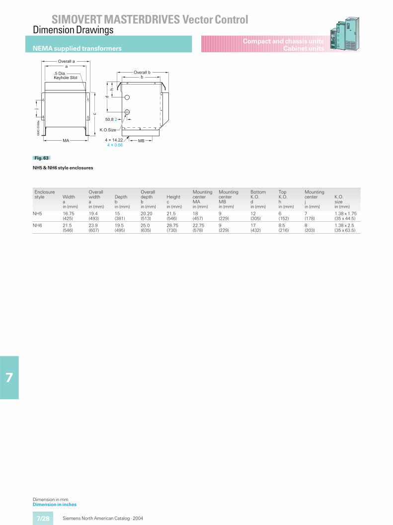
7/28
SIMOVERT MASTERDRIVES Vector ControlDimension Drawings
7
Compact and chassis unitsCabinet units
Siemens North American Catalog · 2004
NEMA supplied transformers
�
%
��
�!
�
�/
<.
��
�� �
��
=>�,�00&�
��&�(��?�8�-0�&;0-1
=>�,�00&�
���� �
?�=�;(@�
�&A&�����&A& ����
Fig. 63
NH5 & NH6 style enclosures
Dimension in mmDimension in inches
Enclosurestyle Width
ain (mm)
Overallwidthain (mm)
Depthbin (mm)
Overalldepthbin (mm)
Heightcin (mm)
MountingcenterMAin (mm)
MountingcenterMBin (mm)
BottomK.O.din (mm)
TopK.O.hin (mm)
Mountingcenterjin (mm)
K.O.sizein (mm)
NH5 16.75(425)
19.4(493)
15(381)
20.20(513)
21.5(546)
18(457)
9(229)
12(305)
6(152)
7(178)
1.38 x 1.75(35 x 44.5)
NH6 21.5(546)
23.9(607)
19.5(495)
25.0(635)
28.75(730)
22.75(578)
9(229)
17(432)
8.5(216)
8(203)
1.38 x 2.5(35 x 63.5)
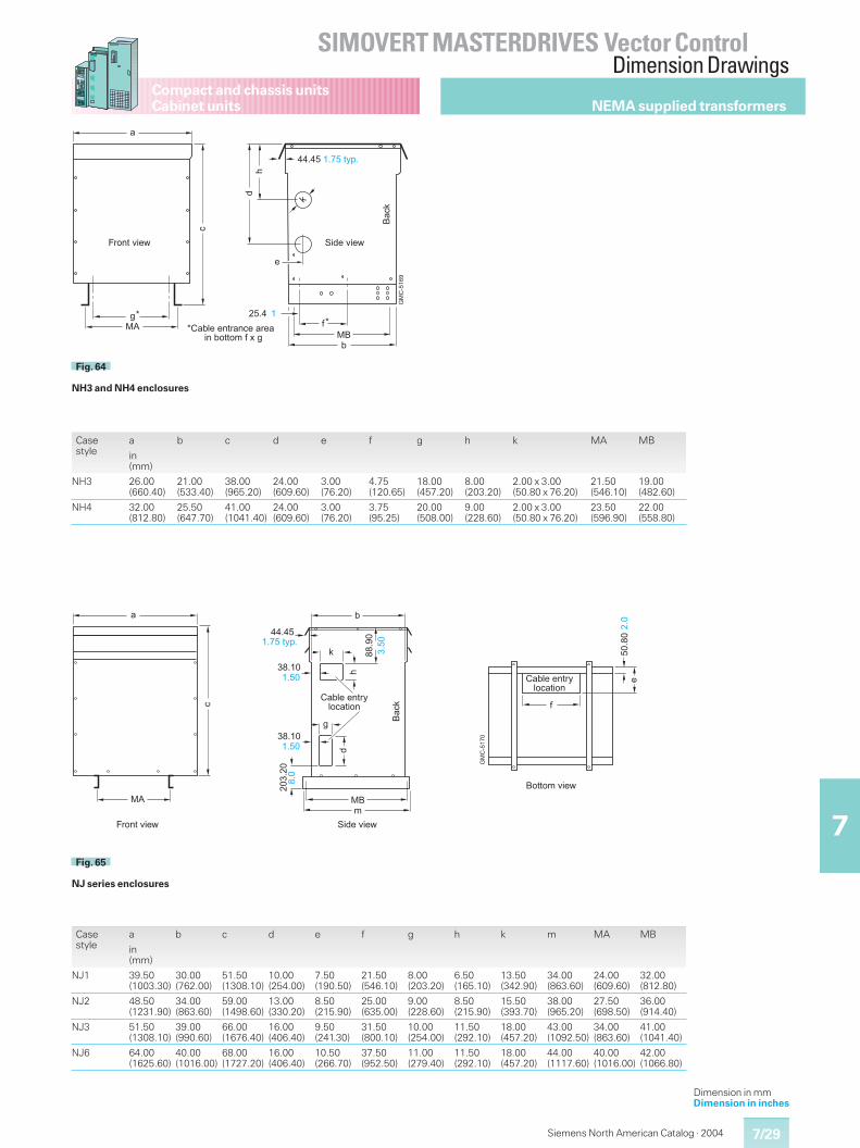
7/29
SIMOVERT MASTERDRIVES Vector ControlDimension Drawings
7
Compact and chassis unitsCabinet units
Siemens North American Catalog · 2004
NEMA supplied transformers
Dimension in mmDimension in inches
5
%
��
�
�!
�
�
"�/�
B ����
B���0�&�)1,�)%�&�,��&&()&�-11-'&"&#&5
C,-)1&>(�D ;(!�&>(�D
����� ���&18+�
/�%
�.
��
�� �
�
B
Fig. 64
NH3 and NH4 enclosures
Casestyle
a b c d e f g h k MA MB
in(mm)
NH3 26.00(660.40)
21.00(533.40)
38.00(965.20)
24.00(609.60)
3.00(76.20)
4.75(120.65)
18.00(457.20)
8.00(203.20)
2.00 x 3.00(50.80 x 76.20)
21.50(546.10)
19.00(482.60)
NH4 32.00(812.80)
25.50(647.70)
41.00(1041.40)
24.00(609.60)
3.00(76.20)
3.75(95.25)
20.00(508.00)
9.00(228.60)
2.00 x 3.00(50.80 x 76.20)
23.50(596.90)
22.00(558.80)
Casestyle
a b c d e f g h k m MA MB
in(mm)
NJ1 39.50(1003.30)
30.00(762.00)
51.50(1308.10)
10.00(254.00)
7.50(190.50)
21.50(546.10)
8.00(203.20)
6.50(165.10)
13.50(342.90)
34.00(863.60)
24.00(609.60)
32.00(812.80)
NJ2 48.50(1231.90)
34.00(863.60)
59.00(1498.60)
13.00(330.20)
8.50(215.90)
25.00(635.00)
9.00(228.60)
8.50(215.90)
15.50(393.70)
38.00(965.20)
27.50(698.50)
36.00(914.40)
NJ3 51.50(1308.10)
39.00(990.60)
66.00(1676.40)
16.00(406.40)
9.50(241.30)
31.50(800.10)
10.00(254.00)
11.50(292.10)
18.00(457.20)
43.00(1092.50)
34.00(863.60)
41.00(1041.40)
NJ6 64.00(1625.60)
40.00(1016.00)
68.00(1727.20)
16.00(406.40)
10.50(266.70)
37.50(952.50)
11.00(279.40)
11.50(292.10)
18.00(457.20)
44.00(1117.60)
40.00(1016.00)
42.00(1066.80)
�/'
�
%
��
�
�
�
5
!
"
���0�&�)1,80-%�1(-)
���
�
���&18+�
���
���
/�%
����0�&�)1,80-%�1(-)
;(!�&>(�DC,-)1&>(�D
����
/-11-'&>(�D
.�
���
��
����
������
��� �
����
��
����
�
������ �
Fig. 65
NJ series enclosures
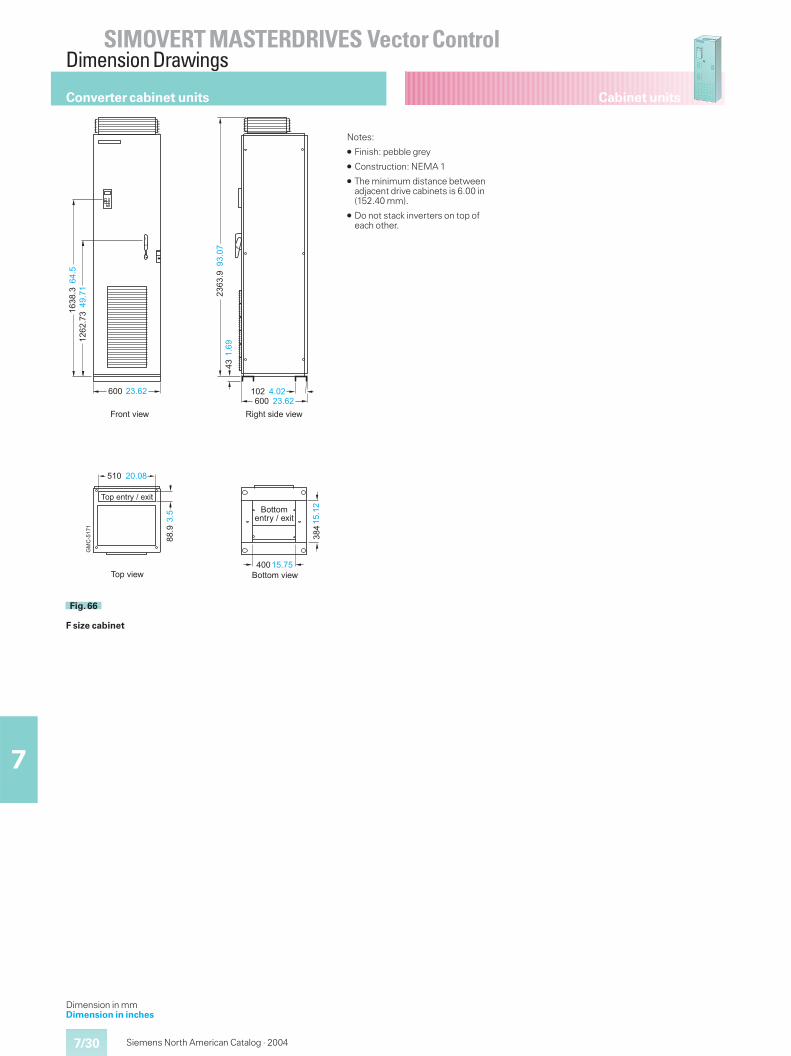
7/30
SIMOVERT MASTERDRIVES Vector ControlDimension Drawings
7
Cabinet units
Siemens North American Catalog · 2004
Converter cabinet units
Dimension in mmDimension in inches
��� ����� �� ����
�� �
����
����
����
�
���
���
����
�
����
����
��� �����
� � �����
����
���
���
��
�
��� ����
.�
���
�
E(5�1&6(!�&>(�DC,-)1&>(�D
�-+&>(�D /-11-'&>(�D
�-+&�)1,8&�&�#(1
/-11-'�)1,8&�&�#(1
Fig. 66
F size cabinet
Notes:
� Finish: pebble grey
� Construction: NEMA 1
� The minimum distance betweenadjacent drive cabinets is 6.00 in(152.40 mm).
� Do not stack inverters on top ofeach other.
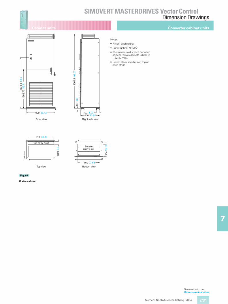
7/31
SIMOVERT MASTERDRIVES Vector ControlDimension Drawings
7
Cabinet units
Siemens North American Catalog · 2004
Converter cabinet units
Dimension in mmDimension in inches
��� ����� �� ����
�� �
����
����
����
�
���
���
����
�
����
����
��� �����
� � � ���
����
���
E(5�1&6(!�&>(�DC,-)1&>(�D
�-+&>(�D
�-+&�)1,8&�&�#(1
���
��
�
��� �����
.�
���
��
/-11-'&>(�D
/-11-'�)1,8&�&�#(1
Fig. 67
G size cabinet
Notes:
� Finish: pebble grey
� Construction: NEMA 1
� The minimum distance betweenadjacent drive cabinets is 6.00 in(152.40 mm).
� Do not stack inverters on top ofeach other.
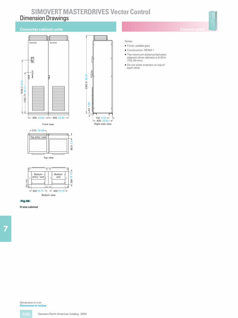
7/32
SIMOVERT MASTERDRIVES Vector ControlDimension Drawings
7
Cabinet units
Siemens North American Catalog · 2004
Converter cabinet units
Dimension in mmDimension in inches
.�
���
��
���
���
����
�
����
����
��� �����
C,-)1&>(�D
��� �����
���
��
�
��� ����
/-11-'&>(�D
/-11-'�#(1
��� ����� �� ����
�� �
����
����
����
�
E(5�1&6(!�&>(�D
��� ����
/-11-'�)1,8&�&�#(1
����
���
�-+&>(�D
� � �����
�-+&�)1,8&�&�#(1
Fig. 68
H size cabinet
Notes:
� Finish: pebble grey
� Construction: NEMA 1
� The minimum distance betweenadjacent drive cabinets is 6.00 in(152.40 mm).
� Do not stack inverters on top ofeach other.
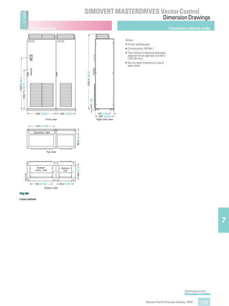
7/33
SIMOVERT MASTERDRIVES Vector ControlDimension Drawings
7
Cabinet units
Siemens North American Catalog · 2004
Converter cabinet units
Dimension in mmDimension in inches
��� ����� �� ����
���
����
����
���
���
���
����
�
����
����
E(5�1&6(!�&>(�D
����
���
� � � ���
�-+&�)1,8&�&�#(1
��� �������� �����
��
C,-)1&>(�D
�-+&>(�D
��� ����
.�
���
��
/-11-'�#(1
���
��
�
��� �����
/-11-'&>(�D
/-11-'�)1,8&�&�#(1
Fig. 69
J size cabinet
Notes:
� Finish: pebble grey
� Construction: NEMA 1
� The minimum distance betweenadjacent drive cabinets is 6.00 in(152.40 mm).
� Do not stack inverters on top ofeach other.
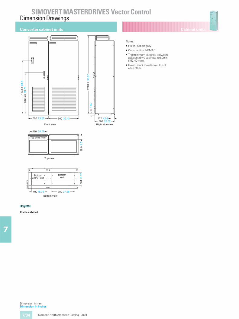
7/34
SIMOVERT MASTERDRIVES Vector ControlDimension Drawings
7
Cabinet units
Siemens North American Catalog · 2004
Converter cabinet units
Dimension in mmDimension in inches
��� ����� �� ����
�� �
����
����
����
�
���
���
����
�
����
����
��� �����
� � �����
����
���
E(5�1&6(!�&>(�D
�-+&�)1,8&�&�#(1
��� �����
C,-)1&>(�D
�-+&>(�D
��� ����
.�
���
��
/-11-'�)1,8&�&�#(1
���
��
�
��� �����
/-11-'&>(�D
/-11-'�#(1
Fig. 70
K size cabinet
Notes:
� Finish: pebble grey
� Construction: NEMA 1
� The minimum distance betweenadjacent drive cabinets is 6.00 in(152.40 mm).
� Do not stack inverters on top ofeach other.
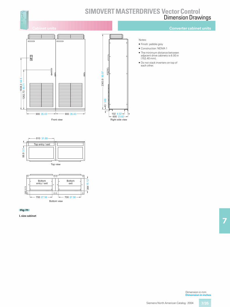
7/35
SIMOVERT MASTERDRIVES Vector ControlDimension Drawings
7
Cabinet units
Siemens North American Catalog · 2004
Converter cabinet units
Dimension in mmDimension in inches
��� ����� �� ����
�� �
����
����
����
�
���
���
����
�
����
����
��� �����
E(5�1&6(!�&>(�DC,-)1&>(�D
�-+&>(�D
��� �����
���
��
�
.�
���
��
� � � ���
�-+&�)1,8&�&�#(1
����
���
��� �����
/-11-'�)1,8&�&�#(1
��� �����
/-11-'&>(�D
/-11-'�#(1
Fig. 71
L size cabinet
Notes:
� Finish: pebble grey
� Construction: NEMA 1
� The minimum distance betweenadjacent drive cabinets is 6.00 in(152.40 mm).
� Do not stack inverters on top ofeach other.
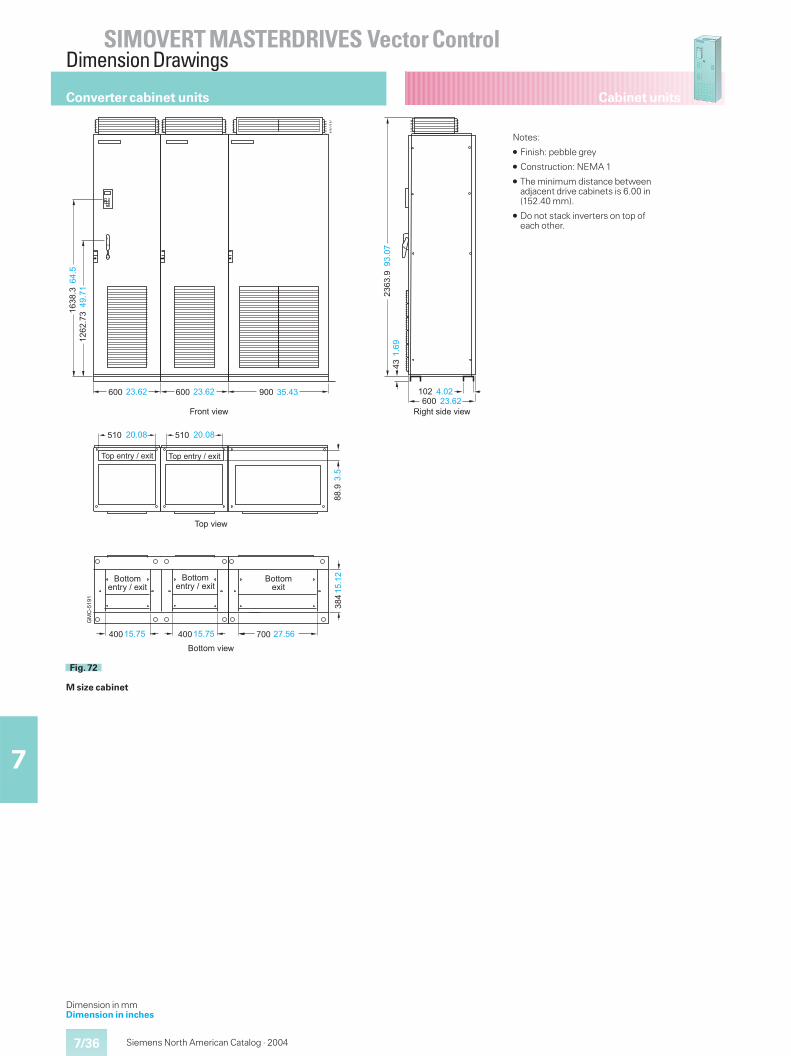
7/36
SIMOVERT MASTERDRIVES Vector ControlDimension Drawings
7
Cabinet units
Siemens North American Catalog · 2004
Converter cabinet units
Dimension in mmDimension in inches
���
���
����
�
����
����
��� �����
C,-)1&>(�D
��� �����
���
��
�
��� ����
/-11-'&>(�D
/-11-'�#(1
.�
���
�
��� ����� �� ����
�� �
����
����
����
�
E(5�1&6(!�&>(�D
��� �����
��� ����
/-11-'�)1,8&�&�#(1
��� �����
/-11-'�)1,8&�&�#(1
� � �����
����
���
�-+&>(�D
� � �����
�-+&�)1,8&�&�#(1 �-+&�)1,8&�&�#(1
Fig. 72
M size cabinet
Notes:
� Finish: pebble grey
� Construction: NEMA 1
� The minimum distance betweenadjacent drive cabinets is 6.00 in(152.40 mm).
� Do not stack inverters on top ofeach other.
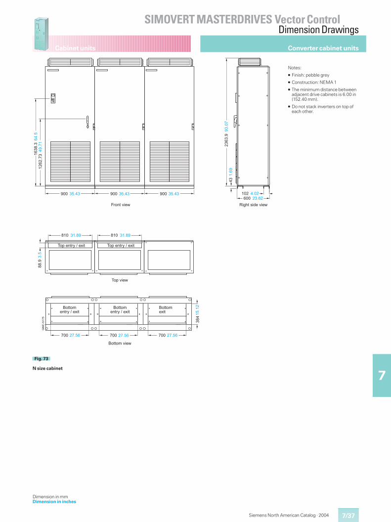
7/37
SIMOVERT MASTERDRIVES Vector ControlDimension Drawings
7
Cabinet units
Siemens North American Catalog · 2004
Dimension in mmDimension in inches
��� ����� �� ����
�� �
����
����
����
�
���
���
����
�
����
����
��� �����
E(5�1&6(!�&>(�DC,-)1&>(�D
�-+&>(�D
��� ����� ��� �������
� �
� �
.�
���
��
� � � ���
�-+&�)1,8&�&�#(1
� � � ���
�-+&�)1,8&�&�#(1
����
���
��� �����
/-11-'�)1,8&�&�#(1
��� �����
/-11-'&>(�D
/-11-'�)1,8&�&�#(1
��� �����
/-11-'�#(1
Fig. 73
N size cabinet
Notes:
� Finish: pebble grey
� Construction: NEMA 1
� The minimum distance betweenadjacent drive cabinets is 6.00 in(152.40 mm).
� Do not stack inverters on top ofeach other.
Converter cabinet units
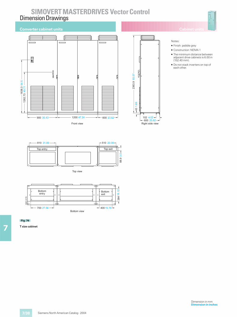
7/38
SIMOVERT MASTERDRIVES Vector ControlDimension Drawings
7
Cabinet units
Siemens North American Catalog · 2004
Dimension in mmDimension in inches
��� ����� �� ����
�� �
����
����
����
�
���
���
����
�
����
����
��� �����
� � � ���
E(5�1&6(!�&>(�DC,-)1&>(�D
�-+&�)1,8
����� ��� ��� �����
�-+&>(�D
� � �����
����
���
�-+&�#(1
��� �����/-11-'&>(�D
/-11-'�)1,8
���
��
�
��� ����
/-11-'�#(1
.�
���
��
Fig. 74
T size cabinet
Notes:
� Finish: pebble grey
� Construction: NEMA 1
� The minimum distance betweenadjacent drive cabinets is 6.00 in(152.40 mm).
� Do not stack inverters on top ofeach other.
Converter cabinet units
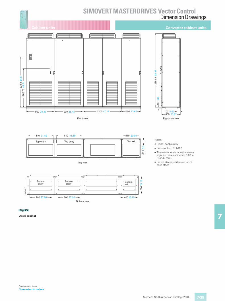
7/39
SIMOVERT MASTERDRIVES Vector ControlDimension Drawings
7
Cabinet units
Siemens North American Catalog · 2004
Dimension in mmDimension in inches
��� ����� �� ����
�� �
����
����
����
�
E(5�1&6(!�&>(�DC,-)1&>(�D
����� ��� ��� �����
�-+&>(�D
� � �����
����
���
�-+&�#(1
.�
���
��
/-11-'&>(�D
���
��
�
��� ����
/-11-'�#(1
��� �����
� � � ���
�-+&�)1,8
� � � ���
�-+&�)1,8
��� �����
/-11-'�)1,8
��� �����
/-11-'�)1,8
���
���
����
�
����
����
��� �����
Fig. 75
U size cabinet
Notes:
� Finish: pebble grey
� Construction: NEMA 1
� The minimum distance betweenadjacent drive cabinets is 6.00 in(152.40 mm).
� Do not stack inverters on top ofeach other.
Converter cabinet units

7/40
SIMOVERT MASTERDRIVES Vector ControlDimension Drawings
7
Cabinet units
Siemens North American Catalog · 2004
Notes
8/1
8
Siemens North American Catalog · 2004
1PH7 Asynchronous servomotors8/2 Technical data8/5 Selection and ordering example with
SIMOVERT MASTERDRIVES converters8/8 Order No. suffix
1PL6 Asynchronous servomotors8/11 Technical data8/13 Selection and ordering example with
SIMOVERT MASTERDRIVES converters8/14 Order No. suffix
Vector ControlAsynchronousServomotors
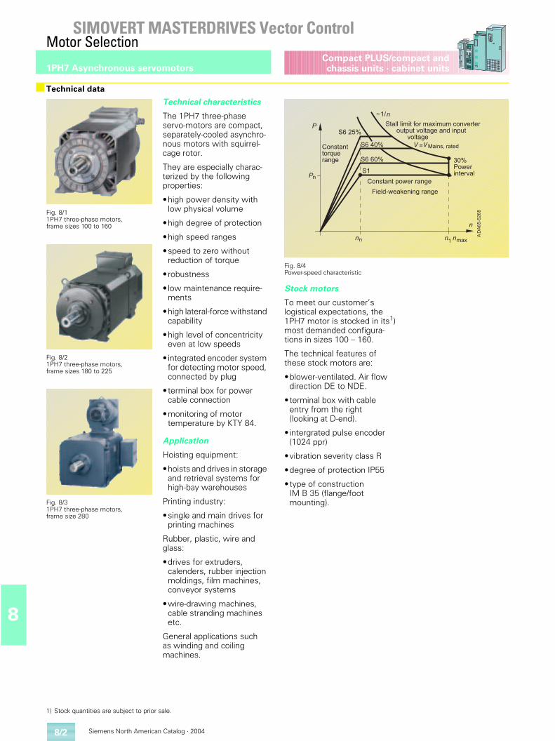
Siemens North American Catalog · 20048/2
SIMOVERT MASTERDRIVES Vector ControlMotor Selection
1PH7 Asynchronous servomotors
8
Compact PLUS/compact andchassis units · cabinet units
■Technical data
Fig. 8/1 1PH7 three-phase motors, frame sizes 100 to 160
Fig. 8/21PH7 three-phase motors, frame sizes 180 to 225
Fig. 8/31PH7 three-phase motors,frame size 280
Technical characteristics
The 1PH7 three-phase servo-motors are compact, separately-cooled asynchro-nous motors with squirrel-cage rotor.
They are especially charac-terized by the following properties:
•high power density with low physical volume
•high degree of protection
•high speed ranges
•speed to zero without reduction of torque
•robustness
• low maintenance require-ments
•high lateral-force withstand capability
•high level of concentricity even at low speeds
• integrated encoder system for detecting motor speed, connected by plug
•terminal box for power cable connection
•monitoring of motor temperature by KTY 84.
Application
Hoisting equipment:
•hoists and drives in storage and retrieval systems for high-bay warehouses
Printing industry:
•single and main drives for printing machines
Rubber, plastic, wire and glass:
•drives for extruders, calenders, rubber injection moldings, film machines, conveyor systems
•wire-drawing machines, cable stranding machines etc.
General applications such as winding and coiling machines.
Fig. 8/4Power-speed characteristic
Stock motors
To meet our customer’s logistical expectations, the 1PH7 motor is stocked in its1) most demanded configura-tions in sizes 100 – 160.
The technical features of these stock motors are:
•blower-ventilated. Air flow direction DE to NDE.
•terminal box with cable entry from the right (looking at D-end).
• intergrated pulse encoder (1024 ppr)
•vibration severity class R
•degree of protection IP55
•type of construction IM B 35 (flange/foot mounting).
���������
�
�����
�����
�� ��
���������������������������������������������������������
� ���!"�����
�#��!������$�������
%�����$��&����������
#��!�������'������� (��
)�$����������
*
���
�
�
1) Stock quantities are subject to prior sale.
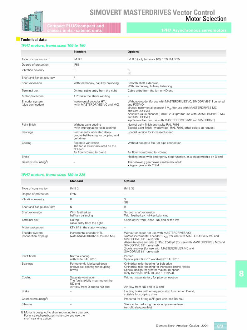
8
Siemens North American Catalog · 2004
SIMOVERT MASTERDRIVES Vector ControlMotor Selection
8/3
1PH7 Asynchronous servomotorsCompact PLUS/compact and chassis units · cabinet units
■Technical data
1PH7 motors, frame sizes 100 to 160
Standard Options
Type of construction IM B 3 IM B 5 (only for sizes 100, 132), IM B 35
Degree of protection IP55 –
Vibration severity R SSR
Shaft and flange accuracy R –
Shaft extension With featherkey, half-key balancing Smooth shaft extensionWith featherkey, full-key balancing
Terminal box On top, cable entry from the right Cable entry from the left or ND-end
Motor protection KTY 84 in the stator winding –
Encoder system(plug connection)
Incremental encoder HTL(with MASTERDRIVES VC and MC)
Without encoder (for use with MASTERDRIVES VC, SIMODRIVE 611 universal and POSMO)sin/cos incremental encoder 1 Vpp (for use with MASTERDRIVES MC and SIMODRIVE)Absolute-value encoder (EnDat) 2048 p/r (for use with MASTERDRIVES MC and SIMODRIVE)2-pole resolver (for use with MASTERDRIVES MC and SIMODRIVE)
Paint finish Without paint coating(with impregnating resin coating)
Normal paint finish anthracite RAL 7016Special paint finish “worldwide” RAL 7016, other colors on request
Bearings Permanently lubricated deep-groove ball bearing for coupling and belt drive
Special version for increased speed
Cooling Separate ventilationThe fan is axially mounted on theND-endAir flow ND-end to D-end
Without separate fan, for pipe connection
Air flow from D-end to ND-end
Brake – Holding brake with emergency stop function, as a brake module on D-end
Gearbox mounting1) – The following gearboxes can be mounted:● 2-gear gear units 2LG4
1PH7 motors, frame sizes 180 to 225
Standard Options
Type of construction IM B 3 IM B 35
Degree of protection IP55 –
Vibration severity R SSR
Shaft and flange accuracy N R
Shaft extension With featherkey, half-key balancing
Smooth shaft extensionWith featherkey, full-key balancing
Terminal box On top, cable entry from the right
Cable entry from D-end, ND-end or the left
Motor protection KTY 84 in the stator winding –
Encoder system(connection by plug)
Incremental encoder HTL(with MASTERDRIVES VC and MC)
Without encoder (for use with MASTERDRIVES VC)sin/cos incremental encoder 1 Vpp (for use with MASTERDRIVES MC and SIMODRIVE 611 universal)Absolute-value encoder (EnDat) 2048 p/r (for use with MASTERDRIVES MC and SIMODRIVE 611 universal)2-pole resolver (for use with MASTERDRIVES MC and SIMODRIVE 611 universal)
Paint finish Normal coating anthracite RAL 7016
PrimedSpecial paint finish “worldwide” RAL 7016
Bearings Permanently lubricated deep-groove ball bearing for coupling drives
Cylindrical roller bearing for belt driveCylindrical roller bearing for increased lateral forcesSpecial design for greater maximum speed(only for types 1PH718. and 1PH7224)
Cooling Separate ventilationThe fan is axially mounted on theND-endAir flow from D-end to ND-end
Without separate fan, for pipe connection
Air flow from ND-end to D-end
Brake – Holding brake with emergency stop function on D-end,suitable for coupling drive
Gearbox mounting1) – Prepared for fitting a ZF gear unit, see DA 65.3
Silencer – Silencer for reducing the sound pressure level(retrofit also possible)
1) Motor is designed to allow mounting to a gearbox. For unsealed gearboxes make sure you use the shaft seal ring option.
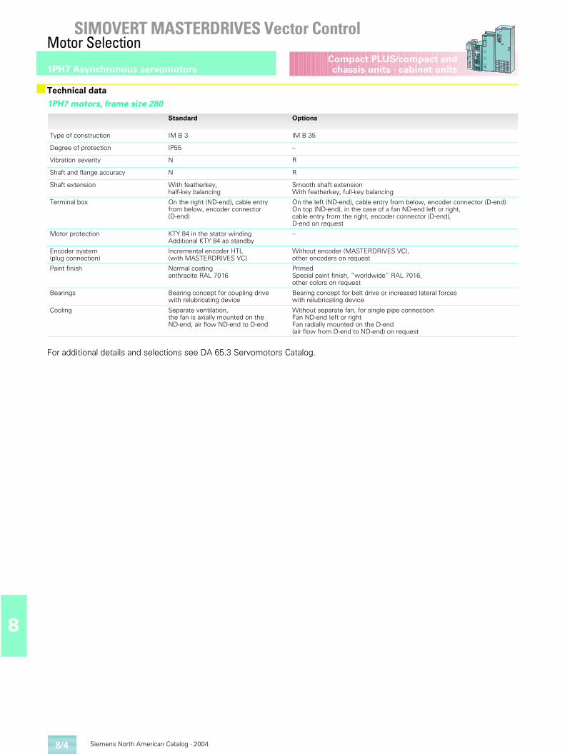
Siemens North American Catalog · 20048/4
SIMOVERT MASTERDRIVES Vector ControlMotor Selection
1PH7 Asynchronous servomotors
8
Compact PLUS/compact andchassis units · cabinet units
For additional details and selections see DA 65.3 Servomotors Catalog.
■Technical data
1PH7 motors, frame size 280
Standard Options
Type of construction IM B 3 IM B 35
Degree of protection IP55 –
Vibration severity N R
Shaft and flange accuracy N R
Shaft extension With featherkey, half-key balancing
Smooth shaft extensionWith featherkey, full-key balancing
Terminal box On the right (ND-end), cable entry from below, encoder connector (D-end)
On the left (ND-end), cable entry from below, encoder connector (D-end)On top (ND-end), in the case of a fan ND-end left or right,cable entry from the right, encoder connector (D-end), D-end on request
Motor protection KTY 84 in the stator winding Additional KTY 84 as standby
–
Encoder system(plug connection)
Incremental encoder HTL(with MASTERDRIVES VC)
Without encoder (MASTERDRIVES VC),other encoders on request
Paint finish Normal coating anthracite RAL 7016
PrimedSpecial paint finish, “worldwide” RAL 7016,other colors on request
Bearings Bearing concept for coupling drive with relubricating device
Bearing concept for belt drive or increased lateral forces with relubricating device
Cooling Separate ventilation,the fan is axially mounted on theND-end, air flow ND-end to D-end
Without separate fan, for single pipe connectionFan ND-end left or rightFan radially mounted on the D-end (air flow from D-end to ND-end) on request
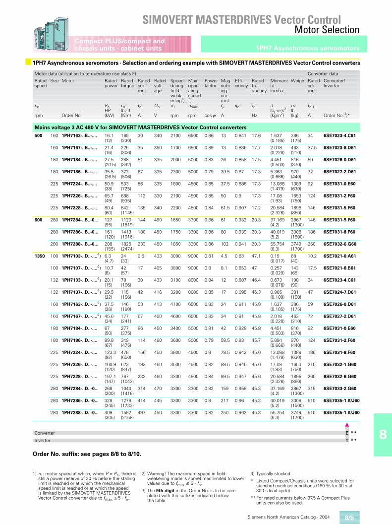
8
Siemens North American Catalog · 2004
SIMOVERT MASTERDRIVES Vector ControlMotor Selection
8/5
1PH7 Asynchronous servomotorsCompact PLUS/compact and chassis units · cabinet units
Order No. suffix: see pages 8/8 to 8/10.
■ 1PH7 Asynchronous servomotors · Selection and ordering example with SIMOVERT MASTERDRIVES Vector Control converters
Motor data (utilization to temperature rise class F) Converter data
Rated speed
nn
rpm
Size Motor
Order No.
Rated power
PnHP(kW)
Rated torque
�nlbf -ft(Nm)
Rated cur-rent
In
A
Rated volt-age
Un
V
Speedduringfield-weak-ening1)n1
rpm
Max.oper-atingspeed2)nmax.
rpm
Powerfactor
cos �
Mag-netiz-ingcur-rentI�
A
Effi-ciency
�n
Ratedfre-quency
fn
Hz
Momentofinertia
Jlbf -in-s2
(kgm2)
Weight
mlb(kg)
Rated cur-rent
InU
A
Converter/Inverter
Order No.3)*
Mains voltage 3 AC 480 V for SIMOVERT MASTERDRIVES Vector Control converters
500 160 1PH7163-..B..-.... 16.1(12)
169(230)
30 340 2100 6500 0.86 13 0.841 17.6 1.637(0.185)
386(175)
34 6SE7023-4.C61
160 1PH7167-..B..-.... 21.4(16)
225(306)
35 350 1700 6500 0.89 13 0.836 17.7 2.018(0.228)
463(210)
37.5 6SE7023-8.D61
180 1PH7184-..B..-.... 27.5(20.5)
288(392)
51 335 2000 5000 0.83 26 0.858 17.5 4.451(0.503)
816(370)
59 6SE7026-0.D61
180 1PH7186-..B..-.... 35.5(26.5)
372(506)
67 335 2300 5000 0.79 39.5 0.87 17.3 5.363(0.666)
970(440)
72 6SE7027-2.D61
225 1PH7224-..B..-.... 50.9(38)
533(725)
86 335 1800 4500 0.85 37.5 0.888 17.3 13.088(1.479)
1389(630)
92 6SE7031-0.E60
225 1PH7226-..B..-.... 65.7(49)
688(935)
112 330 2100 4500 0.85 50 0.9 17.3 17.08(1.93)
1653(750)
124 6SE7031-2.F60
225 1PH7228-..B..-.... 80.4(60)
842(1145)
135 340 2200 4500 0.84 61.5 0.907 17.2 20.584(2.326)
1896(860)
146 6SE7031-5.F60
600 280 1PH7284-..B..-0... 127(95)
1120(1519)
144 480 1650 3300 0.86 61 0.932 20.3 37.169(4.2)
2867(1300)
146 6SE7031-5.F60
280 1PH7286-..B..-0... 161(120)
1413(1916)
180 480 1750 3300 0.86 80 0.939 20.3 40.019(5.2)
3308(1500)
186 6SE7031-8.F60
280 1PH7288-..B..-0... 208 (155)
1825(2474)
233 480 1850 3300 0.86 102 0.941 20.3 55.754(6.3)
3749(1700)
260 6SE7032-6.G60
1350 100 1PH7103-..D..-....4) 6.3(4.7)
24(33)
9.5 433 3000 9000 0.81 4.5 0.83 47.1 0.15(0.017)
88(40)
10.2 6SE7021-0.A61
100 1PH7107-..D..-....4) 10.7(8)
42(57)
17 405 3800 9000 0.8 8.1 0.853 47 0.257(0.029)
143(65)
17.5 6SE7021-8.B61
132 1PH7133-..D..-....4) 20.1(15)
78(106)
30 433 3100 8000 0.84 12 0.887 46.4 0.673(0.076)
198(90)
34 6SE7023-4.C61
132 1PH7137-..D..-....4) 29.5(22)
115(156)
42 416 3200 8000 0.85 17 0.895 46.3 0.965(0.109)
331(150)
47 6SE7024-7.D61
160 1PH7163-..D..-....4) 37.5(28)
146(198)
53 413 4100 6500 0.83 24 0.911 45.8 1.637(0.185)
386(175)
59 6SE7026-0.D61
160 1PH7167-..D..-....4) 45.6(34)
177(241)
67 400 4600 6500 0.83 34 0.91 45.8 2.018(0.228)
463(210)
72 6SE7027-2.D61
180 1PH7184-..D..-.... 67(50)
277(375)
86 450 3400 5000 0.81 42 0.928 45.8 4.451(0.503)
816(370)
92 6SE7031-0.E60
180 1PH7186-..D..-.... 89.8(67)
349(475)
114 460 3600 5000 0.79 59.5 0.93 45.7 5.894(0.666)
970(440)
124 6SE7031-2.F60
225 1PH7224-..D..-.... 123.3(92)
478(650)
156 450 3800 4500 0.8 78.5 0.942 45.6 13.088(1.479)
1389(630)
186 6SE7031-8.F60
225 1PH7226-..D..-.... 160.9(120)
623(847)
193 460 3500 4500 0.82 88.5 0.945 45.6 17.08(1.93)
1653(750)
210 6SE7032-1.G60
225 1PH7228-..D..-.... 197.1(147)
767(1043)
232 460 3300 4500 0.84 99.5 0.947 45.6 20.584(2.326)
1896(860)
260 6SE7032-6.G60
280 1PH7284-..D..-0... 268(200)
1044(1416)
314 470 3300 3300 0.82 159 0.958 45.3 37.169(4.2)
2867(1300)
315 6SE7033-2.G60
280 1PH7286-..D..-0... 328(245)
1278(1733)
414 445 3300 3300 0.8 217 0.96 45.3 40.019(5.2)
3308(1500)
510 6SE7035-1.K/J60
280 1PH7288-..D..-0... 409(305)
1592(2158)
497 450 3300 3300 0.82 250 0.962 45.3 55.754(6.3)
3749(1700)
510 6SE7035-1.K/J60
Converter E * *
Inverter T * *
1) n1: motor speed at which, when P = Pn, there is still a power reserve of 30 % before the stalling limit is reached or at which the mechanical speed limit is reached or at which the speed is limited by the SIMOVERT MASTERDRIVES Vector Control converter due to fmax. � 5 · fn.
2) Warning! The maximum speed in field-weakening mode is sometimes limited to lower values due to fmax � 5 · fn.
3) The 9th digit in the Order No. is to be com-pleted with the suffixes indicated below the table.
4) Typically stocked.
* Listed Compact/Chassis units were selected for standard overload conditions (160 % for 30 s at 300 s load cycle).
**For rated currents below 37.5 A Compact Plus units can also be used.
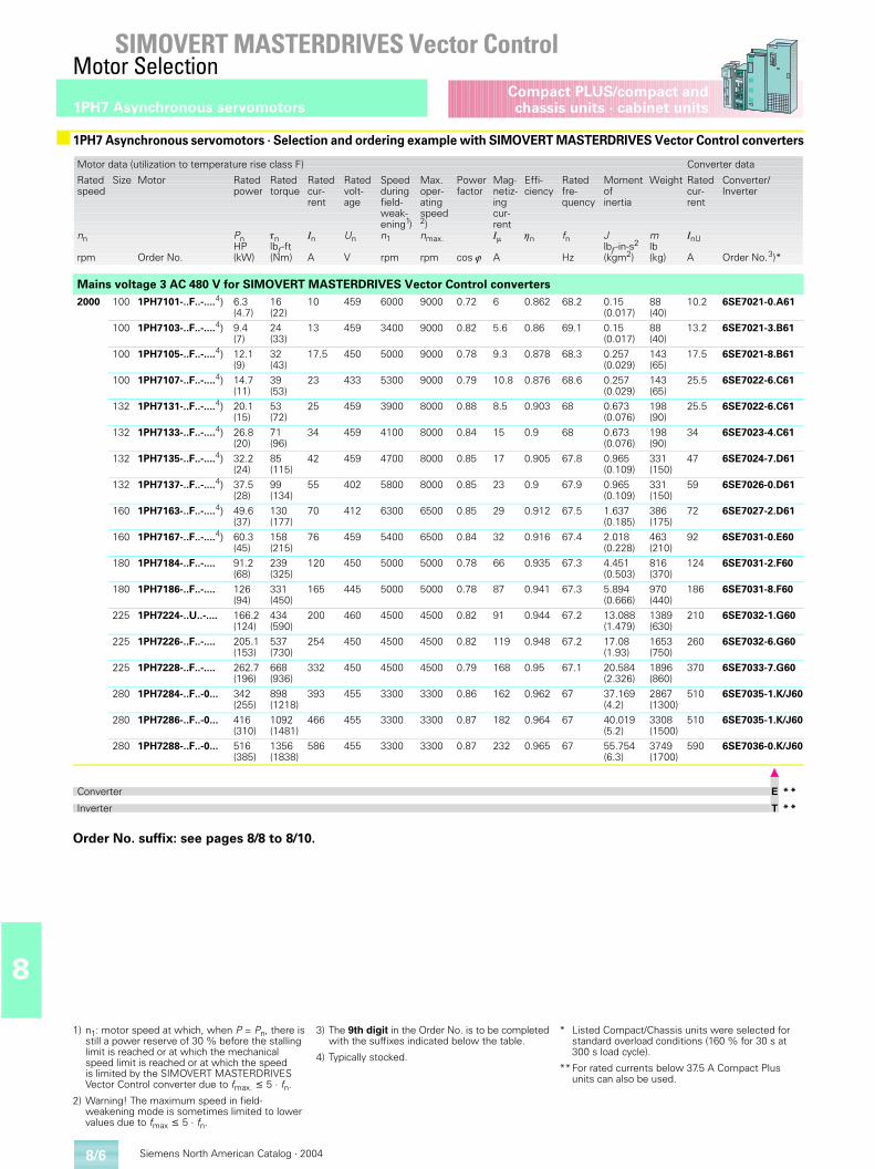
Siemens North American Catalog · 20048/6
SIMOVERT MASTERDRIVES Vector ControlMotor Selection
1PH7 Asynchronous servomotors
8
Compact PLUS/compact andchassis units · cabinet units
Order No. suffix: see pages 8/8 to 8/10.
■ 1PH7 Asynchronous servomotors · Selection and ordering example with SIMOVERT MASTERDRIVES Vector Control converters
Motor data (utilization to temperature rise class F) Converter data
Rated speed
nn
rpm
Size Motor
Order No.
Rated power
PnHP(kW)
Rated torque
�nlbf -ft(Nm)
Rated cur-rent
In
A
Rated volt-age
Un
V
Speedduringfield-weak-ening1)n1
rpm
Max.oper-atingspeed2)nmax.
rpm
Powerfactor
cos �
Mag-netiz-ingcur-rentI�
A
Effi-ciency
�n
Ratedfre-quency
fn
Hz
Momentofinertia
Jlbf -in-s2
(kgm2)
Weight
mlb(kg)
Rated cur-rent
InU
A
Converter/Inverter
Order No.3)*
Mains voltage 3 AC 480 V for SIMOVERT MASTERDRIVES Vector Control converters2000 100 1PH7101-..F..-....4) 6.3
(4.7)16(22)
10 459 6000 9000 0.72 6 0.862 68.2 0.15(0.017)
88(40)
10.2 6SE7021-0.A61
100 1PH7103-..F..-....4) 9.4(7)
24(33)
13 459 3400 9000 0.82 5.6 0.86 69.1 0.15(0.017)
88(40)
13.2 6SE7021-3.B61
100 1PH7105-..F..-....4) 12.1(9)
32(43)
17.5 450 5000 9000 0.78 9.3 0.878 68.3 0.257(0.029)
143(65)
17.5 6SE7021-8.B61
100 1PH7107-..F..-....4) 14.7(11)
39(53)
23 433 5300 9000 0.79 10.8 0.876 68.6 0.257(0.029)
143(65)
25.5 6SE7022-6.C61
132 1PH7131-..F..-....4) 20.1(15)
53(72)
25 459 3900 8000 0.88 8.5 0.903 68 0.673(0.076)
198(90)
25.5 6SE7022-6.C61
132 1PH7133-..F..-....4) 26.8(20)
71(96)
34 459 4100 8000 0.84 15 0.9 68 0.673(0.076)
198(90)
34 6SE7023-4.C61
132 1PH7135-..F..-....4) 32.2(24)
85(115)
42 459 4700 8000 0.85 17 0.905 67.8 0.965(0.109)
331(150)
47 6SE7024-7.D61
132 1PH7137-..F..-....4) 37.5(28)
99(134)
55 402 5800 8000 0.85 23 0.9 67.9 0.965(0.109)
331(150)
59 6SE7026-0.D61
160 1PH7163-..F..-....4) 49.6(37)
130(177)
70 412 6300 6500 0.85 29 0.912 67.5 1.637(0.185)
386(175)
72 6SE7027-2.D61
160 1PH7167-..F..-....4) 60.3(45)
158(215)
76 459 5400 6500 0.84 32 0.916 67.4 2.018(0.228)
463(210)
92 6SE7031-0.E60
180 1PH7184-..F..-.... 91.2(68)
239(325)
120 450 5000 5000 0.78 66 0.935 67.3 4.451(0.503)
816(370)
124 6SE7031-2.F60
180 1PH7186-..F..-.... 126(94)
331(450)
165 445 5000 5000 0.78 87 0.941 67.3 5.894(0.666)
970(440)
186 6SE7031-8.F60
225 1PH7224-..U..-.... 166.2(124)
434(590)
200 460 4500 4500 0.82 91 0.944 67.2 13.088(1.479)
1389(630)
210 6SE7032-1.G60
225 1PH7226-..F..-.... 205.1(153)
537(730)
254 450 4500 4500 0.82 119 0.948 67.2 17.08(1.93)
1653(750)
260 6SE7032-6.G60
225 1PH7228-..F..-.... 262.7(196)
668(936)
332 450 4500 4500 0.79 168 0.95 67.1 20.584(2.326)
1896(860)
370 6SE7033-7.G60
280 1PH7284-..F..-0... 342(255)
898(1218)
393 455 3300 3300 0.86 162 0.962 67 37.169(4.2)
2867(1300)
510 6SE7035-1.K/J60
280 1PH7286-..F..-0... 416(310)
1092(1481)
466 455 3300 3300 0.87 182 0.964 67 40.019(5.2)
3308(1500)
510 6SE7035-1.K/J60
280 1PH7288-..F..-0... 516(385)
1356(1838)
586 455 3300 3300 0.87 232 0.965 67 55.754(6.3)
3749(1700)
590 6SE7036-0.K/J60
Converter E * *
Inverter T * *
1) n1: motor speed at which, when P = Pn, there is still a power reserve of 30 % before the stalling limit is reached or at which the mechanical speed limit is reached or at which the speed is limited by the SIMOVERT MASTERDRIVES Vector Control converter due to fmax. � 5 · fn.
2) Warning! The maximum speed in field-weakening mode is sometimes limited to lower values due to fmax � 5 · fn.
3) The 9th digit in the Order No. is to be completed with the suffixes indicated below the table.
4) Typically stocked.
* Listed Compact/Chassis units were selected for standard overload conditions (160 % for 30 s at 300 s load cycle).
**For rated currents below 37.5 A Compact Plus units can also be used.
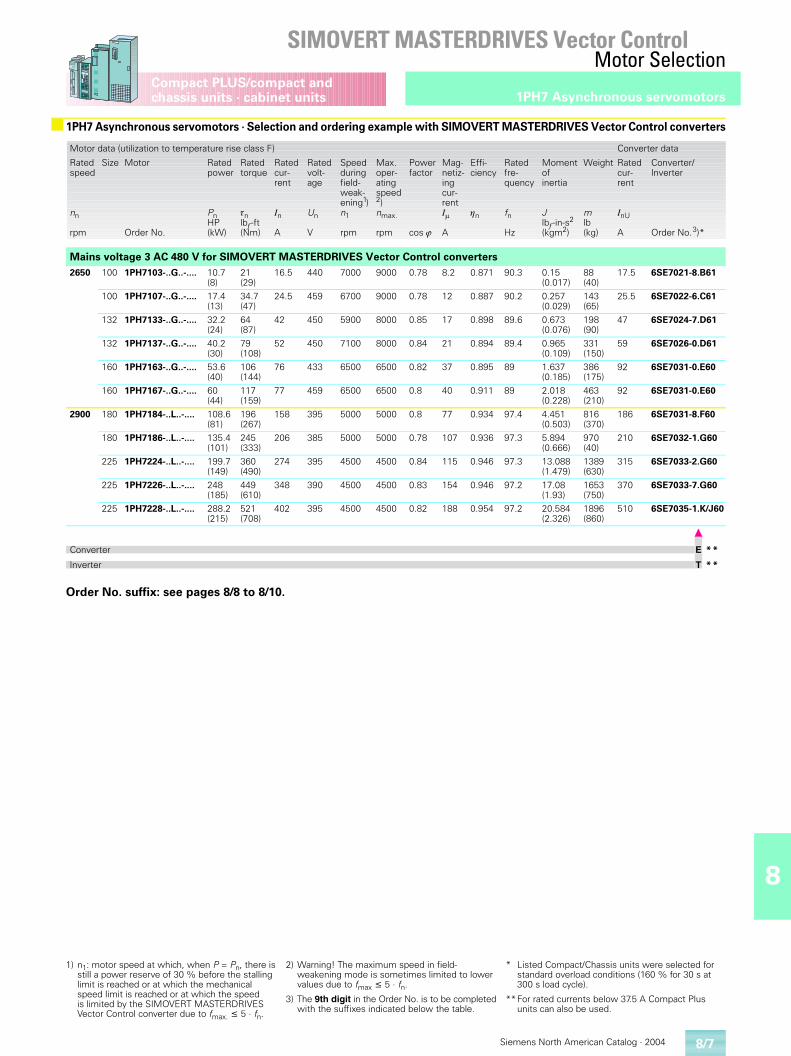
8
Siemens North American Catalog · 2004
SIMOVERT MASTERDRIVES Vector ControlMotor Selection
8/7
1PH7 Asynchronous servomotorsCompact PLUS/compact and chassis units · cabinet units
Order No. suffix: see pages 8/8 to 8/10.
■ 1PH7 Asynchronous servomotors · Selection and ordering example with SIMOVERT MASTERDRIVES Vector Control converters
Motor data (utilization to temperature rise class F) Converter data
Rated speed
nn
rpm
Size Motor
Order No.
Rated power
PnHP(kW)
Rated torque
�nlbf -ft(Nm)
Rated cur-rent
In
A
Rated volt-age
Un
V
Speedduringfield-weak-ening1)n1
rpm
Max.oper-atingspeed2)nmax.
rpm
Powerfactor
cos �
Mag-netiz-ingcur-rentI�
A
Effi-ciency
�n
Ratedfre-quency
fn
Hz
Momentofinertia
Jlbf -in-s2
(kgm2)
Weight
mlb(kg)
Rated cur-rent
InU
A
Converter/Inverter
Order No.3)*
Mains voltage 3 AC 480 V for SIMOVERT MASTERDRIVES Vector Control converters2650 100 1PH7103-..G..-.... 10.7
(8)21(29)
16.5 440 7000 9000 0.78 8.2 0.871 90.3 0.15(0.017)
88(40)
17.5 6SE7021-8.B61
100 1PH7107-..G..-.... 17.4(13)
34.7(47)
24.5 459 6700 9000 0.78 12 0.887 90.2 0.257(0.029)
143(65)
25.5 6SE7022-6.C61
132 1PH7133-..G..-.... 32.2(24)
64(87)
42 450 5900 8000 0.85 17 0.898 89.6 0.673(0.076)
198(90)
47 6SE7024-7.D61
132 1PH7137-..G..-.... 40.2(30)
79(108)
52 450 7100 8000 0.84 21 0.894 89.4 0.965(0.109)
331(150)
59 6SE7026-0.D61
160 1PH7163-..G..-.... 53.6(40)
106(144)
76 433 6500 6500 0.82 37 0.895 89 1.637(0.185)
386(175)
92 6SE7031-0.E60
160 1PH7167-..G..-.... 60(44)
117(159)
77 459 6500 6500 0.8 40 0.911 89 2.018(0.228)
463(210)
92 6SE7031-0.E60
2900 180 1PH7184-..L..-.... 108.6(81)
196(267)
158 395 5000 5000 0.8 77 0.934 97.4 4.451(0.503)
816(370)
186 6SE7031-8.F60
180 1PH7186-..L..-.... 135.4(101)
245(333)
206 385 5000 5000 0.78 107 0.936 97.3 5.894(0.666)
970(40)
210 6SE7032-1.G60
225 1PH7224-..L..-.... 199.7(149)
360(490)
274 395 4500 4500 0.84 115 0.946 97.3 13.088(1.479)
1389(630)
315 6SE7033-2.G60
225 1PH7226-..L..-.... 248(185)
449(610)
348 390 4500 4500 0.83 154 0.946 97.2 17.08(1.93)
1653(750)
370 6SE7033-7.G60
225 1PH7228-..L..-.... 288.2(215)
521(708)
402 395 4500 4500 0.82 188 0.954 97.2 20.584(2.326)
1896(860)
510 6SE7035-1.K/J60
Converter E * *
Inverter T * *
1) n1: motor speed at which, when P = Pn, there is still a power reserve of 30 % before the stalling limit is reached or at which the mechanical speed limit is reached or at which the speed is limited by the SIMOVERT MASTERDRIVES Vector Control converter due to fmax. � 5 · fn.
2) Warning! The maximum speed in field-weakening mode is sometimes limited to lower values due to fmax � 5 · fn.
3) The 9th digit in the Order No. is to be completed with the suffixes indicated below the table.
* Listed Compact/Chassis units were selected for standard overload conditions (160 % for 30 s at 300 s load cycle).
**For rated currents below 37.5 A Compact Plus units can also be used.
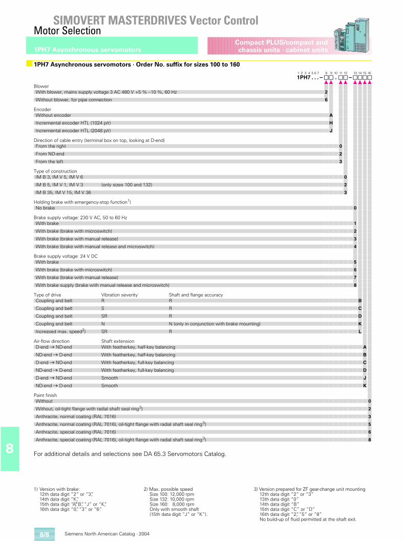
Siemens North American Catalog · 20048/8
SIMOVERT MASTERDRIVES Vector ControlMotor Selection
1PH7 Asynchronous servomotors
8
Compact PLUS/compact andchassis units · cabinet units
For additional details and selections see DA 65.3 Servomotors Catalog.
■1PH7 Asynchronous servomotors · Order No. suffix for sizes 100 to 1601 2 3 4 5 6 7 8 9 10 11 12 13 14 15 161PH7 . . . – . –
BlowerWith blower, mains supply voltage 3 AC 480 V +5 % –10 %, 60 Hz 2
Without blower, for pipe connection 6
EncoderWithout encoder A
Incremental encoder HTL (1024 p/r) H
Incremental encoder HTL (2048 p/r) J
Direction of cable entry (terminal box on top, looking at D-end)From the right 0
From ND-end 2
From the left 3
Type of constructionIM B 3, IM V 5, IM V 6 0
IM B 5, IM V 1, IM V 3 (only sizes 100 and 132) 2
IM B 35, IM V 15, IM V 36 3
Holding brake with emergency-stop function1)No brake 0
Brake supply voltage: 230 V AC, 50 to 60 HzWith brake 1
With brake (brake with microswitch) 2
With brake (brake with manual release) 3
With brake (brake with manual release and microswitch) 4
Brake supply voltage: 24 V DCWith brake 5
With brake (brake with microswitch) 6
With brake (brake with manual release) 7
With brake supply (brake with manual release and microswitch) 8
Type of drive Vibration severity Shaft and flange accuracyCoupling and belt R R B
Coupling and belt S R C
Coupling and belt SR R D
Coupling and belt N N (only in conjunction with brake mounting) K
Increased max. speed2) SR R L
Air-flow direction Shaft extensionD-end � ND-end With featherkey, half-key balancing A
ND-end � D-end With featherkey, half-key balancing B
D-end � ND-end With featherkey, full-key balancing C
ND-end � D-end With featherkey, full-key balancing D
D-end � ND-end Smooth J
ND-end � D-end Smooth K
Paint finishWithout 0
Without, oil-tight flange with radial shaft seal ring3) 2
Anthracite, normal coating (RAL 7016) 3
Anthracite, normal coating (RAL 7016), oil-tight flange with radial shaft seal ring3) 5
Anthracite, special coating (RAL 7016) 6
Anthracite, special coating (RAL 7016), oil-tight flange with radial shaft seal ring3) 8
1) Version with brake:12th data digit “2” or “3”,14th data digit “K”,15th data digit “A”,“B”, “J” or “K”,16th data digit “0”, “3” or “6”.
2) Max. possible speedSize 100: 12,000 rpmSize 132: 10,000 rpmSize 160: 8,000 rpmOnly with smooth shaft(15th data digit “J” or “K”).
3) Version prepared for ZF gear-change unit mounting12th data digit “2” or “3”13th data digit “0”14th data digit “B”15th data digit “C” or “D”16th data digit “2”, “5” or “8”No build-up of fluid permitted at the shaft exit.
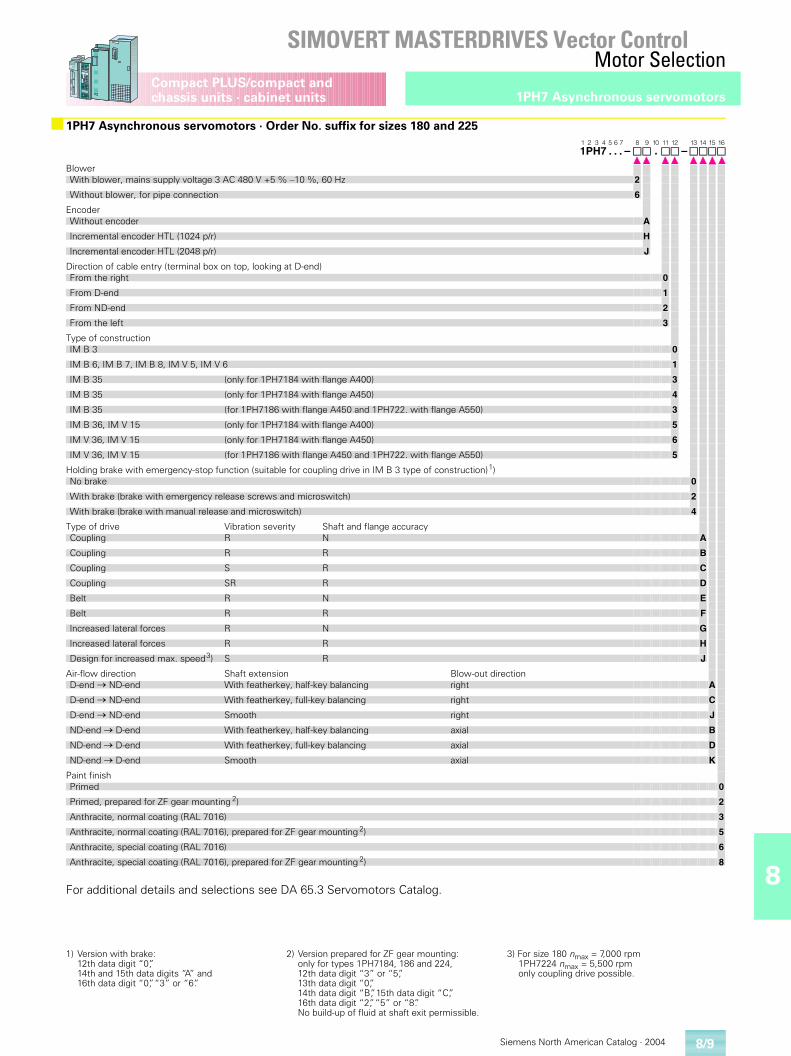
8
Siemens North American Catalog · 2004
SIMOVERT MASTERDRIVES Vector ControlMotor Selection
8/9
1PH7 Asynchronous servomotorsCompact PLUS/compact and chassis units · cabinet units
For additional details and selections see DA 65.3 Servomotors Catalog.
■1PH7 Asynchronous servomotors · Order No. suffix for sizes 180 and 2251 2 3 4 5 6 7 8 9 10 11 12 13 14 15 161PH7 . . . – . –
BlowerWith blower, mains supply voltage 3 AC 480 V +5 % –10 %, 60 Hz 2
Without blower, for pipe connection 6
EncoderWithout encoder A
Incremental encoder HTL (1024 p/r) H
Incremental encoder HTL (2048 p/r) J
Direction of cable entry (terminal box on top, looking at D-end)From the right 0
From D-end 1
From ND-end 2
From the left 3
Type of constructionIM B 3 0
IM B 6, IM B 7, IM B 8, IM V 5, IM V 6 1
IM B 35 (only for 1PH7184 with flange A400) 3
IM B 35 (only for 1PH7184 with flange A450) 4
IM B 35 (for 1PH7186 with flange A450 and 1PH722. with flange A550) 3
IM B 36, IM V 15 (only for 1PH7184 with flange A400) 5
IM V 36, IM V 15 (only for 1PH7184 with flange A450) 6
IM V 36, IM V 15 (for 1PH7186 with flange A450 and 1PH722. with flange A550) 5
Holding brake with emergency-stop function (suitable for coupling drive in IM B 3 type of construction)1)No brake 0
With brake (brake with emergency release screws and microswitch) 2
With brake (brake with manual release and microswitch) 4
Type of drive Vibration severity Shaft and flange accuracyCoupling R N A
Coupling R R B
Coupling S R C
Coupling SR R D
Belt R N E
Belt R R F
Increased lateral forces R N G
Increased lateral forces R R H
Design for increased max. speed3) S R J
Air-flow direction Shaft extension Blow-out directionD-end � ND-end With featherkey, half-key balancing right A
D-end � ND-end With featherkey, full-key balancing right C
D-end � ND-end Smooth right J
ND-end � D-end With featherkey, half-key balancing axial B
ND-end � D-end With featherkey, full-key balancing axial D
ND-end � D-end Smooth axial K
Paint finishPrimed 0
Primed, prepared for ZF gear mounting 2) 2
Anthracite, normal coating (RAL 7016) 3
Anthracite, normal coating (RAL 7016), prepared for ZF gear mounting 2) 5
Anthracite, special coating (RAL 7016) 6
Anthracite, special coating (RAL 7016), prepared for ZF gear mounting 2) 8
1) Version with brake:12th data digit “0”,14th and 15th data digits “A” and16th data digit “0”, “3” or “6”.
2) Version prepared for ZF gear mounting:only for types 1PH7184, 186 and 224,12th data digit “3” or “5”, 13th data digit “0”,14th data digit “B”, 15th data digit “C”,16th data digit “2”, “5” or “8”.No build-up of fluid at shaft exit permissible.
3) For size 180 nmax = 7,000 rpm1PH7224 nmax = 5,500 rpm only coupling drive possible.
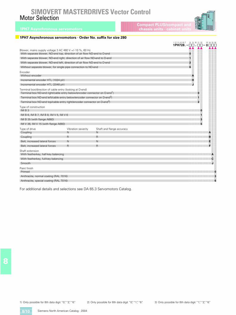
Siemens North American Catalog · 20048/10
SIMOVERT MASTERDRIVES Vector ControlMotor Selection
1PH7 Asynchronous servomotors
8
Compact PLUS/compact andchassis units · cabinet units
For additional details and selections see DA 65.3 Servomotors Catalog.
■1PH7 Asynchronous servomotors · Order No. suffix for size 2801 2 3 4 5 6 7 8 9 10 11 12 13 14 15 161PH728. – . – 0
Blower, mains supply voltage 3 AC 480 V +/–10 %, 60 HzWith separate blower, ND-end top, direction of air flow ND-end to D-end 0
With separate blower, ND-end right, direction of air flow ND-end to D-end 1
With separate blower, ND-end left, direction of air flow ND-end to D-end 2
Without separate blower, for single pipe connection to ND-end 6
EncoderWithout encoder A
Incremental encoder HTL (1024 p/r) H
Incremental encoder HTL (2048 p/r) J
Terminal box/direction of cable entry (looking at D-end)Terminal box ND-end right/cable entry below/encoder connector on D-end1) 0
Terminal box ND-end left/cable entry below/encoder connector on D-end2) 1
Terminal box ND-end top/cable entry right/encoder connector on D-end3) 2
Type of constructionIM B 3 0
IM B 6, IM B 7, IM B 8, IM V 5, IM V 6 1
IM B 35 (with flange A660) 3
IM V 36, IM V 15 (with flange A660) 5
Type of drive Vibration severity Shaft and flange accuracyCoupling N N A
Coupling R R B
Belt, increased lateral forces N N E
Belt, increased lateral forces R R F
Shaft extensionWith featherkey, half-key balancing A
With featherkey, full-key balancing C
Smooth J
Paint finishPrimed 0
Anthracite, normal coating (RAL 7016) 3
Anthracite, special coating (RAL 7016) 6
1) Only possible for 8th data digit “0”, “2”, “6”. 2) Only possible for 8th data digit “0”, “1”, “6”. 3) Only possible for 8th data digit “1”, “2”, “6”.
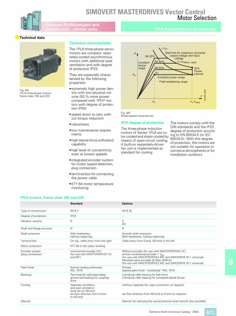
8
Siemens North American Catalog · 2004
SIMOVERT MASTERDRIVES Vector ControlMotor Selection
8/11
1PL6 Asynchronous servomotorsCompact PLUS/compact and chassis units · cabinet units
■Technical data
Fig. 8/51PL6 three-phase motors,frame sizes 180 and 225
Technical characteristics
The 1PL6 three-phase servo-motors are compact, sepa-rately-cooled asynchronous motors with additional axial ventilation and with degree of protection IP23.
They are especially charac-terized by the following properties:
•extremely high power den-sity with low physical vol-ume (50 % more power compared with 1PH7 mo-tors with degree of protec-tion IP55)
•speed down to zero with-out torque reduction
•robustness
• low maintenance require-ments
•high lateral-force withstand capability
•high level of concentricity even at lowest speeds
• integrated encoder system for motor speed detection, plug connection
•terminal box for connecting the power cable
•KTY 84 motor temperature monitoring.
Fig. 8/6 Power-speed characteristic
IP23 degree of protection
The three-phase induction motors of Series 1PL6 are ro-tor-cooled and stator-cooled by means of open-circuit cooling. A built-on separately-driven fan unit is implemented as standard for cooling.
The motors comply with the DIN standards and the IP23 degree of protection accord-ing to EN 60034-5 (or IEC 60034-5). With this degree of protection, the motors are not suitable for operation in corrosive atmospheres or for installation outdoors.
1PL6 motors, frame sizes 180 and 225
Standard Options
Type of construction IM B 3 IM B 35
Degree of protection IP23 –
Vibration severity R SSR
Shaft and flange accuracy N R
Shaft extension With featherkey, half-key balancing
Smooth shaft extensionWith featherkey, full-key balancing
Terminal box On top, cable entry from the right Cable entry from D-end, ND-end or the left
Motor protection KTY 84 in the stator winding –
Encoder system(plug connection)
Incremental encoder HTL(for use with MASTERDRIVES VC and MC)
Without encoder (for use with MASTERDRIVES VC)sin/cos incremental encoder 1 Vpp (for use with MASTERDRIVES MC and SIMODRIVE 611 universal)Absolute-value encoder (EnDat) 2048 p/r (for use with MASTERDRIVES MC and SIMODRIVE 611 universal)
Paint finish Normal coating anthracite RAL 7016
PrimedSpecial paint finish “worldwide” RAL 7016
Bearings Permanently lubricated deep-groove ball bearing for coupling drive
Cylindrical roller bearing for belt driveCylindrical roller bearing for increased lateral forces
Cooling Separate ventilationand axial ventilationAxial fan on ND-endAir-flow direction from D-end to ND-end
(without separate fan, pipe connection on request)
(air-flow direction from ND-end to D-end on request)
Silencer – Silencer for reducing the sound pressure level (retrofit also possible)
���������
�
�����
�����
�� ��
���������������������������������������������������������
� ���!"�����
�#��!������$�������
%�����$��&����������
#��!�������'������� (��
)�$����������
*
���
�
�
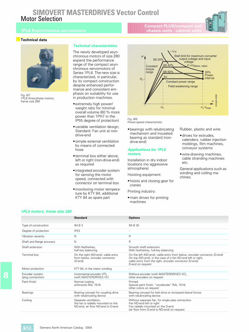
Siemens North American Catalog · 20048/12
SIMOVERT MASTERDRIVES Vector ControlMotor Selection
1PL6 Asynchronous servomotors
8
Compact PLUS/compact andchassis units · cabinet units
■Technical data
Fig. 8/71PL6 three-phase motors,frame size 280
Technical characteristics
The newly developed asyn-chronous motors of size 280 expand the performance range of the compact asyn-chronous servomotors of Series 1PL6. The new size is characterized, in particular, by its compact construction despite enhanced perfor-mance and consistent em-phasis on suitability for use in production machines.
•extremely high power/weight ratio for minimal overall volume (60 % more power than 1PH7 in the IP55 degree of protection)
•variable ventilation design; Standard: Fan unit at non-drive-end
•simple external ventilation by means of connected hose
•terminal box either above, left or right (non-drive-end) as required
• integrated encoder system for sensing the motor speed, connected with connector on terminal box
•monitoring motor tempera-ture by KTY 84; additional KTY 84 as spare part
Fig. 8/8 Power-speed characteristic
•bearings with relubricating mechanism and insulated bearing as standard (non-drive-end)
Applications for 1PL6 motors
Installation in dry indoor locations (no aggressive atmosphere)
Hoisting equipment:
•hoists and closing gear for cranes
Printing industry:
•main drives for printing machines
Rubber, plastic and wire:
•drives for extrudes,calenders, rubber injection moldings, film machines,conveyor systems
•wire-drawing machines, cable stranding machines etc.
General applications such as winding and coiling ma-chines.
1PL6 motors, frame size 280
Standard Options
Type of construction IM B 3 IM B 35
Degree of protection IP23 –
Vibration severity N R
Shaft and flange accuracy N R
Shaft extension With featherkey, half-key balancing
Smooth shaft extensionWith featherkey, full-key balancing
Terminal box On the right (ND-end), cable entry from below, encoder connector (D-end)
On the left (ND-end), cable entry from below, encoder connector (D-end)On top (ND-end), in the case of a fan ND-end left or right,cable entry from the right, encoder connector (D-end),D-end on request
Motor protection KTY 84, in the stator winding –
Encoder system(plug connection)
Incremental encoder HTL(with MASTERDRIVES VC)
Without encoder (with MASTERDRIVES VC),other encoders on request
Paint finish Normal coating anthracite RAL 7016
PrimedSpecial paint finish, “worldwide” RAL 7016,other colors on request
Bearings Bearing concept for coupling drive with relubricating device
Bearing concept for belt drive or increased lateral forces with relubricating device
Cooling Separate ventilation,the fan is radially mounted on theND-end, air flow ND-end to D-end
Without separate fan, for single pipe connectionFan ND-end left or rightFan radially mounted on the D-end (air flow from D-end to ND-end) on request
���������
�
�����
�����
�� ��
���������������������������������������������������������
� ���!"�����
�#��!������$�������
%�����$��&����������
#��!�������'������� (��
)�$����������
*
���
�
�
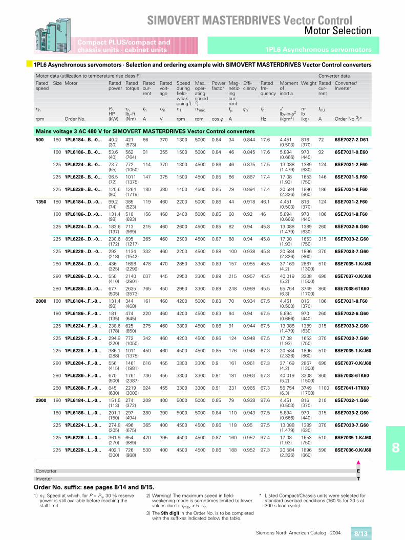
8
Siemens North American Catalog · 2004
SIMOVERT MASTERDRIVES Vector ControlMotor Selection
8/13
1PL6 Asynchronous servomotorsCompact PLUS/compact and chassis units · cabinet units
Order No. suffix: see pages 8/14 and 8/15.
■ 1PL6 Asynchronous servomotors · Selection and ordering example with SIMOVERT MASTERDRIVES Vector Control converters
Motor data (utilization to temperature rise class F) Converter data
Rated speed
nn
rpm
Size Motor
Order No.
Rated power
PnHP(kW)
Rated torque
�nlbf -ft(Nm)
Rated cur-rent
In
A
Rated volt-age
Un
V
Speedduringfield-weak-ening1)n1
rpm
Max.oper-atingspeed2)nmax.
rpm
Powerfactor
cos �
Mag-netiz-ingcur-rentI�
A
Effi-ciency
�n
Ratedfre-quency
fn
Hz
Momentofinertia
Jlbf -in-s2
(kgm2)
Weight
mlb(kg)
Rated cur-rent
InU
A
Converter/Inverter
Order No.3)*
Mains voltage 3 AC 480 V for SIMOVERT MASTERDRIVES Vector Control converters
500 180 1PL6184-..B..-0... 40.2(30)
421(573)
66 370 1300 5000 0.84 34 0.844 17.6 4.451(0.503)
816(370)
72 6SE7027-2.D61
180 1PL6186-..B..-0... 53.6(40)
562(764)
91 355 1500 5000 0.84 46 0.845 17.6 5.894(0.666)
970(440)
92 6SE7031-0.E60
225 1PL6224-..B..-0... 73.7(55)
772(1050)
114 370 1300 4500 0.86 46 0.875 17.5 13.088(1.479)
1389(630)
124 6SE7031-2.F60
225 1PL6226-..B..-0... 96.5(72)
1011(1375)
147 375 1500 4500 0.85 66 0.887 17.4 17.08(1.93)
1653(750)
146 6SE7031-5.F60
225 1PL6228-..B..-0... 120.6(90)
1264(1719)
180 380 1400 4500 0.85 79 0.894 17.4 20.584(2.326)
1896(860)
186 6SE7031-8.F60
1350 180 1PL6184-..D..-0... 99.2(74)
385(523)
119 460 2200 5000 0.86 44 0.918 46.1 4.451(0.503)
816(370)
124 6SE7031-2.F60
180 1PL6186-..D..-0... 131.4(98)
510(693)
156 460 2400 5000 0.85 60 0.92 46 5.894(0.666)
970(440)
186 6SE7031-8.F60
225 1PL6224-..D..-0... 183.6(137)
713(969)
215 460 2600 4500 0.85 82 0.94 45.8 13.088(1.479)
1389(630)
260 6SE7032-6.G60
225 1PL6226-..D..-0... 230.6(172)
895(1217)
265 460 2500 4500 0.87 88 0.94 45.8 17.08(1.93)
1653(750)
315 6SE7033-2.G60
225 1PL6228-..D..-0... 292(218)
1134(1542)
332 460 2200 4500 0.88 100 0.938 45.8 20.584(2.326)
1896(860)
370 6SE7033-7.G60
280 1PL6284-..D..-0... 436(325)
1696(2299)
478 470 2850 3300 0.89 157 0.955 45.5 37.169(4.2)
2867(1300)
510 6SE7035-1.K/J60
280 1PL6286-..D..-0... 550(410)
2140(2901)
637 445 2950 3300 0.89 215 0.957 45.5 40.019(5.2)
3308(1500)
690 6SE7037-0.K/J60
280 1PL6288-..D..-0... 677(505)
2635(3573)
765 450 2950 3300 0.89 248 0.959 45.5 55.754(6.3)
3749(1700)
860 6SE7038-6TK60
2000 180 1PL6184-..F..-0... 131.4(98)
344(468)
161 460 4200 5000 0.83 70 0.934 67.5 4.451(0.503)
816(370)
186 6SE7031-8.F60
180 1PL6186-..F..-0... 181(135)
474(645)
220 460 4200 4500 0.83 94 0.94 67.5 5.894(0.666)
970(440)
260 6SE7032-6.G60
225 1PL6224-..F..-0... 238.6(178)
625(850)
275 460 3800 4500 0.86 91 0.944 67.5 13.088(1.479)
1389(630)
315 6SE7033-2.G60
225 1PL6226-..F..-0... 294.9(220)
772(1050)
342 460 4200 4500 0.86 124 0.948 67.5 17.08(1.93)
1653(750)
370 6SE7033-7.G60
225 1PL6228-..F..-0... 386.1(288)
1011(1375)
450 460 4500 4500 0.85 176 0.948 67.3 20.584(2.326)
1896(860)
510 6SE7035-1.K/J60
280 1PL6284-..F..-0... 556(415)
1461(1981)
616 455 3300 3300 0.9 161 0.961 67.3 37.169(4.2)
2867(1300)
690 6SE7037-0.K/J60
280 1PL6286-..F..-0... 670(500)
1761(2387)
736 455 3300 3300 0.91 181 0.963 67.3 40.019(5.2)
3308(1500)
860 6SE7038-6TK60
280 1PL6288-..F..-0... 845(630)
2219(3009)
924 455 3300 3300 0.91 231 0.965 67.3 55.754(6.3)
3749(1700)
1100 6SE7041-1TK60
2900 180 1PL6184-..L..-0... 151.5(113)
274(372)
209 400 5000 5000 0.85 79 0.938 97.6 4.451(0.503)
816(370)
210 6SE7032-1.G60
180 1PL6186-..L..-0... 201.1(150)
297(494)
280 390 5000 5000 0.84 110 0.943 97.5 5.894(0.666)
970(440)
315 6SE7033-2.G60
225 1PL6224-..L..-0... 274.8(205)
496(675)
365 400 4500 4500 0.86 118 0.95 97.5 13.088(1.479)
1389(630)
370 6SE7033-7.G60
225 1PL6226-..L..-0... 361.9(270)
654(889)
470 395 4500 4500 0.87 160 0.952 97.4 17.08(1.93)
1653(750)
510 6SE7035-1.K/J60
225 1PL6228-..L..-0... 402.1(300)
726(988)
530 400 4500 4500 0.86 188 0.952 97.3 20.584(2.326)
1896(860)
590 6SE7036-0.K/J60
Converter E
Inverter T
1) n1: Speed at which, for P = Pn, 30 % reserve power is still available before reaching the stall limit.
2) Warning! The maximum speed in field-weakening mode is sometimes limited to lower values due to fmax < 5 · fn.
3) The 9th digit in the Order No. is to be completed with the suffixes indicated below the table.
* Listed Compact/Chassis units were selected for standard overload conditions (160 % for 30 s at 300 s load cycle).
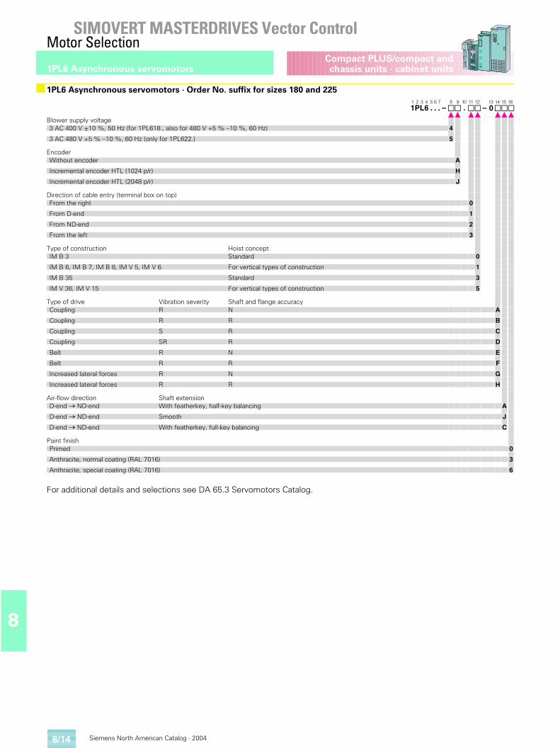
Siemens North American Catalog · 20048/14
SIMOVERT MASTERDRIVES Vector ControlMotor Selection
1PL6 Asynchronous servomotors
8
Compact PLUS/compact andchassis units · cabinet units
For additional details and selections see DA 65.3 Servomotors Catalog.
■1PL6 Asynchronous servomotors · Order No. suffix for sizes 180 and 2251 2 3 4 5 6 7 8 9 10 11 12 13 14 15 161PL6 . . . – . – 0
Blower supply voltage3 AC 400 V ±10 %, 50 Hz (for 1PL618., also for 480 V +5 % –10 %, 60 Hz) 4
3 AC 480 V +5 % –10 %, 60 Hz (only for 1PL622.) 5
EncoderWithout encoder A
Incremental encoder HTL (1024 p/r) H
Incremental encoder HTL (2048 p/r) J
Direction of cable entry (terminal box on top)From the right 0
From D-end 1
From ND-end 2
From the left 3
Type of construction Hoist conceptIM B 3 Standard 0
IM B 6, IM B 7, IM B 8, IM V 5, IM V 6 For vertical types of construction 1
IM B 35 Standard 3
IM V 36, IM V 15 For vertical types of construction 5
Type of drive Vibration severity Shaft and flange accuracyCoupling R N A
Coupling R R B
Coupling S R C
Coupling SR R D
Belt R N E
Belt R R F
Increased lateral forces R N G
Increased lateral forces R R H
Air-flow direction Shaft extensionD-end � ND-end With featherkey, half-key balancing A
D-end � ND-end Smooth J
D-end � ND-end With featherkey, full-key balancing C
Paint finishPrimed 0
Anthracite, normal coating (RAL 7016) 3
Anthracite, special coating (RAL 7016) 6
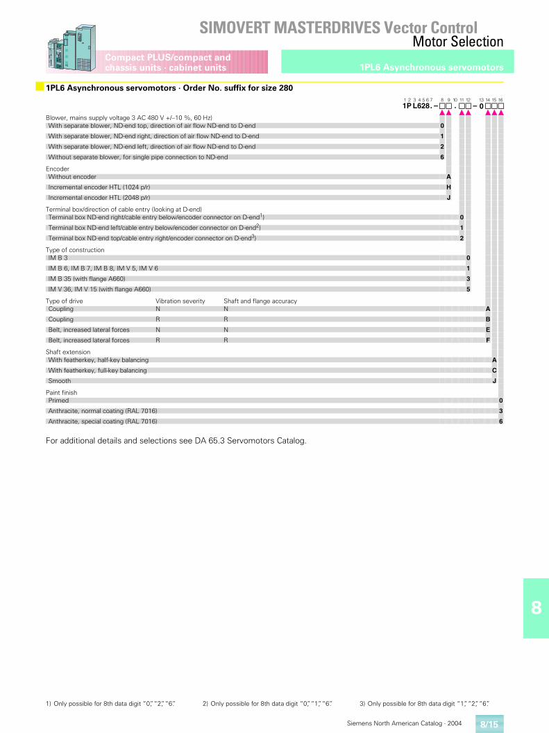
8
Siemens North American Catalog · 2004
SIMOVERT MASTERDRIVES Vector ControlMotor Selection
8/15
1PL6 Asynchronous servomotorsCompact PLUS/compact and chassis units · cabinet units
For additional details and selections see DA 65.3 Servomotors Catalog.
■1PL6 Asynchronous servomotors · Order No. suffix for size 2801 2 3 4 5 6 7 8 9 10 11 12 13 14 15 161P L628. – . – 0
Blower, mains supply voltage 3 AC 480 V +/–10 %, 60 Hz)With separate blower, ND-end top, direction of air flow ND-end to D-end 0
With separate blower, ND-end right, direction of air flow ND-end to D-end 1
With separate blower, ND-end left, direction of air flow ND-end to D-end 2
Without separate blower, for single pipe connection to ND-end 6
EncoderWithout encoder A
Incremental encoder HTL (1024 p/r) H
Incremental encoder HTL (2048 p/r) J
Terminal box/direction of cable entry (looking at D-end)Terminal box ND-end right/cable entry below/encoder connector on D-end1) 0
Terminal box ND-end left/cable entry below/encoder connector on D-end2) 1
Terminal box ND-end top/cable entry right/encoder connector on D-end3) 2
Type of constructionIM B 3 0
IM B 6, IM B 7, IM B 8, IM V 5, IM V 6 1
IM B 35 (with flange A660) 3
IM V 36, IM V 15 (with flange A660) 5
Type of drive Vibration severity Shaft and flange accuracyCoupling N N A
Coupling R R B
Belt, increased lateral forces N N E
Belt, increased lateral forces R R F
Shaft extensionWith featherkey, half-key balancing A
With featherkey, full-key balancing C
Smooth J
Paint finishPrimed 0
Anthracite, normal coating (RAL 7016) 3
Anthracite, special coating (RAL 7016) 6
1) Only possible for 8th data digit “0”, “2”, “6”. 2) Only possible for 8th data digit “0”, “1”, “6”. 3) Only possible for 8th data digit “1”, “2”, “6”.

Siemens North American Catalog · 20048/16
SIMOVERT MASTERDRIVES Vector ControlMotor Selection
Notes
8
Compact PLUS/compact andchassis units · cabinet units
A
A/1Siemens North American Catalog · 2004
A/2 Certificate of AdequacyTest/Factory certificate
A/3 Customer service
A/4 Customer service United States
A/9 Customer service Canada
A/11 Service & Support
A/12 Index
A/15 Conversion tables
Vector ControlAppendix
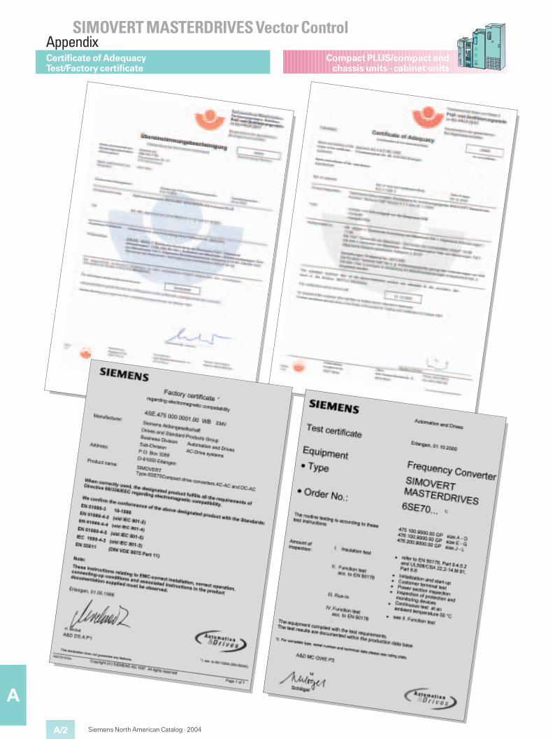
A/2
A
Siemens North American Catalog · 2004
Compact PLUS/compact andchassis units · cabinet units
Certificate of AdequacyTest/Factory certificate
SIMOVERT MASTERDRIVES Vector ControlAppendix
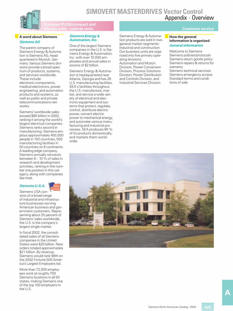
A/3
A
Compact PLUS/compact andchassis units · cabinet units
Siemens North American Catalog · 2004
SIMOVERT MASTERDRIVES Vector ControlAppendix · Overview
Siemens AG
The parent company ofSiemens Energy & Automa-tion is Siemens AG, head-quartered in Munich, Ger-many. Various Siemens divi-sions provide a broad spec-trum of products, systems,and services worldwide.These include:electronic components,medical electronics, powerengineering, and automationproducts and systems, aswell as public and privatetelecommunications net-works.
Siemens’worldwide salesexceed $85 billion in 2002,ranking it among the world’slargest electrical companies.Siemens ranks second inmanufacturing. Siemens em-ploys approximately 450,000people in 193 countries, 500manufacturing facilities in50 countries on 6 continents.A leading edge company,Siemens annually reinvestsbetween 8 – 10 % of sales inresearch and developmentactivities, ranking in the num-ber one position in this cat-egory, along with companieslike Intel.
Siemens U.S.A.
Siemens USA con-sists of a broad rangeof industrial and infrastruc-ture businesses servingAmerican business and gov-ernment customers. Repre-senting about 25 percent ofSiemens’sales worldwide,the U.S. is the company’slargest single market.
In fiscal 2002, the consoli-dated sales of all Siemenscompanies in the UnitedStates were $20 billion. Neworders totaled approximately$21 billion. By revenue,Siemens would rank 98th onthe 2002 Fortune 500 Amer-ica’s Largest Employers list.
More than 72,000 employ-ees work at roughly 700Siemens locations in all 50states, making Siemens oneof the top 100 employers inthe U.S.
Siemens Energy &Automation, Inc.
One of the largest Siemenscompanies in the U.S. is Sie-mens Energy & Automation,Inc. with over 10,000 em-ployees and annual sales inexcess of $2 billion.
Siemens Energy & Automa-tion is headquartered nearAtlanta, Georgia and has 28U.S. manufacturing facilities.SEA’s facilities throughoutthe U.S. manufacture, mar-ket, and service a wide vari-ety of electrical and elec-tronic equipment and sys-tems that protect, regulate,control, distribute electricpower, convert electricpower to mechanical energy,and automate various manu-facturing and industrial pro-cesses. SEA produces 85 %of its products domestically,and markets them world-wide.
Siemens Energy & Automa-tion products are sold in twogeneral market segments:industrial and construction.Our business units are orga-nized into five primary oper-ating divisions:Automation and MotionDivision, Power ConversionDivision, Process SolutionsDivision, Power Distributionand Controls Division, andIndustrial Services Division.
General information
Welcome to SiemensSiemens policies/protocolsSiemens return goods policySiemens repairs & returns forwarrantySiemens technical servicesSiemens emergency accessStandard terms and condi-tions of sale
A word about Siemens How the generalinformation is organized
Customer service
Compact PLUS/compact andchassis units · cabinet units
A/4
A
Siemens North American Catalog · 2004
Customer service United States
If you are a new SiemensDrive Products customer, wethank you for doing businesswith us. We will work hard toearn your trust and serveyour company as if it wereour own! If you are currentlydoing business with us, wethank you for the opportunityto grow with you.
Your primary contact point inthe United States for theMASTERDRIVES 6SE70 andall other Siemens drive prod-ucts are the Regional SalesOffices in the following loca-tions:
Atlanta
5405 Metric PlaceSuite 100Norcross, GA 30092Phone: 7 70-4 52-34 00Fax: 6 78-2 97-84 09
Dallas
501 Fountain Parkway2nd FloorGrand Prairie, TX 75050Phone: 8 17-6 40-49 29Fax: 8 17-6 40-96 40
Chicago
1901 N. Roselle RoadSuite 210Schaumburg, IL 60195Phone: 8 00-3 33-77 32Fax: 8 88-3 33-82 06
Houston
13105 NW FreewaySuite 950Houston, TX 77040Phone: 7 13-6 90-30 00Fax: 7 13-6 90-12 10
Kansas City
6201 College BlvdSuite 385Overland Park, KS 66211Phone: 9 13-4 98-42 00Fax: 9 13-4 98-42 40
Los Angeles
10655 Business Center DrSuite C1Cypress, CA 90630Phone: 7 14-2 52-30 00Fax: 7 14-5 27-72 30
Philadelphia
323 Norristown RoadSuite 210Amber, PA 19002Phone: 8 00-3 88-80 67Fax: 2 15-2 83-47 02
Minimum order
SE&A will assess a $25 han-dling fee on all ground ordersvalued at less than $400.
Freight
All of our original productshipments are F.O.B. point ofshipment. For standard prod-uct orders (excluding mo-tors) greater than $1000shipping from SE&A distribu-tion centers, charges arefreight allowed via methodselected by SE&A. For or-ders less than $1000, mo-tors, and non-standard prod-uct freight charges arepre-paid and added to the in-voice. All air freight chargesare the responsibility of thecustomer. Also, a customeraccount number is requiredfor third party billing offreight charges.
Emergency/Expedite fees
When customers require ur-gent delivery, several meth-ods of expedited delivery areavailable. Each is noted be-low along with the associ-ated charges:
NEXT FLIGHT OUT –This service provides sameday service where possible.In all cases, the expeditedsurcharge is $200. The cus-tomer is responsible for theassociated freight charges.
AFTER HOUR SERVICE –Orders placed for same dayshipment after 5:00 pm east-ern time and weekends/holi-days are subject to a $200surcharge. The customer isresponsible for the associ-ated freight charges.
SPARE PARTS FROMINTERNATIONALLOCATIONS –Siemens Energy & Automa-tion supports all SiemensDrive Products in the USA,regardless of their country oforigin. However, certainproducts may require ship-ment from an internationalemergency warehouse tomeet customer delivery re-quirements. All parts comingfrom the emergency ware-house will be charged an ad-ditional $300 surcharge, plusall freight costs. (The normal$25 surcharge will not apply).Siemens features an interna-tional emergency warehousethat can ship many partswithin 24 hours. Most partscan arrive in the UnitedStates within 2 – 4 days. YourCustomer Service or SalesRepresentative can check tosee if your part is in stock inthe emergency warehouse.
CUSTOMER PICK UP –All customer pick up orderswill be ready 2 hours after or-der is received, and must bepicked up within 24 hours.There is no additional chargefor this service.
Returns
Standard products fall underthe SE&A standard productreturn guidelines (below).Drive systems in cabinets,built to specification, motors,or other non-standard itemsdo not fall under this policy.Contact your Sales or Cus-tomer Service Representa-tive should you have ques-tions regarding return policy.
Welcome to Siemens US Siemens policies/protocols
SIMOVERT MASTERDRIVES Vector ControlAppendix · Overview
A/5
A
Compact PLUS/compact andchassis units · cabinet units
Siemens North American Catalog · 2004
Customer service United States
A Return Goods Request/Authorization (RGA) is re-quired to accompany allproducts returned toSiemens Energy & Automa-tion, Inc. (Siemens). This in-sures that the returned prod-uct is properly identified andcredited to your account. Un-authorized returns will be re-fused and returned to thecustomer with no liability toSiemens.
To provide our customersmaximum opportunity for in-ventory control, we have es-tablished three classes ofproduct returns:
� Accommodation return
� Siemens error return
� Non-Conforming productwarranty return
Product built to a customer’sspecifications cannot be re-turned for credit or exchange,subject to return only whenmaterial in Siemens’opinionhas express economic valuefor potential resale. If re-turned product is a result oferror(s) on the part ofSiemens, a full credit to youraccount will be allowed in-cluding freight charges. Allother returns, freight andhandling will be prepaid bycustomer.
In all cases except when al-leged personal injury/productliability is involved, your ac-count will be credited and acredit memo will be issuedwithin 15 working days fromreceipt of material. Credit isdetermined from the originalinvoice less restockingcharges.
Shipments returned withoutreferencing a returned goodsauthorization (RGA) numberwill be refused by Siemens.Siemens reserves the rightto rebill within 90 days fromour receipt of material basedon results of a physical in-spection of the product.
All claims for loss, damage ordelays in transit are to betransacted by the consigneedirectly with the carrier. Theissuance of this RETURNGOODS AUTHORIZATIONshall not be construed as anacceptance of any responsi-bility or liability on the part ofthe Company or as a waiverof any right to make a deter-mination as to the Com-pany’s responsibility.
Return goods authorizationswill be automatically cancel-led and have no further effectunless the returned goodsare received by the Companywithin 60 days after the dateof issuance.
Accommodation return
Accommodation returns pro-vide Siemens customers theopportunity to return productordered in error or in exces-sive quantities. Products eli-gible for return must be ofcurrent design and revisionlevel, unopened, unused, un-damaged, in the original“as-shipped”package andsecurely packed to be re-ceived by Siemens withoutdamage. Software may onlybe returned when the sealhas not been broken. Cus-tomized, engineered and/orenergized products may notbe returned without prior ap-proval and in Siemens’opin-ion have express economicvalue for potential resale.
Accommodation returns aresubject to a 20 % restockingcharge. After inspection ofthe returned product, youraccount will be credited forthe full invoice value of themerchandise, less restock-ing charges.
Customer should not deductcredit for products returnedfrom payments. Credit willbe processed within 15 daysof receipt of material. Thecustomer is responsible forcosts, including freight andhandling, for returned prod-uct to Siemens.
Siemens error return
Siemens error returns pro-vide customers the opportu-nity to return material within60 days of shipment in theevent of a Siemens order orshipment error. Original pur-chase order, invoice numberand date must be refer-enced. Products must be un-opened, unused, undam-aged, in the original “as-shipped”package or in staticprotection, and securelypacked to be received bySiemens without damage.Software may only be re-turned when seal has notbeen broken.
A return goods authorization(RGA) number will be issuedas authorization to return theproduct(s) to Siemens. Afterreceipt and inspection of thereturned product, a credit willbe issued for the full invoicevalue of the merchandise, ora replacement part provided.If the returned product(s)packaging is deemed notsaleable, a 20 % per itemcharge will be deducted fromthe credit issued.
Product should be returnedcollect by a Siemens ap-proved freight carrier orfreight charges may be as-sessed. Freight charges willbe credited if the entire ship-ment is returned due toSiemens error.
Non-Conforming productwarranty return
Non-Conforming productwarranty returns enableSiemens customers to re-turn product to the factory forreplacement, exchange orcredit if found to be non-con-forming in accordance withthe conditions of the Com-pany’s product warranty.
It is at Siemens discretionwhether to replace, repair orissue a credit for non-con-forming products. The war-ranty at no cost is condi-tional, and will be deter-mined by a technical valida-tion of the warranty once thenon-conforming item is re-ceived in our repair depart-ment or authorized servicecenter.
Siemens return goodspolicy
SIMOVERT MASTERDRIVES Vector ControlAppendix · Overview
Compact PLUS/compact andchassis units · cabinet units
A/6
A
Siemens North American Catalog · 2004
A Return Goods Request/Authorization (RGA) is re-quired to accompany allproducts returned toSiemens. This insures thatthe returned product is prop-erly identified and credited toyour account. Unauthorizedreturns will be refused andreturned to the customerwith no liability to Siemens.
Accommodation return
Accommodation returns pro-vide Siemens customers theopportunity to return productordered in error or in exces-sive quantities.
Procedures
A. Customer contacts Cus-tomer Service or insidesales person to initiate re-turn of material.
B. Products must be un-opened, unused, undam-aged, in the original“as-shipped”package orin static protection, andsecurely packed to be re-ceived by Siemens with-out damage. Softwaremay only be returnedwhen seal has not beenbroken.
C. Siemens Energy & Auto-mation will process yourrequest and a returngoods authorization (RGA)number will be issued asauthorization to return theproduct(s) to Siemens.
D. A copy of your approvedRGA and shipping instruc-tions will be faxed to you.
E. Customer ships productto designated Siemens lo-cation. A Return GoodsRequest/Authorization(RGA) is required toaccompany all materialreturned to Siemens.
F. The customer is responsi-ble for costs, includingfreight and handling, forreturned product toSiemens.
G.For all material returned inconformance with this pol-icy, a credit will be issuedpromptly by Siemenswithin 15 days of receiptof material.
H.Customers should nottake a deduction for mate-rial returned until Siemenshas issued the abovementioned credit.
I. All returned materials aresubject to inspection bySiemens. Returns notcomplying with this policywill be returned to theirsending location.
J. Stock products are sub-ject to a 20 % restockingcharge. Customized andengineered products aresubject to a negotiated re-stocking charge.
A Return Goods Request/Authorization (RGA) is re-quired to accompany allproducts returned toSiemens. This insures thatthe returned product is prop-erly identified and credited toyour account. Unauthorizedreturns will be refused andreturned to the customerwith no liability to Siemens.
Siemens error return
Siemens error returns pro-vide customers the opportu-nity to return material within60 days of shipment in theevent of a Siemens order orshipment error.
Procedures
A. Customer contacts Cus-tomer Service or insidesales person to initiate re-turn of material. Originalpurchase order number orinvoice number must beavailable for reference.
B. Products must be un-opened, unused, undam-aged, in the original“as-shipped”package orin static protection, andsecurely packed to be re-ceived by Siemens with-out damage. Softwaremay only be returnedwhen seal has not beenbroken.
C. Siemens will process yourrequest and a returngoods authorization (RGA)number will be issued asauthorization to return theproduct(s) to Siemens.
D. A copy of your approvedRGA and shipping instruc-tions will be faxed to you.
E. Customer ships productto designated Siemens lo-cation. A Return GoodsRequest/Authorization(RGA) is required to ac-company all material re-turned to Siemens.
F. Material should be re-turned following theRouting/Preferred Carrierinstructions located on theshipping instructions. Ifthese instructions are notfollowed freight chargesmay be assessed.
G.For all material returned inconformance with this pol-icy, a credit will be issuedwithin 15 days of receiptof material or a replace-ment part provided.
H.Customers should nottake a deduction for mate-rial returned. Siemens willissue a credit within 15days of receipt of material.
I. All returned materials aresubject to inspection bySiemens. Returns notcomplying with this policywill be returned to theirsending location.
J. An additional 15 % re-packaging charge will beapplied for returned mate-rial not suitable for resale,or returned in broken innercartons requiring inspec-tion and re-packaging. Nore-packaging charge of anykind will be applied whenmaterial is returned in un-damaged, original in-ner/outer cartons suitablefor resale.
A Return Goods Request/Authorization (RGA) is re-quired to accompany allproducts returned toSiemens. This insures thatthe returned product is prop-erly identified and credited toyour account. Unauthorizedreturns will be refused andreturned to the customerwith no liability to Siemens.
Non-Conforming productreturn (Drives)
Non-Conforming productwarranty returns enableSiemens customers to re-turn product to the factory forreplacement, exchange orcredit if found to be non-con-forming in accordance withthe conditions of the Com-pany’s product warranty.
Procedures
A. Customer contactsCustomer Service(1-8 00-3 33-74 21) to initi-ate return of material. Alist of products requestedto return and alleged fail-ure scenarios are commu-nicated to Siemens forprocessing.
B. Siemens will process yourrequest and a returngoods authorization (RGA)number will be issued asauthorization to return theproduct(s) to Siemens.
C. If the return is an emer-gency, e.g. your equip-ment is down, and thewarranty can be validatedcommercially, for ap-proved product categoriesSiemens will ship a re-placement part to you atno charge. If you shouldfail to return the non-con-forming part within 10days upon instructionsfrom Siemens, you will beinvoiced in full for the re-placement part.
D. A copy of your approvedRGA and shipping instruc-tions will be faxed to you.
Siemens return goodsprocess – Accomodation
Siemens return goodsprocess – Siemens error
Siemens return goodsprocess – Non-Conforming(Warranty)
Customer service United States
SIMOVERT MASTERDRIVES Vector ControlAppendix · Overview
A/7
A
Compact PLUS/compact andchassis units · cabinet units
Siemens North American Catalog · 2004
E. Customer ships productto designated Siemens lo-cation. A Return GoodsRequest/Authorization(RGA) is required to ac-company all material re-turned to Siemens.
F. Material should be re-turned following the in-structions located on theshipping instructionsaccompanying the RGAform.
G.Conforming products willbe shipped back to thecustomer.
H.For non-conforming mate-rial returned in confor-mance with this policy re-pair, exchange, or credit atSiemens discretion will beissued after an evaluationof the received material.
I. Customers should nottake a deduction for mate-rial returned.
J. All returned materials aresubject to inspection bySiemens. Returns notcomplying with this agree-ment will be returned totheir sending location.
Repair, replacement, andwarranty service
All claims for warranty repairor replacement must initiallybe made to Customer Ser-vice at 1-8 00-3 33-74 21.Should the problem not besolved over the phone, anRGA will be issued to returnthe defective part. If the war-ranty can be validated com-mercially (ship date fallswithin warranty period) a re-placement part can beshipped if available. SE&Awill pay for best way freighton such replacements. Thecustomer is responsible forexpedited freight delivery.
Once the defective producthas been returned, a techni-cal evaluation will be per-formed to validate the war-ranty. Should the unit befound to not meet warrantyrequirements, and purchaseorder will be requested fromthe customer.
If your warranty has expired,you may still want to take ad-vantage of our excellent re-pair and replacement ser-vice. Highly trained techni-cians perform incoming teststo determine the exact fail-ure, repair the equipment,and fully test prior to ship-ment back to the customer.However, if you elect, wemay be able to send you aremanufactured part for60 % of the list price of anew part less your applicablediscount on an exchange ba-sis. Remanufactured partscarry a ninety (90) day war-ranty. Your Sales or Cus-tomer Service Representa-tive can tell you which partsare included in our repair andreplacement program.Should you take advantageof this program, please notethat the original part must bereturned to SE&A within ten(10) days, or an invoice will beissued for the additional40 %.
Replacement warranty
Should a remanufactured re-placement of a defectiveitem be the solution to a war-ranty claim, the remanufac-tured part shall be under war-ranty for the duration of thewarranty of the original itemor ninety (90) days, which-ever is longer. A remanufac-tured part (other than originalwarranty replacement) car-ries a ninety (90) day war-ranty.
Extended warranty
Drive products offers an ex-tended warranty for all prod-ucts sold. An extended war-ranty of 12 months is offeredwith a surcharge of 5 % ofthe net price of the product.This extended warranty offeris only available if orderedprior to time of original ship-ment from Siemens.
Deferred warranty
Siemens also offers a de-ferred warranty for all prod-ucts sold. Commissioningmust also be purchased toinspect the condition of thedrive and supervise the startup. This deferred warrantyoffer is only available if or-dered prior to time of originalshipment from Siemens. Thedeferred warranty is offeredfor those applications thatwill have a delayed installa-tion period, but only require a12 month warranty from thedate of commissioning. Thechart below is a listing of thewarranty periods and fees forthe deferred warranty andthe extended warranty pro-grams.
The Technical Service Groupis responsible for technicalservice support for custom-ers, field service, and salesengineers. Requests forparts, equipment commis-sioning, emergency service,or routine maintenance arecoordinated and scheduledthrough this group.
Service coordination andtechnical support for a widevariety of drive products, in-cluding both domestic andinternational supplied units,are available from this team.Interfacing with the SiemensService Organization, otherSiemens Divisions, and sup-plier service facilities, thisgroup is the single point ofcontact in effectively provid-ing remote technical andfield service support.
Over the past year, an inter-nal survey showed thatgreater than 95 % of theproblems called in were re-solved over the telephone.This level of technical exper-tise has significantly reducedthe number of on-site ser-vice calls.
Technical Service is available24-hours, 7 days a week bydialing 1-8 00-3 33-74 21; askfor Drives Technical Servicesand the call will be channeledautomatically through a callcenter which activates theappropriate personnel forboth parts and technical sup-port.
To activate our Emergency/After Hours Service, simplydial 1-800-241-4453 and askfor Drives Technical Serviceand the call will be automati-cally transferred to our mes-sage service, who will in turnpage the On-Call Represen-tative.
Optional warranties
Months from Standardwarranty
6 monthdeferredwarranty
12 monthdeferredwarranty
Installation 12 12 12
Manufacturing 18 24 30
% of net 0 % 1 % 2 %
Siemens technicalservices
Siemens emergencyaccess
Customer service United States
SIMOVERT MASTERDRIVES Vector ControlAppendix · Overview
Compact PLUS/compact andchassis units · cabinet units
A/8
A
Siemens North American Catalog · 2004
Siemens Energy & Automation, Inc. („Seller“)
1. WARRANTY(a) Seller warrants that on the date of shipment the goods are of the kind and
quality described herein and are free of nonconformities in workmanshipand material. This warranty does not apply to goods delivered by Sellerbut manufactured by others.
(b) Buyer’s exclusive remedy for a nonconformity in any item of the goodsshall be the repair or the replacement (at Seller’s option) of the item andany affected part of the goods. Seller’s obligation to repair or replace shallbe in effect for a period of one (1) year from initial operation of the goodsbut not more than eighteen (18) months from Seller’s shipment of thegoods, provided Buyer has sent written notice within that period of timeto Seller that the goods do not conform to the above warranty. Repairedand replacement parts shall be warranted for the remainder of the originalperiod of notification set forth above, but in no event less than 12 monthsfrom repair or replacement. At its expense, Buyer shall remove and shipto Seller any such nonconforming items and shall reinstall the repaired orreplaced parts. Buyer shall grant Seller access to the goods at all reason-able times in order for Seller to determine any nonconformity in thegoods. Seller shall have the right of disposal of items replaced by it. IfSeller is unable or unwilling to repair or replace, or if repair or replacementdoes not remedy the nonconformity, Seller and Buyer shall negotiate anequitable adjustment in the contract price, which may include a full re-fund of the contract price for the nonconforming goods.
(c) SELLER HEREBY DISCLAIMS ALL OTHER WARRANTIES, EXPRESS ORIMPLIED, EXCEPT THAT OF TITLE. SPECIFICALLY, IT DISCLAIMS THEIMPLIED WARRANTIES OF MERCHANTABILITY, FITNESS FOR A PAR-TICULAR PURPOSE, COURSE OF DEALING AND USAGE OF TRADE.
(d) Buyer and successors of Buyer are limited to the remedies specified inthis article and shall have no others for a nonconformity in the goods.Buyer agrees that these remedies provide Buyer and its successors witha minimum adequate remedy and are their exclusive remedies, whetherBuyer’s or its successors’ remedies are based on contract, warranty, tort(including negligence), strict liability, indemnity, or any other legal theory,and whether arising out of warranties, representations, instructions, in-stallations, or non-conformities from any cause.
(e) Note: This article 1 does not apply to any software which may be fur-nished by Seller. In such cases, the attached Software License Adden-dum applies.
2.PATENTSSeller shall pay costs and damages finally awarded in any suit against Buyeror its vendees to the extent based upon a finding that the design or construc-tion of the goods as furnished infringes a United States patent (except in-fringement occurring as a result of incorporating a design or modification atBuyer’s request), provided that Buyer promptly notifies Seller of any chargeof infringement, and Seller is given the right at its expense to settle suchcharge and to defend or control the defense of any suit based upon suchcharge. Seller shall have no obligation hereunder with respect to claims,suits or proceedings, resulting from or related to, in whole or in part, (i) theuse of software or software documentation, (ii) compliance with Buyer’sspecifications, (iii) the combination with, or modification of, the goods afterdelivery by Seller, or (iv) the use of the goods, or any part thereof, in the prac-tice of a process. THIS ARTICLE SETS FORTH SELLER’S ENTIRE LIABILITYWITH RESPECT TO PATENTS.
3.PERFORMANCE; DELAYSTimely performance by Seller is contingent upon Buyer’s supplying to Seller,when needed, all required technical information and data, including drawingapprovals, and all required commercial documentation. If Seller suffers delayin performance due to any cause beyond its reasonable control, the time ofperformance shall be extended a period of time equal to the period of thedelay and its consequences. Seller will give to Buyer notice within a reason-able time after Seller becomes aware of any such delay.
4.SHIPMENT, TITLE AND RISK OF LOSSUnless the delivery terms of this contract expressly provide for F.O.B. desti-nation, shipping/delivery will be F.O.B. Seller’s point of shipment with title tothe goods and risk of loss or damage passing to Buyer at that point. Buyerwill be responsible for shipment during transit and for filing any damage orloss claims directly with the carrier. Seller may make partial shipments.
5.TAXESAny applicable duties or sales, use, excise, value-added or similar taxes willbe added to the price and invoiced separately (unless an acceptable exemp-tion certificate is furnished).
6.TERMS OF PAYMENT
(a) Unless otherwise stated, all payments shall be in United States dollars,and a pro rata payment shall become due as each shipment is made. Ifshipment is delayed by Buyer, date of notice of readiness for shipmentshall be deemed to be date of shipment for payment purposes.
(b) On late payments, the contract price shall, without prejudice to Seller’sright to immediate payment, be increased by 1 1/2 % per month on theunpaid balance, but not to exceed the maximum permitted by law.
(c) If any time in Seller’s judgment Buyer is unable or unwilling to meet theterms specified, Seller may require satisfactory assurance or full or partialpayment as a condition to commencing or continuing manufacture ormaking shipment, and may, if shipment has been made, recover thegoods from the carrier, pending receipt of such assurances.
7. NONCANCELLATIONBuyer may not cancel or terminate for convenience, or direct suspension ofmanufacture, except with Seller’s written consent and then only upon termsthat will compensate Seller for its engineering, fabrication and purchasingcharges and any other costs relating to such cancellation, termination or sus-pension, plus a reasonable amount for profit.
8.NUCLEARBuyer represents and warrants that the goods covered by this contract shallnot be used in or in connection with a nuclear facility or application. If Buyeris unable to make such representation and warranty, then Buyer agrees to in-demnify and hold harmless Seller and to waive and require its insurers towaive all right of recovery against Seller for any damage, loss, destruction, in-jury or death resulting from a „nuclear incident“, as that term is defined in theAtomic Energy Act of 1954, as amended, whether or not due to Seller’s neg-ligence.
9.LIMITATION OF LIABILITYNeither Seller, nor its suppliers shall be liable, whether in contract, warranty,failure of a remedy to achieve its intended or essential purposes, tort (includ-ing negligence), strict liability, indemnity or any other legal theory, for loss ofuse, revenue or profit, or for costs of capital or of substitute use or perfor-mance, or for indirect, special, liquidated, incidental or consequential dam-ages, or for any other loss or cost of a similar type, or for claims by Buyer fordamages of Buyer’s customers. Seller’s maximum liability under this con-tract shall be the contract price. Buyer and Seller agree that the exclusionsand limitations set forth in this article are separate and independent fromany remedies which Buyer may have hereunder and shall be given full forceand effect whether or not any or all such remedies shall be deemed to havefailed of their essential purpose.
10. GOVERNING LAW AND ASSIGNMENTThe laws of the State of Georgia shall govern the validity, interpretation andenforcement of this contract, without regard to its conflicts of law principles.The application of the United Nations Convention on Contracts for the Inter-national Sale of Goods shall be excluded. Assignment may be made onlywith written consent of both parties; provided, however, Seller may assignto its affiliate without Buyer’s consent.
11. ATTORNEY FEESBuyer shall be liable to Seller for any attorney fees and costs incurred bySeller in enforcing any of its rights hereunder.
12. DISPUTESEither party may give the other party written notice of any dispute arising outof or relating to this contract and not resolved in the normal course of busi-ness. The parties shall attempt in good faith to resolve such disputepromptly by negotiations between executives who have authority to settlethe dispute. If the matter has not been resolved within 60 days of the notice,either party may initiate non-binding mediation of the dispute.
13. STATUTE OF LIMITATIONSTo the extent permitted by applicable law, any lawsuit for breach of contract,including breach of warranty, arising out of the transactions covered by thiscontract, must be commenced not later than twelve (12) months from thedate the cause of action accrued.
14. PRICESIn the event of a price increase or decrease, the price of goods on order willbe adjusted to reflect such increase or decrease. This does not apply to ashipment held by request of Buyer. Goods already shipped are not subject toprice increase or decrease. Orders on a bid or contract basis are not subjectto this article. Seller’s prices include the costs of standard domestic packingonly. Any deviation from this standard packing (domestic or export), includ-ing U.S. Government sealed packing, will result in extra charges. To deter-mine such extra charges, consult Seller’s sales offices. Orders of less than$400 will be charged a $25 handling fee.
15. ADDITIONAL TERMS OF PAYMENT
(a) Invoice payment terms are as shown on latest discount sheets as issuedfrom time to time. Cash discounts are not applicable to notes or trade ac-ceptances, to prepaid transportation charges when added to Seller’s in-voices or to discountable items if there are undisputed past due items onthe account. Portions of an invoice in dispute should be deducted and thebalance remitted with a detailed explanation of the deduction. Cash dis-counts will only be allowed on that portion of the invoice paid within thenormal discount period.
(b) Freight will be allowed to any common-carrier free-delivery point withinthe United States, excluding Alaska and Hawaii, on shipments exceeding$1,000 net or more providing Seller selects the carrier. On shipments toAlaska and Hawaii, freight will be allowed to dockside at the listed port ofdebarkation nearest the destination point on shipments of $1,000 net ormore. Buyer shall pay all special costs such as cartage, stevedoring andinsurance. Special freight allowances are as shown on latest discountsheets as issued from time to time. Cataloged weights are estimated,not guaranteed. Seller assumes no responsibility for tariff classificationson carriers.
16. CHANGES IN LAWS AND REGULATIONSSeller’s prices and timely performance are based on all applicable laws,rules, regulations, orders, codes, standards or requirements of governmen-tal authorities effective on the date of Seller’s proposal. Any change to anylaw, rule, regulation, order, code, standard or requirement which requires anychange hereunder shall entitle Seller to an equitable adjustment in the pricesand any time of performance.
Standard terms and conditions of sale (9/1/2001)
Customer service United States
SIMOVERT MASTERDRIVES Vector ControlAppendix · Overview
A/9
A
Compact PLUS/compact andchassis units · cabinet units
Siemens North American Catalog · 2004
As a subsidiary of SiemensAG, Siemens in Canadadraws on the global networkof innovation to generate rev-enues of more than $2 bil-lion. Good news for our econ-omy and our way of life. Fromits corporate headquarters inMississauga, Ontario,Siemens employs 6,300 Ca-nadians coast to coast, de-veloping solutions for the en-tire country. And exportingsolutions around the world,in the amount of 60 % of Ca-nadian production.
Call 1-8 88-3 03-33 53 fortechnical service, spareparts, return materialauthorizations and warrantyissues.
Customer Interaction Centrefor after sales support:provides a national, 24hours, 7 days a week, bilin-gual service to respond to allcustomer calls involving re-turn material authorizations,service requests, spare partsorders and warranty issuesas well as product com-ments. The Customer Inter-action Centre can also becontacted via email [email protected].
Siemens technical servicessupport all Siemens drives inCanada. Throughout CanadaSiemens technical servicesprovide technical servicesupport and fields service.Request for equipment com-missioning, emergency ser-vice, and routine mainte-nance are coordinated andscheduled through thisgroup. If technical service isrequired, please call1-8 88-3 03-33 53.
With over a hundred years’experience in providing reli-ability, safety, and service,Siemens is there.
In case a defective partneeds to be returned toSiemens Canada Ltd. for re-pair or credit, please followthese instructions.
Parts sent to Siemens Can-ada Ltd. not using the proce-dures outlined below maycause the warranty to bevoided or improper credit tobe issued.
1. Call 1-8 88-3 03-33 53 andask for warranty/defectiveproduct returns. The callwill be forwarded to thenext available CustomerService Representative(CSR). The CSR will pro-vide instruction about howto complete a Field In-spection Report & RMARequest Form (FIR&RMA)with the following impor-tant information. TheFIR&RMA form shall befaxed to the advised ad-dress on the form.
a) Company name, con-tact address
b) Original purchase ordernumber
c) Model number
d) Serial number
e) Detailed fault descrip-tion
2. A Return Material Authori-zation form (RMA) will beissued within 24 hours ofreceipt of your FIR&RMA.The copy of RMA formmust accompany thelisted items being re-turned to Siemens. Anyitem received without theappropriate RMA docu-mentation will not be ac-cepted and returned tothe sender collect.
RMAs are valid for 30 daysfrom date issued. Any re-turns received after 30days will be returned tothe sender at their ex-pense. A new RMA willhave to be requested forthe same items before be-ing returned.
3. Electrostatically SensitiveDevices (ESD) handling isto be observed for all elec-tronic- based products.Please use anti-static bagswhen shipping printed cir-cuit boards back toSiemens. Otherwise thewarranty is null or void.
4. If it is a warranty claim, theitem will be inspected andthe warranty validated,upon receipt. Then theitem will be repaired or re-placed as appropriate andwill be returned at nocharge.
5. If it is a non-warranty case,an inspection fee will becharged to cover the costof evaluating the defectivereturn for possible repairwork.
The item will be inspectedand the CSR will issue aquotation for repair. Uponreceipt or Purchase Order,the item will be repaired,tested and returned.
Drive products offer an ex-tended warranty for all prod-ucts sold. The extended war-ranty of 12 months is offeredwith a surcharge of 5 % ofthe net price of the product.This extended warranty isonly available if ordered priorto time of shipment fromSiemens.
The Siemens technical train-ing centre is committed toproviding quality technicalcourses in the CanadianElectrical and AutomationMarkets. Siemens developsand gears each course andthe related materials to be ef-fective in the competitive Ca-nadian marketplace.
Siemens offers 20 qualitycourses with expert instruc-tors and dedicated supportstaff. Our practical, but chal-lenging “hands-on”coursesprovide the ultimate arenafor effective learning and in-formation retention. Trainingis offered in St. Johns,Dartmouth, Montreal,Mississauga, Calgary, Ed-monton, and Vancouver.Custom on-site training tai-lored to customer require-ments and specific requestsare also performed.
Following each course, thestudents can feel confidentthat they are equipped withthe expert knowledge andcapabilities to effectively sellor support the product.
Registration or questions oncourse content can be madeto the Training Centre by thefollowing:
Elizabeth IsaacTraining AdministratorTel.: 9 05-8 19-58 00 Ext.22 19Fax: 9 05-8 19-58 22Email:[email protected]
Months from Standard warranty Extended warranty
Installation 12 24
Manufacturing 18 30
% of net 0 % 5 %
Siemens after salessupport
Siemens technical service
Welcome to SiemensCanada Ltd.
Siemens repairs andreturns
Siemens technical training
Siemens extendedwarranty
Customer service Canada
SIMOVERT MASTERDRIVES Vector ControlAppendix · Overview
Compact PLUS/compact andchassis units · cabinet units
A/10
A
Siemens North American Catalog · 2004
The following terms and conditions of sale shall apply to any sale of goods andservices by Siemens Canada Limited (hereinafter called “Siemens“). Purchasershall be deemed to have full knowledge of the terms and conditions herein andsuch terms and conditions shall be binding if either the goods and services re-ferred to herein are delivered to and accepted by Purchaser, or if Purchaser doesnot within five days from the date hereof deliver to Siemens written objection tosaid terms and conditions or any part thereof.
1. GENERALIn the event of any conflict or inconsistency between the terms and condi-tions of sale herein and the terms and conditions contained in Purchaser’sorder or in any other form issued by Purchaser, whether or not any such formhas been acknowledged or accepted by Siemens, Siemens’ terms and con-ditions herein shall prevail. No waiver, alteration or modification of theseterms and conditions shall be binding upon Siemens unless made in writingand signed by a duly authorized representative of Siemens.
2.QUOTATIONSUnless otherwise stated, Siemens’quotation shall be null and void unlessaccepted by Purchaser within thirty (30) days from the date of quotation.
3.PRICES/COST OF TRANSPORTATIONAll quoted prices are based on the current exchange rates, tariffs and costsof manufacture. Unless otherwise stated in the quotation, quoted prices aresubject to change by Siemens with or without notice until Purchaser’s ac-ceptance. Prices are subject to correction for error. Unless otherwise stated,all prices are f.o.b. factory and include domestic packing. Customary meth-ods of transportation shall be selected by Siemens and such transportationwill be at Purchaser’s expense. Special methods of transportation will beused upon Purchaser’s request and at Purchaser’s additional expense pro-vided reasonable notice of Purchaser’s transportation requirements aregiven by Purchaser to Siemens prior to shipment.
4.TAXESPrices do not include Goods & Services Tax, Provincial or Municipal sales,use, value-added or similar tax. Accordingly, in addition to the price specifiedherein, the amount of any present or future sales, use, value-added or similartax applicable to the sale of the goods hereunder to or the use of such goodsby Purchaser shall be paid by Purchaser to the entire exoneration ofSiemens.
5.DELIVERYDelivery schedules are approximate and are based on prevailing marketconditions applicable respectively at the time of Siemens’quotation andSiemens’acceptance of Purchaser’s order. Delivery shall also depend on theprompt receipt by Siemens of the necessary information to allow mainte-nance of the manufacturer’s engineering and manufacturing schedules.Siemens may extend delivery schedules or may, at its option, cancel Pur-chaser’s order in full or in part without liability other than to return any de-posit or prepayment which is unearned by reason of the cancellation.
6.FORCE MAJEURESiemens shall not be responsible or liable for any loss or damage incurred byPurchaser herein resulting from causes beyond the reasonable control ofSiemens including, but without limitation, acts of God, war, invasion, insur-rection, riot, the order of any civil or military authority, fire, flood, weather,acts of the elements, delays in transportation, unavailability of equipment ormaterials, breakdown, sabotage, lock-outs, strikes or labour disputes, faultycastings or forgings, or the failure of Siemens’suppliers to meet their deliv-ery promises. The acceptance of delivery of the equipment by Purchasershall constitute a waiver of all claims for loss or damage due to any delaywhatsoever.
7. SHIPMENT/DAMAGES OR SHORTAGES IN TRANSPORT/RISKExcept for obligations stated under “Warranty“herein, Siemens’ responsibil-ity for goods ceases upon delivery to the carrier. In the event of loss or dam-age during shipment, Purchaser’s claim shall be against the carrier only.Siemens will, however, give Purchaser any reasonable assistance to secureadjustment of Purchaser’s claim against the carrier provided immediate no-tice of such claim is given by Purchaser to Siemens. Claims for shortagesmust be made in writing within ten (10) days after receipt of goods by Pur-chaser. If Siemens does not receive written notification of such shortageswithin such ten (10) days, it shall be conclusively presumed that the goodswere delivered in their entirety. Unless agreed upon otherwise in writing,Siemens reserves the right to make partial shipments and to submit in-voices for partial shipments.
8.TITLETitle to the goods or any part thereof shall not pass from Siemens to Pur-chaser until all payments due hereunder have been duly made in cash, ex-cept as otherwise expressly stipulated herein. The goods shall be and re-main personal or moveable property, notwithstanding their mode of attach-ment to realty or other property. If default is made in any of the paymentsherein, Purchaser agrees that Siemens may retain all payments which havebeen made on account of the purchase price as liquidated damages, andSiemens shall be free to enter the premises where the goods may be lo-cated and remove them as Siemens’property, without prejudice to Siemens’right to recover any further expenses or damages Siemens may suffer byreason of such nonpayment.
9.LIABILITYSiemens shall not be liable for and shall be held harmless by Purchaser fromany damage, losses or claims of whatever kind, contractual or delictual, con-sequential or incidental, direct or indirect, arising out of, in connection with orresulting from the sale governed hereby or the goods, including, but withoutlimitation, the manufacture, repair, handling, installation, possession, use,operation or dismantling of the goods and any and all claims, actions, suits,and proceedings which may be instituted in respect to the foregoing.
10. WARRANTYGoods sold hereunder are covered by a warranty against defects in materialand workmanship provided the goods and services are subjected to normaluse and service. The applicable warranty period is twelve (12) months fromthe date of installation or eighteen (18) months from shipping date to Pur-chaser of any item of the goods, whichever occurs first, or any other war-ranty period otherwise stipulated in writing by Siemens under this sale. Forcomponents not supplied by Siemens, the original manufacturer’s warrantyshall apply to the extent assignable by Siemens. The obligation under thiswarranty is limited to the repair or replacement, at Siemens’option, of defec-tive parts f.o.b. point of shipment provided that prompt notice of any defectis given by Purchaser to Siemens in writing within the applicable warrantyperiod and that upon the Purchaser’s return of the defective parts toSiemens or, if designated by Siemens, to the location where the works aremade, properly packed and with transportation charges prepaid by Pur-chaser, an inspection thereof shall reveal to Siemens’satisfaction that Pur-chaser’s claim is valid under the terms of this warranty. Purchaser shall as-sume all responsibility and expense for dismantling, removal, re-installationand freight in connection with the foregoing. The same obligations and con-ditions extend to replacement parts furnished by Siemens hereunder.Siemens does not assume liability for installation, labour or consequentialdamages. Siemens makes no warranty other than the one set forth herein.All other warranties, legal, expressed or implied, including but not limited toany expressed or implied warranty of merchantability, of fitness for the in-tended use thereof or against infringement are hereby expressly excluded.
The applicable warranty ceases to be effective if the goods are altered or re-paired other than by persons authorized or approved by Siemens to performsuch work. Repairs or replacement deliveries do not interrupt or prolong theterm of the warranty. The warranty ceases to be effective if Purchaser fails tooperate and use the goods sold hereunder in a safe and reasonable mannerand in accordance with any written instructions from the manufacturers.
11. INSTALLATIONUnless otherwise expressly stipulated, the goods shall be installed by and atthe risk and expense of Purchaser. In the event that Siemens is requested tosupervise such installation, Siemens’ responsibility shall be limited to exer-cising that degree of skill customary in the trade in supervising installationsof the same type. Purchaser shall remain responsible for all other aspects ofthe work including compliance with the local regulations.
12. RETURNED GOODSNo goods may be returned to Siemens without Siemens’prior written per-mission. Siemens reserves the right to decline all returns or to accept themsubject to a handling/restocking charge. Even after Siemens has authorizedthe return of goods for credit, Siemens reserves the right to adjust theamount of any credit given to Purchaser on return of the goods based on theconditions of the goods on arrival in Siemens’warehouse. Credit for returnedgoods will be issued to Purchaser only where such goods are returned byPurchaser and not by any subsequent owner of the goods. Goods will beconsidered for return only if they are in their original condition and packaging.
13. TERMS OF PAYMENTUnless otherwise stated, invoices on “open account“shipment are payablewithin thirty (30) days of invoice date. Unless specifically provided, no cashdiscount shall be available to Purchaser. When cash discount is offered, thediscount price is computed from the date of invoice. Siemens does not offercash discount on C.O.D. shipments. Should payment not be made toSiemens when due, Siemens reserves the right, until the price has beenfully paid in cash, to charge Purchaser with interest on such overdue pay-ments at the rate of eighteen percent (18 %) per annum. The charging ofsuch interest shall not be construed as obligating Siemens to grant any ex-tension of time in the terms of payment.
14. CHANGES AND CANCELLATIONOrders accepted by Siemens are not subject to changes or cancellation byPurchaser, except with Siemens’written consent. In such cases whereSiemens authorizes changes or cancellation, Siemens reserves the right tocharge Purchaser with reasonable costs based upon expenses already in-curred and commitments made by Siemens, including, without limitation,any labour done, material purchased and also including Supplier’s usual over-head and reasonable profit and cancellation charges from Siemens’supp-liers.
15. THE AGREEMENTAn acceptance and official confirmation of Purchaser’s order by Siemensshall constitute the complete agreement, subject to the terms and condi-tions of sale herein set forth, and shall supersede all previous quotations, or-ders or agreements. The law of the Province of Ontario shall govern the va-lidity, interpretation and enforcement of these terms and conditions of saleand of any contract of which these terms and conditions are a part.
General terms and conditions of sale
Customer service Canada
SIMOVERT MASTERDRIVES Vector ControlAppendix · Overview
A/11
A
Compact PLUS/compact andchassis units · cabinet units
Siemens North American Catalog · 2004
Our services for every phase of your project
In the face of harsh competi-tion you need optimum con-ditions to keep ahead all thetime:A strong starting position. Asophisticated strategy andteam for the necessary sup-port – in every phase.Service & Support fromSiemens provides this sup-port with a complete rangeof different services for auto-mation and drives.
In every phase: from plan-ning and startup to mainten-ance and upgrading.
Our specialists know whenand where to act to keep theproductivity and cost-effec-tiveness of your system run-ning in top form.
Service On Site
With Service On Site we of-fer services for startup andmaintenance, essential forensuring system availability.
In the United States, calltoll-free:Tel.: +1 800 333 7421
In Canada, call:Tel.: +1 888 303 3353
In Germany, call:Tel.: 0180 50 50 4441)
Repairs and Spare Parts
In the operating phase of amachine or automation sys-tem we provide a compre-
hensive repair and spareparts service ensuring thehighest degree of operatingsafety and reliability.
In the United States, calltoll-free:Tel.: +1 800 241 4453
In Canada, call:Tel.: +1 888 303 3353
In Germany, call:Tel.: 0180 50 50 4481)
Configuration and Software Engineering
Support in configuring anddeveloping with customer-oriented services fromactual configuration to imple-mentation of the automationproject.1)
Online Support
The comprehensive informa-tion system available roundthe clock via the Internet ran-ging from Product Supportand Service & Support servi-ces to Support Tools in theShop.
http://www.siemens.com/automation/service&
Technical Support
Competent consulting intechnical questions coveringa wide range of customer-oriented services for all ourproducts and systems.
In the United States, calltoll-free:Tel.: +1 800 333 7421Fax: +1 423 262 2200E-Mail: [email protected]
In Canada, call:Tel.: +1 888 303 3353E-Mail: [email protected]
In Europe (headquarters), call:Tel.: +49 (0)180 50 50 222Fax: +49 (0)180 50 50 223E-Mail: [email protected]
In Asia:Tel.: +86 10 6475 7575Fax: +86 10 6474 7474E-Mail: [email protected]
Optimization and Upgrading
To enhance productivity andsave costs in your project weoffer high-quality services inoptimization and upgrading.1)
Technical Consulting
Support in the planning anddesigning of your projectfrom detailed actual-stateanalysis, target definition andconsulting on product andsystem questions right tothe creation of the automa-tion solution.1)
1) For the right partner for your country, please look at our Internet site at:http://www.siemens.com/automation/service&support
SIMOVERT MASTERDRIVES Vector ControlAppendix · Service & Support
Compact PLUS/compact andchassis units · cabinet units
A/12
A
Siemens North American Catalog · 2004
Page120 V AC I/0 board 6/93230 V AC operation 6/43 contactor bypass 4/7; 4/113 contactor isolated transfer 4/193 contactor manual transfer 4/19
A
AC contactorsfor converters from 3/38for rectifier units from 3/58for rectifier/regenerative units from 3/62
Adapter APMU for cabinet-door mounting 3/86Adapter board ADB 3/82; 4/12AFE inverter 3/18; 3/20; 6/22AFE supply connecting module 3/18; 3/54; 6/22Analog tachometer interface ATI 4/12Approvals 3/3Asynchronous servomotors from 8/2
1PH7 from 8/21PL6 from 8/11
ATI analog tachometer interface 4/12Automatic restart 6/15; 6/31Autotransformer 3/36; 3/65;
from 3/77; 6/46
B
Basic enclosure 4/5; 4/9Basic interference suppression 3/18; 3/57; 6/23Basic setting 6/15Bearing currents 6/7BICO data sets 6/32Block diagrams 6/27Brake cables 3/70Brake operation 6/31Braking units and braking resistors from 3/32; 6/48;
4/18Bus adapter for the electronics box LBA 3/82; 6/53
C
Cabinet units from 4/2Cabinet-unit earthing 6/5Cable protection fuses
for converters from 3/39for rectifier units from 3/59for rectifier/regenerative units from 3/62
Cables for motor connection from 3/68; 6/49CAN 2/5; 2/11; 3/80;
4/12Capacitor module for Compact PLUS units 3/66; 6/26CBC board for CANsee CANCBD communication board see DeviceNetCBP board for PROFIBUS DPsee PROFIBUS DPCertificate of Adequacy A/2Certificates A/2Circuit breaker 4/6; 4/10; 4/15Clean power filter 3/57; 6/23Closed-loop control characteristics 2/3; 6/27Closed-loop control functions 2/3; 6/27Commissioning, parameterization and diagnosiswith DriveMonitor 2/10; 3/87Communication from 2/4;
from 6/55Communication boards CBC/CBD/CBP/SLBsee CAN/DeviceNet/PROFIBUS DP/SIMOLINKCommutating reactors 6/46
for converters from 3/38for rectifier units from 3/60for rectifier/regenerative units from 3/64
Compact and chassis units from 3/8Compact PLUS units from 3/4; 6/11Compendium 5/4Components 3/36
for braking units and braking resistors 3/66for converters from 3/38for converters and inverters from 3/42for inverters from 3/47for rectifier units from 3/58for AFE units from 3/54for rectifier/regenerative units from 3/62
Components in the DC link 3/37; 6/47Components line-side 3/36; 6/46Components load-side 3/37; 6/49
PageConfiguration program Drive ES 2/13; 3/87; 6/53Constant load torque 6/6Contactors 4/7; 4/11; 4/18Contactor for isolating the inverter from theDC bus from 3/49Contents 1/4Control connections from 6/34Control functions 2/3; 6/27Control functions, open-loop and closed-loop 2/3; 6/27Control performance 6/30Control terminal strips CUVC, CUR, CUSAand X9 2/9; 6/34; 6/38;
6/42; 6/43; 6/44Converters 2/2
AFE 3/18; 6/22Air-cooled 3/4Cabinet units 4/2Options 3/5; 3/9; 3/19Water-cooled 6/5
Cooling circuit 6/5Correction factors 6/3Coupling module 3/66Current reduction 6/3Customer service Canada from A/9Customer service United States from A/4
D
DC braking 6/31DC link components 3/37; 6/47Demonstration case 5/7DeviceNet 3/80; 4/12; 6/61Digital tachometer interface DTI 3/85; 4/12; 6/91DIN rail for mounting the interface module 3/67Disconnect switch 4/6; 4/10; 4/16;
4/17Documentation overview 5/2Drive circuit breaker 4/15Drive dimensioning 6/6Drive ES 2/13; 3/87; 6/53DriveMonitor 2/10DTI digital tachometer interface 3/87; 4/12; 6/91dv/dt filters 3/37; 6/50
E
EB1/EB2 terminal expansion boards 3/81; 6/65; 4/12;6/67
Electromagnetic compatibility (EMC) 6/45Electronic options for compact and chassis units 3/80Electronics box LBA 3/82; 4/12; 6/53Encoder cables from 3/69Engineering package Drive ES 2/13; 3/87; 6/55Evaluation of motor-temperature sensor 6/31
F
Ferrite-core reactors from 3/42; 6/50Field bus systems 2/11Field-oriented closed-loop control 6/29Free-wheeling diode on the DC bus 3/37; 3/49Function blocks 2/3; 6/33Function data sets FDS 6/31Fused disconnect switch 4/6; 4/10; 4/16;
4/17Fuse switch disconnectors
for converters from 3/39for inverters from 3/48for rectifier units from 3/58for rectifier/regenerative units from 3/62
Fuse switch disconnectors for DC couplingfor braking units 3/66for inverters from 3/48
Fuses for braking units 3/66Fuses for disconnect switch 4/6; 4/10; 4/16;
4/17Fuses for inverters 3/48
G
G rail for mounting compact units 3/67
I
Immunity 6/45Incremental encoder board SBP 3/81; 4/12; 6/69;
6/70Incremental encoder evaluation on the
CUVC board 6/31
Index
SIMOVERT MASTERDRIVES Vector ControlAppendix
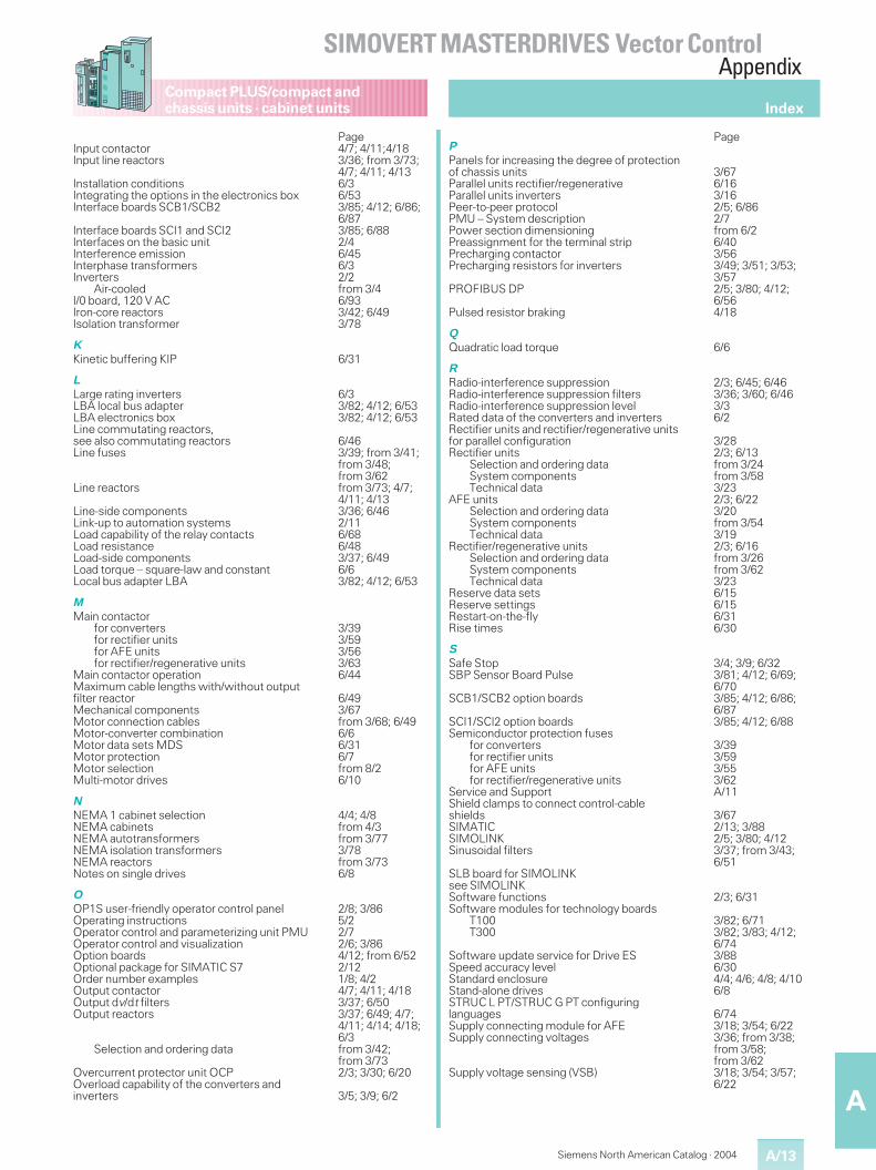
A/13
A
Compact PLUS/compact andchassis units · cabinet units
Siemens North American Catalog · 2004
PageInput contactor 4/7; 4/11;4/18Input line reactors 3/36; from 3/73;
4/7; 4/11; 4/13Installation conditions 6/3Integrating the options in the electronics box 6/53Interface boards SCB1/SCB2 3/85; 4/12; 6/86;
6/87Interface boards SCI1 and SCI2 3/85; 6/88Interfaces on the basic unit 2/4Interference emission 6/45Interphase transformers 6/3Inverters 2/2
Air-cooled from 3/4I/0 board, 120 V AC 6/93Iron-core reactors 3/42; 6/49Isolation transformer 3/78
K
Kinetic buffering KIP 6/31
L
Large rating inverters 6/3LBA local bus adapter 3/82; 4/12; 6/53LBA electronics box 3/82; 4/12; 6/53Line commutating reactors,see also commutating reactors 6/46Line fuses 3/39; from 3/41;
from 3/48;from 3/62
Line reactors from 3/73; 4/7;4/11; 4/13
Line-side components 3/36; 6/46Link-up to automation systems 2/11Load capability of the relay contacts 6/68Load resistance 6/48Load-side components 3/37; 6/49Load torque – square-law and constant 6/6Local bus adapter LBA 3/82; 4/12; 6/53
M
Main contactorfor converters 3/39for rectifier units 3/59for AFE units 3/56for rectifier/regenerative units 3/63
Main contactor operation 6/44Maximum cable lengths with/without outputfilter reactor 6/49Mechanical components 3/67Motor connection cables from 3/68; 6/49Motor-converter combination 6/6Motor data sets MDS 6/31Motor protection 6/7Motor selection from 8/2Multi-motor drives 6/10
N
NEMA 1 cabinet selection 4/4; 4/8NEMA cabinets from 4/3NEMA autotransformers from 3/77NEMA isolation transformers 3/78NEMA reactors from 3/73Notes on single drives 6/8
O
OP1S user-friendly operator control panel 2/8; 3/86Operating instructions 5/2Operator control and parameterizing unit PMU 2/7Operator control and visualization 2/6; 3/86Option boards 4/12; from 6/52Optional package for SIMATIC S7 2/12Order number examples 1/8; 4/2Output contactor 4/7; 4/11; 4/18Output dv/dt filters 3/37; 6/50Output reactors 3/37; 6/49; 4/7;
4/11; 4/14; 4/18;6/3
Selection and ordering data from 3/42;from 3/73
Overcurrent protector unit OCP 2/3; 3/30; 6/20Overload capability of the converters andinverters 3/5; 3/9; 6/2
PageP
Panels for increasing the degree of protectionof chassis units 3/67Parallel units rectifier/regenerative 6/16Parallel units inverters 3/16Peer-to-peer protocol 2/5; 6/86PMU – System description 2/7Power section dimensioning from 6/2Preassignment for the terminal strip 6/40Precharging contactor 3/56Precharging resistors for inverters 3/49; 3/51; 3/53;
3/57PROFIBUS DP 2/5; 3/80; 4/12;
6/56Pulsed resistor braking 4/18
Q
Quadratic load torque 6/6
R
Radio-interference suppression 2/3; 6/45; 6/46Radio-interference suppression filters 3/36; 3/60; 6/46Radio-interference suppression level 3/3Rated data of the converters and inverters 6/2Rectifier units and rectifier/regenerative unitsfor parallel configuration 3/28Rectifier units 2/3; 6/13
Selection and ordering data from 3/24System components from 3/58Technical data 3/23
AFE units 2/3; 6/22Selection and ordering data 3/20System components from 3/54Technical data 3/19
Rectifier/regenerative units 2/3; 6/16Selection and ordering data from 3/26System components from 3/62Technical data 3/23
Reserve data sets 6/15Reserve settings 6/15Restart-on-the-fly 6/31Rise times 6/30
S
Safe Stop 3/4; 3/9; 6/32SBP Sensor Board Pulse 3/81; 4/12; 6/69;
6/70SCB1/SCB2 option boards 3/85; 4/12; 6/86;
6/87SCI1/SCI2 option boards 3/85; 4/12; 6/88Semiconductor protection fuses
for converters 3/39for rectifier units 3/59for AFE units 3/55for rectifier/regenerative units 3/62
Service and Support A/11Shield clamps to connect control-cableshields 3/67SIMATIC 2/13; 3/88SIMOLINK 2/5; 3/80; 4/12Sinusoidal filters 3/37; from 3/43;
6/51SLB board for SIMOLINKsee SIMOLINKSoftware functions 2/3; 6/31Software modules for technology boards
T100 3/82; 6/71T300 3/82; 3/83; 4/12;
6/74Software update service for Drive ES 3/88Speed accuracy level 6/30Standard enclosure 4/4; 4/6; 4/8; 4/10Stand-alone drives 6/8STRUC L PT/STRUC G PT configuringlanguages 6/74Supply connecting module for AFE 3/18; 3/54; 6/22Supply connecting voltages 3/36; from 3/38;
from 3/58;from 3/62
Supply voltage sensing (VSB) 3/18; 3/54; 3/57;6/22
Index
SIMOVERT MASTERDRIVES Vector ControlAppendix
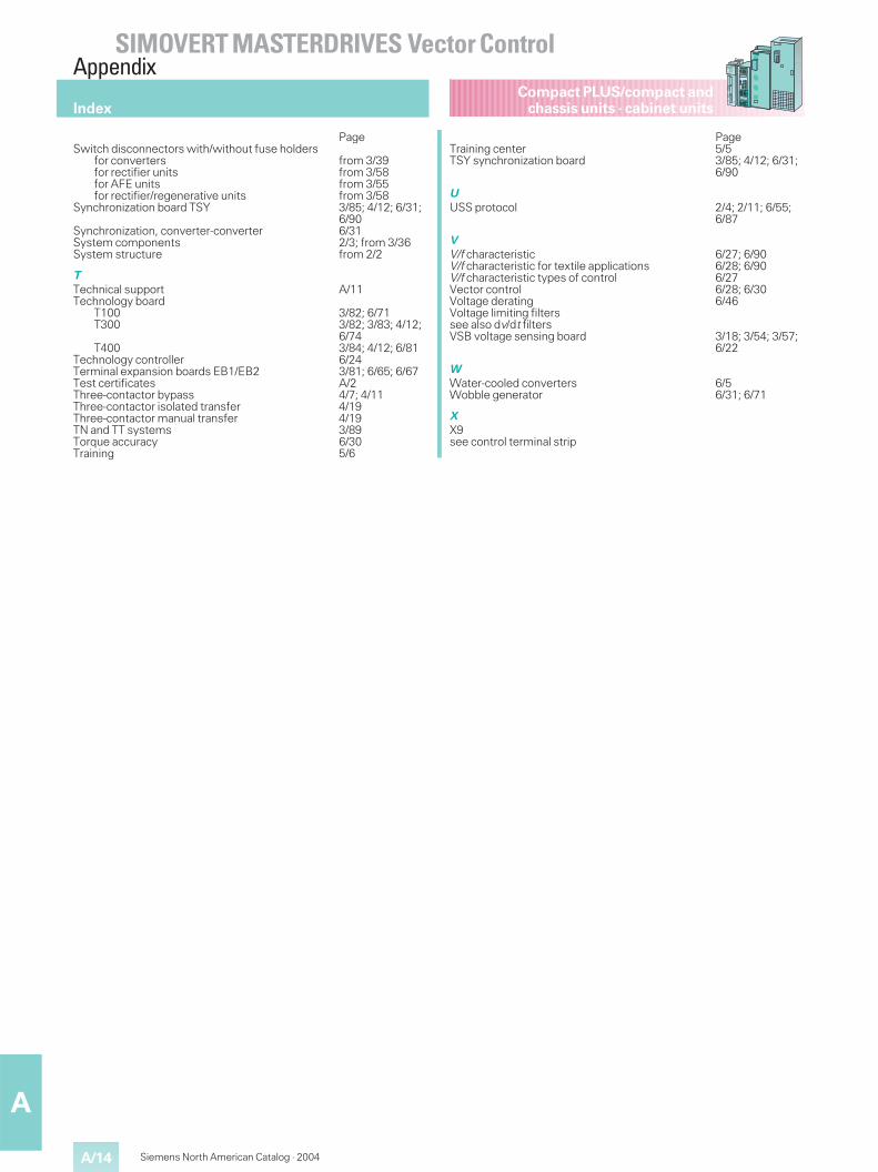
Compact PLUS/compact andchassis units · cabinet units
A/14
A
Siemens North American Catalog · 2004
PageSwitch disconnectors with/without fuse holders
for converters from 3/39for rectifier units from 3/58for AFE units from 3/55for rectifier/regenerative units from 3/58
Synchronization board TSY 3/85; 4/12; 6/31;6/90
Synchronization, converter-converter 6/31System components 2/3; from 3/36System structure from 2/2
T
Technical support A/11Technology board
T100 3/82; 6/71T300 3/82; 3/83; 4/12;
6/74T400 3/84; 4/12; 6/81
Technology controller 6/24Terminal expansion boards EB1/EB2 3/81; 6/65; 6/67Test certificates A/2Three-contactor bypass 4/7; 4/11Three-contactor isolated transfer 4/19Three-contactor manual transfer 4/19TN and TT systems 3/89Torque accuracy 6/30Training 5/6
PageTraining center 5/5TSY synchronization board 3/85; 4/12; 6/31;
6/90
U
USS protocol 2/4; 2/11; 6/55;6/87
V
V/f characteristic 6/27; 6/90V/f characteristic for textile applications 6/28; 6/90V/f characteristic types of control 6/27Vector control 6/28; 6/30Voltage derating 6/46Voltage limiting filterssee also dv/dt filtersVSB voltage sensing board 3/18; 3/54; 3/57;
6/22
W
Water-cooled converters 6/5Wobble generator 6/31; 6/71
X
X9see control terminal strip
Index
SIMOVERT MASTERDRIVES Vector ControlAppendix
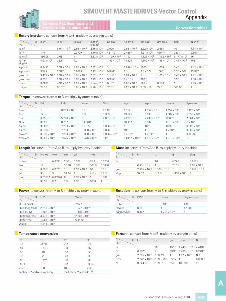
A/15
A
Compact PLUS/compact andchassis units · cabinet units
Siemens North American Catalog · 2004
Conversion tables
SIMOVERT MASTERDRIVES Vector ControlAppendix
Temperature conversion Force (to convert from A to B, multiply by entry in table)
Power (to convert from A to B, multiply by entry in table) Rotation (to convert from A to B, multiply by entry in table)
BA
H.P. Watts
H.P. (English) 1 745.7
(lb-in)(deg./sec) 2.645 × 10⁻⁶ 1.972 × 10⁻³
(lb-in)(RPM) 1.587 × 10⁻⁵ 1.183 × 10⁻²
(lb-ft)(deg./sec) 3.173 × 10⁻⁵ 2.366 × 10⁻²
(lb-ft)(RPM) 1.904 × 10⁻⁴ 0.1420
Watts 1.341 × 10⁻³ 1
BA
RPM rad/sec. degrees/sec.
RPM 1 0.105 6.0
rad/sec. 9.55 1 57.30
degrees/sec. 0.167 1.745 × 10⁻² 1
°F °C °C °F
0 –17.8 –10 14
32 0 0 32
50 10 10 50
70 21.1 20 68
90 32.2 30 86
98.4 37 37 98.4
212 100 100 212
subtract 32 and multiply by 5/9 multiply by 9/5 and add 32
BA
lb oz gm dyne N
lb 1 16 453.6 4.448 × 10⁻⁵ 4.4482
oz 0.0625 1 28.35 2.780 × 10⁻⁴ 0.27801
gm 2.205 × 10⁻³ 0.03527 1 1.02 × 10⁻³ N.A.
dyne 2.248 × 10⁻⁶ 3.59 × 10⁻⁵ 890.7 1 0.00001
N 0.22481 3.5967 N.A. 100.000 1
Torque (to convert from A to B, multiply by entry in table)
BA
lb-in lb-ft oz-in N-m Kg-cm Kg-m gm-cm dyne-cm
lb-in 1 8.333 × 10⁻² 16 0.113 1.152 1.152 × 10⁻² 1.152 × 10³ 1.129 × 10⁶
lb-ft 12 1 192 1.355 13.825 0.138 1.382 × 10⁴ 1.355 × 10⁷
oz-in 6.25 × 10⁻² 5.208 × 10⁻³ 1 7.061 × 10⁻³ 7.200 × 10⁻² 7.200 × 10⁻⁴ 72.007 7.061 × 10⁷
N-m 8.850 0.737 141.612 1 10.197 0.102 1.019 × 10⁴ 1 × 10⁷
Kg-cm 0.8679 7.233 × 10⁻² 13.877 9.806 × 10⁻² 1 10–2 1000 9.806 × 10⁵
Kg-m 86.796 7.233 1.388 × 10³ 9.806 100 1 1 × 10⁵ 9.806 × 10⁷
gm-cm 8.679 × 10⁻⁴ 7.233 × 10⁻⁵ 1.388 × 10⁻² 9.806 × 10⁻⁵ 1 × 10⁻³ 1 × 10⁻⁵ 1 980.665
dyne-cm 8.850 × 10⁻⁷ 7.375 × 10⁻⁸ 1.416 × 10⁻⁵ 10–7 1.0197 × 10⁻⁶ 1.019 × 10⁻⁸ 1.019 × 10⁻³ 1
Length (to convert from A to B, multiply by entry in table) Mass (to convert from A to B, multiply by entry in table)
BA
Inches feet cm yd mm m
Inches 1 0.0833 2.54 0.028 25.4 0.0254
feet 12 1 30.48 0.333 304.8 0.3048
cm 0.3937 0.03281 1 1.09 × 10⁻² 10 0.01
yd 36 3 91.44 1 914.4 0.914
mm 0.03937 0.00328 0.1 1.09 × 10⁻³ 1 0.001
m 39.37 3.281 100 1.09 1000 1
BA
lb oz gm slug
lb 1 16 453.6 0.0311
oz 6.25 × 10⁻² 1 28.35 1.93 × 10⁻³
gm 2.205 × 10⁻³ 3.527 × 10⁻³ 1 6.852 × 10⁻⁵
slug 32.17 514.8 1.459 × 10⁴ 1
Rotary inertia (to convert from A to B, multiply by entry in table)
BA
lb-in2 lb-ft2 lb-in-s2 lb-ft-s2
slug-ft2Kg-cm2 Kg-cm-s2 gm-cm2 gm-cm-s2 oz-in2 oz-in-s2
lb-in2 1 6.94 × 10⁻³ 2.59 × 10⁻³ 2.15 × 10⁻⁴ 2.926 2.98 × 10⁻³ 2.92 × 10³ 2.984 16 4.14 × 10⁻²
lb-ft2 144 1 0.3729 3.10 × 10⁻² 421.40 0.4297 4.21 × 10⁵ 429.71 2304 5.967
lb-in-s2 386.08 2.681 1 8.33 × 10⁻² 1.129 × 10³ 1.152 1.129 × 10⁶ 1.152 × 10³ 6.177 × 10³ 16
lb-ft-s2
slug-ft24.63 × 103 32.17 12 1 1.35 × 10⁻⁴ 13.825 1.355 × 10⁷ 1.38 × 10⁴ 7.41 × 10⁻⁴ 192
Kg-cm2 0.3417 2.37 × 10⁻³ 8.85 × 10⁻⁴ 7.37 × 10⁻⁵ 1 1.019 × 10⁻³ 1000 1.019 5.46 1.42 × 10⁻²
Kg-cm-s2 335.1 2.327 0.8679 7.23 × 10⁻² 980.66 1 9.8 × 10⁵ 1000 5.36 × 10³ 13.887
gm-cm2 3.417 × 10⁻⁴ 2.37 × 10⁻⁶ 8.85 × 10⁻⁷ 7.37 × 10⁻⁸ 1 × 10⁻³ 1.01 × 10⁻⁶ 1 1.01 × 10⁻³ 5.46 × 10⁻³ 1.41 × 10⁻⁵
gm-cm-s2 0.335 2.32 × 10⁻³ 8.67 × 10⁻⁴ 7.23 × 10⁻⁵ 0.9806 1 × 10⁻³ 980.6 1 5.36 1.38 × 10⁻²
oz-in2 0.0625 4.34 × 10⁻⁴ 1.61 × 10⁻⁴ 1.34 × 10⁻⁵ 0.182 1.86 × 10⁻⁴ 182.9 0.186 1 2.59 × 10⁻³
oz-in-s2 24.13 0.1675 6.25 × 10⁻² 5.20 × 10⁻³ 70.615 7.20 × 10⁻² 7.09 × 10⁴ 72.0 386.08 1

A/16
A
Siemens North American Catalog · 2004
Compact PLUS/compact andchassis units · cabinet unitsNotes
SIMOVERT MASTERDRIVES Vector ControlAppendix

Siemens Energy & Automation, Inc.
Automation and Drives
5300 Triangle Parkway
Norcross, GA 30092
Siemens world wide: www.siemens.com
Siemens Energy & Automation: www.usa.siemens.com/automation Order No.: DRSA-02063-0304
© 2004 Siemens Energy & Automation, Inc. All Rights ReservedSiemens is a registered trademark of Siemens AG. Product names mentioned may be trademarks or registered trademarks of their respective companies.Specifications are subject to change without notice.
The information provided in this catalog contains descriptionsor characteristics of performance which in case of actual usedo not always apply as described or which may change as aresult of further development of the products. An obligationto provide the respective characteristics shall only exist if ex-pressly agreed in the terms of contract. Availability and tech-nical specifications are subject to change without notice.
Related Documents


![WÄRTSILÄ ELECTRICAL & AUTOMATION Manfred …s3-eu-west-1.amazonaws.com/stm-stmvalidation... · 3 © Wärtsilä PUBLIC 4.9.2017 WärtsiläElectrical & Automation / Author] We are](https://static.cupdf.com/doc/110x72/5aeda3b97f8b9a585f907ec9/wrtsil-electrical-automation-manfred-s3-eu-west-1-wrtsil-public-492017-wrtsilelectrical.jpg)