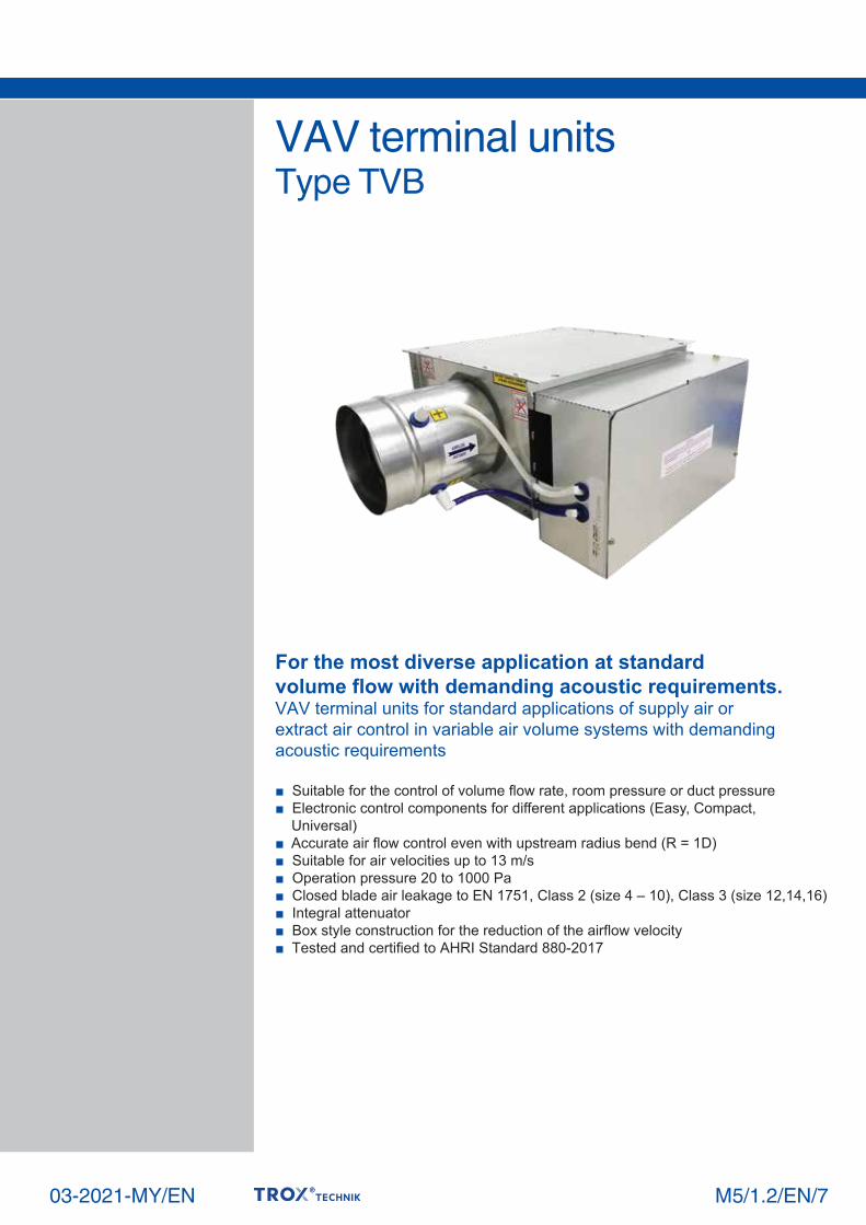
■ Suitable for the control of volume flow rate, room pressure or duct pressure ■ Electronic control components for different applications (Easy, Compact, Universal) ■ Accurate air flow control even with upstream radius bend (R = 1D) ■ Suitable for air velocities up to 13 m/s ■ Operation pressure 20 to 1000 Pa ■ Closed blade air leakage to EN 1751, Class 2 (size 4 – 10), Class 3 (size 12,14,16) ■ Integral attenuator ■ Box style construction for the reduction of the airflow velocity ■ Tested and certified to AHRI Standard 880-2017 VAV terminal units Type TVB For the most diverse application at standard volume flow with demanding acoustic requirements. VAV terminal units for standard applications of supply air or extract air control in variable air volume systems with demanding acoustic requirements 03-2021-MY/EN M5/1.2/EN/7

Welcome message from author
This document is posted to help you gain knowledge. Please leave a comment to let me know what you think about it! Share it to your friends and learn new things together.
Transcript
■ Suitable for the control of volume flow rate, room pressure or duct pressure■ Electronic control components for different applications (Easy, Compact, Universal)■ Accurate air flow control even with upstream radius bend (R = 1D)■ Suitable for air velocities up to 13 m/s■ Operation pressure 20 to 1000 Pa■ Closed blade air leakage to EN 1751, Class 2 (size 4 – 10), Class 3 (size 12,14,16) ■ Integral attenuator ■ Box style construction for the reduction of the airflow velocity■ Tested and certified to AHRI Standard 880-2017
VAV terminal unitsType TVB
For the most diverse application at standardvolume flow with demanding acoustic requirements.VAV terminal units for standard applications of supply air orextract air control in variable air volume systems with demandingacoustic requirements
03-2021-MY/EN M5/1.2/EN/7

M5/1.2/EN/72
VAV terminal unitsContents . General information TVB
Type PageTVB Contents . Description 2-3 Function 4 Order code 5 Quick selection 6 - 7 Aerodynamic data 8 Regenerated sound power level for TVB-A 9 Radiated sound power level for TVB-A 10 Regenerated sound power level TVB-B 11 Radiated sound power level for TVB-B 12 Regenerated sound power level for TVB-E & C 13 Radiated sound power level for TVB-E & C 14 Dimensions and weight TVB-A/B 15 Dimensions and weight TVB-C 16 Appendix 1 17 Installation details 18 Specification text 19
VAV terminal unit, variant TVB-AVariants
Product examples
Description
VAV terminal unit, variant TVB-C
Application■ VAV terminal units of Type TVB for supply air or extract air flow control in variable air volume systems■ Closed-loop volume flow control using an external power supply■ Integral attenuator for demanding acoustic requirements■ Shut-off by means of switching (equipment supplied by others)
Variants■ TVB-A: VAV terminal unit ■ TVB-B: VAV terminal unit with extended casing for better acoustics performance■ TVB-C: VAV terminal unit with multiple outlets■ TVB-E: VAV terminal unit with electric reheat unit■ TVB-EC: VAV terminal unit with multiple outlets and reheat unit
Nominal sizes■ 4, 5, 6, 7, 8, 10, 12, 14, 16
Attachments■ Easy controller: Compact unit consisting of controller with potentiometers, differential pressure transducer and actuator■ Compact controller: Compact unit consisting of controller, differential pressure transducer and actuator■ Universal controller: Controller, differential pressure transducer and actuators for special applications

M5/1.2/EN/7
VAV terminal units General information TVB
3
Useful additions■ Hot water heat exchanger■ Electrical heaterFor more details contact TROX Malaysia
Special characteristics■ Factory set-up or programming and aerodynamic function testing■ Volume flow rate can later be measured and adjusted on site; additional adjustment device may be necessary
Parts and characteristics■ Ready-to-commission unit which consists of mechanical parts and control components■ Averaging differential pressure sensor for volume flow rate measurement■ Damper blade■ Integral attenuator■ Factory assembled control components complete with wiring and tubing■ Aerodynamic functional testing on a special test rig prior to shipping of each unit■ Set-up data is given on a label or volume flow rate scale affixed to the unit
Construction features■ Rectangular casing■ Spigot on the inlet suitable for circular ducts to DW144, 1998■ Connection on the room end suitable for air duct profiles■ Position of the damper blade indicated externally at shaft extension■ Thermal and acoustic insulation (lining)
Materials and surfaces■ Casing and damper blade made of galvanized sheet steel■ Damper blade seal made of Chloroprene rubber■ Lining is fiber glass ■ Differential pressure sensor made of aluminum■ Plastic bearings
Mineral wool■ Internal fiber glass insulation lining. ■ Faced with woven glass fabric as protection against fiber erosion for airflow velocities up to 20 m/s■ Resistant to fungal and bacterial growth
Installation and commissioning■ Any installation orientation (except units with static differential pressure transducer)■ Return edges of the casing with drilled holes suitable for M8 threaded rods
Standards and guidelines■ Closed blade air leakage to EN 1751, Class 2 (4 – 10), Class 3 (12, 14, 16)
Maintenance■ Maintenance-free as construction and materials are not subject to wear

M5/1.2/EN/7
VAV terminal unitsFunction TVB
Functional descriptionThe VAV terminal unit is fitted with adifferential pressure sensor for measuringthe volume flow rate. The control components(attachments) include a differential pressuretransducer that transforms the differentialpressure (effective pressure) into anelectric signal, a controller, and an actuator;the control functions can be achieved withan Easy controller, with a Compact controller,or with individual components.
For most applications, the setpoint valuecomes from a room temperature controller.The controller compares the actual valuewith the setpoint value and alters thecontrol signal of the actuator if there is adifference between the two values. Anintegral attenuator reduces the noise that is created by the restriction of the airflow. The airflow velocity at the room end is,due to the larger rectangular cross section,about half the velocity in the circular duct
Schematic illustration of the TVB
Function
1
2
3
4
1 Differential pressure sensor 3 Control components, e.g. an Easy controller2 Damper blade 4 Access panel
4

Attachments (control component) Specific controller name
Design flow range [l/s or CFM], differential pressure [Pa] min and max for factory setting or ∆pmin for factory setting
TVB-A/12/BC0/95-950 l/sConstruction variation short casingNominal size 12 inchAttachment ControllerVolume flow rate 95-950 l/s
M5/1.2/EN/7
VAV terminal unitsOrder code TVB
Order codeVARYCONTROL
TVB, TVB-/.../Easy
TVB – A / 12 / BC0 / 95 – 950 l/s
1 2 3 4 5
TypeTVB VAV terminal unit
Construction variationA short casingB long casingC with multiple outletsE with electric heaterEC with electric heater and multiple outlets
Nominal size [inch]4567810121416
Order exampleVARYCONTROL
5

VAV terminal unitsQuick selection TVB
M5/1.2/EN/76
Volume flow rate ranges
Quick selection tables providea good overview of the roomsound pressure levels that canbe expected. Approximateintermediate values can beinterpolated. For preciseintermediate values pleasecontact TROX Malaysia.
The first selection criteria forthe nominal size are the actualvolume flow rates Vmin and Vmaxin ft3/min (CFM) and in l/s (LPS).The quick sizing tables arebased on normally acceptedattenuation levels. If the sound pressure level exceeds therequired level, a largerVAV terminal unit and/or asilencer is required.
Radiated sound pressure level
Terminal size
Airflow
CFM LPS
4
5
6
7
8
10
12
14
16
21
95
150
212
31
148
250
327
53
232
400
497
63
295
550
655
85
401
700
866
137
613
1100
1331
201
930
1600
2007
264
1214
2100
2641
380
1732
2800
3750
10
45
71
100
15
70
118
155
25
110
189
235
30
140
260
310
40
190
331
410
65
290
521
630
95
440
757
950
125
575
994
1250
180
820
1325
1775
NoteDash (-) indicates values lower than 20.All values calculated based upon attenuation according to AHRI standard 885:2008 Appendix E1.See appendix for detail.
Radiated Sound Pressure LevelΔPst in H2O (Pa)
0.5"(125Pa)
NC
-
-
-
-
-
-
-
-
-
-
-
-
-
-
22
24
-
-
21
23
-
-
-
20
-
-
-
22
-
-
-
-
-
-
20
26
-
-
21
24
-
-
21
23
-
-
24
26
-
22
28
29
-
22
26
28
-
-
25
26
-
23
28
30
-
-
24
26
-
21
27
31
-
-
20
25
-
-
20
22
-
-
22
24
-
-
28
30
-
20
28
31
-
-
26
29
-
21
28
31
-
-
24
26
-
21
31
37
-
21
26
29
-
23
26
28
-
24
29
31
-
27
33
35
-
28
33
34
-
27
32
34
-
29
34
36
-
27
32
34
-
29
35
39
-
-
23
28
-
-
24
26
-
20
26
28
-
21
31
33
-
24
32
35
-
24
31
34
-
26
33
35
-
24
29
31
-
27
38
44
-
23
28
32
-
26
30
32
-
28
33
35
-
30
36
38
-
31
36
38
-
31
37
39
-
33
38
40
-
31
36
38
-
34
40
44
-
22
29
33
-
25
30
32
-
26
32
35
-
27
35
38
-
31
39
42
-
35
42
44
-
33
41
43
20
33
38
41
-
38
48
54
-
28
33
37
20
31
35
37
20
33
38
40
-
35
41
43
24
37
42
44
23
39
45
47
25
39
44
46
24
39
44
46
22
42
48
52
dB(A)
TVB-A1"
(250Pa)3"
(750Pa)1.5"
(375Pa)
NC dB(A) NC dB
(A) NC dB(A) NC dB
(A) NC dB(A) NC dB
(A) NC dB(A) NC dB
(A) NC dB(A) NC dB
(A) NC dB(A)
0.5"(125Pa)
1"(250Pa)
3"(750Pa)
1.5"(375Pa)
0.5"(125Pa)
1"(250Pa)
3"(750Pa)
1.5"(375Pa)
TVB-B
-
-
-
-
-
-
-
-
-
-
21
24
-
-
24
27
-
-
21
24
-
-
-
20
-
-
-
22
-
-
24
27
-
23
33
38
-
-
21
25
-
-
21
24
-
-
26
29
-
21
29
31
-
20
26
28
-
-
24
27
-
22
27
29
-
23
29
31
-
28
35
39
-
-
-
21
-
-
-
22
-
-
25
28
-
-
29
32
-
-
28
31
-
-
25
28
-
20
26
29
-
22
26
27
-
24
33
38
-
-
24
29
-
-
26
29
-
23
30
33
-
25
33
35
-
26
32
34
-
25
31
33
-
28
33
35
-
27
32
34
-
31
36
40
-
-
-
23
-
-
21
25
-
20
28
31
-
21
32
35
-
23
32
35
-
21
29
33
-
24
30
33
-
26
30
31
-
28
33
38
-
20
26
31
-
23
29
32
-
26
33
35
-
28
35
37
-
29
35
37
-
29
35
37
-
31
36
38
-
30
34
36
-
33
38
41
-
-
21
26
-
20
27
31
-
24
32
35
-
25
35
38
-
30
38
41
-
29
36
40
-
31
37
40
-
33
37
39
-
35
38
40
-
24
30
34
-
28
34
37
-
29
36
39
-
31
39
41
-
35
41
43
-
35
42
44
20
37
42
44
23
36
40
42
21
38
43
45
TVB-E & C
-
20
26
30
-
-
24
27
-
22
29
32
-
23
31
33
-
22
27
29
-
22
29
31
-
26
31
33
-
22
27
30
-
25
32
35
-
-
21
25
-
-
-
20
-
-
22
26
-
-
26
28
-
-
22
25
-
-
22
26
-
-
24
27
-
-
-
22
-
-
26
32
-
24
29
33
-
23
29
32
-
26
33
36
-
27
35
37
-
28
33
35
-
29
36
38
-
32
37
39
-
29
34
36
-
32
39
42
-
-
24
29
-
-
22
26
-
-
27
30
-
20
31
33
-
20
29
32
-
22
30
34
-
25
31
34
-
21
27
29
-
26
35
41
-
20
26
31
-
-
26
29
-
21
30
33
-
23
33
36
-
24
33
36
-
27
35
38
-
28
35
38
-
25
31
35
-
31
40
46
-
25
31
35
-
26
32
35
-
28
35
38
-
30
38
40
-
31
37
39
-
33
40
42
-
35
40
42
-
33
38
40
-
36
43
46
-
23
30
35
-
25
31
35
-
26
34
38
-
26
37
40
-
30
39
43
-
36
45
47
-
35
42
45
-
32
40
43
-
40
49
55
-
28
34
38
-
31
37
40
-
32
39
42
-
33
42
44
20
37
42
44
-
40
47
49
22
40
46
48
23
39
44
47
21
43
49
53
..

M5/1.2/EN/7
VAV terminal unitsQuick selection TVB
7
Regenerated discharge sound pressure level
Terminal size
Airflow
CFM LPS
4
5
6
7
8
10
12
14
16
21
95
150
212
31
148
250
327
53
232
400
497
63
295
550
655
85
401
700
866
137
613
1100
1331
201
930
1600
2007
264
1214
2100
2641
380
1732
2800
3750
10
45
71
100
15
70
118
155
25
110
189
235
30
140
260
310
40
190
331
410
65
290
521
630
95
440
757
950
125
575
994
1250
180
820
1325
1775
Regenerated Discharge Sound Pressure LevelΔPst in H2O (Pa)
0.5"(125Pa)
NC
-
22
27
30
-
22
29
33
-
22
30
33
-
32
41
44
-
22
30
33
-
22
29
31
-
20
26
28
-
-
24
26
-
-
24
27
-
29
33
36
-
28
34
37
-
29
35
37
-
35
42
44
-
29
34
36
-
29
34
36
-
27
32
34
-
26
31
32
-
25
30
32
-
29
33
37
-
27
35
38
-
28
36
39
-
35
45
48
-
27
35
38
-
27
35
37
-
25
32
34
-
24
30
32
-
24
30
33
-
34
38
41
-
32
38
41
-
34
40
42
-
38
45
47
-
33
39
41
-
33
39
41
-
31
36
38
-
31
36
38
-
30
34
37
-
32
37
40
-
30
38
41
-
31
39
42
-
37
47
50
-
30
38
42
-
30
38
40
-
28
35
37
-
27
33
36
-
27
33
37
-
37
41
44
-
34
41
44
-
36
42
45
-
39
47
49
-
36
42
44
-
36
41
43
-
34
39
41
-
33
38
41
-
33
37
40
-
38
43
47
-
34
42
46
-
36
44
48
-
39
50
53
-
35
44
47
-
35
43
45
-
33
40
42
-
32
40
43
-
32
38
42
22
42
46
49
-
37
44
47
21
40
46
49
-
41
50
52
22
40
46
49
24
40
46
47
22
38
43
45
23
38
43
45
21
37
42
44
dB(A)
TVB-A1"
(250Pa)3"
(750Pa)1.5"
(375Pa)
NC dB(A) NC dB
(A) NC dB(A) NC dB
(A) NC dB(A) NC dB
(A) NC dB(A) NC dB
(A) NC dB(A) NC dB
(A) NC dB(A)
0.5"(125Pa)
1"(250Pa)
3"(750Pa)
1.5"(375Pa)
0.5"(125Pa)
1"(250Pa)
3"(750Pa)
1.5"(375Pa)
TVB-B
-
-
26
32
-
21
29
33
-
22
30
34
-
20
30
33
-
20
28
31
-
-
24
26
-
-
20
23
-
-
-
-
-
-
-
-
-
24
30
34
-
26
32
35
-
26
33
36
-
25
33
35
-
26
31
34
-
24
29
30
-
21
26
28
-
20
24
26
-
-
22
25
-
22
29
35
-
25
33
37
-
26
35
38
-
25
35
38
-
26
33
36
-
25
31
32
-
-
26
29
-
-
24
26
-
-
21
24
-
27
32
37
-
29
35
38
-
30
37
39
-
29
37
39
-
30
36
38
-
29
34
35
-
25
30
33
-
25
29
31
-
23
27
30
-
24
31
36
-
27
35
39
-
29
37
41
-
28
38
41
-
29
36
39
-
29
34
36
-
23
29
32
-
23
28
30
-
-
25
28
-
28
34
38
-
30
37
40
-
32
39
41
-
31
39
41
-
32
38
40
20
32
37
38
-
28
33
35
-
28
32
34
-
25
30
33
-
27
34
39
-
31
39
43
-
33
42
45
-
32
43
45
-
33
41
44
-
35
41
42
-
28
35
38
-
30
35
37
-
24
31
34
-
30
36
40
-
33
40
43
-
35
42
45
-
35
43
45
-
36
42
44
24
37
42
44
-
32
38
40
21
33
38
39
-
30
35
38
TVB-E & C
-
-
-
21
-
-
25
28
-
20
28
31
-
24
33
35
-
27
34
36
-
26
33
36
-
24
32
36
-
25
32
34
-
25
32
36
-
-
-
-
-
-
-
24
-
-
23
27
-
-
30
33
-
21
30
33
-
20
30
33
-
-
29
33
-
-
27
30
-
-
28
34
-
-
-
23
-
20
27
31
-
23
31
34
-
27
36
38
-
31
37
39
-
31
38
41
-
28
37
40
-
30
37
39
-
29
36
41
-
-
-
-
-
-
22
27
-
-
27
31
-
22
34
37
-
26
34
37
-
26
36
39
-
23
34
39
-
25
34
37
-
24
34
40
-
-
-
-
-
-
24
29
-
-
29
33
-
25
36
39
-
28
37
40
-
30
40
43
-
26
38
42
-
28
38
41
-
27
37
43
-
-
21
25
-
22
29
32
-
25
33
36
-
29
38
40
-
33
39
42
-
34
41
44
-
31
39
43
-
32
39
42
-
32
39
43
-
-
-
20
-
-
27
32
-
23
33
37
-
29
40
43
-
32
41
44
-
36
46
49
-
32
43
48
-
35
44
48
-
33
42
48
-
-
23
27
-
24
31
35
-
28
36
39
-
33
41
44
-
36
43
45
-
39
46
49
-
35
43
47
-
37
44
47
-
36
43
47
NoteDash (-) indicates values lower than 20.All values calculated based upon attenuation according to AHRI standard 885:2008 Appendix E1.See appendix for detail.
M5/1.2/EN/7
VAV terminal unitsAerodynamic data TVB
8
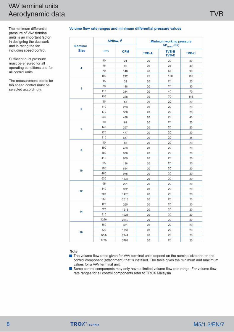
The minimum differentialpressure of VAV terminalunits is an important factorin designing the ductworkand in rating the fanincluding speed control.
Sufficient duct pressuremust be ensured for alloperating conditions and forall control units.
The measurement points forfan speed control must beselected accordingly.
Volume flow rate ranges and minimum differential pressure values
Nominal Size
Airflow, V
CFM TVB-CTVB-A TVB-BTVB-E
Minimum working pressureΔPst min (Pa)
LPS
4
5
6
7
8
10
12
14
16
10
45
70
100
15
70
115
155
25
110
170
235
30
140
225
310
40
190
300
410
65
290
460
630
95
440
695
950
125
575
910
1250
180
820
1295
1775
21
95
148
212
32
148
244
328
53
233
360
498
64
297
477
657
85
403
636
869
138
614
975
1335
201
932
1476
2013
265
1218
1928
2649
381
1737
2744
3761
20
20
40
75
20
20
20
30
20
20
20
20
20
20
20
20
20
20
20
20
20
20
20
20
20
20
20
20
20
20
20
20
20
20
20
20
20
25
65
130
20
20
40
70
20
20
20
20
20
20
20
20
20
20
20
20
20
20
20
20
20
20
20
20
20
20
20
20
20
20
20
20
20
40
90
185
20
30
70
115
20
20
20
40
20
20
20
35
20
20
20
20
20
20
20
20
20
20
20
20
20
20
20
20
20
20
20
20
NoteThe volume flow rates given for VAV terminal units depend on the nominal size and on thecontrol component (attachment) that is installed. The table gives the minimum and maximumvalues for a VAV terminal unit.Some control components may only have a limited volume flow rate range. For volume flowrate ranges for all control components refer to TROX Malaysia
.
VAV terminal unitsRegenerated sound power level for TVB-A TVB
M5/1.2/EN/7 9
Duct End Correction as per AHRI 880-2017 is added in sound power levelbased on the below:
Terminal size
Airflow
CFM LPS
4
5
6
7
8
10
12
14
16
21
95
150
212
31
148
250
327
53
232
400
497
63
295
550
655
85
401
700
866
137
613
1100
1331
201
930
1600
2007
264
1214
2100
2641
380
1732
2800
3750
10
45
71
100
15
70
118
155
25
110
189
235
30
140
260
310
40
190
331
410
65
290
521
630
95
440
757
950
125
575
994
1250
180
820
1325
1775
Sound Power Level, dB at Octave band freq. Hz
ΔPst = 0.5"H2O (125Pa)
33
48
52
54
30
47
52
55
35
49
53
55
37
52
56
58
42
53
56
57
40
52
56
57
39
52
56
58
42
52
55
56
37
49
52
54
ΔPst = 1"H2O (250Pa) ΔPst = 1.5"H2O(375Pa) ΔPst = 3"H2O(750Pa)
125
250
500
1000
2000
4000
125
250
500
1000
2000
4000
125
250
500
1000
2000
4000
125
250
500
1000
2000
4000
51
66
70
72
48
66
72
74
49
66
72
74
53
74
81
83
50
69
75
77
54
69
75
76
56
70
74
76
51
67
72
74
53
69
73
75
46
63
67
70
39
61
67
70
45
63
69
71
45
65
71
73
46
63
68
70
48
63
68
70
46
62
67
69
47
62
66
68
43
59
64
66
21
32
35
36
22
35
39
40
28
40
43
45
32
43
47
48
38
47
49
50
37
46
49
50
38
47
49
50
40
48
51
52
40
47
49
50
54
71
75
77
51
70
76
79
52
71
77
79
54
76
84
86
54
73
79
82
57
73
79
81
59
74
79
80
56
72
77
79
56
73
77
80
27
32
33
33
23
34
37
38
27
37
41
42
32
42
45
46
36
44
47
48
35
44
46
47
37
45
48
49
38
46
48
49
39
46
47
48
30
30
29
28
23
32
35
36
26
35
38
40
29
39
42
42
32
41
44
45
34
41
44
44
33
43
45
46
35
44
47
48
37
44
45
46
50
68
72
75
42
64
71
74
49
67
73
76
48
69
76
78
50
68
73
75
52
68
73
75
50
66
72
74
51
67
71
73
48
64
69
71
59
78
82
85
54
75
82
85
57
77
83
86
56
79
88
90
59
79
86
88
62
79
85
87
64
80
85
87
62
79
85
87
62
79
84
86
37
54
58
60
34
53
58
60
40
55
59
61
41
57
62
63
47
58
62
63
46
58
62
64
44
58
62
64
48
58
62
63
44
56
60
61
26
39
42
43
28
42
46
47
35
47
51
52
38
50
54
55
44
53
56
57
43
53
56
56
44
53
55
57
46
55
58
59
45
53
55
56
32
39
40
40
29
40
43
45
33
44
48
49
37
49
53
53
42
51
54
55
41
50
53
54
43
52
54
56
45
53
55
56
45
52
54
55
37
39
38
37
28
39
42
43
32
43
46
47
35
46
49
50
38
48
51
52
40
48
51
51
40
50
53
54
42
52
55
56
43
51
53
53
56
74
78
80
52
72
78
81
54
73
79
82
55
77
85
88
56
75
82
84
59
76
81
83
61
76
81
83
58
75
80
82
58
75
80
82
51
71
76
79
43
66
73
77
51
70
76
78
50
71
78
80
53
71
76
79
54
70
76
78
52
69
74
76
54
69
74
76
51
67
72
75
39
58
61
64
36
56
61
64
43
58
63
65
43
60
65
67
50
61
65
66
49
61
66
67
47
61
65
67
51
62
66
67
48
60
64
65
29
43
46
48
31
45
49
51
38
51
55
57
41
54
58
59
48
57
60
61
47
56
59
60
47
56
59
60
50
59
61
62
49
57
59
60
35
43
44
44
32
44
47
49
37
48
52
54
40
53
56
57
45
55
58
59
44
54
57
58
46
55
58
59
48
56
59
60
48
55
57
58
41
44
43
42
32
43
46
48
35
47
50
51
38
50
53
54
42
52
55
57
43
52
55
56
44
54
57
58
47
56
59
60
47
55
57
58
55
76
81
84
45
70
77
81
54
73
80
83
52
74
82
84
57
75
81
84
58
74
80
82
56
73
78
81
58
74
79
81
55
72
77
80
47
52
51
51
37
50
53
55
41
53
57
59
44
56
60
61
48
59
62
64
49
58
61
62
50
60
64
65
53
63
66
67
53
61
63
64
43
63
67
70
40
60
66
69
48
64
69
71
47
64
70
72
54
67
71
72
54
67
72
73
52
66
71
73
57
68
72
73
54
67
70
72
34
50
53
55
35
51
56
58
44
58
62
64
46
60
65
66
54
64
67
68
52
62
66
67
52
62
65
66
56
65
68
69
54
62
64
66
40
50
51
51
36
50
54
55
42
55
59
61
45
58
63
64
52
62
65
66
50
59
63
64
51
61
64
66
54
63
66
67
53
61
63
64
Where
f
CoDeE1
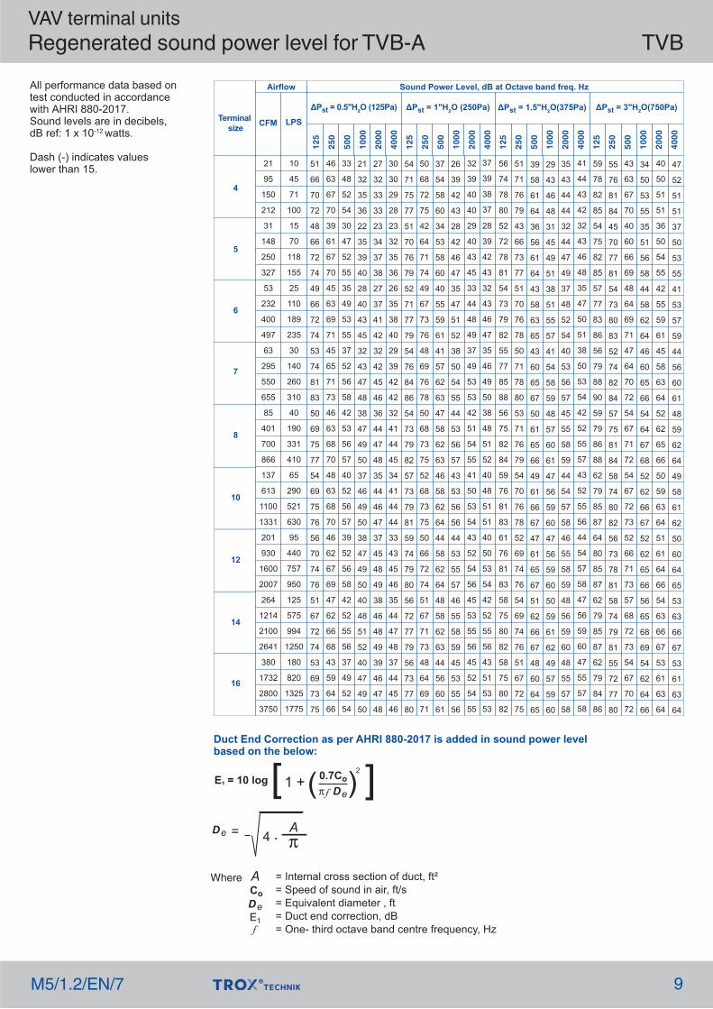
= Internal cross section of duct, ft²= Speed of sound in air, ft/s= Equivalent diameter , ft= Duct end correction, dB= One- third octave band centre frequency, Hz
[ 0.7Co ] π f De( )1 +E1 = 10 log2
A
De 4 . Aπ
=
All performance data based on test conducted in accordance with AHRI 880-2017.Sound levels are in decibels, dB ref: 1 x 10-12 watts.
Dash (-) indicates valueslower than 15.

M5/1.2/EN/7
VAV terminal unitsRadiated sound power level for TVB-A TVB
10
Terminal size
Airflow
CFM LPS
4
5
6
7
8
10
12
14
16
21
95
150
212
31
148
250
327
53
232
400
497
63
295
550
655
85
401
700
866
137
613
1100
1331
201
930
1600
2007
264
1214
2100
2641
380
1732
2800
3750
10
45
71
100
15
70
118
155
25
110
189
235
30
140
260
310
40
190
331
410
65
290
521
630
95
440
757
950
125
575
994
1250
180
820
1325
1775
Sound Power Level, dB at Octave band freq. Hz
-
26
31
34
23
29
31
32
26
37
41
42
27
34
35
35
26
37
39
40
20
33
36
37
26
38
42
43
25
37
41
43
23
38
42
44
125
250
500
1000
2000
4000
125
250
500
1000
2000
4000
125
250
500
1000
2000
4000
125
250
500
1000
2000
4000
16
31
36
39
29
43
47
50
25
41
47
50
34
54
60
62
34
54
59
61
29
50
57
59
38
53
58
60
28
46
52
54
22
51
59
63
26
43
48
52
31
43
47
49
27
43
48
51
24
43
49
51
31
40
42
42
22
41
46
48
33
47
51
53
26
43
48
51
20
42
48
51
-
16
19
21
-
19
23
24
23
36
41
43
23
28
29
29
26
30
30
30
20
29
32
32
20
30
34
35
19
30
34
35
16
34
38
41
23
39
43
47
33
48
52
55
29
46
52
54
35
58
65
66
37
59
65
67
35
57
64
66
44
59
65
67
36
54
60
62
30
59
67
72
-
-
-
19
-
16
19
21
19
35
40
42
19
28
30
31
24
32
33
33
21
30
32
32
16
28
32
34
19
31
35
37
17
34
38
40
-
-
-
-
-
-
-
16
-
29
36
38
12
22
24
25
19
26
26
26
-
23
24
25
-
22
26
28
16
26
30
31
-
28
32
34
31
48
53
56
36
49
52
55
33
49
54
56
29
50
56
58
37
48
50
51
32
50
56
58
38
53
57
59
32
50
55
58
28
50
56
59
33
49
54
58
38
54
59
62
37
54
59
62
37
62
70
72
43
66
73
76
44
66
73
75
53
69
74
77
48
66
72
75
43
72
80
85
18
33
37
41
31
37
39
40
32
43
46
48
33
42
44
44
33
45
48
49
29
41
45
46
33
45
49
51
33
46
50
51
31
47
51
53
-
24
27
29
17
28
32
34
28
42
46
48
29
37
38
38
33
39
39
39
28
38
41
41
28
38
42
43
26
38
41
43
24
42
46
49
-
18
23
27
-
23
27
29
25
41
46
48
25
37
39
40
31
40
42
42
29
38
41
41
24
36
40
42
25
37
41
43
23
40
45
47
-
15
18
21
-
16
22
25
15
35
42
45
18
31
34
35
28
35
36
36
22
32
34
34
20
32
36
37
22
33
36
38
19
35
39
41
27
43
47
51
35
50
55
58
32
49
55
57
36
60
67
69
40
62
68
70
38
60
67
69
48
63
68
70
40
59
65
67
35
64
72
77
33
50
55
59
38
52
56
58
36
52
57
59
31
53
60
61
41
52
55
56
37
56
62
63
41
56
61
63
36
54
59
62
32
55
61
64
22
37
41
45
35
42
44
45
35
46
50
51
36
46
49
49
37
49
53
54
34
46
50
51
38
50
54
55
38
50
54
56
36
52
55
58
17
28
31
34
22
33
37
39
31
45
49
51
33
41
43
43
38
44
45
45
32
43
46
46
32
43
47
48
31
42
46
47
28
46
51
53
-
23
28
32
15
28
32
34
29
44
50
52
28
41
44
45
34
44
47
47
34
43
45
46
28
41
45
47
29
41
45
46
26
44
48
51
-
21
24
27
-
22
28
31
19
39
46
49
22
36
39
40
32
40
42
42
27
37
39
40
25
37
41
43
26
36
40
41
22
39
43
45
37
54
60
64
42
56
61
63
42
57
63
65
35
58
65
67
46
59
62
63
46
65
71
73
46
61
67
69
43
60
66
68
40
63
69
72
17
30
34
37
-
30
36
39
26
46
53
56
29
43
47
48
40
49
51
52
36
45
48
48
33
46
50
52
32
43
46
47
29
46
50
52
27
43
48
51
42
50
52
53
41
52
55
57
42
53
56
57
43
56
60
62
42
54
58
59
44
57
61
63
46
58
63
64
44
60
64
66
24
36
39
41
29
42
46
47
37
50
55
56
39
48
51
51
45
52
53
54
41
51
54
55
39
51
54
56
38
49
53
54
35
54
58
61
-
31
36
40
21
35
39
41
35
50
55
58
34
48
52
53
41
51
54
55
42
51
53
54
36
49
53
55
34
47
51
52
32
50
54
57
ΔPst = 0.5"H2O (125Pa) ΔPst = 1"H2O (250Pa) ΔPst = 1.5"H2O(375Pa) ΔPst = 3"H2O(750Pa)
All performance data based on test conducted in accordance with AHRI 880-2017.Sound levels are in decibels, dB ref: 1 x 10-12 watts.
Dash (-) indicates valueslower than 15.

VAV terminal unitsRegenerated sound power level for TVB-B TVB
M5/1.2/EN/7 11
Terminal size
Airflow
CFM LPS
4
5
6
7
8
10
12
14
16
21
95
150
212
31
148
250
327
53
232
400
497
63
295
550
655
85
401
700
866
137
613
1100
1331
201
930
1600
2007
264
1214
2100
2641
380
1732
2800
3750
10
45
71
100
15
70
118
155
25
110
189
235
30
140
260
310
40
190
331
410
65
290
521
630
95
440
757
950
125
575
994
1250
180
820
1325
1775
Sound Power Level, dB at Octave band freq. Hz
-
36
43
48
14
37
45
49
19
38
44
47
21
37
44
45
23
39
45
47
32
41
44
45
30
41
45
46
32
41
44
46
29
38
40
42
125
250
500
1000
2000
4000
125
250
500
1000
2000
4000
125
250
500
1000
2000
4000
125
250
500
1000
2000
4000
45
64
69
74
45
65
71
75
47
66
73
75
45
65
72
74
52
68
74
76
55
66
71
72
49
65
70
72
52
64
67
69
45
61
65
68
28
51
58
62
30
52
59
63
32
53
61
64
33
53
60
62
41
57
62
64
41
55
60
61
34
52
58
60
40
53
57
59
36
52
56
59
-
-
15
19
-
-
18
22
-
18
23
26
-
21
27
29
16
27
31
33
17
28
31
33
13
28
33
35
20
31
34
36
14
29
33
36
47
66
72
76
48
68
75
78
50
69
76
79
48
68
76
78
56
72
78
80
59
71
76
77
54
69
74
76
57
69
73
74
49
66
70
73
-
-
-
-
-
-
15
18
-
15
21
23
-
17
25
27
12
25
30
32
15
26
30
31
12
28
33
35
18
30
35
36
18
30
34
35
-
-
-
-
-
-
16
18
-
17
21
22
-
19
23
24
16
26
30
31
20
28
31
31
16
27
31
33
18
29
33
34
19
29
32
33
30
53
60
65
34
55
62
66
35
57
64
67
37
57
65
67
45
61
67
69
46
60
66
67
39
57
63
65
45
58
62
64
40
57
61
64
50
70
76
80
53
73
79
83
54
74
81
84
53
74
82
84
61
78
84
86
66
79
83
85
60
76
81
83
64
77
81
83
55
73
78
81
16
39
46
51
17
41
49
52
23
42
49
51
26
43
50
52
30
46
52
54
38
47
51
52
36
47
51
53
39
48
51
53
36
45
48
49
-
15
21
24
-
18
25
28
-
24
30
32
-
27
33
35
22
34
38
39
24
35
39
40
19
35
40
42
27
38
41
43
19
34
39
41
-
-
15
17
-
15
20
23
-
20
26
28
-
22
30
33
17
31
36
38
21
32
37
38
18
34
39
41
23
36
41
42
23
35
39
41
-
-
16
18
-
18
22
24
-
23
27
28
15
26
30
32
22
33
36
38
27
35
38
39
22
34
38
39
25
36
40
41
24
35
38
39
48
68
73
77
50
70
76
80
52
71
78
81
50
71
78
81
58
74
80
82
62
74
79
80
56
72
77
79
60
72
76
78
52
68
73
76
32
55
61
66
35
57
64
67
36
58
66
69
39
60
67
70
48
64
70
72
50
64
69
71
41
60
66
68
48
61
65
67
42
59
64
67
17
41
48
53
19
43
51
54
26
45
51
54
29
47
53
55
33
50
55
58
42
51
55
56
39
51
55
56
43
52
55
57
39
50
52
54
-
19
24
28
-
22
28
32
-
27
33
35
-
30
37
39
25
37
41
43
28
39
43
44
23
38
43
45
31
42
45
47
22
37
42
44
-
15
18
20
-
18
23
26
-
23
29
31
-
26
34
36
20
35
39
41
25
36
40
42
21
37
42
44
27
40
44
46
25
38
42
44
-
18
20
22
-
22
26
28
16
27
30
32
18
30
35
36
26
36
40
41
31
39
42
43
26
38
42
43
28
40
43
45
27
38
41
43
33
57
64
68
38
60
67
70
39
62
69
73
42
64
72
74
52
69
74
76
55
69
75
76
46
64
70
73
52
66
71
72
46
64
69
72
-
24
27
29
15
28
32
34
22
33
37
38
24
37
41
43
32
43
46
48
38
46
49
50
32
44
48
50
35
46
50
52
32
44
47
49
19
43
50
55
23
46
54
58
29
49
56
58
34
53
59
61
39
56
62
64
48
58
62
63
45
57
61
63
49
59
62
64
46
57
60
61
-
24
30
33
-
28
35
38
16
33
39
42
18
36
43
45
31
43
47
49
35
46
50
51
29
45
50
52
37
48
52
54
26
43
47
50
-
21
23
26
-
23
28
31
-
28
34
36
-
31
39
41
26
40
45
47
31
43
47
48
26
43
48
50
32
46
50
52
30
43
47
49
ΔPst = 0.5"H2O (125Pa) ΔPst = 1"H2O (250Pa) ΔPst = 1.5"H2O(375Pa) ΔPst = 3"H2O(750Pa)
Duct End Correction as per AHRI 880-2017 is added in sound power levelbased on the below:
Where
f
CoDeE1
= Internal cross section of duct, ft²= Speed of sound in air, ft/s= Equivalent diameter , ft= Duct end correction, dB= One- third octave band centre frequency, Hz
[ 0.7Co ] π f De( )1 +E1 = 10 log2
A
De 4 . Aπ
=
All performance data based on test conducted in accordance with AHRI 880-2017.Sound levels are in decibels, dB ref: 1 x 10-12 watts.
Dash (-) indicates valueslower than 15.

VAV terminal unitsRadiated sound power level for TVB-B TVB
M5/1.2/EN/712
Terminal size
Airflow
CFM LPS
4
5
6
7
8
10
12
14
16
21
95
150
212
31
148
250
327
53
232
400
497
63
295
550
655
85
401
700
866
137
613
1100
1331
201
930
1600
2007
264
1214
2100
2641
380
1732
2800
3750
10
45
71
100
15
70
118
155
25
110
189
235
30
140
260
310
40
190
331
410
65
290
521
630
95
440
757
950
125
575
994
1250
180
820
1325
1775
Sound Power Level, dB at Octave band freq. Hz
-
33
39
44
14
32
38
41
21
40
47
50
20
31
36
37
22
35
39
40
21
36
39
40
28
40
43
44
24
41
44
46
25
43
47
48
125
250
500
1000
2000
4000
125
250
500
1000
2000
4000
125
250
500
1000
2000
4000
125
250
500
1000
2000
4000
19
38
44
48
27
46
52
56
25
46
54
57
34
54
62
64
31
53
59
61
20
48
56
59
33
52
58
60
33
55
61
64
31
61
68
73
22
40
46
50
20
37
42
45
19
40
47
50
17
38
46
48
21
36
40
42
17
40
46
48
27
44
49
51
16
38
45
47
14
41
46
50
-
-
16
19
-
16
21
24
-
30
37
39
-
19
24
25
16
25
27
27
-
23
25
26
16
27
29
30
15
27
29
29
-
32
35
37
24
44
50
54
31
50
57
60
29
50
57
60
36
58
66
68
36
58
65
67
24
54
62
65
38
57
63
65
33
55
61
64
31
61
68
73
-
-
-
-
-
-
-
16
4
26
34
37
-
-
18
20
19
28
30
30
16
23
23
23
20
26
27
28
24
32
33
33
22
34
35
35
-
-
-
-
-
-
-
-
-
19
27
30
-
-
-
15
-
19
20
20
-
17
19
19
20
24
24
24
-
24
28
29
-
27
30
31
25
43
49
53
25
42
47
50
24
44
51
54
20
43
51
54
27
43
47
48
24
47
54
56
31
50
55
57
24
45
51
53
22
48
54
57
32
52
58
63
38
57
64
67
34
55
63
66
37
62
70
73
42
65
72
75
32
62
71
74
45
66
72
74
33
55
61
64
31
61
68
73
-
36
43
48
19
38
44
47
25
44
51
54
27
40
44
45
30
44
47
48
27
43
47
48
33
46
49
51
33
48
51
53
33
50
53
55
-
19
22
25
-
23
28
31
17
35
41
44
-
27
32
33
23
33
35
36
17
31
34
34
23
34
37
38
24
34
36
37
20
38
42
43
-
-
-
-
-
15
20
23
-
31
39
43
-
21
28
29
24
34
36
36
23
31
31
31
26
33
34
34
29
36
37
37
27
38
39
39
-
-
-
-
-
-
15
18
-
26
34
37
-
17
24
25
21
28
30
30
-
25
27
28
26
31
31
32
13
28
32
33
15
31
34
35
27
47
53
57
34
53
59
63
31
52
59
62
37
60
68
70
38
61
68
70
27
57
66
68
40
61
66
69
33
55
61
64
31
61
68
73
26
45
51
55
28
44
50
53
26
46
54
57
22
46
55
57
30
46
51
52
28
52
58
60
34
53
58
60
29
49
55
57
27
52
58
61
15
38
44
49
23
41
47
50
27
46
53
56
30
44
49
50
34
48
52
53
31
47
51
52
37
50
53
55
38
52
55
57
37
54
57
59
-
23
26
28
-
27
32
35
20
38
44
47
-
31
36
38
27
37
39
40
22
35
38
39
27
38
41
42
29
38
40
41
24
42
45
47
-
-
17
20
-
19
24
27
-
34
42
46
-
27
33
35
27
37
39
40
27
35
36
36
29
36
38
38
32
38
39
39
30
40
41
41
-
-
-
-
-
-
18
21
-
30
37
40
-
23
30
31
26
33
35
35
17
29
32
32
30
35
36
36
17
31
35
36
18
34
36
38
28
48
54
58
32
49
55
58
30
50
58
61
25
50
59
62
35
52
57
59
35
59
66
68
38
58
63
65
36
55
61
63
35
59
65
68
-
19
22
23
-
19
25
28
-
36
44
47
-
32
39
41
33
42
44
44
24
37
40
40
36
42
43
43
22
35
39
40
23
38
40
42
17
40
47
52
28
46
53
56
31
50
57
60
36
51
56
58
41
56
60
61
37
54
59
60
42
56
60
61
45
59
62
63
44
60
63
65
16
29
32
34
17
34
39
42
24
42
49
51
19
37
43
45
33
44
47
48
29
43
46
47
33
46
49
50
37
46
47
48
31
48
51
53
-
22
26
28
-
26
31
33
17
39
47
50
14
34
41
43
32
42
45
46
34
43
44
44
34
43
44
45
36
42
42
42
34
43
44
44
ΔPst = 0.5"H2O (125Pa) ΔPst = 1"H2O (250Pa) ΔPst = 1.5"H2O(375Pa) ΔPst = 3"H2O(750Pa)
All performance data based on test conducted in accordance with AHRI 880-2017.Sound levels are in decibels, dB ref: 1 x 10-12 watts.
Dash (-) indicates valueslower than 15.

VAV terminal unitsRegenerated sound power level for TVB-E & C TVB
M5/1.2/EN/7 13
Terminal size
Airflow
CFM LPS
4
5
6
7
8
10
12
14
16
21
95
150
212
31
148
250
327
53
232
400
497
63
295
550
655
85
401
700
866
137
613
1100
1331
201
930
1600
2007
264
1214
2100
2641
380
1732
2800
3750
10
45
71
100
15
70
118
155
25
110
189
235
30
140
260
310
40
190
331
410
65
290
521
630
95
440
757
950
125
575
994
1250
180
820
1325
1775
Sound Power Level, dB at Octave band freq. Hz
15
35
41
46
-
33
41
45
15
34
41
43
20
43
52
54
25
47
54
57
28
47
54
56
27
48
55
58
22
45
52
55
24
46
52
56
125
250
500
1000
2000
4000
125
250
500
1000
2000
4000
125
250
500
1000
2000
4000
125
250
500
1000
2000
4000
33
49
54
58
36
57
64
67
37
59
67
70
40
63
72
74
48
69
75
78
47
68
75
77
42
68
76
80
47
68
75
78
43
68
76
80
23
44
50
55
22
45
53
57
24
48
56
60
32
53
61
63
40
59
65
67
36
56
64
66
31
55
64
67
37
58
65
68
37
59
65
68
-
-
-
15
-
-
22
26
8
23
28
30
-
37
48
51
-
43
53
56
23
45
53
56
17
44
53
57
21
46
55
58
21
47
55
60
35
52
57
60
39
59
66
70
40
62
70
73
43
66
75
78
51
72
79
81
52
73
80
82
47
72
81
84
52
73
80
83
47
73
80
85
-
-
-
-
-
-
23
28
-
15
23
26
-
31
46
50
-
39
51
56
14
43
53
57
17
45
55
59
13
45
55
59
17
47
56
61
-
-
-
-
-
-
-
15
-
-
18
20
-
24
39
44
-
33
46
51
12
39
50
53
-
39
50
55
-
40
51
55
13
43
52
57
25
46
52
57
26
49
56
60
27
51
60
63
36
57
65
67
45
64
70
72
41
62
70
72
36
60
68
72
41
63
69
72
41
63
69
73
37
56
61
64
42
63
70
74
44
67
75
78
48
71
80
83
56
77
83
86
60
80
88
90
53
79
87
91
59
81
88
91
54
79
87
91
16
37
43
48
13
36
44
48
20
39
45
48
24
47
56
58
29
51
59
61
33
52
59
61
31
52
60
63
27
51
58
61
29
51
58
62
-
15
18
21
-
18
26
30
12
27
32
34
-
39
51
54
16
46
56
59
27
49
57
59
20
47
56
60
24
49
58
61
23
49
57
62
-
-
-
-
-
17
26
31
-
20
28
31
-
34
49
53
-
43
55
60
18
47
57
61
20
49
59
63
16
48
59
63
20
50
59
64
-
17
19
21
-
15
19
21
-
20
24
26
-
28
43
47
-
37
50
55
17
45
55
58
-
44
55
59
-
43
54
59
16
46
55
60
36
54
58
62
40
61
68
71
42
64
72
75
45
68
77
79
53
74
80
83
55
75
83
85
49
74
83
87
54
76
83
86
50
75
83
87
25
47
53
58
28
51
58
62
29
53
62
65
38
59
67
69
47
66
72
74
45
65
73
75
38
63
71
74
44
65
72
75
43
65
71
75
17
38
44
49
15
38
46
50
22
41
48
51
26
49
58
60
32
54
61
64
36
55
62
64
34
55
62
65
31
54
62
65
32
54
61
65
-
18
22
25
-
20
29
33
-
29
34
36
-
41
52
56
18
48
58
61
29
51
59
62
21
49
58
62
25
51
60
63
24
50
58
63
-
-
-
13
-
19
28
33
-
23
31
34
-
36
51
55
-
46
58
62
21
49
60
63
22
51
61
65
18
50
61
65
21
51
60
65
-
21
23
25
-
18
22
24
-
23
28
29
-
30
46
50
-
39
52
57
20
48
58
62
15
46
57
62
12
46
57
61
17
48
57
62
25
49
55
60
31
54
62
66
33
57
66
69
42
63
71
73
52
71
77
79
50
71
78
81
43
67
75
79
48
69
76
79
47
69
75
79
17
28
30
32
-
24
28
30
16
29
33
35
-
34
49
54
-
42
56
61
25
53
64
67
20
51
61
66
16
49
61
65
20
50
59
65
18
40
46
51
18
42
50
54
27
46
53
56
30
53
61
64
36
58
65
68
41
60
67
70
38
59
66
69
36
60
68
71
38
60
66
70
-
24
28
31
-
24
33
37
18
33
38
40
14
44
55
58
21
51
61
65
32
54
62
65
25
52
61
65
28
54
63
66
26
52
60
65
16
19
19
19
-
21
31
35
-
28
36
39
-
39
54
58
-
50
61
66
24
53
64
67
25
54
64
68
22
53
64
68
23
53
62
68
ΔPst = 0.5"H2O (125Pa) ΔPst = 1"H2O (250Pa) ΔPst = 1.5"H2O(375Pa) ΔPst = 3"H2O(750Pa)
All performance data based on test conducted in accordance with AHRI 880-2017.Sound levels are in decibels, dB ref: 1 x 10-12 watts.
Dash (-) indicates valueslower than 15.
Duct End Correction as per AHRI 880-2017 is added in sound power levelbased on the below:
Where
f
CoDeE1
= Internal cross section of duct, ft²= Speed of sound in air, ft/s= Equivalent diameter , ft= Duct end correction, dB= One- third octave band centre frequency, Hz
[ 0.7Co ] π f De( )1 +E1 = 10 log2
A
De 4 . Aπ
=

VAV terminal unitsRadiated sound power level for TVB-E & C TVB
M5/1.2/EN/714
Terminal size
Airflow
CFM LPS
4
5
6
7
8
10
12
14
16
21
95
150
212
31
148
250
327
53
232
400
497
63
295
550
655
85
401
700
866
137
613
1100
1331
201
930
1600
2007
264
1214
2100
2641
380
1732
2800
3750
10
45
71
100
15
70
118
155
25
110
189
235
30
140
260
310
40
190
331
410
65
290
521
630
95
440
757
950
125
575
994
1250
180
820
1325
1775
Sound Power Level, dB at Octave band freq. Hz
-
32
38
43
-
31
37
40
20
39
46
49
19
30
35
36
21
34
38
39
20
35
38
39
27
39
42
43
23
40
43
45
23
41
45
46
125
250
500
1000
2000
4000
125
250
500
1000
2000
4000
125
250
500
1000
2000
4000
125
250
500
1000
2000
4000
20
39
45
49
28
47
53
57
26
47
55
58
35
55
63
65
32
54
60
62
24
52
60
63
37
56
62
64
26
50
57
59
24
56
63
68
29
47
53
57
27
44
49
52
26
47
54
57
24
45
53
55
28
43
47
49
24
47
53
55
34
51
56
58
23
45
52
54
21
48
53
57
-
17
20
23
-
20
25
28
16
34
41
43
-
23
28
29
20
29
31
31
14
27
29
30
20
31
33
34
19
31
33
33
17
36
39
41
25
45
51
55
32
51
58
61
30
51
58
61
37
59
67
69
37
59
66
68
28
58
66
69
42
61
67
69
35
57
63
66
32
63
70
75
-
-
-
-
-
-
-
16
-
26
34
37
-
-
18
20
19
28
30
30
16
23
23
23
20
26
27
28
24
32
33
33
22
34
35
35
-
-
-
-
-
-
-
-
-
19
27
30
-
-
-
15
-
19
20
20
-
17
19
19
20
24
24
24
-
24
28
29
10
27
30
31
32
50
56
60
32
49
54
57
31
51
58
61
27
50
58
61
34
50
54
55
31
54
61
63
38
57
62
64
31
52
58
60
29
55
61
64
33
53
59
64
39
58
65
68
35
56
64
67
38
63
71
74
43
66
73
76
36
66
75
78
49
70
76
78
47
68
74
76
44
74
81
85
-
35
42
47
18
37
43
46
24
43
50
53
26
39
43
44
29
43
46
47
26
42
46
47
32
45
48
50
32
47
50
52
31
48
51
53
-
23
26
29
-
27
32
35
21
39
45
48
-
31
36
37
27
37
39
40
21
35
38
38
27
38
41
42
28
38
40
41
24
42
46
47
-
-
13
15
-
-
20
23
-
31
39
43
-
21
28
29
24
34
36
36
23
31
31
31
26
33
34
34
29
36
37
37
27
38
39
39
-
-
-
-
-
-
-
18
-
26
34
37
-
17
24
25
21
28
30
30
-
25
27
28
26
31
31
32
-
28
32
33
15
31
34
35
28
48
54
58
35
54
60
64
32
53
60
63
38
61
69
71
39
62
69
71
31
61
70
72
44
65
70
73
39
61
67
70
37
67
74
79
33
52
58
62
35
51
57
60
33
53
61
64
29
53
62
64
37
53
58
59
35
59
65
67
41
60
65
67
36
56
62
64
34
59
65
68
-
37
43
48
22
40
46
49
26
45
52
55
29
43
48
49
33
47
51
52
30
46
50
51
36
49
52
54
37
51
54
56
35
52
55
57
15
27
30
32
-
31
36
39
24
42
48
51
18
35
40
42
31
41
43
44
26
39
42
43
31
42
45
46
33
42
44
45
28
46
49
51
-
-
17
20
-
19
24
27
-
34
42
46
-
27
33
35
27
37
39
40
27
35
36
36
29
36
38
38
32
38
39
39
30
40
41
41
-
-
-
-
-
13
18
21
-
30
37
40
-
23
30
31
26
33
35
35
17
29
32
32
30
35
36
36
17
31
35
36
18
34
36
38
35
55
61
65
39
56
62
65
37
57
65
68
32
57
66
69
42
59
64
66
42
66
73
75
45
65
70
72
43
62
68
70
42
66
72
75
-
19
22
23
-
19
25
28
14
36
44
47
-
32
39
41
33
42
44
44
24
37
40
40
36
42
43
43
22
35
39
40
23
38
40
42
16
39
46
51
27
45
52
55
30
49
56
59
35
50
55
57
40
55
59
60
36
53
58
59
41
55
59
60
44
58
61
62
42
58
61
63
20
33
36
38
21
38
43
46
28
46
53
55
23
41
47
49
37
48
51
52
33
47
50
51
37
50
53
54
41
50
51
52
35
52
55
57
-
22
26
28
-
26
31
33
17
39
47
50
-
34
41
43
32
42
45
46
34
43
44
44
34
43
44
45
36
42
42
42
34
43
44
44
ΔPst = 0.5"H2O (125Pa) ΔPst = 1"H2O (250Pa) ΔPst = 1.5"H2O(375Pa) ΔPst = 3"H2O(750Pa)
All performance data based on test conducted in accordance with AHRI 880-2017.Sound levels are in decibels, dB ref: 1 x 10-12 watts.
Dash (-) indicates valueslower than 15.
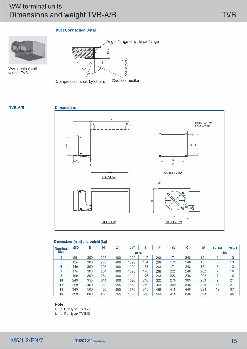
VAV terminal unitsDimensions and weight TVB-A/B TVB
M5/1.2/EN/7 15
TVB-A/B
NoteL : For type TVB-AL1 : For type TVB-B
Duct Connection Detail
Dimensions
Dimensions [mm] and weight [kg]
TVB-A TVB-BNominalSize
4567810121416
300300300300300355400500600
203203203254254311381450450
99124149174199249299349399
400400400400400400655655765
132013201320132013201320157015701680
147154163170176216260315360
268268268268268323368468568
171171171222222279349418418
248248248248248303348448548
151151151202202259329398398
666779151923
131313161621273745
kg
VAV terminal unit,variant TVB

VAV terminal unit,variant TVB-C
–VAV terminal unit with acoustic cladding for the control of variable supply air volume flows–For rooms where the case-radiated noise of the unit is not sufficiently reduced by a false ceiling–The circular ducts for the room under consideration must have adequate acoustic insulation(provided by others) on the fan end.
–Acoustic cladding cannot be retrofitted–Outlet spigot with adjustable perforated damper
VAV terminal unitsDimensions and weight TVB-C TVB
M5/1.2/EN/716
TVB-CDimensions
Dimensions [mm] and weight [kg]
TVB-CNominalsize
4567810121416
1-31-31-32-52-51-51-51-51-5
99124149174199249299349399
300300300300300355400500600
203203203254254311381450450
132013201320132013201320157015701680
147154163170176216260315360
149149149199199199199199199
141414171722283846

VAV terminal unitsAppendix 1 TVB
M5/1.2/EN/7 17

Upstream conditions The volume flow rate accuracy applies toa straight up streamsection of the duct.Bends, junctions or anarrowing or wideningof the duct causeturbulence that mayaffect measurement.Duct connections,e.g. branches off themain duct, must complywith EN1505.Some installationsituations requirestraight duct sectionsupstream.
VAV terminal unitsInstallation details TVB
M5/1.2/EN/718
A radius bend with at least 1D radius at a centre linecurvature-without an additional straight ductsection up stream of the VAV terminal unit - hasonly a neggible effect on the volume flow rateaccuracy
A junction causes strong turbulence. The started volumeflow rate accuracy can only be achieved with a straightduct section of at least 2D length upstream.Shorter upstream sections require a perforated plate in thebranch and before the VAV terminal unit. If there isno straight upstream section at all, the control will not bestable, even with a perforated plate
VAV terminal unitsSpecification text TVB
M5/1.2/EN/7 19
Subj
ect t
o ch
ange
with
out n
otic
e. A
LL R
IGH
TS R
ESER
VED
T
RO
X M
alay
sia
Sdn
Bhd.
(278
360-
V); 0
7/20
21
This specificationdescribes the generalproperties of the product
VAV terminal units for variableand constant air volume systems,suitable for supply or extract air,available in 9 nominal sizes.Ready-to-commission unit which consistsof the mechanical parts and the electroniccontrol components. Each unit contains anaveraging differential pressure sensor forvolume flow rate measurement and adamper blade.
Factory assembled control componentscomplete with wiring and tubing.Spigot suitable for circular ducts to DW 144, 1998Position of the damper blade indicatedexternally at shaft extension.Closed blade air leakage to EN 1751, Class 2 (4 - 10), Class 3 (12, 14, 16)
Special characteristics– Factory set-up or programming and function testing– Volume flow rate can later be measured and adjusted on site; additional adjustment device may be necessary
Materials and surfaces– Casing and damper blade made of galvanized sheet steel– Damper blade seal made of Chloroprene rubber– Lining is mineral wool– Differential pressure sensor made of aluminum– ABS bearings
Mineral wool– Internal fiber glass insulation lining. – Faced with woven glass fabric as protection against erosion through airflow velocities of up to 20 m/s– Resistant to fungal and bacterial growth
Technical data– Nominal sizes: 4 to 16 inches– Volume flow rate range: 10 to 1775 l/s or 21 to 3761 CFM– Volume flow rate range with electric heater: 56 to 1775 l/s or 119 to 3761 CFM– Volume flow rate control range (unit with dynamic differential pressure measurement): approx. 10 to 100 % of the nominal volume flow rate– Minimum differential pressure: 20 Pa– Maximum differential pressure: 1000 Pa
AttachmentsVariable volume flow control with electronicEasy controller to connect an external control signal;actual value signal can be integrated into thecentral BMS.– Supply voltage to controller 24 V AC– Transformer step down from 230 V AC to 24 V AC– Signal voltages 0(2) – 10 V DC– Possible override controls with external switches using volt-free contacts: CLOSED, OPEN, Vmin and Vmax– Potentiometers with percentage scales to set the volume flow rates Vmin and Vmax– The actual value signal relates to the nominal volume flow rate such that commissioning and subsequent adjustment are simplified– Volume flow rate control range: approx. 10 – 100 % of the nominal volume flow rate– Clearly visible external indicator light for signaling the functions: Set, not set, and power failure Electrical connections with screw terminal
.. .
.
Related Documents