VAV Balancing Tool and Network Sensors Technical Bulletin LIT-12011087 Release 10.0 NS-ATV7003-0, NS-ATV7001-0, NS-ATV7002-0, NS-BTV7001-0, NS-BTV7002-0 Johnson Controls www.johnsoncontrols.com 2018-11-19

Welcome message from author
This document is posted to help you gain knowledge. Please leave a comment to let me know what you think about it! Share it to your friends and learn new things together.
Transcript
VAV Balancing Tool and Network SensorsTechnical Bulletin
LIT-12011087
Release 10.0
NS-ATV7003-0, NS-ATV7001-0, NS-ATV7002-0, NS-BTV7001-0, NS-BTV7002-0
Johnson Controlswww.johnsoncontrols.com2018-11-19

ContentsContentsDocument introduction................................................................................................................... 3
Related documentation................................................................................................................... 3
VAV Balancing Tool overview.......................................................................................................... 4
VAV Balancing Tool models.................................................................................................................. 4
General operation..................................................................................................................................4
Detailed procedures.........................................................................................................................6
Entering balancing mode..................................................................................................................... 6
Balancing a single duct system........................................................................................................... 6
Balancing a dual duct system............................................................................................................10
Troubleshooting............................................................................................................................. 17
Error Codes...........................................................................................................................................17

Document introduction
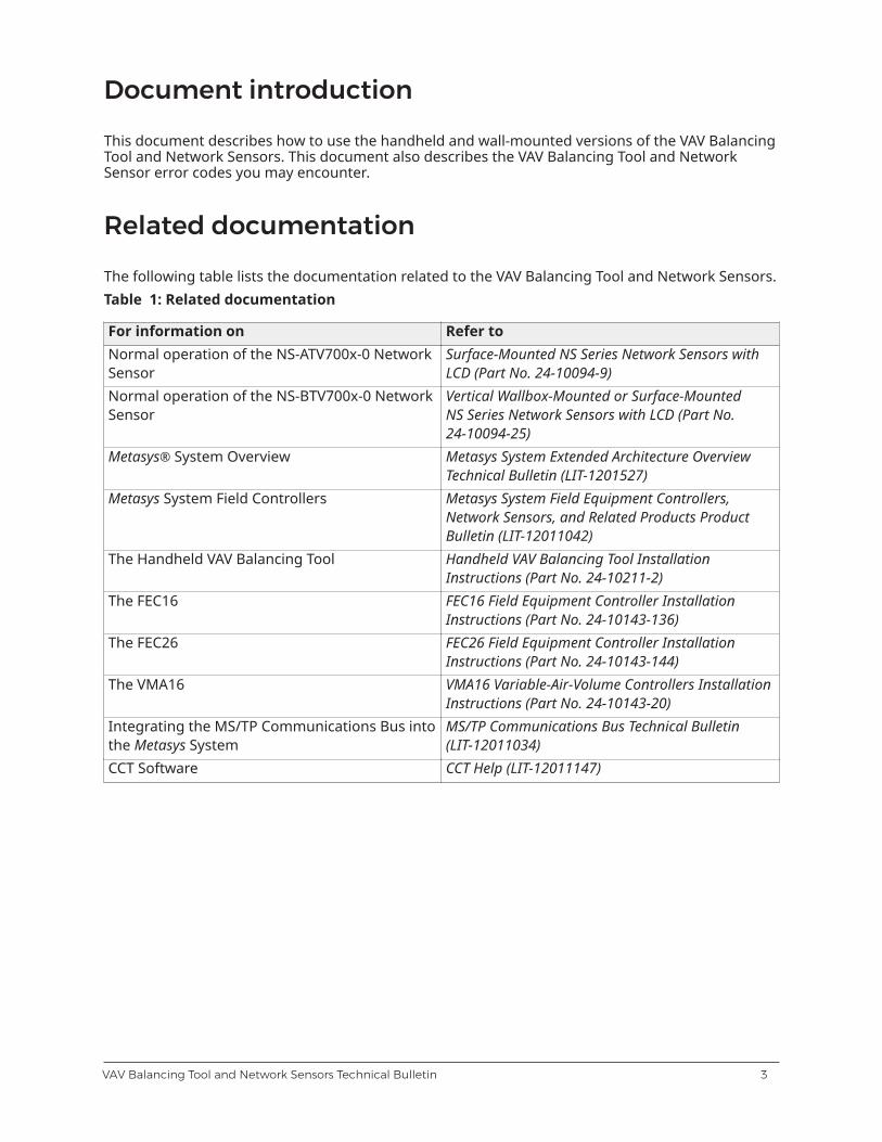
This document describes how to use the handheld and wall-mounted versions of the VAV BalancingTool and Network Sensors. This document also describes the VAV Balancing Tool and NetworkSensor error codes you may encounter.
Related documentation
The following table lists the documentation related to the VAV Balancing Tool and Network Sensors.Table 1: Related documentation
For information on Refer toNormal operation of the NS-ATV700x-0 NetworkSensor
Surface-Mounted NS Series Network Sensors withLCD (Part No. 24-10094-9)
Normal operation of the NS-BTV700x-0 NetworkSensor
Vertical Wallbox-Mounted or Surface-MountedNS Series Network Sensors with LCD (Part No.24-10094-25)
Metasys® System Overview Metasys System Extended Architecture OverviewTechnical Bulletin (LIT-1201527)
Metasys System Field Controllers Metasys System Field Equipment Controllers,Network Sensors, and Related Products ProductBulletin (LIT-12011042)
The Handheld VAV Balancing Tool Handheld VAV Balancing Tool InstallationInstructions (Part No. 24-10211-2)
The FEC16 FEC16 Field Equipment Controller InstallationInstructions (Part No. 24-10143-136)
The FEC26 FEC26 Field Equipment Controller InstallationInstructions (Part No. 24-10143-144)
The VMA16 VMA16 Variable-Air-Volume Controllers InstallationInstructions (Part No. 24-10143-20)
Integrating the MS/TP Communications Bus intothe Metasys System
MS/TP Communications Bus Technical Bulletin(LIT-12011034)
CCT Software CCT Help (LIT-12011147)
3VAV Balancing Tool and Network Sensors Technical Bulletin
VAV Balancing Tool overview
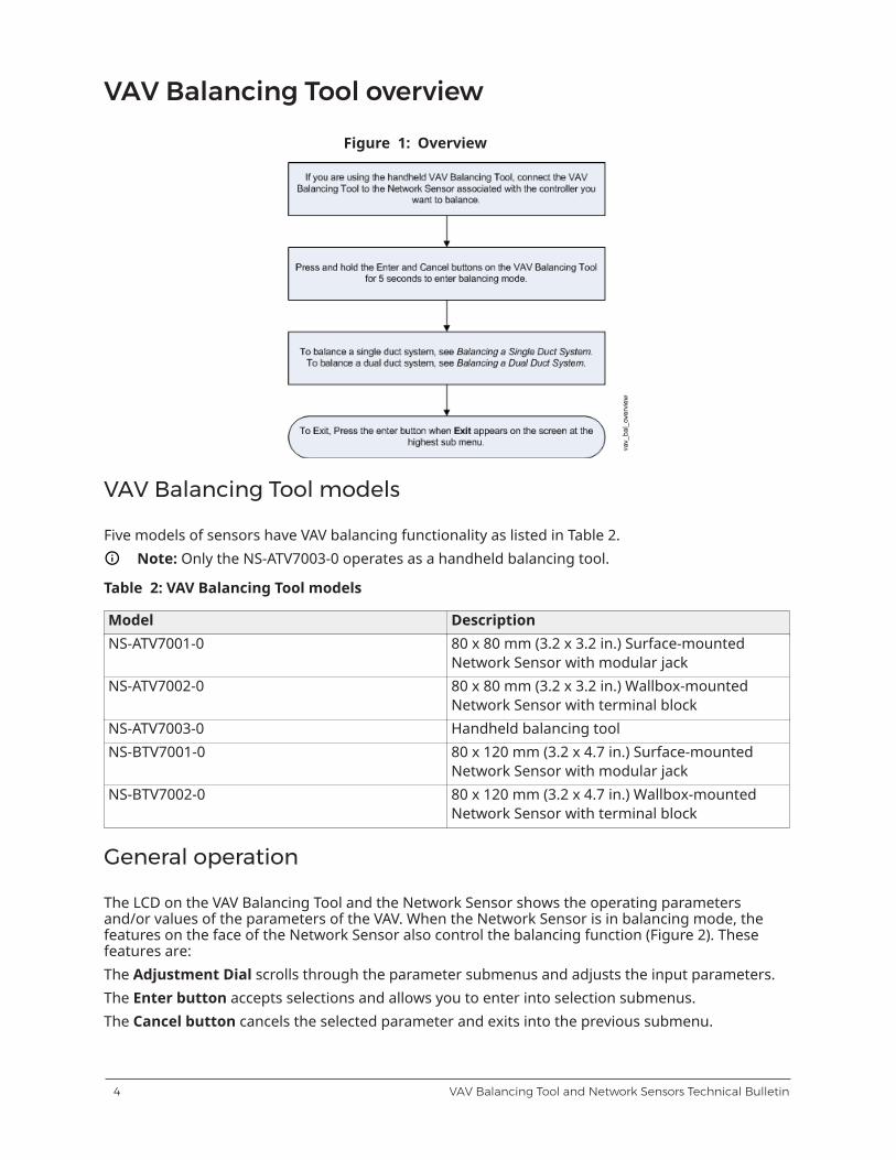
Figure 1: Overview
VAV Balancing Tool models
Five models of sensors have VAV balancing functionality as listed in Table 2.Note: Only the NS-ATV7003-0 operates as a handheld balancing tool.
Table 2: VAV Balancing Tool models
Model DescriptionNS-ATV7001-0 80 x 80 mm (3.2 x 3.2 in.) Surface-mounted
Network Sensor with modular jackNS-ATV7002-0 80 x 80 mm (3.2 x 3.2 in.) Wallbox-mounted
Network Sensor with terminal blockNS-ATV7003-0 Handheld balancing toolNS-BTV7001-0 80 x 120 mm (3.2 x 4.7 in.) Surface-mounted
Network Sensor with modular jackNS-BTV7002-0 80 x 120 mm (3.2 x 4.7 in.) Wallbox-mounted
Network Sensor with terminal block
General operation
The LCD on the VAV Balancing Tool and the Network Sensor shows the operating parametersand/or values of the parameters of the VAV. When the Network Sensor is in balancing mode, thefeatures on the face of the Network Sensor also control the balancing function (Figure 2). Thesefeatures are:The Adjustment Dial scrolls through the parameter submenus and adjusts the input parameters.The Enter button accepts selections and allows you to enter into selection submenus.The Cancel button cancels the selected parameter and exits into the previous submenu.
VAV Balancing Tool and Network Sensors Technical Bulletin4
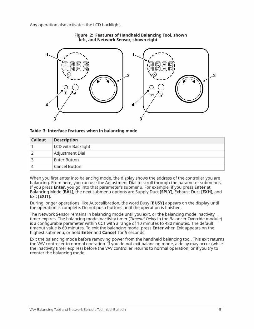
Any operation also activates the LCD backlight.
Figure 2: Features of Handheld Balancing Tool, shownleft, and Network Sensor, shown right
Table 3: Interface features when in balancing mode
Callout Description1 LCD with Backlight2 Adjustment Dial3 Enter Button4 Cancel Button
When you first enter into balancing mode, the display shows the address of the controller you arebalancing. From here, you can use the Adjustment Dial to scroll through the parameter submenus.If you press Enter, you go into that parameter’s submenu. For example, if you press Enter atBalancing Mode [BAL], the next submenu options are Supply Duct [SPLY], Exhaust Duct [EXH], andExit [EXIT].During longer operations, like Autocalibration, the word Busy [BUSY] appears on the display untilthe operation is complete. Do not push buttons until the operation is finished.The Network Sensor remains in balancing mode until you exit, or the balancing mode inactivitytimer expires. The balancing mode inactivity timer (Timeout Delay in the Balancer Override module)is a configurable parameter within CCT with a range of 10 minutes to 480 minutes. The defaulttimeout value is 60 minutes. To exit the balancing mode, press Enter when Exit appears on thehighest submenu, or hold Enter and Cancel for 5 seconds.Exit the balancing mode before removing power from the handheld balancing tool. This exit returnsthe VAV controller to normal operation. If you do not exit balancing mode, a delay may occur (whilethe inactivity timer expires) before the VAV controller returns to normal operation, or if you try toreenter the balancing mode.
5VAV Balancing Tool and Network Sensors Technical Bulletin
Detailed procedures
Entering balancing mode
To enter balancing mode:
1. If you are using the handheld balancing tool, connect it to the Network Sensor associated withthe controller you want to balance.
2. Press and hold the Enter and Cancel buttons together for at least 5 seconds until the wordBusy [BUSY] appears on the display.
Note: The VAV Balancing Tool returns to normal operation after a certain period ofinactivity, based on the Timeout Delay parameter in the Balancer Override module. Thedefault Timeout Delay is 60 minutes.
3. For Single Duct applications, see Balancing a single duct system. For Dual Duct applications,see Balancing a dual duct system.
Balancing a single duct system
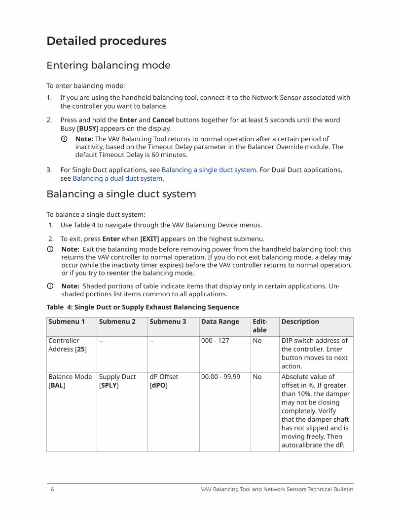
To balance a single duct system:1. Use Table 4 to navigate through the VAV Balancing Device menus.
2. To exit, press Enter when [EXIT] appears on the highest submenu.Note: Exit the balancing mode before removing power from the handheld balancing tool; thisreturns the VAV controller to normal operation. If you do not exit balancing mode, a delay mayoccur (while the inactivity timer expires) before the VAV controller returns to normal operation,or if you try to reenter the balancing mode.
Note: Shaded portions of table indicate items that display only in certain applications. Un-shaded portions list items common to all applications.
Table 4: Single Duct or Supply Exhaust Balancing Sequence
Submenu 1 Submenu 2 Submenu 3 Data Range Edit-able
Description
ControllerAddress [25]
-- -- 000 - 127 No DIP switch address ofthe controller. Enterbutton moves to nextaction.
Balance Mode[BAL]
Supply Duct[SPLY]
dP Offset[dPO]
00.00 - 99.99 No Absolute value ofoffset in %. If greaterthan 10%, the dampermay not be closingcompletely. Verifythat the damper shafthas not slipped and ismoving freely. Thenautocalibrate the dP.
VAV Balancing Tool and Network Sensors Technical Bulletin6
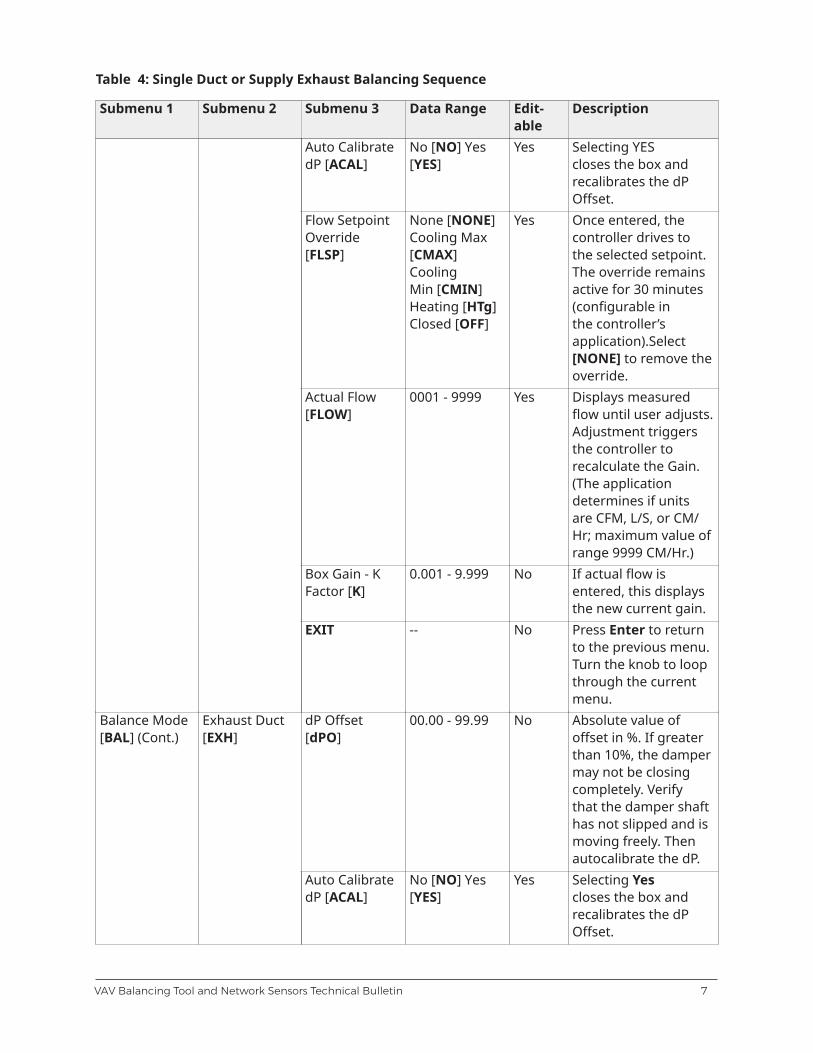
Table 4: Single Duct or Supply Exhaust Balancing Sequence
Submenu 1 Submenu 2 Submenu 3 Data Range Edit-able
Description
Auto CalibratedP [ACAL]
No [NO] Yes[YES]
Yes Selecting YEScloses the box andrecalibrates the dPOffset.
Flow SetpointOverride[FLSP]
None [NONE]Cooling Max[CMAX]CoolingMin [CMIN]Heating [HTg]Closed [OFF]
Yes Once entered, thecontroller drives tothe selected setpoint.The override remainsactive for 30 minutes(configurable inthe controller’sapplication).Select[NONE] to remove theoverride.
Actual Flow[FLOW]
0001 - 9999 Yes Displays measuredflow until user adjusts.Adjustment triggersthe controller torecalculate the Gain.(The applicationdetermines if unitsare CFM, L/S, or CM/Hr; maximum value ofrange 9999 CM/Hr.)
Box Gain - KFactor [K]
0.001 - 9.999 No If actual flow isentered, this displaysthe new current gain.
EXIT -- No Press Enter to returnto the previous menu.Turn the knob to loopthrough the currentmenu.
dP Offset[dPO]
00.00 - 99.99 No Absolute value ofoffset in %. If greaterthan 10%, the dampermay not be closingcompletely. Verifythat the damper shafthas not slipped and ismoving freely. Thenautocalibrate the dP.
Balance Mode[BAL] (Cont.)
Exhaust Duct[EXH]
Auto CalibratedP [ACAL]
No [NO] Yes[YES]
Yes Selecting Yescloses the box andrecalibrates the dPOffset.
7VAV Balancing Tool and Network Sensors Technical Bulletin
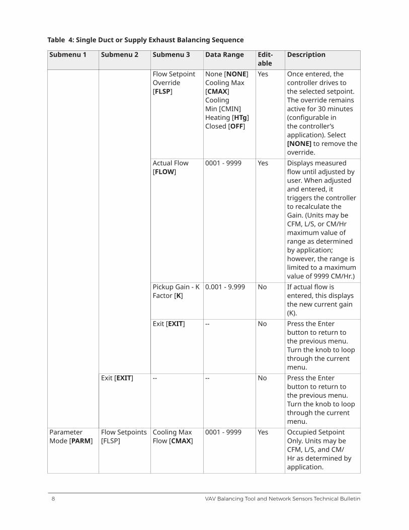
Table 4: Single Duct or Supply Exhaust Balancing Sequence
Submenu 1 Submenu 2 Submenu 3 Data Range Edit-able
Description
Flow SetpointOverride[FLSP]
None [NONE]Cooling Max[CMAX]CoolingMin [CMIN]Heating [HTg]Closed [OFF]
Yes Once entered, thecontroller drives tothe selected setpoint.The override remainsactive for 30 minutes(configurable inthe controller’sapplication). Select[NONE] to remove theoverride.
Actual Flow[FLOW]
0001 - 9999 Yes Displays measuredflow until adjusted byuser. When adjustedand entered, ittriggers the controllerto recalculate theGain. (Units may beCFM, L/S, or CM/Hrmaximum value ofrange as determinedby application;however, the range islimited to a maximumvalue of 9999 CM/Hr.)
Pickup Gain - KFactor [K]
0.001 - 9.999 No If actual flow isentered, this displaysthe new current gain(K).
Exit [EXIT] -- No Press the Enterbutton to return tothe previous menu.Turn the knob to loopthrough the currentmenu.
Exit [EXIT] -- -- No Press the Enterbutton to return tothe previous menu.Turn the knob to loopthrough the currentmenu.
ParameterMode [PARM]
Flow Setpoints[FLSP]
Cooling MaxFlow [CMAX]
0001 - 9999 Yes Occupied SetpointOnly. Units may beCFM, L/S, and CM/Hr as determined byapplication.
VAV Balancing Tool and Network Sensors Technical Bulletin8
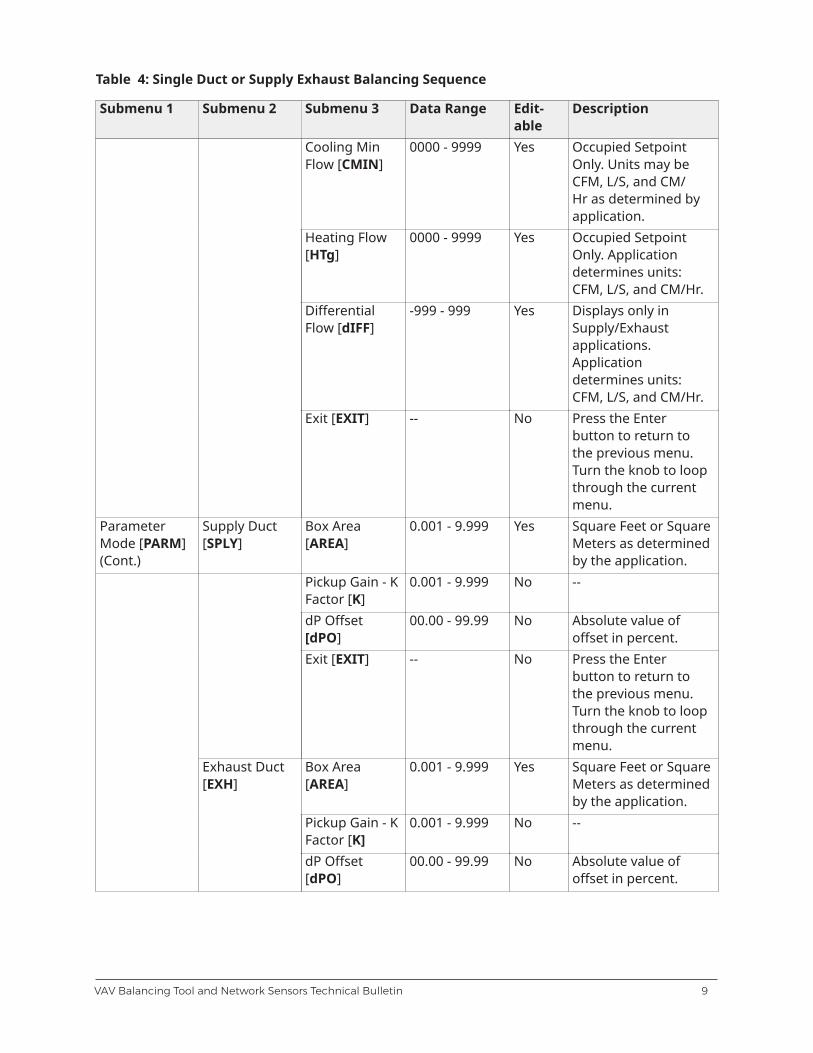
Table 4: Single Duct or Supply Exhaust Balancing Sequence
Submenu 1 Submenu 2 Submenu 3 Data Range Edit-able
Description
Cooling MinFlow [CMIN]
0000 - 9999 Yes Occupied SetpointOnly. Units may beCFM, L/S, and CM/Hr as determined byapplication.
Heating Flow[HTg]
0000 - 9999 Yes Occupied SetpointOnly. Applicationdetermines units:CFM, L/S, and CM/Hr.
DifferentialFlow [dIFF]
-999 - 999 Yes Displays only inSupply/Exhaustapplications.Applicationdetermines units:CFM, L/S, and CM/Hr.
Exit [EXIT] -- No Press the Enterbutton to return tothe previous menu.Turn the knob to loopthrough the currentmenu.
ParameterMode [PARM](Cont.)
Supply Duct[SPLY]
Box Area[AREA]
0.001 - 9.999 Yes Square Feet or SquareMeters as determinedby the application.
Pickup Gain - KFactor [K]
0.001 - 9.999 No --
dP Offset[dPO]
00.00 - 99.99 No Absolute value ofoffset in percent.
Exit [EXIT] -- No Press the Enterbutton to return tothe previous menu.Turn the knob to loopthrough the currentmenu.
Box Area[AREA]
0.001 - 9.999 Yes Square Feet or SquareMeters as determinedby the application.
Pickup Gain - KFactor [K]
0.001 - 9.999 No --
Exhaust Duct[EXH]
dP Offset[dPO]
00.00 - 99.99 No Absolute value ofoffset in percent.
9VAV Balancing Tool and Network Sensors Technical Bulletin
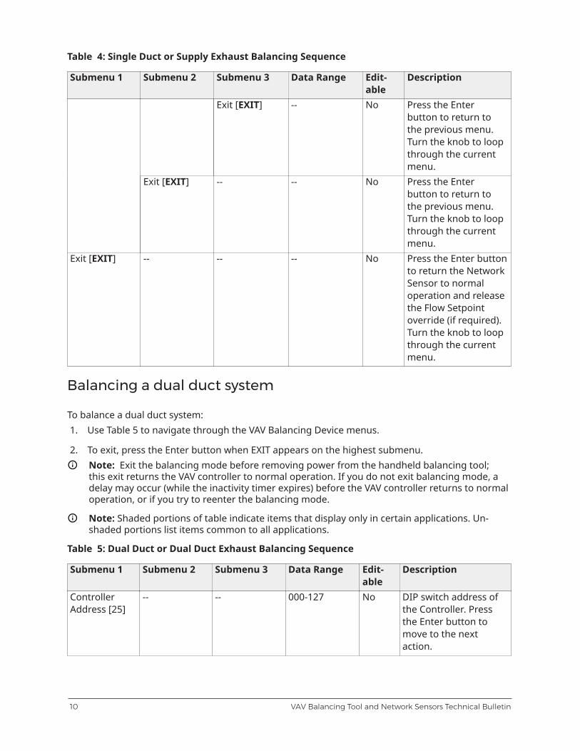
Table 4: Single Duct or Supply Exhaust Balancing Sequence
Submenu 1 Submenu 2 Submenu 3 Data Range Edit-able
Description
Exit [EXIT] -- No Press the Enterbutton to return tothe previous menu.Turn the knob to loopthrough the currentmenu.
Exit [EXIT] -- -- No Press the Enterbutton to return tothe previous menu.Turn the knob to loopthrough the currentmenu.
Exit [EXIT] -- -- -- No Press the Enter buttonto return the NetworkSensor to normaloperation and releasethe Flow Setpointoverride (if required).Turn the knob to loopthrough the currentmenu.
Balancing a dual duct system
To balance a dual duct system:1. Use Table 5 to navigate through the VAV Balancing Device menus.
2. To exit, press the Enter button when EXIT appears on the highest submenu.Note: Exit the balancing mode before removing power from the handheld balancing tool;this exit returns the VAV controller to normal operation. If you do not exit balancing mode, adelay may occur (while the inactivity timer expires) before the VAV controller returns to normaloperation, or if you try to reenter the balancing mode.
Note: Shaded portions of table indicate items that display only in certain applications. Un-shaded portions list items common to all applications.
Table 5: Dual Duct or Dual Duct Exhaust Balancing Sequence
Submenu 1 Submenu 2 Submenu 3 Data Range Edit-able
Description
ControllerAddress [25]
-- -- 000-127 No DIP switch address ofthe Controller. Pressthe Enter button tomove to the nextaction.
VAV Balancing Tool and Network Sensors Technical Bulletin10
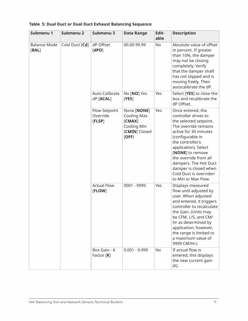
Table 5: Dual Duct or Dual Duct Exhaust Balancing Sequence
Submenu 1 Submenu 2 Submenu 3 Data Range Edit-able
Description
dP Offset[dPO]
00.00-99.99 No Absolute value of offsetin percent. If greaterthan 10%, the dampermay not be closingcompletely. Verifythat the damper shafthas not slipped and ismoving freely. Thenautocalibrate the dP.
Auto CalibratedP [ACAL]
No [NO] Yes[YES]
Yes Select [YES] to close thebox and recalibrate thedP Offset.
Flow SetpointOverride[FLSP]
None [NONE]Cooling Max[CMAX]Cooling Min[CMIN] Closed[OFF]
Yes Once entered, thecontroller drives tothe selected setpoint.The override remainsactive for 30 minutes(configurable inthe controller’sapplication). Select[NONE] to removethe override from alldampers. The Hot Ductdamper is closed whenCold Duct is overridento Min or Max Flow.
Actual Flow[FLOW]
0001 - 9999 Yes Displays measuredflow until adjusted byuser. When adjustedand entered, it triggerscontroller to recalculatethe Gain. (Units maybe CFM, L/S, and CM/Hr as determined byapplication; however,the range is limited toa maximum value of9999 CM/Hr.)
Balance Mode[BAL]
Cold Duct [Cd]
Box Gain - KFactor [K]
0.001 - 9.999 No If actual flow isentered, this displaysthe new current gain(K).
11VAV Balancing Tool and Network Sensors Technical Bulletin
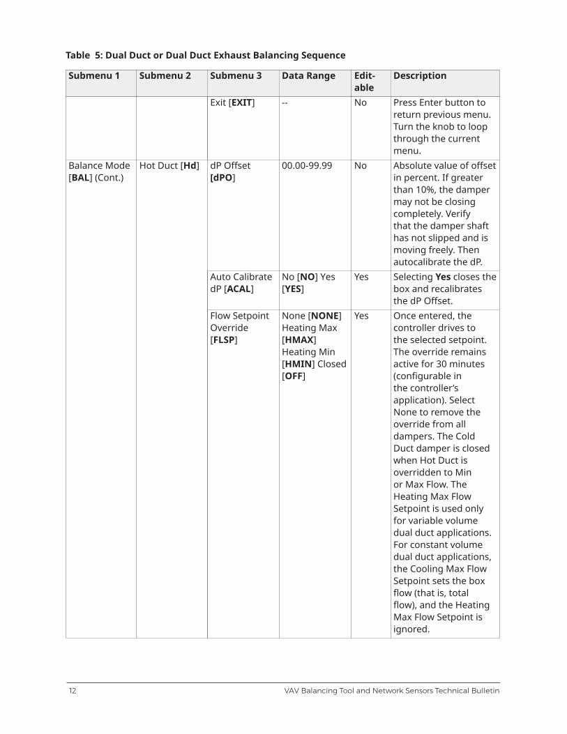
Table 5: Dual Duct or Dual Duct Exhaust Balancing Sequence
Submenu 1 Submenu 2 Submenu 3 Data Range Edit-able
Description
Exit [EXIT] -- No Press Enter button toreturn previous menu.Turn the knob to loopthrough the currentmenu.
dP Offset[dPO]
00.00-99.99 No Absolute value of offsetin percent. If greaterthan 10%, the dampermay not be closingcompletely. Verifythat the damper shafthas not slipped and ismoving freely. Thenautocalibrate the dP.
Auto CalibratedP [ACAL]
No [NO] Yes[YES]
Yes Selecting Yes closes thebox and recalibratesthe dP Offset.
Balance Mode[BAL] (Cont.)
Hot Duct [Hd]
Flow SetpointOverride[FLSP]
None [NONE]Heating Max[HMAX]Heating Min[HMIN] Closed[OFF]
Yes Once entered, thecontroller drives tothe selected setpoint.The override remainsactive for 30 minutes(configurable inthe controller’sapplication). SelectNone to remove theoverride from alldampers. The ColdDuct damper is closedwhen Hot Duct isoverridden to Minor Max Flow. TheHeating Max FlowSetpoint is used onlyfor variable volumedual duct applications.For constant volumedual duct applications,the Cooling Max FlowSetpoint sets the boxflow (that is, totalflow), and the HeatingMax Flow Setpoint isignored.
VAV Balancing Tool and Network Sensors Technical Bulletin12
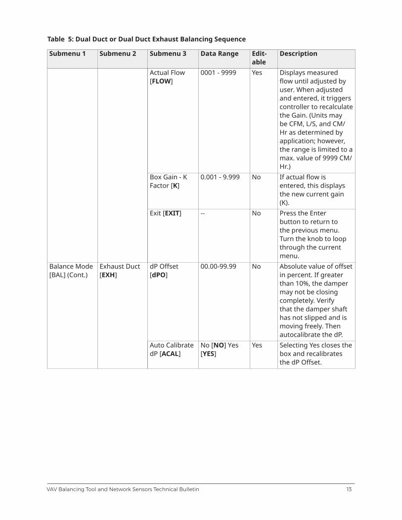
Table 5: Dual Duct or Dual Duct Exhaust Balancing Sequence
Submenu 1 Submenu 2 Submenu 3 Data Range Edit-able
Description
Actual Flow[FLOW]
0001 - 9999 Yes Displays measuredflow until adjusted byuser. When adjustedand entered, it triggerscontroller to recalculatethe Gain. (Units maybe CFM, L/S, and CM/Hr as determined byapplication; however,the range is limited to amax. value of 9999 CM/Hr.)
Box Gain - KFactor [K]
0.001 - 9.999 No If actual flow isentered, this displaysthe new current gain(K).
Exit [EXIT] -- No Press the Enterbutton to return tothe previous menu.Turn the knob to loopthrough the currentmenu.
dP Offset[dPO]
00.00-99.99 No Absolute value of offsetin percent. If greaterthan 10%, the dampermay not be closingcompletely. Verifythat the damper shafthas not slipped and ismoving freely. Thenautocalibrate the dP.
Balance Mode[BAL] (Cont.)
Exhaust Duct[EXH]
Auto CalibratedP [ACAL]
No [NO] Yes[YES]
Yes Selecting Yes closes thebox and recalibratesthe dP Offset.
13VAV Balancing Tool and Network Sensors Technical Bulletin
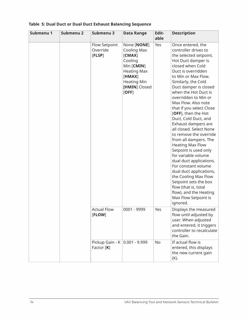
Table 5: Dual Duct or Dual Duct Exhaust Balancing Sequence
Submenu 1 Submenu 2 Submenu 3 Data Range Edit-able
Description
Flow SetpointOverride[FLSP]
None [NONE]Cooling Max[CMAX]CoolingMin [CMIN]Heating Max[HMAX]Heating Min[HMIN] Closed[OFF]
Yes Once entered, thecontroller drives tothe selected setpoint.Hot Duct damper isclosed when ColdDuct is overriddento Min or Max Flow.Similarly, the ColdDuct damper is closedwhen the Hot Duct isoverridden to Min orMax Flow. Also notethat if you select Close[OFF], then the HotDuct, Cold Duct, andExhaust dampers areall closed. Select Noneto remove the overridefrom all dampers. TheHeating Max FlowSetpoint is used onlyfor variable volumedual duct applications.For constant volumedual duct applications,the Cooling Max FlowSetpoint sets the boxflow (that is, totalflow), and the HeatingMax Flow Setpoint isignored.
Actual Flow[FLOW]
0001 - 9999 Yes Displays the measuredflow until adjusted byuser. When adjustedand entered, it triggerscontroller to recalculatethe Gain.
Pickup Gain - KFactor [K]
0.001 - 9.999 No If actual flow isentered, this displaysthe new current gain(K).
VAV Balancing Tool and Network Sensors Technical Bulletin14
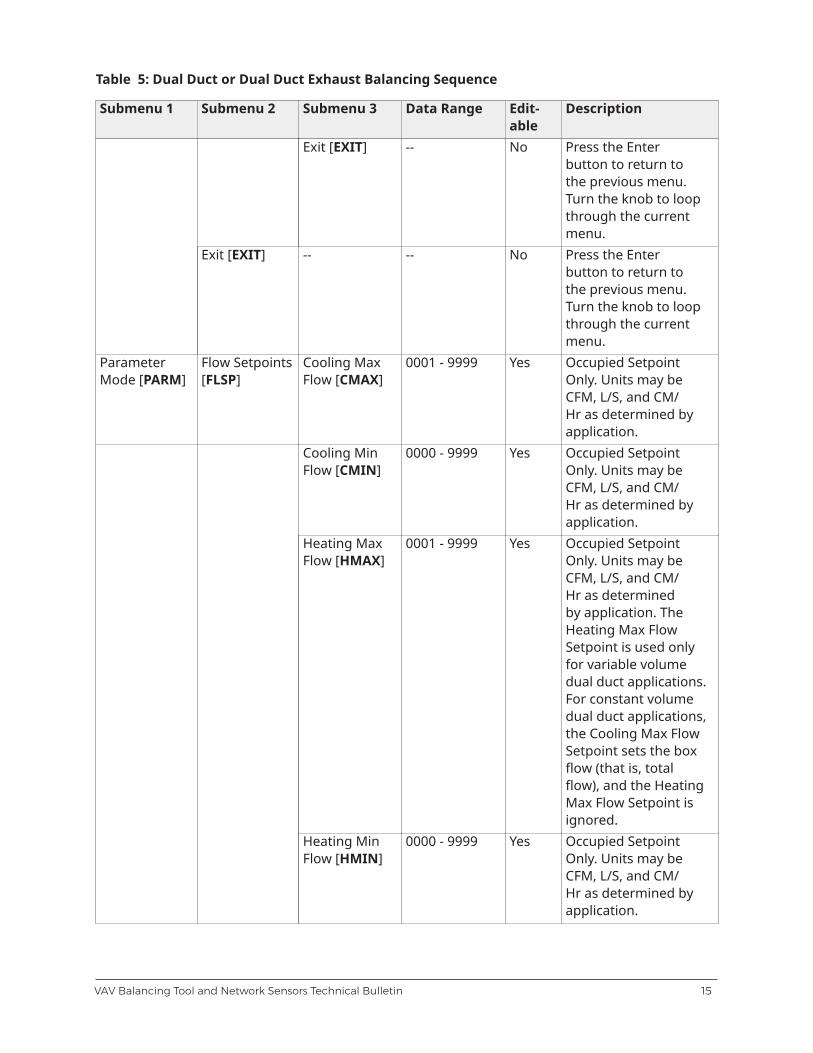
Table 5: Dual Duct or Dual Duct Exhaust Balancing Sequence
Submenu 1 Submenu 2 Submenu 3 Data Range Edit-able
Description
Exit [EXIT] -- No Press the Enterbutton to return tothe previous menu.Turn the knob to loopthrough the currentmenu.
Exit [EXIT] -- -- No Press the Enterbutton to return tothe previous menu.Turn the knob to loopthrough the currentmenu.
ParameterMode [PARM]
Flow Setpoints[FLSP]
Cooling MaxFlow [CMAX]
0001 - 9999 Yes Occupied SetpointOnly. Units may beCFM, L/S, and CM/Hr as determined byapplication.
Cooling MinFlow [CMIN]
0000 - 9999 Yes Occupied SetpointOnly. Units may beCFM, L/S, and CM/Hr as determined byapplication.
Heating MaxFlow [HMAX]
0001 - 9999 Yes Occupied SetpointOnly. Units may beCFM, L/S, and CM/Hr as determinedby application. TheHeating Max FlowSetpoint is used onlyfor variable volumedual duct applications.For constant volumedual duct applications,the Cooling Max FlowSetpoint sets the boxflow (that is, totalflow), and the HeatingMax Flow Setpoint isignored.
Heating MinFlow [HMIN]
0000 - 9999 Yes Occupied SetpointOnly. Units may beCFM, L/S, and CM/Hr as determined byapplication.
15VAV Balancing Tool and Network Sensors Technical Bulletin
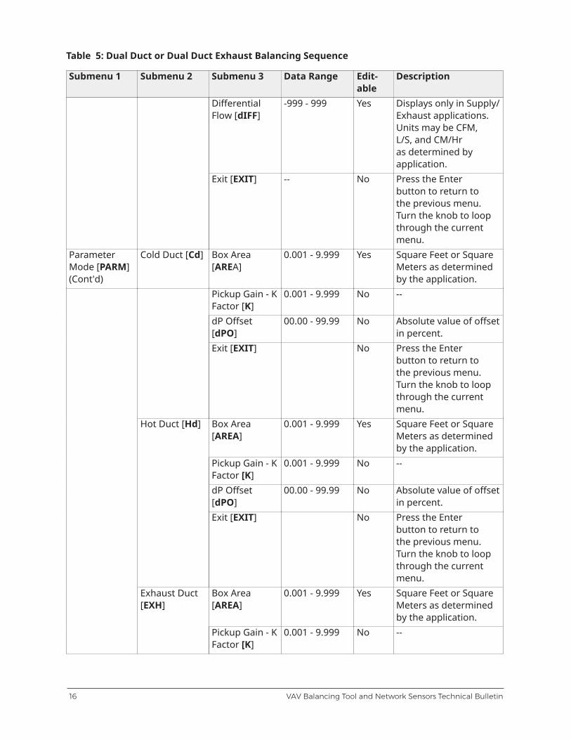
Table 5: Dual Duct or Dual Duct Exhaust Balancing Sequence
Submenu 1 Submenu 2 Submenu 3 Data Range Edit-able
Description
DifferentialFlow [dIFF]
-999 - 999 Yes Displays only in Supply/Exhaust applications.Units may be CFM,L/S, and CM/Hras determined byapplication.
Exit [EXIT] -- No Press the Enterbutton to return tothe previous menu.Turn the knob to loopthrough the currentmenu.
ParameterMode [PARM](Cont'd)
Cold Duct [Cd] Box Area[AREA]
0.001 - 9.999 Yes Square Feet or SquareMeters as determinedby the application.
Pickup Gain - KFactor [K]
0.001 - 9.999 No --
dP Offset[dPO]
00.00 - 99.99 No Absolute value of offsetin percent.
Exit [EXIT] No Press the Enterbutton to return tothe previous menu.Turn the knob to loopthrough the currentmenu.
Box Area[AREA]
0.001 - 9.999 Yes Square Feet or SquareMeters as determinedby the application.
Pickup Gain - KFactor [K]
0.001 - 9.999 No --
dP Offset[dPO]
00.00 - 99.99 No Absolute value of offsetin percent.
Hot Duct [Hd]
Exit [EXIT] No Press the Enterbutton to return tothe previous menu.Turn the knob to loopthrough the currentmenu.
Box Area[AREA]
0.001 - 9.999 Yes Square Feet or SquareMeters as determinedby the application.
Exhaust Duct[EXH]
Pickup Gain - KFactor [K]
0.001 - 9.999 No --
VAV Balancing Tool and Network Sensors Technical Bulletin16
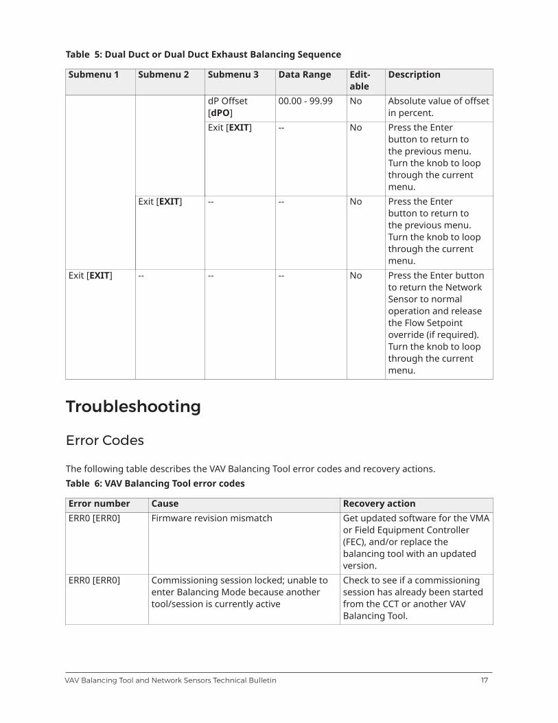
Table 5: Dual Duct or Dual Duct Exhaust Balancing Sequence
Submenu 1 Submenu 2 Submenu 3 Data Range Edit-able
Description
dP Offset[dPO]
00.00 - 99.99 No Absolute value of offsetin percent.
Exit [EXIT] -- No Press the Enterbutton to return tothe previous menu.Turn the knob to loopthrough the currentmenu.
Exit [EXIT] -- -- No Press the Enterbutton to return tothe previous menu.Turn the knob to loopthrough the currentmenu.
Exit [EXIT] -- -- -- No Press the Enter buttonto return the NetworkSensor to normaloperation and releasethe Flow Setpointoverride (if required).Turn the knob to loopthrough the currentmenu.
Troubleshooting
Error Codes
The following table describes the VAV Balancing Tool error codes and recovery actions.Table 6: VAV Balancing Tool error codes
Error number Cause Recovery actionERR0 [ERR0] Firmware revision mismatch Get updated software for the VMA
or Field Equipment Controller(FEC), and/or replace thebalancing tool with an updatedversion.
ERR0 [ERR0] Commissioning session locked; unable toenter Balancing Mode because anothertool/session is currently active
Check to see if a commissioningsession has already been startedfrom the CCT or another VAVBalancing Tool.
17VAV Balancing Tool and Network Sensors Technical Bulletin
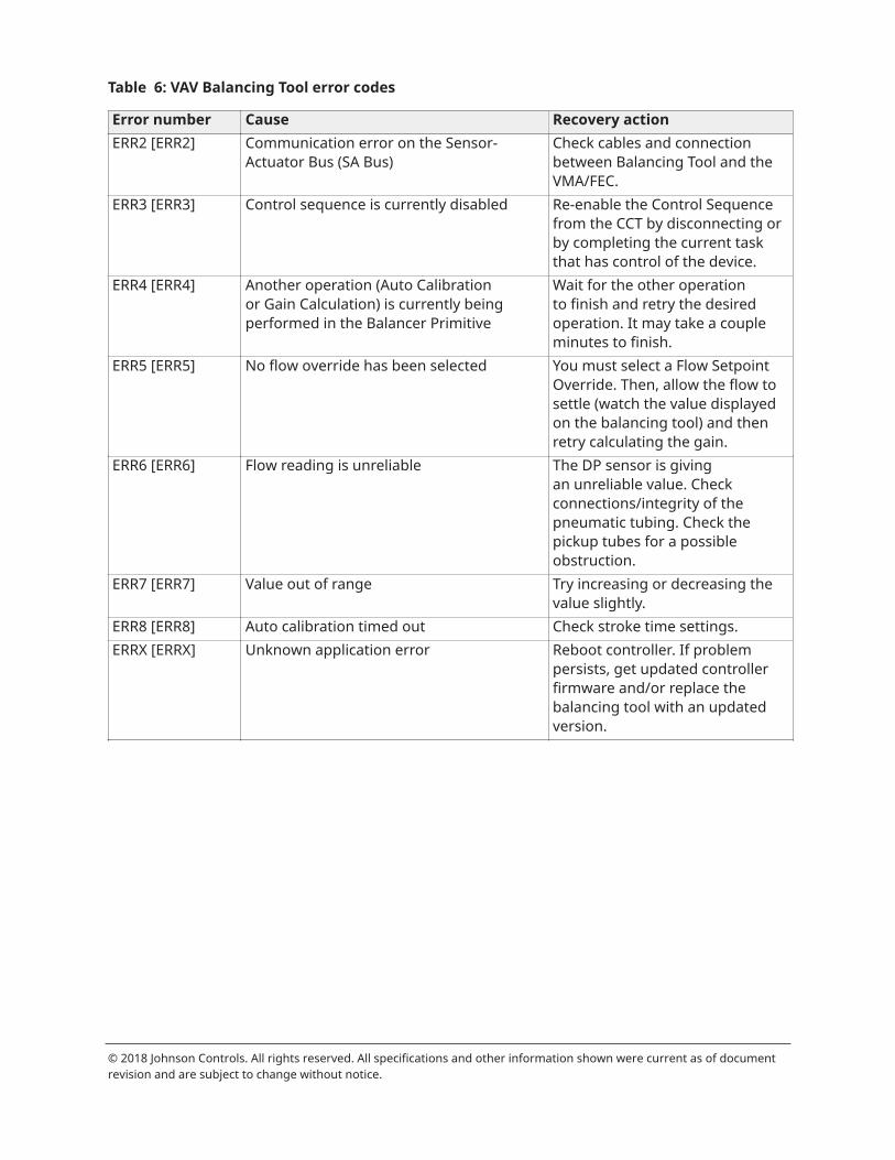
Table 6: VAV Balancing Tool error codes
Error number Cause Recovery actionERR2 [ERR2] Communication error on the Sensor-
Actuator Bus (SA Bus)Check cables and connectionbetween Balancing Tool and theVMA/FEC.
ERR3 [ERR3] Control sequence is currently disabled Re-enable the Control Sequencefrom the CCT by disconnecting orby completing the current taskthat has control of the device.
ERR4 [ERR4] Another operation (Auto Calibrationor Gain Calculation) is currently beingperformed in the Balancer Primitive
Wait for the other operationto finish and retry the desiredoperation. It may take a coupleminutes to finish.
ERR5 [ERR5] No flow override has been selected You must select a Flow SetpointOverride. Then, allow the flow tosettle (watch the value displayedon the balancing tool) and thenretry calculating the gain.
ERR6 [ERR6] Flow reading is unreliable The DP sensor is givingan unreliable value. Checkconnections/integrity of thepneumatic tubing. Check thepickup tubes for a possibleobstruction.
ERR7 [ERR7] Value out of range Try increasing or decreasing thevalue slightly.
ERR8 [ERR8] Auto calibration timed out Check stroke time settings.ERRX [ERRX] Unknown application error Reboot controller. If problem
persists, get updated controllerfirmware and/or replace thebalancing tool with an updatedversion.
© 2018 Johnson Controls. All rights reserved. All specifications and other information shown were current as of documentrevision and are subject to change without notice.
Related Documents


