YASKAWA VARISPEED-656DC5 INSTRUCTION MANUAL YASKAWA MANUAL NO. TOBP C710656 00C PWM TRANSISTOR CONVERTER MODEL: CIMR-D5A Upon receipt of the product and prior to initial operation, read these instructions thoroughly, and retain for future reference. 200 to 230 V, 27 to 120 HP (20 to 90 kW) 380 to 460 V, 27 to 496 HP (20 to 370 kW)

Welcome message from author
This document is posted to help you gain knowledge. Please leave a comment to let me know what you think about it! Share it to your friends and learn new things together.
Transcript
YASKAWA
VARISPEED-656DC5
INSTRUCTION MANUAL
YASKAWA MANUAL NO. TOBP C710656 00C
PWM TRANSISTOR CONVERTER
MODEL: CIMR-D5A
Upon receipt of the product and prior to initial operation, read these instructions thoroughly, and retain for future reference.
200 to 230 V, 27 to 120 HP (20 to 90 kW)380 to 460 V, 27 to 496 HP (20 to 370 kW)

Copyright © 2004 YASKAWA ELECTRIC CORPORATION
All rights reserved. No part of this publication may be reproduced, stored in a retrieval system, or transmitted, in any form, or by any means, mechanical, electronic, photocopying, recording, or otherwise, without the prior written permission of Yaskawa. No patent liability is assumed with respect to the use of the information contained herein. Moreover, because Yaskawa is constantly striving to improve its high-quality products, the information contained in this manual is subject to change without notice. Every precaution has been taken in the preparation of this manual. Nevertheless, Yaskawa assumes no responsibility for errors or omissions. Neither is any liability assumed for damages resulting from the use of the information contained in this publication.
iii
PREFACE
YASKAWA’s VARISPEED-656DC5 is a PWM transistor converter. This instruction man-ual describes installation, maintenance and inspection, troubleshooting, and specifications of the VS-656DC5. Read this instruction manual thoroughly before operation.
YASKAWA ELECTRIC CORPORATION
SAFETY INFORMATION
Read this instruction manual thoroughly before installation, operation, maintenance or inspection of the VS-656DC5. In this manual, NOTES FOR SAFE OPERATION are classi-fied as “WARNING” or “CAUTION.”
Indicates a potentially hazardous situation which, if not avoided, could result in death or serious injury to personnel.
Indicates a potentially hazardous situation which, if not avoided, may result in minor or moderate injury to personnel and damage to equipment.It may also be used to alert against unsafe practices.
Even items described in may result in a vital accident in some situations. In either case, follow these important notes.
These are steps to be taken to insure proper operation.
General Precautions• Some drawings in this manual are shown with the protective cover or shields removed, in order to describe
detail with more clarity. Make sure all covers and shields are replaced before operating this product. • This manual may be modified when necessary because of improvement of the product, modification, or
changes in specifications. Such modifications are denoted by a revised manual No.
• To order a copy of this manual, if your copy has been damaged or lost, contact your YASKAWA represen-tative.
• YASKAWA is not responsible for any modification of the product made by the user, since that will void your guarantee.
WARNING
CAUTION
CAUTION
NOTE
iv
NOTES FOR SAFE OPERATION
RECEIVING
INSTALLATION
(Ref. Page)
• Do not install or operate any VS-656DC5 which is damaged or has missing parts.
Failure to observe this caution may result in personal injury or equipment damage.
E-3
(Ref. Page)
• Lift the cabinet by the base. When moving the VS-656DC5, never lift by the front cover or the front panel.
Otherwise, the main unit may be dropped causing personal injury or damage to the VS-656DC5.
E-5
• Mount the VS-656DC5 on nonflammable material (i.e. metal).
Failure to observe this caution may result in a fire.
E-5
• When mounting several Units in an enclosure, install a fan or other cooling device to keep the intake air temperature below 45 °C.
Overheating may cause a fire or damage to the VS-656DC5.
E-5
CAUTION
CAUTION
v
WIRING
(Ref. Page)
• Only commence wiring after verifying that the power supply is tunred OFF.
Failure to observe this warning may result in an electric shock or a fire.
E-11
• Wiring should be performed only by qualified personnel.
Failure to observe this warning may result in an electric shock or a fire.
E-11
• Make sure to ground the ground terminal before connecting the other terminals. (200 V class: Ground to 100 Ω or less, 400 V class: Ground to 10 Ω or less).
Failure to observe this warning may result in an electric shock or a fire.
E-11
WARNING
(Ref. Page)
• Verify that the VS-656DC5 rated voltage coincides with the AC power supply volt-age.
Failure to observe this caution may result in personal injury or a fire.
E-11
• Do not perform a withstand voltage test of the VS-656DC5.
Failure to observe this caution may result in damage to the semi-conductor elements.
E-11
• Connect the input AC reactor, harmonics filter reactor, and the harmonics filter capacitor as described in this instruciton manual.
Failure to observe this caution may result in a fire.
E-11
• Verify that the rated voltage of the VS-656DC5 coincides with the rated voltage of the Inverter to be connected.
Failure to observe this caution may result in a fire.
E-11
• Tighten terminal screws.
Failure to observe this caution may result in a fire.
E-11
CAUTION
vi
OPERATION
(Ref. Page)
• Only turn ON the input power supply after attaching the front cover or the terminal cover. Do not remove the cover while current is flowing.
Failure to observe this warning may result in an electric shock.
E-30
• Never operate the Digital Operator or other switches when your hand is wet.
Failure to observe this warning may result in an electric shock.
E-30
• Never touch the terminals while current is flowing, even if the VS-656DC5 stops.
Failure to observe this warning may result in an electric shock.
E-30
WARNING
(Ref. Page)
• Never touch the radiation fins (heatsink) or input reactor since the temperature is very high.
Failure to observe this caution may result in harmful burns to the body.
E-30
• The VS-656DC5 is factory set to the suitable settings. Do not change the settings unnecessarily.
Failure to observe this caution may result in damage to the unit.
E-30
CAUTION
vii
MAINTENANCE AND INSPECTION
OTHERS
(Ref. Page)
• Never touch high-voltage terminals in the VS-656DC5.
Failure to observe this warning may result in an electric shock.
E-39
• Perform maintenance or inspection only after verifying that the CHARGE LED goes OFF, after the main circuit power supply is turned OFF.
The capacitors are still charged and can be dangerous.
E-39
• Only authorized personnel should be permitted to perform maintenance, inspec-tions, or parts replacement.
[Remove all metal objects (watches, bracelets, etc.) before operation.](Use tools which are insulated against electric shock.)Failure to observe this warning may result in an electric shock.
E-39
WARNING
(Ref. Page)
• A CMOS IC is used in the control board. Handle the control board and CMOS IC carefully. The CMOS IC can be destroyed by static electricity if touched directly.
The CMOS IC may be destroyed by static electricity if touched directly.
E-39
• Do not change the wiring, or connect/disconnect the connectors while power is applied to the circuit.
Failure to observe this caution may result in personal injury.
E-39
(Ref. Page)
• Never modify the product.
Failure to observe this warning may result in an electric shock or personal injury.
E-39
(Ref. Page)
• Do not subject the VS-656DC5 to halogen gases, such as fiuorine, chlovine, bro-mine, and iodine, at any time even during transportation or installation.
Otherwise, the VS-656DC5 can be damaged or interior parts burnt.
E-39
CAUTION
WARNING
CAUTION
viii
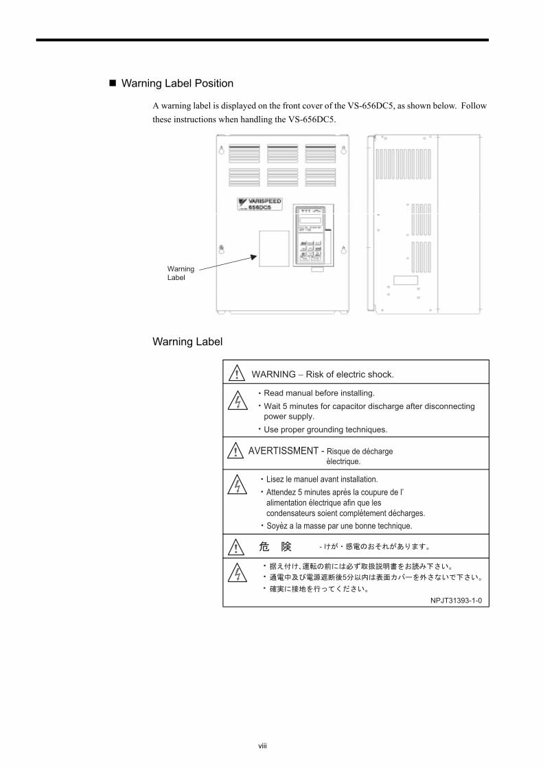
Warning Label Position
A warning label is displayed on the front cover of the VS-656DC5, as shown below. Follow these instructions when handling the VS-656DC5.
Warning Label
WarningLabel
WARNING − Risk of electric shock.
Read manual before installing.Wait 5 minutes for capacitor discharge after disconnecting power supply.Use proper grounding techniques.
AVERTISSMENT - Risque de decharge electrique.
Lisez le manuel avant installation.Attendez 5 minutes apres la coupure de l’alimentation electrique afin que les condensateurs soient completement decharges.Soyez a la masse par une bonne technique.
-
5
NPJT31393-1-0
ix
WARRANTY INFORMATION
Warranty Period
This product is warranted for twelve months after being delivered to Yaskawa’s customer or if applicable eighteen months from the date of shipment from Yaskawa’s factory, whichever comes first.
Scope of Warranty
Inspections
Periodic inspections must be conducted by the customer. However, upon request, Yaskawa or one of Yaskawa’s Service Centers can inspect the product for a fee. In this case, if after conferring with the customer, a Yaskawa product is found to be defective due to Yaskawa workmanship or materials and the defect occurs during the warranty period, then this fee will be waived and the problem remedied free of charge.
Repairs
If a Yaskawa product is found to be defective due to Yaskawa workmanship or materials and the defect occurs during the warranty period, Yaskawa will provide a replacement, repair the defective product, and provide shipping to and from the site free of charge.
However, if the Yaskawa Authorized Service Center determines that the problem with a Yaskawa product is not due to defects in Yaskawa’s workmanship or materials, then the cus-tomer will be responsible for the cost of any necessary repairs. Some problems that are out-side the scope of this warranty are:
• Problems due to improper maintenance or handling, carelessness, or other reasons where the customer is determined to be responsible.
• Problems due to additions or modifications made to a Yaskawa product without Yaskawa’s understanding.
• Problems due to the use of a Yaskawa product under conditions that do not meet the rec-ommended specifications.
• Problems caused by natural disaster or fire.
• Or other problems not due to defects in Yaskawa workmanship or materials.
Warranty service is only applicable within Japan.
However, after-sales service is available for customers outside of Japan for a reasonable fee. Contact your local Yaskawa representative for more information.
Exceptions
Any inconvenience to the customer or damage to non-Yaskawa products due to Yaskawa's defective products whether within or outside the warranty period are NOT covered by this warranty.
x
RESTRICTIONS
• The VS-656DC5 was not designed or manufactured for use in devices or systems that may directly affect or threaten human lives or health.
• Customers who intend to use the product described in this manual for devices or systems relating to transportation, health care, space aviation, atomic or electric power, or under-water use must contact their Yaskawa representatives or the nearest Yaskawa sales office beforehand.
• This product has been manufactured under strict quality-control guidelines. However, if this product is to be installed in any location where failure of this product could involve or result in a life-and-death situation or loss of human life or in a facility where failure may cause a serious accident or physical injury, safety devices must be installed to mini-mize the likelihood of any accident.
E-1
INSTRUCTIONSVarispeed-656DC5
1 RECEIVING - - - - - - - - - - - - - - - - - - - - - - - - - - - - - - - - - - E-3
1.1 Checks - - - - - - - - - - - - - - - - - - - - - - - - - - - - - - - - - - - - - - E-3
1.2 Nameplate Information - - - - - - - - - - - - - - - - - - - - - - - - - - - E-3
2 INSTALLATION - - - - - - - - - - - - - - - - - - - - - - - - - - - - - - - E-5
2.1 Checking Installation Site - - - - - - - - - - - - - - - - - - - - - - - - - E-5
2.2 Clearances - - - - - - - - - - - - - - - - - - - - - - - - - - - - - - - - - - - E-6
2.3 Dimensions - - - - - - - - - - - - - - - - - - - - - - - - - - - - - - - - - - - E-7
2.4 Removing/Attaching the Digital Operator - - - - - - - - - - - - - - E-9
2.5 Removing/Attaching the Front Cover - - - - - - - - - - - - - - - - E-10
3 WIRING - - - - - - - - - - - - - - - - - - - - - - - - - - - - - - - - - - - - -E-11
3.1 Connection and Specifications of Peripheral Devices - - - - E-12
3.2 External Dimensions of Peripheral Devices - - - - - - - - - - - E-14
3.3 Interconnection Diagram with Varispeed G7 - - - - - - - - - - - E-18
3.4 Interconnection Diagram with VS-616G5 - - - - - - - - - - - - - E-20
3.5 Wiring Precautions - - - - - - - - - - - - - - - - - - - - - - - - - - - - E-22
3.6 WIRING MAIN CIRCUIT TERMINALS - - - - - - - - - - - - - - - E-24
3.7 EXTERNAL TERMINALS - - - - - - - - - - - - - - - - - - - - - - - - E-28
4 OPERATION - - - - - - - - - - - - - - - - - - - - - - - - - - - - - - - - E-30
4.1 Checkpoints before Turning ON the Power Supply - - - - - - E-30
4.2 Setting the Power Supply Voltage Jumper (For 400 V Class VS-656DC5 with 22 kW or More) - - - - - E-31
4.3 Using the Digital Operator - - - - - - - - - - - - - - - - - - - - - - - E-32
4.4 Power ON/OFF Sequence - - - - - - - - - - - - - - - - - - - - - - - E-38
E-2
5 MAINTENANCE AND INSPECTION - - - - - - - - - - - - - - - - E-39
5.1 Maintenance Period - - - - - - - - - - - - - - - - - - - - - - - - - - - - E-39
5.2 Daily Inspection - - - - - - - - - - - - - - - - - - - - - - - - - - - - - - - E-40
5.3 Periodic Inspection - - - - - - - - - - - - - - - - - - - - - - - - - - - - E-40
5.4 PERIODIC MAINTENANCE OF PARTS - - - - - - - - - - - - - E-41
6 TROUBLESHOOTING - - - - - - - - - - - - - - - - - - - - - - - - - - E-42
6.1 Fault Detection - - - - - - - - - - - - - - - - - - - - - - - - - - - - - - - E-42
6.2 Minor Fault Detection - - - - - - - - - - - - - - - - - - - - - - - - - - - E-45
6.3 Operation Errors - - - - - - - - - - - - - - - - - - - - - - - - - - - - - - E-46
6.4 Informing the VS-656DC5 of a Peripheral Device Fault to Stop the VS-656DC5 (External Fault Function) - - - - - - E-47
7 SPECIFICATIONS - - - - - - - - - - - - - - - - - - - - - - - - - - - - - E-48
Appendix A CONSTANTS LIST - - - - - - - - - - - - - - - - - - - - - E-50
A.1 Monitor Constant List - - - - - - - - - - - - - - - - - - - - - - - - - - E-50
A.2 Constant List Other Than Monitor Constants - - - - - - - - - - E-54
A.3 Multi-function I/O Terminals (H Constants) - - - - - - - - - - - E-57
Appendix B PRECAUTIONS ON VS-656DC5 APPLICATION - - - - - - - - - - - - - - - - - - - - - - - - E-58
1 RECEIVING
E-3
1 RECEIVING
This chapter describes how to verify the VS-656DC5 after delivery to the user.
1.1 Checks
If any of the above items are not satisfactory, contact your YASKAWA representative.
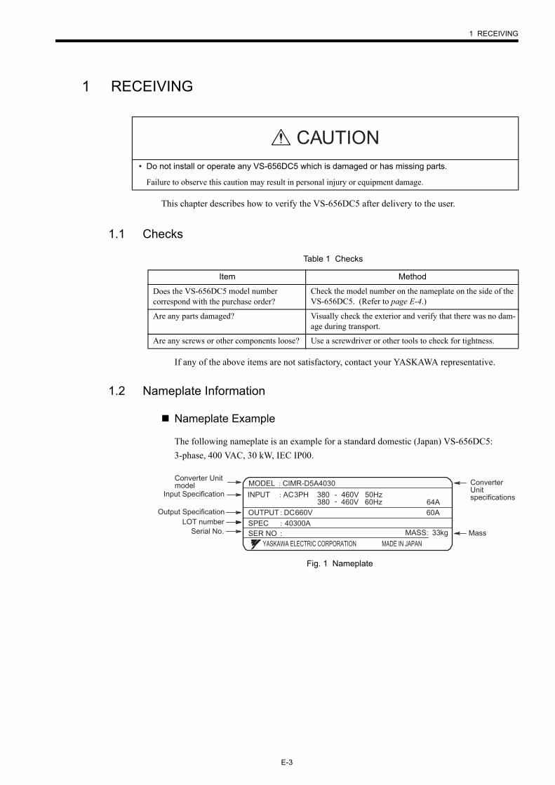
1.2 Nameplate Information
Nameplate Example
The following nameplate is an example for a standard domestic (Japan) VS-656DC5: 3-phase, 400 VAC, 30 kW, IEC IP00.
Fig. 1 Nameplate
• Do not install or operate any VS-656DC5 which is damaged or has missing parts.
Failure to observe this caution may result in personal injury or equipment damage.
CAUTION
Table 1 Checks
Item Method
Does the VS-656DC5 model number correspond with the purchase order?
Check the model number on the nameplate on the side of the VS-656DC5. (Refer to page E-4.)
Are any parts damaged? Visually check the exterior and verify that there was no dam-age during transport.
Are any screws or other components loose? Use a screwdriver or other tools to check for tightness.
YASKAWA ELECTRIC CORPORATION MADE IN JAPAN
MODEL CIMR-D5A4030
OUTPUT DC660V 60A
INPUT AC3PH 380 - 460V 50Hz64A380 - 460V 60Hz
SPEC 40300AMASS: 33kgSER NO
Converter Unit model
Input Specification
Output SpecificationLOT number
MassSerial No.
ConverterUnitspecifications
E-4
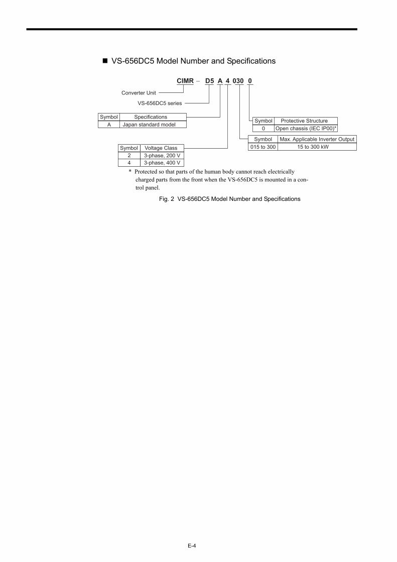
VS-656DC5 Model Number and Specifications
* Protected so that parts of the human body cannot reach electrically charged parts from the front when the VS-656DC5 is mounted in a con-trol panel.
Fig. 2 VS-656DC5 Model Number and Specifications
24
A
CIMR − 5 AD 4 030 0
Voltage Class3-phase, 200 V3-phase, 400 V
Converter Unit
VS-656DC5 series
Symbol
Symbol SpecificationsJapan standard model
015 to 300Symbol Max. Applicable Inverter Output
15 to 300 kW
0Symbol Protective Structure
Open chassis (IEC IP00)*
2 INSTALLATION
E-5
2 INSTALLATION
This chapter describes the configuration, location, and space when mounting the VS-656DC5.
2.1 Checking Installation Site
Installation Site
Install the VS-656DC5 under the following conditions.
To ensure proper performance and long operating life, follow the recommendations below when choosing a location for installing the VS-656DC5. Make sure the VS-656DC5 is pro-tected from the following conditions:
• Extreme cold and heatUse only within ambient temperature range: -10 °C to +45 °C
• Rain, moisture• Oil sprays, splashes• Salt spray• Direct sunlight (Avoid using outdoors.)• Corrosive gases or liquids• Dust or metallic particles in the air• Physical shock, vibration• Magnetic noise (Example: welding machines, power devices, etc.)• High humidity• Radioactive materials• Combustibles: thinners, solvents, etc.
• Lift the cabinet by the base. When moving the VS-656DC5, never lift by the front cover or the front panel.
Otherwise, the main unit may be dropped causing personal injury or damage to the VS-656DC5.
• Mount the VS-656DC5 on nonflammable material (i.e. metal).
Failure to observe this caution may result in a fire.
• When mounting several Units in an enclosure, install a fan or other cooling device to keep the intake air temperature below 45 °C.
Overheating may cause a fire or damage to the VS-656DC5.
CAUTION
Type Ambient Operating Temperature Humidity
Open chassis -10 to + 45 °C 90 % RH or less (no condensation)
E-6
Controlling the Ambient Temperature
To enhance the reliability of operation, the VS-656DC5 should be installed in an environ-ment free from extreme temperature increases. If the VS-656DC5 is installed in an enclosed environment, such as a box, use a cooling fan or air conditioner to maintain the internal air temperature below 45 °C.
Protecting the VS-656DC5 from Foreign Matter
Place a cover over the VS-656DC5 during installation to shield it from metal powder pro-duced by drilling.
Always remove the cover from the VS-656DC5 after completing installation. Otherwise, ventilation will be reduced, causing the VS-656DC5 to overheat.
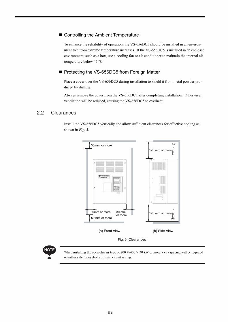
2.2 Clearances
Install the VS-656DC5 vertically and allow sufficient clearances for effective cooling as shown in Fig. 3.
Fig. 3 Clearances
When installing the open chassis type of 200 V/400 V 30 kW or more, extra spacing will be required on either side for eyebolts or main circuit wiring.
(a) Front View (b) Side View
50 mm or more
30mm or more 30 mm or more
50 mm or more120 mm or more
120 mm or more
Air
Air
NOTE
2 INSTALLATION
E-7
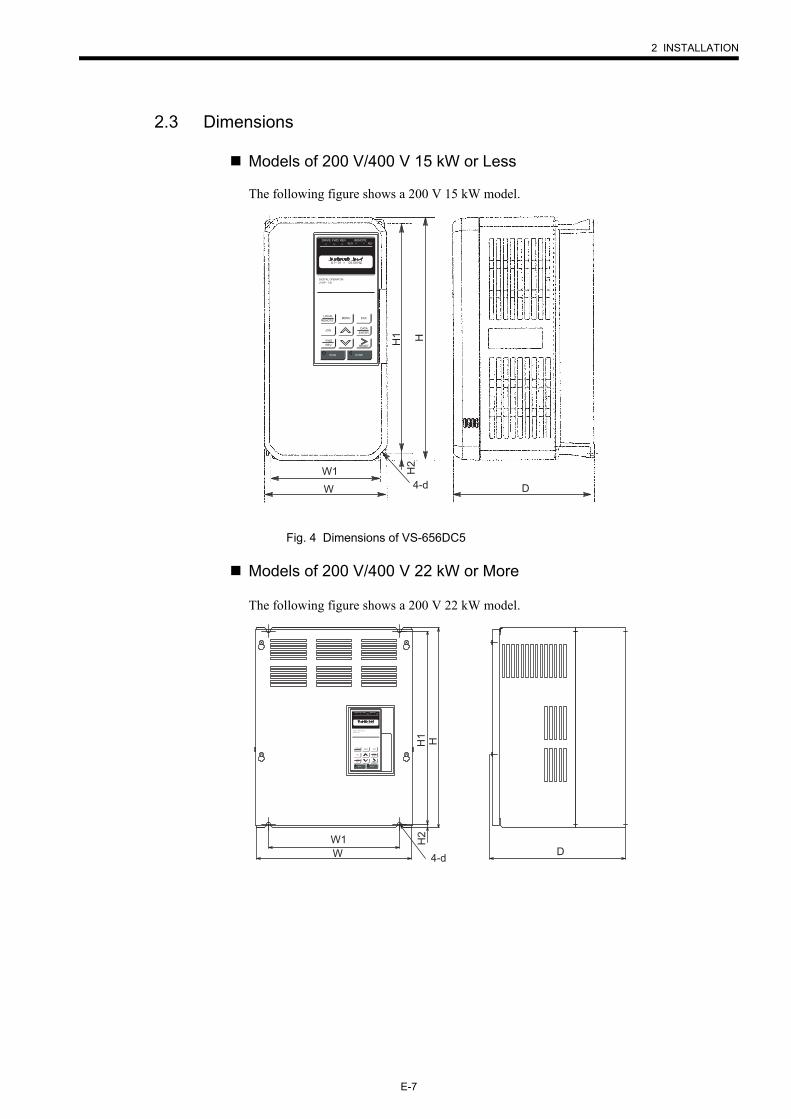
2.3 Dimensions
Models of 200 V/400 V 15 kW or Less
The following figure shows a 200 V 15 kW model.
Fig. 4 Dimensions of VS-656DC5
Models of 200 V/400 V 22 kW or More
The following figure shows a 200 V 22 kW model.
D
H1 H
W1
W 4-d
H2
LOCAL
REMOTEMENU
DIGITAL OPERATORJVOP - 130
ESC
DATAENTER
JOG
FWDREV RESET
RUN STOP
DRIVE FWD REV REMOTESEQ REF
U1 01 = 00.00 HZ
D
H1 H
W1W 4-d
H2
LOCAL
REMOTEMENU
DIGITAL OPERATORJVOP - 130
ESC
DATAENTER
JOG
FWDREV RESET
RUN STOP
DRIVE FWD REV REMOTESEQ REF
U1 01 = 00.00 HZ
E-8
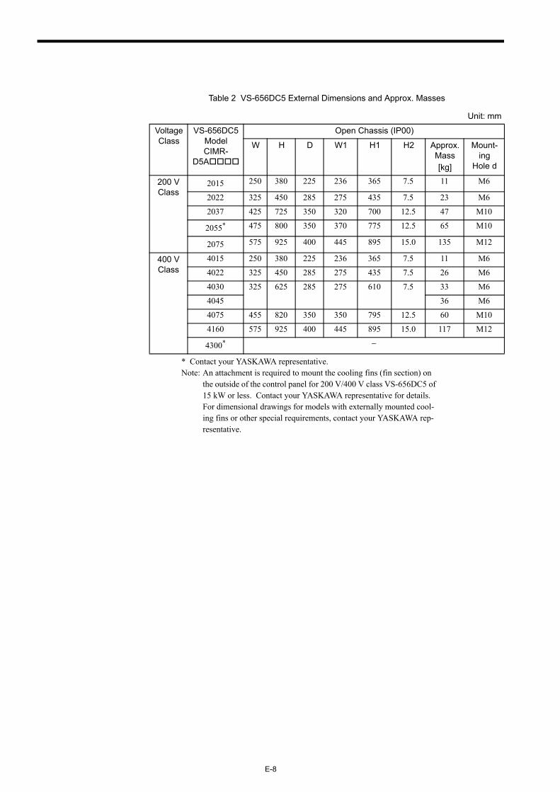
* Contact your YASKAWA representative.Note: An attachment is required to mount the cooling fins (fin section) on
the outside of the control panel for 200 V/400 V class VS-656DC5 of 15 kW or less. Contact your YASKAWA representative for details. For dimensional drawings for models with externally mounted cool-ing fins or other special requirements, contact your YASKAWA rep-resentative.
Table 2 VS-656DC5 External Dimensions and Approx. Masses
Unit: mm
Voltage Class
VS-656DC5 Model CIMR-
D5A
Open Chassis (IP00)
W H D W1 H1 H2 Approx. Mass[kg]
Mount-ing
Hole d
200 V Class
2015 250 380 225 236 365 7.5 11 M6
2022 325 450 285 275 435 7.5 23 M6
2037 425 725 350 320 700 12.5 47 M10
2055* 475 800 350 370 775 12.5 65 M10
2075 575 925 400 445 895 15.0 135 M12
400 V Class
4015 250 380 225 236 365 7.5 11 M6
4022 325 450 285 275 435 7.5 26 M6
4030 325 625 285 275 610 7.5 33 M6
4045 36 M6
4075 455 820 350 350 795 12.5 60 M10
4160 575 925 400 445 895 15.0 117 M12
4300* −
2 INSTALLATION
E-9
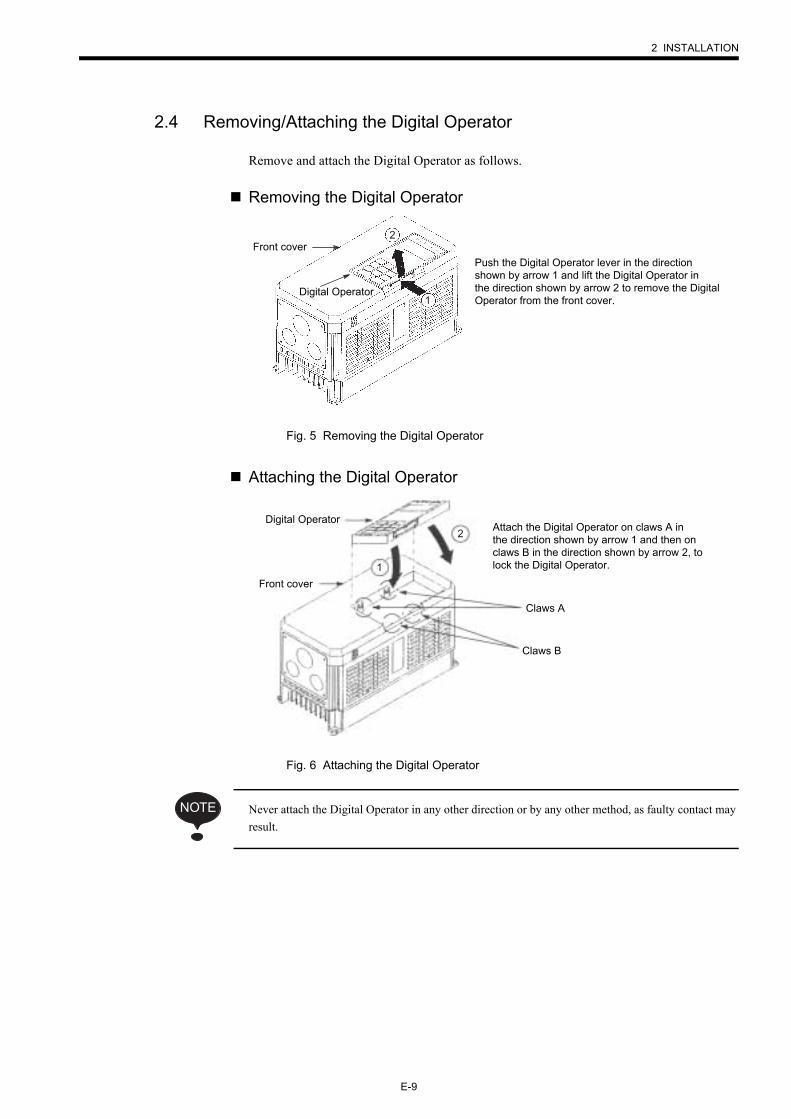
2.4 Removing/Attaching the Digital Operator
Remove and attach the Digital Operator as follows.
Removing the Digital Operator
Fig. 5 Removing the Digital Operator
Attaching the Digital Operator
Fig. 6 Attaching the Digital Operator
Never attach the Digital Operator in any other direction or by any other method, as faulty contact may result.
Digital Operator1
2
Push the Digital Operator lever in the direction shown by arrow 1 and lift the Digital Operator in the direction shown by arrow 2 to remove the Digital Operator from the front cover.
Front cover
Attach the Digital Operator on claws A in the direction shown by arrow 1 and then on claws B in the direction shown by arrow 2, to lock the Digital Operator.
Front cover
2
1
Claws A
Claws B
Digital Operator
NOTE
E-10
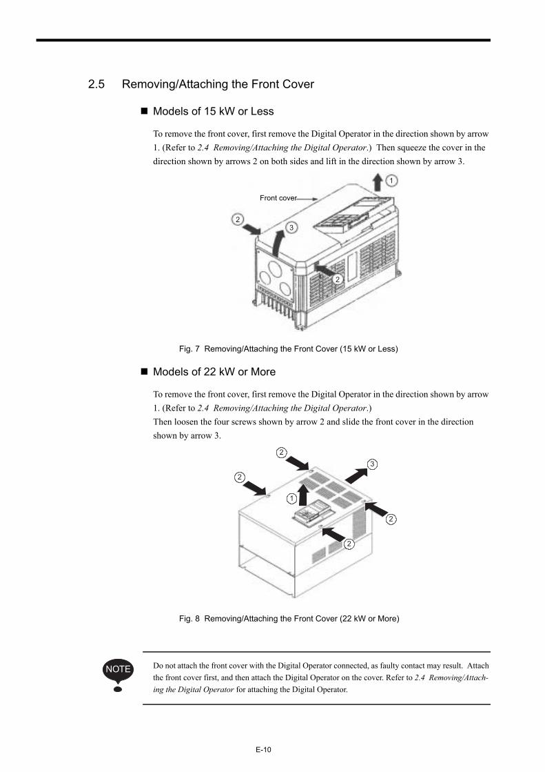
2.5 Removing/Attaching the Front Cover
Models of 15 kW or Less
To remove the front cover, first remove the Digital Operator in the direction shown by arrow 1. (Refer to 2.4 Removing/Attaching the Digital Operator.) Then squeeze the cover in the direction shown by arrows 2 on both sides and lift in the direction shown by arrow 3.
Fig. 7 Removing/Attaching the Front Cover (15 kW or Less)
Models of 22 kW or More
To remove the front cover, first remove the Digital Operator in the direction shown by arrow 1. (Refer to 2.4 Removing/Attaching the Digital Operator.) Then loosen the four screws shown by arrow 2 and slide the front cover in the direction shown by arrow 3.
Fig. 8 Removing/Attaching the Front Cover (22 kW or More)
Do not attach the front cover with the Digital Operator connected, as faulty contact may result. Attach the front cover first, and then attach the Digital Operator on the cover. Refer to 2.4 Removing/Attach-ing the Digital Operator for attaching the Digital Operator.
1
23
Front cover
2
2
2
2
3
2
1
NOTE
3 WIRING
E-11
3 WIRING
• Only commence wiring after verifying that the power supply is tunred OFF.
Failure to observe this warning may result in an electric shock or a fire.
• Wiring should be performed only by qualified personnel.
Failure to observe this warning may result in an electric shock or a fire.
• Make sure to ground the ground terminal before connecting the other terminals. (200 V class: Ground to 100 Ω or less, 400 V class: Ground to 10 Ω or less).
Failure to boserve this warning may result in an electric shock or a fire.
WARNING
• Verify that the VS-656DC5 rated voltage coincides with the AC power supply voltage.
Failure to observe this caution may result in personal injury or a fire.
• Do not perform a withstand voltage test of the VS-656DC5.
Failure to observe this caution may result in damage to the semi-conductor elements.
• Connect the input AC reactor, harmonics filter reactor, and the harmonics filter capacitor as described in this instruciton manual.
Failure to observe this caution may result in a fire.
• Verify that the rated voltage of the VS-656DC5 coincides with the rated voltage of the Inverter to be connected.
Failure to observe this caution may result in a fire.
• Tighten terminal screws.
Failure to observe this caution may result in a fire.
CAUTION
E-12
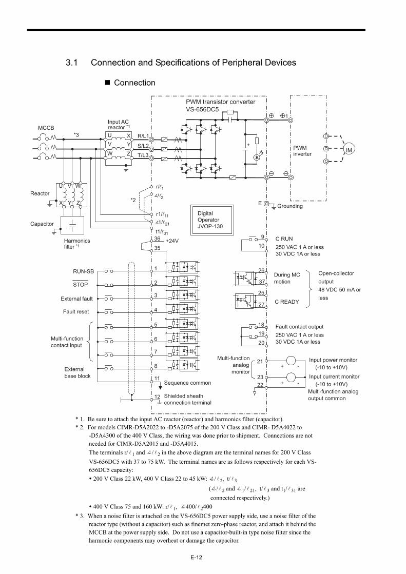
3.1 Connection and Specifications of Peripheral Devices
Connection
* 1. Be sure to attach the input AC reactor (reactor) and harmonics filter (capacitor).* 2. For models CIMR-D5A2022 to -D5A2075 of the 200 V Class and CIMR- D5A4022 to
-D5A4300 of the 400 V Class, the wiring was done prior to shipment. Connections are not needed for CIMR-D5A2015 and -D5A4015.The terminals r/ 1 and / 2 in the above diagram are the terminal names for 200 V Class VS-656DC5 with 37 to 75 kW. The terminal names are as follows respectively for each VS-656DC5 capacity: 200 V Class 22 kW, 400 V Class 22 to 45 kW: / 2, t/ 3
( / 2 and 1/ 21, t/ 3 and t1/ 31 are connected respectively.)
400 V Class 75 and 160 kW: r/ 1, 400/ 2400* 3. When a noise filter is attached on the VS-656DC5 power supply side, use a noise filter of the
reactor type (without a capacitor) such as finemet zero-phase reactor, and attach it behind the MCCB at the power supply side. Do not use a capacitor-built-in type noise filter since the harmonic components may overheat or damage the capacitor.
Open-collectoroutput48 VDC 50 mA orless
1819
20
Fault contact output250 VAC 1 A or less30 VDC 1A or less
C READY
During MCmotion37
25
27
26
IM
E
MCCBInput ACreactor *1
36
PWMinverter
910
C RUN250 VAC 1 A or less30 VDC 1A or less
35+24V
1
2
3
4
11
12
RUN-SB
STOP
External fault
Fault reset
Shielded sheathconnection terminal
Sequence common
5
6
7
8
Multi-functioncontact input
23
21Multi-functionanalogmonitor
(-10 to +10V)
Input current monitor-+
-+Input power monitor
22Multi-function analogoutput common
(-10 to +10V)
t1/ 31
r1/ 11
*2Reactor
Capacitor
Harmonicsfilter *1
R/L1
S/L2
T/L3
1
PWM transistor converterVS-656DC5
+
DigitalOperatorJVOP-130
Grounding
Externalbase block
*3 UV
XY
Z
U V W r/ 1/ 2
W
X Y Z
1/ 21
3 WIRING
E-13
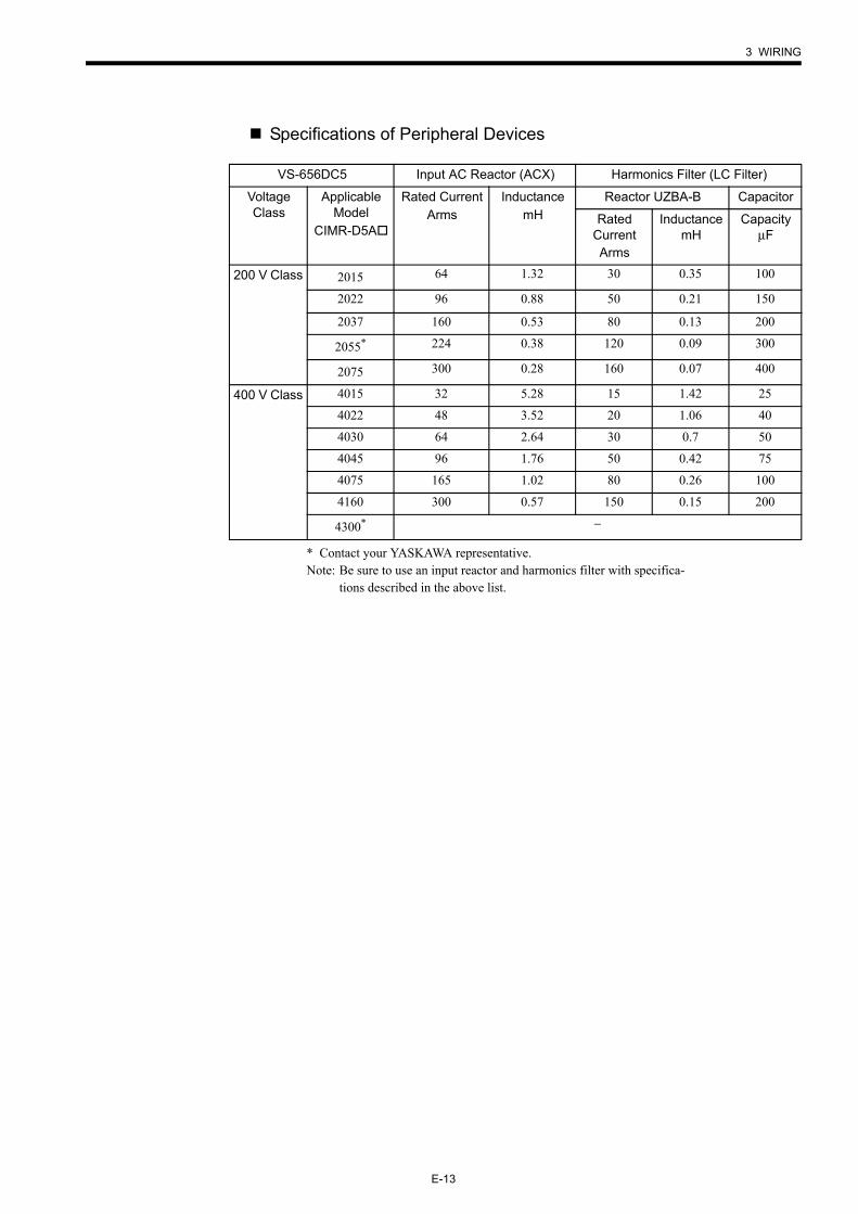
Specifications of Peripheral Devices
* Contact your YASKAWA representative.Note: Be sure to use an input reactor and harmonics filter with specifica-
tions described in the above list.
VS-656DC5 Input AC Reactor (ACX) Harmonics Filter (LC Filter)
Voltage Class
Applicable Model
CIMR-D5A
Rated CurrentArms
InductancemH
Reactor UZBA-B Capacitor
Rated CurrentArms
InductancemH
CapacityµF
200 V Class 2015 64 1.32 30 0.35 100
2022 96 0.88 50 0.21 150
2037 160 0.53 80 0.13 200
2055* 224 0.38 120 0.09 300
2075 300 0.28 160 0.07 400
400 V Class 4015 32 5.28 15 1.42 25
4022 48 3.52 20 1.06 40
4030 64 2.64 30 0.7 50
4045 96 1.76 50 0.42 75
4075 165 1.02 80 0.26 100
4160 300 0.57 150 0.15 200
4300* −
E-14
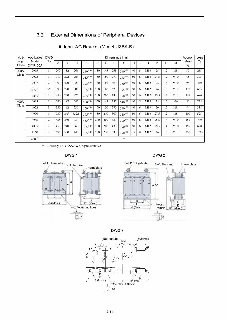
3.2 External Dimensions of Peripheral Devices
Input AC Reactor (Model UZBA-B)
* Contact your YASKAWA representative.
Volt-age
Class
Applicable Model
CIMR-D5A
DWG No.
Dimensinos in mm Approx. Mass
kg
Loss WA B B1 C D E F G H I J K L M
200 V Class
2015 1 290 182 266 280±10 150 145 255 240±10 40 5 M10 25 12 M8 50 285
2022 1 310 222 286 315±10 150 180 270 275±10 50 6 M10 27.5 12 M10 65 395
2037 2 390 220 320 375±10 150 180 380 330±10 50 6 M12 26 15 M10 95 440
2055* 3* 390 220 300 435±10 200 180 320 395±10 50 6 M12 26 15 M12 120 665
2075 2 450 240 375 435±10 200 200 430 390±10 50 6 M12 25.5 14 M12 145 680
400 V Class
4015 1 290 182 246 280±10 150 145 255 240±10 40 5 M10 25 12 M6 50 275
4022 3 330 162 230 330±10 170 130 270 290±10 40 6 M10 20 12 M8 54 335
4030 1 330 245 322.5 355±10 150 210 300 310±10 50 6 M10 27.5 12 M8 100 525
4045 2 455 240 330 435±10 200 200 430 390±10 50 6 M12 25.5 14 M10 150 760
4075 2 450 240 365 435±10 200 200 430 390±10 50 6 M12 25.5 14 M10 155 690
4160 2 575 330 445 525±10 200 270 530 470±10 75 9 M12 36 15 M12 350 1120
4300* −
DWG 1 DWG 2
DWG 3
X
U
Y
V
Z
W
FD
Nameplate
4-J: Mounting holeL
K
BE
CG
H
2-M8: Eyebolts6-M: Terminal
A (Max.) B1 (Max.)
XU
YV
ZW
FD
Nameplate
4-J: Mount- ing hole
L
K
BE
G
H
C
2-M10: Eyebolts 6-M: Terminal
A (Max.) B1 (Max.)
X
U
Y
V
Z
W
C
FD
L
K
4-J: Mounting hole
G
BEH
Nameplate φ25 Hole
A (Max.) B1 (Max.)
6-M: Terminal
3 WIRING
E-15
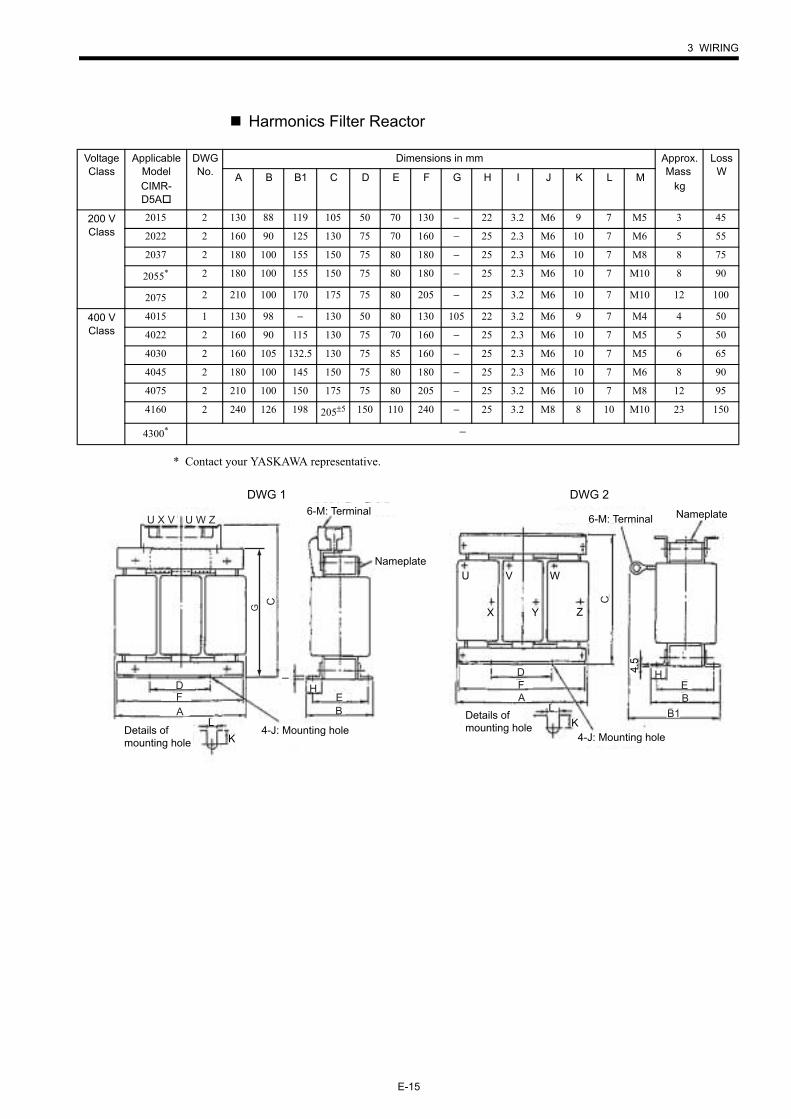
Harmonics Filter Reactor
* Contact your YASKAWA representative.
Voltage Class
Applicable ModelCIMR-D5A
DWG No.
Dimensions in mm Approx. Mass
kg
Loss WA B B1 C D E F G H I J K L M
200 V Class
2015 2 130 88 119 105 50 70 130 − 22 3.2 M6 9 7 M5 3 45
2022 2 160 90 125 130 75 70 160 − 25 2.3 M6 10 7 M6 5 55
2037 2 180 100 155 150 75 80 180 − 25 2.3 M6 10 7 M8 8 75
2055* 2 180 100 155 150 75 80 180 − 25 2.3 M6 10 7 M10 8 90
2075 2 210 100 170 175 75 80 205 − 25 3.2 M6 10 7 M10 12 100
400 V Class
4015 1 130 98 − 130 50 80 130 105 22 3.2 M6 9 7 M4 4 50
4022 2 160 90 115 130 75 70 160 − 25 2.3 M6 10 7 M5 5 50
4030 2 160 105 132.5 130 75 85 160 − 25 2.3 M6 10 7 M5 6 65
4045 2 180 100 145 150 75 80 180 − 25 2.3 M6 10 7 M6 8 90
4075 2 210 100 150 175 75 80 205 − 25 3.2 M6 10 7 M8 12 95
4160 2 240 126 198 205±5 150 110 240 − 25 3.2 M8 8 10 M10 23 150
4300* −
DWG 1 DWG 26-M: Terminal
Nameplate
Details of mounting hole
4-J: Mounting hole
U X V U W Z
AFD
C
EB
H
L
K
I
G
6-M: Terminal Nameplate
Details of mounting hole
4-J: Mounting hole
AFD
LK
X
U V
Y
W
ZC
EB
H4.5
B1
E-16
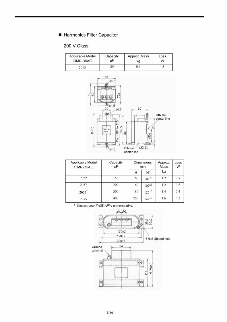
Harmonics Filter Capacitor
200 V Class
* Contact your YASKAWA representative.
Applicable ModelCIMR-D5A
CapacityµF
Approx. Masskg
Loss W
2015 100 0.4 1.8
Applicable ModelCIMR-D5A
CapacityµF
Dimensions mm
Approx. Mass
kg
Loss W
H H12022 150 160 107±3 1.2 2.7
2037 200 160 107±3 1.2 3.6
2055* 300 180 127±3 1.4 5.4
2075 400 200 147±3 1.6 7.2
Name-plate
DIN rail center line
DIN rail center line
67φ4.5
80 60 70±1
φ4.5φ4.530
P+1
0
φ4.5
Pitc
h 10
4 to
115
*10
9.5
86
60
(32.5)7
(50)
90
Ground terminal
6-6×8 Slotted hole
32 32
170±2190±2205±3
25±1
60±2
94
H1 H (M
ax.)
3 WIRING
E-17
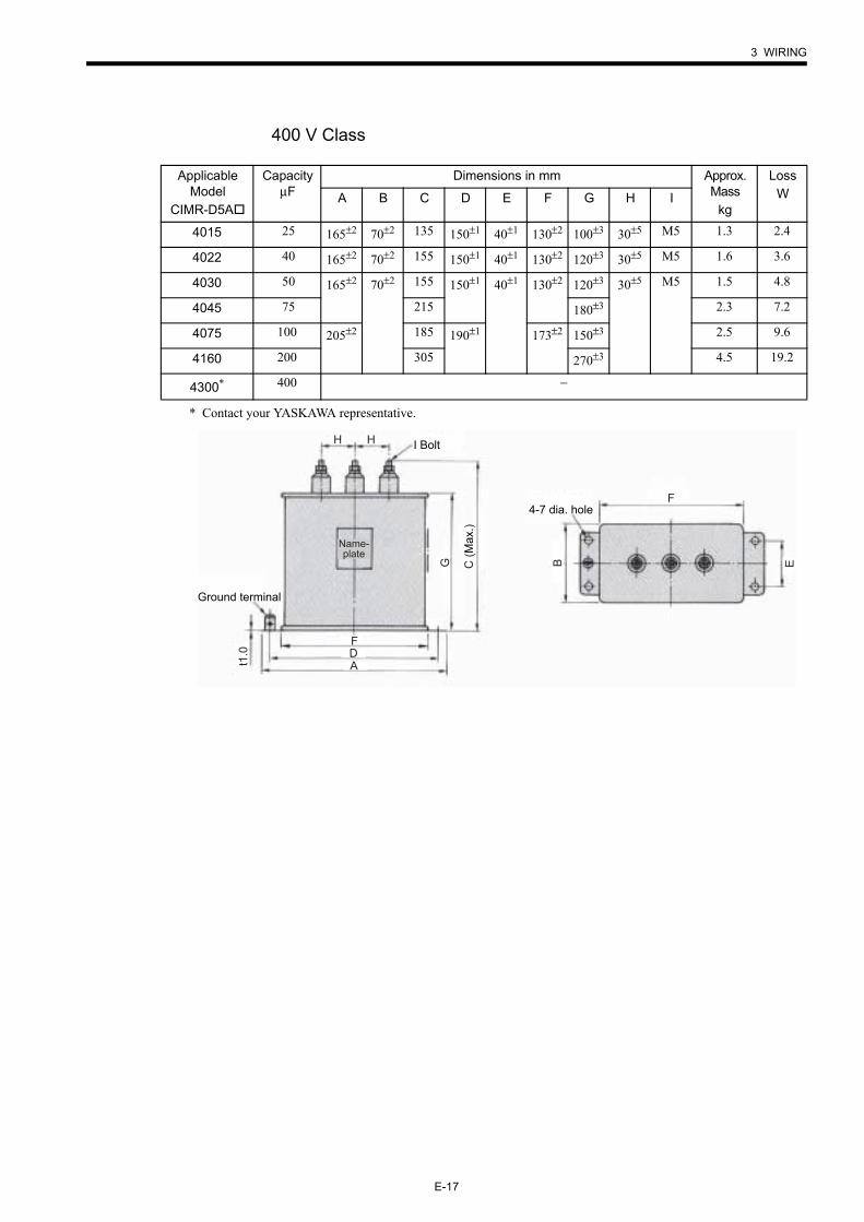
400 V Class
* Contact your YASKAWA representative.
Applicable Model
CIMR-D5A
CapacityµF
Dimensions in mm Approx. Mass
kg
LossWA B C D E F G H I
4015 25 165±2 70±2 135 150±1 40±1 130±2 100±3 30±5 M5 1.3 2.4
4022 40 165±2 70±2 155 150±1 40±1 130±2 120±3 30±5 M5 1.6 3.6
4030 50 165±2 70±2 155 150±1 40±1 130±2 120±3 30±5 M5 1.5 4.8
4045 75 215 180±3 2.3 7.2
4075 100 205±2 185 190±1 173±2 150±3 2.5 9.6
4160 200 305 270±3 4.5 19.2
4300* 400 −
Ground terminal
t1.0
ADF
G C (M
ax.)
I BoltH H
4-7 dia. hole
B E
F
Name-plate
E-18
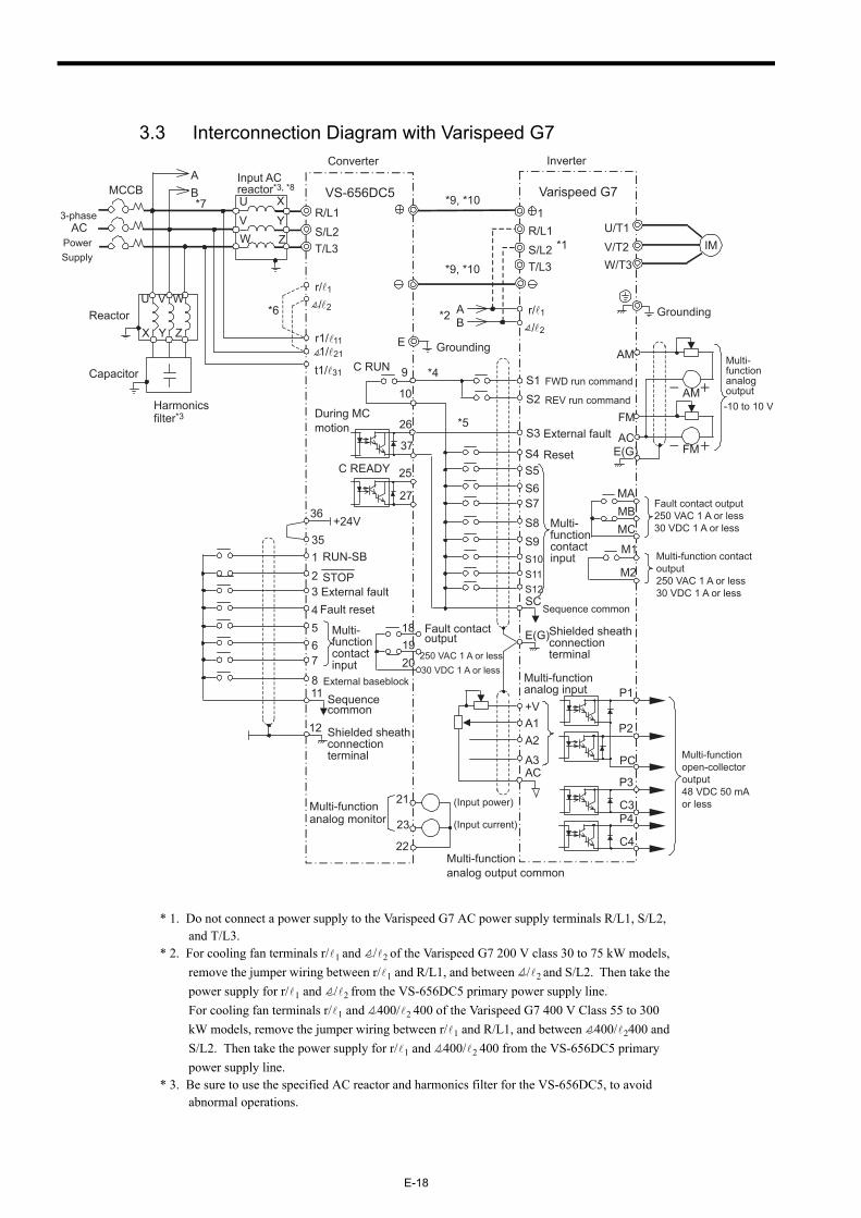
3.3 Interconnection Diagram with Varispeed G7
* 1. Do not connect a power supply to the Varispeed G7 AC power supply terminals R/L1, S/L2, and T/L3.
* 2. For cooling fan terminals r/ 1 and / 2 of the Varispeed G7 200 V class 30 to 75 kW models, remove the jumper wiring between r/ 1 and R/L1, and between / 2 and S/L2. Then take the power supply for r/ 1 and / 2 from the VS-656DC5 primary power supply line.For cooling fan terminals r/ 1 and 400/ 2 400 of the Varispeed G7 400 V Class 55 to 300 kW models, remove the jumper wiring between r/ 1 and R/L1, and between 400/ 2400 and S/L2. Then take the power supply for r/ 1 and 400/ 2 400 from the VS-656DC5 primary power supply line.
* 3. Be sure to use the specified AC reactor and harmonics filter for the VS-656DC5, to avoid abnormal operations.
Converter Inverter
-10 to 10 V
Multi-functionanalog output common
181920
Fault contactoutput
250 VAC 1 A or less30 VDC 1 A or less
C READY
During MCmotion
25
27
37
26
t1/ 31
r1/ 11 E
MCCB
*6
1234
11
35
36+24V
12
RUN-SB
STOPExternal faultFault reset
Shielded sheathconnectionterminal
Sequencecommon
567
8
Multi-functioncontactinput
23
21Multi-functionanalog monitor (Input current)
(Input power)
22
r/ 1
ReactorU V W
Capacitor
Harmonicsfilter*3
VS-656DC5R/L1S/L2T/L3
1
Input ACreactor*3, *8
R/L1S/L2T/L3
Varispeed G7
IMU/T1V/T2W/T3
Grounding
AB
AB*2
*1
E(G)
Multi-functionanalog input
Shielded sheathconnectionterminal
A1A2
A3AC
+V
9
10
C RUN
Sequence common
S1S2
FWD run command
REV run command
S3
S4
External fault
ResetS5S6S7
S8
SC
Multi-functioncontactinput
*5
*4
MAMBMC
Fault contact output250 VAC 1 A or less30 VDC 1 A or less
P1
P2
PC
M1
M2Multi-function contactoutput250 VAC 1 A or less30 VDC 1 A or less
3-phaseAC
PowerSupply
Multi-functionopen-collectoroutput48 VDC 50 mA or less
FM
AM Multi-functionanalogoutput
ACE(G)
AM
FM
Grounding
S10S11S12
S9
P3
P4
C4
C3
*9, *10
*9, *10
External baseblock
U X
YZ
V
/ 2 r/ 1
/ 2X Y Z
W
*7
1/ 21
3 WIRING
E-19
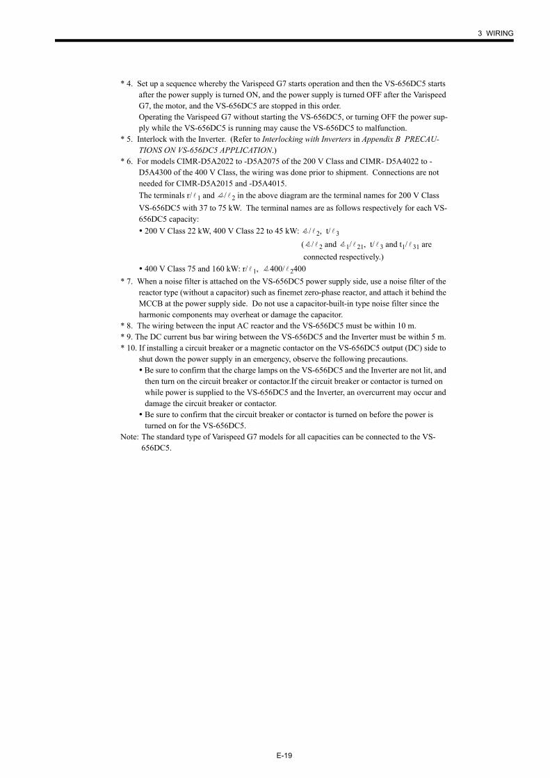
* 4. Set up a sequence whereby the Varispeed G7 starts operation and then the VS-656DC5 starts after the power supply is turned ON, and the power supply is turned OFF after the Varispeed G7, the motor, and the VS-656DC5 are stopped in this order.Operating the Varispeed G7 without starting the VS-656DC5, or turning OFF the power sup-ply while the VS-656DC5 is running may cause the VS-656DC5 to malfunction.
* 5. Interlock with the Inverter. (Refer to Interlocking with Inverters in Appendix B PRECAU-TIONS ON VS-656DC5 APPLICATION.)
* 6. For models CIMR-D5A2022 to -D5A2075 of the 200 V Class and CIMR- D5A4022 to -D5A4300 of the 400 V Class, the wiring was done prior to shipment. Connections are not needed for CIMR-D5A2015 and -D5A4015.The terminals r/ 1 and / 2 in the above diagram are the terminal names for 200 V Class VS-656DC5 with 37 to 75 kW. The terminal names are as follows respectively for each VS-656DC5 capacity: 200 V Class 22 kW, 400 V Class 22 to 45 kW: / 2, t/ 3
( / 2 and 1/ 21, t/ 3 and t1/ 31 are connected respectively.)
400 V Class 75 and 160 kW: r/ 1, 400/ 2400* 7. When a noise filter is attached on the VS-656DC5 power supply side, use a noise filter of the
reactor type (without a capacitor) such as finemet zero-phase reactor, and attach it behind the MCCB at the power supply side. Do not use a capacitor-built-in type noise filter since the harmonic components may overheat or damage the capacitor.
* 8. The wiring between the input AC reactor and the VS-656DC5 must be within 10 m.* 9. The DC current bus bar wiring between the VS-656DC5 and the Inverter must be within 5 m.* 10. If installing a circuit breaker or a magnetic contactor on the VS-656DC5 output (DC) side to
shut down the power supply in an emergency, observe the following precautions. Be sure to confirm that the charge lamps on the VS-656DC5 and the Inverter are not lit, and then turn on the circuit breaker or contactor.If the circuit breaker or contactor is turned on while power is supplied to the VS-656DC5 and the Inverter, an overcurrent may occur and damage the circuit breaker or contactor.
Be sure to confirm that the circuit breaker or contactor is turned on before the power is turned on for the VS-656DC5.
Note: The standard type of Varispeed G7 models for all capacities can be connected to the VS-656DC5.
E-20
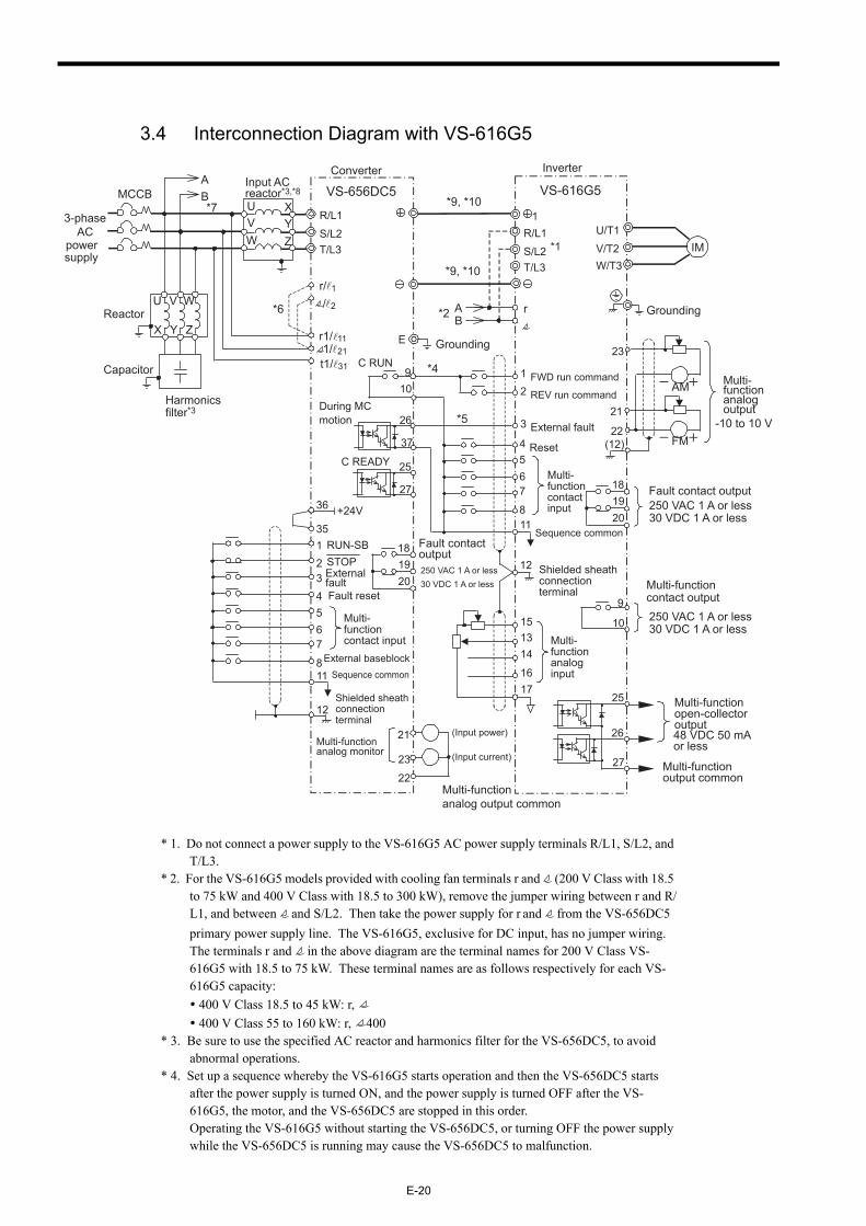
3.4 Interconnection Diagram with VS-616G5
* 1. Do not connect a power supply to the VS-616G5 AC power supply terminals R/L1, S/L2, and T/L3.
* 2. For the VS-616G5 models provided with cooling fan terminals r and (200 V Class with 18.5 to 75 kW and 400 V Class with 18.5 to 300 kW), remove the jumper wiring between r and R/L1, and between and S/L2. Then take the power supply for r and from the VS-656DC5 primary power supply line. The VS-616G5, exclusive for DC input, has no jumper wiring.The terminals r and in the above diagram are the terminal names for 200 V Class VS-616G5 with 18.5 to 75 kW. These terminal names are as follows respectively for each VS-616G5 capacity: 400 V Class 18.5 to 45 kW: r, 400 V Class 55 to 160 kW: r, 400
* 3. Be sure to use the specified AC reactor and harmonics filter for the VS-656DC5, to avoid abnormal operations.
* 4. Set up a sequence whereby the VS-616G5 starts operation and then the VS-656DC5 starts after the power supply is turned ON, and the power supply is turned OFF after the VS-616G5, the motor, and the VS-656DC5 are stopped in this order.Operating the VS-616G5 without starting the VS-656DC5, or turning OFF the power supply while the VS-656DC5 is running may cause the VS-656DC5 to malfunction.
-10 to 10 V
Converter Inverter
Multi-functionanalogoutput
181920
Fault contactoutput250 VAC 1 A or less30 VDC 1 A or less
C READY
During MCmotion
25
27
37
26
E
MCCB
*6
*7
1234
11
35
36 +24V
12
RUN-SBSTOPExternalfaultFault reset
Shielded sheathconnectionterminal
Sequence common
567
8
Multi-functioncontact input
23
21Multi-functionanalog monitor (Input current)
(Input power)
22Multi-functionanalog output common
Reactor
Capacitor
Harmonicsfilter*3
VS-656DC5
R/L1
S/L2T/L3
1
Input ACreactor*3,*8
UV
XY
R/L1
S/L2T/L3
VS-616G5
IMU/T1
V/T2W/T3
Grounding
AB
AB*2
*1
12
Multi-functionanaloginput
Shielded sheathconnectionterminal
1314
1617
15
910
C RUN
Sequence common
12
FWD run command
REV run command
3
4External fault
Reset567
811
Multi-functioncontactinput
*5
*4
181920
Fault contact output250 VAC 1 A or less30 VDC 1 A or less
25
26
27 Multi-functionoutput common
9
10
Multi-functioncontact output250 VAC 1 A or less30 VDC 1 A or less
3-phaseAC
powersupply
Multi-functionopen-collectoroutput48 VDC 50 mAor less
21
23
22(12)
AM
FM
Grounding
*9, *10
*9, *10
External baseblock
t1/ 31
r1/ 11
r/ 1
/ 2
1/ 21
rU
X
V
Y
W
Z
W Z
3 WIRING
E-21
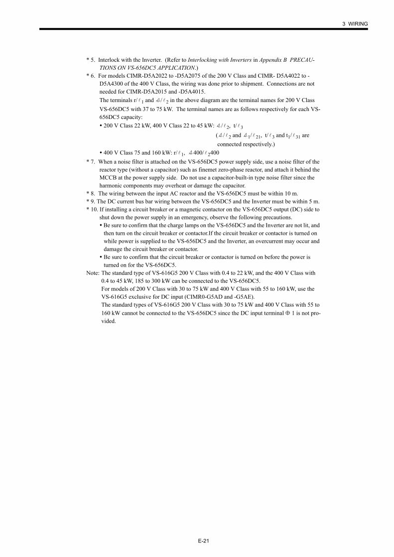
* 5. Interlock with the Inverter. (Refer to Interlocking with Inverters in Appendix B PRECAU-TIONS ON VS-656DC5 APPLICATION.)
* 6. For models CIMR-D5A2022 to -D5A2075 of the 200 V Class and CIMR- D5A4022 to -D5A4300 of the 400 V Class, the wiring was done prior to shipment. Connections are not needed for CIMR-D5A2015 and -D5A4015.The terminals r/ 1 and / 2 in the above diagram are the terminal names for 200 V Class VS-656DC5 with 37 to 75 kW. The terminal names are as follows respectively for each VS-656DC5 capacity: 200 V Class 22 kW, 400 V Class 22 to 45 kW: / 2, t/ 3
( / 2 and 1/ 21, t/ 3 and t1/ 31 are connected respectively.)
400 V Class 75 and 160 kW: r/ 1, 400/ 2400* 7. When a noise filter is attached on the VS-656DC5 power supply side, use a noise filter of the
reactor type (without a capacitor) such as finemet zero-phase reactor, and attach it behind the MCCB at the power supply side. Do not use a capacitor-built-in type noise filter since the harmonic components may overheat or damage the capacitor.
* 8. The wiring between the input AC reactor and the VS-656DC5 must be within 10 m.* 9. The DC current bus bar wiring between the VS-656DC5 and the Inverter must be within 5 m.* 10. If installing a circuit breaker or a magnetic contactor on the VS-656DC5 output (DC) side to
shut down the power supply in an emergency, observe the following precautions. Be sure to confirm that the charge lamps on the VS-656DC5 and the Inverter are not lit, and then turn on the circuit breaker or contactor.If the circuit breaker or contactor is turned on while power is supplied to the VS-656DC5 and the Inverter, an overcurrent may occur and damage the circuit breaker or contactor.
Be sure to confirm that the circuit breaker or contactor is turned on before the power is turned on for the VS-656DC5.
Note: The standard type of VS-616G5 200 V Class with 0.4 to 22 kW, and the 400 V Class with 0.4 to 45 kW, 185 to 300 kW can be connected to the VS-656DC5.For models of 200 V Class with 30 to 75 kW and 400 V Class with 55 to 160 kW, use the VS-616G5 exclusive for DC input (CIMR0-G5AD and -G5AE).The standard types of VS-616G5 200 V Class with 30 to 75 kW and 400 V Class with 55 to 160 kW cannot be connected to the VS-656DC5 since the DC input terminal 1 is not pro-vided.
E-22
3.5 Wiring Precautions
The external interconnection wiring must be performed with following procedures. After completing VS-656DC5 interconnections, be sure to check that the connections are correct. Never use control circuit buzzer check.
Control Circuit Wiring
Separate control circuit wiring from main circuit wiring and other power cables.
Separate wiring for control circuit terminals from other control circuits or main circuit wir-ings.
Wiring distance should be 50 m or less.
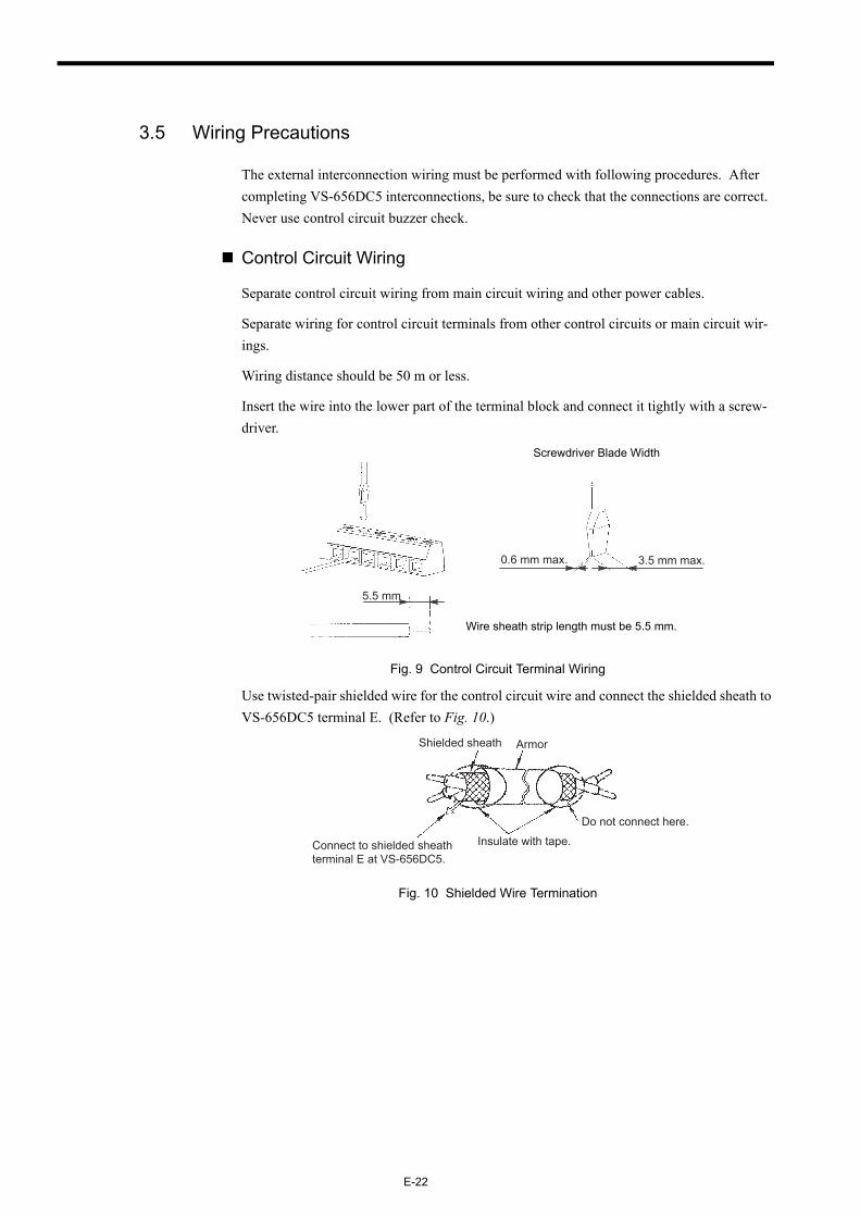
Insert the wire into the lower part of the terminal block and connect it tightly with a screw-driver.
Fig. 9 Control Circuit Terminal Wiring
Use twisted-pair shielded wire for the control circuit wire and connect the shielded sheath to VS-656DC5 terminal E. (Refer to Fig. 10.)
Fig. 10 Shielded Wire Termination
0.6 mm max. 3.5 mm max.
5.5 mm
Wire sheath strip length must be 5.5 mm.
Screwdriver Blade Width
Do not connect here.
Connect to shielded sheath terminal E at VS-656DC5.
Shielded sheath Armor
Insulate with tape.
3 WIRING
E-23
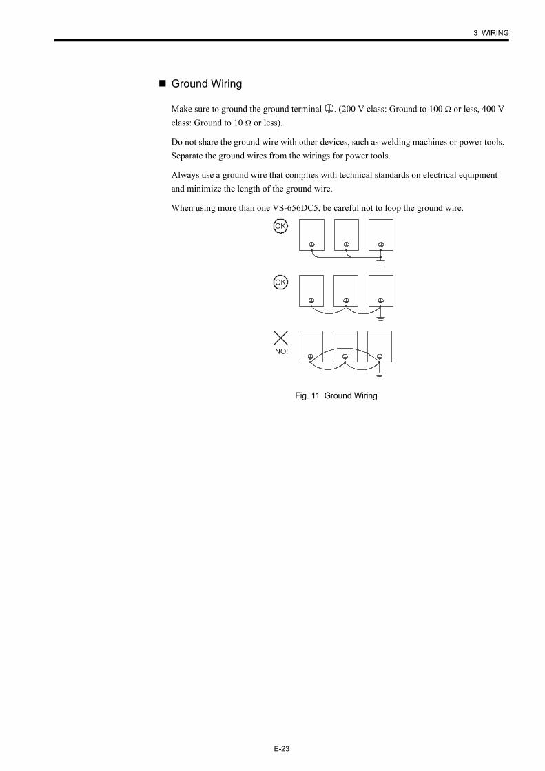
Ground Wiring
Make sure to ground the ground terminal . (200 V class: Ground to 100 Ω or less, 400 V class: Ground to 10 Ω or less).
Do not share the ground wire with other devices, such as welding machines or power tools. Separate the ground wires from the wirings for power tools.
Always use a ground wire that complies with technical standards on electrical equipment and minimize the length of the ground wire.
When using more than one VS-656DC5, be careful not to loop the ground wire.
Fig. 11 Ground Wiring
OK
OK
NO!
E-24
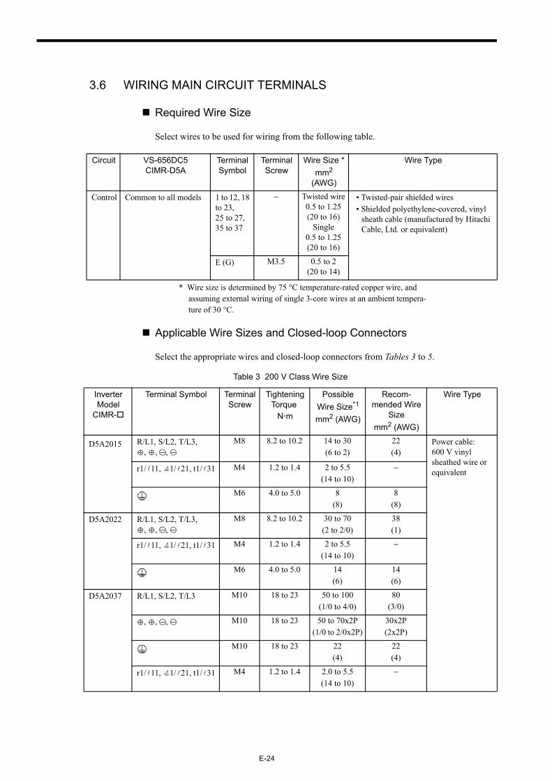
3.6 WIRING MAIN CIRCUIT TERMINALS
Required Wire Size
Select wires to be used for wiring from the following table.
* Wire size is determined by 75 °C temperature-rated copper wire, and assuming external wiring of single 3-core wires at an ambient tempera-ture of 30 °C.
Applicable Wire Sizes and Closed-loop Connectors
Select the appropriate wires and closed-loop connectors from Tables 3 to 5.
Circuit VS-656DC5CIMR-D5A
Terminal Symbol
Terminal Screw
Wire Size *mm2
(AWG)
Wire Type
Control Common to all models 1 to 12, 18 to 23,25 to 27, 35 to 37
− Twisted wire0.5 to 1.25(20 to 16)
Single0.5 to 1.25(20 to 16)
• Twisted-pair shielded wires• Shielded polyethylene-covered, vinyl
sheath cable (manufactured by Hitachi Cable, Ltd. or equivalent)
E (G) M3.5 0.5 to 2(20 to 14)
Table 3 200 V Class Wire Size
Inverter Model
CIMR-
Terminal Symbol Terminal Screw
Tightening Torque
N m
Possible Wire Size*1
mm2 (AWG)
Recom-mended Wire
Sizemm2 (AWG)
Wire Type
D5A2015 R/L1, S/L2, T/L3, , , ,
M8 8.2 to 10.2 14 to 30(6 to 2)
22(4)
Power cable: 600 V vinyl sheathed wire or equivalentr1/ 11, 1/ 21, t1/ 31 M4 1.2 to 1.4 2 to 5.5
(14 to 10)−
M6 4.0 to 5.0 8(8)
8(8)
D5A2022 R/L1, S/L2, T/L3, , , ,
M8 8.2 to 10.2 30 to 70(2 to 2/0)
38(1)
r1/ 11, 1/ 21, t1/ 31 M4 1.2 to 1.4 2 to 5.5(14 to 10)
−
M6 4.0 to 5.0 14(6)
14(6)
D5A2037 R/L1, S/L2, T/L3 M10 18 to 23 50 to 100(1/0 to 4/0)
80(3/0)
, , , M10 18 to 23 50 to 70x2P(1/0 to 2/0x2P)
30x2P(2x2P)
M10 18 to 23 22(4)
22(4)
r1/ 11, 1/ 21, t1/ 31 M4 1.2 to 1.4 2.0 to 5.5(14 to 10)
−
3 WIRING
E-25
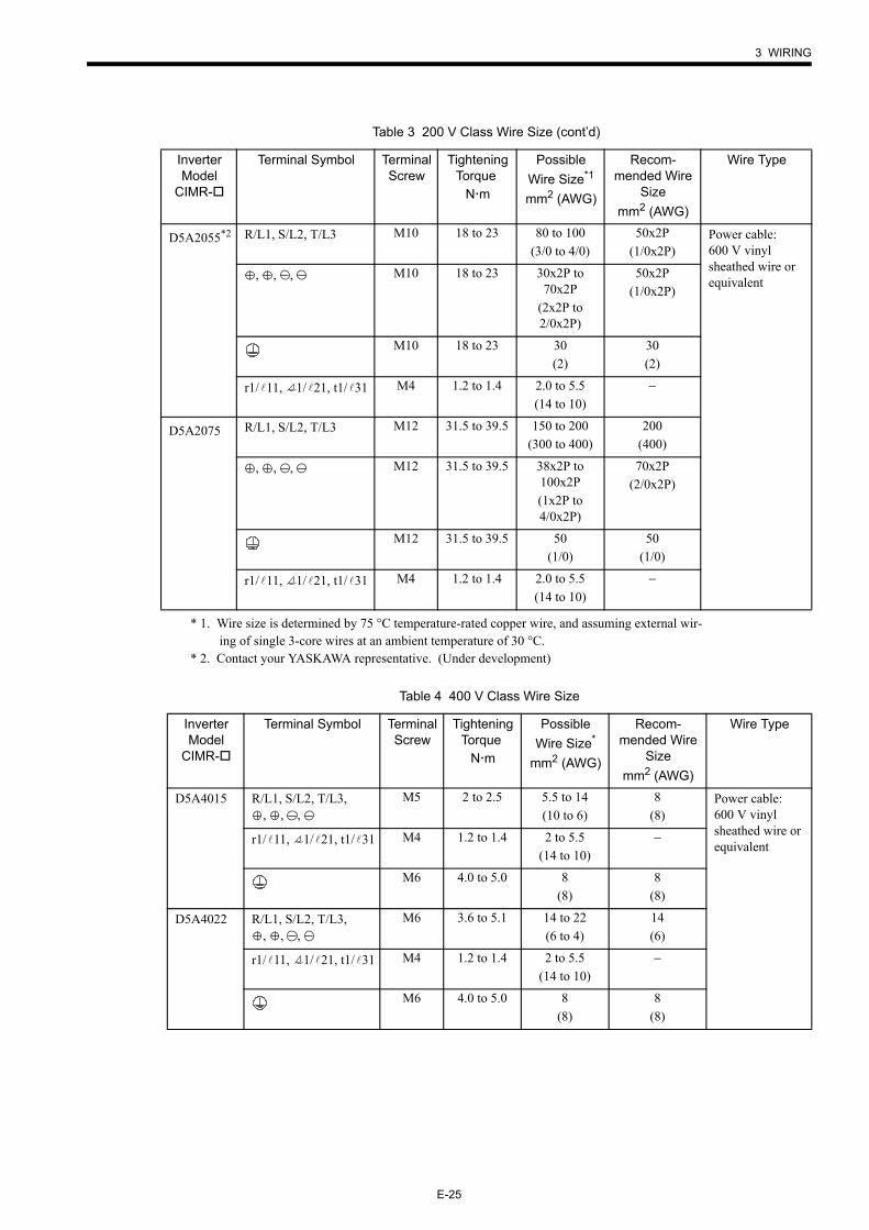
* 1. Wire size is determined by 75 °C temperature-rated copper wire, and assuming external wir-ing of single 3-core wires at an ambient temperature of 30 °C.
* 2. Contact your YASKAWA representative. (Under development)
D5A2055*2 R/L1, S/L2, T/L3 M10 18 to 23 80 to 100(3/0 to 4/0)
50x2P(1/0x2P)
Power cable: 600 V vinyl sheathed wire or equivalent, , , M10 18 to 23 30x2P to
70x2P(2x2P to 2/0x2P)
50x2P(1/0x2P)
M10 18 to 23 30(2)
30(2)
r1/ 11, 1/ 21, t1/ 31 M4 1.2 to 1.4 2.0 to 5.5(14 to 10)
−
D5A2075 R/L1, S/L2, T/L3 M12 31.5 to 39.5 150 to 200(300 to 400)
200(400)
, , , M12 31.5 to 39.5 38x2P to 100x2P(1x2P to 4/0x2P)
70x2P(2/0x2P)
M12 31.5 to 39.5 50(1/0)
50(1/0)
r1/ 11, 1/ 21, t1/ 31 M4 1.2 to 1.4 2.0 to 5.5(14 to 10)
−
Table 3 200 V Class Wire Size (cont’d)
Inverter Model
CIMR-
Terminal Symbol Terminal Screw
Tightening Torque
N m
Possible Wire Size*1
mm2 (AWG)
Recom-mended Wire
Sizemm2 (AWG)
Wire Type
Table 4 400 V Class Wire Size
Inverter Model
CIMR-
Terminal Symbol Terminal Screw
Tightening Torque
N m
Possible Wire Size*
mm2 (AWG)
Recom-mended Wire
Sizemm2 (AWG)
Wire Type
D5A4015 R/L1, S/L2, T/L3, , , ,
M5 2 to 2.5 5.5 to 14(10 to 6)
8(8)
Power cable: 600 V vinyl sheathed wire or equivalentr1/ 11, 1/ 21, t1/ 31 M4 1.2 to 1.4 2 to 5.5
(14 to 10)−
M6 4.0 to 5.0 8(8)
8(8)
D5A4022 R/L1, S/L2, T/L3, , , ,
M6 3.6 to 5.1 14 to 22(6 to 4)
14(6)
r1/ 11, 1/ 21, t1/ 31 M4 1.2 to 1.4 2 to 5.5(14 to 10)
−
M6 4.0 to 5.0 8(8)
8(8)
E-26
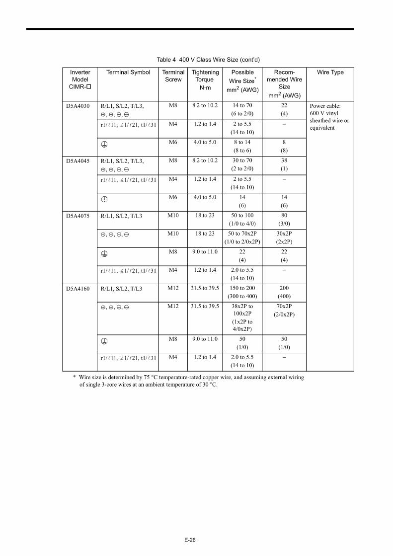
* Wire size is determined by 75 °C temperature-rated copper wire, and assuming external wiring of single 3-core wires at an ambient temperature of 30 °C.
D5A4030 R/L1, S/L2, T/L3, , , ,
M8 8.2 to 10.2 14 to 70(6 to 2/0)
22(4)
Power cable: 600 V vinyl sheathed wire or equivalentr1/ 11, 1/ 21, t1/ 31 M4 1.2 to 1.4 2 to 5.5
(14 to 10)−
M6 4.0 to 5.0 8 to 14(8 to 6)
8(8)
D5A4045 R/L1, S/L2, T/L3, , , ,
M8 8.2 to 10.2 30 to 70(2 to 2/0)
38(1)
r1/ 11, 1/ 21, t1/ 31 M4 1.2 to 1.4 2 to 5.5(14 to 10)
−
M6 4.0 to 5.0 14(6)
14(6)
D5A4075 R/L1, S/L2, T/L3 M10 18 to 23 50 to 100(1/0 to 4/0)
80(3/0)
, , , M10 18 to 23 50 to 70x2P(1/0 to 2/0x2P)
30x2P(2x2P)
M8 9.0 to 11.0 22(4)
22(4)
r1/ 11, 1/ 21, t1/ 31 M4 1.2 to 1.4 2.0 to 5.5(14 to 10)
−
D5A4160 R/L1, S/L2, T/L3 M12 31.5 to 39.5 150 to 200(300 to 400)
200(400)
, , , M12 31.5 to 39.5 38x2P to 100x2P(1x2P to 4/0x2P)
70x2P(2/0x2P)
M8 9.0 to 11.0 50(1/0)
50(1/0)
r1/ 11, 1/ 21, t1/ 31 M4 1.2 to 1.4 2.0 to 5.5(14 to 10)
−
Table 4 400 V Class Wire Size (cont’d)
Inverter Model
CIMR-
Terminal Symbol Terminal Screw
Tightening Torque
N m
Possible Wire Size*
mm2 (AWG)
Recom-mended Wire
Sizemm2 (AWG)
Wire Type
3 WIRING
E-27
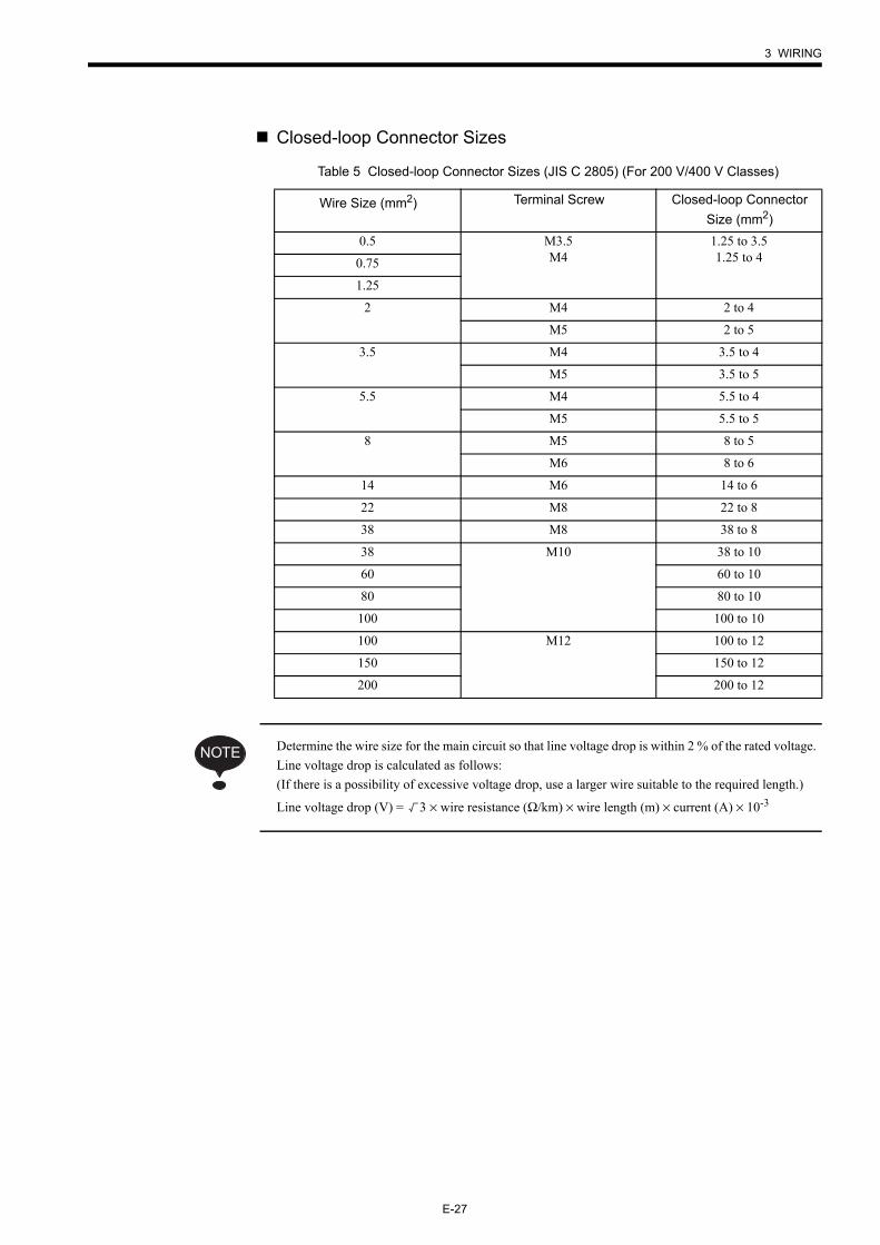
Closed-loop Connector Sizes
Determine the wire size for the main circuit so that line voltage drop is within 2 % of the rated voltage. Line voltage drop is calculated as follows:(If there is a possibility of excessive voltage drop, use a larger wire suitable to the required length.)
Line voltage drop (V) = 3 × wire resistance (Ω/km) × wire length (m) × current (A) × 10-3
Table 5 Closed-loop Connector Sizes (JIS C 2805) (For 200 V/400 V Classes)
Wire Size (mm2) Terminal Screw Closed-loop Connector Size (mm2)
0.5 M3.5M4
1.25 to 3.51.25 to 40.75
1.25
2 M4 2 to 4
M5 2 to 5
3.5 M4 3.5 to 4
M5 3.5 to 5
5.5 M4 5.5 to 4
M5 5.5 to 5
8 M5 8 to 5
M6 8 to 6
14 M6 14 to 6
22 M8 22 to 8
38 M8 38 to 8
38 M10 38 to 10
60 60 to 10
80 80 to 10
100 100 to 10
100 M12 100 to 12
150 150 to 12
200 200 to 12
NOTE
E-28
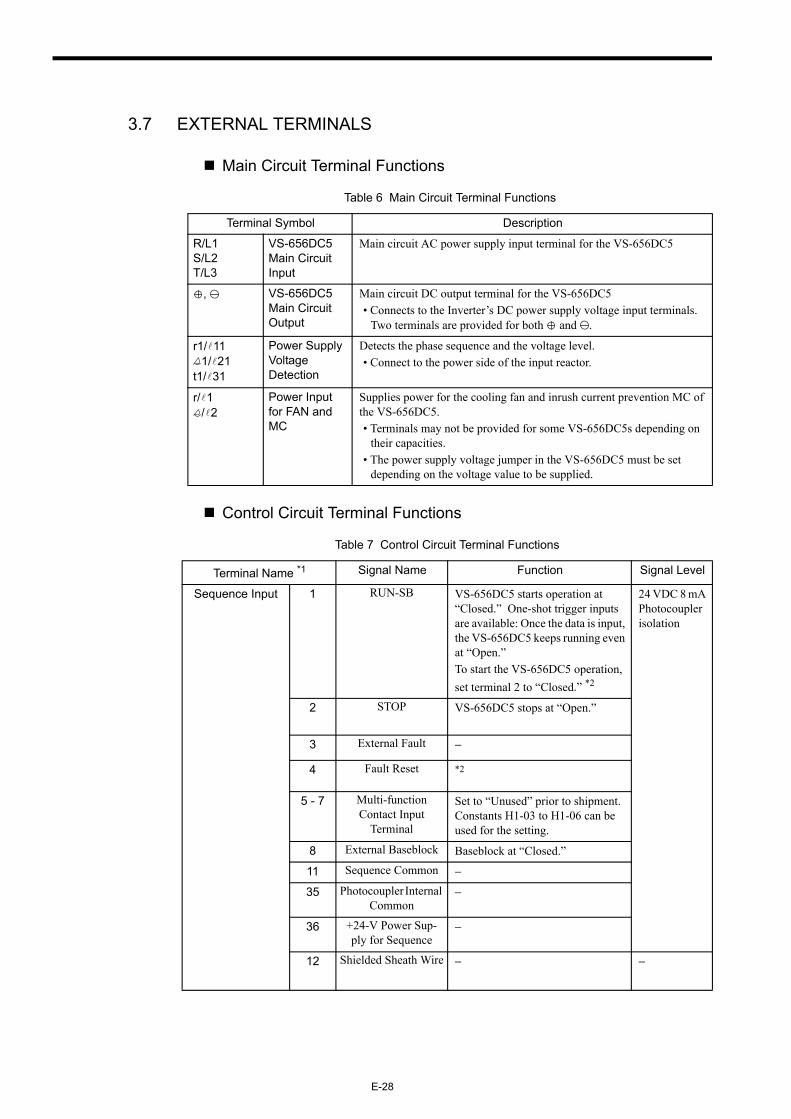
3.7 EXTERNAL TERMINALS
Main Circuit Terminal Functions
Control Circuit Terminal Functions
Table 6 Main Circuit Terminal Functions
Terminal Symbol Description
R/L1S/L2T/L3
VS-656DC5 Main Circuit Input
Main circuit AC power supply input terminal for the VS-656DC5
, VS-656DC5 Main Circuit Output
Main circuit DC output terminal for the VS-656DC5• Connects to the Inverter’s DC power supply voltage input terminals.
Two terminals are provided for both and .
r1/ 111/ 21
t1/ 31
Power Supply Voltage Detection
Detects the phase sequence and the voltage level.• Connect to the power side of the input reactor.
r/ 1/ 2
Power Input for FAN and MC
Supplies power for the cooling fan and inrush current prevention MC of the VS-656DC5.• Terminals may not be provided for some VS-656DC5s depending on
their capacities.• The power supply voltage jumper in the VS-656DC5 must be set
depending on the voltage value to be supplied.
Table 7 Control Circuit Terminal Functions
Terminal Name *1 Signal Name Function Signal Level
Sequence Input 1 RUN-SB VS-656DC5 starts operation at “Closed.” One-shot trigger inputs are available: Once the data is input, the VS-656DC5 keeps running even at “Open.”To start the VS-656DC5 operation, set terminal 2 to “Closed.” *2
24 VDC 8 mA Photocoupler isolation
2 STOP VS-656DC5 stops at “Open.”
3 External Fault −
4 Fault Reset *2
5 - 7 Multi-function Contact Input
Terminal
Set to “Unused” prior to shipment. Constants H1-03 to H1-06 can be used for the setting.
8 External Baseblock Baseblock at “Closed.”
11 Sequence Common −
35 Photocoupler Internal Common
−
36 +24-V Power Sup-ply for Sequence
−
12 Shielded Sheath Wire − −
3 WIRING
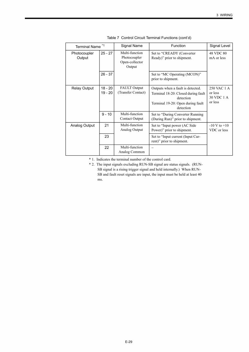
E-29
* 1. Indicates the terminal number of the control card.* 2. The input signals excluding RUN-SB signal are status signals. (RUN-
SB signal is a rising trigger signal and held internally.) When RUN-SB and fault reset signals are input, the input must be held at least 40 ms.
Photocoupler Output
25 - 27 Multi-function Photocoupler
Open-collector Output
Set to “CREADY (Converter Ready)” prior to shipment.
48 VDC 80 mA or less
26 - 37 Set to “MC Operating (MCON)” prior to shipment.
Relay Output 18 - 2019 - 20
FAULT Output(Transfer Contact)
Outputs when a fault is detected.Terminal 18-20: Closed during fault
detectionTerminal 19-20: Open during fault
detection
250 VAC 1 A or less30 VDC 1 A or less
9 - 10 Multi-function Contact Output
Set to “During Converter Running (During Run)” prior to shipment.
Analog Output 21 Multi-function Analog Output
Set to “Input power (AC Side Power)” prior to shipment.
-10 V to +10 VDC or less
23 Set to “Input current (Input Cur-rent)” prior to shipment.
22 Multi-function Analog Common
−
Table 7 Control Circuit Terminal Functions (cont’d)
Terminal Name *1 Signal Name Function Signal Level
E-30
4 OPERATION
4.1 Checkpoints before Turning ON the Power Supply
Check the following before turning ON the power supply.
• Check that the power supply voltage is correct.200 V class: 200 to 220 VAC, 50 Hz
200 to 230 VAC, 60 Hz400 V class: 380 to 460 VAC, 50/60 Hz
• Make sure that the VS-656DC5 and the Inverter are connected correctly.• Make sure that the phase sequence of the main circuit terminals (R/L1, S/L2, T/L3) and
the power supply voltage detection terminals (r1/ 11, 1/ 21, t1/ 31) are correct.• Make sure that the VS-656DC5 control circuit terminals are connected to other control
devices correctly.• Set the run command of the VS-656DC5 and the Inverter to OFF.
• Only turn ON the input power supply after attaching the front cover or the terminal cover. Do not remove the cover while current is flowing.
Failure to observe this warning may result in an electric shock.
• Never operate the Digital Operator or other switches when your hand is wet.
Failure to observe this warning may result in an electric shock.
• Never touch the terminals while current is flowing, even if the VS-656DC5 stops.
Failure to observe this warning may result in an electric shock.
WARNING
• Never touch the radiation fins (heatsink) or input reactor since the temperature is very high.
Failure to observe this caution may result in harmful burns to the body.
• The VS-656DC5 is factory set to the suitable settings. Do not change the settings unnecessarily.
Failure to observe this caution may result in damage to the unit.
CAUTION
4 OPERATION
E-31
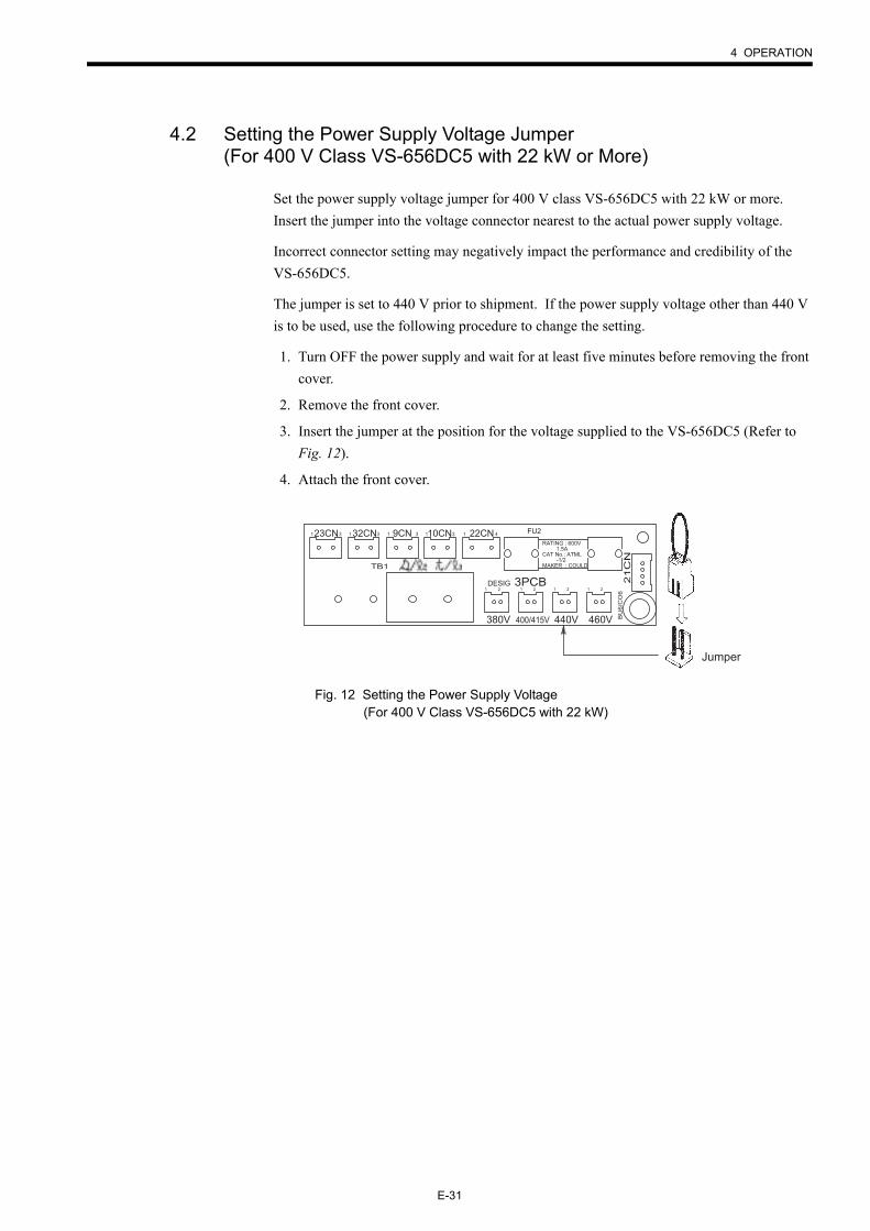
4.2 Setting the Power Supply Voltage Jumper (For 400 V Class VS-656DC5 with 22 kW or More)
Set the power supply voltage jumper for 400 V class VS-656DC5 with 22 kW or more. Insert the jumper into the voltage connector nearest to the actual power supply voltage.
Incorrect connector setting may negatively impact the performance and credibility of the VS-656DC5.
The jumper is set to 440 V prior to shipment. If the power supply voltage other than 440 V is to be used, use the following procedure to change the setting.
1. Turn OFF the power supply and wait for at least five minutes before removing the front cover.
2. Remove the front cover.
3. Insert the jumper at the position for the voltage supplied to the VS-656DC5 (Refer to Fig. 12).
4. Attach the front cover.
Fig. 12 Setting the Power Supply Voltage (For 400 V Class VS-656DC5 with 22 kW)
Jumper
23CN 32CN 9CN 10CN 22CN
3PCB
380V 440V400/415V 460V
FU2
TB1
RATING : 600V 1.5ACAT No.: ATML -1/2MAKER : COULD
DESIG 21C
N
1 3 1 3 1 3 1 3
1 2 1 2 1 2 1 2
BU
6/C
O6
1 4
E-32
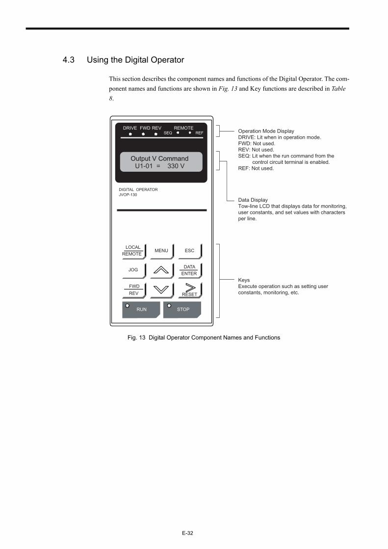
4.3 Using the Digital Operator
This section describes the component names and functions of the Digital Operator. The com-ponent names and functions are shown in Fig. 13 and Key functions are described in Table 8.
Fig. 13 Digital Operator Component Names and Functions
LOCALREMOTE
MENU
DIGITAL OPERATORJVOP-130
ESC
DATAENTER
JOG
FWD
REV RESET
DRIVE FWD REV REMOTESEQ REF
RUN STOP
U1-01 = 330 VOutput V Command
Operation Mode DisplayDRIVE: Lit when in operation mode.FWD: Not used.REV: Not used.SEQ: Lit when the run command from the
control circuit terminal is enabled.REF: Not used.
Data DisplayTow-line LCD that displays data for monitoring, user constants, and set values with characters per line.
KeysExecute operation such as setting user constants, monitoring, etc.
4 OPERATION
E-33
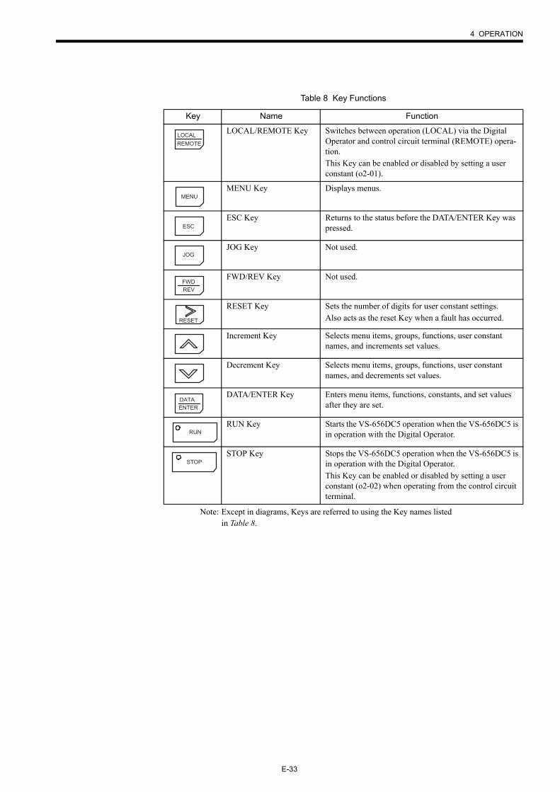
Note: Except in diagrams, Keys are referred to using the Key names listed in Table 8.
Table 8 Key Functions
Key Name Function
LOCAL/REMOTE Key Switches between operation (LOCAL) via the Digital Operator and control circuit terminal (REMOTE) opera-tion.This Key can be enabled or disabled by setting a user constant (o2-01).
MENU Key Displays menus.
ESC Key Returns to the status before the DATA/ENTER Key was pressed.
JOG Key Not used.
FWD/REV Key Not used.
RESET Key Sets the number of digits for user constant settings.Also acts as the reset Key when a fault has occurred.
Increment Key Selects menu items, groups, functions, user constant names, and increments set values.
Decrement Key Selects menu items, groups, functions, user constant names, and decrements set values.
DATA/ENTER Key Enters menu items, functions, constants, and set values after they are set.
RUN Key Starts the VS-656DC5 operation when the VS-656DC5 is in operation with the Digital Operator.
STOP Key Stops the VS-656DC5 operation when the VS-656DC5 is in operation with the Digital Operator.This Key can be enabled or disabled by setting a user constant (o2-02) when operating from the control circuit terminal.
LOCALREMOTE
MENU
ESC
JOG
FWDREV
RESET
DATAENTER
RUN
STOP
E-34
Modes
This section describes the VS-656DC5 monitor modes, switching between modes, and accessing/setting user constants.
VS-656DC5 Modes
The VS-656DC5 user constants and monitoring functions have been organized in groups called modes that make it easier to read and set user constants.
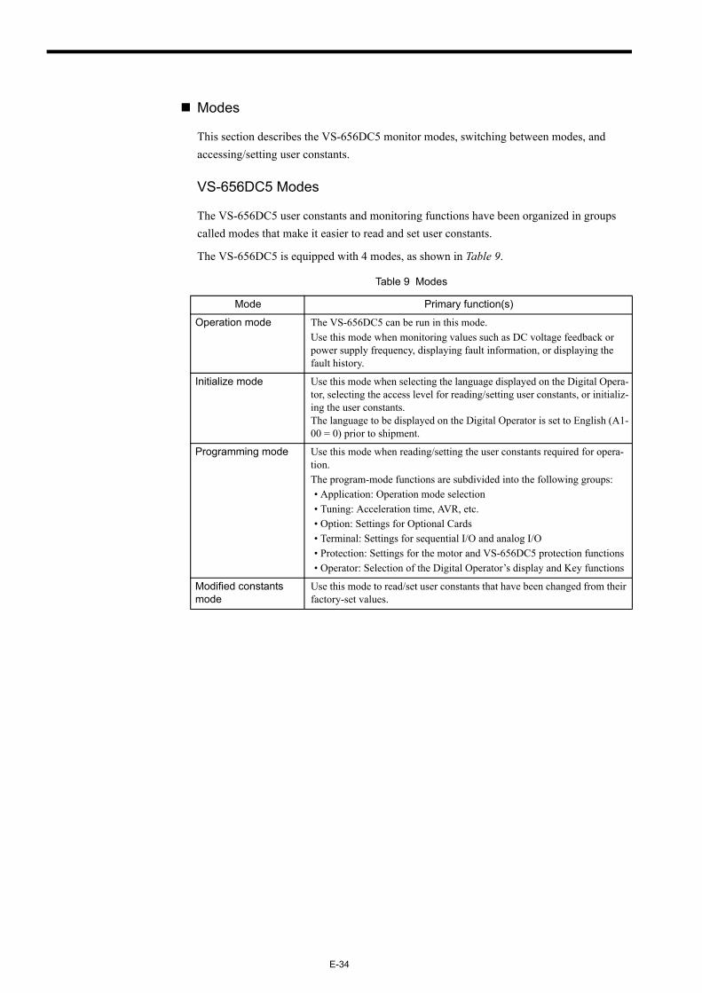
The VS-656DC5 is equipped with 4 modes, as shown in Table 9.
Table 9 Modes
Mode Primary function(s)
Operation mode The VS-656DC5 can be run in this mode.Use this mode when monitoring values such as DC voltage feedback or power supply frequency, displaying fault information, or displaying the fault history.
Initialize mode Use this mode when selecting the language displayed on the Digital Opera-tor, selecting the access level for reading/setting user constants, or initializ-ing the user constants.The language to be displayed on the Digital Operator is set to English (A1-00 = 0) prior to shipment.
Programming mode Use this mode when reading/setting the user constants required for opera-tion.The program-mode functions are subdivided into the following groups:• Application: Operation mode selection• Tuning: Acceleration time, AVR, etc.• Option: Settings for Optional Cards• Terminal: Settings for sequential I/O and analog I/O• Protection: Settings for the motor and VS-656DC5 protection functions• Operator: Selection of the Digital Operator’s display and Key functions
Modified constants mode
Use this mode to read/set user constants that have been changed from their factory-set values.
4 OPERATION
E-35
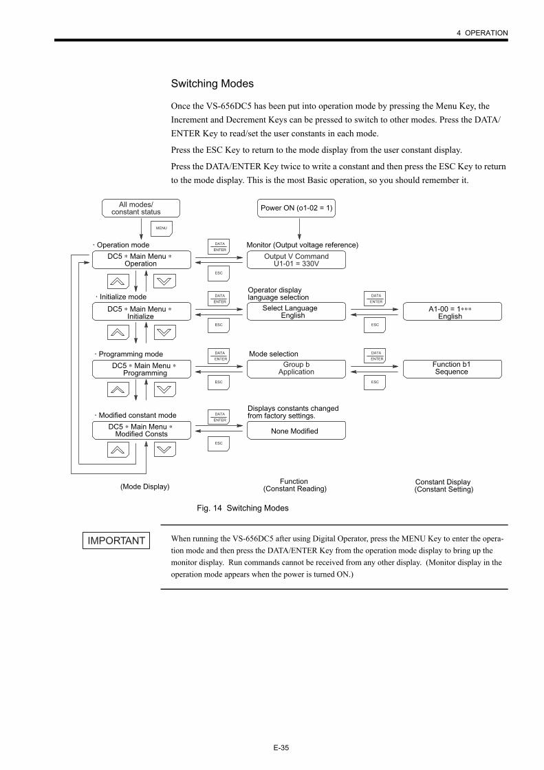
Switching Modes
Once the VS-656DC5 has been put into operation mode by pressing the Menu Key, the Increment and Decrement Keys can be pressed to switch to other modes. Press the DATA/ENTER Key to read/set the user constants in each mode.
Press the ESC Key to return to the mode display from the user constant display.
Press the DATA/ENTER Key twice to write a constant and then press the ESC Key to return to the mode display. This is the most Basic operation, so you should remember it.
Fig. 14 Switching Modes
When running the VS-656DC5 after using Digital Operator, press the MENU Key to enter the opera-tion mode and then press the DATA/ENTER Key from the operation mode display to bring up the monitor display. Run commands cannot be received from any other display. (Monitor display in the operation mode appears when the power is turned ON.)
Power ON (o1-02 = 1)
Select Language English
MENU
ESC
DATA
ENTER
ESC
DATA
ENTER
ESC
DATA
ENTER
ESC
DATA
ENTER
A1-00 = 1∗∗∗English
Function b1Sequence
ESC
DATA
ENTER
ESC
DATA
ENTER
Operation mode
Initialize mode
Programming mode
Modified constant mode
(Mode Display)
Monitor (Output voltage reference)
Operator display language selection
Mode selection
Displays constants changedfrom factory settings.
Function (Constant Reading)
Constant Display (Constant Setting)
DC5 ∗ Main Menu ∗ Operation
Output V CommandU1-01 = 330V
None Modified
DC5 ∗ Main Menu ∗ Initialize
DC5 ∗ Main Menu ∗ Programming
DC5 ∗ Main Menu ∗ Modified Consts
All modes/constant status
Group bApplication
IMPORTANT

E-36
Setting a User Constant
The group level will be displayed when the DATA/ENTER Key is pressed at the program-ming mode display.
Use the following procedure to set a constant.
The constant setting (drive mode is changed from Terminal to Operator with programming mode) has been completed.
Operation Mode
Operation mode is the mode in which the VS-656DC5 can be operated.
Many user constants can't be changed when the VS-656DC5 is operating. Refer to A.1 Mon-itor Constant List for details.
The following monitor displays are possible in operation mode: The AC power supply fre-quency, current or voltage, as well as fault information and the fault history.
When running the VS-656DC5 after using Digital Operator, press the MENU Key to enter the operation mode and then press the DATA/ENTER Key from the operation mode display to bring up the monitor display. Run commands cannot be received from any other display. (Monitor display in the operation mode appears when the power is turned ON.)
Step Key Sequence
Digital Operator Display Remarks
1
2
Press twice.
3
4 Changed to constant reading (function) level.
5
6
7
8
9 Writes in the new setting.
After a few seconds, the Oper-ator display is as shown on the left.
10
EXAMPLE
MENU DC5 ∗ Main Menu ∗Operation
DC5 ∗ Main Menu ∗Programming
Group b Application
SequenceFunction b1
Entry Accepted
Function b1 sequence
Reference SourceOperator
Run SourceTerminals
b1-02 = 1Terminals
b1-02 = 0Operator
Run SourceOperator
DATAENTER
DATAENTER
DATAENTER
DATAENTER
DATAENTER
ESC
IMPORTANT
4 OPERATION
E-37
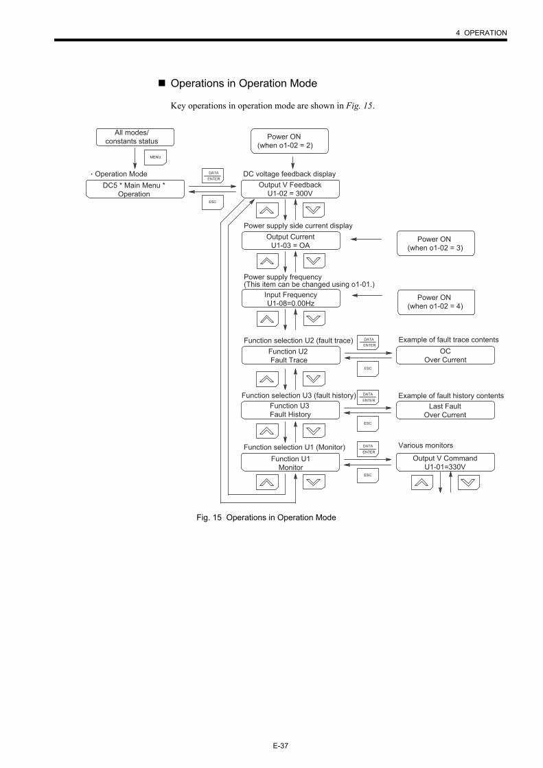
Operations in Operation Mode
Key operations in operation mode are shown in Fig. 15.
Fig. 15 Operations in Operation Mode
All modes/constants status
DC5 * Main Menu *Operation
Function U2 Fault Trace
Power ON (when o1-02 = 2)
MENU
ESC
DATAENTER
ESC
DATAENTER
Operation Mode
Power supply side current display
Power supply frequency (This item can be changed using o1-01.)
Function selection U2 (fault trace)
DC voltage feedback display
Example of fault trace contents
ESC
DATAENTER
ESC
DATAENTER
Function selection U3 (fault history)
Function selection U1 (Monitor)
Example of fault history contents
Various monitors
Power ON (when o1-02 = 3)
Power ON (when o1-02 = 4)
Function U3 Fault History
Function U1Monitor
Output V FeedbackU1-02 = 300V
Output CurrentU1-03 = OA
Input FrequencyU1-08=0.00Hz
OCOver Current
Last FaultOver Current
Output V CommandU1-01=330V
E-38
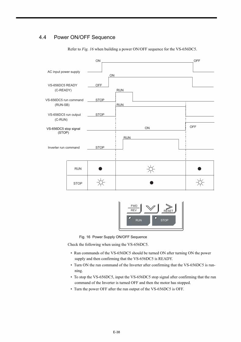
4.4 Power ON/OFF Sequence
Refer to Fig. 16 when building a power ON/OFF sequence for the VS-656DC5.
Fig. 16 Power Supply ON/OFF Sequence
Check the following when using the VS-656DC5.
• Run commands of the VS-656DC5 should be turned ON after turning ON the power supply and then confirming that the VS-656DC5 is READY.
• Turn ON the run command of the Inverter after confirming that the VS-656DC5 is run-ning.
• To stop the VS-656DC5, input the VS-656DC5 stop signal after confirming that the run command of the Inverter is turned OFF and then the motor has stopped.
• Turn the power OFF after the run output of the VS-656DC5 is OFF.
ON OFF
AC input power supplyON
VS-656DC5 READY OFF(C-READY) RUN
VS-656DC5 run command STOP(RUN-SB) RUN
VS-656DC5 run output STOP(C-RUN)
RUN
Inverter run command STOP
STOP
RUN
FWDREV RESET
RUN STOP
ONVS-656DC5 stop signal(STOP)
OFF
5 MAINTENANCE AND INSPECTION
E-39
5 MAINTENANCE AND INSPECTION
5.1 Maintenance Period
The maintenance period of the VS-656DC5 is as follows.
Maintenance period: Within 18 months of shipping from the factory or within 12 months of being delivered to the final user, whichever comes first.
• Never touch high-voltage terminals in the VS-656DC5.
Failure to observe this warning may result in an electric shock.
• Perform maintenance or inspection only after verifying that the CHARGE LED goes OFF, after the main circuit power supply is turned OFF.
The capacitors are still charged and can be dangerous.
• Only authorized personnel should be permitted to perform maintenance, inspections, or parts replacement.
[Remove all metal objects (watches, bracelets, etc.) before operation.](Use tools which are insulated against electric shock.)Failure to observe this warning may result in an electric shock.
• Never modify the product.
Failure to observe this warning may result in an electric shock or personal injury.
WARNING
• A CMOS IC is used in the control board. Handle the control board and CMOS IC carefully. The CMOS IC can be destroyed by static electricity if touched directly.
The CMOS IC may be destroyed by static electricity if touched directly.
• Do not change the wiring, or connect/disconnect the connectors while power is applied to the cir-cuit.
Failure to observe this caution may result in personal injury.
• Do not subject the VS-656DC5 to halogen gases, such as fiuorine, chlovine, bromine, and iodine, at any time even during transportation or installation.
Otherwise, the VS-656DC5 can be damaged or interior parts burnt.
CAUTION
E-40
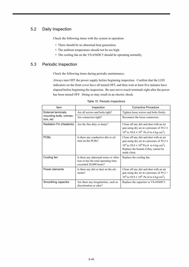
5.2 Daily Inspection
Check the following items with the system in operation.
• There should be no abnormal heat generation.• The ambient temperature should not be too high.• The cooling fan on the VS-656DC5 should be operating normally.
5.3 Periodic Inspection
Check the following items during periodic maintenance.
Always turn OFF the power supply before beginning inspection. Confirm that the LED indicators on the front cover have all turned OFF, and then wait at least five minutes have elapsed before beginning the inspection. Be sure not to touch terminals right after the power has been turned OFF. Doing so may result in an electric shock.
Table 10 Periodic Inspections
Item Inspection Corrective Procedure
External terminals, mounting bolts, connec-tors, etc.
Are all screws and bolts tight? Tighten loose screws and bolts firmly.
Are connectors tight? Reconnect the loose connectors.
Radiation Fin (Heatsink) Are the fins dirty or dusty? Clean off any dirt and dust with an air gun using dry air at a pressure of 39.2 × 10⁴ to 58.8 × 10⁴ Pa (4 to 6 kg cm2).
PCBs Is there any conductive dirt or oil mist on the PCBs?
Clean off any dirt and dust with an air gun using dry air at a pressure of 39.2 × 10⁴ to 58.8 × 10⁴ Pa (4 to 6 kg cm2).Replace the boards if they cannot be made clean.
Cooling fan Is there any abnormal noise or vibra-tion or has the total operating time exceeded 20,000 hours?
Replace the cooling fan.
Power elements Is there any dirt or dust on the ele-ments?
Clean off any dirt and dust with an air gun using dry air at a pressure of 39.2 × 10⁴ to 58.8 × 10⁴ Pa (4 to 6 kg cm2).
Smoothing capacitor Are there any irregularities, such as discoloration or odor?
Replace the capacitor or VS-656DC5.
5 MAINTENANCE AND INSPECTION
E-41
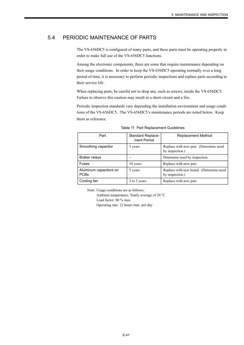
5.4 PERIODIC MAINTENANCE OF PARTS
The VS-656DC5 is configured of many parts, and these parts must be operating properly in order to make full use of the VS-656DC5 functions.
Among the electronic components, there are some that require maintenance depending on their usage conditions. In order to keep the VS-656DC5 operating normally over a long period of time, it is necessary to perform periodic inspections and replace parts according to their service life.
When replacing parts, be careful not to drop any, such as screws, inside the VS-656DC5. Failure to observe this caution may result in a short-circuit and a fire.
Periodic inspection standards vary depending the installation environment and usage condi-tions of the VS-656DC5. The VS-656DC5’s maintenance periods are noted below. Keep them as reference.
Note: Usage conditions are as follows:Ambient temperature: Yearly average of 30 °CLoad factor: 80 % max.Operating rate: 12 hours max. per day
Table 11 Part Replacement Guidelines
Part Standard Replace-ment Period
Replacement Method
Smoothing capacitor 5 years Replace with new part. (Determine need by inspection.)
Braker relays − Determine need by inspection.
Fuses 10 years Replace with new part.
Aluminum capacitors on PCBs
5 years Replace with new board. (Determine need by inspection.)
Cooling fan 2 to 3 years Replace with new part.
E-42
6 TROUBLESHOOTING
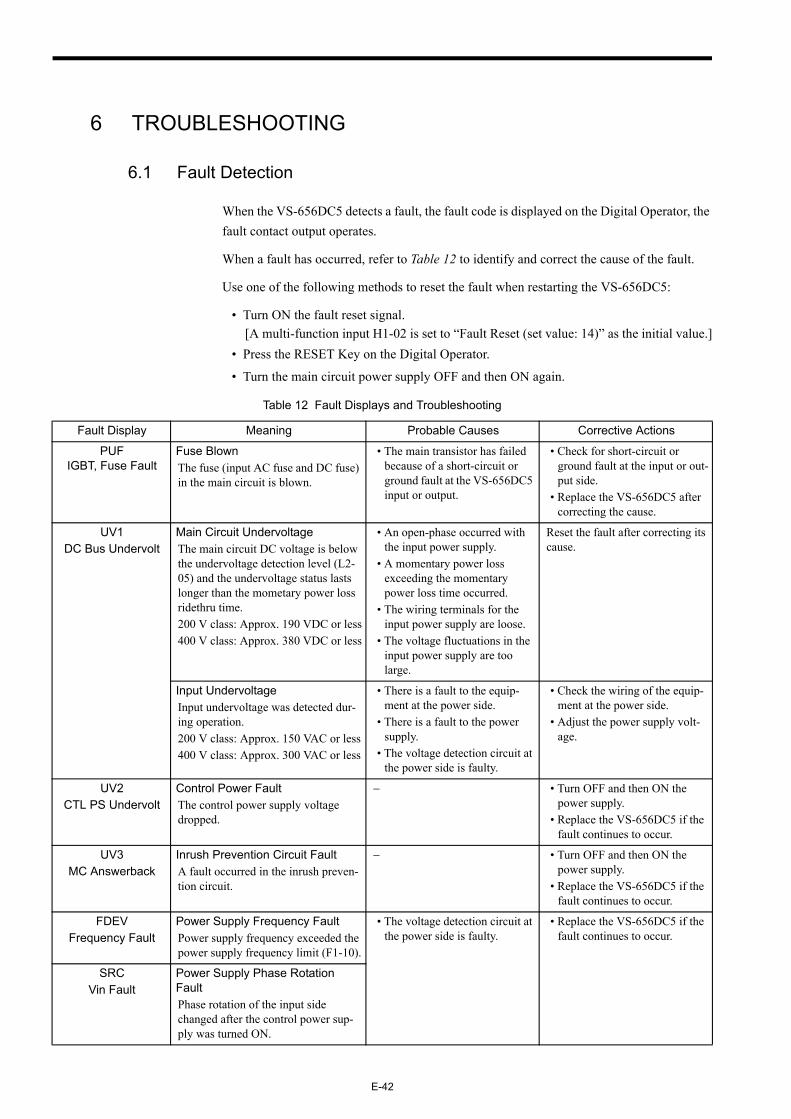
6.1 Fault Detection
When the VS-656DC5 detects a fault, the fault code is displayed on the Digital Operator, the fault contact output operates.
When a fault has occurred, refer to Table 12 to identify and correct the cause of the fault.
Use one of the following methods to reset the fault when restarting the VS-656DC5:
• Turn ON the fault reset signal.[A multi-function input H1-02 is set to “Fault Reset (set value: 14)” as the initial value.]
• Press the RESET Key on the Digital Operator.
• Turn the main circuit power supply OFF and then ON again.
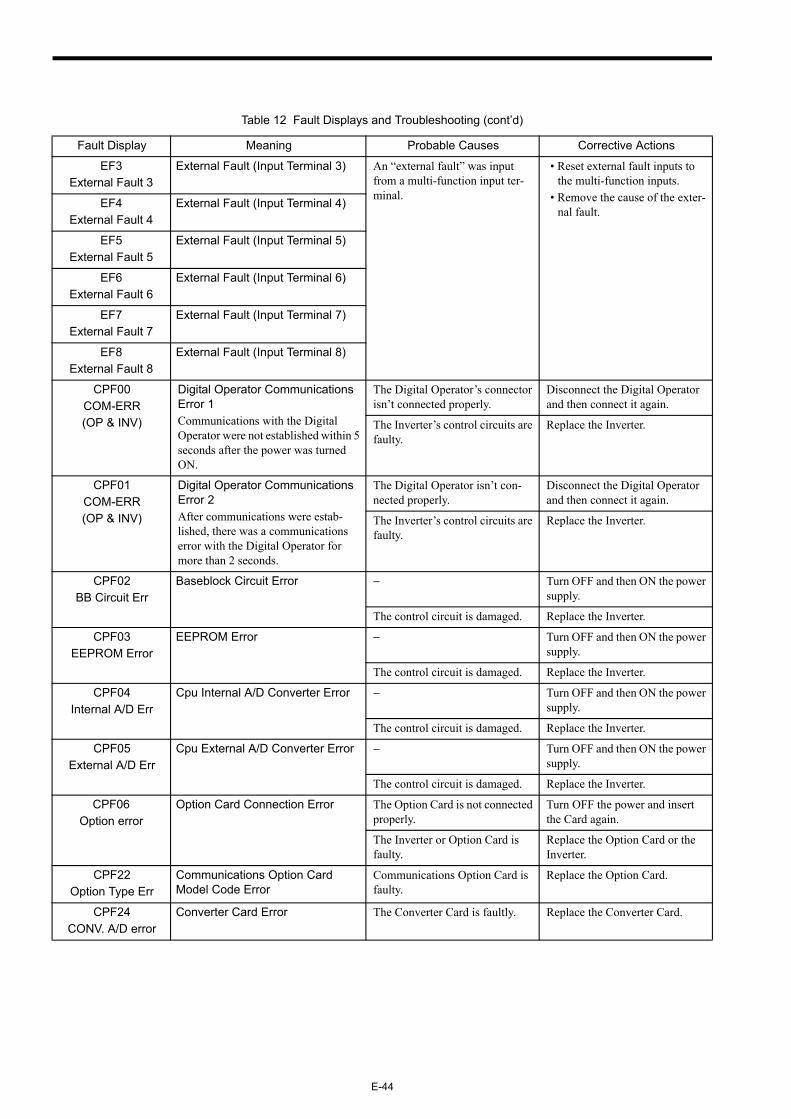
Table 12 Fault Displays and Troubleshooting
Fault Display Meaning Probable Causes Corrective Actions
PUFIGBT, Fuse Fault
Fuse BlownThe fuse (input AC fuse and DC fuse) in the main circuit is blown.
• The main transistor has failed because of a short-circuit or ground fault at the VS-656DC5 input or output.
• Check for short-circuit or ground fault at the input or out-put side.
• Replace the VS-656DC5 after correcting the cause.
UV1DC Bus Undervolt
Main Circuit UndervoltageThe main circuit DC voltage is below the undervoltage detection level (L2-05) and the undervoltage status lasts longer than the mometary power loss ridethru time.200 V class: Approx. 190 VDC or less400 V class: Approx. 380 VDC or less
• An open-phase occurred with the input power supply.
• A momentary power loss exceeding the momentary power loss time occurred.
• The wiring terminals for the input power supply are loose.
• The voltage fluctuations in the input power supply are too large.
Reset the fault after correcting its cause.
Input UndervoltageInput undervoltage was detected dur-ing operation.200 V class: Approx. 150 VAC or less400 V class: Approx. 300 VAC or less
• There is a fault to the equip-ment at the power side.
• There is a fault to the power supply.
• The voltage detection circuit at the power side is faulty.
• Check the wiring of the equip-ment at the power side.
• Adjust the power supply volt-age.
UV2CTL PS Undervolt
Control Power FaultThe control power supply voltage dropped.
− • Turn OFF and then ON the power supply.
• Replace the VS-656DC5 if the fault continues to occur.
UV3MC Answerback
Inrush Prevention Circuit FaultA fault occurred in the inrush preven-tion circuit.
− • Turn OFF and then ON the power supply.
• Replace the VS-656DC5 if the fault continues to occur.
FDEVFrequency Fault
Power Supply Frequency FaultPower supply frequency exceeded the power supply frequency limit (F1-10).
• The voltage detection circuit at the power side is faulty.
• Replace the VS-656DC5 if the fault continues to occur.
SRCVin Fault
Power Supply Phase Rotation FaultPhase rotation of the input side changed after the control power sup-ply was turned ON.
6 TROUBLESHOOTING
E-43
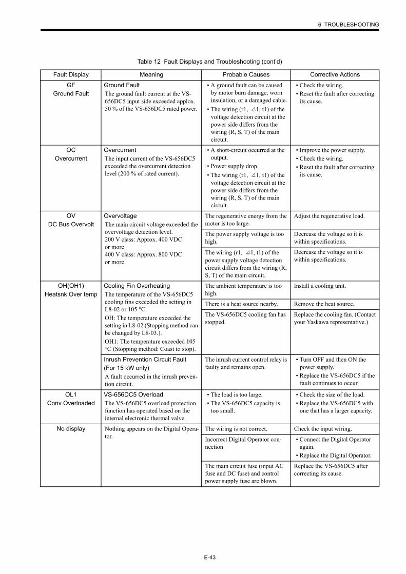
GFGround Fault
Ground FaultThe ground fault current at the VS-656DC5 input side exceeded applox. 50 % of the VS-656DC5 rated power.
• A ground fault can be caused by motor burn damage, worn insulation, or a damaged cable.
• The wiring (r1, 1, t1) of the voltage detection circuit at the power side differs from the wiring (R, S, T) of the main circuit.
• Check the wiring.• Reset the fault after correcting
its cause.
OCOvercurrent
OvercurrentThe input current of the VS-656DC5 exceeded the overcurrent detection level (200 % of rated current).
• A short-circuit occurred at the output.
• Power supply drop• The wiring (r1, 1, t1) of the
voltage detection circuit at the power side differs from the wiring (R, S, T) of the main circuit.
• Improve the power supply.• Check the wiring.• Reset the fault after correcting
its cause.
OVDC Bus Overvolt
OvervoltageThe main circuit voltage exceeded the overvoltage detection level.200 V class: Approx. 400 VDC or more400 V class: Approx. 800 VDC or more
The regenerative energy from the motor is too large.
Adjust the regenerative load.
The power supply voltage is too high.
Decrease the voltage so it is within specifications.
The wiring (r1, 1, t1) of the power supply voltage detection circuit differs from the wiring (R, S, T) of the main circuit.
Decrease the voltage so it is within specifications.
OH(OH1)Heatsnk Over temp
Cooling Fin OverheatingThe temperature of the VS-656DC5 cooling fins exceeded the setting in L8-02 or 105 °C.OH: The temperature exceeded the setting in L8-02 (Stopping method can be changed by L8-03.).OH1: The temperature exceeded 105 °C (Stopping method: Coast to stop).
The ambient temperature is too high.
Install a cooling unit.
There is a heat source nearby. Remove the heat source.
The VS-656DC5 cooling fan has stopped.
Replace the cooling fan. (Contact your Yaskawa representative.)
Inrush Prevention Circuit Fault(For 15 kW only)A fault occurred in the inrush preven-tion circuit.
The inrush current control relay is faulty and remains open.
• Turn OFF and then ON the power supply.
• Replace the VS-656DC5 if the fault continues to occur.
OL1Conv Overloaded
VS-656DC5 OverloadThe VS-656DC5 overload protection function has operated based on the internal electronic thermal valve.
• The load is too large.• The VS-656DC5 capacity is
too small.
• Check the size of the load.• Replace the VS-656DC5 with
one that has a larger capacity.
No display Nothing appears on the Digital Opera-tor.
The wiring is not correct. Check the input wiring.
Incorrect Digital Operator con-nection
• Connect the Digital Operator again.
• Replace the Digital Operator.
The main circuit fuse (input AC fuse and DC fuse) and control power supply fuse are blown.
Replace the VS-656DC5 after correcting its cause.
Table 12 Fault Displays and Troubleshooting (cont’d)
Fault Display Meaning Probable Causes Corrective Actions
E-44
EF3External Fault 3
External Fault (Input Terminal 3) An “external fault” was input from a multi-function input ter-minal.
• Reset external fault inputs to the multi-function inputs.
• Remove the cause of the exter-nal fault.
EF4External Fault 4
External Fault (Input Terminal 4)
EF5External Fault 5
External Fault (Input Terminal 5)
EF6External Fault 6
External Fault (Input Terminal 6)
EF7External Fault 7
External Fault (Input Terminal 7)
EF8External Fault 8
External Fault (Input Terminal 8)
CPF00COM-ERR(OP & INV)
Digital Operator Communications Error 1Communications with the Digital Operator were not established within 5 seconds after the power was turned ON.
The Digital Operator’s connector isn’t connected properly.
Disconnect the Digital Operator and then connect it again.
The Inverter’s control circuits are faulty.
Replace the Inverter.
CPF01COM-ERR(OP & INV)
Digital Operator Communications Error 2After communications were estab-lished, there was a communications error with the Digital Operator for more than 2 seconds.
The Digital Operator isn’t con-nected properly.
Disconnect the Digital Operator and then connect it again.
The Inverter’s control circuits are faulty.
Replace the Inverter.
CPF02BB Circuit Err
Baseblock Circuit Error − Turn OFF and then ON the power supply.
The control circuit is damaged. Replace the Inverter.
CPF03EEPROM Error
EEPROM Error − Turn OFF and then ON the power supply.
The control circuit is damaged. Replace the Inverter.
CPF04Internal A/D Err
Cpu Internal A/D Converter Error − Turn OFF and then ON the power supply.
The control circuit is damaged. Replace the Inverter.
CPF05External A/D Err
Cpu External A/D Converter Error − Turn OFF and then ON the power supply.
The control circuit is damaged. Replace the Inverter.
CPF06Option error
Option Card Connection Error The Option Card is not connected properly.
Turn OFF the power and insert the Card again.
The Inverter or Option Card is faulty.
Replace the Option Card or the Inverter.
CPF22Option Type Err
Communications Option Card Model Code Error
Communications Option Card is faulty.
Replace the Option Card.
CPF24CONV. A/D error
Converter Card Error The Converter Card is faultly. Replace the Converter Card.
Table 12 Fault Displays and Troubleshooting (cont’d)
Fault Display Meaning Probable Causes Corrective Actions
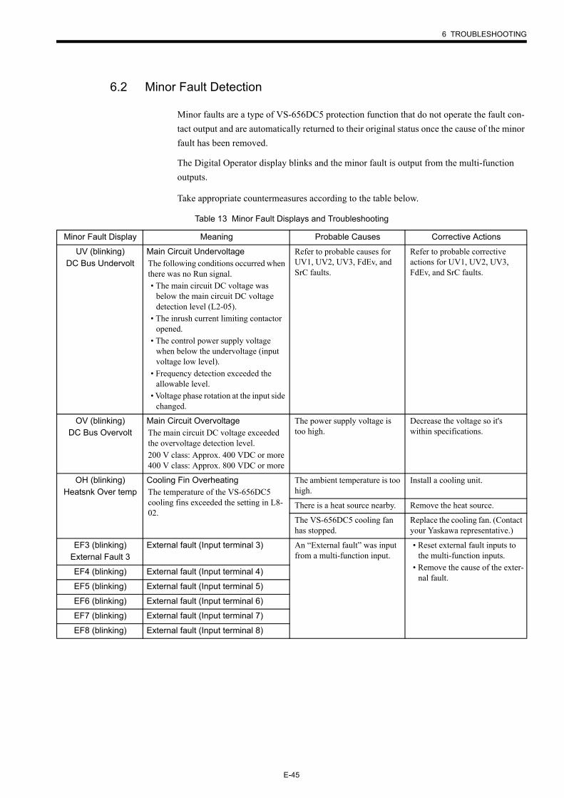
6 TROUBLESHOOTING
E-45
6.2 Minor Fault Detection
Minor faults are a type of VS-656DC5 protection function that do not operate the fault con-tact output and are automatically returned to their original status once the cause of the minor fault has been removed.
The Digital Operator display blinks and the minor fault is output from the multi-function outputs.
Take appropriate countermeasures according to the table below.
Table 13 Minor Fault Displays and Troubleshooting
Minor Fault Display Meaning Probable Causes Corrective Actions
UV (blinking)DC Bus Undervolt
Main Circuit UndervoltageThe following conditions occurred when there was no Run signal.• The main circuit DC voltage was
below the main circuit DC voltage detection level (L2-05).
• The inrush current limiting contactor opened.
• The control power supply voltage when below the undervoltage (input voltage low level).
• Frequency detection exceeded the allowable level.
• Voltage phase rotation at the input side changed.
Refer to probable causes for UV1, UV2, UV3, FdEv, and SrC faults.
Refer to probable corrective actions for UV1, UV2, UV3, FdEv, and SrC faults.
OV (blinking)DC Bus Overvolt
Main Circuit OvervoltageThe main circuit DC voltage exceeded the overvoltage detection level.200 V class: Approx. 400 VDC or more400 V class: Approx. 800 VDC or more
The power supply voltage is too high.
Decrease the voltage so it's within specifications.
OH (blinking)Heatsnk Over temp
Cooling Fin OverheatingThe temperature of the VS-656DC5 cooling fins exceeded the setting in L8-02.
The ambient temperature is too high.
Install a cooling unit.
There is a heat source nearby. Remove the heat source.
The VS-656DC5 cooling fan has stopped.
Replace the cooling fan. (Contact your Yaskawa representative.)
EF3 (blinking)External Fault 3
External fault (Input terminal 3) An “External fault” was input from a multi-function input.
• Reset external fault inputs to the multi-function inputs.
• Remove the cause of the exter-nal fault.
EF4 (blinking) External fault (Input terminal 4)
EF5 (blinking) External fault (Input terminal 5)
EF6 (blinking) External fault (Input terminal 6)
EF7 (blinking) External fault (Input terminal 7)
EF8 (blinking) External fault (Input terminal 8)
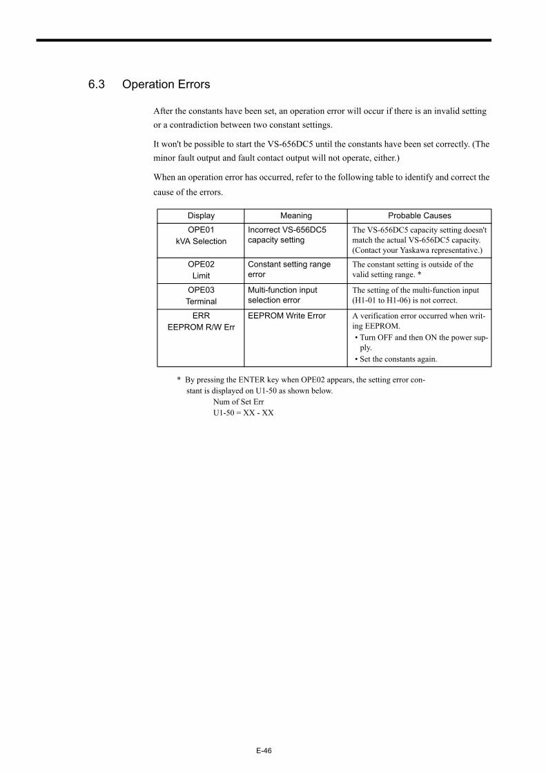
E-46
6.3 Operation Errors
After the constants have been set, an operation error will occur if there is an invalid setting or a contradiction between two constant settings.
It won't be possible to start the VS-656DC5 until the constants have been set correctly. (The minor fault output and fault contact output will not operate, either.)
When an operation error has occurred, refer to the following table to identify and correct the cause of the errors.
* By pressing the ENTER key when OPE02 appears, the setting error con-stant is displayed on U1-50 as shown below. Num of Set Err U1-50 = XX - XX
Display Meaning Probable Causes
OPE01kVA Selection
Incorrect VS-656DC5 capacity setting
The VS-656DC5 capacity setting doesn't match the actual VS-656DC5 capacity. (Contact your Yaskawa representative.)
OPE02Limit
Constant setting range error
The constant setting is outside of the valid setting range. *
OPE03Terminal
Multi-function input selection error
The setting of the multi-function input (H1-01 to H1-06) is not correct.
ERREEPROM R/W Err
EEPROM Write Error A verification error occurred when writ-ing EEPROM.• Turn OFF and then ON the power sup-
ply.• Set the constants again.
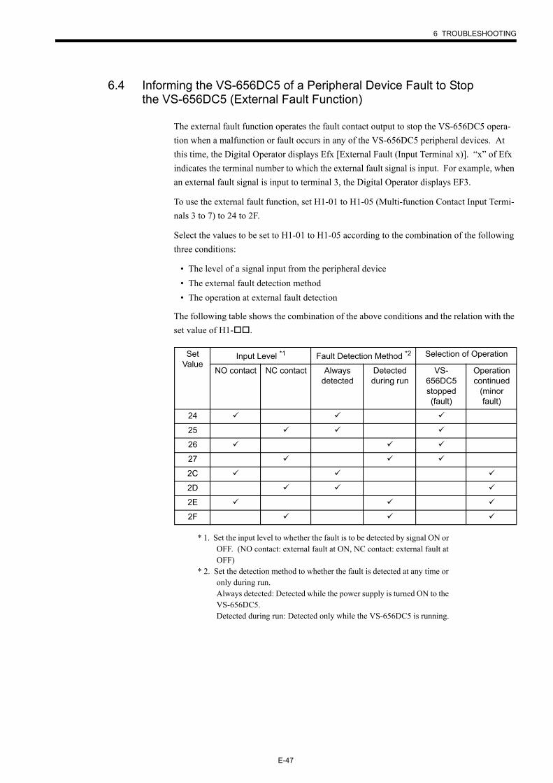
6 TROUBLESHOOTING
E-47
6.4 Informing the VS-656DC5 of a Peripheral Device Fault to Stop the VS-656DC5 (External Fault Function)
The external fault function operates the fault contact output to stop the VS-656DC5 opera-tion when a malfunction or fault occurs in any of the VS-656DC5 peripheral devices. At this time, the Digital Operator displays Efx [External Fault (Input Terminal x)]. “x” of Efx indicates the terminal number to which the external fault signal is input. For example, when an external fault signal is input to terminal 3, the Digital Operator displays EF3.
To use the external fault function, set H1-01 to H1-05 (Multi-function Contact Input Termi-nals 3 to 7) to 24 to 2F.
Select the values to be set to H1-01 to H1-05 according to the combination of the following three conditions:
• The level of a signal input from the peripheral device• The external fault detection method• The operation at external fault detection
The following table shows the combination of the above conditions and the relation with the set value of H1- .
* 1. Set the input level to whether the fault is to be detected by signal ON or OFF. (NO contact: external fault at ON, NC contact: external fault at OFF)
* 2. Set the detection method to whether the fault is detected at any time or only during run.Always detected: Detected while the power supply is turned ON to the VS-656DC5.Detected during run: Detected only while the VS-656DC5 is running.
Set Value
Input Level *1 Fault Detection Method *2 Selection of Operation
NO contact NC contact Always detected
Detected during run
VS-656DC5 stopped (fault)
Operation continued
(minor fault)
24
25
26
27
2C
2D
2E
2F
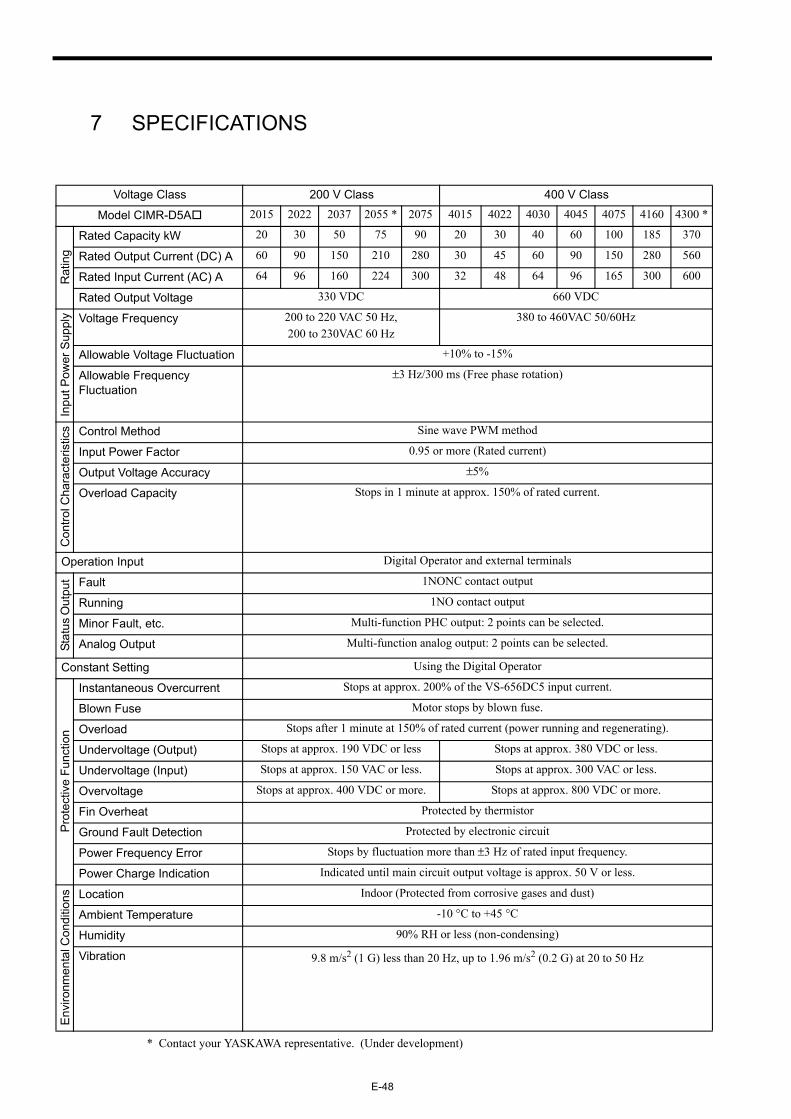
E-48
7 SPECIFICATIONS
* Contact your YASKAWA representative. (Under development)
Voltage Class 200 V Class 400 V Class
Model CIMR-D5A 2015 2022 2037 2055 * 2075 4015 4022 4030 4045 4075 4160 4300 *
Rat
ing
Rated Capacity kW 20 30 50 75 90 20 30 40 60 100 185 370
Rated Output Current (DC) A 60 90 150 210 280 30 45 60 90 150 280 560
Rated Input Current (AC) A 64 96 160 224 300 32 48 64 96 165 300 600
Rated Output Voltage 330 VDC 660 VDC
Inpu
t Pow
er S
uppl
y Voltage Frequency 200 to 220 VAC 50 Hz, 200 to 230VAC 60 Hz
380 to 460VAC 50/60Hz
Allowable Voltage Fluctuation +10% to -15%
Allowable Frequency Fluctuation
±3 Hz/300 ms (Free phase rotation)
Con
trol C
hara
cter
istic
s Control Method Sine wave PWM method
Input Power Factor 0.95 or more (Rated current)
Output Voltage Accuracy ±5%
Overload Capacity Stops in 1 minute at approx. 150% of rated current.
Operation Input Digital Operator and external terminals
Stat
us O
utpu
t Fault 1NONC contact output
Running 1NO contact output
Minor Fault, etc. Multi-function PHC output: 2 points can be selected.
Analog Output Multi-function analog output: 2 points can be selected.
Constant Setting Using the Digital Operator
Prot
ectiv
e Fu
nctio
n
Instantaneous Overcurrent Stops at approx. 200% of the VS-656DC5 input current.
Blown Fuse Motor stops by blown fuse.
Overload Stops after 1 minute at 150% of rated current (power running and regenerating).
Undervoltage (Output) Stops at approx. 190 VDC or less Stops at approx. 380 VDC or less.
Undervoltage (Input) Stops at approx. 150 VAC or less. Stops at approx. 300 VAC or less.
Overvoltage Stops at approx. 400 VDC or more. Stops at approx. 800 VDC or more.
Fin Overheat Protected by thermistor
Ground Fault Detection Protected by electronic circuit
Power Frequency Error Stops by fluctuation more than ±3 Hz of rated input frequency.
Power Charge Indication Indicated until main circuit output voltage is approx. 50 V or less.
Envi
ronm
enta
l Con
ditio
ns Location Indoor (Protected from corrosive gases and dust)
Ambient Temperature -10 °C to +45 °C
Humidity 90% RH or less (non-condensing)
Vibration 9.8 m/s2 (1 G) less than 20 Hz, up to 1.96 m/s2 (0.2 G) at 20 to 50 Hz
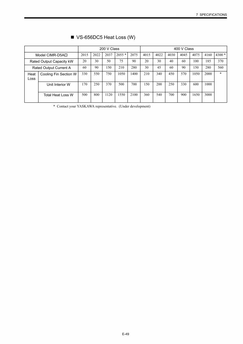
7 SPECIFICATIONS
E-49
VS-656DC5 Heat Loss (W)
* Contact your YASKAWA representative. (Under development)
200 V Class 400 V Class
Model CIMR-D5A 2015 2022 2037 2055 * 2075 4015 4022 4030 4045 4075 4160 4300 *
Rated Output Capacity kW 20 30 50 75 90 20 30 40 60 100 185 370
Rated Output Current A 60 90 150 210 280 30 45 60 90 150 280 560
Heat Loss
Cooling Fin Section W 330 550 750 1050 1400 210 340 450 570 1050 2000 *
Unit Interior W 170 250 370 500 700 150 200 250 330 600 1000
Total Heat Loss W 500 800 1120 1550 2100 360 540 700 900 1650 3000
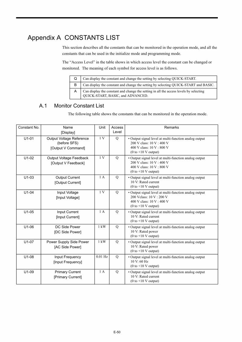
E-50
Appendix A CONSTANTS LISTThis section describes all the constants that can be monitored in the operation mode, and all the constants that can be used in the initialize mode and programming mode.
The “Access Level” in the table shows in which access level the constant can be changed or monitored. The meaning of each symbol for access level is as follows.
A.1 Monitor Constant ListThe following table shows the constants that can be monitored in the operation mode.
Q Can display the constant and change the setting by selecting QUICK-START.
B Can display the constant and change the setting by selecting QUICK-START and BASIC.
A Can display the constant and change the setting in all the access levels by selecting QUICK-START, BASIC, and ADVANCED.
Constant No. Name[Display]
Unit Access Level
Remarks
U1-01 Output Voltage Reference (before SFS)
[Output V Command]
1 V Q • Output signal level at multi-function analog output 200 V class: 10 V : 400 V 400 V class: 10 V : 800 V(0 to +10 V output)
U1-02 Output Voltage Feedback[Output V Feedback]
1 V Q • Output signal level at multi-function analog output200 V class: 10 V : 400 V 400 V class: 10 V : 800 V(0 to +10 V output)
U1-03 Output Current[Output Current]
1 A Q • Output signal level at multi-function analog output10 V: Rated current(0 to +10 V output)
U1-04 Input Voltage[Input Voltage]
1 V Q • Output signal level at multi-function analog output200 Vclass: 10 V : 200 V 400 V class: 10 V : 400 V(0 to +10 V output)
U1-05 Input Current[Input Current]
1 A Q • Output signal level at multi-function analog output10 V: Rated current(0 to +10 V output)
U1-06 DC Side Power[DC Side Power]
1 kW Q • Output signal level at multi-function analog output10 V: Rated power(0 to +10 V output)
U1-07 Power Supply Side Power[AC Side Power]
1 kW Q • Output signal level at multi-function analog output10 V: Rated power(0 to +10 V output)
U1-08 Input Frequency[Input Frequency]
0.01 Hz Q • Output signal level at multi-function analog output10 V: 60 Hz(0 to +10 V output)
U1-09 Primary Current[Primary Current]
1 A Q • Output signal level at multi-function analog output10 V: Rated current(0 to +10 V output)
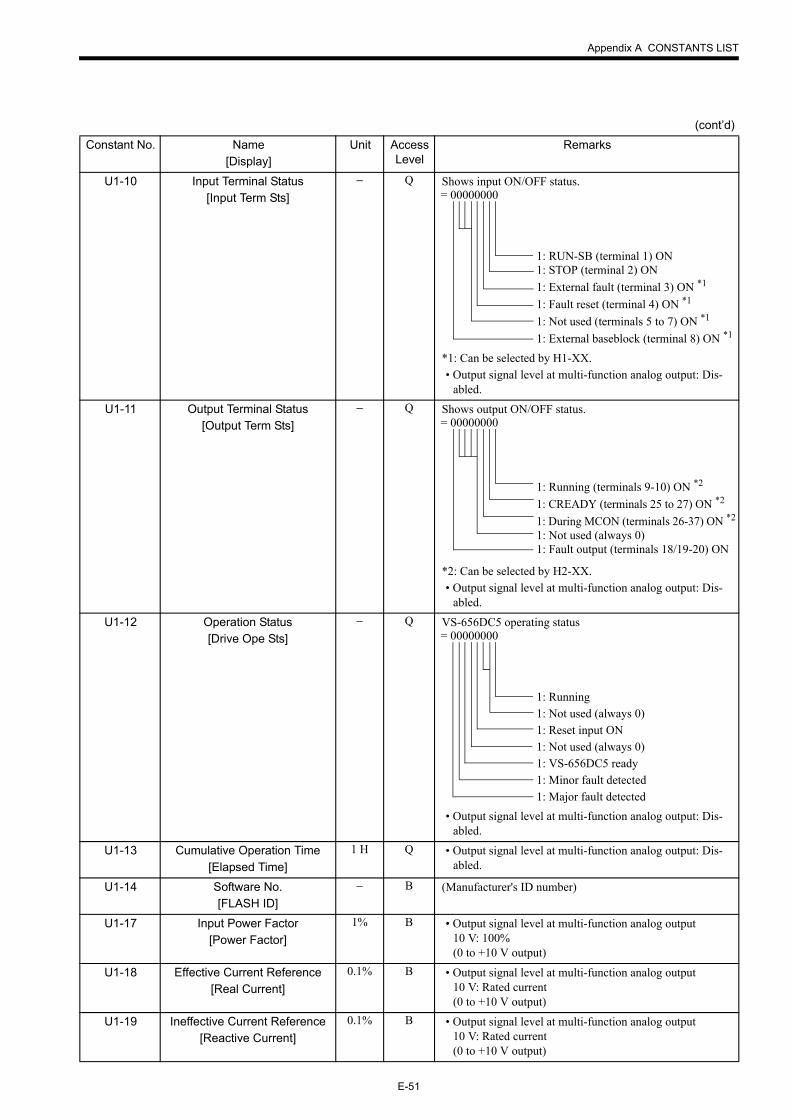
Appendix A CONSTANTS LIST
E-51
U1-10 Input Terminal Status[Input Term Sts]
− Q Shows input ON/OFF status.
*1: Can be selected by H1-XX.• Output signal level at multi-function analog output: Dis-
abled.
U1-11 Output Terminal Status[Output Term Sts]
− Q Shows output ON/OFF status.
*2: Can be selected by H2-XX.• Output signal level at multi-function analog output: Dis-
abled.
U1-12 Operation Status[Drive Ope Sts]
− Q VS-656DC5 operating status
• Output signal level at multi-function analog output: Dis-abled.
U1-13 Cumulative Operation Time[Elapsed Time]
1 H Q • Output signal level at multi-function analog output: Dis-abled.
U1-14 Software No.[FLASH ID]
− B (Manufacturer's ID number)
U1-17 Input Power Factor[Power Factor]
1% B • Output signal level at multi-function analog output10 V: 100%(0 to +10 V output)
U1-18 Effective Current Reference[Real Current]
0.1% B • Output signal level at multi-function analog output10 V: Rated current(0 to +10 V output)
U1-19 Ineffective Current Reference[Reactive Current]
0.1% B • Output signal level at multi-function analog output10 V: Rated current(0 to +10 V output)
(cont’d)Constant No. Name
[Display]Unit Access
LevelRemarks
= 00000000
1: RUN-SB (terminal 1) ON1: STOP (terminal 2) ON1: External fault (terminal 3) ON *1
1: Fault reset (terminal 4) ON *1
1: Not used (terminals 5 to 7) ON *1
1: External baseblock (terminal 8) ON *1
= 00000000
1: Running (terminals 9-10) ON *2
1: CREADY (terminals 25 to 27) ON *2
1: During MCON (terminals 26-37) ON *2
1: Not used (always 0)1: Fault output (terminals 18/19-20) ON
= 00000000
1: Running 1: Not used (always 0)1: Reset input ON1: Not used (always 0)1: VS-656DC5 ready1: Minor fault detected1: Major fault detected
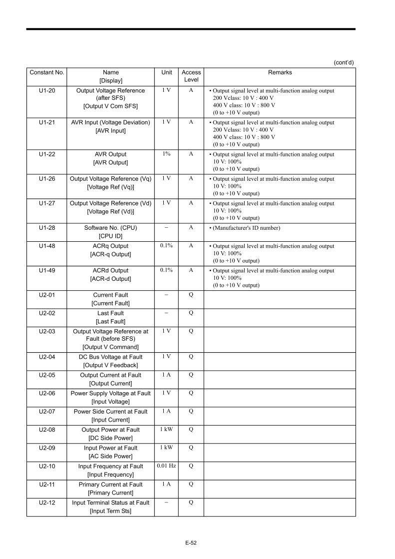
E-52
U1-20 Output Voltage Reference (after SFS)
[Output V Com SFS]
1 V A • Output signal level at multi-function analog output 200 Vclass: 10 V : 400 V 400 V class: 10 V : 800 V(0 to +10 V output)
U1-21 AVR Input (Voltage Deviation)[AVR Input]
1 V A • Output signal level at multi-function analog output 200 Vclass: 10 V : 400 V 400 V class: 10 V : 800 V(0 to +10 V output)
U1-22 AVR Output[AVR Output]
1% A • Output signal level at multi-function analog output10 V: 100%(0 to +10 V output)
U1-26 Output Voltage Reference (Vq)[Voltage Ref (Vq)]
1 V A • Output signal level at multi-function analog output10 V: 100%(0 to +10 V output)
U1-27 Output Voltage Reference (Vd)[Voltage Ref (Vd)]
1 V A • Output signal level at multi-function analog output10 V: 100%(0 to +10 V output)
U1-28 Software No. (CPU)[CPU ID]
− A • (Manufacturer's ID number)
U1-48 ACRq Output[ACR-q Output]
0.1% A • Output signal level at multi-function analog output10 V: 100%(0 to +10 V output)
U1-49 ACRd Output[ACR-d Output]
0.1% A • Output signal level at multi-function analog output10 V: 100%(0 to +10 V output)
U2-01 Current Fault[Current Fault]
− Q
U2-02 Last Fault[Last Fault]
− Q
U2-03 Output Voltage Reference at Fault (before SFS)
[Output V Command]
1 V Q
U2-04 DC Bus Voltage at Fault[Output V Feedback]
1 V Q
U2-05 Output Current at Fault[Output Current]
1 A Q
U2-06 Power Supply Voltage at Fault[Input Voltage]
1 V Q
U2-07 Power Side Current at Fault[Input Current]
1 A Q
U2-08 Output Power at Fault[DC Side Power]
1 kW Q
U2-09 Input Power at Fault[AC Side Power]
1 kW Q
U2-10 Input Frequency at Fault[Input Frequency]
0.01 Hz Q
U2-11 Primary Current at Fault[Primary Current]
1 A Q
U2-12 Input Terminal Status at Fault[Input Term Sts]
− Q
(cont’d)Constant No. Name
[Display]Unit Access
LevelRemarks
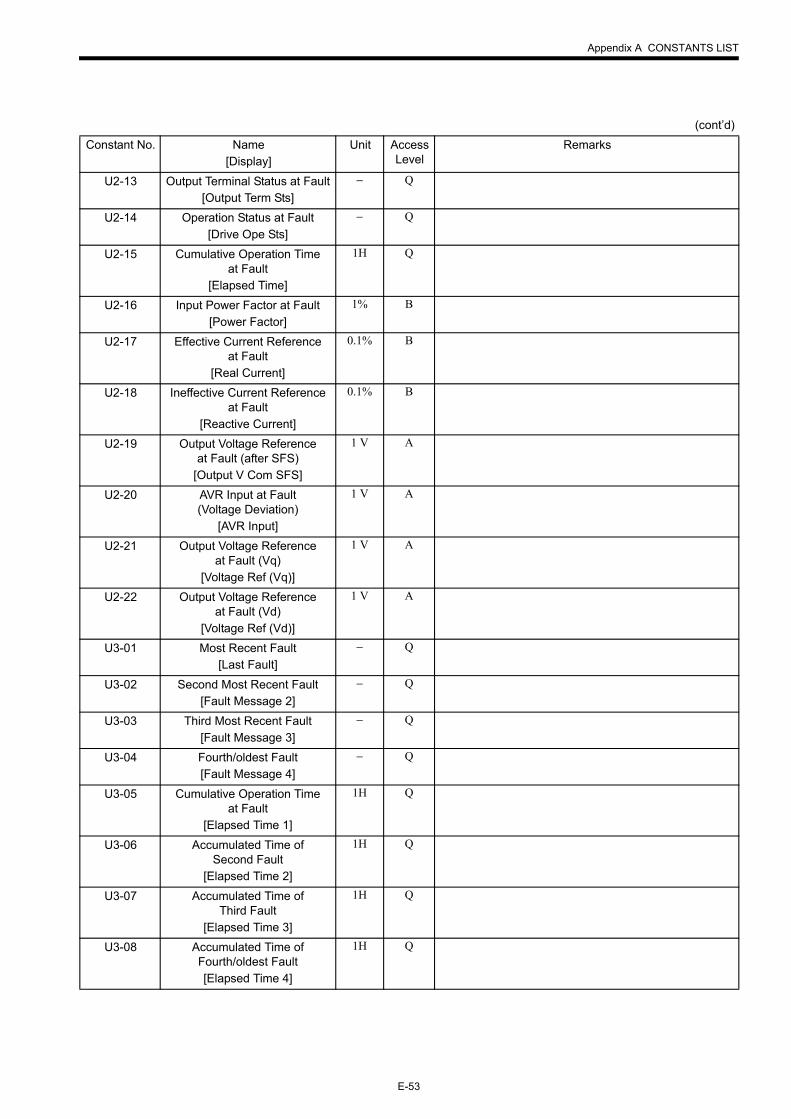
Appendix A CONSTANTS LIST
E-53
U2-13 Output Terminal Status at Fault[Output Term Sts]
− Q
U2-14 Operation Status at Fault[Drive Ope Sts]
− Q
U2-15 Cumulative Operation Time at Fault
[Elapsed Time]
1H Q
U2-16 Input Power Factor at Fault[Power Factor]
1% B
U2-17 Effective Current Reference at Fault
[Real Current]
0.1% B
U2-18 Ineffective Current Reference at Fault
[Reactive Current]
0.1% B
U2-19 Output Voltage Reference at Fault (after SFS)
[Output V Com SFS]
1 V A
U2-20 AVR Input at Fault (Voltage Deviation)
[AVR Input]
1 V A
U2-21 Output Voltage Reference at Fault (Vq)
[Voltage Ref (Vq)]
1 V A
U2-22 Output Voltage Reference at Fault (Vd)
[Voltage Ref (Vd)]
1 V A
U3-01 Most Recent Fault[Last Fault]
− Q
U3-02 Second Most Recent Fault[Fault Message 2]
− Q
U3-03 Third Most Recent Fault[Fault Message 3]
− Q
U3-04 Fourth/oldest Fault[Fault Message 4]
− Q
U3-05 Cumulative Operation Time at Fault
[Elapsed Time 1]
1H Q
U3-06 Accumulated Time of Second Fault
[Elapsed Time 2]
1H Q
U3-07 Accumulated Time of Third Fault
[Elapsed Time 3]
1H Q
U3-08 Accumulated Time of Fourth/oldest Fault[Elapsed Time 4]
1H Q
(cont’d)Constant No. Name
[Display]Unit Access
LevelRemarks
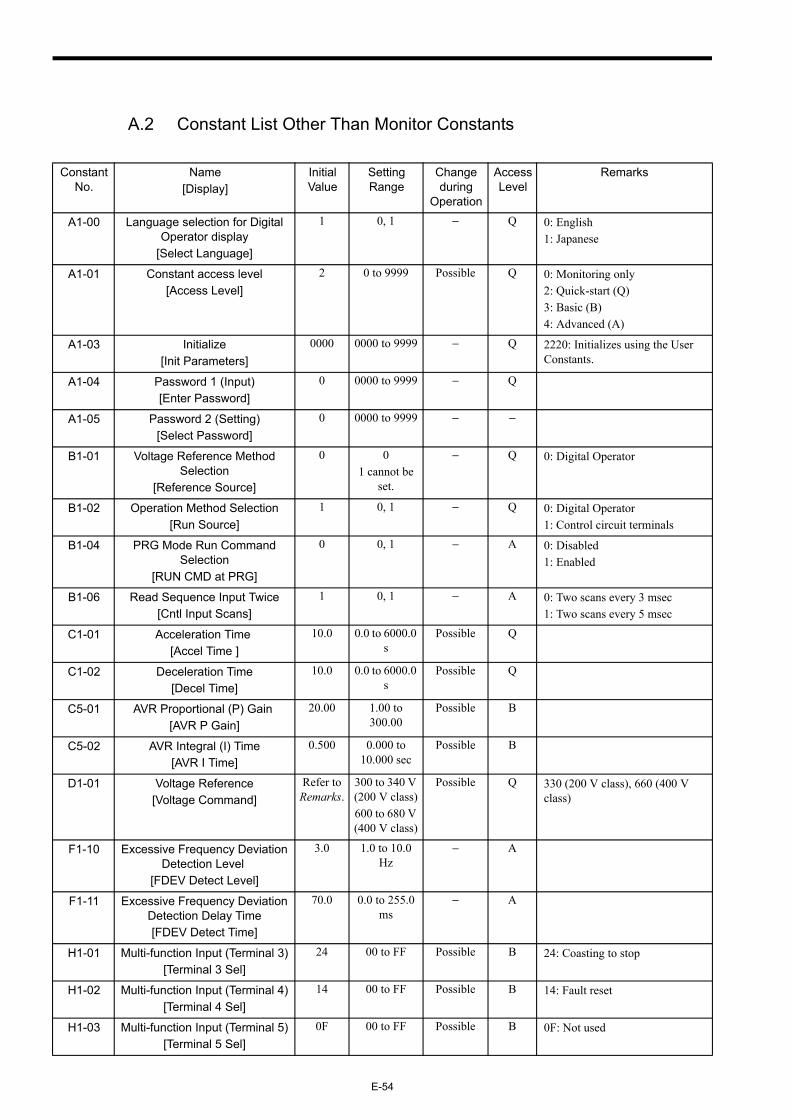
E-54
A.2 Constant List Other Than Monitor Constants
Constant No.
Name[Display]
Initial Value
Setting Range
Change during
Operation
Access Level
Remarks
A1-00 Language selection for Digital Operator display
[Select Language]
1 0, 1 − Q 0: English1: Japanese
A1-01 Constant access level[Access Level]
2 0 to 9999 Possible Q 0: Monitoring only2: Quick-start (Q)3: Basic (B)4: Advanced (A)
A1-03 Initialize[Init Parameters]
0000 0000 to 9999 − Q 2220: Initializes using the User Constants.
A1-04 Password 1 (Input)[Enter Password]
0 0000 to 9999 − Q
A1-05 Password 2 (Setting)[Select Password]
0 0000 to 9999 − −
B1-01 Voltage Reference Method Selection
[Reference Source]
0 01 cannot be
set.
− Q 0: Digital Operator
B1-02 Operation Method Selection[Run Source]
1 0, 1 − Q 0: Digital Operator1: Control circuit terminals
B1-04 PRG Mode Run Command Selection
[RUN CMD at PRG]
0 0, 1 − A 0: Disabled1: Enabled
B1-06 Read Sequence Input Twice[Cntl Input Scans]
1 0, 1 − A 0: Two scans every 3 msec1: Two scans every 5 msec
C1-01 Acceleration Time [Accel Time ]
10.0 0.0 to 6000.0 s
Possible Q
C1-02 Deceleration Time[Decel Time]
10.0 0.0 to 6000.0 s
Possible Q
C5-01 AVR Proportional (P) Gain [AVR P Gain]
20.00 1.00 to 300.00
Possible B
C5-02 AVR Integral (I) Time[AVR I Time]
0.500 0.000 to 10.000 sec
Possible B
D1-01 Voltage Reference[Voltage Command]
Refer to Remarks.
300 to 340 V (200 V class)600 to 680 V (400 V class)
Possible Q 330 (200 V class), 660 (400 V class)
F1-10 Excessive Frequency Deviation Detection Level
[FDEV Detect Level]
3.0 1.0 to 10.0 Hz
− A
F1-11 Excessive Frequency Deviation Detection Delay Time[FDEV Detect Time]
70.0 0.0 to 255.0 ms
− A
H1-01 Multi-function Input (Terminal 3)[Terminal 3 Sel]
24 00 to FF Possible B 24: Coasting to stop
H1-02 Multi-function Input (Terminal 4)[Terminal 4 Sel]
14 00 to FF Possible B 14: Fault reset
H1-03 Multi-function Input (Terminal 5)[Terminal 5 Sel]
0F 00 to FF Possible B 0F: Not used
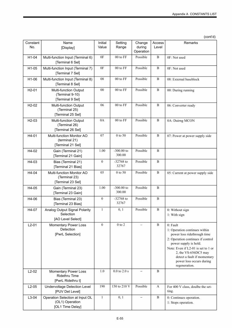
Appendix A CONSTANTS LIST
E-55
H1-04 Multi-function Input (Terminal 6)[Terminal 6 Sel]
0F 00 to FF Possible B 0F: Not used
H1-05 Multi-function Input (Terminal 7)[Terminal 7 Sel]
0F 00 to FF Possible B 0F: Not used
H1-06 Multi-function Input (Terminal 8)[Terminal 8 Sel]
08 00 to FF Possible B 08: External baseblock
H2-01 Multi-function Output (Terminal 9-10)[Terminal 9 Sel]
00 00 to FF Possible B 00: During running
H2-02 Multi-function Output (Terminal 25)
[Terminal 25 Sel]
06 00 to FF Possible B 06: Converter ready
H2-03 Multi-function Output (Terminal 26)
[Terminal 26 Sel]
0A 00 to FF Possible B 0A: Duirng MCON
H4-01 Multi-function Monitor AO (terminal 21)
[Terminal 21 Sel]
07 0 to 50 Possible B 07: Power at power supply side
H4-02 Gain (Terminal 21)[Terminal 21 Gain]
1.00 -300.00 to 300.00
Possible B
H4-03 Bias (Terminal 21)[Terminal 21 Bias]
0 -32768 to 32767
Possible B
H4-04 Multi-function Monitor AO (Terminal 23)
[Terminal 23 Sel]
05 0 to 50 Possible B 05: Current at power supply side
H4-05 Gain (Terminal 23)[Terminal 23 Gain]
1.00 -300.00 to 300.00
Possible B
H4-06 Bias (Terminal 23)[Terminal 23 Bias]
0 -32768 to 32767
Possible B
H4-07 Analog Output Signal Polarity Selection
[AO Level Select]
1 0, 1 Possible B 0: Without sign1: With sign
L2-01 Momentary Power Loss Detection
[PwrL Selection]
0 0 to 2 − B 0: Fault1: Operation continues within
power loss ridethrough time2: Operation continues if control
power supply is hold.Note: Even if L2-01 is set to 1 or
2, the VS-656DC5 may detect a fault if momentary power loss occurs during regeneration.
L2-02 Momentary Power Loss Ridethru Time
[PwrL Ridethru t]
1.0 0.0 to 2.0 s − B
L2-05 Undervoltage Detection Level[PUV Det Level]
190 150 to 210 V Possible A For 400 V class, doulbe the set-ting.
L3-04 Operation Selection at Input OL (OL1) Operation[OL1 Time Delay]
1 0, 1 − B 0: Continues operation.1: Stops operation.
(cont’d)
Constant No.
Name[Display]
Initial Value
Setting Range
Change during
Operation
Access Level
Remarks
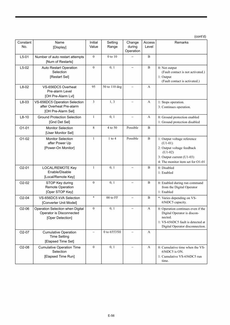
E-56
L5-01 Number of auto restart attempts[Num of Restarts]
0 0 to 10 − B
L5-02 Auto Restart Operation Selection
[Restart Sel]
0 0, 1 − B 0: Not output (Fault contact is not activated.)
1: Output (Fault contact is activated.)
L8-02 VS-656DC5 Overheat Pre-alarm Level
[OH Pre-Alarm Lvl]
95 50 to 110 deg − A
L8-03 VS-656DC5 Operation Selection after Overheat Pre-alarm
[OH Pre-Alarm Sel]
3 1, 3 − A 1: Stops operation.3: Continues operation.
L8-10 Ground Protection Selection[Gnd Det Sel]
1 0, 1 − A 0: Ground protection enabled1: Ground protection disabled
O1-01 Monitor Selection[User Monitor Sel]
8 4 to 50 Possible B
O1-02 Monitor Selection after Power Up
[Power-On Monitor]
1 1 to 4 Possible B 1: Output voltage reference (U1-01)
2: Output voltage feedback (U1-02)
3: Output current (U1-03)4: The monitor item set for O1-01
O2-01 LOCAL/REMOTE Key Enable/Disable
[Local/Remote Key]
1 0, 1 − B 0: Disabled1: Enabled
O2-02 STOP Key during Remote Operation[Oper STOP Key]
0 0, 1 − B 0: Enabled during run command from the Digital Operator
1: Enabled
O2-04 VS-656DC5 kVA Selection[Converter Unit Model]
* 00 to FF − B *: Varies depending on VS-656DC5 capacity.
O2-06 Operation Selection when Digital Operator is Disconnected
[Oper Detection]
0 0, 1 − A 0: Operation continues even if the Digital Operator is discon-nected.
1: VS-656DC5 fault is detected at Digital Operator disconnection.
O2-07 Cumulative Operation Time Setting
[Elapsed Time Set]
− 0 to 65535H − A
O2-08 Cumulative Operation Time Selection
[Elapsed Time Run]
0 0, 1 − A 0: Cumulative time when the VS-656DC5 is ON.
1: Cumulative VS-656DC5 run time.
(cont’d)
Constant No.
Name[Display]
Initial Value
Setting Range
Change during
Operation
Access Level
Remarks
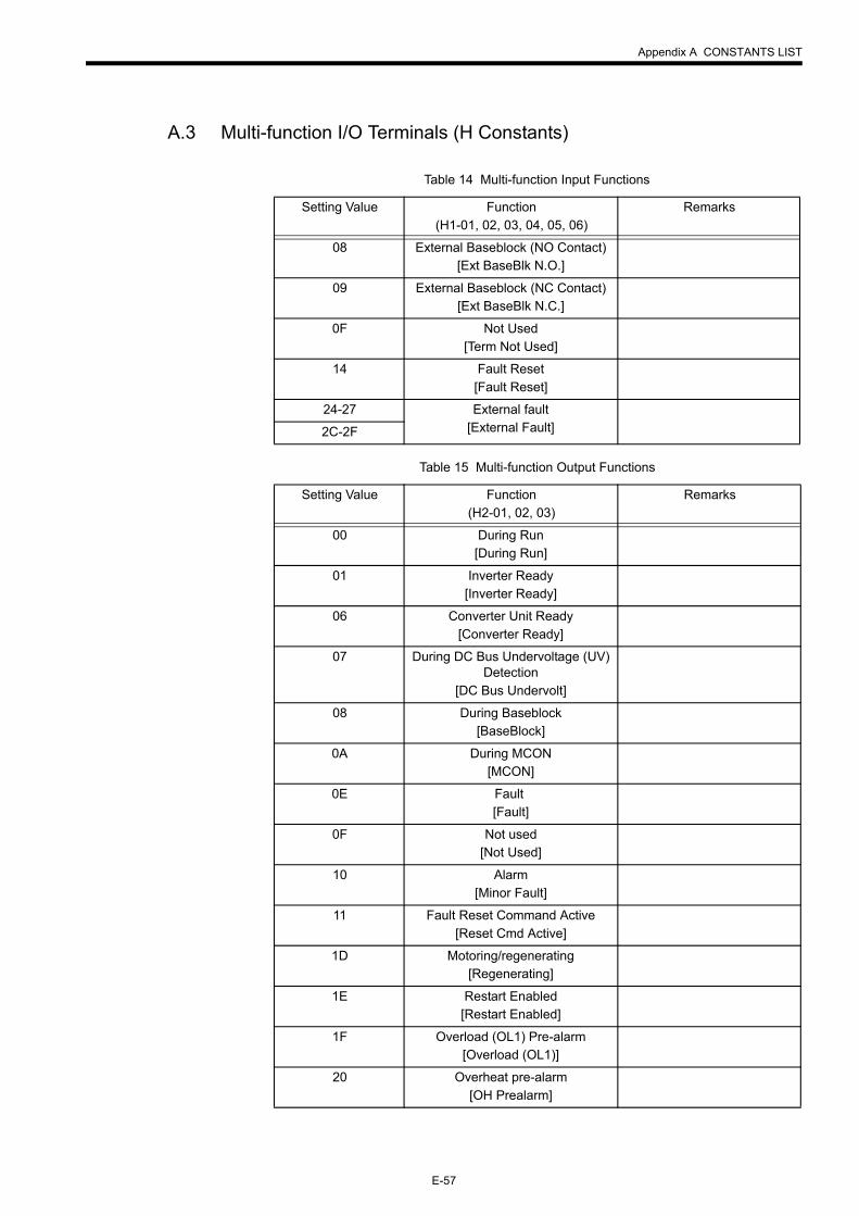
Appendix A CONSTANTS LIST
E-57
A.3 Multi-function I/O Terminals (H Constants)
Table 14 Multi-function Input Functions
Setting Value Function(H1-01, 02, 03, 04, 05, 06)
Remarks
08 External Baseblock (NO Contact)[Ext BaseBlk N.O.]
09 External Baseblock (NC Contact)[Ext BaseBlk N.C.]
0F Not Used[Term Not Used]
14 Fault Reset[Fault Reset]
24-27 External fault[External Fault]2C-2F
Table 15 Multi-function Output Functions
Setting Value Function(H2-01, 02, 03)
Remarks
00 During Run[During Run]
01 Inverter Ready[Inverter Ready]
06 Converter Unit Ready[Converter Ready]
07 During DC Bus Undervoltage (UV) Detection
[DC Bus Undervolt]
08 During Baseblock[BaseBlock]
0A During MCON[MCON]
0E Fault [Fault]
0F Not used[Not Used]
10 Alarm[Minor Fault]
11 Fault Reset Command Active[Reset Cmd Active]
1D Motoring/regenerating[Regenerating]
1E Restart Enabled[Restart Enabled]
1F Overload (OL1) Pre-alarm[Overload (OL1)]
20 Overheat pre-alarm[OH Prealarm]
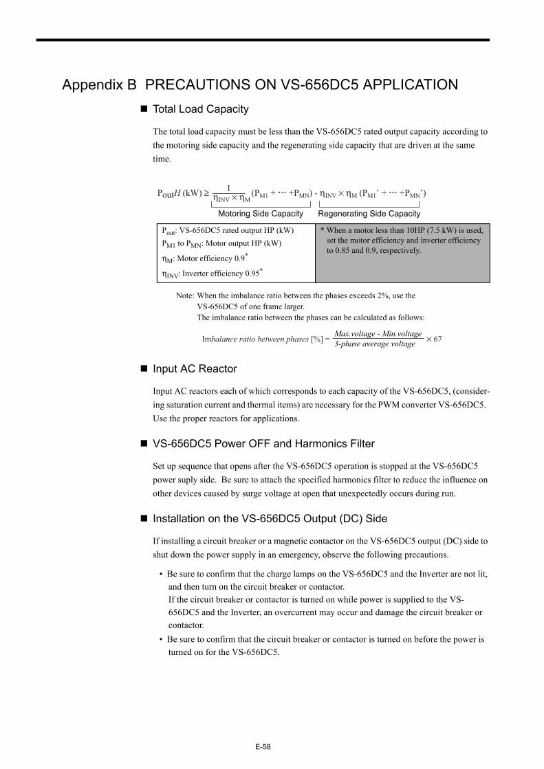
E-58
Appendix B PRECAUTIONS ON VS-656DC5 APPLICATIONTotal Load Capacity
The total load capacity must be less than the VS-656DC5 rated output capacity according to the motoring side capacity and the regenerating side capacity that are driven at the same time.
Note: When the imbalance ratio between the phases exceeds 2%, use the VS-656DC5 of one frame larger.The imbalance ratio between the phases can be calculated as follows:
Input AC Reactor
Input AC reactors each of which corresponds to each capacity of the VS-656DC5, (consider-ing saturation current and thermal items) are necessary for the PWM converter VS-656DC5. Use the proper reactors for applications.
VS-656DC5 Power OFF and Harmonics Filter
Set up sequence that opens after the VS-656DC5 operation is stopped at the VS-656DC5 power suply side. Be sure to attach the specified harmonics filter to reduce the influence on other devices caused by surge voltage at open that unexpectedly occurs during run.
Installation on the VS-656DC5 Output (DC) Side
If installing a circuit breaker or a magnetic contactor on the VS-656DC5 output (DC) side to shut down the power supply in an emergency, observe the following precautions.
• Be sure to confirm that the charge lamps on the VS-656DC5 and the Inverter are not lit, and then turn on the circuit breaker or contactor.If the circuit breaker or contactor is turned on while power is supplied to the VS-656DC5 and the Inverter, an overcurrent may occur and damage the circuit breaker or contactor.
• Be sure to confirm that the circuit breaker or contactor is turned on before the power is turned on for the VS-656DC5.
Pout: VS-656DC5 rated output HP (kW)PM1 to PMN: Motor output HP (kW)
ηM: Motor efficiency 0.9*
ηINV: Inverter efficiency 0.95*
* When a motor less than 10HP (7.5 kW) is used, set the motor efficiency and inverter efficiency to 0.85 and 0.9, respectively.
PoutH (kW) ≥ (PM1 + +PMN) - ηINV × ηM (PM1’ + +PMN’)ηINV × ηM
1
Motoring Side Capacity Regenerating Side Capacity
Imbalance ratio between phases [%] = × 67Max.voltage - Min.voltage3-phase average voltage
Appendix B PRECAUTIONS ON VS-656DC5 APPLICATION
E-59
Power Supply Capacity Selection
Use a power supply with a capacity larger than the VS-656DC5 rated input capacity. If a power supply with a capacity smaller than the VS-656DC5 rated input capacity is used, an operation error may occur. When selecting a power supply, contact your Yaskawa represen-tative.
Use the following formula to obtain the VS-656DC5 rated input capacity.
Interlocking with Inverters
It is necessary to interlock between the VS-656DC5 and the Inverter to stop the Inverter by using the VS-656DC5 fault signal. To restart the operation after a memontary power loss at the Inverter side, the timing for reactivation must be assured.
The “MC Operating (MCON)” signal that the VS-656DC5 outputs from the control terminal is used to assure the timing. When the “MC Operating (MCON)” signal is “open,” use the Inverter external baseblock input to make a sequence to shut OFF the Inverter output.
[Typical Interlock]
• When reactivation after momentary power loss is not performed (Coasting to a stop by momentary power loss detection)
Insert the VS-656DC5 “MC Operating (MCON)” output to the Inverter “External Fault” input.
The Inverter “External Fault” input is NC contact input. To prevent external fault oper-ation at power supply ON, select “External fault accepted only during RUN.”
• When reactivation after momentary power loss is performed as system
Insert the VS-656DC5 “MC Operating (MCON)” output to the Inverter “External BB” input.
Select reactivation after momentary power loss at the Inverter side. Then select the coasting lead-in mode or speed search mode.
Select NC contact input for the Inverter “External BB” input.
Precautions on Application of Peripheral Devices
When a noise filter is attached on the VS-656DC5 power supply side, use a noise filter of the reactor type (without a capacitor) such as finemet zero-phase reactor, and attach it behind the MCCB at the power supply side. Do not use a capacitor-built-in type noise filter since the harmonic components may overheat or damage the capacitor.
Sconv 3 × IAC_rate × Vin ÷ 1000[IAC_rate: VS-656DC5 rated input current (A), Vin : Power supply line voltage (V)]
E-60
When the Power Supply is a Generator
• Use the VS-656DC5 that is exclusively for generators. (For further information, contact your YASKAWA representative.)
• Select the generator capacity approx. twice as large as the VS-656DC5 input power sup-ply capacity. (For further information, contact your YASKAWA representative.)
• Set such deceleration time or load so that the regenerative power from the motor will be 10% or less of the generator capacity.
When A Phase Advance Capacitor or Thyristor Controller Is Provided for the Power Supply
No phase advance capacitor is needed for the VS-656DC5. Installing one on the VS-656DC5 will result in reduction of power factor.
For the phase advance capacitor that has already been installed on the same power supply system as the VS-656DC5, attach a series reactor to prevent oscillation with the VS-656DC5.
Contact your YASKAWA representative, if any derive generaing voltage surge or voltage distortion such as DC motor drive thyristor controller or magnetic agitator is installed on the same power supply system.
Prevention from EMC (Radio Noise) or Harmonics Leak Current
No preventive action from harmonics current is needed. However, some preventive actions from EMC (radio noise) or harmonics leak current are necessary as well as the general inverter drives.
If any device that is apt to be affected by noise is near the VS-656DC5, use a noise filter of the above-mentioned reactor type (zero-phase reactor).
Use a leakage relay or an earth leakage breaker designed for Inverters (products provided with prevention from harmonics leak current), when necessary.
Guideline for Harmonics Reduction
The guideline for harmonics is available for users who receive 6.6 kV or more from the power supply system.
Influence by Power Supply Distortion
When the power supply voltage is distorted, or when several devices are connected in paral-lel to the same power supply, the harmonics contents become larger since the harmonics of the power supply system enter the VS-656DC5.
YASKAWA ELECTRIC CORPORATION
In the event that the end user of this product is to be the military and said product is to be employed in any weapons systems or the manufacture thereof, the export will fall under the relevant regulations as stipulated in the Foreign Exchange and Foreign Trade Regulations. Therefore, be sure to follow all procedures and submit all relevant documentation according to any and all rules, regulations and laws that may apply.
Specifications are subject to change without notice for ongoing product modifications and improvements.
© 2004-2005 YASKAWA ELECTRIC CORPORATION. All rights reserved.
IRUMA BUSINESS CENTER (SOLUTION CENTER)480, Kamifujisawa, Iruma, Saitama 358-8555, JapanPhone 81-4-2962-5696 Fax 81-4-2962-6138
YASKAWA ELECTRIC AMERICA, INC.2121 Norman Drive South, Waukegan, IL 60085, U.S.A.Phone 1-847-887-7000 Fax 1-847-887-7370
YASKAWA ELETRICO DO BRASIL COMERCIO LTD.A.Avenida Fagundes Filho, 620 Bairro Saude-Sao Paulo-SP, Brazil CEP: 04304-000Phone 55-11-5071-2552 Fax 55-11-5581-8795
YASKAWA ELECTRIC EUROPE GmbHAm Kronberger Hang 2, 65824 Schwalbach, GermanyPhone 49-6196-569-300 Fax 49-6196-569-312
YASKAWA ELECTRIC UK LTD.1 Hunt Hill Orchardton Woods Cumbernauld, G68 9LF, United KingdomPhone 44-1236-735000 Fax 44-1236-458182
YASKAWA ELECTRIC KOREA CORPORATION7F, Doore Bldg. 24, Yeoido-dong, Youngdungpo-Ku, Seoul 150-877, KoreaPhone 82-2-784-7844 Fax 82-2-784-8495
YASKAWA ELECTRIC (SINGAPORE) PTE. LTD.151 Lorong Chuan, #04-01, New Tech Park 556741, SingaporePhone 65-6282-3003 Fax 65-6289-3003
YASKAWA ELECTRIC (SHANGHAI) CO., LTD.No.18 Xizang Zhong Road. Room 1702-1707, Harbour Ring Plaza Shanghai 200001, ChinaPhone 86-21-5385-2200 Fax 86-21-5385-3299
YASKAWA ELECTRIC (SHANGHAI) CO., LTD. BEIJING OFFICERoom 1011A, Tower W3 Oriental Plaza, No.1 East Chang An Ave.,Dong Cheng District, Beijing 100738, ChinaPhone 86-10-8518-4086 Fax 86-10-8518-4082
YASKAWA ELECTRIC TAIWAN CORPORATION9F, 16, Nanking E. Rd., Sec. 3, Taipei, TaiwanPhone 886-2-2502-5003 Fax 886-2-2505-1280
YASKAWA
VARISPEED-656DC5
INSTRUCTION MANUAL
05-7⑦ Printed in Japan July 2005 04-3
MANUAL NO. TOBP C710656 00C
2 -0
Related Documents