VFD-S Variable Speed AC Motor Drive 230V/460V 0.25 HP – 3.0HP 0.2KW–2.2KW High-performance / Low Noise / Mini-Type AC Drive User Manual April 24, 1999 DELTA ELECTRONICS, INC.

Welcome message from author
This document is posted to help you gain knowledge. Please leave a comment to let me know what you think about it! Share it to your friends and learn new things together.
Transcript
VFD-SVariable Speed AC Motor Drive
230V/460V 0.25 HP – 3.0HP
0.2KW–2.2KW
High-performance / Low Noise / Mini-Type AC Drive
User Manual
April 24, 1999
DELTA ELECTRONICS, INC.
Delta Electronics, Inc.
NORTH / SOUTH AMERICA EUROPE
DELTA PRODUCTS CORPORATION DELTA ELECTRONICS GmbH
Sales Office
P.O.BOX 12173
5101 DAVIS DRIVE
RESEARCH TRIANGLE PARK,
NORTH CAROLINA, 27709 U. S. A.
PHONE: 1-919-767-3800
FAX: 1-919-767-3969
http://www.deltadrives.com
Sales Office
HANNS-MARTIN-SCHLEYER-STRASSE 9D
GEWERBEPARK MUENCHHIEDE II
47877 WILLICH, GERMANY
PHONE: 49-2154-489-8888
FAX: 49-2154-489-8889
ASIA
DELTA ELECTRONICS, INC.
TAOYUAN Plant
31-1 SHIEN PAN ROAD
KUEI SAN INDUSTRIAL ZONE
333 TAOYUAN, TAIWAN R. O. C.
PHONE: 886-3-361-6301
FAX: 886-3-362-7267
http://www.delta.com.tw
5011201801 9904
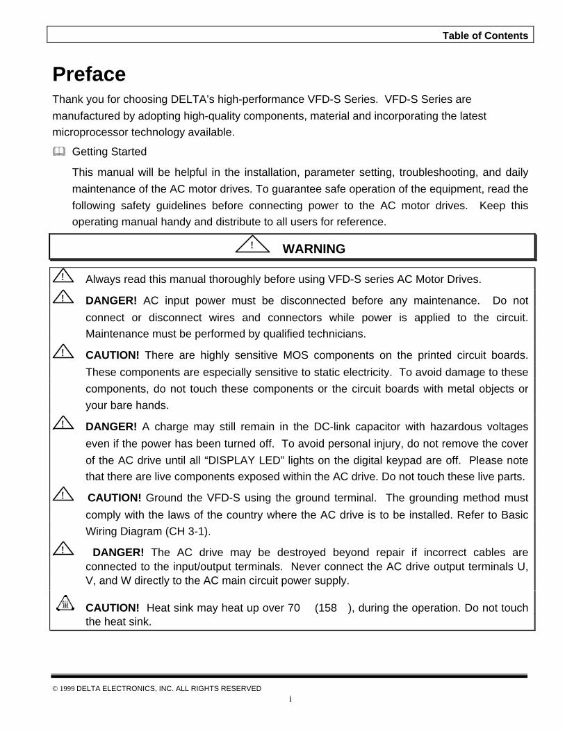
Table of Contents
© 1999 DELTA ELECTRONICS, INC. ALL RIGHTS RESERVED
i
PrefaceThank you for choosing DELTA’s high-performance VFD-S Series. VFD-S Series are
manufactured by adopting high-quality components, material and incorporating the latest
microprocessor technology available.
& Getting Started
This manual will be helpful in the installation, parameter setting, troubleshooting, and daily
maintenance of the AC motor drives. To guarantee safe operation of the equipment, read the
following safety guidelines before connecting power to the AC motor drives. Keep this
operating manual handy and distribute to all users for reference.
!! WARNING
!! Always read this manual thoroughly before using VFD-S series AC Motor Drives.
!! DANGER! AC input power must be disconnected before any maintenance. Do not
connect or disconnect wires and connectors while power is applied to the circuit.
Maintenance must be performed by qualified technicians.
!! CAUTION! There are highly sensitive MOS components on the printed circuit boards.
These components are especially sensitive to static electricity. To avoid damage to these
components, do not touch these components or the circuit boards with metal objects or
your bare hands.
!! DANGER! A charge may still remain in the DC-link capacitor with hazardous voltages
even if the power has been turned off. To avoid personal injury, do not remove the cover
of the AC drive until all “DISPLAY LED” lights on the digital keypad are off. Please note
that there are live components exposed within the AC drive. Do not touch these live parts.
!! CAUTION! Ground the VFD-S using the ground terminal. The grounding method must
comply with the laws of the country where the AC drive is to be installed. Refer to Basic
Wiring Diagram (CH 3-1).
!! DANGER! The AC drive may be destroyed beyond repair if incorrect cables areconnected to the input/output terminals. Never connect the AC drive output terminals U,V, and W directly to the AC main circuit power supply.
CAUTION! Heat sink may heat up over 70 (158), during the operation. Do not touchthe heat sink.
Table of Contents
© 1999 DELTA ELECTRONICS, INC. ALL RIGHTS RESERVED
ii
CHAPTER 1: RECEIVING AND INSPECTIONS
1-1 Nameplate Information ………….…………………….………………………………...…….1
1-2 Model Explanation ………………………………….………………………………………….1
1-3 Serial Number Explanation …….………………………………….………………………….1
CHAPTER 2: STORAGE AND INSTALLATION
2-1 Storage ………………………………………….………………………………………………2
2-2 Ambient Conditions …………...……….………………..……………………………………..2
2-3 Installation ……………………….…….………………………………………………………..3
2-4 Connection …………………………….………………………………………………………..3
2-5 Environment ……………………….….………………………………………………………..5
2-6 Installation Steps ……………….…….………………………………………………………..6
CHAPTER 3: WIRING
3-1 Basic Wiring Diagram……………………………….……………………………….…………9
3-2 External Wiring ………………………………………………………………………………..10
3-3 Main Circuit Wiring…………………….……………………….………………..……………12
3-4 Control Terminal Wiring………….……………….…….…………………………………….13
3-5 Wiring Notes……….……………….……………………….…………………………………14
3-6 Motor Operation Precautions …………………………….……...……………………...…15
CHAPTER 4: DIGITAL KEYPAD OPERATION
4-1 Description of Digital Keypad……………………………………….…………………..……16
4-2 Explanation of Displayed Messages…………………...……………………………………17
4-3 Explanation of LED Indicators…………………………….……………………..…………18
4-4 Keypad Operation…………………………………....……………………………….………20
CHAPTER 5: DESCRIPTION OF PARAMETER SETTINGS
5-1 Group 0: User Parameters ………..………………………………………………………...22
5-2 Group 1: Basic Parameters ……………………………………………………….…………26
5-3 Group 2: Operating Method Parameters ……………...……….…………………………. 34
Table of Contents
© 1999 DELTA ELECTRONICS, INC. ALL RIGHTS RESERVED
iii
5-4 Group 3: Output Function Parameters ……………..…………………………..………....38
5-5 Group 4: Input Function Parameters ……………...……………...…….…………….…...43
5-6 Group 5: Multi-Step Speed and PLC (Process Logic Control) Parameters……….….59
5-7 Group 6: Protection Parameters …………………………………………………...…..…67
5-8 Group 7: Motor Parameters …………………………………………………………….....72
5-9 Group 8: Special Parameters ………………………..……………....…………………….74
5-10 Group 9: Communication Parameters …………………..…..……………………..…...80
CHAPTER 6: MAINTENANCE AND INSPECTIONS
6-1 Periodic Inspection ……………………..……………………….……………………….…..98
6-2 Periodic Maintenance…………………………………………………...…….…………….. 99
CHAPTER 7: TROUBLESHOOTING AND FAULT INFORMATION …….……………………100
CHAPTER 8: SUMMARY OF PARAMETER SETTINGS…………………………………………104
APPENDIX
APPENDIX A STANDARD SPECIFICATIONS ………….……………….…………………… 114
APPENDIX B ACCESSORIES LIST…………….………..………………...…………………...115
B-1 Din Rails ………………….…………………………...…………………….………...…..116
B-2 Remote Control Box ……….…………………..………………………………………….118
B-3 Control Bracket …………………………………………………………………………….119
B-4 Braking Resistors ………………..…………………………….…….…...………………121
B-5 EMI Filters ……………………….…………………………….…….……...…………….123
APPENDIX C VFD-S DIMENSIONS
……………………………....……………….……..……..126
APPENDIX D EC DECLARATION OF CONFORMITY………….…………………………….128
APPENDIX E WARRANTY….…………………………..……….………………………….……130
INDEX….…………….………..……….…………………………………………………..…….…….131
Chapter 1 Receiving and Inspection
© 1999 DELTA ELECTRONICS, INC. ALL RIGHTS RESERVED1
Chapter 1 Receiving and InspectionThis VFD-S AC drive has gone through rigorous quality control tests at the factory beforeshipment. After receiving the AC motor drive, please check for the following:
Receiving
ü Check to make sure that the package includes an AC drive, the User Manual, and rubberbushings.
ü Inspect the unit to insure it was not damaged during shipment.
ü Make sure that the part number indicated on the nameplate corresponds with the partnumber of your order.
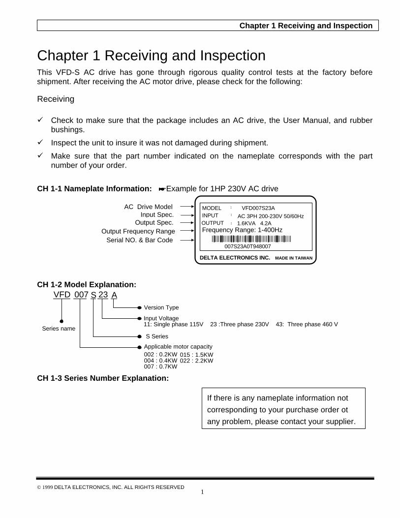
CH 1-1 Nameplate Information: *Example for 1HP 230V AC drive
CH 1-2 Model Explanation:
VFD Version Type
Input Voltage11: Single phase 115V 23 :Three phase 230V 43: Three phase 460 V
Applicable motor capacity002 : 0.2KW004 : 0.4KW007 : 0.7KW
Series nameS Series
015 : 1.5KW022 : 2.2KW
007 S 23
A
CH 1-3 Series Number Explanation:
Serial NO. & Bar Code
AC Drive ModelInput Spec.
Output Spec.
DELTA ELECTRONICS INC. MADE IN TAIWAN
INPUT :: AC 3PH 200-230V 50/60Hz
MODEL VFD007S23A::
OUTPUT
:: 1.6KVA 4.2A
Output Frequency Range
007S23A0T948007
Frequency Range: 1-400Hz
If there is any nameplate information not
corresponding to your purchase order ot
any problem, please contact your supplier.

Chapter 1 Receiving and Inspection
© 1999 DELTA ELECTRONICS, INC. ALL RIGHTS RESERVED2
001
Production number
Production factory(Taoyuan)
Production week
Production year 1999
T 9 01
001
Production number
Production factory(Taoyuan)
Production week
Production year 1999
T 9 01

Chapter 2 Storage and Installation
© 1999 DELTA ELECTRONICS, INC. ALL RIGHTS RESERVED
2
Chapter 2 Storage and Installations
CH 2-1 StorageThe AC motor drive should be kept in the shipping carton before installation. Inorder to retain the warranty coverage, the AC motor drives should be storedproperly when it is not to be used for an extended period of time.
CH 2-2 Ambient Conditions:
w Operation Air Temperature: -10o C to +40o C (14o F to 122o F)Atmosphere pressure: 86 to 106 kPaInstallation Site Altitude: below 1000mVibration: Maximum 9.86 m/s2 (1G) at less than 20Hz
Maximum 5.88 m/s2 (1G) at 20Hz to 50Hz
w Storage Temperature: -20o C to + 60o C (-4o F to 140o F)Relative Humidity: Less than 90%, no condensation allowedAtmosphere pressure: 86 to 106 kPa
w TransportationTemperature: -20o C to +60o C (-4o F to 140o F)Relative Humidity: Less than 90%, no condensation allowedAtmosphere pressure: 86 to 106 kPaVibration: Maximum 9.86 m/s2 (1G) at less than 20Hz
Maximum 5.88 m/s2 (1G) at 20Hz to 50Hz
Chapter 2 Storage and Installation
© 1999 DELTA ELECTRONICS, INC. ALL RIGHTS RESERVED
3
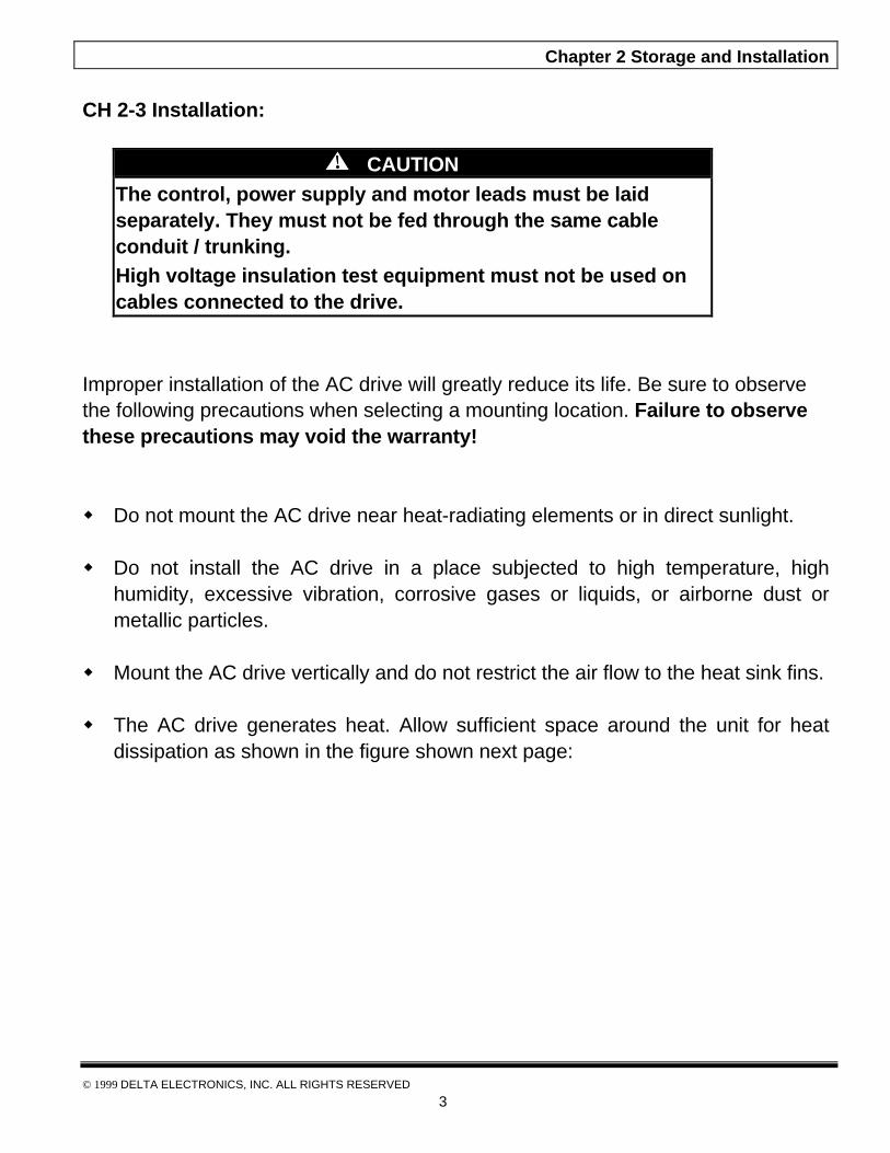
CH 2-3 Installation:
CAUTIONThe control, power supply and motor leads must be laidseparately. They must not be fed through the same cableconduit / trunking.High voltage insulation test equipment must not be used oncables connected to the drive.
Improper installation of the AC drive will greatly reduce its life. Be sure to observethe following precautions when selecting a mounting location. Failure to observethese precautions may void the warranty!
w Do not mount the AC drive near heat-radiating elements or in direct sunlight.
w Do not install the AC drive in a place subjected to high temperature, highhumidity, excessive vibration, corrosive gases or liquids, or airborne dust ormetallic particles.
w Mount the AC drive vertically and do not restrict the air flow to the heat sink fins.
w The AC drive generates heat. Allow sufficient space around the unit for heatdissipation as shown in the figure shown next page:

Chapter 2 Storage and Installation
© 1999 DELTA ELECTRONICS, INC. ALL RIGHTS RESERVED
4
150mm (6 inches) Air Flowor more
or more
VFD-S
50mm(2 inches)or more
50mm(2 inches)or more
150mm (6 inches)
Minimum Clearances and Air Flow

Chapter 2 Storage and Installation
© 1999 DELTA ELECTRONICS, INC. ALL RIGHTS RESERVED
5
CH 2-4 Connections:
DANGERHazardous VoltageBefore servicing the electrical system:w Disconnect all power.w Wait one minute until DC bus capacitors discharge.Failure to observe this instruction will result in death orserious injury.
& General Wiring InformationApplicable Codes
All VFD-S AC drives are Underwriters Laboratories, Inc. (UL) and CanadianUnderwriters Laboratories (cUL) listed, and therefore comply with the requirementsof the National Electrical Code (NEC) and the Canadian Electrical Code (CEC).
Installations intended to meet UL and cUL requirements must follow the instructionsprovided in “CH 3-5 Wiring Notes” section below as a minimum standard. Wherelocal codes exceed these requirements, they must also be followed. Refer to thetechnical data label affixed to the AC drive and the motor nameplate for electricaldata.

Chapter 2 Storage and Installation
© 1999 DELTA ELECTRONICS, INC. ALL RIGHTS RESERVED
6
CH 2-5 Environment
Avoid rain and moisture;Avoid direct sunlight;Avoid corrosive gases or liquids;Free from airborne dust or metallic particles;Free from vibrationFree from magnetic interferenceEnvironment temperature : -10 to 50Environment humidity: below 90% RHEnvironment air pressure: 86 kpa to 106 kpa
CH 2-6 Installation Steps
Installation Steps1. Remove front cover screw and open.2. Remove Division Plate.
If using optional conduit bracket,please refer to next page.
3. Connect AC Input Power and motorleads. Never connect the AC driveoutput terminals U, V, W to main ACInput power.
4. Reinstall Division Plate.
CASE
HEAT SINK
COVERKNOB
DIVISION PLATE
SCREW
Component Explanation
1 Plastic Cover
2 Knob
3 Case
4 Aluminum Heat Sink

Chapter 2 Storage and Installation
© 1999 DELTA ELECTRONICS, INC. ALL RIGHTS RESERVED
7
Install Conduit Bracket Plate as shown.
Reinstall Division Plate.Screw Torque: 5 to 6 kgf.cm
For Optional Conduit Bracket:Make sure to fasten both screws onconduit bracket as shown in thedrawing for safety grounding purpose.Bring all the wires out through theconduit bracket.Screw Torque: 5 to 6 kgf.cm
DIVISION PLATE
SCREW
CONDIUTBRACKET
SCREWSCREW
Install Conduit Bracket cover andtighten screws.
CONDUITBRACKET
SCREW
SCREW

Chapter 2 Storage and Installation
© 1999 DELTA ELECTRONICS, INC. ALL RIGHTS RESERVED
8
For additional communication:Plug the communication deviceinto the RJ11 jack for serialcommunication.
RS485
RJ11PLUG
RJ11JACK
UL ENCLOSED TYPE SCREW
Close the cover and tighten screw asshown. Screw torque: 5 to 6 kgf-cm

Chapter 3 Wiring
© 1999 DELTA ELECTRONICS, INC. ALL RIGHTS RESERVED
9
Chapter 3 Wiring
CH 3-1 Basic Wiring DiagramUsers must connect wiring according to the following circuit diagram shown below.
*NOTE*: Do not plug in a Modem or telephone line to the RS-485 communication port.Terminals 2 & 5 are the power sources for the optional copy keypad. Do notconnect to these terminals while using RS-485 communication port.
R
S
T
GND
M0
M1
M2
M3
M4
M5
R
S
T
U
V
W
IM
P2/B1 B2
AFM
VFD-S
RB
RA
RC
GND
Protective Device
Grounding resistanceless than 100 £[
Potentiometer¡]1K£[¡^
+-
AC Motor
Anolog Output DC 0 to + 10V
Factory default: indicate output frequency
Multi-function indication output contacts below 120VAC/28VDC 5A
Factory default: indicates malfunction
¡¹
¡¹
Reverse/Stop
Reset
Multi-step 1
Multi-step 2
Multi-step 3
Common signal
Power Terminals
200-230VAC50/ 60Hz
Select any of the two terminals for single phase models
Factory default¡¹
P1
MO1
MCM
+10V 10mA(MAX)
AVI
3
21
AC MOTOR DRIVES
GND
Pot.
Multi-function Photocoupler output below 48VDC 50mA
Factory default: indicates duringoperation
¡¹
£[
4~20mA
Shielded leadsMain circuit (power) terminals Control circuit terminals
0~10VDCAnolog voltage
Potentiometer3K~5K
Analog Current
Factory default: output freq.(Pot)determined by the Potentiometeron the control panel.
¡¹
Braking resistor (optional)select
80 120W200 120W400 120W
£[£[
4.7 K
+18VCPU
CPU
+18V
11V
£[
250£[ 47K£[
47K£[
2.4K£[47K£[
4.7K
+18VCPU
£[
12
3
£[
Forward/Stop
Jumper
RJ-11 communication port withRS-485 serial interface
2:GND3:SG-4:SG+5:+5V* SEE NOTE BELOW *
6 1
Chapter 3 Wiring
© 1999 DELTA ELECTRONICS, INC. ALL RIGHTS RESERVED
10
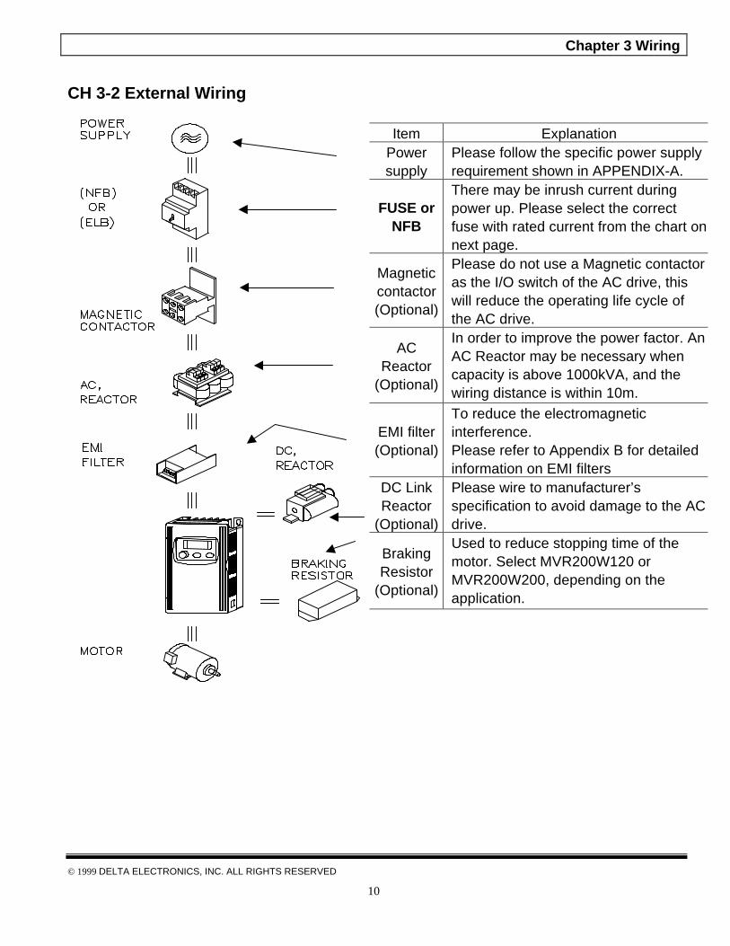
CH 3-2 External Wiring
Item ExplanationPowersupply
Please follow the specific power supplyrequirement shown in APPENDIX-A.
FUSE orNFB
There may be inrush current duringpower up. Please select the correctfuse with rated current from the chart onnext page.
Magneticcontactor(Optional)
Please do not use a Magnetic contactoras the I/O switch of the AC drive, thiswill reduce the operating life cycle ofthe AC drive.
ACReactor
(Optional)
In order to improve the power factor. AnAC Reactor may be necessary whencapacity is above 1000kVA, and thewiring distance is within 10m.
EMI filter(Optional)
To reduce the electromagneticinterference.Please refer to Appendix B for detailedinformation on EMI filters
DC LinkReactor
(Optional)
Please wire to manufacturer’sspecification to avoid damage to the ACdrive.
BrakingResistor
(Optional)
Used to reduce stopping time of themotor. Select MVR200W120 orMVR200W200, depending on theapplication.

Chapter 3 Wiring
© 1999 DELTA ELECTRONICS, INC. ALL RIGHTS RESERVED
11
Fuse and No Fuse Breaker (NFB) Specifications
Fuse for Branch circuit and short circuit protection
ModelsNo FuseBreaker
Specifications Manufacturer P/NVoltagerating(VAC)
Ampererating
(A)Class
VFD002S21A 10A Bussmann JJN-10 300 10 TVFD004S21A 20A Bussmann JJN-20 300 20 TVFD007S43A 5A Bussmann JJS-10 600 10 TVFD015S21A 30A Bussmann JJN-25 300 25 TVFD015S43A 10A Bussmann JJS-15 600 15 TVFD022S23A 20A Bussmann JJN-40 300 40 TVFD022S43A 15A Bussmann JJS-20 600 20 TVFD004S21A 10A Bussmann JJN-10 300 10 TVFD004S23A 5A Bussmann JJN-10 300 10 TVFD007S21A 20A Bussmann JJN-20 300 20 TVFD007S23A 10A Bussmann JJN-20 300 20 TVFD015S21A 30A Bussmann JJN-25 300 25 TVFD015M23A 15A Bussmann JJN-25 300 25 T

Chapter 3 Wiring
© 1999 DELTA ELECTRONICS, INC. ALL RIGHTS RESERVED
12
CH 3-3 Main Circuit Wiring
1. Main Circuit Terminals
2. Terminal Explanations
Terminal Symbol Explanation of Terminal Function
R, S, T AC line input terminals
L, N AC line input terminals (115 VAC)
U, V, W Motor connections
B1 / P2, B2 Connections for Braking Resistor(optional)
B1 / P2, P1 Connections for DC Link Reactor (optional)
Earth Ground
3. Terminal Dimensions
Model VFD-002S11A, 002S21A, 002S23A,004S11A, 004S21A, 004S23A007S23A, 007S23A
015S21A, 022S23A, 007S11A015S33A, 022S43A 007S43A015S43A, 004S43A,
TerminalSpecification(Terminal φ)
M3.5 M4
Wire Gauge: 12-18AWGWire Type: Copper OnlyTorque: 12 kg-cm
B 1
W
AC Input Line Terminal
VUNL
B 2
Braking Resistor
MotorConnection
Ground
115V ModelPower Terminals
B2 B1P2 P1
AC Input Line Terminal
MotorConnection
BrakingResistor
Ground
R S T U V W
DC Reactor
Power Terminal

Chapter 3 Wiring
© 1999 DELTA ELECTRONICS, INC. ALL RIGHTS RESERVED
13
CH 3-4 Control Terminal Wiring (Factory Setting)1. Terminal Explanations:
Terminal symbols Terminal name Remarks
RA - RCMulti-Function IndicationOutput Contact
RB – RCMulti-Function IndicationOutput Contact
Refer to Pr.3-06 Relay output contactRA-RC (N.O. Contact)RB-RC (N.C. Contact)
MO1 -MCM Multi-function PHC output Refer to Pr.3-05
RJ - 11 Serial communication port RS-485 serial communication interface
+10V - GND Power Supply (+10 V)
AVI - GNDAnalog voltage/current freq.command
0 to +10 V (Max. Output Frequency) Input or4 to 20mA (Max. Output Frequency) Input
AFM - GNDAnalog frequency/currentmeter
0 to +10 V (Max. output Frequency) Output
M0 - GND Multi-function auxiliary input
M1 - GND Multi-function input 1
M2 - GND Multi-function input 2
M3 - GND Multi-function input 3
M4 - GND Multi-function input 4
M5 - GND Multi-function input 5
Refer to Pr.4-04 to Pr.4-08
Operation freq. set bypotentiometer3K~5K
Relay contactor outputFactory setting : Fault indication
RS485 Communication port
Factory setting : AC Motor drive operational
Photo coupler output
M5
Mulit-step speed 1Mulit-step speed 2
Control Terminals
Reverse/Stop
M0
biaspotentolmeter: 1K
Freq. meter0~10 VDCFull scale voltmeter
10V+ AFMAVI
Forward/Stop
Reset
M2M1 M4M3
MO1
Mulit-step speed 3
GND
6 ~ 1
MCM
RJ11
RARBRC
Wire Gauge: 22-24AWGWire Type: Copper OnlyTorque: 4 kg-cm
Chapter 3 Wiring
© 1999 DELTA ELECTRONICS, INC. ALL RIGHTS RESERVED
14
Note: Use twisted-shielded, twisted-pair or shielded-lead wires for the control signal wiring. Itis recommended to run all signal wiring in a separate steel conduit. The shield wireshould only be connected at the drive. Do not connect shield wire on both ends.
CH 3-5 Wiring Notes:
1. !! CAUTION: Do not connect the AC input to any of the U, V, W terminals, as it willdamage the AC drive.
2. !! WARNING: Ensure all screws are tightened to the proper torque rating.
3. During installation, follow all local electrical, construction, and safety codes for the countrythe drive is to be installed in.
4. Ensure that the appropriate protective devices (circuit breaker or fuses) are connectedbetween the power supply and AC drive.
5. Make sure that the leads are connected correctly and the AC drive is properly grounded.(Ground resistance should not exceed 100 . For 460V-class AC drive, the groundresistance should not exceed 10 .)
6. Use ground leads that comply with AWG/MCM standards and keep them as short aspossible.
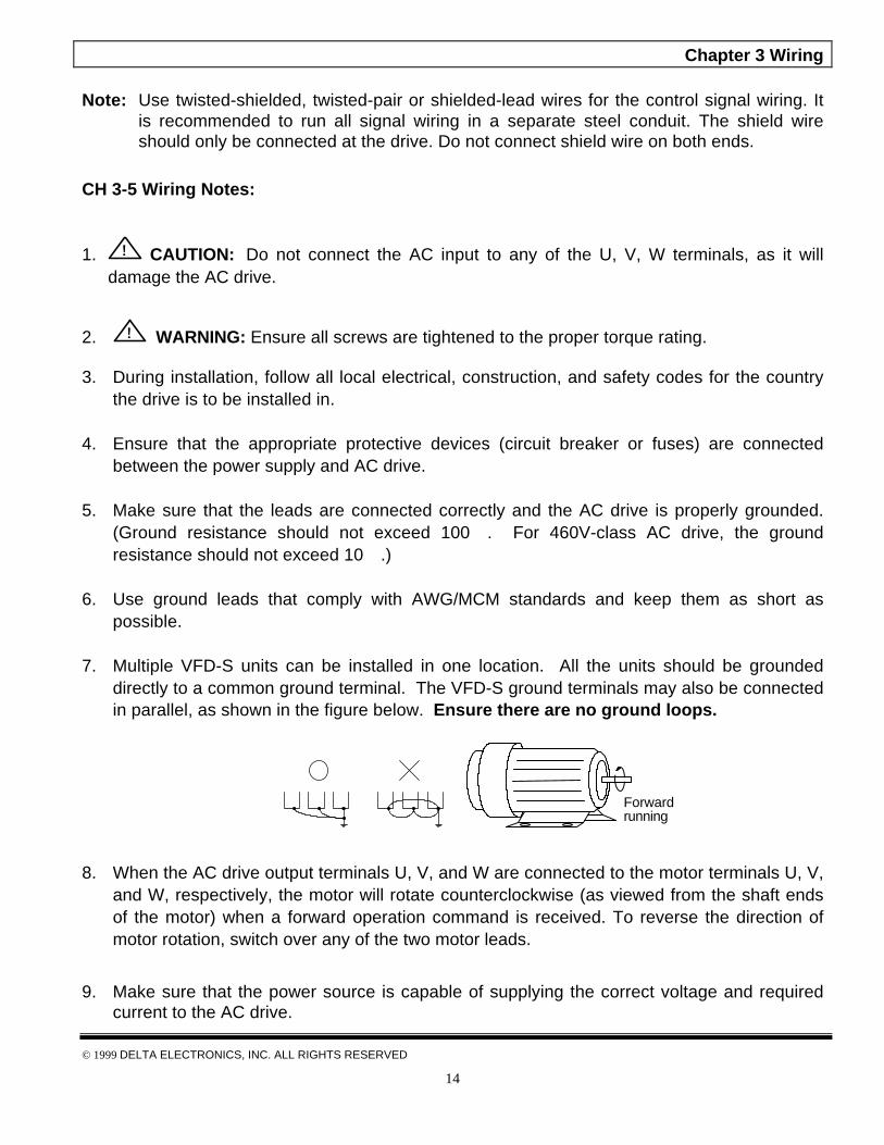
7. Multiple VFD-S units can be installed in one location. All the units should be groundeddirectly to a common ground terminal. The VFD-S ground terminals may also be connectedin parallel, as shown in the figure below. Ensure there are no ground loops.
Forwardrunning
8. When the AC drive output terminals U, V, and W are connected to the motor terminals U, V,and W, respectively, the motor will rotate counterclockwise (as viewed from the shaft endsof the motor) when a forward operation command is received. To reverse the direction ofmotor rotation, switch over any of the two motor leads.
9. Make sure that the power source is capable of supplying the correct voltage and requiredcurrent to the AC drive.
Chapter 3 Wiring
© 1999 DELTA ELECTRONICS, INC. ALL RIGHTS RESERVED
15
10. Do not attach or remove wiring when power is applied to the AC drive.
11. Do not monitor the signals on the circuit board while the AC drive is in operation.
12. For the single-phase applications, the AC input line can be connected to any two of thethree input terminals R, S, T. Note: This drive is not intended for the use with single-phase motors.
13. Route the wires of Power Terminals and Control Terminals separately, or 90°angle to eachother.
14. If a filter is required for reducing EMI (Electro Magnetic Interference), install it as close aspossible to AC drive. EMI can also be reduced by lowering the Carrier Frequency.
15. If the AC drive is installed in the place where load reactor is needed, install the filter closeto U.V.W. side of AC drive. Do not use a Capacitor or L-C Filter (Inductance-Capacitance)or R-C Filter (Resistance-Capacitance).
16. When using a GFCI (Ground Fault Circuit Interrupt), select current sensor with not less than200mA, with not less than 0.1-second detection to avoid nuisance tripping
CH 3-6 Motor Operation Precautions
1. When using the AC drive to operate a standard 3-phase induction motor, notice that the
energy loss is greater than an inverter duty motor.
2. While using the standard induction motor at low speed, the temperature of the motor may
rise, so do not operate the motor at low speed for a long period of time.
3. When the standard motor operates at low speed, the motor output torque will decrease,
please decrease the load during the operation.
4. If 100% output torque were desired at low speed operation, it may be necessary to use a
special motor that can handle this load (inverter duty).
Chapter 4 Digital Keypad Operation
© 1999 DELTA ELECTRONICS, INC. ALL RIGHTS RESERVED
16
Chapter 4 Digital Keypad Operation
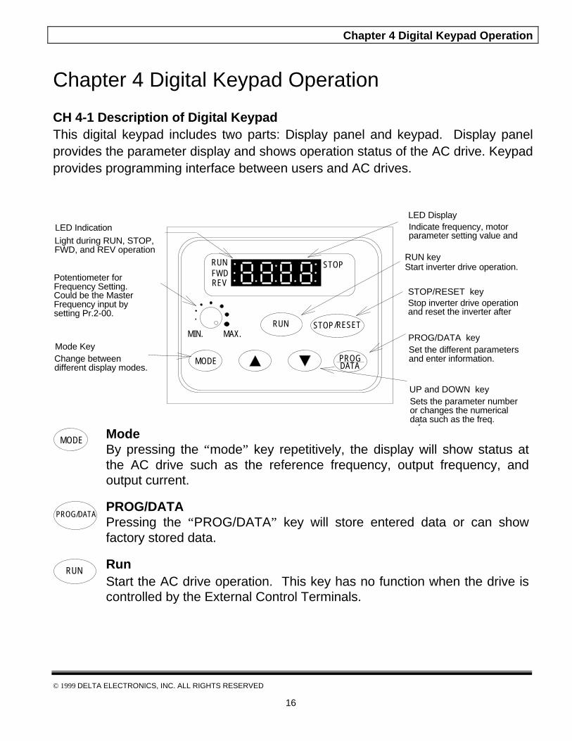
CH 4-1 Description of Digital KeypadThis digital keypad includes two parts: Display panel and keypad. Display panelprovides the parameter display and shows operation status of the AC drive. Keypadprovides programming interface between users and AC drives.
MODE
RUN STOP/RESET
RUNFWDREV
STOP
MIN. MAX.
LED DisplayIndicate frequency, motor parameter setting value and alarm contents.
LED Indication
Light during RUN, STOP, FWD, and REV operation
Potentiometer for Frequency Setting. Could be the Master Frequency input by setting Pr.2-00.
Mode KeyChange between different display modes.
RUN keyStart inverter drive operation.
STOP/RESET keyStop inverter drive operation and reset the inverter after faults occurred.
PROG/DATA keySet the different parameters and enter information.
UP and DOWN keySets the parameter number or changes the numerical data such as the freq. reference.
PROGDATA
MODE Mode
By pressing the “mode” key repetitively, the display will show status atthe AC drive such as the reference frequency, output frequency, andoutput current.
PROG/DATA PROG/DATA Pressing the “PROG/DATA” key will store entered data or can showfactory stored data.
RUN Run
Start the AC drive operation. This key has no function when the drive iscontrolled by the External Control Terminals.
Chapter 4 Digital Keypad Operation
© 1999 DELTA ELECTRONICS, INC. ALL RIGHTS RESERVED
17
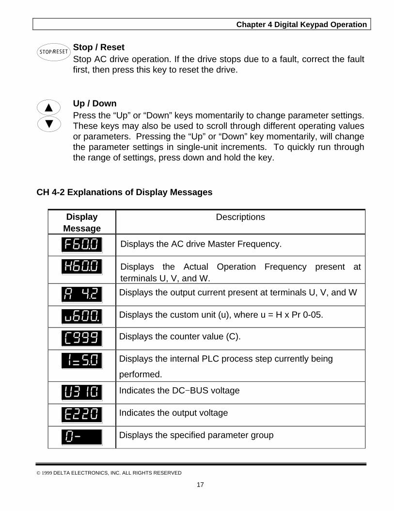
STOP/RESET
Stop / Reset Stop AC drive operation. If the drive stops due to a fault, correct the faultfirst, then press this key to reset the drive.
Up / Down Press the “Up” or “Down” keys momentarily to change parameter settings.These keys may also be used to scroll through different operating valuesor parameters. Pressing the “Up” or “Down” key momentarily, will changethe parameter settings in single-unit increments. To quickly run throughthe range of settings, press down and hold the key.
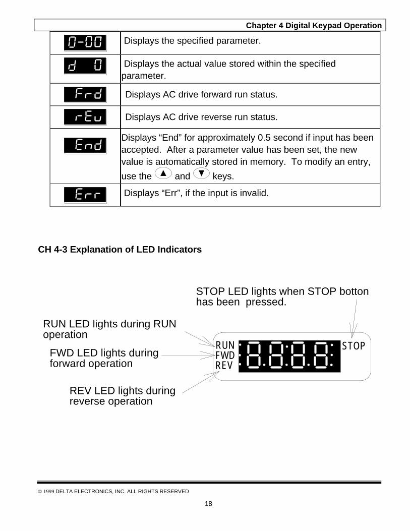
CH 4-2 Explanations of Display Messages
DisplayMessage
Descriptions
Displays the AC drive Master Frequency.
Displays the Actual Operation Frequency present atterminals U, V, and W.
Displays the output current present at terminals U, V, and W
Displays the custom unit (u), where u = H x Pr 0-05.
Displays the counter value (C).
Displays the internal PLC process step currently being
performed.
Indicates the DC−BUS voltage
Indicates the output voltage
Displays the specified parameter group
Chapter 4 Digital Keypad Operation
© 1999 DELTA ELECTRONICS, INC. ALL RIGHTS RESERVED
18
Displays the specified parameter.
Displays the actual value stored within the specifiedparameter.
Displays AC drive forward run status.
Displays AC drive reverse run status.
Displays “End” for approximately 0.5 second if input has beenaccepted. After a parameter value has been set, the newvalue is automatically stored in memory. To modify an entry,
use the and keys.
Displays “Err”, if the input is invalid.
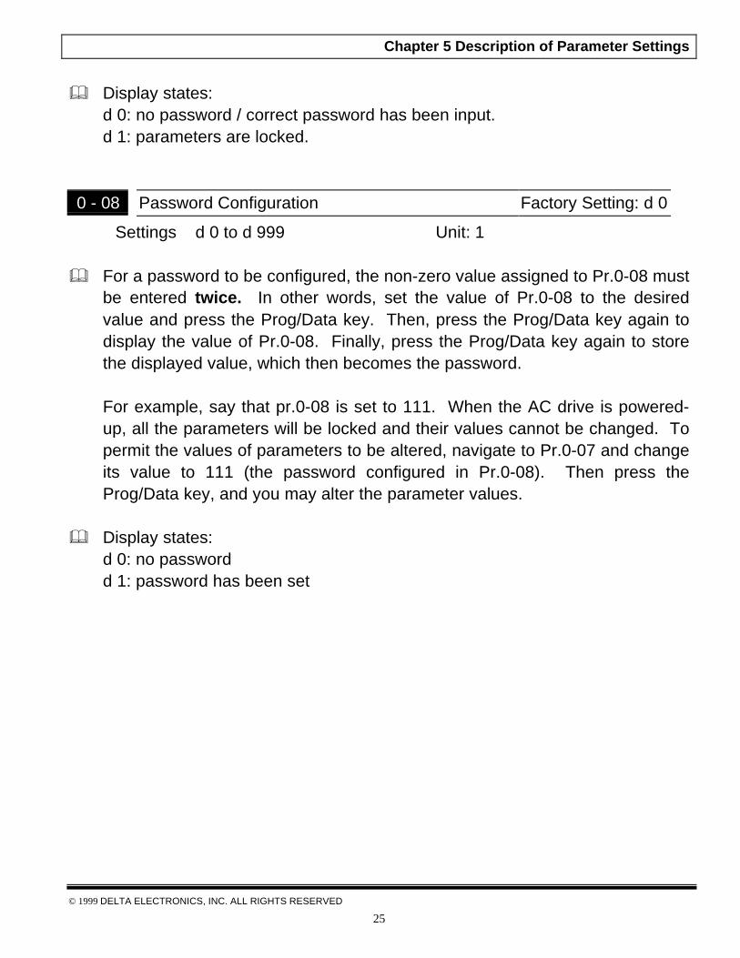
CH 4-3 Explanation of LED Indicators
RUNFWDREV
STOP
RUN LED lights during RUN operation
FWD LED lights during forward operation
REV LED lights during reverse operation
STOP LED lights when STOP bottonhas been pressed.

Chapter 4 Digital Keypad Operation
© 1999 DELTA ELECTRONICS, INC. ALL RIGHTS RESERVED
19
1. Description of LED functions of RUN and STOP
Output frequency of the AC motor drive
Frequency command
KEYKEY
KEY
IndicationRUN
STOP
Light Flash Dark
Indication
STOP/RESET
STOP/RESET
RUN
2. Description of LED functions of FWD and REV.
FWD
Indication FWD
REV
Light Flash Dark
RUN
REV
Output frequency of the AC drive FWD
REV
Indication

Chapter 4 Digital Keypad Operation
© 1999 DELTA ELECTRONICS, INC. ALL RIGHTS RESERVED
20
CH 4-4 Keypad Operation
MODE
MODEMODEMODE
MODE
F60.0 H60.0 A 4.2
0-
FWD
REV
0-00
d 0
End
set freq.
changedisplay mode
changedisplay mode
changedisplay mode
change displaymode
changeoperationdirection
set freq.
setparametergroup
store data
data is stored
parameter is locked or data is out of range, or data can't be entered during RUN mode.
setparameterdata
display data ofthe parameter
displayparameternumber
MODEchange displaymode
Err
U60.0
setparameternumber
displayparameter
number
MODEdisplay freq.command
CEXX
communication error, onlyappears when communicationerror happens.
set freq.
REV state can'tattain if reverse is
inhibited
set freq.
PROGDATA
displayparametergroup
PROGDATA
PROGDATA
PROGDATA

Chapter 5 Description of Parameter Settings
© 1999 DELTA ELECTRONICS, INC. ALL RIGHTS RESERVED
21
Chapter 5 Description of Parameter Settings
This chapter will explain all parameters in detail. They are divided into tenparameter groups to categorize parameter settings more clearly and effectively.
The ten-parameter groups are described as below:
Group 0: User Parameters
Group 1: Basic Parameters
Group 2: Operating Method Parameters
Group 3: Output Function Parameters
Group 4: Input Function Parameters
Group 5: Multi-step Speed and PLC (Process Logic Control) Parameters
Group 6: Protection Parameters
Group 7: Motor Parameters
Group 8: Special Parameters
Group 9: Communication Parameters

Chapter 5 Description of Parameter Settings
© 1999 DELTA ELECTRONICS, INC. ALL RIGHTS RESERVED
22
CH 5-1 Group 0: User Parameters
0 - 00 Identity Code of AC Motor Drive Factory setting: d # Settings None
V \ HP 1/4 1/2 1 2 3115V/230V d 0 d 2 d 4 d 6 d 8
460V -- -- -- d 3 d 5 d 7 d 9
& This parameter shows the capacity of the AC drive. Users can read Pr.0-01 tocheck if it is the rated current of the AC drive corresponds to the identity codeshown above and the current shown below.
V \ HP 1/4 1/2 1 2 3115V/230V 1.6A 2.5A 4.2A 7.5A 11.0A
460V -- -- -- 1.5 A 2.5 A 4.2 A 5.5 A
0 - 01 Rated Current Display of the AC drive Factory Setting: d ##.#
Settings None Unit: 0.1A
& This parameter displays the rated current of the AC drive. It will display basedon Pr.0-00, and is read-only.
0 - 02 Parameter Reset Factory Setting: d 0
Settings d 0 to d 9 Not used
d 10 All parameters are reset to be factory settings
& This setting allows the user to return all parameters to the factory defaultsettings.

Chapter 5 Description of Parameter Settings
© 1999 DELTA ELECTRONICS, INC. ALL RIGHTS RESERVED
23
0 - 03 Start-up Display Selection Factory Setting: d 0
Settings d 0 Display the Master Frequency (F)
d 1 Display the actual operation frequency (H)
d 2 Display the content of users-defined unit
d 3 Display the output current (A
This parameter can be set during operation.
0 - 04 Content of User Defined Unit Factory Setting: d 0
Settings d 0 Display the user-defined unit (u)
d 1 Display the counter value (C)
d 2 Display the content of PLC time (1 – tt)
d 3 Display the DC BUS voltage (U)
d 4 Display the output voltage (E)
This parameter can be set during operation.
Note: Display the user-defined unit, where unit = H H
0 - 05 User Defined Coefficient K Factory Setting: d 1.0
Settings d 0.1 to d 160 Unit: 0.1
This parameter can be set during operation.
& The coefficient K determines the multiplying factor for the user-defined unit.
The display value is calculated as follows:
Display value =(output frequency*K)
& The display window is only capable of showing three digits, yet you could usePr.0-05 to create larger numbers. The display windows uses decimal pointsto signify numbers up to five digits as illustrated in the next page:
0-05

Chapter 5 Description of Parameter Settings
© 1999 DELTA ELECTRONICS, INC. ALL RIGHTS RESERVED
24
Display Number Represented
999 The absence of a decimal point indicates a three –digit integer.
99.9A signal decimal point between the middle and the right-mostnumbers is a true decimal point; it separates ones and tenths asin “30.5” (thirty and one-half).
999.
A single decimal point after the fight-most numbers is not a truedecimal point; instead it indicates that a zero follows the right-most number. For example, the number 1230 would be displayas “123.”
99.9.
Two decimal points (one between the middle and the right-mostnumbers, and one after the right-most number) are not truedecimal points; instead they indicate that two zeros follow theright-most number. For example, the number 34500 would bedisplay as “34.5.”.
0 - 06 Software Version Factory Setting: d #.#
Setting None
& The software version is read-only that stores the version number of VFD-Sseries software.
0 - 07 Password Input Factory Setting: d 0
Settings d 0 to d 999 Unit: 1
& Pr.0-07 and Pr.0-08 work together to provide data security for the AC drive.When Pr.0-08 is set to a value other than 0, a password must be entered toalter the values of parameters. The password is the number set in Pr.0-08,which ranges from 1 to 999. Pr.0-07 is where the password is entered toallow parameter values to be altered.
Chapter 5 Description of Parameter Settings
© 1999 DELTA ELECTRONICS, INC. ALL RIGHTS RESERVED
25
& Display states:d 0: no password / correct password has been input.d 1: parameters are locked.
0 - 08 Password Configuration Factory Setting: d 0
Settings d 0 to d 999 Unit: 1
& For a password to be configured, the non-zero value assigned to Pr.0-08 mustbe entered twice. In other words, set the value of Pr.0-08 to the desiredvalue and press the Prog/Data key. Then, press the Prog/Data key again todisplay the value of Pr.0-08. Finally, press the Prog/Data key again to storethe displayed value, which then becomes the password.
For example, say that pr.0-08 is set to 111. When the AC drive is powered-up, all the parameters will be locked and their values cannot be changed. Topermit the values of parameters to be altered, navigate to Pr.0-07 and changeits value to 111 (the password configured in Pr.0-08). Then press theProg/Data key, and you may alter the parameter values.
& Display states:d 0: no passwordd 1: password has been set

Chapter 5 Description of Parameter Settings
© 1999 DELTA ELECTRONICS, INC. ALL RIGHTS RESERVED
26
CH 5-2 Group 1: Basic Parameters
1 – 00 Maximum Output Frequency (Fo. max) Factory Setting: d 60.0
Settings d 50.0 to d 400 Hz Unit: 0.1Hz
& This parameter determines the AC drive’s Maximum Output Frequency. Allthe AC drive analog inputs (0 to +10V, 4 to 20mA) are scaled to correspondto the output frequency range.
1 - 01 Maximum Voltage Frequency Factory Setting: d 60.0
Settings d 10.0 to d 400Hz Unit: 0.1Hz
& This value should be set according to rated frequency of the motor asindicated on the motor nameplate. Maximum Voltage Frequency determinesthe volts per hertz ratio. For example, if the drive is rated for 460 VAC outputand the Maximum Voltage Frequency is set to 60Hz, the drive will maintain aconstant ratio of 7.66 v/Hz. The setting value must be greater than or equalto the middle freq. setting (Pr.1-03).
1 - 02 Max. Output Voltage (Vmax) Factory Setting: d 220*
Settings d 2.0 to d 255V* Unit: 0.1V* *Twice value for 460V class
& This parameter determines the Maximum Output Voltage of the AC drive.The Maximum Output Voltage setting must be smaller than or equal to therated voltage of the motor as indicated on the motor nameplate. The settingvalue must be greater than or equal to the Mid-Point Voltage (Pr.1-04).
Chapter 5 Description of Parameter Settings
© 1999 DELTA ELECTRONICS, INC. ALL RIGHTS RESERVED
27
1 - 03 Mid-Point Frequency (Fmid) Factory Setting: d 1.0
Settings d 1.0 to d 400Hz Unit: 0.1Hz
& This parameter sets the Mid-Point Frequency of V/F curve. With this setting,the V/F ratio between Minimum Frequency and Mid-Point frequency can bedetermined. This parameter must be greater than or equal to MinimumOutput Frequency (Pr.1-05) and equal to or less than Maximum VoltageFrequency (Pr.1-01).
1 - 04 Mid-Point Voltage (Vmid) Factory Setting: d12.0*
Settings d 2.0 to d 255V* Unit: 0.1V*
*Twice value for 460V class
& The parameter sets the Mid-Point Voltage of any V/F curve. With this setting,the V/F ratio between Minimum Frequency and Mid-Point Frequency can bedetermined. This parameter must be equal to or greater than MinimumOutput Voltage (Pr.1-06) and equal to or less than Maximum Output Voltage(Pr.1-02).
1 - 05 Minimum Output Frequency (Fmin) Factory Setting: d 1.0
Settings d 1.0 to d 60.0Hz Unit: 0.1Hz
& This parameter sets the Minimum Output Frequency of the AC drive. Thisparameter must be equal to or less than Mid-Point Frequency (Pr.1-03).
Chapter 5 Description of Parameter Settings
© 1999 DELTA ELECTRONICS, INC. ALL RIGHTS RESERVED
28
1 - 06 Minimum Output Voltage (Vmin) Factory Setting: d12.0* Settings d 2.0 to d 255V* Unit: 0.1V*
*Twice value for 460V class
& This parameter sets Minimum Output Voltage of the AC drive. Thisparameter must be equal to or less than Mid-Point Voltage (Pr.1-04).
1 - 07 Upper Bound of Output Frequency Factory Setting: d 100
Settings d 1 to d110% Unit: 1%
& This parameter must be equal to or greater than the Lower Bound of OutputFrequency (Pr.1-08). The Maximum Output Frequency (Pr.1-00) is regardedas 100%.

Chapter 5 Description of Parameter Settings
© 1999 DELTA ELECTRONICS, INC. ALL RIGHTS RESERVED
29
1 - 08 Lower Bound of Output Frequency Factory Setting: d 0
Settings d 0 to d100% Unit: 1%
& The Upper/Lower Bound is to prevent operation error and machine damage.
& If the Upper Bound of Output Frequency is 50Hz and the Maximum OutputFrequency is 60Hz, the Maximum Output Frequency will be limited to 50Hz.
& If the Lower Bound of Output Frequency is 10Hz, and the Minimum OutputFrequency Pr.1-05 is set at 1.0Hz, then any Command Frequencybetween 1-10Hz will generate a 10Hz output from the drive.
& This parameter must be equal to or less than the Upper Bound of OutputFrequency (Pr.1-07).
1 - 09 Acceleration Time 1 (Taccel 1) Factory Setting : d10.01 - 10 Deceleration Time 1 (Tdecel 1) Factory Setting : d10.01 - 11 Acceleration Time 2 (Taccel 2) Factory Setting : d10.01 - 12 Deceleration Time 2 (Tdecel 2) Factory Setting : d10.0
Settings d 0.1 to d 600Sec Unit: 0.1Sec
These parameters can be set during operation.
& Pr.1-09. This parameter is used to determine the time required for the ACdrive to ramp from 0 Hz to its Maximum Output Frequency (Pr.1-00). Therate is linear unless S-Curve is “Enabled.”
& Pr.1-10. This parameter is used to determine the time required for the ACdrive to decelerate from the Maximum Output Frequency (Pr.1-00) down to 0Hz. The rate is linear unless S-Curve is “Enabled.”
Chapter 5 Description of Parameter Settings
© 1999 DELTA ELECTRONICS, INC. ALL RIGHTS RESERVED
30
& The accel/decel time 2 determines the time for the AC drive to accel/decelfrom 0Hz to Maximum Output Frequency (Pr.1-00) (accel/decel time 1 is thedefault). A Multi-Function Input terminals must be programmed to selectaccel/decel time 2 and the terminals must be closed to select accel/deceltime 2. See Pr.4-04 to Pr.4-08.
& In the diagram shown below, the accel/decel time of the AC drive is the timebetween 0 Hz to Maximum Output Frequency (Pr.1-00). Suppose theMaximum Output Frequency is 60 Hz, start-up frequency (1-05) is 1.0 Hz,and accel/decel time is 10 seconds. The actual time for the AC drive toaccelerate from start-up to 60 Hz is 9.83 seconds and the deceleration timeis also 9.83 seconds.
1 - 13 Jog Accel/Decel Time Factory Setting: d 10.0 Settings d 0.1 to d 600Sec Unit: 0.1Sec This parameter can be set during operation.

Chapter 5 Description of Parameter Settings
© 1999 DELTA ELECTRONICS, INC. ALL RIGHTS RESERVED
31
1 - 14 Jog Frequency Factory Setting : d 6.0
Settings d 1.0 to d 400Hz Unit: 0.1Hz
This parameter can be set during operation.
& The JOG function can be selected using Multi-function Input terminals (Pr.4-04 to Pr.4-08) if programmed for Jog (d10). When the Jog terminal is“closed”, the AC drive will accelerate from Minimum OutputFrequency Pr.1-05 to Jog Frequency Pr.1-14 . When the Jogterminal “open”, the AC drive will decelerate from Jog Frequency to zero.The accel/decel time is decided by the Jog accel/decel time Pr.1-13 .During operation, the AC drive can not perform Jog command. And duringJog operation, other operation commands can not be accepted, exceptcommand of FORWARD, REVERSE and STOP keys on the digital keypad.

Chapter 5 Description of Parameter Settings
© 1999 DELTA ELECTRONICS, INC. ALL RIGHTS RESERVED
32
1 - 15 Auto-Acceleration / Deceleration Factory Setting : d 0
Settings d 0 Linear acceleration / deceleration.
d 1 Auto acceleration, linear Deceleration.
d 2 Linear acceleration, auto Deceleration.
d 3 Auto acceleration / deceleration
d 4 Linear acceleration/deceleration, and stall preventionduring deceleration.
d 5 Auto acceleration, linear deceleration, and stallprevention during deceleration
& If the auto accel/decel is selected, the AC drive will accel/ decel in thefastest and smoothest means possible by automatically adjusting the timeof accel/decel.
1 - 16 Acceleration S-Curve Factory Setting: d 0 Settings d 0 to d 7
1 - 17 Deceleration S-Curve Factory Setting: d 0
Settings d 0 to d 7
& These two parameters allow you to configure whether the accelerationand/or deceleration ramps are linear or S-shaped. The S-curve is enabledwhen set at d1-d7. Setting d1 offers the quickest S-curve and d7 offers thelongest and smoothest S-curve. The AC drive will not follow the accel/deceltime in Pr.1-09 to Pr.1-12. To Disable the S-curve, set Pr.1-16 and Pr.1-17to d0.
& From the diagram shown below, the original setting accel/decel time will befor reference when the function of the S-curve is enabled. The actualaccel/decel time will be determined based on the S-curve selected (d1 tod7).
Chapter 5 Description of Parameter Settings
© 1999 DELTA ELECTRONICS, INC. ALL RIGHTS RESERVED
33
Chapter 5 Description of Parameter Settings
© 1999 DELTA ELECTRONICS, INC. ALL RIGHTS RESERVED
34
CH 5-3 Group 2: Operation Method Parameters
2 – 00 Source of Frequency Command Factory Setting: d 0
Settings d 0 Master Frequency input determined by digital keypad.
d 1 Master Frequency determined by analog signal DC0V-10V (external terminal AVI).
d 2 Master Frequency determined by analog signal DC4mA - 20mA (external terminal AVI).
d 3 Master Frequency determined by Potentiometer onthe digital keypad.
d 4 Master Frequency operated by RS-485 serialcommunication interface.
& This parameter sets the Frequency Command Source of the AC drive.If the Frequency Command Source is external (DC 0 to +10V or 4 to 20mA),please make sure the AVI terminal jumper is in the proper position asshown below.
& Position of jumper: Please open the top cover. It is at the lower-left corner ofthe panel. The jumper J1 determines the type of external analog input, eitherDC voltage signal or current signal.
Current signal input (4-20mA)
Chapter 5 Description of Parameter Settings
© 1999 DELTA ELECTRONICS, INC. ALL RIGHTS RESERVED
35
2 - 01 Source of Operation Command Factory Setting: d 0
Settings d 0 Controlled by the keypad
d 1 Controlled by the external terminals, keypad STOPenabled.
d 2 Controlled by the external terminals, keypad STOPdisabled.
d 3 Controlled by the RS-485 communication interface,keypad STOP enabled.
d 4 Controlled by the RS-485 communication interface,keypad STOP disabled.
& When the AC drive is controlled by an external source, please refer toparameter group 4 for detailed explanations on related parameter settings.
2 - 02 Stop Method Factory Setting: d 0
Settings d 0 Ramp stop
d 1 Coast stop
& The parameter determines how the motor is stopped when the AC drivereceives a valid stop command.
1. Ramp: the AC drive decelerates the motor to Minimum Output Frequency(Pr.1-05) and then stops according to the deceleration time set in Pr.1-10 orPr.1-12.
2. Coast: the AC drive stops output instantly upon command, and the motorfree runs until it comes to a complete stop.
Chapter 5 Description of Parameter Settings
© 1999 DELTA ELECTRONICS, INC. ALL RIGHTS RESERVED
36
Note: The motor stop method is usually determined by the characteristics of themotor load and frequency of stops.
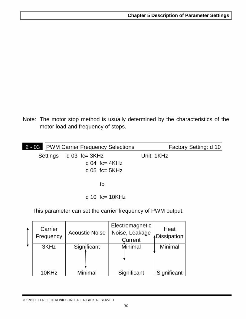
2 - 03 PWM Carrier Frequency Selections Factory Setting: d 10
Settings d 03 fc= 3KHz Unit: 1KHzd 04 fc= 4KHzd 05 fc= 5KHz
to
d 10 fc= 10KHz
This parameter can set the carrier frequency of PWM output.
CarrierFrequency
Acoustic NoiseElectromagneticNoise, Leakage
Current
HeatDissipation
3KHz
10KHz
Significant
Minimal
Minimal
Significant
Minimal
Significant
Chapter 5 Description of Parameter Settings
© 1999 DELTA ELECTRONICS, INC. ALL RIGHTS RESERVED
37
& From the above table, we see that the carrier frequency of PWM output has asignificant influence on the electromagnetic noise, heat dissipation of the ACdrive, and the acoustic noise to the motor.
2 - 04 Reverse Operation Inhibit Factory Setting: d 0
Settings d 0 enable REV operation
d 1 disable REV operation
& The parameter determines whether the AC drive can operate in the reversedirection.
2 - 05 ACI Input Loss Detection Factory Setting: d 0
Settings d 0 Upon the loss of ACI, the drive will default to anoutput frequency of 0 Hz.
d 1 Upon the loss of ACI, the drive will stop and displayerror message “EF”.
d 2 Upon the loss of ACI, the drive will continue to run atthe last known ACI input.
& This parameter is only effective when the Source of Frequency is commandedby a 4 to 20 mA signal. The ACI input is considered lost when the ACI signalfalls below 2 mA.
Chapter 5 Description of Parameter Settings
© 1999 DELTA ELECTRONICS, INC. ALL RIGHTS RESERVED
38
CH 5-4 Group 3: Output Function Parameters
3 - 00 Analog Output Signal Factory Setting: d 0
Settings d 0 Analog frequency meter (0 to Maximum OutputFrequency).
d 1 Analog current meter (0 to 250% of the rated ACdrive current).
& This parameter selects either Output Frequency or current to be displayedusing the 0 to10V AFM output.
3 - 01 Analog Output Gain Factory Setting: d100
Settings d 1 to d 200% Unit: 1%
The parameter can be set during operation.
& The parameter sets the voltage range of analog output signal (frequency orcurrent), on output terminal AFM.
The analog output voltage is directly proportional to the output frequency of the ACdrive. With the factory setting of 100%, the Maximum Output Frequency (Pr.1-00)of the AC drive corresponds to +10VDC analog voltage output. (The actual voltageis about +10VDC, and can be adjusted by Pr.3-01)
Chapter 5 Description of Parameter Settings
© 1999 DELTA ELECTRONICS, INC. ALL RIGHTS RESERVED
39
The analog output voltage is directly proportional to the output current of the ACdrive. With the factory setting of 100%, the 2.5 times rated current of the AC drivecorresponds to +10VDC analog voltage output. (The actual voltage is about+10VDC, and can be adjusted by Pr. 3-01)
Note: Any type of voltmeter can be used. If the meter reads full scale at a voltageless than 10 volts, then Pr.3-01 should be set by the following formula:
Pr.3-01 = ((meter full scale voltage)/10) ×100%
For Example: When using the meter with full scale of 5 volts, adjust Pr.3-01 to50%
3 - 02 Desired Frequency Attained Factory Setting: d 1.0
Settings d 1.0 to d 400 Hz Unit: 0.1Hz
& If a Multi-function output terminal is set to function as Desired FrequencyAttained (Pr.3-05 or 3-06=d9), then the output will be activated when theprogrammed frequency is attained.

Chapter 5 Description of Parameter Settings
© 1999 DELTA ELECTRONICS, INC. ALL RIGHTS RESERVED
40
3 - 03 Terminal Count Value Factory Setting: d 0 Settings d 0 to d 999
& The parameter determines the value of the internal counter. The internalcounter can be triggered by the external terminal (Pr.4-4 to Pr.4-8, d19). Uponcompletion of counting, the specified output terminal will be activated. (Pr.3-05, Pr.3-06, d14).
3 - 04 Preliminary Count Value Factory Setting: d 0
Settings d 0 to d 999
& When the counter value is counted up from “1” to the setting value of thisparameter, the corresponding multi-function output terminal will be closed,when sets d15 as desired value attained setting. The application can be thatclosing the multi-function output terminal makes the AC drive operate at lowspeed until stop before the counting value is going to be attained.
The timing diagram is shown in the next page:

Chapter 5 Description of Parameter Settings
© 1999 DELTA ELECTRONICS, INC. ALL RIGHTS RESERVED
41
3 - 05 Multi-function Output Terminal 1(Photocoupler output)
Factory Setting: d 1
3 - 06 Multi-function Output Terminal 2 (relay output) Factory Setting: d 8
Settings d 0 to d 15
Function Table List:
Setting Function Setting Functiond 0 Not used d 9 Desired Frequency Attainedd 1 AC Drive Operational d 10 PLC Program Running
Maximum Output Frequency d 11 PLC Program Step Completedd 2
Attained d 12 PLC Program Completedd 3 Zero speed d 13 PLC Operation Pausedd 4 Over-Torque detection d 14 Terminal Count Value Attainedd 5 Base-Block (B.B.) Indication d 15 Preliminary Counter Value Attainedd 6 Low-Voltage Indication d 16 All Functions Normald 7 AC Drive Operation Moded 8 Fault Indication

Chapter 5 Description of Parameter Settings
© 1999 DELTA ELECTRONICS, INC. ALL RIGHTS RESERVED
42
& Function Explanations
d 0 Not Used.
d 1 AC drive operational: the output of output terminal will be activated whenthere is an output from the drive.
d 2 Maximum Output Frequency Attained: the output will be activated whenthe AC drive attains Maximum Output Frequency.
d 3 Zero speed: the output will be activated when Command Frequency is lowerthan the Minimum Output Frequency.
d 4 Over-Torque Detection: the output will be activated as long as the over-torque is detected. Pr.6-04 determines the Over-Torque detection level.
d 5 Base-Block (B.B.) Indication: the output will be activated when the output ofthe AC drive is shut off by external Baseblock.
d 6 Low Voltage Indication: the output will be activated when low voltage isdetected.
d 7 AC Drive Operation Mode: the output will be activated when the operation ofthe AC drive is controlled by External Control Terminals.
d 8 Fault Indication: the output will be activated when faults occur (oc, ov, oH,oL, oL1, EF, cF3, HPF, ocA, ocd, ocn, GF).
d 9 Desired Frequency Attained: the output will be activated when the desiredfrequency (Pr.3-02)is attained.
d10 PLC Program Running: the output will be activated when the PLC programis running.
d11 PLC Program Step Completed: the output will be activated for 0.5 sec.when each multi-step speed is attained.
d12 PLC Program completed: the output will be activated for 0.5 sec. when thePLC program cycle has completed.
d13 PLC Program Operation Paused: the output will be activated when PLCoperation is paused.
d14 Terminal Count Value Attained: counter reaches Terminal Count Value.
d15 Preliminary Count Value Attained: counter reaches Preliminary CountValue.
d16 All Functions Normal: a When the AC Drive is in a normal state, the contactwill be closed. If there is a fault or the AC drive is not functioning normally,the contact will be open.

Chapter 5 Description of Parameter Settings
© 1999 DELTA ELECTRONICS, INC. ALL RIGHTS RESERVED
43
CH 5-5 Group 4: Input Function Parameters
4 - 00 Potentiometer Bias Frequency Factory Setting:d0.0
Settings d 0.0 to d 350Hz Unit: 0.1Hz
This parameter can be set during the operation.
4 - 01 Potentiometer Bias Polarity Factory Setting: d 0
Settings d 0 Positive bias
d 1 Negative bias
This parameter can be set during the operation.
4 - 02 Potentiometer Frequency Gain Factory Setting: d 100
Settings d 1 to d 200% Unit: 1%
This parameter can be set during the operation.
4 - 03 Potentiometer Reverse Motion Enable Factory Setting: d 0
Settings d 0 Forward motion only
d 1 Reverse motion enable (must be negative bias)
& Pr.4-00 to Pr.4-03 are used when the source of frequency command is theanalog signal (0 to +10V DC or 4 to 20 mA DC). Refer to the followingexamples.

Chapter 5 Description of Parameter Settings
© 1999 DELTA ELECTRONICS, INC. ALL RIGHTS RESERVED
44
Example 1:
The following is the most common method. Set parameter 2-00 to d1 (0 to+10V signal), d2 (4 to 20mA current signal), or d3 (keypad potentiometer).
Pr.4-02=100%-- Pot. Freq. Gain
Chapter 5 Description of Parameter Settings
© 1999 DELTA ELECTRONICS, INC. ALL RIGHTS RESERVED
45
Example 2:In this example with the potentiometer set to 0V the Output Frequency is 10 Hz.The mid-point of the potentiometer becomes 40 Hz. Once the Maximum OutputFrequency is reached any further increase of the potentiometer will not increaseoutput frequency.
Pr.4-02=100%-- Pot. Freq. Gain
Example 3:The example also shows the popular method. The whole scale of thepotentiometer can be used as desired. In addition to signals of 0 to 10V and 4 to20mA, the popular voltage signals also include signals of 0 to 5V, 20 to 4mA orthat under 10V. Regarding the setting, please refer to the following examples.
Pr.4-02=83%-- Pot. Freq. Gain

Chapter 5 Description of Parameter Settings
© 1999 DELTA ELECTRONICS, INC. ALL RIGHTS RESERVED
46
Example 4:
This example shows a potentiometer range of 0 to 5 Volts.
Pr.4-02=200%-- Pot. Freq. Gain
Example 5:In this example a 1 volt negative bias is used. In a noise environment, it isadvantageous to use negative bias to provide a noise margin (1V in this example).
Pr.4-01=1 --- Bias PolarityPr.4-02=100%-- Pot. Freq. Gain

Chapter 5 Description of Parameter Settings
© 1999 DELTA ELECTRONICS, INC. ALL RIGHTS RESERVED
47
Example 6:In this example, a negative bias is used to provide a noise margin. Also apotentiometer frequency gain is used to allow the Maximum Output Frequency tobe reached.
Pr.4-00=6Hz--Potentiometer Bias Freq.Pr.4-01=1 --- Bias Polarity
Example 7:In this example, the potentiometer is programmed to run a motor is both forwardand reverse direction. A motor will be idle when the potentiometer position is atmid-point of its scale. Using Pr.4-03 will disable the external FWD and REVcontrols.

Chapter 5 Description of Parameter Settings
© 1999 DELTA ELECTRONICS, INC. ALL RIGHTS RESERVED
48
Example 8:In this example, the option of anti-slope is shown. Anti-slope is used in anapplication where control of pressure, temperature, or flow is needed. Under ahigh pressure or flow situation, a sensor will generate a large signal such as 20mA or 10V. With anti-slope enable, the large signal will slow or stop the AC drive
Pr.4-01=1 --- Bias PolarityPr.4-02=100%-- Pot. Freq. Gain
4 - 04 Multi-function Input Terminal (M0, M1) Factory Setting: d 1
Settings d 0 to d 20
4 – 05 Multi-function Input Terminal (M2) Factory Setting: d 64 – 06 Multi-function Input Terminal (M3) Factory Setting: d 74 – 07 Multi-function Input Terminal (M4) Factory Setting: d 84 – 08 Multi-function Input Terminal (M5) Factory Setting: d 9
Settings d0, d 4 to d 20

Chapter 5 Description of Parameter Settings
© 1999 DELTA ELECTRONICS, INC. ALL RIGHTS RESERVED
49
Parameters & Functions table:
Value Function Value Function
d 0 Parameter Disable d11 Accel/Decel Speed Inhibit
d 1M0: FWD / STOPM1: REV / STOP
d12First or Second Accel/DecelTime Selection
d 2M0: RUN / STOPM1: FWD / REV
d13External Base Block (N.O.)
(Normally Open Contact Input)
d 33-Wire Operation Control mode(M0,M1,M2)
d14External Base Block (N.C.)
(Normally Close Contact Input)
d 4 External Fault ( Normally Open) d15 Increase Master Frequency
d 5External Fault ( NormallyClosed )
d16 Decrease Master Frequency
d 6 External Reset d17 Run PLC Programd 7 Multi-Step Speed Command 1 d18 Pause PLC Program
d 8 Multi-Step Speed Command 2 d19 Counter Trigger Signal
d 9 Multi-Step Speed Command 3 d20 Counter Reset
d10 Jog operation d21 ACI / AVI Selection
Explanations:
d0 Parameter Disable:Enter value (d0) to disable any Multi-Function Input Terminal: M1 (Pr.4-04), M2(Pr.4-05), M3 (Pr.4-06), M4 (Pr.4-07) or M5 (Pr.4-08)
Note: The purpose of this function is to provide isolation for unused Multi-FunctionInput Terminals. Any unused terminals should be programmed to d0 to insurethey have no effect on drive operation.

Chapter 5 Description of Parameter Settings
© 1999 DELTA ELECTRONICS, INC. ALL RIGHTS RESERVED
50
d1: Two wire operation: Restricted to Pr.4-04 and external terminals M0, M1.
M1"Open" : Stop; "Close" : REV Run
d2: Two wire operation: Restrict to Pr. 4-04 and external terminals M0, M1.
M1 "Open" : FWD; "Close" : REV
Note: Multi-function Input Terminal M0 does not have its own parameterdesignation. M0 must be used in conjunction with M1 to operate two andthree wire control.

Chapter 5 Description of Parameter Settings
© 1999 DELTA ELECTRONICS, INC. ALL RIGHTS RESERVED
51
d3: Three Wire Control: Restricted to Pr.4-04 control terminals M0, M1, M2.
M1 REV/FWD Run select
Note: When value d3 is selected for Pr. 4-04, this will over ride any valueentered in Pr.4-05, since Pr.4-05 must be used for three wire control as shownabove.
d4, d5 External Faults:Parameter values d4, d5 programs Multi-Function Input Terminals: M1 (Pr. 4-04), M2 (Pr. 4-05), M3 (Pr. 4-06), M4 (Pr. 4-07) or M5 (Pr. 4-08) to be ExternalFault (E.F.) inputs.
When an External Fault input signal is received, the AC drive will stop all outputand display “ E.F.” on Digital Keypad, the motor will free run. Normal operationcan resume after the External Fault is cleared and the AC drive is reset.

Chapter 5 Description of Parameter Settings
© 1999 DELTA ELECTRONICS, INC. ALL RIGHTS RESERVED
52
d6 External Reset:Parameter value d6 programs a Multi-Function Input Terminal: M1 (Pr.4-04),M2 (Pr.4-05), M3 (Pr.4-06), M4 (Pr.4-07) or M5 (Pr.4-08) to be an ExternalReset.
Note: the External Reset has the same function as the Reset key on the Digitalkeypad. After external fault such as O.H., O.C. and O.V. are clear, this inputcan be used to reset the drive.
d7, d8, d9 Multi-Step Speed Command:Parameter values d7, d8, d9 programs any three of the following Multi-FunctionInput Terminals: M1 (Pr.4-04), M2 (Pr.4-05), M3 (Pr.4-06), M4 (Pr.4-07) or M5(Pr.4-08) for multi-step speed command function.
Mx "Close": Operation available
These three inputs select the multi-step speeds defined by Pr.5-00 to Pr.5-06as shown in the following diagram. Pr.5-07 to Pr.5-16 can also control outputspeed by programming the AC drive’s internal PLC function.
Chapter 5 Description of Parameter Settings
© 1999 DELTA ELECTRONICS, INC. ALL RIGHTS RESERVED
53
d10 Jog Operation Control:Parameter value d10 programs Multi-Function Input Terminal: M1 (Pr.4-04),M2 (Pr.4- 05), M3 (Pr.4-06), M4 (Pr.4-07) or M5 (Pr.4-08) for Jog control.
Note: Jog operation programmed by d10 can only be initiated while the motor isstopped. (Refer to Pr.1-13, Pr.1-14.)

Chapter 5 Description of Parameter Settings
© 1999 DELTA ELECTRONICS, INC. ALL RIGHTS RESERVED
54
d11 Accel/Decel Speed Inhibit:Parameter value d11 programs Multi-Function Input Terminal: M1 (Pr.4-04), M2(Pr.4-05), M3 (Pr.4-06), M4 (Pr.4-07) or M5 (Pr.4-08) for Accel/Decel Inhibit.When the command is received, acceleration and deceleration is stopped andthe AC drive maintains a constant speed.
d12 First or Second Accel./Decel. Time Selection:Parameter value d12 programs a Multi-Function Input Terminal: M1 (Pr.4-04),M2 (Pr.4-05), M3 (Pr.4-06), M4 (Pr.4-07) or M5 (Pr.4-08) to control selectionof First or Second Accel/Decel time. (Refer to Pr.1-09 to Pr.1-12.)
"Close": 2nd Accel/Decel"Open": 1st Accel/Decel

Chapter 5 Description of Parameter Settings
© 1999 DELTA ELECTRONICS, INC. ALL RIGHTS RESERVED
55
2nd Accel/
d13, d14 External Base Block:Parameter values d13, d14 program Multi-Function Input Terminals: M1 (Pr.4-04), M2 (Pr.4-05), M3 (Pr.4-06), M4 (Pr.4-07) or M5 (Pr.4-08) for external BaseBlock control. Value d13 is for normally open (N.O.) input, and value d14 is fora normally closed (N.C.) input.
Note: When a Base-Block signal is received, the AC drive will stop all output andthe motor will free run. When base block control is deactivated, the ACdrive will start its speed search function and synchronize with the motorspeed, and then accelerate to Master Frequency.
Chapter 5 Description of Parameter Settings
© 1999 DELTA ELECTRONICS, INC. ALL RIGHTS RESERVED
56
d15, d16 Increase/Decrease Master Frequency:Parameter values d15, d16 program the Multi-Function Input Terminals: M1(Pr.4-04), M2 (Pr.4-05), M3 (Pr.4-06), M4 (Pr.4-07) or M5 (Pr.4-08) toincrementally increase/ decrease the Master Frequency each time an input isreceived.
Chapter 5 Description of Parameter Settings
© 1999 DELTA ELECTRONICS, INC. ALL RIGHTS RESERVED
57
d17, d18 PLC Function Control:Parameter value d17 programs Multi-Function Input Terminal: M1 (Pr.4-04),M2 (Pr.4-05), M3 (Pr.4-06), M4 (Pr.4-07) or M5 (Pr.4-08) to enable the ACdrive internal PLC program. Parameter value d18 programs an input terminalto pause the PLC program.
Note: Pr.5-00 to Pr.5-16 define the PLC program.
d19 Counter Trigger:Parameter value d19 programs Multi-Function Input Terminal: M1 (Pr.4-04),M2 (Pr.4-05), M3 (Pr.4-06), M4 (Pr.4-07) or M5 (Pr.4-08) to increase the ACdrive’s internal counter. When an input is received, the counter is increased by1.
d 19 Counter trigger signal input.Mx Counter value increase by 1 when closed.
Note:The Counter Trigger input can be connected to an external Pulse SignalGenerator to count a processing step or unit of material. See the diagrambelow.
Chapter 5 Description of Parameter Settings
© 1999 DELTA ELECTRONICS, INC. ALL RIGHTS RESERVED
58
d20 Counter Reset:Parameter value d20 programs Multi-Function Input Terminal: M1 (Pr.4-04),M2 (Pr. 4-05), M3 (Pr.4-06), M4 (Pr.4-07) or M5 (Pr.4-08) to reset the counter.
d21 ACI / AVI Selection:Parameter value d21 allows the user to select the input type ACI or AVI via anexternal switch. AVI is selected when the contact is open and ACI is selectedwhen the contact is closed. Please note: The use of this feature will overridePr. 2-00 programming and the jumper on the front of the drive must be movedto the correct location either across the AVI or ACI pin heads.
4- 09 Line Start Lockout Factory Setting: d 0
Settings: d0 Disable
d1 Enable
& When enable, the AC drive will not start when powered up with runcommands applied. To start in Line Start Lockout mode, the AC drive mustsee the run command go from stop to run after power up. When Line StartLockout is disable (also known as Auto-Start), the drive will start whenpowered-up with run commands applied.

Chapter 5 Description of Parameter Settings
© 1999 DELTA ELECTRONICS, INC. ALL RIGHTS RESERVED
59
CH 5-6 Group 5: Multi-step Speed and PLC (Process Logic Control)Parameters
5 - 00 1st Step Speed Frequency Factory Setting: d0.0
5 - 01 2nd Step Speed Frequency Factory Setting: d0.0
5 - 02 3rd Step Speed Frequency Factory Setting: d0.0
5 - 03 4th Step Speed Frequency Factory Setting: d0.0
5 - 04 5th Step Speed Frequency Factory Setting: d0.0
5 - 05 6th Step Speed Frequency Factory Setting: d0.0
5 - 06 7th Step Speed Frequency Factory Setting: d0.0
Settings d 0.0 to d 400 Hz Unit: 0.1Hz
This parameter can be set during operation.
& The Multi-Function Input Terminals (refer to Pr.4-04 to 4-08) are used toselect one of the AC drive Multi-Step speeds. The speeds (frequencies) aredetermined by Pr.5-00 to 5-06 shown above.
5 – 07 PLC Mode Factory Setting: d 0
Settings d 0 Disable PLC operation
d 1 Execute one program cycle
d 2 Continuously execute program cycles
d 3 Execute one program cycle step by step
d 4 Continuously execute program cycles step by step
& This parameter selects the mode of PLC operation for the AC drive. The PLCprogram can be used in lieu of any External Controls, Relays or Switches. The

Chapter 5 Description of Parameter Settings
© 1999 DELTA ELECTRONICS, INC. ALL RIGHTS RESERVED
60
AC drive will change speeds and directions according to the user’s desiredprogramming.

Chapter 5 Description of Parameter Settings
© 1999 DELTA ELECTRONICS, INC. ALL RIGHTS RESERVED
61
Example 1 (Pr.5-07 = d1): Execute one cycle of the PLC program. Its relativeparameter settings are:
1. Pr.5-00 to 5-06: 1st to 7th step speed (sets the frequency of each step speed
2. Pr.4-04 to 4-08: Multi-Function Input Terminals (set one multi-function terminalas d17- PLC auto-operation .
3. Pr.3-05 to 3-06: Multi-Function Output Terminals (set a Multi-Function Terminalas d10-PLC operation indication, d11-one cycle in PLC auto mode or d12-PLCoperation fulfillment attainment).
4. Pr.5-07: PLC mode.
5. Pr.5-08: Direction of operation for Master Frequency and 1st to 7th step speed.
6. Pr.5-09 to 5-16: operation time setting of Master Frequency and 1st to 7th stepspeed.
Note: The above diagram shows one complete PLC cycle. To restart the cycle,turn the PLC program off and then back on.
Chapter 5 Description of Parameter Settings
© 1999 DELTA ELECTRONICS, INC. ALL RIGHTS RESERVED
62
Example 2 (Pr.5-07 = d2): Continuously executes program cycles
The diagram below shows the PLC program stepping through each speed andthe automatically starting again. To stop the PLC program, one must eitherpause the program or turn it off (Refer to Pr.4-05 to 4-08 value d17 and d18).
Chapter 5 Description of Parameter Settings
© 1999 DELTA ELECTRONICS, INC. ALL RIGHTS RESERVED
63
Example 3 (Pr. 5-07 = d3) Execute one cycle step by step:
The example shows how the PLC can perform one cycle at a time, within acomplete cycle. Each step will use the accel/decel times in Pr.1-09 to Pr.1-12. Itshould be noticed that the time each step spends at its intended frequency isdiminished, due to the time spent during accel/decel.

Chapter 5 Description of Parameter Settings
© 1999 DELTA ELECTRONICS, INC. ALL RIGHTS RESERVED
64
Example 4 (Pr. 5-07 =d 4) Continuously execute PLC cycles step by step:
In this explanation, the PLC program runs continuously step by step. Also shownare examples of steps in the Reverse direction.

Chapter 5 Description of Parameter Settings
© 1999 DELTA ELECTRONICS, INC. ALL RIGHTS RESERVED
65
Example 5 (Pr. 5-07 = d1 Execute one cycle of the PLC program):
In this example, the PLC program runs continuously. It should be noted that thetimes of reserve motion may be shorter than expected, due to the accel/deceltimes.
5 - 08 PLC Forward/Reverse Motion Factory Setting: d 0
Settings d 0 to d 255
& This parameter controls the direction of motion for the Multi-Step Speed Pr.5-00 to Pr.5-06 and the Master Frequency. The original direction of MasterFrequency will become invalid.
Chapter 5 Description of Parameter Settings
© 1999 DELTA ELECTRONICS, INC. ALL RIGHTS RESERVED
66
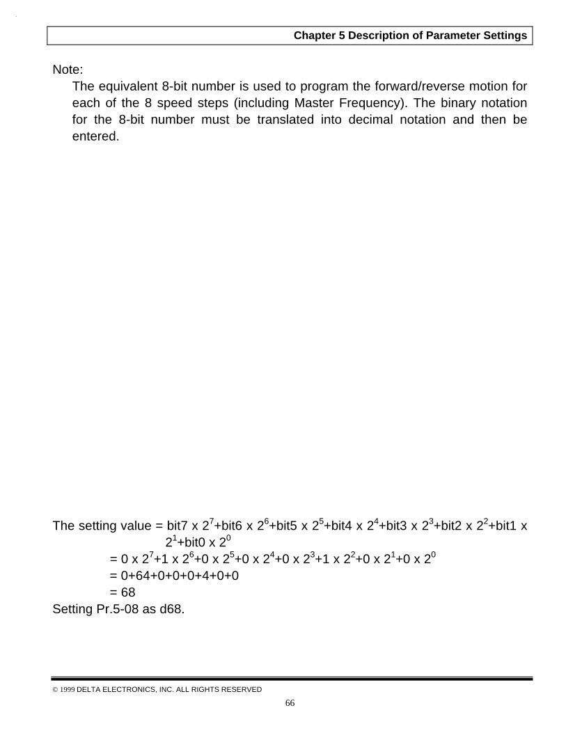
Note:The equivalent 8-bit number is used to program the forward/reverse motion foreach of the 8 speed steps (including Master Frequency). The binary notationfor the 8-bit number must be translated into decimal notation and then beentered.
Direction of 2nd step speed for Pr. 5-01Direction of 1st step speed = FWD
The setting value = bit7 x 27+bit6 x 26+bit5 x 25+bit4 x 24+bit3 x 23+bit2 x 22+bit1 x21+bit0 x 20
= 0 x 27+1 x 26+0 x 25+0 x 24+0 x 23+1 x 22+0 x 21+0 x 20
= 0+64+0+0+0+4+0+0 = 68Setting Pr.5-08 as d68.

Chapter 5 Description of Parameter Settings
© 1999 DELTA ELECTRONICS, INC. ALL RIGHTS RESERVED
67
5 - 09 Time Duration of Master Frequency Factory Setting: d 05 - 10 Time Duration of 1st Step Speed Factory Setting: d 05 - 11 Time Duration of 2nd Step Speed Factory Setting: d 05 - 12 Time Duration of 3rd Step Speed Factory Setting: d 05 - 13 Time Duration of 4th Step Speed Factory Setting: d 05 - 14 Time Duration of 5th Step Speed Factory Setting: d 05 - 15 Time Duration of 6th Step Speed Factory Setting: d 05 - 16 Time Duration of 7th Step Speed Factory Setting: d 0
Settings d 0 to d 65500 Unit: 1 Sec
& Pr.5-10 to Pr.5-16 correspond to operation time of each multi-step speeddefined by parameters 5-00 to 5-06. The maximum value of these parametersis 65500 sec, and it’s displayed as d 65.5.
Note: If a parameter is set to “d0” (0 Sec), the corresponding step will be skipped.This is commonly used to reduce number of program steps

Chapter 5 Description of Parameter Settings
© 1999 DELTA ELECTRONICS, INC. ALL RIGHTS RESERVED
68
CH 5-7 Group 6: Protection Parameters
6 - 00 Over-Voltage Stall Prevention Factory Setting: d 1 Settings d 0 Disable Over-Voltage Stall Prevention
d 1 Enable Over-Voltage Stall Prevention
& During deceleration, the motor DC bus voltage may exceed its MaximumAllowable Value due to motor regeneration. When this function is enabled, theAC drive will stop decelerating. Maintaining a constant output frequency whenit happens. The AC drive will only resume deceleration when the voltage dropsbelow preset value.
Note:With a moderate inertial load, the over-voltage during deceleration won’thappen, and the drive will stop in programmed time. The AC drive willautomatically extend the deceleration time with high inertial loads. Ifdeceleration time is critical for the application, then dynamic braking resistorsshould be used.

Chapter 5 Description of Parameter Settings
© 1999 DELTA ELECTRONICS, INC. ALL RIGHTS RESERVED
69
6 - 01 Over-Current Stall Prevention during Acceleration Factory Setting: d170
Settings d 20 to d 250% Unit: 1%
& A setting of 100% is equal to the Rated Output Current of the drive.
& During acceleration, the AC drive output current may increase abruptly toexceed the value specified by Pr.6-01 due to rapid acceleration or excessiveload on the motor. When this function is enabled, the AC drive will stopaccelerating and maintaining a constant output frequency. The AC drive willonly resume acceleration when the current drops below the maximum value.
6 - 02 Over-current Stall Prevention during Operation Factory Setting: d 170
Settings d 20 to d 250% Unit: 1%
& During the steady-state operation with motor load rapidly increasing, the ACdrive output current may exceed the limit specified in Pr.6-02. When thisoccurred, the output frequency will decrease to maintain a constant motorspeed. The drive will accelerate to the steady-state output frequency onlywhen the output current drops below the level specified by Pr.6-02.
Chapter 5 Description of Parameter Settings
© 1999 DELTA ELECTRONICS, INC. ALL RIGHTS RESERVED
70
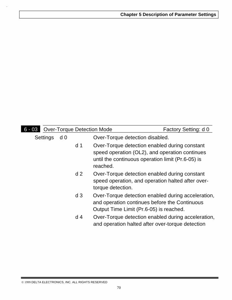
6 - 03 Over-Torque Detection Mode Factory Setting: d 0
Settings d 0 Over-Torque detection disabled.
d 1 Over-Torque detection enabled during constantspeed operation (OL2), and operation continuesuntil the continuous operation limit (Pr.6-05) isreached.
d 2 Over-Torque detection enabled during constantspeed operation, and operation halted after over-torque detection.
d 3 Over-Torque detection enabled during acceleration,and operation continues before the ContinuousOutput Time Limit (Pr.6-05) is reached.
d 4 Over-Torque detection enabled during acceleration,and operation halted after over-torque detection

Chapter 5 Description of Parameter Settings
© 1999 DELTA ELECTRONICS, INC. ALL RIGHTS RESERVED
71
6 - 04 Over-Torque Detection Level Factory Setting: d 150
Settings d 30 to d 200% Unit: 1%
& A setting of proportional to the Rated Output Current of the drive.
6 - 05 Continuous Output Time Limit Factory Setting: d 0.1
Settings d 0.1 to d 10.0Sec Unit: 0.1Sec
& This parameter determines the time that AC drive will run after over-torque isdetected. Over-torque detection is based on the following:If a Multi-Function Output Terminal is set as Over-Torque DetectionIndication and the output current exceeds the Over-Torque Detection Level(Pr.6-04, Factory Setting: 150%), the output will be activated.
6 - 06 Electronic Thermal Overload Relay Selection Factory Setting: d 2 Settings d 0 Reduce Torque Motor
d 1 Constant Torque Motord 2 Inactive
& This function is used to limit the output power of the AC drive when poweringa “self-cooled motor at low speed.
6 - 07 Electronic Thermal Characteristic Factory Setting: d 60
Settings d 30 to d 600Sec Unit: 1 Sec
This parameter can be set during operation.
& The parameter determines the time required activating the I2t electronicthermal protection function. The graph below shows I2t curves for 150%output power for 1 minute.
Chapter 5 Description of Parameter Settings
© 1999 DELTA ELECTRONICS, INC. ALL RIGHTS RESERVED
72
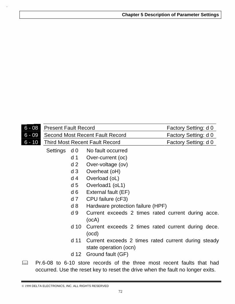
6 - 08 Present Fault Record Factory Setting: d 06 - 09 Second Most Recent Fault Record Factory Setting: d 06 - 10 Third Most Recent Fault Record Factory Setting: d 0
Settings d 0 No fault occurredd 1 Over-current (oc)d 2 Over-voltage (ov)d 3 Overheat (oH)d 4 Overload (oL)d 5 Overload1 (oL1)d 6 External fault (EF)d 7 CPU failure (cF3)d 8 Hardware protection failure (HPF)d 9 Current exceeds 2 times rated current during acce.
(ocA)d 10 Current exceeds 2 times rated current during dece.
(ocd)d 11 Current exceeds 2 times rated current during steady
state operation (ocn)d 12 Ground fault (GF)
& Pr.6-08 to 6-10 store records of the three most recent faults that hadoccurred. Use the reset key to reset the drive when the fault no longer exits.

Chapter 5 Description of Parameter Settings
© 1999 DELTA ELECTRONICS, INC. ALL RIGHTS RESERVED
73
CH 5-8 Group 7: Motor Parameters
7 - 00 Motor Rated Current Factory Setting: d 85
Settings d 30 to d 120 Unit: 1% This parameter can be set during operation.
& This parameter will limit the AC drive output current in order to prevent themotor from overheating. Use the following method to calculate thepercentage entered in this parameter.
Pr.7-00 = ( )*100AC drive Rated Output Current
7 - 01 Motor No-load Current Factory Setting: d 50
Settings d 0 to d 90% Unit: 1% This parameter can be set during operation.
& The rated current of the AC drive is regarded as 100%. Motor setting of no-load current will effect the slip compensation. The setting value must be lessthan motor rated current setting Pr.7-00.
7 - 02 Torque Compensation Factory Setting: d 3
Settings d 0 to d 10 Unit: 1This parameter can be set during operation.
& This parameter may be set so that the AC drive will increase its voltage outputduring start-up to obtain a higher initial starting torque.
Chapter 5 Description of Parameter Settings
© 1999 DELTA ELECTRONICS, INC. ALL RIGHTS RESERVED
74
7 - 03 Slip Compensation Factory Setting: d 0.0
Settings d 0.0 to d 10.0 Unit: 0.1This parameter can be set during operation.
& While driving an asynchronous motor, load on the AC drive will increase,causing an increase in slip. This parameter may be used to compensate thenominal slip within a range of 0 to 10. When the output current of the AC driveis greater than the motor no-load current (Pr.7-01), the AC drive will adjust itsoutput frequency according to this parameter.
Chapter 5 Description of Parameter Settings
© 1999 DELTA ELECTRONICS, INC. ALL RIGHTS RESERVED
75
CH 5-9 Group 8: Special Parameters
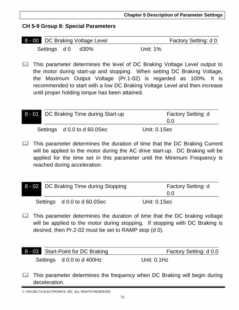
8 - 00 DC Braking Voltage Level Factory Setting: d 0
Settings d 0 ⇔ d30% Unit: 1%
& This parameter determines the level of DC Braking Voltage Level output tothe motor during start-up and stopping. When setting DC Braking Voltage,the Maximum Output Voltage (Pr.1-02) is regarded as 100%. It isrecommended to start with a low DC Braking Voltage Level and then increaseuntil proper holding torque has been attained.
8 - 01 DC Braking Time during Start-up Factory Setting: d0.0
Settings d 0.0 to d 60.0Sec Unit: 0.1Sec
& This parameter determines the duration of time that the DC Braking Currentwill be applied to the motor during the AC drive start-up. DC Braking will beapplied for the time set in this parameter until the Minimum Frequency isreached during acceleration.
8 - 02 DC Braking Time during Stopping Factory Setting: d0.0
Settings d 0.0 to d 60.0Sec Unit: 0.1Sec
& This parameter determines the duration of time that the DC braking voltagewill be applied to the motor during stopping. If stopping with DC Braking isdesired, then Pr.2-02 must be set to RAMP stop (d 0).
8 - 03 Start-Point for DC Braking Factory Setting: d 0.0
Settings d 0.0 to d 400Hz Unit: 0.1Hz
& This parameter determines the frequency when DC Braking will begin duringdeceleration.

Chapter 5 Description of Parameter Settings
© 1999 DELTA ELECTRONICS, INC. ALL RIGHTS RESERVED
76
NOTE: 1. DC Braking during Start-up is used for loads that may move before ACdrive starts, such as fans and pumps. These loads may also be movingin the wrong direction. Under such circumstances, DC Braking can beexecuted to hold the load in position before applying a forward motion.
2. DC Braking during stopping is used to decrease stopping time and alsoto hold a stopped load in position. For high inertial loads, a dynamicbraking resistor may be needed for quick decelerations.
8 - 04 Momentary Power Loss Operation Selection Factory Setting: d 0
Settings d 0 Operation stop after momentary power loss
d 1 Operation continue after momentary power lossSpeed search start with the Master Frequencyreference value
d 2 Operation continue after momentary power lossSpeed search start with the min frequency

Chapter 5 Description of Parameter Settings
© 1999 DELTA ELECTRONICS, INC. ALL RIGHTS RESERVED
77
8 - 05 Maximum Allowable Power Loss Time Factory Setting: d 2.0
Settings d 0.3 to d 5.0Sec Unit: 0.1Sec
& During a power loss, if the power loss time is less than the time defined bythis parameter, the AC drive will resume operation. If the MaximumAllowable Power Loss Time is exceeded, the AC drive output is then turnedoff.
8 - 06 Base-Block Time for Speed Search Factory Setting: d 0.5
Settings d 0.3 to d 5.0Sec Unit: 0.1Sec
& When a momentary power loss is detected, the AC drive turns off for aspecified time interval determined by Pr.8-06 before resuming operation. Thistime interval is called Base-Block. This parameter should be set to a valuewhere the residual output voltage is nearly zero, before the drive resumesoperation.
& This parameter also determines the searching time when performing externalBase-Block and Fault Reset (Pr.8-14).
8 - 07 Maximum Speed Search Current Level Factory Setting: d 150
Settings d 30 to d 200 Unit: 1%
& Following a power failure, the AC drive will start its speed search operation,only if the output current is greater than the value determined by Pr.8-07.When the output current is less than that of Pr.8-07, the AC drive outputfrequency is at a “speed synchronization point”. The drive will start toaccelerate or decelerate back to the operating frequency at which it wasrunning prior to the power failure.

Chapter 5 Description of Parameter Settings
© 1999 DELTA ELECTRONICS, INC. ALL RIGHTS RESERVED
78

Chapter 5 Description of Parameter Settings
© 1999 DELTA ELECTRONICS, INC. ALL RIGHTS RESERVED
79
8 - 08 Skip Frequency 1 Upper Bound Factory Setting: d 0.08 - 09 Skip Frequency 1 Lower Bound Factory Setting: d 0.08 - 10 Skip Frequency 2 Upper Bound Factory Setting: d 0.08 - 11 Skip Frequency 2 Lower Bound Factory Setting: d 0.08 - 12 Skip Frequency 3 Upper Bound Factory Setting: d 0.08 - 13 Skip Frequency 3 Lower Bound Factory Setting: d 0.0
Settings d 0.0 ⇔ d 400Hz Unit: 0.1Hz
& These parameters determine Skip frequency. It will cause the AC drive toskip operation at these frequency ranges with continuous frequency output.
& Pr.8-9, Pr.8-11,Pr.8-13 are for Lower Bound setting, and the settings shouldfollow as Pr.8-9 Pr.8-11 Pr.8-13.
8 - 14 Auto Restart After Fault Factory Setting: d 0
Settings d 0 to d 10
& After fault occurs (allowable faults: over-current OC, over-voltage OV), the ACdrive can be reset/restarted automatically up to 10 times. Setting thisparameter to 0 will disable the reset/restart operation after any fault hasoccurred. When enabled, the AC drive will restart with speed search, whichstarts at the Master Frequency. To set the fault recovery time after a fault,please see (Pr.8-06) Baseblock Time for speed search.
8 - 15 Automatic Voltage Regulation (AVR) Factory Setting: d 2
Settings d 0 AVR function enabled
d 1 AVR function disabled
d 2 AVR function disabled for deceleration

Chapter 5 Description of Parameter Settings
© 1999 DELTA ELECTRONICS, INC. ALL RIGHTS RESERVED
80
& AVR function automatically regulates the AC drive output voltage to theMaximum Output Voltage (Pr.1-02). For instance, if Pr.1-02 is set at 200 VACand the input voltage is at 200V to 264VAC, then the Maximum Output Voltagewill automatically be regarded to 200 VAC.
& Without AVR function, the Maximum Output Voltage may vary between 180Vto 264VAC, due to the input voltage varying between 180V to 264 VAC.
& Selecting program value d2 enables the AVR function and also disables theAVR function during deceleration. This offers a quicker deceleration.
8 - 16 Dynamic Braking Voltage Factory Setting: d 380*
Settings d 350 to d 450V* Unit: 1Volt**Twice value for 460V class
& During deceleration, the DC-bus voltage will increase due to motorregeneration. When DC bus voltage level exceeds the Dynamic BrakingVoltage, the DC brake output pins (B1, B2) will be activated.
8 - 17 DC Braking Inhibit Frequency Factory Setting: d 0
Settings d 0 to d 400 Unit: 0.1 Hz
& This parameter determines the frequency range (from Pr.8-17 to 0 Hz) whereDC injection braking will be inhibited. If the output frequency during stoppingis at or below Pr.8-03, but above Pr.8-17 then DC braking is applied. 0DCbraking will always be inhibited if Pr.8-17 is equal to or greater than Pr.8-03.

Chapter 6 Maintenance and Inspections
© 1999 DELTA ELECTRONICS, INC. ALL RIGHTS RESERVE
98
Chapter 6 Maintenance and InspectionsModern AC drives are based on solid state electronics technology, preventive
maintenance is required to operate this AC drive in its optimal condition, and toensure a long life. It is recommended to perform a monthly check up of the ACdrive by a qualified technician. Before the check up, always turn off the AC Input
Power to the unit. Wait at least 2 minutes after all display lamps have gone out,and then confirm that the capacitors have fully discharged.
CH 6-1 Periodic Inspection:
Basic check up items to detect if there were any abnormality during theoperation.
1. Whether the motors are operating as expected.
2. Whether the installation environment is abnormal.
3. Whether the cooling system is operating as expected.
4. Whether any irregular vibration or sound occurred during the operation.
5. Whether the motors are overheated during the operation.
6. Always check the input voltage of the AC drive with Voltmeter.
CH 6-2 Periodic Maintenance
It is necessary to stop the motor operation during the check up.
1. Tighten and reinforce the screws of the AC drive if necessary, cause it may
loose due to the vibration or changing of temperatures.
2. Whether the conductors or insulators were corroded and damaged.
Chapter 6 Maintenance And Inspections
© 1999 DELTA ELECTRONICS, INC. ALL RIGHTS RESERVED
99
3. Check the resistance of the insulation with Megaohmeter.
4. If use of the AC drive is discontinued for a long period of time, turn the power
on at least once every two years and confirm that it still functions properly. Toconfirm functionality, disconnect the motor and energize the AC drive for 5hours or more before attempting to run a motor with it.
5. Clean off any dust and dirt with a vacuum cleaner. Place special emphasis oncleaning the ventilation ports and PCBs. Always keep these areas clean, asadherence of dust and dirt can cause unforeseen failures.

Chapter 7 Troubleshooting and Fault Information
© 1999 DELTA ELECTRONICS, INC. ALL RIGHTS RESERVE
100
Chapter 7 Troubleshooting and Fault InformationThe AC motor drive has a comprehensive fault diagnostic system that includes several differentalarms and fault messages. Once a fault is detected, the corresponding protective functions willbe activated to shut down the AC drive output. Below are the fault descriptions, for a faultshown on the AC drive digital keypad display. The three most recent faults can be read on thedigital keypad display by viewing Pr.6-08 to Pr.6-10
NOTE: After faults occurred, press RESET to begin using the drive again.
Common Problems and Solutions:
FaultName
Fault Descriptions Corrective Actions
The AC drive detects anabnormal increase incurrent.
1. Check whether the motors horsepower corresponds tothe AC drive output power.
2. Check the wiring connections between the AC driveand motor for possible short circuits.
3. Increase the Acceleration time (Pr.1-09, Pr.1-11).
4. Check for possible excessive loading conditions at themotor.
5. If there are any abnormal conditions when operatingthe AC drive after short-circuit being removed, it shouldbe sent back to manufacturer.
The AC drive detects thatthe DC bus voltage hasexceeded its maximumallowable value.
1. Check whether the input voltage falls within the ratedAC drive input voltage.
2. Check for possible voltage transients.
3. Bus over-voltage may also be caused by motorregeneration. Either increase the decel time or add anoptional braking resistor.
4. Check whether the required braking power is within thespecified limits.
The AC drive temperaturesensor detects excessiveheat.
1. Ensure that the ambient temperature falls within thespecified temperature range.
2. Make sure that the ventilation holes are not obstructed.
3. Remove any foreign objects on the heatsinks andcheck for possible dirty heat sink fins.
4. Provide enough spacing for adequate ventilation.
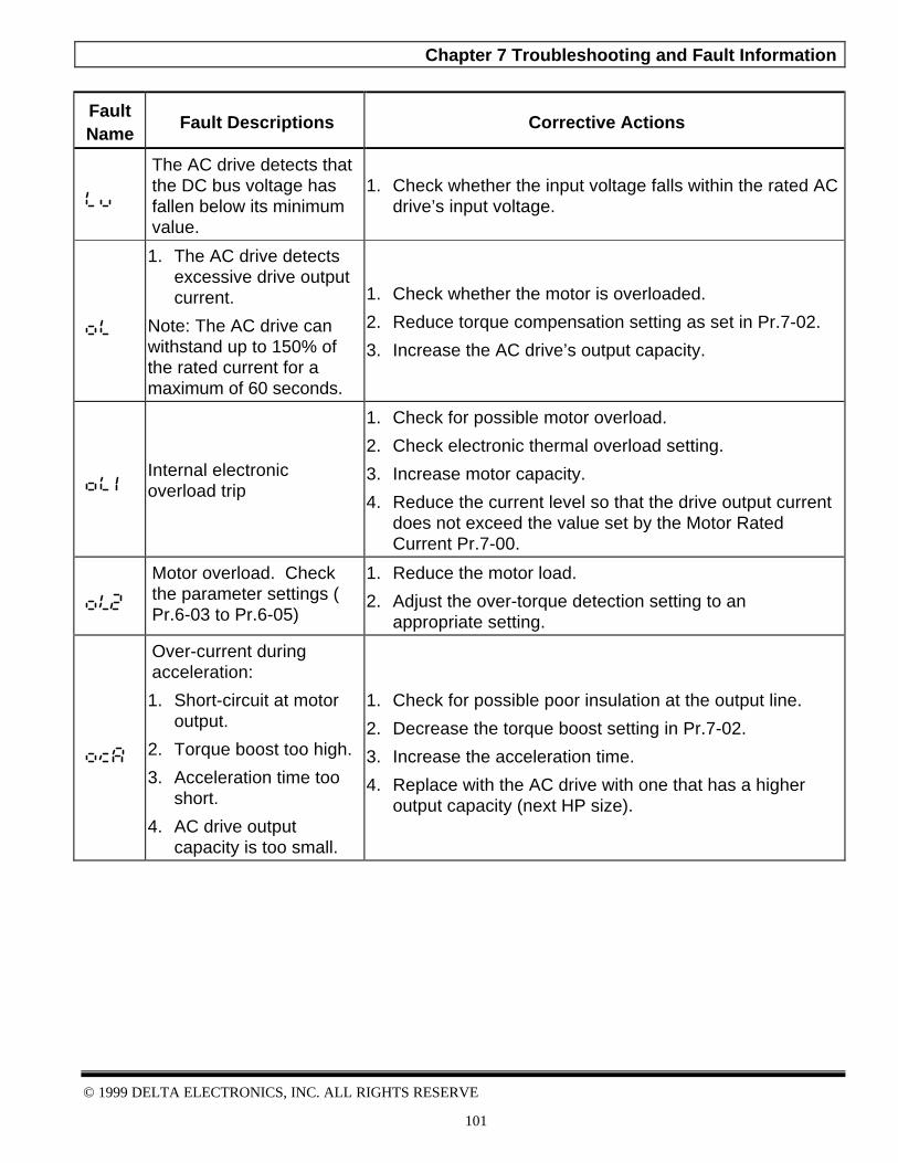
Chapter 7 Troubleshooting and Fault Information
© 1999 DELTA ELECTRONICS, INC. ALL RIGHTS RESERVE
101
FaultName
Fault Descriptions Corrective Actions
The AC drive detects thatthe DC bus voltage hasfallen below its minimumvalue.
1. Check whether the input voltage falls within the rated ACdrive’s input voltage.
1. The AC drive detectsexcessive drive outputcurrent.
Note: The AC drive canwithstand up to 150% ofthe rated current for amaximum of 60 seconds.
1. Check whether the motor is overloaded.
2. Reduce torque compensation setting as set in Pr.7-02.
3. Increase the AC drive’s output capacity.
Internal electronicoverload trip
1. Check for possible motor overload.
2. Check electronic thermal overload setting.
3. Increase motor capacity.
4. Reduce the current level so that the drive output currentdoes not exceed the value set by the Motor RatedCurrent Pr.7-00.
Motor overload. Checkthe parameter settings (Pr.6-03 to Pr.6-05)
1. Reduce the motor load.
2. Adjust the over-torque detection setting to anappropriate setting.
Over-current duringacceleration:
1. Short-circuit at motoroutput.
2. Torque boost too high.
3. Acceleration time tooshort.
4. AC drive outputcapacity is too small.
1. Check for possible poor insulation at the output line.
2. Decrease the torque boost setting in Pr.7-02.
3. Increase the acceleration time.
4. Replace with the AC drive with one that has a higheroutput capacity (next HP size).
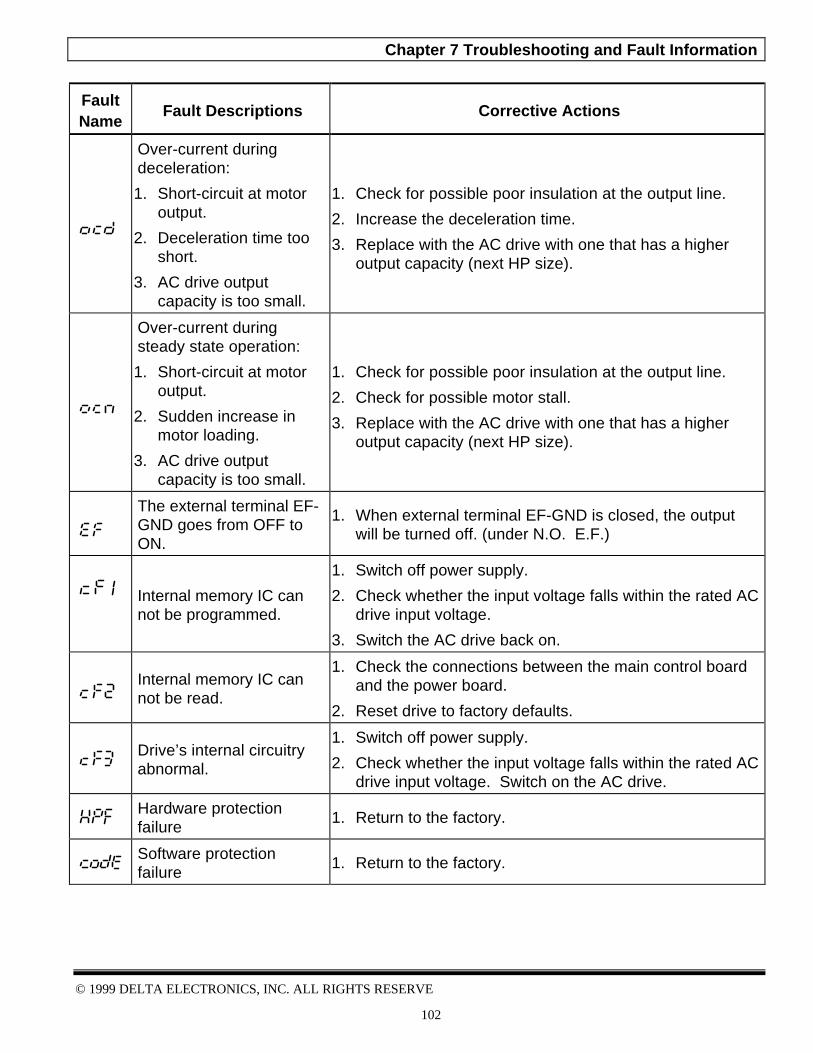
Chapter 7 Troubleshooting and Fault Information
© 1999 DELTA ELECTRONICS, INC. ALL RIGHTS RESERVE
102
FaultName
Fault Descriptions Corrective Actions
Over-current duringdeceleration:
1. Short-circuit at motoroutput.
2. Deceleration time tooshort.
3. AC drive outputcapacity is too small.
1. Check for possible poor insulation at the output line.
2. Increase the deceleration time.
3. Replace with the AC drive with one that has a higheroutput capacity (next HP size).
Over-current duringsteady state operation:
1. Short-circuit at motoroutput.
2. Sudden increase inmotor loading.
3. AC drive outputcapacity is too small.
1. Check for possible poor insulation at the output line.
2. Check for possible motor stall.
3. Replace with the AC drive with one that has a higheroutput capacity (next HP size).
The external terminal EF-GND goes from OFF toON.
1. When external terminal EF-GND is closed, the outputwill be turned off. (under N.O. E.F.)
Internal memory IC cannot be programmed.
1. Switch off power supply.
2. Check whether the input voltage falls within the rated ACdrive input voltage.
3. Switch the AC drive back on.
Internal memory IC cannot be read.
1. Check the connections between the main control boardand the power board.
2. Reset drive to factory defaults.
Drive’s internal circuitryabnormal.
1. Switch off power supply.
2. Check whether the input voltage falls within the rated ACdrive input voltage. Switch on the AC drive.
Hardware protectionfailure
1. Return to the factory.
Software protectionfailure
1. Return to the factory.

Chapter 7 Troubleshooting and Fault Information
© 1999 DELTA ELECTRONICS, INC. ALL RIGHTS RESERVE
103
FaultName
Fault Descriptions Corrective Actions
Auto accel/decel failure1. Don’t use the function of auto acceleration
/deceleration.
Ground fault :
The AC drive output isabnormal. When theoutput terminal isgrounded (short circuitcurrent is 50% more thanthe AC drive ratedcurrent), the AC drivepower module may bedamaged. The shortcircuit protection isprovided for AC driveprotection, not userprotection.
Ground fault :
1. Check whether the IGBT power module is damaged.
2. Check for possible poor insulation at the output line.
Communication Error1. Check the connection between the AC drive and
computer for loose wires.
2. Check if the communication protocol is properly set.
External Base Block.
AC drive output is turnedoff.
1. When the external input terminal (B.B) is active, the ACdrive output will be turned off.
2. Disable this connection and the AC drive will begin towork again.
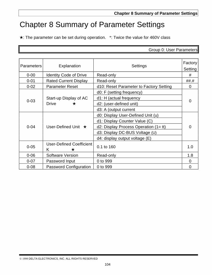
Chapter 8 Summary of Parameter Settings
© 1999 DELTA ELECTRONICS, INC. ALL RIGHTS RESERVED
104
Chapter 8 Summary of Parameter Settings
H: The parameter can be set during operation. *: Twice the value for 460V class
Group 0: User Parameters
Parameters Explanation SettingsFactory
Setting0-00 Identity Code of Drive Read-only #0-01 Rated Current Display Read-only ##.#0-02 Parameter Reset d10: Reset Parameter to Factory Setting 0
d0: F (setting frequency)d1: H (actual frequencyd2: (user-defined unit)
0-03Start-up Display of ACDrive H
d3: A (output current
0
d0: Display User-Defined Unit (u)d1: Display Counter Value (C)d2: Display Process Operation (1= tt)d3: Display DC-BUS Voltage (U)
0-04 User-Defined Unit H
d4: display output voltage (E)
0
0-05User-Defined CoefficientK H
0.1 to 160 1.0
0-06 Software Version Read-only 1.80-07 Password Input 0 to 999 00-08 Password Configuration 0 to 999 0

Chapter 8 Summary of Parameter Settings
© 1999 DELTA ELECTRONICS, INC. ALL RIGHTS RESERVED
105
Group 1 Basic Parameters
Parameters Explanation SettingsFactory
Setting
1-00Maximum Output Freq.(Fo,max)
50.0 to 400 Hz 60.0
1-01Maximum VoltageFrequency (Base Freq)(Fmax)
10.0 to 400 Hz 60.0
1-02Maximum OutputVoltage (Vmax)
2.0V to 255V* 220*
1-03Mid-Point Frequency(Fmid)
1.0 to 400 Hz 1.0
1-04 Mid-Point Voltage (Vmid) 2.0V to 255V* 12*
1-05Minimum OutputFrequency (Fmin)
1.0 to 60.0 Hz 1.0
1-06Minimum Output Voltage(Vmin)
2.0V to 255V* 12*
1-07 Upper bound of freq. 1 to 110% 1001-08 Lower bound of freq. 0 to100 % 01-09 Accel Time 1 (Tacc1) H 0.1 to 600 Sec 10.01-10 Decel Time 1 (Tdec1)H 0.1 to 600 Sec 10.01-11 Accel Time 2 H 0.1 to 600 Sec 10.01-12 Decel Time 2 H 0.1 to 600 Sec 10.01-13 Jog accel/decel Time H 0.1 to 600 Sec 10.01-14 Jog Frequency H 1.0 Hz to 400 Hz 6.0
d0: Linear Accel/Decel
d1: Auto Accel, Linear Decel
d2: Linear Accel, Auto Decel
d3: Auto Accel/Deceld4: Linear Accel/Decel Stall Prevention
during Deceleration
1-15 Auto-Accel/Decel
d5: Auto Accel, Linear Decel Stall Preventionduring Deceleration
0
1-16S-Curve setting inAcceleration
0 to 7 0
1-17S-Curve setting inDeceleration
0 to 7 0
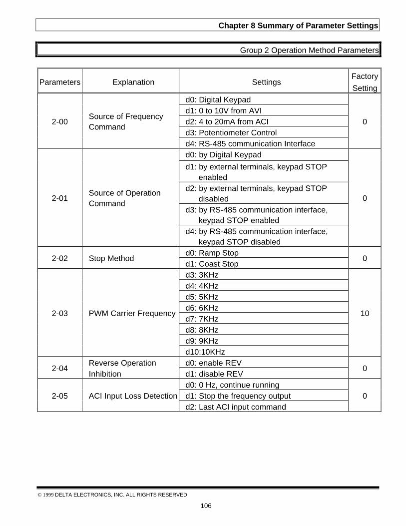
Chapter 8 Summary of Parameter Settings
© 1999 DELTA ELECTRONICS, INC. ALL RIGHTS RESERVED
106
Group 2 Operation Method Parameters
Parameters Explanation SettingsFactory
Settingd0: Digital Keypadd1: 0 to 10V from AVId2: 4 to 20mA from ACId3: Potentiometer Control
2-00Source of FrequencyCommand
d4: RS-485 communication Interface
0
d0: by Digital Keypad
d1: by external terminals, keypad STOPenabled
d2: by external terminals, keypad STOPdisabled
d3: by RS-485 communication interface,keypad STOP enabled
2-01Source of OperationCommand
d4: by RS-485 communication interface,keypad STOP disabled
0
d0: Ramp Stop2-02 Stop Method
d1: Coast Stop0
d3: 3KHzd4: 4KHzd5: 5KHzd6: 6KHzd7: 7KHzd8: 8KHzd9: 9KHz
2-03 PWM Carrier Frequency
d10:10KHz
10
Reverse Operation d0: enable REV2-04
Inhibition d1: disable REV0
d0: 0 Hz, continue runningd1: Stop the frequency output2-05 ACI Input Loss Detectiond2: Last ACI input command
0
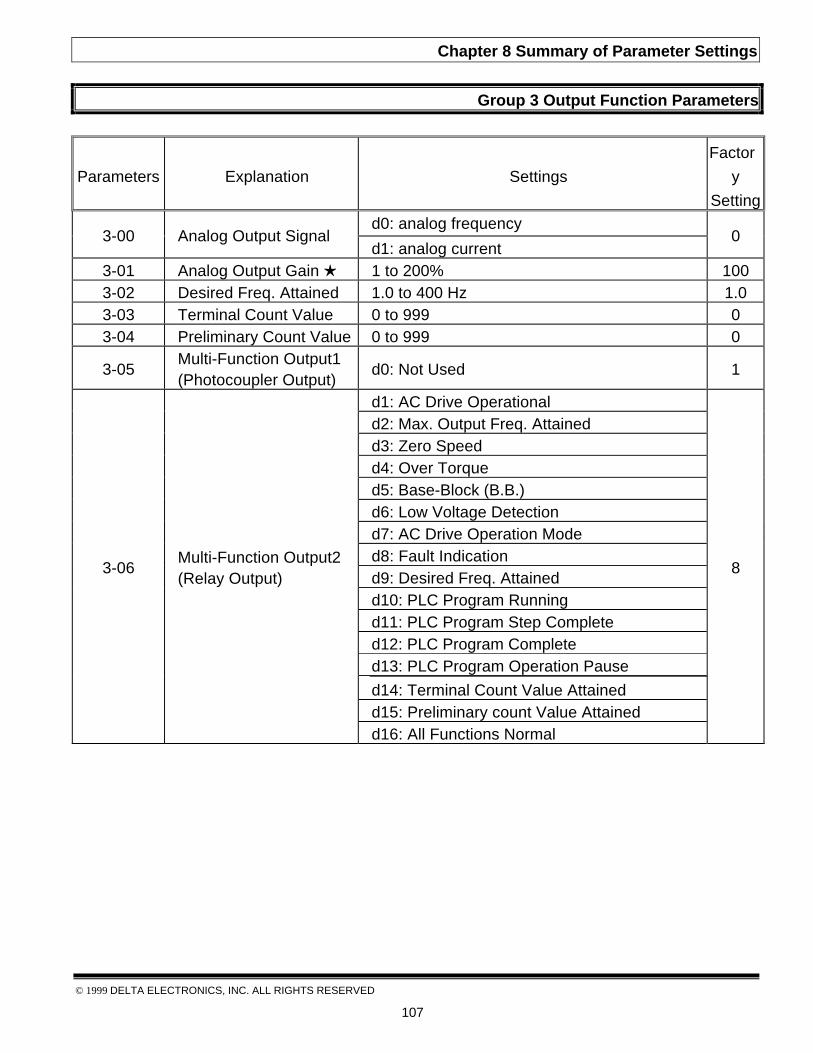
Chapter 8 Summary of Parameter Settings
© 1999 DELTA ELECTRONICS, INC. ALL RIGHTS RESERVED
107
Group 3 Output Function Parameters
Parameters Explanation Settings
Factor
y
Settingd0: analog frequency
3-00 Analog Output Signald1: analog current
0
3-01 Analog Output Gain H 1 to 200% 1003-02 Desired Freq. Attained 1.0 to 400 Hz 1.03-03 Terminal Count Value 0 to 999 03-04 Preliminary Count Value 0 to 999 0
3-05Multi-Function Output1(Photocoupler Output)
d0: Not Used 1
d1: AC Drive Operationald2: Max. Output Freq. Attainedd3: Zero Speedd4: Over Torqued5: Base-Block (B.B.)d6: Low Voltage Detectiond7: AC Drive Operation Moded8: Fault Indicationd9: Desired Freq. Attainedd10: PLC Program Runningd11: PLC Program Step Completed12: PLC Program Completed13: PLC Program Operation Pause
d14: Terminal Count Value Attainedd15: Preliminary count Value Attained
3-06Multi-Function Output2(Relay Output)
d16: All Functions Normal
8

Chapter 8 Summary of Parameter Settings
© 1999 DELTA ELECTRONICS, INC. ALL RIGHTS RESERVED
108
Group 4 Input Function Parameters
Parameters Explanation SettingsFactory
Setting
4-00Potentiometer BiasFrequency H
0.0 to 350 Hz 0.0
d0: Positive Bias4-01
Potentiometer BiasPolarity H d1: Negative Bias
0
4-02PotentiometerFrequency Gain H
1 to 200 % 100
d0: Forward Motion Only4-03
Potentiometer ReverseMotion Enable d1: Reverse Motion enabled
0
4-04Multi-Function InputTerminal 1 (M0, M1)
d0: Parameter Disable 1
4-05Multi-Function InputTerminal 2 (M2)
d1: FWD/STOP, REV/STOP 6
4-06Multi-Function InputTerminal 3 (M3)
d2: FWD/REV, RUN/STOP 7
4-07Multi-Function InputTerminal 4 (M4)
d3: 3-wire Operation Control Mode 8
d4: E.F. External Fault Input (N.O)d5: E.F. External Fault Input (N.C)d6: Resetd7: Multi-Step Speed Command 1d8: Multi-Step Speed Command 2d9: Multi-Step Speed Command 3d10: Jog Operationd11: Accel/Decel Speed Inhibitd12: First or Second Accel/Decel Time
Selectiond13: Base-Block (B.B.) (N.O.)d14: Base-Block (B.B.) (N.C.)d15: Increase Master Frequencyd16: Decrease Master Frequencyd17: Run PLC Programd18: Pause PLCd19: Counter Trigger Signald20: Counter Reset
4-08Multi-Function InputTerminal 5 (M5)
d21: ACI / AVI Selection
9

Chapter 8 Summary of Parameter Settings
© 1999 DELTA ELECTRONICS, INC. ALL RIGHTS RESERVED
109
Group 4 Input Function Parameters
Parameters Explanation SettingsFactory
Settingd0: Disable
4-09 Line Start Lockoutd1: Enable
0
Group 5 Multi-Step Speed and PLC Parameters
Parameters Explanation SettingsFactory
Setting5-00 1st Step Speed Freq. 0.0 to 400 Hz 0.05-01 2nd Step Speed Freq. 0.0 to 400 Hz 0.05-02 3rd Step Speed Freq. 0.0 to 400 Hz 0.05-03 4th Step Speed Freq. 0.0 to 400 Hz 0.05-04 5th Step Speed Freq. 0.0 to 400 Hz 0.05-05 6th Step Speed Freq. 0.0 to 400 Hz 0.05-06 7th Step Speed Freq. 0.0 to 400 Hz 0.0
d0: Disable PLC Operation
d1: Execute one program cycle
d2: Continuously execute program cyclesd3: Execute one program cycle step by step
5-07 PLC Mode
d4: Continuously execute one program cyclestep by step
0
5-08PLC Forward/Reverse Motion
0 to 255 (0:FWD 1:REV) 0
5-09 Time Duration Step 0 0 to 65500 sec 05-10 Time Duration Step 1 0 to 65500 Sec 05-11 Time Duration Step 2 0 to 65500 Sec 05-12 Time Duration Step 3 0 to 65500 Sec 05-13 Time Duration Step 4 0 to 65500 Sec 05-14 Time Duration Step 5 0 to 65500 Sec 05-15 Time Duration Step 6 0 to 65500 Sec 05-16 Time Duration Step 7 0 to 65500 Sec 0
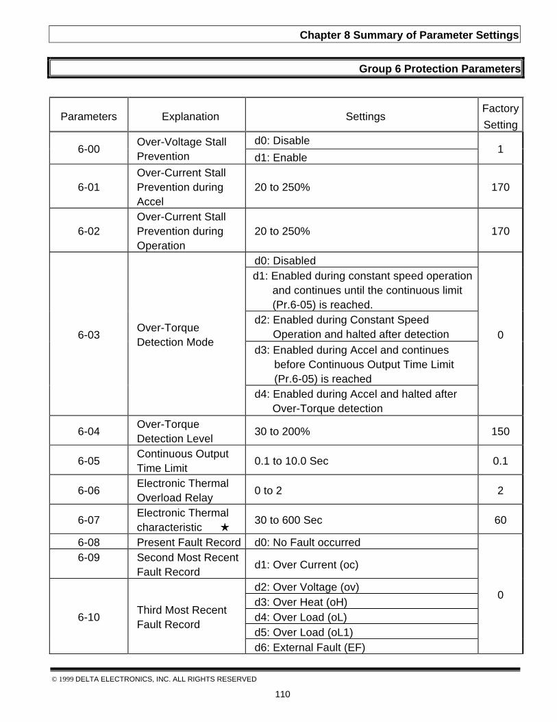
Chapter 8 Summary of Parameter Settings
© 1999 DELTA ELECTRONICS, INC. ALL RIGHTS RESERVED
110
Group 6 Protection Parameters
Parameters Explanation SettingsFactory
Settingd0: Disable
6-00Over-Voltage StallPrevention d1: Enable
1
6-01Over-Current StallPrevention duringAccel
20 to 250% 170
6-02Over-Current StallPrevention duringOperation
20 to 250% 170
d0: Disabledd1: Enabled during constant speed operation
and continues until the continuous limit(Pr.6-05) is reached.
d2: Enabled during Constant SpeedOperation and halted after detection
d3: Enabled during Accel and continuesbefore Continuous Output Time Limit(Pr.6-05) is reached
6-03Over-TorqueDetection Mode
d4: Enabled during Accel and halted afterOver-Torque detection
0
6-04Over-TorqueDetection Level
30 to 200% 150
6-05Continuous OutputTime Limit
0.1 to 10.0 Sec 0.1
6-06Electronic ThermalOverload Relay
0 to 2 2
6-07Electronic Thermalcharacteristic H
30 to 600 Sec 60
6-08 Present Fault Record d0: No Fault occurred6-09 Second Most Recent
Fault Recordd1: Over Current (oc)
d2: Over Voltage (ov)d3: Over Heat (oH)d4: Over Load (oL)d5: Over Load (oL1)
6-10Third Most RecentFault Record
d6: External Fault (EF)
0

Chapter 8 Summary of Parameter Settings
© 1999 DELTA ELECTRONICS, INC. ALL RIGHTS RESERVED
111
Group 6 Protection Parameters
Parameters Explanation SettingsFactorySetting
d7: CPU Fault (cF3)d8: Hardware Protection failure (HPF)d9: Current exceed during Acceleration (ocA)d10: Current exceed during Deceleration
(ocd)d11: Current exceed during Steady State
(ocn)
6-10Third Most RecentFault Record
d12: Ground Fault (GF)
0
Group 7 Motor Parameters
Parameters Explanation SettingsFactorySetting
7-00 Motor Rated Current H 30 to 120% 85
7-01Motor No-Load Current H
0 to 90% 50
7-02Torque Compensation H
0 to 10 3
7-03 Slip Compensation H 0.0 to 10.0 0.0
Group 8 Special Parameters
Parameters Explanation SettingsFactorySetting
8-00DC Braking VoltageLevel
0 to 30% 0
8-01DC Braking Timeduring Start-Up
0.0 to 60.0 Sec 0.0
8-02DC Braking timeduring Stopping
0.0 to 60.0 Sec 0.0
8-03Start-Point for DCBraking
0.0 to 400 Hz 0.0
8-04Momentary PowerLoss
d0: Stop Operation after Momentary PowerLoss
0

Chapter 8 Summary of Parameter Settings
© 1999 DELTA ELECTRONICS, INC. ALL RIGHTS RESERVED
112
Group 8 Special Parameters
Parameters Explanation SettingsFactorySetting
d1: Continues after Momentary Power Loss,speed search starts with Master Frequency
8-04Momentary PowerLoss
d2: Continues after Momentary Power Loss,speed search starts with Minimum OutputFrequency
0
8-05Maximum AllowablePower Loss Time
0.3 to 5.0 Sec 2.0
8-06B.B. Time for SpeedSearch
0.3 to 5.0 Sec 0.5
8-07Maximum SpeedSearch CurrentLevel
30 to 200% 150
8-08Skip Frequency 1Upper Bound
0.0 to 400 Hz 0.0
8-09Skip Frequency 1Lower Bound
0.0 to 400 Hz 0.0
8-10 Skip Frequency 2Upper Bound
0.0 to 400 Hz 0.0
8-11 Skip Frequency 2Lower bound
0.0 to 400 Hz 0.0
8-12 Skip Frequency 3Upper bound
0.0 to 400 Hz 0.0
8-13 Skip Frequency 3Lower Bound
0.0 to 400 Hz 0.0
8-14 Auto Restart AfterFault
0 to 10 0
d0: AVR Function Enabled1: AVR Function Disable8-15 AVR Functiond2: AVR Function Disable for Decel
2
8-16Dynamic BrakingVoltage
350 to 450V* 380*
8-17DC Braking InhibitFreq
0.0 to 400 Hz 0.0
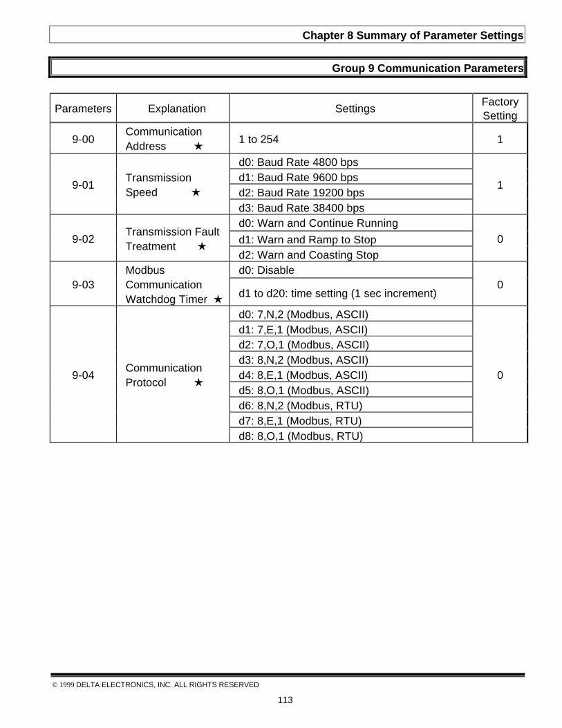
Chapter 8 Summary of Parameter Settings
© 1999 DELTA ELECTRONICS, INC. ALL RIGHTS RESERVED
113
Group 9 Communication Parameters
Parameters Explanation SettingsFactorySetting
9-00CommunicationAddress H
1 to 254 1
d0: Baud Rate 4800 bpsd1: Baud Rate 9600 bpsd2: Baud Rate 19200 bps
9-01TransmissionSpeed H
d3: Baud Rate 38400 bps
1
d0: Warn and Continue Running
d1: Warn and Ramp to Stop9-02Transmission FaultTreatment H
d2: Warn and Coasting Stop0
d0: Disable9-03
ModbusCommunicationWatchdog Timer H d1 to d20: time setting (1 sec increment)
0
d0: 7,N,2 (Modbus, ASCII)d1: 7,E,1 (Modbus, ASCII)d2: 7,O,1 (Modbus, ASCII)d3: 8,N,2 (Modbus, ASCII)d4: 8,E,1 (Modbus, ASCII)d5: 8,O,1 (Modbus, ASCII)d6: 8,N,2 (Modbus, RTU)d7: 8,E,1 (Modbus, RTU)
9-04CommunicationProtocol H
d8: 8,O,1 (Modbus, RTU)
0
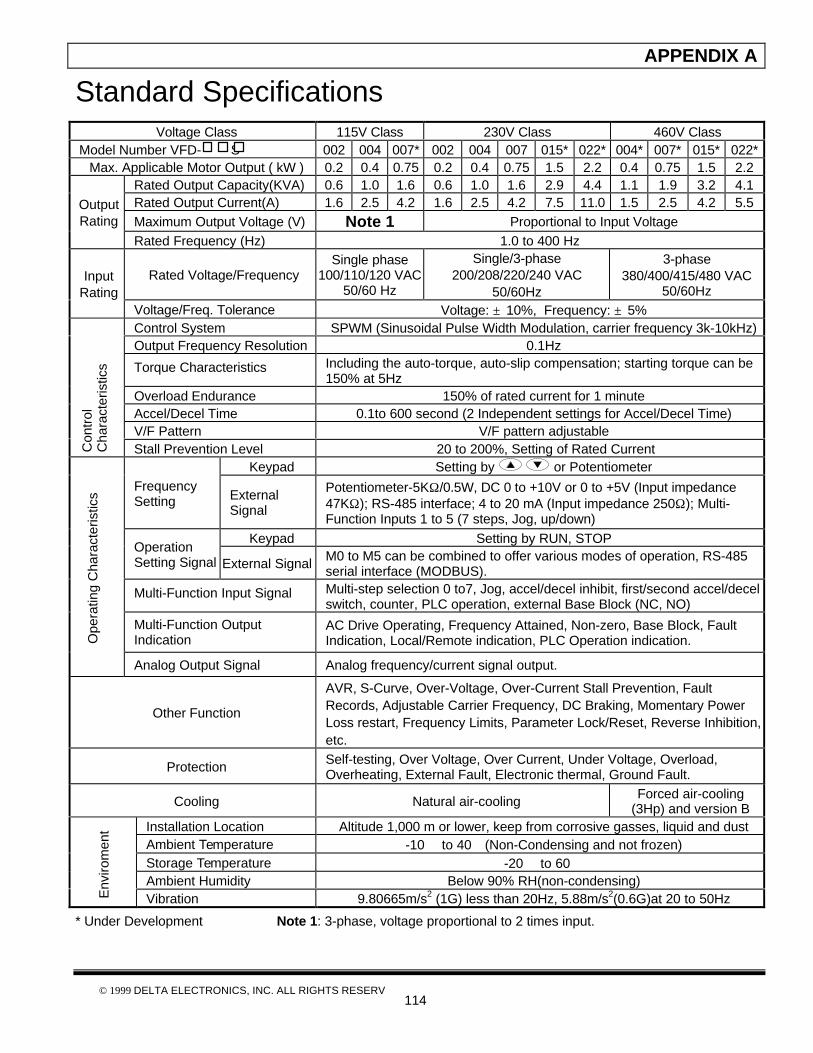
APPENDIX A
© 1999 DELTA ELECTRONICS, INC. ALL RIGHTS RESERV114
Standard SpecificationsVoltage Class 115V Class 230V Class 460V Class
Model Number VFD- S 002 004 007* 002 004 007 015* 022* 004* 007* 015* 022*Max. Applicable Motor Output ( kW ) 0.2 0.4 0.75 0.2 0.4 0.75 1.5 2.2 0.4 0.75 1.5 2.2
Rated Output Capacity(KVA) 0.6 1.0 1.6 0.6 1.0 1.6 2.9 4.4 1.1 1.9 3.2 4.1Rated Output Current(A) 1.6 2.5 4.2 1.6 2.5 4.2 7.5 11.0 1.5 2.5 4.2 5.5Maximum Output Voltage (V) Note 1 Proportional to Input Voltage
OutputRating
Rated Frequency (Hz) 1.0 to 400 Hz
Rated Voltage/FrequencySingle phase
100/110/120 VAC50/60 Hz
Single/3-phase200/208/220/240 VAC
50/60Hz
3-phase380/400/415/480 VAC
50/60HzInput
RatingVoltage/Freq. Tolerance Voltage: ±10%, Frequency: ±5%Control System SPWM (Sinusoidal Pulse Width Modulation, carrier frequency 3k-10kHz)Output Frequency Resolution 0.1Hz
Torque Characteristics Including the auto-torque, auto-slip compensation; starting torque can be150% at 5Hz
Overload Endurance 150% of rated current for 1 minuteAccel/Decel Time 0.1to 600 second (2 Independent settings for Accel/Decel Time)V/F Pattern V/F pattern adjustable
Con
trol
Cha
ract
eris
tics
Stall Prevention Level 20 to 200%, Setting of Rated CurrentKeypad Setting by or Potentiometer
FrequencySetting External
Signal
Potentiometer-5KΩ/0.5W, DC 0 to +10V or 0 to +5V (Input impedance47KΩ); RS-485 interface; 4 to 20 mA (Input impedance 250Ω); Multi-Function Inputs 1 to 5 (7 steps, Jog, up/down)
Keypad Setting by RUN, STOPOperationSetting Signal External Signal M0 to M5 can be combined to offer various modes of operation, RS-485
serial interface (MODBUS).
Multi-Function Input Signal Multi-step selection 0 to7, Jog, accel/decel inhibit, first/second accel/decelswitch, counter, PLC operation, external Base Block (NC, NO)
Multi-Function OutputIndication
AC Drive Operating, Frequency Attained, Non-zero, Base Block, FaultIndication, Local/Remote indication, PLC Operation indication.O
pera
ting
Cha
ract
eris
tics
Analog Output Signal Analog frequency/current signal output.
Other Function
AVR, S-Curve, Over-Voltage, Over-Current Stall Prevention, FaultRecords, Adjustable Carrier Frequency, DC Braking, Momentary PowerLoss restart, Frequency Limits, Parameter Lock/Reset, Reverse Inhibition,etc.
Protection Self-testing, Over Voltage, Over Current, Under Voltage, Overload,Overheating, External Fault, Electronic thermal, Ground Fault.
Cooling Natural air-cooling Forced air-cooling(3Hp) and version B
Installation Location Altitude 1,000 m or lower, keep from corrosive gasses, liquid and dustAmbient Temperature -10 to 40(Non-Condensing and not frozen)Storage Temperature -20 to 60Ambient Humidity Below 90% RH(non-condensing)
Env
irom
ent
Vibration 9.80665m/s2 (1G) less than 20Hz, 5.88m/s2(0.6G)at 20 to 50Hz
* Under Development Note 1: 3-phase, voltage proportional to 2 times input.

APPENDIX B
© 1999 DELTA ELECTRONICS, INC. ALL RIGHTS RESERVED
115
Accessories ListName Model Remarks
Din Rail DR01 & DR02 Refer to B-1 on next page
Remote Control Box RC-01 Use twisted shielded or twisted-pair shieldedwire.
Conduit Bracket BK-S Optional
Braking Resistor Refer to P 121 for detailed specifications
EMI Filter Refer to P 123 for detailed specifications
EMI Core (22*14*8) CTC221408A Selected by the wire diameter and # of turns
EMI Core (31*19*13) CTC311913A Selected by the wire diameter and # of turns
EMI Core (51*31*13) CTC513113A Selected by the wire diameter and # of turns
EMI Core (68*44*13.5) CTC684413B Selected by the wire diameter and # of turns

APPENDIX B
© 1999 DELTA ELECTRONICS, INC. ALL RIGHTS RESERVED
116
B-1 Din Rail-DR01 Units: mm
Models: Screw Size:VFD002S11A M4*22
VFD002S21A M4*22
VFD002S23A M4*22
VFD004S11A M4*12
VFD004S21A M4*12
VFD004S23A M4*12
VFD004S43A M4*12
VFD007S21A M4*12
VFD007S23A M4*12
VFD007S43A M4*12
VFD007S43B M4*12
& To install the Din Rail Adapter use the specified screws for different models. Refer to the
above chart.
& To mount the drive on a Din Rail, place the drive on the rail and push the lever toward the
rail.

APPENDIX B
© 1999 DELTA ELECTRONICS, INC. ALL RIGHTS RESERVED
117
B-1 Din Rail-DR02 Units: mm
Models: Screw Size:VFD007S11A M4*12
VFD015S21A M4*12
VFD015S21B M4*12
VFD015S23A M4*12
VFD015S23A M4*12
VFD015S43A M4*12
VFD015S43B M4*12
VFD022S23A M4*12
VFD022S43A M4*12
& To install the Din Rail Adapter use the specified screws for different models. Refer to the
above chart.
& To mount the drive on a Din Rail, place the drive on the rail and push the lever toward the
rail.
35.5
8.0
4.0
18.0
34.07.0
2.4
94.5100.0
5.5 5.5
146.
0
151.
5
125.
0
25.0
88.5
50.0
Unit : mm

APPENDIX B
© 1999 DELTA ELECTRONICS, INC. ALL RIGHTS RESERVED
118
B-2 Remote Controller RC-01 Unit: mm (inch)
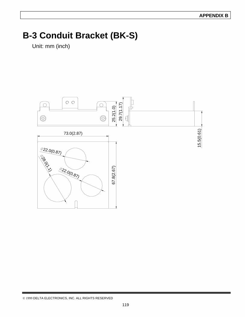
APPENDIX B
© 1999 DELTA ELECTRONICS, INC. ALL RIGHTS RESERVED
119
B-3 Conduit Bracket (BK-S) Unit: mm (inch)
22.0(0.87)
22.0(0.87)
28.0(1.1)
67.8
(2.6
7)
73.0(2.87)
25.2
(1.0
)
29.7
(1.1
7)
15.5
(0.6
1)

APPENDIX B
© 1999 DELTA ELECTRONICS, INC. ALL RIGHTS RESERVED
120
All Braking Resistors & Braking Units Use in AC Drives
ApplicableMotor
Vol
tage
HP4P
kW
FullLoad
TorqueKG-M
Specification fResistors
Braking UnitModel VFDBNo. of Unit
Used
Braking ResistorsModel No of Units
Used
BrakingTorque10%ED
%
MinimumResistance
rates
1/4 0.2 0.110 80W 200 BR080W200 1 400
1/2 0.4 0.216 80W 200 BR080W200 1 220
1 0.75 0.427 80W 200 BR080W200 1 125 802 1.5 0.849 300W 100 BR300W100 1 125 553 2.2 1.262 300W 70 BR300W070 1 125 355 3.7 2.080 400W 40 BR400W040 1 125 25
7.5 5.5 3.111 500W 30 BR500W030 1 125 1610 7.5 4.148 1000W 20 BR1K0W020 1 125 1215 11 6.186 2400W 13.6 2015 1 BR1K2W6P8 2 125
20 15 8.248 3000W 10 2015 1 BR1K5W005 2 125
25 18.5 10.281 4800W 8 2022 1 BR1K2W008 4 125
30 22 12.338 4800W 6.8 2022 1 BR1K2W6P8 4 125
40 30 16.497 6000W 5 2015 2 BR1K5W005 4 125
50 37 20.6 9600W 4 2015 2 BR1K2W008 8 125
60 45 24.745 9600W 3.4 2022 2 BR1K2W6P8 8 125
75 55 31.11 9600W 3.4 2022 2 BR1K2W6P8 8 100
230V
Ser
ies
100 75 42.7 14400W 2.3 2022 3 BR1K2W6P8 12 110
1/4 0.2 0.110 80W 750 BR080W750 1 300
1/2 0.4 0.216 80W 750 BR080W750 1 230
1 0.75 0.427 80W 750 BR080W750 1 125 2602 1.5 0.849 300W 400 BR300W400 1 125 1903 2.2 1.262 300W 250 BR300W250 1 125 1455 3.7 2.080 400W 150 BR400W150 1 125 95
7.5 5.5 3.111 500W 100 BR500W100 1 125 6010 7.5 4.148 1000W 75 BR1K0W075 1 125 4515 11 6.186 1000W 50 4030 1 BR1K0W050 1 125
20 15 8.248 1500W 40 4030 1 BR1K5W040 1 125
25 18.5 10.281 4800W 32 4030 1 BR1K2W008 4 12530 22 12.338 4800W 27.2 4030 1 BR1K2W6P8 4 12540 30 16.497 6000W 20 4030 1 BR1K5W005 4 12550 37 20.6 9600W 16 4045 1 BR1K2W008 8 125
60 45 24.745 9600W 13.6 4045 1 BR1K2W6P8 8 125
75 55 31.11 12000W 10 4030 2 BR1K5W005 8 125
460V
Ser
ies
100 75 42.7 19200W 6.8 4045 2 BR1K2W6P8 16 125
NOTE: Please only use DELTA resistors and recommended values. Other resistors andvalues will void DELTA’s warranty. Please contact your nearest DELTArepresentative for use of special resistors. AC drive has 3 braking units with total of 12 braking

APPENDIX B
© 1999 DELTA ELECTRONICS, INC. ALL RIGHTS RESERVED
121
resistors, so each braking unit uses 4 braking resistors.

APPENDIX B
© 1999 DELTA ELECTRONICS, INC. ALL RIGHTS RESERVED
122
B-4 Braking Resistors Unit: mm (inch)
Type H A B MAX. WEIGHT (g)
MVR080W120 40 (1.57) 8 (0.31) 12 (0.47) 240
MVR200W120 40(1.57) 8 (0.31) 12 (0.47) 240
MVR080W200 60 (2.36) 15 (0.59) 15 (0.59) 460
MVR200W200 60 (2.36) 15 (0.59) 15 (0.59) 460
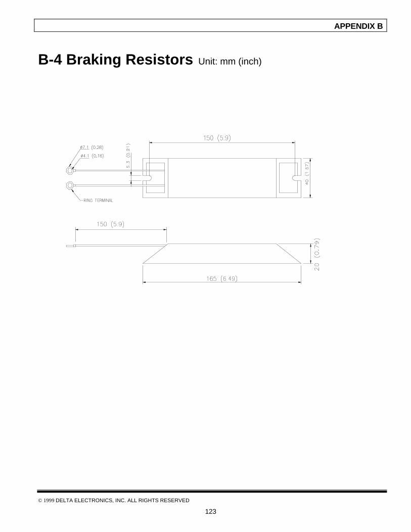
APPENDIX B
© 1999 DELTA ELECTRONICS, INC. ALL RIGHTS RESERVED
123
B-4 Braking Resistors Unit: mm (inch)

APPENDIX B
© 1999 DELTA ELECTRONICS, INC. ALL RIGHTS RESERVED
124
B-5 EMI Filters
The DELTA VFD-S Series 0.25-3HP, 115V / 230V, 1/3 AC drive uses DELTA EMI Filter.
Use the table below to find the appropriate filter for your DELTA VFD-S drive.
Output chokeModel ofAC Motor Drive
Models of EMI Filter SpecificationsPart Numbers PC Turns
VFD002S11AVFD004S11AVFD002S21AVFD004S21AVFD007S21A
10DKT1W3S 250V, 1, 10A CTC513113B 2 10
VFD002S23AVFD004S23AVFD007S23A
06TDT1W4S 250V,3, 6A CTC513113B 2 10
VFD007S11AVFD015S21A
20DKT1W3S 250V,1, 20A CTC513113B 2 8
VFD015S23AVFD022S23A
16TDT1W4S 250V,3, 16A CTC513113B 2 8
1. EMI Filter (10DKT1W3S) Use on 0.25-1 HP, 115V/230V, Single Phase Models
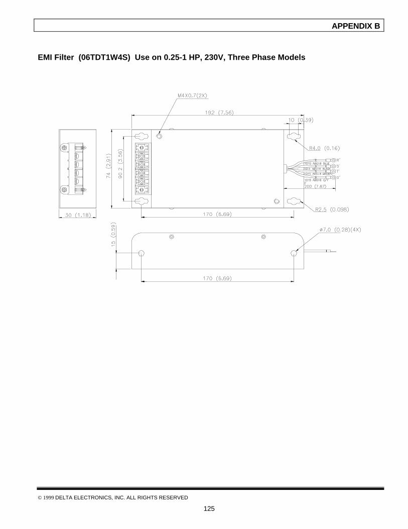
APPENDIX B
© 1999 DELTA ELECTRONICS, INC. ALL RIGHTS RESERVED
125
EMI Filter (06TDT1W4S) Use on 0.25-1 HP, 230V, Three Phase Models
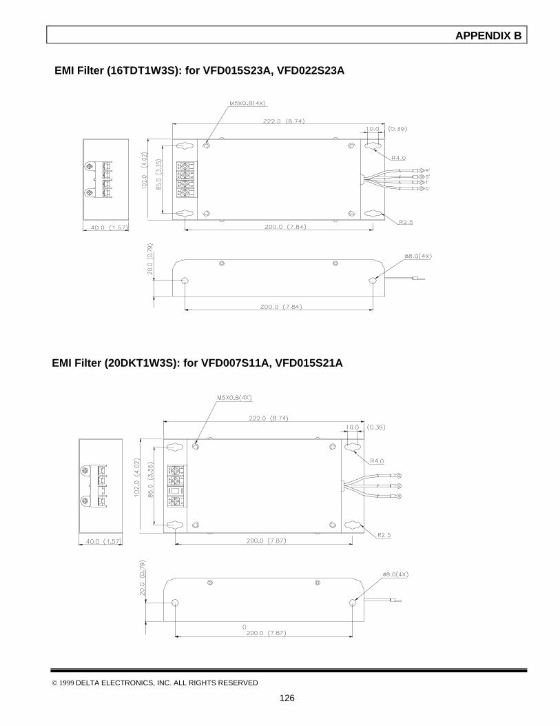
APPENDIX B
© 1999 DELTA ELECTRONICS, INC. ALL RIGHTS RESERVED
126
EMI Filter (16TDT1W3S): for VFD015S23A, VFD022S23A
EMI Filter (20DKT1W3S): for VFD007S11A, VFD015S21A
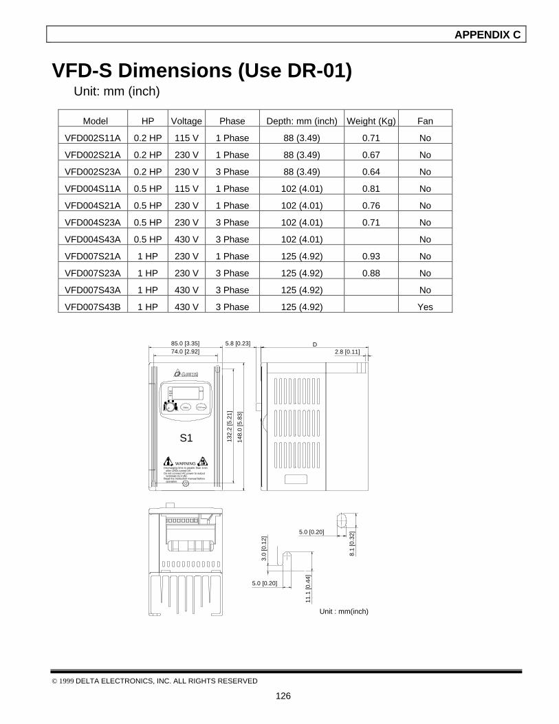
APPENDIX C
© 1999 DELTA ELECTRONICS, INC. ALL RIGHTS RESERVED
126
VFD-S Dimensions (Use DR-01)Unit: mm (inch)
Model HP Voltage Phase Depth: mm (inch) Weight (Kg) Fan
VFD002S11A 0.2 HP 115 V 1 Phase 88 (3.49) 0.71 No
VFD002S21A 0.2 HP 230 V 1 Phase 88 (3.49) 0.67 No
VFD002S23A 0.2 HP 230 V 3 Phase 88 (3.49) 0.64 No
VFD004S11A 0.5 HP 115 V 1 Phase 102 (4.01) 0.81 No
VFD004S21A 0.5 HP 230 V 1 Phase 102 (4.01) 0.76 No
VFD004S23A 0.5 HP 230 V 3 Phase 102 (4.01) 0.71 No
VFD004S43A 0.5 HP 430 V 3 Phase 102 (4.01) No
VFD007S21A 1 HP 230 V 1 Phase 125 (4.92) 0.93 No
VFD007S23A 1 HP 230 V 3 Phase 125 (4.92) 0.88 No
VFD007S43A 1 HP 430 V 3 Phase 125 (4.92) No
VFD007S43B 1 HP 430 V 3 Phase 125 (4.92) Yes
5.8 [0.23]8.
1 [0
.32]
3.0
[0.1
2]
5.0 [0.20]
11.1
[0.4
4]
5.0 [0.20]
after LEDs turned off.Discharging time is greater than 1min
Do not connect AC power to output
Read the instruction manual before terminals (U,V,W).
operation.
S1
FWDREV
RUN
MIN. MAX.RUN STOP/RESET
STOP
74.0 [2.92]
132.
2 [5
.21]
148.
0 [5
.83]
WARNING
85.0 [3.35] D2.8 [0.11]
Unit : mm(inch)
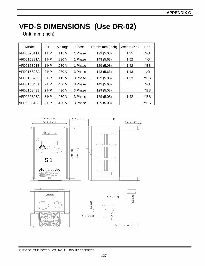
APPENDIX C
© 1999 DELTA ELECTRONICS, INC. ALL RIGHTS RESERVED
127
VFD-S DIMENSIONS (Use DR-02) Unit: mm (inch)
Model HP Voltage Phase Depth: mm (inch) Weight (Kg) Fan
VFD007S11A 1 HP 115 V 1 Phase 129 (5.08) 1.35 NO
VFD015S21A 1 HP 230 V 1 Phase 143 (5.63) 1.52 NO
VFD015S21B 1 HP 230 V 1 Phase 129 (5.08) 1.42 YES
VFD015S23A 2 HP 230 V 3 Phase 143 (5.63) 1.43 NO
VFD015S23B 2 HP 115 V 3 Phase 129 (5.08) 1.33 YES
VFD015S43A 2 HP 430 V 3 Phase 143 (5.63) NO
VFD015S43B 2 HP 430 V 3 Phase 129 (5.08) YES
VFD022S23A 3 HP 230 V 3 Phase 129 (5.08) 1.42 YES
VFD022S43A 3 HP 430 V 3 Phase 129 (5.08) YES
1.0
[0.0
4]
5 . 5 [ 0 . 2 2 ]
9.6
[0.3
8]
5 . 5 [ 0 . 2 2 ]
o p e r a t i o n .
D i s c h a r g i n g t i m e i s g r e a t e r t h a n 1 m i n
D o n o t c o n n e c t A C p o w e r t o o u t p u t
R e a d t h e i n s t r u c t i o n m a n u a l b e f o r e t e r m i n a l s ( U , V , W ) .
a f t e r L E D s t u r n e d o f f .
RUNFWD
MIN.
REV
S 1
R U NMAX.
STOP
STOP /RESET
6.5
[0.2
6]
5 . 4 [ 0 . 2 1 ]1 0 0 . 0 [ 3 . 9 4 ]
8 6 . 5 [ 3 . 4 1 ]
172.
9 [6
.81]
186.
0 [7
.33]
W A R N I N G
3 . 0 [ 0 . 1 2 ]
D
U n it : m m (in c h )
APPENDIX D
© 1999 DELTA ELECTRONICS, INC. ALL RIGHTS RESERVED
128
EC Declaration of Conformity
DELTA ELECTRONICS, INC.
EC Declaration of ConformityAccording to the Low Voltage Directive 73/23/EEC and the Amendment
Directive 93/68/EECFor the following equipment: AC Motor Drive (Product Name)
VFD002S11A, VFD004S11A, VFD002S21A, VFD002S23A,VFD004S21A, VFD004S23A, VFD007S21A, VFD007S23A (Model Name)
is herewith confirmed to comply with the requirements set out in the CouncilDirective 73/23/EEC for electrical equipment used within certain voltage limits andthe Amendment Directive 93/68/EEC. For the evaluation of the compliance with thisDirective, the following standard was applied:
EN 50178
The following manufacturer/importer is responsible for this declaration:
Delta Electronics, Inc. (Company Name)
31-1,Shien Pan Road, Kuei San Industrial Zone, Taoyuan Shien, Taiwan, R.O.C. (Company Address)
Person responsible for making this declaration:
H.L. Pan (Name)
Electromechanical Business Unit / Deputy Manager (Position/Title)
(Place) (Date) (legal Signature)

APPENDIX D
© 1999 DELTA ELECTRONICS, INC. ALL RIGHTS RESERVED
129
DELTA ELECTRONICS,INC.
EC Declaration of ConformityAccording to the Electromagnetic Compatibility 89/336/EEC and the
Amendment Directive 93/68/EEC
For the following equipment:
AC Motor Drive (Product Name)
VFD002S11A, VFD004S11A, VFD002S21A, VFD002S23A,VFD004S21A, VFD004S23A, VFD007S21A, VFD007S23A (Model Designation)
is herewith confirmed to comply with the requirements set out in the CouncilDirective 89/336/EEC for electromagnetic compatibility and the AmendmentDirective 93/68/EEC. For the evaluation of the compliance with this Directive, thefollowing standard was applied:
EN61800-3, EN50081-2, EN50082-2, EN55011, IEC1000-4-2, IEC-1000-4-3,IEC-1000-4-4, IEC-1000-4-5, IEC-1000-4-6, IEC-1000-4-8
The following manufacturer/importer is responsible for this declaration:
Delta Electronics, Inc.(Company Name)
31-1,Shien Pan Road, Kuei San Industrial Zone, Taoyuan Shien, Taiwan, R.O.C.
(Company Address)
Person responsible for marking this declaration:
H.L. Pan (Name)
Electromechanical Business Unit / Deputy Manager (Position/Title)
(Place) (Date) (legal Signature)

APPENDIX E
© 1999 DELTA ELECTRONICS, INC. ALL RIGHTS RESERVED
130
Warranty
DELTA warrants the product delivered in the DELTA ship package to be free from defects in
material and workmanship, under normal use and service, for twenty four (24) months from date
of manufacturing. Products that fail during this period will be repaired or replaced at DELTA’s
discretion, with the same or a functionally equivalent product, provided the original purchaser (A)
returns the failed product, and (B) provides proof of original date of purchase. This warranty
does not apply, in the judgement of Delta, to damage caused during shipment, handling,
storage, or accidental misuse. The original purchaser of the product must obtain a Return
Material Authorization (RMA) number from Delta prior to returning any defective product. (When
purchased through an Authorized Distributor, the Distributor should supply an RMA number to
their customer.)
The maximum liability of this warranty is limited to the purchase price of the product. In no
event, regardless of cause, shall delta be liable (a) for penalties or penalty clauses of any
description, or (b) for certification not otherwise specifically provided herein and/or
indemnification of purchaser or others for costs, damages or expenses, each arising out of or
related to the product or services of any order or (c) for any damages resulting from loss of
profits, use of products or for any incidental indirect or consequential damages, even if advised
of the possibility of such damages.
INDEX
© 1999 DELTA ELECTRONICS, INC. ALL RIGHTS RESERVED
135
1st Step Speed Frequency, 59AC Drive Operation Mode, 41, 42AC Drive Operational, 41Accel./Decel. Speed Inhibit, 49, 54Acceleration S-Curve, 32Acceleration Time 1 (Tacc1), 29Acceleration Time 2 (Tacc2), 29ACI/AVI Selection, 49, 58ACI Input Loss Detection, 37Analog Output Gain, 38Analog Output Signal, 38Auto Restart after Fault, 78Auto-Acceleration/Deceleration, 32Automatic Voltage Regulation (AVR), 78Base-Block (B.B.) Indication, 41, 42Base-Block Time for Speed Search, 76Communication Protocol, 82Content of User Defined Unit, 23Continuous Output Time Limit, 70Counter Reset, 49, 58Counter Trigger, 49, 57DC Braking Inhibit Frequency, 79DC Braking Time during Start-up, 74DC Braking Time during Stopping, 74DC Braking Voltage Level, 74Deceleration S-Curve, 32Deceleration Time 1 (Tdec1), 29Deceleration Time 2 (Tacc2), 29Decrease Master Frequency, 49Desired Frequency Attained, 39Desired Frequency Attained, 41, 42Dynamic Braking Voltage, 79Electronic Thermal Characteristic, 70Electronic Thermal Overload Relay Selection,
70External Base-Block, 49, 55External Fault, 49Fault Indication, 41, 42First-Second Accel./Decel. Time Selection,
49, 54Identity Code of AC Motor Drive, 22Increase Master Frequency, 49, 56Jog Accel/Decel. Time Settings, 30Jog Frequency, 31Line Start Lockout, 58Lower Bound of Output Frequency, 29Low-Voltage Indication, 41, 42
Maximum Allowable Power Loss Time, 76Maximum Output Frequency (FOmax), 26Maximum Output Frequency Attained, 41, 42Maximum Output Voltage (Vmax), 26Maximum Speed Search Current Level, 76Maximum Voltage Frequency (Fmax), 26Mid-Point Frequency (Fmid), 27Mid-Point Voltage (Vmid), 27Minimum Output Frequency (Fmin), 27Minimum Output Voltage (Vmin), 28MODBUS Communication Watchdog Timer,
81Momentary Power Loss Operation, 75Motor No-Load Current, 72Motor Rated Current, 72Multi-Function Input Terminal, 48Multi-Step Speed Command, 49Over-Current Stall Prevention (during
acceleration), 68Over-Current Stall Prevention (during
operation), 68Over-Torque Detection Level, 70Over-Torque Detection Mode, 69Over-Torque Detection, 41, 42Over-Voltage Stall Prevention, 67Parameter Lock/Reset, 22Password Input, 24Password Configuration, 24Pause PLC Program, 49, 57PLC Forward/Reverse Motion, 64PLC Mode, 59PLC Program Completed, 41, 42PLC Program Operation Paused, 41, 42PLC Program Running, 41, 42PLC Program Step Completed, 41, 42Potentiometer Bias Frequency, 43Potentiometer Bias Polarity, 43Potentiometer Frequency Gain, 43Potentiometer Reverse Motion Enable, 43Preliminary Count Value Attained, 41, 42Preliminary Count Value, 40Present Fault Record, 71PWM Carrier Frequency, 36Rate Current Display of AC Drive, 22Run PLC Program, 41, 42Second Most Recent Fault Record, 71Skip Frequency 1 Lower/Upper Bound, 78
INDEX
© 1999 DELTA ELECTRONICS, INC. ALL RIGHTS RESERVED
136
Slip Compensation, 73Software Version, 24Source of Frequency Command, 34Source of Operation Command, 35Start-Point for Dynamic Braking, 74Start-up Display Selection, 23Stop Method, 35Terminal Count Value Attained, 41, 42Terminal Count Value, 40Time Duration of 1st Step Speed, 66Time Duration of Master Frequency, 66Torque Compensation, 72Upper Bound of Output Frequency, 28User Defined Coefficient K, 23Zero Speed, 41, 42
Related Documents