VARIABLE COLUMN TRANSFORMERS Technical Informationen

Welcome message from author
This document is posted to help you gain knowledge. Please leave a comment to let me know what you think about it! Share it to your friends and learn new things together.
Transcript
VARIABLE COLUMN TRANSFORMERSTechnical Informationen
22222
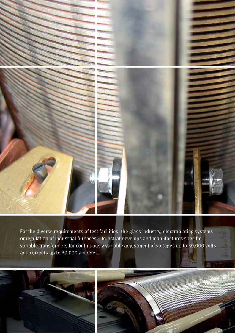
For the diverse requirements of test facilities, the glass industry, electroplating systems or regulation of industrial furnaces – Ruhstrat develops and manufactures specific variable transformers for continuously variable adjustment of voltages up to 30,000 volts and currents up to 30,000 amperes.

3
CONTENTS
INTRODUCTION 4
TECHNICAL INFORMATION 5
SAMPLE PROJECTTEST SYSTEM FOR MEDIUM VOLTAGE VACUUM CIRCUIT BREAKERS 11
THREE-PHASE VARIABLE COLUMN TRANSFORMERS – SINGLE-SIDE DESIGN 12
– ± SWITCHING 14

4
INTRODUCTION VARIABLE COLUMN TRANSFORMERS
Excellence is our standard
Variable transformers from Ruhstrat for the power supply of diverse products are preferred for use in test engineering, the glass industry, as well as in electroplating applications.
In these areas, too, all solutions are tailored to individual cus-tomer requirements.
Whether for test facilities, the glass industry, electroplating or regulation of industrial furnaces – Ruhstrat develops and manu-factures specific variable transformers for continuously variable adjustment of voltages up to 30,000 volts and currents up to 30,000 amperes.
For your technical testing systems we offer you a complete line of transformer-controlled test engineering, including electronic controllers (SIEMENS, Beckhoff, etc.) if requested.
>> Facts Available as variable toroidal and variable column transformers
Also available as avariable transformer aggregate in combination with a low-voltage, medium-voltage or high-current transformer
Power up to 2,000 kVA
Frequencies up to 400 Hz
For electrical test engineering available with:
– Control panels with fuses, contactors, operation and monitoring elements
– Controller for switching, regulation, control and monitoring of relevant processes
High-voltage test laboratories
Industry (electroplating, glass, etc.)
Control of industrial furnaces
>> Applications

TECHNICAL INFORMATIONVARIABLE COLUMN TRANSFORMERS
5
General
Ruhstrat variable column transformers are developed, manufactured and tested in accordance with relevant EC directives, European standards and VDE regulations, in particular DIN EN 61558-2-14 and VDE 0552. The content of the following descriptions is part of our terms and conditions of sale and delivery.
The nominal powers specified in the tables on pages 13 and 15 apply to operation in maintained mode. The nominal current can be collected over the entire control range. Limit values for overload in intermittent oper-ation (S2) and other operating modes are depicted by the curve in Fig. 1.
Application
Variable column transformers are used to regulate alternating voltages or currents under load between zero and the nominal value. They are suitable for the power supply to resistive, induc-tive or capacitive equipment.
For technical testing systems, Ruhstrat offers the entire variable transformer testing technology, including electronic controllers ( SIEMENS S7). For labs, test shops or for mobile use – Ruhstrat develops and manufactures customized voltage and current supply systems for stepless regulation from 0 to 30,000 volts and currents up to 30,000 A.
The tables on pages 13 and 15 include only the most common versions. Other control ranges, power outputs, drive types, etc. are available on request.
Power outputs/ voltages
Variable transformers up to 1,000 volts are available. In combination with a downstream dry-type transformer as a variable transformer aggregate up to 2,000 kVA and 30,000 volts.
Installation
When installing variable column transformers it is important not to block the self-ventilation. Insufficient ventilation can result in excessive heat build-up under normal ambient condi-tions, which can destroy the variable column transformer as a consequence. Perpendicular installation of variable column transformers is ideal with respect to the ther-
mal and mechanical properties. The installation location must exhibit sufficient mechanical rigidity and stability.
Connection
For three-phase variable column transformers which are star connected, the neutral point lead-through is insulated. It must never be used to form an artificial neutral point; however, the nominal current can be applied to each strand of such a trans-former, if the mains neutral point (earthed neutral conductor) and the transformer neutral point are connected to each other.
Winding connections of variable column transformers with au-towindings must never be connected to the protective conduc-tor or earth. However, this does not exclude the necessity for including the transformer and connected consumers in a pro-tective system. If necessary, a transformer with separate wind-ings must be connected for decoupling.
Load
The data specified on the rating plate applies to operation as intended at the nominal voltage and nominal current and a maximum ambient temperature of 40 °C, at an elevation of up to 1,000 m above sea level and relative humidity of up to 85 %. Re-duced heat transfer at ambient temperatures above 40 °C and installation at elevations higher than 1,000 m above sea level cause a decrease in the load capacity of variable transformers; the same applies if the ventilation is blocked. See fig. 2.

6
TECHNICAL INFORMATION VARIABLE COLUMN TRANSFORMERS
▴ Fig. 1 Limit values for overload in intermittent operationA – cold stateB – warm state
▴ Fig. 2 Reduction curve for ambient temperature and installation elevation
Temperature:Curve A = ambient temperatureCurve B = operating temperature

7
TECHNICAL INFORMATION VARIABLE COLUMN TRANSFORMERS
Heavy-duty operation
Ruhstrat variable column transformers conform to the condi-tions of VDE 0552 § 5g for heavy-duty operation. According to VDE 552, heavy-duty operation is “operation under extreme electrical conditions, for examplea) no movement of the current collector over extended periods
(24 h)
b) frequent switching on and off under load
c) operation with current load in which the ratio of effective value to rectified value is 1.15 (e.g. phase angle control)”.
The exact final mode of operation for the required variable transformers is generally not known. Therefore, it must be ex-pected that for technical reasons there will be no regulation over a much longer period than 24 h.
Ruhstrat variable column transformers are designed for these heavy-duty operating conditions.
In variable column transformer for normal operation (VDE 0552, § 5 h) it is assumed that regulation takes place relatively fre-quently. If this frequent regulation does not occur, then it can be expected that the temperature at the contact point will be above the maximum permissible temperature. In such cases, one can expect defects sooner or later.
Hard silver plating of the most important contact points
The contacts are optimized by hard silver plating at the decisive contact points (e.g. on the contact track, within the current col-lector and on the current collector rod).
Compensation winding
Complete failure of the secondary voltage is possible in extreme control positions in variable column transformers without com-pensation winding. Therefore, Ruhstrat variable column trans-formers are designed with compensation winding according to VDE 0552, § 4c 5.
▴ Fig. 3Hard silver plating on the contact track
▴ Fig. 4Voltage drop with variable transformers without compensation winding
▴ Fig. 5Voltage drop with variable transformers with compensation winding
Out
put v
olta
ge
Range
Range
Out
put v
olta
ge
8
TECHNICAL INFORMATION VARIABLE COLUMN TRANSFORMERS
Overload protection
Variable column transformers can be overloaded only temporar-ily (see fig.) and are not short circuit-proof. Overload devices should be selected based on trigger curves. Input-side overload devices cannot sufficiently protect a variable column trans-former due to the changing transmission ratio. If such overload devices are used, the switch-on current impulse must be taken into account. This depends on the mains conditions at the in-stallation location and can be 15 to 30 times the nominal cur-rent at the time of switching on, and subsided after ca. 200 ms.
Variable column transformers can be sufficiently protected by an overload device adapted to the output current of the variable transformer and located in the output circuit if it simultaneously shuts off the input side when triggered.
External interferences
When installing variable column transformers in interconnected networks, the wiring must be carefully routed to prevent inter-ference from compensating currents from external circuits. Biasing by single-wave rectifiers or external DC components is not permitted.
The protection types Ruhstrat variable column transformers are delivereda) as modular versions
– corresponding to IP 00
b) in a housing
– for air self-cooling in accordance with IP 20
c) for oil self-cooling
– in accordance with IP 54 for the active element and
– in accordance with IP 20 for the drive and connection terminals.
Other protection types on request.
Cooling types
Ruhstrat variable column transformers are available as air self-cooling (AN) and oil self-cooling (ON) models. Oil self-cooling is necessary when variable column transformers are used in areas with high relative humidity or subjected to a corrosive or very dusty atmosphere. Unimpeded, natural air circulation for vari-able column transformers is sufficient for operation under con-stant load if the ambient temperature is not higher than 40 °C. Externally cooled variable column transformers are available on request.
Switching types
The variable column transformer allows a large number of switching types. Below our three major types.
a) Normal switching (one-sided), the simplest type of switch-ing, is quite common. In this switching type, a load can be supplied with a voltage from 0 – 100 %.
b) The ± switching (both sides).
The ± switch is also known as a phase inverter circuit. A sec-ond current collector operates on the opposite side of the winding. Both current collectors are compulsively counter-rotated.In the middle position of the current collectors the output voltage is zero. Deviation from the middle position in either direction results in a simple reversal of the phase position. This phase shift of the voltage between the two current collectors can double the control power. This switching type is suitable when only partial control ranges are required for larger control powers.
c) Opposed regulation (both sides).
In opposed regulation the variable transformer is similar in structure to the + regulation. In this switching type, there is no phase reversal. Two currents are created on different potentials. Each current is between a current collector and the end of a winding.
If possible, the device to be controlled (e.g. the primary side of a stationary transformer) should be divided into two decoupled sections, which is quite advantageous for the variable transformer when this switching type is used. The variable transformer then must be designed for only half the current. Half of the current flows into both circuits. When linked to form a network the current that flows corresponds to the total power output. This switching type can also be used for regulated two separate consumers. It is not neces-sary for both consumers to have the same power output. However, the variable transformer must be designed for the power output of the larger consumer. If both current collec-tors are provided with separate actuators, both currents can be regulated separately and independent of each other.
9
TECHNICAL INFORMATION VARIABLE COLUMN TRANSFORMERS
Switching groups
Variable column transformers can be manufactured with differ-ent switching groups. With autowinding, the switching groups I0, YN0 and D0 are possible. These three different types can be executed in all of the above switching types (normal, ± switch-ing and opposed switching).
For switching group D0, only stationary transformers with an open winding can be connected downstream.
For variable column transformers, separate winding is also pos-sible as a design version. Here, the switching groups Ii0, Yy, Dd, Yd and Dy can be implemented. In these switching groups, ± switching and opposed switching are not possible.
The phase shift between the primary and secondary side is achieved by multiplying the number following the switching group position by 30 °.
Windings with zig-zag switching are not possible.
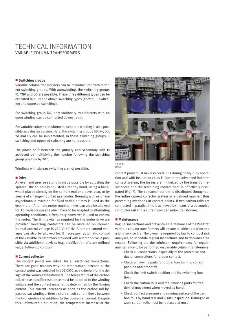
Drive
An even and precise setting is made possible by adjusting the spindle. The spindle is adjusted either by hand, using a hand-wheel placed directly on the spindle end or a bevel gear, or by means of a flange-mounted gear motor. Normally a three-phase asynchronous machine for fixed variable times is used as the gear motor. Alternate motor running times can also be allowed for. For variable speeds which have to be adapted to alternating operating conditions, a frequency converter is used to control the motor. The limit switches required for the motor drive are provided. Reversing contactors can be installed on request. Normal control voltage is 230 V, 50 Hz. Alternate control volt-ages can also be allowed for. If necessary, automatic control of the variable transformers provided with a motor drive is pos-sible via additional devices (e.g. stabilization of a pre-defined value, follow-up control).
Current collector
The contact points are critical for all electrical connections. There are good reasons why the temperature increase at the contact point was selected in VDE 0552 as a criterion for the de-sign of the variable transformers. The temperature of the carbon roll, whose specific resistance must be adapted to the winding voltage and the contact material, is determined by the flowing current. This current increases as soon as the carbon roll by-passes two windings; then a short-circuit current flows between the two windings in addition to the consumer current. Despite this unfavourable situation, the temperature increase at the
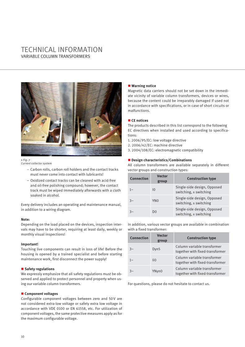
contact point must never exceed 80 K during heavy-duty opera-tion and with insulation class E. Due to the advanced Ruhstrat contact system, the losses are minimized by the transition re-sistances and the remaining contact heat is effectively dissi-pated (Fig. 7). The consumer current is distributed throughout the entire current collector system in a defined manner, thus preventing overloads at contact points. If two carbon rolls are connected in parallel, this is achieved by means of a decoupled conductor rail and a current compensation transformer.
Maintenance
Regular inspections and preventive maintenance of the Ruhstrat variable column transformers will ensure reliable operation and a long service life. The owner is required by law to conduct risk analyses, to schedule regular inspections and to document the results. Following are the minimum requirements for regular maintenance to be performed on variable column transformers:
– Check all connections, especially of the protective con-ductor connections for proper contact.
– Check all moving parts for proper functioning, correct position and proper fit.
– Check the limit switch position and its switching func-tion.
– Check the carbon rolls and their moving parts for free-dom of movement when moved by hand.
– Check contact pressure and running surface of the car-bon rolls by hand test and visual inspection. Damaged or worn carbon rolls must be replaced at once!
▴ Fig. 6Drive
10
TECHNICAL INFORMATION VARIABLE COLUMN TRANSFORMERS
– Carbon rolls, carbon roll holders and the contact tracks must never come into contact with lubricants!
– Oxidized contact tracks can be cleaned with acid-free and oil-free polishing compound; however, the contact track must be wiped immediately afterwards with a cloth soaked in alcohol.
Every delivery includes an operating and maintenance manual, in addition to a wiring diagram.
Note:
Depending on the load placed on the devices, inspection inter-vals may have to be shorter, requiring at least daily, weekly or monthly visual inspections!
Important!
Touching live components can result in loss of life! Before the housing is opened by a trained specialist and before starting maintenance work, first disconnect the power supply!
Safety regulations
We expressly emphasize that all safety regulations must be ob-served and applied to protect personnel and property when us-ing our variable column transformers.
Component voltages
Configurable component voltages between zero and 50 V are not considered extra-low voltage or safety extra low voltage in accordance with VDE 0100 or EN 61558, etc. For utilization of component voltages, the same protective measures apply as for the maximum configurable voltage.
Warning notice
Magnetic data carriers should not be set down in the immedi-ate vicinity of variable column transformers, devices or wires, because the content could be irreparably damaged if used not in accordance with specifications, or in case of short circuits or malfunctions.
CE notices
The products described in this list correspond to the following EC directives when installed and used according to specifica-tions:1. 2006/95/EC: low voltage directive2. 2006/42/EC: machine directive3. 2004/108/EC: electromagnetic compatibility
Design characteristics/Combinations
All column transformers are available separately in different vector groups and construction types:
ConnectionVector
groupConstruction type
1~ I0Single-side design, Opposed switching, ± switching
3~ YN0Single-side design, Opposed switching, ± switching
3~ D0Single-side design, Opposed switching, ± switching
In addition, various vector groups are available in combination with a fixed transformer:
ConnectionVector
groupConstruction type
3~ Dyn5Column variable transformer together with fixed-transformer
1~ Ii0Column variable transformer together with fixed-transformer
3~ YNyn0Column variable transformer together with fixed-transformer
For questions, please do not hesitate to contact us.
▴ Fig. 7Current collector system

11
The test system consists of two three-phase variable column transformers, one three-phase high-current transformer, designed as an exciter unit, and a separate control panel with a PLC controller.
One variable column transformer is used for coarse regulation of the voltage while the second variable column transformer is used for fine regulation of the output current at the high-current transformer. To ensure symmetric current distribution, three motor drives are used for each variable column transformer. The variable speed of the drives can be varied by means of fre-quency converters.
The actual current value is measured by means of current trans-formers with switchable measuring ranges and sent to the ana-logue inputs of the PLC. A higher-level process system defines the setpoint value and records the measured values.
SAMPLE PROJECTTEST SYSTEM FOR MEDIUM VOLTAGE VACUUM CIRCUIT BREAKERS
▴ Fig. 8Test system for medium voltage circuit breakerslt i it b k
Technical data
Nominal power 300 kVA
Nominal input voltage 400 V (at variable transformer)
Nominal output voltage 0 ... 17.3 V no load (at high-current transformer)
Current collection 10,000 A (at high-current transformer)
Switching group Dyn5
Cooling system AN (air self-cooled)
Protection typeVariable transformers IP 00High-current transformer IP 54 or lead-through conductor rails IP 00, control panel IP 20

12
THREE-PHASE VARIABLE COLUMN TRANSFORMERS – SINGLE-SIDE DESIGN
13
THREE-PHASE VARIABLE COLUMN TRANSFORMERS – SINGLE-SIDE DESIGN
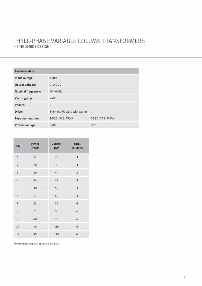
Technical data
Input voltage: 400 V
Output voltage: 0...400 V
Nominal frequency: 50 / 60 Hz
Vector group: YN0
Phases: 3 ~
Drive: Siemens FU G110 with Motor
Type designation: T-SSD_SAE_MEXX T-SSD_SAG_MEXX
Protection type: IP00 IP20
No.Power
[kVA]*
Current
[A]*
Total
columns
1 21 30 3
2 26 38 3
3 30 44 3
4 34 49 3
5 38 55 3
6 41 60 3
7 52 76 6
8 61 88 6
9 68 98 6
10 76 110 6
11 83 120 6
* Other power outputs / currents on request.

14
THREE-PHASE VARIABLE COLUMN TRANSFORMERS – ± SWITCHING

15
THREE-PHASE VARIABLE COLUMN TRANSFORMERS – ± SWITCHING
Technical data
Input voltage: 400 V
Output voltage: 0... ± 230 V
Nominal frequency: 50 / 60 Hz
Vector group: YN0
Phases: 3 ~
Drive: Siemens FU G110 with Motor
Type designation: T-SSD_SAE_MPXX T-SSD_SAG_MPXX
Protection type: IP00 IP20
No.Power
[kVA]*
Current
[A]*
Total
columns
1 21 30 3
2 26 38 3
3 30 44 3
4 34 49 3
5 38 55 3
6 41 60 3
7 52 76 6
8 61 88 6
9 68 98 6
10 76 110 6
11 83 120 6
12 105 152 12
13 121 176 12
14 135 196 12
15 152 220 12
16 166 240 12
17 182 264 18
18 203 294 18
19 228 330 18
20 248 360 18
* Other power outputs / currents on request.

Eisenmann Thermal Solutions GmbH & Co. KGLeinetal / Auf der Mauer 1, 37120 Bovenden, Germany
Tel.: +49 5 51 820 830 – 0, Fax: +49 5 51 820 830 – 50, E-Mail: [email protected]
www.ruhstrat.com
2016 © Eisenmann Thermal Solutions GmbH & Co. KG I 04-2016
All rights reserved. All texts, photos and images are subject to copyright and other laws for the protection of intellectual property. Use of the content requires the prior permission of Eisenmann Thermal Solutions GmbH & Co. KG. All information, descriptions and illustrations are subject to technical modification,
especially with a view toward the further development of our products in accordance with the current state of the art. There will be no special announcement of changes to information, descriptions and illustrations. Errors excepted. Technical characteristics can vary from country to country.
Related Documents