VAP/VAF-B Series Actuator

Welcome message from author
This document is posted to help you gain knowledge. Please leave a comment to let me know what you think about it! Share it to your friends and learn new things together.
Transcript
VAP/VAF-B Series Actuator
2
VAP/VAF-B Series Actuator
Feature
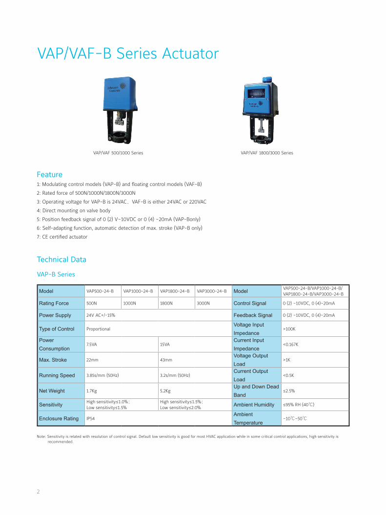
VAP/VAF 500/1000 Series VAP/VAF 1800/3000 Series
1: Modulating control models (VAP-B) and floating control models (VAF-B)
2: Rated force of 500N/1000N/1800N/3000N
3: Operating voltage for VAP-B is 24VAC,VAF-B is either 24VAC or 220VAC
4: Direct mounting on valve body
5: Position feedback signal of 0 (2) V~10VDC or 0 (4) ~20mA (VAP-Bonly)
6: Self-adapting function, automatic detection of max. stroke (VAP-B only)
7: CE certified actuator
Technical Data
VAP-B Series
Model VAP500-24-B VAP1000-24-B VAP1800-24-B VAP3000-24-B Model VAP500-24-B/VAP1000-24-B/VAP1800-24-B/VAP3000-24-B
Rating Force 500N 1000N 1800N 3000N Control Signal 0 (2) ~10VDC, 0 (4)~20mA
Power Supply 24V AC+/-15% Feedback Signal 0 (2) ~10VDC, 0 (4)~20mA
Type of Control ProportionalVoltage Input Impedance
>100K
Power Consumption
7.5VA 15VACurrent Input Impedance
<0.167K
Max. Stroke 22mm 43mmVoltage Output Load
>1K
Running Speed 3.85s/mm (50Hz) 3.2s/mm (50Hz)Current Output Load
<0.5K
Net Weight 1.7Kg 5.2KgUp and Down Dead Band
≤2.5%
Sensitivity High sensitivity≤1.0%;
Low sensitivity≤1.5%High sensitivity≤1.5%;
Low sensitivity≤2.0%Ambient Humidity ≤95% RH (40℃)
Enclosure Rating IP54Ambient Temperature
–10℃~50℃
Note: Sensitivity is related with resolution of control signal. Default low sensitivity is good for most HVAC application while in some critical control applications, high sensitivity is recommended.
3
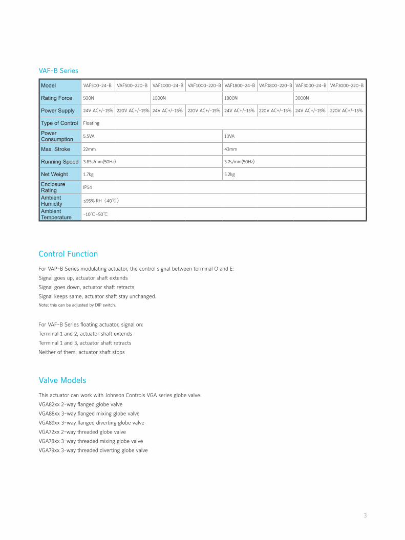
VAF-B Series
Control Function
For VAP-B Series modulating actuator, the control signal between terminal O and E:
Signal goes up, actuator shaft extends
Signal goes down, actuator shaft retracts
Signal keeps same, actuator shaft stay unchanged.
Note: this can be adjusted by DIP switch.
For VAF-B Series floating actuator, signal on:
Terminal 1 and 2, actuator shaft extends
Terminal 1 and 3, actuator shaft retracts
Neither of them, actuator shaft stops
Valve Models
This actuator can work with Johnson Controls VGA series globe valve.
VGA82xx 2-way flanged globe valve
VGA88xx 3-way flanged mixing globe valve
VGA89xx 3-way flanged diverting globe valve
VGA72xx 2-way threaded globe valve
VGA78xx 3-way threaded mixing globe valve
VGA79xx 3-way threaded diverting globe valve
Model VAF500-24-B VAF500-220-B VAF1000-24-B VAF1000-220-B VAF1800-24-B VAF1800-220-B VAF3000-24-B VAF3000-220-B
Rating Force 500N 1000N 1800N 3000N
Power Supply 24V AC+/-15% 220V AC+/-15% 24V AC+/-15% 220V AC+/-15% 24V AC+/-15% 220V AC+/-15% 24V AC+/-15% 220V AC+/-15%
Type of Control Floating
Power Consumption 5.5VA 13VA
Max. Stroke 22mm 43mm
Running Speed 3.85s/mm(50Hz) 3.2s/mm(50Hz)
Net Weight 1.7kg 5.2kg
Enclosure Rating IP54
Ambient Humidity ≤95% RH(40℃)
Ambient Temperature -10℃~50℃
4
Mechanical Design Maintenance free Manual adjustment Window/LED for VAx1800/3000 series
Wiring Diagram
VAP-B
VAF-B
Terminal
B,O 24VAC Power supply
O COM for control/feedback signal
E Control signal
Y Feedback signal
VAF500-xx-B/VAF1000-xx-B VAF1800-xx-B/VAF3000-xx-B
2 31 16 172 31
1 COM
2 DOWN
3 UP
16 Active contact for DOWN limiter (Voltage)
17 Active contact for UP limiter (Voltage)
Note 1: Active contact is 24VAC when power is 24VAC and active contact is 220VAC when power is 220VAC.
Note 2: Active contact is triggered by stall force in either 0% or 100%.
When actuator retracts to the upper limit position, the motor is power off and the red up limit indicator light is on.
When actuator extracts to the down limit position, the motor is power off and the green down limit indicator light is on.
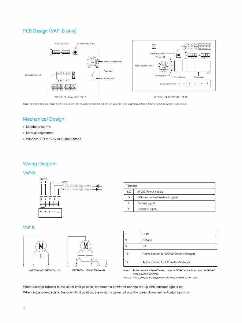
PCB Design (VAP-B only)
S2, S3 dip switch
Connection terminal
Connection terminal
Self-stroking button
Self-stroking button
Aperture potentiometer
Power light
Running light
Aperture potentiometer
Running light
1 2 3 4
1 2 3 4
Failure LED
LED for function LED for value
VAP500-24-B/VAP1000-24-B VAP1800-24-B/VAP3000-24-B
Note: Aperture potentiometer is adjusted to limit the maximum opening, which can be used in for example, different flow rate during summer and winter.
5
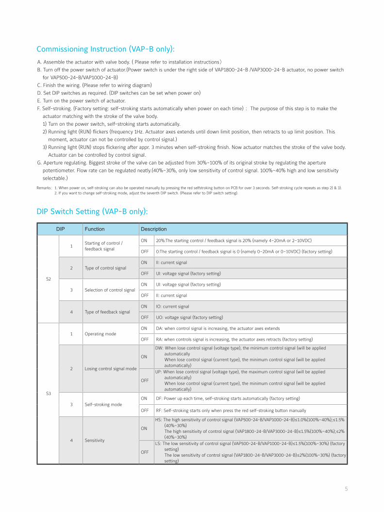
Commissioning Instruction (VAP-B only):
DIP Switch Setting (VAP-B only):
A. Assemble the actuator with valve body. ( Please refer to installation instructions)
B. Turn off the power switch of actuator.(Power switch is under the right side of VAP1800-24-B /VAP3000-24-B actuator, no power switch
for VAP500-24-B/VAP1000-24-B)
C. Finish the wiring. (Please refer to wiring diagram)
D. Set DIP switches as required. (DIP switches can be set when power on)
E. Turn on the power switch of actuator.
F. Self-stroking. (Factory setting: self-stroking starts automatically when power on each time) :The purpose of this step is to make the
actuator matching with the stroke of the valve body.
1) Turn on the power switch, self-stroking starts automatically.
2) Running light (RUN) flickers (frequency 1Hz. Actuator axes extends until down limit position, then retracts to up limit position. This
moment, actuator can not be controlled by control signal.)
3) Running light (RUN) stops flickering after appr. 3 minutes when self-stroking finish. Now actuator matches the stroke of the valve body.
Actuator can be controlled by control signal.
G. Aperture regulating. Biggest stroke of the valve can be adjusted from 30%~100% of its original stroke by regulating the aperture
potentiometer. Flow rate can be regulated neatly.(40%~30%, only low sensitivity of control signal. 100%~40% high and low sensitivity
selectable.)
Remarks:1. When power on, self-stroking can also be operated manually by pressing the red selfstroking button on PCB for over 3 seconds. Self-stroking cycle repeats as step 2) & 3). 2. If you want to change self-stroking mode, adjust the seventh DIP switch. (Please refer to DIP switch setting).
DIP Function Description
S2
1Starting of control / feedback signal
ON 20%:The starting control / feedback signal is 20% (namely 4~20mA or 2~10VDC)
OFF 0:The starting control / feedback signal is 0 (namely 0~20mA or 0~10VDC) (factory setting)
2 Type of control signalON II: current signal
OFF UI: voltage signal (factory setting)
3 Selection of control signalON UI: voltage signal (factory setting)
OFF II: current signal
4 Type of feedback signalON IO: current signal
OFF UO: voltage signal (factory setting)
S3
1 Operating modeON DA: when control signal is increasing, the actuator axes extends
OFF RA: when controls signal is increasing, the actuator axes retracts (factory setting)
2 Losing control signal mode
ON
DW: When lose control signal (voltage type), the minimum control signal (will be applied automaticallyWhen lose control signal (current type), the minimum control signal (will be applied automatically)
OFF
UP: When lose control signal (voltage type), the maximum control signal (will be applied automatically) When lose control signal (current type), the minimum control signal (will be applied automatically)
3 Self-stroking modeON DF: Power up each time, self-stroking starts automatically (factory setting)
OFF RF: Self-stroking starts only when press the red self-stroking button manually
4 Sensitivity
ON
HS: The high sensitivity of control signal (VAP500-24-B/VAP1000-24-B)≤1.0%(100%~40%);≤1.5% (40%~30%) The high sensitivity of control signal (VAP1800-24-B/VAP3000-24-B)≤1.5%(100%~40%);≤2% (40%~30%)
OFF
LS: The low sensitivity of control signal (VAP500-24-B/VAP1000-24-B)≤1.5%(100%~30%) (factory setting) The low sensitivity of control signal (VAP1800-24-B/VAP3000-24-B)≤2%(100%~30%) (factory setting)
6
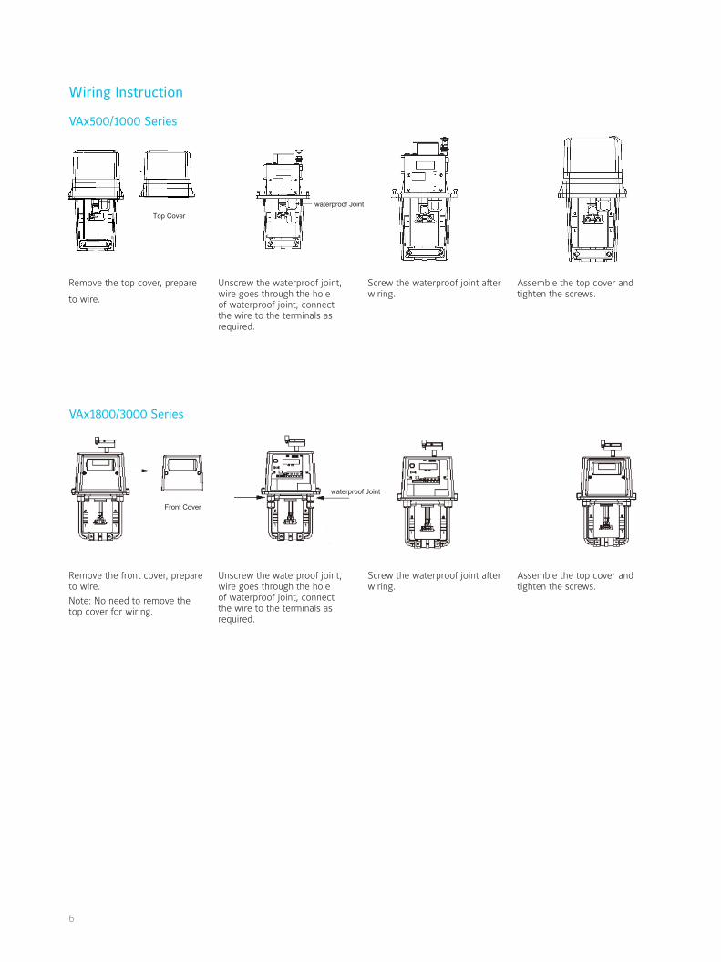
Wiring Instruction
VAx500/1000 Series
VAx1800/3000 Series
Top Cover
waterproof Joint
Front Cover
waterproof Joint
Remove the top cover, prepare
to wire.
Remove the front cover, prepare to wire.
Note: No need to remove the top cover for wiring.
Unscrew the waterproof joint, wire goes through the hole of waterproof joint, connect the wire to the terminals as required.
Unscrew the waterproof joint, wire goes through the hole of waterproof joint, connect the wire to the terminals as required.
Screw the waterproof joint after wiring.
Screw the waterproof joint after wiring.
Assemble the top cover and tighten the screws.
Assemble the top cover and tighten the screws.
7
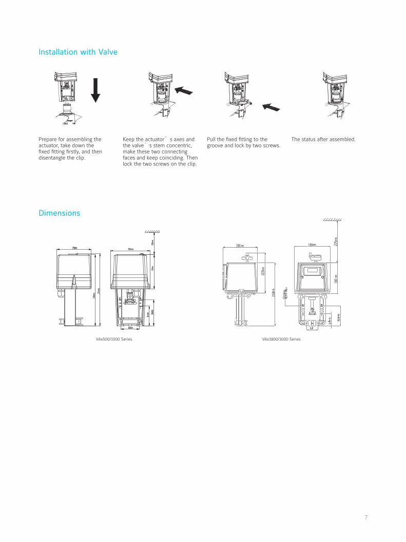
Dimensions
Installation with Valve
Prepare for assembling the actuator, take down the fixed fitting firstly, and then disentangle the clip.
Keep the actuator’s axes and the valve’s stem concentric, make these two connecting faces and keep coinciding. Then lock the two screws on the clip.
Pull the fixed fitting to the groove and lock by two screws.
The status after assembled.
VAx500/1000 Series VAx1800/3000 Series
www.johnsoncontrols.com
Printed on recycled paper
© Johnson Controls, Inc. PUBL-XXXX(XXXX)
Johnson Controls is a global diversified technology and industrial leader serving customers in more
than 150 countries. Our 168,000 employees create quality products, services and solutions to optimize
energy and operational efficiencies of buildings; lead-acid automotive batteries and advanced batteries
for hybrid and electric vehicles; and interior systems for automobiles. Our commitment to sustainability
dates back to our roots in 1885, with the invention of the first electric room thermostat. Through our
growth strategies and by increasing market share we are committed to delivering value to shareholders
and making our customers successful. In 2013, Corporate Responsibility Magazine recognized Johnson
Controls as the #14 company in its annual “100 Best Corporate Citizens” list. For additional information,
please visit http://www.johnsoncontrols.com.
Johnson Controls Building Efficiency delivers products, services and solutions that increase
energy efficiency and lower operating costs in buildings for more than one million customers. Operating
from 500 branch offices in more than 150 countries, we are a leading provider of equipment, controls
and services for heating, ventilating, air-conditioning, refrigeration and security systems. We have been
involved in more than 500 renewable energy projects including solar, wind and geothermal technologies.
Our solutions have reduced carbon dioxide emissions by 16 million metric tons and generated savings
of $7.5 billion since 2000. Many of the world’s largest companies rely on us to manage 1.8 billion square
feet of their commercial real estate.
Asia Engineering Centre: Wuxi, ChinaShanghai Distribution Center: Shanghai, ChinaAsia Centre of Excellence in Engineering (CoEE): Beijing, China · Mumbai & Pune, IndiaManufacturing/Assembly: Guangzhou & Wuxi, China · Pune, India
ThailandTel : +66 (2) 717 1260-80Fax: +66 (2) 717 0861
MalaysiaTel : +60 (3) 7628 4393Fax: +60 (3) 7620 0538
IndonesiaTel : +62 (21) 5366 8500Fax: +62 (21) 5366 8300
AustraliaTel : +61 (2) 9805 8300Fax: +61 (2) 9889 3016
New ZealandTel : +64 (9) 444 6434Fax: +64 (9) 444 2092
JapanTel : +81 (3) 5738 6100Fax: +81 (3) 5738 6298
China (Shanghai)Tel : +86 (21) 6276 6509Fax: +86 (21) 6277 3543
SingaporeTel : +65 6748 0202Fax: +65 6284 3017
KoreaTel : +82 (2) 554 5935Fax: +82 (2) 554 5739
Hong KongTel : +852 2590 0012Fax: +852 2516 5648
MacauTel : +853 2875 1820Fax: +853 2875 1825
IndiaTel : +91 (22) 3082 2200Fax: +91 (22) 3088 1592
Information contained herein including but not limited to the product design, specification or appearance is subject to change without notice. This document is for reference only, please refer to the actual product when buying.
Related Documents
![[Validated Audit Process (VAP)] EICC Manual Pengendalian VAP](https://static.cupdf.com/doc/110x72/587748571a28ab514f8b5fa7/validated-audit-process-vap-eicc-manual-pengendalian-vap.jpg)