Vaporizing foil welding: A new tool for collision welding S. R. Hansen, A. Vivek, B. C. Liu, Glenn S. Daehn Department of Materials Science and Engineering, The Ohio State University, 2041 College Road, Columbus, OH, 43201, USA Corresponding author: S. R. Hansen, email: [email protected] ABSTRACT A new method for implementing collision welding at a laboratory scale has been developed. The pressure that drives the flyer plate toward the target is created by electrically driven rapid vaporization of a thin metallic conductor, rather than by chemical explosives or magnetic forces. Dissimilar welding couples of copper-titanium, copper-steel, aluminum-copper, aluminum- magnesium and titanium-steel have been successfully created with the same set of input parameters (foil driver geometry, input energy and standoff distance). Instrumented peel tests, lap shear tests, and optical and scanning electron microscopy reveal a broad spectrum of strengths and interface microstructures. For example, copper-titanium and copper-steel welds are strong and display wavy interfaces characteristic of collision welds, with little intermetallics or void formation. The other combinations have brittle interfaces with intermetallics and defects with the collision welding parameters used presently. The ideal impact angle for copper-titanium, with the currently used input energy, was identified to be 20°. Peak velocities of up to 560 m/s were observed for titanium flyer sheets. This work introduces the new technique; further research will be done on geometrical, material, and electrical parameters of the process.

Welcome message from author
This document is posted to help you gain knowledge. Please leave a comment to let me know what you think about it! Share it to your friends and learn new things together.
Transcript

Vaporizing foil welding: A new tool for collision welding S. R. Hansen, A. Vivek, B. C. Liu, Glenn S. Daehn
Department of Materials Science and Engineering, The Ohio State University, 2041 College Road, Columbus, OH, 43201, USA
Corresponding author: S. R. Hansen, email: [email protected]
ABSTRACT
A new method for implementing collision welding at a laboratory scale has been developed. The
pressure that drives the flyer plate toward the target is created by electrically driven rapid
vaporization of a thin metallic conductor, rather than by chemical explosives or magnetic forces.
Dissimilar welding couples of copper-titanium, copper-steel, aluminum-copper, aluminum-
magnesium and titanium-steel have been successfully created with the same set of input
parameters (foil driver geometry, input energy and standoff distance). Instrumented peel tests,
lap shear tests, and optical and scanning electron microscopy reveal a broad spectrum of
strengths and interface microstructures. For example, copper-titanium and copper-steel welds are
strong and display wavy interfaces characteristic of collision welds, with little intermetallics or
void formation. The other combinations have brittle interfaces with intermetallics and defects
with the collision welding parameters used presently. The ideal impact angle for copper-titanium,
with the currently used input energy, was identified to be 20°. Peak velocities of up to 560 m/s
were observed for titanium flyer sheets. This work introduces the new technique; further research
will be done on geometrical, material, and electrical parameters of the process.

1. Introduction
When a piece of metal collides with another at an appropriate velocity and angle, a solid-state
metallurgical bond can be created. Successful collision welds are generally obtained when the
impact velocity is in the range of 150 m/s to 1500 m/s and the impact angle is between 5° and
20° [1], [2]. Typically, one of the members (target) is kept stationary while the other (flyer) is
launched toward the stationary target. Bahrani et al. [8] provided an experimentally supported
mechanism for wave formation at the interface of a collision weld. These waves are thought to
be the result of a mechanism that requires the formation of a jet between the colliding members
of the weld. This jet removes surface oxides and enables direct contact between uncontaminated
metallic surfaces, leading to metallurgical bonding. Zhang et al [3] gave a detailed account of the
most common collision welding techniques: explosive welding, magnetic pulse welding, and
laser impact welding [11].
Explosive welding (EXW), which uses an explosive discharge to drive the flyer, is a well-studied
technique for welding of large plates [4] and tube-tube plate configurations [5], [6]. Kacar [7]
reported that over 260 similar and dissimilar metal combinations have been successfully welded
using EXW. This technique is typically applied for large-scale operations with weld lengths on
the order of meters. In a review of recent work in explosive welding, Findik [9] reports that
explosive thicknesses of over 100 mm are needed to create welds between 6 mm thick plates.
Scaling the process down is difficult because detonation of small amounts of explosive charge is
inconsistent and inefficient. Therefore, large, isolated spaces are required to implement EXW,
which adds to the overall cost.
Magnetic pulse welding (MPW) uses a magnetic pulse to drive electrically conductive flyers.
This technique is suitable for smaller-scale operations with weld lengths on the order of

centimeters. However, there are some well-known issues with MPW. Although flyer plate
velocities up to 1000 m/s can be reached [10], longevity of the actuator becomes a concern at
high driving pressures. Additionally, the efficiency of this process goes down as the resistivity of
the flyer plate material increases. MPW is generally limited to more conductive metals; while
conductive drivers can be used to propel less conductive flyers, the inefficiency of that method
leads to increased costs.
One of the main advantages of collision welding over traditional fusion welding is the lack of
continuous regions of intermetallic phases: from transmission electron microscopy of the cross-
section of an explosion weld interface between AA1100 and Cu 102, Zhang et al [3] found
extensive regions of unblemished solid-state metallic bonding, with very narrow (~20 nm)
regions that resemble mechanically alloyed material.
A new method for welding driven by rapid metal vaporization is presented in this work. Thin
foils and wires, when vaporized by passage of a high current driven by a capacitor bank, can
create a region of high pressure around them. This phenomenon has been studied in detail in the
past [12]. Its application for metalworking has recently been investigated by Vivek et al [13],
who used this technique to accomplish spring back calibration and high speed shearing of high
strength steels.
In this work, it will be shown how rapid metal vaporization can be applied to drive flyer plates
for collision welding. Welding was attempted for various combinations of dissimilar metals, all
of which have been previously welded using EXW: copper-steel [14], titanium-steel [15],
magnesium-aluminum [16], aluminum-copper [17], and copper-titanium [18]. The goal of this
research is to show how welds similar to those made by EXW can be created at much smaller
length scales in a laboratory environment. Preliminary characterization of the welds has also

been performed: instrumented peel tests and lap shear tests were conducted, and micrographs of
interface cross-sections were taken in order to look for correlation between the strength of the
welds and microstructural characteristics of the weld interface. A method is also introduced that
allows the effect of varied impact angle to be studied.
2. Experimental Procedure
The flyer plate was placed directly against an aluminum foil driver that was insulated by an
adhesive polymer tape. The ends of the foil were connected to the terminals of a capacitor bank,
whose characteristics are listed in Table 1: Capacitor bank characteristics
Capacitance Inductance Resistance Maximum charging voltage
Maximum charging energy
Short circuit current rise time
426 µF 100 nH 10 mΩ 8.66 kV 16 kJ 12 µs
Figure 1: (A) Schematic of vaporizing foil welding apparatus, (B) schematic of the welding
process showing jetting, wave formation along the interface and the unwelded region in the
region of flat impact, (C) sketch of the aluminum foil driver used, (D) apparatus connected to the
capacitor bank terminals.. As the capacitor bank was discharged, a high current (on the order of
100 kAmps) flowed through the foil and vaporized it in tens of microseconds. The foil was
backed by a heavy steel block; therefore, when the foil vaporized, the pressure was directed

toward the flyer plate, accelerating it to a high speed toward the target plate, which was fixed at a
distance from the flyer by G10 standoff plates. A schematic of the experimental setup is shown
in .
Welding of various combinations of dissimilar metals was attempted using the same input
parameters for all trials. The flyers and targets used were 76.2 mm wide, 101.6 mm long, and
0.508 mm thick, except for the 1018 steel targets, which were 6.35 mm thick. The standoff
distance was 1.6 mm and the lateral spacing between standoffs was 25.4 mm. Aluminum foils
0.0762 mm thick were used as drivers; the active area of the foils was 50.8 mm long and 12.7
mm wide, as illustrated in . The input energy from the capacitor bank was 7.2 kJ for all
experiments. Current was measured by a 100 kAmps:1 volt Rogowski coil, and voltage was
measured using a 1000:1 probe connected across the terminals of the capacitor bank.
Table 1: Capacitor bank characteristics
Capacitance Inductance Resistance Maximum charging voltage
Maximum charging energy
Short circuit current rise time
426 µF 100 nH 10 mΩ 8.66 kV 16 kJ 12 µs

Figure 1: (A) Schematic of vaporizing foil welding apparatus, (B) schematic of the welding
process showing jetting, wave formation along the interface and the unwelded region in the
region of flat impact, (C) sketch of the aluminum foil driver used, (D) apparatus connected to the
capacitor bank terminals.

Strength testing:
Strength was tested in both peel and lap-shear. For peel testing, samples were cut into 25.4 mm
wide strips using an abrasive water jet. At the edge of the weld zone, the flyer plates were bent to
90° with respect to the target plate. The target plate was fixed between a flat and an angled
aluminum piece, as illustrated in Figure 2(A). The vertically aligned flyer plate and angled
aluminum piece were clamped in a MTS 831.10 load frame and pulled apart at a velocity of 0.1
mm/s. The initial distance between the clamped area of the flyer plate and the edge of the weld
interface was 25.4 mm for all tests. The area being failed was 25.4 mm wide and as long as the
width across the weld zone, which varied somewhat between samples. There is always an
unwelded region along the center of the weld zone, where the flyer and target collide with an
impact angle of 0°; this led to dual peaks in the force-displacement curve. Force per unit length
was calculated as the peel strength of the welds, as considered by Zhang [1] and Kendal [20],
who developed formal interface fracture toughness values from similar measurements. The area
under the force-displacement curve was integrated to find energy as a measure of overall weld
toughness.
The material pairs which had low peel strengths were then subjected to lap-shear testing. For
this, the welded samples were cut out with gage dimensions of 50 mm by 10 mm. The main
purpose of the lap shear tests was to investigate whether the weld interface is stronger than the
parent materials when loaded in shear.
Microstructure characterization:
Transverse cross-sections of the weld interface were polished using conventional metallography
techniques and examined using both optical microscopes and a FEI Quanta 200 scanning
electron microscope.
Angle variation:
In order to quantitatively determine the effect of impact angle on weld interface microstructure, a
grooved target plate was devised, as pictured in Figure 3(A). The walls of the grooves were
machined to angles between 8° and 28°. The titanium-copper system was chosen for this
experiment, because it produces a distinctly visible wave microstructure. A CP Ti flyer was used
as the flyer; its dimensions and all other input parameters were the same as the previous
experiments. As a follow-up experiment, a 101.6 mm long, 36 mm wide, 0.508 mm thick
titanium flyer was driven into a 4 mm thick copper target fixed at an angle of 20° in an attempt
to create a weld as long as the active area of the vaporizing foil driver (50.8 mm).
Velocity measurement:
Aluminum, copper, and titanium (0.508 mm thick) flyer velocities were measured in another set
of experiments using the Photonic Doppler Velocimetry (PDV) method [19]. No target plates
were used during these experiments. The standoff distance was increased to 3.2 mm in order to
capture a larger piece of the acceleration profile. The velocity at any distance within this range –
particularly the 1.6 mm standoff distance used for previous experiments –can be estimated by
integration of the resulting velocity-time curve. The input energy used was the same as in the
previous welding experiments (7.2 kJ).

Figure 2: (A) Peel-testing set up, (B) peel-testing in progress, showing direction of forces during
the peel of the second weld line.
Figure 3: (A) Profile of grooved target plate, (B) SEM micrograph of welded grooves, (C)
continuous weld formed at 20° impact angle.

3. Results and discussion
PDV data in Figure 4 shows that the titanium flyer plate reached its peak velocity of 565 m/s
within the first 1.6 mm of travel, whereas the copper and aluminum flyer sheets were still
accelerating when they collided with the target. The estimated impact velocities of the copper
and aluminum flyers at a 1.6-mm standoff distance were 340 m/s and 416 m/s, respectively.
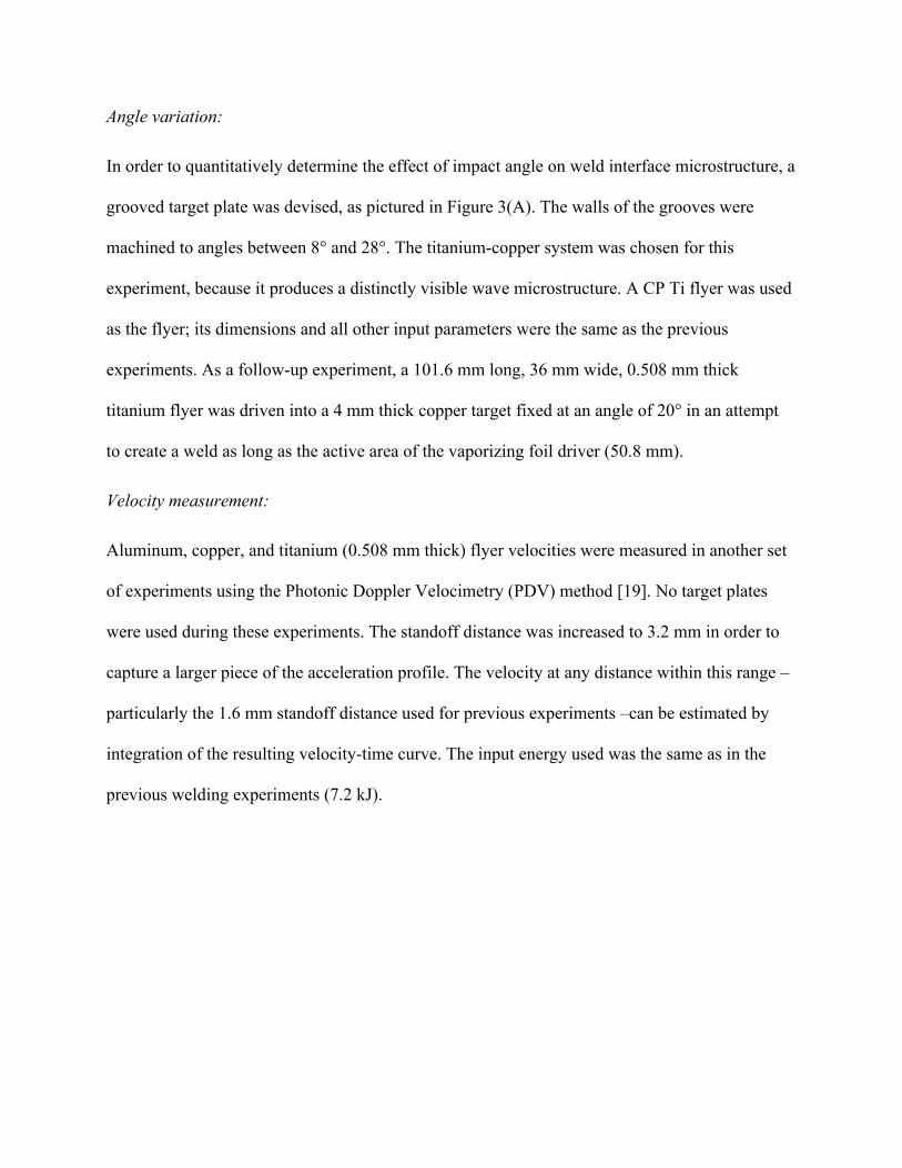
When the welds were sectioned perpendicular to the length of the foil, it was evident that
welding predominantly occurred along the perimeter of the active area. A transverse cross-
section of a weld between CP titanium and 1018 steel is shown in Figure 5. The figure also
shows the fracture surface of the steel plate after the titanium sheet is peeled off from it; the weld
region around the periphery of the active area of the foil is apparent. No welding takes place
directly above the middle of the active foil area because of the flat collision of the flyer with the
target. When the impact angle is zero, no jet forms, so no weld forms in that region. As the rest
of the flyer sheet collapses onto the target, the angle and velocity of impact shift into an
appropriate range where welding takes place. Figure 6 depicts the peeled surfaces of the Ti and
the Fe sides of the weld, with clearly visible waves. The surface EDS map gives clear evidence
of material transfer between the two parent materials at the crests and troughs of the waves.
The same conditions of standoff distance, input energy, and foil geometry resulted in successful
welds in all the material combinations attempted. These conditions must be optimized for each
combination; however, even without optimization, every weld demonstrated measureable
strength and toughness. Most of the tougher welds showed two peaks in the force-displacement
curves, corresponding to the two weld lines from the perimeter of the foil driver. The first peak
was lower because only perpendicular peeling force was involved in breaking the first weld line.
During failure of the second weld line, the flyer sheet was being pulled at an angle, as illustrated

in Figure 2(B). The force being measured therefore had to overcome peel strength combined
with shear strength of the weld. Only the first peak was used for calculation of peel strength,
because it corresponds with near-uniaxial loading of the weld region. In the present work,
emphasis was on qualitative side-by-side comparison of the overall weld strengths for different
material pairs using identical input parameters.
Figure 4: PDV data from 0.508-mm-thick flyer sheets accelerated using the vaporizing foil
method with 7.2 kJ of electrical energy input into a 0.0762 mm thick aluminum foil. The vertical
dashed lines mark the time at which the flyer reaches the indicated distance.
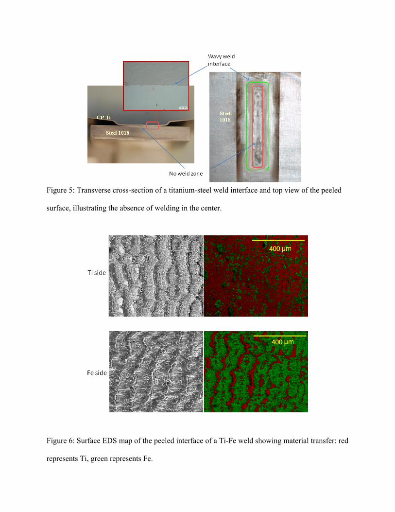
Figure 5: Transverse cross-section of a titanium-steel weld interface and top view of the peeled
surface, illustrating the absence of welding in the center.
Figure 6: Surface EDS map of the peeled interface of a Ti-Fe weld showing material transfer: red
represents Ti, green represents Fe.
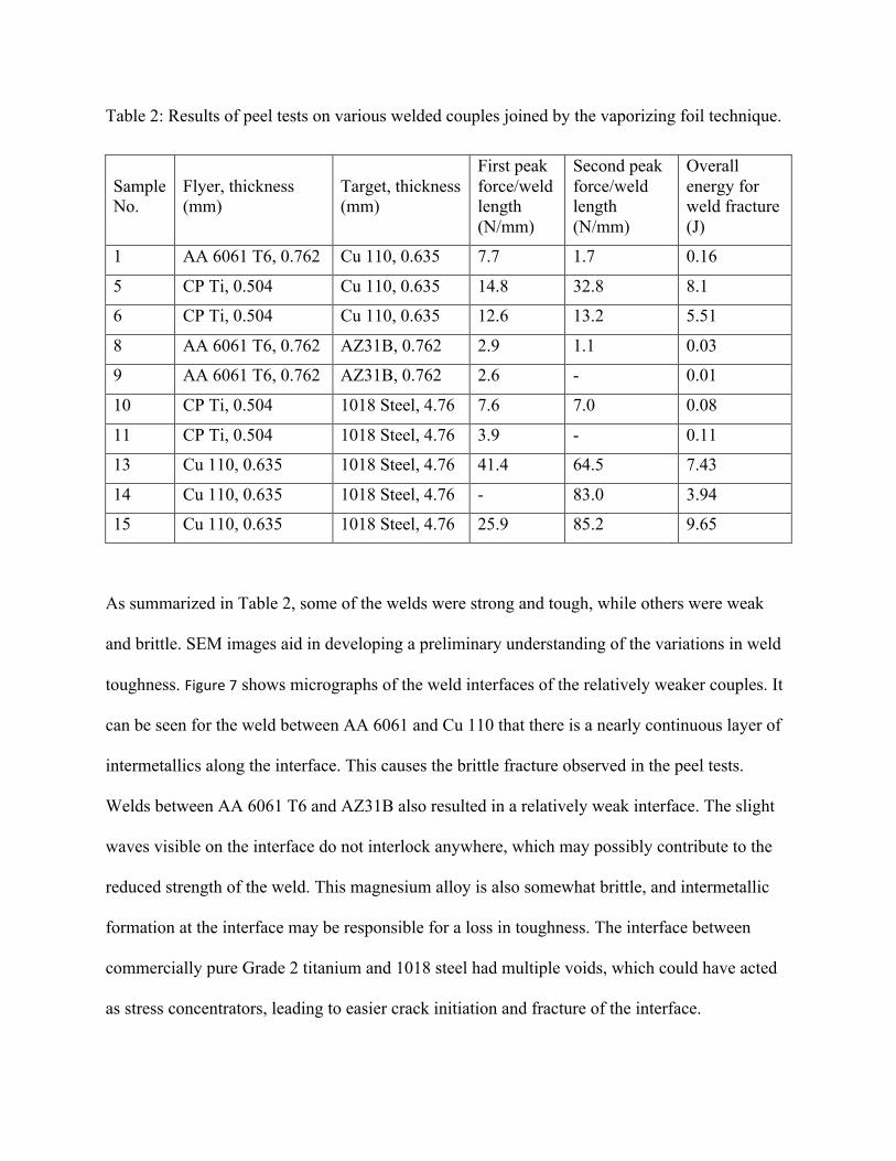
Table 2: Results of peel tests on various welded couples joined by the vaporizing foil technique.
Sample No.
Flyer, thickness (mm)
Target, thickness (mm)
First peak force/weld length (N/mm)
Second peak force/weld length (N/mm)
Overall energy for weld fracture (J)
1 AA 6061 T6, 0.762 Cu 110, 0.635 7.7 1.7 0.16
5 CP Ti, 0.504 Cu 110, 0.635 14.8 32.8 8.1
6 CP Ti, 0.504 Cu 110, 0.635 12.6 13.2 5.51
8 AA 6061 T6, 0.762 AZ31B, 0.762 2.9 1.1 0.03
9 AA 6061 T6, 0.762 AZ31B, 0.762 2.6 - 0.01
10 CP Ti, 0.504 1018 Steel, 4.76 7.6 7.0 0.08
11 CP Ti, 0.504 1018 Steel, 4.76 3.9 - 0.11
13 Cu 110, 0.635 1018 Steel, 4.76 41.4 64.5 7.43
14 Cu 110, 0.635 1018 Steel, 4.76 - 83.0 3.94
15 Cu 110, 0.635 1018 Steel, 4.76 25.9 85.2 9.65
As summarized in Table 2, some of the welds were strong and tough, while others were weak
and brittle. SEM images aid in developing a preliminary understanding of the variations in weld
toughness. Figure 7 shows micrographs of the weld interfaces of the relatively weaker couples. It
can be seen for the weld between AA 6061 and Cu 110 that there is a nearly continuous layer of
intermetallics along the interface. This causes the brittle fracture observed in the peel tests.
Welds between AA 6061 T6 and AZ31B also resulted in a relatively weak interface. The slight
waves visible on the interface do not interlock anywhere, which may possibly contribute to the
reduced strength of the weld. This magnesium alloy is also somewhat brittle, and intermetallic
formation at the interface may be responsible for a loss in toughness. The interface between
commercially pure Grade 2 titanium and 1018 steel had multiple voids, which could have acted
as stress concentrators, leading to easier crack initiation and fracture of the interface.

Although these weld pairs were weaker and brittle in peel testing, they demonstrated much
higher strengths in lap-shear testing, as illustrated in Figure 8. The Al-Cu weld, for example,
sustained 130 MPa before it failed along the interface. The Al-Mg weld failed in the parent Mg
sheet, when the stress reached 140 MPa. The Ti-Fe weld was even stronger, with a maximum
stress of 340 MPa, and the failure occurred partly in the parent Ti sheet.
On the other end of the fracture-toughness spectrum are the Cu 110-1018 steel welds and Cu-
110-CP-Ti welds, which were extremely tough in spite of the presence of some defects.
Intermittent regions of intermetallics can be seen in the Cu-Ti system, and voids can be found in
the Fe-Cu system, though not nearly to the extent of the brittle welds. The micrographs shown in
Figure 9 indicate why these welds may be so strong. The wavy interfaces in both cases show
interlocking between the two materials, which may increase the peel strength. Also, although
some defects are present, there are no continuous regions of intermetallics to propagate brittle
fracture.
SEM micrography of a longitudinal cross-section of the CP Ti-grooved Cu 110 weld interface is
provided in Figure 3(B). It reveals distinct, interlocking waves and a continuously welded region
where the impact angle was 20°. Neighboring angles welded somewhat, but display smaller
waves at the interface and shorter regions of continuous welding. This indicates that, for the
input energy and resulting velocity used for this experiment, 20° is the optimal angle of impact.
However, this would likely change for a different impact velocity.
The CP Ti-Cu 110 weld created at 20° displays uninterrupted bonding for 50 mm –
approximately the length of the foil active area, as desired. The waves produced at the interface
are regularly spaced and interlock the two parent materials. The curvature of the sample seen in
Figure 3(C) is due to the lack of backing supporting the copper target plate in this trial.
Figure 7: SEM images of the interface of relatively weak welds showing (A) continuous region
of intermetallics along the interface of AA 6061 T6 (flyer)-Cu 110 weld, (B) voids in the CP Ti
(flyer)-1018 steel weld, and (C) intermetallics in AA 6061 T6 (flyer)-AZ31B weld.

Figure 8: Lap shear testing of Al-Cu, Al-Mg, and Ti-Fe welds: (A) untested samples and (B)
tested samples, showing failure along the interface for the Al-Cu weld, in the parent Mg sheet for
the Al-Mg weld, and combined failure both in the parent Ti sheet and along the interface for the
Ti-Fe weld.
Figure 9: SEM images of stronger weld interfaces of (A) CP Ti (flyer)-Cu 110 and (B) Cu 110
(flyer)-1018 steel. Despite intermittent presence of voids along its interface, the copper-steel
weld was very strong.

4. Conclusions
Vaporizing foil welding is a robust collision welding technique that allows collision welding
systems to be explored in a laboratory environment. This technique is able to successfully weld
various dissimilar metal pairs under the same set of parameters. Peel testing revealed a wide
range of bond toughnesses, with the 1018 steel-Cu 110 system proving to be the toughest. Some
of the weld interfaces were ductile, while others were brittle. Micrographs of the interface
offered some explanation for these observations: the presence of intermetallics and voids
coincided with the welds that were observed to have low toughness. On the other hand, the high-
toughness welds had very few, if any, continuous regions of intermetallics or extensive molten
regions. Instead, interlocking waves were observed along many interfaces. A more detailed study
of all these interfaces still needs to be conducted. Additionally, further study is warranted to
identify the ideal input parameters for each different metal system. The grooved target plate
devised in this work will allow multiple impact angles to be tested with different velocities for
different metal systems, quickly and efficiently.
Acknowledgements
The authors would like to thank the ALCOA foundation, which supported the work through the
Advancing Sustainability Research Initiative, the Industry & University Cooperative Research
Program (I/UCRC), and the Pratt & Whitney Corporation.
References
[1] Y. Zhang, “Investigation of Magnetic Pulse Welding on Lap Joint of Similar and Dissimilar Materials,” The Ohio State University, 2010.
[2] P. F. Sartangi and S. A. A. A. Mousavi, “Experimental investigations on explosive cladding of cp-titanium/AISI 304 stainless steel,” in Advanced Welding and Micro Joining / Packaging for the 21st Century, vol. 580–582, C. Lee, J. B. Lee, D. H. Park, and S. J. Na, Eds. Stafa-Zurich: Trans Tech Publications Ltd, 2008, pp. 629–632.
[3] Y. Zhang, S. S. Babu, C. Prothe, M. Blakely, J. Kwasegroch, M. LaHa, and G. S. Daehn, “Application of high velocity impact welding at varied different length scales,” J. Mater. Process. Technol., vol. 211, no. 5, pp. 944–952, May 2011.
[4] J. Banker, “Explosion metalworking,” Colorado School of Mines, 08-Oct-2007.
[5] A. S. Bahrani, R. F. Halliburton, and B. Crossland, “Parallel technique of tube to tubeplate welding applied to plugging of heat exchangers,” International Journal of Pressure Vessels and Piping, vol. 1, no. 1, pp. 17–35, Jan. 1973.
[6] G. Arthur, “Applications of explosive welding to heat exchangers,” Materials & Design, vol. 6, no. 1, pp. 37–41, Feb. 1985.
[7] R. Kacar and M. Acarer, “An investigation on the explosive cladding of 316L stainless steel-din-P355GH steel,” Journal of Materials Processing Technology, vol. 152, no. 1, pp. 91–96, Oct. 2004.
[8] A. BAHRANI, T. BLACK, and CROSSLAN.B, “MECHANICS OF WAVE FORMATION IN EXPLOSIVE WELDING,” Proceedings of the Royal Society of London Series a-Mathematical and Physical Sciences, vol. 296, no. 1445, p. 123–&, 1967.
[9] F. Findik, “Recent developments in explosive welding,” Materials & Design, vol. 32, no. 3, pp. 1081–1093, Mar. 2011.
[10] K.-J. Lee, S. Kumai, T. Arai, and T. Aizawa, “Interfacial microstructure and strength of steel/aluminum alloy lap joint fabricated by magnetic pressure seam welding,” Materials Science and Engineering: A, vol. 471, no. 1–2, pp. 95–101, Dec. 2007.
[11] G. S. Daehn, J. C. Lippold, Liu, D., and Wang, H., “Laser Impact Welding,” presented at the International Conference on High Speed Forming, Dortmund, Germany, 2012.
[12] W. Chace and H. Moore, Exploding wires, 4 vols. Plenum Press, 1959.
[13] A. Vivek, G. A. Taber, J. R. Johnson, S. T. Woodward, and G. S. Daehn, “Electrically Driven Plasma via Vaporization of Metallic Conductors: A Tool for Impulse Metal Working,” Journal of Materials Processing Technology, no. 0.
[14] A. Durgutlu, B. Gülenç, and F. Findik, “Examination of copper/stainless steel joints formed by explosive welding,” Materials & Design, vol. 26, no. 6, pp. 497–507, 2005.
[15] N. Kahraman, B. Gülenç, and F. Findik, “Joining of titanium/stainless steel by explosive welding and effect on interface,” Journal of Materials Processing Technology, vol. 169, no. 2, pp. 127–133, Nov. 2005.
[16] Y. B. Yan, Z. W. Zhang, W. Shen, J. H. Wang, L. K. Zhang, and B. A. Chin, “Microstructure and properties of magnesium AZ31B-aluminum 7075 explosively welded composite plate,” Mater. Sci. Eng. A-Struct. Mater. Prop. Microstruct. Process., vol. 527, no. 9, pp. 2241–2245, Apr. 2010.
[17] J. Z. Ashani and S. M. Bagheri, “Explosive scarf welding of aluminum to copper plates and their interface properties,” Materialwiss. Werkstofftech., vol. 40, no. 9, pp. 690–698, Sep. 2009.
[18] N. Kahraman and B. Gulenc, “Microstructural and mechanical properties of Cu-Ti plates bonded through explosive welding process,” J. Mater. Process. Technol., vol. 169, no. 1, pp. 67–71, Oct. 2005.
[19] J. R. Johnson, G. Taber, A. Vivek, Y. Zhang, S. Golowin, K. Banik, G. K. Fenton, and G. S. Daehn, “Coupling Experiment and Simulation in Electromagnetic Forming Using Photon Doppler Velocimetry,” Steel Res. Int., vol. 80, no. 5, pp. 359–365, May 2009.
[20] K. KENDALL, “SHRINKAGE AND PEEL STRENGTH OF ADHESIVE JOINTS,” Journal of Physics D-Applied Physics, vol. 6, no. 15, pp. 1782–1787, 1973.
Related Documents