ULTRASONIC TRANSIT-TIME FLOWMETERS VANTAGE ® 4000 VANTAGE SERIES 4000 Engineered for Accuracy and Simple Installation

Welcome message from author
This document is posted to help you gain knowledge. Please leave a comment to let me know what you think about it! Share it to your friends and learn new things together.
Transcript

UL
TR
AS
ON
ICT
RA
NS
IT-
TIM
E
FL
OW
ME
TE
RS
VANTAGE ® 4000 V
AN
TA
GE
SE
RIE
S
40
00
Engineered for Accuracy and Simple Installation
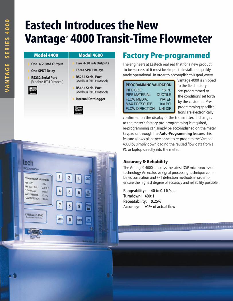
Factory Pre-programmedThe engineers at Eastech realized that for a new product
to be successful, it must be simple to install and quickly
made operational. In order to accomplish this goal, every
Vantage 4000 is shipped
to the field factory
pre-programmed to
the conditions set forth
by the customer. Pre-
programming specifica-
tions are electronically
confirmed on the display of the transmitter. If changes
to the meter’s factory pre-programming is required,
re-programming can simply be accomplished on the meter
keypad or through the Auto-Programming feature. This
feature allows plant personnel to re-program the Vantage
4000 by simply downloading the revised flow data from a
PC or laptop directly into the meter.
Accuracy & ReliabilityThe Vantage® 4000 employs the latest DSP microprocessor
technology. An exclusive signal processing technique com-
bines correlation and FFT detection methods in order to
ensure the highest degree of accuracy and reliability possible.
Rangeability: 40 to 0.1 ft/secTurndown: 400 :1Repeatability: 0.25%Accuracy: ±1% of actual flow
Eastech Introduces the NewVantage® 4000 Transit-Time Flowmeter
2
Model 4400
44One 4-20 mA Output
44One SPDT Relay
44RS232 Serial Port(Modbus RTU Protocol)
Model 4600
44Two 4-20 mA Outputs
44Three SPDT Relays
44RS232 Serial Port(Modbus RTU Protocol)
44RS485 Serial Port(Modbus RTU Protocol)
44Internal Datalogger
VA
NT
AG
E
SE
RIE
S 4
00
0
PROGRAMMING VALIDATION PIPE SIZE: 16 IN. PIPE MATERIAL DUCTILE FLOW MEDIA: WATER MAX PRESSURE: 100 PSI FLOW DIRECTION: UNI-DIR
0

SpeedRailTM Sensor MountingSince the externally mounted sensor is the preferred design for transmitting signals through pipe or conduit, a new
one-piece SpeedRailTM sensor mounting system was developed. Mounting of both sensors is quickly and accurately
accomplished in two simple steps. Lock the self-aligning mounting rail to the pipe or conduit and load in the sensors.
Once the sensors are connected to the transmitter, the Vantage 4000 is ready to measure flow.
Flow Data Graphing PackageQTrend 2007 is an Excel Workbook Flow Data Graphing Package specificallydesigned to interface with every meter offered within the Eastech product line.
QTrend incorporates specific formulas capable of automating the process of charting
and displaying all data contained within the onboard logger of the meter. Each individual
Worksheet presents an OPEN FILE button. Upon initiation, the file browser is displayed
with a complete list of all CSV files contained within the directory. Choosing a file of
interest will automatically import the data from that file into the QTrend Excel
Workbook. By simply clicking on the tab labeled CHART, a comprehensive flow
evaluation and trend analysis Worksheet is displayed.
All graphed data is presented in a color-coded format that coincides with a complete
set of corresponding Data Description Keys prominently displayed on the left perimeter
of the Worksheet. For specific analysis, associated data may be temporarily hidden from
view by a simple click on the appropriate Data Description Key. Maximum and minimum
values for every measurement category are updated and then displayed within each
graphical window.
STEP 2STEP 1
3
Flow and Level (Total Flow Hidden)

VANTAGE®
4000
Eastech was the first company to utilize a phase shift
detection system in the design of transit-time flowmeters.
This technique greatly improves time difference detectability,
which in turn, enhances accuracy and operating stability
while substantially reducing the effects of noise.
Accuracy & ReliabilityRangeability: 40 to 0.1 ft/secTurndown: 400 :1Repeatability: 0.25%Accuracy: ±1% of actual flow
The electronic design of the Vantage 4000 utilizes the latest
microprocessor technology and operates in conjunction with a
DSP floating point coprocessor. An exclusive signal processing
technique combines correlation and FFT detection methods to
ensure the highest degree of accuracy and reliability.
Flash memory is employed for logging of flow data. Up to 8
channels can be logged—including flow, velocity and totals for
one or multiple sensors. The storage capacity for a single channel
logging at 5 minute intervals is 113 days. In addition, graphs may
be visually displayed in pre-programmed time intervals. Daily
summary allows viewing of the previous eight days. This includes
times, dates, averages, minimums, maximums and totals. Plant
operating personnel also have the ability to simply download log-
ger data through the use of a standard Palm® or laptop.
ProgrammingFor fast and simple installation, each Vantage Series 4000 is pre-programmed at the factory for customer specific flow measurement applications.
If re-programming is required in the field, the Auto-Programmingfeature allows for the corrected flow data to simply be
downloaded from a PC or laptop directly into the meter.
Additionally, a self-prompting backlit display, with a menu-driven
guide available in English, Spanish and German, allows for 15
minute programming of standard applications and 30 minute
programming of in-depth data logging applications and
auxiliary outputs.
Programming of the meter is accomplished through the 16
button keypad. The LCD display is a backlit 128 x 64 graphic
module. A simple to use drill-down menu structure allows for
quick programming and set-up of the meter. Most common pipe
sizes and schedules are stored in memory for ease in program-
ming a specific application. Non-volatile memory ensures that
programming constants are not lost during disruption of power.
4
44Water & Wastewater
44Sewage Treatment
44Acids & Toxic Liquids
44Petroleum Products
44HVAC & Irrigation
Transmitter
Model 4400
44One 4-20 mA Output
44One SPDT Relay
44RS232 Serial Port(Modbus RTU Protocol)
Model 4600
44Two 4-20 mA Outputs
44Three SPDT Relays
44RS232 Serial Port(Modbus RTU Protocol)
44RS485 Serial Port(Modbus RTU Protocol)
44Internal Datalogger

Data LoggingThe Vantage 4000 has a 256K Byte logger with storage intervals. The logger can be programmed for various timeintervals. Up to 8 channels can be logged—including flow,velocity and totals for one or multiple sensors.The storagecapacity for a single channel @ 5 minute intervals is 113 days. IEEE floating point storage is used.
Daily AveragesFlash memory is employed for logging of flow data. Data is
retrieved by viewing the local display or downloaded via the
serial port. Daily summaries allow viewing of the previous eight
days. Included are times, dates, averages, minimums, maximums
and totals.
Logger GraphA graph may be visually displayed on the 4000.The graph will
display the stored logger data in pre-programmed time intervals.
09/05/2001 18:36.02 Flw1 230 GPM F1 Avg 249.96 GPM Vel1 6.15 FPS Min 00 08:27 Max 290.0 07:13
09/05T 14:50-15:00
FLO
W
TIME
Data Transfer
Land Line or Wireless
via Modem
Laptop
Additional 4000’s on RS-485 network
PC
Vantage
Vantage w/ Modem
Data RetrievalThe Vantage 4000 is designed for reliable and accurateretrieval of data—either on-site or remotely. The unit isequipped, as standard, with an integrated data logger capable of storing large amounts of information for lateranalysis. Because of its multiple output capability, this information may simply be retrieved through the use of one of the following methods.
LaptopThe Eastech data collection system allows plant operating
personnel the ability to simply download logger data through
the use of a laptop. This information can then be transferred
to a PC. Free operating software may be downloaded from
the Eastech website.
ModemA modem can be installed within the enclosure of the 4000 for
phone line or wireless transfer of data to a central location.
Since the Vantage has two totally independent communica-
tions ports (RS-232 and RS-485), a single modem can provide
data for multiple meters communicating serially through a
field network such as Modbus.
Multiple OutputsTwo 4-20 mA Isolated, 800 ohms maximum.
Three SPDT Relays Available for alarm conditions.
RS232 With Modbus protocol. Flow control
is CTS/RTS or none. DB-9 connection.
RS485 With Modbus protocol, isolated.
The RS-232 & RS-485 can be set with
different slave I.D.s.
5
PC

Eastech offers a wide range of sensor
options covering a multitude of applica-
tions. Simple “walk through” installation
instructions are graphically displayed in
the IOM for local reference in the field
Externally Mounted SensorExternally mounted sensors are the preferred design when
acoustic signals are capable of being transmitted through pipe
or conduit. The sensors are fully potted for use in highly corrosive
areas. Both sensors and mounting hardware are designed to
resist corrosion, function when buried or submerged and operate
over a wide temperature range of -30° to 150°F (-30° to 300°F
optional). External sensors are suitable for placement on all
metallic and plastic piping, with the exception of pit cast iron
and layered fiberglass pipe.
Application: 1” and larger. Plastic, Metallic, Asbestos Cement
and Ductile/Cast Pipe.
SpeedRailTM Mounting
Since externally mounted sensors are the preferred design for
transmitting signals through pipe or conduit, a new one piece
SpeedRailTM sensor mounting system was developed. Mounting
of both sensors is quickly and accurately accomplished in two
simple steps. Lock the self-aligning mounting rail to the pipe
or conduit and load in the sensors.
Once the sensors are connected to the transmitter, the Vantage
4000 is ready to measure flow.
The externally mounted sensor is the
preferred design when acoustic signals
are capable of being transmitted
through pipe or conduit.
VANTAGE®
4000Acoustic Sensors
Externally mounted non-wetted sensors (V-Shot)
Externally mounted non-wetted sensors (Z-Shot)
STEP 1 STEP 2
6

Instream SensorIn open conduits over 12 inches in width or in large concrete pipes where the
outside of the pipe is not accessible, the instream sensor is recommended for
accurate fluid velocity measurement. The design of the sensor facilitates
simple installation. Sensor configuration allows flush mounting against the
sidewall. For accuracy and ease of installation, a unique internal hoop design is
available with premounted instream sensors. This mounting arrangement
makes installation fast and precise. Sensors are constructed of PVC and are
fully potted. (SEE BULLETIN NO. EB401)
Application: Large diameter pipe and pipe or conduit not accessible from
the outside.
Windowed SensorFabricated spool pieces are available in a windowed sensor design with a
wide choice of end connections and materials of construction. Spool pieces
are supplied with both sensors mounted and calibrated to the electronics.
Windowed sensors transmit and receive ultrasonic pulses through an acoustic
window which is in contact with the flow stream. The design allows sensor
removal without de-watering of the line. The sensors and windows are con-
structed of Ultem® thermoplastic material and carry a temperature rating of
150°F and a pressure rating of 150 psi. (SEE BULLETIN NO. EB402)
Application: 3” to 48” with stainless or carbon steel construction and ANSI,
AWWA and plain end connections.
Wetted Sensor“Hot Shot” sensors are utilized on piping or conduits that inhibit the transmis-
sion of acoustic energy. A standard concrete saddle tap is employed for
penetration of the pipe wall. “Hot Shot” sensors are available for 12” and
larger pipe. The sensor design allows for flush mounting within the conduit,
thereby eliminating turbulence or the build-up of solids around the measuring
point. Sensors are provided with an integral valve in order to allow sensor
removal without shutting the process down. Constructed of PVC and fully pot-
ted, the sensors carry a pressure rating of 150 psi. (SEE BULLETIN NO. EB403)
Application: Concrete, Asbestos, Cement, Fiberglass Wrapped, Wood Stave,
heavily corroded steel pipe and pipes with considerable calcium build-up.
Multi-PathTwo and three path diametrical sensor configurations are recommended for
applications that do not have normal upstream straight runs to produce
well developed velocity profiles. The average axial velocity component for
each acoustic path is utilized to establish the velocity profile. The velocity
profile is then numerically integrated over the conduit’s cross-sectional area
to determine the volumetric flow rate. As a result, flowmeter accuracy is
relatively independent of the velocity profile. 3 Paths2 Paths
7
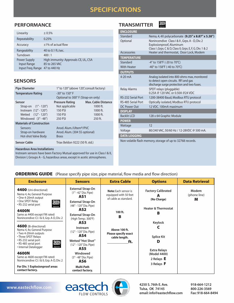
Enclosure Sensors Extra Cable Options Data Retrieval
External Strap-On(1” - 42” Dia. Pipe)
AS1External Strap-On(48” - 120” Dia. Pipe)
AS2External Strap-On(High Temp.: 300°F)
AS3Instream
(12” - 120” Dia. Pipe)
AS4Wetted “Hot Shot”(12” - 120” Dia. Pipe)
AS5Windowed
(3” - 48” Dia. Pipe)
AS6Multi-Path
contact factory.
Note: Each sensor is
equipped with 50 feet
of cable as standard.
100 ft.
B
Above 100 ft.Please specify exact
cable length.
__________ft.
Factory Calibrated
A(No Charge)
Heater & Thermostat
B
Keylock
C
Splice Kit
D
Extra Relays(Model 4400)
2 Relays E3 Relays F
Modem(phone line)
M
4400 (Uni-directional)
Nema 4, 4x; General Purpose• One 4-20mA output• One SPDT Relay• RS-232 serial port
4400NSame as 4400 except FM rated:Nonincendive: Cl. I & II, Grp. A-D, Div. 2
4600 (Bi-directional)Nema 4, 4x; General Purpose• Two 4-20mA outputs• Three SPDT Relays• RS-232 serial port• RS-485 serial port• Internal Datalogger
4600NSame as 4600 except FM rated:Nonincendive: Cl. I & II, Grp. A-D, Div. 2
For Div. 1 Explosionproof areascontact factory.
ORDERING GUIDE (Please specify pipe size, pipe material, flow media and flow direction)
PERFORMANCE
SPECIFICATIONS
Linearity ± 0.5%
Repeatability 0.25%
Accuracy ±1% of actual flow
Rangeability 40 to 0.1 ft./sec.
Turndown 400 : 1
Power Supply High immunity: Approvals CE, UL, CSA
Input Range 85 to 265 VAC
Input Freq. Range 47 to 440 Hz
SENSORS
Pipe Diameter 1” to 120” (above 120”, consult factory)
Temperature Rating -30° to 150° F
Optional to 300° F (Strap-on only)
Sensor Pressure Rating Max. Cable DistanceStrap-on (1” - 120”) Not applicable 1000 ft.
Instream (12” - 120”) 150 PSI 1000 ft.
Wetted (12” - 120”) 150 PSI 1000 ft.
Windowed (3” - 48”) 250 PSI 250 ft.
Materials of Construction
Sensors: Anod. Alum./Ultem®/PVC
Strap-on hardware Anod. Alum. (304 SS optional)
Hot-shot Valve Body Brass
Sensor Cable Triax Beldon 9222 (50 ft. std.)
Hazardous Area InstallationsInstream sensors have been Factory Mutual approved for use in Class I & II,
Division I, Groups A - G, hazardous areas, except in acetic atmospheres.
TRANSMITTER
ENCLOSURE
Standard Nema, 4, 4X polycarbonate (9.25” x 8.87” x 5.38”)
Optional Nonincendive Class I & II , Grps. A - D, Div. 2 Explosionproof, Aluminum Class I ,Grps. C & D, Class II, Grps. E, F, G. Div. 1 & 2
Accessories Heater and thermostat, Door Lock, Modem
TEMPERATURE
Standard -4° to 158°F (-20 to 70°C)
With Heater -40° to 158°F (-40 to 70°C)
OUTPUTS
4-20 mA Analog isolated into 800 ohms max, monitored to detect open circuits. RFI and gas discharge surge protection and two fuses.
Relay Alarms SPDT relays (pluggable)0.25A @ 120 VAC or 0.50A @24 VDC
RS-232 Serial Port 1200-38400 Baud, Modbus RTU protocol
RS-485 Serial Port Optically isolated, Modbus RTU protocol
DC Power Out 12 VDC. 100mA maximum
DISPLAY
Backlit LCD 128 x 64 Graphic Module
POWER
Wattage 12
Voltage 80/240 VAC, 50/60 Hz / 12-28VDC @ 500 mA.
DATA LOGGING
Non-volatile flash memory, storage of up to 32768 records.
eastech 4250 S. 76th E. Ave.Tulsa, OK 74145 email: [email protected]
918-664-1212 800-226-3569 Fax: 918-664-8494
www.eastechflow.com
FLOW CONTROLS
Related Documents