Vanguard Applications Ware IP and LAN Feature Protocols IP Routing

Welcome message from author
This document is posted to help you gain knowledge. Please leave a comment to let me know what you think about it! Share it to your friends and learn new things together.
Transcript

Vanguard Applications WareIP and LAN Feature Protocols
IP Routing
Notice
©2005 Vanguard Networks25 Forbes BoulevardFoxboro, Massachusetts 02035(508) 964-6200All rights reservedPrinted in U.S.A.
Restricted Rights Notification for U.S. Government Users
The software (including firmware) addressed in this manual is provided to the U.S. Government under agreement which grants the government the minimum “restricted rights” in the software, as defined in the Federal Acquisition Regulation (FAR) or the Defense Federal Acquisition Regulation Supplement (DFARS), whichever is applicable.
If the software is procured for use by the Department of Defense, the following legend applies:
Restricted Rights LegendUse, duplication, or disclosure by the Government
is subject to restrictions as set forth in subparagraph (c)(1)(ii) of the
Rights in Technical Data and Computer Software clause at DFARS 252.227-7013.
If the software is procured for use by any U.S. Government entity other than the Department of Defense, the following notice applies:
NoticeNotwithstanding any other lease or license agreement that may pertain to, or accompany the delivery of, this computer software, the rights of the Government regarding its use, reproduction, and disclosure are as set forth in FAR 52.227-19(C).
Unpublished - rights reserved under the copyright laws of the United States.

Notice (continued)
Proprietary Material
Information and software in this document are proprietary to Vanguard Networks (or its Suppliers) and without the express prior permission of an officer, may not be copied, reproduced, disclosed to others, published, or used, in whole or in part, for any purpose other than that for which it is being made available. Use of software described in this document is subject to the terms and conditions of the Software License Agreement.
This document is for information purposes only and is subject to change without notice.
To comment on this manual, please send e-mail to [email protected]
Part No. T0100-03, Rev VPublication Code: TKFirst Printing: November 1998
Manual is current for Release 7.3 of Vanguard Applications Ware.


Contents
v
Chapter 1
IP Routing Basics 1What Is a Router? .......................................................................................... 1-2Internet Protocol Routing .............................................................................. 1-3IP Addressing ................................................................................................ 1-4
IP Address Classes .................................................................................... 1-5Subnet Addresses (Subnetting) ................................................................. 1-7
Types of Routing ........................................................................................... 1-10How IP Routing Works ............................................................................. 1-11
Internet Control Message Protocol (ICMP) .................................................. 1-13
Chapter2
Vanguard IP Routing 1Address Resolution Protocol ......................................................................... 2-2
Proxy ARP ................................................................................................ 2-5Proxy Subnet ARP .................................................................................... 2-7Inverse ARP .............................................................................................. 2-9
Duplicate IP Address Detection .................................................................... 2-10Destination Based Routing ............................................................................ 2-12Routing Information Protocol (RIP).............................................................. 2-13
RIP Version 1 Support............................................................................... 2-14RIP Version 2 Support............................................................................... 2-15
RIP Version 2 Packet Format................................................................ 2-16RIP Version 2 Subnet Masks ................................................................ 2-16RIP Version 2 Authentication ............................................................... 2-18RIP Version 2 Multicasting................................................................... 2-19
RIP Version 2 and OSPF ........................................................................... 2-20How RIP Works............................................................................................. 2-22RIP Implementation....................................................................................... 2-26
Customizing RIP With Flags..................................................................... 2-29RIP Route Control..................................................................................... 2-31On-Demand RIP........................................................................................ 2-33Periodic Broadcast Interval ....................................................................... 2-34RIP Aging Control .................................................................................... 2-35RIP Timers ................................................................................................ 2-37
Virtual Router Redundancy Protocol (VRRP)............................................... 2-38Virtual Router Redundancy Protocol (VRRP) Application Examples ..... 2-44SNMP for Virtual Router Redundancy Protocol (VRRP)......................... 2-48
Dynamic Host Configuration Protocol (DHCP)............................................ 2-51Retransmission .......................................................................................... 2-62DHCP Release and Renew Commands..................................................... 2-63
IP Broadcasting ............................................................................................. 2-65Directed Broadcast Forwarding ................................................................ 2-66All Subnets Broadcast ............................................................................... 2-67BOOTP Forwarding .................................................................................. 2-68IP Helper Address ..................................................................................... 2-69

vi
Contents (continued)
UDP Broadcast Forwarding.................................................................. 2-70IP Broadcast Forwarding ...................................................................... 2-73
Broadcast Forwarding Priority .................................................................. 2-78IP Multicasting .............................................................................................. 2-80
Difference Between Multicasting and Broadcasting................................. 2-81IP Multicasting Addressing....................................................................... 2-82Requirements for IP Multicasting Support ............................................... 2-83Implementation of IP Multicasting ........................................................... 2-84
Internet Group Management Protocol (IGMP)..................................... 2-84Distance Vector Multicast Routing Protocol (DVMRP)....................... 2-85Multicast Route Control........................................................................ 2-85Multicast Route Control Examples....................................................... 2-86
How IGMP and DVMRP Works............................................................... 2-89How IP Multicast Datagrams Are Forwarded........................................... 2-90How IP Multicast Adds and Drops Hosts from Groups............................ 2-91
Protocol Independent Multicast Sparse Mode (PIM-SM)............................. 2-92PIM Functionality ..................................................................................... 2-94PIM-SM Operation.................................................................................... 2-99
Group Range to RP Mapping Algorithm.............................................. 2-107PIM Hash Function............................................................................... 2-107
SNMP for PIM .............................................................................................. 2-108Default Routers (Gateways) .......................................................................... 2-120Proxy Router.................................................................................................. 2-122ICMP Router Discovery ................................................................................ 2-125Address Filtering ........................................................................................... 2-128Access Control............................................................................................... 2-129
How the Vanguard Provides Access Control ............................................ 2-131Firewall Lite .................................................................................................. 2-134How the Vanguard Provides Firewall Lite Features...................................... 2-136Firewall.......................................................................................................... 2-138Unnumbered IP.............................................................................................. 2-139
Typical Unnumbered IP Applications ....................................................... 2-141Classless Interdomain Routing (CIDR)......................................................... 2-143
Aggregation of Routing Information ........................................................ 2-145Implementation of CIDR........................................................................... 2-148
Support for CIDR and RIP Version 2 ................................................... 2-149CIDR Prefix Definition and Conventions ................................................. 2-151
Network Address Translation (NAT)............................................................. 2-154NAT Definitions and Conventions ............................................................ 2-156Implementation of NAT ............................................................................ 2-157One-to-One and Many-to-Many Translations........................................... 2-159Network Address Port Translation (NAPT) .............................................. 2-161
Static and Dynamic NAPT.................................................................... 2-162Permanent Port Binding ............................................................................ 2-165Duplicate Address Translation .................................................................. 2-167Application Layer Translation .................................................................. 2-169Router Operation using Network Address Translation ............................. 2-170
Policy Based Routing .................................................................................... 2-172Support for Policy Based Routing............................................................. 2-174
vii
Contents (continued)
How Vanguard Policy Based Routing Works ....................................... 2-175Defining Policies................................................................................... 2-175
Applications of Policy Based Routing ...................................................... 2-179Switched IP Routing...................................................................................... 2-183Accelerated IP Forwarding............................................................................ 2-186Vanguard Virtual LAN (VLAN).................................................................... 2-188
Port and Link Types .................................................................................. 2-189802.1Q Support ......................................................................................... 2-190802.1p Support .......................................................................................... 2-192Transparent Bridging................................................................................. 2-196Routing...................................................................................................... 2-197SNMP for VLAN ...................................................................................... 2-199
Remote Authentication Dial-In User Server (RADIUS)............................... 2-202RADIUS Standard Attributes.................................................................... 2-211Voice VSA Accounting Method................................................................ 2-217.................................................. User Privilege Level and Access Groups 2-223RADIUS Client Configuration.................................................................. 2-225RADIUS Server Configuration ................................................................. 2-227VSA Dictionary Files for Cisco ACS and FreeRadius ............................. 2-228
SNMP for RADIUS....................................................................................... 2-229RADIUS Statistics MIBs .......................................................................... 2-231
IPFLOW ........................................................................................................ 2-233Null Routes ................................................................................................... 2-234
Chapter 3
IP Configuration 1IP Router Module Basic Configuration ......................................................... 3-2
Configuration Example ............................................................................. 3-5Control of Router Interfaces .......................................................................... 3-6Booting IP Parameters and Tables................................................................. 3-7IP Router Configuration Parameters ............................................................. 3-8Configuring Interface States .......................................................................... 3-9Configuring Events........................................................................................ 3-10Configure IP .................................................................................................. 3-13
IP Parameters Configuration ..................................................................... 3-14IP Interface Configuration Table............................................................... 3-24IP Filter Configuration .............................................................................. 3-41
Firewall Configuration .................................................................................. 3-43Configuring Firewall Global Parameters.............................................. 3-43Configuring Firewall Policies............................................................... 3-47
IP Access Control Configuration................................................................... 3-49Stateful Access Control Configuration.......................................................... 3-58
Booting Stateful Access Parameters and Control Entries ......................... 3-63IP Static Route Table Configuration.............................................................. 3-64Null Routes Configuration ............................................................................ 3-67Default Subnet Gateway Configuration ........................................................ 3-69IP RIP Route Control Table Configuration ................................................... 3-71
viii
Contents (continued)
Configuring CIDR for RIP Version 2........................................................ 3-75CIDR: Multihomed Site Table .............................................................. 3-75CIDR: Aggregation Table ..................................................................... 3-77
IP BOOTP Server Table Configuration......................................................... 3-79IP Broadcast Forwarding ............................................................................... 3-80UDP Broadcast Forwarding .......................................................................... 3-82
Example: Configuring IP Helper Address Using IP and UDP Broadcast 3-84Default Route Origination-Conditional Table ............................................... 3-85Configuring the Address Resolution Protocol (ARP) ................................... 3-87
ARP Parameters ........................................................................................ 3-88ARP Cache Table ...................................................................................... 3-91
Configuring IP Multicast with DVMRP........................................................ 3-93IGMP Configuration ................................................................................. 3-94DVRMP Configuration ............................................................................. 3-97
Configuring DVMRP Parameters Record ............................................ 3-97Configuring DVMRP Circuits Configuration....................................... 3-99Configuring Static DVMRP Forwarding Table .................................... 3-105Configuring Route Report Filter Profile............................................... 3-109
Configuration Example ............................................................................. 3-111IP Multicast Performance Tuning ............................................................. 3-112IP Multicast Boot Controls........................................................................ 3-114
Configuring Protocol Independent Multicast Sparse Mode (PIM-SM) ........ 3-115Configure Multicast Router....................................................................... 3-116Configure PIM on IP Interface.................................................................. 3-125PIM Boot ................................................................................................... 3-128CTP Boot Menu ........................................................................................ 3-129Embedded Web ......................................................................................... 3-130CLI Support............................................................................................... 3-130
Configuring Proxy Router ............................................................................. 3-131Configuring Router Discovery ...................................................................... 3-137Configuring Network Address Translation ................................................... 3-140
Examples of NAT Configuration .............................................................. 3-150Configuring Policy Based Routing................................................................ 3-155
Configure PBR - Parameters Record ........................................................ 3-156Configure PBR - PBR Table Record......................................................... 3-157
Configuring RUIHC Profile .......................................................................... 3-165Configuring Switched IP ............................................................................... 3-170Configuring Virtual LAN (VLAN)................................................................ 3-175Configuring Virtual Router Redundancy Protocol (VRRP) .......................... 3-179Configuring DHCP Server ............................................................................ 3-185
DHCP Server Statistics ............................................................................. 3-193Configuring IPFLOW ................................................................................... 3-196
IPFLOW Configuration Example ............................................................. 3-201IPFLOW Statistics..................................................................................... 3-202
Chapter 4
Statistics 1

ix
Contents (continued)
Router Statistics ............................................................................................. 4-2Reset All Router Statistics......................................................................... 4-3IP Statistics................................................................................................ 4-4
Dump IP Routing Table and IP Routing Table Statistics...................... 4-5Duplicate IP Address Detection............................................................ 4-7IP Routing Cache .................................................................................. 4-8IP Routing Error Statistics .................................................................... 4-9Reset IP Statistics.................................................................................. 4-11Aggregate Cache Statistics ................................................................... 4-12
Switched IP Routing Table Statistics............................................................. 4-15ARP Statistics ................................................................................................ 4-16
ARP Cache ................................................................................................ 4-17ARP Cache Statistics................................................................................. 4-18
Firewall Statistics .......................................................................................... 4-19Proxy Router.................................................................................................. 4-22Unnumbered IP Statistics .............................................................................. 4-23Network Address Translation Statistics......................................................... 4-26Policy Based Routing Statistics ..................................................................... 4-28Dynamic Host Configuration Protocol (DHCP) Statistics ............................ 4-30
DHCP Client Statistics .............................................................................. 4-31Dynamic Host Configuration Protocol (DHCP) Diagnostics........................ 4-34VLAN Statistics............................................................................................. 4-37VLAN Diagnostics ........................................................................................ 4-40RADIUS Statistics ......................................................................................... 4-41Virtual Router Redundancy Protocol (VRRP) Statistics ............................... 4-44Internet Group Management Protocol (IGMP) Statistics .............................. 4-49Distance Vector Multicast Routing Protocol (DVMRP) Statistics ................ 4-51Protocol Independent Multicast Sparse Mode (PIM-SM) Statistics ............. 4-55
Multicast Statistics .................................................................................... 4-56 PIM Statistics ........................................................................................... 4-60
PIM Diagnostics ............................................................................................ 4-68Mtrace ....................................................................................................... 4-70Mrinfo ....................................................................................................... 4-73
Null Route Statistics ...................................................................................... 4-74
Appendix A
Worksheets LAN/WAN Interconnection Worksheet......................................................... A-2Configure Router Worksheets ....................................................................... A-5Configure IP Worksheets............................................................................... A-7Configure ARP Worksheets........................................................................... A-13
Appendix B
VSA Dictionary Files RADIUS Dictionary Files - Cisco ACS ........................................................ B-2

x
Contents (continued)
FreeRadius - VSA Requests and Generating Responses............................... B-12
Appendix C
Installation guide and VSA dictionary files for Steel-belted Radius Server 1
Configuration................................................................................................. C-2RADIUS Client Server Communication ....................................................... C-18
IP Routing Basics 1-1
Chapter 1IP Routing Basics
Overview
Introduction This chapter describes the basic concepts of Internet Protocol Routing.
1-2 IP Routing Basics
What Is a Router?
What Is a Router?
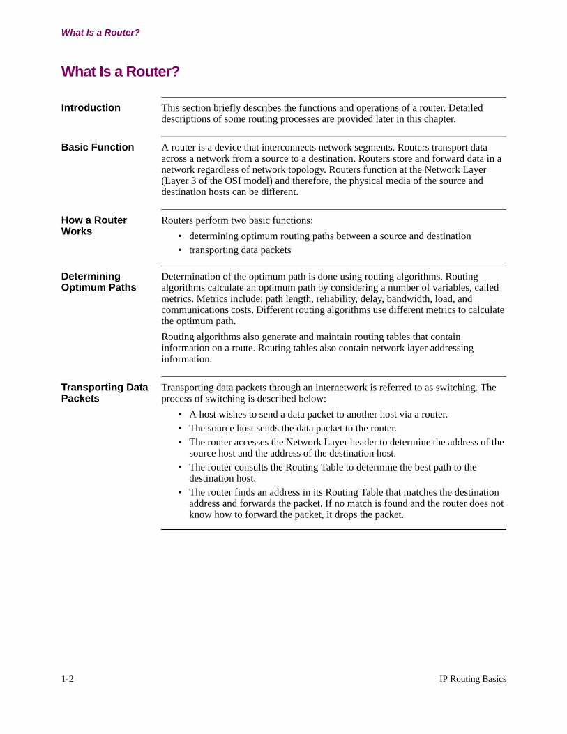
Introduction This section briefly describes the functions and operations of a router. Detailed descriptions of some routing processes are provided later in this chapter.
Basic Function A router is a device that interconnects network segments. Routers transport data across a network from a source to a destination. Routers store and forward data in a network regardless of network topology. Routers function at the Network Layer (Layer 3 of the OSI model) and therefore, the physical media of the source and destination hosts can be different.
How a Router Works
Routers perform two basic functions:
• determining optimum routing paths between a source and destination• transporting data packets
Determining Optimum Paths
Determination of the optimum path is done using routing algorithms. Routing algorithms calculate an optimum path by considering a number of variables, called metrics. Metrics include: path length, reliability, delay, bandwidth, load, and communications costs. Different routing algorithms use different metrics to calculate the optimum path.
Routing algorithms also generate and maintain routing tables that contain information on a route. Routing tables also contain network layer addressing information.
Transporting Data Packets
Transporting data packets through an internetwork is referred to as switching. The process of switching is described below:
• A host wishes to send a data packet to another host via a router.• The source host sends the data packet to the router.• The router accesses the Network Layer header to determine the address of the
source host and the address of the destination host.• The router consults the Routing Table to determine the best path to the
destination host. • The router finds an address in its Routing Table that matches the destination
address and forwards the packet. If no match is found and the router does not know how to forward the packet, it drops the packet.

IP Routing Basics 1-3
T0100-03, Revision V Release 7.3
Internet Protocol Routing
Internet Protocol Routing
Introduction The Internet Protocol suite is used for communication across interconnected networks such as LANs or WANs.
Example Routers in a IP Network
Routers interconnect Internet Protocol (IP) networks as shown in Figure 1-1.
Figure 1-1. Example of an IP Network
IP Protocol The IP protocol is a Layer 3 (Network layer) protocol of the Internet Protocol suite and provides packet processing including fragmentation and reassembly for transporting data packets over a network.
Connectionless Service
IP protocol provides connectionless, best effort service for packet delivery. Connectionless means that each successive packet between the same IP source and destination is individually routed and may follow a different path than its predecessor.
A Transport layer protocol, such as the Transmission Control Protocol (TCP), is responsible for ensuring packet delivery reliability. It implements a reliable transport service on top of the routing delivery service provided by IP.
Another Transport layer protocol, User Datagram Protocol (UDP), makes a best effort to deliver packets to destinations, but does not guarantee that the packet arrives. The result of this service is that packets may be lost or delivered out of sequence. Such conditions are not detected, and neither the sender nor the receiver is informed of the result.
NetworkSegment
Host
Router
Host
Host
Router
HostHost
Host
NetworkSegment
NetworkSegment
1-4 IP Routing Basics
IP Addressing
IP Addressing
Function IP addresses identify where a host’s interface attaches to the IP network or to a particular network segment. If a host has more than one interface attached to the network, that host has an IP address for each connection. In this way, an IP address is like a postal street address that indicates where to send the data but does not define who is to receive the data at that address.
IP Address Hierarchy
An IP address is a 32-bit number contained in the header of an IP datagram that encodes network segment identification and identification of a unique host on that network. This 32-bit number is commonly represented in dotted decimal notation in which a decimal integer represents one octet of the 32-bit address.
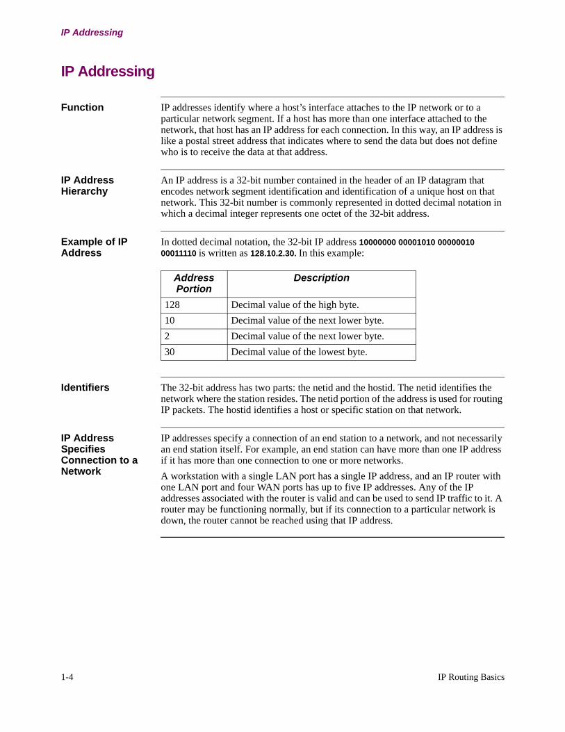
Example of IP Address
In dotted decimal notation, the 32-bit IP address 10000000 00001010 00000010 00011110 is written as 128.10.2.30. In this example:
Identifiers The 32-bit address has two parts: the netid and the hostid. The netid identifies the network where the station resides. The netid portion of the address is used for routing IP packets. The hostid identifies a host or specific station on that network.
IP Address Specifies Connection to a Network
IP addresses specify a connection of an end station to a network, and not necessarily an end station itself. For example, an end station can have more than one IP address if it has more than one connection to one or more networks.
A workstation with a single LAN port has a single IP address, and an IP router with one LAN port and four WAN ports has up to five IP addresses. Any of the IP addresses associated with the router is valid and can be used to send IP traffic to it. A router may be functioning normally, but if its connection to a particular network is down, the router cannot be reached using that IP address.
Address Portion
Description
128 Decimal value of the high byte.
10 Decimal value of the next lower byte.
2 Decimal value of the next lower byte.
30 Decimal value of the lowest byte.
IP Routing Basics 1-5
T0100-03, Revision V Release 7.3
IP Addressing
IP Address Classes
Introduction IP addresses are designated in the following classes: Class A, Class B, and Class C. A host determines the class of IP address by examining the high order bits of the address.
IP Address Classifications
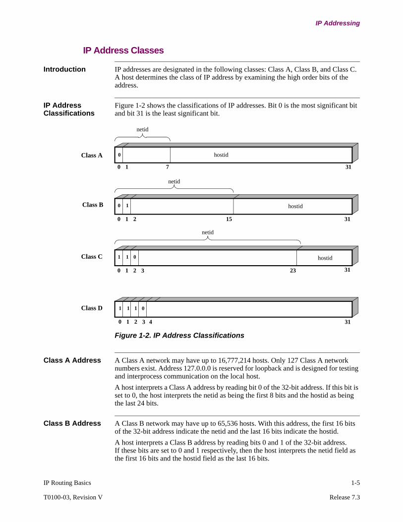
Figure 1-2 shows the classifications of IP addresses. Bit 0 is the most significant bit and bit 31 is the least significant bit.
Figure 1-2. IP Address Classifications
Class A Address A Class A network may have up to 16,777,214 hosts. Only 127 Class A network numbers exist. Address 127.0.0.0 is reserved for loopback and is designed for testing and interprocess communication on the local host.
A host interprets a Class A address by reading bit 0 of the 32-bit address. If this bit is set to 0, the host interprets the netid as being the first 8 bits and the hostid as being the last 24 bits.
Class B Address A Class B network may have up to 65,536 hosts. With this address, the first 16 bits of the 32-bit address indicate the netid and the last 16 bits indicate the hostid.
A host interprets a Class B address by reading bits 0 and 1 of the 32-bit address. If these bits are set to 0 and 1 respectively, then the host interprets the netid field as the first 16 bits and the hostid field as the last 16 bits.
0
0 1 7 31
netid
hostid
0 1
0 1 2 15
netid
hostid
31
1 1
0 1 2 23
netid
hostid
313
0
1 1
0 1 2 3
1 0
4 31
Class A
Class B
Class C
Class D
1-6 IP Routing Basics
IP Addressing
Class C Address A Class C network can have up to 254 hosts. With this address, the first 24 bits of the 32-bit address indicate the netid and the last 8 bits indicate the hostid.
A host interprets a Class C address by reading bits 0, 1, and 2 of the 32-bit address. If these bits are set to 1, 1, and 0 respectively, then the host interprets the netid field as the first 24 bits and the hostid field as the last 8 bits.
Class D Address This address class is use for multicasting.
Multiple IP Addresses on the Same Interface
The implementation of IP lets you assign multiple IP host addresses on the same interface. Multiple IP addresses are useful for:
• Migrating from one IP address to another.• Using two subnets on the same physical link. For example, it is possible that
the number of hosts on the physical network segment exceeds the capacity of the current subnet. When this occurs, another subnet must be added to the physical network segment.
NoteWhen using multiple addresses, be sure that each host can accept the broadcast address that the network is using.
IP Routing Basics 1-7
T0100-03, Revision V Release 7.3
IP Addressing
Subnet Addresses (Subnetting)
Introduction Subnet addressing or subnetting lets a site with multiple physical network segments use a single IP network number. Subnetting adds another level of hierarchy to the internet addressing structure. Instead of a 2-level (netid and hostid) hierarchy, there is a 3-level hierarchy consisting of netid, subnetid, and hostid. An organization is assigned IP network numbers and is free to assign a subnet number to each of its physical network segments (LANs and WANs).
Subnetting Divides Addresses
Subnetting changes the interpretation of the IP address because it divides the address into a network ID, subnet ID, and host ID. The network segment is then identified by a combination of network ID and subnet ID.
There is no set standard for the width of the subnet part; it can be a few bits wide or include most of the width of the hostid field.
At least two bits must be allocated to the hostid. The hostid values of all ones and all zeroes are reserved for broadcasts.
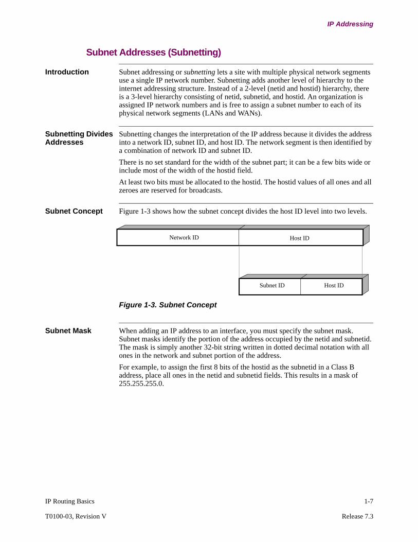
Subnet Concept Figure 1-3 shows how the subnet concept divides the host ID level into two levels.
Figure 1-3. Subnet Concept
Subnet Mask When adding an IP address to an interface, you must specify the subnet mask. Subnet masks identify the portion of the address occupied by the netid and subnetid. The mask is simply another 32-bit string written in dotted decimal notation with all ones in the network and subnet portion of the address.
For example, to assign the first 8 bits of the hostid as the subnetid in a Class B address, place all ones in the netid and subnetid fields. This results in a mask of 255.255.255.0.
Host IDNetwork ID
Subnet ID Host ID

1-8 IP Routing Basics
IP Addressing
Example of an Eight-Bit Subnet Mask
Figure 1-4 shows an example of an eight-bit subnet mask of the IP address of 132.72.15.4.
Figure 1-4. Eight-Bit Subnet Mask
Subnet ID The subnetid can consist of any number of host field bits; you do not need to use multiples of eight. As an example, you may want to assign the first 10 bits of the hostid as the subnetid. This creates a mask of 255.255.255.192.
Example of a Ten-Bit Subnet Mask
Figure 1-5 shows a mask of 255.255.255.192.
Figure 1-5. Ten-Bit Subnet Mask
1
0 1 7
Network ID
255
FF
IP Address 0 0 0 1 0 0 0 1 0 0 1 0 0 0 0 0 0 0 1 1 1 1 0 0 0 0 0 1 0 0
3115 23
Subnet ID Host ID
Hex Mask
Dotted Decimal
FF
255 255 0
FF 0000
1
0 1 7
Network ID
255
FF
IP Address 0 0 0 1 0 0 0 1 0 0 1 0 0 0 0 0 0 0 0 1 1 1 1 1 X X X X X X
3115 23
Subnet ID Host ID
Hex Mask
Dotted Decimal
FF
255 255 192
FF C000
IP Routing Basics 1-9
T0100-03, Revision V Release 7.3
IP Addressing
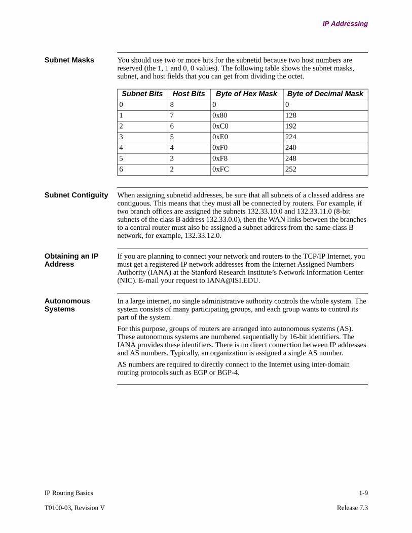
Subnet Masks You should use two or more bits for the subnetid because two host numbers are reserved (the 1, 1 and 0, 0 values). The following table shows the subnet masks, subnet, and host fields that you can get from dividing the octet.
Subnet Contiguity When assigning subnetid addresses, be sure that all subnets of a classed address are contiguous. This means that they must all be connected by routers. For example, if two branch offices are assigned the subnets 132.33.10.0 and 132.33.11.0 (8-bit subnets of the class B address 132.33.0.0), then the WAN links between the branches to a central router must also be assigned a subnet address from the same class B network, for example, 132.33.12.0.
Obtaining an IP Address
If you are planning to connect your network and routers to the TCP/IP Internet, you must get a registered IP network addresses from the Internet Assigned Numbers Authority (IANA) at the Stanford Research Institute’s Network Information Center (NIC). E-mail your request to [email protected].
Autonomous Systems
In a large internet, no single administrative authority controls the whole system. The system consists of many participating groups, and each group wants to control its part of the system.
For this purpose, groups of routers are arranged into autonomous systems (AS). These autonomous systems are numbered sequentially by 16-bit identifiers. The IANA provides these identifiers. There is no direct connection between IP addresses and AS numbers. Typically, an organization is assigned a single AS number.
AS numbers are required to directly connect to the Internet using inter-domain routing protocols such as EGP or BGP-4.
Subnet Bits Host Bits Byte of Hex Mask Byte of Decimal Mask
0 8 0 0
1 7 0x80 128
2 6 0xC0 192
3 5 0xE0 224
4 4 0xF0 240
5 3 0xF8 248
6 2 0xFC 252
1-10 IP Routing Basics
Types of Routing
Types of Routing
Introduction This section describes the types of routing including:
• dynamic routing• static routing
Dynamic Routing A dynamic route is one that is learned through the Open Shortest Path First (OSPF), Routing Interior Protocol (RIP), or Exterior Gateway Protocol (EGP) protocols. These protocols regularly update their routing tables as network conditions change. Dynamic routing lets the router bypass network failures.
Static Routing A static route is a route that never changes. It is also one that you must enter when configuring IP. Static routes are used when the router is unable to determine the correct route dynamically.
Routing Tables IP uses routing tables to decide where to send a packet. The routing table lists all network segments that IP knows how to reach. The routing table contains both dynamic and static routes.

IP Routing Basics 1-11
T0100-03, Revision V Release 7.3
Types of Routing
How IP Routing Works
Routing This table describes how IP routing works:
Action Result/Description
IP receives the packet and reads the 32-bit destination address found within the packet header.
If Then
The packet is destined for this router.
Further routing is not necessary and IP hands the packet to the appropriate internal software module.
Packets in this category include:• Control packets for IP, itself• Routing update packets• Packets used for diagnostic
purposes (ping)
The packet is destined for a host on a network segment that is directly connected.
IP matches the 32-bit destination address with the appropriate physical address in the ARP table.
IP then hands the packet to the appropriate lower-level protocol module for transmission directly to the destination node.
The packet is destined for a host on a remote network segment.
IP uses the routing table to determine which router interface leads to that network segment.
Each entry in the routing table contains a destination address and the IP address of the next hop router.If IP matches the destination address in the table with the destination contained in the packet, the packet is handed to the appropriate lower level protocol module for transmission to that next hop.

1-12 IP Routing Basics
Types of Routing
Other IP Tasks IP also performs several other major tasks including:
• Maintaining default gateways• Address filtering to block incorrect addresses• Controlling access
You can control access of packet traffic to IP networks, subnets, and hosts on those nets and subnets.
If Then
The packet has no entry for its IP address in the routing table
The packet is routed to the default router.
Default routers are used to route packets whose destination address is not found in the routing table. The default router knows the location of the packet’s destination.For additional information, refer to the “Default Routers” section in this guide.
Action (continued) Result/Description

IP Routing Basics 1-13
T0100-03, Revision V Release 7.3
Internet Control Message Protocol (ICMP)
Internet Control Message Protocol (ICMP)
What is ICMP? Internet Control Message Protocol (ICMP) is a message control and error-reporting protocol used between two end points in a network. ICMP messages provide feedback about problems in a network or report errors in processing IP data packets. ICMP only reports errors and does not ensure reliability of the network.
ICMP Packets The Vanguard processes the following Internet Control Message Protocol (ICMP) packets:
NoteCurrently, ICMP receives a Redirect or Destination Unreachable packet only when it originates a “ping” (echo) packet.
Any ICMP packet not listed as “received” causes an ICMP.4 trap event.
TX RX ICMP Type Type # Subtype Subtype #
TX RX Echo reply 0
TX RX Dest Unreachable 3 Unreachable Net
0
Unreachable Host 2
1
Unreachable Protocol
2
Unreachable Port
3
Fragmentation Needed
4
Source Route Fail
5
TX RX Redirect 5 Redirect to Host 1
TX RX Echo 8
TX RX Time to Live Exceeded
11 Time exceeded in transit 0
TX Parameter Problem 12
TX Mask Reply 18

This page intentionally left blank.
Vanguard IP Routing 2-1
Chapter 2Vanguard IP Routing
Overview
Introduction This chapter highlights IP Routing functionality supported by the Vanguard Router.

2-2 Vanguard IP Routing
Address Resolution Protocol
Address Resolution Protocol
Introduction The Address Resolution Protocol (ARP) is a low-level protocol that dynamically learns and maps network layer IP addresses to physical Medium Access Control (MAC) addresses, for example, Ethernet. Given only the network layer IP address of the destination system, ARP lets a router find the MAC address of the destination host on the same network segment.
For example, a router receives an IP packet destined for a host connected to one of its LANs. The packet contains only a 32-bit IP destination address. To be able to forward the packet on the LAN, the router must construct the Data Link layer header using the physical MAC address of the destination host. The router must acquire this physical MAC address of the destination host and map that address to the 32-bit IP address.
To obtain the physical address of the host, the router broadcasts an ARP request to all host of the network. Only the host with that IP address responds with its physical MAC address. The router saves the IP/MAC address mapping in a table called ARP cache and it can use this mapping in the future when forwarding packets to the destination host.
RFC RFC 826 documents the ARP protocol.
ARP Physical Address Broadcast
Figure 2-1 shows the steps involved in an ARP broadcast.
Figure 2-1. ARP Physical Address Broadcast
Router ReceivesPacket
Router ReadsDestination Addressand Accesses ARP
Cache
IsDestination
Address in ARPCache
?
Forward Packetto Destination Host
YES
NO Queue Packet
Router Adds Entryto ARP Caches
Router Transmits Queued Packets
Packets Forwardedto Destination Host
ARP Response
Received or Timer Expires
?
Timer Expires
ARP Response Received
Sends ARP Request

Vanguard IP Routing 2-3
T0100-03, Revision V Release 7.3
Address Resolution Protocol
NoteIf the ARP cache does not contain an entry for a destination, the packet is queued pending an ARP Response. This means that the first packet sent between IP Hosts is queued until the expiration of the Time to Retry timer. If an ARP Response is not received within this time an ARP Request is retransmitted. All IP-based protocols perform this function.
ARP Process Figure 2-2 shows an example of the ARP process.
Figure 2-2. ARP Process
ARP Address Broadcast Description
The following table describes the ARP process shown in Figure 2-2:
Updated ARP Cache
IP Address
MAC Address
LAN IP
Vanguard
IP Packet with IPAddress=219.1.82.07
1
23
4a
4b
MAC AddressIP Address
219.1.82.55
219.1.82.23
219.1.82.07
10-00-5A-00-00-33
10-00-5A-00-00-02
10-00-5A-00-00-A7
Ethernet
ARP Cache
IP Address
MAC Address
4c
Item Action
1 An IP packet arrives at the router with a destination network address of 219.1.82.07.
2 The router determines that the packet must be delivered on the local Ethernet interface. It references its ARP Cache table to look up the MAC address corresponding to the station that has the network address 219.1.82.07.
NoteIn this example, the ARP Cache table does not have an entry for network address 219.1.82.07.

2-4 Vanguard IP Routing
Address Resolution Protocol
NoteIf a second IP packet, intended for the same Destination Address, arrives while the device is awaiting an ARP Response, the packet is queued but a second ARP Request is not sent. When another IP packet, intended for a different Destination Address, arrives while the device is awaiting an ARP Response for the first packet, an ARP Request for the second Destination Address is immediately broadcast to the network.
How the Vanguard Router handles ARP
The Vanguard maintains tables of confirmed ARP mappings of IP and MAC addresses. The ARP operation normally does not require configuration. The Vanguard Router, however, provides configurable parameters to control ARP operation in unusual cases. These parameters controls how often entries are flushed if not used and/or refreshed by the ARP procedure. In addition, the Vanguard allows you to manually enter IP/MAC address mappings which are saved in an ARP Static Cache Table.
Configuring ARP The Vanguard provides two ARP records:
• Configure ARP : Parameters • Configure ARP : Static Cache
For configuration information and detailed parameter descriptions refer to “Configuring the Address Resolution Protocol (ARP)” section on page 3-87.
3 The ARP request is launched to the network with a broadcast address. The Time to Retry timer starts to count.
4 An ARP Response is received and:a)The station that sees its IP address in the ARP request packet
responds with its MAC address.
b)The ARP Cache table is updated with the learned information so that the ARP procedure does not have to be repeated if another packet arrives to IP address 219.1.82.07.
c)The IP packet destined for address 219.1.82.07 is sent to the host with that address.
The Time to Retry timer expires.The second ARP request is launched to the network with a broadcast address.If an ARP Response is not received by for the second time, the queued packet is dropped.
Item Action (continued)

Vanguard IP Routing 2-5
T0100-03, Revision V Release 7.3
Address Resolution Protocol
Proxy ARP
Introduction Modern IP hosts, such as workstations and PCs, transmit directly to either a destination host or router. If the destination is on the same IP network and subnetwork as the sender’s, the sender transmits an ARP request to determine the destination MAC address and then transmits directly to it over the LAN. If the destination’s net/subnet is not the same as the sender’s, the sender transmits the packet to a router. Hosts are usually configured manually with a default router, which is the IP address of a router on their LAN.
Older hosts may always attempt to ARP for a destination address, even if it is not on the local LAN. The older host expects the router to respond to the ARP request with the router’s MAC address. This is called Proxy ARP.
Hosts With No Subnet Support
If the host attempts to send a packet to a network subnet, it sends an ARP request to find the MAC address of the destination host. If the subnet is not on the local wire, a router configured for ARP subnet routing may respond to the ARP request with its own MAC address if the following conditions exist:
• The router has the location of the subnet in its routing table.• The router sends packets to that subnet via a different interface than the interface
that received the ARP request.Because of the second condition, configure all routers on a local wire for ARP subnet routing when you use hosts without network subnet support.
Proxy ARP Request Example
The following list describes the sequence when a station requiring Proxy ARP wants to send an IP packet to a host on a remote network:
• The host issues an ARP request that contains the destination IP address.• Any router enabled to respond looks at the IP address for a match in its
routing table.• If there is a match and the route does not pass back through the same LAN
port where the ARP host resides, the router responds with an ARP response supplying its MAC address. Finding a match without passing back through the ARP host port implies another router is present, has a shorter path to the destination, and replies to the ARP itself.
• The host then sends the packet to the router using the newly learned MAC address.
• The host stores this information (that is, the mapping of the IP address to the MAC address) in a local cache so that if it sends another packet to the same destination, it can do so without sending an ARP Request.
• The information is not used. The information is aged out of the cache and may be relearned by resending an ARP Request.
Caution When Using Proxy ARP
The use of proxy ARP is discouraged in modern IP operation. Few hosts require it.
How the Vanguard Handles Proxy ARP
The Vanguard can be enabled to act as a Proxy and respond to an ARP request from a host or it can be disabled to ignore the ARP request.

2-6 Vanguard IP Routing
Address Resolution Protocol
Configuring Proxy ARP
The Vanguard provides one configurable parameter to enable or disable Proxy ARP:
• Proxy ARP ParameterThis parameter is located under the Configure->Configure Router->ARP->Parameters menu. For more information refer to “Configuring the Address Resolution Protocol (ARP)” section on page 3-87.

Vanguard IP Routing 2-7
T0100-03, Revision V Release 7.3
Address Resolution Protocol
Proxy Subnet ARP
Introduction Proxy Subnet ARP is the same as Proxy ARP except that the router responds to ARP requests for hosts it knows are on other subnets remote from the local subnetwork. Sometimes hosts forward to a router for destinations with different class A, B, or C addresses, but ARP for any destination with the same class A, B, or C address as their own. They do not know about subnets of the class A, B, or C addresses. They expect the router to respond to the ARP for all subnets of the local class A, B, and C net and to forward to the proper subnet.
Proxy Subnet ARP Example
The following example shows that a host functioning with ARP does not use subnetting (i.e., subnetting is not configured or software does not include subnetting). Unless the router is enabled to respond using Proxy ARP subnet, it does not respond to this ARP and denies connectivity to other subnets of the same IP network.
Example Addressing DescriptionA single IP class B network number 128.12.0.0 is used to define two subnetworks connected by a router: 128.12.1.0 and 128.12.2.0 (mask 255.255.255.0). The host is on 128.12.1.0 and is attempting to send to 128.12.2.1.
How the Vanguard Handles Proxy Subnet ARP
The Vanguard handles Proxy Subnet ARP using the Proxy Subnet ARP parameter. With Proxy Subnet ARP parameter enabled, the Vanguard responds to an ARP request from a host when the IP address is for a subnetwork remote from the local subnetwork. When the Proxy ARP Subnet parameter is disabled, the router does not respond to hosts’ ARPs, and thus confines them to the local subnetwork.
NoteARPs are not passed through the router network; they are confined to the locally attached network.
If Then
The host used subnetting It sends a packet to its default router and relies on the router to get the packet delivered to the destination 128.12.2.0.
The host does not use subnetting It sees the IP network address as 128.12.0.0 (it only knows IP network addresses and therefore uses a class B mask of 255.255.0.0 to obtain 128.12.0.0) and calculates that the destination is on the local LAN (because it has the same network number as itself). It therefore ARPs for the 128.12.2.1 address. The router must enable Proxy Subnet ARP in order to respond with the router’s MAC address.

2-8 Vanguard IP Routing
Address Resolution Protocol
Configuring Proxy Subnet ARP
Proxy Subnet ARP parameter is located under the Configure->Configure Router-> ARP->Parameters menu. For more information refer to “Configuring the Address Resolution Protocol (ARP)” section on page 3-87.
Vanguard IP Routing 2-9
T0100-03, Revision V Release 7.3
Address Resolution Protocol
Inverse ARP
Description Inverse ARP is a protocol which allows a device to automatically determine the IP Address of a remote device in a Frame Relay network. As implemented, Inverse ARP allows non-Vanguard Networks routers to automatically determine the IP Addresses of the 6520 branch routers.
NoteInverse ARP conforms to RFC 1293; however, Vanguard only responds to requests. Vanguards do not send requests.
Enable Inverse ARP
There are no configurable parameters for Inverse ARP at the Vanguard end. To implement this feature, you must enable Inverse ARP at the non-Vanguard Networks router.
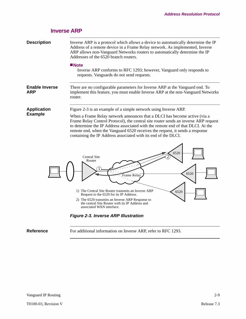
Application Example
Figure 2-3 is an example of a simple network using Inverse ARP.
When a Frame Relay network announces that a DLCI has become active (via a Frame Relay Control Protocol), the central site router sends an inverse ARP request to determine the IP Address associated with the remote end of that DLCI. At the remote end, when the Vanguard 6520 receives the request, it sends a response containing the IP Address associated with its end of the DLCI.
Figure 2-3. Inverse ARP Illustration
Reference For additional information on Inverse ARP, refer to RFC 1293.
6520
6520
6520
Central SiteRouter
1) The Central Site Router transmits an Inverse ARP Request to the 6520 for its IP Address.
2) The 6520 transmits an Inverse ARP Response to the central Site Router with its IP Address and associated WAN interface.
1
2
Frame Relay

2-10 Vanguard IP Routing
Duplicate IP Address Detection
Duplicate IP Address Detection
Duplicate IP Address Detection Defined
Duplicate IP Address Detection is used to detect if the same IP address has been configured on multiple IP devices on the same LAN. If a user configures the Vanguard Interface with the same IP address as another device on the same LAN, the network will not work properly. Both devices could receive and respond to packets with that common IP address.
NoteThis feature works only in IPv4. In the IPv6 protocol suite RFC 2462 provides a similar mechanism which can detect IP address duplication, but RFC 2462 is not fully supported in the Vanguard products.
Duplicate IP Address Detection
Similar to the IPv6 protocol suite RFC 2462 the Vanguard uses the Address Resolution Protocol (ARP) to check for duplicate IP addresses on the LAN. Before the interface is declared active an ARP request is sent out with the target IP address set to the IP address of the Vanguard's LAN interface. If there is another device on the LAN with an IP address that matches that target address it generates an ARP response. When the Vanguard receives that ARP response it generates an alarm and the LAN interface does not become operational. If the Vanguard does not receive an ARP response after three requests it generates its own response to let the other devices on the LAN know that the IP address is valid. Then the Vanguard changes the interface to an operational status (UP state).
NoteDuplicate IP Address Detection cannot detect all the address duplication problems. There is not a central database to hold all the IP address configurations of a full network. Only unicast addresses are checked.
Third Party Support
When using Duplicate IP Address Detection with another vendor’s router, our router has the ability to declare if the configured IP address is a duplicate or not. When our router is working before other vendor’s router joins in and there is an IP address duplicated, our IP address is not declared as duplicated. Our router has the ability to tell the operator that some IP address in the network is not correct and that we should not respond to the ARP request. The ARP cache is not updated.
Duplicate Address Detection Parameter
To support Duplication IP Address Detection a new parameter has been added in the IP Interface configuration Menu called Duplicate Address Detection. See “IP Interface Configuration Table” section on page 3-24.
Vanguard IP Routing 2-11
T0100-03, Revision V Release 7.3
Duplicate IP Address Detection
Example of Duplicate IP Address Detection on a LAN
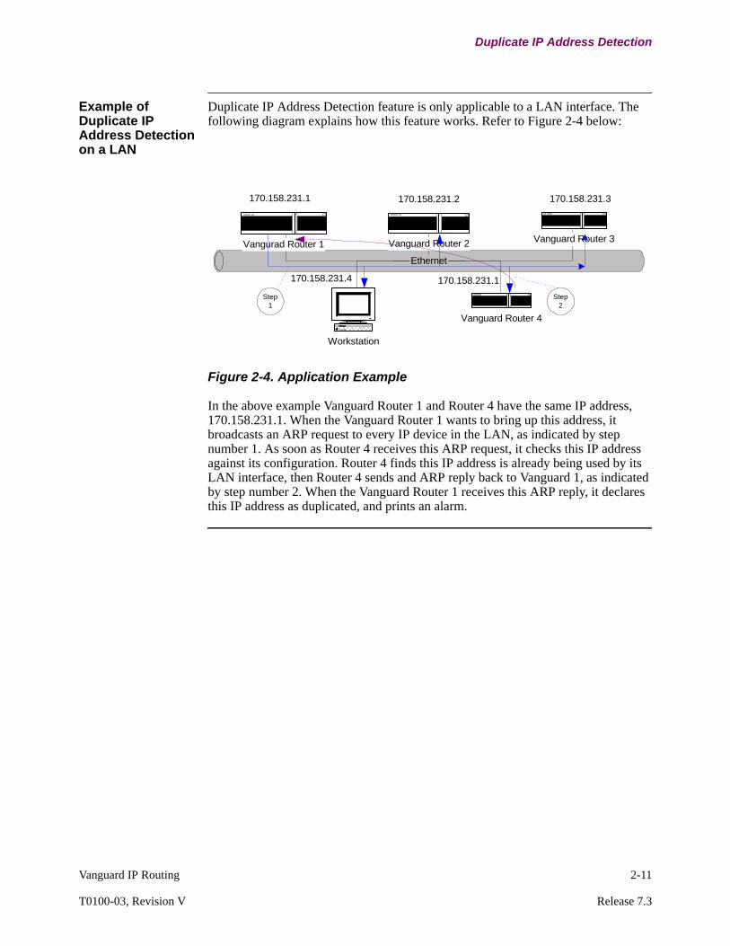
Duplicate IP Address Detection feature is only applicable to a LAN interface. The following diagram explains how this feature works. Refer to Figure 2-4 below:
Figure 2-4. Application Example
In the above example Vanguard Router 1 and Router 4 have the same IP address, 170.158.231.1. When the Vanguard Router 1 wants to bring up this address, it broadcasts an ARP request to every IP device in the LAN, as indicated by step number 1. As soon as Router 4 receives this ARP request, it checks this IP address against its configuration. Router 4 finds this IP address is already being used by its LAN interface, then Router 4 sends and ARP reply back to Vanguard 1, as indicated by step number 2. When the Vanguard Router 1 receives this ARP reply, it declares this IP address as duplicated, and prints an alarm.
Ethernet
Vangurad Router 1 Vanguard Router 2 Vanguard Router 3
Vanguard Router 4
Workstation
170.158.231.1 170.158.231.2 170.158.231.3
170.158.231.4 170.158.231.1
Step1
Step2
2-12 Vanguard IP Routing
Destination Based Routing
Destination Based Routing
Introduction Destination based routing refers to routers which forward packets to a destination using routing information from:
• routes stored a static routing table• dynamic routes via algorithms
With policy based routing, routes are determined by defined policies and flows. For more information on policy based routing, refer to “Policy Based Routing” section on page 2-172.
Static Routing Support
Static routing is used for simple networks that do not change often. With static routing the network administrator must set up a static routing table and manually enter the destination IP address, next hop address, and metric. Use these tables if you calculate a route without using the RIP routing protocol. You can use static routing to augment or replace dynamic routing protocols such as RIP to reduce routing protocol overhead on low speed links.
You can enter up to 1024 routing entries. For information on configuring the Static Routes table refer to “IP Static Route Table Configuration” section on page 3-64. The Static Route Table can be access from:
Configure ->Configure Router ->Configure IP ->Static Route
Dynamic Routing Support
Dynamic routing is more suitable for the current large and changing networks. Dynamic routing algorithms analyze routing update messages, recalculate routes, and redefine routes in the routing table. The Vanguard supports these dynamic routing algorithms:
• Routing Information Protocol (RIP) Versions 1 and 2• Open Shortest Path First (OSPF) Version 2
OSPF For more information on OSPF and configuring OSPF refer to the OSPF Manual (Part Number T0100-04).
Vanguard IP Routing 2-13
T0100-03, Revision V Release 7.3
Routing Information Protocol (RIP)
Routing Information Protocol (RIP)
Introduction Routing Information Protocol (RIP) is an Interior Gateway Protocol used to exchange routing information within a domain or autonomous system.
RIP lets routers exchange information about destinations for the purpose of computing routes throughout the network. Destinations may be individual hosts, networks, or special destinations used to convey a default route.
RIP is based on the Bellman-Ford or the distance-vector algorithm. This means RIP makes routing decisions based on the hop count between a router and a destination.
RIP does not alter IP packets; it routes them based on destination address only.
2-14 Vanguard IP Routing
Routing Information Protocol (RIP)
RIP Version 1 Support
Overview RIP Version 1 contains minimal amount of information required for routers to route data within a network. A RIP Version 1 packet contains the following information:
• Version - the version of RIP• Command - Request, Response• Address Family - used to identify the protocol associated with the address• IP Address• Metric or hop count - indicates the number of hops (routers) the packet must
traverse before reaching the destination
Maximum Hop Count
RIP permits a maximum hop count of 15 and any destination with a hop count exceeding 15 identifies it as unreachable and after time it is removed from the routing table. The maximum hop count restricts RIP use in large networks, however, it prevents the problem of repetitive, network loops.

Vanguard IP Routing 2-15
T0100-03, Revision V Release 7.3
Routing Information Protocol (RIP)
RIP Version 2 Support
Overview RIP Version 2 is an extension of RIP Version 1. It expands the amount of useful information in RIP packets and adds security features.
RIP Version 2 shares the same basic functionality of RIP Version 1, however, it resolves some of the shortcomings of the earlier version by providing the following enhancements:
• Support for Variable Length Subnet Masks• Support for discontiguous subnets• Password authentication• IP address multicasting support
RIP Version 2 lets you design IP networks where you need VLSM and Authentication support without the complexity of OSPF. Moreover, RIP Version 2 may be a better solution in some less complex networks where the limitations of 15 hops maximum and fixed metrics is not prohibitive.
Backward Compatibility
RIP Version 2 routers receive and send either RIP Version 2 or RIP Version 1 messages, depending on how you configure the interfaces on your routers. This means you can have routers running either RIP Version 1 or RIP Version 2 in your network. In addition, you can configure your routers to pass either or both versions’ packets.
NoteUsing IP Multicasting in your network prevents RIP Version 1 routers from receiving RIP Version 2 messages. For more information refer to“IP Multicasting” section on page 2-80.
Maximum Hop Count
Because of the requirement for compatibility with RIP Version 1, RIP Version 2 adheres to same maximum hop count of 15.
RIP Limitations RIP is primarily intended for use in homogeneous networks of moderate size. Because of this, RIP has some specific limitations including:
• As the maximum number of hops is limited to 15 hops, a hop count of 16 is considered infinite.
• The RIP metric (hop count) cannot adequately describe variations in a path’s characteristics and this could result in suboptimal routing. For example, hop count does not evaluate the link speed of a particular path.
• RIP is slow to find new routes when the network changes. This search consumes considerable bandwidth, and in extreme cases, exhibits a slow convergence behavior referred to as a count to infinity.
2-16 Vanguard IP Routing
Routing Information Protocol (RIP)
RIP Version 2 Packet Format
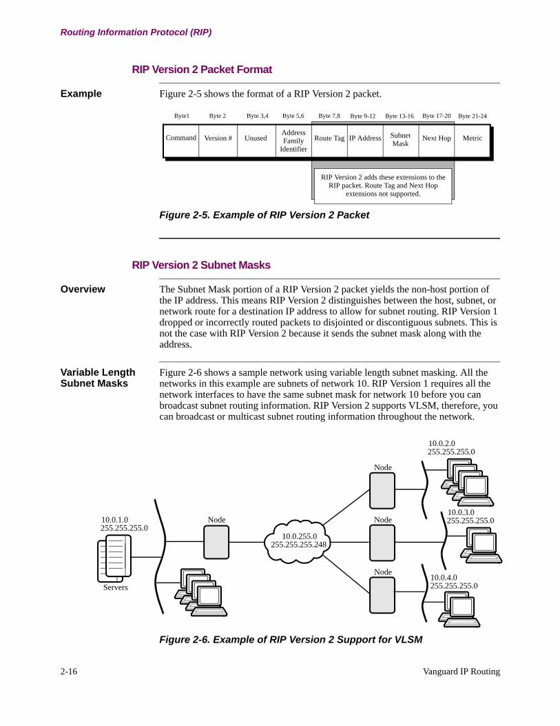
Example Figure 2-5 shows the format of a RIP Version 2 packet.
Figure 2-5. Example of RIP Version 2 Packet
RIP Version 2 Subnet Masks
Overview The Subnet Mask portion of a RIP Version 2 packet yields the non-host portion of the IP address. This means RIP Version 2 distinguishes between the host, subnet, or network route for a destination IP address to allow for subnet routing. RIP Version 1 dropped or incorrectly routed packets to disjointed or discontiguous subnets. This is not the case with RIP Version 2 because it sends the subnet mask along with the address.
Variable Length Subnet Masks
Figure 2-6 shows a sample network using variable length subnet masking. All the networks in this example are subnets of network 10. RIP Version 1 requires all the network interfaces to have the same subnet mask for network 10 before you can broadcast subnet routing information. RIP Version 2 supports VLSM, therefore, you can broadcast or multicast subnet routing information throughout the network.
Figure 2-6. Example of RIP Version 2 Support for VLSM
Byte1 Byte 2 Byte 3,4 Byte 5,6 Byte 7,8 Byte 9-12 Byte 13-16 Byte 17-20 Byte 21-24
Command Version # UnusedAddress Family
Identifier
Route Tag IP Address Subnet Mask
Next Hop Metric
RIP Version 2 adds these extensions to the RIP packet. Route Tag and Next Hop
extensions not supported.
Servers
10.0.1.0255.255.255.0
10.0.255.0255.255.255.248
10.0.2.0255.255.255.0
10.0.3.0255.255.255.0
10.0.4.0255.255.255.0
Node
Node
Node
Node
Vanguard IP Routing 2-17
T0100-03, Revision V Release 7.3
Routing Information Protocol (RIP)
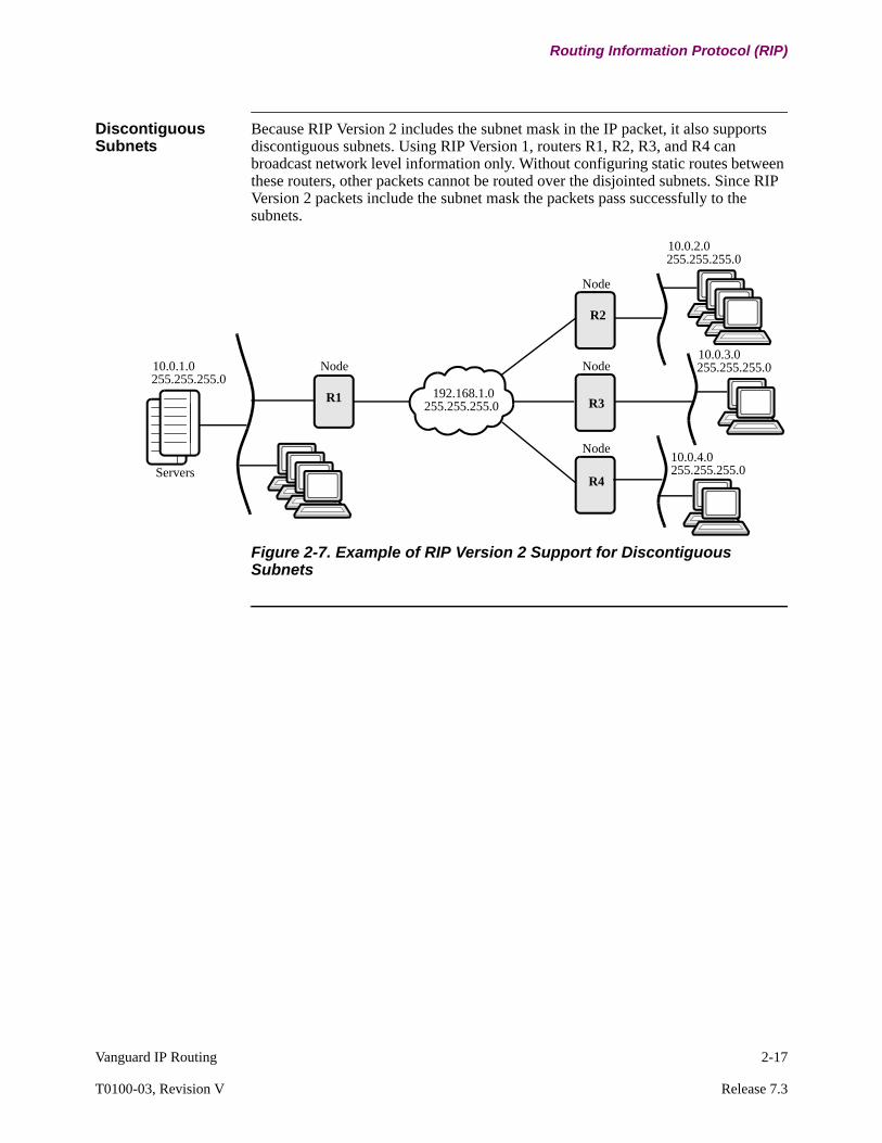
Discontiguous Subnets
Because RIP Version 2 includes the subnet mask in the IP packet, it also supports discontiguous subnets. Using RIP Version 1, routers R1, R2, R3, and R4 can broadcast network level information only. Without configuring static routes between these routers, other packets cannot be routed over the disjointed subnets. Since RIP Version 2 packets include the subnet mask the packets pass successfully to the subnets.
Figure 2-7. Example of RIP Version 2 Support for Discontiguous Subnets
Servers
10.0.1.0255.255.255.0
192.168.1.0255.255.255.0
10.0.2.0255.255.255.0
10.0.3.0255.255.255.0
10.0.4.0255.255.255.0
Node
Node
Node
Node
R1
R2
R3
R4

2-18 Vanguard IP Routing
Routing Information Protocol (RIP)
RIP Version 2 Authentication
Overview Authentication supports a simple 16-byte password key to provide security between routers. This means you can configure a password for each interface on your router. When you enter the password at the CTP, it is contained in the RIP Version 2 packet, and checked against the authentication key configured in the router. Only matching keys are allowed access to the router, as shown in Figure 2-8.
Figure 2-8. Example of RIP Version 2 Authentication
Authentication lets you design networks in which routers need to learn routes through specific routers. In Figure 2-8, routers 1 and 4 exchange routing information and routers 2 and 5 exchange routes.
If you do not configure authentication on a router, any RIP Version 1 or RIP Version 2 messages are accepted by routers.
Authentication does not prevent data corruption.
Authentication is valid for RIP Version 2 packets only.
10.0.0.0
RIP-2
OSPF
OSPF172.17.1.0
172.17.2.0
172.18.1.0
172.16.1.0 172.16.2.0172.16.2.0,255.255.255.0
172.16.1.0,255.255.255.0R1
R2
R3
R4
R5
R6
RIP-2
RIP-2
RIP-2
OSPF
Same Key
Same Key
Vanguard IP Routing 2-19
T0100-03, Revision V Release 7.3
Routing Information Protocol (RIP)
RIP Version 2 Multicasting
Overview RIP Version 2 supports broadcast or multicast updates. This means you can multicast RIP Request or Response datagrams instead of broadcasting them. This increases security and conserves resources on non-RIP hosts.
Using an IP Multicast address reduces the load on hosts unable to support routing protocols such as RIP.
This feature also lets RIP Version 2 routers share information that RIP Version 1 routers cannot hear. This is important since RIP Version 1 routers may misinterpret route information because it cannot apply the subnet mask supplied in RIP Version 2 packets.
NoteIGMP is not needed on a RIP Version 2 router since inter-router messages are not forwarded.

2-20 Vanguard IP Routing
Routing Information Protocol (RIP)
RIP Version 2 and OSPF
Introduction With the improvements of RIP Version 2, the differences between OSPF and RIP are less significant. Both OSPF and RIP version 2 now support:
• Variable Length Subnet Masks• Discontiguous subnets• Authentication• Routing information sent by multicasting
If you must choose between using OSPF and RIP Version 2 for routing operations on your network, keep in mind that OSPF works best in large, hierarchical networks with redundant paths to destinations requiring best path routing decisions. RIP Version 2 works best in small networks with single links to remote destinations or simple backups.
Advantages and Disadvantages of OSPF and RIP
While a solution that combines using both protocols on some nodes may be used, there are some advantages and disadvantages to think about before you make your choice:
OSPF advantages include:
• Scalable for very large networks- OSPF uses a path cost rather than a hop count to determine best path- OSPF can be subdivided into defined areas
• Supports true best path routing• Acknowledges routing information• Easier to troubleshoot• Fast convergence
OSPF disadvantages include:
• Complex network configuration• Higher CPU and memory requirements• No support for SVC rerouting• Update frequency fixed at 30 minute intervals• Increases routing table size• Requires more routers for redundant all OSPF network design• LSA flooding problems in unstable networks
RIP Version 2 advantages include:
• Simple configuration• SVC rerouting • RIP on Demand• Low cost CPU and memory demand

Vanguard IP Routing 2-21
T0100-03, Revision V Release 7.3
Routing Information Protocol (RIP)
RIP Version 2 disadvantages include:
• Hop count limit of 15 hops• Does not always pick the best route because routing decisions are always
made on hop count not congestion or traffic limitations• Slower convergence in large networks• No acknowledgment of routing updates• Difficult to troubleshoot.
2-22 Vanguard IP Routing
How RIP Works
How RIP Works
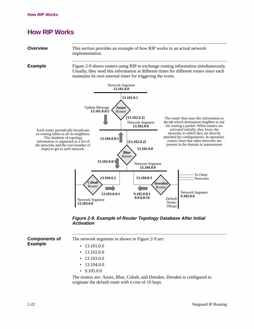
Overview This section provides an example of how RIP works in an actual network implementation.
Example Figure 2-9 shows routers using RIP to exchange routing information simultaneously. Usually, they send this information at different times for different routes since each maintains its own internal timer for triggering the event.
Figure 2-9. Example of Router Topology Database After Initial Activation
Components of Example
The network segments in shown in Figure 2-9 are:
• 13.101.0.0• 13.102.0.0• 13.103.0.0• 13.104.0.0• 9.105.0.0
The routers are: Azure, Blue, Cobalt, and Dresden. Dresden is configured to originate the default route with a cost of 10 hops.
13.104.0.0/1
AzureRouter
Network Segment13.101.0.0
BlueRouter
CobaltRouter
DresdenRouter
13.101.0.0
13.103.0.0/1
To OtherNetworks
Network Segment13.102.0.0
Network Segment13.103.0.0
Network Segment9.105.0.0
Network Segment13.104.0.0
Update Message 13.101.0.0/1
13.102.0.0/1
9.105.0.0/10.0.0.0/10 Default
Route: 10hops
13.101.0.1
13.104.0.2 13.104.0.3
[13.102.0.1]
[13.102.0.2]
Each router periodically broadcasts its routing tables to all its neighbors.
This database of topology information is organized as a list of
the networks and the cost (number of hops) to get to each network.
The router then uses this information to decide which destination neighbor to use
for routing a packet. When routers are activated initially, they know the
networks to which they are directly attached (by configuration). In operation,
routers learn that other networks are present in the domain or autonomous
Vanguard IP Routing 2-23
T0100-03, Revision V Release 7.3
How RIP Works
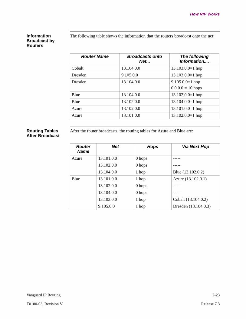
Information Broadcast by Routers
The following table shows the information that the routers broadcast onto the net:
Routing Tables After Broadcast
After the router broadcasts, the routing tables for Azure and Blue are:
Router Name Broadcasts onto Net...
The following Information....
Cobalt 13.104.0.0 13.103.0.0=1 hop
Dresden 9.105.0.0 13.103.0.0=1 hop
Dresden 13.104.0.0 9.105.0.0=1 hop0.0.0.0 = 10 hops
Blue 13.104.0.0 13.102.0.0=1 hop
Blue 13.102.0.0 13.104.0.0=1 hop
Azure 13.102.0.0 13.101.0.0=1 hop
Azure 13.101.0.0 13.102.0.0=1 hop
Router Name
Net Hops Via Next Hop
Azure 13.101.0.0 0 hops -----
13.102.0.0 0 hops -----
13.104.0.0 1 hop Blue (13.102.0.2)
Blue 13.101.0.0 1 hop Azure (13.102.0.1)
13.102.0.0 0 hops -----
13.104.0.0 0 hops -----
13.103.0.0 1 hop Cobalt (13.104.0.2)
9.105.0.0 1 hop Dresden (13.104.0.3)
2-24 Vanguard IP Routing
How RIP Works
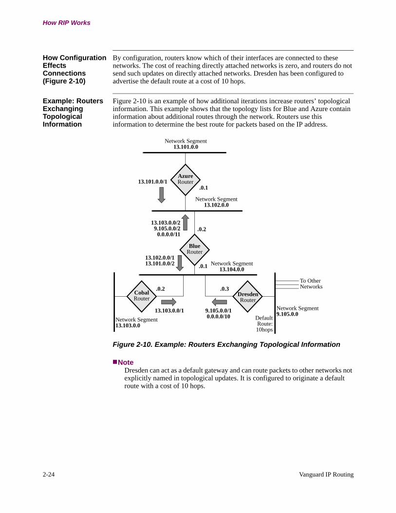
How Configuration Effects Connections (Figure 2-10)
By configuration, routers know which of their interfaces are connected to these networks. The cost of reaching directly attached networks is zero, and routers do not send such updates on directly attached networks. Dresden has been configured to advertise the default route at a cost of 10 hops.
Example: Routers Exchanging Topological Information
Figure 2-10 is an example of how additional iterations increase routers’ topological information. This example shows that the topology lists for Blue and Azure contain information about additional routes through the network. Routers use this information to determine the best route for packets based on the IP address.
Figure 2-10. Example: Routers Exchanging Topological Information
NoteDresden can act as a default gateway and can route packets to other networks not explicitly named in topological updates. It is configured to originate a default route with a cost of 10 hops.
AzureRouter
Network Segment13.101.0.0
BlueRouter
CobalRouter
DresdenRouter
13.103.0.0/1
To OtherNetworks
Network Segment13.102.0.0
Network Segment13.103.0.0
Network Segment9.105.0.0
Network Segment13.104.0.0
13.101.0.0/1
9.105.0.0/10.0.0.0/10 Default
Route: 10hops
.0.1
13.103.0.0/2 9.105.0.0/2
0.0.0.0/11
13.102.0.0/1 13.101.0.0/2
.0.2
.0.2 .0.3
.0.1

Vanguard IP Routing 2-25
T0100-03, Revision V Release 7.3
How RIP Works
Topological Database
After all RIP advertisements have stabilized, the routing tables in Azure and Blue are as follows:
Router Name Net Hops Via Next Hop
Azure 13.101.0.0 0 ---------
13.102.0.0 0 ---------
13.103.0.0 2 13.102.0.2
13.104.0.0 1 13.102.0.2
9.105.0.0 2 13.102.0.2
0.0.0.0 11 13.102.0.2
Blue 13.101.0.0 1 13.102.0.1
13.102.0.0 0 -----------
13.103.0.0 1 13.104.0.2
13.104.0.0 0 -------
9.105.0.0 1 13.104.0.3
0.0.0.0 10 13.104.0.3
2-26 Vanguard IP Routing
RIP Implementation
RIP Implementation
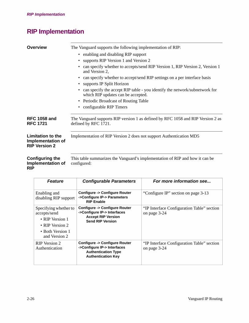
Overview The Vanguard supports the following implementation of RIP:
• enabling and disabling RIP support• supports RIP Version 1 and Version 2• can specify whether to accepts/send RIP Version 1, RIP Version 2, Version 1
and Version 2, • can specify whether to accept/send RIP settings on a per interface basis• supports IP Split Horizon• can specify the accept RIP table - you identify the network/subnetwork for
which RIP updates can be accepted.• Periodic Broadcast of Routing Table• configurable RIP Timers
RFC 1058 and RFC 1721
The Vanguard supports RIP version 1 as defined by RFC 1058 and RIP Version 2 as defined by RFC 1721.
Limitation to the Implementation of RIP Version 2
Implementation of RIP Version 2 does not support Authentication MD5
Configuring the Implementation of RIP
This table summarizes the Vanguard’s implementation of RIP and how it can be configured:
Feature Configurable Parameters For more information see...
Enabling and disabling RIP support
Configure -> Configure Router ->Configure IP-> Parameters
RIP Enable
“Configure IP” section on page 3-13
Specifying whether to accepts/send
• RIP Version 1• RIP Version 2• Both Version 1
and Version 2
Configure -> Configure Router ->Configure IP-> Interfaces
Accept RIP VersionSend RIP Version
“IP Interface Configuration Table” section on page 3-24
RIP Version 2 Authentication
Configure -> Configure Router ->Configure IP-> Interfaces
Authentication TypeAuthentication Key
“IP Interface Configuration Table” section on page 3-24

Vanguard IP Routing 2-27
T0100-03, Revision V Release 7.3
RIP Implementation
Customizing RIP Configure -> Configure Router ->Configure IP-> Parameters
Advertise Default Route Metric
Configure -> Configure Router ->Configure IP-> Interfaces
Learn Network RoutesLearn Subnet RoutesOverride Default RouteOverride Static RoutesAdvertise Default RouteAdvertise Network RoutesAdvertise Subnet RoutesAdvertise Static/Default Routes
“Configure IP” section on page 3-13“IP Interface Configuration Table” section on page 3-24
RIP Route Control Configure -> Configure Router -> Configure IP ->RIP Route Control
Entry NumberIP Network/SubnetIP Address MaskInbound Interface ListOutbound Interface List
“RIP Route Control” section on page 2-31
On Demand RIP Configure -> Configure Router ->Configure IP-> Interfaces
On Demand RIPTriggered Updates
“On-Demand RIP” section on page 2-33“IP Interface Configuration Table” section on page 3-24
RIP Split Horizon Configure -> Configure Router ->Configure IP-> Interfaces
IP RIP Split Horizon
“IP Interface Configuration Table” section on page 3-24
Feature Configurable Parameters For more information see... (continued)
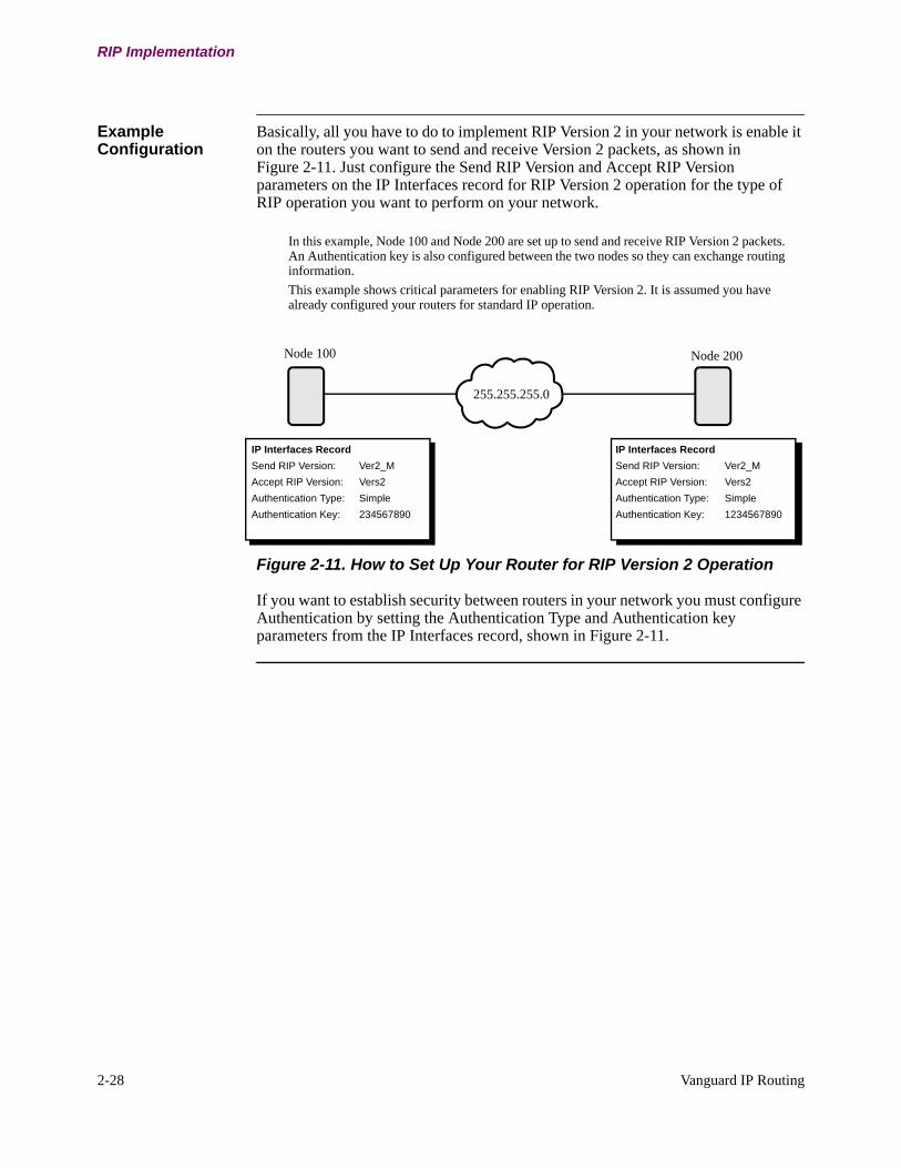
2-28 Vanguard IP Routing
RIP Implementation
Example Configuration
Basically, all you have to do to implement RIP Version 2 in your network is enable it on the routers you want to send and receive Version 2 packets, as shown in Figure 2-11. Just configure the Send RIP Version and Accept RIP Version parameters on the IP Interfaces record for RIP Version 2 operation for the type of RIP operation you want to perform on your network.
Figure 2-11. How to Set Up Your Router for RIP Version 2 Operation
If you want to establish security between routers in your network you must configure Authentication by setting the Authentication Type and Authentication key parameters from the IP Interfaces record, shown in Figure 2-11.
255.255.255.0
IP Interfaces Record
Send RIP Version: Ver2_M
Accept RIP Version: Vers2
Authentication Type: Simple
Authentication Key: 234567890
IP Interfaces Record
Send RIP Version: Ver2_M
Accept RIP Version: Vers2
Authentication Type: Simple
Authentication Key: 1234567890
In this example, Node 100 and Node 200 are set up to send and receive RIP Version 2 packets. An Authentication key is also configured between the two nodes so they can exchange routing information.
This example shows critical parameters for enabling RIP Version 2. It is assumed you have already configured your routers for standard IP operation.
Node 100 Node 200
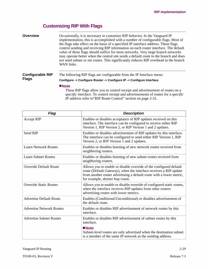
Vanguard IP Routing 2-29
T0100-03, Revision V Release 7.3
RIP Implementation
Customizing RIP With Flags
Overview Occasionally, it is necessary to customize RIP behavior. In the Vanguard IP implementation, this is accomplished with a number of configurable flags. Most of the flags take effect on the basis of a specified IP interface address. These flags control sending and receiving RIP information on each router interface. The default value of these flags should suffice for most networks. Very large branch networks may operate better when the central site sends a default route to the branch and does not send subnet or net routes. This significantly reduces RIP overhead in the branch WAN links.
Configurable RIP Flags
The following RIP flags are configurable from the IP Interface menu:
Configure -> Configure Router -> Configure IP -> Configure Interface
NoteThese RIP flags allow you to control receipt and advertisement of routes on a specific interface. To control receipt and advertisements of routes for a specific IP address refer to“RIP Route Control” section on page 2-31.
Flag Description
Accept RIP Enables or disables acceptance of RIP updates received on this interface. The interface can be configured to receive either RIP Version 1, RIP Version 2, or RIP Version 1 and 2 updates.
Send RIP Enables or disables advertisement of RIP updates by this interface. The interface can be configured to send either RIP Version 1, RIP Version 2, or RIP Version 1 and 2 updates.
Learn Network Routes Enables or disables learning of new network routes received from neighboring routers.
Learn Subnet Routes Enables or disables learning of new subnet routes received from neighboring routers.
Override Default Route Allows you to enable or disable override of the configured default route (Default Gateway), when the interface receives a RIP update from another router advertising a default route with a lower metric, for example, shorter hop count.
Override Static Routes Allows you to enable or disable override of configured static routes, when the interface receives RIP updates from other routers advertising routes with lower metrics.
Advertise Default Route Enables (Conditional/Unconditional) or disables advertisement of the default route.
Advertise Network Routes Enables or disables RIP advertisement of network routes by this interface.
Advertise Subnet Routes Enables or disables RIP advertisement of subnet routes by this interface.
NoteSubnet-level routes are only advertised when the destination subnet is a member of the same IP network as the sending address.

2-30 Vanguard IP Routing
RIP Implementation
Advertise Static/Direct Routes Enables or disables RIP advertisement of static routes and directly connected routes by this interface.
Send Aggregate Route (RIP Version 2 only)
Enables or disables RIP advertisement of CIDR aggregated routes. When disabled, aggregated routing information is converted into non-aggregate routing information before being advertised.
Flag Description
Vanguard IP Routing 2-31
T0100-03, Revision V Release 7.3
RIP Implementation
RIP Route Control
Introduction The RIP route control features controls acceptance and advertisement of RIP information for a given IP Address. RIP route control allows you to specify whether an IP address:
• can or cannot be accepted on inbound interfaces. • can or cannot be advertised on outbound interfaces.
This controls how the router incorporate RIP information in its routing tables and whether the router advertises RIP information.
Overriding IP Interface RIP Setting
RIP route control applies to a specified set of interfaces. RIP settings configured in the IP Interface record apply to individual interfaces. Configuring entries in the RIP Route Control Table may override previously configured IP Interface records:
• For Inbound Interfaces - The router applies RIP Route Control first. It checks the specified list of inbound interfaces to determine if the RIP route information can be accepted for a particular network or subnetwork. If the route is accepted then the router checks the individual interface settings for these parameters: - Disable Learn Net Route- Disable Learn Subnet Route- Disable Accept RIP.
• For Outbound Interfaces - The router applies RIP Route Control and checks the specified list of outbound interfaces to determine if the RIP route information is or is not to be advertised for a particular network or subnetwork. RIP Route Control for outbound interfaces overrides these individual interface settings: - Enabled Advertise Network Routes- Enabled Advertise Subnet Routes- Enabled Static Routes- Enable Dynamic Routes- Send RIP.
For more information on the Interface parameters refer to the “Customizing RIP With Flags” section on page 2-29.
Configuring RIP Route Control
Access the RIP Route Control Table from this menu:
Configure ->Configure Router ->Configure IP ->RIP Route Control
You first specifies an IP address and mask pair that indicates a network or subnetwork. Then specify:
• Inbound RIP Route Control Interface List - Specifies a list of interfaces on which RIP route information is accepted. For example, if you specify an IP address of 129.126.0.0 and set the Inbound RIP Route Control Interface List to ALL, this means that RIP routes for subnet 129.126.0.0 be accepted on all inbound interface.

2-32 Vanguard IP Routing
RIP Implementation
• Outbound RIP Route Control Interface List - Specifies a list of interfaces on which RIP route information is not advertised. For example, if you specify an IP address of 140.140.0.0 and configure the Outbound Interface List to 5, 6, 7, and 8, then the router does not advertise any RIP route information for the 140.140.0.0 subnetwork on interface 5, 6, 7, and 8.
Uses of RIP Routing Control
Figure 2-12 illustrates an example of using RIP Route Control to control advertisement of RIP updates. In this example, only routes to the FTP and Web servers are advertised by router A. All other networks within the organization are not accessible by the public.
Figure 2-12. RIP Route Control
ExternalNetworkRouter
A
BackboneNetwork
RouterB
FTP Server
Web Server
Router
Router
X
Not accessibleby external network
Not accessibleby external network
RIP Routing Control TableEntry Number: 1IP Network/Subnet: 129.10.1.0IP Address Mask: 255.255.255.0Inbound Interface List: ALLOutbound Interface List: NONE
Entry Number: 2IP Network/Subnet: 130.30.1.0IP Address Mask: 255.255.255.0Inbound Interface List: ALLOutbound Interface List: ALL
Entry Number: 3IP Network/Subnet: 140.40.1.0IP Address Mask: 255.255.255.0Inbound Interface List: ALLOutbound Interface List: ALL
Subnet 129.10.1.0 Router A accepts RIP routes for subnetwork 129.10.1.0 on all
interfaces. In addition, Router A advertises all RIP routes for
subnetwork 129.10.1.0 onto all outbound interfaces.
C
D
Subnet 130.30.1.0
Subnet 140.40.1.0
X
Router A does not advertise all RIP routes for subnetwork
130.30.1.0 onto any outbound interfaces.
Router A does not advertise all RIP routes for subnetwork
140.40.1.0 onto any outbound interfaces.
Vanguard IP Routing 2-33
T0100-03, Revision V Release 7.3
RIP Implementation
On-Demand RIP
Introduction This feature ensures that the virtual circuit is deactivated when there is no data to be sent.
The drawback with routing protocols like conventional RIP or OSPF is that the virtual circuit stays up indefinitely because there are periodic bursts of transmitted data. On-Demand RIP essentially fine tunes RIP so that RIP broadcasts are sent over the interfaces when necessary. With this feature, you configure static routes and then disable RIP on that interface. This prevents RIP broadcasts from being sent over the interface. As a consequence, the link does not stay up indefinitely because it is not used to exchange routing information.
Features On-Demand RIP has these features:
Triggered UpdatesYou can configure On-Demand RIP so that updates are also sent whenever there are changes to the routing table. These updates can be used as backups in case previous updates have been lost.
ResetThis allows RIP queries to be sent on all configured interfaces, whether or not they can be configured with On-Demand RIP. Static entries are re-read from CMEM. Routing table entries are not cleared before the queries are sent. The Reset feature allows you to force synchronization of routing information with all the next hop routers.
Periodic Broadcast IntervalRefer to “Periodic Broadcast Interval” section on page 2-34.
Configuration Configure these parameters for On-Demand RIP:
• RIP On-Demand• Triggered Updates• Periodic Broadcast Interval
For parameter descriptions, refer to the parameter tables in the “IP Interface Configuration Table” section on page 3-24.
Resetting RIP Reset feature is provided by the IP RIP Reset Table parameter. This parameter can be accessed from:
LAN Control Menu ->Control Router ->Control IP ->Reset IP RIP Table
2-34 Vanguard IP Routing
RIP Implementation
Periodic Broadcast Interval
Introduction During periodic updates, the entire routing table is sent to all the routers attached to the WAN interface. The periodic updates ensure that the routing information is synchronized. The time interval of this periodic broadcast is configurable for each interface for On Demand RIP or any WAN link.
Usage Recommendation
We recommend that the Periodic Broadcast Interval be kept at the default setting of 30 seconds. To improve your network performance you may increase or decrease the periodic broadcast interval value. For example, if few changes occur in the network, the periodic broadcast interval may be increased so that the routing table is not as frequently broadcasted. This reduces traffic across your network. However, if the periodic broadcast interval is increased, it may take longer for the network route tables to converge should a link go down. Decreasing the periodic broadcast interval value means that the entire routing table is sent at shorter intervals and may cause link congestions.
Configuration To configure the Periodic Broadcast Interval parameter access the IP Interface menu from:
Configure ->Configure Router ->Configure IP ->Interface
For more information refer to “IP Interface Configuration Table” section on page 3-24.
Vanguard IP Routing 2-35
T0100-03, Revision V Release 7.3
RIP Implementation
RIP Aging Control
Introduction Since RIP lets a router dynamically learn about all attached networks, periodic RIP updates (typically at 30 second intervals) can cause a WAN link to become active and stay up unnecessarily solely to pass RIP traffic. Given the cost of unnecessary connection charges, unnecessary passage of RIP traffic is not desirable.
The Vanguard solves this problem on PPP/MLPPP links by using the RIP Aging Control feature. This lets you use RIP for a PPP/MLPPP WAN interface without incurring unnecessary connection charges.
Description When RIP is enabled on a LAN or WAN interface, the Vanguard tries to exchange routing information with all directly connected routers. The Vanguard maintains the learned routing information in its routing table. Each entry in this table is aged, in other words, an internal timer is incriminated at configurable intervals. If the same routing information is received for a particular route, the internal timer for that entry is reset to zero and the route is considered valid.
If, however, no routing information for that particular route is received within a specific period of time (three times the RIP update period) the route is considered invalid; after four times the RIP update period, the route is deleted from the routing table.
Features RIP Aging Control has the following features:
• RIP updates are sent out on PPP and MLPPP links only if the connection is already up.
• RIP Aging on entries learned from the directly connected link stops as soon as the link is deactivated.
• Normal aging of routing table entries resumes when the connection is activated again.
• RIP packets sent over a PPP link do not reset the Idle Disconnect time; the connection is not kept up simply to pass RIP packets.
• The Idle Disconnect timer is reset on outgoing data only.
No User Configurable Parameters
There are no user configurable parameters for this feature, which applies automatically to all PPP/MLPPP links on all platforms.
Configuration Rules for PPP/MLPP Links
RIP Aging Control has the following configuration rules:
• Set the PPP link’s Idle disconnect time long enough to ensure that the connection to the remote node remains active for a sufficiently long period for the node to send/receive RIP updates.
• Set the Idle disconnect time on the PPP/MLPPP link to a minimum of twice the configured RIP update time.
• Configure at least one static entry to the directly connected Vanguard so that one connection forces a connection to a remote node. In this way, the remote node can, if necessary, learn the necessary routing information.

2-36 Vanguard IP Routing
RIP Implementation
Learning Network Topology for the First Time
If a Vanguard (with PPP/MLPPP and ISDN) that is configured to call is booted, the PPP/MLPPP connects to its remote router.
If Then
The connection is successful. The node can then learn about remote networks.
The ISDN link is faulty, or the remote node is not reachable (busy or down) at the time of the node boot.
These calls are not established and the routing table is not learned.
If the Vanguard is to re-learn the network topology, after the network problem is resolved.
Ping the IP address of the remote node to activate the connection.
Vanguard IP Routing 2-37
T0100-03, Revision V Release 7.3
RIP Implementation
RIP Timers
Introduction The Vanguard offers configurable RIP timers to control routing table entries. RIP Timers allows for expiry, deletion, or override of routes in a routing table after a specified amount of time. You can specify values for three timers:
• Route Expire Time: the time that a route expire• Route Flush Time: the time that a route be deleted from the routing table
Configuration To configure the RIP Timers access the IP Interface menu from:
Configure ->Configure Router ->Configure IP ->Interface
For detailed parameter descriptions refer to “IP Interface Configuration Table” section on page 3-24.

2-38 Vanguard IP Routing
Virtual Router Redundancy Protocol (VRRP)
Virtual Router Redundancy Protocol (VRRP)
Introduction A Virtual Router Redundancy Protocol (VRRP) is a protocol that allows several routers on a multiple access link to utilize the same virtual IP address. One router is elected as a master and the other routers are used as backups (in case the master router fails). The primary reason for using a virtual router redundancy protocol is to configure host systems (manually or through DHCP) with a single default gateway, rather than running active routing protocols. The protocol should also support the ability to load share traffic when both routers are up.
The Virtual Router Redundancy Protocol (VRRP) feature is supported on the Vanguard 320, 34x, 6435, 6455 and 7300 Series.
Limitations Limitations when using the VRRP protocol are:
• The Vanguard VRRP router should not acquire its VRRP interface address using DHCP. Interfaces not running VRRP can be configured acquire their IP addresses through DHCP.
• If a VRRP router (running NAT and acting as master) goes down and is replaced by a new master, the new master will not have access to the NAT state information stored by the former master.
• It is recommended that ICMP redirects be disabled when running VRRP. • It is recommended that the Vanguard 320 should not be used as a backup
router in VRRP networks that experience high traffic rates.• It is recommended that the duplicate address verification feature should be
disabled on interfaces running VRRP.
Overview In many LAN topologies, the end hosts use statically configured default routes to reach the outside world. In this topology, the end host is configured with the IP address of a default router (default gateway). All packets destined for the outside world are sent to this default router which then routes each packet accordingly based on the destination address. Using a statically configured default route on an end host is very popular as it minimizes configuration and processing overhead on the end-host and is supported by virtually every IP implementation. The problem with configuring default routes however, is that if connectivity between the end host and the default router were to fail, the host would lose all connectivity to the outside world. Providing one or more backup routers that would take over as default router in such a situation is an attractive option. It would be impractical to have to re-configure the default routes on each end-host to point to the new backup router.
The VRRP protocol was designed to solve this problem without necessitating a reconfiguration of the end-host. In a VRRP topology, routers running the protocol are grouped together by a unique identifier, the Virtual Router Identifier (VRID), and specified with a virtual IP address. One of the routers elects to be the virtual router master, while the remaining routers become the virtual router backups for that virtual IP address. Only the master assumes the responsibility of forwarding packets sent to the virtual IP address. If the master fails, a new master is selected by the VRRP protocol from the set of backup routers and assumes the forwarding of packets sent to the virtual IP address. Figure 2-13 shows an illustration of the VRRP protocol.
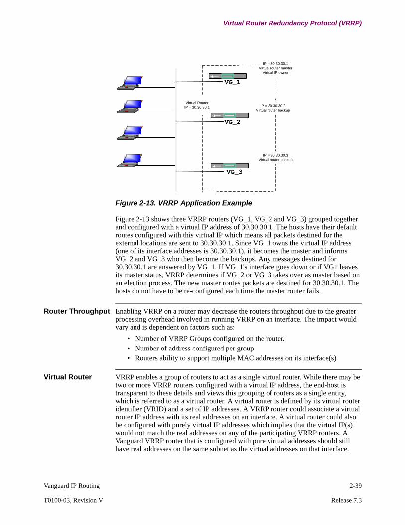
Vanguard IP Routing 2-39
T0100-03, Revision V Release 7.3
Virtual Router Redundancy Protocol (VRRP)
Figure 2-13. VRRP Application Example
Figure 2-13 shows three VRRP routers (VG_1, VG_2 and VG_3) grouped together and configured with a virtual IP address of 30.30.30.1. The hosts have their default routes configured with this virtual IP which means all packets destined for the external locations are sent to 30.30.30.1. Since VG_1 owns the virtual IP address (one of its interface addresses is 30.30.30.1), it becomes the master and informs VG_2 and VG_3 who then become the backups. Any messages destined for 30.30.30.1 are answered by VG_1. If VG_1's interface goes down or if VG1 leaves its master status, VRRP determines if VG_2 or VG_3 takes over as master based on an election process. The new master routes packets are destined for 30.30.30.1. The hosts do not have to be re-configured each time the master router fails.
Router Throughput Enabling VRRP on a router may decrease the routers throughput due to the greater processing overhead involved in running VRRP on an interface. The impact would vary and is dependent on factors such as:
• Number of VRRP Groups configured on the router.• Number of address configured per group• Routers ability to support multiple MAC addresses on its interface(s)
Virtual Router VRRP enables a group of routers to act as a single virtual router. While there may be two or more VRRP routers configured with a virtual IP address, the end-host is transparent to these details and views this grouping of routers as a single entity, which is referred to as a virtual router. A virtual router is defined by its virtual router identifier (VRID) and a set of IP addresses. A VRRP router could associate a virtual router IP address with its real addresses on an interface. A virtual router could also be configured with purely virtual IP addresses which implies that the virtual IP(s) would not match the real addresses on any of the participating VRRP routers. A Vanguard VRRP router that is configured with pure virtual addresses should still have real addresses on the same subnet as the virtual addresses on that interface.
Virtual RouterIP = 30.30.30.1
IP = 30.30.30.1Virtual router master
Virtual IP owner
IP = 30.30.30.2Virtual router backup
IP = 30.30.30.3Virtual router backup
VG_1
VG_2
VG_3
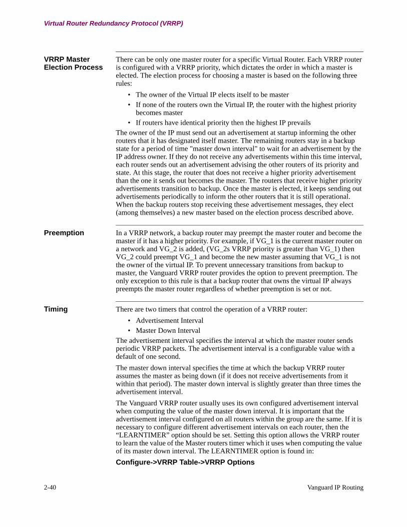
2-40 Vanguard IP Routing
Virtual Router Redundancy Protocol (VRRP)
VRRP Master Election Process
There can be only one master router for a specific Virtual Router. Each VRRP router is configured with a VRRP priority, which dictates the order in which a master is elected. The election process for choosing a master is based on the following three rules:
• The owner of the Virtual IP elects itself to be master• If none of the routers own the Virtual IP, the router with the highest priority
becomes master• If routers have identical priority then the highest IP prevails
The owner of the IP must send out an advertisement at startup informing the other routers that it has designated itself master. The remaining routers stay in a backup state for a period of time "master down interval" to wait for an advertisement by the IP address owner. If they do not receive any advertisements within this time interval, each router sends out an advertisement advising the other routers of its priority and state. At this stage, the router that does not receive a higher priority advertisement than the one it sends out becomes the master. The routers that receive higher priority advertisements transition to backup. Once the master is elected, it keeps sending out advertisements periodically to inform the other routers that it is still operational. When the backup routers stop receiving these advertisement messages, they elect (among themselves) a new master based on the election process described above.
Preemption In a VRRP network, a backup router may preempt the master router and become the master if it has a higher priority. For example, if VG_1 is the current master router on a network and VG_2 is added, (VG_2s VRRP priority is greater than VG_1) then VG_2 could preempt VG_1 and become the new master assuming that VG_1 is not the owner of the virtual IP. To prevent unnecessary transitions from backup to master, the Vanguard VRRP router provides the option to prevent preemption. The only exception to this rule is that a backup router that owns the virtual IP always preempts the master router regardless of whether preemption is set or not.
Timing There are two timers that control the operation of a VRRP router:
• Advertisement Interval• Master Down Interval
The advertisement interval specifies the interval at which the master router sends periodic VRRP packets. The advertisement interval is a configurable value with a default of one second.
The master down interval specifies the time at which the backup VRRP router assumes the master as being down (if it does not receive advertisements from it within that period). The master down interval is slightly greater than three times the advertisement interval.
The Vanguard VRRP router usually uses its own configured advertisement interval when computing the value of the master down interval. It is important that the advertisement interval configured on all routers within the group are the same. If it is necessary to configure different advertisement intervals on each router, then the “LEARNTIMER” option should be set. Setting this option allows the VRRP router to learn the value of the Master routers timer which it uses when computing the value of its master down interval. The LEARNTIMER option is found in:
Configure->VRRP Table->VRRP Options
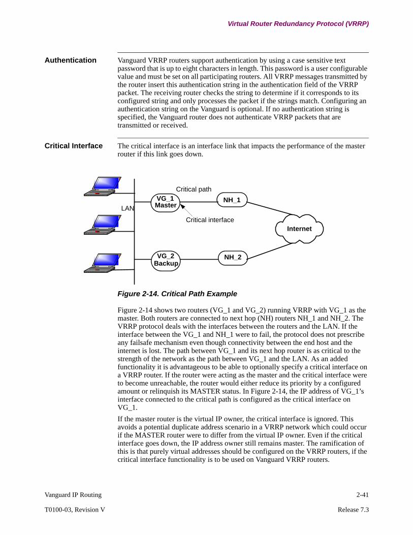
Vanguard IP Routing 2-41
T0100-03, Revision V Release 7.3
Virtual Router Redundancy Protocol (VRRP)
Authentication Vanguard VRRP routers support authentication by using a case sensitive text password that is up to eight characters in length. This password is a user configurable value and must be set on all participating routers. All VRRP messages transmitted by the router insert this authentication string in the authentication field of the VRRP packet. The receiving router checks the string to determine if it corresponds to its configured string and only processes the packet if the strings match. Configuring an authentication string on the Vanguard is optional. If no authentication string is specified, the Vanguard router does not authenticate VRRP packets that are transmitted or received.
Critical Interface The critical interface is an interface link that impacts the performance of the master router if this link goes down.
Figure 2-14. Critical Path Example
Figure 2-14 shows two routers (VG_1 and VG_2) running VRRP with VG_1 as the master. Both routers are connected to next hop (NH) routers NH_1 and NH_2. The VRRP protocol deals with the interfaces between the routers and the LAN. If the interface between the VG_1 and NH_1 were to fail, the protocol does not prescribe any failsafe mechanism even though connectivity between the end host and the internet is lost. The path between VG_1 and its next hop router is as critical to the strength of the network as the path between VG_1 and the LAN. As an added functionality it is advantageous to be able to optionally specify a critical interface on a VRRP router. If the router were acting as the master and the critical interface were to become unreachable, the router would either reduce its priority by a configured amount or relinquish its MASTER status. In Figure 2-14, the IP address of VG_1’s interface connected to the critical path is configured as the critical interface on VG_1.
If the master router is the virtual IP owner, the critical interface is ignored. This avoids a potential duplicate address scenario in a VRRP network which could occur if the MASTER router were to differ from the virtual IP owner. Even if the critical interface goes down, the IP address owner still remains master. The ramification of this is that purely virtual addresses should be configured on the VRRP routers, if the critical interface functionality is to be used on Vanguard VRRP routers.
Internet
Critical path
LAN
Critical interface
NH_1
NH_2
VG_1Master
VG_2Backup

2-42 Vanguard IP Routing
Virtual Router Redundancy Protocol (VRRP)
Primary and Secondary Virtual Addresses
The Vanguard VRRP routers can support up to 16 virtual addresses per VRRP group (entry). If multiple IP addresses are configured, the first IP address is treated as the primary address while the remaining addresses are secondary. Master election among routers are based on primary address with the owner of the primary address electing itself as master. If none of the VRRP routers own the primary address, master election is based on priority. Once the master is elected, it forwards packets sent to any of the virtual addresses configured in its group.
The Vanguard VRRP router advertises all the addresses it supports in the VRRP advertisement messages that it sends out while acting as master. The backup routers check this list of addresses in the advertisement packet and compare it to their own configured list. If the list of addresses does not match the list configured on the router, the Vanguard router generates an alarm informing the user that there is a mis-configuration. In Cisco's VRRP implementation, the router only advertises the primary virtual address, even though multiple secondary addresses may be configured. The Vanguard router provides an option for compatibility with Cisco:
Configure->VRRP Table->VRRP Options
Select the option CISCO and the router checks only the primary address advertised in the VRRP packet.
ICMP Redirects Routing information between routers is exchanged on the basis of real addresses, a router that sends a redirect message to the host provides the redirected routers real address as the new gateway. This could cause potential problems if this redirected router were part of a Virtual Router, as the host could discover the routers real MAC address, when it should instead be using the virtual MAC address. It is advisable to disable redirects on routers running VRRP. An “ICMPR” parameter is provided as part of the VRRP Options to turn on ICMP redirects. This value is not set by default. Although ICMP redirects can also be enabled or disabled on the interface (if a VRRP group is configured on that interface) the VRRP router only examines the ICMPR option when determining whether to send ICMP redirect messages or not. If ICMPR is set on a VRRP router participating in a group, the router uses its virtual address as the source address in the redirected message.
Master Behavior A master router may or may not be the owner of the virtual IP address. The manner in which it processes packets destined for its real and virtual IPs would differ depending on whether it is the IP address owner or not. The following Master Behavior Table illustrates this difference in handling packets when the master router:
• Owns the Virtual IP (Router A) • Does not own the Virtual IP (Router B).
NoteThe master cannot accept packets addressed to the virtual IP address if it is not the IP address owner.

Vanguard IP Routing 2-43
T0100-03, Revision V Release 7.3
Virtual Router Redundancy Protocol (VRRP)
Master Behavior
Packet Type Router A (Master and Virtual IP
Owner)
Router B (Master but does NOT own
Virtual IP)
Packet sent to virtual MAC address for forwarding
Forward Packet Forward Packet
ARP query for virtual address Respond with virtual MAC address
Respond with real Routers A’s MAC address
ARP query for real address Respond with virtual MAC address (since real address = virtual address)
Respond with real Routers A’s MAC address
ICMP (ping) packets addressed to virtual address
Respond (ping reply)
Respond (ping reply)
Packets addressed to virtual address (TCP, telnet...)
Accept (is the virtual IP owner)
Do not Accept (is not the owner)
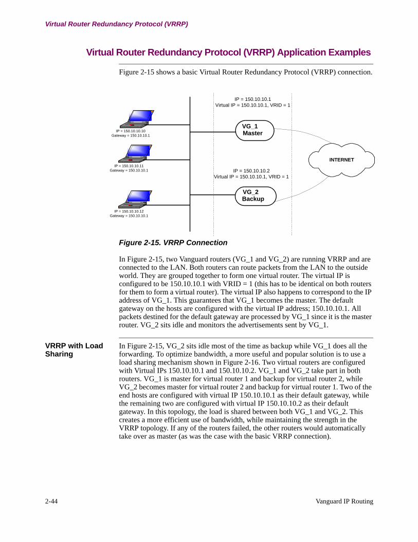
2-44 Vanguard IP Routing
Virtual Router Redundancy Protocol (VRRP)
Virtual Router Redundancy Protocol (VRRP) Application Examples
Figure 2-15 shows a basic Virtual Router Redundancy Protocol (VRRP) connection.
Figure 2-15. VRRP Connection
In Figure 2-15, two Vanguard routers (VG_1 and VG_2) are running VRRP and are connected to the LAN. Both routers can route packets from the LAN to the outside world. They are grouped together to form one virtual router. The virtual IP is configured to be 150.10.10.1 with VRID = 1 (this has to be identical on both routers for them to form a virtual router). The virtual IP also happens to correspond to the IP address of VG_1. This guarantees that VG_1 becomes the master. The default gateway on the hosts are configured with the virtual IP address; 150.10.10.1. All packets destined for the default gateway are processed by VG_1 since it is the master router. VG_2 sits idle and monitors the advertisements sent by VG_1.
VRRP with Load Sharing
In Figure 2-15, VG_2 sits idle most of the time as backup while VG_1 does all the forwarding. To optimize bandwidth, a more useful and popular solution is to use a load sharing mechanism shown in Figure 2-16. Two virtual routers are configured with Virtual IPs 150.10.10.1 and 150.10.10.2. VG_1 and VG_2 take part in both routers. VG_1 is master for virtual router 1 and backup for virtual router 2, while VG_2 becomes master for virtual router 2 and backup for virtual router 1. Two of the end hosts are configured with virtual IP 150.10.10.1 as their default gateway, while the remaining two are configured with virtual IP 150.10.10.2 as their default gateway. In this topology, the load is shared between both VG_1 and VG_2. This creates a more efficient use of bandwidth, while maintaining the strength in the VRRP topology. If any of the routers failed, the other routers would automatically take over as master (as was the case with the basic VRRP connection).
INTERNET
IP = 150.10.10.10Gateway = 150.10.10.1
IP = 150.10.10.11Gateway = 150.10.10.1
IP = 150.10.10.12Gateway = 150.10.10.1
IP = 150.10.10.1Virtual IP = 150.10.10.1, VRID = 1
IP = 150.10.10.2Virtual IP = 150.10.10.1, VRID = 1
VG_1Master
VG_2Backup
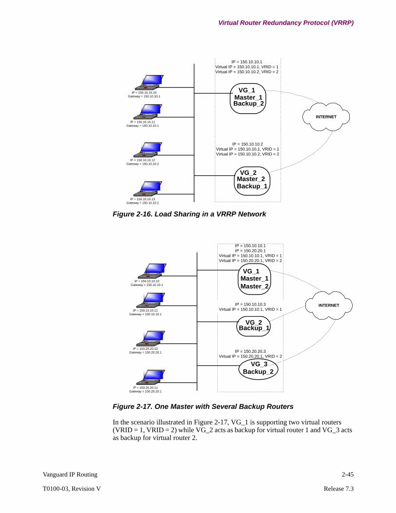
Vanguard IP Routing 2-45
T0100-03, Revision V Release 7.3
Virtual Router Redundancy Protocol (VRRP)
Figure 2-16. Load Sharing in a VRRP Network
Figure 2-17. One Master with Several Backup Routers
In the scenario illustrated in Figure 2-17, VG_1 is supporting two virtual routers (VRID = 1, VRID = 2) while VG_2 acts as backup for virtual router 1 and VG_3 acts as backup for virtual router 2.
INTERNET
IP = 150.10.10.10Gateway = 150.10.10.1
IP = 150.10.10.11Gateway = 150.10.10.1
IP = 150.10.10.12Gateway = 150.10.10.2
IP = 150.10.10.1Virtual IP = 150.10.10.1, VRID = 1Virtual IP = 150.10.10.2, VRID = 2
IP = 150.10.10.2Virtual IP = 150.10.10.1, VRID = 1Virtual IP = 150.10.10.2, VRID = 2
IP = 150.10.10.13Gateway = 150.10.10.2
VG_1Master_1Backup_2
VG_2Master_2Backup_1
INTERNET
IP = 150.10.10.10Gateway = 150.10.10.1
IP = 150.10.10.11Gateway = 150.10.10.1
IP = 150.20.20.10Gateway = 150.20.20.1
IP = 150.10.10.1IP = 150.20.20.1
Virtual IP = 150.10.10.1, VRID = 1Virtual IP = 150.20.20.1, VRID = 2
IP = 150.20.20.3Virtual IP = 150.20.20.1, VRID = 2
IP = 150.20.20.11Gateway = 150.20.20.1
IP = 150.10.10.3Virtual IP = 150.10.10.1, VRID = 1
VG_1Master_1Master_2
VG_2Backup_1
VG_3Backup_2

2-46 Vanguard IP Routing
Virtual Router Redundancy Protocol (VRRP)
Figure 2-18. Multiple Master Routers with one Backup
This configuration is the reverse of Figure 2-17. VG_1 and VG_3 as master routers for Virtual router 1 and Virtual router 2 respectively. VG_2 participates as backup router for both virtual router 1 and virtual router 2. If either VG_1 or VG_3 failed, VG_2 would act as master for one virtual router and backup for the other.
Figure 2-19. VRRP with VLAN
INTERNET
IP = 150.10.10.10Gateway = 150.10.10.1
IP = 150.10.10.11Gateway = 150.10.10.1
IP = 150.20.20.10Gateway = 150.20.20.1
IP = 150.10.10.1Virtual IP = 150.10.10.1, VRID = 1
IP = 150.20.20.1Virtual IP = 150.20.20.1, VRID = 2
IP = 150.20.20.11Gateway = 150.20.20.1
IP = 150.10.10.3IP = 150.20.20.3
Virtual IP = 150.10.10.1, VRID = 1Virtual IP = 150.20.20.1, VRID = 2
VG_1Master_1
VG_2Backup_1Backup_2
VG_3Master_2
VLAN Switch
IP = 150.10.10.5 IP = 150.10.10.4 IP = 150.20.20.4 150.20.20.5
VLAN 1 VLAN 2
IP = 150.10.10.2IP = 150.20.20.2
Virtual IP = 150.10.10.1, VRID = 1Virtual IP = 150.20.20.1, VRID = 2
IP = 150.10.10.3Virtual IP = 150.10.10.1, VRID = 1
IP = 150.20.20.3Virtual IP = 150.20.20.1, VRID = 2
VG_1Master
VG_2Backup_1
VG_3Backup_2

Vanguard IP Routing 2-47
T0100-03, Revision V Release 7.3
Virtual Router Redundancy Protocol (VRRP)
Figure 2-19 shows A VLAN example where VG_1 is connected to a VLAN Switch, which spawns 2 VLAN's, VLAN1 and VLAN2. The VG_2 and VG_3 are connected to each of the respective VLAN subnets. In such a scenario, VG_2 can only provide master/backup support for VLAN1, while VG_3 can only provide master/backup support on VLAN2. Since VG_1 is connected to the trunk link, it can support VRRP for both subnets. In such a scenario, a separate group must be set up for each VLAN subnet. Since VG_1 has access to both groups, it can participate in both virtual routers (1 and 2). VG_2 and VG_3 can only participate in the group corresponding to their respective VLANs.
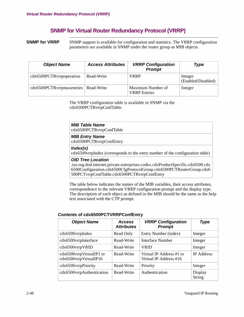
2-48 Vanguard IP Routing
Virtual Router Redundancy Protocol (VRRP)
SNMP for Virtual Router Redundancy Protocol (VRRP)
SNMP for VRRP SNMP support is available for configuration and statistics. The VRRP configuration parameters are available in SNMP under the router group as MIB objects.
The VRRP configuration table is available in SNMP via the cdx6500PCTRvrrpConfTable.
The table below indicates the names of the MIB variables, their access attributes, correspondence to the relevant VRRP configuration prompt and the display type. The description of each object as defined in the MIB should be the same as the help text associated with the CTP prompt.
Object Name Access Attributes VRRP Configuration Prompt
Type
cdx6500PCTRvrrpoperation Read-Write VRRP Integer (Enabled/Disabled)
cdx6500PCTRvrrpmaxentries Read-Write Maximum Number of VRRP Entries
Integer
MIB Table Namecdx6500PCTRvrrpConfTable
MIB Entry Namecdx6500PCTRvrrpConfEntry
Index(s)cdx6500vrrpIndex (corresponds to the entry number of the configuration table)
OID Tree Location.iso.org.dod.internet.private.enterprises.codex.cdxProductSpecific.cdx6500.cdx6500Configuration.cdx6500CfgProtocolGroup.cdx6500PCTRouterGroup.cdx6500PCTvrrpConfTable.cdx6500PCTRvrrpConfEntry
Contents of cdx6500PCTVRRPConfEntry
Object Name Access Attributes
VRRP Configuration Prompt
Type
cdx6500vrrpIndex Read Only Entry Number (index) Integer
cdx6500vrrpInterface Read-Write Interface Number Integer
cdx6500vrrpVRID Read-Write VRID Integer
cdx6500vrrpVirtualIP1 to cdx6500vrrpVirtualIP16
Read-Write Virtual IP Address #1 to Virtual IP Address #16
IP Address
cdx6500vrrpPriority Read-Write Priority Integer
cdx6500vrrpAuthentication Read-Write Authentication Display String

Vanguard IP Routing 2-49
T0100-03, Revision V Release 7.3
Virtual Router Redundancy Protocol (VRRP)
SNMP VRRP Statistics
The Interface summary statistics are basically a more compact subset of the Detailed Statistics. Due to the redundancy between the two VRRP statistics entries, only one table is created for displaying the VRRP statistics. The VRRP statistics are made available through the cdx6500PCTRvrrpStatsTable which are indexed by the interface number (cdx6500vrrpifIndex) and VRID (cdx6500vrrpVrId).
The table below indicates the names of the MIB variables, their access attributes, correspondence to the relevant VRRP statistic and the display type. The description of each object as defined in the MIB should be the same as the help text associated with the CTP statistic variable.
cdx6500vrrpAdvInterval Read-Write Advertisement Interval Integer
cdx6500vrrpOptions Read-Write VRRP Options Display String
cdx6500vrrpOptions Read-Write Critical Interface Number Integer
cdx6500vrrpCriticalIface Read-Write Critical Priority Decrement Integer
Contents of cdx6500PCTVRRPConfEntry
Object Name Access Attributes
VRRP Configuration Prompt
Type
MIB Table Namecdx6500PSTRvrrpStatsTable
MIB Entry Namecdx6500PSTRvrrpStatsEntry
Index(s)cdx6500vrrpifIndex, cdx6500vrrpVrId
OID Tree Location.iso.org.dod.internet.private.enterprises.codex.cdxProductSpecific.cdx6500.cdx6500Statistics.cdx6500StatProtocolGroup.cdx6500PSTRouterGroup.cdx6500PSTRvrrpStatsTable.cdx6500PSTRvrrpStatsEntry
Contents of cdx6500PSTvrrpStatsEntry
Object Name Access Attributes
VRRP Configuration Prompt
Type
VrrpStatsifIndex Read Only Interface Number (index 1) Integer
VrrpStatsVrId Read Only VRID (index 2) Integer
VrrpStatsState Read Only VRRP State Display String
vrrpStatsPriority Read Only Priority Integer
vrrpStatsPreemption Read Only Preemption Display String
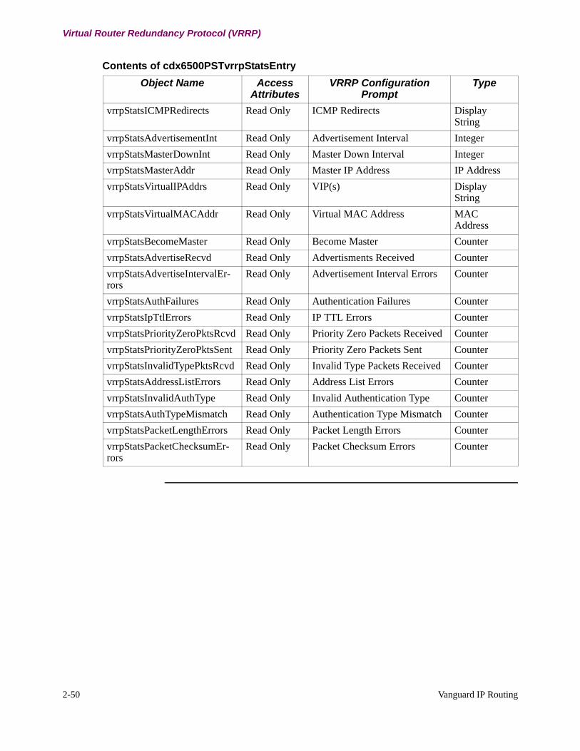
2-50 Vanguard IP Routing
Virtual Router Redundancy Protocol (VRRP)
vrrpStatsICMPRedirects Read Only ICMP Redirects Display String
vrrpStatsAdvertisementInt Read Only Advertisement Interval Integer
vrrpStatsMasterDownInt Read Only Master Down Interval Integer
vrrpStatsMasterAddr Read Only Master IP Address IP Address
vrrpStatsVirtualIPAddrs Read Only VIP(s) Display String
vrrpStatsVirtualMACAddr Read Only Virtual MAC Address MAC Address
vrrpStatsBecomeMaster Read Only Become Master Counter
vrrpStatsAdvertiseRecvd Read Only Advertisments Received Counter
vrrpStatsAdvertiseIntervalEr-rors
Read Only Advertisement Interval Errors Counter
vrrpStatsAuthFailures Read Only Authentication Failures Counter
vrrpStatsIpTtlErrors Read Only IP TTL Errors Counter
vrrpStatsPriorityZeroPktsRcvd Read Only Priority Zero Packets Received Counter
vrrpStatsPriorityZeroPktsSent Read Only Priority Zero Packets Sent Counter
vrrpStatsInvalidTypePktsRcvd Read Only Invalid Type Packets Received Counter
vrrpStatsAddressListErrors Read Only Address List Errors Counter
vrrpStatsInvalidAuthType Read Only Invalid Authentication Type Counter
vrrpStatsAuthTypeMismatch Read Only Authentication Type Mismatch Counter
vrrpStatsPacketLengthErrors Read Only Packet Length Errors Counter
vrrpStatsPacketChecksumEr-rors
Read Only Packet Checksum Errors Counter
Contents of cdx6500PSTvrrpStatsEntry
Object Name Access Attributes
VRRP Configuration Prompt
Type
Vanguard IP Routing 2-51
T0100-03, Revision V Release 7.3
Dynamic Host Configuration Protocol (DHCP)
Dynamic Host Configuration Protocol (DHCP)
Introduction Dynamic Host Configuration Protocol (DHCP) is a communications protocol that enables network officers to administer and automate the assignment of Internet Protocol (IP) addresses in a network. Every unit connected to the Internet needs a unique IP address. When an organization sets up its computer users with a connection to the Internet, an IP address is assigned to each computer. If you do not have DHCP, the IP address has to be entered at each computer. If you move the computers to another location in another part of the network, a new IP address must be entered. DHCP lets a network administrator supervise and distribute IP addresses from a central point. Administrators can automatically send a new IP address when a computer is plugged into a different place in the network.
Purpose The purpose of Vanguard DHCP is to enable hosts (DHCP clients) on an IP network to extract their configurations from a server (DHCP server) or servers. The most important information distributed is the IP address.
Vanguard DHCP implements DHCP client functionality on one or more Ethernet ports and DHCP server functionality on any directly connected subnet or any remote subnet reachable via BOOTP relay.
NoteDHCP Client is supported with Release 6.2 and greater software on the following platforms; Vanguard 320, 34x, 6435, 6455 and 7300 Series.
NoteDHCP Server is supported with release 6.5P11C software on the following platforms; Vanguard 34X, 6435, 6455, 7300 Series.
DHCP Server Features
1) Dynamic and Pre-Fixed IP address assignments
2) Local DHCP clients connected via a Layer 2 Ethernet Switch, which is directly connected to a Vanguard Router Interface
3) Remote DHCP clients via BOOTP Relay
Limitations DHCP Client Limitations
1) It is recommended that only one IP interface per port be configured to use DHCP in order to prevent a situation where two interfaces on the router obtain addresses that are on the same subnet.
2) Enabling DHCP and On Net Proxy on the same Ethernet port is not recommended.
3) The router must have a Global Address before DHCP can be operational. If the router does not have a global address configured, it cannot process DHCP replies from the server, and as a result the DHCP configuration process fails.
4) A DHCP address cannot be used as a BGP ID.
5) DHCP client is supported on ethernet ports only.
DHCP Server Limitations

2-52 Vanguard IP Routing
Dynamic Host Configuration Protocol (DHCP)
1) DHCP Server currently supports only a class C (/24 or 255.255.255.0) or more specific subnet Mask.
2) DHCP Server is currently supports 128 maximum number of client addresses available to assign.
3) DHCP Server is currently limited to 16 supported subnets (Entries) in the "DHCP Server Subnet table".
Componets The Dynamic Host Configuration Protocol (DHCP) provides configuration parameters for Internet hosts. DHCP consists of two components:
1) A protocol for delivering host specific configuration parameters from a DHCP server to a host.
2) A mechanism for allocation of network addresses to hosts.
DHCP is built on a client-server model, where designated DHCP server hosts allocate network addresses and deliver configuration parameters to dynamically configured hosts.
DHCP uses UDP as its transport protocol. DHCP messages from a client to a server are sent to the “DHCP server” (port 67), and DHCP messages from a server to a client are sent to the “DHCP client” (port 68). A server with multiple network address (such as a multi-homed host) may use any of its network addresses in outgoing DHCP messages.
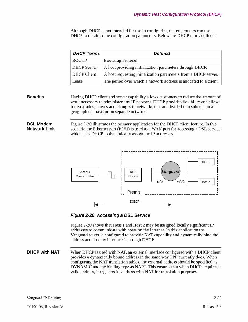
Vanguard IP Routing 2-53
T0100-03, Revision V Release 7.3
Dynamic Host Configuration Protocol (DHCP)
Although DHCP is not intended for use in configuring routers, routers can use DHCP to obtain some configuration parameters. Below are DHCP terms defined:
Benefits Having DHCP client and server capability allows customers to reduce the amount of work necessary to administer any IP network. DHCP provides flexibility and allows for easy adds, moves and changes to networks that are divided into subnets on a geographical basis or on separate networks.
DSL Modem Network Link
Figure 2-20 illustrates the primary application for the DHCP client feature. In this scenario the Ethernet port (i/f #1) is used as a WAN port for accessing a DSL service which uses DHCP to dynamically assign the IP addresses.
Figure 2-20. Accessing a DSL Service
Figure 2-20 shows that Host 1 and Host 2 may be assigned locally significant IP addresses to communicate with hosts on the Internet. In this application the Vanguard router is configured to provide NAT capability and dynamically bind the address acquired by interface 1 through DHCP.
DHCP with NAT When DHCP is used with NAT, an external interface configured with a DHCP client provides a dynamically bound address in the same way PPP currently does. When configuring the NAT translation tables, the external address should be specified as DYNAMIC and the binding type as NAPT. This ensures that when DHCP acquires a valid address, it registers its address with NAT for translation purposes.
DHCP Terms Defined
BOOTP Bootstrap Protocol.
DHCP Server A host providing initialization parameters through DHCP.
DHCP Client A host requesting initialization parameters from a DHCP server.
Lease The period over which a network address is allocated to a client.
Vanguard
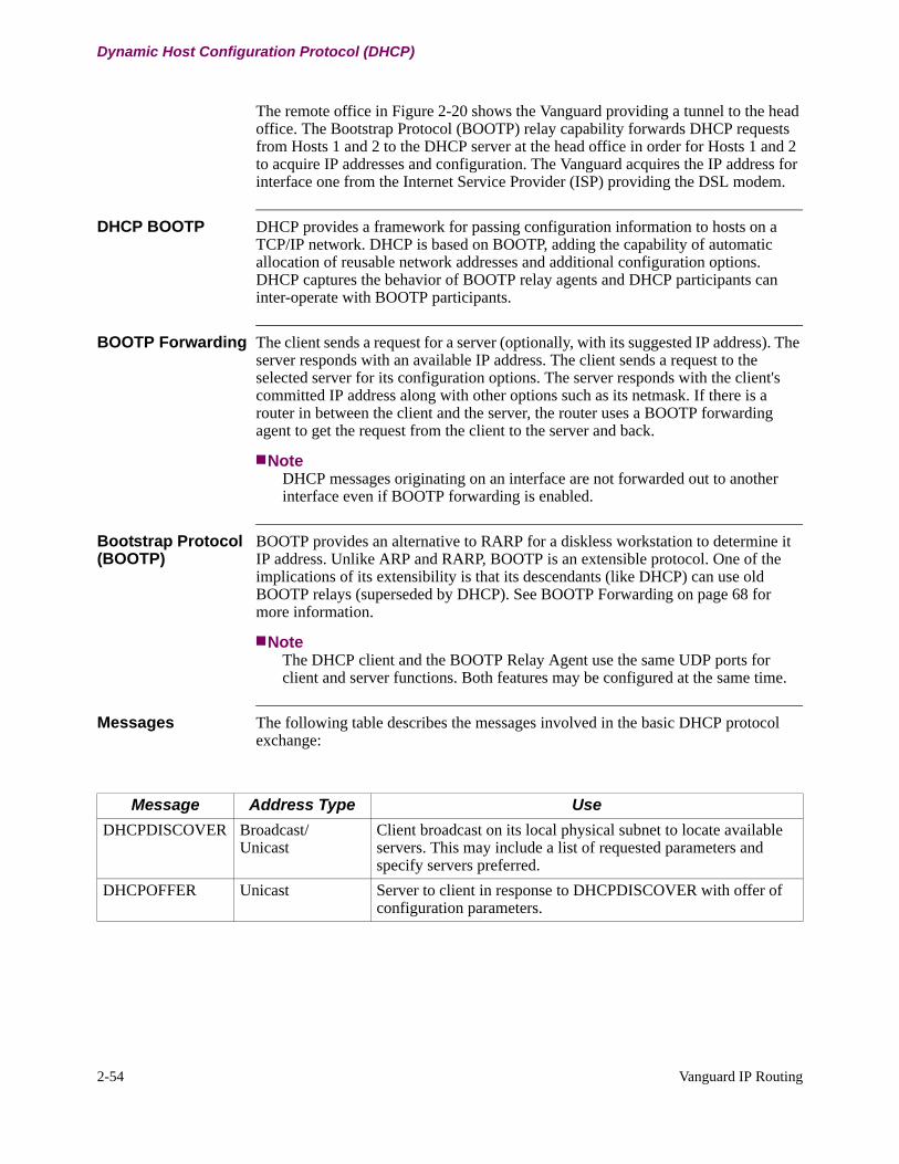
2-54 Vanguard IP Routing
Dynamic Host Configuration Protocol (DHCP)
The remote office in Figure 2-20 shows the Vanguard providing a tunnel to the head office. The Bootstrap Protocol (BOOTP) relay capability forwards DHCP requests from Hosts 1 and 2 to the DHCP server at the head office in order for Hosts 1 and 2 to acquire IP addresses and configuration. The Vanguard acquires the IP address for interface one from the Internet Service Provider (ISP) providing the DSL modem.
DHCP BOOTP DHCP provides a framework for passing configuration information to hosts on a TCP/IP network. DHCP is based on BOOTP, adding the capability of automatic allocation of reusable network addresses and additional configuration options. DHCP captures the behavior of BOOTP relay agents and DHCP participants can inter-operate with BOOTP participants.
BOOTP Forwarding The client sends a request for a server (optionally, with its suggested IP address). The server responds with an available IP address. The client sends a request to the selected server for its configuration options. The server responds with the client's committed IP address along with other options such as its netmask. If there is a router in between the client and the server, the router uses a BOOTP forwarding agent to get the request from the client to the server and back.
NoteDHCP messages originating on an interface are not forwarded out to another interface even if BOOTP forwarding is enabled.
Bootstrap Protocol (BOOTP)
BOOTP provides an alternative to RARP for a diskless workstation to determine it IP address. Unlike ARP and RARP, BOOTP is an extensible protocol. One of the implications of its extensibility is that its descendants (like DHCP) can use old BOOTP relays (superseded by DHCP). See BOOTP Forwarding on page 68 for more information.
NoteThe DHCP client and the BOOTP Relay Agent use the same UDP ports for client and server functions. Both features may be configured at the same time.
Messages The following table describes the messages involved in the basic DHCP protocol exchange:
Message Address Type Use
DHCPDISCOVER Broadcast/Unicast
Client broadcast on its local physical subnet to locate available servers. This may include a list of requested parameters and specify servers preferred.
DHCPOFFER Unicast Server to client in response to DHCPDISCOVER with offer of configuration parameters.

Vanguard IP Routing 2-55
T0100-03, Revision V Release 7.3
Dynamic Host Configuration Protocol (DHCP)
Figure 2-21 shows a typical application for connecting to DSL or cable modem service. The LAN port is being used as a WAN port for accessing a DSL service, which uses DHCP to dynamically assign IP addresses.
Figure 2-21. Dynamic Host Configuration (DHCP) Client
DHCPREQUEST Broadcast/Unicast
Client message to server either:a)requesting offered parameters from one server and
implicitly declining offers from all others.
b)confirming correctness of previously allocated address after a system boot for example.
c)extending the lease on a particular network address.
The message is broadcast unless the client knows the address of the server.
DHCPACK Unicast Server to client with configuration parameters, including committed network address.The client should use information from this message to install configuration.
DHCPNAK Unicast Server to client indicating client's notion of network address is incorrect (for example: a client has moved to a new subnet or a client's lease has expired).
DHCPDECLINE Broadcast Client to server indicating network address is already in use. The message is broadcast so that all listening servers know that the client is declining the IP address assigned by the server.
DHCPRELEASE Unicast Client to server relinquishing network address and cancelling remaining lease.
Message Address Type Use
DHCPDISCOVERClient request for IPAddress and other configuration options(i.e., gateway, DNS, subnet, proxy servers)
DHCPServer
DHCPClient
DHCPOFFERServer sends availableIP Address
DHCPREQUESTClient accepts offer and asks server for its configuration
DHCPACKServer responds withcommitted IP addressand other configurationoptions
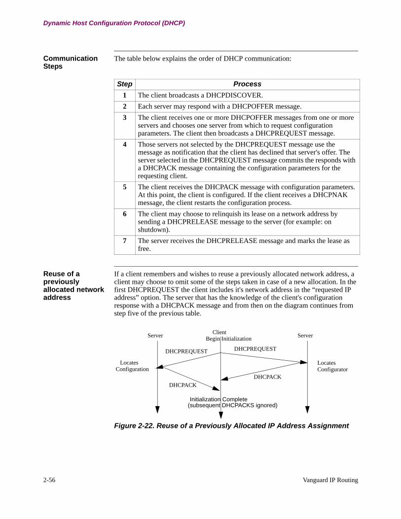
2-56 Vanguard IP Routing
Dynamic Host Configuration Protocol (DHCP)
Communication Steps
The table below explains the order of DHCP communication:
Reuse of a previously allocated network address
If a client remembers and wishes to reuse a previously allocated network address, a client may choose to omit some of the steps taken in case of a new allocation. In the first DHCPREQUEST the client includes it's network address in the “requested IP address” option. The server that has the knowledge of the client's configuration response with a DHCPACK message and from then on the diagram continues from step five of the previous table.
Figure 2-22. Reuse of a Previously Allocated IP Address Assignment
Step Process
1 The client broadcasts a DHCPDISCOVER.
2 Each server may respond with a DHCPOFFER message.
3 The client receives one or more DHCPOFFER messages from one or more servers and chooses one server from which to request configuration parameters. The client then broadcasts a DHCPREQUEST message.
4 Those servers not selected by the DHCPREQUEST message use the message as notification that the client has declined that server's offer. The server selected in the DHCPREQUEST message commits the responds with a DHCPACK message containing the configuration parameters for the requesting client.
5 The client receives the DHCPACK message with configuration parameters. At this point, the client is configured. If the client receives a DHCPNAK message, the client restarts the configuration process.
6 The client may choose to relinquish its lease on a network address by sending a DHCPRELEASE message to the server (for example: on shutdown).
7 The server receives the DHCPRELEASE message and marks the lease as free.
Server ServerClientBegin Initialization
LocatesConfiguration
DHCPREQUEST DHCPREQUEST
LocatesConfigurator
DHCPACK
DHCPACK
Initialization Complete(subsequent DHCPACKS ignored)

Vanguard IP Routing 2-57
T0100-03, Revision V Release 7.3
Dynamic Host Configuration Protocol (DHCP)
DHCP Client States The table below provides a brief description of the DHCP client states defined in RFC 2131.
Allocation DHCP supports three mechanisms for IP Address Allocation:
1) Automatic allocation - DHCP assigns a permanent address.
2) Dynamic allocation - DHCP assigns and address for a limited amount of time (or until the client explicitly relinquishes the address).
3) Manual allocation - Address assigned by network administrator and DHCP is simply the mechanism for convey the address to the client.
All three of the mechanisms listed above are supported by the Vanguard DHCP client.
State Description
INIT This is the initial state of the client when it does not have a valid lease. The client is waiting for the network to become active so it can send a DHCPDISCOVER message.
SELECTING In this state the client is waiting for a DHCPOFFER message from servers in response to the DHCPDISCOVER message it broadcast.
REQUESTING In this state the client is waiting for a DHCPACK from the selected server to which it has sent a DHCPREQUEST, to request its configuration.
BOUND In this state the client has a valid configuration and a valid lease for an IP address.
RENEWING In this state the client is waiting for a DHCPACK in response to the DHCPREQUEST it send to the server from which it obtained its lease, in order to extend its lease.
REBINDING In this state the client is waiting for a DHCPACK, from any server, in response to the DHCPREQUEST it broadcast after failing to get a response from the server it obtained the lease from.
INIT-REBOOT This is the initial state of the client when it has a valid lease. The client is waiting for the network to become active so it can send a DHCPREQUEST message.
REBOOTING In this state the client is waiting for a DHCPACK in response to the DHCPREQUEST it send to the server it obtained the lease from. The client is trying to validate its existing lease after reboot.

2-58 Vanguard IP Routing
Dynamic Host Configuration Protocol (DHCP)
Duplicate Address Verification (DAV)
Duplicate Address Verification (DAV) provides a mechanism for verifying whether or not an IPV4 address is currently in use (that is: assigned to host equipment) on the connected shared LAN media. The DAV algorithm on the Vanguard routers relies on the "creative" use of generating Address Resolution Protocol (ARP) requests and responses to the desired address.
When DHCP is used in combination with Duplicate Address Verification, the status "VDG" is used to indicate that the interface is in the process of verifying that the IP address offered by the DHCP server has not been assigned to any devices currently on the network .
Duplicate IP Address Protection
RFC 2131 recommends that the clients should determine if the address offered by a server is already in use before accepting and using it. The Vanguard series of routers support this capability with the “Duplicate Address Detection” feature which can be enabled independently of the DCHP client feature to allow DHCP client interfaces to validate the address offered by the server or not. If the “Duplicate Address Detection” feature is enabled, the DHCP client uses this mechanism to validate the address specified by the server in the DHCPACK prior to using it. If the address is already in use, the DHCP client sends a DHCPDECLINE message to the server and returns to the INIT state.
DHCP Support DHCP is designed to supply DHCP clients with the configuration parameters defined in the Host Requirements RFCs.
The Vanguard router products support the following parameters from the DHCP server for each Ethernet interface configured for DHCP:
• IP address • Subnet mask • Default Gateway (Router Option)• IP address lease time• Renewal time value• Rebinding time value
DHCP Supported Options
The following DHCP options are supported. Any other options are ignored.
Option Description
Maximum DHCP message size
The client should include the “maximum DHCP message size” option to let the server know how large the server may make its DHCP messages. It should be set to the minimum identified, which is 576.
Server identifier Must be included in DHCPREQUEST message to indicate which server has been selected.
Requested IP address
Must be set to 'yiaddr' in the DHCPOFFER message from the server. Only used in a DHCPREQUEST message when the client is verifying network parameters obtained previously.
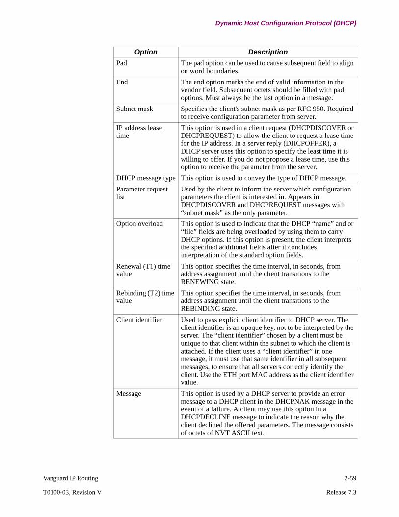
Vanguard IP Routing 2-59
T0100-03, Revision V Release 7.3
Dynamic Host Configuration Protocol (DHCP)
Pad The pad option can be used to cause subsequent field to align on word boundaries.
End The end option marks the end of valid information in the vendor field. Subsequent octets should be filled with pad options. Must always be the last option in a message.
Subnet mask Specifies the client's subnet mask as per RFC 950. Required to receive configuration parameter from server.
IP address lease time
This option is used in a client request (DHCPDISCOVER or DHCPREQUEST) to allow the client to request a lease time for the IP address. In a server reply (DHCPOFFER), a DHCP server uses this option to specify the least time it is willing to offer. If you do not propose a lease time, use this option to receive the parameter from the server.
DHCP message type This option is used to convey the type of DHCP message.
Parameter request list
Used by the client to inform the server which configuration parameters the client is interested in. Appears in DHCPDISCOVER and DHCPREQUEST messages with “subnet mask” as the only parameter.
Option overload This option is used to indicate that the DHCP “name” and or “file” fields are being overloaded by using them to carry DHCP options. If this option is present, the client interprets the specified additional fields after it concludes interpretation of the standard option fields.
Renewal (T1) time value
This option specifies the time interval, in seconds, from address assignment until the client transitions to the RENEWING state.
Rebinding (T2) time value
This option specifies the time interval, in seconds, from address assignment until the client transitions to the REBINDING state.
Client identifier Used to pass explicit client identifier to DHCP server. The client identifier is an opaque key, not to be interpreted by the server. The “client identifier” chosen by a client must be unique to that client within the subnet to which the client is attached. If the client uses a “client identifier” in one message, it must use that same identifier in all subsequent messages, to ensure that all servers correctly identify the client. Use the ETH port MAC address as the client identifier value.
Message This option is used by a DHCP server to provide an error message to a DHCP client in the DHCPNAK message in the event of a failure. A client may use this option in a DHCPDECLINE message to indicate the reason why the client declined the offered parameters. The message consists of octets of NVT ASCII text.
Option Description
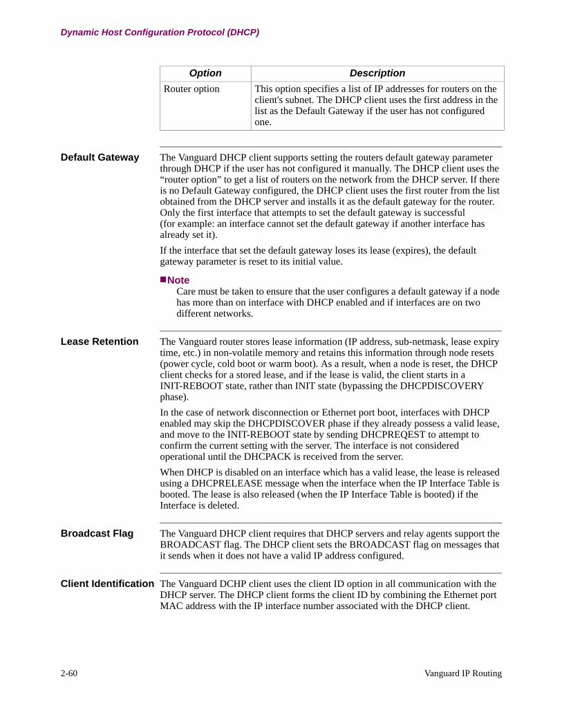
2-60 Vanguard IP Routing
Dynamic Host Configuration Protocol (DHCP)
Default Gateway The Vanguard DHCP client supports setting the routers default gateway parameter through DHCP if the user has not configured it manually. The DHCP client uses the “router option” to get a list of routers on the network from the DHCP server. If there is no Default Gateway configured, the DHCP client uses the first router from the list obtained from the DHCP server and installs it as the default gateway for the router. Only the first interface that attempts to set the default gateway is successful (for example: an interface cannot set the default gateway if another interface has already set it).
If the interface that set the default gateway loses its lease (expires), the default gateway parameter is reset to its initial value.
NoteCare must be taken to ensure that the user configures a default gateway if a node has more than on interface with DHCP enabled and if interfaces are on two different networks.
Lease Retention The Vanguard router stores lease information (IP address, sub-netmask, lease expiry time, etc.) in non-volatile memory and retains this information through node resets (power cycle, cold boot or warm boot). As a result, when a node is reset, the DHCP client checks for a stored lease, and if the lease is valid, the client starts in a INIT-REBOOT state, rather than INIT state (bypassing the DHCPDISCOVERY phase).
In the case of network disconnection or Ethernet port boot, interfaces with DHCP enabled may skip the DHCPDISCOVER phase if they already possess a valid lease, and move to the INIT-REBOOT state by sending DHCPREQEST to attempt to confirm the current setting with the server. The interface is not considered operational until the DHCPACK is received from the server.
When DHCP is disabled on an interface which has a valid lease, the lease is released using a DHCPRELEASE message when the interface when the IP Interface Table is booted. The lease is also released (when the IP Interface Table is booted) if the Interface is deleted.
Broadcast Flag The Vanguard DHCP client requires that DHCP servers and relay agents support the BROADCAST flag. The DHCP client sets the BROADCAST flag on messages that it sends when it does not have a valid IP address configured.
Client Identification The Vanguard DCHP client uses the client ID option in all communication with the DHCP server. The DHCP client forms the client ID by combining the Ethernet port MAC address with the IP interface number associated with the DHCP client.
Router option This option specifies a list of IP addresses for routers on the client's subnet. The DHCP client uses the first address in the list as the Default Gateway if the user has not configured one.
Option Description
Vanguard IP Routing 2-61
T0100-03, Revision V Release 7.3
Dynamic Host Configuration Protocol (DHCP)
Multiple Servers It is possible that multiple DHCP servers may respond to a DHCPDISCOVER sent by a DHCP client. The DHCP client typically chooses to obtain the lease from the server which responds first. However, in order to avoid becoming locked up by a faulty server that is closest to the client, the client maintains a “blocked server” list that it uses to keep track of servers that have sent it a DHCPNAK in the REQUESTING state.
NoteDHCPNAKs received in other states do not cause the server to be placed on the “blocked server” list.
When a DHCP client is in REQUESTING state and receives a DHCPNAK from a server, it places the server on the “blocked server” list. The client does not select DHCPOFFERs from servers that are in the “blocked server” list. Servers are removed from the “blocked server” list once the client has transmitted and re-transmitted three DHCPREQUESTs in the SELECTING (or INIT) state. The “blocked server” list is cleared when a lease is obtained. The client maintains a list of servers that it has received offers from for the last DHCPDISCOVER sent out. The client typically chooses the first offer, but still updates the list as additional offers come in.

2-62 Vanguard IP Routing
Dynamic Host Configuration Protocol (DHCP)
Retransmission
Retransmission Behavior
In the event that a DHCP client receives no response to a message, it employs a re-transmission algorithm that is dependent on the state of the client and the number of re-transmissions that have occurred.
Rebooting and Requesting States
In the REBOOTING and REQUESTING states, the client is sending DHCPREQUEST messages to specific servers. The retransmission scheme is to use an exponential back-off scheme starting with two seconds and allowing fourre-transmissions before giving up. The first re-transmission occurs four seconds after the initial transmission and the second re-transmission occurs eight seconds after the first and so on (16, 32). If there is no response to the forth re-transmission 64 seconds after it is sent, the client moves to the INIT state.
Renewing and Rebinding States
In the RENEWING and REBINDING states, the retransmission algorithm is based on the time remaining until the T2 timeout and the lease expiry, respectively. When the T1 first expires the client sends a DHCPREQUEST and waits for a response. If no response is received, the client wait one half the time until the T2 expiry to re-transmit the DHCPREQUEST, with a minimum limit of 60 seconds. Once the T2 timer expires, the client begins to broadcast the DHCPREQUESTs and waits one half the time to the lease expiry for each re-transmission.
Selecting State The SELECTING state is the state the client state machine settles into if there is never a response from a server. The re-transmission algorithm in this state is similar to the REBOOTING and REQUESTIG states except that the client remains in this state indefinitely and the upper limit on the exponential back off is five minutes.
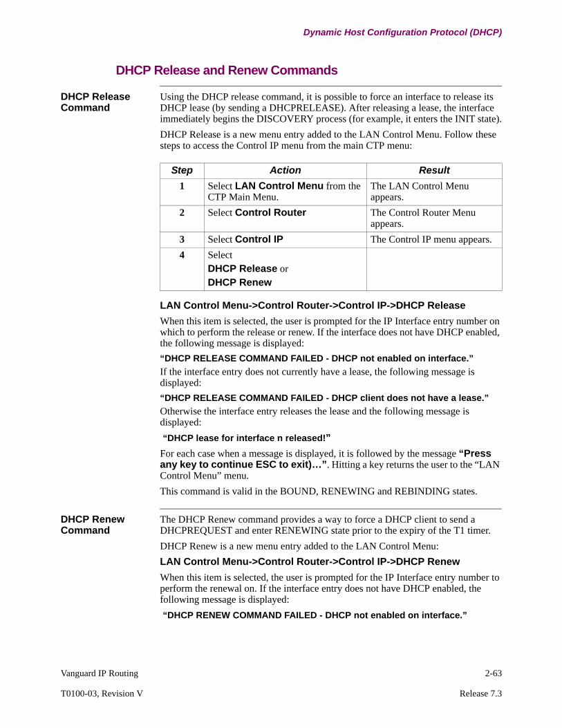
Vanguard IP Routing 2-63
T0100-03, Revision V Release 7.3
Dynamic Host Configuration Protocol (DHCP)
DHCP Release and Renew Commands
DHCP Release Command
Using the DHCP release command, it is possible to force an interface to release its DHCP lease (by sending a DHCPRELEASE). After releasing a lease, the interface immediately begins the DISCOVERY process (for example, it enters the INIT state).
DHCP Release is a new menu entry added to the LAN Control Menu. Follow these steps to access the Control IP menu from the main CTP menu:
LAN Control Menu->Control Router->Control IP->DHCP Release
When this item is selected, the user is prompted for the IP Interface entry number on which to perform the release or renew. If the interface does not have DHCP enabled, the following message is displayed:
“DHCP RELEASE COMMAND FAILED - DHCP not enabled on interface.”
If the interface entry does not currently have a lease, the following message is displayed:
“DHCP RELEASE COMMAND FAILED - DHCP client does not have a lease.”
Otherwise the interface entry releases the lease and the following message is displayed:
“DHCP lease for interface n released!”
For each case when a message is displayed, it is followed by the message “Press any key to continue ESC to exit)…”. Hitting a key returns the user to the “LAN Control Menu” menu.
This command is valid in the BOUND, RENEWING and REBINDING states.
DHCP Renew Command
The DHCP Renew command provides a way to force a DHCP client to send a DHCPREQUEST and enter RENEWING state prior to the expiry of the T1 timer.
DHCP Renew is a new menu entry added to the LAN Control Menu:
LAN Control Menu->Control Router->Control IP->DHCP Renew
When this item is selected, the user is prompted for the IP Interface entry number to perform the renewal on. If the interface entry does not have DHCP enabled, the following message is displayed:
“DHCP RENEW COMMAND FAILED - DHCP not enabled on interface.”
Step Action Result
1 Select LAN Control Menu from the CTP Main Menu.
The LAN Control Menu appears.
2 Select Control Router The Control Router Menu appears.
3 Select Control IP The Control IP menu appears.
4 SelectDHCP Release orDHCP Renew

2-64 Vanguard IP Routing
Dynamic Host Configuration Protocol (DHCP)
If the interface entry does not currently have a lease, the following message is displayed:
“DHCP RENEW COMMAND FAILED - DHCP client does not have a lease.”
Otherwise the interface entry attempts to renew the lease and the following message is displayed:
“DHCP lease renewal for interface n initiated!”
This command only has effect when the DHCP client is in BOUND or RENEWING state. If the client is not in BOUND or RENEWING state, this command fails with the following message displayed on the Control Terminal Port (CTP):
“DHCP RENEW COMMAND FAILED - Client not in BOUND or RENEWING state”
For each case when a message is displayed, it is followed by the message “Press any key to continue ESC to exit)…”. Hitting a key returns the user to the “LAN Control Menu” menu.
Execution of this command does not affect the normal timeout or re-transmission algorithms, unless the lease is extended by the server in which case the timeout values are set to the new values indicated by the lease.
The Renew command can be used to check server connectivity without causing the lease to be lost.
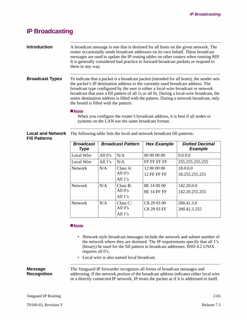
Vanguard IP Routing 2-65
T0100-03, Revision V Release 7.3
IP Broadcasting
IP Broadcasting
Introduction A broadcast message is one that is destined for all hosts on the given network. The router occasionally sends broadcast addresses on its own behalf. These broadcast messages are used to update the IP routing tables on other routers when running RIP. It is generally considered bad practice to forward broadcast packets or respond to them in any way.
Broadcast Types To indicate that a packet is a broadcast packet (intended for all hosts), the sender sets the packet’s IP destination address to the currently used broadcast address. The broadcast type configured by the user is either a local-wire broadcast or network broadcast that uses a fill pattern of all 1s or all 0s. During a local-wire broadcast, the entire destination address is filled with the pattern. During a network broadcast, only the hostid is filled with the pattern.
NoteWhen you configure the router’s broadcast address, it is best if all nodes or systems on the LAN use the same broadcast format.
Local and Network Fill Patterns
The following table lists the local and network broadcast fill patterns:
Note
• Network style broadcast messages include the network and subnet number of the network where they are destined. The IP requirements specify that all 1’s (binary) be used for the fill pattern in broadcast addresses. BSD 4.2 UNIX requires all 0’s.
• Local wire is also named local broadcast.
Message Recognition
The Vanguard IP forwarder recognizes all forms of broadcast messages and addressing. If the network portion of the broadcast address indicates either local wire or a directly connected IP network, IP treats the packet as if it is addressed to itself.
Broadcast Type
Broadcast Pattern Hex Example Dotted Decimal Example
Local Wire All 0’s N/A 00 00 00 00 0.0.0.0
Local Wire All 1’s N/A FF FF FF FF 255.255.255.255
Network N/A Class A: All 0’sAll 1’s
12 00 00 0012 FF FF FF
18.0.0.018.255.255.255
Network N/A Class B: All 0’sAll 1’s
8E 14 00 008E 14 FF FF
142.20.0.0142.20.255.255
Network N/A Class C: All 0’sAll 1’s
C8 29 03 00C8 29 03 FF
200.41.3.0200.42.3.255
2-66 Vanguard IP Routing
IP Broadcasting
Directed Broadcast Forwarding
Overview A directed broadcast is a broadcast destined for a particular subnet. A local subnet directed broadcast is a directed broadcast addressed to a subnet which is local to the router, typically it is directly connected, and is the interface on which it is received. By enabling Vanguard directed broadcast feature, you can forward IP packets whose destination is a non-local (such as remote LAN) broadcast address.
For example, a packet originated by the source host is unicast. This packet is then forwarded, as a unicast, to a destination subnet and exploded into a broadcast. You can use this feature to locate network servers and to enable both the forwarding and exploding of directed broadcasts.
Configuring the Vanguard for Directed Broadcast Forwarding
Enable or Disable the Directed Broadcast feature from the IP Interface Configuration Table. For detailed parameter description refer to the “IP Interface Configuration Table” section on page 3-24.
The default setting for the directed broadcast feature is enabled.

Vanguard IP Routing 2-67
T0100-03, Revision V Release 7.3
IP Broadcasting
All Subnets Broadcast
Introduction The All Subnets Broadcast feature supports the forwarding of local subnet directed broadcasts to all subnets of a network.
How It Works When you enable the parameter All Subnets Broadcast, the Vanguard that receives the broadcast message duplicates and forwards it to all the hosts of the subnets within the network. The receiving host, in turn, duplicates the message and forwards it to its subnet hosts.
Configuration You access the All Subnets Broadcast parameter from the Configure IP Parameters menu described on “Configure IP” section on page 3-13.

2-68 Vanguard IP Routing
IP Broadcasting
BOOTP Forwarding
Introduction The Vanguard supports the BOOTP (BOOT strap Protocol) as an “intelligent forwarder.”
How it Works BOOTP allows workstations on the physical LAN to determine their IP address and load their operating software from another server on the LAN, called the BOOTP server. Normally used by diskless workstations without a stored version of their application, the IP Router module allows the workstation and the BOOTP server to exist on different networks.
The Vanguard sends the BOOTP broadcasted requests that it receives on its LAN port directly to one or more BOOTP servers located remotely. If more than one location is defined, the BOOTP packet is forwarded to each.
The Dynamic Host Configuration Protocol (DHCP) used by some PCs or workstations also uses the BOOTP protocol. The Vanguard forward DHCP packets to the BOOTP server.
Configuration Configure these parameters to enable and operate BOOTP Forwarding:
• BOOTP Forwarding• BOOTP Max Allowed Metric• BOOTP Seconds Before Forward
For parameter descriptions, see “IP Parameters Configuration” section on page 3-14.
Configure BOOTP server IP addresses from the menu:
Configure->Configure Router->Configure IP->BootP Server
For parameter descriptions, see “IP BOOTP Server Table Configuration” section on page 3-79.
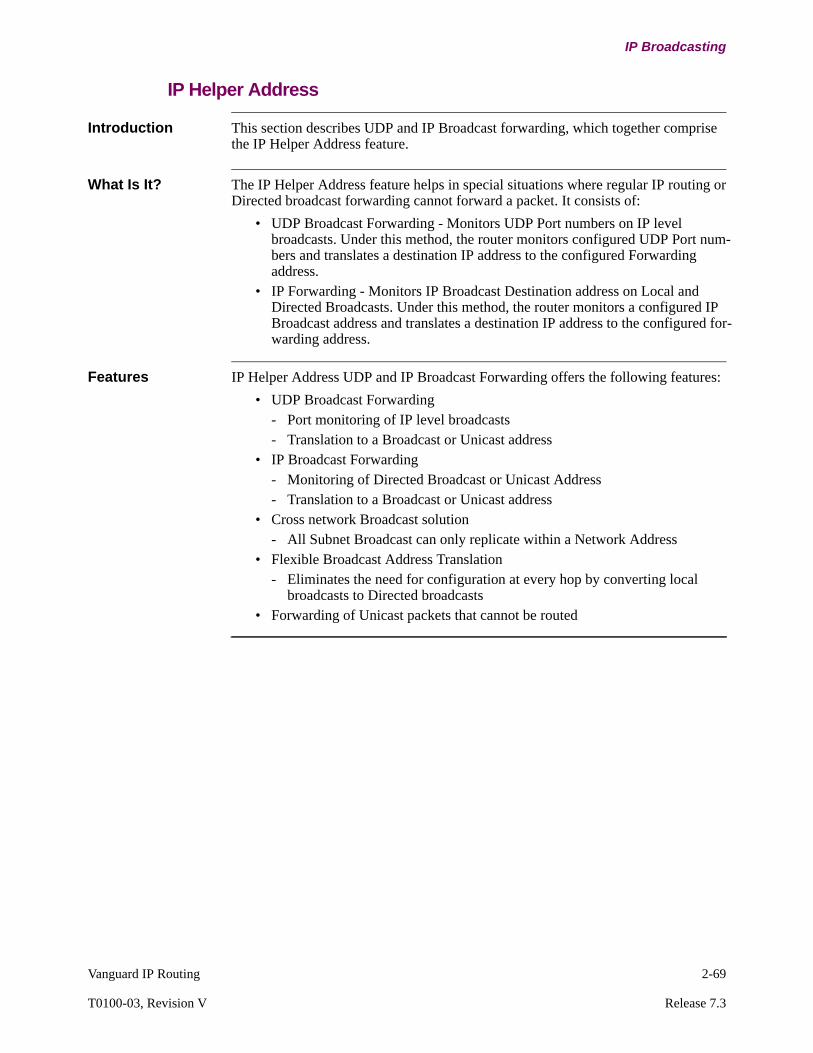
Vanguard IP Routing 2-69
T0100-03, Revision V Release 7.3
IP Broadcasting
IP Helper Address
Introduction This section describes UDP and IP Broadcast forwarding, which together comprise the IP Helper Address feature.
What Is It? The IP Helper Address feature helps in special situations where regular IP routing or Directed broadcast forwarding cannot forward a packet. It consists of:
• UDP Broadcast Forwarding - Monitors UDP Port numbers on IP level broadcasts. Under this method, the router monitors configured UDP Port num-bers and translates a destination IP address to the configured Forwarding address.
• IP Forwarding - Monitors IP Broadcast Destination address on Local and Directed Broadcasts. Under this method, the router monitors a configured IP Broadcast address and translates a destination IP address to the configured for-warding address.
Features IP Helper Address UDP and IP Broadcast Forwarding offers the following features:
• UDP Broadcast Forwarding- Port monitoring of IP level broadcasts- Translation to a Broadcast or Unicast address
• IP Broadcast Forwarding- Monitoring of Directed Broadcast or Unicast Address- Translation to a Broadcast or Unicast address
• Cross network Broadcast solution- All Subnet Broadcast can only replicate within a Network Address
• Flexible Broadcast Address Translation- Eliminates the need for configuration at every hop by converting local
broadcasts to Directed broadcasts• Forwarding of Unicast packets that cannot be routed
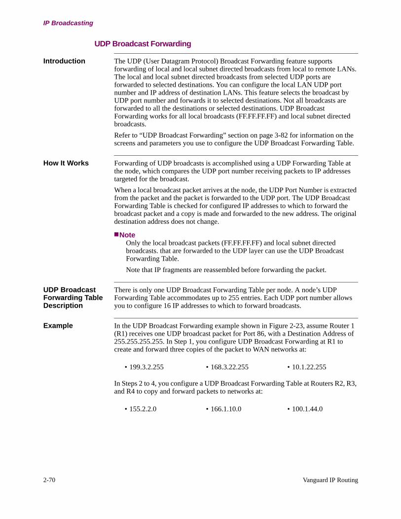
2-70 Vanguard IP Routing
IP Broadcasting
UDP Broadcast Forwarding
Introduction The UDP (User Datagram Protocol) Broadcast Forwarding feature supports forwarding of local and local subnet directed broadcasts from local to remote LANs. The local and local subnet directed broadcasts from selected UDP ports are forwarded to selected destinations. You can configure the local LAN UDP port number and IP address of destination LANs. This feature selects the broadcast by UDP port number and forwards it to selected destinations. Not all broadcasts are forwarded to all the destinations or selected destinations. UDP Broadcast Forwarding works for all local broadcasts (FF.FF.FF.FF) and local subnet directed broadcasts.
Refer to “UDP Broadcast Forwarding” section on page 3-82 for information on the screens and parameters you use to configure the UDP Broadcast Forwarding Table.
How It Works Forwarding of UDP broadcasts is accomplished using a UDP Forwarding Table at the node, which compares the UDP port number receiving packets to IP addresses targeted for the broadcast.
When a local broadcast packet arrives at the node, the UDP Port Number is extracted from the packet and the packet is forwarded to the UDP port. The UDP Broadcast Forwarding Table is checked for configured IP addresses to which to forward the broadcast packet and a copy is made and forwarded to the new address. The original destination address does not change.
NoteOnly the local broadcast packets (FF.FF.FF.FF) and local subnet directed broadcasts. that are forwarded to the UDP layer can use the UDP Broadcast Forwarding Table.
Note that IP fragments are reassembled before forwarding the packet.
UDP Broadcast Forwarding Table Description
There is only one UDP Broadcast Forwarding Table per node. A node’s UDP Forwarding Table accommodates up to 255 entries. Each UDP port number allows you to configure 16 IP addresses to which to forward broadcasts.
Example In the UDP Broadcast Forwarding example shown in Figure 2-23, assume Router 1 (R1) receives one UDP broadcast packet for Port 86, with a Destination Address of 255.255.255.255. In Step 1, you configure UDP Broadcast Forwarding at R1 to create and forward three copies of the packet to WAN networks at:
In Steps 2 to 4, you configure a UDP Broadcast Forwarding Table at Routers R2, R3, and R4 to copy and forward packets to networks at:
• 199.3.2.255 • 168.3.22.255 • 10.1.22.255
• 155.2.2.0 • 166.1.10.0 • 100.1.44.0

Vanguard IP Routing 2-71
T0100-03, Revision V Release 7.3
IP Broadcasting
Configuration is as follows:
Step Action
1 Configure the R1 UDP Broadcast Forwarding Table:
UDP Port Number: 86
UDP Forwarding Address 1: 199.3.2.255
UDP Forwarding Address 2: 168.3.22.255
UDP Forwarding Address 3: 10.1.22.255
2 Configure R2 UDP Broadcast Forwarding Table:
UDP Port Number: 86
UDP Forwarding Address 1: 155.2.2.255
3 Configure R3 UDP Broadcast Forwarding Table:
UDP Port Number: 86
UDP Forwarding Address 1: 166.1.10.255
4 Configure R4 UDP Broadcast Forwarding Table:
UDP Port Number: 86
UDP Forwarding Address 1: 100.1.44.255
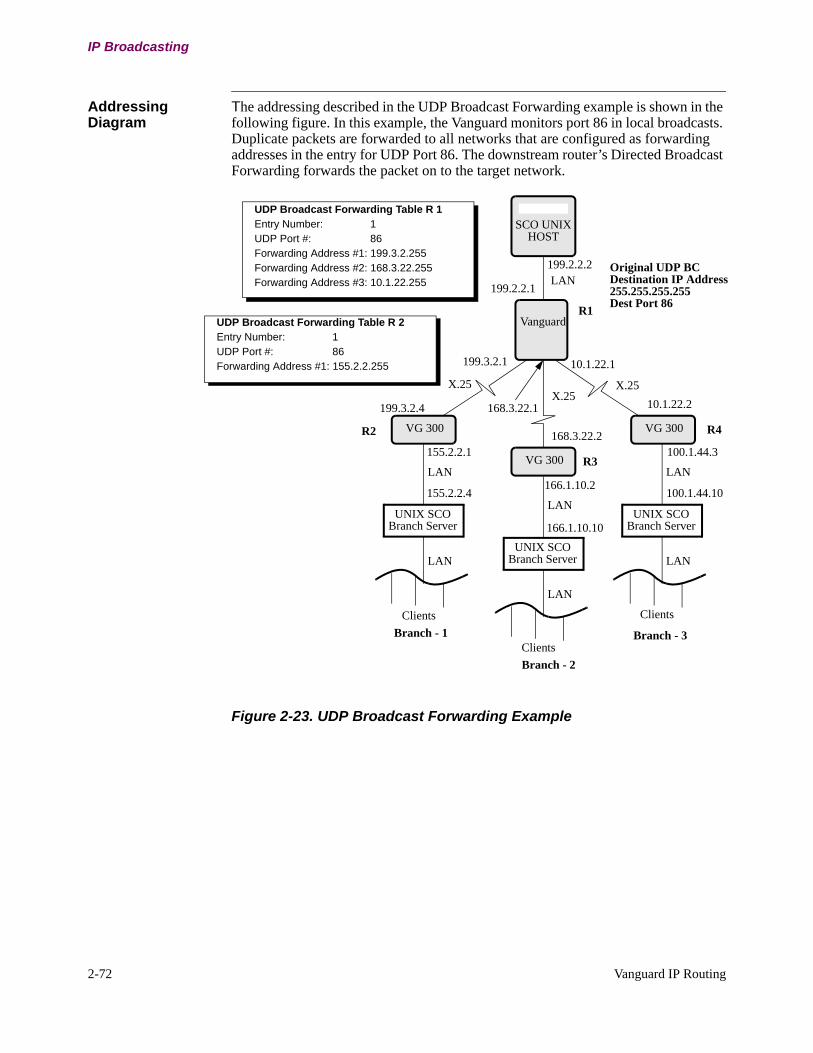
2-72 Vanguard IP Routing
IP Broadcasting
Addressing Diagram
The addressing described in the UDP Broadcast Forwarding example is shown in the following figure. In this example, the Vanguard monitors port 86 in local broadcasts. Duplicate packets are forwarded to all networks that are configured as forwarding addresses in the entry for UDP Port 86. The downstream router’s Directed Broadcast Forwarding forwards the packet on to the target network.
Figure 2-23. UDP Broadcast Forwarding Example
SCO UNIX
Vanguard
X.25
VG 300LAN
UNIX SCOBranch Server
Clients
LAN
LAN199.2.2.1
199.2.2.2
199.3.2.1
168.3.22.1
10.1.22.1
10.1.22.2
168.3.22.2
199.3.2.4
100.1.44.3
166.1.10.2
155.2.2.1
166.1.10.10
100.1.44.10
HOST
VG 300 VG 300
X.25X.25
155.2.2.4LAN
UNIX SCOBranch Server
Clients
LAN
LAN
UNIX SCOBranch Server
Clients
LAN
Branch - 1
Branch - 2
Branch - 3
R1
R4
R3
R2
UDP Broadcast Forwarding Table R 2Entry Number: 1UDP Port #: 86Forwarding Address #1: 155.2.2.255
UDP Broadcast Forwarding Table R 1Entry Number: 1UDP Port #: 86Forwarding Address #1: 199.3.2.255Forwarding Address #2: 168.3.22.255Forwarding Address #3: 10.1.22.255
Original UDP BCDestination IP Address255.255.255.255Dest Port 86

Vanguard IP Routing 2-73
T0100-03, Revision V Release 7.3
IP Broadcasting
Limitations The following limitations apply to UDP Broadcast Forwarding:
• This feature forwards only local broadcast packets with ff.ff.ff.ff in the destination IP address field of the IP packet and local subnet directed broad-cast.
• The node does not forward UDP Broadcast packets if you configure the UDP Broadcast Forwarding Table using a UDP Port Number that is already in use.
• The UDP Broadcast Forwarding Table must be consistent for the internetwork to avoid performance degradation.
• The source IP address does not change.
IP Broadcast Forwarding
Introduction IP Broadcast Forwarding supports forwarding of local and local subnet directed broadcast packets from one local LAN to remote LANs. You can configure both the local LAN IP broadcast addresses and IP address of destination LANs. It selects the broadcast by local/net IP address and forwards it to the destinations selected. It can forward all local broadcasts.
Refer to “IP Broadcast Forwarding” section on page 3-80 for information on the screens and parameters you use to configure the IP Broadcast Forwarding Table.
How It Works Forwarding of IP broadcasts is accomplished using an IP Forwarding Table at the node that compares IP Address to Forward with IP addresses targeted for the broadcast. The Broadcast Address should match the configured value for the Address to Forward parameter. If a match is made, the broadcast is forwarded to the configured destinations.
When a broadcast packet arrives at the node, Forwarding Address #n scan the Route Selection Table to select the forwarding path. The packet is copied and forwarded to the target address. The source address does not change.
IP Broadcast Forwarding Table Description
There is one IP Broadcast Forwarding Table per node. A node’s IP Forwarding Table accommodates up to 255 entries. Each entry in the table allows you to configure a total of 16 IP addresses to which to forward broadcasts.
Example 1 In the IP Broadcast Forwarding example shown in Figure 2-24, assume that the Host is broadcasting on the LAN to address 137.76.255.255, and you want this broadcast to be received on these networks:
• 137.78.0.0 • 137.79.0.0 • 137.80.0.0
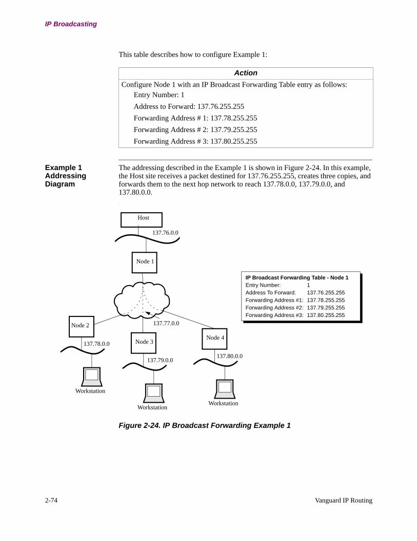
2-74 Vanguard IP Routing
IP Broadcasting
This table describes how to configure Example 1:
Example 1 Addressing Diagram
The addressing described in the Example 1 is shown in Figure 2-24. In this example, the Host site receives a packet destined for 137.76.255.255, creates three copies, and forwards them to the next hop network to reach 137.78.0.0, 137.79.0.0, and 137.80.0.0..
Figure 2-24. IP Broadcast Forwarding Example 1
Action
Configure Node 1 with an IP Broadcast Forwarding Table entry as follows:Entry Number: 1
Address to Forward: 137.76.255.255
Forwarding Address # 1: 137.78.255.255
Forwarding Address # 2: 137.79.255.255
Forwarding Address # 3: 137.80.255.255
Node 2
Host
Node 1
Workstation
137.77.0.0
137.78.0.0
137.79.0.0137.80.0.0
Node 3
Workstation
Node 4
Workstation
IP Broadcast Forwarding Table - Node 1Entry Number: 1Address To Forward: 137.76.255.255Forwarding Address #1: 137.78.255.255Forwarding Address #2: 137.79.255.255Forwarding Address #3: 137.80.255.255
137.76.0.0

Vanguard IP Routing 2-75
T0100-03, Revision V Release 7.3
IP Broadcasting
Example 2 A second example, shown in Figure 2-25, depicts resource considerations to make when configuring IP Broadcast Forwarding. In this example, consider that the remote Vanguard 6520/Vanguard 300 supporting network 137.80.0.0, can also reach two remote LANs at 137.82.0.0 and 137.83.0.0. If these LAN networks also need to see the broadcasts from the Host, you have two options:
Option 1
Step Action Result
1 Configure Host site Node 1 Forwarding Addresses to add LANs at 137.82.0.0 and 137.83.0.0.
Three packets traverse the same link between Nodes 1 and 4. This requires more bandwidth than with Option 2.
Option 2
Step Action Result
1 Configure the first two Forwarding Addresses at Node 1, as in Example 1 (Figure 2-24 on page 2-74).
Node 1 Forwarding Address #1 sends the packet to Node 2 at 137.78.255.255.Node 1 Forwarding Address #2 sends the packet to Node 3 at 137.79.255.255.
2 Configure Node 1 Forwarding Address #3 as 137.77.255.255
Node 1 forwards only one packet to Node 4 and you configure Node 4 to forward to the newer networks by performing Step 3.
3 Configure Node 4 with Forwarding Addresses to networks at 137.80.0.0, 137.82.0.0, and 137.83.0.0.
Host broadcasts reach all remote LANs, while decreasing the number of packets sent across the WAN and saving the additional bandwidth otherwise required.

2-76 Vanguard IP Routing
IP Broadcasting
Example 2 Addressing Diagram
The addressing described in the Example 2 is shown in the following figure.
Figure 2-25. IP Broadcast Forwarding Example 2
137.76.0.0
137.81.0.0
137.82.0.0
137.83.0.0
137.77.1.1
Node 2
Host
Node 1
Workstation
137.77.0.0
137.78.0.0
137.79.0.0137.80.0.0
Node 3
Workstation
Node 4
Workstation
IP Broadcast Forwarding Table - Node 1Entry Number: 1Address To Forward: 137.76.255.255Forwarding Address #1: 137.78.255.255Forwarding Address #2: 137.79.255.255Forwarding Address #3: 137.77.255.255
Node 6
Workstation
Node 5
Workstation
IP Broadcast Forwarding Table - Node 4Entry Number: 1Address To Forward: 137.77.255.255Forwarding Address #1: 137.80.255.255Forwarding Address #2: 137.82.255.255Forwarding Address #3: 137.83.255.255

Vanguard IP Routing 2-77
T0100-03, Revision V Release 7.3
IP Broadcasting
Limitation The following limitation applies to IP Broadcast Forwarding:
• If the Default Route parameter is configured, the packets are not routed using the IP Forwarding feature.
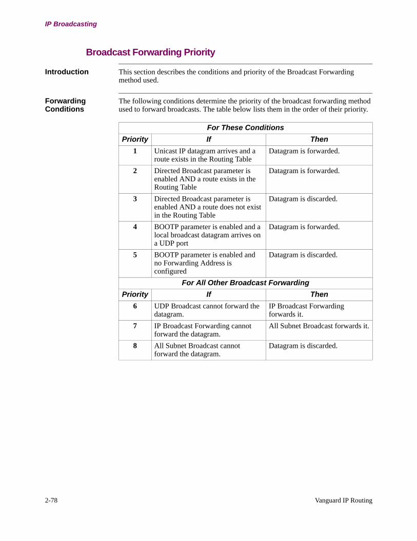
2-78 Vanguard IP Routing
IP Broadcasting
Broadcast Forwarding Priority
Introduction This section describes the conditions and priority of the Broadcast Forwarding method used.
Forwarding Conditions
The following conditions determine the priority of the broadcast forwarding method used to forward broadcasts. The table below lists them in the order of their priority.
For These Conditions
Priority If Then
1 Unicast IP datagram arrives and a route exists in the Routing Table
Datagram is forwarded.
2 Directed Broadcast parameter is enabled AND a route exists in the Routing Table
Datagram is forwarded.
3 Directed Broadcast parameter is enabled AND a route does not exist in the Routing Table
Datagram is discarded.
4 BOOTP parameter is enabled and a local broadcast datagram arrives on a UDP port
Datagram is forwarded.
5 BOOTP parameter is enabled and no Forwarding Address is configured
Datagram is discarded.
For All Other Broadcast Forwarding
Priority If Then
6 UDP Broadcast cannot forward the datagram.
IP Broadcast Forwarding forwards it.
7 IP Broadcast Forwarding cannot forward the datagram.
All Subnet Broadcast forwards it.
8 All Subnet Broadcast cannot forward the datagram.
Datagram is discarded.

Vanguard IP Routing 2-79
T0100-03, Revision V Release 7.3
IP Broadcasting
Broadcast Address Decision Flowchart
Figure 2-26 shows a flowchart indicating the decision process used in determining the forwarding method:
Figure 2-26. Broadcast Address Decision Flowchart
Can packet
be routed?
Route packet and send
Local orLocal Directed
Broadcast
UDP Broadcast
Forwarding
Pass to UDP Broadcast
Forwarding Feature
Directed Broadcast Forward Enabled?
IP Broadcast
Forwarding
Pass to IP Broadcast Forwarding Feature
YesIP Packet
No
Yes Yes
No
Yes
No
No
YesPass to Direct Broadcast Forwarding
Feature
Multicast Packet?
All Subnet Broadcast Packet
and Feature Enabled
Send to upper layer
No
No
Drop Packet
Pass to Multicast Forwarder
Pass to All Subnet Broadcast Forwarding
Feature
Yes
Yes
2-80 Vanguard IP Routing
IP Multicasting
IP Multicasting
What is It? The implementation of IP Multicasting provides efficient multipoint delivery of IP datagrams to hosts across local and remote Frame Relay and X.25 networks using less bandwidth and network resources than unicasting or broadcasting.
IP Multicasting uses a multicast address and a spanning tree approach to connect the source host with destination hosts in a multicast group. This means you can use a multicast address to send an IP datagram to any number of hosts across different networks as long as they are part of the multicast group.
IP Multicasting is useful for video conferencing, corporate messaging to employees over wide areas, or any application used to reach a specific group of hosts with a single datagram stream.
Membership in an IP Multicast group is dynamic, meaning a host can join or leave a multicast group at any time. And, hosts can be members of more than one group. Membership in a multicast group determines whether or not a host receives a copy of datagrams sent to a multicast address. However, a host can send datagrams to a multicast group without being a member.
We use the Internet Group Management Protocol (IGMP) and Distance Vector Multicast Routing Protocol (DVMRP) to provide IP Multicasting support for Vanguard.
Four Levels of Participation for IP Multicasting
Vanguard products support IP Multicasting at four different levels:
• Host does not send or receive multicast datagram.• Host receives multicast datagram (common for voice and video networks).• Host sends multicast datagrams but does not receive any datagrams.• Host sends and receives multicast datagrams.
Limitations The implementation of IP Multicasting has the following limitations:
• IP Multicast supports Ethernet LANs only.• Maximum number of LAN connections is configurable for all platforms. IP
Multicast supports up to 256 to 1,000 connections (depending on the Vanguard platform) over the WAN from Vanguard devices. On the Vanguard, the maximum number of supported LCONs is limited by the configured value in the Maximum Number of LCONs parameter.
• DVMRP routing cannot send or receive default routes. • DVMRP routing cannot send or receive default routes.
NoteMaximum multicast circuits supported:
• 1 to 256 - Vanguard 320, 34x, 6435 and 6455.• 1 to 1,000 - Vanguard 7300 Series.
Configuration For information on configuring the Vanguard for IP Multicasting refer to “Configuring IP Multicast with DVMRP” section on page 3-93.

Vanguard IP Routing 2-81
T0100-03, Revision V Release 7.3
IP Multicasting
Difference Between Multicasting and Broadcasting
Overview IP Multicasting differs from unicasting and broadcasting in that it provides a more practical, efficient means of delivering datagrams from a single source to selected multiple destinations, as shown in Figures 2-27 and 2-28.
IP Multicasting sends one copy of a datagram to selected hosts in your network, instead of sending multiple copies to selected destinations or all destinations, thereby saving bandwidth and conserving network resources.
It also opens your network to new applications such as video conferencing, once considered too costly and impractical for some networks because of bandwidth consumption and limitations on the number of hosts receiving data.,
Figure 2-27. Example of Unicasting
Figure 2-28. Example of IP Multicasting
Unicasting sends multiple copies of the same datagram across the network to multiple hosts. This results in an inefficient use of bandwidth and network resources, and makes the use of some applications prohibitive.
Internetwork
Router
Data
Data
Data
Data
Data
Data
Router RouterData
Data
Data
Data
Sender
Receiver 1
Receiver 2
Receiver 3
Data
Data
IP Multicasting reduces bandwidth consumption and conserves network resources by sending one copy of the datagram to multiple hosts.
Internetwork
Router Data Router Router Data
Data
Data
Receiver 1
Receiver 2
Receiver 3
Data
Sender
Data
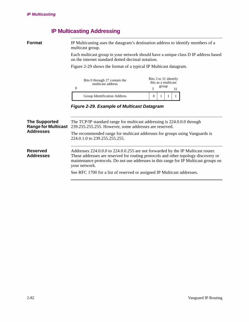
2-82 Vanguard IP Routing
IP Multicasting
IP Multicasting Addressing
Format IP Multicasting uses the datagram’s destination address to identify members of a multicast group.
Each multicast group in your network should have a unique class D IP address based on the internet standard dotted decimal notation.
Figure 2-29 shows the format of a typical IP Multicast datagram.
Figure 2-29. Example of Multicast Datagram
The Supported Range for Multicast Addresses
The TCP/IP standard range for multicast addressing is 224.0.0.0 through 239.255.255.255. However, some addresses are reserved.
The recommended range for multicast addresses for groups using Vanguards is 224.0.1.0 to 239.255.255.255.
Reserved Addresses
Addresses 224.0.0.0 to 224.0.0.255 are not forwarded by the IP Multicast router. These addresses are reserved for routing protocols and other topology discovery or maintenance protocols. Do not use addresses in this range for IP Multicast groups on your network.
See RFC 1700 for a list of reserved or assigned IP Multicast addresses.
Bits 0 through 27 contain the multicast address
0 1 1 1Group Identification Address
0 31
Bits 3 to 31 identify this as a multicast
group3
Vanguard IP Routing 2-83
T0100-03, Revision V Release 7.3
IP Multicasting
Requirements for IP Multicasting Support
Introduction This section describes requirements for support of IP Multicasting on your host or router.
Router’s Requirements for IP Multicasting
Requirements for supporting IP Multicasting on the router are:
• IGMP software • IP protocol• IP Multicast enabled
Host’s Requirements for IP Multicasting
Requirements for supporting IP Multicasting on the host are:
• TCP/IP protocol stack• Operating software support for IP Multicasting, such as MS Windows NT• IGMP software support• Network Interface Card • IP Multicast application software such as video conferencing

2-84 Vanguard IP Routing
IP Multicasting
Implementation of IP Multicasting
Introduction Vanguard products follow the TCP/IP standard for IP multicasting which specifies how hosts send and receive datagrams and identifies methods used to determine multicast group membership on the network.
IGMP and DVMRP Vanguard products use Internet Group Management Protocol (IGMP) and Distance Vector Multicast Routing Protocol (DVMRP) to support IP Multicasting.
Internet Group Management Protocol (IGMP)
What Is It? IP Multicast routing requires Internet Group Management Protocol (IGMP) support on the multicast router. IGMP manages local groups of hosts and helps keep track of the existence of members of an IP Multicast group.
IGMP typically runs between hosts and routers in a network. A host joins a group by sending an IGMP message to the Multicast router. The Multicast router periodically polls the hosts for active membership in the group and maintains a list of groups with active members on the directly attached network interface. The multicast router uses this list to forward a group’s message to the local members and to optimize other groups’ traffic in the WAN.
Vanguard products support IGMP polling on the WAN and LAN ports.
The router always sends three quick polls at 20 second intervals upon restart. If the router does not hear from a host within a specified time period (10 times the host poll interval), IGMP drops the host from the group.
IGMP Version Support
Vanguard products support IGMP Version 1 and 2.

Vanguard IP Routing 2-85
T0100-03, Revision V Release 7.3
IP Multicasting
Distance Vector Multicast Routing Protocol (DVMRP)
What Is It? Distance Vector Multicast Routing Protocol (DVMRP) builds multicast forwarding tables to route datagrams between members of a multicast group. DVMRP does this by exchanging routing updates and other information between members of a multicast group. DVMRP runs between routers in a network.
DVMRP has these functions:
•Generate unicast routing tables with the shortest path back to the source. DVMRP runs its own unicast routing protocol, making it unicast protocol inde-pendent. The unicast routing protocol helps determine valid incoming inter-faces for multicast datagram sources.
•Create upstream and downstream relationship between routers. Downstream routers are the routers multicast datagrams are forwarded to and upstream rout-ers are the routers receiving prunes or grafts as hosts leave or join multicast groups.
•Generate a multicast delivery tree or spanning tree at the source router to forward datagrams to all members in the group. When a datagram arrives on a router interface, the router forwards it if that interface is used by the router to transmit a unicast datagram back to the source. The datagram passes on to all downstream interfaces. Any downstream router sends a prune message back to the source if it has no multicast group members. This creates a source-specific shortest path for all future multicast datagrams. The pruned branches grow back if the router that sent the prune message discovers a new group or member and sends a graft message to begin receiving multicast datagrams for that group or member. (See Figures 2-32 and 2-33). Prunes can be disabled by entering a 0 in the parameter range.
NoteVanguard products support the DVMRP functionality described in RFC 1075 and the Internet Draft Version 3.0.1.
Multicast Route Control
Introduction Release 6.1T02D and greater supports the control of DVMRP routes advertised between the host and remote routers. The maximum number of multicast circuits supported are 256 for Vanguard 320, 34x, 6435 and 6455. The Vanguard 7300 Series supports 1,000 multicast circuits.
For Multicast Route Control to work, filter profiles of address/mask pairs are applied to circuits where filtering is desired. Up to 255 filter profiles and 20 Source address/mask pairs per profile are supported. A profile can be either a “PASS” or “BLOCK” filter. One or more profiles applied to a circuit are searched in sequential order to find a source address/mask match. On a match, the route is then passed or blocked depending on the filter type. Because the profiles are searched in sequential order and the mask entry supports aggregation, the more specific routes should be configured in the earlier profiles. If no match is found in all profiles, the action taken is opposite to the last profile filter type.
NoteRoute report filtering does not apply to routes on a circuit when the router is reporting a route dependency to an upstream router on that circuit.
2-86 Vanguard IP Routing
IP Multicasting
NoteWhen a Vanguard Router receives a default route, it will advertise the default route unconditionally even if the default route advertising condition is not satisfied.
Multicast Route Control Examples
Multicast Example One
Example 1: A User wants to pass all subnets contained within 10.246.1.0/255.255.255.0 and 10.246.2.0/255.255.255.0
Profile 1 Pass
Source Address 1: 10.246.1.0
Source Address Mask 1: 255.255.255.0
Source Address 2: 10.246.2.0
Source Address Mask 2: 255.255.255.0
Source Address 3: 0.0.0.0
Source Address Mask 3: 0.0.0.0
|Source Address 20: 0.0.0.0
Source Address Mask 20: 0.0.0.0
The effect of this filter would be to pass the subnets for entries 1 and 2 and block all others. Since there are situations where you may want to block the more specific subnets contained within the address range you want to pass.
Multicast Example Two
Example 2: Users wants to Pass network 172.16.0.0 but Block Subnets 172.16.1.0/24 and 172.16.2.0/24. In this case since the profiles are searched sequentially, do the most specific first.
Profile 1 Block
Source Address 1: 172.16.1.0
Source Address Mask 1: 255.255.255.0
Source Address 2: 172.16.2.0
Source Address Mask 2: 255.255.255.0
Source Address 3: 0.0.0.0
Source Address Mask 3: 0.0.0.0
|Source Address 20: 0.0.0.0
Source Address Mask 20: 0.0.0.0
Profile 2 Pass
Source Address 1: 172.16.0.0
Source Address Mask 1: 255.255.0.0
Source Address 2: 0.0.0.0
Source Address Mask 2: 0.0.0.0
Vanguard IP Routing 2-87
T0100-03, Revision V Release 7.3
IP Multicasting
Source Address 3: 0.0.0.0
Source Address Mask 3: 0.0.0.0
|Source Address 20: 0.0.0.0
Source Address Mask 20: 0.0.0.0
Multicast Example Three
A Profile can be used to reverse the action of the previous profile. Suppose we modify the requirements of example 2 and the users wants to pass network 172.16.0.0 but Block Subnets 172.16.1.0/24 and 172.16.2.0/24 and pass all other networks. In this case since the profiles are searched sequentially, do the most specific first.
Profile 1 Block
Source Address 1: 172.16.1.0
Source Address Mask 1: 255.255.255.0
Source Address 2: 172.16.2.0
Source Address Mask 2: 255.255.255.0
Source Address 3: 0.0.0.0
Source Address Mask 3: 0.0.0.0
|Source Address 20: 0.0.0.0
Source Address Mask 20: 0.0.0.0
Profile 2 Pass
Source Address 1: 172.16.0.0
Source Address Mask 1: 255.255.0.0
Source Address 2: 0.0.0.0
Source Address Mask 2: 0.0.0.0
Source Address 3: 0.0.0.0
Source Address Mask 3: 0.0.0.0
|Source Address 20: 0.0.0.0
Source Address Mask 20: 0.0.0.0
Profile 3 Block
Source Address 1: 0.0.0.0
Source Address Mask 1: 0.0.0.0
Source Address 2: 0.0.0.0
Source Address Mask 2: 0.0.0.0
Source Address 3: 0.0.0.0
Source Address Mask 3: 0.0.0.0
|Source Address 20: 0.0.0.0
Source Address Mask 20: 0.0.0.0

2-88 Vanguard IP Routing
IP Multicasting
Multicast Example Four
A profile can be used for a default. For example to block all routes being passed on an interface use Pass filter with no specific routes configured. (The reverse to the filter type is the default.)
Profile 1 Pass
Source Address 1: 0.0.0.0
Source Address Mask 1: 0.0.0.0
Source Address 2: 0.0.0.0
Source Address Mask 2: 0.0.0.0
Source Address 3: 0.0.0.0
Source Address Mask 3: 0.0.0.0
|Source Address 20: 0.0.0.0
Source Address Mask 20: 0.0.0.0
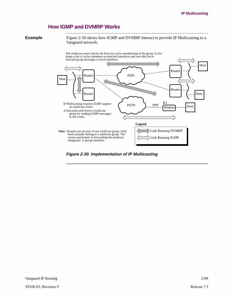
Vanguard IP Routing 2-89
T0100-03, Revision V Release 7.3
IP Multicasting
How IGMP and DVMRP Works
Example Figure 2-30 shows how IGMP and DVMRP interact to provide IP Multicasting to a Vanguard network.
Figure 2-30. Implementation of IP Multicasting
PDNRouter
PSTNModem
R3PPP
RouterHost
Host
Legend
IP Multicasting requires IGMP support on multicast router.
A host joins and leaves a multicast group by sending IGMP messages to the router.
The multicast router checks the hosts for active membership in the group. It also keeps a list of active members on attached interfaces and uses this list to forward group messages to local members.
Note: Routers are not part of any multicast group. Only hosts actually belong to a multicast group. The routers participate in forwarding the multicast datagrams to group members.
RouterRouter
Host
Host
Link Running DVMRP
Link Running IGMP
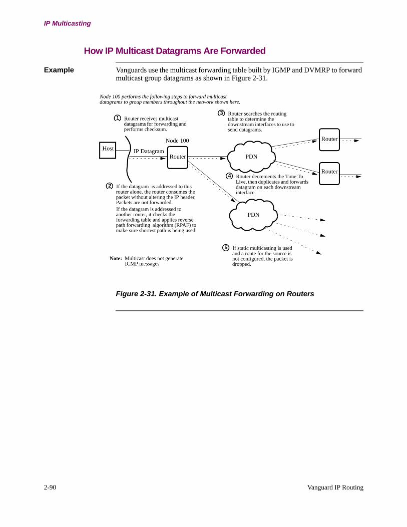
2-90 Vanguard IP Routing
IP Multicasting
How IP Multicast Datagrams Are Forwarded
Example Vanguards use the multicast forwarding table built by IGMP and DVMRP to forward multicast group datagrams as shown in Figure 2-31.
Figure 2-31. Example of Multicast Forwarding on Routers
Router receives multicast datagrams for forwarding and performs checksum.
1Router searches the routing table to determine the downstream interfaces to use to send datagrams.
3
If the datagram is addressed to this router alone, the router consumes the packet without altering the IP header. Packets are not forwarded.If the datagram is addressed to another router, it checks the forwarding table and applies reverse path forwarding algorithm (RPAF) to make sure shortest path is being used.
2
Note: Multicast does not generate ICMP messages
Router decrements the Time To Live, then duplicates and forwards datagram on each downstream interface.
4
PDN
Router
PDN
RouterHost
Router
IP Datagram
Node 100
Node 100 performs the following steps to forward multicast datagrams to group members throughout the network shown here.
If static multicasting is used and a route for the source is not configured, the packet is dropped.
5
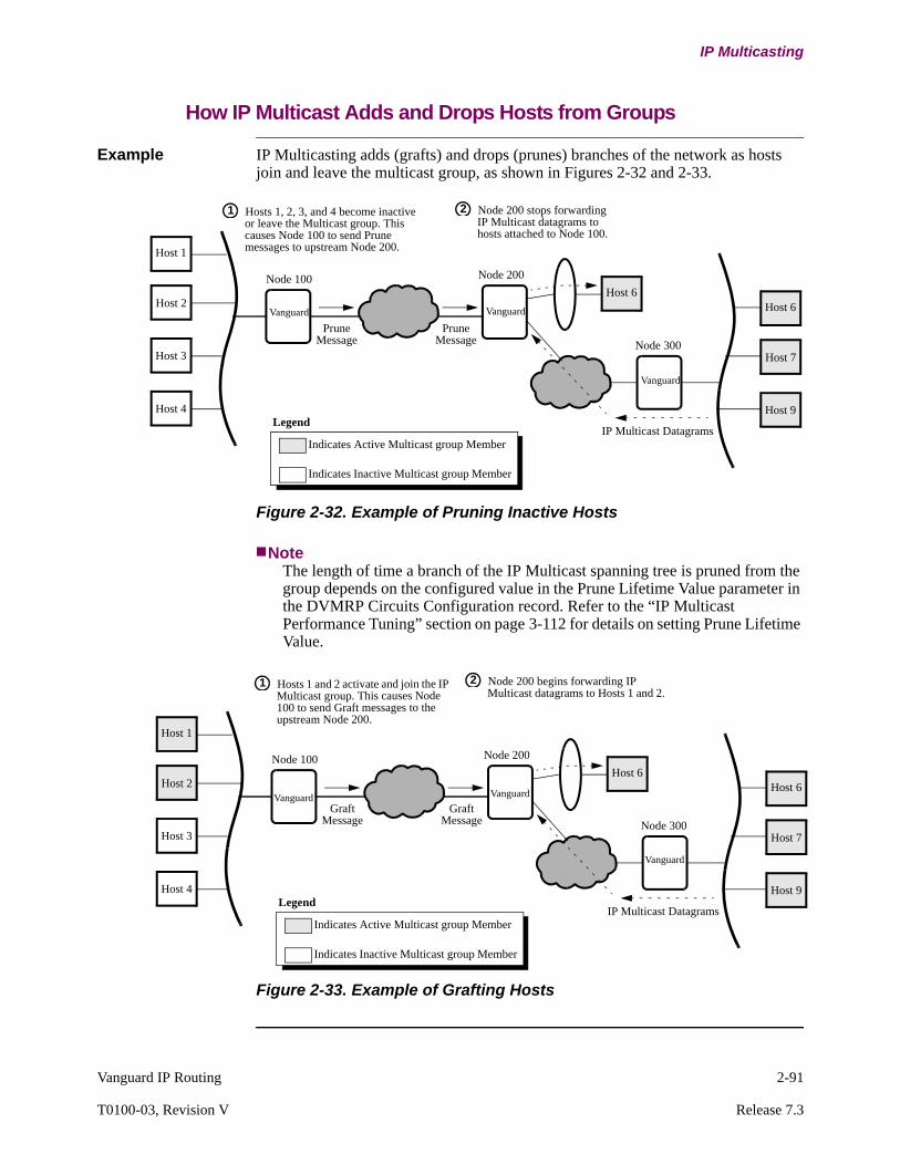
Vanguard IP Routing 2-91
T0100-03, Revision V Release 7.3
IP Multicasting
How IP Multicast Adds and Drops Hosts from Groups
Example IP Multicasting adds (grafts) and drops (prunes) branches of the network as hosts join and leave the multicast group, as shown in Figures 2-32 and 2-33.
Figure 2-32. Example of Pruning Inactive Hosts
NoteThe length of time a branch of the IP Multicast spanning tree is pruned from the group depends on the configured value in the Prune Lifetime Value parameter in the DVMRP Circuits Configuration record. Refer to the “IP Multicast Performance Tuning” section on page 3-112 for details on setting Prune Lifetime Value.
Figure 2-33. Example of Grafting Hosts
PruneMessage
Hosts 1, 2, 3, and 4 become inactive or leave the Multicast group. This causes Node 100 to send Prune messages to upstream Node 200.
1 Node 200 stops forwarding IP Multicast datagrams to hosts attached to Node 100.
2
Legend
Indicates Active Multicast group Member
Indicates Inactive Multicast group Member
Vanguard
Host 1
Host 2
Host 3
Host 4
Node 100Host 6
Node 200
Vanguard Host 6
Host 7
Host 9
Node 300
IP Multicast Datagrams
PruneMessage
Vanguard
Hosts 1 and 2 activate and join the IP Multicast group. This causes Node 100 to send Graft messages to the upstream Node 200.
1 Node 200 begins forwarding IP Multicast datagrams to Hosts 1 and 2.
2
GraftMessage
Legend
Indicates Active Multicast group Member
Indicates Inactive Multicast group Member
Vanguard
Host 1
Host 2
Host 3
Host 4
Node 100Host 6
Node 200
Vanguard Host 6
Host 7
Host 9
Node 300
Vanguard
IP Multicast Datagrams
GraftMessage
2-92 Vanguard IP Routing
Protocol Independent Multicast Sparse Mode (PIM-SM)
Protocol Independent Multicast Sparse Mode (PIM-SM)
Introduction IP Multicasting differs from unicasting and broadcasting in that it provides a more practical, efficient means of delivering datagrams from a single source to selected multiple destinations. Each packet is sent once by the sender regardless the number of the receivers in the group. IP Multicast makes optimal use of network bandwidth as the packets are only replicated for downstream routers on a per needed basis.
PIM-SM was created to support distribution trees (shared and shortest-path) across Wide Area Networks (WANs). PIM-SM is independent because it does not depend on any particular unicast routing protocol. PIM uses the unicast routing table regardless which unicast routing protocol is used. It uses unicast routing for the Reverse Path Forwarding (RPF) check. The RPF interface of a route is the interface used to reach that route in the unicast forwarding table. Multicast data is only forwarded downstream if it arrives from the RPF interface of the source of the packet, (avoiding forwarding the same data more than once).
PIM Modes PIM has two different modes, Sparse Mode (SM) and Dense Mode (DM). Sparse Mode assumes most hosts are not receivers of the multicast traffic, by default no routers are in the distribution tree. In order to receive multicast data for a group, the last hop routers (attached to hosts) have to explicitly join the distribution tree. Dense Mode assumes most hosts are receivers of multicast traffics, therefore by default they are on the distribution tree. Routers that do not want to receive certain multicast data have to explicitly request to be removed from the distribution tree.
Rendezvous Point (RP)
PIM-SM supports Rendezvous Point (RP). Rendezvous Point acts as the root of a share tree for a multicast group. A shared tree of a group is the initial multicast distribution tree used for a group. Hosts interested in receiving multicast packet for a group joins the group using Internet Group Management Protocol (IGMP). The Designated Router (DR), usually the last hop router to the host, joins the shared tree by sending a “PIM Join” message towards the RP. When a sender first sends out multicast data, the multicast packet is encapsulated in a unicast packet, forwarded to the RP, and then the RP forwards it to all receivers of the group. The DR can also later choose to join a Source Specific Tree (SST) for a particular source if there is enough traffic that warrants it. A Source Specific Tree for a group is a shortest path distribution tree rooted at a given source that sends traffic to a group, this ensures that traffic for a group (from that source) will traverse the shortest path to the receivers. When the receiver is no longer interested in receiving the group traffic, the DR sends a PIM Prune message towards the upstream.
Supported Platforms
The PIM-SM feature is supported in release 6.4 and greater on the Vanguard 320, 34x Series, 6435, 6455 and 7300 Series.
PIM-SM and DVMRP
The Vanguard Software Builder will not allow DVMRP and PIM-SM to co-exist in the same image. If a software image with the PIM module loads, DVMRP will be automatically disabled.

Vanguard IP Routing 2-93
T0100-03, Revision V Release 7.3
Protocol Independent Multicast Sparse Mode (PIM-SM)
Interface Types PIM-SM features are supported on both Ethernet and LCON types. PIM is configured on IP interface, therefore the number of interfaces that PIM can support is directly tied to the number of IP interfaces supported on a router.
PIM-SM over VLANs and IP Tunnels are supported. To configure PIM over a VLAN or an IP Tunnel, the IP interface should be configured first, and then PIM-SM should be enabled on the corresponding VLAN/Tunnel IP interface.

2-94 Vanguard IP Routing
Protocol Independent Multicast Sparse Mode (PIM-SM)
PIM Functionality
Supported PIM Functionality
Vanguard Routers support the following functionality:
• Basic PIM• Designated Router (DR)• Bootstrap Router (BSR)• Rendezvous Point (RP)
NoteThe Multicast Border Router (MBR) functionality is not supported.
Basic PIM The Basic PIM router functionalities include:
1) Sending and processing the following messages:
• Hello - Hello messages are used to exchange option information and DR selections. It is also used to maintain PIM adjacencies.PIM Adjacency - PIM uses Hello messages to discover its neighbors and exchange capability information. An interface configured as a PIM interface sends out a hello message periodically. Hello messages are multicast to the ALL-PIM-ROUTERS group (224.0.0.13), therefore only PIM interfaces process the hello message.
•Join/Prune - A Join/Prune message contains information on a router interested in receiving multicast traffic for certain groups. The router then uses this information (in addition to others) to construct its multicast route entries.
• Bootstrap (only propagating, not originating) - A Bootstrap messages contains RP set information, which lists all RPs for different multicast groups. Each router needs to determine who is the active BSR based on the BSR priority and IP address.
2) Performing RP mapping functions. For every group a single RP is selected out of a set of eligible RPs.
3) Consulting the router's unicast routing table (both IGP and BGP tables) for Reverse Path Forwarding (RPF) checks. Information should be available when the unicast route table changes.
4) Participating in DR election process (even if it is not intended to be a DR).
Functionality 320 34x 6435/6455
7300 Series
Basic PIM Y Y Y Y
Designated Router (DR) Y Y Y Y
Bootstrap Router (BSR) N Y Y Y
Rendezvous Point (RP) N Y Y Y
Multicast Border Router (MBR) N N N N

Vanguard IP Routing 2-95
T0100-03, Revision V Release 7.3
Protocol Independent Multicast Sparse Mode (PIM-SM)
Designated Router A Designated Router (DR) is the last hop router that is directly connected to the host(s). When there is more than one router on a subnet, only one is selected as the Designated Router (DR) using DR election process. The Assert mechanism is used to switch the DR role on a per source and group basis when there are multiple paths to a source. By default, every PIM interface is eligible to be the DR. IGMP is enabled on the interface if PIM is enabled.
The Vanguard router software implements the DR functionalities such as:
1) Sending IGMP query on behalf of the LAN.
2) On the sender side: The DR encapsulates the multicast packet in a register message and sends it to the RP of the group. There is a configurable limit on how many register messages a DR can send to the RP within a second (to avoid flooding the RP). If the RP responds with a register stop message, the DR starts a register-suppression timer and refrains from sending register message to the RP for the duration while the timer is active. Just before the timer is about to expire, the DR sends a null register packet as a probe to see if the RP wants to receive future register message. If the RP does not response with a register stop message, the DR resumes encapsulating the multicast packet and forwarding it to the RP in the register message once the timer expires.
3) On the receiver side: The DR can decide when to switch to receive the packet through the Shortest Path source Tree (SPT) instead of using the Share tree that is rooted at the RP. If it does switch, it needs to send a join towards the source and a prune towards the RP. There is a configurable threshold that determines when the DR should switch to the SPT.
4) When a neighbor appears, the DR unicasts the BSR message to the new neighbor.
Designated Router Election Process
The Designated Router (DR) election is based on DR Priority and the IP Address.
1) The interface that has the numerical larger DR priority (if all interfaces have included the DR Priority Option in their Hello messages) is the DR.
2) If at least one router does not implement DR Priority Option or all interfaces have the same DR Priority, the interface with the highest IP address is elected as the DR of that subnet.
3) The DR is responsible of keeping track of hosts' interests in receiving multicast traffic for groups. It runs IGMP with the hosts to get the group join/leave information. A DR is also responsible for forwarding the multicast traffic originated by a local source to the RP, so that the RP can forward it down on the share tree.

2-96 Vanguard IP Routing
Protocol Independent Multicast Sparse Mode (PIM-SM)
Bootstrap Router A Bootstrap Router (BSR) is responsible for periodically generating Bootstrap messages to announce RP set information to all PIM routers.The RP-set information contains the groups and the possible RPs for those groups. Routers that are interested in serving as a BSR can be configured as Candidate-BSR, and they periodically send out Bootstrap messages to all PIM routers. Bootstrap messages are propagated hop by hop by all PIM routers. There are many candidate BSRs, but only one is selected as the BSR. The Candidate-BSRs are first compared by their BSR priorities, and if the priorities are the same, the Candidate-BSR with the highest IP address is selected.
In a PIM network, all Candidate-RPs (C-RP) learn who is the active BSR from the bootstrap messages received, and then unicast their Candidate-RP Advertisements to the active BSR. Therefore, Candidate-RP Advertisement is only sent directly to the active BSR. The BSR in turn sends out this information to all PIM routers through bootstrap messages.
There can be more than one Candidate-BSR in a PIM network, but only one is chosen as the active BSR. By default, the BSR functionality is disabled on a PIM router. To enable a router as a Candidate-BSR, users can configure one of its PIM interfaces as a Candidate-BSR interface.
The Vanguard router software implements the BSR functionalities such as:
• Generate Bootstrap messages periodically to all PIM routers. Bootstrap messages are propagated to all PIM routers hop by hop (i.e., each router sends it with TTL=1).
• Process C-RP Advertisement message. The Candidate-RPs found out who the BSR is through the Bootstrap message. All Candidate-RPs send their RP-set information to BSR in a C-RP Advertisement Message.
• Update RP-set information in a Bootstrap Message. As the BSR learns new RP-set information, it includes the new information in the Bootstrap message.
Rendezvous Point A Rendezvous Point (RP) is the root of the share tree of a multicast group. When a router is configured as a Candidate-RP of a group (usually a range of groups), it advertises the information through a Candidate-RP Advertisement message.
A Candidate-RP configured to support a group is not always selected as the RP for that group. There may be many Candidate-RPs for a given group, and all PIM routers use the same tie breaking rules (see “The Group Range to RP mapping Algorithm” section and the “PIM Hash Function” section) to determine who the RP for a given group is. It is important that all routers select the same RP for a group.
Usually routers that act as RPs tend to be faster routers (therefore have more processing power) and are located near the center of a PIM network (so that the share tree will be rooted closer to the center). By default, the RP functionality is disabled on a PIM router. To enable a router as an RP, users can specify it using static RP or configure one of its PIM interfaces as a Candidate-RP.
NoteIt is not the RP that decides who the RP of a group is. The RP of a group is decided by every PIM router using the group to mapping algorithm together with the hash function.

Vanguard IP Routing 2-97
T0100-03, Revision V Release 7.3
Protocol Independent Multicast Sparse Mode (PIM-SM)
The Vanguard router software implements the RP capabilities such as:
• Generate Candidate-RP (C-RP) Advertisement. This information is sent (through unicast) to BSR.
• Process register message. This indicates that it either decapsulates and forwards the multicast packet, or sends a register stop message back to the DR of the source.
• Join the shortest path source tree and receives multicast natively from the source tree.
PIM Asserts PIM Asserts messages are used to select the upstream interface for a given (*,G) or (S,G) entry when there are multiple parallel paths towards the RP or the source. Assert messages are generated on a shared LAN, and are not used on point to point links.
PIM Bootstrap Filtering
Vanguard routers support capability of filtering BSR messages on a PIM interface. When the option is configured on an interface, bootstrap messages will not be forwarded through this interface, in either direction.
Static RP Configuration
Vanguard routers support statically configured RP set. It specifies the RP(s) of a group, along with the precedence of that configuration (for example, add to the RP sets or override the dynamically learned RPs). Some networks may want to statically configure the RPs, rather than having it dynamically learned.
Cisco RP Hash Cisco used a proprietary hash function instead of the PIM-SM hash as specified in RFC2362. In order to interoperate with Cisco routers, Vanguard routers allow the configured option to use Cisco Proprietary Hash or IETF standard hash.
Filtering of Source-Specific Multicast (SSM) groups
A Source Specific Multicast (SSM) address range is specified as 232.0.0.0/8. These groups are used as special groups where users have to subscribe to a particular sender (not just any sender).
Vanguard router IGMP software will not be able to accept (S,G) group registration from the hosts because it only supports IGMPv2. IGMPv3 is required to allow host to subscribe/unsubscribe to a specific source in SSM groups (i.e., (S,G) Join instead of (*,G) Join). However, the Vanguard PIM routers do accept and propagate (S,G) Join Prune messages for groups within that SSM range. This indicates that it works well within SSM networks if there are other IGMPv3 capable routers connected to the hosts.
Entry Description
Source Source IP Address, the S in (S,G).
Group Group Address, the G in (S, G).
2-98 Vanguard IP Routing
Protocol Independent Multicast Sparse Mode (PIM-SM)
Although Vanguard Routers do not initiate SSM (S,G) upstream join (which is trigged by hosts via IGMPv3), it complies with the latest PIM-SM draft which specifies that a router must not forward any (*,G) Join/Prune messages where G falls into the range allocated to SSM groups. For example, if the router receives (S,G) Join for 232.1.1.1, it will accept it (because it is an "(S,G)"), and if the router receives (*,G) Join for 232.1.1.1, it will ignore it (232.1.1.1 should not be used as a (*,G)).
The router also will not send a register message for any packet that is destined to an SSM address range. A router, acting as an RP, will not forward any register-encapsulated packet that has an SSM address.
QoS Support for Multicast Traffic
Multicast Traffic supports Quality of Service (QoS). The multicast traffic is received, generated and forwarded by the PIM-SM and the new framework will use the QoS Classifier provided by the QoS software.
Multicast Source/Group Filters
The existing Access filter lists are enhanced to filter inbound and outbound Multicast traffic.
Multicast Diagnostics
Vanguard routers support ping on multicast addresses. Mtrace and Mrinfo are supported on routers running PIM-SM. For more information on Mtrace and Mrinfo see the PIM Diagnostics section in Chapter Four.
NoteMtrace and Mrinfo diagnostics will not be supported on Vanguard routers running DVMRP.
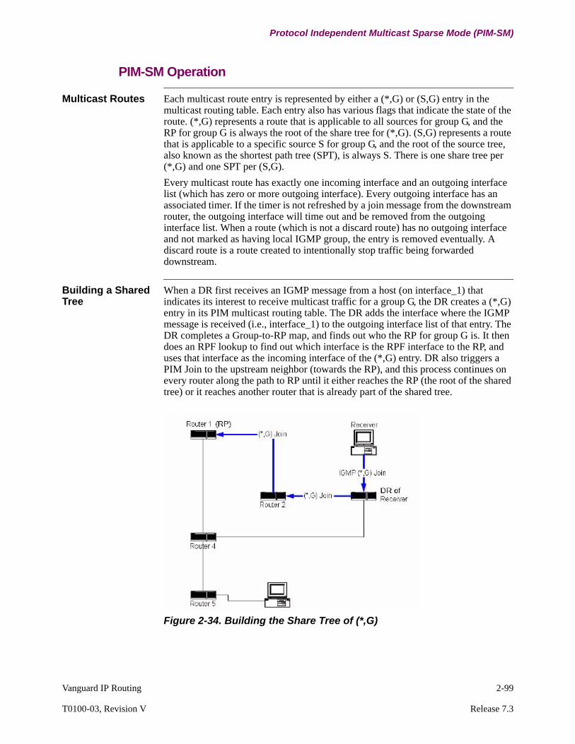
Vanguard IP Routing 2-99
T0100-03, Revision V Release 7.3
Protocol Independent Multicast Sparse Mode (PIM-SM)
PIM-SM Operation
Multicast Routes Each multicast route entry is represented by either a (*,G) or (S,G) entry in the multicast routing table. Each entry also has various flags that indicate the state of the route. (*,G) represents a route that is applicable to all sources for group G, and the RP for group G is always the root of the share tree for (*,G). (S,G) represents a route that is applicable to a specific source S for group G, and the root of the source tree, also known as the shortest path tree (SPT), is always S. There is one share tree per (*,G) and one SPT per (S,G).
Every multicast route has exactly one incoming interface and an outgoing interface list (which has zero or more outgoing interface). Every outgoing interface has an associated timer. If the timer is not refreshed by a join message from the downstream router, the outgoing interface will time out and be removed from the outgoing interface list. When a route (which is not a discard route) has no outgoing interface and not marked as having local IGMP group, the entry is removed eventually. A discard route is a route created to intentionally stop traffic being forwarded downstream.
Building a Shared Tree
When a DR first receives an IGMP message from a host (on interface_1) that indicates its interest to receive multicast traffic for a group G, the DR creates a (*,G) entry in its PIM multicast routing table. The DR adds the interface where the IGMP message is received (i.e., interface_1) to the outgoing interface list of that entry. The DR completes a Group-to-RP map, and finds out who the RP for group G is. It then does an RPF lookup to find out which interface is the RPF interface to the RP, and uses that interface as the incoming interface of the (*,G) entry. DR also triggers a PIM Join to the upstream neighbor (towards the RP), and this process continues on every router along the path to RP until it either reaches the RP (the root of the shared tree) or it reaches another router that is already part of the shared tree.
Figure 2-34. Building the Share Tree of (*,G)
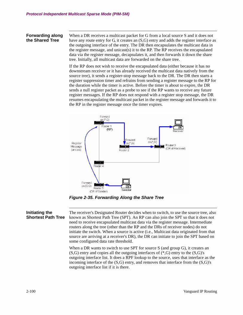
2-100 Vanguard IP Routing
Protocol Independent Multicast Sparse Mode (PIM-SM)
Forwarding along the Shared Tree
When a DR receives a multicast packet for G from a local source S and it does not have any route entry for G, it creates an (S,G) entry and adds the register interface as the outgoing interface of the entry. The DR then encapsulates the multicast data in the register message, and unicast(s) it to the RP. The RP receives the encapsulated data via the register message, decapsulates it, and then forwards it down the share tree. Initially, all multicast data are forwarded on the share tree.
If the RP does not wish to receive the encapsulated data (either because it has no downstream receiver or it has already received the multicast data natively from the source tree), it sends a register-stop message back to the DR. The DR then starts a register suppression timer and refrains from sending a register message to the RP for the duration while the timer is active. Before the timer is about to expire, the DR sends a null register packet as a probe to see if the RP wants to receive any future register messages. If the RP does not respond with a register stop message, the DR resumes encapsulating the multicast packet in the register message and forwards it to the RP in the register message once the timer expires.
Figure 2-35. Forwarding Along the Share Tree
Initiating the Shortest Path Tree
The receiver's Designated Router decides when to switch, to use the source tree, also known as Shortest Path Tree (SPT). An RP can also join the SPT so that it does not need to receive encapsulated multicast data via the register message. Intermediate routers along the tree (other than the RP and the DRs of receiver nodes) do not initiate the switch. When a source is active (i.e., Multicast data originated from that source are arriving at a receiver's DR), the DR can initiate to join the SPT based on some configured data rate threshold.
When a DR wants to switch to use SPT for source S (and group G), it creates an (S,G) entry and copies all the outgoing interfaces of (*,G) entry to the (S,G)'s outgoing interface list. It does a RPF lookup to the source, uses that interface as the incoming interface of the (S,G) entry, and removes that interface from the (S,G)'s outgoing interface list if it is there.

Vanguard IP Routing 2-101
T0100-03, Revision V Release 7.3
Protocol Independent Multicast Sparse Mode (PIM-SM)
The DR then triggers an (S,G) Join towards the source S, sending a PIM join to the incoming interface of (S,G). The process of "creating a new (S,G) entry and triggering an (S,G) join upstream" continues on each router along the path to the source S until it either reaches the DR of source S (the root of SPT) or it reaches another router that has already has the (S,G) entry.
Figure 2-36. Both RP and DR of Receiver Initiate SPT Tree Join
Forwarding Along the Shortest Path Tree
At the DR of the source, there is already an (S,G) route entry with only one outgoing interface called the register interface. The register interface indicates that the data is sent via register message to the RP. When the DR of S receives an (S,G) join from a PIM interface I, it adds interface I to (S,G)'s outgoing interface list, and starts forwarding traffic on both the register interface and interface I.
When the RP starts receiving data from S natively from the RPF interface of S, it sends register-stop messages to the DR of S to indicate that it no longer wishes to receive encapsulated data via a register message. The DR of S will process the register-stop message in the same method as described in “Forwarding along the Shared Tree” section on page 2-100.
The DR of the receiver that has joined the SPT tree will have two route entries: (*,G) and (S,G). The (*,G) entry has the RPF interface towards the RP as the incoming interface while (S,G) has the RPF interface towards S as the incoming interface. The (S,G) entry also has an SPT flag that indicates if the router has started forwarding on the SPT. When the (S,G) entry is first created, the SPT flag is cleared.
When a router (either a DR or an intermediate router) starts receiving multicast traffic for group G from source S on interface I, it will first look up its multicast table (matching to (S,G) if there is any) then look up any (*,G) entries. If interface I is the same as the incoming interface of (S,G) and it is different than the incoming interface of (*,G), the router will set the SPT bit of the (S,G) entry. This indicates that the traffic is now being received/forwarded via SPT.

2-102 Vanguard IP Routing
Protocol Independent Multicast Sparse Mode (PIM-SM)
Figure 2-37. Forwarding on Both (*,G) and (S,G)
When the router has switched to use (S,G) SPT entry, it sends an (S,G) RPT Prune upstream towards the RP. This indicates that now this router is no longer interested in receiving data for group G from S via the share tree.
NoteThe router is still interested in receiving multicast traffic for group G from other sources, therefore the prune will be only for source S.
When the upstream router receives the (S,G) RPT Prune on interface I, it creates a new (S,G) entry, with the RPT-bit set. The (S,G) RPT-bit set entry indicates that this (S,G) entry is on the shared tree. It copies (*,G)'s outgoing interface list to (S,G)'s, and removes interface I from (S,G) outgoing interface list. When there is more traffic from S for G, it is forwarded according to the (S,G) entry (i.e., not forwarded down interface I). Traffic from other sources for group G will continue being forwarded according to the (*,G) entry.
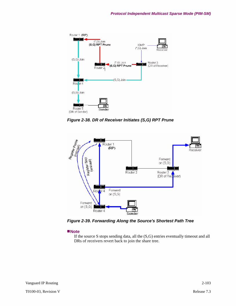
Vanguard IP Routing 2-103
T0100-03, Revision V Release 7.3
Protocol Independent Multicast Sparse Mode (PIM-SM)
Figure 2-38. DR of Receiver Initiates (S,G) RPT Prune
Figure 2-39. Forwarding Along the Source's Shortest Path Tree
NoteIf the source S stops sending data, all the (S,G) entries eventually timeout and all DRs of receivers revert back to join the share tree.

2-104 Vanguard IP Routing
Protocol Independent Multicast Sparse Mode (PIM-SM)
Assert Messages Where multiple PIM routers peer over a shared LAN it is possible for more than one upstream router to have valid forwarding state for a packet, which can lead to packet duplication. PIM does not attempt to prevent this from occurring. Instead it detects when this has happened and elects a single forwarder amongst the upstream routers to prevent further duplication. This election is performed using PIM Assert messages. Assert messages are also received by downstream routers on the LAN, and these messages cause subsequent Join/Prune messages to be sent to the upstream router that “Won the Assert”.
The following figures illustrate a scenario where an Assert is triggered. Router 4 is the router of interest in this example. Router 4, Router 5 and Router 6 are all in the same subnet. Router 4 is the DR, therefore, it is responsible for sending (*,G) upstream for Receiver 1. At Router 6, the RPF neighbor towards the RP is Router 5, then Router 6 sends (*,G) join towards Router 5.
Figure 2-40. Setting up (*,G) Share Tree
In Figure 2-41 the RP (Router 1) starts forwarding traffic downstream (the sender and its DR are not shown in this example) on both interfaces (shown by the solid and dotted unidirectional lines). Router 4 receives the packet twice, one on the incoming interface of its (*,G) entry, and another on the outgoing interface of its (*,G) entry.
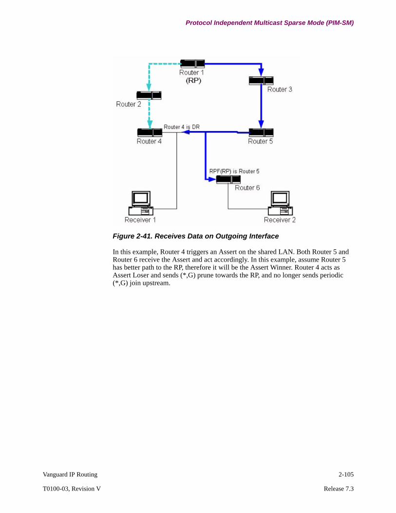
Vanguard IP Routing 2-105
T0100-03, Revision V Release 7.3
Protocol Independent Multicast Sparse Mode (PIM-SM)
Figure 2-41. Receives Data on Outgoing Interface
In this example, Router 4 triggers an Assert on the shared LAN. Both Router 5 and Router 6 receive the Assert and act accordingly. In this example, assume Router 5 has better path to the RP, therefore it will be the Assert Winner. Router 4 acts as Assert Loser and sends (*,G) prune towards the RP, and no longer sends periodic (*,G) join upstream.

2-106 Vanguard IP Routing
Protocol Independent Multicast Sparse Mode (PIM-SM)
Figure 2-42. R4 sends (*,G) Prune Upstream Towards RP
Figure 2-43. The Final (*,G) Share Tree with Asserts

Vanguard IP Routing 2-107
T0100-03, Revision V Release 7.3
Protocol Independent Multicast Sparse Mode (PIM-SM)
Group Range to RP Mapping Algorithm
Each RP mapping (received in BSR message or static RP configuration) specifies a range of multicast groups (expressed as a group and mask) and the RP to which such groups should be mapped. Each mapping may also have an associated priority. It is possible to receive multiple mappings where all of which might match the same multicast group, this is the common case with BSR. The algorithm for performing the group-range-to-RP mapping is as follows:
1) Perform longest match on group-range to obtain a list of RPs.
2) From this list of matching RPs, find the one with highest priority. Eliminate any RPs from the list with lower priorities.
3) If only one RP remains in the list, use that RP.
4) If multiple RPs are in the list, use the PIM hash function to choose one.
If two or more group-range-to-RP mappings cover a particular group, the one with the longest mask is the one to use. If the mappings have the same mask length, then the one with the highest priority is chosen. If there is more than one matching entry with the same longest mask and the priorities are identical, then a hash function is applied to choose the RP.
PIM Hash Function
The hash function is used by all routers within a PIM-SM domain to map a group to one of the RPs from a set of group-range-to-RP mappings (this set all have the same longest mask length and same highest priority). The algorithm takes as input the group address, and the addresses of the candidate RPs from the mappings, and gives as output one RP address to be used.
PIM requires that all routers hash to the same RP within a domain (except for transients). The following hash function must be used in each router:
1) For RP addresses in the matching group-range-to-RP mappings, compute a value:
Value (G,M,C(i))=
(1103515245 * ((1103515245 * (G&M)+12345) XOR C(i)) + 12345) mod 2^31
where C(i) is the RP address and M is a hash-mask. If BSR is being used, the hash-mask is given in the Bootstrap messages. If BSR is not being used, it defaults to a mask with the most significant 30 bits being one for. The hash-mask allows a small number of consecutive groups (for example, 4) to always hash to the same RP. For instance, hierarchically encoded data can be sent on consecutive group addresses to get the same delay and fate-sharing characteristics.
2) The candidate RP with the highest resulting hash value is then the RP chosen by this Hash Function. If more than one RP has the same highest hash value, the RP with the highest IP address is chosen.
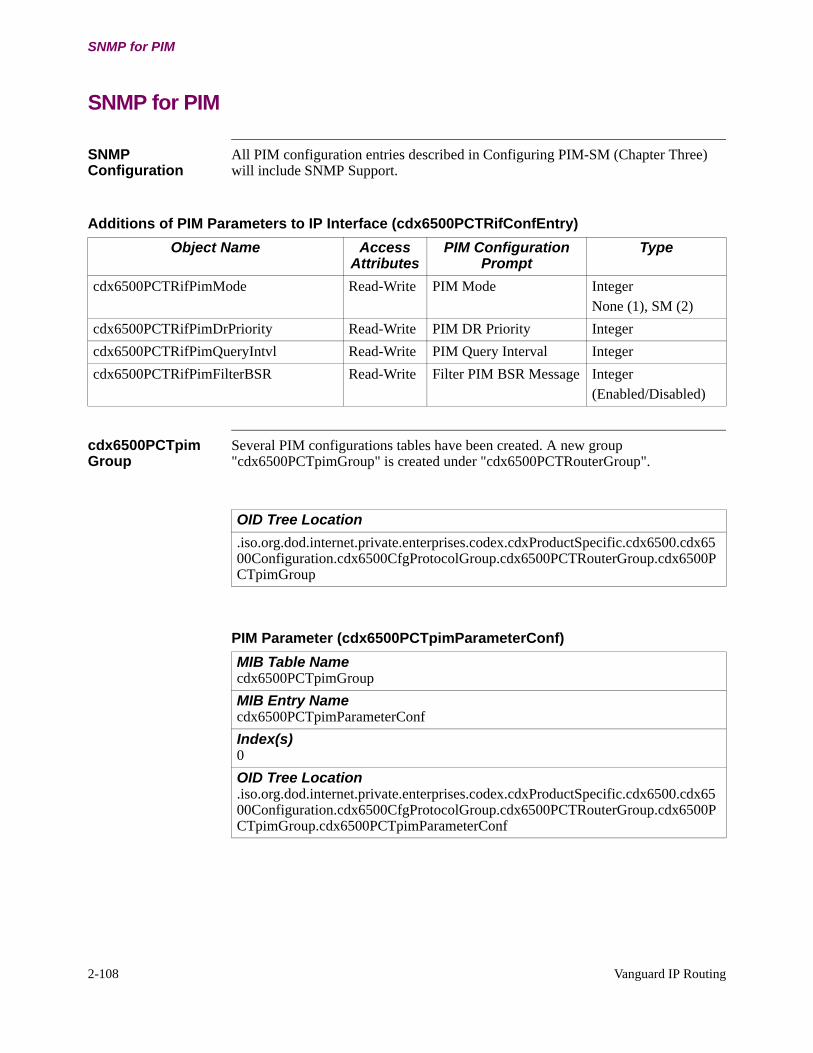
2-108 Vanguard IP Routing
SNMP for PIM
SNMP for PIM
SNMP Configuration
All PIM configuration entries described in Configuring PIM-SM (Chapter Three) will include SNMP Support.
cdx6500PCTpim Group
Several PIM configurations tables have been created. A new group "cdx6500PCTpimGroup" is created under "cdx6500PCTRouterGroup".
Additions of PIM Parameters to IP Interface (cdx6500PCTRifConfEntry)
Object Name Access Attributes
PIM Configuration Prompt
Type
cdx6500PCTRifPimMode Read-Write PIM Mode IntegerNone (1), SM (2)
cdx6500PCTRifPimDrPriority Read-Write PIM DR Priority Integer
cdx6500PCTRifPimQueryIntvl Read-Write PIM Query Interval Integer
cdx6500PCTRifPimFilterBSR Read-Write Filter PIM BSR Message Integer(Enabled/Disabled)
OID Tree Location
.iso.org.dod.internet.private.enterprises.codex.cdxProductSpecific.cdx6500.cdx6500Configuration.cdx6500CfgProtocolGroup.cdx6500PCTRouterGroup.cdx6500PCTpimGroup
PIM Parameter (cdx6500PCTpimParameterConf)
MIB Table Namecdx6500PCTpimGroup
MIB Entry Namecdx6500PCTpimParameterConf
Index(s)0
OID Tree Location.iso.org.dod.internet.private.enterprises.codex.cdxProductSpecific.cdx6500.cdx6500Configuration.cdx6500CfgProtocolGroup.cdx6500PCTRouterGroup.cdx6500PCTpimGroup.cdx6500PCTpimParameterConf
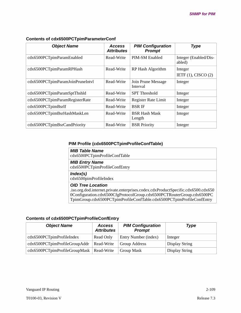
Vanguard IP Routing 2-109
T0100-03, Revision V Release 7.3
SNMP for PIM
Contents of cdx6500PCTpimParameterConf
Object Name Access Attributes
PIM Configuration Prompt
Type
cdx6500PCTpimParamEnabled Read-Write PIM-SM Enabled Integer (Enabled/Dis-abled)
cdx6500PCTpimParamRPHash Read-Write RP Hash Algorithm IntegerIETF (1), CISCO (2)
cdx6500PCTpimParamJoinPruneIntvl Read-Write Join Prune Message Interval
Integer
cdx6500PCTpimParamSptThshld Read-Write SPT Threshold Integer
cdx6500PCTpimParamRegisterRate Read-Write Register Rate Limit Integer
cdx6500PCTpimBsrIf Read-Write BSR IF Integer
cdx6500PCTpimBsrHashMaskLen Read-Write BSR Hash Mask Length
Integer
cdx6500PCTpimBsrCandPriority Read-Write BSR Priority Integer
PIM Profile (cdx6500PCTpimProfileConfTable)
MIB Table Namecdx6500PCTpimProfileConfTable
MIB Entry Namecdx6500PCTpimProfileConfEntry
Index(s)cdx6500pimProfileIndex
OID Tree Location.iso.org.dod.internet.private.enterprises.codex.cdxProductSpecific.cdx6500.cdx6500Configuration.cdx6500CfgProtocolGroup.cdx6500PCTRouterGroup.cdx6500PCTpimGroup.cdx6500PCTpimProfileConfTable.cdx6500PCTpimProfileConfEntry
Contents of cdx6500PCTpimProfileConfEntry
Object Name Access Attributes
PIM Configuration Prompt
Type
cdx6500PCTpimProfileIndex Read Only Entry Number (index) Integer
cdx6500PCTpimProfileGroupAddr Read-Write Group Address Display String
cdx6500PCTpimProfileGroupMask Read-Write Group Mask Display String

2-110 Vanguard IP Routing
SNMP for PIM
PIM-SM RP Candidate (cdx6500PCTpimRpConfTable)
MIB Table Namecdx6500PCTpimRpConfTable
MIB Entry Namecdx6500PCTpimRpConfEntry
Index(s)cdx6500pimRpIndex
OID Tree Location.iso.org.dod.internet.private.enterprises.codex.cdxProductSpecific.cdx6500.cdx6500Configuration.cdx6500CfgProtocolGroup.cdx6500PCTRouterGroup.cdx6500PCTpimGroup.cdx6500PCTpimRpConfTable. cdx6500PCTpimRpConfEntry
Contents of cdx6500PCTpimRPConfEntry
Object Name Access Attributes
PIM Configuration Prompt
Type
cdx6500pimRpIndex Read Only Entry Number (index) Integer
cdx6500pimRpIf Read-Write RP Interface Integer
cdx6500pimRpGrpProfile Read-Write Group Profile Display String
cdx6500pimRpPriority Read-Write RP Priority Integer
PIM-SM Static RP (cdx6500PCTpimsmStaticRpConfTable)
MIB Table Namecdx6500PCTpimStaticRpConfTable
MIB Entry Namecdx6500PCTpimStaticRpConfEntry
Index(s)cdx6500pimStaticRpIndex
OID Tree Location.iso.org.dod.internet.private.enterprises.codex.cdxProductSpecific.cdx6500.cdx6500Configuration.cdx6500CfgProtocolGroup.cdx6500PCTRouterGroup.cdx6500PCTpimGroup.cdx6500PCTpimStaticRpConfTable.cdx6500PCTpimStaticRpConfEntry
Contents of cdx6500PCTpimStaticRpConfEntry
Object Name Access Attributes
PIM Configuration Prompt
Type
cdx6500PCTpimStaticRpIndex Read Only Entry Number (index) Integer
cdx6500PCTpimStaticRpAddr Read-Write RP Address IP Address
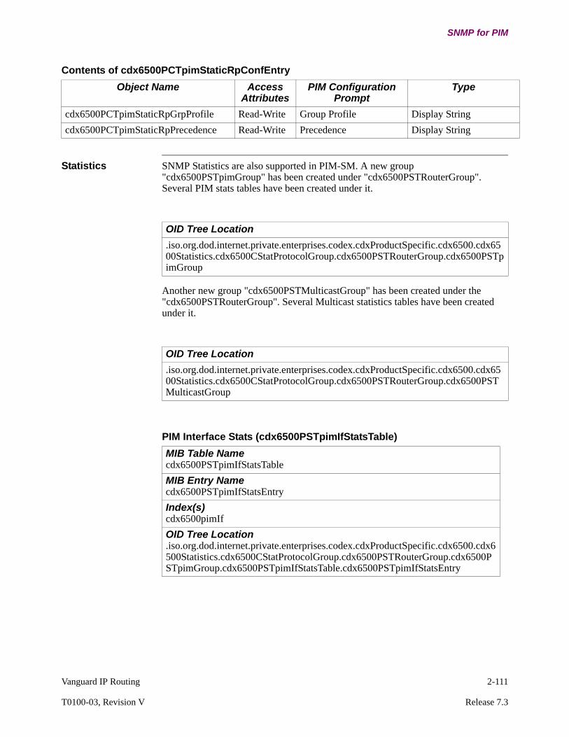
Vanguard IP Routing 2-111
T0100-03, Revision V Release 7.3
SNMP for PIM
Statistics SNMP Statistics are also supported in PIM-SM. A new group "cdx6500PSTpimGroup" has been created under "cdx6500PSTRouterGroup". Several PIM stats tables have been created under it.
Another new group "cdx6500PSTMulticastGroup" has been created under the "cdx6500PSTRouterGroup". Several Multicast statistics tables have been created under it.
cdx6500PCTpimStaticRpGrpProfile Read-Write Group Profile Display String
cdx6500PCTpimStaticRpPrecedence Read-Write Precedence Display String
Contents of cdx6500PCTpimStaticRpConfEntry
Object Name Access Attributes
PIM Configuration Prompt
Type
OID Tree Location
.iso.org.dod.internet.private.enterprises.codex.cdxProductSpecific.cdx6500.cdx6500Statistics.cdx6500CStatProtocolGroup.cdx6500PSTRouterGroup.cdx6500PSTpimGroup
OID Tree Location
.iso.org.dod.internet.private.enterprises.codex.cdxProductSpecific.cdx6500.cdx6500Statistics.cdx6500CStatProtocolGroup.cdx6500PSTRouterGroup.cdx6500PSTMulticastGroup
PIM Interface Stats (cdx6500PSTpimIfStatsTable)
MIB Table Namecdx6500PSTpimIfStatsTable
MIB Entry Namecdx6500PSTpimIfStatsEntry
Index(s)cdx6500pimIf
OID Tree Location.iso.org.dod.internet.private.enterprises.codex.cdxProductSpecific.cdx6500.cdx6500Statistics.cdx6500CStatProtocolGroup.cdx6500PSTRouterGroup.cdx6500PSTpimGroup.cdx6500PSTpimIfStatsTable.cdx6500PSTpimIfStatsEntry

2-112 Vanguard IP Routing
SNMP for PIM
Contents of cdx6500PSTpimIfStatsEntry
Object Name Access Attributes
PIM Statistics Type
cdx6500pimIf Read Only PIM Interface Number (index)
Integer
cdx6500pimRtrIf Read Only Router Interface Number Integer
cdx6500pimIfIpAddr Read Only Interface IP Address IP Address
cdx6500pimIfMode Read Only Protocol Mode Display String
cdx6500pimIfNbrCnt Read Only Neighbor Count Integer
cdx6500PSTpimIfQueryIntvl Read Only Query Interval Integer
cdx6500PSTpimIfDRPriority Read Only DR Address Integer
cdx6500PSTpimIfDR Read Only DR IP Address
PIM Neighbor Stats (cdx6500PSTpimNbrStatsTable)
MIB Table Namecdx6500PSTpimNbrStatsTable
MIB Entry Namecdx6500PSTpimNbrStatsEntry
Index(s)cdx6500pimNbrAddr
OID Tree Location.iso.org.dod.internet.private.enterprises.codex.cdxProductSpecific.cdx6500.cdx6500Statistics.cdx6500CStatProtocolGroup.cdx6500PSTRouterGroup.cdx6500PSTpimGroup.cdx6500PSTpimNbrStatsTable.cdx6500PSTpimNbrStatsEntry
Contents of cdx6500PSTpimNbrStatsEntry
Object Name Access Attributes
PIM Statistics Type
cdx6500pimNbrAddr Read Only Neighbor IP Address (index)
IP Address
cdx6500pimNbrIf Read Only PIM Interface Number Integer
cdx6500PSTpimNbrIfRtr Read Only Interface Type Integer
cdx6500pimNbrUptime Read Only Uptime Display String
cdx6500pimNbrExpire Read Only Expire Time Display String
cdx6500PSTpimDRMode Read Only DR Mode Display String
cdx6500PSTpimNbrDRPriority Read Only DR Priority Integer
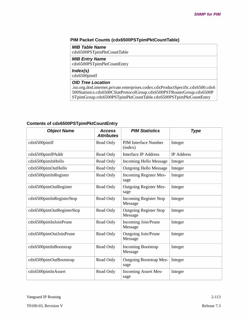
Vanguard IP Routing 2-113
T0100-03, Revision V Release 7.3
SNMP for PIM
PIM Packet Counts (cdx6500PSTpimPktCountTable)
MIB Table Namecdx6500PSTpimPktCountTable
MIB Entry Namecdx6500PSTpimPktCountEntry
Index(s)cdx6500pimIf
OID Tree Location.iso.org.dod.internet.private.enterprises.codex.cdxProductSpecific.cdx6500.cdx6500Statistics.cdx6500CStatProtocolGroup.cdx6500PSTRouterGroup.cdx6500PSTpimGroup.cdx6500PSTpimPktCountTable.cdx6500PSTpimPktCountEntry
Contents of cdx6500PSTpimPktCountEntry
Object Name Access Attributes
PIM Statistics Type
cdx6500pimIf Read Only PIM Interface Number (index)
Integer
cdx6500pimIPAddr Read Only Interface IP Address IP Address
cdx6500pimInHello Read Only Incoming Hello Message Integer
cdx6500pimOutHello Read Only Outgoing Hello Message Integer
cdx6500pimInRegister Read Only Incoming Register Mes-sage
Integer
cdx6500pimOutRegister Read Only Outgoing Register Mes-sage
Integer
cdx6500pimInRegisterStop Read Only Incoming Register Stop Message
Integer
cdx6500pimOutRegisterStop Read Only Outgoing Register Stop Message
Integer
cdx6500pimInJoinPrune Read Only Incoming Join/Prune Message
Integer
cdx6500pimOutJoinPrune Read Only Outgoing Join/Prune Message
Integer
cdx6500pimInBootstrap Read Only Incoming Bootstrap Message
Integer
cdx6500pimOutBootstrap Read Only Outgoing Bootstrap Mes-sage
Integer
cdx6500pimInAssert Read Only Incoming Assert Mes-sage
Integer
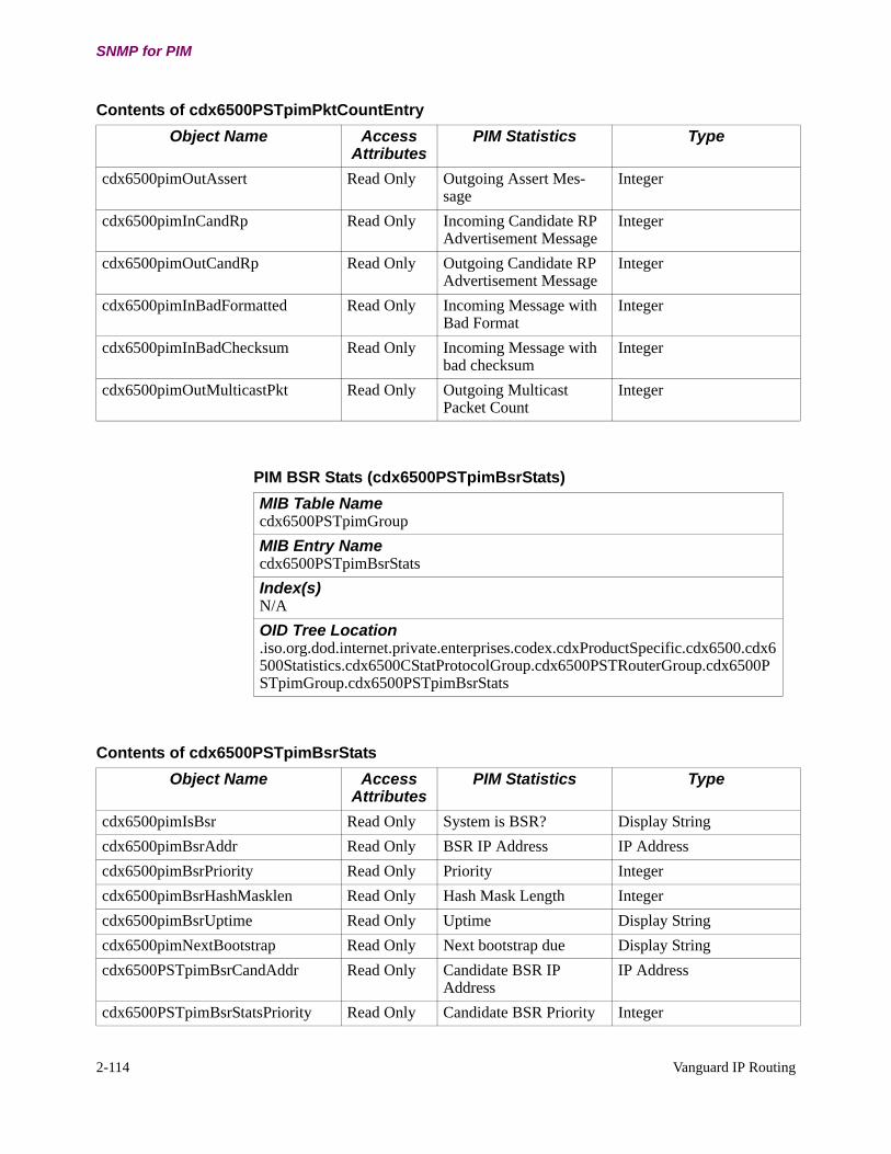
2-114 Vanguard IP Routing
SNMP for PIM
cdx6500pimOutAssert Read Only Outgoing Assert Mes-sage
Integer
cdx6500pimInCandRp Read Only Incoming Candidate RP Advertisement Message
Integer
cdx6500pimOutCandRp Read Only Outgoing Candidate RP Advertisement Message
Integer
cdx6500pimInBadFormatted Read Only Incoming Message with Bad Format
Integer
cdx6500pimInBadChecksum Read Only Incoming Message with bad checksum
Integer
cdx6500pimOutMulticastPkt Read Only Outgoing Multicast Packet Count
Integer
Contents of cdx6500PSTpimPktCountEntry
Object Name Access Attributes
PIM Statistics Type
PIM BSR Stats (cdx6500PSTpimBsrStats)
MIB Table Namecdx6500PSTpimGroup
MIB Entry Namecdx6500PSTpimBsrStats
Index(s)N/A
OID Tree Location.iso.org.dod.internet.private.enterprises.codex.cdxProductSpecific.cdx6500.cdx6500Statistics.cdx6500CStatProtocolGroup.cdx6500PSTRouterGroup.cdx6500PSTpimGroup.cdx6500PSTpimBsrStats
Contents of cdx6500PSTpimBsrStats
Object Name Access Attributes
PIM Statistics Type
cdx6500pimIsBsr Read Only System is BSR? Display String
cdx6500pimBsrAddr Read Only BSR IP Address IP Address
cdx6500pimBsrPriority Read Only Priority Integer
cdx6500pimBsrHashMasklen Read Only Hash Mask Length Integer
cdx6500pimBsrUptime Read Only Uptime Display String
cdx6500pimNextBootstrap Read Only Next bootstrap due Display String
cdx6500PSTpimBsrCandAddr Read Only Candidate BSR IP Address
IP Address
cdx6500PSTpimBsrStatsPriority Read Only Candidate BSR Priority Integer
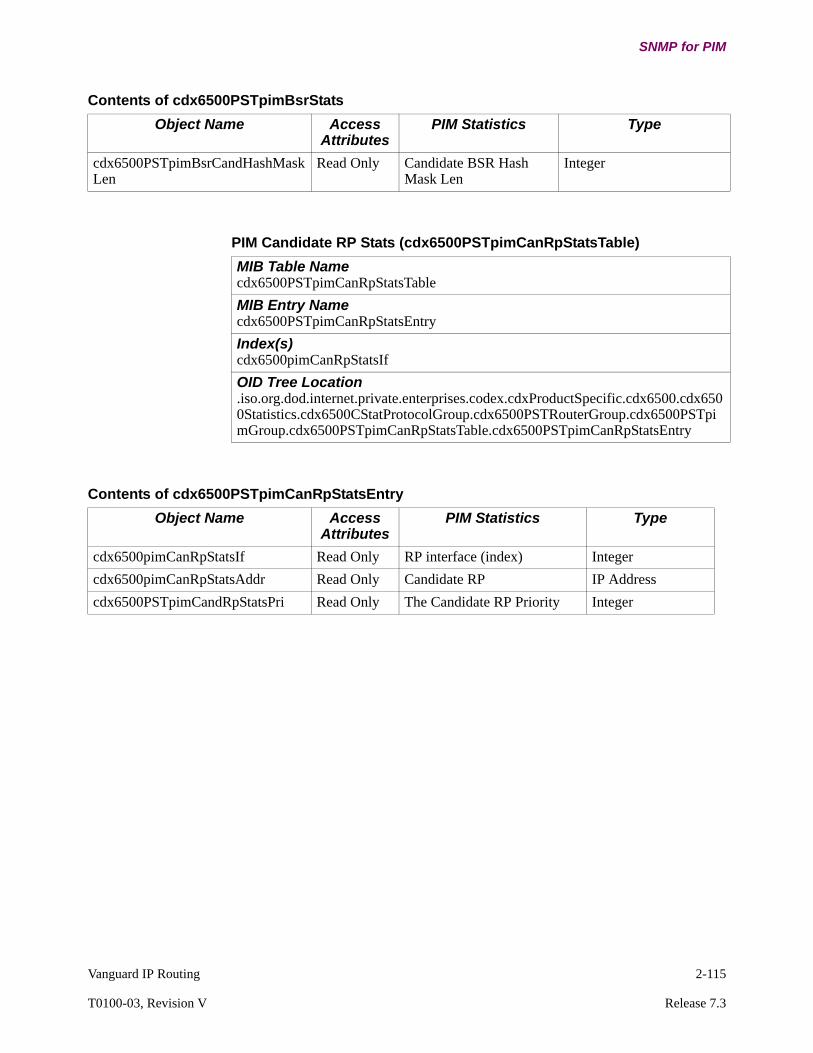
Vanguard IP Routing 2-115
T0100-03, Revision V Release 7.3
SNMP for PIM
cdx6500PSTpimBsrCandHashMaskLen
Read Only Candidate BSR Hash Mask Len
Integer
Contents of cdx6500PSTpimBsrStats
Object Name Access Attributes
PIM Statistics Type
PIM Candidate RP Stats (cdx6500PSTpimCanRpStatsTable)
MIB Table Namecdx6500PSTpimCanRpStatsTable
MIB Entry Namecdx6500PSTpimCanRpStatsEntry
Index(s)cdx6500pimCanRpStatsIf
OID Tree Location.iso.org.dod.internet.private.enterprises.codex.cdxProductSpecific.cdx6500.cdx6500Statistics.cdx6500CStatProtocolGroup.cdx6500PSTRouterGroup.cdx6500PSTpimGroup.cdx6500PSTpimCanRpStatsTable.cdx6500PSTpimCanRpStatsEntry
Contents of cdx6500PSTpimCanRpStatsEntry
Object Name Access Attributes
PIM Statistics Type
cdx6500pimCanRpStatsIf Read Only RP interface (index) Integer
cdx6500pimCanRpStatsAddr Read Only Candidate RP IP Address
cdx6500PSTpimCandRpStatsPri Read Only The Candidate RP Priority Integer

2-116 Vanguard IP Routing
SNMP for PIM
PIM RP Stats (cdx6500PSTpimRpStatsTable)
MIB Table Namecdx6500PSTpimRpStatsTable
MIB Entry Namecdx6500PSTpimRpStatsEntry
Index(s)cdx6500pimRpStatsGroupAddr
OID Tree Location.iso.org.dod.internet.private.enterprises.codex.cdxProductSpecific.cdx6500.cdx6500Statistics.cdx6500CStatProtocolGroup.cdx6500PSTRouterGroup.cdx6500PSTpimGroup.cdx6500PSTpimRpStatsTable.cdx6500PSTpimRpStatsEntry
Contents of cdx6500PSTpimRpStatsEntry
Object Name Access Attributes
PIM Statistics Type
cdx6500pimRpStatsGroupAddr Read Only Group Address (index) IP Address
cdx6500pimRpStatsAddr Read Only RP Address Display String
PIM RP Mapping (cdx6500PSTpimRpMapTable)
MIB Table Namecdx6500PSTpimRpMapTable
MIB Entry Namecdx6500PSTpimRpMapEntry
Index(s)cdx6500PSTpimRpMapSetIndex (index1), cdx6500PSTpimRpMapGroupAddr (index2), cdx6500PSTpimRpMapGroupMask (index3), cdx6500PSTpimRpMapAddr (index4)
OID Tree Location.iso.org.dod.internet.private.enterprises.codex.cdxProductSpecific.cdx6500.cdx6500Statistics.cdx6500CStatProtocolGroup.cdx6500PSTRouterGroup.cdx6500PSTpimGroup.cdx6500PSTpimRpMapTable.cdx6500PSTpimRpMapEntry

Vanguard IP Routing 2-117
T0100-03, Revision V Release 7.3
SNMP for PIM
Contents of cdx6500PSTpimRpMapEntry
Object Name Access Attributes
PIM Statistics Type
cdx6500PSTpimRpMapSetIndex Read Only RP Stat Index (index 1) IntegerDynamic Learned RP Set (1)Static RP Set (Override) (2)Static RP Set (Backup) (3)
cdx6500pimRpMapGroupAddr Read Only Group Address (index 2) IP Address
cdx6500pimRpMapGroupMask Read Only Group Mask (index 3) IP Address
cdx6500pimRpMapAddr Read Only RP Address IP Address
cdx6500pimRpMapPriority Read Only RP Priority Display String
cdx6500pimRpMapVia Read Only Learned Via Display String
cdx6500pimRpMapInfoSource Read Only The source from which the RP mapping was learned.
Display String
cdx6500pimRpMapUptime Read Only Uptime Display String
cdx6500pimRpMapExpiry Read Only Expiry Display String
PIM Multicast Route (cdx6500PSTpimMRouteTable)
MIB Table Namecdx6500PSTpimMRouteTable
MIB Entry Namecdx6500PSTpimMRouteEntry
Index(s)cdx6500PSTpimMRouteGroup (index 1), cdx6500PSTpimMRouteSource(index 2)
OID Tree Location.iso.org.dod.internet.private.enterprises.codex.cdxProductSpecific.cdx6500.cdx6500Statistics.cdx6500CStatProtocolGroup.cdx6500PSTRouterGroup.cdx6500PSTpimGroup.cdx6500PSTpimMRouteTable.cdx6500PSTpimMRouteEntry
Contents of cdx6500PSTpimMRouteEntry
Object Name Access Attributes
PIM Statistics Type
cdx6500PSTpimMRouteGroup Read Only Group Address (index 1) IP Address
cdx6500PSTpimMRouteSource Read Only Source Address (index 2) IP Address
cdx6500PSTpimMRouteCreationTime
Read Only Route Creation Time Display String
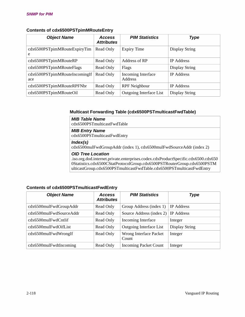
2-118 Vanguard IP Routing
SNMP for PIM
cdx6500PSTpimMRouteExpiryTime
Read Only Expiry Time Display String
cdx6500PSTpimMRouteRP Read Only Address of RP IP Address
cdx6500PSTpimMRouteFlags Read Only Flags Display String
cdx6500PSTpimMRouteIncomingIface
Read Only Incoming Interface Address
IP Address
cdx6500PSTpimMRouteRPFNbr Read Only RPF Neighbour IP Address
cdx6500PSTpimMRouteOil Read Only Outgoing Interface List Display String
Contents of cdx6500PSTpimMRouteEntry
Object Name Access Attributes
PIM Statistics Type
Multicast Forwarding Table (cdx6500PSTmulticastFwdTable)
MIB Table Namecdx6500PSTmulticastFwdTable
MIB Entry Namecdx6500PSTmulticastFwdEntry
Index(s)cdx6500mulFwdGroupAddr (index 1), cdx6500mulFwdSourceAddr (index 2)
OID Tree Location.iso.org.dod.internet.private.enterprises.codex.cdxProductSpecific.cdx6500.cdx6500Statistics.cdx6500CStatProtocolGroup.cdx6500PSTRouterGroup.cdx6500PSTMulticastGroup.cdx6500PSTmulticastFwdTable.cdx6500PSTmulticastFwdEntry
Contents of cdx6500PSTmulticastFwdEntry
Object Name Access Attributes
PIM Statistics Type
cdx6500mulFwdGroupAddr Read Only Group Address (index 1) IP Address
cdx6500mulFwdSourceAddr Read Only Source Address (index 2) IP Address
cdx6500mulFwdCntIif Read Only Incoming Interface Integer
cdx6500mulFwdOifList Read Only Outgoing Interface List Display String
cdx6500mulFwdWrongIf Read Only Wrong Interface Packet Count
Integer
cdx6500mulFwdtIncoming Read Only Incoming Packet Count Integer

Vanguard IP Routing 2-119
T0100-03, Revision V Release 7.3
SNMP for PIM
Multicast Routing Table (cdx6500PSTmulticastRoutTable)
MIB Table Namecdx6500PSTmulticastRoutTable
MIB Entry Namecdx6500PSTmulticastRoutEntry
Index(s)cdx6500mulRoutGroupAddr (index 1), cdx6500mulRoutSourceAddr (index 2)
OID Tree Location.iso.org.dod.internet.private.enterprises.codex.cdxProductSpecific.cdx6500.cdx6500Statistics.cdx6500CStatProtocolGroup.cdx6500PSTRouterGroup.cdx6500PSTMulticastGroup.cdx6500PSTmulticastRoutTable. cdx6500PSTmulticastRoutEntry
Contents of cdx6500PSTmulticastRoutEntry
Object Name Access Attributes
PIM Statistics Type
cdx6500PSTmulRoutGroupAddr Read Only Group Address (index 1) IP Address
cdx6500PSTmulRoutSourceAddr Read Only Source Address (index 2) IP Address
cdx6500PSTmulRoutEntryDataRate Read Only Data Rate Integer
cdx6500PSTmulRoutEntryPacketCount
Read Only Packet Count Integer
cdx6500PSTmulRoutEntryWrongIfCnt
Read Only Wrong Interface Count Integer
cdx6500PSTmulRoutInIf Read Only Incoming Interface IP Address
cdx6500PSTmulRoutOutgoingIf Read Only Outgoing Interface List Display String
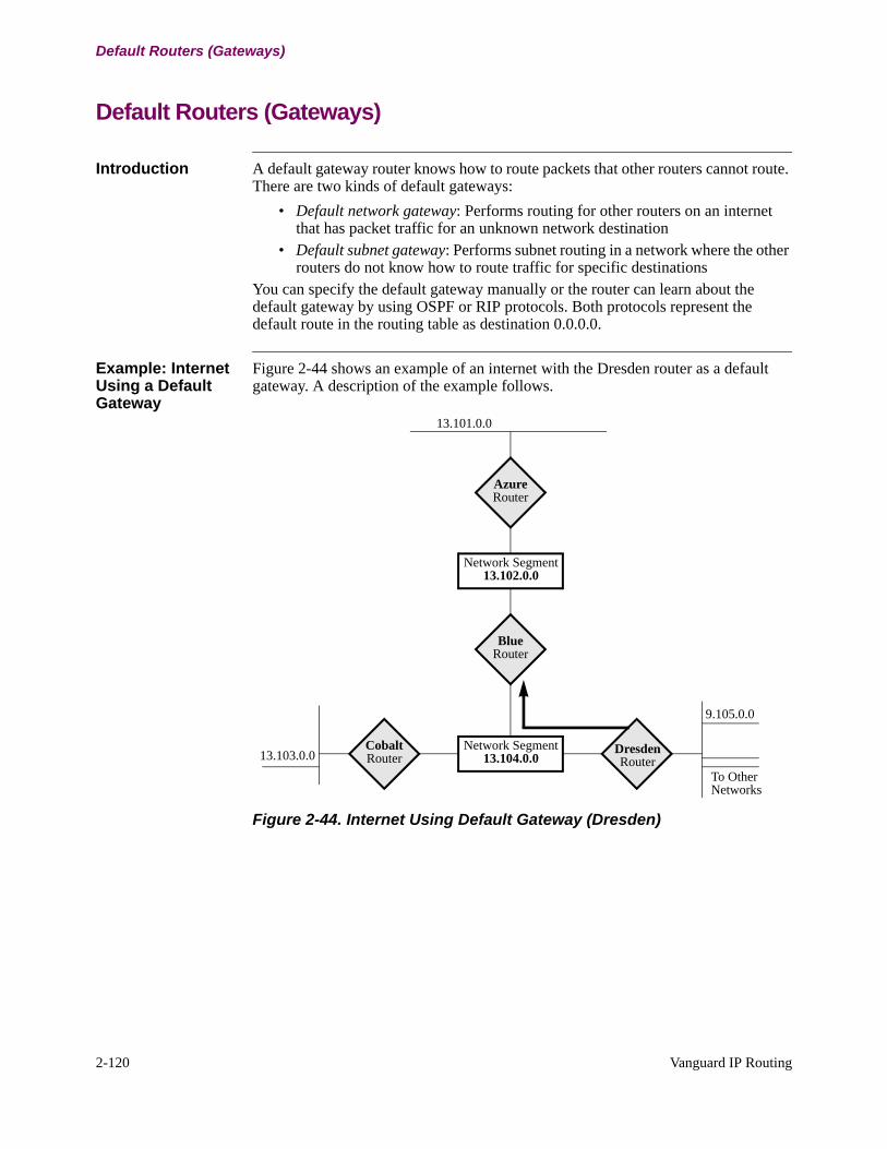
2-120 Vanguard IP Routing
Default Routers (Gateways)
Default Routers (Gateways)
Introduction A default gateway router knows how to route packets that other routers cannot route. There are two kinds of default gateways:
• Default network gateway: Performs routing for other routers on an internet that has packet traffic for an unknown network destination
• Default subnet gateway: Performs subnet routing in a network where the other routers do not know how to route traffic for specific destinations
You can specify the default gateway manually or the router can learn about the default gateway by using OSPF or RIP protocols. Both protocols represent the default route in the routing table as destination 0.0.0.0.
Example: Internet Using a Default Gateway
Figure 2-44 shows an example of an internet with the Dresden router as a default gateway. A description of the example follows.
Figure 2-44. Internet Using Default Gateway (Dresden)
9.105.0.0
AzureRouter
Network Segment13.102.0.0
BlueRouter
Network Segment13.104.0.0
Cobalt Router
DresdenRouter13.103.0.0
To OtherNetworks
13.101.0.0
Vanguard IP Routing 2-121
T0100-03, Revision V Release 7.3
Default Routers (Gateways)
Description of Figure 2-44
In Figure 2-44, the network segments are:
• 13.101.0.0• 13.102.0.0• 13.103.0.0• 13.104.0.0• 9.105.0.0
The routers are Azure, Blue, Cobalt, and Dresden. Dresden is the default network gateway because it has knowledge of network 13 and any other networks. Network 13 routers do not have any knowledge of networks outside of network 13.
On network segment 13.104, unknown network traffic first goes to router Dresden, then toward the appropriate destination.
Configuration The Vanguard forwards to the default gateway router any packets addressed to otherwise unknown destinations. To enable this feature, configure the IP address of the next hop towards the default gateway and the metric using these parameters from the Configure IP Parameters table:
• Default Gateway• Default Gateway Metric
For more information, refer to “Configure IP” section on page 3-13.
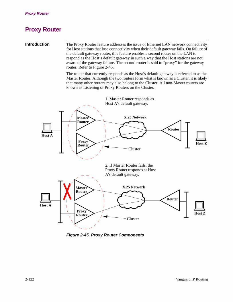
2-122 Vanguard IP Routing
Proxy Router
Proxy Router
Introduction The Proxy Router feature addresses the issue of Ethernet LAN network connectivity for Host stations that lose connectivity when their default gateway fails. On failure of the default gateway router, this feature enables a second router on the LAN to respond as the Host’s default gateway in such a way that the Host stations are not aware of the gateway failure. The second router is said to “proxy” for the gateway router. Refer to Figure 2-45.
The router that currently responds as the Host’s default gateway is referred to as the Master Router. Although the two routers form what is known as a Cluster, it is likely that many other routers may also belong to the Cluster. All non-Master routers are known as Listening or Proxy Routers on the Cluster.
Figure 2-45. Proxy Router Components
X.25 Network
Router
ProxyRouter
Host A
MasterRouter
Host Z
Cluster
1. Master Router responds as Host A’s default gateway.
X.25 Network
Router
ProxyRouter
Host A
MasterRouter
Host Z
Cluster
2. If Master Router fails, the Proxy Router responds as Host A’s default gateway.
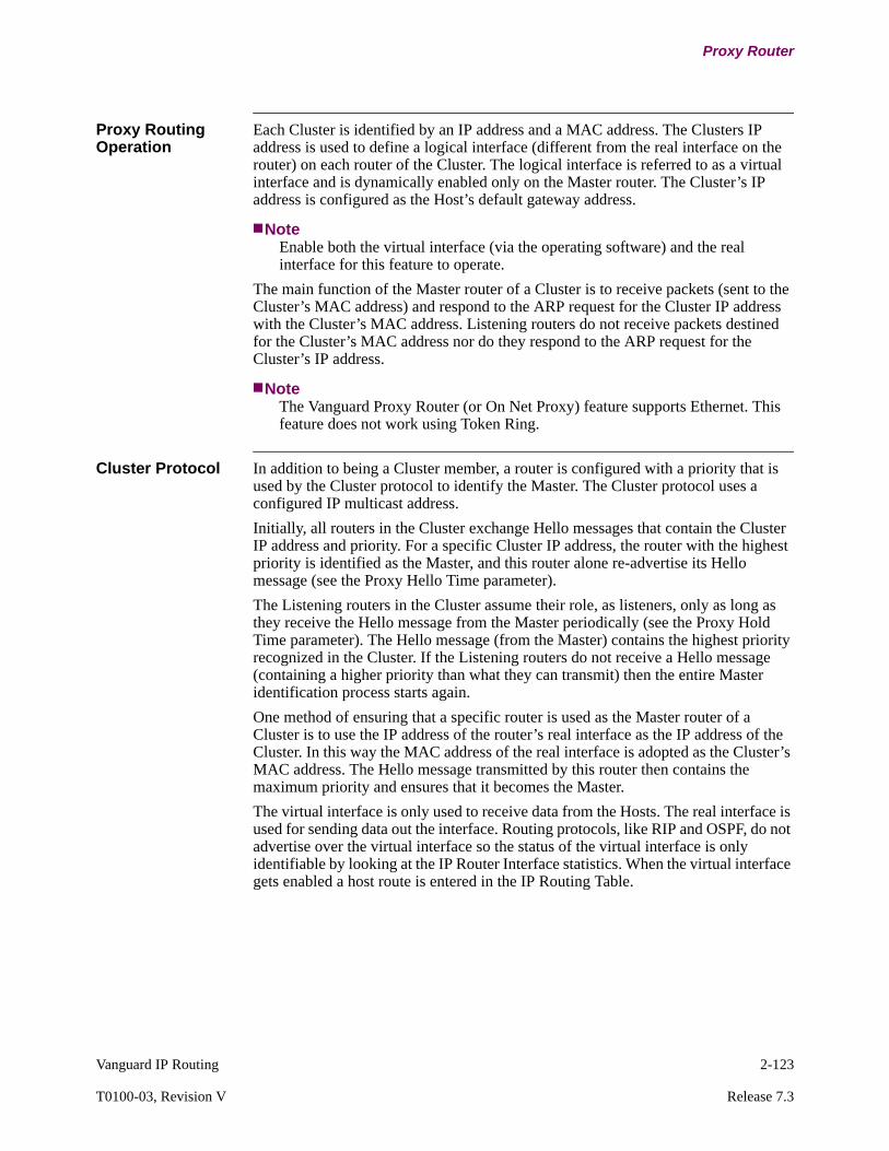
Vanguard IP Routing 2-123
T0100-03, Revision V Release 7.3
Proxy Router
Proxy Routing Operation
Each Cluster is identified by an IP address and a MAC address. The Clusters IP address is used to define a logical interface (different from the real interface on the router) on each router of the Cluster. The logical interface is referred to as a virtual interface and is dynamically enabled only on the Master router. The Cluster’s IP address is configured as the Host’s default gateway address.
NoteEnable both the virtual interface (via the operating software) and the real interface for this feature to operate.
The main function of the Master router of a Cluster is to receive packets (sent to the Cluster’s MAC address) and respond to the ARP request for the Cluster IP address with the Cluster’s MAC address. Listening routers do not receive packets destined for the Cluster’s MAC address nor do they respond to the ARP request for the Cluster’s IP address.
NoteThe Vanguard Proxy Router (or On Net Proxy) feature supports Ethernet. This feature does not work using Token Ring.
Cluster Protocol In addition to being a Cluster member, a router is configured with a priority that is used by the Cluster protocol to identify the Master. The Cluster protocol uses a configured IP multicast address.
Initially, all routers in the Cluster exchange Hello messages that contain the Cluster IP address and priority. For a specific Cluster IP address, the router with the highest priority is identified as the Master, and this router alone re-advertise its Hello message (see the Proxy Hello Time parameter).
The Listening routers in the Cluster assume their role, as listeners, only as long as they receive the Hello message from the Master periodically (see the Proxy Hold Time parameter). The Hello message (from the Master) contains the highest priority recognized in the Cluster. If the Listening routers do not receive a Hello message (containing a higher priority than what they can transmit) then the entire Master identification process starts again.
One method of ensuring that a specific router is used as the Master router of a Cluster is to use the IP address of the router’s real interface as the IP address of the Cluster. In this way the MAC address of the real interface is adopted as the Cluster’s MAC address. The Hello message transmitted by this router then contains the maximum priority and ensures that it becomes the Master.
The virtual interface is only used to receive data from the Hosts. The real interface is used for sending data out the interface. Routing protocols, like RIP and OSPF, do not advertise over the virtual interface so the status of the virtual interface is only identifiable by looking at the IP Router Interface statistics. When the virtual interface gets enabled a host route is entered in the IP Routing Table.
2-124 Vanguard IP Routing
Proxy Router
In Figure 2-46, Routers A and B form the Cluster. The IP and MAC address of the real interface of Router A is IA and MA, while the IP and MAC address of the real interface on Router B is IB and MB.
To select Router A as the Master (that is, enable Router A), you must select the Cluster IP and MAC address (IA and MA). To do this on Router A, you must select the Proxied IP address IA. On Router B, the Proxied IP address and Proxied MAC address must be defined as IA and MA and be associated with a Priority of 5 (less than the Maximum configurable Priority).
Figure 2-46. Proxy Router Solution
When Router A is the Master, it receives MAC frames, with a destination address of MA, and responds to ARP Requests for IA. Additionally, the virtual interface on Router B is disabled.
When the LAN interface on Router A is disabled, or when the Router A fails, the virtual interface on Router B is enabled and Router B performs the Master function.
Once Router A comes online again, the virtual interface on Router B reverts to being disabled and the Master functions are once again performed by Router A.
SNMP and Telnet Access
Doing an SNMP query using the Cluster IP address results in a response from the Master. Since the router identified as the Master of a Cluster can change over time, different results can be obtained when re-issuing the query to the same Cluster IP address.
Using Telnet with the Cluster’s IP address can lead to a hung session if the Master changes from one router to another during the Telnet session.
Configuration Refer to “Configuring Proxy Router” section on page 3-131.
Host
LAN Y
Router A
Router B
Virtual Interface(IA, MA)
(IA, MA)
(IB, MB)
Host
LAN Z
Router C
Vanguard IP Routing 2-125
T0100-03, Revision V Release 7.3
ICMP Router Discovery
ICMP Router Discovery
Introduction ICMP Router Discovery is an enhancement to the Internet Control Message Protocol (ICMP) capability of the IP suite in the Vanguard Applications Ware. ICMP Router Discovery (RFC 1256) enables hosts to discover the IP addresses of their locally attached routers.
Protocol Overview Before a host can send IP datagrams beyond its directly attached subnet, it must discover the address of at least one operational router on that subnet. Typically, this is accomplished by reading a list of one or more router addresses from a configuration file (possibly remote) at startup time. Some hosts also discover their router addresses by listening to routing protocol traffic. However, this adds to administrative burdens as configuration files need to be maintained, and dynamic changes in router availability need to be tracked. Eavesdropping on routing traffic requires that hosts recognize the particular routing protocols in use. These can vary from subnet to subnet, and are subject to change at any time.
Benefits of Router Discovery
Router Discovery provides a method of discovering router addresses using a pair of ICMP messages for use on multicast links. It eliminates the need for manual configuration of router addresses, and is independent of any specific routing protocols. ICMP Router Discovery also provides an automated address learning capability.
Router Discovery Messages
ICMP Router Discovery uses two messages:
• Router Advertisements• Router Solicitations
Each router periodically broadcasts a Router Advertisements from each of its multicast interfaces, announcing the IP address(es) of that interface. Hosts discover the addresses of their neighboring routers simply by listening for advertisements. These router advertisements can occur at startup and at regularly defined intervals.
The router discovery messages do not constitute a routing protocol. They enable hosts to discover the existence of neighboring routers, but not which router is best for reaching a particular destination.
Preference Level Router Advertisements include a preference level for each advertised router address. When a host chooses a default router address, it should choose from those router addresses that have the highest preference level. You can configure router address preference levels to encourage or discourage the use of particular routers as default routers.
Lifetime A Router Advertisement also includes a Lifetime field, specifying the maximum length of time that the advertised addresses are to be considered as valid router addresses by the hosts, in the absence of further advertisements. This ensures that hosts eventually forget about routers that fail, or become unreachable.
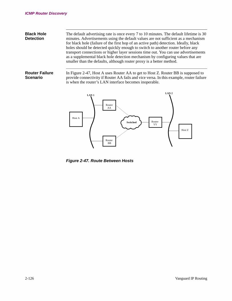
2-126 Vanguard IP Routing
ICMP Router Discovery
Black Hole Detection
The default advertising rate is once every 7 to 10 minutes. The default lifetime is 30 minutes. Advertisements using the default values are not sufficient as a mechanism for black hole (failure of the first hop of an active path) detection. Ideally, black holes should be detected quickly enough to switch to another router before any transport connections or higher layer sessions time out. You can use advertisements as a supplemental black hole detection mechanism by configuring values that are smaller than the defaults, although router proxy is a better method.
Router Failure Scenario
In Figure 2-47, Host A uses Router AA to get to Host Z. Router BB is supposed to provide connectivity if Router AA fails and vice versa. In this example, router failure is when the router’s LAN interface becomes inoperable.
Figure 2-47. Route Between Hosts
Host A
Router
Router
LAN 1
Host Z
Router
LAN 2
Switched
AA
BB
YY

Vanguard IP Routing 2-127
T0100-03, Revision V Release 7.3
ICMP Router Discovery
Consider connectivity between Host A and Host Z when the LAN interface on Router AA fails.
Configuration Refer to “Configuring Router Discovery” section on page 3-137.
If connectivity in this direction fails
Results
From host A to Host Z (LAN interface on AA fails)
Host A has different capabilities which are used in case of router failures:
• Host A can discover an alternate route to Host Z via BB, within one RIP update interval. Although Host A is not configured with a Default Gateway, it can understand RIP sent by both Routers AA and BB.
• Host A is not configured with a Default Gateway. It can understand Router Discovery Protocol (RDP) but not RIP. Routers AA and BB periodically send RDP Router Advertisement messages. Host A uses the router with the higher preference level as its gateway router.Assume Router AA has the higher preference level and becomes the gateway router for host A. When the LAN interface on AA becomes inactive, the Router Advertisement messages with the higher preference level from AA cease. After Host AA receives the next router advertisement from BB, it uses BB as its default gateway. The alternate route is discovered by Host A within one Advertisement interval.If Host A cannot understand RIP or RDP, it can only be configured with a Default Gateway. Assume for this example that the Default Gateway is AA. Now if AA becomes inactive, Host A is unable to discover BB to get to Host Z. This situation is resolved using Router Proxy.
From Host Z to Host A (LAN interface on AA fails).
The problem is resolved by Router YY using Triggered RIP updates sent by Routers AA and BB.
2-128 Vanguard IP Routing
Address Filtering
Address Filtering
What is it? The router uses address filtering to ensure that packets that are incorrectly formatted or that have an improper destination address are not forwarded into the network. Address filtering prevents forwarding of packets to those addresses and prevents broadcasting any routing information concerning those addresses.
How the Vanguard Handles IP Filtering
The Vanguard lets you specify filters to automatically discard packets destined for a particular IP address, or set of addresses, that are received across its interfaces. Filters provide a means to control traffic between networking areas. The ability to use masks allows you to specify ranges of values with a single filter.
Configuration To specify a filter, select Filter from the Configure IP menu and enter the values for these parameters:
• Entry Number• Destination IP Address• IP Address Mask
For more information, refer to “IP Filter Configuration” section on page 3-41.
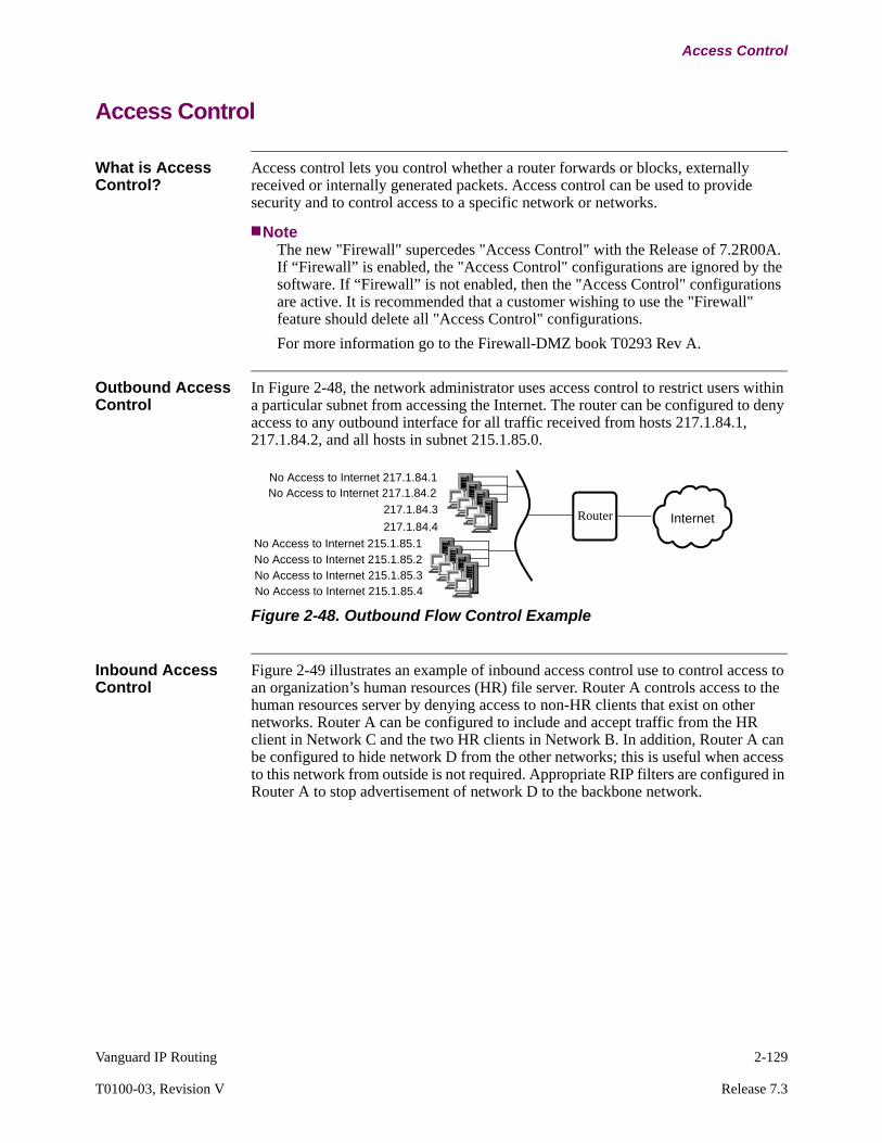
Vanguard IP Routing 2-129
T0100-03, Revision V Release 7.3
Access Control
Access Control
What is Access Control?
Access control lets you control whether a router forwards or blocks, externally received or internally generated packets. Access control can be used to provide security and to control access to a specific network or networks.
NoteThe new "Firewall" supercedes "Access Control" with the Release of 7.2R00A. If “Firewall” is enabled, the "Access Control" configurations are ignored by the software. If “Firewall” is not enabled, then the "Access Control" configurations are active. It is recommended that a customer wishing to use the "Firewall" feature should delete all "Access Control" configurations.
For more information go to the Firewall-DMZ book T0293 Rev A.
Outbound Access Control
In Figure 2-48, the network administrator uses access control to restrict users within a particular subnet from accessing the Internet. The router can be configured to deny access to any outbound interface for all traffic received from hosts 217.1.84.1, 217.1.84.2, and all hosts in subnet 215.1.85.0.
Figure 2-48. Outbound Flow Control Example
Inbound Access Control
Figure 2-49 illustrates an example of inbound access control use to control access to an organization’s human resources (HR) file server. Router A controls access to the human resources server by denying access to non-HR clients that exist on other networks. Router A can be configured to include and accept traffic from the HR client in Network C and the two HR clients in Network B. In addition, Router A can be configured to hide network D from the other networks; this is useful when access to this network from outside is not required. Appropriate RIP filters are configured in Router A to stop advertisement of network D to the backbone network.
Router
No Access to Internet 217.1.84.1No Access to Internet 217.1.84.2
217.1.84.3
217.1.84.4
No Access to Internet 215.1.85.1
Internet
No Access to Internet 215.1.85.2No Access to Internet 215.1.85.3No Access to Internet 215.1.85.4

2-130 Vanguard IP Routing
Access Control
Figure 2-49. Inbound Access Control Example
BackboneNetwork
RouterB
HR Client
HR Client
RouterA
Human Resource HRFile Server 1.1.1.1
HR Client 1.1.1.2
HR Client 1.1.1.3
RouterC
HR Client
Network C
Network B
Network A
Network D
RouterD
6.6.6.0
1.1.1.42.2.2.1
2.2.2.2 2.2.2.3
5.5.5.3
5.5.5.2
5.5.5.1
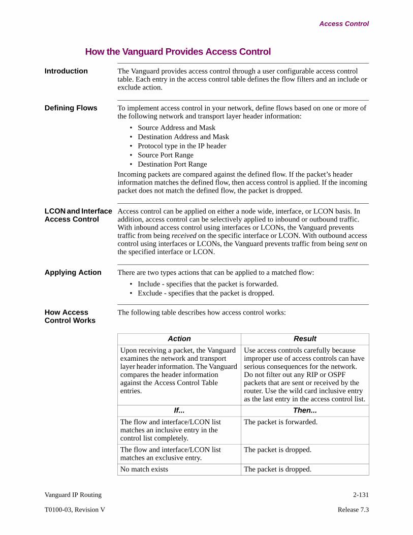
Vanguard IP Routing 2-131
T0100-03, Revision V Release 7.3
Access Control
How the Vanguard Provides Access Control
Introduction The Vanguard provides access control through a user configurable access control table. Each entry in the access control table defines the flow filters and an include or exclude action.
Defining Flows To implement access control in your network, define flows based on one or more of the following network and transport layer header information:
• Source Address and Mask• Destination Address and Mask• Protocol type in the IP header• Source Port Range• Destination Port Range
Incoming packets are compared against the defined flow. If the packet’s header information matches the defined flow, then access control is applied. If the incoming packet does not match the defined flow, the packet is dropped.
LCON and Interface Access Control
Access control can be applied on either a node wide, interface, or LCON basis. In addition, access control can be selectively applied to inbound or outbound traffic. With inbound access control using interfaces or LCONs, the Vanguard prevents traffic from being received on the specific interface or LCON. With outbound access control using interfaces or LCONs, the Vanguard prevents traffic from being sent on the specified interface or LCON.
Applying Action There are two types actions that can be applied to a matched flow:
• Include - specifies that the packet is forwarded.• Exclude - specifies that the packet is dropped.
How Access Control Works
The following table describes how access control works:
Action Result
Upon receiving a packet, the Vanguard examines the network and transport layer header information. The Vanguard compares the header information against the Access Control Table entries.
Use access controls carefully because improper use of access controls can have serious consequences for the network. Do not filter out any RIP or OSPF packets that are sent or received by the router. Use the wild card inclusive entry as the last entry in the access control list.
If... Then...
The flow and interface/LCON list matches an inclusive entry in the control list completely.
The packet is forwarded.
The flow and interface/LCON list matches an exclusive entry.
The packet is dropped.
No match exists The packet is dropped.
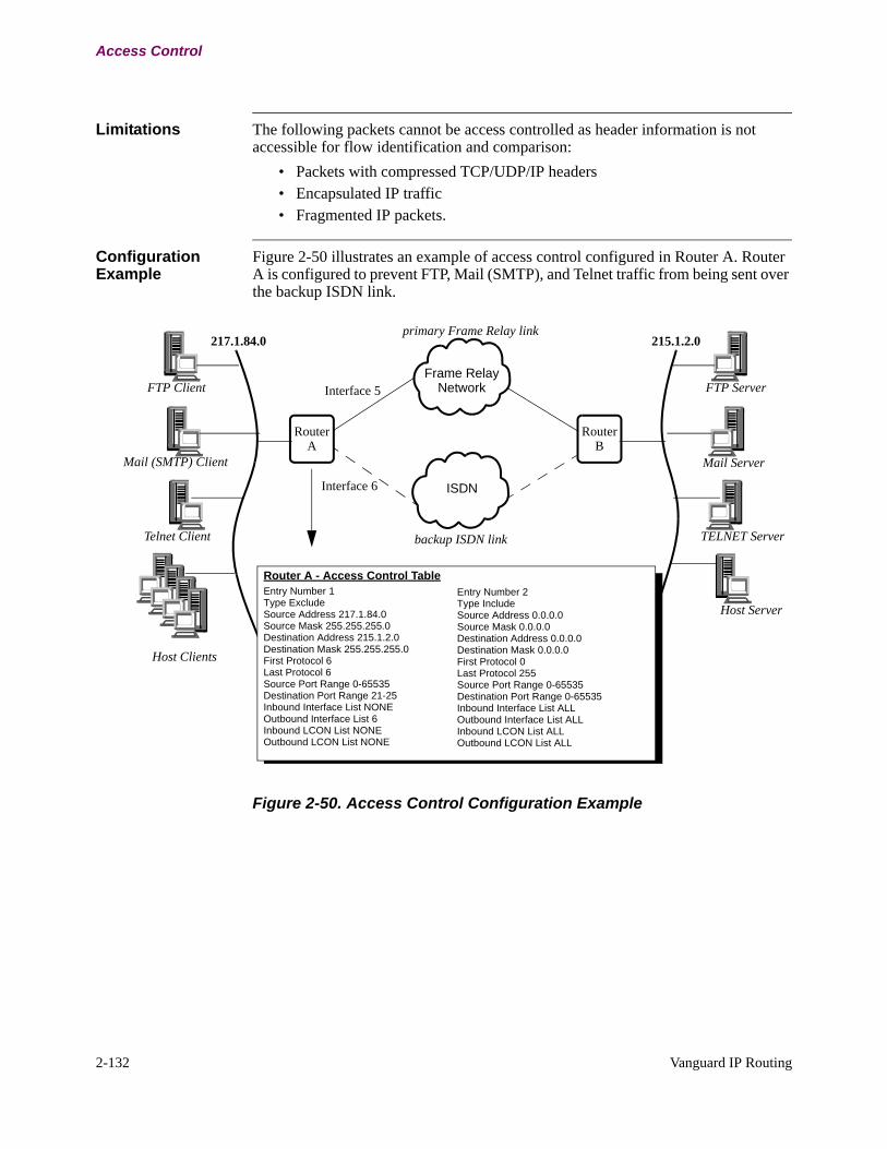
2-132 Vanguard IP Routing
Access Control
Limitations The following packets cannot be access controlled as header information is not accessible for flow identification and comparison:
• Packets with compressed TCP/UDP/IP headers• Encapsulated IP traffic• Fragmented IP packets.
Configuration Example
Figure 2-50 illustrates an example of access control configured in Router A. Router A is configured to prevent FTP, Mail (SMTP), and Telnet traffic from being sent over the backup ISDN link.
Figure 2-50. Access Control Configuration Example
RouterA
FTP Client
Mail (SMTP) Client
Telnet Client
217.1.84.0
Frame RelayNetwork
ISDN
RouterB
FTP Server
Mail Server
TELNET Server
215.1.2.0
Host Clients
Host Server
backup ISDN link
primary Frame Relay link
Router A - Access Control TableEntry Number 1Type ExcludeSource Address 217.1.84.0Source Mask 255.255.255.0Destination Address 215.1.2.0Destination Mask 255.255.255.0First Protocol 6Last Protocol 6Source Port Range 0-65535Destination Port Range 21-25Inbound Interface List NONEOutbound Interface List 6Inbound LCON List NONEOutbound LCON List NONE
Entry Number 2Type IncludeSource Address 0.0.0.0Source Mask 0.0.0.0Destination Address 0.0.0.0Destination Mask 0.0.0.0First Protocol 0Last Protocol 255Source Port Range 0-65535Destination Port Range 0-65535Inbound Interface List ALLOutbound Interface List ALLInbound LCON List ALLOutbound LCON List ALL
Interface 5
Interface 6

Vanguard IP Routing 2-133
T0100-03, Revision V Release 7.3
Access Control
Figure 2-51 illustrates an example of inbound access control use to control access to an organization’s human resources (HR) file server. Router A controls access to the human resources server by denying access to non-HR clients that exist on other networks. Router A can be configured to include and accept traffic from the HR client in Network C and the two HR clients in Network B. In addition, Router A can be configured to hide network D from the other networks; this is useful when access to this network from outside is not required.
Figure 2-51. Inbound Access Control Example
Enabling Access Control
Enable Access Control as described in the “IP Access Control Configuration” section on page 3-49, and enter the specific values using the Access Control menu. You can enter up to 255 Access Control Table entries.
BackboneNetwork
RouterB
HR Client
HR Client
RouterA
Human Resource HRFile Server 1.1.1.1
HR Client 1.1.1.2
HR Client 1.1.1.3
RouterC
HR Client
Network C
Network B
Network A
Network D
RouterD
6.6.6.0
1.1.1.42.2.2.1
2.2.2.2 2.2.2.3
5.5.5.3
5.5.5.2
5.5.5.1
Router A - Access Control TableEntry Number 1Type ExcludeSource Address 2.2.2.2Source Mask 255.255.255.255Destination Address 1.1.1.1Destination Mask 255.255.255.255First Protocol 0Last Protocol 255Source Port Range 0-65535Destination Port Range 0-65535Inbound Interface List ALLOutbound Interface List ALLInbound LCON List ALLOutbound LCON List ALL
Entry Number 2Type ExcludeSource Address 2.2.2.3Source Mask 255.255.255.255Destination Address 1.1.1.1Destination Mask 255.255.255.255First Protocol 0Last Protocol 255Source Port Range 0-65535Destination Port Range 0-65535Inbound Interface List ALLOutbound Interface List ALLInbound LCON List ALLOutbound LCON List ALL
Entry Number 3Type ExcludeSource Address 5.5.5.1Source Mask 255.255.255.255Destination Address 1.1.1.1Destination Mask 255.255.255.255First Protocol 0Last Protocol 255Source Port Range 0-65535Destination Port Range 0-65535Inbound Interface List ALLOutbound Interface List ALLInbound LCON List ALLOutbound LCON List ALL
Entry Number 4Type ExcludeSource Address 6.6.6.0Source Mask 255.255.255.0Destination Address 0.0.0.0Destination Mask 0.0.0.0First Protocol 0Last Protocol 255Source Port Range 0-65535Destination Port Range 0-65535Inbound Interface List ALLOutbound Interface List ALLInbound LCON List ALLOutbound LCON List ALL
2-134 Vanguard IP Routing
Firewall Lite
Firewall Lite
What is Firewall Lite?
The Vanguard Firewall Lite feature lets you control, with dynamic access control based on stateful firewall technology, whether a router forwards or blocks externally received or internally generated packets. Prior to the Firewall Lite feature, Vanguard routers lacked dynamic access control. All access controls were static and could not be modified at run-time based on active flow information. The Firewall Lite feature allows you to control flows of packets not only statically but also dynamically. It supports aggregate cache and also adds more basic IP header sanity checks to filter out bad IP packets, and allows more parameters for access control specifications.
NoteWith Release 7.2R00A, the new “Firewall” feature replaces the “Firewall Lite” feature (Statefull Access Control). The “Firewall Lite” feature parameters are replaced by “Firewall” and will no longer be visible to the user once a node has been upgraded to release 7.2R00A. If a user previously used the “Firewall Lite” feature and upgraded to 7.2R00A, they must configure “Firewall” for the desired results.
For more information go to Firewall-DMZ book T0293 Rev A.
Static Access Control
Static Access Control allows users to filter IP packets based on source/destination address, protocol, source port and destination port. It can be applied globally or on a per interface basis. Associated actions are include (to allow data through) and discard (to discard the data). However, Static Access can not adapt to new run-time flow. All port information must be known in advance so that “holes” can be opened to allow certain traffic to pass through the firewall. Refer to Access Control on page 129.
Stateful Access Control
Stateful Access Control examines not only network layer and transport layer information but it also examines the application-layer protocol information (such as FTP information) to learn the state of TCP and UDP connections. It also maintains connection state information for individual connections. This state information is used to make intelligent decisions about whether packets should be permitted or denied, and dynamically creates and deletes temporary openings in the firewall.
Basic IP header Sanity Checks
More basic sanity checks on IP header info will be performed to verify that a packet has good format and has reasonable value on each field. IP packet that does not conform to those will be discarded.
Some of the fields to be verified are:
• Version• Flags• Header Checksum• Header Length• Total Length field (must correspond to the real packet length)• Source Address (cannot have illegal source address, e.g., 0.0.0.0 – except
link-local packet for unnumbered links)• Destination Address (cannot have illegal destination address, e.g., 0.0.0.0 –
except link-local packet for unnumbered links)

Vanguard IP Routing 2-135
T0100-03, Revision V Release 7.3
Firewall Lite
Layer 3 Classification Parameters
Classification is based on IP packet fields such as:
• Source IP Address (can be wildcard) • Destination IP Address (can be wildcard)• Protocol field (can be wildcard)• TOS field (can be wildcard)• IP Packet size and Fragmentation bit field - this will be useful in conjunction
with protocol field. Certain large size ICMP packets can be filtered this way.
Application Classification Parameters
• Source Port (can be wildcard)• Destination Port (can be wildcard)• Application specific characteristic/fields (only applicable if IP protocol field
is specified)
ICMP specific classification
If the application protocol is set to ICMP, more classification options will be available. They are:
• ICMP type – e.g., Echo Request, Echo Reply, Unreachable• ICMP code field

2-136 Vanguard IP Routing
How the Vanguard Provides Firewall Lite Features
How the Vanguard Provides Firewall Lite Features
Introduction The Vanguard will keep general states of a flow and allows the access filter to dynamically allow traffic of the return and/or related flow. This stateful firewall feature only allows return traffic for TCP, UDP, ICMP, and FTP flows. No detail TCP protocol state will be kept but thises states will only be kept if the protocols are specified in a new parameter: Stateful Access Control Configuration Records.
Configuration Configure these parameters for Firewall Lite.
IP Parameters
• Access Control: EnabledAccess Control
• Include – specifies that the packet is forwarded.• Exclude – specifies that the packet is dropped.
Stateful Access Control Parameters
• Stateful Access Control: EnabledStateful Access Control Entry
• Specifies thhe protocol(s) for which sate information should be kept so that the return traffic will be allowed.
For parameter descriptions for IP Parameters and Access Control, refer to the parameter tables in the IP Interface Configuration Table on page 24.
Stateful Access Control Entry
You can enter up to 256 Stateful Access Control entries.
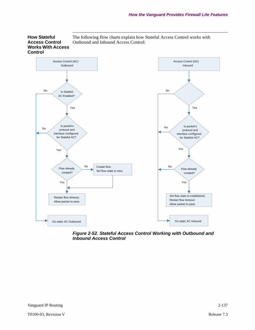
Vanguard IP Routing 2-137
T0100-03, Revision V Release 7.3
How the Vanguard Provides Firewall Lite Features
How Stateful Access Control Works With Access Control
The following flow charts explain how Stateful Access Control works with Outbound and Inbound Access Control:
Figure 2-52. Stateful Access Control Working with Outbound and Inbound Access Control
Access Control (AC)Outbound
Is StatefulAC Enabled?
Is packet’s protocol and
interface configured for Stateful AC?
Flow already created?
Restart flow timeout; Allow packet to pass
Yes
Yes
Yes
Create flow;Set flow state to new;
Do static AC Outbound
No
No
No
Access Control (AC)Inbound
Flow already created?
Set flow state to established;Restart flow timeout; Allow packet to pass
Yes
Yes
Do static AC Inbound
No
Is packet’s protocol and
interface configured for Stateful AC?
Yes
No
No
2-138 Vanguard IP Routing
Firewall
Firewall
Upgrading to Release 702R00A
The following Firewall Lite/Firewall features have been affected when upgrading to Release 7.2R00A:
• The new "Firewall" feature replaces the "Firewall Lite" feature and super-cedes the "Access Control List" feature.
• The "Firewall Lite" feature parameters (Stateful Access Control) are replaced by Firewall and will no longer be visible to the user once a node has been upgraded to release 7.2R00A.
• If a user previously used the "Firewall Lite" feature and upgraded to 7.2R00A they must configure "Firewall" for the desired results.
• The access control menu and parameters will remain in the configuration and are active if the "Firewall" is disabled, but are superceded and will not func-tion when "Firewall" is enabled. It is recommended to delete any access con-trol list configurations if Firewall is to be utilized.
What is Firewall Prior to release 7.2R00A Vanguard provided a limited set of firewall features. These were implemented first with "Access Control List". This however only provided static controls and would not respond to active flow information. Firewall Lite was introduced in release 6.5R00A and provided for dynamic control via "Stateful Access Control" (for more on Firewall Lite go to page 2-134).
The new firewall feature combines the functionality of Access Control List (Static) and Stateful access control (Dynamic) to provide a more traditional firewall implementation. The new "Firewall" also introduces traditional firewall concepts, "Trusted", "Untrusted" and "DMZ" to the Vanguard routers and provides a cleaner configuration structure.
For more information on the Firewall feature please refer to the document "Firewall-DMZ" Part No. T0293 Rev A. This document can be found at http://www.vanguardnetworks.com/support-manuals.htm under "Software Manuals IP and LAN".

Vanguard IP Routing 2-139
T0100-03, Revision V Release 7.3
Unnumbered IP
Unnumbered IP
What Is Unnumbered IP?
The Unnumbered IP feature allows unnumbered point-to-point serial links where there is no third node to be individually addressed. An unnumbered point-to-point link does not have any network prefix associated with it. Consequently, network interfaces connected to an unnumbered point-to-point link do not have IP addresses. Any interface with 0.0.0.0 as its IP address is an unnumbered interface.
Why Use Unnumbered Addresses?
Traditionally, the implementation of an IP router subsystem provides each network interface of the router with its own IP address, resulting in inefficient use of scarce IP address space since it forces allocation of an IP network prefix to every point-to-point link.
Unnumbered interfaces can cause some dilemmas when dealing with things such as
• Record Route IP option• Next hop IP address in a route
A special IP address (called router-id) handles these cases by acting as if it were the IP address of all unnumbered interfaces. It specifies the router-id as one of the router’s IP addresses (a router is required to have at least one IP address). When using an Unnumbered IP interface, for example, to insert the router address into options such as Record Route, Strict Source and Record Route, Loose Source and Record Route, or Timestamp, the router inserts its router-id for an unnumbered interface.
Typical cases where you use Unnumbered IP are as follows:
• Where IP address space must be conserved• Where excessive WAN addressing make very large routing tables• Backup links• Links to ISPs (independent service providers)
When to Use Unnumbered IP
You can use Unnumbered Interfaces when configuring the following. Refer to the pages indicated in the table below for more information.
Configuring Group LCONs With Unnumbered Interfaces
When configuring unnumbered IP with Group LCONs, you use the LAN Connection Table and configure the next hop parameter as 0.0.0.n, where n is the interface number minus 1. For example, interface 5 is configured as 0.0.0.4.
The LAN Connection Table and its parameters are described in detail in the Vanguard Router Basics Manual.
Parameter Refer to...
Default Gateway page 2-120
IP Interface Address page 3-24
IP Static Routes page 3-64
Group LCONs Vanguard Router Basics Manual

2-140 Vanguard IP Routing
Unnumbered IP
Support Unnumbered IP supports serial interfaces only. This includes:
• Point-to-Point LCONs• LANView Group LCONs
Supported serial types include:
• Frame Relay• X.25• Synchronous PPP

Vanguard IP Routing 2-141
T0100-03, Revision V Release 7.3
Unnumbered IP
Typical Unnumbered IP Applications
Introduction This section shows a typical Unnumbered IP application.
Unnumbered Point-to-Point Serial Links
Figure 2-53 shows Unnumbered IP interfaces used with point-to-point serial links.
Figure 2-53. Unnumbered Point-to-Point Serial Links
Router 1
Router 3
PC 1 PC 2
PC 3 PC 4
1.1.1.1
1.1.1.2 1.1.1.3
2.2.2.1
2.2.2.2 2.2.2.3
Router 23.3.3.1
3.3.3.2
3.3.3.3
Unnumbered Interfaces 5
Pt-to-Pt LCON-1
Pt-to-pt LCON-2
PC 5
PC 6
Unnumbered Interface 6

2-142 Vanguard IP Routing
Unnumbered IP
Unnumbered LANView Serial Links
Figure 2-54 shows Unnumbered IP interfaces used with group LCONs in a LANview serial link situation.
Figure 2-54. LAN View (GROUP) of Unnumbered Serial Links
Unnumbered OSPF Backup Links
Figure 2-55 shows the use on Unnumbered IP interfaces used to support OSPF ISDN Backup links.
Figure 2-55. OSPF ISDN Backup Links
GROUP Lcons Starting from Interface 5
Router 1
Router 2
PC 1 PC 2
PC 3 PC 4
1.1.1.1
1.1.1.2 1.1.1.3
2.2.2.1
2.2.2.2 2.2.2.3
Router 33.3.3.1
3.3.3.2
3.3.3.3
Unnumbered Interfaces 5
PC 5
PC 6
F
PRI #1
PRI #2
ABR’s
FrameRelay Network
Typical Area
ISDN
ISDN48 Vanguard’s
OSPF
OSPF
Backup ISDN Links Unnumbered IP
Area 1
ABR
A1R1
A1R48
OSPF
ASBR
R1
& R2
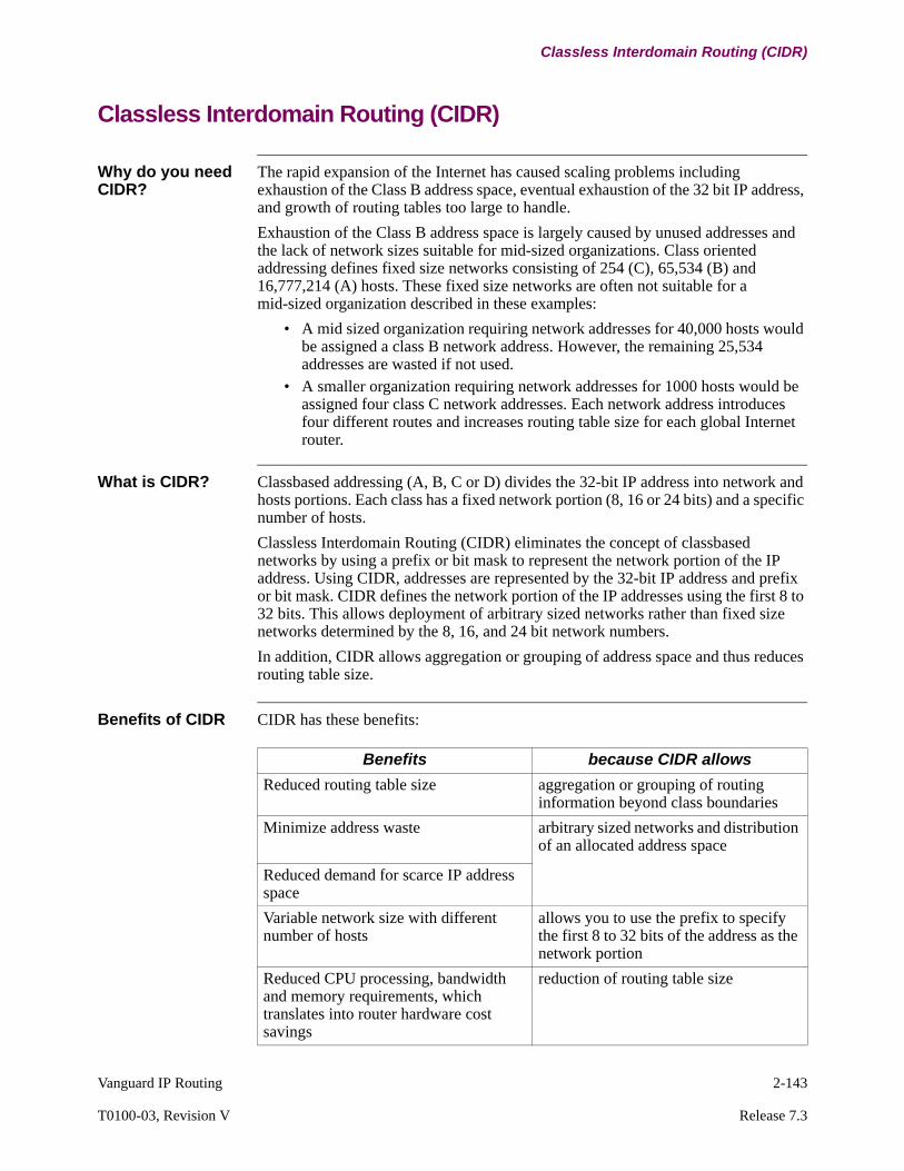
Vanguard IP Routing 2-143
T0100-03, Revision V Release 7.3
Classless Interdomain Routing (CIDR)
Classless Interdomain Routing (CIDR)
Why do you need CIDR?
The rapid expansion of the Internet has caused scaling problems including exhaustion of the Class B address space, eventual exhaustion of the 32 bit IP address, and growth of routing tables too large to handle.
Exhaustion of the Class B address space is largely caused by unused addresses and the lack of network sizes suitable for mid-sized organizations. Class oriented addressing defines fixed size networks consisting of 254 (C), 65,534 (B) and 16,777,214 (A) hosts. These fixed size networks are often not suitable for a mid-sized organization described in these examples:
• A mid sized organization requiring network addresses for 40,000 hosts would be assigned a class B network address. However, the remaining 25,534 addresses are wasted if not used.
• A smaller organization requiring network addresses for 1000 hosts would be assigned four class C network addresses. Each network address introduces four different routes and increases routing table size for each global Internet router.
What is CIDR? Classbased addressing (A, B, C or D) divides the 32-bit IP address into network and hosts portions. Each class has a fixed network portion (8, 16 or 24 bits) and a specific number of hosts.
Classless Interdomain Routing (CIDR) eliminates the concept of classbased networks by using a prefix or bit mask to represent the network portion of the IP address. Using CIDR, addresses are represented by the 32-bit IP address and prefix or bit mask. CIDR defines the network portion of the IP addresses using the first 8 to 32 bits. This allows deployment of arbitrary sized networks rather than fixed size networks determined by the 8, 16, and 24 bit network numbers.
In addition, CIDR allows aggregation or grouping of address space and thus reduces routing table size.
Benefits of CIDR CIDR has these benefits:
Benefits because CIDR allows
Reduced routing table size aggregation or grouping of routing information beyond class boundaries
Minimize address waste arbitrary sized networks and distribution of an allocated address space
Reduced demand for scarce IP address space
Variable network size with different number of hosts
allows you to use the prefix to specify the first 8 to 32 bits of the address as the network portion
Reduced CPU processing, bandwidth and memory requirements, which translates into router hardware cost savings
reduction of routing table size

2-144 Vanguard IP Routing
Classless Interdomain Routing (CIDR)
CIDR Prefix For a detailed description of CIDR prefix refer to the “CIDR Prefix Definition and Conventions” section on page 2-151.

Vanguard IP Routing 2-145
T0100-03, Revision V Release 7.3
Classless Interdomain Routing (CIDR)
Aggregation of Routing Information
What is Aggregation?
Using CIDR, contiguous IP addresses can be consolidated into a single route. Aggregation or grouping of routing information within an autonomous system (AS) reduces administrative tasks required to update routing tables, significantly reduces routing table size and reduces routing traffic. Figure 2-56 illustrates an example of aggregation.
Figure 2-56. Aggregation of Routes
Within a routing domain, detailed information is available about all of the networks that reside in the domain. Outside the domain, only the summarized IP Address with network prefix is advertised to the higher layer routing domain. Thus, CIDR supports route aggregation where a single routing table entry can represent the address space of perhaps thousands of traditional classbased routes.
As shown in Figure 2-56, Router A consolidates and represents the contiguous IP addresses 217.2.0.0. to 217.2.255.0 as one route, 217.2.0.0/16. Similarly, Router B consolidates and represents the contiguous IP addresses 217.3.0.0. to 217.3.255.0 as one route 217.3.0.0/16. Router C aggregates routes of Routers A and B into a single IP address, 217.2.0.0./15 and advertises this address to the IP network.
217.2.0.0
217.2.1.0
217.2.255.0
::
217.3.0.0
217.3.1.0
217.3.255.0
::
Domain B
Domain A
Domain C
IPNetworkRouter C
Router A
Router B
217.2.0.0/16
217.3.0.0/16
217.2.0.0/15
Aggregate RouteAdvertised to Network
AdvertisedAggregate Route
AdvertisedAggregate Route

2-146 Vanguard IP Routing
Classless Interdomain Routing (CIDR)
Multihomed Sites and CIDR
CIDR and route aggregation can be used for multihomed networks. Network 3 is an example of a multihomed network. In this example, Router 2 acts as the primary router for Network 3 and advertises the aggregated route of Network 3. Router 1 provides a backup route in event of link failure to Router 2.
Figure 2-57. Multihomed Sites and Aggregation
Network 1192.24.0.0-192.24.7.0
Aggregated Route 192.24.0.0/21
Network 2192.32.32.0 to 192.32.33.0
Aggregated Route Advertised to Backbone
BackboneIP Network
Network 3192.24.12.0-192.24.15.0
Aggregated Route 192.24.12.0/22
Router 1 Router 2
192.32.32.0/23192.24.12.0/22
Aggregate Route 192.32.32.0/23
Aggregate Route Advertised to Backbone192.24.0.0/21
Primary RouteSecondary Route

Vanguard IP Routing 2-147
T0100-03, Revision V Release 7.3
Classless Interdomain Routing (CIDR)
Black Holes and Aggregation
Black holes may result after aggregation of routes. Black holes are subnet routes that are part of an aggregate route but do not physically exist in the network, as illustrated by two subnets C and D in Figure 2-58. If Router C receives packets matching its advertised aggregated route, but the subnet route does not exist, the packet is dropped.
Figure 2-58. Black Holes and Aggregated Routes
Guidelines for Aggregation and CIDR Usage
For efficient route aggregation and use of CIDR:
• The IP addresses must be assigned on hierarchical or topological lines.• Routing to all destinations must be implemented on a longest-match basis. For
example, for a given destination that matches multiple IP address and mask pairs, the match with the longest mask is used.
• Destinations which are multihomed relative to a routing domain must always be explicitly announced into that routing domain - they cannot be aggregated.
• In order to prevent routing loops, routers that aggregate multiple routes must discard packets which match the aggregate route but do not match any of the explicit routes which makes up the aggregate.
Domain B
Domain A
IPNetworkRouter C
Router A
Router B
15.0.2.0/22
15.0.5.0/22
15.0.0.0/21
Aggregate RouteAdvertised to Network
AdvertisedAggregate Route
AdvertisedAggregate Route
Black HoleAggregate Route15.0.3.0/22
Black HoleAggregate Route15.0.4.0/22
No explicit route
No explicit route
Domain C
Domain D

2-148 Vanguard IP Routing
Classless Interdomain Routing (CIDR)
Implementation of CIDR
Implementation Overview
The implementation of CIDR complies with RFC 1517 to 1520 and supports OSPF, static routing, and RIP Version 2.
These enhancements have been made for CIDR support:
• configuration of classless static routes for static routing and RIP Version 2 routes.
• configuration of OSPF external range table to allow aggregation of external routes into OSPF domains.
• configuration of OSPF area range to allow aggregation on a classless boundary.
• configuration of classless mask on the IP interface to allow aggregation of directly connected multiple network.
• configuration of classless mask to allow arbitrary sized network for efficient use of allocated address space.
• inclusion of classless routes into the routing table and use of these routes for routing.
Enabling CIDR in the Vanguard
The Vanguard node automatically supports CIDR as soon as the Applications Ware software is loaded on the node. The Vanguard understands classless IP addresses and masks, and installs classless IP addresses in the routing table and uses these addresses for routing.
CIDR and OSPF For more information on aggregation and CIDR support for OSPF, refer to the OSPF protocol documentation (T0100-04).

Vanguard IP Routing 2-149
T0100-03, Revision V Release 7.3
Classless Interdomain Routing (CIDR)
Support for CIDR and RIP Version 2
Introduction Effective release 5.4, the Vanguard router supports aggregation of routes learned from RIP Version 2 broadcasts.
Example of CIDR Aggregation of RIP Version 2 Routes
CIDR supports the aggregation of routes learned from RIP Version 2 broadcasts. As shown in Figure 2-59, Router D aggregates routes learned from RIP broadcasts received from Routers A, B, and C. Router D aggregates these routes into a single route before broadcasting this route to the IP network. Aggregation is done by longest match basis and results in an aggregated network address of 172.2.72.0/21.
Figure 2-59. Aggregation of Routes Learned From RIP Version 2 Broadcast
Domain B
Domain A
IPNetworkRouter D
Router A
137.2.72.0
Router B
137.2.73.0
Domain C
Router C
137.2.79.0
Router A sends RIP broadcastwith an address 137.2.72.0
Router C sends RIP broadcastwith an address 137.2.79.0
Router B sends RIP broadcastwith an address 137.2.73.0
1
3
2
Router D aggregates the addressesit has received from Router A, B, andC into one aggregate route, 137.2.72.0/21, and advertises thisroute to the IP Network.
4
137.2.72.0/21
Three Non-Aggregated RIP Version 2 Routes
Router A 137.2.73.0 (Mask 255.255.255.0) -> 1000 1001 . 0000 0010 . 0100 1001 . 0000 0000
Router B 137.2.72.0 (Mask 255.255.255.0) -> 1000 1001 . 0000 0010 . 0100 1000 . 0000 0000
Router C 137.2.79.0 (Mask 255.255.255.0) -> 1000 1001 . 0000 0010 . 0100 1111 . 0000 0000
1000 1001 . 0000 0010 . 0100 1000 . 0000 0000 137.2.72.0/21 (Mask 255.255.248.0) ->
Aggregated into one route
network address host part
Aggregation by Longest Match Basis

2-150 Vanguard IP Routing
Classless Interdomain Routing (CIDR)
Configuring Aggregation in a Vanguard Router
Vanguard routers support static aggregation by which the network administrator specifies the range of addresses to aggregate and the mask or prefix used for aggregation. You can specify IP address and CIDR mask pairs in the Aggregation Table menu under the following menu:
Configure -->Configure Router --> Configure IP -->Configure CIDR --> Aggregation Table
Configuring Aggregation for Multihomed Sites
Networks which connect to more than one router or service provider are multihomed sites. If the Vanguard acts as the primary router for this multihomed network, the IP address and CIDR mask pair must be defined in the Multihomed Site Table and be explicitly advertised. Access the Multihomed Site table from the following menu:
Configure -->Configure Router --> Configure IP -->Configure CIDR --> Multihomed Site Table
Advertisement of Aggregate Route
The Send Aggregate Route parameter allows you to enable or disable RIP advertisement of aggregated routes. When disabled, aggregated routing information is converted into non-aggregate routing information before being advertised. To configure this parameter, access the IP Interface menu from:
Configure -->Configure Router --> Configure IP -->Interface

Vanguard IP Routing 2-151
T0100-03, Revision V Release 7.3
Classless Interdomain Routing (CIDR)
CIDR Prefix Definition and Conventions
Introduction This section describes how CIDR prefixes and masks are defined.
Classbased IP Addresses Ranges
Typically, using classbased addressing, addresses are identified by looking at the network portion of the IP address, for example, the first 8, 16, or 24 bits of the address. The table below shows the classbased address scheme and the number of networks or hosts supported by each class.
Classless IP Address Range
Instead of limiting the network portion of the IP address to the first 8, 16, or 24 bits, CIDR defines the network portion of the IP addresses using the first 8 to 32 bits. A CIDR address can be represented as shown in the table below:
NoteFor the examples provided in this section, classless addresses are represented as an IP address/Prefix. However, to actually configure these addresses in a Vanguard router, you must enter the IP address and the 32 bit mask, as shown by representation 2 in the preceding table.
The table in “CIDR Prefixes” section on page 2-153 provides the prefix mask and its 32-bit classless mask equivalent.
Address Class
IP Address Range Number of Network Bits
Number of Networks
Number of Hosts in each network
A 1.n.n.n to 126.n.n.n 8 126 16,777,214
B 128.1.n.n to 191.254.n.n 16 65,000 65,534
C 192.0.1.n to 223.255.254.n 24 2 million 254
Representation Example
1 the standard 32-bit IP address followed by /prefix, which indicates how many bits are used for the network prefix
217.1.2.0/23
2 the standard 32-bit IP address and 32 bit mask
217.1.2.0, 255.255.254.0
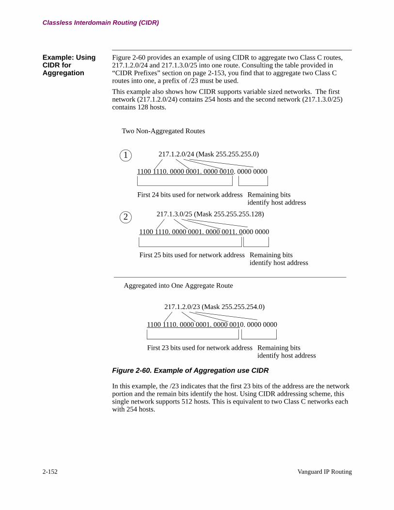
2-152 Vanguard IP Routing
Classless Interdomain Routing (CIDR)
Example: Using CIDR for Aggregation
Figure 2-60 provides an example of using CIDR to aggregate two Class C routes, 217.1.2.0/24 and 217.1.3.0/25 into one route. Consulting the table provided in “CIDR Prefixes” section on page 2-153, you find that to aggregate two Class C routes into one, a prefix of /23 must be used.
This example also shows how CIDR supports variable sized networks. The first network (217.1.2.0/24) contains 254 hosts and the second network (217.1.3.0/25) contains 128 hosts.
Figure 2-60. Example of Aggregation use CIDR
In this example, the /23 indicates that the first 23 bits of the address are the network portion and the remain bits identify the host. Using CIDR addressing scheme, this single network supports 512 hosts. This is equivalent to two Class C networks each with 254 hosts.
217.1.2.0/24 (Mask 255.255.255.0)
1100 1110. 0000 0001. 0000 0010. 0000 0000
First 24 bits used for network address Remaining bits identify host address
217.1.3.0/25 (Mask 255.255.255.128)
1100 1110. 0000 0001. 0000 0011. 0000 0000
First 25 bits used for network address Remaining bits identify host address
Two Non-Aggregated Routes
1
2
Aggregated into One Aggregate Route
217.1.2.0/23 (Mask 255.255.254.0)
1100 1110. 0000 0001. 0000 0010. 0000 0000
First 23 bits used for network address Remaining bits identify host address
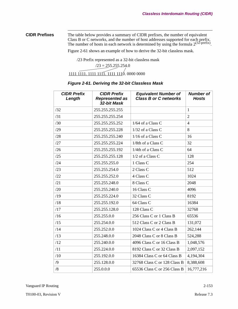
Vanguard IP Routing 2-153
T0100-03, Revision V Release 7.3
Classless Interdomain Routing (CIDR)
CIDR Prefixes The table below provides a summary of CIDR prefixes, the number of equivalent Class B or C networks, and the number of host addresses supported for each prefix. The number of hosts in each network is determined by using the formula 2(32-prefix).
Figure 2-61 shows an example of how to derive the 32-bit classless mask.
Figure 2-61. Deriving the 32-bit Classless Mask
/23 Prefix represented as a 32-bit classless mask/23 = 255.255.254.0
1111 1111. 1111 1111. 1111 1110. 0000 0000
CIDR Prefix Length
CIDR Prefix Represented as
32-bit Mask
Equivalent Number of Class B or C networks
Number of Hosts
/32 255.255.255.255 1
/31 255.255.255.254 2
/30 255.255.255.252 1/64 of a Class C 4
/29 255.255.255.228 1/32 of a Class C 8
/28 255.255.255.240 1/16 of a Class C 16
/27 255.255.255.224 1/8th of a Class C 32
/26 255.255.255.192 1/4th of a Class C 64
/25 255.255.255.128 1/2 of a Class C 128
/24 255.255.255.0 1 Class C 254
/23 255.255.254.0 2 Class C 512
/22 255.255.252.0 4 Class C 1024
/21 255.255.248.0 8 Class C 2048
/20 255.255.240.0 16 Class C 4096
/19 255.255.224.0 32 Class C 8192
/18 255.255.192.0 64 Class C 16384
/17 255.255.128.0 128 Class C 32768
/16 255.255.0.0 256 Class C or 1 Class B 65536
/15 255.254.0.0 512 Class C or 2 Class B 131,072
/14 255.252.0.0 1024 Class C or 4 Class B 262,144
/13 255.248.0.0 2048 Class C or 8 Class B 524,288
/12 255.240.0.0 4096 Class C or 16 Class B 1,048,576
/11 255.224.0.0 8192 Class C or 32 Class B 2,097,152
/10 255.192.0.0 16384 Class C or 64 Class B 4,194,304
/9 255.128.0.0 32768 Class C or 128 Class B 8,388,608
/8 255.0.0.0 65536 Class C or 256 Class B 16,777,216

2-154 Vanguard IP Routing
Network Address Translation (NAT)
Network Address Translation (NAT)
What is it? As a router function, Network Address Translation (NAT) allows for translation of one IP address to another IP address. Using NAT, devices in a private network which use an internal or private IP addressing scheme can access, and be accessed by, other hosts using the global IP addressing scheme.
Figure 2-62. Network Address Translation
RFC 1631 NAT is defined in RFC 1631.
Benefits of NAT The benefits of NAT are listed below:
• NAT offers a flexible solution for IP address depletion problems. NAT assumes that only a small percentage of devices within a private network access the Internet or external network at any point in time. To provide access to the external network, NAT maps a device’s internal address to an external address.
• NAT reduces overhead involved in reconfiguring addresses and renumbering due to network changes. In addition, internal addresses may be duplicated in different private domains in the Internet as long as the external address remains unique.
• NAT also provides security as NAT routers never advertise the internal address of a device to the external network.
Applications of NAT
Network Address Translation provides solutions for the following network implementations:
• private networks wishing to access an external network or domain• devices accessing the Internet using PPP connections through an Internet
Service Provider (ISP)• multiple hosts accessing the Internet using an external IP address provided by
an ISP
Internal or Private Domain
Internet Router10.0.0.110.0.0.2
10.0.0.310.0.0.4
Router
Internal Address External Address10.0.0.1 translated to 120.0.0.1
10.0.0.2 translated to 120.0.0.2
10.0.0.3 translated to 120.0.0.3
10.0.0.4 translated to 120.0.0.4
External or Global Domain

Vanguard IP Routing 2-155
T0100-03, Revision V Release 7.3
Network Address Translation (NAT)
IETF Recommendation for Internal or Private IP Addresses
As specified in RFC 1918, IETF has reserved these IP addresses block for private networks:
• 10.0.0.0 to 10.255.255.255• 172.16.0.0 to 172.16.255.255• 192.168.0.0 to 192.168.255.255

2-156 Vanguard IP Routing
Network Address Translation (NAT)
NAT Definitions and Conventions
General NAT Conventions
These conventions are used throughout this section:
Interface Definition and Translation Convention
Figure 2-63 and the table below describes the conventions for internal and external interface.
Figure 2-63. Interface Definition
Item Definition
Internal Address An IP address used in a private or internal network.
External Address An IP address used in the external network.
Source Address The address of the device sending the datagram.
Destination Address The address of the device receiving the datagram.
Binding Binding is the process of mapping an internal address to an external address.
Translation Translation is the process of replacing an address in a datagram with an another address before forwarding it.
Static Address An address specified by the user. Can be specified as an address or a range of addresses.
Dynamic Address An address obtained by negotiations with a peer.
Static Binding Denotes that the binding is permanent for all sessions
Dynamic Binding Denotes that the binding is valid for the duration of the session or until a timer has expired.
Internal or Private Domain
Internet Router
Router
External or Global Domain
Internal Interface External Interface
Item Description
Internal Interface An interface which connects to a private or internal network.
External Interface An interface which connects to the External or Global Domain.

Vanguard IP Routing 2-157
T0100-03, Revision V Release 7.3
Network Address Translation (NAT)
Implementation of NAT
Introduction This section describes the implementation of NAT. Vanguard Networks implementation of NAT complies with RFC 1631.
NAT Features This table summarizes NAT features:
Routing Support NAT supports the following:
• IP Interface support- you can define NAT on any IP interface, and specify which interfaces support NAT and which do not.
• IP Multicasting over NAT interface using DVMRP static routing. • NAT supports RIP.
Feature Description Refer to...
One-to-One NAT One internal address maps to one external address.
Static Address-Static Binding on page 159.
Many-to-Many NAT A range of internal addresses map to a range of external addresses.
Static Address- Dynamic Binding on page 159.Dynamic Address Dynamic Binding on page 160.
Many-to-One NAT, Network Port Address Translation
A range of internal addresses map to one external address and uses a unique port and address combination.
Network Address Port Translation (NAPT) on page 161.
Static and Dynamic Binding
The user has the option of specifying static or dynamic binding where
• Static: binding is constant for all sessions.• Dynamic: binding varies for different
sessions.
Static Address-Static Binding on page 159.Static Address- Dynamic Binding on page 159.Dynamic Address Dynamic Binding on page 160.
Dynamic Addressing Addresses can be dynamically learned from a peer over a PPP connection via IPCP.
Dynamic Address Dynamic Binding on page 160.
Duplicate Address Translation
Solves the problem of duplicate addresses by using proxy addressing to substitute one duplicated address.
Duplicate Address Translation on page 167.
Application Layer Address Translation
Supports translation of embedded IP addresses in TCP/UDP, FTP, ICMP and DNS datagrams.
Application Layer Translation on page 169.

2-158 Vanguard IP Routing
Network Address Translation (NAT)
Product Support The Vanguard 6520, 6560, 6400 Series, 320, 310 Series, and 305 support NAT.
Limitations The implementation of NAT has the following limitations:
• Forming a single pool of external addresses across multiple interfaces is not supported.
• PPP interfaces cannot be a part of LANview LCON.

Vanguard IP Routing 2-159
T0100-03, Revision V Release 7.3
Network Address Translation (NAT)
One-to-One and Many-to-Many Translations
Introduction This section describes One-to-One and Many-to-Many translations.
Static Address-Static Binding
Figure 2-64 provides an example of static address-static binding. For static addressing, the user defines an internal address, an external address and the one-to-one binding between the addresses. Static binding provides a permanent binding between the internal and external address. Domains which require permanent address re-assignments use this feature.
Figure 2-64. Example Static Address-Static Binding
Static Address- Dynamic Binding
Using static address, the user can configure a range of internal addresses and a range of external addresses. When an internal host initiates a session, the Vanguard selects one external address from the range of external addresses configured.
With dynamic binding, NAT binds the selected external address to the internal address. The binding is valid only for the duration of the session or until the binding timeout expires. When the session clears, NAT returns the external address to the address range and for use as another binding.
This type of NAT suits for applications where there are a smaller number of external IP addresses compared to the number of internal hosts. To determine the ratio of external IP addresses to internal IP addresses that you should use for your network, check your network usage statistics.
Figure 2-65. Example of Static Address-Dynamic Binding
Internal or Private Domain
Internet Router10.0.0.110.0.0.2
10.0.0.310.0.0.4
Internal Address External Address10.0.0.1 translated to 204.34.25.110.0.0.2 translated to 204.34.25.210.0.0.3 translated to 204.34.25.310.0.0.4 translated to 204.34.25.4
External or Global Domain
Internal or Private Domain
Internet Router10.0.0.110.0.0.2
10.0.0.310.0.0.4
Internal Address External Address10.0.0.1-1.0.0.10 translated to 204.34.25.1-204.32.25.10
External or Global Domain

2-160 Vanguard IP Routing
Network Address Translation (NAT)
NoteIn this example, dynamic binding sessions must be initiated from the internal domain.
Dynamic Address Dynamic Binding
For dynamic addressing, the Vanguard learns the external IP address from a peer. When a internal host initiates a session, the Vanguard negotiates with its peer over a PPP link, using PPP-IPCP protocol. NAT dynamically binds the internal address to the external address provided by the peer for the duration of the session or until the binding timeout expires.
Private networks accessing the Internet using a dial-up connection to an Internet Service Provider (ISP) can use dynamic address-dynamic binding.
In Figure 2-66, four hosts connect to a Vanguard. These host are located in the 10.0.0.0 network. The NAT table binds the internal address to dynamically learned external IP address assigned by the peer, in this case the Internet Service Provider (ISP).
Figure 2-66. Example of Dynamic Address-Dynamic Binding
NoteMultiple IP addresses can be learned from the ISP on the different interface on different PPP connections. These IP addresses, however, can be put in the common range of IP addresses, but can only be used to translate the traffic going out on that interface on which they have been learned.
Internal or Private Domain
Internet10.0.0.110.0.0.2
10.0.0.310.0.0.4
Internal Address External Address10.0.0.1 translated to 120.10.20.1 assigned by peer
External or Global Domain
120.10.20.1 assigned by ISP
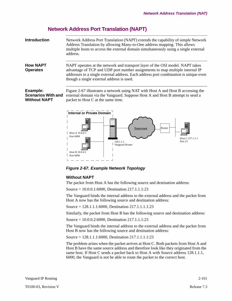
Vanguard IP Routing 2-161
T0100-03, Revision V Release 7.3
Network Address Translation (NAT)
Network Address Port Translation (NAPT)
Introduction Network Address Port Translation (NAPT) extends the capability of simple Network Address Translation by allowing Many-to-One address mapping. This allows multiple hosts to access the external domain simultaneously using a single external address.
How NAPT Operates
NAPT operates at the network and transport layer of the OSI model. NAPT takes advantage of TCP and UDP port number assignments to map multiple internal IP addresses to a single external address. Each address port combination is unique even though a single external address is used.
Example: Scenarios With and Without NAPT
Figure 2-67 illustrates a network using NAT with Host A and Host B accessing the external domain via the Vanguard. Suppose Host A and Host B attempt to send a packet to Host C at the same time.
Figure 2-67. Example Network Topology
Without NAPTThe packet from Host A has the following source and destination address:
Source = 10.0.0.1:6000, Destination 217.1.1.1:23
The Vanguard binds the internal address to the external address and the packet from Host A now has the following source and destination address:
Source = 128.1.1.1:6000, Destination 217.1.1.1.1:23
Similarly, the packet from Host B has the following source and destination address:
Source = 10.0.0.2:6000, Destination 217.1.1.1:23
The Vanguard binds the internal address to the external address and the packet from Host B now has the following source and destination address:
Source = 128.1.1.1:6000, Destination 217.1.1.1.1:23
The problem arises when the packet arrives at Host C. Both packets from Host A and Host B have the same source address and therefore look like they originated from the same host. If Host C sends a packet back to Host A with Source address 128.1.1.1, 6000, the Vanguard is not be able to route the packet to the correct host.
Internal or Private Domain
InternetHost A 10.0.0.1Port 6000
Host B 10.0.0.2Port 6000
128.1.1.1
Router
Vanguard Router
Host C 217.1.1.1Port 23
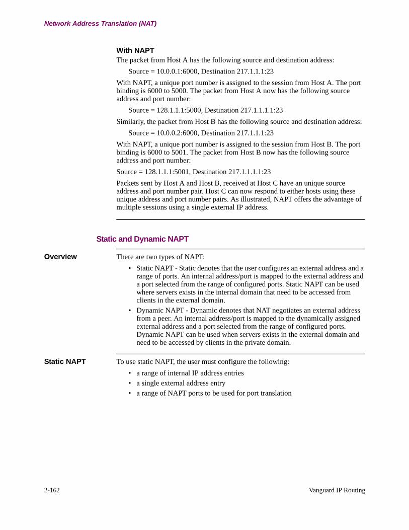
2-162 Vanguard IP Routing
Network Address Translation (NAT)
With NAPTThe packet from Host A has the following source and destination address:
Source = 10.0.0.1:6000, Destination 217.1.1.1:23
With NAPT, a unique port number is assigned to the session from Host A. The port binding is 6000 to 5000. The packet from Host A now has the following source address and port number:
Source = 128.1.1.1:5000, Destination 217.1.1.1.1:23
Similarly, the packet from Host B has the following source and destination address:
Source = 10.0.0.2:6000, Destination 217.1.1.1:23
With NAPT, a unique port number is assigned to the session from Host B. The port binding is 6000 to 5001. The packet from Host B now has the following source address and port number:
Source = 128.1.1.1:5001, Destination 217.1.1.1.1:23
Packets sent by Host A and Host B, received at Host C have an unique source address and port number pair. Host C can now respond to either hosts using these unique address and port number pairs. As illustrated, NAPT offers the advantage of multiple sessions using a single external IP address.
Static and Dynamic NAPT
Overview There are two types of NAPT:
• Static NAPT - Static denotes that the user configures an external address and a range of ports. An internal address/port is mapped to the external address and a port selected from the range of configured ports. Static NAPT can be used where servers exists in the internal domain that need to be accessed from clients in the external domain.
• Dynamic NAPT - Dynamic denotes that NAT negotiates an external address from a peer. An internal address/port is mapped to the dynamically assigned external address and a port selected from the range of configured ports. Dynamic NAPT can be used when servers exists in the external domain and need to be accessed by clients in the private domain.
Static NAPT To use static NAPT, the user must configure the following:
• a range of internal IP address entries• a single external address entry• a range of NAPT ports to be used for port translation
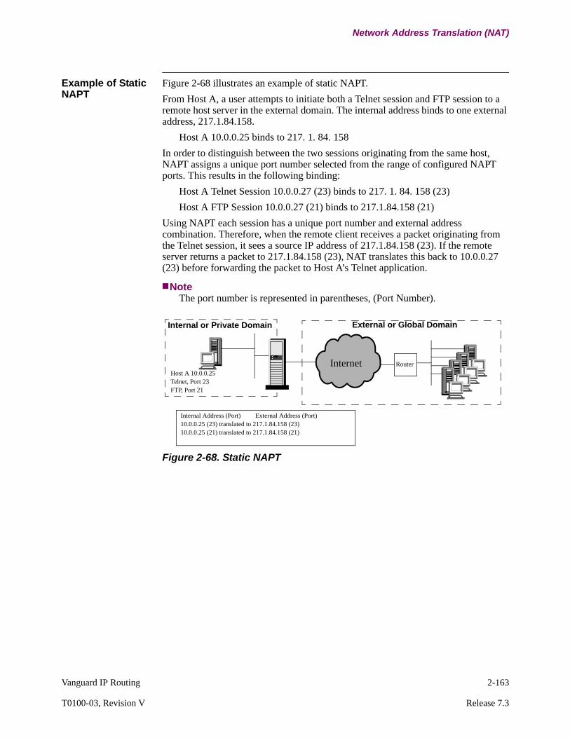
Vanguard IP Routing 2-163
T0100-03, Revision V Release 7.3
Network Address Translation (NAT)
Example of Static NAPT
Figure 2-68 illustrates an example of static NAPT.
From Host A, a user attempts to initiate both a Telnet session and FTP session to a remote host server in the external domain. The internal address binds to one external address, 217.1.84.158.
Host A 10.0.0.25 binds to 217. 1. 84. 158
In order to distinguish between the two sessions originating from the same host, NAPT assigns a unique port number selected from the range of configured NAPT ports. This results in the following binding:
Host A Telnet Session 10.0.0.27 (23) binds to 217. 1. 84. 158 (23)
Host A FTP Session 10.0.0.27 (21) binds to 217.1.84.158 (21)
Using NAPT each session has a unique port number and external address combination. Therefore, when the remote client receives a packet originating from the Telnet session, it sees a source IP address of 217.1.84.158 (23). If the remote server returns a packet to 217.1.84.158 (23), NAT translates this back to 10.0.0.27 (23) before forwarding the packet to Host A’s Telnet application.
NoteThe port number is represented in parentheses, (Port Number).
Figure 2-68. Static NAPT
Internal or Private Domain
Internet Router
Internal Address (Port) External Address (Port)10.0.0.25 (23) translated to 217.1.84.158 (23)10.0.0.25 (21) translated to 217.1.84.158 (21)
External or Global Domain
Host A 10.0.0.25Telnet, Port 23FTP, Port 21

2-164 Vanguard IP Routing
Network Address Translation (NAT)
Dynamic NAPT A Vanguard configured with dynamic NAPT:
• negotiates and learns the external IP address from the peer through PPP-IPCP protocol.
• and maps this external address and a port selected from a range of ports to an internal address/port pair.
To use dynamic NAPT, the user must configure the following:
• a range of internal IP address entries.• a range of NAPT ports to be used for port translation.
Figure 2-69 illustrates an example of Dynamic NAPT.
Figure 2-69. Dynamic NAPT
Internal or Private Domain
Internet Router
Internal Address (Port) External Address (Port)10.0.0.25 (23) translated to 120.10.20.1 (1010)10.0.0.25 (21) translated to 120.10.20.1 (1012)
External or Global Domain
120.10.20.1 assigned by peer
Telnet Server

Vanguard IP Routing 2-165
T0100-03, Revision V Release 7.3
Network Address Translation (NAT)
Permanent Port Binding
Before: NAPT without Permanent Port Binding
For NAPT, address and port binding only occur when the internal interface initiates a session with the external interface. Once the session clears, NAT removes the port bindings from the binding table so the ports can be used for future sessions. An external device in the external network cannot initiate a session with a host in the internal domain because the port bindings no longer exists.
Figure 2-70. NAPT Without Permanent Port Binding
After: NAPT with Permanent Port Binding
Permanent port binding establishes a static or permanent binding between ports. NAT stores this port binding in a binding table. This allows a external host to initiate a session with a host in the internal domain.
Example of Permanent Port Binding
Figure 2-71 provides an example of permanent port binding. In this example, the internal domain contains servers including a WWW server, email server and FTP server.
Figure 2-71. Permanent Port Binding
Internal or Private Domain
Internet Router
Internal Address (Port) External Address (Port)10.0.0.25 (23) translated to 217.1.84.158 (7000)10.0.0.25 (21) translated to 217.1.84.158 (7001)
External or Global Domain
Host A 10.0.0.25Telnet, Port 23FTP, Port 21
Session Initiation
Session Initiation
Internal or Private Domain
Internet
Internal Address External Address10.0.0.3 (1080:UDP) 217.1.84.5 (1080:UDP)10.0.0.7 (25:TCP) 217.1.84.5 (25:TCP)10.0.0.8 (21:TCP) 217.1.84.5 (21:TCP)
External or Global Domain
217.1.84.5 assigned by peer
WWW Server 10.0.0.3
Email Server 10.0.0.7
FTP Server 10.0.0.8
Session Initiation

2-166 Vanguard IP Routing
Network Address Translation (NAT)
Dynamic NAPT is configured so that all servers can access and be accessed by the external domain on a single, dynamically negotiated external address as shown below:
WWW Server 10.0.0.3 binds to dynamically assigned address 217.1.84.5
Email Server 10.0.0.7 binds to dynamically assigned address 217.1.84.5
FTP Server 10.0.0.8 binds to dynamically assigned address 217.1.84.5
When configuring the Vanguard, the user must enter the port for each host and NAT stores the configured port binding in the binding table:
WWW Server 10.0.0.3 (1080:UDP) binds to 217.1.84.5 (1080:UDP)
Email Server 10.0.0.7 (25:TCP) binds to 217.1.84.5 (25:TCP)
FTP Server 10.0.0.8 (21:TCP) binds to 217.1.84.5 (21:TCP)
With permanent port binding, the hosts in the external domain can initiate the session. For example, a host on the external domain sends an HTTP query to the 217.1.84.5, 1080, UDP, the external address of the WWW Server. Permanent port binding has already been established between the external address 217.1.84.5, 1080, UDP and the internal address of the WWW server 10.0.0.3, 1080, UDP. Hence the HTTP query from the external host is forwarded to the WWW server within the internal domain.
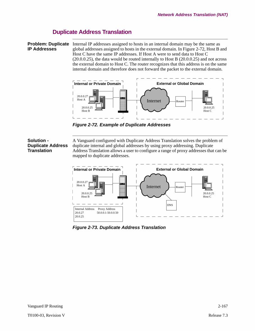
Vanguard IP Routing 2-167
T0100-03, Revision V Release 7.3
Network Address Translation (NAT)
Duplicate Address Translation
Problem: Duplicate IP Addresses
Internal IP addresses assigned to hosts in an internal domain may be the same as global addresses assigned to hosts in the external domain. In Figure 2-72, Host B and Host C have the same IP addresses. If Host A were to send data to Host C (20.0.0.25), the data would be routed internally to Host B (20.0.0.25) and not across the external domain to Host C. The router recognizes that this address is on the same internal domain and therefore does not forward the packet to the external domain.
Figure 2-72. Example of Duplicate Addresses
Solution - Duplicate Address Translation
A Vanguard configured with Duplicate Address Translation solves the problem of duplicate internal and global addresses by using proxy addressing. Duplicate Address Translation allows a user to configure a range of proxy addresses that can be mapped to duplicate addresses.
Figure 2-73. Duplicate Address Translation
Internal or Private Domain
Internet Router
20.0.0.27
20.0.0.25
External or Global Domain
20.0.0.25Host C
Host A
Host B
Internal or Private Domain
Internet Router
20.0.0.27
20.0.0.25
External or Global Domain
20.0.0.25Host C
Host A
Host B
Internal Address Proxy Address20.0.27 50.0.0.1-50.0.0.5020.0.25
DNS
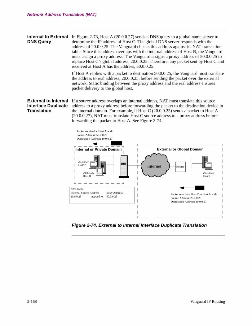
2-168 Vanguard IP Routing
Network Address Translation (NAT)
Internal to External DNS Query
In Figure 2-73, Host A (20.0.0.27) sends a DNS query to a global name server to determine the IP address of Host C. The global DNS server responds with the address of 20.0.0.25. The Vanguard checks this address against its NAT translation table. Since this address overlaps with the internal address of Host B, the Vanguard must assign a proxy address. The Vanguard assigns a proxy address of 50.0.0.25 to replace Host C’s global address, 20.0.0.25. Therefore, any packet sent by Host C and received at Host A has the address, 50.0.0.25.
If Host A replies with a packet to destination 50.0.0.25, the Vanguard must translate the address to real address, 20.0.0.25, before sending the packet over the external network. Static binding between the proxy address and the real address ensures packet delivery to the global host.
External to Internal Interface Duplicate Translation
If a source address overlaps an internal address, NAT must translate this source address to a proxy address before forwarding the packet to the destination device in the internal domain. For example, if Host C (20.0.0.25) sends a packet to Host A (20.0.0.27), NAT must translate Host C source address to a proxy address before forwarding the packet to Host A. See Figure 2-74.
Figure 2-74. External to Internal Interface Duplicate Translation
Packet sent from Host C to Host A withSource Address: 20.0.0.25Destination Address: 10.0.0.27
NAT TableExternal Source Address Proxy Address20.0.0.25 mapped to 50.0.0.25
Packet received at Host A with Source Address: 50.0.0.25Destination Address: 10.0.0.27
Internal or Private Domain
Internet Router
20.0.0.27
20.0.0.25
External or Global Domain
20.0.0.25Host C
Host A
Host B
Vanguard IP Routing 2-169
T0100-03, Revision V Release 7.3
Network Address Translation (NAT)
Application Layer Translation
Overview Generally, application layer protocols are ignorant of network and transport layer protocols. However, application layer protocols such as FTP, ICMP, and DNS are dependent on the network and transport layer protocols and use IP addresses embedded at the application level.
To successfully transmit these types of traffic, Network Address Translation translates an embedded IP address in the header of the IP packet without modifying the IP data portion. The implementation of NAT supports TCP/UDP, FTP, DNS, and ICMP.
NoteNAT does not translate embedded addressing information located in the data field of an IP packet. In addition, NAT does not translate encrypted IP packets.
FTP Translation FTP uses embedded IP addresses and port numbers to negotiate with the peer. NAT translates these embedded addresses and port number to allow FTP operation between devices in internal and external domains.
DNS Translation NAT supports translation of the DNS RR (Resource Record) message.
ICMP Translation Network servers use Internet Control Message Protocol (ICMP) to communicate errors or network problems. ICMP packets contain the header and the first 64 data bits of the datagram causing the problem. NAT must translate the embedded IP address of the original source. NAT translates the following ICMP messages:
• Destination Unreachable (Type 3)• Source Quench (Type 4)• Redirect (Type 5)• Time Exceeded for a Datagram (Type 11)• Parameter Problems on a Datagram (Type 12)
ICMP Translation and NAPT
NAPT operates at the network and transport layer of the OSI model. NAPT takes advantage of TCP and UDP port number assignments to map multiple internal IP addresses to a single external address. This poses a problem for application protocols, such as ICMP, which do not operate on port numbers.
For example, two hosts within an internal network send an ICMP echo requests over external network. While both hosts’ internal addresses bind to a single external address, they each have unique port numbers as defined by NAPT. However, when the remote host responds with an ICMP reply, the Vanguard is not able to forward the reply to the originating host because ICMP does not support port numbers.
To correct this problem, when a Vanguard receives an ICMP request from an internal host, it stores the source address, the identifier field, and sequence number field of the ICMP request. An internally generated sequence number replaces the sequence number in the original ICMP request. NAT uses this sequence number to identify the host when an ICMP reply is received.

2-170 Vanguard IP Routing
Network Address Translation (NAT)
Router Operation using Network Address Translation
Introduction This section describes how a NAT router functions to route and translate IP datagrams.
Rules for Session Initiation
Sessions can only be initiated in both directions (internal to external and external to internal) with static binding configured. For dynamic translation, you must initiate the session from the internal interface.
Rules for Translation
NAT translates the source IP address in packets originating from the internal domain and destined for the external domain. NAT also translates IP destination address in packets originating from the external domain destined for the internal domain. NAT does not perform translation for packets sent from an internal device to another internal device within the same internal network.
Rules for Routing These are rules for routing:
• Packets received on an internal interface are routed on the internal interfaces first.
• Packets received on an external interface are routed on the external interfaces first.
• Routes learned from the external network can be advertised in the private network.
• Routes learned from the private network, however, are never advertised to the external network.
This table describes rules for routing with NAT enabled:
Rules for Traffic Priority
The Vanguard performs traffic prioritization after translation.
IP Multicast and NAT
NAT supports IP multicast over NAT interfaces using DVMRP static routing. When an IP multicast is forwarded from the internal to external domain, NAT replaces the unicast IP source address with an external source address. When the external interface receives IP multicast, it passes the packet to IP multicast/DVMRP processing without changing the IP address.
If a packet is received from
and destined for then the packet is
internal interface internal interface routed without translation
external interface routed, translated, and forwarded
external interface internal interface translated before routing
external interface no translation

Vanguard IP Routing 2-171
T0100-03, Revision V Release 7.3
Network Address Translation (NAT)
RIP and NAT A NAT router does not advertise internal addresses, such as subnets, to the external network. Only translated external addresses are advertised to the external domain. RIP advertisements received from the external network are re-advertised into internal domain. RIP should be disabled if duplicate addresses are configured on both sides of the NAT interface.

2-172 Vanguard IP Routing
Policy Based Routing
Policy Based Routing
What is Policy Based Routing?
Policy based routing (PBR), also known as layer 4 switching, provides a mechanism of routing traffic based on policies defined by the network administrator. Policy based routing classifies traffic by flow and then applies defined policies or actions on the traffic flow. This allows more control on how traffic is routed within an organization’s network. Policy based routing provides the flexibility of using user defined paths rather than paths determined by dynamic routing protocols. Policy based routing overrides destination based routing.
Definition of Flow and Policy
This table defines flow and policy:
Example Figure 2-75 illustrates an example of routing based on defined flows and policies.
Figure 2-75. Policy Based Routing Example
Item Description
Flow Traffic that satisfies particular criteria can be grouped or classified as a traffic flow. Traffic flows can be defined using network and transport layer header information. For example, traffic received with source addresses in the range of 10.0.0.1 to 10.0.0.10 can be classified as one traffic flow and traffic received with the source addresses 20.0.0.1 to 20.0.0.10 can be classified as another traffic flow.
Policy Policy is defined as the set of actions to be applied on specific traffic flows to control and manage traffic through an organization’s network.
Router
ISP 2
Address Range110.0.0.1 to110.0.0.10
Address Range120.0.0.1 to120.0.0.10
Traffic Flow Definition Policy
If the source address of the incoming Packet is in the range of 110.0.0.1 to 110.0.0.10
Route the packet to ISP 1.
If the destination address of the incoming packet is in the range of 120.0.0.1 to 120.0.0.10
Route the packet to ISP 2.
Address Range120.0.0.1 to120.0.0.10
ISP 1
Vanguard IP Routing 2-173
T0100-03, Revision V Release 7.3
Policy Based Routing
Guidelines for Using Policy Based Routing
Note the following when using policy based routing:
• Before implementing policy based routing in your network, define and map out flows and policies. While policy based routing provides flexibility in control routing as defined by an organization’s needs, policies not defined and implemented consistently may cause routing loops within your network.
• In addition, policy based routes differs from dynamically learned routes or static routes. A route specified by policy based routing may not be the best route to a particular destination. It is only the route which represents the organization’s policy.
• Using policy based routing effects the router’s performance because all packets received by the router must go through the flow matching process regardless of whether the packets are to be policy routed or routed using destination based routing.
2-174 Vanguard IP Routing
Policy Based Routing
Support for Policy Based Routing
Benefits and Capabilities
The implementation of policy based routing offers:
• Granular flow definition - Policy based routing uses various network and transport layer information to define specific and granular flows.
• Time of Week (TOW) Based Routing - Flows can be characterized using the Time of Week (TOW) profile.
• Interface and LCON Based Policy - Policy based routing can be applied on a per interface or per LCON basis.
• Flexible Nexthop Representation - The nexthop, to which a matched flow can be forwarded, can be specified as an IP address or LCON number. The LCON number can be used for unnumbered networks or if the nexthop IP address is not known.
• Range of Nexthop - A list of nexthop IP addresses or LCON numbers can be specified for a particular flow. The first available and active nexthop IP address or LCON number is used to route the flow.
• Backup Routes - A list of backup nexthop IP addresses or LCONs can be specified. Backup nexthop routes are used only if none of the primary nexthop routes are active.
Types of Traffic Supported
The Vanguards support policy based routing of all types non-broadcast IP traffic received either through LAN or WAN interfaces. Policy based routing also applies to internally generated non-broadcast IP traffic including Ping, Telnet, FTP, SoTCP, or SNMP.
NotePolicy based routing does not apply on all routing protocols, such as RIP, OSPF, local broadcast, direct broadcast and multicast traffic.
Vanguard IP Routing 2-175
T0100-03, Revision V Release 7.3
Policy Based Routing
How Vanguard Policy Based Routing Works
Introduction Policy based routing operates on two basic principles: defining traffic flows and applying appropriate actions or policies on the defined flow.
Defining Traffic Flows
In the Vanguard router, traffic flows can be defined using one or more of the following:
• Inbound Interface • Inbound LCON• Source Address Range (defined by a Source Address and Mask pair)• Destination Address Range (defined by a Destination Address and Mask pair)• Protocol (TCP/UDP/ICMP)• Destination Port Range • Source Port Range
Upon receiving an IP packet the Vanguard compares the packet’s IP header against the defined traffic flows. If the packet matches the defined traffic flow, then it is routed according to the policy that applies to the defined traffic flow.
Defining Traffic Characteristics - Time of Week Based Routing
In addition to defining traffic flows using the network or IP header information, Vanguard policy based routing supports further characterization of traffic flows using the Time of Day or Time of Week flow characteristic. Traffic flows that fit a defined TOW profile can be policy routed on different routing paths.
With TOW profiles configured, the traffic flow is routed based on the current time. The traffic flow can have different, non-overlapping TOW profiles. For example, a particular flow can be routed over one routing path during the day and routed over another routing path during the evening.
Defining Policies
Introduction After defining traffic flows, the actions or policies applied on these traffic flows must be defined. These policies define how the traffic is routed. The Vanguard router can forward the packet to a configured primary or backup nexthop IP address or LCON. If a range of IP nexthop addresses is specified, the first nexthop address or LCON associated with an active interface is used. If primary nexthop IP addresses or LCONs are not active, the backup nexthop IP addresses or LCONs are used.
Backup Nexthop Backup nexthop IP addresses or LCONs can be used when there are no active primary nexthop IP addresses or LCONs.
When a primary nexthop IP address or LCON becomes active, the packets sent over the backup nexthop are reverted back to the primary nexthop. This is known as reversible backup.
NoteIf the primary or backup nexthop IP address or LCON is not available the packet is dropped.

2-176 Vanguard IP Routing
Policy Based Routing
Load Balancing If there are more than one primary or backup nexthop IP addresses or LCONs specifies, traffic can be distributed or load balanced. Load balancing allows a traffic flow to be routed to a nexthop IP address with the least number of active flows.
For load balancing to work correctly, the router has to be booted with PBR enabled (no PBR table entries are required). The PBR present action causes the IP forwarding cache to operate in source-destination matching mode as opposed to the default destination only matching mode. Therefore, each new source-destination flow will have its own forwarding cache entry. Adding new forwarding cache entries is done in a load balancing mode when multiple equal weight routes exist to the same destination network.
Load Balancing Using Static Routes (without requirement for BGP)Vanguard routers will load balance IP packet flows either based solely on a packet's destination IP address or on a packet's flow context (unique combination of source and destination IP address and ports).
The load balance behavior is configured at the time of a node cold or warm boot. If Policy Based Routing was globally enabled prior to the node boot, then load balancing will be on a per flow basis. If not configured at the time of boot, all packet flows to the same destination network will share the same load balanced link.
NoteNo PBR table entries are required for static route load balancing; the only requirement is to globally enable PBR prior to a node boot.All static routes used for load balancing must be to the same destination subnet and have the same subnet mask and distance metric.When load balanced static routes change state, the router will automatically rebalance the packet flow load based on the maximum number of static load balancing routes available after the disturbance.
Load Balancing BGP routesA BGP route may be load balanced if there are multiple paths to the neighboring BGP peer. This is done by configuring the remote BGP peer's BGP ID (router ID) to be its Internal IP Address (loopback address). At the local router, there are multiple host specific (/32) static routes to the remote peer's internal loopback address, with each host specific route specifying an actual next hop path to the remote BGP peer.
The local router will then receive BGP route advertisements with the remote BGP peer's internal loopback address as the next hop. The load balancing static routes will then resolve the remote peer's internal loopback address to an actual route to the remote peer.
NoteIt is important that the Vanguard BGP peer be configured for "indirect BGP Peering: ALLOWED" and "Peer IP Address List" to be the remote BGP peer's internal loopback address. The BGP peering session will then come up via one of the host specific static routes to the remote BGP peer's internal loopback address.For information on BGP please see the Border Gateway Protocol (BGP-4) Document
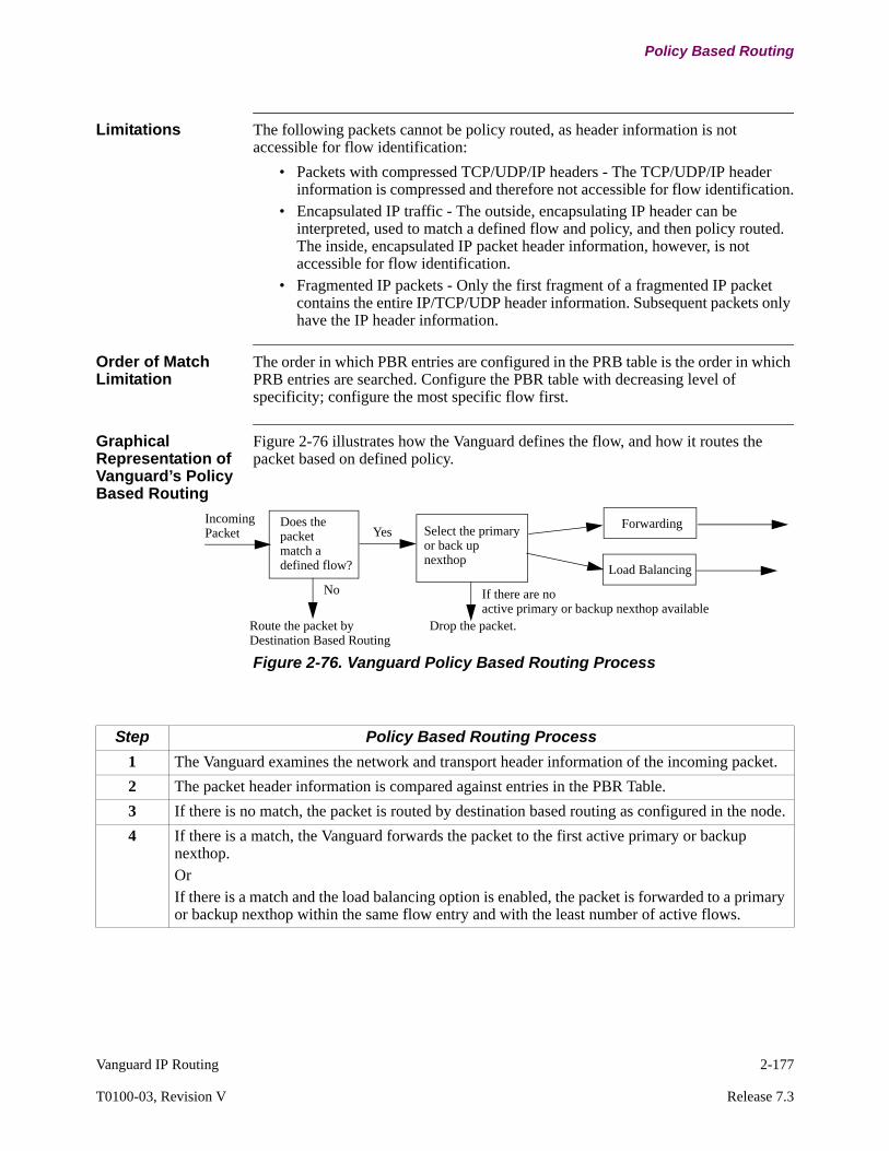
Vanguard IP Routing 2-177
T0100-03, Revision V Release 7.3
Policy Based Routing
Limitations The following packets cannot be policy routed, as header information is not accessible for flow identification:
• Packets with compressed TCP/UDP/IP headers - The TCP/UDP/IP header information is compressed and therefore not accessible for flow identification.
• Encapsulated IP traffic - The outside, encapsulating IP header can be interpreted, used to match a defined flow and policy, and then policy routed. The inside, encapsulated IP packet header information, however, is not accessible for flow identification.
• Fragmented IP packets - Only the first fragment of a fragmented IP packet contains the entire IP/TCP/UDP header information. Subsequent packets only have the IP header information.
Order of Match Limitation
The order in which PBR entries are configured in the PRB table is the order in which PRB entries are searched. Configure the PBR table with decreasing level of specificity; configure the most specific flow first.
Graphical Representation of Vanguard’s Policy Based Routing
Figure 2-76 illustrates how the Vanguard defines the flow, and how it routes the packet based on defined policy.
Figure 2-76. Vanguard Policy Based Routing Process
IncomingPacket
Does thepacketmatch adefined flow?
No
Route the packet by Destination Based Routing
Yes Select the primaryor back upnexthop
If there are noactive primary or backup nexthop available
Drop the packet.
Load Balancing
Forwarding
Step Policy Based Routing Process
1 The Vanguard examines the network and transport header information of the incoming packet.
2 The packet header information is compared against entries in the PBR Table.
3 If there is no match, the packet is routed by destination based routing as configured in the node.
4 If there is a match, the Vanguard forwards the packet to the first active primary or backup nexthop. OrIf there is a match and the load balancing option is enabled, the packet is forwarded to a primary or backup nexthop within the same flow entry and with the least number of active flows.
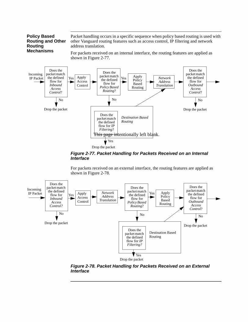
This page intentionally left blank.
Policy Based Routing and Other Routing Mechanisms
Packet handling occurs in a specific sequence when policy based routing is used with other Vanguard routing features such as access control, IP filtering and network address translation.
For packets received on an internal interface, the routing features are applied as shown in Figure 2-77.
Figure 2-77. Packet Handling for Packets Received on an Internal Interface
For packets received on an external interface, the routing features are applied as shown in Figure 2-78.
Figure 2-78. Packet Handling for Packets Received on an External Interface
Does the packet match the defined
flow for Inbound Access
Control?
No
Drop the packet
Yes
Does the packet match the defined
flow for Policy Based
Routing?
No
Destination BasedRouting
Does the packet match the defined flow for IP Filtering?
Yes
Drop the packet
Does the packet match the defined
flow for Outbound
Access Control?
No
Drop the packet
YesApplyAccess Control
Apply Policy Based
Routing
NetworkAddress
Translation
Incoming IP Packet
Does the packet match the defined
flow for Inbound Access
Control?
No
Drop the packet
Yes
Does the packet match the defined
flow for Policy Based
Routing?
No
Destination BasedRouting
Does the packet match the defined flow for IP Filtering?
YesDrop the packet
Does the packet match the defined
flow for Outbound
Access Control?
No
Drop the packet
YesApplyAccess Control
Apply Policy Based
Routing
NetworkAddress
Translation
Incoming IP Packet
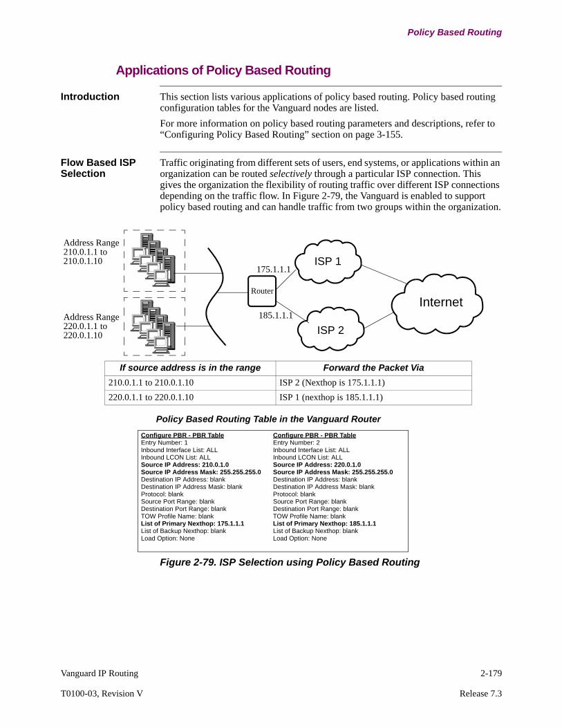
Vanguard IP Routing 2-179
T0100-03, Revision V Release 7.3
Policy Based Routing
Applications of Policy Based Routing
Introduction This section lists various applications of policy based routing. Policy based routing configuration tables for the Vanguard nodes are listed.
For more information on policy based routing parameters and descriptions, refer to “Configuring Policy Based Routing” section on page 3-155.
Flow Based ISP Selection
Traffic originating from different sets of users, end systems, or applications within an organization can be routed selectively through a particular ISP connection. This gives the organization the flexibility of routing traffic over different ISP connections depending on the traffic flow. In Figure 2-79, the Vanguard is enabled to support policy based routing and can handle traffic from two groups within the organization.
Figure 2-79. ISP Selection using Policy Based Routing
Router
Internet
ISP 1
ISP 2
Address Range210.0.1.1 to210.0.1.10
Address Range220.0.1.1 to220.0.1.10
If source address is in the range Forward the Packet Via
210.0.1.1 to 210.0.1.10 ISP 2 (Nexthop is 175.1.1.1)
220.0.1.1 to 220.0.1.10 ISP 1 (nexthop is 185.1.1.1)
Configure PBR - PBR TableEntry Number: 1Inbound Interface List: ALLInbound LCON List: ALLSource IP Address: 210.0.1.0Source IP Address Mask: 255.255.255.0 Destination IP Address: blankDestination IP Address Mask: blankProtocol: blankSource Port Range: blankDestination Port Range: blankTOW Profile Name: blankList of Primary Nexthop: 175.1.1.1List of Backup Nexthop: blankLoad Option: None
Configure PBR - PBR TableEntry Number: 2Inbound Interface List: ALLInbound LCON List: ALLSource IP Address: 220.0.1.0Source IP Address Mask: 255.255.255.0 Destination IP Address: blankDestination IP Address Mask: blank Protocol: blankSource Port Range: blankDestination Port Range: blankTOW Profile Name: blankList of Primary Nexthop: 185.1.1.1List of Backup Nexthop: blankLoad Option: None
175.1.1.1
185.1.1.1
Policy Based Routing Table in the Vanguard Router
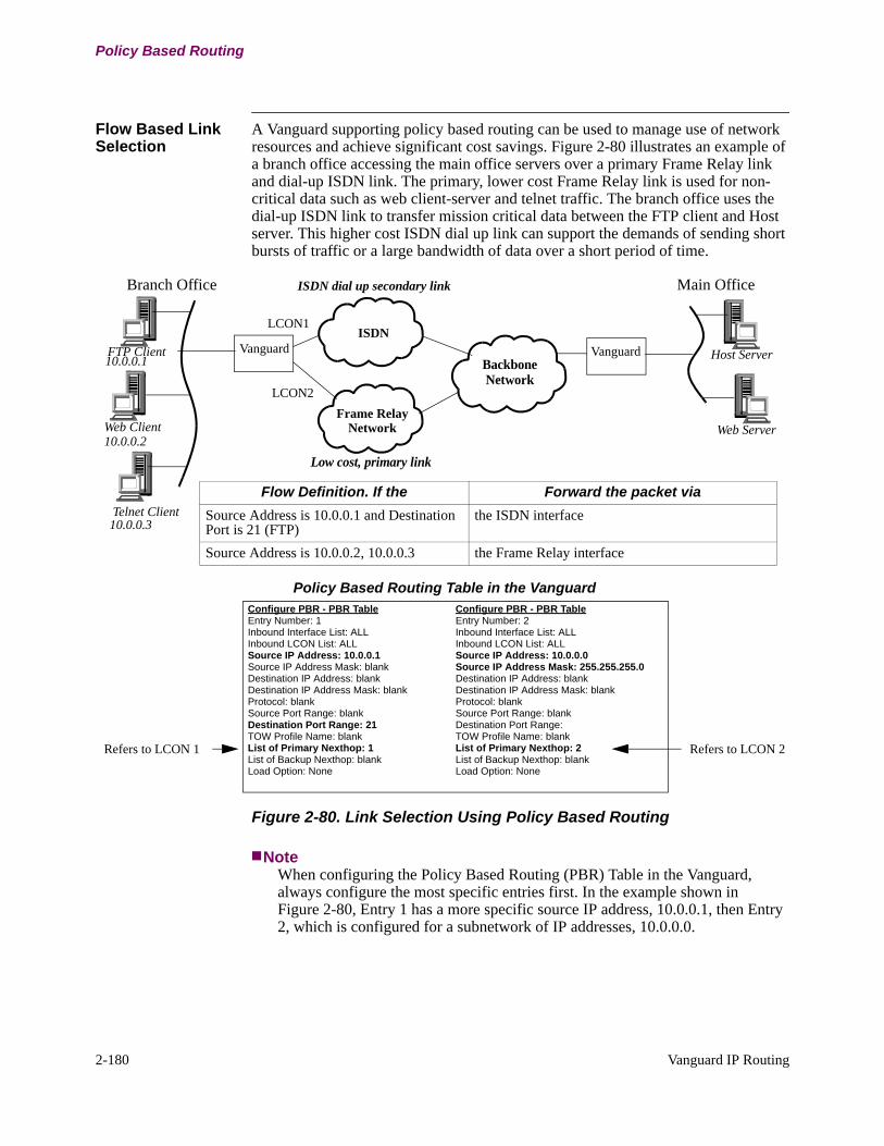
2-180 Vanguard IP Routing
Policy Based Routing
Flow Based Link Selection
A Vanguard supporting policy based routing can be used to manage use of network resources and achieve significant cost savings. Figure 2-80 illustrates an example of a branch office accessing the main office servers over a primary Frame Relay link and dial-up ISDN link. The primary, lower cost Frame Relay link is used for non-critical data such as web client-server and telnet traffic. The branch office uses the dial-up ISDN link to transfer mission critical data between the FTP client and Host server. This higher cost ISDN dial up link can support the demands of sending short bursts of traffic or a large bandwidth of data over a short period of time.
Figure 2-80. Link Selection Using Policy Based Routing
NoteWhen configuring the Policy Based Routing (PBR) Table in the Vanguard, always configure the most specific entries first. In the example shown in Figure 2-80, Entry 1 has a more specific source IP address, 10.0.0.1, then Entry 2, which is configured for a subnetwork of IP addresses, 10.0.0.0.
VanguardFTP Client
Web ClientFrame Relay
Network
BackboneNetwork
ISDN dial up secondary link
ISDN
Low cost, primary link
Vanguard Host Server
Web Server
Main OfficeBranch Office
Flow Definition. If the Forward the packet via
Source Address is 10.0.0.1 and Destination Port is 21 (FTP)
the ISDN interface
Source Address is 10.0.0.2, 10.0.0.3 the Frame Relay interface
10.0.0.2
Telnet Client
Configure PBR - PBR TableEntry Number: 1Inbound Interface List: ALLInbound LCON List: ALLSource IP Address: 10.0.0.1Source IP Address Mask: blankDestination IP Address: blankDestination IP Address Mask: blankProtocol: blankSource Port Range: blankDestination Port Range: 21TOW Profile Name: blankList of Primary Nexthop: 1List of Backup Nexthop: blankLoad Option: None
Configure PBR - PBR TableEntry Number: 2Inbound Interface List: ALLInbound LCON List: ALLSource IP Address: 10.0.0.0Source IP Address Mask: 255.255.255.0Destination IP Address: blankDestination IP Address Mask: blank Protocol: blankSource Port Range: blankDestination Port Range: TOW Profile Name: blankList of Primary Nexthop: 2List of Backup Nexthop: blankLoad Option: None
Policy Based Routing Table in the Vanguard
10.0.0.1
10.0.0.3
LCON1
LCON2
Refers to LCON 2Refers to LCON 1
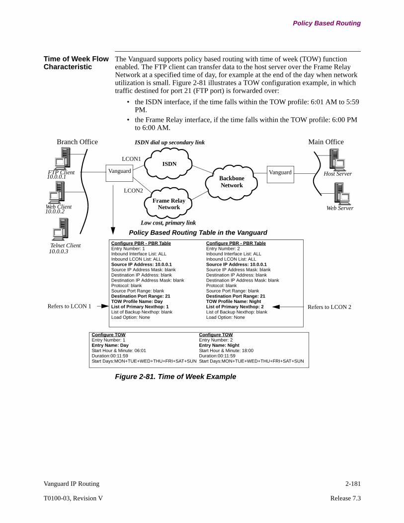
Vanguard IP Routing 2-181
T0100-03, Revision V Release 7.3
Policy Based Routing
Time of Week Flow Characteristic
The Vanguard supports policy based routing with time of week (TOW) function enabled. The FTP client can transfer data to the host server over the Frame Relay Network at a specified time of day, for example at the end of the day when network utilization is small. Figure 2-81 illustrates a TOW configuration example, in which traffic destined for port 21 (FTP port) is forwarded over:
• the ISDN interface, if the time falls within the TOW profile: 6:01 AM to 5:59 PM.
• the Frame Relay interface, if the time falls within the TOW profile: 6:00 PM to 6:00 AM.
Figure 2-81. Time of Week Example
VanguardFTP Client
Web ClientFrame Relay
Network
BackboneNetwork
ISDN dial up secondary link
ISDN
Low cost, primary link
Vanguard Host Server
Web Server
Main OfficeBranch Office
Telnet Client
10.0.0.2
10.0.0.1
10.0.0.3
Configure PBR - PBR TableEntry Number: 1Inbound Interface List: ALLInbound LCON List: ALLSource IP Address: 10.0.0.1Source IP Address Mask: blankDestination IP Address: blankDestination IP Address Mask: blankProtocol: blankSource Port Range: blankDestination Port Range: 21TOW Profile Name: DayList of Primary Nexthop: 1List of Backup Nexthop: blankLoad Option: None
Configure PBR - PBR TableEntry Number: 2Inbound Interface List: ALLInbound LCON List: ALLSource IP Address: 10.0.0.1Source IP Address Mask: blankDestination IP Address: blankDestination IP Address Mask: blank Protocol: blankSource Port Range: blankDestination Port Range: 21TOW Profile Name: NightList of Primary Nexthop: 2List of Backup Nexthop: blankLoad Option: None
Policy Based Routing Table in the Vanguard
LCON1
LCON2
Configure TOWEntry Number: 1Entry Name: DayStart Hour & Minute: 06:01Duration:00:11:59Start Days:MON+TUE+WED+THU+FRI+SAT+SUN
Configure TOWEntry Number: 2Entry Name: NightStart Hour & Minute: 18:00Duration:00:11:59Start Days:MON+TUE+WED+THU+FRI+SAT+SUN
Refers to LCON 1 Refers to LCON 2

2-182 Vanguard IP Routing
Policy Based Routing
Load Balancing Policy base routing can be used to balance the traffic flows between equal cost paths depending upon the number of currently active flows on each path. The Vanguard forwards new traffic flows to nexthop routes or paths with the lowest number of currently active flows. This ensures balanced use of available routes and prevents route congestion for that particular flow.
Figure 2-82. Load Balancing Using Policy Based Routing
In this example, traffic from different transaction clients in the branch office are load balanced between two Frame Relay links. If there are multiple web clients within the 10.0.1.0 subnet, you can define a policy so that web client traffic is equally balanced over the list of primary nexthop routes.
Selective Usage Backup Links
Policy based routing can also be used to define backup links. The ISDN dial-up secondary link, shown in Figure 2-80, can be used to provide on demand backup link if the primary Frame Relay link fails. You can also define a policy so that only FTP and Telnet traffic is sent over the ISDN dial-up secondary link if the frame relay link fails. If the Frame Relay link fails, web client or HTTP traffic is not routed over the ISDN dial-up link, instead the traffic is dropped. To configure a backup link, you must configure one or more backup nexthop routes in addition to the primary nexthop routes when you are defining a flow.
Security Policy based routing can also provide network security. As an example, policy based routing can be used to define flows and policies so that SNMP traffic is routed on a select set of interfaces that are secure or encrypted.
Vanguard
Teller Terminals
Frame RelayNetwork
VanguardTransaction Server
Web Server
Main Bank OfficeBank Branch Office
Frame RelayNetwork
Automated Bank Machine
Web Clients
LCON 1 / DLCI 16
LCON 2 / DLCI 17
Configure PBR - PBR TableEntry Number: 1Inbound Interface List: ALLInbound LCON List: ALLSource IP Address: blankSource IP Address Mask: blankDestination IP Address: blankDestination IP Address Mask: blankProtocol: blankSource Port Range: blankDestination Port Range: blankTOW Profile Name: DayList of Primary Nexthop: 1, 2List of Backup Nexthop: blankLoad Option: Balanced
Subnet 10.0.1.0
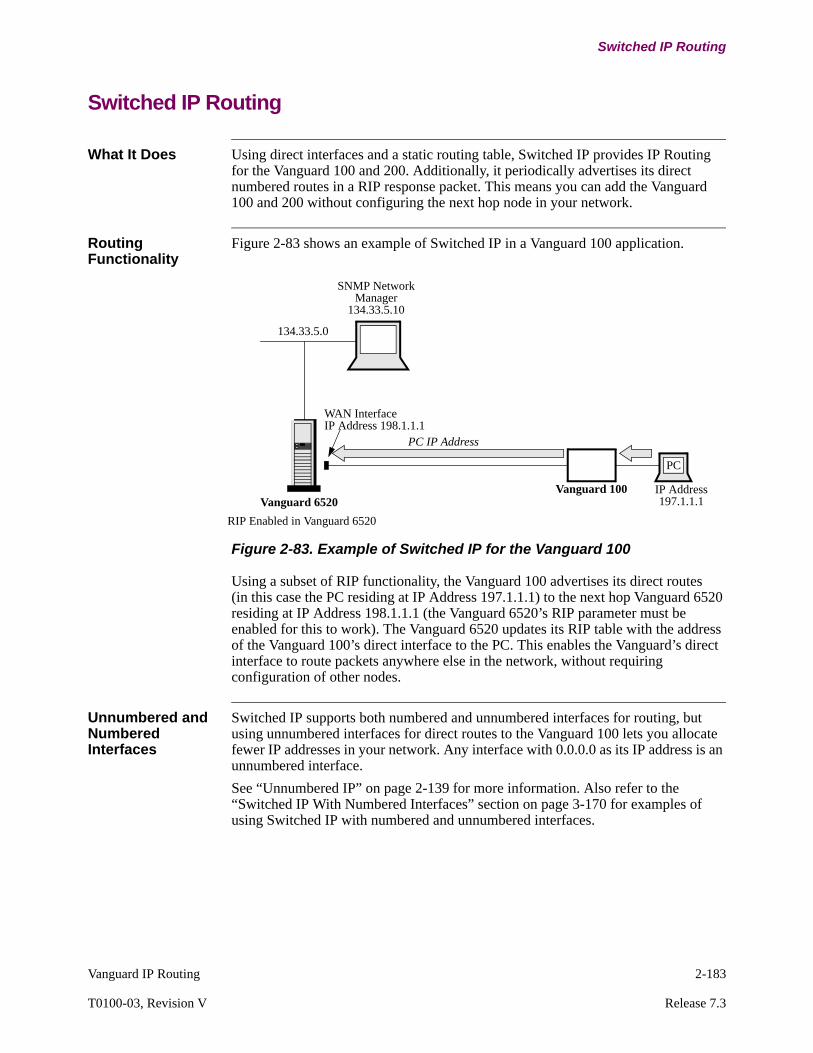
Vanguard IP Routing 2-183
T0100-03, Revision V Release 7.3
Switched IP Routing
Switched IP Routing
What It Does Using direct interfaces and a static routing table, Switched IP provides IP Routing for the Vanguard 100 and 200. Additionally, it periodically advertises its direct numbered routes in a RIP response packet. This means you can add the Vanguard 100 and 200 without configuring the next hop node in your network.
Routing Functionality
Figure 2-83 shows an example of Switched IP in a Vanguard 100 application.
Figure 2-83. Example of Switched IP for the Vanguard 100
Using a subset of RIP functionality, the Vanguard 100 advertises its direct routes (in this case the PC residing at IP Address 197.1.1.1) to the next hop Vanguard 6520 residing at IP Address 198.1.1.1 (the Vanguard 6520’s RIP parameter must be enabled for this to work). The Vanguard 6520 updates its RIP table with the address of the Vanguard 100’s direct interface to the PC. This enables the Vanguard’s direct interface to route packets anywhere else in the network, without requiring configuration of other nodes.
Unnumbered and Numbered Interfaces
Switched IP supports both numbered and unnumbered interfaces for routing, but using unnumbered interfaces for direct routes to the Vanguard 100 lets you allocate fewer IP addresses in your network. Any interface with 0.0.0.0 as its IP address is an unnumbered interface.
See “Unnumbered IP” on page 2-139 for more information. Also refer to the “Switched IP With Numbered Interfaces” section on page 3-170 for examples of using Switched IP with numbered and unnumbered interfaces.
SNMP NetworkManager
134.33.5.10
Vanguard 100Vanguard 6520
PC IP Address
PC
IP Address197.1.1.1
WAN InterfaceIP Address 198.1.1.1
RIP Enabled in Vanguard 6520
134.33.5.0

2-184 Vanguard IP Routing
Switched IP Routing
MTU Discovery Process
Switched IP supports the same Maximum Transmission Unit (MTU) frame size functionality provided for all Vanguard Products. The MTU frame size functionality lets you limit the size of outgoing frames passed from an interface on the Vanguard 100 and 200.
More specifically, MTU sets the router MTU size excluding WAN headers and trailers. The MTU parameter regulates and negotiates incoming frames from a PC across the LAN to the router. Frames larger than the configured maximum node frame size are discarded.
The MTU (datagram) size is configurable up to the maximum node frame size of 4590. The default is 1500.
For example, for an outgoing frame that has the non-fragment bit set and exceeds the configured size of the outgoing interface, the Vanguard 100 generates an ICMP (IP Configuration Management Protocol) message containing the configured MTU size. If the non-fragment bit is not set in the frame, IP fragments it based on the configured MTU size of the outgoing interface. If the frames are destined for a device other than the Vanguard 100, the Vanguard passes the unassembled frames on to their destination. If the frames are destined for the Vanguard 100, they are discarded.
Packet Filtering Packet filtering using Switched IP is based only on the IP destination of the address field of an IP packet. This lets you configure the IP Network/Subnet and IP Address Mask parameters from the Static/Routes Table to filter out specific packets. The interface 0 acts as an internal network for discarded packets. So, any route that is routed to interface 0 results in a packet filter. See “Configuring Static Routes” section on page 3-174” for details on specific parameters and value.
Default Node Address
Normally, the default node address is the address of the lowest numbered interface. The default node address is used as the source address in an IP packet originating at the node and being directed over an unnumbered interface. If an IP address is assigned to interface 0, then that IP address becomes the default node address.
This method of addressing is useful only when all the interfaces are unnumbered and it is necessary to refer to the node using an IP address, for example, when you are performing an SNMP query.
Default Gateway You can configure the default route (destination 0 and mask 0) for Switched IP using the Default Gateway parameter on the Parameters menu.
Configuring the Default Gateway ParameterTo configure the Default Gateway, select the Configure Router menu-> Configure IP -> Parameters from the CTP Main menu, then type in a value for the Default Gateway parameter.
You can also configure the default route from the Static/Routes Table.
Obtaining the Default Gateway AddressYou can obtain the default gateway address by using SNMP to query the following MIB attribute:
cdx6500Statistics.cdx6500StatProtocolGroup.cdx6500PSTRouterGroup.proProtoDefGwAddress.

Vanguard IP Routing 2-185
T0100-03, Revision V Release 7.3
Switched IP Routing
Types of Packets Supported
Switched IP supports Class A, B, and C types of IP packets.
Booting Follow these guidelines to boot your Switched IP implementation:
• If you change the mapping of an IP interface in the LAN Connection Table, for example, when you map a LAN connection to a new interface, perform a node boot to implement the changes.
• When you add, modify, or delete an IP interface, perform an IP Interfaces/Routing boot from the Boot menu to implement your changes. When you delete an interface, the corresponding LAN connection does not disappear until you perform a LAN connection boot.
• When you add, delete, or modify an entry in the Static Routing Table, perform an IP Interfaces/Routing boot from the Boot menu to implement your changes.
Changing from Slim IP to Switched IP Router
The TFTP and SNMP features do not function until you re-configure your IP. If you use Slim IP to configure your IP connection, then you must re-enter your routing configuration (PVC table, LCON table, route interfaces, and mnemonic table) to use the Switched IP router.
SNMP Management SNMP support for the IP group of MIB II includes queries for:
• ipAddrTable• ipRouteTable

2-186 Vanguard IP Routing
Accelerated IP Forwarding
Accelerated IP Forwarding
Introduction This section provides an explanation of Accelerated IP Forwarding as it is implemented in Vanguard 6400 and 6560 Series routers. Accelerated IP Forwarding improves on normal path forwarding to enhance the performance of IP packet flows under specified circumstances.
Accelerated IP Forwarding uses Aggregate Cache to improve IP forwarding performance over normal path forwarding. It reduces the amount of processing that IP packets undergo during transit in the node. This implementation of Accelerated IP Forwarding supports IP forwarding over an Ethernet-Frame Relay path.
Accelerated IP Forwarding is available on Vanguard 6400 and 6560 Series routers only.
How Normal Path Forwarding Works
In the normal path inside the node, for each packet the CPU searches a series of tables or their associated caches for routing information. Depending on which options are enabled in the node, the IP packets must search, for example, the:
• Access Control or Access Control Cache,• Policy based routing table or policy routing cache• Destination routing table or destination routing cache• Network Address Translation (NAT) tables or NAT cache• Quality of Service (QoS) tables• Address Resolution Protocol (ARP) cache.
In addition, because IP and Frame Relay run on different tasks, normal path forwarding uses many task switches.
How Accelerated IP Forwarding Works
The first two packets of the IP flow follow normal path forwarding. As they are processed, the first packets collect the routing and processing data from the various routing tables and caches. The information collected by the first packets is inserted in a forwarding cache, the IP Aggregate Cache.
Subsequent packets in the flow receive their routing and processing instructions from the IP Aggregate Cache. Because the subsequent packets in the flow do not undergo processing through the various tables and caches, these packets’ forwarding is accelerated.
Aggregate Cache Content
Aggregate Cache content differs based on the processing performed on the packet.
• If the packet undergoes destination based routing, the entry in the Aggregated Cache contains:- the destination IP address - the MAC Address or LCON Number.
• If session based routing information is processed, as in Access Control, then the Aggregate Cache contains session information and any actions required. For example, if Access Control is enabled the Aggregate Cache contains:- Source/Destination IP Address- Protocol Type
Vanguard IP Routing 2-187
T0100-03, Revision V Release 7.3
Accelerated IP Forwarding
- Source/Destination Port Number- Accept/Reject Packet Information- Outbound Interface- MAC Address or LCON Number
Because Accelerated IP Forwarding and Frame Relay run on the same task, Accelerated IP Forwarding uses less task switching.
Configuring Accelerated IP Forwarding
To configure Accelerated IP Forwarding, set the Aggregate Cache Enable parameter to Enable. Follow this path to set the Aggregate Cache:
Configure -> Configure Router ->Configure IP -> Parameters ->Aggregate Cache Enable
What Accelerated IP Forwarding Supports
This implementation of Accelerated IP Forwarding functions under these circumstances:
• Ethernet ports and WAN Adapter LCONs support Accelerated IP Forwarding:- If they are connected to a Frame Relay Interface (FRI) Bypass station with
a Permanent Virtual Circuit (PVC) connection.- If they are configured for RFC 1294 encapsulation.- If Access Control is enabled or disabled.
NoteAccelerated IP Forwarding applies only to transit traffic through the node. It does not apply to originating or terminating traffic.
What Accelerated IP Forwarding Does Not Support
This implementation of Accelerated IP Forwarding does not function under these circumstances:
• Ethernet ports and WAN Adapter LCONs do not support Accelerated IP Forwarding:- If QoS is selected on the LCON.- If RTP/UDP/IP Header Compression (RUIHC) is selected on the LCON. - If Network Service (encryption or data compression) is selected on the
LCON. - If RFC 877 or Codex Encapsulation, is enabled.- On a PPP connection.- On a Token Ring interface.
NoteIf QoS, RUIHC, or Network Services are selected on the LCON, all packets follow the normal path.

2-188 Vanguard IP Routing
Vanguard Virtual LAN (VLAN)
Vanguard Virtual LAN (VLAN)
Introduction Release 6.2 and greater software supports the Vanguard Virtual LAN (VLAN) capability. A virtual (or logical) LAN is a local area network with a definition that maps workstations by department, type of user, or primary application. VLAN is not limited to mapping workstations by geographic location. The virtual LAN controller can change or add workstations and manage loadbalancing and bandwidth allocation.
VLAN technology provides logical grouping of stations (MAC Service Access Points (MSAPs) and switch ports allowing communications similar to all stations and ports being on the same physical LAN segment. A VLAN consists of a number of systems, either hosts or network equipment (such as bridges and routers), connected by a single bridging domain. A single bridged LAN could include multiple VLAN segments.
NoteVanguard 802.1Q VLAN is supported with Release 6.2 and greater software on the following platforms; Vanguard 34x, 6435, 6455 and 7300 Series. 802.1Q VLAN features are supported on all 10/100 BaseT Ethernet ports.
Typical Application Figure 2-84 illustrates a typical application that the Vanguard 802.1Q feature set is designed to support. The Vanguard router is connected to a VLAN-aware switch through a trunk link. The VLAN-aware switch provides the membership assignments functions that assign each frame to a specific VLAN. The router is required to route traffic between VLANs in addition to routing traffic to or from the wide area network (WAN).
Figure 2-84. Typical VLAN Application
NoteVanguard products support up to 16 VLANs per Ethernet port.
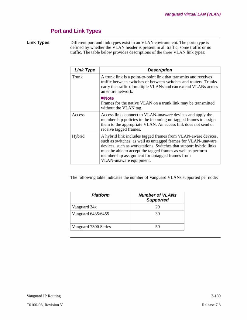
Vanguard IP Routing 2-189
T0100-03, Revision V Release 7.3
Vanguard Virtual LAN (VLAN)
Port and Link Types
Link Types Different port and link types exist in an VLAN environment. The ports type is defined by whether the VLAN header is present in all traffic, some traffic or no traffic. The table below provides descriptions of the three VLAN link types:
The following table indicates the number of Vanguard VLANs supported per node:
Link Type Description
Trunk A trunk link is a point-to-point link that transmits and receives traffic between switches or between switches and routers. Trunks carry the traffic of multiple VLANs and can extend VLANs across an entire network.
NoteFrames for the native VLAN on a trunk link may be transmitted without the VLAN tag.
Access Access links connect to VLAN-unaware devices and apply the membership policies to the incoming un-tagged frames to assign them to the appropriate VLAN. An access link does not send or receive tagged frames.
Hybrid A hybrid link includes tagged frames from VLAN-aware devices, such as switches, as well as untagged frames for VLAN-unaware devices, such as workstations. Switches that support hybrid links must be able to accept the tagged frames as well as perform membership assignment for untagged frames from VLAN-unaware equipment.
Platform Number of VLANs Supported
Vanguard 34x 20
Vanguard 6435/6455 30
Vanguard 7300 Series 50
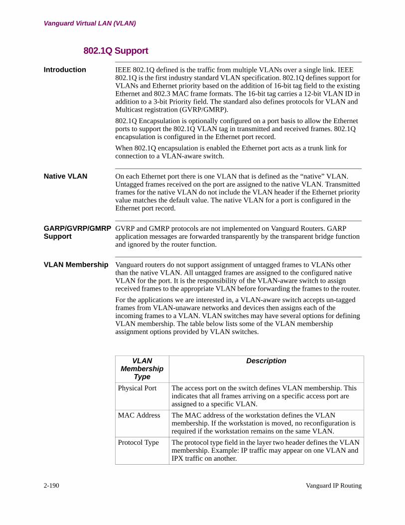
2-190 Vanguard IP Routing
Vanguard Virtual LAN (VLAN)
802.1Q Support
Introduction IEEE 802.1Q defined is the traffic from multiple VLANs over a single link. IEEE 802.1Q is the first industry standard VLAN specification. 802.1Q defines support for VLANs and Ethernet priority based on the addition of 16-bit tag field to the existing Ethernet and 802.3 MAC frame formats. The 16-bit tag carries a 12-bit VLAN ID in addition to a 3-bit Priority field. The standard also defines protocols for VLAN and Multicast registration (GVRP/GMRP).
802.1Q Encapsulation is optionally configured on a port basis to allow the Ethernet ports to support the 802.1Q VLAN tag in transmitted and received frames. 802.1Q encapsulation is configured in the Ethernet port record.
When 802.1Q encapsulation is enabled the Ethernet port acts as a trunk link for connection to a VLAN-aware switch.
Native VLAN On each Ethernet port there is one VLAN that is defined as the “native” VLAN. Untagged frames received on the port are assigned to the native VLAN. Transmitted frames for the native VLAN do not include the VLAN header if the Ethernet priority value matches the default value. The native VLAN for a port is configured in the Ethernet port record.
GARP/GVRP/GMRP Support
GVRP and GMRP protocols are not implemented on Vanguard Routers. GARP application messages are forwarded transparently by the transparent bridge function and ignored by the router function.
VLAN Membership Vanguard routers do not support assignment of untagged frames to VLANs other than the native VLAN. All untagged frames are assigned to the configured native VLAN for the port. It is the responsibility of the VLAN-aware switch to assign received frames to the appropriate VLAN before forwarding the frames to the router.
For the applications we are interested in, a VLAN-aware switch accepts un-tagged frames from VLAN-unaware networks and devices then assigns each of the incoming frames to a VLAN. VLAN switches may have several options for defining VLAN membership. The table below lists some of the VLAN membership assignment options provided by VLAN switches.
VLAN Membership
Type
Description
Physical Port The access port on the switch defines VLAN membership. This indicates that all frames arriving on a specific access port are assigned to a specific VLAN.
MAC Address The MAC address of the workstation defines the VLAN membership. If the workstation is moved, no reconfiguration is required if the workstation remains on the same VLAN.
Protocol Type The protocol type field in the layer two header defines the VLAN membership. Example: IP traffic may appear on one VLAN and IPX traffic on another.
Vanguard IP Routing 2-191
T0100-03, Revision V Release 7.3
Vanguard Virtual LAN (VLAN)
CFI Bit The CFI bit (Token Ring Encapsulation Flag) is not supported by the Vanguard implementation. Frames received with this bit set are discarded.
IP Subnet Address
The layer three header defines the VLAN membership. The IP subnet address could be used to define VLAN membership. Example: 192.168.1.x is part of VLAN 1 and 192.168.2.x is part of VLAN 2.
Higher Level Protocols
Example: FTP applications could be executed on one VLAN and telnet applications on another.
VLAN Membership
Type
Description
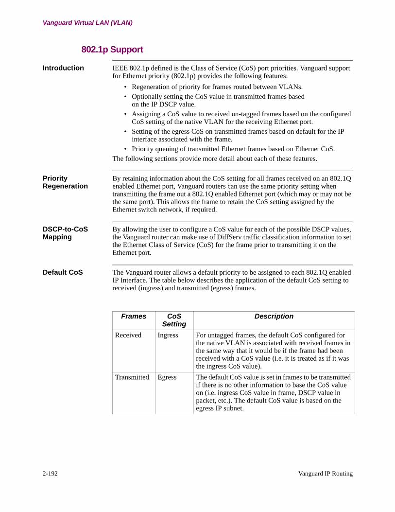
2-192 Vanguard IP Routing
Vanguard Virtual LAN (VLAN)
802.1p Support
Introduction IEEE 802.1p defined is the Class of Service (CoS) port priorities. Vanguard support for Ethernet priority (802.1p) provides the following features:
• Regeneration of priority for frames routed between VLANs.• Optionally setting the CoS value in transmitted frames based
on the IP DSCP value.• Assigning a CoS value to received un-tagged frames based on the configured
CoS setting of the native VLAN for the receiving Ethernet port.• Setting of the egress CoS on transmitted frames based on default for the IP
interface associated with the frame.• Priority queuing of transmitted Ethernet frames based on Ethernet CoS.
The following sections provide more detail about each of these features.
Priority Regeneration
By retaining information about the CoS setting for all frames received on an 802.1Q enabled Ethernet port, Vanguard routers can use the same priority setting when transmitting the frame out a 802.1Q enabled Ethernet port (which may or may not be the same port). This allows the frame to retain the CoS setting assigned by the Ethernet switch network, if required.
DSCP-to-CoS Mapping
By allowing the user to configure a CoS value for each of the possible DSCP values, the Vanguard router can make use of DiffServ traffic classification information to set the Ethernet Class of Service (CoS) for the frame prior to transmitting it on the Ethernet port.
Default CoS The Vanguard router allows a default priority to be assigned to each 802.1Q enabled IP Interface. The table below describes the application of the default CoS setting to received (ingress) and transmitted (egress) frames.
Frames CoS Setting
Description
Received Ingress For untagged frames, the default CoS configured for the native VLAN is associated with received frames in the same way that it would be if the frame had been received with a CoS value (i.e. it is treated as if it was the ingress CoS value).
Transmitted Egress The default CoS value is set in frames to be transmitted if there is no other information to base the CoS value on (i.e. ingress CoS value in frame, DSCP value in packet, etc.). The default CoS value is based on the egress IP subnet.
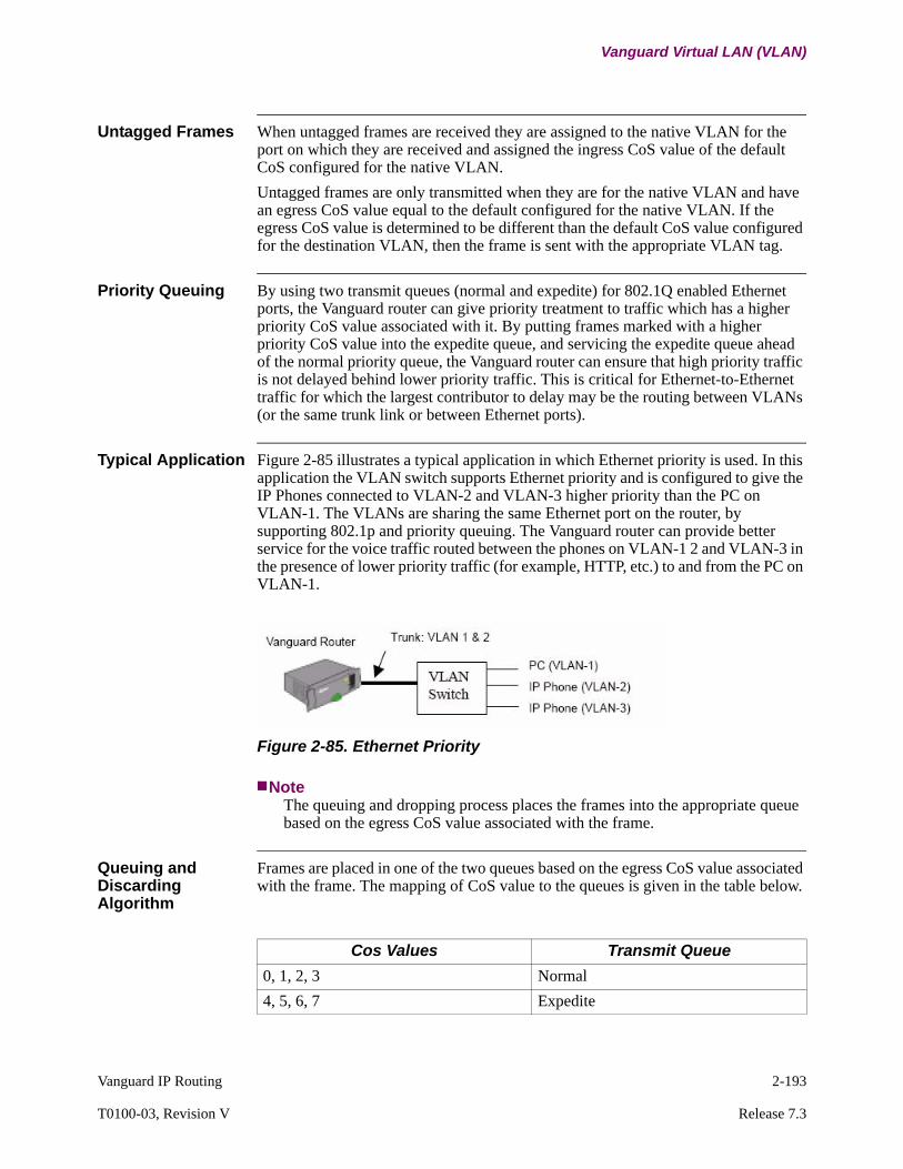
Vanguard IP Routing 2-193
T0100-03, Revision V Release 7.3
Vanguard Virtual LAN (VLAN)
Untagged Frames When untagged frames are received they are assigned to the native VLAN for the port on which they are received and assigned the ingress CoS value of the default CoS configured for the native VLAN.
Untagged frames are only transmitted when they are for the native VLAN and have an egress CoS value equal to the default configured for the native VLAN. If the egress CoS value is determined to be different than the default CoS value configured for the destination VLAN, then the frame is sent with the appropriate VLAN tag.
Priority Queuing By using two transmit queues (normal and expedite) for 802.1Q enabled Ethernet ports, the Vanguard router can give priority treatment to traffic which has a higher priority CoS value associated with it. By putting frames marked with a higher priority CoS value into the expedite queue, and servicing the expedite queue ahead of the normal priority queue, the Vanguard router can ensure that high priority traffic is not delayed behind lower priority traffic. This is critical for Ethernet-to-Ethernet traffic for which the largest contributor to delay may be the routing between VLANs (or the same trunk link or between Ethernet ports).
Typical Application Figure 2-85 illustrates a typical application in which Ethernet priority is used. In this application the VLAN switch supports Ethernet priority and is configured to give the IP Phones connected to VLAN-2 and VLAN-3 higher priority than the PC on VLAN-1. The VLANs are sharing the same Ethernet port on the router, by supporting 802.1p and priority queuing. The Vanguard router can provide better service for the voice traffic routed between the phones on VLAN-1 2 and VLAN-3 in the presence of lower priority traffic (for example, HTTP, etc.) to and from the PC on VLAN-1.
Figure 2-85. Ethernet Priority
NoteThe queuing and dropping process places the frames into the appropriate queue based on the egress CoS value associated with the frame.
Queuing and Discarding Algorithm
Frames are placed in one of the two queues based on the egress CoS value associated with the frame. The mapping of CoS value to the queues is given in the table below.
Cos Values Transmit Queue
0, 1, 2, 3 Normal
4, 5, 6, 7 Expedite

This page intentionally left blank.
Both of the queues (normal/expedite) have a limited size which is set by the “Transmit Queue Limit” parameter in the Ethernet port record. If a frame needs to be queue and the appropriate queue is full, the frame is silently discarded (i.e. tail-drop) with a statistic updated to count the number of discarded frames.
The two queues are serviced on a strict priority basis. If there is data in the expedite priority queue, it is sent before checking the normal priority queue.
Priority Queuing Without 802.1Q
The priority queuing facility provided for Ethernet ports with 802.1Q enabled can also be used when 802.1Q encapsulation is not enabled. The egress CoS value is still used to determine into which queue the packet is to be placed. The only means for assigning an egress CoS value is the DSCP-to-CoS mapping table. This provides a mechanism for the user to assign each of the DSCP values to the one of the two queues.
Determining The Egress CoS Value
In order to determine the CoS value set in frames that are being transmitted (i.e. egress Class-of-Service or eCoS), the Vanguard router uses the following information:
• The CoS setting in the received frame (ingress Class-of-Service or iCoS).• The optional setting for CoS based on DSCP.• The default CoS values set for the IP interface.
The following rules apply to determining the eCoS setting:
• The ingress CoS value (iCoS) is used if it is available (i.e. CoS regeneration) since it is provided by the switch network and is expected to be the most specific information.Please note that for untagged frames the iCoS is set to the default CoS value of the native VLAN.)
• If there is no ingress CoS value associated with the packet (i.e. packets from WAN links or non-802.1Q encapsulated Ethernet ports) the port can be configured to use the DSCP-to-CoS mapping table to set the egress CoS based on the DSCP value in the packet. Please note that DiffServ classification can be used on ingress Ethernet and WAN links if required.
• If the ingress CoS value is not available or mapped, the default priority setting for the egress IP interface/subnet is used. This allows user to configure a default CoS value for traffic exiting the port based on the destination subnet.
NoteThe Ethernet port may or may not have 802.1Q encapsulation enabled when using Ethernet Priority (CoS) queuing. Since the transmit queue priority is based on the effective egress CoS value, it may still be necessary to configure the appropriate CoS value even when 802.1Q encapsulation is not used.
Priority Tagged Frames
Priority tagged frames have a 802.1Q VLAN tag but the VLAN ID is set to zero (0). These frames are treated as if they were part of the native VLAN, but the CoS value is taken from the received tag rather than the native VLAN configuration as with untagged frames.

Vanguard IP Routing 2-195
T0100-03, Revision V Release 7.3
Vanguard Virtual LAN (VLAN)
Bridged Frames CoS values in bridged frames are not used to determine queue selection. All bridged frames are placed in the normal priority queue for transmission.
Limitations 802.1Q VLANsThere is no support for GARP/GVRP/GMRP protocols. GARP protocols are passed transparently by the Transparent Bridge.
Ethernet Priority (802.1p)With the strict priority based queuing algorithm used for the Ethernet priority feature, it is possible to experience starvation of the normal priority queue in the presence of a high volume of high priority traffic. This results in normal priority traffic being discarded as the queue overflows.
DSCP-to-CoS MappingDSCP-to-CoS Mapping is not supported for Fast Path data.
Transparent Bridging• Single spanning tree. • No membership classifications (this should be handled
by an external VLAN switch).• No support for auto-configuration of VLANs (i.e. GVRP). Each bridge link
must be configured with the VLAN IDs that it supports.
IP RoutingMulticast IP routing is not supported.
IPX RoutingIPX Routing is not supported
Unsupported ProtocolsUnsupported protocols must be configured to run on the native VLAN without a VLAN tag.
2-196 Vanguard IP Routing
Vanguard Virtual LAN (VLAN)
Transparent Bridging
Introduction The Transparent Bridge supports two basic modes of operation; VLAN-aware and VLAN-unaware. When the “VLAN Enable” parameter in the “Bridge Parameters” record is set to Enabled, the bridge is VLAN-aware and makes use of the VLAN membership information configured in the bridge link records when deciding to forward frames (that is frames are not forwarded and flooded to links that are not members of the VLAN indicated in the tag of the frame being forwarded). When the parameter is set to Disabled, the bridge is VLAN-unaware and forwards the frames without consideration of the VLAN tag.
Filtering Vanguard currently supports the following filtering options for Transparent Bridging:
• MAC Address Filtering• NetBIOS Name Filtering• Protocol Filtering
All existing filtering options are supported in VLAN applications.
Spanning Trees Vanguard supports a single spanning tree per node. In compliance with the 802.1Q standard, Vanguard also supports a single spanning tree per node in VLAN applications.
GARP/GVRP/GMRP These protocols are not supported, but the bridge must pass them transparently. This allows VLAN switches attached the Vanguard nodes to run these protocols between themselves.
GARP protocols use a LLC type service message and a group MAC address. Bridges receive and propagate GARP declarations. There must be one common VLAN to carry the messages.

Vanguard IP Routing 2-197
T0100-03, Revision V Release 7.3
Vanguard Virtual LAN (VLAN)
Routing
IP Routing Figure 2-86 shows an IP Routing example. Vanguard Router “Ra” is acting as an inter-VLAN router for the local LAN network at Site A in addition to providing routing.
Figure 2-86. IP Routing Example
NoteEven though the VLANs at Sites A and B are assigned the same VLAN IDs, they are not part of the same VLANs. The routers remove the VLAN information (tag) from the frames before routing them.
Unicast, Broadcast and Multicast Traffic information
1) Unicast IP traffic is routed to the appropriate interface and the VLAN tag associated with the destination subnet is added to the Ethernet frame.
2) Broadcast traffic generated by the following protocols is limited to the applicable VLAN:
• RIP• OSPF• ICMP• BOOTP• RDP• ARP• DHCP• Router Proxy
3) Multicast IP routing is not supported in the current release.
Enabling of RIP updates is now supported on an interface basis so that RIP traffic can be controlled at the VLAN level.
IPX Routing Vanguard routers support a single interface per Ethernet port.
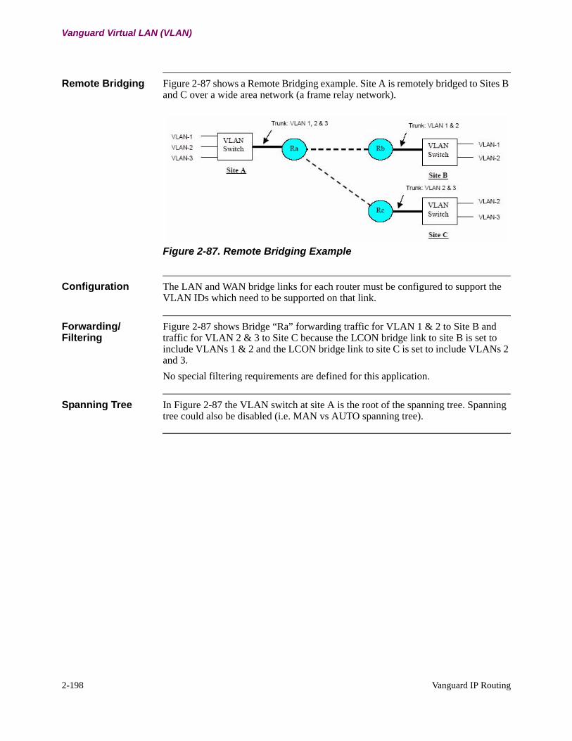
2-198 Vanguard IP Routing
Vanguard Virtual LAN (VLAN)
Remote Bridging Figure 2-87 shows a Remote Bridging example. Site A is remotely bridged to Sites B and C over a wide area network (a frame relay network).
Figure 2-87. Remote Bridging Example
Configuration The LAN and WAN bridge links for each router must be configured to support the VLAN IDs which need to be supported on that link.
Forwarding/Filtering
Figure 2-87 shows Bridge “Ra” forwarding traffic for VLAN 1 & 2 to Site B and traffic for VLAN 2 & 3 to Site C because the LCON bridge link to site B is set to include VLANs 1 & 2 and the LCON bridge link to site C is set to include VLANs 2 and 3.
No special filtering requirements are defined for this application.
Spanning Tree In Figure 2-87 the VLAN switch at site A is the root of the spanning tree. Spanning tree could also be disabled (i.e. MAN vs AUTO spanning tree).
Vanguard IP Routing 2-199
T0100-03, Revision V Release 7.3
Vanguard Virtual LAN (VLAN)
SNMP for VLAN
Introduction The purpose of this section is to describe the SNMP functionality for the VLAN feature. Support for some VLAN Configuration parameters and statistics are provided. The VLAN configuration objects can be added within existing SNMP tables (corresponding to the CTP table), while three new tables are added for each of the statistics that are being displayed.
Configuration Parameters
Ethernet PortThree new parameters were added to the Ethernet Port record to support VLAN applications. SNMP objects are added for these parameters as sub-objects of the cdx6500PPCTdot3PortEntry object which can be found in the following location of the OID tree:
.iso.org.dod.internet.private.enterprises.codex.cdxProductSpecific.
cdx6500.cdx6500Configuration.cdx6500CfgProtocolGroup.
cdx6500PCTPortProtocolGroup.cdx6500PPCTdot3PortTable.
cdx6500PPCTdot3PortEntry
The three new objects are defined as follows:
• VLAN Encapsulation - cdx6500dot3VLANEncapsulation• Native VLAN ID - cdx6500dot3NativeVLANID• DSCP-to-Cos Profile - cdx6500dot3DSCPtoCoSProfile
IP Interface Two new parameters were added to the IP Interface record. SNMP objects are added for these parameters as sub-objects of the cdx6500PCTRifConfEntry object which can be found in the following location of the OID tree:
.iso.org.dod.internet.private.enterprises.codex.cdxProductSpecific.
cdx6500.cdx6500Configuration.cdx6500CfgProtocolGroup.
cdx6500PCTRouterGroup.cdx6500PCTRifConfTable.
cdx6500PCTRifConfEntry
The two new objects are defined as follows :
• VLAN ID - cdx6500PCTRifVLANId• Default Ethernet Priority - cdx6500PCTRifDefEthernetPriority
Bridge Parameters One new parameter was added to the Bridge Parameters record. An SNMP object is added for this parameter as sub-objects of the cdx6500dot1dBasePortCfg object which can be found in the following location on the OID tree:
.iso.org.dod.internet.private.enterprises.codex.cdxProductSpecific.
cdx6500.cdx6500Configuration.cdx6500CfgProtocolGroup.
cdx6500PCTBridgeGroup.cdx6500dot1dBridgeCfgGroup.
cdx6500dot1dBasePortCfg
The new object is defined as follows:
• VLAN Enable - cdx6500LfcmVLANEnable
2-200 Vanguard IP Routing
Vanguard Virtual LAN (VLAN)
Bridge Link Parameters
One new “VLAN Membership” parameter was added to the Bridge Link Parameters record. SNMP support for bridge link parameters is unique because there are two separate SNMP tables, one for LAN links and another for WAN links. The SNMP entries for LAN links are queried by port number and are accessed within the cdx6500PCTBasePortEntry object which can be found in the following location on the OID tree:
.iso.org.dod.internet.private.enterprises.codex.cdxProductSpecific.
cdx6500.cdx6500Configuration.cdx6500CfgProtocolGroup.
cdx6500PCTBridgeGroup.cdx6500PCTBasePortTable.
cdx6500PCTBasePortEntry
A new object for accessing VLAN Membership on LAN bridges is added to this table. It is defined as follows:
• VLAN Membership - cdx6500LfcmPortVLANMembershipA second SNMP object is added for VLAN membership on WAN links. This table is queried by bridge link number as opposed to port number. It is part of the 6500PCTdot1dBaseLinkEntry object which can be found in the following location on the OID tree:
.iso.org.dod.internet.private.enterprises.codex.cdxProductSpecific.
cdx6500.cdx6500Configuration.cdx6500CfgProtocolGroup.
cdx6500PCTBridgeGroup.cdx6500PCTdot1dBaseLinkTable.
cdx6500PCTdot1dBaseLinkEntry
The new object is defined as follows:
• VLAN Membership - cdx6500LfcmVLANMembership
Ethernet Priority Mapping Profile
The Ethernet Priority Mapping Profile is a new CTP Menu that is accessed via a profile and entry number and contains two entries. A corresponding SNMP table is created for this configuration item. The name of the table is cdx6500CfgDSCPtoCoSTable and it is located in the following location on the OID tree:
.iso.org.dod.internet.private.enterprises.codex.cdxProductSpecific.
cdx6500.cdx6500Configuration.cdx6500CfgGeneralGroup.
cdx6500CfgDSCPtoCoSTable
This table is defined by a row of entries Cdx6500CfgDSCPtoCoSEntry containing the following parameters as the column.
Profile Number: cdx6500DSCPtoCoSProfileEntry Number: cdx6500DSCPtoCoSEntryNumDSCP Value: cdx6500DSCPValueCoS Value: cdx6500CoSValue
The table is queried using both the profile number and the entry number (1st and 2nd instance).
SNMP VLAN Statistics
SNMP support is available for the two pages of VLAN Statistics displayed as part of the Ethernet Port Statistics.
Vanguard IP Routing 2-201
T0100-03, Revision V Release 7.3
Vanguard Virtual LAN (VLAN)
DSCP-to-CoS MappingThe DSCP-to-CoS mapping statistics are supported within two SNMP tables. The first table contains the actual DSCP-to-CoS mapping statistics (excluding the priority queuing portion) and is queried by port number as well as index number. The index number ranges from 1-8 and corresponds to each of the CoS entries. The index number is one greater than the CoS Number (index 1= CoS 0, index 2= CoS 1 …).
NoteDo not use a CoS number as a query ID since CoS numbers start from 0 onwards. The entry 0 has a special meaning in SNMP and cannot be used as a valid query key. This is the rationale for entering a separate index number which ranges from 1-8.
The table below resides within the cdx6500PSTPortProtocolGroup Group, which is located in the following location on the OID tree:
.iso.org.dod.internet.private.enterprises.codex.cdxProductSpecific.
cdx6500.cdx6500Statistics.cdx6500StatProtocolGroup.
cdx6500PSTPortProtocolGroup
The proposed name of the table is: cdx6500PPSTDSCPCosTable
The second table contains the Ethernet Priority Queuing Statistics and is queried by the port number. It resides in the cdx6500PSTPortProtocolGroup.
The name of the table is: cdx6500PPSTEthPriQueueTable
Configured VLAN Statistics
The Configured VLAN statistics contains SNMP support. The contents reside in a new table within the cdx6500PSTPortProtocolGroup Group. This table is queried by port number and is located in the following location on the OID tree:
.iso.org.dod.internet.private.enterprises.codex.cdxProductSpecific.
cdx6500.cdx6500Statistics.cdx6500StatProtocolGroup.
cdx6500PSTPortProtocolGroup
The name of the table is: cdx6500PPSTConfVLANStatsTable
VLAN Membership Statistics
Page two of the Detailed Bridge Link Statistics (via CTP) contains a VLAN Membership field. A new SNMP table is added to display this VLAN membership value. This table is queried by bridge link number and resides in the following location on the OID tree:
.iso.org.dod.internet.private.enterprises.codex.cdxProductSpecific.
cdx6500.cdx6500Statistics.cdx6500StatProtocolGroup.
cdx6500PSTBridgeGroup
The name of the table is: cdx6500PSTVLANMembershipTable
2-202 Vanguard IP Routing
Remote Authentication Dial-In User Server (RADIUS)
Remote Authentication Dial-In User Server (RADIUS)
Introduction The purpose of Remote Authentication Dial-In User Server (RADIUS) is to enable Vanguard routers to interoperate and support RADIUS attributes. Vanguard routers are able to act as a RADIUS client.
The RADIUS protocol is based on a client and server model. The client is responsible for passing user information to a designated RADIUS server and then acting on the response that is returned. A RADIUS server (or daemon) can provide authentication and accounting services to one or more client devices. RADIUS servers are responsible for receiving user connection requests, authenticating users, and then returning all configuration information necessary for the client to deliver service to the users. A RADIUS access server is generally a dedicated workstation connected to the network.
A RADIUS client provides:
• Central database for Authentication, Access and Accounting (AAA)• Security when using applications like Virtual Private Network (VPN)• Accounting and Billing applications in Voice over IP (VoIP) environments
Instead of all network access servers maintaining their own user database, which can be redundant and cause management problem for today's huge network, RADIUS manages a single center user database.
Other key features of RADIUS include:
• Client/server model• Networking security• Flexible authentication mechanisms• Extensible protocol
NoteRADIUS is supported with Release 6.2 and greater software on the following platforms; Vanguard 320, 34x, 6435, 6455 and 7300 Series. The 6800 series supports Radius with 6.5P30A and later software.
The Vanguard RADIUS client module requires UDP/IP module for running, it provides service to other application modules such as CTP, SNMP, HTTPD, Telnet and voice modules.
As of release 7.0R000 SSH is added to the list of application modules supported by Radius.
Limitations RADIUS limitations:
• RADIUS is based on UDP/IP protocol stack, it does not support other protocols such as AppleTalk Remote Access (ARA), NETBIOS Frame Control Protocol (NBFCP), NetWare Asynchronous Services Interface (NASI) and X.25 PAD connections.
• RADIUS does not provide two-way authentication.• RADIUS generally binds a user to one service model and cannot be used in a
network with a variety of services.
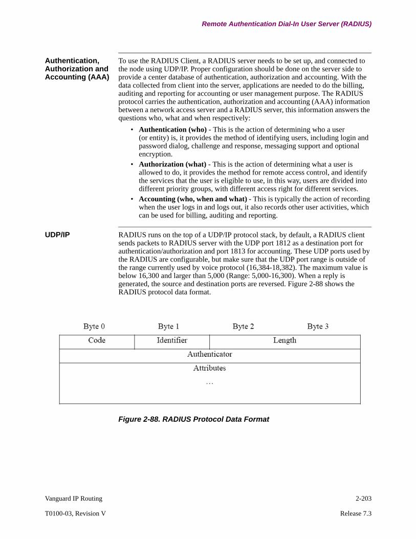
Vanguard IP Routing 2-203
T0100-03, Revision V Release 7.3
Remote Authentication Dial-In User Server (RADIUS)
Authentication, Authorization and Accounting (AAA)
To use the RADIUS Client, a RADIUS server needs to be set up, and connected to the node using UDP/IP. Proper configuration should be done on the server side to provide a center database of authentication, authorization and accounting. With the data collected from client into the server, applications are needed to do the billing, auditing and reporting for accounting or user management purpose. The RADIUS protocol carries the authentication, authorization and accounting (AAA) information between a network access server and a RADIUS server, this information answers the questions who, what and when respectively:
• Authentication (who) - This is the action of determining who a user (or entity) is, it provides the method of identifying users, including login and password dialog, challenge and response, messaging support and optional encryption.
• Authorization (what) - This is the action of determining what a user is allowed to do, it provides the method for remote access control, and identify the services that the user is eligible to use, in this way, users are divided into different priority groups, with different access right for different services.
• Accounting (who, when and what) - This is typically the action of recording when the user logs in and logs out, it also records other user activities, which can be used for billing, auditing and reporting.
UDP/IP RADIUS runs on the top of a UDP/IP protocol stack, by default, a RADIUS client sends packets to RADIUS server with the UDP port 1812 as a destination port for authentication/authorization and port 1813 for accounting. These UDP ports used by the RADIUS are configurable, but make sure that the UDP port range is outside of the range currently used by voice protocol (16,384-18,382). The maximum value is below 16,300 and larger than 5,000 (Range: 5,000-16,300). When a reply is generated, the source and destination ports are reversed. Figure 2-88 shows the RADIUS protocol data format.
Figure 2-88. RADIUS Protocol Data Format

2-204 Vanguard IP Routing
Remote Authentication Dial-In User Server (RADIUS)
Code Field The code field identifies the type of RAIDUS packets:
Identifier Field The identifier field is one octet, and aids in matching requests and replies. The RADIUS server can detect a duplicate request (if it has the same client source IP address, source UDP port and identifier) within a short span of time. The RADIUS client also uses the identifier to match the response from the server. A one octet field indicates that the maximum waiting packet number inside the client queue is 256. When the queue is full packets are lost.
All attributes are composed of attribute-value pairs. The value of each attribute is specified as one of six data types:
Operation A typical RADIUS application uses Control Terminal Port (CTP) authentication. Authentication occurs when a user tries to log on to the network node. A CTP is available for serial port or telnet access. PPP can also use RADIUS for remote dial in user authentication. A web browser client can setup a HTTP connection to the node by authenticating itself to the RADIUS database. With the RADIUS module, it’s possible to use a single center database to authenticate the user and retrieve the accounting and access log messages easily.
Code Field RADIUS Packet Description
1 Access-Request
2 Access-Accept
3 Access-Reject
4 Accounting-Request
5 Accounting-Response
11 Access-Challenge
12 Status-Server (experimental)
13 Status-Client (experimental)
255 Reserved
Data Type Value of each Attribute
Text 1 to 253 octets containing UTF-8 encoded 10646[10] characters.
String 1 to 253 octets containing binary data (values 0 through 255 decimal).
A Binary 0 to 254 octets.
Address 32-bit value.
Integer 32-bit unsigned value.
Date 32-bit unsigned value, seconds since 00:00:00 UTC, Jan. 1, 1970.
Octets Raw octets printed and input as hex strings.
Vanguard IP Routing 2-205
T0100-03, Revision V Release 7.3
Remote Authentication Dial-In User Server (RADIUS)
RADIUS authentication operation:
The ACCEPT or REJECT response is bundled with additional data that is used for application and network authorization. The user first completes RADIUS authentication before using RADIUS authorization and accounting. The additional data included with the ACCEPT or REJECT packets consists of the following:
• Services that the user can access, including Telnet, login, local-area transport (LAT) connections, PPP, or Serial Line Internet Protocol (SLIP).
• Connection parameters, including the host or client IP address, access lists, and user time-outs.
CTP Authentication Follow these steps to select the new configuration parameter under:
Main->Update System Parameters-> Enable CTP User Prompt
Step Process
1 When users attempt to log in the network node, they are prompted for entering a user name and password.
2 The username and encrypted password are sent over the network to the RADIUS server by the node (RADIUS client).
3 One of the following responses is received from the RADIUS server:
a)ACCEPT - The user is authenticated.
b)REJECT - The user is not authenticated and is prompted to reenter the user name and password, or access is denied.
c)CHALLENGE - A challenge is issued by the RADIUS server, the challenge collects additional data from the user.
Step Action Result/Description
1 At the CTP Main menu, type the number of the menu you want to access at the #Enter Selection: prompt, 8 for Update System Parameters and press ENTER.
The Main menu disappears and the selected menu appears.Update System Parameter
2 From the next menu, select submenus to perform specific configuration, control, or monitoring tasks.
Selected sub-menu appears.Enable CTP user Prompt
3 Press ESC to exit a menu or CTRL + T to return to the Main menu.
This returns you to the previous menu or higher.

2-206 Vanguard IP Routing
Remote Authentication Dial-In User Server (RADIUS)
Enable CTP User Prompt Parameter
By default, the user name prompt is disabled. This means the system only authenticates the user with a legacy user password, and there is no prompt for username when logging in. When enabled, we see the username prompt for the CTP logon, in this case, all kinds of users can be authenticated (depending on other RADIUS configurations).
CTP Authentication Figure 2-89 below shows the CTP authentication example when the username prompt option is enabled. In this case, username and password are required for authentication and authorization purpose. An empty blank username is allowed for backward compatibility.
Figure 2-89. CTP Authentication
Universal Time Zone
Match the local time with the RADIUS Server when sending RADIUS packets. The Universal Time Zone (UTC) under the node record should be configured under:
Main Menu->Configure->Node
Enable CTP User Prompt
Range: Disable, Enable
Default: Disable
Description: Enable/Disable the username prompt when logging on to the CTP.
Universal Time Zone (UTC)
Range: IDLW, NT, HST, AKST, PST, MST, CST, EST, AST, BST, VTZ, AT, GMT, CET, EET, MSK, GST, PKT, BDT, JT, CCT, JST, AEST, SBT, NZST
Default: GMT
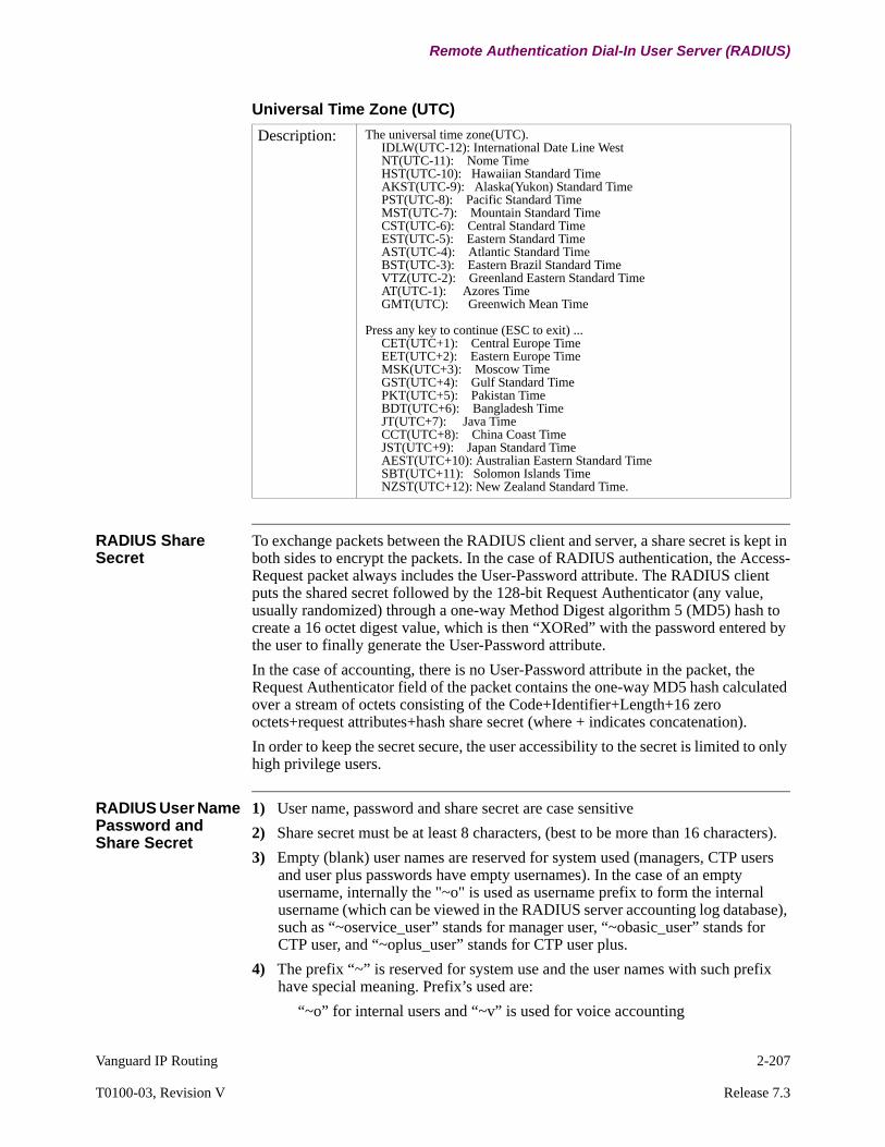
Vanguard IP Routing 2-207
T0100-03, Revision V Release 7.3
Remote Authentication Dial-In User Server (RADIUS)
RADIUS Share Secret
To exchange packets between the RADIUS client and server, a share secret is kept in both sides to encrypt the packets. In the case of RADIUS authentication, the Access-Request packet always includes the User-Password attribute. The RADIUS client puts the shared secret followed by the 128-bit Request Authenticator (any value, usually randomized) through a one-way Method Digest algorithm 5 (MD5) hash to create a 16 octet digest value, which is then “XORed” with the password entered by the user to finally generate the User-Password attribute.
In the case of accounting, there is no User-Password attribute in the packet, the Request Authenticator field of the packet contains the one-way MD5 hash calculated over a stream of octets consisting of the Code+Identifier+Length+16 zero octets+request attributes+hash share secret (where + indicates concatenation).
In order to keep the secret secure, the user accessibility to the secret is limited to only high privilege users.
RADIUS User Name Password and Share Secret
1) User name, password and share secret are case sensitive
2) Share secret must be at least 8 characters, (best to be more than 16 characters).
3) Empty (blank) user names are reserved for system used (managers, CTP users and user plus passwords have empty usernames). In the case of an empty username, internally the "~o" is used as username prefix to form the internal username (which can be viewed in the RADIUS server accounting log database), such as “~oservice_user” stands for manager user, “~obasic_user” stands for CTP user, and “~oplus_user” stands for CTP user plus.
4) The prefix “~” is reserved for system use and the user names with such prefix have special meaning. Prefix’s used are:
“~o” for internal users and “~v” is used for voice accounting
Description: The universal time zone(UTC). IDLW(UTC-12): International Date Line West NT(UTC-11): Nome Time HST(UTC-10): Hawaiian Standard Time AKST(UTC-9): Alaska(Yukon) Standard Time PST(UTC-8): Pacific Standard Time MST(UTC-7): Mountain Standard Time CST(UTC-6): Central Standard Time EST(UTC-5): Eastern Standard Time AST(UTC-4): Atlantic Standard Time BST(UTC-3): Eastern Brazil Standard Time VTZ(UTC-2): Greenland Eastern Standard Time AT(UTC-1): Azores Time GMT(UTC): Greenwich Mean Time
Press any key to continue (ESC to exit) ... CET(UTC+1): Central Europe Time EET(UTC+2): Eastern Europe Time MSK(UTC+3): Moscow Time GST(UTC+4): Gulf Standard Time PKT(UTC+5): Pakistan Time BDT(UTC+6): Bangladesh Time JT(UTC+7): Java Time CCT(UTC+8): China Coast Time JST(UTC+9): Japan Standard Time AEST(UTC+10): Australian Eastern Standard Time SBT(UTC+11): Solomon Islands Time NZST(UTC+12): New Zealand Standard Time.
Universal Time Zone (UTC)
2-208 Vanguard IP Routing
Remote Authentication Dial-In User Server (RADIUS)
Types of Users For backward compatibility reason, there is no change to the currently used manager/user plus/user mechanism, these kind of users are “blank username users”, for clarification purpose, the three different kind of users are defined:
• Legacy users - These are blank name system users, they are defined locally and are always authenticated from the local database. They use special system reserved username for log message and accounting:~oservice_user for manager user
~oplus_user for user plus user
~obasic_user for read only user
~odiag_user for diagnostic user
• Local users - They are defined and authenticated locally, can be assign user names, privileges and user groups.
• Remote users - They are defined and authenticated in RADIUS database.
Local and Remote Authentication
The authentication rules listed below apply to all users except blank username users (including system default manager user, basic user and user plus). For blank username users, the local database is always used for authentication, this is backward compatible with previous versions.
• Local authentication only - User logs on to CTP, HTTPD or telnet and does the authentication using the local database.
• Remote then local authentication - The system tries to authenticate the user using remote database through the RADIUS server, on failure (or there is no RADIUS module available), it automatically falls through to the local database authentication.
• Remote authentication through RADIUS only - On failure, it does not fall through to the local authentication but rejects the access required directly.
Typical Application of Local user Authentication
Any user can access the Vanguard router though an IP network using telnet, web browsing, SSH (as of 7.0R000), or connecting to the CTP port of the node. See Figure 2-90.
When the user attempts to log in to the Vanguard router, a prompt for user name and password is shown. Depending on the configuration of RADIUS record, this prompt can come from the local system, or from a remote RADIUS server. The authentication may go first to the local system and then to the RADIUS server, go in reverse order, or use only one of these databases.
The RADIUS server can be configured to do the remote authentication and authorization, or both authentication, authorization and accounting, independently.
For remote authorization, RADIUS defines specific rights for users using attributes such as Service-Type.

Vanguard IP Routing 2-209
T0100-03, Revision V Release 7.3
Remote Authentication Dial-In User Server (RADIUS)
Figure 2-90. RADIUS Local Access User Authentication
Typical Application for Collecting Voice Accounting Data
For Voice Over IP (VoIP) applications, the accounting information can be sent to the RADIUS Server as depicted in Figure 2-91.
In this application, one of the routers (voice gateway) is a Vanguard router which is running RADIUS client and sending out accounting information to a RADIUS server through any IP network. Another router (voice gateway) can be a vendor product which can bridge voice over IP to end users.
Figure 2-91. RADIUS Remote Voice Accounting Application
RADIUS Server
Vanguard Router(RADIUS Client)
Vanguard orCisco Router
ISP/CarrierShare IP Network
RADIUS Server
PBX
VanguardRouter
PBX
2-210 Vanguard IP Routing
Remote Authentication Dial-In User Server (RADIUS)
Client Function The RADIUS client function includes:
• RADIUS Engine - Implements the RADIUS protocol to talk to the RADIUS server.
• Application Interfaces - Provides applications to use the RADIUS functions.• Application implementation - Includes CTP authentication and
authorization, HTTPD embedded web server authentication and authorization, telnet authentication and authorization, voice over IP accounting, and user activity message logs to the RADIUS server. And as of release 7.0R000 SSH is also included as an application.
With the compatible RADIUS application interfaces, RADIUS functions are able to support other applications like PPP and VPN with ease.
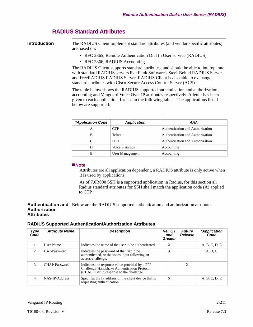
Vanguard IP Routing 2-211
T0100-03, Revision V Release 7.3
Remote Authentication Dial-In User Server (RADIUS)
RADIUS Standard Attributes
Introduction The RADIUS Client implement standard attributes (and vendor specific attributes) are based on:
• RFC 2865, Remote Authentication Dial In User service (RADIUS)• RFC 2866, RADIUS Accounting
The RADIUS Client supports standard attributes, and should be able to interoperate with standard RADIUS servers like Funk Software's Steel-Belted RADIUS Server and FreeRADIUS RADIUS Server. RADIUS Client is also able to exchange standard attributes with Cisco Secure Access Control Server (ACS).
The table below shows the RADIUS supported authentication and authorization, accounting and Vanguard Voice Over IP attributes respectively. A letter has been given to each application, for use in the following tables. The applications listed below are supported:
NoteAttributes are all application dependent, a RADIUS attribute is only active when it is used by applications.
As of 7.0R000 SSH is a supported application in Radius, for this section all Radius standard attributes for SSH shall match the application code (A) applied to CTP.
Authentication and Authorization Attributes
Below are the RADIUS supported authentication and authorization attributes.
*Application Code Application AAA
A CTP Authentication and Authorization
B Telnet Authentication and Authorization
C HTTP Authentication and Authorization
D Voice Statistics Accounting
E User Management Accounting
RADIUS Supported Authentication/Authorization Attributes
Type Code
Attribute Name Description Rel. 6.1 and
Greater
Future Release
*Application Code
1 User-Name Indicates the name of the user to be authenticated. X A, B, C, D, E
2 User-Password Indicates the password of the user to be authenticated, or the user's input following an access-challenge.
X A, B, C
3 CHAP-Password Indicates the response value provided by a PPP Challenge-Handshake Authentication Protocol (CHAP) user in response to the challenge.
X
4 NAS-IP-Address Specifies the IP address of the client device that is requesting authentication.
X A, B, C, D, E
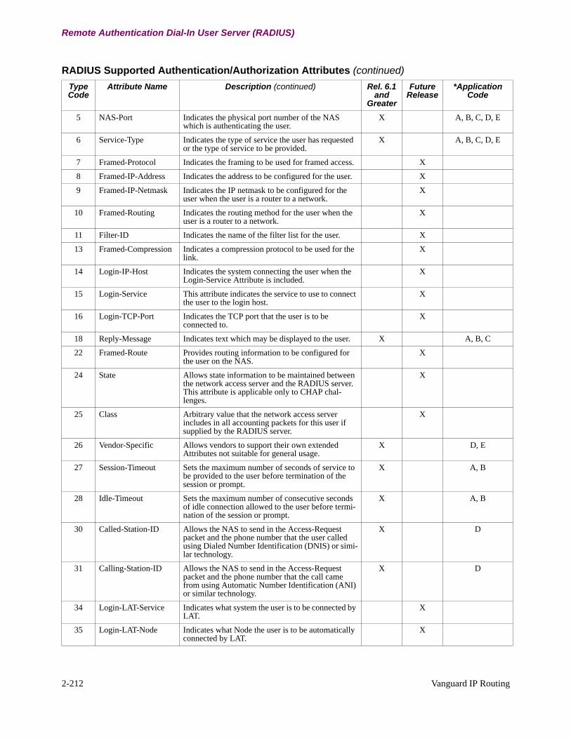
2-212 Vanguard IP Routing
Remote Authentication Dial-In User Server (RADIUS)
5 NAS-Port Indicates the physical port number of the NAS which is authenticating the user.
X A, B, C, D, E
6 Service-Type Indicates the type of service the user has requested or the type of service to be provided.
X A, B, C, D, E
7 Framed-Protocol Indicates the framing to be used for framed access. X
8 Framed-IP-Address Indicates the address to be configured for the user. X
9 Framed-IP-Netmask Indicates the IP netmask to be configured for the user when the user is a router to a network.
X
10 Framed-Routing Indicates the routing method for the user when the user is a router to a network.
X
11 Filter-ID Indicates the name of the filter list for the user. X
13 Framed-Compression Indicates a compression protocol to be used for the link.
X
14 Login-IP-Host Indicates the system connecting the user when the Login-Service Attribute is included.
X
15 Login-Service This attribute indicates the service to use to connect the user to the login host.
X
16 Login-TCP-Port Indicates the TCP port that the user is to be connected to.
X
18 Reply-Message Indicates text which may be displayed to the user. X A, B, C
22 Framed-Route Provides routing information to be configured for the user on the NAS.
X
24 State Allows state information to be maintained between the network access server and the RADIUS server. This attribute is applicable only to CHAP chal-lenges.
X
25 Class Arbitrary value that the network access server includes in all accounting packets for this user if supplied by the RADIUS server.
X
26 Vendor-Specific Allows vendors to support their own extended Attributes not suitable for general usage.
X D, E
27 Session-Timeout Sets the maximum number of seconds of service to be provided to the user before termination of the session or prompt.
X A, B
28 Idle-Timeout Sets the maximum number of consecutive seconds of idle connection allowed to the user before termi-nation of the session or prompt.
X A, B
30 Called-Station-ID Allows the NAS to send in the Access-Request packet and the phone number that the user called using Dialed Number Identification (DNIS) or simi-lar technology.
X D
31 Calling-Station-ID Allows the NAS to send in the Access-Request packet and the phone number that the call came from using Automatic Number Identification (ANI) or similar technology.
X D
34 Login-LAT-Service Indicates what system the user is to be connected by LAT.
X
35 Login-LAT-Node Indicates what Node the user is to be automatically connected by LAT.
X
RADIUS Supported Authentication/Authorization Attributes (continued)
Type Code
Attribute Name Description (continued) Rel. 6.1 and
Greater
Future Release
*Application Code

Vanguard IP Routing 2-213
T0100-03, Revision V Release 7.3
Remote Authentication Dial-In User Server (RADIUS)
Accounting Attributes
The standard accounting attributes are numbered between 40 through 59. Below are the RADIUS supported accounting attributes:
36 Login-LAT-Group Contains a string identifying the LAT group codes that the user is authorized to use.
X
61 NAS-Port-Type Indicates the type of the physical port of the NAS which is authenticating the user.
X A, B, C, D, E
RADIUS Supported Authentication/Authorization Attributes (continued)
Type Code
Attribute Name Description (continued) Rel. 6.1 and
Greater
Future Release
*Application Code
*Application Code Application AAA
A CTP Authentication and Authorization
B Telnet Authentication and Authorization
C HTTP Authentication and Authorization
D Voice Statistics Accounting
E User Management Accounting
RADIUS Supported Accounting Attributes
Type Code
Attribute Name Description Rel. 6.1 and
Greater
Future Release
*Application Code
40 Acct-Status-Type Indicates whether this Accounting-Request marks the beginning of the user service (Start) or the end (Stop).
X D, E
41 Acct-Delay-Time Indicates how many seconds the client has been trying to send this record for, and this can be subtracted from the time of arrival on the server to find the approximate time of the event generating this Accounting-Request.
X D, E
42 Acct-Input-Octets Indicates how many octets have been received from the port over the course of this service being provided, and can only be present in Accounting-Request records where the Acct-Status-Type is set to Stop.
X
43 Acct-Output-Octets Indicates how many octets have been sent to the port in the course of delivering this service, and can only be present in Accounting-Request records where the Acct-Status-Type is set to Stop.
X
44 Acct-Session-ID Is a unique Accounting ID to make it easy to match start and stop records in a log file.
X D, E
45 Acct-Authentic Indicate how the user was authenticated, whether by RADIUS, the NAS itself, or another remote authen-tication protocol.
X D, E
46 Acct-Session-Time Indicates how many seconds the user has received service for, and can only be present in Accounting-Request records where the Acct-Status-Type is set to Stop.
X E

2-214 Vanguard IP Routing
Remote Authentication Dial-In User Server (RADIUS)
Vanguard VoIP Specific Attributes
Figure 2-92 shows the format of the Vanguard Vendor Specific Attributes (VSA) used for voice accounting and other Vanguard applications such as User Management, User Authorization and VPN.
Figure 2-92. Vanguard Vendor Specific Attributes Format
The Vanguard voice VSAs are included in requests and responses between the voice over IP gateway (a RADIUS client) and the RADIUS server, each of these VSAs conforms to the RADIUS specification of attribute 26. (Attribute 26 is defined in RFC 2865.)
47 Acct-Input-Packets Indicates how many packets have been received from the port over the course of this service being provided to a Framed User , and can only be present in Accounting-Request records where the Acct-Status-Type is set to Stop.
X
48 Acct-Output-Packets Indicates how many packets have been sent to the port in the course of delivering this service to a Framed User, and can only be present in Account-ing-Request records where the Acct-Status-Type is set to Stop.
49 Acct-Terminate-Cause Indicates how the session was terminated. D, E
50 Acct-Multi-Session-ID
A unique Accounting ID to easily link together multiple related sessions in a log file.
51 Acct-Link-Count Gives the count of links which are know to have been in a given multilink session at the time the accounting record was generated.
RADIUS Supported Accounting Attributes (continued)
Type Code
Attribute Name Description (continued) Rel. 6.1 and
Greater
Future Release
*Application Code

Vanguard IP Routing 2-215
T0100-03, Revision V Release 7.3
Remote Authentication Dial-In User Server (RADIUS)
Vendor Specific Attribute Fields
The fields within the VSA consist of:
• Length, 7 (bytes, the vendor-string field must be at least one byte)• Vendor-ID = 449 for codex. The high-order octet is 0 and the low-order three
octets are the SMI network management private enterprise code of the vendor in network byte order, as defined in the “Internet Assigned Numbers Authority”. The web site location is http://www.iana.org/
• String, this field is one or more octets. The actual format of the information is site or application specific, and a robust implementation should support the field as undistinguished octets. The format inside this string is:- Vendor-type: Vanguard VSA number- Vendor-length <=247 bytes- Vendor-string: Avpair (attribute value pair) sent as ASCII string.
• Avpair format is: attribute=value
Voice Vendor Specific Attributes
The table below lists the Vanguard Voice VSA attributes, the client sends these Avpairs to the RADIUS server, and the voice accounting data is collected in the server side data for billing, auditing or reporting purposes.
Vanguard Voice Vendor-Specific Attributes (VSA)
Avpair VSA No (Decimal)
Value Format
Sample Value
Description
Packet_Type 10 Integer 1 Packet_Type_Unknown(0)Packet_Type_Voice_ACCT_CDR(1)Packet_Type_Voice_ACCT_PST(2)Packet_Type_Voice_ACCT_VCS(3)Packet_Type_Config_Log(4)Packet_Type_Control_Log(5)Packet_Type_Logon(6)Packet_Type_Authentication(7)Packet_Type_Authorization(8)
Record_Time 11 Date June 1 1999
The time when this record generated.
PercentPeakOfCPULoad 21 Integer 4 Peak CPU Load
PercentAvgOfCPULoad 22 Integer 2 Average CPU Load
PercentCurOfCPULoad 23 Integer 2 Current CPU Load
PercentPeakOfDataBuf 24 Integer 21 Peak data buffer usages
PercentAvgOfDataBuf 25 Integer 1 Average data buffer usages
PercentCurOfDataBuf 26 Integer 1 Current data buffer usages
PercentPeakOfIORBBuf 27 Integer 14 Peak IORB buffer usages
PercentAvgOfIORBBuf 28 Integer 3 Average IORB buffer usages
PercentCurOfIORBBuf 29 Integer 4 Current IORB buffer usages
No_Packets_Dropped 30 Integer 21 Number of dropped packets
No_Calls_Dropped 31 Integer 15 Number of dropped calls
No_Calls_Processed 34 Integer 78 Number of processed packets
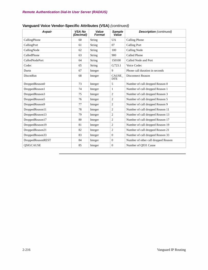
2-216 Vanguard IP Routing
Remote Authentication Dial-In User Server (RADIUS)
CallingPhone 60 String UA Calling Phone
CallingPort 61 String 07 Calling Port
CallingNode 62 String 100 Calling Node
CalledPhone 63 String 900 Called Phone
CalledNodePort 64 String 150100 Called Node and Port
Codec 65 String G.723.1 Voice Codec
Durtn 67 Integer 9 Phone call duration in seconds
DiscntRsn 68 Integer CAUSE_DTE
Disconnect Reason
DroppedReason0 73 Integer 5 Number of call dropped Reason 0
DroppedReason1 74 Integer 1 Number of call dropped Reason 1
DroppedReason3 75 Integer 2 Number of call dropped Reason 3
DroppedReason5 76 Integer 2 Number of call dropped Reason 5
DroppedReason9 77 Integer 2 Number of call dropped Reason 9
DroppedReason11 78 Integer 2 Number of call dropped Reason 11
DroppedReason13 79 Integer 2 Number of call dropped Reason 13
DroppedReason17 80 Integer 2 Number of call dropped Reason 17
DroppedReason19 81 Integer 2 Number of call dropped Reason 19
DroppedReason21 82 Integer 2 Number of call dropped Reason 21
DroppedReason33 83 Integer 0 Number of call dropped Reason 33
DroppedReasonREST 84 Integer 0 Number of other call dropped Reason
QSIGCAUSE 85 Integer 0 Number of Q931 Cause
Vanguard Voice Vendor-Specific Attributes (VSA) (continued)
Avpair VSA No (Decimal)
Value Format
Sample Value
Description (continued)
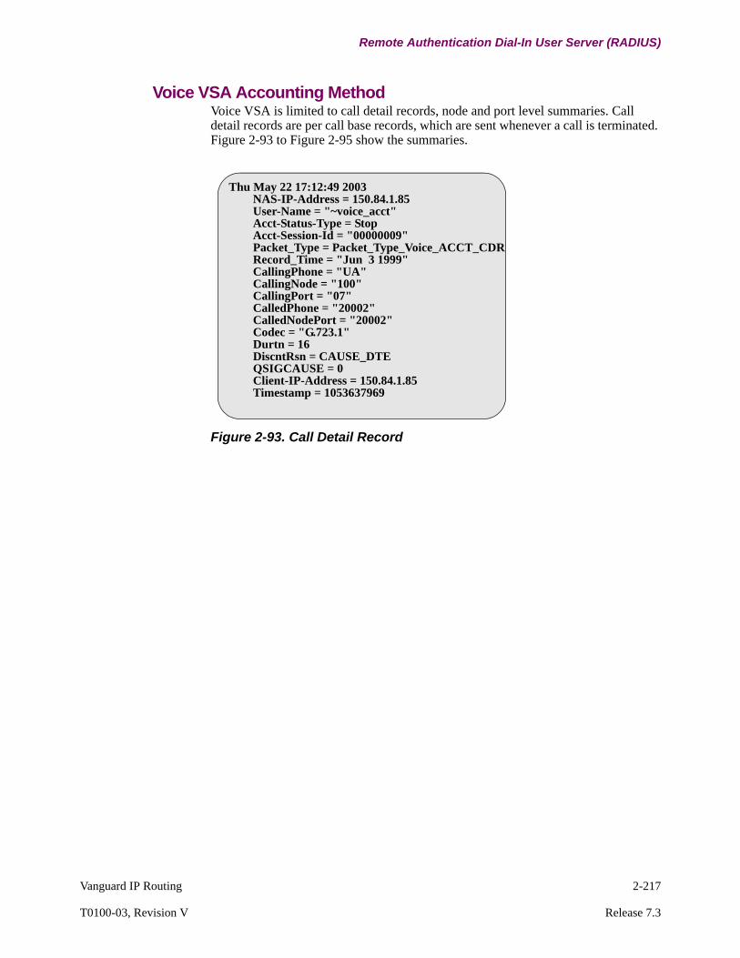
Vanguard IP Routing 2-217
T0100-03, Revision V Release 7.3
Remote Authentication Dial-In User Server (RADIUS)
Voice VSA Accounting MethodVoice VSA is limited to call detail records, node and port level summaries. Call detail records are per call base records, which are sent whenever a call is terminated. Figure 2-93 to Figure 2-95 show the summaries.
Figure 2-93. Call Detail Record
Thu May 22 17:12:49 2003 NAS-IP-Address = 150.84.1.85 User-Name = "~voice_acct" Acct-Status-Type = Stop Acct-Session-Id = "00000009" Packet_Type = Packet_Type_Voice_ACCT_CDR Record_Time = "Jun 3 1999" CallingPhone = "UA" CallingNode = "100" CallingPort = "07" CalledPhone = "20002" CalledNodePort = "20002" Codec = "G.723.1" Durtn = 16 DiscntRsn = CAUSE_DTE QSIGCAUSE = 0 Client-IP-Address = 150.84.1.85 Timestamp = 1053637969

2-218 Vanguard IP Routing
Remote Authentication Dial-In User Server (RADIUS)
Figure 2-94. Node Level Summary Record
Thu May 22 17:22:27 2003
NAS-IP-Address = 150.84.1.85
User-Name = "~voice_acct"
Acct-Status-Type = Stop
Acct-Session-Id = "00000009"
Packet_Type = Packet_Type_Voice_ACCT_VCS
Record_Time = "Jun 3 1999"
No_Packets_Dropped = 6
No_Calls_Dropped = 5
DroppedReason0 = 4
DroppedReason1 = 0
DroppedReason3 = 0
DroppedReason5 = 0
DroppedReason9 = 0
DroppedReason11 = 0
DroppedReason13 = 1
DroppedReason17 = 0
DroppedReason19 = 0
DroppedReason21 = 0
DroppedReason33 = 0
DroppedReasonREST = 0
NO_Calls_Processed = 5
PercentPeakOfCPULoad = 4
PercentAvgOfCPULoad = 2
PercentCurOfCPULoad = 2
PercentPeakOfDataBuf = 1
PercentAvgOfDataBuf = 1
PercentCurOfDataBuf = 1
PercentPeakOfIORBBuf = 14
PercentAvgOfIORBBuf = 8
PercentCurOfIORBBuf = 2
Client-IP-Address = 150.84.1.85
Timestamp = 1053638547
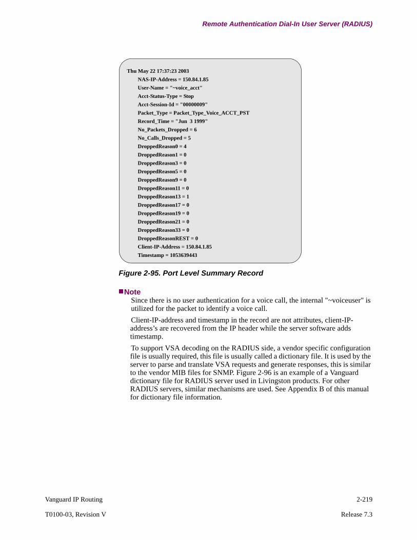
Vanguard IP Routing 2-219
T0100-03, Revision V Release 7.3
Remote Authentication Dial-In User Server (RADIUS)
Figure 2-95. Port Level Summary Record
NoteSince there is no user authentication for a voice call, the internal "~voiceuser" is utilized for the packet to identify a voice call.
Client-IP-address and timestamp in the record are not attributes, client-IP-address’s are recovered from the IP header while the server software adds timestamp.
To support VSA decoding on the RADIUS side, a vendor specific configuration file is usually required, this file is usually called a dictionary file. It is used by the server to parse and translate VSA requests and generate responses, this is similar to the vendor MIB files for SNMP. Figure 2-96 is an example of a Vanguard dictionary file for RADIUS server used in Livingston products. For other RADIUS servers, similar mechanisms are used. See Appendix B of this manual for dictionary file information.
Thu May 22 17:37:23 2003
NAS-IP-Address = 150.84.1.85
User-Name = "~voice_acct"
Acct-Status-Type = Stop
Acct-Session-Id = "00000009"
Packet_Type = Packet_Type_Voice_ACCT_PST
Record_Time = "Jun 3 1999"
No_Packets_Dropped = 6
No_Calls_Dropped = 5
DroppedReason0 = 4
DroppedReason1 = 0
DroppedReason3 = 0
DroppedReason5 = 0
DroppedReason9 = 0
DroppedReason11 = 0
DroppedReason13 = 1
DroppedReason17 = 0
DroppedReason19 = 0
DroppedReason21 = 0
DroppedReason33 = 0
DroppedReasonREST = 0
Client-IP-Address = 150.84.1.85
Timestamp = 1053639443

2-220 Vanguard IP Routing
Remote Authentication Dial-In User Server (RADIUS)
Figure 2-96. Vanguard Dictionary file example
VSA Accounting with Accounting Session ID
Call accounting through RADIUS is done with accounting records that contain data describing various aspects of a call. Records include update records, and stop records. They contain per-call information, the Accounting Session ID, which is RADIUS attribute 44. Attribute 44 is defined to associate the update and stop records, as well as other user operation activities (user configuration logs).
The Accounting Session ID is a unique integer that is consistent for a given link of a connection through the lifetime of the connection, or from user login to user logout. The Accounting Session ID is sent with Access Request packets and Accounting Request packets, and the attributes inside the packets are reassembled in the server side using the Session ID.
The Accounting Session ID is the only identifier provided by the RADIUS protocol that can relate authentication and accounting requests to one another with absolute certainty. The ID is different in each session, it is a string with an 8-digit upper case hexadecimal number, the first two digits increment on each reboot (wrapping every 256 reboots) and the next 6 digits counting from 0 for the first person logging in after a reboot up to 2^24-1, about 16 million.
Voice Accounting Packet Local Buffer
SNMP and RADIUS share the same data source of voice statistics. The node level and port level voice statistics in the node is buffered for 24 hours, call detail records are buffered for 200 records. If a network error occurs, the statistics is buffered locally and when the network link is up again, RADIUS pushes the buffered data out to the server side, and does not lose the buffered records.
RADIUS Handshaking Mechanism
RADIUS is defined to run on top of UDP/IP, which is prone to packet lost and duplicated packets. In RFC 2865 and RFC 2866, the RADIUS protocol introduces application level handshake mechanism to prevent packet lost and packet duplicate for certain types of RADIUS packets.
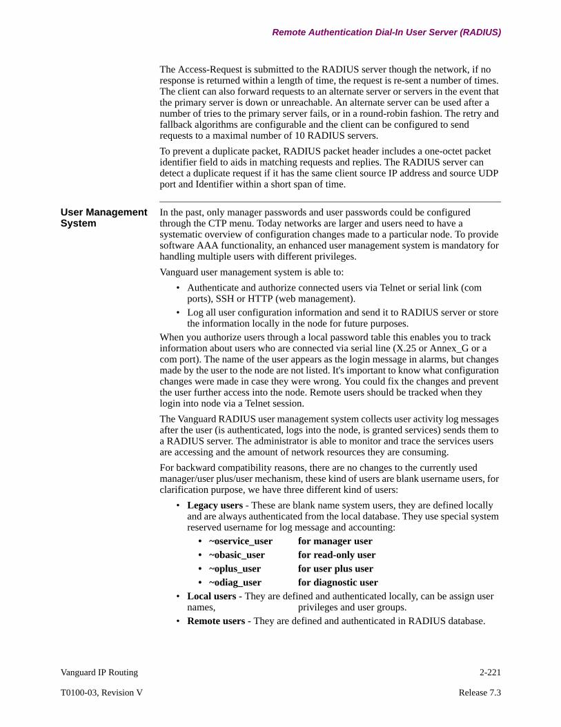
Vanguard IP Routing 2-221
T0100-03, Revision V Release 7.3
Remote Authentication Dial-In User Server (RADIUS)
The Access-Request is submitted to the RADIUS server though the network, if no response is returned within a length of time, the request is re-sent a number of times. The client can also forward requests to an alternate server or servers in the event that the primary server is down or unreachable. An alternate server can be used after a number of tries to the primary server fails, or in a round-robin fashion. The retry and fallback algorithms are configurable and the client can be configured to send requests to a maximal number of 10 RADIUS servers.
To prevent a duplicate packet, RADIUS packet header includes a one-octet packet identifier field to aids in matching requests and replies. The RADIUS server can detect a duplicate request if it has the same client source IP address and source UDP port and Identifier within a short span of time.
User Management System
In the past, only manager passwords and user passwords could be configured through the CTP menu. Today networks are larger and users need to have a systematic overview of configuration changes made to a particular node. To provide software AAA functionality, an enhanced user management system is mandatory for handling multiple users with different privileges.
Vanguard user management system is able to:
• Authenticate and authorize connected users via Telnet or serial link (com ports), SSH or HTTP (web management).
• Log all user configuration information and send it to RADIUS server or store the information locally in the node for future purposes.
When you authorize users through a local password table this enables you to track information about users who are connected via serial line (X.25 or Annex_G or a com port). The name of the user appears as the login message in alarms, but changes made by the user to the node are not listed. It's important to know what configuration changes were made in case they were wrong. You could fix the changes and prevent the user further access into the node. Remote users should be tracked when they login into node via a Telnet session.
The Vanguard RADIUS user management system collects user activity log messages after the user (is authenticated, logs into the node, is granted services) sends them to a RADIUS server. The administrator is able to monitor and trace the services users are accessing and the amount of network resources they are consuming.
For backward compatibility reasons, there are no changes to the currently used manager/user plus/user mechanism, these kind of users are blank username users, for clarification purpose, we have three different kind of users:
• Legacy users - These are blank name system users, they are defined locally and are always authenticated from the local database. They use special system reserved username for log message and accounting:
• ~oservice_user for manager user• ~obasic_user for read-only user• ~oplus_user for user plus user• ~odiag_user for diagnostic user
• Local users - They are defined and authenticated locally, can be assign user names, privileges and user groups.
• Remote users - They are defined and authenticated in RADIUS database.
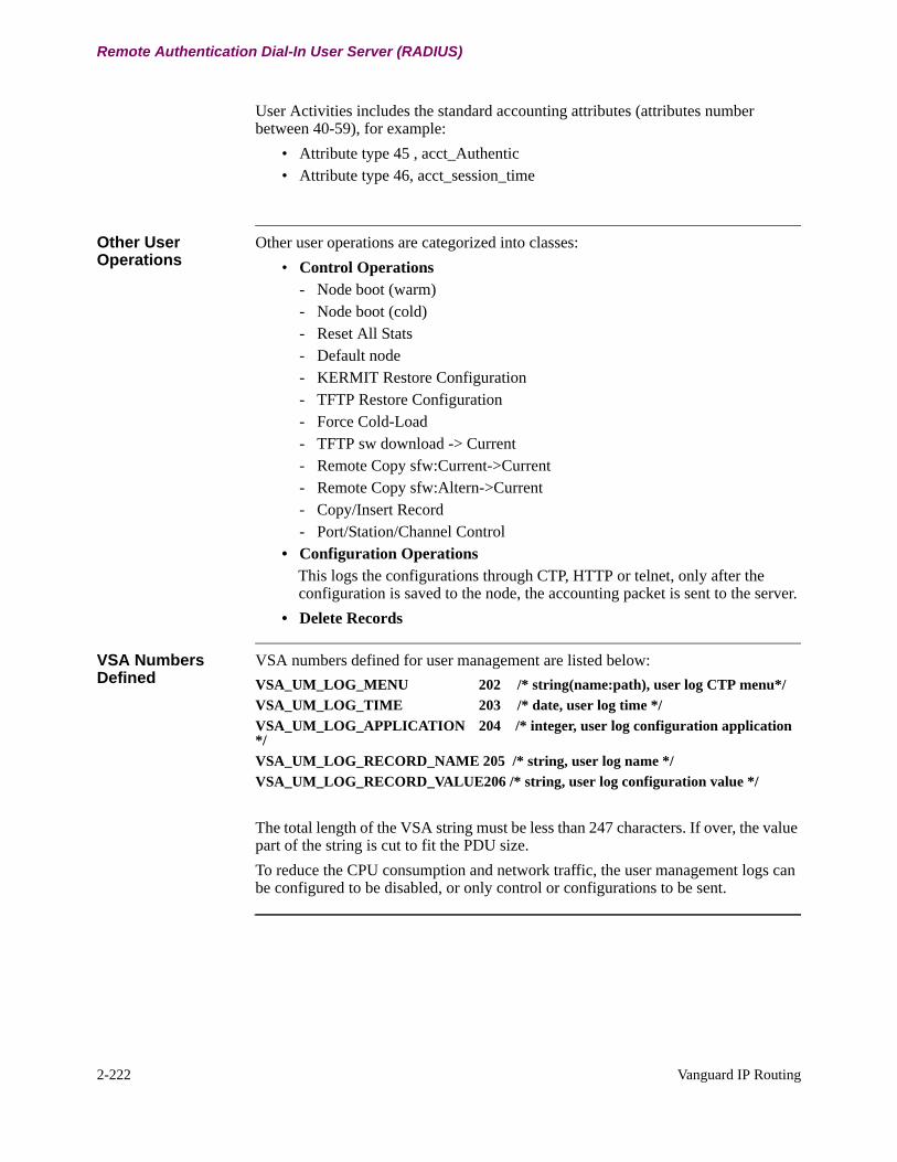
2-222 Vanguard IP Routing
Remote Authentication Dial-In User Server (RADIUS)
User Activities includes the standard accounting attributes (attributes number between 40-59), for example:
• Attribute type 45 , acct_Authentic• Attribute type 46, acct_session_time
Other User Operations
Other user operations are categorized into classes:
• Control Operations - Node boot (warm)- Node boot (cold) - Reset All Stats- Default node- KERMIT Restore Configuration- TFTP Restore Configuration- Force Cold-Load- TFTP sw download -> Current- Remote Copy sfw:Current->Current- Remote Copy sfw:Altern->Current- Copy/Insert Record- Port/Station/Channel Control
• Configuration Operations This logs the configurations through CTP, HTTP or telnet, only after the configuration is saved to the node, the accounting packet is sent to the server.
• Delete Records
VSA Numbers Defined
VSA numbers defined for user management are listed below:
VSA_UM_LOG_MENU 202 /* string(name:path), user log CTP menu*/
VSA_UM_LOG_TIME 203 /* date, user log time */
VSA_UM_LOG_APPLICATION 204 /* integer, user log configuration application */
VSA_UM_LOG_RECORD_NAME 205 /* string, user log name */
VSA_UM_LOG_RECORD_VALUE206 /* string, user log configuration value */
The total length of the VSA string must be less than 247 characters. If over, the value part of the string is cut to fit the PDU size.
To reduce the CPU consumption and network traffic, the user management logs can be configured to be disabled, or only control or configurations to be sent.
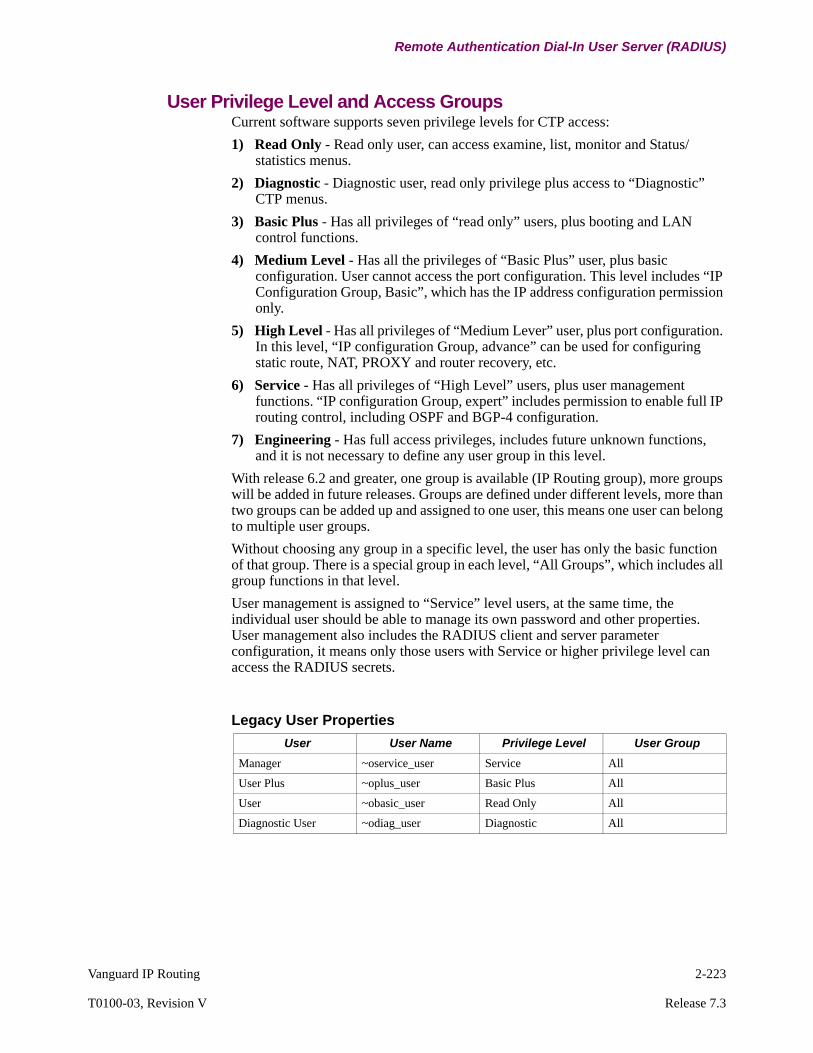
Vanguard IP Routing 2-223
T0100-03, Revision V Release 7.3
Remote Authentication Dial-In User Server (RADIUS)
User Privilege Level and Access GroupsCurrent software supports seven privilege levels for CTP access:
1) Read Only - Read only user, can access examine, list, monitor and Status/statistics menus.
2) Diagnostic - Diagnostic user, read only privilege plus access to “Diagnostic” CTP menus.
3) Basic Plus - Has all privileges of “read only” users, plus booting and LAN control functions.
4) Medium Level - Has all the privileges of “Basic Plus” user, plus basic configuration. User cannot access the port configuration. This level includes “IP Configuration Group, Basic”, which has the IP address configuration permission only.
5) High Level - Has all privileges of “Medium Lever” user, plus port configuration. In this level, “IP configuration Group, advance” can be used for configuring static route, NAT, PROXY and router recovery, etc.
6) Service - Has all privileges of “High Level” users, plus user management functions. “IP configuration Group, expert” includes permission to enable full IP routing control, including OSPF and BGP-4 configuration.
7) Engineering - Has full access privileges, includes future unknown functions, and it is not necessary to define any user group in this level.
With release 6.2 and greater, one group is available (IP Routing group), more groups will be added in future releases. Groups are defined under different levels, more than two groups can be added up and assigned to one user, this means one user can belong to multiple user groups.
Without choosing any group in a specific level, the user has only the basic function of that group. There is a special group in each level, “All Groups”, which includes all group functions in that level.
User management is assigned to “Service” level users, at the same time, the individual user should be able to manage its own password and other properties. User management also includes the RADIUS client and server parameter configuration, it means only those users with Service or higher privilege level can access the RADIUS secrets.
Legacy User Properties
User User Name Privilege Level User Group
Manager ~oservice_user Service All
User Plus ~oplus_user Basic Plus All
User ~obasic_user Read Only All
Diagnostic User ~odiag_user Diagnostic All
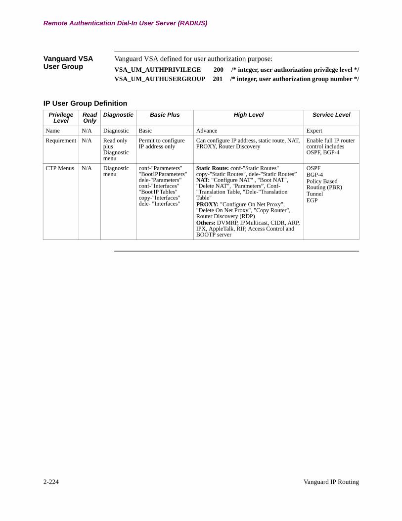
2-224 Vanguard IP Routing
Remote Authentication Dial-In User Server (RADIUS)
Vanguard VSA User Group
Vanguard VSA defined for user authorization purpose:
VSA_UM_AUTHPRIVILEGE 200 /* integer, user authorization privilege level */
VSA_UM_AUTHUSERGROUP 201 /* integer, user authorization group number */
IP User Group Definition
Privilege Level
Read Only
Diagnostic Basic Plus High Level Service Level
Name N/A Diagnostic Basic Advance Expert
Requirement N/A Read only plus Diagnostic menu
Permit to configure IP address only
Can configure IP address, static route, NAT, PROXY, Router Discovery
Enable full IP router control includes OSPF, BGP-4
CTP Menus N/A Diagnostic menu
conf-"Parameters" "Boot IP Parameters" dele-"Parameters" conf-"Interfaces" "Boot IP Tables" copy-"Interfaces" dele- "Interfaces"
Static Route: conf-"Static Routes"copy-"Static Routes", dele-"Static Routes”NAT: "Configure NAT" , "Boot NAT", "Delete NAT", "Parameters”, Conf-"Translation Table, "Dele-"Translation Table"PROXY: "Configure On Net Proxy", "Delete On Net Proxy", "Copy Router", Router Discovery (RDP)Others: DVMRP, IPMulticast, CIDR, ARP, IPX, AppleTalk, RIP, Access Control and BOOTP server
OSPFBGP-4Policy Based Routing (PBR)TunnelEGP

Vanguard IP Routing 2-225
T0100-03, Revision V Release 7.3
Remote Authentication Dial-In User Server (RADIUS)
RADIUS Client Configuration
User Interface User interfaces are CTP, CLI , SNMP and HTTPD embedded web for RADIUS module management, including CTP menus:
• Configure RADIUS Client - This menu is for the RADIUS client parameters configuration
• Configure RADIUS Server - This menu is for the RADIUS server parameters configuration
• Reset RADIUS Statistics - This function is to reset the RADIUS statistics• Exam RADIUS - This function is to examine the RADIUS configuration
record• List RADIUS - This is to list the RADIUS configuration records
Configure RADIUS Client
RADIUS configuration is divided into two parts, client configuration and server configuration. RADIUS configuration for client configuration is listed below:
Main->Configure->Configure RADIUS->Configure RADIUS Client
RADIUS Client Configuration (No RADIUS Client IP Address)
Configuration Parameter Description Supported Values Default
RADIUS Application Application which sends and receives RADIUS packets for AAA.
Default, CTP, Telnet, SSH, HTTP, Voice Accounting, User Man-agement
Default
RADIUS Enable RADIUS Client Enable or Disable. EnabledDisabled
Disabled
Radius Client IP IP address of the RADIUS Client. By default, the system resolves the nodes internal IP address, then the outbound IP interface that is used to reach the destination server.
IP Address Internal IP Address
RADIUS retry and fallback mechanism: (One-by-One and Round-Robin is supported)
When there are more than one RADIUS server configured, the client tries to send a request to the primary server first, if this fails, the next one is tried.
One-by-OneRound-Robin
One-by-One
RADIUS Authentication Method
For authentication applications to decide to use local or remote authentication.Remote-then-Local:
Client authenticates remotely through RADIUS. If remote authentication fails for any reason, then attempt to authenticate client locally through the Vanguard Router.
Local-Only:Client only authenticates locally through Van-guard Router.
Remote-Only:Client only authenticates remotely through RADIUS.
Remote-then-conditional-Local:Client authenticates remotely through RADIUS.If remote authentication fails only because of RADIUS server communication loss, then attempt to authenticate client locally through the Vanguard Router.
Remote-then-Local, Local-Only, Remote-Only,Remote-then-conditional-Local
Remote-then-Local

2-226 Vanguard IP Routing
Remote Authentication Dial-In User Server (RADIUS)
Username/Password Buffer For authentication applications to buffer the username and password after a successful authentication and for use in the next authentication. This is useful for connect-authenticate-operate-disconnect style applications like HTTP. It improves the system performance while reducing the network traffic. Users should be careful when using this feature. When users are deleted, added or updated on the server side, these changes are not known in client side if the buffer is enabled. In the buffer, when a new user name and password pair come in, the old one is pushed out.
[0-64]0 means no buffer for the application
0
RADIUS Client Configuration (No RADIUS Client IP Address)
Configuration Parameter Description Supported Values Default
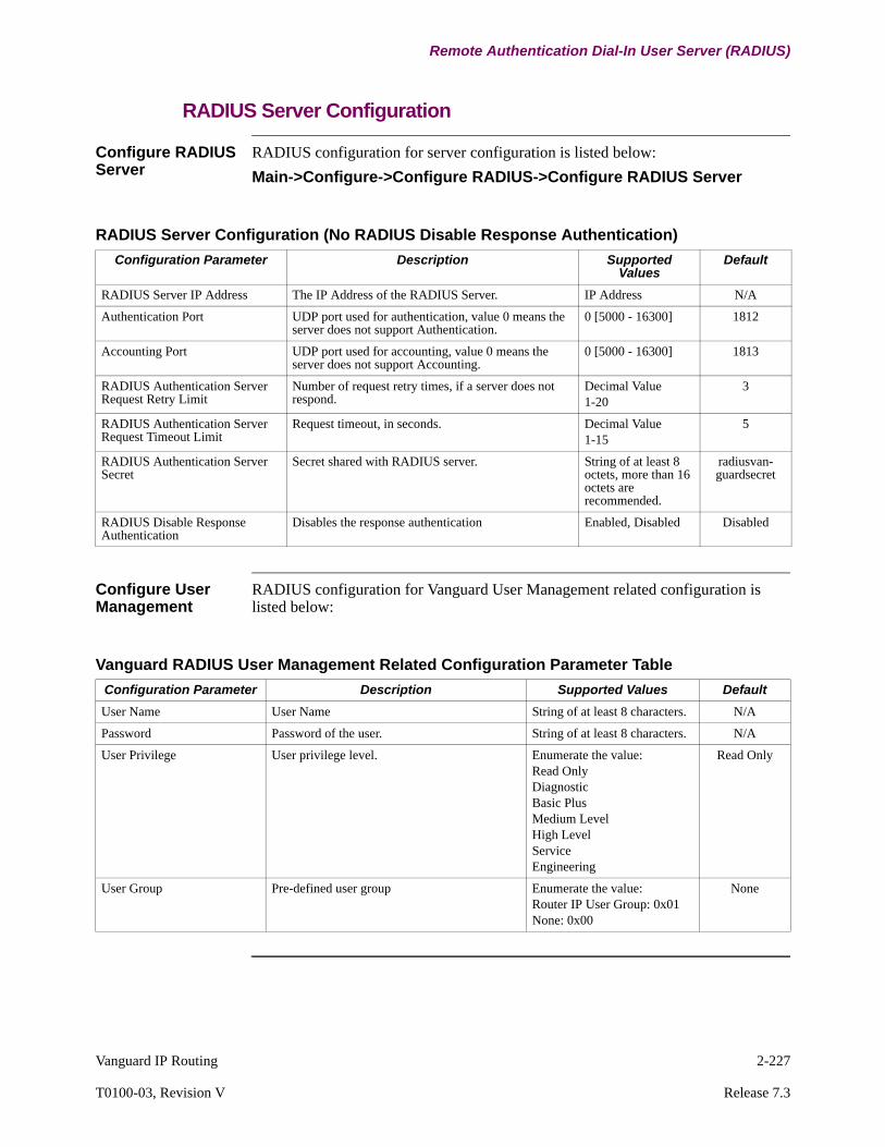
Vanguard IP Routing 2-227
T0100-03, Revision V Release 7.3
Remote Authentication Dial-In User Server (RADIUS)
RADIUS Server Configuration
Configure RADIUS Server
RADIUS configuration for server configuration is listed below:
Main->Configure->Configure RADIUS->Configure RADIUS Server
Configure User Management
RADIUS configuration for Vanguard User Management related configuration is listed below:
RADIUS Server Configuration (No RADIUS Disable Response Authentication)
Configuration Parameter Description Supported Values
Default
RADIUS Server IP Address The IP Address of the RADIUS Server. IP Address N/A
Authentication Port UDP port used for authentication, value 0 means the server does not support Authentication.
0 [5000 - 16300] 1812
Accounting Port UDP port used for accounting, value 0 means the server does not support Accounting.
0 [5000 - 16300] 1813
RADIUS Authentication Server Request Retry Limit
Number of request retry times, if a server does not respond.
Decimal Value1-20
3
RADIUS Authentication Server Request Timeout Limit
Request timeout, in seconds. Decimal Value1-15
5
RADIUS Authentication Server Secret
Secret shared with RADIUS server. String of at least 8 octets, more than 16 octets are recommended.
radiusvan-guardsecret
RADIUS Disable Response Authentication
Disables the response authentication Enabled, Disabled Disabled
Vanguard RADIUS User Management Related Configuration Parameter Table
Configuration Parameter Description Supported Values Default
User Name User Name String of at least 8 characters. N/A
Password Password of the user. String of at least 8 characters. N/A
User Privilege User privilege level. Enumerate the value:Read OnlyDiagnosticBasic PlusMedium LevelHigh LevelService Engineering
Read Only
User Group Pre-defined user group Enumerate the value:Router IP User Group: 0x01None: 0x00
None

2-228 Vanguard IP Routing
Remote Authentication Dial-In User Server (RADIUS)
VSA Dictionary Files for Cisco ACS and FreeRadius
The VSA Dictionary files for Cisco ACS and FreeRadius are listed in Appendix B of this manual.
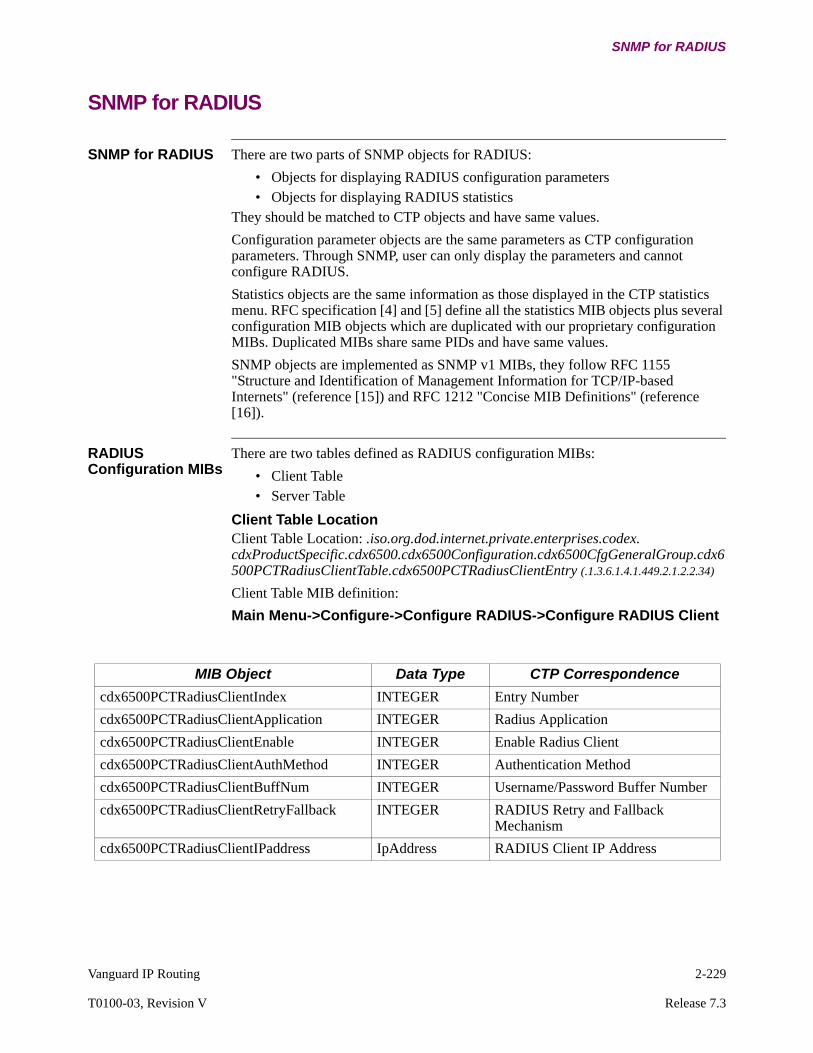
Vanguard IP Routing 2-229
T0100-03, Revision V Release 7.3
SNMP for RADIUS
SNMP for RADIUS
SNMP for RADIUS There are two parts of SNMP objects for RADIUS:
• Objects for displaying RADIUS configuration parameters• Objects for displaying RADIUS statistics
They should be matched to CTP objects and have same values.
Configuration parameter objects are the same parameters as CTP configuration parameters. Through SNMP, user can only display the parameters and cannot configure RADIUS.
Statistics objects are the same information as those displayed in the CTP statistics menu. RFC specification [4] and [5] define all the statistics MIB objects plus several configuration MIB objects which are duplicated with our proprietary configuration MIBs. Duplicated MIBs share same PIDs and have same values.
SNMP objects are implemented as SNMP v1 MIBs, they follow RFC 1155 "Structure and Identification of Management Information for TCP/IP-based Internets" (reference [15]) and RFC 1212 "Concise MIB Definitions" (reference [16]).
RADIUS Configuration MIBs
There are two tables defined as RADIUS configuration MIBs:
• Client Table • Server Table
Client Table LocationClient Table Location: .iso.org.dod.internet.private.enterprises.codex. cdxProductSpecific.cdx6500.cdx6500Configuration.cdx6500CfgGeneralGroup.cdx6500PCTRadiusClientTable.cdx6500PCTRadiusClientEntry (.1.3.6.1.4.1.449.2.1.2.2.34)
Client Table MIB definition:
Main Menu->Configure->Configure RADIUS->Configure RADIUS Client
MIB Object Data Type CTP Correspondence
cdx6500PCTRadiusClientIndex INTEGER Entry Number
cdx6500PCTRadiusClientApplication INTEGER Radius Application
cdx6500PCTRadiusClientEnable INTEGER Enable Radius Client
cdx6500PCTRadiusClientAuthMethod INTEGER Authentication Method
cdx6500PCTRadiusClientBuffNum INTEGER Username/Password Buffer Number
cdx6500PCTRadiusClientRetryFallback INTEGER RADIUS Retry and Fallback Mechanism
cdx6500PCTRadiusClientIPaddress IpAddress RADIUS Client IP Address
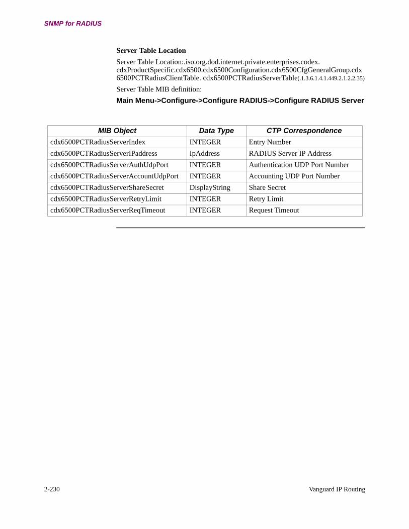
2-230 Vanguard IP Routing
SNMP for RADIUS
Server Table Location
Server Table Location:.iso.org.dod.internet.private.enterprises.codex. cdxProductSpecific.cdx6500.cdx6500Configuration.cdx6500CfgGeneralGroup.cdx6500PCTRadiusClientTable. cdx6500PCTRadiusServerTable(.1.3.6.1.4.1.449.2.1.2.2.35)
Server Table MIB definition:
Main Menu->Configure->Configure RADIUS->Configure RADIUS Server
MIB Object Data Type CTP Correspondence
cdx6500PCTRadiusServerIndex INTEGER Entry Number
cdx6500PCTRadiusServerIPaddress IpAddress RADIUS Server IP Address
cdx6500PCTRadiusServerAuthUdpPort INTEGER Authentication UDP Port Number
cdx6500PCTRadiusServerAccountUdpPort INTEGER Accounting UDP Port Number
cdx6500PCTRadiusServerShareSecret DisplayString Share Secret
cdx6500PCTRadiusServerRetryLimit INTEGER Retry Limit
cdx6500PCTRadiusServerReqTimeout INTEGER Request Timeout
Vanguard IP Routing 2-231
T0100-03, Revision V Release 7.3
SNMP for RADIUS
RADIUS Statistics MIBs
Statistic MIBs RADIUS statistics MIBs are part of standard MIBs. RFC-2618[4] defines the RADIUS authentication client MIBs, which are located in: .iso.org.dod.internet.mgmt.mib-2. radiusMIB. RadiusAuthentication. RadiusAuthClientMIB (.1.3.6.1.2.1.67.1.2)
It contains two items as well as a single table, the two are:
• RadiusAuthClientInvalidServerAddresses, The number of RADIUS Access-Response packets received from unknown addresses
• RadiusAuthClientIdentifier, The NAS-Identifier of the RADIUS authentication client
The table is called radiusAuthServerTable, which is the (conceptual) table listing the RADIUS authentication servers with which the client shares a secret with. This table contains one row for each RADIUS authentication server, each entry in the RADIUS authentication server table includes fifteen columns presenting a view of the activity of the RADIUS.
The column objects are listed as below:
• radiusAuthServerIndex Integer32,• radiusAuthServerAddress IpAddress,• radiusAuthClientServerPortNumber Integer32,• radiusAuthClientRoundTripTime TimeTicks,• radiusAuthClientAccessRequests Counter32,• radiusAuthClientAccessRetransmissions Counter32,• radiusAuthClientAccessAccepts Counter32,• radiusAuthClientAccessRejects Counter32,• radiusAuthClientAccessChallenges Counter32,• radiusAuthClientMalformedAccessResponsesCounter32,• radiusAuthClientBadAuthenticators Counter32,• radiusAuthClientPendingRequests Gauge32,• radiusAuthClientTimeouts Counter32,• radiusAuthClientUnknownTypes Counter32,• radiusAuthClientPacketsDropped Counter32
RFC 2620[5] defines the RADIUS accounting client MIBs, which are located in: .iso.org.dod.internet.mgmt.mib-2. radiusMIB. radiusAccounting. radiusAccClientMIB (.1.3.6.1.2.1.67.2.2)
It contains two items as well as one single table. The two are:
• RadiusAccClientInvalidServerAddresses, The number of RADIUS Accounting-Response packets received from unknown addresses
• RadiusAuthClientIdentifier, The NAS-Identifier of the RADIUS accounting client

2-232 Vanguard IP Routing
SNMP for RADIUS
The table is called radiusAccServerTable, which is the (conceptual) table listing the RADIUS accounting servers with which the client shares a secret with. This table contains one row for each RADIUS server, each entry in the RADIUS accounting server table includes thirteen columns presenting a view of the activity of the RADIUS client.
The column objects are listed as below:
• radiusAccServerIndex Integer32,• radiusAccServerAddress IpAddress,• radiusAccClientServerPortNumber Integer32,• radiusAccClientRoundTripTime TimeTicks,• radiusAccClientRequests Counter32,• radiusAccClientRetransmissions Counter32,• radiusAccClientResponses Counter32,• radiusAccClientMalformedResponses Counter32,• radiusAccClientBadAuthenticators Counter32,• radiusAccClientPendingRequests Gauge32,• radiusAccClientTimeouts Counter32,• radiusAccClientUnknownTypes Counter32,• radiusAccClientPacketsDropped Counter32

Vanguard IP Routing 2-233
T0100-03, Revision V Release 7.3
IPFLOW
IPFLOW
Introduction This section describes the implementation of the IPFLOW feature in Vanguard Networks product family and rovides a general description of the IPFLOW feature, its configurable parameters, and includes explanations of how to Configure Vanguard products to support this feature.
What is IP Flow? The Vanguard IPFLOW product feature is the automatic collection and exporting of the byte and packet counts on identifiable TCP, UDP, ICMP (and any other IP routable) flows through the VG router core. The IPFLOW Data Export records are sent to the IP addresses of remote third party IPFLOW Collector Server that over time, collect network usage and loading statistics.
Cisco NETFLOWTM first conceived IPFLOW version 5 and it is the current de facto standard. Cisco NETFLOWTM Version 9 is being standardized as IPFIX.
The RFC standard track is IPFIX (which is based on Cisco NETFLOWTM Version 9).
Vanguard IPFLOW is equivalent to Version 5.
Vanguard Products Supported
The following lists the Vanguard Router products that will support IPFLOW. Note that the 6435/55 products are no longer supported on release 7.1
• 242D series products• 34x series products• 34xx series products• 68xx series products• 73xx series product
Product Requirements
IPFLOW also requires additional amounts of SDRAM. A minimum of 32 Mbytes of SDRAM is required to be installed on 3xx or 64xx product when IPFLOW is running concurrently with many other Feature options, large IP or BGP route tables and/or large IP caches.
Link Types Supported
The following physical and logical link types are supported. Note the addition of MLPPP/PPP and ATM ports. In support of the new link types modest configuration changes have been required to the Meter table configuration. See the IPFLOW meter table configuration for those changes.:
• Physical T1/E1 ports and Serial (all flavors) and ETH ports• LCON's running over FR Bypass stations, FR AnnexG Stations, MLPPP/PPP
links, and ATM links
Product Requirements
IPFLOW also requires additional amounts of SDRAM. A minimum of 32 Mbytes of SDRAM is required to be installed on 3xx or 64xx product when IPFLOW is running concurrently with many other Feature options, large IP or BGP route tables and/or large IP caches.
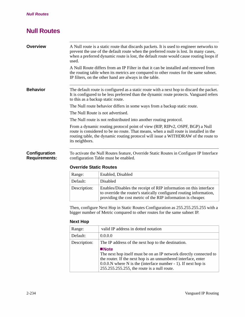
2-234 Vanguard IP Routing
Null Routes
Null Routes
Overview A Null route is a static route that discards packets. It is used to engineer networks to prevent the use of the default route when the preferred route is lost. In many cases, when a preferred dynamic route is lost, the default route would cause routing loops if used.
A Null Route differs from an IP Filter in that it can be installed and removed from the routing table when its metrics are compared to other routes for the same subnet. IP filters, on the other hand are always in the table.
Behavior The default route is configured as a static route with a next hop to discard the packet. It is configured to be less preferred than the dynamic route protects. Vanguard refers to this as a backup static route.
The Null route behavior differs in some ways from a backup static route.
The Null Route is not advertised.
The Null route is not redistributed into another routing protocol.
From a dynamic routing protocol point of view (RIP, RIPv2, OSPF, BGP) a Null route is considered to be no route. That means, when a null route is installed in the routing table, the dynamic routing protocol will issue a WITHDRAW of the route to its neighbors.
Configuration Requirements:
To activate the Null Routes feature, Override Static Routes in Configure IP Interface configuration Table must be enabled.
Then, configure Next Hop in Static Routes Configuration as 255.255.255.255 with a bigger number of Metric compared to other routes for the same subnet IP.
Override Static Routes
Range: Enabled, Disabled
Default: Disabled
Description: Enables/Disables the receipt of RIP information on this interface to override the router's statically configured routing information, providing the cost metric of the RIP information is cheaper.
Next Hop
Range: valid IP address in dotted notation
Default: 0.0.0.0
Description: The IP address of the next hop to the destination.
NoteThe next hop itself must be on an IP network directly connected to the router. If the next hop is an unnumbered interface, enter 0.0.0.N where N is the (interface number - 1). If next hop is 255.255.255.255, the route is a null route.
IP Configuration 3-1
Chapter 3IP Configuration
Overview
Introduction This chapter describes how to configure the Vanguard for IP routing.
3-2 IP Configuration
IP Router Module Basic Configuration
IP Router Module Basic Configuration
Introduction This section describes “Routing” related configuration parameters. Each node that uses Routing across a Wide Area Network (WAN) must also configure the following sections:
• Node Record• Network Services - Route Selection Table• Autocall Mnemonic or PVC Set Up Table• LAN Port Record — AUI/10-100Base-T, Ethernet 802.3, or Token Ring
802.5• LAN Connection (LCON) Table (The required number of virtual circuits
(LCONs) to match the number of WAN router-to-router connections that are planned.
• Frame Relay Port/Station, X.25, or any compatible link configuration that supports routing capabilities.
At the destination node, a LAN Connection (LCON) entry is needed for the WAN Adapter.)
It is also assumed that Frame Relay and/or X.25 physical interfaces, and have also specified . It is also assumed that you have established the X.25 Routing and/or PVC table entries necessary to use these paths.
Additional application related options could include (but not require):
• SNMP• SoTCP• Other sections where Network Management and Voice are used in conjunc-
tion with the router transport function.
Activate and Configure the Router Module
The following table describes the recommended process of activating and configuring the Router module.
Step Action
1 Configure the physical LAN port.
2 Enable/Configure the Router Interfaces.
3 Configure the IP addresses and masks.
4 Configure the RIP Routing parameters.
5 Configure the General IP parameters.
6 Configure ARP parameters.
7 Connect the Router Interfaces to the WAN.

IP Configuration 3-3
T0100-03, Revision V Release 7.3
IP Router Module Basic Configuration
Configure the Physical LAN Port
To configure the physical LAN port, follow these steps:
NoteThis procedure is the same regardless of whether you perform bridging, routing, or both (brouting).
Enabling/Configuring the Router Interfaces
The Vanguard Router provides the ability to connect the IP Router Module to LAN connection(s) and directly connected routers on the WAN side.
Before you configure them, make the interfaces active in the Configure Interface States command in the Configure Router menu. Interface 1 refers to the LAN port, and Interfaces 5 and after refer to the possible WAN connected routers.
Configuring the IP Addresses and Masks
You specify the IP address and address mask in the “IP Interface Configuration Table” section on page 3-24. These two values define the IP network that is connected to the particular interface and the specific IP Host address used by the interface. This number is used for the ICMP Ping to test whether the interface is still working, and is also used by the routing tables of the other routers on the network to which it is attached.
Select the network numbers for the interfaces based on an understanding of the addressing and subnetting scheme used for the whole network, and take into account any future growth that is planned. The sections “IP Addressing” section on page 1-4 and “Subnet Addresses (Subnetting)” section on page 1-7 explain Internet Protocol (IP) addressing and subnetting. You can also configure the mask for classless addressing; for more information refer to “How IP Routing Works” section on page 1-11.
We recommend that you draw the IP Network in a simplified format. This type of diagram allows the WAN complexity to be hidden while you design the IP network and provides a simple way to determine how many interfaces are required on the Router module, as well as which IP addressing and subnetting scheme to use.
Step Action
1 Configure the physical LAN port on the router.
2 • If no LAN port exists, skip this step.• If a LAN Port exists: Select port number 13, 19, 25, 31, 37, 43, or
49 from the Configure Port menu depending on the physical slot in which the LAN card is placed.
3 Select either the Ethernet or the Token Ring depending on the type of operating card.
4 Enter values for the remaining parameters so that the interface is configured with Layer 1/2 parameters (for example, Cable Type, MAC Address, and so on.)

3-4 IP Configuration
IP Router Module Basic Configuration
Configuring the RIP Routing Parameters
The remaining parameters in the Interface Configuration menu primarily deal with how the traffic received and sent over the particular interface reacts with the Router's RIP Routing module. The settings for these parameters depend on conditions such as whether RIP is enabled and how static and default routing are used. Parameters controlling the characteristics of Broadcast messages originating from the interface are also included.
Configuring the General IP Parameters
You can configure parameters effecting the IP Router module as a whole using the Parameters menu in the “IP Router Configuration Parameters” section on page 3-8. These parameters control the operation of areas like ARP, BOOTP, RIP, and Default Routing. They let you enable Broadcasting and Access Control and control the use of the Vanguard Router’s memory for buffering operations used by the Router module.
Connecting the Router Interfaces to the WAN
Once the Router module is programmed, you connect the WAN interfaces configured on it to Frame Relay or X.25 virtual circuits that provide connection to similar interfaces on Router modules located remotely.
Use the WAN Adapter and its LAN Connection Table entries. Use the LAN Connection Table entry in the Configure menu to match the interfaces with the virtual circuits. The connection to the virtual circuit is performed by matching the Router interface number to be connected and an Autocall Mnemonic that can be either a standard X.25 address (which can be routed out an X.25, MX.25, XDLC or Frame Relay port) or a direct Frame Relay Port/Station record entry in the PVC table (which allows Frame Relay to encapsulate data using RFC1294).
The remote Vanguard Router node’s LAN Connection Table entry number is also included to ensure that the two router interfaces are linked across the WAN. Refer to the LAN/WAN Interconnection Configuration Table.
If bridge traffic is combined with the router traffic over the X.25 or Frame Relay virtual circuit, the mix is specified with the LAN Forwarder Type variable, and the Bridge Link number is also specified in the same way as the Router Interface number. In cases where the Router will be connected to a third party device supporting RFC1294 encapsulation of IP traffic, set the Encapsulation Type parameter to RFC1294 to ensure proper operation.

IP Configuration 3-5
T0100-03, Revision V Release 7.3
IP Router Module Basic Configuration
Configuration Example
Introduction Routing between two LANs can be accomplished by remotely attaching them across a WAN. In a point-to-point configuration, as shown in Figure 3-1, routed traffic flows between the router entities over an SVC that connects them across the WAN. The router entities reside in nodes 101 and 102.
Point-to-Point Configuration
Figure 3-1 shows the SVC configured from node 101 to 102.
Figure 3-1. Point-to-Point Configuration
Port RecordWAN Port #: 1Port Type: X.25Clock Source: EXTClock Speed: Any, Matching
other NodeLink Address: DTET4 Timer: 0Packet Size: 128
Port RecordWAN Port #: 2Port Type: X.25Clock Source: INTClock Speed: Any, Matching
other NodeLink Address: DCE
Port RecordLAN Port #: 13Port Type: TRLocal Ring No: 11Ring Speed: 4 mbps
Mnemonic TableMnemonic Name: T0102Call Parameters: 10294
Configure IP ParametersSave Defaults
Configure IP InterfaceInterface #: 1IP Address: 15.0.0.101Interface #: 5IP Address: 17.0.0.101Address Mask: 255.0.0.0
LAN Connection TableEntry #: 1LAN Forwarder Type:RoutRouter Interface: 5Autocall Mnemonic:T0102Max. # of Attempts:0
15.0.0.101 17.0.0.101 17.0.0.102 16.0.0.102
15.0.0.1 16.0.0.1
101 X.25
DCE DTE
PC2PC1
MAU
102
Configure Router InterfaceInterface # 1 State:EnabledInterface # 5 State:Enabled
MAU
Port RecordLAN Port #: 13Port Type: TRLocal Ring No: 12Ring Speed: 4 mbps
Route Selection TableEntry #: 1Address: 101*#1 Destination:X25-1Entry #: 2Address: 10294Destination: LCON
Configure IP ParametersSave Defaults
Configure IP InterfaceEntry #: 1Interface: 1IP Address: 16.0.0.102Address Mask: 255.0.0.0Sending Net Routes: EnabledSending Subnet Routes: EnabledReceiving RIP Packets: EnabledReceiving Dynamic Nets:EnabledEntry #: 1Interface: 5IP Address: 17.0.0.102Address Mask: 255.0.0.0
LAN Connection TableEntry #: 1LAN Forwarder Type:RoutRouter Interface: 5Autocall Mnemonic:<blank>Max. # of Attempts:0
Configure Router InterfaceInterface # 1 State:EnabledInterface # 5 State:Enabled
Route Selection TableEntry #: 1Address: 10194#1 Destination: LCONEntry #: 2Address: 102#1 Destination X25-13

3-6 IP Configuration
Control of Router Interfaces
Control of Router Interfaces
Introduction This section describes the control of router interfaces.
Controlling LAN Interface
Each LAN interface is mapped to either a LAN port or an LCON (LAN connection). To disable a LAN interface, disable the corresponding LAN port or LCON. To enable a LAN interface, enable the corresponding LAN port or LCON. Disabling or enabling a LAN interface in this way effects the IP protocol interfaces mapped to this LAN interface.
When disabling a LAN interface, all IP interfaces mapped to that interface are brought down.
When enabling a LAN interface, all IP interfaces mapped to that interface are activated (brought up). This allows routing traffic to pass on those interfaces. Routing data is exchanged if a routing protocol is enabled on that interface.
Controlling IP Interface
IP interfaces do not have a separate command to control the interface. To disable an IP interface, do one of the following:
• Blank out the IP interface address in the interface record and boot IP tables.• Disable the LAN port or LCON to which the IP interface is mapped.
NoteIf an IPX interface is also mapped to the same physical LAN interface, the IPX interface is marked as down.
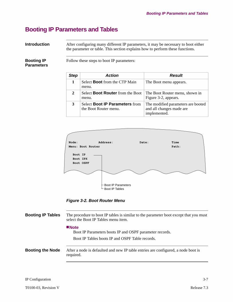
IP Configuration 3-7
T0100-03, Revision V Release 7.3
Booting IP Parameters and Tables
Booting IP Parameters and Tables
Introduction After configuring many different IP parameters, it may be necessary to boot either the parameter or table. This section explains how to perform these functions.
Booting IP Parameters
Follow these steps to boot IP parameters:
Figure 3-2. Boot Router Menu
Booting IP Tables The procedure to boot IP tables is similar to the parameter boot except that you must select the Boot IP Tables menu item.
NoteBoot IP Parameters boots IP and OSPF parameter records.
Boot IP Tables boots IP and OSPF Table records.
Booting the Node After a node is defaulted and new IP table entries are configured, a node boot is required.
Step Action Result
1 Select Boot from the CTP Main menu.
The Boot menu appears.
2 Select Boot Router from the Boot menu.
The Boot Router menu, shown in Figure 3-2, appears.
3 Select Boot IP Parameters from the Boot Router menu.
The modified parameters are booted and all changes made are implemented.
Boot IP ParametersBoot IP Tables
Node: Address: Date: Time Menu: Boot Router Path:
Boot IPBoot IPXBoot OSPF
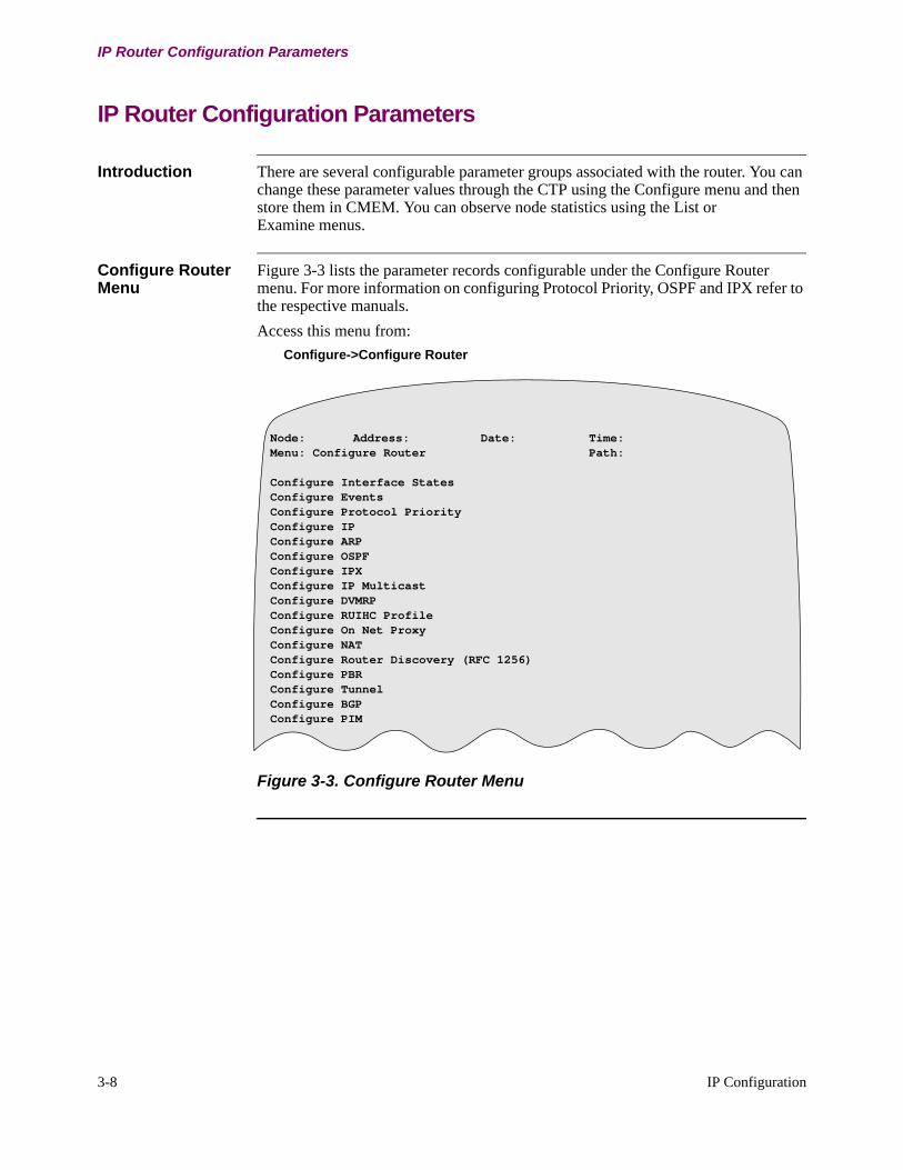
3-8 IP Configuration
IP Router Configuration Parameters
IP Router Configuration Parameters
Introduction There are several configurable parameter groups associated with the router. You can change these parameter values through the CTP using the Configure menu and then store them in CMEM. You can observe node statistics using the List or Examine menus.
Configure Router Menu
Figure 3-3 lists the parameter records configurable under the Configure Router menu. For more information on configuring Protocol Priority, OSPF and IPX refer to the respective manuals.
Access this menu from:
Configure->Configure Router
Figure 3-3. Configure Router Menu
Node: Address: Date: Time:Menu: Configure Router Path:
Configure Interface StatesConfigure EventsConfigure Protocol PriorityConfigure IPConfigure ARPConfigure OSPFConfigure IPXConfigure IP MulticastConfigure DVMRPConfigure RUIHC ProfileConfigure On Net ProxyConfigure NATConfigure Router Discovery (RFC 1256)Configure PBRConfigure TunnelConfigure BGPConfigure PIM

IP Configuration 3-9
T0100-03, Revision V Release 7.3
Configuring Interface States
Configuring Interface States
Introduction Vanguard Routers provide the means to connect the IP Routing Module to directly connected routers on the WAN side and a single LAN connection.
Configure Interface States Menu
Access the Interface State menu from:
Configure->Configure Router->Configure Interface States
Interface number 1 refers to the LAN port and Interfaces 5 and greater refer to the possible WAN connections.
Figure 3-4. Configure Interface States Menu
Parameter This parameter enables or disables a Router Interface. A Node (warm) boot is required for the change to take effect.
Node: Address: Date:Time:Menu: Configure Router Path:
Configure Interface States
Interface # State
*Interface #1 State
Range: Unconfigured, Enable, Disable
Default: Unconfigured
Description: A control parameter that enables or disables the router interface. Disable all interfaces that are not in use.
3-10 IP Configuration
Configuring Events
Configuring Events
Introduction You can display and monitor a wide range of unusual and/or common events occurring in the IP, ICMP ARP, UDP, and RIP modules. This information can help you detect and diagnose problems that may arise. These problems may include interface failure and internal buffer thresholds being reached.
• Passively monitor the node to detect problems.• Diagnose problems by having the node generate information about its
operation.
Event Configuration
Router events can be configured from the:
• Configure Node menu- Alarm Selection
• Configure Events menu (for the router)- Per Packet Trace- Unusual Operation- Common Operation
Enabling any of these parameters can yield a large number of events. It is generally recommended to leave these disabled (default).
Activate Event Generation
This operation can be generated to the node’s Async control port and/or can be passed to the SNMP Management station in the form of SNMP Traps.
NoteTo display Router events, LOW level events must be activated in the Node Record.
Event Categories The following list defines the layout of event categories:
NoteFor both Unusual Operation and Common Operation, events are further categorized as Internal, External, and Info.
Step Action
1 Specify the routing of information using the SNMP configuration menu.
2 Specify the quantity and categories of the event information that is generated in the Events area of the Configure Router menu.
Event Indicates...
UI-Error Unusual Internal Error
CI-Error Common Internal Error
UE-Error Unusual External Error
CE-Error Common External Error
U-Info Unusual Information Comment
C-Info Common Information Comment

IP Configuration 3-11
T0100-03, Revision V Release 7.3
Configuring Events
Configure Events Menu
Figure 3-5 shows the Configure Events menu. Access the menu from:
Configure->Configure Router->Configure Events
Figure 3-5. Configure Events Menu
Parameters These parameters make up the Events record. A Node (warm) boot is required for changes to take effect.
Entry Number
Protocol
Per Packet Trace
Unusual Operation
Common Operation
Node: Address: Date:Time:Menu: Configure Router Path:
Configure Events
Entry Number
Range: 1 to 11
Default: 1
Description: Number used to reference this table record.
Protocol
Range: ARP, IP, ICMP, UDP, RIP, TKR, ETH, OSPF, IPX, PIM
Default: IP
Description: The router function is divided into several subsystems, each with its own event reporting control. This is a single entry that names the protocol for which event reporting controls will be configured in the following parameters.
Per Packet Trace
Range: Enabled, Disabled
Default: Disabled
Description: Controls whether the Per Packet Trace events are reported for the named subsystem (protocol).
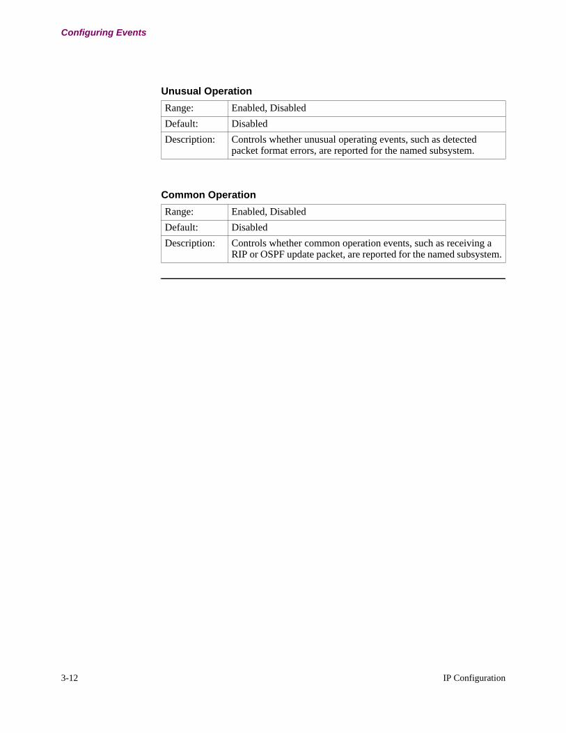
3-12 IP Configuration
Configuring Events
Unusual Operation
Range: Enabled, Disabled
Default: Disabled
Description: Controls whether unusual operating events, such as detected packet format errors, are reported for the named subsystem.
Common Operation
Range: Enabled, Disabled
Default: Disabled
Description: Controls whether common operation events, such as receiving a RIP or OSPF update packet, are reported for the named subsystem.

IP Configuration 3-13
T0100-03, Revision V Release 7.3
Configure IP
Configure IP
Introduction The IP Record settings control these operational areas: ARP, BOOTP, RIP, and Default Routing. These parameters effect the IP Routing module as a whole.
Configure IP Menu Figure 3-3 lists the records configurable under the Configure IP menu. For more information on configuring Protocol Priority, OSPF and IPX refer to the respective manuals.
Access this menu from:
Configure ->Configure Router->Configure IP
Figure 3-6. Configure IP Menu
Node: Address: Date: Time:Menu: Configure IP Path:
ParametersInterfacesFiltersAccess ControlStatic RoutesDefault Subnet GatewayRIP Route ControlConfigure CIDRBootP ServerIP Broadcast Forwarding TableUDP Broadcast Forwarding TableDefault Route Origination-Conditional TableBGP->RIP Import PoliciesConfigure PBR

3-14 IP Configuration
Configure IP
IP Parameters Configuration
Parameter Menu Figure 3-7 shows the Parameters menu. Access this menu from:
Configure->Configure Router->Configure IP->Parameters
Figure 3-7. Parameters Menu
Parameters These IP parameters control the overall behavior of the IP router. Changes to these parameters require a combination of boot types to take effect. Parameters preceded by an asterisk require a Node boot. Other parameters require either a Tables Boot or Parameters Boot. These are indicated in the tables that follow:
Node: Address: Date: Time: Menu: Configure IP Path:
Parameters
*Maximum Number of IP Interfaces
Internal IP Address
Internal Net Mask
*Access Control
RIP Enable
Originate Default Route
Advertised Default Route Metric
Default Gateway
Default Gateway Metric
Directed Broadcast
All Subnets Broadcast
*IP Route Table Size
*IP Route Cache Size
*Reassembly Buffer Size
BOOTP Forwarding
BOOTP Max Allowed Metric
BOOTP Seconds Before Forward
IP Broadcast Forwarding Enable
UDP Broadcast Forwarding Enable
*Aggregate Cache Enable
Source Address Options
Interface Services
*Maximum Number of IP Interfaces
Range: 36 to 1000
Default: 36
Description: Maximum number of interfaces configurable for IP.

IP Configuration 3-15
T0100-03, Revision V Release 7.3
Configure IP
Internal IP Address
Range: A valid IP address in dotted decimal notation
Default: (blank)
Description: The internal IP address overrides the router ID to become the default IP address for the router. This default IP address is used:
• as the IP source address of ICMP Ping and ICMP frames originating from the router.
• as the reported IP address in SNMP Trap frames.If both the router ID and internal IP address are left undefined (as 0.0.0.0), the default IP Address is the IP address of the lowest numbered operational interface of the router. For unnumbered IP, this becomes the Router ID.The internal IP address can also be set to the same address as the IP interface address or the address of attached subnets.When changing an existing Internal IP address:
• The route corresponding to the old internal IP address is marked as down, and is aged out.
• The new Internal IP address is installed in the routing table.When deleting the Internal IP address:
• The route entry corresponding to the deleted internal IP address is marked as down, and is aged out of the table.
Configuring an Internal IP Address:• The internal IP address is added as a route to the IP routing
table.
NoteAll changes to the internal IP address cause a database turnover in OSPF, since all the LSAs must be reoriginated. Use this procedure to rebuild the entire database:
a)Disable OSPF (OSPF Parameters).
b)Boot OSPF Parameters.
c)Enable OSPF (OSPF Parameters).
d)Boot OSPF Parameters.
NoteThe parameter change takes effect immediately following a Parameters Boot.

3-16 IP Configuration
Configure IP
Internal Net Mask
Range: A valid IP address in dotted decimal notation
Default: 255.255.255.0
Description: Configures the 32-bit IP subnetwork address mask associated with the internal interface created when the internal address is added to the router configuration parameters. The internal network address is derived from the configured internal address and internal network mask parameter. For unnumbered IP this should be the same as the mask of the selected Internal IP address.Changing an existing Internal IP addressThe route corresponding to the old internal IP address is marked as down, and is aged out.The new Internal IP address is installed in the routing table.Deleting the Internal IP addressThe route entry corresponding to the deleted internal IP address is marked as down, and is aged out of the table.Configuring an Internal IP AddressThe internal IP address is added as a route to the IP routing table.
NoteAll changes to the internal IP address cause a database turnover in OSPF, since all the LSAs must be reoriginated. Use this procedure to rebuild the entire database:
a)Disable OSPF (OSPF Parameters).
b)Boot OSPF Parameters.
c)Enable OSPF (OSPF Parameters).
d)Boot OSPF Parameters.
NoteThe parameter change takes effect immediately following a Parameters Boot.
*Access Control
Range: Enabled, Disabled
Default: Disabled
Description: Enables or disables the use of IP Access Controls for this router. To configure the IP Access Control Table refer to “IP Access Control Configuration” section on page 3-49 for more information.
NoteThe parameter change takes effect immediately following a Parameters Boot.

IP Configuration 3-17
T0100-03, Revision V Release 7.3
Configure IP
RIP Enable
Range: Enabled, Disabled
Default: Enabled
Description: Controls whether the Routing Information Protocol (RIP) is used by this router. RIP was the original internal gateway routing protocol used for IP networks and is suitable for moderate-sized organization networks. An organization may operate both RIP and OSPF simultaneously.When enabled, RIP packets are sent out beginning with the next update.
NoteDisabling this parameter takes effect immediately after a Boot Tables command.
Originate Default Route
Range: Enabled, Disabled
Default: Disabled
Description: Enables origination and RIP advertisement of the "default" IP route 0.0.0.0. Default route advertisements must also be explicitly enabled for each interface. The router will originate the default route only when the criteria configured on the interface or in the Default Route Origination-Conditional Table are met.
NoteThe value is effective in the next update following the Boot Tables command.
Advertised Default Route Metric
Range: 1 to 16
Default: 10
Description: Sets the cost metric (usually the number of hops) that RIP will advertise for the default route of 0.0.0.0. A metric of 16 advertises that the default route is unreachable.
NoteThe value becomes effective in the next update following the Boot Tables command.
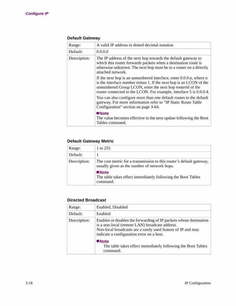
3-18 IP Configuration
Configure IP
Default Gateway
Range: A valid IP address in dotted decimal notation
Default: 0.0.0.0
Description: The IP address of the next hop towards the default gateway to which this router forwards packets when a destination route is otherwise unknown. The next hop must be to a router on a directly attached network.If the next hop is an unnumbered interface, enter 0.0.0.n, where n is the interface number minus 1. If the next hop is an LCON of the unnumbered Group LCON, enter the next hop routerid of the router connected to the LCON. For example, interface 5 is 0.0.0.4.You can also configure more than one default routes to the default gateway. For more information refer to “IP Static Route Table Configuration” section on page 3-64.
NoteThe value becomes effective in the next update following the Boot Tables command.
Default Gateway Metric
Range: 1 to 255
Default: 1
Description: The cost metric for a transmission to this router’s default gateway, usually given as the number of network hops.
NoteThe table takes effect immediately following the Boot Tables command.
Directed Broadcast
Range: Enabled, Disabled
Default: Enabled
Description: Enables or disables the forwarding of IP packets whose destination is a non-local (remote LAN) broadcast address. Non-local broadcasts are a rarely used feature of IP and may indicate a configuration error on a host.
NoteThe table takes effect immediately following the Boot Tables command.

IP Configuration 3-19
T0100-03, Revision V Release 7.3
Configure IP
All Subnets Broadcast
Range: Enabled, Disabled
Default: Disabled
Description: When enabled, this parameter duplicates and forwards IP packets which are destined for all hosts on all subnetworks on the IP network.
NoteThe table takes effect immediately following the Boot Tables command.
*IP Route Table Size
Range: 64 to 4000
Default: 768
Description: The maximum number of routes that may be stored in the IP routing table.
*IP Route Cache Size
Range: 2 to 512
Default: 64
Description: The maximum number of entries that may be stored in the IP Route Cache. The IP Route Cache holds the destination addresses of recently received packets. It maintains a count of packets forwarded to that destination for each entry.
NoteThis parameter also sets the size of the Aggregate Cache.
*Reassembly Buffer Size
Range: 2048 to 65535
Default: 12000
Description: Controls the size (in bytes) of the IP fragment reassembly buffer. Set this value greater than the size of the largest IP packet to be transmitted on your organization’s network.
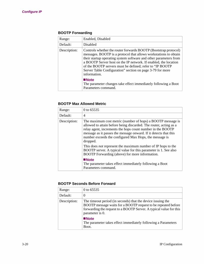
3-20 IP Configuration
Configure IP
BOOTP Forwarding
Range: Enabled, Disabled
Default: Disabled
Description: Controls whether the router forwards BOOTP (Bootstrap protocol) messages. BOOTP is a protocol that allows workstations to obtain their startup operating system software and other parameters from a BOOTP Server host on the IP network. If enabled, the location of the BOOTP servers must be defined; refer to “IP BOOTP Server Table Configuration” section on page 3-79 for more information.
NoteThe parameter changes take effect immediately following a Boot Parameters command.
BOOTP Max Allowed Metric
Range: 0 to 65535
Default: 4
Description: The maximum cost metric (number of hops) a BOOTP message is allowed to attain before being discarded. The router, acting as a relay agent, increments the hops count number in the BOOTP message as it passes the message onward. If it detects that this number exceeds the configured Max Hops, the message is dropped.This does not represent the maximum number of IP hops to the BOOTP server. A typical value for this parameter is 1. See also BOOTP Forwarding (above) for more information.
NoteThe parameter takes effect immediately following a Boot Parameters command.
BOOTP Seconds Before Forward
Range: 0 to 65535
Default: 0
Description: The timeout period (in seconds) that the device issuing the BOOTP message waits for a BOOTP request to be repeated before forwarding the request to a BOOTP Server. A typical value for this parameter is 0.
NoteThe parameter takes effect immediately following a Parameters Boot.
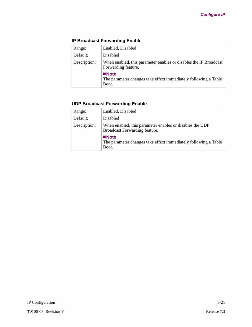
IP Configuration 3-21
T0100-03, Revision V Release 7.3
Configure IP
IP Broadcast Forwarding Enable
Range: Enabled, Disabled
Default: Disabled
Description: When enabled, this parameter enables or disables the IP Broadcast Forwarding feature.
NoteThe parameter changes take effect immediately following a Table Boot.
UDP Broadcast Forwarding Enable
Range: Enabled, Disabled
Default: Disabled
Description: When enabled, this parameter enables or disables the UDP Broadcast Forwarding feature.
NoteThe parameter changes take effect immediately following a Table Boot.
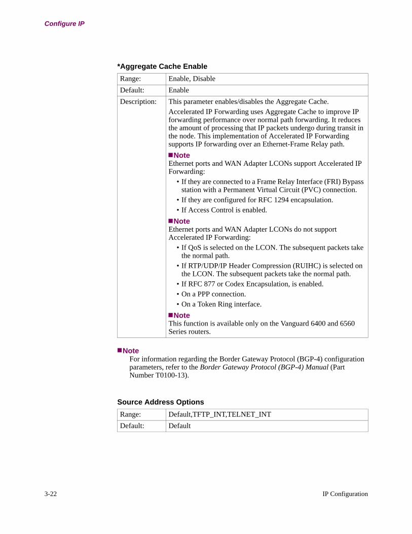
3-22 IP Configuration
Configure IP
NoteFor information regarding the Border Gateway Protocol (BGP-4) configuration parameters, refer to the Border Gateway Protocol (BGP-4) Manual (Part Number T0100-13).
*Aggregate Cache Enable
Range: Enable, Disable
Default: Enable
Description: This parameter enables/disables the Aggregate Cache.Accelerated IP Forwarding uses Aggregate Cache to improve IP forwarding performance over normal path forwarding. It reduces the amount of processing that IP packets undergo during transit in the node. This implementation of Accelerated IP Forwarding supports IP forwarding over an Ethernet-Frame Relay path.
NoteEthernet ports and WAN Adapter LCONs support Accelerated IP Forwarding:
• If they are connected to a Frame Relay Interface (FRI) Bypass station with a Permanent Virtual Circuit (PVC) connection.
• If they are configured for RFC 1294 encapsulation.• If Access Control is enabled.
NoteEthernet ports and WAN Adapter LCONs do not support Accelerated IP Forwarding:
• If QoS is selected on the LCON. The subsequent packets take the normal path.
• If RTP/UDP/IP Header Compression (RUIHC) is selected on the LCON. The subsequent packets take the normal path.
• If RFC 877 or Codex Encapsulation, is enabled.• On a PPP connection.• On a Token Ring interface.
NoteThis function is available only on the Vanguard 6400 and 6560 Series routers.
Source Address Options
Range: Default,TFTP_INT,TELNET_INT
Default: Default

IP Configuration 3-23
T0100-03, Revision V Release 7.3
Configure IP
Description: Allows the configuration of options which alter the default source address selection behaviour of internal traffic sources. Selection choices are:
Default - Use the default mechanism to select the Source Address. The address of the egress interface which the packet is sent out on will be used.
TFTP_INT - The TFTP client will use the internal node address as the Source Address.
TELNET_INT -The Telnet client will use the internal node as the Source Address.
Any combination of above specified by summing. (e.g. TFTP_INT + TELNET_INT)
Source Address Options (continued)
Interface Services
Range: TELNET, HTTP, SSH, PING, SNMP, TFTP, SoTCP, NONE
Default: TELNET, HTTP, SSH, PING, SNMP, TFTP, SoTCP
Description: These services can be enabled/disabled on the Internal Network:TELNETHTTPSSHPINGSNMPTFTPSoTCP
Combinations of the options (TELNET + HTTP ... ) are also valid.None - Disable all services on the Internal NetworkNONE cannot be combined with any other keyword.
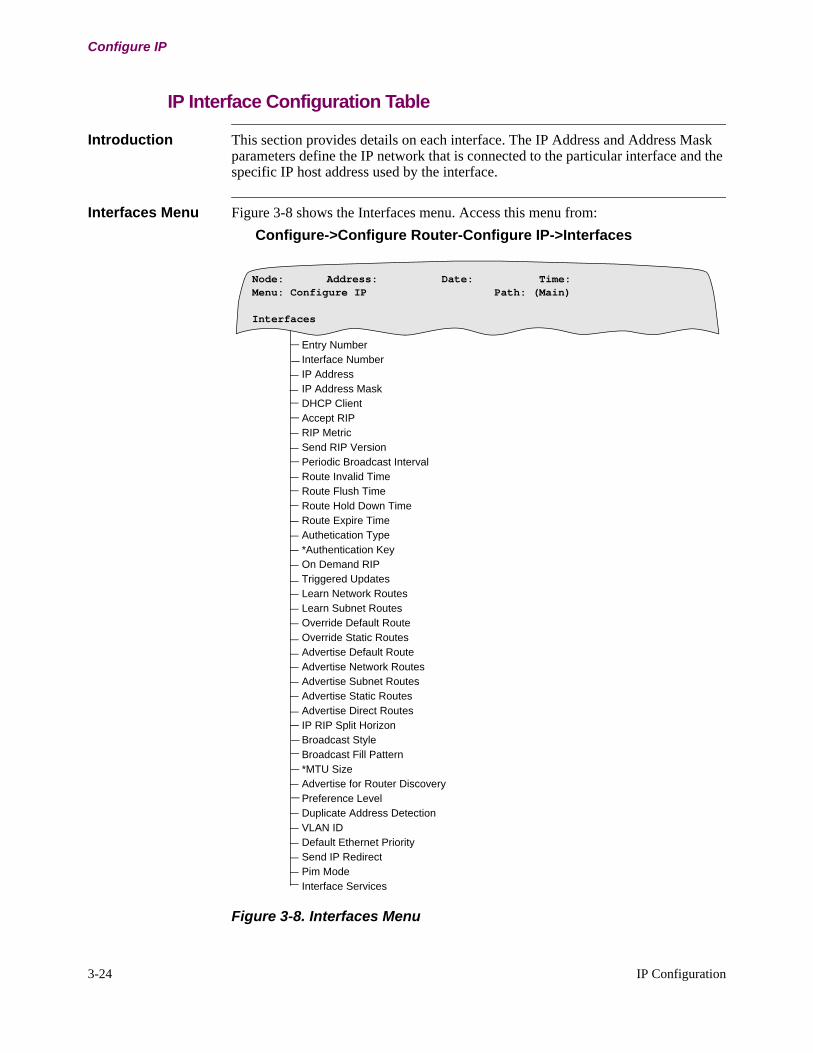
3-24 IP Configuration
Configure IP
IP Interface Configuration Table
Introduction This section provides details on each interface. The IP Address and Address Mask parameters define the IP network that is connected to the particular interface and the specific IP host address used by the interface.
Interfaces Menu Figure 3-8 shows the Interfaces menu. Access this menu from:
Configure->Configure Router-Configure IP->Interfaces
Figure 3-8. Interfaces Menu
Entry NumberInterface NumberIP AddressIP Address MaskDHCP ClientAccept RIPRIP MetricSend RIP VersionPeriodic Broadcast IntervalRoute Invalid TimeRoute Flush TimeRoute Hold Down TimeRoute Expire TimeAuthetication Type*Authentication KeyOn Demand RIPTriggered UpdatesLearn Network RoutesLearn Subnet RoutesOverride Default RouteOverride Static RoutesAdvertise Default RouteAdvertise Network RoutesAdvertise Subnet RoutesAdvertise Static RoutesAdvertise Direct RoutesIP RIP Split HorizonBroadcast StyleBroadcast Fill Pattern*MTU SizeAdvertise for Router DiscoveryPreference LevelDuplicate Address DetectionVLAN IDDefault Ethernet PrioritySend IP RedirectPim ModeInterface Services
Node: Address: Date: Time: Menu: Configure IP Path: (Main)
Interfaces
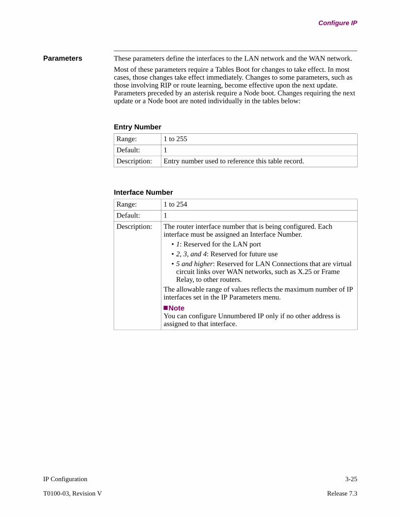
IP Configuration 3-25
T0100-03, Revision V Release 7.3
Configure IP
Parameters These parameters define the interfaces to the LAN network and the WAN network.
Most of these parameters require a Tables Boot for changes to take effect. In most cases, those changes take effect immediately. Changes to some parameters, such as those involving RIP or route learning, become effective upon the next update. Parameters preceded by an asterisk require a Node boot. Changes requiring the next update or a Node boot are noted individually in the tables below:
Entry Number
Range: 1 to 255
Default: 1
Description: Entry number used to reference this table record.
Interface Number
Range: 1 to 254
Default: 1
Description: The router interface number that is being configured. Each interface must be assigned an Interface Number.
• 1: Reserved for the LAN port• 2, 3, and 4: Reserved for future use • 5 and higher: Reserved for LAN Connections that are virtual
circuit links over WAN networks, such as X.25 or Frame Relay, to other routers.
The allowable range of values reflects the maximum number of IP interfaces set in the IP Parameters menu.
NoteYou can configure Unnumbered IP only if no other address is assigned to that interface.
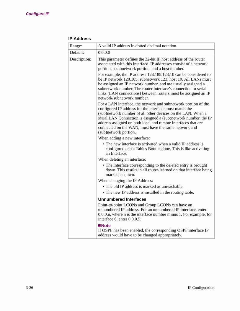
3-26 IP Configuration
Configure IP
IP Address
Range: A valid IP address in dotted decimal notation
Default: 0.0.0.0
Description: This parameter defines the 32-bit IP host address of the router associated with this interface. IP addresses consist of a network portion, a subnetwork portion, and a host number. For example, the IP address 128.185.123.10 can be considered to be IP network 128.185, subnetwork 123, host 10. All LANs must be assigned an IP network number, and are usually assigned a subnetwork number. The router interface’s connection to serial links (LAN connections) between routers must be assigned an IP network/subnetwork number.For a LAN interface, the network and subnetwork portion of the configured IP address for the interface must match the (sub)network number of all other devices on the LAN. When a serial LAN Connection is assigned a (sub)network number, the IP address assigned on both local and remote interfaces that are connected on the WAN, must have the same network and (sub)network portion. When adding a new interface:
• The new interface is activated when a valid IP address is configured and a Tables Boot is done. This is like activating an Interface.
When deleting an interface:• The interface corresponding to the deleted entry is brought
down. This results in all routes learned on that interface being marked as down.
When changing the IP Address:• The old IP address is marked as unreachable.• The new IP address is installed in the routing table.
Unnumbered InterfacesPoint-to-point LCONs and Group LCONs can have an unnumbered IP address. For an unnumbered IP interface, enter 0.0.0.n, where n is the interface number minus 1. For example, for interface 6, enter 0.0.0.5.
NoteIf OSPF has been enabled, the corresponding OSPF interface IP address would have to be changed appropriately.
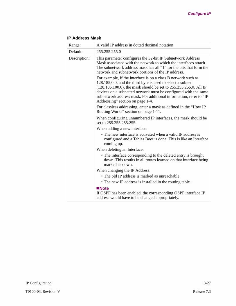
IP Configuration 3-27
T0100-03, Revision V Release 7.3
Configure IP
IP Address Mask
Range: A valid IP address in dotted decimal notation
Default: 255.255.255.0
Description: This parameter configures the 32-bit IP Subnetwork Address Mask associated with the network to which the interfaces attach. The subnetwork address mask has all “1” for the bits that form the network and subnetwork portions of the IP address.For example, if the interface is on a class B network such as 128.185.0.0, and the third byte is used to select a subnet (128.185.100.0), the mask should be set to 255.255.255.0. All IP devices on a subnetted network must be configured with the same subnetwork address mask. For additional information, refer to “IP Addressing” section on page 1-4.For classless addressing, enter a mask as defined in the “How IP Routing Works” section on page 1-11.
When configuring unnumbered IP interfaces, the mask should be set to 255.255.255.255.When adding a new interface:
• The new interface is activated when a valid IP address is configured and a Tables Boot is done. This is like an Interface coming up.
When deleting an Interface:• The interface corresponding to the deleted entry is brought
down. This results in all routes learned on that interface being marked as down.
When changing the IP Address:• The old IP address is marked as unreachable.• The new IP address is installed in the routing table.
NoteIf OSPF has been enabled, the corresponding OSPF interface IP address would have to be changed appropriately.
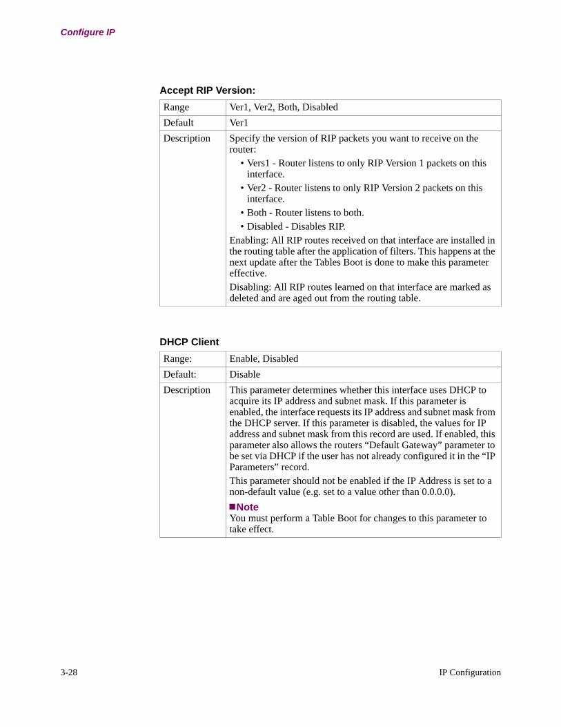
3-28 IP Configuration
Configure IP
Accept RIP Version:
Range Ver1, Ver2, Both, Disabled
Default Ver1
Description Specify the version of RIP packets you want to receive on the router:
• Vers1 - Router listens to only RIP Version 1 packets on this interface.
• Ver2 - Router listens to only RIP Version 2 packets on this interface.
• Both - Router listens to both.• Disabled - Disables RIP.
Enabling: All RIP routes received on that interface are installed in the routing table after the application of filters. This happens at the next update after the Tables Boot is done to make this parameter effective.Disabling: All RIP routes learned on that interface are marked as deleted and are aged out from the routing table.
DHCP Client
Range: Enable, Disabled
Default: Disable
Description This parameter determines whether this interface uses DHCP to acquire its IP address and subnet mask. If this parameter is enabled, the interface requests its IP address and subnet mask from the DHCP server. If this parameter is disabled, the values for IP address and subnet mask from this record are used. If enabled, this parameter also allows the routers “Default Gateway” parameter to be set via DHCP if the user has not already configured it in the “IP Parameters” record. This parameter should not be enabled if the IP Address is set to a non-default value (e.g. set to a value other than 0.0.0.0).
NoteYou must perform a Table Boot for changes to this parameter to take effect.
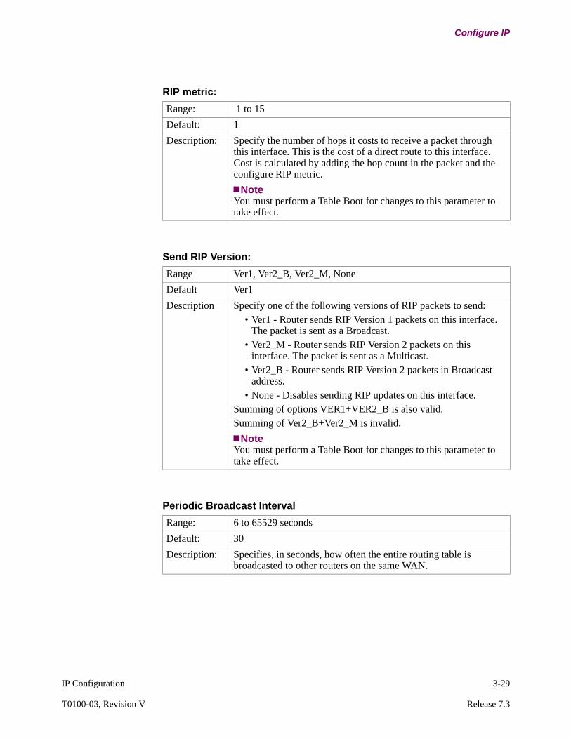
IP Configuration 3-29
T0100-03, Revision V Release 7.3
Configure IP
RIP metric:
Range: 1 to 15
Default: 1
Description: Specify the number of hops it costs to receive a packet through this interface. This is the cost of a direct route to this interface. Cost is calculated by adding the hop count in the packet and the configure RIP metric.
NoteYou must perform a Table Boot for changes to this parameter to take effect.
Send RIP Version:
Range Ver1, Ver2_B, Ver2_M, None
Default Ver1
Description Specify one of the following versions of RIP packets to send:• Ver1 - Router sends RIP Version 1 packets on this interface.
The packet is sent as a Broadcast.• Ver2_M - Router sends RIP Version 2 packets on this
interface. The packet is sent as a Multicast.• Ver2_B - Router sends RIP Version 2 packets in Broadcast
address.• None - Disables sending RIP updates on this interface.
Summing of options VER1+VER2_B is also valid.Summing of Ver2_B+Ver2_M is invalid.
NoteYou must perform a Table Boot for changes to this parameter to take effect.
Periodic Broadcast Interval
Range: 6 to 65529 seconds
Default: 30
Description: Specifies, in seconds, how often the entire routing table is broadcasted to other routers on the same WAN.
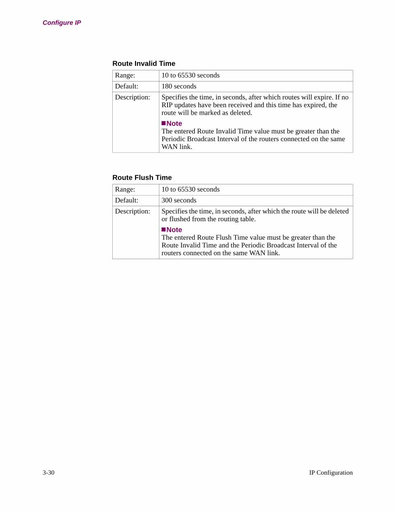
3-30 IP Configuration
Configure IP
Route Invalid Time
Range: 10 to 65530 seconds
Default: 180 seconds
Description: Specifies the time, in seconds, after which routes will expire. If no RIP updates have been received and this time has expired, the route will be marked as deleted.
NoteThe entered Route Invalid Time value must be greater than the Periodic Broadcast Interval of the routers connected on the same WAN link.
Route Flush Time
Range: 10 to 65530 seconds
Default: 300 seconds
Description: Specifies the time, in seconds, after which the route will be deleted or flushed from the routing table.
NoteThe entered Route Flush Time value must be greater than the Route Invalid Time and the Periodic Broadcast Interval of the routers connected on the same WAN link.

IP Configuration 3-31
T0100-03, Revision V Release 7.3
Configure IP
Route Hold Down Time
Range: 10 to 65530
Default: 240
Description: This parameter specifies time in seconds that an unreachable route comes out of the hold down state. The time interval should be a multiple of 10 and should be at least 60 seconds more than Route Invalid Time.The hold down time starts when the invalid timer fires and ends when hold down time is reached. All the values configured are based on the current value of a RIP entry in the routing table. For example, if invalid time is 30, when a RIP entry exists 30 seconds without refreshing by new advertisement, it is marked as unreachable. Similarly, if the hold down time is 90, when a RIP's current time is 90 sec, hold down time stops and new entry regarding the same destination can be accepted. The length of holding down time = hold down time - invalid time. (90 - 30 = 60 sec for the example).The suggestion in help message is at least 60 seconds more than Route Invalid Time which comes from the default values in our code. If the invalid time equals hold down time, it indicates no hold down time, a router can accept new advertisement as soon as the invalid time is met.
NoteIf the flush time is less than hold down time, the hold down time stops automatically since the entry is flushed out when flush time reaches, so new advertisement can be accepted.
Authentication Type:
Range None, Simple
Default None
Description Select Simple if you want to establish password security between this router and other routers in your network. Simple indicates that Authentication is enabled. RIP packets sent from this interface contain a password. Only RIP packets containing this password as the authentication key are accepted at this router.Select None to disable Authentication. The router uses packets with or without Authentication to learn routers in the network.
NoteYou must perform a Table Boot for changes to this parameter to take effect.
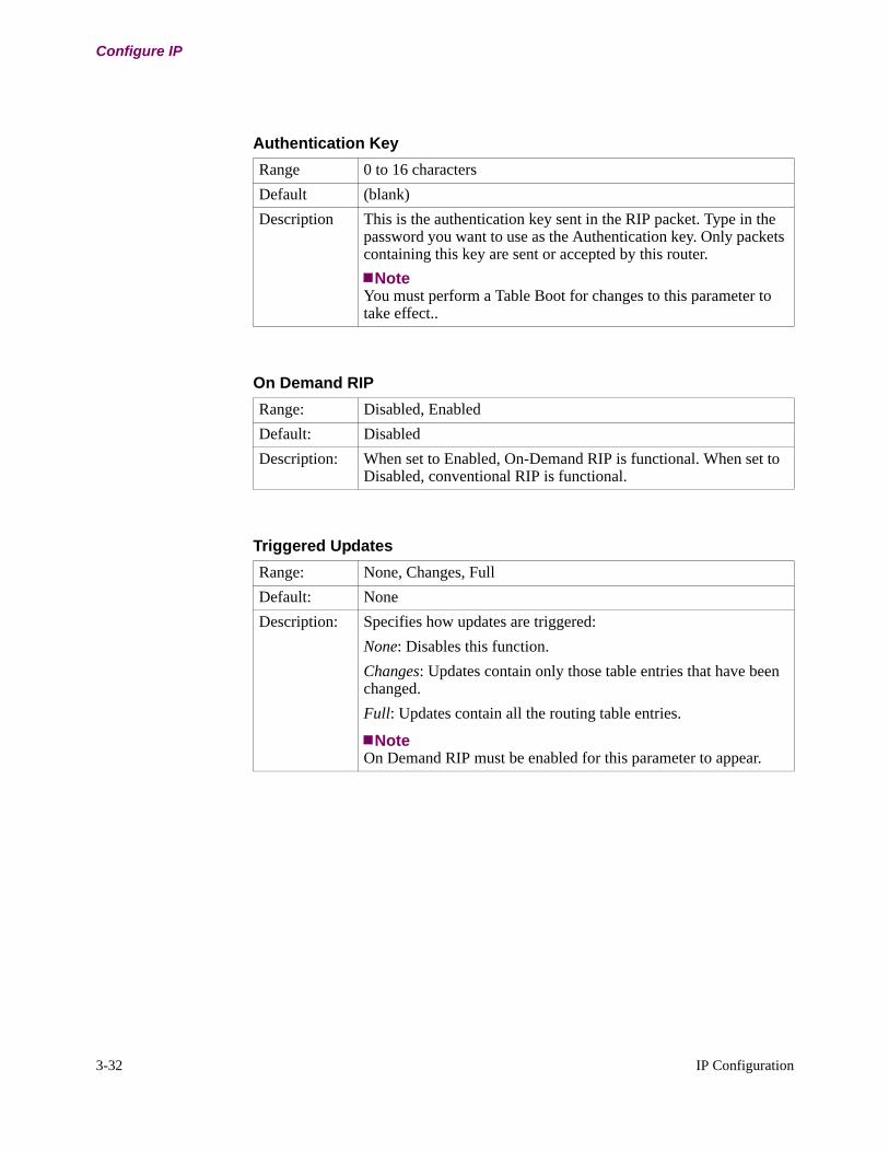
3-32 IP Configuration
Configure IP
Authentication Key
Range 0 to 16 characters
Default (blank)
Description This is the authentication key sent in the RIP packet. Type in the password you want to use as the Authentication key. Only packets containing this key are sent or accepted by this router.
NoteYou must perform a Table Boot for changes to this parameter to take effect..
On Demand RIP
Range: Disabled, Enabled
Default: Disabled
Description: When set to Enabled, On-Demand RIP is functional. When set to Disabled, conventional RIP is functional.
Triggered Updates
Range: None, Changes, Full
Default: None
Description: Specifies how updates are triggered:
None: Disables this function.
Changes: Updates contain only those table entries that have been changed.
Full: Updates contain all the routing table entries.
NoteOn Demand RIP must be enabled for this parameter to appear.

IP Configuration 3-33
T0100-03, Revision V Release 7.3
Configure IP
Learn Network Routes
Range: Enabled, Disabled
Default: Enabled
Description: Controls the learning of new network-level routes received from neighboring routers on this interface’s network.
NoteDisabling this parameter causes all network level routes learned on that interface to be marked as down.You must perform a Table Boot for changes to this parameter to take effect.
Learn Subnet Routes
Range: Enabled, Disabled
Default: Enabled
Description: Controls the learning of new subnet-level routes received from neighboring routers on this interface’s network.
NoteDisabling this parameter causes all subnet routes learned on that interface to be marked as down.You must perform a Table Boot for changes to this parameter to take effect.
Override Default Route
Range: Enabled, Disabled
Default: Disabled
Description: Controls whether the router overrides the configured Default Gateway. This situation occurs when the router receives a RIP update from another router advertising the “default route” of 0.0.0.0 with a cheaper metric than the configured Default Gateway Metric.
NoteYou must perform a Table Boot for changes to this parameter to take effect.

3-34 IP Configuration
Configure IP
NoteWhen a Vanguard Router receives a default route, it will advertise the default route unconditionally even the default route advertising condition is not satisfied.
Override Static Routes
Range: Enabled, Disabled
Default: Disable
Description: Enables or disables the receipt of RIP information on this interface to override the router’s statically configured routing information, provided the cost of the RIP information is cheaper.
NoteYou must perform a Table Boot for changes to this parameter to take effect.
Advertise Default Route
Range: Disabled, Enabled_unconditional, Enabled_conditional.
Default: Disabled
Description: Enables origination and RIP advertisement of the "default" IP route of 0.0.0.0 on this interface.
• Disabled: disable origination of default route• Enabled_unconditional: always originate the default route• Enabled_conditional: originate the default route if the
conditions specified in the Default Origination Condition are satisfied
NoteYou must perform a Table Boot for changes to this parameter to take effect.
Advertise Network Routes
Range: Enabled, Disabled
Default: Enabled
Description: Controls whether the router advertises directly attached networks and learned IP network routes on RIP updates transmitted on this interface.
NoteYou must perform a Table Boot for changes to this parameter to take effect.
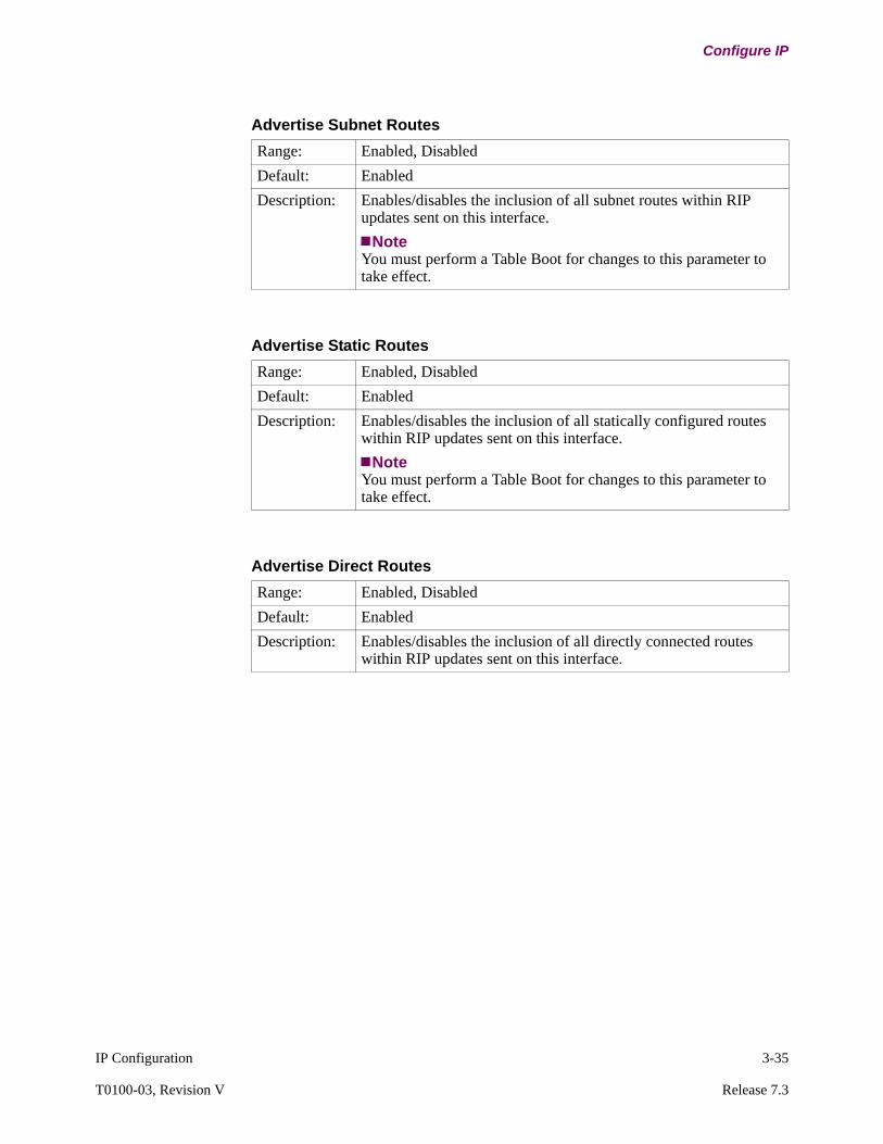
IP Configuration 3-35
T0100-03, Revision V Release 7.3
Configure IP
Advertise Subnet Routes
Range: Enabled, Disabled
Default: Enabled
Description: Enables/disables the inclusion of all subnet routes within RIP updates sent on this interface.
NoteYou must perform a Table Boot for changes to this parameter to take effect.
Advertise Static Routes
Range: Enabled, Disabled
Default: Enabled
Description: Enables/disables the inclusion of all statically configured routes within RIP updates sent on this interface.
NoteYou must perform a Table Boot for changes to this parameter to take effect.
Advertise Direct Routes
Range: Enabled, Disabled
Default: Enabled
Description: Enables/disables the inclusion of all directly connected routes within RIP updates sent on this interface.
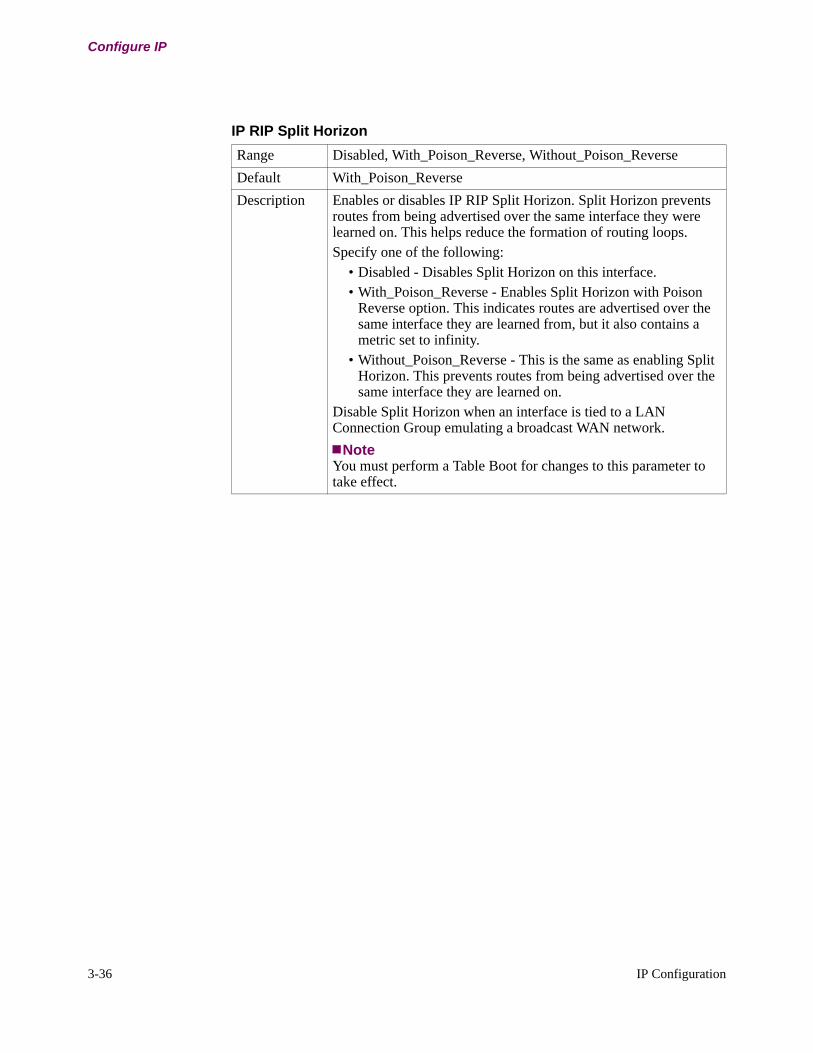
3-36 IP Configuration
Configure IP
IP RIP Split Horizon
Range Disabled, With_Poison_Reverse, Without_Poison_Reverse
Default With_Poison_Reverse
Description Enables or disables IP RIP Split Horizon. Split Horizon prevents routes from being advertised over the same interface they were learned on. This helps reduce the formation of routing loops. Specify one of the following:
• Disabled - Disables Split Horizon on this interface.• With_Poison_Reverse - Enables Split Horizon with Poison
Reverse option. This indicates routes are advertised over the same interface they are learned from, but it also contains a metric set to infinity.
• Without_Poison_Reverse - This is the same as enabling Split Horizon. This prevents routes from being advertised over the same interface they are learned on.
Disable Split Horizon when an interface is tied to a LAN Connection Group emulating a broadcast WAN network.
NoteYou must perform a Table Boot for changes to this parameter to take effect.
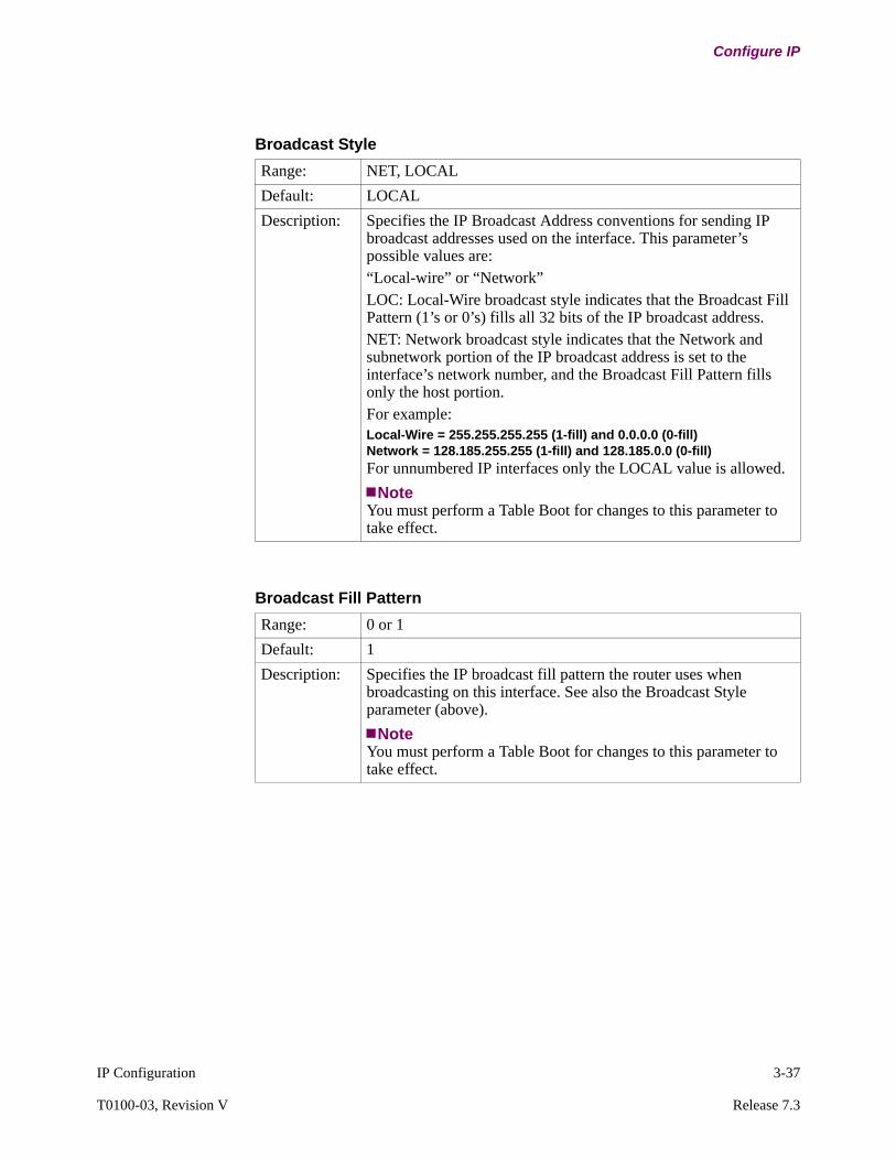
IP Configuration 3-37
T0100-03, Revision V Release 7.3
Configure IP
Broadcast Style
Range: NET, LOCAL
Default: LOCAL
Description: Specifies the IP Broadcast Address conventions for sending IP broadcast addresses used on the interface. This parameter’s possible values are: “Local-wire” or “Network” LOC: Local-Wire broadcast style indicates that the Broadcast Fill Pattern (1’s or 0’s) fills all 32 bits of the IP broadcast address.NET: Network broadcast style indicates that the Network and subnetwork portion of the IP broadcast address is set to the interface’s network number, and the Broadcast Fill Pattern fills only the host portion.For example:Local-Wire = 255.255.255.255 (1-fill) and 0.0.0.0 (0-fill)Network = 128.185.255.255 (1-fill) and 128.185.0.0 (0-fill)For unnumbered IP interfaces only the LOCAL value is allowed.
NoteYou must perform a Table Boot for changes to this parameter to take effect.
Broadcast Fill Pattern
Range: 0 or 1
Default: 1
Description: Specifies the IP broadcast fill pattern the router uses when broadcasting on this interface. See also the Broadcast Style parameter (above).
NoteYou must perform a Table Boot for changes to this parameter to take effect.
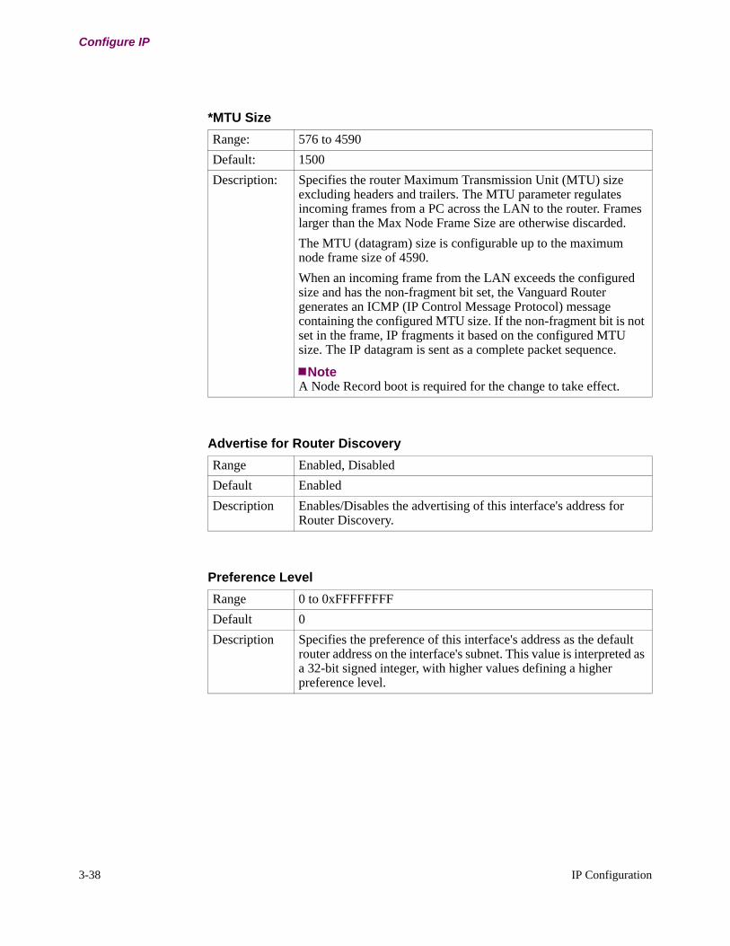
3-38 IP Configuration
Configure IP
*MTU Size
Range: 576 to 4590
Default: 1500
Description: Specifies the router Maximum Transmission Unit (MTU) size excluding headers and trailers. The MTU parameter regulates incoming frames from a PC across the LAN to the router. Frames larger than the Max Node Frame Size are otherwise discarded.
The MTU (datagram) size is configurable up to the maximum node frame size of 4590.
When an incoming frame from the LAN exceeds the configured size and has the non-fragment bit set, the Vanguard Router generates an ICMP (IP Control Message Protocol) message containing the configured MTU size. If the non-fragment bit is not set in the frame, IP fragments it based on the configured MTU size. The IP datagram is sent as a complete packet sequence.
NoteA Node Record boot is required for the change to take effect.
Advertise for Router Discovery
Range Enabled, Disabled
Default Enabled
Description Enables/Disables the advertising of this interface's address for Router Discovery.
Preference Level
Range 0 to 0xFFFFFFFF
Default 0
Description Specifies the preference of this interface's address as the default router address on the interface's subnet. This value is interpreted as a 32-bit signed integer, with higher values defining a higher preference level.
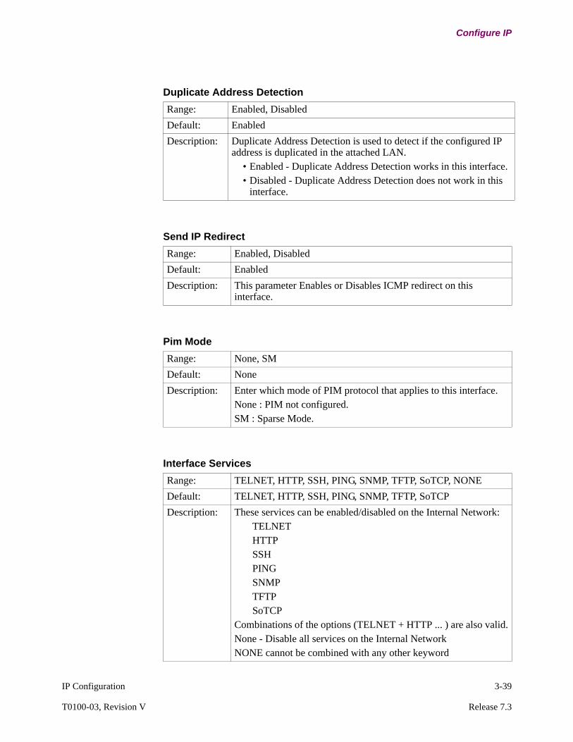
IP Configuration 3-39
T0100-03, Revision V Release 7.3
Configure IP
Duplicate Address Detection
Range: Enabled, Disabled
Default: Enabled
Description: Duplicate Address Detection is used to detect if the configured IP address is duplicated in the attached LAN.
• Enabled - Duplicate Address Detection works in this interface.• Disabled - Duplicate Address Detection does not work in this
interface.
Send IP Redirect
Range: Enabled, Disabled
Default: Enabled
Description: This parameter Enables or Disables ICMP redirect on this interface.
Pim Mode
Range: None, SM
Default: None
Description: Enter which mode of PIM protocol that applies to this interface.None : PIM not configured.SM : Sparse Mode.
Interface Services
Range: TELNET, HTTP, SSH, PING, SNMP, TFTP, SoTCP, NONE
Default: TELNET, HTTP, SSH, PING, SNMP, TFTP, SoTCP
Description: These services can be enabled/disabled on the Internal Network:TELNETHTTPSSHPINGSNMPTFTPSoTCP
Combinations of the options (TELNET + HTTP ... ) are also valid.None - Disable all services on the Internal NetworkNONE cannot be combined with any other keyword
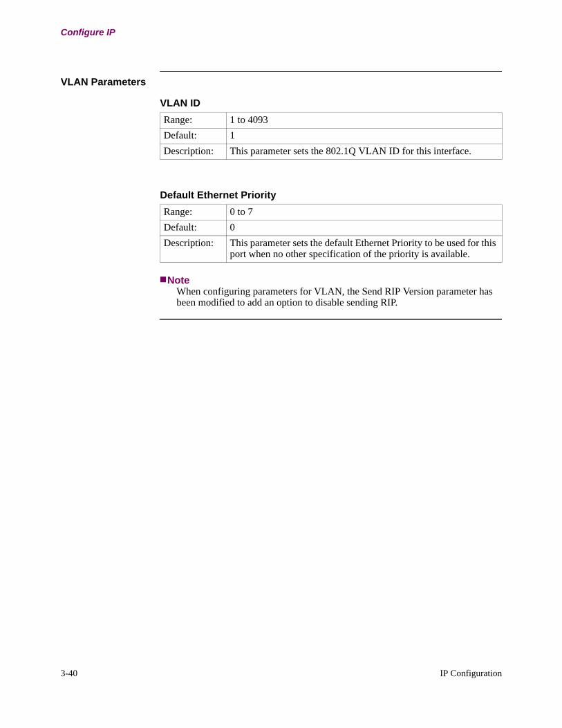
3-40 IP Configuration
Configure IP
VLAN Parameters
NoteWhen configuring parameters for VLAN, the Send RIP Version parameter has been modified to add an option to disable sending RIP.
VLAN ID
Range: 1 to 4093
Default: 1
Description: This parameter sets the 802.1Q VLAN ID for this interface.
Default Ethernet Priority
Range: 0 to 7
Default: 0
Description: This parameter sets the default Ethernet Priority to be used for this port when no other specification of the priority is available.
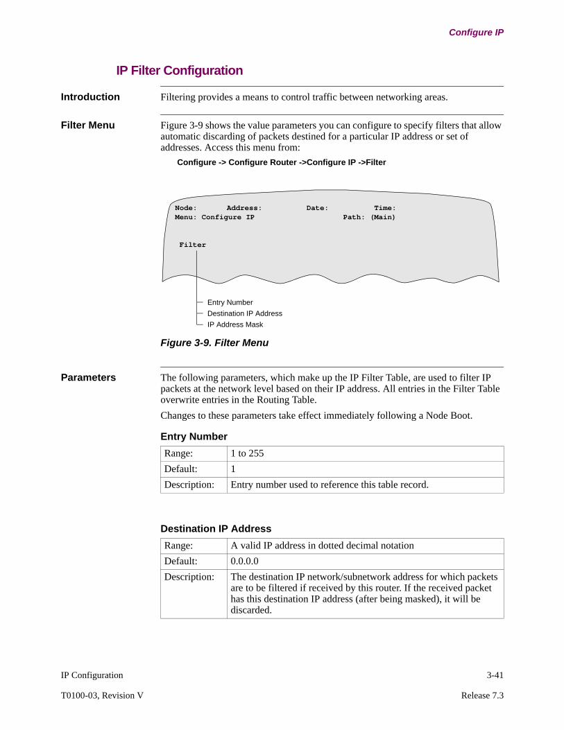
IP Configuration 3-41
T0100-03, Revision V Release 7.3
Configure IP
IP Filter Configuration
Introduction Filtering provides a means to control traffic between networking areas.
Filter Menu Figure 3-9 shows the value parameters you can configure to specify filters that allow automatic discarding of packets destined for a particular IP address or set of addresses. Access this menu from:
Configure -> Configure Router ->Configure IP ->Filter
Figure 3-9. Filter Menu
Parameters The following parameters, which make up the IP Filter Table, are used to filter IP packets at the network level based on their IP address. All entries in the Filter Table overwrite entries in the Routing Table.
Changes to these parameters take effect immediately following a Node Boot.
Entry Number
Destination IP AddressIP Address Mask
Node: Address: Date: Time: Menu: Configure IP Path: (Main)
Filter
Entry Number
Range: 1 to 255
Default: 1
Description: Entry number used to reference this table record.
Destination IP Address
Range: A valid IP address in dotted decimal notation
Default: 0.0.0.0
Description: The destination IP network/subnetwork address for which packets are to be filtered if received by this router. If the received packet has this destination IP address (after being masked), it will be discarded.

3-42 IP Configuration
Configure IP
IP Address Mask
Range: A valid IP address in dotted decimal notation
Default: 255.255.255.0
Description: Network (or Subnetwork) address mask associated with the network/subnetwork Destination IP Address to be filtered.
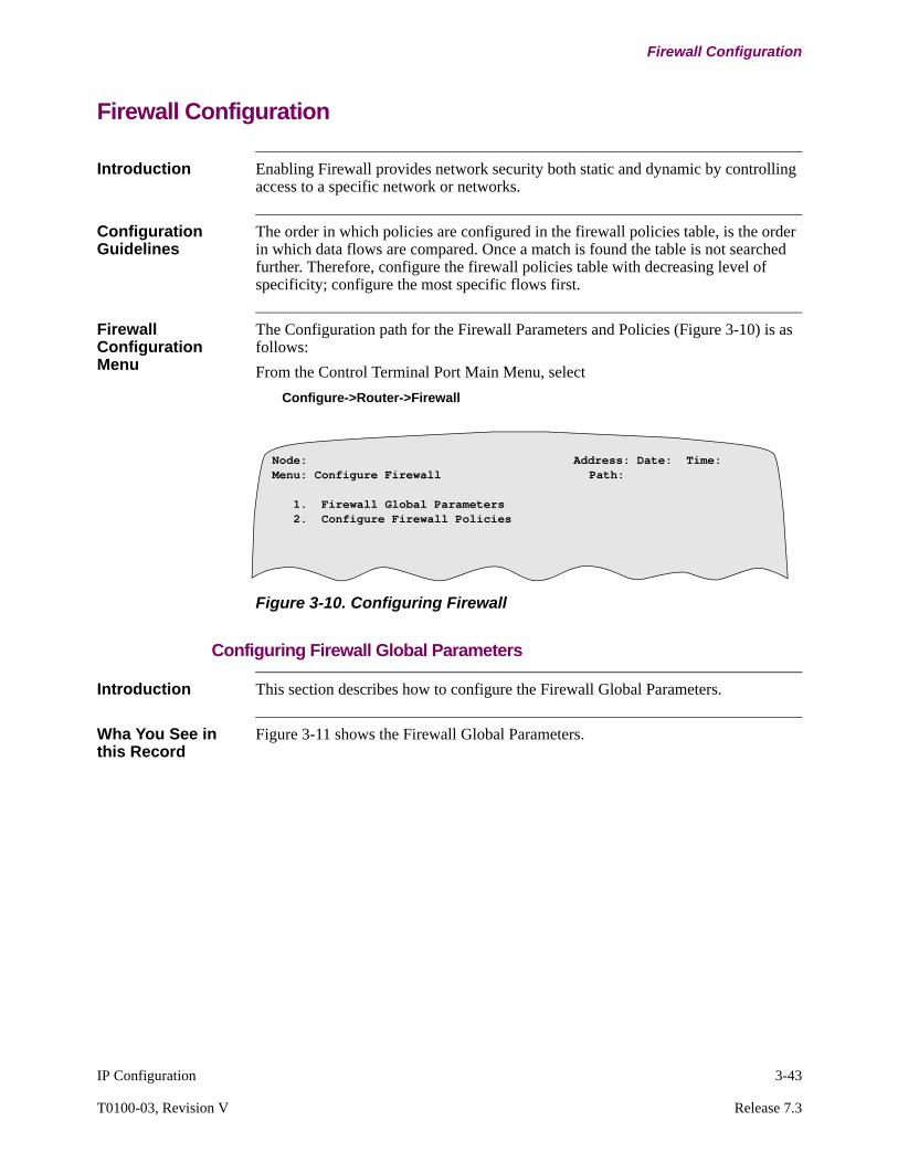
IP Configuration 3-43
T0100-03, Revision V Release 7.3
Firewall Configuration
Firewall Configuration
Introduction Enabling Firewall provides network security both static and dynamic by controlling access to a specific network or networks.
Configuration Guidelines
The order in which policies are configured in the firewall policies table, is the order in which data flows are compared. Once a match is found the table is not searched further. Therefore, configure the firewall policies table with decreasing level of specificity; configure the most specific flows first.
Firewall Configuration Menu
The Configuration path for the Firewall Parameters and Policies (Figure 3-10) is as follows:
From the Control Terminal Port Main Menu, select
Configure->Router->Firewall
Figure 3-10. Configuring Firewall
Configuring Firewall Global Parameters
Introduction This section describes how to configure the Firewall Global Parameters.
Wha You See in this Record
Figure 3-11 shows the Firewall Global Parameters.
Node: Address: Date: Time: Menu: Configure Firewall Path:
1. Firewall Global Parameters 2. Configure Firewall Policies
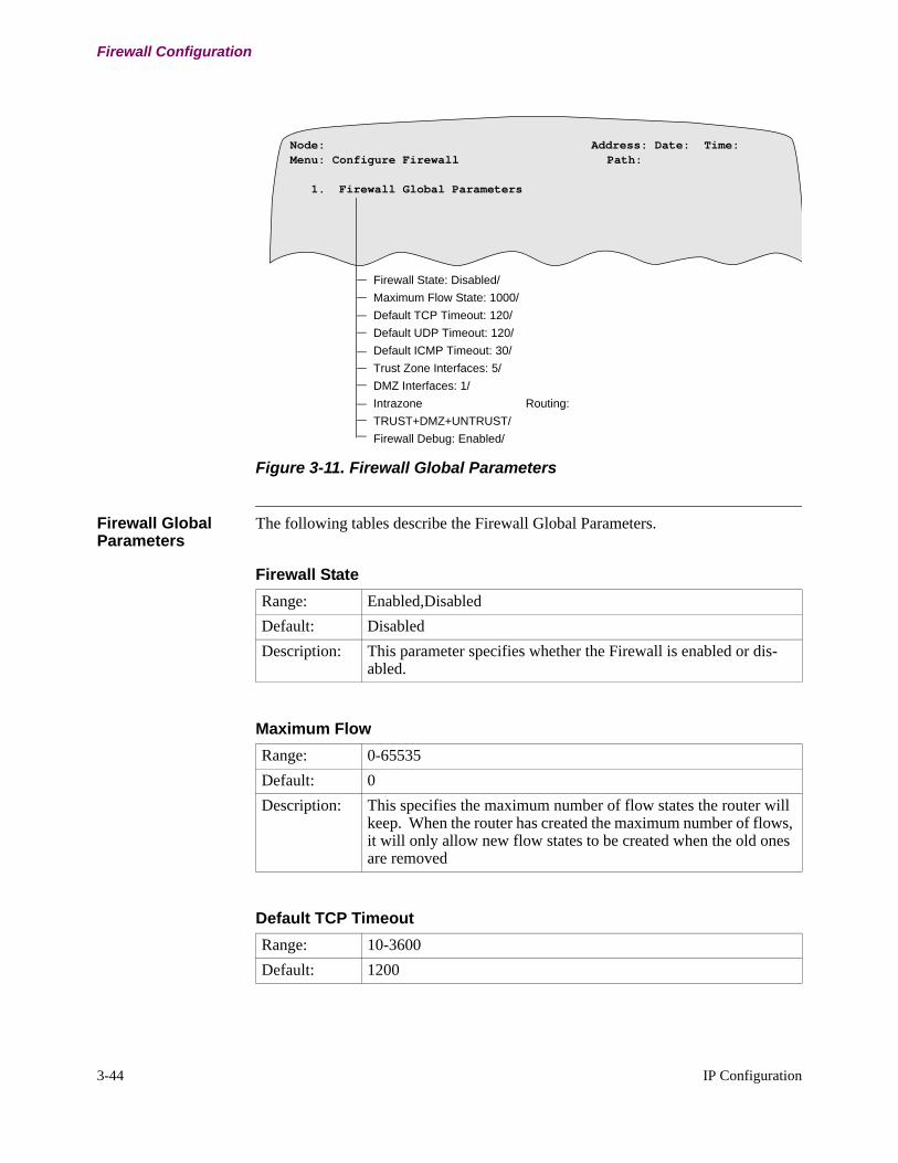
3-44 IP Configuration
Firewall Configuration
Figure 3-11. Firewall Global Parameters
Firewall Global Parameters
The following tables describe the Firewall Global Parameters.
Node: Address: Date: Time: Menu: Configure Firewall Path:
1. Firewall Global Parameters
Firewall State: Disabled/
Maximum Flow State: 1000/
Default TCP Timeout: 120/
Default UDP Timeout: 120/
Default ICMP Timeout: 30/
Trust Zone Interfaces: 5/
DMZ Interfaces: 1/
Intrazone Routing:
TRUST+DMZ+UNTRUST/
Firewall Debug: Enabled/
Firewall State
Range: Enabled,Disabled
Default: Disabled
Description: This parameter specifies whether the Firewall is enabled or dis-abled.
Maximum Flow
Range: 0-65535
Default: 0
Description: This specifies the maximum number of flow states the router will keep. When the router has created the maximum number of flows, it will only allow new flow states to be created when the old ones are removed
Default TCP Timeout
Range: 10-3600
Default: 1200
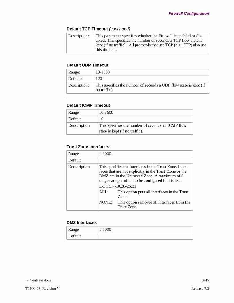
IP Configuration 3-45
T0100-03, Revision V Release 7.3
Firewall Configuration
\
Description: This parameter specifies whether the Firewall is enabled or dis-abled. This specifies the number of seconds a TCP flow state is kept (if no traffic). All protocols that use TCP (e.g., FTP) also use this timeout.
Default TCP Timeout (continued)
Default UDP Timeout
Range: 10-3600
Default: 120
Description: This specifies the number of seconds a UDP flow state is kept (if no traffic).
Default ICMP Timeout
Range 10-3600
Default 10
Decscription This specifies the number of seconds an ICMP flowstate is kept (if no traffic).
Trust Zone Interfaces
Range 1-1000
Default
Decscription This specifies the interfaces in the Trust Zone. Inter-faces that are not explicitly in the Trust Zone or the DMZ are in the Untrusted Zone. A maximum of 8 ranges are permitted to be configured in this list.Ex: 1,5,7-10,20-25,31ALL: This option puts all interfaces in the Trust
Zone.NONE: This option removes all interfaces from the
Trust Zone.
DMZ Interfaces
Range 1-1000
Default
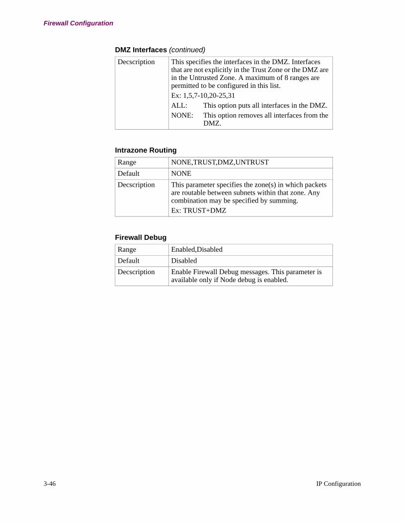
3-46 IP Configuration
Firewall Configuration
Decscription This specifies the interfaces in the DMZ. Interfaces that are not explicitly in the Trust Zone or the DMZ are in the Untrusted Zone. A maximum of 8 ranges are permitted to be configured in this list.Ex: 1,5,7-10,20-25,31ALL: This option puts all interfaces in the DMZ.NONE: This option removes all interfaces from the
DMZ.
DMZ Interfaces (continued)
Intrazone Routing
Range NONE,TRUST,DMZ,UNTRUST
Default NONE
Decscription This parameter specifies the zone(s) in which packets are routable between subnets within that zone. Any combination may be specified by summing.Ex: TRUST+DMZ
Firewall Debug
Range Enabled,Disabled
Default Disabled
Decscription Enable Firewall Debug messages. This parameter is available only if Node debug is enabled.
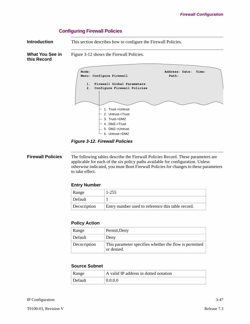
IP Configuration 3-47
T0100-03, Revision V Release 7.3
Firewall Configuration
Configuring Firewall Policies
Introduction This section describes how to configure the Firewall Policies.
What You See in this Record
Figure 3-12 shows the Firewall Policies.
Figure 3-12. Firewall Policies
Firewall Policies The following tables describe the Firewall Policies Record. These parameters are applicable for each of the six policy paths available for configuration. Unless otherwise indicated, you must Boot Firewall Policies for changes to these parameters to take effect.
Node: Address: Date: Time: Menu: Configure Firewall Path:
1. Firewall Global Parameters 2. Configure Firewall Policies
1. Trust->Untrust
2. Untrust->Trust
3. Trust->DMZ
4. DMZ->Trust
5. DMZ->Untrust
6. Untrust->DMZ
Entry Number
Range 1-255
Default 1
Decscription Entry number used to reference this table record.
Policy Action
Range Permit,Deny
Default Deny
Decscription This parameter specifies whether the flow is permitted or denied.
Source Subnet
Range A valid IP address in dotted notation
Default 0.0.0.0

3-48 IP Configuration
Firewall Configuration
Decscription This parameter specifies the source subnet for this pol-icy. It is of the form X.X.X.X.
Source Subnet (continued)
Source Mask
Range A valid IP address in dotted notation
Default 0.0.0.0
Decscription This parameter specifies the source subnet mask for this policy. It is of the form X.X.X.X.
Destination Subnet
Range A valid IP address in dotted notation
Default 0.0.0.0
Decscription This parameter specifies the source subnet for this pol-icy. It is of the form X.X.X.X.
Destination Mask
Range A valid IP address in dotted notation
Default 0.0.0.0
Decscription This parameter specifies the source subnet mask for this policy. It is of the form X.X.X.X.
Protocol
Range Protocol number between 1-255, or TCP,UDP,ICMP or ANY
Default ANY
Decscription This parameter specifies the protocol for this policy. It can be TCP, UDP, ICMP, ANY, or a range of numbers from 1-255.

IP Configuration 3-49
T0100-03, Revision V Release 7.3
IP Access Control Configuration
IP Access Control Configuration
Introduction Enabling IP Access Control provides network security by controlling access to a specific network or networks.
Configuration Guideline
The order in which access control entries are configured in the access control table, is the order in which access control entries are searched. Once a match is found, the access control table is not searched further. Therefore, configure the access control table with decreasing level of specificity; configure the most specific flows first.
Frequently Used TCP and UDP Port Numbers
The following table provides a listing of frequently used TCP and UDP port numbers. For a complete list of TCP and UDP port numbers, refer to RFC-1340.
Port Protocol Usage Port Protocol Usage
5 RJE TCP & UDP 53 DOMAIN TCP & UDP
7 ECHO TCP & UDP 67 BOOTPS TCP & UDP
9 DISCARD TCP & UDP 68 BOOTPC TCP & UDP
11 USERS TCP & UDP 69 TFTP TCP & UDP
13 DAYTIME TCP & UDP 75 private dial TCP & UDP
15 NETSTAT TCP & UDP 77 private RJE TCP & UDP
17 QUOTE TCP & UDP 79 FINGER TCP & UDP
19 CHARGEN TCP & UDP 95 SUPDUP TCP
20 FTP-DATA TCP 101 HOSTNAME TCP
21 FTP TCP 102 ISO-TSAP TCP
23 TELNET TCP 113 AUTH TCP
25 SMTP TCP 117 UUCP-PATH TCP
37 TIME TCP & UDP 123 NTP TCP & UDP
39 RLP TCP & UDP 513 rlogin TCP
42 NAMESERVER
TCP & UDP 520 EXT Name Server
UDP
43 NICNAME TCP & UDP
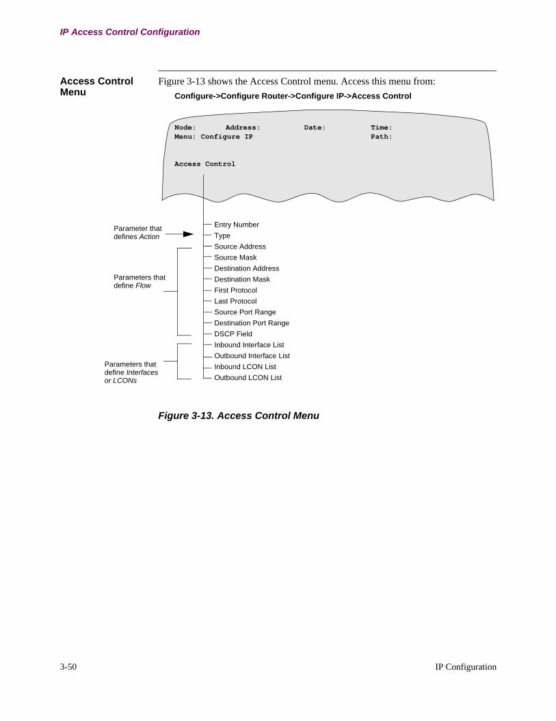
3-50 IP Configuration
IP Access Control Configuration
Access Control Menu
Figure 3-13 shows the Access Control menu. Access this menu from:
Configure->Configure Router->Configure IP->Access Control
Figure 3-13. Access Control Menu
Node: Address: Date: Time: Menu: Configure IP Path:
Access Control
Entry Number
Type
Source Address
Source Mask
Destination Address
Destination Mask
First Protocol
Last Protocol
Source Port Range
Destination Port Range
DSCP Field
Inbound Interface List
Outbound Interface List
Inbound LCON List
Outbound LCON List
Parameters thatdefine Flow
Parameter thatdefines Action
Parameters thatdefine Interfacesor LCONs

IP Configuration 3-51
T0100-03, Revision V Release 7.3
IP Access Control Configuration
Parameters The following parameters make up the IP Access Control Table. Parameter changes take effect immediately following a Table Boot.
Entry Number
Range: 1 to 255
Default: 1
Description: This is the entry number used to reference this table record.
Type
Range: Include, Exclude
Default: Include
Description: Each received IP packet is compared against all defined access control entries in the order of entry number. This parameter specifies the action applied on IP packets matching flows defined by this access control entry. The two parameter settings are:
• Include: If a match is made on the contents of an IP packet (Source IP Address, Destination IP Address, IP Protocol number range, and TCP/UDP port number range), the packet is retained for further processing. If the first matching Access Control Entry is Inclusive, the packet is forwarded.
• Exclude: If a match is made and the Type is exclude, the packet is dropped.
Source Address
Range: A valid IP address in dotted notation
Default: 0.0.0.0
Description: Specifies the source IP address. The source IP address is used with the source IP mask to define an address or subnet against which a match is attempted.
NoteA Source Address of 0.0.0.0 and a Source Mask of 0.0.0.0 is used as a wildcard. This address and mask pair will matches any source IP address in the packet.
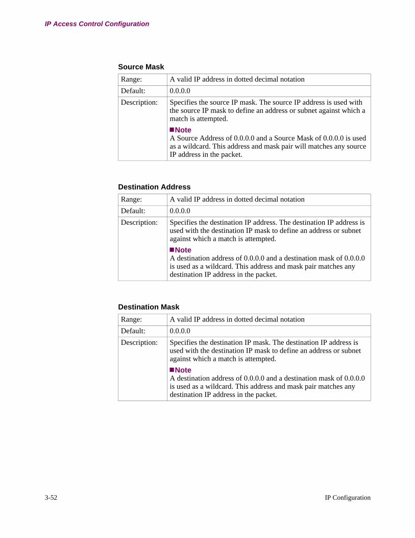
3-52 IP Configuration
IP Access Control Configuration
Source Mask
Range: A valid IP address in dotted decimal notation
Default: 0.0.0.0
Description: Specifies the source IP mask. The source IP address is used with the source IP mask to define an address or subnet against which a match is attempted.
NoteA Source Address of 0.0.0.0 and a Source Mask of 0.0.0.0 is used as a wildcard. This address and mask pair will matches any source IP address in the packet.
Destination Address
Range: A valid IP address in dotted decimal notation
Default: 0.0.0.0
Description: Specifies the destination IP address. The destination IP address is used with the destination IP mask to define an address or subnet against which a match is attempted.
NoteA destination address of 0.0.0.0 and a destination mask of 0.0.0.0 is used as a wildcard. This address and mask pair matches any destination IP address in the packet.
Destination Mask
Range: A valid IP address in dotted decimal notation
Default: 0.0.0.0
Description: Specifies the destination IP mask. The destination IP address is used with the destination IP mask to define an address or subnet against which a match is attempted.
NoteA destination address of 0.0.0.0 and a destination mask of 0.0.0.0 is used as a wildcard. This address and mask pair matches any destination IP address in the packet.

IP Configuration 3-53
T0100-03, Revision V Release 7.3
IP Access Control Configuration
First Protocol
Range: 0 to 255
Default: 0
Description: Corresponds to the protocol byte in the IP header. A packet with the IP protocol byte between the First Protocol value and the Last Protocol value, inclusive, will match the entry. The First Protocol value must be equal to, or less, than the Last Protocol value. A First protocol value of 0 and a last protocol value of 255 matches all IP packets. Commonly used IP protocol numbers are:
• 1: ICMP• 6: TCP• 8: EGP• 17: UDP• 89: OSPF
Last Protocol
Range: 0 to 255
Default: 255
Description: Corresponds to the protocol byte in the IP header. A packet with the protocol value in the specified range matches the parameter. This parameter defines the upper value of this range and must be greater than, or equal to, the First Protocol value field. A First Protocol value of 0 and a Last Protocol value of 255 matches all IP packets. Commonly used IP protocol numbers are:
• 1: ICMP• 6: TCP• 8: EGP• 17: UDP• 89: OSPF
DSCP Field
Range: 000000 - 111111 (binary), * - wildcard
Default: ******
Description: Six bit binary representation of the DSCP (TOS) field in the IP header. (e.g., 101110). Each “*” indicates a wildcard pattern for that bit. “******” will match every 6 bit pattern.

3-54 IP Configuration
IP Access Control Configuration
NoteThis parameter is visible only if first protocol and last protocol is 1 (ICMP).
NoteWe do not allow filtering based on packet size regardless of protocol, because this will make firewall feature incompatible with aggregated cache.
NoteThis parameter is visible only if first protocol and last protocol is 1 (ICMP).
NoteThis parameter is visible only if the ICMP type is set to a single value (i.e., not a range).
Max ICMP Packet Size
Range: 20-65535
Default: 65535
Description: This specify the maximum size of an ICMP packet. The minimum (lower bound) of the size is always 20. E.g., If the parameter is 1000, it specifies ICMP packets of size in range 20-1000.
ICMP TYPE
Range: 0-255
Default: 0-255
Description: This specifies the range of ICMP type of the IP packet to be matched. This parameter can be a group of ranges (e.g., 1-4,6,10-20). It can also be a single value. The common ICMP types are: 0=Echo Reply, 3=Destination unreachable, 5=Redirect, 8=Echo, 12=Parameter Problem, 30=Traceroute
ICMP Code
Range: 0-255
Default: 0-255
Description: This specifies the range of ICMP code of the IP ICMP packet to be matched. This parameter can be a group of ranges (e.g., 1-4,6,10-20). It can also be a single value.
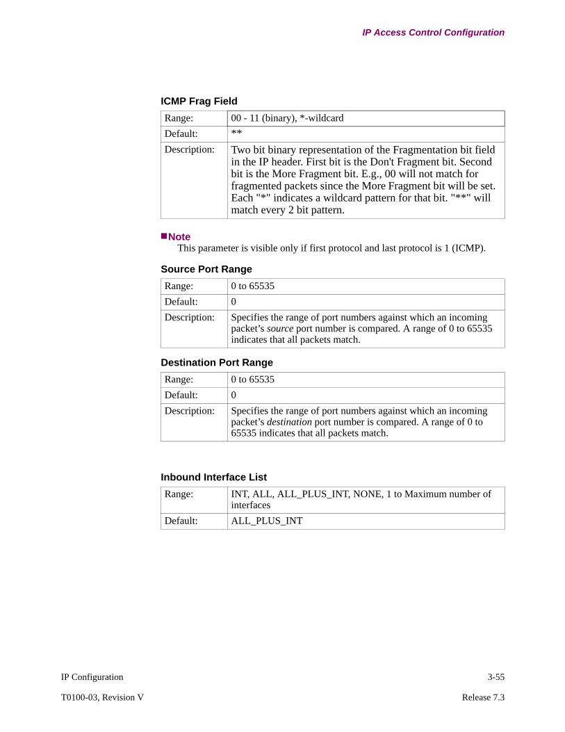
IP Configuration 3-55
T0100-03, Revision V Release 7.3
IP Access Control Configuration
NoteThis parameter is visible only if first protocol and last protocol is 1 (ICMP).
ICMP Frag Field
Range: 00 - 11 (binary), *-wildcard
Default: **
Description: Two bit binary representation of the Fragmentation bit field in the IP header. First bit is the Don't Fragment bit. Second bit is the More Fragment bit. E.g., 00 will not match for fragmented packets since the More Fragment bit will be set. Each "*" indicates a wildcard pattern for that bit. "**" will match every 2 bit pattern.
Source Port Range
Range: 0 to 65535
Default: 0
Description: Specifies the range of port numbers against which an incoming packet’s source port number is compared. A range of 0 to 65535 indicates that all packets match.
Destination Port Range
Range: 0 to 65535
Default: 0
Description: Specifies the range of port numbers against which an incoming packet’s destination port number is compared. A range of 0 to 65535 indicates that all packets match.
Inbound Interface List
Range: INT, ALL, ALL_PLUS_INT, NONE, 1 to Maximum number of interfaces
Default: ALL_PLUS_INT
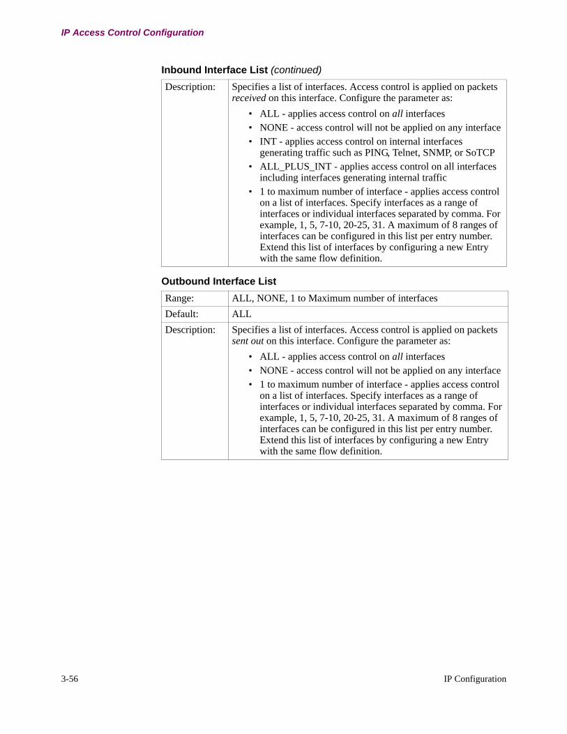
3-56 IP Configuration
IP Access Control Configuration
Description: Specifies a list of interfaces. Access control is applied on packets received on this interface. Configure the parameter as:
• ALL - applies access control on all interfaces• NONE - access control will not be applied on any interface• INT - applies access control on internal interfaces
generating traffic such as PING, Telnet, SNMP, or SoTCP• ALL_PLUS_INT - applies access control on all interfaces
including interfaces generating internal traffic• 1 to maximum number of interface - applies access control
on a list of interfaces. Specify interfaces as a range of interfaces or individual interfaces separated by comma. For example, 1, 5, 7-10, 20-25, 31. A maximum of 8 ranges of interfaces can be configured in this list per entry number. Extend this list of interfaces by configuring a new Entry with the same flow definition.
Outbound Interface List
Range: ALL, NONE, 1 to Maximum number of interfaces
Default: ALL
Description: Specifies a list of interfaces. Access control is applied on packets sent out on this interface. Configure the parameter as:
• ALL - applies access control on all interfaces• NONE - access control will not be applied on any interface• 1 to maximum number of interface - applies access control
on a list of interfaces. Specify interfaces as a range of interfaces or individual interfaces separated by comma. For example, 1, 5, 7-10, 20-25, 31. A maximum of 8 ranges of interfaces can be configured in this list per entry number. Extend this list of interfaces by configuring a new Entry with the same flow definition.
Inbound Interface List (continued)

IP Configuration 3-57
T0100-03, Revision V Release 7.3
IP Access Control Configuration
Inbound LCON List
Range: ALL, NONE, 1 to Maximum number of LCONs
Default ALL
Description Specifies a list of LCONs. Access control is applied on packets received on these LCONs. Configure the parameter as:
• ALL - applies access control on all LCONs.• NONE - access control is not applied on any LCON.• 1 to maximum number of LCON - applies access control on
a list of LCONs. Specify LCONs as a range of interfaces or individual LCONs separated by comma. For example, 1, 5, 7-10, 20-25, 31. A maximum of 8 ranges of LCONs can be configured in this list per entry number. Extend this list LCONs by configuring a new Entry with the same flow definition.
Outbound LCON List
Range: ALL, NONE, 1 to Maximum number of LCONs
Default: ALL
Description: Specifies a list of LCONs. Access control will be applied on packets sent out on these LCONs. Configure the parameter as:
• ALL - applies access control on all LCONs• NONE - access control will not be applied on any LCON• 1 to maximum number of LCON - applies access control on
a list of LCONs. Specify LCONs as a range of interfaces or individual LCONs separated by comma. For example, 1, 5, 7-10, 20-25, 31. A maximum of 8 ranges of LCONs can be configured in this list per entry number. Extend this list LCONs by configuring a new Entry with the same flow definition.

3-58 IP Configuration
Stateful Access Control Configuration
Stateful Access Control Configuration
Introduction Enabling Stateful Access Control allows the access control filter to dynamically allow traffic of the return and/or related flow.
Configuration Guide
Stateful Access Control searches matches in Stateful Access Control entries in ascending order. Once a match is found, the Stateful Access Control entries are not searched further. Therefore, configure the most specific flows first.
Follow These Steps...
To configure the Stateful Access Control, follow these steps:
Figure 3-14. Stateful Access Control Menu
Step Action Result/Description
1 At the CTP Main menu, select Con-figureand press ENTER.
The Configure menu appears.
2 Select Configure Router and press ENTER.
The Configure Router menu appears.
3 Select Configure IP and press ENTER.
The Configure IP Router menu appears.
4 Select Stateful Access Control and press ENTER.
The Stateful Access Control menu-menu similar to Figure 3-14appears.
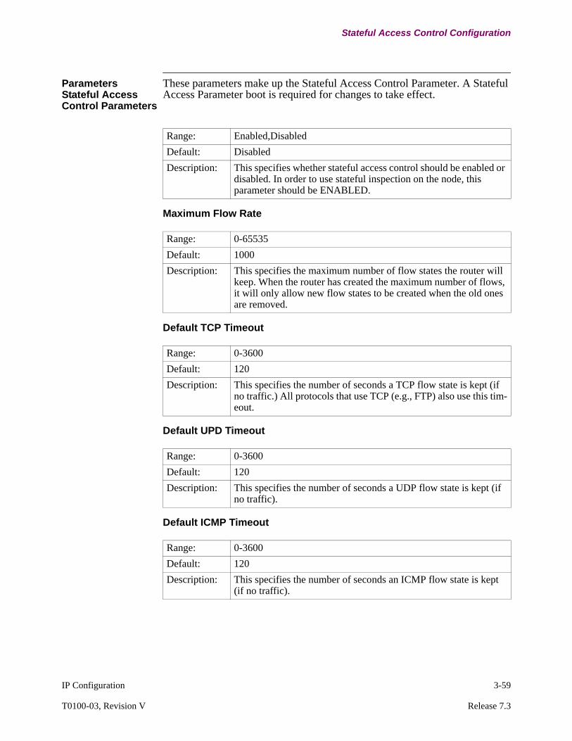
IP Configuration 3-59
T0100-03, Revision V Release 7.3
Stateful Access Control Configuration
ParametersStateful Access Control Parameters
These parameters make up the Stateful Access Control Parameter. A Stateful Access Parameter boot is required for changes to take effect.
Maximum Flow Rate
Default TCP Timeout
Default UPD Timeout
Default ICMP Timeout
Range: Enabled,Disabled
Default: Disabled
Description: This specifies whether stateful access control should be enabled or disabled. In order to use stateful inspection on the node, this parameter should be ENABLED.
Range: 0-65535
Default: 1000
Description: This specifies the maximum number of flow states the router will keep. When the router has created the maximum number of flows, it will only allow new flow states to be created when the old ones are removed.
Range: 0-3600
Default: 120
Description: This specifies the number of seconds a TCP flow state is kept (if no traffic.) All protocols that use TCP (e.g., FTP) also use this tim-eout.
Range: 0-3600
Default: 120
Description: This specifies the number of seconds a UDP flow state is kept (if no traffic).
Range: 0-3600
Default: 120
Description: This specifies the number of seconds an ICMP flow state is kept (if no traffic).

3-60 IP Configuration
Stateful Access Control Configuration
Stateful Access Control Entry
The following parameters make up the Stateful Access Control Entry record. The parameter change takes effect following a Stateful Access Control Entries Boot.
You can enter up to 256 Stateful Access Control entries.
Entry Number
Protocol
Interface
Range: 1-255
Default: 1
Description: Entry number used to reference this table record.
Range: NONE, UDP, ECP,FTP,ICMP
Default: None
Description: This parameter specifies the protocol(s) for which state informa-tion should be kept so that the return traffic will be allowed. To specify only TCP and UDP traffic, users can enter TCP+UDP. Type ALL to indicate that all protocol choices should be used (i.e., UDP+TCP+FTP+ICMP for this release).
Range: 1-1000
Default: N/A
Description: This parameter specifies the interface(s) that this entry is applica-ble. It can be a range 1,5,100-105.
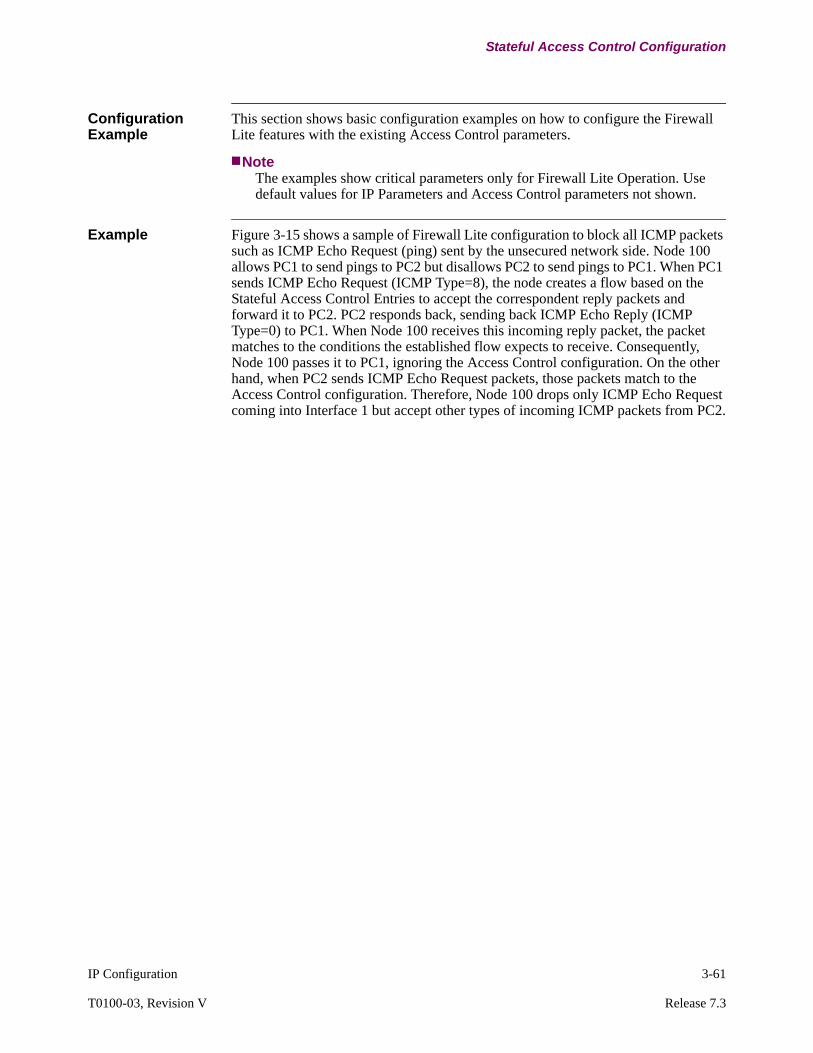
IP Configuration 3-61
T0100-03, Revision V Release 7.3
Stateful Access Control Configuration
Configuration Example
This section shows basic configuration examples on how to configure the Firewall Lite features with the existing Access Control parameters.
NoteThe examples show critical parameters only for Firewall Lite Operation. Use default values for IP Parameters and Access Control parameters not shown.
Example Figure 3-15 shows a sample of Firewall Lite configuration to block all ICMP packets such as ICMP Echo Request (ping) sent by the unsecured network side. Node 100 allows PC1 to send pings to PC2 but disallows PC2 to send pings to PC1. When PC1 sends ICMP Echo Request (ICMP Type=8), the node creates a flow based on the Stateful Access Control Entries to accept the correspondent reply packets and forward it to PC2. PC2 responds back, sending back ICMP Echo Reply (ICMP Type=0) to PC1. When Node 100 receives this incoming reply packet, the packet matches to the conditions the established flow expects to receive. Consequently, Node 100 passes it to PC1, ignoring the Access Control configuration. On the other hand, when PC2 sends ICMP Echo Request packets, those packets match to the Access Control configuration. Therefore, Node 100 drops only ICMP Echo Request coming into Interface 1 but accept other types of incoming ICMP packets from PC2.
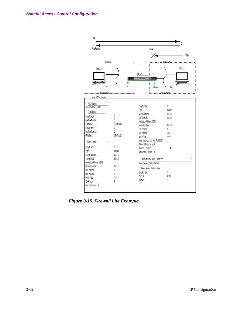
3-62 IP Configuration
Stateful Access Control Configuration
Figure 3-15. Firewall Lite Example
.115
PC1
.144 .44
Node 100
5 VANGUARDRemot eVU G uardi an
p ow e r ha rd d ri ve b oo t v i d eo
st at u s
.2#2 #1
PC2
Secured Network Unsecured Network
150.40.8.0/24 150.40.1.0/24
Block
Pings
Pings
Ping Replies
Node 100 Configuration
Access Control: EnabledIP Parameters :
Access Control :
Entry Number: 1Type: ExcludeSource Address: 0.0.0.0Source Mask: 0.0.0.0Destination Address: 0.0.0.0Destination Mask: 0.0.0.0First Protocol: 1Last Protocol: 1DSCP Field: ******ICMP Type: 8Inbound Interface List: 1
IP Interfaces :
Entry Number: 1Interface Number: 1IP Address: 150.40.8.44Entry Number: 2Interface Number: 2IP Address: 150.40.1.115
Stateful Access Control Parameters :
Stateful Access Control Entries
Stateful Access Control: Enabled
Entry Number: 1Protocol: ICMPInterface: 1
Entry Number: 2Type: IncludeSource Address: 0.0.0.0Source Mask: 0.0.0.0Destination Address: 0.0.0.0Destination Mask: 0.0.0.0First Protocol: 0Last Protocol: 255DSCP Field: ******Inbound Interface List: ALL_PLUS_INTOutbound Interface List: ALLInbound LCON List: ALLOutbound LCON List: ALL

IP Configuration 3-63
T0100-03, Revision V Release 7.3
Stateful Access Control Configuration
Booting Stateful Access Parameters and Control Entries
Introduction After enabling Stateful Access Parameters and/or configuring Stateful Access Control Entries, it is necessary to boot the parameters and/or the entries to take effect. This section explains how to perform these functions.
Follow These Steps...
Follow these steps to boot Stateful Access Parameters and Control Entries:
Figure 3-16. Boot IP Menu
NoteWhen making changes to Access Control, select Boot IP Tables from the Boot IP menu.
NoteWhen Access Control in IP Parameters is enabled, boot IP Parameters.
Step Action Result
1 Select Boot from the CTP Main menu. The Boot menu appears..
2 Select Configure IP. The Configure IP menu appears as shown in Figure 3-6 on page 3-13.
3 Select Boot Router -> Boot IP from the Boot menu.
The Boot IP menu, shown in Figure 3-16, appears.
4 Select Stateful Access Parameters or Stateful Access Control Entries from the Boot IP menu.
The modified parameters are booted and all changes made are implemented.
5 Type ; to save the entry. The entry is saved.
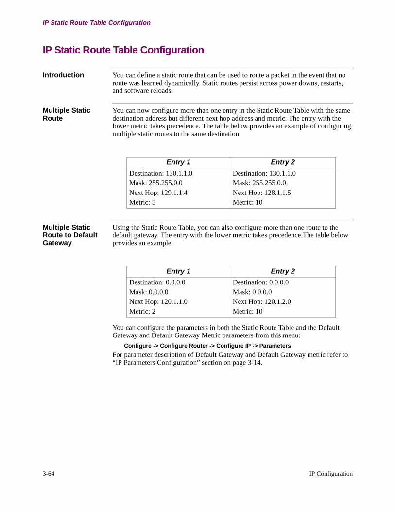
3-64 IP Configuration
IP Static Route Table Configuration
IP Static Route Table Configuration
Introduction You can define a static route that can be used to route a packet in the event that no route was learned dynamically. Static routes persist across power downs, restarts, and software reloads.
Multiple Static Route
You can now configure more than one entry in the Static Route Table with the same destination address but different next hop address and metric. The entry with the lower metric takes precedence. The table below provides an example of configuring multiple static routes to the same destination.
Multiple Static Route to Default Gateway
Using the Static Route Table, you can also configure more than one route to the default gateway. The entry with the lower metric takes precedence.The table below provides an example.
You can configure the parameters in both the Static Route Table and the Default Gateway and Default Gateway Metric parameters from this menu:
Configure -> Configure Router -> Configure IP -> Parameters
For parameter description of Default Gateway and Default Gateway metric refer to “IP Parameters Configuration” section on page 3-14.
Entry 1 Entry 2
Destination: 130.1.1.0Mask: 255.255.0.0Next Hop: 129.1.1.4Metric: 5
Destination: 130.1.1.0Mask: 255.255.0.0Next Hop: 128.1.1.5Metric: 10
Entry 1 Entry 2
Destination: 0.0.0.0Mask: 0.0.0.0Next Hop: 120.1.1.0Metric: 2
Destination: 0.0.0.0Mask: 0.0.0.0Next Hop: 120.1.2.0Metric: 10

IP Configuration 3-65
T0100-03, Revision V Release 7.3
IP Static Route Table Configuration
Static Routes Menu Figure 3-17 shows the Static Routes menu. Access this menu from:
Configure -> Configure Router ->Configure IP -> Static Route
Figure 3-17. Static Routes Menu
Parameters The following parameters make up the IP Route Table, which is used to define static routes. The parameter changes take effect immediately following a Table Boot and the following occurs:
• The changed configuration is read in (this is the new static information).• Dynamic information is not discarded except when static information
overrides dynamic information.• Old static information that is invalid is removed from the table.• Changes in Routing Table generate routing updates
(for example: Rip-triggered update, OSPF updates).
NoteTo flush out all routing table entries and rebuild the IP RIP tables, use the command:
LAN Control Menu -> Control Router -> Control IP -> Reset IP RIP tables.
Entry Number
IP Network/Subnet
IP Address Mask
Next Hop
Metric
Node: Address: Date: Time: Menu: Configure IP Path: (Main)
Static Route
Entry Number
Range:Range - 7300:
1 to 1024Vanguard 7300 Series maximum number of static routes has been increased from 1,024 to 8,000 with release 6.0.P02A and greater.
Default: 1
Description: Number used to reference this table record.

3-66 IP Configuration
IP Static Route Table Configuration
IP Network/Subnet
Range: A valid IP address in dotted decimal notation
Default: 0.0.0.0
Description: The IP address of a destination network or subnetwork. Host addresses are not included in the route table.
IP Mask
Range: A valid IP address in dotted decimal notation
Default: 255.255.255.0
Description: Specifies the IP address mask for defining the subnetwork address if subnetting is being done. For example, if the destination is a subnet of a class B network and the third byte of the IP address is used as the subnet portion, the address mask is set to 255.255.255.0.For classless addressing, enter masks as defined in the “How IP Routing Works” section on page 1-11.
Next Hop
Range: A valid IP address in dotted decimal notation
Default: 0.0.0.0
Description: The IP address of the next hop to the destination.The next hop itself must be on an IP network directly connected to the router. If the next hop is an unnumbered interface, enter 0.0.0.N where N is the (interface number - 1). If next hop is 255.255.255.255, the route is a null route.
NoteFrom Release 7.1 or greater. For IPSEC Tunnels, this entry must be a remote tunnel interface address. A local tunnel interface address is invalid.
Metric
Range: 1 to 255
Default: 1
Description: Specifies the distance or cost metric to the destination. It is interpreted as a number of hops.

IP Configuration 3-67
T0100-03, Revision V Release 7.3
Null Routes Configuration
Null Routes Configuration
Introduction To discard packets, Null Routes need to be configured Next Hop as 255.255.255.255 with a higher metric than preferred routes. The table below provides an example.
Null Routes Configuration Example
Figure 3-18 shows an example of the configurable parameters for Null Routes.
Figure 3-18. Null Routes Configuration Example
In the example above, Node 3480 learns the static route, 191.1.1.0, from the RIP node via RIP protocol. As the learned static route has a lower metric, Node 3480 overwrites the configured Null Route for 191.1.1.0 and update the routing table as shown below:
Type Dest net Mask Metric Age Next hop
Sbnt 134.33.0.0 ffff0000 1 0 None
Dir 134.33.5.0 ffffff00 1 0 SL/51
SPF 134.33.5.5 ffffffff 0 0 SL/51
Dir 134.33.16.0 ffffff00 1 0 ETH/1
RIP 191.1.0.0 ffff0000 2 20 134.33.16.2
RIP* 191.1.1.0 ffffff00 2 20 134.33.16.2
Entry 1
IP Network/Subnet: 192.1.1.0IP Address Mask: 255.255.255.0Next Hop: 255.255.255.255Metric: 10
P 1
Frame Relay Cloud
134.33.16.0/24
.2
6841
P 1
P 7
P 3
Node3461
Node3462
Node3462
P 23
P 23
.1
RIP
OSPF Network
P 16
P 10P 1
P 7
134.33.5.0/24
.5
.2
.4
134.33.2.0/24
134.33.3.0/24
134.33.4.0/24
.1
.1
Interface Number: 1IP Address: 134.33.16.2IP Address Mask: 255.255.255.0
IP Network/Subnet: 191.1.1.0IP Address Mask: 255.255.255.0Next Hop: 192.167.1.78Metric: 1
Interface Number: 1IP Address: 134.33.16.1IP Address Mask: 255.255.255.0Override Static Routes: Enabled
IP Network/Subnet: 191.1.1.0IP Address Mask: 255.255.255.0Next Hop: 255.255.255.255Metric: 5
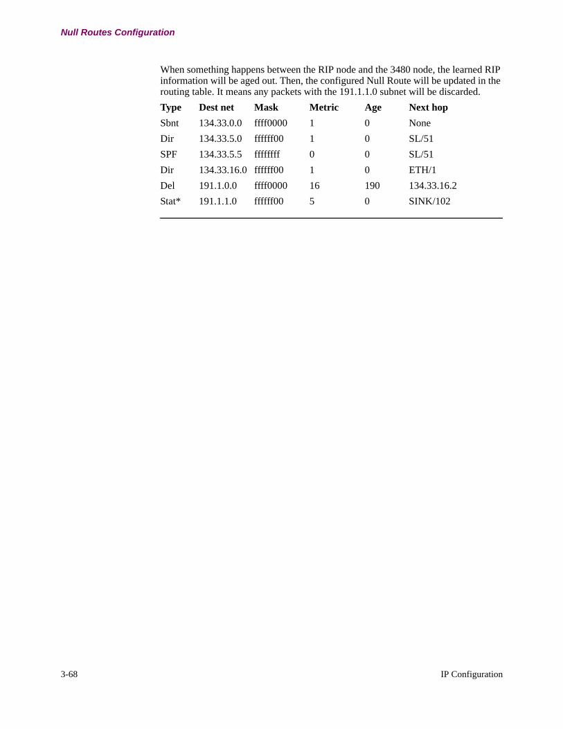
3-68 IP Configuration
Null Routes Configuration
When something happens between the RIP node and the 3480 node, the learned RIP information will be aged out. Then, the configured Null Route will be updated in the routing table. It means any packets with the 191.1.1.0 subnet will be discarded.
Type Dest net Mask Metric Age Next hop
Sbnt 134.33.0.0 ffff0000 1 0 None
Dir 134.33.5.0 ffffff00 1 0 SL/51
SPF 134.33.5.5 ffffffff 0 0 SL/51
Dir 134.33.16.0 ffffff00 1 0 ETH/1
Del 191.1.0.0 ffff0000 16 190 134.33.16.2
Stat* 191.1.1.0 ffffff00 5 0 SINK/102
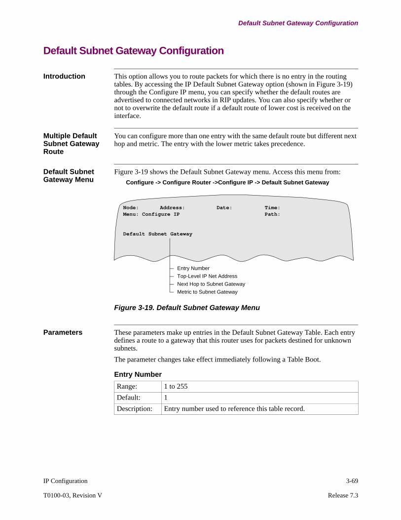
IP Configuration 3-69
T0100-03, Revision V Release 7.3
Default Subnet Gateway Configuration
Default Subnet Gateway Configuration
Introduction This option allows you to route packets for which there is no entry in the routing tables. By accessing the IP Default Subnet Gateway option (shown in Figure 3-19) through the Configure IP menu, you can specify whether the default routes are advertised to connected networks in RIP updates. You can also specify whether or not to overwrite the default route if a default route of lower cost is received on the interface.
Multiple Default Subnet Gateway Route
You can configure more than one entry with the same default route but different next hop and metric. The entry with the lower metric takes precedence.
Default Subnet Gateway Menu
Figure 3-19 shows the Default Subnet Gateway menu. Access this menu from:
Configure -> Configure Router ->Configure IP -> Default Subnet Gateway
Figure 3-19. Default Subnet Gateway Menu
Parameters These parameters make up entries in the Default Subnet Gateway Table. Each entry defines a route to a gateway that this router uses for packets destined for unknown subnets.
The parameter changes take effect immediately following a Table Boot.
Entry Number
Top-Level IP Net Address
Next Hop to Subnet Gateway
Metric to Subnet Gateway
Node: Address: Date: Time: Menu: Configure IP Path:
Default Subnet Gateway
Entry Number
Range: 1 to 255
Default: 1
Description: Entry number used to reference this table record.

3-70 IP Configuration
Default Subnet Gateway Configuration
Top-Level IP Net Address
Range: A valid IP address in dotted decimal notation
Default: 0.0.0.0
Description: This top-level IP network number must be the top level class A/B/C IP address that is to be subnetted. Examples include 16.0.0.0 (Class A), 128.185.0.0 (Class B), and 192.120.100.0 (Class C).The Default Subnet Gateway table informs this router which routers perform subnet routing for the indicated top-level IP network.
Next Hop to Subnet Gateway
Range: A valid IP address in dotted decimal notation
Default: 0.0.0.0
Description: The IP address of the router performing subnet routing for the top-level IP address of this record.If the next hop is an unnumbered interface, enter 0.0.0.n, where n is the interface number minus 1. If the next hop is an LCON of the unnumbered group LCON, enter the next hop routerid of the router connected to the LCON. For example, when configuring a static route across interface 5, enter 0.0.0.4.
Metric to Subnet Gateway
Range: 1 to 16
Default: 1
Description: The cost metric for a transmission to the Default Subnet Gateway, usually the number of network hops to reach that router.

IP Configuration 3-71
T0100-03, Revision V Release 7.3
IP RIP Route Control Table Configuration
IP RIP Route Control Table Configuration
Introduction This option is used to allow the acceptance and advertisement of RIP information for a given IP Address, even if the Interface Parameters have disabled the acceptance or advertisement of RIP information.
RIP Route Control Menu
Figure 3-20 shows the RIP Route Control menu. Access this menu from:
Configure -> Configure Router ->Configure IP ->RIP Route Control
Figure 3-20. RIP Route Control Menu
Configuration Guidelines
This table lists the actions that result from configuring Inbound and Outbound Interface lists:
Entry Number
IP Network/Subnet
IP Address Mask
Inbound Interface List
Outbound Interface List
Node: Address: Date: Time:
Configure IP RIP Route Control Table
Inbound Interface List
Outbound Interface List
Action
NONE NONE Rip routes advertisements for this IP network/subnet are not accepted on any interface and routes are advertised for this IP network/subnet on all interfaces.
ALL ALL Rip route advertisements for this IP network/subnet are accepted on all interfaces, but are not advertised on any interface.
NONE ALL RIP advertisements for this IP network/subnet are not accepted on any of the interfaces and are not advertised on any outbound interface.
ALL NONE RIP routes for this IP network/subnet are accepted on all inbound interfaces and advertised on all the outbound interfaces.
<list > ALL RIP routes for this IP network/subnet are accepted on the specified inbound interfaces, but are not advertised on any outbound interfaces.

3-72 IP Configuration
IP RIP Route Control Table Configuration
Configuration Examples
Three examples are listed to show how the RIP Route Control table can be configured to provide different levels of control for advertisement or acceptance of RIP routes.
Example 1: Advertise and Accept RIP Routes on Specified InterfacesTo advertise RIP routes for subnet 130.26.5.0 on all LAN interfaces and accept them on interfaces 5 and 10, configure a RIP Route Control Table entry as shown:
• IP network/subnet : 130.26.5.0• IP Address Mask : 255.255.255.0• Inbound interface list : 5,10• Outbound interface list : 5-255
Example 2: Accept RIP Routes on a Node-Wide Basis and Do Not Advertise on a Node-Wide BasisTo accept RIP routes for subnet 130.27.5.0 on a node-wide basis, configure a RIP Route Control Table entry as shown:
• IP network/subnet : 130.27.5.0• IP Address Mask : 255.255.255.0• Inbound interface list : ALL• Outbound interface list : ALL
Example 3: Advertise RIP Routes on WAN Interfaces OnlyTo advertise RIP routes for network 129.0.0.0 only on WAN interfaces, configure a RIP Route Control Table entry as shown:
• IP network/subnet : 129.0.0.0• IP Address Mask : 255.0.0.0• Inbound interface list : NONE (If the RIP route is a direct route or static route,
set this parameter to NONE. Set this parameter to ALL, if the route for 129.0.0.0 is coming from another node).
• Outbound interface list : 1-4
<list> NONE RIP routes for this IP network/subnet are accepted on the specified inbound interfaces and advertise on all the outbound interfaces.
<list> <list> RIP routes for this IP network/subnet are accepted on the specified inbound interfaces but are not advertised specified outbound interfaces.
NONE <list> RIP routes for this IP network/subnet are not accepted on all the inbound interfaces and are not advertised on specified outbound interfaces.
ALL <list> RIP routes for this IP network/subnet are accepted on all inbound interfaces, but are not advertised on specified outbound interface.
Inbound Interface List
Outbound Interface List
Action (continued)
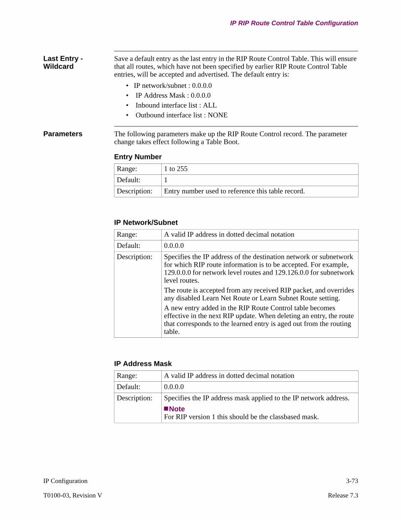
IP Configuration 3-73
T0100-03, Revision V Release 7.3
IP RIP Route Control Table Configuration
Last Entry - Wildcard
Save a default entry as the last entry in the RIP Route Control Table. This will ensure that all routes, which have not been specified by earlier RIP Route Control Table entries, will be accepted and advertised. The default entry is:
• IP network/subnet : 0.0.0.0• IP Address Mask : 0.0.0.0• Inbound interface list : ALL• Outbound interface list : NONE
Parameters The following parameters make up the RIP Route Control record. The parameter change takes effect following a Table Boot.
Entry Number
Range: 1 to 255
Default: 1
Description: Entry number used to reference this table record.
IP Network/Subnet
Range: A valid IP address in dotted decimal notation
Default: 0.0.0.0
Description: Specifies the IP address of the destination network or subnetwork for which RIP route information is to be accepted. For example, 129.0.0.0 for network level routes and 129.126.0.0 for subnetwork level routes.The route is accepted from any received RIP packet, and overrides any disabled Learn Net Route or Learn Subnet Route setting.A new entry added in the RIP Route Control table becomes effective in the next RIP update. When deleting an entry, the route that corresponds to the learned entry is aged out from the routing table.
IP Address Mask
Range: A valid IP address in dotted decimal notation
Default: 0.0.0.0
Description: Specifies the IP address mask applied to the IP network address.
NoteFor RIP version 1 this should be the classbased mask.

3-74 IP Configuration
IP RIP Route Control Table Configuration
Inbound Interface List
Range: ALL, NONE, 1 to 255
Default: ALL
Description: Specifies a list of interfaces on which the RIP Route information is accepted. Enter the parameters as:
• ALL: a wildcard used to match all interfaces• NONE: indicates no inbound RIP router control for the IP
network/subnetwork address.• A range of interface. For example, 1, 5, 7-10, 20-25, 31
A maximum of eight ranges may be configured. To configure more than one Inbound Interface List for a specific IP network/subnet address, configure another table entry using the same IP network/subnet address.
Outbound Interface List
Range: ALL, NONE, 1 to 255
Default: NONE
Description: Specifies a list of interfaces on which the RIP Route information is not advertised. Enter the parameters as:
• ALL: a wildcard used to match all interfaces• NONE: indicates no outbound RIP router control for the IP
network/subnetwork address.A range of interface. For example, 1, 5, 7-10, 20-25, 31A maximum of eight ranges may be configured. To configure more than one Outbound Interface List for a specific IP network/subnet address, configure another table entry using the same IP network/subnet address.
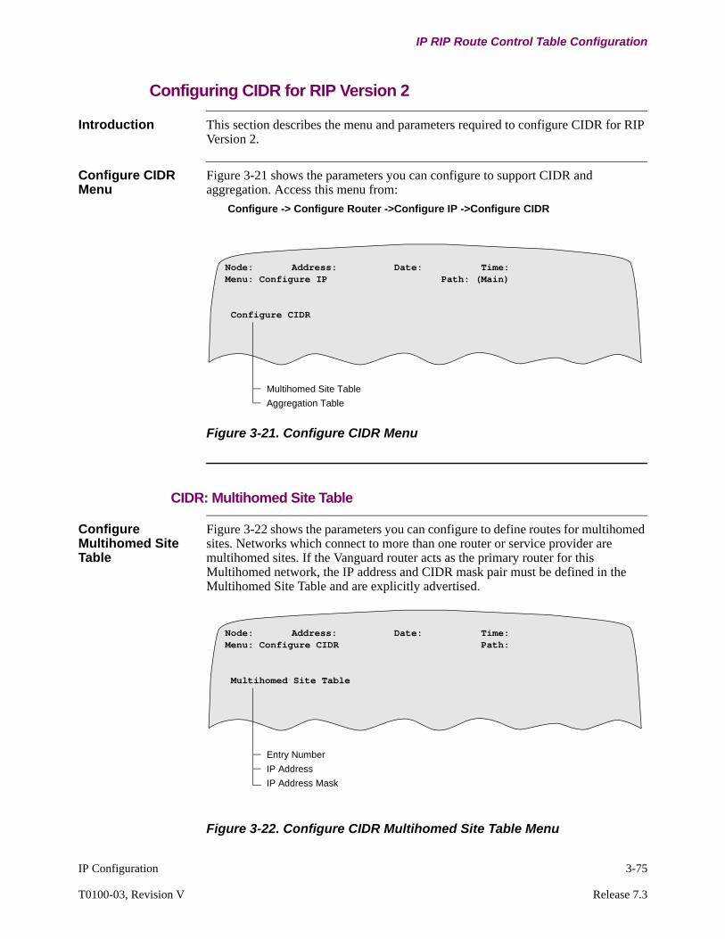
IP Configuration 3-75
T0100-03, Revision V Release 7.3
IP RIP Route Control Table Configuration
Configuring CIDR for RIP Version 2
Introduction This section describes the menu and parameters required to configure CIDR for RIP Version 2.
Configure CIDR Menu
Figure 3-21 shows the parameters you can configure to support CIDR and aggregation. Access this menu from:
Configure -> Configure Router ->Configure IP ->Configure CIDR
Figure 3-21. Configure CIDR Menu
CIDR: Multihomed Site Table
Configure Multihomed Site Table
Figure 3-22 shows the parameters you can configure to define routes for multihomed sites. Networks which connect to more than one router or service provider are multihomed sites. If the Vanguard router acts as the primary router for this Multihomed network, the IP address and CIDR mask pair must be defined in the Multihomed Site Table and are explicitly advertised.
Figure 3-22. Configure CIDR Multihomed Site Table Menu
Multihomed Site Table
Aggregation Table
Node: Address: Date: Time: Menu: Configure IP Path: (Main)
Configure CIDR
Entry Number
IP Address
IP Address Mask
Node: Address: Date: Time: Menu: Configure CIDR Path:
Multihomed Site Table
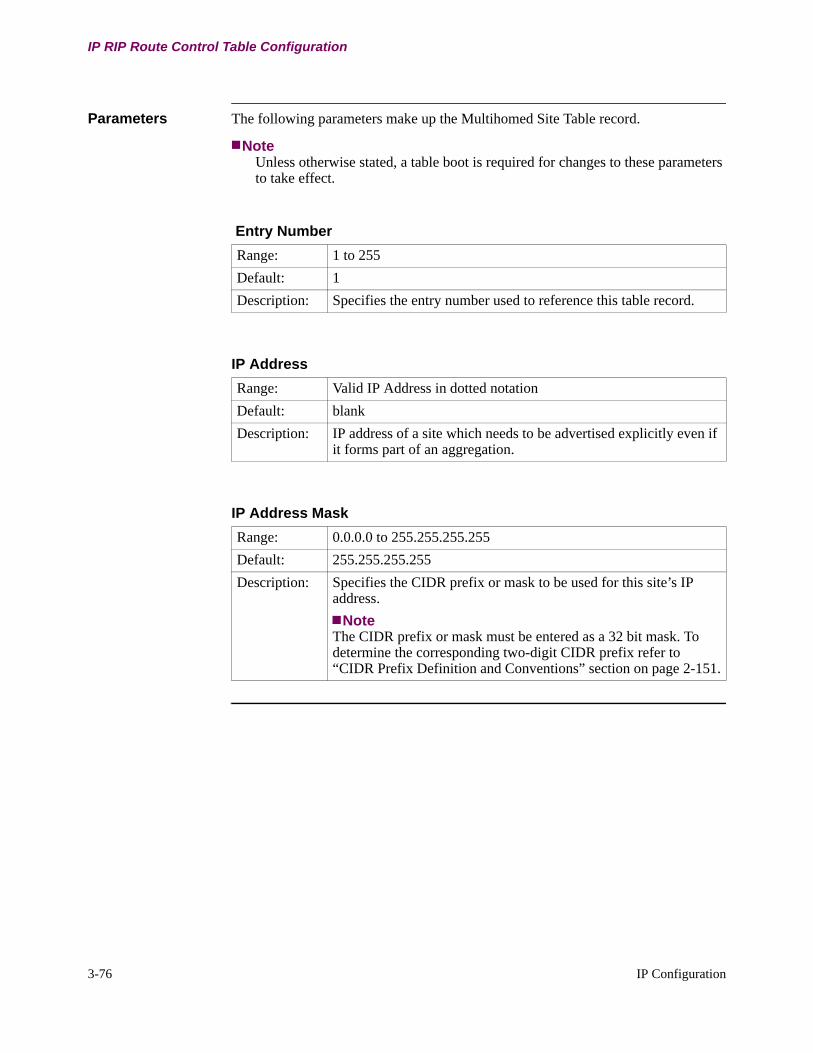
3-76 IP Configuration
IP RIP Route Control Table Configuration
Parameters The following parameters make up the Multihomed Site Table record.
NoteUnless otherwise stated, a table boot is required for changes to these parameters to take effect.
Entry Number
Range: 1 to 255
Default: 1
Description: Specifies the entry number used to reference this table record.
IP Address
Range: Valid IP Address in dotted notation
Default: blank
Description: IP address of a site which needs to be advertised explicitly even if it forms part of an aggregation.
IP Address Mask
Range: 0.0.0.0 to 255.255.255.255
Default: 255.255.255.255
Description: Specifies the CIDR prefix or mask to be used for this site’s IP address.
NoteThe CIDR prefix or mask must be entered as a 32 bit mask. To determine the corresponding two-digit CIDR prefix refer to “CIDR Prefix Definition and Conventions” section on page 2-151.
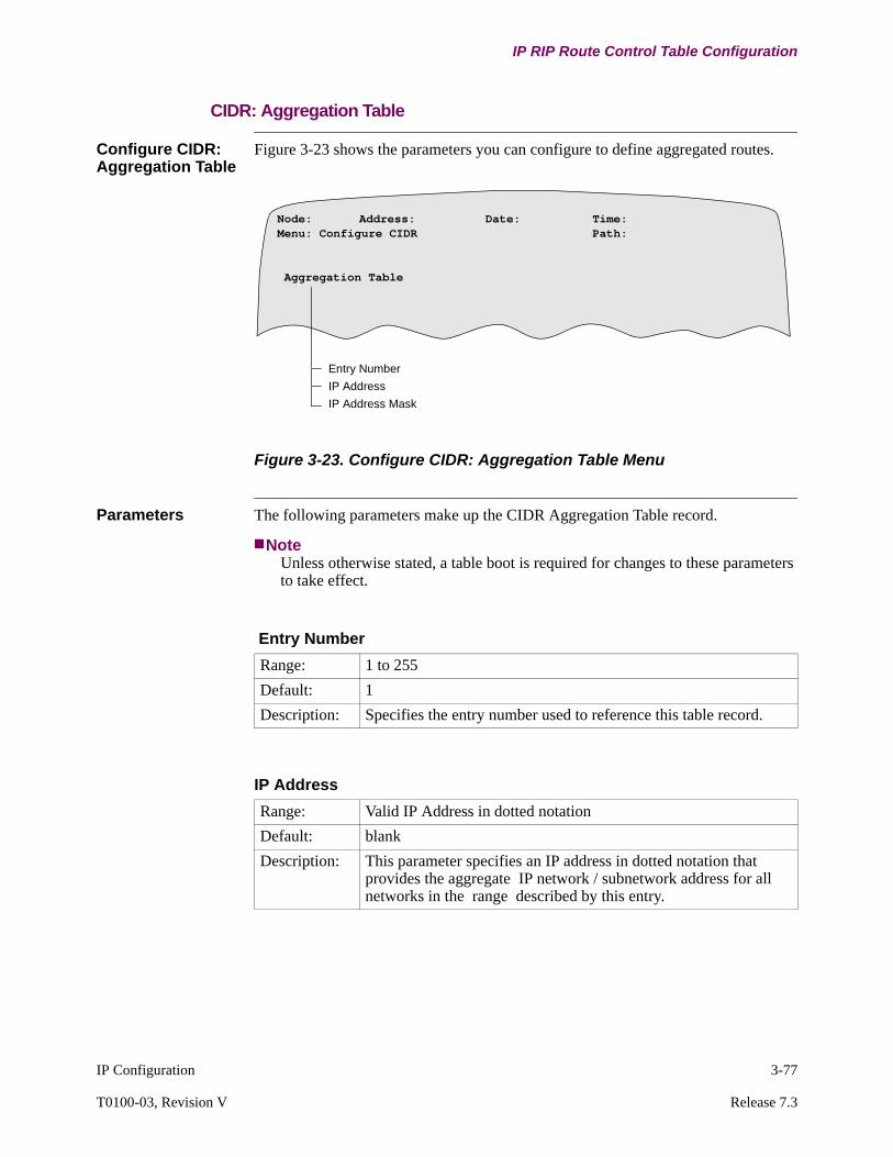
IP Configuration 3-77
T0100-03, Revision V Release 7.3
IP RIP Route Control Table Configuration
CIDR: Aggregation Table
Configure CIDR: Aggregation Table
Figure 3-23 shows the parameters you can configure to define aggregated routes.
Figure 3-23. Configure CIDR: Aggregation Table Menu
Parameters The following parameters make up the CIDR Aggregation Table record.
NoteUnless otherwise stated, a table boot is required for changes to these parameters to take effect.
Entry Number
IP Address
IP Address Mask
Node: Address: Date: Time: Menu: Configure CIDR Path:
Aggregation Table
Entry Number
Range: 1 to 255
Default: 1
Description: Specifies the entry number used to reference this table record.
IP Address
Range: Valid IP Address in dotted notation
Default: blank
Description: This parameter specifies an IP address in dotted notation that provides the aggregate IP network / subnetwork address for all networks in the range described by this entry.

3-78 IP Configuration
IP RIP Route Control Table Configuration
IP Address Mask
Range: 0.0.0.0 to 255.255.255.255
Default: 255.255.255.255
Description: Specifies the CIDR mask to define the aggregate IP address for this entry.
NoteThe CIDR mask must be entered as a 32 bit mask. To determine the corresponding two digit CIDR prefix refer to “CIDR Prefix Definition and Conventions” section on page 2-151.
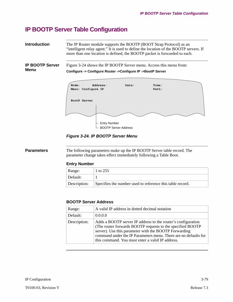
IP Configuration 3-79
T0100-03, Revision V Release 7.3
IP BOOTP Server Table Configuration
IP BOOTP Server Table Configuration
Introduction The IP Router module supports the BOOTP (BOOT Strap Protocol) as an “intelligent relay agent.” It is used to define the location of the BOOTP servers. If more than one location is defined, the BOOTP packet is forwarded to each.
IP BOOTP Server Menu
Figure 3-24 shows the IP BOOTP Server menu. Access this menu from:
Configure -> Configure Router ->Configure IP ->BootP Server
Figure 3-24. IP BOOTP Server Menu
Parameters The following parameters make up the IP BOOTP Server table record. The parameter change takes effect immediately following a Table Boot.
Entry Number
BOOTP Server Address
Node: Address: Date: Time: Menu: Configure IP Path:
BootP Server
Entry Number
Range: 1 to 255
Default: 1
Description: Specifies the number used to reference this table record.
BOOTP Server Address
Range: A valid IP address in dotted decimal notation
Default: 0.0.0.0
Description: Adds a BOOTP server IP address to the router’s configuration (The router forwards BOOTP requests to the specified BOOTP server). Use this parameter with the BOOTP Forwarding command under the IP Parameters menu. There are no defaults for this command. You must enter a valid IP address.
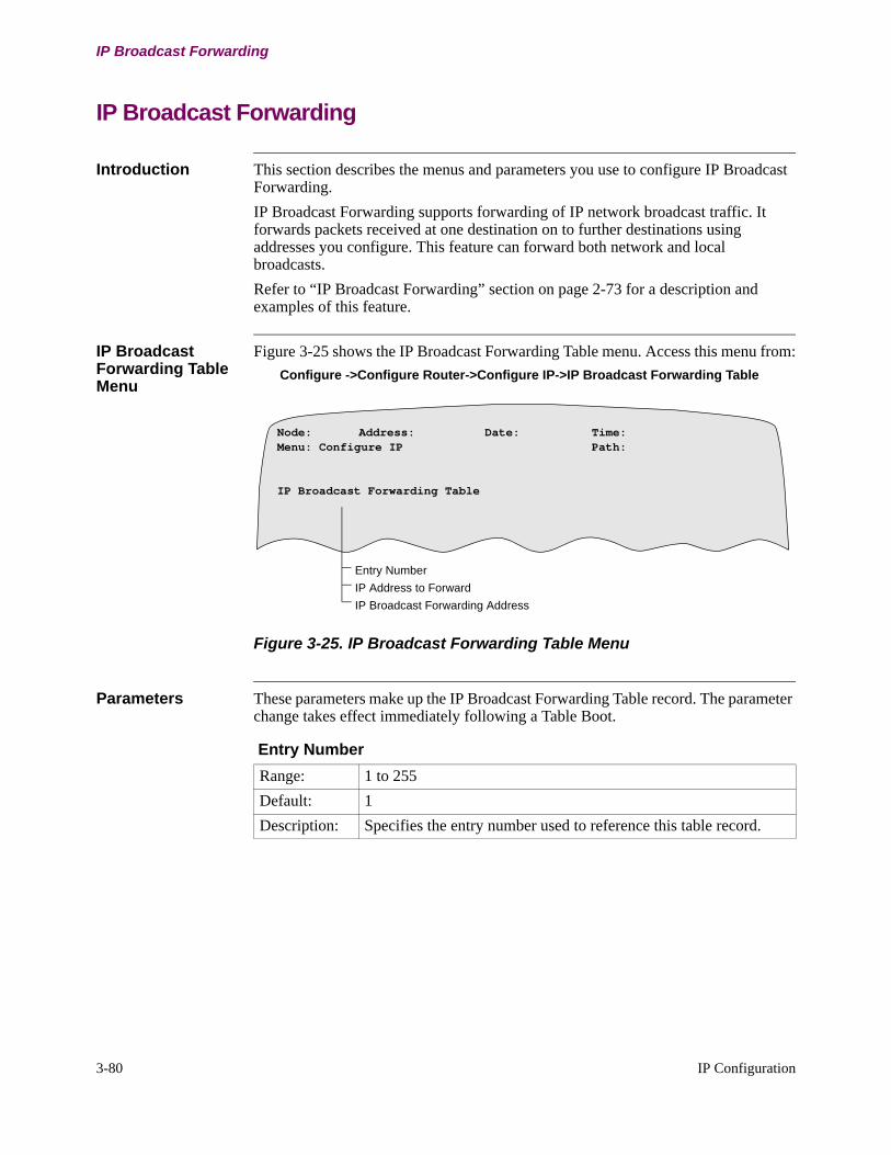
3-80 IP Configuration
IP Broadcast Forwarding
IP Broadcast Forwarding
Introduction This section describes the menus and parameters you use to configure IP Broadcast Forwarding.
IP Broadcast Forwarding supports forwarding of IP network broadcast traffic. It forwards packets received at one destination on to further destinations using addresses you configure. This feature can forward both network and local broadcasts.
Refer to “IP Broadcast Forwarding” section on page 2-73 for a description and examples of this feature.
IP Broadcast Forwarding Table Menu
Figure 3-25 shows the IP Broadcast Forwarding Table menu. Access this menu from:
Configure ->Configure Router->Configure IP->IP Broadcast Forwarding Table
Figure 3-25. IP Broadcast Forwarding Table Menu
Parameters These parameters make up the IP Broadcast Forwarding Table record. The parameter change takes effect immediately following a Table Boot.
Entry Number
IP Address to Forward
IP Broadcast Forwarding Address
Node: Address: Date: Time: Menu: Configure IP Path:
IP Broadcast Forwarding Table
Entry Number
Range: 1 to 255
Default: 1
Description: Specifies the entry number used to reference this table record.

IP Configuration 3-81
T0100-03, Revision V Release 7.3
IP Broadcast Forwarding
IP Address to Forward
Range: x.x.x.x, where x is less than or equal to 255. The address should not be 127.x.x.x as these addresses are reserved for the loopback IP address assignment of the routers and IP hosts.
Default: 0.0.0.0
Description: Specifies the Destination IP address to be forwarded by the IP Broadcast Forwarding table.
IP Broadcast Forwarding Address
Range: x.x.x.x, where x is less than or equal to 255. The address should not be 127.x.x.x as these addresses are reserved for the loopback IP address assignment of the routers and IP hosts.
Default: 0.0.0.0
Description: Specifies the IP address to which the IP broadcast packets are forwarded using the IP Broadcast Forwarding Table. You can configure up to 16 addresses to which to forward packets.

3-82 IP Configuration
UDP Broadcast Forwarding
UDP Broadcast Forwarding
Introduction This section describes the menus and parameters you use to configure UDP Broadcast Forwarding.
UDP Broadcast Forwarding supports forwarding of local broadcast traffic. It forwards packets arriving at a node to a configurable UDP port on that node and on to other addresses you configure.
Refer to the “UDP Broadcast Forwarding” section on page 2-70 for a description and examples of this feature.
UDP Broadcast Forwarding Table Menu
Figure 3-26 shows the UDP Broadcast Forwarding Table menu. Access this menu from:
Configure -> Configure Router ->Configure IP -> UDP Broadcast Forwarding Table
Figure 3-26. UDP Broadcast Forwarding Table Menu
Parameters The following parameters make up the UDP Broadcast Forwarding Table record. The parameter change takes effect immediately following a Table Boot.
Entry Number
UDP Port Number
UDP Broadcast Forwarding Address
Node: Address: Date: Time: Menu: Configure IP Path:
IP Broadcast Forwarding Table
Entry Number
Range: 1 to 255
Default: 1
Description: Specifies the entry number used to reference this table record.
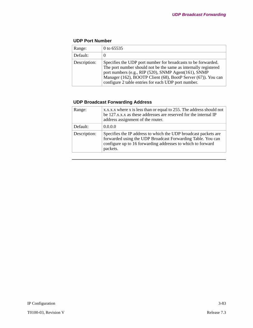
IP Configuration 3-83
T0100-03, Revision V Release 7.3
UDP Broadcast Forwarding
UDP Port Number
Range: 0 to 65535
Default: 0
Description: Specifies the UDP port number for broadcasts to be forwarded. The port number should not be the same as internally registered port numbers (e.g., RIP (520), SNMP Agent(161), SNMP Manager (162), BOOTP Client (68), BootP Server (67)). You can configure 2 table entries for each UDP port number.
UDP Broadcast Forwarding Address
Range: x.x.x.x where x is less than or equal to 255. The address should not be 127.x.x.x as these addresses are reserved for the internal IP address assignment of the router.
Default: 0.0.0.0
Description: Specifies the IP address to which the UDP broadcast packets are forwarded using the UDP Broadcast Forwarding Table. You can configure up to 16 forwarding addresses to which to forward packets.

3-84 IP Configuration
UDP Broadcast Forwarding
Example: Configuring IP Helper Address Using IP and UDP Broadcast
Introduction This section shows a sample Helper Address configuration using IP Broadcast Forwarding.
Example In this example, Netbios is running over TCP/IP. This configuration solves the problem wherein all hosts can ping each other, but you cannot see or access host or servers on other networks using TCP/IP. Starting in release 5.5 the forwarding address must be a network address. For example 172.16.2.255 instead of 172.16.2.1
Figure 3-27. Using IP Broadcast Forwarding to Send Netbios Over TCP/IP
No d e 1 0 0
Ro u t e r 2
N o d e 2 0 0
Ro u t e r 1NT
S e r v e r
1 7 2 .1 6 .2 5 4 .1 1 1
172.16 .2 .2172 .16.254.1172.16.1 .1
W in95172.16.1 .2Fra me
Re la y172.16.1 .1
172.16 .2 .1
IP ParametersEnable UDP BC Forwarding
UDP BC Forwarding Table
Entry 1UDP Port # 137Forward address #1 172.16.2.1 Forward address #2 172.16.254.255
Entry 2
UDP Port # 138Forward address #1 172.16.2.1 Forward address #2 172.16.254.255
Entry 3UDP Port # 139
Forward address #1 172.16.2.1 Forward address #2 172.16.254.255
Router 1IP Parameters
Enable UDP BC ForwardingUDP BC Forwarding Table
Entry 1UDP Port # 137Forward address #1 172.16.2.255Forward address #2 172.16.1.255
Entry 2
UDP Port # 138Forward address #1 172.16.2.255Forward address #2 172.16.1.255
Entry 3UDP Port # 139
Forward address #1 172.16.2.255Forward address #2 172.16.1.255
IP ParametersEnable UDP BC Forwarding
UDP BC Forwarding Table
Entry 1UDP Port # 137Forward address #1 172.16.2.1 Forward address #2 172.16.254.255
Entry 2
UDP Port # 138Forward address #1 172.16.2.1 Forward address #2 172.16.254.255
Entry 3UDP Port # 139
Forward address #1 172.16.2.1 Forward address #2 172.16.254.255
Router 2IP Parameters
Enable UDP BC ForwardingUDP BC Forwarding Table
Entry 1UDP Port # 137Forward address #1 172.16.2.255Forward address #2 172.16.254.255
Entry 2
UDP Port # 138Forward address #1 172.16.2.255Forward address #2 172.16.254.255
Entry 3UDP Port # 139
Forward address #1 172.16.2.255Forward address #2 172.16.254.255
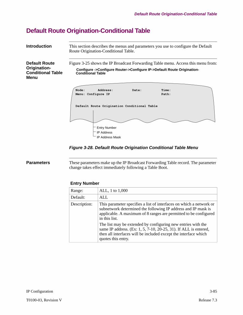
IP Configuration 3-85
T0100-03, Revision V Release 7.3
Default Route Origination-Conditional Table
Default Route Origination-Conditional Table
Introduction This section describes the menus and parameters you use to configure the Default Route Origination-Conditional Table.
Default Route Origination-Conditional Table Menu
Figure 3-25 shows the IP Broadcast Forwarding Table menu. Access this menu from:
Configure ->Configure Router->Configure IP->Default Route Origination-Conditional Table
Figure 3-28. Default Route Origination Conditional Table Menu
Parameters These parameters make up the IP Broadcast Forwarding Table record. The parameter change takes effect immediately following a Table Boot.
Entry Number
IP Address
IP Address Mask
Node: Address: Date: Time: Menu: Configure IP Path:
Default Route Origination Conditional Table
Entry Number
Range: ALL, 1 to 1,000
Default: ALL
Description: This parameter specifies a list of interfaces on which a network or subnetwork determined the following IP address and IP mask is applicable. A maximum of 8 ranges are permitted to be configured in this list.The list may be extended by configuring new entries with the same IP address. (Ex: 1, 5, 7-10, 20-25, 31). If ALL is entered, then all interfaces will be included except the interface which quotes this entry.
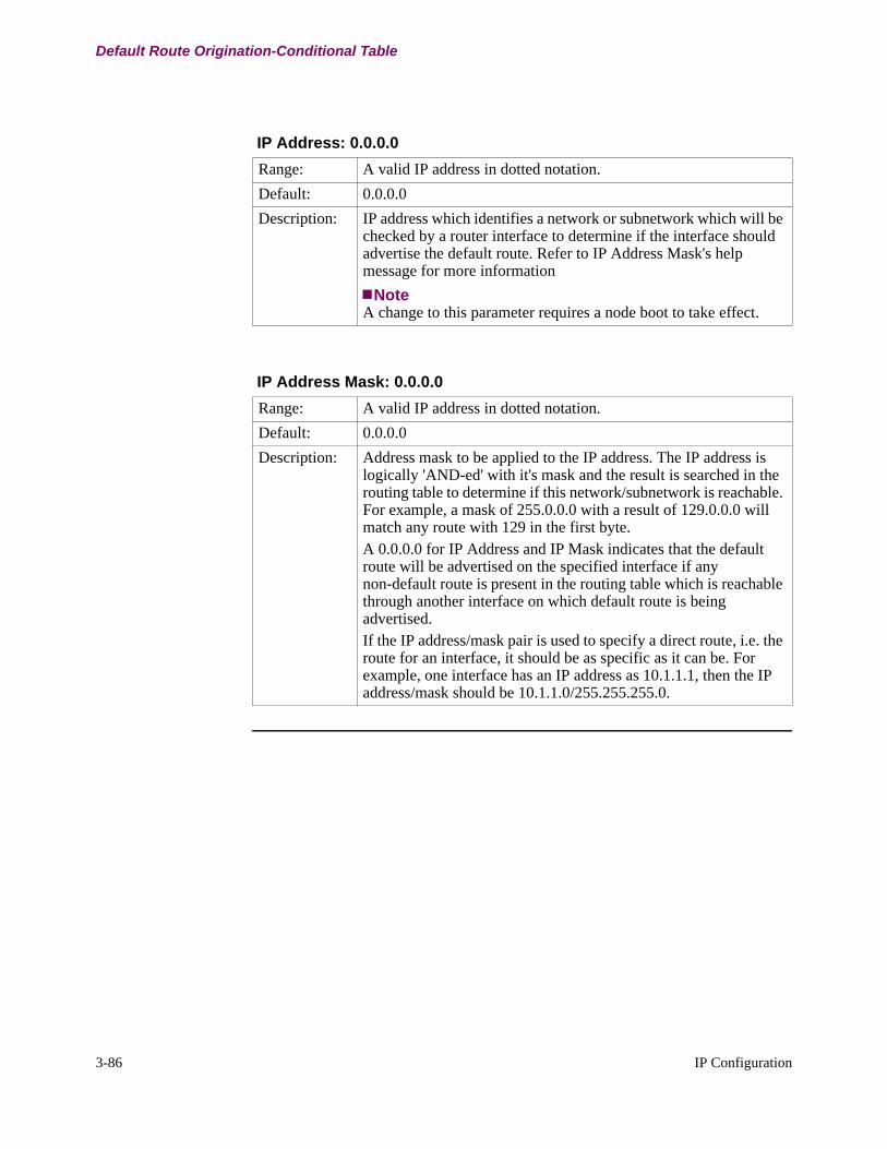
3-86 IP Configuration
Default Route Origination-Conditional Table
IP Address: 0.0.0.0
Range: A valid IP address in dotted notation.
Default: 0.0.0.0
Description: IP address which identifies a network or subnetwork which will be checked by a router interface to determine if the interface should advertise the default route. Refer to IP Address Mask's help message for more information
NoteA change to this parameter requires a node boot to take effect.
IP Address Mask: 0.0.0.0
Range: A valid IP address in dotted notation.
Default: 0.0.0.0
Description: Address mask to be applied to the IP address. The IP address is logically 'AND-ed' with it's mask and the result is searched in the routing table to determine if this network/subnetwork is reachable. For example, a mask of 255.0.0.0 with a result of 129.0.0.0 will match any route with 129 in the first byte. A 0.0.0.0 for IP Address and IP Mask indicates that the default route will be advertised on the specified interface if any non-default route is present in the routing table which is reachable through another interface on which default route is being advertised.If the IP address/mask pair is used to specify a direct route, i.e. the route for an interface, it should be as specific as it can be. For example, one interface has an IP address as 10.1.1.1, then the IP address/mask should be 10.1.1.0/255.255.255.0.

IP Configuration 3-87
T0100-03, Revision V Release 7.3
Configuring the Address Resolution Protocol (ARP)
Configuring the Address Resolution Protocol (ARP)
Introduction This section describes configuration of the Vanguard Router Address Resolution Protocol (ARP). ARP operation normally does not require configuration.
Configure Router Menu
Figure 3-29 shows the Configure Router menu with the Configure ARP menu item. Access this menu from:
Configure -> Configure Router ->Configure ARP
Figure 3-29. Configure Router Menu
Configure ARP Menu
Figure 3-30 shows the two groups that make up the ARP table record: Parameters and Static cache.
Figure 3-30. Configure ARP Menu
Node: Address: Date: Time: Menu: Configure Router Path:
Configure ARP
Node: Address: Date: Time: Menu: Configure ARP Path:
ParametersCache
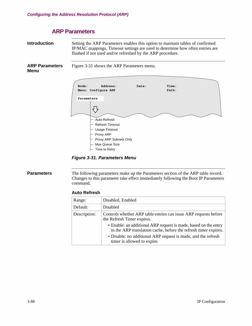
3-88 IP Configuration
Configuring the Address Resolution Protocol (ARP)
ARP Parameters
Introduction Setting the ARP Parameters enables this option to maintain tables of confirmed IP/MAC mappings. Timeout settings are used to determine how often entries are flushed if not used and/or refreshed by the ARP procedure.
ARP Parameters Menu
Figure 3-31 shows the ARP Parameters menu.
Figure 3-31. Parameters Menu
Parameters The following parameters make up the Parameters section of the ARP table record. Changes to this parameter take effect immediately following the Boot IP Parameters command.
Auto-Refresh
Refresh TimeoutUsage TimeoutProxy ARPProxy ARP Subnets OnlyMax Queue SizeTime to Retry
Node: Address: Date: Time: Menu: Configure ARP Path:
Parameters
Auto Refresh
Range: Disabled, Enabled
Default: Disabled
Description: Controls whether ARP table entries can issue ARP requests before the Refresh Timer expires.
• Enable: an additional ARP request is made, based on the entry in the ARP translation cache, before the refresh timer expires.
• Disable: no additional ARP request is made, and the refresh timer is allowed to expire.
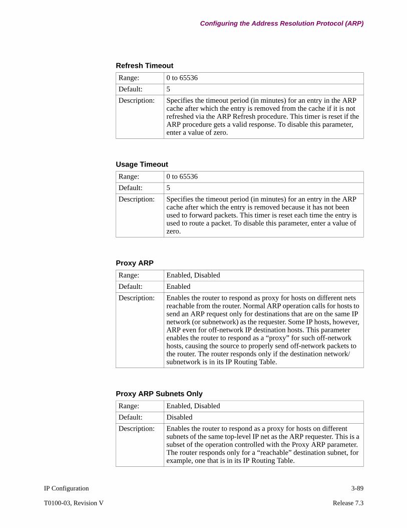
IP Configuration 3-89
T0100-03, Revision V Release 7.3
Configuring the Address Resolution Protocol (ARP)
Refresh Timeout
Range: 0 to 65536
Default: 5
Description: Specifies the timeout period (in minutes) for an entry in the ARP cache after which the entry is removed from the cache if it is not refreshed via the ARP Refresh procedure. This timer is reset if the ARP procedure gets a valid response. To disable this parameter, enter a value of zero.
Usage Timeout
Range: 0 to 65536
Default: 5
Description: Specifies the timeout period (in minutes) for an entry in the ARP cache after which the entry is removed because it has not been used to forward packets. This timer is reset each time the entry is used to route a packet. To disable this parameter, enter a value of zero.
Proxy ARP
Range: Enabled, Disabled
Default: Enabled
Description: Enables the router to respond as proxy for hosts on different nets reachable from the router. Normal ARP operation calls for hosts to send an ARP request only for destinations that are on the same IP network (or subnetwork) as the requester. Some IP hosts, however, ARP even for off-network IP destination hosts. This parameter enables the router to respond as a “proxy” for such off-network hosts, causing the source to properly send off-network packets to the router. The router responds only if the destination network/subnetwork is in its IP Routing Table.
Proxy ARP Subnets Only
Range: Enabled, Disabled
Default: Disabled
Description: Enables the router to respond as a proxy for hosts on different subnets of the same top-level IP net as the ARP requester. This is a subset of the operation controlled with the Proxy ARP parameter. The router responds only for a “reachable” destination subnet, for example, one that is in its IP Routing Table.

3-90 IP Configuration
Configuring the Address Resolution Protocol (ARP)
Max Queue Size
Range: 0 to 50
Default: 30
Description: Specifies the maximum protocol packets that can be queued awaiting translation. This limit is applied independently for each interface and protocol. A setting of zero disables the queue and no subsequent parameters are prompted.
Time to Retry
Range: 1 to 10
Default: 2
Description: Specifies the time period (in seconds) between a first and second ARP Request transmission if an ARP Reply is not received for the first ARP Request. If an ARP Reply is not received within this time period, the packet is dropped.
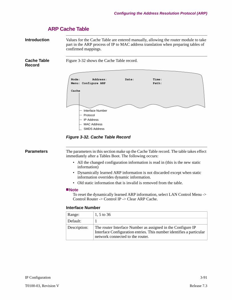
IP Configuration 3-91
T0100-03, Revision V Release 7.3
Configuring the Address Resolution Protocol (ARP)
ARP Cache Table
Introduction Values for the Cache Table are entered manually, allowing the router module to take part in the ARP process of IP to MAC address translation when preparing tables of confirmed mappings.
Cache Table Record
Figure 3-32 shows the Cache Table record.
Figure 3-32. Cache Table Record
Parameters The parameters in this section make up the Cache Table record. The table takes effect immediately after a Tables Boot. The following occurs:
• All the changed configuration information is read in (this is the new static information)
• Dynamically learned ARP information is not discarded except when static information overrides dynamic information.
• Old static information that is invalid is removed from the table.
NoteTo reset the dynamically learned ARP information, select LAN Control Menu -> Control Router -> Control IP -> Clear ARP Cache.
Interface NumberProtocolIP AddressMAC AddressSMDS Address
Node: Address: Date: Time: Menu: Configure ARP Path:
Cache
Interface Number
Range: 1, 5 to 36
Default: 1
Description: The router Interface Number as assigned in the Configure IP Interface Configuration entries. This number identifies a particular network connected to the router.

3-92 IP Configuration
Configuring the Address Resolution Protocol (ARP)
Protocol
Range: IP, IPX, Appletalk
Default: IP
Description: Identifies one of the routing protocols supported by the router. This parameter appears only when the interface number is 5 or greater.
*IP Address
Range: A valid IP address in dotted decimal notation
Default: (blank)
Description: The IP address of a particular host on the attached network identified by the Interface number.
MAC Address
Range: 6 hex bytes in the form: xx-xx-xx-xx-xx-xx or xx:xx:xx:xx:xx:xx
Default: (blank)
Description: The hardware MAC address of the host with the Protocol Address of this entry. Entries using the ‘-’ delimiter are considered in canonical form (as if transmitted LSB first). Entries using the ‘:’ delimiter are in non-canonical form (as if transmitted MSB first).
SMDS
Range: 0 to 17 alphanumeric characters
Default: (blank)
Description: The hardware address of the host associated with the Protocol Address of this entry. Validation of the address format is delayed until the hardware interface type for the interface can be determined.SMDS Address: Each digit is a telephone number digit. Specify at least 11 digits. The 64-bit SMDS Address is then the binary-coded decimal (BCD) of the input with unused bits at the end of the field set to ones.The (Unicast) Address specified is prefixed by a C. For example, the input 19055077200 yields the SMDS Address 0xC19055077200FFFF.

IP Configuration 3-93
T0100-03, Revision V Release 7.3
Configuring IP Multicast with DVMRP
Configuring IP Multicast with DVMRP
Introduction This section shows how to configure IP Multicast with DVMRP using the existing Multicast framework on Vanguard nodes.
NoteDVMRP and PIM are mutually exclusive, you cannot configure both on the same router.
Before You Begin Before Configuring IP Multicast with DVMRP:
• Make sure host computers participating in the IP Multicast group are running IGMP software.
• Make sure IP software is running on Vanguard routers before you configure IP Multicasting.
NoteYou can set up and operate IP Unicasting and Multicasting on a Vanguard router at the same time.
What You Need to Configure
You need to configure the IGMP and DVMRP protocols on each router performing IP Multicasting in your network:
See “IGMP Configuration” section on page 3-94 and “DVRMP Configuration” section on page 3-97 for details on configuring these records and tables.
For This Protocol Configure These Records & Tables
IGMP IGMP Parameters
• IGMP Parameters
• IGMP Interfaces
DVMRP Configure DVMRP
• Configure DVMRP Parameters Record
• DVMRP Circuit(s) Configuration
• Static DVMRP Forwarding Table

3-94 IP Configuration
Configuring IP Multicast with DVMRP
IGMP Configuration
Introduction Figure 3-33 shows the IGMP records. Access this menu from:
Configure->Configure Router->Configure IP Multicast
Figure 3-33. IGMP Parameters and Interface
IGMP Parameters To implement IP Multicasting, configure the following IGMP parameters. You must perform a Node Boot for changes to these parameters to take effect.
Node: Address: Date: Time: Menu: Configure IP Multicast Path:
IGMP ParametersIGMP Interface
IGMP Enable (LAN)IGMP Enable (WAN)IGMP Polling on LANIGMP Polling on WAN
IGMP*LAN Host Poll IntervalWAN Host Poll Interval
*IGMP
Range: Enable, Disable
Default: Disable
Description: Enables or disables IGMP on this router.• Specify Enable to allow IP Multicasting forwarding, receiving
or transmitting using IGMP protocol on this router.• Specify Disable to remove router from participating IP
Multicasting forwarding.
*LAN Host Poll Interval
Range: 60 to 3600
Default: 125
Description: Specify the time interval (in seconds) between membership query messages sent over LAN from host to router.
NoteIGMP must be enabled for this parameter to appear.

IP Configuration 3-95
T0100-03, Revision V Release 7.3
Configuring IP Multicast with DVMRP
IGMP Interfaces These parameters make up the IGMP Interfaces record. Changes to these parameters require a Node boot to take effect.
NoteEnable IGMP in the IGMP Parameters record to display these parameters.
*WAN Host Poll Interval
Range: 60 to 3600
Default: 125
Description: Specify the time (in seconds) between membership queries sent over the WAN between router and host.
NoteIGMP must be enabled for this parameter to appear.
*IGMP Enable (LAN)
Range: Vanguard 320, 34x, 6435 and 64550 to 4Vanguard 7300 Series0 to 50
Default: 0
Description: This parameter enables or disables IP Multicast forwarding, receiving and transmitting of IGMP protocol (listening, polling and IP Multicast routing messages) on the LAN interfaces.
• Specify a list of numbers (1 to 4) of the LAN interfaces you want to enable. For example: 1,2 1,3 or 1-4.
• Specify 0 to disable this function on all LAN interfaces.
NoteFor DVMRP to work on an interface this parameter should be enabled.
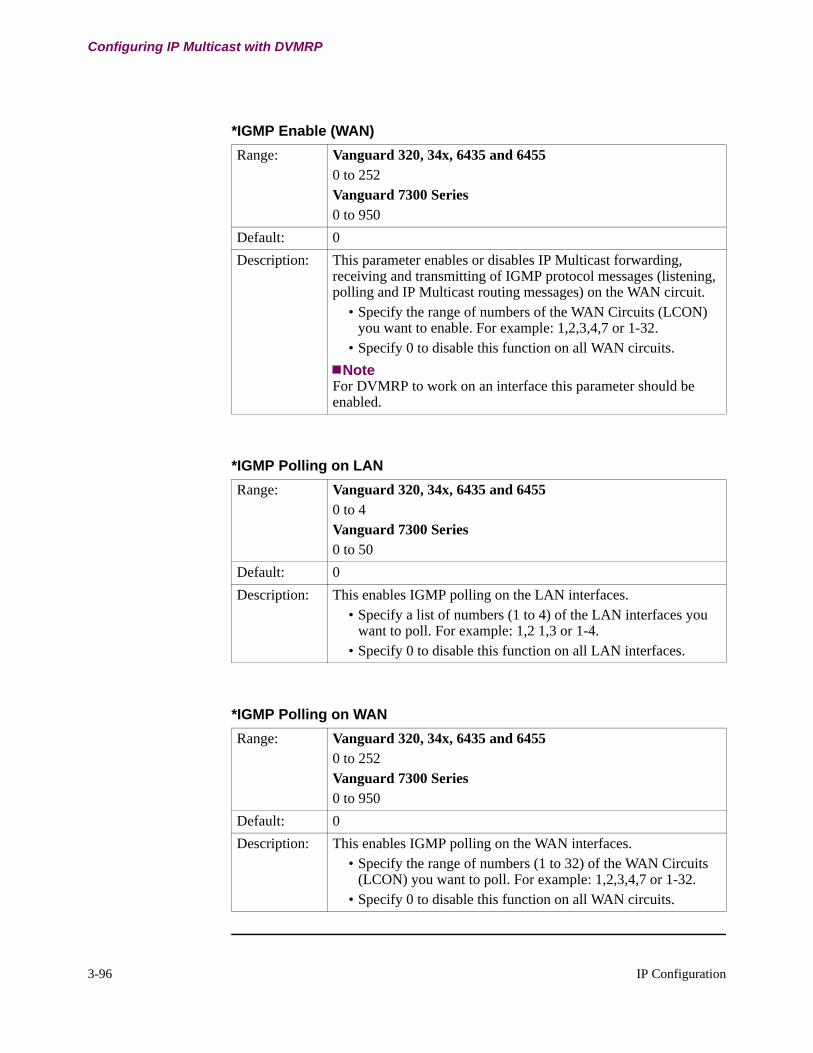
3-96 IP Configuration
Configuring IP Multicast with DVMRP
*IGMP Enable (WAN)
Range: Vanguard 320, 34x, 6435 and 64550 to 252Vanguard 7300 Series0 to 950
Default: 0
Description: This parameter enables or disables IP Multicast forwarding, receiving and transmitting of IGMP protocol messages (listening, polling and IP Multicast routing messages) on the WAN circuit.
• Specify the range of numbers of the WAN Circuits (LCON) you want to enable. For example: 1,2,3,4,7 or 1-32.
• Specify 0 to disable this function on all WAN circuits.
NoteFor DVMRP to work on an interface this parameter should be enabled.
*IGMP Polling on LAN
Range: Vanguard 320, 34x, 6435 and 64550 to 4Vanguard 7300 Series0 to 50
Default: 0
Description: This enables IGMP polling on the LAN interfaces. • Specify a list of numbers (1 to 4) of the LAN interfaces you
want to poll. For example: 1,2 1,3 or 1-4.• Specify 0 to disable this function on all LAN interfaces.
*IGMP Polling on WAN
Range: Vanguard 320, 34x, 6435 and 64550 to 252Vanguard 7300 Series0 to 950
Default: 0
Description: This enables IGMP polling on the WAN interfaces. • Specify the range of numbers (1 to 32) of the WAN Circuits
(LCON) you want to poll. For example: 1,2,3,4,7 or 1-32.• Specify 0 to disable this function on all WAN circuits.
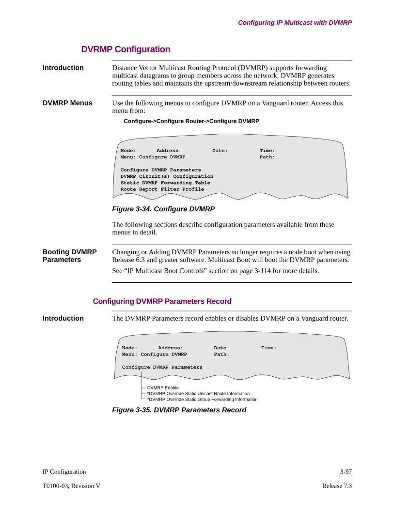
IP Configuration 3-97
T0100-03, Revision V Release 7.3
Configuring IP Multicast with DVMRP
DVRMP Configuration
Introduction Distance Vector Multicast Routing Protocol (DVMRP) supports forwarding multicast datagrams to group members across the network. DVMRP generates routing tables and maintains the upstream/downstream relationship between routers.
DVMRP Menus Use the following menus to configure DVMRP on a Vanguard router. Access this menu from:
Configure->Configure Router->Configure DVMRP
Figure 3-34. Configure DVMRP
The following sections describe configuration parameters available from these menus in detail.
Booting DVMRP Parameters
Changing or Adding DVMRP Parameters no longer requires a node boot when using Release 6.3 and greater software. Multicast Boot will boot the DVMRP parameters.
See “IP Multicast Boot Controls” section on page 3-114 for more details.
Configuring DVMRP Parameters Record
Introduction The DVMRP Parameters record enables or disables DVMRP on a Vanguard router.
Figure 3-35. DVMRP Parameters Record
Node: Address: Date: Time: Menu: Configure DVMRP Path:
Configure DVMRP ParametersDVMRP Circuit(s) ConfigurationStatic DVMRP Forwarding TableRoute Report Filter Profile
DVMRP Enable*DVMRP Override Static Unicast Route Information*DVMRP Override Static Group Forwarding Information
Node: Address: Date: Time: Menu: Configure DVMRP Path:
Configure DVMRP Parameters
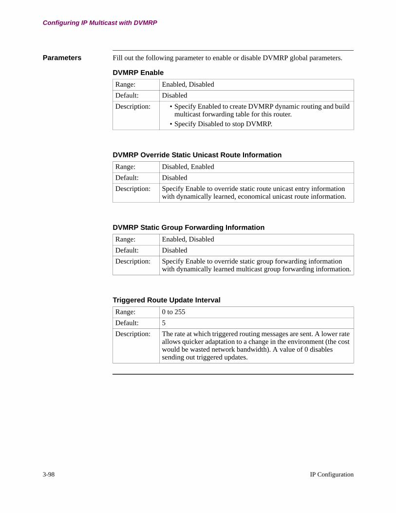
3-98 IP Configuration
Configuring IP Multicast with DVMRP
Parameters Fill out the following parameter to enable or disable DVMRP global parameters.
DVMRP Enable
Range: Enabled, Disabled
Default: Disabled
Description: • Specify Enabled to create DVMRP dynamic routing and build multicast forwarding table for this router.
• Specify Disabled to stop DVMRP.
DVMRP Override Static Unicast Route Information
Range: Disabled, Enabled
Default: Disabled
Description: Specify Enable to override static route unicast entry information with dynamically learned, economical unicast route information.
DVMRP Static Group Forwarding Information
Range: Enabled, Disabled
Default: Disabled
Description: Specify Enable to override static group forwarding information with dynamically learned multicast group forwarding information.
Triggered Route Update Interval
Range: 0 to 255
Default: 5
Description: The rate at which triggered routing messages are sent. A lower rate allows quicker adaptation to a change in the environment (the cost would be wasted network bandwidth). A value of 0 disables sending out triggered updates.
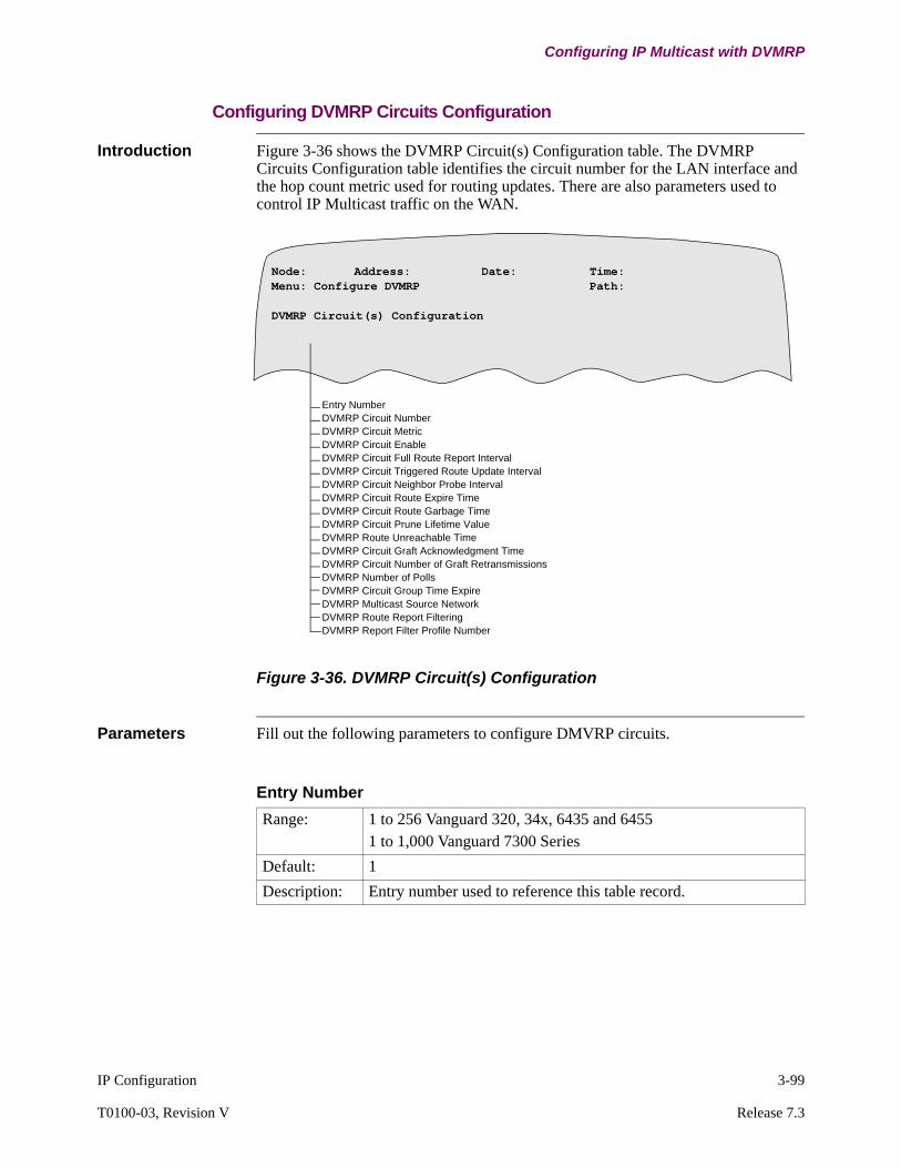
IP Configuration 3-99
T0100-03, Revision V Release 7.3
Configuring IP Multicast with DVMRP
Configuring DVMRP Circuits Configuration
Introduction Figure 3-36 shows the DVMRP Circuit(s) Configuration table. The DVMRP Circuits Configuration table identifies the circuit number for the LAN interface and the hop count metric used for routing updates. There are also parameters used to control IP Multicast traffic on the WAN.
Figure 3-36. DVMRP Circuit(s) Configuration
Parameters Fill out the following parameters to configure DMVRP circuits.
Entry NumberDVMRP Circuit NumberDVMRP Circuit MetricDVMRP Circuit EnableDVMRP Circuit Full Route Report IntervalDVMRP Circuit Triggered Route Update IntervalDVMRP Circuit Neighbor Probe IntervalDVMRP Circuit Route Expire TimeDVMRP Circuit Route Garbage TimeDVMRP Circuit Prune Lifetime ValueDVMRP Route Unreachable TimeDVMRP Circuit Graft Acknowledgment TimeDVMRP Circuit Number of Graft RetransmissionsDVMRP Number of PollsDVMRP Circuit Group Time ExpireDVMRP Multicast Source NetworkDVMRP Route Report FilteringDVMRP Report Filter Profile Number
Node: Address: Date: Time: Menu: Configure DVMRP Path:
DVMRP Circuit(s) Configuration
Entry Number
Range: 1 to 256 Vanguard 320, 34x, 6435 and 64551 to 1,000 Vanguard 7300 Series
Default: 1
Description: Entry number used to reference this table record.

3-100 IP Configuration
Configuring IP Multicast with DVMRP
DVMRP Circuit Number
Range: Vanguard 320, 34x, 6435 and 6455NET-1 to NET-4LCON-1 to LCON-252Vanguard 7300 SeriesNET-1 to NET-50LCON-1 to LCON-950
Default: NET-1
Description: Specify the circuit number for this entry. • Identify LAN ports by the format NET-# • Identify LCON or WAN interfaces by the format LCON-#.
Each circuit must be assigned either LAN port number or LAN connection number. LAN ports range from 1 to 4. LAN connection (LCON) numbers range from 1 to 252 or the maximum number of configured LCONs in CMEM. LCONs are virtual circuit links over WAN networks such as X.25 or Frame Relay to other routers.
DVMRP Circuit Metric
Range: 1 to 32
Default: 1
Description: Specify the hop count metric for the corresponding NET/LCON circuit receiving unicast DVMRP routing updates. The cost metric of the corresponding Net/LCON circuit to be used while receiving unicast DVMRP routing updates.
DVMRP Circuit Enable
Range: Enabled, Disabled
Default: Disabled
Description: • Specify Enable to run DVMRP on this circuit.• Specify Disable to turn off DVMRP on this circuit.
Enable this parameter to use DVMRP on this router.

IP Configuration 3-101
T0100-03, Revision V Release 7.3
Configuring IP Multicast with DVMRP
DVMRP Circuit Full Route Report Interval
Range: 50 to 65535
Default: 60
Description: Specify the time interval (in seconds) between periodic DVMRP full routing table updates. The minimum value of this parameter must be one third of the value set in the Route Unreachable timer. Do not use the maximum value if you set Route Unreachable Timer.
DVMRP Circuit Triggered Route Update Interval
Range: 0 to 65535
Default: 5
Description: Specify the time interval (in seconds) between triggered updates (for example, 60 seconds). Triggered updates notify you of change in the network. If your network is stable with infrequent changes, set this parameter to a long duration to reduce WAN traffic.
DVMRP Circuit Neighbor Probe Interval
Range: 0 to 65535
Default: 10
Description: Specify the time interval (in seconds) for periodic polling of the network to detect a new router, lost router, or leaf router.If your network is stable with infrequent changes, set this parameter to a long duration to reduce WAN traffic (for example, 120 seconds).Probe interval = 0 indicates No Probe Sent Out.
DVMRP Circuit Route Expire Timer
Range: 0 to 65535
Default: 120
Description: Specify the amount of time (in seconds) to consider a route valid without confirmation. When this timer expires, packets are no longer forwarded on the route, and the routing updates consider this route to have a metric of infinity.
3-102 IP Configuration
Configuring IP Multicast with DVMRP
DVMRP Circuit Prune Lifetime Value
Range: 0 to 65535
Default: 60
Description: Specify the time (in seconds) after which a pruned circuit can be used again for forwarding Multicast datagrams.Setting this parameter to long durations (for example, 300 seconds) reduces the amount of WAN traffic in your network by limiting the frequency of polling on inactive branches of the Multicast group.Amount of time (in seconds) for which prune for (source, subnet, group address) pair is active.
NoteEntering 0 disables the sending out of prunes.
DVMRP Route Unreachable Timer
Range: 0 to 65535
Default: 180
Description: Specify the time interval (in seconds) the timer restarts when a Full Route Report Interval report is received. When this timer expires, the route is marked unreachable in the routing table. Set this parameter to a value at least three times greater than the value set in the Full Route Update Interval parameter.
DVMRP Circuit Graft Acknowledgment Time
Range: 1 to 255
Default: 5
Description: Specify the amount of time in seconds before retransmitting a graft packet.
DVMRP Circuit Route Garbage Time
Range: 0 to 65535
Default: 240
Description: Specify time, in seconds, a route exists without confirmation. When this timer expires, routing updates no longer contain any information on this route, and the route is deleted.

IP Configuration 3-103
T0100-03, Revision V Release 7.3
Configuring IP Multicast with DVMRP
DVMRP Circuit Number of Graft Retransmissions
Range: 3 to 20
Default: 5
Description: Specify the number of times a graft packet is retransmitted after the graft acknowledgment timer expires.
DVMRP Number of Polls
Range: 3 to 20
Default: 5
Description: Specify the number of polls to send after a neighboring router goes down.
DVMRP Circuit Group Expire Timer
Range: 1 to 255
Default: 25
Description: Specify the amount of time in seconds to consider a group valid without confirmation. When this timer expires, the router stops forwarding packets on this route.
DVMRP Multicast Source Network
Range: Disabled, Enabled
Default: Enabled
Description: Enable/Disable Multicast Source Network Advertisement. When Enabled, the local interface source route is included in the routing table report. When Disabled it is excluded from the report. Eliminating non-multicast source routes decreases routing table sizes and consequently decreases DVMRP report packet sizes.
3-104 IP Configuration
Configuring IP Multicast with DVMRP
NoteIf DVMRP Route Report Filtering is Enabled, the DVMRP Report Filter Profile Number Parameter is displayed. Both of these parameters are available with Release 6.3 and greater software.
DVMRP Route Report Filtering
Range: Disabled, Enabled
Default: Disabled
Description: Enable/Disable Route Reporting Filtering on circuit.When enabled, route filter profiles applied to the circuit are searched in sequential order to find a route entry match. On the first match, the action defined by the profile filter type determines if the route is reported on the circuit or not. Always configure the more specific routes in the earlier profiles since the profiles are scanned in sequential order. If no match is found in all profiles, the action taken is opposite to the last profile filter type.
DVMRP Report Filter Profile Number
Range: 1 to 255
Default: 1
Description: The list of DVMRP Route Report Filter Profiles that are applied to this circuit. The range of profiles is 1 to 255. Enter 0 to clear field. If multiple profiles are configured for the circuit, the profiles are searched in sequential order to find a route entry match.Examples: 1 (profile 1)1, 3 (profiles 1 and 3)1-2, 4 (profiles 1, 2 and 4).
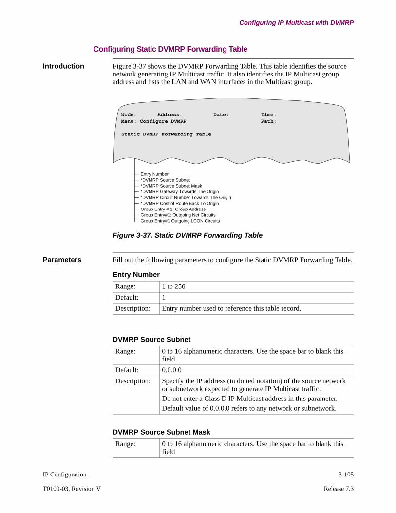
IP Configuration 3-105
T0100-03, Revision V Release 7.3
Configuring IP Multicast with DVMRP
Configuring Static DVMRP Forwarding Table
Introduction Figure 3-37 shows the DVMRP Forwarding Table. This table identifies the source network generating IP Multicast traffic. It also identifies the IP Multicast group address and lists the LAN and WAN interfaces in the Multicast group.
Figure 3-37. Static DVMRP Forwarding Table
Parameters Fill out the following parameters to configure the Static DVMRP Forwarding Table.
Entry Number*DVMRP Source Subnet*DVMRP Source Subnet Mask*DVMRP Gateway Towards The Origin*DVMRP Circuit Number Towards The Origin*DVMRP Cost of Route Back To OriginGroup Entry # 1: Group AddressGroup Entry#1: Outgoing Net CircuitsGroup Entry#1 Outgoing LCON Circuits
Node: Address: Date: Time: Menu: Configure DVMRP Path:
Static DVMRP Forwarding Table
Entry Number
Range: 1 to 256
Default: 1
Description: Entry number used to reference this table record.
DVMRP Source Subnet
Range: 0 to 16 alphanumeric characters. Use the space bar to blank this field
Default: 0.0.0.0
Description: Specify the IP address (in dotted notation) of the source network or subnetwork expected to generate IP Multicast traffic. Do not enter a Class D IP Multicast address in this parameter.Default value of 0.0.0.0 refers to any network or subnetwork.
DVMRP Source Subnet Mask
Range: 0 to 16 alphanumeric characters. Use the space bar to blank this field

3-106 IP Configuration
Configuring IP Multicast with DVMRP
Default: 0.0.0.0
Description: Specify the 32-bit IP Subnet Mask Address. DVMRP supports variable length masks.The subnetwork address mask has all 1 bits in the bits that form the network and subnetwork portions of the IP address. For example, if the interface is on a class B network such as 128.185.0.0, and the third byte is used to select a subnet (for example 128.185.100.0), the mask should be set to 255.255.255.0. All IP devices on a subnet network must be configured with the same subnetwork address mask. Host IP addresses are set to subnet mask 255.255.255.255. The default value of 0.0.0.0 refers to a mask for any network or subnetwork and should be used if the DVMRP Source Subnet is 0.0.0.0.
DVMRP Source Subnet Mask (continued)
DVMRP Gateway Towards The Origin
Range: 0 to 16 alphanumeric characters. Use the Space bar to blank this field.
Default: 0.0.0.0
Description: Specify the IP Address of the next hop gateway towards the source subnetwork. The source subnetwork is the network where the IP Multicasting datagrams originate from. The next hop itself must be on an IP network directly connected to this router.Set value to default of 0.0.0.0 if the origin is on a directly connected subnet.
NoteThis parameter is displayed if DVMRP Source Subnet is set to non-default.
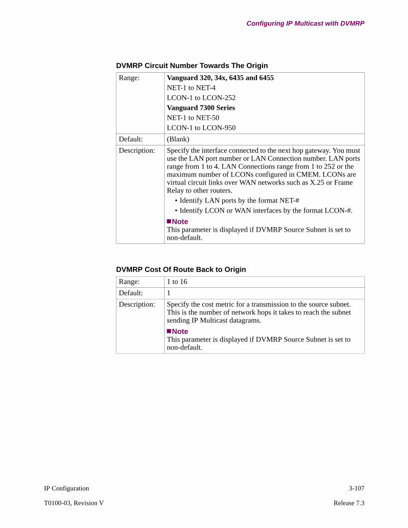
IP Configuration 3-107
T0100-03, Revision V Release 7.3
Configuring IP Multicast with DVMRP
DVMRP Circuit Number Towards The Origin
Range: Vanguard 320, 34x, 6435 and 6455NET-1 to NET-4LCON-1 to LCON-252Vanguard 7300 SeriesNET-1 to NET-50LCON-1 to LCON-950
Default: (Blank)
Description: Specify the interface connected to the next hop gateway. You must use the LAN port number or LAN Connection number. LAN ports range from 1 to 4. LAN Connections range from 1 to 252 or the maximum number of LCONs configured in CMEM. LCONs are virtual circuit links over WAN networks such as X.25 or Frame Relay to other routers.
• Identify LAN ports by the format NET-# • Identify LCON or WAN interfaces by the format LCON-#.
NoteThis parameter is displayed if DVMRP Source Subnet is set to non-default.
DVMRP Cost Of Route Back to Origin
Range: 1 to 16
Default: 1
Description: Specify the cost metric for a transmission to the source subnet. This is the number of network hops it takes to reach the subnet sending IP Multicast datagrams.
NoteThis parameter is displayed if DVMRP Source Subnet is set to non-default.
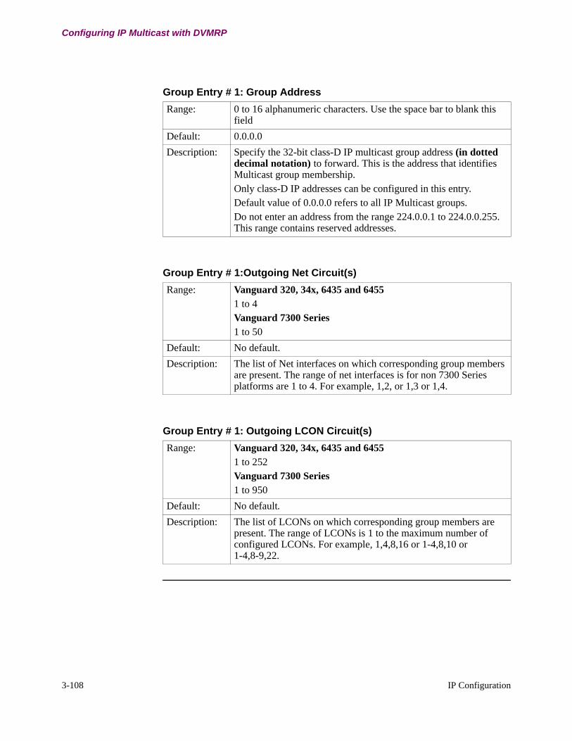
3-108 IP Configuration
Configuring IP Multicast with DVMRP
Group Entry # 1: Group Address
Range: 0 to 16 alphanumeric characters. Use the space bar to blank this field
Default: 0.0.0.0
Description: Specify the 32-bit class-D IP multicast group address (in dotted decimal notation) to forward. This is the address that identifies Multicast group membership. Only class-D IP addresses can be configured in this entry. Default value of 0.0.0.0 refers to all IP Multicast groups.Do not enter an address from the range 224.0.0.1 to 224.0.0.255. This range contains reserved addresses.
Group Entry # 1:Outgoing Net Circuit(s)
Range: Vanguard 320, 34x, 6435 and 64551 to 4Vanguard 7300 Series1 to 50
Default: No default.
Description: The list of Net interfaces on which corresponding group members are present. The range of net interfaces is for non 7300 Series platforms are 1 to 4. For example, 1,2, or 1,3 or 1,4.
Group Entry # 1: Outgoing LCON Circuit(s)
Range: Vanguard 320, 34x, 6435 and 64551 to 252Vanguard 7300 Series1 to 950
Default: No default.
Description: The list of LCONs on which corresponding group members are present. The range of LCONs is 1 to the maximum number of configured LCONs. For example, 1,4,8,16 or 1-4,8,10 or 1-4,8-9,22.
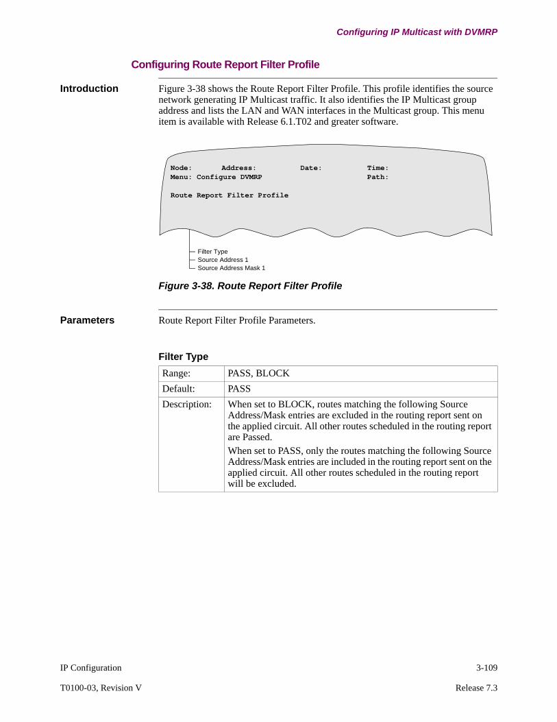
IP Configuration 3-109
T0100-03, Revision V Release 7.3
Configuring IP Multicast with DVMRP
Configuring Route Report Filter Profile
Introduction Figure 3-38 shows the Route Report Filter Profile. This profile identifies the source network generating IP Multicast traffic. It also identifies the IP Multicast group address and lists the LAN and WAN interfaces in the Multicast group. This menu item is available with Release 6.1.T02 and greater software.
Figure 3-38. Route Report Filter Profile
Parameters Route Report Filter Profile Parameters.
Filter TypeSource Address 1Source Address Mask 1
Node: Address: Date: Time: Menu: Configure DVMRP Path:
Route Report Filter Profile
Filter Type
Range: PASS, BLOCK
Default: PASS
Description: When set to BLOCK, routes matching the following Source Address/Mask entries are excluded in the routing report sent on the applied circuit. All other routes scheduled in the routing report are Passed. When set to PASS, only the routes matching the following Source Address/Mask entries are included in the routing report sent on the applied circuit. All other routes scheduled in the routing report will be excluded.
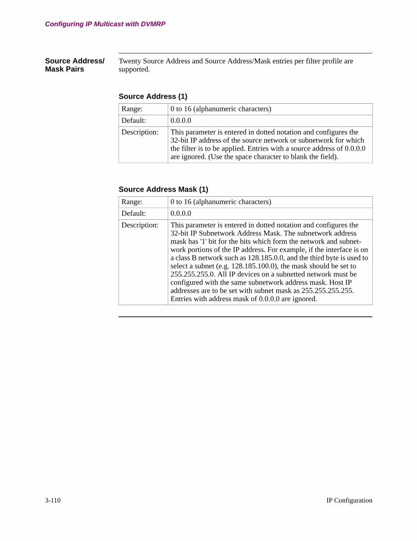
3-110 IP Configuration
Configuring IP Multicast with DVMRP
Source Address/Mask Pairs
Twenty Source Address and Source Address/Mask entries per filter profile are supported.
Source Address (1)
Range: 0 to 16 (alphanumeric characters)
Default: 0.0.0.0
Description: This parameter is entered in dotted notation and configures the 32-bit IP address of the source network or subnetwork for which the filter is to be applied. Entries with a source address of 0.0.0.0 are ignored. (Use the space character to blank the field).
Source Address Mask (1)
Range: 0 to 16 (alphanumeric characters)
Default: 0.0.0.0
Description: This parameter is entered in dotted notation and configures the 32-bit IP Subnetwork Address Mask. The subnetwork address mask has '1' bit for the bits which form the network and subnet-work portions of the IP address. For example, if the interface is on a class B network such as 128.185.0.0, and the third byte is used to select a subnet (e.g. 128.185.100.0), the mask should be set to 255.255.255.0. All IP devices on a subnetted network must be configured with the same subnetwork address mask. Host IP addresses are to be set with subnet mask as 255.255.255.255. Entries with address mask of 0.0.0.0 are ignored.
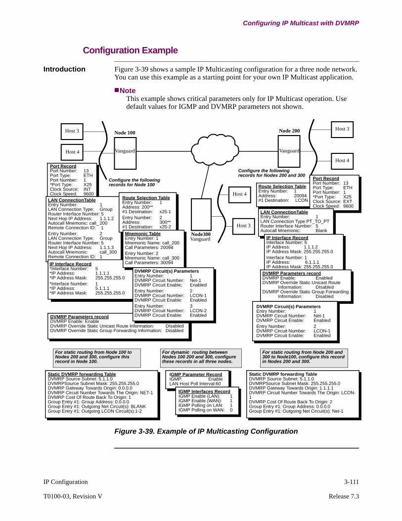
IP Configuration 3-111
T0100-03, Revision V Release 7.3
Configuring IP Multicast with DVMRP
Configuration Example
Introduction Figure 3-39 shows a sample IP Multicasting configuration for a three node network. You can use this example as a starting point for your own IP Multicast application.
NoteThis example shows critical parameters only for IP Multicast operation. Use default values for IGMP and DVMRP parameters not shown.
Figure 3-39. Example of IP Multicasting Configuration
Port RecordPort Number: 13Port Type: ETHPort Number: 1*Port Type: X25Clock Source: INTClock Speed: 9600
DVMRP Parameters recordDVMRP Enable: EnableDVMRP Override Static Unicast Route Information: DIsabledDVMRP Override Static Group Forwarding Information: Disabled
For static routing from Node 100 to Nodes 200 and 300, configure this record in Node 100.
LAN ConnectionTableEntry Number: 1LAN Connection Type: GroupRouter Interface Number: 5Next Hop IP Address: 1.1.1.2Autocall Mnemonic: call_ 200Remote Connection ID: 1Entry Number: 2LAN Connection Type: GroupRouter Interface Number: 5Next Hop IP Address: 1.1.1.3Autocall Mnemonic: call_300Remote Connection ID: 1
For dynamic routing between Nodes 100 200 and 300, configure these records in all three nodes.
Route Selection TableEntry Number: 1Address: 20094#1 Destination: LCON
For static routing from Node 200 and 300 to Node100, configure this record in Nodes 200 and 300.
Configure the following records for Node 100
Configure the following records for Nodes 200 and 300
Host 3
Host 4
Node 100
Vanguard
Host 3
Host 4
Node 200
Host 4
Host 3
Node300Vanguard
Route Selection TableEntry Number: 1Address: 200**#1 Destination: x25-1Entry Number: 2Address: 300**#1 Destination: x25-2
IP Interface Record*Interface Number: 5*IP Address: 1.1.1.1*IP Address Mask: 255.255.255.0*Interface Number: 1*IP Address: 5.1.1.1*IP Address Mask: 255.255.255.0
Mnemonic TableEntry Number: 1Mnemonic Name: call_200Call Parameters: 20094Entry Number: 2Mnemonic Name: call_300Call Parameters: 30094
DVMRP Circuit(s) ParametersEntry Number: 1DVMRP Circuit Number: Net-1DVMRP Circuit Enable; EnabledEntry Number: 2DVMRP Circuit Number: LCON-1DVMRP Circuit Enable: EnabledEntry Number: 3DVMRP Circuit Number: LCON-2DVMRP Circuit Enable: Enabled
Static DVMRP forwarding TableDVMRP Source Subnet: 5.1.1.0DVMRPSource Subnet Mask: 255.255.255.0DVMRP Gateway Towards Origin: 0.0.0.0DVMRP Circuit Number Towards The Origin: NET-1DVMRP Cost Of Route Back To Origin: 1Group Entry #1: Group Address: 0.0.0.0Group Entry #1: Outgoing Net Circuit(s): BLANKGroup Entry #1: Outgoing LCON Circuit(s):1-2
IGMP Parameter RecordIGMP: EnableLAN Host Poll Interval:60
IGMP Interfaces RecordIGMP Enable (LAN): 1IGMP Enable (WAN): 1IGMP Polling on LAN: 1IGMP Polling on WAN: 0
Static DVMRP forwarding TableDVMRP Source Subnet: 5.1.1.0DVMRPSource Subnet Mask: 255.255.255.0DVMRP Gateway Towards Origin: 1.1.1.1DVMRP Circuit Number Towards The Origin: LCON-1DVMRP Cost Of Route Back To Origin: 2Group Entry #1: Group Address: 0.0.0.0Group Entry #1: Outgoing Net Circuit(s): Net-1
Port RecordPort Number: 13Port Type: ETHPort Number: 1*Port Type: X25Clock Source: EXTClock Speed: 9600
LAN ConnectionTableEntry Number: 1LAN Connection Type:PT_TO_PTRouter Interface Number: 5Autocall Mnemonic: Blank
IP Interface RecordInterface Number: 5IP Address: 1.1.1.2IP Address Mask: 255.255.255.0Interface Number: 1IP Address: 6.1.1.1IP Address Mask: 255.255.255.0
DVMRP Parameters recordDVMRP Enable: EnabledDVMRP Override Static Unicast Route
Information: DIsabledDVMRP Override Static Group Forwarding
Information: Disabled
DVMRP Circuit(s) ParametersEntry Number: 1DVMRP Circuit Number: Net-1DVMRP Circuit Enable: EnabledEntry Number: 2DVMRP Circuit Number: LCON-1DVMRP Circuit Enable: Enabled
Vanguard

3-112 IP Configuration
Configuring IP Multicast with DVMRP
IP Multicast Performance Tuning
Overview This section describes parameters you can use to fine tune IP Multicasting on your network.
Optimization Parameters
We provide configurable parameters used to fine tune the flow of traffic on your network during IP Multicasting operation.
Refer to the “Configuring Network Address Translation” section on page 3-140 for details on accessing these parameters. The following sections describe the parameters in detail.
Prune Lifetime Value
This is the amount of time it takes before a pruned circuit can be used again for forwarding IP Multicast datagrams in your network.
Pruning refers to the process used to drop inactive members from Multicast groups. Basically, a router delivers a prune message to an upstream router when it no longer has any active members for the IP Multicast group, or if it receives prune messages from a downstream router. The upstream router stops forwarding IP Multicast messages to that downstream router after receiving a prune message, thereby pruning that router and eliminating attached hosts from the group.
The pruning lasts for the duration of the Prune Lifetime Value parameter configured in the DVMRP Circuits Configuration record. You can set this parameter for short or long durations, depending on how you want to limit traffic on your network.
For example, Figure 3-40 shows how inactive hosts attached to Node 100 causes the node to send Prune messages to upstream Node 200. The upstream router stops forwarding IP Multicast datagrams to Node 100. The Prune Lifetime Value for Node 100 is set for 3600 seconds, so it takes at least one hour before multicast datagrams are forwarded to hosts attached to Node 100 again.
Figure 3-40. Pruning Inactive Group Members
DVMRP Circuits ConfigurationPrune Lifetime Value: 3600
PruneMessage
Legend
Indicates Active Multicast group Member
Indicates Inactive Multicast group Member
Host 1
Host 2
Host 3
Host 4
Node 100Host 6
Node 200Vanguard
Host 6
Host 7
Host 9
Node 300
IP Multicast Datagrams
PruneMessage
Vanguard
Vanguard
IP Configuration 3-113
T0100-03, Revision V Release 7.3
Configuring IP Multicast with DVMRP
Node 100 continues to poll attached hosts for activity according to the configured polling interval. If there is no host activity and multicast datagrams are still being generated, it continues to send prune messages to the upstream router. If a host becomes active, Node 100 sends a Graft message and hosts receive datagrams for that group.
If node 100 reboots or restarts and hosts become active group members, Node 100 does not need to send a Graft message. The upstream node begins sending IP Multicast datagrams as soon as the Prune Lifetime Value expires.
Setting a long Prune Lifetime Value can reduce traffic to and from pruned branches on your network.
Full Route Report Interval
This parameter determines how often DVMRP sends out a complete routing table update.
If you have a stable network topology with infrequent changes, setting this parameter for a long duration is desirable because DVMRP generates fewer reports and less WAN traffic.
However, setting this parameter to long durations, can pose a problem. If an updated route report is not received before the configured Route Unreachable Timer expires, routes learned from that router are marked unreachable. Typically, the Route Unreachable Timer is set to a value three times greater than the Full Route Report Interval.
You should also make sure that routers on the same link have the same value configured in the Full Route Report Interval parameter.
Triggered Route Update Interval
This parameter generates an update identifying changes in network topology.
Changes such as a network going down, a link down, or a cost metric change trigger route updates.
It is a good idea to configure different time intervals for triggered updates on each router in your network, thereby delaying the generation of updates and reducing WAN traffic.
Other Tuning Tips Static Routing is not recommended, use Route Filtering.
IP Multicast Filtering
IP Multicast addresses can be filtered using the IP Filter Table. If filtering is enabled, the IP Multicast datagram is dropped when it is received.
Filtering has the following benefits:
• IP multicast traffic is not sent to all interfaces, which saves WAN bandwidth.• The downstream node does not receive IP Multicast datagram, so it does not
need to send a prune message. This indicates additional bandwidth savings.• If fewer prune messages are generated, the router does not have the overhead
associated with the Prune timer processor. This reduces CPU processing.
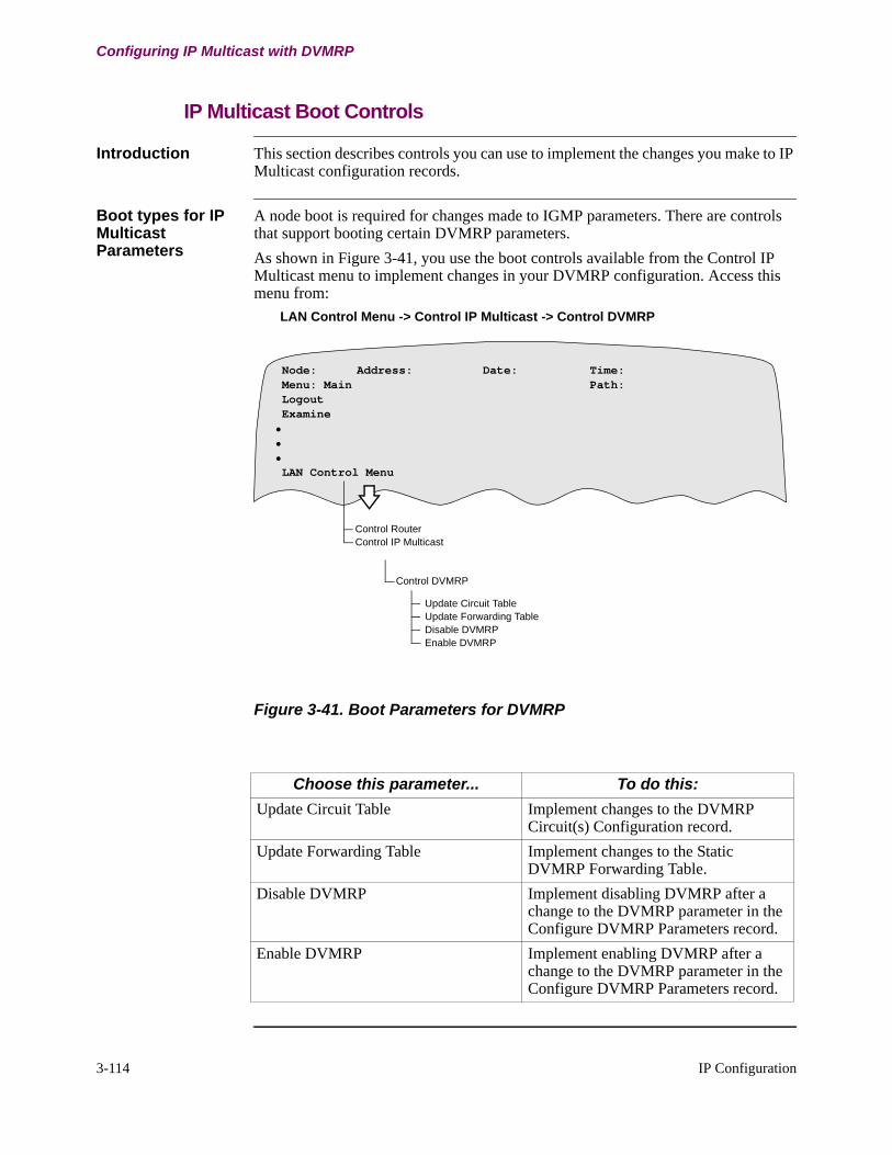
3-114 IP Configuration
Configuring IP Multicast with DVMRP
IP Multicast Boot Controls
Introduction This section describes controls you can use to implement the changes you make to IP Multicast configuration records.
Boot types for IP Multicast Parameters
A node boot is required for changes made to IGMP parameters. There are controls that support booting certain DVMRP parameters.
As shown in Figure 3-41, you use the boot controls available from the Control IP Multicast menu to implement changes in your DVMRP configuration. Access this menu from:
LAN Control Menu -> Control IP Multicast -> Control DVMRP
Figure 3-41. Boot Parameters for DVMRP
Node: Address: Date: Time: Menu: Main Path: Logout Examine••• LAN Control Menu
Control RouterControl IP Multicast
Update Circuit TableUpdate Forwarding TableDisable DVMRPEnable DVMRP
Control DVMRP
Choose this parameter... To do this:
Update Circuit Table Implement changes to the DVMRP Circuit(s) Configuration record.
Update Forwarding Table Implement changes to the Static DVMRP Forwarding Table.
Disable DVMRP Implement disabling DVMRP after a change to the DVMRP parameter in the Configure DVMRP Parameters record.
Enable DVMRP Implement enabling DVMRP after a change to the DVMRP parameter in the Configure DVMRP Parameters record.

IP Configuration 3-115
T0100-03, Revision V Release 7.3
Configuring Protocol Independent Multicast Sparse Mode (PIM-SM)
Configuring Protocol Independent Multicast Sparse Mode (PIM-SM)
Introduction Protocol Independent Multicast Sparse Mode (PIM-SM) is available with Release 6.4 and greater software. PIM-SM supports standard operations such as Configure, List, Examine and Delete functions on all new parameters and records. The Copy function is supported on records with the “entry number” parameter.
IGMP and PIM The IGMP menu is not shown if PIM is included in the image. When PIM is included in the image, there is no need to explicitly enable or disable IGMP. IGMP is automatically enabled on each IP interface that PIM is enabled.
Unlike DVMRP, PIM does not have any protocol dependency on IGMP (PIM uses its own IP protocol number “103”). However, if IGMP is not enabled, PIM-SM will not be informed of any local hosts interested in joining a group. Therefore, IGMP is always needed on interfaces where local IGMP membership is expected. In addition, IGMP is also required if “Mtrace” and “Mrinfo” are to be used in the network. These two diagnostic tools use IGMP messages. To reduce the configuration complexity, the IGMP configuration is eliminated in the new multicast framework. (Mtrace and Mrinfo diagnostics information can be found in Chapter Four of this manual.) When PIM is included in the image (implies using the new multicast framework), there is no need to explicitly configure IGMP. IGMP is enabled on a per IP interface basis, against the existing per router interface model that is not consistent with PIM. By default, no IGMP query message is sent on non broadcast (that is, point to point, either LCON or IP Tunnel). This default can be overridden by changing the "PIM query interval" parameter in the IP interface.
NoteNo changes appear in the IGMP configuration/statistics menu if PIM is not included in the image.
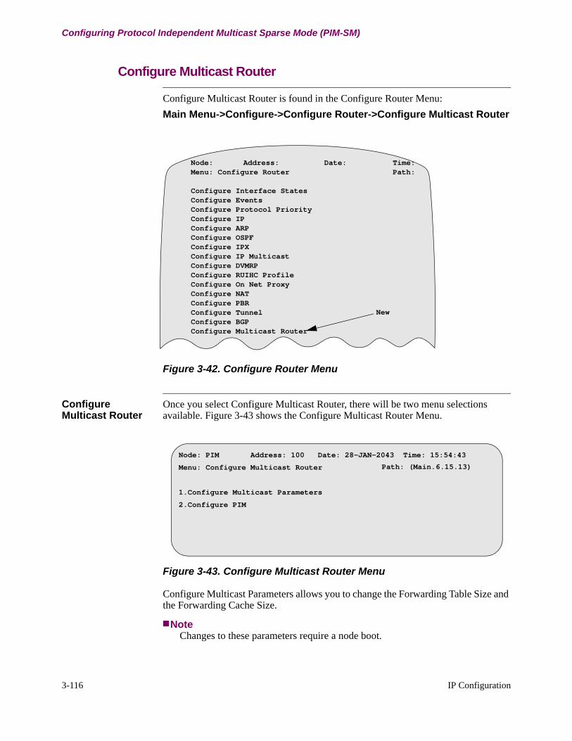
3-116 IP Configuration
Configuring Protocol Independent Multicast Sparse Mode (PIM-SM)
Configure Multicast Router
Configure Multicast Router is found in the Configure Router Menu:
Main Menu->Configure->Configure Router->Configure Multicast Router
Figure 3-42. Configure Router Menu
Configure Multicast Router
Once you select Configure Multicast Router, there will be two menu selections available. Figure 3-43 shows the Configure Multicast Router Menu.
Figure 3-43. Configure Multicast Router Menu
Configure Multicast Parameters allows you to change the Forwarding Table Size and the Forwarding Cache Size.
NoteChanges to these parameters require a node boot.
Node: Address: Date: Time:Menu: Configure Router Path:
Configure Interface StatesConfigure EventsConfigure Protocol PriorityConfigure IPConfigure ARPConfigure OSPFConfigure IPXConfigure IP MulticastConfigure DVMRPConfigure RUIHC ProfileConfigure On Net ProxyConfigure NATConfigure PBRConfigure TunnelConfigure BGPConfigure Multicast Router
New
Node: PIM Address: 100 Date: 28-JAN-2043 Time: 15:54:43
Menu: Configure Multicast Router
1.Configure Multicast Parameters
2.Configure PIM
Path: (Main.6.15.13)
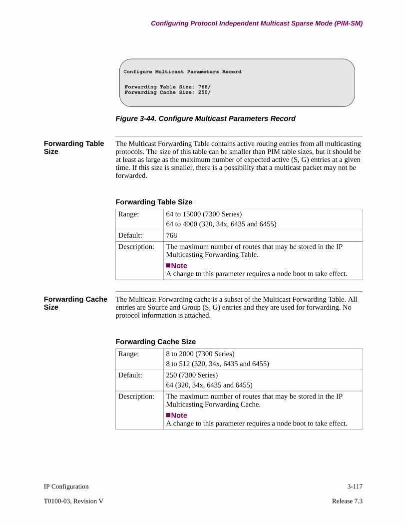
IP Configuration 3-117
T0100-03, Revision V Release 7.3
Configuring Protocol Independent Multicast Sparse Mode (PIM-SM)
Figure 3-44. Configure Multicast Parameters Record
Forwarding Table Size
The Multicast Forwarding Table contains active routing entries from all multicasting protocols. The size of this table can be smaller than PIM table sizes, but it should be at least as large as the maximum number of expected active (S, G) entries at a given time. If this size is smaller, there is a possibility that a multicast packet may not be forwarded.
Forwarding Cache Size
The Multicast Forwarding cache is a subset of the Multicast Forwarding Table. All entries are Source and Group (S, G) entries and they are used for forwarding. No protocol information is attached.
Configure Multicast Parameters Record
Forwarding Table Size: 768/Forwarding Cache Size: 250/
Forwarding Table Size
Range: 64 to 15000 (7300 Series)64 to 4000 (320, 34x, 6435 and 6455)
Default: 768
Description: The maximum number of routes that may be stored in the IP Multicasting Forwarding Table.
NoteA change to this parameter requires a node boot to take effect.
Forwarding Cache Size
Range: 8 to 2000 (7300 Series)8 to 512 (320, 34x, 6435 and 6455)
Default: 250 (7300 Series)64 (320, 34x, 6435 and 6455)
Description: The maximum number of routes that may be stored in the IP Multicasting Forwarding Cache.
NoteA change to this parameter requires a node boot to take effect.

3-118 IP Configuration
Configuring Protocol Independent Multicast Sparse Mode (PIM-SM)
Configure PIM To Configure PIM, select it form the Configure Router Menu:
Main Menu->Configure->Configure Router->Configure Multicast Router->Configure PIM
Figure 3-45 shows the Configure PIM Menu.
Figure 3-45. Configure PIM Menu
Configure PIM-SIM The following parameters can be found under Configure PIM:
Node: PIM Address: 100 Date: 28-JAN-2043 Time: 15:54:43
Menu: Configure PIM Path: (Main.6.15.13)
1.Configure PIM Parameter
2.Configure PIM Profile
3.Configure PIM-SM RP Candidate
4.Configure PIM-SM Static RP
PIM-SM
Range: Enabled, Disabled
Default: Disabled
Description: This parameter specifies if PIM is to be Enabled or Disabled on a router. In order to activate PIM on a router, this parameter has to be set to Enabled. This allows users to globally Enable and Disable PIM without having to change the PIM configuration on the individual IP interfaces.
Boot Effect: The PIM component is reinitialized as required and all PIM Adjacencies are restarted. Multicast forwarding is impacted.
Join Prune Message Interval
Range: 1 to 18724 (seconds)
Default: 60
Description: This parameter configures the frequency (in seconds) at which a PIM-SM router sends periodic Join Prune messages. This parameter specifies how often the PIM sends periodic Join Prune messages to its neighbor(s).
Boot Effect: The new Join Prune Interval is used. PIM will not be restarted.
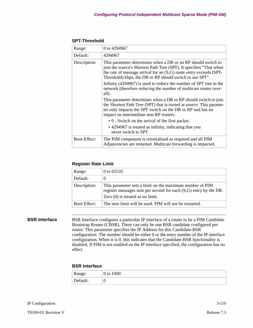
IP Configuration 3-119
T0100-03, Revision V Release 7.3
Configuring Protocol Independent Multicast Sparse Mode (PIM-SM)
BSR Interface BSR Interface configures a particular IP interface of a router to be a PIM Candidate Bootstrap Router (CBSR). There can only be one BSR candidate configured per router. This parameter specifies the IP Address for this Candidate-BSR configuration. The number should be either 0 or the entry number of the IP interface configuration. When it is 0, this indicates that the Candidate-BSR functionality is disabled. If PIM is not enabled on the IP interface specified, the configuration has no effect.
SPT-Threshold
Range: 0 to 4294967
Default: 4294967
Description: This parameter determines when a DR or an RP should switch to join the source's Shortest Path Tree (SPT). It specifies “That when the rate of message arrival for an (S,G) route entry exceeds (SPT-Threshold) kbps, the DR or RP should switch to use SPT". Infinity (4294967) is used to reduce the number of SPT tree in the network (therefore reducing the number of multicast routes over-all). This parameter determines when a DR or RP should switch to join the Shortest Path Tree (SPT) that is rooted at source. This parame-ter only impacts the SPT switch on the DR or RP and has no impact on intermediate non-RP routers.
• 0 - Switch on the arrival of the first packet.• 4294967 is treated as infinity, indicating that you
never switch to SPT.
Boot Effect: The PIM component is reinitialized as required and all PIM Adjancencies are restarted. Multicast forwarding is impacted.
Register Rate Limit
Range: 0 to 65535
Default: 0
Description: This parameter sets a limit on the maximum number of PIM register messages sent per second for each (S,G) entry by the DR. Zero (0) is treated as no limit.
Boot Effect: The new limit will be used. PIM will not be restarted.
BSR Interface
Range: 0 to 1000
Default: 0
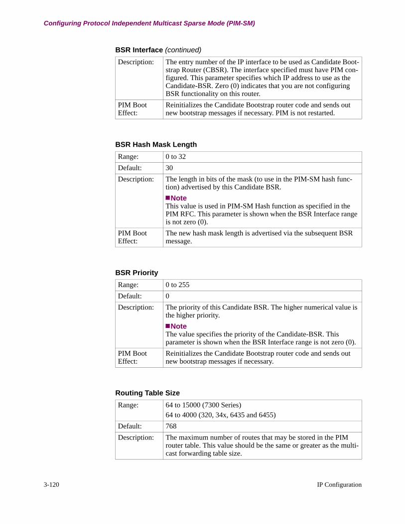
3-120 IP Configuration
Configuring Protocol Independent Multicast Sparse Mode (PIM-SM)
Description: The entry number of the IP interface to be used as Candidate Boot-strap Router (CBSR). The interface specified must have PIM con-figured. This parameter specifies which IP address to use as the Candidate-BSR. Zero (0) indicates that you are not configuring BSR functionality on this router.
PIM Boot Effect:
Reinitializes the Candidate Bootstrap router code and sends out new bootstrap messages if necessary. PIM is not restarted.
BSR Interface (continued)
BSR Hash Mask Length
Range: 0 to 32
Default: 30
Description: The length in bits of the mask (to use in the PIM-SM hash func-tion) advertised by this Candidate BSR.
NoteThis value is used in PIM-SM Hash function as specified in the PIM RFC. This parameter is shown when the BSR Interface range is not zero (0).
PIM Boot Effect:
The new hash mask length is advertised via the subsequent BSR message.
BSR Priority
Range: 0 to 255
Default: 0
Description: The priority of this Candidate BSR. The higher numerical value is the higher priority.
NoteThe value specifies the priority of the Candidate-BSR. This parameter is shown when the BSR Interface range is not zero (0).
PIM Boot Effect:
Reinitializes the Candidate Bootstrap router code and sends out new bootstrap messages if necessary.
Routing Table Size
Range: 64 to 15000 (7300 Series)64 to 4000 (320, 34x, 6435 and 6455)
Default: 768
Description: The maximum number of routes that may be stored in the PIM router table. This value should be the same or greater as the multi-cast forwarding table size.

IP Configuration 3-121
T0100-03, Revision V Release 7.3
Configuring Protocol Independent Multicast Sparse Mode (PIM-SM)
Configure PIM Profile
A PIM profile specifies a range of groups that have different configurations associated with them. They are similar to Cisco's access-list but not identical. They can be associated with Candidate-RP and Static-RP configurations. Below are the parameters and descriptions:
• Entry Number - Entry number for the record• Group Address - Group address for this profile• Group Mask - Group mask for this profile
PIM Boot Effect:
The new maximum is used. PIM is restarted only if the current number of routes is greater than the maximum.
Routing Table Size (continued)
Entry Number
Range: 1 to 256
Default: 1
Description: Entry number used to refer to this record.
Group Address
Range: 224.0.0.0 to 239.255.255.255
Default: 224.0.0.0
Description: The group address of this profile. 224.0.0.0 for Group Address and 240.0.0.0 for Group Mask. Specify "224.0.0.0/4" which determines all multicast groups.This indicates that the profile applies to every group.
Boot Effect: All impacted Candidate-RPs and Static-RPs are reinitialized.
Group Mask
Range: 240.0.0.0 to 255.255.255.255
Default: 240.0.0.0
Description: The group mask of group address. 224.0.0.0 for Group Address and 240.0.0.0 for Group Mask. Specify "224.0.0.0/4" which indicates all multicast groups.This indicates that the profile applies to every group.
Boot Effect: All impacted Candidate-RPs and Static-RPs are reinitialized.

3-122 IP Configuration
Configuring Protocol Independent Multicast Sparse Mode (PIM-SM)
PIM-SM RP Candidate
The following parameters configure a particular interface of a router to be a Candidate Rendezvous Point (RP).
• Entry Number - The Entry Number for this record• RP Interface - The corresponding IP Interface.• Group Profile - The entry number(s) of the corresponding groups in PIM
Profile entries.• Priority - The Priority of the Candidate RP.
NoteThe more Candidate-RPs configured to serve the same group in a PIM network, the higher the overhead is to execute the very frequently used "Group-to-RP mapping algorithm" on every PIM router.
Entry Number
Range: 1 to 100
Default: 1
Description: Entry number used to refer to this record.
RP Interface
Range: 1 to 1000
Default: 1
Description: Entry number of the IP interface to be used as Candidate-RP. PIM must be configured on the specified interface. This parameter specifies the IP Address for this Candidate-RP configuration. The number should be the entry number of the IP interface configura-tion. If PIM is not enabled on the IP interface specified, the con-figuration has no effect.
Boot Effect: This reinitializes the Candidate-RP code and sends out new Candidate-RP advertisement messages if necessary.
Group Profile
Range: 0 to 256
Default: 0
Description: This specifies which group(s) that this candidate RP is responsible for. This is the group address to be served by the RP. The range can be entered as "1", "6-33", or "1,6, 20-23".0 is not a valid profile number. It is used to indicate this is an RP for all multicast groups (i.e., 224.0.0.0/4). Users do not need to explicitly create a profile when they want to refer to 224.0.0.0/4.

IP Configuration 3-123
T0100-03, Revision V Release 7.3
Configuring Protocol Independent Multicast Sparse Mode (PIM-SM)
PIM Static RP PIM Static RP configures the RPs of multicast groups. There can be different precedences associated with each Static-RP. Below are the parameters and descriptions:
• Entry Number - The Entry Number for this record• RP Address- IP Address of the RP• Group Profile - The entry number(s) of the corresponding groups in PIM
Profile entries.• Precedence - Indicates if this configured RP is to override the dynamically
learned RP set for the same group.
Boot Effect: This reinitializes the Candidate-RP code and sends out new Candidate-RP advertisement messages if necessary.
Group Profile
Priority
Range: 1 to 255
Default: 100
Description: The priority of the RP. The lower numerical value is higher priority.
Boot Effect: This reinitializes the Candidate-RP code and sends out new Candidate-RP advertisement messages if necessary.
Entry Number
Range: 1 to 100
Default: 1
Description: Entry number used to refer to this record.
RP Address
Range: IP Address
Default: (No Default)
Description: This parameter specifies the RP to be used for the groups specified under Group Profile.
Boot Effect: Reinitializes the static RP information.
Group Profile
Range: 0 to 256
Default: 0
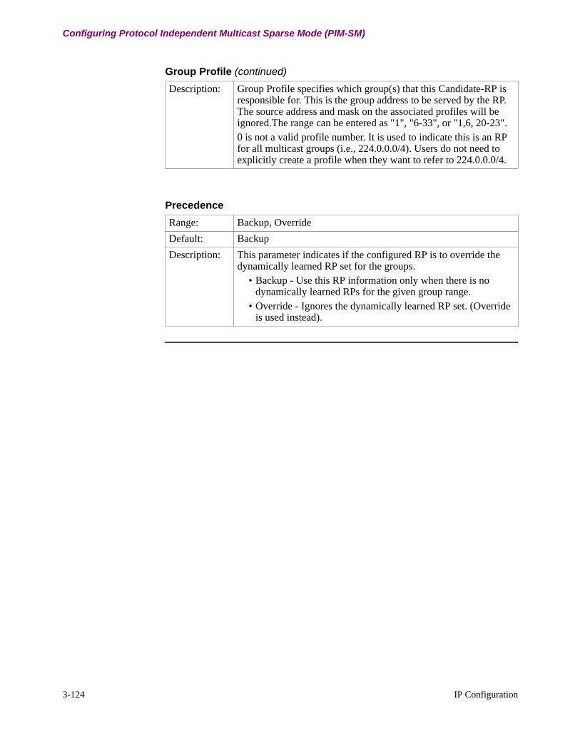
3-124 IP Configuration
Configuring Protocol Independent Multicast Sparse Mode (PIM-SM)
Description: Group Profile specifies which group(s) that this Candidate-RP is responsible for. This is the group address to be served by the RP. The source address and mask on the associated profiles will be ignored.The range can be entered as "1", "6-33", or "1,6, 20-23".0 is not a valid profile number. It is used to indicate this is an RP for all multicast groups (i.e., 224.0.0.0/4). Users do not need to explicitly create a profile when they want to refer to 224.0.0.0/4.
Group Profile (continued)
Precedence
Range: Backup, Override
Default: Backup
Description: This parameter indicates if the configured RP is to override the dynamically learned RP set for the groups.
• Backup - Use this RP information only when there is no dynamically learned RPs for the given group range.
• Override - Ignores the dynamically learned RP set. (Override is used instead).
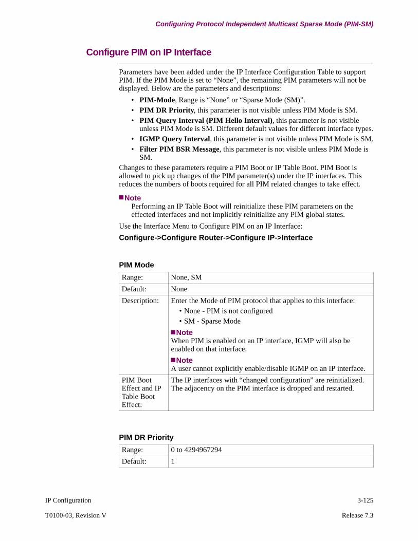
IP Configuration 3-125
T0100-03, Revision V Release 7.3
Configuring Protocol Independent Multicast Sparse Mode (PIM-SM)
Configure PIM on IP Interface
Parameters have been added under the IP Interface Configuration Table to support PIM. If the PIM Mode is set to “None”, the remaining PIM parameters will not be displayed. Below are the parameters and descriptions:
• PIM-Mode, Range is “None” or “Sparse Mode (SM)”.• PIM DR Priority, this parameter is not visible unless PIM Mode is SM.• PIM Query Interval (PIM Hello Interval), this parameter is not visible
unless PIM Mode is SM. Different default values for different interface types.• IGMP Query Interval, this parameter is not visible unless PIM Mode is SM.• Filter PIM BSR Message, this parameter is not visible unless PIM Mode is
SM.Changes to these parameters require a PIM Boot or IP Table Boot. PIM Boot is allowed to pick up changes of the PIM parameter(s) under the IP interfaces. This reduces the numbers of boots required for all PIM related changes to take effect.
NotePerforming an IP Table Boot will reinitialize these PIM parameters on the effected interfaces and not implicitly reinitialize any PIM global states.
Use the Interface Menu to Configure PIM on an IP Interface:
Configure->Configure Router->Configure IP->Interface
PIM Mode
Range: None, SM
Default: None
Description: Enter the Mode of PIM protocol that applies to this interface:• None - PIM is not configured• SM - Sparse Mode
NoteWhen PIM is enabled on an IP interface, IGMP will also be enabled on that interface.
NoteA user cannot explicitly enable/disable IGMP on an IP interface.
PIM Boot Effect and IP Table Boot Effect:
The IP interfaces with “changed configuration” are reinitialized. The adjacency on the PIM interface is dropped and restarted.
PIM DR Priority
Range: 0 to 4294967294
Default: 1

3-126 IP Configuration
Configuring Protocol Independent Multicast Sparse Mode (PIM-SM)
Description: This parameter specifies the priority to be used in the PIM Hello message sent from this interface.The numerical larger value indicates higher priority.
PIM Boot Effect and IP Table Boot Effect:
New priority is advertised via Hello messages immediately. PIM adjacency is not impacted.
PIM DR Priority
PIM Query Interval
Range: 0 to 18724
Default: 30
Description: This parameter specifies the frequency (in seconds) at which the router sends PIM hello messages.
PIM Boot Effect and IP Table Boot Effect:
The new hello interval is advertised via hello messages and the new interval is used. PIM adjacency is not impacted.
IGMP Query Interval
Range: 0 to 65535
Default: 60
Description: This parameter specifies the frequency (in seconds) at which the router sends IGMP host query messages.0 indicates not to send an IGMP query message.
PIM Boot Effect and IP Table Boot Effect:
The new query interval is used. PIM adjacency is not impacted.
Filter BSR Message
Range: Enabled, Disabled
Default: Disabled
Description: This parameter specifies if the interface should filter any incoming and outgoing BSR messages.
• Enabled - All incoming BSR messages that arrived through this interface are dropped.
• Disabled - No special treatment. Forward the BSR messages as normal.

IP Configuration 3-127
T0100-03, Revision V Release 7.3
Configuring Protocol Independent Multicast Sparse Mode (PIM-SM)
PIM Boot Effect and IP Table Boot Effect:
The new configuration takes effect, no PIM adjacency is impacted.
Filter BSR Message (continued)
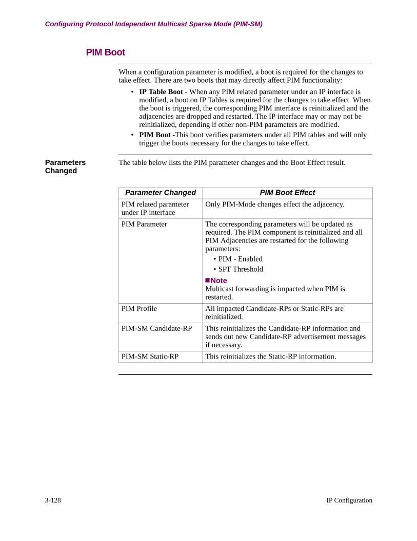
3-128 IP Configuration
Configuring Protocol Independent Multicast Sparse Mode (PIM-SM)
PIM Boot
When a configuration parameter is modified, a boot is required for the changes to take effect. There are two boots that may directly affect PIM functionality:
• IP Table Boot - When any PIM related parameter under an IP interface is modified, a boot on IP Tables is required for the changes to take effect. When the boot is triggered, the corresponding PIM interface is reinitialized and the adjacencies are dropped and restarted. The IP interface may or may not be reinitialized, depending if other non-PIM parameters are modified.
• PIM Boot -This boot verifies parameters under all PIM tables and will only trigger the boots necessary for the changes to take effect.
Parameters Changed
The table below lists the PIM parameter changes and the Boot Effect result.
Parameter Changed PIM Boot Effect
PIM related parameter under IP interface
Only PIM-Mode changes effect the adjacency.
PIM Parameter The corresponding parameters will be updated as required. The PIM component is reinitialized and all PIM Adjacencies are restarted for the following parameters:
• PIM - Enabled• SPT Threshold
NoteMulticast forwarding is impacted when PIM is restarted.
PIM Profile All impacted Candidate-RPs or Static-RPs are reinitialized.
PIM-SM Candidate-RP This reinitializes the Candidate-RP information and sends out new Candidate-RP advertisement messages if necessary.
PIM-SM Static-RP This reinitializes the Static-RP information.
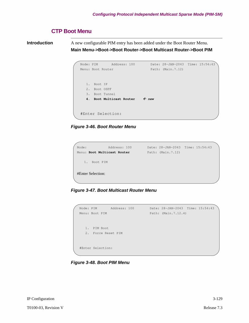
IP Configuration 3-129
T0100-03, Revision V Release 7.3
Configuring Protocol Independent Multicast Sparse Mode (PIM-SM)
CTP Boot Menu
Introduction A new configurable PIM entry has been added under the Boot Router Menu.
Main Menu->Boot->Boot Router->Boot Multicast Router->Boot PIM
Figure 3-46. Boot Router Menu
Figure 3-47. Boot Multicast Router Menu
Figure 3-48. Boot PIM Menu
Node: PIM Address: 100 Date: 28-JAN-2043 Time: 15:54:43
Menu: Boot Router Path: (Main.7.12)
1. Boot IP
2. Boot OSPF
3. Boot Tunnel
4. Boot Multicast Router new
#Enter Selection:
Node: Address: 100 Date: 28-JAN-2043 Time: 15:54:43
Menu: Boot Multicast Router Path: (Main.7.12)
1. Boot PIM
#Enter Selection:
Node: PIM Address: 100 Date: 28-JAN-2043 Time: 15:54:43
Menu: Boot PIM Path: (Main.7.12.4)
1. PIM Boot
2. Force Reset PIM
#Enter Selection:

Boot PIM Figure 3-48displays two entries, PIM Boot and Force Reset PIM in the Boot PIM Menu.
1) Selecting PIM Boot picks up the configuration changes in “Parameters Changed” section on page 3-128. If there are no configuration changes, PIM Boot is non operational.
2) Selecting Force Reset PIM restarts PIM regardless if there are any configuration changes. Force Reset PIM will pick up new configuration changes.
Embedded Web
PIM Configuration through the embedded web is supported on the Vanguard Routers.
CLI Support
CLI is supported on the PIM CTP Configuration Items.
PIM CLI Objects
CLI Object Name Corresponding CTP Record Entry
Supported Operations
ip-pim-parameter PIM Parameter get, set, create, delete, getdefault
ip-pim-profile PIM Profile get, set, create, delete, getdefault
ip-pim-bsr-candidate PIM-SM BSR Candidate get, set, create, delete, getdefault
ip-pim-rp-candidate PIM-SM RP Candidate get, set, create, delete, getdefault
ip-pim-static-rp PIM-SM get, set, create, delete, getdefault
ip-pim Boot PIM boot
multicast-parameter Multicast Parameters get, set, create, delete, getdefault

IP Configuration 3-131
T0100-03, Revision V Release 7.3
Configuring Proxy Router
Configuring Proxy Router
introduction This section describes configuration of the Vanguard Proxy Router (or On Net Proxy) feature.
What Is It? The Proxy Router feature allows a network containing multiple routers to assign the function of Master Router to a specific router on the network. If the network link to the Master Router goes down, the Proxy Router feature automatically causes the function of Master Router to be assigned to a second router on the network.
NoteThe Vanguard Proxy Router (or On Net Proxy) feature supports Ethernet. This feature does not work using Token Ring.
Configuration Guidelines
For the Proxy Router feature to work, enable the bridge link on the Ethernet LAN port. For additional information on configuring bridge links refer to the Bridging Manual (Part Number T0100-02).
NoteThe Vanguard 6560 Ethernet Port 4 does not support Bridging and does not support the Proxy Router feature.

Configuration Example
Figure 3-49 illustrates a sample configuration of Proxy Router. In this figure, Router A is connected to Router C by a leased link. Router B becomes Master when Router A fails and uses the demand link from Router B to Router C.
Figure 3-49. Proxy Router Configuration Example
Router A - IP Interface TableEntry Number: 1
Interface Num: 1IP Addr: 1.0.0.1IP Addr Mask: 255.0.0.0
Entry Number: 2Interface Num: 5IP Addr: 101.0.0.2IP Addr Mask: 255.0.0.0RIP Metric: 1On Demand RIP: Disabled
X.25 Network
Router C
Router B
Router A - LAN Connection TableEntry Number:5
Forwarder Type: ROUTConnection Type: PT Interface Number: 5Autocall Mnemonic: Router C
Host A
Router A
Host Z
Router A - Proxy TableEntry Number: 1
Proxied IP Addr: 1.0.0.1
Router B- IP Interface TableEntry Number: 1
Interface Num: 1IP Addr: 1.0.0.10IP Addr Mask: 255.0.0.0
Entry Number: 2Interface Num: 1IP Addr: 102.0.0.2IP Addr Mask: 255.0.0.0RIP Metric: 1On Demand RIP: Enabled
Router B- LAN Connection TableEntry Number:5
Forwarder Type: ROUTConnection Type: PT Interface Number: 6On Demand: EnabledAutocall Mnemonic: Router C
Router B- Proxy TableEntry Number: 1
Proxied IP Addr: 1.0.0.1Priority: 5Proxied MAC: Use the MAC
address of Router A
Router C - X25 PortPort Number:43
T1 Retrans Timer: 30N2 Tries: 2
Router C - IP Interface TableEntry Number:1
Interface Num:1IP Addr: 3.0.0.1IP Addr Mask: 255.0.0.0
Entry Number:2Interface Num: 5IP Addr: 101.0.0.1IP Addr Mask: 255.0.0.0RIP Metric: 1On Demand RIP: Disabled
Entry Number:3Interface Num: 6IP Addr: 102.0.0.1IP Addr Mask: 255.0.0.0RIP Metric: 2On Demand RIP: Disabled
Router C - LAN Connection TableEntry Number:5
Forwarder Type: ROUTConnection Type: PTInterface Number: 5On Demand: EnabledAutocall Mnemonic: Blank
Entry Number:6Forwarder Type: ROUTConnection Type: PTInterface Number: 6On Demand: DisabledAutocall Mnemonic: Blank

IP Configuration 3-133
T0100-03, Revision V Release 7.3
Configuring Proxy Router
Configure On Net Proxy Menu
Figure 3-50 shows the Configure On Net Proxy menu. Access this menu from:
Configure->Configure Router->Configure On Net Proxy
Figure 3-50. Configure On Net Proxy Menu
Proxy Parameters Menu
Figure 3-51 shows the Proxy Parameters menu.
Figure 3-51. Proxy Parameters Menu
Parameters The following parameters make up the Parameters section of the Configure On Net Proxy record. A Node (warm) boot is required for the changes to take effect.
Node: Address: Date: Time: Menu: Configure On Net Proxy Path:
Proxy ParametersProxy Table
*Proxy UDP Port
*Proxy Hello Time
*Proxy Hold Time
*Multicast Address
Node: Address: Date: Time:Menu: Configure On Net Proxy Path:
Proxy Parameters
*Proxy UDP Port
Range: 1024 to 65535
Default: 25856
Description: Specifies the UDP Port number to be used to run the Proxy Cluster protocol.

3-134 IP Configuration
Configuring Proxy Router
Proxy Table The Proxy Table defines clusters and the routers that are members of the cluster. Each valid entry results in a virtual interface. The only exception is when a cluster IP address is the address of the real interface on the router.
*Proxy Hello Time
Range: 2 to 5
Default: 5
Description: Specifies the duration, in seconds, between the generation of Hello messages, by the Master router, for a proxied IP address.
*Proxy Hold Time
Range: 5 to 10
Default: 10
Description: Specifies the duration, in seconds, that a router waits before declaring a Master router down and restarting the process to elect another Master router for the cluster.
NoteThis value is greater than the Hello time.
*Multicast IP Address
Range: A valid IP address in dotted decimal notation.
Default: 224.0.0.2
Description: Used to derive a multicast MAC Address to run the Hello protocol. This protocol establishes the Master router for the cluster.

IP Configuration 3-135
T0100-03, Revision V Release 7.3
Configuring Proxy Router
Proxy Table Record Figure 3-52 shows the Proxy Table record.
Figure 3-52. Proxy Table Record
Parameters The following parameters make up the Proxy Table record. These parameters require a Node boot to take effect.
Entry Number
*Interface Number
*Proxied IP Address
Priority
*Proxied MAC Address
Node: Address: Date: Time: Menu: Configure On Net Proxy Path: (Main)
Proxy Table
Entry Number
Range: 1 to 255
Default: 1
Description: Specifies the entry number used to reference this table record.
*Interface Number
Range: 1 to 5
Default: 1
Description: Specifies the router interface number corresponding to a LAN port.
NoteWhen only one LAN port exists, this prompt does not appear.

3-136 IP Configuration
Configuring Proxy Router
*Proxied IP Address
Range: A valid IP address in dotted decimal notation.
Default: 0.0.0.0
Description: Specifies the cluster IP address. If this address matches an interface, the cluster MAC address is the address of the real network interface. In this case, priority is the highest possible and this router becomes the Master router; therefore, no other menu prompts are displayed.
Priority
Range: 1 to 10
Default: 10
Description: Specifies the priority used in the Cluster Protocol. The larger this value is, the greater the chance that this router can become the Master router for that Cluster IP address.
*Proxied MAC Address
Range: 00-00-00-00-00-00 to 7F-FF-FF-FF-FF-FF
Default: 00-00-00-00-00-00
Description: Specifies the MAC address for the Cluster IP address. The Master router answers an ARP Request for the Cluster IP address with this MAC Address.

IP Configuration 3-137
T0100-03, Revision V Release 7.3
Configuring Router Discovery
Configuring Router Discovery
Introduction This section shows how to configure Router Discovery.
Router Discovery Table
Figure 3-53 shows how to access the Router Discovery Table menu. Access this menu from:
Configure->Configure Router->Configure Router Discovery
Figure 3-53. Router Discovery Table Menu
Router Discovery Table Parameters
These tables describe the parameters for which you need to configure the Router Discovery Table.
Entry Number
*Advertisement Address
*Advertisement Interval
*LifeTime
Node: Address: Date: Time: Menu: Configure Router Discovery Path:
Router Discover Table
Entry Number
Range 1 to 4
Default 1
Description This corresponds to the network interface number of the LAN Interface. Where only one LAN interface can exist, as on the VG3XX routers, this prompt does not appear.
Advertisement Address
Range Broadcast, Multicast
Default Multicast
Description This is the IP destination address used in router advertisements sent from the interface. The only permissible values are the All Systems Multicast Address 224.0.0.1, or the Broadcast Address 255.255.255.255.

NoteYou must perform a Node boot for changes to these parameters to take effect.
IP Interface Figure 3-54 shows how to access the IP Interface menu to configure parameters for Router Discovery. Access this menu from:
Configure->Configure Router->Configure IP->Interface
Figure 3-54. Interface Menu
Advertisement Interval
Range 3 to 600 seconds
Default 450 seconds
Description Specifies the time (in seconds) between router advertisements.
Lifetime
Range 3 to 9000 seconds
Default 1800 seconds
Description Specifies the length of time (in seconds) the advertised addresses are considered valid router addresses by hosts, in the absence of further advertisements. Lifetime must not be less than the Advertisement interval.
Entry Number
:
Advertise for Router Discovery
Preference Level
Node: Address: Date: Time: Menu: Configure IP Path:
Interface

IP Configuration 3-139
T0100-03, Revision V Release 7.3
Configuring Router Discovery
IP Interface Parameters
These tables describe the IP Interface parameters that you need to configure for Router Discovery operation. These parameters require a Node boot for changes to take effect.
Advertise for Router Discovery
Range Enabled, Disabled
Default Enabled
Description Enables/Disables the advertising of this interface's address for Router Discovery.
Preference Level
Range 0 to 0xFFFFFFFF
Default 0
Description Specifies the preference of this interface's address as the default router address on the interface's subnet. This value is interpreted as a 32-bit signed integer, with higher values defining a higher preference level.
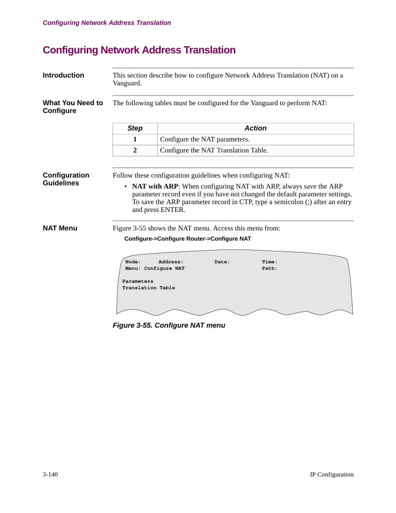
3-140 IP Configuration
Configuring Network Address Translation
Configuring Network Address Translation
Introduction This section describe how to configure Network Address Translation (NAT) on a Vanguard.
What You Need to Configure
The following tables must be configured for the Vanguard to perform NAT:
Configuration Guidelines
Follow these configuration guidelines when configuring NAT:
• NAT with ARP: When configuring NAT with ARP, always save the ARP parameter record even if you have not changed the default parameter settings. To save the ARP parameter record in CTP, type a semicolon (;) after an entry and press ENTER.
NAT Menu Figure 3-55 shows the NAT menu. Access this menu from:
Configure->Configure Router->Configure NAT
Figure 3-55. Configure NAT menu
Step Action
1 Configure the NAT parameters.
2 Configure the NAT Translation Table.
Node: Address: Date: Time: Menu: Configure NAT Path:
ParametersTranslation Table
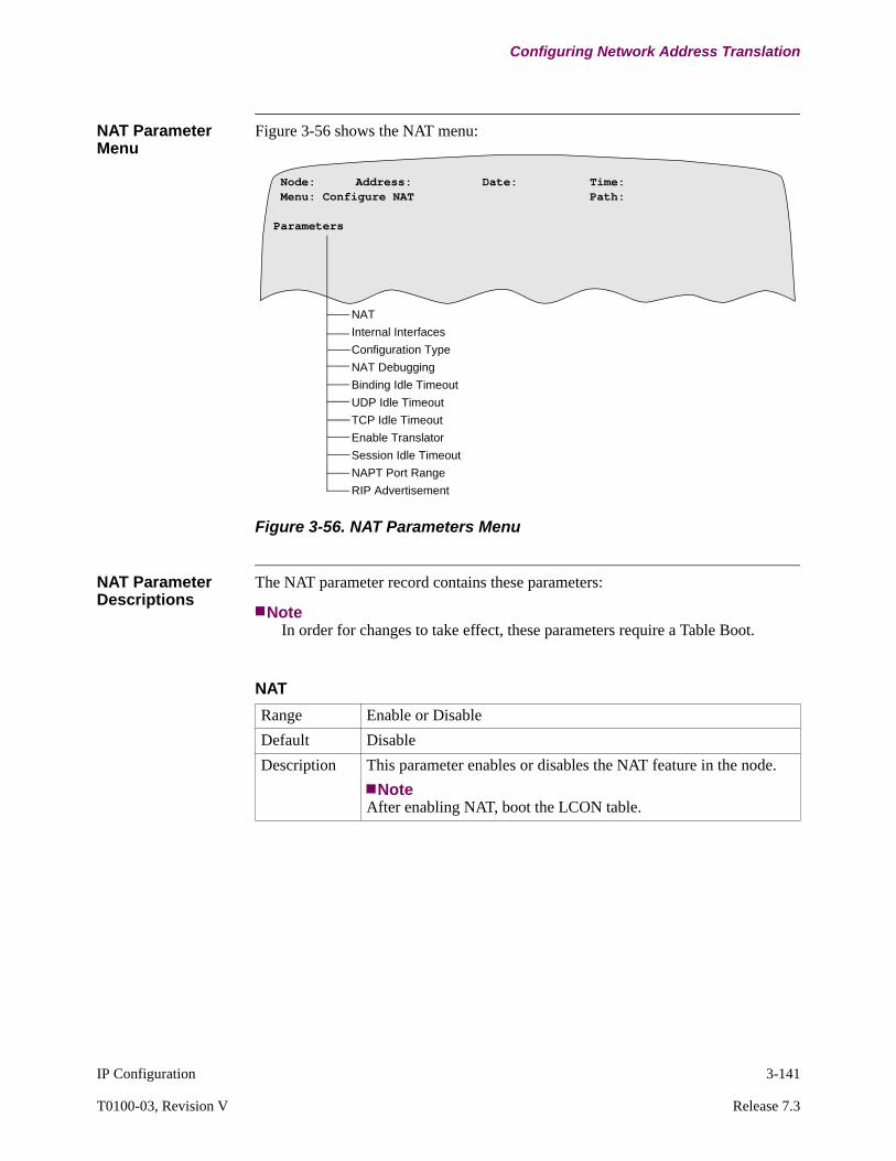
IP Configuration 3-141
T0100-03, Revision V Release 7.3
Configuring Network Address Translation
NAT Parameter Menu
Figure 3-56 shows the NAT menu:
Figure 3-56. NAT Parameters Menu
NAT Parameter Descriptions
The NAT parameter record contains these parameters:
NoteIn order for changes to take effect, these parameters require a Table Boot.
Node: Address: Date: Time: Menu: Configure NAT Path:
Parameters
NAT
Internal Interfaces
Configuration Type
NAT Debugging
Binding Idle Timeout
UDP Idle Timeout
TCP Idle Timeout
Enable Translator
Session Idle Timeout
NAPT Port Range
RIP Advertisement
NAT
Range Enable or Disable
Default Disable
Description This parameter enables or disables the NAT feature in the node.
NoteAfter enabling NAT, boot the LCON table.

3-142 IP Configuration
Configuring Network Address Translation
Internal Interface
Range 1 to 255
Default 1
Description Specifies all internal interfaces configured for the node. Internal interfaces connect to the host or devices that are part of the internal or private domain only.Enter all internal interfaces for this node. Use space (blank) to erase the field.example 1, 5, 7, 9-13
Configuration Type
Range Simple or Advanced
Default Simple
Description The default of SIMPLE only prompts the user to enable NAT, internal interfaces, RIP advertisement and specify the Configuration Type. Selecting ADVANCED displays all parameters and the user may change the values of these parameters.
NAT Debugging
Range 12 to 20
Default 15
Description This parameter specifies the aging time for the sessions. This parameter is used in application translations such as FTP and DNS. If a session is inactive for the timeout period, the session is deleted from the session data base.
NoteNAT Debugging is only displayed if the configuration type is advanced and either FTP or DNS translators are enabled
Binding Idle Timeout
Range 0 to 4000 seconds
Default 60
Description This parameter applies to DYNAMIC binding only.Specifies the idle timeout for dynamic address binding. If the idle time expires and the internal-external address binding is not used, the binding is removed from the NAT table. The external address is now free for new binding.

IP Configuration 3-143
T0100-03, Revision V Release 7.3
Configuring Network Address Translation
UDP Idle Timeout
Range 0 to 4000 seconds
Default 60
Description This parameter is applicable to NAPT binding only.Specifies the port-binding timeout for UDP traffic. If the idle time expires and the port binding is not used, the binding is removed from the NAT table and the port number is free for new binding.
TCP Idle Timeout
Range 0 to 4000 seconds
Default 60
Description This parameter is applicable to NAPT binding only.Specifies the port-binding timeout for TCP traffic. If a binding is not used for the timeout period, the binding is deleted and the port number is returned to the free pool.
Enable Translator
Range FTP, ICMP, DNS, and NONE
Default FTP+ICMP
Description Used to enable the translator to translate embedded addresses within the header portion of an IP datagram. NAT automatically identifies the application (FTP, ICMP, DNS) and accordingly selects the translators. If NONE is selected, then all the translators are turned off.
Session Idle Timeout
Range Enabled, Disabled
Default Disabled
Description This parameter enables or disables the NAT debugging on the node. When this is set to enabled, the node will generate the NAT specific debug alarms and also will display the NAT debug statis-tics to the user.
NoteNAT Debugging is only displayed if the configuration type is advanced and either FTP or DNS translators are enabled

3-144 IP Configuration
Configuring Network Address Translation
NAT Translation Table menu
Figure 3-57 shows the NAT Translation Table menu:
Figure 3-57. NAT Translation Table Menu
NAPT Port Range
Range 6000 to 12000
Default 6000-7000
Description Specifies a range of port numbers used for NAPT translation. NAPT translates the source (or destination) port number of a IP packet. NAPT selects the new port number from the range of NAPT ports.
RIP Advertisement
Range Enabled, Disabled
Default Enabled
Description Advertisement of external address can be controlled by this parameter.
Node: Address: Date: Time: Menu: Configure NAT Path:
Translation Table
Entry NumberExternal Interface NumberExternal Address TypeBinding TypeInternal Address RangeExternal AddressExternal Address StartExternal Address RangeOverlapProxy Address StartAdvertise AddressAdvertise Address Mask

IP Configuration 3-145
T0100-03, Revision V Release 7.3
Configuring Network Address Translation
NAT Translation Table Parameter Descriptions
The NAT translation table contains these parameters:
NoteIn order for changes to take effect, these parameters require a Table Boot. Only modified entries have their bindings reset.
Entry Number
RangeRange -7300
Range - 6800
1-255Vanguard 7300 Series maximum NAT Entries Table Size has been increased from 255 to 1023 with release 6.0P02B and greater.Vanguard 6800 series maximum NAT Table Size has been increased from 255 to 1023 with release 7.2 and greater.
Default 1
Description Specifies the translation table entry.
External Interface Number
Range 1 to Maximum router interface number.
Default 1
Description Specifies the external interface. External interfaces connect a host or device to an external or global domain.
External Address Type
Range STATIC, DYNAMIC
Default DYNAMIC
Description Specifies the type of external address. External addresses can be• STATIC - statically configured• DYNAMIC - dynamically learned using PPP-IPCP
PPP connections must be configured to use DYNAMIC external addressing.
Binding Type
Range STATIC, DYNAMIC, and NAPT
Default DYNAMIC
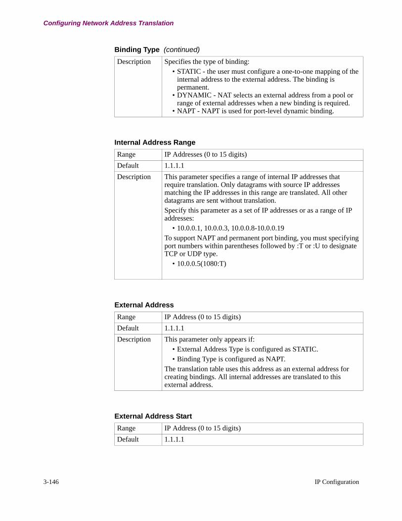
3-146 IP Configuration
Configuring Network Address Translation
Description Specifies the type of binding:• STATIC - the user must configure a one-to-one mapping of the
internal address to the external address. The binding is permanent.
• DYNAMIC - NAT selects an external address from a pool or range of external addresses when a new binding is required.
• NAPT - NAPT is used for port-level dynamic binding.
Binding Type (continued)
Internal Address Range
Range IP Addresses (0 to 15 digits)
Default 1.1.1.1
Description This parameter specifies a range of internal IP addresses that require translation. Only datagrams with source IP addresses matching the IP addresses in this range are translated. All other datagrams are sent without translation. Specify this parameter as a set of IP addresses or as a range of IP addresses:
• 10.0.0.1, 10.0.0.3, 10.0.0.8-10.0.0.19To support NAPT and permanent port binding, you must specifying port numbers within parentheses followed by :T or :U to designate TCP or UDP type.
• 10.0.0.5(1080:T)
External Address
Range IP Address (0 to 15 digits)
Default 1.1.1.1
Description This parameter only appears if: • External Address Type is configured as STATIC.• Binding Type is configured as NAPT.
The translation table uses this address as an external address for creating bindings. All internal addresses are translated to this external address.
External Address Start
Range IP Address (0 to 15 digits)
Default 1.1.1.1

IP Configuration 3-147
T0100-03, Revision V Release 7.3
Configuring Network Address Translation
Description This parameter only appears if: • External Address Type is configured as STATIC.• Binding Type is configured as STATIC.
It specifies the start of the external address block. Size of the block is determined from the internal address range.
External Address Start (continued)
External Address Range
Range IP Address (0 to 15 digits)
Default 1.1.1.1
Description This parameter appears if: • External Address Type is configured as STATIC.• Binding Type is configured as DYNAMIC.
This parameter specifies a pool or range of external addresses to be used when new bindings are created.
Overlap
Range Enabled, Disabled
Default Disabled
Description Setting this parameter to ENABLED allows NAT to translate duplicate internal and external addresses. NAT translates the duplicated external address to a different, unique address so that a datagram intended for the external device can be routed out of the internal domain.
Proxy Address Start
Range IP Address (0 to 15 digits)
Default 1.1.1.1

3-148 IP Configuration
Configuring Network Address Translation
Description This parameter appears only if the Overlap parameter is ENABLED.This address specifies the start of a range of proxy addresses to be used for Duplicate Address Translation.
NoteProxy addresses must not duplicate addresses of other devices with which internal devices intend to communicate. It is recommended that you either configure unused subnets or use the following IETF recommended addresses as specified by RFC 1918:
• 10.0.0.0 -10.255.255.255• 172.16.0.0 -172.16.255.255• 192.168.0.0. - 192.168.255.255
Proxy Address Start (continued)
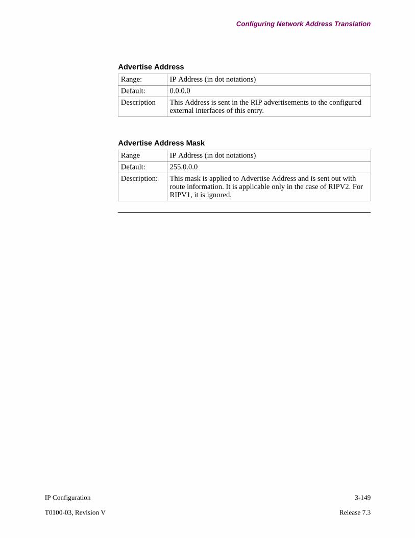
IP Configuration 3-149
T0100-03, Revision V Release 7.3
Configuring Network Address Translation
Advertise Address
Range: IP Address (in dot notations)
Default: 0.0.0.0
Description This Address is sent in the RIP advertisements to the configured external interfaces of this entry.
Advertise Address Mask
Range IP Address (in dot notations)
Default: 255.0.0.0
Description: This mask is applied to Advertise Address and is sent out with route information. It is applicable only in the case of RIPV2. For RIPV1, it is ignored.

3-150 IP Configuration
Configuring Network Address Translation
Examples of NAT Configuration
Introduction This section provides configuration examples for the following translations:
• Static Address -Static Binding • Static Address - Dynamic Binding• Dynamic Address Dynamic Binding • Static NAPT• Dynamic NAPT• Permanent Port Binding• Duplicate Address Translation
NoteThese examples shows configurable parameters for NAT only. For information on configuring IP Routing parameters, refer to the appropriate section in this chapter. For more information on configuring the PPP port, refer to Point-to-Point manual.
Recommended Sequence for Configuration
The following table describes the recommended sequence to configure a Vanguard for NAT.
Step Description
1 Configure the Node Record
2 Configure the Port Record• ETH Port• PPP Port for Dynamic Binding or Dynamic NAPT
3 LAN and IP Parameters:• LAN Connection Parameters• LAN Connection Table• Enable the Router Interface State• Configure IP Parameters• Configure IP Interfaces• Configure the Route Selection Table• Configure the Mnemonic Table
4 PPP Parameters (Only for Dynamic Binding or Dynamic NAPT):• PPP Profile• PPP Parameters• PVC Setup Table
5 Configure NAT Parameters:• NAT Parameters• NAT Translation Table
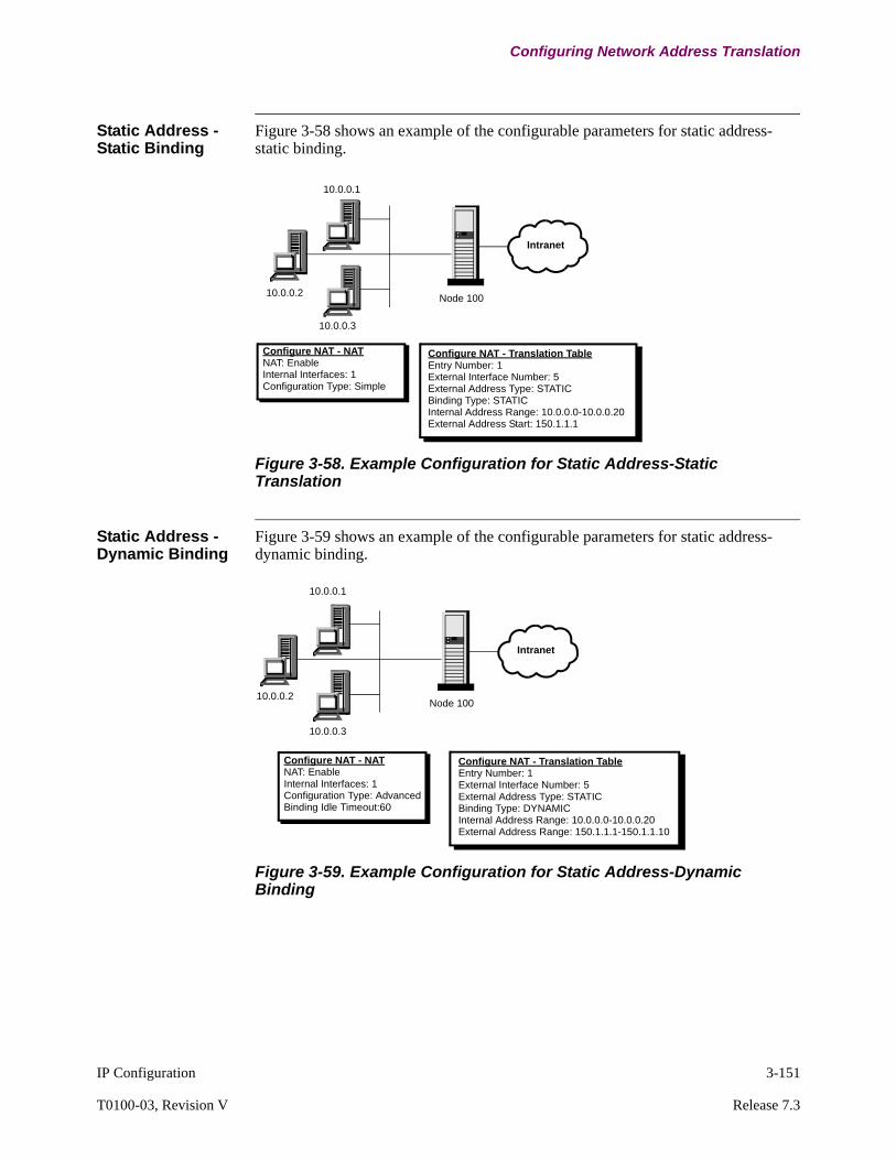
IP Configuration 3-151
T0100-03, Revision V Release 7.3
Configuring Network Address Translation
Static Address -Static Binding
Figure 3-58 shows an example of the configurable parameters for static address-static binding.
Figure 3-58. Example Configuration for Static Address-Static Translation
Static Address - Dynamic Binding
Figure 3-59 shows an example of the configurable parameters for static address-dynamic binding.
Figure 3-59. Example Configuration for Static Address-Dynamic Binding
Configure NAT - NATNAT: EnableInternal Interfaces: 1Configuration Type: Simple
Configure NAT - Translation TableEntry Number: 1External Interface Number: 5External Address Type: STATICBinding Type: STATICInternal Address Range: 10.0.0.0-10.0.0.20External Address Start: 150.1.1.1
Intranet
Node 100
10.0.0.3
10.0.0.2
10.0.0.1
Configure NAT - NATNAT: EnableInternal Interfaces: 1Configuration Type: AdvancedBinding Idle Timeout:60
Intranet
Node 100
Configure NAT - Translation TableEntry Number: 1External Interface Number: 5External Address Type: STATICBinding Type: DYNAMICInternal Address Range: 10.0.0.0-10.0.0.20External Address Range: 150.1.1.1-150.1.1.10
10.0.0.3
10.0.0.2
10.0.0.1

3-152 IP Configuration
Configuring Network Address Translation
Dynamic Address Dynamic Binding
Figure 3-60 shows an example of the configurable parameters for dynamic address-dynamic binding.
NotePPP Port and parameters must be configured. PPP automatically dials out to the peer PPP port if the router interface LCON connects to a PPP port. The dynamic address is negotiated by the PPP using IPCP protocol.
Figure 3-60. Example Configuration for Dynamic Address-Dynamic Binding
Static NAPT Figure 3-60 shows an example of the configurable parameters for static NAPT.
Figure 3-61. Example of Static NAPT
Configure NAT - NATNAT: EnableInternal Interfaces: 1Configuration Type: AdvancedBinding Idle Timeout:60
Internet
Configure NAT - Translation TableEntry Number: 1External Interface Number: 5External Address Type: DYNAMICBinding Type: DYNAMIC
PPP Port
Node 100
LAN Port
Router Interface 5
Router Interface 110.0.0.1
Peer Host
Internet
Node 100
Configure NAT - NATNAT: EnableInternal Interfaces: 1Configuration Type: AdvancedBind Idle Timeout:60UDP Idle Timeout:60TCP Idle Timeout:60Enable Translator: FTP+ICMP+DNSNAPT Port Range:6000-7000
Configure NAT - Translation TableEntry Number: 1External Interface Number: 5External Address Type: STATICBinding Type: NAPTInternal Address Range:10.0.0.0-10.0.0.3External Address:150.1.1.1
10.0.0.3, 7000
10.0.0.2, 7000
10.0.0.1, 6000

IP Configuration 3-153
T0100-03, Revision V Release 7.3
Configuring Network Address Translation
Dynamic NAPT Figure 3-62 shows an example of the configurable parameters for dynamic NAPT.
Figure 3-62. Example of Dynamic NAPT
Permanent Port Binding
Figure 3-63 shows an example of the configurable parameters for permanent port binding.
Figure 3-63. Example of Permanent Port Binding
Internet
Node 100
Configure NAT - NATNAT: EnableInternal Interfaces: 1Configuration Type: AdvancedBind Idle Timeout:60UDP Idle Timeout:60TCP Idle Timeout:60Enable Translator: FTP+ICMP+DNSNAPT Port Range:6000-7000
Configure NAT - Translation TableEntry Number: 1External Interface Number: 5External Address Type: DYNAMICBinding Type: NAPTInternal Address Range:10.0.0.1
Peer Host10.0.0.1, 6000
Internet
Node 100
Configure NAT -NATNAT: EnableInternal Interfaces: 1Configuration Type: AdvancedBind Idle Timeout:60UDP Idle Timeout:60TCP Idle Timeout:60Enable Translator: FTP+ICMP+DNSNAPT Port Range:6000-7000
Configure NAT - Translation TableEntry Number: 1External Interface Number: 5External Address Type: STATICBinding Type: NAPTInternal Address Range:10.0.0.1 (23:T), 10.0.0.2 (23:T)External Address:150.1.1.1
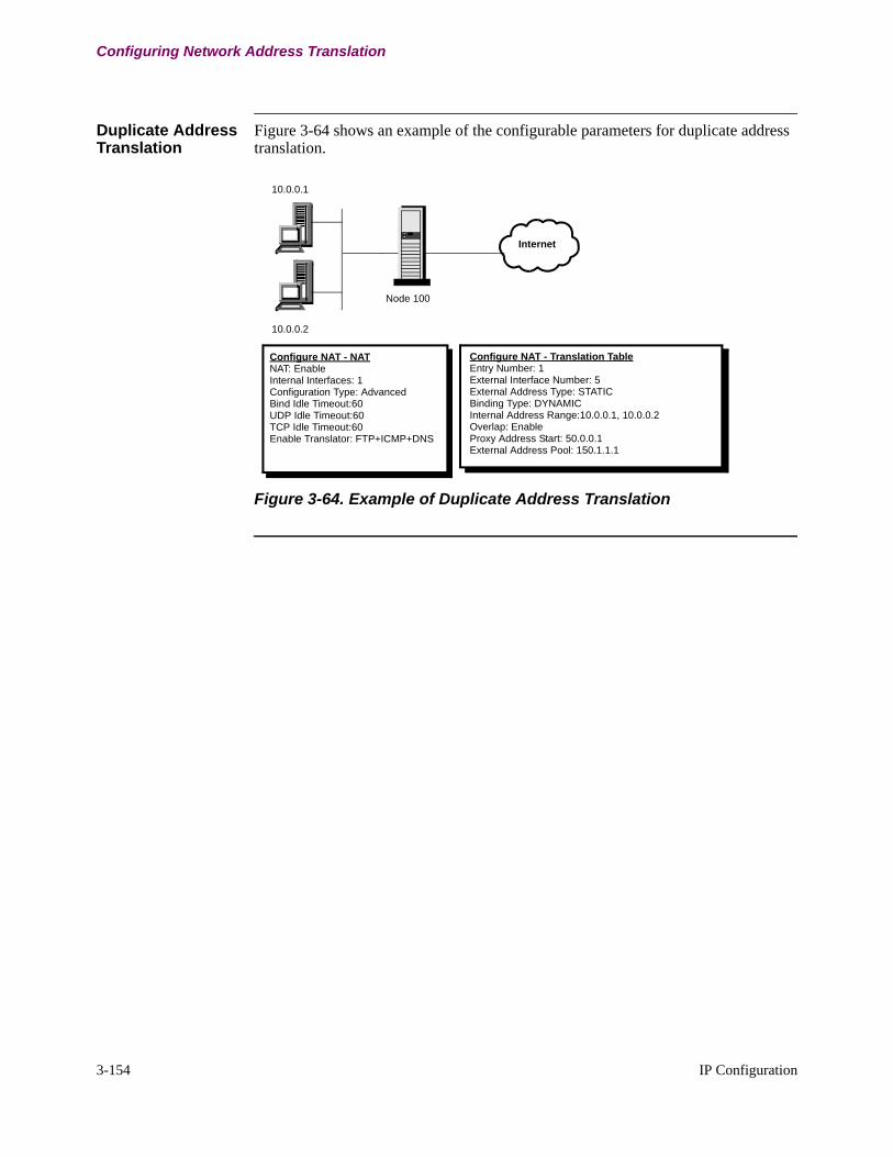
3-154 IP Configuration
Configuring Network Address Translation
Duplicate Address Translation
Figure 3-64 shows an example of the configurable parameters for duplicate address translation.
Figure 3-64. Example of Duplicate Address Translation
Internet
Node 100
Configure NAT - NATNAT: EnableInternal Interfaces: 1Configuration Type: AdvancedBind Idle Timeout:60UDP Idle Timeout:60TCP Idle Timeout:60Enable Translator: FTP+ICMP+DNS
Configure NAT - Translation TableEntry Number: 1External Interface Number: 5External Address Type: STATICBinding Type: DYNAMICInternal Address Range:10.0.0.1, 10.0.0.2 Overlap: EnableProxy Address Start: 50.0.0.1External Address Pool: 150.1.1.1
10.0.0.2
10.0.0.1
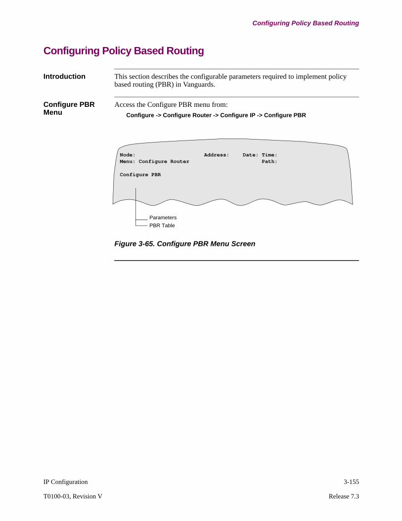
IP Configuration 3-155
T0100-03, Revision V Release 7.3
Configuring Policy Based Routing
Configuring Policy Based Routing
Introduction This section describes the configurable parameters required to implement policy based routing (PBR) in Vanguards.
Configure PBR Menu
Access the Configure PBR menu from:
Configure -> Configure Router -> Configure IP -> Configure PBR
Figure 3-65. Configure PBR Menu Screen
Node: Address: Date: Time:Menu: Configure Router Path:
Configure PBR
Parameters
PBR Table
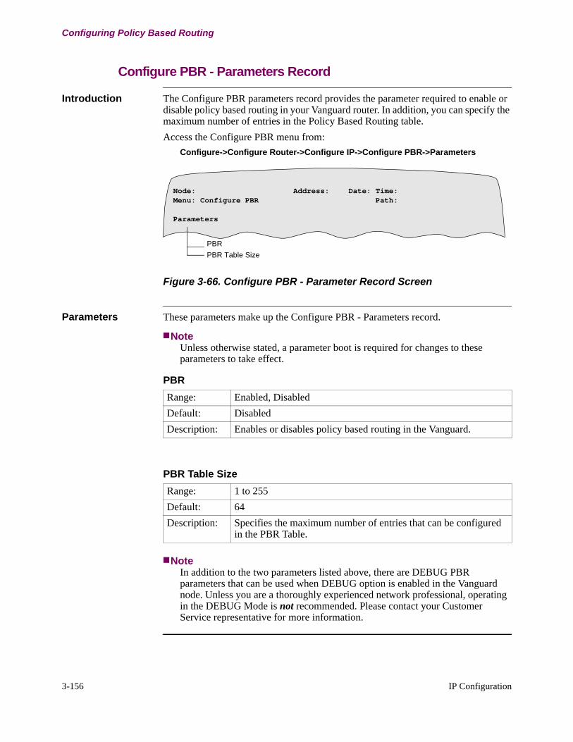
3-156 IP Configuration
Configuring Policy Based Routing
Configure PBR - Parameters Record
Introduction The Configure PBR parameters record provides the parameter required to enable or disable policy based routing in your Vanguard router. In addition, you can specify the maximum number of entries in the Policy Based Routing table.
Access the Configure PBR menu from:
Configure->Configure Router->Configure IP->Configure PBR->Parameters
Figure 3-66. Configure PBR - Parameter Record Screen
Parameters These parameters make up the Configure PBR - Parameters record.
NoteUnless otherwise stated, a parameter boot is required for changes to these parameters to take effect.
NoteIn addition to the two parameters listed above, there are DEBUG PBR parameters that can be used when DEBUG option is enabled in the Vanguard node. Unless you are a thoroughly experienced network professional, operating in the DEBUG Mode is not recommended. Please contact your Customer Service representative for more information.
Node: Address: Date: Time:Menu: Configure PBR Path:
Parameters
PBR
PBR Table Size
PBR
Range: Enabled, Disabled
Default: Disabled
Description: Enables or disables policy based routing in the Vanguard.
PBR Table Size
Range: 1 to 255
Default: 64
Description: Specifies the maximum number of entries that can be configured in the PBR Table.

IP Configuration 3-157
T0100-03, Revision V Release 7.3
Configuring Policy Based Routing
Configure PBR - PBR Table Record
Introduction The Configure PBR- PBR Table record provides the parameters that define the flow and policies applied on the flow. With this PBR Table record, you define flows against which an incoming packet is compared. One entry number corresponds to one flow.
Access the Configure PBR - PBR Table menu from:
Configure->Configure Router->Configure IP->Configure PBR->PBR Table
Figure 3-67 illustrates the PBR Table menu and the parameters that are in this menu:
Figure 3-67. Configure PBR - PBR Table Screen
Order of Configuration
The order in which PBR entries are configured in the PBR table is the order in which PRB entries are searched. Configure the PBR table with decreasing level of specificity. This indicates that you must configure the most specific flow entry first.
Node: Address: Date: Time:Menu: Configure PBR Path:
PBR Table
Entry Number
Inbound Interface List
Inbound LCON List
Source IP Address
Source IP Address Mask (Appears only if Source IP Address is defined)
Destination IP Address
Destination IP Address Mask (Appears only if Destination IP Address is defined)
Protocol
Source Port Range (Appears only for TCP/UDP)
Destination Port Range (Appears only for TCP/UDP)
TOW Profile Name
List of Primary Nexthop
List of Backup Nexthop (Appears only if List of Primary Nexthop is defined)
Load Option
Parameters thatdefine Flow
Parameters thatdefine Nexthop
Parameter thatdefines LoadBalancing
Parameter thatdefines Flowcharacteristics
Route
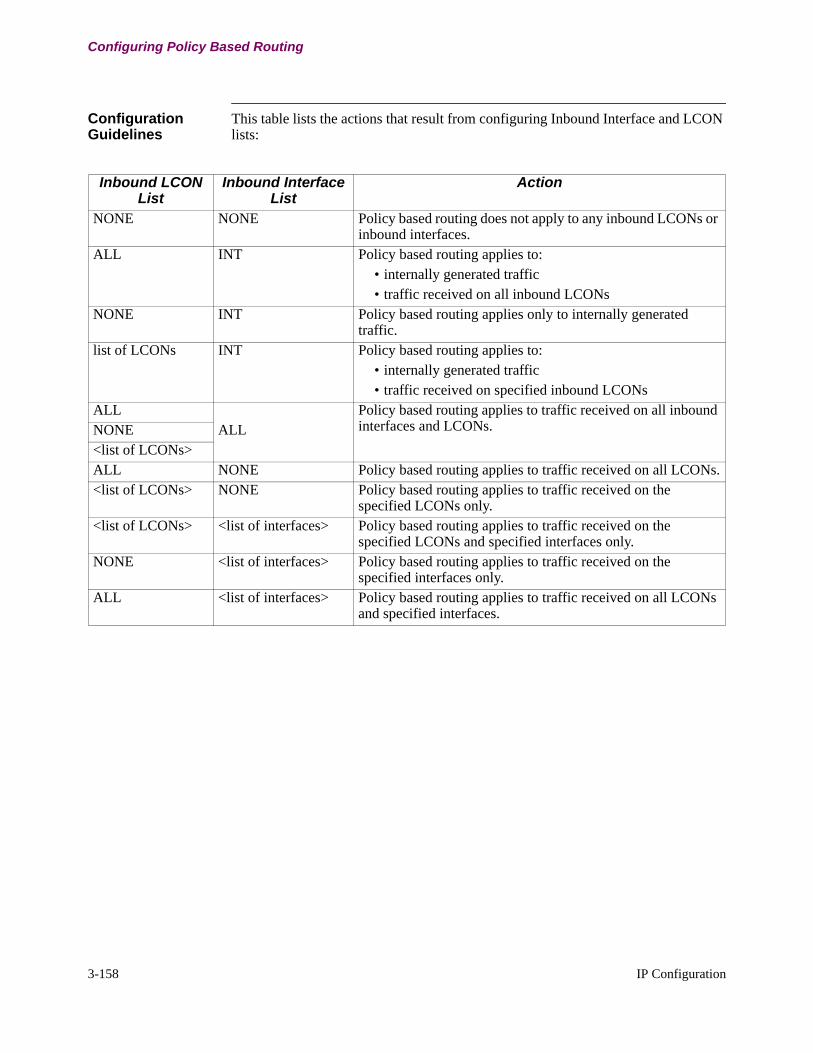
3-158 IP Configuration
Configuring Policy Based Routing
Configuration Guidelines
This table lists the actions that result from configuring Inbound Interface and LCON lists:
Inbound LCON List
Inbound Interface List
Action
NONE NONE Policy based routing does not apply to any inbound LCONs or inbound interfaces.
ALL INT Policy based routing applies to:• internally generated traffic • traffic received on all inbound LCONs
NONE INT Policy based routing applies only to internally generated traffic.
list of LCONs INT Policy based routing applies to:• internally generated traffic• traffic received on specified inbound LCONs
ALLALL
Policy based routing applies to traffic received on all inbound interfaces and LCONs.NONE
<list of LCONs>ALL NONE Policy based routing applies to traffic received on all LCONs.<list of LCONs> NONE Policy based routing applies to traffic received on the
specified LCONs only.<list of LCONs> <list of interfaces> Policy based routing applies to traffic received on the
specified LCONs and specified interfaces only.NONE <list of interfaces> Policy based routing applies to traffic received on the
specified interfaces only.ALL <list of interfaces> Policy based routing applies to traffic received on all LCONs
and specified interfaces.
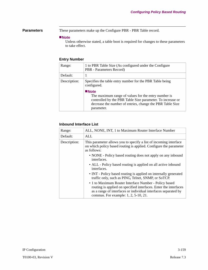
IP Configuration 3-159
T0100-03, Revision V Release 7.3
Configuring Policy Based Routing
Parameters These parameters make up the Configure PBR - PBR Table record.
NoteUnless otherwise stated, a table boot is required for changes to these parameters to take effect.
Entry Number
Range: 1 to PBR Table Size (As configured under the Configure PBR - Parameters Record)
Default: 1
Description: Specifies the table entry number for the PBR Table being configured.
NoteThe maximum range of values for the entry number is controlled by the PBR Table Size parameter. To increase or decrease the number of entries, change the PBR Table Size parameter.
Inbound Interface List
Range: ALL, NONE, INT, 1 to Maximum Router Interface Number
Default: ALL
Description: This parameter allows you to specify a list of incoming interface on which policy based routing is applied. Configure the parameter as follows:
• NONE - Policy based routing does not apply on any inbound interfaces.
• ALL - Policy based routing is applied on all active inbound interfaces.
• INT - Policy based routing is applied on internally generated traffic only, such as PING, Telnet, SNMP, or SoTCP.
• 1 to Maximum Router Interface Number - Policy based routing is applied on specified interfaces. Enter the interfaces as a range of interfaces or individual interfaces separated by commas. For example: 1, 2, 5-10, 21.
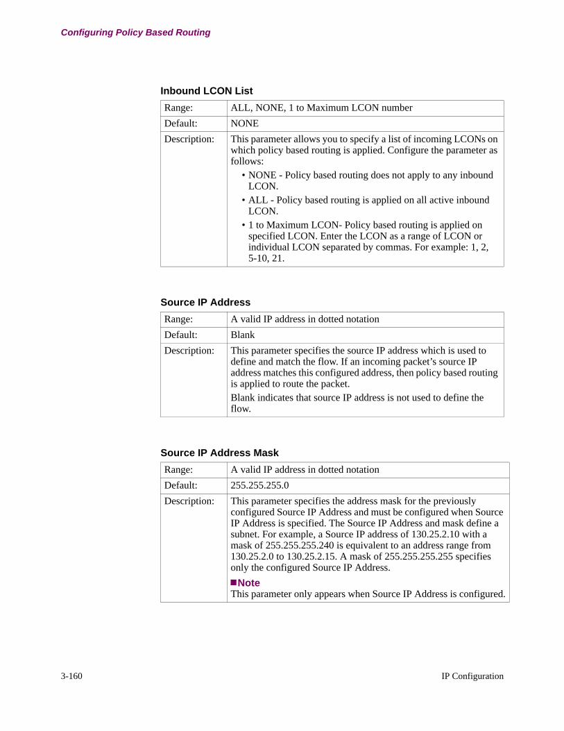
3-160 IP Configuration
Configuring Policy Based Routing
Inbound LCON List
Range: ALL, NONE, 1 to Maximum LCON number
Default: NONE
Description: This parameter allows you to specify a list of incoming LCONs on which policy based routing is applied. Configure the parameter as follows:
• NONE - Policy based routing does not apply to any inbound LCON.
• ALL - Policy based routing is applied on all active inbound LCON.
• 1 to Maximum LCON- Policy based routing is applied on specified LCON. Enter the LCON as a range of LCON or individual LCON separated by commas. For example: 1, 2, 5-10, 21.
Source IP Address
Range: A valid IP address in dotted notation
Default: Blank
Description: This parameter specifies the source IP address which is used to define and match the flow. If an incoming packet’s source IP address matches this configured address, then policy based routing is applied to route the packet.Blank indicates that source IP address is not used to define the flow.
Source IP Address Mask
Range: A valid IP address in dotted notation
Default: 255.255.255.0
Description: This parameter specifies the address mask for the previously configured Source IP Address and must be configured when Source IP Address is specified. The Source IP Address and mask define a subnet. For example, a Source IP address of 130.25.2.10 with a mask of 255.255.255.240 is equivalent to an address range from 130.25.2.0 to 130.25.2.15. A mask of 255.255.255.255 specifies only the configured Source IP Address.
NoteThis parameter only appears when Source IP Address is configured.

IP Configuration 3-161
T0100-03, Revision V Release 7.3
Configuring Policy Based Routing
Destination IP Address
Range: A valid IP address in dotted notation
Default: Blank
Description: This parameter specifies the destination IP address which is used to define and match the flow. If an incoming packet’s destination IP address matches this configured address, then policy based routing is applied to route the packet.Blank indicates that destination IP address is not used to define the flow.
Destination IP Address Mask
Range: A valid IP address in dotted notation
Default: 255.255.255.0
Description: This parameter specifies the address mask for the previously configured Destination IP Address and must be configured when Destination IP Address is specified. The Destination IP Address and mask define a subnet. For example, a Destination IP address of 130.25.2.10 with a mask of 255.255.255.240 is equivalent to an address range from 130.25.2.0 to 130.25.2.15. A mask of 255.255.255.255 specifies only the configured Destination IP Address.
NoteThis parameter only appears when Destination IP Address is configured.
Protocol
Range: 0 to 255
Default: Blank
Description: Specifies the protocol of the incoming packet used to match the flow. Incoming packets with protocol that match this configured protocol are routed by policy based routing. Specify the protocol as shown:
• 1 for ICMP • 6 for TCP• 17 for UDP
Blank indicates that protocol is not used in defining this flow.
NoteRouting protocols such as OSPF (89), IGRP (88), IDRP (45), and EGP (8) protocols are not supported, as the router never forwards these protocols.
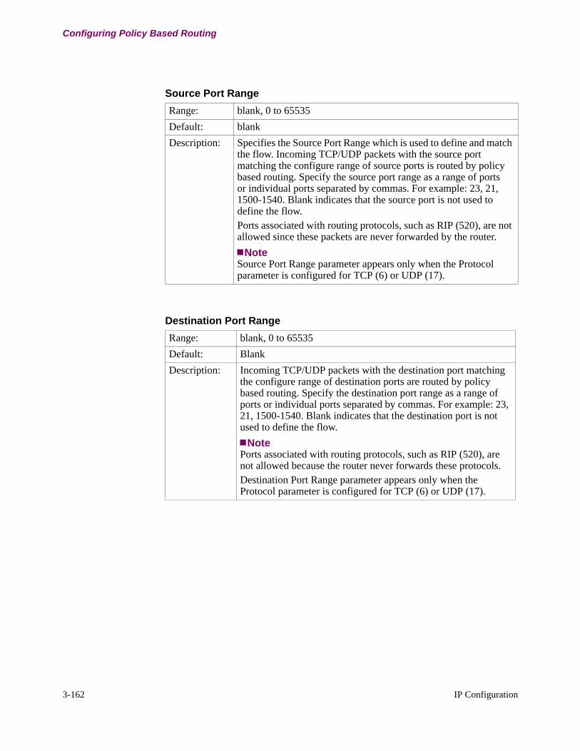
3-162 IP Configuration
Configuring Policy Based Routing
Source Port Range
Range: blank, 0 to 65535
Default: blank
Description: Specifies the Source Port Range which is used to define and match the flow. Incoming TCP/UDP packets with the source port matching the configure range of source ports is routed by policy based routing. Specify the source port range as a range of ports or individual ports separated by commas. For example: 23, 21, 1500-1540. Blank indicates that the source port is not used to define the flow.Ports associated with routing protocols, such as RIP (520), are not allowed since these packets are never forwarded by the router.
NoteSource Port Range parameter appears only when the Protocol parameter is configured for TCP (6) or UDP (17).
Destination Port Range
Range: blank, 0 to 65535
Default: Blank
Description: Incoming TCP/UDP packets with the destination port matching the configure range of destination ports are routed by policy based routing. Specify the destination port range as a range of ports or individual ports separated by commas. For example: 23, 21, 1500-1540. Blank indicates that the destination port is not used to define the flow.
NotePorts associated with routing protocols, such as RIP (520), are not allowed because the router never forwards these protocols.Destination Port Range parameter appears only when the Protocol parameter is configured for TCP (6) or UDP (17).

IP Configuration 3-163
T0100-03, Revision V Release 7.3
Configuring Policy Based Routing
TOW Profile Name
Range: blank, 0 to 20 alphanumeric characters.
Default: Blank
Description: Specifies the name of the Time of Week (TOW) Table Profile against which this defined flow is characterized. The TOW Table Profile describes time durations on certain days of the week. If an incoming packet matches the flow defined by this PBR entry and is received in the TOW profile time, the incoming packet matches this PBR entry. If the time in which the incoming packet was received does not fall in any of the time durations mentioned in this TOW profile then the flow is not considered to match this PBR entry.Blank indicates that the TOW characteristic is not used to characterized the flow.
NoteTo configure the TOW Table Profile, access this CTP menu:
Configure -> TOW Table
List of Primary Nexthops
Range: 1 to Maximum LCON number, Valid IP addresses in dotted notation.
Default: Blank
Description: Specifies a list of primary nexthop LCONs or IP Addresses which are used to forward a packet belonging to flow definition that you have just configured. The first active nexthop (selected in the order as mentioned in the list) LCON or IP address is used for forwarding the packet. This list can be configured as comma separated LCON numbers or IP Addresses:For example: 1, 150.1.1.2, 5, 200.1.1.3Blank indicates this list is not used to forward the packets belong-ing to the flow.
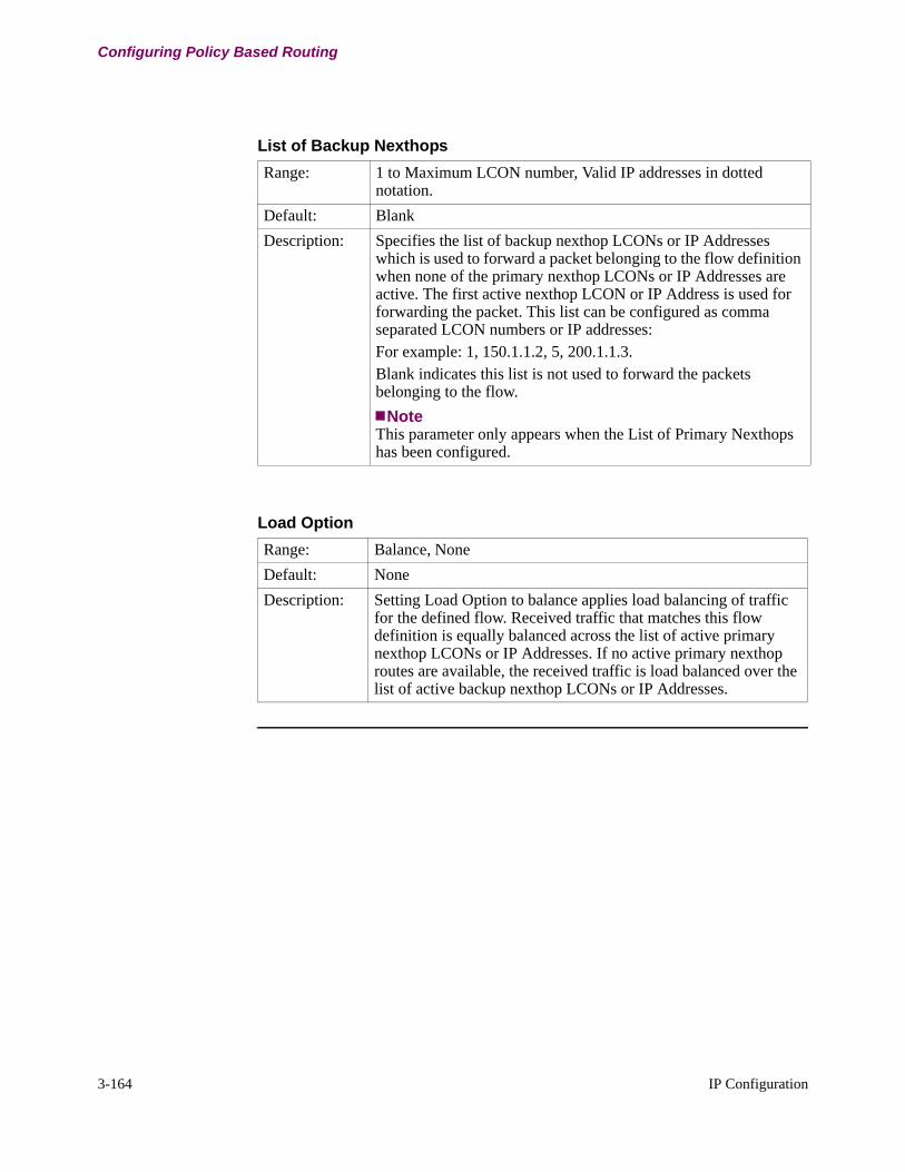
3-164 IP Configuration
Configuring Policy Based Routing
List of Backup Nexthops
Range: 1 to Maximum LCON number, Valid IP addresses in dotted notation.
Default: Blank
Description: Specifies the list of backup nexthop LCONs or IP Addresses which is used to forward a packet belonging to the flow definition when none of the primary nexthop LCONs or IP Addresses are active. The first active nexthop LCON or IP Address is used for forwarding the packet. This list can be configured as comma separated LCON numbers or IP addresses: For example: 1, 150.1.1.2, 5, 200.1.1.3.Blank indicates this list is not used to forward the packets belonging to the flow.
NoteThis parameter only appears when the List of Primary Nexthops has been configured.
Load Option
Range: Balance, None
Default: None
Description: Setting Load Option to balance applies load balancing of traffic for the defined flow. Received traffic that matches this flow definition is equally balanced across the list of active primary nexthop LCONs or IP Addresses. If no active primary nexthop routes are available, the received traffic is load balanced over the list of active backup nexthop LCONs or IP Addresses.
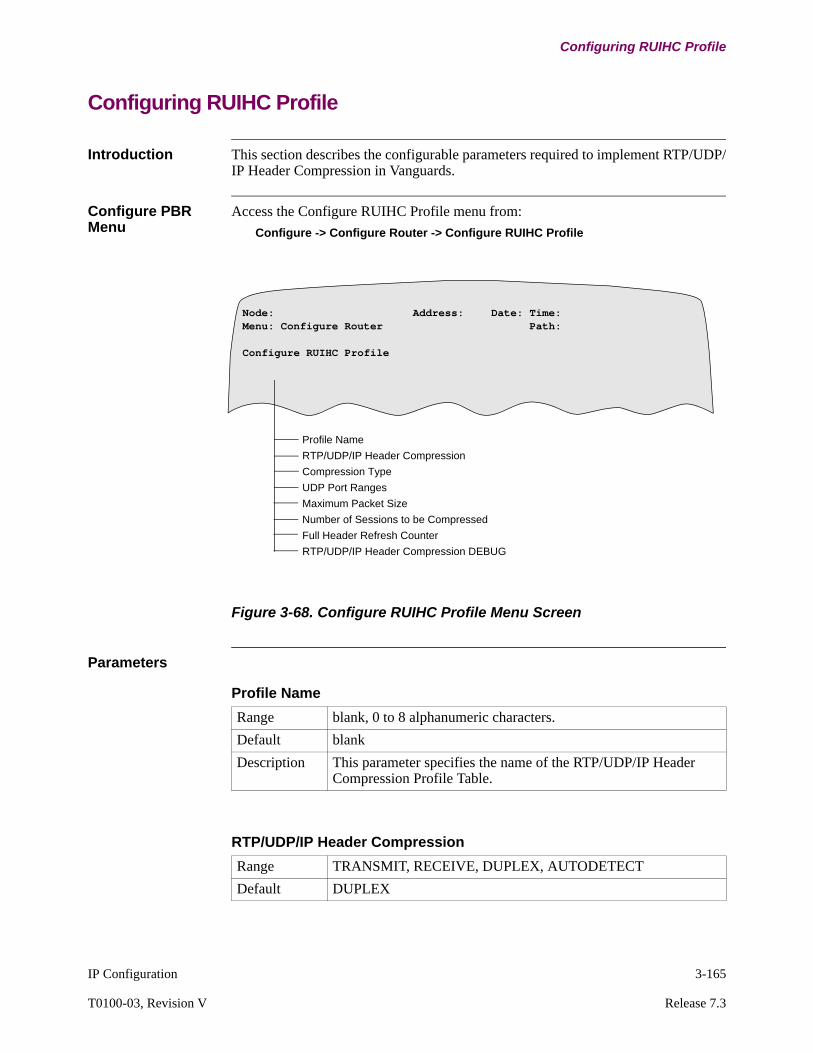
IP Configuration 3-165
T0100-03, Revision V Release 7.3
Configuring RUIHC Profile
Configuring RUIHC Profile
Introduction This section describes the configurable parameters required to implement RTP/UDP/IP Header Compression in Vanguards.
Configure PBR Menu
Access the Configure RUIHC Profile menu from:
Configure -> Configure Router -> Configure RUIHC Profile
Figure 3-68. Configure RUIHC Profile Menu Screen
Parameters
Node: Address: Date: Time:Menu: Configure Router Path:
Configure RUIHC Profile
Profile Name
RTP/UDP/IP Header Compression
Compression Type
UDP Port Ranges
Maximum Packet Size
Number of Sessions to be Compressed
Full Header Refresh Counter
RTP/UDP/IP Header Compression DEBUG
Profile Name
Range blank, 0 to 8 alphanumeric characters.
Default blank
Description This parameter specifies the name of the RTP/UDP/IP Header Compression Profile Table.
RTP/UDP/IP Header Compression
Range TRANSMIT, RECEIVE, DUPLEX, AUTODETECT
Default DUPLEX

3-166 IP Configuration
Configuring RUIHC Profile
Description Enables or disables the RTP/UDP/IP header compression on a link-by-link basis with a configured transmission type:
• TRANSMIT - indicates that compressed packets are transmitted but not received.
• RECEIVE - indicates that compressed packets are received only but not transmitted.
• DUPLEX - indicates that compressed packets are received and transmitted.
• AUTODETECT- indicates that if the incoming traffic is compressed then the outgoing traffic will be compressed.
NoteChanges to this parameter causes the context list to be refreshed.
RTP/UDP/IP Header Compression
Compression Type
Range RTP, UDP, RTP+UDP
Default RTP
Description Specifies the compression type:• RTP - This option compresses RTP/UPD/IP packet headers
only. The Vanguard only tries to compress packets with even number UDP ports and UDP header packet size greater than 12 bytes.
• UDP - This option compresses UDP/IP header compression only. This allows SoTCP voice header packet compression. However, the RTP header of the RTP/UDP/IP stream is not compressed.
• RTP+UDP - This option allows both RTP/UDP/IP and UDP/IP header compression. If this is configured, all packets are compressed.
NoteChanges to this parameter causes the context list to be refreshed.
UDP Port Ranges
Range 1025 to 65535
Default 1025-65535
Description Specifies a range of UDP ports. Header compression applies to packets received or transmitted on this range of UDP ports. Specify the parameter as individual ports or a range of ports; for example 1025-6500, 6567, 7600-7650.A maximum of eight port ranges can be specified.
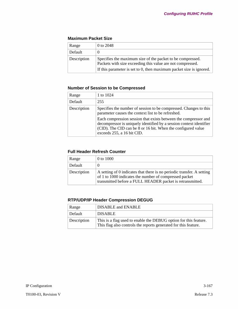
IP Configuration 3-167
T0100-03, Revision V Release 7.3
Configuring RUIHC Profile
Maximum Packet Size
Range 0 to 2048
Default 0
Description Specifies the maximum size of the packet to be compressed. Packets with size exceeding this value are not compressed. If this parameter is set to 0, then maximum packet size is ignored.
Number of Session to be Compressed
Range 1 to 1024
Default 255
Description Specifies the number of session to be compressed. Changes to this parameter causes the context list to be refreshed.Each compression session that exists between the compressor and decompressor is uniquely identified by a session context identifier (CID). The CID can be 8 or 16 bit. When the configured value exceeds 255, a 16 bit CID.
Full Header Refresh Counter
Range 0 to 1000
Default 0
Description A setting of 0 indicates that there is no periodic transfer. A setting of 1 to 1000 indicates the number of compressed packet transmitted before a FULL HEADER packet is retransmitted.
RTP/UDP/IP Header Compression DEGUG
Range DISABLE and ENABLE
Default DISABLE
Description This is a flag used to enable the DEBUG option for this feature. This flag also controls the reports generated for this feature.

3-168 IP Configuration
Configuring RUIHC Profile
NoteThe following four RTP/UDP/IP Header Compression DEBUG parameters should not be modified unless you are a thoroughly experienced network professional. Operating in the DEBUG Mode is not recommended. Please contact your Customer Service Representative for additional information.
COMPRESSED_RTP Packet Identifier
Range 1 to 65535
Default 34570
Description This parameter is used to specify the COMPRESSED_RTP packet indentifier value. Because the Frame Relay DLC layer compressed packet identifying values are not yet defined, this facility gives you the option to configure the value.
Guidelines Appears only if RTP/UDP/IP Header Compression DEGUB is enabled.
COMPRESSED_UDP Packet Identifier
Range 1 to 65535
Default 34571
Description This parameter is used to specify the COMPRESSED_UDP packet indentifier value. Because the Frame Relay DLC layer compressed packet identifying values are not yet defined, this facility gives you the option to configure the value.
Guidelines Appears only if RTP/UDP/IP Header Compression DEGUB is enabled.
FULL_HEADER Packet Identifier
Range 1 to 65535
Default 34572
Description This parameter is used to specify the FULL_HEADER packet indentifier value. Because the Frame Relay DLC layer compressed packet identifying values are not yet defined, this facility gives you the option to configure the value.
Guidelines Appears only if RTP/UDP/IP Header Compression DEGUB is enabled.

IP Configuration 3-169
T0100-03, Revision V Release 7.3
Configuring RUIHC Profile
CONTEXT_STATE Packet Identifier
Range 1 to 65535
Default 34573
Description This parameter is used to specify the CONTEXT_STATE packet indentifier value. Because the Frame Relay DLC layer compressed packet identifying values are not yet defined, this facility gives you the option to configure the value.
Guidelines Appears only if RTP/UDP/IP Header Compression DEGUB is enabled.
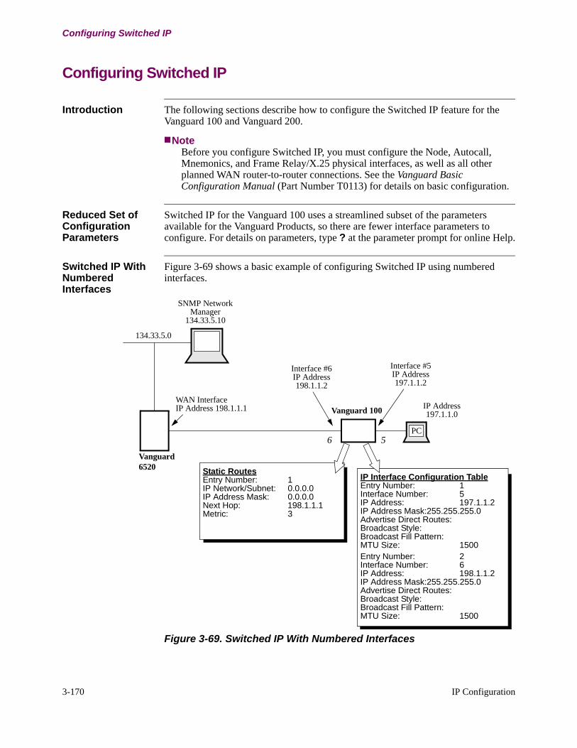
3-170 IP Configuration
Configuring Switched IP
Configuring Switched IP
Introduction The following sections describe how to configure the Switched IP feature for the Vanguard 100 and Vanguard 200.
NoteBefore you configure Switched IP, you must configure the Node, Autocall, Mnemonics, and Frame Relay/X.25 physical interfaces, as well as all other planned WAN router-to-router connections. See the Vanguard Basic Configuration Manual (Part Number T0113) for details on basic configuration.
Reduced Set of Configuration Parameters
Switched IP for the Vanguard 100 uses a streamlined subset of the parameters available for the Vanguard Products, so there are fewer interface parameters to configure. For details on parameters, type ? at the parameter prompt for online Help.
Switched IP With Numbered Interfaces
Figure 3-69 shows a basic example of configuring Switched IP using numbered interfaces.
Figure 3-69. Switched IP With Numbered Interfaces
Static RoutesEntry Number: 1IP Network/Subnet: 0.0.0.0IP Address Mask: 0.0.0.0Next Hop: 198.1.1.1Metric: 3
IP Interface Configuration TableEntry Number: 1Interface Number: 5IP Address: 197.1.1.2IP Address Mask:255.255.255.0Advertise Direct Routes: Broadcast Style: Broadcast Fill Pattern: MTU Size: 1500Entry Number: 2Interface Number: 6IP Address: 198.1.1.2IP Address Mask:255.255.255.0Advertise Direct Routes: Broadcast Style: Broadcast Fill Pattern: MTU Size: 1500
SNMP NetworkManager
134.33.5.10
Vanguard
PC
134.33.5.0
IP Address197.1.1.0
WAN InterfaceIP Address 198.1.1.1
Interface #5IP Address197.1.1.2
Interface #6IP Address198.1.1.2
56
Vanguard 100
6520

IP Configuration 3-171
T0100-03, Revision V Release 7.3
Configuring Switched IP
For a minimum Switched IP implementation, all you need to configure is the IP Interface Configuration Table on the Vanguard. If you want the Vanguard 100 to route beyond the next hop node, you can configure a Static/Routes Table as shown in Figure 3-69 to identify the destination node, or you can configure the default gateway from the Parameters menu for IP.
The Static/Routes Table in Figure 3-69 shows a default static route to the Vanguard 6520. Based on the routing tables within the Vanguard Router, the Vanguard Router will route frames appropriately within the network.
Switched IP With Unnumbered Interfaces
Figure 3-70 shows an example of how to configure Switched IP using unnumbered interfaces.
Figure 3-70. Example of Switched IP Unnumbered Interfaces Configuration
Static RoutesEntry Number: 1IP Network/Subnet: 197.1.1.1IP Address Mask: 255.255.255.255Next Hop: 0.0.0.5Metric:Entry Number: 2IP Network/Subnet: 0.0.0.0IP Address Mask: 0.0.0.0Next Hop: 0.0.0.6
IP Interface Configuration TableEntry Number: 1Interface Number: 5IP Address: 0.0.0.0IP Address Mask: 0.0.0.0Broadcast Style: Broadcast Fill Pattern: MTU Size: 1500Entry Number: 2Interface Number: 6IP Address: 0.0.0.0IP Address Mask: 0.0.0.0Broadcast Style: Broadcast Fill Pattern: MTU Size: 1500
SNMP NetworkManager
134.33.5.10
PC
134.33.5.0
IP Address197.1.1.0
WAN InterfaceIP Address 198.1.1.1
Interface #6IP Address198.1.1.2
Static RoutesEntry Number: 1IP Network/Subnet: 197.1.1.0IP Address Mask: 255.255.255.0Next Hop: 198.1.1.2
56Vanguard6520
Vanguard 100

3-172 IP Configuration
Configuring Switched IP
In Figure 3-70, the next hop in the Static routing table on the Vanguard Router does not really exist, but this method lets you specify that all packets destined for 197.1.1.0 are routed over the 198.1.1.1 interface of the Vanguard 6520. Also, the Vanguard 100 has no IP address; therefore, it can only relay packets. Figure 3-70 shows a Static/Routes table used to route packets, but you can configure the default gateway in the Parameters menu for IP to provide the same routing functionality.
Duplicate Routes and Routing Metrics
When you map duplicate routes to the same destination using Switched IP, you can prioritize the routes based on the lowest metric assigned in the Static/Routes Table. For example, as shown in Figure 3-71, if you have the same route going out over two interfaces, the route with the lowest metric assigned for the static route is used first. Therefore, in Figure 3-71, a packet from the PC to the SNMP manager will go out over interface 7 of the Vanguard 100.
Figure 3-71. Prioritizing Duplicate Routes Using a Metric
Static RoutesEntry Number: 1IP Network/Subnet: 134.33.5.0IP Address Mask: 255.255.255.0Next Hop: 0.0.0.6Metric: 2Entry Number: 2IP Network/Subnet: 134.33.5.0IP Address Mask: 255.255.255.0Next Hop: 0.0.0.7Metric: 1
SNMP NetworkManager
134.33.5.10
Vg100Vg PC
134.33.5.0
IP Address197.1.1.0
WAN InterfaceIP Address 198.1.1.1
Vg
67
5
6520
6520
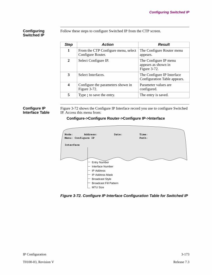
IP Configuration 3-173
T0100-03, Revision V Release 7.3
Configuring Switched IP
Configuring Switched IP
Follow these steps to configure Switched IP from the CTP screen.
Configure IP Interface Table
Figure 3-72 shows the Configure IP Interface record you use to configure Switched IP. Access this menu from:
Configure->Configure Router->Configure IP->Interface
Figure 3-72. Configure IP Interface Configuration Table for Switched IP
Step Action Result
1 From the CTP Configure menu, select Configure Router.
The Configure Router menu appears.
2 Select Configure IP. The Configure IP menu appears as shown in Figure 3-72.
3 Select Interfaces. The Configure IP Interface Configuration Table appears.
4 Configure the parameters shown in Figure 3-72.
Parameter values are configured.
5 Type ; to save the entry. The entry is saved.
Entry Number
Interface Number
IP Address
IP Address Mask
Broadcast Style
Broadcast Fill Pattern
MTU Size
Node: Address: Date: Time: Menu: Configure IP Path: Interface
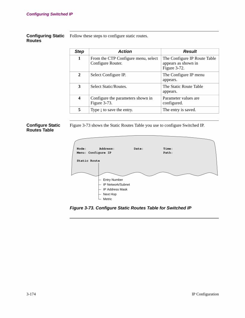
3-174 IP Configuration
Configuring Switched IP
Configuring Static Routes
Follow these steps to configure static routes.
Configure Static Routes Table
Figure 3-73 shows the Static Routes Table you use to configure Switched IP.
Figure 3-73. Configure Static Routes Table for Switched IP
Step Action Result
1 From the CTP Configure menu, select Configure Router.
The Configure IP Route Table appears as shown in Figure 3-72.
2 Select Configure IP. The Configure IP menu appears.
3 Select Static/Routes. The Static Route Table appears.
4 Configure the parameters shown in Figure 3-73.
Parameter values are configured.
5 Type ; to save the entry. The entry is saved.
Node: Address: Date: Time: Menu: Configure IP Path:
Static Route
Entry Number
IP Network/Subnet
IP Address Mask
Next Hop
Metric

IP Configuration 3-175
T0100-03, Revision V Release 7.3
Configuring Virtual LAN (VLAN)
Configuring Virtual LAN (VLAN)
Interfaces Menu Configure the IP Interface Record, see the “IP Interface Configuration Table” section on page 3-24. Figure 3-8 shows the Interfaces menu:
Configure->Configure Router->Configure IP->Interface
Two new parameters have been added for VLAN support:
• VLAN ID• Default Ethernet Priority
NoteThe Send RIP Version parameter has been modified to add an option to disable sending RIP on this interface.
Ethernet This section describes the Ethernet Port Parameters. Figure 3-74 shows the location of the Ethernet Port Record and lists the parameters. Three new parameters have been added for VLAN support:
• Encapsulation• Native VLAN ID• DSCP to Cos Profile
Figure 3-74. Ethernet Port Record
Menu: Configure Path:
Node Port
Port Number*Port TypeLAN Cable Type*Port MAC Address*Local Ring NumberTransmit Queue LimitCarrier Sense Limit
Collision Detection Filter
*Bridge Link Number
*Router Interface Number
Port Operating Mode
Encapsulation
Native VLAN ID
DSCP-to-Cos Profile

3-176 IP Configuration
Configuring Virtual LAN (VLAN)
VLAN Parameters The following parameters have been added to the Ethernet port record to support VLAN applications.
802.1Q Encapsulation
Range: None, 802.1Q
Default: None
Description: This parameter selects the Ethernet frame encapsulation methods supported on this port. The possible options are:
• None - Standard Ethernet frame format is supported.• 802.1Q - IEEE 802.1Q format Ethernet frame formats are
supported.
Boot Type: Port
Native VLAN ID
Range: 1 to 4093
Default: 1
Description: This parameter configures the native VLAN ID for this port. Untagged frames received on this port are assigned to the native VLAN.
Boot Type: Port
DSCP-to-Cos Profile
Range: 0 to 4
Default: 0
Description: This parameter selects the DSCP-to-CoS mapping profile to use when setting CoS values in outgoing frames based on the DSCP field in outgoing packets. Values 1 through 4 select the associated profile. A setting of 0 indicates no profile is used and that CoS values are not based on DSCP values.
Boot Type: Port
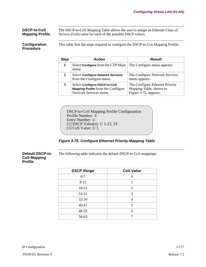
IP Configuration 3-177
T0100-03, Revision V Release 7.3
Configuring Virtual LAN (VLAN)
DSCP-to-CoS Mapping Profile
The DSCP-to-CoS Mapping Table allows the user to assign an Ethernet Class of Service (CoS) value for each of the possible DSCP values.
Configuration Procedure
This table lists the steps required to configure the DSCP-to-Cos Mapping Profile:
Figure 3-75. Configure Ethernet Priority Mapping Table
Default DSCP-to-CoS Mapping Profile
The following table indicates the default DSCP-to-CoS mappings:
Step Action Result
1 Select Configure from the CTP Main menu.
The Configure menu appears.
2 Select Configure Network Services from the Configure menu.
The Configure Network Services menu appears.
3 Select Configure DSCP-to-CoS Mapping Profile from the Configure Network Services menu.
The Configure Ethernet Priority Mapping Table, shown in Figure 3-75, appears.
DSCP-to-CoS Mapping Profile ConfigurationProfile Number: 1/Entry Number: 1/[1] DSCP Value(s): 1/ 1-23, 33[1] CoS Value: 1/ 3
DSCP Range CoS Value
0-7 0
8-15 1
16-23 2
24-31 3
32-39 4
40-47 5
48-55 6
56-63 7

3-178 IP Configuration
Configuring Virtual LAN (VLAN)
Ethernet Mapping Table Parameters
The following parameters have been added to support VLAN applications.
Configure Network Services->DSCP-to-CoS Mapping Profile-> Configure Ethernet Priority Mapping Table
Deleting DSCP-to-CoS Mapping Profile Records
A DSCP-to-CoS Mapping profile can be reset to default by deleting the profile record. The menu entry to delete DSCP-to-CoS Mapping profile records is located on the following path:
Delete Record->Delete Network Services->Delete DSCP-to-CoS Mapping Profile
Bridge Parameters Refer to the Bridging Manual (Part Number T0100-02) for information on configuring the bridging parameters.
DSCP Value(s)
Range: 0 to 63
Default: 1
Description: This parameter specifies the DSCP value(s) that will be mapped to the specified CoS value. The values are specified as a list of values and/or ranges. A maximum of 5 ranges is supported per entry.
Boot Type: Port. The mapping table is loaded when the Ethernet port using the profile is booted.
CoS Value
Range: 0 to 7
Default: 0
Description: This specifies the CoS value that will be set for packets with any of the DSCP values specified in the associated "DSCP Value(s)" entry.
Boot Type: Port. The mapping table is loaded when the Ethernet port using the profile is booted.

IP Configuration 3-179
T0100-03, Revision V Release 7.3
Configuring Virtual Router Redundancy Protocol (VRRP)
Configuring Virtual Router Redundancy Protocol (VRRP)
VRRP Configuration
VRRP is a LAN based protocol and is supported on Vanguard Ethernet interfaces. To add a Vanguard VRRP router to a group, it is necessary to specify the Ethernet interface on which the router will be running VRRP as part of that group and the group VRID. The Interface and VRID uniquely defines a Virtual Router. A router cannot have two VRRP configurations with the same Interface and VRID combination. A router may have the same VRID configured on different interfaces as long as they are on separate LANs.
Configuration Boundaries
The following bullets highlight invalid VRRP configuration:
• VRRP can only be configured on Ethernet interfaces. Attempting to configure VRRP on a non Ethernet interface is not permitted by the CTP/CLI configuration.
• A configuration check is initiated to ensure that the Critical Interface Number is not equal to the interface running VRRP for that particular entry.
• A configuration check is initiated to ensure that the Critical Priority Decrement value is not greater than the configured priority value for that entry.
• Two VRRP entries cannot have an identical (interface, vrid) combination. If this rule if violated, a high severity alarm is generated after the subsequent boot and the duplicate {interface, vrid} pairs will not be operational.
• If multiple IP addresses are configured for the virtual router, and the primary address is not owned by the router, the remaining address should not be owned by the router either. If this rule if violated, a high severity alarm is generated after the subsequent boot.
• Dynamic Configuration - An Ethernet port cannot be changed from or to a NULL port without a node boot.
VRRP Menus Configure->Configure Router->Configure VRRP
Two new menus have been added under Configure VRRP:
• VRRP Parameters• VRRP Table
NoteCLI is supported on VRRP parameters.

3-180 IP Configuration
Configuring Virtual Router Redundancy Protocol (VRRP)
VRRP Parameters This section describes the VRRP Parameters. Two new parameters have been added for VRRP support:
Configure->Configure Router->Configure VRRP->VRRP Parameters
VRRP Table The VRRP Table is specified by an entry number and lists the appropriate fields that are required for configuring a VRRP router. This table is accessible from the following location:
Configure->Configure Router->Configure VRRP->VRRP Table
The VRRP table parameters are:
VRRP
Range: Enable, Disable
Default: Disable
Description: This parameter enables or disables VRRP on the node. If this parameter is enabled, the router operates as a VRRP router on all ethernet interfaces and VRIDs for which it is configured.
Boot Type: IP Parameters
Maximum Number of VRRP Entries
Range: 1 to 255
Default: 32
Description: This parameter specifies the maximum number of VRRP interfaces that can be configured.
NoteA change to this parameter requires a node boot to take effect.
Boot Type: Node
Entry Number
Range: 1 (Maximum number of VRRP entries)
Default: 1
Description: This parameter specifies the entry number used to reference this table record.
Boot Type: IP Table
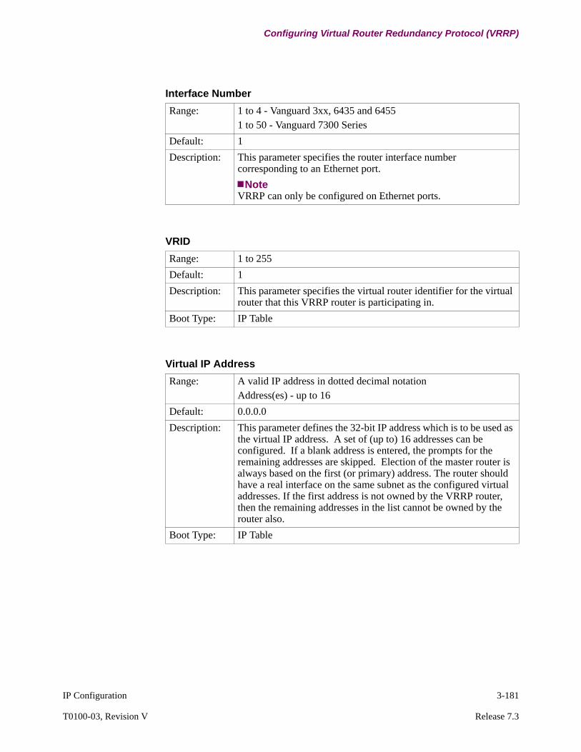
IP Configuration 3-181
T0100-03, Revision V Release 7.3
Configuring Virtual Router Redundancy Protocol (VRRP)
Interface Number
Range: 1 to 4 - Vanguard 3xx, 6435 and 64551 to 50 - Vanguard 7300 Series
Default: 1
Description: This parameter specifies the router interface number corresponding to an Ethernet port.
NoteVRRP can only be configured on Ethernet ports.
VRID
Range: 1 to 255
Default: 1
Description: This parameter specifies the virtual router identifier for the virtual router that this VRRP router is participating in.
Boot Type: IP Table
Virtual IP Address
Range: A valid IP address in dotted decimal notation Address(es) - up to 16
Default: 0.0.0.0
Description: This parameter defines the 32-bit IP address which is to be used as the virtual IP address. A set of (up to) 16 addresses can be configured. If a blank address is entered, the prompts for the remaining addresses are skipped. Election of the master router is always based on the first (or primary) address. The router should have a real interface on the same subnet as the configured virtual addresses. If the first address is not owned by the VRRP router, then the remaining addresses in the list cannot be owned by the router also.
Boot Type: IP Table
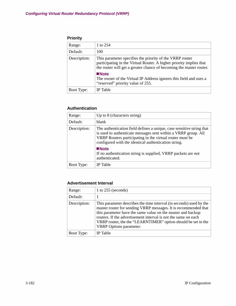
3-182 IP Configuration
Configuring Virtual Router Redundancy Protocol (VRRP)
Priority
Range: 1 to 254
Default: 100
Description: This parameter specifies the priority of the VRRP router participating in the Virtual Router. A higher priority implies that the router will get a greater chance of becoming the master router.
NoteThe owner of the Virtual IP Address ignores this field and uses a “reserved” priority value of 255.
Boot Type: IP Table
Authentication
Range: Up to 8 (characters string)
Default: blank
Description: The authentication field defines a unique, case sensitive string that is used to authenticate messages sent within a VRRP group. All VRRP Routers participating in the virtual router must be configured with the identical authentication string.
NoteIf no authentication string is supplied, VRRP packets are not authenticated.
Boot Type: IP Table
Advertisement Interval
Range: 1 to 255 (seconds)
Default: 1
Description: This parameter describes the time interval (in seconds) used by the master router for sending VRRP messages. It is recommended that this parameter have the same value on the master and backup routers. If the advertisement interval is not the same on each VRRP router, the the “LEARNTIMER” option should be set in the VRRP Options parameter.
Boot Type: IP Table
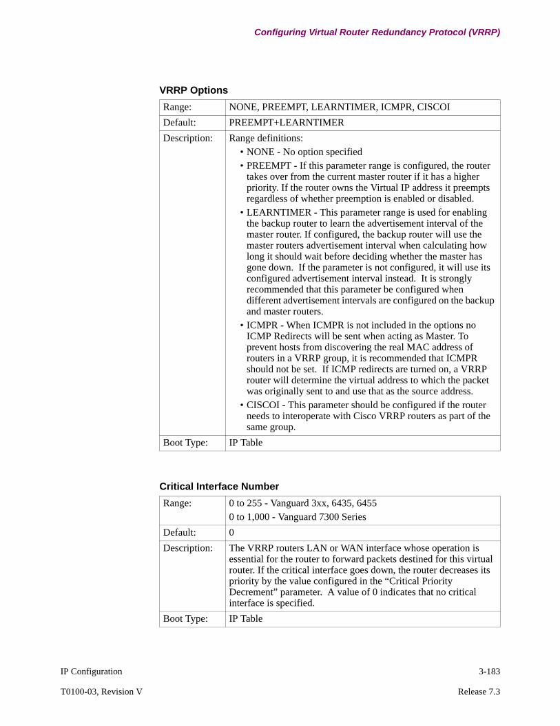
IP Configuration 3-183
T0100-03, Revision V Release 7.3
Configuring Virtual Router Redundancy Protocol (VRRP)
VRRP Options
Range: NONE, PREEMPT, LEARNTIMER, ICMPR, CISCOI
Default: PREEMPT+LEARNTIMER
Description: Range definitions:• NONE - No option specified• PREEMPT - If this parameter range is configured, the router
takes over from the current master router if it has a higher priority. If the router owns the Virtual IP address it preempts regardless of whether preemption is enabled or disabled.
• LEARNTIMER - This parameter range is used for enabling the backup router to learn the advertisement interval of the master router. If configured, the backup router will use the master routers advertisement interval when calculating how long it should wait before deciding whether the master has gone down. If the parameter is not configured, it will use its configured advertisement interval instead. It is strongly recommended that this parameter be configured when different advertisement intervals are configured on the backup and master routers.
• ICMPR - When ICMPR is not included in the options no ICMP Redirects will be sent when acting as Master. To prevent hosts from discovering the real MAC address of routers in a VRRP group, it is recommended that ICMPR should not be set. If ICMP redirects are turned on, a VRRP router will determine the virtual address to which the packet was originally sent to and use that as the source address.
• CISCOI - This parameter should be configured if the router needs to interoperate with Cisco VRRP routers as part of the same group.
Boot Type: IP Table
Critical Interface Number
Range: 0 to 255 - Vanguard 3xx, 6435, 64550 to 1,000 - Vanguard 7300 Series
Default: 0
Description: The VRRP routers LAN or WAN interface whose operation is essential for the router to forward packets destined for this virtual router. If the critical interface goes down, the router decreases its priority by the value configured in the “Critical Priority Decrement” parameter. A value of 0 indicates that no critical interface is specified.
Boot Type: IP Table

3-184 IP Configuration
Configuring Virtual Router Redundancy Protocol (VRRP)
Critical Priority Decrement
Range: 0 to 254
Default: 0
Description: This parameter specifies the amount by which the VRRP router reduces its priority when its configured critical interface goes down. If this value is set to 0 or is made equal to the routers configured priority, the router will relinquish its MASTER status when its critical interface goes down. This value cannot be greater than the routers configured priority.
Boot Type: IP Table
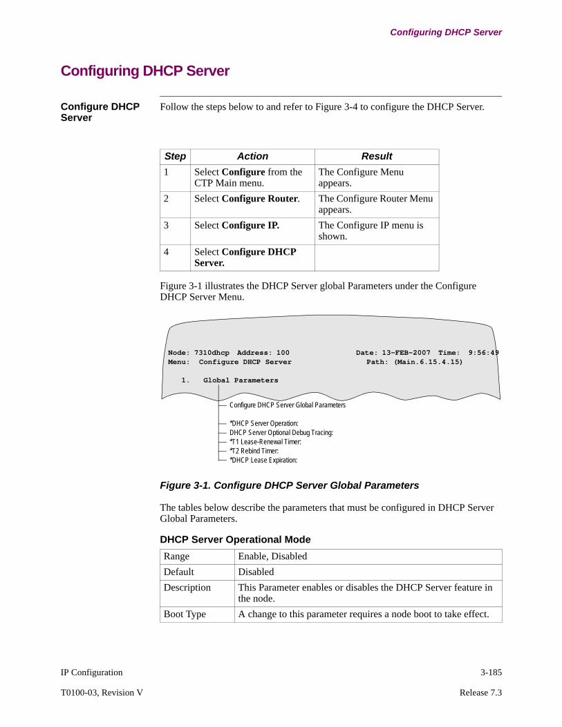
IP Configuration 3-185
T0100-03, Revision V Release 7.3
Configuring DHCP Server
Configuring DHCP Server
Configure DHCP Server
Follow the steps below to and refer to Figure 3-4 to configure the DHCP Server.
Figure 3-1 illustrates the DHCP Server global Parameters under the Configure DHCP Server Menu.
Figure 3-1. Configure DHCP Server Global Parameters
The tables below describe the parameters that must be configured in DHCP Server Global Parameters.
Step Action Result
1 Select Configure from the CTP Main menu.
The Configure Menu appears.
2 Select Configure Router. The Configure Router Menu appears.
3 Select Configure IP. The Configure IP menu is shown.
4 Select Configure DHCP Server.
Node: 7310dhcp Address: 100 Date: 13-FEB-2007 Time: 9:56:49Menu: Configure DHCP Server Path: (Main.6.15.4.15)
1. Global Parameters
Configure DHCP Server Global Parameters
*DHCP Server Operation:DHCP Server Optional Debug Tracing:*T1 Lease-Renewal Timer:*T2 Rebind Timer:*DHCP Lease Expiration:
DHCP Server Operational Mode
Range Enable, Disabled
Default Disabled
Description This Parameter enables or disables the DHCP Server feature in the node.
Boot Type A change to this parameter requires a node boot to take effect.
3-186 IP Configuration
Configuring DHCP Server
DHCP Server Optional Debug Tracing
Range Enable, Disabled
Default Disabled
Description This parameter enables or disables the DHCP Server debug trac-ing in the node.
Boot Type A change in this parameter is immediate when saved to CMEM.
T1 Lease-Renewal Timer
Range 1-720
Default 10
Description This parameter specifies the DHCP T1 timer (in minutes) and is the periodic timer that a DHCP client (re)contacts the DHCP server to preserve it's assigned IP address. It is also the time to reappear in the active client cache after a node boot.
NoteThe maximum time is 720 minutes (12 hours).
Boot Type A change to this parameter requires a node boot to take effect.
T2 Rebind Timer
Range 1-5760
Default 576
Description This parameter specifies the DHCP T2 timer (in minutes) and is the elapsed time before a DHCP client will attempt to contact an alternate DHCP Server in the event it can not (re)contact the ini-tial DHCP server.A current DHCP lease is retained until at least the T2 timer expires in the event that a DHCP server do not reply on the peri-odic expiration of the T1 timer.
NoteThis maximum time is 5760 minutes (4 days) and should be at least 80% of the lease expiry time value.
Boot Type A change to this parameter requires a node boot to take effect.
DHCP Lease Expiration
Range 1-5760
Default 720

IP Configuration 3-187
T0100-03, Revision V Release 7.3
Configuring DHCP Server
Configure DHCP Server Subnet Table
Figure 3-2 illustrates the DHCP Server Subnet table.
Figure 3-2. Configure DHCP Server Subnet Table
The tables below describe the parameters that must be configured in DHCP Server Subnet Table.
Description This parameter specifies the elapsed time before a DHCP cli-ent will return to it's unassigned state in the event that is does not receive any server replies to the periodic T1 timer or re-bind replies after the expiration of the T2 timer.
NoteThis maximum time is 5760 minutes (4 days)
Boot Type A change to this parameter requires a node boot to take effect.
DHCP Lease Expiration
Node: 7310dhcp Address: 100 Date: 13-FEB-2007 Time: 9:56:49Menu: Configure DHCP Server Path: (Main.6.15.4.15)
1. Global Parameters2. Subnet Table
Configure DHCP Server Server Subnet table
Primary Default Gateway IP Address (required):Secondary Default Gateway IP Address (optional): Subnet IP Mask: Max number of DHCP clients: Auto IP Addresses - Starting OffsetPrimary DNS Server IP Addr: Secondary DNS Server IP Addr: DNS Suffix name: Primary NETBIOS/WINS Server IP Addr:
Entry Number
Range 1-64
Default 1
Description Entry number used to reference this table record.
Boot Type

3-188 IP Configuration
Configuring DHCP Server
Primary Default Gateway IP Address (required)
Range IP Address Format: X.X.X.X where X <= 255
NoteThe 127.X.X.X range is reserved for router internal IP addresses.
Default 0.0.0.0
Description The parameter is required for primary default gateway address and optional for the secondary default gateway and specify to a DHCP client the router address(es) to use for a default route.For DHCP clients on a directly connected subnet: Normally this is the IP address of the local router interface for the subnet, but can be any gateway router on the same subnet as the local router interface that delivers DHCP client protocol messages to the local DHCP server.For DHCP clients on a remote subnet: This parameter is nor-mally the address of the remote BOOTP relay that forwards DHCP client protocol messages for it's local directly connected subnets.
Boot Type A change to this parameter requires a DHCP Server Boot to take effect.
Secondary Default Gateway IP Address (optional)
Range IP Address Format: X.X.X.X where X <= 255
NoteThe 127.X.X.X range is reserved for router internal IP addresses
Default 0.0.0.0
Description The parameter is required for primary default gateway address and optional for the secondary default gateway and specify to a DHCP client the router address(es) to use for a default route.For DHCP clients on a directly connected subnet: Normally this is the IP address of the local router interface for the subnet, but can be any gateway router on the same subnet as the local router interface that delivers DHCP client protocol messages to the local DHCP server.For DHCP clients on a remote subnet: This parameter is nomally the address of the remote BOOTP relay that forwards DHCP cli-ent protocol messages for it's local directly connected subnets.
Boot Type A change to this parameter requires a DHCP Server Boot to take effect.

IP Configuration 3-189
T0100-03, Revision V Release 7.3
Configuring DHCP Server
Subnet IP Mask
Range IP Address Format: X.X.X.X where X <= 255
NoteThe 127.X.X.X range is reserved for router internal IP addresses.
Default 255.255.255.0
Description This parameter is the default gateway mask that is sent to regis-tering DHCP clients.
Boot Type A change to this parameter requires a DHCP Server Boot to take effect.
Max number of DHCP clients
Range 0-254
Default 32
Description This parameter specifies the maximum number of DHCP clients to be supported in the subnet.
NoteChanging this parameter to a value less than the current number of active DHCP clients is not recommended
Boot Type A change to this parameter requires a DHCP Server Boot to take effect.
Auto IP Addresses - Starting Offset
Range 0-254
Default 0
Description This parameter specifies an optional offset to the start of auto-matically assigned IP addresses in the subnet.
NoteA complete re-boot of the router is recommended if applying a change to a running configuration.
Boot Type A change to this parameter requires a DHCP Server Boot to take effect.
Primary DNS Server IP Address
Range IP Address Format: X.X.X.X where X <= 255
NoteThe 127.X.X.X range is reserved for router internal IP addresses.
3-190 IP Configuration
Configuring DHCP Server
Default 0.0.0.0
Description This parameter specifies the IP address (in dotted notation) of a DNS server for the subnet. 0.0.0.0 indicates no server assign-ment.
Boot Type A change to this parameter requires a DHCP Server Boot to take effect.
Primary DNS Server IP Address
Secondary DNS Server IP Addr
Range IP Address Format: X.X.X.X where X <= 255NOTE: The 127.X.X.X range is reserved for router internal IP addresses
Default 0.0.0.0
Description This parameter specifies the IP address (in dotted notation) of a DNS server for the subnet.0.0.0.0 indicates no server assignment.
Boot Type A change to this parameter requires a DHCP Server Boot to take effect.
DNS Suffix name
Range 0-15 alphanumeric characters, use the space character to blank field
Default (blank)
Description This optional parameter is the DNS name suffix which DHCP clients may use to complete an unqualified domain name.
Boot Type A change to this parameter requires a DHCP Server Boot to take effect.
Primary NETBIOS/WINS Server IP Address
Range IP Address Format: X.X.X.X where X <= 255
NoteThe 127.X.X.X range is reserved for router internal IP addresses
Default 0.0.0.0
Description This parameter specifies the IP address (in dotted notation) of a Microsoft NetBIOS/WINS server for the subnet 0.0.0.0 indicates no server assignment.
Boot Type A change to this parameter requires a DHCP Server Boot to take effect.
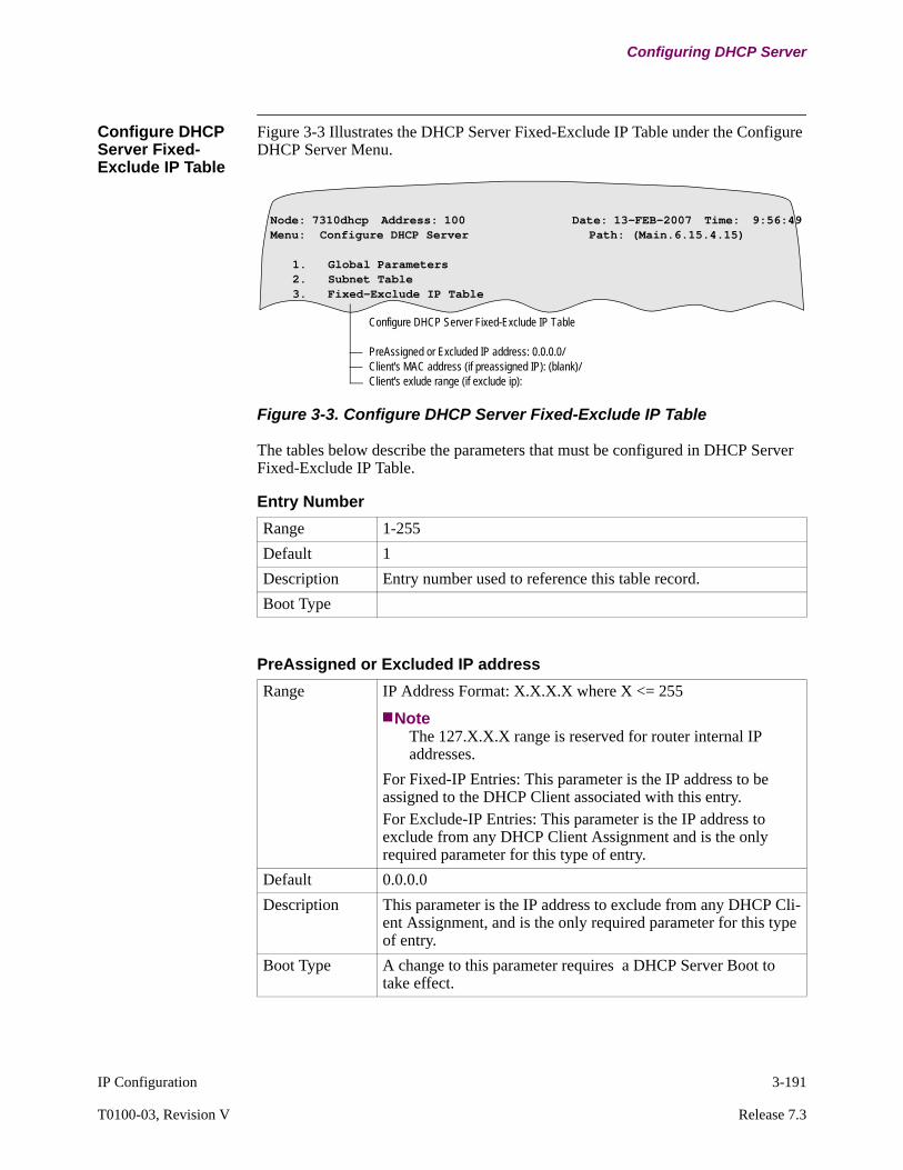
IP Configuration 3-191
T0100-03, Revision V Release 7.3
Configuring DHCP Server
Configure DHCP Server Fixed-Exclude IP Table
Figure 3-3 Illustrates the DHCP Server Fixed-Exclude IP Table under the Configure DHCP Server Menu.
Figure 3-3. Configure DHCP Server Fixed-Exclude IP Table
The tables below describe the parameters that must be configured in DHCP Server Fixed-Exclude IP Table.
Node: 7310dhcp Address: 100 Date: 13-FEB-2007 Time: 9:56:49Menu: Configure DHCP Server Path: (Main.6.15.4.15)
1. Global Parameters2. Subnet Table3. Fixed-Exclude IP Table
Configure DHCP Server Fixed-Exclude IP Table
PreAssigned or Excluded IP address: 0.0.0.0/Client's MAC address (if preassigned IP): (blank)/ Client's exlude range (if exclude ip):
Entry Number
Range 1-255
Default 1
Description Entry number used to reference this table record.
Boot Type
PreAssigned or Excluded IP address
Range IP Address Format: X.X.X.X where X <= 255
NoteThe 127.X.X.X range is reserved for router internal IP addresses.
For Fixed-IP Entries: This parameter is the IP address to be assigned to the DHCP Client associated with this entry. For Exclude-IP Entries: This parameter is the IP address to exclude from any DHCP Client Assignment and is the only required parameter for this type of entry.
Default 0.0.0.0
Description This parameter is the IP address to exclude from any DHCP Cli-ent Assignment, and is the only required parameter for this type of entry.
Boot Type A change to this parameter requires a DHCP Server Boot to take effect.
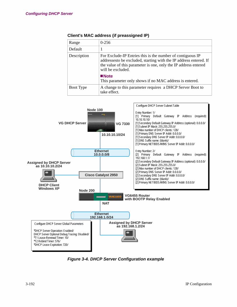
3-192 IP Configuration
Configuring DHCP Server
Figure 3-4. DHCP Server Configuration example
Client's MAC address (if preassigned IP)
Range 0-256
Default 1
Description For Exclude-IP Entries this is the number of contiguous IP addressesto be excluded, starting with the IP address entered. If the value of this parameter is one, only the IP address entered will be excluded.
NoteThis parameter only shows if no MAC address is entered.
Boot Type A change to this parameter requires a DHCP Server Boot to take effect.
VANGUARD
Ethernet10.0.0.0/8
Ethernet192.168.1.0/24
Node 200
Assigned by DHCP Serveras 10.10.10.2/24
Node 100
VG 7330
10.10.10.10/24
VG6455 Routerwith BOOTP Relay Enabled
NAT
Cisco Catalyst 2950
DHCP ClientWindows XP
Assigned by DHCP Serveras 192.168.1.2/24
VG DHCP Server
Configure DHCP Server Subnet Table
Entry Number: 1/[1] Primary Default Gateway IP Address (required): 10.10.10.10/[1] Secondary Default Gateway IP Address (optional): 0.0.0.0/[1] Subnet IP Mask: 255.255.255.0/[1] Max number of DHCP clients: 128/[1] Primary DNS Server IP Addr: 0.0.0.0/[1] Secondary DNS Server IP Addr: 0.0.0.0/[1] DNS Suffix name: (blank)/[1] Primary NETBIOS/WINS Server IP Addr: 0.0.0.0/
Entry Number: 2/[2] Primary Default Gateway IP Address (required): 192.168.1.1/[2] Secondary Default Gateway IP Address (optional): 0.0.0.0/[2] Subnet IP Mask: 255.255.255.0/[2] Max number of DHCP clients: 128/[2] Primary DNS Server IP Addr: 0.0.0.0/[2] Secondary DNS Server IP Addr: 0.0.0.0/[2] DNS Suffix name: (blank)/[2] Primary NETBIOS/WINS Server IP Addr: 0.0.0.0/
Configure DHCP Server Global Parameters
*DHCP Server Operation: Enabled/DHCP Server Optional Debug Tracing: Disabled/*T1 Lease-Renewal Timer: 10/*T2 Rebind Timer: 576/*DHCP Lease Expiration: 720/

IP Configuration 3-193
T0100-03, Revision V Release 7.3
Configuring DHCP Server
DHCP Server StatisticsFollow the steps below to access DHCP Server statistics from the DHCP stats menu.
Figure 3-5 Illustrates the DHCP Server Stats under the Router Stats menu. Figure 3-6 and Figure 3-7 display the DHCP Server Detailed Stats Subnet Entries.
Figure 3-5. DHCP Server Statistics Menu
Step Action Result
1 Select Statistics from the CTP Main menu
The Statistics Menu appears.
2 Select Router Stats. The Router Stats Menu appears.
3 Select DHCP Stats
Node: 7310dhcp Address: 100 Date: 15-FEB-2007 Time: 8:50:53Menu: DHCP Stats Path: (Main.5.15.7)
Local DHCP Server Statistics
#Enter Selection: 1
Local DHCP Server Statistics
DHCP Subnet to display #: 0/?: 1the max client count accommodates for 2 Excluded IP's
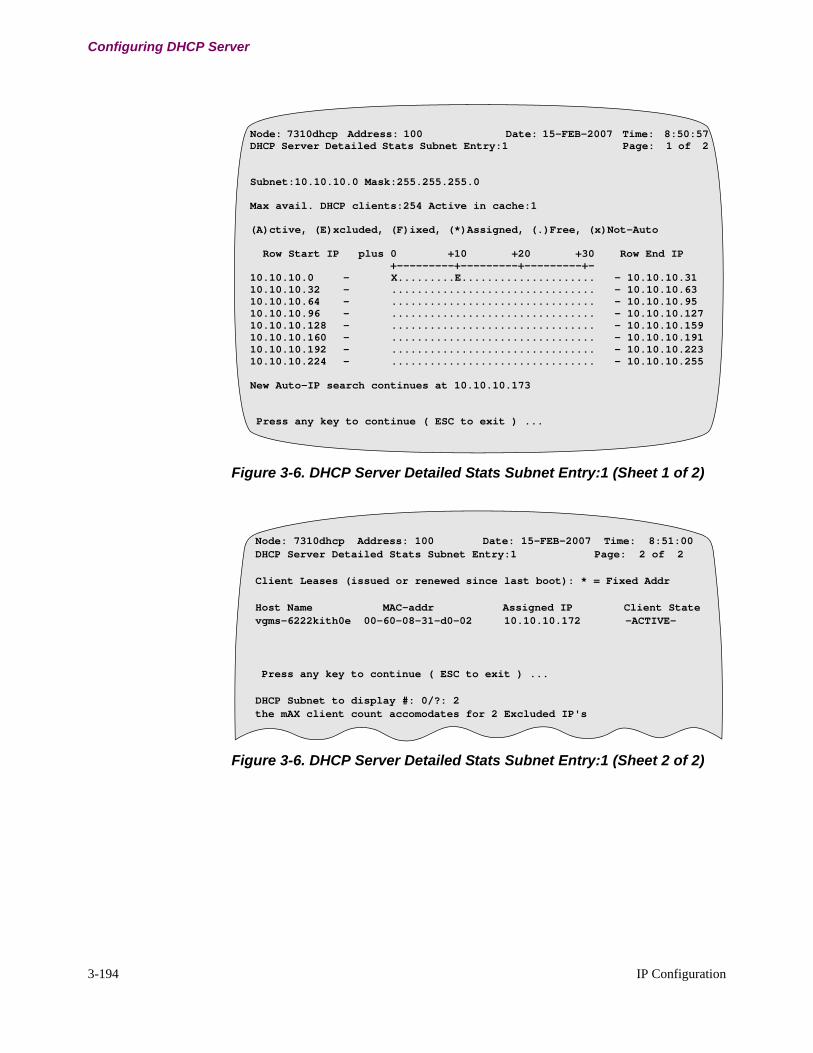
3-194 IP Configuration
Configuring DHCP Server
Figure 3-6. DHCP Server Detailed Stats Subnet Entry:1 (Sheet 1 of 2)
Figure 3-6. DHCP Server Detailed Stats Subnet Entry:1 (Sheet 2 of 2)
Node: 7310dhcp Address: 100 Date: 15-FEB-2007 Time: 8:50:57DHCP Server Detailed Stats Subnet Entry:1 Page: 1 of 2
Subnet:10.10.10.0 Mask:255.255.255.0
Max avail. DHCP clients:254 Active in cache:1
(A)ctive, (E)xcluded, (F)ixed, (*)Assigned, (.)Free, (x)Not-Auto
Row Start IP plus 0 +10 +20 +30 Row End IP +---------+---------+---------+-10.10.10.0 - X.........E..................... - 10.10.10.3110.10.10.32 - ................................ - 10.10.10.6310.10.10.64 - ................................ - 10.10.10.9510.10.10.96 - ................................ - 10.10.10.12710.10.10.128 - ................................ - 10.10.10.15910.10.10.160 - ................................ - 10.10.10.19110.10.10.192 - ................................ - 10.10.10.22310.10.10.224 - ................................ - 10.10.10.255
New Auto-IP search continues at 10.10.10.173
Press any key to continue ( ESC to exit ) ...
Node: 7310dhcp Address: 100 Date: 15-FEB-2007 Time: 8:51:00DHCP Server Detailed Stats Subnet Entry:1 Page: 2 of 2
Client Leases (issued or renewed since last boot): * = Fixed Addr
Host Name MAC-addr Assigned IP Client Statevgms-6222kith0e 00-60-08-31-d0-02 10.10.10.172 -ACTIVE-
Press any key to continue ( ESC to exit ) ...
DHCP Subnet to display #: 0/?: 2the mAX client count accomodates for 2 Excluded IP's

IP Configuration 3-195
T0100-03, Revision V Release 7.3
Configuring DHCP Server
Figure 3-7. DHCP Server Detailed Stats Subnet Entry:2 (Sheet 1 of 2)
Figure 3-7. DHCP Server Detailed Stats Subnet Entry:2 (Sheet 2 of 2)
Node: 7310dhcp Address: 200 Date: 15-FEB-2007 Time: 8:51:05DHCP Server Detailed Stats Subnet Entry:1 Page: 1 of 2
Subnet:192.168.1.0 Mask:255.255.255.0
Max avail. DHCP clients:254 Active in cache:1
(A)ctive, (E)xcluded, (F)ixed, (*)Assigned, (.)Free, (x)Not-Auto
Row Start IP plus 0 +10 +20 +30 Row End IP +---------+---------+---------+-10.10.10.0 - X.........E..................... - 10.10.10.3110.10.10.32 - ................................ - 10.10.10.6310.10.10.64 - ................................ - 10.10.10.9510.10.10.96 - ................................ - 10.10.10.12710.10.10.128 - ..........A..................... - 10.10.10.15910.10.10.160 - ................................ - 10.10.10.19110.10.10.192 - ................................ - 10.10.10.22310.10.10.224 - ................................ - 10.10.10.255
New Auto-IP search continues at 10.10.10.173
Press any key to continue ( ESC to exit ) ...
Node: 7310dhcp Address: 200 Date: 15-FEB-2007 Time: 8:51:09DHCP Server Detailed Stats Subnet Entry:1 Page: 2 of 2
Client Leases (issued or renewed since last boot): * = Fixed Addr
Host Name MAC-addr Assigned IP Client Statevgms-6222kith0e 00-60-08-31-d0-02 192.168.1.172 -ACTIVE-

3-196 IP Configuration
Configuring IPFLOW
Configuring IPFLOW
Introduction Follow these steps to access IPFLOW from the IPFLOW menu.
Figure 3-8 Illustrates the IPFLOW global Parameters under the Configure IPFLOW Menu.
Figure 3-8. Configure IPFLOW global Parameters
The tables below describe the IPFLOW Global Parameters that must be configured.
Step Action Result
1 Select Configure from the CTP Main menu
The Configure Menu appears.
2 Select Configure Router. The Configure Router Menu appears.
3 Select Configure IP The Configure IP menu is shown.
4 Select Configure IPFLOW
Node: ipflow Address: 100 Date: 10-JAN-2007 Time: 13:50:10Menu: Configure IPFLOW Path: (Main.6.14.4.16)
1. Global Parameters 2. Collector Table 3. Meter Table
Configure IPFLOW Global Parameters
*IPFLOW Major Operational Mode: Enabled
IPFLOW Active Timeout (minutes): 5
IPFLOW Inactive Timeout (seconds): 15
IPFLOW Optional Debug Tracing: Disabled
*IPFLOW Major Operational Mode
Range Enable, Disabled
Default Disabled
Description This Parameter globally enables or disables the IPFLOW data exporting feature.
Boot Type A change to this parameter requires a node boot to take effect.

IP Configuration 3-197
T0100-03, Revision V Release 7.3
Configuring IPFLOW
IPFLOW Collector Table parameters
Figure 3-9 Illustrates the IPFLOW Collector Table Parameters under the Configure IPFLOW Collector Table Menu. The tables that follow describe the IPFLOW Collector Table Parameters the must be configured.
Figure 3-9. IPFLOW Collector Table Parameters
IPFLOW Active Timeout
Range 1-60 (minutes)
Default 5
Description This parameter is the time in minutes that the router will wait when a flow is active, before sending the updated flow informa-tion to the collector.
Boot Type A change in this parameter is immediate when saved to CMEM.
IPFLOW Inactive Timeout
Range 15-120 (minutes)
Default 15
Description This parameter is the time in seconds that the router will wait after a flow has become inactive, before sending the final flow update to the collector.
Boot Type A change in this parameter is immediate when saved to CMEM.
IPFLOW Optional Debug Tracing
Range Enable, Disabled
Default Disabled
Description This parameter globally enables or disables the IPFLOW debug tracing
Boot Type A change in this parameter is immediate when saved to CMEM.
Configure IPFLOW Collector Table Entry
Entry Number: 1/[1] Remote Collector's IP Address[1] Remote Collector's UDP port[1] SOURCE port for UDP packet
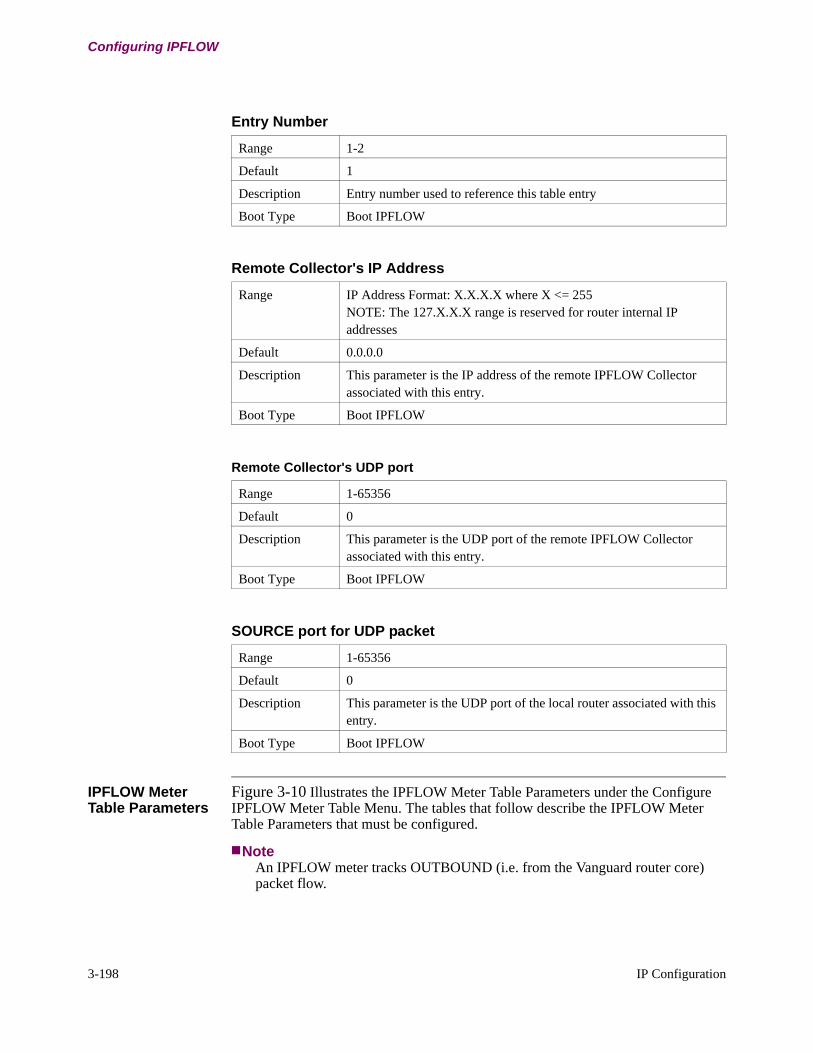
3-198 IP Configuration
Configuring IPFLOW
IPFLOW Meter Table Parameters
Figure 3-10 Illustrates the IPFLOW Meter Table Parameters under the Configure IPFLOW Meter Table Menu. The tables that follow describe the IPFLOW Meter Table Parameters that must be configured.
NoteAn IPFLOW meter tracks OUTBOUND (i.e. from the Vanguard router core) packet flow.
Entry Number
Range 1-2
Default 1
Description Entry number used to reference this table entry
Boot Type Boot IPFLOW
Remote Collector's IP Address
Range IP Address Format: X.X.X.X where X <= 255NOTE: The 127.X.X.X range is reserved for router internal IP addresses
Default 0.0.0.0
Description This parameter is the IP address of the remote IPFLOW Collectorassociated with this entry.
Boot Type Boot IPFLOW
Remote Collector's UDP port
Range 1-65356
Default 0
Description This parameter is the UDP port of the remote IPFLOW Collector associated with this entry.
Boot Type Boot IPFLOW
SOURCE port for UDP packet
Range 1-65356
Default 0
Description This parameter is the UDP port of the local router associated with this entry.
Boot Type Boot IPFLOW

IP Configuration 3-199
T0100-03, Revision V Release 7.3
Configuring IPFLOW
Figure 3-10. IPFLOW Meter Table Parameters
Configure a IPFLOW Meter Table Entry
Entry Number: 1/[1] Meter Type[1] The Ethernet port or LCON to assign to this meter[1] IPFLOW Meter Operational Mode[1] Optional SNMP ifIndex Overide
Entry Number
Range 1-16
Default 1
Description Entry number used to reference this table entry
Boot Type Boot IPFLOW
Meter Type
Range None, Ethernet, LCON
Default None
Description This parameter specifies the meter type for this record entry.None - No outbound meter.Ethernet - Outbound metering is performed on an ethernet port.LCON - Outbound metering is performed on an LCON. Use LCON for a Frame Relay link or an MLPPP link.
Boot Type
The LCON to assign to this meter
Range 0-100
Default 0
Description This parameter is the LCON associated with a meter entry.This parameter option will only appear if the Meter type selection is LCON.
Boot Type Boot IPFLOW
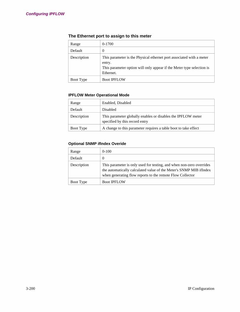
3-200 IP Configuration
Configuring IPFLOW
The Ethernet port to assign to this meter
Range 0-1700
Default 0
Description This parameter is the Physical ethernet port associated with a meter entry.This parameter option will only appear if the Meter type selection is Ethernet.
Boot Type Boot IPFLOW
IPFLOW Meter Operational Mode
Range Enabled, Disabled
Default Disabled
Description This parameter globally enables or disables the IPFLOW meter specified by this record entry
Boot Type A change to this parameter requires a table boot to take effect
Optional SNMP ifIndex Overide
Range 0-100
Default 0
Description This parameter is only used for testing, and when non-zero overrides the automatically calculated value of the Meter's SNMP MIB ifIndex when generating flow reports to the remote Flow Collector
Boot Type Boot IPFLOW

IP Configuration 3-201
T0100-03, Revision V Release 7.3
Configuring IPFLOW
IPFLOW Configuration Example
Simple IPFLOW Configuration with a Vanguard 7300
Figure 3-11 Shows an example of an IPFLOW configuration that illustrates a simple IPFLOW implementation. The 7330 is exporting the collected data out to a third party collector located at a remote site across the internet.
NoteA collector can be located anywhere in the network that is accessible via IP.
Figure 3-11. IPFLOW Configuration Example with a Vanguard 7300
VANGUARD
VANGUARD
VANGUARD
VG 7330
Node 300
VG 342
VG 6455
VG 6455
Node 200
Node 100
Client PC
Client PC
Client PC
Client PC
IP FLOWCollector
201.8.56.200
Internet
Frame Relay
Configure IPFLOW Global Parameters
*IPFLOW Major Operational Mode: Enabled/IPFLOW Optional Debug Tracing: Enabled/
Configure a IPFLOW Collector Table Entry
Entry Number: 1/[1] Remote Collector's IP Address: 201.8.56.200/[1] Remote Collector's UDP port: 63636/[1] SOURCE port for UDP packet: 1024/
Configure a IPFLOW Meter Table Entry
Entry Number: 1/[1] IPFLOW Meter Operational Mode: Enabled/[1] Meter's pysical/virtual port number: 101/[1] Optional SNMP ifIndex Overide: 0/
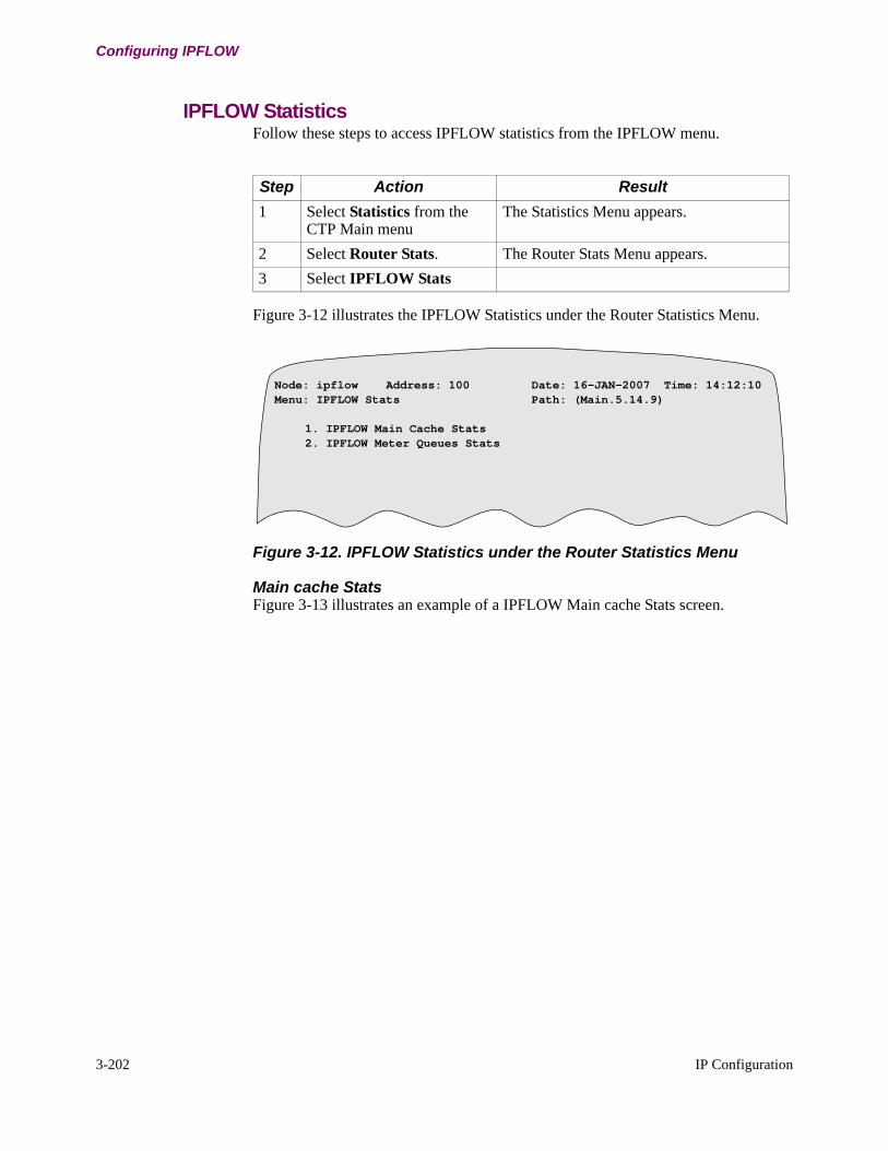
3-202 IP Configuration
Configuring IPFLOW
IPFLOW StatisticsFollow these steps to access IPFLOW statistics from the IPFLOW menu.
Figure 3-12 illustrates the IPFLOW Statistics under the Router Statistics Menu.
Figure 3-12. IPFLOW Statistics under the Router Statistics Menu
Main cache Stats Figure 3-13 illustrates an example of a IPFLOW Main cache Stats screen.
Step Action Result
1 Select Statistics from the CTP Main menu
The Statistics Menu appears.
2 Select Router Stats. The Router Stats Menu appears.
3 Select IPFLOW Stats
Node: ipflow Address: 100 Date: 16-JAN-2007 Time: 14:12:10Menu: IPFLOW Stats Path: (Main.5.14.9)
1. IPFLOW Main Cache Stats2. IPFLOW Meter Queues Stats
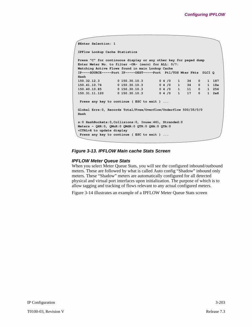
IP Configuration 3-203
T0100-03, Revision V Release 7.3
Configuring IPFLOW
Figure 3-13. IPFLOW Main cache Stats Screen
IPFLOW Meter Queue StatsWhen you select Meter Queue Stats, you will see the configured inbound/outbound meters. These are followed by what is called Auto config “Shadow” inbound only meters. These “Shadow” meters are automatically configured for all detected physical and virtual port interfaces upon initialization. The purpose of which is to allow tagging and tracking of flows relevant to any actual configured meters.
Figure 3-14 illustrates an example of a IPFLOW Meter Queue Stats screen
#Enter Selection: 1
IPFlow Lookup Cache Statistics
Press "C" for continuous display or any other key for paged dumpEnter Meter No. to filter -OR- (zero) for ALL: 0/?:Matching Active Flows found in main Lookup CacheIP----SOURCE-----Port IP-----DEST-----Port Ptl/TOS Mter Pkts DLCI Q Hash150.32.12.3 0 150.30.10.3 0 4 /0 1 34 0 1 187150.41.10.74 0 150.30.10.3 0 4 /0 1 34 0 1 18e150.40.10.85 0 150.30.10.3 0 4 /0 1 11 0 1 256150.31.11.120 0 150.30.10.3 0 4 /0 1 17 0 1 2e8
Press any key to continue ( ESC to exit ) ...
Global Errs:0, Records Total/Free/Overflow/Underflow 500/35/0/0Hash
s:0 HashBuckets:0,Collisions:0, Inuse:461, Stranded:0Meters - QHR:0, QMuR:0 QMdR:0 QTR:0 QHA:0 QTA:0<CTRL>R to update display Press any key to continue ( ESC to exit ) ...

3-204 IP Configuration
Configuring IPFLOW
Figure 3-14. IPFLOW Meter Queue Stats Screen
#Enter Selection: 2IPFlow Meter Statistics
User Configured Inbound-Outbound Flow MetersMtr Type Port LCON ifIdx Mtr Type Port LCON ifIdx1 ETH 101 ---- 1 2 ETH 103 ---- 23 LCON ---- 1 28 4 LCON ---- 3 305 ETH 151 ---- 3 6 ETH 152 ---- 47 ETH 161 ---- 5 8 ETH 162 ---- 69 LCON ---- 2 29 10 LCON ---- 4 111 LCON ---- 5 32
Auto Config "Shadow" Inbound Only MetersMtr Port DLCI LCON ifIdx Mtr Port DLCI LCON ifIdx
Router's local host (internal) ifIndex:39Press "C" for continuous display or any other key for paged dump
IPFLOW meter to display #: 0/?: 2Meter:2/Port:103 OUTifIndex:2 IPPkts:6636512GenErrs:0 QTErrs:0, NOT-IP Cnt:1244
IP---SOURCE----Port IP----DEST-----Port Pro IN OUT F/L(Sec) Pkts Hash
150.32.12.3 0 150.31.11.3 04 3 2 16 0 170 6f39- 2150.40.10.3 0 150.31.11.3 0 228 2 16 0 508 9f05- 2150.41.10.3 0 150.31.11.3 04 29 2 14 0 14 3cb9- 2
IPFLOW meter to display #: 0/?:

Statistics 4-1
Chapter 4Statistics
Overview
Introduction This chapter describes how to monitor the performance and operation of the Vanguard router using statistics.
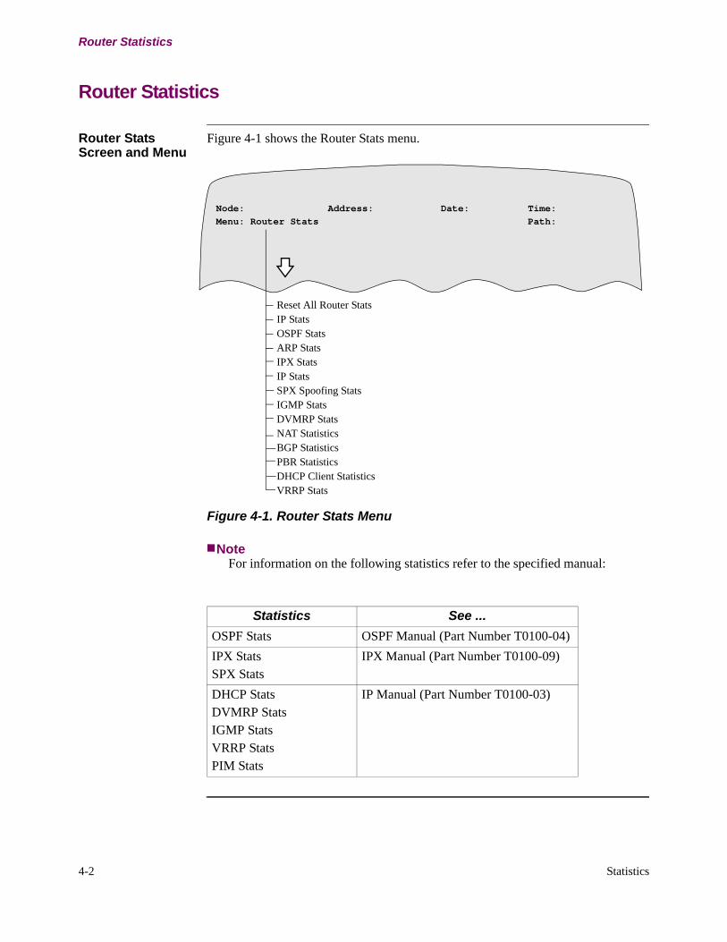
4-2 Statistics
Router Statistics
Router Statistics
Router Stats Screen and Menu
Figure 4-1 shows the Router Stats menu.
Figure 4-1. Router Stats Menu
NoteFor information on the following statistics refer to the specified manual:
Reset All Router Stats IP Stats OSPF StatsARP Stats IPX StatsIP Stats SPX Spoofing StatsIGMP StatsDVMRP StatsNAT StatisticsBGP StatisticsPBR StatisticsDHCP Client StatisticsVRRP Stats
Node: Address: Date: Time:Menu: Router Stats Path:
Statistics See ...
OSPF Stats OSPF Manual (Part Number T0100-04)
IPX StatsSPX Stats
IPX Manual (Part Number T0100-09)
DHCP StatsDVMRP StatsIGMP StatsVRRP StatsPIM Stats
IP Manual (Part Number T0100-03)
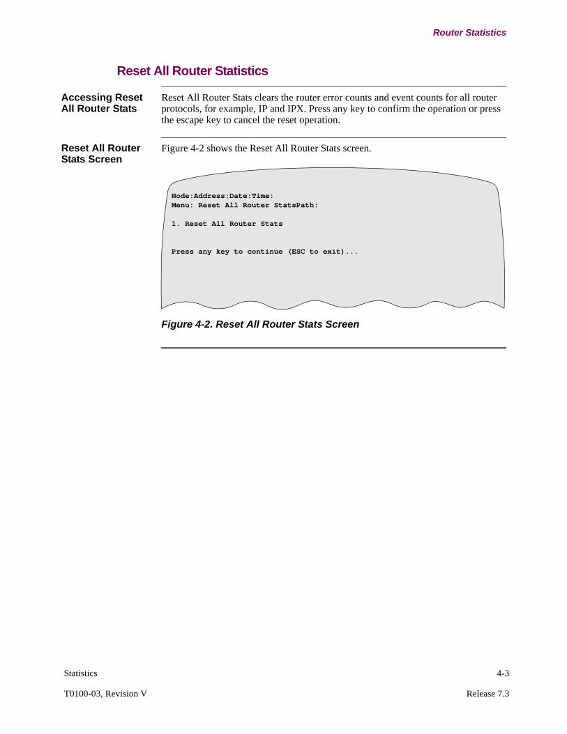
Statistics 4-3
T0100-03, Revision V Release 7.3
Router Statistics
Reset All Router Statistics
Accessing Reset All Router Stats
Reset All Router Stats clears the router error counts and event counts for all router protocols, for example, IP and IPX. Press any key to confirm the operation or press the escape key to cancel the reset operation.
Reset All Router Stats Screen
Figure 4-2 shows the Reset All Router Stats screen.
Figure 4-2. Reset All Router Stats Screen
Node:Address:Date:Time:Menu: Reset All Router StatsPath:
1. Reset All Router Stats
Press any key to continue (ESC to exit)...
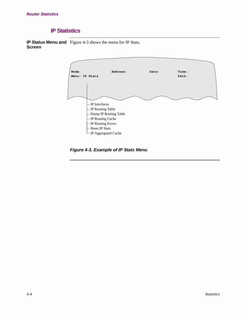
4-4 Statistics
Router Statistics
IP Statistics
IP Status Menu and Screen
Figure 4-3 shows the menu for IP Stats.
Figure 4-3. Example of IP Stats Menu
Node: Address: Date: Time:Menu: IP Stats Path:
IP InterfacesIP Routing TableDump IP Routing TableIP Routing Cache IP Routing Errors Reset IP StatsIP Aggregated Cache

Statistics 4-5
T0100-03, Revision V Release 7.3
Router Statistics
Dump IP Routing Table and IP Routing Table Statistics
What You See in This Screen
Figure 4-4 shows the IP Routing Table Statistics screen.
Figure 4-4. IP Routing Table Screen
IP Routing Table Statistics
Selecting IP Routing Table Statistics prompts you to enter an IP search prefix. Enter an IP search prefix or destination IP address to search the IP Routing Table and to display a sorted statistics screen. Using this feature, you can display only those destination addresses that match the specified IP search prefix. For example, if you enter a IP search prefix of 40.0.0.0, the IP Routing Table only displays destination addresses of 40.X.X.X, as shown in Figure 4-5.
Figure 4-5. Sorted IP Routing Table by IP Search Prefix
Node: Address: Date: Time:IP Routing Table
* Static/Direct Route% Accept RIP Route
Type Dest Net Mask Metric Age Next HopFltr 55.0.0.0 ff000000 0 SINK/37Dir* 20.0.0.0 ff000000 0 TKR/1Dir* 1.0.0.0 ff000000 0 SL/5Stat* 58.0.0.0 ff000000 0 1.0.0.1Aggr 217.1.0.0 ffff0000 4 217.1.1.1Routing Table currently uses 5 of the 768 routes available.
Press any key to continue ( ESC to exit ) . . .
Node: Address: Date: Time:IP Routing Table
* Static/Direct Route% Accept RIP Route
Type Dest Net Mask Metric Age Next HopSbnt 40.0.0.0 ff000000 1 NoneStat 40.1.1.0 ffffff00 1 2.2.2.2
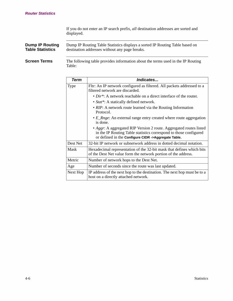
4-6 Statistics
Router Statistics
If you do not enter an IP search prefix, all destination addresses are sorted and displayed.
Dump IP Routing Table Statistics
Dump IP Routing Table Statistics displays a sorted IP Routing Table based on destination addresses without any page breaks.
Screen Terms The following table provides information about the terms used in the IP Routing Table:
Term Indicates...
Type Fltr: An IP network configured as filtered. All packets addressed to a filtered network are discarded.
• Dir*: A network reachable on a direct interface of the router.• Stat*: A statically defined network. • RIP: A network route learned via the Routing Information
Protocol.• E_Rnge: An external range entry created where route aggregation
is done.• Aggr: A aggregated RIP Version 2 route. Aggregated routes listed
in the IP Routing Table statistics correspond to those configured or defined in the Configure CIDR ->Aggregate Table.
Dest Net 32-bit IP network or subnetwork address in dotted decimal notation.
Mask Hexadecimal representation of the 32-bit mask that defines which bits of the Dest Net value form the network portion of the address.
Metric Number of network hops to the Dest Net.
Age Number of seconds since the route was last updated.
Next Hop IP address of the next hop to the destination. The next hop must be to a host on a directly attached network.

Statistics 4-7
T0100-03, Revision V Release 7.3
Router Statistics
Duplicate IP Address Detection
Duplicate IP Address Detection Statistics are used to detect the duplicate IP addresses configured in different IP device on a LAN. In the IP Interface Statistics the following two states are introduced:
The display of these two statistics are shown in Figure 4-6.
Figure 4-6. Duplicate IP Address Detection Statistics
States Definition
DUP The configured IP address for this interface is duplicated with other IP address’s in other IP devices on the LAN.
VLD The configured IP address for this interface is undergoing the “duplicate IP address detection” process. The interface is trying to validate the IP address.
Node: Address: Date: Time:IP Interfaces Table
Type If# LCON ChannelCap Sts IP Address Mask Rip FlagsETH/x 0 B DUP 10.10.10.1 FFFFFF00 ans NSP HETH/x 0 B VLD 10.10.10.1 FFFFFF00 ans NSP H
Press any key to continue (ESC to exit ) . . .
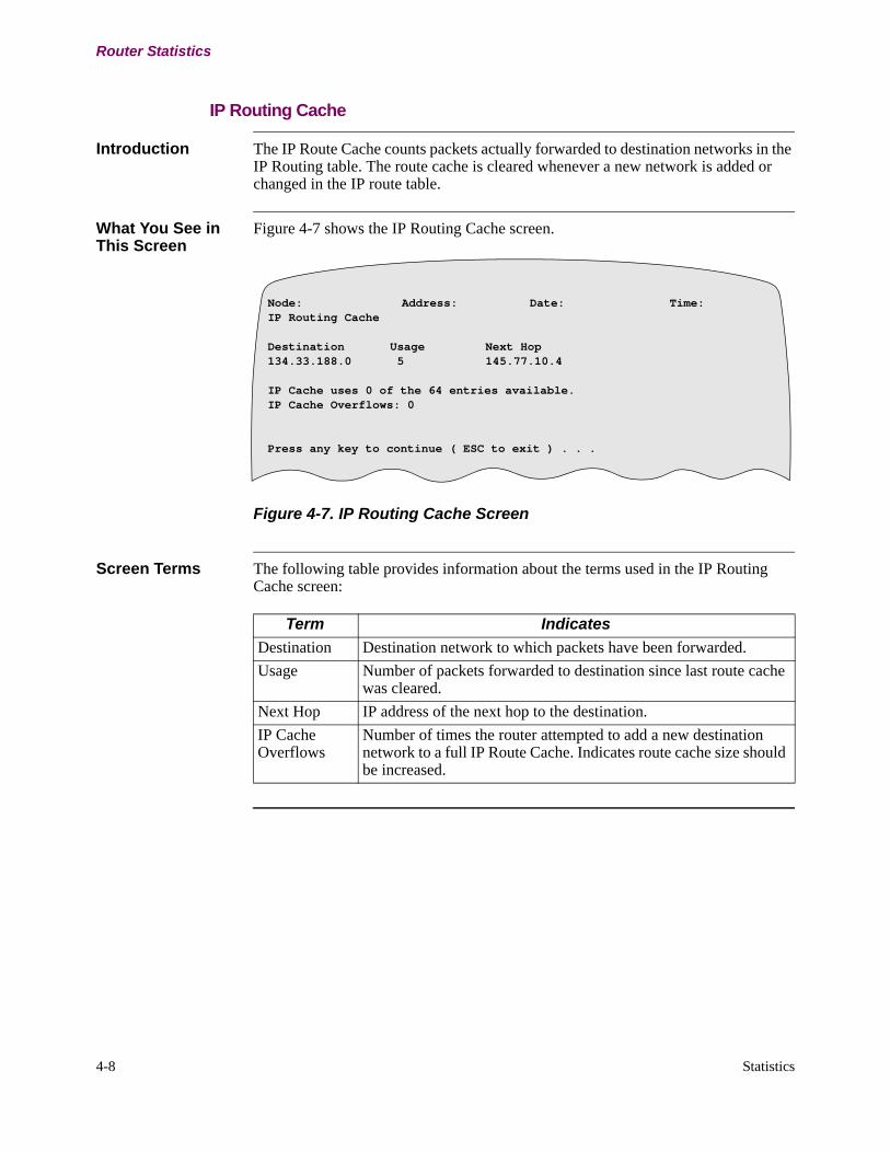
4-8 Statistics
Router Statistics
IP Routing Cache
Introduction The IP Route Cache counts packets actually forwarded to destination networks in the IP Routing table. The route cache is cleared whenever a new network is added or changed in the IP route table.
What You See in This Screen
Figure 4-7 shows the IP Routing Cache screen.
Figure 4-7. IP Routing Cache Screen
Screen Terms The following table provides information about the terms used in the IP Routing Cache screen:
Node: Address: Date: Time:IP Routing Cache
Destination Usage Next Hop134.33.188.0 5 145.77.10.4
IP Cache uses 0 of the 64 entries available.IP Cache Overflows: 0
Press any key to continue ( ESC to exit ) . . .
Term Indicates
Destination Destination network to which packets have been forwarded.
Usage Number of packets forwarded to destination since last route cache was cleared.
Next Hop IP address of the next hop to the destination.
IP Cache Overflows
Number of times the router attempted to add a new destination network to a full IP Route Cache. Indicates route cache size should be increased.
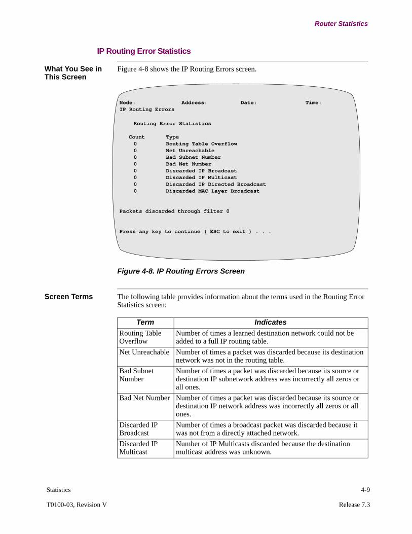
Statistics 4-9
T0100-03, Revision V Release 7.3
Router Statistics
IP Routing Error Statistics
What You See in This Screen
Figure 4-8 shows the IP Routing Errors screen.
Figure 4-8. IP Routing Errors Screen
Screen Terms The following table provides information about the terms used in the Routing Error Statistics screen:
Node: Address: Date: Time:IP Routing Errors
Routing Error Statistics Count Type
0 Routing Table Overflow0 Net Unreachable0 Bad Subnet Number0 Bad Net Number0 Discarded IP Broadcast0 Discarded IP Multicast0 Discarded IP Directed Broadcast0 Discarded MAC Layer Broadcast
Packets discarded through filter 0Press any key to continue ( ESC to exit ) . . .
Term Indicates
Routing Table Overflow
Number of times a learned destination network could not be added to a full IP routing table.
Net Unreachable Number of times a packet was discarded because its destination network was not in the routing table.
Bad Subnet Number
Number of times a packet was discarded because its source or destination IP subnetwork address was incorrectly all zeros or all ones.
Bad Net Number Number of times a packet was discarded because its source or destination IP network address was incorrectly all zeros or all ones.
Discarded IP Broadcast
Number of times a broadcast packet was discarded because it was not from a directly attached network.
Discarded IP Multicast
Number of IP Multicasts discarded because the destination multicast address was unknown.

4-10 Statistics
Router Statistics
Discarded IP Directed Broadcast
Number of Directed Broadcasts discarded because direct broadcast forwarding was disabled.
Discarded MAC Layer Broadcast
Number of IP packets discarded because the MAC address was a broadcast. IP unicast packets must be addressed to the router’s MAC address.
Term Indicates (continued)
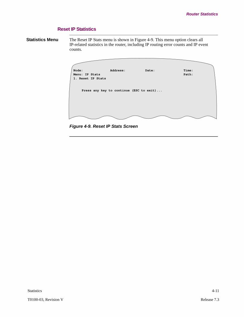
Statistics 4-11
T0100-03, Revision V Release 7.3
Router Statistics
Reset IP Statistics
Statistics Menu The Reset IP Stats menu is shown in Figure 4-9. This menu option clears all IP-related statistics in the router, including IP routing error counts and IP event counts.
Figure 4-9. Reset IP Stats Screen
Node: Address: Date: Time:Menu: IP Stats Path: 1. Reset IP Stats
Press any key to continue (ESC to exit)...
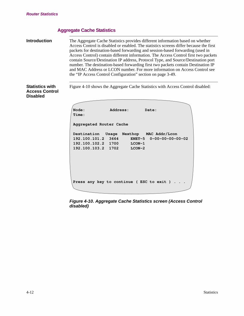
4-12 Statistics
Router Statistics
Aggregate Cache Statistics
Introduction The Aggregate Cache Statistics provides different information based on whether Access Control is disabled or enabled. The statistics screens differ because the first packets for destination-based forwarding and session-based forwarding (used in Access Control) contain different information. The Access Control first two packets contain Source/Destination IP address, Protocol Type, and Source/Destination port number. The destination-based forwarding first two packets contain Destination IP and MAC Address or LCON number. For more information on Access Control see the “IP Access Control Configuration” section on page 3-49.
Statistics with Access Control Disabled
Figure 4-10 shows the Aggregate Cache Statistics with Access Control disabled:
Figure 4-10. Aggregate Cache Statistics screen (Access Control disabled)
Node: Address: Date:Time:
Aggregated Router Cache
Destination Usage Nexthop MAC Addr/Lcon192.100.101.2 3664 ENET-5 0-00-00-00-00-02192.100.102.2 1700 LCON-1 192.100.103.2 1702 LCON-2
Press any key to continue ( ESC to exit ) . . .

Statistics 4-13
T0100-03, Revision V Release 7.3
Router Statistics
Screen Terms This table describes screen attributes for the Aggregate Cache Statistics report when Access Control is disabled:
Statistics with Access Control Enabled
Figure 4-11 shows the Aggregate Router Cache Statistics with Access Control enabled. For more information on Access Control see “IP Access Control Configuration” section on page 3-49.
Figure 4-11. Aggregate Cache Statistics screen (Access Control enabled)
Term Indicates
Destination The Destination IP Address in the IP packet.
Usage A 16-bit counter for the number of packets that are routed using Accelerated IP Forwarding for the specified destination. Once Accelerated IP Forwarding is established, the route cache entry on the slow path could expire as it is no longer used.
Nexthop MAC Addr/Lcon The physical address of the nexthop. If the output interface is ENET, the MAC address also appears. If the output interface is WAN, the LCON appears.
Node: Address: Date: Time:
Aggregated Router Cache
Prt/In Net Source/Destination Usage Out Net MAC Addr/Lcon1 192.100.101.2 1362 LCON-1 ENET-5 192.100.102.2 4 192.100.101.2 1368 DroppedENET-5 192.100.103.2Press any key to continue ( ESC to exit ) . . .

4-14 Statistics
Router Statistics
Screen Terms This table describes screen attributes for the Aggregate Cache Statistics report when Access Control is enabled.
Term Indicates
Prt/In Net (Protocol Number/Input Interface)
The first line specifies the IP Protocol field in the session. The second line specifies the input interface that received the packet.
Source/Destination The first line specifies the source IP address for the session. The second line specifies the destination IP address for the session.
NoteFor UDP/TCP protocols, the ports are also specified.
Usage A 16-bit counter for the number of packets that are routed using Accelerated IP Forwarding for the specified destination. Once Accelerated IP Forwarding is established, the route cache entry on the slow path could expire as it is no longer used.
Net MAC Addr/LCON The physical address of the nexthop. If Access Control requires the packet to be dropped, the field indicates this.If the Output interface is ENET, the MAC address appears. If the Output interface is WAN, the LCON number appears.

Statistics 4-15
T0100-03, Revision V Release 7.3
Switched IP Routing Table Statistics
Switched IP Routing Table Statistics
Introduction This section describes IP Routing Table statistics and event messages for Switched IP.
What You See in This Screen
Figure 4-12 shows the IP Routing Table statistics.
Figure 4-12. IP Routing Table Statistics
Screen Terms The following table describes screen attributes for the IP Routing Table statistics report.
Node: Address: Date: Time:IP Routing TableType Dest Net Mask Metric Age Next Hop/GwyFltr 55.0.0.0 ff000000 0 0Dir* 20.0.0.0 ff000000 0 1Dir* 1.0.0.0 ff000000 0 5Stat* 58.0.0.0 ff000000 0 1.0.0.1 5
Press any key to continue (ESC to exit) . . .
Term Indicates
Type Fltr: An IP network configured as filtered. All packets addressed to a filtered network are discarded.Dir*: A network reachable on a direct interface of the router.Stat*: A statically defined network.
Dest Net A 32-bit IP network or subnetwork address in dotted decimal notation.
Mask The hexadecimal representation of the 32-bit mask that defines which bits of the Dest Net value form the network portion of the address.
Metric Number of network hops to the Destination Network.
Next Hop IP address of the next hop to the destination. The next hop must be to a host on a directly attached network.

4-16 Statistics
ARP Statistics
ARP Statistics
Introduction This section describes the ARP statistics.
ARP Stats Menu Figure 4-13 shows the ARP Stats menu.
Figure 4-13. ARP Stats Menu
Node: Address: Date: Time:Menu: ARP Stats Path: (Main)
1.ARP Cache2.ARP Cache Statistics
#Enter Selection: 1
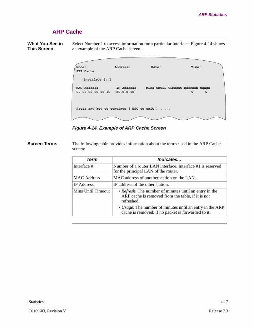
Statistics 4-17
T0100-03, Revision V Release 7.3
ARP Statistics
ARP Cache
What You See in This Screen
Select Number 1 to access information for a particular interface. Figure 4-14 shows an example of the ARP Cache screen.
Figure 4-14. Example of ARP Cache Screen
Screen Terms The following table provides information about the terms used in the ARP Cache screen:
Node: Address: Date: Time:ARP Cache
Interface #: 1
MAC Address IP Address Mins Until Timeout Refresh Usage00-00-00-00-00-10 20.0.0.10 5 5
Press any key to continue ( ESC to exit ) . . .
Term Indicates...
Interface # Number of a router LAN interface. Interface #1 is reserved for the principal LAN of the router.
MAC Address MAC address of another station on the LAN.
IP Address IP address of the other station.
Mins Until Timeout • Refresh: The number of minutes until an entry in the ARP cache is removed from the table, if it is not refreshed.
• Usage: The number of minutes until an entry in the ARP cache is removed, if no packet is forwarded to it.

4-18 Statistics
ARP Statistics
ARP Cache Statistics
Introduction Select Number 2 from the ARP Statistics menu to access the ARP Cache statistics. The ARP Cache is implemented as a Hash table indexed by the lower bits of a MAC address. Excessive Hash lengths may be reduced by timing out ARP cache entries more frequently.
What You See in This Screen
Figure 4-15 shows an example of the ARP Cache Stats screen.
Figure 4-15. Example of ARP Cache Statistics Screen
Screen Terms The following table provides information about the terms used in the ARP Cache Stats screen:
Node: Address: Date: Time:ARP Cache Stats
Interface --Hash-- --Entries-- --Refreshes-- --Timeouts--Num Port Max Cur Current Total Total Fails Refresh Usage1 IP 1 1 1 1 0 0 0 0
Press any key to continue ( ESC to exit ) . . .
Term Description
Interface Number: Route Interface number assigned in the Configuration IP Interface Configuration entry.Port: Protocol running on the specified interface.
Hash Max: Maximum length of any ARP Hash chain.Cur: Current longest Hash chain length.
Entries Current: Current number of active ARP table entries.Total: Total number of additions to ARP table.
Refreshes Total: Total number of attempts to refresh an ARP cache entry.Fails: Number of ARP refresh attempts (ARP requests) that failed to transmit, for example, due to lack of a transmit buffer.
Timeouts Refresh: Number of ARP cache entries deleted, due to no response to a refresh attempt.Usage: Number of ARP cache entries deleted due to no reference within a usage timer interval.
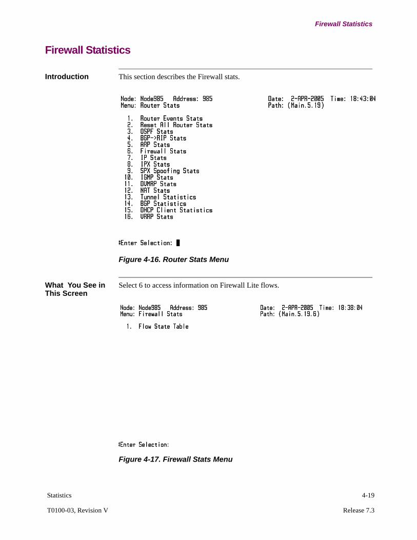
Statistics 4-19
T0100-03, Revision V Release 7.3
Firewall Statistics
Firewall Statistics
Introduction This section describes the Firewall stats.
Figure 4-16. Router Stats Menu
What You See in This Screen
Select 6 to access information on Firewall Lite flows.
Figure 4-17. Firewall Stats Menu

4-20 Statistics
Firewall Statistics
Enter a source and/or destination IP addresses to search and to display a sorted statistics screen. Using this filtering feature, you can display only those source/destination addresses that match the specified Flow State Table search prefix. For example, if you enter 150.40.1.1 for the destination IP address and 255.255.255.0 for the destination IP mask, the Flow State Table only displays flows with the destination address of 150.40.1.1 as shown in Figure 4-18.
Figure 4-18. Flow Stare Table Screen
If you do not enter specific IP addresses and masks for the source and/or destination, all available flows are displayed.
Filtering Parameters
The following parameters can filter so as to display only the flows of interest:
Source IP Address
Default: 0.0.0.0
Description: The source IP address of the flow. 0.0.0.0 is treated as a wild card.
Source IP Mask
Default: 0.0.0.0
Description: This parameter is visible only if the Source IP address is NOT 0.0.0.0. Source IP Mask of the flow, it is used to select a group of flows. 0.0.0.0 is treated as a wild card.
Destination IP Address
Default: 0.0.0.0
Description: The destination IP address of the flow. 0.0.0.0 is treated as a wild card.
Destination IP Mask
Default: 0.0.0.0
Description: This parameter is visible only if the Destination IP address is NOT 0.0.0.0. Source IP Mask of the flow, it is used to select a group of flows. 0.0.0.0 is treated as a wild card.

Statistics 4-21
T0100-03, Revision V Release 7.3
Firewall Statistics
Screen Terms The following table provides information about the terms used in the Flow State.
Statistic Description
SrcIP The source IP of the flow
DestIP The destination IP of the flow.
Sport The source port of the flow.
Dport The destination port of the flow
Proto The type of protocol that this flow per-tains to (eg TCP, UDP, ICMP etc).
State The state of the flow. It could be in one of four states:NEW: This indicates that the flow has been initiated, but the return traffic hasn’t been received as yet (i.e. it is uni-directional).EST: This indicates that the traffic is bi-directional and considered established.REL: This indicates that the flow is related to another “Established” flow. For example, in protocols like FTP the data channel is related to the control channel.
Packet The number of times a packet has matched to this flow.
Expires The time left (minutes and seconds) before the flow expires.

4-22 Statistics
Proxy Router
Proxy Router
Introduction This section describes the Proxy Router statistics.
What You See in This Screen
Figure 4-19 shows an example of the Proxy Router Statistics screen.
Figure 4-19. Example of On Net Proxy Statistics Screen
The Status field (Sts) identifies the current status of the virtual interface:
• PRU - Indicates Proxy Router is Up (active).• PRD - Indicates that the Proxy Router is Down (inactive).
Node: Address: Date: Time:IP Interfaces Table
Type If# LCON Channel Cap Sts IP Address Mask Rip Flags
ETH 1 B UP 10. 40. 1.232 FFFFFF00 ans NSP H
SL 5 1 P DWN 10. 40. 1.250 FFFFFF00 ans NSP HINT 37 P UP 10. 40. 1.232 FFFFFF00 HPress any key to continue ( ESC to exit ) . . .
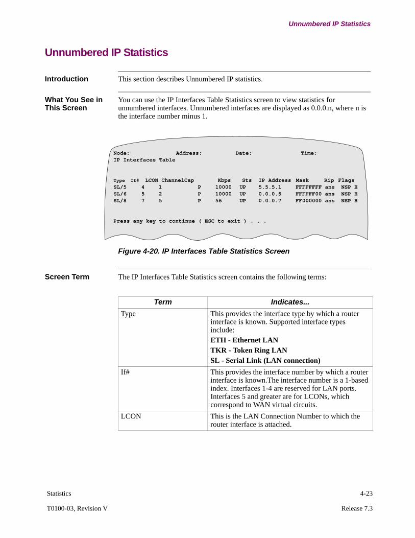
Statistics 4-23
T0100-03, Revision V Release 7.3
Unnumbered IP Statistics
Unnumbered IP Statistics
Introduction This section describes Unnumbered IP statistics.
What You See in This Screen
You can use the IP Interfaces Table Statistics screen to view statistics for unnumbered interfaces. Unnumbered interfaces are displayed as 0.0.0.n, where n is the interface number minus 1.
Figure 4-20. IP Interfaces Table Statistics Screen
Screen Term The IP Interfaces Table Statistics screen contains the following terms:
Node: Address: Date: Time:IP Interfaces Table
Type If# LCON ChannelCap Kbps Sts IP Address Mask Rip FlagsSL/5 4 1 P 10000 UP 5.5.5.1 FFFFFFFF ans NSP HSL/6 5 2 P 10000 UP 0.0.0.5 FFFFFF00 ans NSP HSL/8 7 5 P 56 UP 0.0.0.7 FF000000 ans NSP H
Press any key to continue ( ESC to exit ) . . .
Term Indicates...
Type This provides the interface type by which a router interface is known. Supported interface types include:ETH - Ethernet LANTKR - Token Ring LANSL - Serial Link (LAN connection)
If# This provides the interface number by which a router interface is known.The interface number is a 1-based index. Interfaces 1-4 are reserved for LAN ports. Interfaces 5 and greater are for LCONs, which correspond to WAN virtual circuits.
LCON This is the LAN Connection Number to which the router interface is attached.
4-24 Statistics
Unnumbered IP Statistics
Channel For interfaces attached to LCONs, this provides the port, station, and channel identifier of the WAN virtual circuit to which the LCON is attached. This channel is the result of the Autocall placed by the LCON, or by the connection determined for the LCON in the Network Services table.
Cap This indicates the Capabilities of the router network:B - Broadcast NetworkP - Point-to-Point NetworkM - Non-broadcast Multiple Access Network
Kbps This indicates the speed of the network interface, in thousands of bits per second. All virtual circuits on a physical port are considered to have the speed of the port.
Sts This indicates the status of the router interface:UP - Interface is up and operating normallyDWN - Interface is down, for example due to a failure to establish a virtual circuit. See the LCON or Port statistics menu for further details.NP - Interface is Not Present, for instance it is not configured correctly.DIS - Interface is Disabled, not connecting to the Interface State screen.TST - Interface is in a Testing state.PRU - Proxy Router is up (active).PRD - Proxy Router is down (inactive).
IP Address This is the IP address assigned to the interface in the IP interfaces configuration.
Mask This is the Address Mask assigned to the interface in the IP Interfaces configuration, in hexadecimal format. Note that the mask is originally entered in decimal format.
Term Indicates... (continued)
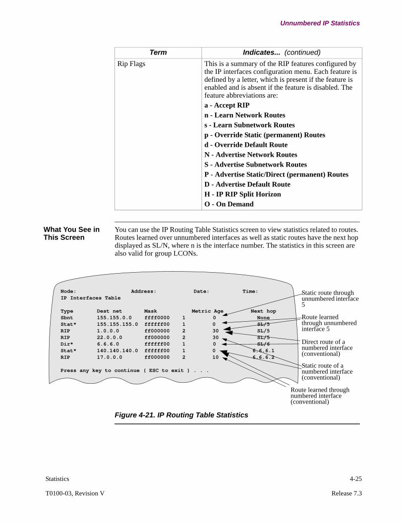
Statistics 4-25
T0100-03, Revision V Release 7.3
Unnumbered IP Statistics
What You See in This Screen
You can use the IP Routing Table Statistics screen to view statistics related to routes. Routes learned over unnumbered interfaces as well as static routes have the next hop displayed as SL/N, where n is the interface number. The statistics in this screen are also valid for group LCONs.
Figure 4-21. IP Routing Table Statistics
Rip Flags This is a summary of the RIP features configured by the IP interfaces configuration menu. Each feature is defined by a letter, which is present if the feature is enabled and is absent if the feature is disabled. The feature abbreviations are:a - Accept RIPn - Learn Network Routess - Learn Subnetwork Routesp - Override Static (permanent) Routesd - Override Default RouteN - Advertise Network RoutesS - Advertise Subnetwork RoutesP - Advertise Static/Direct (permanent) RoutesD - Advertise Default RouteH - IP RIP Split HorizonO - On Demand
Term Indicates... (continued)
Node: Address: Date: Time:IP Interfaces Table
Type Dest net Mask Metric Age Next hopSbnt 155.155.0.0 ffff0000 1 0 NoneStat* 155.155.155.0 ffffff00 1 0 SL/5RIP 1.0.0.0 ff000000 2 30 SL/5RIP 22.0.0.0 ff000000 2 30 SL/5Dir* 6.6.6.0 ffffff00 1 0 SL/6Stat* 140.140.140.0 ffffff00 1 0 6.6.6.1RIP 17.0.0.0 ff000000 2 10 6.6.6.2
Press any key to continue ( ESC to exit ) . . .
Static route through unnumbered interface 5
Route learned through unnumbered interface 5
Direct route of a numbered interface (conventional)
Static route of a numbered interface (conventional)
Route learned through numbered interface (conventional)

4-26 Statistics
Network Address Translation Statistics
Network Address Translation Statistics
Introduction This section describes Network Address Translation statistics. Figure 4-22 below displays the three menu items that are under the NAT Statistics.
Figure 4-22. NAT Statistics
What You See In this Screen
Figure 4-23 shows an example of NAT statistics screen.
Figure 4-23. Example Network Address Translation Statistics Screen
Node: RN40 Address: 40 Date: 25-MAR-2002 Time: 9:17:50 Menu: NAT Stats Path: (Main.5.16.11)
1. NAT External Address Pool Stats 2. NAT Binding Stats 3. NAT Debug and Other Stats
Node: Address: Date: Time:IP NAT Statistics Page 1 of 1
Dropped datagrams (external - internal) : 0Dropped datagrams (internal - external) : 0
External Address Pool:No. I/F # Ext. Address Type1 5 217.1.84.5 STATIC2 5 217.1.84.9 DYNAMIC3 6 *217.1.84.210 DYNAMIC
Binding:No. I/F # Int. Address Ext. Address Active Since1 5 10.0.0.7 (1080) 217.1.84.5 (6001) 1/6/98 11:582 5 10.0.0.9 217.1.84.9 1/6/98 11:59

Statistics 4-27
T0100-03, Revision V Release 7.3
Network Address Translation Statistics
Screen Term The NAT Statistics screen contains the following terms:
Term Indicates...
Dropped datagrams (external - internal)
number of external domain datagram dropped.
Dropped datagrams (internal - external)
number of internal domain datagram dropped.
Number (No.) an index number.
Interface Number (I/F #) the interface number on which this address is assigned.
External Address The external address assigned to this node. * indicates that this address is currently unused.The statistics screen specifies the port number for NAPT.
Type the type of external address used. Type can be STATIC or DYNAMIC.
Internal Address the internal address of the device that is being bound and translated to an external address. If NAPT is enabled, the statistics screen shows the port number.
Active Since the time when the binding became effective.

4-28 Statistics
Policy Based Routing Statistics
Policy Based Routing Statistics
What you see in the PBR Statistics Screen
Access the PBR Statistics screen from the following menu:
Status/statistics->Router Stats->IP Stats->PBR Statistics
Figure 4-24. PBR Statistics
Screen Terms The following table provides information about the terms used in the PBR Statistics:
Node: Address: Date: Time:
PBR Statistics
Dropped Packets:0Total number of active flows = 1
Active Flows:
No. Link# Src_addr Prt S_prt Nexthop Usage_cnt Age Dst_addr D_prt
1 Net-1 10.1.1.1 6 1024 1.1.1.1 2 1 20.1.1.1 21
2 LCON-1 30.1.1.1 1 * 2.1.1.1 2 1 40.1.1.1 *
Item Description
Dropped Packets
Indicates the total number of packets dropped by Policy Base Routing. The Vanguard router drops packets if the packet matches a defined flow but no nexthop routes are active.
No. Indicates the number of currently available sessions.
Link # Specifies the Interface or LCON on which the flow was received:• The tag “LCON-” precedes the LCON number.• The tag “NET-” precedes the interface number.• “INT” represents incoming link # for internally generated
flows.
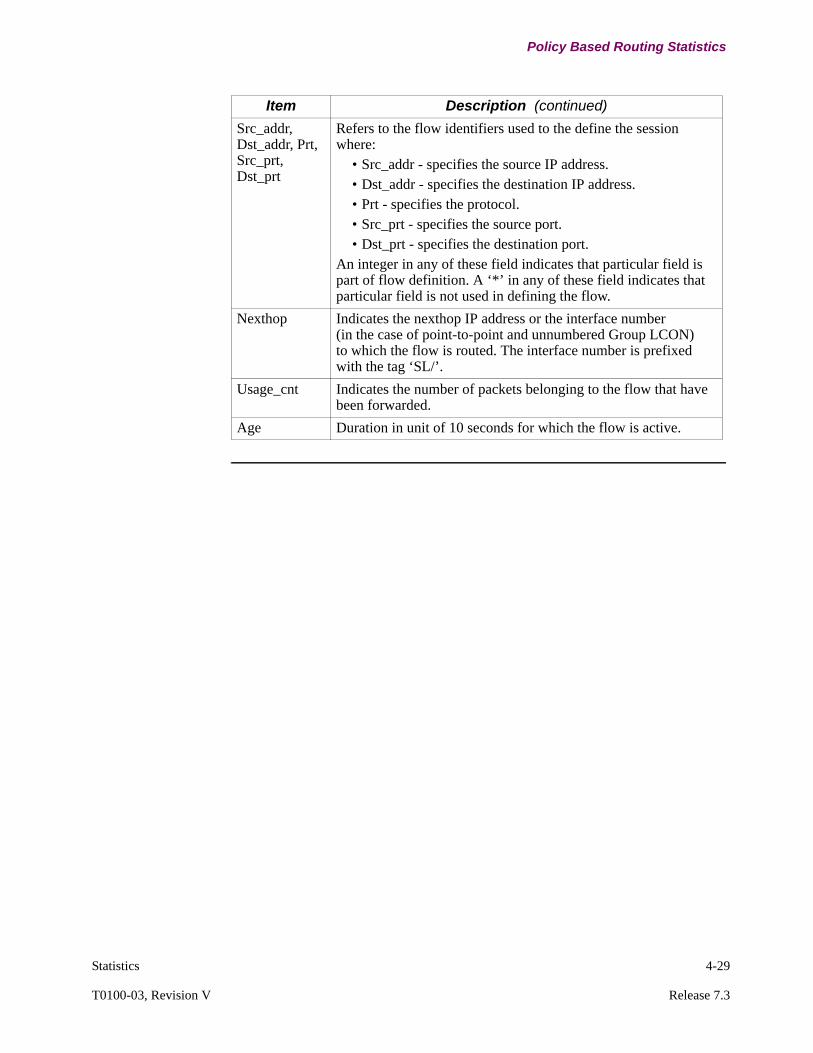
Statistics 4-29
T0100-03, Revision V Release 7.3
Policy Based Routing Statistics
Src_addr, Dst_addr, Prt, Src_prt, Dst_prt
Refers to the flow identifiers used to the define the session where:
• Src_addr - specifies the source IP address.• Dst_addr - specifies the destination IP address.• Prt - specifies the protocol.• Src_prt - specifies the source port.• Dst_prt - specifies the destination port.
An integer in any of these field indicates that particular field is part of flow definition. A ‘*’ in any of these field indicates that particular field is not used in defining the flow.
Nexthop Indicates the nexthop IP address or the interface number (in the case of point-to-point and unnumbered Group LCON) to which the flow is routed. The interface number is prefixed with the tag ‘SL/’.
Usage_cnt Indicates the number of packets belonging to the flow that have been forwarded.
Age Duration in unit of 10 seconds for which the flow is active.
Item Description (continued)
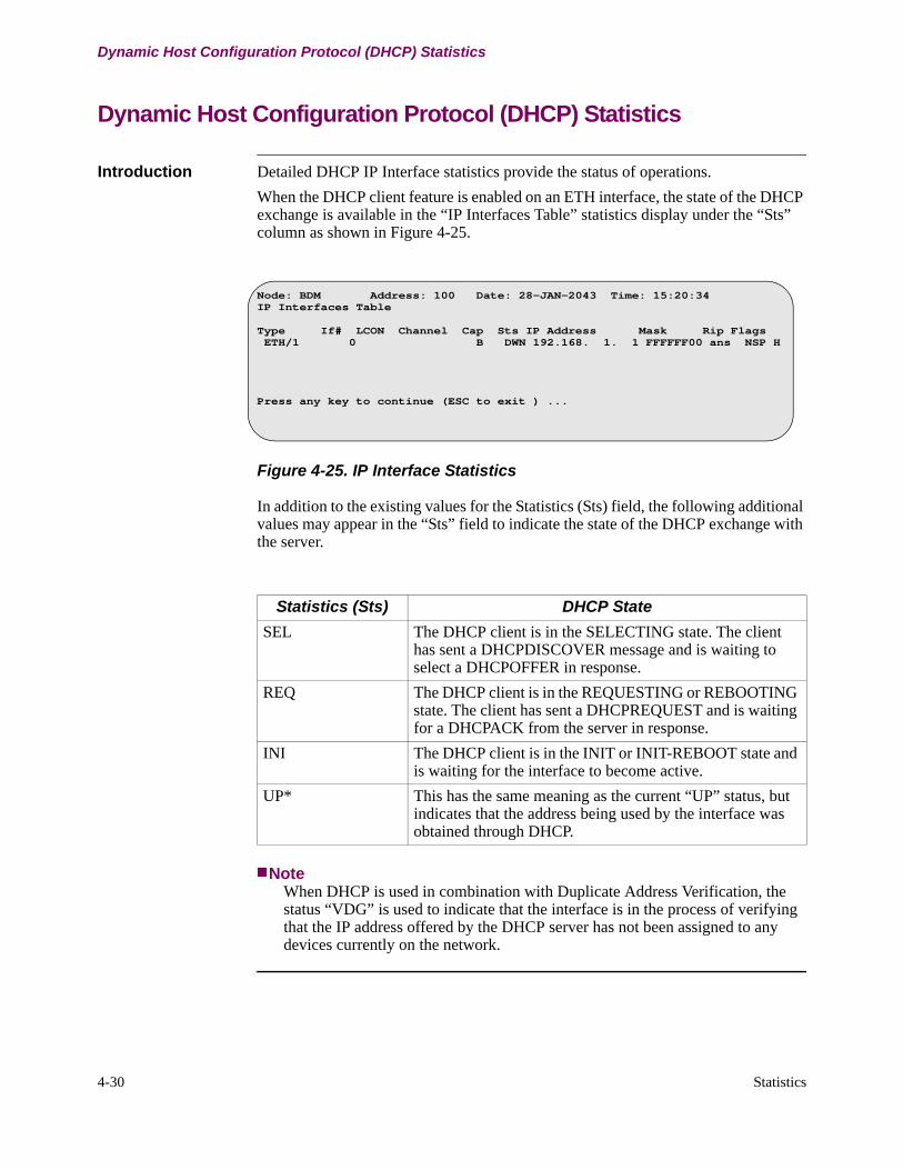
4-30 Statistics
Dynamic Host Configuration Protocol (DHCP) Statistics
Dynamic Host Configuration Protocol (DHCP) Statistics
Introduction Detailed DHCP IP Interface statistics provide the status of operations.
When the DHCP client feature is enabled on an ETH interface, the state of the DHCP exchange is available in the “IP Interfaces Table” statistics display under the “Sts” column as shown in Figure 4-25.
Figure 4-25. IP Interface Statistics
In addition to the existing values for the Statistics (Sts) field, the following additional values may appear in the “Sts” field to indicate the state of the DHCP exchange with the server.
NoteWhen DHCP is used in combination with Duplicate Address Verification, the status “VDG” is used to indicate that the interface is in the process of verifying that the IP address offered by the DHCP server has not been assigned to any devices currently on the network.
Node: BDM Address: 100 Date: 28-JAN-2043 Time: 15:20:34IP Interfaces Table
Type If# LCON Channel Cap Sts IP Address Mask Rip Flags ETH/1 0 B DWN 192.168. 1. 1 FFFFFF00 ans NSP H
Press any key to continue (ESC to exit ) ...
Statistics (Sts) DHCP State
SEL The DHCP client is in the SELECTING state. The client has sent a DHCPDISCOVER message and is waiting to select a DHCPOFFER in response.
REQ The DHCP client is in the REQUESTING or REBOOTING state. The client has sent a DHCPREQUEST and is waiting for a DHCPACK from the server in response.
INI The DHCP client is in the INIT or INIT-REBOOT state and is waiting for the interface to become active.
UP* This has the same meaning as the current “UP” status, but indicates that the address being used by the interface was obtained through DHCP.
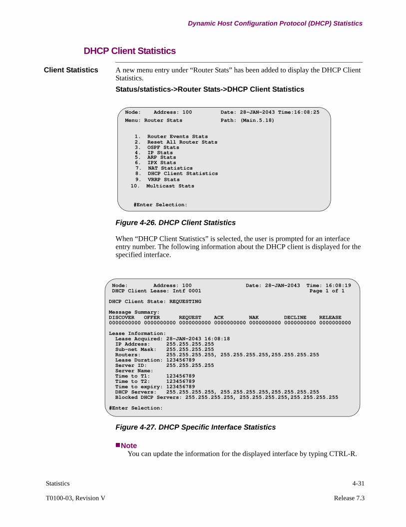
Statistics 4-31
T0100-03, Revision V Release 7.3
Dynamic Host Configuration Protocol (DHCP) Statistics
DHCP Client Statistics
Client Statistics A new menu entry under “Router Stats” has been added to display the DHCP Client Statistics.
Status/statistics->Router Stats->DHCP Client Statistics
Figure 4-26. DHCP Client Statistics
When “DHCP Client Statistics” is selected, the user is prompted for an interface entry number. The following information about the DHCP client is displayed for the specified interface.
Figure 4-27. DHCP Specific Interface Statistics
NoteYou can update the information for the displayed interface by typing CTRL-R.
Node: Address: 100 Date: 28-JAN-2043 Time:16:08:25
Menu: Router Stats Path: (Main.5.18)
1. Router Events Stats 2. Reset All Router Stats
4. IP Stats 5. ARP Stats
7. NAT Statistics 8. DHCP Client Statistics
#Enter Selection:
9. VRRP Stats
3. OSPF Stats
6. IPX Stats
10. Multicast Stats
Node: Address: 100 Date: 28-JAN-2043 Time: 16:08:19 DHCP Client Lease: Intf 0001 Page 1 of 1
DHCP Client State: REQUESTING
Message Summary:DISCOVER OFFER REQUEST ACK NAK DECLINE RELEASE0000000000 0000000000 0000000000 0000000000 0000000000 0000000000 0000000000
Lease Information: Lease Acquired: 28-JAN-2043 16:08:18 IP Address: 255.255.255.255 Sub-net Mask: 255.255.255.255 Routers: 255.255.255.255, 255.255.255.255,255.255.255.255 Lease Duration: 123456789 Server ID: 255.255.255.255 Server Name: Time to T1: 123456789 Time to T2: 123456789 Time to expiry: 123456789 DHCP Servers: 255.255.255.255, 255.255.255.255,255.255.255.255 Blocked DHCP Servers: 255.255.255.255, 255.255.255.255,255.255.255.255
#Enter Selection:
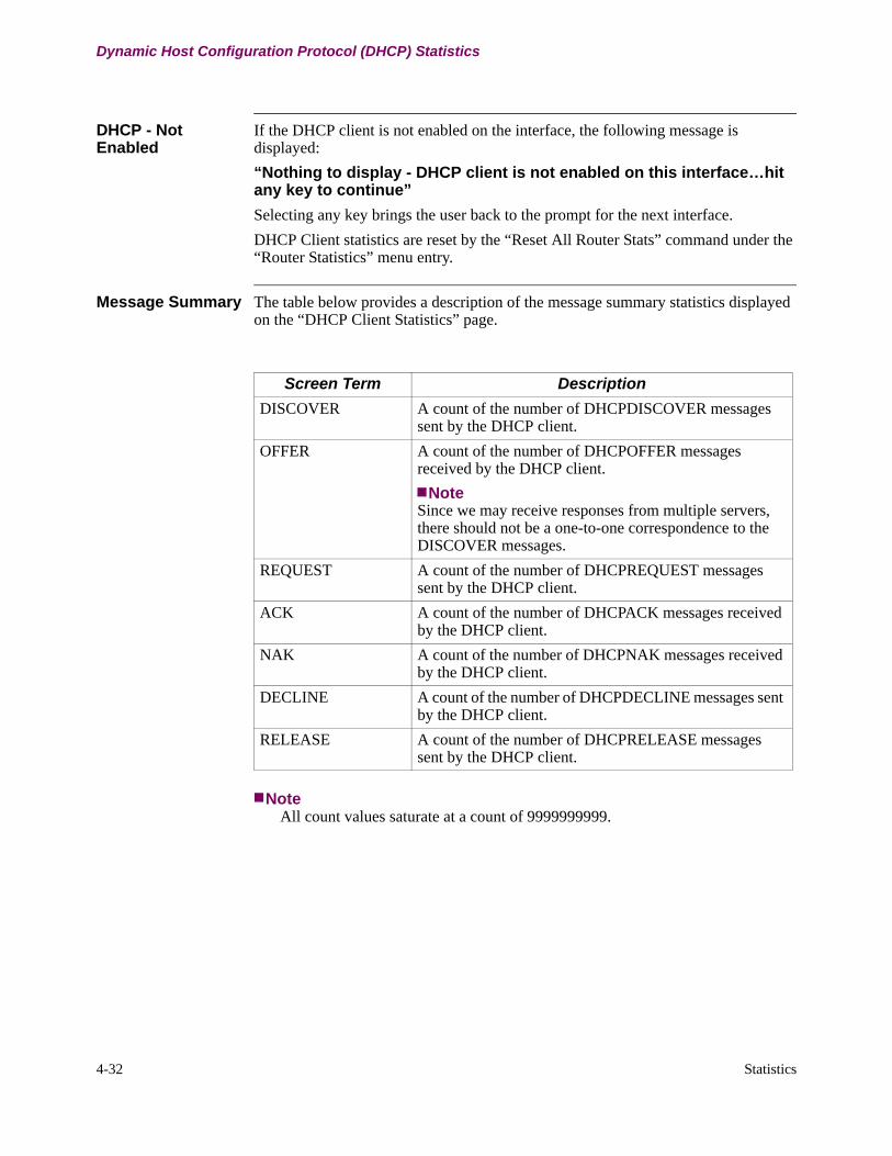
4-32 Statistics
Dynamic Host Configuration Protocol (DHCP) Statistics
DHCP - Not Enabled
If the DHCP client is not enabled on the interface, the following message is displayed:
“Nothing to display - DHCP client is not enabled on this interface…hit any key to continue”
Selecting any key brings the user back to the prompt for the next interface.
DHCP Client statistics are reset by the “Reset All Router Stats” command under the “Router Statistics” menu entry.
Message Summary The table below provides a description of the message summary statistics displayed on the “DHCP Client Statistics” page.
NoteAll count values saturate at a count of 9999999999.
Screen Term Description
DISCOVER A count of the number of DHCPDISCOVER messages sent by the DHCP client.
OFFER A count of the number of DHCPOFFER messages received by the DHCP client.
NoteSince we may receive responses from multiple servers, there should not be a one-to-one correspondence to the DISCOVER messages.
REQUEST A count of the number of DHCPREQUEST messages sent by the DHCP client.
ACK A count of the number of DHCPACK messages received by the DHCP client.
NAK A count of the number of DHCPNAK messages received by the DHCP client.
DECLINE A count of the number of DHCPDECLINE messages sent by the DHCP client.
RELEASE A count of the number of DHCPRELEASE messages sent by the DHCP client.
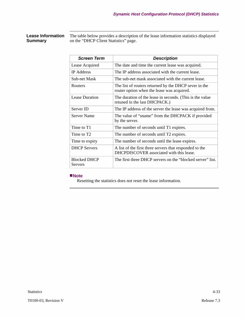
Statistics 4-33
T0100-03, Revision V Release 7.3
Dynamic Host Configuration Protocol (DHCP) Statistics
Lease Information Summary
The table below provides a description of the lease information statistics displayed on the “DHCP Client Statistics” page.
NoteResetting the statistics does not reset the lease information.
Screen Term Description
Lease Acquired The date and time the current lease was acquired.
IP Address The IP address associated with the current lease.
Sub-net Mask The sub-net mask associated with the current lease.
Routers The list of routers returned by the DHCP sever in the router option when the lease was acquired.
Lease Duration The duration of the lease in seconds. (This is the value retuned in the last DHCPACK.)
Server ID The IP address of the server the lease was acquired from.
Server Name The value of “sname” from the DHCPACK if provided by the server.
Time to T1 The number of seconds until T1 expires.
Time to T2 The number of seconds until T2 expires.
Time to expiry The number of seconds until the lease expires.
DHCP Servers A list of the first three servers that responded to the DHCPDISCOVER associated with this lease.
Blocked DHCP Servers
The first three DHCP servers on the “blocked server” list.
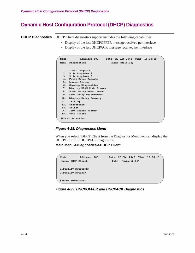
4-34 Statistics
Dynamic Host Configuration Protocol (DHCP) Diagnostics
Dynamic Host Configuration Protocol (DHCP) Diagnostics
DHCP Diagnostics DHCP Client diagnostics support includes the following capabilities:
• Display of the last DHCPOFFER message received per interface• Display of the last DHCPACK message received per interface
Figure 4-28. Diagnostics Menu
When you select “DHCP Client from the Diagnostics Menu you can display the DHCPOFFER or DHCPACK diagnostics.
Main Menu->Diagnostics->DHCP Client
Figure 4-29. DHCPOFFER and DHCPACK Diagnostics
Node: Address: 100 Date: 28-JAN-2043 Time: 16:08:19
Menu: Diagnostics Path: (Main.12)
1. Local Loopback 2. V.54 Loopback 2 3. V.54 Loopback 3 4. Fatal Error Reports 5. Logged Alarms 6. Startup Diagnostics 7. Display DRAM Code Errors 8. Start Delay Measurement 9. Stop Delay Measurement
10. Display Delay Summary 11. IP Ping 12. Traceroute 13. Telnet14. ISDN Packet Viewer15. DHCP Client
#Enter Selection:
Node: Address: 100 Date: 28-JAN-2043 Time: 16:08:19
Menu: DHCP Client Path: (Main.12.15)
1.Display DHCPOFFER
2.Display DHCPACK
#Enter Selection:
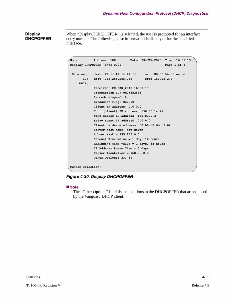
Statistics 4-35
T0100-03, Revision V Release 7.3
Dynamic Host Configuration Protocol (DHCP) Diagnostics
Display DHCPOFFER
When “Display DHCPOFFER” is selected, the user is prompted for an interface entry number. The following lease information is displayed for the specified interface.
Figure 4-30. Display DHCPOFFER
NoteThe “Other Options” field lists the options in the DHCPOFFER that are not used by the Vanguard DHCP client.
Node: Address: 100 Date: 28-JAN-2043 Time: 16:08:19
Display DHCPOFFER: Intf 0001 Page 1 of 1
Ethernet: dest: ff:ff:ff:ff:ff:ff src: 00:06:5b:05:aa:cd
IP: dest: 255.255.255.255 src: 150.83.2.3
DHCP:
Received: 28-JAN_2043 16:08:17
Transaction ID: 0x053f2833
Seconds elapsed: 0
Broadcast flag: 0x0000
Client IP address: 0.0.0.0
Your (client) IP address: 150.83.14.21
Next server IP address: 150.83.2.3
Relay agent IP address: 0.0.0.0
Client hardware address: 00:b0:d0:6b:c3:62
Server host name: not given
Subnet Mask = 255.255.0.0
Renewal Time Value = 1 day, 12 hours
Rebinding Time Value = 2 days, 15 hours
IP Address Lease Time = 3 days
Server Identifier = 150.83.2.3
Other Options: 23, 34
#Enter Selection:

4-36 Statistics
Dynamic Host Configuration Protocol (DHCP) Diagnostics
Display DHCPACK When “Display DHCPACK” is selected, the user is prompted for an interface entry number. The following lease information is displayed for the specified interface.
Figure 4-31. Display DHCPACK
Node: Address: 100 Date: 28-JAN-2043 Time: 16:08:19
Display DHCPACK: Intf 0001 Page 1 of 1
Ethernet: dest: ff:ff:ff:ff:ff:ff src: 00:06:5b:05:aa:cd
IP: dest: 255.255.255.255 src: 150.83.2.3
DHCP:
Received: 28-JAN_2043 16:08:17
Transaction ID: 0x053f2833
Seconds elapsed: 0
Broadcast flag: 0x0000
Client IP address: 0.0.0.0
Your (client) IP address: 150.83.14.21
Next server IP address: 150.83.2.3
Relay agent IP address: 0.0.0.0
Client hardware address: 00:b0:d0:6b:c3:62
Server host name: not given
Subnet Mask = 255.255.0.0
Renewal Time Value = 1 day, 12 hours
Rebinding Time Value = 2 days, 15 hours
IP Address Lease Time = 3 days
Server Identifier = 150.83.2.3
Other Options: 23, 34
#Enter Selection:
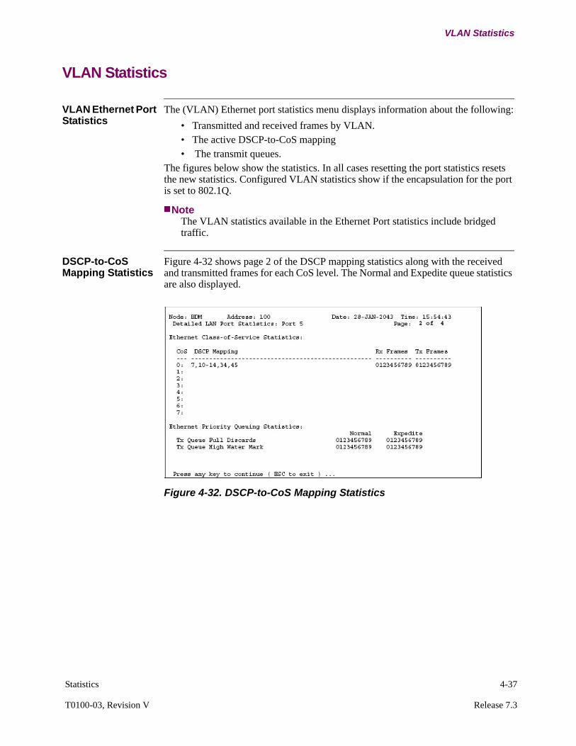
Statistics 4-37
T0100-03, Revision V Release 7.3
VLAN Statistics
VLAN Statistics
VLAN Ethernet Port Statistics
The (VLAN) Ethernet port statistics menu displays information about the following:
• Transmitted and received frames by VLAN.• The active DSCP-to-CoS mapping • The transmit queues.
The figures below show the statistics. In all cases resetting the port statistics resets the new statistics. Configured VLAN statistics show if the encapsulation for the port is set to 802.1Q.
NoteThe VLAN statistics available in the Ethernet Port statistics include bridged traffic.
DSCP-to-CoS Mapping Statistics
Figure 4-32 shows page 2 of the DSCP mapping statistics along with the received and transmitted frames for each CoS level. The Normal and Expedite queue statistics are also displayed.
Figure 4-32. DSCP-to-CoS Mapping Statistics

4-38 Statistics
VLAN Statistics
The table below describes the fields displayed in Figure 4-32.
Configured VLAN Statistics
Figure 4-33 displays the statistics for each configured VLAN. All VLANs that can be configured on a port display on this page (maximum number of VLANs is 16).
Figure 4-33. Configured VLAN Statistics
Screen Term Description
CoS This column displays the CoS value for which this line displays information.
DSCP Mapping If one or more of the DSCP mapping list does not fit on a single line, then up to two additional lines may be added to display the additional mappings (i.e. a maximum of 9 lines can be use to display the mapping table). If the mapping table has already been expanded to 9 lines an a mapping line still does not fit, then an ellipsis ("…") is used to terminate the list in order to indicated the list is incomplete.The list of DSCP mappings is ordered from smallest to greatest numerical value with ranges aggregated.
Rx Frames This column displays the number of frames received with the associated CoS value.
Tx Frames This column displays the number of frames transmitted with the associated CoS value.
Tx Queue Full Discards
This line displays the number of frames that are discarded because the associated queue (Normal/Expedite) was full when the attempt to queue the frame was made.
Tx Queue High Water Mark
This line displays the maximum number of entries that have been in the associated queue at any time since the statistics were last reset.
Node: BDM Address: 100 Date: 28-Jan-2003 Time 18:47:09Detailed LAN Port Statistics: Port 5 Page 3 of 4
Configured VLANs:VLAN Status intf# frames in frames out===== ==== ==== ======== ========1 Up 1 9999999999 99999999993 Up 1 9999999999 9999999999

Statistics 4-39
T0100-03, Revision V Release 7.3
VLAN Statistics
The table below describes the fields displayed in Figure 4-33:
Detailed Bridge Link Statistics
Figure 4-34 displays the Detailed Bridge Link Statistics, the VLAN membership for the link is also shown:
Figure 4-34. Detailed Bridge Link Statistics
The table below describes the fields displayed in Figure 4-34:
Screen Term Description
VLAN The decimal value of the VLAN ID for the configured VLAN.
status The status of the interface associated with this VLAN.
date/time The date and time of the last status change.
intf# The interface number associated with this VLAN.
frames in A count of the frames received on this VLAN. The count saturates at 999999999.
frames out A count of the frames transmitted on this VLAN. The count saturates at 999999999.
Screen Term Description
VLAN Membership When “VLAN Enable” is set to Disabled in the Bridge Parameters this field displays "Disabled", otherwise it displays a list of the VLAN IDs which are configured to be supported on this bridge link.
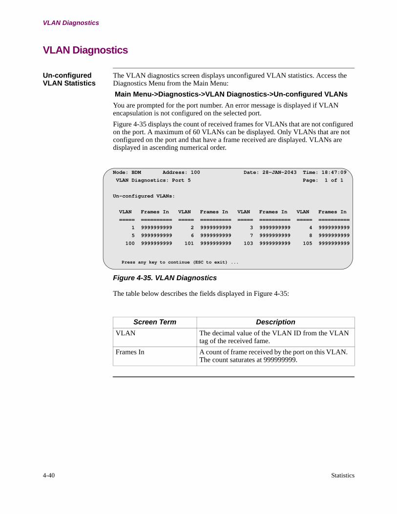
4-40 Statistics
VLAN Diagnostics
VLAN Diagnostics
Un-configured VLAN Statistics
The VLAN diagnostics screen displays unconfigured VLAN statistics. Access the Diagnostics Menu from the Main Menu:
Main Menu->Diagnostics->VLAN Diagnostics->Un-configured VLANs
You are prompted for the port number. An error message is displayed if VLAN encapsulation is not configured on the selected port.
Figure 4-35 displays the count of received frames for VLANs that are not configured on the port. A maximum of 60 VLANs can be displayed. Only VLANs that are not configured on the port and that have a frame received are displayed. VLANs are displayed in ascending numerical order.
Figure 4-35. VLAN Diagnostics
The table below describes the fields displayed in Figure 4-35:
Node: BDM Address: 100 Date: 28-JAN-2043 Time: 18:47:09
VLAN Diagnostics: Port 5 Page: 1 of 1
Un-configured VLANs:
VLAN Frames In VLAN Frames In VLAN Frames In VLAN Frames In
===== ========== ===== ========== ===== ========== ===== ==========
1 9999999999 2 9999999999 3 9999999999 4 9999999999
5 9999999999 6 9999999999 7 9999999999 8 9999999999
100 9999999999 101 9999999999 103 9999999999 105 9999999999
Press any key to continue (ESC to exit) ...
Screen Term Description
VLAN The decimal value of the VLAN ID from the VLAN tag of the received fame.
Frames In A count of frame received by the port on this VLAN. The count saturates at 999999999.
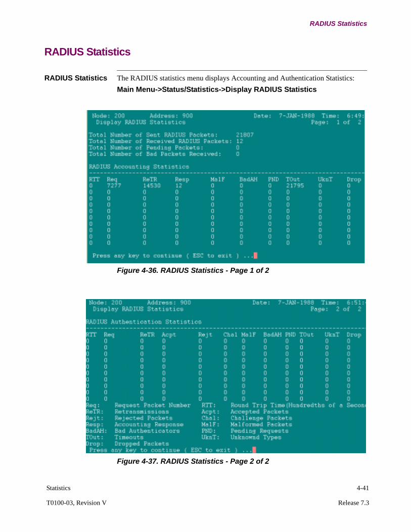
Statistics 4-41
T0100-03, Revision V Release 7.3
RADIUS Statistics
RADIUS Statistics
RADIUS Statistics The RADIUS statistics menu displays Accounting and Authentication Statistics:
Main Menu->Status/Statistics->Display RADIUS Statistics
Figure 4-36. RADIUS Statistics - Page 1 of 2
Figure 4-37. RADIUS Statistics - Page 2 of 2
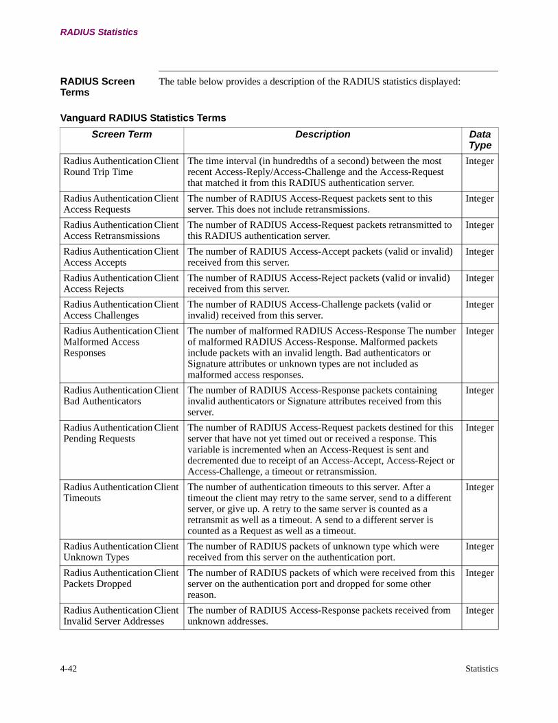
4-42 Statistics
RADIUS Statistics
RADIUS Screen Terms
The table below provides a description of the RADIUS statistics displayed:
Vanguard RADIUS Statistics Terms
Screen Term Description Data Type
Radius Authentication Client Round Trip Time
The time interval (in hundredths of a second) between the most recent Access-Reply/Access-Challenge and the Access-Request that matched it from this RADIUS authentication server.
Integer
Radius Authentication Client Access Requests
The number of RADIUS Access-Request packets sent to this server. This does not include retransmissions.
Integer
Radius Authentication Client Access Retransmissions
The number of RADIUS Access-Request packets retransmitted to this RADIUS authentication server.
Integer
Radius Authentication Client Access Accepts
The number of RADIUS Access-Accept packets (valid or invalid) received from this server.
Integer
Radius Authentication Client Access Rejects
The number of RADIUS Access-Reject packets (valid or invalid) received from this server.
Integer
Radius Authentication Client Access Challenges
The number of RADIUS Access-Challenge packets (valid or invalid) received from this server.
Integer
Radius Authentication Client Malformed Access Responses
The number of malformed RADIUS Access-Response The number of malformed RADIUS Access-Response. Malformed packets include packets with an invalid length. Bad authenticators or Signature attributes or unknown types are not included as malformed access responses.
Integer
Radius Authentication Client Bad Authenticators
The number of RADIUS Access-Response packets containing invalid authenticators or Signature attributes received from this server.
Integer
Radius Authentication Client Pending Requests
The number of RADIUS Access-Request packets destined for this server that have not yet timed out or received a response. This variable is incremented when an Access-Request is sent and decremented due to receipt of an Access-Accept, Access-Reject or Access-Challenge, a timeout or retransmission.
Integer
Radius Authentication Client Timeouts
The number of authentication timeouts to this server. After a timeout the client may retry to the same server, send to a different server, or give up. A retry to the same server is counted as a retransmit as well as a timeout. A send to a different server is counted as a Request as well as a timeout.
Integer
Radius Authentication Client Unknown Types
The number of RADIUS packets of unknown type which were received from this server on the authentication port.
Integer
Radius Authentication Client Packets Dropped
The number of RADIUS packets of which were received from this server on the authentication port and dropped for some other reason.
Integer
Radius Authentication Client Invalid Server Addresses
The number of RADIUS Access-Response packets received from unknown addresses.
Integer
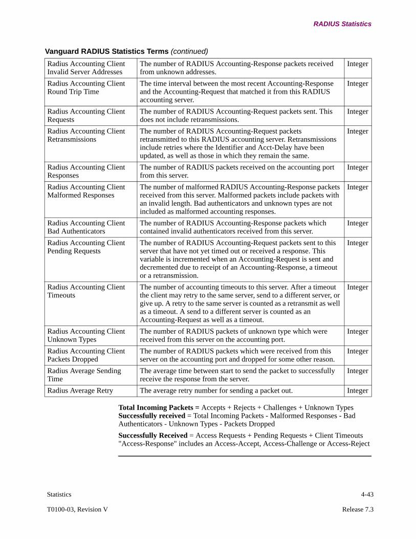
Statistics 4-43
T0100-03, Revision V Release 7.3
RADIUS Statistics
Total Incoming Packets = Accepts + Rejects + Challenges + Unknown Types Successfully received = Total Incoming Packets - Malformed Responses - Bad Authenticators - Unknown Types - Packets Dropped
Successfully Received = Access Requests + Pending Requests + Client Timeouts "Access-Response" includes an Access-Accept, Access-Challenge or Access-Reject
Radius Accounting Client Invalid Server Addresses
The number of RADIUS Accounting-Response packets received from unknown addresses.
Integer
Radius Accounting Client Round Trip Time
The time interval between the most recent Accounting-Response and the Accounting-Request that matched it from this RADIUS accounting server.
Integer
Radius Accounting Client Requests
The number of RADIUS Accounting-Request packets sent. This does not include retransmissions.
Integer
Radius Accounting Client Retransmissions
The number of RADIUS Accounting-Request packets retransmitted to this RADIUS accounting server. Retransmissions include retries where the Identifier and Acct-Delay have been updated, as well as those in which they remain the same.
Integer
Radius Accounting Client Responses
The number of RADIUS packets received on the accounting port from this server.
Integer
Radius Accounting Client Malformed Responses
The number of malformed RADIUS Accounting-Response packets received from this server. Malformed packets include packets with an invalid length. Bad authenticators and unknown types are not included as malformed accounting responses.
Integer
Radius Accounting Client Bad Authenticators
The number of RADIUS Accounting-Response packets which contained invalid authenticators received from this server.
Integer
Radius Accounting Client Pending Requests
The number of RADIUS Accounting-Request packets sent to this server that have not yet timed out or received a response. This variable is incremented when an Accounting-Request is sent and decremented due to receipt of an Accounting-Response, a timeout or a retransmission.
Integer
Radius Accounting Client Timeouts
The number of accounting timeouts to this server. After a timeout the client may retry to the same server, send to a different server, or give up. A retry to the same server is counted as a retransmit as well as a timeout. A send to a different server is counted as an Accounting-Request as well as a timeout.
Integer
Radius Accounting Client Unknown Types
The number of RADIUS packets of unknown type which were received from this server on the accounting port.
Integer
Radius Accounting Client Packets Dropped
The number of RADIUS packets which were received from this server on the accounting port and dropped for some other reason.
Integer
Radius Average Sending Time
The average time between start to send the packet to successfully receive the response from the server.
Integer
Radius Average Retry The average retry number for sending a packet out. Integer
Vanguard RADIUS Statistics Terms (continued)
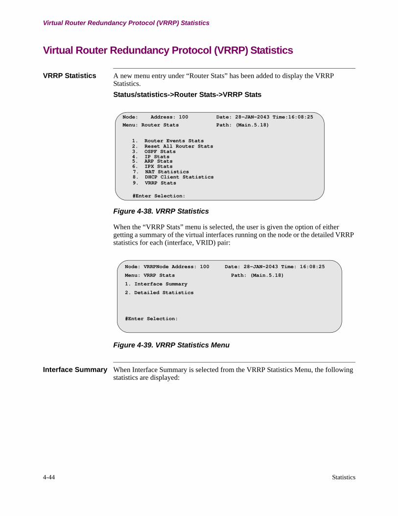
4-44 Statistics
Virtual Router Redundancy Protocol (VRRP) Statistics
Virtual Router Redundancy Protocol (VRRP) Statistics
VRRP Statistics A new menu entry under “Router Stats” has been added to display the VRRP Statistics.
Status/statistics->Router Stats->VRRP Stats
Figure 4-38. VRRP Statistics
When the “VRRP Stats” menu is selected, the user is given the option of either getting a summary of the virtual interfaces running on the node or the detailed VRRP statistics for each (interface, VRID) pair:
Figure 4-39. VRRP Statistics Menu
Interface Summary When Interface Summary is selected from the VRRP Statistics Menu, the following statistics are displayed:
Node: Address: 100 Date: 28-JAN-2043 Time:16:08:25
Menu: Router Stats Path: (Main.5.18)
1. Router Events Stats 2. Reset All Router Stats
4. IP Stats 5. ARP Stats
7. NAT Statistics 8. DHCP Client Statistics
#Enter Selection:
9. VRRP Stats
3. OSPF Stats
6. IPX Stats
Node: VRRPNode Address: 100 Date: 28-JAN-2043 Time: 16:08:25
Menu: VRRP Stats Path: (Main.5.18)
1. Interface Summary
2. Detailed Statistics
#Enter Selection:

Statistics 4-45
T0100-03, Revision V Release 7.3
Virtual Router Redundancy Protocol (VRRP) Statistics
Figure 4-40. Interface Summary Statistics
VRRP Interface Summary Screen Terms
The table below provides a description of the VRRP Interface Summary statistics displayed:
Detailed Statistics When display “Detailed Statistics” is selected VRRP Statistics Menu, the user is prompted for an interface number and VRID of the virtual router running on that interface. After entering the prompts, the following statistics are displayed:
Node: VRRPNode Address: 100 Date: 28-JAN-2043 Time: 16:08:25
Menu: Interface Summary Path: (Main.5.18)
If# VRID Priority Preemption State Master addr Virtual addr
1 255 255 Enabled Master 255.255.255.255 255.255.255.255
2 1 100 Enabled Backup 255.255.255.255 255.255.255.255
3 2 100 Disabled Master 255.255.255.255 255.255.255.255
4 30 110 Enabled Backup 255.255.255.255 255.255.255.255
5 1 255 Enabled Master 255.255.255.255 255.255.255.255
#Enter Selection:
Screen Term Description
If# The Ethernet Interface number.
VRID The VRID of the virtual router operating on the interface.
Priority The running priority of the router. If the router owns the virtual IP, it would be 255, otherwise it would correspond to the configured priority value.
Preemption This field indicates whether the router is running with preemption enabled.
State The current state of the VRRP router (MASTER, BACKUP or INITIALIZE).
Master addr The real IP Address of the master router. This is the primary address of the master that is sent as the source address in VRRP advertisements.
Virtual addr The virtual address that the router is supporting on this group. If multiple addresses are configured, only the first address is displayed.
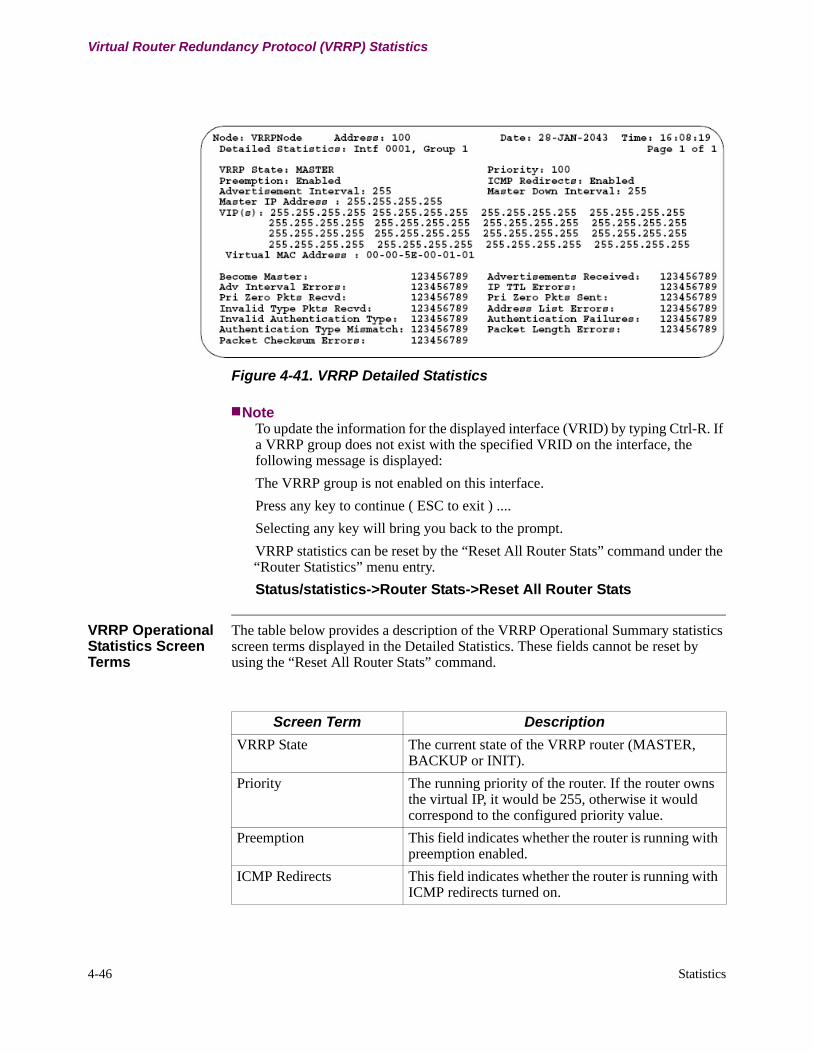
4-46 Statistics
Virtual Router Redundancy Protocol (VRRP) Statistics
Figure 4-41. VRRP Detailed Statistics
NoteTo update the information for the displayed interface (VRID) by typing Ctrl-R. If a VRRP group does not exist with the specified VRID on the interface, the following message is displayed:
The VRRP group is not enabled on this interface.
Press any key to continue ( ESC to exit ) ....
Selecting any key will bring you back to the prompt.
VRRP statistics can be reset by the “Reset All Router Stats” command under the “Router Statistics” menu entry.
Status/statistics->Router Stats->Reset All Router Stats
VRRP Operational Statistics Screen Terms
The table below provides a description of the VRRP Operational Summary statistics screen terms displayed in the Detailed Statistics. These fields cannot be reset by using the “Reset All Router Stats” command.
Screen Term Description
VRRP State The current state of the VRRP router (MASTER, BACKUP or INIT).
Priority The running priority of the router. If the router owns the virtual IP, it would be 255, otherwise it would correspond to the configured priority value.
Preemption This field indicates whether the router is running with preemption enabled.
ICMP Redirects This field indicates whether the router is running with ICMP redirects turned on.

Statistics 4-47
T0100-03, Revision V Release 7.3
Virtual Router Redundancy Protocol (VRRP) Statistics
VRRP Counters The table below describes the counters that are used for statistical purposes. They can be reset by using the “Reset All Router Stats” command.
Advertisement Interval The advertisement interval used by the router to send advertisements if it is MASTER. If the router is a BACKUP router, this value indicates the advertisement interval it uses to compute the master down interval.
Master Down Interval The time interval used by the backup router for receiving advertisements from the master. If it does not receive an advertisement within this interval, it designates the master router as being down.
Master IP Address The real IP Address of the master router. This is the primary (real) address of the master that is advertised as the source address in the VRRP advertisements.
VIP(s) The virtual address(es) that the router is supporting on this group.
Virtual MAC Address The Virtual MAC address that the router sends in response to ARP queries for the virtual IP.
Screen Term Description
Screen Term Description
Become Master The number of times the VRRP router has transitioned to MASTER.
Advertisements Received The total number of VRRP advertisements received by the router.
Advertisement Interval Errors
The total number of advertisements received for which the advertisement interval is different from the advertisement interval configured on the local router.
IP TTL Errors The number of TTL errors in the IP packet. This counter is incremented when the virtual router receives a VRRP packet with TTL not equal to 255.
Pri Zero pkts recvd The number of advertisements received with a priority of 0.
Pri Zero pkts sent The number of advertisements received with a priority of 0. A priority 0 advertisement is sent when the master wishes to relinquish its MASTER status.
Invalid Type Pkts Recvd The number of VRRP packets received by the virtual router with an invalid value in the 'type' type. Since Vanguard only supports VRRP 2, any packet received with a type value not equal to 2 will be logged and discarded.
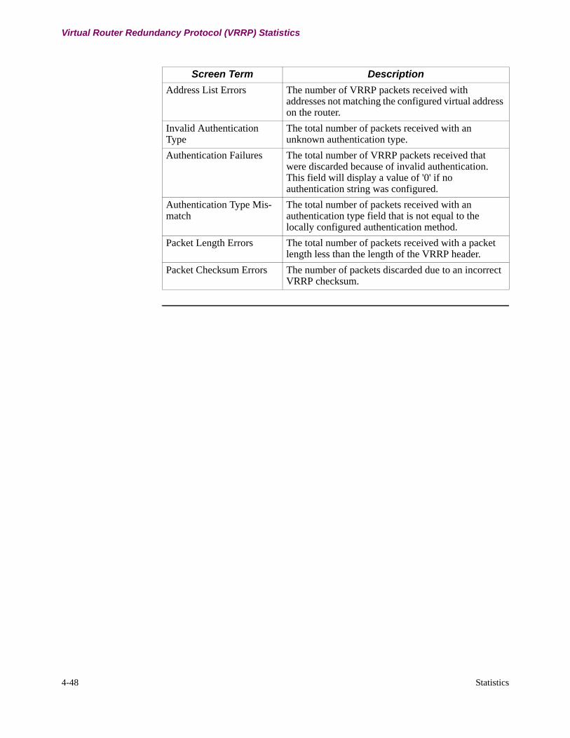
4-48 Statistics
Virtual Router Redundancy Protocol (VRRP) Statistics
Address List Errors The number of VRRP packets received with addresses not matching the configured virtual address on the router.
Invalid Authentication Type
The total number of packets received with an unknown authentication type.
Authentication Failures The total number of VRRP packets received that were discarded because of invalid authentication. This field will display a value of '0' if no authentication string was configured.
Authentication Type Mis-match
The total number of packets received with an authentication type field that is not equal to the locally configured authentication method.
Packet Length Errors The total number of packets received with a packet length less than the length of the VRRP header.
Packet Checksum Errors The number of packets discarded due to an incorrect VRRP checksum.
Screen Term Description
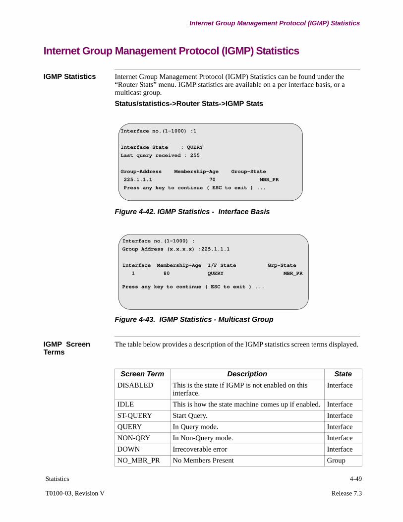
Statistics 4-49
T0100-03, Revision V Release 7.3
Internet Group Management Protocol (IGMP) Statistics
Internet Group Management Protocol (IGMP) Statistics
IGMP Statistics Internet Group Management Protocol (IGMP) Statistics can be found under the “Router Stats” menu. IGMP statistics are available on a per interface basis, or a multicast group.
Status/statistics->Router Stats->IGMP Stats
Figure 4-42. IGMP Statistics - Interface Basis
Figure 4-43. IGMP Statistics - Multicast Group
IGMP Screen Terms
The table below provides a description of the IGMP statistics screen terms displayed.
Interface no.(1-1000) :1
Interface State : QUERY
Last query received : 255
Group-Address Membership-Age Group-State
225.1.1.1 70 MBR_PR
Press any key to continue ( ESC to exit ) ...
Interface no.(1-1000) :
Group Address (x.x.x.x) :225.1.1.1
Interface Membership-Age I/F State Grp-State
1 80 QUERY MBR_PR
Press any key to continue ( ESC to exit ) ...
Screen Term Description State
DISABLED This is the state if IGMP is not enabled on this interface.
Interface
IDLE This is how the state machine comes up if enabled. Interface
ST-QUERY Start Query. Interface
QUERY In Query mode. Interface
NON-QRY In Non-Query mode. Interface
DOWN Irrecoverable error Interface
NO_MBR_PR No Members Present Group

4-50 Statistics
Internet Group Management Protocol (IGMP) Statistics
MBR-PR Members Present Group
CHK_MBR This state is entered when the leave group is received.
Group
V1_MBR_PR Version 1 Host Present on this interface. Group
Screen Term Description State

Statistics 4-51
T0100-03, Revision V Release 7.3
Distance Vector Multicast Routing Protocol (DVMRP) Statistics
Distance Vector Multicast Routing Protocol (DVMRP) Statistics
DVMRP Statistics Distance Vector Multicast Routing Protocol (DVMRP) Statistics can be found under the “Router Stats” menu.
Status/statistics->Router Stats->DVMRP Stats
Figure 4-44. DVMRP Statistics
Circuit Table Figure 4-45 shows the Circuit Table statistics:
Figure 4-45. Circuit Table Statistics
Node: Address: Date: Time:Menu: DVMRP Stats Path:
Circuit TableNeighbors TableUnicast Routing TableMulticast Forwarding Table
Node: 300 Address: 300 Date: 10-MAR-2003 Time: 18:19:10 DVMRP Circuit Statistics Table
Circuit Next Circuit Num Mcast Pkts Rtes RptIdentity Status Line Probe Update Genid NBRs In Out FilteredNet-1 Up Up 10 45 0x0a120e19 0 0 16040 0LCON-1 Up Up 2 17 0x0a120e07 1 16080 0 0LCON-2 Up Up 3 18 0x0a120e07 1 0 0 0LCON-3 Up Up 4 19 0x0a120e07 1 0 0 0LCON-4 Up Up 5 20 0x0a120e07 1 0 0 0LCON-5 Up Up 6 21 0x0a120e07 1 0 0 0LCON-6 Up Up 7 22 0x0a120e07 1 0 0 0LCON-7 Up Up 8 23 0x0a120e07 1 0 0 0LCON-8 Up Up 9 24 0x0a120e07 1 0 0 0LCON-9 Up Up 10 25 0x0a120e07 1 0 0 0LCON-10 Up Up 1 26 0x0a120e07 1 0 0 0LCON-11 Up Up 2 27 0x0a120e07 1 740 0 0LCON-12 Up Up 3 28 0x0a120e07 1 0 0 0LCON-13 Up Up 4 29 0x0a120e07 1 0 0 0LCON-14 Up Up 5 30 0x0a120e07 1 0 0 0LCON-15 Up Up 6 31 0x0a120e07 1 0 0 0LCON-16 Up Up 7 32 0x0a120e07 1 0 0 0LCON-17 Up Up 8 33 0x0a120e07 1 0 0 0 Press any key to continue ( ESC to exit ) ...
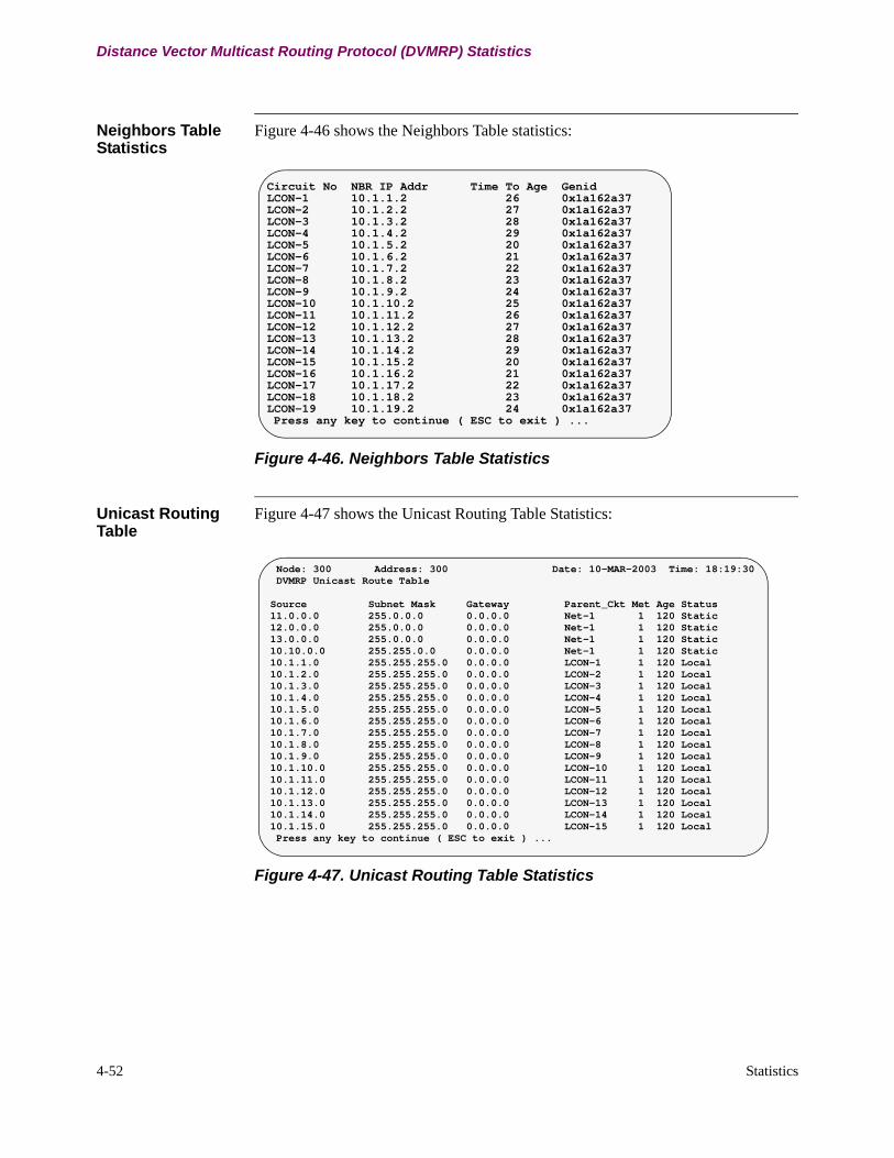
4-52 Statistics
Distance Vector Multicast Routing Protocol (DVMRP) Statistics
Neighbors Table Statistics
Figure 4-46 shows the Neighbors Table statistics:
Figure 4-46. Neighbors Table Statistics
Unicast Routing Table
Figure 4-47 shows the Unicast Routing Table Statistics:
Figure 4-47. Unicast Routing Table Statistics
Circuit No NBR IP Addr Time To Age GenidLCON-1 10.1.1.2 26 0x1a162a37LCON-2 10.1.2.2 27 0x1a162a37LCON-3 10.1.3.2 28 0x1a162a37LCON-4 10.1.4.2 29 0x1a162a37LCON-5 10.1.5.2 20 0x1a162a37LCON-6 10.1.6.2 21 0x1a162a37LCON-7 10.1.7.2 22 0x1a162a37LCON-8 10.1.8.2 23 0x1a162a37LCON-9 10.1.9.2 24 0x1a162a37LCON-10 10.1.10.2 25 0x1a162a37LCON-11 10.1.11.2 26 0x1a162a37LCON-12 10.1.12.2 27 0x1a162a37LCON-13 10.1.13.2 28 0x1a162a37LCON-14 10.1.14.2 29 0x1a162a37LCON-15 10.1.15.2 20 0x1a162a37LCON-16 10.1.16.2 21 0x1a162a37LCON-17 10.1.17.2 22 0x1a162a37LCON-18 10.1.18.2 23 0x1a162a37LCON-19 10.1.19.2 24 0x1a162a37 Press any key to continue ( ESC to exit ) ...
Node: 300 Address: 300 Date: 10-MAR-2003 Time: 18:19:30 DVMRP Unicast Route Table
Source Subnet Mask Gateway Parent_Ckt Met Age Status11.0.0.0 255.0.0.0 0.0.0.0 Net-1 1 120 Static12.0.0.0 255.0.0.0 0.0.0.0 Net-1 1 120 Static13.0.0.0 255.0.0.0 0.0.0.0 Net-1 1 120 Static10.10.0.0 255.255.0.0 0.0.0.0 Net-1 1 120 Static10.1.1.0 255.255.255.0 0.0.0.0 LCON-1 1 120 Local10.1.2.0 255.255.255.0 0.0.0.0 LCON-2 1 120 Local10.1.3.0 255.255.255.0 0.0.0.0 LCON-3 1 120 Local10.1.4.0 255.255.255.0 0.0.0.0 LCON-4 1 120 Local10.1.5.0 255.255.255.0 0.0.0.0 LCON-5 1 120 Local10.1.6.0 255.255.255.0 0.0.0.0 LCON-6 1 120 Local10.1.7.0 255.255.255.0 0.0.0.0 LCON-7 1 120 Local10.1.8.0 255.255.255.0 0.0.0.0 LCON-8 1 120 Local10.1.9.0 255.255.255.0 0.0.0.0 LCON-9 1 120 Local10.1.10.0 255.255.255.0 0.0.0.0 LCON-10 1 120 Local10.1.11.0 255.255.255.0 0.0.0.0 LCON-11 1 120 Local10.1.12.0 255.255.255.0 0.0.0.0 LCON-12 1 120 Local10.1.13.0 255.255.255.0 0.0.0.0 LCON-13 1 120 Local10.1.14.0 255.255.255.0 0.0.0.0 LCON-14 1 120 Local10.1.15.0 255.255.255.0 0.0.0.0 LCON-15 1 120 Local Press any key to continue ( ESC to exit ) ...

Statistics 4-53
T0100-03, Revision V Release 7.3
Distance Vector Multicast Routing Protocol (DVMRP) Statistics
Multicast Forwarding Table
The multicast forwarding table display can be filtered to display only the routes or multicast groups of interest. The user is prompted for Source IP Address, Subnet Mask and Multicast Group.
The following table defines the information displayed:
Specific Source Address Entry
Figure 4-48 shows a specific source address entry:
Figure 4-48. Specific Source Address Entry
Source Mask Multicast Group Displayed
0.0.0.0 (default) Ignored 0.0.0.0 (default) All source routes with multicast groups are displayed.
0.0.0.0 (default) Ignored specific address All source routes with the specific group are displayed.
specific/subnet address
0.0.0.0 (default) 0.0.0.0 (default) Matching subnet routes with/without multicast groups are displayed.
specific/subnetaddress
0.0.0.0 (default) specific address Matching subnet routes with/without specific multicast groups are displayed. Error messages appear if specific groups are not found.
specific addr specific mask 0.0.0.0 (default) Specific matching route with/without multicast groups are displayed.
specific addr specific mask specific addr Specific matching route with/without specific multicast groups are displayed. Error messages appear if specific groups are not found.
Enter IP Address (def: 0.0.0.0) >>192.168.2.0 Enter IP Subnet Mask (def: 0.0.0.0) >> Enter IP Multicast Addr (def: 0.0.0.0) >> Node: 300 Address: 300 Date: 10-MAR-2003 Time: 18:20:26 DVMRP Current Forwarding Table
Source Subnet Mask Gateway Parent_Ckt Met Age Status192.168.2.0 255.255.255.0 10.1.1.2 LCON-1 2 60 Dyn_Reach Group Address :225.1.1.1 Entry Status :Dynamic Out LAN Interfaces :1 Out LCONs : Group ageouts after :25 Was Prune Sent Upstream :NO Was Graft Sent Upstream :NO
Routes printed: 1 Groups printed: 1 Press any key to continue ( ESC to exit ) ...

4-54 Statistics
Distance Vector Multicast Routing Protocol (DVMRP) Statistics
Specific Group Entry
Figure 4-49 shows a specific group entry:
Figure 4-49. Specific Group Entry
Enter IP Address (def: 0.0.0.0) Enter IP Subnet Mask (def: 0.0.0.0) Enter IP Multicast Addr (def: 0.0.0.0) 225.1.1.1Press "C" for continuous display or any other key for paged display
Node: 300 Address: 300 Date: 10-MAR-2003 Time: 18:20:52 DVMRP Current Forwarding Table
Source Subnet Mask Gateway Parent_Ckt Met Age Status11.0.0.0 255.0.0.0 0.0.0.0 Net-1 1 120 Static Group Address :225.1.1.1 Entry Status :Static Out LAN Interfaces :1 Out LCONs :1,3,5-7,90 Group ageouts after :25 Was Prune Sent Upstream :NO Was Graft Sent Upstream :NO192.168.2.0 255.255.255.0 10.1.1.2 LCON-1 2 94 Dyn_Reach Group Address :225.1.1.1 Entry Status :Dynamic Out LAN Interfaces :1 Out LCONs : Group ageouts after :25 Was Prune Sent Upstream :NO Was Graft Sent Upstream :NORoutes printed: 2 Groups printed: 2Press any key to continue ( ESC to exit ) ...
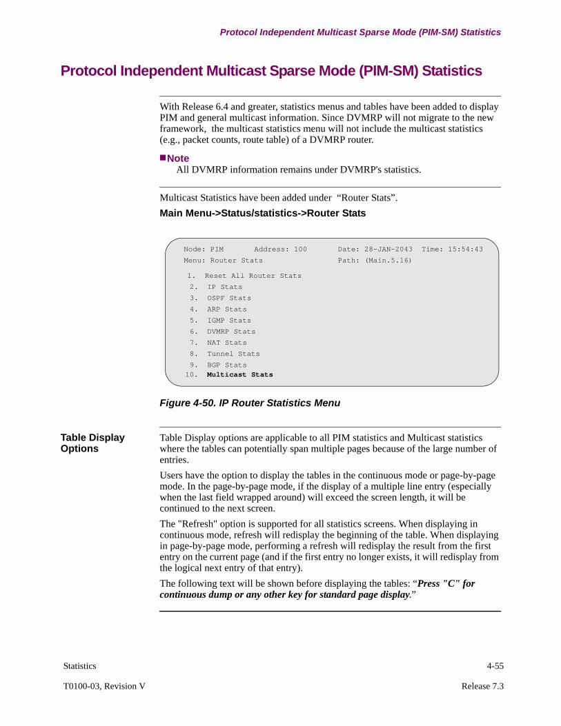
Statistics 4-55
T0100-03, Revision V Release 7.3
Protocol Independent Multicast Sparse Mode (PIM-SM) Statistics
Protocol Independent Multicast Sparse Mode (PIM-SM) Statistics
With Release 6.4 and greater, statistics menus and tables have been added to display PIM and general multicast information. Since DVMRP will not migrate to the new framework, the multicast statistics menu will not include the multicast statistics (e.g., packet counts, route table) of a DVMRP router.
NoteAll DVMRP information remains under DVMRP's statistics.
Multicast Statistics have been added under “Router Stats”.
Main Menu->Status/statistics->Router Stats
Figure 4-50. IP Router Statistics Menu
Table Display Options
Table Display options are applicable to all PIM statistics and Multicast statistics where the tables can potentially span multiple pages because of the large number of entries.
Users have the option to display the tables in the continuous mode or page-by-page mode. In the page-by-page mode, if the display of a multiple line entry (especially when the last field wrapped around) will exceed the screen length, it will be continued to the next screen.
The "Refresh" option is supported for all statistics screens. When displaying in continuous mode, refresh will redisplay the beginning of the table. When displaying in page-by-page mode, performing a refresh will redisplay the result from the first entry on the current page (and if the first entry no longer exists, it will redisplay from the logical next entry of that entry).
The following text will be shown before displaying the tables: “Press "C" for continuous dump or any other key for standard page display.”
Node: PIM Address: 100 Date: 28-JAN-2043 Time: 15:54:43
Menu: Router Stats Path: (Main.5.16)
1. Reset All Router Stats
2. IP Stats
3. OSPF Stats
4. ARP Stats
5. IGMP Stats
6. DVMRP Stats
7. NAT Stats
8. Tunnel Stats
9. BGP Stats 10. Multicast Stats

4-56 Statistics
Protocol Independent Multicast Sparse Mode (PIM-SM) Statistics
Multicast Statistics
Introduction Multicast Statistics displays different general Multicast (not protocol specific) information. Packet counts, forwarding table information and routing table information is displayed.
Figure 4-51. Multicast Stats Menu
Multicast Forwarding Table
The Multicast Forwarding Table shows the routing entries kept by the Multicast Forwarding Table Manager. All the entries are Source, Group (S, G) entries and they are used for forwarding. No protocol information is attached (except for the associated register-interface). The Multicast Forwarding table includes routes from all protocols.
Users have different options in specifying and viewing the multicast route entries:
• Use specific source and wild card groups - (for example, S=10.1.1.1, G=0.0.0.0). This displays all the (S,G) entries for a given source in different groups. Note that these (S,G) entries are not related to one another, and the only thing they have in common is the same source S.
• Use specific source and specific group address (for example, S=10.1.1.1, G=224.0.255.3). This displays the (*,G) and that particular (S,G) route.
• Use wildcard source and specific group address (for example, S=0.0.0.0, G=224.0.255.3). This displays the (*,G) and all (S,G) routes the specified group.
• Use wildcard source and wild card groups (for example, S=0.0.0.0, G=0.0.0.0). This returns every multicast route.
Node: PIM Address: 100 Date: 28-JAN-2043 Time: 15:54:43
Menu: Multicast Stats Path: (Main.5.16.10)
1.Multicast Forwarding Table
2.Reset Multicast Forwarding Table
3.Multicast Forwarding Cache
4.Reset Multicast Forwarding Cache
5.PIM Stats
#Enter Selection:
Source Address
Range: IP Address
Default: 0.0.0.0
Description: The source address of this profile. It has to be either 0.0.0.0 or a unicast address.0.0.0.0 indicates that the profile applies to every source.
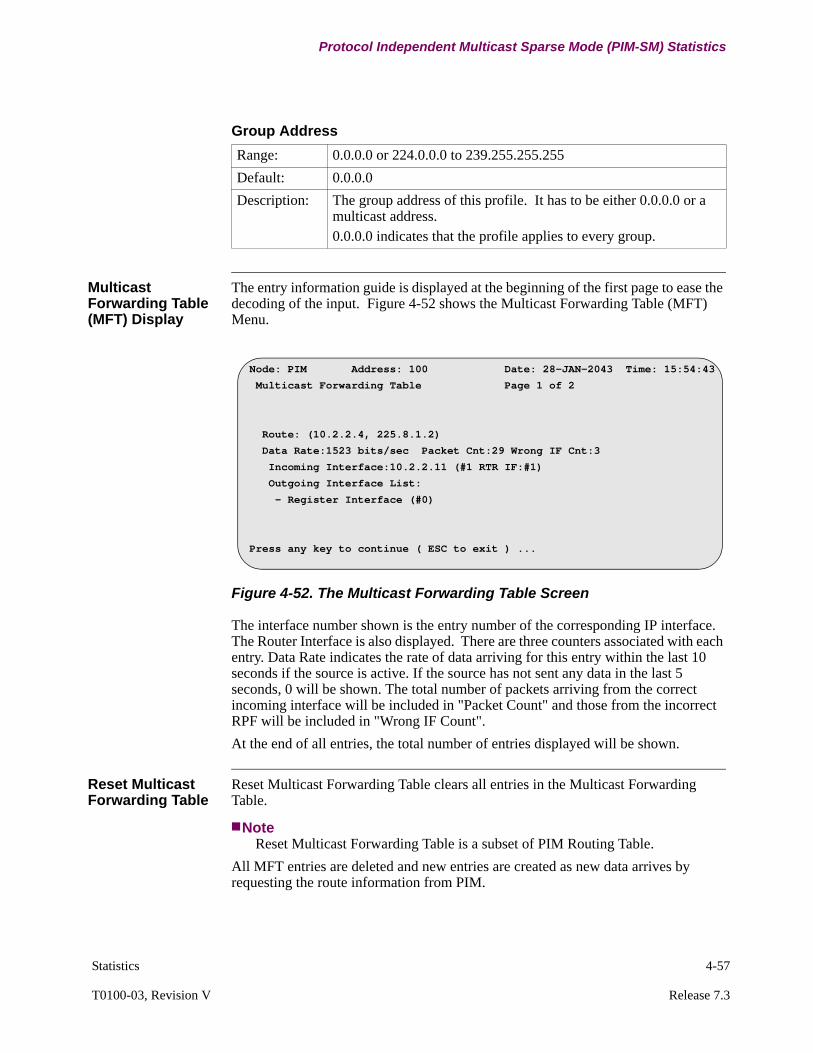
Statistics 4-57
T0100-03, Revision V Release 7.3
Protocol Independent Multicast Sparse Mode (PIM-SM) Statistics
Multicast Forwarding Table (MFT) Display
The entry information guide is displayed at the beginning of the first page to ease the decoding of the input. Figure 4-52 shows the Multicast Forwarding Table (MFT) Menu.
Figure 4-52. The Multicast Forwarding Table Screen
The interface number shown is the entry number of the corresponding IP interface. The Router Interface is also displayed. There are three counters associated with each entry. Data Rate indicates the rate of data arriving for this entry within the last 10 seconds if the source is active. If the source has not sent any data in the last 5 seconds, 0 will be shown. The total number of packets arriving from the correct incoming interface will be included in "Packet Count" and those from the incorrect RPF will be included in "Wrong IF Count".
At the end of all entries, the total number of entries displayed will be shown.
Reset Multicast Forwarding Table
Reset Multicast Forwarding Table clears all entries in the Multicast Forwarding Table.
NoteReset Multicast Forwarding Table is a subset of PIM Routing Table.
All MFT entries are deleted and new entries are created as new data arrives by requesting the route information from PIM.
Group Address
Range: 0.0.0.0 or 224.0.0.0 to 239.255.255.255
Default: 0.0.0.0
Description: The group address of this profile. It has to be either 0.0.0.0 or a multicast address.0.0.0.0 indicates that the profile applies to every group.
Node: PIM Address: 100 Date: 28-JAN-2043 Time: 15:54:43
Multicast Forwarding Table Page 1 of 2
Route: (10.2.2.4, 225.8.1.2)
Data Rate:1523 bits/sec Packet Cnt:29 Wrong IF Cnt:3
Incoming Interface:10.2.2.11 (#1 RTR IF:#1)
Outgoing Interface List:
- Register Interface (#0)
Press any key to continue ( ESC to exit ) ...
4-58 Statistics
Protocol Independent Multicast Sparse Mode (PIM-SM) Statistics
Multicast Forwarding Cache
Choosing Multicast Forwarding Cache will display the Multicast Forwarding Engine. It is a subset of the Multicast Forwarding Table. Multicast Forwarding Cache is protocol independent. All entries are Source, Group (S, G) entries and they are used for forwarding. No protocol information is attached (except the associated register-interface).
NoteThis is not the aggregated cache
Users have different options in specifying the multicast forwarding entry:
• Use specific source and wild card groups (for example, S=10.1.1.1, G=0.0.0.0). This displays all the (S,G) entries for a given source in different groups. Note that these (S,G) entries are not related to one another, and the only thing they have in common is the same source S.
• Use specific source and specific group address (for example, S=10.1.1.1, G=224.0.255.3). This displays only that particular (S,G) route.
• Use wildcard source and specific group address (for example, S=0.0.0.0, G=224.0.255.3). This displays all (S,G) routes the specified group.
• Use wildcard source and wild card groups (for example, S=0.0.0.0, G=0.0.0.0). This returns every entry in the Multicast Forwarding table.
Multicast Forwarding Cache Displayed
Figure 4-53 shows the Multicast Forwarding Cache Menu.
Source Address
Range: IP Address
Default: 0.0.0.0
Description: The source address of this profile. It has to be either 0.0.0.0 or a unicast address.0.0.0.0 indicates that the profile applies to every source.
Group Address
Range: 0.0.0.0 or 224.0.0.0 to 239.255.255.255
Default: 0.0.0.0
Description: The group address of this profile. It has to be either 0.0.0.0 or a multicast address.0.0.0.0 indicates that the profile applies to every group.
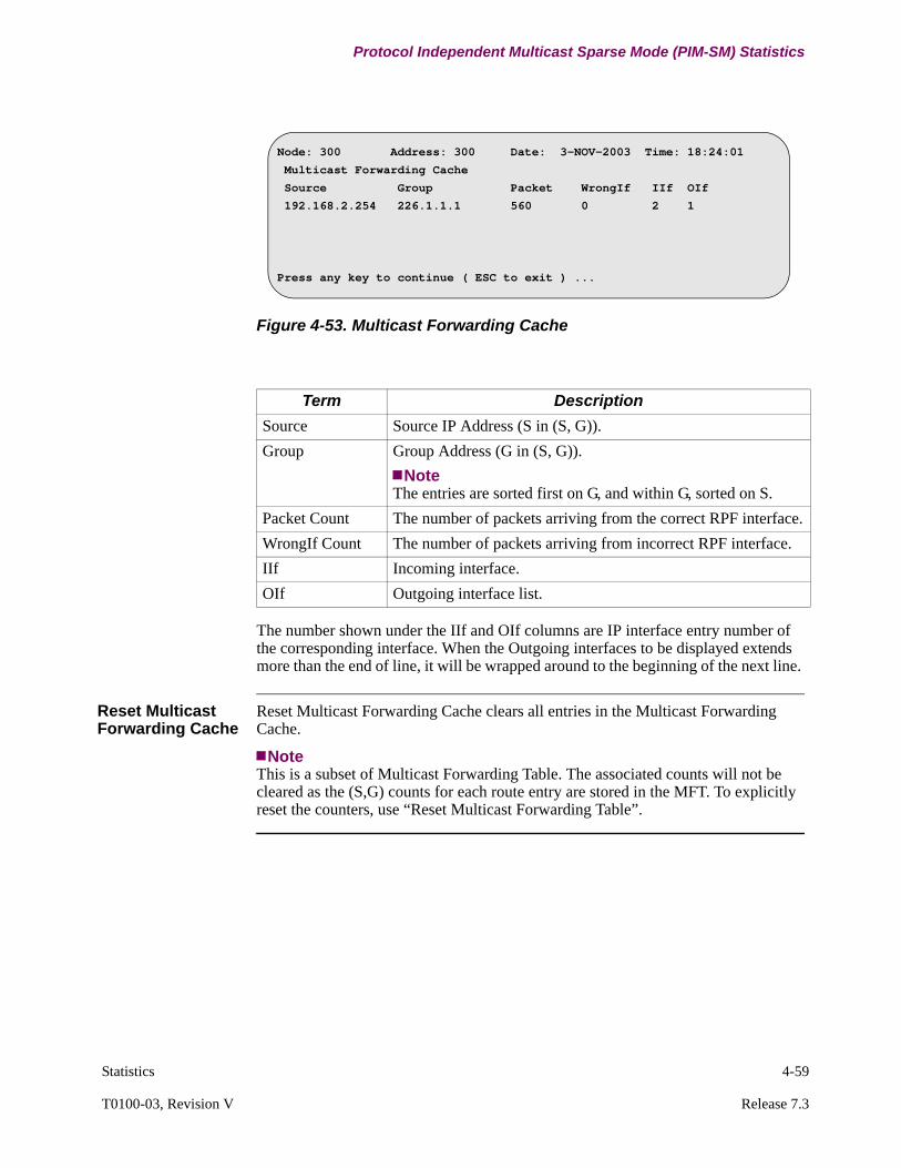
Statistics 4-59
T0100-03, Revision V Release 7.3
Protocol Independent Multicast Sparse Mode (PIM-SM) Statistics
Figure 4-53. Multicast Forwarding Cache
The number shown under the IIf and OIf columns are IP interface entry number of the corresponding interface. When the Outgoing interfaces to be displayed extends more than the end of line, it will be wrapped around to the beginning of the next line.
Reset Multicast Forwarding Cache
Reset Multicast Forwarding Cache clears all entries in the Multicast Forwarding Cache.
NoteThis is a subset of Multicast Forwarding Table. The associated counts will not be cleared as the (S,G) counts for each route entry are stored in the MFT. To explicitly reset the counters, use “Reset Multicast Forwarding Table”.
Node: 300 Address: 300 Date: 3-NOV-2003 Time: 18:24:01
Multicast Forwarding Cache
Source Group Packet WrongIf IIf OIf
192.168.2.254 226.1.1.1 560 0 2 1
Press any key to continue ( ESC to exit ) ...
Term Description
Source Source IP Address (S in (S, G)).
Group Group Address (G in (S, G)).
NoteThe entries are sorted first on G, and within G, sorted on S.
Packet Count The number of packets arriving from the correct RPF interface.
WrongIf Count The number of packets arriving from incorrect RPF interface.
IIf Incoming interface.
OIf Outgoing interface list.
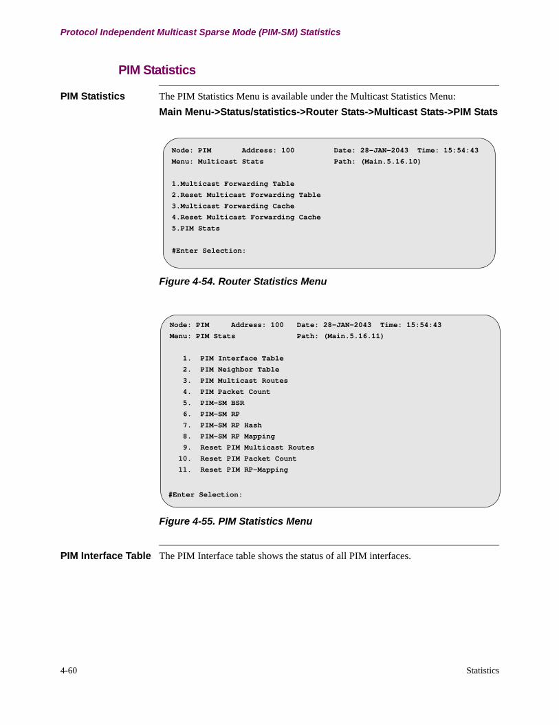
4-60 Statistics
Protocol Independent Multicast Sparse Mode (PIM-SM) Statistics
PIM Statistics
PIM Statistics The PIM Statistics Menu is available under the Multicast Statistics Menu:
Main Menu->Status/statistics->Router Stats->Multicast Stats->PIM Stats
Figure 4-54. Router Statistics Menu
Figure 4-55. PIM Statistics Menu
PIM Interface Table The PIM Interface table shows the status of all PIM interfaces.
Node: PIM Address: 100 Date: 28-JAN-2043 Time: 15:54:43
Menu: Multicast Stats Path: (Main.5.16.10)
1.Multicast Forwarding Table
2.Reset Multicast Forwarding Table
3.Multicast Forwarding Cache
4.Reset Multicast Forwarding Cache
5.PIM Stats
#Enter Selection:
Node: PIM Address: 100 Date: 28-JAN-2043 Time: 15:54:43
Menu: PIM Stats Path: (Main.5.16.11)
1. PIM Interface Table
2. PIM Neighbor Table
3. PIM Multicast Routes
4. PIM Packet Count
5. PIM-SM BSR
6. PIM-SM RP
7. PIM-SM RP Hash
8. PIM-SM RP Mapping
9. Reset PIM Multicast Routes
10. Reset PIM Packet Count
11. Reset PIM RP-Mapping
#Enter Selection:
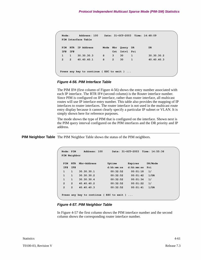
Statistics 4-61
T0100-03, Revision V Release 7.3
Protocol Independent Multicast Sparse Mode (PIM-SM) Statistics
Figure 4-56. PIM Interface Table
The PIM IF# (first column of Figure 4-56) shows the entry number associated with each IP interface. The RTR IF# (second column) is the Router interface number. Since PIM is configured on IP interface, rather than router interface, all multicast routes will use IP interface entry number. This table also provides the mapping of IP interfaces to router interfaces. The router interface is not used in the multicast route entry display because it cannot clearly specify a particular IP subnet or VLAN. It is simply shown here for reference purposes.
The mode shows the type of PIM that is configured on the interface. Shown next is the PIM query interval configured on the PIM interfaces and the DR priority and IP address.
PIM Neighbor Table The PIM Neighbor Table shows the status of the PIM neighbors.
Figure 4-57. PIM Neighbor Table
In Figure 4-57 the first column shows the PIM interface number and the second column shows the corresponding router interface number.
Node: Address: 100 Date: 31-OCT-2003 Time: 14:48:09
PIM Interface Table
PIM RTR IP Address Mode Nbr Query DR DR
IF# IF# Cnt Intvl Pri
1 1 30.30.30.3 S 3 30 1 30.30.30.2
2 2 40.40.40.1 S 2 30 1 40.40.40.3
Press any key to continue ( ESC to exit ) ...
Node: PIM Address: 100 Date: 31-OCT-2003 Time: 14:55:36
PIM Neighbor
PIM RTR Nbr-Address Uptime Expires DR/Mode
IF# IF# d:hh:mm:ss d:hh:mm:ss Pri
1 1 30.30.30.1 00:32:52 00:01:18 1/
1 1 30.30.30.2 00:32:52 00:01:42 1/DR
1 1 30.30.30.4 00:32:52 00:01:34 1/
2 2 40.40.40.2 00:32:52 00:01:22 1/
2 2 40.40.40.3 00:32:52 00:01:41 1/DR
Press any key to continue ( ESC to exit ) ...
4-62 Statistics
Protocol Independent Multicast Sparse Mode (PIM-SM) Statistics
The address of the neighbor is then displayed for that PIM interface. The list is first sorted on PIM interfaces and then on neighbor IP address. The next two columns are the uptime and the expiry time. The last column indicates the configured DR priority of the neighbor and whether the neighbor is a DR.
PIM Multicast Routes
The routing entries kept by PIM are shown below. Users have different options in specifying the Multicast Route entry.
• Use specific source and wild card groups (for example, S=10.1.1.1, G=0.0.0.0). This displays all the (S,G) entries for a given source in different groups. Note that these (S,G) entries are not related to one another, and the only thing they have in common is the same source S.
• Use specific source and specific group address (for example, S=10.1.1.1, G=224.0.255.3). This displays the (*,G) and that particular (S,G) route.
• Use wildcard source and specific group address (for example, S=0.0.0.0, G=224.0.255.3). This displays the (*,G) and all (S,G) routes the specified group.
• Use wildcard source and wild card groups (for example, S=0.0.0.0, G=0.0.0.0). This returns every multicast route.
Figure 4-58 and Figure 4-59 show page 1 and 2 of the Multicast Routing Table Screen. The entry information guide is displayed at the beginning of the first page to ease decoding the input.
Source Address
Range: IP Address
Default: 0.0.0.0
Description: The source address of this profile. It must be either 0.0.0.0 or a unicast address.0.0.0.0 indicates that the profile applies to every source.
Group Address
Range: 0.0.0.0 or 224.0.0.0 to 239.255.255.255
Default: 0.0.0.0
Description: The group address of this profile. It has to be either 0.0.0.0 or a multicast address. 0.0.0.0 indicates that the profile applies to every group.
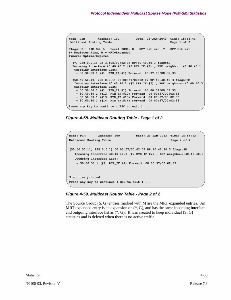
Statistics 4-63
T0100-03, Revision V Release 7.3
Protocol Independent Multicast Sparse Mode (PIM-SM) Statistics
Figure 4-58. Multicast Routing Table - Page 1 of 2
Figure 4-59. Multicast Router Table - Page 2 of 2
The Source Group (S, G) entries marked with M are the MRT expanded entries. An MRT expanded entry is an expansion on (*, G), and has the same incoming interface and outgoing interface list as (*, G). It was created to keep individual (S, G) statistics and is deleted when there is no active traffic.
Node: PIM Address: 100 Date: 28-JAN-2043 Time: 15:54:43 Multicast Routing Table Page 1 of 2
Flags: S - PIM-SM, L - Local IGMP, R - RPT-bit set, T - SPT-bit setF- Register Flag, M - MRT-ExpandedTimers: Uptime/Expires
(*, 228.0.0.1) 05:37:05/00:02:33 RP:40.40.40.3 flags:S Incoming Interface:40.40.40.2 (#2 RTR IF:#2) , RPF neighbour:40.40.40.1 Outgoing Interface List: - 30.30.30.1 (#1 RTR_IF:#1) Forward 05:37:05/00:02:33
(50.50.50.10, 228.0.0.1) 00:00:57/00:02:07 RP:40.40.40.3 flags:SM Incoming Interface:40.40.40.2 (#2 RTR IF:#2) , RPF neighbour:40.40.40.3 Outgoing Interface List: - 30.30.30.1 (#1 RTR_IF:#1) Forward 00:00:57/00:02:33 - 30.40.30.1 (#12 RTR_IF:#12) Forward 00:00:57/00:02:33 - 30.50.30.1 (#13 RTR_IF:#13) Forward 00:00:57/00:02:33 - 30.60.30.1 (#14 RTR_IF:#14) Forward 00:00:57/00:02:33
Press any key to continue ( ESC to exit ) ...
Node: PIM Address: 100 Date: 28-JAN-2043 Time: 15:54:43
Multicast Routing Table Page 2 of 2
(50.50.50.11, 228.0.0.1) 00:00:57/00:02:07 RP:40.40.40.3 flags:SM
Incoming Interface:40.40.40.2 (#2 RTR IF:#2) , RPF neighbour:40.40.40.3
Outgoing Interface List:
- 30.30.30.1 (#1 RTR_IF:#1) Forward 00:00:57/00:02:33
3 entries printed.
Press any key to continue ( ESC to exit ) ...
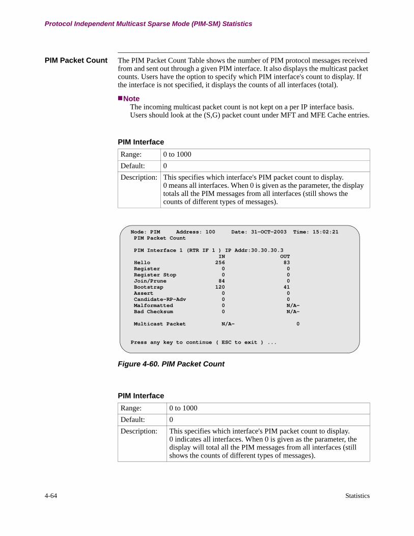
4-64 Statistics
Protocol Independent Multicast Sparse Mode (PIM-SM) Statistics
PIM Packet Count The PIM Packet Count Table shows the number of PIM protocol messages received from and sent out through a given PIM interface. It also displays the multicast packet counts. Users have the option to specify which PIM interface's count to display. If the interface is not specified, it displays the counts of all interfaces (total).
NoteThe incoming multicast packet count is not kept on a per IP interface basis. Users should look at the (S,G) packet count under MFT and MFE Cache entries.
Figure 4-60. PIM Packet Count
PIM Interface
Range: 0 to 1000
Default: 0
Description: This specifies which interface's PIM packet count to display. 0 means all interfaces. When 0 is given as the parameter, the display totals all the PIM messages from all interfaces (still shows the counts of different types of messages).
Node: PIM Address: 100 Date: 31-OCT-2003 Time: 15:02:21 PIM Packet Count
PIM Interface 1 (RTR IF 1 ) IP Addr:30.30.30.3 IN OUT Hello 256 83 Register 0 0 Register Stop 0 0 Join/Prune 84 0 Bootstrap 120 41 Assert 0 0 Candidate-RP-Adv 0 0 Malformatted 0 N/A- Bad Checksum 0 N/A-
Multicast Packet N/A- 0
Press any key to continue ( ESC to exit ) ...
PIM Interface
Range: 0 to 1000
Default: 0
Description: This specifies which interface's PIM packet count to display. 0 indicates all interfaces. When 0 is given as the parameter, the display will total all the PIM messages from all interfaces (still shows the counts of different types of messages).
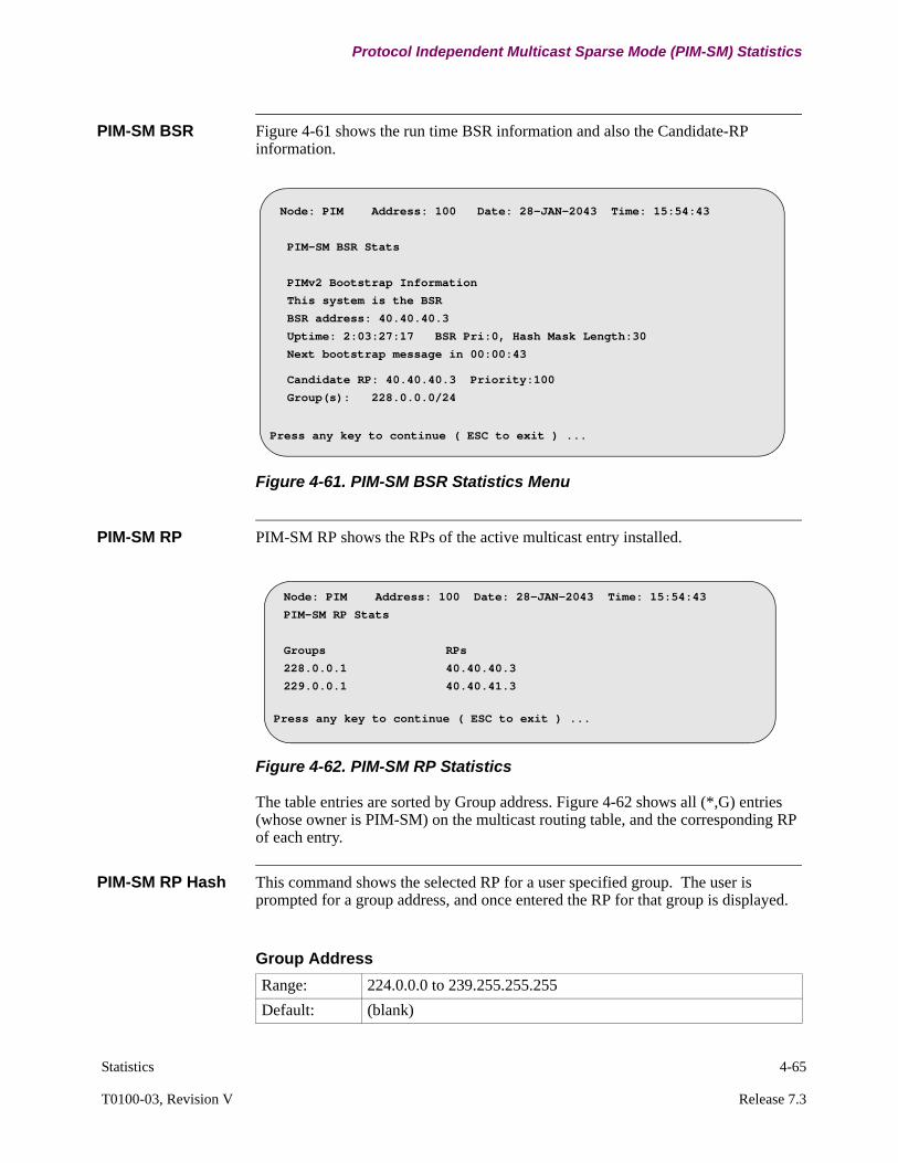
Statistics 4-65
T0100-03, Revision V Release 7.3
Protocol Independent Multicast Sparse Mode (PIM-SM) Statistics
PIM-SM BSR Figure 4-61 shows the run time BSR information and also the Candidate-RP information.
Figure 4-61. PIM-SM BSR Statistics Menu
PIM-SM RP PIM-SM RP shows the RPs of the active multicast entry installed.
Figure 4-62. PIM-SM RP Statistics
The table entries are sorted by Group address. Figure 4-62 shows all (*,G) entries (whose owner is PIM-SM) on the multicast routing table, and the corresponding RP of each entry.
PIM-SM RP Hash This command shows the selected RP for a user specified group. The user is prompted for a group address, and once entered the RP for that group is displayed.
Node: PIM Address: 100 Date: 28-JAN-2043 Time: 15:54:43
PIM-SM BSR Stats
PIMv2 Bootstrap Information
This system is the BSR
BSR address: 40.40.40.3
Uptime: 2:03:27:17 BSR Pri:0, Hash Mask Length:30
Next bootstrap message in 00:00:43
Candidate RP: 40.40.40.3 Priority:100
Group(s): 228.0.0.0/24
Press any key to continue ( ESC to exit ) ...
Node: PIM Address: 100 Date: 28-JAN-2043 Time: 15:54:43
PIM-SM RP Stats
Groups RPs
228.0.0.1 40.40.40.3
229.0.0.1 40.40.41.3
Press any key to continue ( ESC to exit ) ...
Group Address
Range: 224.0.0.0 to 239.255.255.255
Default: (blank)

4-66 Statistics
Protocol Independent Multicast Sparse Mode (PIM-SM) Statistics
PIM-SM RP Mapping
This command shows the RP set information the router receives from the BSR. It also includes statically configured RPs.
Figure 4-63. PIM-SM RP Mapping Menu
Figure 4-63 shows the Group to RP Mapping that the router currently has. It maps each group range to the corresponding RP(s) and displays each RP's priority. It also displays whether the RP is learned dynamically or statically configured. If the RP is learned dynamically, it also shows the IP address of BSR router (as the Info Source). If the RP is statically configured, it also shows its precedence (override or normal). For every RP displayed, it also shows the uptime and expiry time.
NoteThis table represents the RP-set information, and from this set of information, the RP selection and PIM-Hash function will be applied.
Reset PIM Multicast Routes
Reset PIM Multicast Routes resets all the PIM Multicast Routes. This command is generally not used because routes are lost. The routes would need to be relearned from neighbors.
Reset PIM Packet Count
Reset PIM Packet Count resets all packet counts associated with PIM and Multicast. The counters at the IP interface level will not be reset. Users can specify which interface's packet counts to reset. If 0 is given, the PIM packet counts for all PIM interfaces are reset.
Description: Group Address to lookup the RP for a given group.
Group Address
Node: PIM Address: 100 Date: 28-JAN-2043 Time: 15:54:43
PIM-SM RP Mapping
Dynamic Learned RP Set
Group(s): 227.0.0.0/24
RP 30.30.30.1 Priority:100
Info source: 30.30.30.1 via Bootstrap
Uptime:05:42:26, expires: 00:02:04
Group(s): 228.0.0.0/24
RP 40.40.40.3 Priority:100
Info source: 40.40.40.3 via Bootstrap
Uptime:05:42:26, expires: 00:01:08
Group(s): 230.0.0.0/24
RP 30.30.30.4 Priority:100
Info source: 30.30.30.4 via Bootstrap
Uptime:00:03:33, expires: 00:01:54
Press any key to continue ( ESC to exit ) ...
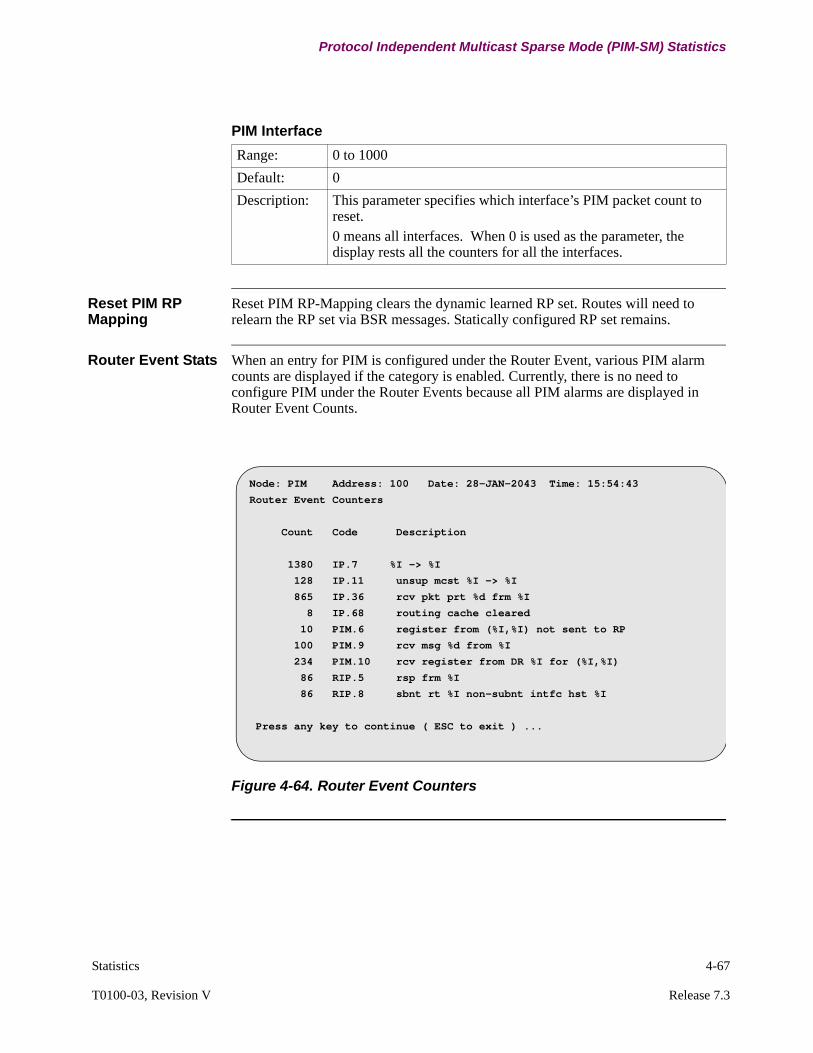
Statistics 4-67
T0100-03, Revision V Release 7.3
Protocol Independent Multicast Sparse Mode (PIM-SM) Statistics
Reset PIM RP Mapping
Reset PIM RP-Mapping clears the dynamic learned RP set. Routes will need to relearn the RP set via BSR messages. Statically configured RP set remains.
Router Event Stats When an entry for PIM is configured under the Router Event, various PIM alarm counts are displayed if the category is enabled. Currently, there is no need to configure PIM under the Router Events because all PIM alarms are displayed in Router Event Counts.
Figure 4-64. Router Event Counters
PIM Interface
Range: 0 to 1000
Default: 0
Description: This parameter specifies which interface’s PIM packet count to reset.0 means all interfaces. When 0 is used as the parameter, the display rests all the counters for all the interfaces.
Node: PIM Address: 100 Date: 28-JAN-2043 Time: 15:54:43
Router Event Counters
Count Code Description
1380 IP.7 %I -> %I
128 IP.11 unsup mcst %I -> %I
865 IP.36 rcv pkt prt %d frm %I
8 IP.68 routing cache cleared
10 PIM.6 register from (%I,%I) not sent to RP
100 PIM.9 rcv msg %d from %I
234 PIM.10 rcv register from DR %I for (%I,%I)
86 RIP.5 rsp frm %I
86 RIP.8 sbnt rt %I non-subnt intfc hst %I
Press any key to continue ( ESC to exit ) ...
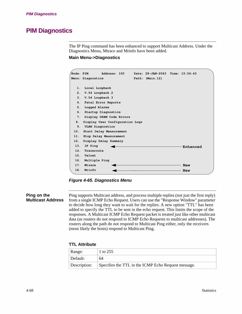
4-68 Statistics
PIM Diagnostics
PIM Diagnostics
The IP Ping command has been enhanced to support Multicast Address. Under the Diagnostics Menu, Mtrace and Mrinfo have been added.
Main Menu->Diagnostics
Figure 4-65. Diagnostics Menu
Ping on the Multicast Address
Ping supports Multicast address, and process multiple replies (not just the first reply) from a single ICMP Echo Request. Users can use the "Response Window" parameter to decide how long they want to wait for the replies. A new option "TTL" has been added to specify the TTL to be sent in the echo request. This limits the scope of the responses. A Multicast ICMP Echo Request packet is treated just like other multicast data (as routers do not respond to ICMP Echo Requests to multicast addresses). The routers along the path do not respond to Multicast Ping either, only the receivers (most likely the hosts) respond to Multicast Ping.
Node: PIM Address: 100 Date: 28-JAN-2043 Time: 15:54:43
Menu: Diagnostics Path: (Main.12)
1. Local Loopback
2. V.54 Loopback 2
3. V.54 Loopback 3
4. Fatal Error Reports
5. Logged Alarms
6. Startup Diagnostics
7. Display DRAM Code Errors
8. Display User Configuration Logs
9. VLAN Diagnostics
10. Start Delay Measurement
11. Stop Delay Measurement
12. Display Delay Summary
13. IP Ping
14. Traceroute
15. Telnet
16. Multiple Ping
17. Mtrace
18. Mrinfo
Enhanced
New
New
TTL Attribute
Range: 1 to 255
Default: 64
Description: Specifies the TTL in the ICMP Echo Request message.
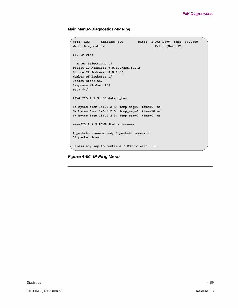
Statistics 4-69
T0100-03, Revision V Release 7.3
PIM Diagnostics
Main Menu->Diagnostics->IP Ping
Figure 4-66. IP Ping Menu
Node: ABC Address: 100 Date: 1-JAN-2000 Time: 0:00:80
Menu: Diagnostics Path: (Main.12)
…
13. IP Ping
…
Enter Selection: 13
Target IP Address: 0.0.0.0/225.1.2.3
Source IP Address: 0.0.0.0/
Number of Packets: 1/
Packet Size: 56/
Response Window: 1/5
TTL: 64/
PING 225.1.2.3: 56 data bytes
64 bytes from 191.1.2.3: icmp_seq=0. time=0. ms
64 bytes from 145.1.2.3: icmp_seq=0. time=10 ms
64 bytes from 156.1.2.3: icmp_seq=0. time=0. ms
----225.1.2.3 PING Statistics----
1 packets transmitted, 3 packets received,
0% packet loss
Press any key to continue ( ESC to exit ) ...
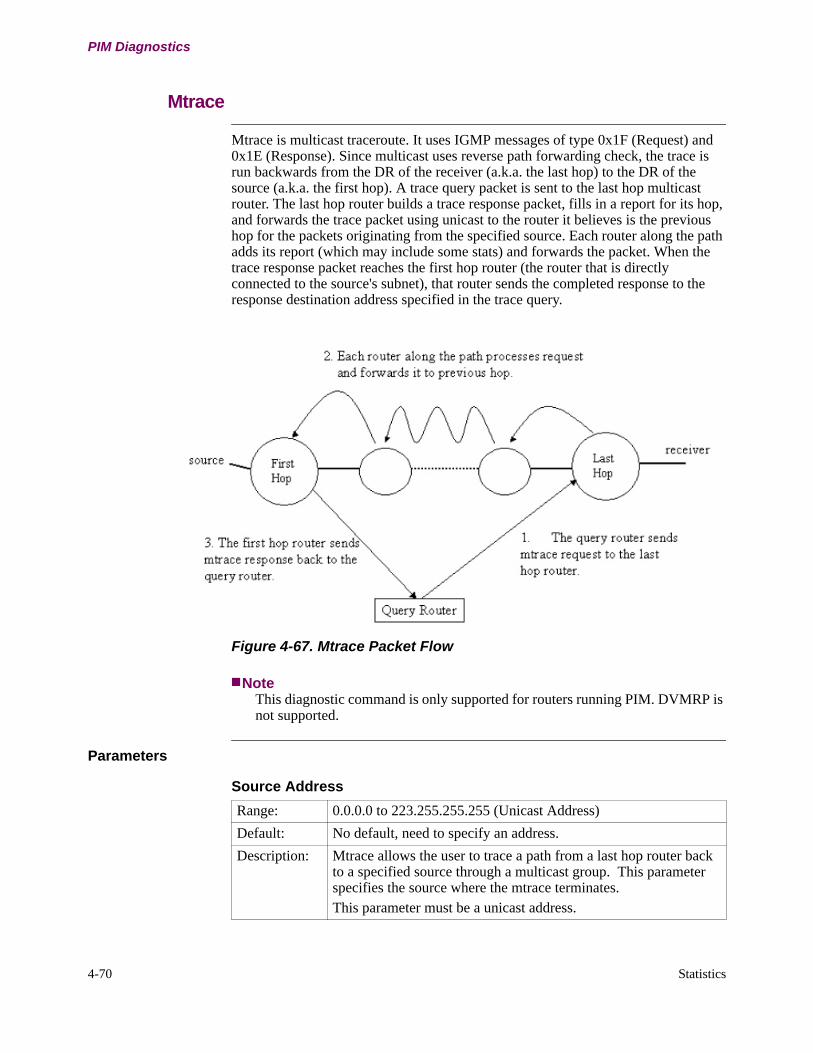
4-70 Statistics
PIM Diagnostics
Mtrace
Mtrace is multicast traceroute. It uses IGMP messages of type 0x1F (Request) and 0x1E (Response). Since multicast uses reverse path forwarding check, the trace is run backwards from the DR of the receiver (a.k.a. the last hop) to the DR of the source (a.k.a. the first hop). A trace query packet is sent to the last hop multicast router. The last hop router builds a trace response packet, fills in a report for its hop, and forwards the trace packet using unicast to the router it believes is the previous hop for the packets originating from the specified source. Each router along the path adds its report (which may include some stats) and forwards the packet. When the trace response packet reaches the first hop router (the router that is directly connected to the source's subnet), that router sends the completed response to the response destination address specified in the trace query.
Figure 4-67. Mtrace Packet Flow
NoteThis diagnostic command is only supported for routers running PIM. DVMRP is not supported.
Parameters
Source Address
Range: 0.0.0.0 to 223.255.255.255 (Unicast Address)
Default: No default, need to specify an address.
Description: Mtrace allows the user to trace a path from a last hop router back to a specified source through a multicast group. This parameter specifies the source where the mtrace terminates.This parameter must be a unicast address.

Statistics 4-71
T0100-03, Revision V Release 7.3
PIM Diagnostics
Max TTL If a multicast router along the path does not implement the multicast traceroute feature or if there is some outage, then no response is returned. To resolve this problem, the trace query includes a maximum hop count field to limit the number of hops traced before the response is returned. This allows a partial path to be traced.
Mtrace Figure 4-68 shows the multicast traceroute (mtrace) diagnostics:
Main Menu->Diagnostics->Mtrace
Destination Address
Range: 0.0.0.0 to 223.255.255.255 (Unicast Address)
Default: 0.0.0.0
Description: This parameter specifies the last hop router to begin the mtrace. 0.0.0.0 means the local router address is used.This parameter must be either 0.0.0.0 or a Unicast Address.
Group Address
Range: 0.0.0.0 to 224.0.0.1 to 239.255.255.255
Default: 0.0.0.0
Description: If 0.0.0.0 is used as the group address (the default case), a weak mtrace is performed. A weak mtrace is one that follows the RPF path to the source, regardless of whether any router along the path has multicast routing table state.
Max TTL
Range: 1 to 255
Default: 64
Description: This parameter indicates the maximum number of hops that will be traced from the last hop router back toward the source.

4-72 Statistics
PIM Diagnostics
Figure 4-68. Mtrace Diagnostics Menu
Node: Address: 100 Date: 1-JAN-2000 Time: 0:00:80
Menu: Diagnostics Path: (Main.12)
…
17. mtrace
…
Enter Selection: 17
Source Address: 0.0.0.0/10.1.1.7
Destination Address: 0.0.0.0/10.2.2.3
Group IP Address: 0.0.0.0/225.1.1.1
Maximum Time to Live: 30/
Mtrace from 10.1.1.7 to 10.2.2.3 via group 225.1.1.1
Querying full reverse path...
0 10.2.2.3
-1 10.2.2.3 PIM
-2 10.1.1.7
Press any key to continue ( ESC to exit ) ...
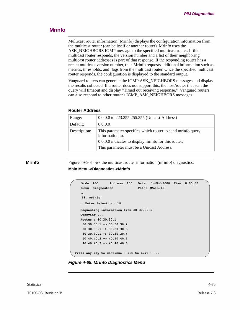
Statistics 4-73
T0100-03, Revision V Release 7.3
PIM Diagnostics
Mrinfo
Multicast router information (Mrinfo) displays the configuration information from the multicast router (can be itself or another router). Mrinfo uses the ASK_NEIGHBORS IGMP message to the specified multicast router. If this multicast router responds, the version number and a list of their neighboring multicast router addresses is part of that response. If the responding router has a recent multicast version number, then Mrinfo requests additional information such as metrics, thresholds, and flags from the multicast router. Once the specified multicast router responds, the configuration is displayed to the standard output.
Vanguard routers can generate the IGMP ASK_NEIGHBORS messages and display the results collected. If a router does not support this, the host/router that sent the query will timeout and display "Timed out receiving response." Vanguard routers can also respond to other router's IGMP_ASK_NEIGHBORS messages.
Mrinfo Figure 4-69 shows the multicast router information (mrinfo) diagnostics:
Main Menu->Diagnostics->Mrinfo
Figure 4-69. Mrinfo Diagnostics Menu
Router Address
Range: 0.0.0.0 to 223.255.255.255 (Unicast Address)
Default: 0.0.0.0
Description: This parameter specifies which router to send mrinfo query information to. 0.0.0.0 indicates to display mrinfo for this router.This parameter must be a Unicast Address.
Node: ABC Address: 100 Date: 1-JAN-2000 Time: 0:00:80
Menu: Diagnostics Path: (Main.12)
…
18. mrinfo
… Enter Selection: 18
Requesting information from 30.30.30.1
Querying ...
Router : 30.30.30.1 30.30.30.1 -> 30.30.30.2
30.30.30.1 -> 30.30.30.3
30.30.30.1 -> 30.30.30.4
40.40.40.2 -> 40.40.40.1
40.40.40.2 -> 40.40.40.3
Press any key to continue ( ESC to exit ) ...
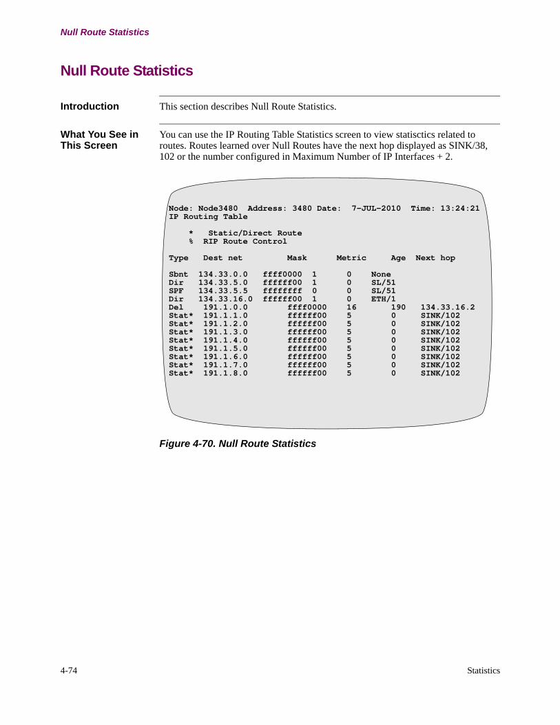
4-74 Statistics
Null Route Statistics
Null Route Statistics
Introduction This section describes Null Route Statistics.
What You See in This Screen
You can use the IP Routing Table Statistics screen to view statisctics related to routes. Routes learned over Null Routes have the next hop displayed as SINK/38, 102 or the number configured in Maximum Number of IP Interfaces + 2.
Figure 4-70. Null Route Statistics
Node: Node3480 Address: 3480 Date: 7-JUL-2010 Time: 13:24:21IP Routing Table
* Static/Direct Route % RIP Route Control
Type Dest net Mask Metric Age Next hop
Sbnt 134.33.0.0 ffff0000 1 0 NoneDir 134.33.5.0 ffffff00 1 0 SL/51SPF 134.33.5.5 ffffffff 0 0 SL/51Dir 134.33.16.0 ffffff00 1 0 ETH/1Del 191.1.0.0 ffff0000 16 190 134.33.16.2Stat* 191.1.1.0 ffffff00 5 0 SINK/102Stat* 191.1.2.0 ffffff00 5 0 SINK/102Stat* 191.1.3.0 ffffff00 5 0 SINK/102Stat* 191.1.4.0 ffffff00 5 0 SINK/102Stat* 191.1.5.0 ffffff00 5 0 SINK/102Stat* 191.1.6.0 ffffff00 5 0 SINK/102Stat* 191.1.7.0 ffffff00 5 0 SINK/102Stat* 191.1.8.0 ffffff00 5 0 SINK/102

Worksheets A-1
Appendix AWorksheets
Overview
Introduction This appendix provides worksheets you use to configure IP Routing.
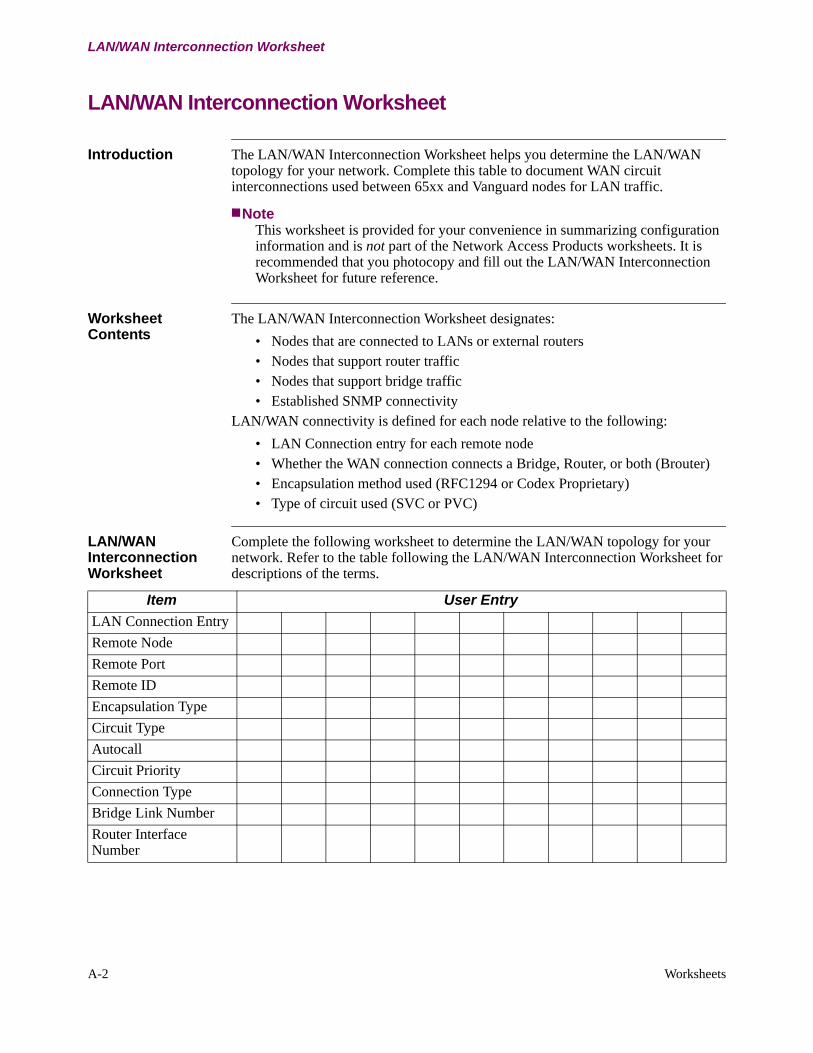
A-2 Worksheets
LAN/WAN Interconnection Worksheet
LAN/WAN Interconnection Worksheet
Introduction The LAN/WAN Interconnection Worksheet helps you determine the LAN/WAN topology for your network. Complete this table to document WAN circuit interconnections used between 65xx and Vanguard nodes for LAN traffic.
NoteThis worksheet is provided for your convenience in summarizing configuration information and is not part of the Network Access Products worksheets. It is recommended that you photocopy and fill out the LAN/WAN Interconnection Worksheet for future reference.
Worksheet Contents
The LAN/WAN Interconnection Worksheet designates:
• Nodes that are connected to LANs or external routers• Nodes that support router traffic• Nodes that support bridge traffic• Established SNMP connectivity
LAN/WAN connectivity is defined for each node relative to the following:
• LAN Connection entry for each remote node• Whether the WAN connection connects a Bridge, Router, or both (Brouter)• Encapsulation method used (RFC1294 or Codex Proprietary)• Type of circuit used (SVC or PVC)
LAN/WAN Interconnection Worksheet
Complete the following worksheet to determine the LAN/WAN topology for your network. Refer to the table following the LAN/WAN Interconnection Worksheet for descriptions of the terms.
Item User Entry
LAN Connection Entry
Remote Node
Remote Port
Remote ID
Encapsulation Type
Circuit Type
Autocall
Circuit Priority
Connection Type
Bridge Link Number
Router Interface Number
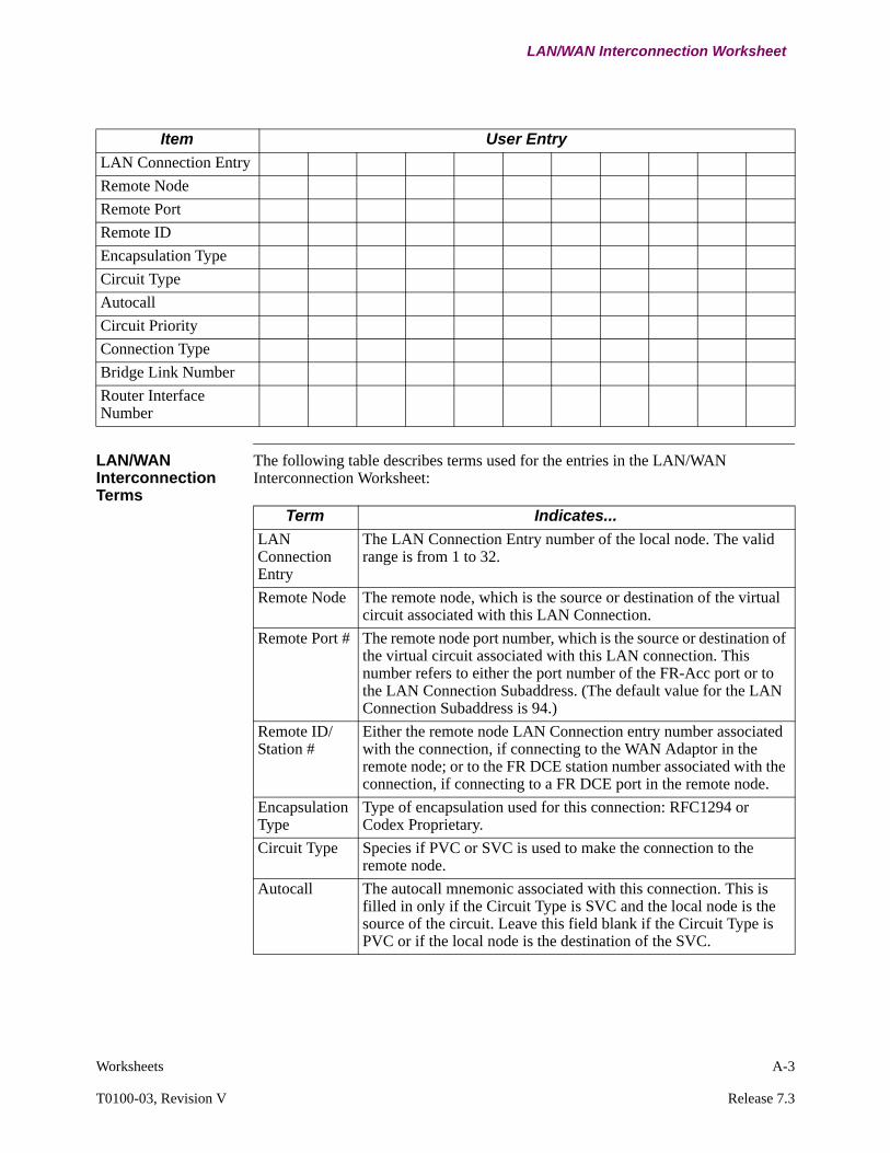
Worksheets A-3
T0100-03, Revision V Release 7.3
LAN/WAN Interconnection Worksheet
LAN/WAN Interconnection Terms
The following table describes terms used for the entries in the LAN/WAN Interconnection Worksheet:
Item User Entry
LAN Connection Entry
Remote Node
Remote Port
Remote ID
Encapsulation Type
Circuit Type
Autocall
Circuit Priority
Connection Type
Bridge Link Number
Router Interface Number
Term Indicates...
LAN Connection Entry
The LAN Connection Entry number of the local node. The valid range is from 1 to 32.
Remote Node The remote node, which is the source or destination of the virtual circuit associated with this LAN Connection.
Remote Port # The remote node port number, which is the source or destination of the virtual circuit associated with this LAN connection. This number refers to either the port number of the FR-Acc port or to the LAN Connection Subaddress. (The default value for the LAN Connection Subaddress is 94.)
Remote ID/Station #
Either the remote node LAN Connection entry number associated with the connection, if connecting to the WAN Adaptor in the remote node; or to the FR DCE station number associated with the connection, if connecting to a FR DCE port in the remote node.
Encapsulation Type
Type of encapsulation used for this connection: RFC1294 or Codex Proprietary.
Circuit Type Species if PVC or SVC is used to make the connection to the remote node.
Autocall The autocall mnemonic associated with this connection. This is filled in only if the Circuit Type is SVC and the local node is the source of the circuit. Leave this field blank if the Circuit Type is PVC or if the local node is the destination of the SVC.

A-4 Worksheets
LAN/WAN Interconnection Worksheet
Circuit Priority
The Data Traffic Priority for the SVC associated with this connection. This entry is used by the network port to determine the priority of data associated with this circuit related to other virtual circuits. Parameter options are EXPEDITE, HIGH, MEDIUM, or LOW. Leave blank if the Circuit Type is PVC.
Connection Type
Defines the type of traffic to go over the virtual circuit associated with this entry. This entry determines if this connection supports only bridge traffic (BRID); only router traffic (ROUT); or both bridge and router traffic (BROUT).
Local Bridge Link #
When Connection Type is BRID or BROUT, this is the Bridge Link number associated with this connection.When Connection Type is ROUT, this should be left blank.The valid range is 5 to 36.
Remote Bridge Link #
When Connection Type is BRID or BROUT, this is the Bridge Link number associated with this connection. When Connection Type is ROUT, this entry should be left blank. The valid range is 5 to 36.
Local Router Interface #
When Connection Type is ROUT or BROUT, this is the Router Interface number associated with this connection.When Connection Type is BRID, this should be left blank. The valid range is 5 to 36.
Remote Router Interface #
When Connection Type is ROUT or BROUT, this is the Router Interface number associated with this connection.When Connection Type is BRID, this should be left blank. The valid range is 5 to 36.
Term Indicates... (continued)

Worksheets A-5
T0100-03, Revision V Release 7.3
Configure Router Worksheets
Configure Router Worksheets
Configure Interface States
Node Name_____________Node Number_____________Date________________
Parameter Operator Entries
Interface #1 State
Interface #5 State
Interface #6 State
Interface #7 State
Interface #8 State
Interface 92 State
Interface #10 State
Interface #11 State
Interface #12 State
Interface #13 State
Interface #14 State
Interface #15 State
Interface #16 State
Interface #17 State
Interface #18 State
Interface #19 State
Interface #20 State
Interface #21 State
Interface #22 State
Interface #23 State
Interface #24 State
Interface #25 State
Interface #26 State
Interface #27 State
Interface #28 State
Interface #29 State
Interface #30 State
Interface #31 State
Interface #32 State
Interface #33 State
Interface #34 State
Interface #35 State
Interface #36 State
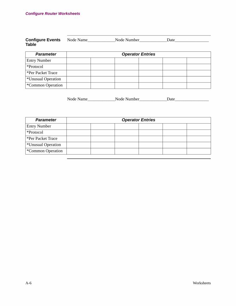
A-6 Worksheets
Configure Router Worksheets
Configure Events Table
Node Name_____________Node Number_____________Date________________
Node Name_____________Node Number_____________Date________________
Parameter Operator Entries
Entry Number
*Protocol
*Per Packet Trace
*Unusual Operation
*Common Operation
Parameter Operator Entries
Entry Number
*Protocol
*Per Packet Trace
*Unusual Operation
*Common Operation

Worksheets A-7
T0100-03, Revision V Release 7.3
Configure IP Worksheets
Configure IP Worksheets
Configure IP Parameters
Node Name_____________Node Number_____________Date________________
Configure IP Interface Configuration Table
Node Name_____________Node Number_____________Date________________
Parameter Operator Entries
*Internal IP Address
*Router ID
*Access Control
*RIP Enable
*Advertise Default Route
*Advertise Default Route Metric
*Default Gateway
*Default Gateway Metric
*Directed Broadcast
*IP Route Table Size
*IP Route Cache Size
*Reassembly Buffer Size
*BOOTP Forwarding
*BOOTP Max Allowed Metric
*BOOTP Seconds Before Forward
Parameter Operator Entries
*Entry Number
*Interface Number
*IP Address
*IP Address Mask
*Accept RIP
*Learn Network Routes
*Learn Subnet Routes
*Override Default Routes
*Override Static Routes
*Advertise Default Route
*Advertise Network Routes
*Advertise Subnet Routes

A-8 Worksheets
Configure IP Worksheets
Configure IP Filter Table
Node Name_____________Node Number_____________Date________________
Node Name_____________Node Number_____________Date________________
Node Name_____________Node Number_____________Date________________
*Advertise Static/Direct Routes
*Broadcast Style
*Broadcast Fill Pattern
Parameter Operator Entries
Parameter Operator Entries
*Entry Number
*Destination IP Address
*IP Address Mask
Parameter Operator Entries
*Entry Number
*Destination IP Address
*IP Address Mask
Parameter Operator Entries
*Entry Number
*Destination IP Address
*IP Address Mask
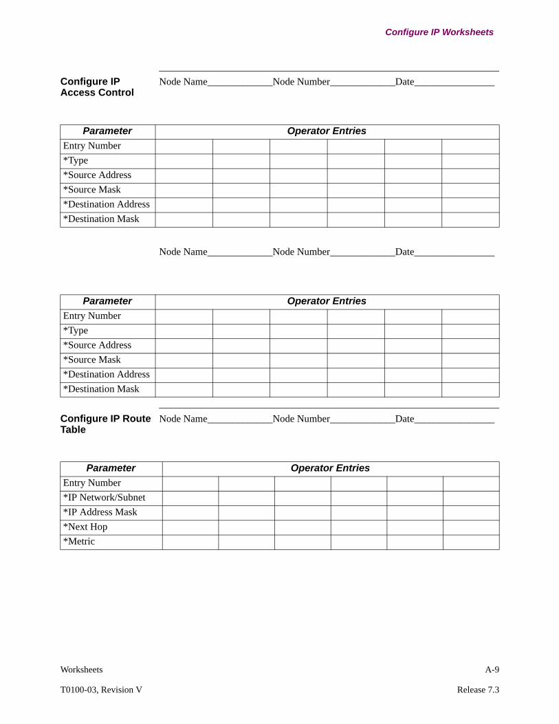
Worksheets A-9
T0100-03, Revision V Release 7.3
Configure IP Worksheets
Configure IP Access Control
Node Name_____________Node Number_____________Date________________
Node Name_____________Node Number_____________Date________________
Configure IP Route Table
Node Name_____________Node Number_____________Date________________
Parameter Operator Entries
Entry Number
*Type
*Source Address
*Source Mask
*Destination Address
*Destination Mask
Parameter Operator Entries
Entry Number
*Type
*Source Address
*Source Mask
*Destination Address
*Destination Mask
Parameter Operator Entries
Entry Number
*IP Network/Subnet
*IP Address Mask
*Next Hop
*Metric

A-10 Worksheets
Configure IP Worksheets
Node Name_____________Node Number_____________Date________________
Configure IP Default Subnet Gateway Table
Node Name_____________Node Number_____________Date________________
Node Name_____________Node Number_____________Date________________
Configure IP Accept RIP Route Table
Node Name_____________Node Number_____________Date________________
Parameter Operator Entries
Entry Number
*IP Network/Subnet
*IP Address Mask
*Next Hop
*Metric
Parameter Operator Entries
Entry Number
*Top-Level IP Net Address
*Next Hop to Subnet Gateway
*Metric to Subnet Gateway
Parameter Operator Entries
Entry Number
*Top-Level IP Net Address
*Next Hop to Subnet Gateway
*Metric to Subnet Gateway
Parameter Operator Entries
Entry Number
*IP Network/Subnet

Worksheets A-11
T0100-03, Revision V Release 7.3
Configure IP Worksheets
Node Name_____________Node Number_____________Date________________
Node Name_____________Node Number_____________Date________________
Configure IP BOOTP Server Table
Node Name_____________Node Number_____________Date________________
Node Name_____________Node Number_____________Date________________
Parameter Operator Entries
Entry Number
*IP Network/Subnet
Parameter Operator Entries
Entry Number
*IP Network/Subnet
Parameter Operator Entries
Entry Number
*BOOTP Server Address
Parameter Operator Entries
Entry Number
*BOOTP Server Address
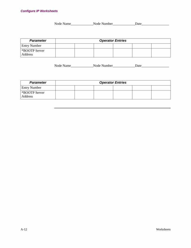
A-12 Worksheets
Configure IP Worksheets
Node Name_____________Node Number_____________Date________________
Node Name_____________Node Number_____________Date________________
Parameter Operator Entries
Entry Number
*BOOTP Server Address
Parameter Operator Entries
Entry Number
*BOOTP Server Address

Worksheets A-13
T0100-03, Revision V Release 7.3
Configure ARP Worksheets
Configure ARP Worksheets
Configure ARP Parameters
Node Name_____________Node Number_____________Date________________
Node Name_____________Node Number_____________Date________________
Configure ARP Cache Table
Node Name_____________Node Number_____________Date________________
Parameter Operator Entries
Interface Number
*Auto-Refresh
*Refresh Timeout
*Usage Timeout
*Proxy ARP
*Proxy ARP Subnets Only
Parameter Operator Entries
Interface Number
*Auto-Refresh
*Refresh Timeout
*Usage Timeout
*Proxy ARP
*Proxy ARP Subnets Only
Parameter Operator Entries
*Interface Number
*IP Address
*MAC Address

A-14 Worksheets
Configure ARP Worksheets
Node Name_____________Node Number_____________Date________________
Node Name_____________Node Number_____________Date________________
Parameter Operator Entries
*Interface Number
*IP Address
*MAC Address
Parameter Operator Entries
*Interface Number
*IP Address
*MAC Address

VSA Dictionary Files B-1
Appendix BVSA Dictionary Files
Overview
Introduction This appendix provides RADIUS dictionary files. VSA dictionary files for Cisco ACS and FreeRadius.

B-2 VSA Dictionary Files
RADIUS Dictionary Files - Cisco ACS
RADIUS Dictionary Files - Cisco ACS
Introduction Below lists the Server Side Vanguard dictionary files (Cisco ACS):
;[User Defined Vendor]
;
; The Name and IETF vendor code and any VSAs MUST be unique.
; Name=Acme 7000
; IETF Code=9999
;
; One or more VSAs named (max 255)
; VSA 1=acme-7000-encryption
; VSA 6=acme-7000-group
;
; Each named VSA requires a definition section…
;
; [acme-7000-encryption]
;
; Types are STRING, INTEGER, IPADDR
; Type=INTEGER
;
; The profile specifies usage, IN for accounting, OUT for authorization, MULTI if more
; than a single instance is allowed per RADIUS message. Combinations are allowed
; eg "IN", "MULTI OUT", "MULT IN OUT"
; Profile=MULTI IN OUT
;
; Enumerations are optional for INTEGER attribute types
; Enums=Acme-7000-Encryption-Types
;
; [Acme-7000-Encryption-Types]
; 0=56-bit
; 1=128-bit
;
; [acme-7000-group]
;
; Type=STRING
; Profile=OUT
[User Defined Vendor]
Name=Codex
IETF Code=449

VSA Dictionary Files B-3
T0100-03, Revision V Release 7.3
RADIUS Dictionary Files - Cisco ACS
; Generic VanguardMS attributes
VSA 1=Codex-Vanguardms-AVPair
VSA 2=Codex-Vanguardms-NAS-Port
VSA 10=Codex-Packet_Type
VSA 11=Codex-Record_Time
VSA 12=Codex-Port_Number
VSA 13=Codex-Port_Interface_Type
VSA 14=Codex-Port_State
VSA 15=Codex-Port_Utilization
VSA 16=Codex-Circuit_State
VSA 17=Codex-Last_Reset_Time
VSA 18=Codex-Current_Status
VSA 19=Codex-Hardware_Rev_And_Part_Number
VSA 20=Codex-DSP_Internal_Faults
VSA 21=Codex-PercentPeakOfCPULoad
VSA 22=Codex-PercentAvgOfCPULoad
VSA 23=Codex-PercentCurOfCPULoad
VSA 24=Codex-PercentPeakOfDataBuf
VSA 25=Codex-PercentAvgOfDataBuf
VSA 26=Codex-PercentCurOfDataBuf
VSA 27=Codex-PercentPeakOfIORBBuf
VSA 28=Codex-PercentAvgOfIORBBuf
VSA 29=Codex-PercentCurOfIORBBuf
VSA 30=Codex-No_Packets_Dropped
VSA 31=Codex-No_Calls_Dropped
VSA 32=Codex-TX_Packets_Dropped
VSA 33=Codex-RX_Packets_Dropped
VSA 34=Codex-NO_Calls_Processed
VSA 35=Codex-TX_Packets_Per_Second
VSA 36=Codex-RX_Packets_Per_Second
VSA 60=Codex-CallingPhone
VSA 61=Codex-CallingPort
VSA 62=Codex-CallingNode
VSA 63=Codex-CalledPhone
VSA 64=Codex-CalledNodePort
VSA 65=Codex-Codec
VSA 66=Codex-TimeOfCall
VSA 67=Codex-Durtn
VSA 68=Codex-DiscntRsn
VSA 69=Codex-Call_Duration
VSA 70=Codex-Total_Call_Duration
VSA 71=Codex-Last_INBND_Call_PKT_CUD
VSA 72=Codex-Last_OUTBND_Call_PKT_CUD

B-4 VSA Dictionary Files
RADIUS Dictionary Files - Cisco ACS
VSA 73=Codex-DroppedReason0
VSA 74=Codex-DroppedReason1
VSA 75=Codex-DroppedReason3
VSA 76=Codex-DroppedReason5
VSA 77=Codex-DroppedReason9
VSA 78=Codex-DroppedReason11
VSA 79=Codex-DroppedReason13
VSA 80=Codex-DroppedReason17
VSA 81=Codex-DroppedReason19
VSA 82=Codex-DroppedReason21
VSA 83=Codex-DroppedReason33
VSA 84=Codex-DroppedReasonREST
;User Management VSAs
VSA 200=Codex-UM-AuthPrivilege
VSA 201=Codex-UM-AuthUserGroup
VSA 202=Codex-UM-LogMenu
VSA 203=Codex-UM-LogApplication
VSA 204=Codex-UM-LogRecordName
VSA 205=Codex-UM-LogRecordValue
VSA 206=Codex-UM-LogAlarm
[Codex-Vanguardms-AVPair]
Type=STRING
Profile=MULTI IN OUT
[Codex-Vanguardms-NAS-Port]
Type=STRING
Profile=MULTI IN OUT
[Codex-Packet_Type]
Type=INTEGER
Profile=IN
Enums=PACKET
[PACKET]
0=Packet_Type_Unknown
1=Packet_Type_Voice_ACCT_CDR
2=Packet_Type_Voice_ACCT_PST
3=Packet_Type_Voice_ACCT_VCS
4=Packet_Type_Config_Log
5=Packet_Type_Control_Log
6=Packet_Type_Logon
7=Packet_Type_Authentication
8=Packet_Type_Authorization

VSA Dictionary Files B-5
T0100-03, Revision V Release 7.3
RADIUS Dictionary Files - Cisco ACS
[Codex-Record_Time]
Type=DATE
Profile=IN
[Codex-Port_Number]
Type=INTEGER
Profile=IN
[Codex-Port_Interface_Type]
Type=INTEGER
Profile=IN
Enums=INTERFACE
[INTERFACE]
1=Voice_2Wire_EM
2=Voice_4Wire_EM
3=Voice_2Wire_FXO
4=Voice_2Wire_FXS
5=Voice_CCS
6=Voice_UNDEFINED
100=Voice_NC
[Codex-Port_State]
Type=INTEGER
Profile=IN
Enums=STATE
[STATE]
1=Port_Disabled
2=Port_Enabled
[Codex-Port_Utilization]
Type=INTEGER
Profile=IN
[Codex-Circuit_State]
Type=INTEGER
Profile=IN
Enums=CIRCUIT
[CIRCUIT]
1=Connected
2=Disconnected

B-6 VSA Dictionary Files
RADIUS Dictionary Files - Cisco ACS
[Codex-Last_Reset_Time]
Type=DATE
Profile=IN
[Codex-Current_Status]
Type=INTEGER
Profile=IN
Enums=CURRENT
[CURRENT]
1=Inhibited
2=Disconnected
3=Calling
4=Called
5=Connected
6=Null
[Codex-Hardware_Rev_And_Part_Number]
Type=STRING
Profile=IN
[Codex-DSP_Internal_Faults]
Type=INTEGER
Profile=IN
[Codex-PercentPeakOfCPULoad]
Type=INTEGER
Profile=IN
[Codex-PercentAvgOfCPULoad]
Type=INTEGER
Profile=IN
[Codex-PercentCurOfCPULoad]
Type=INTEGER
Profile=IN
[Codex-PercentPeakOfDataBuf]
Type=INTEGER
Profile=IN
[Codex-PercentAvgOfDataBuf]
Type=INTEGER
Profile=IN

VSA Dictionary Files B-7
T0100-03, Revision V Release 7.3
RADIUS Dictionary Files - Cisco ACS
[Codex-PercentCurOfDataBuf]
Type=INTEGER
Profile=IN
[Codex-PercentPeakOfIORBBuf]
Type=INTEGER
Profile=IN
[Codex-PercentAvgOfIORBBuf]
Type=INTEGER
Profile=IN
[Codex-PercentCurOfIORBBuf]
Type=INTEGER
Profile=IN
[Codex-No_Packets_Dropped]
Type=INTEGER
Profile=IN
[Codex-No_Calls_Dropped]
Type=INTEGER
Profile=IN
[Codex-TX_Packets_Dropped]
Type=INTEGER
Profile=IN
[Codex-RX_Packets_Dropped]
Type=INTEGER
Profile=IN
[Codex-NO_Calls_Processed]
Type=INTEGER
Profile=IN
[Codex-TX_Packets_Per_Second]
Type=INTEGER
Profile=IN
[Codex-RX_Packets_Per_Second]
Type=INTEGER
Profile=IN

B-8 VSA Dictionary Files
RADIUS Dictionary Files - Cisco ACS
[Codex-CallingPhone]
Type=STRING
Profile=IN
[Codex-CallingPort]
Type=STRING
Profile=IN
[Codex-CallingNode]
Type=STRING
Profile=IN
[Codex-CalledPhone]
Type=STRING
Profile=IN
[Codex-CalledNodePort]
Type=STRING
Profile=IN
[Codex-Codec]
Type=STRING
Profile=IN
[Codex-TimeOfCall]
Type=DATE
Profile=IN
[Codex-Durtn]
Type=INTEGER
Profile=IN
[Codex-DiscntRsn]
Type=INTEGER
Profile=IN
Enums=Record-Disconnect-Reasons
[Codex-Call_Duration]
Type=STRING
Profile=IN
[Codex-Total_Call_Duration]
Type=STRING
Profile=IN

VSA Dictionary Files B-9
T0100-03, Revision V Release 7.3
RADIUS Dictionary Files - Cisco ACS
[Codex-Last_INBND_Call_PKT_CUD]
Type=STRING
Profile=IN
[Codex-Last_OUTBND_Call_PKT_CUD]
Type=STRING
Profile=IN
[Codex-DroppedReason0]
Type=INTEGER
Profile=IN
[Codex-DroppedReason1]
Type=INTEGER
Profile=IN
[Codex-DroppedReason3]
Type=INTEGER
Profile=IN
[Codex-DroppedReason5]
Type=INTEGER
Profile=IN
[Codex-DroppedReason9]
Type=INTEGER
Profile=IN
[Codex-DroppedReason11]
Type=INTEGER
Profile=IN
[Codex-DroppedReason13]
Type=INTEGER
Profile=IN
[Codex-DroppedReason17]
Type=INTEGER
Profile=IN
[Codex-DroppedReason19]
Type=INTEGER
Profile=IN
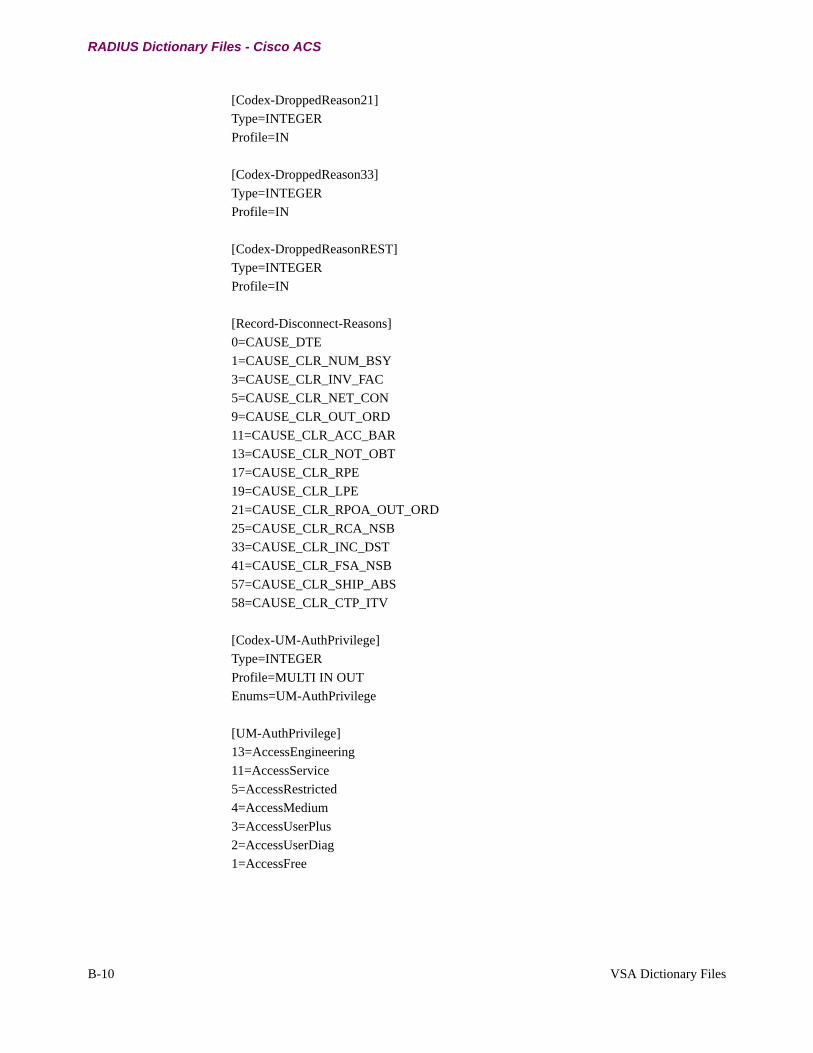
B-10 VSA Dictionary Files
RADIUS Dictionary Files - Cisco ACS
[Codex-DroppedReason21]
Type=INTEGER
Profile=IN
[Codex-DroppedReason33]
Type=INTEGER
Profile=IN
[Codex-DroppedReasonREST]
Type=INTEGER
Profile=IN
[Record-Disconnect-Reasons]
0=CAUSE_DTE
1=CAUSE_CLR_NUM_BSY
3=CAUSE_CLR_INV_FAC
5=CAUSE_CLR_NET_CON
9=CAUSE_CLR_OUT_ORD
11=CAUSE_CLR_ACC_BAR
13=CAUSE_CLR_NOT_OBT
17=CAUSE_CLR_RPE
19=CAUSE_CLR_LPE
21=CAUSE_CLR_RPOA_OUT_ORD
25=CAUSE_CLR_RCA_NSB
33=CAUSE_CLR_INC_DST
41=CAUSE_CLR_FSA_NSB
57=CAUSE_CLR_SHIP_ABS
58=CAUSE_CLR_CTP_ITV
[Codex-UM-AuthPrivilege]
Type=INTEGER
Profile=MULTI IN OUT
Enums=UM-AuthPrivilege
[UM-AuthPrivilege]
13=AccessEngineering
11=AccessService
5=AccessRestricted
4=AccessMedium
3=AccessUserPlus
2=AccessUserDiag
1=AccessFree

VSA Dictionary Files B-11
T0100-03, Revision V Release 7.3
RADIUS Dictionary Files - Cisco ACS
[Codex-UM-AuthUserGroup]
Type=INTEGER
Profile=MULTI IN OUT
Enums=UM-AuthUserGroup
[UM-AuthUserGroup]
0=None-User-Group
1=Router-IP-User-Group
1073741824=All-User-Group
[Codex-UM-LogMenu]
Type=STRING
Profile=MULTI IN OUT
[Codex-UM-LogApplication]
Type=INTEGER
Profile=MULTI IN OUT
Enums=LogApplication
[LogApplication]
1=Log_App_CTP
2=Log_App_HTTPD
3=Log_App_CLI
[Codex-UM-LogRecordName]
Type=STRING
Profile=MULTI IN OUT
[Codex-UM-LogRecordValue]
Type=STRING
Profile=MULTI IN OUT
[Codex-UM-LogAlarm]
Type=STRING
Profile=MULTI IN OUT

B-12 VSA Dictionary Files
FreeRadius - VSA Requests and Generating Responses
FreeRadius - VSA Requests and Generating Responses
This file contains dictionary translations for parsing Vanguard Networks VSA requests and generating responses. To enable enter the line "$INCLUDE dictionary.vanguardms" into the main dictionary file.
$Revision$, $Date$
VENDORCodex449
Generic VanguardMS Attributes
ATTRIBUTE Vanguardms-AVPair 1 string CodexATTRIBUTE Vanguardms-NAS-Port 2 string Codex
ATTRIBUTE Packet_Type 10 integer CodexATTRIBUTE Record_Time 11 date CodexATTRIBUTE Port_Number 12 integer CodexATTRIBUTE Port_Interface_Type 13 integer CodexATTRIBUTE Port_State 14 integer CodexATTRIBUTE Port_Utilization 15 integer CodexATTRIBUTE Circuit_State 16 integer CodexATTRIBUTE Last_Reset_Time 17 date CodexATTRIBUTE Current_Status 18 integer CodexATTRIBUTE Hardware_Rev_And_Part_Number 19 string CodexATTRIBUTE DSP_Internal_Faults 20 integer Codex
ATTRIBUTE PercentPeakOfCPULoad 21 integer CodexATTRIBUTE PercentAvgOfCPULoad 22 integer CodexATTRIBUTE PercentCurOfCPULoad 23 integer CodexATTRIBUTE PercentPeakOfDataBuf 24 integer CodexATTRIBUTE PercentAvgOfDataBuf 25 integer CodexATTRIBUTE PercentCurOfDataBuf 26 integer CodexATTRIBUTE PercentPeakOfIORBBuf 27 integer CodexATTRIBUTE PercentAvgOfIORBBuf 28 integer CodexATTRIBUTE PercentCurOfIORBBuf 29 integer Codex
ATTRIBUTE No_Packets_Dropped 30 integer CodexATTRIBUTE No_Calls_Dropped 31 integer CodexATTRIBUTE TX_Packets_Dropped 32 integer CodexATTRIBUTE RX_Packets_Dropped 33 integer CodexATTRIBUTE NO_Calls_Processed 34 integer CodexATTRIBUTE TX_Packets_Per_Second 35 integer CodexATTRIBUTE RX_Packets_Per_Second 36 integer Codex
ATTRIBUTE CallingPhone 60 string CodexATTRIBUTE CallingPort 61 string CodexATTRIBUTE CallingNode 62 string CodexATTRIBUTE CalledPhone 63 string CodexATTRIBUTE CalledNodePort 64 string CodexATTRIBUTE Codec 65 string CodexATTRIBUTE TimeOfCall 66 date CodexATTRIBUTE Durtn 67 integer CodexATTRIBUTE DiscntRsn 68 integer Codex
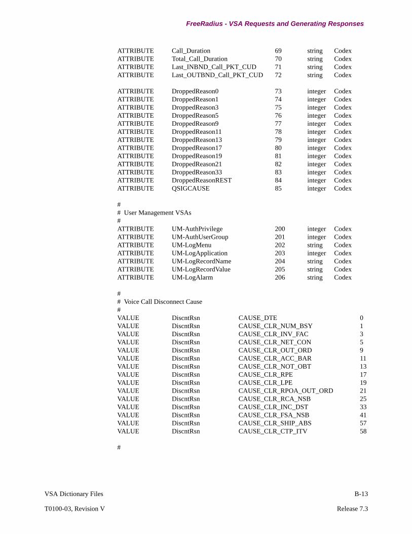
VSA Dictionary Files B-13
T0100-03, Revision V Release 7.3
FreeRadius - VSA Requests and Generating Responses
ATTRIBUTE Call_Duration 69 string CodexATTRIBUTE Total_Call_Duration 70 string CodexATTRIBUTE Last_INBND_Call_PKT_CUD 71 string CodexATTRIBUTE Last_OUTBND_Call_PKT_CUD 72 string Codex
ATTRIBUTE DroppedReason0 73 integer CodexATTRIBUTE DroppedReason1 74 integer CodexATTRIBUTE DroppedReason3 75 integer CodexATTRIBUTE DroppedReason5 76 integer CodexATTRIBUTE DroppedReason9 77 integer CodexATTRIBUTE DroppedReason11 78 integer CodexATTRIBUTE DroppedReason13 79 integer CodexATTRIBUTE DroppedReason17 80 integer CodexATTRIBUTE DroppedReason19 81 integer CodexATTRIBUTE DroppedReason21 82 integer CodexATTRIBUTE DroppedReason33 83 integer CodexATTRIBUTE DroppedReasonREST 84 integer CodexATTRIBUTE QSIGCAUSE 85 integer Codex
## User Management VSAs#ATTRIBUTE UM-AuthPrivilege 200 integer CodexATTRIBUTE UM-AuthUserGroup 201 integer CodexATTRIBUTE UM-LogMenu 202 string CodexATTRIBUTE UM-LogApplication 203 integer CodexATTRIBUTE UM-LogRecordName 204 string CodexATTRIBUTE UM-LogRecordValue 205 string CodexATTRIBUTE UM-LogAlarm 206 string Codex
## Voice Call Disconnect Cause#VALUE DiscntRsn CAUSE_DTE 0VALUE DiscntRsn CAUSE_CLR_NUM_BSY 1VALUE DiscntRsn CAUSE_CLR_INV_FAC 3VALUE DiscntRsn CAUSE_CLR_NET_CON 5VALUE DiscntRsn CAUSE_CLR_OUT_ORD 9VALUE DiscntRsn CAUSE_CLR_ACC_BAR 11VALUE DiscntRsn CAUSE_CLR_NOT_OBT 13VALUE DiscntRsn CAUSE_CLR_RPE 17VALUE DiscntRsn CAUSE_CLR_LPE 19VALUE DiscntRsn CAUSE_CLR_RPOA_OUT_ORD 21VALUE DiscntRsn CAUSE_CLR_RCA_NSB 25VALUE DiscntRsn CAUSE_CLR_INC_DST 33VALUE DiscntRsn CAUSE_CLR_FSA_NSB 41VALUE DiscntRsn CAUSE_CLR_SHIP_ABS 57VALUE DiscntRsn CAUSE_CLR_CTP_ITV 58
#

B-14 VSA Dictionary Files
FreeRadius - VSA Requests and Generating Responses
# Packet Type#VALUE Packet_Type Packet_Type_Unknown 0VALUE Packet_Type Packet_Type_Voice_ACCT_CDR 1VALUE Packet_Type Packet_Type_Voice_ACCT_PST 2VALUE Packet_Type Packet_Type_Voice_ACCT_VCS 3VALUE Packet_Type Packet_Type_Config_Log 4VALUE Packet_Type Packet_Type_Control_Log 5VALUE Packet_Type Packet_Type_Logon 6VALUE Packet_Type Packet_Type_Authentication 7VALUE Packet_Type Packet_Type_Authorization 8## Port Interface Type#VALUE Port_Interface_Type Voice_2Wire_EM 1VALUE Port_Interface_Type Voice_4Wire_EM 2VALUE Port_Interface_Type Voice_2Wire_FXO 3VALUE Port_Interface_Type Voice_2Wire_FXS 4VALUE Port_Interface_Type Voice_CCS 5VALUE Port_Interface_Type Voice_UNDEFINED 6VALUE Port_Interface_Type Voice_NC 100
## Port State#VALUE Port_State Port_Disabled 1VALUE Port_State Port_Enabled 2
## Circuit State#VALUE Circuit_State Connected 1VALUE Circuit_State Disconnected 2
## Current Status #VALUE Current_Status Inhibited 1VALUE Current_Status Disconnected 2VALUE Current_Status Calling 3VALUE Current_Status Called 4VALUE Current_Status Connected 5VALUE Current_Status Null 6## User Privilege Level#VALUE UM-AuthPrivilege AccessEngineering 13VALUE UM-AuthPrivilege AccessService 11VALUE UM-AuthPrivilege AccessRestricted 5VALUE UM-AuthPrivilege AccessMedium 4VALUE UM-AuthPrivilege AccessUserPlus 3VALUE UM-AuthPrivilege AccessUserDiag 2VALUE UM-AuthPrivilege AccessFree 1
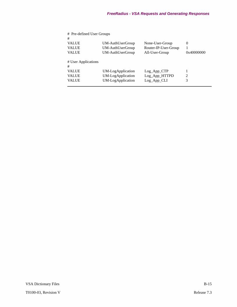
VSA Dictionary Files B-15
T0100-03, Revision V Release 7.3
FreeRadius - VSA Requests and Generating Responses
# Pre-defined User Groups#VALUE UM-AuthUserGroup None-User-Group 0VALUE UM-AuthUserGroup Router-IP-User-Group 1VALUE UM-AuthUserGroup All-User-Group 0x40000000
# User Applications#VALUE UM-LogApplication Log_App_CTP 1VALUE UM-LogApplication Log_App_HTTPD 2VALUE UM-LogApplication Log_App_CLI 3

This page intentionally left blank.
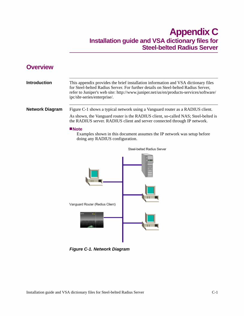
Installation guide and VSA dictionary files for Steel-belted Radius Server C-1
Appendix CInstallation guide and VSA dictionary files for
Steel-belted Radius Server
Overview
Introduction This appendix provides the brief installation information and VSA dictionary files for Steel-belted Radius Server. For further details on Steel-belted Radius Server, refer to Juniper's web site: http://www.juniper.net/us/en/products-services/software/ipc/sbr-series/enterprise/.
Network Diagram Figure C-1 shows a typical network using a Vanguard router as a RADIUS client.
As shown, the Vanguard router is the RADIUS client, so-called NAS; Steel-belted is the RADIUS server. RADIUS client and server connected through IP network.
NoteExamples shown in this document assumes the IP network was setup before doing any RADIUS configuration.
Figure C-1. Network Diagram

C-2 Installation guide and VSA dictionary files for Steel-belted Radius Server
Configuration
Configuration
Vanguard Configuration
Vanguard routers including the 7310/7330, 6435/6455, 340, 342 and 320, all support RADIUS protocol for authentication, accounting and authorization (AAA).
RADIUS configuration can be done through local CTP (serial port), telnet or web access, by using menu mode or CLI mode.
The example shown below uses local CTP menu configuration, the device used is a 6455, with release 6.3 ONS software.
Configure RADIUS Client
From CTP main menu, go to Configure/Configure RADIUS/Configure RADIUS Client menu, as shown in the below diagram.
NoteAll the configurations use default value, except Enable Radius Client is set to Enabled.
Save the configuration with “;” and don’t need to reboot the node or any table, the RADIUS client was already Enabled.
Figure C-2. Configure RADIUS Client
Configure RADIUS Server
From CTP main menu, go to Configure/Configure RADIUS/Configure RADIUS Server menu, as shown in the below diagram.
NoteServer IP address and share secret are configured, save with “;” and the configuration will immediately take effect.
Figure C-3. Configure RADIUS Client
RADIUS Client Configuration
Entry Number: 1/[1] Radius Application: Default/[1] Enable Radius Client: Enabled/[1] Authentication Method: Remote-then-Local/[1] Username/Password Buffer Number: 0/[1] RADIUS Retry and Fallback Mechanism: One-by-One/[1] RADIUS Client IP Address(x.x.x.x): (blank)/; // Or configure Local IP addresuch as 150.30.1.237
RADIUS Server Configuration
Entry Number: 1/[1] RADIUS Server IP Address(x.x.x.x): 150.83.13.19/[1] Authentication UDP Port Number: 1812/[1] Accounting UDP Port Number: 1813/[1] Share Secret: abcd888/[1] Retry Limit: 3/[1] Request Timeout(in second): 5/;

Installation guide and VSA dictionary files for Steel-belted Radius Server C-3
T0100-03, Revision V Release 7.3
Configuration
Edit dictiona.dcm Typically, the dictiona.dcm files located with the Steel-belted configuration files under c:\radius\service directory.
For Release 6.1 or greater, the dictiona.dcm file is now located in C:\Program Files\Juniper Networks\Steel-Belted Radius\Service. Figure C-4 shows the dictiona.dcm file. The file (vgms.dct) is the dictionary file for Vanguard Routers.

C-4 Installation guide and VSA dictionary files for Steel-belted Radius Server
Configuration
Figure C-4. The dictiona.dcm File
################################################################################# dictiona.dcm################################################################################
# Generic Radius
@radius.dct## Specific Implementations (vendor specific)#@[email protected]@[email protected]@[email protected]@[email protected]@[email protected]@[email protected]@[email protected]@[email protected]@[email protected]@[email protected]@[email protected]@[email protected]@[email protected]@[email protected]@[email protected]@[email protected]@[email protected]@[email protected]@[email protected]@[email protected]@[email protected]@[email protected]@[email protected]@[email protected]@[email protected]@[email protected]@[email protected]@[email protected]@[email protected]@[email protected]@[email protected]@[email protected]@[email protected]@[email protected]@[email protected]@[email protected]@xylan.dct################################################################################# dictiona.dcm################################################################################
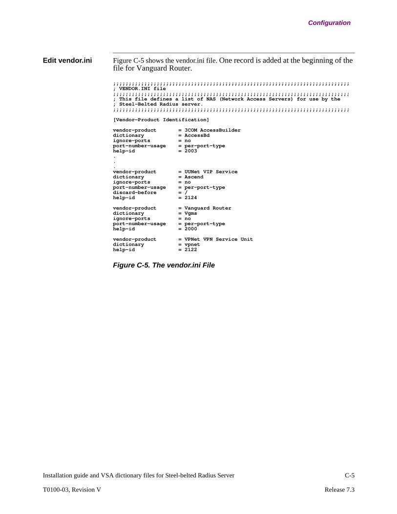
Installation guide and VSA dictionary files for Steel-belted Radius Server C-5
T0100-03, Revision V Release 7.3
Configuration
Edit vendor.ini Figure C-5 shows the vendor.ini file. One record is added at the beginning of the file for Vanguard Router.
Figure C-5. The vendor.ini File
;;;;;;;;;;;;;;;;;;;;;;;;;;;;;;;;;;;;;;;;;;;;;;;;;;;;;;;;;;;;;;;;;;;;;;;;;;;;; VENDOR.INI file;;;;;;;;;;;;;;;;;;;;;;;;;;;;;;;;;;;;;;;;;;;;;;;;;;;;;;;;;;;;;;;;;;;;;;;;;;;;; This file defines a list of NAS (Network Access Servers) for use by the ; Steel-Belted Radius server.;;;;;;;;;;;;;;;;;;;;;;;;;;;;;;;;;;;;;;;;;;;;;;;;;;;;;;;;;;;;;;;;;;;;;;;;;;;;
[Vendor-Product Identification]
vendor-product = 3COM AccessBuilder dictionary = AccessBdignore-ports = noport-number-usage = per-port-typehelp-id = 2003...vendor-product = UUNet VIP Servicedictionary = Ascendignore-ports = noport-number-usage = per-port-typediscard-before = /help-id = 2124
vendor-product = Vanguard Router dictionary = Vgmsignore-ports = noport-number-usage = per-port-typehelp-id = 2000
vendor-product = VPNet VPN Service Unitdictionary = vpnethelp-id = 2122

C-6 Installation guide and VSA dictionary files for Steel-belted Radius Server
Configuration
Create vgms.dct Create the Vanguard dictionary file for Steel-belted as shown in Figure C-6.
Save this dictionary file in the same directory, i.e. c:\radius\service.
For Release 6.1 or greater, save this dictionary file (vgms.dct) in C:\Program Files\Juniper Networks\Steel-Belted Radius\Service.
Figure C-6. The vgms.dct File
################################################################################# vgms.dct - Vanguard Router dictionary# (See README.DCT for more details on the format of this file)################################################################################# Created 2004/18/02 by Eric Liu## Use the Radius specification attributes in lieu of the VanguardMS ones#@radius.dct
## Define additional Vanguard Router VSA parameters# (add Vanguard Management Solution specific attributes below)# Vanguard Management Soulution LLC. Vendor Id (vid)=449
MACRO VGMS-Attr(type,syntax) 26 [vid=449 type1=%type% len1=+2 data=%syntax%]#ATTRIBUTEUM-AuthPrivilegeVGMS-Attr(200,integer)## Generic Vanguardms attributes#ATTRIBUTEVanguardms-AVPairVGMS-Attr(1,string)ATTRIBUTEVanguardms-NAS-PortVGMS-Attr(2,string)
## Voice Accounting VSAs#
## Packet Type#ATTRIBUTE Packet_TypeVGMS-Attr(10,integer)cVALUEPacket_TypePacket_Type_Unknown0VALUEPacket_TypePacket_Type_Voice_ACCT_CDR1VALUEPacket_TypePacket_Type_Voice_ACCT_PST2VALUEPacket_TypePacket_Type_Voice_ACCT_VCS3VALUEPacket_TypePacket_Type_Config_Log4VALUEPacket_TypePacket_Type_Control_Log5VALUEPacket_TypePacket_Type_Logon6VALUEPacket_TypePacket_Type_Authentication7VALUEPacket_TypePacket_Type_Authorization8
ATTRIBUTE Record_TimeVGMS-Attr(11,time)cATTRIBUTE Port_NumberVGMS-Attr(12,integer)c
## Port Interface Type#ATTRIBUTE Port_Interface_TypeVGMS-Attr(13,integer)cVALUEPort_Interface_TypeVoice_2Wire_EM1VALUEPort_Interface_TypeVoice_4Wire_EM2VALUEPort_Interface_TypeVoice_2Wire_FXO3VALUEPort_Interface_TypeVoice_2Wire_FXS4VALUEPort_Interface_TypeVoice_CCS5VALUEPort_Interface_TypeVoice_UNDEFINED6VALUEPort_Interface_TypeVoice_NC100
## Port State#ATTRIBUTE Port_StateVGMS-Attr(14,integer)cVALUEPort_StatePort_Disabled1VALUEPort_StatePort_Enabled2
ATTRIBUTE Port_UtilizationVGMS-Attr(15,integer)
## Circuit State#ATTRIBUTE Circuit_StateVGMS-Attr(16,integer)cVALUECircuit_StateConnected1VALUECircuit_StateDisconnected2
ATTRIBUTE Last_Reset_TimeVGMS-Attr(17,time)c
#
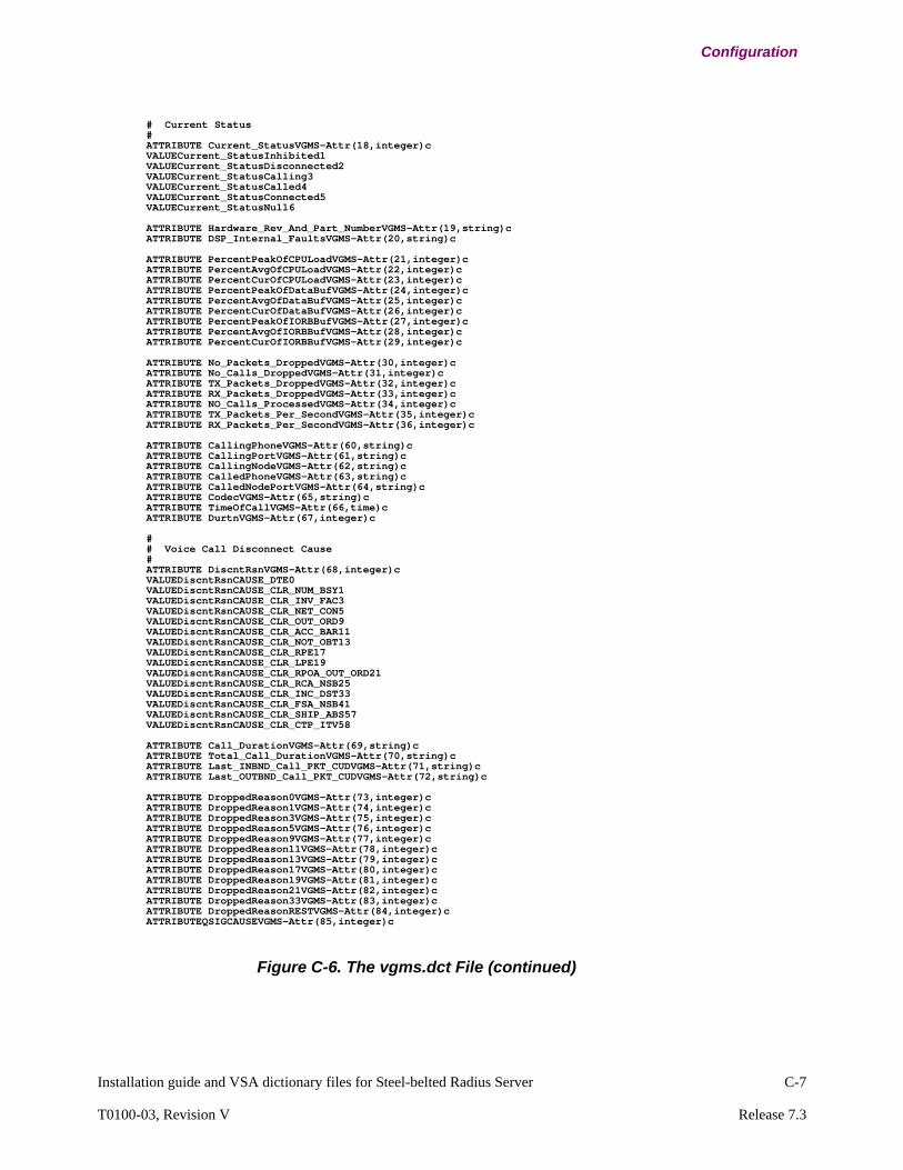
Installation guide and VSA dictionary files for Steel-belted Radius Server C-7
T0100-03, Revision V Release 7.3
Configuration
Figure C-6. The vgms.dct File (continued)
# Current Status #ATTRIBUTE Current_StatusVGMS-Attr(18,integer)cVALUECurrent_StatusInhibited1VALUECurrent_StatusDisconnected2VALUECurrent_StatusCalling3VALUECurrent_StatusCalled4VALUECurrent_StatusConnected5VALUECurrent_StatusNull6
ATTRIBUTE Hardware_Rev_And_Part_NumberVGMS-Attr(19,string)cATTRIBUTE DSP_Internal_FaultsVGMS-Attr(20,string)c
ATTRIBUTE PercentPeakOfCPULoadVGMS-Attr(21,integer)cATTRIBUTE PercentAvgOfCPULoadVGMS-Attr(22,integer)cATTRIBUTE PercentCurOfCPULoadVGMS-Attr(23,integer)cATTRIBUTE PercentPeakOfDataBufVGMS-Attr(24,integer)cATTRIBUTE PercentAvgOfDataBufVGMS-Attr(25,integer)cATTRIBUTE PercentCurOfDataBufVGMS-Attr(26,integer)cATTRIBUTE PercentPeakOfIORBBufVGMS-Attr(27,integer)cATTRIBUTE PercentAvgOfIORBBufVGMS-Attr(28,integer)cATTRIBUTE PercentCurOfIORBBufVGMS-Attr(29,integer)c
ATTRIBUTE No_Packets_DroppedVGMS-Attr(30,integer)cATTRIBUTE No_Calls_DroppedVGMS-Attr(31,integer)cATTRIBUTE TX_Packets_DroppedVGMS-Attr(32,integer)cATTRIBUTE RX_Packets_DroppedVGMS-Attr(33,integer)cATTRIBUTE NO_Calls_ProcessedVGMS-Attr(34,integer)cATTRIBUTE TX_Packets_Per_SecondVGMS-Attr(35,integer)cATTRIBUTE RX_Packets_Per_SecondVGMS-Attr(36,integer)c
ATTRIBUTE CallingPhoneVGMS-Attr(60,string)cATTRIBUTE CallingPortVGMS-Attr(61,string)cATTRIBUTE CallingNodeVGMS-Attr(62,string)cATTRIBUTE CalledPhoneVGMS-Attr(63,string)cATTRIBUTE CalledNodePortVGMS-Attr(64,string)cATTRIBUTE CodecVGMS-Attr(65,string)cATTRIBUTE TimeOfCallVGMS-Attr(66,time)cATTRIBUTE DurtnVGMS-Attr(67,integer)c
## Voice Call Disconnect Cause#ATTRIBUTE DiscntRsnVGMS-Attr(68,integer)cVALUEDiscntRsnCAUSE_DTE0VALUEDiscntRsnCAUSE_CLR_NUM_BSY1VALUEDiscntRsnCAUSE_CLR_INV_FAC3VALUEDiscntRsnCAUSE_CLR_NET_CON5VALUEDiscntRsnCAUSE_CLR_OUT_ORD9VALUEDiscntRsnCAUSE_CLR_ACC_BAR11VALUEDiscntRsnCAUSE_CLR_NOT_OBT13VALUEDiscntRsnCAUSE_CLR_RPE17VALUEDiscntRsnCAUSE_CLR_LPE19VALUEDiscntRsnCAUSE_CLR_RPOA_OUT_ORD21VALUEDiscntRsnCAUSE_CLR_RCA_NSB25VALUEDiscntRsnCAUSE_CLR_INC_DST33VALUEDiscntRsnCAUSE_CLR_FSA_NSB41VALUEDiscntRsnCAUSE_CLR_SHIP_ABS57VALUEDiscntRsnCAUSE_CLR_CTP_ITV58
ATTRIBUTE Call_DurationVGMS-Attr(69,string)cATTRIBUTE Total_Call_DurationVGMS-Attr(70,string)cATTRIBUTE Last_INBND_Call_PKT_CUDVGMS-Attr(71,string)cATTRIBUTE Last_OUTBND_Call_PKT_CUDVGMS-Attr(72,string)c
ATTRIBUTE DroppedReason0VGMS-Attr(73,integer)cATTRIBUTE DroppedReason1VGMS-Attr(74,integer)cATTRIBUTE DroppedReason3VGMS-Attr(75,integer)cATTRIBUTE DroppedReason5VGMS-Attr(76,integer)cATTRIBUTE DroppedReason9VGMS-Attr(77,integer)cATTRIBUTE DroppedReason11VGMS-Attr(78,integer)cATTRIBUTE DroppedReason13VGMS-Attr(79,integer)cATTRIBUTE DroppedReason17VGMS-Attr(80,integer)cATTRIBUTE DroppedReason19VGMS-Attr(81,integer)cATTRIBUTE DroppedReason21VGMS-Attr(82,integer)cATTRIBUTE DroppedReason33VGMS-Attr(83,integer)cATTRIBUTE DroppedReasonRESTVGMS-Attr(84,integer)cATTRIBUTEQSIGCAUSEVGMS-Attr(85,integer)c

C-8 Installation guide and VSA dictionary files for Steel-belted Radius Server
Configuration
Figure C-6. The vgms.dct File (continued)
Edit radius.ini Edit radius.ini as shown in Figure C-7.
NoteAuthenticateOnly = 0 is added into the [Configuration] session.
Figure C-7. The radius.ini File
## User Management VSAs#ATTRIBUTE UM-AuthPrivilegeVGMS-Attr(200,integer)rVALUEUM-AuthPrivilegeAccessEngineering13VALUEUM-AuthPrivilegeAccessService11VALUEUM-AuthPrivilegeAccessRestricted5VALUEUM-AuthPrivilegeAccessMedium4VALUEUM-AuthPrivilegeAccessUserPlus3VALUEUM-AuthPrivilegeAccessUserDiag2VALUEUM-AuthPrivilegeAccessFree1
## Pre-defined User Groups#ATTRIBUTE UM-AuthUserGroupVGMS-Attr(201,integer)rVALUEUM-AuthUserGroupNone-User-Group0VALUEUM-AuthUserGroupRouter-IP-User-Group1VALUEUM-AuthUserGroupAll-User-Group0x40000000
ATTRIBUTE UM-LogMenuVGMS-Attr(202,string)c
## User Applications#ATTRIBUTE UM-LogApplicationVGMS-Attr(203,integer) cVALUEUM-LogApplicationLog_App_CTP1VALUEUM-LogApplicationLog_App_HTTPD2VALUEUM-LogApplicationLog_App_CLI3
ATTRIBUTE UM-LogRecordNameVGMS-Attr(204,string)cATTRIBUTE UM-LogRecordValueVGMS-Attr(205,string)cATTRIBUTE UM-LogAlarmVGMS-Attr(206,string)c
################################################################################# vgms.dct - Vanguard Router dictionary################################################################################…
;;;;;;;;;;;;;;;;;;;;;;;;;;;;;;;;;;;;;;;;;;;;;;;;;;;;;;;;;;;;;;;;;;;;;;;;;;;;; RADIUS.INI file - 4.52 (October 2003);;;;;;;;;;;;;;;;;;;;;;;;;;;;;;;;;;;;;;;;;;;;;;;;;;;;;;;;;;;;;;;;;;;;;;;;;;;;; This file defines operational characteristics of Funk Software's; Steel-Belted Radius server.
[Configuration]LogLevel = 0TraceLevel = 0Allow-Unmasked-Password = noAllow-Unmasked-Secret = noApply-Login-Limits = yes;PrivateDir = <file system location>FramedIPAddressHint = noHeartBeatTimeout = 180CheckMessageAuthenticator = 0AuthenticateOnly = 0FramedIPAddressHint = noAddSourceIPAddressAttrToRequest = 0;ClassAttributeStyle = 2
;[Ports];UDPAuthPort = 1645;UDPAcctPort = 1646
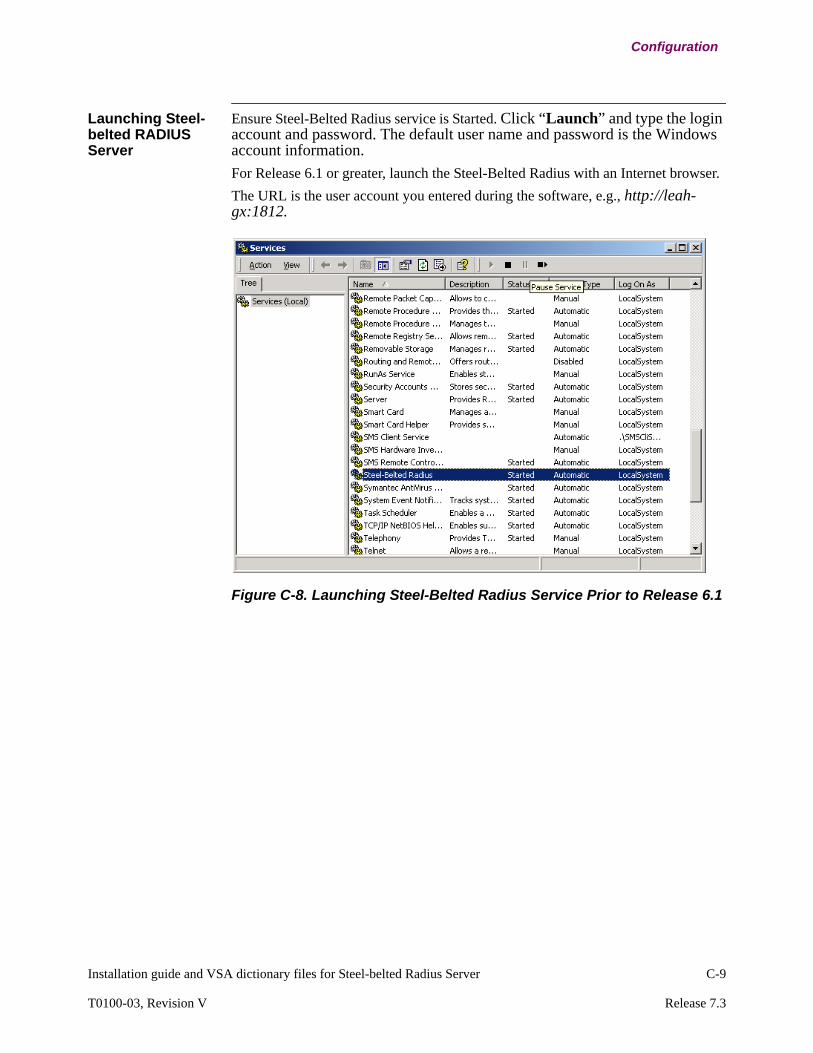
Installation guide and VSA dictionary files for Steel-belted Radius Server C-9
T0100-03, Revision V Release 7.3
Configuration
Launching Steel-belted RADIUS Server
Ensure Steel-Belted Radius service is Started. Click “Launch” and type the login account and password. The default user name and password is the Windows account information.
For Release 6.1 or greater, launch the Steel-Belted Radius with an Internet browser.
The URL is the user account you entered during the software, e.g., http://leah-gx:1812.
Figure C-8. Launching Steel-Belted Radius Service Prior to Release 6.1

C-10 Installation guide and VSA dictionary files for Steel-belted Radius Server
Configuration
Figure C-9. Launching Steel-Belted Radius Service for Release 6.1 or Greater
Figure C-10. Start Steel-Belted Radius Service 6.1 Login Window
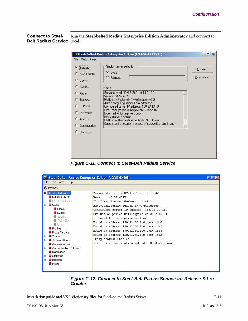
Installation guide and VSA dictionary files for Steel-belted Radius Server C-11
T0100-03, Revision V Release 7.3
Configuration
Connect to Steel-Belt Radius Service
Run the Steel-belted Radius Enterprise Edition Administrator and connect to local.
Figure C-11. Connect to Steel-Belt Radius Service
Figure C-12. Connect to Steel-Belt Radius Service for Release 6.1 or Greater
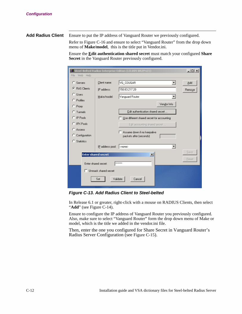
C-12 Installation guide and VSA dictionary files for Steel-belted Radius Server
Configuration
Add Radius Client Ensure to put the IP address of Vanguard Router we previously configured.
Refer to Figure C-16 and ensure to select “Vanguard Router” from the drop down menu of Make/model, this is the title put in Vendor.ini.
Ensure the Edit authentication shared secret must match your configured Share Secret in the Vanguard Router previously configured.
Figure C-13. Add Radius Client to Steel-belted
In Release 6.1 or greater, right-click with a mouse on RADIUS Clients, then select “Add” (see Figure C-14).
Ensure to configure the IP address of Vanguard Router you previously configured. Also, make sure to select “Vanguard Router” form the drop down menu of Make or model, which is the title we added in the vendor.ini file.
Then, enter the one you configured for Share Secret in Vanguard Router’s Radius Server Configuration (see Figure C-15).

Installation guide and VSA dictionary files for Steel-belted Radius Server C-13
T0100-03, Revision V Release 7.3
Configuration
Figure C-14. Add Radius Client to Steel-belted for Release 6.1 or greater

C-14 Installation guide and VSA dictionary files for Steel-belted Radius Server
Configuration
Figure C-15. Edit Radius Client
Configure Users in RADIUS server
Refer to Figure C-16 to configure multiple users, set user name/password for each user, insert check list attributes, and more importantly, insert return list attributes.
NoteVanguard RADIUS client request the UM-AuthPrivilege and UM-AuthUserGroup attributes for authentication and authorization. Only UM-AuthPrivilege is sufficient to assign the user access privilege. If no UM-AuthPrivilege and UM-AuthUserGroup attribute received, Vanguard Router uses the default Read-Only privilege.
Add UsersFore Release 6.1 or greater, refer to Figure C-17 to configure a user account, set user name/password, or add necessary Attributes in both Check List and Return List.
Configure a password in Password.
Then, click “Check List” tab and add three attributes:

Installation guide and VSA dictionary files for Steel-belted Radius Server C-15
T0100-03, Revision V Release 7.3
Configuration
NAS-IP-Address, NAS-Port, Service-Type, and User-Name.
NAS-IP-Address is set to the IP Address assigned to Vanguard Router.
Figure C-16. Add Users to RADIUS server
Insert Check List Attributes
NoteEnsure NAS-Port Value should be set to "0."
NoteIf SBR rejects Access-Request, check what value Vanguard Router sent for NAS-IP-Port (5). If it's not "0" but some other values, make changes to this NAS-Port attribute value to the one Vanguard Router actually uses in Access-Request.
Service-Type needs to be set to "Authenticate-Only."
And configure User-Name with a user name you want to use to login.

Figure C-17. Insert Check List Attributes SBR 6.1
Figure C-18. Add Check List Attributes For Release 6.1 or Greater
Return ListIn Return List, add at least two attributes: UM-AuthPrivilege and UM-AuthUserGroup for authentication and authorization. If no UM-AuthPrivilege and UM-AuthUserGroup attribute recived, Vanguard Router uses the default Read-Only privilege.

Installation guide and VSA dictionary files for Steel-belted Radius Server C-17
T0100-03, Revision V Release 7.3
Configuration
Figure C-19. Add Return List Attributes For Release 6.1 or Greater
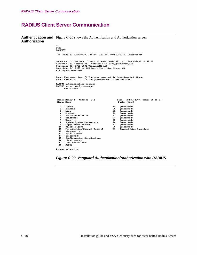
C-18 Installation guide and VSA dictionary files for Steel-belted Radius Server
RADIUS Client Server Communication
RADIUS Client Server Communication
Authentication and Authorization
Figure C-20 shows the Authentication and Authorization screen.
Figure C-20. Vanguard Authentication/Authorization with RADIUS
OKatdsCONNECT
(3) Node342 02-NOV-2007 16:48 ATCIF-1 CONNECTED TO ControlPort
Connected to the Control Port on Node "Node342", at 2-NOV-2007 16:48:22VANGUARD 340 - Model 342, Version V7.0IS10B_@RTPPPRAD_342Copyright (C) 1989-2001 VanguardMS LLCCopyright (c) 1995 by AGE Logic Inc., San Diego, CAAll rights reserved
Enter Username: leah // The user name set in User-Name AttributeEnter Password: ... // The password set in Native User
RADIUS authentication successRADIUS server reply message: Hello Leah
Node: Node342 Address: 342 Date: 2-NOV-2007 Time: 16:48:27 Menu: Main Path: (Main)
1. Logout 19. (reserved) 2. Examine 20. (reserved) 3. List 21. (reserved) 4. Monitor 22. (reserved) 5. Status/statistics 23. (reserved) 6. Configure 24. (reserved) 7. Boot 25. (reserved) 8. Update System Parameters 26. (reserved) 9. Copy/Insert Record 27. (reserved) 10. Delete Record 28. (reserved) 11. Port/Station/Channel Control 29. Command Line Interface 12. Diagnostics 13. Default Node 14. (reserved) 15. Configuration Save/Restore 16. Flash Memory 17. LAN Control Menu 18. DEBUG
#Enter Selection:
Index
Index-1
Numerics
32-bit address 1-4
A
Accelerated IP Forwarding 2-186configuring 2-187IP aggregate cache 2-186overview 2-186support 2-187with Access Control 2-187with QoS 2-187with Token Ring 2-187
Access Controlwith Accelerated IP Forwarding 2-187
access control 2-129configuration 3-49configuration example 2-132how it works 2-131implementing 2-131inbound 2-129limitations 2-132outbound 2-129parameters 3-16
Addressaggregation, see CIDRCIDR 2-143CIDR prefix 2-143classbased 2-151
range 2-151classes 1-5classifications example 1-5classless 2-143
range 2-151duplicate 2-167dynamic 2-156Ethernet 2-2exhaustion 2-143external 2-156filtering 2-128internal 2-156internal IP, configuring 3-15IP 1-4IP Broadcast 3-37IP Helper Address 2-69MAC 2-2private, IETF recommendation 2-155proxy 2-167reserved multicast 2-82Resolution Protocol, see ARP
static 2-156subnet addresses 1-7subnet mask 1-7translation, see NATunnumbered IP 2-139
addressautomated learning capability, see ICMP Router
DiscoveryAggregate Cache Enable
parameter description 3-22Aggregate Cache Enable parameter 3-22Aggregate Cache Statistics 4-12
Access Control disabled 4-12Access Control enabled 4-13
aggregationexample 2-152
aggregation, see CIDR 2-143aging control
RIP 2-35no configurable parameters 2-35
Alarm 3-10algorithm
distance vector 2-13reverse path forwarding 2-90
All Subnets Broadcastdescription 2-67
ARP 2-2broadcasts 2-2cache 2-2
configuring 3-91configuring 2-4, 3-87how it works 2-3how the Vanguard handles ARP 2-4Inverse, see Inverse ARPMAC and IP address determination 2-2parameters 3-88physical address broadcast 2-2process 2-3Proxy, see Proxy ARPrequest 2-2response 2-3static cache table 2-4statistics 4-16table 1-11
authentication 2-18configuring 3-31
Autonomous system 1-9CIDR 2-145
Index-2
Index (continued)
B
Bellman-Ford 2-13Binding 2-156
dynamic address dynamic binding 2-160permanent port 2-165static address-dynamic binding 2-159static address-static binding 2-159
black hole detection 2-126black holes, CIDR 2-147booting
interface parameters 3-25IP Parameters 3-7IP Tables 3-7node 3-7parameters 3-7switched IP 2-185
Booting Stateful Access Parameters and Control Entries 3-63
BOOTP Forwarding 2-68configuring 3-20
BOOTP Server Tableconfiguring 3-79
broadcastsaddress decision flowchart 2-79ARP 2-2Broadcast Forwarding
configuring 3-21, 3-80configuring UDP Broadcast Forwarding 3-
82Broadcast Forwarding Priority 2-78compared with multicasting 2-81configuring 3-18directed 3-18Directed Broadcast Forwarding 2-66IP 2-65physical address 2-2RIP On Demand 2-33subnet 3-19type 2-65
C
cacheARP 2-3
CIDR 2-143aggregation 2-152black holes 2-147prefix 2-153RIP Version 2 2-148
support 2-149Class A address 1-5Class B address 1-5Class C address 1-6
Class D addressmulticast 1-6
Classless Interdomain Routing, see CIDRcluster protocol 2-123Configuration
Firewall 3-43configuration example
IP Helper Address 3-84IP multicasting 3-111point-to-point 3-5
Configure Firewall Lite Features 3-61Configure QoS menu 3-177connectionless service 1-3
D
data packetstransporting 1-2
datagrammulticast 2-82
default gatewayconfiguring 3-18see default routers
Default ICMP Timeout 3-59default route
configuring 3-17default router
multiple static route 3-64switched IP 2-184
default routers 2-120proxy 2-122
default subnet gateway 3-69Default TCP Timeout 3-59Default UPD Timeout 3-59DHCP Server
Configuration Example 3-192Configure Server Subnet Table 3-187Configuring 3-185Configuring Server Fixed-Exclude IP Table 3-
191Statistics 3-193
Directed Broadcast Forwarding 2-66discontiguous subnets 2-17Distance Vector Multicast Routing Protocol, see
DVMRPDNS 2-169DNS query 2-168DSCP Field 3-53Duplicate Address Translation 2-167Duplicate IP Address Detection 2-10
Parameter 3-39Statistics 4-7
DVMRP 2-80, 2-85Circuits 3-99

Index-3
Index (continued)
configuring 3-97, 3-115prune 2-91Static DVMRP Forwarding Table 3-105, 3-109Statistics 4-51
DVMRP, interaction with IGMP 2-89Dynamic Host Configuration Protocol (DHCP) 2-
51Diagnostics 4-34IP Address Allocation 2-57Messages 2-54NAT 2-53Parameter 3-28Release and Renew 2-62Re-transmission 2-62Statistics 4-30
Dynamic Host Configuration Protocol, see DHCPdynamic routing 2-12
definition 1-10OSPF 2-12RIP 2-12
E
EGP 1-10Event 3-10
generationmonitoring
Eventsconfiguring
Exterior Gateway Protocol, see EGP
F
filteringaddress 2-128configuration 3-41switched IP 2-184
Firewall 2-138Firewall Configuration 3-43Firewall Lite Configuration 3-61Firewall Lite feature 2-134Firewall Lite Flows 4-19Firewall Statistictics 4-19Flow State Table 4-20forwarding
BOOTP 2-68IP broadcast 2-73local broadcast 2-67multicast 2-90priority flowchart 2-79priority, broadcast 2-78UDP broadcast 2-70
FTP 2-169
G
gateway 2-120default 2-120
graft 2-85, 2-91
H
Hello messages 2-123Helper Address 2-69
configuring 3-84Hop 1-11hop count 2-13
maximum, RIP Version 1 2-14maximum, RIP Version 2 2-15
Hostid identifiers 1-4
I
ICMP 1-13, 2-169Ping 3-3Router Discovery 2-125types of packets 1-13
ICMP Code 3-54ICMP Frag Field 3-55ICMP TYPE 3-54IGMP 2-19, 2-80, 2-84
configuring 3-94polling 2-84Statistics 4-49support 2-84
IGMP, interaction with DVMRP 2-89Interface
configuration guidelines 3-3Configuring 3-9connecting to WAN 3-4control 3-6disabling 3-6enabling 3-6IP
configuring 3-24LAN connection 3-3maximum number of 3-14number 3-25single LAN connection 3-9
internal IP addressing 2-154, 3-15Internet Control Message Protocol, see ICMPInternet Draft Version 3.0 2-85Internet Group Management Protocol, see IGMPInternet Protocol, see IPInverse ARP 2-9
configuring 2-9example 2-9RFC 1293 2-9

Index-4
Index (continued)
IP 1-3address 1-4
classification 1-5multiple 1-6
addressing 1-4broadcasting 2-65connectionless service 1-3datagram header 1-4forwarding 2-69Helper Address 2-69, 3-84hostid 1-4multicasting 2-80multiple addresses 1-6netid 1-4obtaining an IP address 1-9resetting statistics 4-11router configuration 3-8routing 1-10
how it works 1-11switched 2-183
Routing Cache statistics 4-8Routing Error Statistics 4-9tasks 1-12
IP Aggregate Cache 2-186content 2-186
IP Broadcast Forwarding 2-73IP filtering, see address,filteringIP header Sanity Checks 2-134IP Helper Address
description 2-69IP Multicasting 2-80IPFLOW
Configuration Example 3-201Configuring 3-196Statistics 3-202
IPFLOW ConfigurationCollector Table Parameters 3-197Meter Table Parameters 3-198
L
LAN Connection Table 3-4LAN port
configuration 3-3
M
mask32-bit classless 2-153
Max ICMP Packet Size 3-54Maximum Flow Rate 3-59Maximum Hop Count 2-14, 2-15Menu
Accept RIP Route 3-71Access Control 3-50
ARP Parameters 3-88Cache Table 3-91Configure ARP 3-87Configure Events 3-11Configure Interface States 3-9Configure IP 3-13Configure Router 3-8Control DVMRP 3-114Default Subnet Gateway 3-69DVMRP 3-97DVMRP Circuits 3-99Filter 3-41IGMP Interfaces 3-95IGMP Parameters 3-94Interfaces 3-24, 3-175, 3-179IP BOOTP Server 3-79IP Parameter 3-13, 3-14NAT 3-140NAT Translation Table 3-144On Net Proxy 3-133Proxy Parameters 3-133Proxy Table 3-135Router Discovery 3-137Static DVMRP Forwarding Table 3-105, 3-109Static Routes 3-65UDP Broadcast Forwarding Table 3-82
metrics 1-2Multicast Route Control 2-85Multicast Route Control Examples 2-86Multicasting 2-19, 2-80
addressing 2-82boot control 3-114compared with broadcasting 2-81configuration example 3-111configuring 3-93DVMRP 2-85example 2-81filtering 3-113forwarding table 2-90graft and prunes 2-91how IGMP and DVMRP work 2-89IGMP 2-84
configuring 3-94implementation 2-84NAT 2-170performance tuning 3-112requirements 2-83RFC 1700 2-82support and limitations 2-80
multihomed sitesCIDR 2-146
Index-5
Index (continued)
N
NAPT 2-161dynamic 2-164static 2-162with permanent port binding 2-165without permanent port binding 2-165
NAT 2-154applications 2-154benefits 2-154configuration guidelines 3-140configuring 3-140example configuration 3-150parameter record 3-141statistics 4-26
Netid identifiers 1-4Network Address Port Translation, see NAPTNetwork Address Translation, see NATNetwork Information Center, see NICnetwork layer 1-2NIC 1-9Null Route Statistics 4-74Null Routes 2-234, 3-67Null Routes Configuration Example 3-67
O
On Demand RIP 2-33configuring 3-32description 2-33
On Net Proxysee Proxy router
Open Shortest Path First, see OSPFoptimum path 1-2OSI
layer 3 1-2OSPF 1-10
comparision to RIP version 2 2-20
P
Packetscontrol 1-11diagnostic 1-11routing update 1-11
ParameterAccept RIP Version, Interface parameter 3-28Access Control, IP parameter 3-16Advertise Default Route, Interface
parameter 3-34Advertise for Router Discovery, Interface
parameter 3-38Advertise for Router Discovery, Router Discov-
ery parameter 3-139
Advertise Network Routes, Interface parameter 3-34
Advertise Static/Direct Routes, Interface parameter 3-35
Advertise Subnet Routes, Interface parameter 3-35
Advertised Default Route Metric, IP parameter 3-17
Advertisement Address, Router Discovery parameter 3-137
Aggregate Cache Enable 3-22Aggregate Cache Enable, IP parameter 3-22All Subnets Broadcast, IP parameter 3-19Authentication Key, Interface parameter 3-32Authentication Type, Interface parameter 3-31Auto Refresh, ARP parameter 3-76, 3-77, 3-78,
3-88Binding Idle Timeout, NAT parameter 3-142Binding Type, NAT parameter 3-145BOOTP Forwarding, IP parameter 3-20BOOTP Max Allowed Metric, IP Parameter 3-
20BOOTP Seconds Before Forward, IP
Parameter 3-20BOOTP Server Address, BOOTP Server
parameter 3-79Broadcast Fill Pattern, Interface parameter 3-37Broadcast Style, Interface parameter 3-37Common Operation, event parameter 3-12Configuration Type, NAT parameter 3-142Default Gateway Metric, IP parameter 3-18Default Gateway, IP Parameter 3-18Default ICMP Timeout 3-45Default UDP Timeout 3-45Defaut TCP Timeout 3-44Destination Address, Access Control
parameter 3-52, 4-71Destination IP Address, Filter parameter 3-41Destination Mask 3-48Destination Mask, Access Control parameter 3-
52Destination Subnet 3-48Directed Broadcast, IP parameter 3-18DMZ Interfacesf 3-45DVMRP Circuit Enable, DVMRP parameter 3-
100DVMRP Circuit Graft Acknowledgment Time,
DVMRP parameter 3-102DVMRP Circuit Group Expire Timer, DVMRP
parameter 3-103, 3-104DVMRP Circuit Metric, DVMRP parameter 3-
100DVMRP Circuit Number of Graft Retransmis-
sions, DVMRP parameter 3-103
Index-6
Index (continued)
DVMRP Circuit Number, DVMRP parameter 3-100
DVMRP Circuit Route Expire Timer, DVMRP parameter 3-101
DVMRP Cost Of Route Back to Origin, DVM-RP parameter 3-107
DVMRP Enable, DVMRP parameter 3-98DVMRP Gateway Towards The Origin, DVM-
RP parameter 3-106DVMRP Number of Polls, DVMRP
parameter 3-103DVMRP Override Static Unicast Route Infor-
mation, DVMRP parameter 3-98DVMRP Route Unreachable Timer, DVMRP
parameter 3-102DVMRP Source Subnet Mask, DVMRP
parameter 3-105DVMRP Static Group Forwarding Information,
DVMRP parameter 3-98, 3-109, 3-110Enable Translator, NAT parameter 3-143Entry Number 3-47Entry Number, NAT parameter 3-145External Address Range, NAT parameter 3-147External Address Start, NAT parameter 3-146External Address Type, NAT parameter 3-145External Address, NAT parameter 3-146External Interface Number, NAT parameter 3-
145Firewall Debug 3-46Firewall State 3-44First Protocol, Access Control parameter 3-53Group Entry # 1
Group Address, DVMRP parameter 3-108IGMP Enable (LAN), IGMP parameter 3-95IGMP Enable (WAN), IGMP parameter 3-96IGMP Polling on LAN, IGMP parameter 3-96IGMP Polling on WAN, IGMP parameter 3-96IGMP, IGMP parameter 3-94Interface #1 State, interface state parameter 3-9Interface Number, ARP parameter 3-91Interface Number, Interface parameter 3-25Interface Number, Proxy parameter 3-135Interface Services, Interface parameter 3-39Interface Services, IP parameter 3-23Internal Address Range, NAT parameter 3-146Internal Interface, NAT parameter 3-142Internal IP Address, IP parameter 3-15Internal Net Mask, IP parameter 3-16Intrazone Routing 3-46IP Address Mask, Filter parameter 3-42IP Address Mask, Interface parameter 3-27IP Address to Forward, IP Broadcast Forward-
ing parameter 3-81, 3-86IP Address, Interface parameter 3-26
IP Broadcast Forwarding Address, IP Broadcast Forwarding parameter 3-81, 3-86
IP Broadcast Forwarding Enable, IP parameter 3-21
IP Mask, Static Route parameter 3-66IP Network/Subnet, RIP Route parameter 3-73IP Network/Subnet, Static Route parameter 3-
66IP RIP Split Horizon, Interface parameter 3-36IP Route Cache Size, IP parameter 3-19IP Route Table Size, IP parameter 3-19LAN Host Poll Interval, IGMP parameter 3-94Last Protocol, Access Control parameter 3-53,
3-54, 3-55Learn Network Routes, Interface parameter 3-
33Learn Subnet Routes, Interface parameter 3-33Lifetime, Router Discovery parameter 3-138MAC Address, ARP parameter 3-92Max Queue Size, ARP parameter 3-90Maximum Flow 3-44Maximum Number of IP Interfaces, IP
parameter 3-14Metric to Subnet Gateway, Default Subnet
Gateway parameter 3-70Metric, Static Route parameter 3-66MTU Size, Interface parameter 3-38NAPT Port Range, NAT parameter 3-144NAT, NAT parameter 3-141Next Hop to Subnet Gateway, Default Subnet
Gateway parameter 3-70Next Hop, Static Route parameter 3-66Originate Default Route, IP parameter 3-17Overlap, NAT parameter 3-147Override Default Route, Interface parameter 3-
33Override Static Routes, Interface parameter 3-
34PBR 3-156PBR Table Size 3-156PBR, Destination IP Address 3-161PBR, Destination IP Address Mask 3-161PBR, Destination Port Range 3-162PBR, Inbound Interface List 3-159PBR, Inbound LCON List 3-160PBR, List of Backup Nexthops 3-164PBR, List of Primary Nexthops 3-163PBR, Load Option 3-164PBR, Protocol 3-161PBR, Source IP Address 3-160PBR, Source IP Address Mask 3-160PBR, Source Port Range 3-162PBR, TOW Profile Name 3-163Per Packet Trace, event parameter 3-11
Index-7
Index (continued)
Periodic Broadcast Interval, Interface parameter 3-29
Pim Mode, Interface parameter 3-39Policy Action 3-47Preference Level, Interface parameter 3-38Preference Level, Router Discovery
parameter 3-139Priority, Proxy parameter 3-136Protocol 3-48Protocol, ARP parameter 3-92Protocol, event parameter 3-11Proxied IP Address, Proxy parameter 3-136Proxied MAC Address, Proxy parameter 3-136Proxy Address Start, NAT parameter 3-147Proxy ARP Subnets Only, ARP parameter 3-89Proxy ARP, ARP parameter 3-89Proxy Hello Time, Proxy parameter 3-134Proxy Hold Time, Proxy parameter 3-134Proxy UDP Port, Proxy parameter 3-133Reassembly Buffer Size, IP parameter 3-19Refresh Timeout, ARP parameter 3-89RIP Enable, IP parameter 3-17RIP metric, Interface parameter 3-29Route Flush Time, Interface parameter 3-30Route Invalid Time, Interface parameter 3-30Send IP Redirect, Interface parameter 3-39Send RIP Version, Interface parameter 3-29SMDS, ARP parameter 3-92Source Address Options, IP parameter 3-22Source Address, Access Control parameter 3-
51Source Mask 3-48Source Mask, Access Control parameter 3-52,
4-70Source Subnet 3-47TCP Idle Timeout, NAT parameter 3-143Time to Retry, ARP parameter 3-90Top-Level IP Net Address, Default Subnet
Gateway parameter 3-70Triggered Updates, Interface parameter 3-32Trust Zone Interfaces 3-45Type, Access Control parameter 3-51UDP Broadcast Forwarding Address, UDP
Broadcast Forwarding parameter 3-83UDP Broadcast Forwarding Enable, IP
parameter 3-21UDP Port Number, UDP Broadcast Forwarding
parameter 3-83Unusual Operation, event parameter 3-12Usage Timeout, ARP parameter 3-89WAN Host Poll Interval, IGMP parameter 3-95
PBRconfiguring 2-179defining flows and policies 2-172
flow based ISP selection 2-179flow definition 2-175loading balancing 2-182policy definition 2-175security 2-182Time of Week (TOW) characteristic 2-181Vanguard implementation 2-175
PBR, Policy based routing 2-172Periodic Broadcast Interval
description 2-34On Demand RIP parameter 2-33usage 2-34
Permanent Port Binding 2-165Physical Address Broadcast 2-2Poison Reverse
configuring 3-36Policy based routing, see PBRpolling
IGMP 2-84private addresses 2-155protocol
cluster 2-123Protocol Independent Multicast Sparse Mode (PIM-
SM)Boot Effects 3-128CLI Support 3-130Configuration 3-115Configuration on IP Interface 3-125Diagnostics 4-68Embedded Web 3-130Functionality 2-94Hash Function 2-107Operation 2-99Parameters 3-118RP Mapping Algorithm 2-107SNMP 2-108Statistics 4-60
Proxy ARP 2-5caution 2-5configuring 2-6, 3-89example 2-5how a Vanguard handles it 2-5parameters 3-89subnet routing 2-5, 2-7
Proxy router 2-122configuring 3-131
Proxy Subnet ARP 2-7configuring 2-7, 3-89example 2-7how a Vanguard handles it 2-7parameter 2-7
prune 2-85definition 3-112Lifetime Value 3-112

Index-8
Index (continued)
Prune Lifetime Value parameter 2-91prunes 2-91
R
RADIUSVSA dictionary files B-1
Remote Authentication Dial-In User Server (RADIUS) 2-202
Access Group 2-223Configuration 2-225, 2-227Limitations 2-202SNMP 2-229Standard Attributes 2-211Statistics 4-41, 4-44, 4-49, 4-51Statistics MIBs 2-231User Privleges 2-223Voice VSA Accounting 2-217
RFC 1058 2-26RFC 1075 2-85RFC 1256 2-125RFC 1293 2-9RFC 1340 3-49RFC 1631 2-154RFC 1700 2-82RFC 1721 2-26RFC 1918 2-155RFC 2131 2-58RFC 2865 2-211RFC 2866 2-211RFC 826 2-2RIP 1-10, 2-13
aging control 2-35authentication 3-31configuration guideline 3-4configuring 3-17, 3-28customizing with flags 2-29enabling 3-17example 2-22how it works 2-22implementation 2-26limitations 2-15maximum hop count 2-14NAT 2-171On Demand 2-33periodic broadcast interval 2-34reset RIP table 2-33Split Horizon 3-36Timers 2-37timers 3-30version 1 2-14version 2 2-15
backward compatibility 2-15comparison to OSPF 2-20implementation
configuration 2-26example configuration 2-28
multicasting 2-19Subnet Masks 2-16
routeradvertisements 2-125basic function 1-2cluster 2-122gateway 2-120master 2-122NAT function 2-170proxy 2-122
Router Discoveryadvertise 3-38configuring 3-137
routingalgorithms 1-2between two LAN 3-5dynamic 1-10, 2-12how it works 1-11static 1-10, 2-12switched IP 2-183table 1-2table size 3-19
Routing Information Protocol, see RIPRouting Interior Protocol (see RIP)
S
shortest path, multicasting 2-85SNMP
events 3-10RADIUS 2-229VLAN 2-199
spanning tree, multicast 2-85Split Horizon
configuring 3-36Stateful Access Control 2-134Stateful Access Control Configuration 3-58Stateful Access Control Entry 3-60Stateful Access Control Parameters 3-59Static Access Control 2-134static routing 2-12
configuration 3-64definition 1-10multiple routes 3-64
StatisticsAggregate Cache (Access Control enabled) 4-
14Aggregate Cache Control (Access Control
disabled) 4-12Subnet
addressing 1-7concept example 1-7discontiguous 2-17
Index-9
Index (continued)
eight-bit mask example 1-8mask 1-7
RIP Version 2 2-16variable length 2-16
Proxy ARP 2-5ten-bit mask example 1-8
subnet routingARP 2-5
Subnetid 1-8Switched IP routing 2-183
configuring 3-170statistics 4-15
switching 1-2
T
TCP 2-169function 1-3Port Numbers 3-49
TCP/IPconnecting to the Internet 1-9
timersRIP, Route Expire Time 2-37RIP, Route Flush Time 2-37
Translation 2-156translation
application layer 2-169duplicate address 2-167encyrpted packets 2-169
Transport Control Protocol, see TCP
U
UDP 1-3, 2-169Broadcast Forwarding 2-69, 3-82Port Numbers 3-49
UDP Broadcast Forwarding 2-70unicasting
compared with multicasting 2-81example 2-81routing tables, DVMRP 2-85
Unnumbered IPapplication 2-141statistics 4-23
Unnumbered IP address 2-139switched IP routing 2-183
User Datagram Protocol, see UDP
V
Variable Length Subnet Mask, see VLSMvideo conferencing 2-80, 2-81virtual interface 2-123Virtual LAN (VLAN) 2-188
802.1p Support 2-192
802.1Q Support 2-190Configuration 3-175, 3-179Diagnostics 4-40Ethernet Mapping Table 3-178Port and Link Types 2-189Routing 2-197Statistics 4-37Transparent Bridging 2-196
Virtual Router Redundancy Protocol (VRRP)Configuration 3-179Examples 2-44Limitations 2-38SNMP Support 2-48Statistics 4-44
VLSM 2-15, 2-16
W
WAN Adapter 3-4What is Firewall? 2-138

Related Documents


