Valvetop ® D-ESD SIL-3 Rated Valve Controllers Automated ‘Partial Stroke Testing’ of Emergency Shutdown Valves D-ESD Control Without Compromise p Suitable for use in SIL-3 applications p Certified for use in all hazardous areas p Integrated solution with all controls in a single housing p Onboard diagnostics for performance validation

Welcome message from author
This document is posted to help you gain knowledge. Please leave a comment to let me know what you think about it! Share it to your friends and learn new things together.
Transcript

Valvetop® D-ESD SIL-3 Rated Valve ControllersAutomated ‘Partial Stroke Testing’ of Emergency Shutdown Valves
D-ESD
Control Without Compromise
p Suitable for use in SIL-3 applicationsp Certified for use in all hazardous areasp Integrated solution with all controls in a single housingp Onboard diagnostics for performance validation

A Safety Instrumented System consists of:
Logic Solver PLC that compares process conditions to predetermined process limits
Sensors Level, temperature, pressure, and flow sensors to monitor process conditions
Final Control Element Valve, actuator, and solenoid assembly to shutdown the supply of toxic or flammable fluids in case of an emergency
Determining SIL ValuesThe IEC 61508/11 standard sets guidelines for how to determine the need for a Safety Instrumented System and to determine the level of safety required. The IEC standard uses two inputs to calculate Safety Integrity Levels (SIL Ratings) for a process and system – Level of Risk and Probability of Failure on Demand per year (PFD).
The Safety Integrity Level (SIL) of the Safety Instrument System (SIS) is obtained by adding the PFD value of each of the components in the SIS and then comparing this value to the figures in Table 3.
Level of RiskThe first input into assigning a SIL Rating is to determine the Level of Risk for a process and therefore the corresponding need for a Safety Instrumented System. This risk is normally assessed during a Hazardous Operations Study.
Safety Instrumented Systems (SIS) Safety Instrumented Systems (SIS) are designed to protect employees, equipment, and the environment against the risks associated with the processing of toxic or flammable fluids.
Possible Consequences4 Catastrophic Community Impact Potential for fatalities in the community
3 Employee and Community Impact Potential for multiple fatalities
2 Major Property and Production Protection. Possible Injury to employee Potential for major serious injuries or one fatality
1 Minor Property and Production Protection Potential for minor injuries
Qualitative View of SILSIL
LevelDiscrete I/O
Actuated Valve Solenoid Valve
Logic Solver/PLC DO DI
Flow
Pres
Temp
2
Table 2
3 3Not
Acceptable Risk
2 3 3
1 2 3
NA 1 2
Catastrophic
Extensive
Serious
Minor
Low Moderate High
EventSeverity
EventLikelihood
Table 1

Probability of Failure on Demand (PFD)There are three recognized techniques for determining Probability of Failure on Demand for a SIS. They are Simplified Calculation, Fault Tree Analysis, and Markov Analysis. Simplified Calculation is both the least complex and the most conservative:
PFDavg = (Failure rate)2 * test interval
Failure Rate = 1/MTBF (Mean Time Between Failure)
The Safety Integrity Level (SIL) of the Safety Instrumented System (SIS) is obtained by adding the PFD value of each of the
components in the SIS and then comparing the value to the figures in Table 3.
PFDPLC + PFDSENSOR + PFDFCE
For example, if the value is between 10-4 and 10-3 the SIS will have a SIL 3 rating.
Should PFD data not be available for a component in the SIS, generic values can be obtained from various agencies based on collected field data. For example, generic data is available for components such as ball and butterfly valves, scotch-yoke and rack-n-pinion pneumatic actuators, and 3-way solenoid valves.
SIL 4 ≥10-5 to <10-4 100,000 to 10,000
SIL 3 ≥10-4 to <10-3 10,000 to 1,000
SIL 2 ≥10-3 to <10-2 1,000 to 100
SIL 1 ≥10-2 to <10-1 100 to 10
Probability of Failure on Demand per yearSafety Integrity Level Risk Reduction Factor
3V A LV E T O P D - E S D S I L - 3 R AT E D V A LV E C O N T R O L L E R S
Table 3
These failures can be split into two categories – Safe Failures and Dangerous Failures. Dangerous Failures are
component failures which will cause the Final Control Element not to perform as required in an emergency situation.
Typical causes of Dangerous Failures include:
Analysis of Safety Instrumented System Failures The majority of failures in a Safety Loop are caused by the Final Control Element (valve, actuator, and solenoid assembly).
p Valve packing/shaft damagep Actuator spring fatigue/breakagep Solenoid pilot exhaust blockagep Solenoid spring failurep Poor air quality
8% Safety Systems
42% Sensors
50%Final Elements

Common Methods of Partial Stroke Testing
Partial Stroke Testing (PST) Since an Emergency Shutdown Valve is typically static in the full open position for long periods of time, it is neces-
sary to test its functionality from time to time to prove its reliability and availability in accordance with its SIL rating.
In the past it was necessary to fully close the valve during testing, requiring the plant to undergo a costly shutdown or
install an expensive bypass valve. Now, however, modern-day “Partial Stroke Test” devices promise to eliminate those
costs while simultaneously improving safety.
During a Partial Stroke Test, an Emergency Shutdown Valve is partially closed just enough to prove the valve’s
functionality but not interfere with the flow through the valve. Analysis of SIS failures has shown that performing a
Partial Stroke Test regularly can dramatically extend the period of time between mandatory full stroke tests which shut
down the process. This enables process plants to run continuously for a couple of years before a major shutdown is
required and therefore often increases their profitability by millions of dollars.
4
Mechanical Jamming
Limiting the valve movement mechanically with a stroke limiter in the actuator or on the valve
Limitationsp Emergency Shutdown Valve is NOT available during a partial stroke test!p Larger sizes become proportionally more expensive to installp No diagnostics or position feedbackp Labor intensive to perform a partial stroke test
Instrument Panel
Locally mounted control panel containing partial stroke test instrumentation
Limitationsp Expensive to design, build, and installp Always custom-designed, never an off-the-shelf standard design with standard componentsp Must buy multiple components from multiple vendors rather than a single solution from a single vendorp Labor intensive to perform a partial stroke testp Instrument Panel located on or near the valve Digital Positioner
Common Partial Stroke Test Methods
Mechanical Jammer in gearbox housing
Mechanical Jammer in actuator endcap
Instrument Panel located on or near the valve

High
Low
$
$$$
Price
Functionality
° High Functionality° Low Cost
° Medium Functionality° High Cost
° Low Functionality° Low Cost
° High Functionality° High Cost
Mechanical Jamming TopWorx D-ESD
Digital Positioner
Instrument Panel
Modified Positioner
Using a positioner signal to perform a partial stroke test
Limitationsp Designed for accurate position control – not on/off switching of Isolating Valvesp High cost of ownership – continuous air consumption 1.3m3/hrp Very low airflow rate to actuator (0.3CV) normally requires additional solenoid to achieve required valve closing timesp Partial stroke test does NOT test the solenoid, therefore a redundant solenoid is required to meet higher SIL ratingsp Complicated internal Current to Pneumatic conversion – high maintenance, lower reliabilityp I/P conversion requires high quality Pneumatic supply, adding filter/regulator costp No end-of-stroke position switches – host system requires position feedback
p Local partial stroke test requires externally mounted manual push-button switch.p High cost asset management system required to down load, view, and analyze HART-based diagnostics
The TopWorx Solution
In effect, none of the conventional Partial Stroke Test devices that exist today deliver a high-value combination of functionality and price. Some have reasonable prices, but their functionality is too limited. Others have excellent functionality, but are too complex and excessively priced.
Fortunately, TopWorx has created Valvetop® D-ESD Valve Controllers – a low-cost, high-functionality partial stroke testing solution. The D-ESD hits the “sweet spot” of the market by combining the advantages of common partial stroke test devices and leaving their disadvantages behind.
Common Partial Stroke Test Methods (con’t)
5V A LV E T O P D - E S D S I L - 3 R AT E D V A LV E C O N T R O L L E R S
Digital Positioner
Other Devices

The TopWorx Partial Stroke Test Solution comes complete with:
p Sensor Control Module to partially close the valve without disrupting the process
p Pass/Fail indication via high/low response on the return signal
p Open, Closed, and Partial Stroke Test position sensors for feedback to the DCS or PLC
p Onboard Diagnostics to enable predictive maintenance and early-warning alerts
p Aluminum, Composite, and 316L Stainless Steel platforms certified for use in Flameproof/ Explosion Proof, Intrinsically Safe, or Non-Incendive hazardous areas
p An optional local, lockable partial stroke Test Button integral to the unit
The TopWorx Partial Stroke Test Solution provides Onboard Diagnostics to alert the user to the following Dangerous Failures:
p Valve packing/shaft damagep Actuator spring fatigue/breakagep Solenoid pilot exhaust blockagep Solenoid spring failure
TopWorx SIL-3 ESD Valve Controllers provide a complete Partial Stroke Test Solution with unique features and functionality that enable partial stroke testing of emergency shutdown valves without disrupting or shutting down the process.
Valvetop® SIL-3 D-ESD Partial Stroke Test Solutions
66
Convenient Partial Stroke Testing
Partial Stroke Test Module
Spool Valve
Integral SolenoidGO® Switch
Partial Stroke Confirmation
Switch

7V A LV E T O P D - E S D S I L - 3 R AT E D V A LV E C O N T R O L L E R S
Available in three platforms suitable for your particular application:
Capabilities p Suitable for use in SIL-3 applicationsp Certified for use in all hazardous areasp Integrated solution with all controls in a single housingp Onboard diagnostics for performance validation
Tropicalized Aluminum Flameproof/Explosion ProofIntrinsically Safe
Composite Resin Non-IncendiveIntrinsically Safe 316L Stainless Steel
Flameproof/Explosion ProofIntrinsically SafeDXP
DXR
DXS
Enclosure p All Controls are Integral and contained in a single, standard housing - Limit switches, Solenoid valve, Test button, and Diagnostics all in one device - Eliminates the process of designing and purchasing custom components from multiple vendors
p Fewer Components = higher reliability and easier maintenance - Uses standard valve controller platforms and components which have been field-proven in thousands of installations
p Rugged Aluminum, Composite, or Stainless Steel platforms certified for all hazardous areas - IECEX/ATEX EEx d, EEx me, EEx ia,UL/CSA Class I Division 1 & 2 - Conventional wiring solution enables Partial Stroke Testing on existing valves without the need for expensive controller upgrade
p Local, lockable Partial Stroke Test Button is integral to the device and fully protected - Eliminates external wiring and prevents tampering or accidental partial stroke test
p Enclosure components tested in excess of 50 million cycles
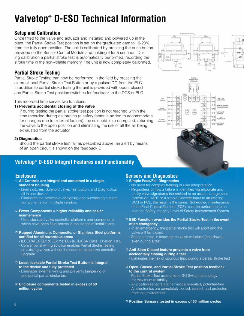
Valvetop® D-ESD Integral Features and Functionality
Sensors and Diagnosticsp Simple Pass/Fail Diagnostics - No need for complex training or user interpretation - Regardless of how a failure is identified via elaborate and costly valve signatures transmitted to an asset management system via HART or a simple Discrete Input to an existing DCS or PCL, the result is the same: Scheduled maintenance of the Final Control Element (FCE) must be performed to en- sure the Safety Integrity Level of Safety Instrumented System
p ESD Function overrides the Partial Stroke Test in the event of an emergency - In an emergency, the partial stroke test will abort and the valve will fail closed - Peace of mind in knowing the valve will close (shutdown), even during a test
p Anti-Slam Closed feature prevents a valve from accidentally closing during a test - Eliminates the risk of spurious trips during a partial stroke test
p Open, Closed, and Partial Stroke Test position feedback to the control system - Partial Stroke Test uses unique GO Switch technology for maximum reliability - All position sensors are hermetically-sealed, potential-free - All electronics are completely potted, sealed, and protected from the environment
p Position Sensors tested in excess of 50 million cycles
Setup and CalibrationOnce fitted to the valve and actuator and installed and powered up in the plant, the Partial Stroke Test position is set on the graduated cam to 10-20% from the fully open position. The unit is calibrated by pressing the push button provided on the Sensor Control Module and holding it for 5 seconds. Dur-ing calibration a partial stroke test is automatically performed, recording the stroke time in the non-volatile memory. The unit is now completely calibrated.
Partial Stroke TestingPartial Stroke Testing can now be performed in the field by pressing the external local Partial Stroke Test Button or by a pulsed DO from the PLC. In addition to partial stroke testing the unit is provided with open, closed and Partial Stroke Test position switches for feedback to the DCS or PLC.
This recorded time serves two functions:1) Prevents accidental closing of the valve
If during testing the partial stroke test position is not reached within the time recorded during calibration (a safety factor is added to accommodate for changes due to external factors), the solenoid is re-energized, returning the valve to the open position and eliminating the risk of all the air being exhausted from the actuator.
2) Diagnostics Should the partial stroke test fail as described above, an alert by means of an open circuit is shown on the feedback DI.
Valvetop® D-ESD Technical Information
sticsostics
8

Solenoid Valvep Uses Standard Solenoid Valve Technology with flow rates of 1.2Cv, 3.0Cv, and 8.0Cv - NO additional boosters or quick exhaust with piping required - NO continuous air bleed (positioner-type devices use in excess of 1.3m3/hr)
p Low Power Consumption (0.5 watts) - Less heat generation in the coil ensures longer life when continuously energized, which is typical in an SIS
p Built-in Flame Arrestors serve as 5-micron air filters - Protects the pilot valve against poor quality air supply, preventing one of the leading causes of Dangerous Failures in an SIS
p Full Air Pressure is transmitted by the pilot to the large cross-sectional area of the spool - Ensures maximum force is transmitted to shift the solenoid spool when needed
p Balanced Spool Design – all forces inside the spool are balanced - Only air pressure from the pilot is needed to overcome seal stiction and spring force
p Solenoid Valve tested in excess of 5 million cycles
9V A LV E T O P D - E S D S I L - 3 R AT E D V A LV E C O N T R O L L E R S
Often mounted on rotary scotch-yoke actuators, Valvetop SIL-3 ESD Valve Controllers are also good for Linear Valve Applications.
PLC DO(24V)
Relay LS1(Part of PST circuit)
PST Switch(local)
Partial Stroke Test(sensors & diagnostics ccts)
ESD Valve(incl. Actuator)
PilotSolenoid
Valve
SpoolValve
OptionalPST Switch(remote)
Error Codes
Reed switches controlled by shaft magnets
ESD Valve StatusShaft
MagnetsFixed onShaft
Notes:
Open
Closed
PS Position
Pass/Fail
The PST (sensors & diagnostics ccts) shaded box is the subject of the FMEA in Appendix 1
PLC DO is the (fail safe) control signal:Hi = ESD Valve OpenLo = ESD Valve Closed

10
Valvetop® D-ESD Ordering InformationOrdering Guide
Suggested SpecificationEmergency Shutdown Valve shall have Partial Stroke Test (PST) capability to periodically test the valve’s functionality without shutting down or disrupting the process. PST solution shall stroke the valve automatically rather than manually, shall provide end of stroke position feedback, and shall provide a means to test the functionality of the solenoid valve. ESD valve must be available to perform at all times during a test.
Enclosure Area Classification Visual Display Shaft Conduit O-Rings Pilot Spool Cv Override
DXP-ES Tropicalized Aluminum
DXR-ES Composite Resin
DXS-ES 316L Stainless Steel
G Standard 90° Green OPEN, Red CLOSED
S 1/4” DD 304 stainless
N NAMUR 304 stainless
4 (2) 3/4” NPT (2) 1/2” NPT
3 (4) M20
* Only (3) conduit
entries available
with PST Button
option
B Buna-N
V Viton
1 (1) 24Vdc pilot, .5W, fail open/ closed
7 (1) 110Vac pilot, 1.1W, fail open/ closed
A (1) 220Vac pilot, 3W, fail open/ closed
A Aluminum hard coat anodized
S 304 stainless
6 316 stainless
2 1.2 Cv (1/4” NPT ports)
3 3.0 Cv (1/2” NPT ports)
8 8.0 Cv (Consult
Factory)
T PST Button with lock cover
U PST Button without lock cover
Enclosure
Ordering GuideFill in the boxes to create your ‘ordering number.’
Area Classification Visual Display Shaft Conduit O-Rings Pilot Spool Cv Override
1 Flameproof/Explosion Proof Class 1, Div 1 Groups C & D Class 1, Div 2 Groups A-D Zone 1 ATEX EEx d IIB+H2 IECEX Ex d IIB+H2 II2G, IP 67 Type 4, 4x, 7
2 Non-Incendive Class I & II Div 2 Groups A-G Type 4, 4X
G General Purpose Ordinary Locations Type 4, 4X (DXR Only)
C Flameproof Zone 1
ATEX EEx d IIC IECEx Ex d IIC II2G II2G, IP67 (DXP Only)
* With appropriate I.S. barrier

TopWorx. The Look of a Leader. TopWorx is the global leader in valve control and position sensing solutions for plants, platforms, and pipelines.
11
WWW.TOPWORX.COM
Visit www.topworx.com for comprehensive information on our
company, capabilities, and products – including model numbers,
data sheets, specifications, dimensions, and certifications.
GLOBAL TECHNOLOGY LEADERSHIP
TopWorx technology advancements are at the forefront of
innovation in the process automation industry. TopWorx uses
wireless technologies and fieldbus protocols such as FOUNDATION
Fieldbus, DeviceNet, AS-Interface, Profibus, and HART to reduce
installation costs and enable predictive maintenance at many of
the world’s leading companies.
GLOBAL HAZARDOUS AREA CERTIFICATIONS
TopWorx valve controllers and position sensors are globally certified
for use in any hazardous location anywhere in the world. In addition
to high temperature (up to 204°C), cold temperature (-50°C), and
sub-sea (depths to 6,000 meters) applications, TopWorx products are
suitable for use in Zone 0 (Intrinsically Safe), Zone 1 (Flameproof/
Explosion Proof), and Zone 2 (Non-Incendive) hazardous areas with
IECEx, ATEX, InMetro, UL, CSA, JIS, KOSHA, GOST, and NEPSI
certifications.
GLOBAL SERVICE & SUPPORT
With company locations in the United States, United Kingdom, South
Africa, Bahrain, and Singapore, TopWorx is strategically positioned to
provide the kind of support that a world without compromise demands.
In addition, over 150 Certified Product Partners throughout the world
are available to provide competent local support when needed.
V A LV E T O P D - E S D S I L - 3 R AT E D V A LV E C O N T R O L L E R S
Related Documents