IMO-I4900 EN • 10/2019 VALVCON® ADC-Series CONTINUOUS DUTY, UNIVERSAL ON/OFF & MODULATING ELECTRIC ACTUATORS With UL2, UL3, UL4, UL5, UL6 & UL7 Options With “-UP” In The Model Number Installation, Maintenance and Operating Instructions

Welcome message from author
This document is posted to help you gain knowledge. Please leave a comment to let me know what you think about it! Share it to your friends and learn new things together.
Transcript

IMO
-I4900 EN • 10/2019
VALVCON®ADC-SeriesCONTINUOUS DUTY, UNIVERSALON/OFF & MODULATING ELECTRIC ACTUATORSWith UL2, UL3, UL4, UL5, UL6 & UL7 OptionsWith “-UP” In The Model Number
Installation, Maintenance and Operating Instructions

1. TABLE OF CONTENTS1. GENERAL .................................................................. 3
1.1 Scope of the Manual .................................................... 31.2 Actuator Markings ........................................................ 31.3 Safety Precautions ......................................................... 3
2. TRANSPORTATION AND STORAGE .......................... 33. GENERAL INSTALLATION INFORMATION ............... 3
3.1 Description of ADC-Series Universal Control Actuators (with Optional Battery Back-Up) .......... 3
3.2 Universal Control Board P/N VCB00010 ................ 44. GENERAL INSTALLATION iNFORMATION ............... 5
4.1 Interface ............................................................................ 54.2 Operation Mode Selector Pot ................................... 64.3 Control Mode Selector Pot ......................................... 64.4 Travel Limit Cam and Switch Operation ................ 6
4.4.1 Smart Limit ......................................................... 64.4.2 Cam Limit ............................................................ 7
4.5 Built-In Heater/Thermostat Feature ........................ 74.6 Torque Limit .................................................................... 7
5. MAIN ACTUATOR POWER ........................................ 75.1 115VAC or 230VAC Power Wiring ............................. 75.2 24VAC Power Wiring ..................................................... 75.3 12VDC or 24VDC Power Wiring ................................ 8
6. ON/OFF CONTROL (See Figure 5) ............................ 86.1 The three methods of On/Off Control: .................. 8
6.1.1 “2 Wire CW” ........................................................ 86.1.2 “2 Wire CCW” ...................................................... 86.1.3 “3 Wire Jogging” Operation
(Open/Stop Close) .......................................... 86.1.4 “3 Wire Latching” Operation ......................... 8
6.2 On/Off Control Signal Wiring .................................... 86.2.1 High Voltage: ..................................................... 86.2.2 Low Voltage: ...................................................... 8
6.3 Set Up and Calibration ................................................ 96.3.1 Initial Set Up ...................................................... 96.3.2 Potentiometer Calibration ............................ 96.3.3 Setting ZERO, MID and SPAN Positions .... 96.3.4 Verify End-Of-Travel Settings: ....................106.3.5 Proper Actuator Cover Replacement ......10
7. POSITION CONTROL (See Figure 5) ....................... 107.1 The three methods of Position Control ...............10
7.1.1 “4-20mA Current Analog” Control ...........107.1.2 “0-10VDC Voltage Analog” Control ..........107.1.3 “Resistive” Control (up to 10K Ohm)........10
7.2 Position Control Signal Wiring ................................107.2.1 Analog Control Wiring .................................107.2.2 Resistive Control Wiring ..............................10
7.3 Set Up and Calibration ..............................................117.3.1 Initial Set Up ....................................................11
7.3.2 Potentiometer Calibration ..........................117.3.3 Setting ZERO, MID, and SPAN Positions .117.3.4 Verify End-Of-Travel Settings: ....................127.3.5 Proper Actuator Cover Replacement ......12
7.4 Deadband Adjustment ..............................................127.5 Signal Fail Options ......................................................12
8. POSITION FEEDBACK AND STATUS INDICATORS . 128.1 Position Feedback .......................................................12
8.1.1 4-20mA ..............................................................138.1.2 0-10VDC ............................................................13
8.2 Status Indicators ..........................................................138.2.1 Auxiliary Switches ..........................................138.2.2 Power Status Relay ........................................138.2.3 Battery Status Relay ......................................13
9. POWER MANAGEMENT .......................................... 149.1 Battery .............................................................................149.2 Power Fail Controls .....................................................149.3 “Wake Up”and Manually Drive Actuator .............149.4 Energy Save Mode ......................................................1510. Board Installation / Replacement ................ 1510.1 Safety Precautions .......................................................1510.2 Safety Precautions Applicable to Units
Equipped with a Back-Up Battery ..........................1510.3 Parts Verification ..........................................................15
10.3.1 Locate the Replacement Board Kit 1510.3.2 Inspect all parts and hardware .................1510.3.3 Collect the tools required. ..........................15
11. BOARD REMOVAL .................................................. 1511.1 Step by Step Instructions for the Removal of a
Universal ADC/LADC-Series Actuator Control Board: ...............................................................................15
12. BOARD INSTALLATION ........................................... 1612.1 Step by Step Instructions..........................................16
13. REASSEMBLY .......................................................... 1714. DEFAULT SETTINGS AND MODES .......................... 1815. TROUBLESHOOTING .............................................. 1816. GENERAL OPERATING INFORMATION .................. 19
16.1 Enclosure Ratings and Product ..............................1916.2 Operating Temperature Limits ...............................1916.3 Actuator Mounting .....................................................1916.4 Manual Override ..........................................................1916.5 Lubrication .....................................................................1916.6 Problem Prevention ....................................................1916.7 Warranty .........................................................................1916.8 Repair Service/Spare Parts .......................................19
17. SPECIFICATIONS & TECHNICAL INFORMATION ... 2017.1 ADC-SERIES UNIVERSAL CONTROL BOARD ........2117.2 DIMENSIONS .................................................................22
18. ADC-SERIES ACTUATORS BY MODEL NUMBER .... 2319. ADDITIONAL ACTUATOR PRODUCTS AND
ACCESSORIES FROM METSO ................................. 24
READ THESE INSTRUCTIONS FIRST!
These instructions provide information about safe handling and operation of the actuator.If you require additional assistance, please contact the manufacturer or manufacturer’s representative.Addresses and phone numbers are printed on the back cover.See also www.metso.com/electricactuators for the latest documentation.
SAVE THESE INSTRUCTIONS!
All trademarks are property of their respective owners.
IMO 10/19
2 IMO-I4900 EN

1. GENERAL
1.1 Scope of the Manual
This instruction manual contains important information regarding the installation, operation and maintenance of the Valvcon ADC-Series electric actuator. Please read these instructions carefully and save them for future reference.
1.2 Actuator Markings
WARNINGAS THE USE OF THE ACTUATOR IS APPLICATION SPECIFIC, A NUMBER OF FACTORS SHOULD BE TAKEN INTO ACCOUNT WHEN SELECTING AN ACTUATOR FOR A GIVEN APPLICATION. THEREFORE, SOME OF THE SITUATIONS IN WHICH THE ACTUATORS ARE USED ARE OUTSIDE THE SCOPE OF THIS MANUAL.IF YOU HAVE ANY QUESTIONS CONCERNING THE USE, APPLICATION OR COMPATIBILITY OF THE ACTUATOR WITH THE INTENDED SERVICE, CONTACT METSO FOR MORE INFORMATION.
The actuator has an identification label attached to the base casting (see Figure 1).
(1) (2) (7) (8) (9)
(3) (6) (5) (4)
MODEL# LADCWX1000UL2-UPSERIAL # DUTY CYCLE 100%
SEAL ALL CONDUITS WITHIN 18"CLASS I, DIV. I, GR. C & D; CLASS II, DIV I, GR. E, F & G; CLASS III.
ENCLOSURE TYPE 4/4X IP66V12345678
TORQUE 1000 LB-IN
SEE MANUAL IMO- I4900
230VAC0.6 A
15 SEC
115VAC0.9 A
15 SEC
24VAC3.5 A
15 SEC
24VDC2.4 A
14 SEC
12VDC4.0 A
21 SEC
METSO FLOW CONTROL USA INC. 44 BOWDITCH DRIVE SHREWSBURY, MA 01545 USA 1-508-595-5083WARNING: DO NOT OPEN WHILE ENERGIZED OR WHEN AN EXPLOSIVE ATMOSPHERE IS PRESENT
VOLTAGECURRENTSTROKE TIME 90° MC# 167265
®
Figure 1 Identification Plate
Identification label markings:
1. Model number2. Serial number3. Maximum output torque4. Voltage5. Current draw (full-load running)6. Cycle time7. Duty cycle8. Applicable manual9. Certifications marking
1.3 Safety Precautions
WARNINGDO NOT EXCEED THE ACTUATOR PERFORMANCE LIMITATIONS!EXCEEDING THE TORQUE LIMITATIONS MARKED ON THE ACTUATOR IDENTIFICATION LABEL MAY CAUSE DAMAGE TO THE ACTUATOR AND/OR FINAL DRIVE ELEMENT.
WARNINGDO NOT EXCEED THE ACTUATOR ELECTRICAL LIMITATIONS!EXCEEDING THE ELECTRICAL LIMITATIONS MARKED ON THE ACTUATOR IDENTIFICATION LABEL MAY CAUSE DAMAGE TO THE ACTUATOR AND/OR PERSONAL INJURY.
WARNINGBEWARE OF MOVEMENT OF THE FINAL DRIVE ELEMENT AND ANY LINKAGE BETWEEN IT AND THE ACTUATOR!
KEEP HANDS, OTHER PARTS OF THE BODY, TOOLS AND OTHER OBJECTS OUT OF THE WAY OF MOVING PARTS. FAILURE TO DO THIS MAY RESULT IN DAMAGE OR PERSONAL INJURY!
2. TRANSPORTATION AND STORAGE
Check the actuator and any accompanying devices for any damage that may have occurred during transport.
Store the actuator carefully. Storage indoors in a dry place is recommended.
Move the actuator to its intended location just before installation.
The actuator is usually shipped in the full clockwise, (typically closed) position.
If the actuator(s) will be stored for a period longer than 90 days, follow the recommendations in IMO-S2 to maintain the actuator’s integrity.
3. GENERAL INSTALLATION INFORMATION
3.1 Description of ADC-Series Universal Control Actuators (with Optional Battery Back-Up)
The ADC-Series consists of two different sized enclosures that cover different torque ranges. Model codes that start with “ADC” indicate the standard enclosure and a torque rating in the range from 150 to 600 in•lbs. “LADC” designates the larger enclosure and a torque rating in the range from 1000 to 3000 in•lbs.
The ADC-Series Actuators provide an optional internal battery pack to power the actuator in the event of a loss of external power. Actuators with battery back-up are identified in the model code by either a “UL2”, “UL3”, “UL4”, “UL5”, “UL6” or “UL7”. The “UL2”, “UL4” and “UL6” options are applicable in a standard ADC enclosure and the “UL3”, “UL5”and “UL7” options are applicable in a LADC enclosure. The “UL4” and “UL5” options are factory-set for 180° operation with the MID position factory set at 90°; and the “UL6” and “UL7” options are factory-set for 270° operation.
The ADC-Series Actuators’ base electronic package consists of two separate boards; P/N VCB00010 Universal Control Board and the Switching Power Supply allowing for the choice of 115VAC, 230VAC, 12VDC, 24VDC or 24VAC actuator power.
IMO 10/19
IMO-I4900 EN 3

3.2 Universal Control Board P/N VCB00010
The Universal Control Board can be configured for either “Two-Wire” or “Three-Wire” On/Off control, or “4-20mA Analog”, “0-10VDC Analog”, or a “Resistive” Positioner Control. (See Figure 5 in Section 4.3)
The Universal Control Board used in Positioner Control mode can be configured for Loss of Signal and has an adjustable input signal Dead Band.
The Universal Control Board allows independent 115VAC, 230VAC, 12VDC, 24VDC or 24VAC control signals from actuator power.
The Universal Control Board can provide analog position feedback, Power and Battery status and includes on-board battery status indicators.
The Universal Control Board with the optional Battery Back-up installed will allow you to select power “Fail” position as well as to choose “Park” or “Multi” cycling upon loss of actuator power.
The Universal Control Board has locked rotor stall protection.
The Universal Control Board has manual push button control and simple digital smart set functionality for entering and saving precise end of travel positions for calibration to the application.
The Universal Control Board has an easy to navigate color scheme for its input and output wiring terminal blocks, detailed below:
Orange = Actuator Power Green = On/Off Control Yellow = Modulating Control White = Analog Feedback Light Blue = Status Feedback
WARNINGDANGEROUS VOLTAGES ARE PRESENT INSIDE THE ACTUATOR COVER UNLESS THE POWER SUPPLY TO THE ACTUATOR HAS BEEN SHUT OFF OR DISCONNECTED. USE EXTREME CAUTION WHENEVER WORKING ON THE ACTUATOR WITH THE COVER REMOVED.
WARNINGACTUATORS SHOULD BE PROPERLY GROUNDED AND WIRED IN ACCORDANCE WITH LOCAL ELECTRICAL CODE; SEE NAMEPLATE FOR MAXIMUM CURRENT DRAW.
WARNINGDO NOT MIS-APPLY HIGH-VOLTAGE SIGNALS TO LOW-VOLTAGE CIRCUITS. DO NOT POWER THE POSITION FEEDBACK CIRCUIT IF EXTERNAL POWER MODE IS NOT SELECTED. SERIOUS DAMAGE TO THE CIRCUIT BOARD MAY RESULT.
WARNINGWHENEVER WORKING INSIDE THE ACTUATOR, CARE MUST BE TAKEN TO AVOID DAMAGE TO THE MACHINED FLANGE SURFACES ON THE COVER AND BASE CASTINGS. FAILURE TO DO SO CAN VOID THE ACTUATOR’S ENVIRONMENTAL CERTIFICATION.
WARNINGUSE CARE WHENEVER WORKING WITH THE ACTUATOR COVER REMOVED. DAMAGE, SCRATCHES, OR DENTS ON THE MACHINED FLANGE SURFACES OF THE ENCLOSURE MAY VOID COMPLIANCE WITH NEMA, CSA, UL, AND/OR IEC SPECIFICATIONS. (SEE SECTIONS 6.3.5, 7.3.5, & 13)
WARNINGIF USING 24VAC TO POWER THE ACTUATOR, A DEDICATED POWER SUPPLY OR ISOLATION TRANSFORMER MUST BE USED.
WARNINGWHEN BATTERY IS CONNECTED TO BOARD, THE UNIT MAY DRIVE!BEWARE OF MOVEMENT OF THE FINAL DRIVE ELEMENT AND ANY LINKAGE BETWEEN IT AND THE ACTUATOR!
KEEP HANDS, OTHER PARTS OF THE BODY, TOOLS AND OTHER OBJECTS OUT OF THE WAY OF MOVING PARTS. FAILURE TO DO THIS MAY RESULT IN DAMAGE OR PERSONAL INJURY!
WARNINGTHIS UNIT CONTAINS A SEALED LEAD ACID BATTERY, REGULARCHARGING IS NECESSARY WITH STORAGE LONGER THAN THREEMONTHS. TO CHARGE THE BATTERY, APPLY ONE OF THE INPUTVOLTAGES TO THE CORRESPONDING INPUT ON THE ACTUATOR,(NOT DIRECTLY TO THE BATTERY) AND LEAVE POWERED FOR ATLEAST TWENTY-FOUR HOURS.
HIGH AMBIENT TEMPERATURES CAN SHORTEN STORAGE LIFE. IT IS RECOMMENDED THAT THE BATTERY BE STORED AT 22°C +/- 5°C. INSPECT THE BATTERY UPON RECEIPT, BEFORE INSTALLATION, AND AT REGULAR MAINTENANCE INTERVALS. REMOVE THE BATTERYFROM THE DEVICE FOR LONG-TERM STORAGE.
FAILURE TO FOLLOW THIS CHARGING REQUIREMENT MAY RESULT IN REDUCED EFFECTIVE BATTERY LIFE.Figure 2
IMO 10/19
4 IMO-I4900 EN

4. GENERAL INSTALLATION INFORMATION
4.1 Interface1 - CAL – A continuous yellow LED indicates that the CAL (calibration) mode has been selected. A flashing yellow LED displays to the user how close they are to hitting the CAL point depending on the speed of the flashes. The CAL mode allows the user to calibrate the position tracking potentiometer without the use of an ohmmeter or other electronic instruments. In CAL mode the actuator will travel beyond the saved settings for the Zero and Span stop positions.
2 - ZERO – A continuous yellow LED indicates that the ZERO mode has been selected. ZERO mode permits the user to set the desired Zero end-of- travel stop position with a corresponding control signal value. The Zero position is typically the fully clockwise position and minimum control signal value, but Zero may be set at any position.
3 - MID - A continuous yellow LED indicates that the MID mode has been selected. MID mode permits the user to save the desired “MID” position. The MID position may be set at any position inside (between) the saved Zero and Span end-of-travel positions. (MID is not typically used with the Position Control configuration but can be used as a mid-travel “fail” position upon loss of external power, provided the actuator is equipped with a back-up battery.)
4 - SPAN – A continuous yellow LED indicates that the SPAN mode has been selected. SPAN mode permits the user to set the desired Span end-of-travel stop with a corresponding control signal value. Typically, the Span position is the fully counterclockwise position and maximum control signal value, but Span may be set at any position.
5 - MAN (MANUAL) – A continuous yellow LED indicates that Manual Control mode has been selected. The actuator will not respond to external control signals and the [CW] and [CCW] push buttons are enabled for manually driving the actuator in either direction. In Manual mode the actuator will not travel beyond the saved settings for the Zero and Span stop positions.
6 - RUN – A continuous green LED indicates that the normal operating mode has been selected. In RUN mode the actuator will respond external signals supplied to the Universal Control Board. This LED will turn off in Energy Save mode.
7 - ENTER – located directly below the mode selector and permits the user to activate modes and confirm settings by pressing the [ENTER] button.
8 - CW (CLOCKWISE) – A continuous yellow LED indicates that the actuator is driving in the CW direction. Located next to the Manual Control push button to drive the actuator in the CW direction.
9 - CCW (COUNTER-CLOCKWISE) – A continuous yellow LED indicates the actuator is driving in the CCW direction. Located next to the Manual Control push button to drive the actuator in the CCW direction.
10 - Motor Stall – A flashing red LED indicates a stall condition exists and that the actuator has been prevented from reaching the position commanded by the control signal. A STALL of more than several seconds will cause power to be automatically removed from the motor circuit, placing the actuator in a safe mode. A reverse signal or a manual mode [CW] or [CCW] movement is required to clear the stall condition. A STALL condition can be initiated by a blockage in the valve or damper, cam limit settings that
10
11
12
6
7
5
4 3
2
1
8
9
13
Figure 3
VCB00010 Universal Control Board (Front)
IMO 10/19
IMO-I4900 EN 5

are inside of the electronically saved travel stop positions, or some other increase in the torque load on the actuator.
11 - Battery Charging* – A continuous yellow LED indicates that the battery charging circuit is active to either charge or maintain the voltage on the Battery.
12 - Battery Charged* – A continuous green LED indicates that the battery is fully charged. A flashing green LED indicates the actuator is running on battery power. This LED will turn off in Energy Save mode.
* NOTE: Battery Charging and Battery Charged LEDs may be lit at the same time depending on the battery charge state.
13 - Switch Trip – A continuous red LED indicates that one of the end-of-travel limit switches has been “tripped” by the respective cam; this LED is intended to aid initial actuator set-up.
4.2 Operation Mode Selector Pot
The Universal Control Board is equipped with an Operation Mode Selector Pot which allows the user to select the 6 modes of operation during calibration and set-up. LED indicators around the knob correspond to each of the modes; RUN, Manual (MAN), SPAN, MID, ZERO and Calibrate (CAL). When the Universal Control Board mode dial is set to any mode, the corresponding LED turns on, indicating the mode is selected.
In MAN (Manual) and CAL mode the unit will ignore any external control signals and respond only to the on-board push buttons (it should be noted that if the unit is equipped with an optional back-up battery and loss of power should occur while in MAN and CAL mode, the unit will drive to the selected “Power Fail” position).
4.3 Control Mode Selector Pot
The Universal Control Board is equipped with a ControlMode Selector Pot which enables the user to selectbetween various “On/Off Control” and “Position Control”modes.
Figure 5
4.4 Travel Limit Cam and Switch OperationWith the Universal Control Board installed, the travel limit stops are set electronically as the Zero and Span position. Two limit switches operated by the cams on the output shaft are safety stops. Their intended function is to prevent damage in the event of a failure of the electronic limits. Therefore: Each cam must be set to operate the switch slightly outside of the electronic Zero and Span position range. Failure to set the cams properly may cause the actuator to stall when it cannot reach the commanded and electronically set end of travel position. The bottom limit switch determines clockwise safety stop position. The next limit switch, up from the bottom, determines the counterclockwise safety stop position. Auxiliary switches and the corresponding cams will be the third and fourth up from the bottom.
Travel limits, also referred to as “end of travel stops”, are the precise positions to which the actuator will drive. For “2 Wire” or “3 Wire” On/Off operation, travel limits are set at the full clockwise (CW) and full counter-clockwise (CCW) ends of travel.
To simplify the process of setting the precise travel limit positions, the ADC-Series provides two On/Off travel limit types. CW, CCW and MID may be set electronically via the “Smart” limit utility or CW and CCW may be set mechanically by selecting the “Cam” limit type.
4.4.1 Smart LimitWhen “Smart” is selected as the limit type, the microprocessor stores the exact positions where the actuator will stop at each end of travel or mid position. Setting the “Smart” limit positions for the ZERO (typically CW), MID, and SPAN (typically CCW) positions is done with the selector knob and [ENTER] button in the Operation field of the Universal Control board. To use the Smart limit features, the Feedback Potentiometer must be installed, connected and calibrated and the travel stop cams must be set to trip the switches slightly beyond the desired “electronic” stop positions for ZERO and SPAN. The end-of-travel limits on ADC actuators can be entered and saved between 0° and 270° of travel. For 180° and 270° rotation alternate potentiometer gearing is required (refer to option code). For “Three-Position” operation, limits must be entered and saved using the “Smart” Limit!
Figure 4
IMO 10/19
6 IMO-I4900 EN

4.4.2 Cam Limit
When “Cam” is selected as the limit type, two limit switches operated by the stainless steel cams on the output shaft extension are used to determine the exact positions where the actuator will stop at each end of CW and CCW travel. The bottom limit switch determines the clockwise stop position. The next limit switch, up from the bottom determines the counter-clockwise stop position. The “end of travel limit” switches can be adjusted to provide from 5 to 320 degrees of actuator rotation. For “Three-Position” operation, limits must be entered and saved using the “Smart” Limit!
4.5 Built-In Heater/Thermostat Feature
The Universal Control Board is equipped with a built-in Heater/Thermostat Option that can be enabled for low-temperature use (environments where the temperature will drop below 32° Fahrenheit), high-humidity use (“tropical” environments), or disabled completely to conserve power, in environments where the climate is stable and/or controlled.
NOTE: All heater modes are disabled in “Energy Save” mode.
The Heater/Thermostat is enabled/disabled by sliding a switch on the Universal Control Board. See graphic below for proper positioning:
Figure 6
4.6 Torque Limit
The actuator is equipped with a torque limit feature; see Figure 7 for identification of the torque setting potentiometer (located under the overlay, between the CW and CCW pushbuttons).
Figure 7
There are two standard settings as follows: “Small” actuator; 150, 300, or 600 lb-in torque rating.“Large” actuator; 1000, 1500, 2000, 2500, or 3000 lb-in torque rating.NOTE: The sections marked “Special” will be utilized only by the factory to limit the torque output to a value below the actuator’s maximum rated torque.
WARNINGFAILURE TO SET THE TORQUE VALUE IN THE APPROPRIATE REGION FOR THE ACTUATOR SIZE WILL VOID THE PRODUCT WARRANTY.
5. MAIN ACTUATOR POWER
The identification label on each actuator specifies themodel number, serial number, actuator power voltage and current requirements for the actuator. It is important to verify the correct actuator voltage and control voltageprior to wiring the actuator.
Figure 8
5.1 115VAC or 230VAC Power Wiring
If using 115VAC or 230VAC as the MAIN Input Power:115/230 VAC must be supplied constantly to the Universal Control Board as follows:
- Terminal A (AC L1/HOT) - Terminal B (AC L2/NEUT)
5.2 24VAC Power Wiring
If using 24VAC as the MAIN Input Power: 24VAC must be supplied constantly to the Universal Control Board as follows:
- Terminal 17 (24AC HOT) - Terminal 18 (24AC NEUT)
IMO 10/19
IMO-I4900 EN 7

WARNINGIF USING 24VAC TO POWER THE ACTUATOR, A DEDICATED POWER SUPPLY OR ISOLATION TRANSFORMER MUST BE USED.
5.3 12VDC or 24VDC Power Wiring
If using 12VDC or 24VDC as the MAIN Input Power: 12/24 VDC must be supplied constantly to the Universal Control Board as follows:
- Terminal 19 (DC POS) - Terminal 20 (DC NEG)
6. ON/OFF CONTROL (See Figure 5)
6.1 The three methods of On/Off Control:
The On/Off Control mode allows the actuator to drive in a desired direction in response to an application of voltage to the desired inputs. The different modes are as follows:
6.1.1 “2 Wire CW”
The actuator will default to the CCW position when main actuator power is present; the actuator will drive CW when the “CW” control power is energized.
6.1.2 “2 Wire CCW”
The actuator will default to the CW position when main actuator power is present; the actuator will drive CCW when the “CCW” control power is energized.
6.1.3 “3 Wire Jogging” Operation (Open/Stop Close)
The actuator will drive CCW when the “CCW” control power is energized and drive CW when the “CW” control power is energized; if control power is removed mid-travel, the actuator will stop in position. The actuator will drive to the programmed “MID” position when the “MID” control power is energized. The “MID” position is optional and can be set anywhere inside of the CW and CCW end-of-travel positions settings to provide a Three-Position “Center-Off” position, or a “Dribble Feed” position.
6.1.4 “3 Wire Latching” Operation
The actuator will “latch” and drive CCW when the “CCW” control power is momentarily energized. The actuator will “latch” and drive CW when the “CW” control power is momentarily energized. After energizing the control power can be removed, as the direction of travel is “latched” in and the unit will continue to drive to the respective travel limit. The actuator will “latch” and drive to the programmed “MID” position when the “MID” control power is momentarily energized. The “MID” position is optional and can be set anywhere inside of the CW and CCW end-of-travel positions settings to provide a Three-Position “Center-Off” position, or a “Dribble Feed” position.
6.2 On/Off Control Signal Wiring
Figure 10
6.2.1 High Voltage:
To control the actuator with a high voltage signal (115VAC or 230VAC): Connect AC L2/NEUT to terminal F on the Universal Control Board. Energize AC L1/HOT at terminal C on the Universal Control Board to drive the actuator clockwise (CW). Energize AC L1/HOT at terminal D on the Universal Control Board to drive the actuator to the “MID” position. Energize AC L1/HOT at terminal E on the Universal Control Board to drive the actuator counter-clockwise (CCW).
6.2.2 Low Voltage:
To control the actuator with a low voltage signal (12VDC, 24VDC or 24VAC): Connect 12/24DC NEG or 24AC NEUT to terminal 8 on the Universal Control Board. Energize DC POS or 24AC HOT at terminal 9 on the Universal Control Board to drive the actuator clockwise (CW). Energize DC POS or 24AC HOT at terminal 10 on the Universal Control Board to drive the actuator to the “MID” position. Energize DC POS or 24AC HOT at terminal 11 on the Universal Control Board to drive the actuator clockwise (CCW).
IMO 10/19
8 IMO-I4900 EN

AB
Hot / L1115/230VAC Neut. / L2CDEFGHIJKL
NO
NCC W S witch 1 C OM
NO
NCC C W S witch 2 C OM
mA / V DC + Opt. E xternal +24V DC F eedback
+
- Wiper R es istive C ontrol
+ 4-20mA or 0-10V DC Analog C ontrol -
123456789
10111213141516
mA / V DC -
17181920
24V AC
+12/24V DC -
Low V oltage P ower
Auxiliary S witches
High V oltage P ower
P os ition C ontrol
AB
Hot / L1115/230VAC Neut. / L2CDEF
Hot / L1 C WHot / L1 MID
Hot / L1 C C WNeut. / L2 C OM
GHIJKL
NO
NCC W S witch 1 C OM
NO
NCC C W S witch 2 C OM
mA / V DC + Opt. E xternal +24V DC F eedback
123456789
10111213141516
mA / V DC -
17181920
24V AC
+12/24V DC -
Low V oltage P ower
Auxiliary S witches P os . / Hot C W P os . / Hot MID P os . / Hot C C W
115/230VAC
High V oltage P ower
On/O� C ontrol
High V oltageOn / O� C ontrol
Low V oltage On / O� C ontrol
12/24V DCor 24V AC
Neg. / C om. C OM
On/Off Control Wiring
Figure 9
6.3 Set Up and Calibration6.3.1 Initial Set Up1. Remove actuator cover. Remove the override shaft
from the actuator cover bushing; if the actuator is equipped with a handwheel, remove the handwheel before removing the top piece of the “two-piece” shaft from the cover bushing. NOTE: Use caution to prevent damage to machined flange surface of cover casting; see cover replacement for additional information.
2. Select LIMIT type “Smart” or “Cam” by sliding the [Smart/Cam] switch down to select Cam or up to select Smart. Selecting Smart will enable other features on the board such as Position Feedback and “Three- Position” operation. Selecting Cam will allow the actuator to drive between the end-of-travel limit switch settings.
3. Select Control Method “2 Wire CCW”, “2 Wire CW”, or “3 Wire” by turning the selection potentiometer with a small flat blade screwdriver.
6.3.2 Potentiometer CalibrationField installation of the Universal Control Board or replacement of the position tracking potentiometer requires calibration of the position tracking potentiometer prior to setting positions and values for ZERO, MID and SPAN. Universal Control Boards installed at the factory are fully calibrated at the factory and should not require further calibration.To confirm proper potentiometer calibration:1. Turn the Mode Selector Dial to [CAL] and press [ENTER]
for 2 seconds.2. Using the CW pushbutton, drive the actuator to the
full clockwise position. - If the [CAL] LED is flashing, potentiometer calibration is required; proceed to step 3 below. - If the [CAL] LED remains on, calibration is not required; proceed to Setting ZERO, MID and SPAN Positions section below.
3. Loosen the set screw in the gear with a 1/16” hex wrench.
4. Rotate the gear until the LED remains on constantly; hold the gear in place and tighten the set screw. Ensure that the LED remains on after the set screw is tightened. NOTE: The LED assists the user in locating the proper calibration window; it will flash faster as you approach the calibration window and slower as you move away from it.
5. Press the [ENTER] button to save the potentiometer setting.
6.3.3 Setting ZERO, MID and SPAN Positions
Once (feedback potentiometer) calibration has been confirmed, set the desired “end of travel” positions. Make certain that the limit switch cams are set to operate the switches beyond the desired range for the ZERO and SPAN positions. ZERO and SPAN may be set at any position between 0° and 94° of travel (0° and 184° with “UL4” or “UL5” option; or 0° and 274° with “UL6” or “UL7” option).
Set ZERO (typically CW):1. Turn the Mode Selector Dial to [ZERO] and press [ENTER]
for 2 seconds. The [ZERO] LED will begin to flash.
2. Drive the actuator to desired clockwise position using the CW or CCW push button. If the “STALL” LED begins to flash; check to see if the limit switch cam is preventing actuator from reaching desired ZERO end-of-travel (the “Switch Trip” LED will be illuminated). If necessary back the cam off so that it will trip the switch slightly beyond the desired end-of-travel and the “Switch Trip” LED will go out.
3. Press the [ENTER] button to save the ZERO setting.
Set MID (MID position will auto-calculate between Zero and Span; if an alternate position is desired, proceed as follows):
1. Turn the Mode Selector Dial to [MID] and press [ENTER] for 2 seconds. The [MID] LED will begin to flash.
2. Drive the actuator to the desired MID or “THIRD” position using the CW or CCW push button.
3. Press the [ENTER] button to save the MID setting.
IMO 10/19
IMO-I4900 EN 9

Set SPAN (typically CCW):
1. Turn the Mode Selector Dial to [SPAN] and press [ENTER] for 2 seconds. The [SPAN] LED will begin to flash.
2. Drive the actuator to desired counterclockwise position using the CW or CCW push button. If the “STALL” LED begins to flash; check to see if the limit switch cam is preventing actuator from reaching desired SPAN end-of-travel (the “Switch Trip” LED will be illuminated). If necessary, back the cam off so that it will trip the switch slightly beyond the desired end-of-travel and the “Switch Trip” LED will go out.
3. Press the [ENTER] button to save the SPAN setting.
6.3.4 Verify End-Of-Travel Settings:
1. Turn the Mode Selector Dial to [RUN].
2. Apply various control signals to verify operation.
3. Verify that the “Switch Trip” LED is not illuminated at either the ZERO or SPAN positions (if it is, “back” the respective end-of-travel cam “off” of the respective limit switch).
4. Replace actuator cover.
6.3.5 Proper Actuator Cover Replacement
NOTE: For actuators including hazardous location certifica-tion. Prior to installing cover, inspect machined flange surfaces for any damage, scratches, or dents. Damage, scratches, or dents that will not fit completely in a circle having a diam-eter of 1/64” will void hazardous location certifications. If such imperfections are present the damaged enclosure parts(s) must be replaced. Consult the factory for replacement parts.
1. Remove the override shaft from the actuator cover bushing; if the actuator is equipped with a handwheel, remove the handwheel before removing the top piece of the “two-piece” shaft from the cover bushing.
2. Install the override shaft on the square motor shaft; if the actuator is equipped with a handwheel, install the bottom piece of the “two-piece” shaft on the motor shaft and then install the top piece of the shaft onto the bottom piece of the shaft.
3. Align cover so that the override shaft will pass through the override bushing and carefully push it down so that the cover flange contacts the base flange.
4. Once the cover is properly seated, tighten the screws to secure the cover; a cross pattern is recommended for uniform distribution of load.
5. If the position indicator is not seated to the output/cam shaft, turn until it drops into place in order to ensure accurate visual position indication.
7. POSITION CONTROL (See Figure 5)
7.1 The three methods of Position Control
The Position Control mode allows the actuator to modulate (change position) in response to a change in an analog or resistance control signal. The different modes are as follows:
7.1.1 “4-20mA Current Analog” ControlThe actuator will modulate between positions in direct response to the change in the input current signal. Set 4 mA as the Zero position and 20mA as Span for normal operation or set 4mA as Span and 20mA as Zero for reverse acting.
7.1.2 “0-10VDC Voltage Analog” ControlThe actuator will modulate between positions in direct response to the change in the input voltage signal. Set 0VDC as the Zero position and 10VDC as Span for normal operation or set 0VDC as Span and 10VDC as Zero for reverse acting.
7.1.3 “Resistive” Control (up to 10K Ohm)The actuator will modulate between positions in direct response to the change in the input resistive signal.
7.2 Position Control Signal Wiring
Figure 11
7.2.1 Analog Control Wiring
To control the actuator with a 4-20mA or 0-10V analog signal: Connect mA / VDC - (NEG) to terminal 16 and mA / VDC + (POS) to terminal 15 on the Universal Control Board Slide the [Input] switch up to select 0-10V or down to select 4-20mA.
7.2.2 Resistive Control WiringTo control the actuator with a resistance signal such as 0- 135 Ohms: Connect Resistance Signal - (NEG) to terminal 14, Resistance Signal Wiper to terminal 13, and Resistance + (POS) to terminal 12 on the Universal Control Board. The board will respond to resistance signals up to 10K Ohms (minimum SPAN signal is 100 Ohms; i.e. signal = 0-100 Ohms). NOTE: There is a current limiter on the Resistive Input circuit, if the current exceeds 50mA for more than 80 milliseconds, the input will shut off. If this happens, it can be reset by cycling Main power.
IMO 10/19
10 IMO-I4900 EN

AB
Hot / L1115/230VAC Neut. / L2CDEFGHIJKL
NO
NCC W S witch 1 C OM
NO
NCC C W S witch 2 C OM
mA / V DC + Opt. E xternal +24V DC F eedback
+
- Wiper R es istive C ontrol
+ 4-20mA or 0-10V DC Analog C ontrol -
123456789
10111213141516
mA / V DC -
17181920
24V AC
+12/24V DC -
Low V oltage P ower
Auxiliary S witches
High V oltage P ower
P os ition C ontrol
AB
Hot / L1115/230VAC Neut. / L2CDEF
Hot / L1 C WHot / L1 MID
Hot / L1 C C WNeut. / L2 C OM
GHIJKL
NO
NCC W S witch 1 C OM
NO
NCC C W S witch 2 C OM
mA / V DC + Opt. E xternal +24V DC F eedback
123456789
10111213141516
mA / V DC -
17181920
24V AC
+12/24V DC -
Low V oltage P ower
Auxiliary S witches P os . / Hot C W P os . / Hot MID P os . / Hot C C W
115/230VAC
High V oltage P ower
On/O� C ontrol
High V oltageOn / O� C ontrol
Low V oltage On / O� C ontrol
12/24V DCor 24V AC
Neg. / C om. C OM
Positioning Control Wiring
Figure 12
7.3 Set Up and Calibration
7.3.1 Initial Set Up
1. Remove actuator cover. Remove the override shaft from the actuator cover bushing; if the actuator is equipped with a handwheel, remove the handwheel before removing the top piece of the “two-piece” shaft from the cover bushing. NOTE: Use caution to prevent damage to machined flange surface of cover casting; see cover replacement for additional information.
2. Select LIMIT type “Smart” by sliding the [Smart/Cam] switch up to select Smart. Selecting Smart will enable other features on the board such as Position Feedback.
3. Select Control Method “Analog” or “Resistive” by turning the selection potentiometer with a small flat blade screwdriver.
7.3.2 Potentiometer Calibration
Field installation of the Universal Control Board option or replacement of the position tracking potentiometer requires calibration of the position tracking potentiometer prior to setting positions and values for ZERO, MID and SPAN. Universal Control Board options installed at the factory are fully calibrated at the factory and should not require further calibration. To confirm proper potentiometer calibration:
1. Turn the Mode Selector Dial to [CAL] and press [ENTER] for 2 seconds.
2. Using the CW pushbutton, drive the actuator to the full clockwise position. - If the [CAL] LED is flashing, potentiometer calibration is required; proceed to step 3 below. - If the [CAL] LED remains on, calibration is not required; proceed to Setting ZERO, MID and SPAN Positions section below.
3. Loosen the set screw in the gear with a 1/16” hex wrench.
4. Rotate the gear until the LED remains on constantly; hold the gear in place and tighten the set screw. Ensure that the LED remains on after the set screw is tightened. NOTE: The LED assists the user in locating the proper calibration window; it will flash faster as you approach the calibration window and slower as you move away from it.
5. Press the [ENTER] button to save the potentiometer setting.
7.3.3 Setting ZERO, MID, and SPAN Positions
Once (feedback potentiometer) calibration has been confirmed, set the desired “end of travel” positions. Make certain that the limit switch cams are set to operate the switches beyond the desired range for the ZERO and SPAN positions. ZERO and SPAN may be set at any position between 0° and 94° of travel (0° and 184° with “UL4” or “UL5” option; or 0° and 274° with “UL6” or “UL7” option).
Set ZERO (typically CW):
1. Turn the Mode Selector Dial to [ZERO] and press [ENTER] for 2 seconds. The [ZERO] LED will begin to flash.
2. Drive the actuator to desired clockwise position using the CW or CCW push button. If the “STALL” LED begins to flash; check to see if the limit switch cam is preventing actuator from reaching desired ZERO end-of-travel (the “Switch Trip” LED will be illuminated). If necessary back the cam off so that it will trip the switch slightly beyond the desired end-of-travel and the “Switch Trip” LED will go out.
3. Apply the desired Analog Signal that will correspond with the Zero position (ie 4mA).
4. Press the [ENTER] button to save the ZERO setting.
IMO 10/19
IMO-I4900 EN 11

Set MID (MID position will auto-calculate between Zero and Span; if an alternate position is desired, proceed as follows):
1. Turn the Mode Selector Dial to [MID] and press [ENTER] for 2 seconds. The [MID] LED will begin to flash.
2. Drive the actuator to the desired MID or “THIRD” position using the CW or CCW push button.
3. Press the [ENTER] button to save the MID setting.
Set SPAN (typically CCW):
1. Turn the Mode Selector Dial to [SPAN] and press [ENTER] for 2 seconds. The [SPAN] LED will begin to flash.
2. Drive the actuator to desired counterclockwise position using the CW or CCW push button. If the “STALL” LED begins to flash; check to see if the limit switch cam is preventing actuator from reaching desired SPAN end-of-travel (the “Switch Trip” LED will be illuminated). If necessary, back the cam off so that it will trip the switch slightly beyond the desired end-of-travel and the “Switch Trip” LED will go out.
3. Apply the desired Analog Signal that will correspond with the Span position (ie 20mA).
4. Press the [ENTER] button to save the SPAN setting.
7.3.4 Verify End-Of-Travel Settings:
1. Turn the Mode Selector Dial to [RUN].
2. Apply various control signals to verify operation.
3. Verify that the “Switch Trip” LED is not illuminated at either the ZERO or SPAN positions (if it is, “back” the respective end-of-travel cam “off” of the respective limit switch).
4. Replace actuator cover.
7.3.5 Proper Actuator Cover Replacement
NOTE: For actuators including hazardous location certifi-cation. Prior to installing cover, inspect machined flange surfaces for any damage, scratches, or dents. Damage, scratches, or dents that will not fit completely in a circle having a diameter of 1/64” will void hazardous location certi-fications. If such imperfections are present the damaged enclosure part(s) must be replaced. Consult the factory for replacement parts.
1. Remove the override shaft from the actuator cover bushing; if the actuator is equipped with a handwheel, remove the handwheel before removing the top piece of the “two-piece” shaft from the cover bushing.
2. Install the override shaft on the square motor shaft; if the actuator is equipped with a handwheel, install the bottom piece of the “two-piece” shaft on the motor shaft and then install the top piece of the shaft onto the bottom piece of the shaft.
3. Align cover so that the override shaft will pass through the override bushing and carefully push it down so that the cover flange contacts the base flange.
4. Once the cover is properly seated, tighten the screws to secure the cover; a cross pattern is recommended for uniform distribution of load.
5. If the position indicator is not seated to the output/cam shaft, turn until it drops into place in order to ensure accurate visual position indication.
7.4 Deadband AdjustmentDead Band is the window of control signal change which the actuator will ignore. The sensitivity of the actuator to respond to changes in the control signal is adjustable.
Minimum Dead Band (1%) allows the actuator to respond to small control signal changes. Maximum Dead Band (3%) allows the actuator to ignore small control signal changes (such as noise on the control signal).
7.5 Signal Fail OptionsIn the event that the control signal to the actuator is lost and external power is still applied, the Signal Fail position selector switch on the Universal Control Board provides options for the actuator to drive to the Zero (minimum signal) position, the Span (maximum signal) position, or to remain at its “Last” (current) position. NOTE: If you use a 0- 10VDC control signal, the actuator cannot differentiate between a 0VDC signal and an actual loss of signal; therefore, it will drive to the “Zero” position regardless of the switch setting.
8. POSITION FEEDBACK AND STATUS INDICATORS
8.1 Position Feedback
The Position Feedback provides an analog indication of the actuator output position scaled between the configured Zero and Span positions.
Figure 13
IMO 10/19
12 IMO-I4900 EN
8.1.1 4-20mA
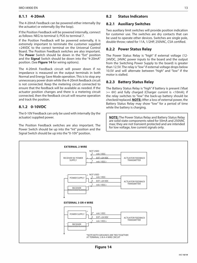
The 4-20mA Feedback can be powered either internally (by the actuator) or externally (by the loop).
If the Position Feedback will be powered internally, connect as follows: NEG to terminal 5; POS to terminal 7.If the Position Feedback will be powered externally, it is extremely important to terminate the customer supplied +24VDC to the correct terminal on the Universal Control Board. The Position Feedback switches are also important. The Power Switch should be down in the “Ext” position and the Signal Switch should be down into the “4-20mA” position. (See Figure 14 for wiring options).
The 4-20mA Feedback circuit will power down if no impedance is measured on the output terminals in both Normal and Energy Save Mode operation. This is to stop any unnecessary power drain while the 4-20mA feedback circuit is not connected. Keep the metering circuit connected to ensure that the feedback will be available as needed. If the actuator position changes and there is a metering circuit connected, then the feedback circuit will resume operation and track the position.
8.1.2 0-10VDC
The 0-10V Feedback can only be used with internally (by the actuator) supplied power.
The Position Feedback switches are also important. The Power Switch should be up into the “Int” position and the Signal Switch should be up into the “0-10V” position.
8.2 Status Indicators
8.2.1 Auxiliary Switches
Two auxiliary limit switches will provide position indication for customer use. The switches are dry contacts that can be used to operate other devices. Switches are single pole, double throw; rated for 11A, 1/2HP, 250VAC, CSA certified.
8.2.2 Power Status Relay
The Power Status Relay is “high” if external voltage (12-24VDC, 24VAC power inputs to the board and the output from the Switching Power Supply to the board) is greater than 12.5V. The relay is “low” if external voltage drops below 10.5V and will alternate between “high” and “low” if the motor is stalled.
8.2.3 Battery Status Relay
The Battery Status Relay is “high” if battery is present (Vbat >= 6V) and fully charged (Charger current is <10mA); if the relay switches to “low” the back-up battery should be checked/replaced. NOTE: After a loss of external power, the Battery Status Relay may show “low” for a period of time while the battery is charging.
NOTE: The Power Status Relay and Battery Status Relay are solid state components rated for 50mA and 250VAC max; they are not transient protected and are intended for low voltage, low current signals only.
RECEIVER W/ POWERSUPPLY
ACTUATOR FEEDBACKTRANSMITTER
EXT +24 VDC
mA / VDC+
mA / VDC-5
6
7
POWER SUPPLY
ACTUATOR FEEDBACKTRANSMITTER
EXT +24 VDC
mA / VDC+
mA / VDC-5
6
7
RECEIVER
- +
- +
POWER SUPPLY
ACTUATOR FEEDBACKTRANSMITTER
EXT +24 VDC
mA / VDC+
mA / VDC-5*
6
7
RECEIVER
- +
- +
NOT USED
*NOTE BOTH GROUNDS ARE TIED TOGETHERAT TERMINAL 5 IN A 4 WIRE CIRCUIT
+
-
NOT USED
EXTERNAL 2 WIRE
EXTERNAL 3 OR 4 WIRE
Figure 14
IMO 10/19
IMO-I4900 EN 13

9. POWER MANAGEMENT
9.1 Battery
WARNINGTHIS UNIT CONTAINS A SEALED LEAD ACID BATTERY, REGULAR CHARGING IS NECESSARY WITH STORAGE LONGER THAN THREE MONTHS. TO CHARGE THE BATTERY, APPLY ONE OF THE INPUT VOLTAGES TO THE CORRESPONDING INPUT ON THE ACTUATOR, (NOT DIRECTLY TO THE BATTERY) AND LEAVE POWERED FOR AT LEAST TWENTY-FOUR HOURS. HIGH AMBIENT TEMPERATURES CAN SHORTEN STORAGE LIFE. IT IS RECOMMENDED THAT THE BATTERY BE STORED AT 22°C +/- 5°C. INSPECT THE BATTERY UPON RECEIPT, BEFORE INSTALLATION, AND AT REGULAR MAINTENANCE INTERVALS. REMOVE THE BATTERY FROM THE DEVICE FOR LONG-TERM STORAGE. FAILURE TO FOLLOW THIS CHARGING REQUIREMENT MAY RESULT IN REDUCED EFFECTIVE BATTERY LIFE.
With the battery backup (included with options UL2, UL3, UL4, UL5, UL6 & UL7), the actuator will sense the loss of main input power to the Universal Control Board and immediately switch to internal battery power. When line power returns, the actuator will automatically resume normal operation.
The battery charging voltage has been designed for optimum battery performance. When the charging circuit is active (even when topping off charge or in sleep mode), the yellow Charging LED will light. After reaching full charge, the green Charged LED will light. *Fully charged, the battery voltage will reach approximately 13.6 volts. This voltage is designed to vary with temperature, and could be as high as 14.4 volts if in a very cold environment, or as low as 12.8 volts if in a very warm environment. This is normal operation. A battery case that is swollen or cracked must be replaced. Please consult the factory for replacement. If the battery does not reach full charge (the green Charged LED remaining on and the yellow Charging LED turning off ) within 48hrs, consult the factory or your local representative.* NOTE: Battery Charging and Battery Charged LEDs may be lit at the same time depending on the battery charge state.
Replacement battery packs should be stored only after a full charge and at less than 80°F. Temperature can affect battery shelf life. Generally lower temperatures will increase shelf life while higher temperatures will decrease shelf life. When recharging battery packs, they should only be recharged from the Universal Control Board charging circuit, which is calibrated to provide the proper voltage and current for maximum battery pack life, or from a Metso recommended battery charger.
The only suggested maintenance is to examine, and if necessary, replace the battery every two years. Battery life can vary with temperature. Cooler environments will generally prolong battery life and under ideal conditions ADC batteries will last in excess of five years. To change the battery, perform the following:
1. Disconnect power to the actuator.
2. Remove actuator cover and set aside carefully so as not to damage the machined flange.
3. Disconnect battery connection at the Universal Control board.
4. Unhook one side of the battery hold-down strap.
5. Remove the battery.
6. Install new battery and replace hold-down strap.
7. Plug battery connector into the connector into the Universal Control Board.
8. Replace actuator cover.
9. Apply power.
9.2 Power Fail Controls
The ADC-Series Universal Control Board is designed to be easily configured to drive to either the CW, CCW or MID position upon loss of actuator power. This is the power loss or “Fail” position.
When designating MID as the power loss or “Fail”position, the limit type must be set at “Smart” and the MID position must have been entered and saved in the “Operation” field otherwise the Actuator will calculate a default MID position between the calibrated Zero and Span positions.
The ADC-Series Universal Control Board is designed to provide continuing service in the event of a loss of external power. Upon power loss the ADC-Series actuator, equipped with a Back-Up Battery, can be configured to drive the actuator and “Park” immediately at the designated power loss Fail position and “go to sleep”.
In “Multi” mode it will continue to cycle on battery power while a control signal and adequate battery power remain available. When “Multi” is selected, the actuator will cycle until a low battery power condition is detected then automatically drive to and remain at the designated power loss or Fail Position.
In “Multi” mode a fully charged battery will provide up to ten complete 90 degree cycles under optimum conditions. Upon reaching the power loss position, the system will “go to sleep” until input power is restored.
9.3 “Wake Up”and Manually Drive Actuator
Manually Drive the Actuator (Using the Battery) During Power Outage (If using “Park” Power Fail Control selection) After the battery drives the actuator to the Power Loss Position, the Universal Control Board powers down and remains in “sleep” mode until external power returns. To “wake” the actuator, to control it with the external control signal or to enable the CW or CCW push buttons for manual control, move the Power Fail Controls switch to “Multi” mode and press [Enter]. This will “wake” the electronics and the actuator can be manually operated via the CW or CCW push buttons until low battery power level is detected. To “park” the actuator and revert it back to sleep mode flip the Power Fail switch back to “Park” mode and the actuator will drive to the fail position and go back to sleep.
IMO 10/19
14 IMO-I4900 EN

9.4 Energy Save ModeThe ADC-Series Universal Control Board is equipped with an “Energy Save” mode in which the unit will “doze” when a control signal change is not detected after a one-minute time-out; this is especially beneficial in solar applications where the continuous power draw can be minimized considerably by using “Energy Save” mode. Once a signal change is detected, the unit will “wake” and respond; if no additional changes are made within one minute, the unit will again enter the “doze” cycle.
Selecting “Energy Save” Mode To select “Energy Save” mode, simply slide the Power Consumption switch down; to return to “Normal”, simply slide the switch up.
NOTE: All heater modes are disabled in “Energy Save”mode.
10. BOARD INSTALLATION / REPLACEMENT
10.1 Safety Precautions
WARNINGDANGEROUS VOLTAGES ARE PRESENT INSIDE THE ACTUATOR COVER UNLESS THE POWER SUPPLY TO THE ACTUATOR HAS BEEN SHUT OFF OR DISCONNECTED. USE EXTREME CAUTION WHENEVER WORKING ON THE ACTUATOR WITH THE COVER REMOVED.
10.2 Safety Precautions Applicable to Units Equipped with a Back-Up Battery
WARNINGWHEN OPTIONAL BATTERY IS CONNECTED TO BOARD, THE UNIT MAY DRIVE!BEWARE OF MOVEMENT OF THE FINAL DRIVE ELEMENT AND ANY LINKAGE BETWEEN IT AND THE ACTUATOR!
KEEP HANDS, OTHER PARTS OF THE BODY, TOOLS AND OTHER OBJECTS OUT OF THE WAY OF MOVING PARTS. FAILURE TO DO THIS MAY RESULT IN DAMAGE OR PERSONAL INJURY!
10.3 Parts Verification
10.3.1 Locate the Replacement Board Kit VCK00003 for ADC, or VCK00019 for LADC
10.3.2 Inspect all parts and hardware to be certain that it is free of damage that may have occurred in shipping.
10.3.3 Collect the tools required.
• 5mm Hex wrench• 6mm Hex wrench• 1/16 inch Hex wrench• #1 Phillips screwdriver• #2 Phillips screwdriver• Small Flat Blade Screwdriver• 9/64 inch Hex wrench• Wire Cutters (to cut tie wraps)
11. BOARD REMOVAL
11.1 Step by Step Instructions for the Removal of a Universal ADC/LADC-Series Actuator Control Board:
Figure 15Remove the actuator cover, using a 6mm Hex wrench for LADC models or a 5mm Hex wrench for ADC models. This is what the inside should resemble (LADC Shown).
Figure 16Remove the overlay from the VCB00010 Circuit Board.
Figure 17
IMO 10/19
IMO-I4900 EN 15

Remove the three Philips head screws that hold the VCB00010 Board in place with the #1 Philips screwdriver, and save them for later use.
Figure 18Unplug all cables attached to the VCB00010 and remove the board. Connections are coded to prevent miswiring.
12. BOARD INSTALLATION
12.1 Step by Step Instructions for the Installation of a Universal ADC/LADC-Series Actuator Control Board:
Figure 19Prior to installation, ensure that all switch an potentiometer settings on the replacement board match that of the original board.Connect the lower power supply cable to the VCB00010.Connect the potentiometer, thermal cut-out, motor harness, and limit switches; as shown in Figure 18.
Figure 20Connect the upper power supply cable and the auxiliary limit switch cables as shown in Figure 20.
Figure 21Secure wires as shown in Figures 18 and 21 to avoid contact with moving parts.Re-install the three screws that secure the VCB00010 board to the bracket as shown in Figure 17.
IMO 10/19
16 IMO-I4900 EN

Figure 22
Re-install the board overlay.
Figure 23
The actuator is now ready to be re-calibrated and set up for your application. Please refer to sections 4 through 9 of this manual for calibration and set up procedures and option settings.
13. REASSEMBLY
Figure 24NOTE: For actuators including hazardous location certifica-tion. Prior to installing cover, inspect machined flange surfaces for any damage, scratches, or dents. Damage, scratches, or dents that will not fit completely in a circle having a diam-eter of 1/64” will void hazardous location certifications. If such imperfections are present the damaged enclosure part(s) must be replaced. Consult the factory for replacement parts.
Once the actuator is calibrated and set for the application, verify operation. Locate the over-ride shaft (remove from cover bushing) and install it on the square shaft of the motor/gearbox. (NOTE: If the actuator is equipped with a handwheel, install the bottom part of the two-piece shaft on the motor/gearbox shaft, and then install the top part of the two-piece shaft onto the bottom shaft)
Figure 26Use the override shaft as a guide the align and re-install the cover onto the base and secure it with the screws that were previously removed.
IMO 10/19
IMO-I4900 EN 17

14. DEFAULT SETTINGS AND MODES
Board Section Function Condition State
Position Feedback Power External Switch Down
Signal 4-20mA Switch Down
On/Off Control Control Mode 2 Wire CCW Pot Full CCW
Position Control Input 4-20mA Switch Down
Signal Fail Zero Switch Up
Dead Band Min Pot Full CCW
Power Fail Controls Park/Multi Park Switch Up
CCW/Mid/CW CW Pot Full CW
Limit Smart/Cam Smart Switch Up
Power Consumption Normal/Energy Save Normal Switch Up
Operation Mode Selector Run Pot Full CCW
Heater Control Humid/Low-Temp/Off Off Switch Down
15. TROUBLESHOOTING
Symptom: Actuator Stall LED is blinking in a mid-travel position.
Fix: This could be due to hunting; increase actuator Deadband or adjust controller’s setpoint tolerance.
Symptom: Actuator does not respond to 4-20mA or 0-10V control signal.
Fix: Verify that Analog Position Control Mode has been selected. If the problem persists calibration is required.
Symptom: No Feedback in Energy Save mode.
Fix: If the Feedback wires are removed from the terminal block, even briefly, the Feedback signal is turned off; ensure the wires are connected and cycle power to reinstate Feedback signal.
Symptom: LED’s shut off after a minute.
Fix: Check to see if Energy Save mode has been selected; LEDs are turned off after one minute in Energy Save mode in order to reduce power consumption.
IMO 10/19
18 IMO-I4900 EN

16. GENERAL OPERATING INFORMATIONFor enclosure specifications and dimensions, see (Tables 1-2 and Figure 26).
16.1 Enclosure Ratings and ProductCertifications Metso offers two versions of ADC-Series actuator enclosures: the “W” enclosure is weathertight, and the “WX” enclosure which is weathertight and explosion-proof.
16.2 Operating Temperature LimitsADC-Series actuators are designed to operate in ambient environments between -40˚F (-40˚C) and 130˚F (55˚C). In outdoor applications where ambient temperatures exceed 80˚F, actuators should be shielded from direct sunlight. In applications with high media temperatures, insulating blankets, heat shields and/or extended mounting shafts should be used to maintain ambient temperatures at the actuator within normal operating limits.
Activation of the heater and thermostat option is recommended for all outdoor applications and may also be used to dry condensation in high humidity environments.
16.3 Actuator MountingThe actuator may be mounted in any position including upside-down. It must be firmly secured to a direct mount flange or sturdy mounting bracket. A minimum of four bolts with lock washers should be used to secure the actuator to the bracket. Flexibility in the bracket is not allowed, and backlash, or “play”, in the coupling should be minimized. The actuator output shaft must be in line (centered) with the valve shaft to avoid side-loading the shaft. See (Figure 26) for output drive dimensions and mounting hardware specifications.
WARNINGFAILURE TO USE MANUAL OVERRIDE PROPERLY COULD RESULT IN DAMAGE TO THE ACTUATOR GEARING. ENSURE THAT THE OVERRIDE IS FULLY DISENGAGED AND DO NOT USE EXCESSIVE FORCE WHEN MANUALLY POSITIONING ACTUATOR. DO NOT DRIVE THE ACTUATOR BEYOND THE TRAVEL LIMIT SETTINGS. FAILURE TO FOLLOW THESE INSTRUCTIONS COULD RESULT IN DAMAGE TO THE ACTUATOR AND/OR FINAL DRIVE ELEMENT.
16.4 Manual Override
WARNINGMANUAL OVERRIDE OF THE ACTUATOR IS INTENDED FOR USE WHEN POWER IS NOT AVAILABLE. USING THE OVERRIDE SHAFT OR HANDWHEEL (IF APPLICABLE) WHEN POWER IS STILL PRESENT AT THE ACTUATOR COULD RESULT IN DAMAGE OR PERSONAL INJURY!
To use the manual override, push the override shaft down approximately 1/4 inch to disengage the motor from the gear train. Failure to disengage motor prior to turning override will cause damage to the actuator. While holding the shaft down, turn the shaft with a wrench or handle to the desired position.
NOTE: The override shaft on actuators below 1000 lb•in must be rotated in the opposite direction of the desired direction of the output shaft. In actuators 1000 lb•in and above, the override and the output shaft turn in the same direction.
Do not drive the actuator beyond the limit switch settings; it is possible to damage installed options such as a feedback potentiometer. The manual override shaft must be returned to its fully upward position before the motor is re-engaged. Rotate the shaft slightly to align the spur gears until the shaft “springs” back to its re-engaged position.
NOTE: The rotation direction of the output may not be the same as the rotation of the override shaft!
16.5 LubricationAll rotating power train components are permanently lubricated with multi-purpose Lithium grease suitable for the operating temperature range of the actuator. Additional lubrication is not required in normal operation.
16.6 Problem PreventionMost actuator problems result from improper installation.
• Incorrect Wiring and Set Up Make certain the actuator is wired correctly and travel stops are properly set before power is applied.
• Coupling, Alignment, and Mounting Do not add extra torque! Make certain that the mounting arrangement is sturdy, centered, properly aligned, and that all mounting hardware is secure and properly tightened.
• Moisture Replace the cover tightly and make certain conduit entry holes are sealed properly to prevent moisture infiltration.
16.7 WarrantyAll V-Series actuators are backed by a 2 year warranty that covers materials and workmanship. The warranty shall expire 24 months from installation or 30 months from delivery; whichever comes first.
To request a Return Authorization for an actuator within the warranty period, please consult your local Metso distributor.
16.8 Repair Service/Spare PartsWe recommend that electric actuators be directed to our Northeast Service Center for maintenance. The Service Center is equipped to provide rapid turn-around at reasonable cost and offer new product warranty with all reconditioned electric actuators.
For electric actuators outside of the warranty period, request a Return Authorization by calling the Northeast Service Center at (508) 595-5195; or by sending an e-mail to [email protected].
NOTE: When sending electric actuators to the Service Center for repair, do not disassemble them! The actuator should be relatively clean upon return. For further informa-tion on spare parts and service or assistance, visit our Web site at www.metso.com/electricactuators.
NOTE: When ordering spare parts, always include the following information:a. Actuator model number from the product nameplate
b. Serial number from the product nameplate
c. Part number and/or description
IMO 10/19
IMO-I4900 EN 19

17. SPECIFICATIONS & TECHNICAL INFORMATION
Table 1
TorqueOutput
Duty Cycle
at/below 40°C/104°F
12VDC 24VDC 24VAC 115VAC 230VAC
Cycle Time
Current Draw
Cycle Time
Current Draw
Cycle Time
Current Draw
Cycle Time
Current Draw
Cycle Time
Current Draw
(sec/90°) (Amps) (sec/90°) (Amps) (sec/90°) (Amps) (sec/90°) (Amps) (sec/90°) (Amps)
150 lb-in; 12 lb-ft; 17 Nm 100% 11 2.2 13 1.2 8 1.8 9 0.4 9 0.4
300 lb-in; 25 lb-ft; 34 Nm 100% 17 2.5 13 1.4 12 2.1 13 0.5 13 0.4
600 lb-in; 50 lb-ft; 68 Nm 100% 17 2.8 13 1.7 13 2.5 14 0.6 14 0.5
1000 lb-in; 83 lb-ft; 113 Nm 100% 21 4 14 2.4 15 3.5 15 0.9 15 0.6
1500 lb-in; 125 lb-ft; 169 Nm 100% 40 4 24 2.4 27 3.5 29 0.9 29 0.6
2000 lb-in; 167 lb-ft; 226 Nm 100% 40 4.3 33 2.4 28 3.5 29 0.9 29 0.6
2500 lb-in; 208 lb-ft; 282 Nm 100% 55 3.3 40 2 38 3.1 39 0.8 39 0.6
3000 lb-in; 250 lb-ft; 339 Nm 100% 60 3.7 42 2.2 40 3.5 42 0.8 43 0.6
Table 2 Specifications
Temperature Range -40°F to 130°F (-40°C to 55°C)
Conduit Connections (2) 3/4” NPT all sizes (3/4” to 1/2” reducing bushings included)
Output 150 to 600 in-lbs: ISO 5211 F05 and F07 bolt circles, 3/4” female square standard; see “Dimensions” section and “How to Order” table for additional output options. 1000 to 3000 in-lbs: ISO 5211 F07 and F10 bolt circles, 1” female square standard; see “Dimensions” section and “How to Order” table for additional output options.
Voltage
12 VDC: 10.8 to 13.2 VAC24 VDC: 21.6 to 26.4 VDC24 VAC: 21.6 to 26.4 VAC, 60 Hz or 50 Hz115 VAC: 103.5 to 126.5 VAC, 60 Hz or 50 Hz230 VAC: 207 to 253 VAC, 60 Hz or 50 Hz
Limit Switches (2) Single pole, double throw switches rated for 11A 1/2HP 250VAC CSA certified.
Motor Brushless DC motor with Class B or better insulation; sub-fractional horsepower
Lubrication Permanently lubricated gear train and bearings
Gear Train Hardened steel, machine cut spur gears
Approximate Weight 17 lbs for sizes up to 600 in•lb (ADC models)31 lbs for sizes 1000 in•lb and above (LADC models)
Enclosure Die cast aluminum; with a baked-on, super durable polyester powder coat finish
IMO 10/19
20 IMO-I4900 EN

17.1 ADC-SERIES UNIVERSAL CONTROL BOARD
Table 3 Control Board Specifications
Input Impedance (Analog Control)
Voltage Input: 35K ohmsCurrent Input: 200 ohms
Analog Control Signal May be either 4-20mA or 0-10VDC (selectable via on-board slide swithch)Fully compatible with ISA-S50. 1 as a type 4, class L, power isolated device.Input minus (-) and transmit minus (-) are tied together and isolated from power and earth ground.
Resistive Control Signal Board will accept a resistance control signal as low as 0-100 ohms and as high as 0-10K ohms.
Position Out Signal May be either 4-20mA or 0-10VDC (selectable via on-board slide switch) Minimum resistive load for voltage output: 1K ohmMaximum resistive load for current output: 500 ohm
Stall Protection If the actuator cannot achieve the position commanded by the control signal, this feature will remove all power to the motor after 5 seconds. The actuator will not restore power to the motor until the control signal commands the actuator to drive in the opposite direction.
Power Loss Position In the event of a loss of main power, user can choose either the Zero position or the Span, or Mid position, via selector pot, as the power loss “Park” position.
Power Fail Park or Battery Cycle
In the event of a loss of main power, user can choose either to drive the actuator immediately to the “Park” Power Loss Position or continue to cycle (if control signal is avail-able) until low battery level is detected before driving to the “Park” position.
Control Fail Position In the event of a loss of control signal (with power still supplied), user can choose either the Zero, Span or the Last position via slide switchNOTE: If the the minimum control signal = 0, the fail position must be Last
Position Potentiometer 360° Rotation, 0 ohms to 1k ohms.
Local Supervisory Control User can select manual (MAN) to override control signal and drive actuator by pushing the CW or CCW buttons. Actuator may be manually positioned to any location between the existing Zero and Span settings. For additional range, reset the ZERO and Span locations.
Split Range Control Actuator will accept split range control signal (i.e. 4-12mA or 12-20mA; 0-5V or 5-10V) with no wiring changes.
Reverse Acting With no wiring changes required, the actuator may be calibrated to drive clockwise upon an increasing control signal, and counter-clockwise upon a decreasing signal.
Dead Band The amount of change in control signal that the actuator will ignore before the output shaft begins to move. Adjustable from 1% to 3%.
IMO 10/19
IMO-I4900 EN 21

V-Series
3/4 NPT Standard1/2 NPT with Bushing
6.000
6.1
3.1 4.1
5.8
1.7
*12.8 11.1
10.3
OptionalHandwheel
Shown
10.8
9.8
7.5 4.6
3.3
Female Square Drive
All Dimensions in inches unless otherwise
TO REMOVE COVER REQUIRES AN ADDITIONAL 5.75"stated
LV-Series
*11.7 WITHOUT HANDWHEEL
Female Keyed Drive
4.6
0.75" MIN..C.B "610.4NO
4 X M8-1.25 2.756" B. C. ON
4 X M10-1.5 0.75" MIN.
SEE TABLE
20 mm
22.4 mm
4.8 mm
Approximate Weight 17 lb / 8 kg
Approximate Weight 31 lb / 14 kg
17.2 DIMENSIONS
Figure 26
ADC-SERIES ENCLOSURES (150-600 LB-IN)Mounting Flange, ISO 5211
F05 / F07
ADC-SERIES ENCLOSURES (1000-3000 LB-IN)
Mounting Flange, ISO 5211 F07 / F10
Actuator Size Drive Option Drive Type Drive Size Depth1000-3000 lb-in (83-250 lb-ft; 113-339 Nm) Standard Square 1.000 (25mm) 1.20 (30.5mm)1000-3000 lb-in (83-250 lb-ft; 113-339 Nm) Option “I2” Square 0.669 (17mm) 1.20 (30.5mm)1000-3000 lb-in (83-250 lb-ft; 113-339 Nm) Option “I3” Square 0.748 (19mm) 1.20 (30.5mm)1000-3000 lb-in (83-250 lb-ft; 113-339 Nm) Option “I4” Square 0.866 (22mm) 1.20 (30.5mm)1000-3000 lb-in (83-250 lb-ft; 113-339 Nm) Option “Y2” Keyed 0.787 (20mm) 1.50 (38.1mm)1000-3000 lb-in (83-250 lb-ft; 113-339 Nm) Option “Y3” Keyed 0.984 (25mm) 1.50 (38.1mm)
Actuator Size Drive Option Drive Type Drive Size Depth150-600 lb-in (12-50 lb-ft; 17-68 Nm) Standard Square 0.750 (19mm) 0.90 (22.9mm)150-600 lb-in (12-50 lb-ft; 17-68 Nm) Option "I1" Square 0.551 (14mm) 0.90 (22.9mm)150-600 lb-in (12-50 lb-ft; 17-68 Nm) Option "I2" Square 0.669 (17mm) 0.90 (22.9mm)150-600 lb-in (12-50 lb-ft; 17-68 Nm) Option "Y1" Keyed 0.591 (15mm) 1.40 (35.6mm)150-600 lb-in (12-50 lb-ft; 17-68 Nm) Option "Y2" Keyed 0.787 (20mm) 1.40 (35.6mm)
IMO 10/19
22 IMO-I4900 EN

18. ADC-SERIES ACTUATORS BY MODEL NUMBERTable 4
How To Order - ADC-Series Electric Actuators (see note 1)
Actuator Series Enclosure Type Torque Board Options (see note 2) Other Options (if desired) Operating Voltage
Order Code
Description Order Code
Description Order Code
Description Order Code Description Order Code
Description
ADC W Weathertight 150 150 in lb UL2* On/Off / Positioner Board with SLA Battery Back-Up
I1 (see note 3) 14mm Female Square Output
-UP
Universal Power:
12/24DC, 24AC, or
115/230AC
NEMA 4/4X 300 300 in lb UL4* On/Off / Positioner Board 180-Degree with SLA Battery Back-Up
I2 (see note 3) 17mm Female Square Output
600 600 in lb UL6* On/Off / Positioner Board 270-Degree with SLA Battery Back-Up
MB (see note 4) Modbus Communication
WX Weathertight & Explosionproof
Y1 (see note 3) 15mm Female Keyed Output
NEMA 4/4X/7&9 Y2 (see note 3) 20mm Female Keyed Output
Z HandwheelLADC W Weathertight 1000 1000 in lb UL3* On/Off / Positioner Board
with SLA Battery Back-UpI2 (see note 3) 17mm Female
Square Output
-UP
Universal Power:
12/24 DC, 24AC, or
115/230AC
NEMA 4/4X 1500 1500 in lb UL5* On/Off / Positioner Board 180-Degree with SLA Battery Back-Up
I3 (see note 3) 19mm Female Square Output
2000 2000 in lb UL7* On/Off / Positioner Board 270-Degree with SLA Battery Back-Up
I4 (see note 3) 22mm Female Square Output
WX Weathertight & Explosionproof
2500 2500 in lb MB (see note 4) Modbus Communication
NEMA 4/4X/7&9 3000 3000 in lb Y2 (see note 3) 20mm Female Keyed Output
Y3 (see note 3) 25mm Female Keyed Output
Z Handwheel
Notes: 1. All ADC-Series actuators accept any of the following input voltages (12VDC, 24VDC, 24VAC, 115VAC and 230VAC), are rated for continuous duty cycle, include a holding brake, two auxiliary limit switches, 4-20mA or 0-10VDC, position feedback, wrench-operated manual override, CSA “C US” certification, CE compliance, and a heater/thermostat that can be user-enabled on the option board.
2. Must select only one board option; all board options can be configured for On/Off or Modulating operation. 3. The standard drive output for 150 - 600 lb-in actuators is a 3/4” female square; the standard drive output for 1000 - 3000 lb-in actuators is a 1”
female square. 4. The Modbus Communication option allows for controlling, and polling the unit for diagnostic information using a Modbus communication signal
(RS-485; Two-Wire). * These options cannot include ATEX and/or IECEx certification.
• Enclosure “W” (weathertight) is certified by CSA to meet specifications for NEMA 4/4X; IP 66 for weathertight and dust-tight, environments and is CE compliant. It is intended for non-hazardous locations in indoor or outdoor use.
• Enclosure “WX” (weathertight & explosionproof) is certified by CSA to meet specifications for NEMA 7&9, hazardous locations, (Class I, Division 1, Groups C, and D; Class II, Division 1, Groups E, F, and G; Class III) as well as to meet NEMA 4/4X and IP 66 specifications. the enclosure is CE compliant.
Sample Model Code: ADCWX150UL2Y1-UP
Actuator Series ADCEnclosure Type WX
Torque 150
Board Option UL2Other Options(if applicable) Y1
Operating Voltage -UP
(For enclosure specifications and dimensions see Table 2 and Figure 26).• Torque = Breakaway Torque Valvcon Electric Actuators
are rated at breakaway torque. This is the torque required to move a full load immediately upon power-up.
Figure 27
IMO 10/19
IMO-I4900 EN 23

19. ADDITIONAL ACTUATOR PRODUCTS AND ACCESSORIES FROM METSO
V-Series• Up to 3000 inch pounds (250 lb-ft; 339 Nm) for On/Off,
Modulating or Automatic Cycling applications• 115VAC and 230VAC voltages• 75% Duty Cycle (55% on 3000 lb-in models)• NEMA 4/4X and NEMA 4/4X/7&9 enclosures• CSA (C US) Certified• CE Compliant• Certified to ATEX Directive 2014/34/EU: Ex d IIB T6 Gb, and IECEx CSA 14.0057X (“WX” models only)• Standard Features: manual override and visual position
indicator• Available Options: Modulating Control Board, Speed
Control/Timer Board, Iso/Readback Board, extra limit switches, heater/thermostats, motor brake, feedback potentiometer, metric and “keyed” female outputs and handwheel override
ESR-Series• Up to 600 inch pounds (50 lb-ft; 68 Nm) for true “Two-
Wire” On/Off applications• 80% Duty Cycle• 115VAC and 230VAC voltages• NEMA 4/4X and NEMA 4/4X/7&9 enclosures• Available Options: dynamic brake, extra limit switches,
heater/thermostats and metric and “keyed” female outputs
I-Series Network Capable• MODBUS®• AS-Interface• DeviceNet™• Foundation fieldbus• Other fieldbus protocols (consult factory)• CSA Certified to Canadian and U.S. standards
QX-Series• Up to 3000 inch pounds (250 lb-ft; 339 Nm) for On/Off
applications• Economical NEMA 4/4X/7&9 solution• 12VDC & 24VDC voltages• 80% Duty Cycle• CSA (C US) Certified• Standard Features: auxiliary limit switches, dynamic
brake, manual override and visual position indicator• Available Options: metric and “keyed” female outputs,
heater/thermostats and handwheel override
LCR Series• Up to 600 inch pounds (50 lb-ft; 68 Nm)• Economical actuators for Reversing applications• 25% duty cycle (80% on 12VDC or 24VDC models)• NEMA 4/4X enclosure• 115VAC, 230VAC, 24VAC, 12 VDC and 24VDC voltages• Options include extra limit switches and heater/
thermostats• Male output (standard) or female output (optional)
LCU Series• Up to 600 inch pounds (50 lb-ft; 68 Nm)• Economical actuators for Unidirectional applications• 25% duty cycle (80% on 12VDC or 24VDC models)• NEMA 4/4X enclosure• 115VAC, 230VAC, 24VAC, 12 VDC and 24VDC voltages• Options include extra limit switches and heater/
thermostats• Male output (standard) or female output (optional)
Q6-Series for Remote Solar Applications• 600 inch pounds (50 lb-ft; 68 Nm)• 12VDC• Low current draw• 80% Duty Cycle• NEMA 4/4X/7&9• CSA (C US) Certified
Subject to change without prior notice.
24 IMO-I4900 EN
Metso Flow Control Inc.
Europe, Vanha Porvoontie 229, P.O. Box 304, FI-01301 Vantaa, Finland. Tel. +358 20 483 150. Fax +358 20 483 151North America, 44 Bowditch Drive, P.O. Box 8044, Shrewsbury, M A 01545, USA. Tel. +1 508 852 0200. Fax +1 508 852 8172
South America, Av. Independéncia, 2500-Iporanga, 18087-101, Sorocaba-São Paulo, Brazil. Tel. +55 15 2102 9700. Fax +55 15 2102 9748 Asia Paci�c, 238B Thomson Road, #17-01 Novena Square Tower B, Singapore 307685. Tel. +65 6511 1011. Fax +65 6250 0830
China, 11/F, China Youth Plaza, No.19 North Rd of East 3rd Ring Rd, Chaoyang District, Beijing 100020, China. Tel. +86 10 6566 6600. Fax +86 10 6566 2583Middle East, Roundabout 8, Unit AB-07, P.O. Box 17175, Jebel Ali Freezone, Dubai, United Arab Emirates. Tel. +971 4 883 6974. Fax +971 4 883 6836
www.metso.com/electricactuators
Related Documents