4 th International Workshop on VALIDATION OF COMPUTATIONAL MECHANICS MODELS 1 Validation of fluid-structure interaction simulations George Lampeas University of Patras and Athena Research Center , Greece

Welcome message from author
This document is posted to help you gain knowledge. Please leave a comment to let me know what you think about it! Share it to your friends and learn new things together.
Transcript

4th International Workshop on VALIDATION OF COMPUTATIONAL MECHANICS MODELS 1
Validation of fluid-structure interaction simulations
George Lampeas
University of Patras and Athena Research Center , Greece

4th International Workshop on VALIDATION OF COMPUTATIONAL MECHANICS MODELS 2
Outline • Introduction to Fluid Structure Interaction (FSI) • Aeroelasticity : an important case of FSI • Aeroelastic simulation models : challenges and validation • Full-field experimental measurement techniques for the solid
and the fluid field • Simulation and experimental data comparison techniques • Conclusions

4th International Workshop on VALIDATION OF COMPUTATIONAL MECHANICS MODELS 3
Introduction to FSI • Fluid-Structure Interaction (FSI) exists in natural systems, man-made structures, human body, etc. • In nature, the interaction between a tree and wind is a typical FSI example. • In engineered systems, typical FSI examples are : - sloshing liquid in moving tanks (liquid – solid interaction) - ocean waves deforming offshore platforms (water – solid interaction) … and many others

4th International Workshop on VALIDATION OF COMPUTATIONAL MECHANICS MODELS 4
Motivation

4th International Workshop on VALIDATION OF COMPUTATIONAL MECHANICS MODELS 5
Aeroelasticity – an important FSI case • The current presentation focuses in simulation and the respective experimental validation of aeroelastic phenomena • Aeroelasticity refers to interaction of structures (e.g. aircraft, wind turbines, buildings, bridges, etc.) with air • Aeroelasticity is important for determining the flight characteristics of aircraft, the aerodynamic efficiency of wind turbines, the safety of buildings…

4th International Workshop on VALIDATION OF COMPUTATIONAL MECHANICS MODELS 6
FSI mechanism in static aeroelasticity • In static aeroelasticity, interactions occur between aerodynamic and elastic forces • Aerodynamic loads are redistributed in wings or blades due to a significant deformation of the structures
Aerodynamic wing loading before (black) and after (red) structural deformation: wing airfoil twists causing increase of angle of attack -> increase of aerodynamic forces

4th International Workshop on VALIDATION OF COMPUTATIONAL MECHANICS MODELS 7
Flutter flight test of Piper PA 30
FSI mechanism in dynamic aeroelasticity • In dynamic aeroelasticity, in addition to aerodynamic and elastic forces, inertia forces also interact • Flutter is one of the most important dynamic aeroelastic phenomena

4th International Workshop on VALIDATION OF COMPUTATIONAL MECHANICS MODELS 8
Simulation

4th International Workshop on VALIDATION OF COMPUTATIONAL MECHANICS MODELS 9
• In order to ensure the structural integrity of structures from aeroelastic viewpoint, validated simulations are required • Computational simulation models should include all interacting fields :
Aeroelastic simulation models
Prediction of aerodynamic phenomena involved =
loading to the solid media
Flow field : Computational Fluid Dynamic
(CFD) models
Prediction of structural phenomena involved =
solid deformation
Structural field : Computational solid mechanics
Models (Finite Elements)

4th International Workshop on VALIDATION OF COMPUTATIONAL MECHANICS MODELS 10
Numerical coupling in aeroelastic simulation models
• Coupling algorithms to ensure that the boundary conditions of both the solid and the fluid fields remain in contact after the solid displacement occurs.
Regional aircraft wing finite element / volume CFD-mesh and boundaries (GRETEL CS2 project)

4th International Workshop on VALIDATION OF COMPUTATIONAL MECHANICS MODELS 11
Numerical coupling in aeroelastic simulation models
• Load transfer between dissimilar meshes • Fluid mesh quality deterioration due to high
deformation
FSI boundary mesh correctly set up, deformation rate small enough for proper mesh updating
FSI boundary mesh set up inadequate and deformation rate per iteration too high
Unacceptable mesh quality

4th International Workshop on VALIDATION OF COMPUTATIONAL MECHANICS MODELS 12
MOTIVATE Validation Protocol
in FSI

4th International Workshop on VALIDATION OF COMPUTATIONAL MECHANICS MODELS 13
MOTIVATE validation protocol [1]
1. MOTIVATE - Matrix Optimisation for Testing by Interaction of Virtual And Testing Environments

4th International Workshop on VALIDATION OF COMPUTATIONAL MECHANICS MODELS 14
Specification of validation experiment : the challenge of wind tunnel testing
• Validation testing of aeroelastic simulations is commonly performed by well-established wind tunnel tests of scale models • Simultaneous scaling of aerodynamic, inertia and elastic magnitudes, via non-dimensional similarity parameters • Ensure that the inherent scaling does not cause significant discrepancies between the behavior observed in measurements and the real scale
T-103 full a/c wind tunnel testing in Tsagi ONERA- natural laminar flow test of a semi span wing at an ONERA wind tunnel

4th International Workshop on VALIDATION OF COMPUTATIONAL MECHANICS MODELS 15
Selection of magnitudes to be validated
• In FSI : - ‘fit for purpose’ validation, i.e. only the magnitude of interest is validated
(in aeroelastic analysis this would be displacement only), or - ‘most / all possible magnitudes involved in simulations’ are validated • Balance between cost / time and simulation model deep understanding • Experimental techniques are available for full-field measurement of most
important magnitudes
Flow full- field data: • velocities • pressures
• temperatures
Solid full- field data: • displacements
• strains • forces

4th International Workshop on VALIDATION OF COMPUTATIONAL MECHANICS MODELS 16
Experimental techniques

4th International Workshop on VALIDATION OF COMPUTATIONAL MECHANICS MODELS 17
Wind tunnel data measurements - structural field data (displacement / strain)
• Digital Image Correlation (DIC) is used for monitoring structural response data (displacements, strains)
[Werter, N., Sodja, J., & De Breuker, R. (2016). Design and Testing of Aeroelastically Tailored Wings Under Maneuver Loading. AIAA Journal: devoted to aerospace research and development, 55(3), 1012-1025]

4th International Workshop on VALIDATION OF COMPUTATIONAL MECHANICS MODELS 18
Wind tunnel data measurements - structural field data (displacement / strain)
• Stereoscopic Pattern Recognition uses high-speed digital cameras in a stereoscopic arrangement to track 3D coordinates of markers (instead of speckles) applied to the structure. • The tracking technique can be employed for wing deformation measurements of airplane models, as well as high-speed tracking of moving objects. • Coordinate detection accuracy can approximately reach 0.5 ‰ of the chord length for wing displacement and 0.1 degree for wing twist (torsion)

4th International Workshop on VALIDATION OF COMPUTATIONAL MECHANICS MODELS 19
Wind tunnel data measurements - aerodynamic field data (pressure / velocity) • Pressure taps connected to pressure sensors by tubes are used for pressure measurement on the model surface • A number of locations on the aerodynamic surfaces of interest can be measured, but only accounts for normal forces of the body

4th International Workshop on VALIDATION OF COMPUTATIONAL MECHANICS MODELS 20
Wind tunnel data measurements - aerodynamic field data (pressure / velocity)
• Pressure sensitive paint (PSP) has the capability of providing full field measurements over the entire surface of a model • The pressure field is computed from the luminescence of the test article captured using digital cameras with accuracy of about 0.02 in pressure coefficient measurements

4th International Workshop on VALIDATION OF COMPUTATIONAL MECHANICS MODELS 21
Wind tunnel data measurements - aerodynamic field data (pressure / velocity) • Particle Image Velocimetry (PIV) is used to measure the flow field. • PIV records the displacement and hence the air flow of very small tracer particles that are injected into the flow. • Separate photos taken at ultra-short intervals (few microsecs) enabling measurements of the speed and direction of the particles. • The advantage of PIV is that it measures the entire flow field instantaneously, including movements of vortices.
PIV non-intrusive flow measurement in ONERA wind tunnel

4th International Workshop on VALIDATION OF COMPUTATIONAL MECHANICS MODELS 22
Wind tunnel data measurements - temperature field data
• Infra Red Thermography (IRT) is applied for detailed surface flow visualizations of aerodynamic phenomena such as laminar-turbulent boundary layer transition. • Distinguish between locations with laminar and turbulent boundary layers, from differences in skin-friction and heat-transfer properties
IRT temperature measurements at a DLR wind tunnel

4th International Workshop on VALIDATION OF COMPUTATIONAL MECHANICS MODELS 23
Data comparison techniques

4th International Workshop on VALIDATION OF COMPUTATIONAL MECHANICS MODELS 24
• MOTIVATE validation protocol and CEN guideline (CWA16799:20141 ) recommend decomposition of data fields and comparison of the derived shape descriptors
1. CEN, 2014, Validation of computational solid mechanics models, Brussels: Comité Européen de Normalisation (CEN), CWA 16799(2014).
Simulation and experimental data decomposition and comparison
-100 0 100 200 300 400 500-100
0
100
200
300
400
500
DIC data Tchebichef moments
FEA
data
Tch
ebic
hef m
omen
ts
-100 0 100 200 300 400 500-100
0
100
200
300
400
500
DIC data Tchebichef moments
FEA
data
Tch
ebic
hef m
omen
ts
Mod
el sh
ape d
escr
ipto
rs, s
M
Mod
el sh
ape d
escr
ipto
rs, s
M
Experiment shape descriptors, sEExperiment shape descriptors, sE

4th International Workshop on VALIDATION OF COMPUTATIONAL MECHANICS MODELS 25
Simulation and experimental data decomposition and comparison
• In FSI it is suggested that an individual validation is performed at the level of each magnitude for all fields possible, i.e. both fluid (aerodynamic) and solid (structure) magnitudes • In dynamic aeroelasticity, a series of images (history) should be considered, for which decomposition techniques in 2D are available. • At a preliminary level, volume magnitude data (velocities) can be treated as a series of 2D cross-sectional rectangular images, by application of :
- data extrapolation in cavities in order to create rectangular shaped images - ‘cross sectional’ technique in order to overcome difficulties of decomposing complex 3D fields

4th International Workshop on VALIDATION OF COMPUTATIONAL MECHANICS MODELS 26
Simulation and experimental data decomposition and comparison
Data extrapolation of velocity data in GRETEL airfoil cavity

4th International Workshop on VALIDATION OF COMPUTATIONAL MECHANICS MODELS 27
Simulation and experimental data decomposition and comparison
Series of 2D cross-sections instead of 3D volume data - Mach number results on cutout planes along the span for GRETEL wing
4th International Workshop on VALIDATION OF COMPUTATIONAL MECHANICS MODELS 28
Simulation and experimental data decomposition and comparison
Tip vortex captured on cutouts at the outlet region and at GRETEL wing’s root plane

4th International Workshop on VALIDATION OF COMPUTATIONAL MECHANICS MODELS 29
Simulation and experimental data decomposition and comparison
GRETEL wing displacement plot due to static aeroelastic effects
4th International Workshop on VALIDATION OF COMPUTATIONAL MECHANICS MODELS 30
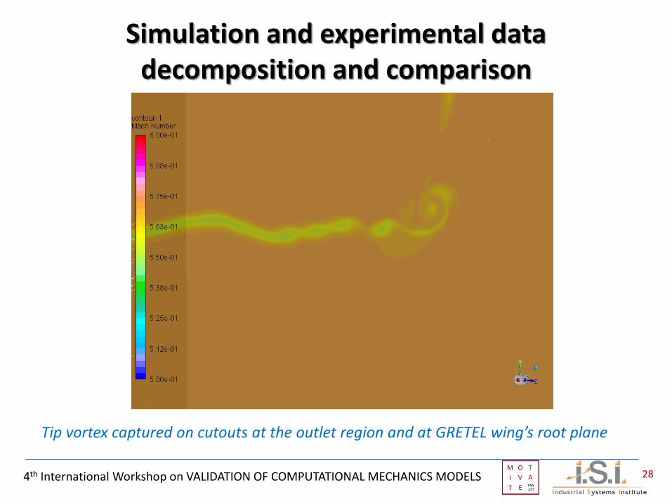
Simulation and experimental data decomposition and comparison
Combination of different cross sectional data in one validation chart (only 2 magnitudes are indicatively shown here)
… more charts for different magnitudes …

4th International Workshop on VALIDATION OF COMPUTATIONAL MECHANICS MODELS 31
Uncertainty types involved • Experimental measurement uncertainty of the various magnitudes related to the structural and fluid fields (displacement, velocity, pressure) • Uncertainties related to the length scaling, i.e. scale model tested in the wind tunnel instead of real scale structure • Uncertainties arising by the different conditions achieved in wind tunnel with respect to the real flight conditions of in-flight experiments : - imperfections of the flow quality in the wind tunnel - constraints to the air flow by the tunnel walls and the model mounting structures - air temperature increase (air speed > 300km / h)

4th International Workshop on VALIDATION OF COMPUTATIONAL MECHANICS MODELS 32
Conclusions • The methodologies developed in MOTIVATE project are in principle
applicable in validation of FSI simulations. • The extensions / modifications required include : - decomposition of volume full-field data (also transient) - advancement of multi-field comparison techniques - methods for the assessment of model quality in multi-field • Commonly agreed quantification of uncertainty techniques for the
individual measurement methods are also required (example the MOTIVATE method for the case of DIC).
• Methodologies for uncertainty quantification for wind tunnel testing instead of real flight tests.

4th International Workshop on VALIDATION OF COMPUTATIONAL MECHANICS MODELS 33
THANK YOU!
Acknowledgments : This research has received funding from the Clean Sky 2 Joint Undertaking under the European Union’s Horizon 2020 research and innovation programme under grant agreement No 754660: MOTIVATE - Matrix Optimisation for Testing by Interaction of Virtual And Testing Environments. … and grant agreement No 737671: GRETEL - GREen Turboprop Experimental Laminar Flow Wind Tunnel Testing The views expressed are those of the authors and not the Clean Sky 2 Joint Undertaking
Related Documents