© Valeport Limited miniIPS Operating Manual Page 1 0760807c.doc VALEPORT LIMITED miniIPS Intelligent Pressure Sensor Operating Manual Document Ref: 0760807 Document Version: C Date: May 2010 This confidential document was prepared by the staff of Valeport Limited, the Company, and is the property of the Company, which also owns the copyright therein. All rights conferred by the law of the copyright and by virtue of international copyright conventions are reserved to the Company. This document must not be copied, reprinted or reproduced in any material form, either wholly or in part, and the contents of this document, and any method or technique available therefrom, must not be disclosed to any other person whatsoever without the prior written consent of the Company. Valeport Limited, Tel: +44 (0)1803 869292 St Peters Quay, Fax: +44 (0)1803 869293 Totnes, e-mail: [email protected] Devon, TQ9 5EW, Web: www.valeport.co.uk UK As part of our policy of continuous development, we reserve the right to alter, without prior notice, all specifications, designs, prices and conditions of supply for all our equipment. Copyright 2008

Valeport Ips
Jan 03, 2016
valeport manual
Welcome message from author
This document is posted to help you gain knowledge. Please leave a comment to let me know what you think about it! Share it to your friends and learn new things together.
Transcript
© Valeport Limited
miniIPS Operating Manual Page 1 0760807c.doc
VALEPORT LIMITED
miniIPS Intelligent Pressure Sensor
Operating Manual
Document Ref: 0760807 Document Version: C Date: May 2010 This confidential document was prepared by the staff of Valeport Limited, the Company, and is the property of the Company, which also owns the copyright therein. All rights conferred by the law of the copyright and by virtue of international copyright conventions are reserved to the Company. This document must not be copied, reprinted or reproduced in any material form, either wholly or in part, and the contents of this document, and any method or technique available therefrom, must not be disclosed to any other person whatsoever without the prior written consent of the Company. Valeport Limited, Tel: +44 (0)1803 869292 St Peters Quay, Fax: +44 (0)1803 869293 Totnes, e-mail: [email protected] Devon, TQ9 5EW, Web: www.valeport.co.uk UK As part of our policy of continuous development, we reserve the right to alter, without prior notice, all specifications, designs, prices and conditions of supply for all our equipment.
Copyright 2008
© Valeport Limited
miniIPS Operating Manual Page 2 0760807c.doc
CHAPTER DESCRIPTION PAGE
1 INTRODUCTION .................................................................................. 3
2 SPECIFICATIONS ............................................................................... 4
3 DATA REQUESTS AND OUTPUT FORMATS .................................... 5
3.1 Start / Stop .................................................................................................... 8
3.2 Communications Setup ................................................................................. 9
3.3 Sampling Pattern .......................................................................................... 9
3.4 Pressure Tare ............................................................................................. 11
3.5 Data Output Formats .................................................................................. 11
3.5.1 Units ....................................................................................................... 12
3.5.2 Valeport Format ...................................................................................... 12
3.5.3 CSV Format ............................................................................................ 12
3.5.4 NMEA Format ......................................................................................... 12
3.5.5 HYPACK Format .................................................................................... 13
3.5.6 Digiquartz Format ................................................................................... 13
3.5.7 Digiquartz CDL Format ........................................................................... 13
3.6 Calibration .................................................................................................. 13
3.7 Welcome Message ..................................................................................... 13
3.8 Information .................................................................................................. 14
4 WIRING INFORMATION .................................................................... 14
5 CARE & MAINTENANCE ................................................................... 15
© Valeport Limited
miniIPS Operating Manual Page 3 0760807c.doc
1 INTRODUCTION
The Valeport miniIPS “Intelligent Pressure Sensor” is designed to measure water
pressure and provide a real time output of that data. Suitable for use in a variety of
subsea applications (ROV‟s, construction, monitoring, positioning), one of the key
development drivers was to provide a cost effective alternative to the use of resonant
quartz pressure sensors. Using the very latest technology in temperature
compensated piezo-resistive transducers, the miniIPS offers several advantages over
resonant quartz sensors, with similar performance.
No external diaphragms, oil reservoir or oil-filled tubes
Easy to clean – no salt build up
Titanium construction
Pressure ranges from 10 to 600Bar (approx 100m to 6000m water)
Long term calibration stability
May be recalibrated by customers using standard Class A deadweight
tester (requires optional adapter)
RS232 or addressable RS485 data output
Choice of calibrated data formats
Choice of sampling modes
© Valeport Limited
miniIPS Operating Manual Page 4 0760807c.doc
2 SPECIFICATIONS
Sensor:
Range: Standard available ranges are 10, 30, 100, 300 & 600Bar
Accuracy: ±0.01% Range
Resolution: 0.0001 Bar (approximately 1mm depth)
Dimensions:
40mmØ x 185mm long (including connector)
Connector:
Standard is Subconn type MCBH6F (titanium)
Alternatives may be supplied on request
Wiring Information is in Section 4
Materials:
Main housing: Titanium
Sensor cap: Acetal
Transducer diaphragm: Stainless Steel 316
Power:
9 – 30V DC input (isolated)
Draws approximately 40mA at 12vDC
Output:
Units are fitted with both RS232 and RS485 communications as standard. RS485 is enabled by
grounding a pin in the communications lead (refer to Section 4). Protocol is 8 data bits, 1 stop bit,
no parity, no flow control.
Baud rate is factory set to 19200. User may choose between 2400, 4800, 9600, 19200, 38400,
57600 or 115200. (Note that fast data rates may not be possible with low baud rates).
© Valeport Limited
miniIPS Operating Manual Page 5 0760807c.doc
3 USING WINDOWS HYPERTERMINAL WITH THE MINIIPS
HyperTerminal is a program that is supplied free of charge with Windows, and used to communicate
with external devices via the serial port(s) on your PC. There are other similar programs commercially
available.
If HyperTerminal is already installed on your PC, you will be able to access it through the Start /
Programs menu in Windows, either under its own HyperTerminal folder, or under Accessories /
Communications.
If HyperTerminal is not installed, you can add it from your original Windows installation disks, or you
can download it from the following website location: http://www.hilgraeve.com/htpe/htpe63.exe
Save the file to your PC, and then Run it. This will now install HyperTerminal to your PC. Note that
you should confirm that you are a PRIVATE USER of the PC, or HyperTerminal will not install.
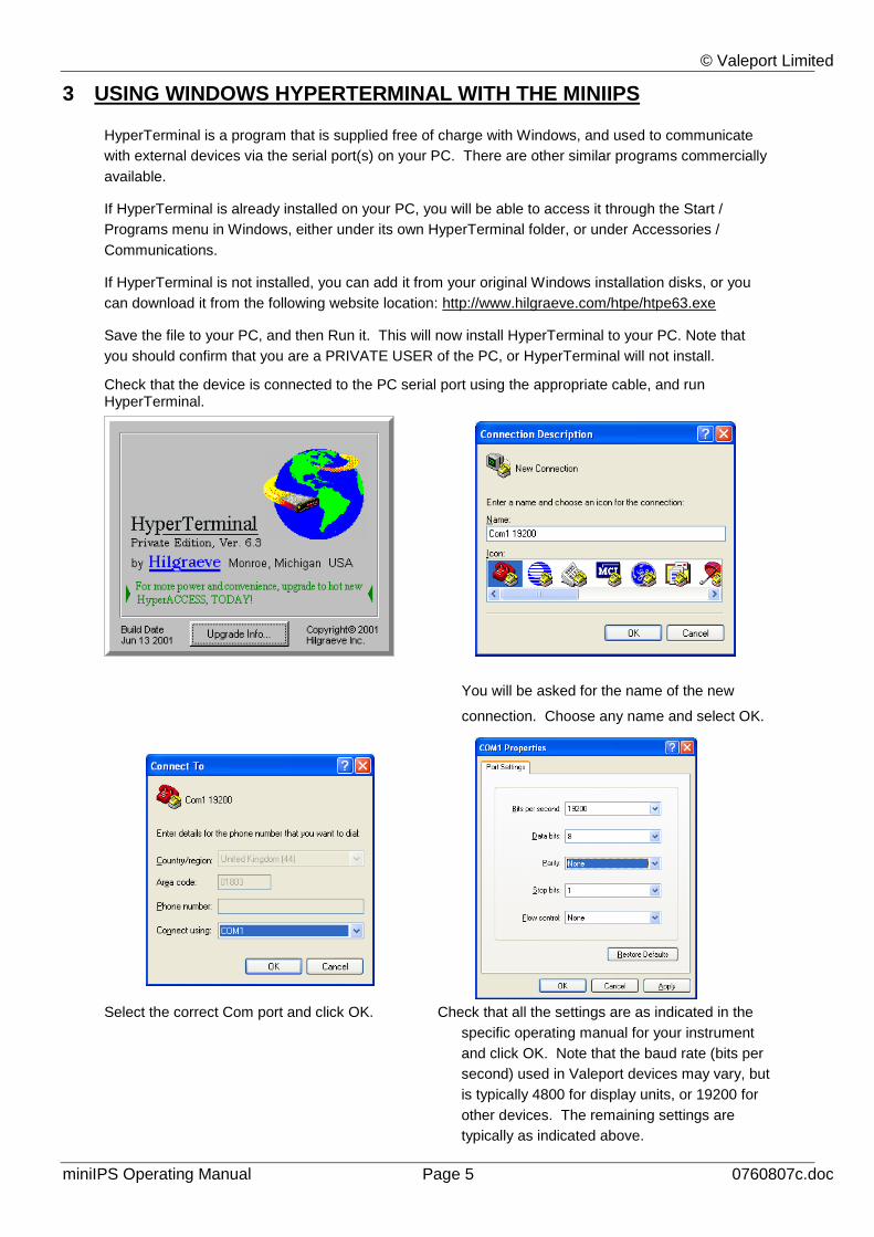
Check that the device is connected to the PC serial port using the appropriate cable, and run HyperTerminal.
You will be asked for the name of the new
connection. Choose any name and select OK.
Select the correct Com port and click OK. Check that all the settings are as indicated in the
specific operating manual for your instrument
and click OK. Note that the baud rate (bits per
second) used in Valeport devices may vary, but
is typically 4800 for display units, or 19200 for
other devices. The remaining settings are
typically as indicated above.
© Valeport Limited
miniIPS Operating Manual Page 6 0760807c.doc
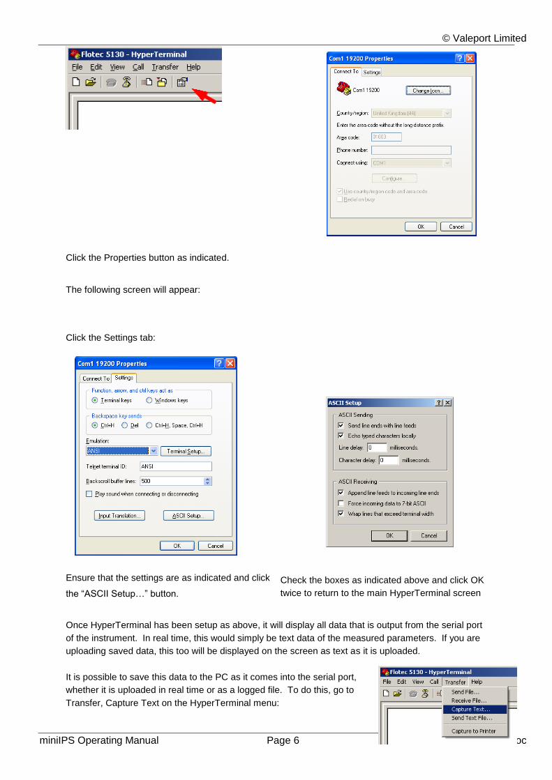
Click the Properties button as indicated.
The following screen will appear:
Click the Settings tab:
Ensure that the settings are as indicated and click
the “ASCII Setup…” button.
Check the boxes as indicated above and click OK
twice to return to the main HyperTerminal screen
Once HyperTerminal has been setup as above, it will display all data that is output from the serial port
of the instrument. In real time, this would simply be text data of the measured parameters. If you are
uploading saved data, this too will be displayed on the screen as text as it is uploaded.
It is possible to save this data to the PC as it comes into the serial port,
whether it is uploaded in real time or as a logged file. To do this, go to
Transfer, Capture Text on the HyperTerminal menu:
© Valeport Limited
miniIPS Operating Manual Page 7 0760807c.doc
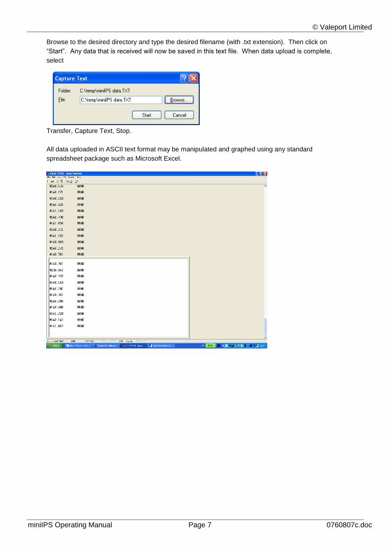
Browse to the desired directory and type the desired filename (with .txt extension). Then click on
“Start”. Any data that is received will now be saved in this text file. When data upload is complete,
select
Transfer, Capture Text, Stop.
All data uploaded in ASCII text format may be manipulated and graphed using any standard
spreadsheet package such as Microsoft Excel.
© Valeport Limited
miniIPS Operating Manual Page 8 0760807c.doc
4 DATA REQUESTS AND OUTPUT FORMATS
Control of the miniIPS is achieved through the use of “# codes”, as described below.
Note that all commands must be “sent” by pressing the Enter key, with the exception of the single „#‟
character required to enter setup mode.
Additionally, note that you must use the main Enter key on the keyboard, not the smaller number pad
Enter key. The large key actually sends two instructions – “Carriage Return” (or <CR>) and “Line
Feed” (or <LF>). The miniIPS requires both these instructions to terminate a command. The smaller
Enter key on a keyboard only sends the <CR> instruction.
4.1 START / STOP
When power is applied to the miniIPS, it will immediately begin to operate according to the existing
settings. The most basic level of Stop / Start control is therefore by switching power on and off.
# When the instrument is running, the miniIPS may be put into setup mode at any
time by typing the „#‟ character. The device will respond with a command prompt
„>‟ and await the next instruction.
Note that there is a “watchdog” function here – if the unit is interrupted with the „#‟
character, and no further command is received for a period of 5 minutes, the
sensor will automatically begin sampling data using the existing settings
#028 Starts sampling from setup mode, or takes a single reading if unit is in “Single”
sampling mode.
© Valeport Limited
miniIPS Operating Manual Page 9 0760807c.doc
4.2 COMMUNICATIONS SETUP
#059;{baud rate} Sets the sensor baud rate as required. Available baud rates are 1200, 2400,
4800, 9600, 19200, 38400, 57600, 115200.
Example: #059;9600
#005;ON (or OFF) Turns the miniIPS address mode on (or OFF). In address mode, the sensor
will only respond to commands prefixed by its address, or the global address
“00”.
Examples: 03:#028 Sensor address “03” begin sampling
00:#028 All sensor addresses begin sampling
#001;nn Sets the sensor address to any number from 01 to 99
#002 Responds with current sensor address
4.3 SAMPLING PATTERN
The miniIPS will operate in 3 different modes:
CONT Continuous mode, where data is output at a fixed frequency from 1 to 16Hz
SINGLE Single mode is effectively “Sample on Demand” – when instructed, the sensor will
measure and report a single reading
BURST Burst mode is useful for longer term deployments, where data is measured for a number
of samples, and the sensor then “sleeps” for a defined period of time. The measured
data may be averaged or output as it is.
In each case, the sampling mode is set using the command #003 as described overleaf. Note also
that the command #004 will return the current sampling pattern.
© Valeport Limited
miniIPS Operating Manual Page 10 0760807c.doc
The command string to set the sampling parameters is as follows:
#003;mode;rate;period;interval;average;length where:
mode Enter CONT, SINGLE or BURST as required
rate Enter 1, 2, 4, 8 or 16 as the required sampling rate in Hz. Note that this value must
be included in the string for SINGLE mode, even though it is not used.
period This value defines the Burst sampling mode, but must be entered for the other
modes even though it is not used. Enter the number of samples that should be
taken in the Burst, from 1 to 65535
interval This value defines the Burst sampling mode, but must be entered for the other
modes even though it is not used. Enter the number of seconds between the start
of each measurement burst, from 1 to 65535
average This parameter defines the Burst sampling mode, but must be entered for the other
modes even though it is not used. Enter FIXED, MOVING or NONE as required.
Fixed averaging means that a single average number of all the readings in the
burst will be output. Moving average is a sliding window of defined duration,
averaging several data points within the burst, and updating with each single
reading. None means that no averaging should be done, with each data point in
the burst being output as it is measured.
length Defines the number of samples in the “sliding window” of the Moving Average.
Enter a value from 1 to 120. Note that this value is part of the definition of Burst
mode, but must also be entered for the other modes, even though it is not used.
Examples:
1: Continuous data output at 4Hz
#003;CONT;4;1;1;NONE;1
Note that the characters shown in italics must be included, even though they are not part of the
definition of Continuous mode. It does not matter what values are used here, provided they fit within
the general constraints defined above (1 to 65535 etc).
© Valeport Limited
miniIPS Operating Manual Page 11 0760807c.doc
2: Data on demand
#003;SINGLE;1;1;1;NONE;1
Note that the characters shown in italics must be included, even though they are not part of the
definition of this mode. It does not matter what values are used, as long as they fit within the general
constraints for each term defined above (1 to 65535 etc).
3: Burst Mode, 80 readings over 5 secs, once per minute. Output average value only
#003;BURST;16;80;60;FIXED;1
Note that the last value (shown in italics) must be included, even though it is not part of the definition
of Fixed Averaging. It does not matter what values is used here, provided it fits within the general
constraints defined above (1 to 120 etc).
4.4 PRESSURE TARE
The pressure sensor fitted to the miniIPS measures absolute pressure, i.e. it includes atmospheric
pressure. The pressure tare function allows the atmospheric pressure (as measured by the sensor
before deployment) to be removed from the readings, so the output is simply pressure of water. Note
also that by taking a tare reading at any fixed point in the water column, readings will then be output
relative to that point.
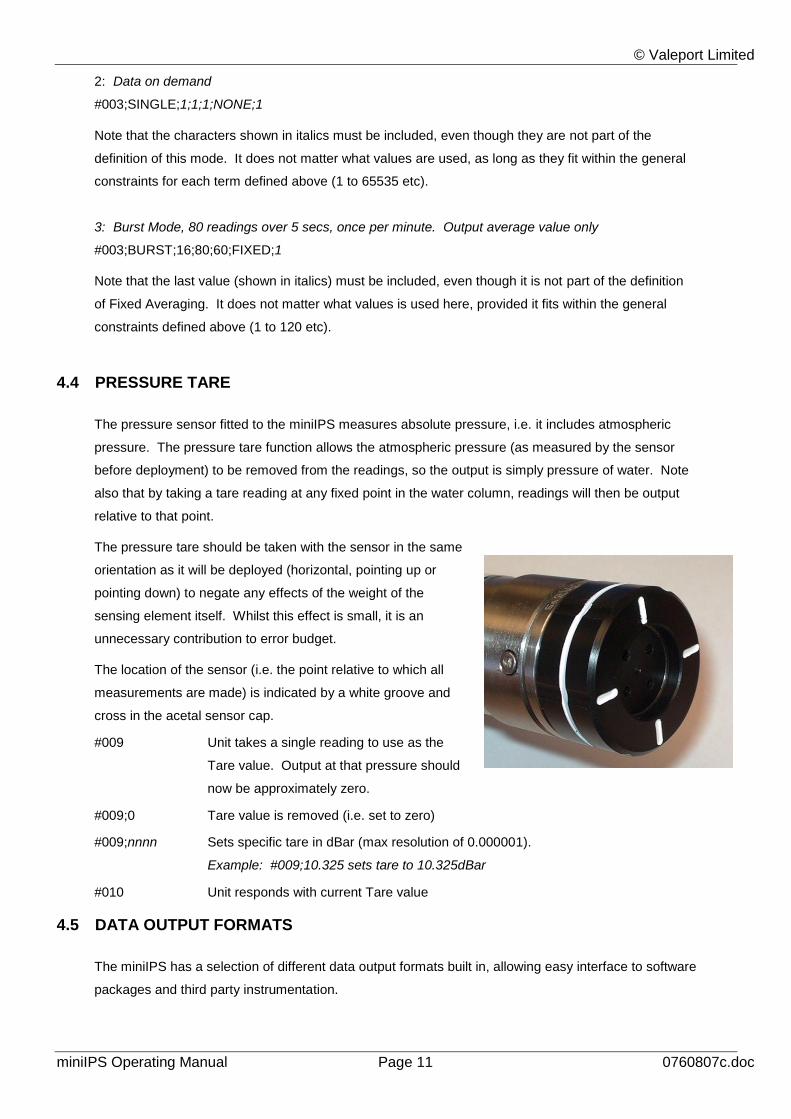
The pressure tare should be taken with the sensor in the same
orientation as it will be deployed (horizontal, pointing up or
pointing down) to negate any effects of the weight of the
sensing element itself. Whilst this effect is small, it is an
unnecessary contribution to error budget.
The location of the sensor (i.e. the point relative to which all
measurements are made) is indicated by a white groove and
cross in the acetal sensor cap.
#009 Unit takes a single reading to use as the
Tare value. Output at that pressure should
now be approximately zero.
#009;0 Tare value is removed (i.e. set to zero)
#009;nnnn Sets specific tare in dBar (max resolution of 0.000001).
Example: #009;10.325 sets tare to 10.325dBar
#010 Unit responds with current Tare value
4.5 DATA OUTPUT FORMATS
The miniIPS has a selection of different data output formats built in, allowing easy interface to software
packages and third party instrumentation.

© Valeport Limited
miniIPS Operating Manual Page 12 0760807c.doc
4.5.1 UNITS
The default output units for the miniIPS are deciBar (dBar), equivalent to 0.1Bar, or approximately 1m
of seawater. The miniIPS can also output pressure in PSI. It is also possible to present the data in
units of metres or feet of seawater, calculated using the UNESCO Simple Pressure / Depth
relationship, which assumes “standard” water density.
#020;M Outputs data in Metres
#020;F Outputs data in Feet
#020;D Outputs data in Dbar
#020;P Outputs data in PSI
#135;{latitude} Sets the local operating latitude in decimal degrees. This is required for an
accurate pressure / depth conversion, since the relationship is partially
dependent on local gravity, which varies with distance from the equator.
Positive / negative signing for North / South of the equator is not relevant.
Example: #135;50.426
Sets latitude to 50.426° (50° 25’ 34”), (Totnes UK).
All output formats are affected by changing the output units.
4.5.2 VALEPORT FORMAT
Command: #013;VALEPORT
Format: 0009.914 DBAR
Default separator is TAB. This may be changed to any chosen character using the command #026.
Example: #026;/
0009.914/DBAR
4.5.3 CSV FORMAT
Command: #13;CSV
Format: 00/00/00, 00:00:00, 0009.9, 0.0, 00.0
Notes: DD/MM/YY, HH:mm:SS, Output Data, Spare, Spare
4.5.4 NMEA FORMAT
Command: #013;NMEA
Format: $PIPS,0009.91, M*78
Notes: NMEA Identifier, Output Data, Units + Checksum
Last three characters are a checksum
© Valeport Limited
miniIPS Operating Manual Page 13 0760807c.doc
4.5.5 HYPACK FORMAT
Command: #013;HYPACK
Format: 009.9 0000.0
Notes: Output Data + Spare field
4.5.6 DIGIQUARTZ FORMAT
Command: #013;DIGIQUARTZ
Format: *00019.914
Notes: This format emulates the Paroscientific Digiquartz sensor output
4.5.7 DIGIQUARTZ CDL FORMAT
Command: #013;DIGIQUARTZ_CDL
Format: *0001+0009.9139318
Notes: This format emulates the Paroscientific Digiquartz CDL sensor
output
4.6 CALIBRATION
The miniIPS may be returned to Valeport or one of its approved laboratories for recalibration, or it may
be recalibrated by the customer using a Class A deadweight tester, or defined standard of the
customer‟s choosing. Whilst this process is reasonably straightforward, it is beyond the scope of this
manual. Please refer to the Support pages of Valeport‟s website www.valeport.co.uk for full
instructions on the recalibration procedure, together with a spreadsheet to calculate the new
calibration coefficients, and details of how to enter them into the sensor.
4.7 WELCOME MESSAGE
When power is applied to the miniIPS, it will normally output a welcome message as follows, detailing
the software version :
You are connected to a Valeport Mini IPS Sensor
0760700B 14/09/2006 07:00
Copyright 2006.
#209;OFF (or ON) This command will disable (or enable) the welcome message when
power is applied.
© Valeport Limited
miniIPS Operating Manual Page 14 0760807c.doc
4.8 INFORMATION
The following commands will cause the sensor to report back various pieces of information, as
described:
#032 Software version number
#034 Instrument serial number
#093 pcb serial number
#138 Year of manufacture, month and year of last inspection/service
#202 Maximum transducer pressure range
#900 Outputs a full list of all command codes applicable to the sensor. Note that not all of
these codes are covered by this manual – use this feature with care.
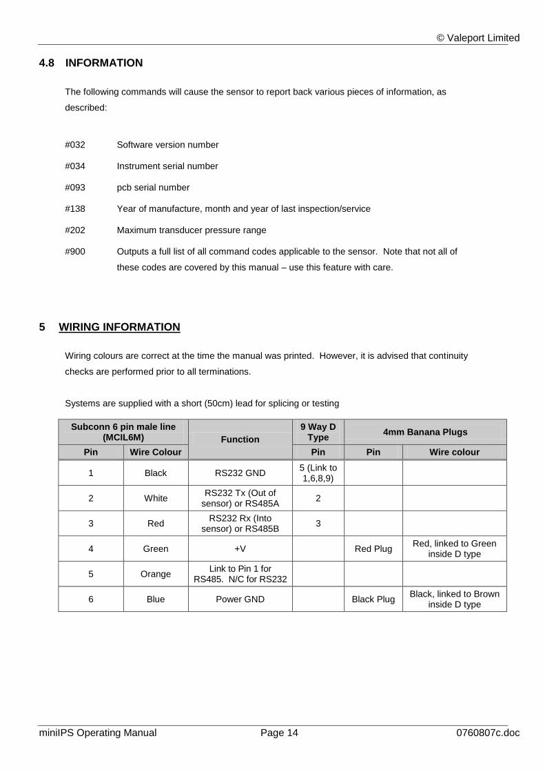
5 WIRING INFORMATION
Wiring colours are correct at the time the manual was printed. However, it is advised that continuity
checks are performed prior to all terminations.
Systems are supplied with a short (50cm) lead for splicing or testing
Subconn 6 pin male line (MCIL6M) Function
9 Way D Type
4mm Banana Plugs
Pin Wire Colour Pin Pin Wire colour
1 Black RS232 GND 5 (Link to 1,6,8,9)
2 White RS232 Tx (Out of
sensor) or RS485A 2
3 Red RS232 Rx (Into
sensor) or RS485B 3
4 Green +V Red Plug Red, linked to Green
inside D type
5 Orange Link to Pin 1 for
RS485. N/C for RS232
6 Blue Power GND Black Plug Black, linked to Brown
inside D type
© Valeport Limited
miniIPS Operating Manual Page 15 0760807c.doc
6 CARE & MAINTENANCE
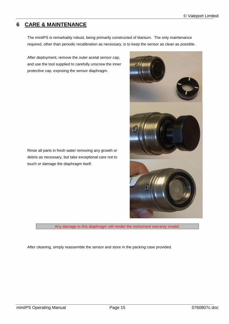
The miniIPS is remarkably robust, being primarily constructed of titanium. The only maintenance
required, other than periodic recalibration as necessary, is to keep the sensor as clean as possible.
After deployment, remove the outer acetal sensor cap,
and use the tool supplied to carefully unscrew the inner
protective cap, exposing the sensor diaphragm.
Rinse all parts in fresh water removing any growth or
debris as necessary, but take exceptional care not to
touch or damage the diaphragm itself.
Any damage to this diaphragm will render the instrument warranty invalid.
After cleaning, simply reassemble the sensor and store in the packing case provided.
Related Documents