3 Edition 06.17 AGA Technical Information · GB • All-purpose servo regulator for gaseous media with integrated safety valve • Suitable for a max. inlet pressure of 500 mbar (7 psig) • Minimum installation effort: no external impulse line required • Setting options from two sides Pressure regulators with solenoid valve VAD, VAG, VAV, VAH Flow rate regulator VRH Pressure regulators with double solenoid valve VCD, VCG, VCV, VCH

Welcome message from author
This document is posted to help you gain knowledge. Please leave a comment to let me know what you think about it! Share it to your friends and learn new things together.
Transcript
3 Edition 0617
AGA
Technical Information middot GB
bull All-purpose servo regulator for gaseous media with integrated safety valve
bull Suitable for a max inlet pressure of 500 mbar (7 psig)
bull Minimum installation effort no external impulse line required
bull Setting options from two sides
Pressure regulators with solenoid valve VAD VAG VAV VAHFlow rate regulator VRHPressure regulators with double solenoid valve VCD VCG VCV VCH
VAD VAG VAH VAV VRH VCD VCG VCV VCH middot Edition 0617 2
= To be continued
ContentsPressure regulators with solenoid valve VAD VAG VAV VAH 1Flow rate regulator VRH 1Pressure regulators with double solenoid valve VCD VCG VCV VCH 1Contents 21 Application 411 Examples of application 6
111 Constant pressure control 6112 Constant pressure control with two gas solenoid valves 6113 Constant pressure control with max pressure switch 7114 Constant pressure control with non-controlled pilot gas outlet 7115 Modulating control 8116 Modulating control with two gas solenoid valves 8117 Modulating control with two gas solenoid valves and inlet pressure switch 9118 HighLow control 9119 Zero pressure control 101110 Staged flow rate control 101111 Continuous or staged flow rate control 111112 Modulating control with variable airgas ratio control with gas solenoid valve 111113 Modulating control in residential heat generation 12
2 Certification 133 Function 1531 VAD VAG VAH VRH VAV 15
311 Pressure regulator for gas VAD 15312 Airgas ratio control VAG 16313 Flow rate regulators VAH VRH 17314 Variable airgas ratio control VAV 18315 Pressure regulator with gas solenoid valve VAxS closed position switch with visual position indicator 20
32 Animation 22
33 Connection diagram 23331 VAx with M20 cable gland 23332 VAx with plug 23333 VAS with VADVAGVAHVAV with M20 cable gland 23334 VAS with VADVAGVAHVAV with plug 23
4 Replacement possibilities for MODULINE pressure regulators with gas solenoid valve 2441 GVS GVI GVIB GVR and GVRH are to be replaced by VAD VAG VAG+VAS VAH and VAV 24
5 Flow rate 2651 Selection example for VAD 26
511 Calculate VAD 2652 Selection example for VAG VAH VRH VAV 27
521 Calculate VAG VxH VAV 27
53 Selection example for zero governor VAGN 28531 Calculate VAGN 28
6 Selection 2961 Selection table for pressure regulator with solenoid valve VAD 2962 Type code for VAD 3063 Selection table for airgas ratio control with solenoid valve VAG flow rate regulators VAH VRH 31
631 Type code for VAG VAH VRH 3264 Selection table for variable airgas ratio control with solenoid valve VAV 33641 Type code for VAV 34
65 Accessories 35
VAD VAG VAH VAV VRH VCD VCG VCV VCH middot Edition 0617 3
= To be continued
7 Project planning information 3671 Installation 36
711 Installation position 3772 Setting the low-fire rate on VAG VAH VRH VAV 3873 Setting the high-fire rate on VAV 39
731 Calculation 39
8 Accessories 4081 Gas pressure switch DGC 4082 Bypass valvepilot gas valve VAS 1 41
821 Flow rate 41822 Lieferumfang VAS 1 fuumlr VAx 1 VAx 2 VAx 3 42
83 Bypass valvepilot gas valve VBY 8 for VADVAGVAHVAV 1 43
831 Scope of delivery VBY 8I as bypass valve 43832 Scope of delivery VBY 8R as pilot gas valve 43833 Selection 43834 Type code 43835 Flow rate 44836 Technical data 44
84 Pressure test points 4585 Cable gland set 4586 Attachment block 4587 Seal set VA 1thinspndashthinsp3 4688 Seal set VCS 1thinspndashthinsp3 4689 Differential pressure orifice 47810 Measuring orifice VMO 47811 Filter module VMF 48812 Fine-adjusting valve VMV 48813 Gas control line 48814 Cable gland with pressure equalization element 49
9 Technical data 5091 VAD 5192 VAG 5193 VAH VRH 52
94 VAV 5295 Safety-specific characteristic values for VAx 1thinspndashthinsp3 53
951 Determining the PFHD value the λD value and the MTTFd value 54952 Calculating the PFHD and PFDavg 54
96 Dimensions 5597 Converting units 56
10 Maintenance cycles 5611 Glossary 57111 Diagnostic coverage DC 57112 Mode of operation 57113 Category 57114 Common cause failure CCF 57115 Fraction of undetected common cause failures β 57116 B10d value 57117 T10d value 57118 Hardware fault tolerance HFT 58119 Mean dangerous failure rate λD 581110 Safe failure fraction SFF 581111 Probability of dangerous failure PFHD 581112 Mean time to dangerous failure MTTFd 581113 Demand rate nop 581114 Average probability of dangerous failure on demand PFDavg 58
Feedback 59Contact 59
VAD VAG VAH VAV VRH VCD VCG VCV VCH middot Edition 0617 4
VAD VAG VAH VAV VRH
Application
1 ApplicationRegulators with solenoid valves are designed for shut-off and thanks to the servo technology for precise control of the gas supply to gas burners and gas ap-pliances They are used in gas control and safety sys-tems in all sectors of the iron steel glass and ceramics industries as well as in residential or commercial heat generation such as the packaging paper and food-stuffs industries
VADConstant pressure governor Class A with high control accuracy for excess air burners atmospheric burners or single-stage forced draught burners Pressure preset via setpoint spring In the case of fluctuating furnace or kiln pressures the furnace chamber pressure may also be connected for maintaining a constant burner capac-ity
VAGAirgas ratio control Class A for maintaining a con-stant airgas pressure ratio for modulating-controlled burners or with VAS 1 bypass valve for stage-controlled burners Pressure preset by the air control line
The VAGN can also be used as a zero governor for gas engines
VAH VRHFlow rate regulators VAH and VRH are used to maintain a constant gasair ratio for modulating-controlled and stage-controlled burners The gas flow rate is cont-rolled proportionally to the air flow rate
In addition flow rate regulator VAH is designed as a gas solenoid valve and shuts off the gas or air supply safely
VAD VAG VAH VAV VRH VCD VCG VCV VCH middot Edition 0617 5
Application
VAVVariable airgas ratio control Class A for maintaining a constant gasair pressure ratio for modulating-con-trolled burners Pressure preset by the air control line The ratio of gas pressure to air pressure remains con-stant It can be set from 061 to 31 Pressure fluctua-tions in the combustion chamber can be compensated via the combustion chamber control pressure
Pressure regulator on excess air burners in the ceram-ics industry
Airgas ratio control on melting furnace for ensuring stoichiometric combustion over the entire capacity range
Aluminium age-hardening furnace with airgas ratio controls for air deficiency cut-out
VAD VAG VAH VAV VRH VCD VCG VCV VCH middot Edition 0617 6
Application
1 1 Examples of application
1 1 1 Constant pressure control
VAD
The pressure regulator with gas solenoid valve VAD maintains the set gas outlet pressure pd constant when subject to differing flow rates If a second gas solenoid valve is used upstream of the VAD this complies with the requirements of EN 746-2 for two Class A gas sole-noid valves connected in series
1 1 2 Constant pressure control with two gas solenoid valves
VADVAS
The pressure regulator with gas solenoid valve VAD maintains the set gas outlet pressure pd constant when subject to differing flow rates
VAD VAG VAH VAV VRH VCD VCG VCV VCH middot Edition 0617 7
Application
1 1 3 Constant pressure control with max pressure switch
VAD
DGCmin DGCmax
VASPZL PZH
In this example the minimum inlet pressure pu and the maximum outlet pressure pd are monitored with the pressure switches DGC The simple attachment of the pressure switch module makes installation easier
1 1 4 Constant pressure control with non-controlled pilot gas outlet
DGCmin DGCmax
VADVAS
VAS
PZL PZH
In this application the pilot burner is supplied with a high inlet pressure via the pilot gas outlet The simple attachment of the bypass valve module makes instal-lation easier The minimum inlet pressure pu and the maximum outlet pressure pd are monitored with the pressure switches DGC
VAD VAG VAH VAV VRH VCD VCG VCV VCH middot Edition 0617 8
Application
1 1 5 Modulating control
psa
psa
VAG
MIC + BVA
The gas outlet pressure pd is con trolled via the airgas ratio control with gas solenoid valve VAG The gas outlet pressure pd follows the changing air control pressure psa The ratio of gas pressure to air pressure remains constant The VAG is suitable for a control range up to 101
If a second solenoid valve is used upstream of the VAG this complies with the requirements of EN 746-2 for two Class A valves connected in series
1 1 6 Modulating control with two gas solenoid valves
psa
psaM
IC + BVA
VASVAG
The gas outlet pressure pd is con trolled via the airgas ratio control with gas solenoid valve VAG The gas outlet pressure pd follows the changing air control pressure psa The ratio of gas pressure to air pressure remains constant The VAG is suitable for a control range up to 101
The gas line is two Class A shut-off valves connected in series in accordance with the requirements of EN 746-2
VAD VAG VAH VAV VRH VCD VCG VCV VCH middot Edition 0617 9
Application
1 1 7 Modulating control with two gas solenoid valves and inlet pressure switch
DGCmin
PZL
psa
psa
M
IC + BVA
VAS
VAG
In this case the minimum inlet pressure pu is monitored by the pressure switch DGC The simple attachment of the pressure switch module makes installation easier
1 1 8 HighLow control
psa
DGCmin
PZL
psa
M
IC 40 + BVA
VAS
VAG
VAS 1
At high fire the gas outlet pressure pd follows the air control pressure psa The ratio of gas pressure to air pressure remains constant Low fire is determined via the bypass valve VAS 1 Here as well the simple attach-ment of the bypass valve module makes installation easier
VAD VAG VAH VAV VRH VCD VCG VCV VCH middot Edition 0617 10
Application
1 1 9 Zero pressure control
Venturi
DGCmin
PZL
M
IC + BVA
VASVAGN
In this application the control air pressure is the at-mospheric air pressure The air flow rate generates a negative pressure in the gas pipe via the Venturi This negative pressure is compensated by the airgas ratio control with gas solenoid valve VAGN The greater the negative pressure the greater the gas flow rate
1 1 10 Staged flow rate control
BVHM + MB7L
VMV EKO
LEH
ECOMAX
VAH
BCU BZA
Prozess SteuerungProcess Control (PCC)
AKT
psa-
psa
pd-
VASN
This application shows the VAH on a self recuperative burner
The pressure loss in the recuperator depends on the furnace or kiln temperature When the furnace or kiln temperature is increased (at a constant air supply pres-sure) the flow rate drops This change in the air flow ra-te is measured by the orifice and the VAH changes the gas volume accordingly
The air index (lambda) can be set using the fine-adjus-ting valve VMV
VAD VAG VAH VAV VRH VCD VCG VCV VCH middot Edition 0617 11
Application
1 1 11 Continuous or staged flow rate control
M
IC + BVA
VMV
VMO
VAH
VAS
psa-psa
pd-
This application shows flow rate control for a radiant tube burner system with plug-in recuperator for air pre-heating
There are temperature-dependent air pressure losses in the recuperator The ratio of gas pressure to air pres-sure does not remain constant The fluctuating air flow rate is measured at the measuring orifice VMO and the VAH controls the gas flow rate proportionally
The air index (lambda) can be set using the fine-adjust-ing valve VMV
1 1 12 Modulating control with variable airgas ratio control with gas solenoid valve
psa
psc
DGCmin
PZL
psa
psc
M
IC + BVA
VASVAV
The ratio of gas pressure to air pressure can be adjusted infinitely between 061 and 31 Pressure fluctuations in the combustion chamber can be compensated via the combustion chamber control pressure psc see page 15 (Function)
VAD VAG VAH VAV VRH VCD VCG VCV VCH middot Edition 0617 12
Application
1 1 13 Modulating control in residential heat generation
DGCmin
PZL
psa
psc
VAS VAV
This application shows the variable airgas ratio control with solenoid valve VAV fitted to a modulating-con-trolled forced draught burner
The combustion air volume is set via a butterfly valve for air or by adjusting the fan speed
VAD VAG VAH VAV VRH VCD VCG VCV VCH middot Edition 0617 13
Certification
2 CertificationCertificates ndash see Docuthek
VAD VAG VAV VAH certified to SIL and PL
For systems up to SIL 3 pursuant to EN 61508 and PL e pursuant to ISO 13849
VAD VAG VAV VAH
EU certified pursuant to
ndash Gas Appliances Directive (2009142EC) in conjunc-tion with EN 13611 EN 161 EN 88-1 EN 126 and EN 1854
Meets the requirements of thendash Low Voltage Directive (201435EU)
ndash EMC Directive (201430EU)
VAD VAG VAV VAH FM approved
Factory Mutual Research Class 7400 Process Control Valves Designed for applications pursuant to NFPA 85 and NFPA 86 wwwapprovalguidecom
VAD VAG ANSICSA approved
American National Standards InstituteCanadian Standards AssociationthinspndashthinspANSI Z2121CSA 65 ANSI Z2118 and CSA 63
wwwcsagrouporg ndash Class number 3371-83 (natural gas LPG) 3371-03 (natural gas propane)
VAD VAG VAV UL listed(for 120 V only)
Underwriters Laboratories ndash UL 429 ldquoElectrically operated valvesrdquo wwwulcom Tools (at the bottom of the page) On-line Certifications Directory
VAD VAG VAV AGA approved
AGA
Australian Gas Association Approval No 5319 httpwwwagaasnauproduct_directory
Approval does not apply for 100 V AC and 200 V AC
VAD VAG VAH VAV VRH VCD VCG VCV VCH middot Edition 0617 14
Certification
Eurasian Customs Union
The product VAD VAG VAV VAH VCD VCG VCV VCH meets the technical specifications of the Eurasian Cus-toms Union
VAD VAG VAH VAV VRH VCD VCG VCV VCH middot Edition 0617 15
Function
3 Function3 1 VAD VAG VAH VRH VAVThe regulator is closed when it is disconnected from the power supply
Opening connect the system to the electrical power supply (alternating voltage will be rectified) The blue LED lights up The coilrsquos magnetic field pulls the armature upwards and clears the supply nozzle for the gas inlet pressure pu The gas passes through the internal impulse tube to the adjustment diaphragm and then pushes the
valve disc open The outlet pressure is applied to the servo diaphragm via the internal feedback
The servo regulator then maintains a set constant outlet pressure pd
3 1 1 Pressure regulator for gas VADThe nominal outlet pressure pd is defined by the control spring
Servoregulator
Valve
Armature
Valve disc
Adjustmentdiaphragm
Servodiaphragm
Internalfeedback
Controlspring
Solenoid coil
Supplynozzle
VAD VAG VAH VAV VRH VCD VCG VCV VCH middot Edition 0617 16
Function
3 1 2 Airgas ratio control VAGThe airgas ratio control VAG controls the outlet pres-sure pd depending on the variable air control pres-sure psa
The ratio of gas pressure to air pressure remains con-stant 11 The VAG is suitable for a control range up to 101
If the burner operates at low-fire rate the gasair mixture can be changed by adjusting the zero point spring ldquoNrdquo
psa
pd
Zero point setting N zero point spring
VAD VAG VAH VAV VRH VCD VCG VCV VCH middot Edition 0617 17
Function
3 1 3 Flow rate regulators VAH VRHThe flow rate regulators VAH VRH control the gas flow rate depending on the variable air flow rate The ratio of gas flow rate to air flow rate remains constant If the burner operates at low-fire rate the gasair mixture can be changed by adjusting the zero point spring ldquoNrdquo
In addition flow rate regulator VAH is designed as a gas solenoid valve and shuts off the gas or air supply safely
psa
psa-
pd-
pdInternal feedback
Zero point setting N zero point spring
VAD VAG VAH VAV VRH VCD VCG VCV VCH middot Edition 0617 18
Function
3 1 4 Variable airgas ratio control VAVThe servo regulator maintains a set constant outlet pressure pd The variable airgas ratio control VAV con-trols the outlet pressure pd depending on the variable air control pressure psa The ratio of gas pressure to air pressure remains constant
The settings N and V can be changed and read off from both sides of the unit using the adjusting screws
The ratio of gas pressure to air pressure at low-fire rate can be changed by adjusting the zero point setting N By turning the adjusting screw ldquoNrdquo the force of the zero point spring and thus the zero point is changed by plusmn 15 mbar (06 WC) see page 36 (Project planning information)
pdpsc
psa
Air diaphragm
Transmission ratio V
Zero point setting N zero point spring
Internalfeedback
Adjustment diaphragm
Servo diaphragm
VAD VAG VAH VAV VRH VCD VCG VCV VCH middot Edition 0617 19
Function
The high-fire rate is set by turning the adjusting screw ldquoVrdquo until the required flue gas values are achieved see page 36 (Project planning information) The ra-tio of gas pressure to air pressure can be set from 061 to 31
The settings N and V influence each other and the ad-justment process must be repeated if necessary
The outlet pressure pd is applied to the servo diaphragm via the internal feedback The combustion chamber control pressure psc is transmitted to the space under the air and servo diaphragms via an impulse line
The pressure differential psa - psc is achieved on the air diaphragm and the pressure differential pd - psc on the servo diaphragm This ensures that pressure fluctua-tions in the combustion chamber can be compensated The flue gas values remain constant in the case of fluc-tuations in the combustion chamber pressure (pd - psc) = (psa - psc) times V + N
VAD VAG VAH VAV VRH VCD VCG VCV VCH middot Edition 0617 20
1 COM
2 NO
3 NC
Function
3 1 5 Pressure regulator with gas solenoid valve VAx S closed position switch with visual position indicatorOpening when the pressure regulator is opened the closed position switch switches The visual position in-dicator is activated The ldquoopenrdquo signal is marked in red The double valve seat opens to release the volume of gas
Closing the pressure regulator VAx is disconnected from the voltage supply and the closing spring presses the double valve disc on to the valve seat The closed position switch is actuated The visual position indicator is white for ldquoclosedrdquo
VAD VAG VAH VAV VRH VCD VCG VCV VCH middot Edition 0617 21
Function
The actuator cannot be rotated on a pressure regulator with a closed position switch with visual position indi-cator
NOTE NFPA 86thinspndashthinspsafety shut-off valve VASS must be fitted with an overtravel switch with visual position indicator and the burner-side pressure regulator with gas solenoid valve VAxS must also be fitted with a closed position switch with visual position indicator The closed position can be verified using the proof of closure switch of the gas solenoid valve VASS
VAD VAG VAH VAV VRH VCD VCG VCV VCH middot Edition 0617 22
Function
3 2 AnimationThe interactive animation shows the function of the val-Vario controls VADVAGVAHVAV
Click on the picture The animation can be controlled using the control bar at the bottom of the window (as on a DVD player) To play the animation you will need Adobe Reader 7 or a
newer version If you do not have Adobe Reader on your system you can download it from the Internet
If the animation does not start to play you can down-load it from the document library (wwwdocuthekcom) as an independent application
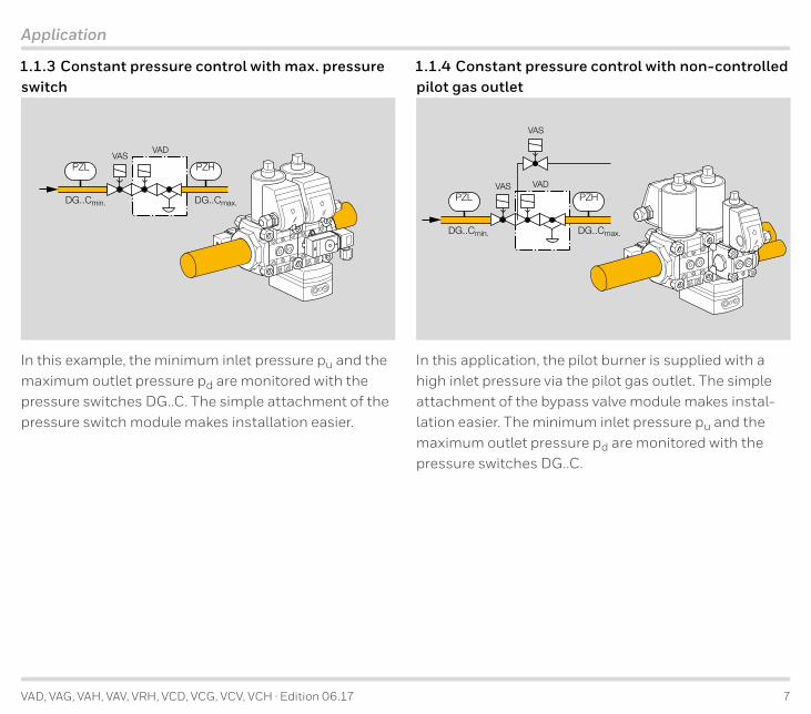
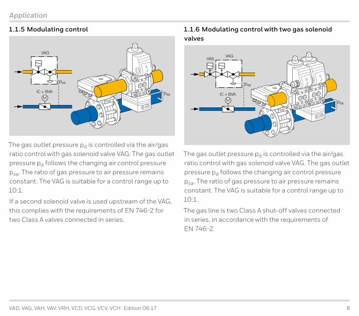
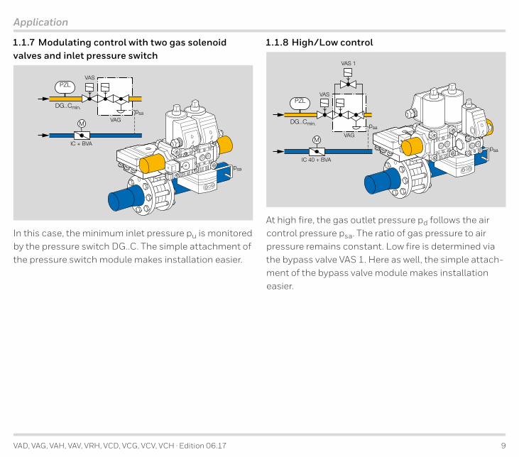
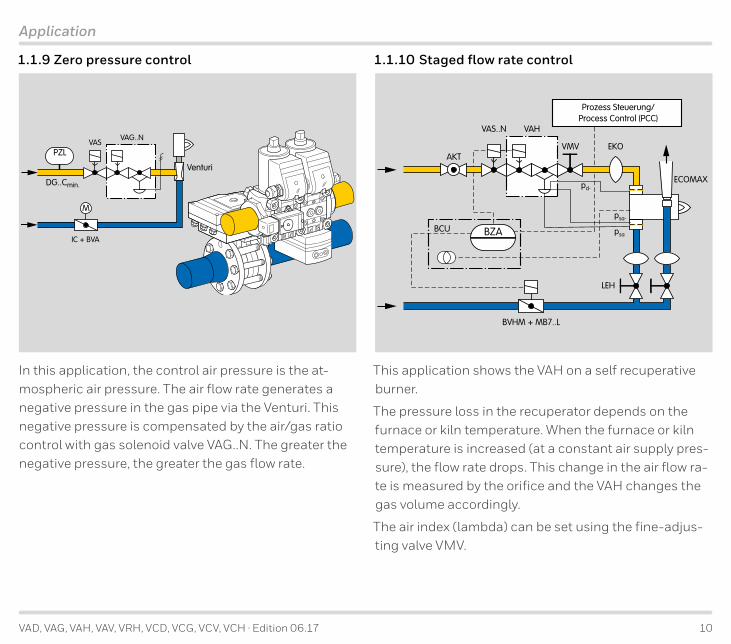
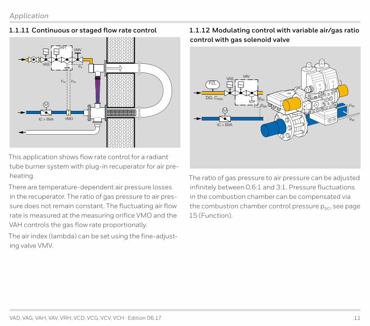
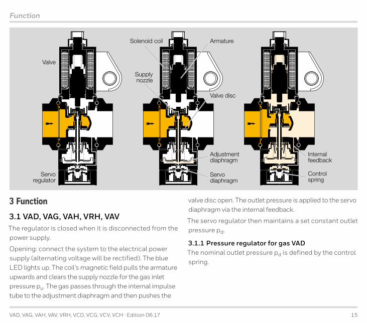
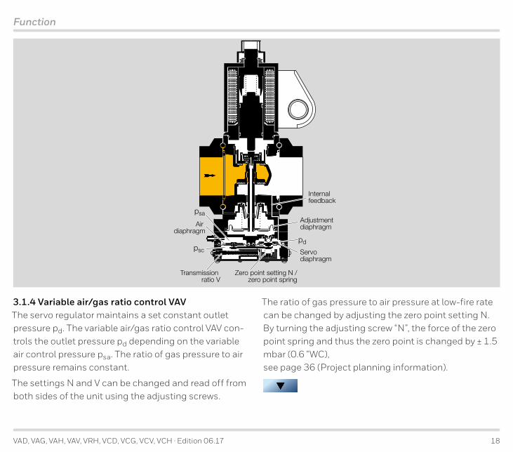
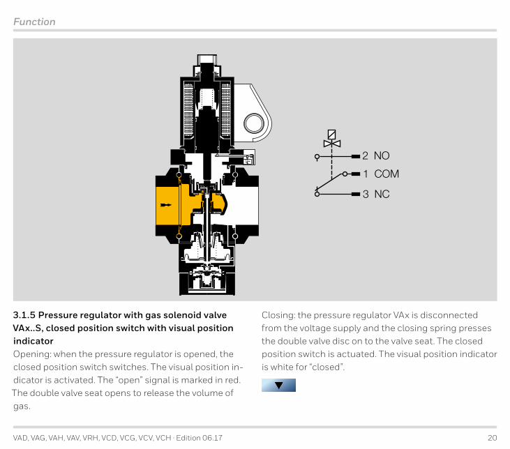
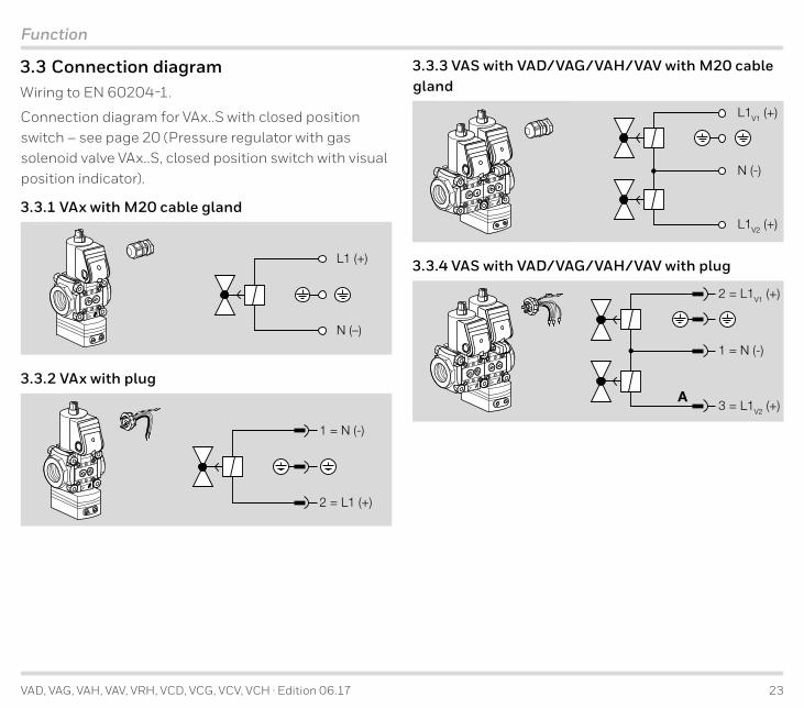
VAD VAG VAH VAV VRH VCD VCG VCV VCH middot Edition 0617 23
Function
3 3 Connection diagramWiring to EN 60204-1
Connection diagram for VAxS with closed position switch ndash see page 20 (Pressure regulator with gas solenoid valve VAxS closed position switch with visual position indicator)
3 3 1 VAx with M20 cable gland
L1 (+)
N (ndash)
3 3 2 VAx with plug
1 = N (-)
2 = L1 (+)
3 3 3 VAS with VADVAGVAHVAV with M20 cable gland
L1V1 (+)
N (-)
L1V2 (+)
3 3 4 VAS with VADVAGVAHVAV with plug
2 = L1V1 (+)
1 = N (-)
3 = L1V2 (+)A
VAD VAG VAH VAV VRH VCD VCG VCV VCH middot Edition 0617 24
Replacement possibilities for MODULINE pressure regulators with gas solenoid valve
4 Replacement possibilities for MODULINE pressure regulators with gas solenoid valve4 1 GVS GVI GVIB GVR and GVRH are to be replaced by VAD VAG VAG+VAS VAH and VAV
Type TypeGVS Pressure regulator with gas solenoid valve Pressure regulator with gas solenoid valve VADGVI Airgas ratio control with gas solenoid valve Airgas ratio control with gas solenoid valve VAG
GVIB Airgas ratio control with gas solenoid valve and bypass valve Airgas ratio control with gas solenoid valve and bypass valve VAG+VASGVRH Flow rate regulator with gas solenoid valve Flow rate regulator with gas solenoid valve VAHGVR Variable airgas ratio control with gas solenoid valve Variable airgas ratio control with solenoid valve VAV115125 Flange 38 Size 115
Size 125 ndash ndash
115125 Flange frac12 Size 115
Size 125 Size 1 DN 15 115
115125 Flange frac34 Size 115
Size 125 Size 1 DN 20 120
115125 Flange 1 Size 115
Size 125 Size 1 DN 25 125
232240 Flange 1 Size 232
Size 240 Size 2 DN 2540 22540
232240 Flange 1frac12 Size 232
Size 240 Size 2 DN 40 240
350 Flange 1frac12 Size 350 Size 3 DN 4050 34050350 Flange 2 Size 350 Size 3 DN 50 350ML MODULINE + Rp internal thread connection fl anges Rp internal thread R
TML MODULINE + NPT internal thread connection fl anges NPT internal thread N01 pumax 100 mbar (15 psig) pu max 500 mbar (7 psig)
02 200 mbar (3 psig) 500 mbar (7 psig)
VAD VAG VAH VAV VRH VCD VCG VCV VCH middot Edition 0617 25
Replacement possibilities for MODULINE pressure regulators with gas solenoid valve
Continuation
Type Type Quick opening Quick opening NF1 Control ratio 11 Control ratio 11
K Mains voltage 24 V DC Mains voltage 24 V DC Kndash 100 V AC P
Q 120 V AC 120 V AC Qndash 200 V AC Y
T 220240 V AC 230 V AC W3 Electrical connection via terminals Electrical connection via terminals
6 Electrical connection via socket Electrical connection via socket
9 Metal terminal connection box Electrical connection via terminals
S Closed position switch CPS with visual position indicator SG Closed position switch for 24 V CPS for 24 V with visual position indicator GM Suitable for biogas Suitable for biogas
Pressure test point at the inlet Pressure test point at the inlet and outlet
Outlet pressure pd -25Outlet pressure pd 25thinspndashthinsp25 mbar (1thinspndashthinsp10 WC)
2thinspndashthinsp90 mbar (08thinspndashthinsp36 WC) 20thinspndashthinsp50 mbar (8thinspndashthinsp20 WC) -5035thinspndashthinsp100 mbar (14thinspndashthinsp40 WC) -100Standard seat A
GVS 350ML01T3 with Rp 2 connection fl anges Example Example VAD 350RNW-100A with test points
= standard = available Pressure test points may be attached at the left- andor right-hand side Closed position switch with visual position indicator can be attached at the left- or right-hand side
VAD VAG VAH VAV VRH VCD VCG VCV VCH middot Edition 0617 26
∆p [i
nch
WC
]
Qn [SCFH]100 400 600 4000 60001000 200020 30 40 50 200 3006015 80
1
08
1
2
3
4
56
8
10
20
30
40
5060
80
100
200
∆p [m
bar]
5
8
3
20
10
30
40
80
60
300
400
50
04 06 1 2 3 4 5 808 10 20 30 40203 60 100 200
100
200
500
1
3
2
04 06 08 1 2 3 4 5 6 8 10 20 30 40
04 06 08 1 2 3 4 5 6 8 10
200
80 10020 3003
03Qn [m3h]
02
5060 80 100
40 5060
VAD
1B
P1P2
VAD
120
AVA
D 1
25A
VAD
2A
VAD
3A
RV v∆pmiacuten
Flow rate
= natural gas (ρ = 080 kgm3) = propane (ρ = 201 kgm3) = air (ρ = 129 kgm3)
The characteristic flow rate curves have been measured with the specified flanges and a fit-ted strainer If two or more valves are combined the pressure loss of each additional valve drops by approx 5
metric imperial
Enter densityFlow rate Qn
Inlet pressure pu
Outlet pressure pd
Product
Pressure loss ∆p
5 Flow rate5 1 Selection example for VADNatural gas Flow rate Qmax = 30 m3h Inlet pressure pu = 80 mbar Outlet pressure pd = 60 mbarThe desired control ratio from high-fire to low-fire rate is RV = 101High fire ∆p = pu - pd = 20 mbar Point P1Low fire Point P2 Qmin = 26 m3h at ∆p = 20 mbar RV = Qmax Qmin = 1151Point P1 and point P2 must be within the working range of a unit size We recommend that you select the small-est size to achieve the best control properties
5 1 1 Calculate VAD
VAD VAG VAH VAV VRH VCD VCG VCV VCH middot Edition 0617 27
∆p [i
nch
WC
]
Qn [SCFH]100 400 600 4000 60001000 200020 30 40 50 200 3006015 80
1
08
1
2
3
4
56
8
10
20
30
40
5060
80
100
200
∆p [m
bar]
5
8
3
20
10
30
40
80
60
300
400
50
04 06 1 2 3 4 5 808 10 20 30 40203 60 100 200
100
200
500
1
3
2
04 06 08 1 2 3 4 5 6 8 10 20 30 40
04 06 08 1 2 3 4 5 6 8 10
200
80 10020 3003
03Qn [m3h]
02
5060 80 100
40 5060
= pd min lt 5 mbar
VAG
VxH
VAV
1B
VAG
VxH
VAV
120
A
VAG
VxH
VAV
125
A
P1
P2
VAG
VxH
VAV
2A
VAG
VxH
VAV
3A
RV v∆pmiacuten
Flow rate
= natural gas (ρ = 080 kgm3) = propane (ρ = 201 kgm3) = air (ρ = 129 kgm3)
The characteristic flow rate curves have been measured with the specified flanges and a fit-ted strainer If two or more valves are combined the pressure loss of each additional valve drops by approx 5
5 2 Selection example for VAG VAH VRH VAV Natural gas Flow rate Qmax = 30 m3h Inlet pressure pu = 80 mbar Outlet pressure pd max VAG = 60 mbarThe desired control ratio from high-fire to low-fire rate is RV = 101High fire ∆p = pu - pd max = 20 mbar Point P1Low fire pd min = pd max RV2 = 06 mbar Qmin = Qmax RV = 3 m3h ∆p = pu - pd min = 794 mbar Point P2 select VAG 120APoint P1 and point P2 must be within the working range of a unit size We recommend that you select the smallest size to achieve the best control properties
metric imperial
Enter densityFlow rate Qn
Inlet pressure pu
Outlet pressure pd
Product
5 2 1 Calculate VAG VxH VAV
Pressure loss ∆p
VAD VAG VAH VAV VRH VCD VCG VCV VCH middot Edition 0617 28
∆p [i
nch
WC
]
Qn [SCFH]100 400 600 4000 60001000 200020 30 40 50 200 3006015 80
1
08
1
2
3
4
56
8
10
20
30
40
5060
80
100
200
∆p [m
bar]
5
8
3
20
10
30
40
80
60
300
400
50
04 06 2 3 4 5 808 10 20 30 40203 60 100 200
100
200
500
1
3
2
04 06 08 1 2 3 4 5 6 8 10 20 30 40
04 06 08 1 2 3 4 5 6 8 10
200
80 10020 3003
03Qn [m3h]
02
5060 80 100
40 5060
VAG
1N
P1
VAG
125
N
VAG
120
N
VAG
2N
P2
VAG
3N
RV v∆pmin
Flow rate
= natural gas (ρ = 080 kgm3) = propane (ρ = 201 kgm3) = air (ρ = 129 kgm3)
The characteristic flow rate curves have been measured with the specified flanges and a fit-ted strainer If two or more valves are combined the pressure loss of each additional valve drops by approx 5
5 3 Selection example for zero governor VAG NNatural gas Flow rate Qmax = 30 m3h Inlet pressure pu = 20 mbar Outlet pressure pd = 0 mbar (atmos-pheric pressure)The desired control ratio from high-fire to low-fire rate is RV = 101High fire ∆p = pu - pd max = 20 mbar Point P1Low fire Point P2 Qmin = 24 m3h at ∆p = 20 mbar RV = Qmax Qmin = 1231Point P1 and point P2 must be within the working range of a unit size We recom-mend that you select the smallest size to achieve the best control properties
metric imperial
Enter densityFlow rate Qn
Inlet pressure pu
Outlet pressure pd
Product
5 3 1 Calculate VAG N
Pressure loss ∆p
VAD VAG VAH VAV VRH VCD VCG VCV VCH middot Edition 0617 29
Selection
6 Selection6 1 Selection table for pressure regulator with solenoid valve VAD
Type1)
T-pr
oduc
tRp NP
TIS
Oqu
ick o
peni
ng -
clos
ing
24 V
DC
100
V AC
120
V AC
200
V AC
230
V AC
Clos
ed p
ositi
on sw
itch
Posit
ion
indi
cato
r 24
V
View
ed ri
ght
View
ed le
ftM
20 ca
ble g
land
Plug
with
sock
etPl
ug w
ithou
t soc
ket
Outle
t pre
ssur
e pd
valv
e sea
t
Accessories right Accessories left
Scre
w pl
ugPr
essu
re te
st p
oint
DG 1
7VCthinsp
3)
DG 4
0VCthinsp
3)
DG 1
10VC
thinsp3)
DG 3
00VC
thinsp3)
Bypa
ss va
lve V
BYBy
pass
valv
e VAS
1Sc
rew
plug
Pres
sure
test
poi
ntDG
17V
Cthinsp3)
DG 4
0VCthinsp
3)
DG 1
10VC
thinsp3)
DG 3
00VC
thinsp3)
Bypa
ss va
lve V
BYBy
pass
valv
e VAS
1
T R N F N K P Q Y W S2) G2) R2) L2) -25 -50 -100 A BVAD 115
VAD 120
VAD 125
VAD 240
VAD 350
= standard = available1) Nominal inlet fl ange diameters size 1 with nominal diameter DN 15 to 25 size 2 with nominal diameters
DN 25 to DN 50 size 3 with nominal diameters DN 40 to DN 65Nominal outlet fl ange diameters size 1 with nominal diameter DN 15 to 25 size 2 with nominal diameter DN 40 size 3 with nominal diameter DN 50
2) Closed position switch and bypasspilot gas valve cannot be fi tted together on the same side3) Specify the test point for inlet pressure pu or outlet pressure pd Help for selecting the pressure regulator VAD can be found on the ProFi DVD wwwkromschroedercom
Products DVD Product fi nder ldquoProFirdquo
Order exampleVAD 240RNW-100A
VAD VAG VAH VAV VRH VCD VCG VCV VCH middot Edition 0617 30
Selection
6 2 Type code for VAD
Code DescriptionVAD Pressure regulator with solenoid valve1thinspndashthinsp3 SizeT T-product15thinspndashthinsp6515thinspndashthinsp50
Nominal inlet diameterNominal outlet diameter
RNF
Rp internal threadNPT internal thread
ISO fl angeN Quick opening quick closingKPQYW
Mains voltage 24 V DCMains voltage 100 V AC 5060 HzMains voltage 120 V AC 5060 HzMains voltage 200 V AC 5060 HzMains voltage 230 V AC 5060 Hz
SG
CPS with visual position indicatorCPS for 24 V with visual position indicator
RL
Viewed from the right (in the direction of fl ow)Viewed from the left (in the direction of fl ow)
-25-50-100
Outlet pressure pd 25thinspndashthinsp25 mbar20thinspndashthinsp50 mbar
35thinspndashthinsp100 mbarAB
Standard valve seatReduced valve seat
VAD VAG VAH VAV VRH VCD VCG VCV VCH middot Edition 0617 31
Selection
6 3 Selection table for airgas ratio control with solenoid valve VAG flow rate regulators VAH VRH
Type1)
T-pr
oduc
tRp NP
TIS
Oqu
ick o
peni
ng
-clo
sing
24 V
DC
100
V AC
120
V AC
200
V AC
230
V AC
Posit
ion i
ndica
tor
Posit
ion i
ndica
tor 2
4 V
View
ed ri
ght
View
ed le
ftM
20 ca
ble g
land
Plug
with
sock
etPl
ug w
ithou
t soc
ket
valv
e sea
t
Conn
ectio
n ki
t
Accessories right Accessories left
Scre
w pl
ugPr
essu
re te
st p
oint
DG 1
7VCthinsp
3)
DG 4
0VCthinsp
3)
DG 1
10VC
thinsp3)
DG 3
00VC
thinsp3)
Bypa
ss va
lve V
BYBy
pass
valv
e VAS
1Sc
rew
plug
Pres
sure
test
poi
ntDG
17V
Cthinsp3)
DG 4
0VCthinsp
3)
DG 1
10VC
thinsp3)
DG 3
00VC
thinsp3)
Bypa
ss va
lve V
BYBy
pass
valv
e VAS
1
T R N F N K P Q Y W S2) G2) R2) L2) A B E K A NVAG 115 VAG 120 VAG 125 VAG 240 VAG 350
VAH 115 VAH 120 VAH 125 VAH 240 VAH 350
VRH 115
VRH 120 VRH 125 VRH 240 VRH 350 = standard = available1) Nominal inlet fl ange diameters size 1 with nominal diameter DN 15 to 25 size 2 with nominal diameters
DN 25 to DN 50 size 3 with nominal diameters DN 40 to DN 65Nominal outlet fl ange diameters size 1 with nominal diameter DN 15 to 25 size 2 with nominal diameter DN 40 size 3 with nominal diameter DN 50
2) Position indicator and bypasspilot gas valve cannot be fi tted together on the same side3) Specify the test point for inlet pressure pu or outlet pressure pd Help for selecting the regulators can be found on the ProFi DVD wwwkromschroedercom Products
DVD Product fi nder ldquoProFirdquo
Order exampleVAG 240RNWAE
VAD VAG VAH VAV VRH VCD VCG VCV VCH middot Edition 0617 32
Selection
6 3 1 Type code for VAG VAH VRH
Code DescriptionVAGVAHVRH
Airgas ratio control with solenoid valveFlow rate regulator with solenoid valve
Flow rate regulator1thinspndashthinsp3 SizeT T-product15thinspndashthinsp6515thinspndashthinsp50
Nominal inlet diameterNominal outlet diameter
RNF
Rp internal threadNPT internal thread
ISO fl angeN1) Quick opening quick closingK1)
P1)
Q1)
Y1)
W1)
Mains voltage 24 V DCMains voltage 100 V AC 5060 HzMains voltage 120 V AC 5060 HzMains voltage 200 V AC 5060 HzMains voltage 230 V AC 5060 Hz
S1)
G1)CPS with visual position indicator
CPS for 24 V with visual position indicatorRL
Viewed from the right (in the direction of fl ow)Viewed from the left (in the direction of fl ow)
AB
Standard valve seatReduced valve seat
EKAN
Connection kit for air control pressure psaVAG VAH VRH compression fi tting
VAG plastic hose couplingVAG VAH VRH NPT ⅛ adapter
VAG zero governor
1) Only available for VAG VAV VAH
VAD VAG VAH VAV VRH VCD VCG VCV VCH middot Edition 0617 33
Selection
6 4 Selection table for variable airgas ratio control with solenoid valve VAV
Type1)
T-pr
oduc
t
Conn
ectio
n
quic
k ope
ning
-c
losin
g24
V D
C10
0 V
AC12
0 V
AC20
0 V
AC23
0 V
ACCl
osed
posit
ion sw
itch
Posit
ion in
dicat
or 24
VVi
ewed
righ
tVi
ewed
left
M20
cabl
e gla
ndPl
ug w
ith so
cket
Plug
with
out s
ocke
t
valv
e sea
t
Conn
ectio
n ki
t
Accessories right Accessories leftthinsp
Scre
w pl
ugPr
essu
re te
st p
oint
DG 1
7VCthinsp
3)
DG 4
0VCthinsp
3)
DG 1
10VC
thinsp3)
DG 3
00VC
thinsp3)
Bypa
ss va
lve V
BYBy
pass
valv
e VAS
1Sc
rew
plug
Pres
sure
test
poi
ntDG
17V
Cthinsp3)
DG 4
0VCthinsp
3)
DG 1
10VC
thinsp3)
DG 3
00VC
thinsp3)
Bypa
ss va
lve V
BYBy
pass
valv
e VAS
1
T R N F N K P Q Y W S2) G2) R2) L2) A B E K AVAV 115
VAV 120
VAV 125
VAV 240
VAV 350
= standard = available1) Nominal inlet fl ange diameters size 1 with nominal diameter DN 15 to 25 size 2 with nominal diameters
DN 25 to DN 50 size 3 with nominal diameters DN 40 to DN 65Nominal outlet fl ange diameters size 1 with nominal diameter DN 15 to 25 size 2 with nominal diameter DN 40 size 3 with nominal diameter DN 50
2) Closed position switch and bypasspilot gas valve cannot be fi tted together on the same side3) Specify the test point for inlet pressure pu or outlet pressure pd Help for selecting the variable airgas ratio control VAV can be found on the ProFi DVD
wwwkromschroedercom Products DVD Product fi nder ldquoProFirdquo
Order exampleVAV 240RNWAK
VAD VAG VAH VAV VRH VCD VCG VCV VCH middot Edition 0617 34
Selection
6 4 1 Type code for VAV
Code DescriptionVAV Variable airgas ratio control with solenoid valve1thinspndashthinsp3 SizeT T-product15thinspndashthinsp6515thinspndashthinsp50
Nominal inlet diameterNominal outlet diameter
RNF
Rp internal threadNPT internal thread
ISO fl angeN Quick opening quick closingKPQYW
Mains voltage 24 V DCMains voltage 100 V AC 5060 HzMains voltage 120 V AC 5060 HzMains voltage 200 V AC 5060 HzMains voltage 230 V AC 5060 Hz
SG
CPS with visual position indicatorCPS for 24 V with visual position indicator
RL
Viewed from the right (in the direction of fl ow)Viewed from the left (in the direction of fl ow)
AB
Standard valve seatReduced valve seat
EKA
Connection kit for air control pressure psa and combustion chamber control pressure psc
compression fi ttingplastic hose coupling
NPT ⅛ adapter
VAD VAG VAH VAV VRH VCD VCG VCV VCH middot Edition 0617 35
Selection
6 5 AccessoriesModularly configurable with
ndash Screw plugs
ndash Pressure test points
ndash Pressure switch DGVC for inlet andor outlet pressure
ndash Tightness control TC
ndash Bypasspilot gas valve VBY 8 for size 1
ndash Bypasspilot gas valve VAS 1
For further information see page 40 (Accessories)
Closed position switch
Plug with socket
Plug
Screwplugs
Pressuretest points
Pressure switch DGC
Tightness control TC
Bypasspilot gas valve VBY 8 for size 1
Bypasspilot gas valve VAS 1
1
2
Power
VAD VAG VAH VAV VRH VCD VCG VCV VCH middot Edition 0617 36
Project planning information
7 Project planning informationDo not store or install the unit in the open air
The inlet pressure pu and the outlet pressure pd can be measured on both sides of the valve body To increase the control accuracy an external impulse line can be connected instead of the pressure test point pd
VAD
pu
pd
(psa)
VAGpd
pu
psa
psa
VAD measurement point for the gas outlet pressure pd on the regulator body A combustion chamber control line (psc) can be connected to connection psa for main-taining a constant burner capacity
VAG additional measurement point for the air control pressure psa on the regulator body
For burners which are operated with excess air the minimum values for pd and psa may be below the li-mit Technical data see page 51 (VAG) No situation which would jeopardize safety must arise
VAV
psapsc
pu
pd
VAH VRH
pu
pd-
pdpsa-
psa
psa-
VAV measurement point for the outlet pressure pd on the regulator body
VAH additional measurement points for the outlet pressure pd- and the air control pressure psapsa- on the regulator body
A gasair mixture may be applied at the psa- connection for the air control pressure
7 1 Installation
GFK
VAGVAH
GFKVAD
Sealing material and thread cuttings must not be al-lowed to get into the valve housing Install a filter up-stream of every system
Always install an activated carbon filter upstream of the regulator when air is the medium Otherwise the ageing of elastomer materials will be accelerated
VAD VAG VAH VAV VRH VCD VCG VCV VCH middot Edition 0617 37
Project planning information
gt20 mmgt079
The unit must not be in contact with masonry Minimum clearance 20 mm (079 inches)
Ensure that there is sufficient space for installation and adjustment
The pipe system must be designed in such a way so as to avoid strain at the connections
The solenoid actuator heats up during operation Sur-face temperature approx 85degC (approx 185degF) pursu-ant to EN 60730-1
In the case of double solenoid valves the position of the connection box can only be changed by removing the actuator and reinstalling it offset by 90deg or 180deg
If more than three valVario controls are installed in line the controls must be supported
The seals in some gas compression fittings are approved for temperatures of up to 70degC (158degF) This tempera-ture limit will not be exceeded if the flow through the pipe is at least 1 msup3h (3531 SCFH) of gas and the maxi-mum ambient temperature is 50degC (122degF)
7 1 1 Installation position
pu ge 80 mbar(80 hPa32 WC)
VAD VAG VAH VRH VAV
In humid environments black solenoid actuator in the vertical upright position only
VAD VAG VAH VRH black solenoid actuator in the ver-tical upright position or tilted up to the horizontal not upside down
VAG VAH horizontal position only if pu ge 80 mbar (32 WC))
VAV installation in the vertical position only black sole-noid actuator in the vertical upright position
VAD VAG VAH VAV VRH VCD VCG VCV VCH middot Edition 0617 38
Project planning information
To ensure that the airgas ratio control VAG the flow rate regulator VAH VRH or the variable airgas ratio control VAV can react quickly when the load is changed the impulse line for the air control pressure psa and for VAV the impulse line for the combustion chamber con-trol pressure psc should be kept as short as possible The tube internal diameter for the impulse line must al-ways be ge 39 mm (015)
VAH VRHIt is not permitted to install a gas solenoid valve VAS downstream of flow rate regulator VAH VRH and up-stream of fine-adjusting valve VMV The VAS would no longer be able to perform its function as a second safe-ty valve if installed in the above-mentioned position
M
VMV
VAH
VASVAS
pd-
psa-psa
VMV
VAH pd-
psa-psa
The measuring orifice in the air line for impulse lines psa and psa- must always be installed downstream of the air control valve
VAVThe impulse line for the combustion chamber control pressure psc must be fitted so that no condensation can enter the pressure regulator but rather flows back into the combustion chamber
7 2 Setting the low-fire rate on VAG VAH VRH VAV
-1
0 +05-05
ndash
+1
-15
mbar
+15
06
1 152
3
N V
+ +ndash
+30 -15+15
ndash
-3
+5
mbar
-5
N
+
VAG VAH VRH VAV
If the burner operates at low-fire rate the gasair mix-ture can be changed using the parallel shift of the char-acteristic curve by turning the adjusting screw ldquoNrdquo
Adjusting range at low fire VAG VAH VRH -5 to +5 mbar (-195 to +195 WC) VAV -15 to +15 mbar (-06 to +06 WC)
VAD VAG VAH VAV VRH VCD VCG VCV VCH middot Edition 0617 39
Project planning information
7 3 Setting the high-fire rate on VAVTo set the high-fire rate the transmission ratio is changed using the adjusting screw ldquoVrdquo until the re-quired flue gas values are achieved
Transmission ratio V = pdpsa = 061 to 31
The settings N and V can influence each other and must be repeated if necessary
+N+V
-V
-N
VAV
psa [mbar]
p d [m
bar]
7 3 1 CalculationWith no connection to the combustion chamber control pressure psc pd = V times psa + N
With connection to the combustion chamber control pressure psc (pd - psc) = V times (psa - psc) + N
VAD VAG VAH VAV VRH VCD VCG VCV VCH middot Edition 0617 40
pupd
50
6420527
37
DGVC
25
15
2511
08
DGVCT
Accessories
8 Accessories8 1 Gas pressure switch DG CMonitoring the inlet pressure pu the electrical plug of the pressure switch for gas points towards the inlet flange
Monitoring the outlet pressure pd the electrical plug of the pressure switch for gas points towards the outlet flange
Scope of delivery 1 times pressure switch for gas 2 times retaining screws 2 times sealing rings
Also available with gold-plated contacts for voltages of 5 to 250 V
DG VC for VAx VRHType Adjusting range [mbar]DG 17VC 2 to 17DG 40VC 5 to 40DG 110VC 30 to 110DG 300VC 100 to 300
DG VCT for VAx T VRH Twith AWG 18 connection wiresType Adjusting range [WC]DG 17VCT 08 to 68DG 40VCT 2 to 16DG 110VCT 12 to 44DG 300VCT 40 to 120
Fastening set DG C for VAx 1thinspndashthinsp3Order No 74921507 Scope of delivery 2 times retaining screws 2 times sealing rings
VAD VAG VAH VAV VRH VCD VCG VCV VCH middot Edition 0617 41
2
3
456
810
20
30
405060
80100
∆p
[mba
r]
005 01 02 03 05 08 1 2 3 4 51
3
2
Qn [m3h]
1
01
02
03
0405
08
003
002
6 8 10
005 01 02 03 05 08 1 2 3 4 5003 6 8 10
20
005 01 02 03 05 08 1 2 3 4 5003 6 8 10 20
30
∆p [i
nch
WC
]
1
2
3
456
810
20
30
40
04
004
006
008
01
02
03
0506
08
Qn [SCFH]10 40 60 100 200 3001 500 10002 3 4 5
120 306 8
21 3 4 5 6 7 8 910
Accessories
8 2 Bypass valvepilot gas valve VAS 1
8 2 1 Flow rate
The characteristic flow rate curves have been measured for bypass valve VAS 1 with connection pipe diameter 1 to 10 mm (004 to 04) and for the pilot gas valve with 10 mm (04) connection pipe
Scope of delivery and connection pipes see page 42 (Scope of delivery of VAS 1 for VAx 1 VAx 2 VAx 3)
Bypass valve connection pipe diameter [mm]
Pilo
t gas
val
ve 1
0 m
m (0
4)
conn
ectio
n pi
pe d
iam
eter
= natural gas (ρ = 080 kgm3) = propane (ρ = 201 kgm3) = air (ρ = 129 kgm3)
VAD VAG VAH VAV VRH VCD VCG VCV VCH middot Edition 0617 42
A
VAS 1 rarr VAx 1
VAS 1 rarr VAx 2 VAx 3
C
A
D
F
B
E
C
D
F
B
E
Accessories
8 2 2 Scope of delivery of VAS 1 for VAx 1 VAx 2 VAx 3A 1 times bypasspilot gas valve VAS 1 B 4 times O-rings C 4 x double nuts for VAS 1 rarr VAx 1 C 4 x spacer sleeves for VAS 1 rarr VAx 2VAx 3 D 4 times connection parts E 1 times mounting aid Pilot gas valve VAS 1 F 1 times connection pipe 1 times sealing plug if the pilot gas
valve has a threaded flange at the outlet side
Bypass valve VAS 1 F 2 times connection pipes if the bypass valve has a blind
flange at the outlet side Standard bypass diameter 10 mm
Other connection pipes with bypass diameter as of 1 mm are available
Oslash Order No1 mm 749238772 mm 749239103 mm 749239114 mm 749239125 mm 749239136 mm 749239147 mm 749239158 mm 749239169 mm 7492391710 mm 74923918
VAD VAG VAH VAV VRH VCD VCG VCV VCH middot Edition 0617 43
Accessories
8 3 Bypass valvepilot gas valve VBY 8 for VADVAGVAHVAV 1
B
C
AVBY 8
VAx 1
55
(217)40(157)
70 (276)
80(315)
Rp frac14(pilot gas valve)
For mounting on VAD VAG VAH VAV 1 and double sole-noid valve VCD VCG VCH VCV 1
8 3 1 Scope of delivery VBY 8I as bypass valveA 1 times bypass valve VBY 8I
B 2 times retaining screws with 4 times O-rings both retaining screws have a bypass orifice
C 1 times grease for o-rings
8 3 2 Scope of delivery VBY 8R as pilot gas valveA 1 times pilot gas valve VBY 8R
B 2 times retaining screws with 5 x O-rings one retaining screw has a bypass orifice (2 x O-rings) the other does not (3 x O-rings)
C 1 times grease for O-rings
8 3 3 Selection
Type I R W Q K 6L -R -L E B D 05
VBY 8
Order exampleVBY 8RW6L-LED
8 3 4 Type code
Code DescriptionVBY Gas solenoid valve8 Nominal sizeIR
For internal gas pick-up as bypass valveFor external gas pick-up as pilot gas valve
KQW
Mains voltage 24 V DC Mains voltage 120 V AC 5060 HzMains voltage 230 V AC 5060 Hz
6L Electrical connection via plug and socket with LED-R-L
Attachment side of main valve right-hand sideAttachment side of main valve left-hand side
EB
Attached on the VAxEnclosed (separate packing unit)
D05
Flow adjustmentNozzle diameter = 05 mm (002)
VAD VAG VAH VAV VRH VCD VCG VCV VCH middot Edition 0617 44
2
01
02
03
05
081
3
456
810
20
30
405060
80100
∆p [m
bar]
1
3
201 02 03 05 1 2 3001 003 4
Qn [m3h]
02 03 05 1 2
01 02 05
002 006
002
002 006 1
0010006 005 01
001
0003
0006 2 3
VBY 8DVBY 805
∆p [i
nch
WC
]
1
2
3
456
810
20
30
40
040506
08
1
Qn [SCFH]10 40 60 1005 2081 2 30402
01
02
03
004005006
008
Accessories
8 3 5 Flow rate
VBY 8 D
+
-
The flow rate can be set by turning the flow rate restric-tor (4 mm016 Allen screw) frac14 of a turn Flow rate 10 to 100
VBY 8 05The flow is routed through a 05 mm (002) nozzle and thus has a fixed characteristic flow rate curve Adjust-ment is not possible
8 3 6 Technical dataInlet pressure pu max 500 mbar (7 psig)
Ambient temperature 0 to +60degC (32 to 140degF) no condensation permitted
Storage temperature 0 to +40degC (32 to 104degF)
Power consumption 24 V DC = 8 W 120 V AC = 8 W 230 V AC = 95 W
Enclosure IP 54
Adjusting range
= Natural gas (ρ = 080 kgm3) = Propane (ρ = 201 kgm3) = Air (ρ = 129 kgm3)
VAD VAG VAH VAV VRH VCD VCG VCV VCH middot Edition 0617 45
VCx 1 VCx 2VCx 3
BA
C
Accessories
8 4 Pressure test pointsTest points to check the inlet pressure pu and outlet pressure pd
Scope of delivery 1 x test points with 1 x profiled sealing rings Rp frac14 Order No 74923390 frac14 NPT Order No 75455894
8 5 Cable gland setWhen wiring a double solenoid valve with pressure reg-ulator VCx the connection boxes are to be connected using a cable gland set
The cable gland set can only be used if the connection boxes are at the same height and on the same side and if both valves are equipped either with or without a proof of closure switch
VA 1 Order No 74921985 VA 2 Order No 74921986 VA 3 Order No 74921987
8 6 Attachment blockFor locked installation of pressure gauge or other acces-sories
Attachment block Rp frac14 order No 74922228 Attachment block frac14 NPT order No 74926048
Scope of delivery A 1 x attachment block B 2 x self-tapping screws for installation C 2 x O-rings
VAD VAG VAH VAV VRH VCD VCG VCV VCH middot Edition 0617 46
C
A BC
E
D
Accessories
8 7 Seal set VA 1thinspndashthinsp3VA 1 Order No 74921988 VA 2 Order No 74921989 VA 3 Order No 74921990
Scope of delivery A 1 x double block seal B 1 x retaining frame C 2 x O-rings (flange) D 2 x O-rings (pressure switch) for pressure test pointscrew plug E 2 x sealing rings (flat sealing)
2 x profiled sealing rings
8 8 Seal set VCS 1thinspndashthinsp3VA 1 Order No 74924978 VA 2 Order No 74924979 VA 3 Order No 74924980
Scope of delivery A 1 x double block seal B 1 x retaining frame
VAD VAG VAH VAV VRH VCD VCG VCV VCH middot Edition 0617 47
Accessories
810 Measuring orifice VMOThe measuring orifice VMO is designed to reduce the gas and air flow rates and is installed downstream of the valVario control The measuring orifice is available with Rp internal thread (NPT internal thread) or flange to ISO 7005
See wwwdocuthekcom Technical Information VMO
89 Differential pressure orifice
Size Pipe DNDifferential pressure orifi ce
Colour outlet dia Order No1 15 yellow 185 mm 067 749222381 20 green 25 mm 098 749222391 25 transparent 30 mm 118 749222402 40 transparent 46 mm 181 749249073 50 transparent 58 mm 228 74924908
If pressure regulator VADVAGVAV 1 is retrofitted up-stream of gas solenoid valve VAS 1 a DN 25 differential pressure orifice with outlet opening d = 30 mm (118) must be inserted at the outlet of the pressure regulator
In the case of pressure regulator VAx 115 or VAx 120 the DN 25 differential pressure orifice must be ordered separately and retrofitted Order No 74922240
VAD VAG VAH VAV VRH VCD VCG VCV VCH middot Edition 0617 48
pd-
Accessories
8 12 Fine-adjusting valve VMVThe flow rate is set using the fine-adjusting valve VMV The fine-adjusting valve is available with Rp internal thread (NPT internal thread) or flange to ISO 7005
See wwwdocuthekcom Technical Information VMV
8 13 Gas control lineFine-adjusting valve VMV can be installed on the flow rate regulator VAH for fine adjustment of the gas flow rate
The gas control line for gas outlet pressure pd- is avail-able with 2 ⅛ compression fittings
Size 1 Order No 74924458 Size 2 Order No 74924459
8 11 Filter module VMFUsing the filter module VMF the gas flow upstream of the gas solenoid valve VAS and the airgas ratio control is cleaned The filter module is available with Rp internal thread (NPT internal thread) or flange to ISO 7005 and can also be supplied with fitted pressure switch as an option
See wwwdocuthekcom Technical Information VMF
VAD VAG VAH VAV VRH VCD VCG VCV VCH middot Edition 0617 49
Accessories
8 14 Cable gland with pressure equalization elementTo avoid the formation of condensation the cable gland with pressure equalization element can be used instead of the standard M20 cable gland The diaphragm in the gland is designed to ventilate the device without allow-ing water to enter
1 x cable gland Order No 74924686
VAD VAG VAH VAV VRH VCD VCG VCV VCH middot Edition 0617 50
Technical data
9 Technical dataGas types natural gas LPG (gaseous) biogas (max 01 -by-vol H2S) or clean air other gases on request The gas must be clean and dry in all temperature conditions and must not contain condensate
CE and FM approved UL listed max inlet pressure pu 10thinspndashthinsp500 mbar (4thinspndashthinsp200 WC) FM approved (230 V AC 120 V AC 24 V DC) non opera-tional pressure 700 mbar (10 psig)
ANSICSA approved (230 V AC 120 V AC 24 V DC) up to 350 mbar (5 psig)
Opening time of the solenoid valve quick opening lethinsp05 s Closing time quick closing ltthinsp1 s
Medium and ambient temperatures -20 to +60degC (-4 to +140degF) no condensation permitted Long-term use in the upper ambient temperature range accelerates the ageing of the elastomer materials and reduces the service life (please contact manufacturer)
Storage temperature -20 to +40degC (-4 to +104degF)
Enclosure IP 65
Valve housing aluminium valve seal NBR
Connection flanges with internal thread Rp to ISO 7-1 NPT to ANSIASME
Safety valve Class A to EN 161 Factory Mutual Research Class 7400 Process Control Valves (230 V AC 120 V AC 24 V DC) ANSI Z2121 and CSA 65 ANSI Z2118 and CSA 63
Control class A to EN 88-1
Control range up to 101
Mains voltage 230 V AC +10-15 5060 Hz 200 V AC +10-15 5060 Hz 120 V AC +10-15 5060 Hz 100 V AC +10-15 5060 Hz 24 V DC plusmn20
Duty cycle 100
Power factor of the solenoid coil cos φ = 09
Power consumption
Type Voltage Power
VAx 1
24 V DC 25 W ndash100 V AC 25 W (26 VA)120 V AC 25 W (26 VA)200 V AC 25 W (26 VA)230 V AC 25 W (26 VA)
VAx 2 VAx 3
24 V DC 36 W ndash100 V AC 36 W (40 VA)120 V AC 40 W (44 VA)200 V AC 40 W (44 VA)230 V AC 40 W (44 VA)
VBY24V DC 8 W ndash
120 V AC 8 W ndash230 V AC 95 W ndash
VAD VAG VAH VAV VRH VCD VCG VCV VCH middot Edition 0617 51
Technical data
Cable gland M20 times 15
Electrical connection cable with max 25 mm2 (AWG 12) or plug with socket to EN 175301-803
Closed position switch contact rating
Type Voltage Min current(resistive load)
Max current(resistive load)
VAxS VCxS 12thinspndashthinsp250 V AC 5060 Hz 100 mA 3 AVAxG VCxG 12thinspndashthinsp30 V DC 2 mA 01 A
Closed position switch switching frequency max 5 times per minute
Switching current [A]Switching cycles
cos φ = 1 cos φ = 0601 500000 50000005 300000 2500001 200000 1000003 100000 ndash
Limited to max 200000 cycles for heating systems
9 1 VADOutlet pressure pd VAD-25 25thinspndashthinsp25 mbar (1thinspndashthinsp10 WC) VAD-50 20thinspndashthinsp50 mbar (8thinspndashthinsp20 WC) VAD-100 35thinspndashthinsp100 mbar (14thinspndashthinsp40 WC)
Combustion chamber control pressure psc (connection psa) -20 to +20 mbar (-78 to +78 WC)
VAD
pu
pd
(psa)
9 2 VAGOutlet pressure pd 05thinspndashthinsp100 mbar (02thinspndashthinsp40 WC)
Air control pressure psa 05thinspndashthinsp100 mbar (02 ndash 40 WC)
For burners which are operated with excess air pd and psa may be below the limit of 05 mbar see page 36 (Project planning information)
Adjusting range at low fire plusmn5 mbar (plusmn2 WC)
Transmission ratio of air to gas 11
The inlet pressure must always be higher than the air control pressure psa + pressure loss ∆p + 5 mbar (2 WC)
VAGpd
pu
psa
psa
VAGK 1 x ⅛ coupling for plastic hose (internal dia 39 mm (015) external dia 61 mm (024)) or VAGE 1 x ⅛ compression fitting for 6 times 1 tube or VAGA 1 x NPT ⅛ adapter or VAGN zero governor with breathing orifice
VAD VAG VAH VAV VRH VCD VCG VCV VCH middot Edition 0617 52
Technical data
9 3 VAH VRHAir control pressure psa 06thinspndashthinsp100 mbar (024thinspndashthinsp40 WC) Differential air pressure ∆psa (psa - psa-) 06thinspndashthinsp50 mbar (024thinspndashthinsp197 WC) Differential gas pressure ∆pd (pd - pd-) 06thinspndashthinsp50 mbar (024thinspndashthinsp197 WC)
Transmission ratio of gas to air 11
The inlet pressure must always be higher than the dif-ferential air pressure ∆psa + pressure loss ∆p + max gas pressure on burner + 5 mbar (2 WC)
Adjusting range at low fire plusmn5 mbar (plusmn2 WC)
VAHVRH
pd-
pu
psa-
psa
Connection of the air control pressure psa
VAHE VRHE 3 x ⅛ compression fitting for 6 times 1 tube or VAHA VRHA 3 x NPT ⅛ adapter
9 4 VAVOutlet pressure pd
05thinspndashthinsp30 mbar (02thinspndashthinsp117 WC)
Air control pressure psa
04thinspndashthinsp30 mbar (015thinspndashthinsp117 WC)
Combustion chamber control pressure psc
-20 to +20 mbar (-78 to +78 WC)
Min control pressure differential psa - psc 04 mbar (015 WC)
Min pressure differential pd - psc 05 mbar (02 WC)
Adjusting range at low fire plusmn15 mbar (plusmn06 WC)
Transmission ratio of air to gas 061 to 31
The inlet pressure pu must always be higher than the air control pressure psa times transmission ratio V + pressure loss ∆p + 15 mbar (06 WC)
pu
pd psa
pscVAV
VAVK 2 x plastic hose couplings (internal dia 39 mm (015) external dia 61 mm (024)) or VAVE 2 x ⅛ compression fitting for 6 times 1 tube or VAVA 2 x NPT ⅛ adapter
VAD VAG VAH VAV VRH VCD VCG VCV VCH middot Edition 0617 53
Technical data
9 5 Safety-specific characteristic values for VAx 1thinspndashthinsp3
For SILSuitable for Safety Integrity Level SIL 1 2 3 Diagnostic coverage DC 0Type of subsystem Type A to EN 61508-2 74312
Operating mode High demand mode pursuant to EN 61508-4 3512
For PLSuitable for Performance Level PL a b c d eCategory B 1 2 3 4Common cause failure CCF gt 65Application of essential safety requirements Satisfied
Application of tried-and-tested safety requirements Satisfied
For SIL and PL
B10d value
Operating cyclesVAD VAG VAV VAH 1 10094360VAD VAG VAV VAH 2 8229021VAD VAG VAV VAH 3 6363683
Hardware fault tolerance (1 valve) HFT 0
Hardware fault tolerance (2 valves) HFT 1
Safe failure fraction SFF gt 90Fraction of undetected common cause failures β ge 2
Max service life under operating conditions
10 years after date of production plus max 12 year in storage prior to first use or once the given number of operating cycles has been reached depending on which is achieved first
The devices are suitable for single-channel systems (HFT = 0) up to SIL 2PL d and up to SIL 3PL e when two redundant valves are installed in a double-channel architecture (HFT = 1) provided that the complete system complies with the requirements of EN 61508ISO 13849
For a glossary of terms see page 57 (Glossary)
VAD VAG VAH VAV VRH VCD VCG VCV VCH middot Edition 0617 54
nop 1hnop 1a
sB10d
T10d aPFHD (1 VAx) 1h
PFHD (2 VAx) 1h
PFDavg (1 VAx)
PFDavg (2 VAx)
Technical data
9 5 1 Determining the PFHD value the λD value and the MTTFd value
PFHD = λD = x nop= 1MTTFd
01B10d
Type
Cycle time
suitable for
suitable for
PFHD = Probability of dangerous failure (HDM = high demand mode) [1hour]
PFDavg = Average probability of dangerous failure on demand (LDM = low demand mode)
λD = Mean dangerous failure rate [1hour]
MTTFd = Mean time to dangerous failure [hours]
nop = Demand rate (mean number of annual operations) [1hour]
9 5 2 Calculating the PFHD and PFDavg
VAD VAG VAH VAV VRH VCD VCG VCV VCH middot Edition 0617 55
VAD VAG VAH VAV
H1
Rp frac14(NPT frac14)
H2
E
LF
F
H4
H3
B
VAxS VAxF
L2G
G
Technical data
9 6 Dimensions
TypeConnection Dimensions
WeightRpNPT DN
L L2 E F G H1 H2 H3 H4 Bmm inch mm inch mm inch mm inch mm inch mm inch mm inch mm inch mm inch mm inch kg lbs
VAx 115 frac12 15 75 29 ndash ndash 75 29 15 06 ndash ndash 143 56 82 32 161 63 117 46 97 38 18 40VAH 115 frac12 15 75 29 ndash ndash 75 29 15 06 ndash ndash 143 56 100 39 161 63 135 53 97 38 2 44VAx 120 frac34 20 91 36 ndash ndash 75 29 23 09 ndash ndash 143 56 82 33 161 63 117 46 97 38 19 42
VAH 120 frac34 20 91 36 ndash ndash 75 29 23 09 ndash ndash 143 56 100 39 161 63 135 53 97 38 21 46VAx 125 1 25 91 36 ndash ndash 75 29 23 09 ndash ndash 143 56 82 33 161 63 117 46 97 38 19 42VAH 125 1 25 91 36 ndash ndash 75 29 23 09 ndash ndash 143 56 100 39 161 63 135 53 97 38 21 46VAx 240 1frac12 40 127 50 200 79 85 33 29 11 66 26 170 67 112 44 191 75 162 64 125 49 44 97VAH 240 1frac12 40 127 50 200 79 85 33 29 11 66 26 170 67 132 52 191 75 182 72 125 49 47 104VAx 350 2 50 155 61 230 91 85 33 36 14 74 29 180 70 135 53 201 79 196 77 160 63 61 134VAH 350 2 50 155 61 230 91 85 33 36 14 74 29 180 70 156 61 201 79 217 85 160 63 64 141
VAD VAG VAH VAV VRH VCD VCG VCV VCH middot Edition 0617 56
Maintenance cycles
9 7 Converting unitssee wwwadlatusorg
10 Maintenance cyclesAt least once per annum at least twice per annum for biogas
If the flow rate drops clean the strainer
VAD VAG VAH VAV VRH VCD VCG VCV VCH middot Edition 0617 57
Glossary
11 Glossary11 1 Diagnostic coverage DCMeasure of the effectiveness of diagnostics which may be determined as the ratio between the failure rate of detected dangerous failures and the failure rate of total dangerous failures
NOTE Diagnostic coverage can exist for the whole or parts of a safety-related system For example diagnos-tic coverage could exist for sensors andor logic system andor final elements Unit see EN ISO 13849-1
11 2 Mode of operationHigh demand mode or continuous mode
Operating mode where the frequency of demands for operation made on a safety-related system is greater than one per year or greater than twice the proof-test frequencysee EN 61508-4
11 3 CategoryClassification of the safety-related parts of a control system in respect of their resistance to faults and their subsequent behaviour in the fault condition and which is achieved by the structural arrangement of the parts fault detection andor by their reliability see EN ISO 13849-1
11 4 Common cause failure CCFFailures of different items resulting from a single event where these failures are not consequences of each othersee EN ISO 13849-1
11 5 Fraction of undetected common cause failures β Fraction of undetected failures of redundant compo-nents due to a single event whereby these failures are not based on mutual causes
NOTE β is expressed as a fraction in the equations and as a percentage elsewheresee EN 61508-6
11 6 B10d valueMean number of cycles until 10 of the components fail dangerouslysee EN ISO 13849-1
11 7 T10d valueMean time until 10 of the components fail danger-ouslysee EN ISO 13849-1
VAD VAG VAH VAV VRH VCD VCG VCV VCH middot Edition 0617 58
Glossary
11 8 Hardware fault tolerance HFTA hardware fault tolerance of N means that N + 1 is the minimum number of faults that could cause a loss of the safety functionsee IEC 61508-2
11 9 Mean dangerous failure rate λDMean rate of dangerous failures during operation time (T10d) Unit 1h
see EN ISO 13849-1
11 10 Safe failure fraction SFFFraction of safe failures related to all failures which are assumed to appear
see EN 13611A2
11 11 Probability of dangerous failure PFHD Value describing the likelihood of dangerous failure per hour of a component for high demand mode or con-tinuous mode Unit 1hsee EN 13611A2
11 12 Mean time to dangerous failure MTTFd Expectation of the mean time to dangerous failure see
EN ISO 13849-1
11 13 Demand rate nop Mean number of annual operationssee EN ISO 13849-1
11 14 Average probability of dangerous failure on demand PFDavg (LDM = 1 ndash 10 switching cyclesyear)
Average probability of a dangerous failure of the safety function on demand (LDM = low demand mode)see EN 61508-6
VAD VAG VAH VAV VRH VCD VCG VCV VCH middot Edition 0617
FeedbackFinally we are offering you the opportunity to assess this ldquoTechnical Information (TI)rdquo and to give us your opinion so that we can improve our documents further and suit them to your needs
ClarityFound information quicklySearched for a long timeDidnrsquot find informationWhat is missing
ComprehensionCoherentToo complicatedNo answer
ScopeToo littleSufficientToo wideNo answer
No answer
NavigationI can find my way aroundI got ldquolostrdquoNo answer
UseTo get to know the productTo choose a productPlanningTo look for information
My scope of functionsTechnical departmentSalesNo answer
Remarks
Elster GmbH Postfach 2809 middot 49018 Osnabruumlck Strotheweg 1 middot 49504 Lotte (Buumlren) GermanyTel +49 541 1214-0 Fax +49 541 1214-370 infokromschroedercomwwwkromschroedercom
ContactThe current addresses of our international agents are available on the Internet wwwkromschroederdeWeltweit200htmlampL=1
We reserve the right to make technical modifications in the interests of progressCopyright copy 2017 Elster GmbH All rights reserved
Feedback
Contact
03
25
05
30
- Pressure regulators with solenoid valve VAD VAG VAV VAH
- Flow rate regulator VRH
- Pressure regulators with double solenoid valve VCD VCG VCV VCH
- Contents
- 1 Application
-
- 11 Examples of application
-
- 111 Constant pressure control
- 112 Constant pressure control with two gas solenoid valves
- 113 Constant pressure control with max pressure switch
- 114 Constant pressure control with non-controlled pilot gas outlet
- 115 Modulating control
- 116 Modulating control with two gas solenoid valves
- 117 Modulating control with two gas solenoid valves and inlet pressure switch
- 118 HighLow control
- 119 Zero pressure control
- 1110 Staged flow rate control
- 1111 Continuous or staged flow rate control
- 1112 Modulating control with variable airgas ratio control with gas solenoid valve
- 1113 Modulating control in residential heat generation
-
- 2 Certification
- 3 Function
-
- 31 VAD VAG VAH VRH VAV
-
- 311 Pressure regulator for gas VAD
- 312 Airgas ratio control VAG
- 313 Flow rate regulators VAH VRH
- 314 Variable airgas ratio control VAV
- 315 Pressure regulator with gas solenoid valve VAxS closed position switch with visual position indicator
-
- 32 Animation
- 33 Connection diagram
-
- 331 VAx with M20 cable gland
- 332 VAx with plug
- 333 VAS with VADVAGVAHVAV with M20 cable gland
- 334 VAS with VADVAGVAHVAV with plug
-
- 4 Replacement possibilities for MODULINE pressure regulators with gas solenoid valve
-
- 41 GVS GVI GVIB GVR and GVRH are to be replaced by VAD VAG VAG+VAS VAH and VAV
-
- 5 Flow rate
-
- 51 Selection example for VAD
-
- 511 Calculate VAD
-
- 52 Selection example for VAG VAH VRH VAV
-
- 521 CalculateVAG VxHVAV
-
- 53 Selection example for zero governor VAGN
-
- 531 Calculate VAGN
-
- 6 Selection
-
- 61 Selection table for pressure regulator with solenoid valve VAD
- 62 Type code for VAD
- 63 Selection table for airgas ratio control with solenoid valve VAG flow rate regulators VAH VRH
-
- 631 Type code for VAG VAH VRH
-
- 64 Selection table for variable airgas ratio control with solenoid valve VAV
-
- 641 Type code for VAV
-
- 65 Accessories
-
- 7 Project planning information
-
- 71 Installation
-
- 711 Installation position
-
- 72 Setting the low-fire rate on VAG VAH VRH VAV
- 73 Setting the high-fire rate on VAV
-
- 731 Calculation
-
- 8 Accessories
-
- 81 Gas pressure switch DGC
- 82 Bypass valvepilot gas valve VAS 1
-
- 821 Flow rate
- 822 Lieferumfang VAS 1 fuumlr VAx 1 VAx 2 VAx 3
-
- 83 Bypass valvepilot gas valve VBY 8 for VADVAGVAHVAV 1
-
- 831 Scope of delivery VBY 8I as bypass valve
- 832 Scope of delivery VBY 8R as pilot gas valve
- 833 Selection
- 834 Type code
- 835 Flow rate
- 836 Technical data
-
- 84 Pressure test points
- 85 Cable gland set
- 86 Attachment block
- 87 Seal set VA 1thinspndashthinsp3
- 88 Seal set VCS 1thinspndashthinsp3
- 89 Differential pressure orifice
- 810 Measuring orifice VMO
- 811 Filter module VMF
- 812 Fine-adjusting valve VMV
- 813 Gas control line
- 814 Cable gland with pressure equalization element
-
- 9 Technical data
-
- 91 VAD
- 92 VAG
- 93 VAH VRH
- 94 VAV
- 95 Safety-specific characteristic values for VAx 1thinspndashthinsp3
-
- 951 Determining the PFHD value the λD value and the MTTFd value
- 952 Calculating the PFHD and PFDavg
-
- 96 Dimensions
- 97 Converting units
-
- 10 Maintenance cycles
- 11 Glossary
-
- 111 Diagnostic coverage DC
- 112 Mode of operation
- 113 Category
- 114 Common cause failure CCF
- 115 Fraction of undetected common cause failures β
- 116 B10d value
- 117 T10d value
- 118 Hardware fault tolerance HFT
- 119 Mean dangerous failure rate λD
- 1110 Safe failure fraction SFF
- 1111 Probability of dangerous failure PFHD
- 1112 Mean time to dangerous failure MTTFd
- 1113 Demand rate nop
- 1114 Average probability of dangerous failure on demand PFDavg
-
- Feedback
- Contact
-
- naechste_Seite 26
- naechste_Seite 33
- naechste_Seite 34
- naechste_Seite 35
- naechste_Seite 36
- naechste_Seite 37
- naechste_Seite 38
- naechste_Seite 27
- fbArbeitspunkt_Min Ja
- fbArbeitspunkt Ja
- ftProgramm T-Programm
- fz_kv
- fz_pe 80
- fz_pG 60
- fzDelta_p_Soll 20
- ftEinheit_Druck mbar
- fatTyp [115]
- fbArbeitspunkt_Min_2 Ja
- fbArbeitspunkt_2 Ja
- ftRegler_Typ VAG
- ftProgramm_2 T-Programm
- fz_kv_2
- fatMedium [08]
- fzDichte 08
- ftEinheit_Dichte kgm3
- fzV_Norm 30
- ftEinheit_Volstrom m3h
- fz_pe_2 80
- fz_pG_2 60
- fzDelta_p_Soll_2 20
- fatTyp_2 [10954451150103322]
- ftEinheit_Druck2 [mbar]
- ftEinheit_Geschw [ms]
- fbArbeitspunkt_Min_3 Ja
- fbArbeitspunkt_3 Ja
- ftProgramm_3 T-Programm
- fz_kv_3
- fz_pe_3 20
- fz_pG_3 0
- fzDelta_p_Soll_3 20
- fatTyp_3 [123]
- fz_nop_Stunde 2
- fatSchaltleistung [6363683]
- fz_nop_Jahr 8760
- fzZyklus 3600
- fzB10d 6363683
- fzT10d 10
- fzPFHd_1V 15714170551864384e-8
- fzPFDavg_1V
- ftGeeignet_1V PL d SIL 2
- fzPFHd_2V 33505832253532625e-10
- fzPFDavg_2V
- ftGeeignet_2V PL e SIL 3
- ftUebersicht Off
- ftVerstaendlichkeit Off
- ftFehlende_Info
- ftUmfang Off
- ftVerwendung_1 Off
- ftVerwendung_2 Off
- ftVerwendung_3 Off
- ftVerwendung_4 Off
- ftNavigation Off
- ftTaetigkeitsbereich Off
- ftBemerkung
- Michael Rehkamp Elster Kromschroumlder>btnSenden
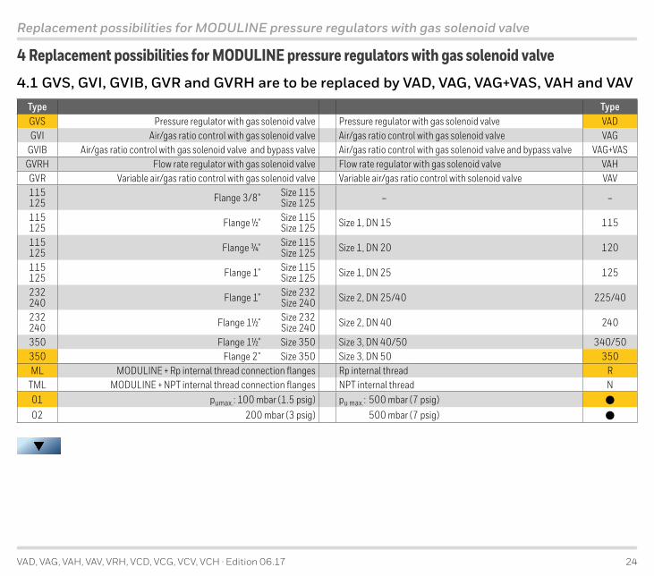
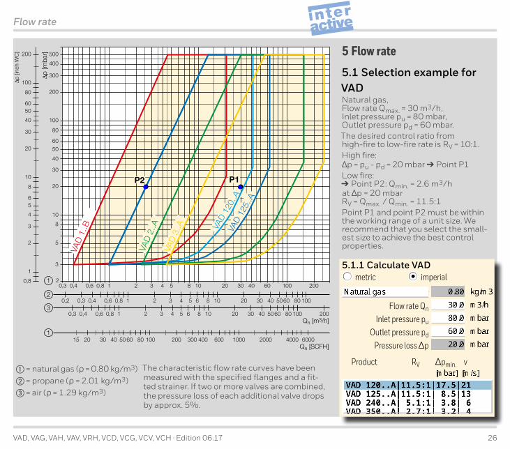
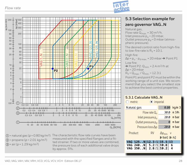
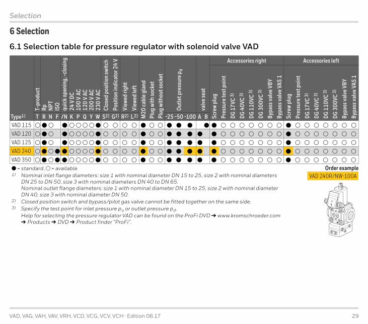
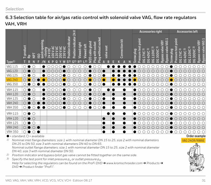
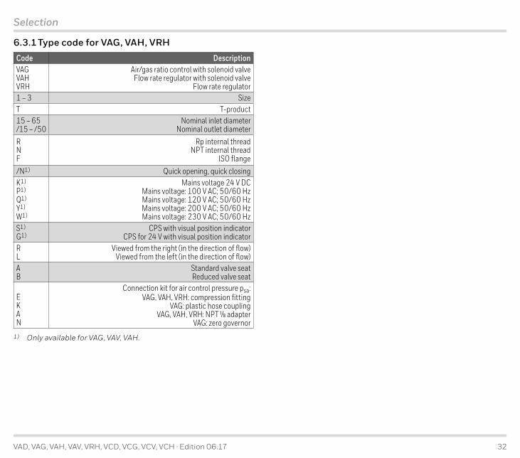
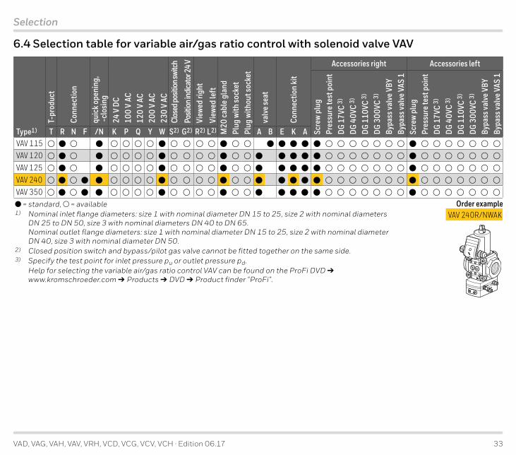
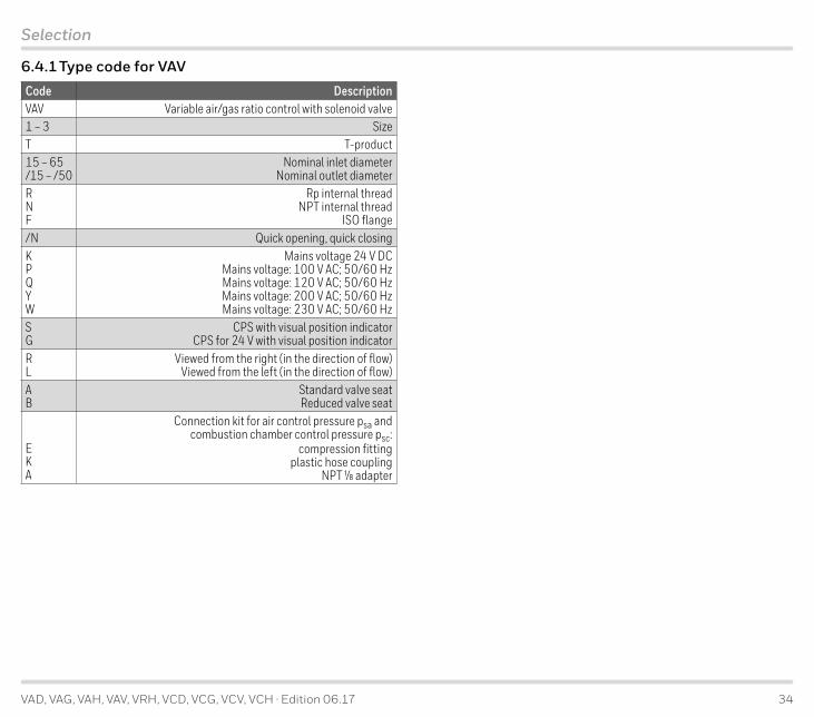
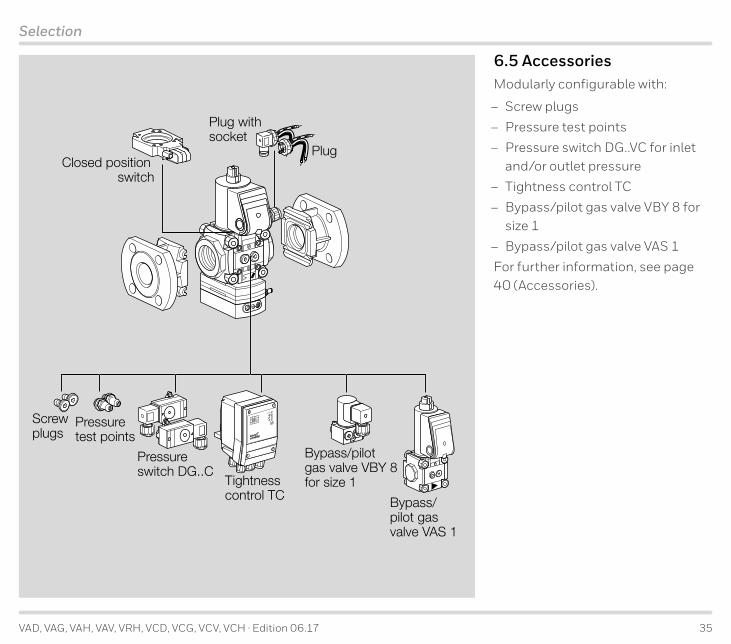
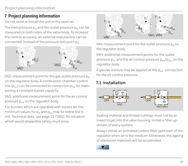
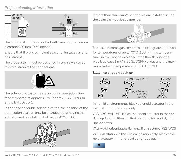
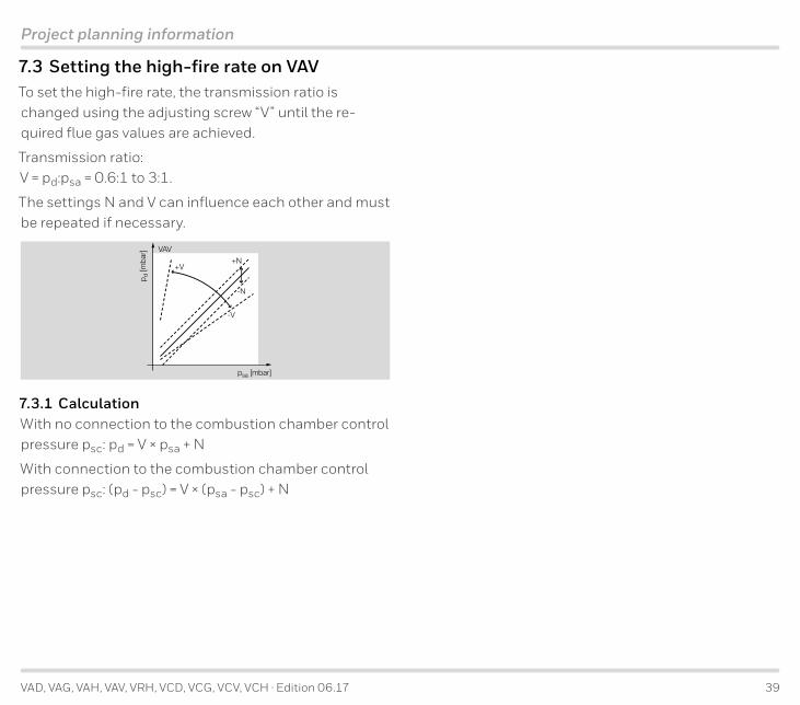
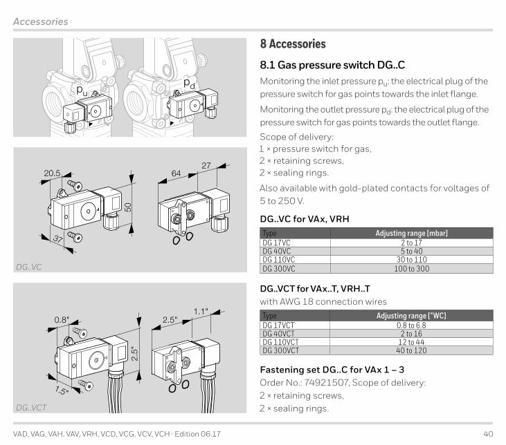
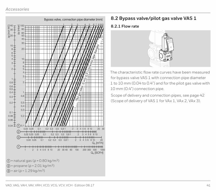
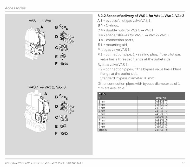
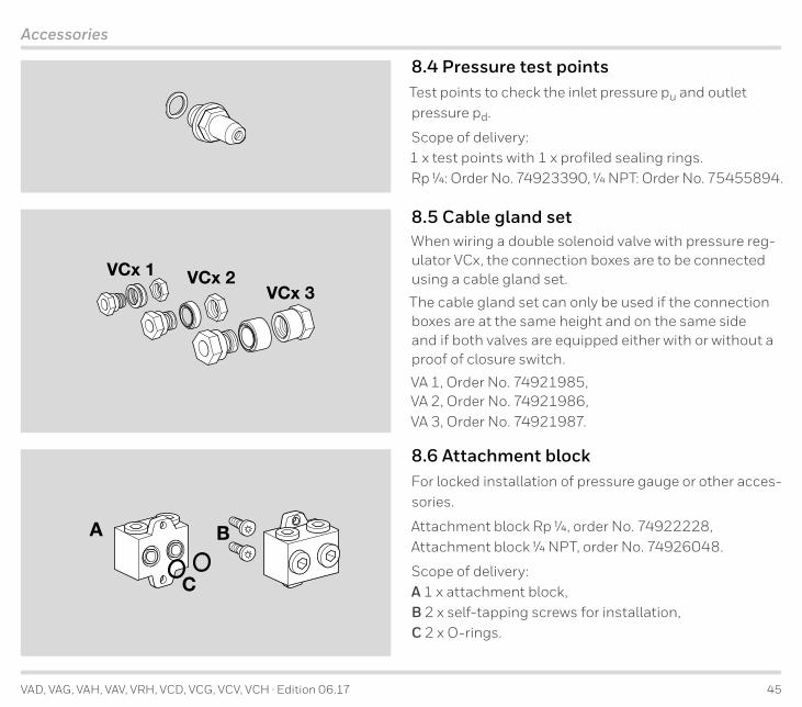
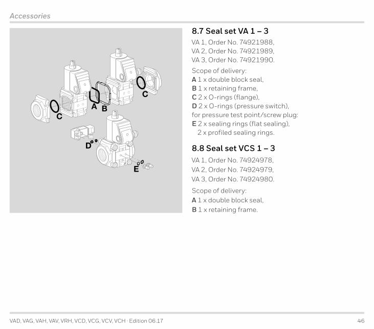
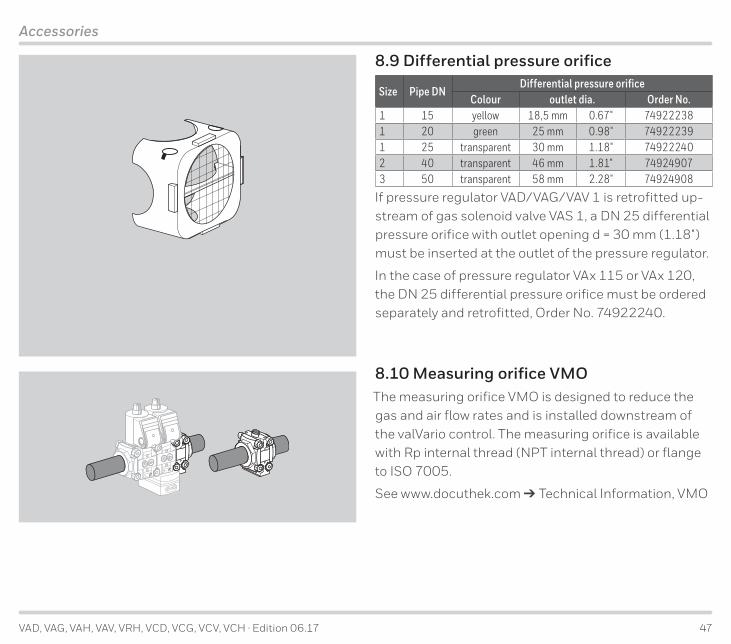
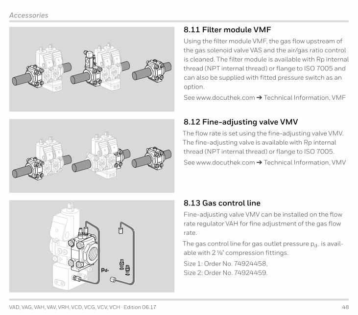
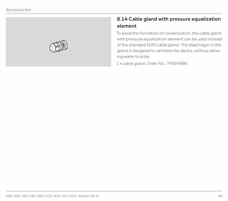
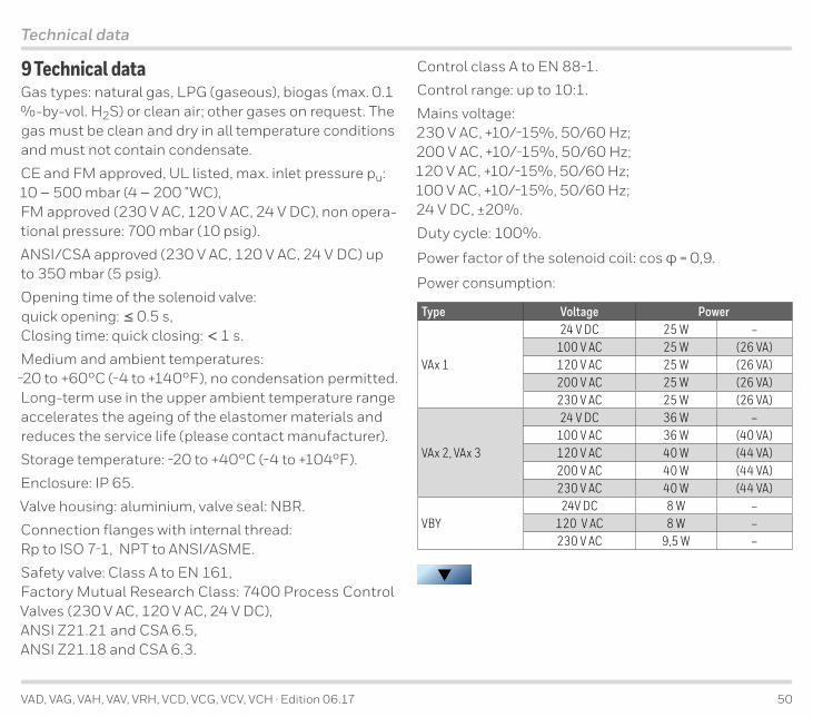
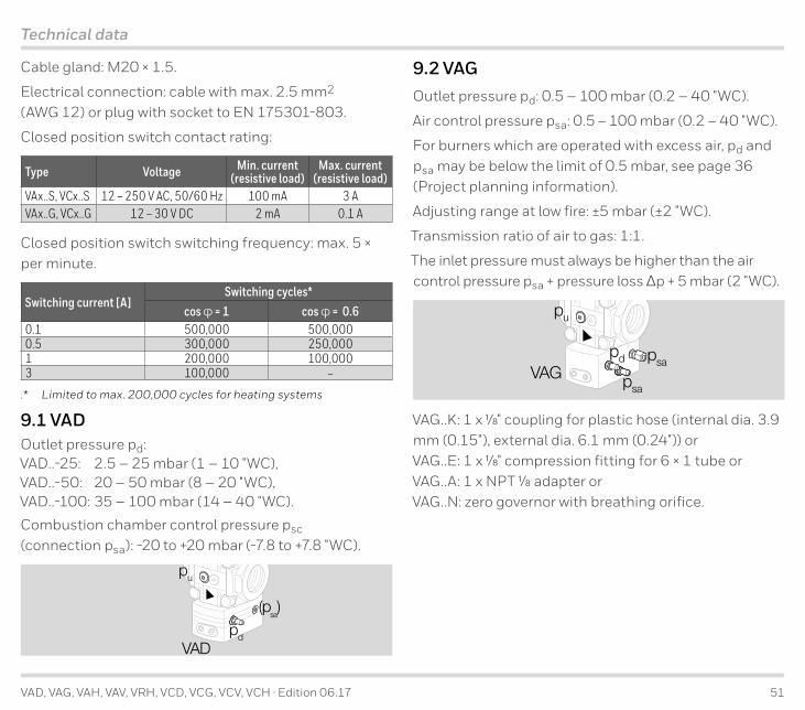
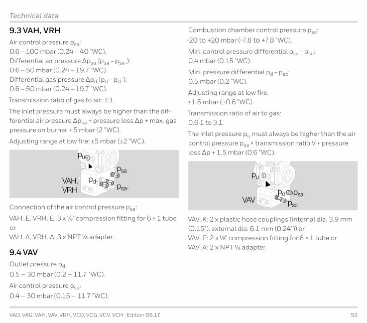
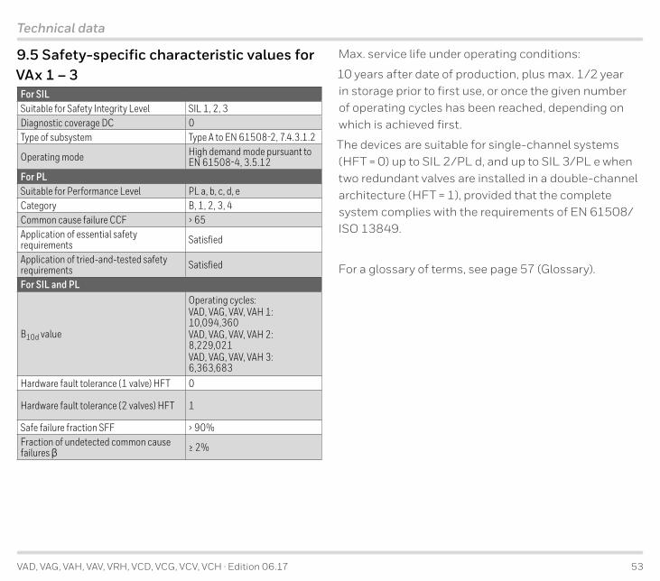
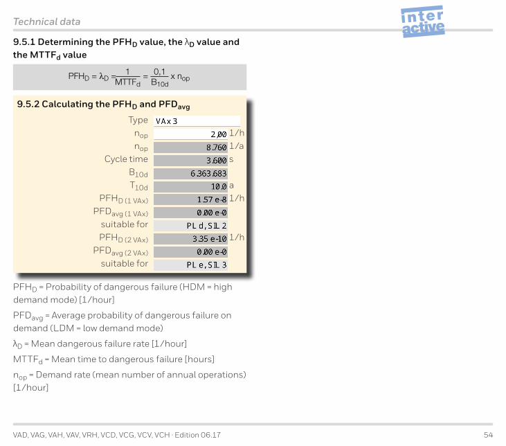
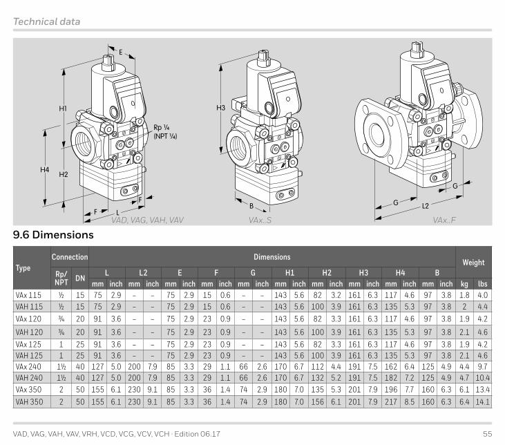
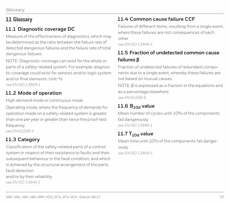
Related Documents