Vacuum Technology Michael McKeown Introduction to concepts that should be understood before designing, constructing, modifying, ‘assessing’ or, perhaps even using a vacuum system

Welcome message from author
This document is posted to help you gain knowledge. Please leave a comment to let me know what you think about it! Share it to your friends and learn new things together.
Transcript

Vacuum Technology
Michael McKeown
Introduction to concepts that should be understood before designing, constructing, modifying, ‘assessing’or, perhaps even using a vacuum system

Gas–solid surface interactions*Basics of conductance & pumpingGas load and its many sourcesOutgassing & ways to reduce itPump throughput & keeping it highEquating gas load & throughputModeling performance with VacTran
Outline
With KTG defines VTGas Load = totalOutgassing – major source

References
OverviewAdsorption-Desorption,Diffusion & Permeation
Arrival at SurfaceReflection & Sticking
Departure from SurfaceCosine Distribution
Gas-Surface Interactions

1. Modern Vacuum Practice Harris2. Vacuum Technology Roth3. Foundations of Vacuum Science and Technology Lafferty4. The Physical Basis of Ultrahigh Vacuum Redhead5. A User’s Guide to Vacuum Technology O’Hanlon6. Vacuum Sealing Techniques Roth7. Handbook of Electron Tube and Vacuum Techniques
Rosebury
References

Adsorption
‘Satisfying’ surface’s residual forcesInitially molecules of any type adsorbedMore polar molecules preferred
Reduced by higher temperatureIncreased by lower temperature *
Gas-Surface Interactions 1
Pump mech

Desorption – (outgassing)
Opposite of adsorptionMolecule gains sufficient energy to overcome binding energy to peers or surface
Increased by higher temperatureReduced by lower temperature
Gas-Surface Interactions 2
main problem

Diffusion
Gas trapped in bulk intersticesConcentration gradient near surfaceStainless steel: atomic H and CO
Increased by higher temperature *Reduced by lower temperature
Gas-Surface Interactions 3
1000C 3hr

Permeation
Gases permeate through all materialsGas/Solid usually immeasurably slow*
Gas/Elastomer are measurable*
Permeation ratef (partial pressure)f (specific for gas & elastomer)f (temperature)q
Gas-Surface Interactions 4
H2 > Pd & He > quartzH20,N2,O2 Viton, Buna

1. Reflect back into gas phase with no energy exchange *
2. Reflect back into gas phase with energy exchange *
3. Trapped shallow minimum energy state:*Physisorption 0 – 10 kcals/mole
4. Trapped in deep minimum energy state:Chemisorption 20 – 100 kcals/mole
5. Chemically react:Heat of formation ~100 – 500 kcals/mole
Gas-Surface Interactions 5
Molecules Arriving at Surface
Rare even for HeT/C, PiraniResidence time defined by energyContimuum

Reflection of Light
QED FeynmanMoelcules?
Gas-Surface Interactions 6

Gas-Surface Interactions 7
Flux = 1
Flux = 0.707
45°
Flux = 0
Cosine Distribution
Molecules Leaving Surface

Reflection of Atoms/Molecules
Gas-Surface Interactions 8
L – dot RT Pt/RT He, circle hot Pt/RT He Pt 1300°C He 1800°CR – dot RT Pt/hot He, circle hot Pt/hot He

Reflection of Atoms/Molecules at Large Angles
N2 - Glass
Gas-Surface Interactions 9

Adsorption of Atoms/Molecules
Accommodation coeff ― reflection with energy exchange
Condensation coeff ― adsorption into shallow minimum
Sticking probability ― adsorption into deep minimum
Gas-Surface Interactions 10

Accommodation Coefficients of Atoms/MoleculesGas Substrate CoefficientHe Ni (298K) 0.385H2 Ni (298K) 0.249Ar Ni (298K) 0.935N2 Pt (?) 0.816
Gas-Surface Interactions 11
Gas Substrate CoefficientHe glass at 50°C 0.17H2 0.57N2 0.76O2 0.82Ar 0.86
Condensation Coefficients of Atoms/Molecules

Gas-Surface Conclusions
Molecules hitting a surface:Do NOT reflect like lightStick (momentarily ► permanently)Desorb with cosine distribution
(Under vacuum: every solid surface desorbs gas)
Gas-Surface Interactions 12

Flow RegimesConductancePumping SpeedConductance plus Pumping Speed‘Effective’ Pumping Speeds (EPS)Measuring EPS
Basic Pumping Concepts

Flow Regimes
mfp -- mean free path
Continuum Flow: molecules’ mfp is small compared to characteristic dimensions of vacuum volume
Transitional Flow: molecules’ mfp roughly equal to characteristic dimensions of vacuum volume
Molecular Flow: molecules’ mfp is large compared to characteristic dimensions of vacuum volume
Flow regime (ie pressure) affects conductance
Pumping Concepts 1

Conductance
Passive Components
Ability to transfer gas volume in unit time
Determined by shape, open area, length, gas, & pressure(Volumetric flow measured in: L/s, cfm, m3/hr, L/m)
Pumping Concepts 2

Calculating Conductance
Pumping Concepts 3
• Dushman’s Table• Transmission Probability• VacTran®
Aperture, long ducts (1/L), short ducts

Conductance vs Pressure
Tubes(with no losses)
Pumping Concepts 4
Molecular
Continuum
Transitional

Conductance vs Pressure
Tubes(with entrance loss)
Pumping Concepts 5

Conductance vs Pressure
Tube vs Elbow(of equal ‘length’)
Pumping Concepts 6

Conductance vs Pressure
Elbow vs Elbow(radius vs miter)
Pumping Concepts 7

Pumping Speed *
Active Components (Pump/Trap)
Ability to transfer (remove) gas volume in unit time
Determined by gas, pump’s mechanism, and pressure)(Volumetric flow measured in: L/s, cfm, m3/hr, L/m)
Pumping Concepts 8
Manuf quotes max value
Ult press

Pumping Speed vs Pressure
Pumping Concepts 9
max values

Combining Conductance with Pumping Speed
Units for both: volume / unit time
Combined as reciprocals1/Conductance + 1/Pump Speed = 1/Effective Pump Speed
1/EPS = 1/PS + 1/C1 + 1/C2 + 1/C3
Pumping Concepts 10

Effective Pumping Speed
500 L/s pump & infinite conductance
1/EPS = 1/500 + 1/∞1/EPS = 1/500EPS = 500 L/s
Pumping Concepts 11

Effective Pumping Speed
500 L/s pump & 500 L/s conductance
1/EPS = 1/500 + 1/5001/EPS = 2/500EPS = 250 L/s
Pumping Concepts 12

Effective Pumping Speed
500 L/s pump & 50 L/s conductance
1/EPS = 1/500 + 1/501/EPS = 11/500EPS = 45 L/s
Pumping Concepts 13

Effective Pumping Speed
5000 L/s pump & 50 L/s conductance
1/EPS = 1/5000 + 1/501/EPS = 101/5000EPS = 49.5 L/s *
Pumping Concepts 14
5E6 L/s/

Effective Pumping Speed
HP700 + 160mm ID x 10cm tube
Pumping Concepts 15

Effective Pumping Speed
HP700 + 160mm ID x 20cm tube + miter elbow
Pumping Concepts 16

Effective Pumping Speed
CTI-8: tube 3.92˝ ID x 2″ long
Pumping Concepts 17

Measuring EPS 1 (i)
1. Measure chamber (base) pressure P1
2. Inject known mass flow rate of gas
3. Measure new (working) pressure P2
4. Calculate pressure difference P2 – P1
(Convert mass flow units as needed)
Mass flow / Pressure Difference = EPS
Pumping Concepts 18

Measuring EPS 1 (ii)
1. Base pressure P1 5x10⁻⁷ Torr2. Mass flow (N2) 10 sccm3. Working pressure P2 5x10⁻⁵ Torr4. P2 – P1 4.95x10⁻⁵ Torr
10 sccm (10/60) x (760/1000) 1.27x10⁻¹ T.L/sEPS 1.27x10⁻¹ T.L/s / 4.95x10⁻⁵ TEPS (N2) 1600 L/s
Pumping Concepts 19

Measuring EPS 2 (i)
1. Estimate chamber volume V2. Inject unknown flow of gas3. Measure (working) pressure P14. Time pressure decay
At time = 0 shut off gas flowAt time = t sec measure pressure P2
EPS = V/t x loge (P1/P2)
Pumping Concepts 20

Measuring EPS 2 (ii)
1. Chamber volume 150 L2. Inject unknown flow of gas3. Working pressure 4x10⁻⁴ Torr4. Time 15 sec5. Pressure (t = 15 s) 6x10⁻⁶ Torr
EPS V/t x loge (P1/P2)EPS 150/15 x ln(4x10⁻⁴/6x10-6)
EPS 42 L/sec
Pumping Concepts 21
Molecular flow only

Conductance & Pumping Speed Conclusions
Pumping Concepts 22
High conductance shorter/fatter is betterConductance is too high (I wish!)Conductance is too low serious (and expensive!)
The lowest conductance winsPump’s `quoted´ PS means very little
Think: Effective Pumping Speed

Meaning & UnitsSources of Gas Load
Gas Load

Gas Load
The total mass (quantity/amount) of gas entering the vacuum volume in a given time period
Mass flow measured in: T.L/s, Pa.m3/s, mbar.cc/s, atm.cc/s, sccm (pressure x volume / time)
Gas Load 1

Gas Load - Sources
PermeationReal leaks: from air / not from airVirtual leaksBackstreamingDiffusionSublimation/EvaporationInjected gas*Outgassing
Gas Load 2

Gas Load ─ PermeationAir / H2O and o-ringsAir / H2O and plastic gas line tubing *H2O and Teflon insulators *H2O and plastic cooling lines (in chamber) *H2 / He and glass/silica tubingH2 / CO and high temp. metal tubes *
Permeation rates through o-rings depend on:gas, elastomer, elastomer compounding,partial pressure, temperature.
Reducing permeation? *Ar from cyl to chamx
Terawatt facilityFlex linesTritium thru SS Double with evac
Gas Load 3

Gas Load 4

Gas Load ─ Real Leaks (air)
Gaskets at flanges/jointsRe-welds (in high carbon SS)At welds after baking/cleaningAt welds in cryo conditionsBlank flanges cut from barFeedthroughs:
braze faults/cracked ceramicsporous deep drawn weld lips
Detecting leaks?
Gas Load 5

Gas Load ─ Real Leaks (not air)
Needle valves connected to gas sourceLeaking shut-off valves connected to gas sourceLeaking valve on shut-off mass flow controllerGas/water circulation lines inside chamber
with cracked tube or leaking joint
Detecting (not air) leaks?
Gas Load 6

Gas Load ─ Virtual Leaks
Blind tapped holes / non-vented hardwareMulti-strand wire with plastic insulationFlat surfaces clamped togetherWelds on air-side surfaces
Test for virtual leaks?
Gas Load 7

Gas Load ─ Backstreaming
Oil vapor: rotary vane & piston, diffusion, oil ejectorMethane, argon: ion (and getter?)Hydrogen, helium, neon: turbo, cryo, molecular dragWater vapor: liquid ring, stream ejector
Check for backstreaming?
Gas Load 8
Gas Load ─ Diffusion
H2 & CO stainlessH2 titanium* / palladiumH2O glassVOMs plastics
Pumping H2 from Ti Bars
Gas Load 9

Gas Load ─ Sublimation/Evaporation
Metals to avoidMercury, cadmium, zincCesium, rubidium, potassium, sodiumStainless steels (containing non-metals)
Non-Metals to avoidPhosphorus, arsenicSulfur, selenium
Gas Load 10
Refer to VP charts

What is it? Units of measureWhat are the worst sources? Main componentsReducing outgassing
Outgassing

Outgassing
Consider all gas phase and absorbed vapormolecules inside a vacuum chamber
Outgassing Rate is difference between number of molecules:
desorbing from the surface (in time ‘t’)absorbing on the surface (in time ‘t’)
Outgassing follows exponential decay
Outgassing 1

Outgassing Rate
Effective desorption rate from a given surface measured by rate-of-rise test (from a significantly large area)
• After preparation & cleaning in a repeatable way• At a particular temperature• After a specified time under vacuum (1 & 10 hours)• From a specified area
Mass flow/unit area measured in:T.L.cm-2.s-1; mbar.L/cm2.s; Pa.m3/m2.s; (W.m-2)
(Pressure x volume / area x time)
Outgassing 2

Main Components
Water vaporOil/grease (‘hydrocarbons’)SolventsVOMsH2 and CO'Other stuff'
Outgassing 3

Main Components
Outgassing 4
H2
H2O
N2/CO/C2H4
O2 CO2

Worst Sources
Porous surfaces (ceramics or metals)Plastics, elastomers, polymersPreviously backstreamed oilEpoxy gluesLubricating/sealing/heat transfer greases
andUs!
(hair, skin cells, dust mites, spit, fingerprints, food)
Outgassing 5

Outgassing vs Time
1cm2 Viton (fresh/baked) + 2000cm2 SS (sanded)
Outgassing 6

Outgassing vs Time
2000 cm2 anodized Al & 2000cm2 sanded SS
Outgassing 7

Reducing Outgassing ─ 1st Steps
1. Make a log book and document everything!2. Don’t put weird stuff in the chamber3. Solvent clean everything (no plastic squash bottles) *4. Vacuum bake before assembly (if possible)5. Wrap it (in what?) until ready to mount6. Never touch anything with bare hands!
Outgassing 8
Vapor degrease

Reducing Outgassing ─ 2nd Steps
Vacuum HistoryHeatLightPlasma(Chemistry)
Outgassing 9

Reducing Outgassing ─ Vacuum History
Following initial pump-down, subsequentpump-down times depends on:
• Time at atmosphere when vented• Venting gas & dryness of vent gas *• Dry gas flowing while chamber vented *• Application or process in chamber *
Outgassing 10
LN2 offgasPartial close openingsLive with it

Reducing Outgassing ─ Heat
Outgassing 11
1L, 1L.s, 100cm2

Reducing Outgassing ─ HeatUnbaked Baked Time/Temperature(W/m2) (W/m2)
Stainless 6 x 10⁻⁷ 4 x 10⁻⁹ 30hr / 250ºC3 x 10-10 2hr / 900ºC2 x 10-11 3hr / 1000ºC +
Aluminum 6 x 10⁻⁷ 5 x 10⁻¹⁰ 15hr / 250ºC1 x 10-11 GD & 200ºC
Copper 5 x 10⁻⁶ 2 x 10⁻⁹ 20hr / 100ºC
Outgassing 12

Reducing Outgassing ─ UV Light
Outgassing 13

Reducing Outgassing ─ Plasma / Glow Discharge
Outgassing Mechanisms Include:UV stimulated desorptionElectron stimulated desorptionIon bombardmentHot atom energy transferFree radical ‘oxidation’
Outgassing 14

Pump Throughput
Equating Throughput & Gas Load
Flow Conversions & Calculations*
Pump Throughput

Gas Load ― reminder
Total mass (quantity/amount) of gas entering the vacuum volume in a given time period
Mass flow measured in: T.L/s, Pa.m3/s, mbar.cc/s, atm.cc/s, sccm (pressure x volume / time)
Pump Throughput 1

Pump Throughput
Total mass (quantity/amount) of gas leaving the vacuum volume (via the pumps) in a given time period
Mass flow measured in: T.L/s, Pa.m3/s, mbar.cc/s, atm.cc/s, sccm (pressure x volume / time)
Pump Throughput 2

Equating Gas Load & Pump Throughput
Gas Load Torr.Liter/secPump Throughput Torr.Liter/sec
When Gas Load = Pump Throughput *(Gas In = Gas Out)
Chamber pressure is stable!
Pump Throughput 3
effective

Throughput Calculations ― 1
Injecting 800 sccm, chamber pressure 2 mbar.What is the effective pumping speed needed in L/min?
= 800/1000 sL/min= (800/1000) x 1013 mbar.L/min= 810 mbar.L/min= 810/2 L/min @ 2 mbar
EPS = 405 L/min
Pump Throughput 4
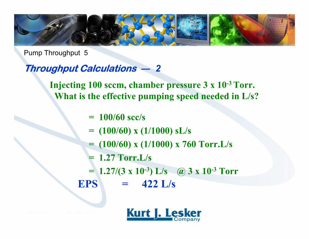
Injecting 100 sccm, chamber pressure 3 x 10⁻³ Torr.What is the effective pumping speed needed in L/s?
= 100/60 scc/s= (100/60) x (1/1000) sL/s= (100/60) x (1/1000) x 760 Torr.L/s= 1.27 Torr.L/s= 1.27/(3 x 10-3) L/s @ 3 x 10⁻³ Torr
EPS = 422 L/s
Pump Throughput 5
Throughput Calculations ― 2

Injecting 1 sLm, chamber pressure 0.5 mbar.What is the effective pumping speed needed in m3/h?
= 1 x 60 sL/h= (1 x 60) x (1/1000) sm3/h= (1 x 60) x (1/1000) x 1013 mbar.m3/h= 60.8 mbar.m3/h= 60.8/(0.5) m3/h @ 0.5 mbar
EPS = 122 m3/h
Pump Throughput 6
Throughput Calculations ― 3

Injecting 300 sccm, have 500 L/s pump.What is base pressure in mbar?
= 300/60 scc/s= (300/60) x (1/1000) sL/s= (300/60) x (1/1000) x 1013 mbar.L/s= 5.06 mbar.L/s
(assume EPS is ½ quoted pumping speed)
= 5.06/(250) mbarBase Pressure = 0.02 mbar
Pump Throughput 7
Throughput Calculations ― 4

Injecting 200 sccm, 400 L/s turbo backed by 3.8 m3/h vane pump. Turbo’s max foreline pressure 2 mbar.Will this work?
= 200 x 60 scc/h= (200 x 60) x (1/1000) sL/h= (200 x 60) x (1/1000) x (1/1000) sm3/h= (200 x 60) x (1/1000) x (1/1000) x 1013 mbar.m3/h= 12.2 mbar.m3/h
(assume EPS equals quoted pumping speed)= 12.2/(3.8) mbar = 3.2 mbar
It will not work!
Pump Throughput 8
Throughput Calculations ― 5

Gas Load & Pump Throughput Conclusions
When Gas Load = Effective Pump Throughput
Chamber pressure is stable
If you don’t like that pressure your options are:
1. Reduce gas load
2. Increase pump throughput
Pump Throughput 9

Modeling with VacTran®
Related Documents