U N I V E R S A L S I L E N C E R Product Catalog 280-A VACUUM PUMP LIQUID SEPARATOR-SILENCERS CONTENTS Product description .............................2 Application guide ................................3 RWVS inlet separator-silencers ...........4 RWSI inlet separator-silencers.............5 RVCS discharge separator-silencers ...6 RVRS discharge separator-silencers ...7 Manufacturing capabilities, contact information, and catalogs .............................Back cover Vacuum Pump Liquid Separator-Silencers niversal Silencer separator- silencers separate liquid particles from gas flow, while attenuating noise at the inlet and discharge ports of blowers and liquid ring vacuum pumps. These separator- silencers support better working conditions, lower operating costs, and a quieter environment. Convenient Drop-in Design Dimensionally equivalent to most existing units. High-performance Liquid Separation and Silencing High-performance liquid removal efficiencies, 90% to 99%, to suit your application. Choice of high or moderate acoustic performance. Choose from two inlet models (RWVS and RWSI) designed for full vacuum or two discharge models (RVCS and RVRS) designed for discharge to atmosphere. Built to Suit Your Application Designed to application requirements, including easy installation and low maintenance. Optional design features for special production and assembly conditions are available. ASME Code construction and special materials available. Outstanding Construction Carbon steel construction with a high-quality shop coat primer finish. Special materials such as stainless steel are available. Optional leak test available upon request. Immediate Availability Off-the-shelf delivery for most sizes. U PRODUCT SELECTION GUIDE

Welcome message from author
This document is posted to help you gain knowledge. Please leave a comment to let me know what you think about it! Share it to your friends and learn new things together.
Transcript

UN
IV
ER
SA
LS
IL
EN
CE
RPro
du
ct Catalo
g 280-A
VAC
UU
MP
UM
P LIQ
UID
SEPAR
ATO
R-SILEN
CER
S
CONTENTSProduct description .............................2Application guide ................................3RWVS inlet separator-silencers ...........4RWSI inlet separator-silencers.............5RVCS discharge separator-silencers ...6RVRS discharge separator-silencers ...7Manufacturing capabilities,
contact information, andcatalogs .............................Back cover
VVaaccuuuumm PPuummppLLiiqquuiidd SSeeppaarraattoorr--SSiilleenncceerrss
niversal Silencer separator-silencers separate liquidparticles from gas flow,while attenuating noise at the inlet and discharge
ports of blowers and liquid ringvacuum pumps. These separator-silencers support better workingconditions, lower operating costs,and a quieter environment.
Convenient Drop-in Design� Dimensionally equivalent to most existing units.
High-performance Liquid Separationand Silencing
� High-performance liquid removal efficiencies, 90% to 99%,to suit your application.
� Choice of high or moderate acoustic performance.� Choose from two inlet models (RWVS and RWSI) designed for full vacuum
or two discharge models (RVCS and RVRS) designed for discharge toatmosphere.
Built to Suit Your Application� Designed to application requirements, including easy installation and
low maintenance.� Optional design features for special production and assembly conditions
are available.� ASME Code construction and special materials available.
Outstanding Construction� Carbon steel construction with a high-quality shop coat primer finish.� Special materials such as stainless steel are available.� Optional leak test available upon request.
Immediate Availability� Off-the-shelf delivery for most sizes.
U
PRODUCT SELECTION GUIDE

Vacuum Pump Systems
eparator-silencers are used to remove liquid from gas
flow vacuum systems using either liquid-sealed rotary
positive blowers or liquid ring vacuum pumps (Fig. 1).
Separator-silencers may be required for both the
inlet (vacuum) and the discharge (atmospheric) of a vacuum
system. Only the most stringent acoustical environments
require significant inlet silencing. An inlet separator provides
corrosion protection for the pump by removing most, if not all,
of the process liquid before it enters the vacuum pump.
The vacuum pump or blower discharge is normally
extremely noisy and requires a high-performance separator-
silencer.
Operation and CapacityWhen a vacuum pump first starts operating at normal
atmospheric pressure, system pressure drop and power
requirements are at their maximum. As the vacuum pump
continues to evacuate the system, the inlet pressure decreases
so the system pressure losses and power requirements
decrease. The inlet volume flow in actual cubic feet per minute
(ACFM) stays essentially constant throughout system operation,
but because of decreasing inlet pressure, the discharge volume
decreases until normal operating conditions are reached.
Vacuum pump capacities at operating conditions are
expressed by the inlet volume flow of air and the amount that
the inlet pressure has been reduced below atmospheric pres-
sure. Thus, vacuum pump capacities are stated in inlet ACFM at
a relative vacuum, usually measured in inches of mercury (Hg).
P R O D U C T D E S C R I P T I O N
Liquid Separation PerformanceSeparator-silencers meet their rated liquid separation efficiency
at a nozzle velocity of 5500 fpm. At lower velocities their
performance improves. At higher velocities their efficiency
decreases. The nozzle velocity is the air velocity in the inlet or
discharge nozzle and is equal to the actual volume flow rate
(ACFM) divided by the nozzle area.
Since the inlet volume flow rate is nearly constant during
normal vacuum pump operation, the inlet separator-silencer
should be sized so the velocity does not exceed 5500 fpm
during all phases of operation (Table 1).
The discharge flow rate decreases from startup to normal
operation, and in some applications it may be acceptable to
exceed a velocity of 5500 fpm during startup. If it is not accept-
able to discharge liquid during startup, the velocity must be
reduced (Table 1). If some liquid bypass is allowed during
startup, the selection of the discharge separator-silencer should
be based on pressure drop.
Inlet and discharge separator-silencers require drain
systems to remove the liquid. These systems (both inlet and
discharge) must provide an adequate drain sealing system or
liquid level to offset the vacuum on the inlet side and prevent
blowout on the discharge side. See Tables 2 and 3 for liquid
removal data.
2 � 608.873.4272 � 608.873.4298 fax � [email protected] � www.universal-silencer.com
FIGURE 1.
This is an example of a vacuum pumpand liquid removal system. Air and liquidenter the inlet separator-silencer duringprocessing (1). Process liquid is removed(2), and air enters the vacuum pump (3).The pump takes in seal liquid (4). Air andseal liquid are pumped into thedischarge separator-silencer (5), whichremoves the liquid (6) and sends the airinto the atmosphere (7).
liquid
air
vacuumpump
inletseparator
dischargeseparator-
silencer
1
2
3
4
5
7
6
S
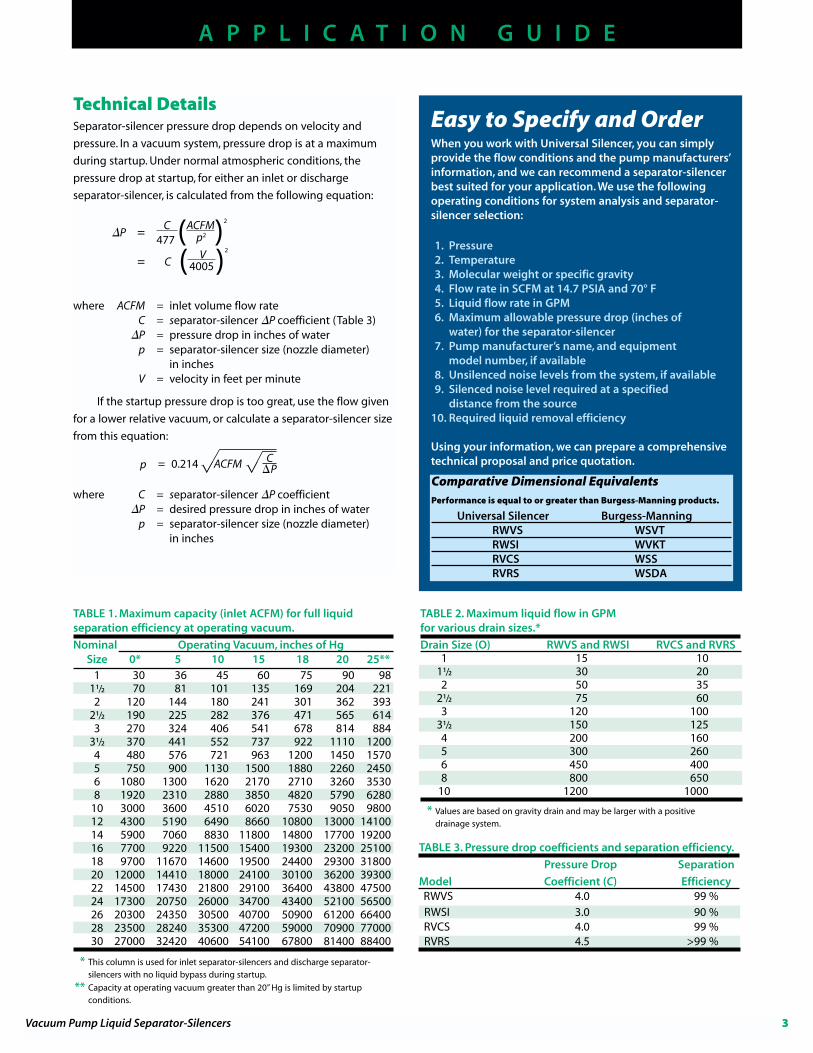
TABLE 1. Maximum capacity (inlet ACFM) for full liquidseparation efficiency at operating vacuum.
Nominal Operating Vacuum, inches of HgSize 0* 5 10 15 18 20 25**
1 30 36 45 60 75 90 9811/2 70 81 101 135 169 204 2212 120 144 180 241 301 362 393
21/2 190 225 282 376 471 565 6143 270 324 406 541 678 814 884
31/2 370 441 552 737 922 1110 12004 480 576 721 963 1200 1450 15705 750 900 1130 1500 1880 2260 24506 1080 1300 1620 2170 2710 3260 35308 1920 2310 2880 3850 4820 5790 6280
10 3000 3600 4510 6020 7530 9050 980012 4300 5190 6490 8660 10800 13000 1410014 5900 7060 8830 11800 14800 17700 1920016 7700 9220 11500 15400 19300 23200 2510018 9700 11670 14600 19500 24400 29300 3180020 12000 14410 18000 24100 30100 36200 3930022 14500 17430 21800 29100 36400 43800 4750024 17300 20750 26000 34700 43400 52100 5650026 20300 24350 30500 40700 50900 61200 6640028 23500 28240 35300 47200 59000 70900 7700030 27000 32420 40600 54100 67800 81400 88400
TABLE 3. Pressure drop coefficients and separation efficiency.
Pressure Drop Separation
Model Coefficient (C) EfficiencyRWVS 4.0 99 %RWSI 3.0 90 %RVCS 4.0 99 %RVRS 4.5 >99 %
* Values are based on gravity drain and may be larger with a positive drainage system.
TABLE 2. Maximum liquid flow in GPMfor various drain sizes.*
Drain Size (O) RWVS and RWSI RVCS and RVRS1 15 10
11/2 30 202 50 35
21/2 75 603 120 100
31/2 150 1254 200 1605 300 2606 450 4008 800 650
10 1200 1000
A P P L I C A T I O N G U I D E
Technical DetailsSeparator-silencer pressure drop depends on velocity and
pressure. In a vacuum system, pressure drop is at a maximum
during startup. Under normal atmospheric conditions, the
pressure drop at startup, for either an inlet or discharge
separator-silencer, is calculated from the following equation:
�P = C (ACFM)2
477
= C ( V )2
where ACFM = inlet volume flow rateC = separator-silencer �P coefficient (Table 3)
�P = pressure drop in inches of waterp = separator-silencer size (nozzle diameter)
in inchesV = velocity in feet per minute
If the startup pressure drop is too great, use the flow given
for a lower relative vacuum, or calculate a separator-silencer size
from this equation:
where C = separator-silencer �P coefficient�P = desired pressure drop in inches of water
p = separator-silencer size (nozzle diameter)in inches
Vacuum Pump Liquid Separator-Silencers 3
p2
4005
Easy to Specify and OrderWhen you work with Universal Silencer, you can simplyprovide the flow conditions and the pump manufacturers’information, and we can recommend a separator-silencerbest suited for your application. We use the followingoperating conditions for system analysis and separator-silencer selection:
1. Pressure2. Temperature3. Molecular weight or specific gravity4. Flow rate in SCFM at 14.7 PSIA and 70° F5. Liquid flow rate in GPM6. Maximum allowable pressure drop (inches of
water) for the separator-silencer7. Pump manufacturer’s name, and equipment
model number, if available8. Unsilenced noise levels from the system, if available9. Silenced noise level required at a specified
distance from the source10. Required liquid removal efficiency
Using your information, we can prepare a comprehensivetechnical proposal and price quotation.
Comparative Dimensional EquivalentsPerformance is equal to or greater than Burgess-Manning products.
Universal Silencer Burgess-ManningRWVS WSVTRWSI WVKTRVCS WSSRVRS WSDA
* This column is used for inlet separator-silencers and discharge separator-silencers with no liquid bypass during startup.
** Capacity at operating vacuum greater than 20” Hg is limited by startup conditions.

RATED CAPACITY*
MAX. ACFMAT VACUUM LIQUID
MODEL P (nom.) D N L K Z J O (nom.) WEIGHT (BLOWER INLET) GPM**
RWVS-4 4 123/4 3 52 131/2 191/2 55/8 2 76 530 35
RWVS-5 5 16 3 58 141/2 231/2 71/8 21/2 144 830 55
RWVS-6 6 18 3 66 18 30 8 3 189 1200 80
RWVS-8 8 22 31/2 78 211/2 36 93/4 31/2 355 2100 150
RWVS-10 10 24 31/2 85 26 37 101/2 4 442 3300 200
RWVS-12 12 30 31/2 97 311/2 45 131/4 5 630 4700 300
RWVS-14 14 36 31/2 105 361/2 47 16 6 1029 6000 400
RWVS-16 16 42 31/2 114 411/2 50 189/16 6 1401 7800 500
RWVS-18 18 42 31/2 135 47 68 187/16 8 1645 10000 600
RWVS-20 20 48 41/2 138 52 66 211/8 8 2925 12000 800
RWVS-22 22 54 41/2 149 57 70 237/8 10 2384 15000 1000
RWVS-24 24 60 41/2 158 62 74 265/8 10 3502 18000 1200
4 � 608.873.4272 � 608.873.4298 fax � [email protected] � www.universal-silencer.com
P R O D U C T S P E C I F I C A T I O N S
RWVS SERIESInlet LiquidSeparator-Silencers
TYPICAL INSERTION LOSS
DIMENSIONS, WEIGHTS, AND RATED CAPACITIES
Octave Band Center Frequency, Hz
Inse
rtio
n L
oss
,dB
TOP VIEW
SIDE VIEW
he RWVS inlet liquid separator-silencers provide
corrosion protection for vacuum pumps by removing
most of the process liquid before it enters the
vacuum pump. These separators are best suited for
full vacuum conditions under critical applications, which require
inlet silencing.
TZ
L
P
N
K
J
O
D
P
* Capacities for larger sizes available on request.
** If maximum gas flow is not exceeded for a given separator size, liquid GPM may exceed nominal capacity shown, up to the capacity of the next larger separator.
inletflow

RATED CAPACITY*MAX. ACFMAT VACUUM LIQUID
MODEL P (nom.) D N L K Z J O (nom.) WEIGHT (BLOWER INLET) GPM**
RWSI-4 4 12 3 26 11 15 33/4 2 40 530 35
RWSI-5 5 16 3 31 141/4 18 53/16 21/2 82 830 55
RWSI-6 6 18 3 36 151/2 21 511/16 3 108 1200 80
RWSI-8 8 22 31/2 46 18 27 611/16 31/2 202 2100 150
RWSI-10 10 24 31/2 58 23 34 65/8 4 276 3300 200
RWSI-12 12 30 31/2 68 251/2 40 85/8 5 403 4700 300
RWSI-14 14 36 31/2 78 28 46 11 6 708 6000 400
RWSI-16 16 42 31/2 88 28 52 13 6 950 7800 500
RWSI-18 18 42 31/2 98 301/2 58 12 8 1050 10000 600
RWSI-20 20 48 41/2 108 33 64 14 8 1308 12000 800
RWSI-22 22 54 41/2 120 35 71 16 8 1619 15000 1000
RWSI-24 24 60 41/2 130 38 77 18 10 2481 18000 1200
RWSI-26 26 66 41/2 140 401/2 83 20 10 2986 21000 1400
RWSI-28 28 72 41/2 150 43 89 22 10 3554 24000 1600
RWSI-30 30 78 41/2 160 451/2 95 24 10 4959 28000 1800
Vacuum Pump Liquid Separator-Silencers 5
P R O D U C T S P E C I F I C A T I O N S
RWSI SERIESInlet LiquidSeparator-Silencers
DIMENSIONS, WEIGHTS, AND RATED CAPACITIES
TYPICAL INSERTION LOSS
Octave Band Center Frequency, Hz
Inse
rtio
n L
oss
,dB
he RWSI inlet liquid separator-silencers provide
corrosion protection for vacuum pumps by removing
most of the process liquid before it enters the vacuum
pump. These separators are best suited for full
vacuum conditions under critical applications, which require
inlet silencing. The RWSI models include larger pipe sizes than
the RWVS and have a different profile.
T
TOP VIEW
SIDE VIEW
Z
L
P
N
K
J
O
D
P
* Capacities for larger sizes available on request.
** If maximum gas flow is not exceeded for a given separator size, liquid GPM may exceed nominal capacity shown, up to the capacity of the next larger separator.
inletflow

MODEL P (nom.) D N L K E F Z R J O (nom.) WEIGHT
RVCS-1 1 41/2 2 14 6 – – 83/4 – 23/32 1 4
RVCS-11/4 11/4 41/2 2 14 6 – – 8 – 21/16 1 5
RVCS-11/2 11/2 6 2 17 7 – – 10 – 23/4 11/2 10
RVCS-2 2 8 3 22 9 – – 13 – 311/16 2 15
RVCS-21/2 21/2 10 3 24 10 – – 14 – 45/8 2 20
RVCS-3 3 10 3 27 11 – – 16 – 49/16 21/2 25
RVCS-31/2 31/2 12 3 30 12 – – 18 – 51/2 21/2 35
RVCS-4 4 12 3 29 131/2 8 3 181/2 41/4 57/16 3 50
RVCS-5 5 16 3 35 141/2 9 31/2 211/2 61/4 75/16 3 95
RVCS-6 6 18 3 42 18 10 31/2 27 71/4 83/16 3 130
RVCS-8 8 22 31/2 52 211/2 12 4 32 91/4 915/16 3 240
RVCS-10 10 24 31/2 56 26 14 41/2 32 101/4 1011/16 3 300
RVCS-12 12 30 31/2 69 311/2 16 5 401/2 123/4 137/16 4 445
RVCS-14 14 36 31/2 75 361/2 16 5 43 153/4 161/4 4 620
RVCS-16 16 42 31/2 88 411/2 19 61/2 52 183/4 187/8 4 1035
P R O D U C T S P E C I F I C A T I O N S
6 � 608.873.4272 � 608.873.4298 fax � [email protected] � www.universal-silencer.com
RVCS SERIESDischarge LiquidSeparator-Silencers
DIMENSIONS AND WEIGHTS
he RVCS models provide high-performance liquid
separation and noise attenuation. When an inlet
separator is not installed, the discharge separator
might need to be over-sized.T Octave Band Center Frequency, Hz
Inse
rtio
n L
oss
,dB
Z
L
PN
O
L
PN
Z
! All models use a pipe thread connection (MNPT) for the liquid outlet (O).! Sizes 1 in. through 31/2 in. are standard with male pipe thread connection (MNPT).! Sizes 4 in. through 16 in. are standard with 150# ANSI drilled plate flanges.
SIDE VIEWPipe sizes 1 in.through 31/2 in.
SIDE VIEWPipe sizes 4 in.through 16 in.
TOP VIEWPipe sizes 1 in.through 31/2 in.
TOP VIEWPipe sizes 4 in.through 16 in.
D
K
J
TYPICAL INSERTION LOSS
D
K
J
F
R
P
E
O
P
inletflow
inletflow

MODEL P (nom.) D N L K E F Z R J O (nom.) WEIGHT
RVRS-1 1 41/2 2 203/4 6 31/2 11/4 151/2 119/32 23/32 1 10
RVRS-11/4 11/4 41/2 2 203/4 6 31/2 11/4 143/4 119/32 21/16 1 10
RVRS-11/2 11/2 6 2 25 7 4 13/4 19 23/64 23/4 11/2 15
RVRS-2 2 8 2 327/8 9 5 2 25 213/16 311/16 2 30
RVRS-21/2 21/2 10 3 351/2 10 6 3 26 313/16 45/8 2 40
RVRS-3 3 10 3 41 11 6 3 31 39/16 43/16 21/2 45
RVRS-31/2 31/2 12 3 443/8 13 7 3 33 49/16 51/2 21/2 55
RVRS-4 4 12 3 47 131/2 8 3 361/2 41/4 57/16 3 70
RVRS-5 5 16 3 591/2 141/2 9 31/2 47 61/4 75/16 3 140
RVRS-6 6 18 3 713/4 18 10 31/2 57 71/4 83/16 3 244
RVRS-8 8 22 31/2 901/4 211/2 12 4 71 91/4 915/16 3 355
RVRS-10 10 24 31/2 1031/4 26 14 41/2 80 101/4 1011/16 3 460
RVRS-12 12 30 31/2 1281/2 311/2 16 5 101 123/4 137/16 4 1092
RVRS-14 14 36 31/2 1411/4 361/2 16 5 1091/4 153/4 161/4 4 1678
RVRS-16 16 42 31/2 1541/4 411/2 19 61/2 1181/4 183/4 187/8 4 2212
P R O D U C T S P E C I F I C A T I O N S
Vacuum Pump Liquid Separator-Silencers 7
RVRS SERIESDischarge LiquidSeparator-Silencers
DIMENSIONS AND WEIGHTS
TYPICAL INSERTION LOSS
Octave Band Center Frequency, Hz
Inse
rtio
n L
oss
,dB
he RVRS models are similar to the RVCS models. For
pipe sizes 1 in. through 3 in., the RVRS has a side
liquid outlet, while the RVCS has a vertical liquid
outlet.T
Z
L
PN
L
PN
Z
SIDE VIEWPipe sizes 1 in.through 3 in.
SIDE VIEWPipe sizes 31/2 in.through 16 in.
TOP VIEWPipe sizes 1 in.through 3 in.
D
K
J
R
O
F
E
P
TOP VIEWPipe sizes 31/2 in.through 16 in.
D
K
J
R
O
F
E
! All models use a pipe thread connection (MNPT) for the liquid outlet (O).! Sizes 1 in. through 3 in. are standard with male pipe thread connection (MNPT).! Sizes 31/2 in. through 16 in. are standard with 150# ANSI drilled plate flanges.
P
inletflow
inletflow

UNIVERSAL SILENCER
Internet E-mail: [email protected] the Web: www.universal-silencer.com
Copyright 2000 Universal Silencer. All rights reserved. Acousti-Tube and Acousti-Ring areregistered trademarks of Universal Silencer. Specifications subject to change. 280-A-1/2000.
TM
Manufacturing facilities are in Muscoda (above), 75 mileswest of Stoughton, and Montello (below), 70 miles north.
Keepingindustrial equipment
clean and quiet.
RWVS, RWSI, RVCS,AND RVRS SERIESVacuum Pump LiquidSeparator-Silencers
Our corporate headquarters are located in Stoughton,Wisconsin, just southeast of Madison, the state capital. Thisnew building houses administration, sales, and engineeringdepartments.
Our products have been used to protect,quiet, and optimize the performance ofindustrial equipment for 40 years.We maintain a fully equipped testingfacility to qualify filters and silencers.We are an ISO 9001 registered firm andASME Code certified.
Our extensive in-house engineering,manufacturing, and testingcapabilities ensure optimizedprocess, mechanical, and acousticperformance for your application.
Quality You Can Count On
Contact us for more information about our completeline of industrial filter-silencers and air filters:
� Universal Silencer guide to industrial products,catalog 278
� Vacuum pump low-profile liquid separator-silencers,catalog 285-A
� Rotary positive blowers, catalog 244-D� Acousti-Tube� and Acousti-Ring� vent silencers,
catalog 243-C� Acousti-Tube� and Acousti-Ring� vent silencer
specification sheet, form 88-0063� Air filters and filter silencers, catalog 241-B� Cartridge air filters and filter silencers, catalog 242-C� CB compact blower silencers, catalog 255-A� CBF/CBFI compact blower filter-silencers, catalog
261-A� Reciprocating engines, catalog 246-A� Compressors, information provided by application� Industrial fans, catalog 249-A� Steam ejectors, pressure reduction valves, and
other special applications� Gas turbines, catalog B-249-A! Universal Silencer guide to gas turbine products,
catalog 265
Related Documents