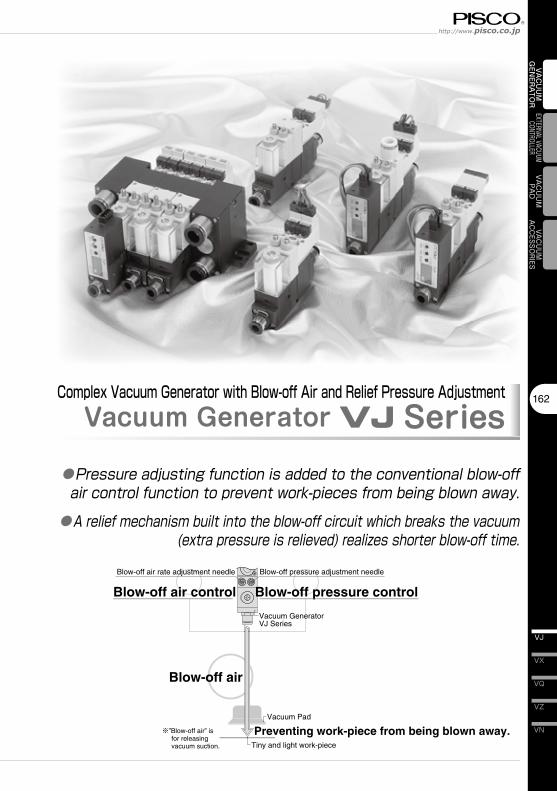
162 VN VZ VQ VX VJ VACUUM GENERATOR EXTERNAL VACUUM CONTROLLER VACUUM PAD VACUUM ACCESSORIES Vacuum Pad Tiny and light work-piece Blow-off pressure adjustment needle Blow-off air rate adjustment needle ※”Blow-off air” is for releasing vacuum suction. Blow-off pressure control Blow-off air control Vacuum Generator VJ Series Preventing work-piece from being blown away. Blow-off air Complex Vacuum Generator with Blow-off Air and Relief Pressure Adjustment Vacuum Generator VJ Series ● Pressureadjustingfunctionisaddedtotheconventionalblow-off aircontrolfunctiontopreventwork-piecesfrombeingblownaway. ● Areliefmechanismbuiltintotheblow-offcircuitwhichbreaksthevacuum (extrapressureisrelieved)realizesshorterblow-offtime.

Welcome message from author
This document is posted to help you gain knowledge. Please leave a comment to let me know what you think about it! Share it to your friends and learn new things together.
Transcript
162
VN
VZ
VQ
VX
VJ
VAC
UU
M
GEN
ERA
TOR
EXTERNAL VACUUM CONTROLLER
VAC
UU
MPA
DVACUUM
ACCESSORIES
Vacuum Pad
Tiny and light work-piece
Blow-off pressure adjustment needleBlow-off air rate adjustment needle
※”Blow-off air” is for releasing vacuum suction.
Blow-off pressure controlBlow-off air control
Vacuum Generator VJ Series
Preventing work-piece from being blown away.
Blow-off air
Complex Vacuum Generator with Blow-off Air and Relief Pressure AdjustmentVacuum Generator VJ Series
●Pressure�adjusting�function�is�added�to�the�conventional�blow-off�air�control�function�to�prevent�work-pieces�from�being�blown�away.●A�relief�mechanism�built�into�the�blow-off�circuit�which�breaks�the�vacuum�
(extra�pressure�is�relieved)�realizes�shorter�blow-off�time.
Vacuum Generator SeriesVacuum Generator VJ
VH · VS
163
VU
VB
VM · VC
VG
VK
VJ
VY
VUM
VRL
VAC
UU
M
GEN
ERA
TOR ■ Characteristics
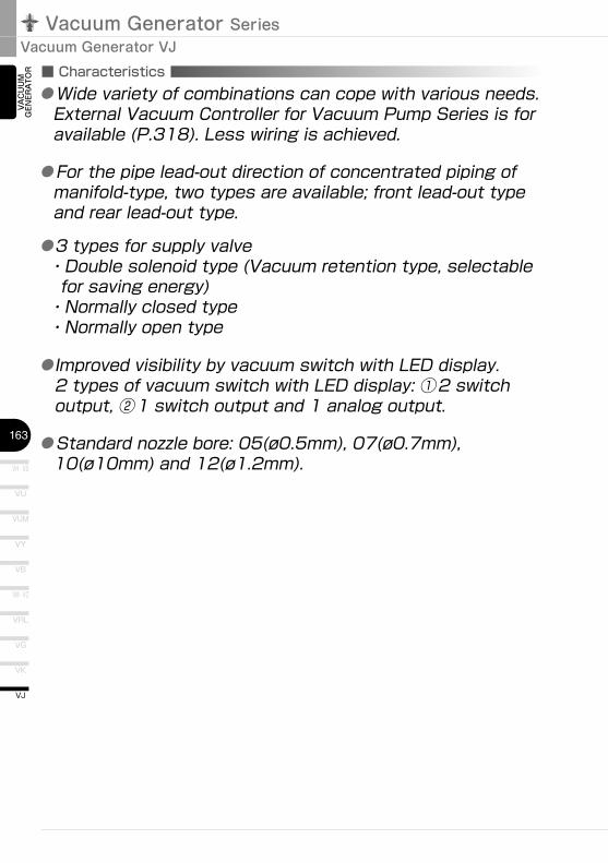
●�For�the�pipe�lead-out�direction�of�concentrated�piping�of�manifold-type,�two�types�are�available;�front�lead-out�type�and�rear�lead-out�type.
●3�types�for�supply�valve・�Double�solenoid�type�(Vacuum�retention�type,�selectable�for�saving�energy)・Normally�closed�type・Normally�open�type
●Improved�visibility�by�vacuum�switch�with�LED�display.2�types�of�vacuum�switch�with�LED�display:�①2�switch�output,�②1�switch�output�and�1�analog�output.
● �Standard�nozzle�bore:�05(ø0.5mm),�07(ø0.7mm),�10(ø10mm)�and�12(ø1.2mm).
● �Wide�variety�of�combinations�can�cope�with�various�needs.�External�Vacuum�Controller�for�Vacuum�Pump�Series�is�for�available�(P.318).�Less�wiring�is�achieved.
164
VN
VZ
VQ
VX
VJ
VAC
UU
M
GEN
ERA
TOR
EXTERNAL VACUUM CONTROLLER
VAC
UU
MPA
DVACUUM
ACCESSORIES
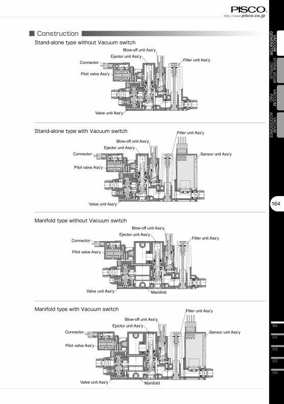
■ ConstructionStand-alone�type�without�Vacuum�switch
Filter unit Ass'y
Blow-off unit Ass'y
Ejector unit Ass'y
Connector
Pilot valve Ass'y
Valve unit Ass'y
Stand-alone�type�with�Vacuum�switch Filter unit Ass'y
Blow-off unit Ass'y
Ejector unit Ass'y
Connector
Pilot valve Ass'y
Valve unit Ass'y
Sensor unit Ass'y
Manifold�type�without�Vacuum�switch
Filter unit Ass'y
Blow-off unit Ass'y
Ejector unit Ass'y
Connector
Pilot valve Ass'y
Valve unit Ass'y
Manifold�type�with�Vacuum�switch Filter unit Ass'y
Blow-off unit Ass'y
Ejector unit Ass'y
Connector
Pilot valve Ass'y
Valve unit Ass'y
Sensor unit Ass'y
Manifold
Manifold
Vacuum Generator SeriesVacuum Generator VJ
VH�·�VS
165
VU
VB
VM�·�VC
VG
VK
VJ
VY
VUM
VRL
VAC
UU
M
GEN
ERA
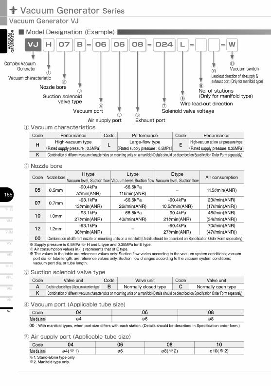
TOR ■ Model Designation (Example)
VJ 07 06
④Vacuum�port
②Nozzle�bore
H
①Vacuum�characteristic
06
⑤Air�supply�port
L
⑧Wire�lead-out�direction
② Nozzle bore
Complex�Vacuum�Generator
⑨No.�of�stations(Only�for�manifold�type)
W
⑪Vacuum�switch
④ Vacuum port (Applicable tube size)
B
③Suction�solenoid
valve�type
08
⑥Exhaust�port
D24
⑦Solenoid�valve�voltage
① Vacuum characteristics
⑩Lead-out�direction�of�air-supply�&�exhaust�port�(Only�for�manifold�type)
③ Suction solenoid valve type
⑤ Air supply port (Applicable tube size)
Code
05
07
10
12
00
Nozzle bore
0.5mm
0.7mm
1.0mm
1.2mm
H typeVacuum level, Suction flow
-90.4kPa7l/min(ANR)
-93.1kPa13l/min(ANR)
-93.1kPa27l/min(ANR)
-93.1kPa38l/min(ANR)
L typeVacuum level, Suction flow
-66.5kPa11l/min(ANR)
-66.5kPa26l/min(ANR)
-66.5kPa40l/min(ANR)
–
E typeVacuum level, Suction flow
–
-90.4kPa10.5l/min(ANR)
-90.4kPa21l/min(ANR)
-90.4kPa27l/min(ANR)
Air consumption
11.5l/min(ANR)
23l/min(ANR)(17l/min(ANR))46l/min(ANR)
(34l/min(ANR))70l/min(ANR)
(47l/min(ANR))
※ Supply pressure is 0.5MPa for H and L type and 0.35MPa for E type.※ Air consumption values in ( ) represents that of E type.※ The values in the table are reference values only. Suction flow varies according to the vacuum system conditions; vacuum
port dia. or tube length. are reference values only. Suction flow changes according to the vacuum system conditions; vacuum port dia. or tube length.
CodeTube dia.(mm)
04ø4
Code
H
K
PerformanceHigh-vacuum type
(Rated supply pressure:0.5MPa)
Code
L
PerformanceLarge-flow type
(Rated supply pressure:0.5MPa)
Code
E
PerformanceHigh-vacuum at low air pressure type
(Rated supply pressure:0.35MPa)
Combination of different nozzle on mounting units on a manifold (Details should be described on Specification Order Form separately)
00:With manifold types, when port size differs with each station. (Details should be described in Specification order form.)
Combination of different vacuum characteristics on mounting units on a manifold (Details should be described on Specification Order Form separately)
CodeAK
Valve unitDouble solenoid type (Vacuum retention type)
CodeB
Valve unitNormally closed type
CodeC
Valve unitNormally open type
Combination of different vacuum characteristics on mounting units on a manifold (Details should be described on Specification Order Form separately)
06ø6
08ø8
CodeTube dia.(mm)
04ø4(※1)
※1. Stand-alone type only※2. Manifold type only.
06ø6
08ø8(※2)
10ø10(※2)
166
VN
VZ
VQ
VX
VJ
VAC
UU
M
GEN
ERA
TOR
EXTERNAL VACUUM CONTROLLER
VAC
UU
MPA
DVACUUM
ACCESSORIES
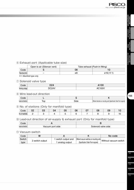
⑦ Solenoid valve type
⑨ No. of stations (Only for manifold type)
⑪ Vacuum switch
⑥ Exhaust port (Applicable tube size)
⑧ Wire lead-out direction
⑩ Lead-out direction of air-supply & exhaust port (Only for manifold type)
CodeWorking voltage
D24DC24V
CodeNo. of manifolds
022
CodeSwitch type
W
2 switch output
A1 switch output and
1 analog output
KDifferent vacuum switches on mounting units
(Specification Order Form required)
No code
Without vacuum switch
CodeTube dia.(mm)
Open to air (Silencer vent)S–
※1. Manifold type only
08ø8
10ø10(※1)
Tube exhaust (Push-in fitting)
A100AC100V
Codelead-out direction
LTop
SSide
033
044
055
066
077
088
099
1010
Codelead-out direction
AVacuum port side
BSolenoid valve side
KDifferent directions on mounting units (Specification Order Form required)
Vacuum Generator SeriesVacuum Generator VJ
VH · VS
167
VU
VB
VM · VC
VG
VK
VJ
VY
VUM
VRL
VAC
UU
M
GEN
ERA
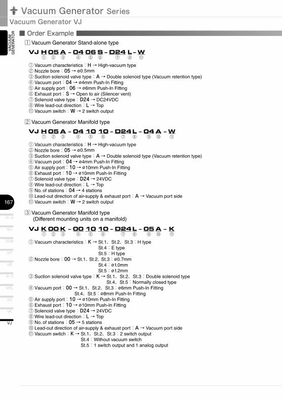
TOR ■ Order Example
♳ Vacuum Generator Stand-alone type
VJ H 05 A – 04 06 S – D24 L – W ① ② ③ ④ ⑤ ⑥ ⑦ ⑧ ⑪
① Vacuum characteristics:H → High-vacuum type② Nozzle bore:05 → ø0.5mm③ Suction solenoid valve type:A → Double solenoid type (Vacuum retention type)④ Vacuum port:04 → ø4mm Push-In Fitting⑤ Air supply port:06 → ø6mm Push-In Fitting⑥ Exhaust port:S → Open to air (Silencer vent)⑦ Solenoid valve type:D24 → DC24VDC⑧ Wire lead-out direction:L → Top⑪ Vacuum switch:W → 2 switch output
♴ Vacuum Generator Manifold type
VJ H 05 A – 04 10 10 – D24 L – 04 A – W ① ② ③ ④ ⑤ ⑥ ⑦ ⑧ ⑨ ⑩ ⑪
① Vacuum characteristics:H → High-vacuum type② Nozzle bore:05 → ø0.5mm③ Suction solenoid valve type:A → Double solenoid type (Vacuum retention type)④ Vacuum port:04 → ø4mm Push-In Fitting⑤ Air supply port:10 → ø10mm Push-In Fitting⑥ Exhaust port:10 → ø10mm Push-In Fitting⑦ Solenoid valve type:D24 → 24VDC⑧ Wire lead-out direction:L → Top⑨ No. of stations:04 → 4 stations⑩ Lead-out direction of air-supply & exhaust port:A → Vacuum port side⑪ Vacuum switch:W → 2 switch output
♵ Vacuum Generator Manifold type(Different mounting units on a manifold)
VJ K 00 K – 00 10 10 – D24 L – 05 A – K ① ② ③ ④ ⑤ ⑥ ⑦ ⑧ ⑨ ⑩ ⑪
① Vacuum characteristics:K → St.1、St.2、St.3:H typeSt.4:E typeSt.5:H type
② Nozzle bore:00 → St.1、St.2、St.3:ø0.7mmSt.4:ø1.0mmSt.5:ø1.2mm
③ Suction solenoid valve type:K → St.1、St.2、St.3:Double solenoid typeSt.4、St.5:Normally closed type
④ Vacuum port:00 → St.1、St.2、St.3:ø6mm Push-In FittingSt.4、St.5:ø8mm Push-In Fitting
⑤ Air supply port:10 → ø10mm Push-In Fitting⑥ Exhaust port:10 → ø10mm Push-In Fitting⑦ Solenoid valve type:D24 → 24VDC⑧ Wire lead-out direction:L → Top⑨ No. of stations:05 → 5 stations⑩ Lead-out direction of air-supply & exhaust port:A → Vacuum port side⑪ Vacuum switch:K → St.1、St.2、St.3:2 switch output
St.4:Without vacuum switchSt.5:1 switch output and 1 analog output
168
VN
VZ
VQ
VX
VJ
VAC
UU
M
GEN
ERA
TOR
EXTERNAL VACUUM CONTROLLER
VAC
UU
MPA
DVACUUM
ACCESSORIES
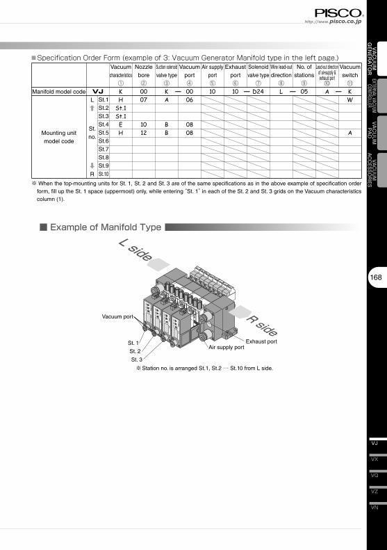
■ Example of Manifold Type
PS
P
V
MODE
SW1
SW2
S1S1
ME
kPa
P
V
MODE
SW1
SW2
S1S1
ME
kPa
P
V
MODE
SW1
SW2
S1S1
ME
kPa
P
V
MODE
SW1
SW2
S1S1
ME
kPa PS
L side
R side
Manifold model code
Mounting unitmodel code
VJ
Vacuumcharacteristics
①
Nozzlebore②
Suction solenoid valve type
③
Vacuum port④
Air supply port⑤
Exhaust port⑥
Solenoid valve type
⑦
Wire lead-out direction
⑧
No. of stations
⑨
Lead-out direction of air-supply & exhaust port
⑩
Vacuum switch
⑪— — — —
L
R
St.1St.2St.3St.4St.5St.6St.7St.8St.9St.10
※ When the top-mounting units for St. 1, St. 2 and St. 3 are of the same specifications as in the above example of specification order form, fill up the St. 1 space (uppermost) only, while entering “St. 1” in each of the St. 2 and St. 3 grids on the Vacuum characteristics column (1).
■ Specification Order Form (example of 3: Vacuum Generator Manifold type in the left page.)
Vacuum port
※Station no. is arranged St.1, St.2 … St.10 from L side.
Exhaust portAir supply port
St. 1
St. 2
St. 3
St. no.
Vacuum Generator SeriesVacuum Generator VJ
VH · VS
169
VU
VB
VM · VC
VG
VK
VJ
VY
VUM
VRL
VAC
UU
M
GEN
ERA
TOR
Manifold model code
Mounting unitmodel code
VJ
Vacuumcharacteristics
①
Nozzlebore②
Suction solenoid valve type
③
Vacuum port④
Air supply port⑤
Exhaust port⑥
Solenoid valve type
⑦
Wire lead-out direction
⑧
No. of stations
⑨
Lead-out direction of air-supply & exhaust port
⑩
Vacuum switch
⑪— — — —
St.1St.2St.3St.4St.5St.6St.7St.8St.9St.10
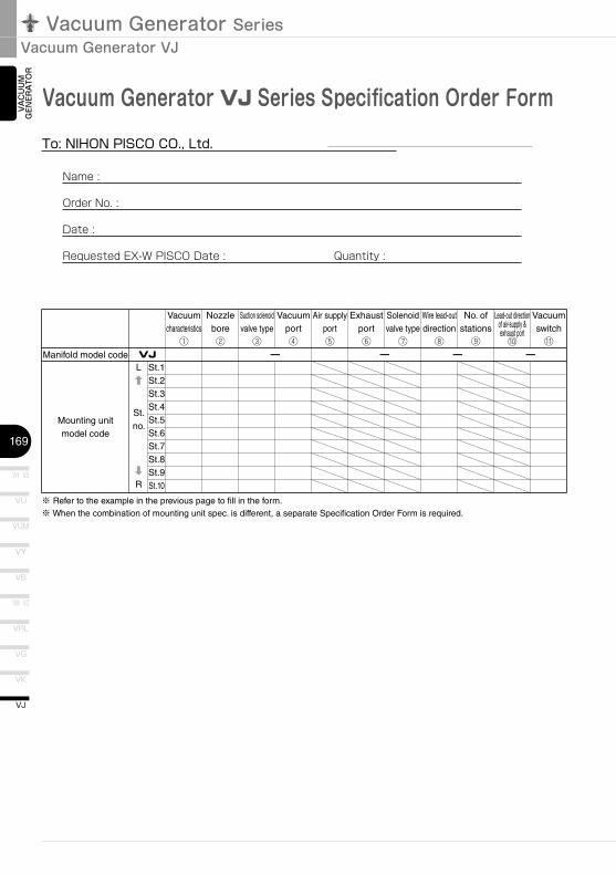
※ Refer to the example in the previous page to fill in the form.※ When the combination of mounting unit spec. is different, a separate Specification Order Form is required.
L
R
St. no.
Vacuum Generator VJ Series Specification Order FormTo:�NIHON�PISCO�CO.,�Ltd.�
Name :
Order No. :
Date :
Requested EX-W PISCO Date : Quantity :

170
VN
VZ
VQ
VX
VJ
VAC
UU
M
GEN
ERA
TOR
EXTERNAL VACUUM CONTROLLER
VAC
UU
MPA
DVACUUM
ACCESSORIES
■ Mechanism of VJ
(OFF)(ON)
PSV
(OFF) (OFF)
PSV
(ON)(OFF)
V
(OFF)(ON)
PSV
(OFF) (OFF) (ON)(OFF)
V
Example)�VJ□□A-□□□-□□-□□-□�(Valve�unit�type:�Double�solenoid�type�(Vacuum�retention�type))
①At vacuum generation suspended ②At vacuum generatingBlow-off air rate adjustment needle
Suction solenoid valveBlow-off pressure adjustment needle
Blow-off solenoid valve
Suction switch over valveBlow-off switch over valve
EjectorFilter
Vacuum switch
③At vacuum retention ④At blowing-off
Retention of suction switchover valve
Relief air
Example)�VJ□□B-□□□-□□-□□-□�(Valve�unit�type:�Normally�closed)
①At vacuum generation suspended ②At vacuum generatingBlow-off air rate adjustment needle
Suction solenoid valveBlow-off pressure adjustment needle
Blow-off solenoid valve
Suction switch over valveBlow-off switch over valve
EjectorFilter
Vacuum switch
③At vacuum retention ④At blowing-offRelief air
Vacuum Generator SeriesVacuum Generator VJ
VH · VS
171
VU
VB
VM · VC
VG
VK
VJ
VY
VUM
VRL
VAC
UU
M
GEN
ERA
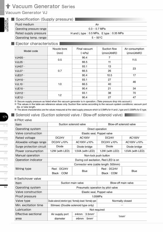
TOR ■ Specification (Supply pressure)
■ Ejector characteristics
■ Solenoid valve (Suction solenoid valve / Blow-off solenoid valve)
Fluid�medium Air
Operating�pressure�range 0.3 ~ 0.7 MPa
Rated�supply�pressure H and L type:0.5 MPa、E type:0.35 MPa
Operating�temp.�range 5 ~ 50°C
Model code
VJH05···VJL05···VJH07···VJL07···VJE07···VJH10···VJL10···VJE10···VJH12···VJE12···
Nozzle bore
(mm)
0.5
0.7
1.0
1.2
Final vacuum
(–kPa)
90.4
66.5
93.1
66.5
90.4
93.1
66.5
90.4
93.1
90.4
Suction flow
(l/min(ANR))
7
11
13
26
10.5
27
40
21
38
27
Air consumption
(l/min(ANR))
11.5
23
17
46
34
70
47
※ Secure supply pressure as listed when the vacuum generator is in operation. (Take pressure drop into account.)※ The values in the table are reference values only. Suction flow varies according to the vacuum system conditions; vacuum port
dia. or tube length. ※ The above characteristics are the values measured at the rated supply pressure which is 0.5MPa for H and L type and 0.35MPa for E type.
ItemOperating�systemValve�constructionRated�voltageAllowable�voltage�rangeSurge�protection�circuitPower�consumptionManual�operationOperation�indicator
Wiring�type
Suction solenoid valve
Non-lock push button
During coil excitation, Red LED is on
Connector wire (cable length: 500mm)
Blow-off solenoid valve
DC24V
DC24V ±10%
Diode
1.2W (with LED)
AC100V
AC100V ±10%
Diode bridge
1.5VA (with LED)
DC24V
DC24V ±10%
Diode
1.2W (with LED)
AC100V
AC100V ±10%
Diode bridge
1.5VA (with LED)
■Pilot�valve
Direct operation
Elastic seal, Poppet valve
Red:DC24V
Black:COMBlue
Red:DC24V
Black:COMBlue
ItemOperating�systemValve�constructionProof�pressureValve�typeMin.�excitation�timeLubricationEffective�sectionalarea
Suction main valve
Not required
Blow-off main valve
■Switchover�valve
Pneumatic operation by pilot valve
Elastic seal, Poppet valve
1.05MPa
Air supply port
diameter
ø4mm:3.5mm2
ø6mm:5mm21mm2
Double solenoid (retention type) / Normally closed / Normally open
50msec (Double solenoid type only)
Normally closed
-
172
VN
VZ
VQ
VX
VJ
VAC
UU
M
GEN
ERA
TOR
EXTERNAL VACUUM CONTROLLER
VAC
UU
MPA
DVACUUM
ACCESSORIES
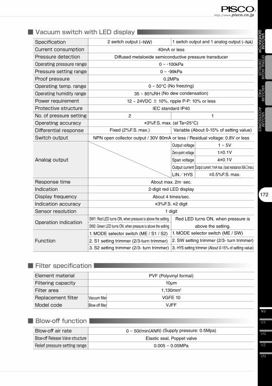
■ Filter specification
■ Vacuum switch with LED display
■ Blow-off function
Element�material PVF (Polyvinyl formal)
Filtering�capacity 10µm
Filter�area 1,130mm2
Replacement�filter Vacuum filter VGFE 10
Model�code Blow-off filter VJFF
SpecificationCurrent�consumptionPressure�detectionOperating�pressure�rangePressure�setting�rangeProof�pressureOperating�temp.�rangeOperating�humidity�rangePower�requirementProtective�structureNo.�of�pressure�settingOperating�accuracyDifferential�responseSwitch�output
Analog�output
Response�timeIndicationDisplay�frequencyIndication�accuracySensor�resolution
Operation�indication�
Function
2 switch output (–NW) 1 switch output and 1 analog output (–NA)
40mA or less
Diffused metaloxide semiconductive pressure transducer
0 ~ -100kPa
0 ~ -99kPa
0.2MPa
0 ~ 50°C (No freezing)
35 ~ 85%RH (No dew condensation)
12 ~ 24VDC ± 10%, ripple P-P: 10% or less
IEC standard IP40
2 1
±3%F.S. max. (at Ta=25°C)
Fixed (2%F.S. max.)
NPN open collector output / 30V 80mA or less / Residual voltage: 0.8V or less
Variable (About 0-15% of setting value)
Output voltage 1 ~ 5V
Zero-point voltage 1±0.1V
Span voltage 4±0.1V
Output current Output current: 1mA max. (load resistance 50kΩmax.)
LIN/HYS ±0.5%F.S. max.
About max. 2m・sec.
2-digit red LED display
About 4 times/sec.
±3%F.S. ±2 digit
1 digit
Red LED turns ON, when pressure is
above the setting.
1. MODE selector switch (ME / SW)
2. SW setting trimmer (2/3- turn trimmer)
3. HYS setting trimmer (About 0-15% of setting value)
SW1: Red LED turns ON, when pressure is above the setting.
SW2: Green LED turns ON, when pressure is above the setting.
1. MODE selector switch (ME / S1 / S2)
2. S1 setting trimmer (2/3-turn trimmer)
3. S2 setting trimmer (2/3- turn trimmer)
Blow-off�air�rate 0 ~ 50l/min(ANR) (Supply pressure: 0.5Mpa)
Blow-off�Release�Valve�structure Elastic seal, Poppet valve
Relief�pressure�setting�range 0.005 ~ 0.05MPa
Vacuum Generator SeriesVacuum Generator VJ
VH · VS
173
VU
VB
VM · VC
VG
VK
VJ
VY
VUM
VRL
VAC
UU
M
GEN
ERA
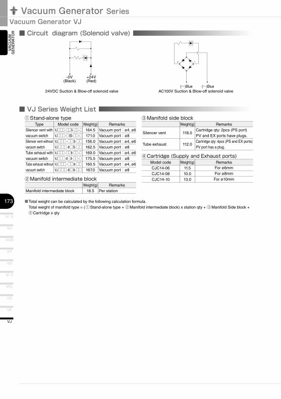
TOR ■ Circuit diagram (Solenoid valve)
-0V +24V(Black) (Red)
(~)Blue (~)Blue
+ –
■ VJ Series Weight List
24VDC Suction & Blow-off solenoid valve AC100V Suction & Blow-off solenoid valve
■Total weight can be calculated by the following calculation formula.Total weight of manifold type = (①Stand-alone type + ②Manifold intermediate block) x station qty + ③Manifold Side block + ④Cartridge x qty
Type Weight(g)164.5171.0156.0162.5169.0175.5160.5167.0
Silencer vent with vacuum switchSilencer vent without vacuum switchTube exhaust with vacuum switchTube exhaust without vacuum switch
RemarksVacuum port:ø4, ø6Vacuum port:ø8Vacuum port:ø4, ø6Vacuum port:ø8Vacuum port:ø4, ø6Vacuum port:ø8Vacuum port:ø4, ø6Vacuum port:ø8
Model codeVJ□□□ -□□S-□□ -□VJ□□□ -□8S-□□ -□VJ□□□ -□□S-□□VJ□□□ -8□S-□□VJ□□□ -□□8-□□ -□VJ□□□ -8□8-□□ -□VJ□□□ -□□8-□□VJ□□□ -8□8-□□
①Stand-alone�type
Weight(g)18.5Manifold intermediate block
RemarksPer station
②Manifold�intermediate�block
Weight(g)
118.0
112.0
Silencer vent
Tube exhaust
RemarksCartridge qty: 2pcs (PS port)PV and EX ports have plugs.Cartridge qty: 4pcs (PS and EX ports)PV port has a plug.
③Manifold�side�block
Model code Weight(g)11.510.013.0
CJC14-06CJC14-08CJC14-10
RemarksFor ø6mmFor ø8mmFor ø10mm
④Cartridge�(Supply�and�Exhaust�ports)
174
VN
VZ
VQ
VX
VJ
VAC
UU
M
GEN
ERA
TOR
EXTERNAL VACUUM CONTROLLER
VAC
UU
MPA
DVACUUM
ACCESSORIES
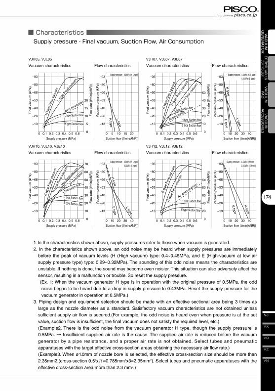
■ Characteristics
0 0 5 10 15
–13
–26
–40
–53
–66
–80
–93
–13
–26
–40
–53
–66
–80
–93
0.1 0.2 0.3 0.4 0.5 0.6
Supply pressure (MPa) Suction flow (l/min(ANR))
Fin
al v
acuu
m (
kPa)
Vac
uum
pre
ssur
e (k
Pa)
Flo
w r
ate
(l/m
in(A
NR
))
VJH05, VJL05
Vacuum characteristics Flow characteristics
0
5
10
15
20
20
H type
L type
Supply pressure:0.5MPa (H, L type)
0 0 10 20 30
–13
–26
–40
–53
–66
–80
–93
–13
–26
–40
–53
–66
–80
–93
0.1 0.2 0.3 0.4 0.5 0.6
Supply pressure (MPa) Suction flow (l/min(ANR))
Fin
al v
acuu
m (
kPa)
Vac
uum
pre
ssur
e (k
Pa)
Flo
w r
ate
(l/m
in(A
NR
))
VJH07, VJL07, VJE07
Vacuum characteristics Flow characteristics
0
10
20
30
40
50
40
H type
E type
L type
Supply pressure:0.5MPa (H, L type)0.35MPa (E type )
H ty
pe F
inal
vac
uum
E ty
pe F
inal
vac
uum
L ty
pe F
inal
vac
uum
L type Suction flow
H type Suction flow
E type Suction flow
Air consumption
0 0 10 20 30
–13
–26
–40
–53
–66
–80
–93
–13
–26
–40
–53
–66
–80
–93
0.1 0.2 0.3 0.4 0.5 0.6
Supply pressure (MPa) Suction flow (l/min(ANR))
Fin
al v
acuu
m (
kPa)
Vac
uum
pre
ssur
e (k
Pa)
Flo
w r
ate
(l/m
in(A
NR
))
VJH10, VJL10, VJE10
Vacuum characteristics Flow characteristics
0
10
20
30
40
50
60
70
40
H type
E type
L type
Supply pressure:0.5MPa (H, L type)0.35MPa (E type)
H ty
pe F
inal
vac
uum
E ty
pe F
inal
vac
uum
L typ
e Fina
l vac
uum
L type Suction flow
H type Suction flowE type Suction flow
Air cons
umptio
n
0 0 10 20 30
–13
–26
–40
–53
–66
–80
–93
–13
–26
–40
–53
–66
–80
–93
0.1 0.2 0.3 0.4 0.5 0.6
Supply pressure (MPa) Suction flow (l/min(ANR))
Fin
al v
acuu
m (
kPa)
Vac
uum
pre
ssur
e (k
Pa)
Flo
w r
ate
(l/m
in(A
NR
))
VJH12, VJL12, VJE12
Vacuum characteristics Flow characteristics
0
20
40
60
80
100
40
H type
E type
Supply pressure:0.5MPa (H type)0.35MPa (E type )
H ty
pe F
inal
vac
uum
E ty
pe F
inal
vac
uum
H type Suction flow
E type Suction flow
Air consu
mption
H ty
pe F
inal
vac
uum
L ty
pe F
inal
vac
uum
L type Suction flow
H type Suction flow
Air consumption
Supply�pressure�-�Final�vacuum,�Suction�Flow,�Air�Consumption
1. In the characteristics shown above, supply pressures refer to those when vacuum is generated.2. In the characteristics shown above, an odd noise may be heard when supply pressures are immediately
before the peak of vacuum levels (H (High vacuum) type: 0.4~0.45MPa, and E (High-vacuum at low air supply pressure type) type: 0.29~0.32MPa). The sounding of this odd noise means the characteristics are unstable. If nothing is done, the sound may become even noisier. This situation can also adversely affect the sensor, resulting in a malfunction or trouble. So reset the supply pressure.
(Ex. 1: When the vacuum generator H type is in operation with the original pressure of 0.5MPa, the odd noise began to be heard due to a drop in supply pressure to 0.43MPa. Reset the supply pressure for the vacuum generator in operation at 0.5MPa.)
3. Piping design and equipment selection should be made with an effective sectional area being 3 times as large as the nozzle diameter as a standard. Satisfactory vacuum characteristics are not obtained unless sufficient supply air flow is secured.(For example, the odd noise is heard even when pressure is at the set value, suction flow is insufficient, the final vacuum does not satisfy the required level, etc.)
(Example2. There is the odd noise from the vacuum generator H type, though the supply pressure is 0.5MPa. → Insufficient supplied air rate is the cause. The supplied air rate is reduced before the vacuum generator by a pipe resistance, and a proper air rate is not obtained. Select tubes and pneumatic apparatuses with the target effective cross-section areas obtaining the necessary air flow rate.)
(Example3. When ø1.0mm of nozzle bore is selected, the effective cross-section size should be more than 2.35mm2.(cross-section 0.52xπ=0.785mm2x3=2.35mm2). Select tubes and pneumatic apparatuses with the effective cross-section area more than 2.3 mm2.)
Vacuum Generator SeriesVacuum Generator VJ
VH · VS
175
VU
VB
VM · VC
VG
VK
VJ
VY
VUM
VRL
VAC
UU
M
GEN
ERA
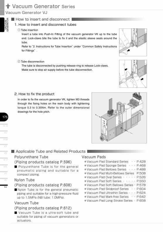
TOR ■ How to insert and disconnect
■ Applicable Tube and Related Products
1.�How�to�insert�and�disconnect�tubes① Tube insertion
Insert a tube into Push-In Fitting of the vacuum generator VK up to the tube
end. Lock-claws bite the tube to fix it and the elastic sleeve seals around the
tube.
Refer to “2. Instructions for Tube Insertion” under “Common Safety Instructions
for Fittings” .
② Tube disconnection
The tube is disconnected by pushing release-ring to release Lock-claws.
Make sure to stop air supply before the tube disconnection.
2.�How�to�fix�the�productIn order to fix the vacuum generator VK, tighten M3 threads
through the fixing holes on the resin body with tightening
torque 0.3 to 0.35Nm. Refer to the outer dimensional
drawings for the hole pitch.
Polyurethane Tube (Piping products catalog P.596)■ Polyurethane Tube is for the general
pneumatic pip ing and suitable for a compact piping.
Nylon Tube (Piping products catalog P.608)■ Nylon Tube is for the general pneumatic
piping and suitable for a high-pressure fluid up to 1.5MPa (NB tube: 1.0MPa).
Vacuum Tube (Piping products catalog P.612)■ Vacuum Tube is a ultra-soft tube and
suitable for piping of vacuum generators or actuators.
Vacuum Pads ● Vacuum Pad Standard Series ・・ P.428 ● Vacuum Pad Sponge Series ・・・ P.468 ● Vacuum Pad Bellows Series ・・・ P.488 ● Vacuum Pad Multi-Bellows Series P.508 ● Vacuum Pad Oval Series ・・・・・ P.526 ● Vacuum Pad Soft Series ・・・・・ P.550 ● Vacuum Pad Soft Bellows Series ・ P.578 ● Vacuum Pad Skidproof Series ・・ P.604 ● Vacuum Pad Ultrathin Series ・・・ P.624 ● Vacuum Pad Mark-free Series ・・ P.642 ● Vacuum Pad Long Stroke Series ・ P.658
176
VN
VZ
VQ
VX
VJ
VAC
UU
M
GEN
ERA
TOR
EXTERNAL VACUUM CONTROLLER
VAC
UU
MPA
DVACUUM
ACCESSORIES
PS EX
V
PS EX
V V
EXPS
Double solenoid
Normally closed Normally open
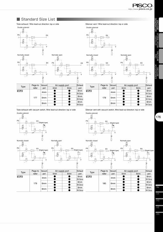
■ Standard Size List
PS EX
V
PS EX
V V
EXPS
Double solenoid
Normally closed Normally open
(Digital type)PS EX
V
(Digital type)PS EX
V
(Digital type)
V
EXPS
Double solenoid
Normally closed Normally open
(Digital type)PS EX
V
(Digital type)PS EX
V
(Digital type)
V
EXPS
Double solenoid
Normally closed Normally open
TypePage to
referVacuum
portAir supply port
4mmVJ
177
4mm
6mm
8mm
●●●●●●
Tube exhaust / Wire lead-out direction: top or side
Exhaust port
8mmWith Silencer8mm
With Silencer8mm
With Silencer
Silencer vent / Wire lead-out direction: top or side
6mm●●●●●●
TypePage to
referVacuum
portAir supply port
4mmVJ
178
4mm
6mm
8mm
●●●●●●
Exhaust port
8mmWith Silencer8mm
With Silencer8mm
With Silencer
6mm●●●●●●
TypePage to
referVacuum
portAir supply port
4mmVJ
179
4mm
6mm
8mm
●●●●●●
Tube exhaust with vacuum switch, Wire lead-out direction: top or side
Exhaust port
8mmWith Silencer8mm
With Silencer8mm
With Silencer
Silencer vent with vacuum switch, Wire lead-out direction: top or side
6mm●●●●●●
TypePage to
referVacuum
portAir supply port
4mmVJ
180
4mm
6mm
8mm
●●●●●●
Exhaust port
8mmWith Silencer8mm
With Silencer8mm
With Silencer
6mm●●●●●●
Vacuum Generator SeriesVacuum Generator VJ
VH�·�VS
177
VU
VB
VM�·�VC
VG
VK
VJ
VY
VUM
VRL
VAC
UU
M
GEN
ERA
TOR VJ
266 6
56.6
39.518
.2 26
1655
2-ø3.2
16.5
123
67 L2C2
34
12.5L1
C1
14.6 øD2: Vacuum port
20
7
Blow-off pressure adjustment needle
ø8:Exhaust port
Manual button
Operation indicator LED
Blow-off air rate adjustment needle
6.1
4.5
4
19øD1:Air supply port
Blow-off pilot valve
Suction pilot valve
VP
Abo
ut 5
00
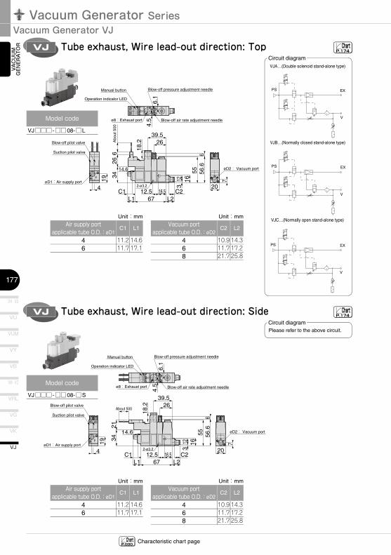
Tube exhaust, Wire lead-out direction: Top
VJC…(Normally open stand-alone type)
VJB…(Normally closed stand-alone type)
VJA…(Double solenoid stand-alone type)
PS EX
V
PS EX
V
V
EXPS
VJ Tube exhaust, Wire lead-out direction: Side
P
21
656
.6
39.5
18.2 26
1655
2-ø3.2
16.5
123
67 L2C2
34
12.5L1
C1
14.6 øD2: Vacuum port
20
7
ø8:Exhaust port
Manual button
6.1
4.5
4
19øD1:Air supply portV
Operation indicator LED
Blow-off pressure adjustment needle
Blow-off air rate adjustment needle
Blow-off pilot valve
Suction pilot valve
About 500
ChartP.000 Characteristic chart page
ChartP.174
ChartP.174
Circuit diagram
Model�code
VJ□□□ -□□08-□L
Vacuum�portapplicable�tube�O.D.:øD2
468
C2
10.911.721.7
L2
14.317.225.8
Circuit diagram
Air�supply�portapplicable�tube�O.D.:øD1
46
C1
11.211.7
L1
14.617.1
Unit:mm Unit:mm
Please refer to the above circuit.
Model�code
VJ□□□ -□□08-□S
Vacuum�portapplicable�tube�O.D.:øD2
468
C2
10.911.721.7
L2
14.317.225.8
Unit:mmAir�supply�port
applicable�tube�O.D.:øD1
46
C1
11.211.7
L1
14.617.1
Unit:mm
178
VN
VZ
VQ
VX
VJ
VAC
UU
M
GEN
ERA
TOR
EXTERNAL VACUUM CONTROLLER
VAC
UU
MPA
DVACUUM
ACCESSORIES
VJ
266
656
.6
26
1655
2-ø3.2
16.512
367 L2
C2
34
12.5L1
C1
14.6 øD2:Vacuum port
20
7
Manual button
6.1
4.5
4
19øD1:Air supply portVP
Abo
ut 5
00
Operation indicator LED
Blow-off pressure adjustment needle
Blow-off air rate adjustment needle
Blow-off pilot valve
Suction pilot valve
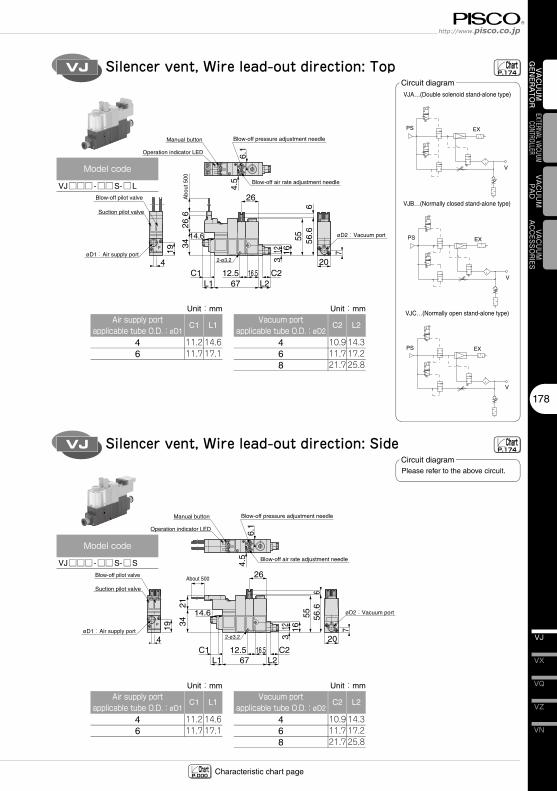
Silencer vent, Wire lead-out direction: Top
PS EX
V
VJA…(Double solenoid stand-alone type)
PS EX
V
VJB…(Normally closed stand-alone type)
V
EXPS
VJC…(Normally open stand-alone type)
VJ Silencer vent, Wire lead-out direction: Side
P
21
656
.6
26
1655
2-ø3.2
16.5
123
67 L2C2
34
12.5L1
C1
14.6 øD2:Vacuum port
20
7
Manual button
6.1
4.5
4
19øD1:Air supply portV
Operation indicator LED
Blow-off pressure adjustment needle
Blow-off air rate adjustment needle
Blow-off pilot valve
Suction pilot valve
About 500
ChartP.000 Characteristic chart page
ChartP.174
ChartP.174
Circuit diagram
Model�code
VJ□□□ -□□S-□L
Vacuum�portapplicable�tube�O.D.:øD2
468
C2
10.911.721.7
L2
14.317.225.8
Circuit diagram
Air�supply�portapplicable�tube�O.D.:øD1
46
C1
11.211.7
L1
14.617.1
Unit:mm Unit:mm
Please refer to the above circuit.
Model�code
VJ□□□ -□□S-□S
Vacuum�portapplicable�tube�O.D.:øD2
468
C2
10.911.721.7
L2
14.317.225.8
Unit:mmAir�supply�port
applicable�tube�O.D.:øD1
46
C1
11.211.7
L1
14.617.1
Unit:mm
Vacuum Generator SeriesVacuum Generator VJ
VH�·�VS
179
VU
VB
VM�·�VC
VG
VK
VJ
VY
VUM
VRL
VAC
UU
M
GEN
ERA
TOR VJ
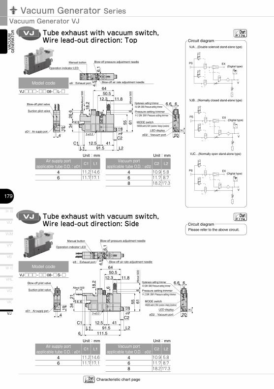
LED display
66.6
øD2:Vacuum port
MODE switch※MODE switch (2 SW: 3 positions / Analog: 2 positions)
Pressure setting trimmer※ 2 SW: SW1 Pressure setting trimmer
Hysteresis setting trimmer※2 SW: SW2 Pressure setting trimmer
20
7kP
a
SW
2S
W1
S1
S2
MEMO
DE
V
266 66
56.6
61
6418
.2
50.512.3 11.8
55
2-ø3.2
41
123
91.5 L2
C2
34
12.5L1
C1
14.6
ø8:Exhaust port
Manual button
6.1
4.5
4
19øD1:Air supply portP
Operation indicator LED
Blow-off pressure adjustment needle
Blow-off air rate adjustment needle
Blow-off pilot valve
Suction pilot valve
Abo
ut 5
00
Abo
ut 5
00
Tube exhaust with vacuum switch, Wire lead-out direction: Top
VJA…(Double solenoid stand-alone type)
(Digital type)PS EX
V
VJB…(Normally closed stand-alone type)
(Digital type)PS EX
V
VJC…(Normally open stand-alone type)
(Digital type)
V
EXPS
VJ Tube exhaust with vacuum switch, Wire lead-out direction: Side
P
66.6
øD2:Vacuum port 20
7kP
a
SW
2S
W1
S1
S2
MEMO
DE
V
21
6656
.6
61
64
18.2
50.512.3 11.8
55
2-ø3.2
41
123
91.5111.56
L2
C2
34
12.5L1
C1
14.6
ø8: Exhaust port
Manual button
6.1
4.5
4
19øD1:Air supply port
Hysteresis setting trimmer※2 SW: SW2 Pressure setting trimmer
Pressure setting trimmer※ 2 SW: SW1 Pressure setting trimmer
MODE switch※MODE switch (2 SW: 3 positons / Analog: 2positions)
LED display
Blow-off pilot valve
Suction pilot valveAbout 500
Abo
ut 5
00
Operation indicator LED
Blow-off pressure adjustment needle
Blow-off air rate adjustment needle
ChartP.000 Characteristic chart page
ChartP.174
ChartP.174
Circuit diagram
Model�code
VJ□□□ -□□08-□L-□
Vacuum�portapplicable�tube�O.D.:øD2
468
C2
10.911.718.2
L2
5.88.717.3
Circuit diagram
Air�supply�portapplicable�tube�O.D.:øD1
46
C1
11.211.7
L1
14.617.1
Unit:mm Unit:mm
Please refer to the above circuit.
Model�code
VJ□□□ -□□08-□S-□
Vacuum�portapplicable�tube�O.D.:øD2
468
C2
10.911.718.2
L2
5.88.717.3
Unit:mmAir�supply�port
applicable�tube�O.D.:øD1
46
C1
11.211.7
L1
14.617.1
Unit:mm
180
VN
VZ
VQ
VX
VJ
VAC
UU
M
GEN
ERA
TOR
EXTERNAL VACUUM CONTROLLER
VAC
UU
MPA
DVACUUM
ACCESSORIES
VJ
66.6
øD2:Vacuum port 20
7kP
a
SW
2S
W1
S1
S2
MEMO
DE
V
266 6
656.6
61
50.512.3 11.8
552-ø3.2
41
123
91.5 L2
C2
34
12.5L1
C1
14.6
Manual button
6.1
4.5
4
19øD1:Air supply portP
Operation indicator LED
Blow-off pressure adjustment needle
Blow-off air rate adjustment needle
Blow-off pilot valve
Suction pilot valve
Abo
ut 5
00
Abo
ut 5
00
Hysteresis setting trimmer※2 SW: SW2 Pressure setting trimmer
Pressure setting trimmer※ 2 SW: SW1 Pressure setting trimmer
MODE switch※MODE switch (2 SW: 3 positions / Analog: 2 positions)
LED display
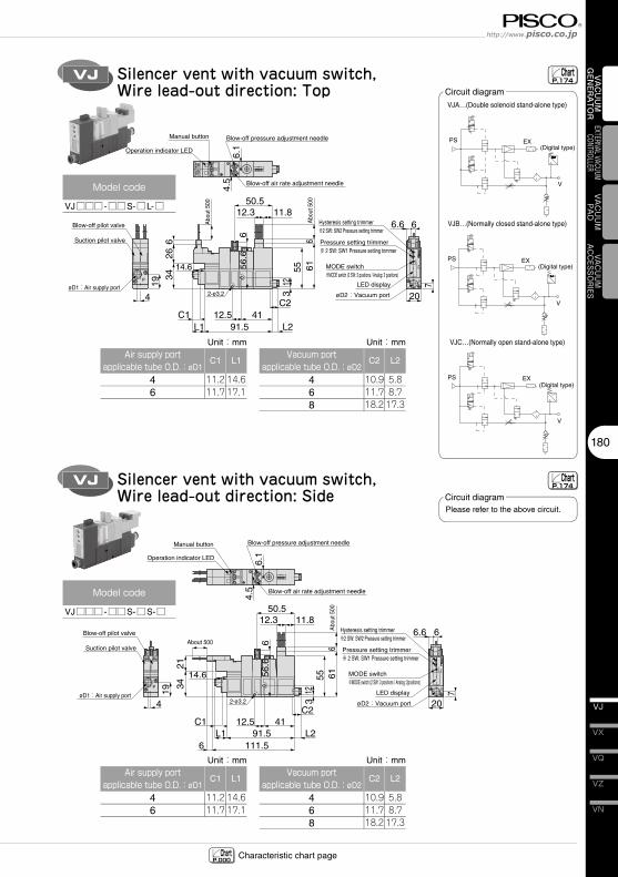
Silencer vent with vacuum switch, Wire lead-out direction: Top
(Digital type)PS EX
V
VJA…(Double solenoid stand-alone type)
(Digital type)PS EX
V
VJB…(Normally closed stand-alone type)
(Digital type)
V
EXPS
VJC…(Normally open stand-alone type)
VJ Silencer vent with vacuum switch, Wire lead-out direction: Side
P
66.6
øD2:Vacuum port 20
7kP
a
SW
2S
W1
S1
S2
MEMO
DE
V
21
6656
.6
61
50.512.3 11.8
55
2-ø3.2
41
123
91.5111.56
L2
C2
34
12.5L1
C1
14.6
Manual button
6.1
4.5
4
19øD1:Air supply port
Operation indicator LED
Blow-off pressure adjustment needle
Blow-off air rate adjustment needle
Blow-off pilot valve
Suction pilot valveAbout 500
Abo
ut 5
00
Hysteresis setting trimmer※2 SW: SW2 Pressure setting trimmer
Pressure setting trimmer※ 2 SW: SW1 Pressure setting trimmer
MODE switch※MODE switch (2 SW: 3 positions / Analog: 2positions)
LED display
ChartP.000 Characteristic chart page
ChartP.174
ChartP.174
Circuit diagram
Model�code
VJ□□□ -□□S-□L-□
Vacuum�portapplicable�tube�O.D.:øD2
468
C2
10.911.718.2
L2
5.88.717.3
Circuit diagram
Air�supply�portapplicable�tube�O.D.:øD1
46
C1
11.211.7
L1
14.617.1
Unit:mm Unit:mm
Please refer to the above circuit.
Model�code
VJ□□□ -□□S-□S-□
Vacuum�portapplicable�tube�O.D.:øD2
468
C2
10.911.718.2
L2
5.88.717.3
Unit:mmAir�supply�port
applicable�tube�O.D.:øD1
46
C1
11.211.7
L1
14.617.1
Unit:mm
Vacuum Generator SeriesVacuum Generator VJ
VH�·�VS
181
VU
VB
VM�·�VC
VG
VK
VJ
VY
VUM
VRL
VAC
UU
M
GEN
ERA
TOR VJ
R
PS PS
R
øD1:Exhaust port
øD1:Air supply port
øD2:Vacuum port
70+21×n (n = No. of stations)60+21×n (n = No. of stations)50+21×n (n = No. of stations)
12.5
12.5 23
25 25
P=2120
4.5 6.1
6.1
L1C1
205
3.5
3610
60.
5
7.555
.5
6 26About 500
kPa
SW
2S
W1
S1
S2
V
MO
DE
ME
kPa
SW
2S
W1
S1
S2
V
MO
DE
ME
kPa
SW
2S
W1
S1
S2
V
MO
DE
ME
620
6 56.6
55
21 34
C2
53.5
50.5 12
.311
.8
4614
.6
L211
1.5
8
6 61
Abo
ut 5
00
About 500
29
L3
V V V
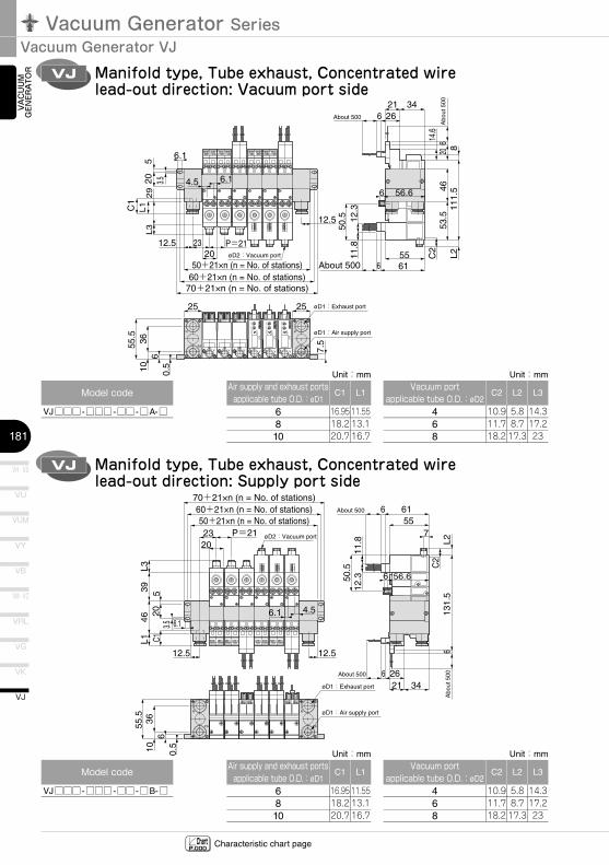
Manifold type, Tube exhaust, Concentrated wire lead-out direction: Vacuum port side
VJ Manifold type, Tube exhaust, Concentrated wire lead-out direction: Supply port side
R
PS PS
R
70+21×n (n = No. of stations)60+21×n (n = No. of stations)50+21×n (n = No. of stations)23
6.1
39L3
46L1
3610
60.
5
55.5
C120
53.5
P=2120
6.1 4.5
12.512.5
øD2:Vacuum port
6 26øD1:Exhaust port
øD1:Air supply port
About 500
6 56.6
557
6
3421
C2
L2
50.5
11.8
12.3
131.
5
6 61
Abo
ut 5
00
About 500
ChartP.000 Characteristic chart page
Model�code
VJ□□□ -□□□ -□□ -□A-□
Vacuum�portapplicable�tube�O.D.:øD2
468
C2
10.911.718.2
L2
5.88.717.3
Air�supply�and�exhaust�ports�applicable�tube�O.D.:øD1
6810
C1
16.9518.220.7
L1
11.5513.116.7
Unit:mm Unit:mm
L3
14.317.223
Vacuum�portapplicable�tube�O.D.:øD2
468
C2
10.911.718.2
L2
5.88.717.3
Air�supply�and�exhaust�ports�applicable�tube�O.D.:øD1
6810
C1
16.9518.220.7
L1
11.5513.116.7
Unit:mm Unit:mm
L3
14.317.223
Model�code
VJ□□□ -□□□ -□□ -□B-□
182
VN
VZ
VQ
VX
VJ
VAC
UU
M
GEN
ERA
TOR
EXTERNAL VACUUM CONTROLLER
VAC
UU
MPA
DVACUUM
ACCESSORIES
VJ
PS PS
øD1: Air supply port
øD2:Vacuum port
70+21×n (n = No. of stations)60+21×n (n = No. of stations)50+21×n (n = No. of stations)
12.5
12.5 23
25 25
P=2120
4.5 6.1
6.1L1C1
205
3.5
106
0.5
7.555
.5
6 26
29L3
About 500
620
6 56.6
55
21 34
C2
53.5
50.5 12
.311
.8
4614
.6
L211
1.5
8
6 61
Abo
ut 5
00
About 500
kPa
SW
2S
W1
S1
S2
V
MO
DE
ME
kPa
SW
2S
W1
S1
S2
V
MO
DE
ME
kPa
SW
2S
W1
S1
S2
V
MO
DE
ME
V V V
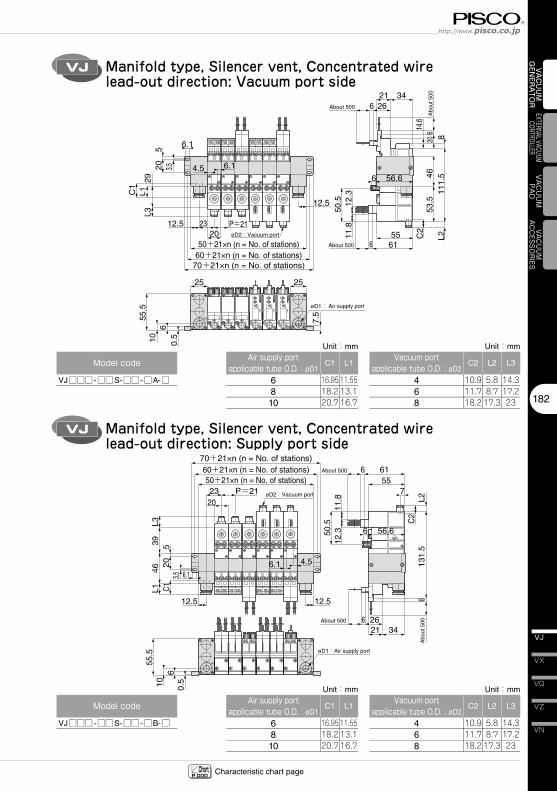
Manifold type, Silencer vent, Concentrated wire lead-out direction: Vacuum port side
VJ Manifold type, Silencer vent, Concentrated wire lead-out direction: Supply port side
6 26About 500
PS PS
70+21×n (n = No. of stations)60+21×n (n = No. of stations)50+21×n (n = No. of stations)23
6.1
39L3
46L1
106
0.5
55.5
C120
53.5
P=2120
6.1 4.5
12.512.5
øD2:Vacuum port
øD1:Air supply port
6 56.6
557
6
3421
C2
L2
50.5
11.8
12.3
131.
5
6 61
Abo
ut 5
00
About 500
ChartP.000 Characteristic chart page
Model�code
VJ□□□ -□□S-□□ -□A-□
Vacuum�portapplicable�tube�O.D.:øD2
468
Air�supply�portapplicable�tube�O.D.:øD1
6810
Unit:mm Unit:mm
Vacuum�portapplicable�tube�O.D.:øD2
468
Air�supply�portapplicable�tube�O.D.:øD1
6810
Unit:mm Unit:mm
Model�code
VJ□□□ -□□S-□□ -□B-□
C2
10.911.718.2
L2
5.88.717.3
C1
16.9518.220.7
L1
11.5513.116.7
L3
14.317.223
C2
10.911.718.2
L2
5.88.717.3
C1
16.9518.220.7
L1
11.5513.116.7
L3
14.317.223
Vacuum Generator SeriesVacuum Generator VJ
VH · VS
183
VU
VB
VM · VC
VG
VK
VJ
VY
VUM
VRL
VAC
UU
M
GEN
ERA
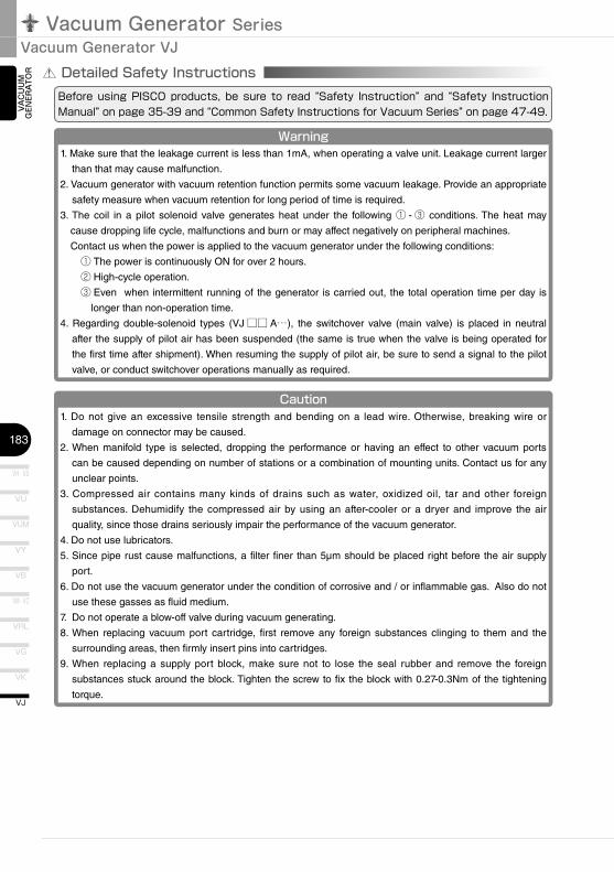
TOR Detailed Safety Instructions
Before� using�PISCO�products,� be� sure� to� read� “Safety� Instruction”� and� “Safety� Instruction�Manual”�on�page�35-39�and�“Common�Safety�Instructions�for�Vacuum�Series”�on�page�47-49.
Warning1. Make sure that the leakage current is less than 1mA, when operating a valve unit. Leakage current larger
than that may cause malfunction.
2. Vacuum generator with vacuum retention function permits some vacuum leakage. Provide an appropriate
safety measure when vacuum retention for long period of time is required.
3. The coil in a pilot solenoid valve generates heat under the following ① - ③ conditions. The heat may
cause dropping life cycle, malfunctions and burn or may affect negatively on peripheral machines.
Contact us when the power is applied to the vacuum generator under the following conditions:
① The power is continuously ON for over 2 hours.
② High-cycle operation.
③ Even when intermittent running of the generator is carried out, the total operation time per day is
longer than non-operation time.
4. Regarding double-solenoid types (VJ □□ A…), the switchover valve (main valve) is placed in neutral
after the supply of pilot air has been suspended (the same is true when the valve is being operated for
the first time after shipment). When resuming the supply of pilot air, be sure to send a signal to the pilot
valve, or conduct switchover operations manually as required.
Caution1. Do not give an excessive tensile strength and bending on a lead wire. Otherwise, breaking wire or
damage on connector may be caused.
2. When manifold type is selected, dropping the performance or having an effect to other vacuum ports
can be caused depending on number of stations or a combination of mounting units. Contact us for any
unclear points.
3. Compressed air contains many kinds of drains such as water, oxidized oil, tar and other foreign
substances. Dehumidify the compressed air by using an after-cooler or a dryer and improve the air
quality, since those drains seriously impair the performance of the vacuum generator.
4. Do not use lubricators.
5. Since pipe rust cause malfunctions, a filter finer than 5µm should be placed right before the air supply
port.
6. Do not use the vacuum generator under the condition of corrosive and / or inflammable gas. Also do not
use these gasses as fluid medium.
7. Do not operate a blow-off valve during vacuum generating.
8. When replacing vacuum port cartridge, first remove any foreign substances clinging to them and the
surrounding areas, then firmly insert pins into cartridges.
9. When replacing a supply port block, make sure not to lose the seal rubber and remove the foreign
substances stuck around the block. Tighten the screw to fix the block with 0.27-0.3Nm of the tightening
torque.
184
VN
VZ
VQ
VX
VJ
VAC
UU
M
GEN
ERA
TOR
EXTERNAL VACUUM CONTROLLER
VAC
UU
MPA
DVACUUM
ACCESSORIES
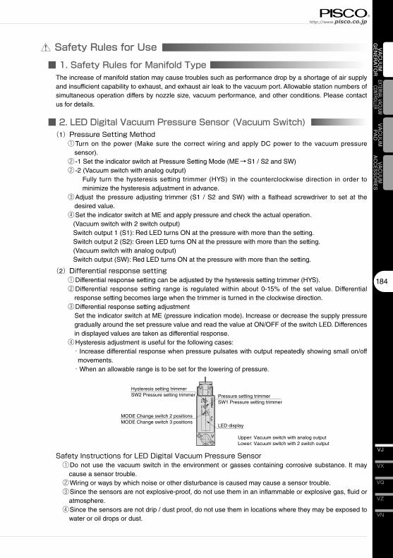
Safety Rules for Use■ 1. Safety Rules for Manifold Type
kPa
SW
2S
W1
S1
S2
MEMO
DE
V
LED display
MODE Change switch 2 positions MODE Change switch 3 positions
Pressure setting trimmerSW1 Pressure setting trimmer
Hysteresis setting trimmerSW2 Pressure setting trimmer
Upper: Vacuum switch with analog outputLower: Vacuum switch with 2 switch output
■ 2. LED Digital Vacuum Pressure Sensor (Vacuum Switch)
The increase of manifold station may cause troubles such as performance drop by a shortage of air supply and insufficient capability to exhaust, and exhaust air leak to the vacuum port. Allowable station numbers of simultaneous operation differs by nozzle size, vacuum performance, and other conditions. Please contact us for details.
(1)Pressure�Setting�Method① Turn on the power (Make sure the correct wiring and apply DC power to the vacuum pressure
sensor).② -1 Set the indicator switch at Pressure Setting Mode (ME→S1 / S2 and SW)② -2 (Vacuum switch with analog output)
Fully turn the hysteresis setting trimmer (HYS) in the counterclockwise direction in order to minimize the hysteresis adjustment in advance.
③ Adjust the pressure adjusting trimmer (S1 / S2 and SW) with a flathead screwdriver to set at the desired value.
④Set the indicator switch at ME and apply pressure and check the actual operation.(Vacuum switch with 2 switch output)Switch output 1 (S1): Red LED turns ON at the pressure with more than the setting.Switch output 2 (S2): Green LED turns ON at the pressure with more than the setting.(Vacuum switch with analog output)Switch output (SW): Red LED turns ON at the pressure with more than the setting.
(2)Differential�response�setting①Differential response setting can be adjusted by the hysteresis setting trimmer (HYS).② Differential response setting range is regulated within about 0-15% of the set value. Differential
response setting becomes large when the trimmer is turned in the clockwise direction.③Differential response setting adjustment
Set the indicator switch at ME (pressure indication mode). Increase or decrease the supply pressure gradually around the set pressure value and read the value at ON/OFF of the switch LED. Differences in displayed values are taken as differential response.
④Hysteresis adjustment is useful for the following cases:・ Increase differential response when pressure pulsates with output repeatedly showing small on/off
movements.・When an allowable range is to be set for the lowering of pressure.
Safety�Instructions�for�LED�Digital�Vacuum�Pressure�Sensor ①Do not use the vacuum switch in the environment or gasses containing corrosive substance. It may
cause a sensor trouble. ②Wiring or ways by which noise or other disturbance is caused may cause a sensor trouble. ③Since the sensors are not explosive-proof, do not use them in an inflammable or explosive gas, fluid or
atmosphere. ④Since the sensors are not drip / dust proof, do not use them in locations where they may be exposed to
water or oil drops or dust.
Vacuum Generator SeriesVacuum Generator VJ
VH · VS
185
VU
VB
VM · VC
VG
VK
VJ
VY
VUM
VRL
VAC
UU
M
GEN
ERA
TOR
Load
Load
SW1 OUT(Black)
SW2 OUT(Gray)
COM(Blue)
V+(Brown)
Maincircuit
Load
SW1 OUT(Black)
ANALOG OUT(Gray)
COM(Blue)
V+(Brown)
Maincircuit
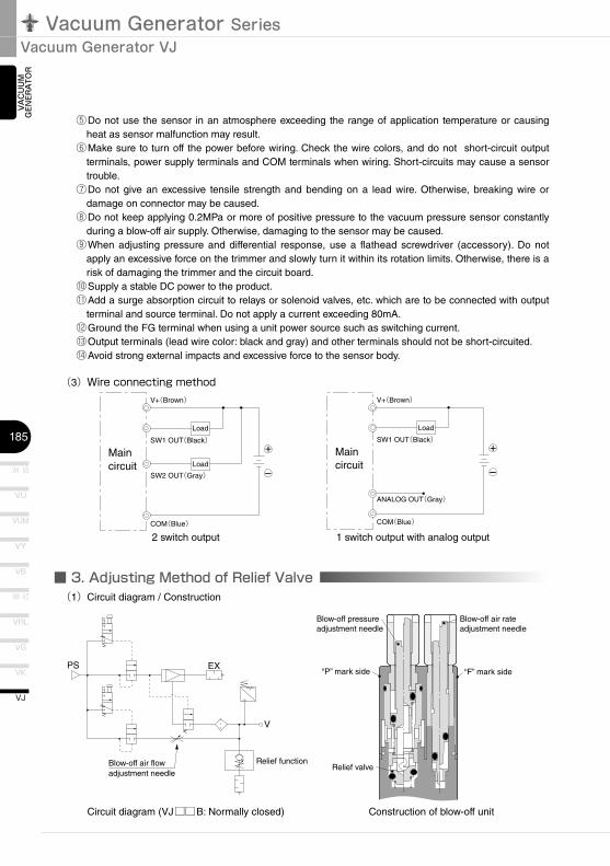
■ 3. Adjusting Method of Relief Valve
PS EX
V
Blow-off air flowadjustment needle
Relief function
“F” mark side
Blow-off air rate adjustment needle
Blow-off pressure adjustment needle
“P” mark side
Relief valve
(3)Wire�connecting�method
2 switch output 1 switch output with analog output
⑤Do not use the sensor in an atmosphere exceeding the range of application temperature or causing heat as sensor malfunction may result.
⑥Make sure to turn off the power before wiring. Check the wire colors, and do not short-circuit output terminals, power supply terminals and COM terminals when wiring. Short-circuits may cause a sensor trouble.
⑦Do not give an excessive tensile strength and bending on a lead wire. Otherwise, breaking wire or damage on connector may be caused.
⑧Do not keep applying 0.2MPa or more of positive pressure to the vacuum pressure sensor constantly during a blow-off air supply. Otherwise, damaging to the sensor may be caused.
⑨When adjusting pressure and differential response, use a flathead screwdriver (accessory). Do not apply an excessive force on the trimmer and slowly turn it within its rotation limits. Otherwise, there is a risk of damaging the trimmer and the circuit board.
⑩Supply a stable DC power to the product. ⑪Add a surge absorption circuit to relays or solenoid valves, etc. which are to be connected with output
terminal and source terminal. Do not apply a current exceeding 80mA. ⑫Ground the FG terminal when using a unit power source such as switching current. ⑬Output terminals (lead wire color: black and gray) and other terminals should not be short-circuited. ⑭Avoid strong external impacts and excessive force to the sensor body.
(1)Circuit diagram / Construction
Circuit diagram (VJ□□B: Normally closed) Construction of blow-off unit
186
VN
VZ
VQ
VX
VJ
VAC
UU
M
GEN
ERA
TOR
EXTERNAL VACUUM CONTROLLER
VAC
UU
MPA
DVACUUM
ACCESSORIES
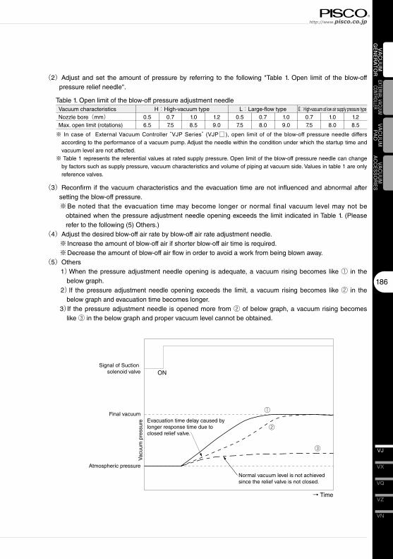
Atmospheric pressure
Final vacuum
Signal of Suction solenoid valve
①
②
③
Evacuation time delay caused by longer response time due to closed relief valve.
Normal vacuum level is not achieved since the relief valve is not closed.
ON
→ Time
Vac
uum
pre
ssur
e
Vacuum characteristicsNozzle bore(mm)Max. open limit (rotations)
(2)Adjust and set the amount of pressure by referring to the following "Table 1. Open limit of the blow-off pressure relief needle".
H:High-vacuum type0.56.5
0.77.5
1.08.5
1.29.0
L:Large-flow type0.57.5
0.78.0
1.09.0
0.77.5
1.08.0
1.28.5
E:High-vacuum at low air supply pressure type
Table 1. Open limit of the blow-off pressure adjustment needle
※ In case of External Vacuum Controller “VJP Series” (VJP□ ), open limit of of the blow-off pressure needle differs according to the performance of a vacuum pump. Adjust the needle within the condition under which the startup time and vacuum level are not affected.
※ Table 1 represents the referential values at rated supply pressure. Open limit of the blow-off pressure needle can change by factors such as supply pressure, vacuum characteristics and volume of piping at vacuum side. Values in table 1 are only reference valves.
(3)Reconfirm if the vacuum characteristics and the evacuation time are not influenced and abnormal after setting the blow-off pressure.※Be noted that the evacuation time may become longer or normal final vacuum level may not be
obtained when the pressure adjustment needle opening exceeds the limit indicated in Table 1. (Please refer to the following (5) Others.)
(4)Adjust the desired blow-off air rate by blow-off air rate adjustment needle.※ Increase the amount of blow-off air if shorter blow-off air time is required.※Decrease the amount of blow-off air flow in order to avoid a work from being blown away.
(5)Others1)When the pressure adjustment needle opening is adequate, a vacuum rising becomes like ① in the
below graph.2)If the pressure adjustment needle opening exceeds the limit, a vacuum rising becomes like ② in the
below graph and evacuation time becomes longer.3)If the pressure adjustment needle is opened more from ② of below graph, a vacuum rising becomes
like ③ in the below graph and proper vacuum level cannot be obtained.
Vacuum Generator SeriesVacuum Generator VJ
VH · VS
187
VU
VB
VM · VC
VG
VK
VJ
VY
VUM
VRL
VAC
UU
M
GEN
ERA
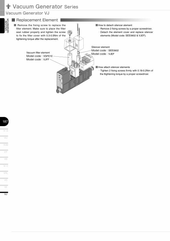
TOR ■ Replacement Element
P
V
MODE
SW1
SW2
S1S1
ME
kPa
Vacuum filter elementModel�code:VGFE10Model�code:VJFF
Silencer elementModel�code:SEE0602Model�code:VJEF
■ Remove the fixing screw to replace the filter element. Make sure to place the filter seal rubber properly and tighten the screw to fix the filter cover with 0.3-0.5Nm of the tightening torque after the replacement.
■How to detach silencer element ・Remove 2 fixing screws by a proper screwdriver. ・Detach the element cover and replace silencer
elements (Model code: SEE0602 & VJEF).
■How attach silencer elements ・Tighten 2 fixing screws firmly with 0.18-0.2Nm of
the ttightening torque by a proper screwdriver.
35
Safety Instructions
SAFETY Instructions
Warning
This safety instructions aim to prevent personal injury and damage to properties by requiring proper use of PISCO products. Be certain to follow ISO 4414 and JIS B 8370
ISO 4414:Pneumatic fluid power…Recomendations for the application of equipment to transmission and control systems.
JIS B 8370:General rules and safety requirements for systems and their components.This safety instructions is classified into “Danger”, “Warning” and “Caution” depending on the degree of danger or damages caused by improper use of PISCO products.
1. Selection of pneumatic products① A user who is a pneumatic system designer or has sufficient experience
and technical expertise should select PISCO products.② Due to wide variety of operating conditions and applications for PISCO
products, carry out the analysis and evaluation on PISCO products. The pneumatic system designer is solely responsible for assuring that the user's requirements are met and that the application presents no health or safety hazards. All designers are required to fully understand the specifications of PISCO products and constitute all systems based on the latest catalog or information, considering any malfunctions.
2. Handle the pneumatic equipment with enough knowledge and experience① Improper use of compressed air is dangerous. Assembly, operation
and maintenance of machines using pneumatic equipment should be conducted by a person with enough knowledge and experience.
3. Do not operate machine / equipment or remove pneumatic equipment until safety is confirmed.① Make sure that preventive measures against falling work-pieces or
sudden movements of machine are completed before inspection or maintenance of these machine.
② Make sure the above preventive measures are completed. A compressed air supply and the power supply to the machine must be off, and also the compressed air in the systems must be exhausted.
③ Restart the machines with care after ensuring to take all preventive measures against sudden movements.
Danger Hazardous conditions. It can cause death or serious personal injury.
Warning Hazardous conditions depending on usages. Improper use of PISCO products can cause death or serious personal injury.
Caution Hazardous conditions depending on usages. Improper use of PISCO products can cause personal injury or damages to properties.
※ . This safety instructions are subject to change without notice.
http://www.pisco.co.jphttp://www.pisco.co.jp
36
Disclaimer1. PISCO does not take any responsibility for any incidental or indirect
loss, such as production line stop, interruption of business, loss of benefits, personal injury, etc., caused by any failure on use or application of PISCO products.
2. PISCO does not take any responsibility for any loss caused by natural disasters, fires not related to PISCO products, acts by third parties, and intentional or accidental damages of PISCO products due to incorrect usage.
3. PISCO does not take any responsibility for any loss caused by improper usage of PISCO products such as exceeding the specification limit or not following the usage the published instructions and catalog allow.
4. PISCO does not take any responsibility for any loss caused by remodeling of PISCO products, or by combinational use with non-PISCO products and other software systems.
5. The damages caused by the defect of Pisco products shall be covered but limited to the full amount of the PISCO products paid by the customer.
37
Safety Instructions
SAFETY INSTRUCTION MANUAL
Danger1. Do not use PISCO products for the following applications.
① Equipment used for maintaining / handling human life and body.② Equipment used for moving / transporting human.③ Equipment specifically used for safety purposes.
Warning1. Do not use PISCO products under the following conditions.
① Beyond the specifications or conditions stated in the catalog, or the instructions.② Under the direct sunlight or outdoors.③ Excessive vibrations and impacts.④ Exposure / adhere to corrosive gas, inflammable gas, chemicals, seawater, water and vapor. *
* Some products can be used under the condition above(④), refer to the details of specification and condition of each product.
2. Do not disassemble or modify PISCO products, which affect the performance, function, and basic structure of the product.
3. Turn off the power supply, stop the air supply to PISCO products, and make sure there is no residual air pressure in the pipes before maintenance and inspection.
4. Do not touch the release-ring of push-in fitting when there is a working pressure. The lock may be released by the physical contact, and tube may fly out or slip out.
5. Frequent switchover of compressed air may generate heat, and there is a risk of causing burn injury.
6. Avoid any load on PISCO products, such as a tensile strength, twisting and bending. Otherwise, there is a risk of causing damage to the products.
7. As for applications where threads or tubes swing / rotate, use Rotary Joints, High Rotary Joints or Multi-Circuit Rotary Block only. The other PISCO products can be damaged in these applications.
8. Use only Die Temperature Control Fitting Series, Tube Fitting Stainless SUS316 Series, Tube Fitting Stainless SUS316 Compression Fitting Series or Tube Fitting Brass Series under the condition of over 60℃ (140°F) water or thermal oil. Other PISCO products can be damaged by heat and hydrolysis under the condition above.
9. As for the condition required to dissipate static electricity or provide an antistatic performance, use EG series fitting and antistatic products only, and do not use other PISCO products. There is a risk that static electricity can cause system defects or failures.
10. Use only Fittings with a characteristic of spatter-proof such as Anti-spatter or Brass series in a place where flame and weld spatter is produced. There is a risk of causing fire by sparks.
11. Turn off the power supply to PISCO products, and make sure there is no residual air pressure in the pipes and equipment before maintenance. Follow the instructions below in order to ensure safety.① Make sure the safety of all systems related to PISCO products before maintenance.② Restart of operation after maintenance shall be proceeded with care after
ensuring safety of the system by preventive measures against unexpected movements of machines and devices where pneumatic equipment is used.
③ Keep enough space for maintenance when designing a circuit.12. Take safety measures such as providing a protection cover if there is a
risk of causing damages or fires on machine / facilities by a fluid leakage.
PISCO products are designed and manufactured for use in general industrial machines. Be sure to read and follow the instructions below.
http://www.pisco.co.jphttp://www.pisco.co.jp
38
Caution1. Remove dusts or drain before piping. They may get into the peripheral
machine / facilities and cause malfunction.2. When inserting an ultra-soft tube into push-in fitting, make sure to place
an Insert Ring into the tube edge. There is a risk of causing the escape of tube and a fluid leakage without using an Insert Ring.
3. The product incorporating NBR as seal rubber material has a risk of malfunction caused by ozone crack. Ozone exists in high concentrations in static elimination air, clean-room, and near the high-voltage motors, etc. As a countermeasure, material change from NBR to HNBR or FKM is necessary. Consult with PISCO for more information.
4. Special option “Oil-free” products may cause a very small amount of a fluid leakage. When a fluid medium is liquid or the products are required to be used in harsh environments, contact us for further information.
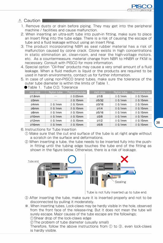
5. In case of using non-PISCO brand tubes, make sure the tolerance of the outer tube diameter is within the limits of Table 1.
●Table 1. Tube O.D. Tolerancemm size Nylon tube Polyurethane tube inch size Nylon tube Polyurethane tubeø1.8mm ─ ±0.05mm ø1/8 ±0.1mm ±0.15mmø3mm ─ ±0.15mm ø5/32 ±0.1mm ±0.15mmø4mm ±0.1mm ±0.15mm ø3/16 ±0.1mm ±0.15mmø6mm ±0.1mm ±0.15mm ø1/4 ±0.1mm ±0.15mmø8mm ±0.1mm ±0.15mm ø5/16 ±0.1mm ±0.15mmø10mm ±0.1mm ±0.15mm ø3/8 ±0.1mm ±0.15mmø12mm ±0.1mm ±0.15mm ø1/2 ±0.1mm ±0.15mmø16mm ±0.1mm ±0.15mm ø5/8 ±0.1mm ±0.15mm
6. Instructions for Tube Insertion① Make sure that the cut end surface of the tube is at right angle without
a scratch on the surface and deformations.② When inserting a tube, the tube needs to be inserted fully into the push-
in fitting until the tubing edge touches the tube end of the fitting as shown in the figure below. Otherwise, there is a risk of leakage.
Tube end
Sealing
Tube is not fully inserted up to tube end.
③ After inserting the tube, make sure it is inserted properly and not to be disconnected by pulling it moderately.
※. When inserting tubes, Lock-claws may be hardly visible in the hole, observed from the front face of the release-ring. But it does not mean the tube will surely escape. Major causes of the tube escape are the followings; ①Shear drop of the lock-claws edge②The problem of tube diameter (usually small)Therefore, follow the above instructions from ① to ③, even lock-claws is hardly visible.
39
7. Instructions for Tube Disconnection① Make sure there is no air pressure inside of the tube, before disconnecting it.② Push the release-ring of the push-in fitting evenly and deeply enough to
pull out the tube toward oneself. By insufficient pushing of the release-ring, the tube may not be pulled out or damaged by scratch, and tube shavings may remain inside of the fitting, which may cause the leakage later.
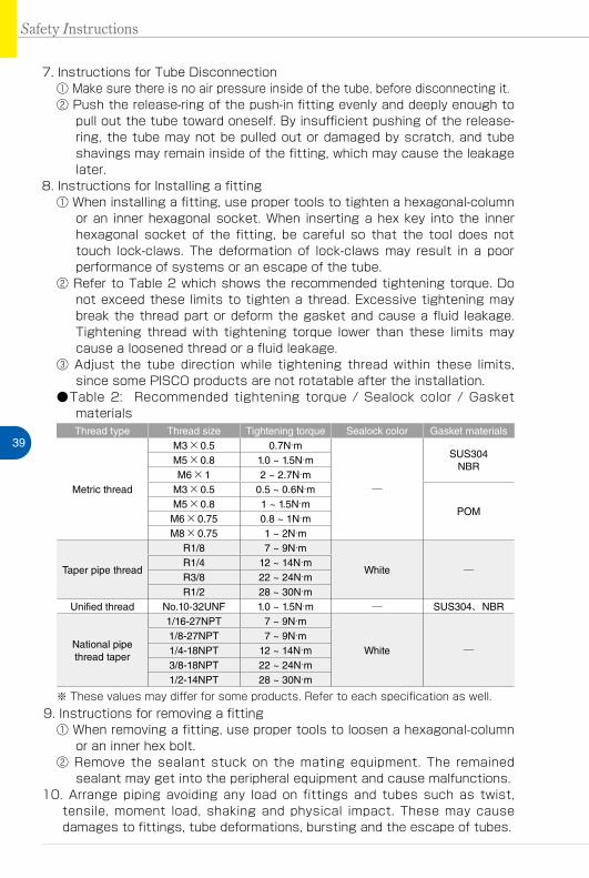
8. Instructions for Installing a fitting① When installing a fitting, use proper tools to tighten a hexagonal-column
or an inner hexagonal socket. When inserting a hex key into the inner hexagonal socket of the fitting, be careful so that the tool does not touch lock-claws. The deformation of lock-claws may result in a poor performance of systems or an escape of the tube.
② Refer to Table 2 which shows the recommended tightening torque. Do not exceed these limits to tighten a thread. Excessive tightening may break the thread part or deform the gasket and cause a fluid leakage. Tightening thread with tightening torque lower than these limits may cause a loosened thread or a fluid leakage.
③ Adjust the tube direction while tightening thread within these limits, since some PISCO products are not rotatable after the installation.
●Table 2: Recommended tightening torque / Sealock color / Gasket materialsThread type Thread size Tightening torque Sealock color Gasket materials
Metric thread
M3×0.5 0.7N·m
─
SUS304NBR
M5×0.8 1.0 ~ 1.5N·mM6×1 2 ~ 2.7N·m
M3×0.5 0.5 ~ 0.6N·m
POMM5×0.8 1 ~ 1.5N·mM6×0.75 0.8 ~ 1N·mM8×0.75 1 ~ 2N·m
Taper pipe thread
R1/8 7 ~ 9N·m
White ─R1/4 12 ~ 14N·mR3/8 22 ~ 24N·mR1/2 28 ~ 30N·m
Unified thread No.10-32UNF 1.0 ~ 1.5N·m ─ SUS304、NBR
National pipe thread taper
1/16-27NPT 7 ~ 9N·m
White ─1/8-27NPT 7 ~ 9N·m1/4-18NPT 12 ~ 14N·m3/8-18NPT 22 ~ 24N·m1/2-14NPT 28 ~ 30N·m
※ These values may differ for some products. Refer to each specification as well.9. Instructions for removing a fitting
① When removing a fitting, use proper tools to loosen a hexagonal-column or an inner hex bolt.
② Remove the sealant stuck on the mating equipment. The remained sealant may get into the peripheral equipment and cause malfunctions.
10. Arrange piping avoiding any load on fittings and tubes such as twist, tensile, moment load, shaking and physical impact. These may cause damages to fittings, tube deformations, bursting and the escape of tubes.
Safety Instructions
Vacuum Generator SeriesVacuum Generator
47
VAC
UU
M
GEN
ERA
TOR
Common Safety Instructions for Vacuum Series
Warning
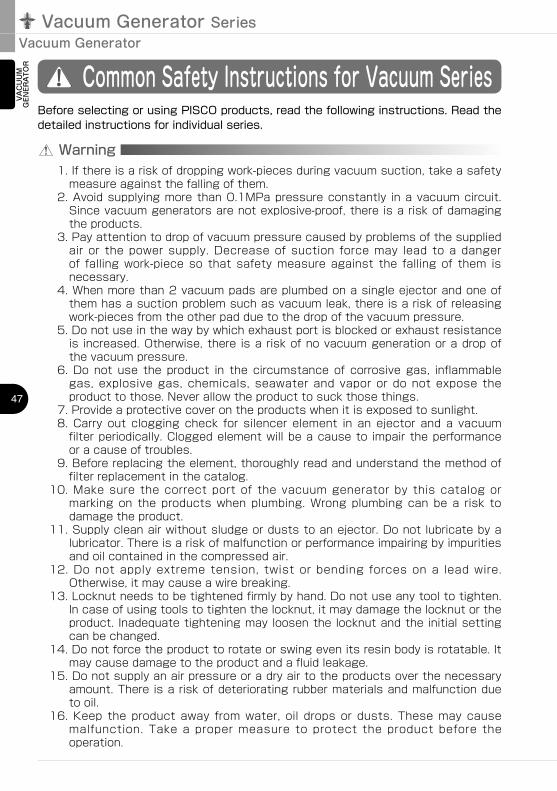
Before selecting or using PISCO products, read the following instructions. Read the detailed instructions for individual series.
1. If there is a risk of dropping work-pieces during vacuum suction, take a safety measure against the falling of them.
2. Avoid supplying more than 0.1MPa pressure constantly in a vacuum circuit. Since vacuum generators are not explosive-proof, there is a risk of damaging the products.
3. Pay attention to drop of vacuum pressure caused by problems of the supplied air or the power supply. Decrease of suction force may lead to a danger of falling work-piece so that safety measure against the falling of them is necessary.
4. When more than 2 vacuum pads are plumbed on a single ejector and one of them has a suction problem such as vacuum leak, there is a risk of releasing work-pieces from the other pad due to the drop of the vacuum pressure.
5. Do not use in the way by which exhaust port is blocked or exhaust resistance is increased. Otherwise, there is a risk of no vacuum generation or a drop of the vacuum pressure.
6. Do not use the product in the circumstance of corrosive gas, inflammable gas, explosive gas, chemicals, seawater and vapor or do not expose the product to those. Never allow the product to suck those things.
7. Provide a protective cover on the products when it is exposed to sunlight.8. Carry out clogging check for silencer element in an ejector and a vacuum
filter periodically. Clogged element will be a cause to impair the performance or a cause of troubles.
9. Before replacing the element, thoroughly read and understand the method of filter replacement in the catalog.
10. Make sure the correct port of the vacuum generator by this catalog or marking on the products when plumbing. Wrong plumbing can be a risk to damage the product.
11. Supply clean air without sludge or dusts to an ejector. Do not lubricate by a lubricator. There is a risk of malfunction or performance impairing by impurities and oil contained in the compressed air.
12. Do not apply extreme tension, twist or bending forces on a lead wire. Otherwise, it may cause a wire breaking.
13. Locknut needs to be tightened firmly by hand. Do not use any tool to tighten. In case of using tools to tighten the locknut, it may damage the locknut or the product. Inadequate tightening may loosen the locknut and the initial setting can be changed.
14. Do not force the product to rotate or swing even its resin body is rotatable. It may cause damage to the product and a fluid leakage.
15. Do not supply an air pressure or a dry air to the products over the necessary amount. There is a risk of deteriorating rubber materials and malfunction due to oil.
16. Keep the product away from water, oil drops or dusts. These may cause malfunction. Take a proper measure to protect the product before the operation.
Chemical NameThinner
Carbon tetrachlorideChloroform
AcetateAniline
CyclohexaneTrichloroethylene
Sulfuric acidLactic acid
Water soluble cutting oil (alkaline)
* There are more chemicals which should be avoided. Contact us for the use under chemical circumstance.
48
VN
VZ
VQ
VX
VJ
VK
VG
VM · VC
VB
VU
VH · VS
VY
VUM
VRL
VAC
UU
M
GEN
ERA
TOR
EXTERNAL VACUUM CONTROLLER
VAC
UU
MPA
DVACUUM
ACCESSORIES
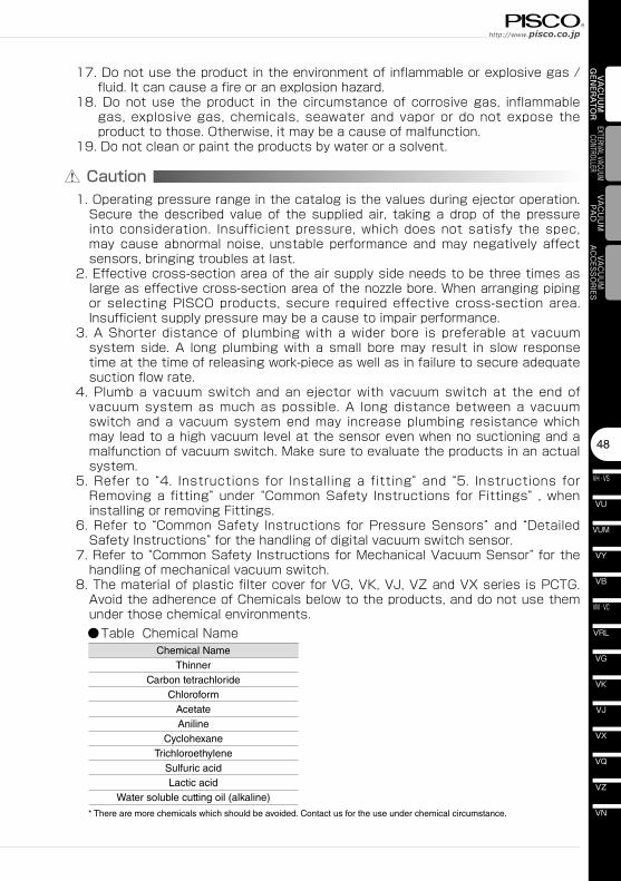
Caution1. Operating pressure range in the catalog is the values during ejector operation.
Secure the described value of the supplied air, taking a drop of the pressure into consideration. Insufficient pressure, which does not satisfy the spec, may cause abnormal noise, unstable performance and may negatively affect sensors, bringing troubles at last.
2. Effective cross-section area of the air supply side needs to be three times as large as effective cross-section area of the nozzle bore. When arranging piping or selecting PISCO products, secure required effective cross-section area. Insufficient supply pressure may be a cause to impair performance.
3. A Shorter distance of plumbing with a wider bore is preferable at vacuum system side. A long plumbing with a small bore may result in slow response time at the time of releasing work-piece as well as in failure to secure adequate suction flow rate.
4. Plumb a vacuum switch and an ejector with vacuum switch at the end of vacuum system as much as possible. A long distance between a vacuum switch and a vacuum system end may increase plumbing resistance which may lead to a high vacuum level at the sensor even when no suctioning and a malfunction of vacuum switch. Make sure to evaluate the products in an actual system.
5. Refer to “4. Instructions for Installing a fitting” and “5. Instructions for Removing a fitting” under “Common Safety Instructions for Fittings” , when installing or removing Fittings.
6. Refer to “Common Safety Instructions for Pressure Sensors” and “Detailed Safety Instructions” for the handling of digital vacuum switch sensor.
7. Refer to “Common Safety Instructions for Mechanical Vacuum Sensor” for the handling of mechanical vacuum switch.
8. The material of plastic filter cover for VG, VK, VJ, VZ and VX series is PCTG. Avoid the adherence of Chemicals below to the products, and do not use them under those chemical environments.
●Table Chemical Name
17. Do not use the product in the environment of inflammable or explosive gas / fluid. It can cause a fire or an explosion hazard.
18. Do not use the product in the circumstance of corrosive gas, inflammable gas, explosive gas, chemicals, seawater and vapor or do not expose the product to those. Otherwise, it may be a cause of malfunction.
19. Do not clean or paint the products by water or a solvent.
Chemical NameMethanolEthanol
Nitric acidSulfuric acid
Hydrochloric acidLactic acidAcetone
ChloroformAniline
TrichloroethyleneHydrogen peroxide
Vacuum Generator SeriesVacuum Generator
49
VAC
UU
M
GEN
ERA
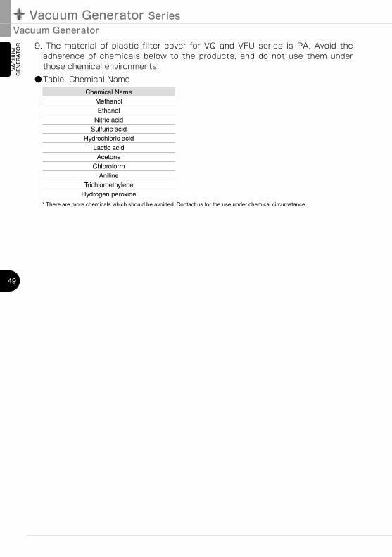
TOR 9. The material of plastic filter cover for VQ and VFU series is PA. Avoid the
adherence of chemicals below to the products, and do not use them under those chemical environments.
●Table Chemical Name
* There are more chemicals which should be avoided. Contact us for the use under chemical circumstance.
Related Documents