Vacuum controller Instructions for use Technology for Vacuum Systems CVC 3000 detect

Welcome message from author
This document is posted to help you gain knowledge. Please leave a comment to let me know what you think about it! Share it to your friends and learn new things together.
Transcript

page 1 of 80
Vacuum controller
Instructions for use
Technology for Vacuum Systems
CVC 3000 detect

page 2 of 80
After sales service: Contact your local dealer or call +49 9342 808-5500
Dear customer,
Your VACUUBRAND controllers are designed to provide you with many years of trouble-free service with optimal performance. Our many years of practical experience allow us to provide a wealth of application and safety information. Please read these instructions for use before the ini-tial operation of your controller.VACUUBRAND controllers combine our many years of experience in de-sign, construction and practical operation, with the latest developments in material and manufacturing technology.
Our quality maxim is the ”zero fault principle”:Every controller, before leaving our factory, is tested intensively, including an endurance run. Any faults, even those which occur rarely, are identi-fied and can be eliminated immediately.After completion of the endurance run, every controller is tested, and must achieve specifications before shipment.We are committed to providing our customers only controllers that meet this high quality standard.While our controllers cannot eliminate all of your work, we design, manu-facture and test them to ensure that they will be an effective and trouble-free tool to assist you in that work.
Yours,VACUUBRAND GMBH + CO KG
Trademark index:VACUU•LAN® (US-Reg.No 3,704,401), VACUU•BUS®, VACUU•CONTROL®, Peltronic®, VARIO® (US-Reg.No 3,833,788), VACUUBRAND® (US-Reg.No 3,733,388) and also the shown company logos are registered trademarks of VACUUBRAND GMBH + CO KG in Germany and/or other countries.

page 3 of 80
DEAchtung: Die vorliegende Betriebsanleitung ist nicht in allen EU-Sprachen verfügbar. Der Anwender darf die beschriebenen Geräte nur dann in Betrieb nehmen, wenn er die vorliegende Anleitung versteht oder eine fachlich korrekte Übersetzung der voll-ständigen Anleitung vorliegen hat. Die Betriebsanleitung muss vor Inbetriebnahme der Geräte vollständig gelesen und verstanden werden, und alle geforderten Maß-nahmen müssen eingehalten werden. ”Sicherheitshinweise für Vakuumgeräte”
ENAttention: This manual is not available in all languages of the EU. The user must not operate the device if he does not understand this manual. In this case a technically correct translation of the complete manual has to be available. The manual must be completely read and understood before operation of the device and all required measures must be applied. ”Safety instructions for vacuum equipment”
FRAttention: Le mode d’emploi présent n’est pas disponible dans toutes les langues d’Union Européenne. L’utilisateur ne doit mettre le dispositif en marche que s’il comprend le mode d’emploi présent ou si une traduction complète et correcte du mode d’emploi est sous ses yeux. Le dispositif ne doit pas être mis en marche avant que le mode d’emploi ait été lu et compris complètement et seulement si le mode d’emploi est observé et tous les mesures demandées sont prises. «Avis de sécurité pour des dispositifs à vide»
BGВнимание: Тези инструкции не са преведени на всички езици от ЕО. Потреби-телят не бива да работи с уреда, ако не разбира инструкциите за ползване. В този случай е необходимо да бъде предоставен пълен технически превод на инструкциите за ползване. Преди работа с уреда е задължително потребите-лят да прочете изцяло инструкциите за работа. ”Указания за безопасност за вакуумни уреди”
CN注意:该操作手册不提供所有的语言版本。操作者在没有理解手册之前,不能操作该设备。在这种情况下,需要有一个整个操作手册技术上正确的翻译。在操作该设备前,必须完全阅读并理解该操作手册,必须实施所有需要的测量。 真空设备的安全信息
CZ Upozornění :Tento návod k použití není k dispozici ve všech jazycích Evropské unie. Uživatel není oprávněn požít přístroj pokud nerozumí tomuto návodu. V tako-vém případě je nutno zajistit technicky korektní překlad manuálu do češtiny. Návod musí být uživatelem prostudován a uživatel mu musí plně porozumět před tím než začne přístroj používat. Uživatel musí dodržet všechna příslušná a požadovaná opatření. ”Bezpečnostní upozornění pro vakuové přístroje”.

page 4 of 80
DA Bemærk: Denne manual foreligger ikke på alle EU sprog. Brugeren må ikke be-tjene apparatet hvis manualen ikke er forstået. I det tilfælde skal en teknisk korrekt oversættelse af hele manual stilles til rådighed. Manual skal være gennemlæst og forstået før apparatet betjenes og alle nødvendige forholdsregler skal tages. »Sikkerhedsregler for vakuumudstyr«
EETähelepanu! Käesolev kasutusjuhend ei ole kõigis EL keeltes saadaval. Kasutaja ei tohi seadet käsitseda, kui ta ei saa kasutusjuhendist aru. Sel juhul peab saadaval olema kogu kasutusjuhendi tehniliselt korrektne tõlge. Enne seadme kasutamist tu-leb kogu juhend läbi lugeda, see peab olema arusaadav ning kõik nõutud meetmed peavad olema rakendatud. ”Ohutusnõuded vaakumseadmetele”
ES Atención: Este manual no está disponible en todos los idiomas de UE. El usuario no debe manejar el instrumento si no entiende este manual. En este caso se debe disponer de una traducción técnicamente correcta del manual completo. El manual debe ser leído y entendido completamente y deben aplicarse todas las medidas de seguridad antes de manejar el instrumento. ”Notas sobre la seguridad para equipos de vacío”
FIHuomio: Tämä käyttöohje ei ole saatavilla kaikilla EU: n kielillä. Käyttäjä ei saa käyt-tää laitetta, jos hän ei ymmärrä tätä ohjekirjaa. Tässä tapauksessa on saatavilla ol-tava teknisesti oikein tehty ja täydellinen ohjekirjan käännös. Ennen laitteen käyttöä on ohjekirja luettava ja ymmärrettävä kokonaan sekä suoritettava kaikki tarvittavat valmistelut ja muut toimenpiteet. ”Vakuumilaitteen turvallisuustiedot”
GR Προσοχή! : Οι οδηγίες αυτές δεν είναι διαθέσιµες σε όλες τις γλώσσες της Ευρω-παϊκής Ένωσης. Ο χρήστης δεν πρέπει να θέσει σε λειτουργία την συσκευή αν δεν κατανοήσει πλήρως τις οδηγίες αυτές. Σε τέτοια περίπτωση ο χρήστης πρέπει να προµηθευτεί ακριßή µετάφραση του ßιßλίου οδηγιών. Ο χρήστης πρέπει να διαßά-σει και να κατανοήσει πλήρως τις οδηγίες χρήσης και να λάßει όλα τα απαραίτητα µέτρα πριν θέσει σε λειτουργία την συσκευή. ”Υποδείξεις ασφάλειας για αντλίες κενού”
HRPažnja:ove upute ne postoje na svim jezicima Europske Unije. Korisnik nemora ra-diti sa aparatom ako ne razumije ove upute.U tom slucaju tehnicki ispravni prijevod cijelih uputstava mora biti na raspolaganju. Uputstva moraju biti cijela procitana i razumljiva prije rada sa aparatom i sve zahtijevane mjere moraju biti primjenjene. ”Sigurnosne napomene za vakuumske uređaje”
page 5 of 80
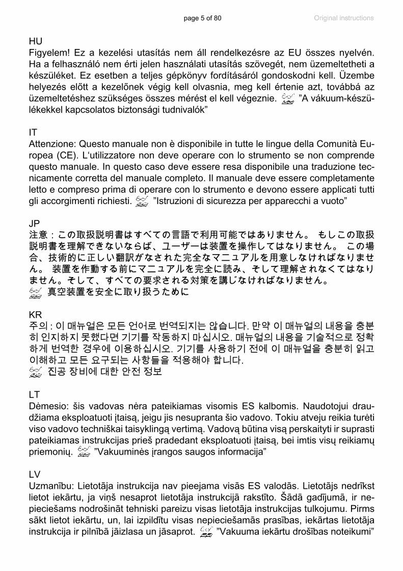
HUFigyelem! Ez a kezelési utasítás nem áll rendelkezésre az EU összes nyelvén. Ha a felhasználó nem érti jelen használati utasítás szövegét, nem üzemeltetheti a készüléket. Ez esetben a teljes gépkönyv fordításáról gondoskodni kell. Üzembe helyezés előtt a kezelőnek végig kell olvasnia, meg kell értenie azt, továbbá az üzemeltetéshez szükséges összes mérést el kell végeznie. ”A vákuum-készü-lékekkel kapcsolatos biztonsági tudnivalók”
ITAttenzione: Questo manuale non è disponibile in tutte le lingue della Comunità Eu-ropea (CE). L‘utilizzatore non deve operare con lo strumento se non comprende questo manuale. In questo caso deve essere resa disponibile una traduzione tec-nicamente corretta del manuale completo. Il manuale deve essere completamente letto e compreso prima di operare con lo strumento e devono essere applicati tutti gli accorgimenti richiesti. ”Istruzioni di sicurezza per apparecchi a vuoto”
JP注意:この取扱説明書はすべての言語で利用可能ではありません。 もしこの取扱説明書を理解できないならば、ユーザーは装置を操作してはなりません。 この場合、技術的に正しい翻訳がなされた完全なマニュアルを用意しなければなりません。 装置を作動する前にマニュアルを完全に読み、そして理解されなくてはなりません。そして、すべての要求される対策を講じなければなりません。 真空装置を安全に取り扱うために
KR주의 : 이 매뉴얼은 모든 언어로 번역되지는 않습니다. 만약 이 매뉴얼의 내용을 충분히 인지하지 못했다면 기기를 작동하지 마십시오. 매뉴얼의 내용을 기술적으로 정확하게 번역한 경우에 이용하십시오. 기기를 사용하기 전에 이 매뉴얼을 충분히 읽고 이해하고 모든 요구되는 사항들을 적용해야 합니다. 진공 장비에 대한 안전 정보
LTDėmesio: šis vadovas nėra pateikiamas visomis ES kalbomis. Naudotojui drau-džiama eksploatuoti įtaisą, jeigu jis nesupranta šio vadovo. Tokiu atveju reikia turėti viso vadovo techniškai taisyklingą vertimą. Vadovą būtina visą perskaityti ir suprasti pateikiamas instrukcijas prieš pradedant eksploatuoti įtaisą, bei imtis visų reikiamų priemonių. ”Vakuuminės įrangos saugos informacija”
LVUzmanību: Lietotāja instrukcija nav pieejama visās ES valodās. Lietotājs nedrīkst lietot iekārtu, ja viņš nesaprot lietotāja instrukcijā rakstīto. Šādā gadījumā, ir ne-pieciešams nodrošināt tehniski pareizu visas lietotāja instrukcijas tulkojumu. Pirms sākt lietot iekārtu, un, lai izpildītu visas nepieciešamās prasības, iekārtas lietotāja instrukcija ir pilnībā jāizlasa un jāsaprot. ”Vakuuma iekārtu drošības noteikumi”
page 6 of 80
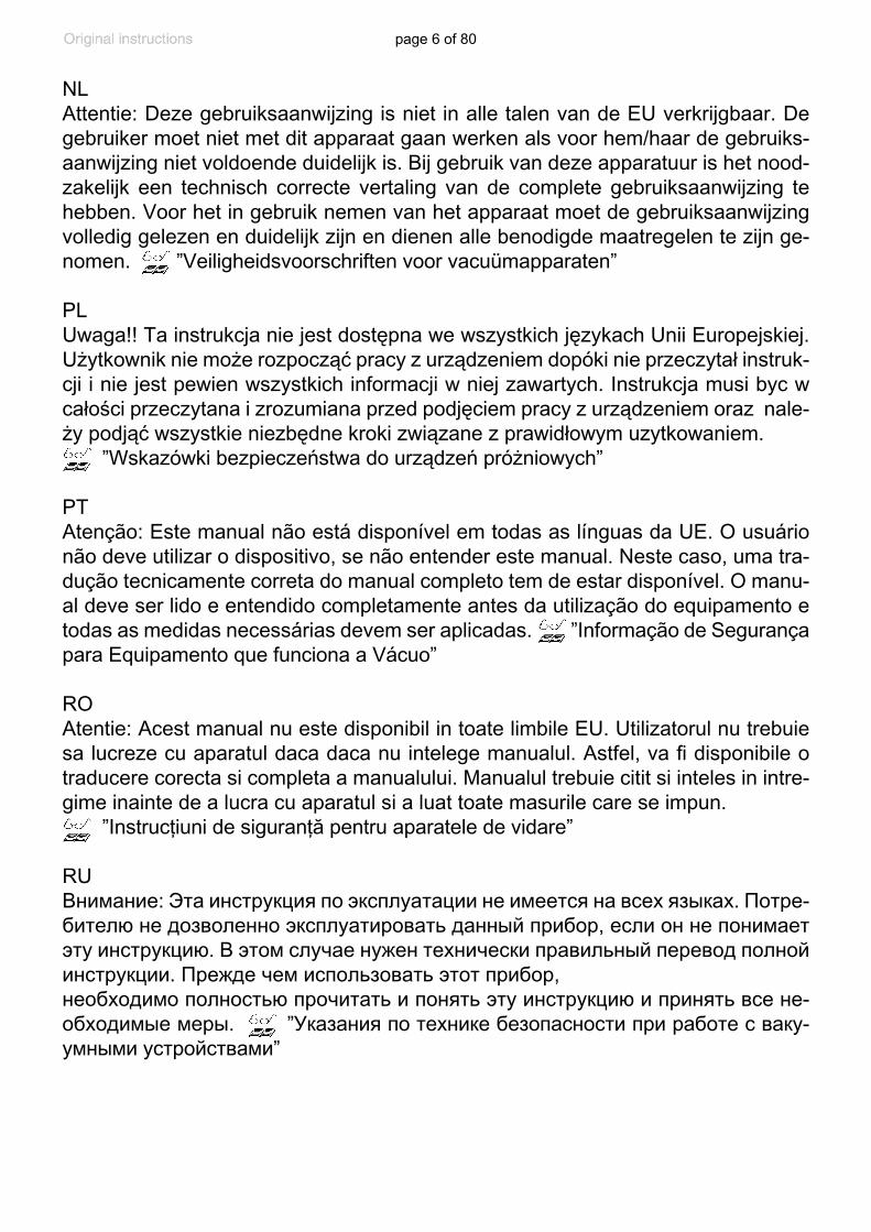
NL Attentie: Deze gebruiksaanwijzing is niet in alle talen van de EU verkrijgbaar. De gebruiker moet niet met dit apparaat gaan werken als voor hem/haar de gebruiks-aanwijzing niet voldoende duidelijk is. Bij gebruik van deze apparatuur is het nood-zakelijk een technisch correcte vertaling van de complete gebruiksaanwijzing te hebben. Voor het in gebruik nemen van het apparaat moet de gebruiksaanwijzing volledig gelezen en duidelijk zijn en dienen alle benodigde maatregelen te zijn ge-nomen. ”Veiligheidsvoorschriften voor vacuümapparaten”
PLUwaga!! Ta instrukcja nie jest dostępna we wszystkich językach Unii Europejskiej. Użytkownik nie może rozpocząć pracy z urządzeniem dopóki nie przeczytał instruk-cji i nie jest pewien wszystkich informacji w niej zawartych. Instrukcja musi byc w całości przeczytana i zrozumiana przed podjęciem pracy z urządzeniem oraz nale-ży podjąć wszystkie niezbędne kroki związane z prawidłowym uzytkowaniem. ”Wskazówki bezpieczeństwa do urządzeń próżniowych”
PTAtenção: Este manual não está disponível em todas as línguas da UE. O usuário não deve utilizar o dispositivo, se não entender este manual. Neste caso, uma tra-dução tecnicamente correta do manual completo tem de estar disponível. O manu-al deve ser lido e entendido completamente antes da utilização do equipamento e todas as medidas necessárias devem ser aplicadas. ”Informação de Segurança para Equipamento que funciona a Vácuo”
ROAtentie: Acest manual nu este disponibil in toate limbile EU. Utilizatorul nu trebuie sa lucreze cu aparatul daca daca nu intelege manualul. Astfel, va fi disponibile o traducere corecta si completa a manualului. Manualul trebuie citit si inteles in intre-gime inainte de a lucra cu aparatul si a luat toate masurile care se impun. ”Instrucţiuni de siguranţă pentru aparatele de vidare”
RUВнимание: Эта инструкция по эксплуатации не имеется на всех языках. Потре-бителю не дозволенно эксплуатировать данный прибор, если он не понимает эту инструкцию. В этом случае нужен технически правильный перевод полной инструкции. Прежде чем использовать этот прибор,необходимо полностью прочитать и понять эту инструкцию и принять все не-обходимые меры. ”Указания по технике безопасности при работе с ваку-умными устройствами”
page 7 of 80
SEVarning: Denna instruktion är inte tillgänglig på alla språk inom EU. Användaren får inte starta utrustningen om hon/han inte förstår denna instruktion. Om så är fallet måste en tekniskt korrekt instruktion göras tillgänglig. Instruktionen måste läsas och förstås helt före utrustningen tas i drift och nödvändiga åtgärder göres. ”Säkerhetsinformation för vakuumutrustning”
SIPozor: Ta navodila niso na voljo v vseh jezikih EU. Uporabnik ne sme upravljati z napravo, če ne razume teh navodil. V primeru nerazumljivosti mora biti na voljo tehnično pravilen prevod. Navodila se morajo prebrati in razumeti pred uporaba naprave, opravljene pa moraja biti tudi vse potrebne meritve. ”Varnostni nasveti za vakuumske naprave”
SKUpozornenie: Tento manuál nie je k dispozícii vo všetkých jazykoch EÚ. Užívateľ nesmie obsluhovať zariadenie, pokiaľ nerozumie tomuto manuálu. V takomto prípa-de musí byť k dispozícii technicky správny preklad celého manuálu. Pred obsluhou zariadenia je potrebné si prečítať celý manuál a porozumieť mu, a musia byť prijaté všetky opatrenia. ”Bezpečnostné pokyny pre vákuové zariadenia”
TRDikkat : Bu kullanım kitabı, tüm dillerde mevcut değildir. Kullanıcı, bu kullanım kita-bını anlayamadıysa cihazı çalıştırmamalıdır. Bu durumda, komple kullanım kitabı-nın, teknik olarak düzgün çevirisinin bulunması gerekir. Cihazın çalıştırılmasından önce kullanım kitabının komple okunması ve anlaşılması ve tüm gerekli ölçümlerin uygulanması gerekir. ”Vakumlu cihazlar için güvenlik uyarıları”
page 8 of 80
PortuguêΡyccкийPolskiNederl .
Suomi日本語
中文 한국어
CVC 3000 V2.0
DeutschEnglishFrançaisItal ianoEspañolTürkçe
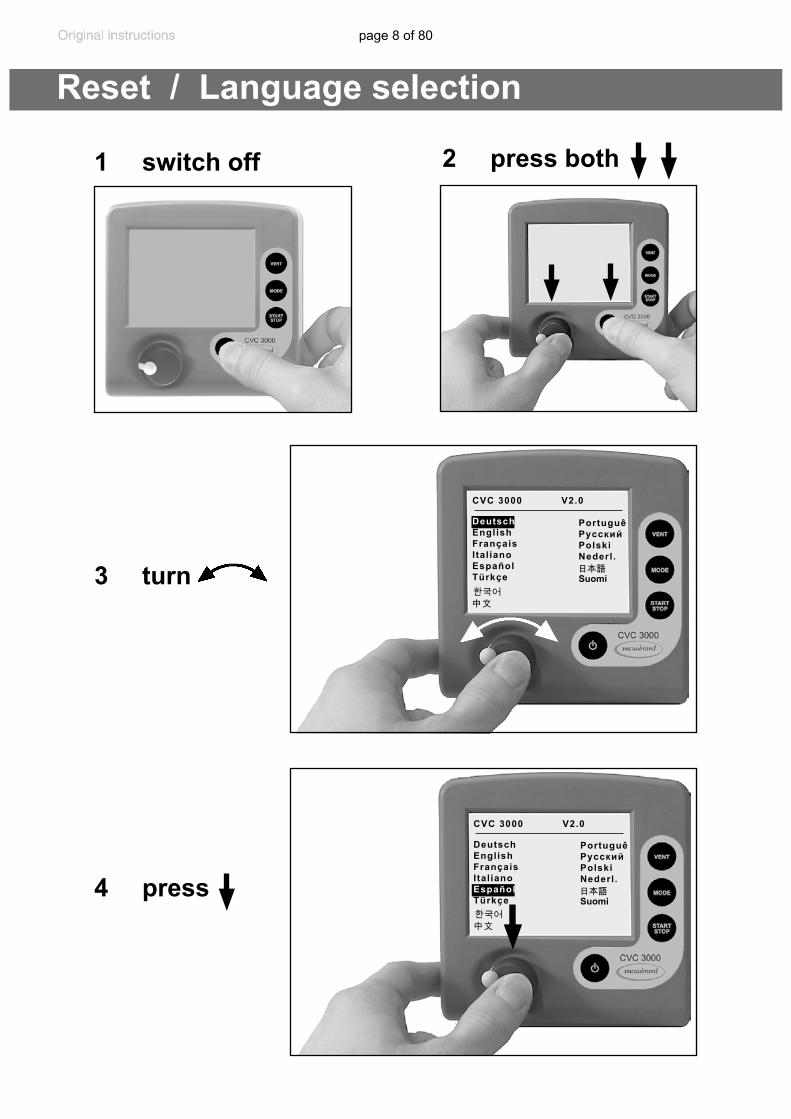
Reset / Language selection
1 switch off 2 press both
3 turn
4 press
PortuguêΡyccкийPolskiNederl .
Suomi日本語
中文 한국어
CVC 3000 V2.0
DeutschEnglishFrançaisItal ianoEspañolTürkçe
page 9 of 80
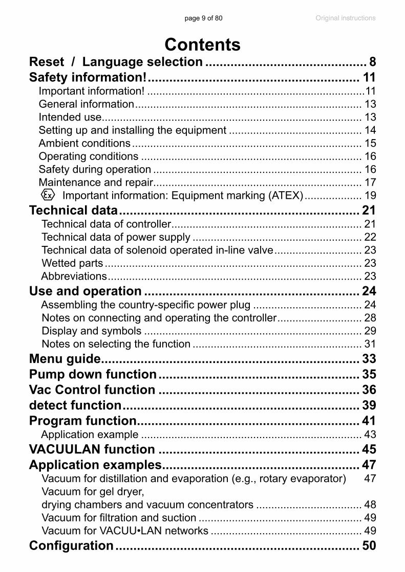
ContentsReset / Language selection ............................................. 8Safety information! ........................................................... 11
Important information! ........................................................................11General information ........................................................................... 13Intended use...................................................................................... 13Setting up and installing the equipment ............................................ 14Ambient conditions ............................................................................ 15Operating conditions ......................................................................... 16Safety during operation ..................................................................... 16Maintenance and repair..................................................................... 17 Important information: Equipment marking (ATEX) ................... 19
Technical data ................................................................... 21 Technical data of controller ............................................................... 21 Technical data of power supply ........................................................ 22 Technical data of solenoid operated in-line valve ............................. 23 Wetted parts ..................................................................................... 23 Abbreviations .................................................................................... 23
Use and operation ............................................................ 24 Assembling the country-specific power plug .................................... 24 Notes on connecting and operating the controller ............................ 28 Display and symbols ........................................................................ 29 Notes on selecting the function ........................................................ 31
Menu guide ........................................................................ 33Pump down function ........................................................ 35Vac Control function ........................................................ 36detect function .................................................................. 39Program function .............................................................. 41
Application example ......................................................................... 43VACUULAN function ........................................................ 45Application examples....................................................... 47
Vacuum for distillation and evaporation (e.g., rotary evaporator) 47 Vacuum for gel dryer, drying chambers and vacuum concentrators ................................... 48 Vacuum for filtration and suction ...................................................... 49 Vacuum for VACUU•LAN networks .................................................. 49
Configuration .................................................................... 50
page 10 of 80
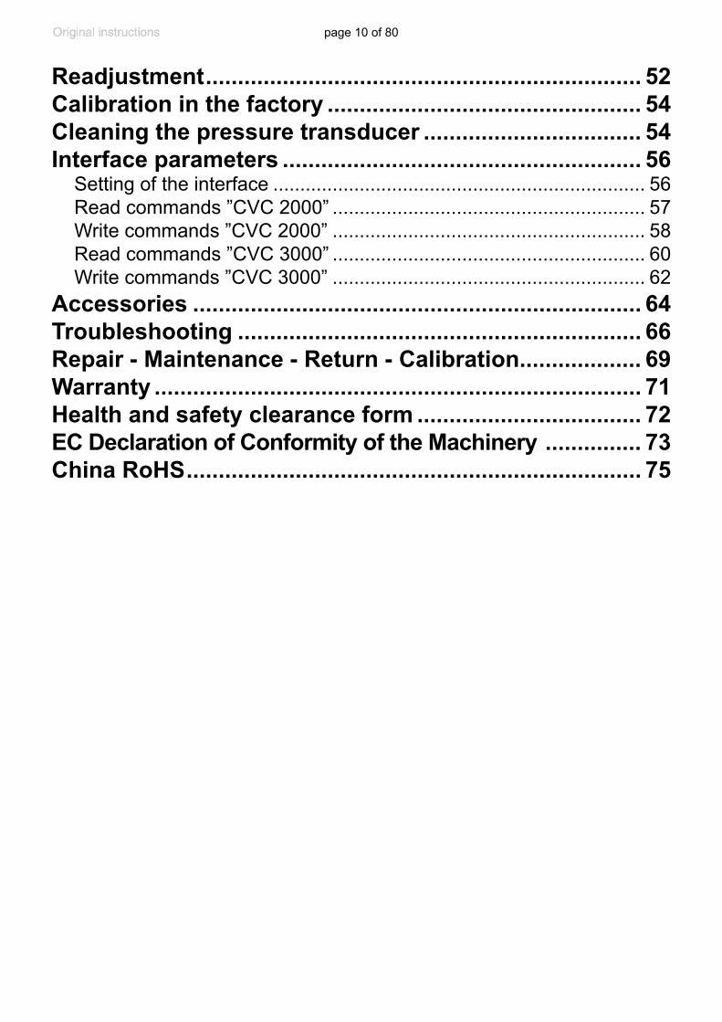
Readjustment .................................................................... 52Calibration in the factory ................................................. 54Cleaning the pressure transducer .................................. 54Interface parameters ........................................................ 56
Setting of the interface ..................................................................... 56 Read commands ”CVC 2000” .......................................................... 57 Write commands ”CVC 2000” .......................................................... 58 Read commands ”CVC 3000” .......................................................... 60 Write commands ”CVC 3000” .......................................................... 62
Accessories ...................................................................... 64Troubleshooting ............................................................... 66Repair - Maintenance - Return - Calibration ................... 69Warranty ............................................................................ 71Health and safety clearance form ................................... 72EC Declaration of Conformity of the Machinery ............... 73China RoHS ....................................................................... 75
page 11 of 80
Safety information!Important information!
+Keep this manual complete and accessible to per-sonnel at all times!
+Read this manual carefully before installing or op-erating the equipment. Observe the instructions contained in this manual.
+Do not modify the equipment without authoriza-tion.
This manual is an integral part of the equipment de-scribed therein. It describes the safe and proper use of the vacuum controller. Make operating personnel aware of dangers arising from the pump and the pumped substances. VACUUBRAND disclaims any liability for inappropri-ate use of this controller and for damage from failure to follow instructions contained in this manual.
This manual is only to be used and distributed in its com-plete and original form. It is strictly the users’ responsibility to check carefully the validity of this manual with respect to his product. Manual-no.: 20901317
The following signal word panels and safety symbols are used throughout this manual:
This is the safety alert symbol. It is used to alert you to po-tential personal injury hazards. Obey all safety messages that follow this symbol to avoid possible injury and death.
NOTICE
page 12 of 80
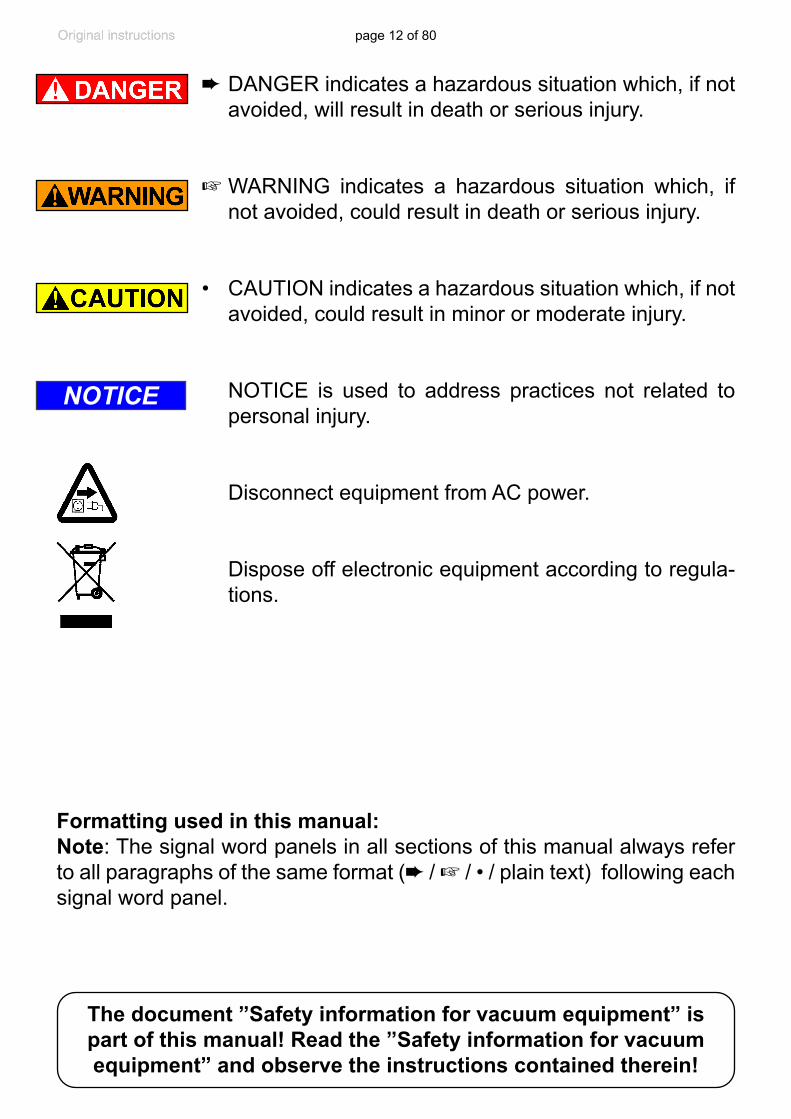
➨ DANGER indicates a hazardous situation which, if not avoided, will result in death or serious injury.
+ WARNING indicates a hazardous situation which, if not avoided, could result in death or serious injury.
• CAUTION indicates a hazardous situation which, if not
avoided, could result in minor or moderate injury. NOTICE is used to address practices not related to
personal injury.
Disconnect equipment from AC power.
Dispose off electronic equipment according to regula-tions.
NOTICE
Formatting used in this manual:Note: The signal word panels in all sections of this manual always refer to all paragraphs of the same format (➨ / + / • / plain text) following each signal word panel.
The document ”Safety information for vacuum equipment” is part of this manual! Read the ”Safety information for vacuum equipment” and observe the instructions contained therein!
page 13 of 80
General information
Remove all packing material from the packing box. Re-move the product from its packing-box and retain all pack-aging until the equipment is inspected and tested. Inspect the equipment promptly and carefully.If the equipment is damaged, notify the supplier and the carrier in writing within three days. Retain all packing ma-terial for inspection. State the item number of the product together with the order number and the supplier’s invoice number. Failure to check and give notice of damage will void any and all warranty claims for those deficiencies.Store the equipment in dry and non-corrosive conditions (see also “Technical data”, pg. 21) if the equipment is not used immediately.
+ Do not use any damaged equipment.
Intended use+ Ensure that the individual components are only con-
nected, combined and operated according to their de-sign and as indicated in the instructions for use.
Use only original manufacturer’s spare parts and accessories. Otherwise the safety and performance of the equipment, as well as the electromagnetic com-patibility of the equipment might be reduced.
The CE mark or the cTÜVus mark may be voided if not using original manufacturer’s spare parts.
+ Comply with all notes on correct vacuum and electri-cal connections; see section “Use and operation”, pg. 24.
+The controllers are designed for operation at ambient temperatures and gas temperatures at the pressure transducer between +50°F and +104°F (+10°C and +40°C), or for short periods up to +176°F (+80°C) at the pressure transducer (gas temperature). Periodical-ly check maximum temperatures if installing the con-
NOTICE
page 14 of 80
troller in a cabinet or a housing. Make sure ventilation is adequate to maintain recommended operating tem-perature. Install an external automatic ventilation sys-tem if necessary. If processing hot gases, make sure that the maximum permitted gas temperature at the pressure transducer is not exceeded (see “Technical data”, pg. 21).
Use the equipment only as intended, that is, for mea-surement and control of vacuum in vessels designed for that purpose. Any other use will automatically invalidate all warranty and liability claims. Remain aware of safety and risks.
Setting up and installing the equipment
+ Do not permit any uncontrolled pressurizing (e.g., make sure that pipelines cannot become blocked) to avoid a risk of bursting!
+Keep the VACUU•BUS cables away from heated sur-faces.
• Comply with maximum permissible pressures at the pressure transducer. See section. “Technical data”, pg. 21.
• Connect hoses gas tight at the vacuum connection and
at the connection to the vacuum pump.• Secure hoses at hose nozzles (e.g., with hose clamp)
to prevent their accidental slipping.
• Check the power source and the equipment’s rating plate to be sure that the power source and the equipment match in voltage, phase, and frequency.
• When working with residues, aggressive or condens-able media, install a gas washing bottle if necessary.
NOTICE
page 15 of 80
Assemble and lock the suitable power plug (included in shipment) to the power supply prior to use. The controller is equipped with a short-circuit-proof, wide-range power supply with an integrated overload protec-tion.
Position the controller and its vacuum line in such a way that condensate cannot flow towards the pressure trans-ducer.In case connect inert gas at the venting connection.
Allow the equipment to equilibrate to ambient temperature if you bring it from cold environment into a room prior to operation. Notice if there is water condensation on cold surfaces.
Comply with all applicable and relevant safety require-ments (regulations and guidelines). Implement the re-quired actions and adopt suitable safety measures.
Ambient conditions
➨ Do not reach for this product if it has fallen into liquid. There is a risk of deadly electrical shock. Unplug the system immediately.
+ Do not use this product in an area where it can fall or be pulled into water or other liquids.
• Adopt suitable measures in case of differences from
recommended conditions, e.g., using the equipment outdoors, conductive pollution or external condensa-tion.
• Do not operate this product near flames.
To the best of our knowledge the equipment is in com-pliance with the requirements of the applicable EC-direc-tives and harmonized standards (see ”Declaration of Con-formity”) with regard to design, type and model. Directive
NOTICE
NOTICE
page 16 of 80
EN 61010-1 gives in detail the conditions under which the equipment can be operated safely (see also IP degree of protection, “Technical data”, pg. 21).
Operating conditions
➨ This device is not approved for operation in potentially explosive atmospheres. Do not operate the device in potentially explosive atmospheres.
➨ Controllers without the ”`” mark on the rating plate are not approved for operation with dangerous or explosive gases or with potentially explosive or inflammable substances. Do not operate the con-troller with dangerous or explosive gases or with potentially explosive or inflammable substances.
➨ Controllers bearing the ”`” mark on their rating plates are approved for operation with potentially explosive atmospheres according to their ATEX clas-sification imprinted on their rating plate, but they are not approved for operation in potentially explosive atmospheres (see section “` Important information: Equipment marking (ATEX)”, pg. 19).
• Ensure that the materials of the controller’s wetted parts are compatible with the substances in the vacu-um system, see section “Technical data”, pg. 21.
Safety during operation➨ Adopt suitable measures to prevent the release of
dangerous, toxic, explosive, corrosive, noxious or pol-luting fluids, vapors and gases.
+ Never operate this controller if it has a damaged cord or plug. If the controller is not working properly, has been dropped or has fallen into water, contact your service provider.
page 17 of 80
+ Prevent any part of the human body from coming into contact with vacuum.
+Attention: At pressures above approximately 795 Torr (1060 mbar) the pressure reading becomes incorrect due to saturation of the pressure transducer. The dis-play flashes. Release pressure immediately! Risk of bursting!
• You must take suitable precautions to prevent any dan-
gerous situation from arising if the controller switches the in-line valve or a coolant valve, switches a vacuum pump (in combination with a VMS module), or opens a venting valve.
• Attention: If the controller is set to Autostart, the pro-cess will start immediately after a power failure with-out pressing any further key. It is your responsibility to ensure that automatic start-up of the system will not lead to any dangerous condition. Provide appropriate safety measures. Check prior to starting the process whether the option ”Autostart” (menu: configuration) is enabled.
Electronic equipment is never 100% fail-safe. This may lead to an ill-defined status of the equipment or of other connected devices. Provide appropriate protective mea-sures to allow for the possibility of failure and malfunction. The protective measures must also allow for the require-ments of the respective application.
Maintenance and repair
➨ Switch off the controller. Disconnect the power supply and wait five seconds before starting mainte-nance to allow the capacitors to discharge.
➨ Note: The equipment may be contaminated with chem-icals, which have been processed during operation.
NOTICE

page 18 of 80
Ensure that the controller is completely decontaminat-ed before maintenance commences. Take adequate precautions to protect people from the effects of dan-gerous substances if contamination has occurred. Use appropriate protective clothing, safety goggles and protective gloves.
+ Vent the vacuum connection before starting mainte-nance. Isolate the controller from the vacuum system.
Ensure that maintenance is done only by suitably trained and supervised technicians. Ensure that the maintenance technician is familiar with the safety procedures which re-late to the products processed in the vacuum system. Interior components of the controller can only be repaired at the factory.In order to comply with laws (occupational, health and safety regulations, safety at work law and regulations for environmental protection) components and measuring in-struments can only be returned when certain procedures (see section “Repair - Maintenance - Return - Calibration”, pg. 69) are followed.
NOTICE
page 19 of 80
Important information: Equipment marking (ATEX)
VACUUBRAND equipment bearing the ATEX mark (see rating plate)
The classification according to ATEX is only valid for the inner part (wet-ted part, pumped gas or vapor) of the equipment. The equipment is not suitable for use in external, potentially explosive atmospheres (environ-ment).
The overall category of the equipment depends on the connected com-ponents. If the connected components do not comply with the classifi-cation of the VACUUBRAND equipment, the specified category of the VACUUBRAND equipment is no longer valid.
Vacuum pumps and vacuum gauges in category 3 are intended for con-nection to equipment in which during normal operation explosive atmo-spheres caused by gases, vapors or mists normally don’t occur; or, if they do occur, are likely to do so only infrequently and for a short period only.Equipment in this category ensures the requisite level of protection dur-ing normal operation.The use of gas ballast or the operation of venting valves is only permit-ted if thereby explosive atmospheres normally don’t occur in the interior of the equipment or, if they do occur, are likely to do so only infrequently and for a short period.
The pumps are marked with ”X” (according to EN 13463-1), i.e., restric-tions of the operation conditions:
• The equipment is designated for a low degree of mechanical stress and has to be installed in a way so that it cannot be damaged from outside.
Pumping units have to be installed so that they are protected against shocks from the outside and against glass splinters in the event of breakage (implosion).
page 20 of 80
• The equipment is designated for an ambient and gas inlet temperature during operation of +10 to +40°C. Never exceed these ambient and gas inlet temperatures. If pumping / measuring gases which are not potentially explosive, extended gas inlet temperatures are permissible. See instructions for use, section “Gas inlet temperatures” or “Techni-cal data”.
After any intervention at the equipment (e.g., repair / maintenance) the ul-timate vacuum of the pump has to be checked. Only if the pump achieves its specified ultimate vacuum is the pump’s leak rate low enough to en-sure that no explosive atmospheres will occur in the interior of the equip-ment. After any intervention at the vacuum sensor, the leak rate of the equip-ment has to be checked.
Attention: This manual is not available in all languages of the EU. The user must not op-erate the device if he does not understand this manual. In this case a technically cor-rect translation of the complete manual has to be available. The manual must be com-pletely read and understood before opera-tion of the device. All specified measures must be applied, or else must be replaced by equivalent measures at the user’s own risk.

page 21 of 80
Technical data Technical data of controller
Controller CVC 3000 detect
Pressure transducerceramic diaphragm (alumina), capacitive, absolute pressure,
gas type independentDisplay LCD graphic display, illuminatedPressure units / scale (selectable) Torr, mbar or hPaMeasuring range (absolute) 810 - 0.1 Torr (1080 - 0.1 mbar)Maximum control range (absolute)* 795 - 0.1 Torr (1060 - 0.1 mbar)Resolution 0.07 Torr (0.1 mbar)Maximum permissible pressure at pres-sure transducer (absolute) 1125 Torr (1.5 bar)
Maximum permissible temperature of gaseous media**
continuous operation: 104°F (40°C), for short periods (less than 5 minutes)
up to 176°F (80°C)Measurement uncertainty (absolute) after careful adjustment and at constant temperature
<± 0.75 Torr (1 mbar)
Temperature coefficient <± 0.07 mbar/K (0.05 Torr/K)Ambient temperature range (operation) 50°F to 104°F (10°C to +40°C)Ambient temperature range (storage) 14°F to 158°F (-10°C to +70°C)Permissible relative atmospheric mois-ture during operation (no condensation) 30% to 85%
Maximum permissible range of supply voltage ( ±25% ) 24 V DC
Maximum power draw 3.4 W (140 mA at 24 V DC)Maximum permitted current of connect-ed valves (connected components) 4A
Degree of protection IEC 529 IP 20Connections to vacuum pump and to application
hose nozzle for tubing I.D. 1/4” / 3/8” (hose nozzle DN 6/10 mm)
Venting connection hose nozzle for hose I.D. 3/16” (4-5 mm)Maximum admissible pressure at vent-ing connection 17.4 psi (1.2 bar) absolute
page 22 of 80
We reserve the right for technical modification without prior notice!
* The actual vacuum control range in your application might be reduced due to ultimate vacuum of the pump, volume of gas present, etc.
** if pumping potentially explosive atmospheres: 50 °F to 104 °F (+10°C to +40°C)
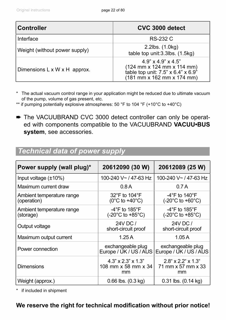
Controller CVC 3000 detect
Interface RS-232 C
Weight (without power supply) 2.2lbs. (1.0kg)table top unit:3.3lbs. (1.5kg)
Dimensions L x W x H approx.4.9” x 4.9” x 4.5”
(124 mm x 124 mm x 114 mm)table top unit: 7.5” x 6.4” x 6.9” (181 mm x 162 mm x 174 mm)
* if included in shipment
➨ The VACUUBRAND CVC 3000 detect controller can only be operat-ed with components compatible to the VACUUBRAND VACUU•BUS system, see accessories.
Technical data of power supply
Power supply (wall plug)* 20612090 (30 W) 20612089 (25 W)Input voltage (±10%) 100-240 V~ / 47-63 Hz 100-240 V~ / 47-63 HzMaximum current draw 0.8 A 0.7 AAmbient temperature range (operation)
32°F to 104°F (0°C to +40°C)
-4°F to 140°F(-20°C to +60°C)
Ambient temperature range (storage)
-4°F to 185°F (-20°C to +85°C)
-4°F to 185°F (-20°C to +85°C)
Output voltage 24V DC / short-circuit proof
24V DC / short-circuit proof
Maximum output current 1.25 A 1.05 A
Power connection exchangeable plug Europe / UK / US / AUS
exchangeable plug Europe / UK / US / AUS
Dimensions4.3” x 2.3” x 1.3”
108 mm x 58 mm x 34 mm
2.8“ x 2.2“ x 1.3“71 mm x 57 mm x 33
mm
Weight (approx.) 0.66 lbs. (0.3 kg) 0.31 lbs. (0.14 kg)
page 23 of 80
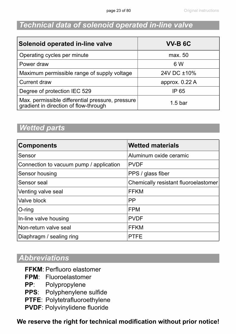
Technical data of solenoid operated in-line valve
Components Wetted materialsSensor Aluminum oxide ceramicConnection to vacuum pump / application PVDFSensor housing PPS / glass fiberSensor seal Chemically resistant fluoroelastomerVenting valve seal FFKMValve block PPO-ring FPMIn-line valve housing PVDFNon-return valve seal FFKMDiaphragm / sealing ring PTFE
We reserve the right for technical modification without prior notice!
Abbreviations
Wetted parts
Solenoid operated in-line valve VV-B 6COperating cycles per minute max. 50Power draw 6 WMaximum permissible range of supply voltage 24V DC ±10%Current draw approx. 0.22 ADegree of protection IEC 529 IP 65Max. permissible differential pressure, pressure gradient in direction of flow-through 1.5 bar
FFKM: Perfluoro elastomer FPM: Fluoroelastomer PP: Polypropylene PPS: Polyphenylene sulfide PTFE: Polytetrafluoroethylene PVDF: Polyvinylidene fluoride
page 24 of 80
Use and operation
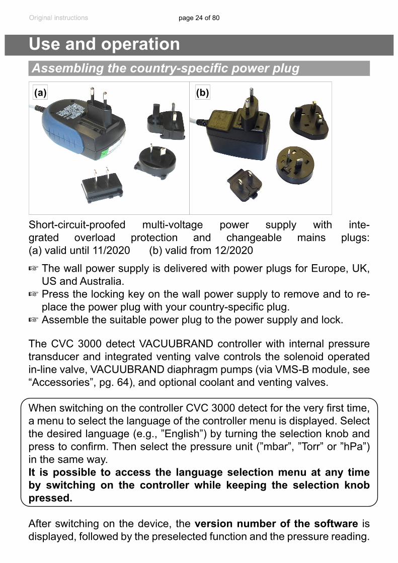
The CVC 3000 detect VACUUBRAND controller with internal pressure transducer and integrated venting valve controls the solenoid operated in-line valve, VACUUBRAND diaphragm pumps (via VMS-B module, see “Accessories”, pg. 64), and optional coolant and venting valves.
When switching on the controller CVC 3000 detect for the very first time, a menu to select the language of the controller menu is displayed. Select the desired language (e.g., ”English”) by turning the selection knob and press to confirm. Then select the pressure unit (”mbar”, ”Torr” or ”hPa”) in the same way. It is possible to access the language selection menu at any time by switching on the controller while keeping the selection knob pressed.
After switching on the device, the version number of the software is displayed, followed by the preselected function and the pressure reading.
Assembling the country-specific power plug
+ The wall power supply is delivered with power plugs for Europe, UK, US and Australia.
+ Press the locking key on the wall power supply to remove and to re-place the power plug with your country-specific plug.
+ Assemble the suitable power plug to the power supply and lock.
(a) (b)
Short-circuit-proofed multi-voltage power supply with inte-grated overload protection and changeable mains plugs: (a) valid until 11/2020 (b) valid from 12/2020
page 25 of 80
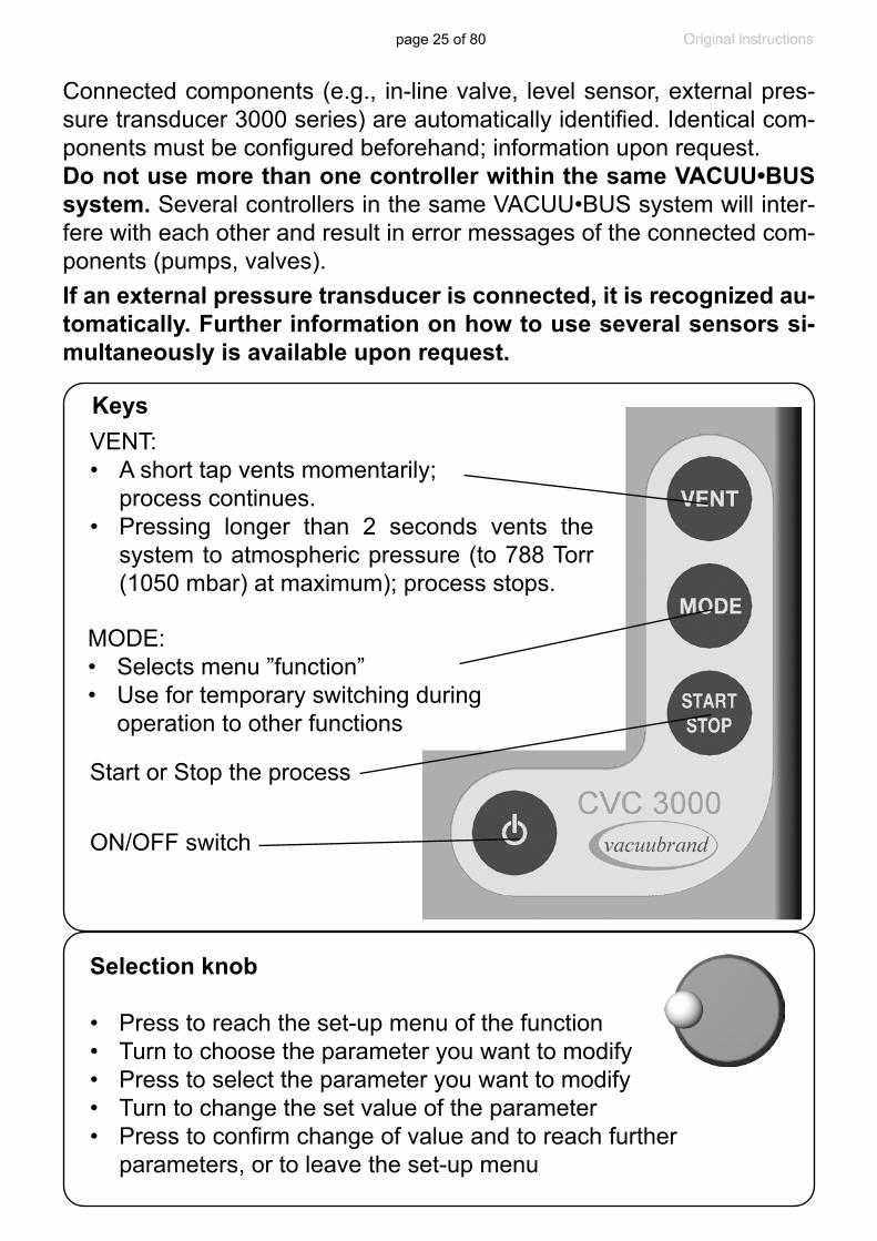
Selection knob
• Press to reach the set-up menu of the function• Turn to choose the parameter you want to modify• Press to select the parameter you want to modify• Turn to change the set value of the parameter• Press to confirm change of value and to reach further
parameters, or to leave the set-up menu
If an external pressure transducer is connected, it is recognized au-tomatically. Further information on how to use several sensors si-multaneously is available upon request.
Keys
Start or Stop the process
VENT:• A short tap vents momentarily; process continues.• Pressing longer than 2 seconds vents the
system to atmospheric pressure (to 788 Torr (1050 mbar) at maximum); process stops.
MODE:• Selects menu ”function” • Use for temporary switching during operation to other functions
ON/OFF switch
Connected components (e.g., in-line valve, level sensor, external pres-sure transducer 3000 series) are automatically identified. Identical com-ponents must be configured beforehand; information upon request.Do not use more than one controller within the same VACUU•BUS system. Several controllers in the same VACUU•BUS system will inter-fere with each other and result in error messages of the connected com-ponents (pumps, valves).
page 26 of 80
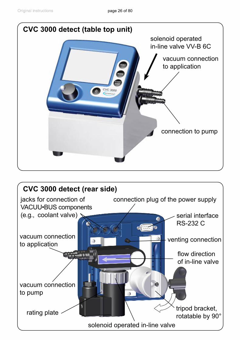
connection plug of the power supplyjacks for connection of VACUU•BUS components (e.g., coolant valve) serial interface
RS-232 C
CVC 3000 detect (rear side)
venting connection
vacuum connection to pump
rating plate
vacuum connection to application
solenoid operated in-line valve
CVC 3000 detect (table top unit)
connection to pump
vacuum connection to application
solenoid operated in-line valve VV-B 6C
tripod bracket,rotatable by 90°
flow direction of in-line valve
page 27 of 80
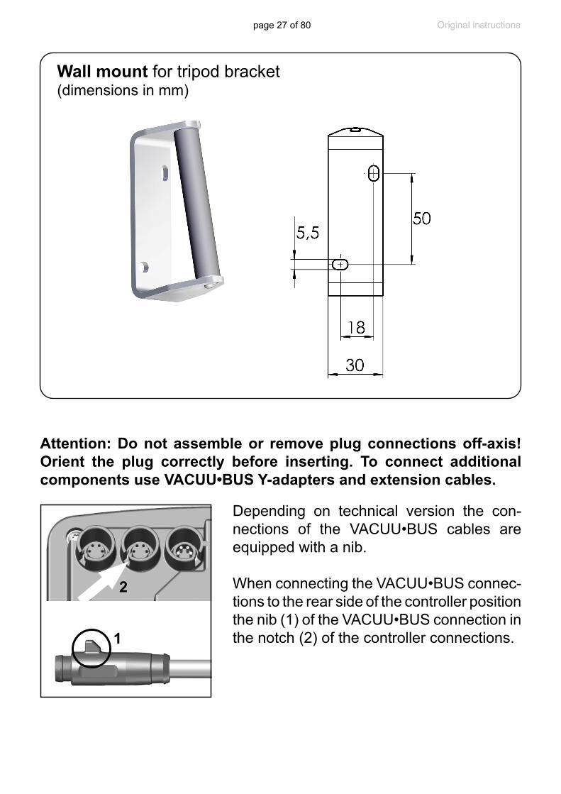
Wall mount for tripod bracket(dimensions in mm)
Depending on technical version the con-nections of the VACUU•BUS cables are equipped with a nib.
When connecting the VACUU•BUS connec-tions to the rear side of the controller position the nib (1) of the VACUU•BUS connection in the notch (2) of the controller connections.1
2
Attention: Do not assemble or remove plug connections off-axis! Orient the plug correctly before inserting. To connect additional components use VACUU•BUS Y-adapters and extension cables.

page 28 of 80
Notes on connecting and operating the controller
The vacuum controller CVC 3000 detect is fitted with an in-line valve VV-B 6C at its rear.
The controller can switch a possibly connected coolant and/or venting valve.
The CVC 3000 detect is equipped with an internal capacitive pressure transducer with ceramic diaphragm. It measures the actual pressure in-dependently of the gas type, and with reference to the vacuum, i.e., ab-solute.
➨ Connect the vacuum connection of the controller to the vacuum appli-cation and to the vacuum pump.
+Maximum permissible pressure: 21.8 psi (1.5 bar) ab-solute.
Attention: At pressures above approximately 795 Torr (1060 mbar) the pressure reading becomes incorrect due to saturation of the pressure transducer. The dis-play flashes. Release pressure immediately! Risk of bursting!
- Position the CVC 3000 detect controller and its vacuum line in such a way that conden-sate cannot flow towards the pressure trans-ducer. Condensate and deposits will affect the measurement results. Clean the pressure transducer, if necessary. See section “Clean-ing the pressure transducer”, pg. 54.
- Inside a vacuum system where evaporation occurs, e.g., a rotary evaporator, the vacuum is not uniform. For example, a condenser can act as a pump, or the vacuum in the connecting tubing can be higher or lower than in the application itself. This affects the measurement results as well as the control levels. Therefore, carefully choose the position where to connect the pressure transducer.
- If residues occur or when working with aggressive or condensable substances, install a gas washing bottle in front of the pressure trans-ducer.
vacuum connection to application
page 29 of 80
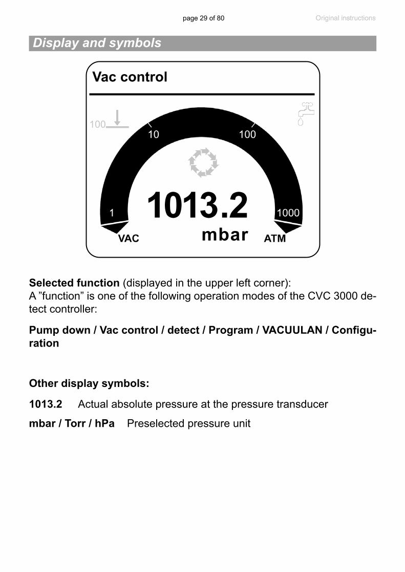
Pump down / Vac control / detect / Program / VACUULAN / Configu-ration
Selected function (displayed in the upper left corner):A ”function” is one of the following operation modes of the CVC 3000 de-tect controller:
1013 . 2mbar
Vac control
100
mbar / Torr / hPa Preselected pressure unit
1013.2 Actual absolute pressure at the pressure transducer
Other display symbols:
Display and symbols
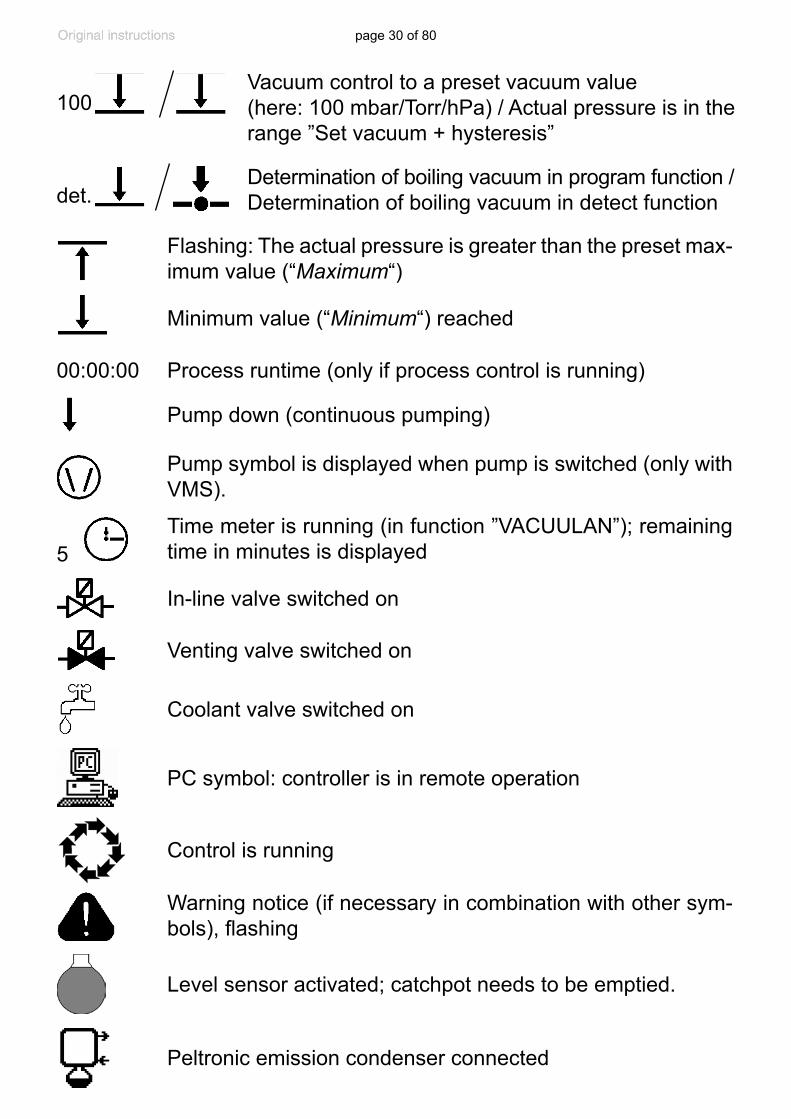
page 30 of 80
Control is running
Warning notice (if necessary in combination with other sym-bols), flashing
Coolant valve switched on
Venting valve switched on
PC symbol: controller is in remote operation
Time meter is running (in function ”VACUULAN”); remaining time in minutes is displayed
00:00:00
Vacuum control to a preset vacuum value (here: 100 mbar/Torr/hPa) / Actual pressure is in the range ”Set vacuum + hysteresis”
Pump down (continuous pumping)
Process runtime (only if process control is running)
5
In-line valve switched on
Level sensor activated; catchpot needs to be emptied.
Peltronic emission condenser connected
Pump symbol is displayed when pump is switched (only with VMS).
100
Flashing: The actual pressure is greater than the preset max-imum value (“Maximum“)
Minimum value (“Minimum“) reached
det.Determination of boiling vacuum in program function /Determination of boiling vacuum in detect function
page 31 of 80
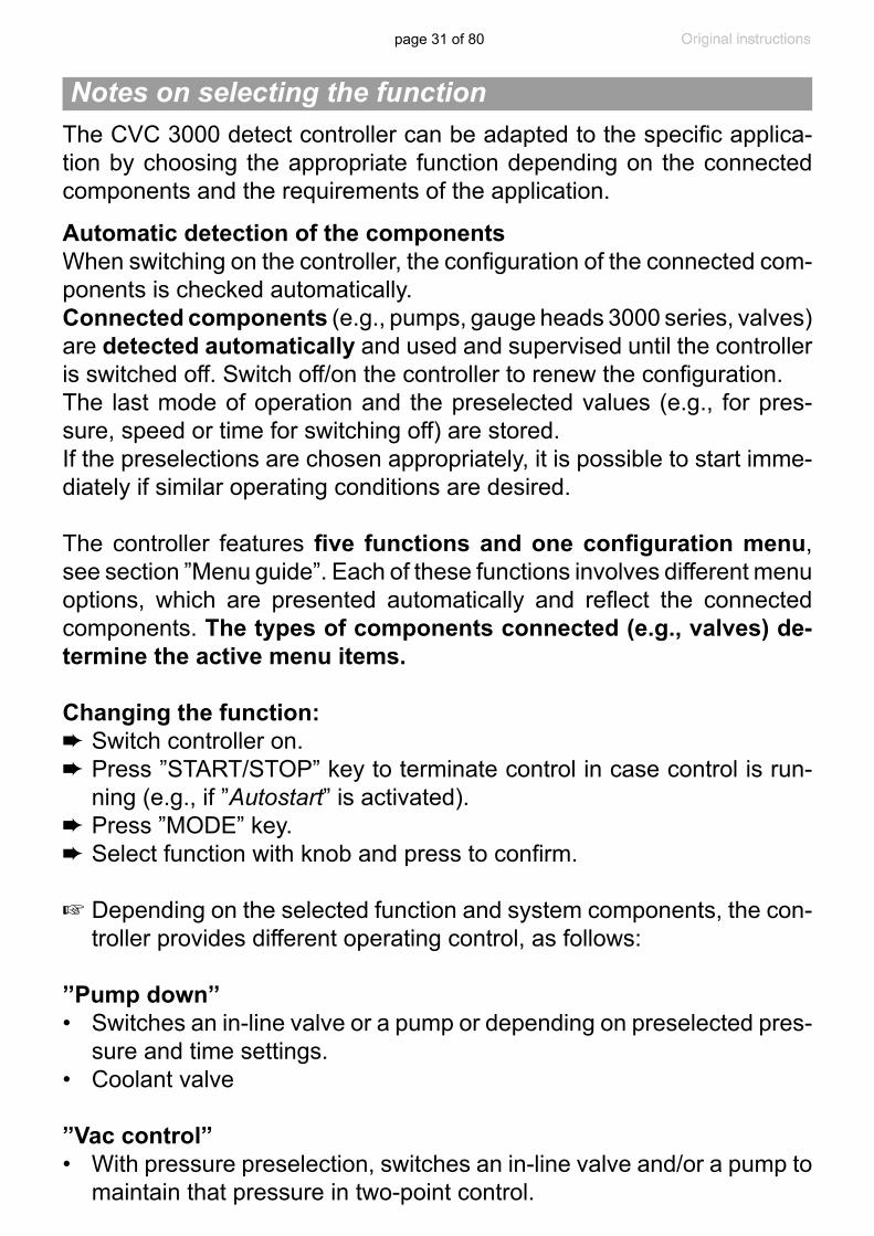
The CVC 3000 detect controller can be adapted to the specific applica-tion by choosing the appropriate function depending on the connected components and the requirements of the application.
Automatic detection of the componentsWhen switching on the controller, the configuration of the connected com-ponents is checked automatically.Connected components (e.g., pumps, gauge heads 3000 series, valves) are detected automatically and used and supervised until the controller is switched off. Switch off/on the controller to renew the configuration.The last mode of operation and the preselected values (e.g., for pres-sure, speed or time for switching off) are stored. If the preselections are chosen appropriately, it is possible to start imme-diately if similar operating conditions are desired.
The controller features five functions and one configuration menu, see section ”Menu guide”. Each of these functions involves different menu options, which are presented automatically and reflect the connected components. The types of components connected (e.g., valves) de-termine the active menu items.
Changing the function:➨ Switch controller on.➨ Press ”START/STOP” key to terminate control in case control is run-
ning (e.g., if ”Autostart” is activated).➨ Press ”MODE” key.➨ Select function with knob and press to confirm.
+ Depending on the selected function and system components, the con-troller provides different operating control, as follows:
’’Pump down’’• Switches an in-line valve or a pump or depending on preselected pres-
sure and time settings.• Coolant valve
”Vac control” • With pressure preselection, switches an in-line valve and/or a pump to
maintain that pressure in two-point control.
Notes on selecting the function
page 32 of 80
• Coolant valve
”detect”• Provides fully automatic boiling point determination and switches an
in-line valve and/or a pump to maintain that pressure in two-point con-trol.
• Coolant valve
’’Program’’• Control in-line valve or pump based on time and pressure preselec-
tions.• Coolant valve• Venting valve
”VACUULAN”• Switches a pump (VMS, see ”Accessories”, pg. 64, required) and
an in-line valve depending on preselected pressure and time settings.• Coolant valve
’’Configuration’’ (also accessible by pressing the selection knob while the start display is shown)
Preselections for• Adjustment of the pressure transducer• Interface RS-232• Sensors (configuration and switching between several sensors)• Display (brightness and contrast of the display, language, sound)• Autostart (automatic restart after power failure) • Defaults (reset the controller to factory set values)
page 33 of 80
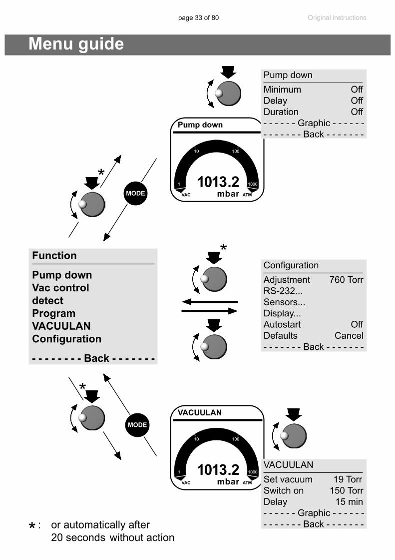
1013 . 2mbar
VACUULAN
1013 . 2mbar
Pump down
Pump down Minimum OffDelay OffDuration Off- - - - - - Graphic - - - - - - - - - - - - - Back - - - - - - -
MODE
Menu guide
Configuration Adjustment 760 TorrRS-232... Sensors... Display... Autostart OffDefaults Cancel - - - - - - - Back - - - - - - -
VACUULAN Set vacuum 19 TorrSwitch on 150 TorrDelay 15 min- - - - - - Graphic - - - - - - - - - - - - - Back - - - - - - -
MODE
: or automatically after 20 seconds without action
*
*
*
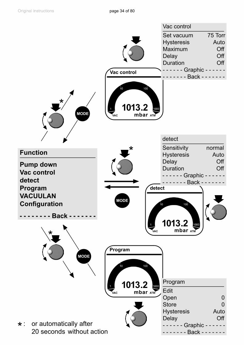
*Function
Pump downVac controldetectProgramVACUULANConfiguration
- - - - - - - - Back - - - - - - -
page 34 of 80
1013 . 2mbar
Program
1013 . 2mbar
Vac control
Vac control Set vacuum 75 TorrHysteresis AutoMaximum OffDelay OffDuration Off- - - - - - Graphic - - - - - - - - - - - - - Back - - - - - - -
Program EditOpen 0Store 0Hysteresis AutoDelay Off- - - - - - Graphic - - - - - - - - - - - - - Back - - - - - - -
MODE
: or automatically after 20 seconds without action
*
MODE
*
*
Function
Pump downVac controldetectProgramVACUULANConfiguration
- - - - - - - - Back - - - - - - - 1013 . 2
detect
mbar
detect Sensitivity normalHysteresis Auto Delay OffDuration Off- - - - - - Graphic - - - - - - - - - - - - - Back - - - - - - -
MODE
*

page 35 of 80
Pump down function➨ Continuous pumping with pressure and time settings
• Operation of a vacuum pump via in-line valve• Operation of a vacuum pump without in-line valve with VMS (Vac-
uum Management System, see “Accessories”, pg. 64)
Preselections+ Use the selection knob to select the parameters. All parameters can
be altered even while operation control is running.
+ Minimum: The controller switches the pump off or closes the in-line valve once the preset value for ”Minimum” has been reached.
”Minimum” is adjustable in a range of 1-795 Torr (1-1060 mbar) or can be set to ”Off”.
A preset ”Duration” (process time) has no effect if the process is stopped due to a preset ”Minimum” before ”Duration” is reached.
+ Delay: ”Delay” determines the time the coolant valve remains open af-ter the process has been stopped. Determines also the time the pump (only with VMS module and in-line valve) remains running after the process has been stopped.
The ”Delay” is adjustable in a range of 1-300 minutes or can be set to ”Off” (”Off” means that the coolant valve closes immediately - and that a pump with VMS module and in-line valve is switched off immediately - when the process stops.).
+ Duration: ”Duration” determines the total process time since control start.
The process time is adjustable between 1-1440 minutes (24 h) or can be set to ”Off”. ”Off” indicates that no endpoint for pump down is deter-mined.
If a ”Duration” is preset, the controller switches off the pump when the preset process time is reached, even if a preset ”Minimum” is still not reached.
+ If neither ”Minimum” nor ”Duration” is preset, process control has to be stopped by pressing the ”STOP” key.

page 36 of 80
The screen-shot shows the factory-set values.
When selecting ”Graphic” the display shows a pressure vs. time curve.
The timeline in the diagram adapts automatically to the process time.+ Press the selection knob twice to return to the standard display.
10 mbar00:03:50
Pump downPump down Minimum OffDelay OffDuration Off
- - - - - - Graphic - - - - - - - - - - - - - Back - - - - - - -
00:00:00
Temporary switching from ”Pump down” to ”Vac control” (only if control is running):+ Press ”MODE” key. The controller switches to ”Vac control” function,
the current vacuum is used as set value.+ The preset function of the controller does not change due to this tem-
porary switching. When pressing ”STOP” key, the controller is set again to the ”Pump down” function.
Vac Control function
➨ Vacuum control to a preset vacuum value
• Operation of a vacuum pump via in-line valve• Operation of a vacuum pump without in-line valve with VMS (Vac-
uum Management System, see ”Accessories”)
Preselections+ Use the selection knob to select the parameters. All parameters can
be altered even while operation control is running.
page 37 of 80
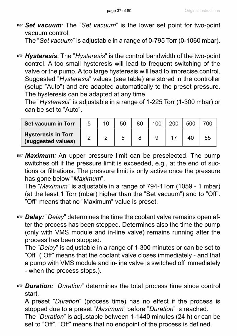
+ Set vacuum: The ”Set vacuum” is the lower set point for two-point vacuum control.
The ”Set vacuum” is adjustable in a range of 0-795 Torr (0-1060 mbar).
+ Hysteresis: The ”Hysteresis” is the control bandwidth of the two-point control. A too small hysteresis will lead to frequent switching of the valve or the pump. A too large hysteresis will lead to imprecise control. Suggested ”Hysteresis” values (see table) are stored in the controller (setup ”Auto”) and are adapted automatically to the preset pressure. The hysteresis can be adapted at any time.
The ”Hysteresis” is adjustable in a range of 1-225 Torr (1-300 mbar) or can be set to ”Auto”.
+ Maximum: An upper pressure limit can be preselected. The pump switches off if the pressure limit is exceeded, e.g., at the end of suc-tions or filtrations. The pressure limit is only active once the pressure has gone below ”Maximum”.
The ”Maximum” is adjustable in a range of 794-1Torr (1059 - 1 mbar) (at the least 1 Torr (mbar) higher than the ”Set vacuum”) and to ”Off”. ”Off” means that no ”Maximum” value is preset.
+ Delay: ”Delay” determines the time the coolant valve remains open af-ter the process has been stopped. Determines also the time the pump (only with VMS module and in-line valve) remains running after the process has been stopped.
The ”Delay” is adjustable in a range of 1-300 minutes or can be set to ”Off” (”Off” means that the coolant valve closes immediately - and that a pump with VMS module and in-line valve is switched off immediately - when the process stops.).
+ Duration: ”Duration” determines the total process time since control start.
A preset ”Duration” (process time) has no effect if the process is stopped due to a preset ”Maximum” before ”Duration” is reached.
The ”Duration” is adjustable between 1-1440 minutes (24 h) or can be set to ”Off”. ”Off” means that no endpoint of the process is defined.
Set vacuum in Torr 5 10 50 80 100 200 500 700
Hysteresis in Torr (suggested values) 2 2 5 8 9 17 40 55
page 38 of 80
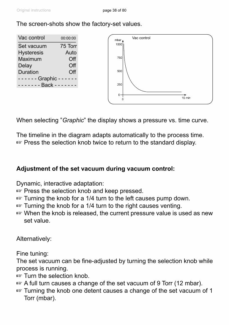
The screen-shots show the factory-set values.
Vac control
When selecting ”Graphic” the display shows a pressure vs. time curve.
The timeline in the diagram adapts automatically to the process time.+ Press the selection knob twice to return to the standard display.
Vac control Set vacuum 75 TorrHysteresis AutoMaximum OffDelay OffDuration Off- - - - - - Graphic - - - - - - - - - - - - - Back - - - - - - -
00:00:00
Adjustment of the set vacuum during vacuum control:
Dynamic, interactive adaptation:+ Press the selection knob and keep pressed.+ Turning the knob for a 1/4 turn to the left causes pump down.+ Turning the knob for a 1/4 turn to the right causes venting.+ When the knob is released, the current pressure value is used as new
set value.
Alternatively:
Fine tuning:The set vacuum can be fine-adjusted by turning the selection knob while process is running.+ Turn the selection knob.+ A full turn causes a change of the set vacuum of 9 Torr (12 mbar).+ Turning the knob one detent causes a change of the set vacuum of 1
Torr (mbar).
page 39 of 80
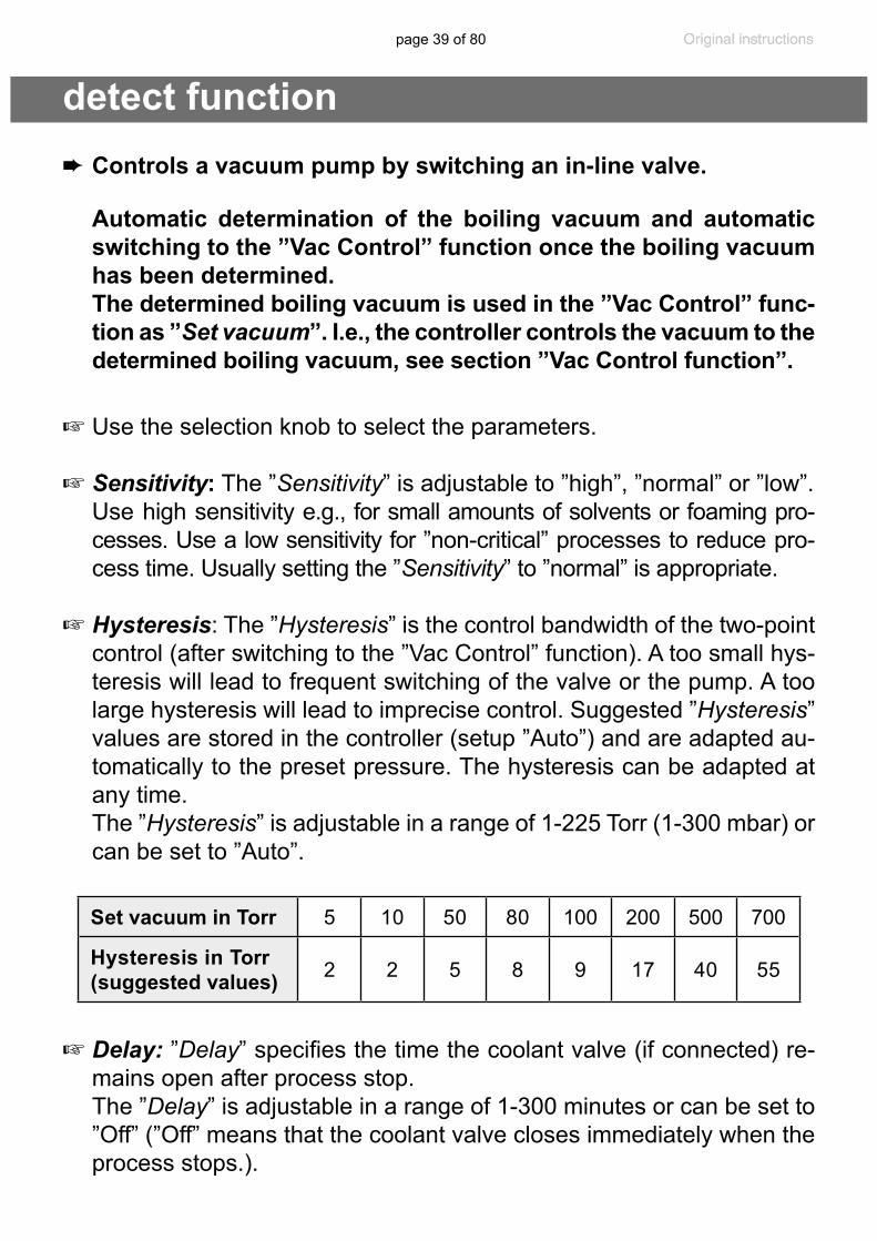
detect function
+ Use the selection knob to select the parameters.
+ Sensitivity: The ”Sensitivity” is adjustable to ”high”, ”normal” or ”low”. Use high sensitivity e.g., for small amounts of solvents or foaming pro-
cesses. Use a low sensitivity for ”non-critical” processes to reduce pro-cess time. Usually setting the ”Sensitivity” to ”normal” is appropriate.
+ Hysteresis: The ”Hysteresis” is the control bandwidth of the two-point control (after switching to the ”Vac Control” function). A too small hys-teresis will lead to frequent switching of the valve or the pump. A too large hysteresis will lead to imprecise control. Suggested ”Hysteresis” values are stored in the controller (setup ”Auto”) and are adapted au-tomatically to the preset pressure. The hysteresis can be adapted at any time.
The ”Hysteresis” is adjustable in a range of 1-225 Torr (1-300 mbar) or can be set to ”Auto”.
+ Delay: ”Delay” specifies the time the coolant valve (if connected) re-mains open after process stop.
The ”Delay” is adjustable in a range of 1-300 minutes or can be set to ”Off” (”Off” means that the coolant valve closes immediately when the process stops.).
➨ Controls a vacuum pump by switching an in-line valve.
Automatic determination of the boiling vacuum and automatic switching to the ”Vac Control” function once the boiling vacuum has been determined.
The determined boiling vacuum is used in the ”Vac Control” func-tion as ”Set vacuum”. I.e., the controller controls the vacuum to the determined boiling vacuum, see section ”Vac Control function”.
Set vacuum in Torr 5 10 50 80 100 200 500 700
Hysteresis in Torr (suggested values) 2 2 5 8 9 17 40 55

page 40 of 80
+ Duration: ”Duration” determines the total process time since control start.
The ”Duration” is adjustable between 1-1440 minutes (24 h) or can be set to ”Off”. (”Off” means that no endpoint for pump down is preset.)
The screen-shot shows the factory-set values.
detectSensitivity normalHysteresis Auto Delay OffDuration Off- - - - - - Graphic - - - - - - - - - - - - - Back - - - - - - -
00:00:00
When selecting ”Graphic” the display shows a pressure vs. time curve.
The timeline in the diagram adapts automatically to the process time.+ Press the selection knob twice to return to the standard display.
430 mbar00:07:45
detect
+ When pressing ”STOP” key, or after process stop due to elapsed ”Du-ration” (preset process time), the controller is set again to the ”detect” function.
Temporary switching from ”detect” to ”Vac control” (only if control is running):+ Press ”MODE” key. The controller switches to ”Vac control” function,
the current vacuum is used as set value.+ The preset function of the controller does not change due to this tem-
porary switching. When pressing ”STOP” key, the controller is set again to the ”detect” function.
➨ Attention: The ”detect” function is designed for operation with a stand-alone vac-
uum pump. If the CVC 3000 detect is to be operated in a vacuum network you must ensure that during the determination of the boiling vacuum no disturbance due to other users will occur.
page 41 of 80
Program function➨ Permits ten programs to be defined and stored, each with up to
ten program steps with preset values for vacuum and time.
+ Edit: Use to define the preset values for the process run: Time: Defines either the process runtime for each program step to
reach a preset vacuum level or, if programming a ”Step”, the runtime after having achieved the vacuum level. The total process runtime is shown in the base line. Attention: A preset runtime of 99:59:59 hours in the final program step will cause the process to run endlessly. Ter-minate the process by pressing the ”STOP” key.
Vacuum: Vacuum level to be attained. Venting valve: Operating a venting valve to reach a preset vacuum
level. ”Step”: ”Step” causes pump down as fast as possible to the preset
vacuum level. As soon as the vacuum level is reached the time meter starts running.
”det.” (detect): det. =
➜
: indicates that the system will search for a boiling point automatically until a preselected time interval is reached.
Selecting ”det.” in combination with ”Step” in one program step is not possible.
+ Open: Choose program (Programs 0 - 9).
+ Store: This command stores an edited program or the program of the last process to one of the storage spaces 0 - 9.
+ Hysteresis: The ”Hysteresis” is the control bandwidth of the two-point control. A too small hysteresis will lead to frequent switching of the valve or the pump. A too large hysteresis will lead to imprecise con-trol. Suggested ”Hysteresis” values are stored in the controller (setup ”Auto”) and are adapted automatically to the preset pressure. The hys-teresis can be adapted at any time.
The ”Hysteresis” is adjustable in a range of 1-225 Torr (1-300 mbar) or can be set to ”Auto”.

page 42 of 80
The screen-shot shows the factory-set values.
Editing:+ To select row: turn and press selection knob.+ To adjust parameter: turn the selection knob.+ To confirm parameter: Press selection knob. Controller will accept
change and jump to the next parameter in the same row.+ After 5 seconds without a change, the parameter is assumed to be the
current setting. Select the next row to edit or return to the Program menu.➨ In case, store an edited program after having quit ”Edit” by storing it to
one of the storage spaces 0 - 9 (select ”Store”).
1013 mbar00:28:00
Program 5 : 4 1013mbarProgram EditOpen 0Store 0Hysteresis AutoDelay Off- - - - - - Graphic - - - - - - - - - - - - - Back - - - - - - -
00:00:00
When selecting ”Graphic”, the display shows a pressure vs. time curve.
Program number, and the step number in that program, along with the vacuum setting, the actual current pressure and the actual runtime are displayed across the top.The timeline in the diagram adapts automatically to the process time.+ Press the selection knob twice to return to the standard display.
The most recent process (except in ”VACUULAN” function) is stored in the temporary data memory as long as the controller stays switched on.
+ Delay: ”Delay” determines the time the coolant valve remains open af-ter the process has been stopped. Determines also the time the pump (only with VMS module and in-line valve) remains running after the process has been stopped.
The ”Delay” is adjustable in a range of 1-300 minutes or can be set to ”Off” (”Off” means that the coolant valve closes immediately - and that a pump with VMS module and in-line valve is switched off immediately - when the process stops.).
page 43 of 80
Application example
This program can be transferred to a storage space and edited. Once the program is finished, the clock symbol starts to flash. Confirm the end of the program by pressing START/STOP (clock symbol will dis-appear).
Attention: If ”Autostart” is set to ”On”, the program will start again (time will be reset to 00:00:00) after a power failure or after switch-ing the controller off/on. Only if the end of the program (clock symbol flashing) has been confirmed by pressing START/STOP, the program will not start again.
Attention: If the controller is set to ”Defaults”: ”On”, all stored pro-grams will be deleted.
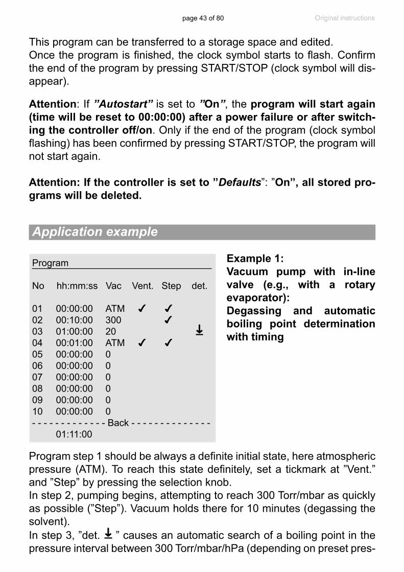
Example 1: Vacuum pump with in-line valve (e.g., with a rotary evaporator): Degassing and automatic boiling point determination with timing
Program
No hh:mm:ss Vac Vent. Step det.
01 00:00:00 ATM ✔ ✔02 00:10:00 300 ✔ 03 01:00:00 20 04 00:01:00 ATM ✔ ✔05 00:00:00 006 00:00:00 007 00:00:00 0 08 00:00:00 009 00:00:00 010 00:00:00 0- - - - - - - - - - - - - Back - - - - - - - - - - - - - - 01:11:00
➜
Program step 1 should be always a definite initial state, here atmospheric pressure (ATM). To reach this state definitely, set a tickmark at ”Vent.” and ”Step” by pressing the selection knob. In step 2, pumping begins, attempting to reach 300 Torr/mbar as quickly as possible (”Step”). Vacuum holds there for 10 minutes (degassing the solvent).In step 3, ”det.
➜
” causes an automatic search of a boiling point in the pressure interval between 300 Torr/mbar/hPa (depending on preset pres-
page 44 of 80
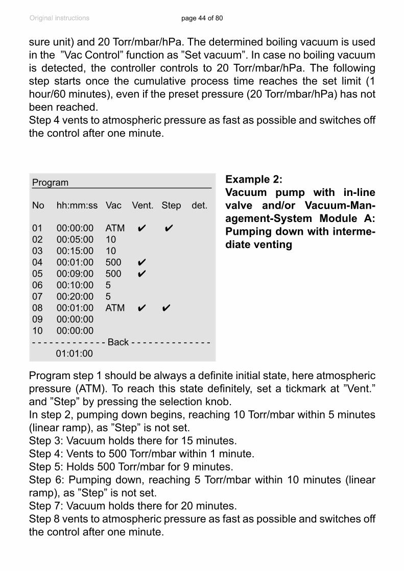
Example 2: Vacuum pump with in-line valve and/or Vacuum-Man-agement-System Module A: Pumping down with interme-diate venting
Program step 1 should be always a definite initial state, here atmospheric pressure (ATM). To reach this state definitely, set a tickmark at ”Vent.” and ”Step” by pressing the selection knob. In step 2, pumping down begins, reaching 10 Torr/mbar within 5 minutes (linear ramp), as ”Step” is not set. Step 3: Vacuum holds there for 15 minutes.Step 4: Vents to 500 Torr/mbar within 1 minute.Step 5: Holds 500 Torr/mbar for 9 minutes. Step 6: Pumping down, reaching 5 Torr/mbar within 10 minutes (linear ramp), as ”Step” is not set. Step 7: Vacuum holds there for 20 minutes.Step 8 vents to atmospheric pressure as fast as possible and switches off the control after one minute.
Program
No hh:mm:ss Vac Vent. Step det.
01 00:00:00 ATM ✔ ✔02 00:05:00 10 03 00:15:00 10 04 00:01:00 500 ✔ 05 00:09:00 500 ✔06 00:10:00 5 07 00:20:00 508 00:01:00 ATM ✔ ✔09 00:00:00 10 00:00:00- - - - - - - - - - - - - Back - - - - - - - - - - - - - - 01:01:00
sure unit) and 20 Torr/mbar/hPa. The determined boiling vacuum is used in the ”Vac Control” function as ”Set vacuum”. In case no boiling vacuum is detected, the controller controls to 20 Torr/mbar/hPa. The following step starts once the cumulative process time reaches the set limit (1 hour/60 minutes), even if the preset pressure (20 Torr/mbar/hPa) has not been reached. Step 4 vents to atmospheric pressure as fast as possible and switches off the control after one minute.

page 45 of 80
VACUULAN function
➨ Optimizes vacuum control for vacuum networks (e.g., VACUUBRAND VACUU•LAN) - pump control only with VMS
Preselections+ Use the selection knob to select the parameters.
+ Set vacuum (the lower switch-off value): If the pressure drops below the ”Set vacuum”, a time-meter starts to run. When the pressure ex-ceeds the ”Set vacuum” pressure again, the time meter is reset. If the ”Set vacuum” is not reached within 100 hours, the controller signals an error.
The ”Set vacuum” is adjustable in the range of 1-795 Torr (1-1060 mbar).
+ Switch on (the higher switching value): If the pressure exceeds this pressure, pumping down starts again.
The ”Switch on” pressure is adjustable in the range of 2-795 Torr (2-1060 mbar) (at the least 1 Torr (mbar) higher than the ”Set vacuum”).
In the event of a sudden high-pressure spike, pumping starts again even if the ”Switch on” pressure has not been reached (pressure in-crease control).
+ Delay: If the vacuum is below ”Set vacuum” for longer than the ”Delay” time, the pump is stopped. Pumping starts again in the event of a rapid pressure increase or if the ”Switch on” level is exceeded.
The ”Delay” is adjustable in a range of 1-300 minutes or can be set to ”Off” (”Off” means that the pump stops immediately when the pressure drops below ”Set vacuum”.).
page 46 of 80
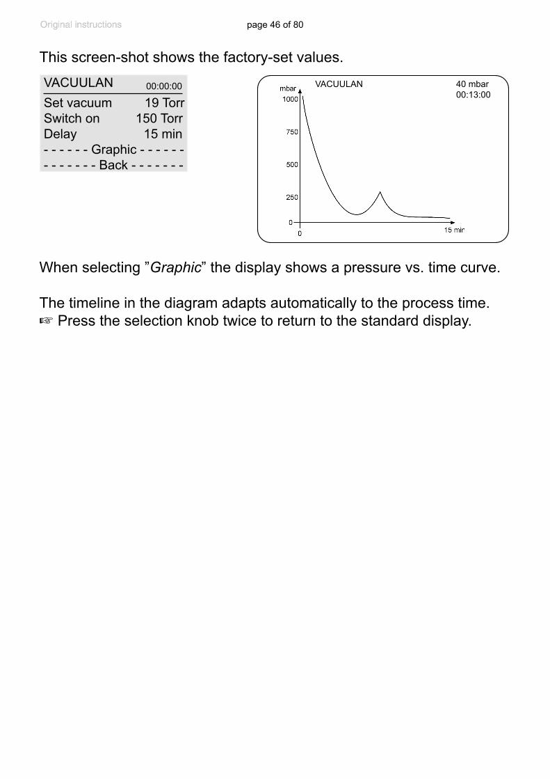
This screen-shot shows the factory-set values.
VACUULAN 40 mbar00:13:00
VACUULAN Set vacuum 19 TorrSwitch on 150 TorrDelay 15 min- - - - - - Graphic - - - - - - - - - - - - - Back - - - - - - -
00:00:00
When selecting ”Graphic” the display shows a pressure vs. time curve.
The timeline in the diagram adapts automatically to the process time.+ Press the selection knob twice to return to the standard display.
page 47 of 80
Vacuum for distillation and evaporation (e.g., rotary evaporator)
1. Fully automatic determination the boiling point
+ Select ”detect” function.+ Start process by pressing ”START/STOP” key.
+ The ”detect” function allows an automatic determination of the solvent’s boiling vacuum. In case of solvent mixtures, the controller detects the boiling vacuum of the solvent with the highest boiling point. The con-troller switches automatically to the ”Vac Control” function once the boiling vacuum has been determined. The determined boiling vacuum is used in the ”Vac Control” function as ”Set vacuum”.
+By switching the in-line valve (two-point control), the determined boil-ing vacuum (used as ”Set vacuum” in the ”Vac Control” function) is kept constant within the limits of the hysteresis. If the boiling vacuum changes, e.g., due to cooling of the solvent, either turn the selection knob to adjust the ”Set vacuum” or press ”START/STOP” key twice to restart the ”detect” function.
+ When setting a value for ”Duration” the controller stops control when ”Duration” has passed.
+ If no ”Duration” is preset, control has to be finished by pressing the ”START/STOP” key.
+ When pressing ”STOP” key, or after process stop due to elapsed ”Du-ration” (preset process time), the controller is set again to the ”detect” function.
+If, in case of solvent mixtures, the solvent with the highest boiling point
Assembly of a vacuum system+ Assemble vacuum connection lines between controller, vacuum pump
(diaphragm pump with in-line valve or Vacuum-Management-System) and vacuum application.
+ Assemble electrical connections.+ Connect coolant if necessary.
Application examples
page 48 of 80
alternatively:
For diaphragm pump with in-line valve and/or Vacuum-Management-System
+ Select ”Vac control” function.+ Set ”Set vacuum” (and ”Hysteresis”, if necessary) depending on the
solvent and the bath temperature. + Considering the hysteresis and the bath temperature, set ”Set vacu-
um” to a value which ensures that the solvent will definitely boil. + To set ”Maximum” is usually not necessary, unlike filtrations, because
the pressure does not increase at the end of the evaporation.+ Set a value for ”Duration” if the process should be terminated auto-
matically after a definite time. + Use ”Delay” to pump out condensate and clean the pump at the end of
the process. The in-line valve is closed and so the pump is separated from the application. During ”Delay” the coolant valve is still open.
+ Start process by pressing ”START/STOP” key.
2. Semi-automatic distillation and evaporation
+ Select ”Pump down” function.+ Start process by pressing ”START/STOP” key.+ Observe process. As soon as evaporation starts, press ”MODE” key
(switching to ”Vac control”). The vacuum level is kept constant (at the boiling pressure). Fine tuning of the vacuum value is possible by turn-ing the selection knob.
+ Select ”Pump down” function.+ Set ”Minimum” to prevent volatile components from evaporating. The
process is stopped automatically as soon as ”Minimum” is reached.+ Set a process time (”Duration”) if necessary.+ Start process by pressing ”START/STOP” key.
Vacuum for gel dryer, drying chambers and vacuum concentrators
has evaporated and the controller is set again to the ”detect” function, further components of the solvent mixture can be evaporated by re-starting the ”detect” function.

page 49 of 80
+ Select function ”VACUULAN”. + Set ”Set vacuum” to a pressure which can be reached reliably in the
vacuum network. Take account of the ultimate vacuum of the pump and of the system’s leak rate in case of no vacuum demand.
+ Set ”Switch on” pressure appropriately to ensure sufficient vacuum for all connected applications.
+ Set ”Delay” if necessary.+ Start process by pressing ”START/STOP” key.
Vacuum for VACUU•LAN networks
Vacuum for filtration and suction+ Select ”Pump down” function.+ Set ”Minimum” to a value which provides adequate suction but does
not lead to evaporation of the solvent.+ Start process by pressing ”START/STOP” key.
alternatively:
+ Select ”Vac control” function. + Set ”Set vacuum” (and ”Hysteresis”, if necessary) to a value which
does not lead to evaporation of the solvent.+ Set ”Maximum” pressure setting so that pump will switch off at the end
of the filtration process, or in the event that a filter cake cracks, leading to a sudden pressure increase.
+ Start process by pressing ”START/STOP” key.
+ Tip for filtration: Adjust preset pressure to a value well above the boiling pressure of the solvent (e.g., for water >>15 Torr (20 mbar)). Set the maximum pressure to e.g., 375 Torr (500 mbar). Once the fil-tration has finished, the pressure increases and the pump is switched off automatically.
alternatively:
+ Select ”Vac control” function to dry at a predetermined vacuum level.+ Set ”Set vacuum” to the preferred evaporation vacuum of the solvent.
Adapt ”Hysteresis” if necessary.+ Set a process time (”Duration”) if necessary.+ Start process by pressing ”START/STOP” key.

page 50 of 80
ConfigurationIn the ”Configuration” menu the device parameters are preselected. After 20 seconds without action the function ”Configuration” and its sub-menus (except submenu ”Sensors”) are quit automatically without stor-ing any possibly changed parameter.
+ Adjustment: Adjustment of the pressure transducer under vacuum and/or at atmospheric pressure, see also section “Readjustment”, pg. 52.
Adjustment to atmospheric pressure is carried out at an absolute pres-sure value between 795 - 525 Torr (1060 - 700 mbar). This is espe-cially helpful in high elevation laboratories. Adjustment under vacuum may be done at an absolute vacuum value between 0 - 15 Torr (0 - 20 mbar). In the range between 15 to 525 Torr (20 to 700 mbar) no adjust-ment is possible; ---- Torr is displayed.
+ RS-232: Configuration of the interface, setting of parameters and com-mands, see section ”Interface”.
Baud rate can be set to 19200, 9600, 4800 or 2400, parity on ”8-N-1”, ”7-O-1” or ”7-E-1”, Handshake on ”no”, ”Xon-Xoff” or ”RTS-CTS” and remote on ”On” or ”Off”.
+ Sensors: Selection of the pressure transducer to be controlled Maximum number of pressure transducers of the same type (VSK
3000 or VSP 3000) connected to one CVC 3000: four. That is a total of eight external pressure transducers at maximum. Up to four additional pressure transducers VSK 3000 may be connected as reference if configured accordingly.
+ Display: Selection of the device parameters ”Brightness” between 0 - 100%, ”Contrast” between 0 - 100%, ”Sound” ”On” or ”Off”, ”Units” ”mbar”, ”hPa” or ”Torr”, ”Language” ”German”, ”English”, ”French”, ”Italian”, ”Spanish”, ”Turkish”, ”Korean”, ”Chinese”, ”Portuguese”, ”Russian”, ”Polish”, ”Dutch”, ”Japanese”, ”Finnish”.
Preselections+ Use the selection knob to select the parameters.

page 51 of 80
This screen-shot shows the factory-set values.
+ Autostart: If ”Autostart” is set to ”On” the controller restarts a running process automatically after a mains failure. If this is unwanted, set ”Autostart” to ”Off”.
Attention: If ”Autostart” is preselected, the process starts immediately after power failure without pressing any fur-ther key. It is the user’s responsibility to ensure that no dangerous status of the system due to the automatic start-up can occur and to provide appropriate safety measures. If necessary, the user has to check prior to starting the process if the option ”Autostart” is enabled.
+ Defaults: If ”Defaults” is set to ”Load”, the controller is reset to factory set values. All stored programs and parameters are deleted.
Configuration Adjustment 760 TorrRS-232... Sensors... Display... Autostart OffDefaults Cancel - - - - - - - Back - - - - - - -
page 52 of 80
The vacuum gauge was adjusted using factory standards, which are traceable through regular calibration in an ac-credited laboratory (DAkkS calibration laboratory) to the German national pressure standard. Depending on the process and/or accuracy requirements, check the adjust-ment and readjust if necessary. For readjustment, the device has to be adjusted both at atmospheric pressure as well as under vacuum but only if the reference pres-sures are known with certainty. The adjustment mode can be activated only if the process control is inactive. Press ”START/STOP” key, if necessary. In the range between 15 to 525 Torr (20 to 700 mbar) no adjustment is possible; ---- Torr is displayed.
Readjustment
NOTICE
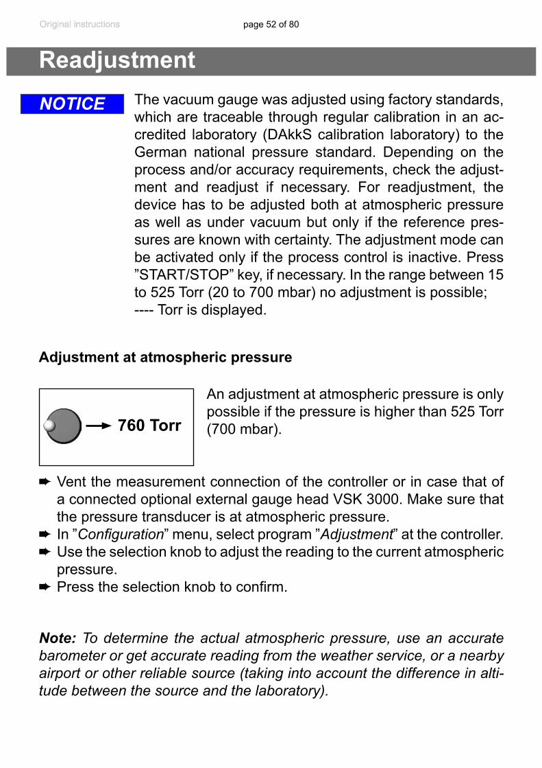
Adjustment at atmospheric pressure
An adjustment at atmospheric pressure is only possible if the pressure is higher than 525 Torr (700 mbar).
➨ Vent the measurement connection of the controller or in case that of a connected optional external gauge head VSK 3000. Make sure that the pressure transducer is at atmospheric pressure.
➨In ”Configuration” menu, select program ”Adjustment” at the controller.➨ Use the selection knob to adjust the reading to the current atmospheric
pressure.➨ Press the selection knob to confirm.
760 Torr
Note: To determine the actual atmospheric pressure, use an accurate barometer or get accurate reading from the weather service, or a nearby airport or other reliable source (taking into account the difference in alti-tude between the source and the laboratory).
page 53 of 80
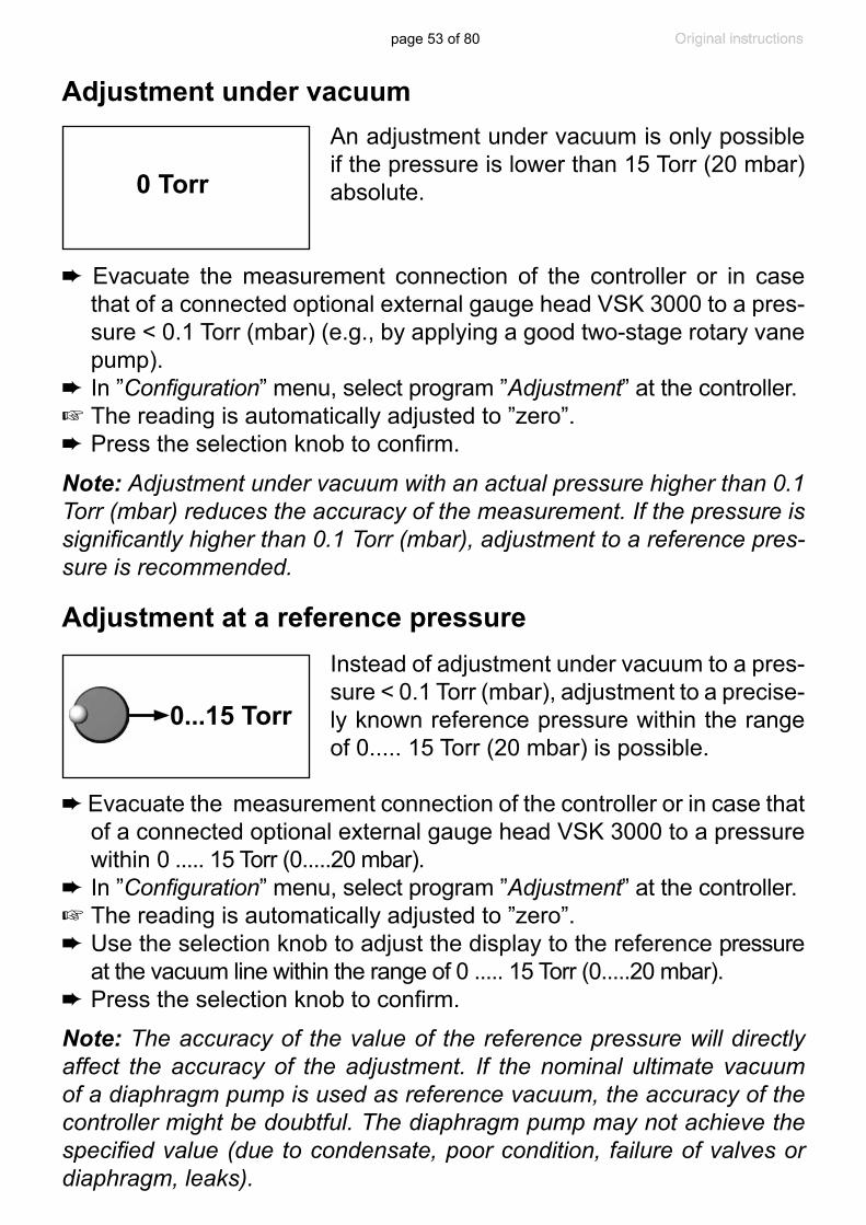
Adjustment under vacuumAn adjustment under vacuum is only possible if the pressure is lower than 15 Torr (20 mbar) absolute.
➨ Evacuate the measurement connection of the controller or in case that of a connected optional external gauge head VSK 3000 to a pres-sure < 0.1 Torr (mbar) (e.g., by applying a good two-stage rotary vane pump).
➨In ”Configuration” menu, select program ”Adjustment” at the controller.+ The reading is automatically adjusted to ”zero”.➨ Press the selection knob to confirm.
0 Torr
Note: Adjustment under vacuum with an actual pressure higher than 0.1 Torr (mbar) reduces the accuracy of the measurement. If the pressure is significantly higher than 0.1 Torr (mbar), adjustment to a reference pres-sure is recommended.
Adjustment at a reference pressureInstead of adjustment under vacuum to a pres-sure < 0.1 Torr (mbar), adjustment to a precise-ly known reference pressure within the range of 0..... 15 Torr (20 mbar) is possible.
➨Evacuate the measurement connection of the controller or in case that of a connected optional external gauge head VSK 3000 to a pressure within 0 ..... 15 Torr (0.....20 mbar).
➨In ”Configuration” menu, select program ”Adjustment” at the controller.+ The reading is automatically adjusted to ”zero”.➨Use the selection knob to adjust the display to the reference pressure
at the vacuum line within the range of 0 ..... 15 Torr (0.....20 mbar).➨ Press the selection knob to confirm.
0...15 Torr
Note: The accuracy of the value of the reference pressure will directly affect the accuracy of the adjustment. If the nominal ultimate vacuum of a diaphragm pump is used as reference vacuum, the accuracy of the controller might be doubtful. The diaphragm pump may not achieve the specified value (due to condensate, poor condition, failure of valves or diaphragm, leaks).
page 54 of 80
Calibration in the factory
DAkkS calibration of the CVC 3000 detect pressure transducer ..............20900215
Control of measuring equipmentThe VACUUBRAND DAkkS calibration laboratory is accredited by the Deutsche Akkreditierungsstelle GmbH (national accreditation body of the Federal Republic of Germany) for the measurable variable pressure in the pressure range from 7.5*10-4 Torr to 975 Torr (10-3 mbar to 1300 mbar) in accordance with the general criteria for the operation of testing laboratories defined in the DIN EN ISO/IEC 17025:2000 series of stan-dards (accreditation number D-K-15154-01). The DAkkS is signatory to the multilateral agreements of the European cooperation for Accredita-tion (EA) and of the International Laboratory Accreditation Cooperation (ILAC) for the mutual recognition of calibration certificates.
Rely on calibration in the VACUUBRAND calibration laboratory: - To meet the requirements of the DIN ISO 9000ff and 10012 series of
standards regarding the calibration of inspection, measuring and test equipment at specified intervals.
- To document that the vacuum gauges calibrated are traceable to na-tional standards of the PTB (Physikalisch-Technische Bundesanstalt; German national institute for science and technology and the highest technical authority of the Federal Republic of Germany for the field of metrology and certain sectors of safety engineering).
Attention: Never use a pointed or sharp-edged tool to clean the pressure transducer.Never touch the ceramic diaphragm of the pressure transducer with hard objects.
➨ Fill the measurement chamber via the vacuum connection with a sol-vent (e.g., benzene) and allow sufficient cleaning time. Observe all regulations concerning usage and disposal of solvents!
Cleaning the pressure transducer
NOTICE

page 55 of 80
Readjustment of the controller CVC 3000 detectSee section “Readjustment”, pg. 52.
➨ Drain the solvent and dispose of in accordance with regulations. Re-peat cleaning if necessary.
➨ Rinse the measurement chamber several times with alcohol in order to remove all solvent residues.
➨ Allow the pressure transducer to dry.➨ Readjust the pressure transducer if necessary.
page 56 of 80
Interface parametersThe CVC 3000 controller is equipped with a serial interface (RS 232C, nine-pin Sub-D-plug).+ Plug-in or remove the cable (cable RS 232C) from the interface only if
the equipment is switched off.+ The interface is not electrically isolated from the measuring circuit.
The controller is fully operable via the serial interface. Measuring results, preselections and the status of the controller can be read at any time.The factory-set read and write commands are completely compatible with the VACUUBRAND CVC 2000 controller (see sections ”Read / Write commands CVC 2000”). An extended instruction set is available using the command ”CVC 3” (see sections ”Read / Write commands CVC 3000”).
Setting of the interfaceSet the interface parameters directly at the CVC 3000 controller. The fac-tory set values are underlined.Edit and confirm the interface parameters in the ”Configuration” menu in ”RS-232” submenu using the selection knob.
➨ Baud: 2400, 4800, 9600 or 19200➨ Parity: 8-N-1, 7-O-1 or 7-E-1➨ Handshake: Off, Xon-Xoff or RTS-CTS➨ Remote: On or Off➨ Timeout: Sending 1s, receiving 10s.
In remote mode (”Remote On”, with the ”PC symbol” in the display) all keys at the controller are inoperable.
To return to the manual operation of the controller, set the control-ler to ”Remote off” in menu configuration: Switch off the controller. Then switch the controller back on, and press the selection knob within 2s.
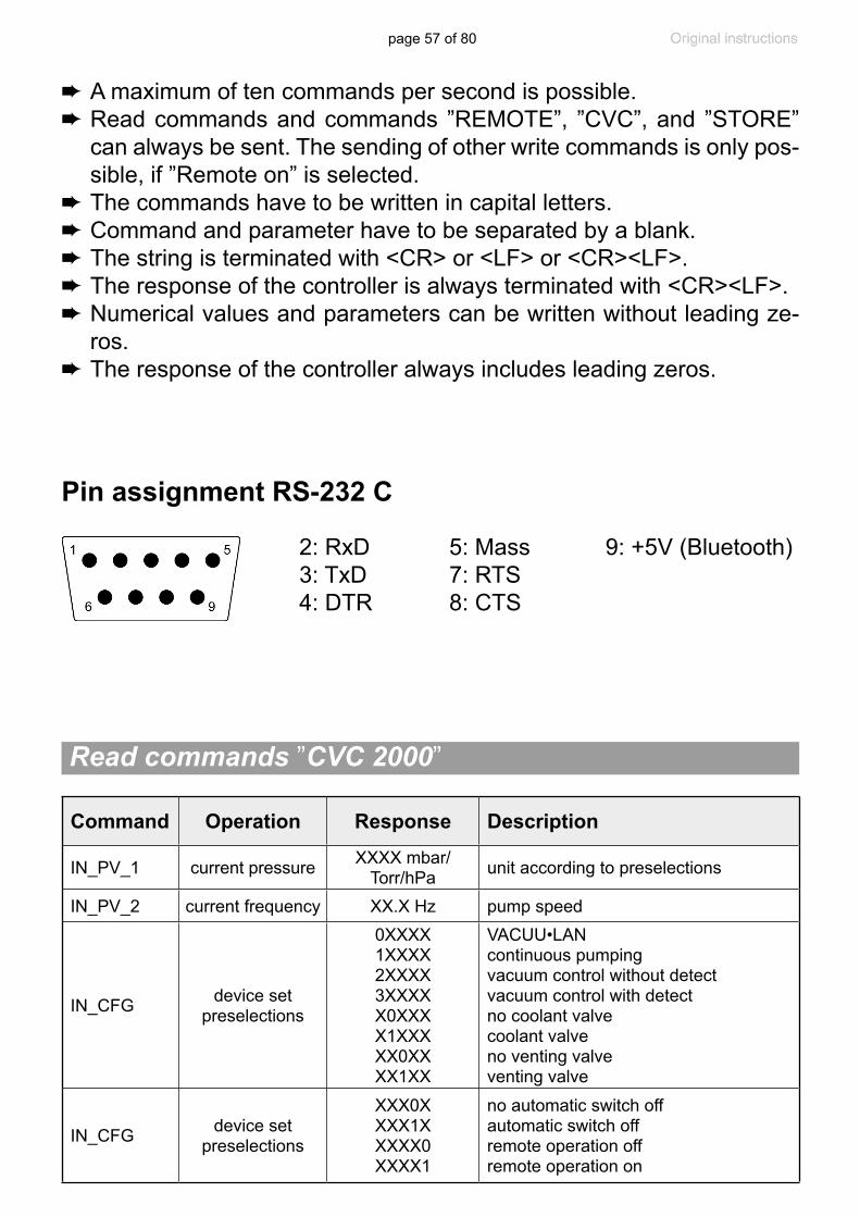
page 57 of 80
Command Operation Response Description
IN_PV_1 current pressure XXXX mbar/Torr/hPa unit according to preselections
IN_PV_2 current frequency XX.X Hz pump speed
IN_CFG device set preselections
0XXXX1XXXX2XXXX3XXXXX0XXXX1XXXXX0XXXX1XX
VACUU•LANcontinuous pumpingvacuum control without detectvacuum control with detectno coolant valvecoolant valveno venting valveventing valve
IN_CFG device set preselections
XXX0XXXX1XXXXX0XXXX1
no automatic switch offautomatic switch offremote operation offremote operation on
Read commands ”CVC 2000”
Pin assignment RS-232 C
2: RxD 5: Mass 9: +5V (Bluetooth)3: TxD 7: RTS4: DTR 8: CTS
➨ A maximum of ten commands per second is possible.➨ Read commands and commands ”REMOTE”, ”CVC”, and ”STORE”
can always be sent. The sending of other write commands is only pos-sible, if ”Remote on” is selected.
➨ The commands have to be written in capital letters.➨ Command and parameter have to be separated by a blank.➨ The string is terminated with <CR> or <LF> or <CR><LF>. ➨ The response of the controller is always terminated with <CR><LF>.➨ Numerical values and parameters can be written without leading ze-
ros.➨ The response of the controller always includes leading zeros.

page 58 of 80
Write commands ”CVC 2000”
Command Operation Parameter Description
OUT_MODE function
123
30 31 32
continuous pumpingvacuum control without detectvacuum control with detect optional: sensitivity: low optional: sensitivity: normal optional: sensitivity: high
OUT_SP_1 set vacuum XXXXunit (mbar/Torr/hPa) according to pre-selection; see respective function for parameter range
OUT_SP_V set vacuum with venting* XXXX
unit (mbar/Torr/hPa) according to pre-selection; see respective function for parameter range
OUT_SP_2 set frequency XX.X motor speed in Hz (01.0 to 60.0 in steps of 0.5 Hz or 99.9 for “HI”)
Command Operation Response Description
IN_ERR error code
1XXXX1XXXX1XXXX1
fault at pump electronicsoverpressuremaloperation mode pressure transducerlast command to interface incorrect
IN_STAT status of process control
0XXX1XXXX0XXX1XXXX00XX01
XX02
XX03XX10XX11XX20XX21
XX22
XX23
XX30XX31
coolant valve closedcoolant valve openventing valve closedventing valve openVACUU•LAN: inactiveVACUU•LAN: pumping down, current pressure > selected pressureVACUU•LAN: pumping down, time for automatic switching off is runningVACUU•LAN: system is switched offcontinuous pumping: not activecontinuous pumping; activevacuum control: not activevacuum control: current pressure above set vacuumvacuum control: current pressure equals set vacuum (±1 Torr/mbar)vacuum control: current pressure below set vacuumdetect: not activedetect: determining boiling point

page 59 of 80
** If remote operation is selected or deselected, the user has to ensure that no dangerous status of the system can occur due to the change of the mode of operation, and must take appropriate safety precautions, especially if selecting remote operation interferes with a locally oper-ated active process.
* Pressure setting with venting is only possible in ”Vac control” function if a venting valve is connected and configured, and vacuum control is started. The venting valve opens automatically if the actual pressure is at least 7.5 Torr (10 mbar) below the preset pressure. Automatic venting becomes inactive if vacuum control is stopped (by pressing ”START/STOP” or ”VENT”), a pressure value is set using the com-mand OUT_SP_1, or if the function is changed. Activate the command OUT_SP_V again if necessary.
Command Operation Parameter Description
OUT_SP_3 vacuum for switch on (VACUU•LAN) XXXX
unit (mbar/Torr/hPa) according to pre-selection; see respective function for parameter range
OUT_SP_4 delay XX:XX hh:mm (hours:minutes)
OUT_SP_5vacuum for auto-matic switching
offXXXX
unit (mbar/Torr/hPa) according to pre-selection; see respective function for parameter range
OUT_SP_6time for automatic
switching off (VACUU•LAN)
XX:XX hh:mm (hours:minutes)
START starting process control
STOP stopping process control
12
termination of process controltermination of process control and stor-age of the current pressure as new set point
REMOTE remote operation**
01
set controller to local operationset controller to remote operation
OUT_VENT driving venting valve
01
close venting valve (not automatically)open venting valve (process control stopped)

page 60 of 80
Read commands ”CVC 3000”
Command Operation Response Description
IN_PV_1 current pressure XXXX.X mbar/Torr/hPa unit according to preselections
IN_PV_2 current speed XXX% 1-100% or ”HI”
IN_PV_3 time XX:XX h:m process runtime (hours:minutes)
IN_PV_X pressure XXXX.X XXXX.X ...pressure of all connected sensors, unit (mbar/Torr/hPa) according to preselections
IN_PV_T operation time of the controller XXXXdXXh operation time in days and hours
IN_CFG device set preselections
0XXXXXXXXXXXXXXX1XXXXXXXXXXXXXXX2XXXXXXXXXXXXXXX3XXXXXXXXXXXXXXX4XXXXXXXXXXXXXXX5XXXXXXXXXXXXXXXXyXXXXXXXXXXXXXXXX0XXXXXXXXXXXXXXX1XXXXXXXXXXXXXXX2XXXXXXXXXXXXXXXX0XXXXXXXXXXXXXXX1XXXXXXXXXXXXXXXX0XXXXXXXXXXXXXXX1XXXXXXXXXXXXXXXX0XXXXXXXXXXXXXXX1XXXXXXXXXXXXXXXX0XXXXXXXXXXXXXXX1XXXXXXXXXXXXXXXX0XXXXXXXXXXXXXXX1XXXXXXXXXXXXXXXX0XXXXXXXXXXXXXXX1XXXXXXXXXXXXXXXX0XXXXXXXXXXXXXXX1XXXXXXXXXXXXXXXX0XXXXXXXXXXXXXXX1XXXXXXXXXXXXXXXX0XXXXXXXXXXXXXXX1XXXXXXXXXXXXXXXX0XXXXXXXXXXXXXXX1XXXXXXXXXXXXXXXXyXXXXXXXXXXXXXXXXyXXXXXXXXXXXXXXXX0XXXXXXXXXXXXXXX1
VACUU•LANPump downVac controldetectProgrammeasuring devicey: 0......D: language+ (hexadecimal)pressure unit mbarpressure unit Torrpressure unit hPaautostart offautostart onacoustic signal offacoustic signal onVARIO pump not connectedVARIO pump connectedVMS not connectedVMS connectedin-line valve not connectedin-line valve connectedcoolant valve not connectedcoolant valve connectedventing valve not connectedventing valve connectedfault indicator not connectedfault indicator connectedlevel sensor not connectedlevel sensor connectedremote module not connectedremote module connectedy: 1......9: sensor numbery: 1......9: sensor quantityremote operation offremote operation on
+ Language:0: German1: English2: French 3: Italian4: Spanish5: Turkish6: Korean7: Chinese8: Portuguese9: RussianA: PolishB: DutchC: JapaneseD: Finnish
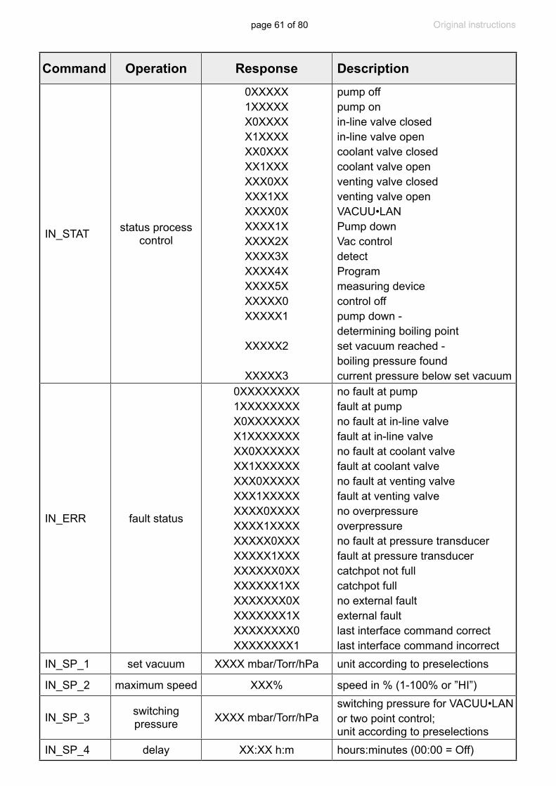
page 61 of 80
Command Operation Response Description
IN_STAT status process control
0XXXXX1XXXXXX0XXXXX1XXXXXX0XXXXX1XXXXXX0XXXXX1XXXXXX0XXXXX1XXXXX2XXXXX3XXXXX4XXXXX5XXXXXX0XXXXX1
XXXXX2
XXXXX3
pump offpump onin-line valve closedin-line valve opencoolant valve closedcoolant valve openventing valve closedventing valve openVACUU•LANPump downVac controldetectProgrammeasuring devicecontrol offpump down - determining boiling pointset vacuum reached - boiling pressure foundcurrent pressure below set vacuum
IN_ERR fault status
0XXXXXXXX1XXXXXXXXX0XXXXXXXX1XXXXXXXXX0XXXXXXXX1XXXXXXXXX0XXXXXXXX1XXXXXXXXX0XXXXXXXX1XXXXXXXXX0XXXXXXXX1XXXXXXXXX0XXXXXXXX1XXXXXXXXX0XXXXXXXX1XXXXXXXXX0XXXXXXXX1
no fault at pumpfault at pumpno fault at in-line valvefault at in-line valveno fault at coolant valvefault at coolant valveno fault at venting valvefault at venting valveno overpressureoverpressureno fault at pressure transducerfault at pressure transducercatchpot not fullcatchpot fullno external fault external faultlast interface command correctlast interface command incorrect
IN_SP_1 set vacuum XXXX mbar/Torr/hPa unit according to preselections
IN_SP_2 maximum speed XXX% speed in % (1-100% or ”HI”)
IN_SP_3 switching pressure XXXX mbar/Torr/hPa
switching pressure for VACUU•LAN or two point control; unit according to preselections
IN_SP_4 delay XX:XX h:m hours:minutes (00:00 = Off)
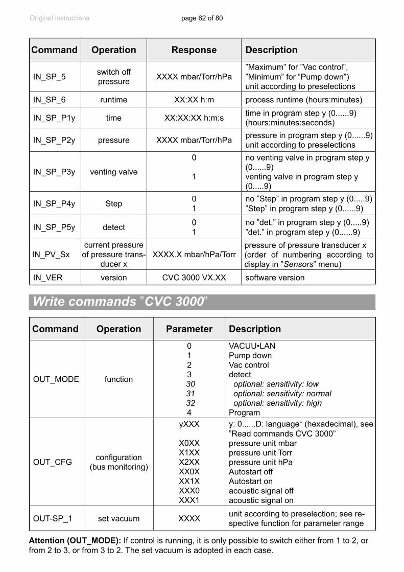
page 62 of 80
Write commands ”CVC 3000”
Attention (OUT_MODE): If control is running, it is only possible to switch either from 1 to 2, or from 2 to 3, or from 3 to 2. The set vacuum is adopted in each case.
Command Operation Response Description
IN_SP_5 switch off pressure XXXX mbar/Torr/hPa
”Maximum” for ”Vac control”, ”Minimum” for ”Pump down”) unit according to preselections
IN_SP_6 runtime XX:XX h:m process runtime (hours:minutes)
IN_SP_P1y time XX:XX:XX h:m:s time in program step y (0......9)(hours:minutes:seconds)
IN_SP_P2y pressure XXXX mbar/Torr/hPa pressure in program step y (0......9) unit according to preselections
IN_SP_P3y venting valve
0
1
no venting valve in program step y (0......9)venting valve in program step y (0.....9)
IN_SP_P4y Step 01
no ”Step” in program step y (0.....9)”Step” in program step y (0......9)
IN_SP_P5y detect 01
no ”det.” in program step y (0.....9)”det.” in program step y (0......9)
IN_PV_Sxcurrent pressure of pressure trans-
ducer xXXXX.X mbar/hPa/Torr
pressure of pressure transducer x(order of numbering according to display in ”Sensors” menu)
IN_VER version CVC 3000 VX.XX software version
Command Operation Parameter Description
OUT_MODE function
0123
30 31 324
VACUU•LAN Pump downVac controldetect optional: sensitivity: low optional: sensitivity: normal optional: sensitivity: highProgram
OUT_CFG configuration (bus monitoring)
yXXX
X0XXX1XXX2XXXX0XXX1XXXX0XXX1
y: 0......D: language+ (hexadecimal), see ”Read commands CVC 3000”pressure unit mbarpressure unit Torrpressure unit hPaAutostart offAutostart onacoustic signal offacoustic signal on
OUT-SP_1 set vacuum XXXX unit according to preselection; see re-spective function for parameter range
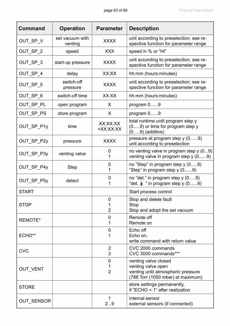
page 63 of 80
Command Operation Parameter Description
OUT_SP_V set vacuum with venting XXXX unit according to preselection; see re-
spective function for parameter rangeOUT_SP_2 speed XXX speed in % or ”HI”
OUT_SP_3 start-up pressure XXXX unit according to preselection; see re-spective function for parameter range
OUT_SP_4 delay XX:XX hh:mm (hours:minutes)
OUT_SP_5 switch-off pressure XXXX unit according to preselection; see re-
spective function for parameter range
OUT_SP_6 switch-off time XX:XX hh:mm (hours:minutes)
OUT_SP_PL open program X program 0......9
OUT_SP_PS store program X program 0......9
OUT_SP_P1y time XX:XX:XX+XX:XX:XX
total runtime until program step y (0.....9) or time for program step y (0.....9) (additive)
OUT_SP_P2y pressure XXXX pressure at program step y (0......9)unit according to preselection
OUT_SP_P3y venting valve 01
no venting valve in program step y (0...9)venting valve in program step y (0......9)
OUT_SP_P4y Step 01
no ”Step” in program step y (0.....9)”Step” in program step y (0......9)
OUT_SP_P5y detect 01
no ”det.” in program step y (0.....9)”det.
➜
” in program step y (0......9)
START Start process control
STOP012
Stop and delete faultStopStop and adopt the set vacuum
REMOTE* 01
Remote offRemote on
ECHO**01
Echo offEcho on, write command with return value
CVC 23
CVC 2000 commandsCVC 3000 commands***
OUT_VENT
012
venting valve closedventing valve openventing until atmospheric pressure (788 Torr (1050 mbar) at maximum)
STORE store settings permanently, if ”ECHO = 1” after realization
OUT_SENSOR 12...9
internal sensorexternal sensors (if connected)

page 64 of 80
* If remote operation is selected or deselected, the user has to ensure that no dangerous status of the system can occur due to the change of the mode of operation, and must also take appropriate safety precau-tions, especially if selecting remote operation interferes with a locally operated active process.
** With command ”ECHO 1” a return value can be activated at write com-mands. A return value is only given if the command is performed cor-rectly.
*** After being switched on, the controller is in ”CVC 2” mode by default. Send ”CVC 3” and ”STORE” to permanently set the controller RS 232C commands to the extended set ”CVC 3000”.
AccessoriesExternal pressure transducer VSK 3000, ..................................................20636657capacitive, ceramic diaphragm sensor 810 - 0.1 Torr (1080 - 0.1 mbar)Coolant valve VKW-B, VACUU•BUS .........................................................20674220Venting valve VBM-B / KF 16, VACUU•BUS ............................................ 20674217VACUU•BUS Y-type adapter ....................................................................20636656VACUU•BUS extension cable, 6.6ft (2m) ..................................................20612552VACUU•BUS wall jack ...............................................................................20636153Serial cable RS 232C, 9-pin, Sub-D ..........................................................20637837Installation set CVC 3000 (clips and screws) ............................................20636593Level sensor ..............................................................................................20699908(control of liquid level in catchpots)VACUU•BUS Digital-I/O-Module ................................................................20636228(e.g., fault indicator / remote module)VACUU•BUS Analog-I/O-Module...............................................................20636229(for analog input and output of vacuum and motor speed)VMS-B module 100-230V 50/60Hz (with connection cable) .....................20676030PC-Software VACUU•CONTROL ..............................................................20692920Tripod bracket (incl. wall mount) ...............................................................22614163
Use VACUU•BUS Y-adapters and extension cables to connect further components. When connecting an external pressure transducer, it is used automatically. Further information on how to use several sensors simultaneously is available on request.
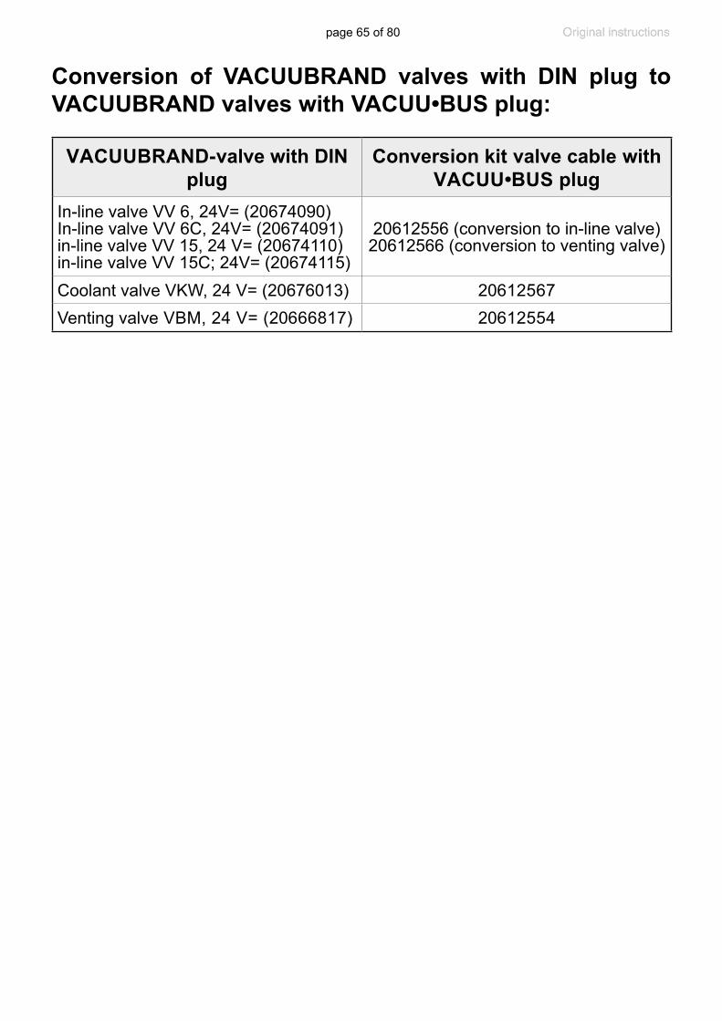
page 65 of 80
Conversion of VACUUBRAND valves with DIN plug to VACUUBRAND valves with VACUU•BUS plug:
VACUUBRAND-valve with DIN plug
Conversion kit valve cable with VACUU•BUS plug
In-line valve VV 6, 24V= (20674090)In-line valve VV 6C, 24V= (20674091)in-line valve VV 15, 24 V= (20674110)in-line valve VV 15C; 24V= (20674115)
20612556 (conversion to in-line valve)20612566 (conversion to venting valve)
Coolant valve VKW, 24 V= (20676013) 20612567Venting valve VBM, 24 V= (20666817) 20612554

page 66 of 80
Fault Possible cause Remedy❑ No display. ➨ Power supply not
plugged in (wall plug)?✔ Plug in power supply.
➨ CVC 3000 detect con-troller switched off?
✔ Switch on controller.
➨ VACUU • BUS cable of power supply not plugged in at control-ler?
✔ Plug in VACUU • BUS cable at controller.
➨ Other than above men-tioned causes?
✔ Contact local distributor.
❑ Display disappears. ➨ Too much load (e.g., valves) connected?
✔ Check current draw of the connected devices.
➨ Short circuit at connect-ed valves?
✔ Replace valves.
➨ Short circuit at the RS 232 plug?
✔ Check plug and cable.
➨ Other than above men-tioned causes?
✔ Contact local distributor.
❑ Pressure reading incorrect.
➨ Pressure transducer decalibrated?
✔ Readjust CVC 3000 detect or external gauge head.
➨ Humidity in the pres-sure transducer?
✔ Let the pressure trans-ducer dry, e.g., by pump-ing. Readjust if neces-sary. Determine and eliminate the cause for humidity.
➨ Pressure transducer contaminated?
✔ See ”Cleaning the pres-sure transducer”.
➨ Other than above men-tioned causes?
✔ Contact local distributor.
❑ Digital pressure reading is flash-ing, display shows ”0.0”.
➨ Pressure transducer not correctly adjusted under vacuum?
✔ Adjust CVC 3000 detect or external gauge head correctly.
❑ No digital pressure reading.
➨ Pressure transducer defective?
✔ Contact local distributor.
❑ Digital pressure reading is flashing, one blip*.
➨ Overpressure at the pressure transducer, pressure > 795 Torr (1060 mbar)?
✔ Release pressure imme-diately (risk of bursting).
Troubleshooting
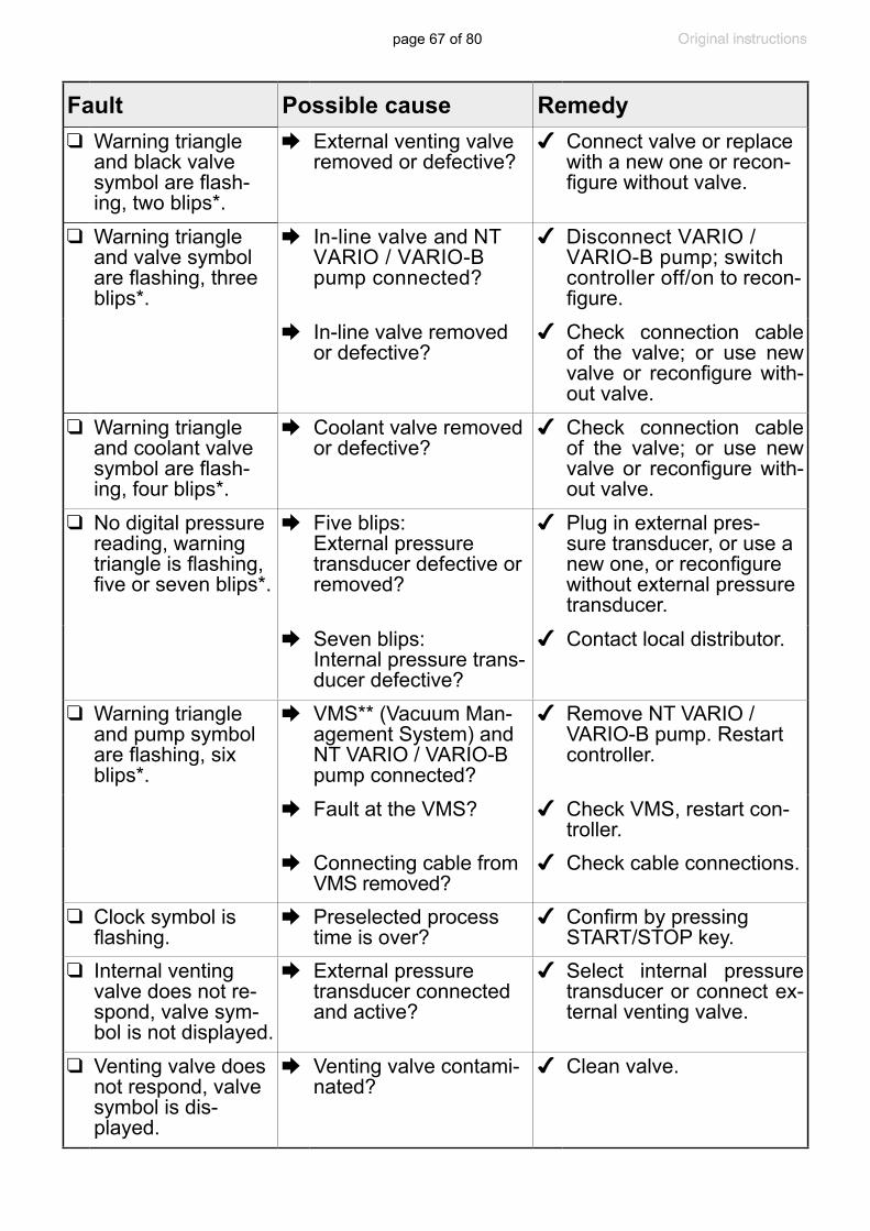
page 67 of 80
Fault Possible cause Remedy❑ Warning triangle
and black valve symbol are flash-ing, two blips*.
➨ External venting valve removed or defective?
✔ Connect valve or replace with a new one or recon-figure without valve.
❑ Warning triangle and valve symbol are flashing, three blips*.
➨ In-line valve and NT VARIO / VARIO-B pump connected?
✔ Disconnect VARIO / VARIO-B pump; switch controller off/on to recon-figure.
➨ In-line valve removed or defective?
✔ Check connection cable of the valve; or use new valve or reconfigure with-out valve.
❑ Warning triangle and coolant valve symbol are flash-ing, four blips*.
➨ Coolant valve removed or defective?
✔ Check connection cable of the valve; or use new valve or reconfigure with-out valve.
❑ No digital pressure reading, warning triangle is flashing, five or seven blips*.
➨ Five blips:External pressure transducer defective or removed?
✔ Plug in external pres-sure transducer, or use a new one, or reconfigure without external pressure transducer.
➨ Seven blips:Internal pressure trans-ducer defective?
✔ Contact local distributor.
❑ Warning triangle and pump symbol are flashing, six blips*.
➨ VMS** (Vacuum Man-agement System) and NT VARIO / VARIO-B pump connected?
✔ Remove NT VARIO / VARIO-B pump. Restart controller.
➨ Fault at the VMS? ✔ Check VMS, restart con-troller.
➨ Connecting cable from VMS removed?
✔ Check cable connections.
❑ Clock symbol is flashing.
➨ Preselected process time is over?
✔ Confirm by pressing START/STOP key.
❑ Internal venting valve does not re-spond, valve sym-bol is not displayed.
➨ External pressure transducer connected and active?
✔ Select internal pressure transducer or connect ex-ternal venting valve.
❑ Venting valve does not respond, valve symbol is dis-played.
➨ Venting valve contami-nated?
✔ Clean valve.

page 68 of 80
* only if ”Sound” ”On” is selected** VMS: Vacuum management system to switch non-VARIO pumps
Fault Possible cause Remedy❑ ”Vac control” func-
tion: Control stops, ”arrow up” is flash-ing.
➨ Preset maximum pres-sure exceeded?
✔ Confirm by pressingSTART/STOP key. Change maximum pres-sure value if necessary.
❑ ”Pump down” func-tion: Control stops, ”arrow down” is flashing.
➨ Pressure below preset minimum pressure?
✔ Confirm by pressingSTART/STOP key. Change minimum pres-sure value if necessary.
❑ No function is dis-played. No menu available.
➨ No controllable device is connected (valve, VMS, NT VARIO / VARIO-B pump)?
✔ Connect devices or use controller as measuring device.
❑ Controller does not respond when pressing keys (ex-cept ON/OFF). PC symbol is dis-played.
➨ Controller in remote mode?
✔ Control CVC 3000 detect via interface or switch off remote mode.
❑ Controller does not respond when operating any keys. No change after switching off/on.
✔ Contact local distributor.
Note: All error messages comprising a flashing warning triangle have to be confirmed (deleted) by pressing the START/STOP key.Solve the problem (see ”Remedy”), then press the START/STOP key to delete the error message.

page 69 of 80
Repair - Maintenance - Return - Calibration
Every employer (user) is held responsible for the health and safety of his employees. This also applies to service personnel performing repair, maintenance, return or cali-bration.The health and safety clearance form informs the con-tractor about any possible contamination of the device and forms the basis for the risk assessment. In case of devices which have been in contact with biological substances of risk level 2 contact the VACUUBRAND service absolutely before dispatch-ing the device. These devices have to be completely disassembled and decontaminated by the user prior to shipment. Do not return devices which have been in contact biological substances of risk level 3 or 4. These devices cannot be checked, maintained or re-paired. Also decontaminated devices must not returned to VACUUBRAND due to a residual risk.The same conditions apply to on-site work.
No repair, maintenance, return or calibration is possi-ble unless the correctly completed health and safety clearance form is returned. Devices sent are rejected if applicable. Send a completed copy of the health and safety clearance form to us in advance. The declaration must arrive before the equipment. Enclose a second com-pleted copy with the product.
Remove all components from the device that are no origi-nal VACUUBRAND components. VACUUBRAND will not be responsible for lost or damaged components that are no original components. Drain the device completely of fluids and residues. Decontaminate the device. Close all openings airtight especially if using substances hazardous to health. To expedite repair and to reduce costs, please enclose a detailed description of the problem and the product’s op-erating conditions with every product returned.
IMPORTANT
page 70 of 80
If you do not wish a repair on the basis of our quotation, the device may be returned to you disassembled and at your expense.In many cases, the components must be cleaned in the factory prior to repair.For cleaning we use an environmentally friendly water based process. Unfortunately the combined attack of el-evated temperature, cleaning agent, ultrasonic treatment and mechanical stress (from pressurised water) may re-sult in damage to the paint. Please mark in the health and safety clearance form if you wish a repaint at your ex-pense just in case such a damage should occur. We will also replace parts for cosmetic reasons at your request and at your expense.
Before returning the devicePack the device properly, if necessary, please order origi-nal packaging materials at your costs.Mark the package completelyEnclose the completed health and safety clearance form.Notify the carrier of any possible contamination if required.
Scrapping and waste disposalDispose of the equipment and any components removed from it safely in accordance with all local and national safety and environmental requirements. Particular care must be taken with components and waste oil which have been contaminated with dangerous substances from your processes. Do not incinerate fluoroelastomer seals and O-rings. You may authorize us to dispose of the equip-ment at your expense. Otherwise we return the device at your expense.
page 71 of 80
VACUUBRAND shall be liable for insuring that this prod-uct, including any agreed installation, has been free of de-fects at the time of the transfer of risk.
VACUUBRAND shall not be liable for the consequences of improper handling, use, servicing or operation of this product or the consequences of normal wear and tear of wearing parts such as diaphragms, seals, valves, vanes, condensers, oil and the breakage of glass or ceramic parts, for the consequences of chemical, electrochemical or electrical influences or the failure to follow the instruc-tions in this manual.
Claims for defects against VACUUBRAND shall be limited to one year from delivery. The same shall apply to claims for damages irrespective of legal grounds.
For further information on general terms and conditions refer to www.vacuubrand.com.
Warranty
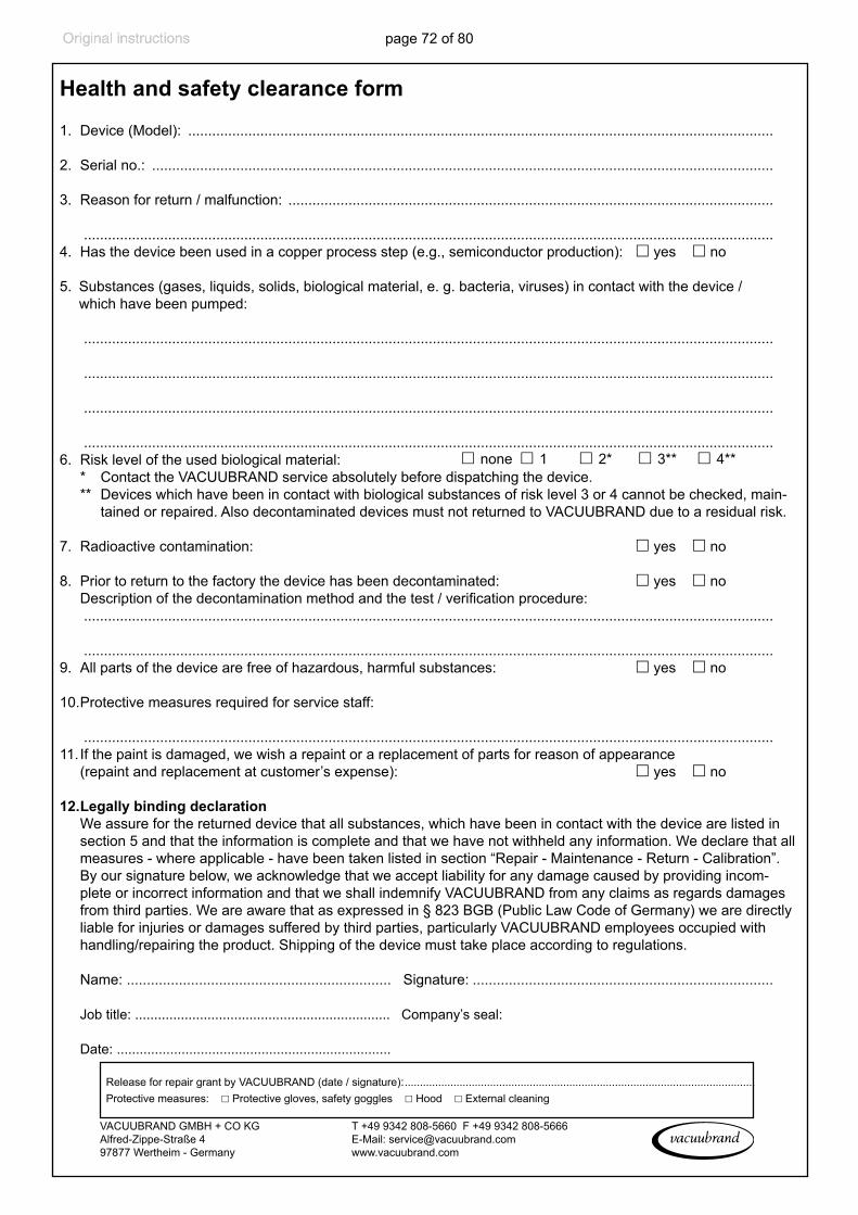
page 72 of 80
Health and safety clearance
form
Health and safety clearance form
1. Device (Model): ..................................................................................................................................................
2. Serial no.: ...........................................................................................................................................................
3. Reason for return / malfunction: ......................................................................................................................... ............................................................................................................................................................................4. Has the device been used in a copper process step (e.g., semiconductor production): ☐ yes ☐ no
5. Substances (gases, liquids, solids, biological material, e. g. bacteria, viruses) in contact with the device / which have been pumped:
............................................................................................................................................................................
............................................................................................................................................................................
............................................................................................................................................................................
............................................................................................................................................................................ 6. Risk level of the used biological material: ☐ none ☐ 1 ☐ 2* ☐ 3** ☐ 4** * Contact the VACUUBRAND service absolutely before dispatching the device. ** Devices which have been in contact with biological substances of risk level 3 or 4 cannot be checked, main-
tained or repaired. Also decontaminated devices must not returned to VACUUBRAND due to a residual risk.
7. Radioactive contamination: ☐ yes ☐ no
8. Prior to return to the factory the device has been decontaminated: ☐ yes ☐ no Descriptionofthedecontaminationmethodandthetest/verificationprocedure: ............................................................................................................................................................................
............................................................................................................................................................................9. All parts of the device are free of hazardous, harmful substances: ☐ yes ☐ no
10. Protective measures required for service staff: ............................................................................................................................................................................11. If the paint is damaged, we wish a repaint or a replacement of parts for reason of appearance (repaint and replacement at customer’s expense): ☐ yes ☐ no
12. Legally binding declaration We assure for the returned device that all substances, which have been in contact with the device are listed in
section 5 and that the information is complete and that we have not withheld any information. We declare that all measures - where applicable - have been taken listed in section “Repair - Maintenance - Return - Calibration”. By our signature below, we acknowledge that we accept liability for any damage caused by providing incom-plete or incorrect information and that we shall indemnify VACUUBRAND from any claims as regards damages from third parties. We are aware that as expressed in § 823 BGB (Public Law Code of Germany) we are directly liable for injuries or damages suffered by third parties, particularly VACUUBRAND employees occupied with handling/repairing the product. Shipping of the device must take place according to regulations.
Name: .................................................................. Signature: ...........................................................................
Job title: ................................................................... Company’s seal:
Date: ........................................................................
Release for repair grant by VACUUBRAND (date / signature): ................................................................................................................... Protective measures: ☐ Protective gloves, safety goggles ☐ Hood ☐ External cleaning
VACUUBRAND GMBH + CO KGAlfred-Zippe-Straße 4 97877 Wertheim - Germany
T +49 9342 808-5660 F +49 9342 808-5666E-Mail: [email protected]
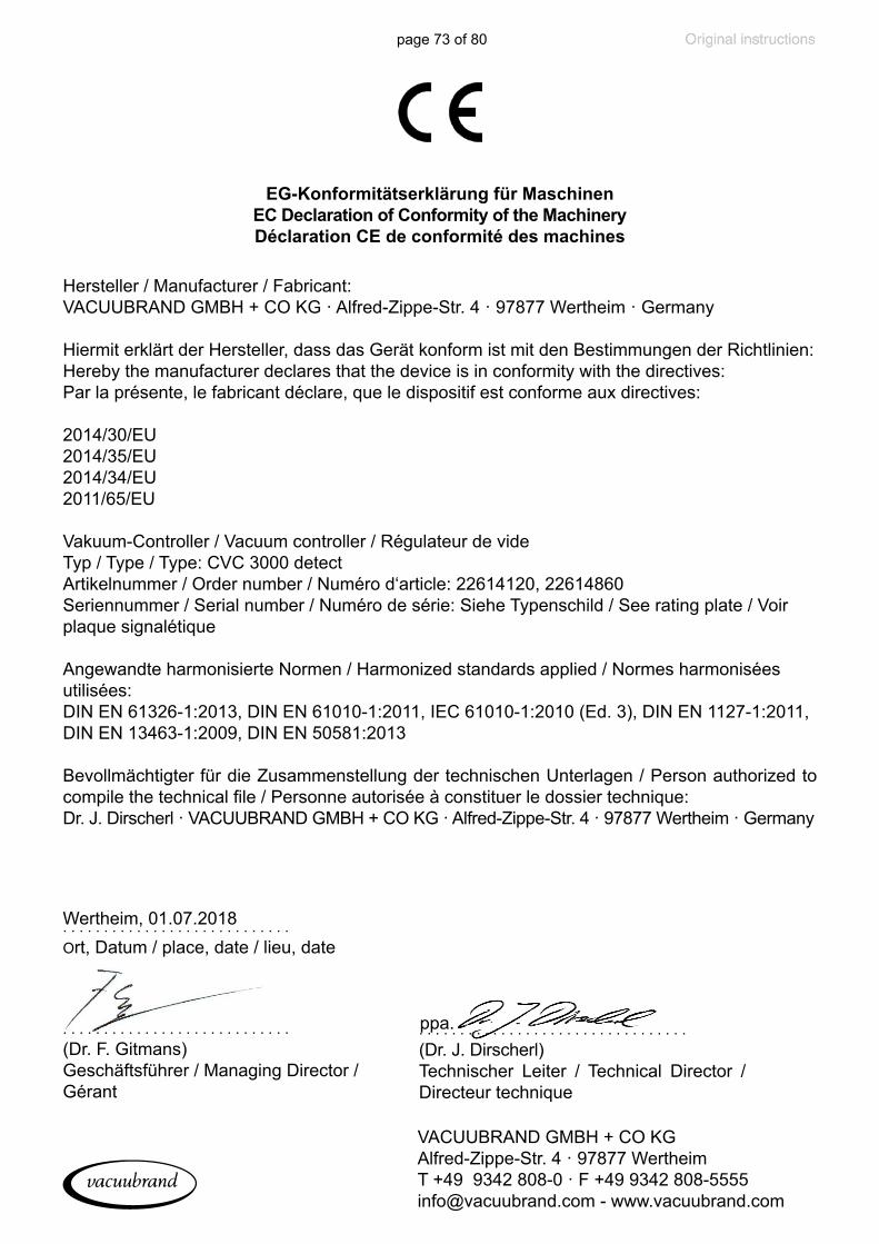
page 73 of 80
Hersteller / Manufacturer / Fabricant: VACUUBRAND GMBH + CO KG · Alfred-Zippe-Str. 4 · 97877 Wertheim · Germany
Hiermit erklärt der Hersteller, dass das Gerät konform ist mit den Bestimmungen der Richtlinien:Hereby the manufacturer declares that the device is in conformity with the directives:Par la présente, le fabricant déclare, que le dispositif est conforme aux directives:
2014/30/EU2014/35/EU2014/34/EU2011/65/EU
Vakuum-Controller / Vacuum controller / Régulateur de videTyp / Type / Type: CVC 3000 detectArtikelnummer / Order number / Numéro d‘article: 22614120, 22614860Seriennummer / Serial number / Numéro de série: Siehe Typenschild / See rating plate / Voir plaque signalétique
Angewandte harmonisierte Normen / Harmonized standards applied / Normes harmonisées utilisées:DIN EN 61326-1:2013, DIN EN 61010-1:2011, IEC 61010-1:2010 (Ed. 3), DIN EN 1127-1:2011, DIN EN 13463-1:2009, DIN EN 50581:2013
Bevollmächtigter für die Zusammenstellung der technischen Unterlagen / Person authorized to compile the technical file / Personne autorisée à constituer le dossier technique:Dr. J. Dirscherl · VACUUBRAND GMBH + CO KG · Alfred-Zippe-Str. 4 · 97877 Wertheim · Germany
EG-Konformitätserklärung für MaschinenEC Declaration of Conformity of the Machinery Déclaration CE de conformité des machines
. . . . . . . . . . . . . . . . . . . . . . . . . . . .(Dr. F. Gitmans)Geschäftsführer / Managing Director / Gérant
. . . . . . . . . . . . . . . . . . . . . . . . . . . . Ort, Datum / place, date / lieu, dateWertheim, 01.07.2018
. . . . . . . . . . . . . . . . . . . . . . . . . . . . . . . . . (Dr. J. Dirscherl)Technischer Leiter / Technical Director / Directeur technique
ppa.
VACUUBRAND GMBH + CO KGAlfred-Zippe-Str. 4 · 97877 WertheimT +49 9342 808-0 · F +49 9342 [email protected] - www.vacuubrand.com

page 74 of 80
This certificate is only valid for pumps with the respective mark (Li-censed Test mark) on the pump rating plate.
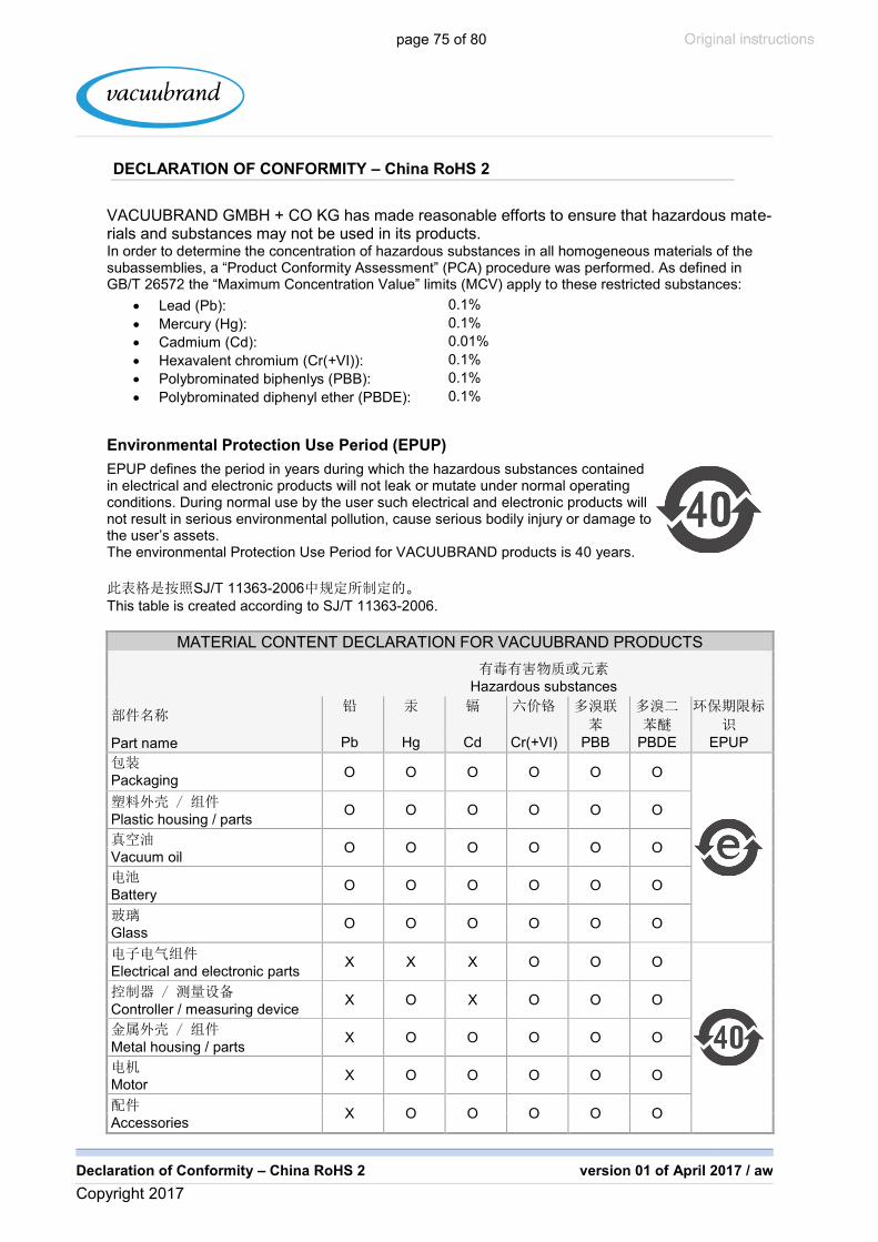
page 75 of 80
Declaration of Conformity – China RoHS 2 version 01 of April 2017 / aw
Copyright 2017
DECLARATION OF CONFORMITY – China RoHS 2
VACUUBRAND GMBH + CO KG has made reasonable efforts to ensure that hazardous mate-rials and substances may not be used in its products. In order to determine the concentration of hazardous substances in all homogeneous materials of the subassemblies, a “Product Conformity Assessment” (PCA) procedure was performed. As defined in GB/T 26572 the “Maximum Concentration Value” limits (MCV) apply to these restricted substances:
� Lead (Pb): 0.1%
� Mercury (Hg): 0.1%
� Cadmium (Cd): 0.01%
� Hexavalent chromium (Cr(+VI)): 0.1%
� Polybrominated biphenlys (PBB): 0.1%
� Polybrominated diphenyl ether (PBDE): 0.1%
Environmental Protection Use Period (EPUP)
EPUP defines the period in years during which the hazardous substances contained in electrical and electronic products will not leak or mutate under normal operating conditions. During normal use by the user such electrical and electronic products will not result in serious environmental pollution, cause serious bodily injury or damage to the user’s assets. The environmental Protection Use Period for VACUUBRAND products is 40 years.
SJ/T 11363-2006
This table is created according to SJ/T 11363-2006.
MATERIAL CONTENT DECLARATION FOR VACUUBRAND PRODUCTS
Hazardous substances
Part name Pb Hg Cd Cr(+VI) PBB PBDE EPUP
Packaging
O O O O O O
Plastic housing / parts O O O O O O
Vacuum oil
O O O O O O
Battery
O O O O O O
Glass
O O O O O O
Electrical and electronic parts
X X X O O O
Controller / measuring device
X O X O O O
Metal housing / parts
X O O O O O
Motor
X O O O O O
Accessories
X O O O O O
China RoHS

page 76 of 80
Declaration of Conformity – China RoHS 2 version 01 of April 2017 / aw
Copyright 2017
Note: Table applies to all products. Some of the components or parts listed above may not be part of the enclosed product.
O:
O: Indicates that the above mentioned hazardous substance contained in all homogeneous mate-rials of the part is below the required limit as defined in GB/T 26572.
X:
X: Indicates that the above mentioned hazardous substance contained in at least one of the ho-mogeneous materials of this part is above the required limit as defined in GB/T 26572.
Pb Hg Cd
Cr(+VI) PBB PBDE
Apart from the disclosures in the above table, the subassemblies are not intentionally manufactured or formulated with lead (Pb), mercury (Hg), cadmium (Cd), hexavalent chromium (Cr+VI), polybrominated biphenyls (PBB), and polybrominated diphenyl ethers (PBDE).
Products manufactured by VACUUBRAND may enter into further devices (e.g., rotary evaporator) or can be used together with other appliances (e.g., usage as booster pumps). With these products and appliances in particular, please note the EFUP labeled on these products. VACUUBRAND will not take responsibility for the EFUP of those products and appliances.
Place, date: Wertheim, 04/24/2017
ppa.
(Dr. F. Gitmans) (Dr. J. Dirscherl)
Managing Director Technical Director
VACUUBRAND GMBH + CO KG Tel.: +49 9342 808-0
Alfred-Zippe-Str. 4 Fax: +49 9342 808-5555
97877 Wertheim E-Mail: [email protected]
Germany Web: www.vacuubrand.com

page 77 of 80

page 78 of 80

page 79 of 80

page 80 of 80
Disclaimer: Our technical literature is only intended to inform our custom-er. The validity for specific applications of general empirical values and results obtained under test conditions depends on a number of factors beyond our control. It is therefore strictly the users’ responsibility to very carefully check the validity of application to their specific requirements. No claims arising from the information provided in this literature will, con-sequently, be entertained.
VACUUBRAND GMBH + CO KG- Technology for Vacuum Systems -© 2018 VACUUBRAND GMBH + CO KG Printed in Germany
Manual-no.: 20901317 / 26/11/2020
Alfred-Zippe-Str. 4 · 97877 Wertheim / GermanyT +49 9342 808-0 · F +49 9342 808-5555
[email protected] · www.vacuubrand.com
Related Documents