02-01-15 23 22 13 - 1 SECTION 23 22 13 STEAM AND CONDENSATE HEATING PIPING SPEC WRITER NOTE: 1. Delete between // ---- // if not applicable to project. Also delete any other item or paragraph not applicable in the section and renumber the paragraphs. 2. References to pressure in this section are gage pressure unless otherwise noted. PART 1 - GENERAL 1.1 DESCRIPTION A. Steam, condensate and vent piping inside buildings. Boiler plant and outside steam distribution piping is covered in specification Section 33 63 00, STEAM ENERGY DISTRIBUTION and Section 23 21 11, BOILER PLANT PIPING SYSTEMS. 1.2 RELATED WORK A. Section 01 33 23, SHOP DRAWINGS, PRODUCT DATA, and SAMPLES. C. Section 13 05 41, SEISMIC RESTRAINT REQUIREMENTS FOR NON-STRUCTURAL COMPONENTS. D. Section 23 05 11, COMMON WORK RESULTS FOR HVAC and STEAM GENERATION. F. Section 23 07 11, HVAC, - AND BOILER PLANT INSULATION. L. Section 23 09 23, DIRECT-DIGITAL CONTROL SYSTEM FOR HVAC. E. Section 23 22 23, STEAM CONDENSATE PUMPS. 1.3 QUALITY ASSURANCE A. Section 23 05 11, COMMON WORK RESULTS FOR HVAC and STEAM GENERATION, which includes welding qualifications. 1.4 SUBMITTALS A. Submit in accordance with Section 01 33 23, SHOP DRAWINGS, PRODUCT DATA, and SAMPLES. B. Manufacturer's Literature and Data: 1. Pipe and equipment supports.//Submit calculations for variable spring and constant support hangers//. 2. Pipe and tubing, with specification, class or type, and schedule. 3. Pipe fittings, including miscellaneous adapters and special fittings. 4. Flanges, gaskets and bolting. 5. Valves of all types. 6. Strainers. 7. Pipe alignment guides.

Welcome message from author
This document is posted to help you gain knowledge. Please leave a comment to let me know what you think about it! Share it to your friends and learn new things together.
Transcript
02-01-15
23 22 13 - 1
SECTION 23 22 13 STEAM AND CONDENSATE HEATING PIPING
SPEC WRITER NOTE: 1. Delete between // ---- // if not
applicable to project. Also delete any other item or paragraph not applicable in the section and renumber the paragraphs.
2. References to pressure in this section are gage pressure unless otherwise noted.
PART 1 - GENERAL
1.1 DESCRIPTION
A. Steam, condensate and vent piping inside buildings. Boiler plant and
outside steam distribution piping is covered in specification Section
33 63 00, STEAM ENERGY DISTRIBUTION and Section 23 21 11, BOILER PLANT
PIPING SYSTEMS.
1.2 RELATED WORK
A. Section 01 33 23, SHOP DRAWINGS, PRODUCT DATA, and SAMPLES.
C. Section 13 05 41, SEISMIC RESTRAINT REQUIREMENTS FOR NON-STRUCTURAL
COMPONENTS.
D. Section 23 05 11, COMMON WORK RESULTS FOR HVAC and STEAM GENERATION.
F. Section 23 07 11, HVAC, - AND BOILER PLANT INSULATION.
L. Section 23 09 23, DIRECT-DIGITAL CONTROL SYSTEM FOR HVAC.
E. Section 23 22 23, STEAM CONDENSATE PUMPS.
1.3 QUALITY ASSURANCE
A. Section 23 05 11, COMMON WORK RESULTS FOR HVAC and STEAM GENERATION,
which includes welding qualifications.
1.4 SUBMITTALS
A. Submit in accordance with Section 01 33 23, SHOP DRAWINGS, PRODUCT
DATA, and SAMPLES.
B. Manufacturer's Literature and Data:
1. Pipe and equipment supports.//Submit calculations for variable
spring and constant support hangers//.
2. Pipe and tubing, with specification, class or type, and schedule.
3. Pipe fittings, including miscellaneous adapters and special
fittings.
4. Flanges, gaskets and bolting.
5. Valves of all types.
6. Strainers. 7. Pipe alignment guides.

02-01-15
23 22 13 - 2
8. Expansion joints.
9. Expansion compensators.
10. Flexible ball joints: Catalog sheets, performance charts, schematic
drawings, specifications and installation instructions.
11. All specified steam system components.
12. Gages.
13. Thermometers and test wells.
14. Electric heat tracing systems.
//15. Seismic bracing details for piping.//
C. Manufacturer's certified data report, Form No. U-1, for ASME pressure
vessels:
1. Heat Exchangers (Steam-to-Hot Water).
2. Flash tanks.
D. Coordination Drawings: Refer to Article, SUBMITTALS of Section 23 05
11, COMMON WORK RESULTS FOR HVAC AND STEAM GENERATION.
E. As-Built Piping Diagrams: Provide drawing as follows for steam and
steam condensate piping and other central plant equipment.
1. One wall-mounted stick file for prints. Mount stick file in the
chiller plant or adjacent control room along with control diagram
stick file.
2. One set of reproducible drawings.
1.5 APPLICABLE PUBLICATIONS
A. The publications listed below form a part of this specification to the
extent referenced. The publications are referenced in the text by the
basic designation only.
B. American Society of Mechanical Engineers/American National Standards
Institute (ASME/ANSI):
B1.20.1-83(R2006).......Pipe Threads, General Purpose (Inch)
B16.4-2006..............Gray Iron Threaded Fittings
C. American Society of Mechanical Engineers (ASME):
B16.1-2005..............Gray Iron Pipe Flanges and Flanged Fittings
B16.3-2006..............Malleable Iron Threaded Fittings
B16.9-2007..............Factory-Made Wrought Buttwelding Fittings
B16.11-2005.............Forged Fittings, Socket-Welding and Threaded
B16.14-91...............Ferrous Pipe Plugs, Bushings, and Locknuts with
Pipe Threads
B16.22-2001.............Wrought Copper and Copper Alloy Solder-Joint
Pressure Fittings

02-01-15
23 22 13 - 3
B16.23-2002.............Cast Copper Alloy Solder Joint Drainage
Fittings
B16.24-2006.............Cast Copper Alloy Pipe Flanges and Flanged
Fittings, Class 150, 300, 400, 600, 900, 1500
and 2500
B16.39-98...............Malleable Iron Threaded Pipe Unions, Classes
150, 250, and 300
B31.1-2007..............Power Piping
B31.9-2008..............Building Services Piping
B40.100-2005............Pressure Gauges and Gauge Attachments
Boiler and Pressure Vessel Code: SEC VIII D1-2001, Pressure Vessels,
Division 1
D. American Society for Testing and Materials (ASTM):
A47-99..................Ferritic Malleable Iron Castings
A53-2007................Pipe, Steel, Black and Hot-Dipped, Zinc-Coated,
Welded and Seamless
A106-2008...............Seamless Carbon Steel Pipe for High-Temperature
Service
A126-2004...............Standard Specification for Gray Iron Castings
for Valves, Flanges, and Pipe Fittings
A181-2006...............Carbon Steel Forgings, for General-Purpose
Piping
A183-2003 .............. Carbon Steel Track Bolts and Nuts
A216-2008 .............. Standard Specification for Steel Castings,
Carbon, Suitable for Fusion Welding, for High
Temperature Service
A285-01 ................ Pressure Vessel Plates, Carbon Steel, Low-and-
Intermediate-Tensile Strength
A307-2007 .............. Carbon Steel Bolts and Studs, 60,000 PSI Tensile
Strength
A516-2006 .............. Pressure Vessel Plates, Carbon Steel, for
Moderate-and- Lower Temperature Service
A536-84(2004)e1 ........ Standard Specification for Ductile Iron Castings
B32-2008 ............... Solder Metal
B61-2008 ............... Steam or Valve Bronze Castings
B62-2009 ............... Composition Bronze or Ounce Metal Castings
B88-2003 ............... Seamless Copper Water Tube
02-01-15
23 22 13 - 4
F439-06 ................ Socket-Type Chlorinated Poly (Vinyl Chloride)
(CPVC) Plastic Pipe Fittings, Schedule 80
F441-02(2008) .......... Chlorinated Poly (Vinyl Chloride) (CPVC) Plastic
Pipe, Schedules 40 and 80
E. American Welding Society (AWS):
A5.8-2004...............Filler Metals for Brazing and Braze Welding
B2.1-00.................Welding Procedure and Performance
Qualifications
F. Manufacturers Standardization Society (MSS) of the Valve and Fitting
Industry, Inc.:
SP-67-95................Butterfly Valves
SP-70-98................Cast Iron Gate Valves, Flanged and Threaded
Ends
SP-71-97................Gray Iron Swing Check Valves, Flanged and
Threaded Ends
SP-72-99................Ball Valves with Flanged or Butt-Welding Ends
for General Service
SP-78-98................Cast Iron Plug Valves, Flanged and Threaded
Ends
SP-80-97................Bronze Gate, Globe, Angle and Check Valves
SP-85-94................Cast Iron Globe and Angle Valves, Flanged and
Threaded Ends
G. Military Specifications (Mil. Spec.):
MIL-S-901D-1989.........Shock Tests, H.I. (High Impact) Shipboard
Machinery, Equipment, and Systems
H. National Board of Boiler and Pressure Vessel Inspectors (NB): Relieving
Capacities of Safety Valves and Relief Valves
I. Tubular Exchanger Manufacturers Association: TEMA 18th Edition, 2000
PART 2 - PRODUCTS
2.1 PIPE AND EQUIPMENT SUPPORTS, PIPE SLEEVES, AND WALL AND CEILING PLATES
A. Provide in accordance with Section 23 05 11, COMMON WORK RESULTS FOR
HVAC AND STEAM GENERATION.
2.2 PIPE AND TUBING
A. Steam Piping: Steel, ASTM A53, Grade B, seamless or ERW; A106 Grade B,
Seamless; Schedule 40.
B. Steam Condensate and Pumped Condensate Piping:
1. Concealed above ceiling, in wall or chase: Copper water tube ASTM
B88, Type K, hard drawn.

02-01-15
23 22 13 - 5
2. All other locations: Copper water tube ASTM B88, Type K, hard drawn;
or steel, ASTM A53, Grade B, Seamless or ERW, or A106 Grade B
Seamless, Schedule 80.
C. Vent Piping: Steel, ASTM A53, Grade B, seamless or ERW; A106 Grade B,
Seamless; Schedule 40, galvanized.
2.3 FITTINGS FOR STEEL PIPE
A. 50 mm (2 inches) and Smaller: Screwed or welded.
1. Butt welding: ASME B16.9 with same wall thickness as connecting
piping.
2. Forged steel, socket welding or threaded: ASME B16.11.
3. Screwed: 150 pound malleable iron, ASME B16.3. 125 pound cast iron,
ASME B16.4, may be used in lieu of malleable iron, except for steam
and steam condensate piping. Provide 300 pound malleable iron, ASME
B16.3 for steam and steam condensate piping. Cast iron fittings or
piping is not acceptable for steam and steam condensate piping.
Bushing reduction of a single pipe size, or use of close nipples, is
not acceptable.
4. Unions: ASME B16.39.
5. Steam line drip station and strainer quick-couple blowdown hose
connection: Straight through, plug and socket, screw or cam locking
type for 15 mm (1/2 inch) ID hose. No integral shut-off is required.
B. 65 mm (2-1/2 inches) and Larger: Welded or flanged joints.
1. Butt welding fittings: ASME B16.9 with same wall thickness as
connecting piping. Elbows shall be long radius type, unless
otherwise noted.
2. Welding flanges and bolting: ASME B16.5:
a. Steam service: Weld neck or slip-on, raised face, with
non-asbestos gasket. Non-asbestos gasket shall either be
stainless steel spiral wound strip with flexible graphite filler
or compressed inorganic fiber with nitrile binder rated for
saturated and superheated steam service 750 degrees F and 1500
psi.
b. Flange bolting: Carbon steel machine bolts or studs and nuts,
ASTM A307, Grade B.
C. Welded Branch and Tap Connections: Forged steel weldolets, or
branchlets and threadolets may be used for branch connections up to one
pipe size smaller than the main. Forged steel half-couplings, ASME
B16.11 may be used for drain, vent and gage connections.

02-01-15
23 22 13 - 6
2.4 FITTINGS FOR COPPER TUBING
A. Solder Joint:
1. Joints shall be made up in accordance with recommended practices of
the materials applied. Apply 95/5 tin and antimony on all copper
piping.
B. Bronze Flanges and Flanged Fittings: ASME B16.24.
C. Fittings: ANSI/ASME B16.18 cast copper or ANSI/ASME B16.22 solder
wrought copper.
2.5 DIELECTRIC FITTINGS
A. Provide where copper tubing and ferrous metal pipe are joined.
B. 50 mm (2 inches) and Smaller: Threaded dielectric union, ASME B16.39.
C. 65 mm (2 1/2 inches) and Larger: Flange union with dielectric gasket
and bolt sleeves, ASME B16.42.
D. Temperature Rating, 121 degrees C (250 degrees F) for steam condensate
and as required for steam service.
E. Contractor’s option: On pipe sizes 2” and smaller, screwed end brass
gate valves // or dielectric nipples // may be used in lieu of
dielectric unions.
2.6 SCREWED JOINTS
A. Pipe Thread: ANSI B1.20.
B. Lubricant or Sealant: Oil and graphite or other compound approved for
the intended service.
2.7 VALVES
A. Asbestos packing is not acceptable.
B. All valves of the same type shall be products of a single manufacturer.
C. Provide chain operators for valves 150 mm (6 inches) and larger when
the centerline is located 2100 mm (7 feet) or more above the floor or
operating platform.
D. Shut-Off Valves
1. Gate Valves:
a. 50 mm (2 inches) and smaller: MSS-SP80, Bronze, 1034 kPa (150
lb.), wedge disc, rising stem, union bonnet.
b. 65 mm (2 1/2 inches) and larger: Flanged, outside screw and yoke.
1) High pressure steam 413 kPa (60 psig) and above nominal MPS
system): Cast steel body, ASTM A216 grade WCB, 1034 kPa (150
psig) at 260 degrees C (500 degrees F), 11-1/2 to 13 percent
chrome stainless steel solid disc and seats. Provide 25 mm (1

02-01-15
23 22 13 - 7
inch) factory installed bypass with globe valve on valves 100
mm (4 inches) and larger.
2) All other services: MSS-SP 70, iron body, bronze mounted, 861
kPa (125 psig) wedge disc.
E. Globe and Angle Valves:
1. Globe Valves:
a. 50 mm (2 inches) and smaller: MSS-SP 80, bronze, 1034 kPa (150
lb.) Globe valves shall be union bonnet with metal plug type
disc.
b. 65 mm (2 1/2 inches) and larger:
1) Globe valves for high pressure steam 413 kPa (60 psig) and
above nominal MPS system): Cast steel body, ASTM A216 grade
WCB, flanged, OS&Y, 1034 kPa (150 psig) at 260 degrees C (500
degrees F), 11-1/2 to 13 percent chrome stainless steel disc
and renewable seat rings.
2) All other services: 861 kPa (125 psig), flanged, iron body,
bronze trim, MSS-SP-85 for globe valves.
2. Angle Valves
a. 50 mm (2 inches) and smaller: MSS-SP 80, bronze, 1034 kPa (150
lb.) Angle valves shall be union bonnet with metal plug type
disc.
b. 65 mm (2 1/2 inches) and larger:
1) Angle valves for high pressure steam 413 kPa (60 psig) and
above nominal MPS system): Cast steel body, ASTM A216 grade
WCB, flanged, OS&Y, 1034 kPa (150 psig) at 260 degrees C (500
degrees F), 11-1/2 to 13 percent chrome stainless steel disc
and renewable seat rings.
2) All other services: 861 kPa (125 psig), flanged, iron body,
bronze trim, MSS-SP-85 for angle valves.
F. Swing Check Valves
1. 50 mm (2 inches) and smaller: MSS-SP 80, bronze, 1034 kPa (150
psig), 45 degree swing disc.
2. 65 mm (2-1/2 inches) and Larger:
a Check valves for high pressure steam 413 kPa (60 psig) and above
nominal MPS system: Cast steel body, ASTM A216 grade WCB,
flanged, OS&Y, 1034 kPa (150 psig) at 260 degrees C (500 degrees
F), 11-1/2 to 13 percent chrome stainless steel disc and
renewable seat rings.

02-01-15
23 22 13 - 8
b. All other services: 861 kPa (125 psig), flanged, iron body,
bronze trim, MSS-SP-71 for check valves.
G. Manual Radiator/Convector Valves: Brass, packless, with position
indicator.
2.8 STRAINERS
A. Basket or Y Type. Tee type is acceptable for gravity flow and pumped
steam condensate service.
B. High Pressure Steam: Rated 1034 kPa (150 psig) saturated steam.
1. 50 mm (2 inches) and smaller: Iron, ASTM A116 Grade B, or bronze,
ASTM B-62 body with screwed connections (250 psig).
2. 65 mm (2-1/2 inches) and larger: Flanged cast steel or 1723 kPa (250
psig) cast iron.
C. All Other Services: Rated 861 kPa (125 psig) saturated steam.
1. 50 mm (2 inches) and smaller: Cast iron or bronze.
2. 65 mm (2-1/2 inches) and larger: Flanged, iron body.
D. Screens: Bronze, monel metal or 18-8 stainless steel, free area not
less than 2-1/2 times pipe area, with perforations as follows:
1. 75 mm (3 inches) and smaller: 20 mesh for steam and 1.1 mm (0.045
inch) diameter perforations for liquids.
2. 100 mm (4 inches) and larger: 1.1 mm (0.045) inch diameter
perforations for steam and 3.2 mm (0.125 inch) diameter perforations
for liquids.
2.9 PIPE ALIGNMENT
A. Guides: Provide factory-built guides along the pipe line to permit
axial movement only and to restrain lateral and angular movement.
Guides must be designed to withstand a minimum of 15 percent of the
axial force which will be imposed on the expansion joints and anchors.
Field-built guides may be used if detailed on the contract drawings.
DESIGNER NOTE: Pipe loops are preferred. Provide pipe loops where possible.
2.10 EXPANSION JOINTS
A. Factory built devices, inserted in the pipe lines, designed to absorb
axial cyclical pipe movement which results from thermal expansion and
contraction. This includes factory-built or field-fabricated guides
located along the pipe lines to restrain lateral pipe motion and direct
the axial pipe movement into the expansion joints.

02-01-15
23 22 13 - 9
B. Minimum Service Requirements:
1. Pressure Containment:
a. Steam Service 35-200 kPa (5-30 psig): Rated 345 kPa (50 psig) at
148 degrees C (298 degrees F).
b. Steam Service 214-850 kPa (31-125 psig): Rated 1025 kPa (150
psig) at 186 degrees C (366 degrees F).
c. Steam Service 869-1025 kPa (126-150 psig): Rated 1375 kPa (200
psig) at 194 degrees C (382 degrees F).
d. Condensate Service: Rated 690 kPa (100 psig) at 154 degrees C
(310 degrees F).
2. Number of Full Reverse Cycles without failure: Minimum 1000.
3. Movement: As shown on drawings plus recommended safety factor of
manufacturer.
C. Manufacturing Quality Assurance: Conform to Expansion Joints
Manufacturers Association Standards.
D. Bellows - Internally Pressurized Type:
1. Multiple corrugations of Type 304 or Type A240-321 stainless steel.
2. Internal stainless steel sleeve entire length of bellows.
3. External cast iron equalizing rings for services exceeding 340 kPa
(50 psig).
4. Welded ends.
5. Design shall conform to standards of EJMA and ASME B31.1.
6. External tie rods designed to withstand pressure thrust force upon
anchor failure if one or both anchors for the joint are at change in
direction of pipeline.
7. Integral external cover.
E. Bellows - Externally Pressurized Type:
1. Multiple corrugations of Type 304 stainless steel.
2. Internal and external guide integral with joint.
3. Design for external pressurization of bellows to eliminate squirm.
4. Welded ends.
5. Conform to the standards of EJMA and ASME B31.1.
6. Threaded connection at bottom, 25 mm (one inch) minimum, for drain
or drip point.
7. Integral external cover and internal sleeve.
F. Expansion Joint Identification: Provide stamped brass or stainless
steel nameplate on each expansion joint listing the manufacturer, the
allowable movement, flow direction, design pressure and temperature,

02-01-15
23 22 13 - 10
date of manufacture, and identifying the expansion joint by the
identification number on the contract drawings.
2.11 FLEXIBLE BALL JOINTS
A. Design and Fabrication: One piece component construction, fabricated
from steel with welded ends, designed for a working steam pressure of
1720 kPa (250 psig) and a temperature of 232 degrees C (450 degrees F).
Each joint shall provide for 360 degrees rotation in addition to a
minimum angular flexible movement of 30 degrees for sizes 6 mm (1/4
inch) to 150 mm (6 inch) inclusive, and 15 degrees for sizes 65 mm
(2-1/2 inches) to 750 mm (30 inches). Joints through 350 mm (14 inches)
shall have forged pressure retaining members; while size 400 mm (16
inches) through 760 mm (30 inches) shall be of one piece construction.
B. Material:
1. Cast or forged steel pressure containing parts and bolting in
accordance with Section II of the ASME Boiler Code or ASME B31.1.
Retainer may be ductile iron ASTM A536, Grade 65-45-12, or ASME
Section II SA 515, Grade 70.
2. Gaskets: Steam pressure molded composition design for a temperature
range of from minus 10 degrees C (50 degrees F) to plus 274 degrees
C (525 degrees F).
C. Certificates: Submit qualifications of ball joints in accordance with
the following test data:
1. Low pressure leakage test: 41 kPa (6psig) saturated steam for 60
days.
2. Flex cycling: 800 Flex cycles at 3445 kPa (500 psig) saturated
steam.
3. Thermal cycling: 100 saturated steam pressure cycles from
atmospheric pressure to operating pressure and back to atmospheric
pressure.
4. Environmental shock tests: Forward certificate from a recognized
test laboratory, that ball joints of the type submitted has passed
shock testing in accordance with Mil. Spec MIL-S-901.
5. Vibration: 170 hours on each of three mutually perpendicular axis at
25 to 125 Hz; 1.3 mm to 2.5 mm (0.05 inch to 0.1 inch) double
amplitude on a single ball joint and 3 ball joint off set.

02-01-15
23 22 13 - 11
2.12 STEAM SYSTEM COMPONENTS
A. Heat Exchanger (Steam to Hot Water): Shell and tube type, U-bend
removable tube bundle, steam in shell, water in tubes, equipped with
support cradles.
1. Maximum tube velocity: 2.3 m/s (7.5 feet per second).
2. Tube fouling factor: TEMA Standards, but not less than 0.00018 m2K/W
(0.001 ft2hrF/Btu).
3. Materials:
a. Shell: Steel.
b. Tube sheet and tube supports: Steel or brass.
c. Tubes: 20 mm (3/4 inch) OD copper.
d. Head or bonnet: Cast iron or steel.
4. Construction: In accordance with ASME Pressure Vessel Code for 861
kPa (125 psig) working pressure for shell and tubes. Provide
manufacturer's certified data report, Form No. U-1.
B. Optional Heat Transfer Package: In lieu of field erected individual
components, the Contractor may provide a factory or shop assembled
package of heat exchangers, pumps, and other components supported on a
welded steel frame.
C. Steam Pressure Reducing Valves in PRV Stations:
1. Type: Single-seated, diaphragm operated, spring-loaded, external or
internal steam pilot-controlled, normally closed, adjustable set
pressure. Pilot shall sense controlled pressure downstream of main
valve.
2. Service: Provide controlled reduced pressure to steam piping
systems.
3. Pressure control shall be smooth and continuous with maximum drop of
10 percent. Maximum flow capability of each valve shall not exceed
capacity of downstream safety valve(s).
4. Main valve and pilot valve shall have replaceable valve plug and
seat of stainless steel, monel, or similar durable material.
a. Pressure rating for high pressure steam: Not less than 1034 kPa
(150 psig) saturated steam.
b. Connections: Flanged for valves 65 mm (2-1/2 inches) and larger;
flanged or threaded ends for smaller valves.
DESIGNER NOTE: Evaluate the need to provide acoustical measures for maintaining the specified noise levels in the adjoining spaces.
02-01-15
23 22 13 - 12
5. Select pressure reducing valves to develop less than 85 dbA at 1500
mm (5 feet) elevation above adjacent floor, and 1500 mm (5 feet)
distance in any direction. Inlet and outlet piping for steam
pressure reducing valves shall be Schedule 80 minimum for required
distance to achieve required levels or sound attenuators shall be
applied.
DESIGNER NOTE: Use pneumatically controlled valves for replacement of existing valves in existing facilities where continued use of pneumatics is required by the VA
//6. Pneumatically controlled valve: May be furnished in lieu of
steam-operation. All specification requirements for steam operated
valves apply. Valves shall close on failure of air supply.//
D. Safety Valves and Accessories: Comply with ASME Boiler and Pressure
Vessel Code, Section VIII. Capacities shall be certified by National
Board of Boiler and Pressure Vessel Inspectors, maximum accumulation 10
percent. Provide lifting lever. Provide drip pan elbow where shown.
E. Steam PRV for Individual Equipment: Cast steel or bronze body, screwed
or flanged ends, rated 861 kPa (125 psig), or 20% about the working
pressure, whichever is greater. Single-seated, diaphragm operated,
spring loaded, adjustable range, all parts renewable.
F. Flash Tanks: Horizontal or vertical vortex type, constructed of copper
bearing steel, ASTM A516 or ASTM A285, for a steam working pressure of
861 kPa (125 psig) to comply with ASME Code for Unfired Pressure
Vessels and stamped with "U" symbol. Perforated pipe inside tank shall
be ASTM A53 Grade B, Seamless or ERW, or A106 Grade B Seamless,
Schedule 80. Corrosion allowance of 1.6 mm (1/16 inch) may be provided
in lieu of the copper bearing requirement. Provide data Form No. U-1.
G. Steam Trap: Each type of trap shall be the product of a single
manufacturer. Provide trap sets at all low points and at 61 m (200
feet) intervals on the horizontal main lines.
1. Floats and linkages shall provide sufficient force to open trap
valve over full operating pressure range available to the system.
Unless otherwise indicated on the drawings, traps shall be sized for
capacities indicated at minimum pressure drop as follows:

02-01-15
23 22 13 - 13
a. For equipment with modulating control valve: 1.7 kPa (1/4 psig),
based on a condensate leg of 300 mm (12 inches) at the trap inlet
and gravity flow to the receiver.
b. For main line drip trap sets and other trap sets at steam
pressure: Up to 70 percent of design differential pressure.
Condensate may be lifted to the return line.
2. Trap bodies: Bronze, cast iron, or semi-steel, constructed to permit
ease of removal and servicing working parts without disturbing
connecting piping,(4 bolt raised face flange). For systems without
relief valve traps shall be 5. Mechanism: Brass, stainless steel
or corrosion resistant alloy rated for the pressure upstream of the
PRV supplying the system.
3. Balanced pressure thermostatic elements: Phosphor bronze, stainless
steel or monel metal.
4. Valves and seats: Suitable hardened corrosion resistant alloy.
6. Floats: Stainless steel.
7. Inverted bucket traps: Provide bi-metallic thermostatic element for
rapid release of non-condensables.
H. Thermostatic Air Vent (Steam): Brass or iron body, balanced pressure
bellows, stainless steel (renewable) valve and seat, rated 861 kPa (125
psig) working pressure, 20 mm (3/4 inch) screwed connections. Air vents
shall be balanced pressure type that responds to steam
pressure-temperature curve and vents air at any pressure.
DESIGNER NOTES: 1. Humidifiers should be located in the Air Handling Unit as far as possible and where mandated by the design. 2. Direct boiler plant steam can be used, provided the boiler water treatment chemicals are FDA and OSHA approved. Otherwise, an unfired clean steam generator shall be used.
I. Steam Humidifiers:
1. Steam separator type that discharges steam into the air stream
through a steam jacketed distribution manifold or dispersion tube.
Humidifiers shall be complete with Y-type steam supply strainer;
modulating, normally closed steam control valve; normally closed
condensate temperature switch; and manufacturer's standard steam
trap.
2. Steam separator: Stainless steel or cast iron.

02-01-15
23 22 13 - 14
3. Distribution manifold: Stainless steel, composed of dispersion pipe
and surrounding steam jacket, manifold shall span the width of duct
or air handler, and shall be multiple manifold type under any of the
following conditions:
a. Duct section height exceeds 900 mm (36 inches).
b. Duct air velocity exceeds 5.1 m/s (1000 feet per minute).
b. If within 900 mm (3 feet) upstream of fan, damper or pre-filter.
d. If within 3000 mm (10 feet) upstream of after-filter.
DESIGNER NOTE: Coordinate water quality requirements with manufacturer and local water quality conditions and provide additional equipment as recommended.
J. Unfired clean steam generator
1. Provide a packaged factory assembled, pre-piped unfired steam
generator consisting of stainless steel shell, stainless steel tube
coil, stainless steel steam piping, valves and controls All
stainless steel piping shall be type //304//316 factory-fabricated
and provided as a part of the complete package.
2. Shell: Stainless steel ASME code construction with flanged piping
connections. (150 psig) maximum WSP.
3. Tubes: Stainless Steel tubes suitable for (150 psig) working
pressure.
4. Design: Heated fluid in shell and heating fluid (higher pressure
steam) in tubes.
5. Each steam generator shall be furnished with the following
accessories:
a. Resilient insulation.
b. Pilot operated modulating control valve with pressure controller.
c. Control pilot to maintain constant steam output.
d. Pressure relief valve.
e. Vessel and tube side pressure gages.
f. Liquid level controller with brass feed water solenoid valve, in
check valve and strainer.
g. Over-pressure limit system with auto-reset.
h. Factory packaging.
i. Dual F&T condensate traps.
j. Manual blow down valve.
k. //Time based//TDS based// automatic blow down
02-01-15
23 22 13 - 15
l. Low water cut-off and high pressure cut-off.
m. Fully wired control box.
n. Automatic drain solenoid valve.
6. Provide solid state control module with LED backlit LCD display and
LED pilot lights to indicate on-off, high pressure, low pressure,
low water and water feed. Control module shall allow the local
adjustment of pressure limits on display screen. Control module
shall have alarm light and alarm horn with built in alarm silence
relay. Control module shall be supplied with dry contact closure
outputs to indicate to building automation controls (BAC) the
occurrence of power on, high pressure, low pressure, low water and
water feed. The control module shall allow the BAC to turn the
unfired steam generator on or off through a remote relay suitable
for 24 VAC, 1 amp. The control module shall allow the BAC to
remotely monitor the operating pressure. Control module shall be
supplied with an on-off switch and shall be mounted in a NEMA 1
panel. All solenoids and limits shall be 24 VAC.
K. Steam Gun Set: Furnish for ready coupling to building steam and cold
water and designed for rinsing equipment (such as carts and racks) with
hot or cold water, cleaning such articles with detergent-laden hot
water or steam, or alternately sanitizing the articles with only live
steam.
1. Gun: Fit gun for finger-tip release of steam. Design so siphoning
action will automatically mix detergent with gun effluent. Equip gun
with hardwood front and rear handgrips. Include a 25 mm (15/16-inch)
diameter, double tube butyl hose reinforced with braid and designed
for 1034 kPa (150 psig) pressure. Hose shall be 3600 mm (12 feet)
long.
2. Detergent Tank: Furnish 9.5 L (2-1/2 gallon) polyethylene or
fiberglass storage tank and fit for wall mounting. Also provide 13
mm (1/2 inch) diameter neoprene double wall detergent hose of the
same length as steam hose. Fit hose-to-tank connection with
strainer. Fit other end of hose with valve to regulate amount of
detergent to be mixed with steam.
3. Steam/Water Selector: Furnish manifold for wall mounting; design
manifold to deliver only steam or water, or steam and water mix to
gun. Construct mounting panel of stainless steel. Valves and piping
located in panel shall be brass.
02-01-15
23 22 13 - 16
4. Accessories: Provide one pair of protective gloves and three 50 mm
(2 inch) diameter brushes, one nylon and two stainless-steel.
L. Steam Hose and Accessories: Hose shall be sufficiently flexible to be
placed in a 100 mm (4 feet) diameter coil.
1. Furnish and install in the mechanical room housing each PRV station
a 7500 mm (25 feet) length of 13 mm (1/2 inch) ID steam hose, rated
861 kPa (125 psig) and a hose rack. In one end of the hose install a
quick-couple device, suitable for steam service, to match
corresponding devices in the PRV blowdown connections.
2. Hose storage rack: Wall-mounted, steel, iron or aluminum,
semi-circular shape, with capacity to store 7500 mm (25 feet) of 13
mm (1/2 inch) ID steam hose.
SPEC WRITER NOTE: Provide flow meters as shown in the design and coordinate the metering requirements with any on-going metering projects at the VA facility.
M. Steam Flow Meter/Recorder: Section 23 09 23, DIRECT-DIGITAL CONTROL
SYSTEM FOR HVAC.
SPEC WRITER NOTE: Steam exhaust head is used on steam turbines. Delete this item if not applicable.
N. Steam Exhaust Head: Cast iron, fitted with baffle plates, to trap and
drain condensed water.
2.13 GAGES, PRESSURE AND COMPOUND
A. ASME B40.1, Accuracy Grade 1A, (pressure, vacuum, or compound), initial
mid-scale accuracy 1 percent of scale (Qualify grade), metal or
phenolic case, 115 mm (4-1/2 inches) in diameter, 6 mm (1/4 inch) NPT
bottom connection, white dial with black graduations and pointer, clear
glass or acrylic plastic window, suitable for board mounting. Provide
red "set hand" to indicate normal working pressure.
B. Provide brass, lever handle union cock. Provide brass/bronze pressure
snubber for gages in water service. Provide brass pigtail syphon for
steam gages.
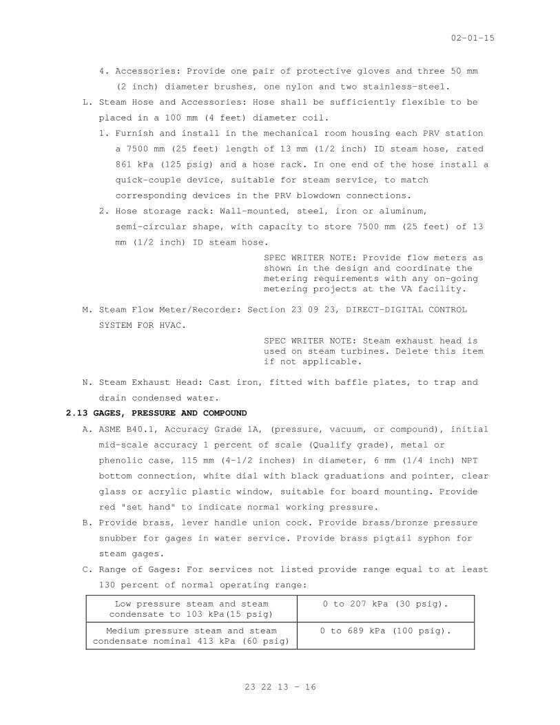
C. Range of Gages: For services not listed provide range equal to at least
130 percent of normal operating range:
Low pressure steam and steam condensate to 103 kPa(15 psig)
0 to 207 kPa (30 psig).
Medium pressure steam and steam condensate nominal 413 kPa (60 psig)
0 to 689 kPa (100 psig).

02-01-15
23 22 13 - 17
High pressure steam and steam condensate nominal 620 kPa to 861
kPa (90 to 125 psig)
0 to 1378 kPa (200 psig).
Pumped condensate, steam condensate, gravity or vacuum
(30” HG to 30 psig)
0 to 415 kPa (60 psig)
2.14 PRESSURE/TEMPERATURE TEST PROVISIONS
A. Provide one each of the following test items to the Resident Engineer:
1. 6 mm (1/4 inch) FPT by 3 mm (1/8 inch) diameter stainless steel
pressure gage adapter probe for extra long test plug. PETE'S 500 XL
is an example.
2. 90 mm (3-1/2 inch) diameter, one percent accuracy, compound gage,
762 mm (30 inches) Hg to 689 kPa (100 psig) range.
3. 0 - 104 degrees C (32-220 degrees F) pocket thermometer one-half
degree accuracy, 25 mm (one inch) dial, 125 mm (5 inch) long
stainless steel stem, plastic case.
2.15 FIRESTOPPING MATERIAL
A. Refer to Section 23 05 11, COMMON WORK RESULTS FOR HVAC AND STEAM
GENERATION.
SPEC WRITER NOTE: Verify that the extent of freeze protection for outdoor steam, condensate, and pumped condensate piping is clearly described and that electrical drawings show power supply to heat tracing.
2.16 ELECTRICAL HEAT TRACING SYSTEMS
//A. Systems shall meet requirements of the National Electrical Code (NEC),
Section 427.
B. Provide tracing for outdoor piping subject to freezing temperatures
(Below 38 degrees F) as follows:
//1. Steam piping exposed to weather. //
//2. Steam condensate exposed to weather.//
//3. Pumped condensate piping exposed to weather.//
C. Heat tracing shall be provided to the extent shown on the drawings
(Floor Plans and Elevations). Heat tracing shall extend below grade to
below the defined frost line.
D. Heating Cable: Flexible, parallel circuit construction consisting of a
continuous self-limiting resistance, conductive inner core material
between two parallel copper bus wires, designed for cut-to-length at
the job site and for wrapping around valves and complex fittings.

02-01-15
23 22 13 - 18
Self-regulation shall prevent overheating and burnouts even where the
cable overlaps itself.
1. Provide end seals at ends of circuits. Wires at the ends of the
circuits are not to be tied together.
2. Provide sufficient cable, as recommended by the manufacturer, to
keep the pipe surface at 2.2 degrees C (36 degrees F) minimum during
winter outdoor design temperature, but not less than the following:
a. 75 mm (3 inch) pipe and smaller with 25 mm (1 inch) thick
insulation: 4 watts per foot of pipe.
b. 100 mm (4 inch)pipe and larger 38 mm (1-1/2 inch) thick
insulation: 8 watts per feet of pipe.
SPEC WRITER NOTE: Coordinate the need for emergency power with project drawings (electric discipline).
E. Electrical Heating Tracing Accessories:
1. Power supply connection fitting and stainless steel mounting
brackets. Provide stainless steel worm gear clamp to fasten bracket
to pipe.
2. 13 mm (1/2 inch) wide fiberglass reinforced pressure sensitive cloth
tape to fasten cable to pipe at 300 mm (12 inch) intervals.
3. Pipe surface temperature control thermostat: Cast aluminum, NEMA 4
(watertight) enclosure, 13 mm (1/2 inch) NPT conduit hub, SPST
switch rated 20 amps at 480 volts AC, with capillary and copper bulb
sensor. Set thermostat to maintain pipe surface temperature at not
less than 1.1 degrees C (34 degrees F).
4. Signs: Manufacturer's standard (NEC Code), stamped "ELECTRIC TRACED"
located on the insulation jacket at 3000 mm (10 feet) intervals
along the pipe on alternating sides.
PART 3 - EXECUTION
3.1 GENERAL
A. The drawings show the general arrangement of pipe and equipment but do
not show all required fittings and offsets that may be necessary to
connect pipes to equipment, fan-coils, coils, radiators, etc., and to
coordinate with other trades. Provide all necessary fittings, offsets
and pipe runs based on field measurements and at no additional cost to
the government. Coordinate with other trades for space available and
relative location of HVAC equipment and accessories to be connected on
ceiling grid. Pipe location on the drawings shall be altered by

02-01-15
23 22 13 - 19
contractor where necessary to avoid interferences and clearance
difficulties.
B. Store materials to avoid excessive exposure to weather or foreign
materials. Keep inside of piping relatively clean during installation
and protect open ends when work is not in progress.
C. Support piping securely. Refer to PART 3, Section 23 05 11, COMMON WORK
RESULTS FOR HVAC AND STEAM GENERATION. Install convertors and other
heat exchangers at height sufficient to provide gravity flow of
condensate to the flash tank and condensate pump.
D. Install piping generally parallel to walls and column center lines,
unless shown otherwise on the drawings. Space piping, including
insulation, to provide 25 mm (one inch) minimum clearance between
adjacent piping or other surface. Unless shown otherwise, slope steam,
condensate and drain piping down in the direction of flow not less than
25 mm (one inch) in 12 m (40 feet). Provide eccentric reducers to keep
bottom of sloped piping flat.
E. Locate and orient valves to permit proper operation and access for
maintenance of packing, seat and disc. Generally locate valve stems in
overhead piping in horizontal position. Provide a union adjacent to one
end of all threaded end valves. Control valves usually require reducers
to connect to pipe sizes shown on the drawing. Install butterfly valves
with the valve open as recommended by the manufacturer to prevent
binding of the disc in the seat.
F. Offset equipment connections to allow valving off for maintenance and
repair with minimal removal of piping. Provide flexibility in equipment
connections and branch line take-offs with 3-elbow swing joints where
noted on the drawings.
G. Tee water piping runouts or branches into the side of mains or other
branches. Avoid bull-head tees, which are two return lines entering
opposite ends of a tee and exiting out the common side.
H. Connect piping to equipment as shown on the drawings. Install
components furnished by others such as:
1. Flow elements (orifice unions), control valve bodies, flow switches,
pressure taps with valve, and wells for sensors.
I. Firestopping: Fill openings around uninsulated piping penetrating
floors or fire walls, with firestop material. For firestopping
insulated piping refer to Section 23 07 11, HVAC, and BOILER PLANT
INSULATION.

02-01-15
23 22 13 - 20
J. Where copper piping is connected to steel piping, provide dielectric
connections.
K. Pipe vents to the exterior. Where a combined vent is provided, the
cross sectional area of the combined vent shall be equal to sum of
individual vent areas. Slope vent piping one inch in 40 feet (0.25
percent) in direction of flow. Provide a drip trap elbow on relief
valve outlets if the vent rises to prevent backpressure. Terminate
vent minimum 0.3 M (12 inches) above the roof or through the wall
minimum 2.5 M (8 feet) above grade with down turned elbow.
3.2 PIPE JOINTS
A. Welded: Beveling, spacing and other details shall conform to ASME B31.1
and AWS B2.1. See Welder’s qualification requirements under "Quality
Assurance" in Section 23 05 11, COMMON WORK RESULTS FOR HVAC and STEAM
GENERATION.
B. Screwed: Threads shall conform to ASME B1.20; joint compound shall be
applied to male threads only and joints made up so no more than three
threads show. Coat exposed threads on steel pipe with joint compound,
or red lead paint for corrosion protection.
C. 125 Pound Cast Iron Flange (Plain Face): Mating flange shall have
raised face, if any, removed to avoid overstressing the cast iron
flange.
3.3 EXPANSION JOINTS (BELLOWS AND SLIP TYPE)
A. Anchors and Guides: Provide type, quantity and spacing as recommended
by manufacturer of expansion joint and as shown. A professional
engineer shall verify in writing that anchors and guides are properly
designed for forces and moments which will be imposed.
B. Cold Set: Provide setting of joint travel at installation as
recommended by the manufacturer for the ambient temperature during the
installation.
C. Preparation for Service: Remove all apparatus provided to restrain
joint during shipping or installation. Representative of manufacturer
shall visit the site and verify that installation is proper.
D. Access: Expansion joints must be located in readily accessible space.
Locate joints to permit access without removing piping or other
devices. Allow clear space to permit replacement of joints and to
permit access to devices for inspection of all surfaces and for adding
packing.

02-01-15
23 22 13 - 21
3.4 STEAM TRAP PIPING
A. Install to permit gravity flow to the trap. Provide gravity flow (avoid
lifting condensate) from the trap where modulating control valves are
used. Support traps weighing over 11 kg (25 pounds) independently of
connecting piping.
//3.5 SEISMIC BRACING
A. Provide is accordance with Section 13 05 41, SEISMIC RESTRAINT
REQUIREMENTS FOR NON-STRUCTURAL COMPONENTS.//
3.6 LEAK TESTING
A. Inspect all joints and connections for leaks and workmanship and make
corrections as necessary, to the satisfaction of the Resident Engineer
in accordance with the specified requirements. Testing shall be
performed in accordance with the specification requirements.
B. An operating test at design pressure, and for hot systems, design
maximum temperature.
C. A hydrostatic test at 1.5 times design pressure. For water systems the
design maximum pressure would usually be the static head, or expansion
tank maximum pressure, plus pump head. Factory tested equipment
(convertors, exchangers, coils, etc.) need not be field tested. Avoid
excessive pressure on mechanical seals and safety devices.
3.7 FLUSHING AND CLEANING PIPING SYSTEMS
A. Steam, Condensate and Vent Piping: No flushing or chemical cleaning
required. Accomplish cleaning by pulling all strainer screens and
cleaning all scale/dirt legs during start-up operation.
3.8 OPERATING AND PERFORMANCE TEST AND INSTRUCTION
A. Refer to PART 3, Section 23 05 11, COMMON WORK RESULTS FOR HVAC and
STEAM GENERATION.
B. Adjust red set hand on pressure gages to normal working pressure.
- - - E N D - - -
Related Documents