Technical Publication 0366 GE Medical Systems - Kretztechnik Voluson® 730 Service Manual Direction 105844 Revision 1 Copyright© 2002; 2003 by General Electric Co. Operating Documentation GE Medical Systems Kretz Ultrasound

Welcome message from author
This document is posted to help you gain knowledge. Please leave a comment to let me know what you think about it! Share it to your friends and learn new things together.
Transcript

Technical Publication
0366
GE Medical Systems - Kretztechnik
Voluson® 730Service Manual
Direction 105844Revision 1
Copyright© 2002; 2003 by General Electric Co.
Operating Documentation
GE Medical SystemsKretz Ultrasound


GE MEDICAL SYSTEMS - KRETZTECHNIK ULTRASOUNDDIRECTION 105844, REVISION 1 VOLUSON® 730 SERVICE MANUAL
i
Important Precautions
• THIS SERVICE MANUAL IS AVAILABLE IN ENGLISH ONLY.• IF A CUSTOMER’S SERVICE PROVIDER REQUIRES A LANGUAGE OTHER THAN
ENGLISH, IT IS THE CUSTOMER’S RESPONSIBILITY TO PROVIDE TRANSLATION SERVICES.
• DO NOT ATTEMPT TO SERVICE THE EQUIPMENT UNLESS THIS SERVICE MANUAL HAS BEEN CONSULTED AND IS UNDERSTOOD.
• FAILURE TO HEED THIS WARNING MAY RESULT IN INJURY TO THE SERVICE PROVIDER, OPERATOR OR PATIENT FROM ELECTRIC SHOCK, MECHANICAL OR OTHER HAZARDS.
• CE MANUEL DE MAINTENANCE N’EST DISPONIBLE QU’EN ANGLAIS.• SI LE TECHNICIEN DU CLIENT A BESOIN DE CE MANUEL DANS UNE AUTRE
LANGUE QUE L’ANGLAIS, C’EST AU CLIENT QU’IL INCOMBE DE LE FAIRE TRADUIRE.
• NE PAS TENTER D’INTERVENTION SUR LES ÉQUIPEMENTS TANT QUE LE MANUEL SERVICE N’A PAS ÉTÉ CONSULTÉ ET COMPRIS.
• LE NON-RESPECT DE CET AVERTISSEMENT PEUT ENTRAÎNER CHEZ LE TECHNICIEN, L’OPÉRATEUR OU LE PATIENT DES BLESSURES DUES À DES DANGERS ÉLECTRIQUES, MÉCANIQUES OU AUTRES.
• DIESES KUNDENDIENST-HANDBUCH EXISTIERT NUR IN ENGLISCHER SPRACHE.
• FALLS EIN FREMDER KUNDENDIENST EINE ANDERE SPRACHE BENÖTIGT, IST ES AUFGABE DES KUNDEN FÜR EINE ENTSPRECHENDE ÜBERSETZUNG ZU SORGEN.
• VERSUCHEN SIE NICHT, DAS GERÄT ZU REPARIEREN, BEVOR DIESES KUNDENDIENST-HANDBUCH NICHT ZU RATE GEZOGEN UND VERSTANDEN WURDE.
• WIRD DIESE WARNUNG NICHT BEACHTET, SO KANN ES ZU VERLETZUNGEN DES KUNDENDIENSTTECHNIKERS, DES BEDIENERS ODER DES PATIENTEN DURCH ELEKTRISCHE SCHLÄGE, MECHANISCHE ODER SONSTIGE GEFAHREN KOMMEN.
WARNING
AVERTISSEMENT
WARNUNG

GE MEDICAL SYSTEMS - KRETZTECHNIK ULTRASOUNDDIRECTION 105844, REVISION 1 VOLUSON® 730 SERVICE MANUAL
ii -
• ESTE MANUAL DE SERVICIO SÓLO EXISTE EN INGLÉS.• SI ALGÚN PROVEEDOR DE SERVICIOS AJENO A GEMS SOLICITA UN IDIOMA
QUE NO SEA EL INGLÉS, ES RESPONSABILIDAD DEL CLIENTE OFRECER UN SERVICIO DE TRADUCCIÓN.
• NO SE DEBERÁ DAR SERVICIO TÉCNICO AL EQUIPO, SIN HABER CONSULTADO Y COMPRENDIDO ESTE MANUAL DE SERVICIO.
• LA NO OBSERVANCIA DEL PRESENTE AVISO PUEDE DAR LUGAR A QUE EL PROVEEDOR DE SERVICIOS, EL OPERADOR O EL PACIENTE SUFRAN LESIONES PROVOCADAS POR CAUSAS ELÉCTRICAS, MECÁNICAS O DE OTRA NATURALEZA.
• ESTE MANUAL DE ASSISTÊNCIA TÉCNICA SÓ SE ENCONTRA DISPONÍVEL EM INGLÊS.
• SE QUALQUER OUTRO SERVIÇO DE ASSISTÊNCIA TÉCNICA, QUE NÃO A GEMS, SOLICITAR ESTES MANUAIS NOUTRO IDIOMA, É DA RESPONSABILIDADE DO CLIENTE FORNECER OS SERVIÇOS DE TRADUÇÃO.
• NÃO TENTE REPARAR O EQUIPAMENTO SEM TER CONSULTADO E COMPREENDIDO ESTE MANUAL DE ASSISTÊNCIA TÉCNICA.
• O NÃO CUMPRIMENTO DESTE AVISO PODE POR EM PERIGO A SEGURANÇA DO TÉCNICO, OPERADOR OU PACIENTE DEVIDO A‘ CHOQUES ELÉTRICOS, MECÂNICOS OU OUTROS.
• IL PRESENTE MANUALE DI MANUTENZIONE È DISPONIBILE SOLTANTO IN INGLESE.
• SE UN ADDETTO ALLA MANUTENZIONE ESTERNO ALLA GEMS RICHIEDE IL MANUALE IN UNA LINGUA DIVERSA, IL CLIENTE È TENUTO A PROVVEDERE DIRETTAMENTE ALLA TRADUZIONE.
• SI PROCEDA ALLA MANUTENZIONE DELL’APPARECCHIATURA SOLO DOPO AVER CONSULTATO IL PRESENTE MANUALE ED AVERNE COMPRESO IL CONTENUTO.
• NON TENERE CONTO DELLA PRESENTE AVVERTENZA POTREBBE FAR COMPIERE OPERAZIONI DA CUI DERIVINO LESIONI ALL’ADDETTO ALLA MANUTENZIONE, ALL’UTILIZZATORE ED AL PAZIENTE PER FOLGORAZIONE ELETTRICA, PER URTI MECCANICI OD ALTRI RISCHI.
AVISO
ATENÇÃO
AVVERTENZA

GE MEDICAL SYSTEMS - KRETZTECHNIK ULTRASOUNDDIRECTION 105844, REVISION 1 VOLUSON® 730 SERVICE MANUAL
iii

GE MEDICAL SYSTEMS - KRETZTECHNIK ULTRASOUNDDIRECTION 105844, REVISION 1 VOLUSON® 730 SERVICE MANUAL
iv -
DAMAGE IN TRANSPORTATION - FOR USA ONLYAll packages should be closely examined at time of delivery. If damage is apparent write “Damage In Shipment” on ALL copies of the freight or express bill BEFORE delivery is accepted or “signed for” by a GE representative or hospital receiving agent. Whether noted or concealed, damage MUST be reported to the carrier immediately upon discovery, or in any event, within 14 days after receipt, and the contents and containers held for inspection by the carrier. A transportation company will not pay a claim for damage if an inspection is not requested within this 14 day period.
Call Traffic and Transportation, Milwaukee, WI (262) 827-3468 or 8*285-3468 immediately after damage is found. At this time be ready to supply name of carrier, delivery date, consignee name, freight or express bill number, item damaged and extent of damage.
Complete instructions regarding claim procedure are found in Section “S” of the Policy And Procedures Bulletins.
CERTIFIED ELECTRICAL CONTRACTOR STATEMENT - FOR USA ONLYAll electrical Installations that are preliminary to positioning of the equipment at the site prepared for the equipment shall be performed by licensed electrical contractors. Other connections between pieces of electrical equipment, calibrations and testing shall be performed by qualified GE Medical Systems personnel. In performing all electrical work on these products, GEwill use its own specially trained field engineers. All of GE’s electrical work on these products will comply with the requirements of the applicable electrical codes.
The purchaser of GE equipment shall only utilize qualified personnel (i.e., GE’s field engineers, personnel of third-party service companies with equivalent training, or licensed electricians) to perform electrical servicing on the equipment.
OMISSIONS & ERRORSIf there are any omissions, errors or suggestions for improving this documentation, please contact the GE Medical Systems Global Documentation Group with specific information listing the system type, manual title, part number, revision number, page number and suggestion details. E-mail the information to: [email protected]
GE Medical Systems employees should use the Customer Quality Assurance (CQA) System to report all documentation omissions, errors or suggestions.
For USA Only
For USA Only

GE MEDICAL SYSTEMS - KRETZTECHNIK ULTRASOUNDDIRECTION 105844, REVISION 1 VOLUSON® 730 SERVICE MANUAL
v
Revision History
List of Effected Pages
Revision Date Reason for change0 July 16, 2002 Release for M4
1 July 23, 2003 Software Version Sys D03-1.07
Pages Revision Pages Revision Pages Revision
Title Page 1Chapter 2 - Pre-Installationpages 2-1 to 2-8pages 2-9 to 2-10
01
Chapter 7 - Diagnostics/Troubleshootingpage 7-1 to 7-7page 7-8pages 7-9 to 7-26
010
Important Precautionspages i to iv 1
Chapter 3 - Installationpages 3-1 to 3-3pages 3-4 to 3-10pages 3-11 to 3-27pages 3-28 to 3-34pages 3-35 to 3-38
10101
Chapter 8 - Replacement Procedurespages 8-1 to 8-8 1
Rev History/LOEPpages v to vi 1
Chapter 4 - Functional Checkspages 4-1 to 4-22pages 4-23 to 4-28pages 4-29 to 4-30pages 4-31 to 4-32pages 4-33 to 4-36
01010
Chapter 9 - Replacement Partspages 9-1 to 9-3pages 9-4 to 9-29pages 9-30 to 9-34
010
Table of Contentspages vii to xxii 1
Chapter 5 - Theorypages 5-1 to 5-22pages 5-23 to 5-24pages 5-25 to 5-42pages 5-43 to 5-44
0101
Chapter 10 - Periodic Maintenancepages 10-1 to 10-8page 10-9pages 10-10 to 10-26
010
Chapter 1 - Introductionpages 1-1 to 1-8page 1-9pages 1-10 to 1-12
010
Chapter 6 - Service Adjustmentspages 6-1 to 6-6 0
Indexpages I to IV 1
Back Cover 0

GE MEDICAL SYSTEMS - KRETZTECHNIK ULTRASOUNDDIRECTION 105844, REVISION 1 VOLUSON® 730 SERVICE MANUAL
vi -

GE MEDICAL SYSTEMS - KRETZTECHNIK ULTRASOUNDDIRECTION 105844, REVISION 1 VOLUSON® 730 SERVICE MANUAL
vii Table of Contents
Table of ContentsCHAPTER 1Introduction
Overview . . . . . . . . . . . . . . . . . . . . . . . . . . . . . . . . . . . . . . . . . . . . . . . . . . . . . . . . . 1 - 1Purpose of Chapter 1 . . . . . . . . . . . . . . . . . . . . . . . . . . . . . . . . . . . . . . . . . . 1 - 1Purpose of Service Manual . . . . . . . . . . . . . . . . . . . . . . . . . . . . . . . . . . . . . 1 - 1Typical Users of the Basic Service Manual . . . . . . . . . . . . . . . . . . . . . . . . . 1 - 2Voluson® 730 Models Covered by this Manual . . . . . . . . . . . . . . . . . . . . . . 1 - 2Purpose of Operator Manual(s) . . . . . . . . . . . . . . . . . . . . . . . . . . . . . . . . . . 1 - 2
Important Conventions. . . . . . . . . . . . . . . . . . . . . . . . . . . . . . . . . . . . . . . . . . . . . . . 1 - 3Conventions Used in Book . . . . . . . . . . . . . . . . . . . . . . . . . . . . . . . . . . . . . . 1 - 3Standard Hazard Icons . . . . . . . . . . . . . . . . . . . . . . . . . . . . . . . . . . . . . . . . 1 - 4Product Icons . . . . . . . . . . . . . . . . . . . . . . . . . . . . . . . . . . . . . . . . . . . . . . . . 1 - 5
Safety Considerations . . . . . . . . . . . . . . . . . . . . . . . . . . . . . . . . . . . . . . . . . . . . . . . 1 - 7Introduction . . . . . . . . . . . . . . . . . . . . . . . . . . . . . . . . . . . . . . . . . . . . . . . . . 1 - 7Human Safety . . . . . . . . . . . . . . . . . . . . . . . . . . . . . . . . . . . . . . . . . . . . . . . 1 - 7Mechanical Safety . . . . . . . . . . . . . . . . . . . . . . . . . . . . . . . . . . . . . . . . . . . . 1 - 7Electrical Safety . . . . . . . . . . . . . . . . . . . . . . . . . . . . . . . . . . . . . . . . . . . . . . 1 - 8Labels Locations . . . . . . . . . . . . . . . . . . . . . . . . . . . . . . . . . . . . . . . . . . . . . 1 - 8Dangerous Procedure Warnings . . . . . . . . . . . . . . . . . . . . . . . . . . . . . . . . . 1 - 9Lockout/Tagout Requirements (For USA Only) . . . . . . . . . . . . . . . . . . . . . . 1 - 9Returning/Shipping Probes and Repair Parts . . . . . . . . . . . . . . . . . . . . . . . 1 - 9
EMC, EMI, and ESD . . . . . . . . . . . . . . . . . . . . . . . . . . . . . . . . . . . . . . . . . . . . . . . . 1 - 10Electromagnetic Compatibility (EMC) . . . . . . . . . . . . . . . . . . . . . . . . . . . . . 1 - 10CE Compliance . . . . . . . . . . . . . . . . . . . . . . . . . . . . . . . . . . . . . . . . . . . . . . 1 - 10Electrostatic Discharge (ESD) Prevention . . . . . . . . . . . . . . . . . . . . . . . . . . 1 - 10
Customer Assistance . . . . . . . . . . . . . . . . . . . . . . . . . . . . . . . . . . . . . . . . . . . . . . . . 1 - 11Contact Information . . . . . . . . . . . . . . . . . . . . . . . . . . . . . . . . . . . . . . . . . . . 1 - 11System Manufacturer . . . . . . . . . . . . . . . . . . . . . . . . . . . . . . . . . . . . . . . . . . 1 - 12

GE MEDICAL SYSTEMS - KRETZTECHNIK ULTRASOUNDDIRECTION 105844, REVISION 1 VOLUSON® 730 SERVICE MANUAL
viii -
CHAPTER 2Pre-Installation
Overview . . . . . . . . . . . . . . . . . . . . . . . . . . . . . . . . . . . . . . . . . . . . . . . . . . . . . . . . . 2 - 1Purpose of Chapter 2 . . . . . . . . . . . . . . . . . . . . . . . . . . . . . . . . . . . . . . . . . . 2 - 1
General Console Requirements. . . . . . . . . . . . . . . . . . . . . . . . . . . . . . . . . . . . . . . . 2 - 2Console Environmental Requirements . . . . . . . . . . . . . . . . . . . . . . . . . . . . . 2 - 2
Cooling . . . . . . . . . . . . . . . . . . . . . . . . . . . . . . . . . . . . . . . . . . . . . . . 2 - 2Lighting . . . . . . . . . . . . . . . . . . . . . . . . . . . . . . . . . . . . . . . . . . . . . . . 2 - 2
Electrical Requirements . . . . . . . . . . . . . . . . . . . . . . . . . . . . . . . . . . . . . . . . 2 - 2Voluson® 730 Power Requirements . . . . . . . . . . . . . . . . . . . . . . . . . 2 - 2Inrush Current . . . . . . . . . . . . . . . . . . . . . . . . . . . . . . . . . . . . . . . . . . 2 - 2Site Circuit Breaker . . . . . . . . . . . . . . . . . . . . . . . . . . . . . . . . . . . . . . 2 - 3Site Power Outlets . . . . . . . . . . . . . . . . . . . . . . . . . . . . . . . . . . . . . . . 2 - 3Unit Power Plug . . . . . . . . . . . . . . . . . . . . . . . . . . . . . . . . . . . . . . . . . 2 - 3
EMI Limitations . . . . . . . . . . . . . . . . . . . . . . . . . . . . . . . . . . . . . . . . . . . . . . . 2 - 4Scan Probe Environmental Requirements . . . . . . . . . . . . . . . . . . . . . . . . . . 2 - 5Time and Manpower Requirements . . . . . . . . . . . . . . . . . . . . . . . . . . . . . . . 2 - 5
Facility Needs . . . . . . . . . . . . . . . . . . . . . . . . . . . . . . . . . . . . . . . . . . . . . . . . . . . . . 2 - 6Purchaser Responsibilities . . . . . . . . . . . . . . . . . . . . . . . . . . . . . . . . . . . . . . 2 - 6Required Features . . . . . . . . . . . . . . . . . . . . . . . . . . . . . . . . . . . . . . . . . . . . 2 - 6Desirable Features . . . . . . . . . . . . . . . . . . . . . . . . . . . . . . . . . . . . . . . . . . . . 2 - 7Minimal Floor Plan Suggestion . . . . . . . . . . . . . . . . . . . . . . . . . . . . . . . . . . 2 - 8Networking Pre-installation Requirements . . . . . . . . . . . . . . . . . . . . . . . . . . 2 - 9
Purpose of the DICOM Network Function . . . . . . . . . . . . . . . . . . . . . 2 - 9DICOM Option Pre-installation Requirements . . . . . . . . . . . . . . . . . . 2 - 9

GE MEDICAL SYSTEMS - KRETZTECHNIK ULTRASOUNDDIRECTION 105844, REVISION 1 VOLUSON® 730 SERVICE MANUAL
ix
CHAPTER 3Installation
Overview. . . . . . . . . . . . . . . . . . . . . . . . . . . . . . . . . . . . . . . . . . . . . . . . . . . . . . . . . 3 - 1The Purpose of Chapter 3 . . . . . . . . . . . . . . . . . . . . . . . . . . . . . . . . . . . . . 3 - 1Average Installation Time . . . . . . . . . . . . . . . . . . . . . . . . . . . . . . . . . . . . . . 3 - 1Installation Warnings . . . . . . . . . . . . . . . . . . . . . . . . . . . . . . . . . . . . . . . . . 3 - 2
Brake Pedal Operation . . . . . . . . . . . . . . . . . . . . . . . . . . . . . . . . . . . 3 - 2Operator I/O Panel Position . . . . . . . . . . . . . . . . . . . . . . . . . . . . . . . 3 - 2
Safety Reminders . . . . . . . . . . . . . . . . . . . . . . . . . . . . . . . . . . . . . . . . . . . . 3 - 3
Receiving and Unpacking the Equipment. . . . . . . . . . . . . . . . . . . . . . . . . . . . . . . . 3 - 4
Preparing for Installation. . . . . . . . . . . . . . . . . . . . . . . . . . . . . . . . . . . . . . . . . . . . . 3 - 6Connection of Auxiliary Devices . . . . . . . . . . . . . . . . . . . . . . . . . . . . . . . . . 3 - 6
Monitor Connection . . . . . . . . . . . . . . . . . . . . . . . . . . . . . . . . . . . . . 3 - 6Connection of Peripherals . . . . . . . . . . . . . . . . . . . . . . . . . . . . . . . . 3 - 6
Verify Customer Order . . . . . . . . . . . . . . . . . . . . . . . . . . . . . . . . . . . . . . . . 3 - 7Physical Inspection . . . . . . . . . . . . . . . . . . . . . . . . . . . . . . . . . . . . . . . . . . . 3 - 7
System Voltage Settings . . . . . . . . . . . . . . . . . . . . . . . . . . . . . . . . . 3 - 7EMI Protection . . . . . . . . . . . . . . . . . . . . . . . . . . . . . . . . . . . . . . . . . . . . . . 3 - 7
Completing the Installation . . . . . . . . . . . . . . . . . . . . . . . . . . . . . . . . . . . . . . . . . . . 3 - 8System Specifications . . . . . . . . . . . . . . . . . . . . . . . . . . . . . . . . . . . . . . . . . 3 - 8
Physical Dimensions of Voluson® 730 . . . . . . . . . . . . . . . . . . . . . . 3 - 8Weight without Monitor and Peripherals . . . . . . . . . . . . . . . . . . . . . 3 - 8Acoustic Noise Output . . . . . . . . . . . . . . . . . . . . . . . . . . . . . . . . . . . 3 - 8
Electrical Specifications . . . . . . . . . . . . . . . . . . . . . . . . . . . . . . . . . . . . . . . 3 - 8Power On / Boot Up . . . . . . . . . . . . . . . . . . . . . . . . . . . . . . . . . . . . . . . . . . 3 - 9
Scanner Power On . . . . . . . . . . . . . . . . . . . . . . . . . . . . . . . . . . . . . . 3 - 9Back-end Processor Boot Up . . . . . . . . . . . . . . . . . . . . . . . . . . . . . . 3 - 9
Power Off/ Shutdown . . . . . . . . . . . . . . . . . . . . . . . . . . . . . . . . . . . . . . . . . 3 - 10Back-end Processor Power Down . . . . . . . . . . . . . . . . . . . . . . . . . . 3 - 10Scanner Shutdown . . . . . . . . . . . . . . . . . . . . . . . . . . . . . . . . . . . . . . 3 - 10
Transducer Connection . . . . . . . . . . . . . . . . . . . . . . . . . . . . . . . . . . . . . . . 3 - 11
Printer Installation. . . . . . . . . . . . . . . . . . . . . . . . . . . . . . . . . . . . . . . . . . . . . . . . . . 3 - 12Installing Line Printer HP 990cxi or HP 995c . . . . . . . . . . . . . . . . . . . . . . . 3 - 12
Install the HP printer software/driver . . . . . . . . . . . . . . . . . . . . . . . . 3 - 12Installing Digital Color Printer Sony UP-D21MD . . . . . . . . . . . . . . . . . . . . . 3 - 14
Install the UP-D21MD printer software/driver . . . . . . . . . . . . . . . . . 3 - 14Installing Digital Color Printer (Sony UP-D2600S or Mitsubishi CP770DW) 3 - 16Printer Installation manually . . . . . . . . . . . . . . . . . . . . . . . . . . . . . . . . . . . . 3 - 17Adjustment of Printer Settings . . . . . . . . . . . . . . . . . . . . . . . . . . . . . . . . . . 3 - 23

GE MEDICAL SYSTEMS - KRETZTECHNIK ULTRASOUNDDIRECTION 105844, REVISION 1 VOLUSON® 730 SERVICE MANUAL
x -
HP 990cxi / HP 995c - Printer Settings . . . . . . . . . . . . . . . . . . . . . . . 3 - 24UP-D21MD - Printer Settings . . . . . . . . . . . . . . . . . . . . . . . . . . . . . . 3 - 25CP770DW - Printer Settings . . . . . . . . . . . . . . . . . . . . . . . . . . . . . . . 3 - 26
Printer Remote Control Selection . . . . . . . . . . . . . . . . . . . . . . . . . . . . . . . . . 3 - 27
System Configuration. . . . . . . . . . . . . . . . . . . . . . . . . . . . . . . . . . . . . . . . . . . . . . . . 3 - 28System Configuration . . . . . . . . . . . . . . . . . . . . . . . . . . . . . . . . . . . . . . . . . . 3 - 28
How to enter Date and Time . . . . . . . . . . . . . . . . . . . . . . . . . . . . . . . 3 - 29How to enter Hospital Name . . . . . . . . . . . . . . . . . . . . . . . . . . . . . . . 3 - 29How to change Language . . . . . . . . . . . . . . . . . . . . . . . . . . . . . . . . . 3 - 29
On-Board Optional Peripherals . . . . . . . . . . . . . . . . . . . . . . . . . . . . . . . . . . 3 - 30External I/O Connection Panel (GES) . . . . . . . . . . . . . . . . . . . . . . . . . . . . . 3 - 31
External I/O Pin Outs . . . . . . . . . . . . . . . . . . . . . . . . . . . . . . . . . . . . . 3 - 32Video Specification . . . . . . . . . . . . . . . . . . . . . . . . . . . . . . . . . . . . . . . . . . . . 3 - 34Available Probes . . . . . . . . . . . . . . . . . . . . . . . . . . . . . . . . . . . . . . . . . . . . . 3 - 35Software/Option Configuration . . . . . . . . . . . . . . . . . . . . . . . . . . . . . . . . . . . 3 - 35
Connectivity Installation Worksheet . . . . . . . . . . . . . . . . . . . . . . . . . . . . . . . . . . . . . 3 - 36
Network IP Address Configuration. . . . . . . . . . . . . . . . . . . . . . . . . . . . . . . . . . . . . . 3 - 37
Paperwork . . . . . . . . . . . . . . . . . . . . . . . . . . . . . . . . . . . . . . . . . . . . . . . . . . . . . . . . 3 - 38Product Locator Installation . . . . . . . . . . . . . . . . . . . . . . . . . . . . . . . . . . . . . 3 - 38User Manual(s) . . . . . . . . . . . . . . . . . . . . . . . . . . . . . . . . . . . . . . . . . . . . . . . 3 - 38

GE MEDICAL SYSTEMS - KRETZTECHNIK ULTRASOUNDDIRECTION 105844, REVISION 1 VOLUSON® 730 SERVICE MANUAL
xi
CHAPTER 4Functional Checks
. . . . . . . . . . . . . . . . . . . . . . . . . . . . . . . . . . . . . . . . . . . . . . . . . . . . . . . . . . . . . . . . Overview . . . . . . . . . . . . . . . . . . . . . . . . . . . . . . . . . . . . . . . . . . . . . . . . . . . . . . . . 4 - 1
Purpose of Chapter 4 . . . . . . . . . . . . . . . . . . . . . . . . . . . . . . . . . . . . . . . . . 4 - 1
Required Equipment. . . . . . . . . . . . . . . . . . . . . . . . . . . . . . . . . . . . . . . . . . . . . . . . 4 - 1
General Procedure . . . . . . . . . . . . . . . . . . . . . . . . . . . . . . . . . . . . . . . . . . . . . . . . . 4 - 2Power On / Boot Up . . . . . . . . . . . . . . . . . . . . . . . . . . . . . . . . . . . . . . . . . . 4 - 2
Scanner Power On . . . . . . . . . . . . . . . . . . . . . . . . . . . . . . . . . . . . . . 4 - 2Power Off / Shutdown . . . . . . . . . . . . . . . . . . . . . . . . . . . . . . . . . . . . . . . . 4 - 3
Scanner Shutdown . . . . . . . . . . . . . . . . . . . . . . . . . . . . . . . . . . . . . . 4 - 3System Features . . . . . . . . . . . . . . . . . . . . . . . . . . . . . . . . . . . . . . . . . . . . . 4 - 4
Control Panel . . . . . . . . . . . . . . . . . . . . . . . . . . . . . . . . . . . . . . . . . . 4 - 4Touch Panel . . . . . . . . . . . . . . . . . . . . . . . . . . . . . . . . . . . . . . . . . . 4 - 5Monitor Display . . . . . . . . . . . . . . . . . . . . . . . . . . . . . . . . . . . . . . . . 4 - 6
Functional Checks . . . . . . . . . . . . . . . . . . . . . . . . . . . . . . . . . . . . . . . . . . . . . . . . . 4 - 72D-Mode Checks . . . . . . . . . . . . . . . . . . . . . . . . . . . . . . . . . . . . . . . . . . . . 4 - 7M-Mode Checks . . . . . . . . . . . . . . . . . . . . . . . . . . . . . . . . . . . . . . . . . . . . . 4 - 10Spectral Doppler Mode Checks . . . . . . . . . . . . . . . . . . . . . . . . . . . . . . . . . 4 - 11Color Doppler Mode Checks . . . . . . . . . . . . . . . . . . . . . . . . . . . . . . . . . . . 4 - 12Volume Mode Checks . . . . . . . . . . . . . . . . . . . . . . . . . . . . . . . . . . . . . . . . 4 - 14
Pre-Volume Mode Functions . . . . . . . . . . . . . . . . . . . . . . . . . . . . . . 4 - 14Functions after the 3D Acquisition . . . . . . . . . . . . . . . . . . . . . . . . . . 4 - 15Functions in the Tool Menu . . . . . . . . . . . . . . . . . . . . . . . . . . . . . . . 4 - 16
Using Cine-Mode . . . . . . . . . . . . . . . . . . . . . . . . . . . . . . . . . . . . . . . . . . . . 4 - 17Activating Cine . . . . . . . . . . . . . . . . . . . . . . . . . . . . . . . . . . . . . . . . . 4 - 17Cine-Split Function (Multiple Format) . . . . . . . . . . . . . . . . . . . . . . . 4 - 17Activating 2D Auto Cine . . . . . . . . . . . . . . . . . . . . . . . . . . . . . . . . . . 4 - 17Spectral Doppler- or M-Cine Loop . . . . . . . . . . . . . . . . . . . . . . . . . . 4 - 17Activating 3D Rotation Cine . . . . . . . . . . . . . . . . . . . . . . . . . . . . . . . 4 - 17Activating 4D Cine . . . . . . . . . . . . . . . . . . . . . . . . . . . . . . . . . . . . . . 4 - 17Activating Live 3D Cine . . . . . . . . . . . . . . . . . . . . . . . . . . . . . . . . . . 4 - 17
Basic Measurements . . . . . . . . . . . . . . . . . . . . . . . . . . . . . . . . . . . . . . . . . 4 - 18Distance and Tissue DepthMeasurements (B- and M-Mode) . . . . . 4 - 18Circumference/Area (using Ellipse or Trace) Measurements . . . . . 4 - 19Volume Measurements . . . . . . . . . . . . . . . . . . . . . . . . . . . . . . . . . . 4 - 19
3D Multi-Plane Measurements . . . . . . . . . . . . . . . . . . . . . . . 4 - 19Velocity Measurements (Spectral Doppler Mode) . . . . . . . . . . . . . . 4 - 20
Acceleration Velocity and Velocity Ratio . . . . . . . . . . . . . . . . 4 - 20Average Velocity (Manual Trace) . . . . . . . . . . . . . . . . . . . . . 4 - 20Average Velocity (Auto Trace) . . . . . . . . . . . . . . . . . . . . . . . 4 - 20
Calculation Measurements . . . . . . . . . . . . . . . . . . . . . . . . . . . . . . . . . . . . 4 - 21
GE MEDICAL SYSTEMS - KRETZTECHNIK ULTRASOUNDDIRECTION 105844, REVISION 1 VOLUSON® 730 SERVICE MANUAL
xii -
OB Calculations . . . . . . . . . . . . . . . . . . . . . . . . . . . . . . . . . . . . . . . . . 4 - 21GYN Calculations . . . . . . . . . . . . . . . . . . . . . . . . . . . . . . . . . . . . . . . 4 - 21Cardiac Calculations . . . . . . . . . . . . . . . . . . . . . . . . . . . . . . . . . . . . . 4 - 21Vascular Calculations . . . . . . . . . . . . . . . . . . . . . . . . . . . . . . . . . . . . 4 - 21Report Pages . . . . . . . . . . . . . . . . . . . . . . . . . . . . . . . . . . . . . . . . . . 4 - 21
Probe/Connectors Usage . . . . . . . . . . . . . . . . . . . . . . . . . . . . . . . . . . . . . . . 4 - 22Connecting a probe . . . . . . . . . . . . . . . . . . . . . . . . . . . . . . . . . . . . . . 4 - 22Activating the probe . . . . . . . . . . . . . . . . . . . . . . . . . . . . . . . . . . . . . . 4 - 22Deactivating the probe . . . . . . . . . . . . . . . . . . . . . . . . . . . . . . . . . . . 4 - 22Disconnecting the probe . . . . . . . . . . . . . . . . . . . . . . . . . . . . . . . . . . 4 - 22
Image Management (Sonoview) . . . . . . . . . . . . . . . . . . . . . . . . . . . . . . . . . 4 - 23Using the MOD (Magneto-Optical Drive) . . . . . . . . . . . . . . . . . . . . . . . . . . . 4 - 24Backup and Restore Database, Preset Configurations and Images . . . . . . 4 - 25
Formatting Media . . . . . . . . . . . . . . . . . . . . . . . . . . . . . . . . . . . . . . . 4 - 25Save System Presets and Configurations (Application Settings) . . . 4 - 27Load System Presets and Configurations (Application Settings) . . . 4 - 28Archiving Images . . . . . . . . . . . . . . . . . . . . . . . . . . . . . . . . . . . . . . . . 4 - 30
ECG Check Out . . . . . . . . . . . . . . . . . . . . . . . . . . . . . . . . . . . . . . . . . . . . . 4 - 31
Software Configuration Checks . . . . . . . . . . . . . . . . . . . . . . . . . . . . . . . . . . . . . . . . 4 - 31
Peripheral Checks . . . . . . . . . . . . . . . . . . . . . . . . . . . . . . . . . . . . . . . . . . . . . . . . . . 4 - 32
Mechanical Function Checks . . . . . . . . . . . . . . . . . . . . . . . . . . . . . . . . . . . . . . . . . 4 - 33Rotation of the Control Console . . . . . . . . . . . . . . . . . . . . . . . . . . . . . . . . . . 4 - 33Brakes and Direction Locks . . . . . . . . . . . . . . . . . . . . . . . . . . . . . . . . . . . . . 4 - 33Power Supply Adjustment . . . . . . . . . . . . . . . . . . . . . . . . . . . . . . . . . . . . . . 4 - 34
Site Log . . . . . . . . . . . . . . . . . . . . . . . . . . . . . . . . . . . . . . . . . . . . . . . . . . . . . . . . . . 4 - 35Site Log - System (Service Database) . . . . . . . . . . . . . . . . . . . . . . . . . . . . . 4 - 35Site Log - Paper Documentation . . . . . . . . . . . . . . . . . . . . . . . . . . . . . . . . . 4 - 36

GE MEDICAL SYSTEMS - KRETZTECHNIK ULTRASOUNDDIRECTION 105844, REVISION 1 VOLUSON® 730 SERVICE MANUAL
xiii
CHAPTER 5Components and Functions (Theory)
Overview. . . . . . . . . . . . . . . . . . . . . . . . . . . . . . . . . . . . . . . . . . . . . . . . . . . . . . . . . 5 - 1Purpose of Chapter 5 . . . . . . . . . . . . . . . . . . . . . . . . . . . . . . . . . . . . . . . . . 5 - 1
General Information . . . . . . . . . . . . . . . . . . . . . . . . . . . . . . . . . . . . . . . . . . . . . . . . 5 - 2Description of Voluson® 730 Operating Modes . . . . . . . . . . . . . . . . . . . . . 5 - 6
B-Mode or 2D-Mode: . . . . . . . . . . . . . . . . . . . . . . . . . . . . . . . . . . . . 5 - 6M-Mode: . . . . . . . . . . . . . . . . . . . . . . . . . . . . . . . . . . . . . . . . . . . . . . 5 - 6Color Doppler Mode: . . . . . . . . . . . . . . . . . . . . . . . . . . . . . . . . . . . . 5 - 6
Color Flow Mode: . . . . . . . . . . . . . . . . . . . . . . . . . . . . . . . . . 5 - 6Power Doppler: . . . . . . . . . . . . . . . . . . . . . . . . . . . . . . . . . . . 5 - 6
Pulsed (PW) Doppler: . . . . . . . . . . . . . . . . . . . . . . . . . . . . . . . . . . . 5 - 73D Imaging . . . . . . . . . . . . . . . . . . . . . . . . . . . . . . . . . . . . . . . . . . . . . . . . . 5 - 7
3D Data Collection and Reconstruction: . . . . . . . . . . . . . . . . . . . . . 5 - 73D Image Presentation: . . . . . . . . . . . . . . . . . . . . . . . . . . . . . . . . . . 5 - 83D Rendering: . . . . . . . . . . . . . . . . . . . . . . . . . . . . . . . . . . . . . . . . . 5 - 8
Blockdiagram Voluson® 730 . . . . . . . . . . . . . . . . . . . . . . . . . . . . . . . . . . . 5 - 9Dataflow Control Description . . . . . . . . . . . . . . . . . . . . . . . . . . . . . . . . . . . 5 - 10
B-Mode . . . . . . . . . . . . . . . . . . . . . . . . . . . . . . . . . . . . . . . . . . . . . . 5 - 10M-Mode . . . . . . . . . . . . . . . . . . . . . . . . . . . . . . . . . . . . . . . . . . . . . . 5 - 11D-Mode (Pulsed Wave- and Continuous Wave Doppler) . . . . . . . . 5 - 12CFM-Mode (Color Flow Mode) . . . . . . . . . . . . . . . . . . . . . . . . . . . . 5 - 123D-Mode . . . . . . . . . . . . . . . . . . . . . . . . . . . . . . . . . . . . . . . . . . . . . 5 - 13Real Time 4D-Mode . . . . . . . . . . . . . . . . . . . . . . . . . . . . . . . . . . . . . 5 - 13External Video Mode (Video display from VCR) . . . . . . . . . . . . . . . 5 - 14
Description of Software Options . . . . . . . . . . . . . . . . . . . . . . . . . . . . . . . . . 5 - 15Real Time 4D . . . . . . . . . . . . . . . . . . . . . . . . . . . . . . . . . . . . . . . . . . 5 - 15DICOM . . . . . . . . . . . . . . . . . . . . . . . . . . . . . . . . . . . . . . . . . . . . . . . 5 - 15Real Time 4D-Biopsy . . . . . . . . . . . . . . . . . . . . . . . . . . . . . . . . . . . . 5 - 15VOCAL - Virtual Organ Computer-aided Analysis . . . . . . . . . . . . . . 5 - 15Tissue Harmonic Imaging (THI) . . . . . . . . . . . . . . . . . . . . . . . . . . . . 5 - 16Sonoview – Image Management . . . . . . . . . . . . . . . . . . . . . . . . . . . 5 - 16CRI - Compound Resolution Imaging . . . . . . . . . . . . . . . . . . . . . . . 5 - 16Tissue Doppler Imaging . . . . . . . . . . . . . . . . . . . . . . . . . . . . . . . . . . 5 - 16VCI - Volume Contrast Imaging . . . . . . . . . . . . . . . . . . . . . . . . . . . . 5 - 16
Description of Hardware Options . . . . . . . . . . . . . . . . . . . . . . . . . . . . . . . . 5 - 17CW - Continuous Wave Doppler . . . . . . . . . . . . . . . . . . . . . . . . . . . 5 - 17ECG Digital Module . . . . . . . . . . . . . . . . . . . . . . . . . . . . . . . . . . . . . 5 - 17Scan freeze Footswitch . . . . . . . . . . . . . . . . . . . . . . . . . . . . . . . . . . 5 - 17
Main board Chassis GEF Module. . . . . . . . . . . . . . . . . . . . . . . . . . . . . . . . . . . . . . 5 - 18
Front End Processor . . . . . . . . . . . . . . . . . . . . . . . . . . . . . . . . . . . . . . . . . . . . . . . 5 - 19Front End - Board Descriptions . . . . . . . . . . . . . . . . . . . . . . . . . . . . . . . . . 5 - 21

GE MEDICAL SYSTEMS - KRETZTECHNIK ULTRASOUNDDIRECTION 105844, REVISION 1 VOLUSON® 730 SERVICE MANUAL
xiv -
CPU - Probe Board . . . . . . . . . . . . . . . . . . . . . . . . . . . . . . . . . . . . . . 5 - 21CPR - Beamformer Board . . . . . . . . . . . . . . . . . . . . . . . . . . . . . . . . . 5 - 21
CPD-Beamformer-Sub-board . . . . . . . . . . . . . . . . . . . . . . . . . 5 - 21CRW - (old version: CWD) CW-Doppler Board (Optional) . . . . . . . . 5 - 21CPZ - Cover Board . . . . . . . . . . . . . . . . . . . . . . . . . . . . . . . . . . . . . . 5 - 21CPG - MID-Processor Board . . . . . . . . . . . . . . . . . . . . . . . . . . . . . . . 5 - 22CPC - Control Board . . . . . . . . . . . . . . . . . . . . . . . . . . . . . . . . . . . . . 5 - 22CPF - Doppler+CFM Board . . . . . . . . . . . . . . . . . . . . . . . . . . . . . . . . 5 - 22CCM - Motor Control Board . . . . . . . . . . . . . . . . . . . . . . . . . . . . . . . 5 - 23CPP- Power Supply Secondary Board + Motor Power stage . . . . . . 5 - 23CPK - Motherboard of GEF-Module . . . . . . . . . . . . . . . . . . . . . . . . . 5 - 23
Back End Processor . . . . . . . . . . . . . . . . . . . . . . . . . . . . . . . . . . . . . . . . . . . . . . . . 5 - 24Blockdiagram CPS . . . . . . . . . . . . . . . . . . . . . . . . . . . . . . . . . . . . . . . . . . . . 5 - 25Back End - Board Descriptions . . . . . . . . . . . . . . . . . . . . . . . . . . . . . . . . . . 5 - 26
SBC - Single Board Computer . . . . . . . . . . . . . . . . . . . . . . . . . . . . . 5 - 26CPS - DMA-Controller-Card . . . . . . . . . . . . . . . . . . . . . . . . . . . . . . . 5 - 26CKV - Video-Card . . . . . . . . . . . . . . . . . . . . . . . . . . . . . . . . . . . . . . . 5 - 26Hard Disk Drive . . . . . . . . . . . . . . . . . . . . . . . . . . . . . . . . . . . . . . . . . 5 - 26CPE - Back Panel I/O-Card . . . . . . . . . . . . . . . . . . . . . . . . . . . . . . . . 5 - 26CPM - PC-Motherboard card . . . . . . . . . . . . . . . . . . . . . . . . . . . . . . . 5 - 26CPP- Power Supply Secondary Board + Motor Power stage . . . . . . 5 - 27
Internal I/O . . . . . . . . . . . . . . . . . . . . . . . . . . . . . . . . . . . . . . . . . . . . . . . . . . . . . . . 5 - 28
Top Console. . . . . . . . . . . . . . . . . . . . . . . . . . . . . . . . . . . . . . . . . . . . . . . . . . . . . . . 5 - 31
Monitor . . . . . . . . . . . . . . . . . . . . . . . . . . . . . . . . . . . . . . . . . . . . . . . . . . . . . . . . . . . 5 - 32
External I/O . . . . . . . . . . . . . . . . . . . . . . . . . . . . . . . . . . . . . . . . . . . . . . . . . . . . . . . 5 - 33
Peripherals. . . . . . . . . . . . . . . . . . . . . . . . . . . . . . . . . . . . . . . . . . . . . . . . . . . . . . . . 5 - 34General Information: . . . . . . . . . . . . . . . . . . . . . . . . . . . . . . . . . . . . . . . . . . 5 - 34
ECG-preamplifier (MAN6 - optional) . . . . . . . . . . . . . . . . . . . . . . . . . 5 - 34CD-RW Drive . . . . . . . . . . . . . . . . . . . . . . . . . . . . . . . . . . . . . . . . . . . 5 - 34Magneto-Optical Drive . . . . . . . . . . . . . . . . . . . . . . . . . . . . . . . . . . . . 5 - 34
Power Distribution . . . . . . . . . . . . . . . . . . . . . . . . . . . . . . . . . . . . . . . . . . . . . . . . . . 5 - 35CPN-Module (Primary Power Module) . . . . . . . . . . . . . . . . . . . . . . . . . . . . . 5 - 35
Mechanical Concept and Overview . . . . . . . . . . . . . . . . . . . . . . . . . . 5 - 35Major Functions of CPN . . . . . . . . . . . . . . . . . . . . . . . . . . . . . . . . . . 5 - 35Fuses on Rear Panel . . . . . . . . . . . . . . . . . . . . . . . . . . . . . . . . . . . . . 5 - 36Fuses inside CPN . . . . . . . . . . . . . . . . . . . . . . . . . . . . . . . . . . . . . . . 5 - 36
Mechanical Descriptions . . . . . . . . . . . . . . . . . . . . . . . . . . . . . . . . . . . . . . . . . . . . . 5 - 37Physical Dimensions . . . . . . . . . . . . . . . . . . . . . . . . . . . . . . . . . . . . . . . . . . 5 - 37Monitor . . . . . . . . . . . . . . . . . . . . . . . . . . . . . . . . . . . . . . . . . . . . . . . . . . . . . 5 - 38

GE MEDICAL SYSTEMS - KRETZTECHNIK ULTRASOUNDDIRECTION 105844, REVISION 1 VOLUSON® 730 SERVICE MANUAL
xv
Top Console Positioning . . . . . . . . . . . . . . . . . . . . . . . . . . . . . . . . . . . . . . . 5 - 38Rotation of the Control Console . . . . . . . . . . . . . . . . . . . . . . . . . . . . . . . . . 5 - 38Assembly Drawing GW & GEU & Monitor . . . . . . . . . . . . . . . . . . . . . . . . . 5 - 39
Air Flow Control . . . . . . . . . . . . . . . . . . . . . . . . . . . . . . . . . . . . . . . . . . . . . . . . . . . 5 - 40Air Flow Distribution . . . . . . . . . . . . . . . . . . . . . . . . . . . . . . . . . . . . . . . . . . 5 - 40
Air Flow Distribution Overview: . . . . . . . . . . . . . . . . . . . . . . . . . . . . 5 - 40
Service Page . . . . . . . . . . . . . . . . . . . . . . . . . . . . . . . . . . . . . . . . . . . . . . . . . . . . . 5 - 41Introduction . . . . . . . . . . . . . . . . . . . . . . . . . . . . . . . . . . . . . . . . . . . . . . . . . 5 - 41Access / Security . . . . . . . . . . . . . . . . . . . . . . . . . . . . . . . . . . . . . . . . . . . . 5 - 41Service Login . . . . . . . . . . . . . . . . . . . . . . . . . . . . . . . . . . . . . . . . . . . . . . . 5 - 41
Auto Tester File . . . . . . . . . . . . . . . . . . . . . . . . . . . . . . . . . . . . . . . . 5 - 42Service Viewer . . . . . . . . . . . . . . . . . . . . . . . . . . . . . . . . . . . . . . . . . 5 - 43Export System Status . . . . . . . . . . . . . . . . . . . . . . . . . . . . . . . . . . . 5 - 43Export Event Log . . . . . . . . . . . . . . . . . . . . . . . . . . . . . . . . . . . . . . . 5 - 43Delete all Patients . . . . . . . . . . . . . . . . . . . . . . . . . . . . . . . . . . . . . . 5 - 43Maintenance Report . . . . . . . . . . . . . . . . . . . . . . . . . . . . . . . . . . . . . 5 - 43Export System Data . . . . . . . . . . . . . . . . . . . . . . . . . . . . . . . . . . . . . 5 - 44Update . . . . . . . . . . . . . . . . . . . . . . . . . . . . . . . . . . . . . . . . . . . . . . . 5 - 44
EUM . . . . . . . . . . . . . . . . . . . . . . . . . . . . . . . . . . . . . . . . . . . 5 - 44NLS . . . . . . . . . . . . . . . . . . . . . . . . . . . . . . . . . . . . . . . . . . . . 5 - 44
Printer . . . . . . . . . . . . . . . . . . . . . . . . . . . . . . . . . . . . . . . . . . . . . . . 5 - 44

GE MEDICAL SYSTEMS - KRETZTECHNIK ULTRASOUNDDIRECTION 105844, REVISION 1 VOLUSON® 730 SERVICE MANUAL
xvi -
CHAPTER 6Service Adjustments
Overview . . . . . . . . . . . . . . . . . . . . . . . . . . . . . . . . . . . . . . . . . . . . . . . . . . . . . . . . . 6 - 1Purpose of Chapter 6 . . . . . . . . . . . . . . . . . . . . . . . . . . . . . . . . . . . . . . . . . . 6 - 1
Regulatory . . . . . . . . . . . . . . . . . . . . . . . . . . . . . . . . . . . . . . . . . . . . . . . . . . . . . . . . 6 - 1
Monitor Adjustment . . . . . . . . . . . . . . . . . . . . . . . . . . . . . . . . . . . . . . . . . . . . . . . . . 6 - 2
Control Console, Transport Lock . . . . . . . . . . . . . . . . . . . . . . . . . . . . . . . . . . . . . . . 6 - 4Control Console . . . . . . . . . . . . . . . . . . . . . . . . . . . . . . . . . . . . . . . . . . . . . . 6 - 4Transport Lock . . . . . . . . . . . . . . . . . . . . . . . . . . . . . . . . . . . . . . . . . . . . . . . 6 - 4
Trackball Adjustment . . . . . . . . . . . . . . . . . . . . . . . . . . . . . . . . . . . . . . . . . . . . . . . . 6 - 5

GE MEDICAL SYSTEMS - KRETZTECHNIK ULTRASOUNDDIRECTION 105844, REVISION 1 VOLUSON® 730 SERVICE MANUAL
xvii
CHAPTER 7Diagnostics/Troubleshooting
Overview. . . . . . . . . . . . . . . . . . . . . . . . . . . . . . . . . . . . . . . . . . . . . . . . . . . . . . . . . 7 - 1Purpose of Chapter 7 . . . . . . . . . . . . . . . . . . . . . . . . . . . . . . . . . . . . . . . . . 7 - 1Overview . . . . . . . . . . . . . . . . . . . . . . . . . . . . . . . . . . . . . . . . . . . . . . . . . . . 7 - 1
Collect Vital System Information. . . . . . . . . . . . . . . . . . . . . . . . . . . . . . . . . . . . . . . 7 - 2
Check Points Voltages . . . . . . . . . . . . . . . . . . . . . . . . . . . . . . . . . . . . . . . . . . . . . . 7 - 3How to check power . . . . . . . . . . . . . . . . . . . . . . . . . . . . . . . . . . . . . . . . . . 7 - 3
Screen Captures and Logs. . . . . . . . . . . . . . . . . . . . . . . . . . . . . . . . . . . . . . . . . . . 7 - 4Capturing a screen . . . . . . . . . . . . . . . . . . . . . . . . . . . . . . . . . . . . . . . . . . . 7 - 4Export Log’s and System Data’s . . . . . . . . . . . . . . . . . . . . . . . . . . . . . . . . . 7 - 4
Export Event Log . . . . . . . . . . . . . . . . . . . . . . . . . . . . . . . . . . . . . . . 7 - 4Export System Data . . . . . . . . . . . . . . . . . . . . . . . . . . . . . . . . . . . . . 7 - 4Export System Status . . . . . . . . . . . . . . . . . . . . . . . . . . . . . . . . . . . 7 - 4
How to use the Auto Tester program . . . . . . . . . . . . . . . . . . . . . . . . . . . . . . . . . . . 7 - 5
Minimum Cable Configuration to Boot . . . . . . . . . . . . . . . . . . . . . . . . . . . . . . . . . . 7 - 8Minimum Cable Configuration to Scan . . . . . . . . . . . . . . . . . . . . . . . . . . . . 7 - 9
Troubleshooting Trees and Instructions . . . . . . . . . . . . . . . . . . . . . . . . . . . . . . . . . 7 - 10System does not Power On / Boot Up . . . . . . . . . . . . . . . . . . . . . . . . . . . . 7 - 10Noise in Image . . . . . . . . . . . . . . . . . . . . . . . . . . . . . . . . . . . . . . . . . . . . . . 7 - 11Trackball . . . . . . . . . . . . . . . . . . . . . . . . . . . . . . . . . . . . . . . . . . . . . . . . . . . 7 - 12System does not Power Off / Shutdown . . . . . . . . . . . . . . . . . . . . . . . . . . . 7 - 13Monitor Troubleshooting . . . . . . . . . . . . . . . . . . . . . . . . . . . . . . . . . . . . . . . 7 - 14Unable to Record to VCR . . . . . . . . . . . . . . . . . . . . . . . . . . . . . . . . . . . . . . 7 - 15Printer Troubleshooting . . . . . . . . . . . . . . . . . . . . . . . . . . . . . . . . . . . . . . . 7 - 16
CD-RW Troubleshooting (CD-Rom Drive) . . . . . . . . . . . . . . . . . . . . 7 - 18MOD Troubleshooting . . . . . . . . . . . . . . . . . . . . . . . . . . . . . . . . . . . . . . . . . 7 - 18Audio Test . . . . . . . . . . . . . . . . . . . . . . . . . . . . . . . . . . . . . . . . . . . . . . . . . . 7 - 18Network Troubleshooting . . . . . . . . . . . . . . . . . . . . . . . . . . . . . . . . . . . . . . 7 - 19
No Connection to the Network at All . . . . . . . . . . . . . . . . . . . . . . . . 7 - 19
Error Messages . . . . . . . . . . . . . . . . . . . . . . . . . . . . . . . . . . . . . . . . . . . . . . . . . . . 7 - 20
GE MEDICAL SYSTEMS - KRETZTECHNIK ULTRASOUNDDIRECTION 105844, REVISION 1 VOLUSON® 730 SERVICE MANUAL
xviii -
CHAPTER 8Replacement Procedures
Overview . . . . . . . . . . . . . . . . . . . . . . . . . . . . . . . . . . . . . . . . . . . . . . . . . . . . . . . . . 8 - 1Purpose of Chapter 8 . . . . . . . . . . . . . . . . . . . . . . . . . . . . . . . . . . . . . . . . . . 8 - 1Returning/Shipping Probes and Repair Parts . . . . . . . . . . . . . . . . . . . . . . . 8 - 1
Backup Loading Procedure . . . . . . . . . . . . . . . . . . . . . . . . . . . . . . . . . . . . . . . . . . . 8 - 2Loading Procedure . . . . . . . . . . . . . . . . . . . . . . . . . . . . . . . . . . . . . . . . . . . . 8 - 2
EUM (Electronic User Manual) Upgrade Procedure . . . . . . . . . . . . . . . . . . . . . . . . 8 - 3EUM - Upgrade Procedure (up to Software Version 1.06F) . . . . . . . . . . . . . 8 - 3EUM - Upgrade Procedure (from Software Version 1.06G) . . . . . . . . . . . . . 8 - 5
EUM - Removal Procedure . . . . . . . . . . . . . . . . . . . . . . . . . . . . . . . . 8 - 5EUM - Installation Procedure . . . . . . . . . . . . . . . . . . . . . . . . . . . . . . 8 - 7
Replacement of the Trackball top fixation ring. . . . . . . . . . . . . . . . . . . . . . . . . . . . . 8 - 8Manpower . . . . . . . . . . . . . . . . . . . . . . . . . . . . . . . . . . . . . . . . . . . . . . . . . . 8 - 8Trackball top fixation ring - Replacement Procedure . . . . . . . . . . . . . . . . . . 8 - 8

GE MEDICAL SYSTEMS - KRETZTECHNIK ULTRASOUNDDIRECTION 105844, REVISION 1 VOLUSON® 730 SERVICE MANUAL
xix
CHAPTER 9Renewal Parts
. . . . . . . . . . . . . . . . . . . . . . . . . . . . . . . . . . . . . . . . . . . . . . . . . . . . . . . . . . . . . . . . Overview. . . . . . . . . . . . . . . . . . . . . . . . . . . . . . . . . . . . . . . . . . . . . . . . . . . . . . . . . 9 - 1
Purpose of Chapter 9 . . . . . . . . . . . . . . . . . . . . . . . . . . . . . . . . . . . . . . . . . 9 - 1
List of Abbreviations . . . . . . . . . . . . . . . . . . . . . . . . . . . . . . . . . . . . . . . . . . . . . . . . 9 - 2
Parts List Groups . . . . . . . . . . . . . . . . . . . . . . . . . . . . . . . . . . . . . . . . . . . . . . . . . . 9 - 3
Housing (GW) and additional Console Hardware. . . . . . . . . . . . . . . . . . . . . . . . . . 9 - 4
User Interface (GEU) + Monitor . . . . . . . . . . . . . . . . . . . . . . . . . . . . . . . . . . . . . . . 9 - 6
Disk Drives (GEM) . . . . . . . . . . . . . . . . . . . . . . . . . . . . . . . . . . . . . . . . . . . . . . . . . 9 - 9
Main Power Module (CPN). . . . . . . . . . . . . . . . . . . . . . . . . . . . . . . . . . . . . . . . . . . 9 - 10
Main Board Module (GEF) . . . . . . . . . . . . . . . . . . . . . . . . . . . . . . . . . . . . . . . . . . . 9 - 11FrontEnd (US-Part) . . . . . . . . . . . . . . . . . . . . . . . . . . . . . . . . . . . . . . . . . . . 9 - 12BackEnd Processor (PC-Part) . . . . . . . . . . . . . . . . . . . . . . . . . . . . . . . . . . 9 - 16
Options and Upgrades . . . . . . . . . . . . . . . . . . . . . . . . . . . . . . . . . . . . . . . . . . . . . . 9 - 18
Miscellaneous Cables. . . . . . . . . . . . . . . . . . . . . . . . . . . . . . . . . . . . . . . . . . . . . . . 9 - 19
Optional Peripherals and Accessories . . . . . . . . . . . . . . . . . . . . . . . . . . . . . . . . . . 9 - 25
Probes . . . . . . . . . . . . . . . . . . . . . . . . . . . . . . . . . . . . . . . . . . . . . . . . . . . . . . . . . . 9 - 292D-Probes . . . . . . . . . . . . . . . . . . . . . . . . . . . . . . . . . . . . . . . . . . . . . . . . . . 9 - 29Real-Time 4D Volume Probes . . . . . . . . . . . . . . . . . . . . . . . . . . . . . . . . . . 9 - 31CW-Pencil Probes . . . . . . . . . . . . . . . . . . . . . . . . . . . . . . . . . . . . . . . . . . . 9 - 32Live 3D Probes . . . . . . . . . . . . . . . . . . . . . . . . . . . . . . . . . . . . . . . . . . . . . . 9 - 33

GE MEDICAL SYSTEMS - KRETZTECHNIK ULTRASOUNDDIRECTION 105844, REVISION 1 VOLUSON® 730 SERVICE MANUAL
xx -
CHAPTER 10Periodic Maintenance
Overview . . . . . . . . . . . . . . . . . . . . . . . . . . . . . . . . . . . . . . . . . . . . . . . . . . . . . . . . . 10 - 1Purpose of Chapter 10 . . . . . . . . . . . . . . . . . . . . . . . . . . . . . . . . . . . . . . . . . 10 - 1
Why do Periodic Maintenance . . . . . . . . . . . . . . . . . . . . . . . . . . . . . . . . . . . . . . . . . 10 - 2Keeping Records . . . . . . . . . . . . . . . . . . . . . . . . . . . . . . . . . . . . . . . . . . . . . 10 - 2Quality Assurance . . . . . . . . . . . . . . . . . . . . . . . . . . . . . . . . . . . . . . . . . . . . 10 - 2
Periodic Maintenance Schedule . . . . . . . . . . . . . . . . . . . . . . . . . . . . . . . . . . . . . . . 10 - 2How often should PMs be performed? . . . . . . . . . . . . . . . . . . . . . . . . . . . . . 10 - 2
Tools Required. . . . . . . . . . . . . . . . . . . . . . . . . . . . . . . . . . . . . . . . . . . . . . . . . . . . . 10 - 5Special Tools, Supplies and Equipment . . . . . . . . . . . . . . . . . . . . . . . . . . . . 10 - 5
Specific Requirements for Periodic Maintenance . . . . . . . . . . . . . . . 10 - 5
System Periodic Maintenance . . . . . . . . . . . . . . . . . . . . . . . . . . . . . . . . . . . . . . . . . 10 - 6Preliminary Checks . . . . . . . . . . . . . . . . . . . . . . . . . . . . . . . . . . . . . . . . . . . 10 - 6Functional Checks (See Also Chapter 4) . . . . . . . . . . . . . . . . . . . . . . . . . . . 10 - 7
System Checks . . . . . . . . . . . . . . . . . . . . . . . . . . . . . . . . . . . . . . . . . 10 - 7Peripheral/Option Checks . . . . . . . . . . . . . . . . . . . . . . . . . . . . . . . . . 10 - 8
Input Power . . . . . . . . . . . . . . . . . . . . . . . . . . . . . . . . . . . . . . . . . . . . . . . . . 10 - 8Mains Cable Inspection . . . . . . . . . . . . . . . . . . . . . . . . . . . . . . . . . . . 10 - 8
Cleaning . . . . . . . . . . . . . . . . . . . . . . . . . . . . . . . . . . . . . . . . . . . . . . . . . . . . 10 - 8General Cleaning . . . . . . . . . . . . . . . . . . . . . . . . . . . . . . . . . . . . . . . 10 - 8
Physical Inspection . . . . . . . . . . . . . . . . . . . . . . . . . . . . . . . . . . . . . . . . . . . 10 - 9Optional Diagnostic Checks . . . . . . . . . . . . . . . . . . . . . . . . . . . . . . . . . . . . . 10 - 10Probe Maintenance . . . . . . . . . . . . . . . . . . . . . . . . . . . . . . . . . . . . . . . . . . . 10 - 10
Probe Related Checks . . . . . . . . . . . . . . . . . . . . . . . . . . . . . . . . . . . 10 - 10Basic Probe Care . . . . . . . . . . . . . . . . . . . . . . . . . . . . . . . . . . . . . . . 10 - 10Basic Probe Cleaning . . . . . . . . . . . . . . . . . . . . . . . . . . . . . . . . . . . . 10 - 10
Using a Phantom . . . . . . . . . . . . . . . . . . . . . . . . . . . . . . . . . . . . . . . . . . . . . . . . . . . 10 - 11
Electrical Safety Tests . . . . . . . . . . . . . . . . . . . . . . . . . . . . . . . . . . . . . . . . . . . . . . . 10 - 11Safety Test Overview . . . . . . . . . . . . . . . . . . . . . . . . . . . . . . . . . . . . . . . . . . 10 - 11GEMS Leakage Current Limits . . . . . . . . . . . . . . . . . . . . . . . . . . . . . . . . . . 10 - 12Outlet Test - Wiring Arrangement - USA & Canada . . . . . . . . . . . . . . . . . . . 10 - 13Grounding Continuity . . . . . . . . . . . . . . . . . . . . . . . . . . . . . . . . . . . . . . . . . 10 - 14
Meter Procedure . . . . . . . . . . . . . . . . . . . . . . . . . . . . . . . . . . . . . . . . 10 - 14Chassis Leakage Current Test . . . . . . . . . . . . . . . . . . . . . . . . . . . . . . . . . . . 10 - 15
Definition . . . . . . . . . . . . . . . . . . . . . . . . . . . . . . . . . . . . . . . . . . . . . . 10 - 15Generic Procedure . . . . . . . . . . . . . . . . . . . . . . . . . . . . . . . . . . . . . . 10 - 15

GE MEDICAL SYSTEMS - KRETZTECHNIK ULTRASOUNDDIRECTION 105844, REVISION 1 VOLUSON® 730 SERVICE MANUAL
xxi
Data Sheet for Chassis Source Leakage Current . . . . . . . . . . . . . . 10 - 17Isolated Patient Lead (Source) Leakage–Lead to Ground . . . . . . . . . . . . . 10 - 17
Definition . . . . . . . . . . . . . . . . . . . . . . . . . . . . . . . . . . . . . . . . . . . . . 10 - 17Generic Procedure . . . . . . . . . . . . . . . . . . . . . . . . . . . . . . . . . . . . . . 10 - 18
Isolated Patient Lead (Source) Leakage–Lead to Lead . . . . . . . . . . . . . . . 10 - 18Isolated Patient Lead (Sink) Leakage-Isolation Test . . . . . . . . . . . . . . . . . 10 - 19
Data Sheet for ECG Leakage Current . . . . . . . . . . . . . . . . . . . . . . . 10 - 20Probe Leakage Current Test . . . . . . . . . . . . . . . . . . . . . . . . . . . . . . . . . . . 10 - 21
Definition . . . . . . . . . . . . . . . . . . . . . . . . . . . . . . . . . . . . . . . . . . . . . 10 - 21Generic Procedure . . . . . . . . . . . . . . . . . . . . . . . . . . . . . . . . . . . . . . 10 - 21No Meter Probe Adapter Procedure . . . . . . . . . . . . . . . . . . . . . . . . 10 - 22Data Sheet for Transducer Source Leakage Current . . . . . . . . . . . 10 - 23
When There's Too Much Leakage Current... . . . . . . . . . . . . . . . . . . . . . . . . . . . . . 10 - 24

GE MEDICAL SYSTEMS - KRETZTECHNIK ULTRASOUNDDIRECTION 105844, REVISION 1 VOLUSON® 730 SERVICE MANUAL
xxii -

GE MEDICAL SYSTEMS - KRETZTECHNIK ULTRASOUND DIRECTION 105844, REVISION 1 VOLUSON® 730 SERVICE MANUAL
Chapter 1 Introduction 1-1
Chapter 1Introduction
Section 1-1Overview
1-1-1 Purpose of Chapter 1This chapter describes important issues related to safely servicing the Voluson® 730 scanner. The service provider must read and understand all the information presented in this manual before installing or servicing a unit.
1-1-2 Purpose of Service ManualThis Service Manual provides installation and service information for the Voluson® 730 Ultrasound Scanning System and contains the following chapters:
1.) Chapter 1 - Introduction: Contains a content summary and warnings.2.) Chapter 2 - Pre-Installation: Contains pre-installation requirements for the Voluson® 730.3.) Chapter 3 - Installation: Contains installation procedures.4.) Chapter 4 - Functional Checks: Contains functional checks that are recommended as part of the
installation, or as required during servicing and periodic maintenance.5.) Chapter 5 - Components and Functions (Theory): Contains block diagrams and functional
explanations of the electronics.6.) Chapter 6 - Service Adjustments: Contains instructions on how to make available adjustments to
the Voluson® 730.7.) Chapter 7 - Diagnostics/Troubleshooting: Provides procedures for running diagnostic or related
routines for the Voluson® 730.8.) Chapter 8 - Replacement Procedures: Provides disassembly procedures and reassembly
procedures for all changeable Field Replaceable Units (FRU).9.) Chapter 9 - Renewal Parts: Contains a complete list of field replaceable parts for the Voluson®
730.10.)Chapter 10 - Periodic Maintenance: Provides periodic maintenance procedures for the Voluson®
730.
Table 1-1 Contents in Chapter 1
Section Description Page Number
1-1 Overview 1-1
1-2 Important Conventions 1-3
1-3 Safety Considerations 1-7
1-4 EMC, EMI, and ESD 1-10
1-5 Customer Assistance 1-11

GE MEDICAL SYSTEMS - KRETZTECHNIK ULTRASOUNDDIRECTION 105844, REVISION 1 VOLUSON® 730 SERVICE MANUAL
1-2 Section 1-1 - Overview
1-1-3 Typical Users of the Basic Service Manual• Service Personnel (installation, maintenance, etc.).• Hospital’s Service Personnel• Contractors (Some parts of Chapter 2 - Pre-Installation)
1-1-4 Voluson® 730 Models Covered by this Manual
1-1-5 Purpose of Operator Manual(s)The Operator Manual(s) should be fully read and understood before operating the Voluson® 730 and also kept near the unit for quick reference.
Table 1-2 Voluson® 730 Model Designations
GE Part Number Kretz # Description
H46601A 154585 Voluson® 730 Main Body
GE MEDICAL SYSTEMS - KRETZTECHNIK ULTRASOUND DIRECTION 105844, REVISION 1 VOLUSON® 730 SERVICE MANUAL
Chapter 1 Introduction 1-3
Section 1-2Important Conventions
1-2-1 Conventions Used in BookIcons
Pictures, or icons, are used wherever they reinforce the printed message. The icons, labels and conventions used on the product and in the service information are described in this chapter.
Safety Precaution Messages
Various levels of safety precaution messages may be found on the equipment and in the service information. The different levels of concern are identified by a flag word that precedes the precautionary message. Known or potential hazards are labeled in one of following ways:
NOTE: Notes provide important information about an item or a procedure. Information contained in a NOTE can often save you time or effort.
DANGER DANGER IS USED TO INDICATE THE PRESENCE OF A HAZARD THAT WILL CAUSE SEVERE PERSONAL INJURY OR DEATH IF THE INSTRUCTIONS ARE IGNORED.
WARNINGWARNING WARNING IS USED TO INDICATE THE PRESENCE OF A HAZARD THAT CAN CAUSE SEVERE PERSONAL INJURY AND PROPERTY DAMAGE IF INSTRUCTIONS ARE IGNORED.
CAUTION Caution is used to indicate the presence of a hazard that will or can cause minor personal injury and property damage if instructions are ignored.
NOTICE Equipment Damage PossibleNotice is used when a hazard is present that can cause property damage but has absolutely no personal injury risk. Example: Disk drive will crash.
GE MEDICAL SYSTEMS - KRETZTECHNIK ULTRASOUNDDIRECTION 105844, REVISION 1 VOLUSON® 730 SERVICE MANUAL
1-4 Section 1-2 - Important Conventions
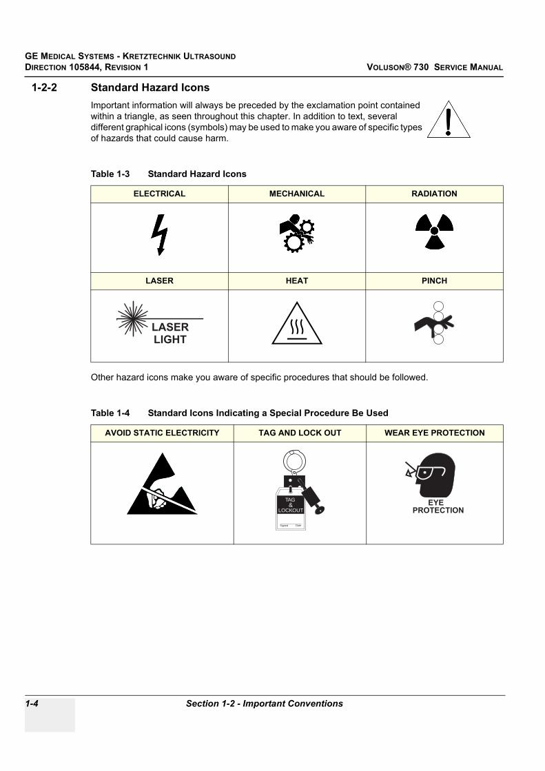
1-2-2 Standard Hazard IconsImportant information will always be preceded by the exclamation point contained within a triangle, as seen throughout this chapter. In addition to text, several different graphical icons (symbols) may be used to make you aware of specific types of hazards that could cause harm.
Other hazard icons make you aware of specific procedures that should be followed.
Table 1-3 Standard Hazard Icons
ELECTRICAL MECHANICAL RADIATION
LASER HEAT PINCH
Table 1-4 Standard Icons Indicating a Special Procedure Be Used
AVOID STATIC ELECTRICITY TAG AND LOCK OUT WEAR EYE PROTECTION
LASERLIGHT
Signed Date
TAG &
LOCKOUTEYE
PROTECTION

GE MEDICAL SYSTEMS - KRETZTECHNIK ULTRASOUND DIRECTION 105844, REVISION 1 VOLUSON® 730 SERVICE MANUAL
Chapter 1 Introduction 1-5
1-2-3 Product IconsThe following table describes the purpose and location of safety labels and other important information provided on the equipment.
Table 1-5 Product Icons
LABEL/SYMBOL PURPOSE/MEANING LOCATION
Identification and Rating PlateManufacturer's name and addressModel and serial numbersElectrical ratings
Rear side of the unitMonitor rear sideOn each probe
Device Listing/Certification LabelsLaboratory logo or labels denoting conformance with industry safety standards such as UL or IEC.
Rear side of the unitRear side of the monitor
Type/Class Label Used to indicate the degree of safety or protection.
IP Code (IPX 1)IP Code (IPX 7)
Indicates the degree of protection provided by the enclosure per IEC 529.IPX 1 and IPX 7 indicates drip proof.
FootswitchProbes
Equipment Type BF (man in the box symbol) IEC 878-02-03 indicates B Type equipment having even more electrical isolation than standard Type B equipment because it is intended for intimate patient contact.
Probe connectors Front side of the ECG-preamplifier (MAN)Rear of Power Supply
“CAUTIONThis unit weighs...
Special care must be used to avoid..."This precaution is intended to prevent injury that may result if one person attempt to move the unit considerable distances or on an incline due to the weight of the unit.
"CAUTION" The equilateral triangle is usually used in combination with other symbols to advise or warn the user.
Various
ATTENTION - Consult accompanying documents " is intended to alert the user to refer to the operator manual or other instructions when complete information cannot be provided on the label.
Rear side of Power Supply

GE MEDICAL SYSTEMS - KRETZTECHNIK ULTRASOUNDDIRECTION 105844, REVISION 1 VOLUSON® 730 SERVICE MANUAL
1-6 Section 1-2 - Important Conventions
"CAUTION - Dangerous voltage" (the lightning flash with arrowhead in equilateral triangle) is used to indicate electric shock hazards.
Rear side of Monitor
"Mains OFF" Indicates the power off position of the mains power switch. Rear of system at mains switch (F1)
"OFF/Standby" Indicates the power off/standby position of the power switch.CAUTIONThis Power Switch DOES NOT ISOLATE Mains Supply
Adjacent to On-Off/Standby switch left below the Control panel.
"Mains ON" Indicates the power on position of the mains power switch. Rear of system at mains switch (F1)
ON switch of the isolation transformer for auxiliary devices. Rear of system at the switch for auxiliary devices (F2)
OFF switch of the isolation transformer for auxiliary devices. Rear of system at the switch for auxiliary devices (F2)
"Protective Earth" Indicates the protective earth (grounding) terminal. Internal, Rear side of Power Supply
"Equipotentiality" Indicates the terminal to be used for connecting equipotential conductors when interconnecting (grounding) with other equipment.
Rear side of Power Supply
Table 1-5 Product Icons (Continued)
LABEL/SYMBOL PURPOSE/MEANING LOCATION

GE MEDICAL SYSTEMS - KRETZTECHNIK ULTRASOUND DIRECTION 105844, REVISION 1 VOLUSON® 730 SERVICE MANUAL
Chapter 1 Introduction 1-7
Section 1-3Safety Considerations
1-3-1 IntroductionThe following safety precautions must be observed during all phases of operation, service and repair of this equipment. Failure to comply with these precautions or with specific warnings elsewhere in this manual, violates safety standards of design, manufacture and intended use of the equipment.
1-3-2 Human SafetyOperating personnel must not remove the system covers. Servicing should be performed by authorized personnel only. Only personnel who have participated in a Voluson® 730 Training are authorized to service the equipment.
1-3-3 Mechanical Safety
WARNINGWARNING WHEN THE UNIT IS RAISED FOR A REPAIR OR MOVED ALONG ANY INCLINE, USE EXTREME CAUTION SINCE IT MAY BECOME UNSTABLE AND TIP OVER.
WARNINGWARNING ULTRASOUND PROBES ARE HIGHLY SENSITIVE MEDICAL INSTRUMENTS THAT CAN EASILY BE DAMAGED BY IMPROPER HANDLING. USE CARE WHEN HANDLING AND PROTECT FROM DAMAGE WHEN NOT IN USE. DO NOT USE A DAMAGED OR DEFECTIVE PROBE. FAILURE TO FOLLOW THESE PRECAUTIONS CAN RESULT IN SERIOUS INJURY AND EQUIPMENT DAMAGE.
WARNINGWARNING NEVER USE A PROBE THAT HAS FALLEN TO THE FLOOR. EVEN IF IT LOOKS OK, IT MAY BE DAMAGED.
CAUTION Always lower and center the Operator I/O Panel before moving the scanner.
CAUTION The Voluson® 730 weighs 136 kgor more, depending on installed peripherals, (300 lbs., or more) when ready for use. Care must be used when moving it or replacing its parts. Failure to follow the precautions listed could result in injury, uncontrolled motion and costly damage.ALWAYS:Be sure the pathway is clear.Use slow, careful motions.Use two people when moving on inclines or lifting more than 16 kg (35 lbs).

GE MEDICAL SYSTEMS - KRETZTECHNIK ULTRASOUNDDIRECTION 105844, REVISION 1 VOLUSON® 730 SERVICE MANUAL
1-8 Section 1-3 - Safety Considerations
1-3-3 Mechanical Safety (cont’d)
NOTE: Special care should be taken when transporting the unit in a vehicle:
• Secure the unit in an upright position.• Lock the wheels (brake)• DO NOT use the Control Panel as an anchor point.• Place the probes in their carrying case.• Eject any Magneto Optical disk or CD from their drive.
1-3-4 Electrical SafetyTo minimize shock hazard, the equipment chassis must be connected to an electrical ground. The system is equipped with a three-conductor AC power cable. This must be plugged into an approved electrical outlet with safety ground. If an extension cord is used with the system, make sure that the total current rating of the system does not exceed the extension cord rating.
The power outlet used for this equipment should not be shared with other types of equipment.
Both the system power cable and the power connector meet international electrical standards.
1-3-5 Labels Locations
1.) Caution Label2.) CE-Label3.) VDE-Label4.) UL-Label5.) Identification plate 6.) CW-Doppler (only if the CW-Doppler option is installed)7.) Homologation label (for Japan only)
CAUTION Keep the heat venting holes on the monitor unobstructed to avoid overheating of the monitor.
Figure 1-1 Labeling
1 2 3 4 5 6 7

GE MEDICAL SYSTEMS - KRETZTECHNIK ULTRASOUND DIRECTION 105844, REVISION 1 VOLUSON® 730 SERVICE MANUAL
Chapter 1 Introduction 1-9
1-3-6 Dangerous Procedure WarningsWarnings, such as the examples below, precede potentially dangerous procedures throughout this manual. Instructions contained in the warnings must be followed.
1-3-7 Lockout/Tagout Requirements (For USA Only)Follow OSHA Lockout/Tagout requirements by ensuring you are in total control of the electrical Mains plug.
1-3-8 Returning/Shipping Probes and Repair PartsEquipment being returned must be clean and free of blood and other infectious substances.
GEMS policy states that body fluids must be properly removed from any part or equipment prior to shipment. GEMS employees, as well as customers, are responsible for ensuring that parts/equipment have been properly decontaminated prior to shipment. Under no circumstance should a part or equipment with visible body fluids be taken or shipped from a clinic or site (for example, body coils or and ultrasound probe).
The purpose of the regulation is to protect employees in the transportation industry, as well as the people who will receive or open this package.
The US Department of Transportation (DOT) has ruled that “items what were saturated and/or dripping with human blood that are now caked with dried blood; or which were used or intended for use in patient care” are “regulated medical waste” for transportation purpose and must be transported as a hazardous material.
DANGER DANGEROUS VOLTAGES, CAPABLE OF CAUSING DEATH, ARE PRESENT IN THIS EQUIPMENT. USE EXTREME CAUTION WHEN HANDLING, TESTING AND ADJUSTING.
WARNINGWARNING EXPLOSION WARNINGDO NOT OPERATE THE EQUIPMENT IN AN EXPLOSIVE ATMOSPHERE. OPERATION OF ANY ELECTRICAL EQUIPMENT IN SUCH AN ENVIRONMENT CONSTITUTES A DEFINITE SAFETY HAZARD.
WARNINGWARNING DO NOT SUBSTITUTE PARTS OR MODIFY EQUIPMENTBECAUSE OF THE DANGER OF INTRODUCING ADDITIONAL HAZARDS, DO NOT INSTALL SUBSTITUTE PARTS OR PERFORM ANY UNAUTHORIZED MODIFICATION OF THE EQUIPMENT.

GE MEDICAL SYSTEMS - KRETZTECHNIK ULTRASOUNDDIRECTION 105844, REVISION 1 VOLUSON® 730 SERVICE MANUAL
1-10 Section 1-4 - EMC, EMI, and ESD
Section 1-4EMC, EMI, and ESD
1-4-1 Electromagnetic Compatibility (EMC)Electromagnetic compatibility describes a level of performance of a device within its electromagnetic environment. This environment consists of the device itself and its surroundings including other equipment, power sources and persons with which the device must interface. Inadequate compatibility results when a susceptible device fails to perform as intended due interference from its environment or when the device produces unacceptable levels of emission to its environment. This interference is often referred to as radio–frequency or electromagnetic interference (RFI/EMI) and can be radiated through space or conducted over interconnecting power of signal cables. In addition to electromagnetic energy, EMC also includes possible effects from electrical fields, magnetic fields, electrostatic discharge and disturbances in the electrical power supply.
For applicable standards refer to Chapter 2 in the Basic User Manual.
1-4-2 CE ComplianceThe Voluson® 730 unit conforms to all applicable conducted and radiated emission limits and to immunity from electrostatic discharge, radiated and conducted RF fields, magnetic fields and power line transient requirements.
NOTE: For CE Compliance, it is critical that all covers, screws, shielding, gaskets, mesh, clamps, are in good condition, installed tightly without skew or stress. Proper installation following all comments noted in this service manual is required in order to achieve full EMC performance.
1-4-3 Electrostatic Discharge (ESD) Prevention
WARNINGWARNING DO NOT TOUCH ANY BOARDS WITH INTEGRATED CIRCUITS PRIOR TO TAKING THE NECESSARY ESD PRECAUTIONS: 1.ALWAYS CONNECT YOURSELF, VIA AN ARM-WRIST STRAP, TO THE
EQUIPOTENTIALITY CONNECTION POINT LOCATED ON THE REAR OF THE SCANNER (TO THE RIGHT OF THE POWER CONNECTOR).
2.FOLLOW GENERAL GUIDELINES FOR HANDLING OF ELECTROSTATIC SENSITIVE EQUIPMENT.

GE MEDICAL SYSTEMS - KRETZTECHNIK ULTRASOUND DIRECTION 105844, REVISION 1 VOLUSON® 730 SERVICE MANUAL
Chapter 1 Introduction 1-11
Section 1-5Customer Assistance
1-5-1 Contact InformationIf this equipment does not work as indicated in this service manual or in the Basic User Manual, or if you require additional assistance, please contact the local distributor or appropriate support resource, as listed below.
NOTE: Prepare the following information before you call:
• System ID serial number.• Software version.
Table 1-6 Phone Numbers for Customer Assistance
Location Phone Number
USA/ CanadaGE Medical SystemsUltrasound Service Engineering4855 W. Electric AvenueMilwaukee, WI 53219
Customer Answer Center
1-800-437-1171
1-800-682-53271-262-524-5698Fax: +1-414-647-4125
Latin AmericaGE Medical SystemsUltrasound Service Engineering4855 W. Electric AvenueMilwaukee, WI 53219
Customer Answer Center
1-262-524-5300
1-262-524-5698Fax: +1-414-647-4125
EuropeGE Medical Systems Kretztechnik GmbH & Co OHGService Department - UltrasoundTiefenbach 15A-4871 ZipfAustria
Customer Answer Center
Tel: +43 7683 3800-0Fax: +43 7682 3800-47
Tel: +33-13083-1300
AsiaGE Ultrasound AsiaService Department - Ultrasound298 Tiong Bahru Road #15-01/06Central PlazaSingapore 169730
Tel: +65 6291-8528+81 426-482950
Fax: +65 6272-7006

GE MEDICAL SYSTEMS - KRETZTECHNIK ULTRASOUNDDIRECTION 105844, REVISION 1 VOLUSON® 730 SERVICE MANUAL
1-12 Section 1-5 - Customer Assistance
1-5-2 System Manufacturer
Table 1-7 System Manufacturer
Manufacturer Telephone FAX
GE Medical Systems Kretztechnik GmbH & Co OHGTiefenbach 15A-4871 ZipfAustria
+43-7682-3800-0 +43-7682-3800-47

GE MEDICAL SYSTEMS - KRETZTECHNIK ULTRASOUND DIRECTION 105844, REVISION 1 VOLUSON® 730 SERVICE MANUAL
Chapter 2 Pre-Installation 2-1
Chapter 2Pre-Installation
Section 2-1Overview
2-1-1 Purpose of Chapter 2This chapter provides the information required to plan and prepare for the installation of a Voluson® 730. Included are descriptions of the facility and electrical needs to be met by the purchaser of the unit.
Table 2-1 Contents in Chapter 2
Section Description Page Number
2-1 Overview 2-1
2-2 General Console Requirements 2-2
2-3 Facility Needs 2-6

GE MEDICAL SYSTEMS - KRETZTECHNIK ULTRASOUNDDIRECTION 105844, REVISION 1 VOLUSON® 730 SERVICE MANUAL
2-2 Section 2-2 - General Console Requirements
Section 2-2General Console Requirements
2-2-1 Console Environmental Requirements
2-2-1-1 CoolingThe cooling requirement for the Voluson® 730 is 2500 BTU/hr This figure does not include cooling needed for lights, people, or other equipment in the room. Each person in the room places an additional 300 BTU/hr. demand on the cooling system.
2-2-1-2 LightingBright light is needed for system installation, updates and repairs. However, operator and patient comfort may be optimized if the room light is subdued and indirect. Therefore a combination lighting system (dim/bright) is recommended. Keep in mind that lighting controls and dimmers can be a source of EMI which could degrade image quality. These controls should be selected to minimize possible interference.
2-2-2 Electrical Requirements
NOTE: GE Medical Systemsrequires a dedicated power and ground for the proper operation of its Ultrasound equipment. This dedicated power shall originate at the last distribution panel before the system. The dedicated line shall consist of one phase, a neutral (not shared with any other circuit), and a full size ground wire from the distribution panel to the Ultrasound outlet. Please note that image artifacts can occur, if at any time within the facility, the ground from the main facility's incoming power source to the Ultrasound unit is only a conduit.
2-2-2-1 Voluson® 730 Power Requirements
2-2-2-2 Inrush CurrentInrush current is not a factor to consider due to the inrush current limiting properties of the power supplies.
Table 2-2 Environmental Requirements
Operating Temperature
OperatingHumidity Heat Dissipation
Storage Temperature Storage Humidity
10 to 40oC (50 to 104oF)
30 to 80% rH non-condensing 2500 BTU pr hour -10 to 40 oC
(14 to 104oF)< 90% rH non-
condensing
Table 2-3 Electrical Specifications for Voluson® 730
Voltage Tolerances Current Frequency
100 VAC ±10% 10.10 A 50, 60 Hz (±2%)
115 VAC ±10% 8.80 A 50, 60 Hz (±2%)
130 VAC ±10% 7.80 A 50, 60 Hz (±2%)
230 VAC ±10% 4.40 A 50, 60 Hz (±2%)
240 VAC ±10% 4.20 A 50, 60 Hz (±2%)

GE MEDICAL SYSTEMS - KRETZTECHNIK ULTRASOUND DIRECTION 105844, REVISION 1 VOLUSON® 730 SERVICE MANUAL
Chapter 2 Pre-Installation 2-3
2-2-2-3 Site Circuit BreakerIt is recommended that the branch circuit breaker for the machine be readily accessible.
2-2-2-4 Site Power OutletsA dedicated AC power outlet must be within reach of the unit without extension cords. Other adequate outlets for the external peripherals, medical and test equipment needed to support this unit must also be present within 1 m (3.2 ft.) of the unit. Electrical installation must meet all current local, state, and national electrical codes.
2-2-2-5 Unit Power PlugIf the unit arrives without a power plug, or with the wrong plug, you must contact your GEdealer or the installation engineer must supply what is locally required.
CAUTION POWER OUTAGE MAY OCCUR. The Voluson® 730 requires a dedicated single branch circuit. To avoid circuit overload and possible loss of critical care equipment, make sure you DO NOT have any other equipment operating on the same circuit.

GE MEDICAL SYSTEMS - KRETZTECHNIK ULTRASOUNDDIRECTION 105844, REVISION 1 VOLUSON® 730 SERVICE MANUAL
2-4 Section 2-2 - General Console Requirements
2-2-3 EMI LimitationsUltrasound machines are susceptible to Electromagnetic Interference (EMI) from radio frequencies, magnetic fields, and transients in the air or wiring. Ultrasound machines also generate EMI. The Voluson® 730 complies with limits as stated on the EMC label. However, there is no guarantee that interference will not occur in a particular installation.
Possible EMI sources should be identified before the unit is installed.
Electrical and electronic equipment may produce EMI unintentionally as the result of a defect. These sources include:
• medical lasers, • scanners, • cauterizing guns, • computers, • monitors, • fans, • gel warmers, • microwave ovens,• light dimmers • portable phones. The presence of a broadcast station or broadcast van may also cause interference.
See Table 2-4 for EMI Prevention tips.
Table 2-4 EMI Prevention/Abatement
EMI Rule Details
Be aware of RF sourcesKeep the unit at least 5 meters or 15 feet away from other EMI sources. Special shielding may be required to eliminate interference problems caused by high frequency, high powered radio or video broadcast signals.
Ground the unit Poor grounding is the most likely reason a unit will have noisy images. Check grounding of the power cord and power outlet.
Replace all screws, RF gaskets, covers, cores
After you finish repairing or updating the system, replace all covers and tighten all screws. Any cable with an external connection requires a magnet wrap at each end. Install the shield over the front of card cage. Loose or missing covers or RF gaskets allow radio frequencies to interfere with the ultrasound signals.
Replace broken RF gaskets If more than 20% or a pair of the fingers on an RF gasket are broken, replace the gasket. Do not turn on the unit until any loose metallic part is removed.
Do not place labels where RF gaskets touch metal
Never place a label where RF gaskets meet the unit. Otherwise, the gap created will permit RF leakage. Or, if a label has been found in such a position, move the label.
Use GE specified harnesses and peripherals
The interconnect cables are grounded and require ferrite beads and other shielding. Also, cable length, material, and routing are all important; do not change from what is specified.
Take care with cellular phones Cellular phones may transmit a 5 V/m signal; that could cause image artifacts.
Properly dress peripheral cables
Do not allow cables to lie across the top of the card cage or hang out of the peripheral bays. Loop the excess length for peripheral cables inside the peripheral bays. Attach the monitor cables to the frame.

GE MEDICAL SYSTEMS - KRETZTECHNIK ULTRASOUND DIRECTION 105844, REVISION 1 VOLUSON® 730 SERVICE MANUAL
Chapter 2 Pre-Installation 2-5
2-2-4 Scan Probe Environmental RequirementsOperation:1Ambient temperature 18° to 30° C
Storage:-10° to 50° C
NOTE: Temperature in degrees C. Conversion to degrees F = °C (9/5) + 32).
2-2-5 Time and Manpower RequirementsSite preparation takes time. Begin Pre-installation checks as soon as possible. If possible, allow six weeks before delivery, for enough time to make necessary changes.
NOTICE SYSTEMS AND ELECTRONIC PROBES ARE DESIGNED FOR STORAGE TEMPERATURES OF-10 TO + 50 degrees C. WHEN EXPOSED TO LARGE TEMPERATURE VARIATIONS, THE PRODUCT SHOULD BE KEPT IN ROOM TEMPERATURE FOR 10 HOURS BEFORE USE.
CAUTION Have two people available to deliver and unpack the Voluson® 730.Attempts to move the unit considerable distances or on an incline by one person could result in injury or damage or both.

GE MEDICAL SYSTEMS - KRETZTECHNIK ULTRASOUNDDIRECTION 105844, REVISION 1 VOLUSON® 730 SERVICE MANUAL
2-6 Section 2-3 - Facility Needs
Section 2-3Facility Needs
2-3-1 Purchaser ResponsibilitiesThe work and materials needed to prepare the site is the responsibility of the purchaser. Delay, confusion, and waste of manpower can be avoided by completing pre installation work before delivery. Use the Pre installation checklist to verify that all needed steps have been taken. Purchaser responsibility includes:
• Procuring the materials required.• Completing the preparations before delivery of the ultrasound system.• Paying the costs for any alterations and modifications not specifically provided in the sales contract.
NOTE: All electrical installations that are preliminary to the positioning of the equipment at the site prepared for the equipment must be performed by licensed electrical contractors. Other connections between pieces of electrical equipment, calibrations, and testing must also be performed by qualified personnel. The products involved (and the accompanying electrical installations) are highly sophisticated and special engineering competence is required. All electrical work on these products must comply with the requirements of applicable electrical codes. The purchaser of GE equipment must only utilize qualified personnel to perform electrical servicing on the equipment.
The desire to use a non–listed or customer provided product or to place an approved product further from the system than the interface kit allows presents challenges to the installation team. To avoid delays during installation, such variances should be made known to the individuals or group performing the installation at the earliest possible date (preferably prior to the purchase).
The ultrasound suite must be clean prior to delivery of the machine. Carpet is not recommended because it collects dust and creates static. Potential sources of EMI (electromagnetic interference) should also be investigated before delivery. Dirt, static, and EMI can negatively impact system reliability.
2-3-2 Required Features
NOTE: GE Medical Systems requires a dedicated power and ground for the proper operation of its Ultrasound equipment. This dedicated power shall originate at the last distribution panel before the system. The dedicated line shall consist of one phase, a neutral (not shared with any other circuit), and a full size ground wire from the distribution panel to the Ultrasound outlet. Please note that image artifacts can occur, if at any time within the facility, the ground from the main facility's incoming power source to the Ultrasound unit is only a conduit.
• Door opening is at least 76 cm (30 in) wide.• Proposed location for unit is at least 0.3 m (1 ft.) from the wall for cooling• Power outlet and place for any external peripheral are within 2 m (6.5 ft) of each other with
peripheral within 1 m of the unit to connect cables.
NOTE: The Voluson® 730 has four outlets inside the unit. One is for the monitor and three for on board peripherals.

GE MEDICAL SYSTEMS - KRETZTECHNIK ULTRASOUND DIRECTION 105844, REVISION 1 VOLUSON® 730 SERVICE MANUAL
Chapter 2 Pre-Installation 2-7
2-3-3 Desirable Features• Door is at least 90 cm (3 ft.) wide• Circuit breaker for dedicated power outlet is easily accessible• Sink with hot and cold water• Receptacle for bio–hazardous waste, like used probe sheaths• Emergency oxygen supply• Storage for linens and equipment• Nearby waiting room, lavatory, and dressing room• Dual level lighting (bright and dim)• Lockable cabinet ordered by GE for its software and proprietary manuals

GE MEDICAL SYSTEMS - KRETZTECHNIK ULTRASOUNDDIRECTION 105844, REVISION 1 VOLUSON® 730 SERVICE MANUAL
2-8 Section 2-3 - Facility Needs
2-3-4 Minimal Floor Plan Suggestion
Figure 2-1 Minimal Floor Plan

GE MEDICAL SYSTEMS - KRETZTECHNIK ULTRASOUND DIRECTION 105844, REVISION 1 VOLUSON® 730 SERVICE MANUAL
Chapter 2 Pre-Installation 2-9
2-3-5 Networking Pre-installation Requirements
2-3-5-1 Purpose of the DICOM Network FunctionDICOM (Digital Imaging and Communications in Medicine) services provide the operator with clinically useful features for moving images and patient information over a hospital network. Examples of DICOM services include the transfer of images to workstations for viewing or transferring images to remote printers. As an added benefit, transferring images in this manner frees up the on-board monitor and peripherals, enabling viewing to be done while scanning continues. With DICOM, images can be archived, stored, and retrieved faster, easier, and at a lower cost.
2-3-5-2 DICOM Option Pre-installation RequirementsTo configure the Voluson® 730 to work with other network connections, the site’s network administrator must provide some necessary information.
Information must include:
• A Station name, AE Title, IP address and Net Mask for the Voluson® 730. • The IP addresses for the default gateway and other routers at the site for ROUTING
INFORMATION. Only if necessary (e.g. for Internet access).Installation see: Section 3-8 "Network IP Address Configuration" on page 3-37.

GE MEDICAL SYSTEMS - KRETZTECHNIK ULTRASOUNDDIRECTION 105844, REVISION 1 VOLUSON® 730 SERVICE MANUAL
2-10 Section 2-3 - Facility Needs
This page was intentionally left blank.

GE MEDICAL SYSTEMS - KRETZTECHNIK ULTRASOUND DIRECTION 105844, REVISION 1 VOLUSON® 730 SERVICE MANUAL
Chapter 3 Installation 3-1
Chapter 3Installation
Section 3-1Overview
3-1-1 The Purpose of Chapter 3This chapter contains information needed to install the unit. Included are procedures to receive, unpack and configure the equipment.
3-1-2 Average Installation TimeManpower requirement: 2 persons
Table 3-1 Contents in Chapter 3
Section Description Page Number
3-1 Overview 3-1
3-2 Receiving and Unpacking the Equipment 3-4
3-3 Preparing for Installation 3-6
3-4 Completing the Installation 3-8
3-5 Printer Installation 3-12
3-6 System Configuration 3-28
3-7 Connectivity Installation Worksheet 3-36
3-8 Network IP Address Configuration 3-37
3-9 Paperwork 3-38
Table 3-2 Average Installation Time
Description Average Installation Time Comments
Unpacking the scanner 0.5 hours
Scanner /options / printers 0.5 to 1.5 hours Dependant on the required configuration
DICOM Option 0.5 - 1.5 hours Dependant on the configuration amount

GE MEDICAL SYSTEMS - KRETZTECHNIK ULTRASOUNDDIRECTION 105844, REVISION 1 VOLUSON® 730 SERVICE MANUAL
3-2 Section 3-1 - Overview
3-1-3 Installation Warnings1.) Since the Voluson® 730 weighs approximately 136 kg (300 lb.) without options, preferably two
people should unpack it. Two people are also preferable for installing any additional items in excess of 35 pounds (e.g. Monitor).
2.) There are no operator serviceable components. To prevent shock, do not remove any covers or panels. Should problems or malfunctions occur, unplug the power cord. Only qualified service personnel should carry out servicing and troubleshooting.
3.) After being transported, the unit may be very cold or hot. If this is the case, allow the unit to acclimate before you turn it on. It requires one hour for each 2.5°C increment it's temperature is below 10°C or above 40°C.
3-1-3-1 Brake Pedal Operation
3-1-3-2 Operator I/O Panel PositionIf weight is placed on the Operator I/O Panel in it’s extended position the console could tip over.
CAUTION Equipment damage possibility. Turning the system on without acclimation after arriving at site may cause the system to be damaged.
Table 3-3 Acclimation Time
°C 60 55 50 45 40 35 30 25 20 15 10 5 0 -5 -10 -15 -20 -25 -30 -35 -40
°F 140 131 122 113 104 96 86 77 68 59 50 41 32 23 14 5 -4 -13 -22 -31 -40
hrs 8 6 4 2 0 0 0 0 0 0 0 2 4 6 8 10 12 14 16 18 20
Figure 3-1 pulling, moving or lifting the system
WARNINGWARNING REMEMBER: If the front wheels are engaged for transportation, pressing the release brake pedals (brakes on front wheels under the foot rest) once disengages the lock.
WARNINGWARNING The system should NOT be moved with the Operator I/O Panel extended. Move the Operator I/O Panel to it’s centered and locked position.
WARNINGWARNING Monitor mounting mechanism may break if not properly supported (e.g. with packing foam) during transportation even inside the hospital.
When pulling, moving or lifting the system, grasp it only at the rear handle of the trolley and the handle underneath the foot rest.
Do NOT pull or lift the system with the front handleof the user interface (operator panel).
WARNINGWARNING

GE MEDICAL SYSTEMS - KRETZTECHNIK ULTRASOUND DIRECTION 105844, REVISION 1 VOLUSON® 730 SERVICE MANUAL
Chapter 3 Installation 3-3
3-1-4 Safety Reminders
DANGER WHEN USING ANY TEST INSTRUMENT THAT IS CAPABLE OF OPENING THE AC GROUND LINE (I.E., METER’S GROUND SWITCH IS OPEN), DON’T TOUCH THE UNIT!
CAUTION Two people should unpack the unit because of its weight. Two people are required whenever a part weighing 16kg (35 lb.) or more must be lifted.
CAUTION If the unit is very cold or hot, do not turn on its power until it has had a chance to acclimate to its operating environment.
CAUTION To prevent electrical shock, connect the unit to a properly grounded power outlet. Do not use a three to two prong adapter. This defeats safety grounding.
CAUTION Do NOT wear the ESD wrist strap when you work on live circuits and more than 30 V peak is present.
CAUTION Do not use a20 Amp to 15 Amp adapter on the 120 Vac unit’s power cord. This unit requires a dedicated 16 A circuit.
CAUTION Do not operate this unit unless all board covers and frame panels are securely in place. System performance and cooling require this.
CAUTION OPERATOR MANUAL(S) The User Manual(s) should be fully read and understood before operating the Voluson® 730 and kept near the unit for quick reference.
CAUTION ACOUSTIC OUTPUT HAZARDAlthough the ultrasound energy transmitted from the Voluson® 730 probe is within FDA limits, avoid unnecessary exposure. Ultrasound energy can produce heat and mechanical damage.
Figure 3-2 Environmental Labels

GE MEDICAL SYSTEMS - KRETZTECHNIK ULTRASOUNDDIRECTION 105844, REVISION 1 VOLUSON® 730 SERVICE MANUAL
3-4 Section 3-2 - Receiving and Unpacking the Equipment
Section 3-2Receiving and Unpacking the Equipment
CAUTION Transport only with forklift or stracker truck.During transport pay attention to the point of gravity!
Have two people available to unpack the Voluson® 730. Attempts to move the unit considerable distances or on an incline by one person could result in injury or damage or both.
Figure 3-3 Unpacking the system
Table 3-4 Unpacking Procedure
Step Task
1. Loosen the screws and remove top panel from crater
Unpack the devices such a way that packaging can be reused.
The device must only be transported in the original packaging.
Check whether delivery is complete (according to delivery note) and check visual damage!
A drill with size 20 torx bit and/or medium cross point bit will be needed to open the crate.

GE MEDICAL SYSTEMS - KRETZTECHNIK ULTRASOUND DIRECTION 105844, REVISION 1 VOLUSON® 730 SERVICE MANUAL
Chapter 3 Installation 3-5
2. Open front panel (ramp) by removing the screws from the side panels. Lower ramp.
3. Carefully remove foam packing material, plastic bag from ultrasound unit and the monitor and any other item from the wooden box.
Caution: Two people are needed in the next step due to the weight of the equipment.
4. Disengage the brakes and slowly move unit down the ramp
Note: Packing crate and material should be stored for future use.
5. Remove Monitor from its box and mount it on the system.
Table 3-4 Unpacking Procedure
Step Task
screwsscrews
ramppacking
Left and Right panels are shown removed for clarity.
BrakesBrakes
Ramp
MonitorMountingBracket
MonitorConnectors
1. Attach Monitora) Insert b) Press the Monitor
Mounting Bracket to engage (to hear a “click”).Check if the moni-tor is fixed correct.
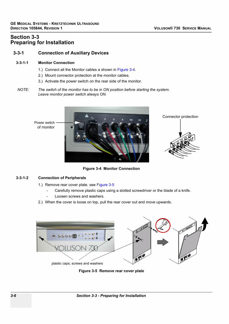
GE MEDICAL SYSTEMS - KRETZTECHNIK ULTRASOUNDDIRECTION 105844, REVISION 1 VOLUSON® 730 SERVICE MANUAL
3-6 Section 3-3 - Preparing for Installation
Section 3-3Preparing for Installation
3-3-1 Connection of Auxiliary Devices
3-3-1-1 Monitor Connection
1.) Connect all the Monitor cables a shown in Figure 3-4.2.) Mount connector protection at the monitor cables.3.) Activate the power switch on the rear side of the monitor.
NOTE: The switch of the monitor has to be in ON position before starting the system.Leave monitor power switch always ON.
3-3-1-2 Connection of Peripherals
1.) Remove rear cover plate. see Figure 3-5- Carefully remove plastic caps using a slotted screwdriver or the blade of a knife.- Loosen screws and washers.
2.) When the cover is loose on top, pull the rear cover out and move upwards.
Figure 3-4 Monitor Connection
Figure 3-5 Remove rear cover plate
Connector protection
of monitorPower switch
plastic caps; screws and washers

GE MEDICAL SYSTEMS - KRETZTECHNIK ULTRASOUND DIRECTION 105844, REVISION 1 VOLUSON® 730 SERVICE MANUAL
Chapter 3 Installation 3-7
3.) Disconnect the GND ground-cable from the back of the rear cover plate.
4.) Connect all Peripherals.For connection schemes of Peripherals refer to Chapter 20 in the Basic User Manual of Voluson® 730.
5.) Connect the GND ground-cable at the rear cover plate.6.) Mount rear cover plate.
- Reattach screw and washers.- Plug-in caps.
3-3-2 Verify Customer OrderCompare items received by the customer to that which is listed on the delivery order. Report any items that are missing, back ordered or damaged.
3-3-3 Physical Inspection
3-3-3-1 System Voltage SettingsVerify that the scanner is set to the correct voltage.The Voltage settings for the Voluson® 730 Scanner is found on a metal plate, on the rear of the system.
3-3-4 EMI ProtectionThis unit has been designed to minimize the effects of Electo-Magnetic Interference (EMI). Many of the covers, shields, and screws are provided primarily to protect the system from image artifacts caused by this interference. For this reason, it is imperative that all covers and hardware are installed and secured before the unit is put into operation.
Figure 3-6 GND ground-cable
Figure 3-7 Identification Plate Example
WARNINGWARNING CONNECTING A Voluson® 730 SCANNER TO THE WRONG VOLTAGE LEVEL WILL MOST LIKELY DESTROY THE SCANNER.
GND ground cable

GE MEDICAL SYSTEMS - KRETZTECHNIK ULTRASOUNDDIRECTION 105844, REVISION 1 VOLUSON® 730 SERVICE MANUAL
3-8 Section 3-4 - Completing the Installation
Section 3-4Completing the Installation
3-4-1 System Specifications
3-4-1-1 Physical Dimensions of Voluson® 730The physical dimensions of the Voluson® 730 unit are summarized in Table 3-5.Table 3-6 lists the size of Voluson® 730, with monitor and without on-board peripherals.
3-4-1-2 Weight without Monitor and Peripherals
3-4-1-3 Acoustic Noise Outputmax. 57dB(A)
3-4-2 Electrical Specifications
Power Consumption nominal 1010 VA including all options.
Mains outlets: Mains socket ST1, ST2, ST3, ST4, ST5 for accessories.All mains outlets are co-switched by the unit’s mains switch via built-in isolation transformer.Output voltage for: ST1 - ST5: 115V or 230V.
Table 3-5 Physical Dimensions of Voluson® 730
Height Width Depth
145 cm / 57.1 inches 68 cm / 26.8 inches 100 cm / 39.4 inches
Table 3-6 Weight of Voluson® 730 With Monitor and Without Other Peripherals
Model Weight [kg] Weight [lbs.]
Voluson® 730 136 300
Table 3-7 Electrical Specifications for Voluson® 730
Voltage Tolerances Current Frequency
100 VAC ±10% 10.10 A 50, 60 Hz (±2%)
115 VAC ±10% 8.80 A 50, 60 Hz (±2%)
130 VAC ±10% 7.80 A 50, 60 Hz (±2%)
230 VAC ±10% 4.40 A 50, 60 Hz (±2%)
240 VAC ±10% 4.20 A 50, 60 Hz (±2%)
CAUTION Modification of voltage setting only by an authorized service person! Output power: 350VA per mains outlet, max. power of all connected accessories must not exceed 350VA.

GE MEDICAL SYSTEMS - KRETZTECHNIK ULTRASOUND DIRECTION 105844, REVISION 1 VOLUSON® 730 SERVICE MANUAL
Chapter 3 Installation 3-9
3-4-3 Power On / Boot Up
3-4-3-1 Scanner Power On
1.) Connect the Power Cable to the back of the system.2.) Connect the Main Power Cable to a hospital grade power receptacle with the proper rated voltage.
Never use an adapter that would defeat the safety ground. 3.) Switch ON the Circuit Breaker and the Power Switch of peripherals at the rear of the system.
3-4-3-2 Back-end Processor Boot UpPress the ON/OFF Stand-By switch left belowthe Control Panel once.
When the ON/OFF Stand-By switch left below the Control Panel is pressed once, the System (including the Back-end Processor) starts and the software code is distributed to initiate the scanner.
The company logo appears on the Touch screen during boot up. Depending on the BIOS-Version no status messages are displayed during this process. Boot up time is about 3 minutes.
NOTE: The mains outlet of the system for peripheral auxiliary equipment are commonly switched with the Stand-By switch. The switch of printers has to be in ON position before starting the system. So the auxiliary equipment need not to be switched ON/OFF separately if the F2 power switch on the back of the system and the switches of the peripherals are always ON.
Figure 3-8 Circuit Breaker (F1) and Power Switch of Peripherals (F2)
NOTICE When AC power is applied to the scanner, the ON/OFF switch on the Control panel is illuminated, indicating that the System (including the Back-end Processor) is in standby mode.
Figure 3-9 ON/OFF Stand-By Switch
Circuit Breaker (F1)
Connector for Mains Power Cable
Power Switch of Peripherals(F2)
ON/OFF Stand By Switch

GE MEDICAL SYSTEMS - KRETZTECHNIK ULTRASOUNDDIRECTION 105844, REVISION 1 VOLUSON® 730 SERVICE MANUAL
3-10 Section 3-4 - Completing the Installation
3-4-4 Power Off/ Shutdown
NOTE: After turning off a system, wait at least ten seconds before turning it on again. The system may not be able to boot if power is recycled too quickly.
3-4-4-1 Back-end Processor Power Down
1.) Press the ON/OFF Stand-By switch left below the Control Panel once. Figure 3-9
3-4-4-2 Scanner Shutdown
1.) Press the ON/OFF Stand-By switch left below the Control Panel once.2.) Switch OFF the Circuit Breaker at the rear of the system.
NOTE: The mains outlet of the system for peripheral auxiliary equipment are commonly switched with the Standby switch. So the auxiliary equipment need not to be switched ON/OFF separately.
3.) Disconnect the Mains Power Cable if necessary. For example: Repairing the system.
4.) Press once on the brakes to block the front wheels (brakes on front wheels under the foot rest).5.) Prior to disconnect a probe freeze the image.6.) Open the right-hand side door, remove the probe cable from the cable holder and close the door.7.) Move the probe locking handle counterclockwise. Pull the connector straight out of the probe port.
Figure 3-10 Circuit Breaker and Power Cable on Back of Voluson® 730
CAUTION If a probe is disconnected while running (Write-Mode) a software error may occur. In this case switch the unit OFF (perform a reset).
Circuit Breaker
Mains Power Cable

GE MEDICAL SYSTEMS - KRETZTECHNIK ULTRASOUND DIRECTION 105844, REVISION 1 VOLUSON® 730 SERVICE MANUAL
Chapter 3 Installation 3-11
3-4-5 Transducer Connection
NOTE: Prior to connecting or disconnecting a probe, freeze the image. It is not necessary to turn OFF power to connect or disconnect a transducer.
Connect a transducer to one of the three rightmost transducer receptacle as follows:
1.) Ensure that the transducer twist lock lever is at horizontal position.2.) Insert the transducer connector on the receptacle guide pin until it touches the receptacle mating
surface.3.) Twist the transducer twist lock lever to vertical position to lock it in place. Twist the lever to the
horizontal position to disconnect the transducer.4.) Open the right-hand side door, lay the cable into the intended cable holder and close the door.
Figure 3-11 Transducer Connection
CAUTION If the cable spout on the right-hand door is missing, don’t pull the probe cable.Please insert the spout in the designated place to avoid damage of the probe cable.

GE MEDICAL SYSTEMS - KRETZTECHNIK ULTRASOUNDDIRECTION 105844, REVISION 1 VOLUSON® 730 SERVICE MANUAL
3-12 Section 3-5 - Printer Installation
Section 3-5Printer Installation
3-5-1 Installing Line Printer HP 990cxi or HP 995c For connection schemes of Peripherals refer to Chapter 20 in the Basic User Manual of Voluson® 730.
NOTE: “Mouse functions” can be performed by using the trackball for moving the cursor. “Normal select” (Click) by pressing the left or right trackball keys and for “opening a context menu” press the upper trackball key.
1.) Turn ON the system, and wait till the system has booted.2.) Prepare the color printer as illustrated at HP quick start poster “Windows quick start”:• Attach Automatic Two–Side Printing Module and load white paper• Plug in power cord (Do NOT turn ON the printer!!!)• Turn on the printer and install print cartridges, after closing the top cover a calibration page is
printed automatically.
3-5-1-1 Install the HP printer software/driverPerform the following steps if this printer was never installed on the Voluson® 730!
3.) Connect the USB cable to the printer and the system. The windows ‘Searching for Drivers …’, ‘Found new Hardware …’ and finally the following windows appear.
Figure 3-12 Found New Hardware Wizard
select “Search for a suitable driver for my device (recommended)”
Click on “Specify a location”

GE MEDICAL SYSTEMS - KRETZTECHNIK ULTRASOUND DIRECTION 105844, REVISION 1 VOLUSON® 730 SERVICE MANUAL
Chapter 3 Installation 3-13
3-5-1-1 Install the HP printer software/driver (cont’d)4.) Click the NEXT buttons to start the Hardware Wizard and to locate the driver files. 5.) Use the BROWSE button to search the following path on the hard disk (see: Figure 3-13)
- C:\Utilities\PrinterDriver\HPDeskjet990c for HP 990cxi- C:\Utilities\PrinterDriver\HPDeskjet995c for HP 995c, and then click OK.
NOTE: If no drivers can be found on the hard disk (C:\…) for HP995c , use the HP-Installation disk and browse for the file HPF995K.INF. Path: F: \DEU\DRIVERS\WIN2K_XP.
6.) Confirm the correct path and click NEXT to install the driver. All necessary files are copied.7.) Confirm the installation by clicking FINISH to close the Hardware Wizard.
8.) Close all open windows, close the “System Setup” with SAVE & EXIT and restart the system (turn off and on the system).
Figure 3-13 Search for Network path
Figure 3-14 Confirm correct path and finish the Installation
NOTICEVer
After boot up of the system, verify the correct settings in the printer “Properties”, see: Section 3-5-5 "Adjustment of Printer Settings" on page 3-23.
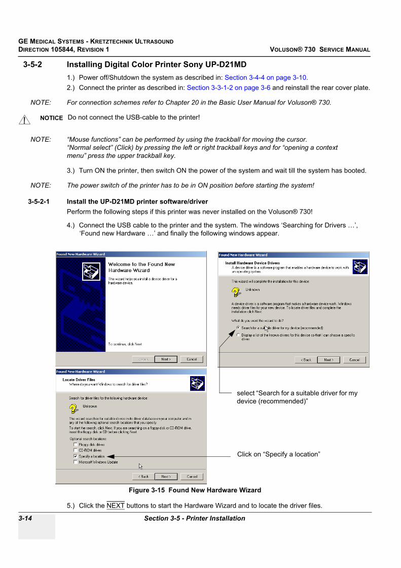
GE MEDICAL SYSTEMS - KRETZTECHNIK ULTRASOUNDDIRECTION 105844, REVISION 1 VOLUSON® 730 SERVICE MANUAL
3-14 Section 3-5 - Printer Installation
3-5-2 Installing Digital Color Printer Sony UP-D21MD1.) Power off/Shutdown the system as described in: Section 3-4-4 on page 3-10.2.) Connect the printer as described in: Section 3-3-1-2 on page 3-6 and reinstall the rear cover plate.
NOTE: For connection schemes refer to Chapter 20 in the Basic User Manual for Voluson® 730.
NOTE: “Mouse functions” can be performed by using the trackball for moving the cursor. “Normal select” (Click) by pressing the left or right trackball keys and for “opening a context menu” press the upper trackball key.
3.) Turn ON the printer, then switch ON the power of the system and wait till the system has booted.
NOTE: The power switch of the printer has to be in ON position before starting the system!
3-5-2-1 Install the UP-D21MD printer software/driverPerform the following steps if this printer was never installed on the Voluson® 730!
4.) Connect the USB cable to the printer and the system. The windows ‘Searching for Drivers …’, ‘Found new Hardware …’ and finally the following windows appear.
5.) Click the NEXT buttons to start the Hardware Wizard and to locate the driver files.
NOTICE Do not connect the USB-cable to the printer!
Figure 3-15 Found New Hardware Wizard
select “Search for a suitable driver for my device (recommended)”
Click on “Specify a location”

GE MEDICAL SYSTEMS - KRETZTECHNIK ULTRASOUND DIRECTION 105844, REVISION 1 VOLUSON® 730 SERVICE MANUAL
Chapter 3 Installation 3-15
3-5-2-1 Install the UP-D21MD printer software/driver (cont’d)6.) Use the BROWSE button to search the following path C:\Utilities\PrinterDriver\SonyUP-D21MD
see: Figure 3-13and then click OK.
7.) Confirm the correct path and click NEXT to install the driver. All necessary files are copied.8.) The Message: Digital Signature Not Found appears. Click YES.9.) Confirm the installation by clicking FINISH to close the Hardware Wizard.
10.)Close all open windows, close the “System Setup” with SAVE & EXIT and restart the system (turn off and on the system).
Figure 3-16 Search for Network path
Figure 3-17 Confirm correct path and finish the Installation
NOTICEVer
After boot up of the system, verify the correct settings in the printer “Properties”, see: Section 3-5-5 "Adjustment of Printer Settings" on page 3-23.
GE MEDICAL SYSTEMS - KRETZTECHNIK ULTRASOUNDDIRECTION 105844, REVISION 1 VOLUSON® 730 SERVICE MANUAL
3-16 Section 3-5 - Printer Installation
3-5-3 Installing Digital Color Printer (Sony UP-D2600S or Mitsubishi CP770DW) 1.) Power off/Shutdown the system as described in: Section 3-4-4 on page 3-10.2.) Remove the rear cover plate as described in: Section 3-3-1-2 on page 3-6.3.) Remove SCSI-Adapter.
4.) Feed the SCSI-cables through the holes of the system housing to the front side where the printer will be placed and connect them to the printer.
5.) Feed the Power cable to the backside and connect it on the Voluson® 730 power supply.
NOTE: For connection schemes refer to Chapter 20 in the Basic User Manual of Voluson® 730.
6.) Reinstall the rear cover plate.
NOTE: “Mouse functions” can be performed by using the trackball for moving the cursor. “Normal select” (Click) by pressing the left or right trackball keys and for “opening a context menu” press the upper trackball key.
7.) Turn ON the printer.8.) Switch ON the power of the system and wait till the system has booted.
NOTE: The power switch of the printer has to be in ON position before starting the system!Leave the power switch of the printer always in the ON position.
9.) Follow the printer installation steps as described in Section 3-5-4 "Printer Installation manually" on page 3-17.
NOTICE If only one single SCSI-cable is connected between Main Module and GEM (Drive Module):Disconnect the SCSI connector from the main module (PC-part) and connect it to the SCSI-printer.Connect the additional SCSI-cable (included in PZP50 connection set) from the main module to the SCSI-printer.
NOTICE Do not insert more SCSI-cables than required; the SCSI-cable length should be as short as possible!
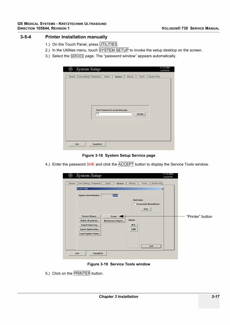
GE MEDICAL SYSTEMS - KRETZTECHNIK ULTRASOUND DIRECTION 105844, REVISION 1 VOLUSON® 730 SERVICE MANUAL
Chapter 3 Installation 3-17
3-5-4 Printer Installation manually1.) On the Touch Panel, press UTILITIES.2.) In the Utilities menu, touch SYSTEM SETUP to invoke the setup desktop on the screen.3.) Select the SERVICE page. The “password window” appears automatically.
4.) Enter the password SHE and click the ACCEPT button to display the Service Tools window.
5.) Click on the PRINTER button.
Figure 3-18 System Setup Service page
Figure 3-19 Service Tools window
“Printer” button

GE MEDICAL SYSTEMS - KRETZTECHNIK ULTRASOUNDDIRECTION 105844, REVISION 1 VOLUSON® 730 SERVICE MANUAL
3-18 Section 3-5 - Printer Installation
3-5-4 Printer Installation manually (cont’d)
6.) Click the ADD PRINTER button. A warning message appears:Please read this message carefully and click YES if you have skills to do this.
Figure 3-20 Printer Installation / Properties
NOTICE At older Software versions, first the warning message appears. After confirming with the YES button, click the ADD PRINTER icon on the displayed screen.
Figure 3-21 Add Printer

GE MEDICAL SYSTEMS - KRETZTECHNIK ULTRASOUND DIRECTION 105844, REVISION 1 VOLUSON® 730 SERVICE MANUAL
Chapter 3 Installation 3-19
3-5-4 Printer Installation manually (cont’d)
7.) Click the NEXT button to start the Add Printer Wizard.8.) Select the ‘Local Printer‘ , deselect “Automatically install Plug and Play printer” and then click NEXT.
9.) Select the corresponding Printer Port (e.g., Figure 3-23 Sony UP-D21MD = USB002) and click NEXT.
Figure 3-22 Add Printer Wizard
CAUTION If you have to install the SCSI-Printer UP-D2600S or the SCSI-Printer CP770DW for the first time, the correct port may not be listed. In this case, select any port and finish the installation procedure. After restart of the system, adjust the port selection in the printer “Properties”; see: Section 3-5-5 on page 3-23.
Figure 3-23 Select Printer Port

GE MEDICAL SYSTEMS - KRETZTECHNIK ULTRASOUNDDIRECTION 105844, REVISION 1 VOLUSON® 730 SERVICE MANUAL
3-20 Section 3-5 - Printer Installation
3-5-4 Printer Installation manually (cont’d)
10.)In the following window select the HAVE DISK button.
11.)Use the BROWSE button to search the Printer Driver path.• for Line Printer HP 990cxi C:\Utilities\PrinterDriver\HPDeskjet990c• for Line Printer HP 995c C:\Utilities\PrinterDriver\HPDeskjet995c• for Color Printer UP-D21MD C:\Utilities\PrinterDriver\SonyUP-D21MD• for SCSI-Printer UP-D2600S C:\Utilities\PrinterDriver\SonyUP-D2600S• for SCSI-Printer CP770DW C:\Utilities\PrinterDriver\MitsubishiCP770DW
NOTE: If no drivers can be found on the hard disk (C:\…) for HP995c , use the HP-Installation disk and browse for the file HPF995K.INF. Path: F: \DEU\DRIVERS\WIN2K_XP
Figure 3-24 Have Disk...
Figure 3-25 Select Printer Driver path (C:\Utilities\PrinterDriver\....)

GE MEDICAL SYSTEMS - KRETZTECHNIK ULTRASOUND DIRECTION 105844, REVISION 1 VOLUSON® 730 SERVICE MANUAL
Chapter 3 Installation 3-21
3-5-4 Printer Installation manually (cont’d)
12.)Verify the selected Printer Driver path and confirm with OK.
13.)Select the manufacturer and model of your printer and confirm with the NEXT button.14.)Assign a name, decide if the printer should be used as default printer and confirm with NEXT.
see: Figure 3-27.
15.)Select ‘Do not share this printer‘ and confirm the “Printer Sharing” window (Figure 3-27) by clicking NEXT.
Figure 3-26 verify selected Printer Driver path
Figure 3-27 Assign name and select Printer Sharing - no

GE MEDICAL SYSTEMS - KRETZTECHNIK ULTRASOUNDDIRECTION 105844, REVISION 1 VOLUSON® 730 SERVICE MANUAL
3-22 Section 3-5 - Printer Installation
3-5-4 Printer Installation manually (cont’d)
16.)The “Complete the Add Printer Wizard” window appears on the screen.
17.)Complete the manual Printer Installation with the FINISH button.18.)Close all open windows, close the “System Setup” with SAVE & EXIT and restart the system
(turn off and on the system).
Figure 3-28 Complete manual Printer Installation
NOTICEVer
After boot up of the system, verify the correct settings in the printer “Properties”, see: Section 3-5-5 "Adjustment of Printer Settings" on page 3-23.

GE MEDICAL SYSTEMS - KRETZTECHNIK ULTRASOUND DIRECTION 105844, REVISION 1 VOLUSON® 730 SERVICE MANUAL
Chapter 3 Installation 3-23
3-5-5 Adjustment of Printer Settings1.) After system restart, touch the UTILITIES key, and then SYSTEM SETUP on the Touch Panel.2.) Select the SERVICE page, enter the password SHE and click the ACCEPT button.3.) Click on the PRINTER button.4.) Select the desired printer from the pull-down menu and click the EDIT SETTINGS button.5.) Confirm the warning message with the YES button. The “Printer Properties” appear.
To adjust the HP 990cxi / HP 995c Printer see: Section 3-5-5-1 "HP 990cxi / HP 995c - Printer Settings" .
To adjust the UP-D21MD Printer see: Section 3-5-5-2 "UP-D21MD - Printer Settings" .
To adjust the CP770DW Printer see: Section 3-5-5-3 "CP770DW - Printer Settings" .
Figure 3-29 select the desired printer
NOTICE At older Software versions, first the warning message appears. After confirming with the YES button, select the desired printer and press the upper trackball key to call up the “Printer Properties”.
Figure 3-30 Printer Installation (at older Software versions)
WARNINGWARNING After each printer installation, the leakage currents have to be measured acc. IEC 60601-1 resp. UL2601-1.
hp deskjet 990c select the desired printer from the pull-down menu

GE MEDICAL SYSTEMS - KRETZTECHNIK ULTRASOUNDDIRECTION 105844, REVISION 1 VOLUSON® 730 SERVICE MANUAL
3-24 Section 3-5 - Printer Installation
3-5-5-1 HP 990cxi / HP 995c - Printer Settings
1.) Call up the ‘Printer Properties’; operation see: Section 3-5-5 "Adjustment of Printer Settings" .2.) Select the GENERAL page and click the PRINTING PREFERENCES... button.3.) Select the SETUP page for adjusting print quality and paper size.
Paper type should be set to ‘Automatic’. See left Figure 3-31.4.) Select the FEATURES page for adjusting ‘Two-Side Printing’ if desired.
‘Orientation’ must be set to ‘Portrait’. See right Figure 3-31.
5.) For saving the adjusted printer settings click APPLY and then OK.6.) Select the PORTS page and selct/verify the correct USB printer port.7.) For saving the adjusted printer settings click APPLY and then OK.
Finally close the ‘Printers’-window with the close button and exit System Setup with SAVE&EXIT.8.) Assign the HP 990cxi / HP 995c printer as Report Printer;
see: Section 3-5-6 "Printer Remote Control Selection" on page 3-27.9.) Print report page(s) containing measurements.
For operation see Basic User Manual of Voluson® 730.10.)Turn off the system!
Figure 3-31 HP Printer - Settings

GE MEDICAL SYSTEMS - KRETZTECHNIK ULTRASOUND DIRECTION 105844, REVISION 1 VOLUSON® 730 SERVICE MANUAL
Chapter 3 Installation 3-25
3-5-5-2 UP-D21MD - Printer Settings
1.) Call up the ‘Printer Properties’; operation see: Section 3-5-5 "Adjustment of Printer Settings" .2.) Select the PAPER page and select: Orientation = Landscape, Paper = UPC-21L + High Speed.
3.) Select the GRAPHICS page, select “Gamma Select” from the pop-up menu: choose Gamma 1.4.) Select “Color Correction” from the pop up menu: set Printer Hardware Color Correction.
5.) Select “Lightness” from the pop-up menu: Sharpness = 7 or 8; Dark = 0; Gamma = -12; Light = 8.6.) For saving the adjusted printer settings click APPLY and then OK.
Finally close the ‘Printers’-window with the close button and exit System Setup with SAVE&EXIT.
Figure 3-32 Paper page + Graphics page (Gamma Select)
Figure 3-33 Graphics page (Color Correction + Lightness)

GE MEDICAL SYSTEMS - KRETZTECHNIK ULTRASOUNDDIRECTION 105844, REVISION 1 VOLUSON® 730 SERVICE MANUAL
3-26 Section 3-5 - Printer Installation
3-5-5-3 CP770DW - Printer Settings
1.) Call up the ‘Printer Properties’; operation see: Section 3-5-5 "Adjustment of Printer Settings" .2.) Select the PORTS page and select/verify the correct printer port.3.) Select the GENERAL page and click the PRINTING PREFERENCES... button.4.) In the displayed PAPER page select: Paper Size = S and Orientation = Portrait.
5.) Select the COLOR ADJUST page and click the GAMMA ADJ... button.
6.) Hook the “Adjust” field and move the line with the trackball till it shows: Input = 65; Output = 100.
Figure 3-34 Ports page + Paper page
Figure 3-35 Color Adjust page + Gamma Adjust page

GE MEDICAL SYSTEMS - KRETZTECHNIK ULTRASOUND DIRECTION 105844, REVISION 1 VOLUSON® 730 SERVICE MANUAL
Chapter 3 Installation 3-27
3-5-5-3 CP770DW - Printer Settings (cont’d)7.) For saving the adjusted printer settings click OK.
NOTE: When you call up the “Gamma Adjust” page again, the Input and Output parameters won´t be shown until re-adjustment of the displayed Gamma curve.
8.) For saving the adjusted printer settings click APPLY and then OK.9.) Finally close the ‘Printers’-window with the close button and exit System Setup with SAVE&EXIT.
3-5-6 Printer Remote Control SelectionTo assign the Remote PRINT A key, Remote PRINT B key and Report Printer to desired Printer:
1.) On the Touch Panel, touch UTILITIES.2.) In the Utilities menu, touch SYSTEM SETUP to invoke the setup desktop on the screen.3.) Select the PERIPHERALS page.
• Remote Print A: Select the desired Printer for the remote control PRINT A key.• Remote Print B: Select the desired Printer for the remote control PRINT B key.
NOTE: Optionally the Remote Control can be done by Foot switches.Therefore select “Print A” or “Print B” in “Foot Switch Left” or “Foot Switch Right” - section.
• Report Printer: Select the desired Report Printer from the drop-down menu.
Figure 3-36 Peripherals page
NOTICE The selected Report Printer (usually HP 990cxi or HP 995c) is used for printing reports and images from Sonoview.
Foot SwitchRemote Control
Report Printer
Print B
Print A

GE MEDICAL SYSTEMS - KRETZTECHNIK ULTRASOUNDDIRECTION 105844, REVISION 1 VOLUSON® 730 SERVICE MANUAL
3-28 Section 3-6 - System Configuration
Section 3-6System Configuration
3-6-1 System Configuration
NOTE: To customize the system, see Chapter 17 - System Setup, Chapter 18 - Measurement Setup and Chapter 19 - Biopsy Setup of the Basic User Manual of Voluson® 730.
Modifications of system parameters are supported by diverse dialog pages and windows on the system setup desktop:
• General - Date, Time, Clinic Name, Language, Screen saver, etc.• User Settings - to save User programs, 3D/4D programs, Auto Text, Doppler 2D Refresh, etc.• Peripherals - to adjust the assignment of PRINT keys, select Save Destination, Video norm, etc.• Option - shows which options are installed in the system• Service - enter the password to get access to the Service Tools functions• Backup - Backup Save, Backup Load• DICOM - to set up all DICOM target nodes (image servers)• System Info - shows which Software/Hardware version is installed in the system
To invoke the System Setup procedure:
1.) Touch the UTILITIES key on the Touch Panel.2.) Touch the SYSTEM SETUP key in the “Utilities” menu to activate the setup desktop screen.
In general operations are done with the trackball and the trackball keys (mouse emulation).
Trackball (mouse position):positions the pointing device (arrow) on the desktop
left Trackball key (left mouse button):sets, fixates markers and activates pages/buttons etc. marked by the pointing device
upper Trackball key (right mouse button):no function in system desktop
right Trackball key (left mouse button):sets, fixates markers and activates pages/buttons etc. marked by the pointing device

GE MEDICAL SYSTEMS - KRETZTECHNIK ULTRASOUND DIRECTION 105844, REVISION 1 VOLUSON® 730 SERVICE MANUAL
Chapter 3 Installation 3-29
3-6-1-1 How to enter Date and TimeSelect the GENERAL page in the System Setup see: Figure 3-37.
1.) Select the “Date Format” (only one can be active).2.) Click the DATE/TIME button to activate a sub dialog window to enter date, time and time zone.3.) Click the TIME FORMAT button to activate a sub dialog window to choose the preferred time
format.4.) Click SAVE&EXIT to save Settings and exit System Setup.
3-6-1-2 How to enter Hospital NameSelect the GENERAL page in the System Setup see: Figure 3-37.
1.) Select the text box to enter a new “Clinic Name” with the keyboard.2.) Click SAVE&EXIT to save Settings and exit System Setup.The clinic name will be copied into the Hospital ID in the information header.
3-6-1-3 How to change LanguageSelect the GENERAL page in the System Setup see: Figure 3-37.
1.) Select the desired language from the pop-up menu.2.) Click SAVE&EXIT to save Settings and exit System Setup.
NOTE: After changing the language the system has to reboot.
Figure 3-37 System Setup - General page
select Date Format
change Language
Save Settings & Exit
select Time Format
select Date/Timeand Time Zone
enter Clinic Name
Exit without saving
Display options

GE MEDICAL SYSTEMS - KRETZTECHNIK ULTRASOUNDDIRECTION 105844, REVISION 1 VOLUSON® 730 SERVICE MANUAL
3-30 Section 3-6 - System Configuration
3-6-2 On-Board Optional Peripherals
Table 3-8 Electrical Specifications for Voluson® 730
Voltage Tolerances Current Frequency
100 VAC ±10% 10.10 A 50, 60 Hz (±2%)
115 VAC ±10% 8.80 A 50, 60 Hz (±2%)
130 VAC ±10% 7.80 A 50, 60 Hz (±2%)
230 VAC ±10% 4.40 A 50, 60 Hz (±2%)
240 VAC ±10% 4.20 A 50, 60 Hz (±2%)
Table 3-9 Approved Peripherals
Device Manufacturer Model Video Signal
B/W Video Printer SONY UP-895MD NTSC/PAL
B/W Video Printer Mitsubishi P91E NTSC/PAL
Color Video Printer SONY UP-D2600S SCSI-Port
Color Video Printer SONY UP-D21MD USB-Port
Color Video Printer Mitsubishi CP770DW SCSI-Port
Video Cassette Recorder SONY SVO-9500MDSVO-9500-MDP
NTSCPAL
Line Printer Hewlett Packard hp deskjet 990cxi USB-Port
Line Printer Hewlett Packard hp deskjet 995c USB-Port
ECG Preamplifier MAN3
ECG Preamplifier MAN6
Footswitch MFT7

GE MEDICAL SYSTEMS - KRETZTECHNIK ULTRASOUND DIRECTION 105844, REVISION 1 VOLUSON® 730 SERVICE MANUAL
Chapter 3 Installation 3-31
3-6-3 External I/O Connection Panel (GES)
NOTICE If peripherals (e.g. VCR) are connected at the Internal I/O, some connectors on the External I/O may not be available. Please refer to Section 5-6 "Internal I/O" on page 5-28.
Figure 3-38 External I/O Panel Connectors
Table 3-10 External I/O Connector Description
Item Connector Name Table Number Description
1 VGA (OUTPUT) Table 3-13 print out VGA signal with monitor/printer
2 R, G, B, H/V, SYNC Table 3-16 outputs for color video printer/monitor
3 NETWORK Table 3-15 DICOM input/outputtwisted pair RJ-45 10/100 megabit/s
4 USB-1 Table 3-14 USB port
5 USB-2 Table 3-14 USB port
6 AUDIO LEFT OUT
7 AUDIO RIGHT OUT
8 VHS OUT
9 S-VHS OUT Table 3-12
10 AUDIO LEFT IN
11 AUDIO RIGHT IN
12 VHS IN
13 S-VHS IN Table 3-11
1 3 4 5 6 7 8 9
11 131210
2

GE MEDICAL SYSTEMS - KRETZTECHNIK ULTRASOUNDDIRECTION 105844, REVISION 1 VOLUSON® 730 SERVICE MANUAL
3-32 Section 3-6 - System Configuration
3-6-3-1 External I/O Pin Outs
Table 3-11 S-VHS IN Video Connector, 4 Pin
Pin No Output Signal Description
1 SVIDEO IN YG Y (Luma) GND
2 SVIDEO IN CG C (Chroma) GND
3 SVIDEO IN Y Y (Luma) SIGNAL
4 SVIDEO IN C C (Chroma) SIGNAL
Table 3-12 S-VHS OUT Video Connector, 4 Pin
Pin No Output Signal Description
1 SVIDEO OUT YG Y (Luma) GND
2 SVIDEO OUT CG C (Chroma) GND
3 SVIDEO OUT Y Y (Luma) SIGNAL
4 SVIDEO OUT C C (Chroma) SIGNAL
Table 3-13 VGA (Output) Connector, Sub-D 15 Pin
Pin No Output Signal Description
1 VGA OUT1 R Red
2 VGA OUT1 G Green
3 VGA OUT1 B Blue
4, 9,11,12,15 N/C N/C
5, 6, 7, 8, 10 GND GND
13 VGA OUT1 HS H Sync
14 VGA OUT1 VS V Sync
Table 3-14 USB 1, 2 Connectors
Pin No Output Signal Description
1 VCC USB Power Supply
2 - Data USB Data (-)
3 + Data USB Data (+)
4 GND USB Power Ground

GE MEDICAL SYSTEMS - KRETZTECHNIK ULTRASOUND DIRECTION 105844, REVISION 1 VOLUSON® 730 SERVICE MANUAL
Chapter 3 Installation 3-33
Table 3-15 Network Connector, RJ45 Modular 8 Pin
Pin No Output Signal Description
1 ETHER TD Ethernet RD+
2 ETHER TD Ethernet RD-
3 ETHER RD Ethernet TD+
6 ETHER RD Ethernet TD-
Others NC Non-connection
Table 3-16 R, G, B, SYNC, L-Audio-R (IN/OUT), VHS (IN/OUT) Connectors
Pin No Signal Description
1 (Center Pin) Signal
2 (Koax Pin) Signal GND
Table 3-17 Footswitch Connector (located at Power Supply Module CPN - rear side)
Pin No Input Signal Description
1 Signal GND
2 right switch normally open
3 left switch normally open
4 not connected not connected

GE MEDICAL SYSTEMS - KRETZTECHNIK ULTRASOUNDDIRECTION 105844, REVISION 1 VOLUSON® 730 SERVICE MANUAL
3-34 Section 3-6 - System Configuration
3-6-4 Video SpecificationVideo specifications may be needed to be able to connect laser cameras or other devices to the Voluson® 730.
Electrical Specifications on VGA Connector
• Signal Level: 700 mV at 75 Ohm• H/V Sync: TTL Level
Table 3-18 Video Specifications VGA Connector
S-Video Output set to: Timing Parameter
PAL50Hz
NTSC60Hz
Visible Resolution 800 x 600 800 x 600
Horizontal Rate [kHz] 47.20 57.10
H Total cycle time [µs] 21.20 17.50
H Sync width [µs] 1.50 1.48
H Back Porch [µs] 2.94 1.84
H Active Video Time [µs] 16.15 13.70
H Front Porch [µs] 0.616 0.512
Horizontal +/- pos pos
Vertical Rate [Hz] 75.00 90.00
Vertical Total cycle time [ms] 13.30 11.10
V Sync Width [ms] 0.170 0.140
V Back Porch [ms] 0.276 0.332
V Active Video Time [ms] 12.68 10.48
V Front Porch [ms] 0.174 0.144
Dot Clock [MHz] 49.54 58.39
Table 3-19 Video Specifications for Composite, B/W, S-Video and RGB Connectors
S-Video Output set to: Timing Parameter
PAL50Hz
NTSC60Hz
Visible Resolution 800 x 600 800 x 600
Pixel Clock17.734475 MHz
= 4* ft.14.318 MHz
= 4* ft.
Horizontal Total Line 64µs / 1135 Pixel 63.56µs / 910 Pixel
Horizontal Active Display 50.50µs / 902 Pixel 52.50µs / 752 Pixel
Horizontal Front Porch 1.96µs / 35 Pixel 1.62µs / 23 Pixel
Horizontal Sync Width 4.62µs / 82 Pixel 4.68µs / 67 Pixel
Horizontal Back Porch 6.52µs / 116 Pixel 4.76µs / 68 Pixel
Vertical Total Lines 20ms / 312.50 Lines 16.68ms / 262.50 Lines
Vertical Active Lines 18.18ms / 284 Lines 15.22ms / 239.50 Lines

GE MEDICAL SYSTEMS - KRETZTECHNIK ULTRASOUND DIRECTION 105844, REVISION 1 VOLUSON® 730 SERVICE MANUAL
Chapter 3 Installation 3-35
* RGB OUT has no sync on signals - other values decrease by 300mV
3-6-5 Available ProbesSee Chapter 9 - Probes, for part numbers to be used when ordering new or replacement service probes.
3-6-6 Software/Option ConfigurationRefer to the Voluson® 730 Basic User Manual, Chapter 17.3.1, System Setup - General, for information on configuring items like Clinic Name, Language, Display, Date/Time, Date Format and Time Format.
For information on configuring User Settings, refer to Refer to the Voluson® 730 Basic User Manual, Chapter 17.3.2, System Setup - User Settings.
For information on configuring assignment of PRINT keys, Save Destination, Video norm, etc., refer to the Voluson® 730 Basic User Manual, Chapter 17.3.3, System Setup - Peripherals.
For information on configuring Software Options, refer to the Voluson® 730 Basic User Manual, Chapter 17.3.4, System Setup - Options.
For information on configuring DICOM Connectivity, refer to the Voluson® 730 Basic User Manual, Chapter 17.3.8, System Setup - DICOM.
For information on configuring General Measurement Setup, refer to the Voluson® 730 Basic User Manual, Chapter 18.3.1.
For information on configuring Obstetric Measurement Setup, refer to the Voluson® 730 Basic User Manual, Chapter 18.3.2.
For information on configuring Cardiac Measurement Setup, refer to the Voluson® 730 Basic User Manual, Chapter 18.3.3.
Vertical Front Porch 256us 4 Lines 381us / 6 Lines
Vertical Sync 160us / 2.50 Lines 190us 7 3 Lines
Vertical Back Porch 1408us / 22 Lines 890us / 14 Lines
Serration Pulses 5 6
Interlaced yes yes
Aspect Ratio pixel size 14.75 (H) : 17.734475 (V) 14.75 (H) : 14.318 (V)
Video levels on 75 Ohm:
white level 1020mV 1020mV
black level 370mV 370mV
blanking level 320mV 320mV
sync level* 20mV 20mV
Table 3-19 Video Specifications for Composite, B/W, S-Video and RGB Connectors
S-Video Output set to: Timing Parameter
PAL50Hz
NTSC60Hz

GE MEDICAL SYSTEMS - KRETZTECHNIK ULTRASOUNDDIRECTION 105844, REVISION 1 VOLUSON® 730 SERVICE MANUAL
3-36 Section 3-7 - Connectivity Installation Worksheet
Section 3-7Connectivity Installation Worksheet
Site System Information
Services (Destination Devices)
TCP/IP Settings
Device Type Manufacturer Name IP Address Port AE Title123456789101112
Name - AE Title:
Dept:
Serial #: Type:
Floor:
Room:
REV:
Comments:
CONTACT INFORMATION
Name Title Phone E-Mail Address
Site:
IP Settings
IP Address:Subnet Mask:
Default Gateway:
Remote Archive Setup
Remote Archive IP:Remote Archive Name:

GE MEDICAL SYSTEMS - KRETZTECHNIK ULTRASOUND DIRECTION 105844, REVISION 1 VOLUSON® 730 SERVICE MANUAL
Chapter 3 Installation 3-37
Section 3-8Network IP Address Configuration
NOTE: Following Information must be provided by customer or hospital engineer before you can start: A Station name, AE Title, IP address and Port Number for the Voluson® 730. The IP addresses for the default gateway and other routers at the site for ROUTING INFORMATION. Only if necessary (e.g. for Internet access).
1.) Touch the UTILITIES key on the Touch Panel once to display the Utilities menu.2.) Select SYSTEM SETUP and open the DICOM page on the System Setup desktop screen.3.) Click the NETWORK CONFIG button, read the message and afterwards confirm with YES.
4.) The “Internet Protocol (TCP/IP) Properties” dialog page appears.
To specify a DICOM Address, follow the instructions of described in the Basic User Manual, Chapter 17.3.8 of the Voluson® 730.
Figure 3-39 Network Configuration
Figure 3-40 Internet Protocol (TCP/IP)
click Network Config button, read messageand afterwards confirm with Yes
You can get IP settings assigned automatically if your network supports this capability.You need to ask your network administrator forthe appropriate settings.
Type in:• IP address• Subnet mask• Default gateway
NOTE: This example shows fictive numbers!

GE MEDICAL SYSTEMS - KRETZTECHNIK ULTRASOUNDDIRECTION 105844, REVISION 1 VOLUSON® 730 SERVICE MANUAL
3-38 Section 3-9 - Paperwork
Section 3-9Paperwork
NOTE: During and after installation, the documentation (i.e. User´s Manual, Installation Manual,...) for the peripheral units must be kept as part of the original system documentation. This will ensure that all relevant safety and user information is available during the operation and service of the complete system.
3-9-1 Product Locator Installation
NOTE: The Product Locator Installation Card shown may not be same as the provided Product Locator card.
3-9-2 User Manual(s)Check that the correct User Manual(s) for the system and software revision, is included with the installation. Specific language versions of the User Manual may also be available. Check with your GE Sales Representative for availability.
Figure 3-1 Product Locator Installation Card

GE MEDICAL SYSTEMS - KRETZTECHNIK ULTRASOUND DIRECTION 105844, REVISION 1 VOLUSON® 730 SERVICE MANUAL
Chapter 4 Functional Checks 4-1
Chapter 4Functional Checks
Section 4-1Overview
4-1-1 Purpose of Chapter 4This chapter provides procedures for quickly checking major functions of the Voluson® 730 scanner diagnostics by using the built-in service software, and power supply adjustments.
Section 4-2Required Equipment
• An empty (blank) MO Disk or CD-RW.• At least one transducer. See ”Probes” on page 9-29 for an overview.
(normally you should check all the transducers used on the system)
Table 4-1 Contents in Chapter 4
Section Description Page Number
4-1 Overview 4-1
4-2 Required Equipment 4-1
4-3 General Procedure 4-2
4-4 Functional Checks 4-7
4-5 Software Configuration Checks 4-31
4-6 Peripheral Checks 4-32
4-7 Mechanical Function Checks 4-33
4-8 Site Log 4-36
NOTICE Most of the information pertaining to this Functional Checks chapter is found in the Voluson® 730 Basic User Manual (Direction number 105837).

GE MEDICAL SYSTEMS - KRETZTECHNIK ULTRASOUNDDIRECTION 105844, REVISION 1 VOLUSON® 730 SERVICE MANUAL
4-2 Section 4-3 - General Procedure
Section 4-3General Procedure
4-3-1 Power On / Boot Up
NOTE: After turning off a system, wait at least ten seconds before turning it on again. The system may not be able to boot if power is recycled too quickly.
4-3-1-1 Scanner Power On
1.) Connect the Power Cable to the back of the system.2.) Connect the Power Cable to an appropriate mains power outlet.3.) Switch ON the Circuit Breaker at the rear of the system.
CAUTION SYSTEM REQUIRES ALL COVERSOperate this unit only when all board covers and frame panels are securely in place. The covers are required for safe operation, good system performance and cooling purposes.
NOTICE Lockout/Tagout Requirements (For USA only)Follow OSHA Lockout/Tagout requirements by ensuring you are in total control of the Power Cable on the system.
Figure 4-1 Circuit Breaker and Power Cable on Back of Voluson® 730
NOTICE When AC power is applied to the scanner, the ON/OFF switch on the Control panel illuminates amber, indicating the System (including the Back-end Processor) is in standby mode.
Signed Date
TAG &
LOCKOUT
Circuit Breaker
Mains Power Cable

GE MEDICAL SYSTEMS - KRETZTECHNIK ULTRASOUND DIRECTION 105844, REVISION 1 VOLUSON® 730 SERVICE MANUAL
Chapter 4 Functional Checks 4-3
4.) Press the ON/OFF Standby switch left below the Control Panel once.
When the ON/OFF Standby switch left below the Control Panel is pressed once, the System (including the Back-end Processor) starts and the software code is distributed to initiate the scanner.
The company logo appears on the Touch Panel during boot up. Depending on the BIOS-Version no status messages are displayed during this process. Boot up time is about 3 minutes.
NOTE: The mains outlet of the system for peripheral auxiliary equipment are commonly switched with the Standby switch. So the auxiliary equipment need not to be switched ON/OFF separately.
4-3-2 Power Off / Shutdown
NOTE: After turning off a system, wait at least ten seconds before turning it on again. The system may not be able to boot if power is recycled too quickly.
4-3-2-1 Scanner Shutdown
1.) Press the ON/OFF Standby switch left below the Control Panel once.2.) Switch OFF the Circuit Breaker at the rear of the system.3.) Disconnect the Mains Power Cable is necessary. For example: Relocating the scanner.
Figure 4-2 ON/OFF Stand-By Switch
Figure 4-3 Circuit Breaker and Power Cable on Back of Voluson® 730
ON/OFF Standby Switch
Circuit Breaker
Mains Power Cable

GE MEDICAL SYSTEMS - KRETZTECHNIK ULTRASOUNDDIRECTION 105844, REVISION 1 VOLUSON® 730 SERVICE MANUAL
4-4 Section 4-3 - General Procedure
4-3-3 System Features
4-3-3-1 Control Panel
1.) Touch Panel screen2.) Touch Panel digipot and toggle switch controls3.) TGC - Slider Controls4.) Mode/Gain keys5.) 3D/4D Volume Mode key6.) Depth-, Focus- and Power toggle switch controls7.) VCR Remote Control key8.) Print A Trigger key9.) Inter memory key to save to Sonoview or send to DICOM server10.)Freeze / Run key11.)Trackball and Trackball keys12.)Annotation and Measurement keys13.)Keyboard and F1 key to invoke the electronic user manual (EUM)14.)Probe key15.)Patient Data Entry key16.)Network key (Sonoview)17.)Printer B Trigger key
Figure 4-4 Control Panel Tour
1 2
3
4
5
6
7
8
11 10 9
12
13
14
15
16
17

GE MEDICAL SYSTEMS - KRETZTECHNIK ULTRASOUND DIRECTION 105844, REVISION 1 VOLUSON® 730 SERVICE MANUAL
Chapter 4 Functional Checks 4-5
4-3-3-2 Touch Panel
1.) Main menu key: to change from one Sub menu to another.2.) Sub menu key: to adjust settings of the selected Scan mode.3.) Utilities key: activates the configuration system. The UTILITIES key is available in each Main menu.4.) Setting window: shows all settings for the active application. The active one is highlighted.5.) Additional functions which are supported by the selected Mode.
NOTE: Different menus are displayed depending on which Touch Panel Menu is selected.
At the bottom of the Touch Panel, there are combination rotary dials/push buttons and flip switch controls. The functionality of these controls changes, depending upon the currently displayed menu. Press the button to switch between controls (as with ß-View/Zoom), or rotate the dial to adjust the value.
Figure 4-5 Touch Panel - Main Menu
1
5
4
2 3

GE MEDICAL SYSTEMS - KRETZTECHNIK ULTRASOUNDDIRECTION 105844, REVISION 1 VOLUSON® 730 SERVICE MANUAL
4-6 Section 4-3 - General Procedure
4-3-3-3 Monitor Display
Figure 4-6 Monitor Display Tour
Table 4-2 Monitor Display Features
1. Patient Name (family, given, prefix) 10. Focal zone marker(s)
2. Hospital Identification 11. Gray scale wedge
3. Date 12. Depth scale markers
4. Time 13. Image Info
5. Depth / Frame rate 14. TGC curve
6. Probe / Application 15. Image Area
7. Patient Identification (ID-number) 16. Status Bar
8. Logo 17. Measurement results
9. Orientation marker 18. Bodymarks

GE MEDICAL SYSTEMS - KRETZTECHNIK ULTRASOUND DIRECTION 105844, REVISION 1 VOLUSON® 730 SERVICE MANUAL
Chapter 4 Functional Checks 4-7
Section 4-4Functional Checks
For a basic functional check of the system’s different modes, following pageswill familiarize you with image optimization for:
• 2D-Mode (B-Mode)• M-Mode• Spectral Doppler Modes
- PW - Pulsed Wave Doppler- CW - Continuous Wave Doppler
• Color Doppler Modes - CFM - Color Flow Mode- PD - Power Doppler- TD - Tissue Doppler
• Volume Modes - 3D- Real Time 4D- Live 3D- Real Time 4D Biopsy- VCI - Volume Contrast Imaging
NOTE: Some software may be considered standard depending upon system configuration.If any Modes or Options are not part of the system configuration, the check can be omitted.
NOTE: Different menus are displayed depending on which Touch Panel Menu and which Mode is selected.Some function keys only appear on the Touch Panel if they are available for the selected Probe.
4-4-1 2D-Mode Checks
Figure 4-7 2D Main- and 2D Sub Menu

GE MEDICAL SYSTEMS - KRETZTECHNIK ULTRASOUNDDIRECTION 105844, REVISION 1 VOLUSON® 730 SERVICE MANUAL
4-8 Section 4-4 - Functional Checks
4-4-1 2D-Mode Checks (cont’d)
Table 4-3 2D-Mode Functions
Step Task Expected Results
1 2D-Mode Gain Rotate the 2D-MODE key to adjust the sensitivity (brightness) of the entire image.
2
Transmit Power
Optimizes image quality and allows user to reduce beam intensity.
3Focus Depth
To select the depth position of the actual focus zone(s). Arrows at the left edge of the 2D-Image mark the active focal zone(s) by their depth position.
4Depth
Adjusts the depth range of the ultrasound image for the region of interest. The number of image lines and the frame rate are automatically optimized.
5
Screen Format (Dual, Quad)Press this keys to change the display Mode from Single to DUAL or QUAD display mode.Press the 2D-MODE key to change from Dual or Quad to Single display.
6 FFC (Focus and Frequency Composite)FFC combines a low frequency to increase the penetration and higher frequency to keep a high resolution.It reduces speckle and artifacts in the 2D-image.
7 CRI (Compound Resolution Imaging)Pulses are transmitted not only perpendicularly to the acoustic window, but also in oblique directions. The advantages of CRI are enhanced contrast resolution with better tissue differentiation and clear organ borders.
8 LINEAR / TRAPEZ Advantage of the Trapezoid-Mode: The scan area is very increased in relation to the linear display by steering the ultrasound lines in the border of the probe.
9 Image Orientation Use the LEFT/RIGHT respectively the UP/DOWN keys on the Touch Panel to alternate the image orientation.
10 ANGLEUse this control to select a part of interest of the 2D-Image. The advantage of the decreased field-of-view is an increased 2D frame rate due to the smaller sector width.
11 ß-VIEWThis function allows the adjustment of the Volume O-Axis position of 3D probes in 2D-Mode. The green line in the displayed symbol indicates the position of the acoustic block.
12 ZOOM Image magnification (Pan Zoom) in Read-/ and Write-Mode.
13 FOC. ZONES Increases the number of transmit focal zone, so that you can tighten up the beam for a specific area.
14 OTI (Otimized Tissue Imaging) OTI™ allows to “fine tune” the system for scanning different kinds of tissue.
15 FREQUENCYTo adjust the range of the receive frequency. high resolution / lower penetration, mid resolution / mid penetration, orlower resolution / high penetration
16 GRAY CHROMA MAP A gray map determines the displayed Brightness of an echo in relationship to its amplitude.

GE MEDICAL SYSTEMS - KRETZTECHNIK ULTRASOUND DIRECTION 105844, REVISION 1 VOLUSON® 730 SERVICE MANUAL
Chapter 4 Functional Checks 4-9
For further details refer to the Voluson® 730 Basic User Manual, Chapter 5, 2D-Mode.
17 PERSIST. Persistence is a temporal filter that averages frames together. This has the effect of presenting a smoother, softer image.
18 LINE FILTER The signals of the neighboring pulses are less weighted for the display of the actual pulse which considerably improves the detail lateral resolution and signal-to-noise ratio.
19 DYN.CONTR. Dynamic Range controls how echo intensities are converted to shades of gray, thereby increasing the adjustable range of contrast.
20 ENHANCE
Edge Enhance brings out subtle tissue differences and boundaries by enhancing the gray scale differences corresponding to the edges of structures. Adjustments to M Mode's edge enhancement affects the M Mode only.
21 REJECT Selects a level below which echoes will not be amplified (an echo must have a certain minimum amplitude before it will be processed).
22 QUALITY Control to improve the resolution by reducing the frame rate. Respectively reducing the resolution by increasing the image frame rate.
Table 4-3 2D-Mode Functions
Step Task Expected Results

GE MEDICAL SYSTEMS - KRETZTECHNIK ULTRASOUNDDIRECTION 105844, REVISION 1 VOLUSON® 730 SERVICE MANUAL
4-10 Section 4-4 - Functional Checks
4-4-2 M-Mode Checks
For further details refer to the Voluson® 730 Basic User Manual, Chapter 6, M-Mode.
Figure 4-8 M Main- and M Sub Menu
Table 4-4 M-Mode Functions
Step Task Expected Results
1 Cursor Position Adjust the M-Cursor position with the TRACKBALL in the B-Single image.
2 Activation of M-Mode Press the right or left trackball key to activate both Modes (B/M).
3 M-Mode Gain Rotate the M-MODE key to adjust the sensitivity (brightness) of the entire M-image.
4 M-Mode Depth Common with B-Mode Depth.
5 SPEED By touching up or down, four different sweep speeds can be selected.
6 INVERT Invert of the M-Mode image.
7 FREQUENCY Common with B-Mode Frequency.
8 FORMAT For selection of three different rations of display format.
9 DYN.CONTR. Dynamic Range enhances a part of the grayscale to make it easier to display pathology.
10 ENHANCE Due to this function a finer, sharper impression of the image is produced.
11 REJECT It determines the amplitude-level below which echoes are suppressed (rejected).

GE MEDICAL SYSTEMS - KRETZTECHNIK ULTRASOUND DIRECTION 105844, REVISION 1 VOLUSON® 730 SERVICE MANUAL
Chapter 4 Functional Checks 4-11
4-4-3 Spectral Doppler Mode Checks
For further details refer to the Voluson® 730 Basic User Manual, Chapter 7, Spectral Doppler Mode.
Figure 4-9 PW Main- and PW Sub Menu
Table 4-5 Spectral Doppler Mode (PW, CW) Functions
Step Task Expected Results
1 Gate Position and Gate Size Adjust the Gate- Position resp. Size with the TRACKBALL in the B-Single image.The upper trackball key changes from Gate position to Gate size.
2 Activation of Doppler-Mode Press the right trackball key to activate the motion display.Press the left trackball key to activate both Modes (B/D).
3 Doppler-Gain Rotate the PW-MODE key to adjust the amplification of the entire spectrum.
4 STEERING The steering function is only available with linear probes.
5 SPEED By touching up or down, four different sweep speeds can be selected.
6 RT TRACE (Real time Auto-Trace) The envelope curve of the Doppler spectrum (maximum velocities) and the corresponding evaluations are automatically displayed on the monitor.
7 INVERT To invert the Doppler spectrum display in relation to the direction of the flow.
8 ANGLE The angle cursor can be turned in both directions without stop. By pressing the angle knob repeatedly the angle correction switches from +60° to 0° and to -60°.
9 BASELINE Adjusting the baseline is possible in Read- and Write-Mode (up/down in 8 steps).
10 WMF (Wall Motion Filter) Used to eliminate Doppler “noise” that is caused by vessel wall motion.
11 VEL. RANGE respectively PRF The Velocity Range display is governed by the pulse repetition frequency (PRF)Exceeding the maximum PRF, the HPRF-Mode is automatically switched on.
12 DYN. Dynamic Range adjusts the display cutoff of the Doppler analysis waveform.
13 REJECT Low echo information below the adjusted reject level will not be displayed.
14 CENTER FREQUENCY It serves for selection of the required transmit frequency.
15 SCALE To select the displayed measuring unit (in relation to the zero-line).
16 FORMAT For selection of either one of three formats.

GE MEDICAL SYSTEMS - KRETZTECHNIK ULTRASOUNDDIRECTION 105844, REVISION 1 VOLUSON® 730 SERVICE MANUAL
4-12 Section 4-4 - Functional Checks
4-4-4 Color Doppler Mode Checks
NOTE: Different menus are displayed depending on which Color Doppler Mode (CFM, PD or TD)is selected.
NOTE: The Tissue Doppler Mode is an Option. The TD key in the 2D Main menu is only visible if the option is installed and the selected probe is capable for the Tissue Mode.
Figure 4-10 CFM Main- and CFM Sub Menu
Table 4-6 Color Doppler Mode (CFM, PD, TD) Functions
Step Task Expected Results
1 Color-Box Position and Color-Box Size
Adjust the Box- Position resp. Size with the TRACKBALL in the B-Single image.The upper trackball key changes from Box position to Box size.
2CFM-GainPD-GainTD-Gain
Rotate the C-MODE key to ensure that continuous flow is displayed, where appropriate.Rotate the PD-MODE key to adjust the Power Doppler Gain.Rotate the C-MODE key to adjust the Tissue Doppler Gain.
3 STEERING Beam Steering is only possible with linear probes in CFM- and PD-Mode.
4 2D+2D/C (PD or TD)Changes the Single image display to two simultaneous half images. The left frame shows only the 2D-Mode image. The right frame shows the 2D-Mode image with color information.
5 INVERT The color of the color wedge inverts around the baseline. (impossible in PD-Mode)
6 ZOOM Image magnification (PAN-Zoom) in Read- and Write-Mode.
7 QUALITY Improves the Color Resolution by reducing the image frame rate, respectively vice versa.
8 WMF (Wall Motion Filter) Used to eliminate Doppler “noise” that is caused by vessel wall or cardiac wall motion. (CFM,PD)
9 VEL. RANGE respectiv. PRF By touching toward up the PRF increases. By touching toward the PRF decreases.
10 THRESHOLDAfter FREEZE you can adjust the Color Threshold. It eliminates small color noise or motion artifact signals in the color image. (small number cuts off less signals than a higher setting)
11 DISPL. M To select the CFM- Display Mode (V; V-T; V-Pow; Pow-T; or T).

GE MEDICAL SYSTEMS - KRETZTECHNIK ULTRASOUND DIRECTION 105844, REVISION 1 VOLUSON® 730 SERVICE MANUAL
Chapter 4 Functional Checks 4-13
For further details refer to the Voluson® 730 Basic User Manual:
• Chapter 8, CFM-Mode (Color Flow Mode)• Chapter 9, PD-Mode (Power Doppler Mode)• Chapter 10, TD-Mode (Tissue Doppler Mode)
12 SMOOTHTo select different filter periods for rising velocity and falling velocity.RISE Filtering of the rise velocity leads to noise suppression.FALL This filter leads for “prolongation” of the display flow.
13 FREQU. It serves for selection of the Transmit Frequency which also depends on the Color-Box position.
14 ENSEMBLE Controls the number of pulses to constitute one Color- or Power-Doppler line in the display.
15 DYNAMIC Dynamic range refers to the compression of grayscale information into a suitable range for the display. It allows you to enhance an interesting part of the grayscale.
16 LINE DEN Determines the line density within the Color-Box. The lower the line density, the larger the line distance and the size of the color pixels.
17 SCALE (CFM, TD) The maximum velocities are displayed above and under the color scale in kHz, cm/s or m/s.
18 CFM-MAP (PD, TD)Provides selectability of the color coding for an optimization of the display of blood flow (similar to the post-processing curves with grayscale 2D scans).After a selection has been made, the color bar displays the resultant map.
19 BALANCE The Balance controls the amount of Color display over bright echoes and helps to confine color within the vessel walls.
20 ARTEFACT (on/off) Switch on/off the artifact suppression.
21 BASELINE (up/down) The baseline shift can be used to prevent aliasing in one flow direction similar to the Doppler baseline shift. There are 8 steps in each direction. (impossible in PD-Mode)
Table 4-6 Color Doppler Mode (CFM, PD, TD) Functions
Step Task Expected Results

GE MEDICAL SYSTEMS - KRETZTECHNIK ULTRASOUNDDIRECTION 105844, REVISION 1 VOLUSON® 730 SERVICE MANUAL
4-14 Section 4-4 - Functional Checks
4-4-5 Volume Mode Checks
NOTE: Different menus are displayed depending on which Touch Panel Menu and which Volume Mode (3D, Live 3D, Real-time 4D, Real-time 4D Biopsy, VCI) is selected.Some function keys only appear on the Touch Panel if they are available for the selected Probe.
4-4-5-1 Pre-Volume Mode Functions
NOTICE Real Time 4D, RT_4D_Biopsy and VCI are Options. If these options are not part of the system configuration, the appendant checks can be omitted.
Figure 4-11 Pre-Volume Mode Menu
Table 4-7 Pre-Volume Mode Functions
Step Task Expected Results
1 3D 3D Volume Mode - Static volume acquisition (also possible in combination with PD-Mode)
2 4D Real-time 4D - continuous volume acquisition and parallel calculation of 3D rendered images
3 LIVE 3D Live 3D - continuous volume acquisition and parallel calculation of 3D rendered images
4 VCI Volume Contrast Imagingimproves the contrast resolution and therefore facilitates finding of diffuse lesions in organs
5 4D BIOPSY Real-time 4D Biopsy continuous volume acquisition and parallel calculation of 3D rendered images
6 Display of Sectional Planes without 3D image.
7 Quarter size display of Sectional Planes + rendered 3D image.(Note: The display of the Touch key depends on selected Acquisition Mode e.g. 4D.)
8 Dual size display of Sectional Planes + rendered 3D image.(Note: The display of the Touch key depends on selected Acquisition Mode e.g. 4D.)
9 Full size display of a rendered 3D image.(Note: The display of the Touch key depends on selected Acquisition Mode e.g. 4D.)
Volume Acquisition Modes
Display Formats
3D/4DSettings
Pre-Adjustments

GE MEDICAL SYSTEMS - KRETZTECHNIK ULTRASOUND DIRECTION 105844, REVISION 1 VOLUSON® 730 SERVICE MANUAL
Chapter 4 Functional Checks 4-15
4-4-5-2 Functions after the 3D Acquisition
10 Volume Box Position and Volume Box Size
Adjust the Volume Box (ROI) Position resp. Size with the TRACKBALL in the B-Single image. The upper trackball key to change the Trackball function from Box Position to Box Size.
11 QUALITY Changes the line density at the expense of the acquisition speed (low, mid1, mid2, high1, high2).
12 VOL. ANGLE To select the Volume Sweep Angle.
13 Start Acquisition Press the FREEZE key resp. the right trackball key to start the Volume acquisition.
Figure 4-12 Sectional Planes and 3D Image Rendering
Table 4-8 Functions after the 3D Acquisition
Step Task Expected Results
1M-MODE rotary control: Rotation about X-axis of the reference image.PD-MODE rotary control: Rotation about the Y-axis of the reference image.PW-MODE rotary control: Rotation about the Z-axis of the reference image.
2 C-MODE rotary control: Movement along Z-axis of the reference image.TRACKBALL: Movement along X- and Y-axis of the reference image.
3 Parts of the orthogonal sections A, B and C are complied to a 3D-section aspect.The aspect shows quasi a spatial cut into the reference image.
4 REF. IMAGE SELECT To select the Reference image among A, B or C.
5 INIT Resets the rotations and translations of a volume section to the initial (start) position.
6 3D ORIENTATION To change the image orientation of the 3D-image as well as the sectional planes.
7 ZOOM The 3D-image as well as the sectional planes can be varied by their aspect ratio.
8 MIX To adjust the mix ratio between two calculated modes.
Table 4-7 Pre-Volume Mode Functions
Step Task Expected Results

GE MEDICAL SYSTEMS - KRETZTECHNIK ULTRASOUNDDIRECTION 105844, REVISION 1 VOLUSON® 730 SERVICE MANUAL
4-16 Section 4-4 - Functional Checks
4-4-5 Volume Mode Checks (cont’d)
4-4-5-3 Functions in the Tool Menu
For further details refer to the Voluson® 730 Basic User Manual:
• Chapter 11.2, 3D Acquisition• Chapter 11.3, 3D Image Rendering, Operation• Chapter 11.5, Real Time 4D Acquisition• Chapter 11.6, Live 3D Acquisition• Chapter 11.7, Real Time 4D Biopsy• Chapter 11.8, Volume Contrast Imaging (VCI)
Figure 4-13 Tool Menu
Table 4-9 Functions in the Tool Menu
Step Task Expected Results
1 RENDER MODE To select the Render Mode (Image Type and Render Algorithm)
2 MAGI CUT Ability to electronically manipulate the images and cut way “3D artifacts”.
3 GRAY CHROMA MAP Depending on individual requirements a “harder” or “softer” image can be obtained.
4 RENDER DIRECTION To select the desired Render Direction. The green line symbolizes the direction of the view.
5 TH. LOW By changing the treshold all echoes below the level are enhanced in color to remove noise and to get a “clear sight”. (Surface Mode only)
6 TRANSPARENCY A higher number makes the gray scale information more transparent.

GE MEDICAL SYSTEMS - KRETZTECHNIK ULTRASOUND DIRECTION 105844, REVISION 1 VOLUSON® 730 SERVICE MANUAL
Chapter 4 Functional Checks 4-17
4-4-6 Using Cine-Mode
4-4-6-1 Activating CinePress FREEZE, then roll the TRACKBALL to display the images of the stored sequence one by one.
4-4-6-2 Cine-Split Function (Multiple Format)After FREEZE of a sequence in 2D-Mode two or four different images of the sequence can be displayed simultaneously in Dual respectively Quad Display Mode.
Move the TRACKBALL to display the images of the stored sequence. Use the FORMAT keys to change to the next (part of) frozen 2D-Image sequence to play back the cine memory.
NOTE: The Cine-Split function (multiple format) is also possible in 2D Auto Cine mode.
4-4-6-3 Activating 2D Auto Cine
1.) After Freeze touch the 2D CINE key on the Touch Panel.2.) Select the START IMAGE of the sequence.The selected image is simultaneously displayed.3.) Turn the END IMAGE digipot to the end of the sequence. The selected image is displayed.4.) Select the review SPEED and the read ZOOM factor.5.) Select the Cine Mode review direction.6.) To start/stop the Cine Loop playback touch 2D CINE START/STOP. After stopping the sequence, move the TRACKBALL to display the images one by one.
4-4-6-4 Spectral Doppler- or M-Cine LoopPress FREEZE, then roll the TRACKBALL to display the Cine / Loop one by one.
The UPPER TRACKBALL KEY changes from the 2D-Cine to the D-Loop (respectively M-Loop).
NOTE: The active Cine is displayed on the monitor screen: 2D/D(M)-Image or 2D/D(M)-Image.
4-4-6-5 Activating 3D Rotation Cine
1.) After 3D Volume acquisition touch the 3D ROT. CINE key on the Touch Panel.2.) Select the Rotation angle with the touch keys or select it manually with the START IMAGE and
END IMAGE rotary controls.3.) Select the Step angle and the Rotation axis.4.) Touch the CALCULATE CINE SEQUENCE key to start the calculation.5.) To start/stop the 3D Rotation Cine sequence touch START/STOP.
4-4-6-6 Activating 4D Cine
1.) After Real Time 4D acquisition touch the 4D CINE START/STOP key on the Touch Panel.2.) Select the Cine Mode direction and the review SPEED.3.) To start/stop the Real-time 4D sequence touch the 4D CINE START/STOP key again.
4-4-6-7 Activating Live 3D Cine
1.) After Live 3D acquisition touch the LIVE 3D CINE START/STOP key on the Touch Panel.2.) Select the Cine Mode direction and the review SPEED.3.) To start/stop the Live 3D sequence touch the LIVE 3D CINE START/STOP key again.
NOTE: After stopping a 3D-, Real-Time 4D- or Live 3D sequence, move the TRACKBALL to display the images one by one.

GE MEDICAL SYSTEMS - KRETZTECHNIK ULTRASOUNDDIRECTION 105844, REVISION 1 VOLUSON® 730 SERVICE MANUAL
4-18 Section 4-4 - Functional Checks
4-4-7 Basic Measurements
NOTE: Different menus are displayed depending on which Mode is selected.
NOTE: The following instructions assume that you first scan the patient and then press FREEZE.
4-4-7-1 Distance and Tissue DepthMeasurements (B- and M-Mode)
1.) Press the MM key once.2.) Touch the appropriate item on the Touch Panel. An active cursor appears.3.) To position the active cursor at the start point (distance) or the most anterior point (tissue
depth), move the TRACKBALL.4.) To fix the start point, press SET (the right or left trackball key). The system fixes the first cursor
and displays a second active caliper.5.) To position the second active caliper at the end point (distance) or the most posterior point
(tissue depth), move the TRACKBALL.6.) To complete the measurement, press SET. The system displays the distance or tissue depth
value in the measurement results window.Before you complete a measurement:
To toggle between active calipers, press CHANGE (upper trackball key).
To erase results, touch the DELETE key on the Touch Panel or press the CLEAR ALL key on the control panel.
NOTE: The CHANGE key alternates the control from one cursor to the other.
NOTE: To exit Basic measurements, touch the EXIT key on the Touch Panel of press the MM key on the control panel.
General remarks to perform Basic measurements:• By pressing the MM key on the control panel the Basic Measurement function is switched on.• Positioning of measurement marks is done with the TRACKBALL.• Entering and storage of measuring marks is done with SET (right or left trackball key).• To change measuring marks before completion press CHANGE (upper trackball key). • The status bar area shows the current function of the trackball.• To erase measurement results, touch the DELETE key on the Touch Panel or press the CLEAR
ALL key on the control panel.• To exit from Basic measurements touch the EXIT key on the Touch Panel or press the MM key on
the control panel.

GE MEDICAL SYSTEMS - KRETZTECHNIK ULTRASOUND DIRECTION 105844, REVISION 1 VOLUSON® 730 SERVICE MANUAL
Chapter 4 Functional Checks 4-19
4-4-7 Basic Measurements (cont’d)
4-4-7-2 Circumference/Area (using Ellipse or Trace) Measurements
1.) Press the MM key once.2.) Touch the corresponding item on the Touch Panel. An active cursor displays.3.) To position the active cursor, move the TRACKBALL.4.) To fix the start point, press SET (the right or left trackball key). The system fixes the first cursor
and displays a second active caliper.5.) To position the second caliper, move the TRACKBALL and press SET (Rt. / Lt. trackball key).
NOTE: If you have selected the 2D TRACE item, the measurement is finished and the area and circumference results appear on the screen.
6.) An ellipse appears the axis of which is defined by these two points.To adjust the width of the ellipse, move the TRACKBALL.
7.) To toggle between calipers, press CHANGE (upper trackball key).8.) To complete the measurement, press SET (right or left trackball key). The system displays the
circumference and area in the measurement results area.Before you complete a measurement:
- To erase the ellipse resp. trace and the current data measured, touch DELETE once. The original caliper is displayed to restart the measurement.
- To exit the measurement function without completing the measurement, touch EXIT on the Touch Panel or press the MM key again.
4-4-7-3 Volume Measurements
1.) Press the MM key once.2.) Select the appropriate item among 1 DIST.; 1 ELLIP.; 3.DIST.; 1 DIST.+ELLIP.3.) Perform the measurement(s) using the TRACKBALL and SET (right or left trackball key).
For further details: see 4-4-7-1 and 4-4-7-2.
4-4-7-3-1 3D Multi-Plane Measurements
NOTE: This volume measurement is only possible in 3D-Mode.
1.) Select the reference image in which the measurement is to be performed (A, B or C).2.) Press the MM key once and select the 3D MULTI PLANE item.3.) Select the first section through the body by rotating the REF.SLICE digipot below the Touch
Panel or by rotating the C-MODE digipot. (first section should be set at the edge of the object)4.) Position the start dot of the area which should be surrounded and store it with SET. 5.) Surround the area with the trackball, then press SET (right or left trackball key). The area is
calculated and displayed. It may even be “zero”. Press the SET key twice.6.) Select the next parallel section with the REF. SLICE digipot or the C-MODE digipot, and
measure the area.7.) Repeat 5. and 6. until the edge of the measured object is reached.
NOTE: The contour of the measured area is not erased if a new section is adjusted. To call back the measured areas touch the PREV. respectively the NEXT key on the Touch Panel.
NOTE: To erase the results, touch the INIT key on the Touch Panel.

GE MEDICAL SYSTEMS - KRETZTECHNIK ULTRASOUNDDIRECTION 105844, REVISION 1 VOLUSON® 730 SERVICE MANUAL
4-20 Section 4-4 - Functional Checks
4-4-7 Basic Measurements (cont’d)
4-4-7-4 Velocity Measurements (Spectral Doppler Mode)
NOTE: The Spectral Doppler image is displayed based on time (X-axis) and velocity (Y-axis).
4-4-7-4-1 Acceleration Velocity and Velocity Ratio
1.) Press the MM key once.2.) Select the appropriate item among D VELOCITY or D A/B.3.) Perform the measurement(s) using the TRACKBALL and SET (right or left trackball key).
4-4-7-4-2 Average Velocity (Manual Trace)
1.) Press the MM key once.2.) Touch D TRACE on the Touch Panel. A cursor appears on the screen.3.) Move the cursor with the TRACKBALL to the start point of the measurement and press SET
(right or left trackball key) to fix the marker.4.) Trace to the end of the period and press the SET key again to fix the mark.
The measurement results appear on the screen.Before you complete the measurement:
To readjust the traced line, press UNDO (upper trackball key) repeatedly.
NOTE: Depending on the setting in the Measure Setup, the envelope curve will be performed with a continuous trace line or by setting points.
4-4-7-4-3 Average Velocity (Auto Trace)
1.) Press the MM key once.2.) Touch D AUTO TRACE on the Touch Panel.
It traces the Spectral Doppler image automatically and displays the results.3.) Select the SENSITIVITY of the envelope curve (to eliminate artifacts).4.) Select the TRACE MODE channel of the envelope curve (upper, both, lower).5.) If necessary, select the Angle and the Baseline.6.) Press the right or left trackball key to FINISH the measurement.
Before you complete the measurement:
- To readjust the start cycle (vertical yellow line), press CHANGE (upper trackball key). Press SET (right or left trackball key) to fix the line.
- Press the CHANGE key again to readjust the end cycle (vertical green line).Press SET to fix the line.
NOTE: The determination of the envelope curve requires a clear and low-noise record of the Doppler spectrum. Otherwise the reliability of the displayed measurement results may not be ensured!
GE MEDICAL SYSTEMS - KRETZTECHNIK ULTRASOUND DIRECTION 105844, REVISION 1 VOLUSON® 730 SERVICE MANUAL
Chapter 4 Functional Checks 4-21
4-4-8 Calculation Measurements
NOTE: Confirm that the patient information is correct and the probe and application are selected properly.
4-4-8-1 OB CalculationsThe most of items in the OB calculations are the measurement of a distance. see 4-4-7-1The items that calculate the circumference include HC, AC and FTA. see 4-4-7-2In case of AFI you can measure the distances in several images.The ways for fetal doppler measurements are the same as those of basic velocity measurements.For details see 4-4-7-4-2 and 4-4-7-4-3.
4-4-8-2 GYN CalculationsThe ways of the measurement in the GYN Calculations are the same as those of distance see 4-4-7-1 and Spectral Doppler measurements see 4-4-7-4-2 and 4-4-7-4-3.For details, refer to the Voluson® 730 Basic User Manual, Chapter 14.5, GYN Calculations.
4-4-8-3 Cardiac CalculationsThis system allows measurements in B-Mode, M-Mode, Spectral Doppler Mode and Color Doppler Mode using different items of Cardiac Calculations. For further details, refer to the Voluson® 730 Basic User Manual, Chapter 14.7, Cardiac Calculations.
4-4-8-4 Vascular CalculationsThe way of Vascular Calculations such as Lt.ICA, Rt. ICA, Lt. CCA, Rt. CCA, Lt. ECA, Rt. ECA and Peripherals are the same.For further details, refer to the Voluson® 730 Basic User Manual, Chapter 14.9, Vascular Calculations.
4-4-8-5 Report Pages
General remarks to perform Calculation measurements:• By pressing the CALC key on the control panel the Calculation function is switched on.• Positioning of measurement marks is done with the TRACKBALL.• Entering and storage of measuring marks is done with SET (right or left trackball key).• To change measuring marks before completion press CHANGE (upper trackball key). • Depending on the setting in the Measurement Setup, also the FREEZE key can be used for
confirming the last measuring mark of the currently performed measurement.• The status bar area shows the current function of the trackball.• To cancel the measurement of the currently selected item, touch CANCEL on the Touch Panel.• To delete the results of the last measured item, touch UNDO LAST on the Touch Panel.• To delete all measurement results of the selected group from the monitor as well as from the
corresponding report, touch the CLEAR GROUP key on the Touch Panel.• All measurement results will be automatically included in the corresponding patient report. (Except
Auto Trace measurements; therefore you have to press the right or left trackball key STORE.)• To erase results, press the CLEAR ALL key on the control panel.• To exit from Basic measurements touch the EXIT key on the Touch Panel or press the CALC key.
Press the Report key on the control panel to view a patient report that contains the results of Calculation Measurements. Any stored patient report can be edited, printed, transfered, saved to Sonoview or sent to DICOM server.

GE MEDICAL SYSTEMS - KRETZTECHNIK ULTRASOUNDDIRECTION 105844, REVISION 1 VOLUSON® 730 SERVICE MANUAL
4-22 Section 4-4 - Functional Checks
4-4-9 Probe/Connectors Usage
4-4-9-1 Connecting a probe
1.) Place the probe's carrying case on a stable surface and open the case.2.) Carefully remove the probe and unwrap the probe cable.3.) DO NOT allow the probe head to hang free. Impact to the probe head could result in irreparable
damage.4.) Turn the connector locking handle counterclockwise.5.) Align the connector with the probe port and carefully push into place.6.) Turn the connector locking handle clockwise to secure the probe connector.7.) Open the right-hand side door, lay the cable into the intended cable holders and close the door.
So it is free to move, but not resting on the floor.
4-4-9-2 Activating the probe
1.) Press the PROBE key to activate the “Probe Select” menu. 2.) Select the appropriate probe by touching the corresponding key. 3.) Upon selection of an “Application”, the programmed user presets appear.4.) Touching a “Setting” key causes loading of the preset.
The probe activates in the 2D-Mode, the Touch Panel shows the main menu and the ultrasound image appears on the monitor in Write-Mode (real-time display).
4-4-9-3 Deactivating the probeWhen deactivating the probe, the probe is automatically placed in standby mode (Read-Mode).
1.) Press the FREEZE key.2.) Gently wipe the excess gel from the face of the probe. (Refer to the User’s Manual of the
respective probe for complete cleaning instructions.)3.) Carefully slide the probe around the right side of the keyboard, toward the probe holder.
Ensure that the probe is placed gently in the probe holder.
4-4-9-4 Disconnecting the probePrior to disconnect a probe freeze the image. It is unnecessary to switch the unit off.
1.) Open the right-hand side door, remove the cable from the cable holder and close the door.2.) Move the probe locking handle counterclockwise. Pull the probe and connector straight out of
the probe port.3.) Carefully slide the probe and connector away from the probe port and around the right side of
the keyboard. Ensure the cable is free.
CAUTION If a probe is disconnected while running (Write-Mode) a software error may occur. In this case switch the unit OFF (perform a reset).

GE MEDICAL SYSTEMS - KRETZTECHNIK ULTRASOUND DIRECTION 105844, REVISION 1 VOLUSON® 730 SERVICE MANUAL
Chapter 4 Functional Checks 4-23
4-4-10 Image Management (Sonoview) For Sonoview - Image Management functionality refer to the Voluson® 730 Basic User Manual.It talks about several topics:
• Clipboard• Sending Exams• Printing Exams / Images• Export Exams / Images• Backup Exams• Restore the Backup Exams• DICOM Print / Send• Sending Images via e-mail• Browsing and Managing an Exam’s stored Image• Connectivity, and Dataflow Concept and Creation• Configuring Connectivity• MO and CD-RW Formatting• Services (Destinations)• Buttons• Views• Verifying and Pinging a Device• etc.
Figure 4-14 Sonoview
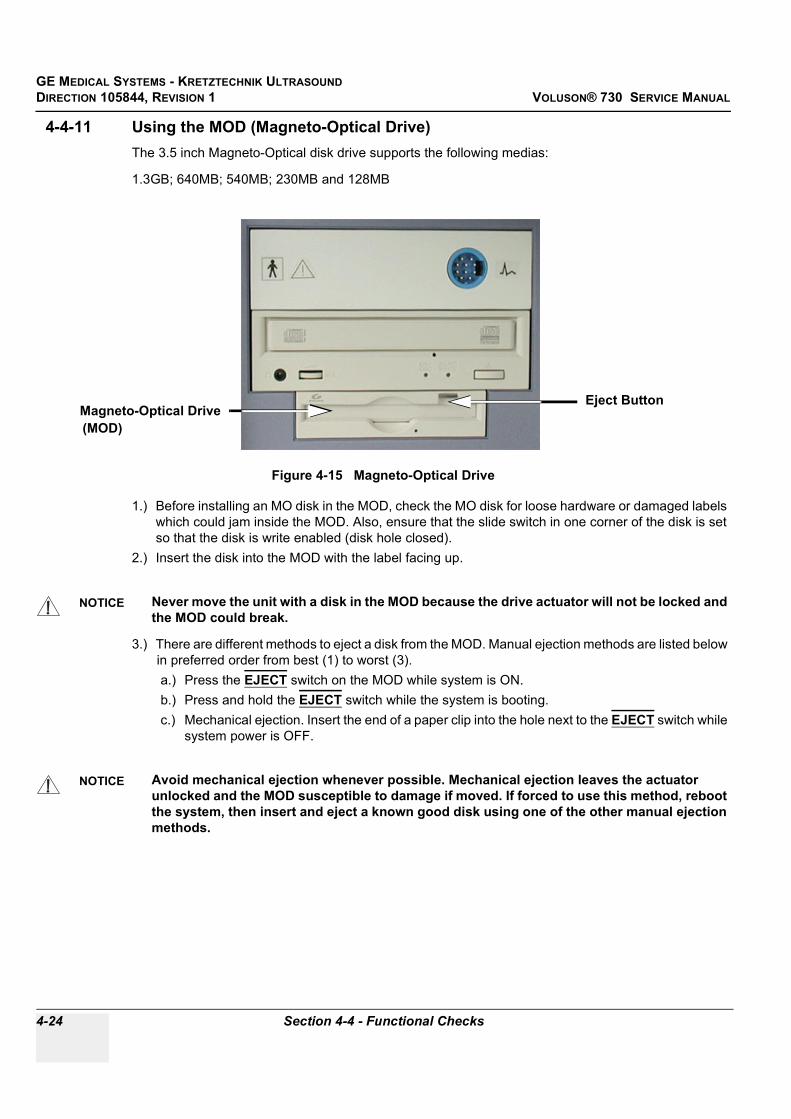
GE MEDICAL SYSTEMS - KRETZTECHNIK ULTRASOUNDDIRECTION 105844, REVISION 1 VOLUSON® 730 SERVICE MANUAL
4-24 Section 4-4 - Functional Checks
4-4-11 Using the MOD (Magneto-Optical Drive)The 3.5 inch Magneto-Optical disk drive supports the following medias:
1.3GB; 640MB; 540MB; 230MB and 128MB
1.) Before installing an MO disk in the MOD, check the MO disk for loose hardware or damaged labels which could jam inside the MOD. Also, ensure that the slide switch in one corner of the disk is set so that the disk is write enabled (disk hole closed).
2.) Insert the disk into the MOD with the label facing up.
3.) There are different methods to eject a disk from the MOD. Manual ejection methods are listed below in preferred order from best (1) to worst (3).a.) Press the EJECT switch on the MOD while system is ON.b.) Press and hold the EJECT switch while the system is booting.c.) Mechanical ejection. Insert the end of a paper clip into the hole next to the EJECT switch while
system power is OFF.
Figure 4-15 Magneto-Optical Drive
NOTICE Never move the unit with a disk in the MOD because the drive actuator will not be locked and the MOD could break.
NOTICE Avoid mechanical ejection whenever possible. Mechanical ejection leaves the actuator unlocked and the MOD susceptible to damage if moved. If forced to use this method, reboot the system, then insert and eject a known good disk using one of the other manual ejection methods.
Eject ButtonMagneto-Optical Drive(MOD)
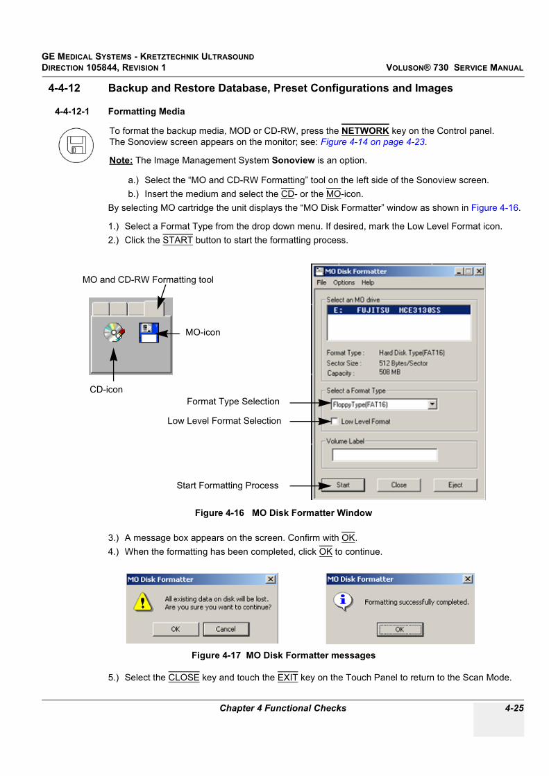
GE MEDICAL SYSTEMS - KRETZTECHNIK ULTRASOUND DIRECTION 105844, REVISION 1 VOLUSON® 730 SERVICE MANUAL
Chapter 4 Functional Checks 4-25
4-4-12 Backup and Restore Database, Preset Configurations and Images
4-4-12-1 Formatting Media
a.) Select the “MO and CD-RW Formatting” tool on the left side of the Sonoview screen.b.) Insert the medium and select the CD- or the MO-icon.
By selecting MO cartridge the unit displays the “MO Disk Formatter” window as shown in Figure 4-16.
1.) Select a Format Type from the drop down menu. If desired, mark the Low Level Format icon.2.) Click the START button to start the formatting process.
3.) A message box appears on the screen. Confirm with OK.4.) When the formatting has been completed, click OK to continue.
5.) Select the CLOSE key and touch the EXIT key on the Touch Panel to return to the Scan Mode.
To format the backup media, MOD or CD-RW, press the NETWORK key on the Control panel.The Sonoview screen appears on the monitor; see: Figure 4-14 on page 4-23.
Note: The Image Management System Sonoview is an option.
Figure 4-16 MO Disk Formatter Window
Figure 4-17 MO Disk Formatter messages
CD-icon
MO and CD-RW Formatting tool
MO-icon
Format Type Selection
Low Level Format Selection
Start Formatting Process

GE MEDICAL SYSTEMS - KRETZTECHNIK ULTRASOUNDDIRECTION 105844, REVISION 1 VOLUSON® 730 SERVICE MANUAL
4-26 Section 4-4 - Functional Checks
4-4-12-1 Formatting Media (cont’d)By selecting CD-RW the unit displays the “Erase CD-RW” window as shown in Figure 4-18.
1.) Select the “Erase Mode” and click the OK button to start the format process.
2.) During erasing the Ultrasound system displays following message.
3.) Touch the EXIT key on the Touch Panel to return to the Scan Mode.
NOTE: It is possible to adjust the Write Speed of the CD-Writer.At older software versions, also the Erase Mode can be preset in the “Settings” window.
1.) Click the SETTINGS icon on the left side of the Sonoview screen.2.) Select CD RECORDER from the tool bar.
3.) Choose the “Write Speed” (and the “Erase Mode” at systems with older software versions) from the corresponding pop-up menu.
NOTICE It is highly recommended to use the complete erase mode, to avoid problems with the CD-RW!
Figure 4-18 Erase CD-RW Window
Figure 4-19 Erasing disk
Figure 4-20 Settings of the CD-Recorder
Settings-icon

GE MEDICAL SYSTEMS - KRETZTECHNIK ULTRASOUND DIRECTION 105844, REVISION 1 VOLUSON® 730 SERVICE MANUAL
Chapter 4 Functional Checks 4-27
4-4-12-2 Save System Presets and Configurations (Application Settings)The Backup contains:
• User Settings, Auto Text, Measurement user tables• Biopsy (needle guide positions)• Setup settings (language, date format, screensaver on/off, etc.)
NOTE: Always backup any preset configurations before upgrading the Application Settings. This ensures that if the presets need to be reloaded, after the software update, will be the same ones the customer was using prior to service.
1.) Insert a formatted MOD (Magneto-Optical Disk) into the drive.2.) On the Touch Panel, touch UTILITIES.3.) On the Utilities Touch Panel, touch SYSTEM SETUP to invoke the setup desktop on the screen.4.) Select the BACKUP page and click the SAVE button to display the Backup Save window.
5.) Choose the media (e.g.MO-Drive) and click the SAVE button.6.) Select the NEW FILE... button and enter a file name (backup name - without extension).7.) Click the OK button. The system performs the backup.8.) When the saving of the System Settings has been completed, click OK.
NOTICE Saving the Backup to CD-RW is impossible!
Figure 4-21 Backup Save window
Figure 4-22 System Settings are saved successfully
Choose the mediaand
click the Save button

GE MEDICAL SYSTEMS - KRETZTECHNIK ULTRASOUNDDIRECTION 105844, REVISION 1 VOLUSON® 730 SERVICE MANUAL
4-28 Section 4-4 - Functional Checks
4-4-12-3 Load System Presets and Configurations (Application Settings)
1.) If available, insert the Backup/Restore MOD (Magneto-Optical Disk) or CD-RW into the drive. 2.) On the Touch Panel, touch UTILITIES.3.) In the Utilities menu, touch SYSTEM SETUP to invoke the setup desktop on the screen.4.) Select the BACKUP page and click the LOAD button to display the Backup Load window.
5.) Choose the media (e.g. MO-Drive) and click the LOAD button.6.) Select the appropriate file and click OK. The “Load Backup Data” window appears.
CAUTION Always backup any Application Settings before the upgrade; see: Section 4-4-12-2 on page 4-27.The loading procedure overwrites the existing application settings on the local hard drive. Make sure to insert the correct MOD or CD-RW. Additionally you can load the backup from d:\User Settings.
Figure 4-23 Backup Load window
NOTICE If the selected Backup file doesn’t fit, a message box appears. see Figure 4-24It is highly recommend to use Application settings which are adapted for the systems software version!
Figure 4-24 Wrong Version messages
NOTICE If you select the CONTINUE key to proceed loading the unfit Application settings, a request message (Figure 4-24) to load the appropriate factory settings will appear with each restart of the Voluson® 730.
Choose the mediaand
click the Load button
request message to load factory setting

GE MEDICAL SYSTEMS - KRETZTECHNIK ULTRASOUND DIRECTION 105844, REVISION 1 VOLUSON® 730 SERVICE MANUAL
Chapter 4 Functional Checks 4-29
4-4-12-3 Load System Presets and Configurations (Application Settings) (cont’d)
7.) Select the Complete Backup (marked blue) and click the ARROW button to copy the Complete Backup into the Load Data field.
8.) Click the LOAD button to start the loading procedure of the complete backup into the system.
NOTE: Also only parts of a Backup can be loaded into the database to overwrite, restore, copy, etc.... the database in the system.
1.) Click the + sign to open the content tree.
2.) Click the ARROW button to copy the selected item into the Load Data field.3.) To return selected items from the Load Data field to Backup Data field select the SCISSORS button.4.) Click the LOAD button to start loading procedure of the selected Backup item into the system.
Figure 4-25 Load Backup Data
Figure 4-26 Load only parts of the Backup
“Arrow” button
Load button
Complete Backup
sign to open thecontent tree “Arrow” button
Load button
“Scissors” button

GE MEDICAL SYSTEMS - KRETZTECHNIK ULTRASOUNDDIRECTION 105844, REVISION 1 VOLUSON® 730 SERVICE MANUAL
4-30 Section 4-4 - Functional Checks
4-4-12-4 Archiving Images
1.) Insert the archive media. 2.) Press the NETWORK (Sonoview) key on the Control panel.3.) Format the MOD/CD-RW. To format the media, CD-RW or MOD see Section 4-4-12-1 "Formatting
Media" on page 4-25. 4.) When you click the OPEN button on the upper left side of the screen, a list of all the exams is
displayed see Figure 4-27.
5.) Select the exam(s) using the TRACKBALL and the right trackball key SET.
NOTE: The number of all exams of the exam list, the number of currently selected exams, the number of images and the capacity of selected images are displayed automatically at the right and upper corner of the exams list.
6.) Click the BACKUP button.7.) Select on which medium you would like to Backup the files.8.) After finishing the backup, select whether the selected exam(s) is to be deleted or not.
Figure 4-27 Sonoview Screen
Figure 4-28 Backup windows
NOTICE If you select to delete the exam after finishing the backup, it will be absolutely deleted from the hard disk of the ultrasound scanner Voluson® 730!
Open button
Backup
capacityof selectedexams
button
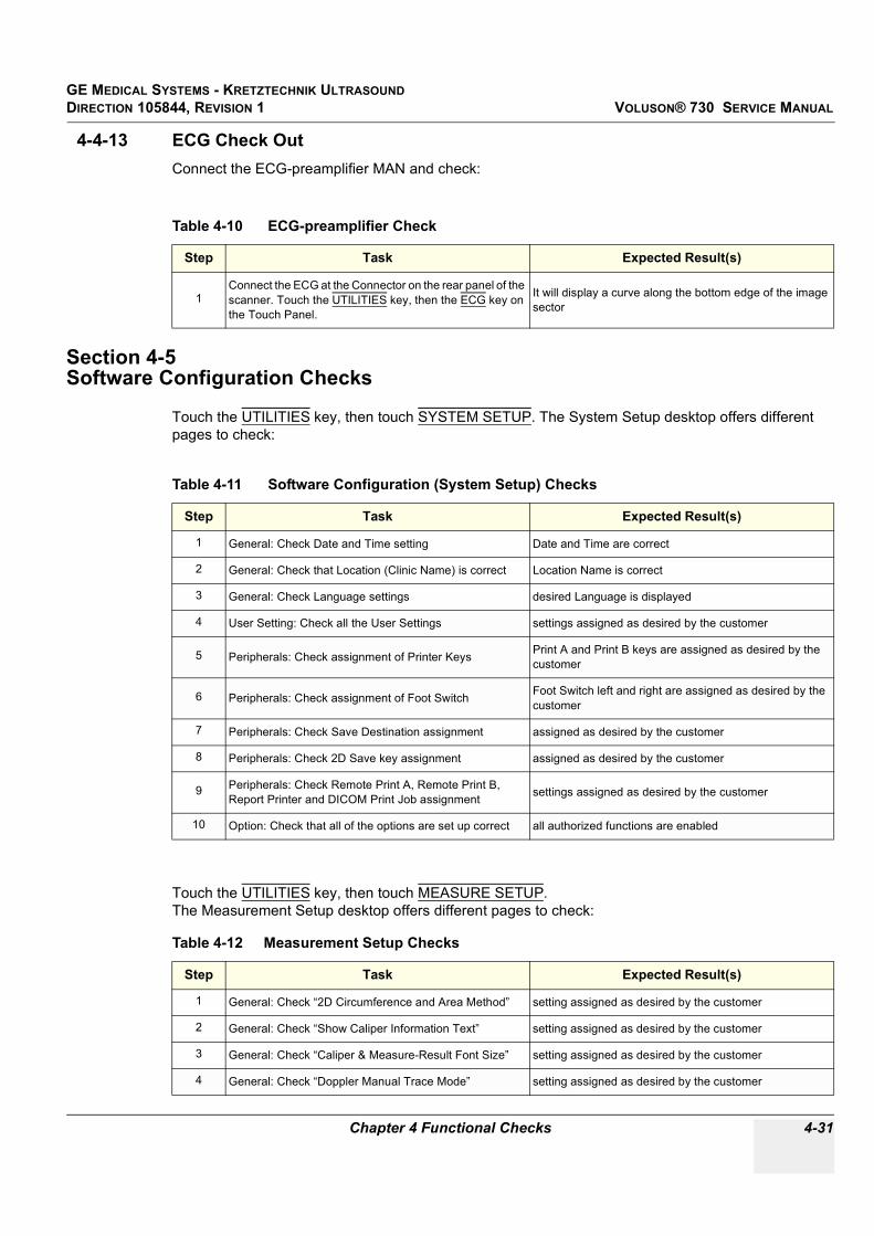
GE MEDICAL SYSTEMS - KRETZTECHNIK ULTRASOUND DIRECTION 105844, REVISION 1 VOLUSON® 730 SERVICE MANUAL
Chapter 4 Functional Checks 4-31
4-4-13 ECG Check Out Connect the ECG-preamplifier MAN and check:
Section 4-5Software Configuration Checks
Touch the UTILITIES key, then touch SYSTEM SETUP. The System Setup desktop offers different pages to check:
Touch the UTILITIES key, then touch MEASURE SETUP. The Measurement Setup desktop offers different pages to check:
Table 4-10 ECG-preamplifier Check
Step Task Expected Result(s)
1Connect the ECG at the Connector on the rear panel of the scanner. Touch the UTILITIES key, then the ECG key on the Touch Panel.
It will display a curve along the bottom edge of the image sector
Table 4-11 Software Configuration (System Setup) Checks
Step Task Expected Result(s)
1 General: Check Date and Time setting Date and Time are correct
2 General: Check that Location (Clinic Name) is correct Location Name is correct
3 General: Check Language settings desired Language is displayed
4 User Setting: Check all the User Settings settings assigned as desired by the customer
5 Peripherals: Check assignment of Printer Keys Print A and Print B keys are assigned as desired by the customer
6 Peripherals: Check assignment of Foot Switch Foot Switch left and right are assigned as desired by the customer
7 Peripherals: Check Save Destination assignment assigned as desired by the customer
8 Peripherals: Check 2D Save key assignment assigned as desired by the customer
9 Peripherals: Check Remote Print A, Remote Print B, Report Printer and DICOM Print Job assignment settings assigned as desired by the customer
10 Option: Check that all of the options are set up correct all authorized functions are enabled
Table 4-12 Measurement Setup Checks
Step Task Expected Result(s)
1 General: Check “2D Circumference and Area Method” setting assigned as desired by the customer
2 General: Check “Show Caliper Information Text” setting assigned as desired by the customer
3 General: Check “Caliper & Measure-Result Font Size” setting assigned as desired by the customer
4 General: Check “Doppler Manual Trace Mode” setting assigned as desired by the customer

GE MEDICAL SYSTEMS - KRETZTECHNIK ULTRASOUNDDIRECTION 105844, REVISION 1 VOLUSON® 730 SERVICE MANUAL
4-32 Section 4-6 - Peripheral Checks
Section 4-6Peripheral Checks
Check that peripherals work as described below:
5 General: Check “Store Measurements” setting assigned as desired by the customer
6 General: Check “Doppler Trace Display Results” settings assigned as desired by the customer
7 General: Check “Measure Results Display” setting assigned as desired by the customer
8 OB: Check “Preset Selection” setting assigned as desired by the customer
9 OB: Check “Pregnancy Weeks” setting assigned as desired by the customer
10 OB: Check “Ratio Calculations” settings assigned as desired by the customer
11 OB: Check “GS Measurement Method” setting assigned as desired by the customer
12 OB: Check “Show Author´s Name at Measure Menu” setting assigned as desired by the customer
13 Cardiac: Check “2D Circumference and Area Method” setting assigned as desired by the customer
14 Cardiac: Check “LV Volume Calculation Method” setting assigned as desired by the customer
Table 4-13 Peripheral Checks
Step Task to do Expected Result(s)
1 Press the FREEZE key. Stop image acquisition.
2 Press the PRINT A or PRINT B key on the Control Panel.
The image displayed on the screen is printed on B&W or Color printer, depending on the key assignment configuration
3 Press the VCR key on the Control Panel twice. VCR starts recording (REC - will be displayed on the screen)
4 Press the VCR key twice again. VCR stops recording
5 Press the VCR key on the Control Panel once. The VCR Remote Control menu is displayed on the Touch Panel.
6 Press RECORD on the Touch Panel.to start recordingA red dot is displayed in the VCR status area on the Title bar to indicate that recording has begun
7 Press STOP on the Touch Panel.To Stop recordingThe video status icon is changed to (Pause)
8 Press PLAY on the Touch Panel. To start, Play back an examination
9 Press EXIT on the Touch Panel to return to the scanning mode
10 Use the assignable keys on the Touch Panelto perform actions on the recorded session, such as stop, pause, rewind or fast forward.The video status icon in updated accordingly.
Table 4-12 Measurement Setup Checks
Step Task Expected Result(s)

GE MEDICAL SYSTEMS - KRETZTECHNIK ULTRASOUND DIRECTION 105844, REVISION 1 VOLUSON® 730 SERVICE MANUAL
Chapter 4 Functional Checks 4-33
Section 4-7Mechanical Function Checks
4-7-1 Rotation of the Control Console
4-7-2 Brakes and Direction Locks
Figure 4-29 Locking Lever under Control Console
Table 4-14 Rotation of the Control Console
Step Task Expected Result(s)
1 Push the locking lever under the Control Console forward, grasp it at the front grip of the user interface and rotate the console.
It is possible to rotate the Control Console up to 30° to the right.
WARNINGWARNING Do not put your hand between the control console and the main unit when moving the console to the 0° position: Danger of injuries!
Figure 4-30 Front Wheel with Brake
Table 4-15 Brakes and Direction Lock
Step Task Expected Result(s)
1 Flap the foot rest up and press the release brake pedals on the front wheels.
The front wheels are engaged / disengaged for transportation.
Locking Leverfor locking and unlocking the control console
Brakepedal
steer ableFront Wheel

GE MEDICAL SYSTEMS - KRETZTECHNIK ULTRASOUNDDIRECTION 105844, REVISION 1 VOLUSON® 730 SERVICE MANUAL
4-34 Section 4-7 - Mechanical Function Checks
4-7-3 Power Supply AdjustmentThere are no adjustments on the power supplies. The DC Power is self-regulated. If a voltage is outside the specified range, it means that something is wrong, either with the power supply itself or with a component connected to that specific power outlet.

GE MEDICAL SYSTEMS - KRETZTECHNIK ULTRASOUND DIRECTION 105844, REVISION 1 VOLUSON® 730 SERVICE MANUAL
Chapter 4 Functional Checks 4-35
Section 4-8Site Log
4-8-1 Site Log - System (Service Database)1.) On the Touch Panel, touch UTILITIES.2.) In the Utilities menu, touch SYSTEM SETUP to invoke the setup desktop on the screen.3.) Select the SERVICE page. The “password window” appears automatically.4.) Enter the password SHE and click the ACCEPT button to display the Service Tools window.
5.) Click the MAINTENANCE REPORT button. The following message box will be displayed.
6.) Fill in the requested information and click OK.7.) Click the EXIT button on the Service Tools window and the EXIT button on the System Setup
Service page.
NOTE: After Hardware or Software modifications normally the “Maintenance Report” message box (see: Figure 4-32) appears automatically on the screen.
Figure 4-31 System Setup Service page and Service Tools window
Figure 4-32 Maintenance Report

GE MEDICAL SYSTEMS - KRETZTECHNIK ULTRASOUNDDIRECTION 105844, REVISION 1 VOLUSON® 730 SERVICE MANUAL
4-36 Section 4-8 - Site Log
4-8-2 Site Log - Paper Documentation
Table 4-16 Site Log
Date Service person Problem Comments

GE MEDICAL SYSTEMS - KRETZTECHNIK ULTRASOUND DIRECTION 105844, REVISION 1 VOLUSON® 730 SERVICE MANUAL
Chapter 5 Components and Functions (Theory) 5-1
Chapter 5Components and Functions (Theory)
Section 5-1Overview
5-1-1 Purpose of Chapter 5This chapter explains Voluson® 730’s system concepts, component arrangement, and subsystem function. It also describes the Power Distribution System (PDS) and probes.
Table 5-1 Contents in Chapter 5
Section Description Page Number
5-1 Overview 5-1
5-2 General Information 5-2
5-3 Main board Chassis GEF Module 5-18
5-4 Front End Processor 5-19
5-5 Back End Processor 5-24
5-6 Internal I/O 5-28
5-7 Top Console 5-31
5-8 Monitor 5-32
5-9 External I/O 5-33
5-10 Peripherals 5-34
5-11 Power Distribution 5-35
5-12 Mechanical Descriptions 5-37
5-13 Air Flow Control 5-40
5-14 Service Page 5-41

GE MEDICAL SYSTEMS - KRETZTECHNIK ULTRASOUNDDIRECTION 105844, REVISION 1 VOLUSON® 730 SERVICE MANUAL
5-2 Section 5-2 - General Information
Section 5-2General Information
Voluson® 730 is a digital beam forming curved-, linear- and phased array ultrasound imaging system. It has provisions for analog input sources like ECG and Phono. A CW-Doppler probe may also be connected and used.
The system can be used for:
- 2D Gray Scale and 2D Color Doppler Imaging (CFM, PD, TD)- M-Mode Gray Scale Imaging - Doppler (PW, CW)- 3D Mode and Real Time 4D Imaging- Different combinations of the above modes
Figure 5-1 Voluson® 730 Major Components
Monitor
Touch Panel/Display
TGC - Slider Controls
Monitor Controls
Control Console
Front Grip
VCR
Bolt to rotate and lock the Control Console(mounted at the front below the Console)
Probe Connectors
Foot rest
Brakes to block the front wheels (under the foot rest)
Probe storage
Name Plate
Place for ECG Module
Stand By switch
3.5” MOD Drive
CD-RW Drive
Color Printer
CW Connector
(not active for scanning)connector

GE MEDICAL SYSTEMS - KRETZTECHNIK ULTRASOUND DIRECTION 105844, REVISION 1 VOLUSON® 730 SERVICE MANUAL
Chapter 5 Components and Functions (Theory) 5-3
Section 5-2 General Information (cont’d)
Major System Components:
• GEF: Main Board Chassis: Section 5-3 on page 5-18- Front-End processor Section 5-4 on page 5-19- Back-End processor Section 5-5 on page 5-24
• GEU: Top Console User interface (System I/O with hard keys, Touch screen and EL-Display)Section 5-7 on page 5-31
• MONITOR: Section 5-8 on page 5-32• GES: External I/O Connection Module Section 5-9 on page 5-33• GEM: Removable Disk drive module (ECG-preamplifier MAN6 - optional)
Section 5-10 on page 5-34• CPN: Primary Power supply and Isolation transformer for the peripherals Section 5-11 on page 5-35• GW: System mechanical chassis, stand alone trolley to keep all major components
Section 5-12 on page 5-37
Figure 5-2 Major System Components
MONITOR
GES
CPN
GEM
GEFGW
GEU
without GEU

GE MEDICAL SYSTEMS - KRETZTECHNIK ULTRASOUNDDIRECTION 105844, REVISION 1 VOLUSON® 730 SERVICE MANUAL
5-4 Section 5-2 - General Information
Section 5-2 General Information (cont’d)
Figure 5-3 Basic Blockdiagram of Voluson® 730
CPU Probeboard
CPR Beamformer-Motherboard
CRW CW-Dopplerboard (Optional)
CPG MID-Processingboard
CPC Controlboard
CCM Motorcontrolboard
CPF Doppler+CFM board
CPM PC-Motherboard. Subboards: Slot-CPU,
several PC-Cards, CKV(Video-Card), CPS(DMA-
Controller-Card) , CPE(Backplane-Card)
CPP Powersupply- Secondaryboard
GEU User-Interface-Module
Monitor
GES External IO
GEF Main board Chassis
CPN MainPowerSupply Module
Subboards: 32xCPD
CP
Z C
overb
oard
CP
K M
oth
erb
oard
of G
EF
-Module
GEM-
ECG+Diskdrive
Module
GW Trolley
(housing, mechanical
framework).
The following components
are part of GW:
- monitor-table,
- shaft for GEU,
- GES External IO,
- GEM ECG-Diskdrive,
- framework,
- cover-panels,
- CPN MainPowerS.
- wheels.

GE MEDICAL SYSTEMS - KRETZTECHNIK ULTRASOUND DIRECTION 105844, REVISION 1 VOLUSON® 730 SERVICE MANUAL
Chapter 5 Components and Functions (Theory) 5-5
Section 5-2 General Information (cont’d)
The Voluson® 730 used digital beam forming technology which provides high resolution and high penetration performance. It is a general purpose, mobile, software controlled diagnostic ultrasound scanner. Its function is to acquire ultrasound data and to display the data of different modes.Voluson® 730 gives the operator the ability to measure anatomical structures and offers analysis packages that provide information that is used to make a diagnosis by competent health care professionals.
The Calculation and Report function supports 4 application packages:
• Obstetric Calculations• Gynecology Calculations• Cardiology Calculations• Vascular Calculations•The Voluson® 730 supports a variety of linear-, curved-, phased array and pencil probes for various clinical applications. Any three probes may be connected at the same time (+ one pencil CW-probe).
Medical application fields include:
• Obstetrics• Gynecology and Fertility• Radiology• Internal Medicine• Neurology• Cardiology• Oncology• Urology• Orthopedics• PediatricsThe system is designed for follow-up expansion.
In addition to the initial operational settings for each transducer pre-programmed in the system, user-customized parameter settings for each transducer may be inserted by the operator and stored for recall as needed via the system control panel. System configuration is stored on the hard drive and all necessary software is loaded from the hard drive on power up.
Biopsy guidelines are provided on screen to assist in the collection of tissue samples, using biopsy guide adapters offered as an optional accessory.
The system provides the ability to perform remote viewing of images without compression, via DICOM 3.0 compatible output. Management of patient history is possible by “Sonoview” image-filing function. High-resolution images are provided by utilizing a technology called digital dynamic receive focusing.
Signal flow travels from the Probe Connector Panel to the Front End Electronics, to the Back-End Processor, and finally displayed on the monitor and peripherals.
For more detailed explanations of functions and controls refer to the Voluson® 730 Basic User Manual.

GE MEDICAL SYSTEMS - KRETZTECHNIK ULTRASOUNDDIRECTION 105844, REVISION 1 VOLUSON® 730 SERVICE MANUAL
5-6 Section 5-2 - General Information
5-2-1 Description of Voluson® 730 Operating Modes
5-2-1-1 B-Mode or 2D-Mode:B-Mode or 2D-mode is a two-dimensional image of the amplitude of the echo signal. It is used for location and measurement of anatomical structures and for spatial orientation during operation of other modes. In 2D-mode, a two-dimensional cross-section of a three-dimensional soft tissue structure such as the heart is displayed in real time. Ultrasound echoes of different intensities are mapped to different gray scale or color values in the display. The outline of the 2D cross-section may be a rectangle, parallelogram, sector or 360-degree circle, depending on the particular transducer used. 2D-mode can be used in combination with any other mode.
5-2-1-2 M-Mode:In M-mode, soft tissue structure is presented as scrolling display, with depth on the Y-axis and time on the X-axis. It is used primarily for cardiac measurements such as value timing on septal wall thickness when accurate timing information is required. M-mode is also known as T-M mode or time-motion mode. Ultrasound echoes of different intensities are mapped to different gray scale values in the display. M-mode displays time motion information of the ultrasound data derived from a stationary beam. Depth is arranged along the vertical axis with time along the horizontal axis. M-mode is normally used in conjunction with a 2D image for spatial reference. The 2D image has a graphical line (M-line) superimposed on the 2D image indicating where the M-mode beam is located.
5-2-1-3 Color Doppler Mode: Color Doppler is used to detect motion presented as a two-dimensional display. There are three applications of this technique:
• Color Flow Mode (C) - used to visualize blood flow velocity and direction• Power Doppler (PD) - used to visualize the spatial distribution of blood• Tissue Doppler (TD) - used to visualize tissue motion direction and velocity (optional see 5-2-5-8)
5-2-1-3-1 Color Flow Mode:a real-time two-dimensional cross-section image of blood flow is displayed. The 2D cross-section may be presented as a rectangle, parallelogram, trapezoid, sector, or a full circle, depending on the particular transducer used. The 2D cross-section is presented as a full color display, with various colors being used to represent blood flow (velocity, variance, power and/or direction). Often, to provide spatial orientation, the full color blood flow cross-section is overlaid on top of the grayscale cross-section of soft tissue structure (2D echo). For each pixel in the overlay, the decision of whether to display color (Doppler), gray scale (echo) information or a blended combination is based on the relative strength of return echoes from the soft tissue structures and from the red blood cells. Blood velocity is the primary parameter used to determine the display colors, but power and variance may also used. A high pass filter (wall filter) is used to remove the signals from stationary or slowly moving structures. Tissue motion is discriminated from blood flow by assuming that blood is moving faster than the surrounding tissue, although additional parameters may also be used to enhance the discrimination. Color flow can be used in combination with 2D and Spectral Doppler modes.
5-2-1-3-2 Power Doppler: a real-time two dimensional cross-section of blood flow is displayed. The 2D cross-section may be presented as a rectangle, parallelogram, trapezoid, sector, or a full circle, depending on the particular transducer used. The 2D cross-section is presented as a full color display, with various colors being used to represent the power in blood flow echoes. Often, to provide spatial orientation, the full color blood flow cross-section is overlaid on top of the gray scale cross-section of soft tissue structure (2D echo). For each pixel in the overlay, the decision of whether to display color (Doppler power), gray scale (echo) information or a blended combination is based on the relative strength of return echoes from the soft-tissue structures and from the red blood cells. A high pass filter (wall filter) is used to remove the signals from stationary or slowly moving structures.

GE MEDICAL SYSTEMS - KRETZTECHNIK ULTRASOUND DIRECTION 105844, REVISION 1 VOLUSON® 730 SERVICE MANUAL
Chapter 5 Components and Functions (Theory) 5-7
Tissue motion is discriminated from blood flow by assuming that blood is moving faster than the surrounding tissue, although additional parameters may also be used to enhance the discrimination. The power in the remaining signal after wall filtering is then averaged over time (persistence) to present a steady state image of blood flow distribution. Power Doppler can be used in combination with 2D and Spectral Doppler modes as well as with 3D mode.
5-2-1-4 Pulsed (PW) Doppler:PW Doppler processing is one of two spectral Doppler modalities, the other being CW Doppler. In spectral Doppler, blood flow is presented as a scrolling display, with flow velocity on the Y-axis and time on the X-axis. The presence of spectral broadening indicates turbulent flow, while the absence of spectral broadening indicates laminar flow. PW Doppler provides real time spectral analysis of pulsed Doppler signals. This information describes the Doppler shifted signal from the moving reflectors in the sample volume. PW Doppler can be used alone but is normally used in conjunction with a 2D image with an M-line and sample volume marker superimposed on the 2-D image indicating the position of the Doppler sample volume. The sample volume size and location are specified by the operator. Sample volume can be overlaid by a flow direction cursor which is aligned, by the operator, with the direction of flow in the vessel, thus determining the Doppler angle. This allows the spectral display to be calibrated in flow velocity (m/sec) as well as frequency (Hz). PW Doppler also provides the capability of performing spectral analysis at a selectable depth and sample volume size. PW Doppler can be used in combination with 2D and Color Flow modes.
5-2-2 3D ImagingThe Voluson® 730 Ultrasound System will be used to acquire multiple, sequential 2D images which can be combined to reconstruct a three dimensional image. These 3D images are useful in visualizing three-dimensional structures, and in understanding the spatial or temporal relationships between the images in the 2D sequence. The 3D image is presented using standard visualization techniques, such as surface or volume rendering.
5-2-2-1 3D Data Collection and Reconstruction:2D gray scale including Power Doppler images may be reconstructed. The acquisition of volume data sets is performed by sweeping 2D-scans with special transducers (called 3D-transducers) designed for the 2D-scans and the 3D-sweep.
Images are spatially registered, using internal probe position sensing and a position control to ensure geometric accuracy of the 3D data.
2D ultrasound imaging modes are used to view a two dimensional cross-sections of parts of the body. For example in 2D gray scale imaging, a 2 dimensional cross-section of a 3-dimensional soft-tissue structure such as the heart is displayed in real time. Typically, the user of an ultrasound machine manipulates the position and orientation of this 2D cross-section in real time during an ultrasound exam. By changing the position of the cross-section, a variety of views of the underlying structure are obtained, and these views can be used to understand a 3-dimensional structure in the body.
To complete survey a 3-dimensional structure in the body, it is necessary to collect 2D images which span a volume containing the structure. One way is to sweep the imaging cross-section by translating it in a direction perpendicular to the cross-section. Another example method is to rotate the cross section about a line contained in the cross section. The Voluson® 730 Ultrasound System uses the automated so called C-Scan for the motion perpendicular to automated B-scan.
Once a representative set of 2D cross-sections are obtained, standard reconstruction techniques can be used to construct other 2D cross-sections, or to view the collection of the cross-sections as a 3D images.

GE MEDICAL SYSTEMS - KRETZTECHNIK ULTRASOUNDDIRECTION 105844, REVISION 1 VOLUSON® 730 SERVICE MANUAL
5-8 Section 5-2 - General Information
5-2-2-2 3D Image Presentation:The basic technique for 3D image presentation is to combine the 2D cross –sections into an image which represents how the volume of the data would appear from a particular viewing direction. The mathematics behind this feature is called 3D-rendering. Such combined images are called projections, because the data from the volume is projected onto a flat 2-dimensional surface(e.g. the ultrasound system display.) This technique can be applied to any 2D ultrasound mode.
Several techniques can be used to aid the human observer in understanding the resulting 2D image as a representation of a three-dimensional object. One is to rotate the volume of data, and present the resulting sequence of 2D projections to the observer. The changing direction of observation helps the observer to separate the features in the volume according to their distance from the observer.
5-2-2-3 3D Rendering:The 3D (volume) rendering is a calculation process to visualize certain 3D-structures of a scanned volume by means of a 2D-image. The gray value for each pixel of the 2D-image is calculated from the voxels along the corresponding projection path (analyzing beam) through the volume. The render (calculation) algorithm, surface or transparent mode, determines how 3D-structures are visualized.
With the MagiCut function it is possible to cut off “3D artifacts” which hide regions that are of interest for the diagnostic purpose.
Figure 5-4 Principle of Volume Rendering
PIXEL
VOXEL
Y
XZ
PRINCIPLE: VOLUME RENDERING
PROJECTION WAY
2D - DISPLAY
VOLUME - BLOCK
X

GE MEDICAL SYSTEMS - KRETZTECHNIK ULTRASOUND DIRECTION 105844, REVISION 1 VOLUSON® 730 SERVICE MANUAL
Chapter 5 Components and Functions (Theory) 5-9
5-2-3 Blockdiagram Voluson® 730
Figure 5-5 Voluson® 730 - Block Diagram
CP
K M
oth
erb
oard
of
GE
F-M
od
ule
:
C
PU
CP
R
P
CW
C
PG
CP
F C
PC
CC
M
CP
P
C
PM
CP
C C
on
tro
lbo
ard
-Clo
ckO
scill
ato
r(60M
Hz)
-PR
F(P
uls
RepetitionF
req)G
enera
tor
-Beam
form
erC
onfigura
tion:
-T
xF
req, T
xR
xF
ocus,
-T
xR
xA
podis
ation
-Lin
enum
ber(
late
ral P
ositio
n)
-conta
ins T
X-P
ow
er-
DA
C
CC
M
Mo
torc
on
tro
lbo
ard
Maste
r of C
ontr
ol of
3D
-Sw
eep.
-Drives M
oto
r via
SIN
-CO
S
-Triggers
Fra
mesta
rt o
n
CP
R(B
eam
form
er)
.
-Triggers
Write
-Logic
on
CP
S(D
MA
-Contr
olle
r)
CP
M P
C-M
oth
erb
oard
CP
E-B
ackp
lan
e-C
ard
Multip
lexer+
Am
p for
PC
-Sound<
>D
opple
rAudio
Feedth
rough f. P
ow
er,
Std
by,
etc
.
CP
N-M
ain
Po
werS
up
ply
-Mo
du
le
CP
Z C
overb
oard
C
PU
C
PR
C
WD
(CR
W)
CP
P
Po
wers
up
ply
-
Seco
nd
ary
bo
ard
Pow
ers
upply
:
DC
-DC
-Convert
er:
59V
DC
to:
+3.3
V,+
-5V
,+12V
,+-1
5V
,
+F
AN
(+24V
DC
)
+-T
X_P
OW
(+-9
0V
)
Moto
r-S
IN-C
OS
-Pow
Am
p
GE
U-U
ser-
Inte
rface-
Mo
du
le
R
CP
U
Pro
beb
oard
1 C
W-P
rbC
onnecto
r 3 P
rb-C
onnecto
rs
260pol
1 D
um
my-
Prb
Conn.
2
60pol
-Pro
be S
ele
ct R
ela
is
-Pro
be R
ecognitio
n
CP
R
Beam
form
er-
Mo
therb
oard
T
ransm
itte
r-R
eceiv
er
CP
D-B
eam
form
er-
Su
bb
oard
1x : B
eam
form
er-
AS
IC
ge
ne
rate
s T
X-P
uls
es+
TxF
ocu
s+
TxA
po
dis
atio
n,
RxF
ocu
sD
ela
y+
Su
mm
atio
n.
8x : T
X-P
ow
erA
mplif
ier
4x : T
GC
+A
ntiA
liasin
gF
ilter+
AD
C
Each
CP
D c
apable
of
8 T
X-C
hannels
, 4 R
X-C
hannels
32 x
CP
D
CP
S-D
MA
-Co
ntr
oller-
Card
US
-Lin
eM
em
ory
, F
ram
eM
em
ory
DS
C(D
ig.S
canC
onvert
er)
f. 2D
DM
A-C
ontr
olle
r f. H
ighS
peed D
ata
Tra
nsfe
r in
to S
lot-
CP
U-M
em
.
CK
V-V
ideo
-Card
Overlay-
Logic
VG
A-A
dapte
r
Vid
eo-C
onvert
er
RG
B-V
HS
, etc
CW
-Channels
sele
cte
d b
y R
ela
is
T/R
(256)
CW
TX
(16)
CP
Y
Po
wers
wit
ch
-
Plu
gb
oard
CC
F
Po
wers
up
ply
-
Pri
mary
bo
ard
CP
H
Tra
fo
Console
Fo
otS
wit
ch
Std
byS
wit
ch
(U
ser
Pow
er
ON
/OF
F)
CP
N
GE
M-
EC
G+
Dis
kd
rive-M
od
ule
: E
xte
rnal D
iskdrives
EC
G-M
odule
Aux_S
upply
SB
C-
Sin
gle
Bo
ard
Co
mp
ute
rC
om
ponents
:Netw
ork
, U
SB
Sound (
in o
ld V
ers
ion s
epara
te P
CB
)
SC
SI (in o
ld V
ers
ion s
epara
te P
CB
)
Majo
rTasks:
Sys
tem
Contr
ol
3D
-Rendering
ImageP
rocessin
g (
CR
I, S
train
Image,e
tc)
Mouse
RS
232
SC
SI-
1
KV
N
(59
VD
C,
Po
we
r-O
FF
-Sig
na
ls)
Mo
nit
or
Po
werS
up
ply
-Cab
le 5
V,1
2V
KV
RY-A
dap
ter
KV
S
Fla
tCa
ble
10
po
l
Po
we
r-O
FF
-Sig
na
ls
KV
R
Exte
rnV
ideo
Data
"E
BF
_D
"(1
8)
CW
-Da
ta s
eri
al,
D,Q
,16
Bit
ea
ch
CP
U-C
on
tro
l
"MC
PU
_A
"(1
2)
"MC
PU
_D
"(8
)
CP
U-C
on
tro
l
"MC
PU
_A
"(1
2)
"MC
PU
_D
"(8
)
"ED
_IN
"(1
6),
"EQ
_IN
"(1
6)
SIN
-CO
S
SIN
-CO
S
Po
we
red
CP
G
MID
-Pro
cesserb
oard
For
B,C
,D m
odes:
-Multib
eam
-DeIn
terleave
-Subtr
actionF
ilter
(for
TH
I)
-Dig
.TG
C, D
C-C
ancel
-Mix
er
with N
CO
-FIR
-Low
Pass
For
B m
ode o
nly
:
-MagnitudeC
alc
ula
tor
-Log.A
mplif
ier
-Resam
ple
-Edge E
nhance
-Lin
eF
ilter
-Ble
ndin
g
-Fra
meF
ilter
CP
F
Do
pp
ler+
CF
M b
oard
CF
M-p
rocessin
g:
Sam
ple
rate
Conv.
Auto
corr
ela
tor,
WM
F
Velo
city-
, T
urb
ule
nce-,
Pow
er-
Calc
ula
tion
Pers
ista
nceF
ilter(
Sm
ooth
)
Axia
l-,L
ate
ral-F
ilter
Thre
shold
ing
Lin
ebuffer
for
Tra
nsfe
r to
CP
S
Dopple
r-pro
cessin
g:
DS
P, A
udio
DA
C
Be
am
form
er-
Co
nfi
gu
rati
on
-Da
ta:
"EH
_D
AT
A"(
16
)
"EH
_A
DR
"(8
)
B-m
od
e-D
ata
"2B
WD
"(8
)
CW
D o
r new
:
CR
W
CW
-Do
pp
lerb
oard
(Op
tio
nal)
-Separa
te
Clk
Osc.+
Clo
ckgenera
tor
PR
F,F
N
-TxD
ela
yMatr
ix
-Tra
nsm
itte
r,
-RxA
mp,
-RxD
ela
yMatr
ix
-Analo
g: M
ixer,
Am
ps,
Filt
er(
WM
F,A
ntiA
liasin
g)
-PR
F-S
am
pA
DC
16B
it,
CF
M-D
ata
:
"EV
","E
T",
"EP
"(8
)
DO
P-D
ata
: "E
P"(
8)
CF
M-D
ata
:
"EV
","E
T",
"EP
"(8
)
DO
P-D
ata
: "E
P"(
8)
Hard
dis
k5
V,1
2V
Da
ta
VG
A1
VG
A2
S-V
HS
2V
HS
1 O
VH
S IN
VH
S2 O
S-V
HS
Ad
ditio
na
l C
PE
-Co
nn
ecto
rs:
- L
am
p,
- E
CG
, -
RS
23
2-3
- R
em
ote
B/W
Pri
nte
r
- A
ud
io V
TR
OU
T,
...V
TR
IN
LIN
E O
UT
Sound IN
eg
. fo
r S
on
ovie
w-
So
un
d R
eco
rds
Be
am
form
er-
Co
nfi
gu
rati
on
-Da
ta:
"EH
_D
AT
A"(
16
)
"EH
_A
DR
"(8
)
RG
BS
-VH
S1
SC
SI-
Cab
le
Mo
t-S
tro
be
s
Mo
t-S
tro
be
s
SIN
-CO
S
Po
we
red
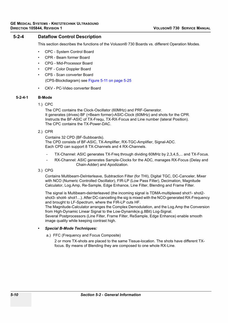
GE MEDICAL SYSTEMS - KRETZTECHNIK ULTRASOUNDDIRECTION 105844, REVISION 1 VOLUSON® 730 SERVICE MANUAL
5-10 Section 5-2 - General Information
5-2-4 Dataflow Control DescriptionThis section describes the functions of the Voluson® 730 Boards vs. different Operation Modes.
• CPC - System Control Board• CPR - Beam former Board• CPG - Mid-Processor Board• CPF - Color Doppler Board• CPS - Scan converter Board
(CPS-Blockdiagram) see Figure 5-11 on page 5-25
• CKV - PC-Video converter Board
5-2-4-1 B-Mode
1.) CPCThe CPC contains the Clock-Oscillator (60MHz) and PRF-Generator. It generates (drives) BF (=Beam former)-ASIC-Clock (60MHz) and shots for the CPR. Instructs the BF-ASIC of TX-Frequ, TX-RX-Focus and Line number (lateral Position). The CPC contains the TX-Power-DAC.
2.) CPRContains 32 CPD (BF-Subboards). The CPD consists of BF-ASIC, TX-Amplifier, RX-TGC-Amplifier, Signal-ADC. Each CPD can support 8 TX-Channels and 4 RX-Channels.
- TX-Channel: ASIC generates TX-Freq through dividing 60MHz by 2,3,4,5,... and TX-Focus.- RX-Channel: ASIC generates Sample-Clocks for the ADC, manages RX-Focus (Delay and
Chain-Adder) and Apodization.3.) CPG
Contains Multibeam-DeInterleave, Subtraction Filter (for THI), Digital TGC, DC-Canceler, Mixer with NCO (Numeric Controlled Oscillator), FIR-LP (Low Pass Filter), Decimation, Magnitude Calculator, Log.Amp, Re-Sample, Edge Enhance, Line Filter, Blending and Frame Filter.
The signal is Multibeam-deinterleaved (the incoming signal is TDMA-multiplexed shot1- shot2-shot3- shot4- shot1...). After DC-cancelling the sig is mixed with the NCO-generated RX-Frequency and brought to LF-Spectrum, where the FIR-LP cuts HF. The Magnitude-Calculator arranges the Complex Demodulation, and the Log.Amp the Conversion from High-Dynamic Linear Signal to the Low-Dynamik(e.g.8Bit) Log-Signal. Several Postprocessors (Line Filter, Frame Filter, ReSample, Edge Enhance) enable smooth image quality while keeping contrast high.
• Special B-Mode Techniques:
a.) FFC (Frequency and Focus Composite)2 or more TX-shots are placed to the same Tissue-location. The shots have different TX-focus. By means of Blending they are composed to one whole RX-Line.

GE MEDICAL SYSTEMS - KRETZTECHNIK ULTRASOUND DIRECTION 105844, REVISION 1 VOLUSON® 730 SERVICE MANUAL
Chapter 5 Components and Functions (Theory) 5-11
b.) THI = HAR (Tissue Harmonic Imaging)Generally with THI the RX-Frequency is doubled, so that the axial resolution is increased due to the higher RX-Frequency. Another step of THI is the pulse-inversion: 2 TX-shots are placed to the same Tissue-location, one with positive, one with negative polarity. The Subtraction of both shots (Subtraction Filter) brings to bear the nonlinear-echo-reflection-properties of the tissue (especially in usage of Contrast-medias), which is very useful with extremely difficult-to-scan patients.
c.) CRI (Contrast Resolution Imaging) Does not need any special functions of CPG. Image is composed of Single different-direction-steered images. PC-calculated.
d.) VCI (Volume Contrast Imaging)Does not need any special functions of CPG.Image is composed of single at close range placed images. PC-calculated. (Only possible with 4D-Probes).
4.) CPFHas no function in B-Mode.
5.) CPSB-mode-Data from CPG are written into Line Memory (Cine Mode-Mem). The DSC (Dig.ScanConverter) reads out the Lines and writes them scan converted (A-mode-polar to B-mode-cartesian) into the Frame Memory. From there the non deflected Image can be read out and overlaid with the rest of the Monitor-Image. see: 6.) CKVCine Mode: Same, Cine Mode-Memory is the Line Memory.
6.) CKVIs the Graphic Board of the PC. Special function for B-MODE: The above mentioned overlay-function is performed here.
5-2-4-2 M-Mode
1.) CPCsee: 5-2-4-1 B-Mode
2.) CPRsee: 5-2-4-1 B-Mode
3.) CPGsee: 5-2-4-1 B-Mode
4.) CPFsee: 5-2-4-1 B-Mode
5.) CPSM-mode-Data from CPG are written into Line Memory (Cine Mode-Mem). The DSC (Dig.ScanConverter) reads out the Lines and writes them into the Frame Memory. From there the Lines can be read out and overlaid with the rest of the Monitor-Image. see: 6.) CKVCine Mode: Same, Cine Mode-Memory is the Line Memory.
6.) CKVsee: 5-2-4-1 B-Mode
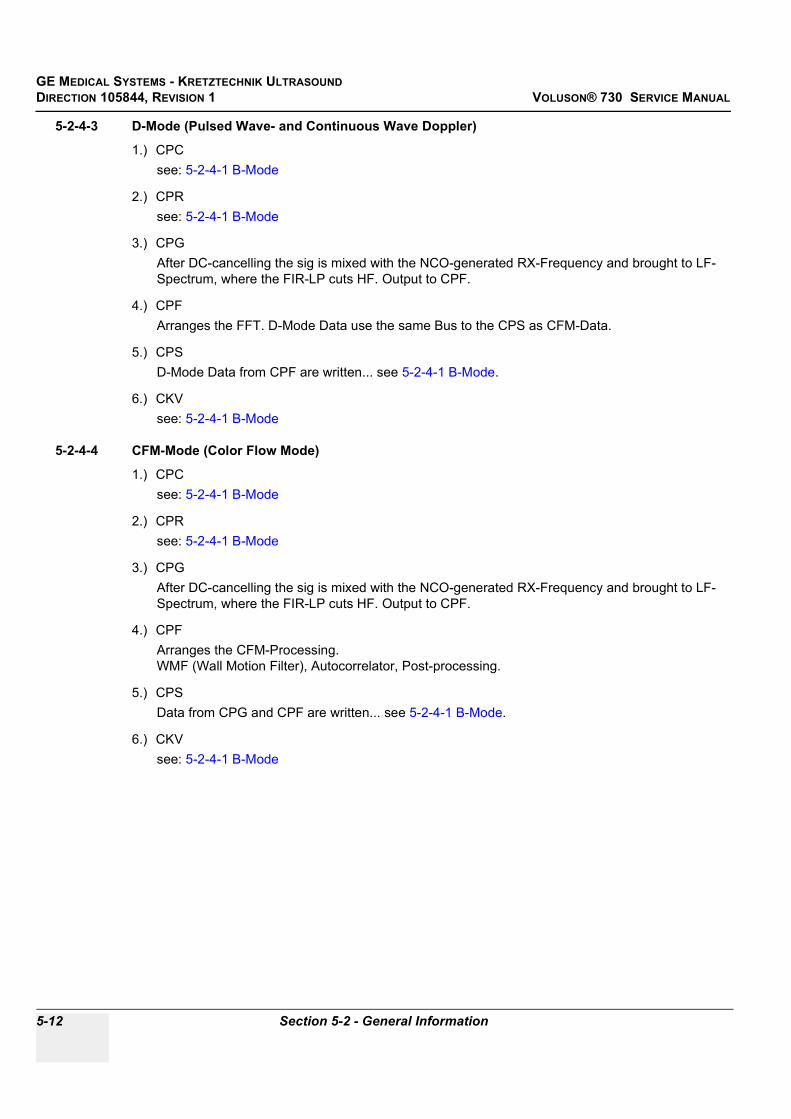
GE MEDICAL SYSTEMS - KRETZTECHNIK ULTRASOUNDDIRECTION 105844, REVISION 1 VOLUSON® 730 SERVICE MANUAL
5-12 Section 5-2 - General Information
5-2-4-3 D-Mode (Pulsed Wave- and Continuous Wave Doppler)
1.) CPCsee: 5-2-4-1 B-Mode
2.) CPRsee: 5-2-4-1 B-Mode
3.) CPGAfter DC-cancelling the sig is mixed with the NCO-generated RX-Frequency and brought to LF-Spectrum, where the FIR-LP cuts HF. Output to CPF.
4.) CPFArranges the FFT. D-Mode Data use the same Bus to the CPS as CFM-Data.
5.) CPSD-Mode Data from CPF are written... see 5-2-4-1 B-Mode.
6.) CKVsee: 5-2-4-1 B-Mode
5-2-4-4 CFM-Mode (Color Flow Mode)
1.) CPCsee: 5-2-4-1 B-Mode
2.) CPRsee: 5-2-4-1 B-Mode
3.) CPGAfter DC-cancelling the sig is mixed with the NCO-generated RX-Frequency and brought to LF-Spectrum, where the FIR-LP cuts HF. Output to CPF.
4.) CPFArranges the CFM-Processing. WMF (Wall Motion Filter), Autocorrelator, Post-processing.
5.) CPSData from CPG and CPF are written... see 5-2-4-1 B-Mode.
6.) CKVsee: 5-2-4-1 B-Mode

GE MEDICAL SYSTEMS - KRETZTECHNIK ULTRASOUND DIRECTION 105844, REVISION 1 VOLUSON® 730 SERVICE MANUAL
Chapter 5 Components and Functions (Theory) 5-13
5-2-4-5 3D-Mode
1.) CPCsee: 5-2-4-1 B-Mode
2.) CPRsee: 5-2-4-1 B-Mode
3.) CPGsee: 5-2-4-1 B-Mode
4.) CPFArranges the CFM-Processing. WMF (Wall Motion Filter), Autocorrelator, Post-processing.(In case that 3D-Color is active, else CPF not used)
5.) CPSData from CPG and CPF go to both:
a.) to the LineMemory,...FrameMemory,...CKV (see: 5-2-4-1 B-Mode) and b.) via DMA-Controller and PCI-Bus to the PC-Memory.
The way from the Line Memory to the CKV is the same as in B-Mode. This is the only case that the Line Memory-Frame Memory-Path is active in context with 3D-Mode and Real Time 4D-Mode – just for displaying the actual scanned 3D-Acquisition Sweep-B-Frame. All other displayed B-Frames in 3D-, 4D- or SonoView-Mode are PC-generated and do not need CPS any more.
6.) CKVsee: 5-2-4-1 B-Mode
5-2-4-6 Real Time 4D-Mode
1.) CPCsee: 5-2-4-1 B-Mode
2.) CPRsee: 5-2-4-1 B-Mode
3.) CPGsee: 5-2-4-1 B-Mode
4.) CPFArranges the CFM-Processing. WMF (Wall Motion Filter), Autocorrelator, Post-processing.(In case that 4D-Color is active, else CPF not used)
5.) CPSIn Real Time 4D the signal path is even simpler than in 3D, because we do not have to display the actual scanned 3D-Acquisition Sweep-B-Frame. Data from CPG and CPF go via DMA-Controller and PCI-Bus to the PC-Memory. All displayed B-Frames are PC-generated and do not need CPS any more.
6.) CKVsee: 5-2-4-1 B-Mode

GE MEDICAL SYSTEMS - KRETZTECHNIK ULTRASOUNDDIRECTION 105844, REVISION 1 VOLUSON® 730 SERVICE MANUAL
5-14 Section 5-2 - General Information
5-2-4-7 External Video Mode (Video display from VCR)
1.) CPCNot used for Signal-Processing
2.) CPRNot used for Signal-Processing
3.) CPGNot used for Signal-Processing
4.) CPFNot used for Signal-Processing
5.) CPSV-Rec-Data from the CKV-Video-Decoder are input to the CPS via the CFM-Data-Bus (CPF must disable Output-Driver). In the LM-FPGA the data are synchronized and output to the FM-FPGA. In the Extern-Video Mode the FM-FPGA is specially configured, that’s why the right part of the CPS-Blockdiagram is not valid in this Mode. In this Mode the FM-FPGA re-scales the Videorecorder-Image, that is to say that the Video is made for fitting exact into the Monitor-Frame.
6.) CKVAD-Conversion of the grapped Video, etc.

GE MEDICAL SYSTEMS - KRETZTECHNIK ULTRASOUND DIRECTION 105844, REVISION 1 VOLUSON® 730 SERVICE MANUAL
Chapter 5 Components and Functions (Theory) 5-15
5-2-5 Description of Software OptionsTo activate the software options: touch UTILITIES, SYSTEM SETUP and select the OPTION page.For further details see: Basic User Manual Voluson® 730, chapter 17.3.4
5-2-5-1 Real Time 4DReal Time 4D mode is obtained through continuous volume acquisition and parallel calculation of 3D rendered images. In Real Time 4D mode the volume acquisition box is at the same time the render box. All information in the volume box is used for the render process. In Real Time 4D mode a “frame rate” of up 16 volumes/second is possible. By freezing the acquired volumes, size can be adjusted, manipulated manually as known from the Voluson 3D Mode.
5-2-5-2 DICOMV730 software package providing following DICOM functionality:
• Storage Service Class• Print Management Service Class• Modality Worklist Management Service ClassSending of reports - All OB/Gyn measurements can be sent to a PC. Receiving of these reports is supported by ViewPoint workstation “PIA” only. All other workstations can be adapted individually.
5-2-5-3 Real Time 4D-Biopsy For minimal invasive procedures like biopsies, ultrasound is a widely used method to visualize and guide the needle during puncture. The advantage in comparison with other imaging methods is the real-time display, quick availability and easy access to any desired region of the patient. The 4D biopsy allows for real time control of the biopsy needle in 3D multi-planar display during the puncture. The user is able to see the region of interest in three perpendicular planes (longitudinal, transversal and frontal section) and can guide the biopsy needle accurately into the centre of the lesion.
5-2-5-4 VOCAL - Virtual Organ Computer-aided AnalysisDiagnosis and therapy of cancer is one of the most important issues in medical care.The new VOCAL™- Imaging program is an extension of the 3DView™ software, integrated in Kretztechnik’s VOLUSON® sonography systems and also available for PC. It allows completely new possibilities in cancer diagnosis, therapy planning and follow-up therapy control.
Table 5-2 Software Options
SW-Options PSU Description
1 Real Time 4D 11 5-2-5-1 Real Time 4D
2 DICOM 4 5-2-5-2 DICOM
3 RT_4D_Biopsy 13 5-2-5-3 Real Time 4D-Biopsy
4 VOCAL 3 5-2-5-4 VOCAL - Virtual Organ Computer-aided Analysis
5 Harmonic Imaging 10 5-2-5-5 Tissue Harmonic Imaging (THI)
6 SonoView 9 5-2-5-6 Sonoview – Image Management
7 CRI 15 5-2-5-7 CRI - Compound Resolution Imaging
8 Tissue Doppler 16 5-2-5-8 Tissue Doppler Imaging
9 VCI 14 5-2-5-9 VCI - Volume Contrast Imaging
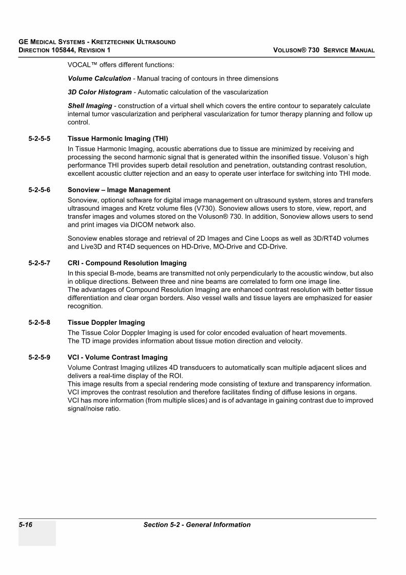
GE MEDICAL SYSTEMS - KRETZTECHNIK ULTRASOUNDDIRECTION 105844, REVISION 1 VOLUSON® 730 SERVICE MANUAL
5-16 Section 5-2 - General Information
VOCAL™ offers different functions:
Volume Calculation - Manual tracing of contours in three dimensions
3D Color Histogram - Automatic calculation of the vascularization
Shell Imaging - construction of a virtual shell which covers the entire contour to separately calculate internal tumor vascularization and peripheral vascularization for tumor therapy planning and follow up control.
5-2-5-5 Tissue Harmonic Imaging (THI)In Tissue Harmonic Imaging, acoustic aberrations due to tissue are minimized by receiving and processing the second harmonic signal that is generated within the insonified tissue. Voluson`s high performance THI provides superb detail resolution and penetration, outstanding contrast resolution, excellent acoustic clutter rejection and an easy to operate user interface for switching into THI mode.
5-2-5-6 Sonoview – Image ManagementSonoview, optional software for digital image management on ultrasound system, stores and transfers ultrasound images and Kretz volume files (V730). Sonoview allows users to store, view, report, and transfer images and volumes stored on the Voluson® 730. In addition, Sonoview allows users to send and print images via DICOM network also.
Sonoview enables storage and retrieval of 2D Images and Cine Loops as well as 3D/RT4D volumes and Live3D and RT4D sequences on HD-Drive, MO-Drive and CD-Drive.
5-2-5-7 CRI - Compound Resolution ImagingIn this special B-mode, beams are transmitted not only perpendicularly to the acoustic window, but also in oblique directions. Between three and nine beams are correlated to form one image line. The advantages of Compound Resolution Imaging are enhanced contrast resolution with better tissue differentiation and clear organ borders. Also vessel walls and tissue layers are emphasized for easier recognition.
5-2-5-8 Tissue Doppler Imaging The Tissue Color Doppler Imaging is used for color encoded evaluation of heart movements. The TD image provides information about tissue motion direction and velocity.
5-2-5-9 VCI - Volume Contrast ImagingVolume Contrast Imaging utilizes 4D transducers to automatically scan multiple adjacent slices and delivers a real-time display of the ROI.This image results from a special rendering mode consisting of texture and transparency information. VCI improves the contrast resolution and therefore facilitates finding of diffuse lesions in organs. VCI has more information (from multiple slices) and is of advantage in gaining contrast due to improved signal/noise ratio.

GE MEDICAL SYSTEMS - KRETZTECHNIK ULTRASOUND DIRECTION 105844, REVISION 1 VOLUSON® 730 SERVICE MANUAL
Chapter 5 Components and Functions (Theory) 5-17
5-2-6 Description of Hardware Options
5-2-6-1 CW - Continuous Wave Doppler CW Doppler mode provides real time spectral analysis of CW Doppler signals. This information describes the Doppler shifted signal from the moving reflectors in the CW Doppler beam. CW Doppler can be referenced through a small pencil probe or phased array scan head, but it can also be used in conjunction with a 2D image which has an M-line superimposed on the 2D image indicating the position of the Doppler sample volume. For through-the-beamformer CW, this beam is steerable by the operator, and is done by adjusting the location of the M-line. The CW Doppler beam, or M-mode line, can be steered allowing interrogation along an operator-selected line within the image.This option can be upgraded by implementing the CW-Dopplerboard (CRW, old version CWD).
5-2-6-2 ECG Digital ModuleThe ECG-preamplifier is used for acquiring an ECG-signal to be displayed with the ultrasound image. This optional peripheral serves for gaining an ECG-signal to mark the systolic and end diastolic moments in M-Mode and Doppler evaluations.The ECG-preamplifier must not be used for ECG-diagnostics. It is not intended for use as a cardiac monitor and must not be used for an intra-operative application on the heart.
1.) MAN3 (external version)2.) MAN6 (internal, digital version)
5-2-6-3 Scan freeze Footswitch
Table 5-3 Hardware Options
HW-Options Description
1 CW-Doppler 5-2-6-1 CW - Continuous Wave Doppler
2 ECG Digital Module 5-2-6-2 ECG Digital Module
3 Scan freeze Footswitch 5-2-6-3 Scan freeze Footswitch
Figure 5-6 Foot-switch Connector on CPN
Footswitch connected to Power Supply-Box (below Main Electronic-Box)

GE MEDICAL SYSTEMS - KRETZTECHNIK ULTRASOUNDDIRECTION 105844, REVISION 1 VOLUSON® 730 SERVICE MANUAL
5-18 Section 5-3 - Main board Chassis GEF Module
Section 5-3Main board Chassis GEF Module
The GEF Module contains the Front End processor and the Back End processor and the Secondary Power supply for the full GEF Chassis.Additionally GEF Module is the connection point of the internal I/O wiring.
Figure 5-7 Mechanic of GEF Module
Front End
Secondary PowerBoard - CPP
Back End
Front Rear with Internal I/O (Audio Video)
View from Rightwith Internal I/O (PC-part) Top View

GE MEDICAL SYSTEMS - KRETZTECHNIK ULTRASOUND DIRECTION 105844, REVISION 1 VOLUSON® 730 SERVICE MANUAL
Chapter 5 Components and Functions (Theory) 5-19
Section 5-4Front End Processor
Figure 5-8 Front End Processor - Block Diagram
CP
K M
oth
erb
oard
of
GE
F-M
od
ule
:
C
PU
CP
R
PC
W
CP
G
CP
F C
PC
CC
M
CP
P
CP
C C
on
tro
lbo
ard
-Clo
ckO
scill
ato
r(60M
Hz)
-PR
F(P
uls
RepetitionF
req)G
enera
tor
-Beam
form
erC
onfigura
tion:
-T
xF
req, T
xR
xF
ocus,
-T
xR
xA
podis
ation
-Lin
enum
ber(
late
ral P
ositio
n)
-conta
ins T
X-P
ow
er-
DA
C
CC
M
Mo
torc
on
tro
lbo
ard
Maste
r of C
ontr
ol of
3D
-Sw
eep.
-Drives M
oto
r via
SIN
-CO
S
-Triggers
Fra
mesta
rt o
n
CP
R(B
eam
form
er)
.
-Triggers
Write
-Logic
on
CP
S(D
MA
-Contr
olle
r)
CP
Z C
overb
oard
C
PU
C
PR
C
WD
(CR
W)
CP
P
Po
wers
up
ply
-
Seco
nd
ary
bo
ard
Pow
ers
upply
:
DC
-DC
-Convert
er:
59V
DC
to:
+3.3
V,+
-5V
,+12V
,+-1
5V
,
+F
AN
(+24V
DC
)
+-T
X_P
OW
(+-9
0V
)
Moto
r-S
IN-C
OS
-Pow
Am
pC
PU
Pro
beb
oard
1 C
W-P
rbC
onnecto
r 3 P
rb-C
onnecto
rs
260pol
1 D
um
my-
Prb
Conn.
2
60pol
-Pro
be S
ele
ct R
ela
is
-Pro
be R
ecognitio
n
CP
R
Beam
form
er-
Mo
therb
oard
T
ransm
itte
r-R
eceiv
er
CP
D-B
eam
form
er-
Su
bb
oard
1x : B
eam
form
er-
AS
IC
ge
ne
rate
s T
X-P
uls
es+
TxF
ocu
s+
TxA
po
dis
atio
n,
RxF
ocu
sD
ela
y+
Su
mm
atio
n.
8x : T
X-P
ow
erA
mplif
ier
4x : T
GC
+A
ntiA
liasin
gF
ilter+
AD
C
Each
CP
D c
apable
of
8 T
X-C
hannels
, 4 R
X-C
hannels
32 x
CP
D
CW
-Channels
sele
cte
d b
y R
ela
is
T/R
(256)
CW
TX
(16)
Exte
rnV
ideo
Data
"E
BF
_D
"(1
8)
CW
-Da
ta s
eri
al,
D,Q
,16
Bit
ea
ch
CP
U-C
on
tro
l
"MC
PU
_A
"(1
2)
"MC
PU
_D
"(8
)
CP
U-C
on
tro
l
"MC
PU
_A
"(1
2)
"MC
PU
_D
"(8
)
"ED
_IN
"(1
6),
"EQ
_IN
"(1
6)
SIN
-CO
S
SIN
-CO
S
Po
we
red
CP
G
MID
-Pro
cesserb
oard
For
B,C
,D m
odes:
-Multib
eam
-DeIn
terleave
-Subtr
actionF
ilter
(for
TH
I)
-Dig
.TG
C, D
C-C
ancel
-Mix
er
with N
CO
-FIR
-Low
Pass
For
B m
ode o
nly
:
-MagnitudeC
alc
ula
tor
-Log.A
mplif
ier
-Resam
ple
-Edge E
nhance
-Lin
eF
ilter
-Ble
ndin
g
-Fra
meF
ilter
CP
F
Do
pp
ler+
CF
M b
oard
CF
M-p
rocessin
g:
Sam
ple
rate
Conv.
Auto
corr
ela
tor,
WM
F
Velo
city-
, T
urb
ule
nce-,
Pow
er-
Calc
ula
tion
Pers
ista
nceF
ilter(
Sm
ooth
)
Axia
l-,L
ate
ral-F
ilter
Thre
shold
ing
Lin
ebuffer
for
Tra
nsfe
r to
CP
S
Dopple
r-pro
cessin
g:
DS
P, A
udio
DA
C
Be
am
form
er-
Co
nfi
gu
rati
on
-Da
ta:
"EH
_D
AT
A"(
16
)
"EH
_A
DR
"(8
)
B-m
od
e-D
ata
"2B
WD
"(8
)
CW
D o
r new
:
CR
W
CW
-Do
pp
lerb
oard
(Op
tio
nal)
-Separa
te
Clk
Osc.+
Clo
ckgenera
tor
PR
F,F
N
-TxD
ela
yMatr
ix
-Tra
nsm
itte
r,
-RxA
mp,
-RxD
ela
yMatr
ix
-Analo
g: M
ixer,
Am
ps,
Filt
er(
WM
F,A
ntiA
liasin
g)
-PR
F-S
am
pA
DC
16B
it,
CF
M-D
ata
:
"EV
","E
T",
"EP
"(8
)
DO
P-D
ata
: "E
P"(
8)
CF
M-D
ata
:
"EV
","E
T",
"EP
"(8
)
DO
P-D
ata
: "E
P"(
8)
Be
am
form
er-
Co
nfi
gu
rati
on
-Da
ta:
"EH
_D
AT
A"(
16
)
"EH
_A
DR
"(8
)
Mo
t-S
tro
be
s
Mo
t-S
tro
be
s
SIN
-CO
S
Po
we
red

GE MEDICAL SYSTEMS - KRETZTECHNIK ULTRASOUNDDIRECTION 105844, REVISION 1 VOLUSON® 730 SERVICE MANUAL
5-20 Section 5-4 - Front End Processor
Section 5-4 Front End Processor (cont’d)
Figure 5-9 CPU + Beamformer
Power
192 TX / RX
MOT_signals
CTRL-signals
CPU Probe Board
Power
192 TX / RX
MOT_signals
CTRL-signals
Power
192 TX / RX
MOT_signals
CTRL-signals
TX / RX
Pro
be
1P
rob
e 2
Pro
be
3C
W P
rob
e
CPK Motherboard
PowerSupply
SIN-COS, Mot-Strobes
CTRL-signals
MCPU_A [0..12]
MCPU_D [0..7]
CPZCover Board
32 * CPD Beamformer Subboard
CPR Beamformer Motherboard
Transmitter/Receiver
to CW_Board CWD / newlyCRW
192 *
Tx/R
x C
hannels
32 * Tx/Rx Channels
EBF_D(18) to CPG
192 *
Tx/R
x C
hannels

GE MEDICAL SYSTEMS - KRETZTECHNIK ULTRASOUND DIRECTION 105844, REVISION 1 VOLUSON® 730 SERVICE MANUAL
Chapter 5 Components and Functions (Theory) 5-21
5-4-1 Front End - Board Descriptions
5-4-1-1 CPU - Probe Board• 1 CW-Probe Connector• 3 Probe-Connectors 260pin• 1 Dummy-Probe Connector 260pin• Probe Select Relays• Probe Recognition
5-4-1-2 CPR - Beamformer BoardTransmitter-Receiver (192 transmitter channel used, 128 Receiver channels)
CPR contains 32 pieces of CPD
5-4-1-2-1 CPD-Beamformer-Sub-board1x : Beamformer-ASIC
generates TX-Pulses + TX-Focus +TX-Apodisation, Rx Focus Delay and Summation
8x : TX-Power Amplifier
4x : TGC + Anti Aliasing Filter + Analogue Digital Conversion (ADC)
Each CPD is capable of 8 TX-Channels and 4 RX-Channels
5-4-1-3 CRW - (old version: CWD) CW-Doppler Board (Optional)- Separate Clock Oscillator + Clock generator PRF, FN- TxDelayMatrix- Transmitter,- Receiver Amplifiers (RxAmp),- Receiver Delay matrix (RxDelayMatrix)- Analogue: Mixer, Amplifier, Filter(WMF, Anti Aliasing)- PRF-SampADC16Bit,
5-4-1-4 CPZ - Cover BoardTransfers the analogue transmitting / receiving signals between the following boards:
- CPU (in old version BYM)- CPR- CRW (in old version CWD)
192 Transmitter channels, 128 Receiver channels, 16 CW-Doppler channels - switched by relays at CPZ

GE MEDICAL SYSTEMS - KRETZTECHNIK ULTRASOUNDDIRECTION 105844, REVISION 1 VOLUSON® 730 SERVICE MANUAL
5-22 Section 5-4 - Front End Processor
5-4-1 Front End - Board Descriptions (cont’d)
5-4-1-5 CPG - MID-Processor Board
A.) For B,C,D modes:- Multi Beam-DeInterleave- Subtraction Filter (for THI)- Digital TGC, DC-Cancelling- Mixer with NCO- FIR-Low Pass
B.) For B mode only:- Magnitude Calculator- Logarithmic Amplifier- Resample- Edge Enhance- Line Filter- Blending- Frame Filter
5-4-1-6 CPC - Control Board• Clock Oscillator (60MHz)• PRF (Pulse Repetition Frequency) Generator• Beamformer Configuration:• Tx (transmitting Frequency, TxRx (transmitting/receiving) Focus timing• TxRx (transmitting/receiving) Apodisation• Line number (lateral Position)• contains TX-Power-DAC
5-4-1-7 CPF - Doppler+CFM Board
A.) CFM-processing:- Sample rate Conversion- Auto-Correlator- Wall motion filter (WMF)- Velocity-, Turbulence-, Power-Calculation- Persistence Filter (Smooth)- Axial-, Lateral-Filter- Thresholding- Line buffer for Transfer to CPS
B.) Doppler-Processing:- DSP, Audio DAC
C.) Beamformer- Configuration-Data:- "EH_DATA"(16)- "EH_ADR"(8)- B-Mode-Data

GE MEDICAL SYSTEMS - KRETZTECHNIK ULTRASOUND DIRECTION 105844, REVISION 1 VOLUSON® 730 SERVICE MANUAL
Chapter 5 Components and Functions (Theory) 5-23
5-4-1 Front End - Board Descriptions (cont’d)
5-4-1-8 CCM - Motor Control Board• Master of Control of 3D-Sweep• Drives Motor via SIN-COS• Triggers Frame-start on CPR (Beamformer)• Triggers Write-Logic on CPS (DMA-Controller)
5-4-1-9 CPP- Power Supply Secondary Board + Motor Power stageused for Supply of both Front End and Back End DC-DC-Converter:
59VDC to following output voltages:
+ 3.3V, +/-5V, +12V, +/-15V,
+ FAN (+24V DC)
+TX_POW (+/-90V) fused by F7
-TX_POW (+/-90V) fused by F1
Motor Sinus2 Powerstage Amplifier fused by F3
Monitor Cosinus2 Powerstage Amplifier fused by F6
5-4-1-10 CPK - Motherboard of GEF-ModuleFollowing boards are direct connected to the CPK:
• CPU (BYM) - Probe connector Board• CPR - Beam former Board• CRW (CWD) - CW-Doppler Board• CPG - Mid-Processor Board• CPF - Doppler + CFM Board Board• CPC - System Control Board• CCM - Motor Control Board• CPP - Power Supply Board• CPM - Motherboard (electrical Signal- and Supply connection between all PC-Plug-In Boards)

GE MEDICAL SYSTEMS - KRETZTECHNIK ULTRASOUNDDIRECTION 105844, REVISION 1 VOLUSON® 730 SERVICE MANUAL
5-24 Section 5-5 - Back End Processor
Section 5-5Back End Processor
Figure 5-10 Back End Processor - Block Diagram
P
CW
C
PG
CP
F C
PC
CC
M
CP
P
C
PM
CP
M P
C-M
oth
erb
oard
CP
E-B
ackp
lan
e-C
ard
Multip
lexer+
Am
p for
PC
-Sound<
>D
opple
rAudio
Feedth
rough f. P
ow
er,
Std
by,
etc
.
CP
N-M
ain
Po
werS
up
ply
-Mo
du
le
CP
P
Po
wers
up
ply
-
Seco
nd
ary
bo
ard
Pow
ers
upply
:
DC
-DC
-Convert
er:
59V
DC
to:
+3.3
V,+
-5V
,+12V
,+-1
5V
,
+F
AN
(+24V
DC
)
+-T
X_P
OW
(+-9
0V
)
Moto
r-S
IN-C
OS
-Pow
Am
p
GE
U-U
ser-
Inte
rface-
Mo
du
le
CP
S-D
MA
-Co
ntr
oller-
Card
US
-Lin
eM
em
ory
, F
ram
eM
em
ory
DS
C(D
ig.S
canC
onvert
er)
f. 2D
DM
A-C
ontr
olle
r f. H
ighS
peed D
ata
Tra
nsfe
r in
to S
lot-
CP
U-M
em
.
CK
V-V
ideo
-Card
Overlay-
Logic
VG
A-A
dapte
r
Vid
eo-C
onvert
er
RG
B-V
HS
, etc
CP
Y
Po
wers
wit
ch
-
Plu
gb
oard
CC
F
Po
wers
up
ply
-
Pri
mary
bo
ard
CP
H
Tra
fo
Console
Fo
otS
wit
ch
Std
byS
wit
ch
(U
ser
Pow
er
ON
/OF
F)
CP
N
GE
M-
EC
G+
Dis
kd
rive-M
od
ule
: E
xte
rnal D
iskdrives
EC
G-M
odule
Aux_S
upply
SB
C-S
ing
le B
oar
d C
om
pu
ter
Com
ponents
:Netw
ork
, U
SB
Sound (
in o
ld V
ers
ion s
epara
te P
CB
)
SC
SI (in o
ld V
ers
ion s
epara
te P
CB
)
Majo
rTasks:
Sys
tem
Contr
ol
3D
-Rendering
ImageP
rocessin
g (
CR
I, S
train
Image,e
tc)
Mouse
RS
232
SC
SI-
1
KV
N
(59
VD
C,
Po
we
r-O
FF
-Sig
na
ls)
Mo
nit
or
Po
werS
up
ply
-Cab
le 5
V,1
2V
KV
RY-A
dap
ter
KV
S
Fla
tCa
ble
10
po
l
Po
we
r-O
FF
-Sig
na
ls
KV
R
Exte
rnV
ideo
Data
B-m
od
e-D
ata
"2B
WD
"(8
)
CF
M-D
ata
:
"EV
","E
T",
"EP
"(8
)
DO
P-D
ata
: "E
P"(
8)
CF
M-D
ata
:
"EV
","E
T",
"EP
"(8
)
DO
P-D
ata
: "E
P"(
8)
Hard
dis
k5
V,1
2V
Da
ta
VG
A1
VG
A2
S-V
HS
2V
HS
1 O
VH
S IN
VH
S2 O
S-V
HS
Ad
ditio
na
l C
PE
-Co
nn
ecto
rs:
- L
am
p,
- E
CG
, -
RS
23
2-3
- R
em
ote
B/W
Pri
nte
r
- A
ud
io V
TR
OU
T,
...V
TR
IN
LIN
E O
UT
Sound IN
eg
. fo
r S
on
ovie
w-
So
un
d R
eco
rds
RG
BS
-VH
S1
SC
SI-
Cab
le

GE MEDICAL SYSTEMS - KRETZTECHNIK ULTRASOUND DIRECTION 105844, REVISION 1 VOLUSON® 730 SERVICE MANUAL
Chapter 5 Components and Functions (Theory) 5-25
5-5-1 Blockdiagram CPS
Figure 5-11 Blockdiagram CPS
Beamformer BlockschaltbildBerger Josef
Sit
1
Lin
e M
em
ory
64 M
B x
32
(MM
2)
BW
Data
I/F
LM
Adre
ss
Gen.
Fra
me M
em
ory
2 x
1 M
B x
32
(MM
1)
CF
M
Data
I/F
LM
Contr
ol
DM
A D
ata
I/F
Local D
MA
Contr
ol
Lin
e 0
,1
Buffer
Local B
us
I/F
DS
C
DS
C
Contr
olle
r
(P
)
INT
_R
B
INT
_T
INT
_U
FM
Adre
ss
Gen
FIF
O
FM
Contr
ol
Colo
ur
Encoder
LU
T
Gam
ma-R
AM
(I6)
DM
A-D
escripto
r
RA
M 1
28x32
(Xili
nx-B
lockra
m
Local B
us
I/F
Ext.B
us
I/F
DM
A C
ontr
olle
r
PC
I 9054
(I5)
EE
PR
OM
Clk
Gen
Quad U
AR
T
ST
16C
554
(I16)
RS
232
Dri
ver/
Receiv
er,
(I21)
3 x
74A
LV
CH
16601
+ L
CX
574
(I4,I7,I8;I11)
PC
I-B
us
33M
Hz
66M
Hz
RS
232
VC
R
Rem
ote
33M
Hz
CF
M
Slo
tB
W
Slo
t
RD
Slo
t
SD
RA
M
Contr
.
BW
,CF
M,R
D S
lot
Count E
nable
s
DS
C_LA
0
DS
C_LA
1
TV
X,T
VY
SD
RA
M
Contr
ol
CLK
EN
VG
A H
SY
NC
RE
D
GR
N
BLU
to C
KV
EA
D,C
trl
PC
Contr
ol
for
CP
G,C
PC
,CP
F,...)
TT
L
Moto
r
Contr
ol
CC
MR
S232
PC
KV
S-C
able
PC
Data
(Sonovie
w
,
Dic
om
,
Printe
r,
etc
.)
FP
GA
"LM
" (I
15
)F
PG
A
"FM
" (I
12
)
LA
D
Lo
ca
l
Ad
dre
ss
Da
ta
Exte
rn V
ideo S
ync fro
m C
KV
LA
D
Lo
ca
l
Ad
dre
ss
Da
ta
LA
D
Contr
ol
LA
D
Contr
ol
Sync.
Exte
rn
Vid
eo
B,M
Data
fro
m C
PG
CF
M,D
Data
fro
m C
PF
PC
-Data
Exte
rnV
ideo D
ata
from
CK
V

GE MEDICAL SYSTEMS - KRETZTECHNIK ULTRASOUNDDIRECTION 105844, REVISION 1 VOLUSON® 730 SERVICE MANUAL
5-26 Section 5-5 - Back End Processor
5-5-2 Back End - Board Descriptions
5-5-2-1 SBC - Single Board ComputerBuilt in or external Components:
- Network, USB- Sound (in old Version separate PCB)- SCSI (in old Version separate PCB)
Major Tasks:
- System Control- 3D-Rendering- Image Processing (CRI, Strain Image, etc.)- Mouse (COM-Interface)- RS232 (User Interface)- PS2 (User Interface PC-Keyboard, Mouse as Trackball)
5-5-2-2 CPS - DMA-Controller-Card• US-Line Memory, Frame Memory• DSC(Digital. Scan Converter) for 2D• DMA-Controller f. High Speed Data Transfer into Slot-CPU-Memory
5-5-2-3 CKV - Video-Card• Overlay-Logic (Adding the Overlay graphics to the Ultrasound graphics)• VGA-Output (2 Channels) for the System Main Monitor• Video-Converter RGB-VHS, External Video Playback PAL/NTSC Video Generation etc.
5-5-2-4 Hard Disk DriveMinimum 20GB; IDE
Stores the system programs and Image filing (patient data, Report files)
5-5-2-5 CPE - Back Panel I/O-CardMultiplexer +Amplifier for PC-Sound<>Doppler Audio
Feed through for DC- Power and signals and for built in Peripherals (User Interface, Disk drive module, ECG, etc.)
5-5-2-6 CPM - PC-Motherboard cardIndustrial Standard compatible (PCI) Motherboard
For interfacing between Front End and Back End Processor.
CPE is connected at CPM too.

GE MEDICAL SYSTEMS - KRETZTECHNIK ULTRASOUND DIRECTION 105844, REVISION 1 VOLUSON® 730 SERVICE MANUAL
Chapter 5 Components and Functions (Theory) 5-27
5-5-2 Back End - Board Descriptions (cont’d)
5-5-2-7 CPP- Power Supply Secondary Board + Motor Power stageused for Supply of both Front End and Back End DC-DC-Converter:
59VDC to following output voltages:
+ 3.3V, +/-5V, +12V, +/-15V,
+ FAN (+24V DC)
+TX_POW (+/-90V) fused by F7
-TX_POW (+/-90V) fused by F1
Motor Sinus2 Powerstage Amplifier fused by F3
Monitor Cosinus2 Powerstage Amplifier fused by F6

GE MEDICAL SYSTEMS - KRETZTECHNIK ULTRASOUNDDIRECTION 105844, REVISION 1 VOLUSON® 730 SERVICE MANUAL
5-28 Section 5-6 - Internal I/O
Section 5-6Internal I/O
Because of different Slot CPU Card versions there are three different internal wirings
1.) SNO’s A05500 - A05724 (850MHZ PC, no Sound card, separate SCSI-Card installed) Figure 5-12: Internal I/O Board 1
2.) SNO’s A05725 - A06268 (850MHZ PC, separate Sound card, separate SCSI-Card installed) Figure 5-13: Internal I/O Board 2
3.) SNO’s A06269 - A----- (1GHZ PC, Sound onboard, SCSI onboard) Figure 5-14: Internal I/O Board 3
Figure 5-12 Internal I/O Board 1
CPN
FootSwitch
External IO Board
IN
OUT
VGA R G B Sync
NET USB L-AUDIO-R VHS
S-VHS
VGA-1 VGA-2 RGB S-VHS-1S-VHS-2
VHS-1 VHS-2 VHS S-VHS
AUDIO
OUT IN
SOUND
IN
R
L
CKV
CPE
GEM
50 pol.
Monitor
PC
USB
PS2 RS232 NET
50 pol.
KVR
ECG RS232 CONSOLE REMOTE
BW PRINTER
KVG
KVA
AUX SUPPLY LAMP CPN
V-SYNC
not conn.
SCSI
Stand-BySwitch
(User PowerON/OFF)
GEU User-Interface-
Modul

GE MEDICAL SYSTEMS - KRETZTECHNIK ULTRASOUND DIRECTION 105844, REVISION 1 VOLUSON® 730 SERVICE MANUAL
Chapter 5 Components and Functions (Theory) 5-29
Figure 5-13 Internal I/O Board 2
CPN
FootSwitch
External IO Board
IN
OUT
VGA R G B Sync
NET USB L-AUDIO-R VHS
S-VHS
VGA-1 VGA-2 RGB S-VHS-1S-VHS-2
VHS-1 VHS-2 VHS S-VHS
AUDIO
OUT IN
SOUND
IN
R
L
CKV
CPE
GEM
50 pol.
Monitor
PC
USB
PS2 RS232 NET
50 pol.
KVR
ECG RS232 CONSOLE REMOTE
BW PRINTER
KVG
KVA
AUX SUPPLY LAMP CPN
V-SYNC
not conn.
SCSI
StdbySwitch
(User PowerON/OFF)
LINE OUT
MIC INLINE IN
GEU User-Interface-
Modul

GE MEDICAL SYSTEMS - KRETZTECHNIK ULTRASOUNDDIRECTION 105844, REVISION 1 VOLUSON® 730 SERVICE MANUAL
5-30 Section 5-6 - Internal I/O
Figure 5-14 Internal I/O Board 3
External IO Board
IN
OUT
VGA R G B Sync
NET USB L-AUDIO-R VHS
S-VHS
VGA-1 VGA-2 RGB S-VHS-1S-VHS-2
VHS-1 VHS-2 VHS S-VHS
AUDIO
OUT IN
SOUND
IN
R
L
CKV
CPE
GEM
50 pol.
Monitor
USB
PS2 RS232
50 pol.
KVR
ECG RS232 CONSOLE REMOTE
BW PRINTER
KVG
KVA
AUX SUPPLY LAMP CPN
V-SYNC
not conn.
USB
LAN1 LAN2
LINE
OUT
RS232 Line In MIC
USB
PC
PS2
CPN
FootSwitch
StdbySwitch
(User PowerON/OFF)
GEU User-Interface-
Modul

GE MEDICAL SYSTEMS - KRETZTECHNIK ULTRASOUND DIRECTION 105844, REVISION 1 VOLUSON® 730 SERVICE MANUAL
Chapter 5 Components and Functions (Theory) 5-31
Section 5-7Top Console
The Voluson® 730 Operator Control Panel (OCP) consists of the following electronic subassemblies and/or functional components:
• Display/Touch screen module:- Electro luminescence VGA display – 640x480 pixels- Resistive 5-wire analog touch screen- Integrated display graphics controller - Embedded PC104 486 PC based controller card
• Console module:- Embedded 80C32 console micro controller- Built-in serial UART for PC104 communication- Slide pots TGC with zero raster position)- Rotary Encoders with integrated push buttons- PS/2 compatible Trackball (2”) with standard PC interface- PS/2 compatible Qwerty Keyboard with standard PC interface- LED indicators with 3 intensity levels (off, 50%,100%)- 2 Speaker, used for Doppler and voice replay
• DC/DC Converter:- Converts 12V DC input voltage to 5V DC output voltage for supplying UI components
Figure 5-15 Top Console
ControllerRS232
DC/ DC
Converter
12V
5V
TrackballMouse
Port
Buttons
EL-Display
with integrated Touch
TGC Slider
Led'sFlip switches
25
po
l C
on
ne
cto
r
Grafic
Touch
PS 2
PS 2
Keyboard
Port

GE MEDICAL SYSTEMS - KRETZTECHNIK ULTRASOUNDDIRECTION 105844, REVISION 1 VOLUSON® 730 SERVICE MANUAL
5-32 Section 5-8 - Monitor
Section 5-8Monitor
For further details refer to: Section 6-3 "Monitor Adjustment" on page 6-2.
Figure 5-16 Monitor Adjustment buttons

GE MEDICAL SYSTEMS - KRETZTECHNIK ULTRASOUND DIRECTION 105844, REVISION 1 VOLUSON® 730 SERVICE MANUAL
Chapter 5 Components and Functions (Theory) 5-33
Section 5-9External I/O
Figure 5-17 External I/O Panel Connectors
NOTICE If peripherals (e.g. VCR) are connected at the Internal I/O, some connectors on the External I/O may not be available. Please refer to Section 5-6 "Internal I/O" on page 5-28.
Table 5-4 External I/O Connector Description
Item Connector Name Description
1 VGA (OUTPUT) print out VGA signal with monitor/printer
2 R, G, B, H/V SYNC outputs for color video printer/monitor
3 NETWORK DICOM input/outputtwisted pair RJ-45 10/100 megabit/s
4 USB-1 USB port
5 USB-2 USB port
6 AUDIO LEFT OUT
7 AUDIO RIGHT OUT
8 VHS OUT
9 S-VHS OUT
10 AUDIO LEFT IN
11 AUDIO RIGHT IN
12 VHS IN
13 S-VHS IN
10 11 12 13
1 2 3 4 5 6 7 8 9

GE MEDICAL SYSTEMS - KRETZTECHNIK ULTRASOUNDDIRECTION 105844, REVISION 1 VOLUSON® 730 SERVICE MANUAL
5-34 Section 5-10 - Peripherals
Section 5-10Peripherals
5-10-1 General Information:The GEM Module contains the Magneto Optical Drive and the CD-RW Drive.Additionally the ECG-preamplifier MAN6 can be installed as an Option.
5-10-1-1 ECG-preamplifier (MAN6 - optional)The ECG-preamplifier is used for acquiring an ECG-signal to be displayed with the ultrasound image. This optional peripheral serves for gaining an ECG-signal to mark the systolic and end diastolic moments in M-Mode and Doppler evaluations.
The ECG-preamplifier must not be used for ECG-diagnostics. It is not intended for use as a cardiac monitor and must not be used for an intra-operative application on the heart.
5-10-1-2 CD-RW DriveInternal SCSI - 24x Read / 8x Write / 8x Re-Write CD-RW DriveAccess Speed: 140ms; Max Data Transfer (Read): 3600KB/sec; Buffer size: 4MB
Recordable and Re-writable CD´s are ideal for any storage purpose and offer complete security and reliability for important data.
5-10-1-3 Magneto-Optical DriveStorage capacity by disk: 1.3GB, 640MB, 540MB, 230MB, 128MB
The MO-Drive allows to read and write any GIGAMO standard 1.3GB disk at twice the liner bit density. Additionally it retains full read/write compatibility with ISO/IEC 3.5 - inch disks ranging from original 128MB to current 640MB.
MO disks are nearly indestructible and immune from the problems that plague magnetic media.MO disks can be rewritten an unlimited number of times.
Figure 5-18 GEM incl. optional ECG
optional ECGMAN6
CD-RW Drive
Magneto-OpticalDrive (MOD)

GE MEDICAL SYSTEMS - KRETZTECHNIK ULTRASOUND DIRECTION 105844, REVISION 1 VOLUSON® 730 SERVICE MANUAL
Chapter 5 Components and Functions (Theory) 5-35
Section 5-11Power Distribution
5-11-1 CPN-Module (Primary Power Module)
5-11-1-1 Mechanical Concept and OverviewThe AC Power’s main tasks are to supply the various internal subsystems with AC power and to galvanically isolate the scanner from the on site Mains Power System. To reduce inrush current, an inrush current limiter as well as an EMI filter. Voltage to peripherals can be configured to either 115 VAC or 230 VAC.
The mains cord has plugs in both ends. A female plug connects to the scanner and a male plug to the mains outlet on site.
The mains voltage is routed via an EMI filter to the Mains Switch, located on the rear of the system.
The Mains Switch is of the auto fuse type, if for some reason the current grows to high, the switch will automatically break the power.
From the Mains Switch, the AC power is routed via an Inrush Current Limiter to a internal outlet connector for the Mains Transformer.
5-11-1-2 Major Functions of CPN• Inrush Current limiter • Power factor correction transformer for Sinus load for the mains voltage• Power down Circuitry + Standby-Switch • The CPN module generates 57VDC (+/-2V) as an input voltage for the Secondary Power supply of
the GEF module. • The CPN module contains also the isolation transformer for the peripherals. (Maximum load: 350
VA; see: Basic User Manual Chapter 22 Technical Data/Information)
NOTE: All DC-supply voltages for built in peripherals are generated in GEF-module not inside CPN.
NOTE: The system mains supply input voltage can be set to: 100V,115V,130V,230V,240V. The output voltages may be set to 110V or 230VAC (independent from the input voltages)

GE MEDICAL SYSTEMS - KRETZTECHNIK ULTRASOUNDDIRECTION 105844, REVISION 1 VOLUSON® 730 SERVICE MANUAL
5-36 Section 5-11 - Power Distribution
5-11-1-3 Fuses on Rear PanelF1: The main Input voltage is fused by a magnetic Circuit breaker (Rated current 16A) built in the Main Power switch labelled F1
F2:The AC Output voltage (110/230V) is fused by F2 (magnetic Circuit breaker 2.5/5A)
F3, F4, F5, F6: are the fuses for the input voltage for the switching power supplies generating the DC-Supply voltage for the Secondary power supply inside GEF-Module
5-11-1-4 Fuses inside CPNF1 on CCF board: fuses the surge current limiter circuit.
NOTE: If this fuse is blown, the NTC (limiting the surge current will remain hot during system operation and if the system is switched off/on within a few seconds the surge current could be to high.Because of this reason Fuse F1 on CPN Rear Panel or the Hospital circuit fuse could be blown.
Figure 5-19 Fuses

GE MEDICAL SYSTEMS - KRETZTECHNIK ULTRASOUND DIRECTION 105844, REVISION 1 VOLUSON® 730 SERVICE MANUAL
Chapter 5 Components and Functions (Theory) 5-37
Section 5-12Mechanical Descriptions
5-12-1 Physical Dimensions
Figure 5-20 Physical Dimensions
1445,94
1067,50
851,75
667,50
607,61
677,77
561,25

GE MEDICAL SYSTEMS - KRETZTECHNIK ULTRASOUNDDIRECTION 105844, REVISION 1 VOLUSON® 730 SERVICE MANUAL
5-38 Section 5-12 - Mechanical Descriptions
5-12-2 Monitor• Tilt: 10° forwards and backwards• Swivel: +/-45°rotation.
5-12-3 Top Console Positioning
5-12-4 Rotation of the Control Console
• Horizontal Access: The control panel offers 30° of horizontal adjustment to the right.
Figure 5-21 Top Console Positioning
Figure 5-22 Locking Bolt under Control Console
30
Locking Boltfor locking and unlocking the control console

GE MEDICAL SYSTEMS - KRETZTECHNIK ULTRASOUND DIRECTION 105844, REVISION 1 VOLUSON® 730 SERVICE MANUAL
Chapter 5 Components and Functions (Theory) 5-39
5-12-5 Assembly Drawing GW & GEU & Monitor
Figure 5-23 Assembly Drawing GW & GEU & Monitor

GE MEDICAL SYSTEMS - KRETZTECHNIK ULTRASOUNDDIRECTION 105844, REVISION 1 VOLUSON® 730 SERVICE MANUAL
5-40 Section 5-13 - Air Flow Control
Section 5-13Air Flow Control
5-13-1 Air Flow DistributionThe fans at the right side of the Main Board Chassis draw air into the scanner, through the filter grid, and pushes it through the card rack.
Air holes in the left and right side of the rack allow the air to move down through the card rack. Air exits the scanner through holes the Main Air Outlet at the left side panel.
5-13-1-1 Air Flow Distribution Overview:
Figure 5-24 Console Views
Figure 5-25 Air Flow Control
Main Air Outlet
CPN Air Outlet
Main Air Inlet (Filter grid)
MainAir Inlet
Main Air Outlet
PC-Rack fan
PC-Air In

GE MEDICAL SYSTEMS - KRETZTECHNIK ULTRASOUND DIRECTION 105844, REVISION 1 VOLUSON® 730 SERVICE MANUAL
Chapter 5 Components and Functions (Theory) 5-41
Section 5-14Service Page
5-14-1 IntroductionThe Service Page contains a set of software modules that will increase service productivity and reduce training and service costs.
5-14-2 Access / SecurityThe service page has different access and security user levels.Each user is only granted access to the tools that are authorized for their use.
5-14-3 Service Login1.) On the Touch Panel, press UTILITIES.2.) In the Utilities menu, touch SYSTEM SETUP to invoke the setup desktop on the screen.3.) Select the SERVICE page. The “password window” appears automatically.
Figure 5-26 System Setup Service page

GE MEDICAL SYSTEMS - KRETZTECHNIK ULTRASOUNDDIRECTION 105844, REVISION 1 VOLUSON® 730 SERVICE MANUAL
5-42 Section 5-14 - Service Page
4.) Enter the password SHE and click the ACCEPT button to display the Service Tools window.
After selecting the corresponding button, following Data’s can be requested by the Service Engineers:
5-14-3-1 Auto Tester FileAutotest is a log function of customer activities. It records all user actions (scanning, Touch Panel entries, performing Calculations, review of Patient Reports, etc.…). It is possible to safe (record) as file on HDD. But also export to CD or MOD can be done to allow replay of the records on other units.
Operation see: Section 7-5 "How to use the Auto Tester program" on page 7-5.
Figure 5-27 Service Tools window
NOTICE For intermittent problems this file can be requested from the Service Engineer or customer.It is possible to burn this file on CD or to store it on MO-disk.
Service Viewer
Export System Status
Export Event LogExport System Data
Auto Tester
EUM
Printer
Delete all patientsMaintenanceReport

GE MEDICAL SYSTEMS - KRETZTECHNIK ULTRASOUND DIRECTION 105844, REVISION 1 VOLUSON® 730 SERVICE MANUAL
Chapter 5 Components and Functions (Theory) 5-43
5-14-3-2 Service ViewerProvides common information about System Temperature, Probes, Working hours of system components and probes.
1.) Select the SERVICE VIEWER button to get access to the E-Service page.
5-14-3-3 Export System StatusSelect this button to export informations about probes, boards, Software, Options and Service Actions to MO or CD Drive.
5-14-3-4 Export Event LogSelect this button to export the Event Log File to MO or CD Drive.
5-14-3-5 Delete all Patients
1.) Click the DELETE ALL PATIENTS... button. Following WARNING message appears on the screen.
5-14-3-6 Maintenance ReportAny modification upgrade and maintenance action should be entered in this report to get a history of all service actions.
Figure 5-28 Kretztechnik E-Service
Figure 5-29 Warning message
WARNINGWARNING If you select the YES button, all patients data, studies, images and measure report data will be deleted permanently from the hard disk and cannot be recovered!

GE MEDICAL SYSTEMS - KRETZTECHNIK ULTRASOUNDDIRECTION 105844, REVISION 1 VOLUSON® 730 SERVICE MANUAL
5-44 Section 5-14 - Service Page
1.) Click the MAINTENANCE REPORT button. The following message box will be displayed.
2.) Fill in the requested information and click OK.3.) Click the EXIT button on the Service Tools window and the EXIT button on the System Setup
Service page.
NOTE: After Hardware or Software modifications normally the “Maintenance Report” message box Figure 5-30 appears automatically on the screen.
5-14-3-7 Export System DataSelect this button to transfer the Service Database to MO or CD Drive.
5-14-3-8 Update
5-14-3-8-1 EUM is for updating the Electronic User Manual Operation see: Section 8-3 "EUM (Electronic User Manual) Upgrade Procedure" on page 8-3.
5-14-3-8-2 NLSNot for use in the field!
5-14-3-9 PrinterInstallation of Printers is possible without entering the Windows Desktop.Operation see: Section 3-5-4 "Printer Installation manually" on page 3-17.
Figure 5-30 Maintenance Report
WARNINGWARNING Only accessories explicitly recognized and released by the system manufacturer GE Medical Systems - Kretztechnik may be used in connection with the system.

GE MEDICAL SYSTEMS - KRETZTECHNIK ULTRASOUND DIRECTION 105844, REVISION 1 VOLUSON® 730 SERVICE MANUAL
Chapter 6 Service Adjustments 6-1
Chapter 6Service Adjustments
Section 6-1Overview
6-1-1 Purpose of Chapter 6This chapter describes how to test and adjust the mechanical capabilities of a scanner that may be out of specification. Although some tests may be optional they should only be performed by qualified personnel.
Section 6-2Regulatory
Verify, where applicable, that any regulatory information or tests required by national law are present and accounted for, and any regulatory tests required by national law are performed and documented.
Table 6-1 Chapter 6 Contents
Section Description Page Number
6-1 Overview 6-1
6-2 Regulatory 6-1
6-3 Monitor Adjustment 6-2
6-4 Control Console, Transport Lock 6-4
6-5 Trackball Adjustment 6-5

GE MEDICAL SYSTEMS - KRETZTECHNIK ULTRASOUNDDIRECTION 105844, REVISION 1 VOLUSON® 730 SERVICE MANUAL
6-2 Section 6-3 - Monitor Adjustment
Section 6-3Monitor Adjustment
Color temperature, Geometry, Size, Picture location, Brightness and Contrast are adjusted using the keys located on the front of the monitor just below the screen.The screen is degaussed automatically when the power is turned on.
Figure 6-1 Monitor Adjustment buttons
Figure 6-2 Description of Monitor Adjustment buttons
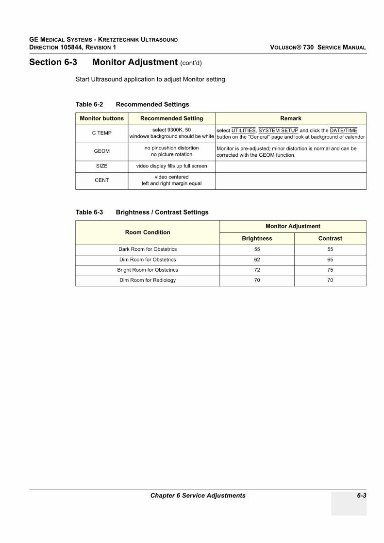
GE MEDICAL SYSTEMS - KRETZTECHNIK ULTRASOUND DIRECTION 105844, REVISION 1 VOLUSON® 730 SERVICE MANUAL
Chapter 6 Service Adjustments 6-3
Section 6-3 Monitor Adjustment (cont’d)
Start Ultrasound application to adjust Monitor setting.
Table 6-2 Recommended Settings
Monitor buttons Recommended Setting Remark
C TEMP select 9300K, 50windows background should be white
select UTILITIES, SYSTEM SETUP and click the DATE/TIME button on the “General” page and look at background of calender
GEOM no pincushion distortionno picture rotation
Monitor is pre-adjusted; minor distortion is normal and can be corrected with the GEOM function.
SIZE video display fills up full screen
CENT video centeredleft and right margin equal
Table 6-3 Brightness / Contrast Settings
Room ConditionMonitor Adjustment
Brightness Contrast
Dark Room for Obstetrics 55 55
Dim Room for Obstetrics 62 65
Bright Room for Obstetrics 72 75
Dim Room for Radiology 70 70

GE MEDICAL SYSTEMS - KRETZTECHNIK ULTRASOUNDDIRECTION 105844, REVISION 1 VOLUSON® 730 SERVICE MANUAL
6-4 Section 6-4 - Control Console, Transport Lock
Section 6-4Control Console, Transport Lock
6-4-1 Control ConsoleThe control console can be rotated 30° to the right.
When rotating the control console grasp it only on the front grip of the user interface.
1.) Push the bolt under the control console forward.2.) Rotate the console to wanted position.
6-4-2 Transport LockThere is a locking bolt for locking and unlocking the control console, mounted at the front below the control console. When preparing the system for transport, the lock has to be engaged in order to secure the console against uncontrolled rotation. The lock catches in when the console is rotated to its center 0° position.
Figure 6-3 Locking Bolt under Control Console
WARNINGWARNINGDo no
Do not put your hand between the control console and the Main unit when moving the console to the 0 position: Danger of injuries!
Locking Boltfor locking and unlocking the control console
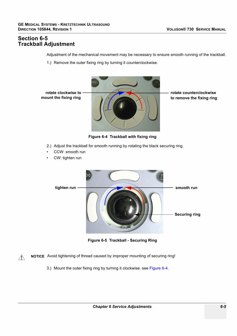
GE MEDICAL SYSTEMS - KRETZTECHNIK ULTRASOUND DIRECTION 105844, REVISION 1 VOLUSON® 730 SERVICE MANUAL
Chapter 6 Service Adjustments 6-5
Section 6-5Trackball Adjustment
Adjustment of the mechanical movement may be necessary to ensure smooth running of the trackball.
1.) Remove the outer fixing ring by turning it counterclockwise.
2.) Adjust the trackball for smooth running by rotating the black securing ring.• CCW: smooth run• CW: tighten run
3.) Mount the outer fixing ring by turning it clockwise. see Figure 6-4.
Figure 6-4 Trackball with fixing ring
Figure 6-5 Trackball - Securing Ring
NOTICE Avoid tightening of thread caused by improper mounting of securing ring!
rotate counterclockwiseto remove the fixing ring
rotate clockwise tomount the fixing ring
Securing ring
smooth runtighten run

GE MEDICAL SYSTEMS - KRETZTECHNIK ULTRASOUNDDIRECTION 105844, REVISION 1 VOLUSON® 730 SERVICE MANUAL
6-6 Section 6-5 - Trackball Adjustment
This page was intentionally left blank.

GE MEDICAL SYSTEMS - KRETZTECHNIK ULTRASOUND DIRECTION 105844, REVISION 1 VOLUSON® 730 SERVICE MANUAL
Chapter 7 Diagnostics/Troubleshooting 7-1
Chapter 7Diagnostics/Troubleshooting
Section 7-1Overview
7-1-1 Purpose of Chapter 7This section describes how to setup and run the tools and software that help maintain image quality and system operation. Basic host, system, and board level diagnostics are run whenever power is applied. Some Service Tools may be run at the application level.
7-1-2 OverviewThere may be a time when it would be advantageous to capture trouble images and system data (logs) for acquisition through remote diagnostics (InSite) or to be sent back to the manufacturer for analysis. There are different options to acquire this data that would give different results.
Table 7-1 Contents in Chapter 7
Section Description Page Number
7-1 Overview 7-1
7-2 Collect Vital System Information 7-2
7-3 Check Points Voltages 7-3
7-4 Screen Captures and Logs 7-4
7-5 How to use the Auto Tester program 7-5
7-6 Minimum Cable Configuration to Boot 7-8
7-7 Troubleshooting Trees and Instructions 7-10
7-8 Error Messages 7-20

GE MEDICAL SYSTEMS - KRETZTECHNIK ULTRASOUNDDIRECTION 105844, REVISION 1 VOLUSON® 730 SERVICE MANUAL
7-2 Section 7-2 - Collect Vital System Information
Section 7-2Collect Vital System Information
The following information is necessary in order to properly analyze data or images being reported as a malfunction or being returned to the manufacturer:
1.) System Serial number• External number - Label on back of the system• Internal number - Touch UTILITIES, then SYSTEM SETUP and select the SYSTEM INFO page.2.) Applications SoftwareTouch UTILITIES, then SYSTEM SETUP and select the SYSTEM INFO page.
NOTICE Voluson® 730 can have two different serial numbers!
Figure 7-1 System Serial Number
Internal number
ApplicationsSoftware

GE MEDICAL SYSTEMS - KRETZTECHNIK ULTRASOUND DIRECTION 105844, REVISION 1 VOLUSON® 730 SERVICE MANUAL
Chapter 7 Diagnostics/Troubleshooting 7-3
Section 7-3Check Points Voltages
7-3-1 How to check power
Figure 7-2 Connectors
Pin 15+5V Pin 13
+15V
Pin 11-15V
ECG
Check above Voltage with DVM to GroundDVM
Check with DVM (Digital Volt Meter) the 58V/DC
Check above Voltages with DVM to Ground
1 8
915
(Backpanel of GEF)
(SCSI Power-Connector Backpanel of GEF)(Power Connection-Cable from CPN to GEF)
+12VPin 1
1
23
Check Voltage with DVM to Ground
both Pins 2 and 3 are + 3.3VPin 1 is Ground

GE MEDICAL SYSTEMS - KRETZTECHNIK ULTRASOUNDDIRECTION 105844, REVISION 1 VOLUSON® 730 SERVICE MANUAL
7-4 Section 7-4 - Screen Captures and Logs
Section 7-4Screen Captures and Logs
There may be times when the customer or field engineer want to capture a presentation on the screen so it may be recovered by the OnLine Center. This is accomplished by saving the image(s) to Sonoview and export them to CD-Rom.
7-4-1 Capturing a screenOnly possible if SonoView Option is enabled.
The following is the generic process to capture any screen from the scanner.
1.) Navigate to and display the image/screen to be captures.2.) Press SAVE button and save the image to SonoView.3.) Select the stored image(s) in SonoView (Exam List) and export the image(s) to CD-Rom (jpg,
bmp or tiff)
7-4-2 Export Log’s and System Data’sTouch UTILITIES, then SYSTEM SETUP and select the SERVICE page.
Type in the password SHE and click the ACCEPT button.
7-4-2-1 Export Event LogExports Event Log File to MO or CD Drive.
7-4-2-2 Export System DataTransfer Service Database to MO or CD Drive.
7-4-2-3 Export System StatusThis function exports information about probes, boards, SW, Options Service Actions to MO or CD Drive.
Figure 7-3 Service Tools

GE MEDICAL SYSTEMS - KRETZTECHNIK ULTRASOUND DIRECTION 105844, REVISION 1 VOLUSON® 730 SERVICE MANUAL
Chapter 7 Diagnostics/Troubleshooting 7-5
Section 7-5How to use the Auto Tester program
1.) Touch UTILITIES and SYSTEM SETUP on the Touchscreen.2.) Select the SERVICE page on the screen.
3.) Type in the password SHE and click ACCEPT. The following screen appears.
4.) Activate the “Auto Tester” program by clicking START.
Figure 7-4 System Setup Service
Figure 7-5 Service Tools

GE MEDICAL SYSTEMS - KRETZTECHNIK ULTRASOUNDDIRECTION 105844, REVISION 1 VOLUSON® 730 SERVICE MANUAL
7-6 Section 7-5 - How to use the Auto Tester program
5.) Click OK.6.) Press the PAUSE/BREAK key on the keyboard.7.) Activate the “Auto Tester” program by clicking the “Record” icon on the displayed screen.
8.) Start scanning.You can scan normally and everything will be recorded to the program (up to several hours.)
NOTE: It is important that you are recording the processes where the errors normally occur.
9.) Stop the program by pressing the PAUSE/BREAK key on the right upper corner of the keyboard.
Figure 7-6 Message Box
Figure 7-7 Start Auto Tester
Pause/Breakkey on theright upper corner of the keyboard
“Record”icon

GE MEDICAL SYSTEMS - KRETZTECHNIK ULTRASOUND DIRECTION 105844, REVISION 1 VOLUSON® 730 SERVICE MANUAL
Chapter 7 Diagnostics/Troubleshooting 7-7
The following screen will appear.
10.)Insert an empty CD-RW in the Drive and select the “CD-Burn” icon.11.)Enter a Filename.
12.)After clicking OK, the following message boxes will appear.
13.)After the CD write is finished click the OK button and close the “Auto Tester” program.
Figure 7-8 Auto Tester Finished
Figure 7-9 Enter a Filename
Figure 7-10 CD-Burn Process
“CD-Burn”icon

GE MEDICAL SYSTEMS - KRETZTECHNIK ULTRASOUNDDIRECTION 105844, REVISION 1 VOLUSON® 730 SERVICE MANUAL
7-8 Section 7-6 - Minimum Cable Configuration to Boot
Section 7-6Minimum Cable Configuration to Boot
Following Cables must be connected for minimum Configuration: see: Figure 7-11: Cable- Minimum configuration
a.) RS232-1 (connector for User Interface, near to the Mouse connector)
NOTE: Don´t mix up the RS232-1 with the RS232-2 and RS232-3 connectors.
b.) VGA (Monitor)c.) CPN (Primary Power Supply)d.) Consolee.) Stand By switchf.) Monitor Power Supplyg.) Mouse (connector for Mouse/Keyboard)
Figure 7-11 Cable- Minimum configuration
g
a
b c d
e f

GE MEDICAL SYSTEMS - KRETZTECHNIK ULTRASOUND DIRECTION 105844, REVISION 1 VOLUSON® 730 SERVICE MANUAL
Chapter 7 Diagnostics/Troubleshooting 7-9
7-6-1 Minimum Cable Configuration to ScanFollowing Cables must be connected for minimum Configuration: see: Figure 7-11: Cable- Minimum configuration
a.) RS232-1 (connector for User Interface, near to the Mouse connector)
NOTE: Don’t mix up the RS232-1 with the RS232-2 and RS232-3 connectors.
b.) VGA (Monitor)c.) CPN (Primary Power Supply)d.) Consolee.) Stand By switchf.) Monitor Power Supplyg.) Mouse (connector for Mouse/Keyboard)h.) Probes

GE MEDICAL SYSTEMS - KRETZTECHNIK ULTRASOUNDDIRECTION 105844, REVISION 1 VOLUSON® 730 SERVICE MANUAL
7-10 Section 7-7 - Troubleshooting Trees and Instructions
Section 7-7Troubleshooting Trees and Instructions
7-7-1 System does not Power On / Boot Up
Figure 7-12 System does not boot up
Is the scanner pluged
in?
Is there AC at the wall
outlet?
Make sure the
Scanner isn't
plugged into
emergency power
(red outlet)Yes
Is the circuit breaker on
Yes
+ These three condidtions should be the first items checked if
the scanner doesn't boot up.
+ If all three conditions are present, the scanner should be in
astandby mode with the ON/OFF switch illuminated with amber
color.
+ Follow the flow chart to determine the reason the scanner
doesn't boot up
No
No
Switch in ON
Position
Fan Noise ?
Yes+ Check if the power switch over the mains plug of the Primary Power
Supply isn't switched off.
+ Check the connections to and from the Power Supply
+ Check the power of the cable which connects the Power Supply with
the GEF module (description Check Points Voltages)
+ If ther is no power and the connections are O.K., replace the Primary
Power Supply
No
Yes
System is on and ready for use
Section 7-3

GE MEDICAL SYSTEMS - KRETZTECHNIK ULTRASOUND DIRECTION 105844, REVISION 1 VOLUSON® 730 SERVICE MANUAL
Chapter 7 Diagnostics/Troubleshooting 7-11
7-7-2 Noise in Image
Figure 7-13 Noise in Image
Noise is shown in Image.
YES
NO
Is there any electrical devices that affect the
Scanner?
Keep the Scanner away from those electrical devices.
use another wallsocket
Check probes.

GE MEDICAL SYSTEMS - KRETZTECHNIK ULTRASOUNDDIRECTION 105844, REVISION 1 VOLUSON® 730 SERVICE MANUAL
7-12 Section 7-7 - Troubleshooting Trees and Instructions
7-7-3 Trackball
Figure 7-14 Trackball Troubleshooting
The trackball is low sensitive!
Remove the ball from the Trackball, and clean it.
YES
NO
Does the trackball move at all?
Replace the trackball unit.

GE MEDICAL SYSTEMS - KRETZTECHNIK ULTRASOUND DIRECTION 105844, REVISION 1 VOLUSON® 730 SERVICE MANUAL
Chapter 7 Diagnostics/Troubleshooting 7-13
7-7-4 System does not Power Off / Shutdown
Figure 7-15 Power Off / Shutdown - Troubleshooting
System has been switched off
System starts with the
shut down procedure
System is down
Yes
system switched off
automatically in app.
3min.
Primary Power (CPY
inside)Supply is defekt
check the switch and the cable -if O.K
Primary Power Supply is defekt
No Yes
No

GE MEDICAL SYSTEMS - KRETZTECHNIK ULTRASOUNDDIRECTION 105844, REVISION 1 VOLUSON® 730 SERVICE MANUAL
7-14 Section 7-7 - Troubleshooting Trees and Instructions
7-7-5 Monitor Troubleshooting
Figure 7-16 Monitor Troubleshooting
Fault symptom Check these items
If neither the Power Indicator nor Power
Saving is lit
+ Check the power cord is properly connected
+ Check the mains supply switch is set to the "On" position
If the Power Saving Indicator is lit + Check the video cable is properly connected
+ Check no pins of the video cable are bent
No
Image
If the Power Indicator is flashing
alternately green and orange, and the
Power Saving Indicator is flashing
+ There is a potential monitor failure. Contact your dealer
Color is not uniform + Turn on the power to activate the Auto-Degauss function
Screen image is not centered or sized properly + Adjust the picture location, picture size, picture rotation,
or pincushion distortion
+ Some video modes do not fill the screen to the edge of the
monitor There is no single answer to solve the problem.
This phenomenon may occur on higher refresh rates
(vertical frequency)
Picture is fuzzy + Adjust the picture contrast and picture brightness.
Some SVGA cards having an excessive video output level
will cause a fuzzy picture at the maximum contrast level
+ Turn on the power to activate the Auto-Degauss function
+ The video cable is connected to the video output
connectors on the rear, but the other ends of the video cable
are not connected to another monitor In this case, the video
output level increases and makes the picture fuzzy.
So, disconnect the video cable, or connect the other ends of
the video cable to another monitor

GE MEDICAL SYSTEMS - KRETZTECHNIK ULTRASOUND DIRECTION 105844, REVISION 1 VOLUSON® 730 SERVICE MANUAL
Chapter 7 Diagnostics/Troubleshooting 7-15
7-7-6 Unable to Record to VCR
Figure 7-17 VCR Troubleshooting
Unable to record to VCR!
Check that all signal, and power supply cable connections to the VCR
unit are OK.
YES
NOIs the VCR properly connected?
Is the VCR tape put into the device?
Put the tape into the device and rewind it.
NO
YES
Replace VCR.
Is recording impossible even by manual operation?
YES - Check the signal cable connections between VCR and Internal I/O.
NO
YES
Video Output of System o.k.?
Replace CKV
NO

GE MEDICAL SYSTEMS - KRETZTECHNIK ULTRASOUNDDIRECTION 105844, REVISION 1 VOLUSON® 730 SERVICE MANUAL
7-16 Section 7-7 - Troubleshooting Trees and Instructions
7-7-7 Printer Troubleshooting
Figure 7-18 Printer Troubleshooting
Unable to use Printer(s)!
Check that all signal, and power supply cable connections between
Printer and Scanner are OK.
YES
NOIs the printer(s) properly connected?
Are there print papers left?
Insert the printer papers.
NO
YES
Is proper configuration for the Print key(s) set?
Configure the Print key(s).
NO
See next page.

GE MEDICAL SYSTEMS - KRETZTECHNIK ULTRASOUND DIRECTION 105844, REVISION 1 VOLUSON® 730 SERVICE MANUAL
Chapter 7 Diagnostics/Troubleshooting 7-17
7-7-7 Printer Troubleshooting (cont’d)
Figure 7-19 Printer Troubleshooting (cont´d)
Still unable to use the Printer(s)!
Check the signal cables between GEF and Backpanel.
YES
NOIs printing unavailable even by manual
operation?
Still no image on the print out
Video Output of System o.k.?
NO
YES
Printer o.k.
Replace the Printer
Replace CKV
NO
YES

GE MEDICAL SYSTEMS - KRETZTECHNIK ULTRASOUNDDIRECTION 105844, REVISION 1 VOLUSON® 730 SERVICE MANUAL
7-18 Section 7-7 - Troubleshooting Trees and Instructions
7-7-7-1 CD-RW Troubleshooting (CD-Rom Drive)
1.) Insert an empty CD-RW into the Drive.2.) Enter “Sonoview” by pressing the NETWORK key on the control panel; see Figure 7-20.3.) Click the “Open” icon to display the list of exams.4.) Select exam(s) and backup them to CD-ROM.5.) Choose “CD-ROM” Drive.6.) The images, which you have chosen during backup should be visible.
7-7-8 MOD Troubleshooting 1.) Insert an empty MO into the Drive.2.) Enter “Sonoview” by pressing the NETWORK key on the control panel; see Figure 7-20.3.) Click the “Open” icon to display the list of exams.4.) Select exam(s) and backup them to MO.5.) Choose “MO” Drive.6.) The images, which you have chosen during backup should be visible.
7-7-9 Audio TestPreparations for Audio Test: Start a probe and select the PW-Mode.
Change the volume from 0 to 96dB with the digipot and listen if both loudspeakers are making some noise.
Figure 7-20 To backup exams to CD-ROM resp. MO-Disk
1. Press Network key 2. Click “Open” iconand backup exams
3. After Backup,choose CD-ROM(resp. MO)
GE MEDICAL SYSTEMS - KRETZTECHNIK ULTRASOUND DIRECTION 105844, REVISION 1 VOLUSON® 730 SERVICE MANUAL
Chapter 7 Diagnostics/Troubleshooting 7-19
7-7-10 Network Troubleshooting
7-7-10-1 No Connection to the Network at All
1.) Check that the network cable between the scanner and the wall network is connected and well seated in both ends.
2.) Try a network cable that is known to be OK.3.) Check the cable between the network-connector on the Back Panel to the LAN-
connector on the GEF.4.) Connect a network cable between your Scanner and your PC. Try to ping from the Scanner to the
IP address on the PC. If OK, the hardware connection inside the Scanner is OK.

GE MEDICAL SYSTEMS - KRETZTECHNIK ULTRASOUNDDIRECTION 105844, REVISION 1 VOLUSON® 730 SERVICE MANUAL
7-20 Section 7-8 - Error Messages
Section 7-8Error Messages
Error Messages Actions
530-Probe connected on………. Disconnect and reconnect the probe. If error remains don't use such a probe.
Array bounds exceeded restart the system
Attempt to read Probe-ID from an invalid probe connector. Reboot system.
AVI Save function fails check the SCSI and the Power cable - restart the machine and try again
B_Enhance Out Of Range Press ok and save this user-setting once again
B_Gain Out Of Range Press ok and save this user-setting once again
B_Reject Out Of Range Press ok and save this user-setting once again
B_TxFocus - not calculated and B_SHOT_PART_ON restart the system, If after restart not ok then call technical support
BC lines_per_sequenz < 1 restart the system
BC lines_per_sequenz < 2 restart the system
BC_Dynamic Out Of Range Press ok and save this user-setting once again
BC_Gain Out Of Range Press ok and save this user-setting once again
BC_Lines: BC_LineDensity out of limit restart the system
BCMC_Balance Out Of Range Press ok and save this user-setting once again
BC-TxPower Out Of Range Press ok and save this user-setting once again
BF: can't set BM RxApod restart the system, If after restart not ok then call technical support
BF: can´t set C Rx Apod restart the system, If after restart not ok then call technical support
BF: can't set D RxApod restart the system, If after restart not ok then call technical support
BM_Resample: overrun SampleLengthOnLineMem restart the system
Cannot read a valid Probe-ID (%02X) from…………. Disconnect and reconnect the probe
Cannot write Probe-ID into EEPROM on left probe connector (A). connect the probe once more, if not ok call technical support
Cannot write Probe-ID into EEPROM on left probe connector (B). connect the probe once more, if not ok call technical support
Cannot write RotatingAngleCorr into EEPROM on left probe connector (A). connect the probe once more, if not ok call technical support
Cannot write RotatingAngleCorr into EEPROM on left probe connector (B). connect the probe once more, if not ok call technical support
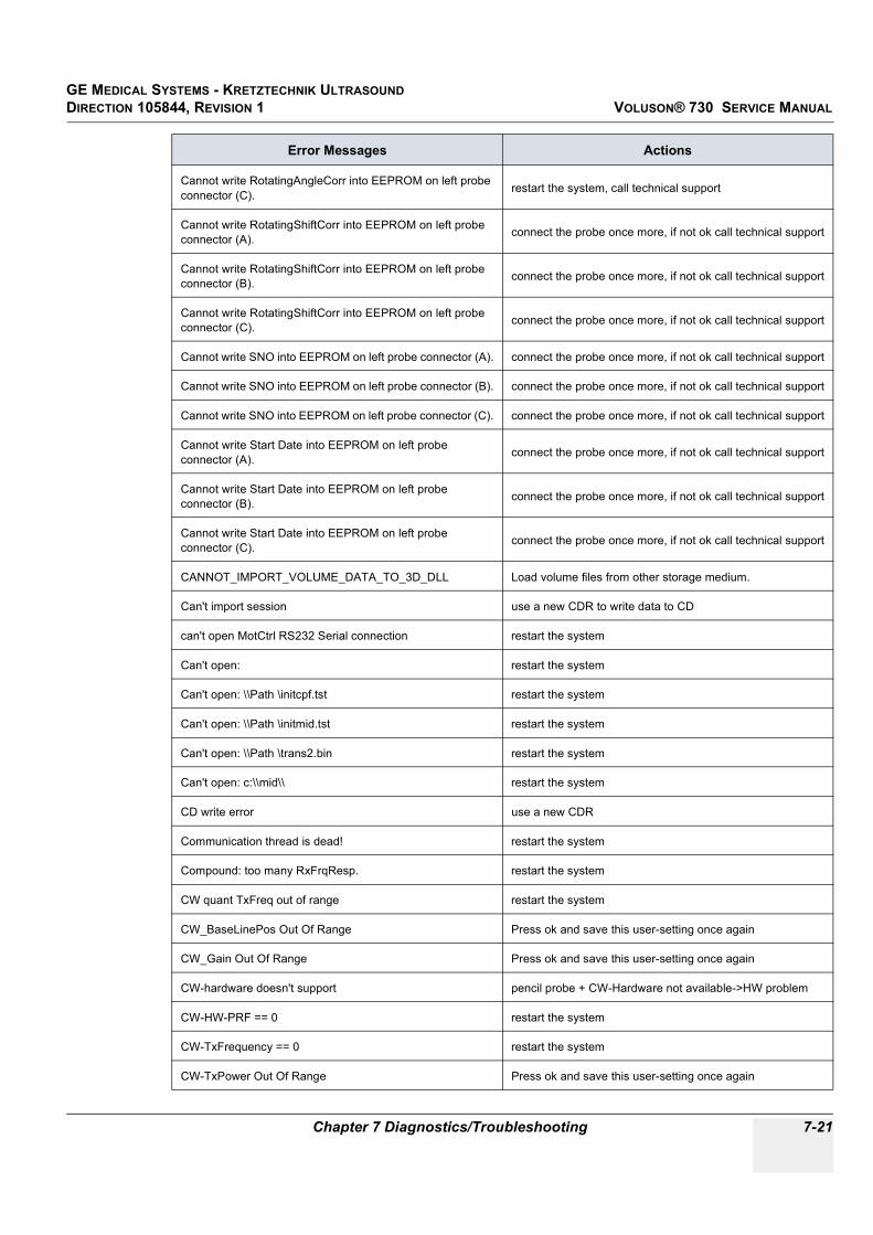
GE MEDICAL SYSTEMS - KRETZTECHNIK ULTRASOUND DIRECTION 105844, REVISION 1 VOLUSON® 730 SERVICE MANUAL
Chapter 7 Diagnostics/Troubleshooting 7-21
Cannot write RotatingAngleCorr into EEPROM on left probe connector (C). restart the system, call technical support
Cannot write RotatingShiftCorr into EEPROM on left probe connector (A). connect the probe once more, if not ok call technical support
Cannot write RotatingShiftCorr into EEPROM on left probe connector (B). connect the probe once more, if not ok call technical support
Cannot write RotatingShiftCorr into EEPROM on left probe connector (C). connect the probe once more, if not ok call technical support
Cannot write SNO into EEPROM on left probe connector (A). connect the probe once more, if not ok call technical support
Cannot write SNO into EEPROM on left probe connector (B). connect the probe once more, if not ok call technical support
Cannot write SNO into EEPROM on left probe connector (C). connect the probe once more, if not ok call technical support
Cannot write Start Date into EEPROM on left probe connector (A). connect the probe once more, if not ok call technical support
Cannot write Start Date into EEPROM on left probe connector (B). connect the probe once more, if not ok call technical support
Cannot write Start Date into EEPROM on left probe connector (C). connect the probe once more, if not ok call technical support
CANNOT_IMPORT_VOLUME_DATA_TO_3D_DLL Load volume files from other storage medium.
Can't import session use a new CDR to write data to CD
can't open MotCtrl RS232 Serial connection restart the system
Can't open: restart the system
Can't open: \\Path \initcpf.tst restart the system
Can't open: \\Path \initmid.tst restart the system
Can't open: \\Path \trans2.bin restart the system
Can't open: c:\\mid\\ restart the system
CD write error use a new CDR
Communication thread is dead! restart the system
Compound: too many RxFrqResp. restart the system
CW quant TxFreq out of range restart the system
CW_BaseLinePos Out Of Range Press ok and save this user-setting once again
CW_Gain Out Of Range Press ok and save this user-setting once again
CW-hardware doesn't support pencil probe + CW-Hardware not available->HW problem
CW-HW-PRF == 0 restart the system
CW-TxFrequency == 0 restart the system
CW-TxPower Out Of Range Press ok and save this user-setting once again
Error Messages Actions

GE MEDICAL SYSTEMS - KRETZTECHNIK ULTRASOUNDDIRECTION 105844, REVISION 1 VOLUSON® 730 SERVICE MANUAL
7-22 Section 7-8 - Error Messages
Datatype misalignment restart the system
Density Out Of Range Press ok and save this user-setting once again
DFE:Block with openInput restart the system
Disc full ! use a new CDR for writing data to CD
Display:Rect Region fails restart the system
Division by zero restart the system
done is low ! restart the system
DSP - Gamma Corr - Load Data Timeout restart the system
DSP - HilbertCoeff - Load Data Timeout restart the system
DSP - Low Pass Coeff - Load Data Timeout restart the system
DSP - SetFFT_Para - Load Data Timeout restart the system
DSP - SetWMF_Koeff - Load Data Timeout restart the system
DSP/MSE:Hanning-Window Load Data Timeout restart the system
DynContrast Out Of Range Press ok and save this user-setting once again
End Bandwidth too big restart the system, If after restart not ok then call technical support
End ET too big restart the system, If after restart not ok then call technical support
End frequency too big restart the system, If after restart not ok then call technical support
Enhance Out Of Range Press ok and save this user-setting once again
Ensemble Out Of Range Press ok and save this user-setting once again
Error in CreateCineImage try to store again
Error not enough time for BC shot! restart the system
Error on LoadBootMem Page:%2d, Addr:%5d restart the system
Error programming Flashcomplette restart the system
Error setting state restart the system
ERROR_MSG_INIT_FAILED Check connection from US machine to VCR, VCR has power and is on.
ERROR_MSG_NO_ACK Check VCR cables and try again
ERROR_MSG_NO_CASSETTE Put cassette into drive of VCR
ERROR_MSG_NO_RESPONSE Check VCR cables, casette,... and try again
ERROR_MSG_WRITE_PROTECTED Remove cassette from VCR and put writable cassette into drive of VCR.
Error Messages Actions

GE MEDICAL SYSTEMS - KRETZTECHNIK ULTRASOUND DIRECTION 105844, REVISION 1 VOLUSON® 730 SERVICE MANUAL
Chapter 7 Diagnostics/Troubleshooting 7-23
Execute privileged instruction restart the system
FallSmooth Out Of Range Press ok and save this user-setting once again
File Could not CRC Check Load volume files from other storage medium.
File CRC Error Load volume files from other storage medium.
File CRC Missing Load volume files from other storage medium.
File Data Missing Load volume files from other storage medium.
File Datalength Not Consistent Load volume files from other storage medium.
File Decompress Error Load volume files from other storage medium.
File Decompress method Unknown Load volume files from other storage medium.
File End Error Load volume files from other storage medium.
File Execute Error Load volume files from other storage medium.
File Memory Missing Load volume files from other storage medium.
File Not Found Load volume files from other storage medium.
File Not Found Load another Backup from CD,…. (restart or reinstall the Application)
File Not Found restart, install latest software version
File Pos Load volume files from other storage medium.
File Read Error Load volume files from other storage medium.
File Type Unknown Load volume files from other storage medium.
File Volume size not consistent Load volume files from other storage medium.
FLT: Denormal operand restart the system
FLT: Divide by zero restart the system
FLT: Invalid operation restart the system
FLT: Stack overflow restart the system
FLT: Underflow restart the system
Hardware doesn't support CW-mode pencil probe + CW-Hardware not available->HW problem
hardware error on restart the system
HardwareRelatedSoftware_Windows in write have different ProbeAcousticUnitIDs
disconnect all connected probes and connect they anew, if not ok restart the system
HardwareRelatedSoftware_Windows in write have different ProbeScanFuncIDs
disconnect all connected probes and connect they anew, if not ok restart the system
IBegrenzer.cpp Bshots TxMultiFocus problem restart the system
IBegrenzer.cpp Mshots TxMultiFocus problem restart the system
Error Messages Actions
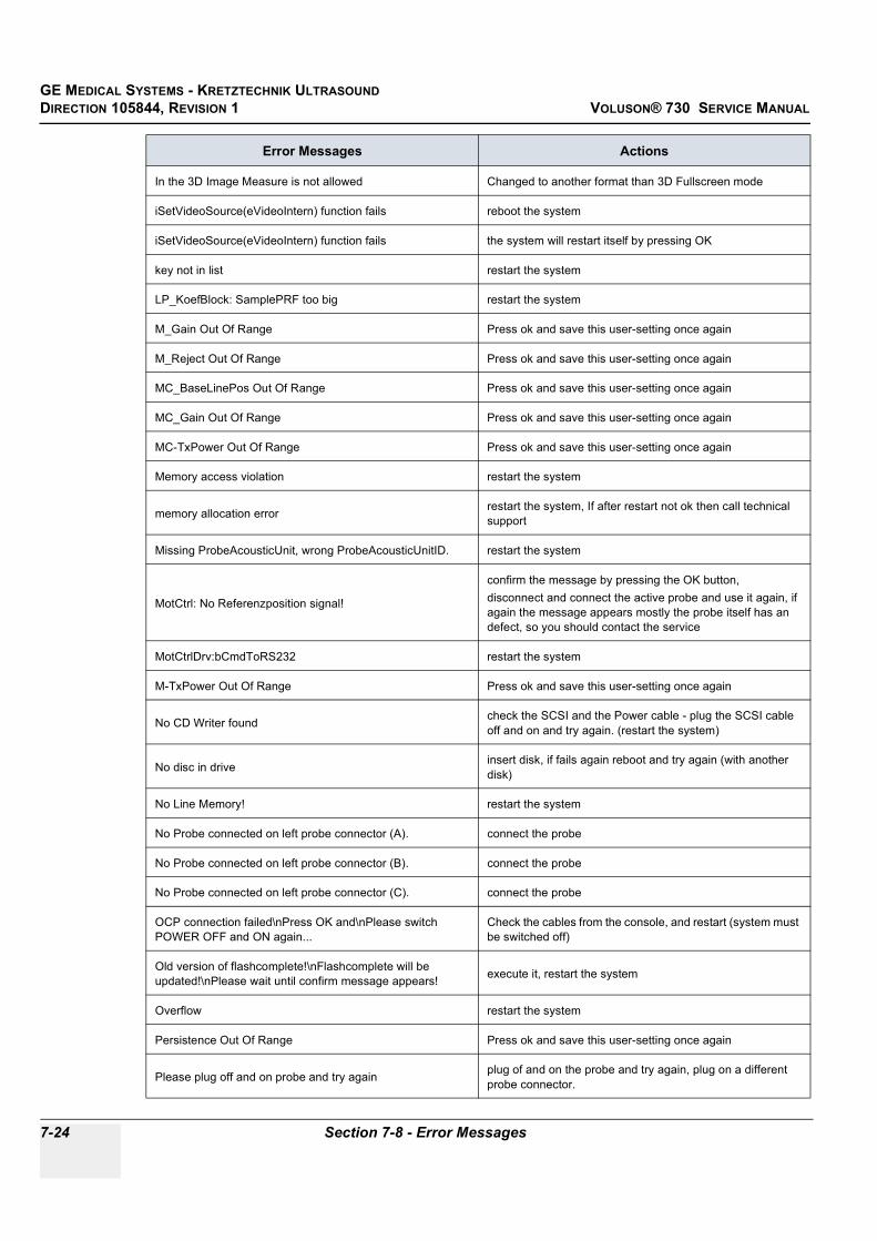
GE MEDICAL SYSTEMS - KRETZTECHNIK ULTRASOUNDDIRECTION 105844, REVISION 1 VOLUSON® 730 SERVICE MANUAL
7-24 Section 7-8 - Error Messages
In the 3D Image Measure is not allowed Changed to another format than 3D Fullscreen mode
iSetVideoSource(eVideoIntern) function fails reboot the system
iSetVideoSource(eVideoIntern) function fails the system will restart itself by pressing OK
key not in list restart the system
LP_KoefBlock: SamplePRF too big restart the system
M_Gain Out Of Range Press ok and save this user-setting once again
M_Reject Out Of Range Press ok and save this user-setting once again
MC_BaseLinePos Out Of Range Press ok and save this user-setting once again
MC_Gain Out Of Range Press ok and save this user-setting once again
MC-TxPower Out Of Range Press ok and save this user-setting once again
Memory access violation restart the system
memory allocation error restart the system, If after restart not ok then call technical support
Missing ProbeAcousticUnit, wrong ProbeAcousticUnitID. restart the system
MotCtrl: No Referenzposition signal!
confirm the message by pressing the OK button, disconnect and connect the active probe and use it again, if again the message appears mostly the probe itself has an defect, so you should contact the service
MotCtrlDrv:bCmdToRS232 restart the system
M-TxPower Out Of Range Press ok and save this user-setting once again
No CD Writer found check the SCSI and the Power cable - plug the SCSI cable off and on and try again. (restart the system)
No disc in drive insert disk, if fails again reboot and try again (with another disk)
No Line Memory! restart the system
No Probe connected on left probe connector (A). connect the probe
No Probe connected on left probe connector (B). connect the probe
No Probe connected on left probe connector (C). connect the probe
OCP connection failed\nPress OK and\nPlease switch POWER OFF and ON again...
Check the cables from the console, and restart (system must be switched off)
Old version of flashcomplete!\nFlashcomplete will be updated!\nPlease wait until confirm message appears! execute it, restart the system
Overflow restart the system
Persistence Out Of Range Press ok and save this user-setting once again
Please plug off and on probe and try again plug of and on the probe and try again, plug on a different probe connector.
Error Messages Actions

GE MEDICAL SYSTEMS - KRETZTECHNIK ULTRASOUND DIRECTION 105844, REVISION 1 VOLUSON® 730 SERVICE MANUAL
Chapter 7 Diagnostics/Troubleshooting 7-25
PRF_GeneratorBoundary: BBC Ensemble Limitation out of limit restart the system
PRF_GeneratorBoundary: BBCPW Ensemble Limitation out of limit restart the system
Probe Scan Function Not Supplied restart the system
Probe with Probe-ID %02X not supported………………. Disconnect and reconnect the probe
Probe-ID valid, but Flexible-EEPROM-Datamodel not implemented yet. On………. Disconnect and reconnect the probe
PW_BaseLinePos Out Of Range Press ok and save this user-setting once again
PW_BurstCalcBlock: UserProgApplication out of range restart the system
PW_CW_FFT_FactBlock: DSC_ScrollX_Zoom darf nicht kleiner als eins sein! restart the system
PW_Dynamic Out Of Range Press ok and save this user-setting once again
PW_Reject Out Of Range Press ok and save this user-setting once again
PWGain Out Of Range Press ok and save this user-setting once again
PW-TxPower Out Of Range Press ok and save this user-setting once again
RiseSmooth Out Of Range Press ok and save this user-setting once again
Start Bandwidth too small restart the system, If after restart not ok then call technical support
Start ET too small restart the system, If after restart not ok then call technical support
Start frequency too small restart the system, If after restart not ok then call technical support
System detected severe error, please call technical support. restart, call technical support
System detected severe error. Some components like Touch Panel server may not be registered.Please register Touch Panel server and restart.
restart, call technical support
The Database corrupted, System try to repair. database will be deleted, please load it new from backup
The Regesitery not closed close registry, restart, try again
The Regesitery not closed restart
The System Settings Database is Corrupted, All the data will be lost, Please load it from Backup
database will be deleted d:\UserSettings\SystemSettings.mdb, please load it new from backup
The User Programs Database is Corrupted, All the data will be lost, Please load it from Backup
database will be deleted, please load it new from backup
Thickness mismatch %d - GIP %d restart 3D (go to 2D)
UI_BBC_Wnd:vSet() has an wrong ImageType restart the system
Error Messages Actions

GE MEDICAL SYSTEMS - KRETZTECHNIK ULTRASOUNDDIRECTION 105844, REVISION 1 VOLUSON® 730 SERVICE MANUAL
7-26 Section 7-8 - Error Messages
UI_BBC_Wnd:vSet() will change from eB_Wnd to wrong ImageType restart the system
UI_BBC_Wnd:vSet() will change from eBBC_Wnd to wrong ImageType restart the system
UI_Manager:vHRS_Execute multiple call restart the system
Unable to save... restart the system, if the problem still exists call technical support
undefined CW ADC_Clk-Teiler restart the system
Unhandled Probe-EEPROM data type on………. Disconnect and reconnect the probe
unknown CPF_1 Xilinx-Version restart the system
unknown CPF_2 Xilinx-Version restart the system
unknown CPG1 Xilinx-Version restart the system
unknown CPG2 Xilinx-Version restart the system
unknown CPG3 Xilinx-Version restart the system
Unknown Error Load volume files from other storage medium.
unknown FMV Xilinx-Version restart the system
unknown LMV Xilinx-Version restart the system
unknown Xilinx-Version restart the system
unknown XSYS Xilinx-Version restart the system
unrecordable disc in drive try again with another disk
VolAcqu3D4D_Enum has changes and isn't implemented in this block! restart the system
Volume_dB Out Of Range Press ok and save this user-setting once again
WMF_KoefBlock: SamplePRF too big restart the system
Error Messages Actions

GE MEDICAL SYSTEMS - KRETZTECHNIK ULTRASOUND DIRECTION 105844, REVISION 1 VOLUSON® 730 SERVICE MANUAL
Chapter 8 Replacement Procedures 8-1
Chapter 8Replacement Procedures
Section 8-1Overview
8-1-1 Purpose of Chapter 8This chapter contains replacement procedures for different modules and their subsystems.
8-1-2 Returning/Shipping Probes and Repair PartsEquipment being returned must be clean and free of blood and other infectious substances.
GEMS policy states that body fluids must be properly removed from any part or equipment prior to shipment. GEMS employees, as well as customers, are responsible for ensuring that parts/equipment have been properly decontaminated prior to shipment. Under no circumstance should a part or equipment with visible body fluids be taken or shipped from a clinic or site (for example, body coils or and ultrasound probe).
The purpose of the regulation is to protect employees in the transportation industry, as well as the people who will receive or open this package.
The US Department of Transportation (DOT) has ruled that “items what were saturated and/or dripping with human blood that are now caked with dried blood; or which were used or intended for use in patient care” are “regulated medical waste” for transportation purpose and must be transported as a hazardous material.
WARNINGWARNING No covers or panels should be removed from the system (high-voltage risk). Service and repairs must only be performed by authorized personal. Attempting do-it-yourself repairs invalidate warranty and are an infringement to regulations and are inadmissible acc. to IEC 60601-1.
Table 8-1 Chapter 8 Contents
Section Description Page Number
8-1 Overview 8-1
8-2 Backup Loading Procedure 8-2
8-3 EUM (Electronic User Manual) Upgrade Procedure 8-3
8-4 Replacement of the Trackball top fixation ring 8-8

GE MEDICAL SYSTEMS - KRETZTECHNIK ULTRASOUNDDIRECTION 105844, REVISION 1 VOLUSON® 730 SERVICE MANUAL
8-2 Section 8-2 - Backup Loading Procedure
Section 8-2Backup Loading Procedure
The Backup contains:
• User settings, Auto Text, Measurement user tables• Biopsy (needle guide positions)• Setup settings (language, date format, screensaver on/off, etc.)
8-2-1 Loading Proceduresee: Section 4-4-12-3 "Load System Presets and Configurations (Application Settings)" on page 4-28

GE MEDICAL SYSTEMS - KRETZTECHNIK ULTRASOUND DIRECTION 105844, REVISION 1 VOLUSON® 730 SERVICE MANUAL
Chapter 8 Replacement Procedures 8-3
Section 8-3EUM (Electronic User Manual) Upgrade Procedure
8-3-1 EUM - Upgrade Procedure (up to Software Version 1.06F)1.) Restart the system (turn off and on the system).
2.) Press the UTILITIES key on the Touch Panel once to display the Utilities menu.3.) Touch the SYSTEM SETUP key to invoke the setup desktop on the screen.4.) Select the SERVICE page. The “Password window” appears automatically.5.) Enter the password SHE, and click the ACCEPT key to get access to the Service Tools.6.) The “Service Tools” menu appears on the screen.
7.) Click the EUM button. The “Update Software” dialog appears.8.) Select CD DRIVE. Browse for the EUMSetup_en.exe file in the Install folder and click OK.9.) Confirm the following message with YES to proceed the update.10.)The contents of this package are being extracted.11.)Follow the instructions of the “InstallShield Wizard” (confirm the messages with the NEXT key).
NOTICE The Loading Procedure of the EUM (Electronic User Manual) differs at various software versions:for Software Version up to 1.06F follow the instructions as described in Section on page 8-4for Software Version from 1.06G follow the instructions as described in Section 8-3-2 on page 8-5
NOTICE The electronic user manual (EUM) must never be opened (by pressing the F1 key on the keyboard) after last restart! Even if closed again before installing the new EUM.
Figure 8-1 Service Tools
EUM button

GE MEDICAL SYSTEMS - KRETZTECHNIK ULTRASOUNDDIRECTION 105844, REVISION 1 VOLUSON® 730 SERVICE MANUAL
8-4 Section 8-3 - EUM (Electronic User Manual) Upgrade Procedure
8-3-1 EUM - Upgrade Procedure (up to Software Version 1.06F) (cont’d)
NOTE: Please select “Yes I want to restart my computer now”, see: Figure 8-2.(Otherwise the electronic user manual does not work till the next system start.)
12.)Remove any disks from their drives and click FINISH to complete the EUM installation. The system will reboot automatically.
NOTE: If the “End Program” message box appears, select END NOW.
13.)After rebooting the system, fill in the requested information into the “System Status Messenger” box and click OK.
14.)Press the F1 key on the keyboard to invoke the electronic user manual.15.)Press the ESC key to exit the EUM.
Figure 8-2 complete EUM installation
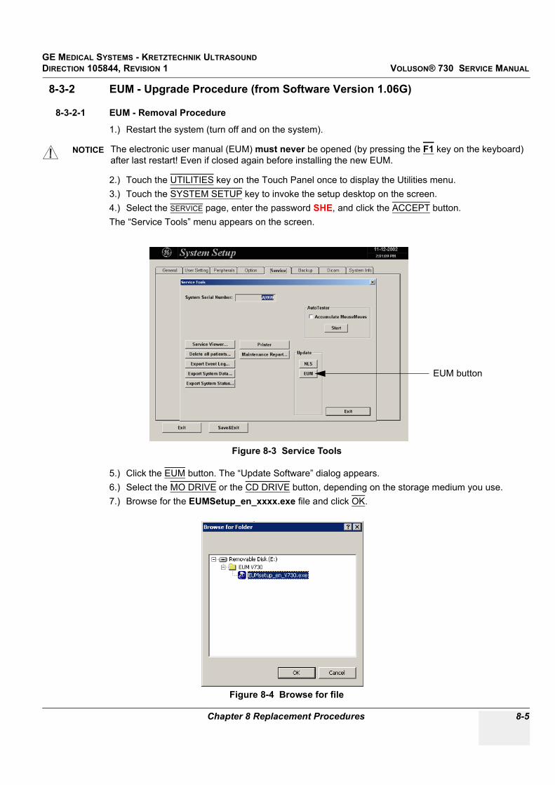
GE MEDICAL SYSTEMS - KRETZTECHNIK ULTRASOUND DIRECTION 105844, REVISION 1 VOLUSON® 730 SERVICE MANUAL
Chapter 8 Replacement Procedures 8-5
8-3-2 EUM - Upgrade Procedure (from Software Version 1.06G)
8-3-2-1 EUM - Removal Procedure
1.) Restart the system (turn off and on the system).
2.) Touch the UTILITIES key on the Touch Panel once to display the Utilities menu.3.) Touch the SYSTEM SETUP key to invoke the setup desktop on the screen.4.) Select the SERVICE page, enter the password SHE, and click the ACCEPT button.The “Service Tools” menu appears on the screen.
5.) Click the EUM button. The “Update Software” dialog appears.6.) Select the MO DRIVE or the CD DRIVE button, depending on the storage medium you use. 7.) Browse for the EUMSetup_en_xxxx.exe file and click OK.
NOTICE The electronic user manual (EUM) must never be opened (by pressing the F1 key on the keyboard) after last restart! Even if closed again before installing the new EUM.
Figure 8-3 Service Tools
Figure 8-4 Browse for file
EUM button

GE MEDICAL SYSTEMS - KRETZTECHNIK ULTRASOUNDDIRECTION 105844, REVISION 1 VOLUSON® 730 SERVICE MANUAL
8-6 Section 8-3 - EUM (Electronic User Manual) Upgrade Procedure
8-3-2-1 EUM - Removal Procedure (cont’d)8.) Confirm the next message with YES to proceed the update. The contents of the package are being extracted.
9.) Read the following warning message and confirm it with OK.
10.)Confirm the “Maintenance Complete” message: «InstallShield Wizard has finished performing maintenance operations on V730 User Manual» with the FINISH button..
Figure 8-5 confirm warning message
NOTICE At this step the old EUM files will be uninstalled.
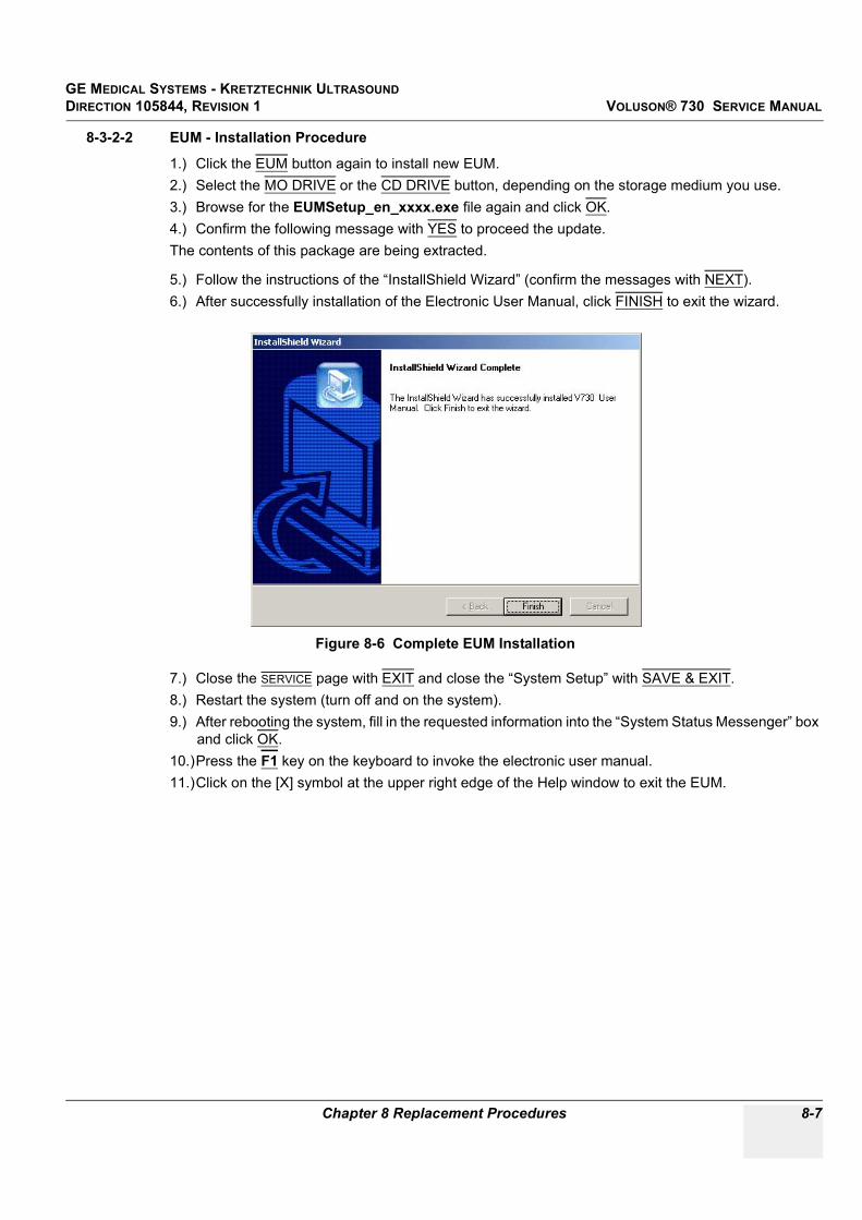
GE MEDICAL SYSTEMS - KRETZTECHNIK ULTRASOUND DIRECTION 105844, REVISION 1 VOLUSON® 730 SERVICE MANUAL
Chapter 8 Replacement Procedures 8-7
8-3-2-2 EUM - Installation Procedure
1.) Click the EUM button again to install new EUM.2.) Select the MO DRIVE or the CD DRIVE button, depending on the storage medium you use. 3.) Browse for the EUMSetup_en_xxxx.exe file again and click OK.4.) Confirm the following message with YES to proceed the update.The contents of this package are being extracted.
5.) Follow the instructions of the “InstallShield Wizard” (confirm the messages with NEXT).6.) After successfully installation of the Electronic User Manual, click FINISH to exit the wizard.
7.) Close the SERVICE page with EXIT and close the “System Setup” with SAVE & EXIT.8.) Restart the system (turn off and on the system).9.) After rebooting the system, fill in the requested information into the “System Status Messenger” box
and click OK.10.)Press the F1 key on the keyboard to invoke the electronic user manual.11.)Click on the [X] symbol at the upper right edge of the Help window to exit the EUM.
Figure 8-6 Complete EUM Installation

GE MEDICAL SYSTEMS - KRETZTECHNIK ULTRASOUNDDIRECTION 105844, REVISION 1 VOLUSON® 730 SERVICE MANUAL
8-8 Section 8-4 - Replacement of the Trackball top fixation ring
Section 8-4Replacement of the Trackball top fixation ring
8-4-1 ManpowerOne person, 5 min.
8-4-2 Trackball top fixation ring - Replacement Procedure1.) Remove the fixation ring by turning it counterclockwise.
2.) Mount the fixation ring by turning it clockwise.
Figure 8-7 Trackball with top fixation ring
rotate counterclockwiseto remove the fixing ring
rotate clockwise tomount the fixing ring

GE MEDICAL SYSTEMS - KRETZTECHNIK ULTRASOUND DIRECTION 105844, REVISION 1 VOLUSON® 730 SERVICE MANUAL
Chapter 9 Renewal Parts 9-1
Chapter 9Renewal Parts
Section 9-1Overview
9-1-1 Purpose of Chapter 9This chapter gives you an overview of Spare Parts available for the Voluson® 730.
Table 9-1 Contents in Chapter 9
Section Description Page Number
9-1 Overview 9-1
9-2 List of Abbreviations 9-2
9-3 Parts List Groups 9-3
9-4 Housing (GW) and additional Console Hardware 9-4
9-5 User Interface (GEU) + Monitor 9-6
9-6 Disk Drives (GEM) 9-9
9-7 Main Power Module (CPN) 9-10
9-8 Main Board Module (GEF) 9-11
9-9 Options and Upgrades 9-18
9-10 Miscellaneous Cables 9-19
9-11 Optional Peripherals and Accessories 9-25
9-12 Probes 9-29

GE MEDICAL SYSTEMS - KRETZTECHNIK ULTRASOUNDDIRECTION 105844, REVISION 1 VOLUSON® 730 SERVICE MANUAL
9-2 Section 9-2 - List of Abbreviations
Section 9-2List of Abbreviations
• FRU 1 - Replacement part available in parts hub• FRU 2 - Replacement part available from the manufacturer (lead time involved)• GW - Trolley including Console and Monitor mounting plate (except GEU)• GEU - User interface: Keyboard, Touch Screen, EL-Display, TGC Unit • GEM - Disk Drive module (with or without MAN)• CPN - Primary power module• GEF - Main Board Module (Ultrasound (FrontEnd) and PC-Boards (Backend Processor))• MAN - ECG module• GES - I/O –Interface (User accessible)

GE MEDICAL SYSTEMS - KRETZTECHNIK ULTRASOUND DIRECTION 105844, REVISION 1 VOLUSON® 730 SERVICE MANUAL
Chapter 9 Renewal Parts 9-3
Section 9-3Parts List Groups
Figure 9-1 Console Views
Table 9-2 Mechanical and user accessible parts
Item Part Group Name Table Number Description
100- Housing (GW) and additional Console Hardware
Table 9-3 on page 5 GW -Trolley including Console and Monitor mounting plate (except GEU and GEM)
200- User Interface (GEU) + Monitor Table 9-4 on page 6 GEU - User interface: Keyboard, Touch Screen, EL-Display, TGC Unit + Monitor
300- Disk Drives (GEM) Table 9-6 on page 9 GEM - Disk Drive module (with or without MAN)
400- Main Power Module (CPN) Table 9-7 on page 10 CPN - Primary power module
500-510-520-530-570-
Main Board Module (GEF)• FrontEnd (US-Part)• FrontEnd (US-Part) cont´d• FrontEnd (US-Part) cont´d• BackEnd Processor (PC-Part)
Table 9-8 on page 11Table 9-9 on page 12
Table 9-10 on page 14Table 9-11 on page 15Table 9-12 on page 17
GEF - Main Board ModuleUltrasound (FrontEnd) and
PC-Boards (BackEnd Processor)
600- Options and Upgrades Table 9-13 on page 18
700- Miscellaneous Cables Table 9-14 on page 19
800- Optional Peripherals and Accessories• Optional Peripherals and Access. cont´d
Table 9-15 on page 26Table 9-16 on page 27
Printers, Video Recorder, ECG-Module (MAN)
System Manuals Table 9-17 on page 28
900-906-920-930-940-
Probes• 2D curved array Transducers• 2D linear- and phased array Transducers• Real-Time 4D Volume Probes• CW-Pencil Probes• Live 3D Probes
Table 9-18 on page 29Table 9-19 on page 30Table 9-20 on page 31Table 9-21 on page 32Table 9-22 on page 33

GE MEDICAL SYSTEMS - KRETZTECHNIK ULTRASOUNDDIRECTION 105844, REVISION 1 VOLUSON® 730 SERVICE MANUAL
9-4 Section 9-4 - Housing (GW) and additional Console Hardware
Section 9-4Housing (GW) and additional Console Hardware
Figure 9-2 Housing (GW) and additional Console Hardware
101
102
103
104
105
106
107
108
109
110
111112
113
114
115
116
117
118
119
120 121
122123
124
125
126

GE MEDICAL SYSTEMS - KRETZTECHNIK ULTRASOUND DIRECTION 105844, REVISION 1 VOLUSON® 730 SERVICE MANUAL
Chapter 9 Renewal Parts 9-5
Table 9-3 Housing (GW) and additional Console Hardware
Item Part Name Part Number Description Qty FRU
101 Rear Handle for Trolley KTZ220031 Rear Handle for Trolley 1 1
102 Blind Cap for rear screws KTZ208109 covers housing screws to make them invisible 1 1
103 Rear Metal Cover Plate (from A06150) KTZ208739 Rear metal cover plate complete 1 2
104 Rear Metal Cover Plate (up to A06149) KTZ220035 Rear metal cover plate 1 2
105 Side Panel left (from A06150) KTZ208762 side panel left complete 1 2
106 Side Panel left (up to A06149) KTZ220032 side panel left 1 2
107 Side Panel right (from A06150) KTZ208763 side panel right complete 1 2
108 Side Panel right (up to A06149) KTZ220033 side panel right 1 2
109 Door for Probe cables (from A06150) KTZ208737 Through this door the side-panel-right can be opened to place the probe-cables within the housing of V730. 1 1
110 Door for Probe cables (up to A06149) KTZ220034 Through this door the side-panel-right can be opened to place the probe-cables within the housing of V730. 1 1
111 Monitor Mounting Plate (from A05722) KTZ207270 Monitor mounting plate incl. probe holder 1 1
112 Monitor Mounting Plate (up to A05721) KTZ154604 Monitor mounting plate 1 1
113 Probe Holder (up to A05721) KTZ13K815 Probe holder for Vaginal probe 1 1
114 Rear Wheel (Ø175 mm x 32) KTZ211081 Rear wheel non-steerable 1 1
115 Blind Cap for Wheel KTZ14M871 Cover for the rear wheels 1 1
116 Steerable Wheel KTZ211080 Front wheel steerable 1 1
117 Foot rest (up to A05568) KTZ154602 Foot rest 1 2
118 Foot rest (from A05569) KTZ207126 Foot rest 1 1
119 GW83 Trolley V730 KTZ154628 Housing with wheels, monitor mounting plate, backpanel with connectors and cables 1 2
120 GES2 I/O Connection Panel KTZ195503External Rear Panel with electrical Signal- and
Supply-Connection-Cables to the V730-Main-Unit (internal) Rear-Panel.
1 1
121 GES3 I/O Connection Panel KTZ195638External Rear Panel with electrical Signal- and
Supply-Connection-Cables to the V730-Main-Unit (internal) Rear-Panel.
1 1
122 Hinges for Foot rest (from A05569) KTZ220018 Hinges for Foot rest 2 1
123 Top Cover of Trolley KTZ208092 Top Cover of Trolley 1 1
124 Top Cover of Trolley KTZ208119 Top Cover of Trolley (can replace KTZ208092) 1 1
125 Stand By Switch KTZ207125 Standby switch left below the control panel 1 1
126 Probe Cable Guide KTZ14M787 routing for Probe cable 1 1

GE MEDICAL SYSTEMS - KRETZTECHNIK ULTRASOUNDDIRECTION 105844, REVISION 1 VOLUSON® 730 SERVICE MANUAL
9-6 Section 9-5 - User Interface (GEU) + Monitor
Section 9-5User Interface (GEU) + Monitor
Figure 9-3 User Interface (GEU) + Monitor
Table 9-4 User Interface (GEU) + Monitor
Item Part Name Part Number Description Qty FRU
201 Color Monitor 15” Light colored KTZ211001 Reserved for V530D (Please order KTZ211096) 1 1
202 Color Monitor 15” Painted KTZ211096 Sony PGM-100P1MD KR; lacquered 1 1
203 Color Monitor 15” Painted KTZ211212Sony PGM-100P1MD KR; lacquered
(slightly different color shade - can replace KTZ211096)
1 1
204 Monitor mount Shell KTZ208509 fixing part for Sony Monitor 1 1
205 Front Handle User Interface KTZ220039 V730 Front Handle 1 1
206 Probe Holder Kit V730 KTZ207105 right hand Probe holder part 1 1
207 Trackball top fixation ring KTZ208256 Trackball for top fixation ring 1 1
201
202
203204
205206 207
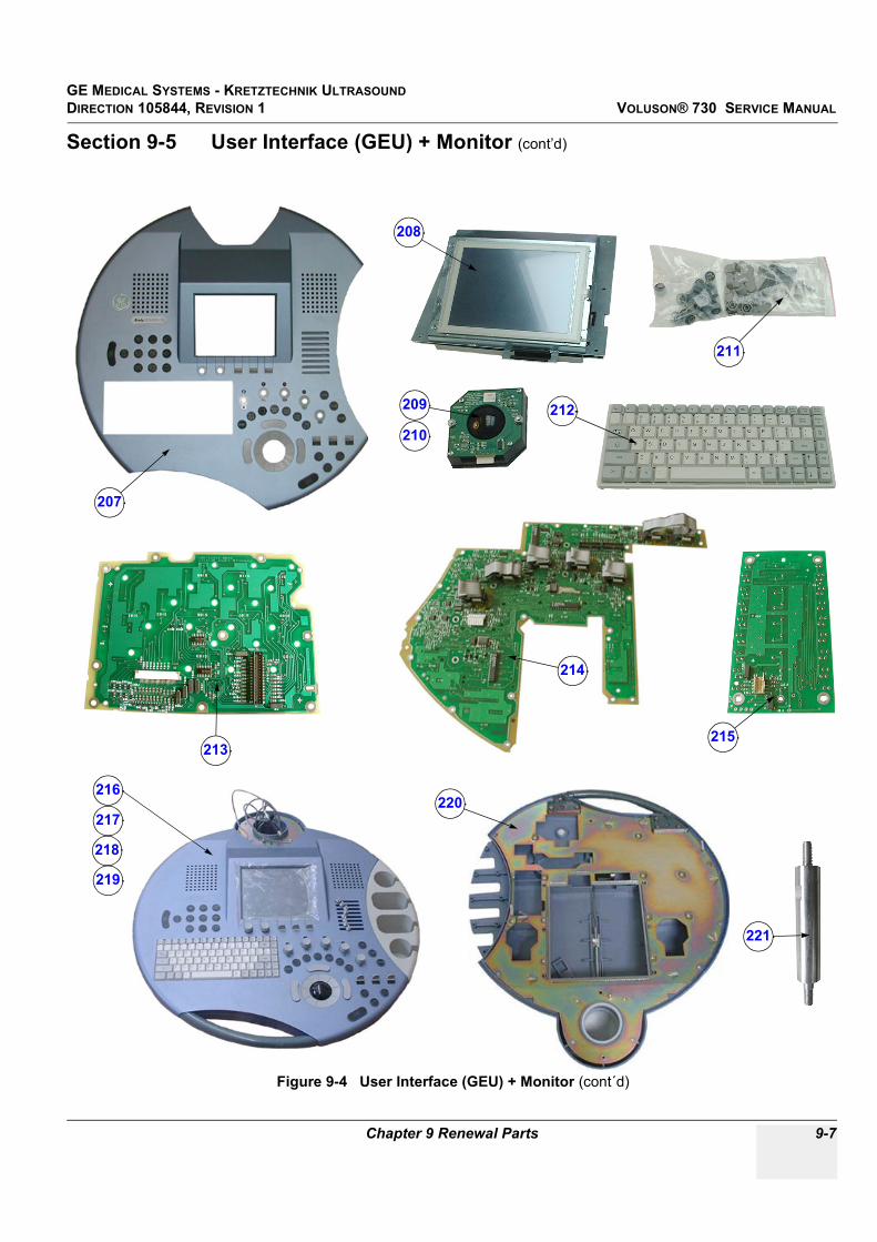
GE MEDICAL SYSTEMS - KRETZTECHNIK ULTRASOUND DIRECTION 105844, REVISION 1 VOLUSON® 730 SERVICE MANUAL
Chapter 9 Renewal Parts 9-7
Section 9-5 User Interface (GEU) + Monitor (cont’d)
Figure 9-4 User Interface (GEU) + Monitor (cont´d)
207
208
209
210
211
212
214
215
216
217
218
219
220
221
213

GE MEDICAL SYSTEMS - KRETZTECHNIK ULTRASOUNDDIRECTION 105844, REVISION 1 VOLUSON® 730 SERVICE MANUAL
9-8 Section 9-5 - User Interface (GEU) + Monitor
Table 9-5 User Interface (GEU) + Monitor (cont´d)
Item Part Name Part Number Description Qty FRU
207 Top Housing Kit V730 KTZ207102 upper plastic part of User Interface housing (GEU) including Push-buttons and Switches 1 1
208 Touchscreen, Display + Board Kit KTZ207111 Electronic part of User Interface. This is the free programmable Part of V730-User Interface. 1 1
209 Trackball Kit V730 KTZ207099 generates X-Y-Coordinates of Trackball-Movements like moving a PC-Mouse 1 1
210 Trackball Kit V730 KTZ208264 generates X-Y-Coordinates of Trackball-Movements like moving a PC-Mouse 1 1
211 GEU4-6 Operator keys kit KTZ207103 GEU4-6 Operator keys kit (incl. Shift Potentiometer knobs and digipots and toggle switch paddles)
1 1
212 GEU4-6 PC-Keyboard kit KTZ207115 GEU4-6 PC-alphanumeric Keyboard kit 1 1
213 Left PWB kit for V730 KTZ207108 Printed Wire Board inside GEU 1 1
214 Right PWB kit for V730 KTZ207109 Printed Wire Board inside GEU 1 1
215 Slide Potentiometer kit for V730 KTZ207110 TGC Slider controls - board inside GEU 1 1
216 GEU1-2 User Interface AID without PS II KTZ154621 keyboard, trackball, display, special knobs, switches(used in serial production up to # A05569) 1 2
217 GEU4-4b User Interface AID with PS II KTZ154606keyboard, trackball, display, special knobs, switches
replaces GEU1-2(used in serial production # A05570 - A06033)
1 1
218 GEU5-5b User Interface AID with PS II KTZ154640keyboard, trackball, display, special knobs, switches
replaces GEU4-4b(used in serial production # A06034 - A06312)
1 1
219 GEU6 User Interface AID & PS II KTZ154660keyboard, trackball, display, special knobs, switches
replaces GEU5-5b(used in serial production from # A06313 -)
1 1
220 Bottom Housing kit of GEU KTZ207104 Bottom Housing kit of GEU 1 1
221 Distance Rod on GEU KTZ208082 Distance Rod on GEU 1 1

GE MEDICAL SYSTEMS - KRETZTECHNIK ULTRASOUND DIRECTION 105844, REVISION 1 VOLUSON® 730 SERVICE MANUAL
Chapter 9 Renewal Parts 9-9
Section 9-6Disk Drives (GEM)
Figure 9-5 Disk Drives (GEM)
Table 9-6 Disk Drives (GEM)
Item Part Name Part Number Description Qty FRU
301 CD/RW-Drive KTZ207047 Standard CD-ROM-Burner internal (no own cabinet) 1 1
302 Fan axial 62 x 62 x 14 mm KTZ207602 Fan for Air-Cooling of GEM (SCSI-Drive-Module) 1 1
303 GEM1-1a SCSI Disk Drive Module KTZ195474 Mechanical Module for SCSI-Drives MO and CD/RW(used in serial production up to # A06310) 1 2
304 GEM2 MO-Drive + CR/RW KTZ154652Mechanical Module for SCSI-Drives MO and CD/RW
replaces GEM1-1a(used in serial production from # A06311 - )
1 2
305 GEM3-3a MO-Drive + CR/RW KTZ154673Mechanical Module for SCSI-Drives MO and CD/RW
replaces GEM1-1a and GEM2(not used in serial production)
1 2
306 MO-Drive SCSI 1.3 GB internal KTZ207050 Standard Magneto-Optical-Drive SCSI 1.3GB internal (has no own cabinet) 1 1
301302
303
304
305
306

GE MEDICAL SYSTEMS - KRETZTECHNIK ULTRASOUNDDIRECTION 105844, REVISION 1 VOLUSON® 730 SERVICE MANUAL
9-10 Section 9-7 - Main Power Module (CPN)
Section 9-7Main Power Module (CPN)
Figure 9-6 Main Power Module (CPN)
Table 9-7 Main Power Module (CPN)
Item Part Name Part Number Description Qty FRU
401 CPN3 Primary Power Supply Module KTZ195510 CPN3-3a Primary Power Supply Module(used in serial production up to # A05800) 1 1
402 CPN4 Power Supply Module KTZ195564CPN4-4 Power Supply Module
replaces CPN3(used in serial production from # A05801 - A06353)
1 1
403 CPN5 Power Supply Module KTZ195739CPN5 Power Supply Module
replaces CPN4(used in serial production from # A06354 -)
1 1
404 CPY3.P3 Power Switch KTZ195471 Board to switch on and shut down Ultrasound System 1 1
405 Mains Power Input connector KTZ207574 Mains Power Input connector 1 1
406 Fuse 10 Ampere 6.3 x 32 KTZ208239 Electric Current Overflow Protection GEF 4 1
407 KVN2 - Fan for Primary Power Supply KTZ195440 KVN2 - Fan for Primary Power Supply (CPN) 1 1
401402
403
404
405
406
407

GE MEDICAL SYSTEMS - KRETZTECHNIK ULTRASOUND DIRECTION 105844, REVISION 1 VOLUSON® 730 SERVICE MANUAL
Chapter 9 Renewal Parts 9-11
Section 9-8Main Board Module (GEF)
Figure 9-7 Main Board Module (GEF)
Table 9-8 Main Board Module (GEF)
Item Part Name Part Number Description Qty FRU
501 GEF1-2d Main Board Chassis KTZ195400 GEF1-2d Chassis mech.+ electr. (Main Board)(used in serial production up to # A06353) 1 N
502 GEF3 Main Board Chassis KTZ195700GEF3 Chassis mech. + electr. (Main Board)
can replace GEF1-2d(used in serial production from # A06354 -)
1 N
503 Fan for GEF-box (2 fan) KTZ154678 Fan for GEF-box (2 fan) 1 1
504 Fan for GEF-box (single) KTZ154679 Fan for GEF-box (single) 1 1
501
502
503
504

GE MEDICAL SYSTEMS - KRETZTECHNIK ULTRASOUNDDIRECTION 105844, REVISION 1 VOLUSON® 730 SERVICE MANUAL
9-12 Section 9-8 - Main Board Module (GEF)
9-8-1 FrontEnd (US-Part)
Figure 9-8 FrontEnd (US-Part)
Table 9-9 FrontEnd (US-Part)
Item Part Name Part Number Description Qty FRU
511 CPD3-3a.P3 Beamformer SUB-Board KTZ195375 Sub-board on CPR 1 1
512 CPR4-4b.P4 Beamformer Board(up to A06353)
KTZ195462 Beamformer Board (can not be replaced by CPR51.P6) 1 1
513 CPR51.P6 Beamformer Board (from A06354)
KTZ195645 Beamformer Board (can not be replaced by CPR4-4b.P4) 1 1
514 CWD2 CW Doppler Board KTZ195663 CW-Doppler Board 1 1
515 CRW2.P2 CW Doppler Board KTZ195723 CW-Doppler Board (can replace CWD2), minimum software requirement 1.06 1 1
516 CPZ2-2a.P2 Cover board(up to A06353)
KTZ195406electrical signal connection between CPU,CPR and CW-Board; contains Relays for Signal to CW-Board
(can not be replaced by CPZ50-50a.P3)1 1
517 CPZ50-50a.P3 Cover board (from A06354)
KTZ195592electrical signal connection between CPU,CPR and CW-Board; contains Relays for Signal to CW-Board.
(can not be replaced by CPZ2-2a.P2)1 1
511
512
513
515
516
517
514

GE MEDICAL SYSTEMS - KRETZTECHNIK ULTRASOUND DIRECTION 105844, REVISION 1 VOLUSON® 730 SERVICE MANUAL
Chapter 9 Renewal Parts 9-13
9-8-1 FrontEnd (US-Part) (cont’d)
Figure 9-9 FrontEnd (US-Part) cont´d
521
522
523
524
525
526
527
528
529 530
531 532

GE MEDICAL SYSTEMS - KRETZTECHNIK ULTRASOUNDDIRECTION 105844, REVISION 1 VOLUSON® 730 SERVICE MANUAL
9-14 Section 9-8 - Main Board Module (GEF)
A05540, A05547, A05589, A05667, A05668, A05669, A05670, A05675, A05676, A05677, A05705, A05748, A05789, A05978, A05984, A05990, A06058, A06064, A06065, A06070, 1509KR9(A06075), 1492KR0(A06076), 1477KR9(A06077), 1502KR4(A06078), 1503KR2(A06079), 750KR0(A06080), 1481KR1(A06081), 748KR4(A06082), 1479KR5(A06084), 1497KR7(A06085), 756KR7(A06086), 1507KR3(A06087), 1490KR2(A06088), 749KR2(A06089), 1488KR6(A06090), 1498KR5(A06091), 1476KR1(A06092), 1485KR2(A06093), 1510KR7(A06094), 753KR4(A06095), 1513KR1(A06096), 1501KR6(A06097), 752KR6(A06098), 1500KR8(A06099), 1474KR6(A06100), 1471KR2(A06101), 1486KR0(A06102), 1505KR7(A06104)
Table 9-10 FrontEnd (US-Part) cont´d
Item Part Name Part Number Description Qty FRU
521 CCM50.P7 Motor Control Board KTZ195497 Motor Control Board 1 1
522 CCM55.P9 Motor Control Board KTZ195788 Motor Control Boardcan replace CCM50.P7 1 1
523 CPC2-2f.P2 System Control Board(up to A06104) ***
KTZ195324 System Control Board (can not be replaced by CPC4.P4 and CPC5, except ***) 1 1
524 CPC4.P4 System Control Board(from A06105 - )
KTZ195654 System Control Board(can not be replaced by CPC2-2f.P2) 1 1
525 CPC5.P4 System Contorl Board (from Ap6105 - )
KTZ195821 System Control Board(can replace CPC4.P4 ; can not replace CPC2-2f.P2) 1 1
526 CPF3-3a.P3 Color Doppler Board(up to A06104) ***
KTZ195439 Color Doppler Board (can not be replaced byCPF10-10a.P4 and CPF11.P5, except ***) 1 1
527 CPF10-10a.P4 Color Doppler Board(from A06105)
KTZ195597 Color Doppler Board(can not be replaced by CPF3-3a.P3) 1 1
528 CPF11.P5 Color Doppler Board KTZ195750 Color Doppler Board(can replaced CPF10-10a.P4 ; but not CPF3-3a.P3) 1 1
529 CPG3-3c.P3 Mid-Processor Board(up to A06104) ***
KTZ195414Mid-Processor Board (Frame Filter, Mixer, HF-Filter,
Log.Demodulator) (can not be replaced by CPG4.P3, except ***)
1 1
530 CPG4.P3 Mid-Processor Board(from A06105)
KTZ195594Mid-Processor Board (Frame Filter, Mixer, HF-Filter,
Log.Demodulator) (can not be replaced by CPG3-3c.P3)
1 1
531 CPK3.P3 Motherboard V730 KTZ195466 Electrical Signal- and Supply-Connection for all boards including PC-Motherboard (CPM) 1 1
532 CPK4.P3 Motherboard V730 KTZ195822Electrical Signal- and Supply-Connection for all
boards including PC-Motherboard (CPM)can replace CPK3.P3
1 1
CAUTION
*** For Voluson® 730 system with serial numbers listed below use CPC4; or CPF10; or CPG4!!!

GE MEDICAL SYSTEMS - KRETZTECHNIK ULTRASOUND DIRECTION 105844, REVISION 1 VOLUSON® 730 SERVICE MANUAL
Chapter 9 Renewal Parts 9-15
9-8-1 FrontEnd (US-Part) (cont’d)
Figure 9-10 FrontEnd (US-Part) cont´d
Table 9-11 FrontEnd (US-Part) cont´d
Item Part Name Part Number Description Qty FRU
531 CPP2-2e.P2 Power Supply Board KTZ195353 Power Supply Board Output Power: 900W 1 1
532 CPP3-3c.P3 Power Supply Board KTZ195515 Power Supply Board Output Power: 900 W(can replace CPP2-2e.P2) 1 1
533 CPP4-4b.P3 Power Supply Board KTZ195679 Power Supply Board Output Power: 900 W(can replace CPP2-2e.P2 and CPP3-3c.P3) 1 1
534 CPP5.P3 Power Supply Board KTZ195826 Power Supply Board Output Power: 900 W(can replace CPP2-2e.P2, CPP3-3c.P3 + CPP4-4b.P3) 1 1
535 CPU1-1d.P1 Probe Connector Board(up to A06353)
KTZ195417
Probe Connector Board, Module Board(CW connector not fitted)
(used in serial production up to # A06353)(can not be replaced by CPU5.P5)
1 1
536 CPU5.P5 Module Board (BYM)(from A06354)
KTZ195636Probe Connector Board, Module Board
(used in serial production from # A06354 -)(can not be replaced by CPU1-1d.P1)
1 1
531
532
533
534
535 536

GE MEDICAL SYSTEMS - KRETZTECHNIK ULTRASOUNDDIRECTION 105844, REVISION 1 VOLUSON® 730 SERVICE MANUAL
9-16 Section 9-8 - Main Board Module (GEF)
9-8-2 BackEnd Processor (PC-Part)
Figure 9-11 BackEnd Processor (PC-Part)
571
572
574
575 576
577 578
579 580
581
582
583
584
573

GE MEDICAL SYSTEMS - KRETZTECHNIK ULTRASOUND DIRECTION 105844, REVISION 1 VOLUSON® 730 SERVICE MANUAL
Chapter 9 Renewal Parts 9-17
A05540, A05547, A05589, A05667, A05668, A05669, A05670, A05675, A05676, A05677, A05705, A05748, A05789, A05978, A05984, A05990, A06058, A06064, A06065, A06070, 1509KR9(A06075), 1492KR0(A06076), 1477KR9(A06077), 1502KR4(A06078), 1503KR2(A06079), 750KR0(A06080), 1481KR1(A06081), 748KR4(A06082), 1479KR5(A06084), 1497KR7(A06085), 756KR7(A06086), 1507KR3(A06087), 1490KR2(A06088), 749KR2(A06089), 1488KR6(A06090), 1498KR5(A06091), 1476KR1(A06092), 1485KR2(A06093), 1510KR7(A06094), 753KR4(A06095), 1513KR1(A06096), 1501KR6(A06097), 752KR6(A06098), 1500KR8(A06099), 1474KR6(A06100), 1471KR2(A06101), 1486KR0(A06102), 1505KR7(A06104)
Table 9-12 BackEnd Processor (PC-Part)
Item Part Name Part Number Description Qty FRU
571 AHA-2940U SCSI-II-Control Board KTZ207402 SCSI-II Control Board 1 1
572 BT948 (SCSI-Controller Board) KTZ207973 SCSI Controller Board 1 1
573 CKV20.P2-21a.P3 Video manager Board KTZ207034 PC-Video converter Board 1 1
574 CKV22.P3 Video manager Board KTZ207593 PC-Video converter Board (can replace CKV20 if SW 1.06G is installed) 1 1
575 CPE3.P3 Motherboard - Extension KTZ195463Motherboard Extension
(used in serial production up to # A06040)1 1
576 CPE4.-4a.P4 Motherboard - Extension KTZ195542Motherboard Extension
(used in serial production from # A06041 -)can replace CPE3.P3
1 1
577 CPM2.P2 Motherboard (up to A06104) *** KTZ195191electrical Signal- and Supply-Connection between
all PC-Plug-In-Boards(can not be replaced by CPM3.P2, except ***)
1 1
578 CPM3.P2 Motherboard (from A06105) KTZ195699electrical Signal- and Supply-Connection between
all PC-Plug-In-Boards(can not be replaced by CPM2.P2)
1 1
579 CPS3-3a.P3 Scan converter Board(up to A06104) ***
KTZ195415 Scan converter Board(can not be replaced by CPS4.P3, except ***) 1 1
580 CPS4.P3 Scan converter Board(from A06105)
KTZ195596 Scan converter Board(can not be replaced by CPS3-3a.P3) 1 1
581 Harddisk (Systems with 850 MHz PC)(up to A06267)
KTZ207625Harddisk IDE
(used in serial production up to # A06267)(can not be replaced by HDD 1GHz)
1 1
582 Harddisk (Systems with 1 GHz PC)(from A06268)
KTZ208799Harddisk IDE
(used in serial production from # A06268)(can not be replaced by HDD 850MHz)
1 1
583 SBC- Single Board Computer PIII 133 MHz FSB (1GHz) ; (from A06268)
KTZ207389Standard Single Board-PC, Pentium-III, 1GHZ, 133MHz-FrontSideBus, PCI-Bus, 768MB Ram,
(used in serial production from # A06268)1 1
584 SBC-Single Board Computer PII/PIII (850MHz) ; (up to A06267)
KTZ207666Standard Single Board Computer
(used in serial production up to # A06267)can be replaced by PC-kit KTZ195718
1 1
CAUTION
*** For Voluson® 730 system with serial numbers listed below use CPM3; or CPS4!!!

GE MEDICAL SYSTEMS - KRETZTECHNIK ULTRASOUNDDIRECTION 105844, REVISION 1 VOLUSON® 730 SERVICE MANUAL
9-18 Section 9-9 - Options and Upgrades
Section 9-9Options and Upgrades
Figure 9-12 Options and Upgrades
Table 9-13 Options and Upgrades
Item Part Name Part Number Description Qty FRU
601 MO Disk Media 1.3GB KTZ207077 MO-Disk Media (Standard) 1 1
602 Service Boot CD-Rom PIII/ 1GHz KTZ1C2192Repair CD-Rom (Linux based); only for 1GHZ SBC-boards which have no GE licensed BIOS
(1 1
603 PC-Replace Kit PIII/ 1GHz (up to A06267)
KTZ195718 PC Board - replacement for 850MHz 1 1
604 PCW1-1a CW Upgrade Kit (from A05900)
KTZ195615 CW-Doppler Upgrade Kit 1 1
601
602
603
604

GE MEDICAL SYSTEMS - KRETZTECHNIK ULTRASOUND DIRECTION 105844, REVISION 1 VOLUSON® 730 SERVICE MANUAL
Chapter 9 Renewal Parts 9-19
Section 9-10Miscellaneous Cables
Table 9-14 Miscellaneous Cables
Item Part Name Part Number Description Qty FRU
701 Adapter SCSI-II DB50/DB50 KTZ207121
SCSI-Link
1 1
702 Adaptor 26Pin / SUB-D25 KTZ207085
Adaptor LPT1 / Parallel Port
1 1
703 Adapter Line in MIC; GEU KTZ207390
Serial - MIC in - Speaker out
1 1
704 Cable 50Pin SCSI-2 Data Cable 1.8m KTZ212403
Data Transfer between PC and SCSI-Module
1 1

GE MEDICAL SYSTEMS - KRETZTECHNIK ULTRASOUNDDIRECTION 105844, REVISION 1 VOLUSON® 730 SERVICE MANUAL
9-20 Section 9-10 - Miscellaneous Cables
705 Cable HDD Y-Power KTZ212426
12V/5V-Power Supply-Distributor-Cable (2x) for PC-Component (yellow-black, red-black)
1 1
706 Cable Stereo Jack - Chinch KTZ212074
Cable from PC-Sound-StereoJack to External Rear Panel
1 1
707 Data Cable HDD KTZ212398
Data cable for IDE-Harddisk 40pin 330mm
1 1
708 GES2 I/O Connection Panel KTZ195503
External Rear Panel with electrical Signal- and Supply-Connection-Cables to the V730-Main-Unit (internal)
Rear-Panel.1 1
709 GES3 I/O Connection Panel KTZ195638
External Rear Panel with electrical Signal- and Supply-Connection-Cables to the V730-Main-Unit (internal)
Rear-Panel.1 1
710 KGS10 Cable Power GEM-GEF KTZ195464
Electrical Power-Supply for SCSI-Drives (5V/12V)
1 1
Table 9-14 Miscellaneous Cables
Item Part Name Part Number Description Qty FRU

GE MEDICAL SYSTEMS - KRETZTECHNIK ULTRASOUND DIRECTION 105844, REVISION 1 VOLUSON® 730 SERVICE MANUAL
Chapter 9 Renewal Parts 9-21
711 KUG5 Remote Cable KTZ195606
VCR -Remote Control Cable
1 1
712 KUR10 Cable Data SCSI KTZ195473
internal Data Cable between SCSI-Module-Connector and SCSI-Drives (CD-Rom, MO-Drive)
1 1
713 KVR1 TERM-RS232PC / V730, Y-Cable
KTZ195416
electrical Signal- and Supply-Connection between V730 and User Interface GEU
1 1
714 KVR2 TERM-RS232PC / V730, Y-Cable
KTZ207353
electrical Signal- and Supply-Connection between Voluson® 730 and User Interface GEU(can replace KVR1 cable - KTZ195416)
1 1
715 KVS2 Cable Serial Interface KTZ195717
electrical-Signal-Connection between CPS and PIC_MG-Slot-CPU
1 1
716 KVX1 Network Cable KTZ212016
Cable from external rear Panel to the V730-Main-Unit (internal) rear-Panel 1m
1 1
Table 9-14 Miscellaneous Cables
Item Part Name Part Number Description Qty FRU
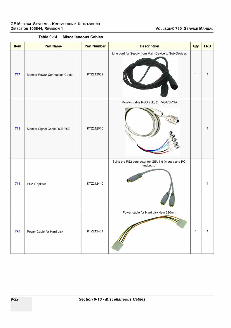
GE MEDICAL SYSTEMS - KRETZTECHNIK ULTRASOUNDDIRECTION 105844, REVISION 1 VOLUSON® 730 SERVICE MANUAL
9-22 Section 9-10 - Miscellaneous Cables
717 Monitor Power Connection Cable KTZ212032
Line cord for Supply from Main-Device to Sub-Devices
1 1
718 Monitor Signal Cable RGB 75E KTZ212010
Monitor cable RGB 75E; 2m VGA/SVGA
1 1
719 PS2 Y-splitter KTZ212440
Splits the PS2 connector for GEU4-6 (mouse and PC-keyboard)
1 1
720 Power Cable for Hard disk KTZ212401
Power cable for Hard disk 4pin 230mm
1 1
Table 9-14 Miscellaneous Cables
Item Part Name Part Number Description Qty FRU

GE MEDICAL SYSTEMS - KRETZTECHNIK ULTRASOUND DIRECTION 105844, REVISION 1 VOLUSON® 730 SERVICE MANUAL
Chapter 9 Renewal Parts 9-23
721 Power Cord Europe 230V KTZ212317
Power Cord Europe 230V/240V
1 1
722 Power Cord Japan (Hosp.grade) KTZ212448
Power Cord Japan Hospital Grade
1 1
723 Power Cord UK KTZ212441
Power Cord United Kingdom 240V
1 1
724 Power Cord USA (Hosp.grade) KTZ212402
Power Cord USA Hospital Grade
1 1
Table 9-14 Miscellaneous Cables
Item Part Name Part Number Description Qty FRU

GE MEDICAL SYSTEMS - KRETZTECHNIK ULTRASOUNDDIRECTION 105844, REVISION 1 VOLUSON® 730 SERVICE MANUAL
9-24 Section 9-10 - Miscellaneous Cables
725 SCSI Adapter 68 Pin - 50 Pin KTZ212075
Leads the SCSI-Signal from the PC-Board to the PC-Backpanel. Connector on PC-Side: 68pol, Connector on
PC-Backpanel: MD-50P female
1 1
726 SCSI Adapter 68 Pol. -> 50 Pol. KTZ212103
Leads the SCSI-Signal from the PC-Board to the PC-Backpanel. Connector on PC-Side: 68pol, Connector on
PC-Backpanel: MD-50P female
1 1
727 USB to ICP CPU Board KTZ207029
USB for PC-Slot, Connector on Backpanel. Cables are connected to PC-Board. Leads the USB-signals to the
PC-Backpanel
1 1
Table 9-14 Miscellaneous Cables
Item Part Name Part Number Description Qty FRU
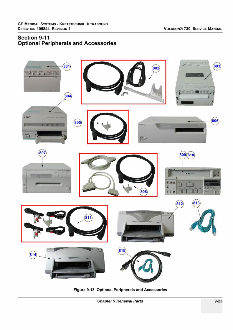
GE MEDICAL SYSTEMS - KRETZTECHNIK ULTRASOUND DIRECTION 105844, REVISION 1 VOLUSON® 730 SERVICE MANUAL
Chapter 9 Renewal Parts 9-25
Section 9-11Optional Peripherals and Accessories
Figure 9-13 Optional Peripherals and Accessories
801 802 803
804
805 806
807
808
809 810
811
812 813
814815

GE MEDICAL SYSTEMS - KRETZTECHNIK ULTRASOUNDDIRECTION 105844, REVISION 1 VOLUSON® 730 SERVICE MANUAL
9-26 Section 9-11 - Optional Peripherals and Accessories
Table 9-15 Optional Peripherals and Accessories
Item Part Name Part Number Description Qty FRU
801 Sony B/W Video Printer UP-895MD (CE) KTZ211332 NTSC/PAL 1 1
802 PPP55 Connection Set KTZ195643 Connection Set UP-895MD 1 1
803 Mitsubishi B/W Video Printer P-91E KTZ211007 NTSC/PAL 1 1
804 Sony Digital Color Printer UP-D21MD KTZ211357 USB-Port 1 1
805 PZP60 Connection Set KTZ195776 Connection Set UP-D21MD 1 1
806 Sony Digital Color Printer UP-D2600S KTZ211060 SCSI-Port 1 1
807 Mitsubishi Digital Color Printer CP770DW KTZ211352 SCSI-Port 1 1
808 PZP50 Connection Set KTZ195486 Connection Set UP-D2600S / CP770DW 1 1
809 Sony VCR SVO-9500 MD KTZ211317 NTSC 1 1
810 Sony VCR SVO-9500 MDP KTZ211318 PAL 1 1
811 PRR50 Connection Set KTZ195492 Connection Set for VCR without remote control 1 1
812 HP Line Printer HPdeskjet 990cxi KTZ211102 USB-Port 1 1
813 PZP55 Connection Set KTZ195749 Connection Set HPdeskjet 990cxi 1 1
814 HP Line Printer HP deskjet 995c KTZ211107 USB-Port 1 1
815 PZP56 Connection Set KTZ195882 Connection Set HPdeskjet 990cxi / 995c(can replace PZP55 - KTZ195749) 1 1

GE MEDICAL SYSTEMS - KRETZTECHNIK ULTRASOUND DIRECTION 105844, REVISION 1 VOLUSON® 730 SERVICE MANUAL
Chapter 9 Renewal Parts 9-27
Section 9-9 Options and Upgrades (cont’d)
Figure 9-14 Optional Peripherals and Accessories cont´d
Table 9-16 Optional Peripherals and Accessories cont´d
Item Part Name Part Number Description Qty FRU
816 ECG-preamplifier (MAN 3) KTZ154258 consists of ECG-preamplifier and patient connection cable 1 1
817 ECG-preamplifier (MAN 6) KTZ154644 consists of ECG-preamplifier and patient connection cable 1 1
818 Foot switch (MFT7) KTZ195446 Foot switch 1 1
819 USB-RS232 Connection kit PRY KTZ195858 Converter from USB to RS-232 Serial Port 1 1
820 Touch-up Paint Set (gray-blue) KTZ154680 contains blue, dark-gray, bright-gray and black4x 2cl bottels incl. brush 1 1
816817
818
819
820

GE MEDICAL SYSTEMS - KRETZTECHNIK ULTRASOUNDDIRECTION 105844, REVISION 1 VOLUSON® 730 SERVICE MANUAL
9-28 Section 9-11 - Optional Peripherals and Accessories
Table 9-17 System Manuals
Item Part Name Part Number Kretz # Description Qty FRU
Voluson® 730 Service Manual KTZ105844 105844 1 N
System User Manuals
Basic User Manual, Voluson® 730, English H46601B 1 N
Instruction Manual, Voluson® 730, English H46611E 1 N
Instruction Manual, Voluson® 730, German H46611G 1 N
Instruction Manual, Voluson® 730, Spanish H46611S 1 N
Instruction Manual, Voluson® 730, Russian H46611R 1 N
Instruction Manual, Voluson® 730, French H46611F 1 N
Instruction Manual, Voluson® 730, Italian H46611Y 1 N

GE MEDICAL SYSTEMS - KRETZTECHNIK ULTRASOUND DIRECTION 105844, REVISION 1 VOLUSON® 730 SERVICE MANUAL
Chapter 9 Renewal Parts 9-29
Section 9-12Probes
9-12-1 2D-Probes
Figure 9-15 2D curved array Transducers
Table 9-18 2D curved array Transducers
Item Part Name Part Number Description Qty FRU
901 AB2-5 KTZ195351 electronic broadband curved array transducer, frequency range of 2-5 MHz Applications: Abdominal, Obstetrics, Gynecology 1
902 AB2-5GL KTZ195372electronic broadband curved array transducer, frequency range of 2-5 MHz
Applications: Abdominal, Obstetrics, Gynecology(with Gray Lense ; replaces AB2-5 ->KTZ195351)
1
903 AB3-8 KTZ195546 electronic broadband curved array transducer, frequency range of 3-8 MHzApplications: Abdominal, Obstetrics, Gynecology, Urology, Pediatrics 1
904 AB4-8 KTZ195354 electronic broadband curved array transducer, frequency range of 4-8 MHzApplications: Abdominal, Obstetrics, Gynecology, Pediatrics 1
905 S-ACP4-7 KTZ194840 electronic wideband sector transducer with a center frequency of 4.5 MHzApplications: Abdominal, Obstetrics, Gynecology 1
906 IC5-9 KTZ195386electronic endocavity broadband curved array transducer, frequency range
of 5-9 MHz and a field-of-view of max. 150°Applications: Obstetrics, Gynecology, Urology
1
901
902
903
904 905906

GE MEDICAL SYSTEMS - KRETZTECHNIK ULTRASOUNDDIRECTION 105844, REVISION 1 VOLUSON® 730 SERVICE MANUAL
9-30 Section 9-12 - Probes
9-12-1 2D-Probes (cont’d)
Figure 9-16 2D linear- and phased array Transducers
Table 9-19 2D linear- and phased array Transducers
Item Part Name Part Number Description Qty FRU
906 SP4-10 KTZ195530electronic broadband linear array transducer, frequency range of 4-10 MHz,
electronically steerableApplications: Small Parts, Peripheral Vascular, Pediatrics, Orthopedics
1
907 SP6-12 KTZ195362electronic broadband linear array transducer, frequency range of 6-12 MHz,
electronically steerableApplications: Small Parts, Peripheral Vascular, Pediatrics, Orthopedics
1
908 SP10-16 KTZ195531electronic broadband linear array transducer, frequency range of 10-16 MHz,
electronically steerableApplications: Small Parts, Orthopedics
1
909 PA2-5 KTZ195507 electronic broadband phased array transducer, frequency range of 2-5 MHzApplications: Abdominal, Cardiology, Transcranial 1
910 PA4-7 KTZ195511 electronic broadband phased array transducer, frequency range of 4-7 MHzApplications: Cardiology, Pediatrics 1
911 PA6-8 KTZ195532 electronic broadband phased array transducer, frequency range of 6-8 MHzApplications: Cardiology, Pediatrics/Neonatology 1
906 907 908
909 910 911

GE MEDICAL SYSTEMS - KRETZTECHNIK ULTRASOUND DIRECTION 105844, REVISION 1 VOLUSON® 730 SERVICE MANUAL
Chapter 9 Renewal Parts 9-31
9-12-2 Real-Time 4D Volume Probes
Figure 9-17 Real-Time 4D Volume Probes
Table 9-20 Real-Time 4D Volume Probes
Item Part Name Part Number Description Qty FRU
921 RAB2-5 KTZ156736Real-time 4D broadband electronic curved-array transducer with a frequency
range of 2-5MHz.Applications: Abdominal, Obstetrics, Gynecology, Interventional Radiology
1
922 RAB4-8 KTZ156738 Real-time 4D broadband electronic curved-array transducer with a
frequency range of 4-8 MHz.Applications: Abdominal, OB, Gyn, Pediatrics, Interventional Radiology
1
923 RAB4-8P KTZ156767
(Follow-up model of RAB4-8 -> KTZ156738)Real-time 4D broadband electronic curved-array transducer with a frequency
range of 4-8 MHz.Applications: Abdominal, OB, Gyn, Pediatrics, Interventional Radiology
1
924 RSP6-12 KTZ195533Real-time 4D broadband electronic linear array transducer with a frequency
range of 6-12MHz and a scan width of 40 mm.Applications: Small Parts, Periph.Vascular, Pediatrics, Urology, Orthopedics
1
925 RIC5-9 KTZ195242Real-time 4D endocavity broadband electronic curved array transducer with
a frequency range of 5-9MHz.Applications: Gynecology/Fertility, Obstetrics, Urology
1
926 RRE6-10 KTZ195534Real-time 4D Multi-Plane electronic broadband curved array transrectal
transducer with a frequency range of 6-10 MHz.Applications: Urology, Rectal wall
1
921
922
923924
925 926

GE MEDICAL SYSTEMS - KRETZTECHNIK ULTRASOUNDDIRECTION 105844, REVISION 1 VOLUSON® 730 SERVICE MANUAL
9-32 Section 9-12 - Probes
9-12-3 CW-Pencil Probes
Figure 9-18 CW- Pencil Probes
Table 9-21 CW- Pencil Probes
Item Part Name Part Number Description Qty FRU
931 PCW4.0 KTZ195540single element Continuous Wave (CW) Doppler pencil probe with a
nominal operating frequency of 4.0 MHz (no B-image)Applications: Cardiology, Pediatrics
1
932 SCW2.0 KTZ195538single element Continuous Wave (CW) Doppler pencil probe with a
nominal operating frequency of 2.0 MHz (no B-image)Applications: Cardiology (suprasternal)
1
931 932

GE MEDICAL SYSTEMS - KRETZTECHNIK ULTRASOUND DIRECTION 105844, REVISION 1 VOLUSON® 730 SERVICE MANUAL
Chapter 9 Renewal Parts 9-33
9-12-4 Live 3D Probes
Figure 9-19 Live 3D Probes
Table 9-22 Live 3D Probes
Item Part Name Part Number Description Qty FRU
941 S-VAW3-5 KTZ156606 3D wideband electronic sector-transducer, center frequency: 3.5 MHz Applications: Abdominal, Obstetrics and Gynecology 1
942 S-VAW4-7 KTZ156685 3D wideband electronic sector-transducer, center frequency: 4.5 MHz Applications: Abdominal, Obstetrics and Gynecology 1
943 S-VDW5-8B KTZ156664 3D endocavity electronic sector transducer, center frequency: 6.5 MHzApplications: Obstetrics, Gynecology, Urology 1
944 S-VNA5-8B KTZ156662 3D neonatal electronic wideband transducer, center frequency: 6.5 MHzApplications: Neonatal Cephalic, Pediatrics, Small parts 1
945 S-VNW5-10 KTZ156695 3D broadband electronic linear array transducer with a frequency range
from 5-10 MHz and a scan width of 40 mm.Applications: Small parts, Peripheral Vascular, Pediatrics, Musculoskeletal
1
946 S-VNW6-12 KTZ195339 3D broadband electronic linear array transducer with a frequency of 8.0MHz
and a scan width of 40 mm.Applications: Small parts, Peripheral Vascular, Pediatrics, Musculoskeletal
1
941
942 943
944
945
946

GE MEDICAL SYSTEMS - KRETZTECHNIK ULTRASOUNDDIRECTION 105844, REVISION 1 VOLUSON® 730 SERVICE MANUAL
9-34 Section 9-12 - Probes
This page was intentionally left blank.

GE MEDICAL SYSTEMS - KRETZTECHNIK ULTRASOUND DIRECTION 105844, REVISION 1 VOLUSON® 730 SERVICE MANUAL
Chapter 10 Periodic Maintenance 10-1
Chapter 10Periodic Maintenance
Section 10-1Overview
10-1-1 Purpose of Chapter 10This chapter describes Periodic Maintenance (PM) on the scanner and its peripherals. These PM procedures are intended to maintain the quality of the ultrasound systems performance. Read this chapter completely and familiarize yourself with the procedures before starting a PM.
Table 10-1 Contents in Chapter 10
Section Description Page Number
10-1 Overview 10-1
10-2 Why do Periodic Maintenance 10-2
10-3 Periodic Maintenance Schedule 10-2
10-4 Tools Required 10-5
10-5 System Periodic Maintenance 10-6
10-6 Using a Phantom 10-11
10-7 Electrical Safety Tests 10-11
10-8 When There's Too Much Leakage Current... 10-24
PM INSPECTION CERTIFICATE 10-25
CAUTION Practice good ESD prevention. Wear an anti–static strap when handling electronic parts and even when disconnecting/connecting cables.
DANGER THERE ARE SEVERAL PLACES ON THE BACKPLANE, THE AC DISTRIBUTION, AND DC DISTRIBUTION THAT ARE DANGEROUS. BE SURE TO DISCONNECT THE SYSTEM POWER PLUG AND SWITCH OFF THE MAIN CIRCUIT BREAKER (F1) BEFORE YOU REMOVE ANY PARTS. BE CAUTIOUS WHENEVER POWER IS STILL ON AND COVERS ARE REMOVED.
CAUTION Do not pull out or insert circuit boards while power is ON.
CAUTION Do not operate this unit unless all board covers and frame panels are securely in place. System performance and cooling require this.

GE MEDICAL SYSTEMS - KRETZTECHNIK ULTRASOUNDDIRECTION 105844, REVISION 1 VOLUSON® 730 SERVICE MANUAL
10-2 Section 10-2 - Why do Periodic Maintenance
Section 10-2Why do Periodic Maintenance
10-2-1 Keeping RecordsIt is good business practice that ultrasound facilities maintain records of periodic and corrective maintenance. The Ultrasound Periodic Maintenance Inspection Certificate provides the customer with documentation that the ultrasound scanner is maintained on a periodic basis.
A copy of the Ultrasound Periodic Maintenance Inspection Certificate should be kept in the same room or near the scanner.
10-2-2 Quality AssuranceIn order to gain accreditation from organizations such as the American College of Radiology (USA), it is the customer’s responsibility to have a quality assurance program in place for each scanner. The program must be directed by a medical physicists, the supervising radiologist/physician or appropriate designer.
Routine quality control testing must occur regularly. The same tests are performed during each period so that changes can be monitored over time and effective corrective action can be taken.
Testing results, corrective action and the effects of corrective action must be documented and maintained on the site.
Your GE service representative can help you with establishing, performing and maintaining records for a quality assurance program.
Section 10-3Periodic Maintenance Schedule
10-3-1 How often should PMs be performed?The Periodic Maintenance Schedule specifies how often your Voluson® 730 should be serviced and what items need attention. It is the customer’s responsibility to ensure the Voluson® 730 periodic maintenance is performed as scheduled in order to retain its high level of safety, dependability and performance.
Your GEService Representative knows your Voluson® 730 best and can provide competent, efficient service. Please contact us for further information and to schedule GE Medical SystemsUltrasound to perform this service for you.
The services and intervals shown in the maintenance schedule assumes that you use your Voluson® 730 for an average patient load (10-12 per day) and not use it as a primary mobile unit which is transported between diagnostic facilities.
If conditions exist which exceed typical usage and patient load, then it is recommended to increase the periodic maintenance frequencies.
Abbreviations used in the Periodic Maintenance Schedule Table 10-2:
• D = Daily• W = Weekly• M = Monthly• A = Annually

GE MEDICAL SYSTEMS - KRETZTECHNIK ULTRASOUND DIRECTION 105844, REVISION 1 VOLUSON® 730 SERVICE MANUAL
Chapter 10 Periodic Maintenance 10-3
Table 10-2 Periodic Maintenance Schedule
Item Service at Indicated Time D W M A Notes
Air Filter GridClean the air filter grid with vacuum cleaner from outside (right side of the system front view).
• more frequently depending on your environment
Air Filter GridRemove back panel and board chassis and clean the housing from inside. (vacuum cleaner and soft brush)
• more frequently depending on your environment
AC Mains Cable Inspect AC Mains Cable • Mobile Unit Check Weekly
Cables and Connectors
Remove the Back Panel and check if all cables are well seated and if there is no mechanical damage visible;Check if they are fixed and well seated at the correct position.
• also after corrective maintenance
User Interface
Clean alphanumerical keyboard, Functional keys, Digital potentiometers, TGC-Shift potentiometers. (vacuum cleaner, lukewarm soap water on a soft, damp cloth)
•Be careful not to get the cloth too wet so that moisture does not enter the loudspeakers, TGC-Slider, or other keys!
Monitor and Touch Panel
Clean Top surface, Monitor, Touch Panel and Probe holder with a fluid detergent in warm water on a soft, damp cloth.
•Be careful not to get the cloth too wet so that moisture does not enter the entire system.
Mechanical parts
Clean and inspect the mechanical function of wheels, casters, brakes and swivel locks as well as side door, foot rest, front and rear handle, and monitor holder. Remove Dust and Coupling gel.
• Mobile Unit Check Daily
Control Panel movement Check Turn mechanism • Mobile Unit Check Daily
Trackball Check Check proper operation (Cursor movement X, Y direction) • If failure occurs go to trackball
cleaning
Trackball Cleaning
Remove top trackball cover; open the trackball housing and take out the trackball. Clean the X, Y axes of the trackball (soft tissue and screw driver shaft)
• Please record it in the systems setup maintenance report
Disk Drives(Sonoview Data Backup)
Save Image filing (Sonoview) Import and Export data capability (MO-, CD-RW Drive) • •*
* save the image filing data monthly or weekly on CD depending on the numbers of examinations
Safe Probe Operation
Clean probes and probe cables and check acoustic lens housing (cracks) and probe cables. In case of mechanical damage, don’t use them! Danger: Safety risk for operator and patient.
•* * or before each use
Probe Air bubblesTo detect air bubbles in filling liquid, shake the probe carefully and check abnormal noise.
•
Probe connectors Remove dust/dirt of all probe connectors. Clean with vacuum cleaner if dust is visible. •
Console Leakage Current Checks •
Also after corrective maintenance or as required by your facilities QA program.

GE MEDICAL SYSTEMS - KRETZTECHNIK ULTRASOUNDDIRECTION 105844, REVISION 1 VOLUSON® 730 SERVICE MANUAL
10-4 Section 10-3 - Periodic Maintenance Schedule
Peripheral Leakage Current Checks •
Also after corrective maintenance or as required by your facilities QA program.
Surface Probe Leakage Current Checks •
Also after corrective maintenance or as required by your facilities QA program.
Endocavity Probe Leakage Current Checks
Twice Annually
Measurement Accuracy Checks •
Also after corrective maintenance or as required by your facilities QA program.
Probe/Phantom Checks
Check axial and lateral resolution (see Basic User Manual Technical specifications). Check Gain and TGC changes, vary the focus and check reaction on screen.
•Also after corrective maintenance or as required by your facilities QA program.
Functional Checks of all probes Section 10-5-2 on page 10-7
•Also after corrective maintenance or as required by your facilities QA program.
Table 10-2 Periodic Maintenance Schedule
Item Service at Indicated Time D W M A Notes

GE MEDICAL SYSTEMS - KRETZTECHNIK ULTRASOUND DIRECTION 105844, REVISION 1 VOLUSON® 730 SERVICE MANUAL
Chapter 10 Periodic Maintenance 10-5
Section 10-4Tools Required
10-4-1 Special Tools, Supplies and Equipment
10-4-1-1 Specific Requirements for Periodic Maintenance see Chapter 7
Table 10-3 Overview of Requirements for Periodic Maintenance
Tool Part Number Comments
Digital Volt Meter (DVM) minimum 5% accuracy, 3.5 digit and 200 Ohm range required
Anti Static Kit
46–194427P23146–194427P27946–194427P36946–194427P37346–194427P370
Kit includes anti–static mat, wrist strap and cables for 200 to 240 V system3M #2204 Large adjustable wrist strap3M #2214 Small adjustable wrist strap3M #3051 conductive ground cord
Anti Static Vacuum Cleaner46–194427P27846–194427P279
120V230V
Safety Analyzer 46–285652G1 DALE 600 KIT (or equivalent) for electrical tests
SVHS VCR CassetteE7010GGE7010GF
60 minute120 minute
SVHS VCR Head Cleaner See VCR user manual for requirements
3.5” MOD MEDIAE8381AAE8381AB
KTZ207077
blank 128 M diskblank 230 M diskblank 1.3 GB MO-disk
3.5” MOD Media Cleaner 2117811 cleans the diskettes
3.5” MOD Head Cleaner Kit 2148392 cleans the drive heads
QIQ Phantom E8370RB RMI Grayscale Target Model 403GS
CD-RW Media (minimum quad speed)
B/W Printer Cleaning Sheet See printer user manual for requirements
Color Printer Cleaning Sheet See printer user manual for requirements
Disposable Gloves
Screwdriver PH0
Screwdriver PH1
Screwdriver PH2

GE MEDICAL SYSTEMS - KRETZTECHNIK ULTRASOUNDDIRECTION 105844, REVISION 1 VOLUSON® 730 SERVICE MANUAL
10-6 Section 10-5 - System Periodic Maintenance
Section 10-5System Periodic Maintenance
10-5-1 Preliminary ChecksThe preliminary checks take about 15 minutes to perform. Refer to the system user documentation whenever necessary.
Table 10-4 System Preliminary Checks
Step Item Description
1 Ask & Listen Ask the customer if they have any problems or questions about the equipment.
2 Paperwork Fill in the top of the Periodic Maintenance (PM) Inspection Certificate. Note all probes and system options.
3 Power up Turn the system power on and verify that all fans and peripherals turn on. Watch the displays during power up to verify that no warning or error messages are displayed.
4 Probes Verify that the system properly recognizes all probes.
5 Displays Verify proper display on the monitor and Touch Panel.
6 Presets Backup all customer presets on an MO-disk.

GE MEDICAL SYSTEMS - KRETZTECHNIK ULTRASOUND DIRECTION 105844, REVISION 1 VOLUSON® 730 SERVICE MANUAL
Chapter 10 Periodic Maintenance 10-7
10-5-2 Functional Checks (See Also Chapter 4)The functional checks take about 60 minutes to perform. Refer to the system user documentation whenever necessary.
10-5-2-1 System Checks
NOTE: * Some software may be considered standard depending upon system model configuration.
Table 10-5 System Functional Checks
Step Item Description
1 B-Mode Verify basic B-Mode (2D) operation. Check the basic system controls that affect this mode of operation.
2 M-Mode Verify basic M-Mode operation. Check the basic system controls that affect this mode of operation.
3 C-Mode Verify basic C-Mode (Color Flow Mode) operation. Check the basic system controls that affect this mode of operation.
4 PD-Mode Verify basic PD-Mode (Power Doppler Mode) operation. Check the basic system controls that affect this mode of operation.
5 Doppler Modes Verify basic Doppler Mode operation (PW and CW if available). Check the basic system controls that affect this mode of operation.
6 3D-Mode Verify basic 3D-Mode operation. Check the basic system controls that affect this mode of operation.
7 *Applicable Software Options
Verify the basic operation of all optional modes such as Real Time 4D, RT_4D Biopsy, VOCAL, Harmonic Imaging, Sonoview, CRI (Compound Resolution Imaging), TD (Tissue Doppler), VCI (Volume Contrast Imaging),... etc. Check the basic system controls that affect each options operation.
8 Keyboard Test Perform the Keyboard Test Procedure to verify that all keyboard controls are OK.
9 Monitor Verify basic Monitor display functions.
10 Touch Panel Verify basic Touch Panel display functions.
11 MeasurementsScan a gray scale phantom and use the measurement controls to verify distance and area calculation accuracy. Refer to theBasic User Manual, Chapter 13, for measurement accuracy specifications.

GE MEDICAL SYSTEMS - KRETZTECHNIK ULTRASOUNDDIRECTION 105844, REVISION 1 VOLUSON® 730 SERVICE MANUAL
10-8 Section 10-5 - System Periodic Maintenance
10-5-2-2 Peripheral/Option ChecksIf any peripherals or options are not part of the system configuration, the check can be omitted. Refer to Table 3-9, “Approved Peripherals,” on page 30for a list of approved peripherals.
10-5-3 Input Power
10-5-3-1 Mains Cable Inspection
10-5-4 Cleaning
10-5-4-1 General Cleaning
Table 10-6 Approved Peripheral/Hardware Option Functional Checks
Step Item Description
1 VCR Verify record/playback capabilities of the VCR. Clean heads and covers if necessary.
2 B/W Printer Verify hardcopy output of the B/W video page printer. Clean heads and covers if necessary.
3 Color Printer Verify hardcopy output of the Color video page printer. Clean heads and covers if necessary.
4 Line Printer Verify hardcopy output of the Line printer. Clean heads and covers if necessary.
5 DICOM Verify that DICOM is functioning properly. Send an image to a DICOM device.
6 Footswitch Verify that the footswitch is functioning as programed. Clean as necessary.
7 ECG Verify basic operation with customer.
Table 10-7 Mains Cable Inspection
Step Item Description
1 Unplug Cord Disconnect the mains cable from the wall and system.
2 Inspect Inspect it and its connectors for damage of any kind.
3 Verify Verify that the LINE, NEUTRAL and GROUND wires are properly attached to the terminals, and that no strands may cause a short circuit.
4 Verify Inlet connector retainer is functional.
Table 10-8 General Cleaning
Step Item Description
1 Console Use a fluid detergent in warm water on a soft, damp cloth to carefully wipe the entire system. Be careful not to get the cloth too wet so that moisture does not enter the console.
2 Probe Holder Clean probe holders (they may need to be soaked to remove excess gel).
3 Monitor and Touch Panel Clean Top surface, Monitor and Touch Panel with a fluid detergent in warm water on a soft, damp cloth.

GE MEDICAL SYSTEMS - KRETZTECHNIK ULTRASOUND DIRECTION 105844, REVISION 1 VOLUSON® 730 SERVICE MANUAL
Chapter 10 Periodic Maintenance 10-9
10-5-5 Physical Inspection.
Table 10-9 Physical Checks
Step Item Description
1 Labeling Verify that all system labeling is present and in readable condition.
2 Scratches & Dents Inspect the console for dents, scratches or cracks.
3 Control Panel Inspect keyboard and control panel. Note any damaged or missing items.
4 Control Panel Movement
Verify ease of control panel (Operator I/O Panel) movement in acceptable direction. Ensure that it latches in position as required.
5 Wheels & Brakes Check all wheels and casters for wear and verify operation of foot brake, to stop the unit from moving, and release mechanism. Check all wheel locks for proper operation.
6 Cables & Connectors Check all internal cable harnesses and connectors for wear and secure connector seating. Pay special attention to footswitch assembly and probe strain or bend reliefs.
7 Shielding & Covers Check to ensure that all EMI shielding, internal covers, air flow panels and screws are in place. Missing covers and hardware could causeEMI/RFI problems while scanning.
8 External I/O Check all connectors for damage and verify that the labeling is good.
9 Op Panel Lights Check for proper operation of all operator panel key illuminations (flash once during system start-up).
10 Monitor Light Check for proper operation of any monitor lights if available.
11 External Microphone Check for proper operation of any external microphones by recording an audio test if available.
NOTICE There is no microphone built in and released for Voluson® 730.

GE MEDICAL SYSTEMS - KRETZTECHNIK ULTRASOUNDDIRECTION 105844, REVISION 1 VOLUSON® 730 SERVICE MANUAL
10-10 Section 10-5 - System Periodic Maintenance
10-5-6 Optional Diagnostic ChecksTo complete the PM checks, access the diagnostic software as described in Chapters 5 or 7. View the error logs and run desired diagnostics.
10-5-7 Probe Maintenance
10-5-7-1 Probe Related Checks
10-5-7-2 Basic Probe CareThe probe user manuals provide a complete description of probe care, maintenance, cleaning and disinfection. Ensure that you are completely familiar with the proper care of GE probes.
Ultrasound probes can be easily damaged by improper handling. See the User’s Manual of the respective probe for more details. Failure to follow these precautions can result in serious injury and equipment damage. Failure to properly handle or maintain a probe may also void its warranty.
Any evidence of wear indicates the probe cannot be used.
Do a visual check of the probe pins and system sockets before plugging in a probe.
10-5-7-3 Basic Probe CleaningRefer to the User’s Manual of the respective probe for details on cleaning.
NOTE: To help protect yourself from blood borne diseases, wear approved disposable gloves. These are made of nitrile derived from vegetable starch to prevent allergic latex reactions.
NOTE: Failure to follow the prescribed cleaning or disinfection procedures will void the probe’s warranty. DO NOT soak or wipe the lens with any product not listed in the User Manual. Doing so could result in irreparable damage to the probe. Follow care instructions that came with the probe.
NOTE: Disinfect a defective probe before you return it. Be sure to tag the probe as being disinfected.
Table 10-10 Probe Related Checks
Step Item Description
1 Probe Holder Clean probe holders (they may need to be soaked to remove excess gel).
2 Probes Thoroughly check the system probe connectors and remove dust from inside the connector sockets if necessary. Visually check for bent, damaged or missing pins

GE MEDICAL SYSTEMS - KRETZTECHNIK ULTRASOUND DIRECTION 105844, REVISION 1 VOLUSON® 730 SERVICE MANUAL
Chapter 10 Periodic Maintenance 10-11
Section 10-6Using a Phantom
See the User´s Manual of the Phantom for information on using a phantom and quality assurance tests. Measurement Accuracy of the system (chapter 13.4). To get comparable results, use Multi-purpose phantom, Model 539-05 from ATS Laboratories Inc.
Section 10-7Electrical Safety Tests
10-7-1 Safety Test OverviewThe electrical safety tests in this section are based on and conform to NFPA 99 (For USA) and IEC 60601-1 Medical Equipment Safety Standards. They are intended for the electrical safety evaluation of cord-connected, electrically operated, patient care equipment. If additional information is needed, refer to the NFPA 99 (For USA) and IEC 60601-1 documents.
Test the system, peripherals and probes for leakage current. Excessive leakage current can cause injury or death in sensitive patients. High leakage current can also indicate degradation of insulation and a potential for electrical failure. Do not use probes or equipment having excessive leakage current.
To minimize the risk that a probe may shock someone the customer should:
• Not use a probe that is cracked or damaged in any way• Check probe leakage current:
* once a year on surface probes* twice a year on endocavitary probes* whenever probe damage is suspected
WARNINGWARNING THE USER MUST ENSURE THAT THE SAFETY INSPECTIONS ARE PERFORMED AT LEAST EVERY 12 MONTHS ACCORDING TO THE REQUIREMENTS OF THE PATIENT SAFETY STANDARD IEC-EN 60601-1. ONLY TRAINED PERSONS ARE ALLOWED TO PERFORM THE SAFETY INSPECTIONS MENTIONED ABOVE.
CAUTION To avoid electrical shock, the unit under test must not be connected to other electrical equipment. Remove all interconnecting cables and wires. The unit under test must not be contacted by users or patients while performing these tests.
CAUTION Possible risk of infection. Do not handle soiled or contaminated probes and other components that have been in patient contact. Follow appropriate cleaning and disinfecting procedures before handling the equipment.

GE MEDICAL SYSTEMS - KRETZTECHNIK ULTRASOUNDDIRECTION 105844, REVISION 1 VOLUSON® 730 SERVICE MANUAL
10-12 Section 10-7 - Electrical Safety Tests
10-7-2 GEMS Leakage Current LimitsThe following limits are summarized for NFPA 99 (For USA) and IEC 60601-1 Medical Equipment Safety Standards. These limits are GEMS standards and in some cases are lower than the above standards listed.
NOTE: *Mains Applied refers to the sink leakage test where mains (supply) voltage is applied to the part to determine the amount of current that will pass (or sink) to ground if a patient contacted mains voltage.
The following tests are performed at the factory and should be performed at the site. These tests are: grounding continuity, chassis leakage current, probe leakage current, and ECG leakage current. All measurements are made with an electrical safety analyzer.
Table 10-11 Chassis Leakage Current Limits-Accessible Metal Surfaces
Country Normal Condition Open Ground Reverse Polarity Open Neutral
USA N/A 0.3 mA 0.3 mA N/A
Other 0.1 mA 0.5 mA 0.5 mA 0.5 mA
Table 10-12 Type BF Applied Part Leakage Current Limits - Non-Conductive (Floating) Surface and Cavity Probes and ECG-preamplifier
CountryNormal
Condition Open Ground Reverse Polarity Open Neutral *Mains Applied
USA 0.05 mA 0.05 mA 0.05 mA 0.05 mA N/A
Other 0.1 mA 0.5 mA 0.5 mA 0.5 mA 5.0 mA
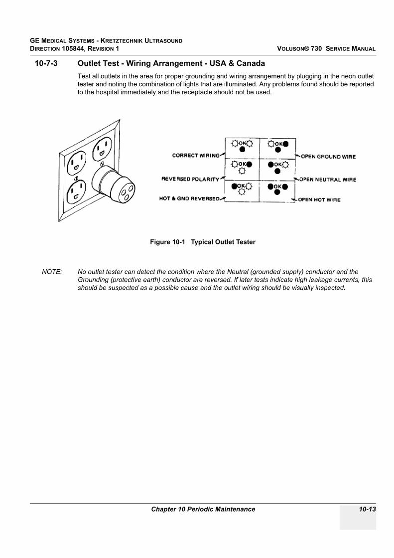
GE MEDICAL SYSTEMS - KRETZTECHNIK ULTRASOUND DIRECTION 105844, REVISION 1 VOLUSON® 730 SERVICE MANUAL
Chapter 10 Periodic Maintenance 10-13
10-7-3 Outlet Test - Wiring Arrangement - USA & CanadaTest all outlets in the area for proper grounding and wiring arrangement by plugging in the neon outlet tester and noting the combination of lights that are illuminated. Any problems found should be reported to the hospital immediately and the receptacle should not be used.
NOTE: No outlet tester can detect the condition where the Neutral (grounded supply) conductor and the Grounding (protective earth) conductor are reversed. If later tests indicate high leakage currents, this should be suspected as a possible cause and the outlet wiring should be visually inspected.
Figure 10-1 Typical Outlet Tester

GE MEDICAL SYSTEMS - KRETZTECHNIK ULTRASOUNDDIRECTION 105844, REVISION 1 VOLUSON® 730 SERVICE MANUAL
10-14 Section 10-7 - Electrical Safety Tests
10-7-4 Grounding Continuity
Measure the resistance from the third pin of the attachment plug to the exposed metal parts of the case. The ground wire resistance should be less than 0.2 ohms. Reference the procedure in the IEC 601-1.1.
10-7-4-1 Meter ProcedureFollow these steps to test the ground wire resistance.
1.) Turn the Voluson® 730 unit OFF.2.) Plug the unit into the meter, and the meter into the tested AC wall outlet.3.) Plug the black chassis cable into the meter's “CHASSIS” connector and attach the black chassis
cable clamp to an exposed metal part of the Voluson® 730 unit.4.) Set the meter's “FUNCTION” switch to the RESISTANCE position.5.) Set the meter's “POLARITY” switch to the OFF (center) position.6.) Measure and record the ground wire resistance.
CAUTION Electric Shock Hazard. The patient must not be contacted to the equipment during this test
Figure 10-2 Ground Continuity Test

GE MEDICAL SYSTEMS - KRETZTECHNIK ULTRASOUND DIRECTION 105844, REVISION 1 VOLUSON® 730 SERVICE MANUAL
Chapter 10 Periodic Maintenance 10-15
10-7-5 Chassis Leakage Current Test
10-7-5-1 DefinitionThis test measures the current that would flow in a grounded person who touched accessible metal parts of the bedside station if the ground wire should break. The test verifies the isolation of the power line from the chassis. The meter is connected from accessible metal parts of the case to ground. Measurements should be made with the unit On and Off, with the power line polarity Normal and Reversed. Record the highest reading.
10-7-5-2 Generic ProcedureThe test verifies the isolation of the power line from the chassis. The testing meter is connected from accessible metal parts of the case to ground. Measurements should be made with the unit ON and OFF, with the power line polarity Normal and Reversed. Record the highest reading of current.
When using the Microguard or a similar test instrument, its power plug may be inserted into the wall outlet and the equipment under test is plugged into the receptacle on the panel of the meter. This places the meter in the grounding conductor and the current flowing from the case to ground will be indicated in any of the current ranges. The maximum allowable limit for chassis source leakage is shown in Table 10-11.
CAUTION Electric Shock Hazard. When the meter's ground switch is OPEN, don't touch the unit!
CAUTION Equipment damage possibility. Never switch the Polarity and the status of Neutral when the unit is powered ON. Be sure to turn the unit power OFF before switching them using the POLARITY switch and/or the NEUTRAL switch. Otherwise, the unit may be damaged.
Figure 10-3 Set Up for Chassis Source Leakage Current, IEC 601-1 Clause 19 - Continuos Leakage Currents and
Patient, Auxiliary Currents

GE MEDICAL SYSTEMS - KRETZTECHNIK ULTRASOUNDDIRECTION 105844, REVISION 1 VOLUSON® 730 SERVICE MANUAL
10-16 Section 10-7 - Electrical Safety Tests
7.) Follow the test conditions described for respective test points shown in Table 10-13.
8.) Keep a record of the results with other hard copies of PM data kept on site.
Table 10-13 Chassis Leakage Current Test Condition
TEST CONDITION
1 Mounting screw for probe receptacle
2 Wheel support
3 Mounting screw for CRT housing
4 Mounting screw for peripheral plugged into unit
5 Mounting screw for other peripheral powered by unit

GE MEDICAL SYSTEMS - KRETZTECHNIK ULTRASOUND DIRECTION 105844, REVISION 1 VOLUSON® 730 SERVICE MANUAL
Chapter 10 Periodic Maintenance 10-17
10-7-5-3 Data Sheet for Chassis Source Leakage CurrentThe test passes when all readings measure less than the value shown in Table 10-11. Record all data on the PM Inspection Certificate.
10-7-6 Isolated Patient Lead (Source) Leakage–Lead to Ground
10-7-6-1 DefinitionThis test measures the current which would flow to ground from any of the isolated ECG leads. The meter simulates a patient who is connected to the monitoring equipment and is grounded by touching some other grounded surface. Measurements should be made with the ground open and closed, with power line polarity normal and reversed, and with the ultrasound console Off and On. For each combination the operating controls, such as the lead switch, should be operated to find the worst case condition.
Table 10-14 Typical Data Sheet for Chassis Source Leakage Current
Unit PowerTester Polarity
Switch
Tester Neutral or Ground
Switch
Test 1 Probe
ConnectorTest 2 Wheel
Test 3 CRT
Optional Test 4
Optional Test 5
Enter Name of tested peripheral here:
ON NORM OPEN
ON NORM CLOSED
ON REV OPEN
ON REV CLOSED
OFF NORM OPEN
OFF NORM CLOSED
OFF REV OPEN
OFF REV CLOSED
CAUTION Equipment damage possibility. Never switch the Polarity when the unit is powered ON. Be sure to turn the unit power OFF before switching the polarity using the POLARITY switch. Otherwise, the unit may be damaged.

GE MEDICAL SYSTEMS - KRETZTECHNIK ULTRASOUNDDIRECTION 105844, REVISION 1 VOLUSON® 730 SERVICE MANUAL
10-18 Section 10-7 - Electrical Safety Tests
10-7-6-2 Generic ProcedureMeasurements should be made with the ground open and closed, with power line polarity normal and reversed, and with the unit Off and On. For each combination, the operating controls such as the lead switch should be operated to find the worst case condition.
10-7-7 Isolated Patient Lead (Source) Leakage–Lead to LeadReference the procedure in the IEC 60601-1. When using the Dale 600, switch the meter’s function selector to the LEAD-LEAD position. Select and test each of the five ECG lead positions (except ALL) on the LEAD selector, testing each to the power condition combinations found in the table. Record the highest leakage current measured.
Figure 10-4 Test Circuit for Measuring Non-Isolated Patient Leads
Table 10-15 Testing Power Conditions
ECG Power Meter’s Polarity Switch Meter’s Neutral Switch
ON NORM CLOSED
ON NORM OPEN
ON REVERSE CLOSED
ON REVERSE OPEN
OFF NORM CLOSED
OFF NORM OPEN
OFF REVERSE CLOSED
OFF REVERSE OPEN
POWEROUTLET
H (Black)
N (White)
G (Green)
Internalcircuitry
Insulating surface
Polarity reversing switch(use both positions)
Appliance power switch(use both "off" and "on" positions)
Patient connected leads
The connection is at service entranceor on the supply side of a separatelyderived system
Buildingground
Grounding contact switch (use in both"open" and "closed" positions)
Current meterH = HotN = Neutral (grounded)G = Grounding conductor
H
N
G
Patient lead selector switch (if any)(activated as required)
Appliance
Between each patient lead and ground

GE MEDICAL SYSTEMS - KRETZTECHNIK ULTRASOUND DIRECTION 105844, REVISION 1 VOLUSON® 730 SERVICE MANUAL
Chapter 10 Periodic Maintenance 10-19
10-7-8 Isolated Patient Lead (Sink) Leakage-Isolation TestReference the procedure in the IEC 60601-1. When using the Dale 600, switch the meter’s function selector to the LEAD-ISO. Select the ALL position on the lead selector. Depress the rocker switch to ISO TEST to test lead isolation.
NOTE: It is not necessary to test each lead individually or power condition combinations as required in previous tests.
CAUTION Line voltage is applied to the ECG leads during this test. To avoid possible electric shock hazard, the system being tested must not be touched by patients, users or anyone while the ISO TEST switch is depressed.
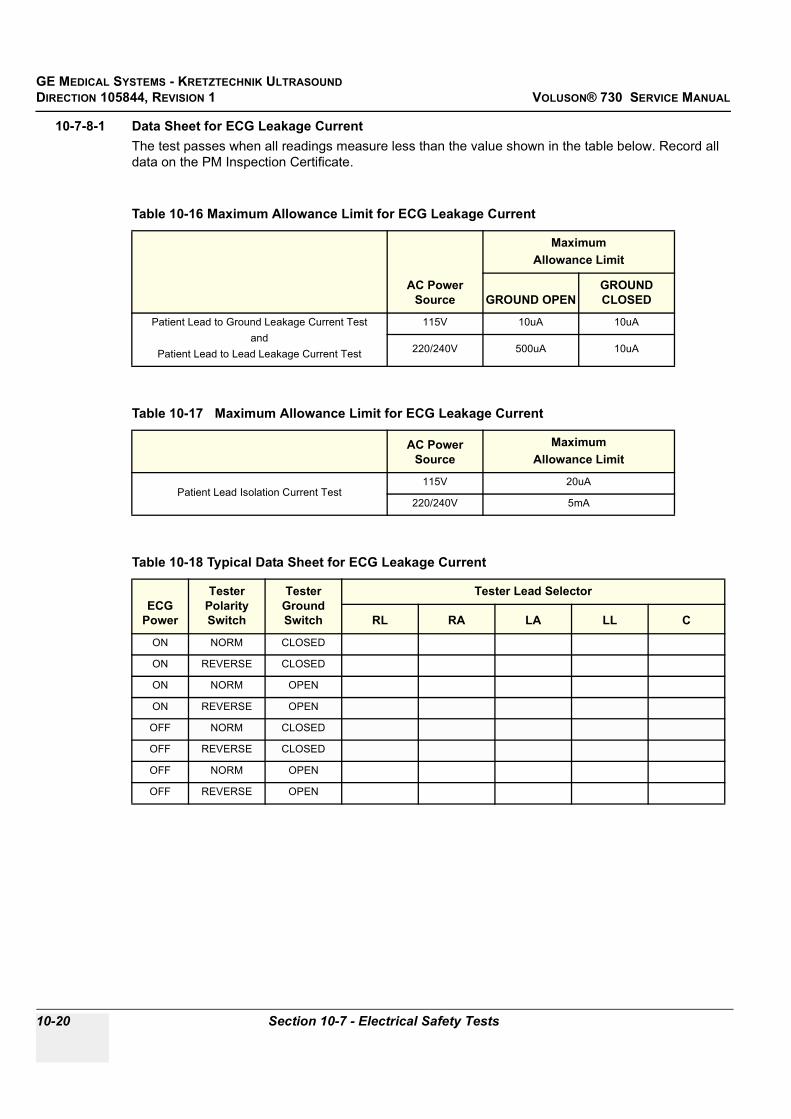
GE MEDICAL SYSTEMS - KRETZTECHNIK ULTRASOUNDDIRECTION 105844, REVISION 1 VOLUSON® 730 SERVICE MANUAL
10-20 Section 10-7 - Electrical Safety Tests
10-7-8-1 Data Sheet for ECG Leakage CurrentThe test passes when all readings measure less than the value shown in the table below. Record all data on the PM Inspection Certificate.
Table 10-16 Maximum Allowance Limit for ECG Leakage Current
AC Power Source
MaximumAllowance Limit
GROUND OPENGROUND CLOSED
Patient Lead to Ground Leakage Current Testand
Patient Lead to Lead Leakage Current Test
115V 10uA 10uA
220/240V 500uA 10uA
Table 10-17 Maximum Allowance Limit for ECG Leakage Current
AC Power Source
MaximumAllowance Limit
Patient Lead Isolation Current Test115V 20uA
220/240V 5mA
Table 10-18 Typical Data Sheet for ECG Leakage Current
ECG Power
Tester Polarity Switch
Tester Ground Switch
Tester Lead Selector
RL RA LA LL C
ON NORM CLOSED
ON REVERSE CLOSED
ON NORM OPEN
ON REVERSE OPEN
OFF NORM CLOSED
OFF REVERSE CLOSED
OFF NORM OPEN
OFF REVERSE OPEN

GE MEDICAL SYSTEMS - KRETZTECHNIK ULTRASOUND DIRECTION 105844, REVISION 1 VOLUSON® 730 SERVICE MANUAL
Chapter 10 Periodic Maintenance 10-21
10-7-9 Probe Leakage Current Test
10-7-9-1 DefinitionThis test measures the current that would flow to ground from any of the probes through a patient who is being scanned and becomes grounded by touching some other grounded surface.
10-7-9-2 Generic ProcedureMeasurements should be made with the ground open and closed, with power line polarity normal and reversed, and with the unit Off and On. For each combination, the probe must be active to find the worst case condition.
NOTE: Each probe will have some amount of leakage current, dependent on its design. Small variations in probe leakage currents are normal from probe to probe. Other variations will result from differences in line voltage and test lead placement.
Figure 10-5 Set Up for Probe Leakage Current
POWEROUTLET
H (BLACK)POLARITY REVERSING SWITCH
MOMENTARYSWITCH
N (WHITE)
G (GREEN)
LEAKAGE TESTMETER
CONSOLE
PROBE

GE MEDICAL SYSTEMS - KRETZTECHNIK ULTRASOUNDDIRECTION 105844, REVISION 1 VOLUSON® 730 SERVICE MANUAL
10-22 Section 10-7 - Electrical Safety Tests
10-7-9-3 No Meter Probe Adapter Procedure
Follow these steps to test each transducer for leakage current.
1.) Turn the Voluson® 730 unit OFF.2.) Plug the unit into the test meter, and the meter into the tested AC wall outlet.3.) Plug the external probe into the meter's “EXTERNAL” connector.4.) Set the meter's “FUNCTION” switch to EXTERNAL position.5.) Connect the probe for test with the connector of the console.6.) Add the saline probe and the imaging area of the probe into the saline bath.7.) Have unit power ON for the first part; turn it OFF for the second half.8.) Depress the ISO TEST rocker switch and record the highest current reading.9.) Follow the test conditions described in Table 10-19 for every transducer.10.)Keep a record of the results with other hand copies of PM data.
Figure 10-6 Check Without Probe Adapter

GE MEDICAL SYSTEMS - KRETZTECHNIK ULTRASOUND DIRECTION 105844, REVISION 1 VOLUSON® 730 SERVICE MANUAL
Chapter 10 Periodic Maintenance 10-23
10-7-9-4 Data Sheet for Transducer Source Leakage CurrentThe test passes when all readings measure less than the values shown in Table 10-12. Record all data on the PM Inspection Certificate.
.
CAUTION Equipment damage possibility. Never switch the Polarity and the status of Neutral when the unit is powered ON. Be sure to turn the unit power OFF before switching them using the POLARITY switch and/or the NEUTRAL switch. Otherwise, the unit may be damaged
Table 10-19 Typical Data Sheet For Transducer Source Leakage Current
Transducer Tested:
Unit PowerTester Power Polarity
SwitchTester GROUND or NUETRAL Switch Measurement
ON NORM OPEN
ON NORM CLOSED
ON REV OPEN
ON REV CLOSED
OFF NORM OPEN
OFF NORM CLOSED
OFF REV OPEN
OFF REV CLOSED

GE MEDICAL SYSTEMS - KRETZTECHNIK ULTRASOUNDDIRECTION 105844, REVISION 1 VOLUSON® 730 SERVICE MANUAL
10-24 Section 10-8 - When There's Too Much Leakage Current...
Section 10-8When There's Too Much Leakage Current...
CHASSIS FAILSCheck the ground on the power cord and plug for continuity. Ensure the ground is not broken, frayed, or intermittent. Replace any defective part.
Tighten all grounds. Ensure star washers are under all ground studs.
Inspect wiring for bad crimps, poor connections, or damage.
Test the wall outlet; verify it is grounded and is free of other wiring abnormalities. Notify the user or owner to correct any deviations. As a work around, check the other outlets to see if they could be used instead.
NOTE: No outlet tester can detect the condition where the white neutral wire and the green grounding wire are reversed. If later tests indicate high leakage currents, this should be suspected as a possible cause and the outlet wiring should be visually inspected.
PROBE FAILSTest the probe in another connector to isolate if the fault lies with the probe or the scanner.
NOTE: Each probe will have some amount of leakage, dependent on its design. Small variations in probe leakage currents are normal from probe to probe. Other variations will result from differences in line voltage and test lead placement. The maximum allowable leakage current for body surface contact probe differs from inter-cavity probe. Be sure to enter the correct probe type in the appropriate space on the check list.
If excessive leakage current is slot dependent, inspect the system connector for bent pins, poor connections, and ground continuity.
If the problem remains with the probe, replace the probe.
PERIPHERAL FAILSTighten all grounds. Ensure star washers are under all ground studs.
Inspect wiring for bad crimps, poor connections, or damage.
STILL FAILSIf all else fails, begin isolation by removing the probes, external peripherals, then the on board ones, one at a time while monitoring the leakage current measurement.
NEW UNITIf the leakage current measurement tests fail on a new unit and if situation can not be corrected, submit a Safety Failure Report to document the system problem. Remove unit from operation.
ECG FAILSInspect cables for damage or poor connections.

GE MEDICAL SYSTEMS - KRETZTECHNIK ULTRASOUND DIRECTION 105844, REVISION 1 VOLUSON® 730 SERVICE MANUAL
Chapter 10 Periodic Maintenance 10-25
PM INSPECTION CERTIFICATE
* Scan Format: Phased Array, Linear Array, Curved Array, Mechanical Array or Other
FUNCTIONAL CHECKS PHYSICAL INSPECTION AND CLEANING
COMMENTS: ________________________________________________________________________________________________________________________________________________________________________________________________________________________________________________________________________________________________________________________
Customer Name: System ID: Dispatch Number / Date Performed: Warranty/Contract/HBS
System Type Model Number: Serial Number: Manufacture Date:
Probe 1: Frequency: Scan Format*: Model Number: Serial Number:
Probe 2: Frequency: Scan Format*: Model Number: Serial Number:
Probe 3: Frequency: Scan Format*: Model Number: Serial Number:
Probe 4: Frequency: Scan Format*: Model Number: Serial Number:
Probe 5: Frequency: Scan Format*: Model Number: Serial Number:
Probe 6: Frequency: Scan Format*: Model Number: Serial Number:
Probe 7: Frequency: Scan Format*: Model Number: Serial Number:
Probe 8: Frequency: Scan Format*: Model Number: Serial Number:
Probe 9: Frequency: Scan Format*: Model Number: Serial Number:
Functional Check (if applicable)OK? or
N/APhysical Inspection and Cleaning
(if applicable) Inspect Clean
B-Mode Function Console
M-Mode Function Monitor
Doppler Modes Functions Touch Panel
Color Modes Functions Air Filter
3D-Mode Function Probe Holders
Applicable Software Options External I/O
Applicable Hardware Options Wheels, Brakes & Swivel Locks
Control Panel Cables and Connectors
Monitor Approved Peripherals (VCR, CD-RW, MOD, Printers)
Touch Panel
Measurement Accuracy

GE MEDICAL SYSTEMS - KRETZTECHNIK ULTRASOUNDDIRECTION 105844, REVISION 1 VOLUSON® 730 SERVICE MANUAL
10-26 Section 10-8 - When There's Too Much Leakage Current...
ELECTRICAL SAFETY
Final Check. All system covers are in place. System scans with all probes as expected.
Accepted by: ______________________________________________________________________
Electrical Test PerformedMax Value Allowed
Value Measured OK? Comments
Outlet (correct ground &wiring config.)
System Ground Continuity
Chassis Source Leakage Current - Probe
Chassis Source Leakage Current - Wheel
Chassis Source Leakage Current - CRT
Patient Lead Source Leakage(Lead to Ground)
Patient Lead Source Leakage(Lead to Lead)
Patient Lead Source Leakage(Isolation)
Peripheral 1 Leakage Current
Peripheral 1Ground Continuity
Peripheral 2 Leakage Current
Peripheral 2Ground Continuity
Peripheral 3 Leakage Current
Peripheral 3Ground Continuity
PROBES
Probe Number (from previous page)
Max Value Allowed
Max Value Measured OK? Comments
Probe 1:
Probe 2:
Probe 3:
Probe 4:
Probe 5:
Probe 6:
Probe 7:
Probe 8:
Probe 9:

GE MEDICAL SYSTEMS - KRETZTECHNIK ULTRASOUNDDIRECTION 105844, REVISION 1 VOLUSON® 730 SERVICE MANUAL
Index I
INDEXNumerics2D-Mode Checks
Functional Checks, 4-7
A,BAcoustic Noise Output, 3-8Adjustment
Monitor, 6-2Printer Settings, 3-23Trackball, 6-5
Air Flow Control, 5-40Application Settings (Backup)
Loading Procedure, 8-2Archiving Images, 4-30Audio Test, 7-18Back End
Board Description, 5-26CKV - Video-Card, 5-26CPE - Back Panel I/O-Card, 5-26CPM - PC-Motherboard card, 5-26CPP - Power Supply Secondary Board, 5-27CPS - DMA-Controller-Card, 5-26Hard Disk Drive, 5-26SBC - Single Board Computer, 5-26
BackEnd ProcessorTheory, 5-24
BackupPatient Database, 4-25Preset Configurations, 4-25
Basic MeasurementsFunctional Checks, 4-18
BlockdiagramBack End Processor, 5-24CPS - Scan Converter Board, 5-25Front End Processor, 5-19Voluson 730, 5-9Voluson 730 Basic, 5-4
Board DescriptionsBack End, 5-26Front End, 5-21
Boot Up, 3-9, , 4-2
CCalculation Measurements
Functional Checks, 4-21General remarks to perform, 4-21
CD/RW-DriveTheory, 5-34
CE Compliance, 1-10Cine-Mode
Functional Checks, 4-17Color Flow Modes
Functional Checks, 4-12Connectivity
Worksheet, 3-36Contact Information, 1-11Control Console
Rotation, 5-38Transport Lock, 6-4
Control Panel, 4-4CPN-Module
Theory, 5-35Customer Assistance, 1-11
DDangerous Procedure Warnings, 1-9Dataflow Control Description, 5-10Digital Color Printer
Installation CP770DW, 3-16Installation UP-D21MD, 3-14Installation UP-D2600S, 3-16
Doppler Mode ChecksFunctional Checks, 4-11
EECG
Functional Checks, 4-31Theory, 5-34
Electrical Requirements, 2-2Electrical Safety, 1-8Electrostatic Discharge Warning, 1-10EMC, 1-10EMI, 1-10EMI Protection, 3-7Error Messages, 7-20ESD, 1-10EUM (Electronic User Manual)
Loading Procedure, 8-3External I/O
Theory, 5-33
FFootswitch
Connection, 5-17Formatting Media, 4-25

GE MEDICAL SYSTEMS - KRETZTECHNIK ULTRASOUNDDIRECTION 105844, REVISION 1 VOLUSON® 730 SERVICE MANUAL
II -
Front EndBoard Descriptions, 5-21CCM - Motor Control Board, 5-23CPC - Control Board, 5-22CPF - Doppler+CFM Board, 5-22CPG - MID-Processor Board, 5-22CPK - Motherboard of GEF-Module, 5-23CPP - Power Supply Secondary Board, 5-23CPR - Beamformer Board, 5-21CPU - Probe Connector Board, 5-21CPZ - Cover Board, 5-21CRW (CWD) - CW-Doppler Board, 5-21
Front End Processor, 5-19Functional Checks, 4-1
2D-Mode, 4-7Basic Measurements, 4-18Brakes, 4-33Calculation Measurements, 4-21Cine-Mode, 4-17Color Flow Modes, 4-12Control Panel, 4-4Doppler Modes, 4-11ECG Checkout, 4-31Mechanical, 4-33M-Mode, 4-10MOD (Magneto-Optical Drive), 4-24Monitor Display, 4-6Peripherals, 4-32Probes/Connector Usage, 4-22Required Equipment, 4-1Touch Panel, 4-5Volume Modes, 4-14
GGEF Module
Main board Chassis, 5-18General Cleaning, 10-8
HHard Disk Drive, 5-26Hardware Options, 5-17Hazard Icons, 1-4How to use the Auto Tester, 7-5Human Safety, 1-7
IImage Management
Functional Checks, 4-23Inrush Current, 2-2Installation
Digital Color Printer CP770DW, 3-16Digital Color Printer UP-D21MD, 3-14
Digital Color Printer UP-D2600S, 3-16Line Printer HP 990cxi, 3-12Line Printer HP 995c, 3-12
Internal I/OTheory, 5-28
LLabel Locations, 1-8Line Printer
Installation HP 990cxi, 3-12Installation HP 995c, 3-12
LoadPresets & Configurations (Application Settings), 4-28
Loading ProcedureApplication Settings (Backup), 8-2EUM (Electronic User Manual), 8-3
MMain board Chassis
GEF Module, 5-18Mechanical Checks
Control Console, 4-33Mechanical Safety, 1-7Minimum Cable Configuration to Boot, 7-8M-Mode Checks
Functional Checks, 4-10Models Covered, 1-2MO-Drive
Functional Checks, 4-24Theory, 5-34
Monitor, 5-32Adjustment, 6-2Theory, 5-32
Monitor DisplayFunctional Checks, 4-6
NNetwork IP Address Configuration, 3-37
PPeripherals
Functional Checks, 4-32GEM, 5-34
Physical Dimensions, 3-8, , 5-37Power Distribution, 5-35Power Off, 3-10
Procedure, 4-3Power On, 3-9, , 4-2Power Requirements
electrical, 2-2

GE MEDICAL SYSTEMS - KRETZTECHNIK ULTRASOUNDDIRECTION 105844, REVISION 1 VOLUSON® 730 SERVICE MANUAL
III
Power Stability Requirements, 2-3Power-up Procedures
Voltage Settings, 3-7Preparing the Unit for Installation, 3-6Printer Installation manually, 3-17Printer Remote Control Selection, 3-27Printer Settings
Adjustment, 3-23Probe Connector Cleaning, 10-10Probes, 3-35
Disconnecting, 4-31Probes/Connector Usage
Functional Checks, 4-22Product Icons, 1-5
RReceiving and Unpacking the Equipment, 3-4Regulatory, 6-1Replacement Procedures
Trackball top fixation ring, 8-8Returning/Shipping
Probes and Repair Parts, 1-9, , 8-1
SSafety Considerations, 1-7Save
Presets & Configurations (Application Settings), 4-27Screen Captures, 7-4Service Adjustments, 6-1Service Manual
Purpose of, 1-1Service Page, 5-41Shutdown Procedure, 3-10, , 4-3Software Options, 5-15System Components, 5-3System Configuration, 3-28
How to change Language, 3-29How to enter Date and Time, 3-29How to enter Hospital Name, 3-29
System Maintenance, 10-6System Manufacturer, 1-12
TTheory
General, 5-2Top Console, 5-31
Theory, 5-31Touch Panel
Functional Checks, 4-4, , 4-5Trackball
Adjustment, 6-5Trackball top fixation ring
Replacement Procedure, 8-8Transducer Connection, 3-11Troubleshooting
CD-RW, 7-18Error Messages, 7-20MOD, 7-18Monitor, 7-14Network, 7-19Screen Captures, 7-4Voltage Points, 7-3
Troubleshooting TreesNoise in Image, 7-11Printer, 7-16System does not Power OFF/Shutdown, 7-13System does not Power ON/Boot up, 7-10Trackball, 7-12Unable to Record to VCR, 7-15
UUnpacking the Equipment, 3-4
VVideo
Specifications, 3-34Voltage Settings, 3-7Voltages Points, 7-3Volume Modes
Functional Checks, 4-14
WWarnings and Cautions, 1-7Weight without Monitor and Peripherals, 3-8

GE MEDICAL SYSTEMS - KRETZTECHNIK ULTRASOUNDDIRECTION 105844, REVISION 1 VOLUSON® 730 SERVICE MANUAL
IV -


GE Medical Systems
GE Medical Systems: Telex 3797371P.O. Box 414; Milwaukee, Wisconsin 53201, U.S.A.(Asia, Pacific, Latin America, North America)
GE Ultraschall:Tel: +49 (0) 212 28 02 208Deutschland GmbH & Co KGBeethovenstrabe 239, Postfach 11 05 60D-42655 Solingen, German