N/en 5.3.100.01 10/11 V60 ... V63 3/2, 2 x 3/2, 5/2 and 5/3 In-line valves Solenoid and pilot actuated G1/8 ... G1/2 Our policy is one of continued research and development. We therefore reserve the right to amend, without notice, the specifications given in this document. High flow rate at small size Proven sealing system, maintenance-free Different manual override options available Low power consumption Manifold system for easy assembly Different pressure ranges possible Technical Data Medium: Compressed air, filtered lubricated or non lubricated Operation: Electromagnetically or pneumatically controlled Mounting position: Optional, spring return valves, preferably horizontal Connection: G 1/8 ... G 1/2 Operating pressure: -0,9 ... 10 bar Details see following pages Flow direction: Internal pilot supply: fixed External pilot supply: optional Flow: 500 ... 4500 l/min Fluid/Ambient temperature: -10 ... +50°C Consult our Technical Service for use below +2°C. Materials Housing and base plate: aluminium Static and dynamic seals: NBR, Alternative models NPT ports 3/2 directional control valves, solenoid actuated Symbol Port size Function Actuation Pilot supply Flow (l/min) Operating pressure (bar) Pilot pressure (bar) Weight (kg) Drawing No. Model *1) 3 2 1 3 G 1/8 NC Sol/spring Internal 750 2 ... 10 – 0,22 1 V60A417A-A#* G 1/4 NC Sol/spring Internal 1300 2 ... 10 – 0,29 1 V61B417A-A#* G 3/8 NC Sol/spring Internal 2600 2 ... 10 – 0,52 1 V62C417A-A#* G 1/2 NC Sol/spring Internal 4500 2 ... 10 – 0,78 2 V63D417A-A#* 3 2 1 3 G 1/8 NC Sol/air spring Internal 750 2 ... 10 – 0,22 3 V60A413A-A#* G 1/4 NC Sol/air spring Internal 1300 2 ... 10 – 0,29 3 V61B413A-A#* G 3/8 NC Sol/air spring Internal 2600 2 ... 10 – 0,52 3 V62C413A-A#* G 1/2 NC Sol/air spring Internal 4500 3 ... 10 – 0,78 4 V63D413A-A#* 2 1 3 G 1/8 NC Sol/air spring External 750 -0,9 ... 10 3 ... 10 0,22 3 V60A423A-A#* G 1/4 NC Sol/air spring External 1300 -0,9 ... 10 3 ... 10 0,29 3 V61B423A-A#* G 3/8 NC Sol/air spring External 2600 -0,9 ... 10 3 ... 10 0,52 3 V62C423A-A#* G 1/2 NC Sol/air spring External 4500 -0,9 ... 10 3 ... 10 0,78 4 V63D423A-A#* 2 3 1 3 G 1/8 NO Sol/air spring Internal 750 2 ... 10 – 0,22 5 V60A313A-A#* G 1/4 NO Sol/air spring Internal 1300 2 ... 10 – 0,29 5 V61B313A-A#* G 3/8 NO Sol/air spring Internal 2600 2 ... 10 – 0,52 5 V62C313A-A#* G 1/2 NO Sol/air spring Internal 4500 3 ... 10 – 0,78 6 V63D313A-A#* 3 2 1 3 G 1/8 NC Sol/Sol Internal 750 1,5 ... 10 – 0,30 7 V60A411A-A#* G 1/4 NC Sol/Sol Internal 1300 1,5 ... 10 – 0,38 7 V61B411A-A#* G 3/8 NC Sol/Sol Internal 2600 1,5 ... 10 – 0,61 7 V62C411A-A#* G 1/2 NC Sol/Sol Internal 4500 2 ... 10 – 0,87 8 V63D411A-A#* # Insert code for manual override, see page 3 *1) Insert voltage code from table on page 3 or 000 for version without solenoid NC = Normally closed NO = Normally open

Welcome message from author
This document is posted to help you gain knowledge. Please leave a comment to let me know what you think about it! Share it to your friends and learn new things together.
Transcript

N/en 5.3.100.0110/11
V60 ... V633/2, 2 x 3/2, 5/2 and 5/3 In-line valves
Solenoid and pilot actuated G1/8 ... G1/2
Our policy is one of continued research and development. We therefore reserve the right to amend, without notice, the specifications given in this document.
High flow rate at small sizeProven sealing system, maintenance-freeDifferent manual override options availableLow power consumptionManifold system for easy assemblyDifferent pressure ranges possible
Technical DataMedium: Compressed air, filtered lubricated or non lubricatedOperation: Electromagnetically or pneumatically controlled Mounting position: Optional, spring return valves, preferably horizontalConnection: G 1/8 ... G 1/2
Operating pressure: -0,9 ... 10 bar Details see following pagesFlow direction: Internal pilot supply: fixedExternal pilot supply: optional
Flow: 500 ... 4500 l/minFluid/Ambient temperature: -10 ... +50°C Consult our Technical Service for use below +2°C.
Materials Housing and base plate: aluminium Static and dynamic seals: NBR,
Alternative models NPT ports
3/2 directional control valves, solenoid actuated Symbol Port
size Function Actuation Pilot
supplyFlow (l/min)
Operatingpressure (bar)
Pilotpressure (bar)
Weight
(kg)
Drawing
No.
Model *1)
3
3
2
1 3
MH
G 1/8 NC Sol/spring Internal 750 2 ... 10 – 0,22 1 V60A417A-A#*
G 1/4 NC Sol/spring Internal 1300 2 ... 10 – 0,29 1 V61B417A-A#*
G 3/8 NC Sol/spring Internal 2600 2 ... 10 – 0,52 1 V62C417A-A#*
G 1/2 NC Sol/spring Internal 4500 2 ... 10 – 0,78 2 V63D417A-A#*
3
2
1 3
G 1/8 NC Sol/air spring Internal 750 2 ... 10 – 0,22 3 V60A413A-A#*
G 1/4 NC Sol/air spring Internal 1300 2 ... 10 – 0,29 3 V61B413A-A#*
G 3/8 NC Sol/air spring Internal 2600 2 ... 10 – 0,52 3 V62C413A-A#*
G 1/2 NC Sol/air spring Internal 4500 3 ... 10 – 0,78 4 V63D413A-A#*
2
1 3
E
G 1/8 NC Sol/air spring External 750 -0,9 ... 10 3 ... 10 0,22 3 V60A423A-A#*
G 1/4 NC Sol/air spring External 1300 -0,9 ... 10 3 ... 10 0,29 3 V61B423A-A#*
G 3/8 NC Sol/air spring External 2600 -0,9 ... 10 3 ... 10 0,52 3 V62C423A-A#*
G 1/2 NC Sol/air spring External 4500 -0,9 ... 10 3 ... 10 0,78 4 V63D423A-A#*
2
31 3
M S
G 1/8 NO Sol/air spring Internal 750 2 ... 10 – 0,22 5 V60A313A-A#*
G 1/4 NO Sol/air spring Internal 1300 2 ... 10 – 0,29 5 V61B313A-A#*
G 3/8 NO Sol/air spring Internal 2600 2 ... 10 – 0,52 5 V62C313A-A#*
G 1/2 NO Sol/air spring Internal 4500 3 ... 10 – 0,78 6 V63D313A-A#*
3
2
1 3
G 1/8 NC Sol/Sol Internal 750 1,5 ... 10 – 0,30 7 V60A411A-A#*
G 1/4 NC Sol/Sol Internal 1300 1,5 ... 10 – 0,38 7 V61B411A-A#*
G 3/8 NC Sol/Sol Internal 2600 1,5 ... 10 – 0,61 7 V62C411A-A#*
G 1/2 NC Sol/Sol Internal 4500 2 ... 10 – 0,87 8 V63D411A-A#*# Insert code for manual override, see page 3*1) Insert voltage code from table on page 3 or 000 for version without solenoid NC = Normally closedNO = Normally open

10/11N/en 5.3.100.02
V60 ... V63
Our policy is one of continued research and development. We therefore reserve the right to amend, without notice, the specifications given in this document.
2 x 3/2 directional control valves, solenoid actuated
5/2 directional control valves, solenoid actuated
Symbol Portsize
Function Actuation Pilotsupply
Flow (l/min)
Operatingpressure (bar)
Weight
(kg)
Drawing
No.
Model *1)
2
3
4
15
G 1/8 NC/NC Sol/Sol Internal 500 2 ... 10 0,34 13 V60AA11A-A#*
G 1/4 NC/NC Sol/Sol Internal 950 2 ... 10 0,43 13 V61BA11A-A#*
G 3/8 NC/NC Sol/Sol Internal 1900 2 ... 10 0,73 13 V62CA11A-A#*
2
3
4
15
G 1/8 NO/NO Sol/Sol Internal 500 2 ... 10 0,34 13 V60AB11A-A#*
G 1/4 NO/NO Sol/Sol Internal 950 2 ... 10 0,43 13 V61BB11A-A#*
G 3/8 NO/NO Sol/Sol Internal 1900 2 ... 10 0,73 13 V62CB11A-A#*
2
3
4
15
31
5
G 1/8 NO/NC Sol/Sol Internal 500 2 ... 10 0,34 13 V60AC11A-A#*
G 1/4 NO/NC Sol/Sol Internal 950 2 ... 10 0,43 13 V61BC11A-A#*
G 3/8 NO/NC Sol/Sol Internal 1900 2 ... 10 0,73 13 V62CC11A-A#*
Symbol Portsize
Actuation Pilotsupply
Flow (l/min)
Operatingpressure (bar)
Pilotpressure (bar)
Weight
(kg)
Drawing
No.
Model *1)
24
15 3
-F
G 1/8 Sol/spring Internal 750 3 ... 10 – 0,22 9 V60A517A-A#*
G 1/4 Sol/spring Internal 1300 3 ... 10 – 0,29 9 V61B517A-A#*
G 3/8 Sol/spring Internal 2600 3 ... 10 – 0,52 9 V62C517A-A#*
G 1/2 Sol/spring Internal 4500 3 ... 10 – 0,96 10 V63D517A-A#*
24
15 3
M-S
G 1/8 Sol/air spring Internal 750 2 ... 10 – 0,24 11 V60A513A-A#*
G 1/4 Sol/air spring Internal 1300 2 ... 10 – 0,33 11 V61B513A-A#*
G 3/8 Sol/air spring Internal 2600 2 ... 10 – 0,62 11 V62C513A-A#*
G 1/2 Sol/air spring Internal 4500 3 ... 10 – 0,96 12 V63D513A-A#*
24
15 3
G 1/8 Sol/air spring External 750 -0,9 ... 10 3 ... 10 0,24 11 V60A523A-A#*
G 1/4 Sol/air spring External 1300 -0,9 ... 10 3 ... 10 0,33 11 V61B523A-A#*
G 3/8 Sol/air spring External 2600 -0,9 ... 10 3 ... 10 0,62 11 V62C523A-A#*
G 1/2 Sol/air spring External 4500 -0,9 ... 10 3 ... 10 0,96 12 V63D523A-A#*
24
15 3
M
G 1/8 Sol/Sol Internal 50 1,5 ... 10 – 0,33 13 V60A511A-A#*
G 1/4 Sol/Sol Internal 1300 1,5 ... 10 – 0,42 13 V61B511A-A#*
G 3/8 Sol/Sol Internal 2600 1,5 ... 10 – 0,72 13 V62C511A-A#*
G 1/2 Sol/Sol Internal 4500 2 ... 10 – 0,98 14 V63D511A-A#*# Insert code for manual override, see next page*1) Insert voltage code from table on next page or 000 for version without solenoidNC Normally closedNO = Normally openNC/NC = Both valves normally closed (port P)NO/NO = Both valves normally opend(port P)NO/NC = 1 valve normally open, 1 valve normally closed (port P)
Our policy is one of continued research and development. We therefore reserve the right to amend, without notice, the specifications given in this document.
10/11 N/en 5.3.100.03
V60 ... V63
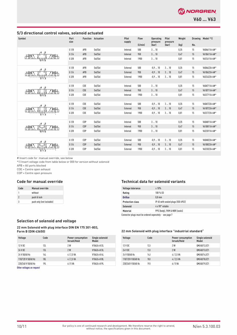
5/3 directional control valves, solenoid actuated
Selection of solenoid and voltage
22 mm Solenoid with plug interface DIN EN 175 301-803, Form B (DIN 43650) 22 mm Solenoid with plug interface ”industrial standard“
Code for manual override Technical data for solenoid variants
Code Manual override
1 without
2 push & lock
3 push only (not lockable)
Voltage tolerance ± 10%
Rating 100 % ED
Orifice 0,8 mm
Protection class IP 65 with sealed plugs (ISO 6952)
Solenoid 4 x 90° rotable
Material PPS (body), FKM & NBR (seals)Connector plugs must be ordered seperately - see page 7
Voltage Code Power consumptionInrush/Hold
Single solenoidModel
12 V DC 12L 2 W V10626-A12L
24 V DC 13L 2 W V10626-A13L
24 V 50/60 Hz 14L 4 / 2,5 VA V10626-A14L
110/120 V 50/60 Hz 18L 4 / 2,5 VA V10626-A18L
220/240 V 50/60 Hz 19L 6 / 5 VA V10626-A19LOther voltages on request
Voltage Code Power consumptionInrush/Hold
Single solenoidModel
12 V DC 12J 2 W QM/48/12J/21
24 V DC 13J 2 W QM/48/13J/21
24 V 50/60 Hz 14J 4 / 2,5 VA QM/48/14J/21
110/120 V 50/60 Hz 18J 4 / 2,5 VA QM/48/18J/21
220/240 V 50/60 Hz 19J 6 / 5 VA QM/48/19J/21
Symbol Portsize
Function Actuation Pilotsupply
Flow (l/min)
Operatingpressure (bar)
Pilotpressure (bar)
Weight
(kg)
Drawing
No.
Model *1)
4 2
5 1 3
G 1/8 APB Sol/Sol Internal 500 3 ... 10 0,35 15 V60A611A-A#*
G 1/4 APB Sol/Sol Internal 950 3 ... 10 0,47 15 V61B611A-A#*
G 3/8 APB Sol/Sol Internal 1900 3 ... 10 0,81 15 V62C611A-A#*
4 2
5 1 3
G 1/8 APB Sol/Sol External 500 -0,9 ... 10 3 ... 10 0,35 15 V60A622A-A#*
G 1/4 APB Sol/Sol External 950 -0,9 ... 10 3 ... 10 0,47 15 V61B622A-A#*
G 3/8 APB Sol/Sol External 1900 -0,9 ... 10 3 ... 10 0,81 15 V62C622A-A#*
4 2
5 1 3
G 1/8 COE Sol/Sol Internal 500 3 ... 10 0,35 15 V60A711A-A#*
G 1/4 COE Sol/Sol Internal 950 3 ... 10 0,47 15 V61B711A-A#*
G 3/8 COE Sol/Sol Internal 1900 3 ... 10 0,81 15 V62C711A-A#*
4 2
5 1 3
G 1/8 COE Sol/Sol External 500 -0,9 ... 10 3 ... 10 0,35 15 V60A722A-A#*
G 1/4 COE Sol/Sol External 950 -0,9 ... 10 3 ... 10 0,47 15 V61B722A-A#*
G 3/8 COE Sol/Sol External 1900 -0,9 ... 10 3 ... 10 0,81 15 V62C722A-A#*
4 2
5 1 3
G 1/8 COP Sol/Sol Internal 500 3 ... 10 0,35 15 V60A811A-A#*
G 1/4 COP Sol/Sol Internal 950 3 ... 10 0,47 15 V61B811A-A#*
G 3/8 COP Sol/Sol Internal 1900 3 ... 10 0,81 15 V62C811A-A#*
4 2
5 1 3
G 1/8 COP Sol/Sol External 500 -0,9 ... 10 3 ... 10 0,35 15 V60A822A-A#*
G 1/4 COP Sol/Sol External 950 -0,9 ... 10 3 ... 10 0,47 15 V61B822A-A#*
G 3/8 COP Sol/Sol External 1900 -0,9 ... 10 3 ... 10 0,81 15 V62C822A-A#*
# Insert code for manual override, see below*1) Insert voltage code from table below or 000 for version without solenoidAPB = All ports blocked COE = Centre open exhaustCOP = Centre open pressure

10/11N/en 5.3.100.04
V60 ... V63
Our policy is one of continued research and development. We therefore reserve the right to amend, without notice, the specifications given in this document.
Symbol Port size Function Actuation Pilot supply Flow (l/min)
Operatingpressure (bar)
Weight (kg)
Drawing No.
Model
24
15 382/84
G 1/8 Sol/Sol Internal 750 1,5 ... 10 0,23 17 V60A511D-C#13A
G 1/4 Sol/Sol Internal 300 1,5 ... 10 0,32 17 V61B511D-C#13A
G 3/8 Sol/Sol Internal 2600 1,5 ... 10 0,62 17 V62C511D-C#13A
4 2
3A
5 1 382/84
G 1/8 APB Sol/Sol Internal 500 3 ... 10 0,35 18 V60A611D-C#13A
G 1/4 APB Sol/Sol Internal 950 3 ... 10 0,47 18 V61B611D-C#13A
G 3/8 APB Sol/Sol Internal 1900 3 ... 10 0,81 18 V62C611D-C#13A
4 2
5 1 382/84
G 1/8 COE Sol/Sol Internal 500 3 ... 10 0,35 18 V60A711D-C#13A
G 1/4 COE Sol/Sol Internal 950 3 ... 10 0,47 18 V61B711D-C#13A
G 3/8 COE Sol/Sol Internal 1900 3 ... 10 0,81 18 V62C711D-C#13A
4 2
5 1 382/84
G 1/8 COP Sol/Sol Internal 500 3 ... 10 0,35 18 V60A811D-C#13A
G 1/4 COP Sol/Sol Internal 950 3 ... 10 0,47 18 V61B811D-C#13A
G 3/8 COP Sol/Sol Internal 1900 3 ... 10 0,81 18 V62C811D-C#13A
# Insert code for manual override *1) Insert voltage code from this table or 000 for version without solenoidAPB = All ports blockedCOE = Centre open exhaustCOP = Centre open pressure
Twin-Pilot Valves 3/2 directional control valves, solenoid actuated
2 x 3/2 directional control valves, solenoid actuated
5/2-, 5/3-directional control valves, solenoid actuated
Twin pilot with plug interface DIN EN 175 301-803 (DIN 43650 C) 4 pin
Connector plug configuration, valve side / Twin pilot
Solenoid parameters
Symbol Port size Function Actuation Pilot supply Flow (l/min)
Operatingpressure (bar)
Weight (kg)
Drawing No.
Model
3
2
180 3
G 1/8 NC Sol/air spring Internal 750 2 ... 10 0,20 16 V60A413D-C#13A
G 1/4 NC Sol/air spring Internal 1300 2 ... 10 0,27 16 V61B413D-C#13A
G 3/8 NC Sol/air spring Internal 2600 2 ... 10 0,50 16 V62C413D-C#13A
2
31 3
S
80
G 1/8 NO Sol/air spring Internal 750 2 ... 10 0,20 16 V60A313D-C#13A
G 1/4 NO Sol/air spring Internal 1300 2 ... 10 0,27 16 V61B313D-C#13A
G 3/8 NO Sol/air spring Internal 2600 2 ... 10 0,50 16 V62C313D-C#13A
2
M sp
EMR p
31 380/82
G 1/8 NC Sol/Sol Internal 750 1,5 ... 10 0,43 16 V60A411D-C#13A
G 1/4 NC Sol/Sol Internal 1300 1,5 ... 10 0,43 16 V61B411D-C#13A
G 3/8 NC Sol/Sol Internal 2600 1,5 ... 10 0,43 16 V62C411D-C#13A
Symbol Port size Function Actuation Pilot supply Flow (l/min)
Operatingpressure (bar)
Weight (kg)
Drawing No.
Model
2
3
4
1582/84
G 1/8 NC/NC Sol/Sol Internal 500 2 ... 10 0,24 17 V60AA11D-C#13A
G 1/4 NC/NC Sol/Sol Internal 950 2 ... 10 0,33 17 V61BA11D-C#13A
G 3/8 NC/NC Sol/Sol Internal 1900 2 ... 10 0,63 17 V62CA11D-C#13A
24
31
580
G 1/8 NO/NO Sol/Sol Internal 500 2 ... 10 0,24 17 V60AB11D-C#13A
G 1/4 NO/NO Sol/Sol Internal 950 2 ... 10 0,33 17 V61BB11D-C#13A
G 3/8 NO/NO Sol/Sol Internal 1900 2 ... 10 0,63 17 V62CB11D-C#13A
24
24
D O MR _s c
31
580/82
G 1/8 NO/NC Sol/Sol Internal 500 2 ... 10 0,24 17 V60AC11D-C#13A
G 1/4 NO/NC Sol/Sol Internal 950 2 ... 10 0,33 17 V61BC11D-C#13A
G 3/8 NO/NC Sol/Sol Internal 1900 2 ... 10 0,63 17 V62CC11D-C#13A
Voltage Code Powerconsumption
Manual-override
Twin-Pilot complete(with solenoids)
Model
24 V DC 13 A 2 W Code 2 push & lock 9031704 9000 02400
Code 3 push only (not lockable) 9031703 9000 02400
Symbol Plug No. Function Actuation
123
1 (+) Solenoid 2, right
2 (–) Solenoid 1 & 2, right & left
3 (+) Magnet 1, left
Voltage tolerance ± 10%
Rating 100 % ED
Protection class IP 65 mit abgedichteten Steckern (ISO 6952)
Connection plugs must be ordered separately - see page 7

Our policy is one of continued research and development. We therefore reserve the right to amend, without notice, the specifications given in this document.
10/11 N/en 5.3.100.05
V60 ... V63
3/2 directional control valves, pilot actuated
2 x 3/2 directional control valves, pilot actuated
5/2 directional control valves, pilot actuated
5/3 directional control valves, pilot actuated
Symbol Port size Function Actuation Flow (l/min)
Operatingpressure (bar)
Pilot pressureexternal(bar)
Weight (kg)
Drawing No.
Model
2
1 3
G 1/8 NC Air/Spring 750 -0,9 ... 10 2,5 ... 10 0,13 31 V60A4D7A-XA090
G 1/4 NC Air/Spring 1300 -0,9 ... 10 2,5 ... 10 0,21 31 V61B4D7A-XA090
G 3/8 NC Air/Spring 2600 -0,9 ... 10 2,5 ... 10 0,43 33 V62C4D7A-XA090
G 1/2 NC Air/Spring 4500 -0,9 ... 16 3 ... 16 0,75 35 V63D4D7A-XA090
2
1 3
G 1/8 NO Air/Spring 750 -0,9 ... 10 2,5 ... 10 0,13 32 V60A3D7A-XA090
G 1/4 NO Air/Spring 1300 -0,9 ... 10 2,5 ... 10 0,21 32 V61B3D7A-XA090
G 3/8 NO Air/Spring 2600 -0,9 ... 10 2,5 ... 10 0,43 34 V62C3D7A-XA090
G 1/2 NO Air/Spring 4500 -0,9 ... 16 3 ... 16 0,75 36 V63D3D7A-XA090
2
1 3
G 1/8 NC Air/Air 750 -0,9 ... 10 1,5 ... 10 0,13 37 V60A4DDA-XA020
G 1/4 NC Air/Air 1300 -0,9 ... 10 1,5 ... 10 0,21 37 V61B4DDA-XA020
G 3/8 NC Air/Air 2600 -0,9 ... 10 1,5 ... 10 0,43 38 V62C4DDA-XA020
G 1/2 NC Air/Air 4500 -0,9 ... 16 1,5 ... 16 0,68 39 V63D4DDA-XA020
Symbol Port size Function Actuation Flow (l/min)
Operatingpressure (bar)
Pilot pressureexternal(bar)
Weight (kg)
Drawing No.
Model
2
3
4
15
G 1/8 NC/NC Air/Air 500 2 ... 10 2 ... 10 0,18 43 V60AADDA-XA020
G 1/4 NC/NC Air/Air 950 2 ... 10 2 ... 10 0,28 43 V61BADDA-XA020
G 3/8 NC/NC Air/Air 1900 2 ... 10 2 ... 10 0,60 44 V62CADDA-XA020
2
3
4
15
G 1/8 NO/NO Air/Air 500 2 ... 10 2 ... 10 0,18 43 V60ABDDA-XA020
G 1/4 NO/NO Air/Air 950 2 ... 10 2 ... 10 0,28 43 V61BBDDA-XA020
G 3/8 NO/NO Air/Air 1900 2 ... 10 2 ... 10 0,60 44 V62CBDDA-XA020
2
3
4
15
G 1/8 NO/NC Air/Air 500 2 ... 10 2 ... 10 0,18 43 V60ACDDA-XA020
G 1/4 NO/NC Air/Air 950 2 ... 10 2 ... 10 0,28 43 V61BCDDA-XA020
G 3/8 NO/NC Air/Air 1900 2 ... 10 2 ... 10 0,60 44 V62CCDDA-XA020
Symbol Port size Actuation Flow (l/min)
Operatingpressure (bar)
Pilot pressureexternal(bar)
Weight (kg)
Drawing No.
Model
24
15 3
G 1/8 Air/Spring 750 -0,9 ... 10 2,5 ... 10 0,16 40 V60A5D7A-XA090
G 1/4 Air/Spring 1300 -0,9 ... 10 2,5 ... 10 0,26 40 V61B5D7A-XA090
G 3/8 Air/Spring 2600 -0,9 ... 10 2,5 ... 10 0,56 41 V62C5D7A-XA090
G 1/2 Air/Spring 4500 -0,9 ... 16 3 ... 16 0,92 42 V63D5D7A-XA090
24
15 3
G 1/8 Air/Air 750 -0,9 ... 10 1,5 ... 10 0,17 43 V60A5DDA-XA020
G 1/4 Air/Air 1300 -0,9 ... 10 1,5 ... 10 0,27 43 V61B5DDA-XA020
G 3/8 Air/Air 2600 -0,9 ... 10 1,5 ... 10 0,58 44 V62C5DDA-XA020
G 1/2 Air/Air 4500 -0,9 ... 16 1,5 ... 16 0,87 45 V63D5DDA-XA020
Symbol Port size Function Actuation Flow (l/min)
Operatingpressure (bar)
Pilot pressureexternal(bar)
Weight (kg)
Drawing No.
Model
4 2
5 1 3
G 1/8 APB Air/Air 500 -0,9 ... 10 3 ... 10 0,20 46 V60A6DDA-XA020
G 1/4 APB Air/Air 950 -0,9 ... 10 3 ... 10 0,32 46 V61B6DDA-XA020
G 3/8 APB Air/Air 1900 -0,9 ... 10 3 ... 10 0,67 47 V62C6DDA-XA020
G1/2 APB Air/Air 2300 -0,9 ... 10 3 ... 10 1,10 48 V63D6DDA-XA020
4 2
5 1 3
G 1/8 COE Air/Air 500 -0,9 ... 10 3 ... 10 0,20 46 V60A7DDA-XA020
G 1/4 COE Air/Air 950 -0,9 ... 10 3 ... 10 0,32 46 V61B7DDA-XA020
G 3/8 COE Air/Air 1900 -0,9 ... 10 3 ... 10 0,67 47 V62C7DDA-XA020
G 1/2 COE Air/Air 2300 -0,9 ... 10 3 ... 10 1,10 48 V63D7DDA-XA020
4 2
5 1 3
G 1/8 COP Air/Air 500 -0,9 ... 10 3 ... 10 0,20 46 V60A8DDA-XA020
G 1/4 COP Air/Air 950 -0,9 ... 10 3 ... 10 0,32 46 V61B8DDA-XA020
G 3/8 COP Air/Air 1900 -0,9 ... 10 3 ... 10 0,67 47 V62C8DDA-XA020
NC = Normally closedNO = Normally openNC/NC = Both valves normally closed (port P)NO/NO = Both valves normally open (port P))NO/NC = 1valve normally open, 1 valve normally closed (port P)
APB = All ports blockedCOE = Centre open exhaustCOP = Centre open pressure

10/11N/en 5.3.100.06
V60 ... V63
Our policy is one of continued research and development. We therefore reserve the right to amend, without notice, the specifications given in this document.
Option selector (directional control valves, solenoid actuated)
Option selector (directional control valves, pilot actuated)
V6˙˙˙˙˙˙-˙˙˙˙˙
V6˙˙˙D˙A-X˙˙˙0
Plug Interface Substitute
22 mm, industrial standard J
15 mm, to EN 175301-803 (DIN 43650), Form C
A
22 mm, to EN 175301-803 (DIN 43650), Form B
L
Voltage Substitute
12 V d.c. 2 W 12
24 V d.c. 2 W 13
24 V a.c. (50/60 Hz) 4/2,5 VA 14
110/120 V a.c. (50/60 Hz) 4/2,5 VA 18
220/240 V a.c. (50/60 Hz ) 6/5 VA 19
Manual override Substitute
Push, locked position 2
Push only 3
Without 1
Solenoid Substitute
22 mm A-A
15 mm for Twin-Pilot D-C
Actuation/return Pilot Supply
Substitute
Sol/Sol Internal 11
Sol/air spring Internal 13
Sol/spring Internal 17
Sol/Sol External 22
Sol/air spring External 23
Sol/spring External 27
Actuation/return Substitute
Air/Air 02
Air/Spring 09
Pilot port Substitute
G1/8 A
1/8 NPT P
Actuation/return Substitute
Air/Air D
Air/Spring 7
Valve size Substitute
G1/8 0A
G1/4 1B
G3/8 2C
G1/2 3D
NPT-Valve size Substitute
1/8 NPT 0P
1/4 NPT 1R
3/8 NPT 2S
1/2 NPT 3T
Function Substitute
3/2 - NO 3
3/2 - NC 4
5/2 5
5/3 - APB 6
5/3 - COE 7
5/3 - COP 8
2 x 3/2 - NC A
2 x 3/2 - NO B
2 x 3/2 - NO/NC C
Port size ISO G Substitute
G1/8 0A
G1/4 1B
G3/8 2C
G1/2 3D
Port size NPT Substitute
1/8 NPT 0P
1/4 NPT 1R
3/8 NPT 2S
1/2 NPT 3T
Function Substitute
3/2 - NO 3
3/2 - NC 4
5/2 5
5/3 - APB 6
5/3 - COE 7
5/3 - COP 8
2 x 3/2 - NC A
2 x 3/2 - NO B
2 x 3/2 - NO/NC C
Our policy is one of continued research and development. We therefore reserve the right to amend, without notice, the specifications given in this document.
10/11 N/en 5.3.100.07
V60 ... V63
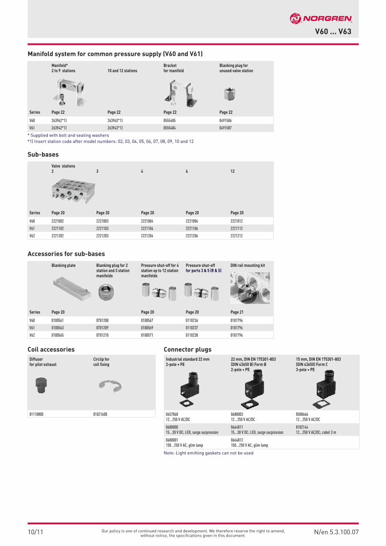
Manifold system for common pressure supply (V60 and V61)
Sub-bases
Accessories for sub-bases
Coil accessories Connector plugs
Series
Manifold*2 to 9 stations
Page 22
10 and 12 stations
Page 22
Bracket for manifold
Page 22
Blanking plug for unused valve station
Page 22
V60 263962*1) 263963*1) 0555485 0491586
V61 263942*1) 263943*1) 0555484 0491587
* Supplied with bolt and sealing washers*1) Insert station code after model numbers: 02, 03, 04, 05, 06, 07, 08, 09, 10 and 12
Series
Valve stations2
Page 20
3
Page 20
4
Page 20
6
Page 20
12
Page 20
V60 2221002 2221003 2221004 2221006 2221012
V61 2221102 2221103 2221104 2221106 2221112
V62 2221202 2221203 2221204 2221206 2221212
Series
Blanking plate
Page 20
Blanking plug for 2 station and 3 station manifolds
Pressure shut-off for 4station op to 12 stationmanifolds
Page 20
Pressure shut-off for ports 3 & 5 (R & S)
Page 20
DIN rail mounting kit
Page 21
V60 0100561 0701208 0100567 0110236 0101796
V61 0100563 0701209 0100569 0110237 0101796
V62 0100565 0701210 0100571 0110238 0101796
Diffusor for pilot exhaust
Circlip for coil fixing
81110800 81021600
Industrial standard 22 mm 2-pole + PE
22 mm, DIN EN 175301-803(DIN 43650 B) Form B2-pole + PE
15 mm, DIN EN 175301-803(DIN 43650) Form C3-pole + PE
0657868 12...250 V AC/DC
068000312...250 V AC/DC
058866612...250 V AC/DC
068000015...30 V DC; LED, surge surpression
066481115...30 V DC; LED, surge surpression
010214412...250 V AC/DC; cabel 3 m
0680001150...250 V AC; glim lamp
0664812150...250 V AC; glim lamp
Note: Light emitting gaskets can not be used

10/11N/en 5.3.100.08
V60 ... V63
Our policy is one of continued research and development. We therefore reserve the right to amend, without notice, the specifications given in this document.
Dimensions
No. A B C Ø D E F G H I J K L M N O P Q Ø R S Ø T Ø U V X Model
1 125 45 16 4,5 18 25 56 17 26 35 28 12 35 G1/8 - 17 22 3,2 - - 6,5 - 19 V60A417A-...
1 147 57,5 21 4,5 24 32 70 22,5 26 40 28 17 46 G1/4 - 20 25 3,2 - - 6,5 - 23 V61B417A-...
1 166,5 70 24,5 4,5 26 - 83,5 28 36 55 44 32 54 G3/8 - 28 34 4,5 - - 8,0 23 30 V62C417A-...
2 197 87,5 38 7 46 75 108 33,5 26 65 - 38 - G1/2 - - 35 - 18,5 5,5 - - 36 V63D417A-...
3 116,5 37 16 4,5 18 25 56 9 26 35 28 12 35 G1/8 - 17 22 3,2 - - 6,5 - 19 V60A413A-...
3 132,5 43 21 4,5 24 32 70 8 26 40 28 17 46 G1/4 - 20 25 3,2 - - 6,5 - 23 V61B413A-...
3 147 50,5 24,5 4,5 26 - 83,5 9 36 55 44 32 54 G3/8 - 28 34 4,5 - - 8,0 - 30 V62C413A-...
3 116,5 37 16 4,5 18 25 56 9 26 35 28 12 35 G1/8 22 17 22 3,2 - - 6,5 - 19 V60A423A-...
3 132,5 43 21 4,5 24 32 70 8 26 40 28 17 46 G1/4 29 20 25 3,2 - - 6,5 - 23 V61B423A-...
3 147 50,5 24,5 4,5 26 - 83,5 9 36 55 44 32 54 G3/8 - 28 34 4,5 - - 8,0 - 30 V62C423A-...
4 190 80 38 7,0 46 75 108 26 26 65 - 38 - G1/2 - - 35 - 18,5 5,5 - 23 36 V63D413A-...
4 190 80 38 7,0 46 75 108 26 26 65 - 38 - G1/2 45 - 35 - 18,5 5,5 - 23 36 V63D423A-...
1
3
2
4
JI
K
20,5
L22
B
A
G H
E X
D
F 33
1 0
Q
M
P
N21
C
13
212
U
R
J
IV20
,5L
22
E X
D
T
G H
F S
1 0
Q
N21
C
B
A
1
13
212
J
2 (0
V60
)
I
K
20,5
L22
B
A
G H
E X
D
F
4
3
1 0
QP
21
C
O
M
N
U
R
1 10/123212
10/12
20,5
L22
E X
D
T
G H
F S
4
1 0
Q
N21
C
B
A
O
1
3 1
212
J
IV
1 Collected pilot exhaust (M5)
2 Manual Override
3 V62: Central mounting hole (left hole is not applicable) and square end cover
4 External pilot port, M5 or 10-32 UNF (V60 & V61), G1/8 or 1/8-27 NPT

Our policy is one of continued research and development. We therefore reserve the right to amend, without notice, the specifications given in this document.
10/11 N/en 5.3.100.09
V60 ... V63
No. A B C Ø D E F G H I J K L M N P Q Ø R S Ø T Ø U V X Model
5 116,5 37 16 4,5 18 7 56 9 26 35 28 12 35 G1/8 17 22 3,2 - - 6,5 - 19 V60A313A-...
5 132,5 43 21 4,5 24 8 70 8 26 40 28 17 46 G1/4 20 25 3,2 - - 6,5 - 23 V61B313A-...
5 147 50,5 24,5 4,5 26 - 83,5 9 36 55 44 32 54 G3/8 28 34 4,5 - - 8,0 - 28 V62C313A-...
6 190 80 38 7,0 46 75 108 26 26 65 - 38 - G1/2 - 35 - 14,5 5,5 - 23 26 V63D313A-...
7 159,5 79,5 16 4,5 18 25 56 - 26 35 28 12 35 G1/8 17 22 3,2 - - 6,5 - 19 V60A411A-...
7 179 89,5 21 4,5 24 32 70 - 26 40 28 17 46 G1/4 20 25 3,2 - - 6,5 - 23 V61B411A-...
7 193,5 97 24,5 4,5 26 - 83,5 - 36 55 44 32 54 G3/8 28 34 4,5 - - 8,0 - 30 V62C411A-...
8 219 109,5 38 7,0 46 75 108 - 26 65 - 38 - G1/2 - 35 - 18,5 5,5 - 23 36 V63D411A-...
5
7
6
8
110
3K
20,5
L22
2
B
A
G
E X
D
F3
1 0
21
C
M
N
U
R
JIH
QP
20,5
L22
E X
D
T
G H
F S
1 0
Q
N
21
C
B
A
1
J
IV
1
10 2
3
12 103 1
JI
K
2
1 0
10
QP
20,5
L22
(B)
A
G
E X
D
F 3
21
C
M
N
U
R
1012
20,5
L22
E X
D
T
G
F S
1 0
10
Q
N
21
C
(B)
A
1
J
IV
13
2
1 Collected pilot exhaust (M5)
2 Manual Override
3 V62: Central mounting hole (left hole is not applicable) and square end cover
4 External pilot port, M5 or 10-32 UNF (V60 & V61), G1/8 or 1/8-27 NPT

10/11N/en 5.3.100.10
V60 ... V63
Our policy is one of continued research and development. We therefore reserve the right to amend, without notice, the specifications given in this document.
9
11
10
12
5 1 3
JI
K
20,5
L22
4 2
B
A
G H
E
DX
F 3
3
1 0
QM
W
P
N
21
C
14
U
R
JIV
20,5
L22
E
TF
G H
Z
1 0
W
Q
N
21
C
B
A
1 1
1 35
4
DX Y
214
5 1 3
JI
K
20,5
L22
4 2
B
A
G H
E
DX
F
3
1 0
Q
M
W
P
N
21
C
14
2 (0
V60
)
4
O
10/12
U
R
JIV
20,5
L22
1 0
W
Q
N
21
C
B
A
1
1
1 35
4 214
12/14
4
O
E
TF
G H
Z
DX Y
No. A B C Ø D E F G H I J K L M N O P Q Ø R Ø T Ø U V W X Y Z Model
9 140 52,5 32,5 4,5 33,5 8 71 17 26 35 28 12 50 G1/8 - 17 22 3,2 - 6,5 - 16 17 - - V60A517A-...
9 167 67,5 42 4,5 44 10 90 22,5 26 40 28 17 66 G1/4 - 20 25 3,2 - 6,5 - 21 22 - - V61B517A-...
9 191 82 49 4,5 - 12 108 28 36 55 44 32 78 G3/8 - 28 34 4,5 - 8,0 - 24,5 26 - - V62C517A-...
10 235 106,5 76 7,0 60 19 146 33,5 52 65 - 38 - G1/2 - - 35 - 5,5 - 46 38 57,5 3 115 V63D517A-...
11 132 44,5 32,5 4,5 33,5 8 71 9 26 35 28 12 50 G1/8 - 17 22 3,2 - 6,5 - 16 17 - - V60A513A-...
11 153 53 42 4,5 44 10 90 8 26 40 28 17 66 G1/4 - 20 25 3,2 - 6,5 - 21 22 - - V61B513A-...
11 171,5 62,5 49 4,5 - 12 108 8,5 36 55 44 32 78 G3/8 - 28 34 4,5 - 8,0 - 24,5 26 - - V62C513A-...
12 228 99 76 7,0 60 19 146 26 52 65 - 38 - G1/2 - - 35 5,5 - 46 38 57,5 3 115 V63D513A-...
11 132 44,5 32,5 4,5 33,5 8 71 9 26 35 28 12 50 G1/8 29,5 17 22 3,2 - 6,5 - 16 17 - - V60A523A-...
11 153 53 42 4,5 44 10 90 8 26 40 28 17 66 G1/4 39 20 25 3,2 - 6,5 - 21 22 - - V61B523A-...
11 171,5 62,5 49 4,5 - 12 108 8,5 36 55 44 32 78 G3/8 48 28 34 4,5 - 8,0 - 24,5 26 - - V62C523A-...
12 228 99 76 7,0 60 19 146 26 52 65 - 38 - G1/2 64 - 35 5,5 - 46 38 57,5 3 115 V63D523A-...
1 Collected pilot exhaust (M5)
2 Manual Override
3 V62: Central mounting hole (left hole is not applicable) and square end cover
4 External pilot port, M5 or 10-32 UNF (V60 & V61), G1/8 or 1/8-27 NPT

Our policy is one of continued research and development. We therefore reserve the right to amend, without notice, the specifications given in this document.
10/11 N/en 5.3.100.11
V60 ... V63
5 1 3
JI
K
20,5
L22
4 2
(B)
A
G
E
DX
F
3
1 0
QM
W
P
N
21
C
14 (10)
10
12 (10)
U
R
JIV
20,5
L22
1 0
W
Q
N
21
10
C
(B)
A
1 1
1 35
4 214 12
E
TF
G
Z
DX Y
13 14
No. A B C Ø D E F G I J K L M N P Q Ø R Ø T Ø U V W X Y Z Model
13 174,5 87,5 32,5 4,5 33,5 8 71 26 35 28 12 50 G1/8 17 22 3,2 - 6,5 - 16 17 - - V60A511A-...
13 174,5 87,5 32,5 4,5 33,5 8 71 26 35 28 12 50 G1/8 17 22 3,2 - 6,5 - 16 17 - - V60AA11A-...
13 174,5 87,5 32,5 4,5 33,5 8 71 26 35 28 12 50 G1/8 17 22 3,2 - 6,5 - 16 17 - - V60AB11A-...
13 174,5 87,5 32,5 4,5 33,5 8 71 26 35 28 12 50 G1/8 17 22 3,2 - 6,5 - 16 17 - - V60AC11A-...
13 199 99,5 42 4,5 44 10 90 26 40 28 17 66 G1/4 20 25 3,2 - 6,5 - 21 22 - - V61B511A-...
13 199 99,5 42 4,5 44 10 90 26 40 28 17 66 G1/4 20 25 3,2 - 6,5 - 21 22 - - V61BA11A-...
13 199 99,5 42 4,5 44 10 90 26 40 28 17 66 G1/4 20 25 3,2 - 6,5 - 21 22 - - V61BB11A-...
13 199 99,5 42 4,5 44 10 90 26 40 28 17 66 G1/4 20 25 3,2 - 6,5 - 21 22 - - V61BC11A-...
13 218 109 49 4,5 - 12 108 36 55 44 32 78 G3/8 28 34 4,5 - 8,0 - 24,5 26 - - V62C511A-...
13 218 109 49 4,5 - 12 108 36 55 44 32 78 G3/8 28 34 4,5 - 8,0 - 24,5 26 - - V62CA11A-...
13 218 109 49 4,5 - 12 108 36 55 44 32 78 G3/8 28 34 4,5 - 8,0 - 24,5 26 - - V62CB11A-...
13 218 109 49 4,5 - 12 108 36 55 44 32 78 G3/8 28 34 4,5 - 8,0 - 24,5 26 - - V62CC11A-...
14 257 128,5 76 7,0 60 19 146 52 65 - 38 - G1/2 - 35 - 5,5 - 46 38 57,5 3 115 V63D511A-...
1 Collected pilot exhaust (M5)
2 Manual Override
3 V62: Central mounting hole (left hole is not applicable)

10/11N/en 5.3.100.12
V60 ... V63
Our policy is one of continued research and development. We therefore reserve the right to amend, without notice, the specifications given in this document.
5 1 3
JI
K
20,5
L22
4 2
B
A
G H
E
DX
F
3
1 0
QM
W
P
N
21
C
141 0
12
U
R
2 (0
V60
)
4O
15
No. A B C Ø D E F G H I J K L M N O P Q Ø R Ø U W X Model
15 188,5 101,5 32,5 4,5 33,5 8 71 14 26 35 28 12 50 G1/8 13 17 22 3,2 6,5 16 17 V60A611A-...
15 188,5 101,5 32,5 4,5 33,5 8 71 14 26 35 28 12 50 G1/8 13 17 22 3,2 6,5 16 17 V60A622A-...
15 188,5 101,5 32,5 4,5 33,5 8 71 14 26 35 28 12 50 G1/8 13 17 22 3,2 6,5 16 17 V60A711A-...
15 188,5 101,5 32,5 4,5 33,5 8 71 14 26 35 28 12 50 G1/8 13 17 22 3,2 6,5 16 17 V60A722A-...
15 188,5 101,5 32,5 4,5 33,5 8 71 14 26 35 28 12 50 G1/8 13 17 22 3,2 6,5 16 17 V60A811A-...
15 188,5 101,5 32,5 4,5 33,5 8 71 14 26 35 28 12 50 G1/8 13 17 22 3,2 6,5 16 17 V60A822A-...
15 217 117,5 42 4,5 44 10 90 18 26 40 28 17 66 G1/4 18 20 25 3,2 6,5 21 22 V61B611A-...
15 217 117,5 42 4,5 44 10 90 18 26 40 28 17 66 G1/4 18 20 25 3,2 6,5 21 22 V61B622A-...
15 217 117,5 42 4,5 44 10 90 18 26 40 28 17 66 G1/4 18 20 25 3,2 6,5 21 22 V61B711A-...
15 217 117,5 42 4,5 44 10 90 18 26 40 28 17 66 G1/4 18 20 25 3,2 6,5 21 22 V61B722A-...
15 217 117,5 42 4,5 44 10 90 18 26 40 28 17 66 G1/4 18 20 25 3,2 6,5 21 22 V61B811A-...
15 217 117,5 42 4,5 44 10 90 18 26 40 28 17 66 G1/4 18 20 25 3,2 6,5 21 22 V61B822A-...
15 240,5 131,5 49 4,5 - 12 108 22,5 36 55 44 32 78 G3/8 23,5 28 34 4,5 8 24,5 26 V62C611A-...
15 240,5 131,5 49 4,5 - 12 108 22,5 36 55 44 32 78 G3/8 23,5 28 34 4,5 8 24,5 26 V62C622A-...
15 240,5 131,5 49 4,5 - 12 108 22,5 36 55 44 32 78 G3/8 23,5 28 34 4,5 8 24,5 26 V62C711A-...
15 240,5 131,5 49 4,5 - 12 108 22,5 36 55 44 32 78 G3/8 23,5 28 34 4,5 8 24,5 26 V62C722A-...
15 240,5 131,5 49 4,5 - 12 108 22,5 36 55 44 32 78 G3/8 23,5 28 34 4,5 8 24,5 26 V62C811A-...
15 240,5 131,5 49 4,5 - 12 108 22,5 36 55 44 32 78 G3/8 23,5 28 34 4,5 8 24,5 26 V62C811A-...
1 Collected pilot exhaust (M5)
2 Manual Override
3 V62: Central mounting hole (left hole is not applicable) and square end cover
4 External pilot port, M5 or 10-32 UNF (V60 & V61), G1/8 or 1/8-27 NPT
Our policy is one of continued research and development. We therefore reserve the right to amend, without notice, the specifications given in this document.
10/11 N/en 5.3.100.13
V60 ... V63
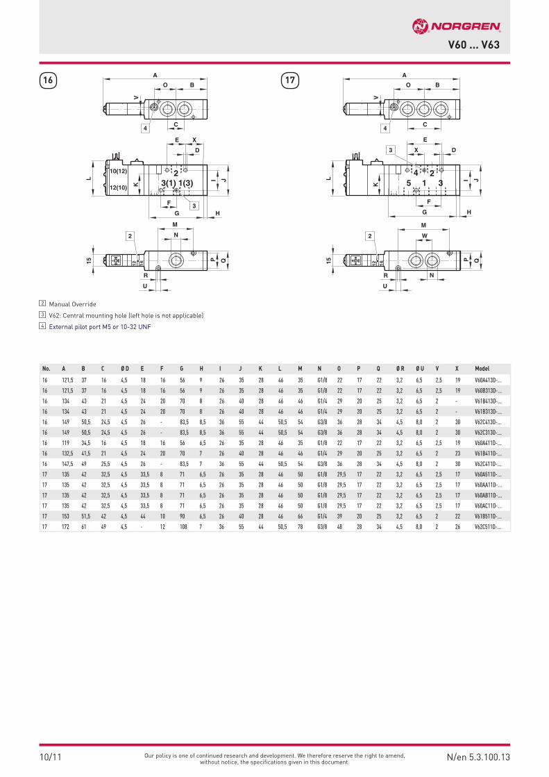
16 17
No. A B C Ø D E F G H I J K L M N O P Q Ø R Ø U V X Model
16 121,5 37 16 4,5 18 16 56 9 26 35 28 46 35 G1/8 22 17 22 3,2 6,5 2,5 19 V60A413D-...
16 121,5 37 16 4,5 18 16 56 9 26 35 28 46 35 G1/8 22 17 22 3,2 6,5 2,5 19 V60B313D-...
16 134 43 21 4,5 24 20 70 8 26 40 28 46 46 G1/4 29 20 25 3,2 6,5 2 - V61B413D-...
16 134 43 21 4,5 24 20 70 8 26 40 28 46 46 G1/4 29 20 25 3,2 6,5 2 - V61B313D-...
16 149 50,5 24,5 4,5 26 - 83,5 8,5 36 55 44 50,5 54 G3/8 36 28 34 4,5 8,0 2 30 V62C413D-...
16 149 50,5 24,5 4,5 26 - 83,5 8,5 36 55 44 50,5 54 G3/8 36 28 34 4,5 8,0 2 30 V62C313D-...
16 119 34,5 16 4,5 18 16 56 6,5 26 35 28 46 35 G1/8 22 17 22 3,2 6,5 2,5 19 V60A411D-...
16 132,5 41,5 21 4,5 24 20 70 7 26 40 28 46 46 G1/4 29 20 25 3,2 6,5 2 23 V61B411D-...
16 147,5 49 25,5 4,5 26 - 83,5 7 36 55 44 50,5 54 G3/8 36 28 34 4,5 8,0 2 30 V62C411D-...
17 135 42 32,5 4,5 33,5 8 71 6,5 26 35 28 46 50 G1/8 29,5 17 22 3,2 6,5 2,5 17 V60A511D-...
17 135 42 32,5 4,5 33,5 8 71 6,5 26 35 28 46 50 G1/8 29,5 17 22 3,2 6,5 2,5 17 V60AA11D-...
17 135 42 32,5 4,5 33,5 8 71 6,5 26 35 28 46 50 G1/8 29,5 17 22 3,2 6,5 2,5 17 V60AB11D-...
17 135 42 32,5 4,5 33,5 8 71 6,5 26 35 28 46 50 G1/8 29,5 17 22 3,2 6,5 2,5 17 V60AC11D-...
17 153 51,5 42 4,5 44 10 90 6,5 26 40 28 46 66 G1/4 39 20 25 3,2 6,5 2 22 V61B511D-...
17 172 61 49 4,5 - 12 108 7 36 55 44 50,5 78 G3/8 48 28 34 4,5 8,0 2 26 V62C511D-...
2 Manual Override
3 V62: Central mounting hole (left hole is not applicable)
4 External pilot port M5 or 10-32 UNF
1(3)3(1) J
V
I
K
L
2
Q15 P
10(12)
12(10)
B
A
G H
E X
D
F 3
2
C
O
412 14
M
N
U
R
1 35 J
V
I
K
L
4
Q15
M
P
N
W
B
A
2
2
C
O
4
12 14
E
DX3
G H
F
U
R

10/11N/en 5.3.100.14
V60 ... V63
Our policy is one of continued research and development. We therefore reserve the right to amend, without notice, the specifications given in this document.
18
1 35 J
V
I
K
L
4
Q15 P
B
A
2
2
C
O
4
12 14
E
DX3
G H
F
M
W
N
U
R
2 Manual Override
3 V62: Central mounting hole (left hole is not applicable)
4 External pilot port M5 or 10-32 UNF
No. A B C Ø D E F G H I J K L M N O P Q Ø R Ø U V X Model
18 148,5 56 32,5 4,5 33,5 8 71 20,5 26 35 28 46 50 G1/8 29,5 17 22 3,2 6,5 2,5 17 V60A611D-...
18 148,5 56 32,5 4,5 33,5 8 71 20,5 26 35 28 46 50 G1/8 29,5 17 22 3,2 6,5 2,5 17 V60A711D-..
18 148,5 56 32,5 4,5 33,5 8 71 20,5 26 35 28 46 50 G1/8 29,5 17 22 3,2 6,5 2,5 17 V60A811D-..
18 170,5 69,5 42 4,5 44 10 90 24,5 26 40 28 46 66 G1/4 39 20 25 3,2 6,5 2 22 V61B611D-...
18 170,5 69,5 42 4,5 44 10 90 24,5 26 40 28 46 66 G1/4 39 20 25 3,2 6,5 2 22 V61B711D-...
18 170,5 69,5 42 4,5 44 10 90 24,5 26 40 28 46 66 G1/4 39 20 25 3,2 6,5 2 22 V61B811D-...
18 194,5 83,5 49 4,5 - 12 108 29,5 36 55 44 50,5 78 G3/8 48 28 34 4,5 8,0 2 26 V62C611D-...
18 194,5 83,5 49 4,5 - 12 108 29,5 36 55 44 50,5 78 G3/8 48 28 34 4,5 8,0 2 26 V62C711D-...
18 194,5 83,5 49 4,5 - 12 108 29,5 36 55 44 50,5 78 G3/8 48 28 34 4,5 8,0 2 26 V62C811D-...

Our policy is one of continued research and development. We therefore reserve the right to amend, without notice, the specifications given in this document.
10/11 N/en 5.3.100.15
V60 ... V63
JI
K L
B4,5
A
G H
E X
D
QP
C
M
N
O
U
R
1
2
13122
31
34
32
35
33
36
1 Pilot ports G1/8 or 1/8-27 NPT
2 Alternative pilot ports G1/8 or 1/8-27 NPT
No. A B C Ø D E F G H I J K L M N O P Q Ø R S Ø T Ø U V X Model
31 89,5 45 16 4,5 18 16 56 17 26 35 28 - 35 G1/8 36 17 22 3,2 - - 6,5 - - V60A4D7A-...
31 110 57,5 21 4,5 24 20 70 22,5 26 40 28 - 46 G1/4 43 20 25 3,2 - - 6,5 - - V61B4D7A-...
32 89,5 45 16 4,5 18 16 56 17 26 35 28 - 35 G1/8 36 17 22 3,2 - - 6,5 - - V60A3D7A-...
32 110 57,5 21 4,5 24 20 70 22,5 26 40 28 - 46 G1/4 43 20 25 3,2 - - 6,5 - - V61B3D7A-...
33 132 70 24,5 4,5 26 - 83,5 28 36 55 - 33,5 54 G3/8 52 28 34 4,5 - - 8,0 - 30 V62C4D7A-...
34 132 70 24,5 4,5 26 - 83,5 28 36 55 - 33,5 54 G3/8 52 28 34 4,5 - - 8,0 - 28 V62C3D7A-...
35 162 87,5 38 7,0 46 75 108 33,5 26 65 - 39,5 - G1/2 64 - 35 - 18,5 5,5 - 23 36 V63D4D7A-...
36 162 87,5 38 7,0 46 75 108 33,5 26 65 - 39,5 - G1/2 64 - 35 - 14,5 5,5 - 23 26 V63D3D7A-...
3 1
JI
K
212
B
A
G H
E
D
F
Q
2,5
P
C
M
N
O
U
R
1
1 3
JI
K
210
B
A
G H
E
D
F
Q
2,5
P
C
M
N
O
U
R
1
JI
K L
B4,5
A
G H
E X
D
QP
C
M
N
O
U
R
1
31102
2
E X
D
T
G H
F S
Q
N
O
C
B4,5
A
1
L4
3 1
212
J
IV
2
1
E X
D
T
G H
F S
Q
N
O
C
B4,5
A
1
L4
1 3
210
J
IV
2
1

10/11N/en 5.3.100.16
V60 ... V63
Our policy is one of continued research and development. We therefore reserve the right to amend, without notice, the specifications given in this document.
E X
D
T
G H
F S
Q
N
O
C
(B)4,5
A
1
L4
3 1
2 1012
J
IV
2
1
37 38 39
3 1
JI
212 10
QP
(B)
A
G
E
D
F
C
U
R
K
1
M
N
O
JI
K L
(B)4,5
A
G
E X
D
QP
C
M
N
O
U
R
1
2
1312 102
1 Pilot ports G1/8 or 1/8-27 NPT
2 Alternative pilot ports G1/8 or 1/8-27 NPT
No. A B C D E F G I J K L M N O P Q R S T U V X Model
37 89 44,5 16 4,5 18 16 56 26 35 28 - 35 G1/8 36 17 22 3,2 - - 6,5 - - V60A4DDA-...
37 104 52 21 4,5 24 20 70 26 40 28 - 46 G1/4 43 20 25 3,2 - - 6,5 - - V61B4DDA-...
38 124 62 24,5 4,5 26 - 83,5 36 55 44 33,5 54 G3/8 52 28 34 4,5 - - 8,0 - 30 V62C4DDA-...
39 148 74 38 7,0 46 75 108 26 65 - 39,5 - G1/2 64 - 35 - 18,5 5,5 - 23 36 V63D4DDA-...

Our policy is one of continued research and development. We therefore reserve the right to amend, without notice, the specifications given in this document.
10/11 N/en 5.3.100.17
V60 ... V63
40 41
42
1 Pilot ports G1/8 or 1/8-27 NPT
2 Alternative pilot ports G1/8 or 1/8-27 NPT
No. A B C D E F G H I J K L M N O P Q R T U V W X Y Z Model
40 105 52,5 32,5 4,5 33,5 8 71 17 26 35 28 - 50 G1/8 43,5 17 22 3,2 - 6,5 - 16 - - - V60A5D7A-...
40 130 67,5 42 4,5 44 10 90 22,5 26 40 28 - 66 G1/4 53 20 25 3,2 - 6,5 - 21 - - - V61B5D7A-...
41 156 82 49 4,5 26 12 108 28 36 55 44 33,5 78 G3/8 64 28 34 4,5 - 8,0 - 24,5 - - - V62C5D7A-...
42 200 106,5 76 7,0 60 19 146 33,5 52 65 - 39,5 - G1/2 83 - 35 - 5,5 - 46 38 57,5 3 115 V63D5D7A-...
5 1 3
JI4 2
B
A
G H
E
D
F
Q
M
O
W
P
N
C
U
R
K
14
2,5
1
5 1 3
JI414
2
B4,5
A
G H
E
D
F
Q
M
O
W
P
N
C
U
R
K L
1
JIV
W
O
Q
N
C
B
A
1
1
1 35
414 2
E
TF
G H
Z
DX Y
4,5
L4
2
1

10/11N/en 5.3.100.18
V60 ... V63
Our policy is one of continued research and development. We therefore reserve the right to amend, without notice, the specifications given in this document.
43
45
44
5 1 3
JI4 2
(B)
A
G
E
D
FQ
M
O
W
P
N
C
U
R
K
14(10) 12(10)
2,5
1
514(10) 12(10)1 3
JI4 2
(B)4,5
A
G
E
D
F
Q
M
W
P
N
O
C
U
R
K L
1
2
JIV
W
O
Q
N
C
(B)
A
1
1
1 35
414 122
E
TF
G H
Z
DX Y
4,5
L4
2
1
No. A B C D E F G H I J K L M N O P Q R T U V W X Z Model
43 104,5 52,5 32,5 4,5 33,5 8 71 - 26 35 28 - 50 G1/8 44 17 22 3,2 - 6,5 - 16 - - V60A5DDA-...
43 104,5 52,5 32,5 4,5 33,5 8 71 - 26 35 28 - 50 G1/8 44 17 22 3,2 - 6,5 - 16 - - V60AADDA-...
43 104,5 52,5 32,5 4,5 33,5 8 71 - 26 35 28 - 50 G1/8 44 17 22 3,2 - 6,5 - 16 - - V60ABDDA-...
43 104,5 52,5 32,5 4,5 33,5 8 71 - 26 35 28 - 50 G1/8 44 17 22 3,2 - 6,5 - 16 - - V60ACDDA-...
43 124 62 42 4,5 44 10 90 - 26 40 28 - 66 G1/4 53 20 25 3,2 - 6,5 - 21 - - V61B5DDA-...
43 124 62 42 4,5 44 10 90 - 26 40 28 - 66 G1/4 53 20 25 3,2 - 6,5 - 21 - - V61BADDA-...
43 124 62 42 4,5 44 10 90 - 26 40 28 - 66 G1/4 53 20 25 3,2 - 6,5 - 21 - - V61BBDDA-...
43 124 62 42 4,5 44 10 90 - 26 40 28 - 66 G1/4 53 20 25 3,2 - 6,5 - 21 - - V61BCDDA-...
44 148 74 49 4,5 26 12 108 - 36 55 44 33,5 78 G3/8 64 28 34 4,5 - 8,0 - 24,5 - - V62C5DDA-...
44 148 74 49 4,5 26 12 108 - 36 55 44 33,5 78 G3/8 64 28 34 4,5 - 8,0 - 24,5 - - V62CADDA-...
44 148 74 49 4,5 26 12 108 - 36 55 44 33,5 78 G3/8 64 28 34 4,5 - 8,0 - 24,5 - - V62CBDDA-...
44 148 74 49 4,5 26 12 108 - 36 55 44 33,5 78 G3/8 64 28 34 4,5 - 8,0 - 24,5 - - V62CCDDA-...
45 186 93 76 7,0 60 19 146 - 52 65 - 39,5 - G1/2 83 - 35 - 5,5 - 46 38 57,5 115 V63D5DDA-...
1 Pilot ports G1/8 or 1/8-27 NPT
2 Alternative pilot ports G1/8 or 1/8-27 NPT

Our policy is one of continued research and development. We therefore reserve the right to amend, without notice, the specifications given in this document.
10/11 N/en 5.3.100.19
V60 ... V63
46 47
48
No. A B C D E F G H I J K L M N O P Q R U V W X Model
46 118,5 66 32,5 4,5 33,5 8 71 14 26 35 28 - 50 G1/8 43,5 17 22 3,2 6,5 - 16 - V60A6DDA-...
46 118,5 66 32,5 4,5 33,5 8 71 14 26 35 28 - 50 G1/8 43,5 17 22 3,2 6,5 - 16 - V60A7DDA-...
46 118,5 66 32,5 4,5 33,5 8 71 14 26 35 28 - 50 G1/8 43,5 17 22 3,2 6,5 - 16 - V60A8DDA-...
46 142 80 42 4,5 44 10 90 18 26 40 28 - 66 G1/4 53 20 25 3,2 6,5 - 21 - V61B6DDA-...
46 142 80 42 4,5 44 10 90 18 26 40 28 - 66 G1/4 53 20 25 3,2 6,5 - 21 - V61B7DDA-...
46 142 80 42 4,5 44 10 90 18 26 40 28 - 66 G1/4 53 20 25 3,2 6,5 - 21 - V61B8DDA-...
47 170,5 96,5 49 4,5 26 12 108 22,5 36 55 44 33,5 78 G3/8 64 28 34 4,5 8,0 - 24,5 - V62C6DDA-...
47 170,5 96,5 49 4,5 26 12 108 22,5 36 55 44 33,5 78 G3/8 64 28 34 4,5 8,0 - 24,5 - V62C7DDA-...
47 170,5 96,5 49 4,5 26 12 108 22,5 36 55 44 33,5 78 G3/8 64 28 34 4,5 8,0 - 24,5 - V62C8DDA-...
48 216 108 66 7,0 34 16 160 - 50 70 - 41 - G1/2 98 - 40 - - 21 33 44 V63D6DDA-...
48 216 108 66 7,0 34 16 160 - 50 70 - 41 - G1/2 98 - 40 - - 21 33 44 V63D7DDA-...
1 Pilot ports G1/8 or 1/8-27 NPT
2 Alternative pilot ports G1/8 or 1/8-27 NPT
5 1 3
JI4 2
B
A
G H
E
D
F
Q
M
O
W
P
N
C
U
R
K
14 12
2,5
1
5 1 3
JI4 2
B4,5
A
G H
X
D
F
Q
M
W
P
N
O
C
U
R
K L
14 12
1
2
JI
V
W
O
Q
N
C
(B)
A
4
1 35
4 2
E
F
G
D
X
4,5
L7,
5
14 12
2
1

10/11N/en 5.3.100.20
V60 ... V63
Our policy is one of continued research and development. We therefore reserve the right to amend, without notice, the specifications given in this document.
P1 P2 P1 P2
Sub bases 2 and 3 stations
Mounting instructions
Pressure shut-off part
Sub bases 4 to 12 stations G
F EA
B
C D
P
O
R S
J K M
H
N
1
G
F E
A
B
C D
O
V W
RP
J K M
H
N
1
Series Valve-stations
A B C D E F G H J K M N O P R S V *2)
W *2) Weight (kg) *2)
Model
V60 2 98 30 16 G1/8 8 11 21 32 11 35,5 G1/4 86 6 28 23 46 - 46 0,23 2221002
V60 3 98 30 16 G1/8 8 11 21 32 11 35,5 G1/4 86 6 28 23 69 - 69 0,28 2221003
V60 4 » 12 98 30 16 G1/8 8 11 21 32 11 35,5 G1/4 86 6 6,5 23 - (N x 23) +10 (N x 23) +23 4 stations = 0,61 *2) 22210*1)
V61 2 104 26 9 G1/8 8 13 20 33 10 35,5 G3/8 24 40 26 26 52 - 52 0,28 2221102
V61 3 104 26 9 G1/8 8 13 20 33 10 35,5 G3/8 24 40 52 26 78 - 78 0,45 2221103
V61 4 » 12 104 26 9 G1/8 8 13 20 33 10 35,5 G3/8 24 40 6,5 26 - (N x 26) +10 (N x 26) +23 4 stations = 0,72 *2) 22211*1)
V62 2 120 29 9 G1/8 8 15 22 38 12 35,5 G1/2 32 44 35 35 70 - 70 0,50 2221202
V62 3 120 29 9 G1/8 8 15 22 38 12 35,5 G1/2 32 44 70 35 105 - 105 0,85 2221203
V62 4 » 12 120 29 9 G1/8 8 15 22 38 12 35,5 G1/2 32 44 7 35 - (N x 35) +12 (N x 35) +12 4 stations = 1,25 *2) 22212*1)
*1) Insert sub-base code after model numbers: 04, 06, 08, 10 and 12 corresponding the stations*2) Add +0,25 for two further stations V60 series, +0,30 for V61 and +0,54 for V62 series
1 For M5 bolts only
1. Set stopper at required position (in main pressure line).
2. Insert two bushes to lock stopper in position.
3. Mount valves on sub-base (bushes rise into P port of valves).

Our policy is one of continued research and development. We therefore reserve the right to amend, without notice, the specifications given in this document.
10/11 N/en 5.3.100.21
V60 ... V63
V60
V61
V62
Extension possibilities of sub-bases
Screw torque for sub-baseM3 = 0,7 +0,3 NmM4 = 1,6 +0,5 NmM5 = 3,4 +0,5 NmM6 = 5,2 +0,5 Nm
Mounting kit for DIN rail

10/11N/en 5.3.100.22
V60 ... V63
Our policy is one of continued research and development. We therefore reserve the right to amend, without notice, the specifications given in this document.
Manifold for common pressure supply
Series Valvestations
A B C D E F G Ø H I K L M N P R Weight (kg)
Model
V60 2 G1/4 76 32 22 14 90 106 6,5 2,5 60 16 G1/8 48 28 42 0,053 2639622
V60 3 G1/4 108 32 22 14 122 138 6,5 2,5 60 16 G1/8 48 28 42 0,075 2639623
V60 4 G1/4 140 32 22 14 154 170 6,5 2,5 60 16 G1/8 48 28 42 0,099 2639624
V60 5 G1/4 172 32 22 14 186 202 6,5 2,5 60 16 G1/8 48 28 42 0,123 2639625
V60 6 G1/4 204 32 22 14 218 234 6,5 2,5 60 16 G1/8 48 28 42 0,147 2639626
V60 7 G1/4 236 32 22 14 250 266 6,5 2,5 60 16 G1/8 48 28 42 0,174 2639627
V60 8 G1/4 268 32 22 14 282 298 6,5 2,5 60 16 G1/8 48 28 42 0,194 2639628
V60 9 G1/4 300 32 22 14 314 330 6,5 2,5 60 16 G1/8 48 28 42 0,209 2639629
V60 10 G1/4 332 32 22 14 346 362 6,5 2,5 60 16 G1/8 48 28 42 0,230 2639630
V60 12 G1/4 396 32 22 14 410 426 6,5 2,5 60 16 G1/8 48 28 42 0,280 2639632
V61 2 G3/8 85 35 25 19 100 116 6,5 3 75 23 G1/4 57 35 50 0,130 2639422
V61 3 G3/8 120 35 25 19 135 151 6,5 3 75 23 G1/4 57 35 50 0,192 2639423
V61 4 G3/8 155 35 25 19 170 186 6,5 3 75 23 G1/4 57 35 50 0,250 2639424
V61 5 G3/8 190 35 25 19 205 221 6,5 3 75 23 G1/4 57 35 50 0,309 2639425
V61 6 G3/8 225 35 25 19 240 256 6,5 3 75 23 G1/4 57 35 50 0,367 2639426
V61 7 G3/8 260 35 25 19 275 291 6,5 3 75 23 G1/4 57 35 50 0,421 2639427
V61 8 G3/8 295 35 25 19 310 326 6,5 3 75 23 G1/4 57 35 50 0,482 2639428
V61 9 G3/8 330 35 25 19 345 361 6,5 3 75 23 G1/4 57 35 50 0,537 2639429
V61 10 G3/8 365 35 25 19 380 396 6,5 3 75 23 G1/4 57 35 50 0,595 2639430
V61 12 G3/8 435 35 25 19 450 466 6,5 3 75 23 G1/4 57 35 50 0,642 2639432
A
K
I
L MN
L
PR
ø H
FG
DCB
Warning
These products are intended for use in industrial compressed air systems only. Do not use these products where pressures and temperatures can exceed those listed under »Technical features«.
Before using these products with fluids other than those specified, for non-industrial applications, life-support systems, or other ap-plications not within published specifications, consult NORGREN.
Through misuse, age, or malfunction, components used in fluid power systems can fail in various modes.
The system designer is warned to consider the failure modes of all component parts used in pneumatic systems and to provide adequate safeguards to prevent personal injury or damage to equipment in the event of such failure.System designers must provide a warning to end users in the system instructional manual if protection against a failure mode cannot be adequately provided.System designers and end users are cautioned to review specific warnings found in instruction sheets packed and shipped with these products.
Related Documents