VMS v3.16.4 VIPERSAT Management System Installation and Operational Manual Part Number MN/22156 Revision Number 16 IMPORTANT NOTE: The information contained in this document supersedes all previously pub- lished information regarding this product. Product specifications are subject to change without pri- or notice.

Welcome message from author
This document is posted to help you gain knowledge. Please leave a comment to let me know what you think about it! Share it to your friends and learn new things together.
Transcript
VMS v3.16.4
VIPERSAT Management System Installation and Operational Manual
Part Number MN/22156 Revision Number 16
IMPORTANT NOTE: The information contained in this document supersedes all previously pub-lished information regarding this product. Product specifications are subject to change without pri-or notice.
MN/22156, Revision 16 Page 2 of 455
COMTECH EF DATA VIPERSAT Network Products Group 3550 Bassett Street Santa Clara, 95054 USA Phone: (510) 252-1462 Fax: (510) 252-1695 www.comtechefdata.com
Part Number: MN/22156 Revision: 16 Release Date: December 2020
Software Version: 3.16.4.1526
Copyright © 2020 Comtech EF Data. All rights reserved. Printed in the USA. Comtech EF Data, 2114 West 7th Street, Tempe, Arizona 85281 USA, 480.333.2200, FAX: 480.333.2161
Comtech reserves the right to revise this publication at any time without obligation to provide notification of such revision. Comtech periodically revises and improves its products and therefore the information in this document is subject to change without prior notice. Comtech makes no warranty of any kind with regard to this material, including but not limited to the implied warranties of merchantability and fitness for a particular purpose. No responsibility for any errors or omissions that may pertain to the material herein is assumed. Comtech makes no commitment to update nor to keep current the information contained in this document.
Patents and Trademarks All products, names and services are trademarks or registered trademarks of their respective companies. See all Comtech EF Data’s patents and patents pending at http://patents.comtechefdata.com.
Printed in the United States of America
MN/22156, Revision 16 Page 3 of 455
Document Revision History Revision Date Description
12 3/05/14 New functionality in v3.12.x: Bandwidth Exclusion Zones, Carrier Presence Switching; Operations Monitor, ViperView2 Multi-Select, Antenna View Drag-and-Drop, Active Demodulator Blocking, Codecast Image Upgrade, Bandwidth View Animation options, Dual Speed Status Update Timer, Event Log Auto Scroll control, CDM-760 SNMP driver for OOB switching; RESTful Interface for NMS.
13 8/15/16 New functionality & device drivers in 3.13.x: NetVue Interface, CDM-570A, CDD-564A, Heights, HTO/HTX, HRX & Hx device drivers with VersaFEC2 support. Carrier Preservation, Hub Redundancy Enhancements. Heights Roaming support.
14
15
16
12/29/16
- -
Dec 2020
New functionality in 3.14.x: Inband & OOB dynamic CnC switching. Device driver CDM-625A, CDM-570A VersaFEC2 support.
Not used.
New functionality 3.16.x: Hub Resiliency The VMS platform now supports a completely revised Hub Resiliency with the addition of Service Area protection. The standard device redundancy was enhanced to provide backing up a group of units on failure across multiple hub uplink and/or downlink channels. This new hub resiliency feature minimize cost, rack space and power within a network. Managed RF combiner/splitter offers the ability to share one or more backup units among different up/down entrance links using a Matrix Switch. In addition, maintain LAN segmentation adding management of a network traffic switch using VLAN ID/Port control. Amongst these new changes automatic rearming of failed units increases the reliability reducing the possible downtime by trying to ensure that a backup is always in place. Backward compatibility with current redundancy configurations. The upgrade process during installation from older versions of VMS will transform redundancy database to the new 3.16.x structure. Supported Changes:
• Standard Modem to Multiple Modem (M:N) control• Standard AC power management providing failed unit shut-
down protection• New H-DNA Service Area, grouping multiple units as a single
protection switchover• New RF Matrix Switch device providing multiple service area
controlo SNMP command support for QuintechTM QRM-2500
• New command control of Network LAN switcheso SNMP command support for Cisco SG300-xx at
minimum• Updated the ViperView2 GUI for configuration management
and control• Modified API to support configuration and operational controls
via NetVue
MN/22156, Revision 16 Page 4 of 455
Distributed VMS (Roaming)
The VMS roaming architecture was enhanced allowing either single source manager or multiple units distributed at each shore point service area. This new enhancement promotes increased reliability, no one single point of failure and reduced timing latency in HDNA. Normally a roaming device in a single VMS architecture is identified through the site RF antenna which indicates satellite resources it is currently assigned.
Each time a remote roam the antenna and its associated RF components, up converter, modulator, down converter, and demodulator are moved to a new satellite binding the frequency domain essentials on a successful roam. In a distributed architecture along with normal roaming the remotes will leave one shore point VMS and appear in another requesting registration. The recep-tion VMS announces to all listening VMS through a peer list that it has taken management of roaming remote. The shore point that was vacated processes cleanup of previously allocated satellite resources issuing management route updates, while bridged traffic interface relies on routing protocols, e.g. OSPF to update customer data.
NetVue recognizes that the applicable HTO’s have modified their site list infor-mation through removal and addition updating capacity group list accordingly. Standard entry and dynamic switching operate normally from this point forward.
Roaming Avoidance
The avoidance algorithm utilizes resource availability to guide selection of a beam when a roaming operation is required. To make this decision, it considers the availability of outbound symbols, inbound symbols, and demodulator’s availability. Then proceeds to broadcast a message to all service area remote modems a preferred list of beams and their loading conditions. This allows re-mote roaming modems to determine before beam switch to roam to the best available for bandwidth and throughput.
HDNA Diagnostic Switching
HDNA 3.3.1 package release supports a feature call “Diagnostic Switching” where an operator can issue a switch multi-command (like dSCPC) during HDNA operation. The command will stand-up the remote return carrier at com-manded, MODCOD and Symbol Rate, but because the allocation of bandwidth is from the pool(s) the frequency is dynamically assigned. During the operation the carrier slot remains fixed, non-movable until command to return to HDNA.
MN/22156, Revision 16 Page 5 of 455
Table of Contents
1. How to Use This Manual .................................................................................................................... 11
1.1 Manual Organization .................................................................................................................. 11
1.2 Conventions and References ....................................................................................................... 13
1.3 Introduction ................................................................................................................................. 15
1.3.1 VMS Features ..................................................................................................................... 17
1.3.2 VMS Operation & Architecture .......................................................................................... 18
1.3.3 Contact Information ............................................................................................................ 20
2. VMS Installation ................................................................................................................................. 21
2.1 New Server Installation ............................................................................................................... 22
2.1.1 Part List ............................................................................................................................... 22
2.1.2 Requirements ...................................................................................................................... 22
2.2 Procedure .................................................................................................................................... 22
2.2.1 Stock Server Setup .............................................................................................................. 22
2.2.2 Required Test Equipment .................................................................................................... 22
2.2.3 Windows Settings ............................................................................................................... 22
2.2.4 Standard license agreement ................................................................................................. 23
2.2.5 Setting the Administrator Password .................................................................................... 24
2.2.6 Setting OS drive partition. .................................................................................................. 24
2.2.7 Notification Screen ............................................................................................................. 24
2.2.8 Server Login ........................................................................................................................ 25
2.2.9 OEM OS Package Options .................................................................................................. 26
2.3 Operational Settings .................................................................................................................... 26
2.3.1 Firewall Configuration ........................................................................................................ 26
2.3.2 Remote Desktop .................................................................................................................. 27
2.4 VMS Installation Procedure ........................................................................................................ 29
2.4.1 Preparation .......................................................................................................................... 29
MN/22156, Revision 16 Page 6 of 455
2.4.2 File Copy ............................................................................................................................. 29
2.4.3 VMS Account ..................................................................................................................... 29
2.4.4 VMS Service Port Range Protection ................................................................................... 31
2.4.5 USB High Performance Power setting ................................................................................ 33
2.5 VMS Software Installation.......................................................................................................... 34
2.6 VMS Server - MS Windows Update Setting .............................................................................. 40
2.7 Types of Installation ................................................................................................................... 41
2.8 Back Up VMS Database (Upgrade) ............................................................................................ 42
2.9 Prepare for Crypto-Key Updating (Upgrade) ............................................................................. 43
2.10 Uninstall Previous VMS Version (Upgrade) .............................................................................. 46
2.11 Update USB Crypto-Key (Upgrade) ........................................................................................... 47
2.12 VMS Server/Client Installation ................................................................................................... 48
2.13 Management Security Installation — Option ............................................................................. 54
2.14 Verify Server Only Installation ................................................................................................... 55
2.14.1 VMS Full Install Service Startup ........................................................................................ 56
2.14.2 VMS Service Start Failure .................................................................................................. 57
2.15 VMS Client Installation .............................................................................................................. 58
2.16 Create Client Accounts ............................................................................................................... 59
2.16.1 Verify Client Installation .................................................................................................... 59
3. VMS Configuration ............................................................................................................................ 60
3.1 Hardware Configuration ............................................................................................................. 63
3.2 VMS Quick Configuration Guide ............................................................................................... 64
3.3 VMS Initial Startup Procedure .................................................................................................... 67
3.4 Vipersat Manager Configuration ................................................................................................ 68
3.5 RF Manager Configuration ......................................................................................................... 79
3.5.1 HDNA Service Area HTO/HTX Assignment ..................................................................... 88
3.5.2 Create Site Level RF Chain ................................................................................................ 89
3.5.3 Bind Modulators and Demodulators to Converters ............................................................ 93
3.6 Network Manager Configuration ................................................................................................ 96
3.6.1 Network Build Procedure .................................................................................................... 96

MN/22156, Revision 16 Page 7 of 455
3.6.2 Set Carrier Flags................................................................................................................ 101
3.6.3 Mask Rx Unlock Alarms ................................................................................................... 104
3.7 Auto Home State ....................................................................................................................... 106
3.8 InBand Management Configuration .......................................................................................... 108
3.9 Switching Function Verification ............................................................................................... 133
3.10 Remote Site Wizard .................................................................................................................. 137
3.11 Redundancy Configuration ....................................................................................................... 147
3.12 Dynamic Route (CDM-570) ..................................................................................................... 147
3.13 Encryption Configuration ......................................................................................................... 150
4. Configuring Heights Modems ........................................................................................................... 153
4.1 Hardware/Software Configuration ............................................................................................ 155
4.2 Using Heights Parameter Editor ............................................................................................... 156
4.2.1 Parameter Editor Features ................................................................................................. 157
4.2.2 Parameter Editor Tree Menu ............................................................................................. 158
4.3 General ...................................................................................................................................... 159
4.4 Network..................................................................................................................................... 162
5. Roaming Configurations ................................................................................................................... 198
5.1 Distributed VMS ....................................................................................................................... 198
5.2 SOTM Position Configuration .................................................................................................. 204
5.3 Avoidance Feature .................................................................................................................... 206
6. VMS Client Application ................................................................................................................... 213
6.1 ViperView2 Monitoring and Control GUI ................................................................................ 214
6.2 Customizable Views ................................................................................................................. 215
6.2.1 Arrange and dock windows ............................................................................................... 215
6.3 HDNA Channel Status .............................................................................................................. 222
6.3.1 Inbound QoS Group Configuration and Status View........................................................ 224
6.4 Network Manager Status View ................................................................................................. 228
6.5 Operations Monitor ................................................................................................................... 228
6.6 Error Detection .......................................................................................................................... 229
6.6.1 Direct Event Filtering ........................................................................................................ 236
MN/22156, Revision 16 Page 8 of 455
6.7 Event Relay Server ................................................................................................................... 238
6.8 Alarm Masks ............................................................................................................................. 239
6.9 Diagnostic Switching ................................................................................................................ 241
6.10 Database Backup and Restore ................................................................................................... 244
6.11 VMS Service Managers ............................................................................................................ 246
6.11.1 Network Manager ............................................................................................................. 246
6.12 InBand Management ................................................................................................................. 248
6.12.1 Switching Distribution Lists ............................................................................................. 249
6.12.2 Guaranteed Bandwidth ...................................................................................................... 250
6.12.3 Operator Switch Request .................................................................................................. 252
6.12.4 Advanced Switching — MODCOD.................................................................................. 253
6.13 Subnet Manager ........................................................................................................................ 256
6.14 RF Manager .............................................................................................................................. 257
6.15 Switching Manager (Engine) .................................................................................................... 260
6.15.1 dSCPC Switching Engine ................................................................................................. 260
6.15.2 HDNA Switching .............................................................................................................. 270
6.16 SNMP Modem Manager ........................................................................................................... 273
6.17 Redundancy Manager ............................................................................................................... 273
6.18 Vipersat Network Manager ....................................................................................................... 274
7. Out of Band Units ............................................................................................................................. 278
7.1 SNMP Modem Manager ........................................................................................................... 280
7.2 Parameter View ......................................................................................................................... 283
7.2.1 Configuring the RF Chain ................................................................................................. 284
7.3 Switching Out-of-Band Modems .............................................................................................. 286
7.4 Out-of-Band Circuit Manager (OBCM).................................................................................... 287
A1 Cross Banding ............................................................................................................................... 306
B1 Antenna Visibility ......................................................................................................................... 311
B2 Using Antenna Visibility .............................................................................................................. 312
C1 Redundancy ................................................................................................................................... 317
C2 VMS Redundancy ......................................................................................................................... 317
MN/22156, Revision 16 Page 9 of 455
C3 Redundant Hot-Standby ................................................................................................................ 319
C4 Server Synchronization ................................................................................................................. 320
C5 Server Contention ......................................................................................................................... 321
C6 Server Status ................................................................................................................................. 321
C7 Installing & Configuring VMS Server Redundancy ..................................................................... 322
C8 Manual Switching ......................................................................................................................... 328
C9 Clearing Server Contention ........................................................................................................... 328
C10 Hub Device Redundancy .............................................................................................................. 329
C11 Device Redundancy Structure ....................................................................................................... 332
C12 HTO 1:1 Redundancy Configuration Procedure ........................................................................... 334
C13 Service Area Hub Resiliency for HDNA Networks ..................................................................... 342
C14 Service Area Redundancy Configuration Procedure .................................................................... 345
C15 HRX Demodulator Shelves Redundancy ...................................................................................... 351
C16 Carrier Preservation ...................................................................................................................... 353
D1 SNMP TRAPS .............................................................................................................................. 355
D2 Configuring SNMP Traps ............................................................................................................. 356
D3 Summary ....................................................................................................................................... 358
E1 Automatic Switching, dSCPC ....................................................................................................... 359
E2 Hitless Switching .......................................................................................................................... 360
E3 Load Switching ............................................................................................................................. 361
E4 Application Switching .................................................................................................................. 370
E5 ToS Switching ............................................................................................................................... 371
E6 Entry Channel Mode Switching .................................................................................................... 376
E7 Dynamic Entry Channel Mode ..................................................................................................... 382
E8 Carrier Presence Switching ........................................................................................................... 386
E9 Point-to-Point Switching ............................................................................................................... 392
E10 Carrier in Carrier Switching .......................................................................................................... 399
E11 dSCPC Meshing, Single Hop on Demand .................................................................................... 404
F1 Northbound Interface .................................................................................................................... 412
F2 NBI Feature Description ............................................................................................................... 413
MN/22156, Revision 16 Page 10 of 455
F3 Operational Status Queries............................................................................................................ 414
F4 Operational Procedures ................................................................................................................. 417
G1 VMS Client Users Account Control ............................................................................................. 428
G2 Server Configuration ..................................................................................................................... 429
G3 Client Configuration ..................................................................................................................... 439
H1 Glossary ........................................................................................................................................ 441
MN/22156, Revision 16 Page 11 of 455
1 GENERAL
1. How to Use This ManualThis manual document the features and functions of the Vipersat Management System (VMS), and guides the user in how to install, configure, and operate this product in a Comtech EF Data network.
NOC administrators and operators responsible for the configuration and maintenance of the Comtech EF Data network, as well as earth station engineers, are the intended audience for this document.
1.1 Manual Organization This User Guide is organized into the following sections:
Chapter 1 – General
Contains VMS product description, customer support information, and manual conventions and references.
Chapter 2 - VMS Installation Covers the steps for installing the VMS software applications on a host server, in both stand-alone and redundant configurations, and on a client PC.
Chapter 3 — VMS Configuration Covers the Quick Configuration procedure as well as detailed steps for full System Configuration in building the Comtech EF Data network.
Chapter 4 — Configuring Network Modems Describes how VMS is used to configure modems in the Comtech EF Data network. The use of Parameter Editor and its application to the Series, 500, 800 modem is presented.
Chapter 5 — Roaming Configurations Multiple VMS distribution, peer list and avoidance information on operation and configuration.
MN/22156, Revision 16 Page 12 of 455
Chapter 6 — VMS Services Describes the various service managers that comprise VMS and how ViperView is used to monitor and control the Comtech EF Data network.
Chapter 7 — Out-of-Band Units Describes the methods for integrating Out-of-Band modem units into a VMS-controlled satellite network.
Appendix A — VMS Cross Banding An explanation of how VMS accommodates applications involving satellite cross strapping and cross banding.
Appendix B — Antenna Visibility An explanation of how to use the VMS antenna visibility function to control the frequency spectrum used in VMS switching.
Appendix C — Redundancy Describes the optional redundancy services available for VMS—N:1 Server redundancy and N:M Hub Modem redundancy.
Appendix D — SNMP Traps Describes the use of SNMP traps by VMS.
Appendix E — Automatic Switching Reference on how the VMS monitors and automatically responds to changing load and traffic type, as well as ToS and QoS requirements in the network. This includes the features that provide load switching (response to network traffic load) functions, application switching (response to network traffic type) functions, Entry Channel Mode switching functions, and carrier presence switching functions.
Appendix F — Northbound Interface Reference on the SNMP module Northbound Interface service for external network management systems.
Appendix G — VMS Client Users Describes dual-level user account control and presents procedures for configuring security and account policies between the VMS Server and VMS Client workstations.
Appendix H — Glossary A glossary of terms that pertain to Vipersat satellite network technology.
MN/22156, Revision 16 Page 13 of 455
1.2 Conventions and References The following conventions are utilized in this manual to assist the reader:
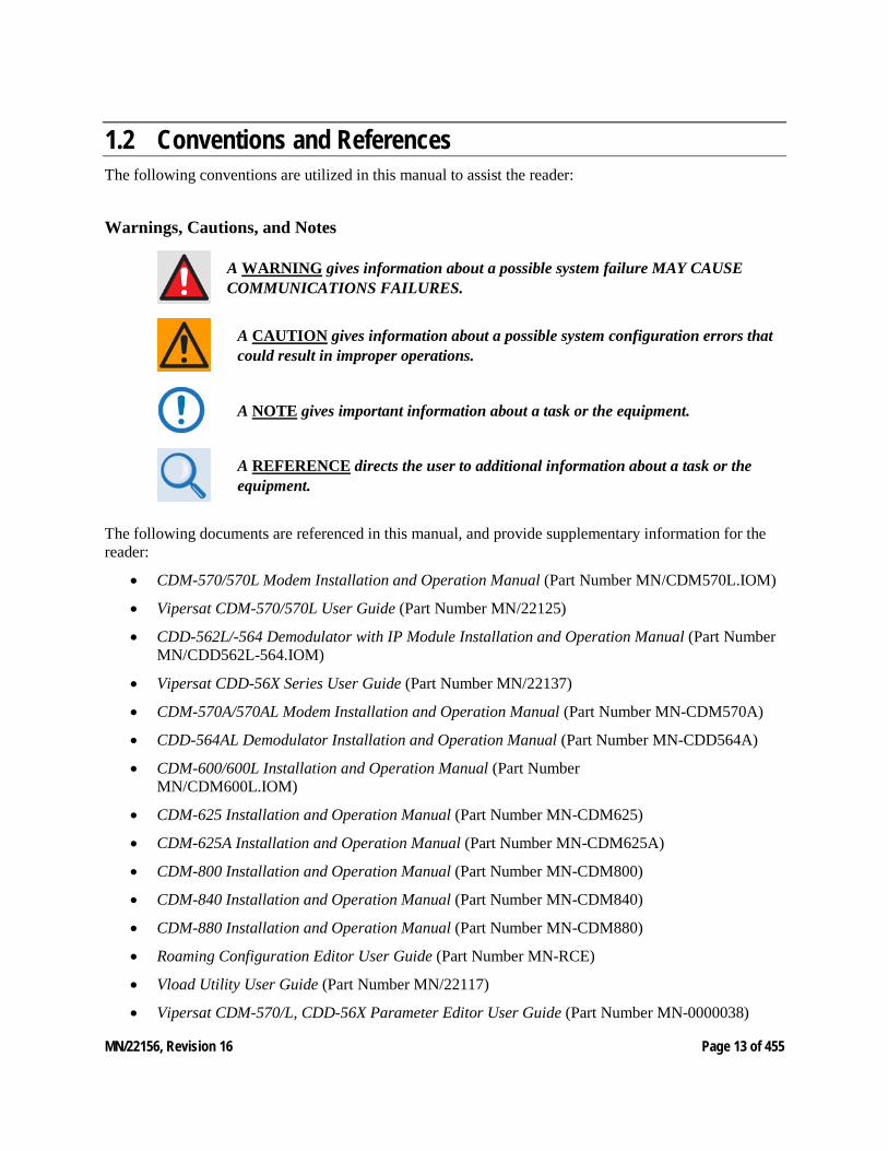
Warnings, Cautions, and Notes
A WARNING gives information about a possible system failure MAY CAUSE COMMUNICATIONS FAILURES.
A CAUTION gives information about a possible system configuration errors that could result in improper operations.
A NOTE gives important information about a task or the equipment.
A REFERENCE directs the user to additional information about a task or the equipment.
The following documents are referenced in this manual, and provide supplementary information for the reader:
• CDM-570/570L Modem Installation and Operation Manual (Part Number MN/CDM570L.IOM)
• Vipersat CDM-570/570L User Guide (Part Number MN/22125)
• CDD-562L/-564 Demodulator with IP Module Installation and Operation Manual (Part NumberMN/CDD562L-564.IOM)
• Vipersat CDD-56X Series User Guide (Part Number MN/22137)
• CDM-570A/570AL Modem Installation and Operation Manual (Part Number MN-CDM570A)
• CDD-564AL Demodulator Installation and Operation Manual (Part Number MN-CDD564A)
• CDM-600/600L Installation and Operation Manual (Part NumberMN/CDM600L.IOM)
• CDM-625 Installation and Operation Manual (Part Number MN-CDM625)
• CDM-625A Installation and Operation Manual (Part Number MN-CDM625A)
• CDM-800 Installation and Operation Manual (Part Number MN-CDM800)
• CDM-840 Installation and Operation Manual (Part Number MN-CDM840)
• CDM-880 Installation and Operation Manual (Part Number MN-CDM880)
• Roaming Configuration Editor User Guide (Part Number MN-RCE)
• Vload Utility User Guide (Part Number MN/22117)
• Vipersat CDM-570/L, CDD-56X Parameter Editor User Guide (Part Number MN-0000038)
MN/22156, Revision 16 Page 14 of 455
• Heights Hub Installation and Operation Manual, Part Number
o MN-HEIGHTS-HUB
o MN-HEIGHTS-HTO
o MN-HRXMCR
o MN-HEIGHTS-SPOKE
• Heights Remote Gateway Installation and Operation Manual, Part Numbers:
o MN-H-DNA-NRS-HPRO
o MN-H-DNA-NRS-HPLUS
o MN-H-DNA-NRS-HPICO
• NetVue User Guide (Part Number MN-NETVUE)
MN/22156, Revision 16 Page 15 of 455
1.3 Introduction Product Description The Vipersat Management System (VMS) is a server and client-based network management system that gathers and processes information it receives from the networking modems that comprise a CEFD satellite network. The modem’s internal microprocessor-based input/output (I/O) controller measures, captures, and transmits real-time network operating parameters to the VMS via either PLDM (Path Loss Data Message) or SUM (Status Update Message) packets, depending on the type of modem product.
The VMS receives, stores, and processes these messages and uses the data to update and display current network status information, and to manage bandwidth resources and switching operations. The network data is then displayed by the VMS in an easy-to-interpret, real-time graphic presentation. The result is a comprehensive, intuitive operator’s network Management and Control tool for quick, responsive network control.
The VMS is customized at setup for each satellite network it controls, recognizing the unique bandwidth resources and limitations associated with each network. The VMS has trigger points set defining the upper and lower limits for usage, type of service, and other network parameters defining bandwidth resource allocations for each traffic type. These triggers, or set-points, are easily modified at any time by a qualified operator whenever network resource allocations need to be reconfigured.
As the VMS receives a switching request from a network modem, it uses sophisticated algorithms to evaluate the request against available network resources and network policies before sending a switch command back to the requesting modem to make a switch to a given frequency and bit rate. If the switch request is denied—because of lack of available network resources, for example—the modem will not make the switch until the necessary resources become available.
The CEFD satellite network modems detect, monitor and, when commanded by the VMS, physically or logically make network changes. The VMS collects, analyzes, and displays data, and commands the CEFD modems to make these network changes. Refer to each modem’s User Guide for more details on each device’s role in the satellite network.
The Vipersat External Switching Protocol (VESP) is available to equipment manufacturers, making it possible for them to smoothly integrate their products into a VMS controlled satellite network. Contact a CEFD representative for details.
The VMS ViperView2 display gives the operator a complete view of a network’s configuration, the health of all network components, and current bandwidth usage. The ViperView2 display is flexible and can be modified by the operator at any time, as described in this User Guide, to optimize network Management and Control.
ViperView is being deprecated and replaced with ViperView2. For an indeterminate duration ViperView will continue to be part of the install base, however support for newer features and UI controls, i.e. hub resiliency will not be accessible.
MN/22156, Revision 16 Page 16 of 455
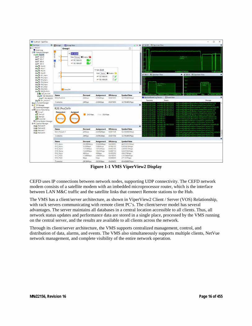
Figure 1-1 VMS ViperView2 Display
CEFD uses IP connections between network nodes, supporting UDP connectivity. The CEFD network modem consists of a satellite modem with an imbedded microprocessor router, which is the interface between LAN M&C traffic and the satellite links that connect Remote stations to the Hub.
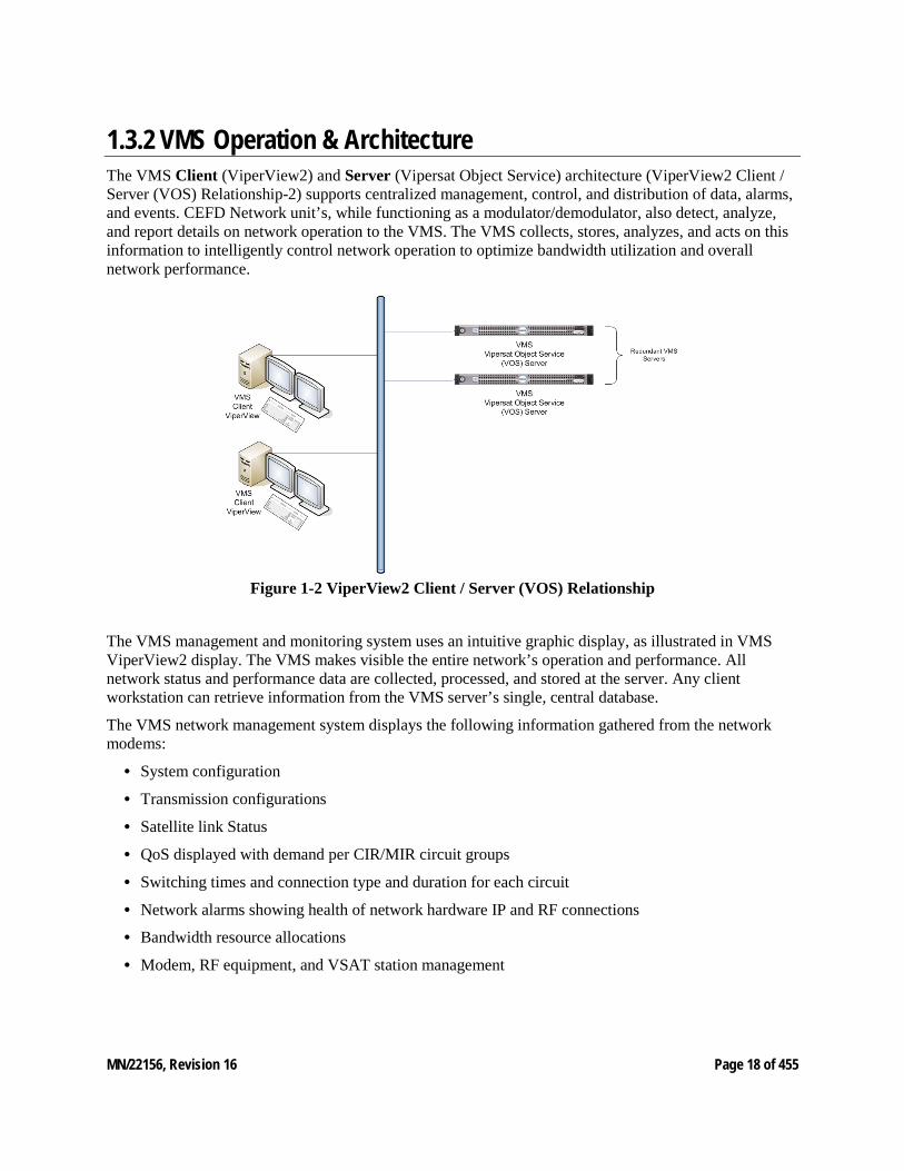
The VMS has a client/server architecture, as shown in ViperView2 Client / Server (VOS) Relationship, with rack servers communicating with remote client PC’s. The client/server model has several advantages. The server maintains all databases in a central location accessible to all clients. Thus, all network status updates and performance data are stored in a single place, processed by the VMS running on the central server, and the results are available to all clients across the network.
Through its client/server architecture, the VMS supports centralized management, control, and distribution of data, alarms, and events. The VMS also simultaneously supports multiple clients, NetVue network management, and complete visibility of the entire network operation.
MN/22156, Revision 16 Page 17 of 455
1.3.1 VMS Features The VMS network management software has the following features:
• System Configuration
• Network Status Displays (automatic and manual)
• Dynamic Bandwidth Management
• Guaranteed Bandwidth Reservations
• Switching Operations, including:
• dSCPCv1
• dSCPCv2/HDNA
• Meshing
• Single Hop On Demand (SHOD)
• Point-to-Point Switching
• Carrier in Carrier Switching
• Advanced Modulation/Code Switching
• Out-of-Band Switching
• Diagnostics Monitor and Control (automatic and manual)
• Alarm Processing
• Run Authorization via USB Crypto-Key
• Optional Management Security
• Optional VMS and Critical Hardware Redundancy
• Statistics Gathering (automatic and manual)
• Report Generation
• Network Administrator Mode
• Remote Access via Local LAN or Internet/Intranet
• Dual-level User Account Authorization
• Interfaces to external NMS:
• REST Interface, NetVue
• Northbound Interface SNMP
• Event Log Relay Server
MN/22156, Revision 16 Page 18 of 455
1.3.2 VMS Operation & Architecture The VMS Client (ViperView2) and Server (Vipersat Object Service) architecture (ViperView2 Client / Server (VOS) Relationship-2) supports centralized management, control, and distribution of data, alarms, and events. CEFD Network unit’s, while functioning as a modulator/demodulator, also detect, analyze, and report details on network operation to the VMS. The VMS collects, stores, analyzes, and acts on this information to intelligently control network operation to optimize bandwidth utilization and overall network performance.
Figure 1-2 ViperView2 Client / Server (VOS) Relationship
The VMS management and monitoring system uses an intuitive graphic display, as illustrated in VMS ViperView2 display. The VMS makes visible the entire network’s operation and performance. All network status and performance data are collected, processed, and stored at the server. Any client workstation can retrieve information from the VMS server’s single, central database.
The VMS network management system displays the following information gathered from the network modems:
• System configuration
• Transmission configurations
• Satellite link Status
• QoS displayed with demand per CIR/MIR circuit groups
• Switching times and connection type and duration for each circuit
• Network alarms showing health of network hardware IP and RF connections
• Bandwidth resource allocations
• Modem, RF equipment, and VSAT station management
MN/22156, Revision 16 Page 19 of 455
The network map displays an integrated view of the entire network including all nets, subnets, equipment, and equipment interconnections. The user can double-click on an icon to display its status information and/or sub-components. Right-clicking on an icon displays a drop-down menu allowing the operator to issue commands, change configurations, or change the unit’s state, as applicable.
The colors associated with each icon, as shown in the display illustrated in VMS ViperView display, reflect the current status condition of the network component or its sub-components:
• Green = Okay
• Red = Alarm
• Yellow = Disabled
• Gray = Disconnected (offline) as the result of missing three consecutive PLDMs and not responding to the recovery process
All devices, networks, and carriers displayed by ViperView2 share the same color scheme for indicating their health in the network, giving the operator real-time at-a-glance network health status.
The VMS provides operator notification in the event of network alarms. This notification can be in the form of both visual and audible alerts. The VMS also maintains a log of all network activity, making use of analysis and network trouble-shooting information readily available.
MN/22156, Revision 16 Page 20 of 455
1.3.3 Contact Information Customer Support Contact Comtech EF Data Customer Support for information or assistance with product support, service, or training on any product.
Tel:
+1.240.243.1880
+1.866.472.3963 (toll-free USA)
Email:
Comtech EF Data Headquarters Comtech EF Data Corporation 2114 West 7th Street Tempe, Arizona 85281 USA Tel:
+1.480.333.2200
Web:
www.comtechefdata.com
Reader Comments / Corrections If the reader would like to submit any comments or corrections regarding this manual and its contents, please forward them to a Comtech Customer Support representative. All input is appreciated.
MN/22156, Revision 16 Page 21 of 455
2 VMS INSTALLATION 2. VMS Installation For specifications for the minimum recommended hardware and software platform configuration to host the VMS, please refer to the VMS Release Notes for the version of software that will be installed. Both Server and Client configurations are provided.
The VMS software is installed using an Installation Wizard. Depending on the desired setup, installation can be performed with the full set of files (both client and server), client-only files, or server-only files.
The Wizard guides the installer through the installation process and provides all necessary information to complete typical, compact, and custom installations.
The same procedure for installation of the VMS on a server is used for both stand-alone and redundant configurations.
Installing VMS on non-recommended hardware or operating system will void the support warranty. Also, VMS must be installed on a dedicated server to retain support warranty.
CEFD strongly recommends against running any kind of anti-virus program on the VMS server. Instead, all Microsoft Windows Updates should be installed as they become available. However, the Automatic Updates function in Microsoft Windows must be properly set to avoid possible disruption of the VMS and the CEFD network. Please see the information below.
MN/22156, Revision 16 Page 22 of 455
2.1 New Server Installation This section installs and configures Windows TM OS and VMS software in order to build a NEW out-of-the-box Bandwidth Manager (BWM) server product.
All revision markings and ordered options are omitted for standardization at this level. If your server is already preinstalled with Windows server, go to “VMS Software Installation”. VMS version 3.16.x or greater is certified to install and operate on Windows Server 2019.
2.1.1 Part List • Production Server – (PP-0020721) with Windows Server 2019 Installed • VMS Software Provided by PSO • Serialized USB Encryption Key Assembly Provided by PSO
2.1.2 Requirements • Monitor, USB keyboard & mouse • Internet Connection, OS updates
2.2 Procedure
The following steps listed will ensure that all necessary applications and sub-server configurations are set and tested before shipment.
2.2.1 Stock Server Setup The manufacture servers come preinstalled with the latest Operating System. When powered on the auto setup will walk through a series of steps completing the default settings.
2.2.2 Required Test Equipment
• Connect all peripherals, (monitor, keyboard, mouse, power cord and Ethernet network cable) to production server.
• Once all peripherals have been connected, power on the server.
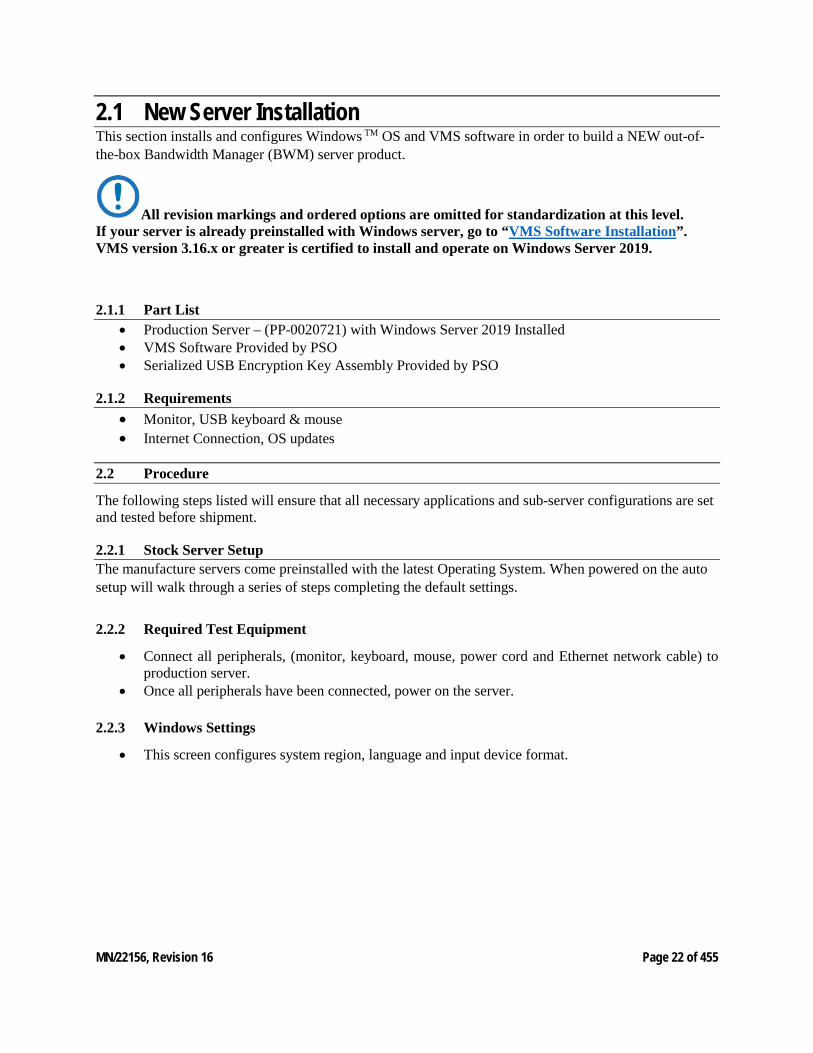
2.2.3 Windows Settings
• This screen configures system region, language and input device format.
MN/22156, Revision 16 Page 23 of 455
• From the dropdown lists select the follow and click ‘Next’ when complete. • Country or Region United States *Default Option • Application Language English (United States) *Default Option • Keyboard input US *Default Option
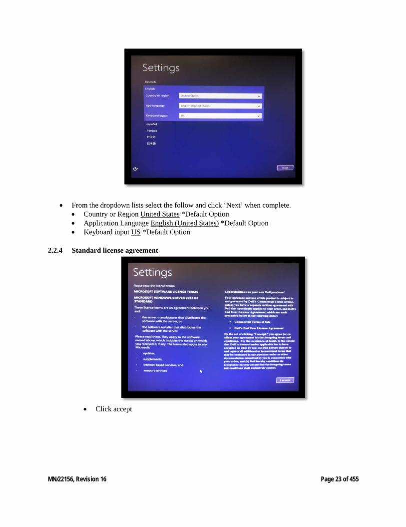
2.2.4 Standard license agreement
• Click accept
MN/22156, Revision 16 Page 24 of 455
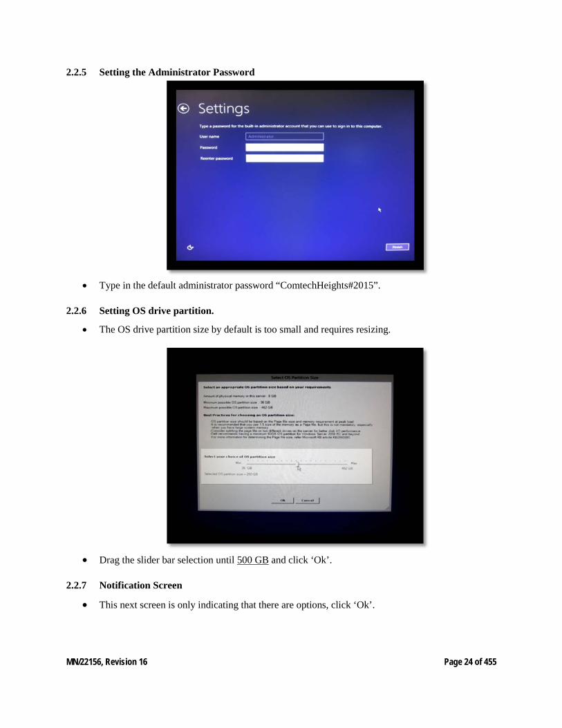
2.2.5 Setting the Administrator Password
• Type in the default administrator password “ComtechHeights#2015”.
2.2.6 Setting OS drive partition.
• The OS drive partition size by default is too small and requires resizing.
• Drag the slider bar selection until 500 GB and click ‘Ok’.
2.2.7 Notification Screen
• This next screen is only indicating that there are options, click ‘Ok’.
MN/22156, Revision 16 Page 25 of 455
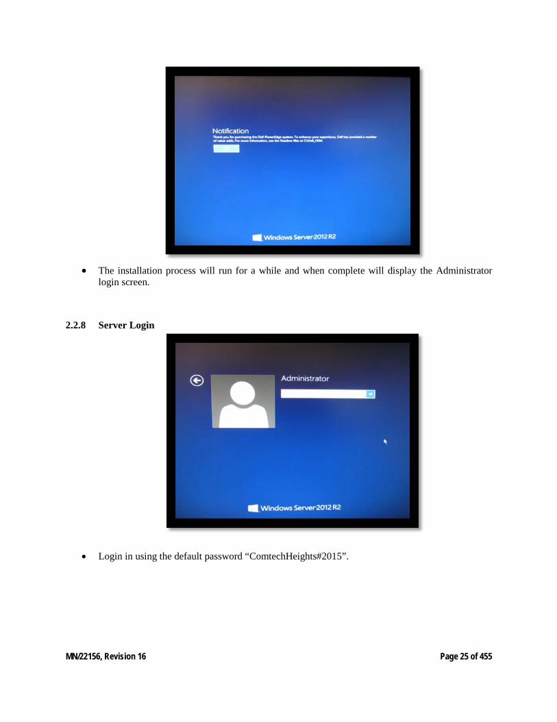
• The installation process will run for a while and when complete will display the Administrator
login screen.
2.2.8 Server Login
• Login in using the default password “ComtechHeights#2015”.
MN/22156, Revision 16 Page 26 of 455
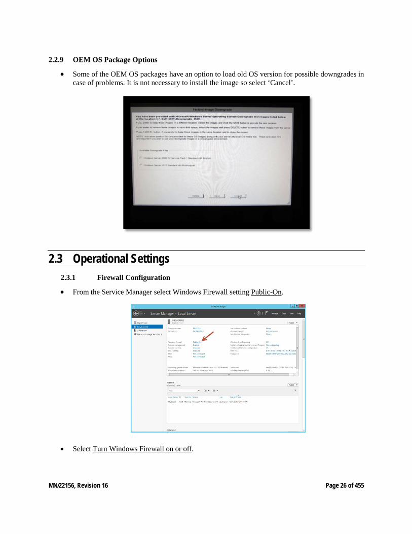
2.2.9 OEM OS Package Options
• Some of the OEM OS packages have an option to load old OS version for possible downgrades in case of problems. It is not necessary to install the image so select ‘Cancel’.
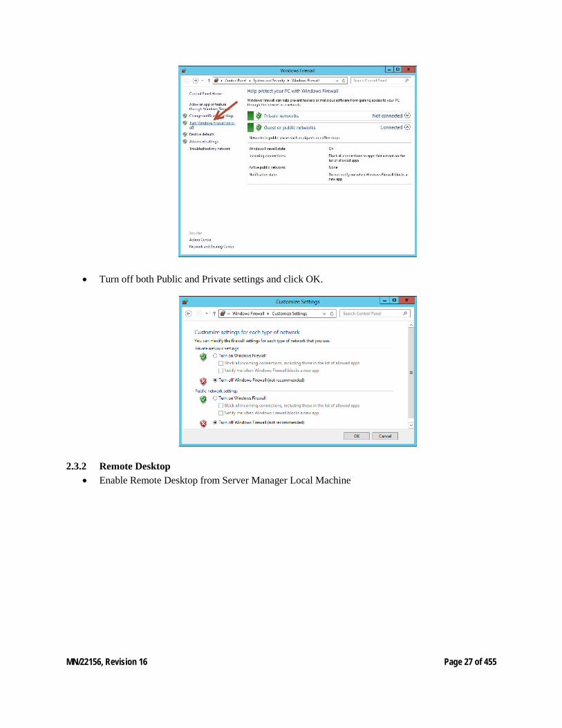
2.3 Operational Settings 2.3.1 Firewall Configuration
• From the Service Manager select Windows Firewall setting Public-On.
• Select Turn Windows Firewall on or off.
MN/22156, Revision 16 Page 27 of 455
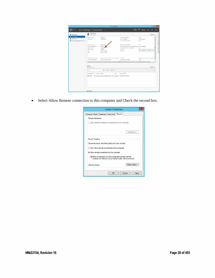
• Turn off both Public and Private settings and click OK.
2.3.2 Remote Desktop • Enable Remote Desktop from Server Manager Local Machine
MN/22156, Revision 16 Page 28 of 455
• Select Allow Remote connection to this computer and Check the second box.
MN/22156, Revision 16 Page 29 of 455
2.4 VMS Installation Procedure This section requires the VMS installation DVD/USB drive with the latest release of software ap-plications and the VMS USB license encryption key. The USB key as generated by the projects sales order and must be authorized to match the VMS software release version and the options pur-chased.
2.4.1 Preparation There are a few setup configurations required before installation can commence.
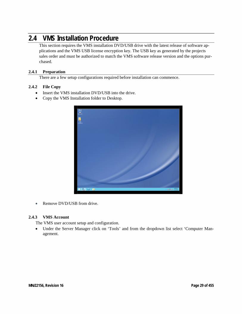
2.4.2 File Copy • Insert the VMS installation DVD/USB into the drive. • Copy the VMS Installation folder to Desktop.
• Remove DVD/USB from drive.
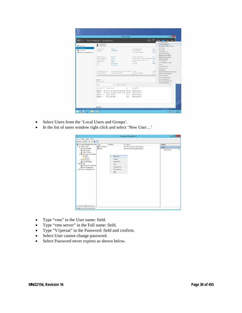
2.4.3 VMS Account The VMS user account setup and configuration. • Under the Server Manager click on ‘Tools’ and from the dropdown list select ‘Computer Man-
agement.
MN/22156, Revision 16 Page 30 of 455
• Select Users from the ‘Local Users and Groups’. • In the list of users window right click and select ‘New User…’
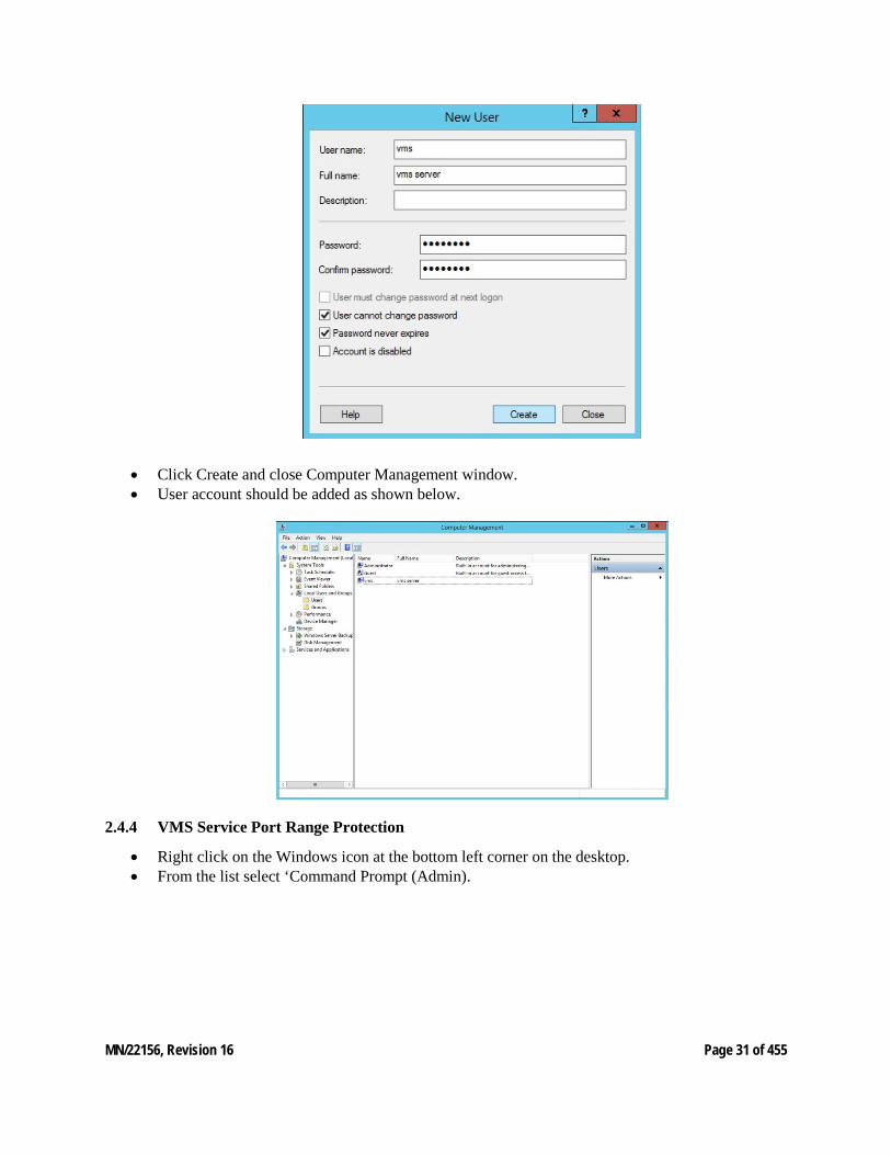
• Type “vms” in the User name: field. • Type “vms server” in the Full name: field. • Type “V1persat” in the Password: field and confirm. • Select User cannot change password. • Select Password never expires as shown below.
MN/22156, Revision 16 Page 31 of 455
• Click Create and close Computer Management window. • User account should be added as shown below.
2.4.4 VMS Service Port Range Protection
• Right click on the Windows icon at the bottom left corner on the desktop. • From the list select ‘Command Prompt (Admin).

MN/22156, Revision 16 Page 32 of 455
• In the command window type the follow command “netsh int ipv4 set dynamicport udp start=49200 num=10000” and enter.
• The system should return ‘Ok.’ if the command was successful.
MN/22156, Revision 16 Page 33 of 455
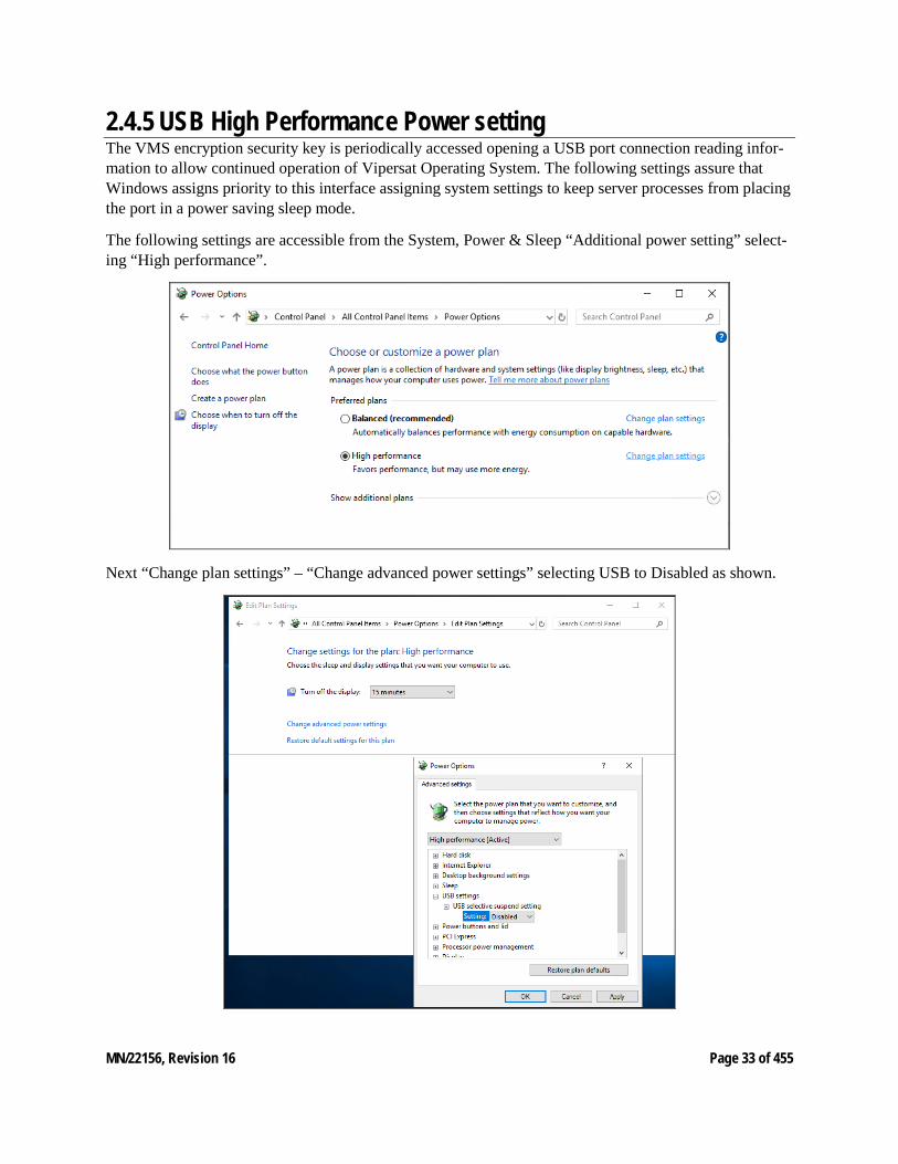
2.4.5 USB High Performance Power setting The VMS encryption security key is periodically accessed opening a USB port connection reading infor-mation to allow continued operation of Vipersat Operating System. The following settings assure that Windows assigns priority to this interface assigning system settings to keep server processes from placing the port in a power saving sleep mode.
The following settings are accessible from the System, Power & Sleep “Additional power setting” select-ing “High performance”.
Next “Change plan settings” – “Change advanced power settings” selecting USB to Disabled as shown.
MN/22156, Revision 16 Page 34 of 455
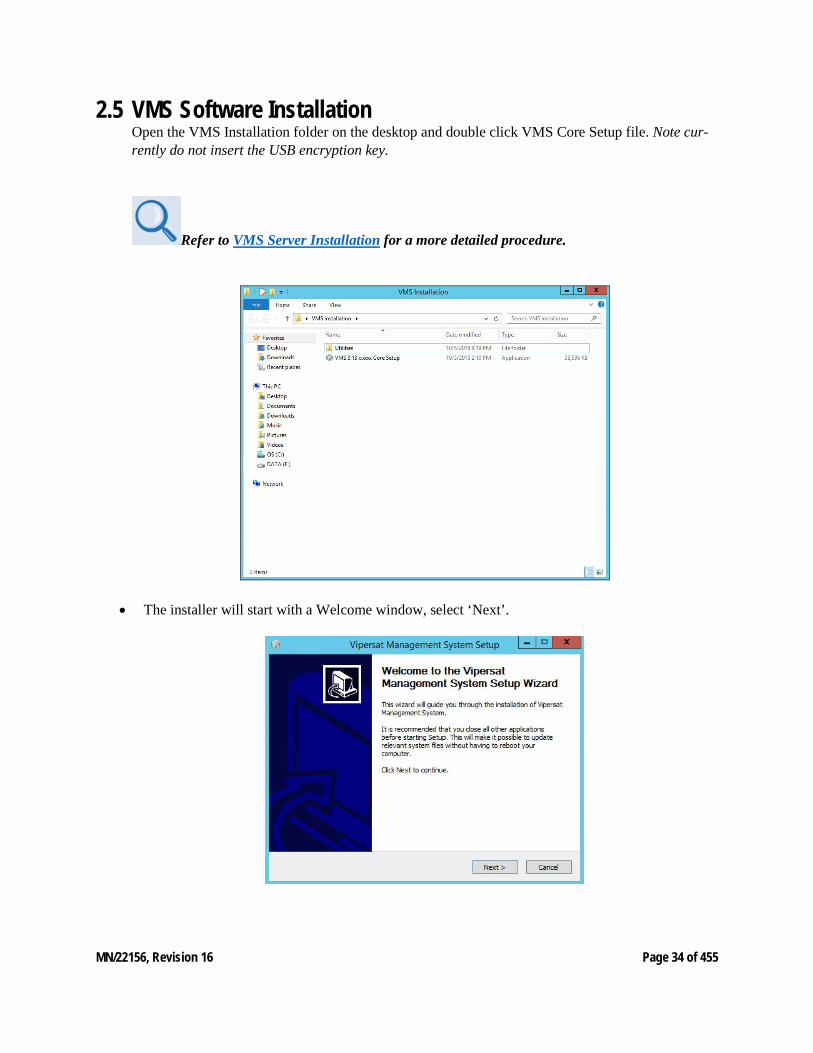
2.5 VMS Software Installation Open the VMS Installation folder on the desktop and double click VMS Core Setup file. Note cur-rently do not insert the USB encryption key.
Refer to VMS Server Installation for a more detailed procedure.
• The installer will start with a Welcome window, select ‘Next’.
MN/22156, Revision 16 Page 35 of 455
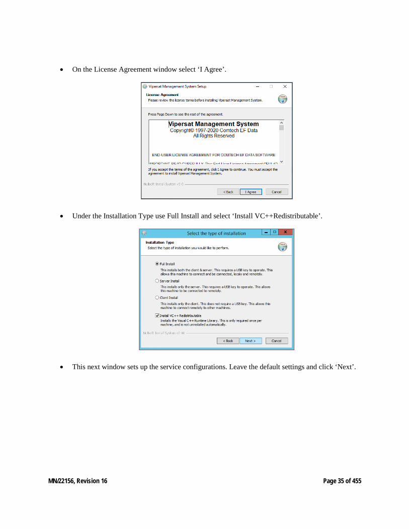
• On the License Agreement window select ‘I Agree’.
• Under the Installation Type use Full Install and select ‘Install VC++Redistributable’.
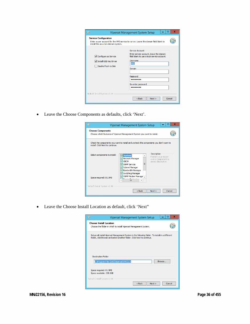
• This next window sets up the service configurations. Leave the default settings and click ‘Next’.
MN/22156, Revision 16 Page 36 of 455
• Leave the Choose Components as defaults, click ‘Next’.
• Leave the Choose Install Location as default, click ‘Next”
MN/22156, Revision 16 Page 37 of 455
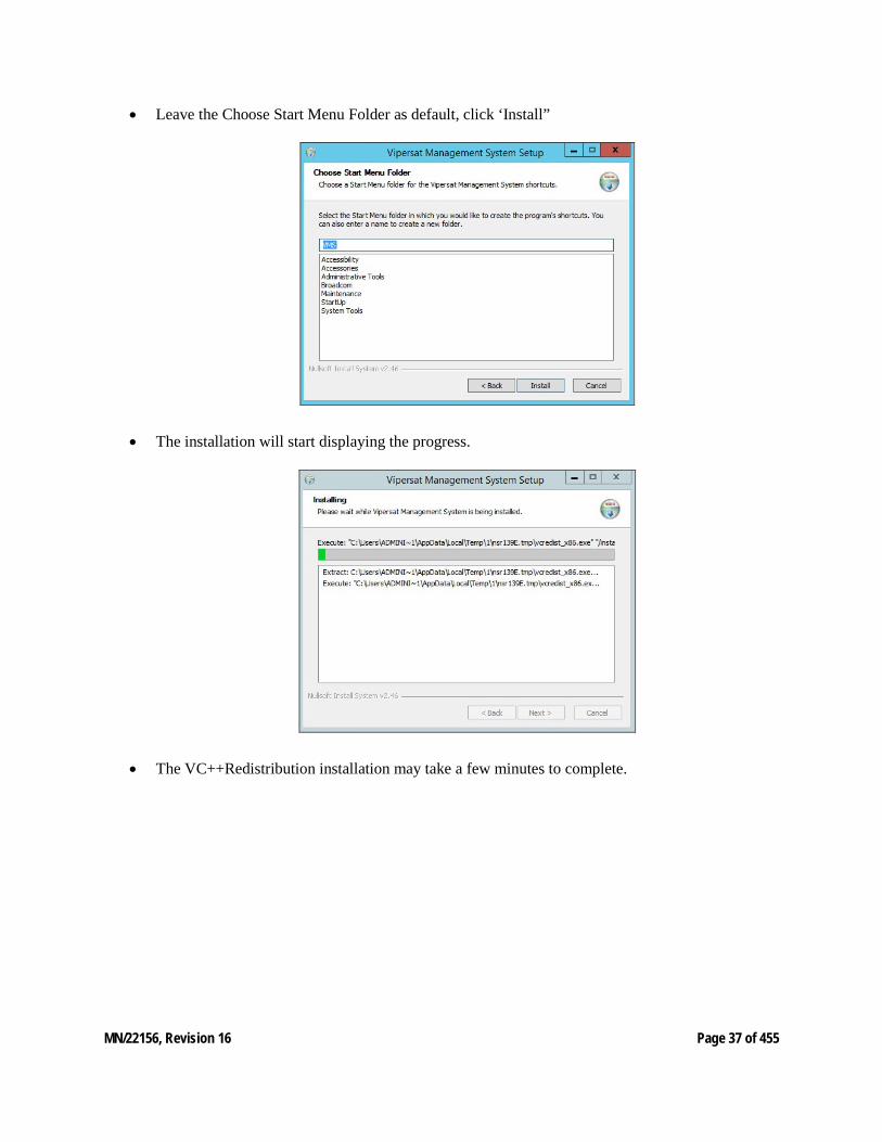
• Leave the Choose Start Menu Folder as default, click ‘Install”
• The installation will start displaying the progress.
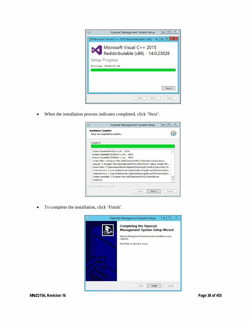
• The VC++Redistribution installation may take a few minutes to complete.
MN/22156, Revision 16 Page 38 of 455
• When the installation process indicates completed, click ‘Next’.
• To complete the installation, click ‘Finish’.

MN/22156, Revision 16 Page 39 of 455
• At this point insert USB encryption key into any available USB port on the server.
Figure 2-1 VMS USB Encryption Key
MN/22156, Revision 16 Page 40 of 455
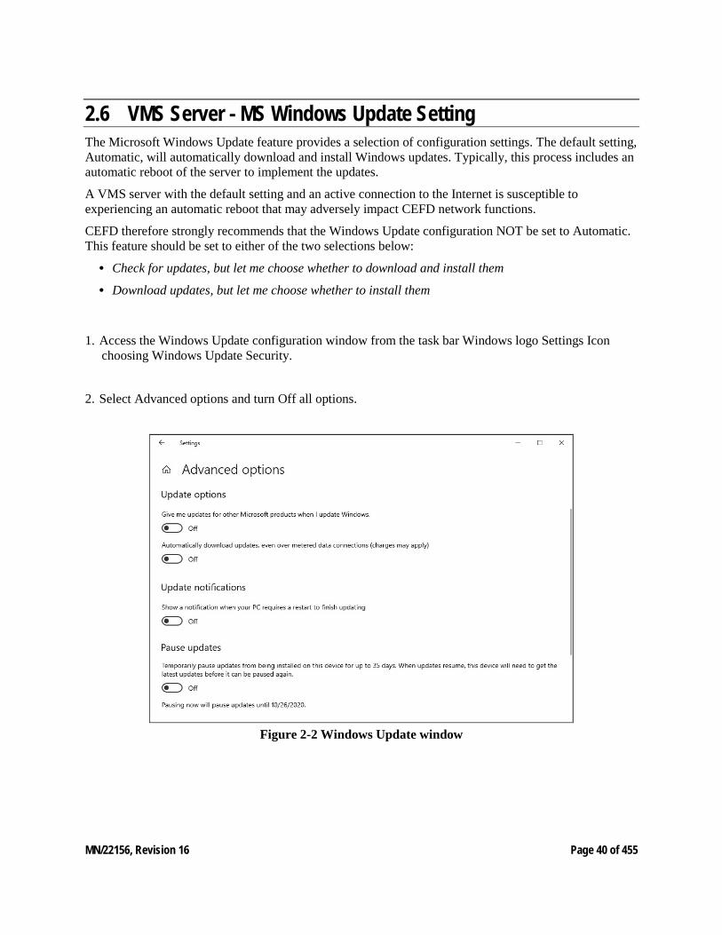
2.6 VMS Server - MS Windows Update Setting The Microsoft Windows Update feature provides a selection of configuration settings. The default setting, Automatic, will automatically download and install Windows updates. Typically, this process includes an automatic reboot of the server to implement the updates.
A VMS server with the default setting and an active connection to the Internet is susceptible to experiencing an automatic reboot that may adversely impact CEFD network functions.
CEFD therefore strongly recommends that the Windows Update configuration NOT be set to Automatic. This feature should be set to either of the two selections below:
• Check for updates, but let me choose whether to download and install them
• Download updates, but let me choose whether to install them
1. Access the Windows Update configuration window from the task bar Windows logo Settings Icon choosing Windows Update Security.
2. Select Advanced options and turn Off all options.
Figure 2-2 Windows Update window
MN/22156, Revision 16 Page 41 of 455
2.7 Types of Installation The VMS can be installed in three different configurations:
1. On a single VMS server; Vipersat Management System Service.
2. On two or more (1:N) VMS servers in the optional fault-tolerant, redundant configuration; Vipersat Management System Service.
3. On a client workstation; ViperView2 User Interface.
Server installations can be performed as either: • Clean Installation - An installation on a server that has not previously operated as a VMS server, or
that has had its hard drive re-formatted. With no existing network database, a full network configuration (“New Server Installation”) must be performed following installation.
• Upgrade Installation - An installation on a server that has previously been installed as a VMS server in a CEFD network, operating with a previous version of VMS. An existing v3.7 or later network database will be automatically converted during installation.
When upgrading from v3.6.x, the existing network database is incompatible and will NOT be automatically converted during installation. Contact a service representative prior to attempting this type of upgrade. PSO technician will guide the operator in the necessary transition process to prevent loss of network configuration.
It is NOT RECOMMENDED to run ViperView2 on the same machine as the VOS. Therefore, installing and running the VMS Client software component on a workstation that is separate from the VMS server is preferred.
Upgrade installations require a file (.vku) update for the CEFD USB Crypto-Key to be compatible with the new version of VMS software. An incompatibility will prevent the VMS from running on the server.
Redundant Server Upgrade For a redundant VMS configuration, perform the upgrade on the Standby server first. This will allow the installation of the new software and database creation to be verified without losing VMS service. If successful, continue the upgrade by doing the following:
• Deactivate the Active (Primary) server. • Activate the Standby (Secondary) server. • Perform upgrade installation on the now deactivated server.
This method provides a seamless upgrade with no VMS downtime.
MN/22156, Revision 16 Page 42 of 455
The installation instructions in the following section include special instructions for each of these various installation types.
Failure to note and follow the instructions for the intended network configuration may cause the VMS installation to fail or to operate erratically.
2.8 Back Up VMS Database (Upgrade) For VMS upgrades, it is recommended that the current VMS database be backed up prior to installing the new version of VMS. This precaution will allow for the current database to be restored if the new install fails.
This database backup can only be restored on the current VMS version. It is not compatible with the new VMS version.
Should the new VMS installation fail, the fallback procedure would be to re-install the previous version of VMS, then restore the database with the backup.
A successful installation of the new VMS will result in a new database. This new database should immediately be backed up, and any previous database backups should be removed from the server to avoid compatibility issues.
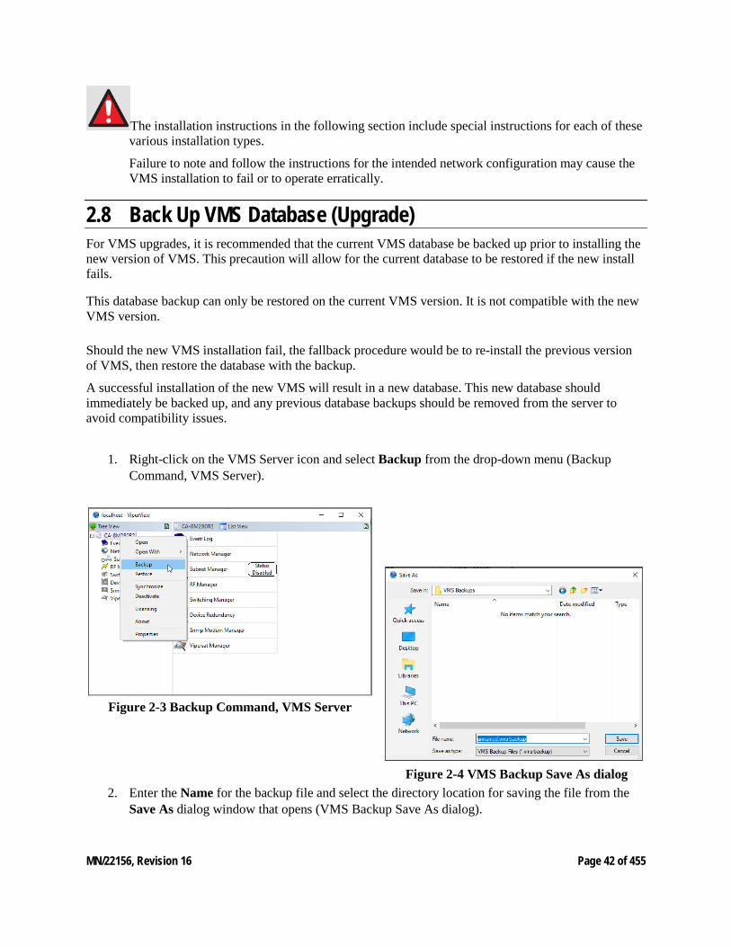
1. Right-click on the VMS Server icon and select Backup from the drop-down menu (Backup Command, VMS Server).
Figure 2-3 Backup Command, VMS Server
Figure 2-4 VMS Backup Save As dialog 2. Enter the Name for the backup file and select the directory location for saving the file from the
Save As dialog window that opens (VMS Backup Save As dialog).
MN/22156, Revision 16 Page 43 of 455
2.9 Prepare for Crypto-Key Updating (Upgrade) Each time the VMS software is upgraded to a new version, the USB Crypto-Key must be updated for the VMS to run on the server. An update utility, vms-key-update.exe, is used for this purpose and is obtained by contacting (“Contact Information”).
The following information will be required:
• Key Serial Number
• Licensing
• Customer Name
Both the serial number and the licensing can be obtained from ViperView2 using the following method:
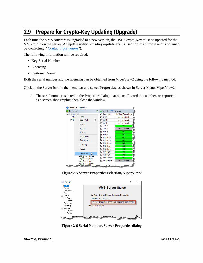
Click on the Server icon in the menu bar and select Properties, as shown in Server Menu, ViperView2.
1. The serial number is listed in the Properties dialog that opens. Record this number, or capture it as a screen shot graphic, then close the window.
Figure 2-5 Server Properties Selection, ViperView2
Figure 2-6 Serial Number, Server Properties dialog
MN/22156, Revision 16 Page 44 of 455
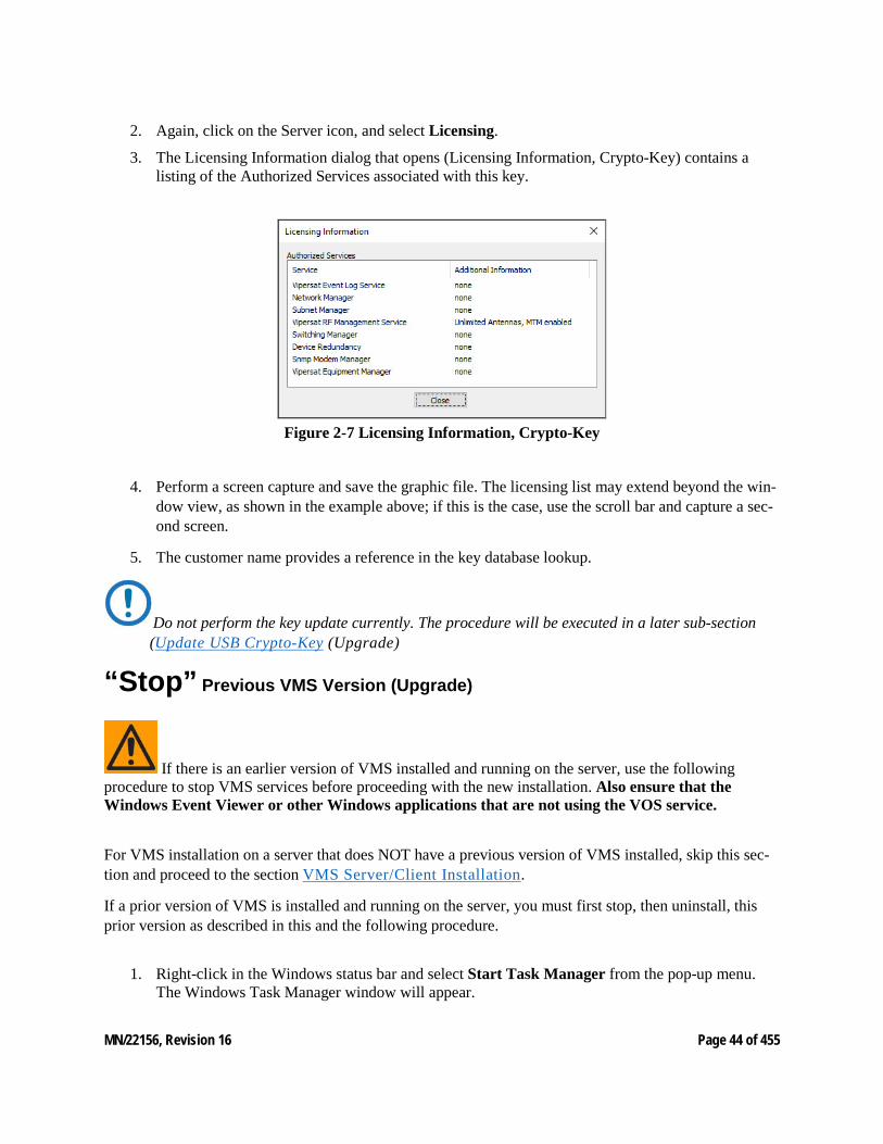
2. Again, click on the Server icon, and select Licensing.
3. The Licensing Information dialog that opens (Licensing Information, Crypto-Key) contains a listing of the Authorized Services associated with this key.
Figure 2-7 Licensing Information, Crypto-Key
4. Perform a screen capture and save the graphic file. The licensing list may extend beyond the win-dow view, as shown in the example above; if this is the case, use the scroll bar and capture a sec-ond screen.
5. The customer name provides a reference in the key database lookup.
Do not perform the key update currently. The procedure will be executed in a later sub-section (Update USB Crypto-Key (Upgrade)
“Stop” Previous VMS Version (Upgrade)
If there is an earlier version of VMS installed and running on the server, use the following procedure to stop VMS services before proceeding with the new installation. Also ensure that the Windows Event Viewer or other Windows applications that are not using the VOS service.
For VMS installation on a server that does NOT have a previous version of VMS installed, skip this sec-tion and proceed to the section VMS Server/Client Installation.
If a prior version of VMS is installed and running on the server, you must first stop, then uninstall, this prior version as described in this and the following procedure.
1. Right-click in the Windows status bar and select Start Task Manager from the pop-up menu. The Windows Task Manager window will appear.
MN/22156, Revision 16 Page 45 of 455
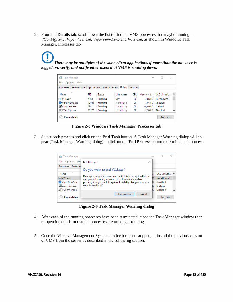
2. From the Details tab, scroll down the list to find the VMS processes that maybe running—VConMgr.exe, ViperView.exe, ViperView2.exe and VOS.exe, as shown in Windows Task Manager, Processes tab.
There may be multiples of the same client applications if more than the one user is logged on, verify and notify other users that VMS is shutting down.
Figure 2-8 Windows Task Manager, Processes tab
3. Select each process and click on the End Task button. A Task Manager Warning dialog will ap-pear (Task Manager Warning dialog)—click on the End Process button to terminate the process.
Figure 2-9 Task Manager Warning dialog
4. After each of the running processes have been terminated, close the Task Manager window then re-open it to confirm that the processes are no longer running.
5. Once the Vipersat Management System service has been stopped, uninstall the previous version of VMS from the server as described in the following section.
MN/22156, Revision 16 Page 46 of 455
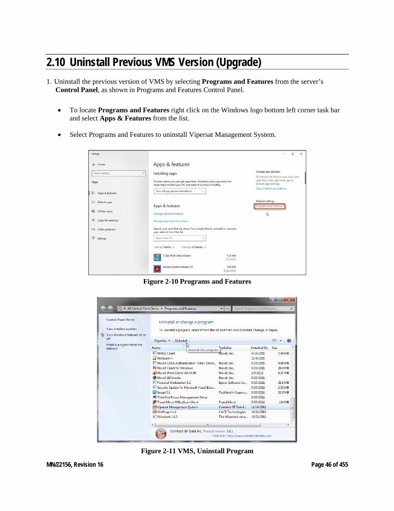
2.10 Uninstall Previous VMS Version (Upgrade) 1. Uninstall the previous version of VMS by selecting Programs and Features from the server’s
Control Panel, as shown in Programs and Features Control Panel.
• To locate Programs and Features right click on the Windows logo bottom left corner task bar and select Apps & Features from the list.
• Select Programs and Features to uninstall Vipersat Management System.
Figure 2-10 Programs and Features
Figure 2-11 VMS, Uninstall Program
MN/22156, Revision 16 Page 47 of 455
2. Select Vipersat Management System and click the Uninstall button (VMS, Uninstall Program).
If any previous versions of Heights device driver were installed, uninstall before upgrading to new installation. If there are new additional drivers, install after VMS. Note drivers must be in-stalled with VOS service not running.
3. Close the Programs and Features window.
2.11 Update USB Crypto-Key (Upgrade) Execute the procedure for updating the CEFD USB Crypto-Key that was provided by CEFD PSO (refer to the section Prepare for Crypto-Key Updating (Upgrade) prior to performing the VMS Server instal-lation procedure in the following section.
PSO will provide both the vipersat.vku update file and the vms-key-update.exe update utility.
If this procedure has not yet been provided, contact “Contact Information” and update the Key before continuing with installation.
MN/22156, Revision 16 Page 48 of 455
2.12 VMS Server/Client Installation
If this is a clean installation, ensure that the CEFD USB Crypto-Key is not plugged in at this time.
The installation process will install the drivers necessary for the key. The key will be inserted later when the VMS is ready to be started (Verify Server Installation).
For VMS Redundancy Server configurations, after installing VMS on each of the servers as de-scribed in this section, refer to Appendix C, “Redundancy”, for detailed instructions for config-uring the redundant servers.
For Client only installations see Appendix G, “VMS Client Users”, for security account control.
1. Locate the file VMS 3.x.x Core Setup.exe in the VMS distribution file set (available from www.comtechefdata.com, or from “Contact Information”) and double-click it to start the VMS Installer.
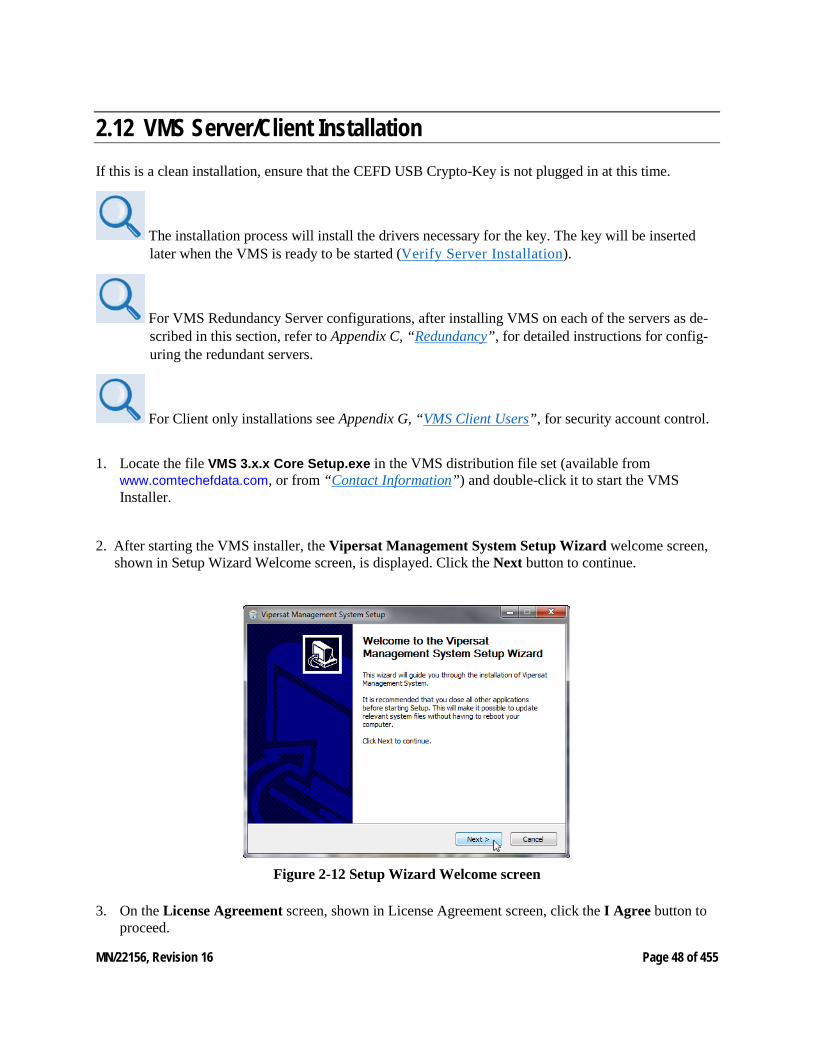
2. After starting the VMS installer, the Vipersat Management System Setup Wizard welcome screen, shown in Setup Wizard Welcome screen, is displayed. Click the Next button to continue.
Figure 2-12 Setup Wizard Welcome screen
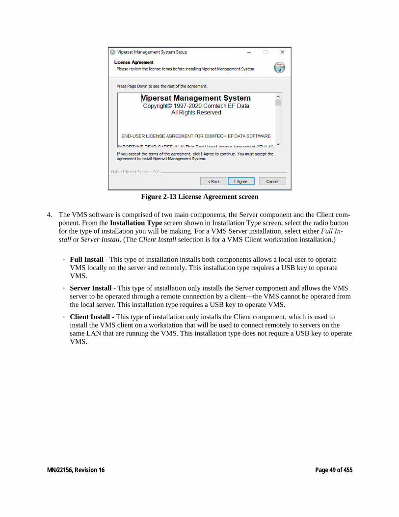
3. On the License Agreement screen, shown in License Agreement screen, click the I Agree button to proceed.
MN/22156, Revision 16 Page 49 of 455
Figure 2-13 License Agreement screen
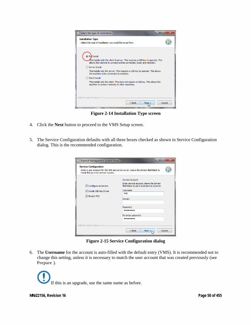
4. The VMS software is comprised of two main components, the Server component and the Client com-ponent. From the Installation Type screen shown in Installation Type screen, select the radio button for the type of installation you will be making. For a VMS Server installation, select either Full In-stall or Server Install. (The Client Install selection is for a VMS Client workstation installation.)
• Full Install - This type of installation installs both components allows a local user to operate VMS locally on the server and remotely. This installation type requires a USB key to operate VMS.
• Server Install - This type of installation only installs the Server component and allows the VMS server to be operated through a remote connection by a client—the VMS cannot be operated from the local server. This installation type requires a USB key to operate VMS.
• Client Install - This type of installation only installs the Client component, which is used to install the VMS client on a workstation that will be used to connect remotely to servers on the same LAN that are running the VMS. This installation type does not require a USB key to operate VMS.
MN/22156, Revision 16 Page 50 of 455
Figure 2-14 Installation Type screen
4. Click the Next button to proceed to the VMS Setup screen.
5. The Service Configuration defaults with all three boxes checked as shown in Service Configuration dialog. This is the recommended configuration.
Figure 2-15 Service Configuration dialog
6. The Username for the account is auto-filled with the default entry (VMS). It is recommended not to change this setting, unless it is necessary to match the user account that was created previously (see Prepare ).
If this is an upgrade, use the same name as before.
MN/22156, Revision 16 Page 51 of 455
7. The Password field is auto-filled with the default password, V1persat. Enter a new password, if de-sired, to change the default setting. This password must match the password associated with the VMS user account.
If this is an upgrade of a domain account, enter the password associated with this account.
8. Click the Next button when this dialog is complete.
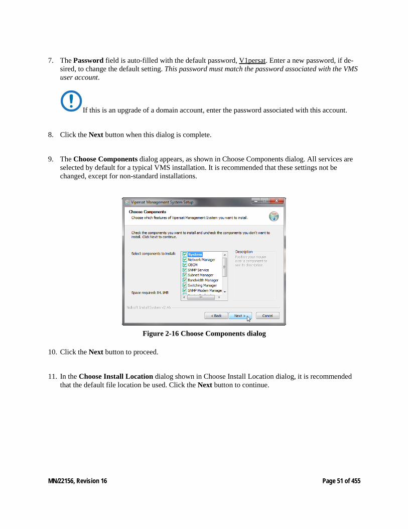
9. The Choose Components dialog appears, as shown in Choose Components dialog. All services are selected by default for a typical VMS installation. It is recommended that these settings not be changed, except for non-standard installations.
Figure 2-16 Choose Components dialog
10. Click the Next button to proceed.
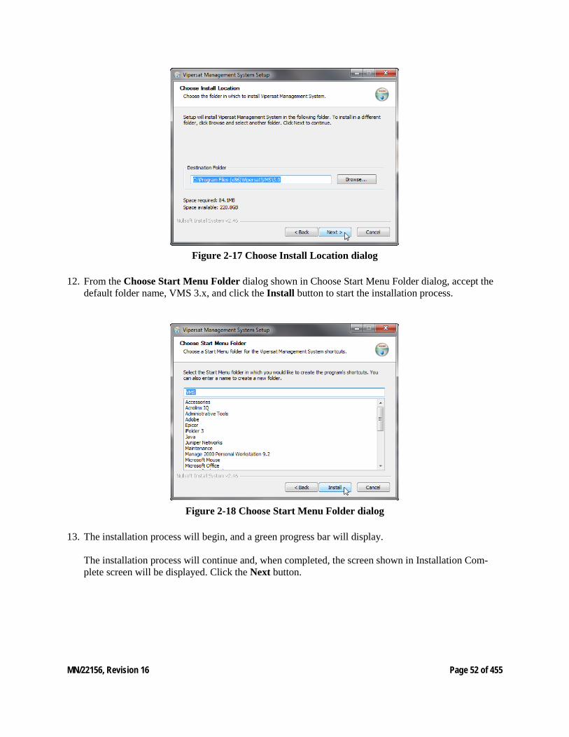
11. In the Choose Install Location dialog shown in Choose Install Location dialog, it is recommended that the default file location be used. Click the Next button to continue.
MN/22156, Revision 16 Page 52 of 455
Figure 2-17 Choose Install Location dialog
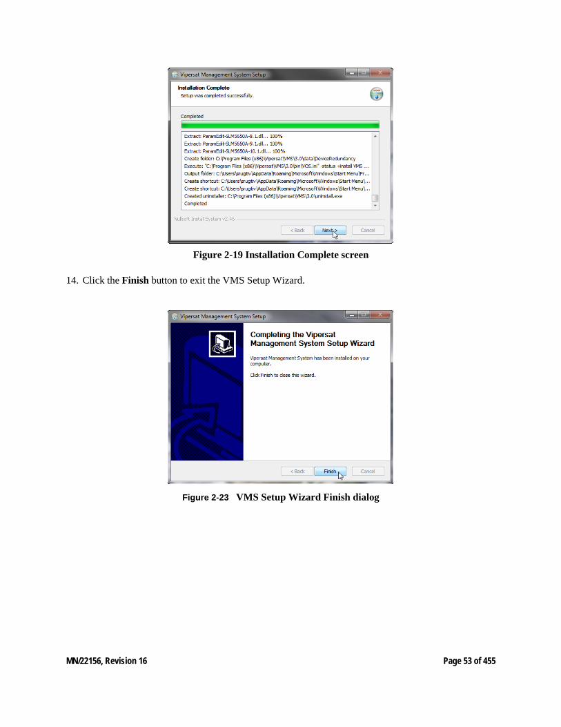
12. From the Choose Start Menu Folder dialog shown in Choose Start Menu Folder dialog, accept the default folder name, VMS 3.x, and click the Install button to start the installation process.
Figure 2-18 Choose Start Menu Folder dialog
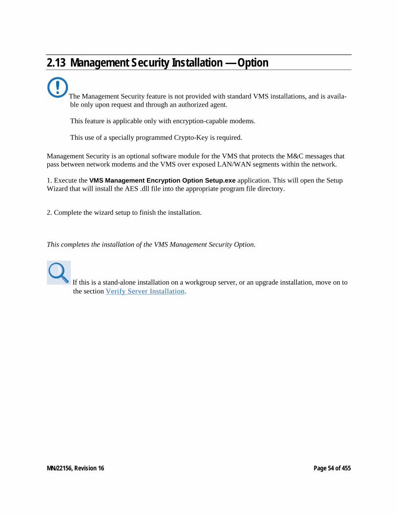
13. The installation process will begin, and a green progress bar will display. The installation process will continue and, when completed, the screen shown in Installation Com-plete screen will be displayed. Click the Next button.
MN/22156, Revision 16 Page 53 of 455
Figure 2-19 Installation Complete screen
14. Click the Finish button to exit the VMS Setup Wizard.
Figure 2‑23 VMS Setup Wizard Finish dialog
MN/22156, Revision 16 Page 54 of 455
2.13 Management Security Installation — Option
The Management Security feature is not provided with standard VMS installations, and is availa-ble only upon request and through an authorized agent. This feature is applicable only with encryption-capable modems. This use of a specially programmed Crypto-Key is required.
Management Security is an optional software module for the VMS that protects the M&C messages that pass between network modems and the VMS over exposed LAN/WAN segments within the network.
1. Execute the VMS Management Encryption Option Setup.exe application. This will open the Setup Wizard that will install the AES .dll file into the appropriate program file directory.
2. Complete the wizard setup to finish the installation.
This completes the installation of the VMS Management Security Option.
If this is a stand-alone installation on a workgroup server, or an upgrade installation, move on to the section Verify Server Installation.
MN/22156, Revision 16 Page 55 of 455
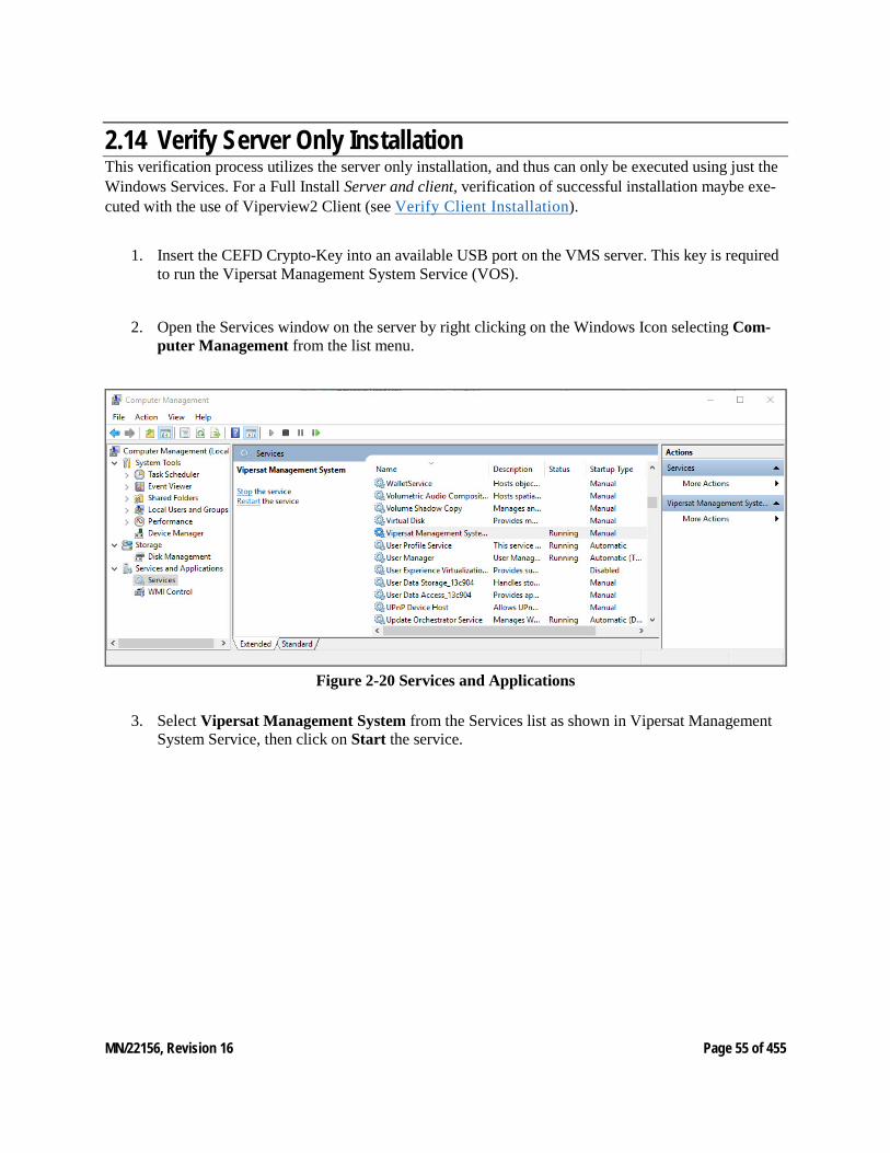
2.14 Verify Server Only Installation This verification process utilizes the server only installation, and thus can only be executed using just the Windows Services. For a Full Install Server and client, verification of successful installation maybe exe-cuted with the use of Viperview2 Client (see Verify Client Installation).
1. Insert the CEFD Crypto-Key into an available USB port on the VMS server. This key is required to run the Vipersat Management System Service (VOS).
2. Open the Services window on the server by right clicking on the Windows Icon selecting Com-puter Management from the list menu.
Figure 2-20 Services and Applications
3. Select Vipersat Management System from the Services list as shown in Vipersat Management System Service, then click on Start the service.
MN/22156, Revision 16 Page 56 of 455
This will start the VOS (Vipersat Object Service) process. VOS.exe will appear in the Processes tab of the Windows Task Manager.
The CEFD Crypto-Key must be connected to the server’s USB port. Otherwise, the attempt to start VMS (VOS) will fail.
If the Start attempt fails, proceed to VMS Service Start Failure.
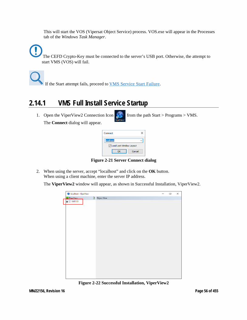
2.14.1 VMS Full Install Service Startup 1. Open the ViperView2 Connection Icon from the path Start > Programs > VMS.
The Connect dialog will appear.
Figure 2-21 Server Connect dialog
2. When using the server, accept “localhost” and click on the OK button. When using a client machine, enter the server IP address.
The ViperView2 window will appear, as shown in Successful Installation, ViperView2.
Figure 2-22 Successful Installation, ViperView2
MN/22156, Revision 16 Page 57 of 455
To verify the version of VMS that is installed, right click server on the top of the ViperView2 tree view shown and select About.
For upgrade installations only, activate the server processes and verify that the network database configuration is accurately displayed.
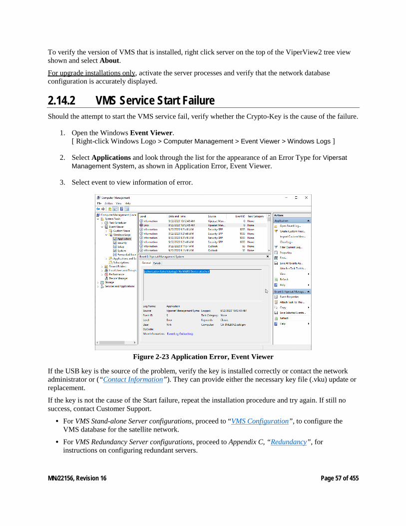
2.14.2 VMS Service Start Failure Should the attempt to start the VMS service fail, verify whether the Crypto-Key is the cause of the failure.
1. Open the Windows Event Viewer. [ Right-click Windows Logo > Computer Management > Event Viewer > Windows Logs ]
2. Select Applications and look through the list for the appearance of an Error Type for Vipersat Management System, as shown in Application Error, Event Viewer.
3. Select event to view information of error.
Figure 2-23 Application Error, Event Viewer
If the USB key is the source of the problem, verify the key is installed correctly or contact the network administrator or (“Contact Information”). They can provide either the necessary key file (.vku) update or replacement.
If the key is not the cause of the Start failure, repeat the installation procedure and try again. If still no success, contact Customer Support.
• For VMS Stand-alone Server configurations, proceed to “VMS Configuration”, to configure the VMS database for the satellite network.
• For VMS Redundancy Server configurations, proceed to Appendix C, “Redundancy”, for instructions on configuring redundant servers.
MN/22156, Revision 16 Page 58 of 455
2.15 VMS Client Installation The Vipersat Management System Client software should be installed on a high-performance, industry-standard workstation computer running Microsoft Windows 10. For specifications for the minimum recommended VMS platform configuration, please refer to the VMS Release Notes for the version of software that will be installed.
Dual monitors are recommended for greater viewing of multiple windows. The VMS Client software is installed using the same installation disk used for the Server installation. The Installation Wizard will prompt the user for Full Install, Server Install, or Client Install. Selection of the Client will only install the necessary files without prompting for USB key and password. This type of in-stallation only installs the Client component on a workstation that will be used to connect remotely to the server(s) on the same LAN that are running the VMS. This installation type does not require a USB key to operate the software.
The installation does not require the USB Crypto-Key as there are no services running on the cli-ent workstation. This machine will require network connections and proper security configurations to connect to the active VMS sever.
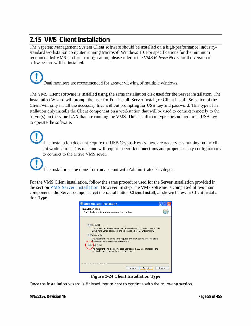
The install must be done from an account with Administrator Privileges. For the VMS Client installation, follow the same procedure used for the Server installation provided in the section VMS Server Installation. However, in step The VMS software is comprised of two main components, the Server compo, select the radial button Client Install, as shown below in Client Installa-tion Type.
Figure 2-24 Client Installation Type
Once the installation wizard is finished, return here to continue with the following section.
MN/22156, Revision 16 Page 59 of 455
2.16 Create Client Accounts It is necessary to configure the appropriate security settings for the Client workstation to gain network access privileges to the VMS server.
Follow the procedure in Appendix G, “VMS Client Users” for setting up client user accounts.
2.16.1 Verify Client Installation After installation, verify that the VMS Client installation was successful by running the program. The VMS Server must be running VOS, the Vipersat Management System service (see Verify Server Instal-lation for the necessary steps to start the VMS service).
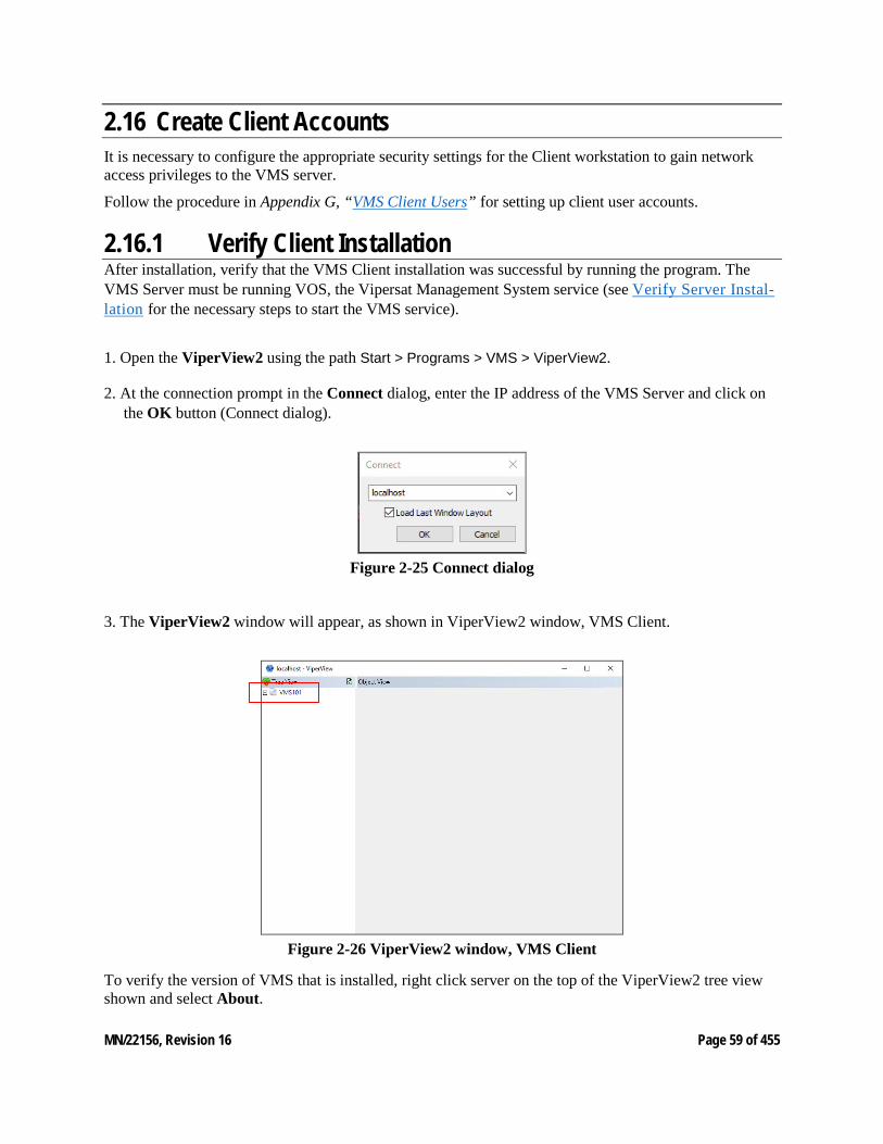
1. Open the ViperView2 using the path Start > Programs > VMS > ViperView2.
2. At the connection prompt in the Connect dialog, enter the IP address of the VMS Server and click on the OK button (Connect dialog).
Figure 2-25 Connect dialog
3. The ViperView2 window will appear, as shown in ViperView2 window, VMS Client.
Figure 2-26 ViperView2 window, VMS Client
To verify the version of VMS that is installed, right click server on the top of the ViperView2 tree view shown and select About.
MN/22156, Revision 16 Page 60 of 455
3 VMS CONFIGURATION 3. VMS Configuration The VMS configuration procedure assumes that the user is experienced with the VMS and/or has attended the System Operator training course and gives summary instructions for configuring an installed VMS. If difficulties are experienced during configuration, contact Comtech EF Data’s ESC for assistance.
This procedure must be executed in the order that is presented to ensure proper setup and configuration. After file installation and network hardware is in place and operational, the equipment should be communicating with the network management system. That is, the VMS has IP access to each unit either through a LAN or satellite connection.
Once the VMS is installed, started up, and the initial Vipersat Manager configuration is completed, the VMS immediately starts gathering and storing information from the units which make up the network.
For a Redundant VMS Server configuration, perform the VMS configuration procedure on the Active server only. When completed, perform a server synchronization to synchronize the server databases.
Before proceeding with configuring the network using VMS, the Administrator’s Network Plan and the following network information should be available, for reference.
• A list of all equipment used in the network, broken down by site.
• A schematic or other documentation of the network’s topology.
• A Physical site map where each piece of equipment is located.
• IP addresses assigned to all network hardware.
• Documentation assigning IP address numbers and subnet masks to each site in the network, the multicast address(s) to be used, and the IP address of the VMS server’s connection to the network.
• The functions each piece of equipment is to perform in the network (Hub, Remote, Expansion unit, etc.) and the equipment type (CDM-570/570L, CDD-564/564L, CDM-570A/570AL, CDM-625A, HEIGHTS, etc.).
MN/22156, Revision 16 Page 61 of 455
• All frequencies and frequency allocations to be used by each site and each piece of equipment, and available pool frequencies.
• Types of traffic expected to be handled by each site and corresponding bandwidth allocations to accommodate the expected traffic volume and type.
• A list of the VMS licensing options that have been purchased. Details can be found on the Purchase Order, or a CEFD representative can provide detailed information on licensing options and pricing for the VMS-managed network.
• A list of network modem equipment and the FAST features associated with each. This information can be obtained either via Telnet from the Main>Administration>Feature Configuration screen, or with Vload and the use of the Parameter Editor (Features tab).
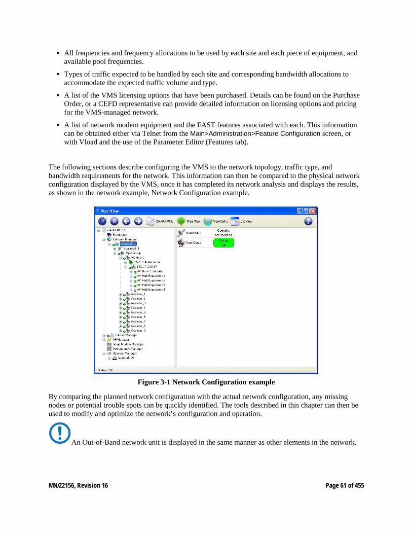
The following sections describe configuring the VMS to the network topology, traffic type, and bandwidth requirements for the network. This information can then be compared to the physical network configuration displayed by the VMS, once it has completed its network analysis and displays the results, as shown in the network example, Network Configuration example.
Figure 3-1 Network Configuration example
By comparing the planned network configuration with the actual network configuration, any missing nodes or potential trouble spots can be quickly identified. The tools described in this chapter can then be used to modify and optimize the network’s configuration and operation.
An Out-of-Band network unit is displayed in the same manner as other elements in the network.
MN/22156, Revision 16 Page 62 of 455
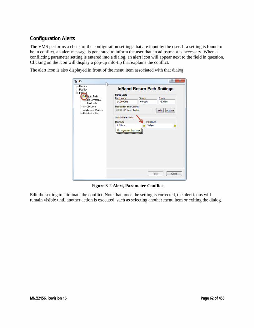
Configuration Alerts The VMS performs a check of the configuration settings that are input by the user. If a setting is found to be in conflict, an alert message is generated to inform the user that an adjustment is necessary. When a conflicting parameter setting is entered into a dialog, an alert icon will appear next to the field in question. Clicking on the icon will display a pop-up info-tip that explains the conflict.
The alert icon is also displayed in front of the menu item associated with that dialog.
Figure 3-2 Alert, Parameter Conflict
Edit the setting to eliminate the conflict. Note that, once the setting is corrected, the alert icons will remain visible until another action is executed, such as selecting another menu item or exiting the dialog.
MN/22156, Revision 16 Page 63 of 455
3.1 Hardware Configuration
For VMS compatibility, see the product Release Notes for specific versions of each modem type that is supported.
Once all the needed information is obtained, configuration can begin. Before making the physical installation of hardware into a network, each modem must be pre-configured using either Telnet (CLI) or HTTP. Refer to the modem’s documentation for details.
Comtech EF Data ships all modems with FAST Codes pre-configured. The modems are always configured at the factory as type Remote, with the Default Gateway pointed toward the Satellite, and with STDMA or ECM disabled.
At this point, VMS cannot discover the node. The operator can either use Telnet (CLI) or HTTP to set up these parameters.
As a minimum, the following items in the modem will have to be configured before it will be able to communicate with the VMS following installation in the network:
• Network ID
• Receive Multicast Address
• Managing IP address is set through reception of VMS announcement multicast message that is sent continuously on timed intervals.
Once the modems have the minimum required configuration and an installer successfully points the antenna at the satellite and establishes a receive link, the operator at the Hub site can push frequencies, bit rates, and FEC code rates to the units at remote sites using the VMS. The frequencies can be anywhere in the customer’s frequency pool, allowing a thin-route SCPC connection to be established with the satellite network’s modems.
For example, once communication is established, the Hub operator can set up the unit for STDMA or ECM channel using the instructions found in each modem manual. After a reset, the unit will come back online operating in either STDMA or ECM mode with the desired configuration.
Once communication is established between VMS and all network devices, the network is ready to be configured.
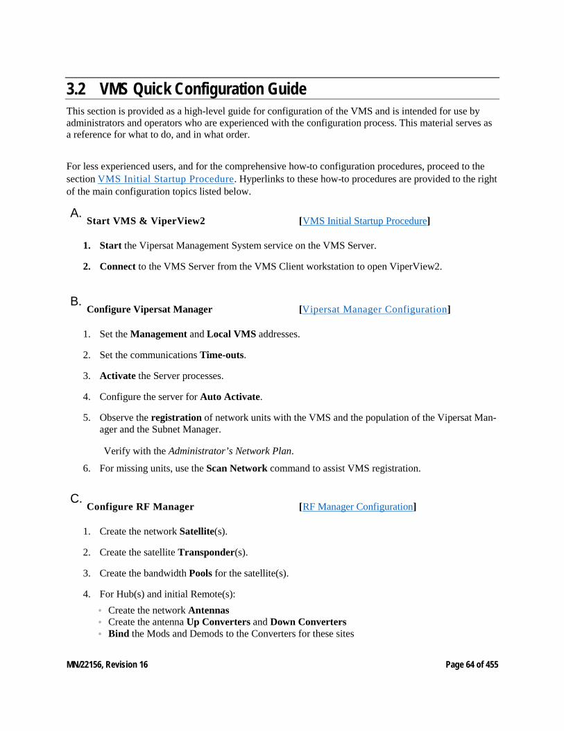
MN/22156, Revision 16 Page 64 of 455
3.2 VMS Quick Configuration Guide This section is provided as a high-level guide for configuration of the VMS and is intended for use by administrators and operators who are experienced with the configuration process. This material serves as a reference for what to do, and in what order.
For less experienced users, and for the comprehensive how-to configuration procedures, proceed to the section VMS Initial Startup Procedure. Hyperlinks to these how-to procedures are provided to the right of the main configuration topics listed below.
A.Start VMS & ViperView2 [VMS Initial Startup Procedure]
1. Start the Vipersat Management System service on the VMS Server.
2. Connect to the VMS Server from the VMS Client workstation to open ViperView2.
B.
Configure Vipersat Manager [Vipersat Manager Configuration]
1. Set the Management and Local VMS addresses.
2. Set the communications Time-outs.
3. Activate the Server processes.
4. Configure the server for Auto Activate.
5. Observe the registration of network units with the VMS and the population of the Vipersat Man-ager and the Subnet Manager.
Verify with the Administrator’s Network Plan.
6. For missing units, use the Scan Network command to assist VMS registration.
C.
Configure RF Manager [RF Manager Configuration]
1. Create the network Satellite(s).
2. Create the satellite Transponder(s).
3. Create the bandwidth Pools for the satellite(s).
4. For Hub(s) and initial Remote(s): • Create the network Antennas • Create the antenna Up Converters and Down Converters • Bind the Mods and Demods to the Converters for these sites
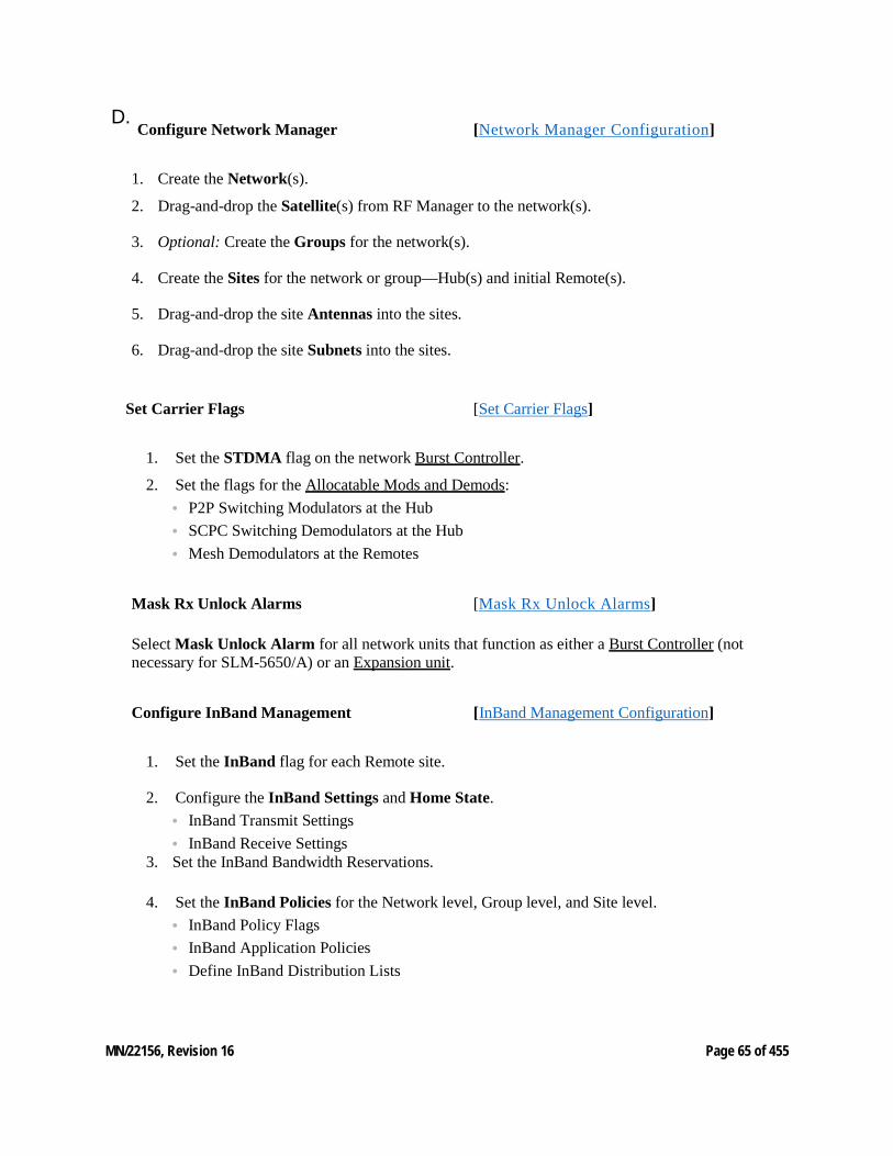
MN/22156, Revision 16 Page 65 of 455
D.Configure Network Manager [Network Manager Configuration]
1. Create the Network(s).
2. Drag-and-drop the Satellite(s) from RF Manager to the network(s).
3. Optional: Create the Groups for the network(s).
4. Create the Sites for the network or group—Hub(s) and initial Remote(s).
5. Drag-and-drop the site Antennas into the sites.
6. Drag-and-drop the site Subnets into the sites.
Set Carrier Flags [Set Carrier Flags]
1. Set the STDMA flag on the network Burst Controller.
2. Set the flags for the Allocatable Mods and Demods: • P2P Switching Modulators at the Hub • SCPC Switching Demodulators at the Hub • Mesh Demodulators at the Remotes
Mask Rx Unlock Alarms [Mask Rx Unlock Alarms]
Select Mask Unlock Alarm for all network units that function as either a Burst Controller (not necessary for SLM-5650/A) or an Expansion unit.
Configure InBand Management [InBand Management Configuration]
1. Set the InBand flag for each Remote site.
2. Configure the InBand Settings and Home State. • InBand Transmit Settings • InBand Receive Settings
3. Set the InBand Bandwidth Reservations.
4. Set the InBand Policies for the Network level, Group level, and Site level. • InBand Policy Flags • InBand Application Policies • Define InBand Distribution Lists

MN/22156, Revision 16 Page 66 of 455
Perform Switching Function Verification [Switching Function Verification]
Create Additional Remote Sites with Remote Site Wizard [Remote Site Wizard]
Configure Advanced Switching [Set InBand Modulation and Coding]
E.
Configure Redundancy [Redundancy Configuration] Configure M:N Hub Device Redundancy Configure VMS Redundancy G.
Configure Encryption [Encryption Configuration]
Management Security Option
This feature option is NOT included with the standard VMS package, and is only available upon request from an authorized agent.
1. Enable Management and/or Switching encryption for the VMS server.
2. Enter the Encryption Key.
Modem TRANSEC Setting (SLM-5650A/B only) Specify the number of FIPS Blocks per Frame for the modem.
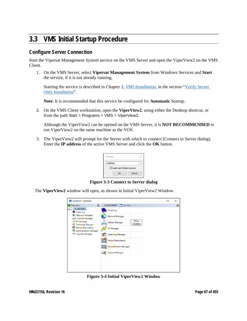
MN/22156, Revision 16 Page 67 of 455
3.3 VMS Initial Startup Procedure Configure Server Connection Start the Vipersat Management System service on the VMS Server and open the ViperView2 on the VMS Client.
1. On the VMS Server, select Vipersat Management System from Windows Services and Start the service, if it is not already running.
Starting the service is described in Chapter 2, VMS Installation, in the section “Verify Server Only Installation”.
Note: It is recommended that this service be configured for Automatic Startup.
2. On the VMS Client workstation, open the ViperView2, using either the Desktop shortcut, or from the path Start > Programs > VMS > ViperView2.
Although the ViperView2 can be opened on the VMS Server, it is NOT RECOMMENDED to run ViperView2 on the same machine as the VOS.
3. The ViperView2 will prompt for the Server with which to connect (Connect to Server dialog). Enter the IP address of the active VMS Server and click the OK button.
Figure 3-3 Connect to Server dialog
The ViperView2 window will open, as shown in Initial ViperView2 Window.
Figure 3-4 Initial ViperView2 Window
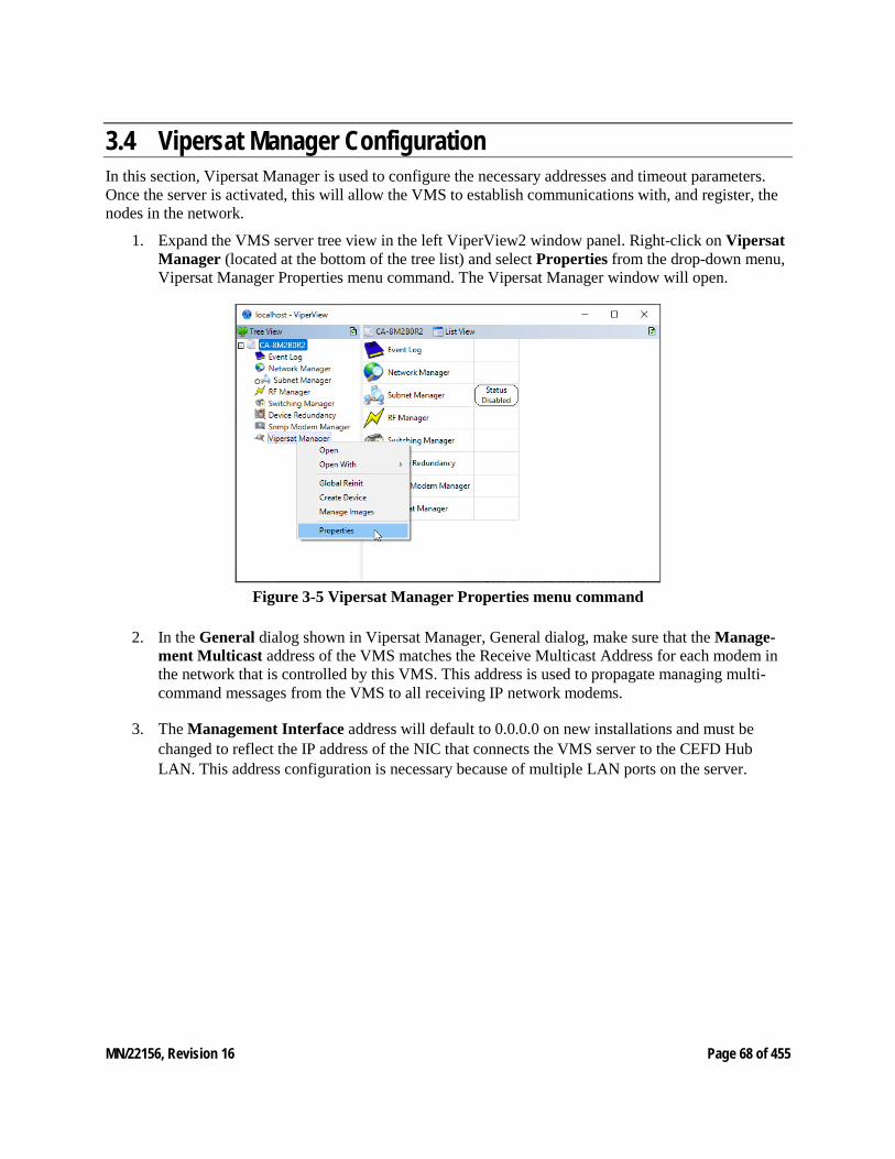
MN/22156, Revision 16 Page 68 of 455
3.4 Vipersat Manager Configuration In this section, Vipersat Manager is used to configure the necessary addresses and timeout parameters. Once the server is activated, this will allow the VMS to establish communications with, and register, the nodes in the network.
1. Expand the VMS server tree view in the left ViperView2 window panel. Right-click on Vipersat Manager (located at the bottom of the tree list) and select Properties from the drop-down menu, Vipersat Manager Properties menu command. The Vipersat Manager window will open.
Figure 3-5 Vipersat Manager Properties menu command
2. In the General dialog shown in Vipersat Manager, General dialog, make sure that the Manage-ment Multicast address of the VMS matches the Receive Multicast Address for each modem in the network that is controlled by this VMS. This address is used to propagate managing multi-command messages from the VMS to all receiving IP network modems.
3. The Management Interface address will default to 0.0.0.0 on new installations and must be changed to reflect the IP address of the NIC that connects the VMS server to the CEFD Hub LAN. This address configuration is necessary because of multiple LAN ports on the server.
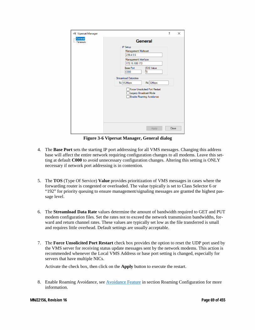
MN/22156, Revision 16 Page 69 of 455
Figure 3-6 Vipersat Manager, General dialog
4. The Base Port sets the starting IP port addressing for all VMS messages. Changing this address base will affect the entire network requiring configuration changes to all modems. Leave this set-ting at default C000 to avoid unnecessary configuration changes. Altering this setting is ONLY necessary if network port addressing is in contention.
5. The TOS (Type Of Service) Value provides prioritization of VMS messages in cases where the forwarding router is congested or overloaded. The value typically is set to Class Selector 6 or “192” for priority queuing to ensure management/signaling messages are granted the highest pas-sage level.
6. The Streamload Data Rate values determine the amount of bandwidth required to GET and PUT modem configuration files. Set the rates not to exceed the network transmission bandwidths, for-ward and return channel rates. These values are typically set low as the file transferred is small and requires little overhead. Default settings are usually acceptable.
7. The Force Unsolicited Port Restart check box provides the option to reset the UDP port used by the VMS server for receiving status update messages sent by the network modems. This action is recommended whenever the Local VMS Address or base port setting is changed, especially for servers that have multiple NICs.
Activate the check box, then click on the Apply button to execute the restart.
8. Enable Roaming Avoidance, see Avoidance Feature in section Roaming Configuration for more information.
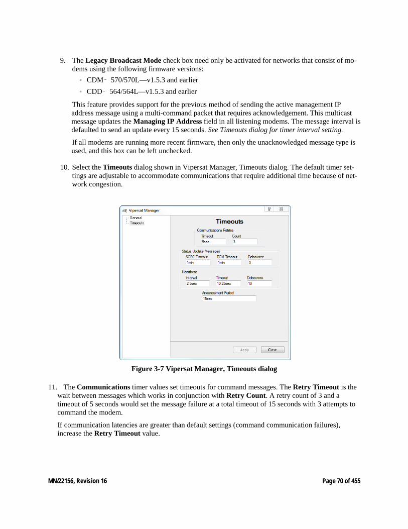
MN/22156, Revision 16 Page 70 of 455
9. The Legacy Broadcast Mode check box need only be activated for networks that consist of mo-dems using the following firmware versions:
• CDM‑ 570/570L—v1.5.3 and earlier • CDD‑ 564/564L—v1.5.3 and earlier
This feature provides support for the previous method of sending the active management IP address message using a multi-command packet that requires acknowledgement. This multicast message updates the Managing IP Address field in all listening modems. The message interval is defaulted to send an update every 15 seconds. See Timeouts dialog for timer interval setting.
If all modems are running more recent firmware, then only the unacknowledged message type is used, and this box can be left unchecked.
10. Select the Timeouts dialog shown in Vipersat Manager, Timeouts dialog. The default timer set-tings are adjustable to accommodate communications that require additional time because of net-work congestion.
Figure 3-7 Vipersat Manager, Timeouts dialog
11. The Communications timer values set timeouts for command messages. The Retry Timeout is the wait between messages which works in conjunction with Retry Count. A retry count of 3 and a timeout of 5 seconds would set the message failure at a total timeout of 15 seconds with 3 attempts to command the modem.
If communication latencies are greater than default settings (command communication failures), increase the Retry Timeout value.
MN/22156, Revision 16 Page 71 of 455
12. The Status Update Messages (SUMs) values set the dual timeouts and debounce for Remotes that are either in SCPC mode or ECM. • The SCPC Timeout parameter is the time interval between the sending of SUMs to the VMS by
Remotes that are in SCPC mode. • The ECM Timeout is the time interval between the sending of SUMs to the VMS by Remotes
that are in Entry Channel Mode. • The Debounce is a counter setting for the number of consecutive time intervals that can pass
without the VMS receiving a SUM for a particular Remote unit before a switch failure occurs for that Remote.
Generally, the SCPC Timeout is set to a relatively short interval to provide timely responses to switch requests, such as due to variations in load for Load Switching applications.
For networks that support large numbers of Remotes that are often operating in ECM—such as those in “Wait” mode, for example—, a longer interval setting for ECM Timeout will reduce contention for shared bandwidth usage.
13. The Heartbeat timer settings include the Interval, Timeout and Debounce values for Hub device redundancy messaging. • The Interval parameter updates the modem to send its heartbeat message to the VMS at the set
rate. • The Timeout is how long the VMS will wait before determining communications failure and
commanding a device redundancy switchover. • The Debounce is a counter setting for the number of consecutive alarmed messages the VMS will
receive from a Hub unit before a redundancy switch is triggered. This parameter setting is useful for reducing or eliminating unnecessary redundancy triggers due to spurious alarms.
14. The Announcement Period is the interval at which the VMS will multicast its management IP address to all listening modems within the network. This ensures, for example, that remotes that are not online during a redundancy switch will pick up the new managing address when they come back online.
The default value (15sec) enables the VMS to send the update message on a 15 second interval to establish the current managing address in all modems set to receive the message.
15. Click the Apply button to save these settings for the Vipersat Manager Properties, then Close the window.
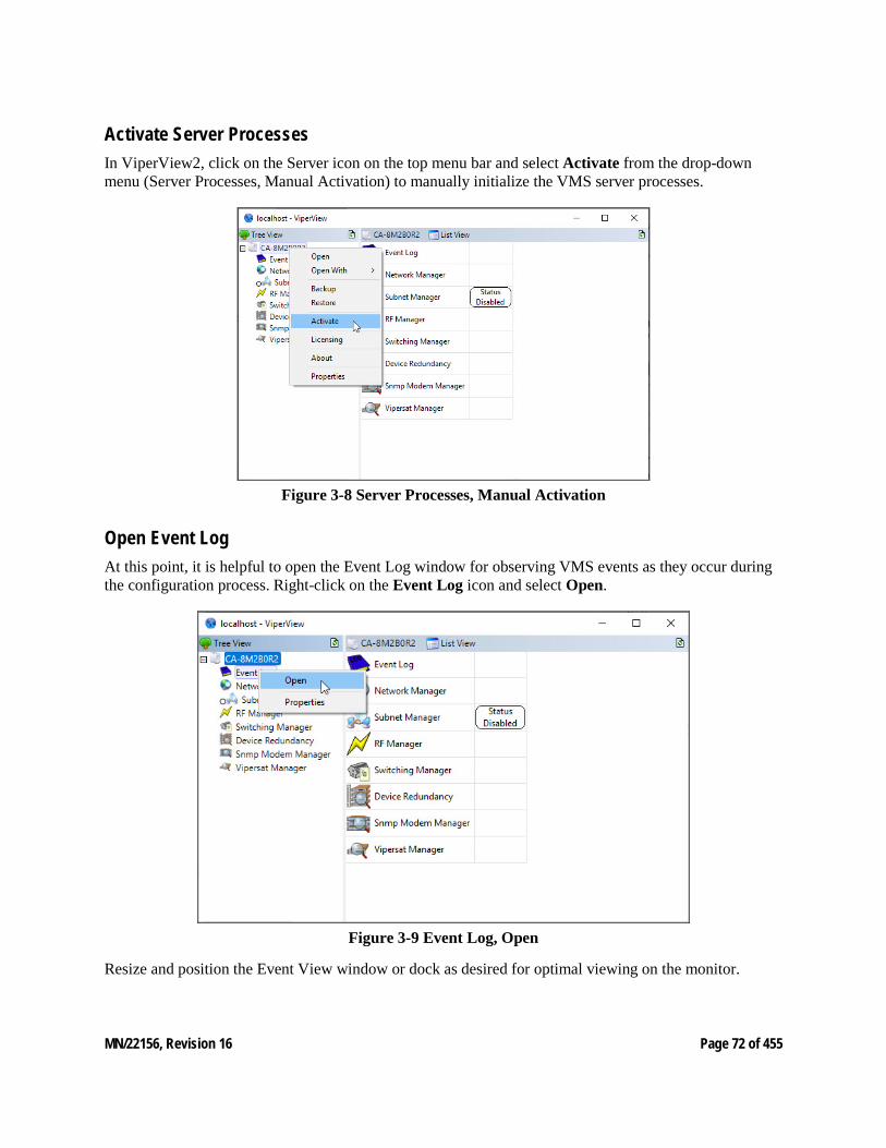
MN/22156, Revision 16 Page 72 of 455
Activate Server Processes In ViperView2, click on the Server icon on the top menu bar and select Activate from the drop-down menu (Server Processes, Manual Activation) to manually initialize the VMS server processes.
Figure 3-8 Server Processes, Manual Activation
Open Event Log At this point, it is helpful to open the Event Log window for observing VMS events as they occur during the configuration process. Right-click on the Event Log icon and select Open.
Figure 3-9 Event Log, Open
Resize and position the Event View window or dock as desired for optimal viewing on the monitor.
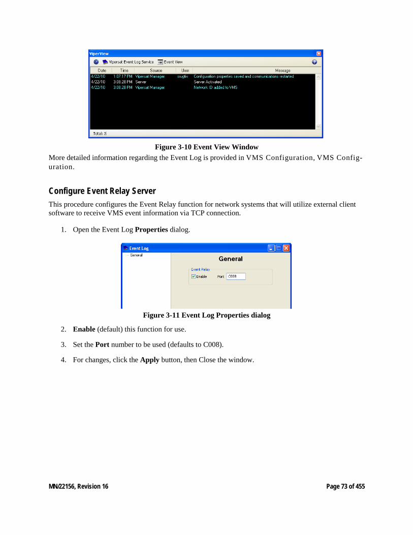
MN/22156, Revision 16 Page 73 of 455
Figure 3-10 Event View Window More detailed information regarding the Event Log is provided in VMS Configuration, VMS Config-uration.
Configure Event Relay Server This procedure configures the Event Relay function for network systems that will utilize external client software to receive VMS event information via TCP connection.
1. Open the Event Log Properties dialog.
Figure 3-11 Event Log Properties dialog
2. Enable (default) this function for use.
3. Set the Port number to be used (defaults to C008).
4. For changes, click the Apply button, then Close the window.
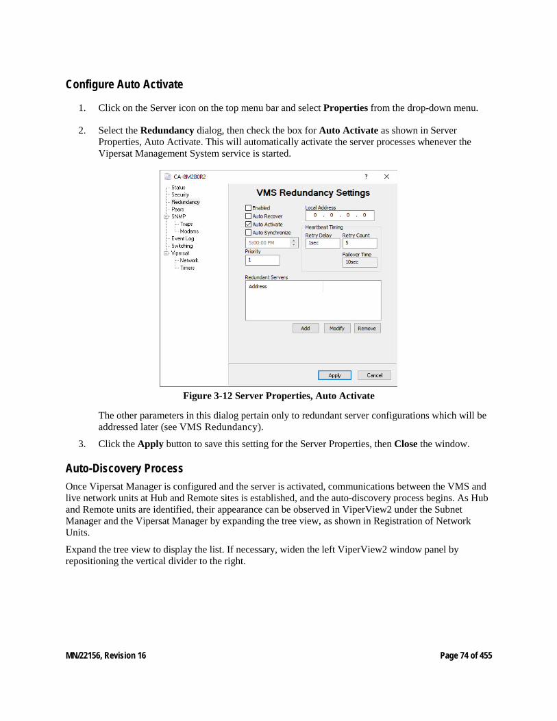
MN/22156, Revision 16 Page 74 of 455
Configure Auto Activate
1. Click on the Server icon on the top menu bar and select Properties from the drop-down menu.
2. Select the Redundancy dialog, then check the box for Auto Activate as shown in Server Properties, Auto Activate. This will automatically activate the server processes whenever the Vipersat Management System service is started.
Figure 3-12 Server Properties, Auto Activate
The other parameters in this dialog pertain only to redundant server configurations which will be addressed later (see VMS Redundancy).
3. Click the Apply button to save this setting for the Server Properties, then Close the window.
Auto-Discovery Process Once Vipersat Manager is configured and the server is activated, communications between the VMS and live network units at Hub and Remote sites is established, and the auto-discovery process begins. As Hub and Remote units are identified, their appearance can be observed in ViperView2 under the Subnet Manager and the Vipersat Manager by expanding the tree view, as shown in Registration of Network Units.
Expand the tree view to display the list. If necessary, widen the left ViperView2 window panel by repositioning the vertical divider to the right.
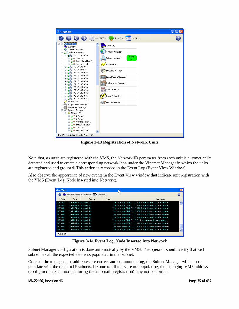
MN/22156, Revision 16 Page 75 of 455
Figure 3-13 Registration of Network Units
Note that, as units are registered with the VMS, the Network ID parameter from each unit is automatically detected and used to create a corresponding network icon under the Vipersat Manager in which the units are registered and grouped. This action is recorded in the Event Log (Event View Window).
Also observe the appearance of new events in the Event View window that indicate unit registration with the VMS (Event Log, Node Inserted into Network).
Figure 3-14 Event Log, Node Inserted into Network
Subnet Manager configuration is done automatically by the VMS. The operator should verify that each subnet has all the expected elements populated in that subnet.
Once all the management addresses are correct and communicating, the Subnet Manager will start to populate with the modem IP subnets. If some or all units are not populating, the managing VMS address (configured in each modem during the automatic registration) may not be correct.
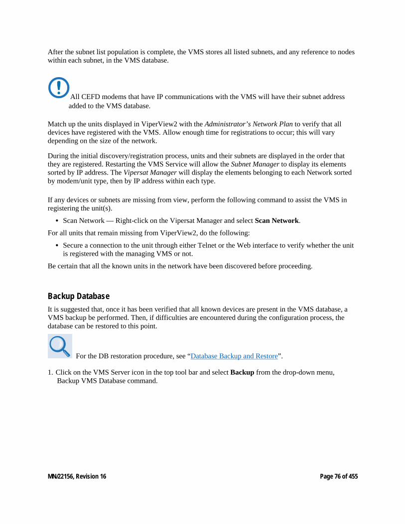
MN/22156, Revision 16 Page 76 of 455
After the subnet list population is complete, the VMS stores all listed subnets, and any reference to nodes within each subnet, in the VMS database.
All CEFD modems that have IP communications with the VMS will have their subnet address added to the VMS database.
Match up the units displayed in ViperView2 with the Administrator’s Network Plan to verify that all devices have registered with the VMS. Allow enough time for registrations to occur; this will vary depending on the size of the network.
During the initial discovery/registration process, units and their subnets are displayed in the order that they are registered. Restarting the VMS Service will allow the Subnet Manager to display its elements sorted by IP address. The Vipersat Manager will display the elements belonging to each Network sorted by modem/unit type, then by IP address within each type.
If any devices or subnets are missing from view, perform the following command to assist the VMS in registering the unit(s).
• Scan Network — Right-click on the Vipersat Manager and select Scan Network.
For all units that remain missing from ViperView2, do the following:
• Secure a connection to the unit through either Telnet or the Web interface to verify whether the unit is registered with the managing VMS or not.
Be certain that all the known units in the network have been discovered before proceeding.
Backup Database It is suggested that, once it has been verified that all known devices are present in the VMS database, a VMS backup be performed. Then, if difficulties are encountered during the configuration process, the database can be restored to this point.
For the DB restoration procedure, see “Database Backup and Restore”.
1. Click on the VMS Server icon in the top tool bar and select Backup from the drop-down menu, Backup VMS Database command.
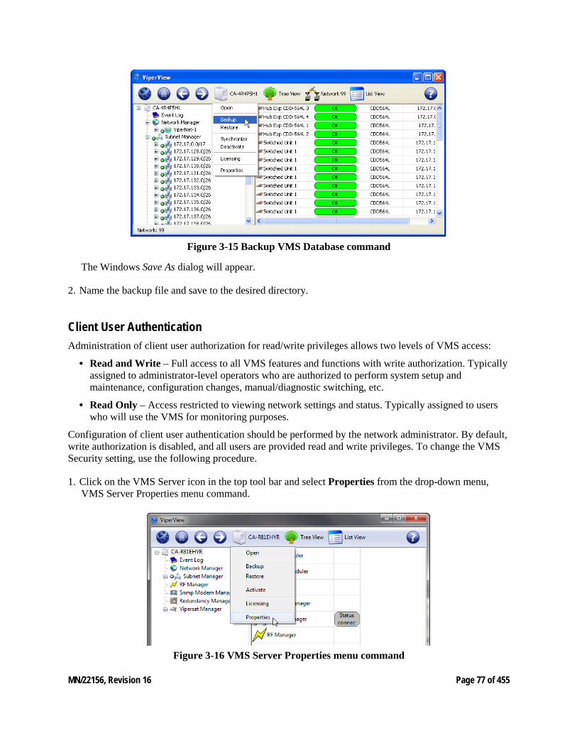
MN/22156, Revision 16 Page 77 of 455
Figure 3-15 Backup VMS Database command
The Windows Save As dialog will appear.
2. Name the backup file and save to the desired directory.
Client User Authentication Administration of client user authorization for read/write privileges allows two levels of VMS access:
• Read and Write – Full access to all VMS features and functions with write authorization. Typically assigned to administrator-level operators who are authorized to perform system setup and maintenance, configuration changes, manual/diagnostic switching, etc.
• Read Only – Access restricted to viewing network settings and status. Typically assigned to users who will use the VMS for monitoring purposes.
Configuration of client user authentication should be performed by the network administrator. By default, write authorization is disabled, and all users are provided read and write privileges. To change the VMS Security setting, use the following procedure.
1. Click on the VMS Server icon in the top tool bar and select Properties from the drop-down menu, VMS Server Properties menu command.
Figure 3-16 VMS Server Properties menu command
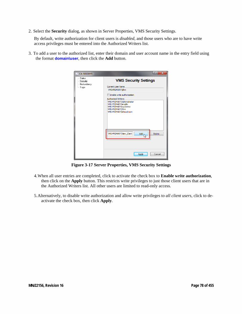
MN/22156, Revision 16 Page 78 of 455
2. Select the Security dialog, as shown in Server Properties, VMS Security Settings.
By default, write authorization for client users is disabled, and those users who are to have write access privileges must be entered into the Authorized Writers list.
3. To add a user to the authorized list, enter their domain and user account name in the entry field using the format domain\user, then click the Add button.
Figure 3-17 Server Properties, VMS Security Settings
4. When all user entries are completed, click to activate the check box to Enable write authorization, then click on the Apply button. This restricts write privileges to just those client users that are in the Authorized Writers list. All other users are limited to read-only access.
5. Alternatively, to disable write authorization and allow write privileges to all client users, click to de-activate the check box, then click Apply.
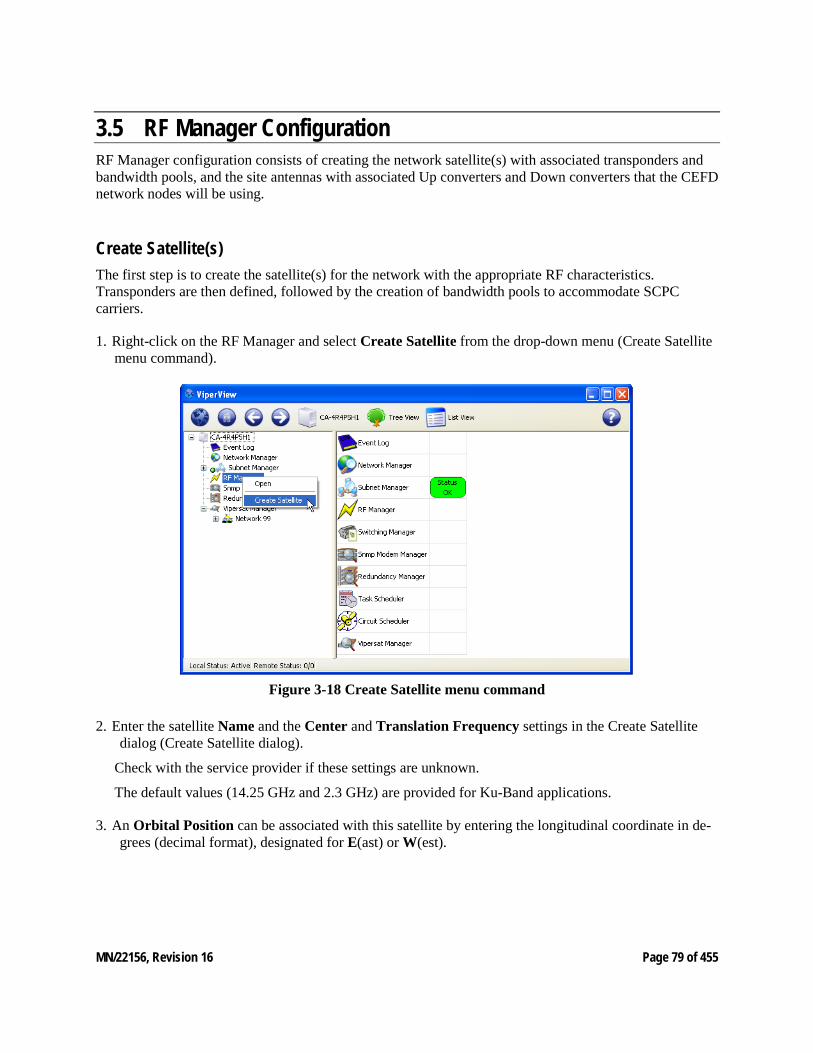
MN/22156, Revision 16 Page 79 of 455
3.5 RF Manager Configuration RF Manager configuration consists of creating the network satellite(s) with associated transponders and bandwidth pools, and the site antennas with associated Up converters and Down converters that the CEFD network nodes will be using.
Create Satellite(s) The first step is to create the satellite(s) for the network with the appropriate RF characteristics. Transponders are then defined, followed by the creation of bandwidth pools to accommodate SCPC carriers.
1. Right-click on the RF Manager and select Create Satellite from the drop-down menu (Create Satellite menu command).
Figure 3-18 Create Satellite menu command
2. Enter the satellite Name and the Center and Translation Frequency settings in the Create Satellite dialog (Create Satellite dialog).
Check with the service provider if these settings are unknown.
The default values (14.25 GHz and 2.3 GHz) are provided for Ku-Band applications.
3. An Orbital Position can be associated with this satellite by entering the longitudinal coordinate in de-grees (decimal format), designated for E(ast) or W(est).
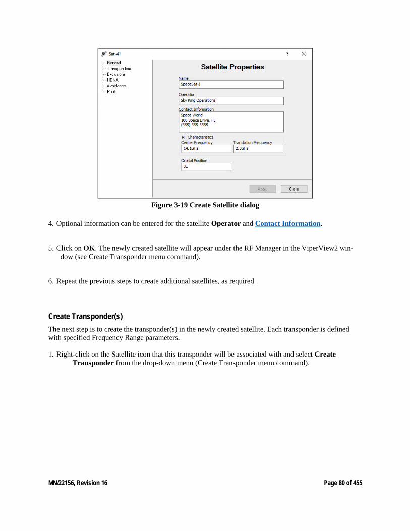
MN/22156, Revision 16 Page 80 of 455
Figure 3-19 Create Satellite dialog
4. Optional information can be entered for the satellite Operator and Contact Information.
5. Click on OK. The newly created satellite will appear under the RF Manager in the ViperView2 win-dow (see Create Transponder menu command).
6. Repeat the previous steps to create additional satellites, as required.
Create Transponder(s) The next step is to create the transponder(s) in the newly created satellite. Each transponder is defined with specified Frequency Range parameters.
1. Right-click on the Satellite icon that this transponder will be associated with and select Create Transponder from the drop-down menu (Create Transponder menu command).
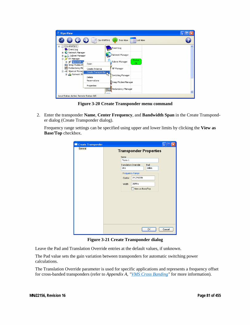
MN/22156, Revision 16 Page 81 of 455
Figure 3-20 Create Transponder menu command
2. Enter the transponder Name, Center Frequency, and Bandwidth Span in the Create Transpond-er dialog (Create Transponder dialog).
Frequency range settings can be specified using upper and lower limits by clicking the View as Base/Top checkbox.
Figure 3-21 Create Transponder dialog
Leave the Pad and Translation Override entries at the default values, if unknown.
The Pad value sets the gain variation between transponders for automatic switching power calculations.
The Translation Override parameter is used for specific applications and represents a frequency offset for cross-banded transponders (refer to Appendix A, "VMS Cross Banding" for more information).
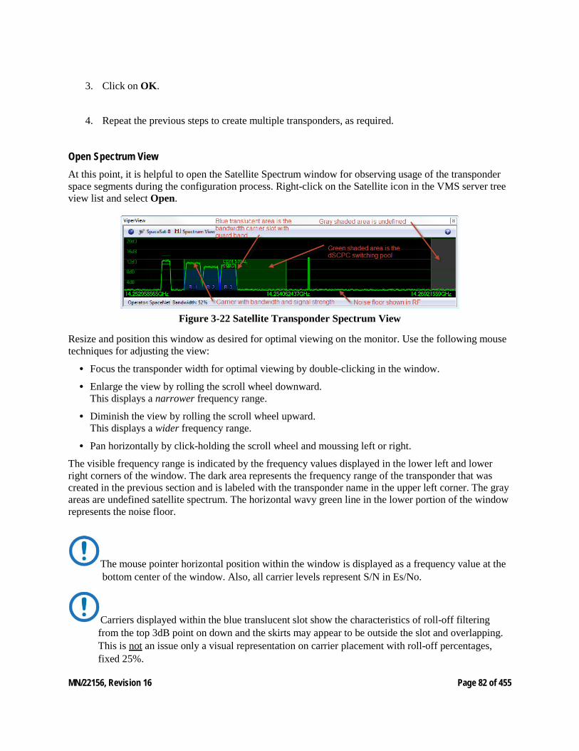
MN/22156, Revision 16 Page 82 of 455
3. Click on OK.
4. Repeat the previous steps to create multiple transponders, as required.
Open Spectrum View At this point, it is helpful to open the Satellite Spectrum window for observing usage of the transponder space segments during the configuration process. Right-click on the Satellite icon in the VMS server tree view list and select Open.
Figure 3-22 Satellite Transponder Spectrum View
Resize and position this window as desired for optimal viewing on the monitor. Use the following mouse techniques for adjusting the view:
• Focus the transponder width for optimal viewing by double-clicking in the window.
• Enlarge the view by rolling the scroll wheel downward. This displays a narrower frequency range.
• Diminish the view by rolling the scroll wheel upward. This displays a wider frequency range.
• Pan horizontally by click-holding the scroll wheel and moussing left or right.
The visible frequency range is indicated by the frequency values displayed in the lower left and lower right corners of the window. The dark area represents the frequency range of the transponder that was created in the previous section and is labeled with the transponder name in the upper left corner. The gray areas are undefined satellite spectrum. The horizontal wavy green line in the lower portion of the window represents the noise floor.
The mouse pointer horizontal position within the window is displayed as a frequency value at the bottom center of the window. Also, all carrier levels represent S/N in Es/No.
Carriers displayed within the blue translucent slot show the characteristics of roll-off filtering from the top 3dB point on down and the skirts may appear to be outside the slot and overlapping. This is not an issue only a visual representation on carrier placement with roll-off percentages, fixed 25%.
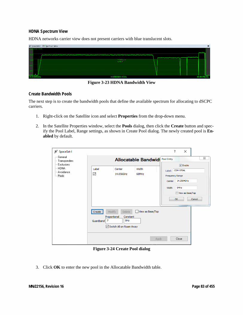
MN/22156, Revision 16 Page 83 of 455
HDNA Spectrum View HDNA networks carrier view does not present carriers with blue translucent slots.
Figure 3-23 HDNA Bandwidth View
Create Bandwidth Pools The next step is to create the bandwidth pools that define the available spectrum for allocating to dSCPC carriers.
1. Right-click on the Satellite icon and select Properties from the drop-down menu.
2. In the Satellite Properties window, select the Pools dialog, then click the Create button and spec-ify the Pool Label, Range settings, as shown in Create Pool dialog. The newly created pool is En-abled by default.
Figure 3-24 Create Pool dialog
3. Click OK to enter the new pool in the Allocatable Bandwidth table.
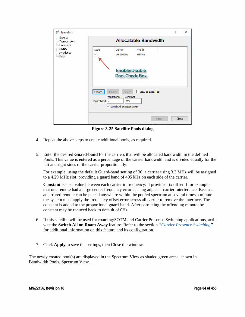
MN/22156, Revision 16 Page 84 of 455
Figure 3-25 Satellite Pools dialog
4. Repeat the above steps to create additional pools, as required.
5. Enter the desired Guard-band for the carriers that will be allocated bandwidth in the defined Pools. This value is entered as a percentage of the carrier bandwidth and is divided equally for the left and right sides of the carrier proportionally.
For example, using the default Guard-band setting of 30, a carrier using 3.3 MHz will be assigned to a 4.29 MHz slot, providing a guard band of 495 kHz on each side of the carrier.
Constant is a set value between each carrier in frequency. It provides fix offset if for example that one remote had a large center frequency error causing adjacent carrier interference. Because an errored remote can be placed anywhere within the pooled spectrum at several times a minute the system must apply the frequency offset error across all carrier to remove the interface. The constant is added to the proportional guard-band. After correcting the offending remote the constant may be reduced back to default of 0Hz.
6. If this satellite will be used for roaming/SOTM and Carrier Presence Switching applications, acti-vate the Switch All on Roam Away feature. Refer to the section “Carrier Presence Switching” for additional information on this feature and its configuration.
7. Click Apply to save the settings, then Close the window.
The newly created pool(s) are displayed in the Spectrum View as shaded green areas, shown in Bandwidth Pools, Spectrum View.
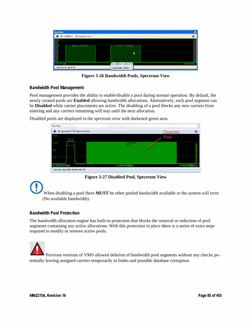
MN/22156, Revision 16 Page 85 of 455
Figure 3-26 Bandwidth Pools, Spectrum View
Bandwidth Pool Management Pool management provides the ability to enable/disable a pool during normal operation. By default, the newly created pools are Enabled allowing bandwidth allocations. Alternatively, each pool segment can be Disabled while carrier placements are active. The disabling of a pool blocks any new carriers from entering and any carriers remaining will stay until the next allocation.
Disabled pools are displayed in the spectrum view with darkened green area.
Figure 3-27 Disabled Pool, Spectrum View
When disabling a pool there MUST be other pooled bandwidth available or the system will error (No available bandwidth).
Bandwidth Pool Protection The bandwidth allocation engine has built-in protection that blocks the removal or reduction of pool segments containing any active allocations. With this protection in place there is a series of extra steps required to modify or remove active pools.
Previous versions of VMS allowed deletion of bandwidth pool segments without any checks po-tentially leaving assigned carriers temporarily in limbo and possible database corruption.

MN/22156, Revision 16 Page 86 of 455
Bandwidth Pool Deletion/Modification The recommended method is to use Exclusion zones to reduce the size, fragment or eliminate an existing pool. Exclusion mapping deploys a method that when aligned over a pool with active carriers the manager will automatically move existing carriers contained within the exclusion bandwidth range. This assumes that enough additional bandwidth is available.
Inserting an exclusion zone and selecting Apply the VMS will reassign carriers that are occupying bandwidth within that zone to available bandwidth. If there is no available bandwidth the Apply will error (No available bandwidth). Once correctly implemented the exclusion will prevent any new carriers from entering that restricted segment of bandwidth allowing the modification or deletion of the pool segment.
Figure 3-28 Exclusion Zone, Spectrum View
Sites with active reservations MUST have pooled bandwidth equal to or greater than assigned reservation bandwidth or the system will error.
Bandwidth Exclusion Zones For network applications where portions of satellite bandwidth are to be reserved for use by externally managed carriers or bandwidth pool segments requiring modification, Exclusion zones can be implemented. Dynamic carriers are not allowed to utilize these segments of bandwidth, even in regions where a zone overlays an existing pool.
Although this masking of dSCPC bandwidth pools is typically performed manually it is possible to remotely automate. (see “Space Segment Exclusions”).
Manual operation is performed via Satellite Properties Exclusions dialog window (Space Segment Exclusions dialog).
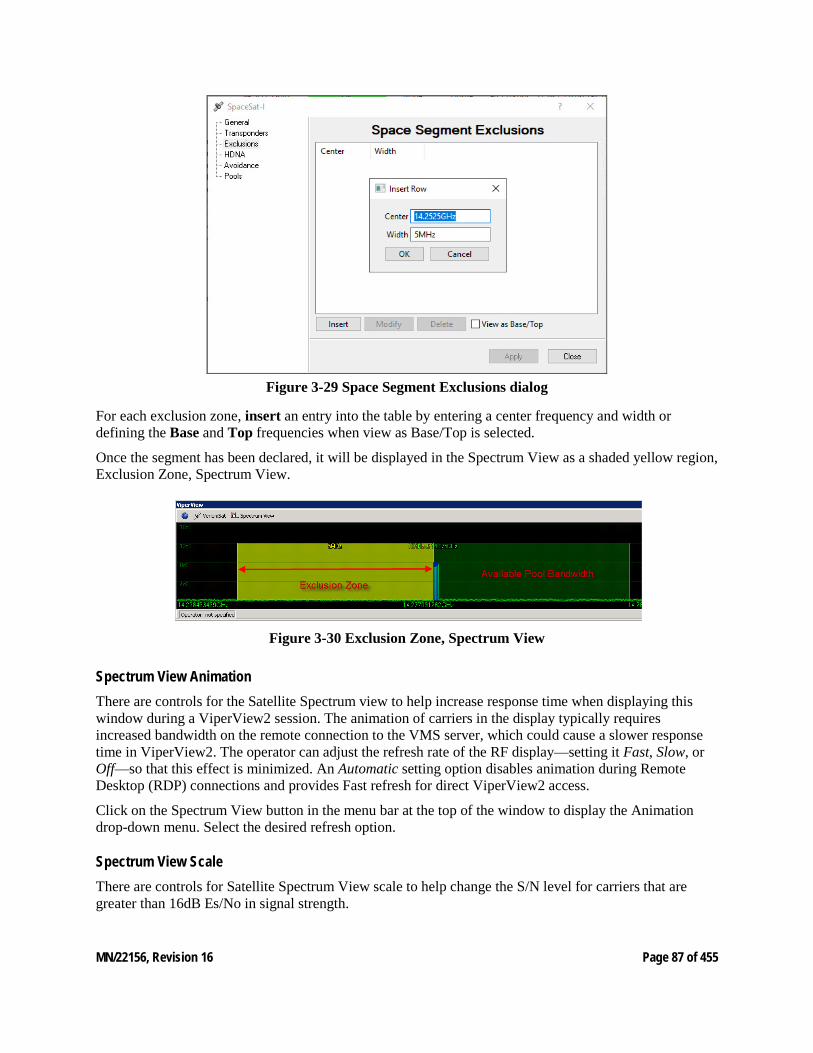
MN/22156, Revision 16 Page 87 of 455
Figure 3-29 Space Segment Exclusions dialog
For each exclusion zone, insert an entry into the table by entering a center frequency and width or defining the Base and Top frequencies when view as Base/Top is selected.
Once the segment has been declared, it will be displayed in the Spectrum View as a shaded yellow region, Exclusion Zone, Spectrum View.
Figure 3-30 Exclusion Zone, Spectrum View
Spectrum View Animation There are controls for the Satellite Spectrum view to help increase response time when displaying this window during a ViperView2 session. The animation of carriers in the display typically requires increased bandwidth on the remote connection to the VMS server, which could cause a slower response time in ViperView2. The operator can adjust the refresh rate of the RF display—setting it Fast, Slow, or Off—so that this effect is minimized. An Automatic setting option disables animation during Remote Desktop (RDP) connections and provides Fast refresh for direct ViperView2 access.
Click on the Spectrum View button in the menu bar at the top of the window to display the Animation drop-down menu. Select the desired refresh option.
Spectrum View Scale There are controls for Satellite Spectrum View scale to help change the S/N level for carriers that are greater than 16dB Es/No in signal strength.
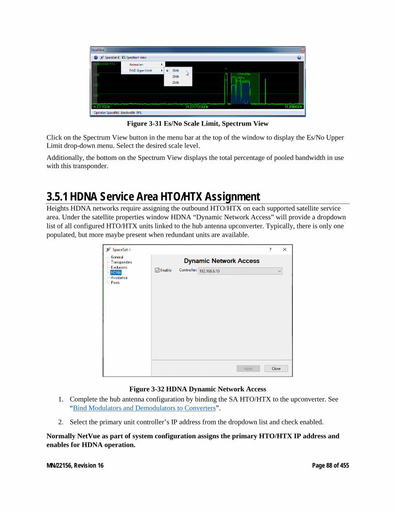
MN/22156, Revision 16 Page 88 of 455
Figure 3-31 Es/No Scale Limit, Spectrum View
Click on the Spectrum View button in the menu bar at the top of the window to display the Es/No Upper Limit drop-down menu. Select the desired scale level.
Additionally, the bottom on the Spectrum View displays the total percentage of pooled bandwidth in use with this transponder.
3.5.1 HDNA Service Area HTO/HTX Assignment Heights HDNA networks require assigning the outbound HTO/HTX on each supported satellite service area. Under the satellite properties window HDNA “Dynamic Network Access” will provide a dropdown list of all configured HTO/HTX units linked to the hub antenna upconverter. Typically, there is only one populated, but more maybe present when redundant units are available.
Figure 3-32 HDNA Dynamic Network Access 1. Complete the hub antenna configuration by binding the SA HTO/HTX to the upconverter. See
“Bind Modulators and Demodulators to Converters”.
2. Select the primary unit controller’s IP address from the dropdown list and check enabled.
Normally NetVue as part of system configuration assigns the primary HTO/HTX IP address and enables for HDNA operation.

MN/22156, Revision 16 Page 89 of 455
3.5.2 Create Site Level RF Chain Here, the Hub antenna(s) with associated converters and the initial Remote antenna(s) with associated converters will be created. The binding of the unit modulators and demodulators to their designated converters will then be performed. Later in the configuration process (Network Manager Configuration), the Vipersat Remote Site Wizard feature will be used to create the RF chain for the other Remotes.
Create Antennas The following steps cover creation of the network antennas. Each antenna is a site container for up conversion/down conversion and modem devices. First create the Hub antenna(s), followed by the initial Remote antenna(s), as described below.
3. Right-click on the Satellite icon and select Create Antenna from the drop-down menu.
4. In the General dialog of the Create Antenna window (Create Antenna dialog), enter the Name to be used for identifying this antenna. Entering the Operator and Contact Information is option-al.
Figure 3-33 Create Antenna dialog
5. Set the Antenna Receive-Gain for the Mesh Compensation Factor.
If gain is set on any antenna, it must be set on all antennas that belong to the same satellite. This includes all Hub and Remote antennas. Failure to do so will result in a network imbalance that may cause the satellite to overdrive a site that is set incorrectly.
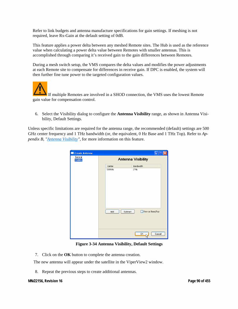
MN/22156, Revision 16 Page 90 of 455
Refer to link budgets and antenna manufacture specifications for gain settings. If meshing is not required, leave Rx-Gain at the default setting of 0dB.
This feature applies a power delta between any meshed Remote sites. The Hub is used as the reference value when calculating a power delta value between Remotes with smaller antennas. This is accomplished through comparing it’s received gain to the gain differences between Remotes.
During a mesh switch setup, the VMS compares the delta values and modifies the power adjustments at each Remote site to compensate for differences in receive gain. If DPC is enabled, the system will then further fine tune power to the targeted configuration values.
If multiple Remotes are involved in a SHOD connection, the VMS uses the lowest Remote gain value for compensation control.
6. Select the Visibility dialog to configure the Antenna Visibility range, as shown in Antenna Visi-bility, Default Settings.
Unless specific limitations are required for the antenna range, the recommended (default) settings are 500 GHz center frequency and 1 THz bandwidth (or, the equivalent, 0 Hz Base and 1 THz Top). Refer to Ap-pendix B, "Antenna Visibility", for more information on this feature.
Figure 3-34 Antenna Visibility, Default Settings
7. Click on the OK button to complete the antenna creation.
The new antenna will appear under the satellite in the ViperView2 window.
8. Repeat the previous steps to create additional antennas.
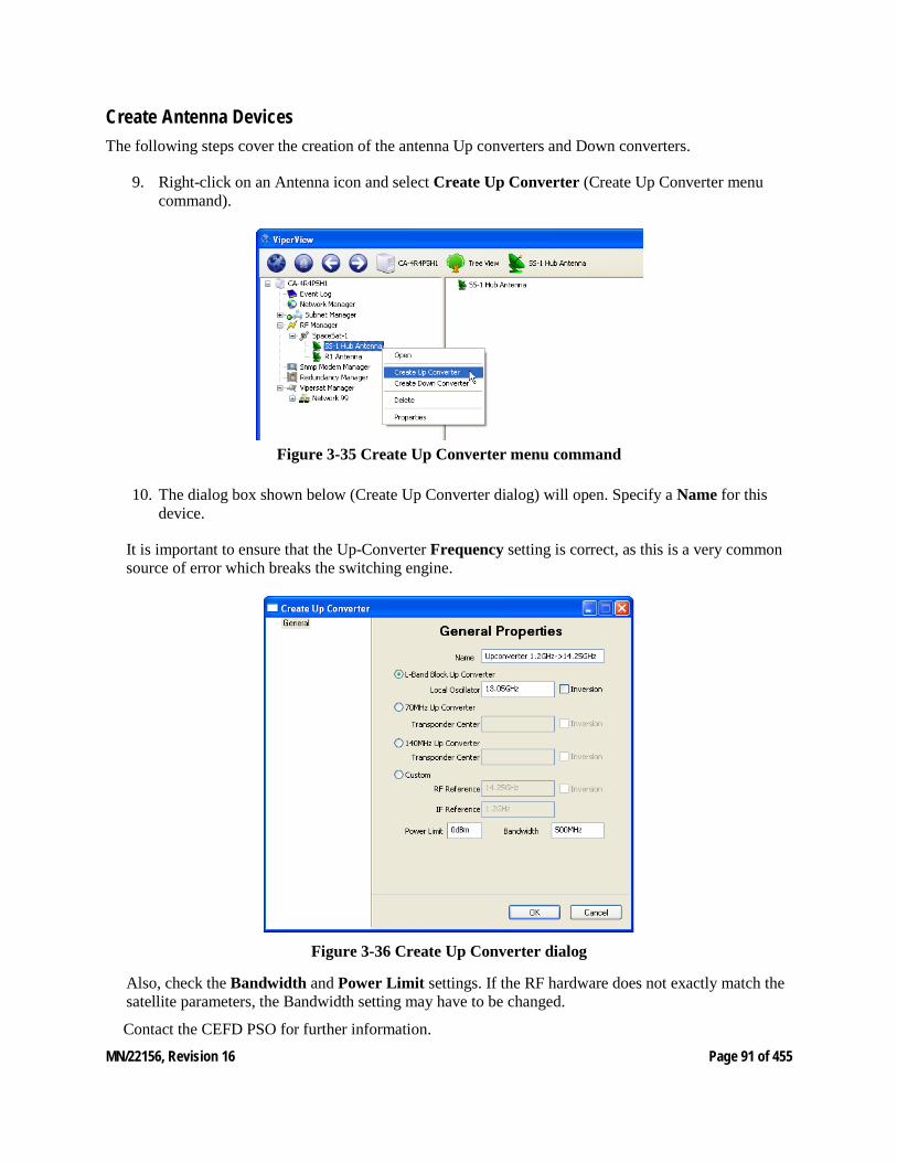
MN/22156, Revision 16 Page 91 of 455
Create Antenna Devices The following steps cover the creation of the antenna Up converters and Down converters.
9. Right-click on an Antenna icon and select Create Up Converter (Create Up Converter menu command).
Figure 3-35 Create Up Converter menu command
10. The dialog box shown below (Create Up Converter dialog) will open. Specify a Name for this device.
It is important to ensure that the Up-Converter Frequency setting is correct, as this is a very common source of error which breaks the switching engine.
Figure 3-36 Create Up Converter dialog
Also, check the Bandwidth and Power Limit settings. If the RF hardware does not exactly match the satellite parameters, the Bandwidth setting may have to be changed.
Contact the CEFD PSO for further information.
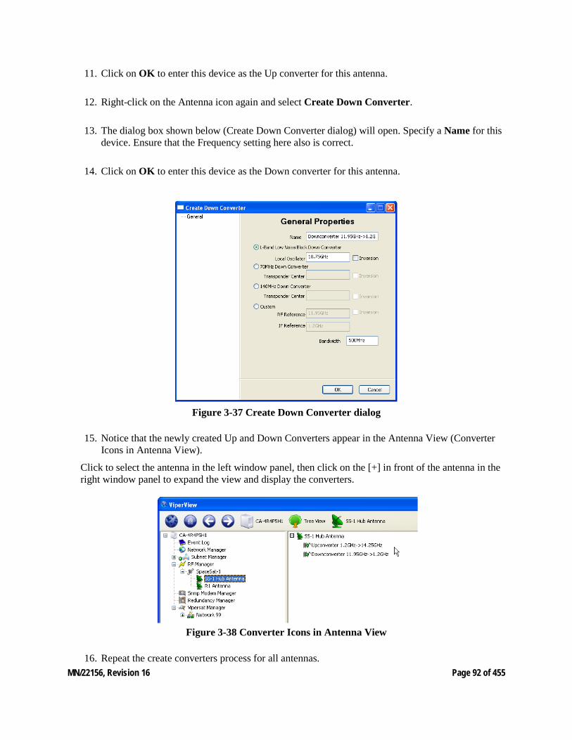
MN/22156, Revision 16 Page 92 of 455
11. Click on OK to enter this device as the Up converter for this antenna.
12. Right-click on the Antenna icon again and select Create Down Converter.
13. The dialog box shown below (Create Down Converter dialog) will open. Specify a Name for this device. Ensure that the Frequency setting here also is correct.
14. Click on OK to enter this device as the Down converter for this antenna.
Figure 3-37 Create Down Converter dialog
15. Notice that the newly created Up and Down Converters appear in the Antenna View (Converter Icons in Antenna View).
Click to select the antenna in the left window panel, then click on the [+] in front of the antenna in the right window panel to expand the view and display the converters.
Figure 3-38 Converter Icons in Antenna View
16. Repeat the create converters process for all antennas.
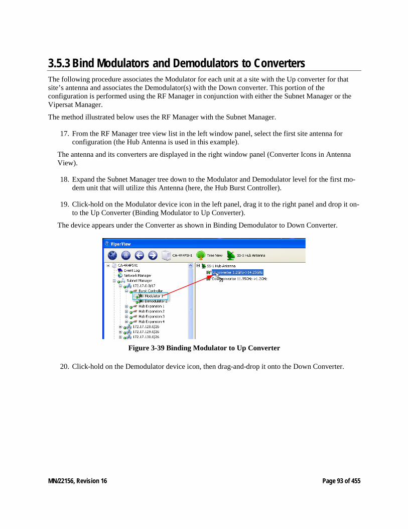
MN/22156, Revision 16 Page 93 of 455
3.5.3 Bind Modulators and Demodulators to Converters The following procedure associates the Modulator for each unit at a site with the Up converter for that site’s antenna and associates the Demodulator(s) with the Down converter. This portion of the configuration is performed using the RF Manager in conjunction with either the Subnet Manager or the Vipersat Manager.
The method illustrated below uses the RF Manager with the Subnet Manager.
17. From the RF Manager tree view list in the left window panel, select the first site antenna for configuration (the Hub Antenna is used in this example).
The antenna and its converters are displayed in the right window panel (Converter Icons in Antenna View).
18. Expand the Subnet Manager tree down to the Modulator and Demodulator level for the first mo-dem unit that will utilize this Antenna (here, the Hub Burst Controller).
19. Click-hold on the Modulator device icon in the left panel, drag it to the right panel and drop it on-to the Up Converter (Binding Modulator to Up Converter).
The device appears under the Converter as shown in Binding Demodulator to Down Converter.
Figure 3-39 Binding Modulator to Up Converter
20. Click-hold on the Demodulator device icon, then drag-and-drop it onto the Down Converter.

MN/22156, Revision 16 Page 94 of 455
Figure 3-40 Binding Demodulator to Down Converter
As soon as the Hub BC binding is complete, the STDMA and the TDM carriers will appear in the Spectrum view. Note that the TDM carrier is displayed in red due to the fact that a power value has not yet been reported from a receiving Remote. The STDMA carrier appearance will vary between green and red, as the accuracy of the Eb/No values received by the BC may fluctuate due to the rapid locking/unlocking behavior.
TDM Carrier STDMA Carrier
Figure 3-41 STDMA and TDM Carrier Appearance
21. Repeat the above steps for each additional unit at this site.
Now that the binding procedure for the first unit has been completed with the understanding of the relationship between the modem devices and the converters, perform all subsequent bindings by simply dragging the modem unit and dropping it directly onto the antenna. This abbreviated method will automatically bind the mods and demods with the up converters and down converters.
22. Select the next site antenna and perform the binding procedure for the units at that site.
Once at least one Remote site binding is completed, the TDM carrier display will change to green (TDM Carrier Appearance Change).
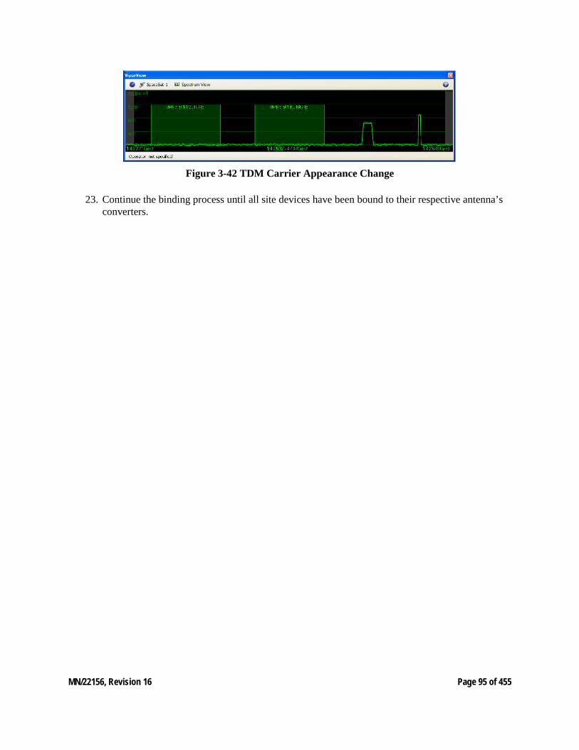
MN/22156, Revision 16 Page 95 of 455
Figure 3-42 TDM Carrier Appearance Change
23. Continue the binding process until all site devices have been bound to their respective antenna’s converters.
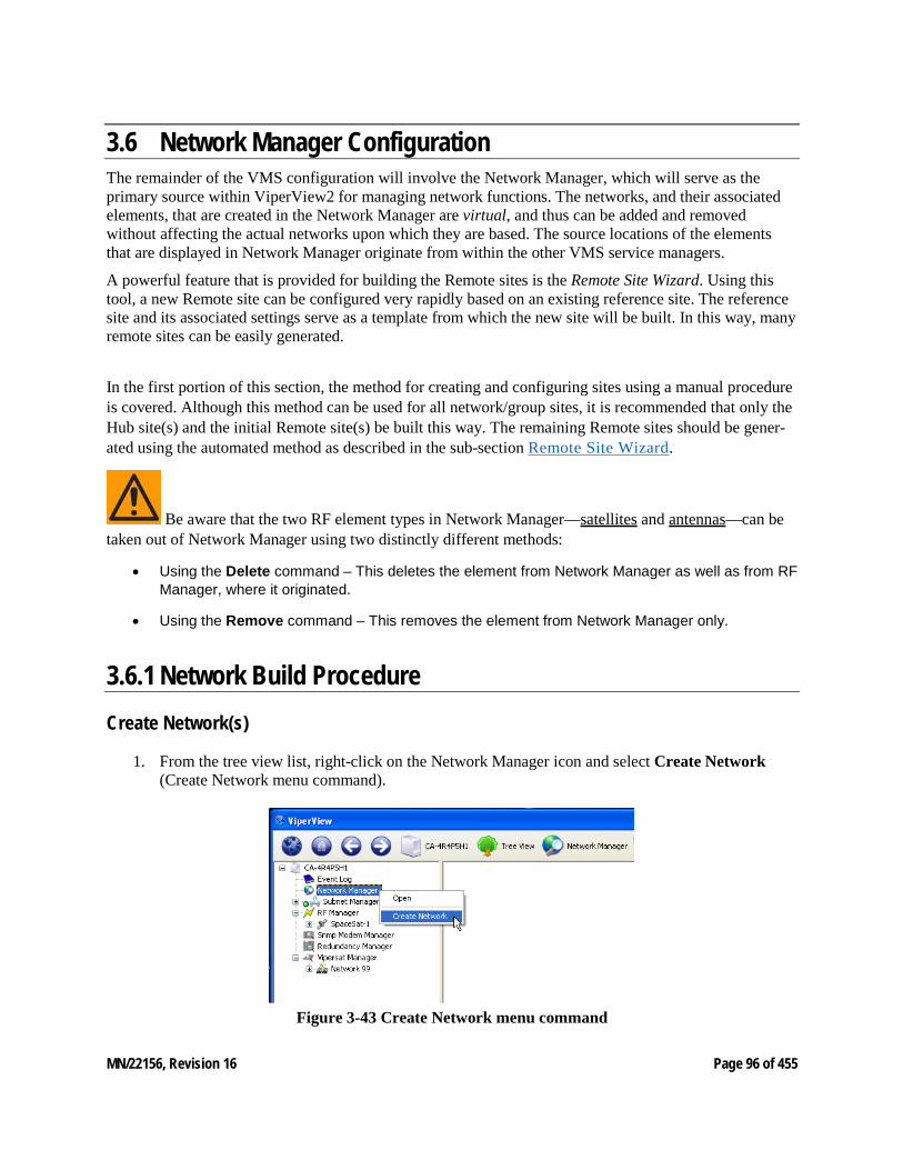
MN/22156, Revision 16 Page 96 of 455
3.6 Network Manager Configuration The remainder of the VMS configuration will involve the Network Manager, which will serve as the primary source within ViperView2 for managing network functions. The networks, and their associated elements, that are created in the Network Manager are virtual, and thus can be added and removed without affecting the actual networks upon which they are based. The source locations of the elements that are displayed in Network Manager originate from within the other VMS service managers.
A powerful feature that is provided for building the Remote sites is the Remote Site Wizard. Using this tool, a new Remote site can be configured very rapidly based on an existing reference site. The reference site and its associated settings serve as a template from which the new site will be built. In this way, many remote sites can be easily generated.
In the first portion of this section, the method for creating and configuring sites using a manual procedure is covered. Although this method can be used for all network/group sites, it is recommended that only the Hub site(s) and the initial Remote site(s) be built this way. The remaining Remote sites should be gener-ated using the automated method as described in the sub-section Remote Site Wizard.
Be aware that the two RF element types in Network Manager—satellites and antennas—can be taken out of Network Manager using two distinctly different methods:
• Using the Delete command – This deletes the element from Network Manager as well as from RF Manager, where it originated.
• Using the Remove command – This removes the element from Network Manager only.
3.6.1 Network Build Procedure Create Network(s)
1. From the tree view list, right-click on the Network Manager icon and select Create Network (Create Network menu command).
Figure 3-43 Create Network menu command
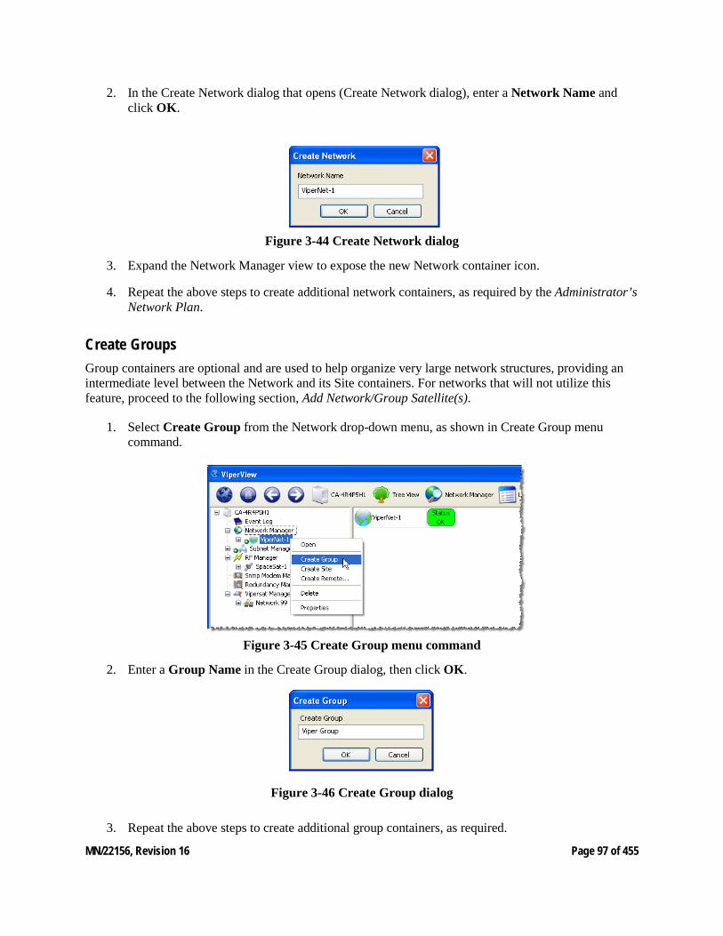
MN/22156, Revision 16 Page 97 of 455
2. In the Create Network dialog that opens (Create Network dialog), enter a Network Name and click OK.
Figure 3-44 Create Network dialog
3. Expand the Network Manager view to expose the new Network container icon.
4. Repeat the above steps to create additional network containers, as required by the Administrator’s Network Plan.
Create Groups Group containers are optional and are used to help organize very large network structures, providing an intermediate level between the Network and its Site containers. For networks that will not utilize this feature, proceed to the following section, Add Network/Group Satellite(s).
1. Select Create Group from the Network drop-down menu, as shown in Create Group menu command.
Figure 3-45 Create Group menu command
2. Enter a Group Name in the Create Group dialog, then click OK.
Figure 3-46 Create Group dialog
3. Repeat the above steps to create additional group containers, as required.

MN/22156, Revision 16 Page 98 of 455
Add Network/Group Satellite(s) Satellites can be associated with either a Network or a Group by dragging from RF Manager and dropping onto either element container. A satellite that is placed at the Network level will be available to all Groups and Sites under that network. A satellite that is placed at a Group level will only be available to the Sites under that group.
Note that once a satellite is dropped onto an element, it cannot then be dragged out of that element and dropped onto another element, say from a Network to a Group. The satellite must be removed from the first element, then dragged from the RF Manager (the originating container) and dropped onto the other element.
1. Locate the satellite for this network/group in RF Manager, click-hold and drag-and-drop it onto the network/group icon as shown in Drag Satellite to Network.
Figure 3-47 Drag Satellite to Network
2. If there are multiple satellites and/or networks/groups, repeat this drag-and-drop process as re-quired.
3. Expand the network/group tree view to expose the satellite appearance(s).
Create Sites Site containers are used to hold the antenna and subnet for a Hub or Remote site. This procedure follows the manual method for creating the Hub site(s) and the initial Remote site(s).
1. Select Create Site from the Network (or from the Group, if the site is to be a member of an existing group) drop-down menu, as shown in Create Site menu command.
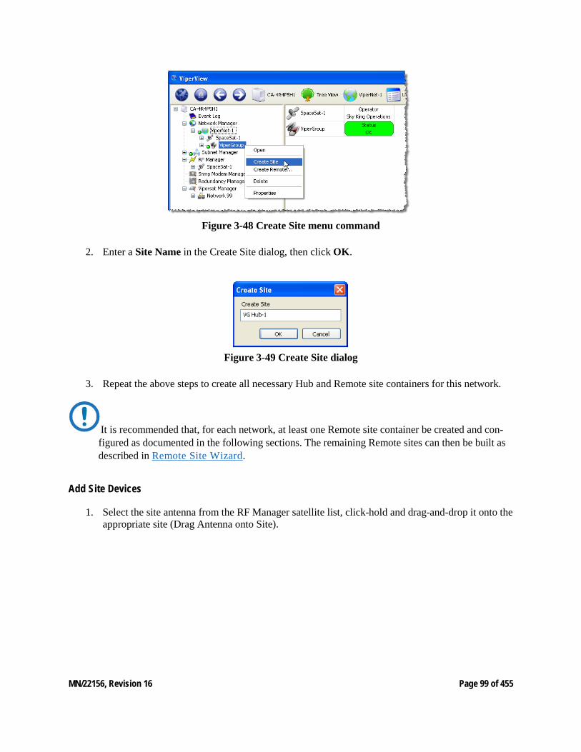
MN/22156, Revision 16 Page 99 of 455
Figure 3-48 Create Site menu command
2. Enter a Site Name in the Create Site dialog, then click OK.
Figure 3-49 Create Site dialog
3. Repeat the above steps to create all necessary Hub and Remote site containers for this network.
It is recommended that, for each network, at least one Remote site container be created and con-figured as documented in the following sections. The remaining Remote sites can then be built as described in Remote Site Wizard.
Add Site Devices
1. Select the site antenna from the RF Manager satellite list, click-hold and drag-and-drop it onto the appropriate site (Drag Antenna onto Site).
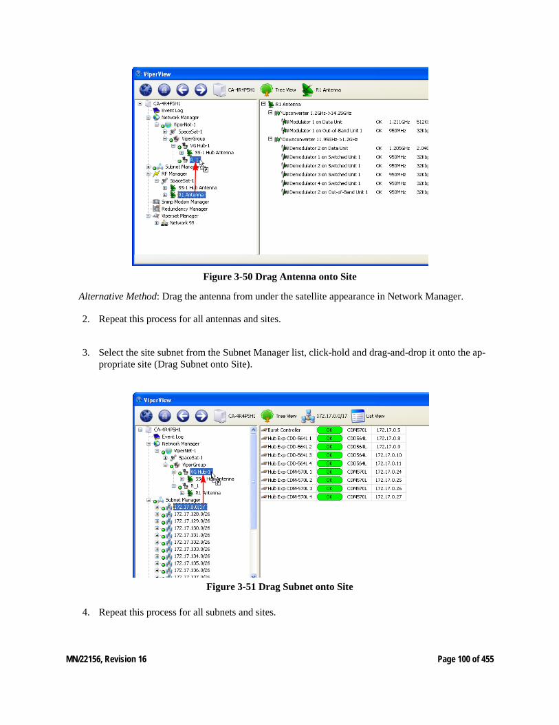
MN/22156, Revision 16 Page 100 of 455
Figure 3-50 Drag Antenna onto Site
Alternative Method: Drag the antenna from under the satellite appearance in Network Manager.
2. Repeat this process for all antennas and sites.
3. Select the site subnet from the Subnet Manager list, click-hold and drag-and-drop it onto the ap-propriate site (Drag Subnet onto Site).
Figure 3-51 Drag Subnet onto Site
4. Repeat this process for all subnets and sites.
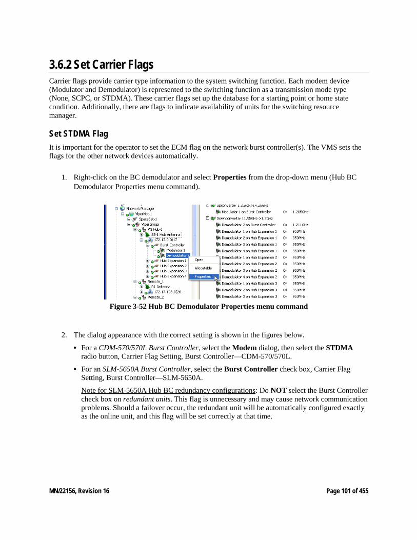
MN/22156, Revision 16 Page 101 of 455
3.6.2 Set Carrier Flags Carrier flags provide carrier type information to the system switching function. Each modem device (Modulator and Demodulator) is represented to the switching function as a transmission mode type (None, SCPC, or STDMA). These carrier flags set up the database for a starting point or home state condition. Additionally, there are flags to indicate availability of units for the switching resource manager.
Set STDMA Flag It is important for the operator to set the ECM flag on the network burst controller(s). The VMS sets the flags for the other network devices automatically.
1. Right-click on the BC demodulator and select Properties from the drop-down menu (Hub BC
Demodulator Properties menu command).
Figure 3-52 Hub BC Demodulator Properties menu command
2. The dialog appearance with the correct setting is shown in the figures below.
• For a CDM-570/570L Burst Controller, select the Modem dialog, then select the STDMA radio button, Carrier Flag Setting, Burst Controller—CDM-570/570L.
• For an SLM-5650A Burst Controller, select the Burst Controller check box, Carrier Flag Setting, Burst Controller—SLM-5650A.
Note for SLM-5650A Hub BC redundancy configurations: Do NOT select the Burst Controller check box on redundant units. This flag is unnecessary and may cause network communication problems. Should a failover occur, the redundant unit will be automatically configured exactly as the online unit, and this flag will be set correctly at that time.
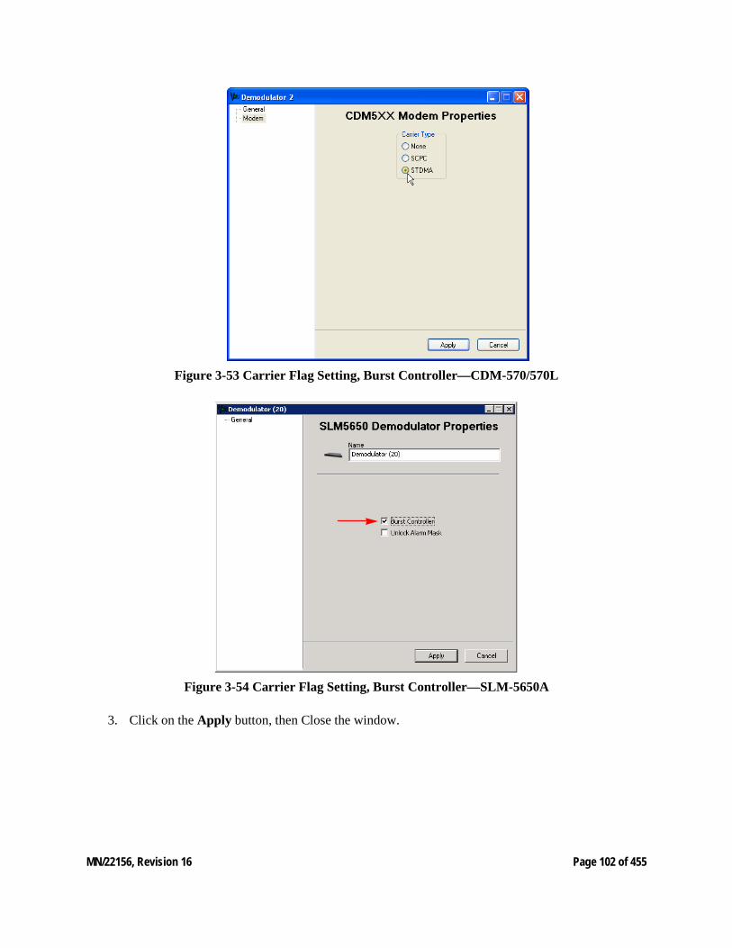
MN/22156, Revision 16 Page 102 of 455
Figure 3-53 Carrier Flag Setting, Burst Controller—CDM-570/570L
Figure 3-54 Carrier Flag Setting, Burst Controller—SLM-5650A
3. Click on the Apply button, then Close the window.
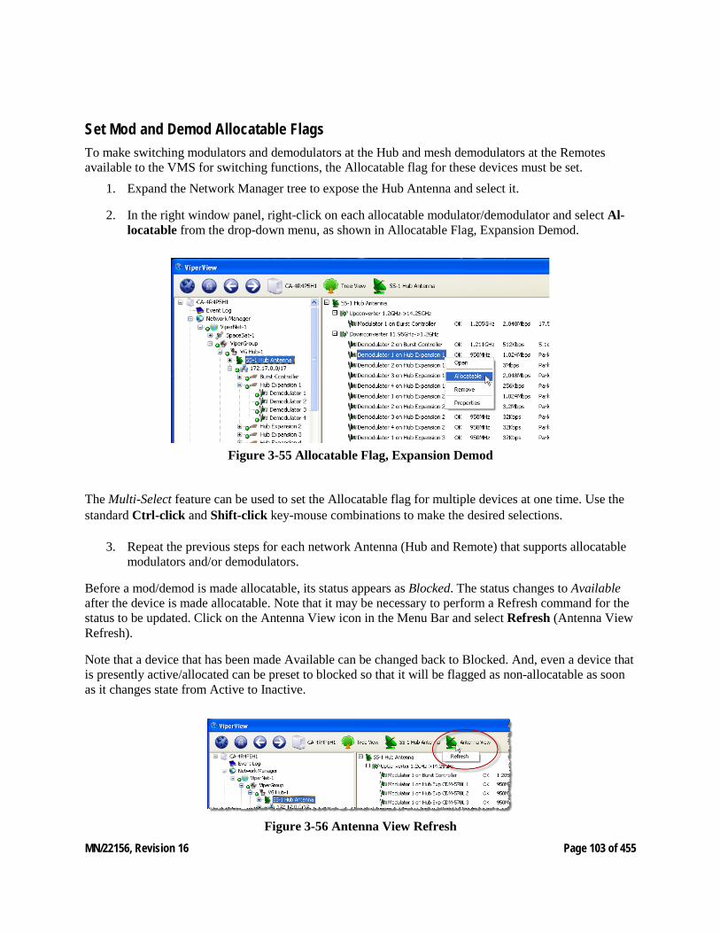
MN/22156, Revision 16 Page 103 of 455
Set Mod and Demod Allocatable Flags To make switching modulators and demodulators at the Hub and mesh demodulators at the Remotes available to the VMS for switching functions, the Allocatable flag for these devices must be set.
1. Expand the Network Manager tree to expose the Hub Antenna and select it.
2. In the right window panel, right-click on each allocatable modulator/demodulator and select Al-locatable from the drop-down menu, as shown in Allocatable Flag, Expansion Demod.
Figure 3-55 Allocatable Flag, Expansion Demod
The Multi-Select feature can be used to set the Allocatable flag for multiple devices at one time. Use the standard Ctrl-click and Shift-click key-mouse combinations to make the desired selections.
3. Repeat the previous steps for each network Antenna (Hub and Remote) that supports allocatable modulators and/or demodulators.
Before a mod/demod is made allocatable, its status appears as Blocked. The status changes to Available after the device is made allocatable. Note that it may be necessary to perform a Refresh command for the status to be updated. Click on the Antenna View icon in the Menu Bar and select Refresh (Antenna View Refresh).
Note that a device that has been made Available can be changed back to Blocked. And, even a device that is presently active/allocated can be preset to blocked so that it will be flagged as non-allocatable as soon as it changes state from Active to Inactive.
Figure 3-56 Antenna View Refresh
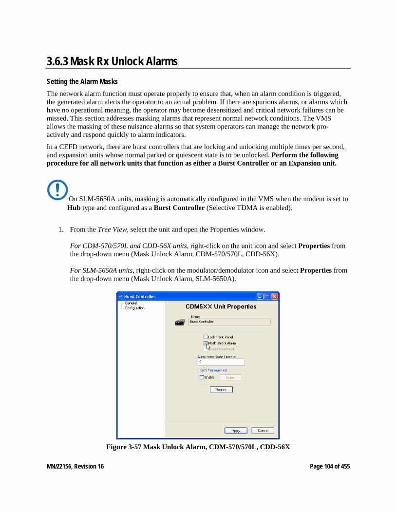
MN/22156, Revision 16 Page 104 of 455
3.6.3 Mask Rx Unlock Alarms Setting the Alarm Masks The network alarm function must operate properly to ensure that, when an alarm condition is triggered, the generated alarm alerts the operator to an actual problem. If there are spurious alarms, or alarms which have no operational meaning, the operator may become desensitized and critical network failures can be missed. This section addresses masking alarms that represent normal network conditions. The VMS allows the masking of these nuisance alarms so that system operators can manage the network pro-actively and respond quickly to alarm indicators.
In a CEFD network, there are burst controllers that are locking and unlocking multiple times per second, and expansion units whose normal parked or quiescent state is to be unlocked. Perform the following procedure for all network units that function as either a Burst Controller or an Expansion unit.
On SLM-5650A units, masking is automatically configured in the VMS when the modem is set to Hub type and configured as a Burst Controller (Selective TDMA is enabled).
1. From the Tree View, select the unit and open the Properties window. For CDM-570/570L and CDD-56X units, right-click on the unit icon and select Properties from the drop-down menu (Mask Unlock Alarm, CDM-570/570L, CDD-56X). For SLM-5650A units, right-click on the modulator/demodulator icon and select Properties from the drop-down menu (Mask Unlock Alarm, SLM-5650A).
Figure 3-57 Mask Unlock Alarm, CDM-570/570L, CDD-56X

MN/22156, Revision 16 Page 105 of 455
Figure 3-58 Mask Unlock Alarm, SLM-5650A
2. In the General dialog, select Mask Unlock Alarm, then click on Apply and Close the window.
3. In the following sequence, right-click on the unit icon again and select: • Force Registration • then, Soft Reset
This will activate the flag in the modem and clear any latched alarms.
Again, the Multi-Select feature can be used to perform common operations on multiple units/devices at
a time.
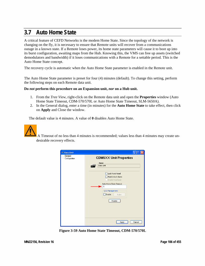
MN/22156, Revision 16 Page 106 of 455
3.7 Auto Home State A critical feature of CEFD Networks is the modem Home State. Since the topology of the network is changing on the fly, it is necessary to ensure that Remote units will recover from a communications outage in a known state. If a Remote loses power, its home state parameters will cause it to boot up into its burst configuration, awaiting maps from the Hub. Knowing this, the VMS can free up assets (switched demodulators and bandwidth) if it loses communications with a Remote for a settable period. This is the Auto Home State concept.
The recovery cycle is automatic when the Auto Home State parameter is enabled in the Remote unit.
The Auto Home State parameter is preset for four (4) minutes (default). To change this setting, perform the following steps on each Remote data unit.
Do not perform this procedure on an Expansion unit, nor on a Hub unit.
1. From the Tree View, right-click on the Remote data unit and open the Properties window (Auto Home State Timeout, CDM-570/570L or Auto Home State Timeout, SLM-5650A).
2. In the General dialog, enter a time (in minutes) for the Auto Home State to take effect, then click on Apply and Close the window.
The default value is 4 minutes. A value of 0 disables Auto Home State.
A Timeout of no less than 4 minutes is recommended; values less than 4 minutes may create un-desirable recovery effects.
Figure 3-59 Auto Home State Timeout, CDM-570/570L
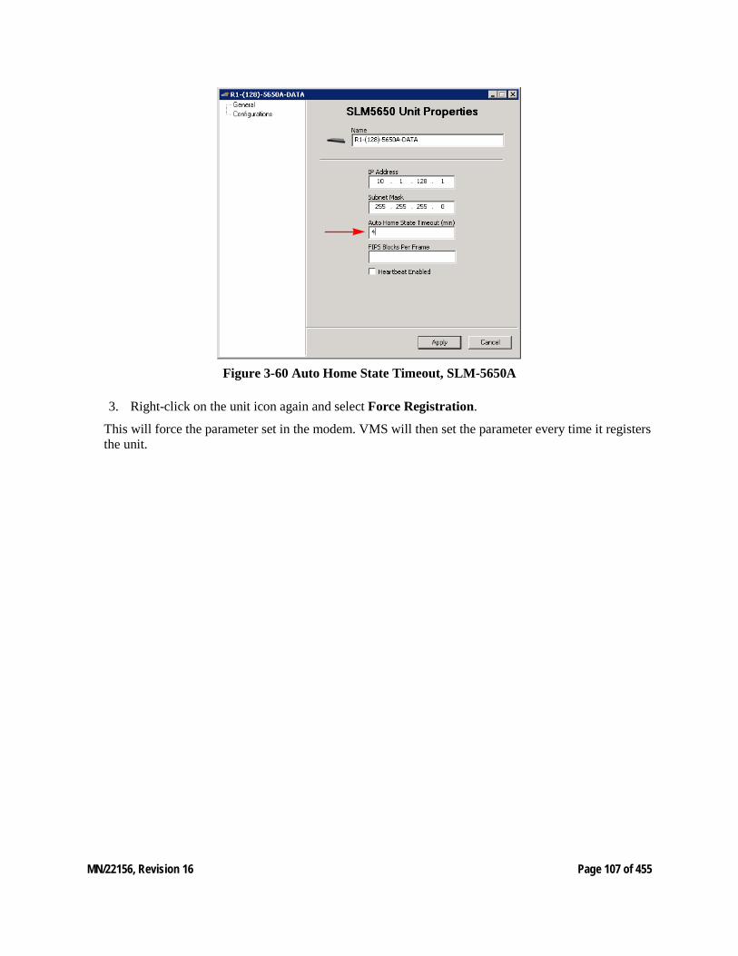
MN/22156, Revision 16 Page 107 of 455
Figure 3-60 Auto Home State Timeout, SLM-5650A
3. Right-click on the unit icon again and select Force Registration.
This will force the parameter set in the modem. VMS will then set the parameter every time it registers the unit.
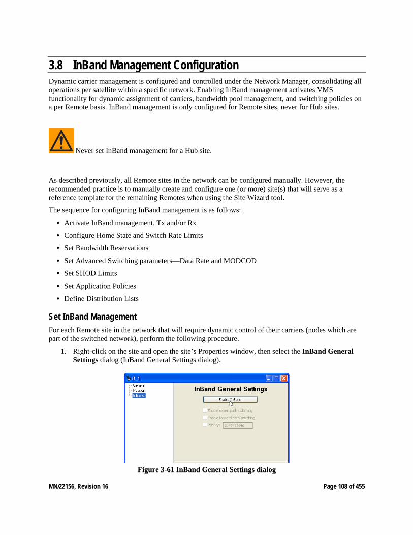
MN/22156, Revision 16 Page 108 of 455
3.8 InBand Management Configuration Dynamic carrier management is configured and controlled under the Network Manager, consolidating all operations per satellite within a specific network. Enabling InBand management activates VMS functionality for dynamic assignment of carriers, bandwidth pool management, and switching policies on a per Remote basis. InBand management is only configured for Remote sites, never for Hub sites.
Never set InBand management for a Hub site.
As described previously, all Remote sites in the network can be configured manually. However, the recommended practice is to manually create and configure one (or more) site(s) that will serve as a reference template for the remaining Remotes when using the Site Wizard tool.
The sequence for configuring InBand management is as follows:
• Activate InBand management, Tx and/or Rx
• Configure Home State and Switch Rate Limits
• Set Bandwidth Reservations
• Set Advanced Switching parameters—Data Rate and MODCOD
• Set SHOD Limits
• Set Application Policies
• Define Distribution Lists
Set InBand Management For each Remote site in the network that will require dynamic control of their carriers (nodes which are part of the switched network), perform the following procedure.
1. Right-click on the site and open the site’s Properties window, then select the InBand General Settings dialog (InBand General Settings dialog).
Figure 3-61 InBand General Settings dialog
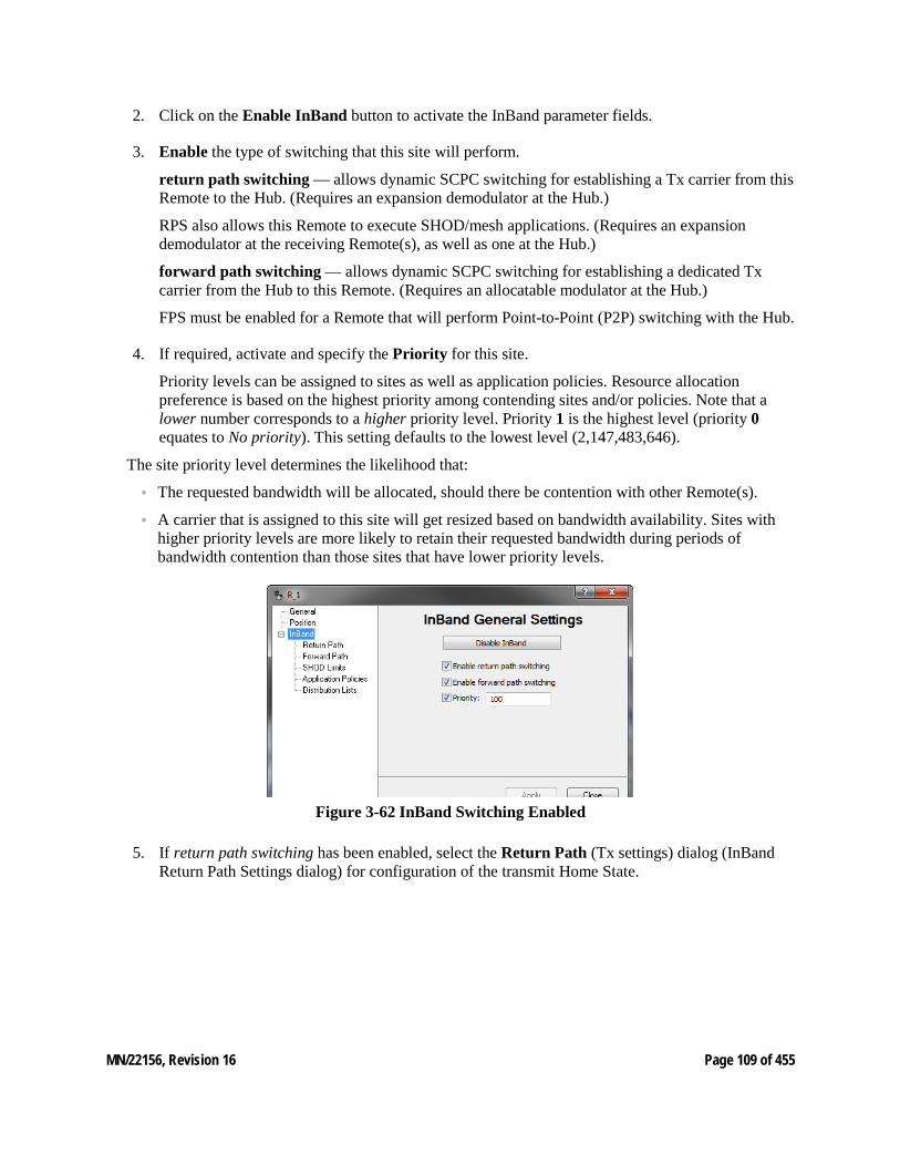
MN/22156, Revision 16 Page 109 of 455
2. Click on the Enable InBand button to activate the InBand parameter fields.
3. Enable the type of switching that this site will perform.
return path switching — allows dynamic SCPC switching for establishing a Tx carrier from this Remote to the Hub. (Requires an expansion demodulator at the Hub.)
RPS also allows this Remote to execute SHOD/mesh applications. (Requires an expansion demodulator at the receiving Remote(s), as well as one at the Hub.)
forward path switching — allows dynamic SCPC switching for establishing a dedicated Tx carrier from the Hub to this Remote. (Requires an allocatable modulator at the Hub.)
FPS must be enabled for a Remote that will perform Point-to-Point (P2P) switching with the Hub.
4. If required, activate and specify the Priority for this site.
Priority levels can be assigned to sites as well as application policies. Resource allocation preference is based on the highest priority among contending sites and/or policies. Note that a lower number corresponds to a higher priority level. Priority 1 is the highest level (priority 0 equates to No priority). This setting defaults to the lowest level (2,147,483,646).
The site priority level determines the likelihood that:
• The requested bandwidth will be allocated, should there be contention with other Remote(s).
• A carrier that is assigned to this site will get resized based on bandwidth availability. Sites with higher priority levels are more likely to retain their requested bandwidth during periods of bandwidth contention than those sites that have lower priority levels.
Figure 3-62 InBand Switching Enabled
5. If return path switching has been enabled, select the Return Path (Tx settings) dialog (InBand Return Path Settings dialog) for configuration of the transmit Home State.
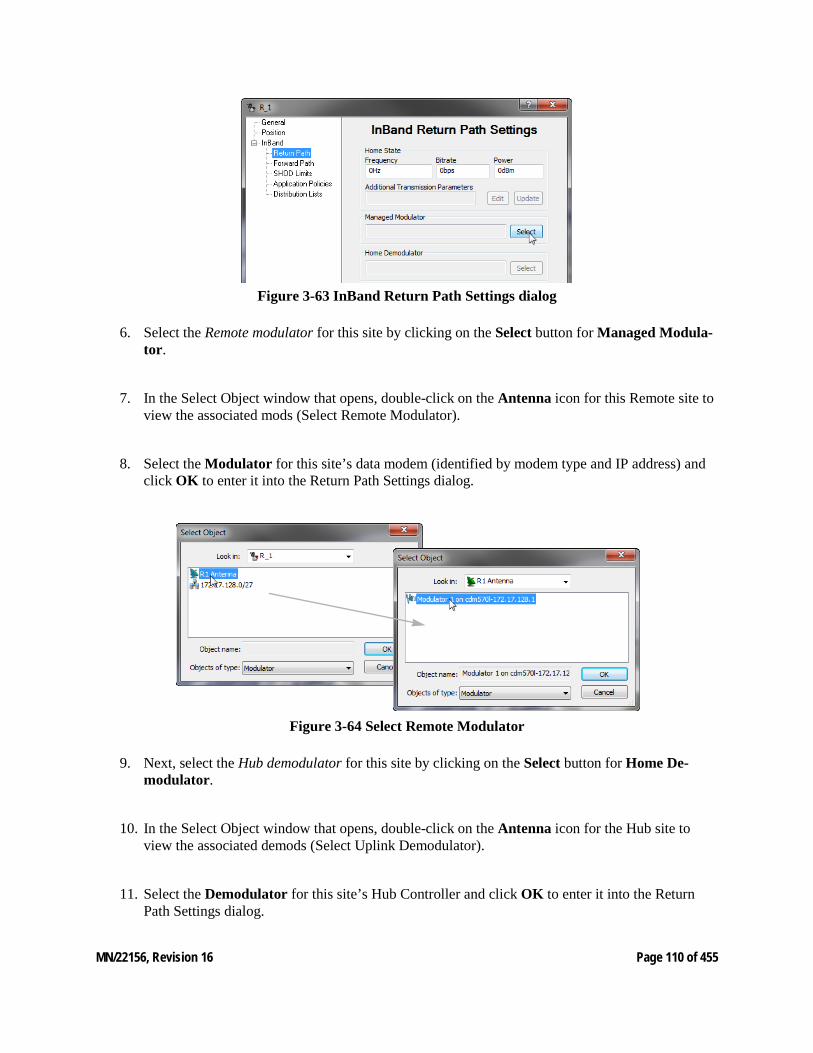
MN/22156, Revision 16 Page 110 of 455
Figure 3-63 InBand Return Path Settings dialog
6. Select the Remote modulator for this site by clicking on the Select button for Managed Modula-tor.
7. In the Select Object window that opens, double-click on the Antenna icon for this Remote site to view the associated mods (Select Remote Modulator).
8. Select the Modulator for this site’s data modem (identified by modem type and IP address) and click OK to enter it into the Return Path Settings dialog.
Figure 3-64 Select Remote Modulator
9. Next, select the Hub demodulator for this site by clicking on the Select button for Home De-modulator.
10. In the Select Object window that opens, double-click on the Antenna icon for the Hub site to view the associated demods (Select Uplink Demodulator).
11. Select the Demodulator for this site’s Hub Controller and click OK to enter it into the Return Path Settings dialog.
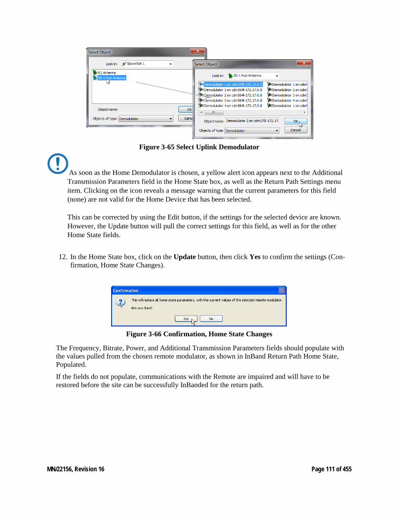
MN/22156, Revision 16 Page 111 of 455
Figure 3-65 Select Uplink Demodulator
As soon as the Home Demodulator is chosen, a yellow alert icon appears next to the Additional Transmission Parameters field in the Home State box, as well as the Return Path Settings menu item. Clicking on the icon reveals a message warning that the current parameters for this field (none) are not valid for the Home Device that has been selected. This can be corrected by using the Edit button, if the settings for the selected device are known. However, the Update button will pull the correct settings for this field, as well as for the other Home State fields.
12. In the Home State box, click on the Update button, then click Yes to confirm the settings (Con-firmation, Home State Changes).
Figure 3-66 Confirmation, Home State Changes
The Frequency, Bitrate, Power, and Additional Transmission Parameters fields should populate with the values pulled from the chosen remote modulator, as shown in InBand Return Path Home State, Populated.
If the fields do not populate, communications with the Remote are impaired and will have to be restored before the site can be successfully InBanded for the return path.
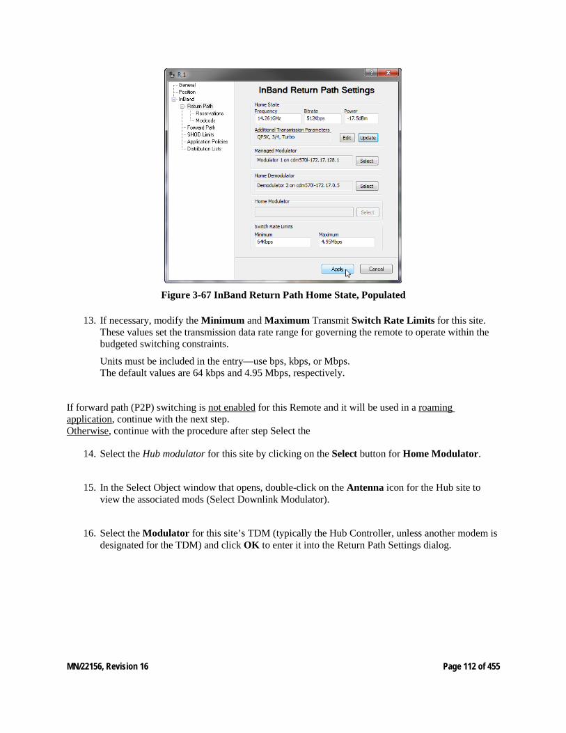
MN/22156, Revision 16 Page 112 of 455
Figure 3-67 InBand Return Path Home State, Populated
13. If necessary, modify the Minimum and Maximum Transmit Switch Rate Limits for this site. These values set the transmission data rate range for governing the remote to operate within the budgeted switching constraints.
Units must be included in the entry—use bps, kbps, or Mbps. The default values are 64 kbps and 4.95 Mbps, respectively.
If forward path (P2P) switching is not enabled for this Remote and it will be used in a roaming application, continue with the next step. Otherwise, continue with the procedure after step Select the
14. Select the Hub modulator for this site by clicking on the Select button for Home Modulator.
15. In the Select Object window that opens, double-click on the Antenna icon for the Hub site to view the associated mods (Select Downlink Modulator).
16. Select the Modulator for this site’s TDM (typically the Hub Controller, unless another modem is designated for the TDM) and click OK to enter it into the Return Path Settings dialog.
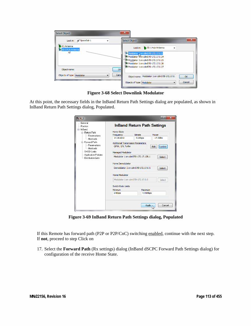
MN/22156, Revision 16 Page 113 of 455
Figure 3-68 Select Downlink Modulator
At this point, the necessary fields in the InBand Return Path Settings dialog are populated, as shown in InBand Return Path Settings dialog, Populated.
Figure 3-69 InBand Return Path Settings dialog, Populated
If this Remote has forward path (P2P or P2P/CnC) switching enabled, continue with the next step. If not, proceed to step Click on
17. Select the Forward Path (Rx settings) dialog (InBand dSCPC Forward Path Settings dialog) for configuration of the receive Home State.
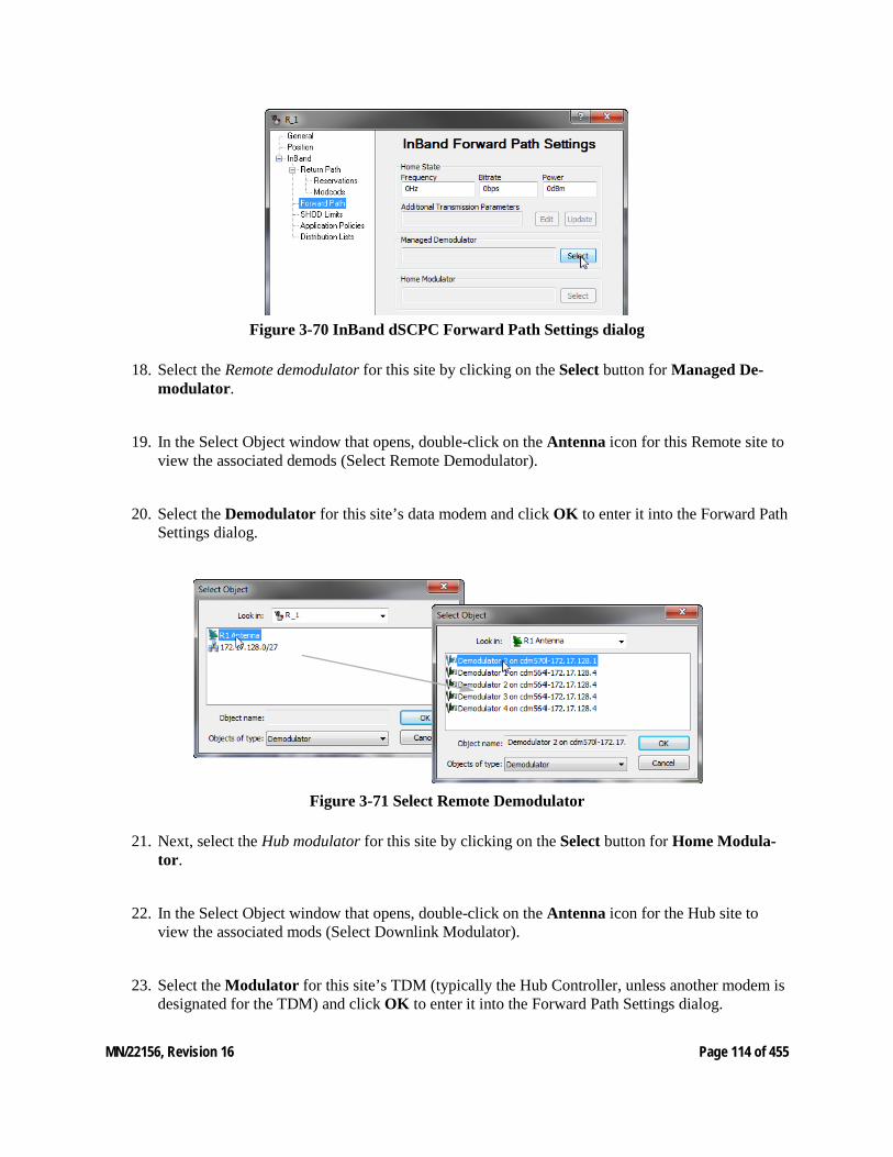
MN/22156, Revision 16 Page 114 of 455
Figure 3-70 InBand dSCPC Forward Path Settings dialog
18. Select the Remote demodulator for this site by clicking on the Select button for Managed De-modulator.
19. In the Select Object window that opens, double-click on the Antenna icon for this Remote site to view the associated demods (Select Remote Demodulator).
20. Select the Demodulator for this site’s data modem and click OK to enter it into the Forward Path Settings dialog.
Figure 3-71 Select Remote Demodulator
21. Next, select the Hub modulator for this site by clicking on the Select button for Home Modula-tor.
22. In the Select Object window that opens, double-click on the Antenna icon for the Hub site to view the associated mods (Select Downlink Modulator).
23. Select the Modulator for this site’s TDM (typically the Hub Controller, unless another modem is designated for the TDM) and click OK to enter it into the Forward Path Settings dialog.
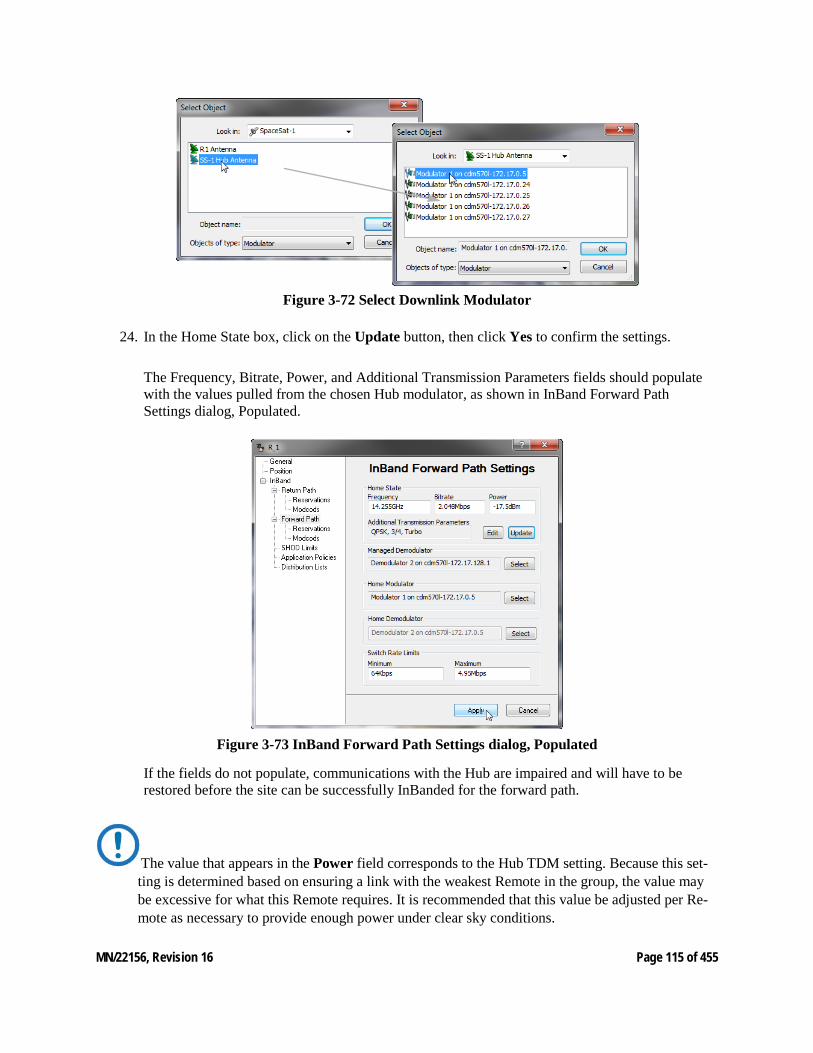
MN/22156, Revision 16 Page 115 of 455
Figure 3-72 Select Downlink Modulator
24. In the Home State box, click on the Update button, then click Yes to confirm the settings.
The Frequency, Bitrate, Power, and Additional Transmission Parameters fields should populate with the values pulled from the chosen Hub modulator, as shown in InBand Forward Path Settings dialog, Populated.
Figure 3-73 InBand Forward Path Settings dialog, Populated
If the fields do not populate, communications with the Hub are impaired and will have to be restored before the site can be successfully InBanded for the forward path.
The value that appears in the Power field corresponds to the Hub TDM setting. Because this set-ting is determined based on ensuring a link with the weakest Remote in the group, the value may be excessive for what this Remote requires. It is recommended that this value be adjusted per Re-mote as necessary to provide enough power under clear sky conditions.
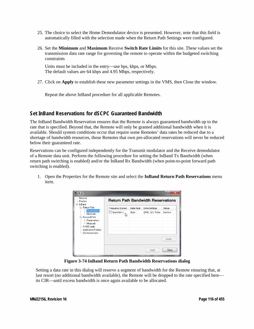
MN/22156, Revision 16 Page 116 of 455
25. The choice to select the Home Demodulator device is presented. However, note that this field is automatically filled with the selection made when the Return Path Settings were configured.
26. Set the Minimum and Maximum Receive Switch Rate Limits for this site. These values set the transmission data rate range for governing the remote to operate within the budgeted switching constraints
Units must be included in the entry—use bps, kbps, or Mbps. The default values are 64 kbps and 4.95 Mbps, respectively.
27. Click on Apply to establish these new parameter settings in the VMS, then Close the window.
Repeat the above InBand procedure for all applicable Remotes.
Set InBand Reservations for dSCPC Guaranteed Bandwidth The InBand Bandwidth Reservation ensures that the Remote is always guaranteed bandwidth up to the rate that is specified. Beyond that, the Remote will only be granted additional bandwidth when it is available. Should system conditions occur that require some Remotes’ data rates be reduced due to a shortage of bandwidth resources, those Remotes that own pre-allocated reservations will never be reduced below their guaranteed rate.
Reservations can be configured independently for the Transmit modulator and the Receive demodulator of a Remote data unit. Perform the following procedure for setting the InBand Tx Bandwidth (when return path switching is enabled) and/or the InBand Rx Bandwidth (when point-to-point forward path switching is enabled).
1. Open the Properties for the Remote site and select the InBand Return Path Reservations menu item.
Figure 3-74 InBand Return Path Bandwidth Reservations dialog
Setting a data rate in this dialog will reserve a segment of bandwidth for the Remote ensuring that, at last resort (no additional bandwidth available), the Remote will be dropped to the rate specified here—its CIR—until excess bandwidth is once again available to be allocated.
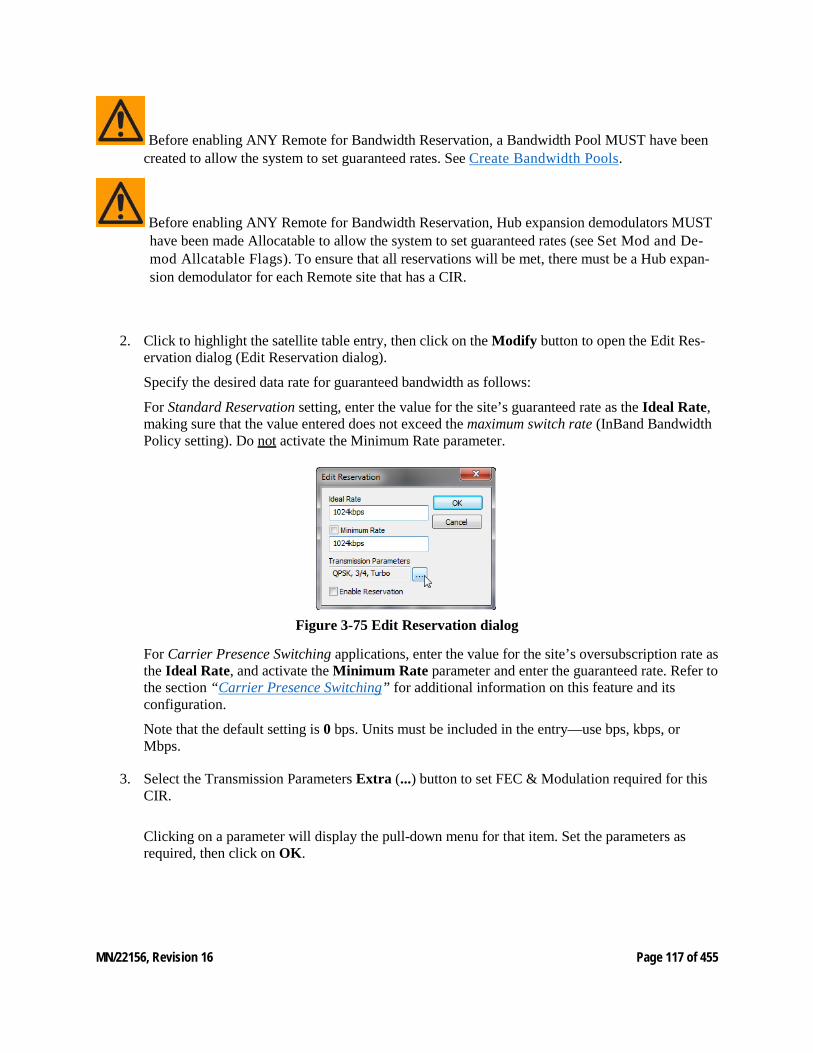
MN/22156, Revision 16 Page 117 of 455
Before enabling ANY Remote for Bandwidth Reservation, a Bandwidth Pool MUST have been created to allow the system to set guaranteed rates. See Create Bandwidth Pools.
Before enabling ANY Remote for Bandwidth Reservation, Hub expansion demodulators MUST have been made Allocatable to allow the system to set guaranteed rates (see Set Mod and De-mod Allcatable Flags). To ensure that all reservations will be met, there must be a Hub expan-sion demodulator for each Remote site that has a CIR.
2. Click to highlight the satellite table entry, then click on the Modify button to open the Edit Res-ervation dialog (Edit Reservation dialog).
Specify the desired data rate for guaranteed bandwidth as follows:
For Standard Reservation setting, enter the value for the site’s guaranteed rate as the Ideal Rate, making sure that the value entered does not exceed the maximum switch rate (InBand Bandwidth Policy setting). Do not activate the Minimum Rate parameter.
Figure 3-75 Edit Reservation dialog
For Carrier Presence Switching applications, enter the value for the site’s oversubscription rate as the Ideal Rate, and activate the Minimum Rate parameter and enter the guaranteed rate. Refer to the section “Carrier Presence Switching” for additional information on this feature and its configuration.
Note that the default setting is 0 bps. Units must be included in the entry—use bps, kbps, or Mbps.
3. Select the Transmission Parameters Extra (...) button to set FEC & Modulation required for this CIR.
Clicking on a parameter will display the pull-down menu for that item. Set the parameters as required, then click on OK.
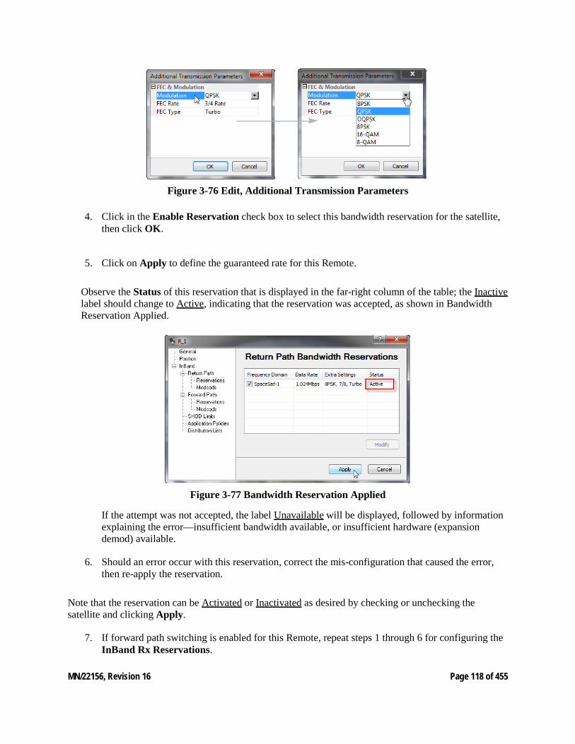
MN/22156, Revision 16 Page 118 of 455
.
Figure 3-76 Edit, Additional Transmission Parameters
4. Click in the Enable Reservation check box to select this bandwidth reservation for the satellite, then click OK.
5. Click on Apply to define the guaranteed rate for this Remote.
Observe the Status of this reservation that is displayed in the far-right column of the table; the Inactive label should change to Active, indicating that the reservation was accepted, as shown in Bandwidth Reservation Applied.
Figure 3-77 Bandwidth Reservation Applied
If the attempt was not accepted, the label Unavailable will be displayed, followed by information explaining the error—insufficient bandwidth available, or insufficient hardware (expansion demod) available.
6. Should an error occur with this reservation, correct the mis-configuration that caused the error, then re-apply the reservation.
Note that the reservation can be Activated or Inactivated as desired by checking or unchecking the satellite and clicking Apply.
7. If forward path switching is enabled for this Remote, repeat steps 1 through 6 for configuring the InBand Rx Reservations.
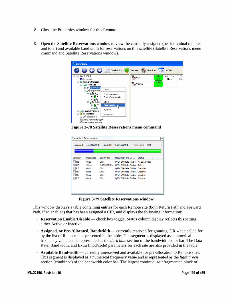
MN/22156, Revision 16 Page 119 of 455
8. Close the Properties window for this Remote.
9. Open the Satellite Reservations window to view the currently assigned (per individual remote, and total) and available bandwidth for reservations on this satellite (Satellite Reservations menu command and Satellite Reservations window).
Figure 3-78 Satellite Reservations menu command
Figure 3-79 Satellite Reservations window
This window displays a table containing entries for each Remote site (both Return Path and Forward Path, if so enabled) that has been assigned a CIR, and displays the following information:
• Reservation Enable/Disable — check box toggle. Status column display reflects this setting, either Active or Inactive.
• Assigned, or Pre-Allocated, Bandwidth — currently reserved for granting CIR when called for by the list of Remote sites presented in the table. This segment is displayed as a numerical frequency value and is represented as the dark blue section of the bandwidth color bar. The Data Rate, Bandwidth, and Extra (mod/code) parameters for each site are also provided in the table.
• Available Bandwidth — currently unreserved and available for pre-allocation to Remote sites. This segment is displayed as a numerical frequency value and is represented as the light green section (combined) of the bandwidth color bar. The largest continuous/unfragmented block of
MN/22156, Revision 16 Page 120 of 455
available bandwidth is represented by the light green section that is not underlined with dark green.
• Fragmented Bandwidth — additional available bandwidth remaining that is separate from the largest continuous block. This segment is displayed as a numerical frequency value and is represented as the light green section of the bandwidth color bar that is underlined with dark green.
The divisions shown in the color bar will vary depending on several factors, including the quantity and size(s) of the bandwidth pool(s), and the amount of pre-allocated bandwidth.
When Site reservations are assigned for both Tx and Rx (Point-to-Point), the first listing for a Remote represents the Tx bandwidth and the second listing is the Rx bandwidth.
From this window, individual reservations can be enabled/disabled via the check box in the Identity column. Reservation settings (Data Rate, Bandwidth, and Extra) can be edited by double-clicking on a table entry.
Note that the Satellite Reservations window can be left open to assist the user/operator in the reservation assignment process for other Remotes.
10. Continue to select Remotes as required and configure them for guaranteed bandwidth until either all resources are exhausted, or network requirements are achieved.
11. To remove a bandwidth reservation for a Remote, click to uncheck the satellite check box in the site Reservations page, then click Apply.
Hub Allocatable Modulator & Demodulator Compatibility
Compatibility issues with allocatable mods and demods at the Hub may arise when implementing the Guaranteed Bandwidth feature in networks that include multiple modem types. When combining modem types, careful network design is essential to ensure that a compatible Hub mod/demod is available for establishing an SCPC link with a Remote. The following factors must be considered:
• Transmission Rate — The device must be capable of handling the data rate that will be allocated between the Remote and the Hub (e.g., SLM-5650A/B versus CDM-570/L or CDD-56X).
• FAST Codes — The modems must have the appropriate FAST codes to ensure compatible functionality.
• Encryption — A Remote set for using TRANSEC requires the Hub device to use TRANSEC also.
Considerations for Using Guaranteed Bandwidth with Advanced Switching Care should be taken when assigning Bandwidth Reservations to a Remote that also uses Advanced Switching (refer to Set InBand Modulation and Coding).
MN/22156, Revision 16 Page 121 of 455
The VMS does not guarantee a bit rate, per se. Rather, a bandwidth reservation (frequency value) is as-signed. Therefore, the option for editing FEC and Modulation settings is provided in the Reservations dialog for a remote site.
The VMS attempts to assign the most efficient bandwidth utilization in an advanced switching environment. If Advanced Switching is configured for a Remote, a switch request that crosses the threshold where the higher-order modulation becomes more bandwidth efficient will result in a step up to the higher-order modulation at the lowest bit rate that exceeds the request.
For example, a site currently operating at QPSK 3/4 that generates a switch request for 192 kbps will be switched up to 256 kbps at 8PSK 7/8, provided this modulation code rate was specified in the Advanced Switching table entry for this switch point. This scenario is illustrated using the following equations:
QPSK 3/4 @192 kbps @1.3 spacing: Allocated Bandwidth = 192 x (1/2) x (1/.75) x 1.3 = 166.4 kHz
8PSK 7/8 @256 kbps @1.3 spacing: Allocated Bandwidth = 256 x (1/3) x (1/.875) x 1.3 = 126.781 kHz
However, when a bandwidth reservation is added to this scenario, the end result may differ. If the reservation specifies 192 kbps at QPSK 3/4, the VMS will perform the same calculation as shown in the first equation above and the reserved bandwidth will be 166.4 kHz. Since these falls within the range at which the VMS would step up to 8PSK, the bit rate available with an allocated bandwidth of 166.4 kHz would be provided, which is 336 kbps.
Thus, when a guarantee is set within the threshold range of advanced switching, unexpected results may result. In this example, the result is that the guaranteed data rate that is provided by the VMS (336 kbps) is actually greater than the expected CIR that was entered as the bandwidth reservation (192 kbps). In addition, the advanced switching performance will also differ, resulting in a higher data rate as well as higher bandwidth usage.
Effect of RF Changes on Reservations
The operator must be aware that changes made to bandwidth resources in the RF configuration after reservations have been defined may require re-evaluating these reservations and resetting pre-allocated bandwidth.
Reducing or moving a bandwidth pool, for example, may result in a failed attempt to grant the bandwidth necessary to meet a site’s CIR requirement. Such a failure would cause the site to become unavailable for switching until reservations for that site are reset.
Any sites that become unavailable must be reset on an individual basis. However, for those sites with reservations that have not been made unavailable, resetting the reservations for one of those sites will result in all of them being reset. To reset site reservations, perform the following steps:
1. Open the Properties for the Remote site and select the InBand Reservations dialog.
2. Click on the check box to de-select the satellite for this bandwidth reservation, then click again to re-select the satellite.
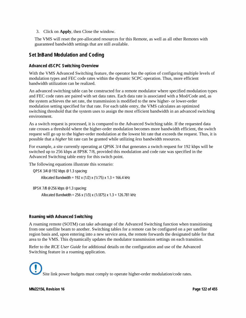
MN/22156, Revision 16 Page 122 of 455
3. Click on Apply, then Close the window.
The VMS will reset the pre-allocated resources for this Remote, as well as all other Remotes with guaranteed bandwidth settings that are still available.
Set InBand Modulation and Coding
Advanced dSCPC Switching Overview With the VMS Advanced Switching feature, the operator has the option of configuring multiple levels of modulation types and FEC code rates within the dynamic SCPC operation. Thus, more efficient bandwidth utilization can be realized.
An advanced switching table can be constructed for a remote modulator where specified modulation types and FEC code rates are paired with set data rates. Each data rate is associated with a Mod/Code and, as the system achieves the set rate, the transmission is modified to the new higher- or lower-order modulation setting specified for that rate. For each table entry, the VMS calculates an optimized switching threshold that the system uses to assign the most efficient bandwidth in an advanced switching environment.
As a switch request is processed, it is compared to the Advanced Switching table. If the requested data rate crosses a threshold where the higher-order modulation becomes more bandwidth efficient, the switch request will go up to the higher-order modulation at the lowest bit rate that exceeds the request. Thus, it is possible that a higher bit rate can be granted while utilizing less bandwidth resources.
For example, a site currently operating at QPSK 3/4 that generates a switch request for 192 kbps will be switched up to 256 kbps at 8PSK 7/8, provided this modulation and code rate was specified in the Advanced Switching table entry for this switch point.
The following equations illustrate this scenario: QPSK 3/4 @192 kbps @1.3 spacing:
Allocated Bandwidth = 192 x (1/2) x (1/.75) x 1.3 = 166.4 kHz
8PSK 7/8 @256 kbps @1.3 spacing: Allocated Bandwidth = 256 x (1/3) x (1/.875) x 1.3 = 126.781 kHz
Roaming with Advanced Switching A roaming remote (SOTM) can take advantage of the Advanced Switching function when transitioning from one satellite beam to another. Switching tables for a remote can be configured on a per satellite region basis and, upon entering into a new service area, the remote forwards the designated table for that area to the VMS. This dynamically updates the modulator transmission settings on each transition.
Refer to the RCE User Guide for additional details on the configuration and use of the Advanced Switching feature in a roaming application.
Site link power budgets must comply to operate higher-order modulation/code rates.
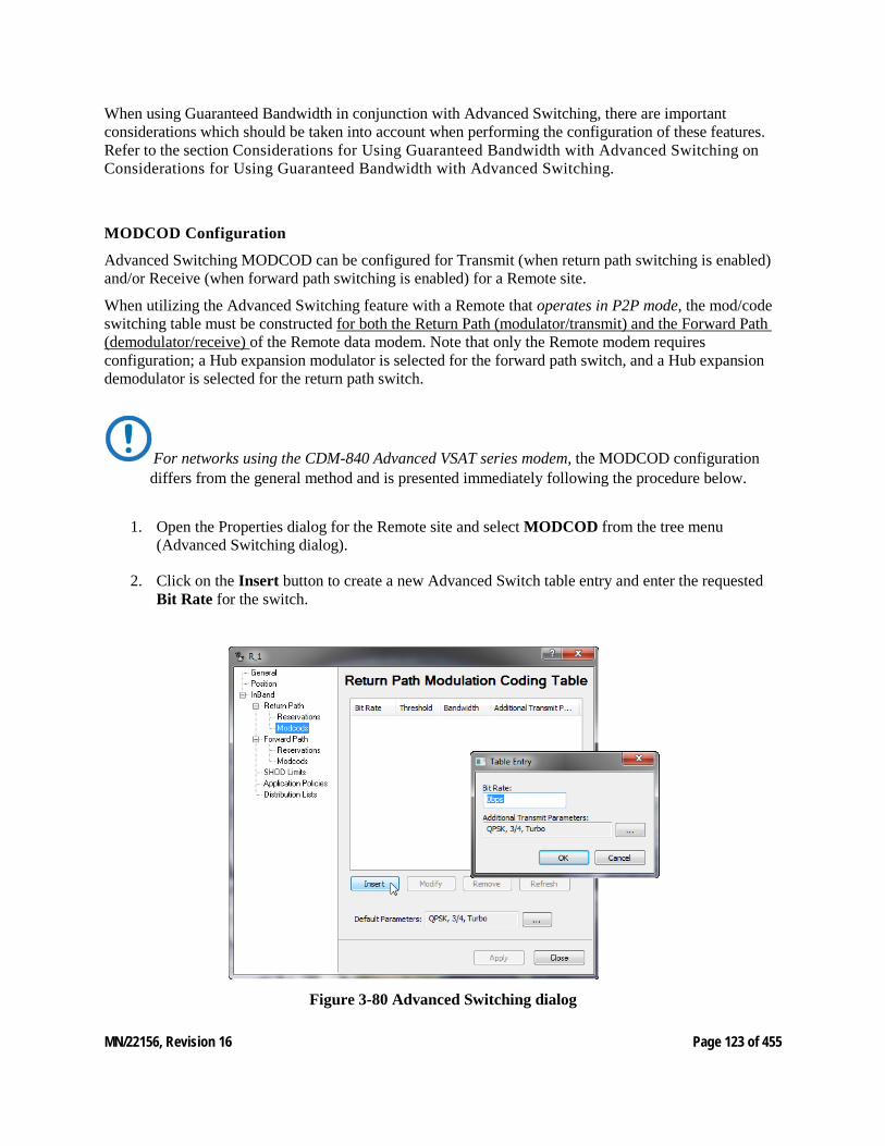
MN/22156, Revision 16 Page 123 of 455
When using Guaranteed Bandwidth in conjunction with Advanced Switching, there are important considerations which should be taken into account when performing the configuration of these features. Refer to the section Considerations for Using Guaranteed Bandwidth with Advanced Switching on Considerations for Using Guaranteed Bandwidth with Advanced Switching.
MODCOD Configuration
Advanced Switching MODCOD can be configured for Transmit (when return path switching is enabled) and/or Receive (when forward path switching is enabled) for a Remote site.
When utilizing the Advanced Switching feature with a Remote that operates in P2P mode, the mod/code switching table must be constructed for both the Return Path (modulator/transmit) and the Forward Path (demodulator/receive) of the Remote data modem. Note that only the Remote modem requires configuration; a Hub expansion modulator is selected for the forward path switch, and a Hub expansion demodulator is selected for the return path switch.
For networks using the CDM-840 Advanced VSAT series modem, the MODCOD configuration differs from the general method and is presented immediately following the procedure below.
1. Open the Properties dialog for the Remote site and select MODCOD from the tree menu (Advanced Switching dialog).
2. Click on the Insert button to create a new Advanced Switch table entry and enter the requested Bit Rate for the switch.
Figure 3-80 Advanced Switching dialog
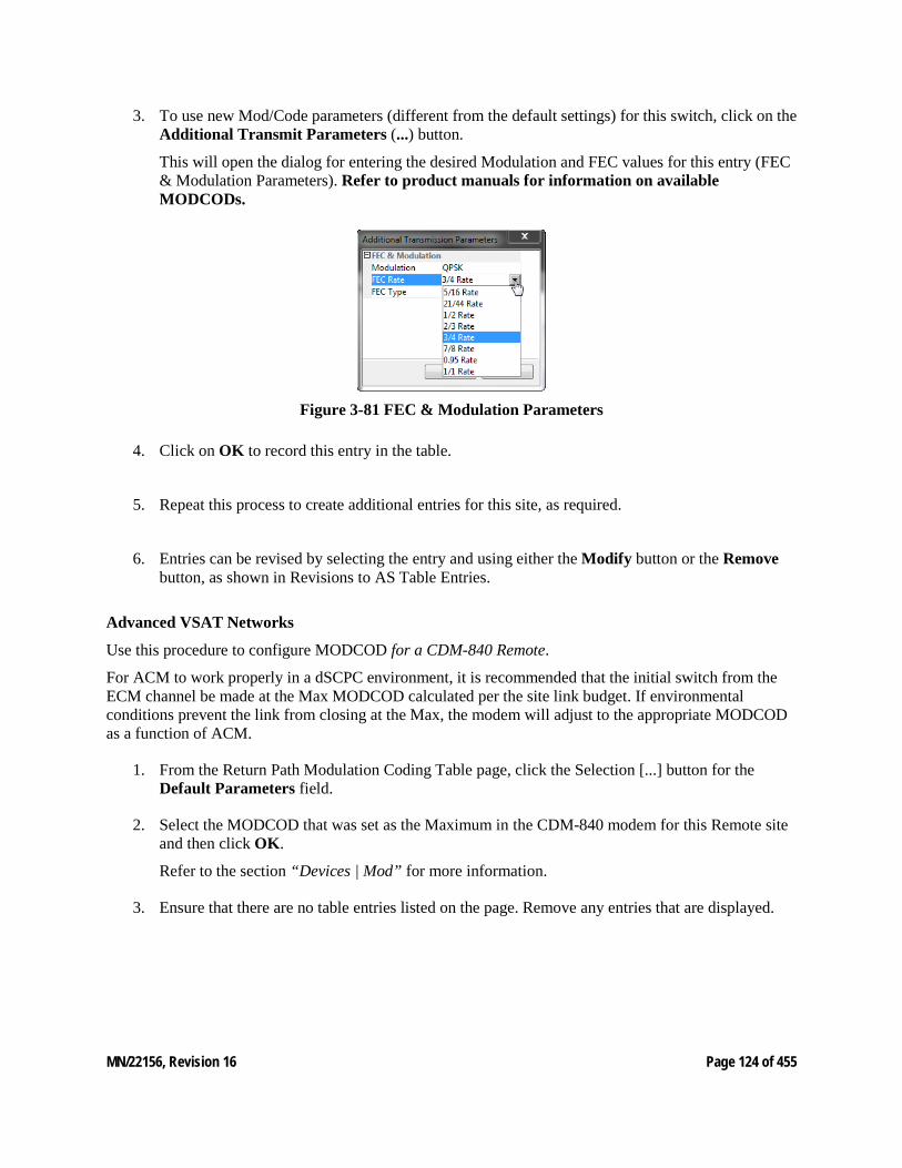
MN/22156, Revision 16 Page 124 of 455
3. To use new Mod/Code parameters (different from the default settings) for this switch, click on the Additional Transmit Parameters (...) button.
This will open the dialog for entering the desired Modulation and FEC values for this entry (FEC & Modulation Parameters). Refer to product manuals for information on available MODCODs.
Figure 3-81 FEC & Modulation Parameters
4. Click on OK to record this entry in the table.
5. Repeat this process to create additional entries for this site, as required.
6. Entries can be revised by selecting the entry and using either the Modify button or the Remove button, as shown in Revisions to AS Table Entries.
Advanced VSAT Networks
Use this procedure to configure MODCOD for a CDM-840 Remote.
For ACM to work properly in a dSCPC environment, it is recommended that the initial switch from the ECM channel be made at the Max MODCOD calculated per the site link budget. If environmental conditions prevent the link from closing at the Max, the modem will adjust to the appropriate MODCOD as a function of ACM.
1. From the Return Path Modulation Coding Table page, click the Selection [...] button for the Default Parameters field.
2. Select the MODCOD that was set as the Maximum in the CDM-840 modem for this Remote site and then click OK.
Refer to the section “Devices | Mod” for more information.
3. Ensure that there are no table entries listed on the page. Remove any entries that are displayed.
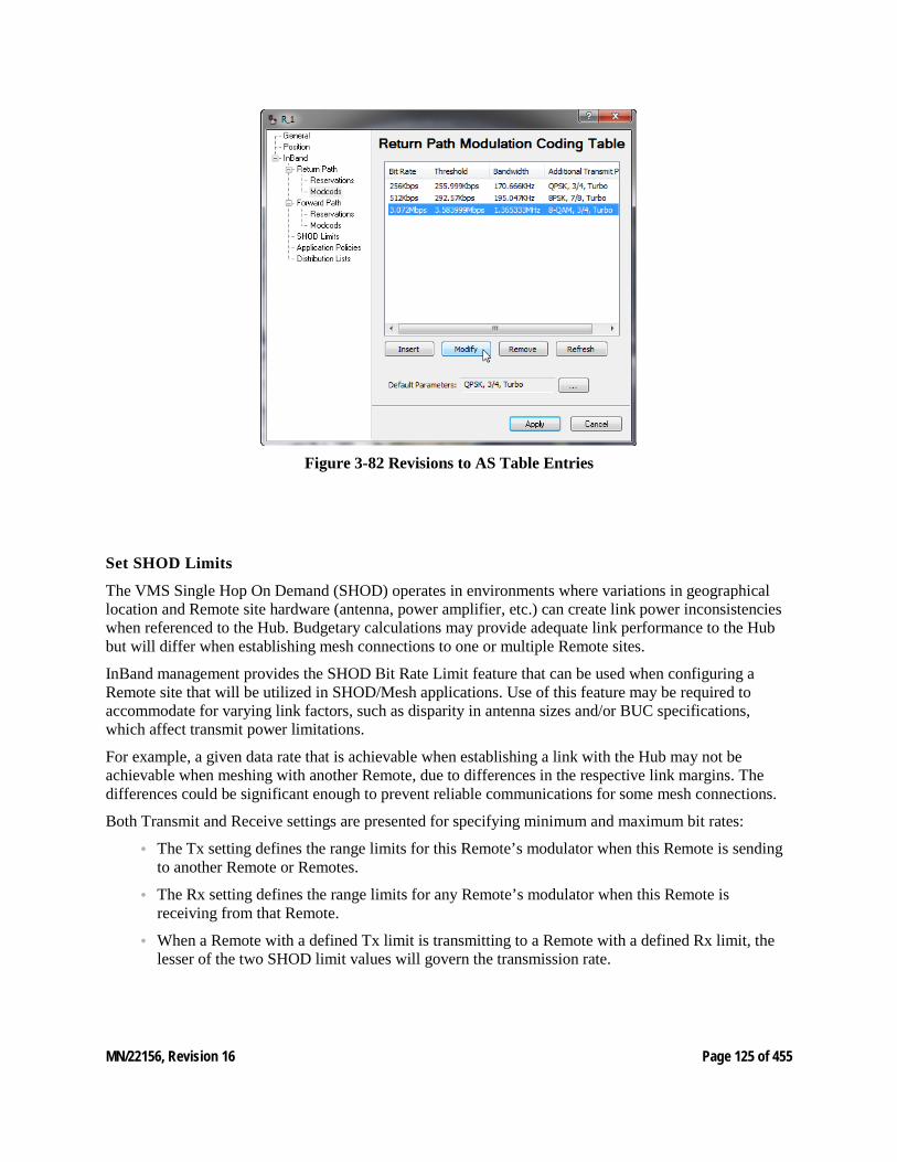
MN/22156, Revision 16 Page 125 of 455
Figure 3-82 Revisions to AS Table Entries
Set SHOD Limits
The VMS Single Hop On Demand (SHOD) operates in environments where variations in geographical location and Remote site hardware (antenna, power amplifier, etc.) can create link power inconsistencies when referenced to the Hub. Budgetary calculations may provide adequate link performance to the Hub but will differ when establishing mesh connections to one or multiple Remote sites.
InBand management provides the SHOD Bit Rate Limit feature that can be used when configuring a Remote site that will be utilized in SHOD/Mesh applications. Use of this feature may be required to accommodate for varying link factors, such as disparity in antenna sizes and/or BUC specifications, which affect transmit power limitations.
For example, a given data rate that is achievable when establishing a link with the Hub may not be achievable when meshing with another Remote, due to differences in the respective link margins. The differences could be significant enough to prevent reliable communications for some mesh connections.
Both Transmit and Receive settings are presented for specifying minimum and maximum bit rates:
• The Tx setting defines the range limits for this Remote’s modulator when this Remote is sending to another Remote or Remotes.
• The Rx setting defines the range limits for any Remote’s modulator when this Remote is receiving from that Remote.
• When a Remote with a defined Tx limit is transmitting to a Remote with a defined Rx limit, the lesser of the two SHOD limit values will govern the transmission rate.
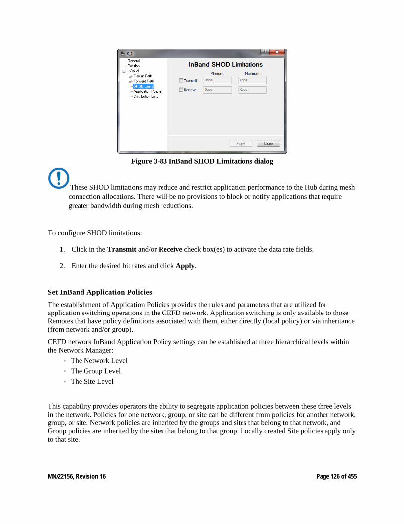
MN/22156, Revision 16 Page 126 of 455
Figure 3-83 InBand SHOD Limitations dialog
These SHOD limitations may reduce and restrict application performance to the Hub during mesh connection allocations. There will be no provisions to block or notify applications that require greater bandwidth during mesh reductions.
To configure SHOD limitations:
1. Click in the Transmit and/or Receive check box(es) to activate the data rate fields.
2. Enter the desired bit rates and click Apply.
Set InBand Application Policies
The establishment of Application Policies provides the rules and parameters that are utilized for application switching operations in the CEFD network. Application switching is only available to those Remotes that have policy definitions associated with them, either directly (local policy) or via inheritance (from network and/or group).
CEFD network InBand Application Policy settings can be established at three hierarchical levels within the Network Manager:
• The Network Level • The Group Level • The Site Level
This capability provides operators the ability to segregate application policies between these three levels in the network. Policies for one network, group, or site can be different from policies for another network, group, or site. Network policies are inherited by the groups and sites that belong to that network, and Group policies are inherited by the sites that belong to that group. Locally created Site policies apply only to that site.

MN/22156, Revision 16 Page 127 of 455
Start by building policies at the Network level, then set the policies at the Group and/or Site levels.
1. Open the Network Properties and select the InBand Application Policies dialog, as shown in InBand Application Policies dialog, Network.
Figure 3-84 InBand Application Policies dialog, Network
2. To add a policy, right-click in the table space and select Insert.
3. Enter the Type value, Label, Priority, and Bitrate limits for this policy (Application Policy Set-tings), then click OK to enter this policy in the table.
Figure 3-85 Application Policy Settings
Application Policy Type numbers have the following convention: 0 — ECM Load Switching 1 — Scheduled Switching and VFS 2 — Voice 3 — Video 4-62 Reserved for the System 63 — ECM version 2 entry switch, system defined 64–252 — User Defined
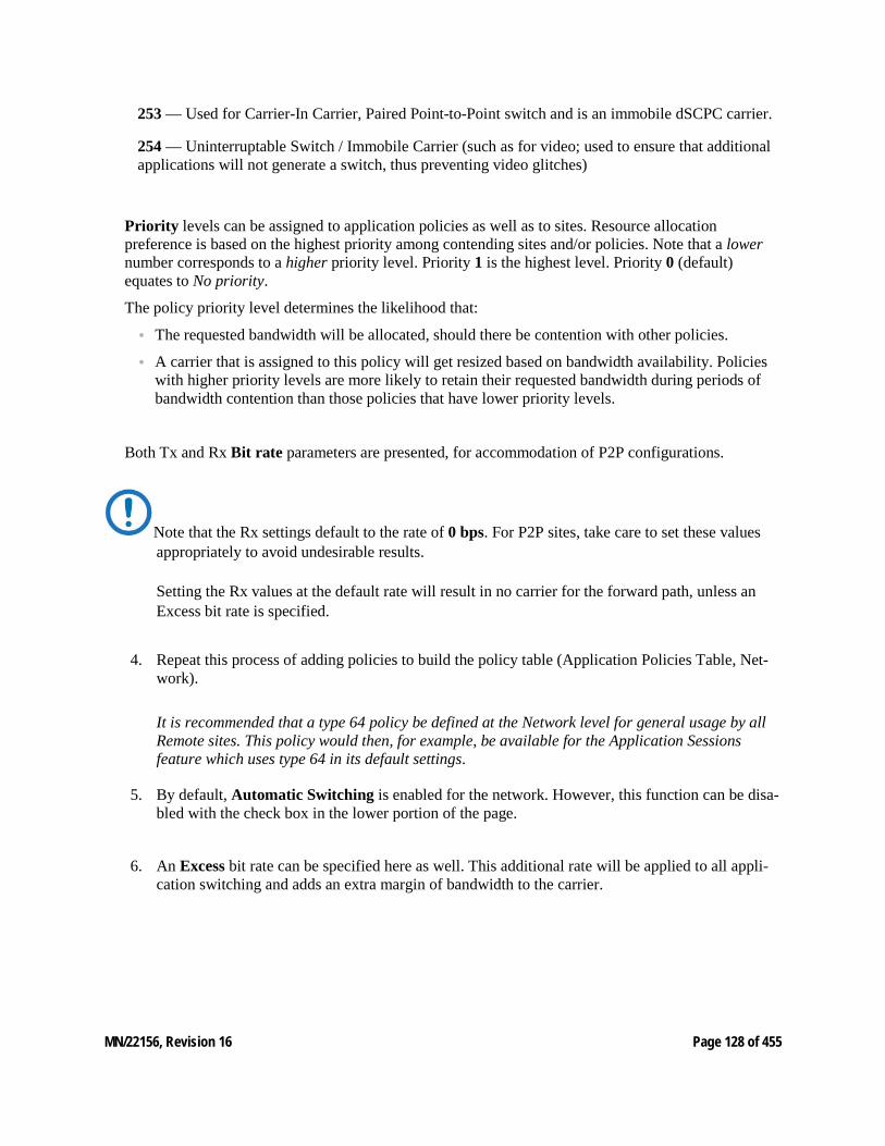
MN/22156, Revision 16 Page 128 of 455
253 — Used for Carrier-In Carrier, Paired Point-to-Point switch and is an immobile dSCPC carrier.
254 — Uninterruptable Switch / Immobile Carrier (such as for video; used to ensure that additional applications will not generate a switch, thus preventing video glitches)
Priority levels can be assigned to application policies as well as to sites. Resource allocation preference is based on the highest priority among contending sites and/or policies. Note that a lower number corresponds to a higher priority level. Priority 1 is the highest level. Priority 0 (default) equates to No priority.
The policy priority level determines the likelihood that:
• The requested bandwidth will be allocated, should there be contention with other policies.
• A carrier that is assigned to this policy will get resized based on bandwidth availability. Policies with higher priority levels are more likely to retain their requested bandwidth during periods of bandwidth contention than those policies that have lower priority levels.
Both Tx and Rx Bit rate parameters are presented, for accommodation of P2P configurations.
Note that the Rx settings default to the rate of 0 bps. For P2P sites, take care to set these values appropriately to avoid undesirable results. Setting the Rx values at the default rate will result in no carrier for the forward path, unless an Excess bit rate is specified.
4. Repeat this process of adding policies to build the policy table (Application Policies Table, Net-work).
It is recommended that a type 64 policy be defined at the Network level for general usage by all Remote sites. This policy would then, for example, be available for the Application Sessions feature which uses type 64 in its default settings.
5. By default, Automatic Switching is enabled for the network. However, this function can be disa-bled with the check box in the lower portion of the page.
6. An Excess bit rate can be specified here as well. This additional rate will be applied to all appli-cation switching and adds an extra margin of bandwidth to the carrier.
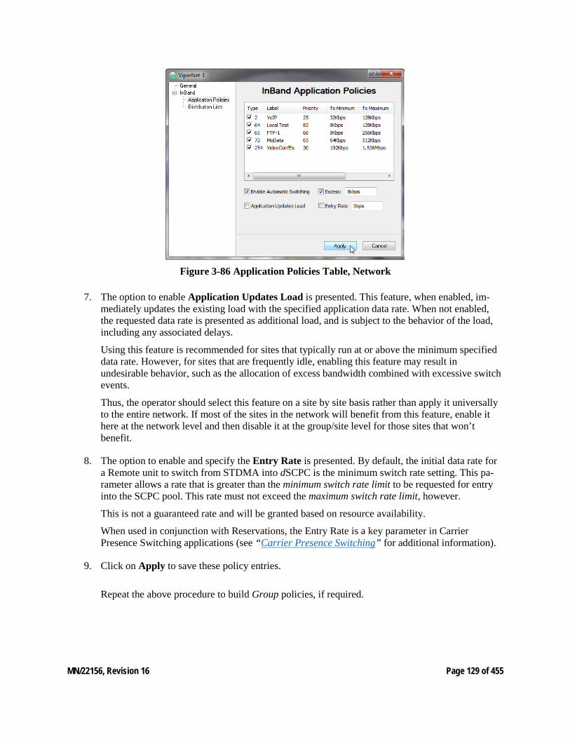
MN/22156, Revision 16 Page 129 of 455
Figure 3-86 Application Policies Table, Network
7. The option to enable Application Updates Load is presented. This feature, when enabled, im-mediately updates the existing load with the specified application data rate. When not enabled, the requested data rate is presented as additional load, and is subject to the behavior of the load, including any associated delays.
Using this feature is recommended for sites that typically run at or above the minimum specified data rate. However, for sites that are frequently idle, enabling this feature may result in undesirable behavior, such as the allocation of excess bandwidth combined with excessive switch events.
Thus, the operator should select this feature on a site by site basis rather than apply it universally to the entire network. If most of the sites in the network will benefit from this feature, enable it here at the network level and then disable it at the group/site level for those sites that won’t benefit.
8. The option to enable and specify the Entry Rate is presented. By default, the initial data rate for a Remote unit to switch from STDMA into dSCPC is the minimum switch rate setting. This pa-rameter allows a rate that is greater than the minimum switch rate limit to be requested for entry into the SCPC pool. This rate must not exceed the maximum switch rate limit, however.
This is not a guaranteed rate and will be granted based on resource availability.
When used in conjunction with Reservations, the Entry Rate is a key parameter in Carrier Presence Switching applications (see “Carrier Presence Switching” for additional information).
9. Click on Apply to save these policy entries.
Repeat the above procedure to build Group policies, if required.
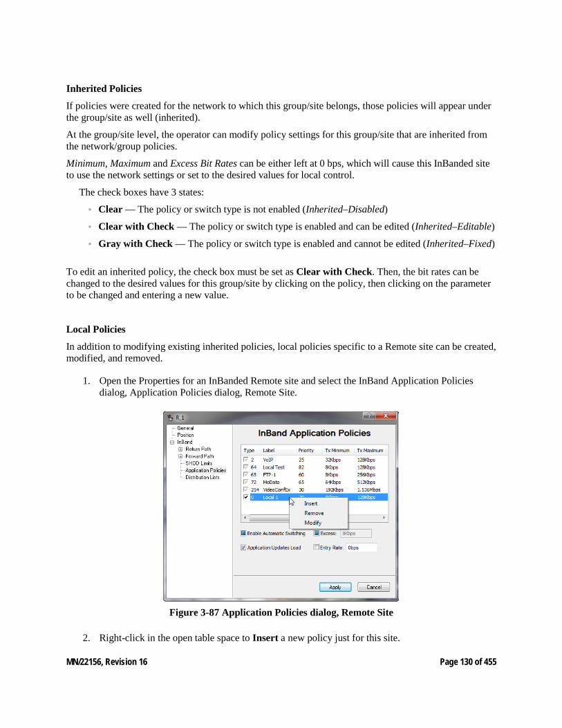
MN/22156, Revision 16 Page 130 of 455
Inherited Policies
If policies were created for the network to which this group/site belongs, those policies will appear under the group/site as well (inherited).
At the group/site level, the operator can modify policy settings for this group/site that are inherited from the network/group policies.
Minimum, Maximum and Excess Bit Rates can be either left at 0 bps, which will cause this InBanded site to use the network settings or set to the desired values for local control.
The check boxes have 3 states:
• Clear — The policy or switch type is not enabled (Inherited–Disabled)
• Clear with Check — The policy or switch type is enabled and can be edited (Inherited–Editable)
• Gray with Check — The policy or switch type is enabled and cannot be edited (Inherited–Fixed)
To edit an inherited policy, the check box must be set as Clear with Check. Then, the bit rates can be changed to the desired values for this group/site by clicking on the policy, then clicking on the parameter to be changed and entering a new value.
Local Policies
In addition to modifying existing inherited policies, local policies specific to a Remote site can be created, modified, and removed.
1. Open the Properties for an InBanded Remote site and select the InBand Application Policies dialog, Application Policies dialog, Remote Site.
Figure 3-87 Application Policies dialog, Remote Site
2. Right-click in the open table space to Insert a new policy just for this site.
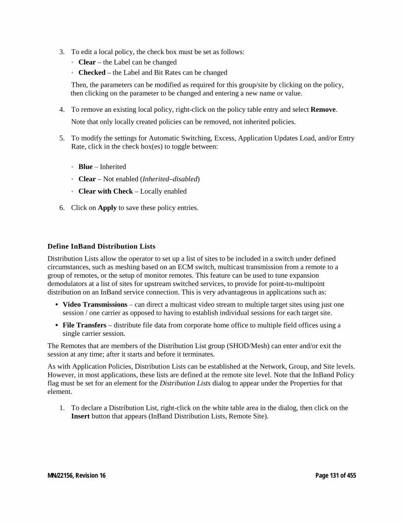
MN/22156, Revision 16 Page 131 of 455
3. To edit a local policy, the check box must be set as follows: • Clear – the Label can be changed • Checked – the Label and Bit Rates can be changed
Then, the parameters can be modified as required for this group/site by clicking on the policy, then clicking on the parameter to be changed and entering a new name or value.
4. To remove an existing local policy, right-click on the policy table entry and select Remove.
Note that only locally created policies can be removed, not inherited policies.
5. To modify the settings for Automatic Switching, Excess, Application Updates Load, and/or Entry Rate, click in the check box(es) to toggle between:
• Blue – Inherited
• Clear – Not enabled (Inherited–disabled)
• Clear with Check – Locally enabled
6. Click on Apply to save these policy entries.
Define InBand Distribution Lists
Distribution Lists allow the operator to set up a list of sites to be included in a switch under defined circumstances, such as meshing based on an ECM switch, multicast transmission from a remote to a group of remotes, or the setup of monitor remotes. This feature can be used to tune expansion demodulators at a list of sites for upstream switched services, to provide for point-to-multipoint distribution on an InBand service connection. This is very advantageous in applications such as:
• Video Transmissions – can direct a multicast video stream to multiple target sites using just one session / one carrier as opposed to having to establish individual sessions for each target site.
• File Transfers – distribute file data from corporate home office to multiple field offices using a single carrier session.
The Remotes that are members of the Distribution List group (SHOD/Mesh) can enter and/or exit the session at any time; after it starts and before it terminates.
As with Application Policies, Distribution Lists can be established at the Network, Group, and Site levels. However, in most applications, these lists are defined at the remote site level. Note that the InBand Policy flag must be set for an element for the Distribution Lists dialog to appear under the Properties for that element.
1. To declare a Distribution List, right-click on the white table area in the dialog, then click on the Insert button that appears (InBand Distribution Lists, Remote Site).
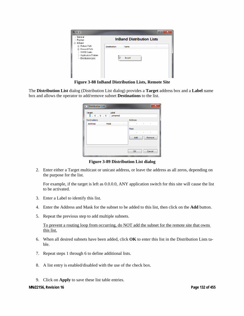
MN/22156, Revision 16 Page 132 of 455
Figure 3-88 InBand Distribution Lists, Remote Site
The Distribution List dialog (Distribution List dialog) provides a Target address box and a Label name box and allows the operator to add/remove subnet Destinations to the list.
Figure 3-89 Distribution List dialog
2. Enter either a Target multicast or unicast address, or leave the address as all zeros, depending on the purpose for the list.
For example, if the target is left as 0.0.0.0, ANY application switch for this site will cause the list to be activated.
3. Enter a Label to identify this list.
4. Enter the Address and Mask for the subnet to be added to this list, then click on the Add button.
5. Repeat the previous step to add multiple subnets.
To prevent a routing loop from occurring, do NOT add the subnet for the remote site that owns this list.
6. When all desired subnets have been added, click OK to enter this list in the Distribution Lists ta-ble.
7. Repeat steps 1 through 6 to define additional lists.
8. A list entry is enabled/disabled with the use of the check box.
9. Click on Apply to save these list table entries.
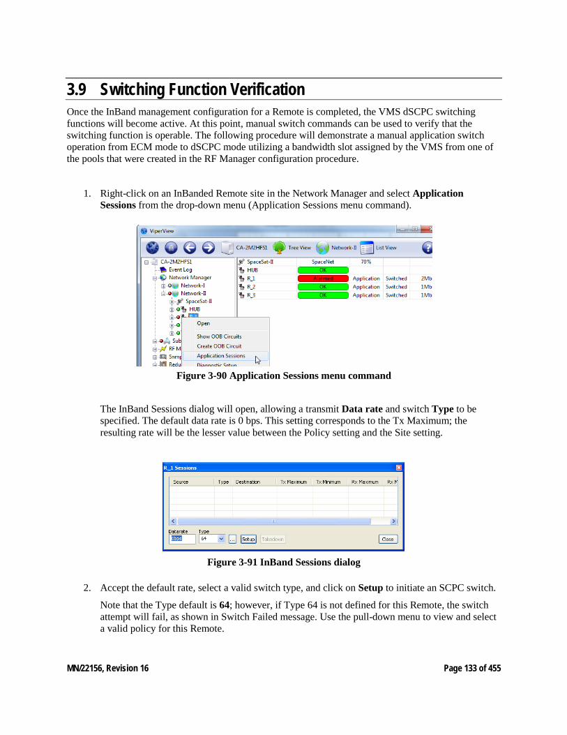
MN/22156, Revision 16 Page 133 of 455
3.9 Switching Function Verification Once the InBand management configuration for a Remote is completed, the VMS dSCPC switching functions will become active. At this point, manual switch commands can be used to verify that the switching function is operable. The following procedure will demonstrate a manual application switch operation from ECM mode to dSCPC mode utilizing a bandwidth slot assigned by the VMS from one of the pools that were created in the RF Manager configuration procedure.
1. Right-click on an InBanded Remote site in the Network Manager and select Application Sessions from the drop-down menu (Application Sessions menu command).
Figure 3-90 Application Sessions menu command
The InBand Sessions dialog will open, allowing a transmit Data rate and switch Type to be specified. The default data rate is 0 bps. This setting corresponds to the Tx Maximum; the resulting rate will be the lesser value between the Policy setting and the Site setting.
Figure 3-91 InBand Sessions dialog
2. Accept the default rate, select a valid switch type, and click on Setup to initiate an SCPC switch.
Note that the Type default is 64; however, if Type 64 is not defined for this Remote, the switch attempt will fail, as shown in Switch Failed message. Use the pull-down menu to view and select a valid policy for this Remote.
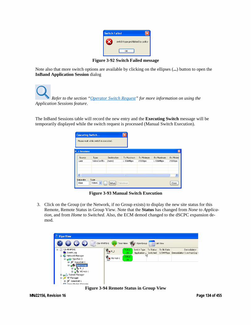
MN/22156, Revision 16 Page 134 of 455
Figure 3-92 Switch Failed message
Note also that more switch options are available by clicking on the ellipses (...) button to open the InBand Application Session dialog
Refer to the section “Operator Switch Request” for more information on using the Application Sessions feature.
The InBand Sessions table will record the new entry and the Executing Switch message will be temporarily displayed while the switch request is processed (Manual Switch Execution).
Figure 3-93 Manual Switch Execution
3. Click on the Group (or the Network, if no Group exists) to display the new site status for this Remote, Remote Status in Group View. Note that the Status has changed from None to Applica-tion, and from Home to Switched. Also, the ECM demod changed to the dSCPC expansion de-mod.
Figure 3-94 Remote Status in Group View
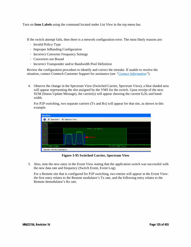
MN/22156, Revision 16 Page 135 of 455
Turn on Item Labels using the command located under List View in the top menu bar.
If the switch attempt fails, then there is a network configuration error. The most likely reasons are: • Invalid Policy Type • Improper InBanding Configuration • Incorrect Converter Frequency Settings • Converters not Bound • Incorrect Transponder and/or Bandwidth Pool Definition
Review the configuration procedure to identify and correct the mistake. If unable to resolve the situation, contact Comtech Customer Support for assistance (see “Contact Information”).
4. Observe the change in the Spectrum View (Switched Carrier, Spectrum View); a blue shaded area will appear representing the slot assigned by the VMS for the switch. Upon receipt of the next SUM (Status Update Message), the carrier(s) will appear showing the current EbN0 and band-width.
For P2P switching, two separate carriers (Tx and Rx) will appear for that site, as shown in this example.
Figure 3-95 Switched Carrier, Spectrum View
5. Also, note the new entry in the Event View stating that the application switch was successful with the new data rate and frequency (Switch Event, Event Log).
For a Remote site that is configured for P2P switching, two entries will appear in the Event View: the first entry relates to the Remote modulator’s Tx rate, and the following entry relates to the Remote demodulator’s Rx rate.
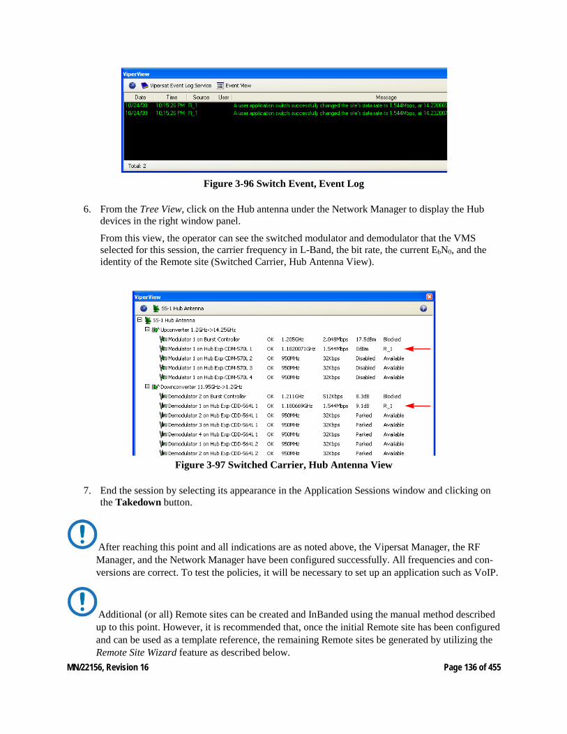
MN/22156, Revision 16 Page 136 of 455
Figure 3-96 Switch Event, Event Log
6. From the Tree View, click on the Hub antenna under the Network Manager to display the Hub devices in the right window panel.
From this view, the operator can see the switched modulator and demodulator that the VMS selected for this session, the carrier frequency in L-Band, the bit rate, the current EbN0, and the identity of the Remote site (Switched Carrier, Hub Antenna View).
Figure 3-97 Switched Carrier, Hub Antenna View
7. End the session by selecting its appearance in the Application Sessions window and clicking on the Takedown button.
After reaching this point and all indications are as noted above, the Vipersat Manager, the RF Manager, and the Network Manager have been configured successfully. All frequencies and con-versions are correct. To test the policies, it will be necessary to set up an application such as VoIP.
Additional (or all) Remote sites can be created and InBanded using the manual method described up to this point. However, it is recommended that, once the initial Remote site has been configured and can be used as a template reference, the remaining Remote sites be generated by utilizing the Remote Site Wizard feature as described below.
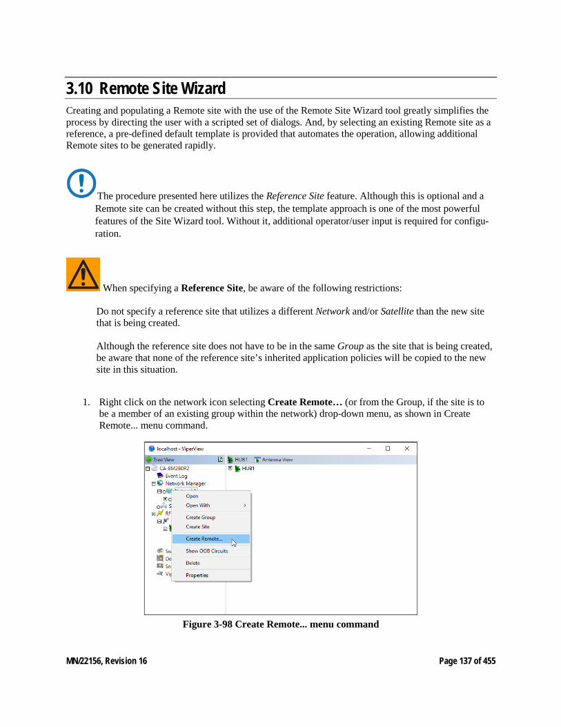
MN/22156, Revision 16 Page 137 of 455
3.10 Remote Site Wizard Creating and populating a Remote site with the use of the Remote Site Wizard tool greatly simplifies the process by directing the user with a scripted set of dialogs. And, by selecting an existing Remote site as a reference, a pre-defined default template is provided that automates the operation, allowing additional Remote sites to be generated rapidly.
The procedure presented here utilizes the Reference Site feature. Although this is optional and a Remote site can be created without this step, the template approach is one of the most powerful features of the Site Wizard tool. Without it, additional operator/user input is required for configu-ration.
When specifying a Reference Site, be aware of the following restrictions: Do not specify a reference site that utilizes a different Network and/or Satellite than the new site that is being created. Although the reference site does not have to be in the same Group as the site that is being created, be aware that none of the reference site’s inherited application policies will be copied to the new site in this situation.
1. Right click on the network icon selecting Create Remote… (or from the Group, if the site is to be a member of an existing group within the network) drop-down menu, as shown in Create Remote... menu command.
Figure 3-98 Create Remote... menu command
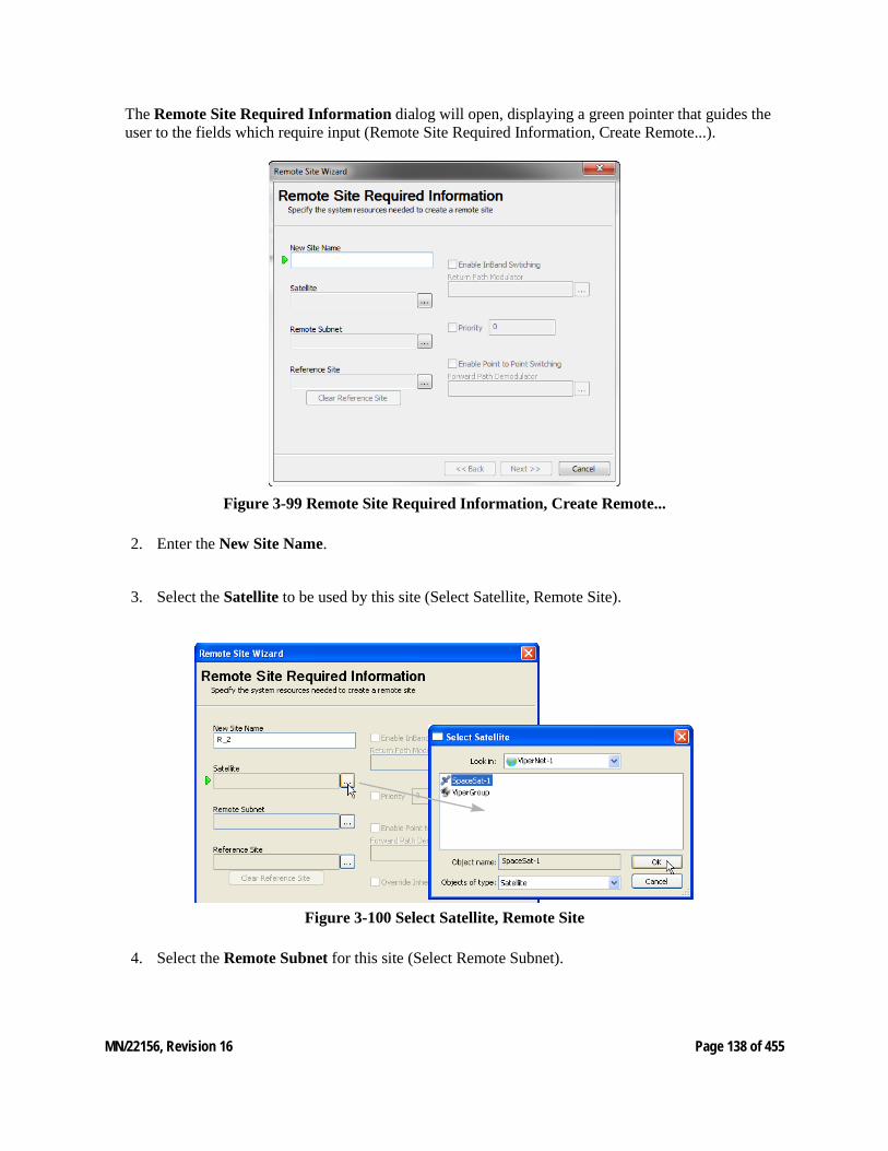
MN/22156, Revision 16 Page 138 of 455
The Remote Site Required Information dialog will open, displaying a green pointer that guides the user to the fields which require input (Remote Site Required Information, Create Remote...).
Figure 3-99 Remote Site Required Information, Create Remote...
2. Enter the New Site Name.
3. Select the Satellite to be used by this site (Select Satellite, Remote Site).
Figure 3-100 Select Satellite, Remote Site
4. Select the Remote Subnet for this site (Select Remote Subnet).
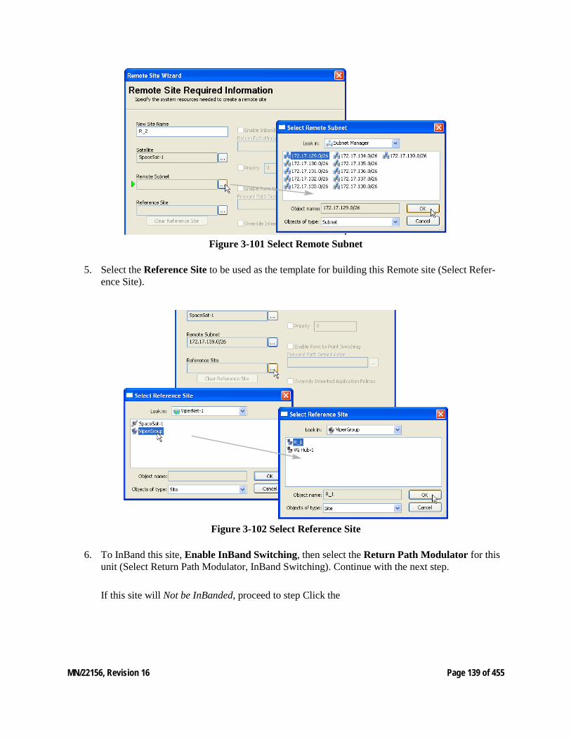
MN/22156, Revision 16 Page 139 of 455
Figure 3-101 Select Remote Subnet
5. Select the Reference Site to be used as the template for building this Remote site (Select Refer-ence Site).
Figure 3-102 Select Reference Site
6. To InBand this site, Enable InBand Switching, then select the Return Path Modulator for this unit (Select Return Path Modulator, InBand Switching). Continue with the next step.
If this site will Not be InBanded, proceed to step Click the
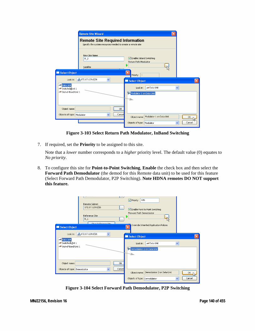
MN/22156, Revision 16 Page 140 of 455
Figure 3-103 Select Return Path Modulator, InBand Switching
7. If required, set the Priority to be assigned to this site.
Note that a lower number corresponds to a higher priority level. The default value (0) equates to No priority.
8. To configure this site for Point-to-Point Switching, Enable the check box and then select the Forward Path Demodulator (the demod for this Remote data unit) to be used for this feature (Select Forward Path Demodulator, P2P Switching). Note HDNA remotes DO NOT support this feature.
Figure 3-104 Select Forward Path Demodulator, P2P Switching

MN/22156, Revision 16 Page 141 of 455
9. Click the Next button to proceed to the dialog for configuring the Site RF Profile (Site RF Pro-file, Create Remote...).
Figure 3-105 Site RF Profile, Create Remote...
When a reference site has been specified, the template of that site’s parameters will auto-fill these next dialogs, requiring modifications only to settings that differ for this new site.
10. Review the RF settings and edit this dialog if necessary, then click the Next button.
For InBanded sites, the Return Path Home State Configuration dialog will appear (Return Path Home State Configuration, InBand). Continue with the next step.
For sites that are not InBanded, the Ready To Create window will appear (Ready to Create, Site Summary). Proceed to step 17.
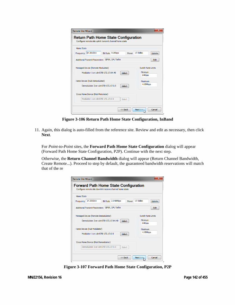
MN/22156, Revision 16 Page 142 of 455
Figure 3-106 Return Path Home State Configuration, InBand
11. Again, this dialog is auto-filled from the reference site. Review and edit as necessary, then click Next.
For Point-to-Point sites, the Forward Path Home State Configuration dialog will appear (Forward Path Home State Configuration, P2P). Continue with the next step.
Otherwise, the Return Channel Bandwidth dialog will appear (Return Channel Bandwidth, Create Remote...). Proceed to step by default, the guaranteed bandwidth reservations will match that of the re
Figure 3-107 Forward Path Home State Configuration, P2P
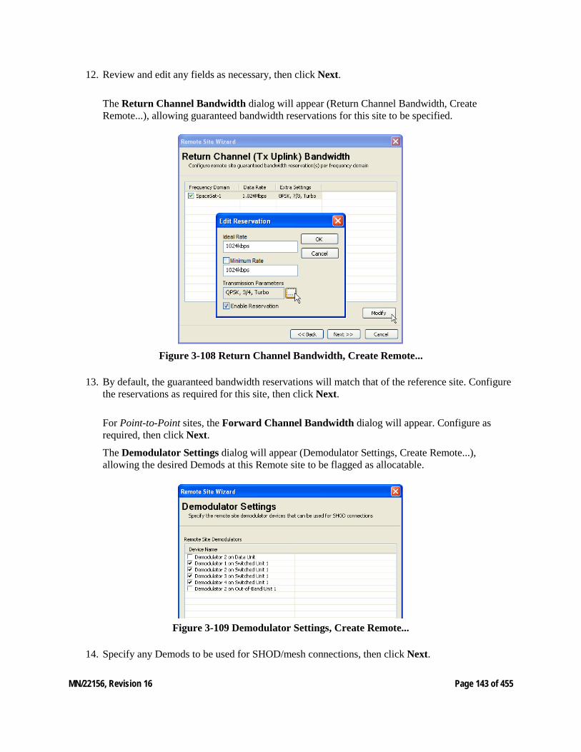
MN/22156, Revision 16 Page 143 of 455
12. Review and edit any fields as necessary, then click Next.
The Return Channel Bandwidth dialog will appear (Return Channel Bandwidth, Create Remote...), allowing guaranteed bandwidth reservations for this site to be specified.
Figure 3-108 Return Channel Bandwidth, Create Remote...
13. By default, the guaranteed bandwidth reservations will match that of the reference site. Configure the reservations as required for this site, then click Next.
For Point-to-Point sites, the Forward Channel Bandwidth dialog will appear. Configure as required, then click Next.
The Demodulator Settings dialog will appear (Demodulator Settings, Create Remote...), allowing the desired Demods at this Remote site to be flagged as allocatable.
Figure 3-109 Demodulator Settings, Create Remote...
14. Specify any Demods to be used for SHOD/mesh connections, then click Next.
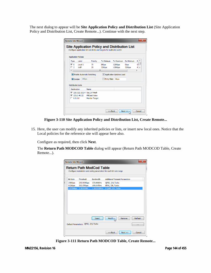
MN/22156, Revision 16 Page 144 of 455
The next dialog to appear will be Site Application Policy and Distribution List (Site Application Policy and Distribution List, Create Remote...). Continue with the next step.
Figure 3-110 Site Application Policy and Distribution List, Create Remote...
15. Here, the user can modify any inherited policies or lists, or insert new local ones. Notice that the Local policies for the reference site will appear here also.
Configure as required, then click Next.
The Return Path MODCOD Table dialog will appear (Return Path MODCOD Table, Create Remote...).
Figure 3-111 Return Path MODCOD Table, Create Remote...
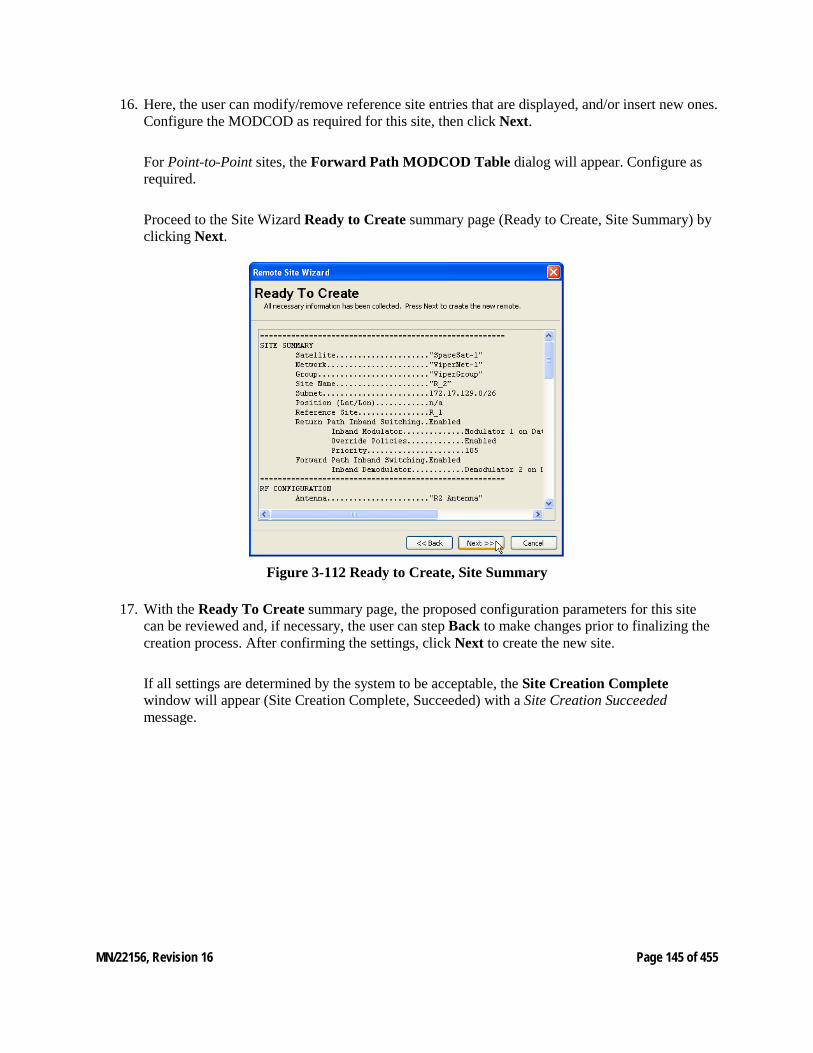
MN/22156, Revision 16 Page 145 of 455
16. Here, the user can modify/remove reference site entries that are displayed, and/or insert new ones. Configure the MODCOD as required for this site, then click Next.
For Point-to-Point sites, the Forward Path MODCOD Table dialog will appear. Configure as required.
Proceed to the Site Wizard Ready to Create summary page (Ready to Create, Site Summary) by clicking Next.
Figure 3-112 Ready to Create, Site Summary
17. With the Ready To Create summary page, the proposed configuration parameters for this site can be reviewed and, if necessary, the user can step Back to make changes prior to finalizing the creation process. After confirming the settings, click Next to create the new site.
If all settings are determined by the system to be acceptable, the Site Creation Complete window will appear (Site Creation Complete, Succeeded) with a Site Creation Succeeded message.
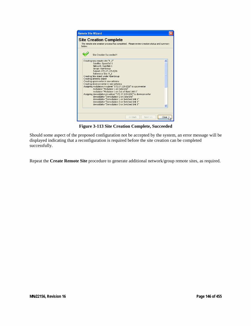
MN/22156, Revision 16 Page 146 of 455
Figure 3-113 Site Creation Complete, Succeeded
Should some aspect of the proposed configuration not be accepted by the system, an error message will be displayed indicating that a reconfiguration is required before the site creation can be completed successfully.
Repeat the Create Remote Site procedure to generate additional network/group remote sites, as required.

MN/22156, Revision 16 Page 147 of 455
3.11 Redundancy Configuration M:N Device Redundancy If device redundancy for hub primary modems is desired, it should be configured at this point. Complete instructions for configuring this feature can be found in Appendix C, "Redundancy".
VMS Redundancy If VMS server redundancy is desired, it should be configured at this point. Complete instructions for configuring this feature can be found in Appendix C, "Redundancy".
3.12 Dynamic Route (CDM-570) The next step will be to set up the VMS to push the routes to the TDM outbounds. This step is necessary if there is more than one satellite–or satellite beam–being used in the network, or if multiple TDM outbounds are being used and the mobile sites will transition between them.
It will no longer be necessary to put static routes in the TDM modems. If any static routes exist, either telnet/console into the box(es) or use the Parameter Editor from the VMS and delete them. The only routes left in the TDM outbounds should be the Default Gateway to the edge router and any non-mobile remotes in the network (if desired, these routes can also be entered as dynamic VMS routes).
1. Right-click on the Hub modem unit that represents the first TDM outbound and select the Properties page.
Figure 3-114 TDM Properties, Routes
2. Select Routes from the tree menu to display the Routes table (TDM Properties, Routes).
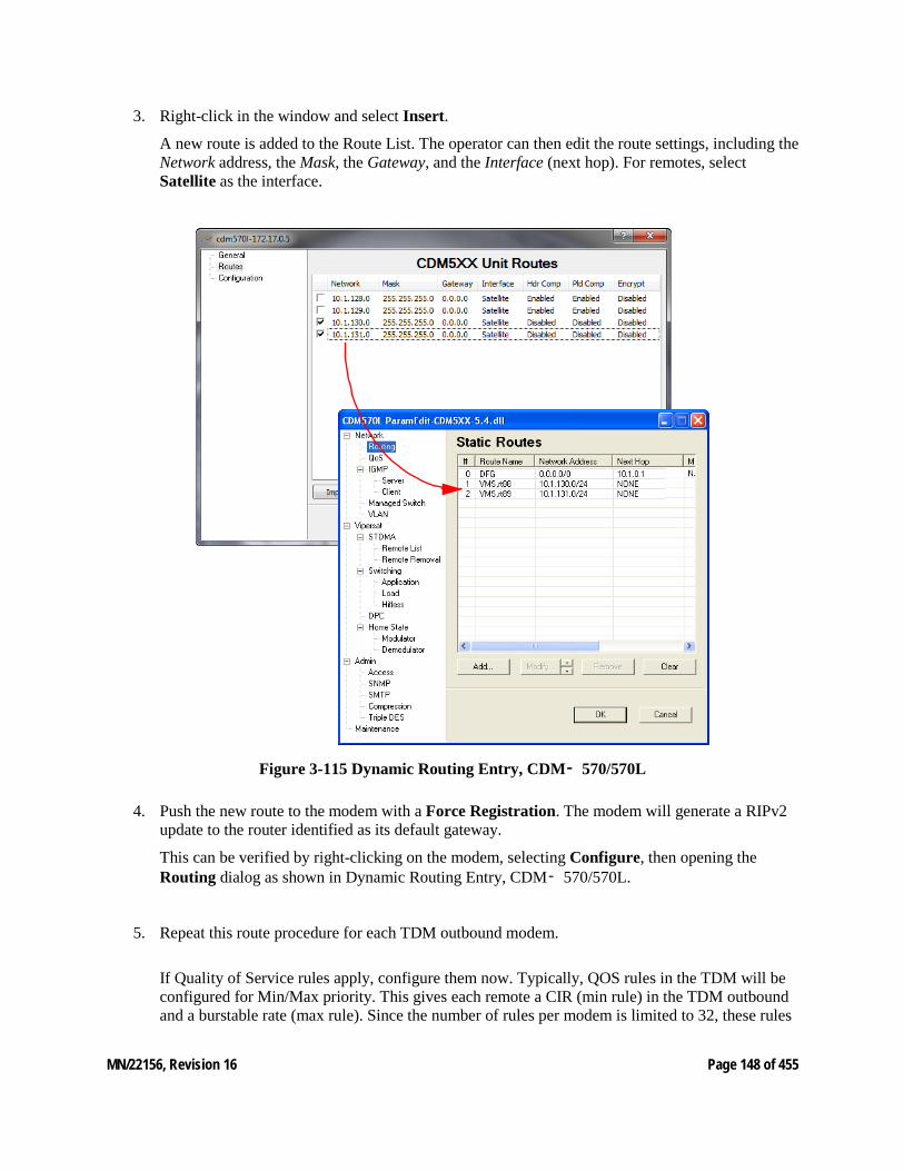
MN/22156, Revision 16 Page 148 of 455
3. Right-click in the window and select Insert.
A new route is added to the Route List. The operator can then edit the route settings, including the Network address, the Mask, the Gateway, and the Interface (next hop). For remotes, select Satellite as the interface.
Figure 3-115 Dynamic Routing Entry, CDM‑ 570/570L
4. Push the new route to the modem with a Force Registration. The modem will generate a RIPv2 update to the router identified as its default gateway.
This can be verified by right-clicking on the modem, selecting Configure, then opening the Routing dialog as shown in Dynamic Routing Entry, CDM‑ 570/570L.
5. Repeat this route procedure for each TDM outbound modem.
If Quality of Service rules apply, configure them now. Typically, QOS rules in the TDM will be configured for Min/Max priority. This gives each remote a CIR (min rule) in the TDM outbound and a burstable rate (max rule). Since the number of rules per modem is limited to 32, these rules
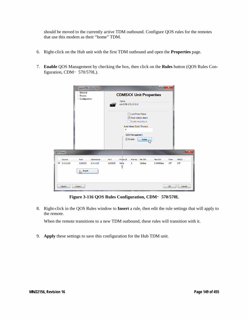
MN/22156, Revision 16 Page 149 of 455
should be moved to the currently active TDM outbound. Configure QOS rules for the remotes that use this modem as their “home” TDM.
6. Right-click on the Hub unit with the first TDM outbound and open the Properties page.
7. Enable QOS Management by checking the box, then click on the Rules button (QOS Rules Con-figuration, CDM‑ 570/570L).
Figure 3-116 QOS Rules Configuration, CDM‑ 570/570L
8. Right-click in the QOS Rules window to Insert a rule, then edit the rule settings that will apply to the remote.
When the remote transitions to a new TDM outbound, these rules will transition with it.
9. Apply these settings to save this configuration for the Hub TDM unit.
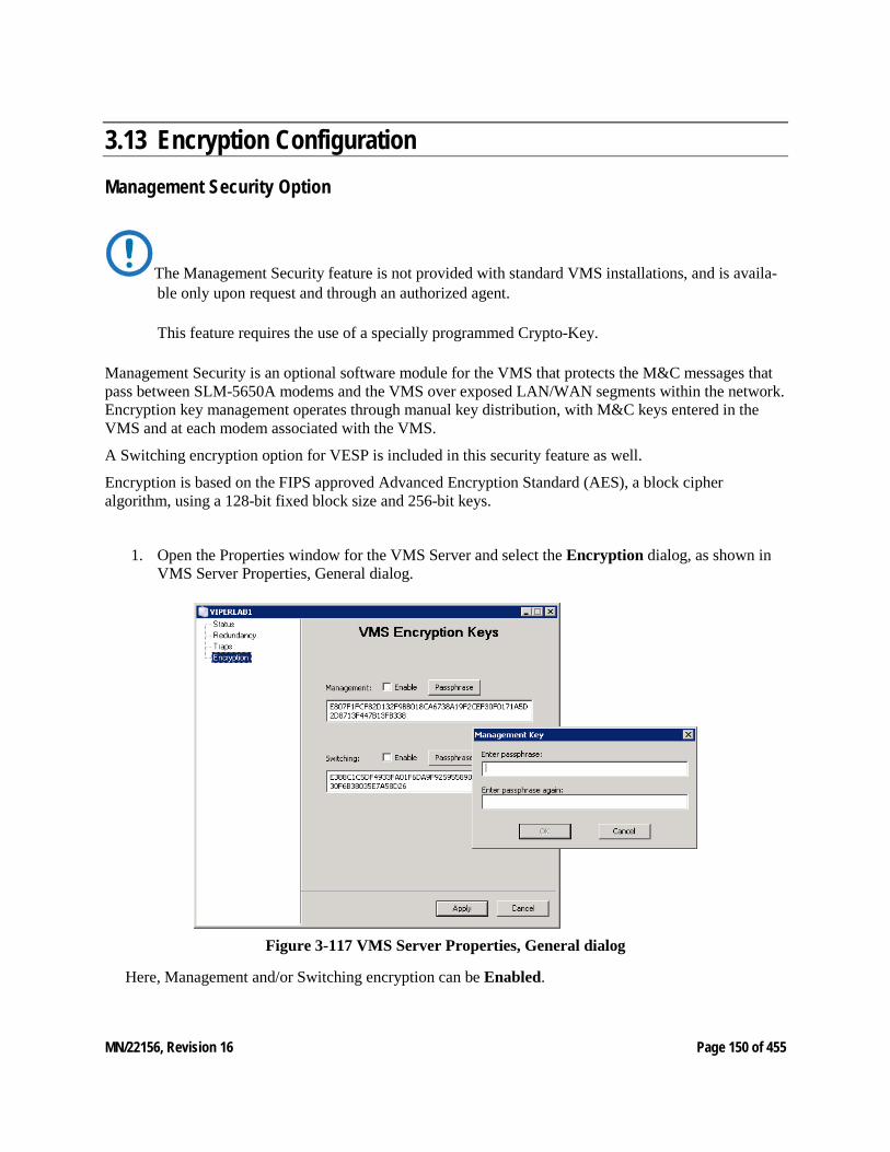
MN/22156, Revision 16 Page 150 of 455
3.13 Encryption Configuration Management Security Option
The Management Security feature is not provided with standard VMS installations, and is availa-ble only upon request and through an authorized agent. This feature requires the use of a specially programmed Crypto-Key.
Management Security is an optional software module for the VMS that protects the M&C messages that pass between SLM-5650A modems and the VMS over exposed LAN/WAN segments within the network. Encryption key management operates through manual key distribution, with M&C keys entered in the VMS and at each modem associated with the VMS.
A Switching encryption option for VESP is included in this security feature as well.
Encryption is based on the FIPS approved Advanced Encryption Standard (AES), a block cipher algorithm, using a 128-bit fixed block size and 256-bit keys.
1. Open the Properties window for the VMS Server and select the Encryption dialog, as shown in VMS Server Properties, General dialog.
Figure 3-117 VMS Server Properties, General dialog
Here, Management and/or Switching encryption can be Enabled.
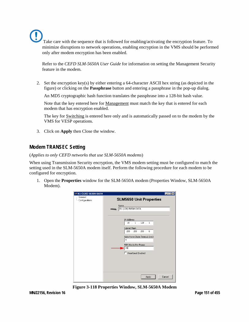
MN/22156, Revision 16 Page 151 of 455
Take care with the sequence that is followed for enabling/activating the encryption feature. To minimize disruptions to network operations, enabling encryption in the VMS should be performed only after modem encryption has been enabled. Refer to the CEFD SLM-5650A User Guide for information on setting the Management Security feature in the modem.
2. Set the encryption key(s) by either entering a 64-character ASCII hex string (as depicted in the figure) or clicking on the Passphrase button and entering a passphrase in the pop-up dialog.
An MD5 cryptographic hash function translates the passphrase into a 128-bit hash value.
Note that the key entered here for Management must match the key that is entered for each modem that has encryption enabled.
The key for Switching is entered here only and is automatically passed on to the modem by the VMS for VESP operations.
3. Click on Apply then Close the window.
Modem TRANSEC Setting (Applies to only CEFD networks that use SLM-5650A modems)
When using Transmission Security encryption, the VMS modem setting must be configured to match the setting used in the SLM-5650A modem itself. Perform the following procedure for each modem to be configured for encryption.
1. Open the Properties window for the SLM-5650A modem (Properties Window, SLM-5650A Modem).
Figure 3-118 Properties Window, SLM-5650A Modem

MN/22156, Revision 16 Page 152 of 455
2. Enter the number of blocks used for encryption in the FIPS Blocks Per Frame parameter field.
In the SLM-5650A/B modem, this parameter is specified on the Admin/Config page as the Encryption Frame Length in 16 Byte Blocks.
3. Click on Apply then Close the window.
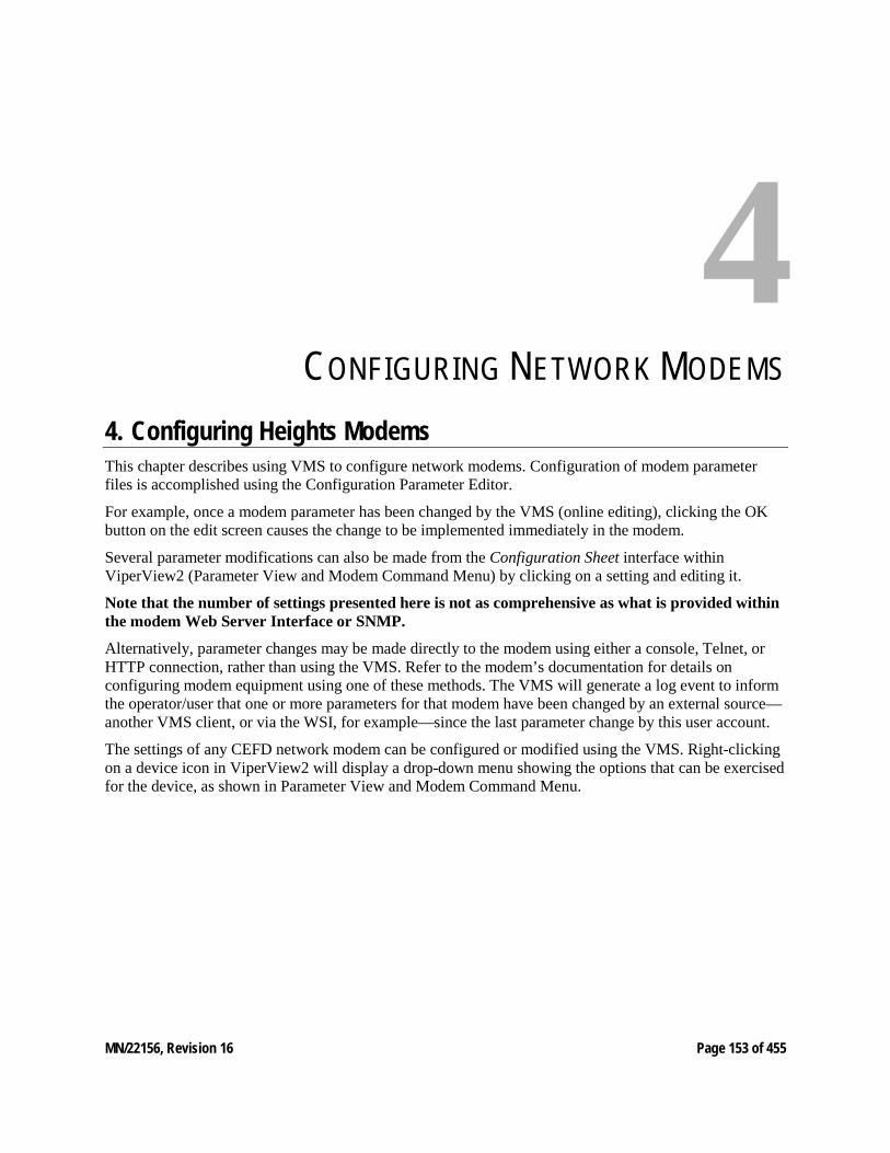
MN/22156, Revision 16 Page 153 of 455
4 CONFIGURING NETWORK MODEMS
4. Configuring Heights Modems This chapter describes using VMS to configure network modems. Configuration of modem parameter files is accomplished using the Configuration Parameter Editor.
For example, once a modem parameter has been changed by the VMS (online editing), clicking the OK button on the edit screen causes the change to be implemented immediately in the modem.
Several parameter modifications can also be made from the Configuration Sheet interface within ViperView2 (Parameter View and Modem Command Menu) by clicking on a setting and editing it.
Note that the number of settings presented here is not as comprehensive as what is provided within the modem Web Server Interface or SNMP.
Alternatively, parameter changes may be made directly to the modem using either a console, Telnet, or HTTP connection, rather than using the VMS. Refer to the modem’s documentation for details on configuring modem equipment using one of these methods. The VMS will generate a log event to inform the operator/user that one or more parameters for that modem have been changed by an external source—another VMS client, or via the WSI, for example—since the last parameter change by this user account.
The settings of any CEFD network modem can be configured or modified using the VMS. Right-clicking on a device icon in ViperView2 will display a drop-down menu showing the options that can be exercised for the device, as shown in Parameter View and Modem Command Menu.
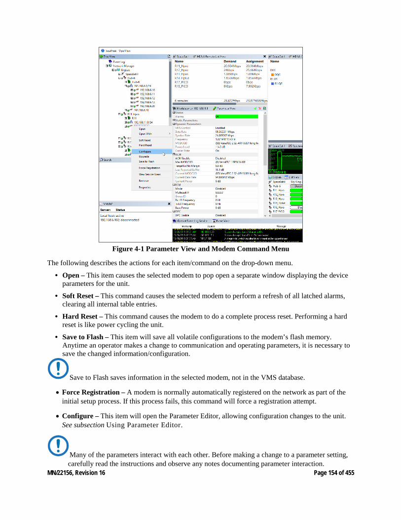
MN/22156, Revision 16 Page 154 of 455
Figure 4-1 Parameter View and Modem Command Menu
The following describes the actions for each item/command on the drop-down menu.
• Open – This item causes the selected modem to pop open a separate window displaying the device parameters for the unit.
• Soft Reset – This command causes the selected modem to perform a refresh of all latched alarms, clearing all internal table entries.
• Hard Reset – This command causes the modem to do a complete process reset. Performing a hard reset is like power cycling the unit.
• Save to Flash – This item will save all volatile configurations to the modem’s flash memory. Anytime an operator makes a change to communication and operating parameters, it is necessary to save the changed information/configuration.
Save to Flash saves information in the selected modem, not in the VMS database.
• Force Registration – A modem is normally automatically registered on the network as part of the initial setup process. If this process fails, this command will force a registration attempt.
• Configure – This item will open the Parameter Editor, allowing configuration changes to the unit. See subsection Using Parameter Editor.
Many of the parameters interact with each other. Before making a change to a parameter setting, carefully read the instructions and observe any notes documenting parameter interaction.
MN/22156, Revision 16 Page 155 of 455
• Upgrade – This command is used to upload an application image file to upgrade the firmware for the unit.
• Remove – This command deletes the device container from the VMS configuration database, removing it from selected view.
• Properties – This command allows access to the General Properties and the Stored Configurations for the selected unit.
4.1 Hardware/Software Configuration Refer to the user documentation for each modem in the satellite network for details on the physical installation of the device. The hardware documentation also has detailed information on using the unit’s front panel controls, a Telnet connection and the command line interface, or an HTTP connection and the web server interface for directly configuring the target modem.
A modem, when managed by the VMS as part of a communications network, has its performance automatically controlled as the VMS monitors its role and function in the network. The VMS commands the modem to modify its configuration, as needed, to optimize network performance.
In addition, the modem portion of each modem in a network can be controlled manually. Each modem will have its own unique user interface and connection methods. Check the modem documentation for details.
Not all modem functions may be controlled by the VMS. Refer to the device’s user documenta-tion for instructions for using functions not available through the VMS.
Table 4-1 Modem Control Options (Heights) User Interface Connection Modem Functions IP Functions
Serial Command Line Interface (CLI) Local - Serial RS-232 via Console Port
MOST ALL
Telnet Local or Remote - Ethernet via 10/100 BaseT Traffic interface
MOST ALL
Web Server Local or Remote - Ethernet via 10/100 BaseT Traffic interface
ALL ALL
SNMP Local or Remote - Ethernet via 10/100 BaseT Traffic interface
ALL ALL

MN/22156, Revision 16 Page 156 of 455
4.2 Using Heights Parameter Editor The use of the Parameter Editor from the VMS is presented here for the Heights HDNA modems. Configuration of modem parameter files for supporting products can be performed using the VMS.
Because Parameter Editor modem configuration for the CDM-570/L, the CDD-56x series, and the SLM-5650/A is available via both the VMS and the VLoad utility, user documentation relating to these models is provided separately as follows:
• CEFD CDM-570/L, CDD-56X Parameter Editor User Guide (Part Number MN-0000038)
• CEFD SLM-5650/A Parameter Editor User Guide (Part Number MN-0000041)
The Parameter Editor provides a simple graphical user interface (GUI) for making configuration changes to modem used in a CEFD satellite network. Accessible from the VMS, the Parameter Editor operates on the param files that are stored in the modem’s nonvolatile memory. This section documents the Parameter Editor as it applies to the Heights satellite modems (HTO, HRX & HRG).
Once a modem’s configuration has been changed using the VMS, the change is immediately applied to the modem and a change event is generated in the Event Log.
Many of the parameters will interact with other parameters. Carefully read the instructions before making changes to a unit’s configuration settings.
Parameter modifications may also be made directly to the modem using an HTTP connection and the Web Server Interface (WSI). Refer to the modem’s documentation for details on making equipment parameter modifications directly at the unit.
Configuration Process
The VMS parameter editor uses a highly efficient bit packing algorithm to compress the data file. When an operator selects configure from the unit the system uses a UDP streamload library to get the packed file from the modem unpacks presenting configuration parameters within the file. Editing one or many parameters are locally stored as changed values. On completion “OK” the system only sends the changed values minimizing the transmission to the modem, then the modem updates changes, executes and stores.
Tracking Parameter Changes
When making configuration changes to network units, it is recommended that the Event Log window be displayed in ViperView2 so that the change events can be observed as they are recorded. This applies to changes made locally as well as externally, such as by another operator/user. A log event will be generated to inform the local operator/user that one or more parameters for a modem unit have been changed by an external source, another VMS client, or via the WSI, for example, since the last parameter change by this user account. See “Event Log” for more information.
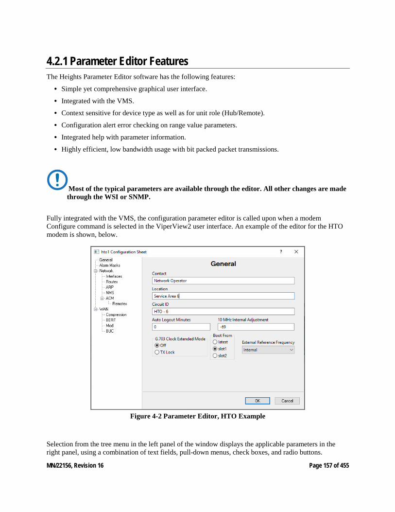
MN/22156, Revision 16 Page 157 of 455
4.2.1 Parameter Editor Features The Heights Parameter Editor software has the following features:
• Simple yet comprehensive graphical user interface.
• Integrated with the VMS.
• Context sensitive for device type as well as for unit role (Hub/Remote).
• Configuration alert error checking on range value parameters.
• Integrated help with parameter information.
• Highly efficient, low bandwidth usage with bit packed packet transmissions.
Most of the typical parameters are available through the editor. All other changes are made through the WSI or SNMP.
Fully integrated with the VMS, the configuration parameter editor is called upon when a modem Configure command is selected in the ViperView2 user interface. An example of the editor for the HTO modem is shown, below.
Figure 4-2 Parameter Editor, HTO Example
Selection from the tree menu in the left panel of the window displays the applicable parameters in the right panel, using a combination of text fields, pull-down menus, check boxes, and radio buttons.
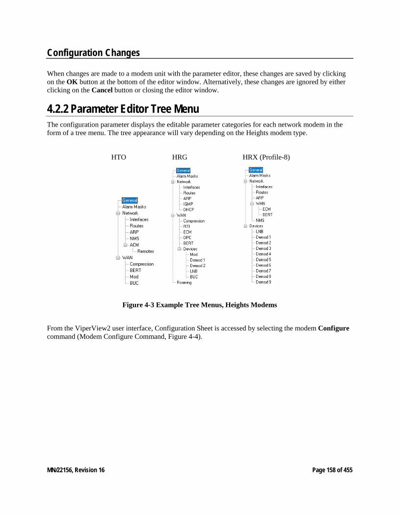
MN/22156, Revision 16 Page 158 of 455
Configuration Changes
When changes are made to a modem unit with the parameter editor, these changes are saved by clicking on the OK button at the bottom of the editor window. Alternatively, these changes are ignored by either clicking on the Cancel button or closing the editor window.
4.2.2 Parameter Editor Tree Menu The configuration parameter displays the editable parameter categories for each network modem in the form of a tree menu. The tree appearance will vary depending on the Heights modem type.
HTO HRG HRX (Profile-8)
Figure 4-3 Example Tree Menus, Heights Modems
From the ViperView2 user interface, Configuration Sheet is accessed by selecting the modem Configure command (Modem Configure Command, Figure 4-4).
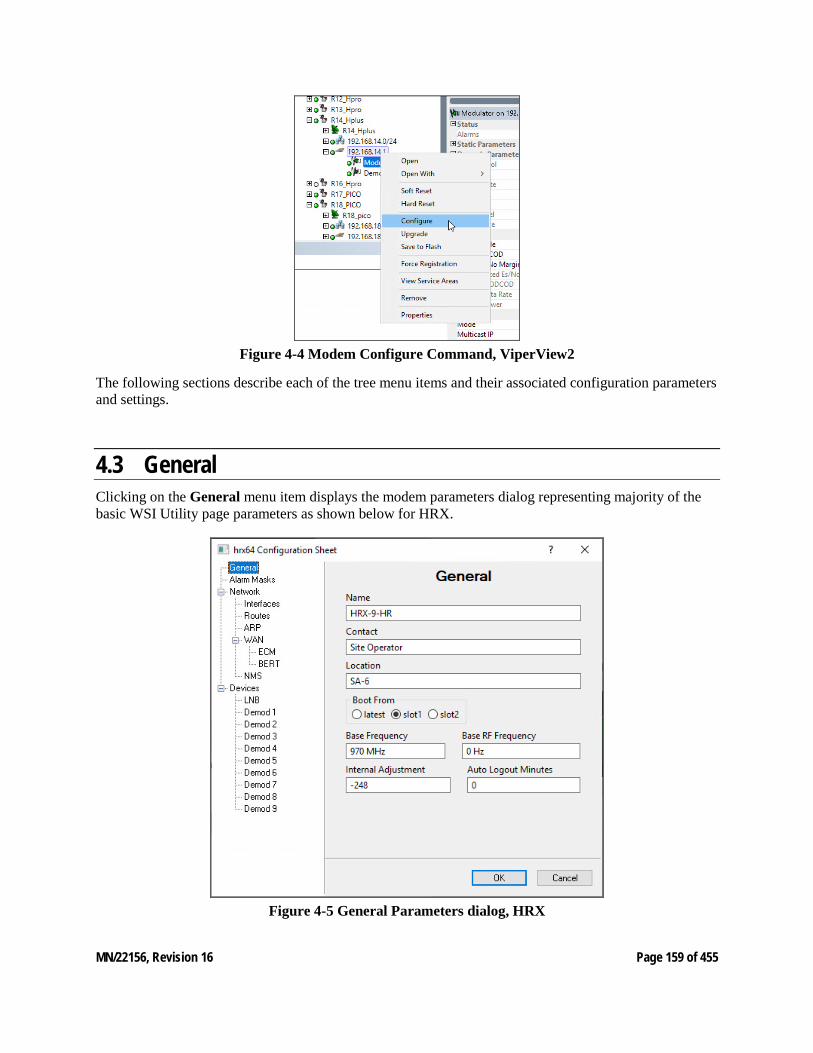
MN/22156, Revision 16 Page 159 of 455
Figure 4-4 Modem Configure Command, ViperView2
The following sections describe each of the tree menu items and their associated configuration parameters and settings.
4.3 General Clicking on the General menu item displays the modem parameters dialog representing majority of the basic WSI Utility page parameters as shown below for HRX.
Figure 4-5 General Parameters dialog, HRX
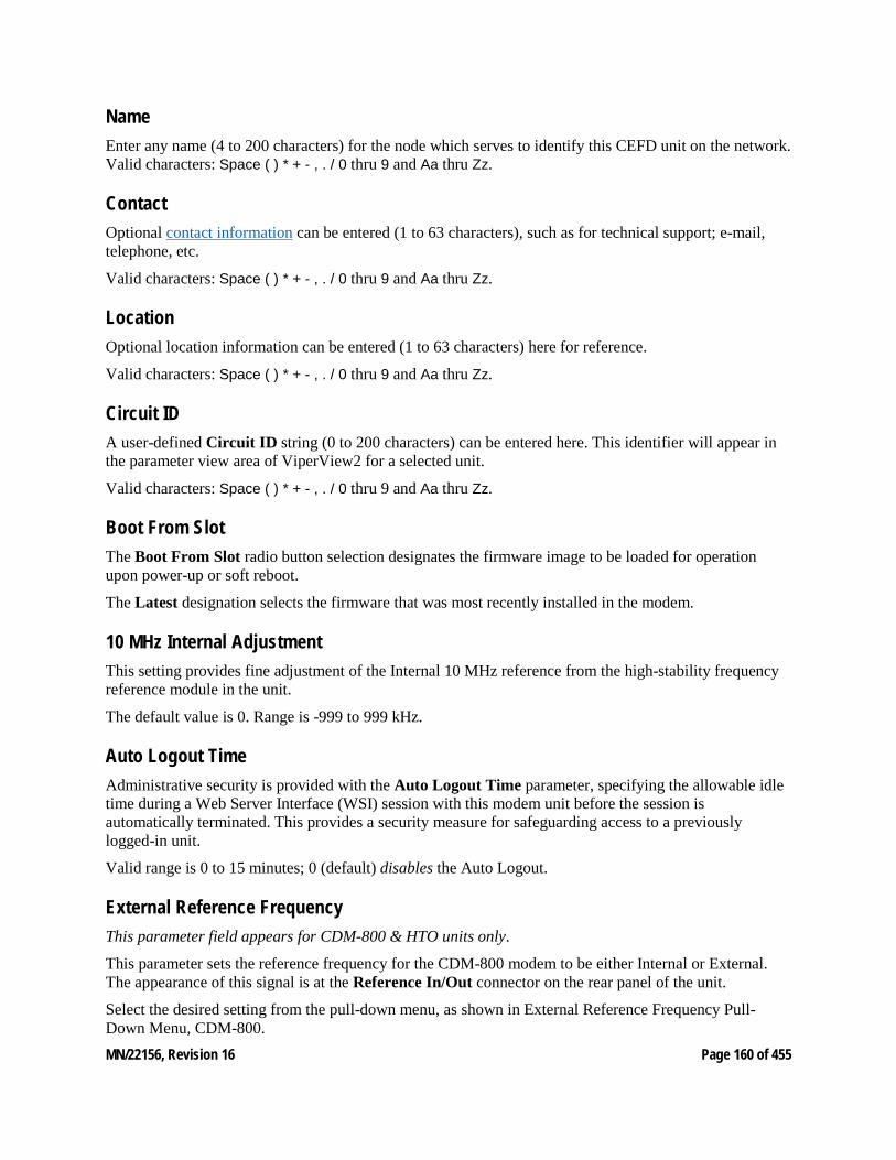
MN/22156, Revision 16 Page 160 of 455
Name Enter any name (4 to 200 characters) for the node which serves to identify this CEFD unit on the network. Valid characters: Space ( ) * + - , . / 0 thru 9 and Aa thru Zz.
Contact Optional contact information can be entered (1 to 63 characters), such as for technical support; e-mail, telephone, etc.
Valid characters: Space ( ) * + - , . / 0 thru 9 and Aa thru Zz.
Location Optional location information can be entered (1 to 63 characters) here for reference.
Valid characters: Space ( ) * + - , . / 0 thru 9 and Aa thru Zz.
Circuit ID A user-defined Circuit ID string (0 to 200 characters) can be entered here. This identifier will appear in the parameter view area of ViperView2 for a selected unit.
Valid characters: Space ( ) * + - , . / 0 thru 9 and Aa thru Zz.
Boot From Slot The Boot From Slot radio button selection designates the firmware image to be loaded for operation upon power-up or soft reboot.
The Latest designation selects the firmware that was most recently installed in the modem.
10 MHz Internal Adjustment This setting provides fine adjustment of the Internal 10 MHz reference from the high-stability frequency reference module in the unit.
The default value is 0. Range is -999 to 999 kHz.
Auto Logout Time Administrative security is provided with the Auto Logout Time parameter, specifying the allowable idle time during a Web Server Interface (WSI) session with this modem unit before the session is automatically terminated. This provides a security measure for safeguarding access to a previously logged-in unit.
Valid range is 0 to 15 minutes; 0 (default) disables the Auto Logout.
External Reference Frequency This parameter field appears for CDM-800 & HTO units only.
This parameter sets the reference frequency for the CDM-800 modem to be either Internal or External. The appearance of this signal is at the Reference In/Out connector on the rear panel of the unit.
Select the desired setting from the pull-down menu, as shown in External Reference Frequency Pull-Down Menu, CDM-800.
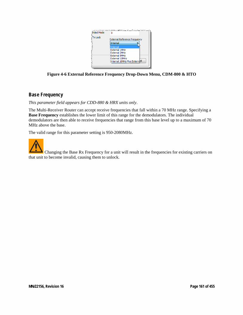
MN/22156, Revision 16 Page 161 of 455
Figure 4-6 External Reference Frequency Drop-Down Menu, CDM-800 & HTO
Base Frequency This parameter field appears for CDD-880 & HRX units only.
The Multi-Receiver Router can accept receive frequencies that fall within a 70 MHz range. Specifying a Base Frequency establishes the lower limit of this range for the demodulators. The individual demodulators are then able to receive frequencies that range from this base level up to a maximum of 70 MHz above the base.
The valid range for this parameter setting is 950-2080MHz.
Changing the Base Rx Frequency for a unit will result in the frequencies for existing carriers on that unit to become invalid, causing them to unlock.
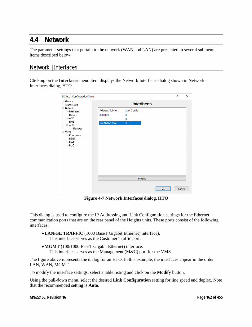
MN/22156, Revision 16 Page 162 of 455
4.4 Network The parameter settings that pertain to the network (WAN and LAN) are presented in several submenu items described below.
Network | Interfaces
Clicking on the Interfaces menu item displays the Network Interfaces dialog shown in Network Interfaces dialog, HTO.
Figure 4-7 Network Interfaces dialog, HTO
This dialog is used to configure the IP Addressing and Link Configuration settings for the Ethernet communication ports that are on the rear panel of the Heights units. These ports consist of the following interfaces:
• LAN/GE TRAFFIC (1000 BaseT Gigabit Ethernet) interface). This interface serves as the Customer Traffic port.
• MGMT (100/1000 BaseT Gigabit Ethernet) interface. This interface serves as the Management (M&C) port for the VMS.
The figure above represents the dialog for an HTO. In this example, the interfaces appear in the order LAN, WAN, MGMT.
To modify the interface settings, select a table listing and click on the Modify button.
Using the pull-down menu, select the desired Link Configuration setting for line speed and duplex. Note that the recommended setting is Auto.
MN/22156, Revision 16 Page 163 of 455
Network | Routes
Because satellite networks are often used as extensions for access to services such as the Internet or the PSTN, they lend themselves quite readily to private addressing. For example, to provide Internet access to the satellite network, only the Hub requires a public IP address in order for the entire satellite network that is controlled by the Hub to have access to the Internet backbone. Utilizing Network Address Translation (NAT), the administrator can effectively address the network using a minimum number of static route statements.
Example:
The IP address 172.16.0.0 is the private address network number for class B networks. If there is a router at the Hub with a connection to the Internet, the operator can define the local network as a class B. If the operator splits the Class B in half and points the upper half toward the satellite, there will be over 16,000 usable addresses at the Hub as well as at the Remotes.
By putting the one route statement “Remotes 172.16.128.0/17 WAN to LAN” in the Hub modem, and by using the route statement “GW 0.0.0.0/0 LAN to WAN” at each of the Remote modems, the network will successfully route packets. The Remotes can then be subnetted as class C networks or below. Additional routers at the Remotes can be added for unusually large sites, allowing an additional layer of NAT without requiring any more explicit routing within the CEFD network modems.
The Heights satellite modems are basically two-port routers, with one port to the LAN (Ethernet) and the other to the WAN (satellite network). Therefore, very little dynamic decision making is necessary, and most routing is done using static routes. These routes can be entered to route IP traffic either over the satellite or to another device on the local network.
However, typically the traffic Working Mode is set to Bridge-Point-Multipoint requiring only routes for MGMT Interface.
Route definitions vary depending on which of the three units in the product series is being configured. Each of these unit types perform a unique role:
MGMT Routes -
• The HTO is a Hub unit that serves as a forwarding router, and requires explicit route definitions for each of its Remote units (satellite WAN), as well as a default gateway to the Ethernet LAN. For WAN traffic, GSE labeling is applied and the data is forwarded per the table entries.
• The HRX is a Hub unit that receives traffic off the WAN and forwards all packets to its default gateway (to LAN).
• The HRG serves as the Remote modem unit that filters received satellite WAN transmissions based on GSE labeling and routes packets destined for the Ethernet LAN. LAN traffic received from its subnet is forwarded using the lone default route to the WAN.
Default gateways are defined as the route of last resort. Typically, the IP address of the next hop router in the network is specified here.
Refer to the Heights Installation and Operation Manual for additional information on entering routes.
MN/22156, Revision 16 Page 164 of 455
Creating Static Routes The following procedure outlines the basic route structure that the target Heights units will require for its role in the managed network.
One of the key routes that must be created is a default gateway address for routing the data traffic that is received by the unit.
In a Hub configuration, the default route will typically point to a router on the same LAN as the Hub unit. In the example shown in the below figure, that router is specified as the Next Hop address 10.1.0.1.
In a Remote configuration, the default route will typically point to the satellite modem (WAN) used for communications back to the Hub.
For a Hub unit that is providing the DVB-S2X outbound to all associated Remotes, routes are added either by dynamic or static entries to provide local and satellite network communications. Route statements defining management and traffic communications with the Remote units consist of one for traffic and one for management, per Remote depending on Working Mode configuration. There are two working modes under network settings, Router or Bridge-Point-Multipoint (BPM) where Router mode requires both traffic and management routes and BPM only requires management. While the Heights BPM feature supports Bridged Traffic ports, the Management ports for all units in the Heights System must operate in Router Mode. When configuring the HTO for “BPM” Working Mode, Comtech Dynamic Routing Protocol (CDRP) continues to work as expected to populate the HTO with the routes required to manage the remote HRG’s via their Management IP Addresses. Handle the Return Link Routed Management Traffic by entering a default route (0.0.0.0/0 “toWAN”) in the HRG’s routing table. As with “Router” Working Mode, you must enable CDRP for ACM/VCM on the DVB-S2X Outbound Carrier to work for Management Traffic destined to each remote. User traffic on the Traffic ports does not require CDRP, as BPM automatically and seamlessly handles ACM/VCM for this traffic.
Working Mode, CDRP and RIP are only configurable via WSI or SNMP. Refer to HTO user’s manual for more information.
Automatic MGMT Routes: (route labels ~Auto:)
• The ECM TAP multicast address (M&C)
• The VMS multicast address (M&C)
Comtech Dynamic Route Protocol (CDRP)
If CDRG is enabled the remote “MGMT Subnet” routes do not require any modifications, recommend any modifications should be done on the remote unit configuration.
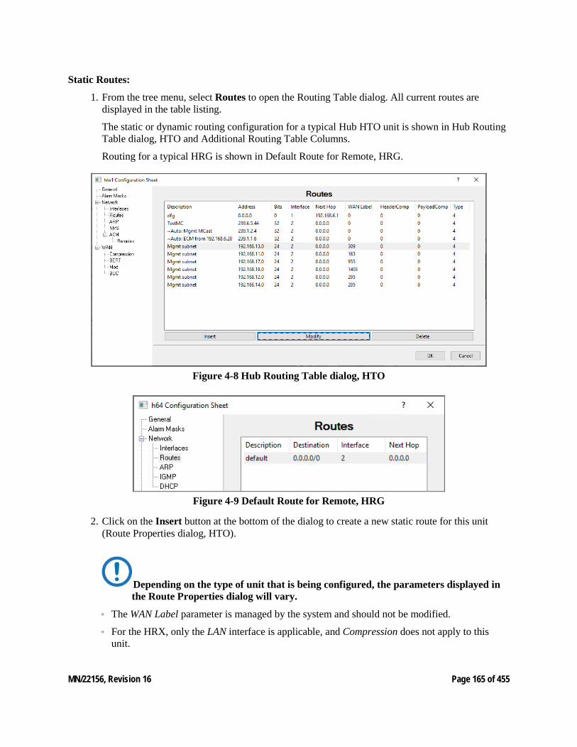
MN/22156, Revision 16 Page 165 of 455
Static Routes:
1. From the tree menu, select Routes to open the Routing Table dialog. All current routes are displayed in the table listing.
The static or dynamic routing configuration for a typical Hub HTO unit is shown in Hub Routing Table dialog, HTO and Additional Routing Table Columns.
Routing for a typical HRG is shown in Default Route for Remote, HRG.
Figure 4-8 Hub Routing Table dialog, HTO
Figure 4-9 Default Route for Remote, HRG
2. Click on the Insert button at the bottom of the dialog to create a new static route for this unit (Route Properties dialog, HTO).
Depending on the type of unit that is being configured, the parameters displayed in the Route Properties dialog will vary.
• The WAN Label parameter is managed by the system and should not be modified.
• For the HRX, only the LAN interface is applicable, and Compression does not apply to this unit.
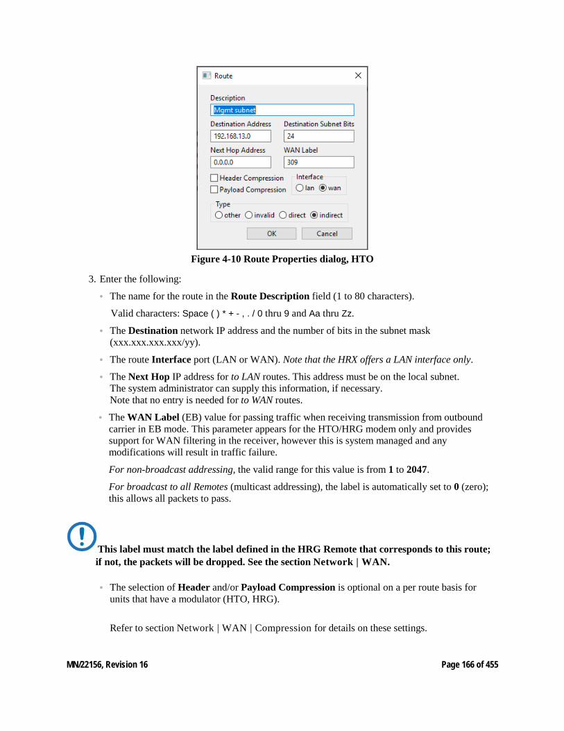
MN/22156, Revision 16 Page 166 of 455
Figure 4-10 Route Properties dialog, HTO
3. Enter the following:
• The name for the route in the Route Description field (1 to 80 characters).
Valid characters: Space ( ) * + - , . / 0 thru 9 and Aa thru Zz.
• The Destination network IP address and the number of bits in the subnet mask (xxx.xxx.xxx.xxx/yy).
• The route Interface port (LAN or WAN). Note that the HRX offers a LAN interface only.
• The Next Hop IP address for to LAN routes. This address must be on the local subnet. The system administrator can supply this information, if necessary. Note that no entry is needed for to WAN routes.
• The WAN Label (EB) value for passing traffic when receiving transmission from outbound carrier in EB mode. This parameter appears for the HTO/HRG modem only and provides support for WAN filtering in the receiver, however this is system managed and any modifications will result in traffic failure.
For non-broadcast addressing, the valid range for this value is from 1 to 2047.
For broadcast to all Remotes (multicast addressing), the label is automatically set to 0 (zero); this allows all packets to pass.
This label must match the label defined in the HRG Remote that corresponds to this route; if not, the packets will be dropped. See the section Network | WAN.
• The selection of Header and/or Payload Compression is optional on a per route basis for units that have a modulator (HTO, HRG).
Refer to section Network | WAN | Compression for details on these settings.
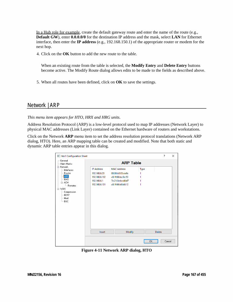
MN/22156, Revision 16 Page 167 of 455
In a Hub role for example, create the default gateway route and enter the name of the route (e.g., Default GW), enter 0.0.0.0/0 for the destination IP address and the mask, select LAN for Ethernet interface, then enter the IP address (e.g., 192.168.150.1) of the appropriate router or modem for the next hop.
4. Click on the OK button to add the new route to the table.
When an existing route from the table is selected, the Modify Entry and Delete Entry buttons become active. The Modify Route dialog allows edits to be made to the fields as described above.
5. When all routes have been defined, click on OK to save the settings.
Network | ARP
This menu item appears for HTO, HRX and HRG units.
Address Resolution Protocol (ARP) is a low-level protocol used to map IP addresses (Network Layer) to physical MAC addresses (Link Layer) contained on the Ethernet hardware of routers and workstations.
Click on the Network ARP menu item to set the address resolution protocol translations (Network ARP dialog, HTO). Here, an ARP mapping table can be created and modified. Note that both static and dynamic ARP table entries appear in this dialog.
Figure 4-11 Network ARP dialog, HTO
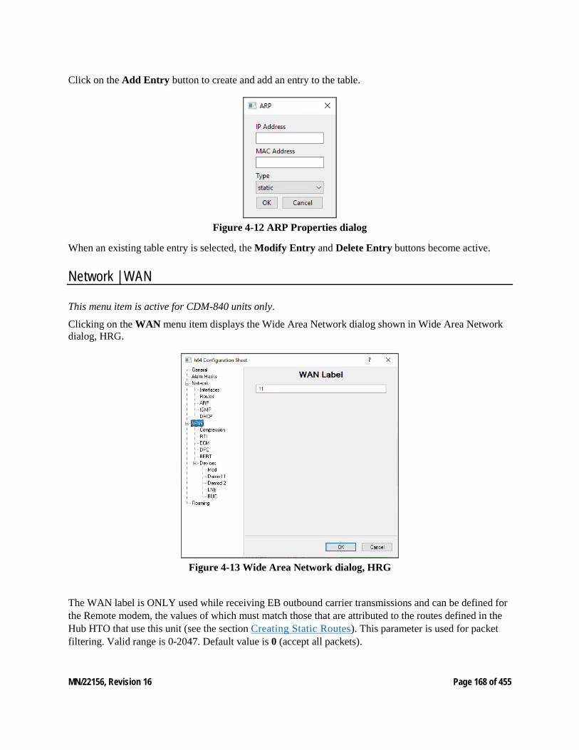
MN/22156, Revision 16 Page 168 of 455
Click on the Add Entry button to create and add an entry to the table.
Figure 4-12 ARP Properties dialog
When an existing table entry is selected, the Modify Entry and Delete Entry buttons become active.
Network | WAN
This menu item is active for CDM-840 units only.
Clicking on the WAN menu item displays the Wide Area Network dialog shown in Wide Area Network dialog, HRG.
Figure 4-13 Wide Area Network dialog, HRG
The WAN label is ONLY used while receiving EB outbound carrier transmissions and can be defined for the Remote modem, the values of which must match those that are attributed to the routes defined in the Hub HTO that use this unit (see the section Creating Static Routes). This parameter is used for packet filtering. Valid range is 0-2047. Default value is 0 (accept all packets).
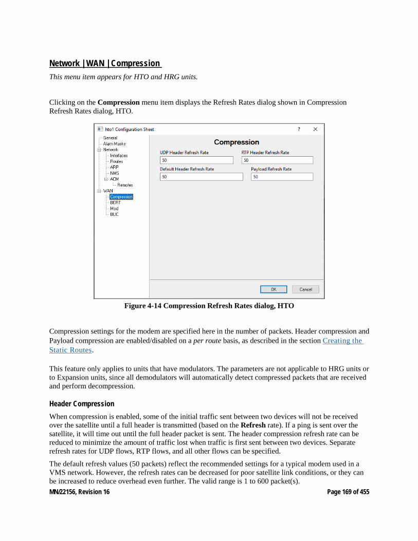
MN/22156, Revision 16 Page 169 of 455
Network | WAN | Compression This menu item appears for HTO and HRG units.
Clicking on the Compression menu item displays the Refresh Rates dialog shown in Compression Refresh Rates dialog, HTO.
Figure 4-14 Compression Refresh Rates dialog, HTO
Compression settings for the modem are specified here in the number of packets. Header compression and Payload compression are enabled/disabled on a per route basis, as described in the section Creating the Static Routes.
This feature only applies to units that have modulators. The parameters are not applicable to HRG units or to Expansion units, since all demodulators will automatically detect compressed packets that are received and perform decompression.
Header Compression When compression is enabled, some of the initial traffic sent between two devices will not be received over the satellite until a full header is transmitted (based on the Refresh rate). If a ping is sent over the satellite, it will time out until the full header packet is sent. The header compression refresh rate can be reduced to minimize the amount of traffic lost when traffic is first sent between two devices. Separate refresh rates for UDP flows, RTP flows, and all other flows can be specified.
The default refresh values (50 packets) reflect the recommended settings for a typical modem used in a VMS network. However, the refresh rates can be decreased for poor satellite link conditions, or they can be increased to reduce overhead even further. The valid range is 1 to 600 packet(s).
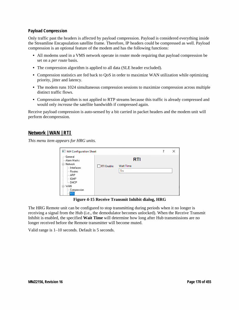
MN/22156, Revision 16 Page 170 of 455
Payload Compression Only traffic past the headers is affected by payload compression. Payload is considered everything inside the Streamline Encapsulation satellite frame. Therefore, IP headers could be compressed as well. Payload compression is an optional feature of the modem and has the following functions:
• All modems used in a VMS network operate in router mode requiring that payload compression be set on a per route basis.
• The compression algorithm is applied to all data (SLE header excluded).
• Compression statistics are fed back to QoS in order to maximize WAN utilization while optimizing priority, jitter and latency.
• The modem runs 1024 simultaneous compression sessions to maximize compression across multiple distinct traffic flows.
• Compression algorithm is not applied to RTP streams because this traffic is already compressed and would only increase the satellite bandwidth if compressed again.
Receive payload compression is auto-sensed by a bit carried in packet headers and the modem unit will perform decompression.
Network | WAN | RTI This menu item appears for HRG units.
Figure 4-15 Receive Transmit Inhibit dialog, HRG
The HRG Remote unit can be configured to stop transmitting during periods when it no longer is receiving a signal from the Hub (i.e., the demodulator becomes unlocked). When the Receive Transmit Inhibit is enabled, the specified Wait Time will determine how long after Hub transmissions are no longer received before the Remote transmitter will become muted.
Valid range is 1–10 seconds. Default is 5 seconds.
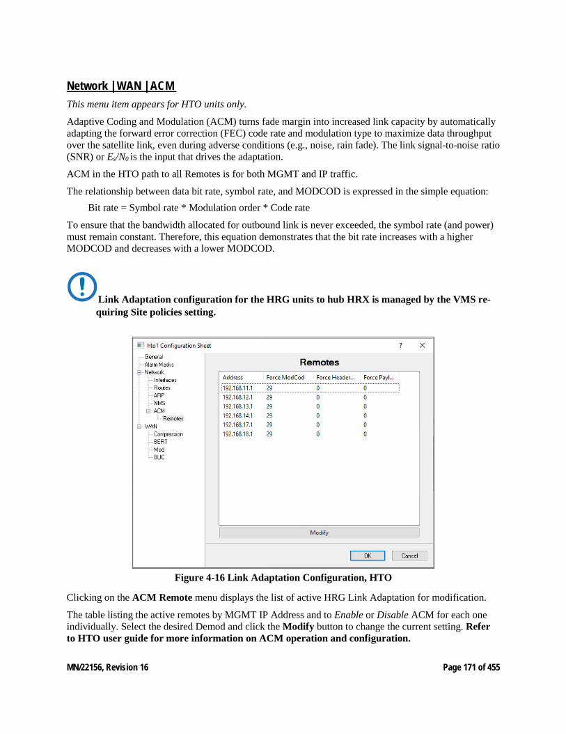
MN/22156, Revision 16 Page 171 of 455
Network | WAN | ACM This menu item appears for HTO units only.
Adaptive Coding and Modulation (ACM) turns fade margin into increased link capacity by automatically adapting the forward error correction (FEC) code rate and modulation type to maximize data throughput over the satellite link, even during adverse conditions (e.g., noise, rain fade). The link signal-to-noise ratio (SNR) or Es/N0 is the input that drives the adaptation.
ACM in the HTO path to all Remotes is for both MGMT and IP traffic.
The relationship between data bit rate, symbol rate, and MODCOD is expressed in the simple equation: Bit rate = Symbol rate * Modulation order * Code rate
To ensure that the bandwidth allocated for outbound link is never exceeded, the symbol rate (and power) must remain constant. Therefore, this equation demonstrates that the bit rate increases with a higher MODCOD and decreases with a lower MODCOD.
Link Adaptation configuration for the HRG units to hub HRX is managed by the VMS re-quiring Site policies setting.
Figure 4-16 Link Adaptation Configuration, HTO
Clicking on the ACM Remote menu displays the list of active HRG Link Adaptation for modification.
The table listing the active remotes by MGMT IP Address and to Enable or Disable ACM for each one individually. Select the desired Demod and click the Modify button to change the current setting. Refer to HTO user guide for more information on ACM operation and configuration.
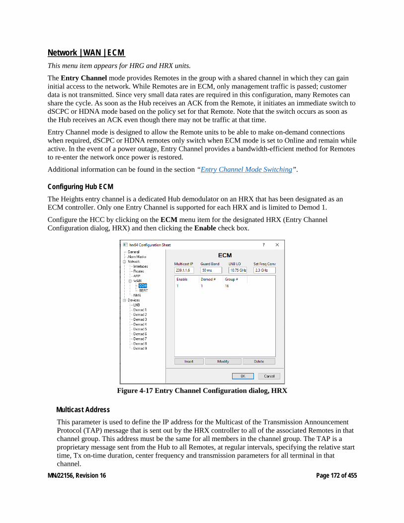
MN/22156, Revision 16 Page 172 of 455
Network | WAN | ECM This menu item appears for HRG and HRX units.
The Entry Channel mode provides Remotes in the group with a shared channel in which they can gain initial access to the network. While Remotes are in ECM, only management traffic is passed; customer data is not transmitted. Since very small data rates are required in this configuration, many Remotes can share the cycle. As soon as the Hub receives an ACK from the Remote, it initiates an immediate switch to dSCPC or HDNA mode based on the policy set for that Remote. Note that the switch occurs as soon as the Hub receives an ACK even though there may not be traffic at that time.
Entry Channel mode is designed to allow the Remote units to be able to make on-demand connections when required, dSCPC or HDNA remotes only switch when ECM mode is set to Online and remain while active. In the event of a power outage, Entry Channel provides a bandwidth-efficient method for Remotes to re-enter the network once power is restored.
Additional information can be found in the section “Entry Channel Mode Switching”.
Configuring Hub ECM The Heights entry channel is a dedicated Hub demodulator on an HRX that has been designated as an ECM controller. Only one Entry Channel is supported for each HRX and is limited to Demod 1.
Configure the HCC by clicking on the ECM menu item for the designated HRX (Entry Channel Configuration dialog, HRX) and then clicking the Enable check box.
Figure 4-17 Entry Channel Configuration dialog, HRX
Multicast Address This parameter is used to define the IP address for the Multicast of the Transmission Announcement Protocol (TAP) message that is sent out by the HRX controller to all of the associated Remotes in that channel group. This address must be the same for all members in the channel group. The TAP is a proprietary message sent from the Hub to all Remotes, at regular intervals, specifying the relative start time, Tx on-time duration, center frequency and transmission parameters for all terminal in that channel.
MN/22156, Revision 16 Page 173 of 455
Group ID This menu item appears for non-Heights units.
The ECM Group ID number defines a group of equipment (both Hub and Remote units) that will respond to the output of a single Hub channel controller. This group is addressable within a network which, in turn, is defined by the Network ID number assigned to the modems.
Allocation of bandwidth is shared among the Remotes in an ECM group. Depending on the number of Remotes in a network, a Hub may have multiple controllers, each with its own set of Remotes. This is accomplished by assigning a unique Group ID number to each controller and its associated Remotes.
Valid range is 0 to 255.
Guard Band This parameter displays the current length of the Slot Guard Band in milliseconds for the Remotes in the group. The Slot Guard Band is the amount of time between the point when one Remote completes transmitting data and the point when the next Remote in the cycle begins transmitting. This prevents the Remote from overrunning the next terminal in the cycle. The setting for this parameter should be obtained using the ECM Calculator. Typically, a value of 50ms is adequate.
To modify this parameter on a Hub unit, enter a value from 0–1000 in the Guard Band field. The value represents time in milliseconds (ms).
The following two parameter settings—LNB LO and Frequency Conversion—are very critical for determining RF frequency translations between Hub and Remote offsets or data spectral in-versions. Take care in setting these correctly.
LNB LO Important: Enter the correct LNB Local Oscillator frequency (MHz) that this Hub unit will be receiving.
Frequency Conversion Important: Enter the correct satellite Frequency Conversion value (MHz) for this Hub unit.
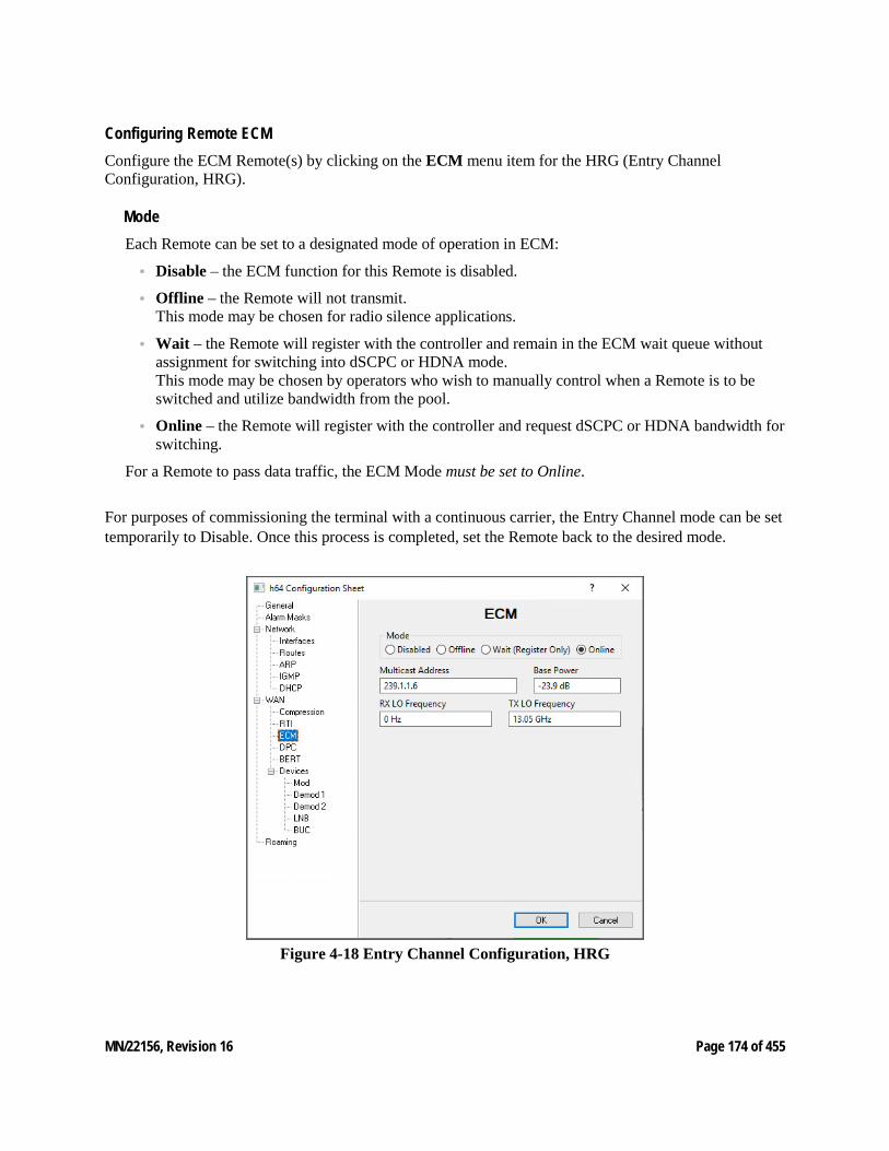
MN/22156, Revision 16 Page 174 of 455
Configuring Remote ECM Configure the ECM Remote(s) by clicking on the ECM menu item for the HRG (Entry Channel Configuration, HRG).
Mode Each Remote can be set to a designated mode of operation in ECM:
• Disable – the ECM function for this Remote is disabled.
• Offline – the Remote will not transmit. This mode may be chosen for radio silence applications.
• Wait – the Remote will register with the controller and remain in the ECM wait queue without assignment for switching into dSCPC or HDNA mode. This mode may be chosen by operators who wish to manually control when a Remote is to be switched and utilize bandwidth from the pool.
• Online – the Remote will register with the controller and request dSCPC or HDNA bandwidth for switching.
For a Remote to pass data traffic, the ECM Mode must be set to Online.
For purposes of commissioning the terminal with a continuous carrier, the Entry Channel mode can be set temporarily to Disable. Once this process is completed, set the Remote back to the desired mode.
Figure 4-18 Entry Channel Configuration, HRG
MN/22156, Revision 16 Page 175 of 455
Multicast Address This parameter is used to define the IP address for the Multicast of the Transmission Announcement Protocol (TAP) message that is sent out by the HCC to all of the associated Remotes in that group. This address must be the same for all members of the group. The TAP is a proprietary message sent from the Hub to all Remotes, at regular intervals, specifying the relative start time and duration for each terminal to transmit.
Base Power The Base Power is managed by the remotes commissioning settings and modifying during normal operations will not have any effect on base changing power.
LO Frequencies
The parameter setting for Tx LO Frequency is very critical for determining RF frequency trans-lations between Hub and Remote offsets or data spectral inversions. Take care in setting this cor-rectly. The Rx LO Frequency is necessary for roaming to establish multi-band beam conver-sions.
Set the Transmit and the Receive local oscillator frequencies (MHz) for the ODU as specified in the Network Plan.
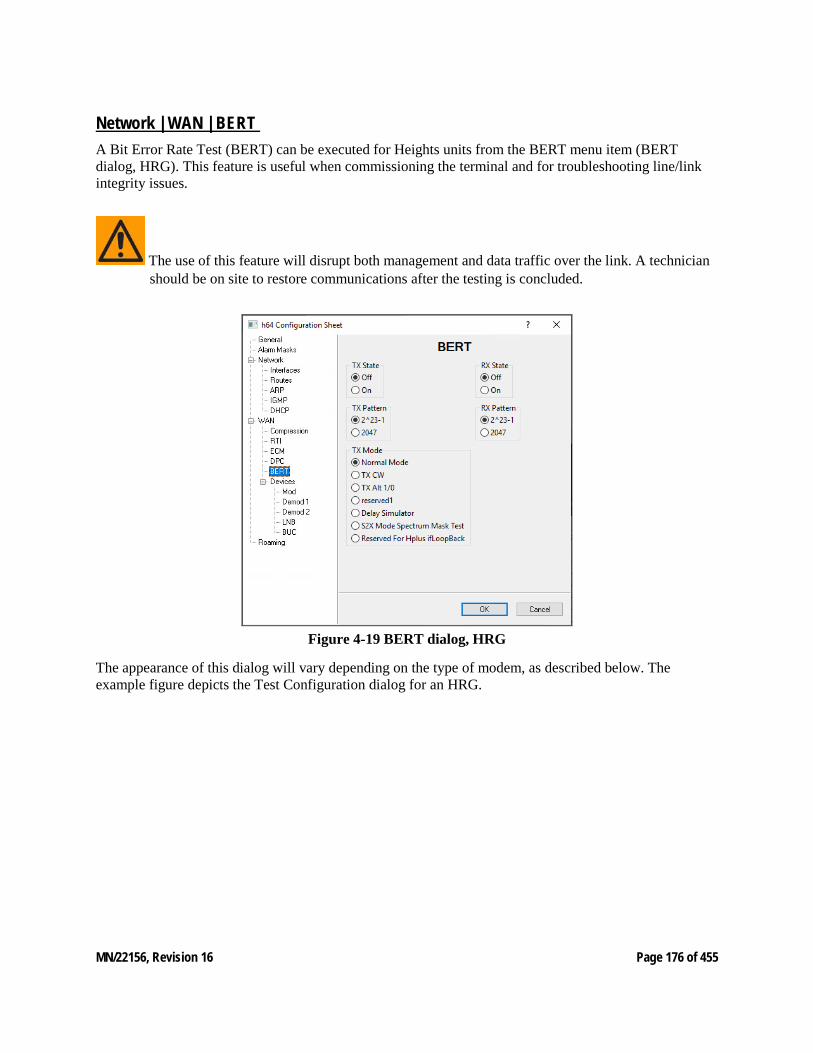
MN/22156, Revision 16 Page 176 of 455
Network | WAN | BERT A Bit Error Rate Test (BERT) can be executed for Heights units from the BERT menu item (BERT dialog, HRG). This feature is useful when commissioning the terminal and for troubleshooting line/link integrity issues.
The use of this feature will disrupt both management and data traffic over the link. A technician should be on site to restore communications after the testing is concluded.
Figure 4-19 BERT dialog, HRG
The appearance of this dialog will vary depending on the type of modem, as described below. The example figure depicts the Test Configuration dialog for an HRG.
MN/22156, Revision 16 Page 177 of 455
State The State check box is used to toggle the BERT On and Off.
On the HTO, this setting applies only to transmit due to its lone transmitter. Similarly, on the HRX this setting only applies to the demodulator receive. The HRG provides both a Tx and a Rx setting.
Demod Select This parameter appears for HRX units only.
Specify the demodulator for this unit that will be utilized for the test.
Pattern A choice of two pseudo-random test patterns are available, 2^23-1 or 2047.
The first pattern, 223-1, is primarily intended for error and jitter measurements at bit rates of 34,368 kbps and 139,264 kbps (equipment operating at the primary rate and above). A maximum of 22 consecutive zeros and 23 consecutive ones are generated; pattern length is 8,388,607 bits.
The second pattern, 2047 (211-1), is primarily intended for error measurements at bit rates of 64 kbps and N*64 kbps (error performance at bit rates below the primary rate). A maximum of 10 consecutive zeros and 11 consecutive ones are generated; pattern length is 2,047 bits.
Test Mode This parameter appears for HTO and HRG units.
Select the desired mode of test:
• Normal – BERT is Off. This is the setting for normal terminal operation.
• Tx CW – transmits a continuous unmodulated wave. Satellite provider can check for problems with cross-polarization, power, etc. with a clean and calibrated signal.
• Tx Alternate 1/0 – transmits continuous stream of alternating ones and zeros.
• WAN Packet Loopback – available for HRG only. Loopback test for the WAN transmit and receive interfaces.
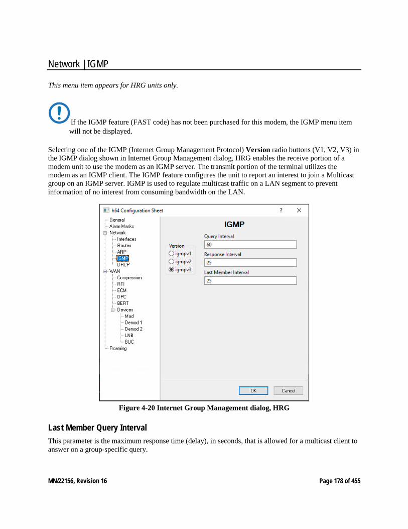
MN/22156, Revision 16 Page 178 of 455
Network | IGMP
This menu item appears for HRG units only.
If the IGMP feature (FAST code) has not been purchased for this modem, the IGMP menu item will not be displayed.
Selecting one of the IGMP (Internet Group Management Protocol) Version radio buttons (V1, V2, V3) in the IGMP dialog shown in Internet Group Management dialog, HRG enables the receive portion of a modem unit to use the modem as an IGMP server. The transmit portion of the terminal utilizes the modem as an IGMP client. The IGMP feature configures the unit to report an interest to join a Multicast group on an IGMP server. IGMP is used to regulate multicast traffic on a LAN segment to prevent information of no interest from consuming bandwidth on the LAN.
Figure 4-20 Internet Group Management dialog, HRG
Last Member Query Interval This parameter is the maximum response time (delay), in seconds, that is allowed for a multicast client to answer on a group-specific query.
MN/22156, Revision 16 Page 179 of 455
Query Interval The IGMP protocol requests that a server periodically publish to users on the LAN the multicast IP Addresses that it can service. The IGMP Query Interval defines the time interval (in seconds) between each of these queries for membership.
The interval must be equal to or greater than the maximum response time, defined by the Response Interval.
Response Interval The IGMP Response Interval defines the time interval (in seconds) that the unit should wait before it assumes that no parties are interested in the content published via an IGMP query. This is the maximum response time (delay) that is allowed for a multicast client to answer on a general query.
This option is expressed in seconds and the maximum response time that is accepted by the unit is equal to the Query Interval.
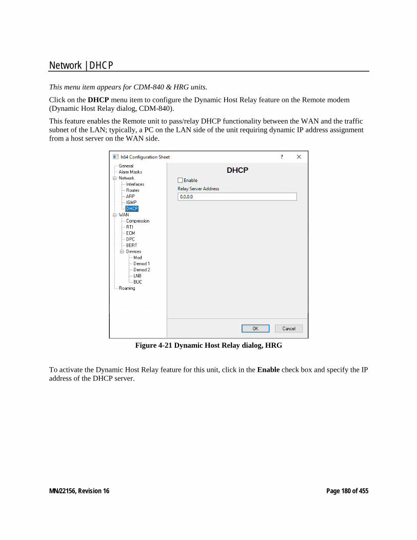
MN/22156, Revision 16 Page 180 of 455
Network | DHCP
This menu item appears for CDM-840 & HRG units.
Click on the DHCP menu item to configure the Dynamic Host Relay feature on the Remote modem (Dynamic Host Relay dialog, CDM-840).
This feature enables the Remote unit to pass/relay DHCP functionality between the WAN and the traffic subnet of the LAN; typically, a PC on the LAN side of the unit requiring dynamic IP address assignment from a host server on the WAN side.
Figure 4-21 Dynamic Host Relay dialog, HRG
To activate the Dynamic Host Relay feature for this unit, click in the Enable check box and specify the IP address of the DHCP server.
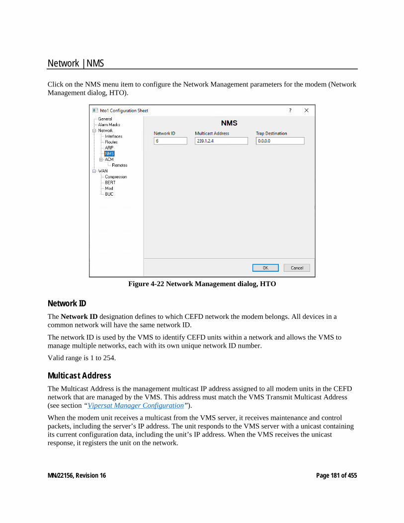
MN/22156, Revision 16 Page 181 of 455
Network | NMS
Click on the NMS menu item to configure the Network Management parameters for the modem (Network Management dialog, HTO).
Figure 4-22 Network Management dialog, HTO
Network ID The Network ID designation defines to which CEFD network the modem belongs. All devices in a common network will have the same network ID.
The network ID is used by the VMS to identify CEFD units within a network and allows the VMS to manage multiple networks, each with its own unique network ID number.
Valid range is 1 to 254.
Multicast Address The Multicast Address is the management multicast IP address assigned to all modem units in the CEFD network that are managed by the VMS. This address must match the VMS Transmit Multicast Address (see section “Vipersat Manager Configuration”).
When the modem unit receives a multicast from the VMS server, it receives maintenance and control packets, including the server’s IP address. The unit responds to the VMS server with a unicast containing its current configuration data, including the unit’s IP address. When the VMS receives the unicast response, it registers the unit on the network.
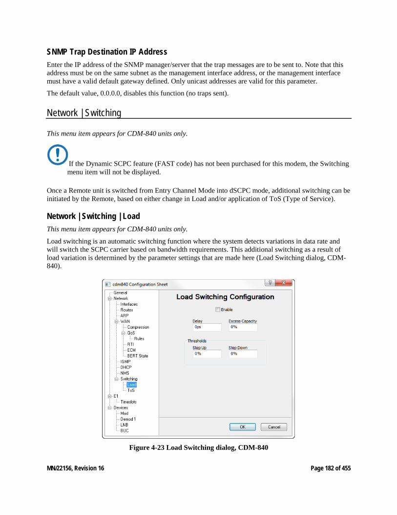
MN/22156, Revision 16 Page 182 of 455
SNMP Trap Destination IP Address Enter the IP address of the SNMP manager/server that the trap messages are to be sent to. Note that this address must be on the same subnet as the management interface address, or the management interface must have a valid default gateway defined. Only unicast addresses are valid for this parameter.
The default value, 0.0.0.0, disables this function (no traps sent).
Network | Switching
This menu item appears for CDM-840 units only.
If the Dynamic SCPC feature (FAST code) has not been purchased for this modem, the Switching menu item will not be displayed.
Once a Remote unit is switched from Entry Channel Mode into dSCPC mode, additional switching can be initiated by the Remote, based on either change in Load and/or application of ToS (Type of Service).
Network | Switching | Load This menu item appears for CDM-840 units only.
Load switching is an automatic switching function where the system detects variations in data rate and will switch the SCPC carrier based on bandwidth requirements. This additional switching as a result of load variation is determined by the parameter settings that are made here (Load Switching dialog, CDM-840).
Figure 4-23 Load Switching dialog, CDM-840
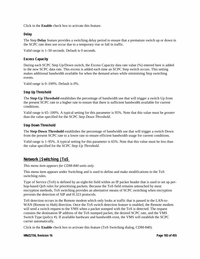
MN/22156, Revision 16 Page 183 of 455
Click in the Enable check box to activate this feature.
Delay The Step Delay feature provides a switching delay period to ensure that a premature switch up or down in the SCPC rate does not occur due to a temporary rise or fall in traffic.
Valid range is 1–50 seconds. Default is 0 seconds.
Excess Capacity During each SCPC Step Up/Down switch, the Excess Capacity data rate value (%) entered here is added to the new SCPC data rate. This excess is added each time an SCPC Step switch occurs. This setting makes additional bandwidth available for when the demand arises while minimizing Step switching events.
Valid range is 0–100%. Default is 0%.
Step Up Threshold The Step-Up Threshold establishes the percentage of bandwidth use that will trigger a switch Up from the present SCPC rate to a higher rate to ensure that there is sufficient bandwidth available for current conditions.
Valid range is 65–100%. A typical setting for this parameter is 95%. Note that this value must be greater than the value specified for the SCPC Step Down Threshold.
Step Down Threshold The Step-Down Threshold establishes the percentage of bandwidth use that will trigger a switch Down from the present SCPC rate to a lower rate to ensure efficient bandwidth usage for current conditions.
Valid range is 1–95%. A typical setting for this parameter is 65%. Note that this value must be less than the value specified for the SCPC Step Up Threshold.
Network | Switching | ToS This menu item appears for CDM-840 units only.
This menu item appears under Switching and is used to define and make modifications to the ToS switching rules.
Type of Service (ToS) is defined by an eight-bit field within an IP packet header that is used to set up per-hop-based QoS rules for prioritizing packets. Because the ToS field remains untouched by most encryption methods, ToS switching provides an alternative means of SCPC switching when encryption prevents the detection of SIP and H.323 protocols.
ToS detection occurs in the Remote modem which only looks at traffic that is passed in the LAN-to-WAN (Remote to Hub) direction. Once the ToS switch detection feature is enabled, the Remote modem will send a switch request to the VMS when a packet stamped with the ToS is detected. The request contains the destination IP address of the ToS stamped packet, the desired SCPC rate, and the VMS Switch Type (policy #). If available hardware and bandwidth exist, the VMS will establish the SCPC carrier automatically.
Click in the Enable check box to activate this feature (ToS Switching dialog, CDM-840).
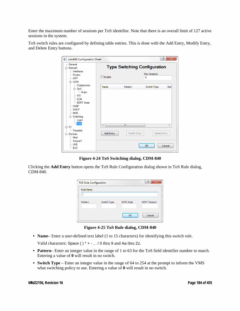
MN/22156, Revision 16 Page 184 of 455
Enter the maximum number of sessions per ToS identifier. Note that there is an overall limit of 127 active sessions in the system.
ToS switch rules are configured by defining table entries. This is done with the Add Entry, Modify Entry, and Delete Entry buttons.
Figure 4-24 ToS Switching dialog, CDM-840
Clicking the Add Entry button opens the ToS Rule Configuration dialog shown in ToS Rule dialog, CDM-840.
Figure 4-25 ToS Rule dialog, CDM-840
• Name– Enter a user-defined text label (1 to 15 characters) for identifying this switch rule.
Valid characters: Space ( ) * + - , . / 0 thru 9 and Aa thru Zz.
• Pattern– Enter an integer value in the range of 1 to 63 for the ToS field identifier number to match. Entering a value of 0 will result in no switch.
• Switch Type – Enter an integer value in the range of 64 to 254 at the prompt to inform the VMS what switching policy to use. Entering a value of 0 will result in no switch.
MN/22156, Revision 16 Page 185 of 455
• SCPC Rate – Enter the desired data rate for switching on this service type. Valid entries are from 0 to 155000000 bps. This setting will override the VMS set policy value.
• SCPC Timeout – This timer monitors the defined packet flow. Once data stops for the duration of the timer setting, the link state will be restored to the Home State condition for this Remote. Valid entries are from 1 to 60 seconds.
After field entry, clicking the OK button will update the ToS Switch Rules table with the new configuration. Note that the Add Type of Service Rule dialog remains open after adding a rule so that additional rules can be added easily. Click the Cancel button to return to the ToS dialog.
When one or more rules that appear in the table list are selected, the Modify Entry and Delete Entry buttons become active.
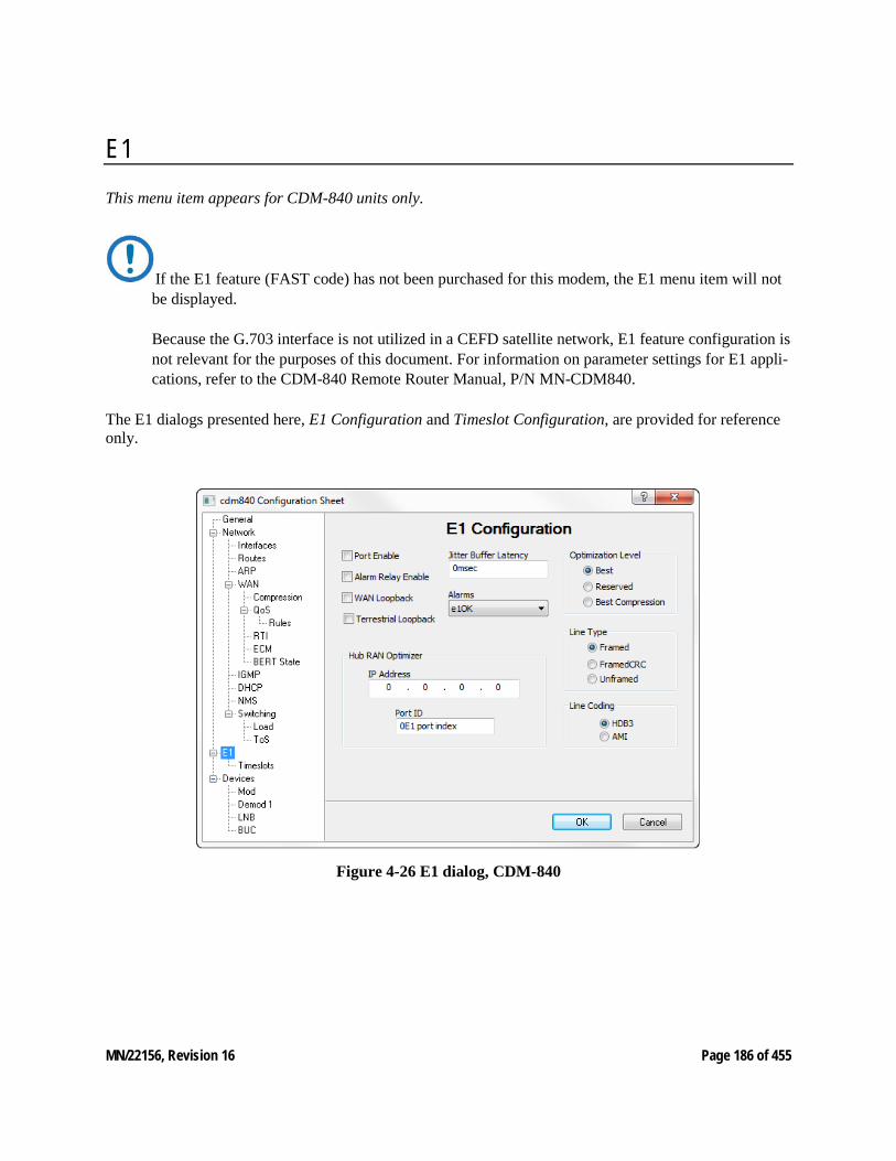
MN/22156, Revision 16 Page 186 of 455
E1 This menu item appears for CDM-840 units only.
If the E1 feature (FAST code) has not been purchased for this modem, the E1 menu item will not be displayed. Because the G.703 interface is not utilized in a CEFD satellite network, E1 feature configuration is not relevant for the purposes of this document. For information on parameter settings for E1 appli-cations, refer to the CDM-840 Remote Router Manual, P/N MN-CDM840.
The E1 dialogs presented here, E1 Configuration and Timeslot Configuration, are provided for reference only.
Figure 4-26 E1 dialog, CDM-840
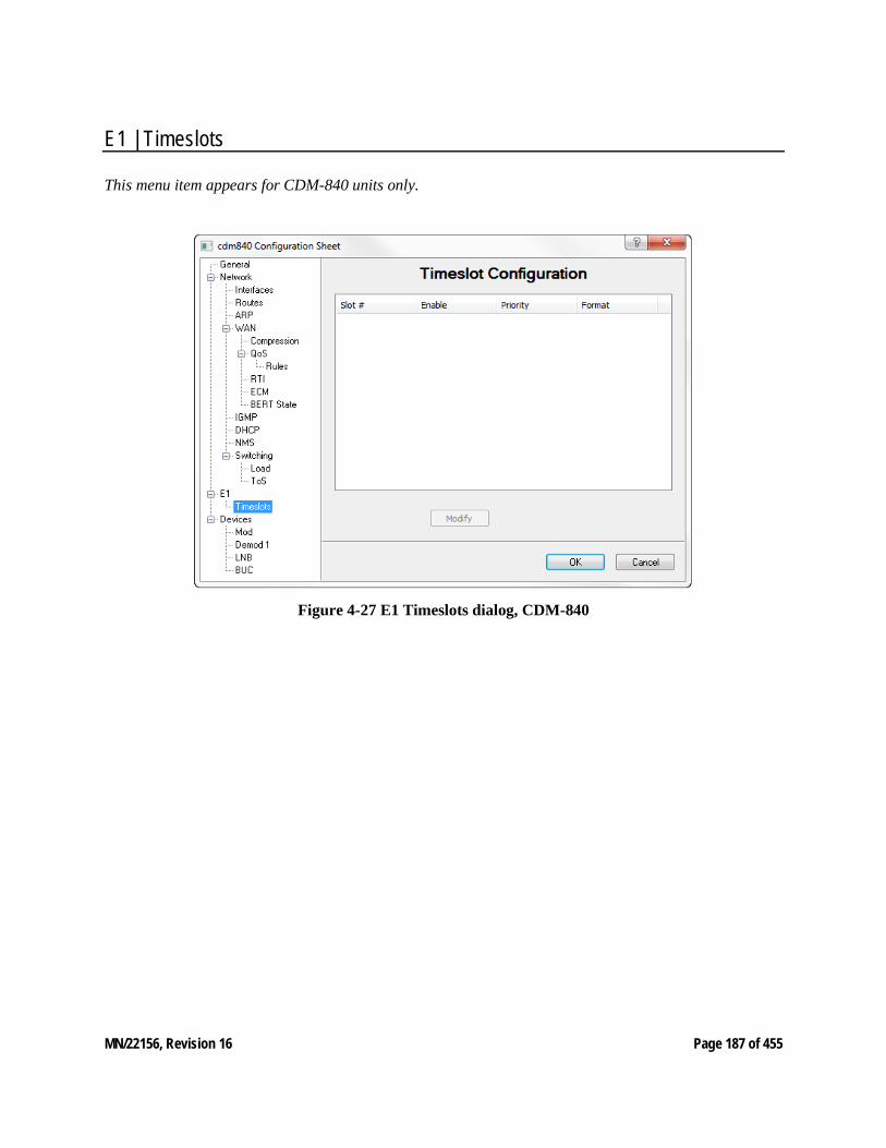
MN/22156, Revision 16 Page 187 of 455
E1 | Timeslots
This menu item appears for CDM-840 units only.
Figure 4-27 E1 Timeslots dialog, CDM-840
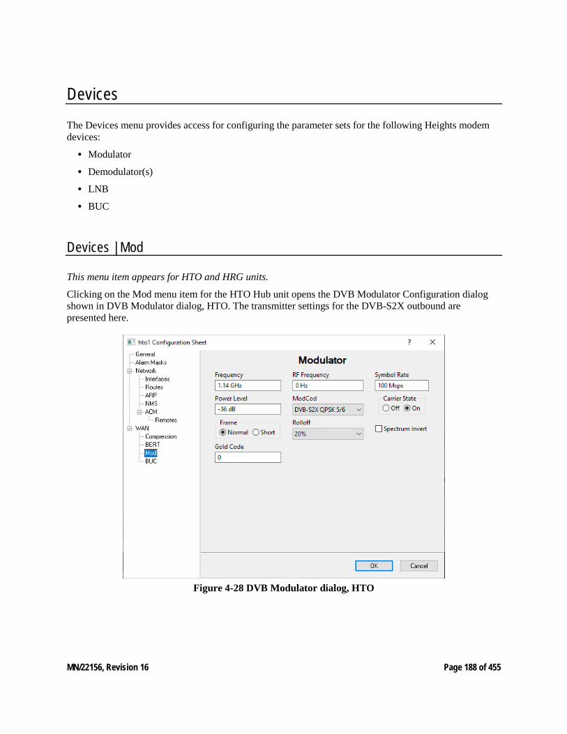
MN/22156, Revision 16 Page 188 of 455
Devices The Devices menu provides access for configuring the parameter sets for the following Heights modem devices:
• Modulator
• Demodulator(s)
• LNB
• BUC
Devices | Mod
This menu item appears for HTO and HRG units.
Clicking on the Mod menu item for the HTO Hub unit opens the DVB Modulator Configuration dialog shown in DVB Modulator dialog, HTO. The transmitter settings for the DVB-S2X outbound are presented here.
Figure 4-28 DVB Modulator dialog, HTO
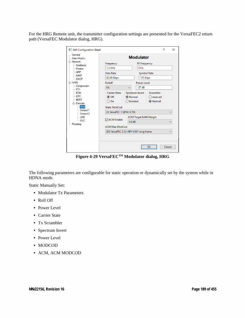
MN/22156, Revision 16 Page 189 of 455
For the HRG Remote unit, the transmitter configuration settings are presented for the VersaFEC2 return path (VersaFEC Modulator dialog, HRG).
Figure 4-29 VersaFECTM Modulator dialog, HRG
The following parameters are configurable for static operation or dynamically set by the system while in HDNA mode.
Static Manually Set:
• Modulator Tx Parameters
• Roll Off
• Power Level
• Carrier State
• Tx Scrambler
• Spectrum Invert
• Power Level
• MODCOD
• ACM, ACM MODCOD
MN/22156, Revision 16 Page 190 of 455
Roll Off This parameter represents the Tx α (alpha) filter roll-off factor that dictates how fast the spectral edges of the carrier are attenuated beyond the 3dB bandwidth. A lower value corresponds to a faster attenuation and thus less broadening of the power spectrum density, and less satellite bandwidth required.
MODCOD For the HTO, the MODCOD is automatically selected; it is determined from the QoS Group configura-tion (see the section Network | WAN | QoS | Groups).
For the HRG, the MODCOD is auto-configured in ACM mode when Link Adaptation is Enabled. Static operation ACM is enabled and set manually.
Frequency For the HTO, enter the center Frequency for the DVB outbound carrier.
• L-Band: 950.000–2150.000 MHz
For the HRG, the Frequency is automatically managed by the system once the unit has registered with the active server. In static operation enter center frequency carrier.
• L-Band: 950.000–2150.000 MHz
Symbol Rate For the HTO, set the Symbol Rate. Valid range is 2500.000–150000.000Ksps.
For the HRG, the Symbol Rate is automatically managed by the system once the unit has registered with the active server. In static operation check device type for maximum symbols supported.
Data Rate This parameter appears for HRG units only.
The Data Rate is auto-configured in ACM mode when Link Adaptation is Enabled.
Gold Code This parameter appears for HTO units only.
Changing this parameter setting with the Parameter Editor will disrupt both management and data traffic over the link, and communications with the Remotes will be lost. A technician will have to be deployed to each Remote site to restore communications by setting the gold code for the demodulator to match. To minimize disruption of communications between Hub and Remotes when changing this parameter, utilize the “Alternate” configuration feature that is available through the WSI. Refer to the modem Opera-tion Manual for details.
The Gold Code is the physical layer spreading sequence number or spreading factor to be applied (for instances of low power) and can be set from 0 to 262141 chips/bit. Default is 0.
MN/22156, Revision 16 Page 191 of 455
Power Level Set the transmit Power Level based on the site link budget calculations. Valid range is:
• L-Band: -5.0 to -40.0 dBm
For the HRG, the Power Level is automatically managed by the HRG commissioning settings once the unit has registered with the active server.
Static Operation is: • L-Band: 0 to -40.0 dBm
Spectrum Invert Select Spectrum Invert if required for this site, HTO or HRG. Default is disabled.
This setting allows for adjustment of the orientation of the signal bandwidth with respect to the carrier frequency. This adjustment can be used to prevent the transmitted frequency (combined modulated and fundamental) from potentially causing interference with adjacent bands. Typically, the spectrum inversion setting of the modem will match that of the BUC.
Scrambler This parameter appears for HRG units only.
The transmit Scrambler can be set for the Remote if required and is managed for the system while in HDNA. Default is disabled.
Enabling this parameter for the Remote transmit does not requires any action for the Hub receiver (HRX) to perform descrambling.
Enabling this parameter will randomize the data stream to be transmitted, resulting in the following:
• Elimination of long ‘0’-only and ‘1’-only sequences.
• Creating energy dispersal of the carrier signal to realize coding gain for the receiver, such as when there is no traffic being passed and power is concentrated in a narrow frequency band.
Carrier State Set the Carrier State to ‘On’ to enable the modulator to transmit. Default is Off.
For the HRG, the Carrier State is automatically managed by the System once the unit has registered with the active server, unless in static operation.
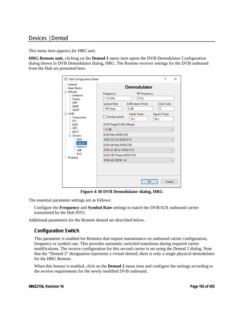
MN/22156, Revision 16 Page 192 of 455
Devices | Demod
This menu item appears for HRG unit.
HRG Remote unit, clicking on the Demod 1 menu item opens the DVB Demodulator Configuration dialog shown in DVB Demodulator dialog, HRG. The Remote receiver settings for the DVB outbound from the Hub are presented here.
Figure 4-30 DVB Demodulator dialog, HRG
The essential parameter settings are as follows:
Configure the Frequency and Symbol Rate settings to match the DVB-S2X outbound carrier transmitted by the Hub HTO.
Additional parameters for the Remote demod are described below.
Configuration Switch This parameter is enabled for Remotes that require maintenance on outbound carrier configuration, frequency or symbol rate. This provides automatic switched transitions during required carrier modifications. The receive configuration for this second carrier is set using the Demod 2 dialog. Note that the “Demod 2” designation represents a virtual demod; there is only a single physical demodulator for the HRG Remote.
When this feature is enabled, click on the Demod 2 menu item and configure the settings according to the receive requirements for the newly modified DVB outbound.
MN/22156, Revision 16 Page 193 of 455
Gold Code
Changing this parameter setting will disrupt both management and data traffic over the link, and communications with the Hub will be lost. A technician will have to restore communications by setting the gold code for the HTO modulator to match. To minimize disruption of communications between Hub and Remotes when changing this parameter, utilize the “Alternate” configuration feature that is available through the WSI. Refer to the modem Opera-tion Manual for details.
The Gold Code is the physical layer spreading sequence number or spreading factor to be applied (for instances of low power) and can be set from 0 to 262141 chips/bit. Default is 0.
Es/N0 Alarm Point The receive Es/N0 level that will generate an alarm condition for this Remote can be set with this parameter.
Valid range is -3.0 – 32.0dB. Default is 0.
ACM Target Es/No Margin Refer to operational manuals on setting ACM levels.
This menu item appears for HRX unit.
HRX Hub unit, clicking on the Demod 1 menu item presents the receiver configuration settings for the VersaFECTM return path from the Remote (VersaFECTM Demodulator dialog, HRX). This unit can have up to 24 individual demodulators depending on profile setting.
The essential Static Mode parameter settings are as follows: (If not specified the parameter is managed automatically in HDNA)
Specify demod Enable – And in HDNA demod 1-2 requires manual selection for ECM operation.
Specify the receive Frequency.
Specify either the Data Rate (for VersaFECTM receive) or the Symbol Rate (for VersaFECTM ACM receive).
Select the FEC/MODCOD for this demod to receive.
Define the Circuit ID (4–32 characters). This identifier will appear in the Parameter View area of ViperView2 for both static and HDNA operation.
Valid characters: Space ( ) * + - , . / 0 thru 9 and Aa thru Zz.
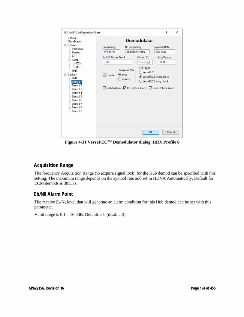
MN/22156, Revision 16 Page 194 of 455
Figure 4-31 VersaFECTM Demodulator dialog, HRX Profile 8
Acquisition Range The frequency Acquisition Range (to acquire signal lock) for the Hub demod can be specified with this setting. The maximum range depends on the symbol rate and set in HDNA Automatically. Default for ECM demods is 30KHz.
Eb/N0 Alarm Point The receive Eb/N0 level that will generate an alarm condition for this Hub demod can be set with this parameter.
Valid range is 0.1 – 16.0dB. Default is 0 (disabled).
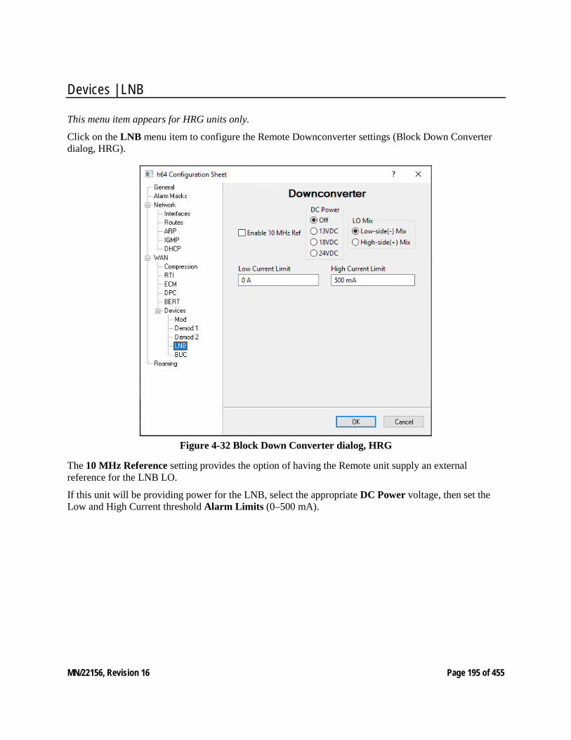
MN/22156, Revision 16 Page 195 of 455
Devices | LNB
This menu item appears for HRG units only.
Click on the LNB menu item to configure the Remote Downconverter settings (Block Down Converter dialog, HRG).
Figure 4-32 Block Down Converter dialog, HRG
The 10 MHz Reference setting provides the option of having the Remote unit supply an external reference for the LNB LO.
If this unit will be providing power for the LNB, select the appropriate DC Power voltage, then set the Low and High Current threshold Alarm Limits (0–500 mA).
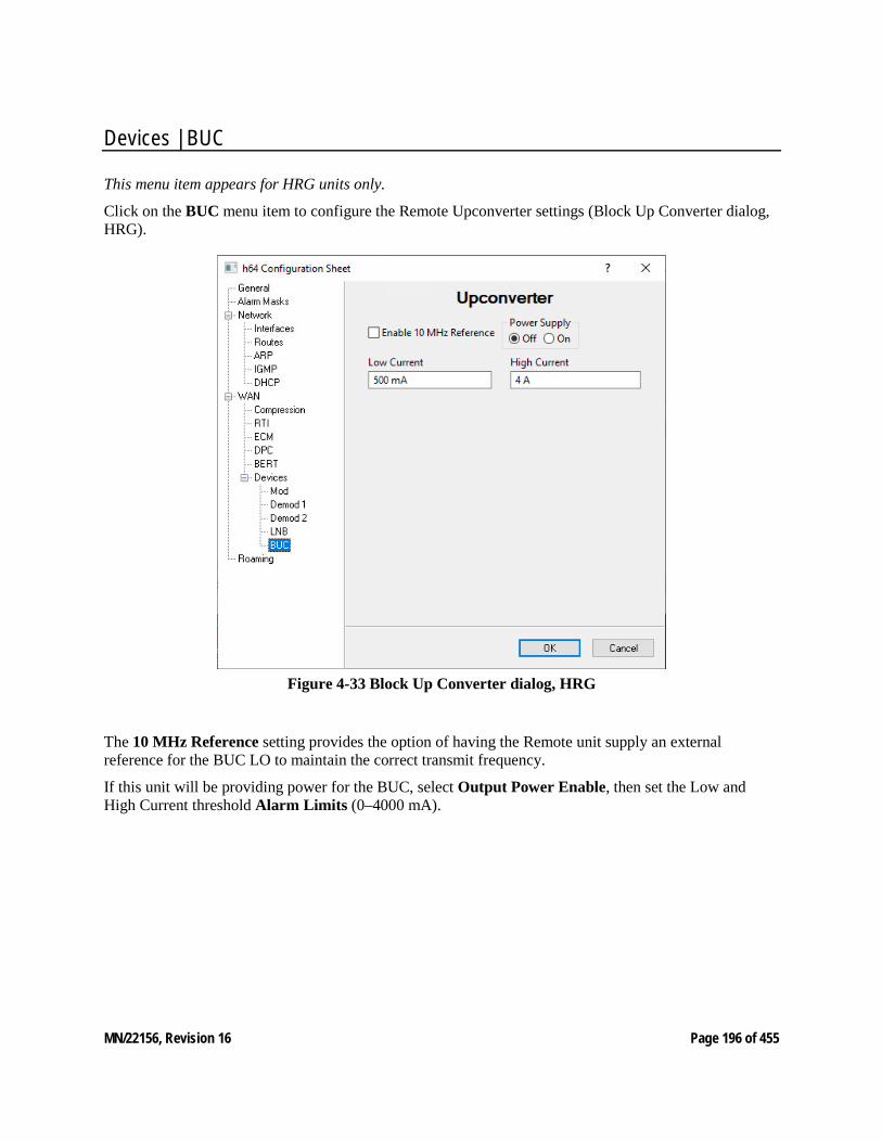
MN/22156, Revision 16 Page 196 of 455
Devices | BUC
This menu item appears for HRG units only.
Click on the BUC menu item to configure the Remote Upconverter settings (Block Up Converter dialog, HRG).
Figure 4-33 Block Up Converter dialog, HRG
The 10 MHz Reference setting provides the option of having the Remote unit supply an external reference for the BUC LO to maintain the correct transmit frequency.
If this unit will be providing power for the BUC, select Output Power Enable, then set the Low and High Current threshold Alarm Limits (0–4000 mA).
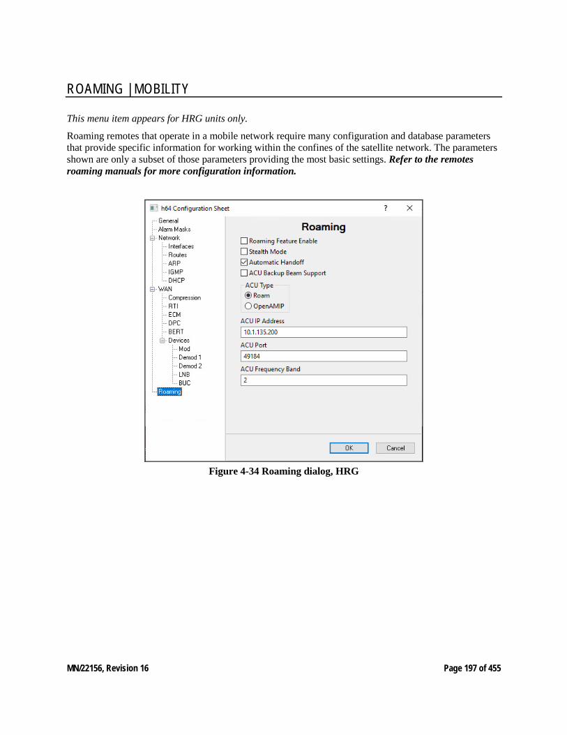
MN/22156, Revision 16 Page 197 of 455
ROAMING | MOBILITY
This menu item appears for HRG units only.
Roaming remotes that operate in a mobile network require many configuration and database parameters that provide specific information for working within the confines of the satellite network. The parameters shown are only a subset of those parameters providing the most basic settings. Refer to the remotes roaming manuals for more configuration information.
Figure 4-34 Roaming dialog, HRG
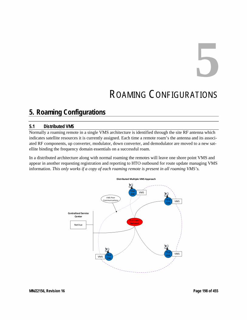
MN/22156, Revision 16 Page 198 of 455
5 ROAMING CONFIGURATIONS
5. Roaming Configurations
5.1 Distributed VMS Normally a roaming remote in a single VMS architecture is identified through the site RF antenna which indicates satellite resources it is currently assigned. Each time a remote roam’s the antenna and its associ-ated RF components, up converter, modulator, down converter, and demodulator are moved to a new sat-ellite binding the frequency domain essentials on a successful roam.
In a distributed architecture along with normal roaming the remotes will leave one shore point VMS and appear in another requesting registration and reporting to HTO outbound for route update managing VMS information. This only works if a copy of each roaming remote is present in all roaming VMS’s.
NetVue
Centralized Service Center
Distributed Multiple VMS Approach
TELEGW
TELEGW
TELEGWTELE
GW
BackboneNetwork
VMS
VMS
VMSVMS
VMS Peer Communications
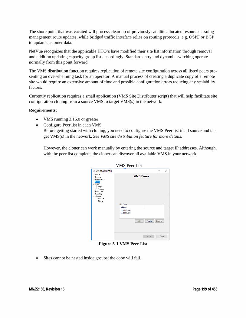
MN/22156, Revision 16 Page 199 of 455
The shore point that was vacated will process clean-up of previously satellite allocated resources issuing management route updates, while bridged traffic interface relies on routing protocols, e.g. OSPF or BGP to update customer data.
NetVue recognizes that the applicable HTO’s have modified their site list information through removal and addition updating capacity group list accordingly. Standard entry and dynamic switching operate normally from this point forward.
The VMS distribution function requires replication of remote site configuration across all listed peers pre-senting an overwhelming task for an operator. A manual process of creating a duplicate copy of a remote site would require an extensive amount of time and possible configuration errors reducing any scalability factors.
Currently replication requires a small application (VMS Site Distributer script) that will help facilitate site configuration cloning from a source VMS to target VMS(s) in the network.
Requirements:
• VMS running 3.16.0 or greater • Configure Peer list in each VMS
Before getting started with cloning, you need to configure the VMS Peer list in all source and tar-get VMS(s) in the network. See VMS site distribution feature for more details. However, the cloner can work manually by entering the source and target IP addresses. Although, with the peer list complete, the cloner can discover all available VMS in your network.
VMS Peer List
Figure 5-1 VMS Peer List
• Sites cannot be nested inside groups; the copy will fail.
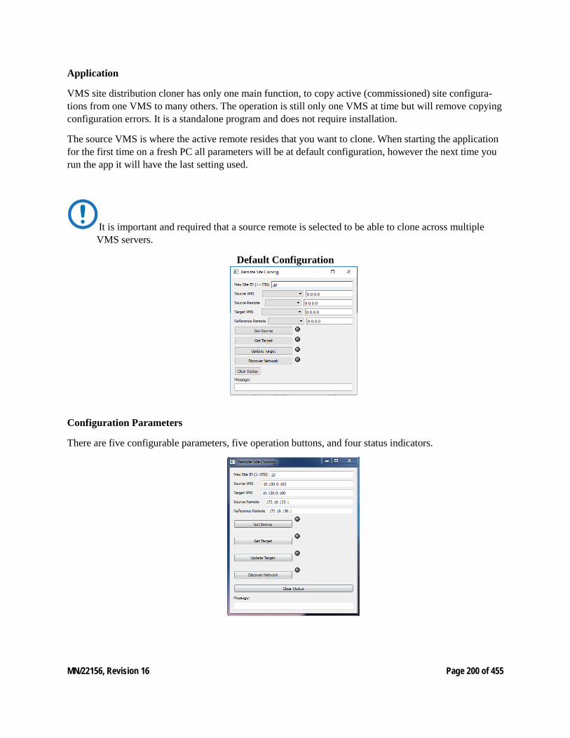
MN/22156, Revision 16 Page 200 of 455
Application
VMS site distribution cloner has only one main function, to copy active (commissioned) site configura-tions from one VMS to many others. The operation is still only one VMS at time but will remove copying configuration errors. It is a standalone program and does not require installation.
The source VMS is where the active remote resides that you want to clone. When starting the application for the first time on a fresh PC all parameters will be at default configuration, however the next time you run the app it will have the last setting used.
It is important and required that a source remote is selected to be able to clone across multiple VMS servers.
Default Configuration
Configuration Parameters
There are five configurable parameters, five operation buttons, and four status indicators.
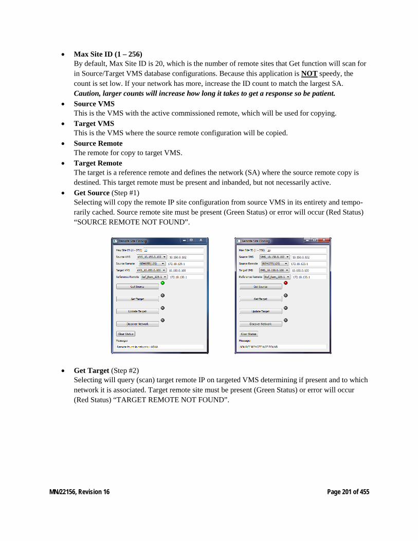
MN/22156, Revision 16 Page 201 of 455
• Max Site ID (1 – 256) By default, Max Site ID is 20, which is the number of remote sites that Get function will scan for in Source/Target VMS database configurations. Because this application is NOT speedy, the count is set low. If your network has more, increase the ID count to match the largest SA. Caution, larger counts will increase how long it takes to get a response so be patient.
• Source VMS This is the VMS with the active commissioned remote, which will be used for copying.
• Target VMS This is the VMS where the source remote configuration will be copied.
• Source Remote The remote for copy to target VMS.
• Target Remote The target is a reference remote and defines the network (SA) where the source remote copy is destined. This target remote must be present and inbanded, but not necessarily active.
• Get Source (Step #1) Selecting will copy the remote IP site configuration from source VMS in its entirety and tempo-rarily cached. Source remote site must be present (Green Status) or error will occur (Red Status) “SOURCE REMOTE NOT FOUND”.
• Get Target (Step #2) Selecting will query (scan) target remote IP on targeted VMS determining if present and to which network it is associated. Target remote site must be present (Green Status) or error will occur (Red Status) “TARGET REMOTE NOT FOUND”.
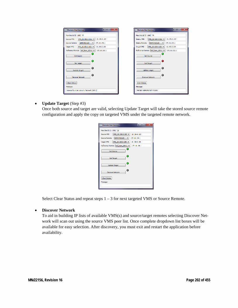
MN/22156, Revision 16 Page 202 of 455
• Update Target (Step #3) Once both source and target are valid, selecting Update Target will take the stored source remote configuration and apply the copy on targeted VMS under the targeted remote network.
Select Clear Status and repeat steps 1 – 3 for next targeted VMS or Source Remote.
• Discover Network To aid in building IP lists of available VMS(s) and source/target remotes selecting Discover Net-work will scan out using the source VMS peer list. Once complete dropdown list boxes will be available for easy selection. After discovery, you must exit and restart the application before availability.
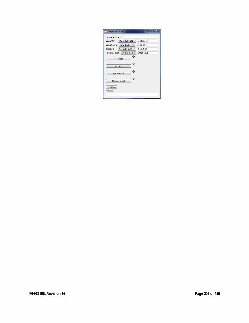
MN/22156, Revision 16 Page 203 of 455
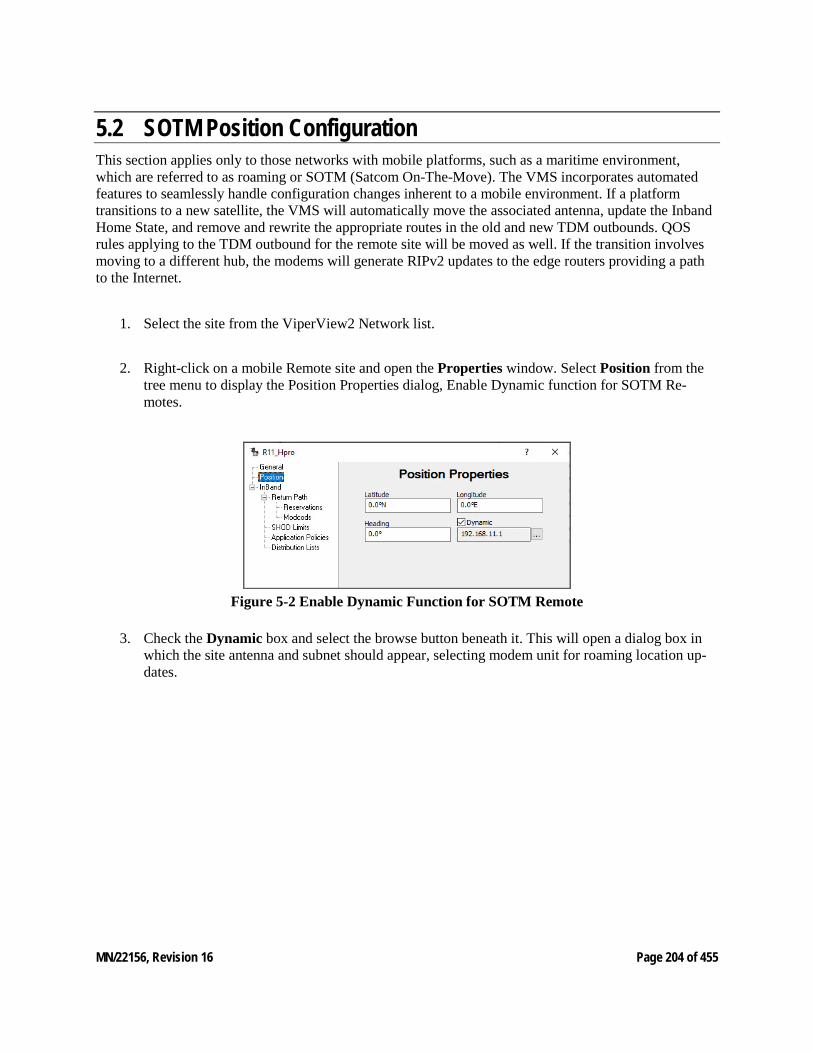
MN/22156, Revision 16 Page 204 of 455
5.2 SOTM Position Configuration This section applies only to those networks with mobile platforms, such as a maritime environment, which are referred to as roaming or SOTM (Satcom On-The-Move). The VMS incorporates automated features to seamlessly handle configuration changes inherent to a mobile environment. If a platform transitions to a new satellite, the VMS will automatically move the associated antenna, update the Inband Home State, and remove and rewrite the appropriate routes in the old and new TDM outbounds. QOS rules applying to the TDM outbound for the remote site will be moved as well. If the transition involves moving to a different hub, the modems will generate RIPv2 updates to the edge routers providing a path to the Internet.
1. Select the site from the ViperView2 Network list.
2. Right-click on a mobile Remote site and open the Properties window. Select Position from the tree menu to display the Position Properties dialog, Enable Dynamic function for SOTM Re-motes.
Figure 5-2 Enable Dynamic Function for SOTM Remote
3. Check the Dynamic box and select the browse button beneath it. This will open a dialog box in which the site antenna and subnet should appear, selecting modem unit for roaming location up-dates.
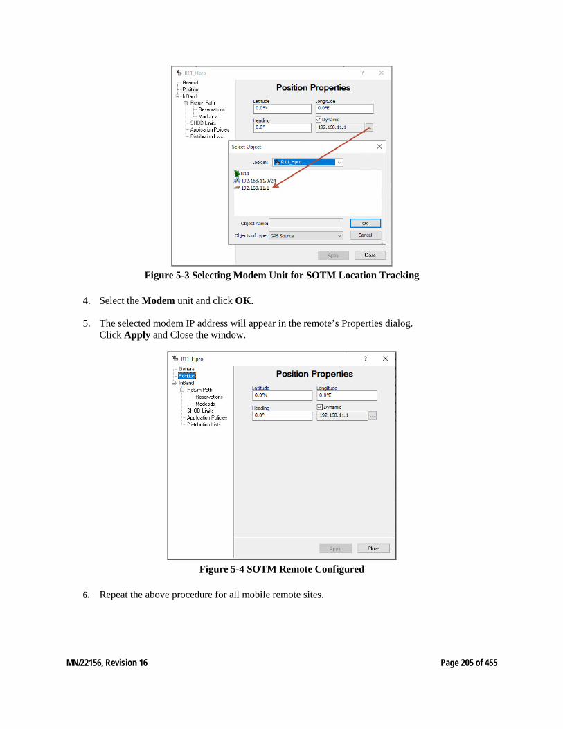
MN/22156, Revision 16 Page 205 of 455
Figure 5-3 Selecting Modem Unit for SOTM Location Tracking
4. Select the Modem unit and click OK.
5. The selected modem IP address will appear in the remote’s Properties dialog. Click Apply and Close the window.
Figure 5-4 SOTM Remote Configured
6. Repeat the above procedure for all mobile remote sites.
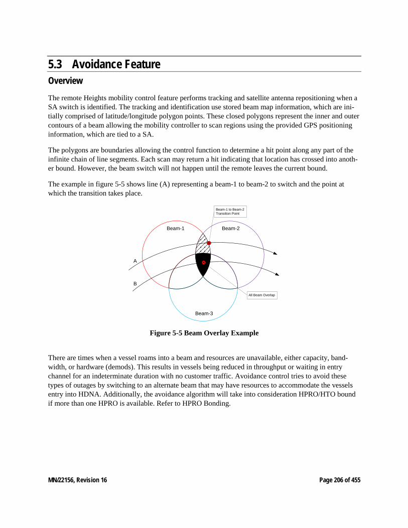
MN/22156, Revision 16 Page 206 of 455
5.3 Avoidance Feature Overview The remote Heights mobility control feature performs tracking and satellite antenna repositioning when a SA switch is identified. The tracking and identification use stored beam map information, which are ini-tially comprised of latitude/longitude polygon points. These closed polygons represent the inner and outer contours of a beam allowing the mobility controller to scan regions using the provided GPS positioning information, which are tied to a SA.
The polygons are boundaries allowing the control function to determine a hit point along any part of the infinite chain of line segments. Each scan may return a hit indicating that location has crossed into anoth-er bound. However, the beam switch will not happen until the remote leaves the current bound.
The example in figure 5-5 shows line (A) representing a beam-1 to beam-2 to switch and the point at which the transition takes place.
Beam-1 Beam-2
Beam-3
A
B
Beam-1 to Beam-2 Transition Point
All Beam Overlap
Figure 5-5 Beam Overlay Example
There are times when a vessel roams into a beam and resources are unavailable, either capacity, band-width, or hardware (demods). This results in vessels being reduced in throughput or waiting in entry channel for an indeterminate duration with no customer traffic. Avoidance control tries to avoid these types of outages by switching to an alternate beam that may have resources to accommodate the vessels entry into HDNA. Additionally, the avoidance algorithm will take into consideration HPRO/HTO bound if more than one HPRO is available. Refer to HPRO Bonding.
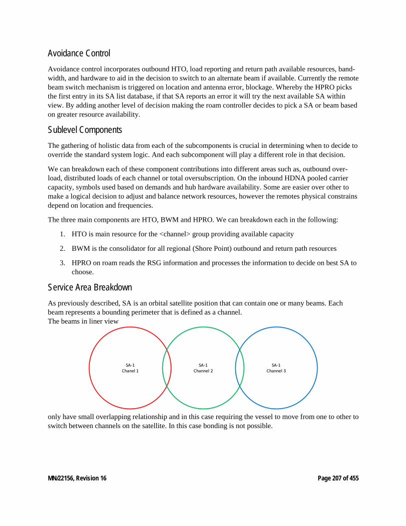
MN/22156, Revision 16 Page 207 of 455
Avoidance Control Avoidance control incorporates outbound HTO, load reporting and return path available resources, band-width, and hardware to aid in the decision to switch to an alternate beam if available. Currently the remote beam switch mechanism is triggered on location and antenna error, blockage. Whereby the HPRO picks the first entry in its SA list database, if that SA reports an error it will try the next available SA within view. By adding another level of decision making the roam controller decides to pick a SA or beam based on greater resource availability.
Sublevel Components The gathering of holistic data from each of the subcomponents is crucial in determining when to decide to override the standard system logic. And each subcomponent will play a different role in that decision.
We can breakdown each of these component contributions into different areas such as, outbound over-load, distributed loads of each channel or total oversubscription. On the inbound HDNA pooled carrier capacity, symbols used based on demands and hub hardware availability. Some are easier over other to make a logical decision to adjust and balance network resources, however the remotes physical constrains depend on location and frequencies.
The three main components are HTO, BWM and HPRO. We can breakdown each in the following:
1. HTO is main resource for the <channel> group providing available capacity
2. BWM is the consolidator for all regional (Shore Point) outbound and return path resources
3. HPRO on roam reads the RSG information and processes the information to decide on best SA to choose.
Service Area Breakdown As previously described, SA is an orbital satellite position that can contain one or many beams. Each beam represents a bounding perimeter that is defined as a channel. The beams in liner view
SA-1Chanel 1
SA-1Channel 3
SA-1Channel 2
only have small overlapping relationship and in this case requiring the vessel to move from one to other to switch between channels on the satellite. In this case bonding is not possible.
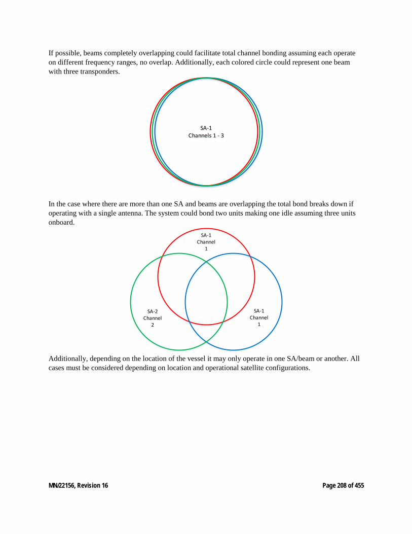
MN/22156, Revision 16 Page 208 of 455
If possible, beams completely overlapping could facilitate total channel bonding assuming each operate on different frequency ranges, no overlap. Additionally, each colored circle could represent one beam with three transponders.
SA-1Channels 1 - 3
In the case where there are more than one SA and beams are overlapping the total bond breaks down if operating with a single antenna. The system could bond two units making one idle assuming three units onboard.
SA-2Channel
2
SA-1Channel
1
SA-1Channel
1
Additionally, depending on the location of the vessel it may only operate in one SA/beam or another. All cases must be considered depending on location and operational satellite configurations.
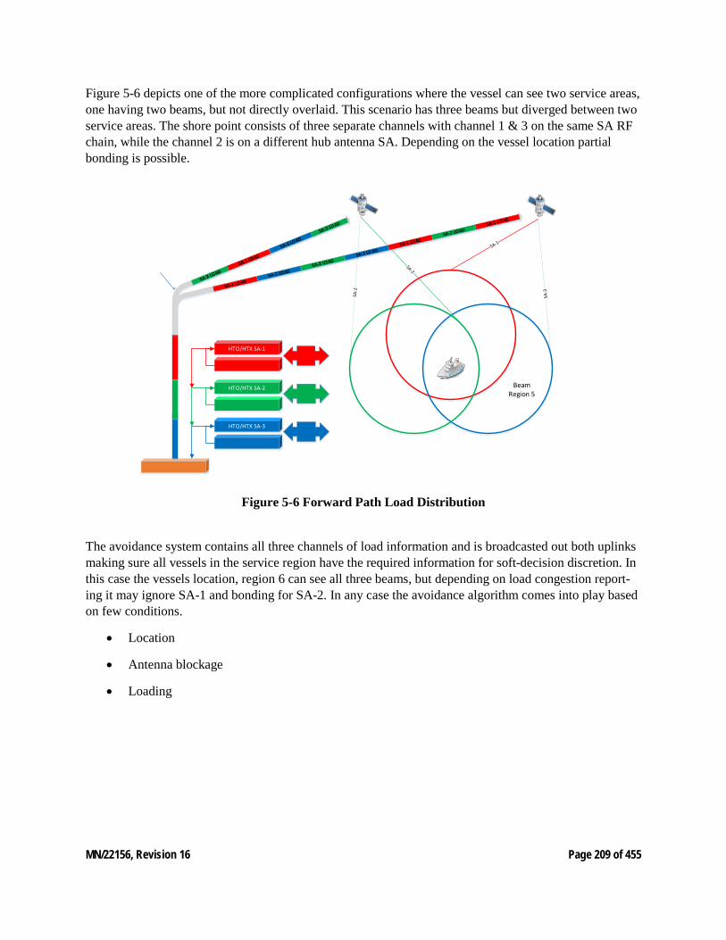
MN/22156, Revision 16 Page 209 of 455
Figure 5-6 depicts one of the more complicated configurations where the vessel can see two service areas, one having two beams, but not directly overlaid. This scenario has three beams but diverged between two service areas. The shore point consists of three separate channels with channel 1 & 3 on the same SA RF chain, while the channel 2 is on a different hub antenna SA. Depending on the vessel location partial bonding is possible.
HTO/HTX SA-1
HTO/HTX SA-2
HTO/HTX SA-3
BeamRegion 5
Figure 5-6 Forward Path Load Distribution
The avoidance system contains all three channels of load information and is broadcasted out both uplinks making sure all vessels in the service region have the required information for soft-decision discretion. In this case the vessels location, region 6 can see all three beams, but depending on load congestion report-ing it may ignore SA-1 and bonding for SA-2. In any case the avoidance algorithm comes into play based on few conditions.
• Location
• Antenna blockage
• Loading

MN/22156, Revision 16 Page 210 of 455
Closer look at the same configuration from the vessels point of view.
BeamRegion 5
Each beam region defines a different course of action some are a simple choose, while others require avoidance logic to switch.
The avoidance algorithm utilizes resource availability to guide selection of a beam when a roaming opera-tion is required. To make this decision, it considers the availability outbound symbols, inbound symbols, and demodulators.
Periodically the VMS will:
For each service channel –
• Collect number of symbols not being used by CIR for both the forward and return path.
• Produce a "bandwidth ranking" using the aggregation function on both the return and forward path availabilities.
• Update the running average of the channel’s bandwidth ranking
• Produce a bandwidth ranking for each beam using the same formula as for the service channel, aggregating the channels availabilities.
• Group the set of service channels by beam and sort them locally.
• Sort the set of beams by their bandwidth metric.
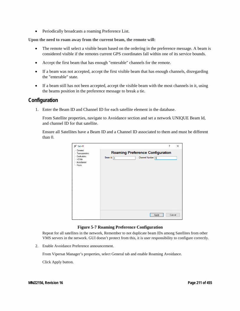
MN/22156, Revision 16 Page 211 of 455
• Periodically broadcasts a roaming Preference List.
Upon the need to roam away from the current beam, the remote will:
• The remote will select a visible beam based on the ordering in the preference message. A beam is considered visible if the remotes current GPS coordinates fall within one of its service bounds.
• Accept the first beam that has enough "enterable" channels for the remote.
• If a beam was not accepted, accept the first visible beam that has enough channels, disregarding the "enterable" state.
• If a beam still has not been accepted, accept the visible beam with the most channels in it, using the beams position in the preference message to break a tie.
Configuration 1. Enter the Beam ID and Channel ID for each satellite element in the database.
From Satellite properties, navigate to Avoidance section and set a network UNIQUE Beam Id, and channel ID for that satellite.
Ensure all Satellites have a Beam ID and a Channel ID associated to them and must be different than 0.
Figure 5-7 Roaming Preference Configuration Repeat for all satellites in the network, Remember to not duplicate beam IDs among Satellites from other VMS servers in the network. GUI doesn’t protect from this, it is user responsibility to configure correctly.
2. Enable Avoidance Preference announcement.
From Vipersat Manager’s properties, select General tab and enable Roaming Avoidance.
Click Apply button.
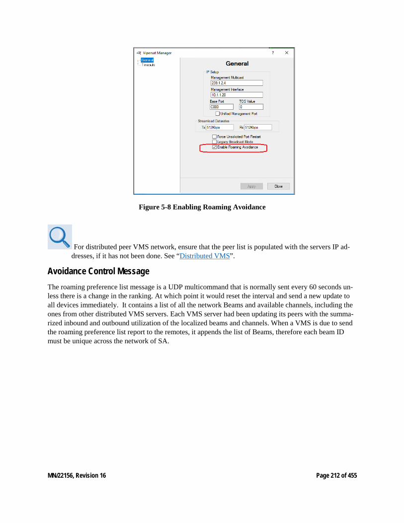
MN/22156, Revision 16 Page 212 of 455
Figure 5-8 Enabling Roaming Avoidance
For distributed peer VMS network, ensure that the peer list is populated with the servers IP ad-dresses, if it has not been done. See “Distributed VMS”.
Avoidance Control Message The roaming preference list message is a UDP multicommand that is normally sent every 60 seconds un-less there is a change in the ranking. At which point it would reset the interval and send a new update to all devices immediately. It contains a list of all the network Beams and available channels, including the ones from other distributed VMS servers. Each VMS server had been updating its peers with the summa-rized inbound and outbound utilization of the localized beams and channels. When a VMS is due to send the roaming preference list report to the remotes, it appends the list of Beams, therefore each beam ID must be unique across the network of SA.

MN/22156, Revision 16 Page 213 of 455
6 VMS CLIENT APPLICATION 6. VMS Client Application This chapter covers using the various Services that make up the VMS, the satellite network management system with an intuitive, user-friendly, graphical user interface which displays:
• Monitor and Control functions that autonomously update network health and status
• Multiple networks managed from a single server
• Centralized network configurations
• Organized network layouts
• Automated equipment detection
• Intuitive drag-and-drop bandwidth management and configuration
• Window docking for customizable views
The following sections describe the system services which, working together, from the VMS ViperView2 windows driven Graphical Users Interface.
ViperView is being deprecated and replaced with ViperView2. For an indeterminate duration ViperView will continue to be part of the install base, however support for newer features and UI controls, i.e. hub resiliency will not be accessible.
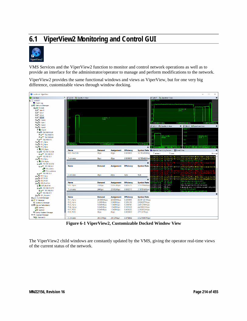
MN/22156, Revision 16 Page 214 of 455
6.1 ViperView2 Monitoring and Control GUI
VMS Services and the ViperView2 function to monitor and control network operations as well as to provide an interface for the administrator/operator to manage and perform modifications to the network.
ViperView2 provides the same functional windows and views as ViperView, but for one very big difference, customizable views through window docking.
Figure 6-1 ViperView2, Customizable Docked Window View
The ViperView2 child windows are constantly updated by the VMS, giving the operator real-time views of the current status of the network.
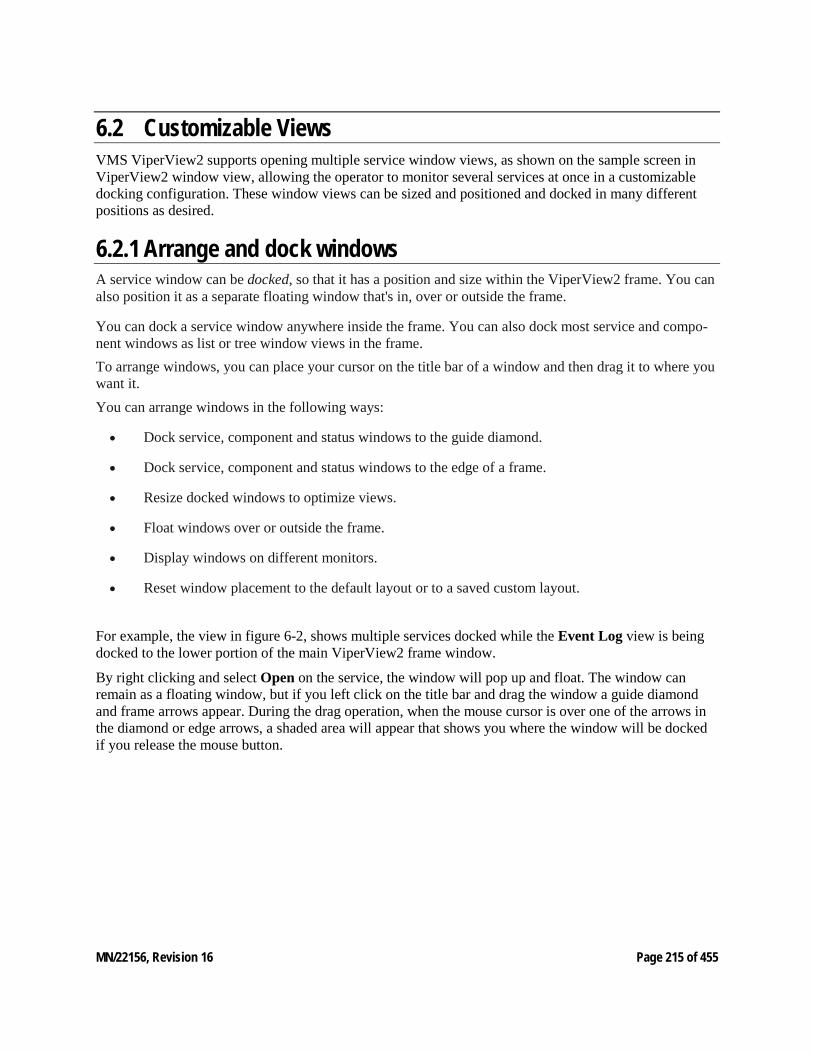
MN/22156, Revision 16 Page 215 of 455
6.2 Customizable Views VMS ViperView2 supports opening multiple service window views, as shown on the sample screen in ViperView2 window view, allowing the operator to monitor several services at once in a customizable docking configuration. These window views can be sized and positioned and docked in many different positions as desired.
6.2.1 Arrange and dock windows A service window can be docked, so that it has a position and size within the ViperView2 frame. You can also position it as a separate floating window that's in, over or outside the frame.
You can dock a service window anywhere inside the frame. You can also dock most service and compo-nent windows as list or tree window views in the frame. To arrange windows, you can place your cursor on the title bar of a window and then drag it to where you want it. You can arrange windows in the following ways:
• Dock service, component and status windows to the guide diamond.
• Dock service, component and status windows to the edge of a frame.
• Resize docked windows to optimize views.
• Float windows over or outside the frame.
• Display windows on different monitors.
• Reset window placement to the default layout or to a saved custom layout.
For example, the view in figure 6-2, shows multiple services docked while the Event Log view is being docked to the lower portion of the main ViperView2 frame window.
By right clicking and select Open on the service, the window will pop up and float. The window can remain as a floating window, but if you left click on the title bar and drag the window a guide diamond and frame arrows appear. During the drag operation, when the mouse cursor is over one of the arrows in the diamond or edge arrows, a shaded area will appear that shows you where the window will be docked if you release the mouse button.
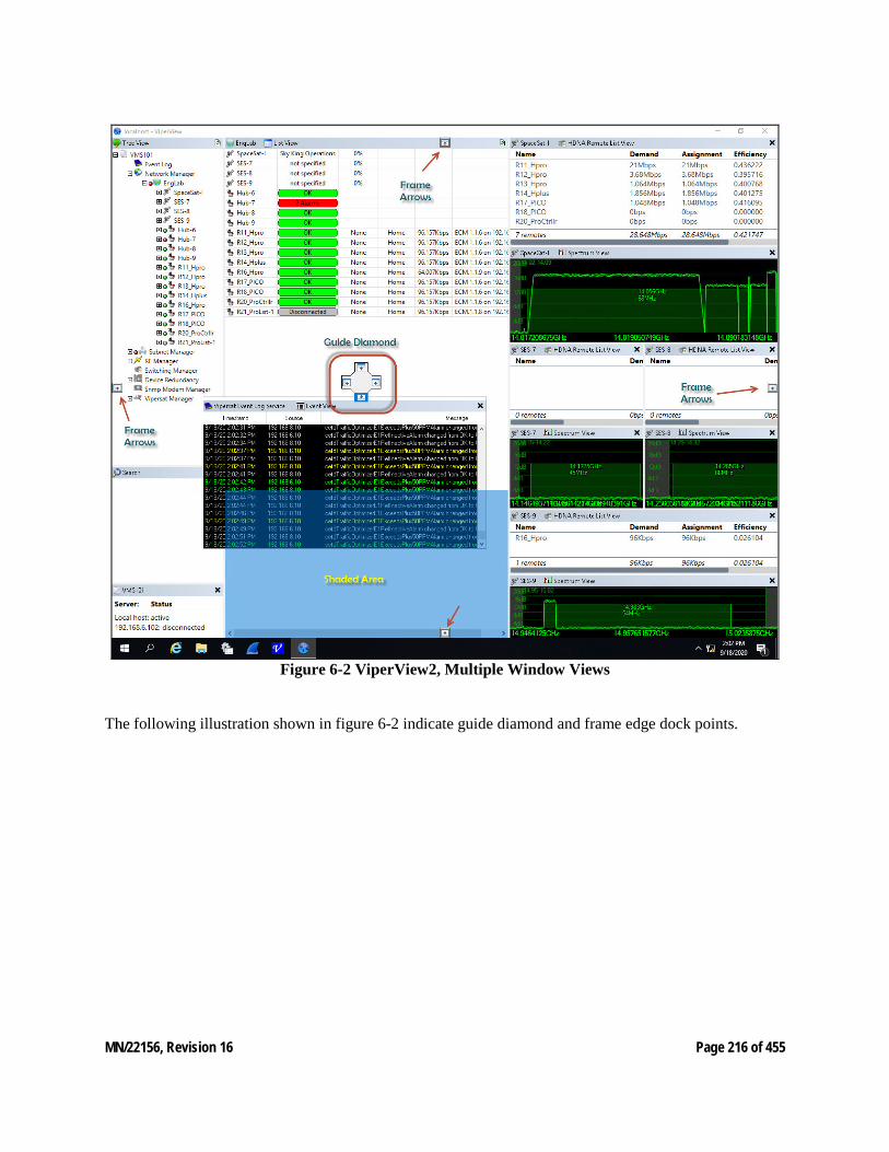
MN/22156, Revision 16 Page 216 of 455
Figure 6-2 ViperView2, Multiple Window Views
The following illustration shown in figure 6-2 indicate guide diamond and frame edge dock points.

MN/22156, Revision 16 Page 217 of 455
To return a docked window to a float or new location, click on title bar move the window to the next location. Keeping a floating window make sure when moving that the guide diamond/arrows are not highlighted, and the shaded area is not present.
Figure 6-3 Undocking windows
You can close a window by clicking X in the upper right of the title bar without undocking first.
The server connection menu provides a selection to load the last saved frame view or by unchecking the “Load Last Window Layout” ViperView2 will open to default layout.
Figure 6-4 Last Saved Layout
The save last layout function only works by closing ViperView2.

MN/22156, Revision 16 Page 218 of 455
The following section shows a few of the main service windows undocked starting with the Network Manager View.
Figure 6-5 Network Manager, Group View
Similarly, the Antenna View displays the current status of a site’s Modulators and Demodulators, as shown for the Hub site in Antenna View, Hub.
Figure 6-6 Antenna View, Hub
The Antenna View Shows L-Band frequencies.
Each List View within ViperView2 presents the option to turn Item Labels either On or Off via the com-mand located under List View in the top menu bar. When set to Off, smaller element icons and the ab-sence of table cell labels result in a more compact view.
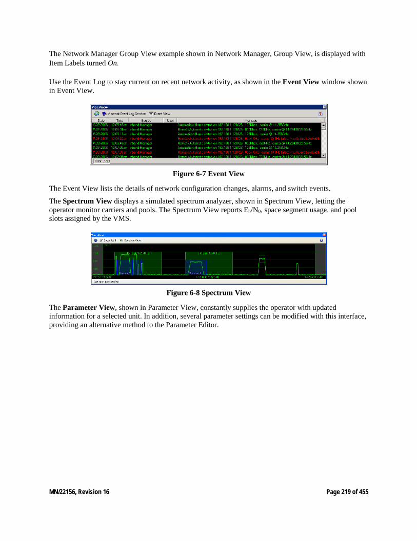
MN/22156, Revision 16 Page 219 of 455
The Network Manager Group View example shown in Network Manager, Group View, is displayed with Item Labels turned On.
Use the Event Log to stay current on recent network activity, as shown in the Event View window shown in Event View.
Figure 6-7 Event View
The Event View lists the details of network configuration changes, alarms, and switch events.
The Spectrum View displays a simulated spectrum analyzer, shown in Spectrum View, letting the operator monitor carriers and pools. The Spectrum View reports Eb/N0, space segment usage, and pool slots assigned by the VMS.
Figure 6-8 Spectrum View
The Parameter View, shown in Parameter View, constantly supplies the operator with updated information for a selected unit. In addition, several parameter settings can be modified with this interface, providing an alternative method to the Parameter Editor.

MN/22156, Revision 16 Page 220 of 455
Figure 6-9 Parameter View
The Parameter View of a selected unit includes:
• Unit Status
• Unit Alarms
• Unit Config Store/Load
• Unit Events Log
• Unit Statistics Log
• Unit Reference
• Unit Ethernet
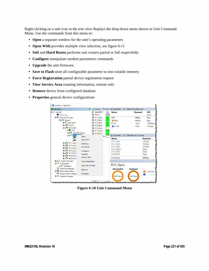
MN/22156, Revision 16 Page 221 of 455
Right-clicking on a unit icon in the tree view displays the drop-down menu shown in Unit Command Menu. Use the commands from this menu to:
• Open a separate window for the unit’s operating parameters
• Open With provides multiple view selection, see figure 6-11
• Soft and Hard Resets performs unit restarts partial or full respectfully
• Configure manipulate modem parameters commands
• Upgrade the unit firmware.
• Save to Flash store all configurable parameter to non-volatile memory
• Force Registration partial device registration request
• View Service Area roaming information, remote only
• Remove device from configured database
• Properties general device configurations
Figure 6-10 Unit Command Menu
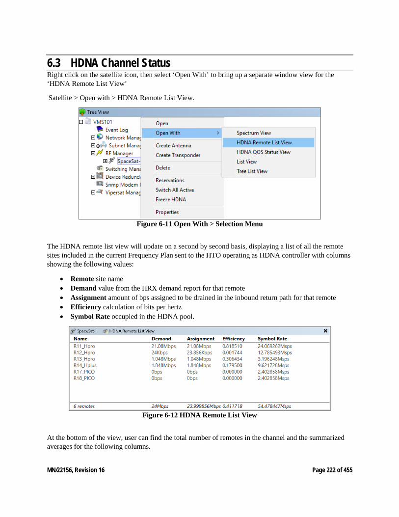
MN/22156, Revision 16 Page 222 of 455
6.3 HDNA Channel Status Right click on the satellite icon, then select ‘Open With’ to bring up a separate window view for the ‘HDNA Remote List View’
Satellite > Open with > HDNA Remote List View.
Figure 6-11 Open With > Selection Menu
The HDNA remote list view will update on a second by second basis, displaying a list of all the remote sites included in the current Frequency Plan sent to the HTO operating as HDNA controller with columns showing the following values:
• Remote site name • Demand value from the HRX demand report for that remote • Assignment amount of bps assigned to be drained in the inbound return path for that remote • Efficiency calculation of bits per hertz • Symbol Rate occupied in the HDNA pool.
Figure 6-12 HDNA Remote List View
At the bottom of the view, user can find the total number of remotes in the channel and the summarized averages for the following columns.
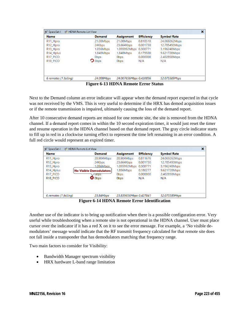
MN/22156, Revision 16 Page 223 of 455
Figure 6-13 HDNA Remote Error Status
Next to the Demand column an error indicator will appear when the demand report expected in that cycle was not received by the VMS. This is very useful to determine if the HRX has demod acquisition issues or if the remote transmission is impaired, ultimately causing the loss of the demand report.
After 10 consecutive demand reports are missed for one remote site, the site is removed from the HDNA channel. If a demand report comes in within the 10 second expiration timer, it would just reset the timer and resume operation in the HDNA channel based on that demand report. The gray circle indicator starts to fill up in red in a clockwise turning effect to represent the time left remaining in an error condition. A full red circle would represent an expired timer.
Figure 6-14 HDNA Remote Error Identification
Another use of the indicator is to bring up notification when there is a possible configuration error. Very useful while troubleshooting when a remote site is not operational in the HDNA channel. User must place cursor over the indicator if it has a red X on it to see the error message. For example, a ‘No visible de-modulators’ message would indicate that the RF transmit frequency calculated for that remote site does not fall inside a transponder that has demodulators matching that frequency range.
Two main factors to consider for Visibility:
• Bandwidth Manager spectrum visibility • HRX hardware L-band range limitation
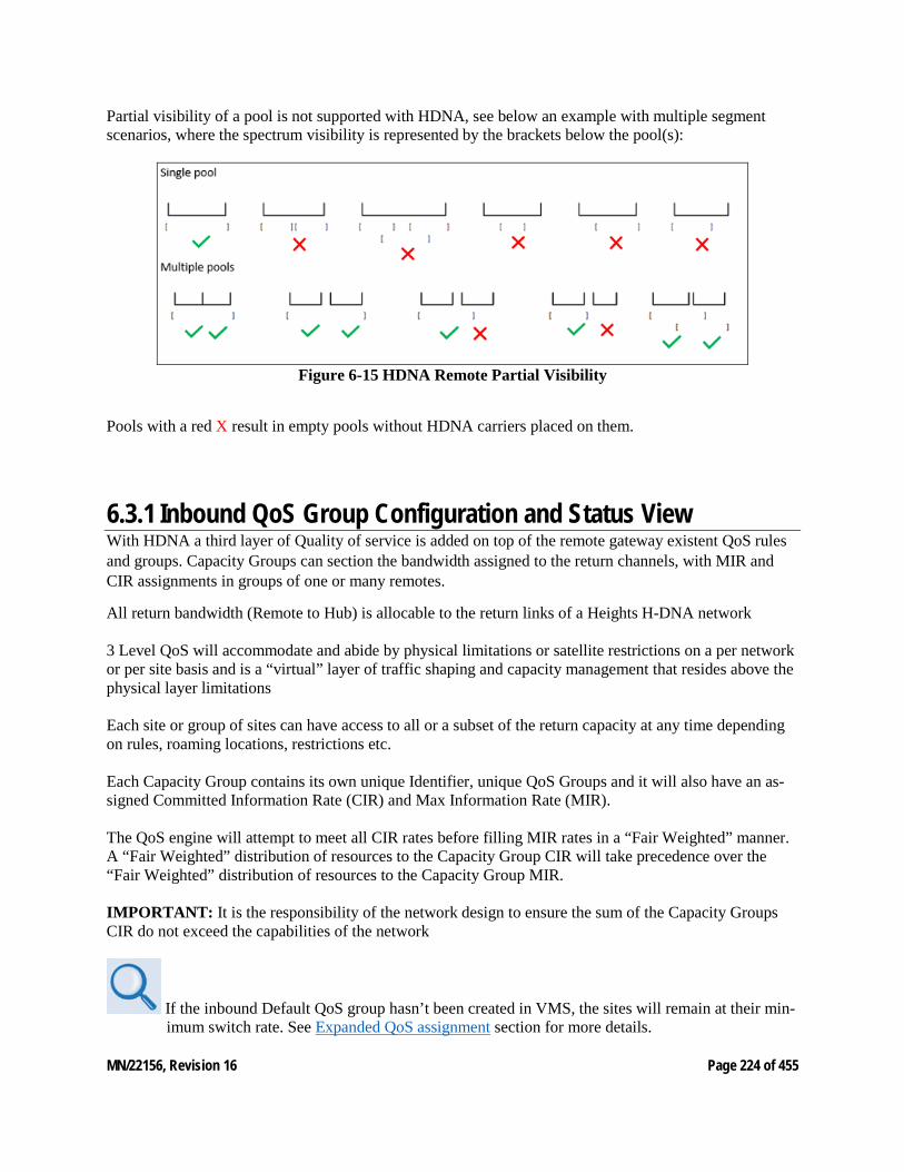
MN/22156, Revision 16 Page 224 of 455
Partial visibility of a pool is not supported with HDNA, see below an example with multiple segment scenarios, where the spectrum visibility is represented by the brackets below the pool(s):
Figure 6-15 HDNA Remote Partial Visibility
Pools with a red X result in empty pools without HDNA carriers placed on them.
6.3.1 Inbound QoS Group Configuration and Status View With HDNA a third layer of Quality of service is added on top of the remote gateway existent QoS rules and groups. Capacity Groups can section the bandwidth assigned to the return channels, with MIR and CIR assignments in groups of one or many remotes.
All return bandwidth (Remote to Hub) is allocable to the return links of a Heights H-DNA network 3 Level QoS will accommodate and abide by physical limitations or satellite restrictions on a per network or per site basis and is a “virtual” layer of traffic shaping and capacity management that resides above the physical layer limitations Each site or group of sites can have access to all or a subset of the return capacity at any time depending on rules, roaming locations, restrictions etc. Each Capacity Group contains its own unique Identifier, unique QoS Groups and it will also have an as-signed Committed Information Rate (CIR) and Max Information Rate (MIR). The QoS engine will attempt to meet all CIR rates before filling MIR rates in a “Fair Weighted” manner. A “Fair Weighted” distribution of resources to the Capacity Group CIR will take precedence over the “Fair Weighted” distribution of resources to the Capacity Group MIR. IMPORTANT: It is the responsibility of the network design to ensure the sum of the Capacity Groups CIR do not exceed the capabilities of the network
If the inbound Default QoS group hasn’t been created in VMS, the sites will remain at their min-imum switch rate. See Expanded QoS assignment section for more details.
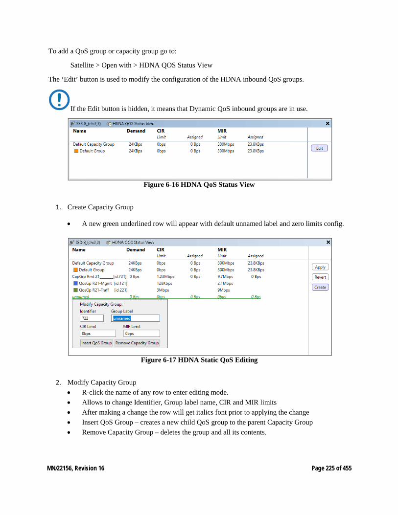
MN/22156, Revision 16 Page 225 of 455
To add a QoS group or capacity group go to:
Satellite > Open with > HDNA QOS Status View
The ‘Edit’ button is used to modify the configuration of the HDNA inbound QoS groups.
If the Edit button is hidden, it means that Dynamic QoS inbound groups are in use.
Figure 6-16 HDNA QoS Status View
1. Create Capacity Group
• A new green underlined row will appear with default unnamed label and zero limits config.
Figure 6-17 HDNA Static QoS Editing
2. Modify Capacity Group • R-click the name of any row to enter editing mode. • Allows to change Identifier, Group label name, CIR and MIR limits • After making a change the row will get italics font prior to applying the change • Insert QoS Group – creates a new child QoS group to the parent Capacity Group • Remove Capacity Group – deletes the group and all its contents.
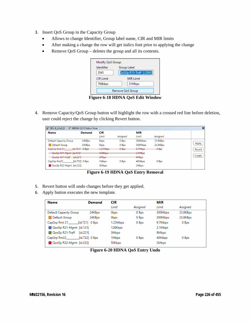
MN/22156, Revision 16 Page 226 of 455
3. Insert QoS Group in the Capacity Group • Allows to change Identifier, Group label name, CIR and MIR limits • After making a change the row will get italics font prior to applying the change • Remove QoS Group – deletes the group and all its contents.
Figure 6-18 HDNA QoS Edit Window
4. Remove Capacity/QoS Group button will highlight the row with a crossed red line before deletion, user could reject the change by clicking Revert button.
Figure 6-19 HDNA QoS Entry Removal
5. Revert button will undo changes before they get applied. 6. Apply button executes the new template.
Figure 6-20 HDNA QoS Entry Undo
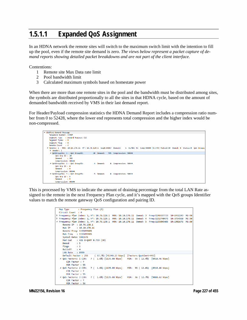
MN/22156, Revision 16 Page 227 of 455
1.5.1.1 Expanded QoS Assignment In an HDNA network the remote sites will switch to the maximum switch limit with the intention to fill up the pool, even if the remote site demand is zero. The views below represent a packet capture of de-mand reports showing detailed packet breakdowns and are not part of the client interface. Contentions:
1 Remote site Max Data rate limit 2 Pool bandwidth limit 3 Calculated maximum symbols based on homestate power
When there are more than one remote sites in the pool and the bandwidth must be distributed among sites, the symbols are distributed proportionally to all the sites in that HDNA cycle, based on the amount of demanded bandwidth received by VMS in their last demand report. For Header/Payload compression statistics the HDNA Demand Report includes a compression ratio num-ber from 0 to 52428, where the lower end represents total compression and the higher index would be non-compressed.
This is processed by VMS to indicate the amount of draining percentage from the total LAN Rate as-signed to the remote in the next Frequency Plan cycle, and it’s mapped with the QoS groups Identifier values to match the remote gateway QoS configuration and pairing ID.
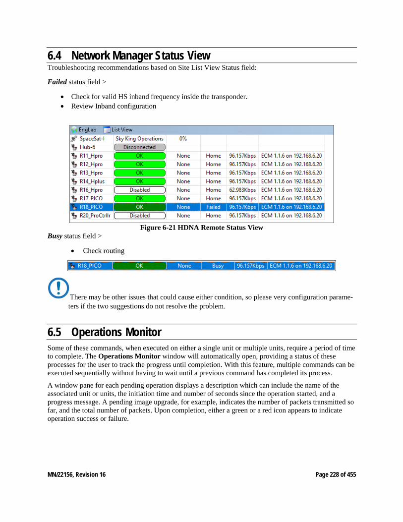
MN/22156, Revision 16 Page 228 of 455
6.4 Network Manager Status View Troubleshooting recommendations based on Site List View Status field:
Failed status field >
• Check for valid HS inband frequency inside the transponder. • Review Inband configuration
Figure 6-21 HDNA Remote Status View
Busy status field >
• Check routing
There may be other issues that could cause either condition, so please very configuration parame-ters if the two suggestions do not resolve the problem.
6.5 Operations Monitor Some of these commands, when executed on either a single unit or multiple units, require a period of time to complete. The Operations Monitor window will automatically open, providing a status of these processes for the user to track the progress until completion. With this feature, multiple commands can be executed sequentially without having to wait until a previous command has completed its process.
A window pane for each pending operation displays a description which can include the name of the associated unit or units, the initiation time and number of seconds since the operation started, and a progress message. A pending image upgrade, for example, indicates the number of packets transmitted so far, and the total number of packets. Upon completion, either a green or a red icon appears to indicate operation success or failure.
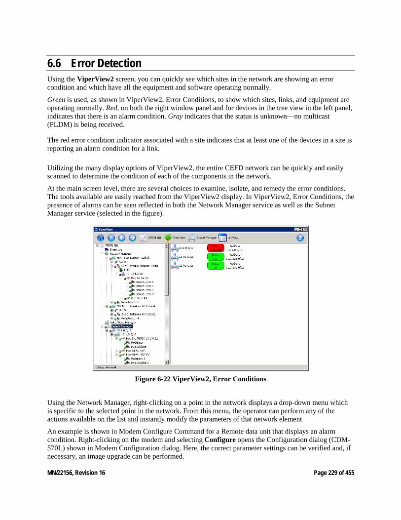
MN/22156, Revision 16 Page 229 of 455
6.6 Error Detection Using the ViperView2 screen, you can quickly see which sites in the network are showing an error condition and which have all the equipment and software operating normally.
Green is used, as shown in ViperView2, Error Conditions, to show which sites, links, and equipment are operating normally. Red, on both the right window panel and for devices in the tree view in the left panel, indicates that there is an alarm condition. Gray indicates that the status is unknown—no multicast (PLDM) is being received.
The red error condition indicator associated with a site indicates that at least one of the devices in a site is reporting an alarm condition for a link.
Utilizing the many display options of ViperView2, the entire CEFD network can be quickly and easily scanned to determine the condition of each of the components in the network.
At the main screen level, there are several choices to examine, isolate, and remedy the error conditions. The tools available are easily reached from the ViperView2 display. In ViperView2, Error Conditions, the presence of alarms can be seen reflected in both the Network Manager service as well as the Subnet Manager service (selected in the figure).
Figure 6-22 ViperView2, Error Conditions
Using the Network Manager, right-clicking on a point in the network displays a drop-down menu which is specific to the selected point in the network. From this menu, the operator can perform any of the actions available on the list and instantly modify the parameters of that network element.
An example is shown in Modem Configure Command for a Remote data unit that displays an alarm condition. Right-clicking on the modem and selecting Configure opens the Configuration dialog (CDM-570L) shown in Modem Configuration dialog. Here, the correct parameter settings can be verified and, if necessary, an image upgrade can be performed.
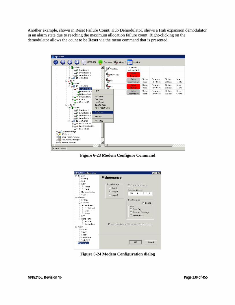
MN/22156, Revision 16 Page 230 of 455
Another example, shown in Reset Failure Count, Hub Demodulator, shows a Hub expansion demodulator in an alarm state due to reaching the maximum allocation failure count. Right-clicking on the demodulator allows the count to be Reset via the menu command that is presented.
Figure 6-23 Modem Configure Command
Figure 6-24 Modem Configuration dialog
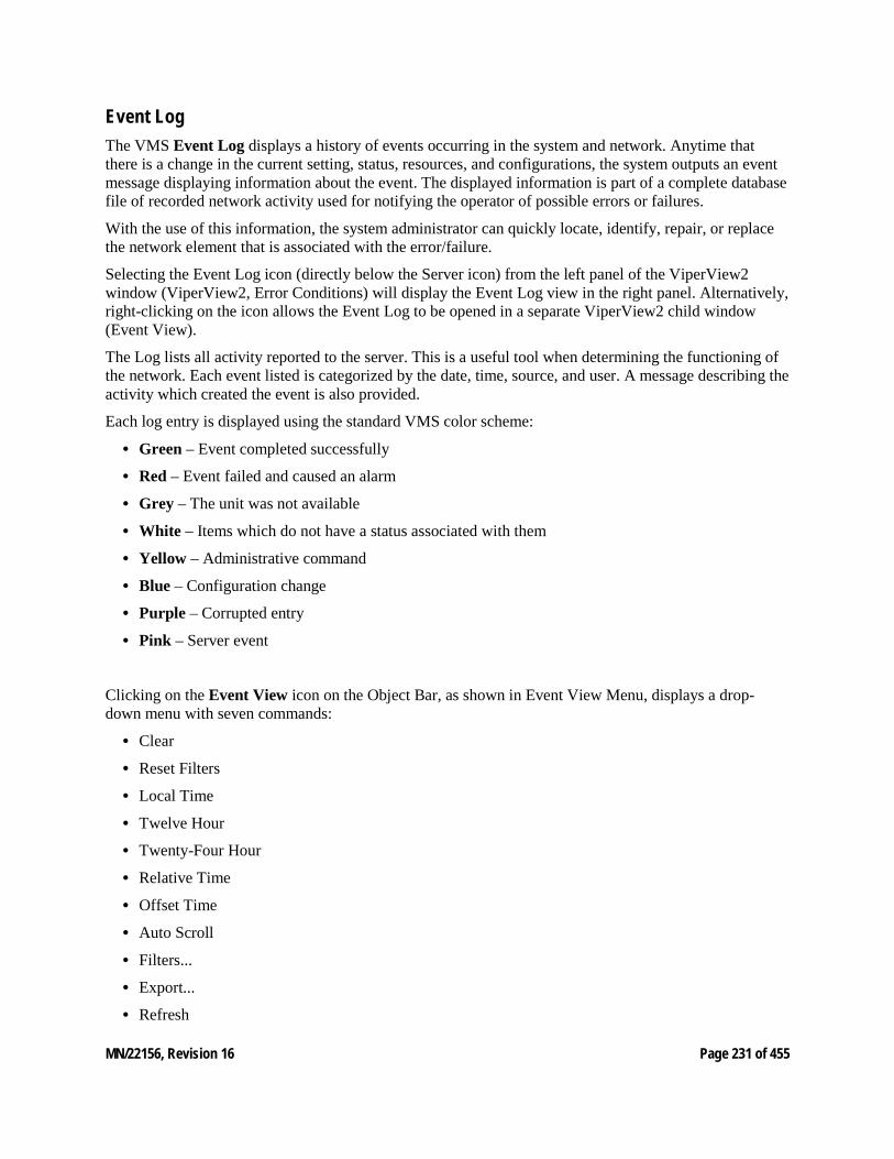
MN/22156, Revision 16 Page 231 of 455
Event Log The VMS Event Log displays a history of events occurring in the system and network. Anytime that there is a change in the current setting, status, resources, and configurations, the system outputs an event message displaying information about the event. The displayed information is part of a complete database file of recorded network activity used for notifying the operator of possible errors or failures.
With the use of this information, the system administrator can quickly locate, identify, repair, or replace the network element that is associated with the error/failure.
Selecting the Event Log icon (directly below the Server icon) from the left panel of the ViperView2 window (ViperView2, Error Conditions) will display the Event Log view in the right panel. Alternatively, right-clicking on the icon allows the Event Log to be opened in a separate ViperView2 child window (Event View).
The Log lists all activity reported to the server. This is a useful tool when determining the functioning of the network. Each event listed is categorized by the date, time, source, and user. A message describing the activity which created the event is also provided.
Each log entry is displayed using the standard VMS color scheme:
• Green – Event completed successfully
• Red – Event failed and caused an alarm
• Grey – The unit was not available
• White – Items which do not have a status associated with them
• Yellow – Administrative command
• Blue – Configuration change
• Purple – Corrupted entry
• Pink – Server event
Clicking on the Event View icon on the Object Bar, as shown in Event View Menu, displays a drop-down menu with seven commands:
• Clear
• Reset Filters
• Local Time
• Twelve Hour
• Twenty-Four Hour
• Relative Time
• Offset Time
• Auto Scroll
• Filters...
• Export...
• Refresh
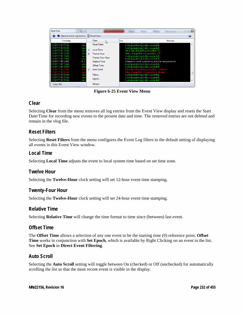
MN/22156, Revision 16 Page 232 of 455
Figure 6-25 Event View Menu
Clear Selecting Clear from the menu removes all log entries from the Event View display and resets the Start Date/Time for recording new events to the present date and time. The removed entries are not deleted and remain in the vlog file.
Reset Filters Selecting Reset Filters from the menu configures the Event Log filters to the default setting of displaying all events in this Event View window.
Local Time Selecting Local Time adjusts the event to local system time based on set time zone.
Twelve Hour Selecting the Twelve-Hour clock setting will set 12-hour event time stamping.
Twenty-Four Hour Selecting the Twelve-Hour clock setting will set 24-hour event time stamping.
Relative Time Selecting Relative Time will change the time format to time since (between) last event.
Offset Time The Offset Time allows a selection of any one event to be the starting time (0) reference point. Offset Time works in conjunction with Set Epoch, which is available by Right Clicking on an event in the list. See Set Epoch in Direct Event Filtering.
Auto Scroll Selecting the Auto Scroll setting will toggle between On (checked) or Off (unchecked) for automatically scrolling the list so that the most recent event is visible in the display.
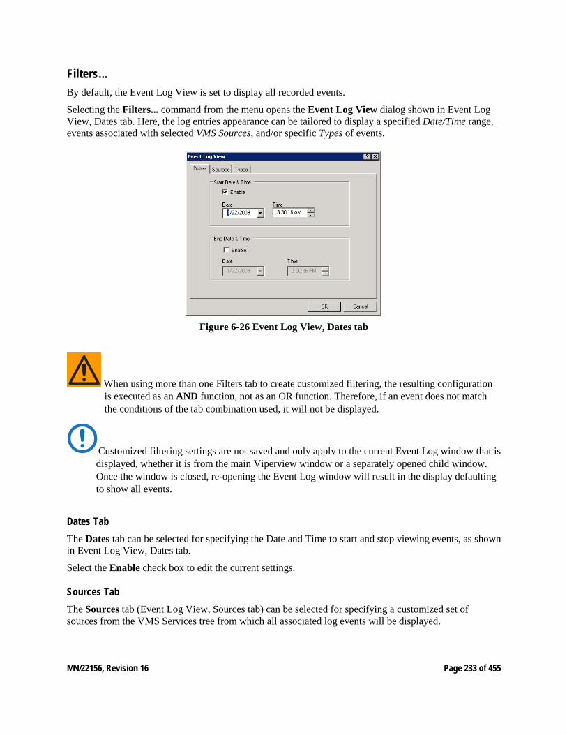
MN/22156, Revision 16 Page 233 of 455
Filters... By default, the Event Log View is set to display all recorded events.
Selecting the Filters... command from the menu opens the Event Log View dialog shown in Event Log View, Dates tab. Here, the log entries appearance can be tailored to display a specified Date/Time range, events associated with selected VMS Sources, and/or specific Types of events.
Figure 6-26 Event Log View, Dates tab
When using more than one Filters tab to create customized filtering, the resulting configuration is executed as an AND function, not as an OR function. Therefore, if an event does not match the conditions of the tab combination used, it will not be displayed.
Customized filtering settings are not saved and only apply to the current Event Log window that is displayed, whether it is from the main Viperview window or a separately opened child window. Once the window is closed, re-opening the Event Log window will result in the display defaulting to show all events.
Dates Tab The Dates tab can be selected for specifying the Date and Time to start and stop viewing events, as shown in Event Log View, Dates tab.
Select the Enable check box to edit the current settings.
Sources Tab The Sources tab (Event Log View, Sources tab) can be selected for specifying a customized set of sources from the VMS Services tree from which all associated log events will be displayed.
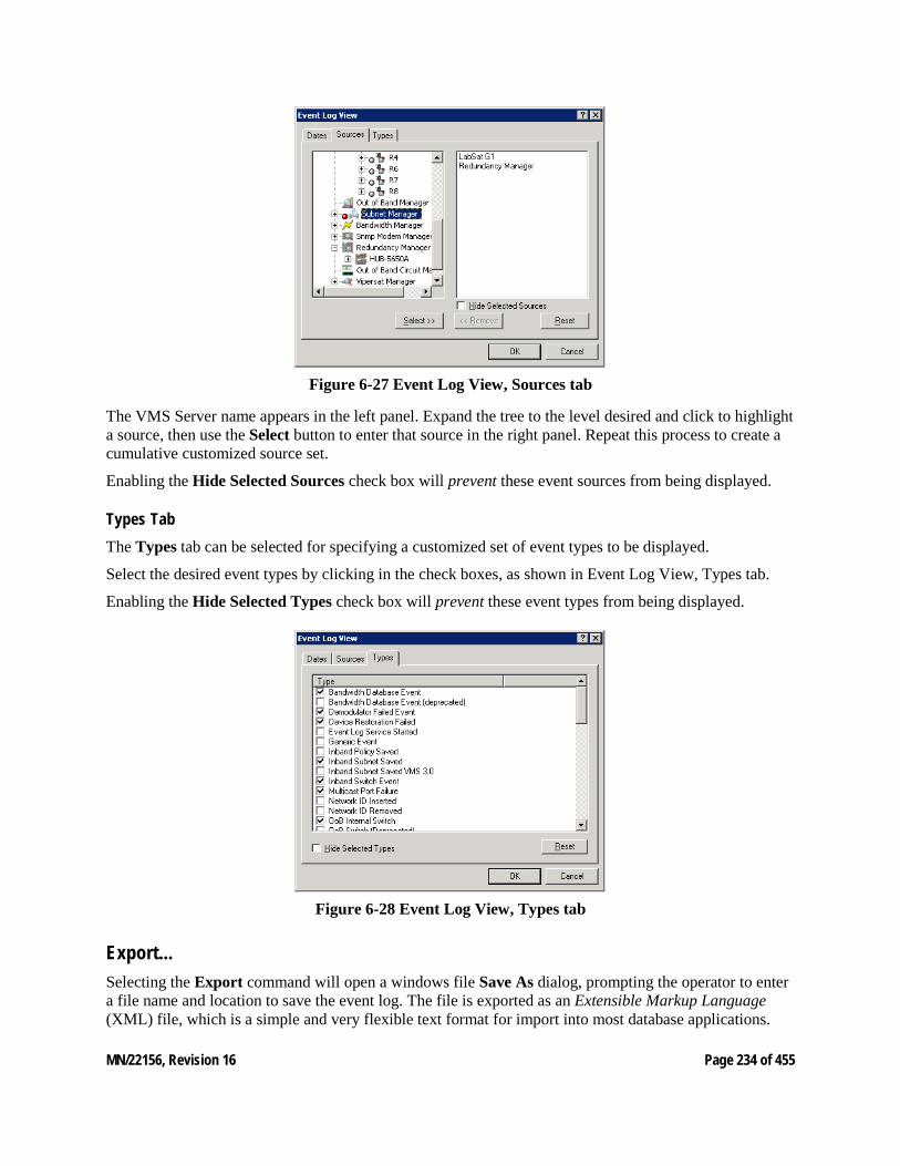
MN/22156, Revision 16 Page 234 of 455
Figure 6-27 Event Log View, Sources tab
The VMS Server name appears in the left panel. Expand the tree to the level desired and click to highlight a source, then use the Select button to enter that source in the right panel. Repeat this process to create a cumulative customized source set.
Enabling the Hide Selected Sources check box will prevent these event sources from being displayed.
Types Tab The Types tab can be selected for specifying a customized set of event types to be displayed.
Select the desired event types by clicking in the check boxes, as shown in Event Log View, Types tab.
Enabling the Hide Selected Types check box will prevent these event types from being displayed.
Figure 6-28 Event Log View, Types tab
Export... Selecting the Export command will open a windows file Save As dialog, prompting the operator to enter a file name and location to save the event log. The file is exported as an Extensible Markup Language (XML) file, which is a simple and very flexible text format for import into most database applications.
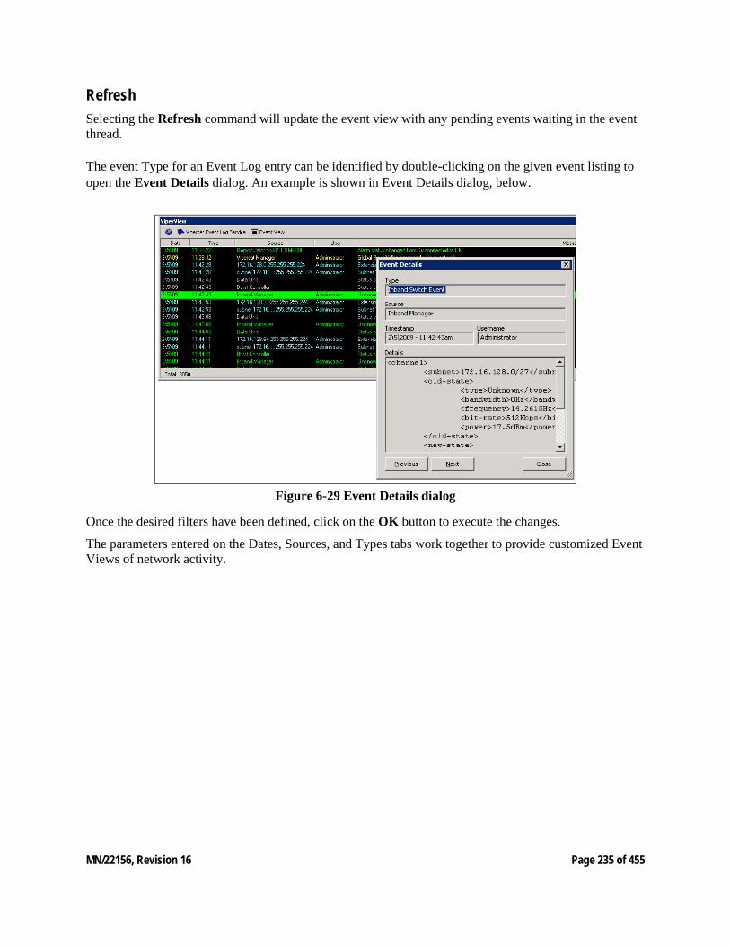
MN/22156, Revision 16 Page 235 of 455
Refresh Selecting the Refresh command will update the event view with any pending events waiting in the event thread.
The event Type for an Event Log entry can be identified by double-clicking on the given event listing to open the Event Details dialog. An example is shown in Event Details dialog, below.
Figure 6-29 Event Details dialog
Once the desired filters have been defined, click on the OK button to execute the changes.
The parameters entered on the Dates, Sources, and Types tabs work together to provide customized Event Views of network activity.
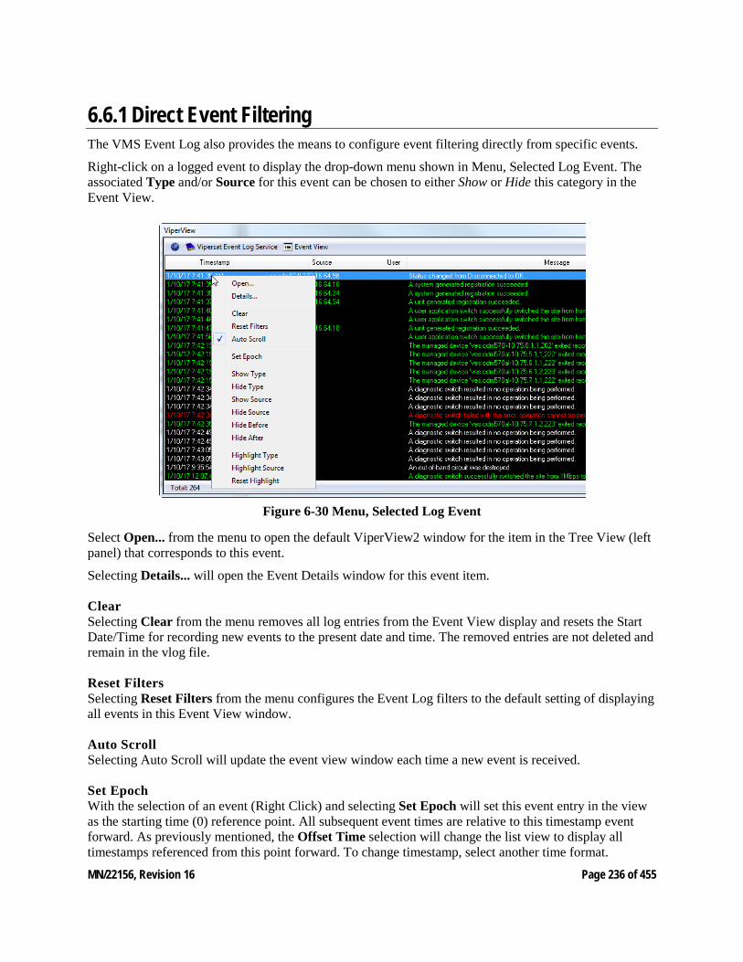
MN/22156, Revision 16 Page 236 of 455
6.6.1 Direct Event Filtering The VMS Event Log also provides the means to configure event filtering directly from specific events.
Right-click on a logged event to display the drop-down menu shown in Menu, Selected Log Event. The associated Type and/or Source for this event can be chosen to either Show or Hide this category in the Event View.
Figure 6-30 Menu, Selected Log Event
Select Open... from the menu to open the default ViperView2 window for the item in the Tree View (left panel) that corresponds to this event.
Selecting Details... will open the Event Details window for this event item. Clear Selecting Clear from the menu removes all log entries from the Event View display and resets the Start Date/Time for recording new events to the present date and time. The removed entries are not deleted and remain in the vlog file. Reset Filters Selecting Reset Filters from the menu configures the Event Log filters to the default setting of displaying all events in this Event View window. Auto Scroll Selecting Auto Scroll will update the event view window each time a new event is received. Set Epoch With the selection of an event (Right Click) and selecting Set Epoch will set this event entry in the view as the starting time (0) reference point. All subsequent event times are relative to this timestamp event forward. As previously mentioned, the Offset Time selection will change the list view to display all timestamps referenced from this point forward. To change timestamp, select another time format.

MN/22156, Revision 16 Page 237 of 455
Show Type Selecting an event from the list and selecting Show Type will update the list event view with event of this type. Hide Type Selecting an event from the list and selecting Hide Type will update the list event view removing this type of event. Show Source Selecting an event from the list and selecting Show Source will update the list event view only show events from this source. Hide Source Selecting an event from the list and selecting Hide Source will update the list event view removing this type of sourced event. Hide Type Selecting an event from the list and selecting Hide Type will update the list event view removing this type of event. Hide Before Selecting an event from the list and selecting Hide Before will update the list event view moving this event to the top of the window hiding all events before this one. Hide After Selecting an event from the list and selecting Hide After will update the list event view hiding all events after this one. Highlight Type Selecting an event from the list and selecting Highlight Type will update the list event view by highlighting all events of this type. Highlight Source Selecting an event from the list and selecting Highlight Source will update the list event view by highlighting all events with this source. Reset Highlight Selecting an event from the list and selecting Reset Highlight will update the list event view by clearing all highlighted events.
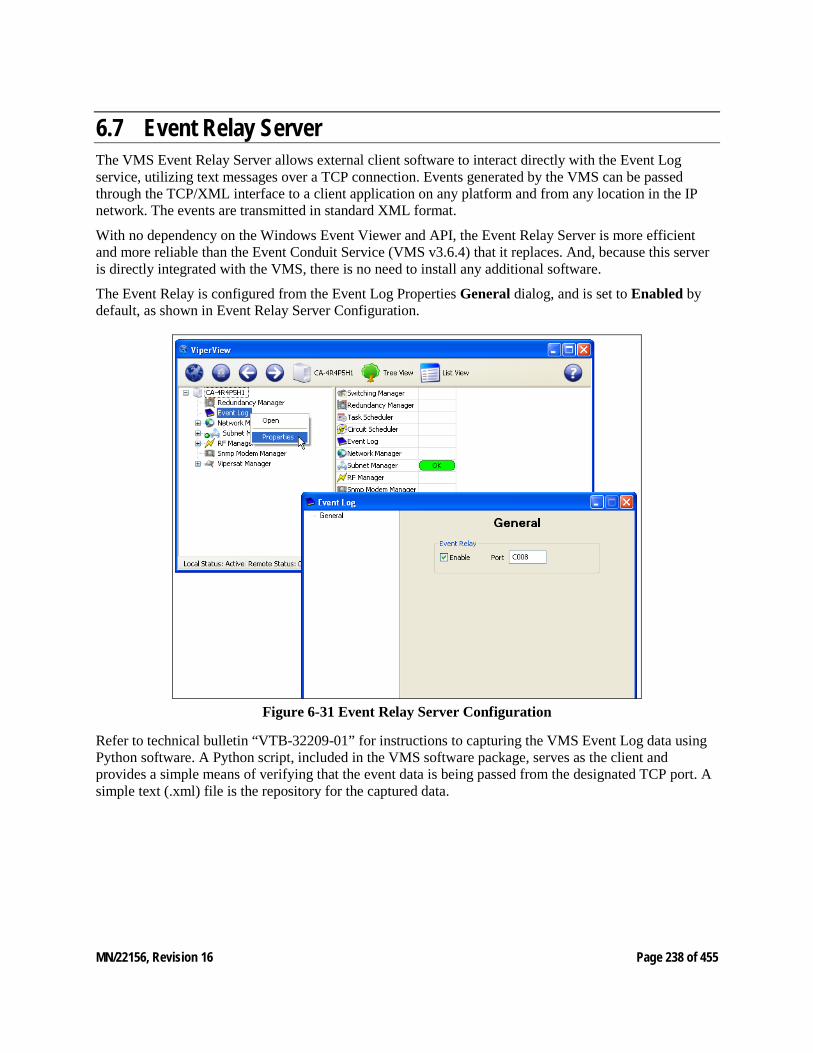
MN/22156, Revision 16 Page 238 of 455
6.7 Event Relay Server The VMS Event Relay Server allows external client software to interact directly with the Event Log service, utilizing text messages over a TCP connection. Events generated by the VMS can be passed through the TCP/XML interface to a client application on any platform and from any location in the IP network. The events are transmitted in standard XML format.
With no dependency on the Windows Event Viewer and API, the Event Relay Server is more efficient and more reliable than the Event Conduit Service (VMS v3.6.4) that it replaces. And, because this server is directly integrated with the VMS, there is no need to install any additional software.
The Event Relay is configured from the Event Log Properties General dialog, and is set to Enabled by default, as shown in Event Relay Server Configuration.
Figure 6-31 Event Relay Server Configuration
Refer to technical bulletin “VTB-32209-01” for instructions to capturing the VMS Event Log data using Python software. A Python script, included in the VMS software package, serves as the client and provides a simple means of verifying that the event data is being passed from the designated TCP port. A simple text (.xml) file is the repository for the captured data.
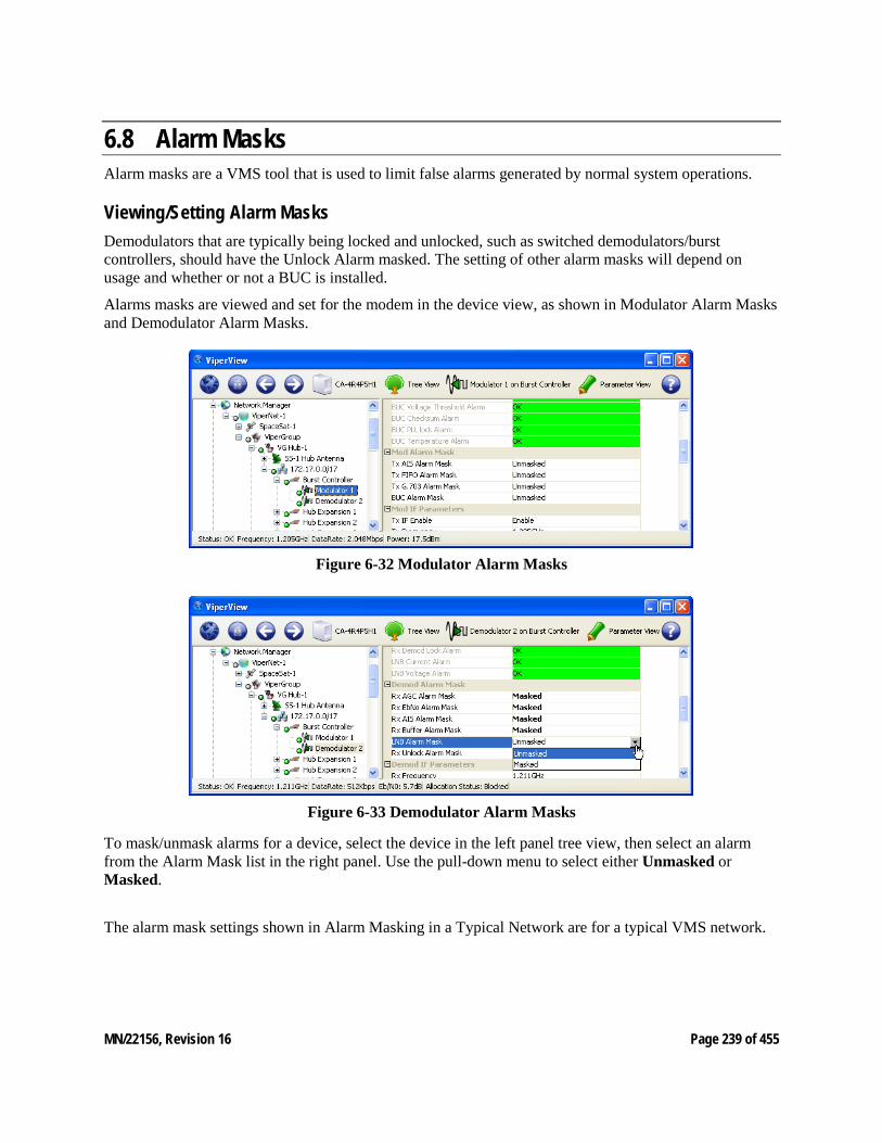
MN/22156, Revision 16 Page 239 of 455
6.8 Alarm Masks Alarm masks are a VMS tool that is used to limit false alarms generated by normal system operations.
Viewing/Setting Alarm Masks Demodulators that are typically being locked and unlocked, such as switched demodulators/burst controllers, should have the Unlock Alarm masked. The setting of other alarm masks will depend on usage and whether or not a BUC is installed.
Alarms masks are viewed and set for the modem in the device view, as shown in Modulator Alarm Masks and Demodulator Alarm Masks.
Figure 6-32 Modulator Alarm Masks
Figure 6-33 Demodulator Alarm Masks
To mask/unmask alarms for a device, select the device in the left panel tree view, then select an alarm from the Alarm Mask list in the right panel. Use the pull-down menu to select either Unmasked or Masked.
The alarm mask settings shown in Alarm Masking in a Typical Network are for a typical VMS network.
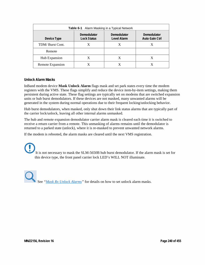
MN/22156, Revision 16 Page 240 of 455
Table 6-1 Alarm Masking in a Typical Network
Device Type Demodulator Lock Status
Demodulator Level Alarm
Demodulator Auto Gain Ctrl
TDM/ Burst Cont. X X X
Remote
Hub Expansion X X X
Remote Expansion X X X
Unlock Alarm Masks InBand modem device Mask Unlock Alarm flags mask and set park states every time the modem registers with the VMS. These flags simplify and reduce the device item-by-item settings, making them persistent during active state. These flag settings are typically set on modems that are switched expansion units or hub burst demodulators. If these devices are not masked, many unwanted alarms will be generated in the system during normal operations due to their frequent locking/unlocking behavior.
Hub burst demodulators, when masked, only shut down their link status alarms that are typically part of the carrier lock/unlock, leaving all other internal alarms unmasked.
The hub and remote expansion demodulator carrier alarm mask is cleared each time it is switched to receive a return carrier from a remote. This unmasking of alarms remains until the demodulator is returned to a parked state (unlock), where it is re-masked to prevent unwanted network alarms.
If the modem is rebooted, the alarm masks are cleared until the next VMS registration.
It is not necessary to mask the SLM-5650B hub burst demodulator. If the alarm mask is set for this device type, the front panel carrier lock LED’s WILL NOT illuminate.
See “Mask Rx Unlock Alarms” for details on how to set unlock alarm masks.
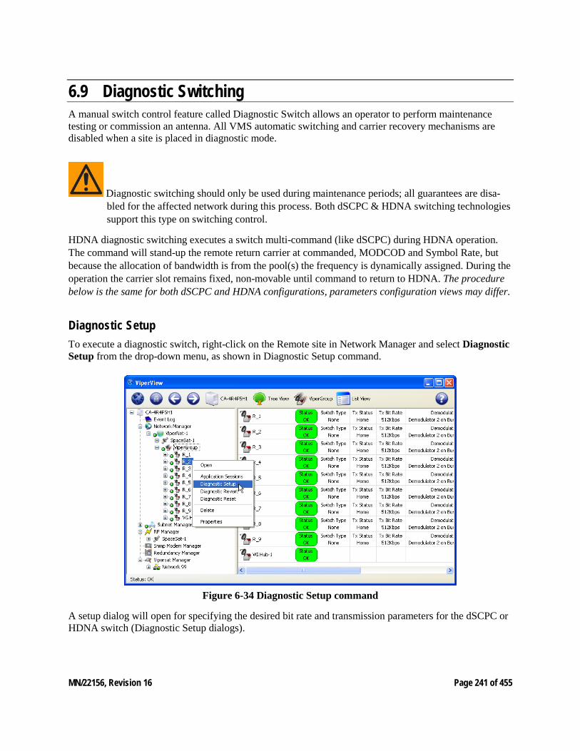
MN/22156, Revision 16 Page 241 of 455
6.9 Diagnostic Switching A manual switch control feature called Diagnostic Switch allows an operator to perform maintenance testing or commission an antenna. All VMS automatic switching and carrier recovery mechanisms are disabled when a site is placed in diagnostic mode.
Diagnostic switching should only be used during maintenance periods; all guarantees are disa-bled for the affected network during this process. Both dSCPC & HDNA switching technologies support this type on switching control.
HDNA diagnostic switching executes a switch multi-command (like dSCPC) during HDNA operation. The command will stand-up the remote return carrier at commanded, MODCOD and Symbol Rate, but because the allocation of bandwidth is from the pool(s) the frequency is dynamically assigned. During the operation the carrier slot remains fixed, non-movable until command to return to HDNA. The procedure below is the same for both dSCPC and HDNA configurations, parameters configuration views may differ.
Diagnostic Setup To execute a diagnostic switch, right-click on the Remote site in Network Manager and select Diagnostic Setup from the drop-down menu, as shown in Diagnostic Setup command.
Figure 6-34 Diagnostic Setup command
A setup dialog will open for specifying the desired bit rate and transmission parameters for the dSCPC or HDNA switch (Diagnostic Setup dialogs).
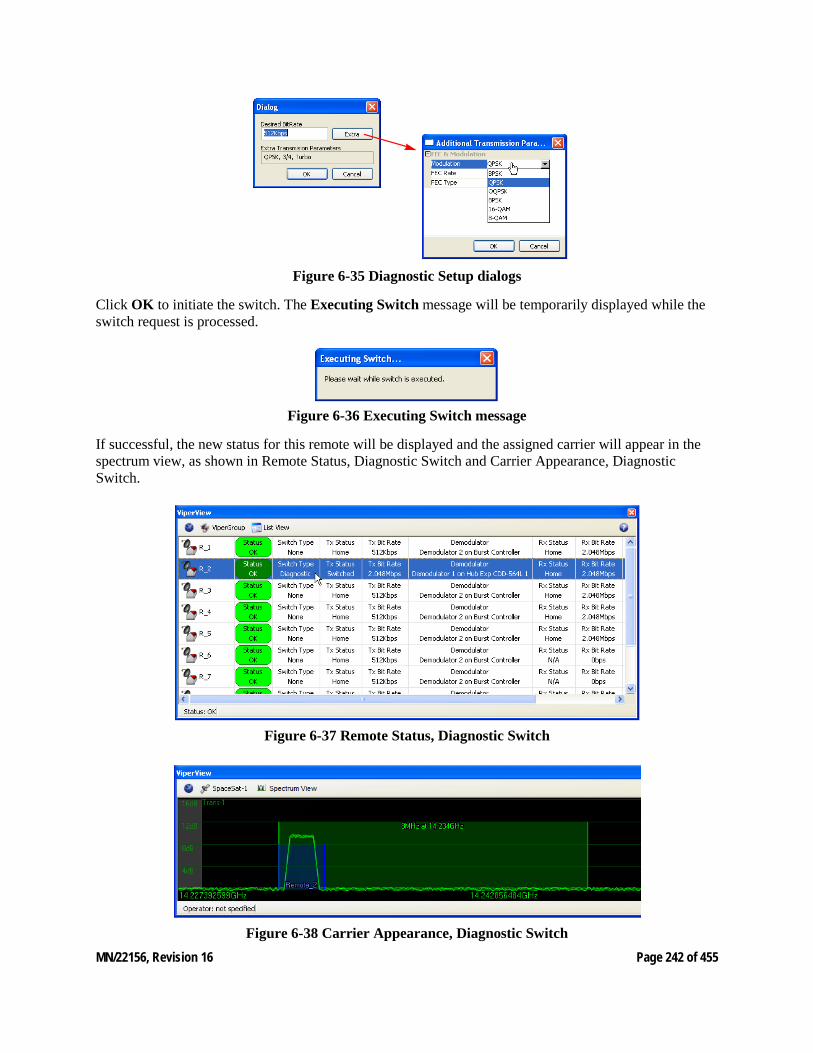
MN/22156, Revision 16 Page 242 of 455
Figure 6-35 Diagnostic Setup dialogs
Click OK to initiate the switch. The Executing Switch message will be temporarily displayed while the switch request is processed.
Figure 6-36 Executing Switch message
If successful, the new status for this remote will be displayed and the assigned carrier will appear in the spectrum view, as shown in Remote Status, Diagnostic Switch and Carrier Appearance, Diagnostic Switch.
Figure 6-37 Remote Status, Diagnostic Switch
Figure 6-38 Carrier Appearance, Diagnostic Switch
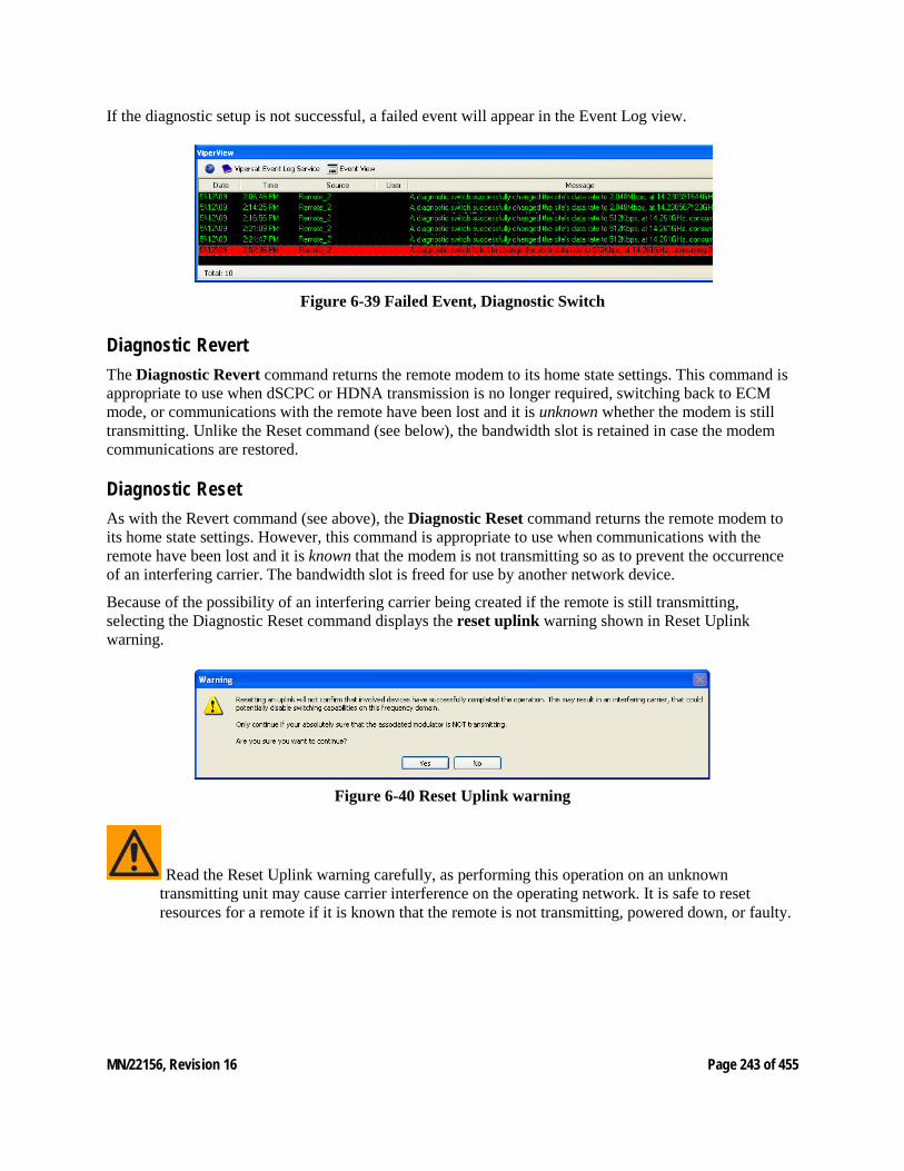
MN/22156, Revision 16 Page 243 of 455
If the diagnostic setup is not successful, a failed event will appear in the Event Log view.
Figure 6-39 Failed Event, Diagnostic Switch
Diagnostic Revert The Diagnostic Revert command returns the remote modem to its home state settings. This command is appropriate to use when dSCPC or HDNA transmission is no longer required, switching back to ECM mode, or communications with the remote have been lost and it is unknown whether the modem is still transmitting. Unlike the Reset command (see below), the bandwidth slot is retained in case the modem communications are restored.
Diagnostic Reset As with the Revert command (see above), the Diagnostic Reset command returns the remote modem to its home state settings. However, this command is appropriate to use when communications with the remote have been lost and it is known that the modem is not transmitting so as to prevent the occurrence of an interfering carrier. The bandwidth slot is freed for use by another network device.
Because of the possibility of an interfering carrier being created if the remote is still transmitting, selecting the Diagnostic Reset command displays the reset uplink warning shown in Reset Uplink warning.
Figure 6-40 Reset Uplink warning
Read the Reset Uplink warning carefully, as performing this operation on an unknown transmitting unit may cause carrier interference on the operating network. It is safe to reset resources for a remote if it is known that the remote is not transmitting, powered down, or faulty.
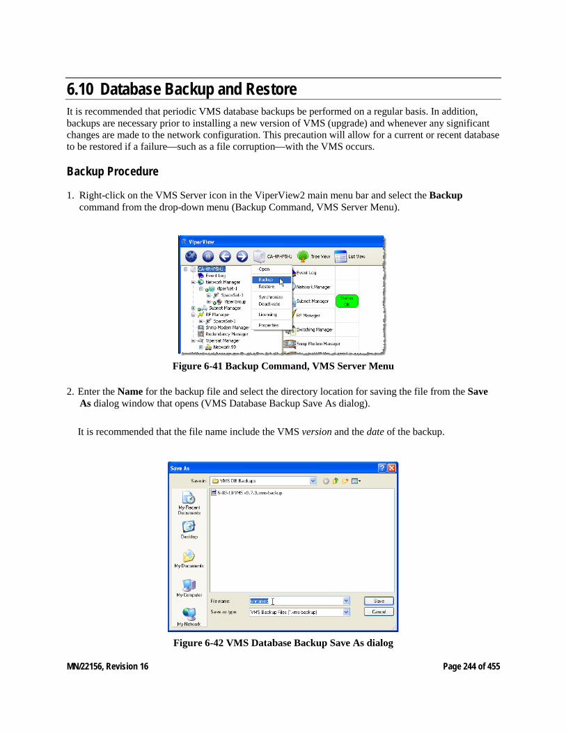
MN/22156, Revision 16 Page 244 of 455
6.10 Database Backup and Restore It is recommended that periodic VMS database backups be performed on a regular basis. In addition, backups are necessary prior to installing a new version of VMS (upgrade) and whenever any significant changes are made to the network configuration. This precaution will allow for a current or recent database to be restored if a failure—such as a file corruption—with the VMS occurs.
Backup Procedure
1. Right-click on the VMS Server icon in the ViperView2 main menu bar and select the Backup command from the drop-down menu (Backup Command, VMS Server Menu).
Figure 6-41 Backup Command, VMS Server Menu
2. Enter the Name for the backup file and select the directory location for saving the file from the Save As dialog window that opens (VMS Database Backup Save As dialog).
It is recommended that the file name include the VMS version and the date of the backup.
Figure 6-42 VMS Database Backup Save As dialog
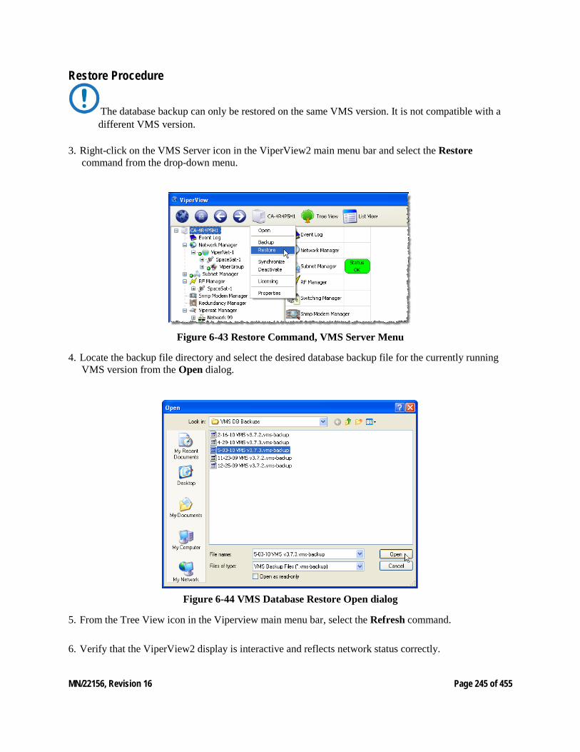
MN/22156, Revision 16 Page 245 of 455
Restore Procedure
The database backup can only be restored on the same VMS version. It is not compatible with a different VMS version.
3. Right-click on the VMS Server icon in the ViperView2 main menu bar and select the Restore command from the drop-down menu.
Figure 6-43 Restore Command, VMS Server Menu
4. Locate the backup file directory and select the desired database backup file for the currently running VMS version from the Open dialog.
Figure 6-44 VMS Database Restore Open dialog
5. From the Tree View icon in the Viperview main menu bar, select the Refresh command.
6. Verify that the ViperView2 display is interactive and reflects network status correctly.
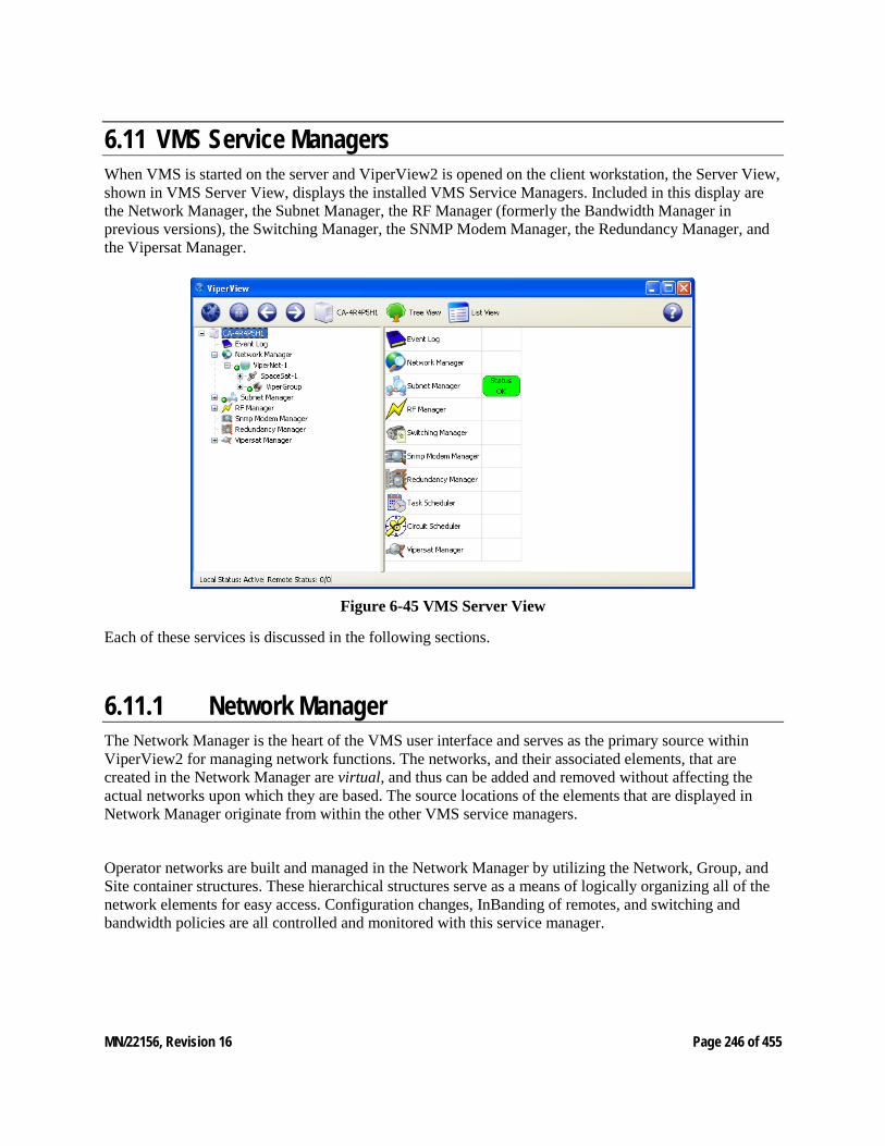
MN/22156, Revision 16 Page 246 of 455
6.11 VMS Service Managers When VMS is started on the server and ViperView2 is opened on the client workstation, the Server View, shown in VMS Server View, displays the installed VMS Service Managers. Included in this display are the Network Manager, the Subnet Manager, the RF Manager (formerly the Bandwidth Manager in previous versions), the Switching Manager, the SNMP Modem Manager, the Redundancy Manager, and the Vipersat Manager.
Figure 6-45 VMS Server View
Each of these services is discussed in the following sections.
6.11.1 Network Manager The Network Manager is the heart of the VMS user interface and serves as the primary source within ViperView2 for managing network functions. The networks, and their associated elements, that are created in the Network Manager are virtual, and thus can be added and removed without affecting the actual networks upon which they are based. The source locations of the elements that are displayed in Network Manager originate from within the other VMS service managers.
Operator networks are built and managed in the Network Manager by utilizing the Network, Group, and Site container structures. These hierarchical structures serve as a means of logically organizing all of the network elements for easy access. Configuration changes, InBanding of remotes, and switching and bandwidth policies are all controlled and monitored with this service manager.
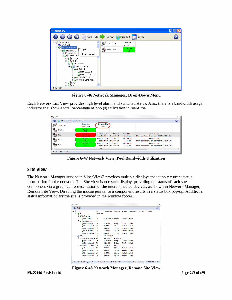
MN/22156, Revision 16 Page 247 of 455
Figure 6-46 Network Manager, Drop-Down Menu
Each Network List View provides high level alarm and switched status. Also, there is a bandwidth usage indicator that show a total percentage of pool(s) utilization in real-time.
Figure 6-47 Network View, Pool Bandwidth Utilization
Site View The Network Manager service in ViperView2 provides multiple displays that supply current status information for the network. The Site view is one such display, providing the status of each site component via a graphical representation of the interconnected devices, as shown in Network Manager, Remote Site View. Directing the mouse pointer to a component results in a status box pop-up. Additional status information for the site is provided in the window footer.
Figure 6-48 Network Manager, Remote Site View
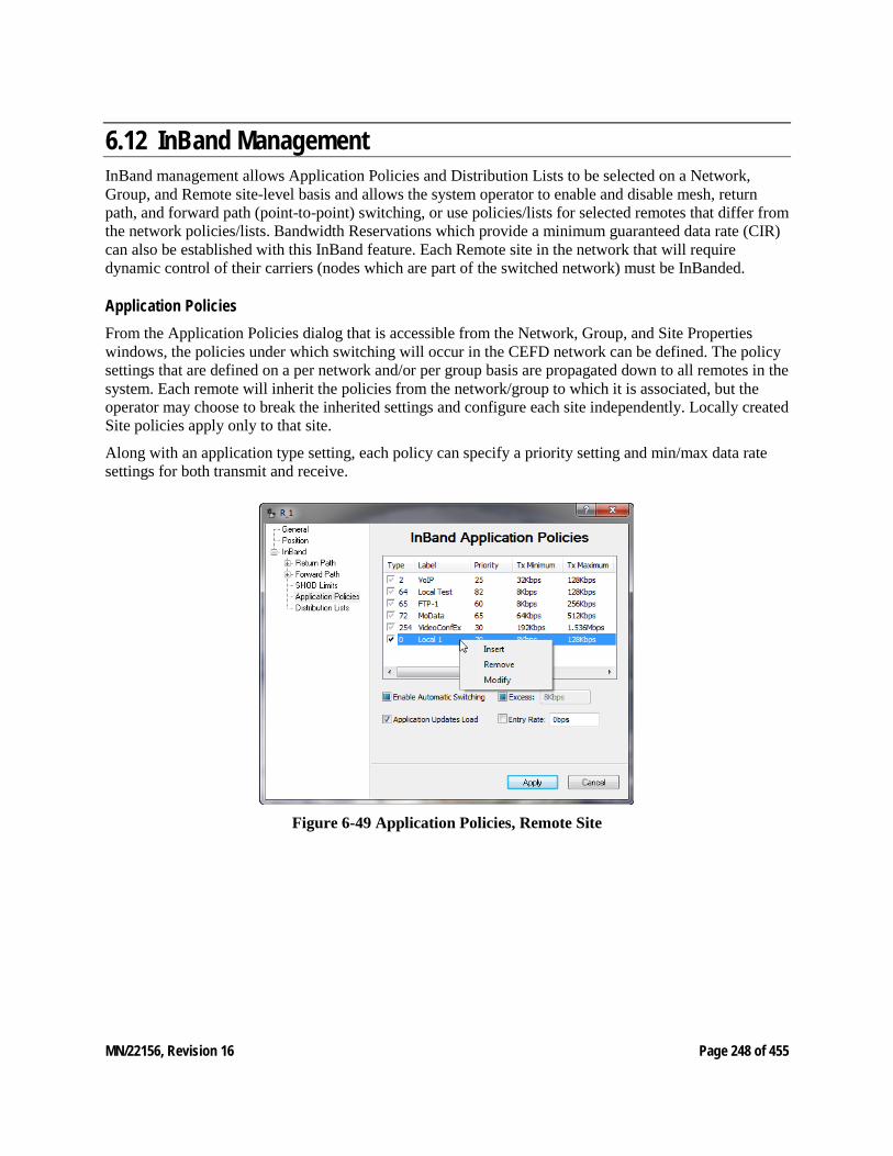
MN/22156, Revision 16 Page 248 of 455
6.12 InBand Management InBand management allows Application Policies and Distribution Lists to be selected on a Network, Group, and Remote site-level basis and allows the system operator to enable and disable mesh, return path, and forward path (point-to-point) switching, or use policies/lists for selected remotes that differ from the network policies/lists. Bandwidth Reservations which provide a minimum guaranteed data rate (CIR) can also be established with this InBand feature. Each Remote site in the network that will require dynamic control of their carriers (nodes which are part of the switched network) must be InBanded.
Application Policies From the Application Policies dialog that is accessible from the Network, Group, and Site Properties windows, the policies under which switching will occur in the CEFD network can be defined. The policy settings that are defined on a per network and/or per group basis are propagated down to all remotes in the system. Each remote will inherit the policies from the network/group to which it is associated, but the operator may choose to break the inherited settings and configure each site independently. Locally created Site policies apply only to that site.
Along with an application type setting, each policy can specify a priority setting and min/max data rate settings for both transmit and receive.
Figure 6-49 Application Policies, Remote Site
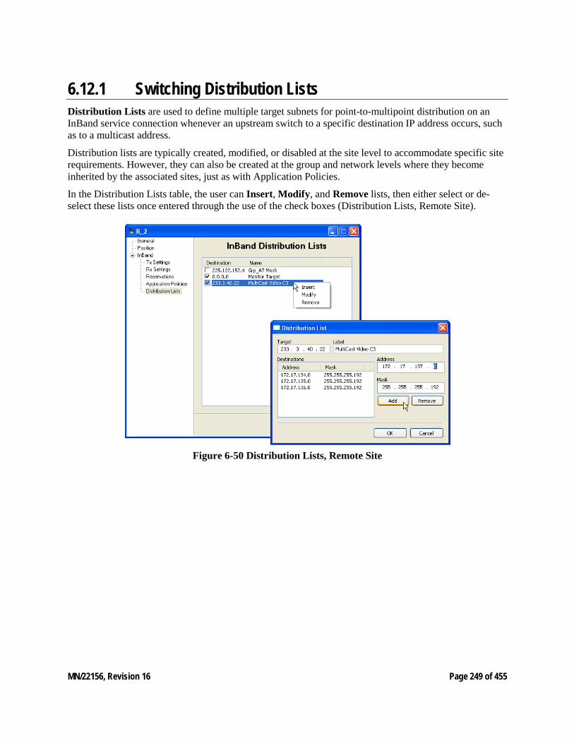
MN/22156, Revision 16 Page 249 of 455
6.12.1 Switching Distribution Lists Distribution Lists are used to define multiple target subnets for point-to-multipoint distribution on an InBand service connection whenever an upstream switch to a specific destination IP address occurs, such as to a multicast address.
Distribution lists are typically created, modified, or disabled at the site level to accommodate specific site requirements. However, they can also be created at the group and network levels where they become inherited by the associated sites, just as with Application Policies.
In the Distribution Lists table, the user can Insert, Modify, and Remove lists, then either select or de-select these lists once entered through the use of the check boxes (Distribution Lists, Remote Site).
Figure 6-50 Distribution Lists, Remote Site
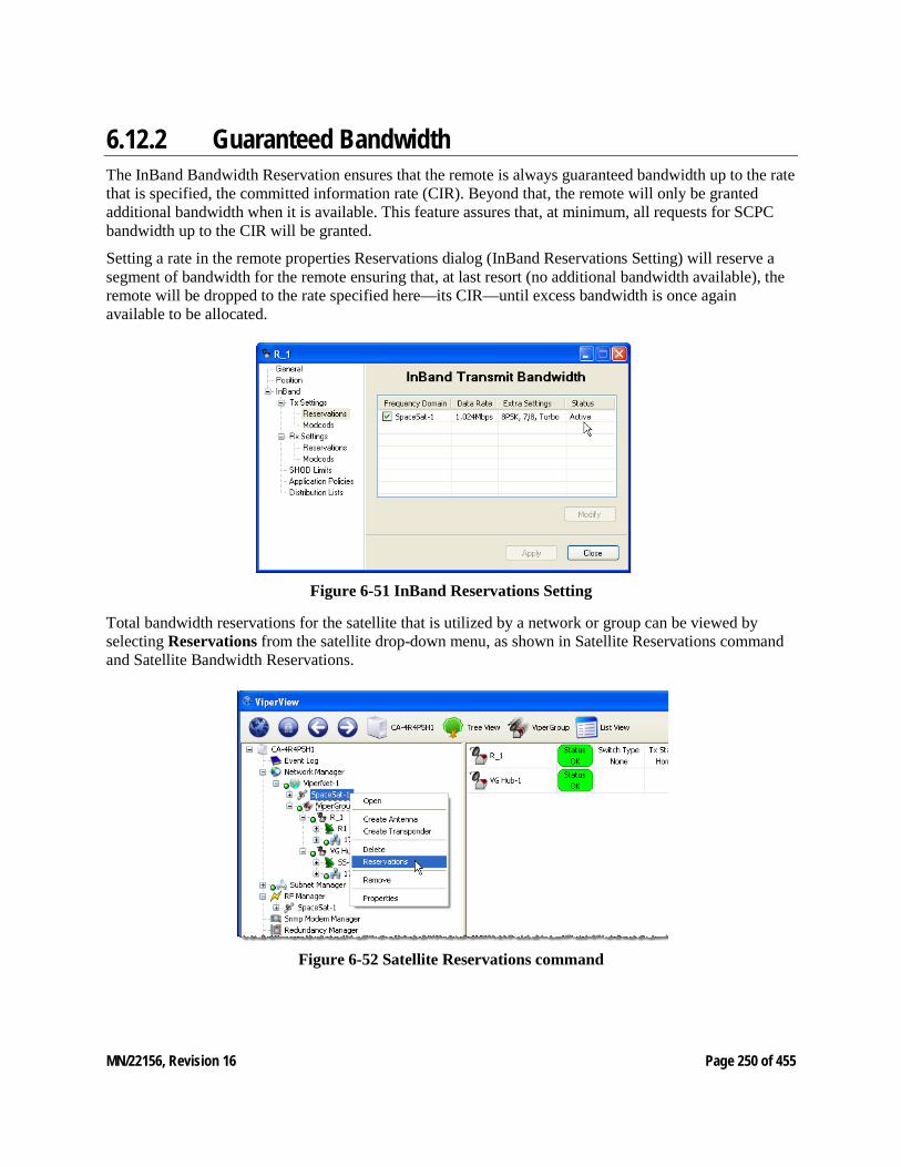
MN/22156, Revision 16 Page 250 of 455
6.12.2 Guaranteed Bandwidth The InBand Bandwidth Reservation ensures that the remote is always guaranteed bandwidth up to the rate that is specified, the committed information rate (CIR). Beyond that, the remote will only be granted additional bandwidth when it is available. This feature assures that, at minimum, all requests for SCPC bandwidth up to the CIR will be granted.
Setting a rate in the remote properties Reservations dialog (InBand Reservations Setting) will reserve a segment of bandwidth for the remote ensuring that, at last resort (no additional bandwidth available), the remote will be dropped to the rate specified here—its CIR—until excess bandwidth is once again available to be allocated.
Figure 6-51 InBand Reservations Setting
Total bandwidth reservations for the satellite that is utilized by a network or group can be viewed by selecting Reservations from the satellite drop-down menu, as shown in Satellite Reservations command and Satellite Bandwidth Reservations.
Figure 6-52 Satellite Reservations command
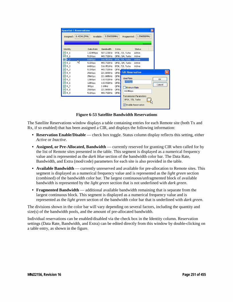
MN/22156, Revision 16 Page 251 of 455
Figure 6-53 Satellite Bandwidth Reservations
The Satellite Reservations window displays a table containing entries for each Remote site (both Tx and Rx, if so enabled) that has been assigned a CIR, and displays the following information:
• Reservation Enable/Disable — check box toggle. Status column display reflects this setting, either Active or Inactive.
• Assigned, or Pre-Allocated, Bandwidth — currently reserved for granting CIR when called for by the list of Remote sites presented in the table. This segment is displayed as a numerical frequency value and is represented as the dark blue section of the bandwidth color bar. The Data Rate, Bandwidth, and Extra (mod/code) parameters for each site is also provided in the table.
• Available Bandwidth — currently unreserved and available for pre-allocation to Remote sites. This segment is displayed as a numerical frequency value and is represented as the light green section (combined) of the bandwidth color bar. The largest continuous/unfragmented block of available bandwidth is represented by the light green section that is not underlined with dark green.
• Fragmented Bandwidth — additional available bandwidth remaining that is separate from the largest continuous block. This segment is displayed as a numerical frequency value and is represented as the light green section of the bandwidth color bar that is underlined with dark green.
The divisions shown in the color bar will vary depending on several factors, including the quantity and size(s) of the bandwidth pools, and the amount of pre-allocated bandwidth.
Individual reservations can be enabled/disabled via the check box in the Identity column. Reservation settings (Data Rate, Bandwidth, and Extra) can be edited directly from this window by double-clicking on a table entry, as shown in the figure.
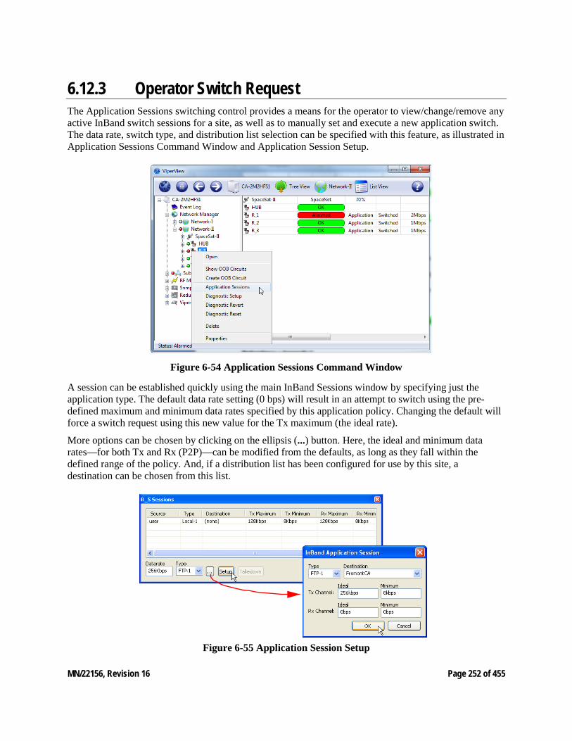
MN/22156, Revision 16 Page 252 of 455
6.12.3 Operator Switch Request The Application Sessions switching control provides a means for the operator to view/change/remove any active InBand switch sessions for a site, as well as to manually set and execute a new application switch. The data rate, switch type, and distribution list selection can be specified with this feature, as illustrated in Application Sessions Command Window and Application Session Setup.
Figure 6-54 Application Sessions Command Window
A session can be established quickly using the main InBand Sessions window by specifying just the application type. The default data rate setting (0 bps) will result in an attempt to switch using the pre-defined maximum and minimum data rates specified by this application policy. Changing the default will force a switch request using this new value for the Tx maximum (the ideal rate).
More options can be chosen by clicking on the ellipsis (...) button. Here, the ideal and minimum data rates—for both Tx and Rx (P2P)—can be modified from the defaults, as long as they fall within the defined range of the policy. And, if a distribution list has been configured for use by this site, a destination can be chosen from this list.
Figure 6-55 Application Session Setup
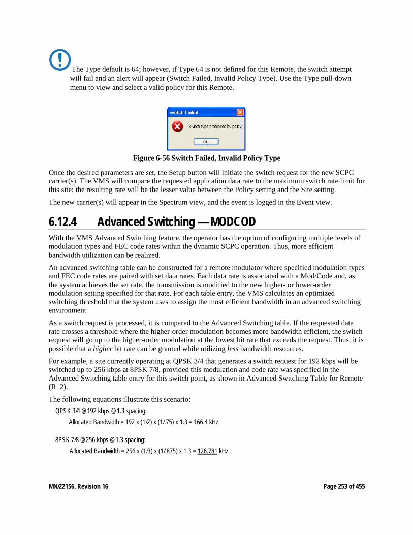
MN/22156, Revision 16 Page 253 of 455
The Type default is 64; however, if Type 64 is not defined for this Remote, the switch attempt will fail and an alert will appear (Switch Failed, Invalid Policy Type). Use the Type pull-down menu to view and select a valid policy for this Remote.
Figure 6-56 Switch Failed, Invalid Policy Type
Once the desired parameters are set, the Setup button will initiate the switch request for the new SCPC carrier(s). The VMS will compare the requested application data rate to the maximum switch rate limit for this site; the resulting rate will be the lesser value between the Policy setting and the Site setting.
The new carrier(s) will appear in the Spectrum view, and the event is logged in the Event view.
6.12.4 Advanced Switching — MODCOD With the VMS Advanced Switching feature, the operator has the option of configuring multiple levels of modulation types and FEC code rates within the dynamic SCPC operation. Thus, more efficient bandwidth utilization can be realized.
An advanced switching table can be constructed for a remote modulator where specified modulation types and FEC code rates are paired with set data rates. Each data rate is associated with a Mod/Code and, as the system achieves the set rate, the transmission is modified to the new higher- or lower-order modulation setting specified for that rate. For each table entry, the VMS calculates an optimized switching threshold that the system uses to assign the most efficient bandwidth in an advanced switching environment.
As a switch request is processed, it is compared to the Advanced Switching table. If the requested data rate crosses a threshold where the higher-order modulation becomes more bandwidth efficient, the switch request will go up to the higher-order modulation at the lowest bit rate that exceeds the request. Thus, it is possible that a higher bit rate can be granted while utilizing less bandwidth resources.
For example, a site currently operating at QPSK 3/4 that generates a switch request for 192 kbps will be switched up to 256 kbps at 8PSK 7/8, provided this modulation and code rate was specified in the Advanced Switching table entry for this switch point, as shown in Advanced Switching Table for Remote (R_2).
The following equations illustrate this scenario: QPSK 3/4 @192 kbps @1.3 spacing:
Allocated Bandwidth = 192 x (1/2) x (1/.75) x 1.3 = 166.4 kHz
8PSK 7/8 @256 kbps @1.3 spacing: Allocated Bandwidth = 256 x (1/3) x (1/.875) x 1.3 = 126.781 kHz
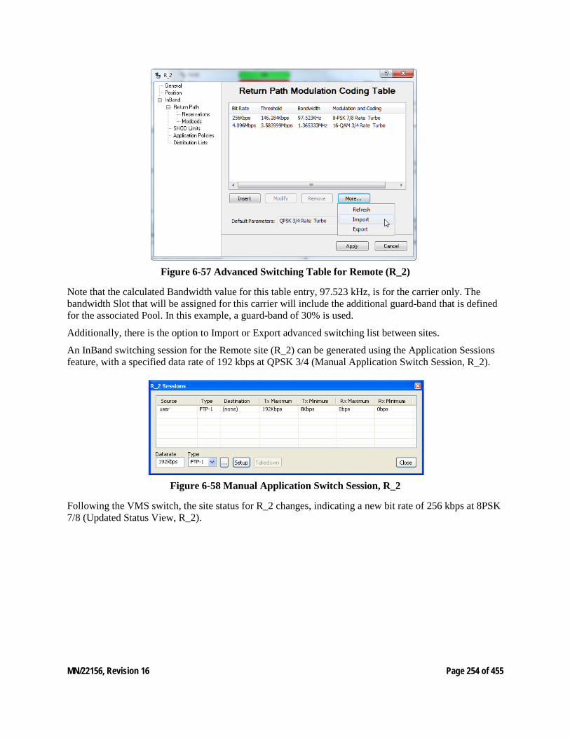
MN/22156, Revision 16 Page 254 of 455
Figure 6-57 Advanced Switching Table for Remote (R_2)
Note that the calculated Bandwidth value for this table entry, 97.523 kHz, is for the carrier only. The bandwidth Slot that will be assigned for this carrier will include the additional guard-band that is defined for the associated Pool. In this example, a guard-band of 30% is used.
Additionally, there is the option to Import or Export advanced switching list between sites.
An InBand switching session for the Remote site (R_2) can be generated using the Application Sessions feature, with a specified data rate of 192 kbps at QPSK 3/4 (Manual Application Switch Session, R_2).
Figure 6-58 Manual Application Switch Session, R_2
Following the VMS switch, the site status for R_2 changes, indicating a new bit rate of 256 kbps at 8PSK 7/8 (Updated Status View, R_2).
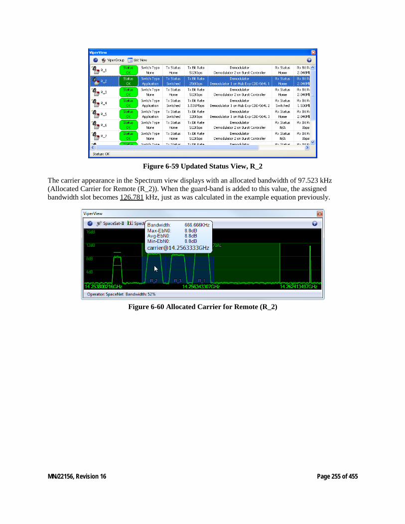
MN/22156, Revision 16 Page 255 of 455
Figure 6-59 Updated Status View, R_2
The carrier appearance in the Spectrum view displays with an allocated bandwidth of 97.523 kHz (Allocated Carrier for Remote (R_2)). When the guard-band is added to this value, the assigned bandwidth slot becomes 126.781 kHz, just as was calculated in the example equation previously.
Figure 6-60 Allocated Carrier for Remote (R_2)
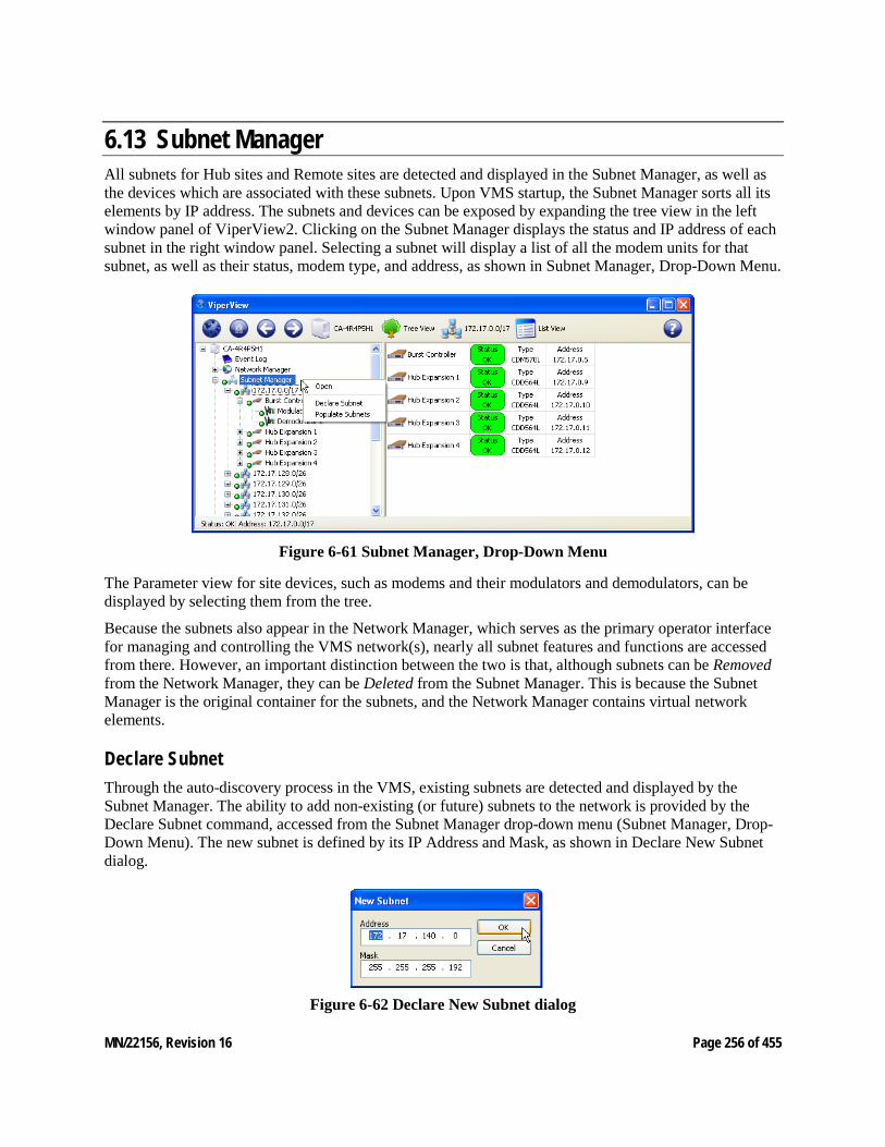
MN/22156, Revision 16 Page 256 of 455
6.13 Subnet Manager All subnets for Hub sites and Remote sites are detected and displayed in the Subnet Manager, as well as the devices which are associated with these subnets. Upon VMS startup, the Subnet Manager sorts all its elements by IP address. The subnets and devices can be exposed by expanding the tree view in the left window panel of ViperView2. Clicking on the Subnet Manager displays the status and IP address of each subnet in the right window panel. Selecting a subnet will display a list of all the modem units for that subnet, as well as their status, modem type, and address, as shown in Subnet Manager, Drop-Down Menu.
Figure 6-61 Subnet Manager, Drop-Down Menu
The Parameter view for site devices, such as modems and their modulators and demodulators, can be displayed by selecting them from the tree.
Because the subnets also appear in the Network Manager, which serves as the primary operator interface for managing and controlling the VMS network(s), nearly all subnet features and functions are accessed from there. However, an important distinction between the two is that, although subnets can be Removed from the Network Manager, they can be Deleted from the Subnet Manager. This is because the Subnet Manager is the original container for the subnets, and the Network Manager contains virtual network elements.
Declare Subnet Through the auto-discovery process in the VMS, existing subnets are detected and displayed by the Subnet Manager. The ability to add non-existing (or future) subnets to the network is provided by the Declare Subnet command, accessed from the Subnet Manager drop-down menu (Subnet Manager, Drop-Down Menu). The new subnet is defined by its IP Address and Mask, as shown in Declare New Subnet dialog.
Figure 6-62 Declare New Subnet dialog
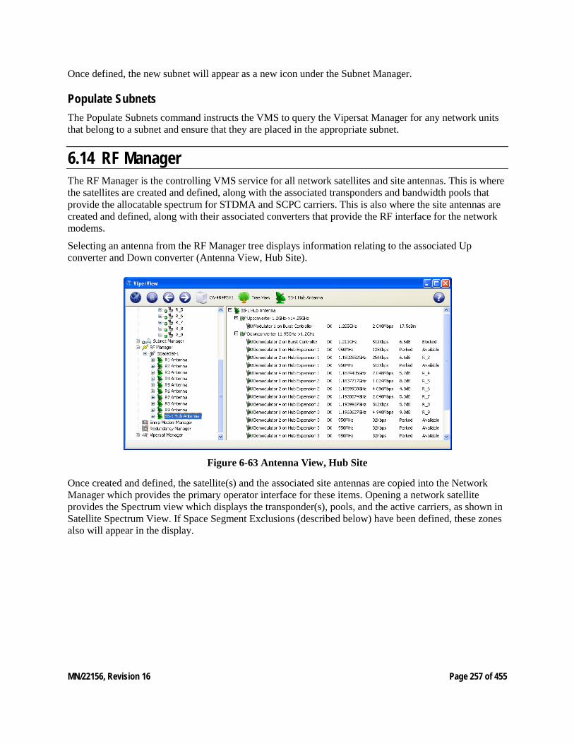
MN/22156, Revision 16 Page 257 of 455
Once defined, the new subnet will appear as a new icon under the Subnet Manager.
Populate Subnets The Populate Subnets command instructs the VMS to query the Vipersat Manager for any network units that belong to a subnet and ensure that they are placed in the appropriate subnet.
6.14 RF Manager The RF Manager is the controlling VMS service for all network satellites and site antennas. This is where the satellites are created and defined, along with the associated transponders and bandwidth pools that provide the allocatable spectrum for STDMA and SCPC carriers. This is also where the site antennas are created and defined, along with their associated converters that provide the RF interface for the network modems.
Selecting an antenna from the RF Manager tree displays information relating to the associated Up converter and Down converter (Antenna View, Hub Site).
Figure 6-63 Antenna View, Hub Site
Once created and defined, the satellite(s) and the associated site antennas are copied into the Network Manager which provides the primary operator interface for these items. Opening a network satellite provides the Spectrum view which displays the transponder(s), pools, and the active carriers, as shown in Satellite Spectrum View. If Space Segment Exclusions (described below) have been defined, these zones also will appear in the display.
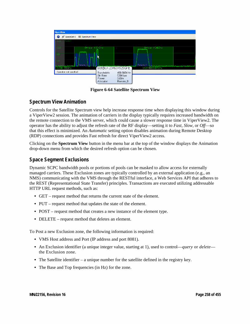
MN/22156, Revision 16 Page 258 of 455
Figure 6-64 Satellite Spectrum View
Spectrum View Animation Controls for the Satellite Spectrum view help increase response time when displaying this window during a ViperView2 session. The animation of carriers in the display typically requires increased bandwidth on the remote connection to the VMS server, which could cause a slower response time in ViperView2. The operator has the ability to adjust the refresh rate of the RF display—setting it to Fast, Slow, or Off—so that this effect is minimized. An Automatic setting option disables animation during Remote Desktop (RDP) connections and provides Fast refresh for direct ViperView2 access.
Clicking on the Spectrum View button in the menu bar at the top of the window displays the Animation drop-down menu from which the desired refresh option can be chosen.
Space Segment Exclusions Dynamic SCPC bandwidth pools or portions of pools can be masked to allow access for externally managed carriers. These Exclusion zones are typically controlled by an external application (e.g., an NMS) communicating with the VMS through the RESTful interface, a Web Services API that adheres to the REST (Representational State Transfer) principles. Transactions are executed utilizing addressable HTTP URL request methods, such as:
• GET – request method that returns the current state of the element.
• PUT – request method that updates the state of the element.
• POST – request method that creates a new instance of the element type.
• DELETE – request method that deletes an element.
To Post a new Exclusion zone, the following information is required:
• VMS Host address and Port (IP address and port 8081).
• An Exclusion identifier (a unique integer value, starting at 1), used to control—query or delete—the Exclusion zone.
• The Satellite identifier – a unique number for the satellite defined in the registry key.
• The Base and Top frequencies (in Hz) for the zone.
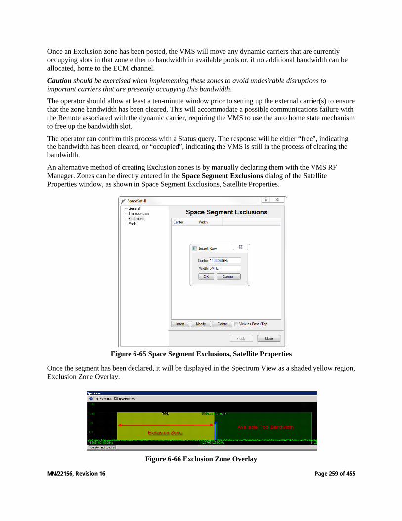
MN/22156, Revision 16 Page 259 of 455
Once an Exclusion zone has been posted, the VMS will move any dynamic carriers that are currently occupying slots in that zone either to bandwidth in available pools or, if no additional bandwidth can be allocated, home to the ECM channel.
Caution should be exercised when implementing these zones to avoid undesirable disruptions to important carriers that are presently occupying this bandwidth.
The operator should allow at least a ten-minute window prior to setting up the external carrier(s) to ensure that the zone bandwidth has been cleared. This will accommodate a possible communications failure with the Remote associated with the dynamic carrier, requiring the VMS to use the auto home state mechanism to free up the bandwidth slot.
The operator can confirm this process with a Status query. The response will be either “free”, indicating the bandwidth has been cleared, or “occupied”, indicating the VMS is still in the process of clearing the bandwidth.
An alternative method of creating Exclusion zones is by manually declaring them with the VMS RF Manager. Zones can be directly entered in the Space Segment Exclusions dialog of the Satellite Properties window, as shown in Space Segment Exclusions, Satellite Properties.
Figure 6-65 Space Segment Exclusions, Satellite Properties
Once the segment has been declared, it will be displayed in the Spectrum View as a shaded yellow region, Exclusion Zone Overlay.
Figure 6-66 Exclusion Zone Overlay
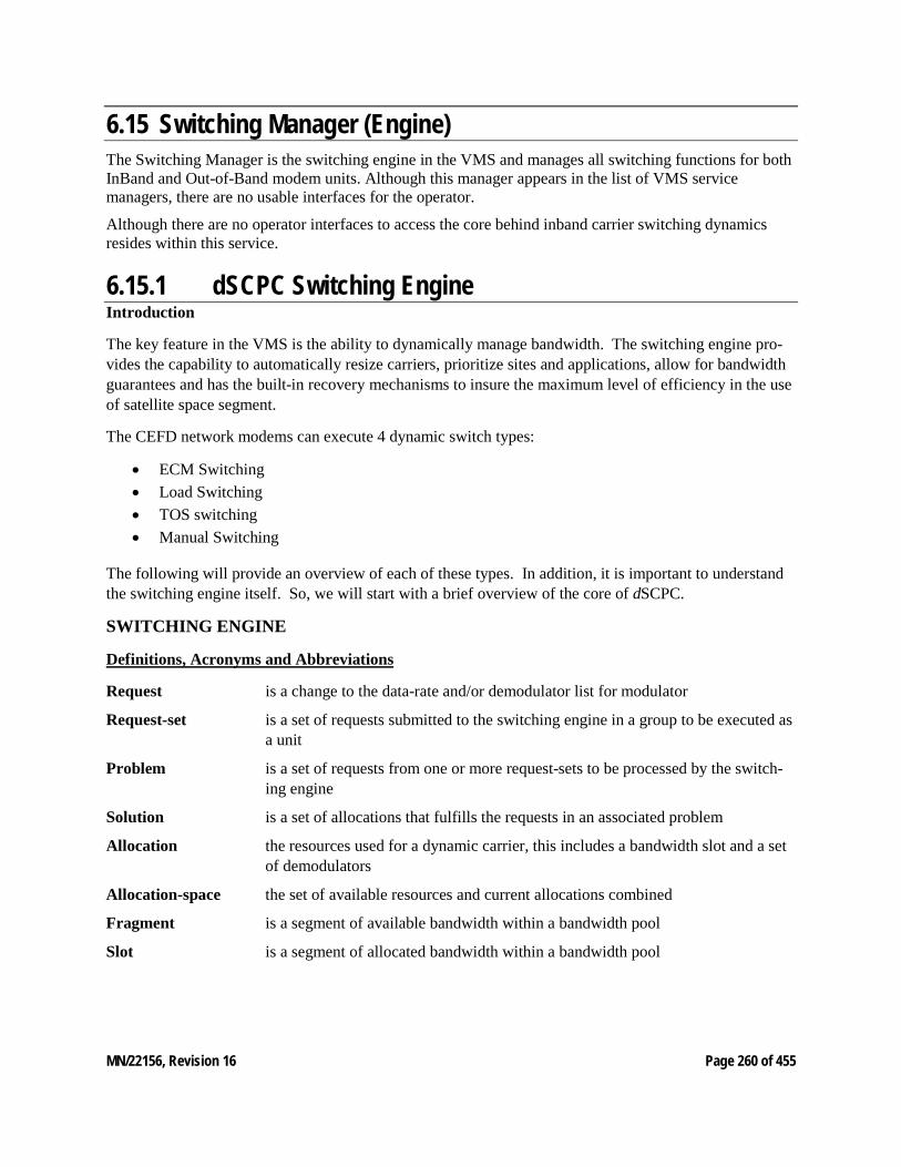
MN/22156, Revision 16 Page 260 of 455
6.15 Switching Manager (Engine) The Switching Manager is the switching engine in the VMS and manages all switching functions for both InBand and Out-of-Band modem units. Although this manager appears in the list of VMS service managers, there are no usable interfaces for the operator.
Although there are no operator interfaces to access the core behind inband carrier switching dynamics resides within this service.
6.15.1 dSCPC Switching Engine Introduction
The key feature in the VMS is the ability to dynamically manage bandwidth. The switching engine pro-vides the capability to automatically resize carriers, prioritize sites and applications, allow for bandwidth guarantees and has the built-in recovery mechanisms to insure the maximum level of efficiency in the use of satellite space segment.
The CEFD network modems can execute 4 dynamic switch types:
• ECM Switching • Load Switching • TOS switching • Manual Switching
The following will provide an overview of each of these types. In addition, it is important to understand the switching engine itself. So, we will start with a brief overview of the core of dSCPC.
SWITCHING ENGINE
Definitions, Acronyms and Abbreviations
Request is a change to the data-rate and/or demodulator list for modulator
Request-set is a set of requests submitted to the switching engine in a group to be executed as a unit
Problem is a set of requests from one or more request-sets to be processed by the switch-ing engine
Solution is a set of allocations that fulfills the requests in an associated problem
Allocation the resources used for a dynamic carrier, this includes a bandwidth slot and a set of demodulators
Allocation-space the set of available resources and current allocations combined
Fragment is a segment of available bandwidth within a bandwidth pool
Slot is a segment of allocated bandwidth within a bandwidth pool
MN/22156, Revision 16 Page 261 of 455
Overall Description
The switching engine is a core component of the Switching Subsystem in the VMS responsible for ac-cepting data-rate change requests for a modulator, determining resource availability and coordinating the reconfiguration of devices to fulfill those requests.
The engine interacts with its environment through a set of abstract interfaces. This allows the engine to work with different types of carriers (in-band and out-of-band), and hardware devices (all devices that VMS currently has M&C support for) without specific knowledge of those components. This has the ad-vantage that in theory the engine could transparently work with new devices types and switch types (i.e. Heights Modems).
The engine depends on other components of the system in order to fulfill its role. It depends on device drivers to provide information about limits to perform operations based on device specifications (i.e. cal-culating bandwidth or power required given a set of transmission parameters). It depends on the band-width manager (RF manager) to perform frequency calculations and track device visibility. It also de-pends on switching state objects to interface with external clients and translate results of solutions into switch type specific command structures for the modem drivers to use for sending commands to the actual hardware.
COMPONENTS
Allocation Space
The allocation space is the component that manages the switching functionality for a satellite. It maintains the satellites available resources. It tracks allocations and pre-allocations. It hosts all the queuing func-tionality and it is also the entry point for switch requests to be processed by the engine. Each allocation space executes operations in parallel (assuming available processing resources).
Queuing Structure
The queuing structure refers to the mechanisms necessary to prevent incoming requests for conflicting with each other. In addition to preventing conflicts, it will group and/or skip requests to improve perfor-mance in active networks. Request sets combine to form problems which are fed to the solver to generate solutions which are then implemented (sent to hardware). The queuing structure is multiple layers that track different aspects of the pending requests.
The first layer is comprised of the individual switch requests posted to the allocation space. There is a separate queue for each allocator which is identified by the transmitting modulator. This queue gives the engine a view on the future progression of an individual carrier as it is processed.
The second layer is comprised of the request(s) sets posted to the allocation space. This queue stores the request(s) sets in chronological order and is used to relinquish sets as close as possible to the order in which they were posted.
The third layer is the problem queue. This is a dependency queue that acts to combine request sets togeth-er to be processed as a unit. This queue allows the engine to gang requests together while maintaining that each set is processed as a unit.
The fourth layer is the solution queue. This is another dependency queue, which ensures that solutions that may have conflicts with proceeding solutions wait for their turn, possibility throwing them away if problems occur with dependencies.
MN/22156, Revision 16 Page 262 of 455
Allocation Algorithm
The allocation algorithm's goal is to come up with a set of allocations for a set of requests given as input. As part of this work, it may require the manipulation of allocations for entities that were not originally part of the set of requests.
The algorithm operates in three broad phases. The first phase checks whether the request should even be pursued. The second phase consists of a series of passes over the problem attempting to place the requests in a manner that minimizes impact on existing carriers. In the final phase, the system falls back to a known solution that provides at minimum the configured guaranteed data-rate (CIR).
The Allocation Algorithm attempts to minimally affect the carriers in the bandwidth pools. It does this by using a Minimal Impact Solver. The goal of the minimal impact solver is to produce a solution that has the least impact on the system. Generally, minimal impact means fewest additional carriers involved, though a carrier’s priority, and the amount that it is over its guaranteed rate are also factors.
During evaluation, the rule for reducing a carrier’s bandwidth involves priorities and the guaranteed-rate for the involved sites. Given two carriers, the carrier with the highest priority will reduce the lower priori-ty carrier as far as needed for the higher priority carrier to fulfill its needs to the extent that the lower pri-ority is using bandwidth above its guaranteed rate. Therefore, if a higher priority carrier requires the lower priority carrier to be reduced below its guaranteed rate to fulfill its request, the higher priority carriers request rate will be reduced enough to allow the lower priority carrier to maintain its guaranteed rate. If neither carrier retains its guaranteed rate, the placement is invalid, and another approach must be taken.
Communication Failure
In the case of communications failures (e.g. environment, interference and hardware breakdown) within the network, the rate guarantee cannot be maintained. When the system detects failures, it enters a state of recovery that attempts to return faulting remotes to a known state removing possible contention within the resource pool. During this recovery mode normal switching can continue. Resources occupied by faulting remotes are unavailable and rate guarantees potentially are not honored. Once all faulting remotes are re-covered or identified through failure state analysis the rate guarantees are once again honored. The band-width from this point is once again available for continued allocations.
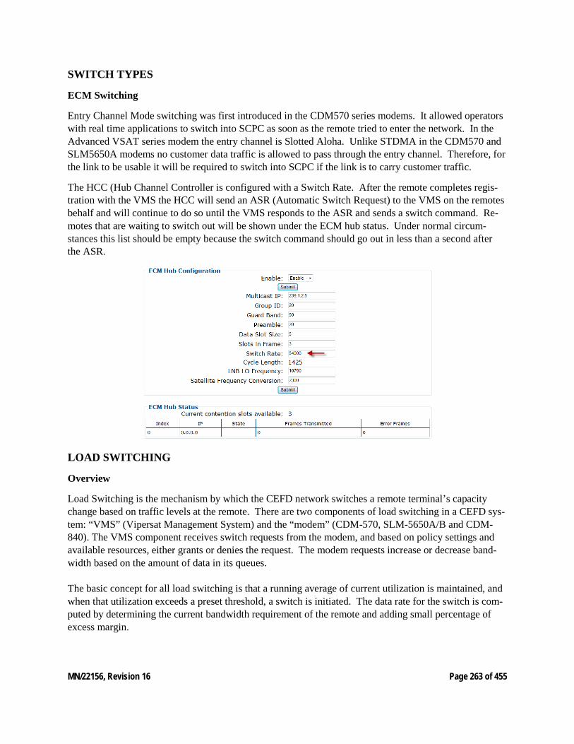
MN/22156, Revision 16 Page 263 of 455
SWITCH TYPES
ECM Switching
Entry Channel Mode switching was first introduced in the CDM570 series modems. It allowed operators with real time applications to switch into SCPC as soon as the remote tried to enter the network. In the Advanced VSAT series modem the entry channel is Slotted Aloha. Unlike STDMA in the CDM570 and SLM5650A modems no customer data traffic is allowed to pass through the entry channel. Therefore, for the link to be usable it will be required to switch into SCPC if the link is to carry customer traffic.
The HCC (Hub Channel Controller is configured with a Switch Rate. After the remote completes regis-tration with the VMS the HCC will send an ASR (Automatic Switch Request) to the VMS on the remotes behalf and will continue to do so until the VMS responds to the ASR and sends a switch command. Re-motes that are waiting to switch out will be shown under the ECM hub status. Under normal circum-stances this list should be empty because the switch command should go out in less than a second after the ASR.
LOAD SWITCHING
Overview
Load Switching is the mechanism by which the CEFD network switches a remote terminal’s capacity change based on traffic levels at the remote. There are two components of load switching in a CEFD sys-tem: “VMS” (Vipersat Management System) and the “modem” (CDM-570, SLM-5650A/B and CDM-840). The VMS component receives switch requests from the modem, and based on policy settings and available resources, either grants or denies the request. The modem requests increase or decrease band-width based on the amount of data in its queues. The basic concept for all load switching is that a running average of current utilization is maintained, and when that utilization exceeds a preset threshold, a switch is initiated. The data rate for the switch is com-puted by determining the current bandwidth requirement of the remote and adding small percentage of excess margin.
MN/22156, Revision 16 Page 264 of 455
Functional Description
Load switching is accomplished by maintaining a running average of the data traffic passing over the WAN. The running average is maintained as a percentage of the current Data Rate. Whenever a switch in data rate occurs, that running average is cleared and must accumulate for at least the specified delay period before another switch can occur. After the specified delay period is reached, once a second, the system checks the current utilization against the step up and step-down thresholds and if the utilization is outside the desired range, the system requests a switch with the new calculated rate. After request is granted, the running average is reset and accumulated for the specified period. If at the end of the delay period, the utilization is still out of range, a switch is requested again, using the re-computed utilization adjust by the excess capacity. The user defines both Step Up and Step-Down threshold in terms of percent utilization, a bandwidth mar-gin value, and a latency or averaging period. Once per second, the modem software determines the cur-rent percent utilization by dividing the bits transmitted by the current transmit data rate. If the percent utilization exceeds the step-up threshold or is less than the step-down threshold for the entire latency peri-od, then an ASR (Automatic Switch Request) is sent to the VMS. The bandwidth requirement for the ASR is computed by taking the average percent utilization over the latency period and multiplying that by the current data rate to determine the actual data rate used over the measured interval. This number is multiplied by the margin value and rounded up to the nearest 8K to determine the requested bandwidth. Step Up Delay:
This delay time is simply when the traffic exceeds the step-up threshold percentage for greater than the specified time; the system generates a switch request at calculated rate. Step Down Delay:
When the system check indicates that current utilization is below the step-down threshold, a timer is set for specified delay period. Unlike step up, which restarts the running average, during the step-down wait period, the utilization statistics continue to accumulate. This is because the expected longer time period of the step-down delay allows a more accurate estimate of utilization. If the step-down condition remains at the end of the wait period, the switch is requested, using the current utilization as the basis of the data rate request. The step-down time delay also provides a major improvement in MOS (Mean Opinion Scores) calculations as it allows the system to flush-out spurious switching events due to short dips in traffic flows. Allowing a longer step-down delay will greatly reduce the amount of traffic interruptions based on excess switch down and back up transitions. It will also reduce the overall dSCPC switch interruptions between all remotes in the network. Step-up Excess:
This is an excess amount of bandwidth that is allocated beyond the calculated traffic rate and is added to each switch request. For example, if the current average traffic at the time of the switch is 60K, and the Percent Allocation is 10%, then the allocation will be for 60K + 6K = 66K. This excess assures that the next allocated rate falls within (between) the step up and step-down thresholds allowing for next accumu-lated rates to establish, also reducing unnecessary switching events.
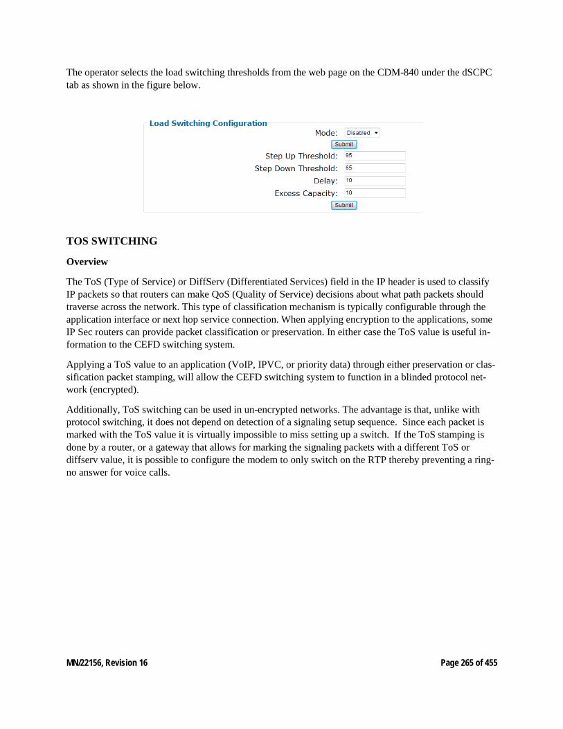
MN/22156, Revision 16 Page 265 of 455
The operator selects the load switching thresholds from the web page on the CDM-840 under the dSCPC tab as shown in the figure below.
TOS SWITCHING
Overview
The ToS (Type of Service) or DiffServ (Differentiated Services) field in the IP header is used to classify IP packets so that routers can make QoS (Quality of Service) decisions about what path packets should traverse across the network. This type of classification mechanism is typically configurable through the application interface or next hop service connection. When applying encryption to the applications, some IP Sec routers can provide packet classification or preservation. In either case the ToS value is useful in-formation to the CEFD switching system.
Applying a ToS value to an application (VoIP, IPVC, or priority data) through either preservation or clas-sification packet stamping, will allow the CEFD switching system to function in a blinded protocol net-work (encrypted).
Additionally, ToS switching can be used in un-encrypted networks. The advantage is that, unlike with protocol switching, it does not depend on detection of a signaling setup sequence. Since each packet is marked with the ToS value it is virtually impossible to miss setting up a switch. If the ToS stamping is done by a router, or a gateway that allows for marking the signaling packets with a different ToS or diffserv value, it is possible to configure the modem to only switch on the RTP thereby preventing a ring-no answer for voice calls.

MN/22156, Revision 16 Page 266 of 455
Functional Description
• The table to manage the ToS switches is split in two; one to hold the “static” data for each ToS ID and another with is a pool of dynamic entries to hold the Destination IP of active streams and the time stamp for the last packet that was seen. The dynamic pool is shared across all ToS IDs.
• The number of entries in the static table is 64. A ToS value is considered active if any of the Des-tination IP’s (see table below) are non-zero. This also means that its index pointer is non-zero. If a ToS ID has active sessions, it cannot be deleted from the table.
• The “Time of Last Packet” and “Destination IP” fields are added to a dynamic pool. The buffer count is currently set to 128. (Actually 127 since the 1st entry is unavailable for use.) This means there can be a total of up to 127 active sessions at any one time.
• When an IP Packet with a ToS value other than 0 is detected, the static table entry for that value is checked. If the flag field is set (i.e. the operator specified switching enable for that value, the buffer pool chain is walked for a match on the Destination IP of the packet. If a match is found, the Time of Last Packet is updated for that entry. If no match is found and there is room in the pool and the limit has not been reached for this ToS ID, then a new entry is allocated, and the Destination IP is set for that entry and a switch request is sent to VMS. The Session ID (cookie) in the request is equal to the index of the entry within the overall pool.
• The Switch Data Rate is the same for all destinations for specified ToS value. It is expected that VMS keeps track of the session ID and will add or subtract the specified bandwidth from an ex-isting switch for new setups or teardowns.
• Since the time of last Packet is maintained by address, the background loop must check all entries in the table in order to test for timeouts.
• The menu to display the ToS table provides the following information for each selected ToS value: o ToS ID (1 – 63) o VMS Switch Type o Switch Data Rate o Timeout Period
Also, for each active session, the IP Address of the destination and the time since the last packet was re-ceived are displayed, with up to two entries per line (in order to save screen space.)
Note that once a switch is set up, its location in the table remains fixed so the session id remains the same and can be used for the teardown. If the same destination is later set up again, it may occupy a different location in the table; but again, it remains fixed for the duration of the session.
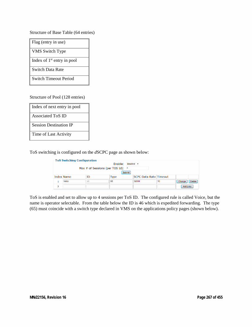
MN/22156, Revision 16 Page 267 of 455
Structure of Base Table (64 entries)
Flag (entry in use)
VMS Switch Type
Index of 1st entry in pool
Switch Data Rate
Switch Timeout Period
Structure of Pool (128 entries)
Index of next entry in pool
Associated ToS ID
Session Destination IP
Time of Last Activity
ToS switching is configured on the dSCPC page as shown below:
ToS is enabled and set to allow up to 4 sessions per ToS ID. The configured rule is called Voice, but the name is operator selectable. From the table below the ID is 46 which is expedited forwarding. The type (65) must coincide with a switch type declared in VMS on the applications policy pages (shown below).
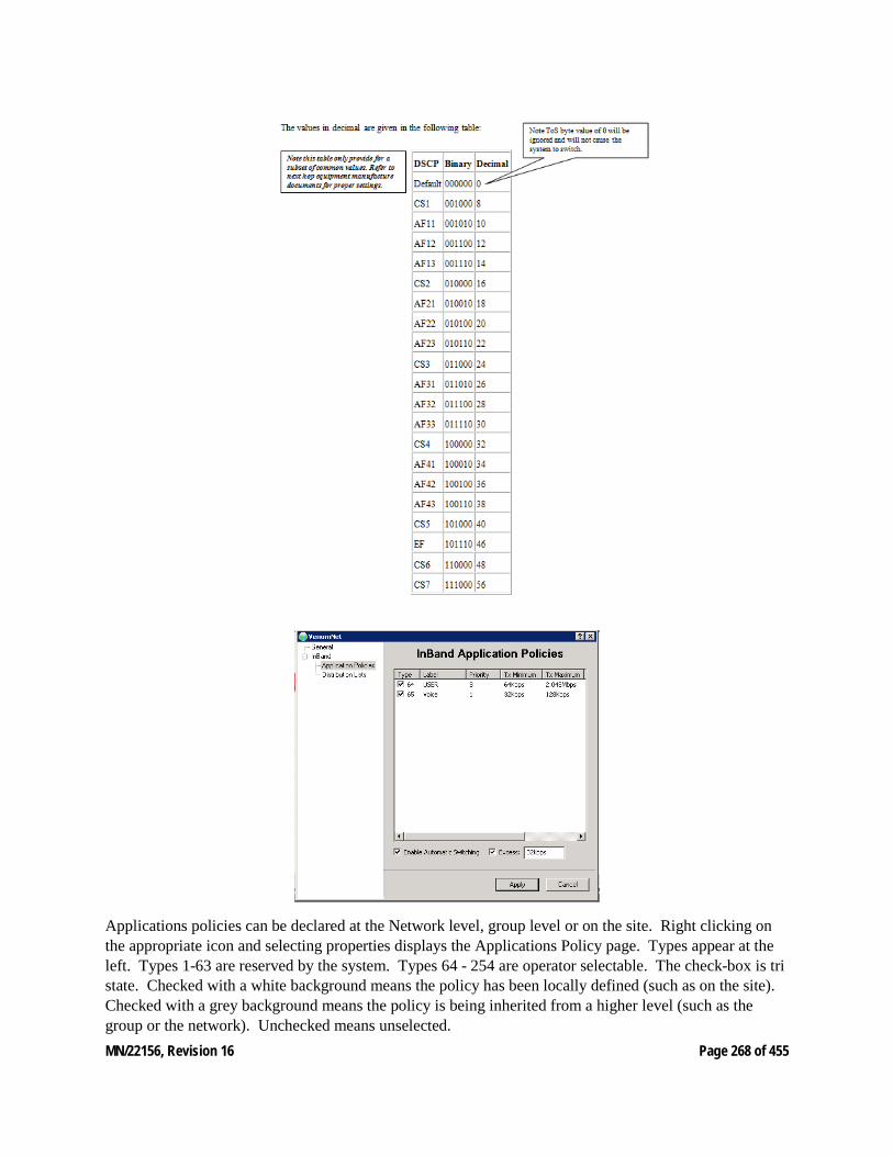
MN/22156, Revision 16 Page 268 of 455
Applications policies can be declared at the Network level, group level or on the site. Right clicking on the appropriate icon and selecting properties displays the Applications Policy page. Types appear at the left. Types 1-63 are reserved by the system. Types 64 - 254 are operator selectable. The check-box is tri state. Checked with a white background means the policy has been locally defined (such as on the site). Checked with a grey background means the policy is being inherited from a higher level (such as the group or the network). Unchecked means unselected.

MN/22156, Revision 16 Page 269 of 455
The label is user defined. Priority for the application is compared with site priority. The lowest of the two (lowest number has highest priority) is used for making switching decisions. Each defined type has a minimum and maximum bit rate. For ToS switching a rate is defined in the modem and sent with the ASR. For switches where no rate is included in the ASR the VMS will switch up at the policy maximum if there is available bandwidth to support it and will downsize toward the minimum in order to honor bandwidth guarantees.
Manual Switching
Sometimes it is desirable to be able to set up dSCPC carriers manually. VMS allows for establishment of 2 types of manual switching: Diagnostic and Manual Applications setup.
Diagnostic Switching
Diagnostic switching is used mostly for troubleshooting issues with other types of automatic switching. It has special rules. The VMS will not downsize or revert a diagnostic switch. Therefore, while diagnostic switches are in the allocation space, guaranteed bandwidth is disabled. Care should be taken not to leave diagnostic switches up in the bandwidth pool for this reason.
Diagnostic switches can be performed by right clicking on the site icon and selecting Diagnostic. A Dia-log box will open allowing the operator to select a bit rate for the switch. Clicking on the Extra button will allow the operator to select Modulation and FEC Type as shown below.
Manual Applications Switching
Manual Applications switching allows the operator to set up a manual switch with a predefined switch type. Any of the defined switch types can be selected. These switches do follow the rules for guaranteed bandwidth. Therefore, they are safer and less disruptive than the Diagnostic switch. Right clicking on the site icon brings up a dialog for Applications Switching.
From this dialog the user can select a data rate. If it is left at 0 bps the VMS will attempt to switch at the maximum for the type depending on priority and available bandwidth. By highlighting the session, the user can take down the switch.
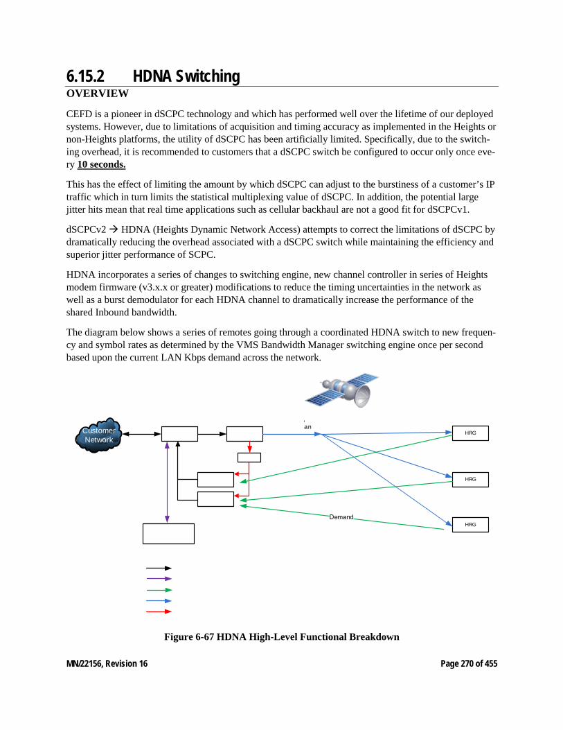
MN/22156, Revision 16 Page 270 of 455
6.15.2 HDNA Switching OVERVIEW
CEFD is a pioneer in dSCPC technology and which has performed well over the lifetime of our deployed systems. However, due to limitations of acquisition and timing accuracy as implemented in the Heights or non-Heights platforms, the utility of dSCPC has been artificially limited. Specifically, due to the switch-ing overhead, it is recommended to customers that a dSCPC switch be configured to occur only once eve-ry 10 seconds.
This has the effect of limiting the amount by which dSCPC can adjust to the burstiness of a customer’s IP traffic which in turn limits the statistical multiplexing value of dSCPC. In addition, the potential large jitter hits mean that real time applications such as cellular backhaul are not a good fit for dSCPCv1.
dSCPCv2 HDNA (Heights Dynamic Network Access) attempts to correct the limitations of dSCPC by dramatically reducing the overhead associated with a dSCPC switch while maintaining the efficiency and superior jitter performance of SCPC.
HDNA incorporates a series of changes to switching engine, new channel controller in series of Heights modem firmware (v3.x.x or greater) modifications to reduce the timing uncertainties in the network as well as a burst demodulator for each HDNA channel to dramatically increase the performance of the shared Inbound bandwidth.
The diagram below shows a series of remotes going through a coordinated HDNA switch to new frequen-cy and symbol rates as determined by the VMS Bandwidth Manager switching engine once per second based upon the current LAN Kbps demand across the network.
Customer Network
HRG
HRG
HRG
, an
Figure 6-67 HDNA High-Level Functional Breakdown
MN/22156, Revision 16 Page 271 of 455
This dSCPC enhanced technology increases return path efficiencies by:
• Rapidly adapts to changing environments • Instantly assigns capacity based on network-wide demand • Intelligently always utilizes total network bandwidth • Sub-second reaction time to changing traffic demand and link conditions • HDNA controller receives real-time traffic demand from all remotes in the network:
o Network wide Traffic Demand o Es/No and Link Conditions o Multi-tier QoS per queue
• On a one-second period, HDNA controller distributes a new plan • At the start of the next time period, all devices execute the new plan
The HDNA Channel Controller, is another component of the switching engine. It integrates into the dSCPC switching logic, to convert demand reports into channel plans based on quality of service, re-source, environmental and hardware constraints.
HDNA Channel Controller Module
The term "Channel" in "Channel Controller" refers to the set of hardware working in concert to pass cus-tomer traffic statistics from the remote back to the hub using a dedicated set of hardware and satellite re-sources. It is made up of the "Channel Controller", "Channel Device", "Allocable Devices" and "Allocator Devices".
These concepts map to physical entities as follows:
• Channel Controller VMS server • Channel Device HTO • Allocable Devices Individual demodulators in an HRX • Allocator Devices Modulator in each HRG
The channel device is the point of interface between the channel controller, and the allocator devices in the channel. The allocatable devices collects demand data from the allocator devices and link quality met-rics from the allocable devices and forwards it to the channel controller. The channel controller processes this data and produces a channel plan that is sent back to the channel device. The channel device then dis-tributes the plan to the allocator and allocable devices.
A demand report identifies the necessary LAN rate needed to drain each QOS queue on each remote in the channel. It also includes compression estimates and link quality metrics, specifically those related spectral efficiency degradation due to environmental conditions.
The channel plan message specifies for a single cycle what each component involved in the channel should be doing. It specifies the transmit and receive parameters the allocator and allocable devices should be tuned to respectively. It also specifies for the cycle how QOS should drain its queues.
The channel controller coordinates configuration and execution of the channel processor, QOS calculator, and placement algorithms. It interfaces with external components to collect configuration details and di-rect requests. The channel processor maintains the state for the channel and has the top-level procedure for producing a channel plan from demand information.

MN/22156, Revision 16 Page 272 of 455
The QOS calculator take demands and produces a set of assignments. The placement algorithm takes a set of resource requests and places them into the bandwidth pool with an appropriate demodulator.
From Demand Report to Channel Plan within the VMS, processing flows from receipt of a demand report to generation of a channel plan except for entry of the first remote into the channel. In this case, a switch request is received, and a demand report is synthesized within the channel controller to get the loop start-ed. The entire process starts and ends with the CEFD Network Interface (VNI). This component provides an interface to the CEFD management protocol and multi-command message protocols that are used to transport demand reports and channel plans, respectively.
Each fragment of the demand report lands in the VNI and is forwarded to the demand collector by source IP address. Once all the fragments of the demand report have been received, an unprocessed demand re-port is sent the channel controller.
The channel process moves the demand report from the VNI's threading context into the channel proces-sors threading context and gives it to the demand processor for additional hardware specific processing.
Once complete, the demand processor gives the demand report back to the channel processor which im-mediately passes it to its channel processor.
The channel processor starts by applying the demand report to its internal state map. This will record the demand for remotes that successfully acquired or increment the consecutive missed ack counter for those that did not. If a remote's missed ack counter exceeds the threshold it is marked for removal from the map. With the internal state up to date, the channel processor begins generation of the channel plan by collecting the last known demands for remotes still in the channel into an intermediate state structure. This is used throughout the operation to track details about each remote during plan generation.
Next, the QOS calculator is run to determine the how many symbols each remote is entitled to be based on the QOS rules. This results in a set of QoS drain assignments and the number of symbols needed to drain those assignments. This starts with the amount of available bandwidth and as such, the sum of all symbol allocations will be less than the number of available symbols in the pool. The QOS calculator also allocates any "excess" QOS drain capacity proportionally. For additional details, see the QOS algorithm document.
The channel processor takes the list of QOS assignments and produces a set of placement requests. This involves a couple steps. The first is to sum the symbol rate assignments for QOS groups subset per remote to come up with the symbol rate. Then symbol rate limits are applied. Finally, any remaining symbols that where not needed to fulfill the QOS assignments is distributed. A fraction of the remaining symbols are distributed evenly, with the other fraction distributed proportionally.
With the placement requests ready, the channel processor calls on the placement algorithm to assign bandwidth and demodulators to each remote. This algorithm is responsible for optimizing placement of carriers, while respecting bandwidth visibility constraints and demodulator capability, compatibility, and availability constraints.
Once placement is complete, the channel processor combines the carrier placements with the QOS as-signments from the QOS calculation into an abstract channel plan. This plan is then handed off to the hardware specific map generator. The map generator formats channel plan fragments, consulting the pro-tocol processor state for certain details, and send the formatted plan back to VNI to be sent to the channel device. For more detailed information refer to HDNA operational manuals.
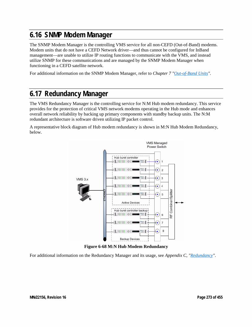
MN/22156, Revision 16 Page 273 of 455
6.16 SNMP Modem Manager The SNMP Modem Manager is the controlling VMS service for all non-CEFD (Out-of-Band) modems. Modem units that do not have a CEFD Network driver—and thus cannot be configured for InBand management—are unable to utilize IP routing functions to communicate with the VMS, and instead utilize SNMP for these communications and are managed by the SNMP Modem Manager when functioning in a CEFD satellite network.
For additional information on the SNMP Modem Manager, refer to Chapter 7 "Out-of-Band Units".
6.17 Redundancy Manager The VMS Redundancy Manager is the controlling service for N:M Hub modem redundancy. This service provides for the protection of critical VMS network modems operating in the Hub mode and enhances overall network reliability by backing up primary components with standby backup units. The N:M redundant architecture is software driven utilizing IP packet control.
A representative block diagram of Hub modem redundancy is shown in M:N Hub Modem Redundancy, below.
Figure 6-68 M:N Hub Modem Redundancy
For additional information on the Redundancy Manager and its usage, see Appendix C, "Redundancy".
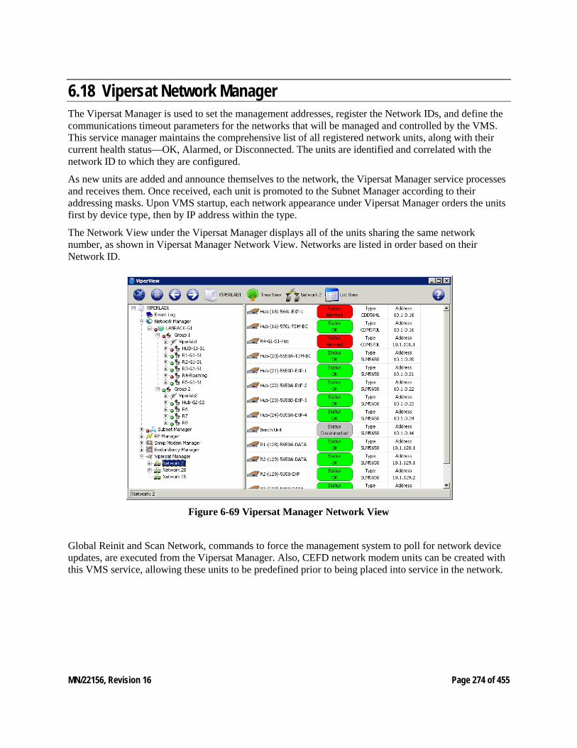
MN/22156, Revision 16 Page 274 of 455
6.18 Vipersat Network Manager The Vipersat Manager is used to set the management addresses, register the Network IDs, and define the communications timeout parameters for the networks that will be managed and controlled by the VMS. This service manager maintains the comprehensive list of all registered network units, along with their current health status—OK, Alarmed, or Disconnected. The units are identified and correlated with the network ID to which they are configured.
As new units are added and announce themselves to the network, the Vipersat Manager service processes and receives them. Once received, each unit is promoted to the Subnet Manager according to their addressing masks. Upon VMS startup, each network appearance under Vipersat Manager orders the units first by device type, then by IP address within the type.
The Network View under the Vipersat Manager displays all of the units sharing the same network number, as shown in Vipersat Manager Network View. Networks are listed in order based on their Network ID.
Figure 6-69 Vipersat Manager Network View
Global Reinit and Scan Network, commands to force the management system to poll for network device updates, are executed from the Vipersat Manager. Also, CEFD network modem units can be created with this VMS service, allowing these units to be predefined prior to being placed into service in the network.
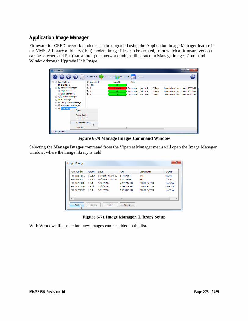
MN/22156, Revision 16 Page 275 of 455
Application Image Manager Firmware for CEFD network modems can be upgraded using the Application Image Manager feature in the VMS. A library of binary (.bin) modem image files can be created, from which a firmware version can be selected and Put (transmitted) to a network unit, as illustrated in Manage Images Command Window through Upgrade Unit Image.
Figure 6-70 Manage Images Command Window
Selecting the Manage Images command from the Vipersat Manager menu will open the Image Manager window, where the image library is held.
Figure 6-71 Image Manager, Library Setup
With Windows file selection, new images can be added to the list.
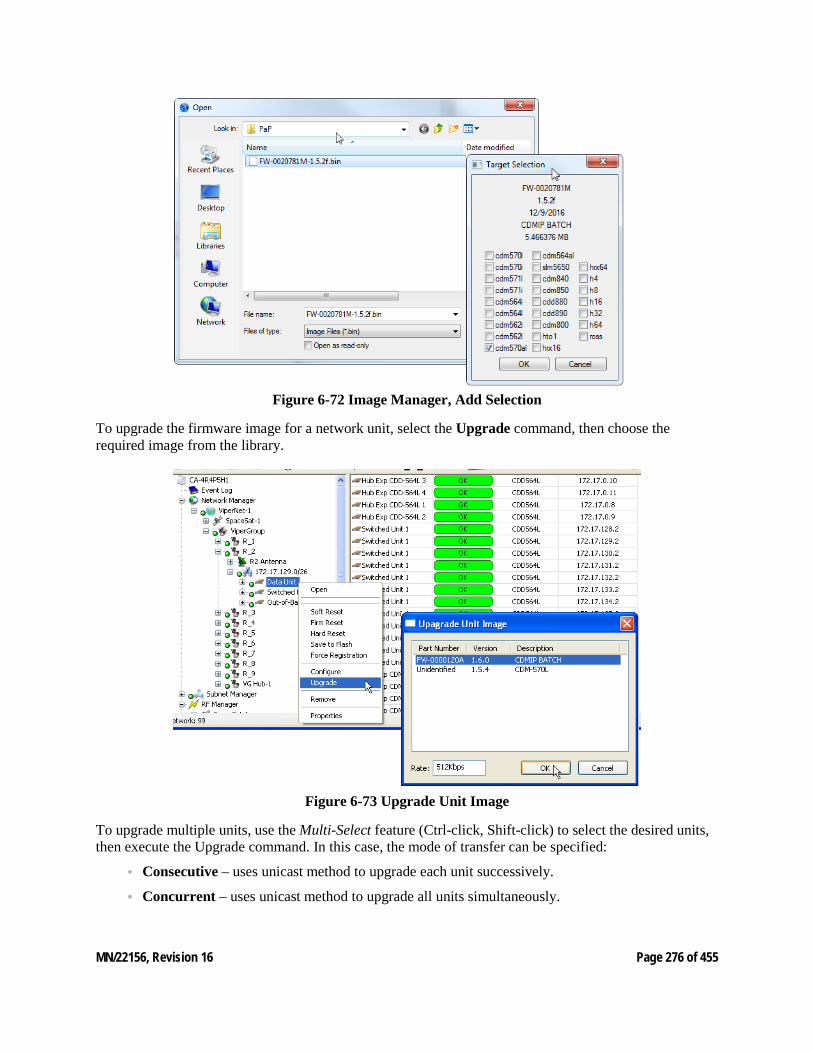
MN/22156, Revision 16 Page 276 of 455
Figure 6-72 Image Manager, Add Selection
To upgrade the firmware image for a network unit, select the Upgrade command, then choose the required image from the library.
Figure 6-73 Upgrade Unit Image
To upgrade multiple units, use the Multi-Select feature (Ctrl-click, Shift-click) to select the desired units, then execute the Upgrade command. In this case, the mode of transfer can be specified:
• Consecutive – uses unicast method to upgrade each unit successively.
• Concurrent – uses unicast method to upgrade all units simultaneously.

MN/22156, Revision 16 Page 277 of 455
• Codecast – uses multicast method to upgrade all units simultaneously. Note that this mode utilizes Streamload 2 protocol and is applicable to Heights, CDM-5xx, CDM-8xx series (version 1.5.2.x or greater), and SLM-5650A/B units.
When the upgrade process begins, the progress of each of the targeted units is displayed by the Operations Monitor, which will display the image burning phase and report either successful completion (green) or failure (red). The operator can then safely reset the unit(s).
The monitor window also provides the option to terminate an upgrade attempt by presenting an Abort button.
MN/22156, Revision 16 Page 278 of 455
7 OUT-OF-BAND UNITS 7. Out of Band Units Out-of-Band management and switching serves to control satellite modems that either utilize a primary data interface that is not IP based, or do not possess the CEFD technology for InBand operation. All that is required is that the modem has an Ethernet IP interface that is routable via a default gateway, and that the SNMP MIB for the interface has a driver implemented in the VMS. Out-of-Band management provides switching capability for synchronous serial or bulk encrypted applications and extends the family of modems that can be controlled by the VMS.
This chapter describes integrating Out-of-Band modem units into a VMS-controlled satellite network.
Overview
In a CEFD network, Out-of-Band units typically use Simple Network Management Protocol (SNMP) for management and control by the VMS. These are modems that are supported by the VMS SNMP Modem Manager. It is possible to utilize modems that are supported by the VMS Vipersat Manager as Out-of-Band units. However, because these modem types possess integrated CEFD technology and offer a primary data interface that is IP based, they are more efficiently used as InBand units, and require only a single carrier out of a remote terminal.
Possible considerations for using managed units for OOB include: • Very simple configurations for applications that do not require automatic switching capability. • The MODCOD setting to be used for the channel can be specified, both when configuring the circuit
and when conducting the switch setup. • No restriction on the number of channels per circuit.
The SNMP Modem Manager is the controlling VMS service for all Out-of-Band modems. Modem units that do not have a CEFD Network driver—and thus cannot be configured for InBand management—are unable to utilize IP routing functions to communicate with the VMS, and instead utilize SNMP for these communications and are managed by the SNMP Modem Manager when functioning in a CEFD satellite network.
MN/22156, Revision 16 Page 279 of 455
Configuration and setup of Out-of-Band units and circuits is relatively simple and straightforward due to the functional limitations of these units. Switching operations are conducted either manually or via schedule. Automatic switching is not available. Other features/functions that are not available include the following:
• Reservations for assigned bandwidth • Advanced MODOCD switching • Home state, SHOD, Policies, Distribution lists • Allocated devices (devices are assigned) • Multicast (each device is controlled separately) • Minimum/Maximum data rate per site limits
Out-of-Band Circuit Manager (OBCM)—the VMS service manager that enables Out-of-Band switching—works seamlessly with the InBand Manager. Priorities for both InBand and Out-of-Band sessions and bandwidth reservations for InBand are still honored. It is incumbent upon the operator to determine what types of circuits have higher priorities within his network.
Ethernet IP Interface
For the VMS to communicate with a satellite network modem, the modem must have an IP-addressable unit. Modems such as the CDM-700, SLM-5650(A), CDM-625(A), and CDM-570(A) have built-in Ethernet interfaces and do not require an external CiM adapter. An SNMP unit can use either the base modem or the NP card as the Ethernet interface for IP. In contrast, unit must use the NP card as the Ethernet interface. Refer to each modem unit’s documentation for the procedure for assigning a valid IP address to the unit.
The CDM-600/L is a non-IP capable modem and requires the use of the Comtech CiM-25 to provide the Ethernet IP interface. The CiM-25 is assigned a valid IP address using procedures described in the appropriate product documentation, as well as in the procedure below.
1. Connect the target CiM-25 unit to a PC workstation and assign a valid IP address for the network where the CiM-25 and its companion CDM‑ 600L are to be installed.
2. Reconnect the CiM-25 to its companion CDM‑ 600L, then connect the Ethernet LAN and apply power as required.
The CiM-25 must be plugged into an operating modem (except during setup) in order for it to op-erate reliably. A CiM-25 operating disconnected from a modem will exhibit erratic Ethernet com-munications. Refer to the CiM-25 manual for additional information.
Next, the modem must be declared in the VMS using the procedure provided in the following section.
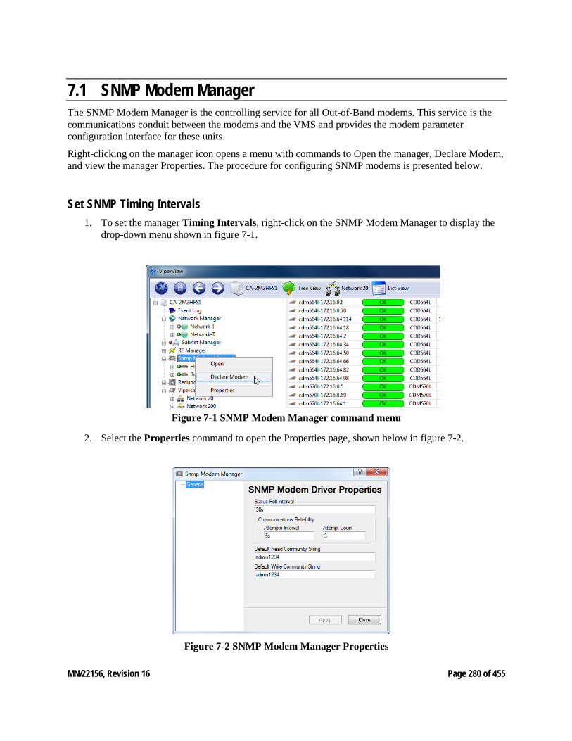
MN/22156, Revision 16 Page 280 of 455
7.1 SNMP Modem Manager The SNMP Modem Manager is the controlling service for all Out-of-Band modems. This service is the communications conduit between the modems and the VMS and provides the modem parameter configuration interface for these units.
Right-clicking on the manager icon opens a menu with commands to Open the manager, Declare Modem, and view the manager Properties. The procedure for configuring SNMP modems is presented below.
Set SNMP Timing Intervals 1. To set the manager Timing Intervals, right-click on the SNMP Modem Manager to display the
drop-down menu shown in figure 7-1.
Figure 7-1 SNMP Modem Manager command menu
2. Select the Properties command to open the Properties page, shown below in figure 7-2.
Figure 7-2 SNMP Modem Manager Properties
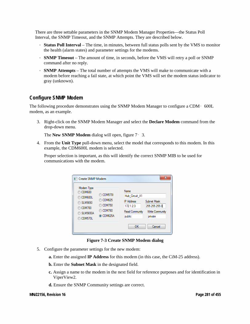
MN/22156, Revision 16 Page 281 of 455
There are three settable parameters in the SNMP Modem Manager Properties—the Status Poll Interval, the SNMP Timeout, and the SNMP Attempts. They are described below.
• Status Poll Interval – The time, in minutes, between full status polls sent by the VMS to monitor the health (alarm states) and parameter settings for the modems.
• SNMP Timeout – The amount of time, in seconds, before the VMS will retry a poll or SNMP command after no reply.
• SNMP Attempts – The total number of attempts the VMS will make to communicate with a modem before reaching a fail state, at which point the VMS will set the modem status indicator to gray (unknown).
Configure SNMP Modem The following procedure demonstrates using the SNMP Modem Manager to configure a CDM‑ 600L modem, as an example.
3. Right-click on the SNMP Modem Manager and select the Declare Modem command from the drop-down menu.
The New SNMP Modem dialog will open, figure 7‑ 3.
4. From the Unit Type pull-down menu, select the model that corresponds to this modem. In this example, the CDM600L modem is selected.
Proper selection is important, as this will identify the correct SNMP MIB to be used for communications with the modem.
Figure 7-3 Create SNMP Modem dialog
5. Configure the parameter settings for the new modem:
a. Enter the assigned IP Address for this modem (in this case, the CiM-25 address).
b. Enter the Subnet Mask in the designated field.
c. Assign a name to the modem in the next field for reference purposes and for identification in ViperView2.
d. Ensure the SNMP Community settings are correct.
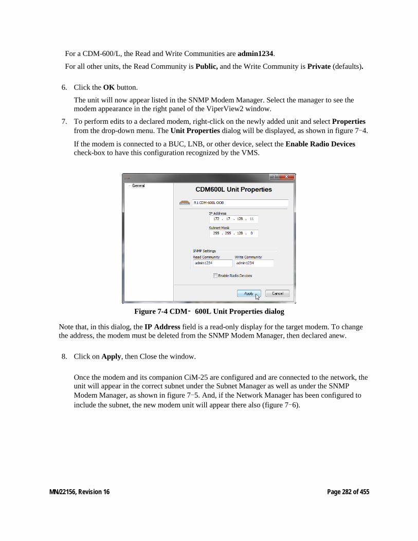
MN/22156, Revision 16 Page 282 of 455
For a CDM-600/L, the Read and Write Communities are admin1234.
For all other units, the Read Community is Public, and the Write Community is Private (defaults).
6. Click the OK button.
The unit will now appear listed in the SNMP Modem Manager. Select the manager to see the modem appearance in the right panel of the ViperView2 window.
7. To perform edits to a declared modem, right-click on the newly added unit and select Properties from the drop-down menu. The Unit Properties dialog will be displayed, as shown in figure 7-4.
If the modem is connected to a BUC, LNB, or other device, select the Enable Radio Devices check-box to have this configuration recognized by the VMS.
Figure 7-4 CDM‑ 600L Unit Properties dialog
Note that, in this dialog, the IP Address field is a read-only display for the target modem. To change the address, the modem must be deleted from the SNMP Modem Manager, then declared anew.
8. Click on Apply, then Close the window.
Once the modem and its companion CiM-25 are configured and are connected to the network, the unit will appear in the correct subnet under the Subnet Manager as well as under the SNMP Modem Manager, as shown in figure 7-5. And, if the Network Manager has been configured to include the subnet, the new modem unit will appear there also (figure 7-6).
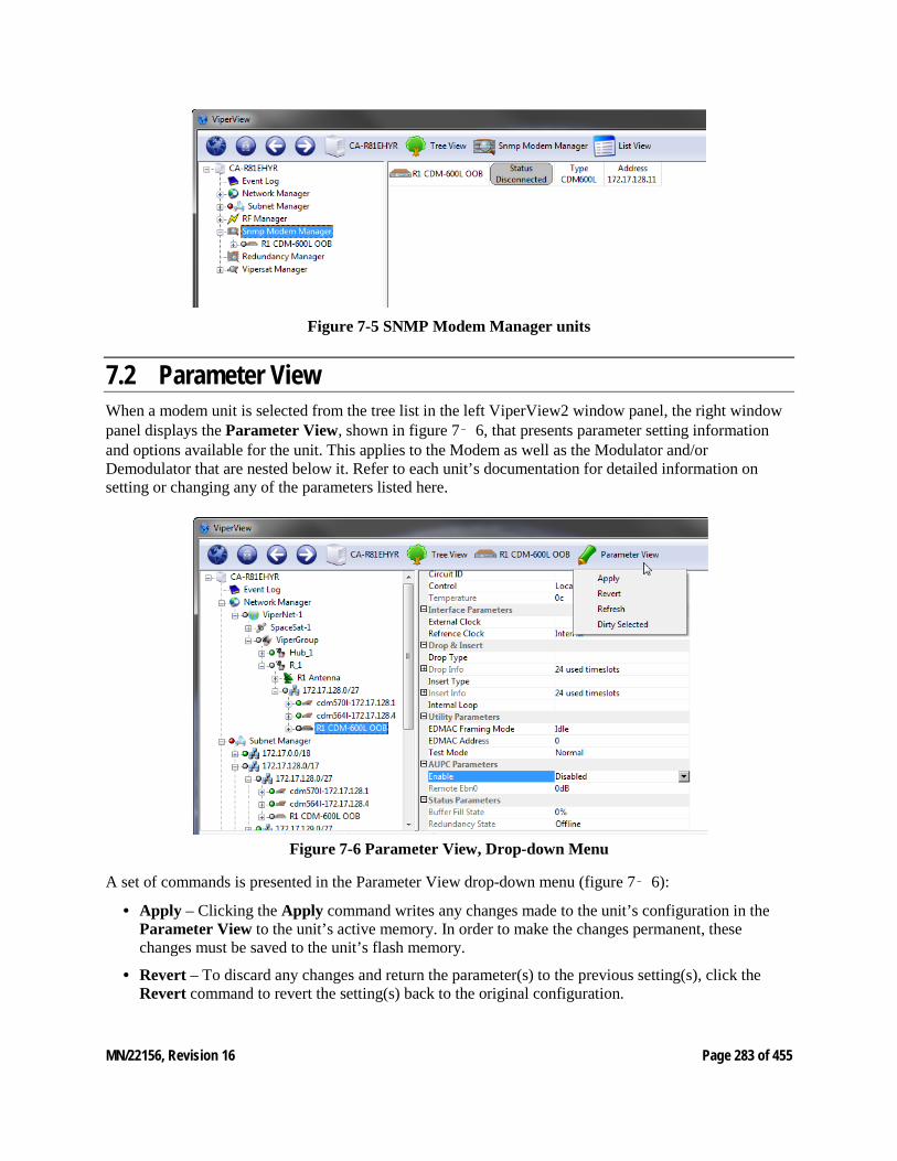
MN/22156, Revision 16 Page 283 of 455
Figure 7-5 SNMP Modem Manager units
7.2 Parameter View When a modem unit is selected from the tree list in the left ViperView2 window panel, the right window panel displays the Parameter View, shown in figure 7‑ 6, that presents parameter setting information and options available for the unit. This applies to the Modem as well as the Modulator and/or Demodulator that are nested below it. Refer to each unit’s documentation for detailed information on setting or changing any of the parameters listed here.
Figure 7-6 Parameter View, Drop-down Menu
A set of commands is presented in the Parameter View drop-down menu (figure 7‑ 6):
• Apply – Clicking the Apply command writes any changes made to the unit’s configuration in the Parameter View to the unit’s active memory. In order to make the changes permanent, these changes must be saved to the unit’s flash memory.
• Revert – To discard any changes and return the parameter(s) to the previous setting(s), click the Revert command to revert the setting(s) back to the original configuration.
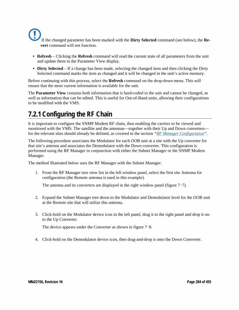
MN/22156, Revision 16 Page 284 of 455
If the changed parameter has been marked with the Dirty Selected command (see below), the Re-vert command will not function.
• Refresh – Clicking the Refresh command will read the current state of all parameters from the unit and update them in the Parameter View display.
• Dirty Selected – If a change has been made, selecting the changed item and then clicking the Dirty Selected command marks the item as changed and it will be changed in the unit’s active memory.
Before continuing with this process, select the Refresh command on the drop-down menu. This will ensure that the most current information is available for the unit.
The Parameter View contains both information that is hard-coded in the unit and cannot be changed, as well as information that can be edited. This is useful for Out-of-Band units, allowing their configurations to be modified with the VMS.
7.2.1 Configuring the RF Chain It is important to configure the SNMP Modem RF chain, thus enabling the carriers to be viewed and monitored with the VMS. The satellite and the antennas—together with their Up and Down converters—for the relevant sites should already be defined, as covered in the section “RF Manager Configuration”.
The following procedure associates the Modulator for each OOB unit at a site with the Up converter for that site’s antenna and associates the Demodulator with the Down converter. This configuration is performed using the RF Manager in conjunction with either the Subnet Manager or the SNMP Modem Manager.
The method illustrated below uses the RF Manager with the Subnet Manager.
1. From the RF Manager tree view list in the left window panel, select the first site Antenna for configuration (the Remote antenna is used in this example).
The antenna and its converters are displayed in the right window panel (figure 7-7).
2. Expand the Subnet Manager tree down to the Modulator and Demodulator level for the OOB unit at the Remote site that will utilize this antenna.
3. Click-hold on the Modulator device icon in the left panel, drag it to the right panel and drop it on-to the Up Converter.
The device appears under the Converter as shown in figure 7-8.
4. Click-hold on the Demodulator device icon, then drag-and-drop it onto the Down Converter.
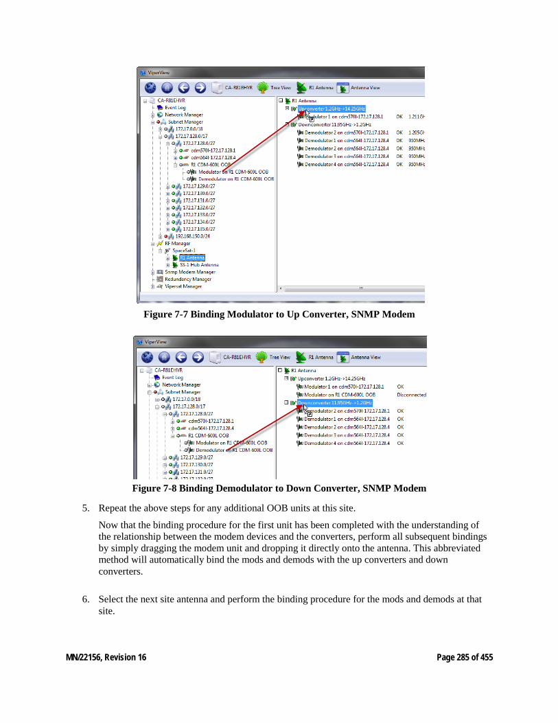
MN/22156, Revision 16 Page 285 of 455
Figure 7-7 Binding Modulator to Up Converter, SNMP Modem
Figure 7-8 Binding Demodulator to Down Converter, SNMP Modem
5. Repeat the above steps for any additional OOB units at this site.
Now that the binding procedure for the first unit has been completed with the understanding of the relationship between the modem devices and the converters, perform all subsequent bindings by simply dragging the modem unit and dropping it directly onto the antenna. This abbreviated method will automatically bind the mods and demods with the up converters and down converters.
6. Select the next site antenna and perform the binding procedure for the mods and demods at that site.
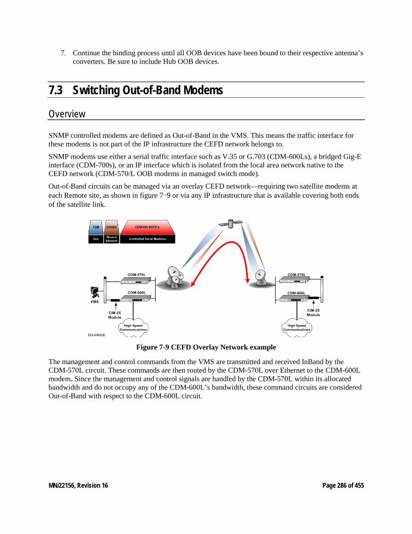
MN/22156, Revision 16 Page 286 of 455
7. Continue the binding process until all OOB devices have been bound to their respective antenna’s converters. Be sure to include Hub OOB devices.
7.3 Switching Out-of-Band Modems
Overview
SNMP controlled modems are defined as Out-of-Band in the VMS. This means the traffic interface for these modems is not part of the IP infrastructure the CEFD network belongs to.
SNMP modems use either a serial traffic interface such as V.35 or G.703 (CDM-600Ls), a bridged Gig-E interface (CDM-700s), or an IP interface which is isolated from the local area network native to the CEFD network (CDM-570/L OOB modems in managed switch mode).
Out-of-Band circuits can be managed via an overlay CEFD network—requiring two satellite modems at each Remote site, as shown in figure 7-9 or via any IP infrastructure that is available covering both ends of the satellite link.
Figure 7-9 CEFD Overlay Network example
The management and control commands from the VMS are transmitted and received InBand by the CDM-570L circuit. These commands are then routed by the CDM-570L over Ethernet to the CDM-600L modem. Since the management and control signals are handled by the CDM-570L within its allocated bandwidth and do not occupy any of the CDM-600L’s bandwidth, these command circuits are considered Out-of-Band with respect to the CDM-600L circuit.
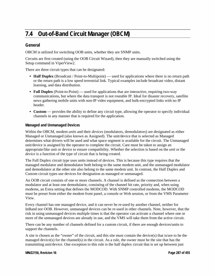
MN/22156, Revision 16 Page 287 of 455
7.4 Out-of-Band Circuit Manager (OBCM) General OBCM is utilized for switching OOB units, whether they are SNMP units.
Circuits are first created (using the OOB Circuit Wizard), then they are manually switched using the Setup command in ViperView2.
There are three circuit types that can be designated:
• Half Duplex (Broadcast / Point-to-Multipoint) — used for applications where there is no return path or the return path is a low speed terrestrial link. Typical examples include broadcast video, distant learning, and data distribution.
• Full Duplex (Point-to-Point) — used for applications that are interactive, requiring two-way communications, but where the data transport is not routable IP. Ideal for disaster recovery, satellite news gathering mobile units with non-IP video equipment, and bulk-encrypted links with no IP header.
• Custom — provides the ability to define any circuit type, allowing the operator to specify individual channels in any manner that is required for the application.
Managed and Unmanaged Devices Within the OBCM, modem units and their devices (modulators, demodulators) are designated as either Managed or Unmanaged (also known as Assigned). The unit/device that is selected as Managed determines what drivers will be used and what space segment is available for the circuit. The Unmanaged unit/device is assigned by the operator to complete the circuit. Care must be taken to assign an appropriate/like unit or device to ensure compatibility. Whether the selection is based on the unit or the device is a function of the type of circuit that is being created.
The Full Duplex circuit type uses units instead of devices. This is because this type requires that the managed modulator and demodulator both belong to the same modem unit, and the unmanaged modulator and demodulator at the other site also belong to the same modem unit. In contrast, the Half Duplex and Custom circuit types use devices for designation as managed or unmanaged.
An OOB circuit consists of one or more channels. A channel is defined as the connection between a modulator and at least one demodulator, consisting of the channel bit rate, priority and, when using modems, an Extra setting that defines the MODCOD. With SNMP controlled modems, the MODCOD must be preset from either the modem front panel, a console or Web session, or from the VMS Parameter View.
Every channel has one managed device, and it can never be re-used by another channel, neither for InBand nor OOB. However, unmanaged devices can be re-used in other channels. Note, however, that the risk in using unmanaged devices multiple times is that the operator can activate a channel where one or more of the unmanaged devices are already in use, and the VMS will take them from the active circuit.
There can be any number of channels defined for a custom circuit, if there are enough devices/units to support the channels.
A site is chosen as the “owner” of the circuit, and this site must contain the device(s) that is/are to be the managed device(s) for the channel(s) in the circuit. As a rule, the owner must be the site that has the transmitting unit/device. One exception to this rule is the half duplex circuit that is set up between just
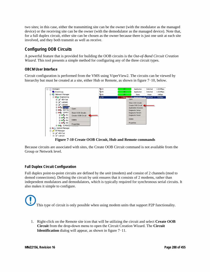
MN/22156, Revision 16 Page 288 of 455
two sites; in this case, either the transmitting site can be the owner (with the modulator as the managed device) or the receiving site can be the owner (with the demodulator as the managed device). Note that, for a full duplex circuit, either site can be chosen as the owner because there is just one unit at each site involved, and they both transmit as well as receive.
Configuring OOB Circuits A powerful feature that is provided for building the OOB circuits is the Out-of-Band Circuit Creation Wizard. This tool presents a simple method for configuring any of the three circuit types.
OBCM User Interface Circuit configuration is performed from the VMS using ViperView2. The circuits can be viewed by hierarchy but must be created at a site, either Hub or Remote, as shown in figure 7-10, below.
Figure 7-10 Create OOB Circuit, Hub and Remote commands
Because circuits are associated with sites, the Create OOB Circuit command is not available from the Group or Network level.
Full Duplex Circuit Configuration Full duplex point-to-point circuits are defined by the unit (modem) and consist of 2 channels (mod to demod connections). Defining the circuit by unit ensures that it consists of 2 modems, rather than independent modulators and demodulators, which is typically required for synchronous serial circuits. It also makes it simple to configure.
This type of circuit is only possible when using modem units that support P2P functionality.
1. Right-click on the Remote site icon that will be utilizing the circuit and select Create OOB Circuit from the drop-down menu to open the Circuit Creation Wizard. The Circuit Identification dialog will appear, as shown in figure 7-11.
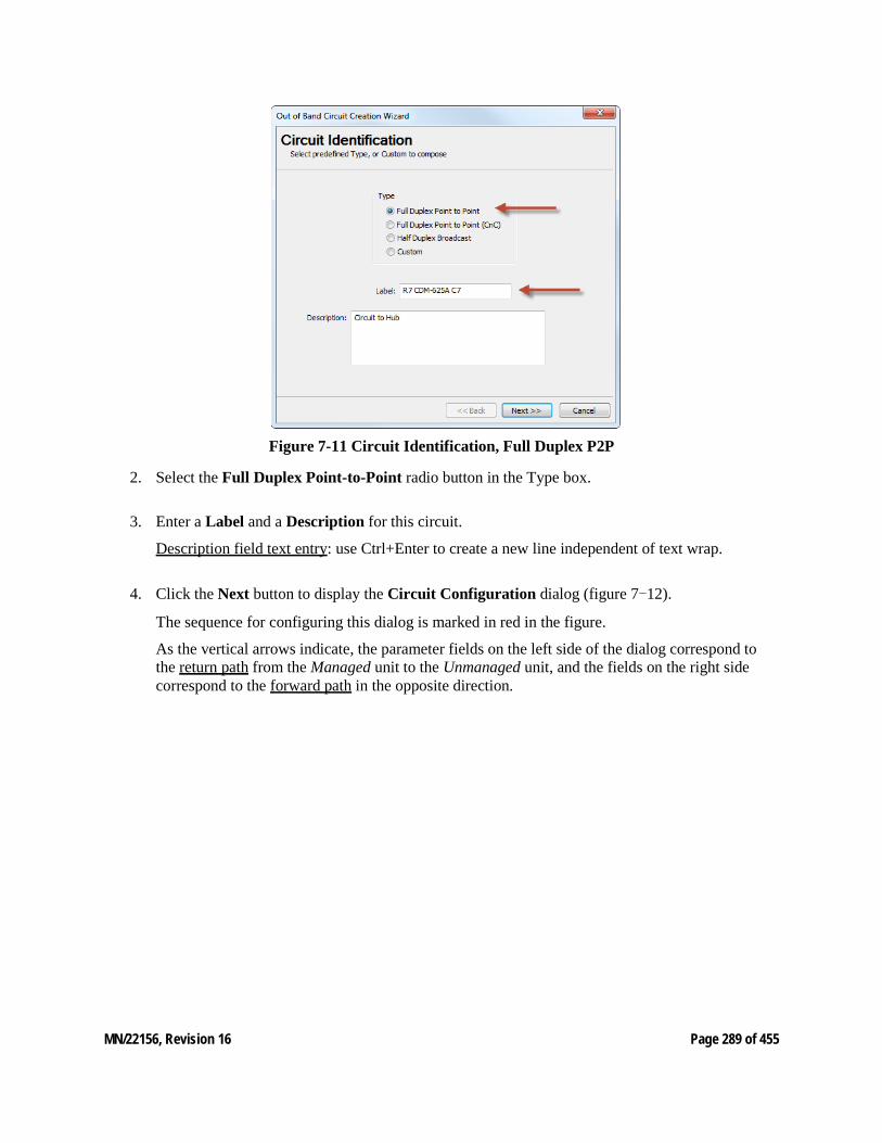
MN/22156, Revision 16 Page 289 of 455
Figure 7-11 Circuit Identification, Full Duplex P2P
2. Select the Full Duplex Point-to-Point radio button in the Type box.
3. Enter a Label and a Description for this circuit.
Description field text entry: use Ctrl+Enter to create a new line independent of text wrap.
4. Click the Next button to display the Circuit Configuration dialog (figure 7-12).
The sequence for configuring this dialog is marked in red in the figure.
As the vertical arrows indicate, the parameter fields on the left side of the dialog correspond to the return path from the Managed unit to the Unmanaged unit, and the fields on the right side correspond to the forward path in the opposite direction.
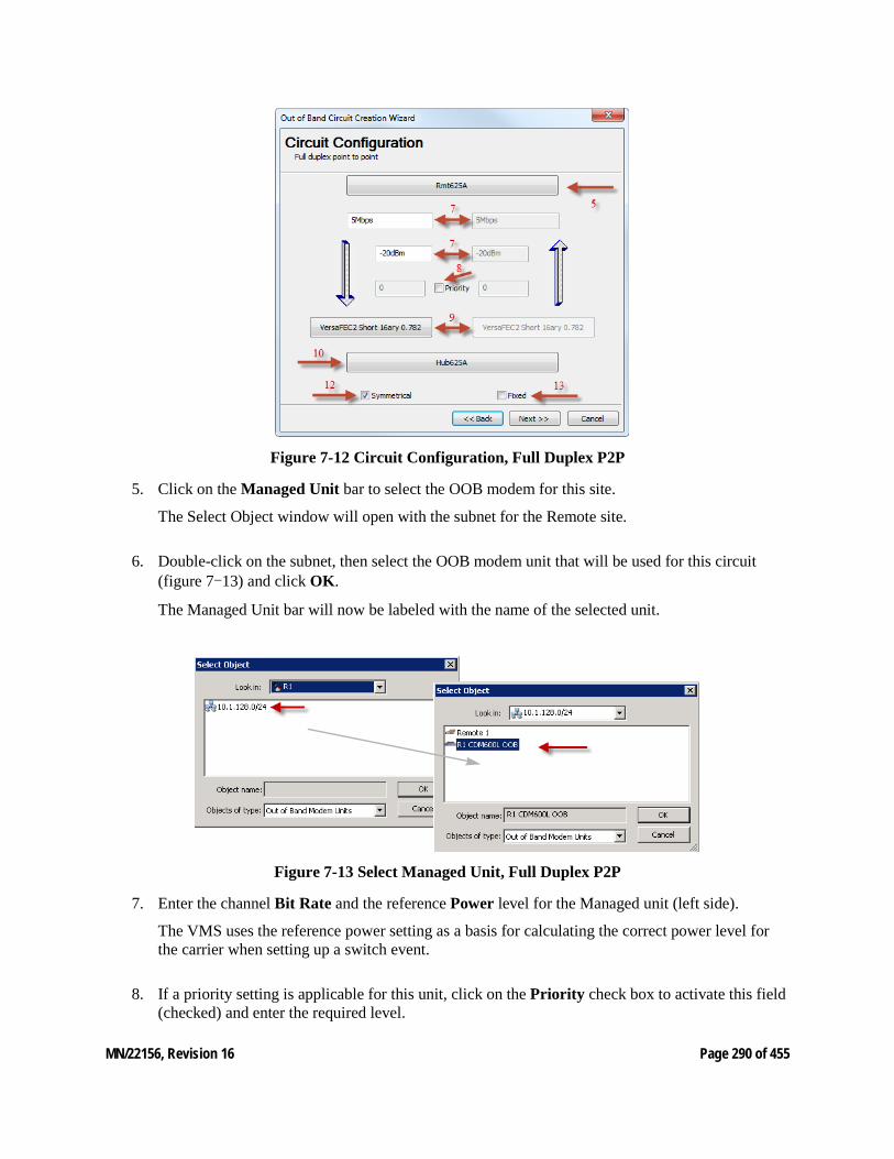
MN/22156, Revision 16 Page 290 of 455
Figure 7-12 Circuit Configuration, Full Duplex P2P
5. Click on the Managed Unit bar to select the OOB modem for this site.
The Select Object window will open with the subnet for the Remote site.
6. Double-click on the subnet, then select the OOB modem unit that will be used for this circuit (figure 7-13) and click OK.
The Managed Unit bar will now be labeled with the name of the selected unit.
Figure 7-13 Select Managed Unit, Full Duplex P2P
7. Enter the channel Bit Rate and the reference Power level for the Managed unit (left side).
The VMS uses the reference power setting as a basis for calculating the correct power level for the carrier when setting up a switch event.
8. If a priority setting is applicable for this unit, click on the Priority check box to activate this field (checked) and enter the required level.
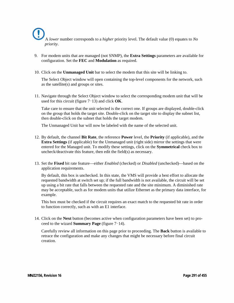
MN/22156, Revision 16 Page 291 of 455
A lower number corresponds to a higher priority level. The default value (0) equates to No priority.
9. For modem units that are managed (not SNMP), the Extra Settings parameters are available for configuration. Set the FEC and Modulation as required.
10. Click on the Unmanaged Unit bar to select the modem that this site will be linking to.
The Select Object window will open containing the top-level components for the network, such as the satellite(s) and groups or sites.
11. Navigate through the Select Object window to select the corresponding modem unit that will be used for this circuit (figure 7-13) and click OK.
Take care to ensure that the unit selected is the correct one. If groups are displayed, double-click on the group that holds the target site. Double-click on the target site to display the subnet list, then double-click on the subnet that holds the target modem.
The Unmanaged Unit bar will now be labeled with the name of the selected unit.
12. By default, the channel Bit Rate, the reference Power level, the Priority (if applicable), and the Extra Settings (if applicable) for the Unmanaged unit (right side) mirror the settings that were entered for the Managed unit. To modify these settings, click on the Symmetrical check box to uncheck/deactivate this feature, then edit the field(s) as necessary.
13. Set the Fixed bit rate feature—either Enabled (checked) or Disabled (unchecked)—based on the application requirements.
By default, this box is unchecked. In this state, the VMS will provide a best effort to allocate the requested bandwidth at switch set up; if the full bandwidth is not available, the circuit will be set up using a bit rate that falls between the requested rate and the site minimum. A diminished rate may be acceptable, such as for modem units that utilize Ethernet as the primary data interface, for example.
This box must be checked if the circuit requires an exact match to the requested bit rate in order to function correctly, such as with an E1 interface.
14. Click on the Next button (becomes active when configuration parameters have been set) to pro-ceed to the wizard Summary Page (figure 7-14).
Carefully review all information on this page prior to proceeding. The Back button is available to retrace the configuration and make any changes that might be necessary before final circuit creation.
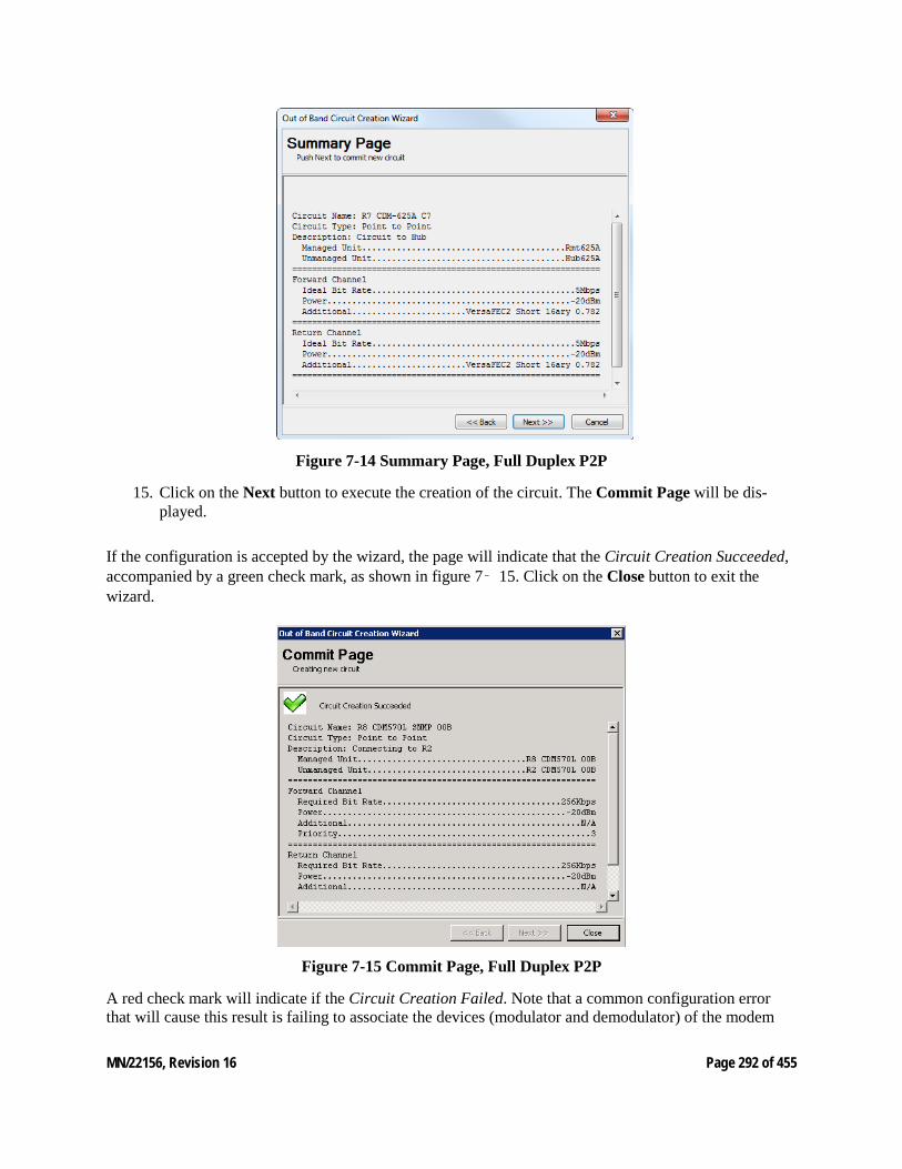
MN/22156, Revision 16 Page 292 of 455
Figure 7-14 Summary Page, Full Duplex P2P
15. Click on the Next button to execute the creation of the circuit. The Commit Page will be dis-played.
If the configuration is accepted by the wizard, the page will indicate that the Circuit Creation Succeeded, accompanied by a green check mark, as shown in figure 7‑ 15. Click on the Close button to exit the wizard.
Figure 7-15 Commit Page, Full Duplex P2P
A red check mark will indicate if the Circuit Creation Failed. Note that a common configuration error that will cause this result is failing to associate the devices (modulator and demodulator) of the modem
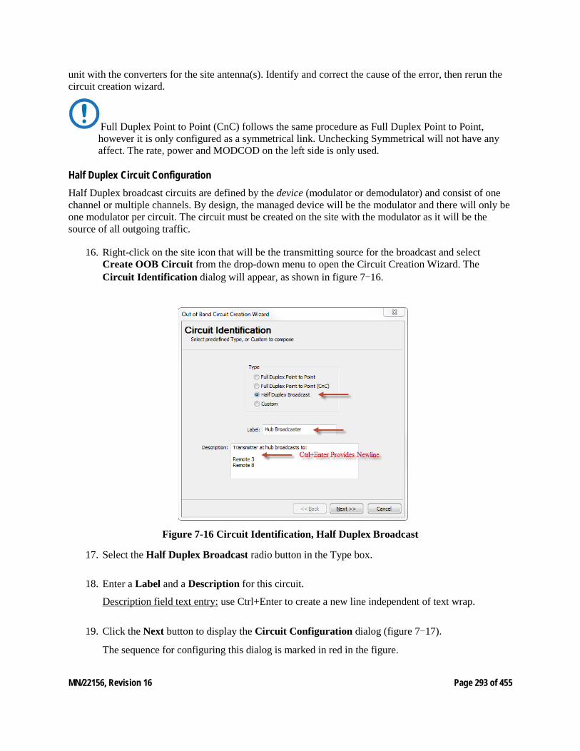
MN/22156, Revision 16 Page 293 of 455
unit with the converters for the site antenna(s). Identify and correct the cause of the error, then rerun the circuit creation wizard.
Full Duplex Point to Point (CnC) follows the same procedure as Full Duplex Point to Point, however it is only configured as a symmetrical link. Unchecking Symmetrical will not have any affect. The rate, power and MODCOD on the left side is only used.
Half Duplex Circuit Configuration Half Duplex broadcast circuits are defined by the device (modulator or demodulator) and consist of one channel or multiple channels. By design, the managed device will be the modulator and there will only be one modulator per circuit. The circuit must be created on the site with the modulator as it will be the source of all outgoing traffic.
16. Right-click on the site icon that will be the transmitting source for the broadcast and select Create OOB Circuit from the drop-down menu to open the Circuit Creation Wizard. The Circuit Identification dialog will appear, as shown in figure 7-16.
Figure 7-16 Circuit Identification, Half Duplex Broadcast
17. Select the Half Duplex Broadcast radio button in the Type box.
18. Enter a Label and a Description for this circuit.
Description field text entry: use Ctrl+Enter to create a new line independent of text wrap.
19. Click the Next button to display the Circuit Configuration dialog (figure 7-17).
The sequence for configuring this dialog is marked in red in the figure.
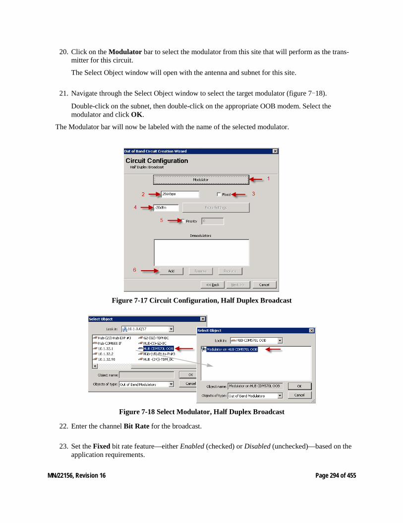
MN/22156, Revision 16 Page 294 of 455
20. Click on the Modulator bar to select the modulator from this site that will perform as the trans-mitter for this circuit.
The Select Object window will open with the antenna and subnet for this site.
21. Navigate through the Select Object window to select the target modulator (figure 7-18).
Double-click on the subnet, then double-click on the appropriate OOB modem. Select the modulator and click OK.
The Modulator bar will now be labeled with the name of the selected modulator.
Figure 7-17 Circuit Configuration, Half Duplex Broadcast
Figure 7-18 Select Modulator, Half Duplex Broadcast
22. Enter the channel Bit Rate for the broadcast.
23. Set the Fixed bit rate feature—either Enabled (checked) or Disabled (unchecked)—based on the application requirements.
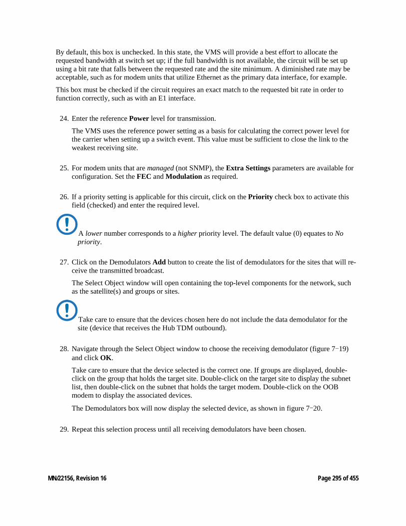
MN/22156, Revision 16 Page 295 of 455
By default, this box is unchecked. In this state, the VMS will provide a best effort to allocate the requested bandwidth at switch set up; if the full bandwidth is not available, the circuit will be set up using a bit rate that falls between the requested rate and the site minimum. A diminished rate may be acceptable, such as for modem units that utilize Ethernet as the primary data interface, for example.
This box must be checked if the circuit requires an exact match to the requested bit rate in order to function correctly, such as with an E1 interface.
24. Enter the reference Power level for transmission.
The VMS uses the reference power setting as a basis for calculating the correct power level for the carrier when setting up a switch event. This value must be sufficient to close the link to the weakest receiving site.
25. For modem units that are managed (not SNMP), the Extra Settings parameters are available for configuration. Set the FEC and Modulation as required.
26. If a priority setting is applicable for this circuit, click on the Priority check box to activate this field (checked) and enter the required level.
A lower number corresponds to a higher priority level. The default value (0) equates to No priority.
27. Click on the Demodulators Add button to create the list of demodulators for the sites that will re-ceive the transmitted broadcast.
The Select Object window will open containing the top-level components for the network, such as the satellite(s) and groups or sites.
Take care to ensure that the devices chosen here do not include the data demodulator for the site (device that receives the Hub TDM outbound).
28. Navigate through the Select Object window to choose the receiving demodulator (figure 7-19) and click OK.
Take care to ensure that the device selected is the correct one. If groups are displayed, double-click on the group that holds the target site. Double-click on the target site to display the subnet list, then double-click on the subnet that holds the target modem. Double-click on the OOB modem to display the associated devices.
The Demodulators box will now display the selected device, as shown in figure 7-20.
29. Repeat this selection process until all receiving demodulators have been chosen.
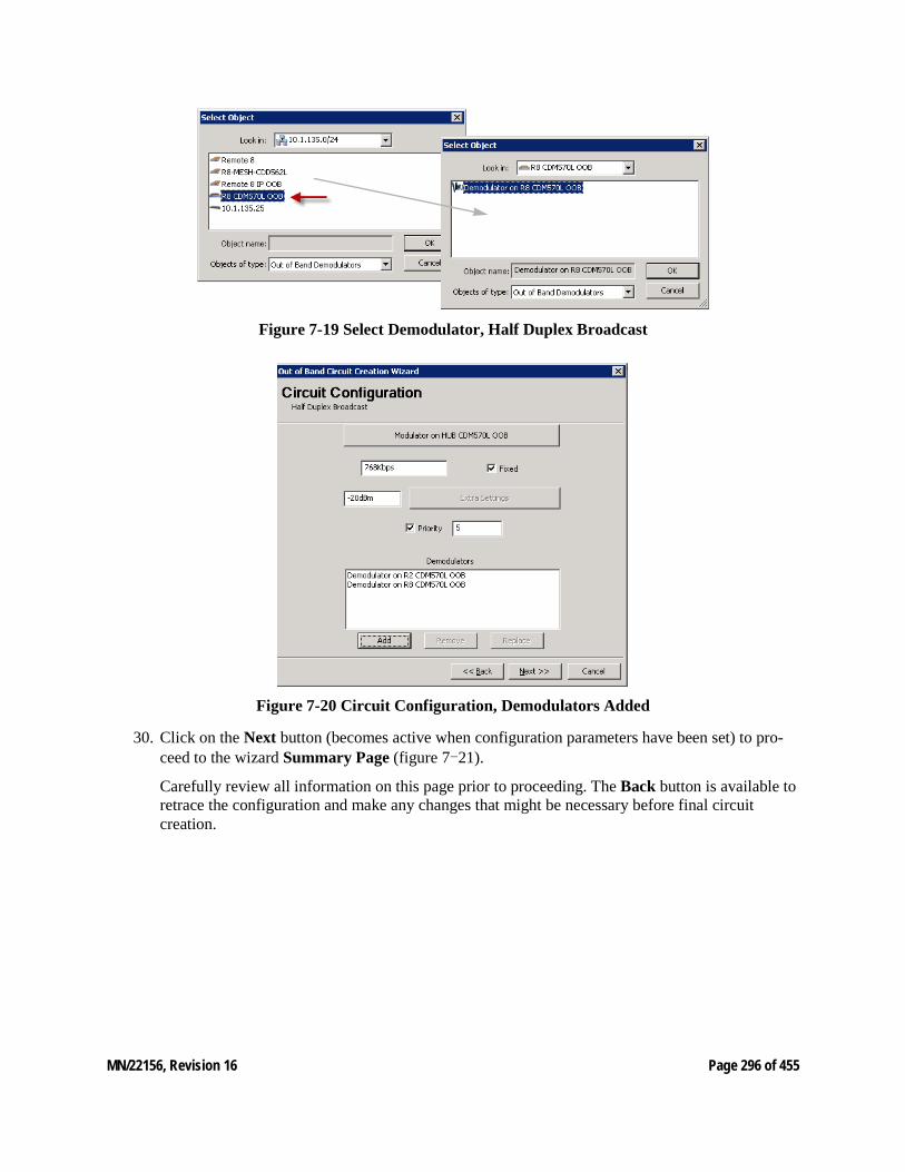
MN/22156, Revision 16 Page 296 of 455
Figure 7-19 Select Demodulator, Half Duplex Broadcast
Figure 7-20 Circuit Configuration, Demodulators Added
30. Click on the Next button (becomes active when configuration parameters have been set) to pro-ceed to the wizard Summary Page (figure 7-21).
Carefully review all information on this page prior to proceeding. The Back button is available to retrace the configuration and make any changes that might be necessary before final circuit creation.
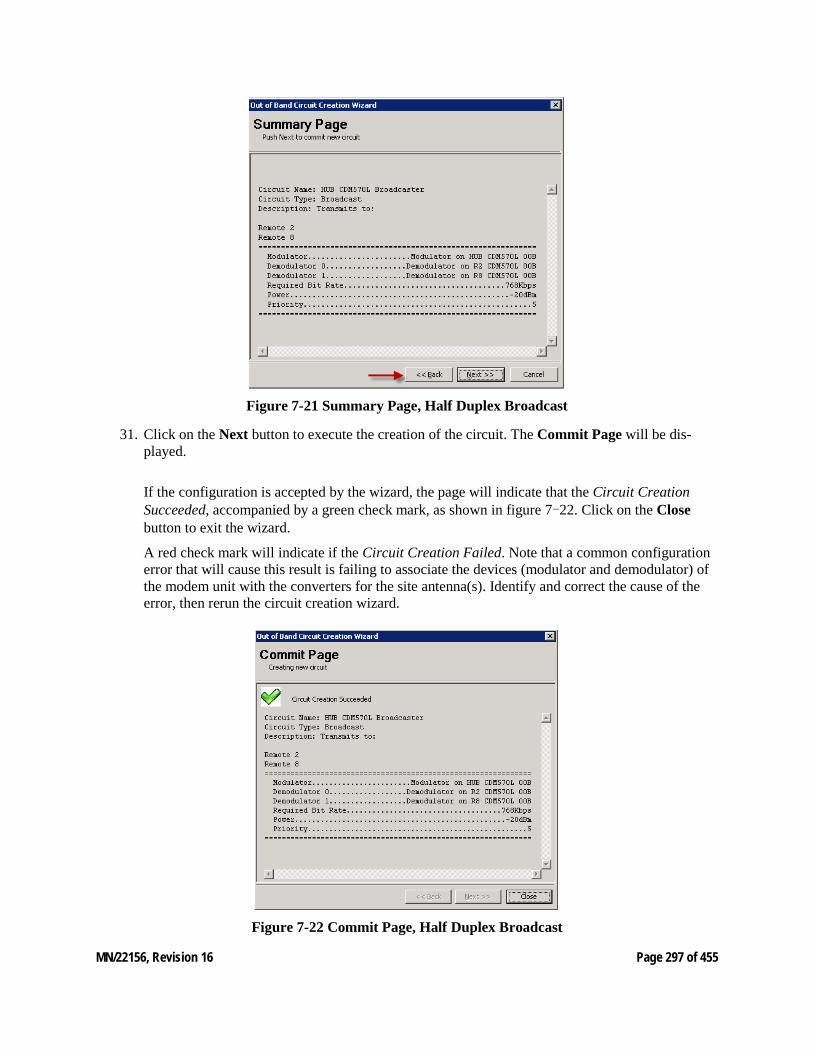
MN/22156, Revision 16 Page 297 of 455
Figure 7-21 Summary Page, Half Duplex Broadcast
31. Click on the Next button to execute the creation of the circuit. The Commit Page will be dis-played.
If the configuration is accepted by the wizard, the page will indicate that the Circuit Creation Succeeded, accompanied by a green check mark, as shown in figure 7-22. Click on the Close button to exit the wizard.
A red check mark will indicate if the Circuit Creation Failed. Note that a common configuration error that will cause this result is failing to associate the devices (modulator and demodulator) of the modem unit with the converters for the site antenna(s). Identify and correct the cause of the error, then rerun the circuit creation wizard.
Figure 7-22 Commit Page, Half Duplex Broadcast
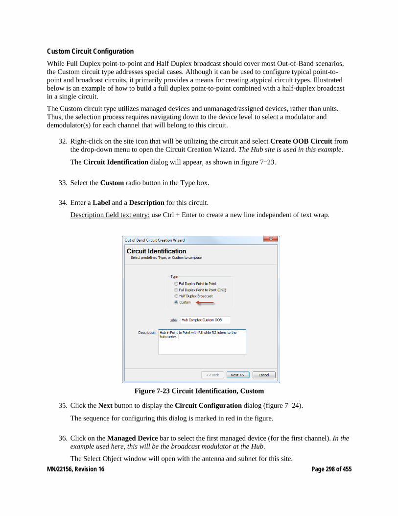
MN/22156, Revision 16 Page 298 of 455
Custom Circuit Configuration While Full Duplex point-to-point and Half Duplex broadcast should cover most Out-of-Band scenarios, the Custom circuit type addresses special cases. Although it can be used to configure typical point-to-point and broadcast circuits, it primarily provides a means for creating atypical circuit types. Illustrated below is an example of how to build a full duplex point-to-point combined with a half-duplex broadcast in a single circuit.
The Custom circuit type utilizes managed devices and unmanaged/assigned devices, rather than units. Thus, the selection process requires navigating down to the device level to select a modulator and demodulator(s) for each channel that will belong to this circuit.
32. Right-click on the site icon that will be utilizing the circuit and select Create OOB Circuit from the drop-down menu to open the Circuit Creation Wizard. The Hub site is used in this example.
The Circuit Identification dialog will appear, as shown in figure 7-23.
33. Select the Custom radio button in the Type box.
34. Enter a Label and a Description for this circuit.
Description field text entry: use Ctrl + Enter to create a new line independent of text wrap.
Figure 7-23 Circuit Identification, Custom
35. Click the Next button to display the Circuit Configuration dialog (figure 7-24).
The sequence for configuring this dialog is marked in red in the figure.
36. Click on the Managed Device bar to select the first managed device (for the first channel). In the example used here, this will be the broadcast modulator at the Hub.
The Select Object window will open with the antenna and subnet for this site.

MN/22156, Revision 16 Page 299 of 455
37. Navigate through the Select Object window to select the target device:
Double-click on the subnet, then double-click on the appropriate OOB modem. Select the device that is to be managed and click OK.
The Managed Device bar will now be labeled with the name of the selected device (figure 7-25).
Figure 7-24 Circuit Configuration, Custom
Figure 7-25 Custom Circuit, First Channel Completed
38. Enter the channel Bit Rates, Ideal and Minimum, and the reference Power level.

MN/22156, Revision 16 Page 300 of 455
The VMS uses the reference power setting as a basis for calculating the correct power level for the carrier when setting up a switch event. This value must be enough to close the link to the weakest receiving site.
39. If a priority setting is applicable for this circuit, click on the Priority check box to activate this field (checked) and enter the required level.
A lower number corresponds to a higher priority level. The default value (0) equates to No priority.
40. For modem units that are managed (not SNMP), the Extra Settings parameters are available for configuration. Set the FEC and Modulation as required.
41. Click the Add button below the Unmanaged Devices box to select the target device(s) that will complete this channel. In the example used here, this will be the demods for the two receiving sites.
The Select Object window will open containing the top-level components for the network, such as the satellite(s) and groups or sites.
42. Navigate through the Select Object window to select the corresponding device(s) that will be used for this channel (figure 7-25) and click OK.
Take care to ensure that each device selected is the correct one. If groups are displayed, double-click on the group that holds the target site. Double-click on the target site to display the subnet list, then double-click on the subnet that holds the target modem. Finally, double-click on the modem and select the appropriate device.
The Unmanaged Devices box will now list the selected device(s).
If this is the only channel required for the circuit that is being created, proceed to step 17.
If more channels remain to be defined for this circuit, continue with the next step. For this example, a second channel will be defined for the P2P return path from Remote 8 back to the Hub.
43. Click on the Add button in the lower section of the window.
The newly defined channel will be displayed in the channel table, showing the associated parameters in the Managed Device, Ideal Rate, Power, and Priority columns.
44. A second, incomplete channel appears directly below the first channel and should be highlighted. If not, click on it to highlight it.
Click on the Managed Device bar to select the next managed device (for the second channel). In the example used here, this will be the demodulator at the Hub. It can be associated with the same modem from which the modulator was selected, or from another available unit.
45. Again, navigate the Select Object window and select the target device, as shown in figure 7-26.
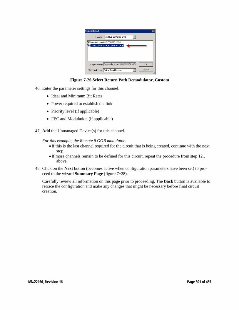
MN/22156, Revision 16 Page 301 of 455
Figure 7-26 Select Return Path Demodulator, Custom
46. Enter the parameter settings for this channel:
• Ideal and Minimum Bit Rates
• Power required to establish the link
• Priority level (if applicable)
• FEC and Modulation (if applicable)
47. Add the Unmanaged Device(s) for this channel.
For this example, the Remote 8 OOB modulator. • If this is the last channel required for the circuit that is being created, continue with the next
step. • If more channels remain to be defined for this circuit, repeat the procedure from step 12.,
above.
48. Click on the Next button (becomes active when configuration parameters have been set) to pro-ceed to the wizard Summary Page (figure 7-28).
Carefully review all information on this page prior to proceeding. The Back button is available to retrace the configuration and make any changes that might be necessary before final circuit creation.
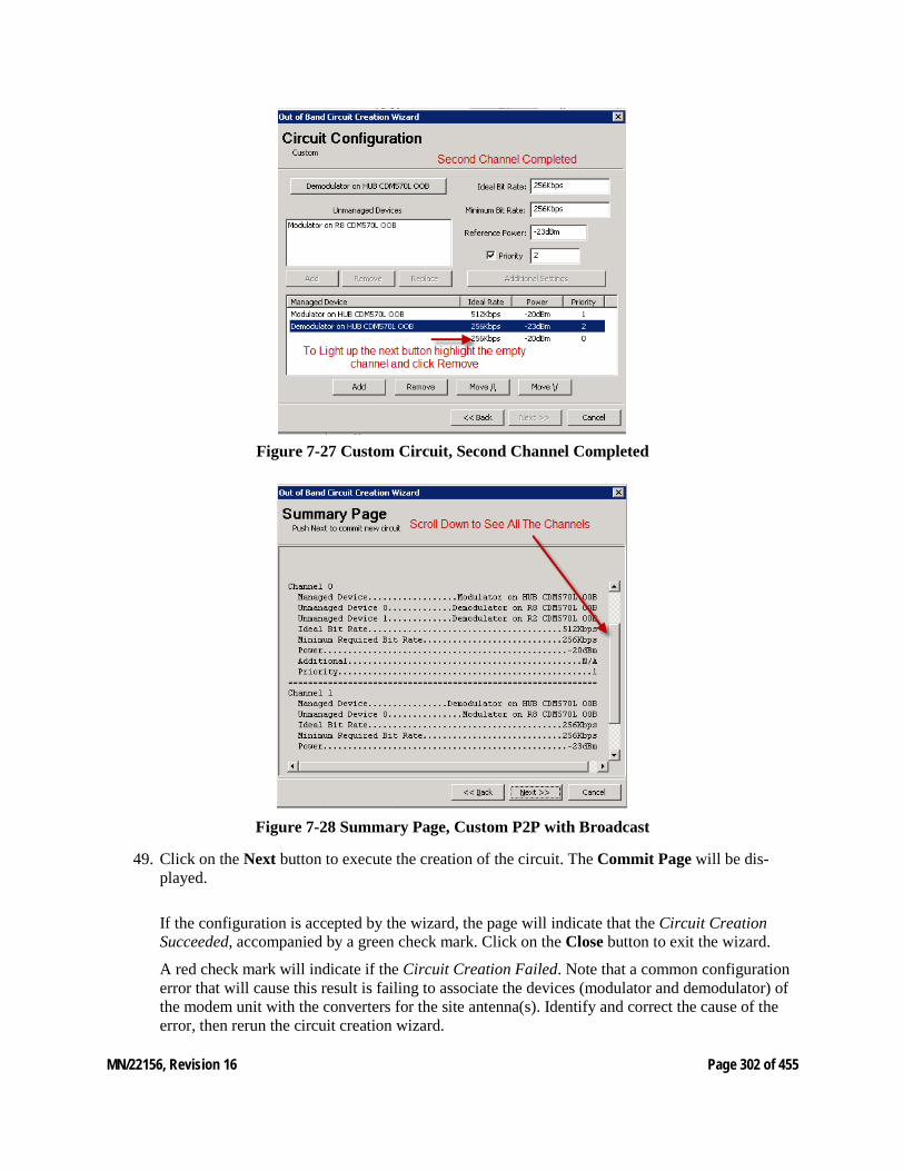
MN/22156, Revision 16 Page 302 of 455
Figure 7-27 Custom Circuit, Second Channel Completed
Figure 7-28 Summary Page, Custom P2P with Broadcast
49. Click on the Next button to execute the creation of the circuit. The Commit Page will be dis-played.
If the configuration is accepted by the wizard, the page will indicate that the Circuit Creation Succeeded, accompanied by a green check mark. Click on the Close button to exit the wizard.
A red check mark will indicate if the Circuit Creation Failed. Note that a common configuration error that will cause this result is failing to associate the devices (modulator and demodulator) of the modem unit with the converters for the site antenna(s). Identify and correct the cause of the error, then rerun the circuit creation wizard.
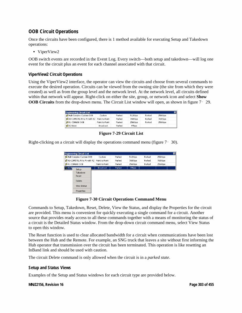
MN/22156, Revision 16 Page 303 of 455
OOB Circuit Operations Once the circuits have been configured, there is 1 method available for executing Setup and Takedown operations:
• ViperView2
OOB switch events are recorded in the Event Log. Every switch—both setup and takedown—will log one event for the circuit plus an event for each channel associated with that circuit.
ViperView2 Circuit Operations Using the ViperView2 interface, the operator can view the circuits and choose from several commands to execute the desired operation. Circuits can be viewed from the owning site (the site from which they were created) as well as from the group level and the network level. At the network level, all circuits defined within that network will appear. Right-click on either the site, group, or network icon and select Show OOB Circuits from the drop-down menu. The Circuit List window will open, as shown in figure 7‑ 29.
Figure 7-29 Circuit List
Right-clicking on a circuit will display the operations command menu (figure 7‑ 30).
Figure 7-30 Circuit Operations Command Menu
Commands to Setup, Takedown, Reset, Delete, View the Status, and display the Properties for the circuit are provided. This menu is convenient for quickly executing a single command for a circuit. Another source that provides ready access to all these commands together with a means of monitoring the status of a circuit is the Detailed Status window. From the drop-down circuit command menu, select View Status to open this window.
The Reset function is used to clear allocated bandwidth for a circuit when communications have been lost between the Hub and the Remote. For example, an SNG truck that leaves a site without first informing the Hub operator that transmission over the circuit has been terminated. This operation is like resetting an InBand link and should be used with caution.
The circuit Delete command is only allowed when the circuit is in a parked state.
Setup and Status Views Examples of the Setup and Status windows for each circuit type are provided below.
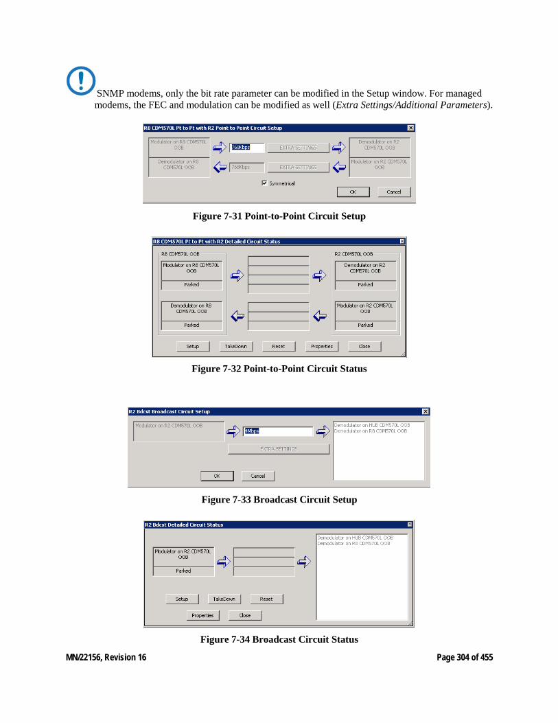
MN/22156, Revision 16 Page 304 of 455
SNMP modems, only the bit rate parameter can be modified in the Setup window. For managed modems, the FEC and modulation can be modified as well (Extra Settings/Additional Parameters).
Figure 7-31 Point-to-Point Circuit Setup
Figure 7-32 Point-to-Point Circuit Status
Figure 7-33 Broadcast Circuit Setup
Figure 7-34 Broadcast Circuit Status
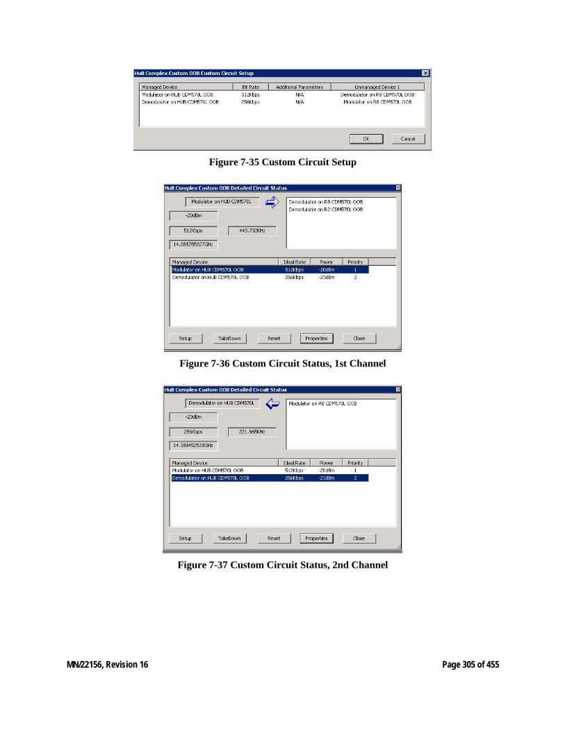
MN/22156, Revision 16 Page 305 of 455
Figure 7-35 Custom Circuit Setup
Figure 7-36 Custom Circuit Status, 1st Channel
Figure 7-37 Custom Circuit Status, 2nd Channel
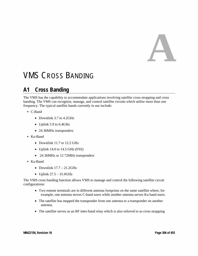
MN/22156, Revision 16 Page 306 of 455
A VMS CROSS BANDING A1 Cross Banding The VMS has the capability to accommodate applications involving satellite cross strapping and cross banding. The VMS can recognize, manage, and control satellite circuits which utilize more than one frequency. The typical satellite bands currently in use include:
• C-Band
• Downlink 3.7 to 4.2GHz
• Uplink 5.9 to 6.4GHz
• 24 36MHz transponders
• Ku-Band
• Downlink 11.7 to 12.2 GHz
• Uplink 14.0 to 14.5 GHz (FSS)
• 24 36MHz or 12 72MHz transponders
• Ka-Band
• Downlink 17.7 – 21.2GHz
• Uplink 27.5 – 31.0GHz
The VMS cross banding function allows VMS to manage and control the following satellite circuit configurations:
• Two remote terminals are in different antenna footprints on the same satellite where, for example, one antenna serves C-band users while another antenna serves Ku band users.
• The satellite has mapped the transponder from one antenna to a transponder on another antenna.
• The satellite serves as an RF inter-band relay which is also referred to as cross strapping
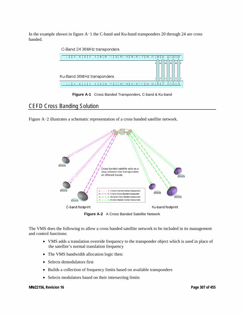
MN/22156, Revision 16 Page 307 of 455
In the example shown in figure A-1 the C-band and Ku-band transponders 20 through 24 are cross banded.
Figure A‑1 Cross Banded Transponders, C-band & Ku-band
CEFD Cross Banding Solution
Figure A-2 illustrates a schematic representation of a cross banded satellite network.
Figure A‑2 A Cross Banded Satellite Network
The VMS does the following to allow a cross banded satellite network to be included in its management and control functions:
• VMS adds a translation override frequency to the transponder object which is used in place of the satellite’s normal translation frequency
• The VMS bandwidth allocation logic then:
• Selects demodulators first
• Builds a collection of frequency limits based on available transponders
• Selects modulators based on their intersecting limits
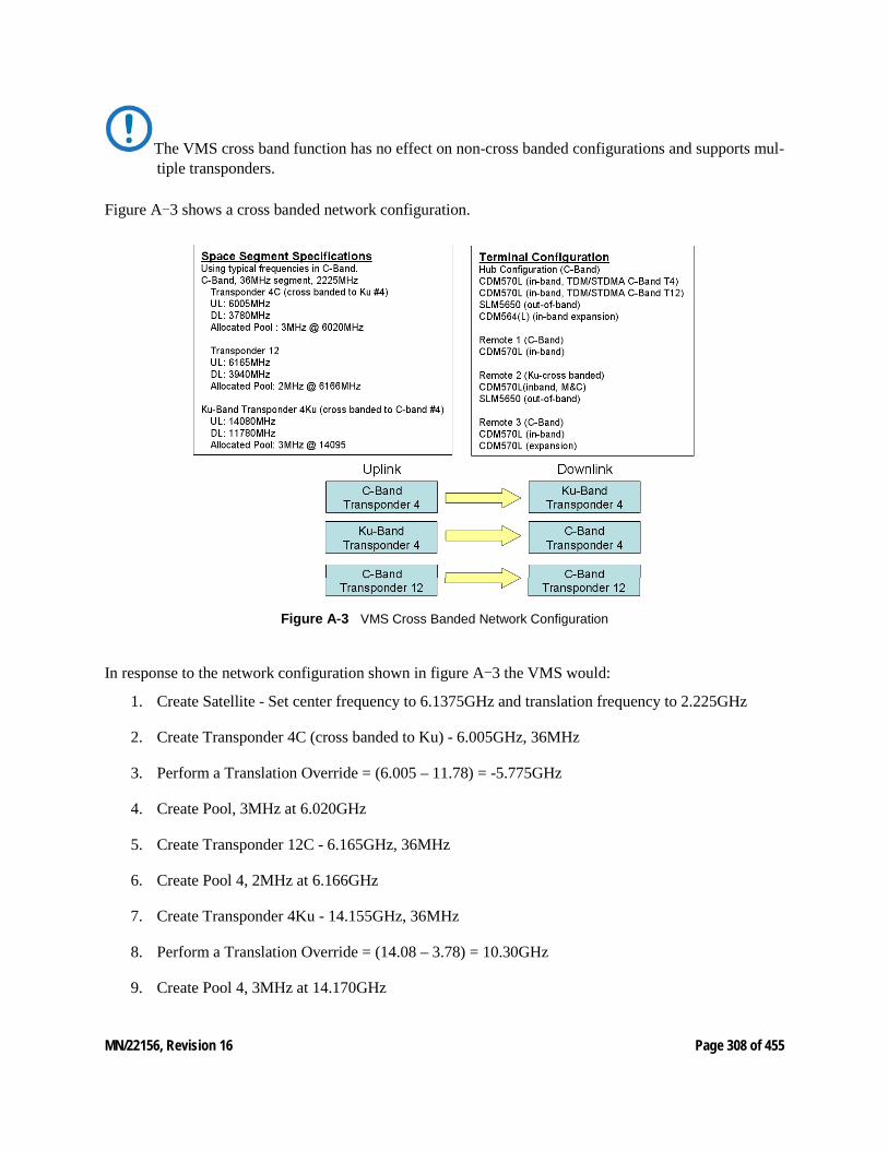
MN/22156, Revision 16 Page 308 of 455
The VMS cross band function has no effect on non-cross banded configurations and supports mul-tiple transponders.
Figure A-3 shows a cross banded network configuration.
Figure A‑3 VMS Cross Banded Network Configuration
In response to the network configuration shown in figure A-3 the VMS would:
1. Create Satellite - Set center frequency to 6.1375GHz and translation frequency to 2.225GHz
2. Create Transponder 4C (cross banded to Ku) - 6.005GHz, 36MHz
3. Perform a Translation Override = (6.005 – 11.78) = -5.775GHz
4. Create Pool, 3MHz at 6.020GHz
5. Create Transponder 12C - 6.165GHz, 36MHz
6. Create Pool 4, 2MHz at 6.166GHz
7. Create Transponder 4Ku - 14.155GHz, 36MHz
8. Perform a Translation Override = (14.08 – 3.78) = 10.30GHz
9. Create Pool 4, 3MHz at 14.170GHz
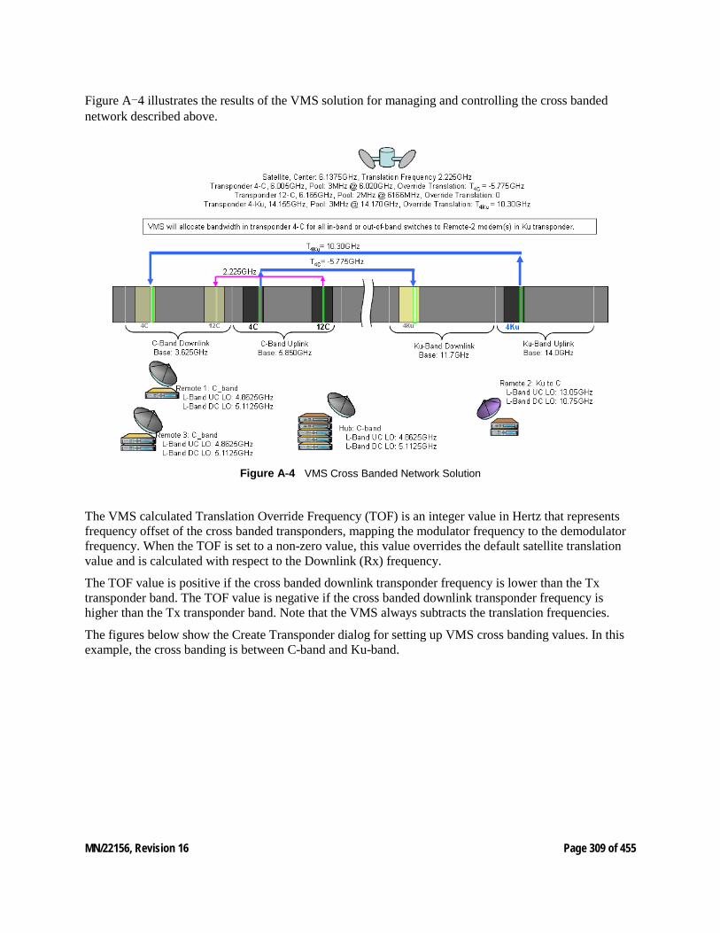
MN/22156, Revision 16 Page 309 of 455
Figure A-4 illustrates the results of the VMS solution for managing and controlling the cross banded network described above.
Figure A‑4 VMS Cross Banded Network Solution
The VMS calculated Translation Override Frequency (TOF) is an integer value in Hertz that represents frequency offset of the cross banded transponders, mapping the modulator frequency to the demodulator frequency. When the TOF is set to a non-zero value, this value overrides the default satellite translation value and is calculated with respect to the Downlink (Rx) frequency.
The TOF value is positive if the cross banded downlink transponder frequency is lower than the Tx transponder band. The TOF value is negative if the cross banded downlink transponder frequency is higher than the Tx transponder band. Note that the VMS always subtracts the translation frequencies.
The figures below show the Create Transponder dialog for setting up VMS cross banding values. In this example, the cross banding is between C-band and Ku-band.
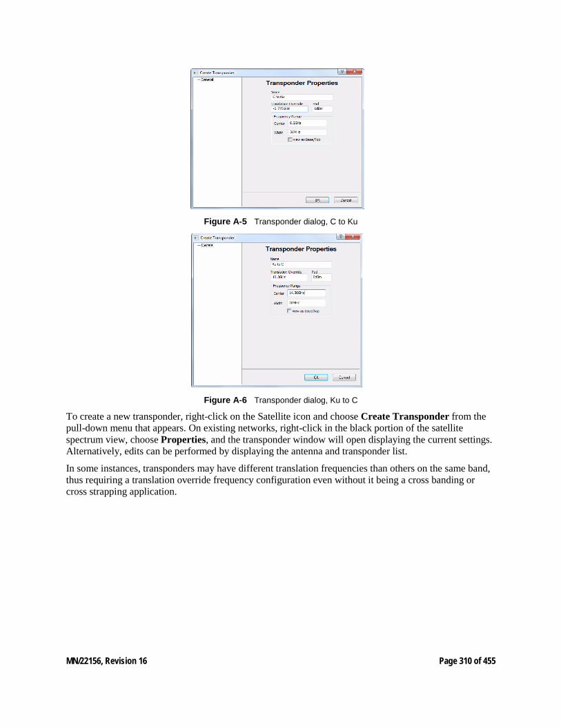
MN/22156, Revision 16 Page 310 of 455
Figure A‑5 Transponder dialog, C to Ku
Figure A‑6 Transponder dialog, Ku to C
To create a new transponder, right-click on the Satellite icon and choose Create Transponder from the pull-down menu that appears. On existing networks, right-click in the black portion of the satellite spectrum view, choose Properties, and the transponder window will open displaying the current settings. Alternatively, edits can be performed by displaying the antenna and transponder list.
In some instances, transponders may have different translation frequencies than others on the same band, thus requiring a translation override frequency configuration even without it being a cross banding or cross strapping application.

MN/22156, Revision 16 Page 311 of 455
B ANTENNA VISIBILITY B1 Antenna Visibility General Antenna Visibility is a powerful tool in the VMS that allows an operator to control the spectrum used by the VMS switching engine. Simply stated, it allows the operator on a site by site basis to block portions of the satellite or transponder bandwidth from being used by the RF manager, even if a defined bandwidth pool exists within the blocked portion.
Antenna visibility can be used in a variety of ways. However, great care must be taken when implementing this powerful tool in a CEFD satellite network, or unexpected results will occur.
Do Not use antenna visibility without a thorough understanding of the mechanics involved. It is highly recommended that an operator completes the CEFD Advanced VMS training course that includes coverage of Antenna Visibility prior to configuring a live network with this feature.
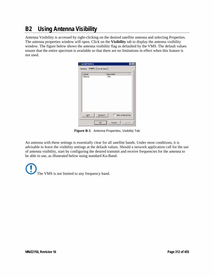
MN/22156, Revision 16 Page 312 of 455
B2 Using Antenna Visibility Antenna Visibility is accessed by right-clicking on the desired satellite antenna and selecting Properties. The antenna properties window will open. Click on the Visibility tab to display the antenna visibility window. The figure below shows the antenna visibility flag as defaulted by the VMS. The default values ensure that the entire spectrum is available so that there are no limitations in effect when this feature is not used.
Figure B‑1 Antenna Properties, Visibility Tab
An antenna with these settings is essentially clear for all satellite bands. Under most conditions, it is advisable to leave the visibility settings at the default values. Should a network application call for the use of antenna visibility, start by configuring the desired transmit and receive frequencies for the antenna to be able to use, as illustrated below using standard Ku-Band.
The VMS is not limited to any frequency band.
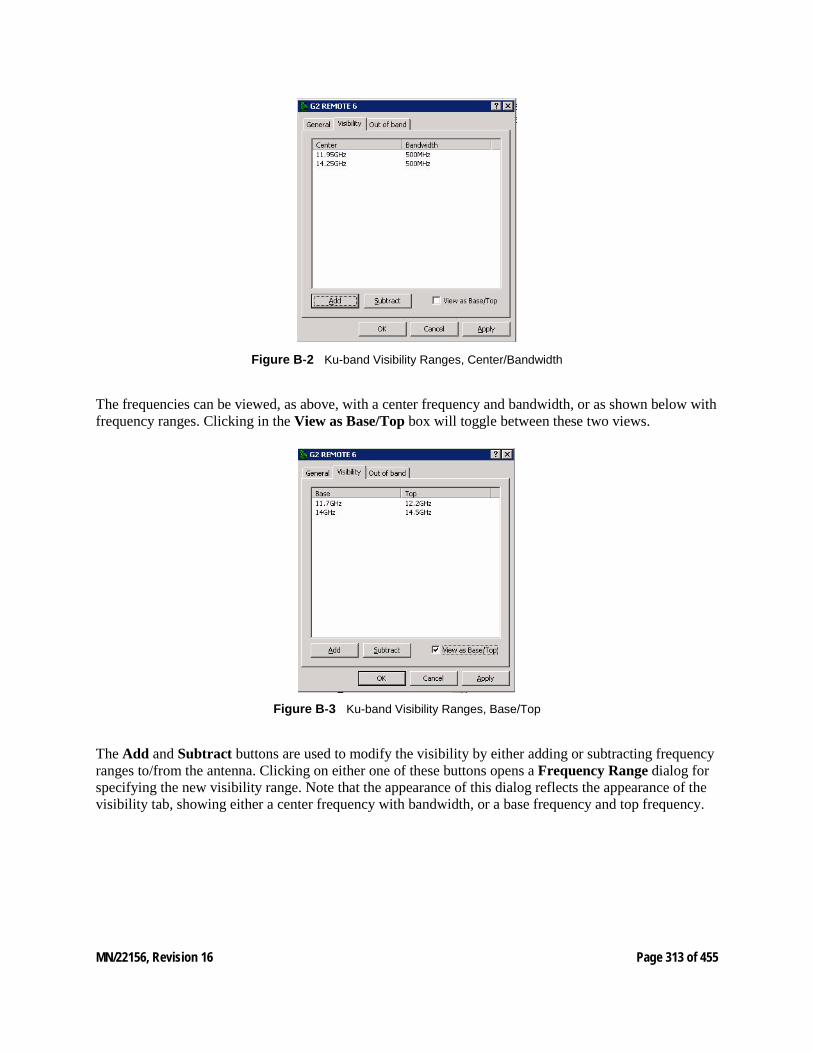
MN/22156, Revision 16 Page 313 of 455
Figure B‑2 Ku-band Visibility Ranges, Center/Bandwidth
The frequencies can be viewed, as above, with a center frequency and bandwidth, or as shown below with frequency ranges. Clicking in the View as Base/Top box will toggle between these two views.
Figure B‑3 Ku-band Visibility Ranges, Base/Top
The Add and Subtract buttons are used to modify the visibility by either adding or subtracting frequency ranges to/from the antenna. Clicking on either one of these buttons opens a Frequency Range dialog for specifying the new visibility range. Note that the appearance of this dialog reflects the appearance of the visibility tab, showing either a center frequency with bandwidth, or a base frequency and top frequency.
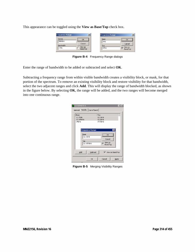
MN/22156, Revision 16 Page 314 of 455
This appearance can be toggled using the View as Base/Top check box.
Figure B‑4 Frequency Range dialogs
Enter the range of bandwidth to be added or subtracted and select OK.
Subtracting a frequency range from within visible bandwidth creates a visibility block, or mask, for that portion of the spectrum. To remove an existing visibility block and restore visibility for that bandwidth, select the two adjacent ranges and click Add. This will display the range of bandwidth blocked, as shown in the figure below. By selecting OK, the range will be added, and the two ranges will become merged into one continuous range.
Figure B‑5 Merging Visibility Ranges
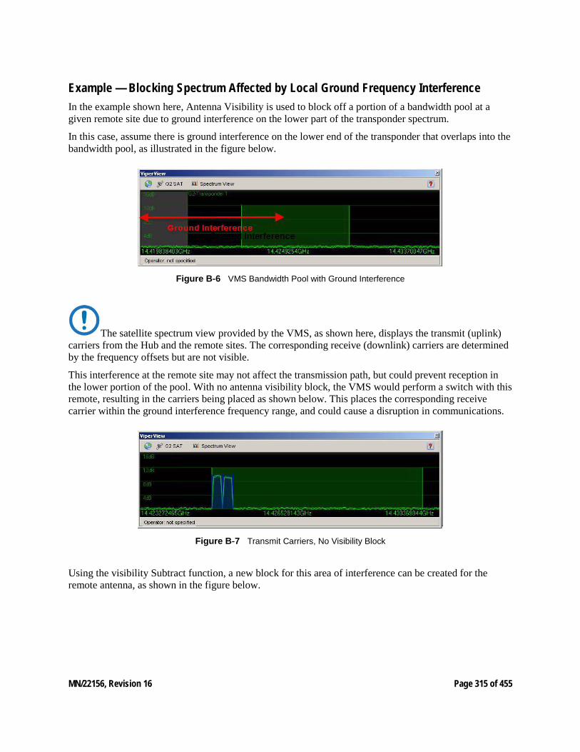
MN/22156, Revision 16 Page 315 of 455
Example — Blocking Spectrum Affected by Local Ground Frequency Interference In the example shown here, Antenna Visibility is used to block off a portion of a bandwidth pool at a given remote site due to ground interference on the lower part of the transponder spectrum.
In this case, assume there is ground interference on the lower end of the transponder that overlaps into the bandwidth pool, as illustrated in the figure below.
Figure B‑6 VMS Bandwidth Pool with Ground Interference
The satellite spectrum view provided by the VMS, as shown here, displays the transmit (uplink) carriers from the Hub and the remote sites. The corresponding receive (downlink) carriers are determined by the frequency offsets but are not visible.
This interference at the remote site may not affect the transmission path, but could prevent reception in the lower portion of the pool. With no antenna visibility block, the VMS would perform a switch with this remote, resulting in the carriers being placed as shown below. This places the corresponding receive carrier within the ground interference frequency range, and could cause a disruption in communications.
Figure B‑7 Transmit Carriers, No Visibility Block
Using the visibility Subtract function, a new block for this area of interference can be created for the remote antenna, as shown in the figure below.
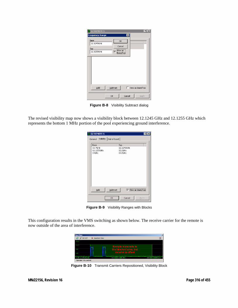
MN/22156, Revision 16 Page 316 of 455
Figure B‑8 Visibility Subtract dialog
The revised visibility map now shows a visibility block between 12.1245 GHz and 12.1255 GHz which represents the bottom 1 MHz portion of the pool experiencing ground interference.
Figure B‑9 Visibility Ranges with Blocks
This configuration results in the VMS switching as shown below. The receive carrier for the remote is now outside of the area of interference.
Figure B‑10 Transmit Carriers Repositioned, Visibility Block
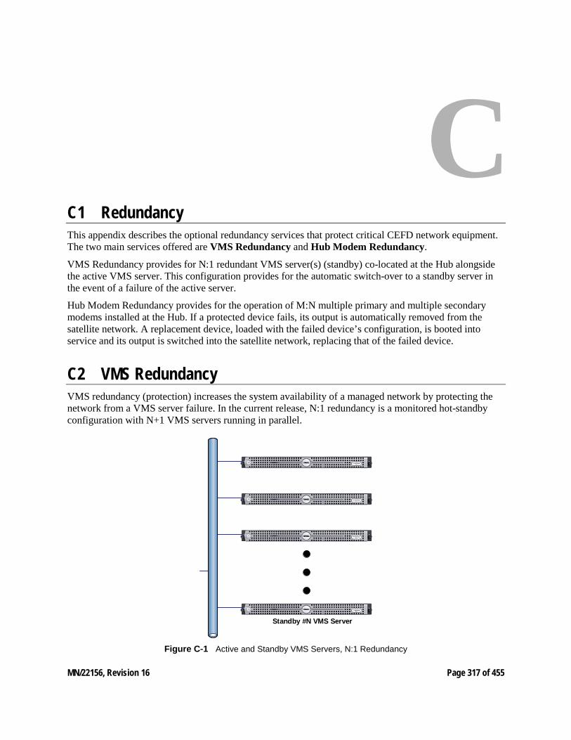
MN/22156, Revision 16 Page 317 of 455
C C1 Redundancy This appendix describes the optional redundancy services that protect critical CEFD network equipment. The two main services offered are VMS Redundancy and Hub Modem Redundancy.
VMS Redundancy provides for N:1 redundant VMS server(s) (standby) co-located at the Hub alongside the active VMS server. This configuration provides for the automatic switch-over to a standby server in the event of a failure of the active server.
Hub Modem Redundancy provides for the operation of M:N multiple primary and multiple secondary modems installed at the Hub. If a protected device fails, its output is automatically removed from the satellite network. A replacement device, loaded with the failed device’s configuration, is booted into service and its output is switched into the satellite network, replacing that of the failed device.
C2 VMS Redundancy VMS redundancy (protection) increases the system availability of a managed network by protecting the network from a VMS server failure. In the current release, N:1 redundancy is a monitored hot-standby configuration with N+1 VMS servers running in parallel.
Standby #N VMS Server
Figure C‑1 Active and Standby VMS Servers, N:1 Redundancy
MN/22156, Revision 16 Page 318 of 455
Each server can switch between two mutually exclusive modes of active or standby. The active/standby hierarchy is specified through the assignment of a priority level attribute. In the event that the active server fails, the backup server with the highest priority is hot-switched to assume control of the satellite network, replacing the failed server.
The redundant VMS protection feature can only be activated with a valid license in the server(s) USB Crypto-Box key.
MN/22156, Revision 16 Page 319 of 455
C3 Redundant Hot-Standby In a redundant configuration, the VMS servers run in parallel. The VMS database on the standby server(s) is continuously maintained, in real-time, as a mirror image of the VMS database running on the active server.
It is recommended that all servers be co-located at the same site and be connected to the same Ethernet LAN. The monitoring workstation should also be co-located. This is to eliminate reliability is-sues that may be associated with the terrestrial data-link communications between a geographically re-mote server and NOC units. A data-link failure may result in contention of automatic switch-over control and interruption of restoral processing.
Protection Switch-over If the active server fails, the VMS protected by N:1 redundancy immediately switches to a standby server. The VMS running on the standby server picks up and executes the ongoing network management tasks until the failure in the active VMS server is resolved by human intervention.
Both the active and standby servers operate in a query-peer mode to determine which server is to be the active VMS server in the network.
If, for example, the active VMS server fails causing a protection switch, a standby VMS server assumes control of the network. While the standby server is actively managing the live network, a previously active server that is being restarted cannot assume the active server role without first checking for the presence of an active VMS server already managing the network. The process for initiating and managing the transitions between active to standby modes is described below.
Active to Standby Switch This transition occurs whenever:
• An automatic switch-over is triggered by the failure detection mechanism due to active VMS failure,
or
• A manual switch-over is invoked from the active console by, for example, taking down the active server for maintenance.
A switch-over from the currently active server back to the server with higher priority (once recovered) is NOT automatic. An operator must manually perform the switch at the active server’s console.
When a server with a higher priority is restarted, the VMS on the server detects an active peer on the network (a previous standby server) and automatically enters standby mode and remains in standby mode until either an operator manually switches the server back to active mode, or a failure occurs causing an automatic switch-over.
For instructions on performing a manual switch-over, refer to the section “Manual Switching”.
MN/22156, Revision 16 Page 320 of 455
Active Server Role The active VMS server has the following specific privileges that differ from a standby server:
• There can be only one (1) VMS server actively managing the network.
• The active server is considered the default VMS server for configuration and network topology purposes.
• The active server's database is considered the master copy. The standby server(s) receives a copy of the master database from the active server as a part of its start-up process and automatic synchronization.
• The first VMS server to come on-line assumes the active mode provided that all redundant servers are online, and no other server is operating in active mode.
• The active server is the only unit that may initiate a manual protection switch-over (a transition from active-to-standby mode or standby-to-active mode). This is a two-step event controlled by the operator/administrator: The Active server is first Deactivated, then a Standby server is Activated.
Standby Server Role A VMS standby server has the following specific functions that differ from the active VMS server:
• Upon startup, a standby VMS enters a query-peer mode where it attempts to discover a peer VMS in active mode. The VMS enters a standby mode when an active VMS is discovered.
• A standby VMS server's default mode is standby. It can only enter active as a result of a protection switch, either automatic or manual.
Automatic VMS Activation An Auto Activate function is available to resolve any activation conflicts in the event that all servers go offline temporarily. Once the servers return to online status, the server that was the last active will automatically reactivate and assume the active role.
C4 Server Synchronization Server synchronization is always executed by/from the active VMS server, and is performed to ensure that all standby servers receive any necessary updates due to changes in the master database that resides in the active server. Two types of server synchronization occur with a redundant VMS configuration, automatic and manual.
Automatic Synchronization As the name implies, automatic synchronization occurs automatically by the active VMS and is performed whenever any changes occur that are associated with automatic system functions, such as automatic switching, device redundancy, etc. The active server maintains a memory cache that holds the updates until they can be pushed out to the standby servers by an automatic synchronization that occurs during the VMS heartbeat. The updates are tagged onto the heartbeat message that is sent by the active server to the standby servers.
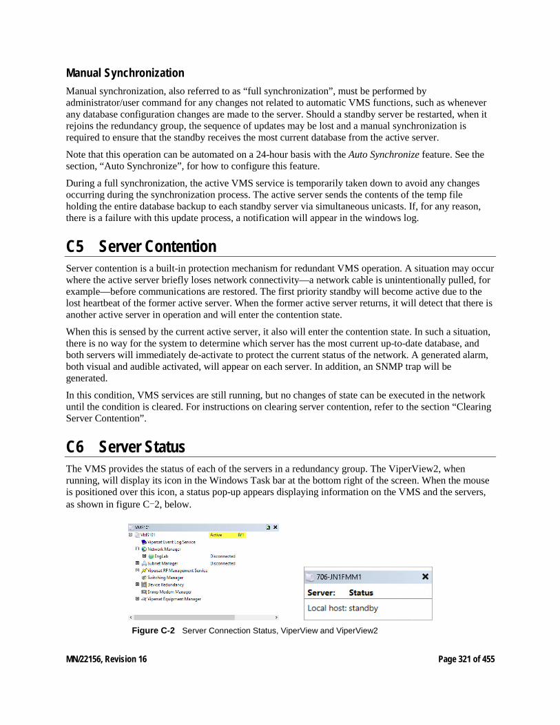
MN/22156, Revision 16 Page 321 of 455
Manual Synchronization Manual synchronization, also referred to as “full synchronization”, must be performed by administrator/user command for any changes not related to automatic VMS functions, such as whenever any database configuration changes are made to the server. Should a standby server be restarted, when it rejoins the redundancy group, the sequence of updates may be lost and a manual synchronization is required to ensure that the standby receives the most current database from the active server.
Note that this operation can be automated on a 24-hour basis with the Auto Synchronize feature. See the section, “Auto Synchronize”, for how to configure this feature.
During a full synchronization, the active VMS service is temporarily taken down to avoid any changes occurring during the synchronization process. The active server sends the contents of the temp file holding the entire database backup to each standby server via simultaneous unicasts. If, for any reason, there is a failure with this update process, a notification will appear in the windows log.
C5 Server Contention Server contention is a built-in protection mechanism for redundant VMS operation. A situation may occur where the active server briefly loses network connectivity—a network cable is unintentionally pulled, for example—before communications are restored. The first priority standby will become active due to the lost heartbeat of the former active server. When the former active server returns, it will detect that there is another active server in operation and will enter the contention state.
When this is sensed by the current active server, it also will enter the contention state. In such a situation, there is no way for the system to determine which server has the most current up-to-date database, and both servers will immediately de-activate to protect the current status of the network. A generated alarm, both visual and audible activated, will appear on each server. In addition, an SNMP trap will be generated.
In this condition, VMS services are still running, but no changes of state can be executed in the network until the condition is cleared. For instructions on clearing server contention, refer to the section “Clearing Server Contention”.
C6 Server Status The VMS provides the status of each of the servers in a redundancy group. The ViperView2, when running, will display its icon in the Windows Task bar at the bottom right of the screen. When the mouse is positioned over this icon, a status pop-up appears displaying information on the VMS and the servers, as shown in figure C-2, below.
Figure C‑2 Server Connection Status, ViperView and ViperView2
MN/22156, Revision 16 Page 322 of 455
There are four possible server states:
• active
• standby
• contention
• disconnected
If no servers are connected, the status message will read “Vipersat Management System Disconnected”.
The server to which the console is currently connected (the local server) is identified by whatever was entered in the Connect To dialog; either its assigned name or its IP address (as appears in the first line of the example shown in figure C-2). The next server status that is displayed is that of the local server, followed by any remote servers listed by their IP address.
C7 Installing & Configuring VMS Server Redundancy Installation of a redundant VMS server configuration in a VMS controlled network requires the following:
• Two or more dedicated servers and a client workstation.
• The servers and the workstation should be co-located (in the same physical location) and connected to the same Ethernet LAN.
• A dedicated IP address for each VMS server.
• A common domain for the redundant servers and the client workstation.
Starting a redundant VMS configuration requires bringing up the VMS servers and the workstation using the following procedure:
1. Install VMS on each of the servers following the instruction in Chapter 1, “General”.
2. Start the Vipersat Management System service and ViperView2. Select Vipersat Management System from Windows Services and Start the service, if it is not already running. Note: It is recommended that this service be configured for Automatic Startup. Click ViperView2 on the path: Start > All Programs > VMS 3.x> ViperView2 The ViperView2 will prompt for the server to connect to. Select the server that is to be the initial Active server; typically, this is the server with the highest priority setting. The ViperView2 window will appear as shown in figure C-3.

MN/22156, Revision 16 Page 323 of 455
Figure C‑3 ViperView2, VMS Server Drop-down Menu
3. From the VMS Server drop-down menu, select the Properties command to display the VMS Server dialog window, shown in figure C-4.
The Status tab is displayed, providing the current status information for this server.
Figure C‑4 VMS Server Properties, Status Tab
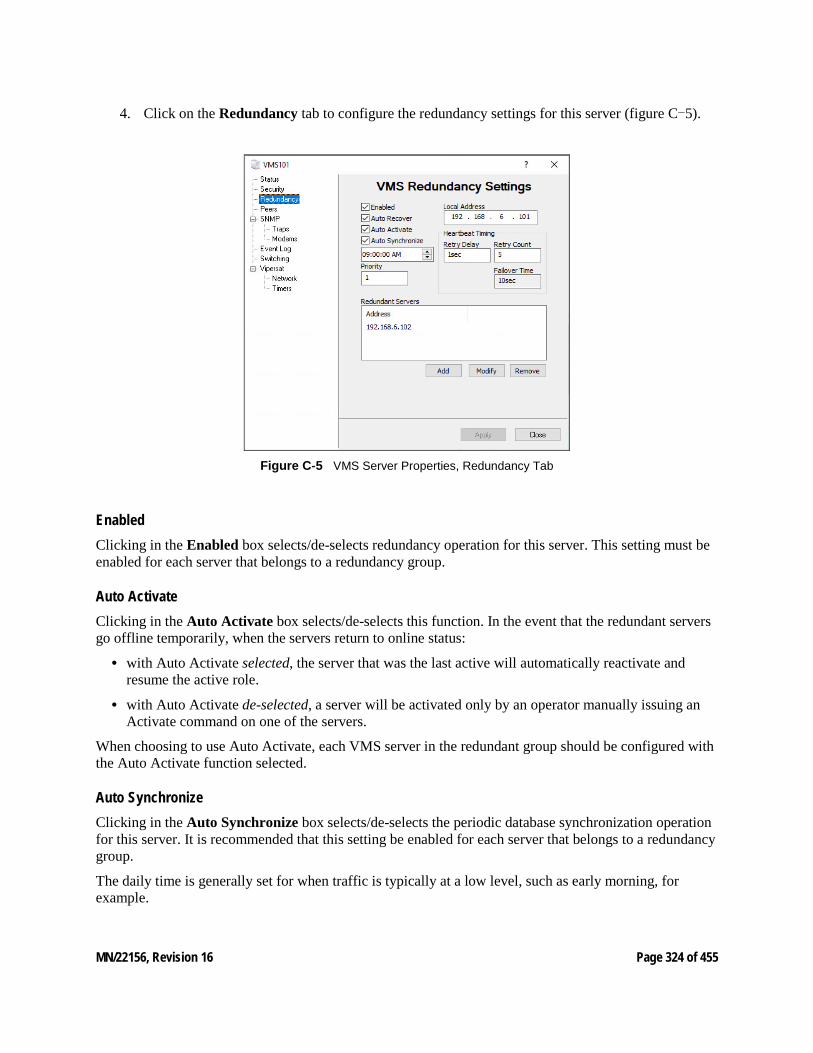
MN/22156, Revision 16 Page 324 of 455
4. Click on the Redundancy tab to configure the redundancy settings for this server (figure C-5).
Figure C‑5 VMS Server Properties, Redundancy Tab
Enabled Clicking in the Enabled box selects/de-selects redundancy operation for this server. This setting must be enabled for each server that belongs to a redundancy group.
Auto Activate Clicking in the Auto Activate box selects/de-selects this function. In the event that the redundant servers go offline temporarily, when the servers return to online status:
• with Auto Activate selected, the server that was the last active will automatically reactivate and resume the active role.
• with Auto Activate de-selected, a server will be activated only by an operator manually issuing an Activate command on one of the servers.
When choosing to use Auto Activate, each VMS server in the redundant group should be configured with the Auto Activate function selected.
Auto Synchronize Clicking in the Auto Synchronize box selects/de-selects the periodic database synchronization operation for this server. It is recommended that this setting be enabled for each server that belongs to a redundancy group.
The daily time is generally set for when traffic is typically at a low level, such as early morning, for example.
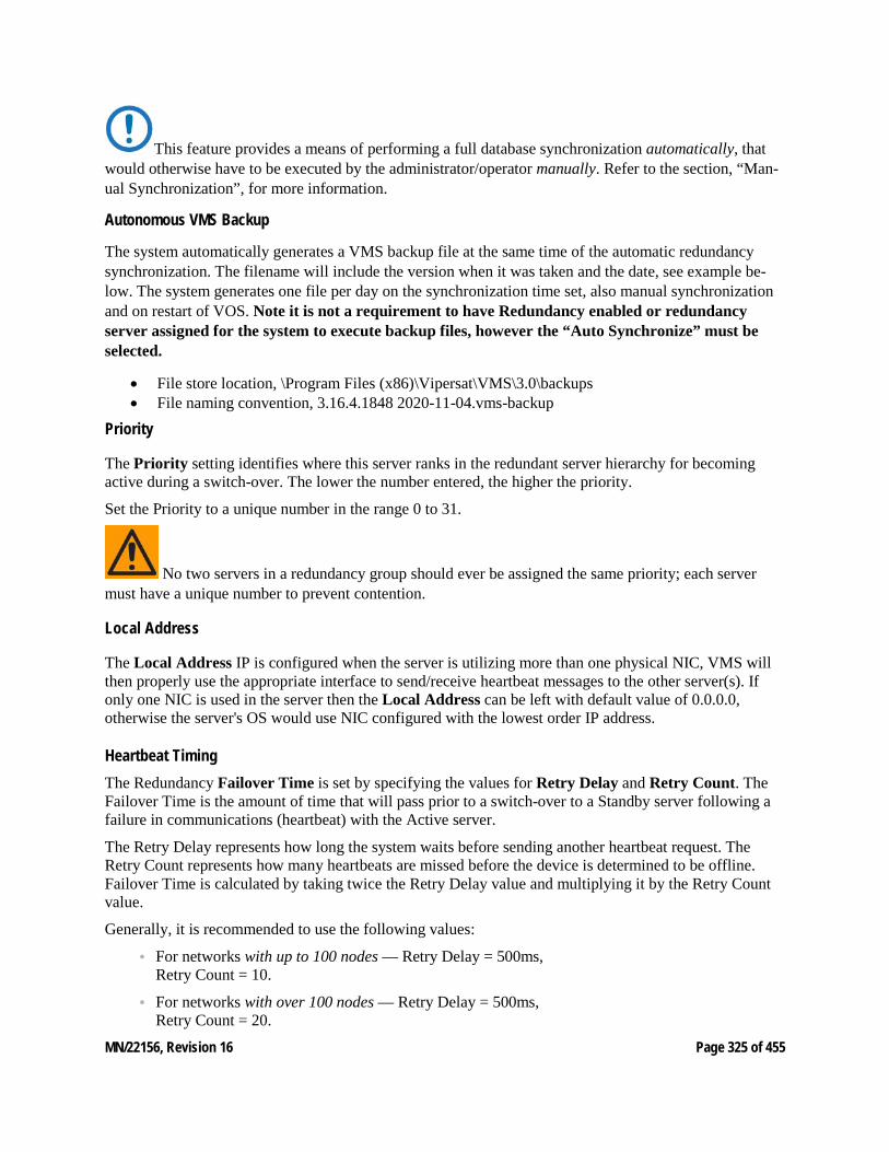
MN/22156, Revision 16 Page 325 of 455
This feature provides a means of performing a full database synchronization automatically, that would otherwise have to be executed by the administrator/operator manually. Refer to the section, “Man-ual Synchronization”, for more information.
Autonomous VMS Backup
The system automatically generates a VMS backup file at the same time of the automatic redundancy synchronization. The filename will include the version when it was taken and the date, see example be-low. The system generates one file per day on the synchronization time set, also manual synchronization and on restart of VOS. Note it is not a requirement to have Redundancy enabled or redundancy server assigned for the system to execute backup files, however the “Auto Synchronize” must be selected.
• File store location, \Program Files (x86)\Vipersat\VMS\3.0\backups • File naming convention, 3.16.4.1848 2020-11-04.vms-backup
Priority
The Priority setting identifies where this server ranks in the redundant server hierarchy for becoming active during a switch-over. The lower the number entered, the higher the priority.
Set the Priority to a unique number in the range 0 to 31.
No two servers in a redundancy group should ever be assigned the same priority; each server must have a unique number to prevent contention.
Local Address
The Local Address IP is configured when the server is utilizing more than one physical NIC, VMS will then properly use the appropriate interface to send/receive heartbeat messages to the other server(s). If only one NIC is used in the server then the Local Address can be left with default value of 0.0.0.0, otherwise the server's OS would use NIC configured with the lowest order IP address.
Heartbeat Timing The Redundancy Failover Time is set by specifying the values for Retry Delay and Retry Count. The Failover Time is the amount of time that will pass prior to a switch-over to a Standby server following a failure in communications (heartbeat) with the Active server.
The Retry Delay represents how long the system waits before sending another heartbeat request. The Retry Count represents how many heartbeats are missed before the device is determined to be offline. Failover Time is calculated by taking twice the Retry Delay value and multiplying it by the Retry Count value.
Generally, it is recommended to use the following values:
• For networks with up to 100 nodes — Retry Delay = 500ms, Retry Count = 10.
• For networks with over 100 nodes — Retry Delay = 500ms, Retry Count = 20.
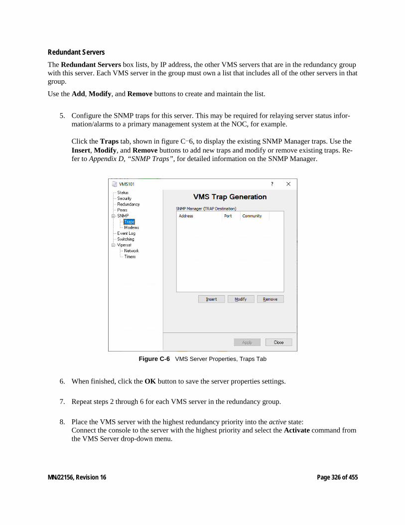
MN/22156, Revision 16 Page 326 of 455
Redundant Servers The Redundant Servers box lists, by IP address, the other VMS servers that are in the redundancy group with this server. Each VMS server in the group must own a list that includes all of the other servers in that group.
Use the Add, Modify, and Remove buttons to create and maintain the list.
5. Configure the SNMP traps for this server. This may be required for relaying server status infor-mation/alarms to a primary management system at the NOC, for example. Click the Traps tab, shown in figure C-6, to display the existing SNMP Manager traps. Use the Insert, Modify, and Remove buttons to add new traps and modify or remove existing traps. Re-fer to Appendix D, “SNMP Traps”, for detailed information on the SNMP Manager.
Figure C‑6 VMS Server Properties, Traps Tab
6. When finished, click the OK button to save the server properties settings.
7. Repeat steps 2 through 6 for each VMS server in the redundancy group.
8. Place the VMS server with the highest redundancy priority into the active state: Connect the console to the server with the highest priority and select the Activate command from the VMS Server drop-down menu.
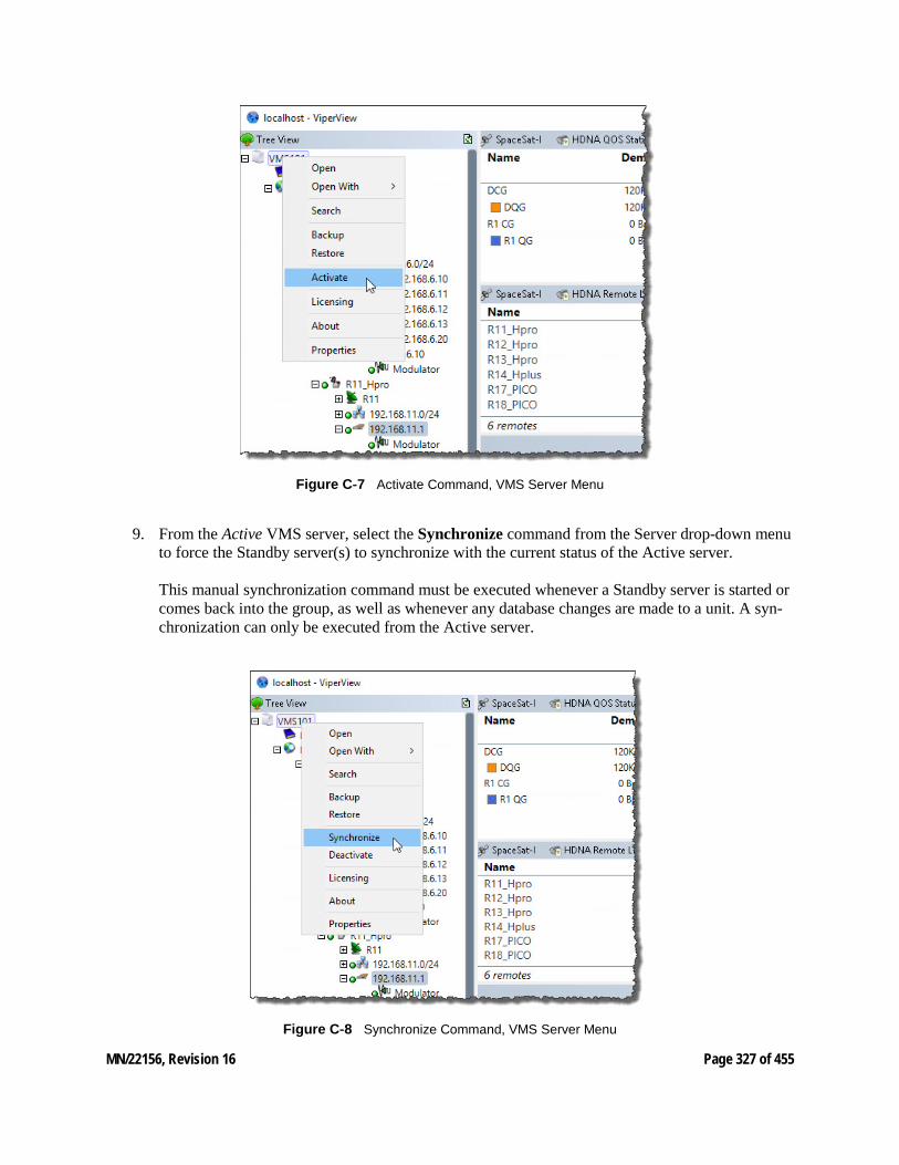
MN/22156, Revision 16 Page 327 of 455
Figure C‑7 Activate Command, VMS Server Menu
9. From the Active VMS server, select the Synchronize command from the Server drop-down menu to force the Standby server(s) to synchronize with the current status of the Active server. This manual synchronization command must be executed whenever a Standby server is started or comes back into the group, as well as whenever any database changes are made to a unit. A syn-chronization can only be executed from the Active server.
Figure C‑8 Synchronize Command, VMS Server Menu
MN/22156, Revision 16 Page 328 of 455
• The next step is to configure the VMS database for the satellite network on the Active server. Refer to Chapter 3, “VMS Configuration”, for details on this procedure.
• Once the VMS configuration is completed on the Active server, perform a server synchronization to synch the Standby server database(s) with the Active server database.
C8 Manual Switching Manual switching can be used to designate a different server to be the active VMS server in the redundancy group.
1. From the currently active server, right-click on the server icon in Viperview to display the pull-down menu and select Deactivate.
2. From the standby server that will become the new active server, right-click on the server icon in Viperview and select Activate.
3. Verify the new server status using ViperView2.
C9 Clearing Server Contention Should contention for active status between two VMS servers occur, use the following procedure to clear the condition.
1. From Viperview, right-click on the server icon and select Clear Contention from the pull-down menu that appears. A pop-up message will appear on the console indicating that the server will enter standby mode, and that the contention on the other server must also be cleared before this server status can be changed to active.
2. Repeat the previous step for the second server in contention.
3. Determine which server is to be made active (typically, the server with the highest priority) and select the Activate command. This server will become active and the other server will remain in standby mode.
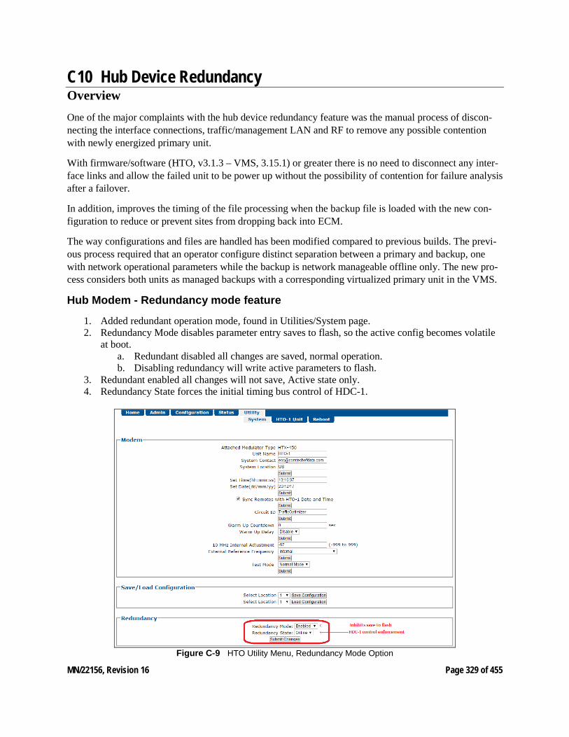
MN/22156, Revision 16 Page 329 of 455
C10 Hub Device Redundancy Overview One of the major complaints with the hub device redundancy feature was the manual process of discon-necting the interface connections, traffic/management LAN and RF to remove any possible contention with newly energized primary unit.
With firmware/software (HTO, v3.1.3 – VMS, 3.15.1) or greater there is no need to disconnect any inter-face links and allow the failed unit to be power up without the possibility of contention for failure analysis after a failover.
In addition, improves the timing of the file processing when the backup file is loaded with the new con-figuration to reduce or prevent sites from dropping back into ECM.
The way configurations and files are handled has been modified compared to previous builds. The previ-ous process required that an operator configure distinct separation between a primary and backup, one with network operational parameters while the backup is network manageable offline only. The new pro-cess considers both units as managed backups with a corresponding virtualized primary unit in the VMS.
Hub Modem - Redundancy mode feature
1. Added redundant operation mode, found in Utilities/System page. 2. Redundancy Mode disables parameter entry saves to flash, so the active config becomes volatile
at boot. a. Redundant disabled all changes are saved, normal operation. b. Disabling redundancy will write active parameters to flash.
3. Redundant enabled all changes will not save, Active state only. 4. Redundancy State forces the initial timing bus control of HDC-1.
Figure C‑9 HTO Utility Menu, Redundancy Mode Option
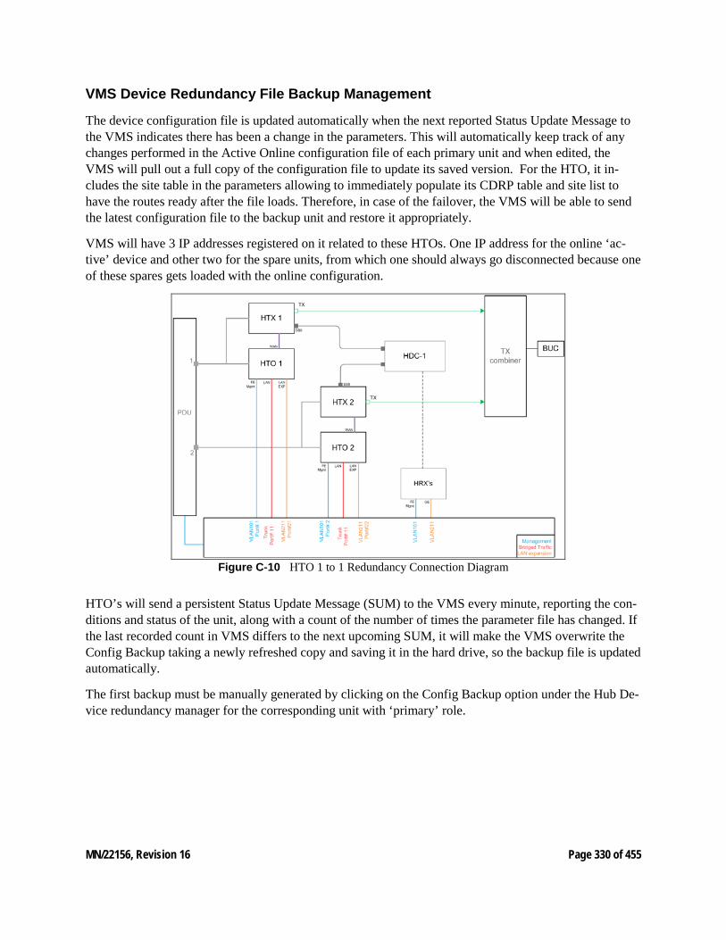
MN/22156, Revision 16 Page 330 of 455
VMS Device Redundancy File Backup Management
The device configuration file is updated automatically when the next reported Status Update Message to the VMS indicates there has been a change in the parameters. This will automatically keep track of any changes performed in the Active Online configuration file of each primary unit and when edited, the VMS will pull out a full copy of the configuration file to update its saved version. For the HTO, it in-cludes the site table in the parameters allowing to immediately populate its CDRP table and site list to have the routes ready after the file loads. Therefore, in case of the failover, the VMS will be able to send the latest configuration file to the backup unit and restore it appropriately.
VMS will have 3 IP addresses registered on it related to these HTOs. One IP address for the online ‘ac-tive’ device and other two for the spare units, from which one should always go disconnected because one of these spares gets loaded with the online configuration.
Figure C‑10 HTO 1 to 1 Redundancy Connection Diagram
HTO’s will send a persistent Status Update Message (SUM) to the VMS every minute, reporting the con-ditions and status of the unit, along with a count of the number of times the parameter file has changed. If the last recorded count in VMS differs to the next upcoming SUM, it will make the VMS overwrite the Config Backup taking a newly refreshed copy and saving it in the hard drive, so the backup file is updated automatically.
The first backup must be manually generated by clicking on the Config Backup option under the Hub De-vice redundancy manager for the corresponding unit with ‘primary’ role.
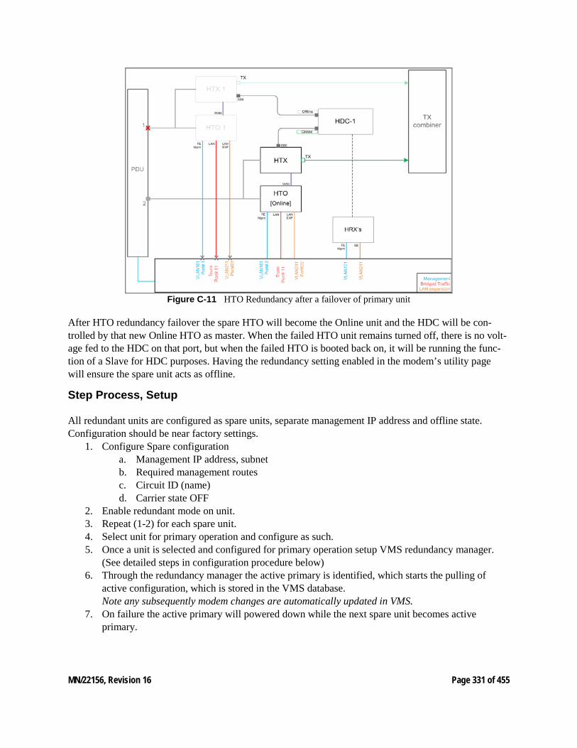
MN/22156, Revision 16 Page 331 of 455
Figure C‑11 HTO Redundancy after a failover of primary unit
After HTO redundancy failover the spare HTO will become the Online unit and the HDC will be con-trolled by that new Online HTO as master. When the failed HTO unit remains turned off, there is no volt-age fed to the HDC on that port, but when the failed HTO is booted back on, it will be running the func-tion of a Slave for HDC purposes. Having the redundancy setting enabled in the modem’s utility page will ensure the spare unit acts as offline.
Step Process, Setup All redundant units are configured as spare units, separate management IP address and offline state. Configuration should be near factory settings.
1. Configure Spare configuration a. Management IP address, subnet b. Required management routes c. Circuit ID (name) d. Carrier state OFF
2. Enable redundant mode on unit. 3. Repeat (1-2) for each spare unit. 4. Select unit for primary operation and configure as such. 5. Once a unit is selected and configured for primary operation setup VMS redundancy manager.
(See detailed steps in configuration procedure below) 6. Through the redundancy manager the active primary is identified, which starts the pulling of
active configuration, which is stored in the VMS database. Note any subsequently modem changes are automatically updated in VMS.
7. On failure the active primary will powered down while the next spare unit becomes active primary.
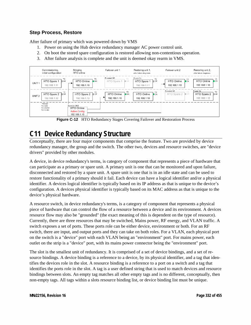
MN/22156, Revision 16 Page 332 of 455
Step Process, Restore
After failure of primary which was powered down by VMS 1. Power on using the Hub device redundancy manager AC power control unit. 2. On boot the stored spare configuration is restored allowing non-contentious operation. 3. After failure analysis is complete and the unit is deemed okay rearm in VMS.
Figure C‑12 HTO Redundancy Stages Covering Failover and Restoration Process
C11 Device Redundancy Structure Conceptually, there are four major components that comprise the feature. Two are provided by device redundancy manager, the group and the switch. The other two, devices and resource switches, are "device drivers" provided by other modules.
A device, in device redundancy's terms, is category of component that represents a piece of hardware that can participate as a primary or spare unit. A primary unit is one that can be monitored and upon failure, disconnected and restored by a spare unit. A spare unit is one that is in an idle state and can be used to restore functionality of a primary should it fail. Each device can have a logical identifier and/or a physical identifier. A devices logical identifier is typically based on its IP address as that is unique to the device’s configuration. A devices physical identifier is typically based on its MAC address as that is unique to the device’s physical hardware.
A resource switch, in device redundancy's terms, is a category of component that represents a physical piece of hardware that can control the flow of a resource between a device and its environment. A devices resource flow may also be "grounded" (the exact meaning of this is dependent on the type of resource). Currently, there are three resources that may be switched, Mains power, RF energy, and VLAN traffic. A switch exposes a set of ports. These ports role can be either device, environment or both. For an RF switch, there are input, and output ports and they can take on both roles. For a VLAN, each physical port on the switch is a "device" port with each VLAN being an "environment" port. For mains power, each outlet on the strip is a "device" port, with its mains power connector being the "environment" port.
The slot is the smallest unit of redundancy. It is comprised of a set of device bindings, and a set of re-source bindings. A device binding is a reference to a device, by its physical identifier, and a tag that iden-tifies the devices role in the slot. A resource binding is a reference to a port on a switch and a tag that identifies the ports role in the slot. A tag is a user defined string that is used to match devices and resource bindings between slots. An empty tag matches all other empty tags and is no different, conceptually, then non-empty tags. All tags within a slots resource binding list, or device binding list must be unique.
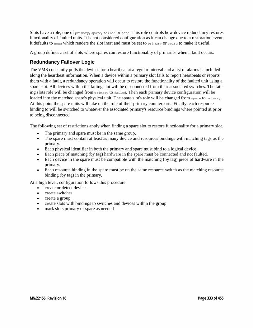
MN/22156, Revision 16 Page 333 of 455
Slots have a role, one of primary, spare, failed or none. This role controls how device redundancy restores functionality of faulted units. It is not considered configuration as it can change due to a restoration event. It defaults to none which renders the slot inert and must be set to primary or spare to make it useful.
A group defines a set of slots where spares can restore functionality of primaries when a fault occurs.
Redundancy Failover Logic The VMS constantly polls the devices for a heartbeat at a regular interval and a list of alarms is included along the heartbeat information. When a device within a primary slot fails to report heartbeats or reports them with a fault, a redundancy operation will occur to restore the functionality of the faulted unit using a spare slot. All devices within the failing slot will be disconnected from their associated switches. The fail-ing slots role will be changed from primary to failed. Then each primary device configuration will be loaded into the matched spare's physical unit. The spare slot's role will be changed from spare to primary. At this point the spare units will take on the role of their primary counterparts. Finally, each resource binding to will be switched to whatever the associated primary's resource bindings where pointed at prior to being disconnected.
The following set of restrictions apply when finding a spare slot to restore functionality for a primary slot. • The primary and spare must be in the same group. • The spare must contain at least as many device and resources bindings with matching tags as the
primary. • Each physical identifier in both the primary and spare must bind to a logical device. • Each piece of matching (by tag) hardware in the spare must be connected and not faulted. • Each device in the spare must be compatible with the matching (by tag) piece of hardware in the
primary. • Each resource binding in the spare must be on the same resource switch as the matching resource
binding (by tag) in the primary. At a high level, configuration follows this procedure:
• create or detect devices • create switches • create a group • create slots with bindings to switches and devices within the group • mark slots primary or spare as needed
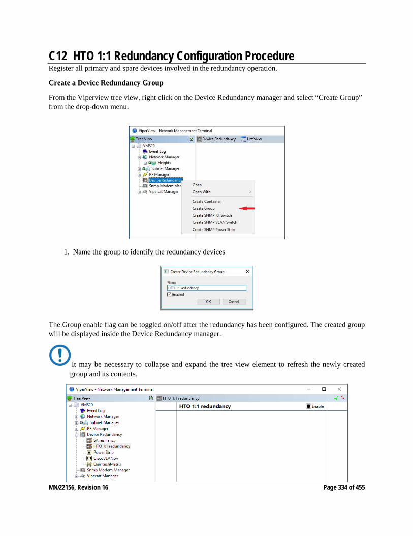
MN/22156, Revision 16 Page 334 of 455
C12 HTO 1:1 Redundancy Configuration Procedure Register all primary and spare devices involved in the redundancy operation. Create a Device Redundancy Group
From the Viperview tree view, right click on the Device Redundancy manager and select “Create Group” from the drop-down menu.
1. Name the group to identify the redundancy devices
The Group enable flag can be toggled on/off after the redundancy has been configured. The created group will be displayed inside the Device Redundancy manager.
It may be necessary to collapse and expand the tree view element to refresh the newly created group and its contents.
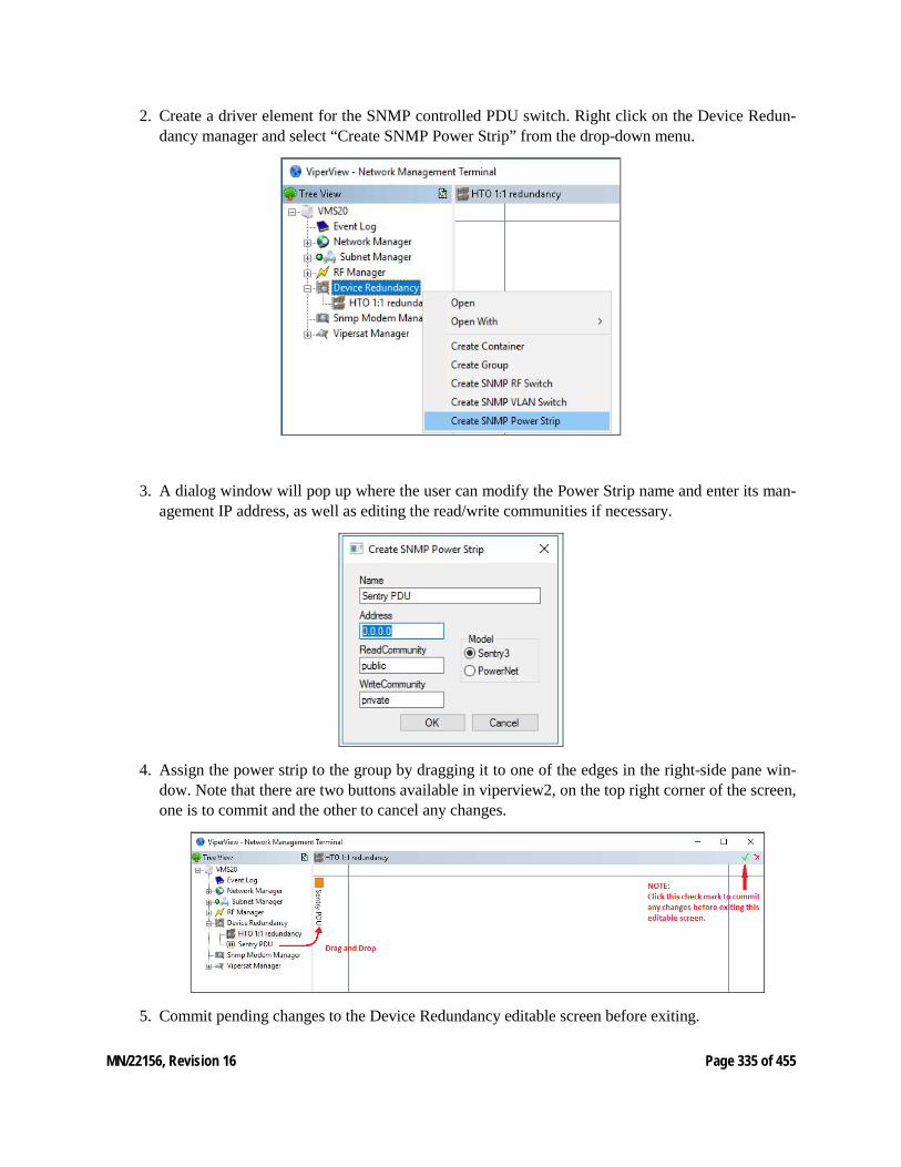
MN/22156, Revision 16 Page 335 of 455
2. Create a driver element for the SNMP controlled PDU switch. Right click on the Device Redun-dancy manager and select “Create SNMP Power Strip” from the drop-down menu.
3. A dialog window will pop up where the user can modify the Power Strip name and enter its man-agement IP address, as well as editing the read/write communities if necessary.
4. Assign the power strip to the group by dragging it to one of the edges in the right-side pane win-dow. Note that there are two buttons available in viperview2, on the top right corner of the screen, one is to commit and the other to cancel any changes.
5. Commit pending changes to the Device Redundancy editable screen before exiting.
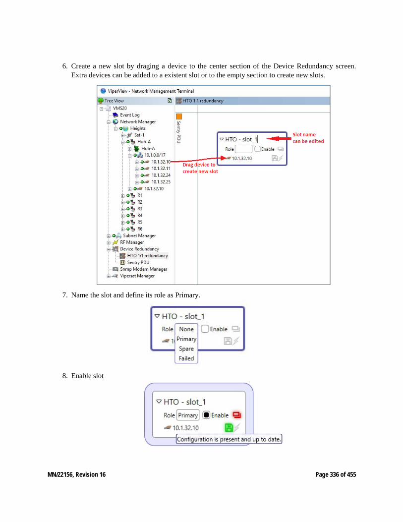
MN/22156, Revision 16 Page 336 of 455
6. Create a new slot by draging a device to the center section of the Device Redundancy screen. Extra devices can be added to a existent slot or to the empty section to create new slots.
7. Name the slot and define its role as Primary.
8. Enable slot
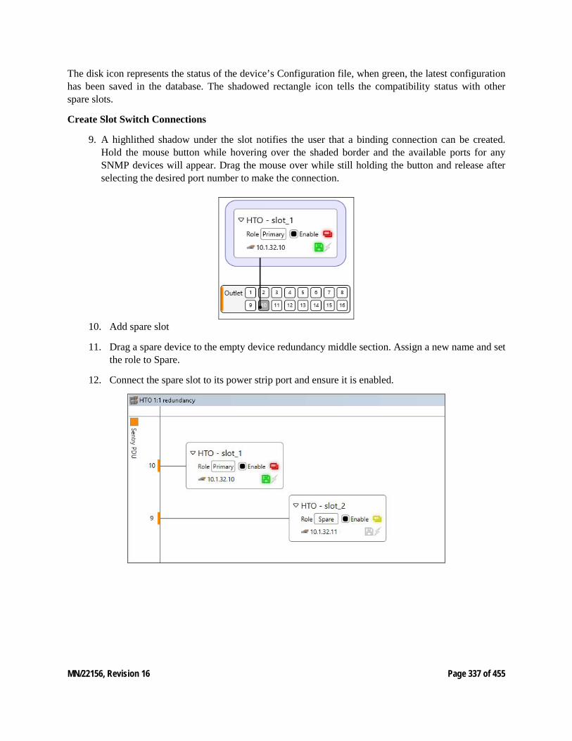
MN/22156, Revision 16 Page 337 of 455
The disk icon represents the status of the device’s Configuration file, when green, the latest configuration has been saved in the database. The shadowed rectangle icon tells the compatibility status with other spare slots.
Create Slot Switch Connections
9. A highlithed shadow under the slot notifies the user that a binding connection can be created. Hold the mouse button while hovering over the shaded border and the available ports for any SNMP devices will appear. Drag the mouse over while still holding the button and release after selecting the desired port number to make the connection.
10. Add spare slot
11. Drag a spare device to the empty device redundancy middle section. Assign a new name and set the role to Spare.
12. Connect the spare slot to its power strip port and ensure it is enabled.
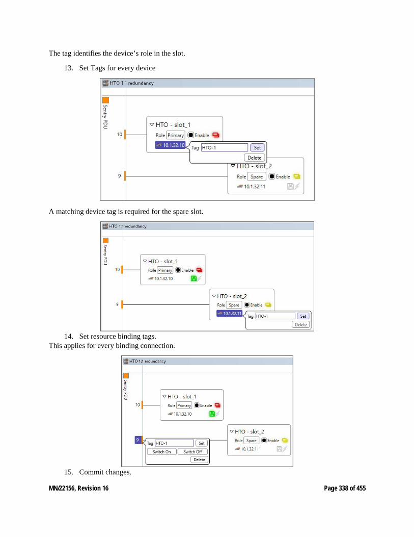
MN/22156, Revision 16 Page 338 of 455
The tag identifies the device’s role in the slot.
13. Set Tags for every device
A matching device tag is required for the spare slot.
14. Set resource binding tags.
This applies for every binding connection.
15. Commit changes.
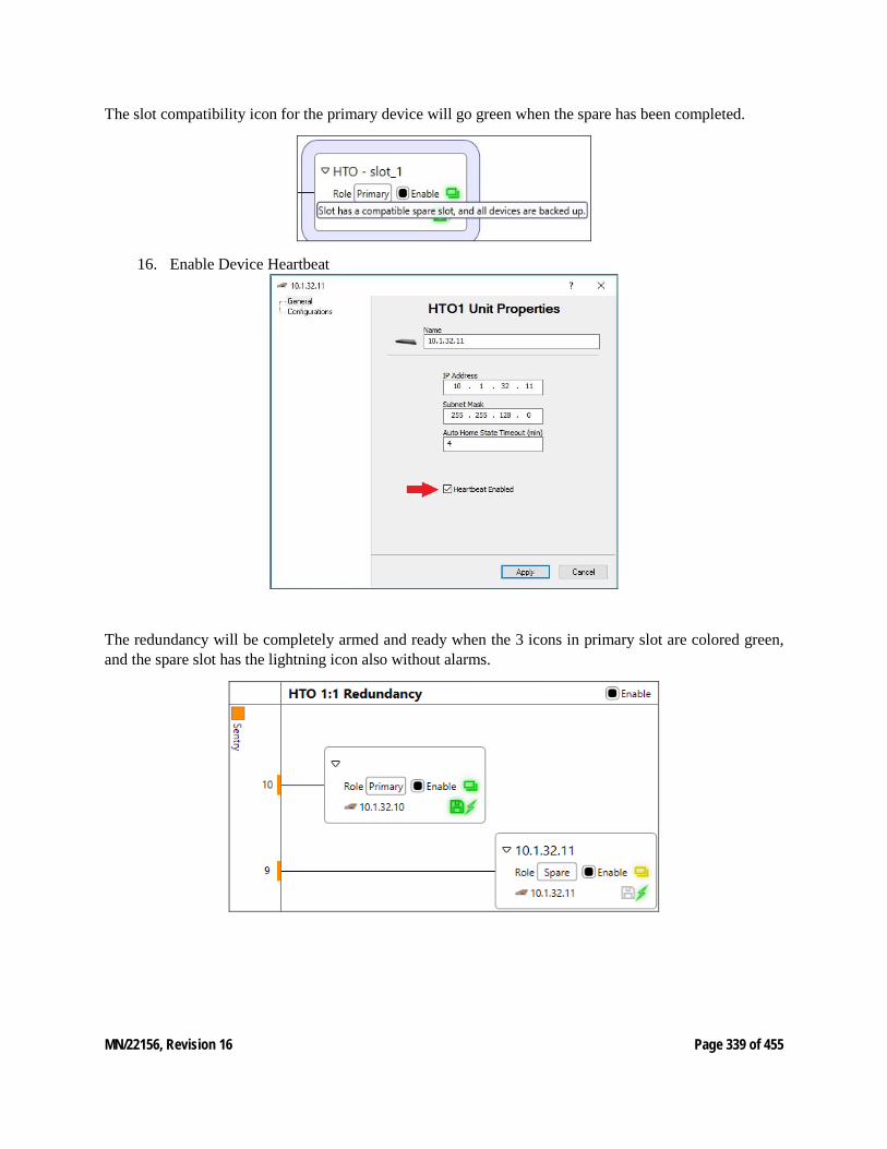
MN/22156, Revision 16 Page 339 of 455
The slot compatibility icon for the primary device will go green when the spare has been completed.
16. Enable Device Heartbeat
The redundancy will be completely armed and ready when the 3 icons in primary slot are colored green, and the spare slot has the lightning icon also without alarms.

MN/22156, Revision 16 Page 340 of 455
Redundancy Failover and Rearming
Slot 1 containing the failed device will be flagged as failed, the logical identifier would tempo-rarily lose MAC address binding since the unit has been powered off. Slot 2 has now become the Primary slot and its device IP address updated accordingly with the online configuration.
New messages are recorded in the event log with the redundancy group label and the timestamp of the occurrence.
1. In order to rearm the redundancy, the failed device must be powered on. To do so, right click on the Power strip port and select the “Switch On’ button. This will boot the device in its spare con-figuration.
2. Once the failed Device booted up, the MAC address binding is updated with the spare IP address

MN/22156, Revision 16 Page 341 of 455
3. Manually rearm Redundancy by setting Role from Failed to Spare, Re enable Heartbeat for failed device, and Enable Group.
Auto Re-Arm
When this function is enabled the Device Redundancy engine issues a Reboot instead of turning off the power strip port of the failed device, allowing the unit to boot with a spare configuration, Hub redundancy mode is expected to be enabled on the Hub devices.
Once the failed unit has successfully registered back online in the system, and if no alarms are reported, the VMS will automatically update the slot role for the corresponding MAC address from Failed to Spare, leaving it ready to support any future failover from a primary slot.
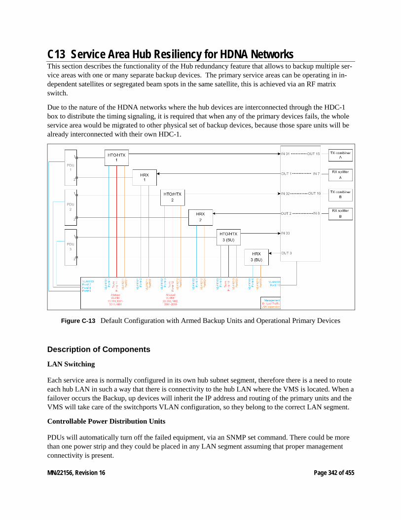
MN/22156, Revision 16 Page 342 of 455
C13 Service Area Hub Resiliency for HDNA Networks This section describes the functionality of the Hub redundancy feature that allows to backup multiple ser-vice areas with one or many separate backup devices. The primary service areas can be operating in in-dependent satellites or segregated beam spots in the same satellite, this is achieved via an RF matrix switch.
Due to the nature of the HDNA networks where the hub devices are interconnected through the HDC-1 box to distribute the timing signaling, it is required that when any of the primary devices fails, the whole service area would be migrated to other physical set of backup devices, because those spare units will be already interconnected with their own HDC-1.
Figure C‑13 Default Configuration with Armed Backup Units and Operational Primary Devices
Description of Components
LAN Switching
Each service area is normally configured in its own hub subnet segment, therefore there is a need to route each hub LAN in such a way that there is connectivity to the hub LAN where the VMS is located. When a failover occurs the Backup, up devices will inherit the IP address and routing of the primary units and the VMS will take care of the switchports VLAN configuration, so they belong to the correct LAN segment.
Controllable Power Distribution Units
PDUs will automatically turn off the failed equipment, via an SNMP set command. There could be more than one power strip and they could be placed in any LAN segment assuming that proper management connectivity is present.
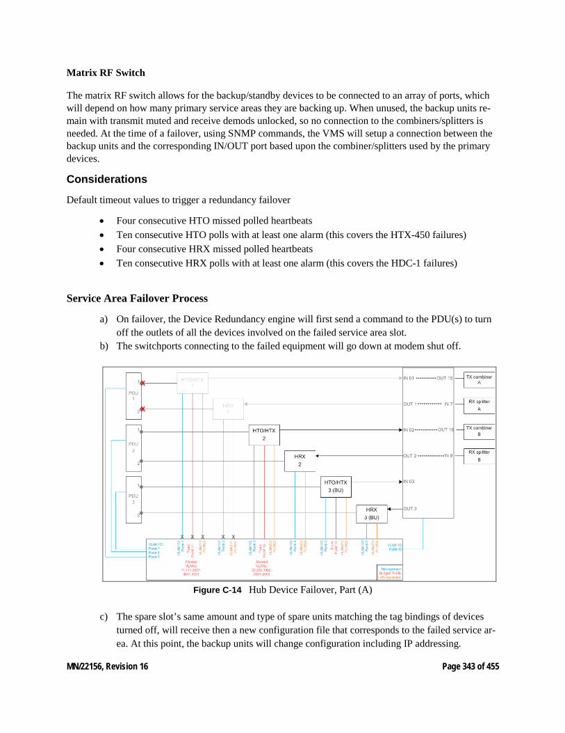
MN/22156, Revision 16 Page 343 of 455
Matrix RF Switch
The matrix RF switch allows for the backup/standby devices to be connected to an array of ports, which will depend on how many primary service areas they are backing up. When unused, the backup units re-main with transmit muted and receive demods unlocked, so no connection to the combiners/splitters is needed. At the time of a failover, using SNMP commands, the VMS will setup a connection between the backup units and the corresponding IN/OUT port based upon the combiner/splitters used by the primary devices.
Considerations
Default timeout values to trigger a redundancy failover
• Four consecutive HTO missed polled heartbeats • Ten consecutive HTO polls with at least one alarm (this covers the HTX-450 failures) • Four consecutive HRX missed polled heartbeats • Ten consecutive HRX polls with at least one alarm (this covers the HDC-1 failures)
Service Area Failover Process
a) On failover, the Device Redundancy engine will first send a command to the PDU(s) to turn off the outlets of all the devices involved on the failed service area slot.
b) The switchports connecting to the failed equipment will go down at modem shut off.
Figure C‑14 Hub Device Failover, Part (A)
c) The spare slot’s same amount and type of spare units matching the tag bindings of devices
turned off, will receive then a new configuration file that corresponds to the failed service ar-ea. At this point, the backup units will change configuration including IP addressing.

MN/22156, Revision 16 Page 344 of 455
d) Immediately after the configuration load command, an SNMP command is issued to the VLAN switch forcing it to update the VLAN tag on the access switchports. The full switchport configuration of the failed port is copied to the switchport where the spare device is connected. Traffic port on HTO should be Tagged differently than the management ports to a matching Traffic tag on spare slot, then the Device Redundancy engine can detect between an access switchport or a trunk port and for the later one, copy the allowed VLAN list for that trunk.
The catalyst layer 3 switch must be preconfigured to support IP routing and since each service area is on a separate LAN segment, the newly configured backup units will match the VLAN tag of the service area so they can be routed.
e) At the same time, the Device Redundancy Manager will configure the Quintech Matrix
switch via SNMP setting the input and output ports accordingly. The manager will do a GET SNMP to learn the configuration of the failed port and copy the setup performing a SET SNMP to the spare port.
Figure C‑15 Hub Device Failover, Part (B)
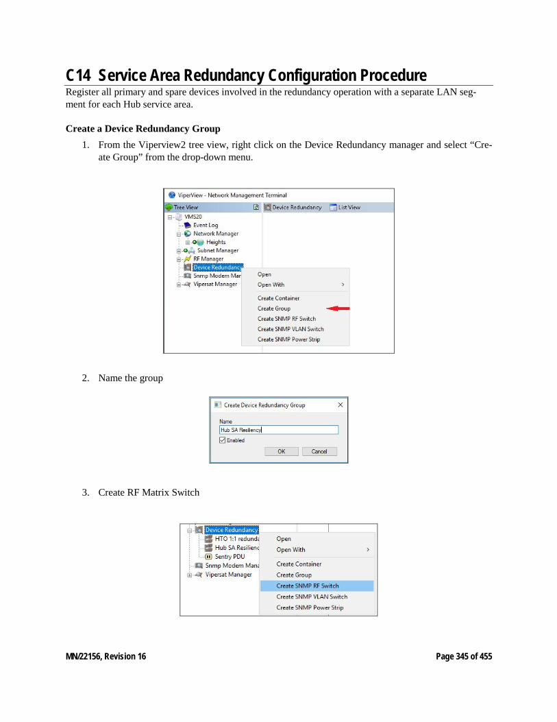
MN/22156, Revision 16 Page 345 of 455
C14 Service Area Redundancy Configuration Procedure Register all primary and spare devices involved in the redundancy operation with a separate LAN seg-ment for each Hub service area.
Create a Device Redundancy Group 1. From the Viperview2 tree view, right click on the Device Redundancy manager and select “Cre-
ate Group” from the drop-down menu.
2. Name the group
3. Create RF Matrix Switch
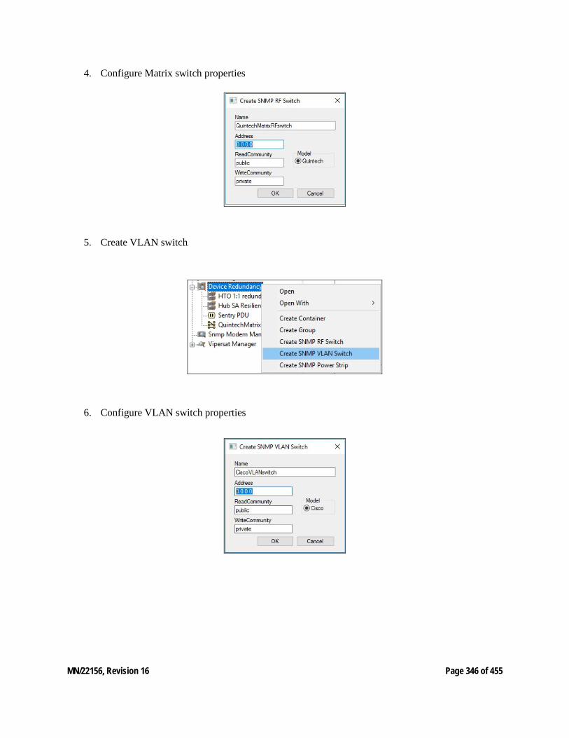
MN/22156, Revision 16 Page 346 of 455
4. Configure Matrix switch properties
5. Create VLAN switch
6. Configure VLAN switch properties
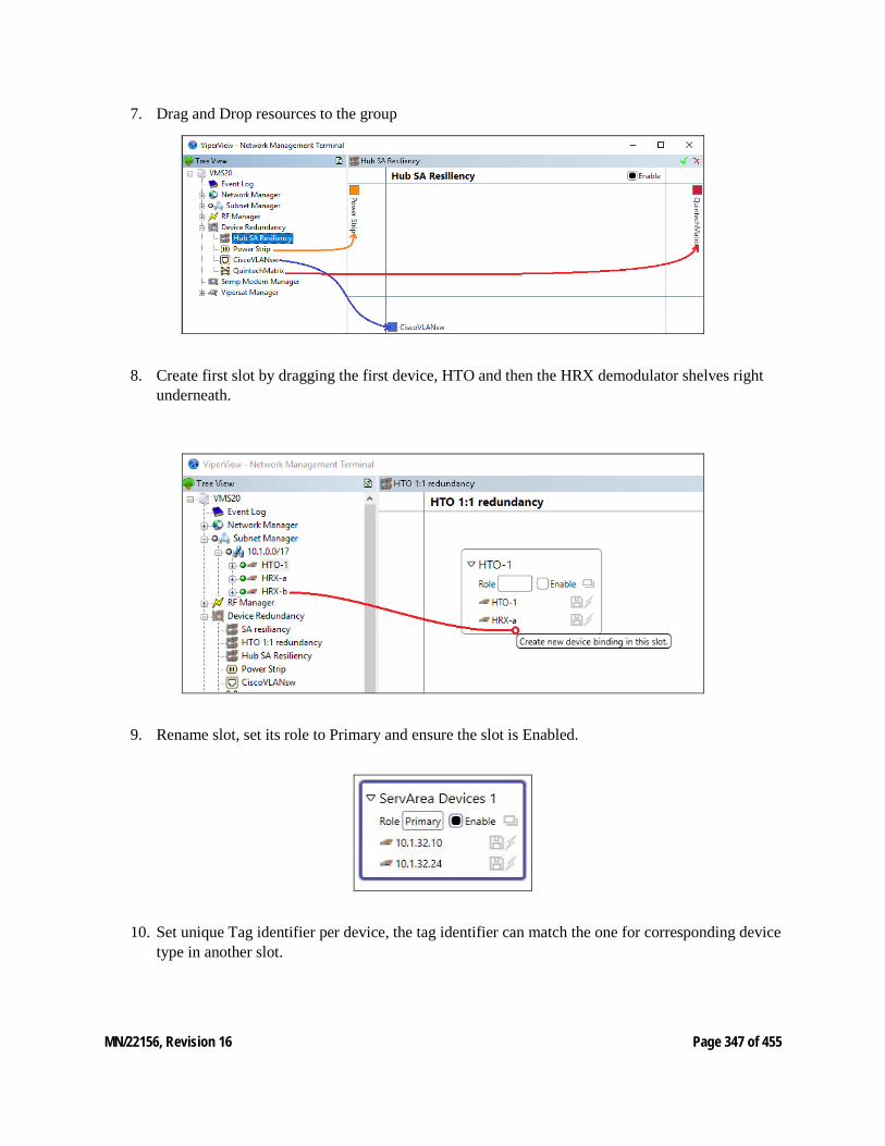
MN/22156, Revision 16 Page 347 of 455
7. Drag and Drop resources to the group
8. Create first slot by dragging the first device, HTO and then the HRX demodulator shelves right
underneath.
9. Rename slot, set its role to Primary and ensure the slot is Enabled.
10. Set unique Tag identifier per device, the tag identifier can match the one for corresponding device
type in another slot.
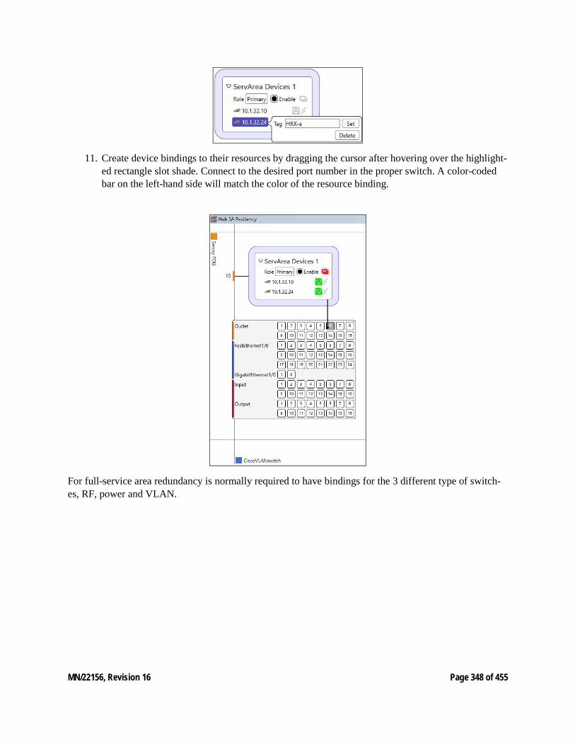
MN/22156, Revision 16 Page 348 of 455
11. Create device bindings to their resources by dragging the cursor after hovering over the highlight-ed rectangle slot shade. Connect to the desired port number in the proper switch. A color-coded bar on the left-hand side will match the color of the resource binding.
For full-service area redundancy is normally required to have bindings for the 3 different type of switch-es, RF, power and VLAN.
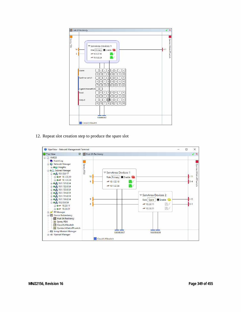
MN/22156, Revision 16 Page 349 of 455
12. Repeat slot creation step to produce the spare slot
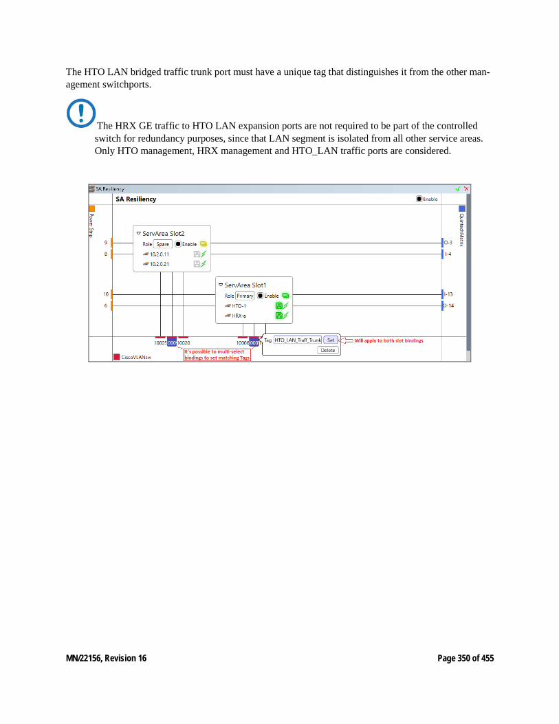
MN/22156, Revision 16 Page 350 of 455
The HTO LAN bridged traffic trunk port must have a unique tag that distinguishes it from the other man-agement switchports.
The HRX GE traffic to HTO LAN expansion ports are not required to be part of the controlled switch for redundancy purposes, since that LAN segment is isolated from all other service areas. Only HTO management, HRX management and HTO_LAN traffic ports are considered.
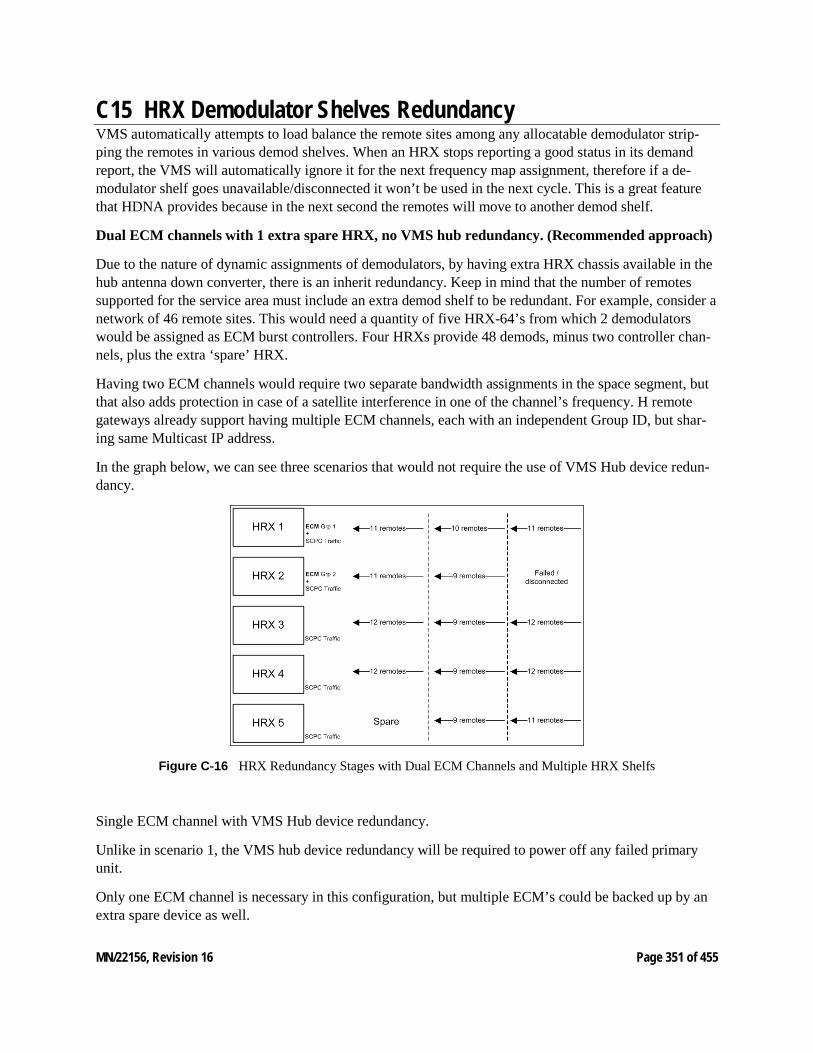
MN/22156, Revision 16 Page 351 of 455
C15 HRX Demodulator Shelves Redundancy VMS automatically attempts to load balance the remote sites among any allocatable demodulator strip-ping the remotes in various demod shelves. When an HRX stops reporting a good status in its demand report, the VMS will automatically ignore it for the next frequency map assignment, therefore if a de-modulator shelf goes unavailable/disconnected it won’t be used in the next cycle. This is a great feature that HDNA provides because in the next second the remotes will move to another demod shelf.
Dual ECM channels with 1 extra spare HRX, no VMS hub redundancy. (Recommended approach)
Due to the nature of dynamic assignments of demodulators, by having extra HRX chassis available in the hub antenna down converter, there is an inherit redundancy. Keep in mind that the number of remotes supported for the service area must include an extra demod shelf to be redundant. For example, consider a network of 46 remote sites. This would need a quantity of five HRX-64’s from which 2 demodulators would be assigned as ECM burst controllers. Four HRXs provide 48 demods, minus two controller chan-nels, plus the extra ‘spare’ HRX.
Having two ECM channels would require two separate bandwidth assignments in the space segment, but that also adds protection in case of a satellite interference in one of the channel’s frequency. H remote gateways already support having multiple ECM channels, each with an independent Group ID, but shar-ing same Multicast IP address.
In the graph below, we can see three scenarios that would not require the use of VMS Hub device redun-dancy.
Figure C‑16 HRX Redundancy Stages with Dual ECM Channels and Multiple HRX Shelfs
Single ECM channel with VMS Hub device redundancy.
Unlike in scenario 1, the VMS hub device redundancy will be required to power off any failed primary unit.
Only one ECM channel is necessary in this configuration, but multiple ECM’s could be backed up by an extra spare device as well.
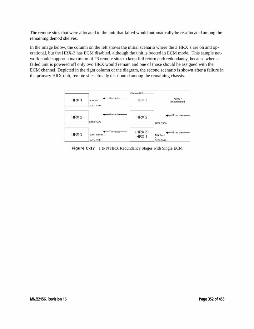
MN/22156, Revision 16 Page 352 of 455
The remote sites that were allocated to the unit that failed would automatically be re-allocated among the remaining demod shelves.
In the image below, the column on the left shows the initial scenario where the 3 HRX’s are on and op-erational, but the HRX-3 has ECM disabled, although the unit is booted in ECM mode. This sample net-work could support a maximum of 23 remote sites to keep full return path redundancy, because when a failed unit is powered off only two HRX would remain and one of those should be assigned with the ECM channel. Depicted in the right column of the diagram, the second scenario is shown after a failure in the primary HRX unit, remote sites already distributed among the remaining chassis.
Figure C‑17 1 to N HRX Redundancy Stages with Single ECM

MN/22156, Revision 16 Page 353 of 455
C16 Carrier Preservation The system components are evolving into higher performance and real estate reduction where units are increasing in the number of carriers that a single rack unit can support. Focusing on the hub receive initially units only supported one return path demodulator. As technologies evolve the amount of receive channels in a single unit have increased in steps of (CDD-564) 4, (CDD-880) 12 and (HRX-16) 48 demodulators.
This increase pushes the degree of a single outage where a CDD-880 on failure (device redundancy/reboot) will push all associated remotes back into entry channel on failure resulting in a large network outage, which will be greater than 4 minutes. Even with hub device redundancy feature a switchover will still result in a large network outage.
To reduce this return path outage Carrier Preservation was added to preserve dSCPC carriers during a hub receive unit failure with or without hub device redundancy.
Currently if the managed hub demodulator unit fails, redundant failover the unit coming online has lost the entire dynamic allocation configuration leaving all managed dSCPC returns associated in limbo until carrier recovery logic completes. If the redundancy manager initiates a failover the backup unit assumes the role of the primary unit that has failed. Within this process the remotes associated are also in limbo until the disconnect carrier recovery timers expire, which places a large group of remotes into entry channel contention.
Typically, the remotes are unaware that the hub demodulator unit has changed or gone away, not until the remote receives a Revert command from the VMS. With the absences of the hub receive path the required remote SUM messages sent on 60 second intervals will timeout after approximately 3 minutes causing a disconnect which triggers recovery issuing a Revert. However, during the 3minute recovery window the remote carriers will remain at last dSCPC state.
To enhance this behavior the carrier preservation process removes the need to force active dSCPC carriers back through entry channel.
Current Performance: • Reboot = ~190 seconds + Entry Channel
• Redundancy Switchover = ~204 seconds + Entry Channel
Taking advantage of this recovery window allows the system time to reconfigure the demodulator unit with remote carrier last state configurations.
The VMS is aware of all dSCPC allocations, which are temporarily stored carrier information.
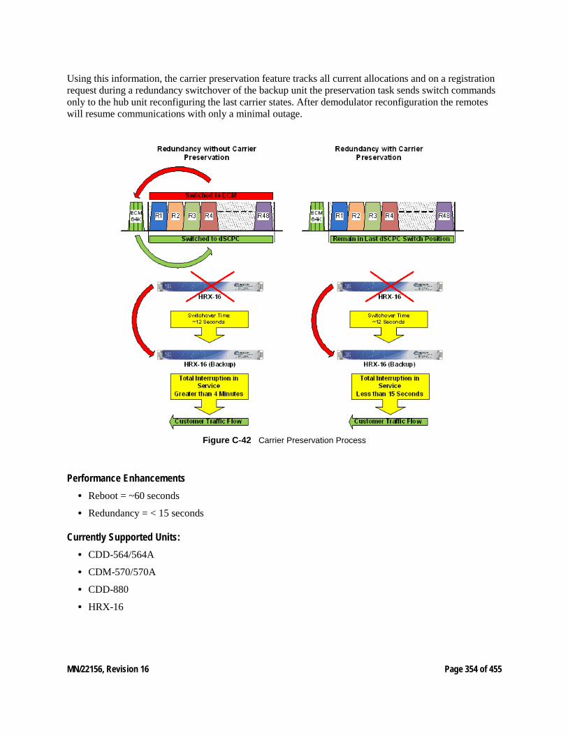
MN/22156, Revision 16 Page 354 of 455
Using this information, the carrier preservation feature tracks all current allocations and on a registration request during a redundancy switchover of the backup unit the preservation task sends switch commands only to the hub unit reconfiguring the last carrier states. After demodulator reconfiguration the remotes will resume communications with only a minimal outage.
Figure C‑42 Carrier Preservation Process
Performance Enhancements • Reboot = ~60 seconds
• Redundancy = < 15 seconds
Currently Supported Units: • CDD-564/564A
• CDM-570/570A
• CDD-880
• HRX-16
MN/22156, Revision 16 Page 355 of 455
D SNMP TRAPS D1 SNMP TRAPS INTRODUCTION This appendix describes the use of SNMP traps by the Vipersat Management System (VMS). SNMP traps enable the VMS to capture significant network events, then generate an SNMP message reporting the event. In a VMS controlled satellite system, this configuration has several advantages:
• The VMS system, using its existing network monitoring capability, acts as a central collection point for all changes to the satellite network status and provides a single source for SNMP events reported for the satellite network. Individual network devices are not required to generate SNMP traps thereby reducing network overhead bandwidth.
• The VMS collects network changes and status as they occur and as they are reported by the satellite network’s modems as part of the normal VMS management and control function.
• Only events defined by the VMS MIB are sent as SNMP traps. This reduces the requirement to have each device transmit an SNMP trap as its status changes thereby reducing network overhead bandwidth requirements.
Since VMS only collects and reports SNMP events from the satellite network and it is not the source of the event, you cannot query the VMS for additional information about an SNMP trapped event.
Using SNMP Traps
SNMP (Simple Network Management Protocol) along with the associated VMS Management Information Base (MIB), provides trap-directed notification of network changes.
VMS can be responsible for many network parameters as defined in the VMS MIB. It is impractical for VMS to poll or request information from each device in a satellite network. Instead of each managed device generating its own SNMP traps, the VMS detects network status changes and when an event defined in the MIB occurs responds with a message called a trap.
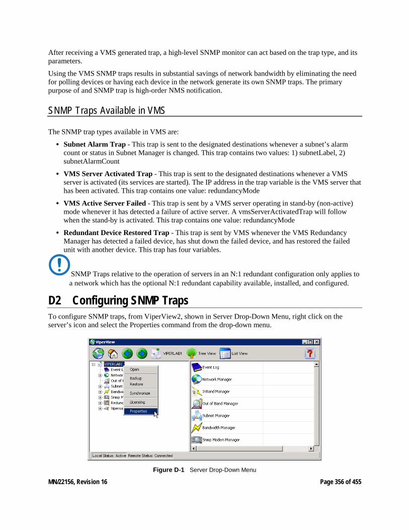
MN/22156, Revision 16 Page 356 of 455
After receiving a VMS generated trap, a high-level SNMP monitor can act based on the trap type, and its parameters.
Using the VMS SNMP traps results in substantial savings of network bandwidth by eliminating the need for polling devices or having each device in the network generate its own SNMP traps. The primary purpose of and SNMP trap is high-order NMS notification.
SNMP Traps Available in VMS
The SNMP trap types available in VMS are:
• Subnet Alarm Trap - This trap is sent to the designated destinations whenever a subnet’s alarm count or status in Subnet Manager is changed. This trap contains two values: 1) subnetLabel, 2) subnetAlarmCount
• VMS Server Activated Trap - This trap is sent to the designated destinations whenever a VMS server is activated (its services are started). The IP address in the trap variable is the VMS server that has been activated. This trap contains one value: redundancyMode
• VMS Active Server Failed - This trap is sent by a VMS server operating in stand-by (non-active) mode whenever it has detected a failure of active server. A vmsServerActivatedTrap will follow when the stand-by is activated. This trap contains one value: redundancyMode
• Redundant Device Restored Trap - This trap is sent by VMS whenever the VMS Redundancy Manager has detected a failed device, has shut down the failed device, and has restored the failed unit with another device. This trap has four variables.
SNMP Traps relative to the operation of servers in an N:1 redundant configuration only applies to a network which has the optional N:1 redundant capability available, installed, and configured.
D2 Configuring SNMP Traps To configure SNMP traps, from ViperView2, shown in Server Drop-Down Menu, right click on the server’s icon and select the Properties command from the drop-down menu.
Figure D‑1 Server Drop-Down Menu
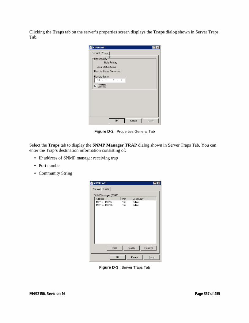
MN/22156, Revision 16 Page 357 of 455
Clicking the Traps tab on the server’s properties screen displays the Traps dialog shown in Server Traps Tab.
Figure D‑2 Properties General Tab
Select the Traps tab to display the SNMP Manager TRAP dialog shown in Server Traps Tab. You can enter the Trap’s destination information consisting of:
• IP address of SNMP manager receiving trap
• Port number
• Community String
Figure D‑3 Server Traps Tab
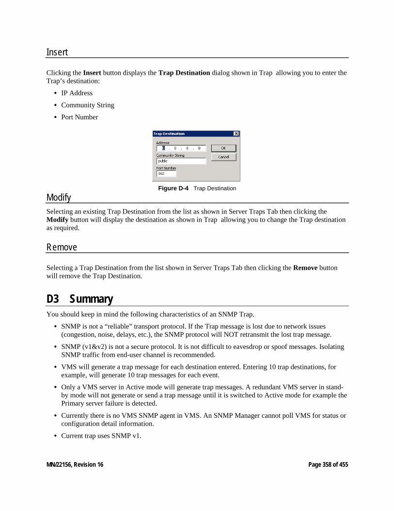
MN/22156, Revision 16 Page 358 of 455
Insert
Clicking the Insert button displays the Trap Destination dialog shown in Trap allowing you to enter the Trap’s destination:
• IP Address
• Community String
• Port Number
Figure D‑4 Trap Destination
Modify Selecting an existing Trap Destination from the list as shown in Server Traps Tab then clicking the Modify button will display the destination as shown in Trap allowing you to change the Trap destination as required.
Remove
Selecting a Trap Destination from the list shown in Server Traps Tab then clicking the Remove button will remove the Trap Destination.
D3 Summary You should keep in mind the following characteristics of an SNMP Trap.
• SNMP is not a “reliable” transport protocol. If the Trap message is lost due to network issues (congestion, noise, delays, etc.), the SNMP protocol will NOT retransmit the lost trap message.
• SNMP (v1&v2) is not a secure protocol. It is not difficult to eavesdrop or spoof messages. Isolating SNMP traffic from end-user channel is recommended.
• VMS will generate a trap message for each destination entered. Entering 10 trap destinations, for example, will generate 10 trap messages for each event.
• Only a VMS server in Active mode will generate trap messages. A redundant VMS server in stand-by mode will not generate or send a trap message until it is switched to Active mode for example the Primary server failure is detected.
• Currently there is no VMS SNMP agent in VMS. An SNMP Manager cannot poll VMS for status or configuration detail information.
• Current trap uses SNMP v1.
MN/22156, Revision 16 Page 359 of 455
E AUTOMATIC SWITCHING E1 Automatic Switching, dSCPC INTRODUCTION Automatic switching is a feature of the VMS that allows dynamically changing the network configuration in response to changes in either network traffic loads (Load switching), traffic type (Application switching), or Type of Service (ToS switching) detecting stamped packets with Diffserv values. Entry Channel Mode switching, and Carrier Presence switching are also covered here.
These switching types are presented in the following material which uses CDM-570/L, SLM-5650A/B, and Series800 modem units for purposes of illustration. For simplicity, these units shall be referred to as modems.
The basic signal topology in a CEFD network is TDM (Time Division Multiplex) outbound and proprietary STDMA (Selected Time Division Multiple Access) inbound. The STDMA slots can have their duration and bandwidth allotments varied, tailoring bandwidth allocation to meet the bursty traffic load of a typical data network.
When required, a network is switched from STDMA to SCPC. SCPC bandwidth is allocated from a bandwidth pool by the VMS to meet QoS or other requirements for the duration of a connection. When the SCPC connection is no longer required, the bandwidth is returned to the pool for use by another client.
This basic structure gives the VMS-controlled network its flexible, automated network utilization and optimization capability.
The VMS has the intelligence to interpret the constantly changing statistics gathered by the CEFD network modems and uses this data to issue commands back to these intelligent modems, effectively managing the CEFD network operation in real time, and optimizing each site’s bandwidth usage to meet their QoS and cost requirements within their bandwidth allocation. The result is a stable satellite network connection that automatically responds to the customer’s requirements while continuously monitoring and reacting to changing load, data type, and QoS requirements.

MN/22156, Revision 16 Page 360 of 455
E2 Hitless Switching Unless inherent delays in configuring both ends of a satellite bandwidth link during dynamic switching are accounted for, transmitted data may be lost during the transition. The time for a switch command to be sent across the satellite link (~ 250 ms), the command processing time, as well as receiver acquisition time must be considered. The Vipersat Hitless Switching feature provides a means to coordinate timing and utilize buffering to eliminate these data outages.
The parameters for configuring the Hitless Switching feature for a CDM-570/570L are set from the screen shown in Hitless Switching screen. This screen is accessed from the STDMA/SCPC Auto Switching screen (see Auto Switching Menu, CDM-570/570L Hub and Auto Switching Menu, CDM-570/570L Remote).
Figure E‑2 Hitless Switching screen
• Enable/Disable – The Hitless Switching screen will initially display all lock times as -1, indicating that the feature is disabled. The Restore Default Lock Times command is used to enable this feature.
• Delay for Mod – This parameter allows the operator to insert additional delay to buffer more data after modulator transmission is ceased.
• Delay for Demod – This parameter allows the operator to insert additional delay to account for the tuning of the demodulator.
• LockTimes – LockTime settings for the four data rates displayed can be adjusted either up or down, but default settings based on satellite testing should be used as a starting point. These defaults are stored in each modulator/demodulator unit and are restored by entering R at the command prompt.
Once restored, the lock time for each data rate can be modified by entering the corresponding number.
MN/22156, Revision 16 Page 361 of 455
E3 Load Switching OVERVIEW There are three primary functional components involved in the load switching process.
• Hub Controller(s)—These are the Hub units that provide the load switching detection mechanism for Remotes that are operating within the shared channel(s). Hub units that can serve as controllers include CDM-570/570A, CDD-56x/564A, CDD-880, and SLM-5650A/B.
• Remote InBand Modems—The Remote modem units provide the load switch detection mechanism when operating in dedicated SCPC return channel. These modems include CDM-570/570A, CDM-840, and SLM-5650A/B.
• VMS—The Vipersat Management System provides the switched capacity and resource control for each request generated by the components described above.
Load Switching is the mechanism by which the CEFD network switches a Remote terminal based on traffic levels at the Remote. This mechanism controls both the switch from STDMA to SCPC mode as well as switches for SCPC capacity changes. The main components of load switching in a CEFD system are the VMS (network management) and the Comtech modem. The VMS component receives switch requests from the modem, and based on policy settings and available resources, either grants or denies the request. Within the modem component, load switching is managed at either the Hub or the Remote, based on the current mode of operation. When a Remote is in STDMA mode, load switching requests for that Remote are managed by the Hub STDMA Controller. After a Remote has been switched to SCPC mode, it manages its own switching (or Step Up/Step Down) requests.
For Hub STDMA Controllers operating in either GIR (Guaranteed Information Rate) or Entry Channel Mode, typical load switching is not the mechanism that performs the transition from STDMA to SCPC mode due to traffic load. In GIR mode, the Remote is switched to SCPC as soon as the GIR threshold is reached. In Entry Channel mode, the Remote is switched to SCPC as soon as the Hub re-ceives the first transmission from the Remote. For both GIR and ECM, the event of switching from STDMA to SCPC can only occur if the SCPC Switch Rate parameter is set to a value greater than 0 (zero).
The basic concept for all load switching is that a running average of current utilization is maintained, and when that utilization exceeds a preset threshold, a switch is initiated. The data rate for the switch is computed by determining the current bandwidth requirement of the Remote and adding some percentage of excess margin.
The main difference between switching from STDMA to SCPC and adjusting within SCPC is that in STDMA mode, the current available bandwidth is constantly changing, while in SCPC mode, it is constant between switches. Furthermore, switches from STDMA to SCPC mode are always caused by the traffic level exceeding the switch rate threshold. Within SCPC mode, switches can be caused by traffic exceeding an upper threshold or dropping below a lower threshold. However, in both cases the new data rate is based on the actual traffic requirements adjusted up by the margin percentage. Also, based on policy settings in the VMS, if a Remote request less than the specified threshold amount of bandwidth, the Remote is put back into STDMA mode. The exception to this is a Hub controller operating in ECM whose Remotes will remain in SCPC mode but drop down to the specified entry rate.
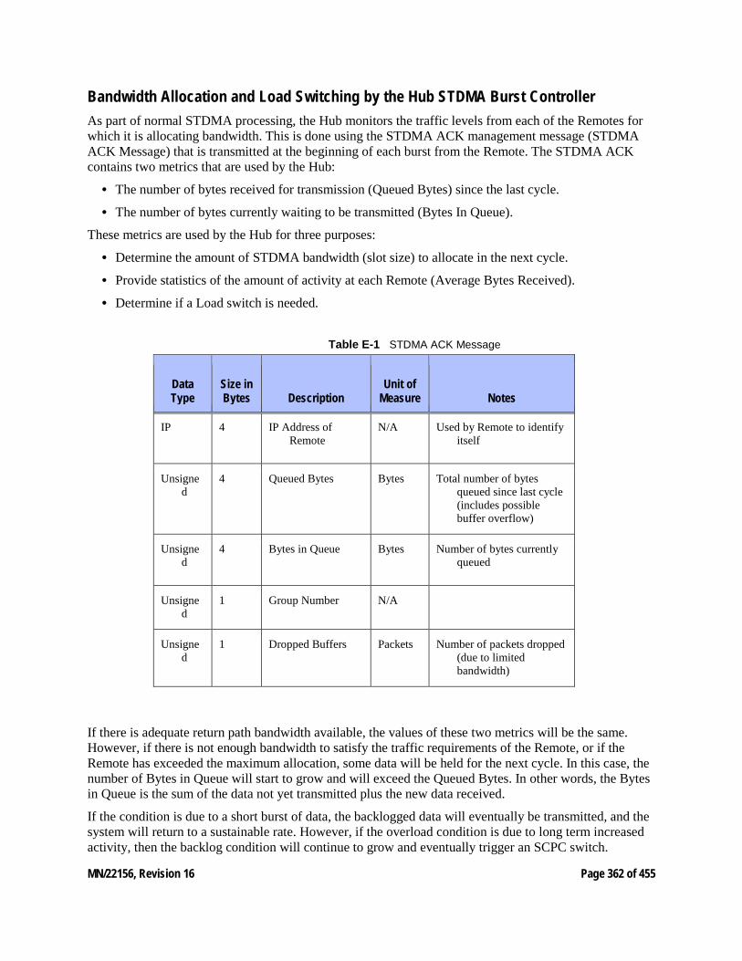
MN/22156, Revision 16 Page 362 of 455
Bandwidth Allocation and Load Switching by the Hub STDMA Burst Controller As part of normal STDMA processing, the Hub monitors the traffic levels from each of the Remotes for which it is allocating bandwidth. This is done using the STDMA ACK management message (STDMA ACK Message) that is transmitted at the beginning of each burst from the Remote. The STDMA ACK contains two metrics that are used by the Hub:
• The number of bytes received for transmission (Queued Bytes) since the last cycle.
• The number of bytes currently waiting to be transmitted (Bytes In Queue).
These metrics are used by the Hub for three purposes:
• Determine the amount of STDMA bandwidth (slot size) to allocate in the next cycle.
• Provide statistics of the amount of activity at each Remote (Average Bytes Received).
• Determine if a Load switch is needed.
Table E-1 STDMA ACK Message
Data Type
Size in Bytes Description
Unit of Measure Notes
IP 4 IP Address of Remote
N/A Used by Remote to identify itself
Unsigned
4 Queued Bytes Bytes Total number of bytes queued since last cycle (includes possible buffer overflow)
Unsigned
4 Bytes in Queue Bytes Number of bytes currently queued
Unsigned
1 Group Number N/A
Unsigned
1 Dropped Buffers Packets Number of packets dropped (due to limited bandwidth)
If there is adequate return path bandwidth available, the values of these two metrics will be the same. However, if there is not enough bandwidth to satisfy the traffic requirements of the Remote, or if the Remote has exceeded the maximum allocation, some data will be held for the next cycle. In this case, the number of Bytes in Queue will start to grow and will exceed the Queued Bytes. In other words, the Bytes in Queue is the sum of the data not yet transmitted plus the new data received.
If the condition is due to a short burst of data, the backlogged data will eventually be transmitted, and the system will return to a sustainable rate. However, if the overload condition is due to long term increased activity, then the backlog condition will continue to grow and eventually trigger an SCPC switch.
MN/22156, Revision 16 Page 363 of 455
If the overload condition lasts long enough, buffer capacity will eventually be exceeded, and some data may have to be discarded.
This is not necessarily bad, as it is often more effective to discard old data than transmit it after it has become ‘stale’.
The “Bytes in Queue” metric is used to determine the STDMA bandwidth allocated (slot size) for the next cycle; the goal being to keep the data backlog to zero. The Hub uses this metric to compute the slot size for each Remote in the next cycle as follows:
• Fixed Mode – All Remotes get the same slot size, regardless of need. This is the only mode that uses a static assignment of available bandwidth; the Bytes in Queue metric is not used here.
• Dynamic Slot Mode – The slot size for each Remote is computed based on the time (at the current data rate) needed to transmit all the “Bytes in Queue”. If the result is less than the minimum slot size or more than the maximum slot size, the slot is adjusted accordingly.
• Dynamic Cycle Mode – Available bandwidth is allocated to Remotes proportionally, based on current need. The Bytes in Queue for each Remote is divided by the total Bytes in Queue for all Remotes to determine the percentage allocation of bandwidth for each Remote.
• GIR (Guaranteed Information Rate) Mode – Initially computed the same as Dynamic Cycle, except there is no maximum limit. After all Remotes have been assigned slots, the Burst Map is checked to see if the total cycle length exceeds one second. If not, then all requirements are satisfied, and the Burst Map is complete. However, if the cycle is greater than one second, then the slots are adjusted proportionally so that all Remotes receive at least their guaranteed rate plus whatever excess is still available.
In the current design, when the one second restriction is exceeded, Remotes without a specified GIR are reduced to the global minimum slot size and the remaining bandwidth is distributed amongst Remotes that have been assigned a GIR rate. This approach assumes that Remotes that have been assigned a GIR are paying a premium and should benefit from available excess bandwidth when needed.
Note that the GIR allocations are restricted so that the assigned GIR totals cannot exceed available bandwidth. If this restriction is somehow violated, then it will not be possible to properly allocate bandwidth when the network is overloaded.
• Entry Channel Mode – This is the same as Dynamic Cycle, except that as soon as the Hub receives an STDMA ACK, it initiates a switch to SCPC mode based on the policy set for that Remote.
Note that load switching is disabled for ECM Remotes while operating in STDMA mode.
The important thing to understand about “Bytes in Queue” is that any data that is not transmitted (i.e., does not fit) in the next slot will be reported again in the next STDMA ACK. Thus the “Bytes in Queue” is not necessarily an accurate measure of the actual traffic being passed through the Remote.
The “Queued Bytes” on the other hand, reflects only the data that was received in the last cycle and thus is never duplicated (not including TCP retransmissions). This is the metric that is used for computing average load and initiating a load switch as needed.
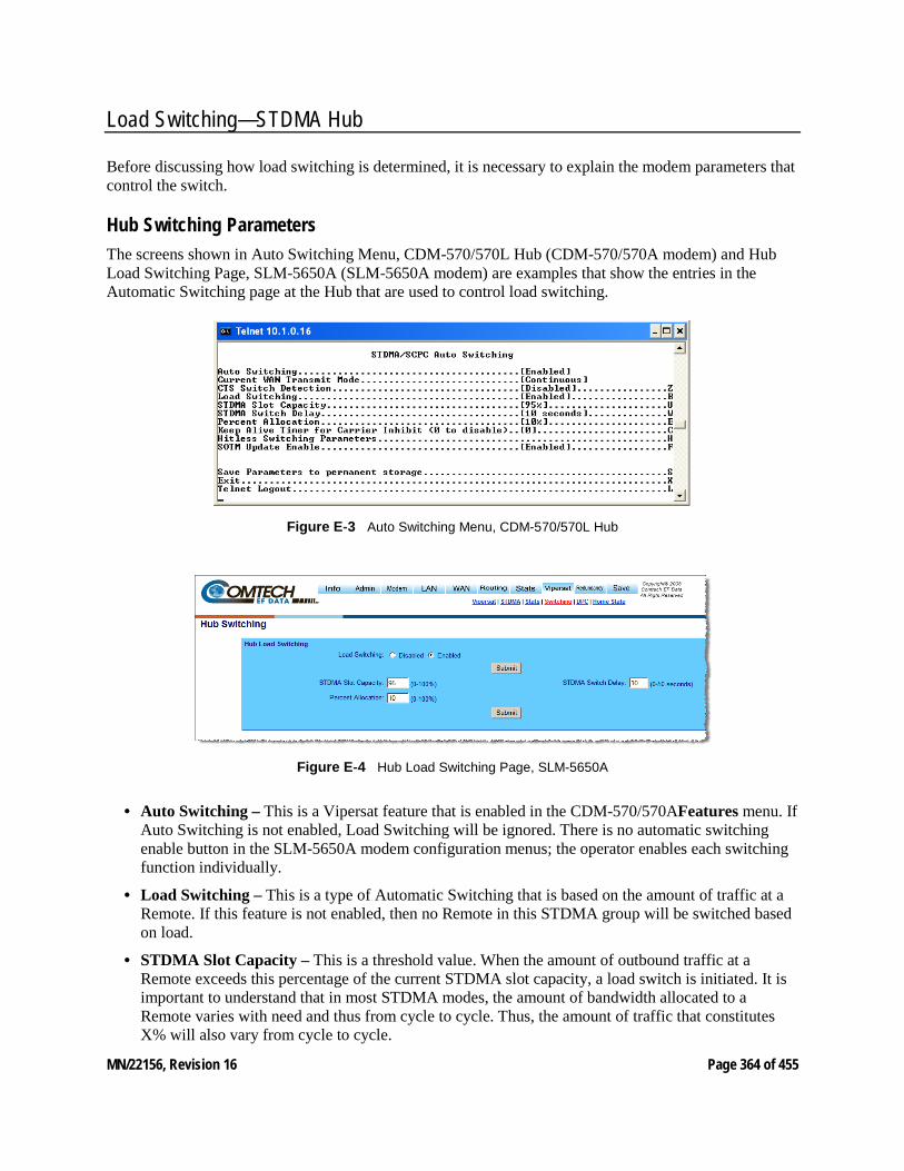
MN/22156, Revision 16 Page 364 of 455
Load Switching—STDMA Hub
Before discussing how load switching is determined, it is necessary to explain the modem parameters that control the switch.
Hub Switching Parameters The screens shown in Auto Switching Menu, CDM-570/570L Hub (CDM-570/570A modem) and Hub Load Switching Page, SLM-5650A (SLM-5650A modem) are examples that show the entries in the Automatic Switching page at the Hub that are used to control load switching.
Figure E‑3 Auto Switching Menu, CDM-570/570L Hub
Figure E‑4 Hub Load Switching Page, SLM-5650A
• Auto Switching – This is a Vipersat feature that is enabled in the CDM-570/570AFeatures menu. If Auto Switching is not enabled, Load Switching will be ignored. There is no automatic switching enable button in the SLM-5650A modem configuration menus; the operator enables each switching function individually.
• Load Switching – This is a type of Automatic Switching that is based on the amount of traffic at a Remote. If this feature is not enabled, then no Remote in this STDMA group will be switched based on load.
• STDMA Slot Capacity – This is a threshold value. When the amount of outbound traffic at a Remote exceeds this percentage of the current STDMA slot capacity, a load switch is initiated. It is important to understand that in most STDMA modes, the amount of bandwidth allocated to a Remote varies with need and thus from cycle to cycle. Thus, the amount of traffic that constitutes X% will also vary from cycle to cycle.

MN/22156, Revision 16 Page 365 of 455
Note for Dynamic Cycle mode: Since Dynamic Cycle mode tends to provide no more bandwidth than is needed, Remotes will typically appear to be near 100% capacity whenever they are passing real traffic. Thus, in this mode, if the threshold is set too low, switches will occur unnecessarily.
• STDMA Switch Delay – This is a built-in latency that forces a Remote to maintain an average load over some number of seconds after reaching a switch condition before the switch is actually initiated. This prevents switches due to momentary traffic bursts.
• Percent Allocation – This is an excess amount of bandwidth that is allocated beyond the current traffic rate when the switch to SCPC is made. For example, if the current average traffic at the time of the switch is 60 kbps, and the Percent Allocation is 10%, then the allocation will be for 60k + 6k = 66 kbps.
Note that, because the Hub always allocates bandwidth in 8 kbps blocks, the 66 kbps will be rounded up to 72 kbps in this example.
Hub Switching Process Each time the Hub receives an STDMA ACK, it computes the average load for that Remote. This average is then compared to the bandwidth currently allocated to the Remote.
For example, if a Remote gets a 50ms slot in an upstream that is running at 512000 bps, then it can transmit 0.050 * 512000 = 25600 bits = 3200 bytes. If the Queued Bytes was 3000, then for that cycle, the Remote was at 3000/3200 = 93.75% of capacity. If the current cycle time is exactly 1 second, then the effective data rate of the Remote is also 25600 bits per second. However, if the cycle time is only 500 milliseconds, then the effective data rate is actually 25600/.5 = 51200 bits per second. The effective data rate is important for calculating switch data rates.
If the average bandwidth used exceeds the threshold percentage of available bandwidth, then a flag is set indicating a switch is pending. At this point, the statistics are reset, and the traffic load is then computed for the time period specified by the switch delay. At the end of this delay, if the threshold is still exceeded, a switch is initiated. The data rate specified for the switch is determined by taking the current load, as indicated by the bytes queued during the delay period, multiplying it by the percent allocation and rounding up to the next 8 kbps.
A key point is that in most of the STDMA modes, the bandwidth allocated to each Remote is constantly being adjusted to the needs of the network. As long as the network is running below capacity, most Remotes will get the bandwidth they need, and a switch will not be required. Only when a Remote requires more bandwidth than is available in STDMA will a switch occur.
In Dynamic Cycle mode, each Remote will always appear to be running at near 100% capacity, even when there is excess bandwidth available. This is because in this mode, the Remotes are almost never given more bandwidth than they need. As a result, the algorithm for this mode uses a maximum allowed slot size rather than the actual allocated slot size to calculate the effective data rate. This results in a more accurate estimate of the available STDMA bandwidth.
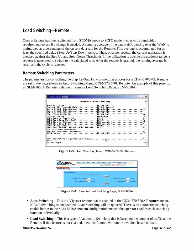
MN/22156, Revision 16 Page 366 of 455
Load Switching—Remote
Once a Remote has been switched from STDMA mode to SCPC mode, it checks its bandwidth requirements to see if a change is needed. A running average of the data traffic passing over the WAN is maintained as a percentage of the current data rate for the Remote. This average is accumulated for at least the specified delay (Step Up/Step Down) period. Then, once per second, the current utilization is checked against the Step Up and Step-Down Thresholds. If the utilization is outside the up/down range, a request is generated to switch to the calculated rate. After the request is granted, the running average is reset, and the cycle is repeated.
Remote Switching Parameters The parameters for controlling the Step Up/Step Down switching process for a CDM-570/570L Remote are set in the page shown in Auto Switching Menu, CDM-570/570L Remote. An example of this page for an SLM-5650A Remote is shown in Remote Load Switching Page, SLM-5650A.
Figure E‑5 Auto Switching Menu, CDM-570/570L Remote
Figure E‑6 Remote Load Switching Page, SLM-5650A
• Auto Switching – This is a Vipersat feature that is enabled in the CDM-570/570A Features menu. If Auto Switching is not enabled, Load Switching will be ignored. There is no automatic switching enable button in the SLM-5650A modem configuration menus; the operator enables each switching function individually.
• Load Switching – This is a type of Automatic Switching that is based on the amount of traffic at the Remote. If this feature is not enabled, then this Remote will not be switched based on load.
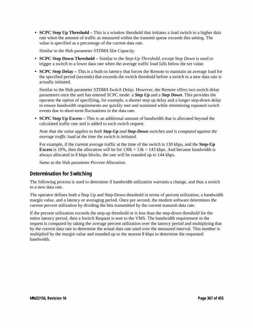
MN/22156, Revision 16 Page 367 of 455
• SCPC Step Up Threshold – This is a window threshold that initiates a load switch to a higher data rate when the amount of traffic as measured within the transmit queue exceeds this setting. The value is specified as a percentage of the current data rate.
Similar to the Hub parameter STDMA Slot Capacity.
• SCPC Step Down Threshold – Similar to the Step-Up Threshold, except Step Down is used to trigger a switch to a lower data rate when the average traffic load falls below the set value.
• SCPC Step Delay – This is a built-in latency that forces the Remote to maintain an average load for the specified period (seconds) that exceeds the switch threshold before a switch to a new data rate is actually initiated.
Similar to the Hub parameter STDMA Switch Delay. However, the Remote offers two switch delay parameters once the unit has entered SCPC mode: a Step Up and a Step Down. This provides the operator the option of specifying, for example, a shorter step up delay and a longer step-down delay to ensure bandwidth requirements are quickly met and sustained while minimizing repeated switch events due to short-term fluctuations in the data rate.
• SCPC Step Up Excess – This is an additional amount of bandwidth that is allocated beyond the calculated traffic rate and is added to each switch request.
Note that the value applies to both Step-Up and Step-Down switches and is computed against the average traffic load at the time the switch is initiated.
For example, if the current average traffic at the time of the switch is 130 kbps, and the Step-Up Excess is 10%, then the allocation will be for 130k + 13k = 143 kbps. And because bandwidth is always allocated in 8 kbps blocks, the rate will be rounded up to 144 kbps.
Same as the Hub parameter Percent Allocation.
Determination for Switching The following process is used to determine if bandwidth utilization warrants a change, and thus a switch to a new data rate.
The operator defines both a Step Up and Step-Down threshold in terms of percent utilization, a bandwidth margin value, and a latency or averaging period. Once per second, the modem software determines the current percent utilization by dividing the bits transmitted by the current transmit data rate.
If the percent utilization exceeds the step-up threshold or is less than the step-down threshold for the entire latency period, then a Switch Request is sent to the VMS. The bandwidth requirement in the request is computed by taking the average percent utilization over the latency period and multiplying that by the current data rate to determine the actual data rate used over the measured interval. This number is multiplied by the margin value and rounded up to the nearest 8 kbps to determine the requested bandwidth.
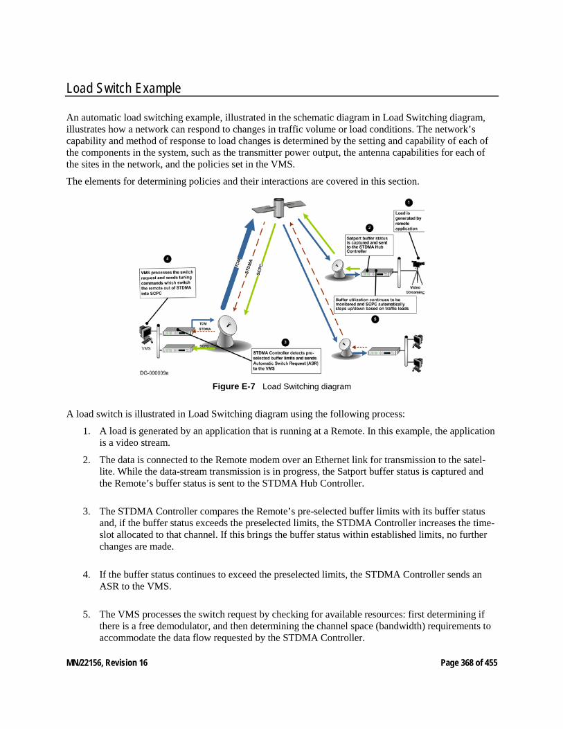
MN/22156, Revision 16 Page 368 of 455
Load Switch Example
An automatic load switching example, illustrated in the schematic diagram in Load Switching diagram, illustrates how a network can respond to changes in traffic volume or load conditions. The network’s capability and method of response to load changes is determined by the setting and capability of each of the components in the system, such as the transmitter power output, the antenna capabilities for each of the sites in the network, and the policies set in the VMS.
The elements for determining policies and their interactions are covered in this section.
Figure E‑7 Load Switching diagram
A load switch is illustrated in Load Switching diagram using the following process:
1. A load is generated by an application that is running at a Remote. In this example, the application is a video stream.
2. The data is connected to the Remote modem over an Ethernet link for transmission to the satel-lite. While the data-stream transmission is in progress, the Satport buffer status is captured and the Remote’s buffer status is sent to the STDMA Hub Controller.
3. The STDMA Controller compares the Remote’s pre-selected buffer limits with its buffer status and, if the buffer status exceeds the preselected limits, the STDMA Controller increases the time-slot allocated to that channel. If this brings the buffer status within established limits, no further changes are made.
4. If the buffer status continues to exceed the preselected limits, the STDMA Controller sends an ASR to the VMS.
5. The VMS processes the switch request by checking for available resources: first determining if there is a free demodulator, and then determining the channel space (bandwidth) requirements to accommodate the data flow requested by the STDMA Controller.
MN/22156, Revision 16 Page 369 of 455
6. If the VMS finds available resources, it processes the switch request and sends tuning commands that switch the Remote out of STDMA and into SCPC mode.
The modem continuously monitors traffic flow volume. Whenever a preset upper or lower limit is exceeded, the modem sends a request to the VMS to change bandwidth by the amount needed to meet the new requirement. By this process, the bandwidth is continuously optimized in real time, precisely accommodating circuit traffic volume.
The ideal condition is for utilization of the channel to reach approximately 90%, thus optimizing the use of available bandwidth. The ability to actually accomplish this is limited by the currently available carrier bandwidth and, ultimately, the power output and antenna size available at the transmitting Remote site.
If the requested bandwidth is not available, the STDMA Controller will continue to receive buffer status reports from the Remote indicating that buffer flow is continuing, and the STDMA Controller will, in turn, continue to request additional bandwidth from the VMS. When bandwidth does become available, the VMS will perform the switch the next time that the STDMA Controller makes the request.
If the video data stream ends before the switch in bandwidth is completed, the channel is closed, the bandwidth which had been allocated is made available again to the pool, and no further action is taken.
Reduced Data Flow in Switched Mode (SCPC) In the event the data flow is reduced—for example, a streaming file transfer terminates—the SCPC switched demodulator detects the reduced flow and notifies the VMS. The VMS will then send a switch command to reduce the size of the carrier bandwidth to the newly calculated requirement.
This entire process is automatic, following the policies established for the network. The network is dynamically modified, changing configuration to automatically respond to changes to the network’s load.
The Home Threshold is the bit rate set to trigger a return to the home condition. This function is used when bandwidth has been allocated to meet load requirements, and then the load has been either removed or partially removed. The Home Threshold is used to determine whether the current bit rate has fallen below this preset level and, if so, the channel is switched back to its home condition (STDMA mode, for example).
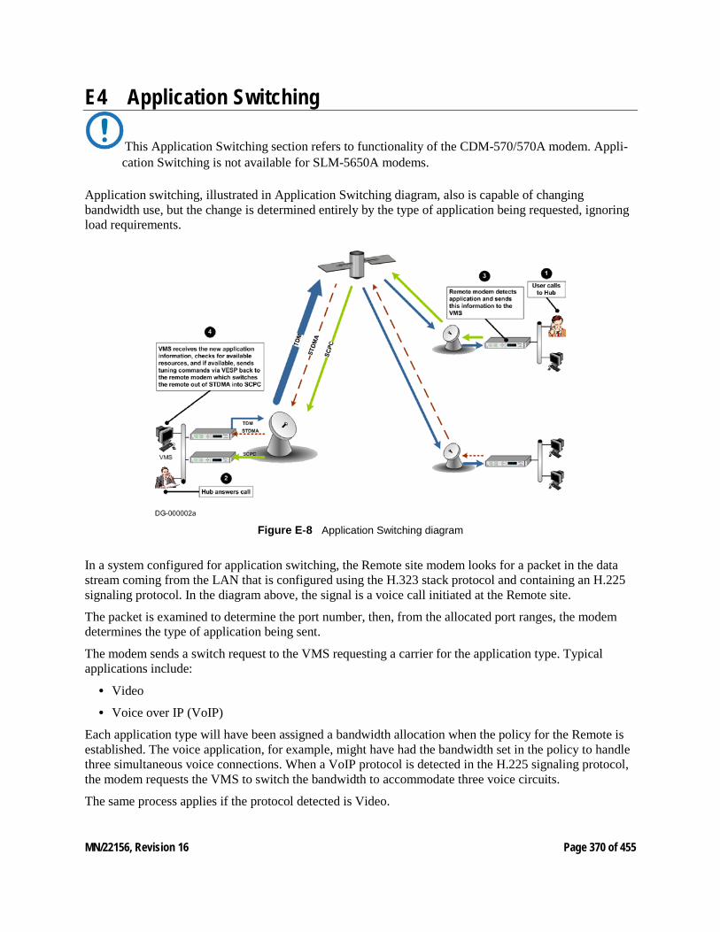
MN/22156, Revision 16 Page 370 of 455
E4 Application Switching
This Application Switching section refers to functionality of the CDM-570/570A modem. Appli-cation Switching is not available for SLM-5650A modems.
Application switching, illustrated in Application Switching diagram, also is capable of changing bandwidth use, but the change is determined entirely by the type of application being requested, ignoring load requirements.
Figure E‑8 Application Switching diagram
In a system configured for application switching, the Remote site modem looks for a packet in the data stream coming from the LAN that is configured using the H.323 stack protocol and containing an H.225 signaling protocol. In the diagram above, the signal is a voice call initiated at the Remote site.
The packet is examined to determine the port number, then, from the allocated port ranges, the modem determines the type of application being sent.
The modem sends a switch request to the VMS requesting a carrier for the application type. Typical applications include:
• Video
• Voice over IP (VoIP)
Each application type will have been assigned a bandwidth allocation when the policy for the Remote is established. The voice application, for example, might have had the bandwidth set in the policy to handle three simultaneous voice connections. When a VoIP protocol is detected in the H.225 signaling protocol, the modem requests the VMS to switch the bandwidth to accommodate three voice circuits.
The same process applies if the protocol detected is Video.
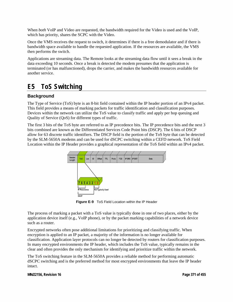
MN/22156, Revision 16 Page 371 of 455
When both VoIP and Video are requested, the bandwidth required for the Video is used and the VoIP, which has priority, shares the SCPC with the Video.
Once the VMS receives the request to switch, it determines if there is a free demodulator and if there is bandwidth space available to handle the requested application. If the resources are available, the VMS then performs the switch.
Applications are streaming data. The Remote looks at the streaming data flow until it sees a break in the data exceeding 10 seconds. Once a break is detected the modem presumes that the application is terminated (or has malfunctioned), drops the carrier, and makes the bandwidth resources available for another service.
E5 ToS Switching Background The Type of Service (ToS) byte is an 8-bit field contained within the IP header portion of an IPv4 packet. This field provides a means of marking packets for traffic identification and classification purposes. Devices within the network can utilize the ToS value to classify traffic and apply per hop queuing and Quality of Service (QoS) for different types of traffic.
The first 3 bits of the ToS byte are referred to as IP precedence bits. The IP precedence bits and the next 3 bits combined are known as the Differentiated Services Code Point bits (DSCP). The 6 bits of DSCP allow for 63 discrete traffic identifiers. The DSCP field is the portion of the ToS byte that can be detected by the SLM-5650A modems and can be used for dSCPC switching within a CEFD network. ToS Field Location within the IP Header provides a graphical representation of the ToS field within an IPv4 packet.
Figure E‑9 ToS Field Location within the IP Header
The process of marking a packet with a ToS value is typically done in one of two places, either by the application device itself (e.g., VoIP phone), or by the packet marking capabilities of a network device such as a router.
Encrypted networks often pose additional limitations for prioritizing and classifying traffic. When encryption is applied to an IP packet, a majority of the information is no longer available for classification. Application layer protocols can no longer be detected by routers for classification purposes. In many encrypted environments the IP header, which includes the ToS value, typically remains in the clear and often provides the only mechanism for identifying and prioritize traffic within the network.
The ToS switching feature in the SLM-5650A provides a reliable method for performing automatic dSCPC switching and is the preferred method for most encrypted environments that leave the IP header intact.
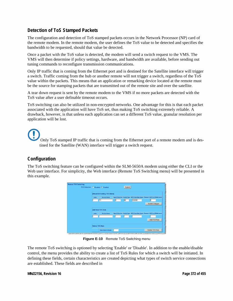
MN/22156, Revision 16 Page 372 of 455
Detection of ToS Stamped Packets The configuration and detection of ToS stamped packets occurs in the Network Processor (NP) card of the remote modem. In the remote modem, the user defines the ToS value to be detected and specifies the bandwidth to be requested, should that value be detected.
Once a packet with the ToS value is detected, the modem will send a switch request to the VMS. The VMS will then determine if policy settings, hardware, and bandwidth are available, before sending out tuning commands to reconfigure transmission communications.
Only IP traffic that is coming from the Ethernet port and is destined for the Satellite interface will trigger a switch. Traffic coming from the hub or another remote will not trigger a switch, regardless of the ToS value within the packets. This means that an application or remarking device located at the remote must be the source for stamping packets that are transmitted out of the remote site and over the satellite.
A tear down request is sent by the remote modem to the VMS if no more packets are detected with the ToS value after a user definable timeout occurs.
ToS switching can also be utilized in non-encrypted networks. One advantage for this is that each packet associated with the application will have ToS set, thus making ToS switching extremely reliable. A drawback, however, is that unless each application can set a different ToS value, granular resolution per application will be lost.
Only ToS stamped IP traffic that is coming from the Ethernet port of a remote modem and is des-tined for the Satellite (WAN) interface will trigger a switch request.
Configuration The ToS switching feature can be configured within the SLM-5650A modem using either the CLI or the Web user interface. For simplicity, the Web interface (Remote ToS Switching menu) will be presented in this example.
Figure E‑10 Remote ToS Switching menu
The remote ToS switching is optioned by selecting 'Enable' or 'Disable'. In addition to the enable/disable control, the menu provides the ability to create a list of ToS Rules for which a switch will be initiated. In defining these fields, certain characteristics are created depicting what types of switch service connections are established. These fields are described in
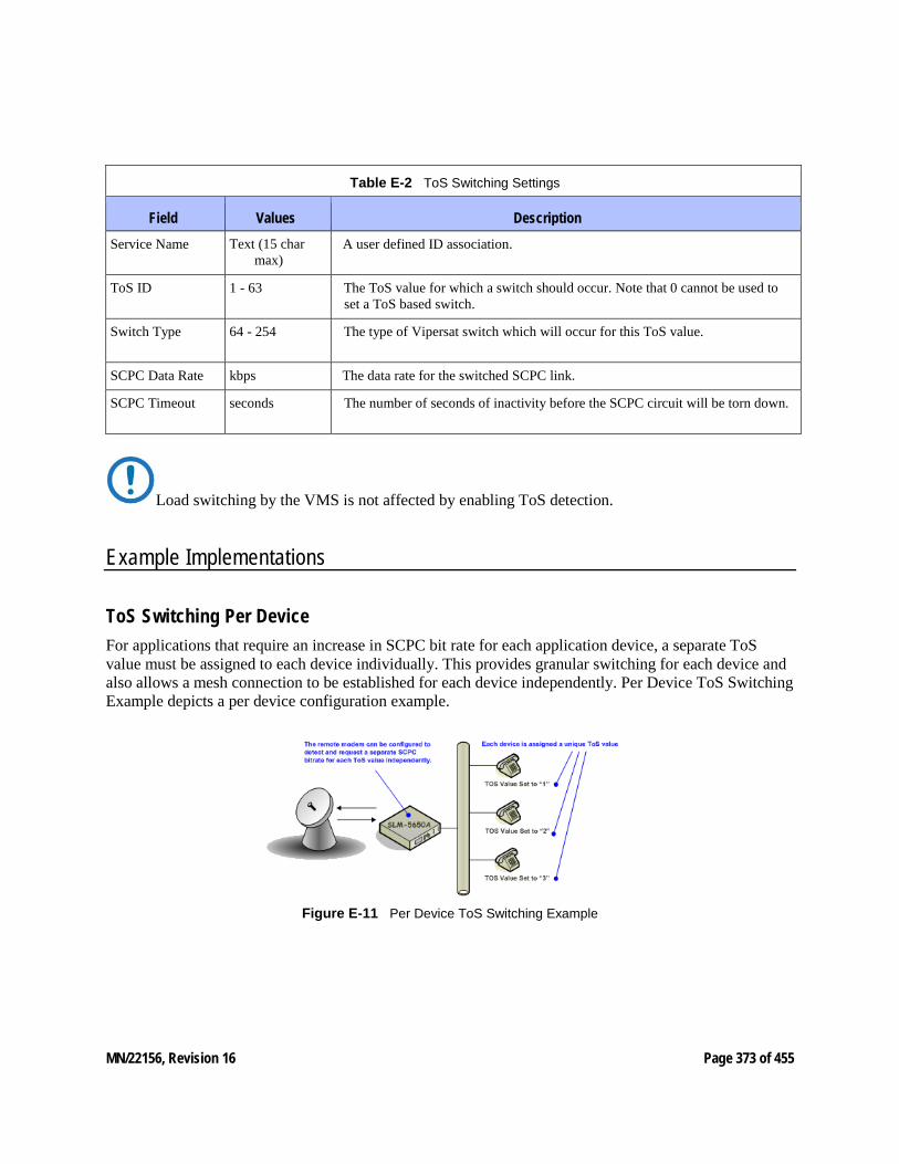
MN/22156, Revision 16 Page 373 of 455
Table E-2 ToS Switching Settings
Field Values Description Service Name Text (15 char
max) A user defined ID association.
ToS ID 1 - 63 The ToS value for which a switch should occur. Note that 0 cannot be used to set a ToS based switch.
Switch Type 64 - 254 The type of Vipersat switch which will occur for this ToS value.
SCPC Data Rate kbps The data rate for the switched SCPC link.
SCPC Timeout seconds The number of seconds of inactivity before the SCPC circuit will be torn down.
Load switching by the VMS is not affected by enabling ToS detection.
Example Implementations
ToS Switching Per Device For applications that require an increase in SCPC bit rate for each application device, a separate ToS value must be assigned to each device individually. This provides granular switching for each device and also allows a mesh connection to be established for each device independently. Per Device ToS Switching Example depicts a per device configuration example.
Figure E‑11 Per Device ToS Switching Example
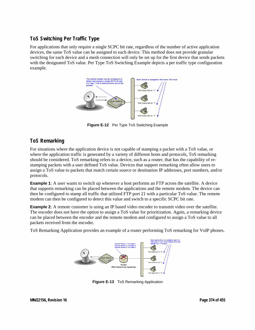
MN/22156, Revision 16 Page 374 of 455
ToS Switching Per Traffic Type For applications that only require a single SCPC bit rate, regardless of the number of active application devices, the same ToS value can be assigned to each device. This method does not provide granular switching for each device and a mesh connection will only be set up for the first device that sends packets with the designated ToS value. Per Type ToS Switching Example depicts a per traffic type configuration example.
Figure E‑12 Per Type ToS Switching Example
ToS Remarking For situations where the application device is not capable of stamping a packet with a ToS value, or where the application traffic is generated by a variety of different hosts and protocols, ToS remarking should be considered. ToS remarking refers to a device, such as a router, that has the capability of re-stamping packets with a user defined ToS value. Devices that support remarking often allow users to assign a ToS value to packets that match certain source or destination IP addresses, port numbers, and/or protocols.
Example 1: A user wants to switch up whenever a host performs an FTP across the satellite. A device that supports remarking can be placed between the applications and the remote modem. The device can then be configured to stamp all traffic that utilized FTP port 21 with a particular ToS value. The remote modem can then be configured to detect this value and switch to a specific SCPC bit rate.
Example 2: A remote customer is using an IP based video encoder to transmit video over the satellite. The encoder does not have the option to assign a ToS value for prioritization. Again, a remarking device can be placed between the encoder and the remote modem and configured to assign a ToS value to all packets received from the encoder.
ToS Remarking Application provides an example of a router performing ToS remarking for VoIP phones.
Figure E‑13 ToS Remarking Application
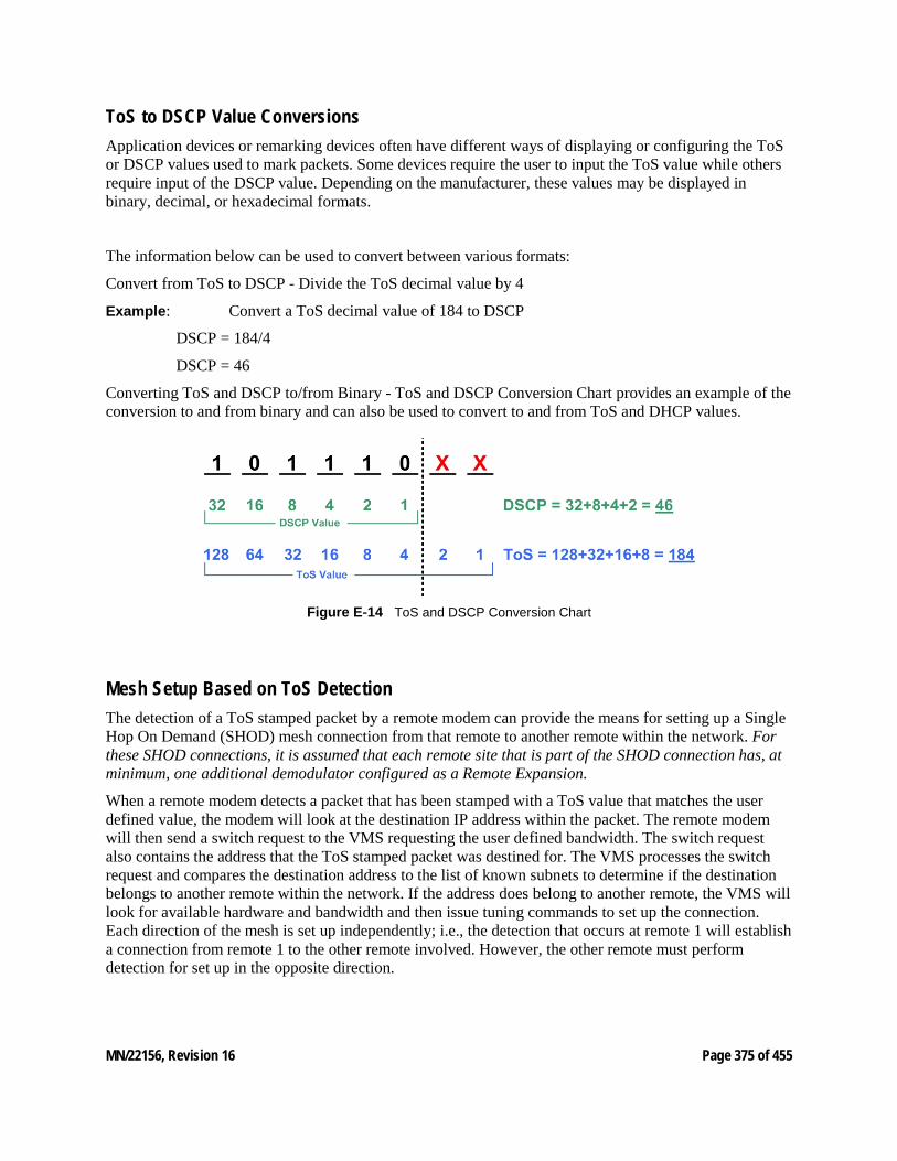
MN/22156, Revision 16 Page 375 of 455
ToS to DSCP Value Conversions Application devices or remarking devices often have different ways of displaying or configuring the ToS or DSCP values used to mark packets. Some devices require the user to input the ToS value while others require input of the DSCP value. Depending on the manufacturer, these values may be displayed in binary, decimal, or hexadecimal formats.
The information below can be used to convert between various formats:
Convert from ToS to DSCP - Divide the ToS decimal value by 4
Example: Convert a ToS decimal value of 184 to DSCP
DSCP = 184/4
DSCP = 46
Converting ToS and DSCP to/from Binary - ToS and DSCP Conversion Chart provides an example of the conversion to and from binary and can also be used to convert to and from ToS and DHCP values.
Figure E‑14 ToS and DSCP Conversion Chart
Mesh Setup Based on ToS Detection The detection of a ToS stamped packet by a remote modem can provide the means for setting up a Single Hop On Demand (SHOD) mesh connection from that remote to another remote within the network. For these SHOD connections, it is assumed that each remote site that is part of the SHOD connection has, at minimum, one additional demodulator configured as a Remote Expansion.
When a remote modem detects a packet that has been stamped with a ToS value that matches the user defined value, the modem will look at the destination IP address within the packet. The remote modem will then send a switch request to the VMS requesting the user defined bandwidth. The switch request also contains the address that the ToS stamped packet was destined for. The VMS processes the switch request and compares the destination address to the list of known subnets to determine if the destination belongs to another remote within the network. If the address does belong to another remote, the VMS will look for available hardware and bandwidth and then issue tuning commands to set up the connection. Each direction of the mesh is set up independently; i.e., the detection that occurs at remote 1 will establish a connection from remote 1 to the other remote involved. However, the other remote must perform detection for set up in the opposite direction.
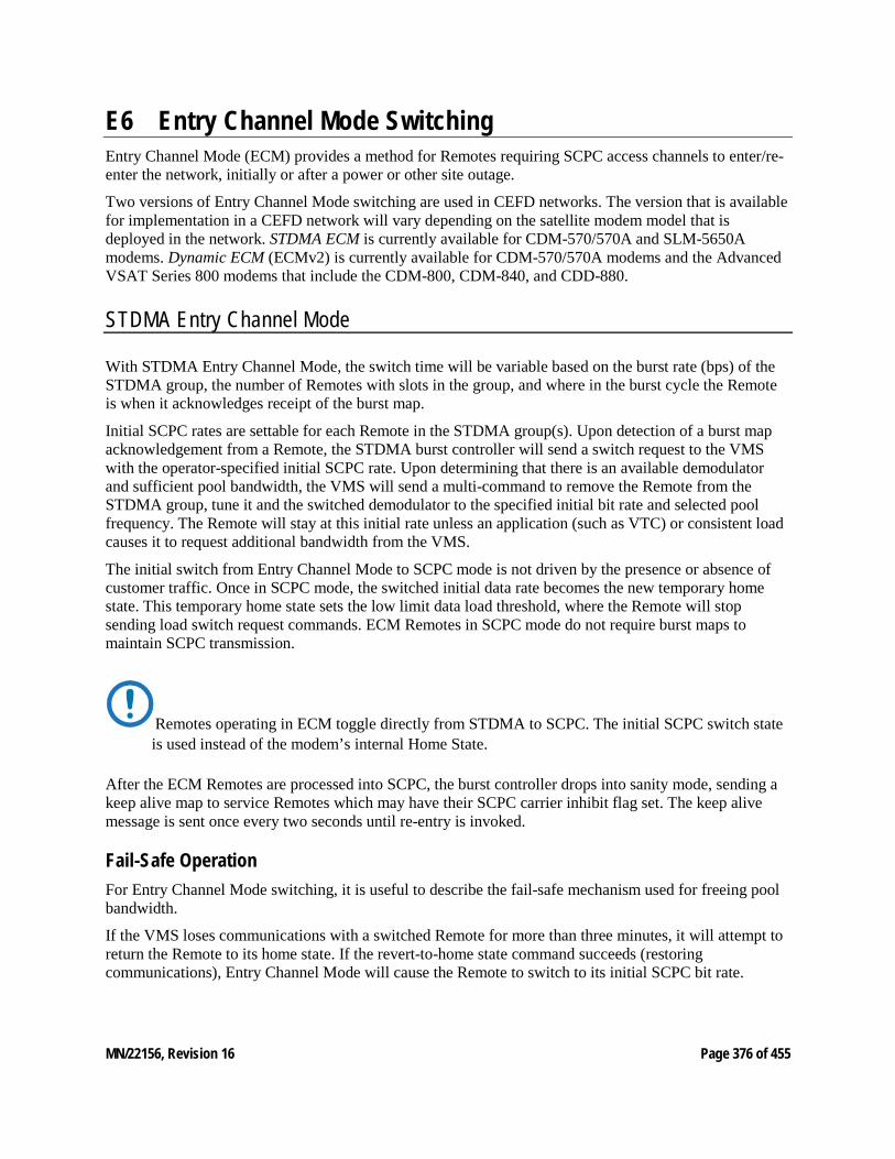
MN/22156, Revision 16 Page 376 of 455
E6 Entry Channel Mode Switching Entry Channel Mode (ECM) provides a method for Remotes requiring SCPC access channels to enter/re-enter the network, initially or after a power or other site outage.
Two versions of Entry Channel Mode switching are used in CEFD networks. The version that is available for implementation in a CEFD network will vary depending on the satellite modem model that is deployed in the network. STDMA ECM is currently available for CDM-570/570A and SLM-5650A modems. Dynamic ECM (ECMv2) is currently available for CDM-570/570A modems and the Advanced VSAT Series 800 modems that include the CDM-800, CDM-840, and CDD-880.
STDMA Entry Channel Mode
With STDMA Entry Channel Mode, the switch time will be variable based on the burst rate (bps) of the STDMA group, the number of Remotes with slots in the group, and where in the burst cycle the Remote is when it acknowledges receipt of the burst map.
Initial SCPC rates are settable for each Remote in the STDMA group(s). Upon detection of a burst map acknowledgement from a Remote, the STDMA burst controller will send a switch request to the VMS with the operator-specified initial SCPC rate. Upon determining that there is an available demodulator and sufficient pool bandwidth, the VMS will send a multi-command to remove the Remote from the STDMA group, tune it and the switched demodulator to the specified initial bit rate and selected pool frequency. The Remote will stay at this initial rate unless an application (such as VTC) or consistent load causes it to request additional bandwidth from the VMS.
The initial switch from Entry Channel Mode to SCPC mode is not driven by the presence or absence of customer traffic. Once in SCPC mode, the switched initial data rate becomes the new temporary home state. This temporary home state sets the low limit data load threshold, where the Remote will stop sending load switch request commands. ECM Remotes in SCPC mode do not require burst maps to maintain SCPC transmission.
Remotes operating in ECM toggle directly from STDMA to SCPC. The initial SCPC switch state is used instead of the modem’s internal Home State.
After the ECM Remotes are processed into SCPC, the burst controller drops into sanity mode, sending a keep alive map to service Remotes which may have their SCPC carrier inhibit flag set. The keep alive message is sent once every two seconds until re-entry is invoked.
Fail-Safe Operation For Entry Channel Mode switching, it is useful to describe the fail-safe mechanism used for freeing pool bandwidth.
If the VMS loses communications with a switched Remote for more than three minutes, it will attempt to return the Remote to its home state. If the revert-to-home state command succeeds (restoring communications), Entry Channel Mode will cause the Remote to switch to its initial SCPC bit rate.
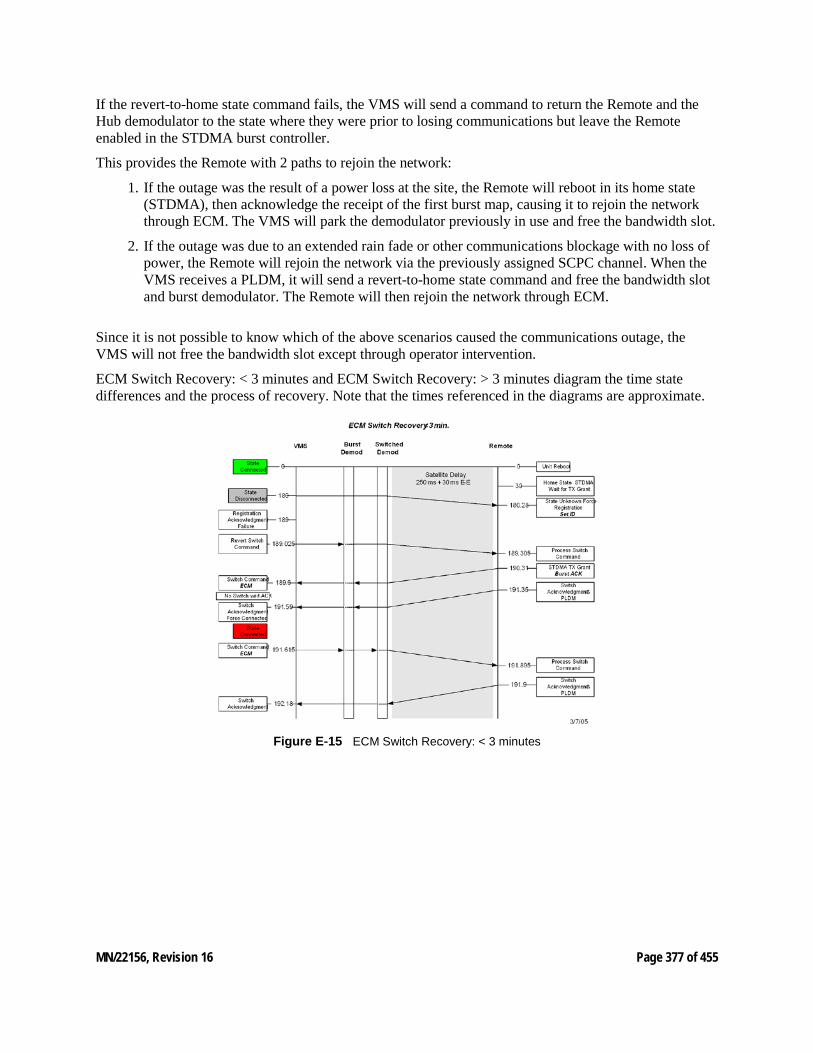
MN/22156, Revision 16 Page 377 of 455
If the revert-to-home state command fails, the VMS will send a command to return the Remote and the Hub demodulator to the state where they were prior to losing communications but leave the Remote enabled in the STDMA burst controller.
This provides the Remote with 2 paths to rejoin the network:
1. If the outage was the result of a power loss at the site, the Remote will reboot in its home state (STDMA), then acknowledge the receipt of the first burst map, causing it to rejoin the network through ECM. The VMS will park the demodulator previously in use and free the bandwidth slot.
2. If the outage was due to an extended rain fade or other communications blockage with no loss of power, the Remote will rejoin the network via the previously assigned SCPC channel. When the VMS receives a PLDM, it will send a revert-to-home state command and free the bandwidth slot and burst demodulator. The Remote will then rejoin the network through ECM.
Since it is not possible to know which of the above scenarios caused the communications outage, the VMS will not free the bandwidth slot except through operator intervention.
ECM Switch Recovery: < 3 minutes and ECM Switch Recovery: > 3 minutes diagram the time state differences and the process of recovery. Note that the times referenced in the diagrams are approximate.
Figure E‑15 ECM Switch Recovery: < 3 minutes
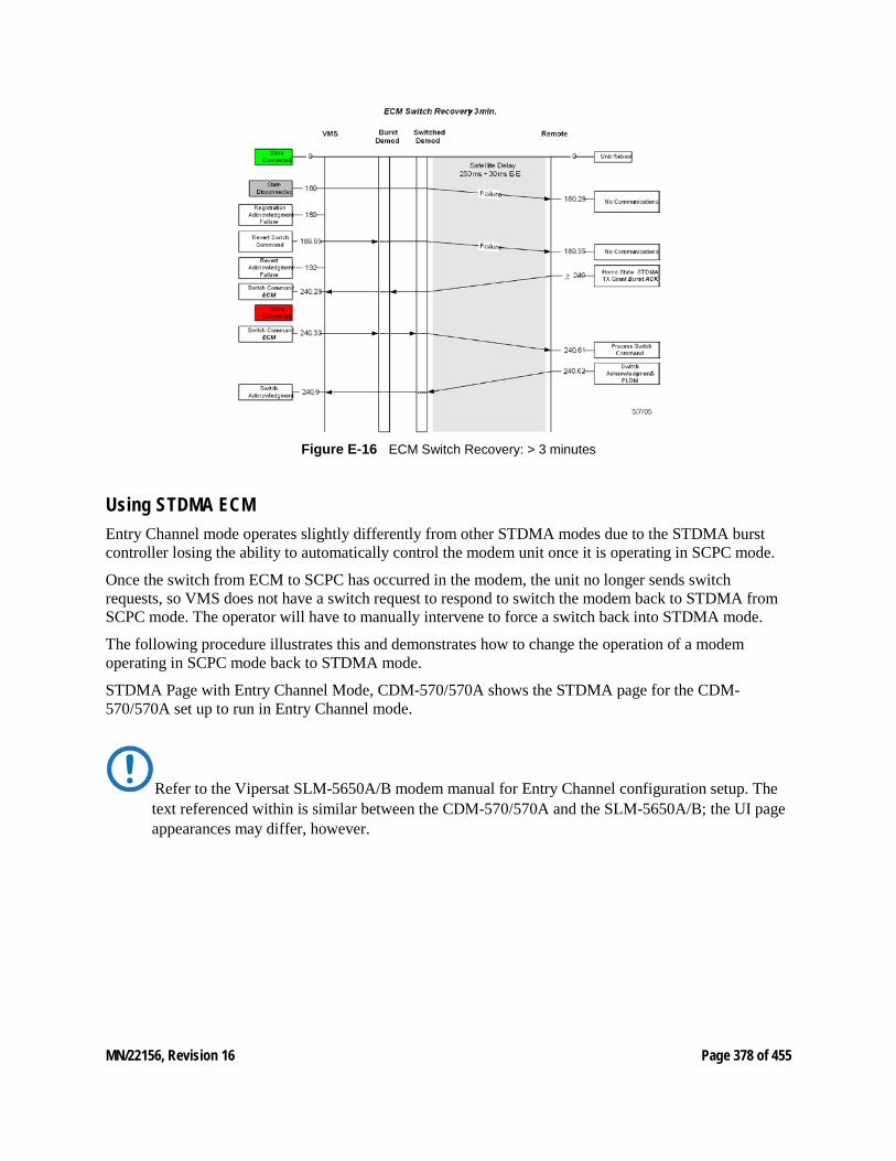
MN/22156, Revision 16 Page 378 of 455
Figure E‑16 ECM Switch Recovery: > 3 minutes
Using STDMA ECM Entry Channel mode operates slightly differently from other STDMA modes due to the STDMA burst controller losing the ability to automatically control the modem unit once it is operating in SCPC mode.
Once the switch from ECM to SCPC has occurred in the modem, the unit no longer sends switch requests, so VMS does not have a switch request to respond to switch the modem back to STDMA from SCPC mode. The operator will have to manually intervene to force a switch back into STDMA mode.
The following procedure illustrates this and demonstrates how to change the operation of a modem operating in SCPC mode back to STDMA mode.
STDMA Page with Entry Channel Mode, CDM-570/570A shows the STDMA page for the CDM-570/570A set up to run in Entry Channel mode.
Refer to the Vipersat SLM-5650A/B modem manual for Entry Channel configuration setup. The text referenced within is similar between the CDM-570/570A and the SLM-5650A/B; the UI page appearances may differ, however.
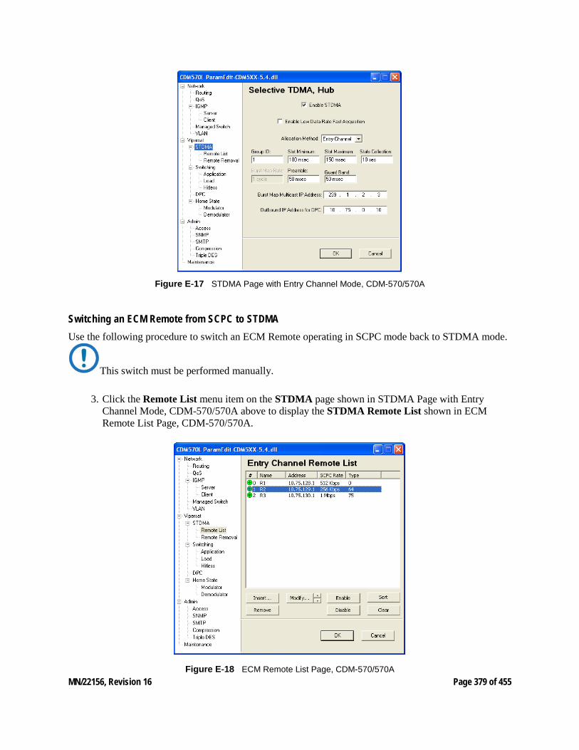
MN/22156, Revision 16 Page 379 of 455
Figure E‑17 STDMA Page with Entry Channel Mode, CDM-570/570A
Switching an ECM Remote from SCPC to STDMA Use the following procedure to switch an ECM Remote operating in SCPC mode back to STDMA mode.
This switch must be performed manually.
3. Click the Remote List menu item on the STDMA page shown in STDMA Page with Entry Channel Mode, CDM-570/570A above to display the STDMA Remote List shown in ECM Remote List Page, CDM-570/570A.
Figure E‑18 ECM Remote List Page, CDM-570/570A
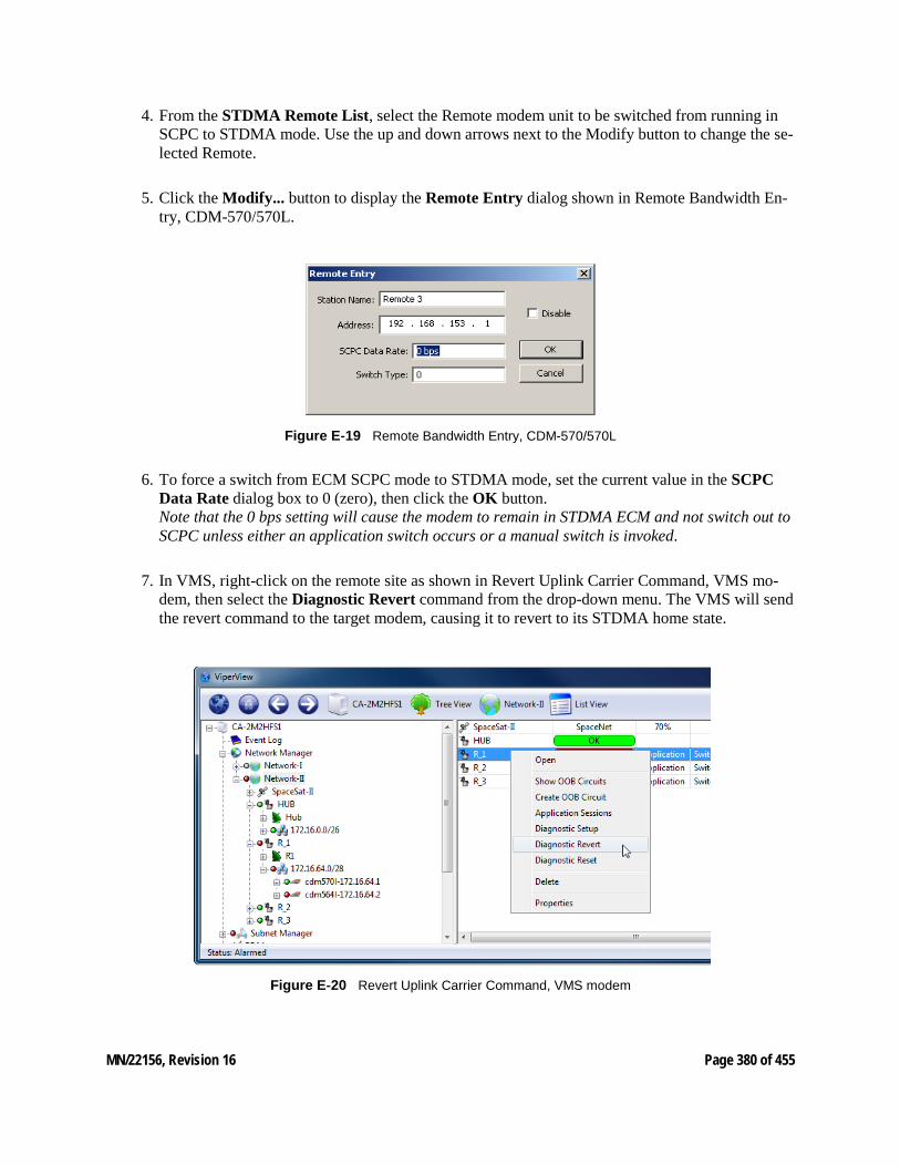
MN/22156, Revision 16 Page 380 of 455
4. From the STDMA Remote List, select the Remote modem unit to be switched from running in SCPC to STDMA mode. Use the up and down arrows next to the Modify button to change the se-lected Remote.
5. Click the Modify... button to display the Remote Entry dialog shown in Remote Bandwidth En-try, CDM-570/570L.
Figure E‑19 Remote Bandwidth Entry, CDM-570/570L
6. To force a switch from ECM SCPC mode to STDMA mode, set the current value in the SCPC Data Rate dialog box to 0 (zero), then click the OK button. Note that the 0 bps setting will cause the modem to remain in STDMA ECM and not switch out to SCPC unless either an application switch occurs or a manual switch is invoked.
7. In VMS, right-click on the remote site as shown in Revert Uplink Carrier Command, VMS mo-dem, then select the Diagnostic Revert command from the drop-down menu. The VMS will send the revert command to the target modem, causing it to revert to its STDMA home state.
Figure E‑20 Revert Uplink Carrier Command, VMS modem

MN/22156, Revision 16 Page 381 of 455
If the remote site is offline or the remote may be in an unknown state, sending a Diagnostic Reset will issue a command to remote forcing home state configuration and the VMS will clear ALL al-locations associated.
This completes resetting the Remote modem to operate in the STDMA mode.
MN/22156, Revision 16 Page 382 of 455
E7 Dynamic Entry Channel Mode Dynamic ECM (ECMv2) utilizes a modified slotted Aloha method for Remotes to establish registration in the network and obtain the means for switching into SCPC mode. Rather than sharing an STDMA burst map, as is the method with STDMA ECM, the Remotes rely on communicating with the Hub channel controller using a multicast Transmission Announcement Protocol (TAP) message. This eliminates the restriction in the number of Remotes in an Entry Channel group that is inherent with the burst map method.
The TAP, broadcast periodically, supplies the Remotes with the transmit parameters that are required for transmitting back to the Hub. In addition, the TAP provides timing information in the form of slot parameters that define the required acquisition time of the receiver and the amount of time allowed for M&C packet transactions.
All Remotes will receive the TAP message from the Hub, but a Remote will only transmit back to the Hub if it is a member of the specified group. Upon receipt of the TAP, the Remote resets its timing and uses the provided slot information to determine the next transmit opportunity. This allows each Remote to transmit at a discrete time to minimize the chance of collision. When a transmission to the Hub is not received, the Remote uses a random back-off (next slot) algorithm to further reduce contention and will try again until a Hub response is received.
Upon valid reception of the Remote’s transmission, the Hub channel controller will place the Remote into queue for assignment of switching into a dSCPC channel. The Remote will be registered in the VMS, then await the availability of the hardware and bandwidth resources necessary for execution of the switch request. The TAP will continue to be received even after the Remote has been switched out into SCPC.
Only management traffic is allowed while a Remote is in ECM. No data traffic is transmitted until the Remote is switched out of ECM and is operating in dSCPC mode.
Hub Configuration The Hub channel controller is a dedicated demodulator that has been selected as an ECM controller. The Entry Channel configuration settings of this demodulator (Entry Channel Mode v2 Configuration, Hub) determine the channel parameters that are transmitted in the TAP message and include:
• ECM Enable • Group ID • TAP IP Multicast Address • Preamble • Guard Band • LNB LO Frequency • Satellite Frequency Conversion • Total Slot Count
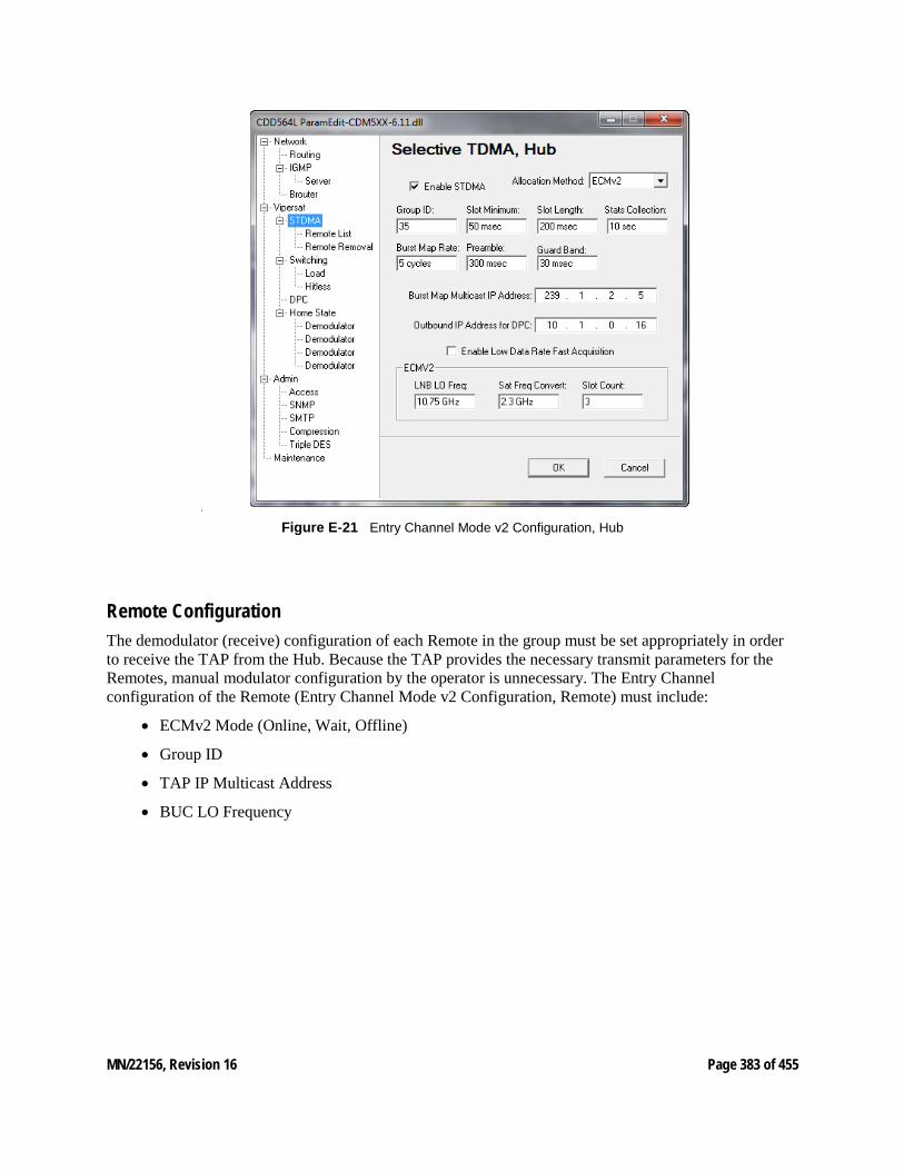
MN/22156, Revision 16 Page 383 of 455
•
Figure E‑21 Entry Channel Mode v2 Configuration, Hub
Remote Configuration The demodulator (receive) configuration of each Remote in the group must be set appropriately in order to receive the TAP from the Hub. Because the TAP provides the necessary transmit parameters for the Remotes, manual modulator configuration by the operator is unnecessary. The Entry Channel configuration of the Remote (Entry Channel Mode v2 Configuration, Remote) must include:
• ECMv2 Mode (Online, Wait, Offline)
• Group ID
• TAP IP Multicast Address
• BUC LO Frequency
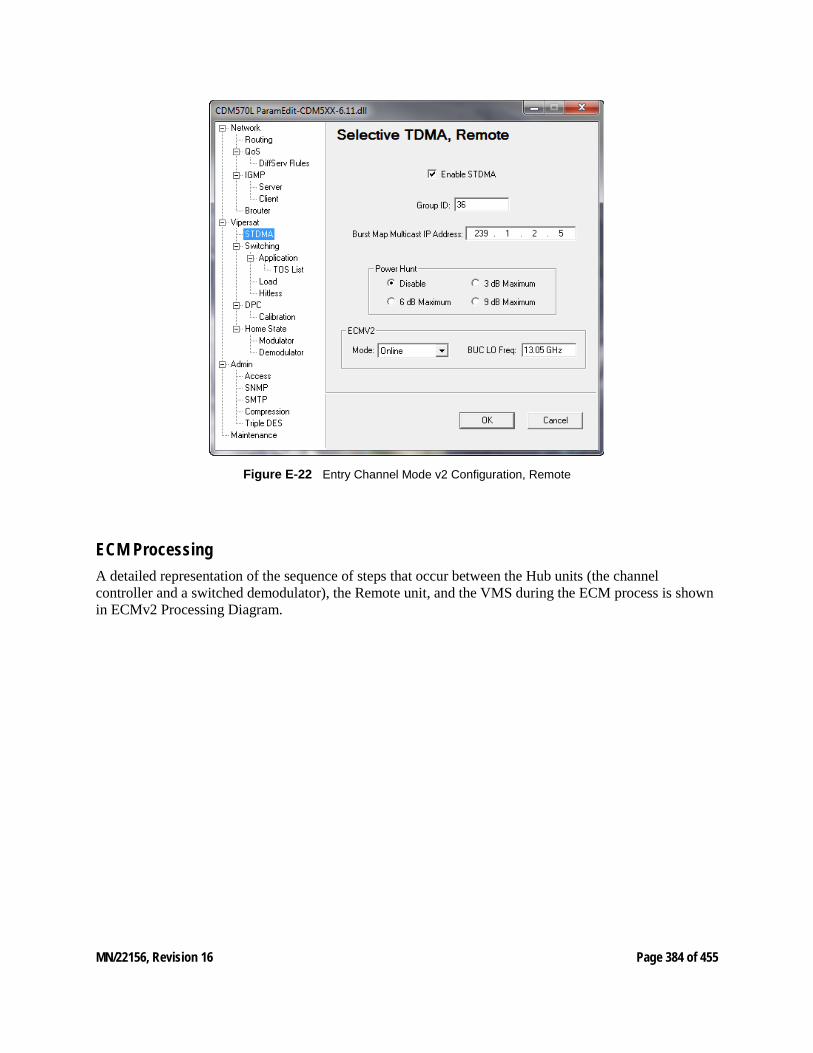
MN/22156, Revision 16 Page 384 of 455
Figure E‑22 Entry Channel Mode v2 Configuration, Remote
ECM Processing A detailed representation of the sequence of steps that occur between the Hub units (the channel controller and a switched demodulator), the Remote unit, and the VMS during the ECM process is shown in ECMv2 Processing Diagram.
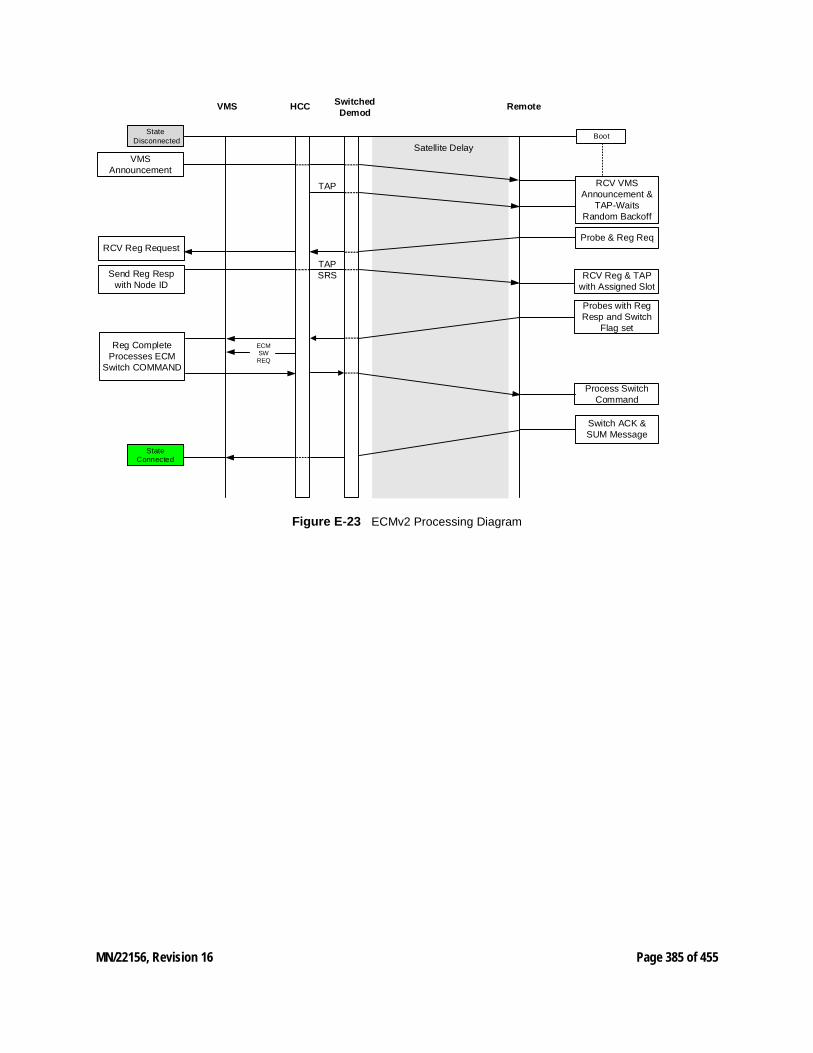
MN/22156, Revision 16 Page 385 of 455
Boot
VMS Remote
Satellite Delay
RCV VMS Announcement &
TAP-Waits Random Backoff
RCV Reg & TAP with Assigned Slot
RCV Reg Request
Send Reg Resp with Node ID
Probes with Reg Resp and Switch
Flag set
Process Switch Command
Switch ACK & SUM Message
HCC Switched Demod
TAP
TAPSRS
Reg CompleteProcesses ECM
Switch COMMAND
ECMSWREQ
State Disconnected
State Connected
VMS Announcement
Probe & Reg Req
Figure E‑23 ECMv2 Processing Diagram
MN/22156, Revision 16 Page 386 of 455
Carrier Presence Switching
E8 Carrier Presence Switching Overview Carrier Presence Switching (CPS) allows the VMS to autonomously manipulate carriers through presence-based distributions within the satellite bandwidth pools. This switching type is determined by the presence or absence of carriers, executing bandwidth shifts governed by divisional carrier distribution and individual policy settings. CPS is a Hertz defined switching method in which a carrier may occupy a large segment of bandwidth even with little to no traffic load on the terminal.
Typically, the VMS does not resize or move carriers unless requested to do so. However, a Carrier Presence switch, when enabled, will change the position and allocation of active carriers due to the addition or removal of carriers. But in this scenario, the Remote is not initiating the switch with a request for additional bandwidth. The resizing and movement of carriers is equally distributed based on available bandwidth and utilizing site policies, while always observing guarantees.
Switching Parameters / Configuration
The Carrier Presence Switching feature is not simply enabled or disabled in the VMS; it requires a specific combination of parameter settings within the group(s) of Remotes to become operational. The following switching parameters must be configured as specified for CPS to become fully functional.
It is NOT recommended to enable automatic switching functions—Load and/or Application—for a group of Remotes that will be utilizing CPS; undesirable behavior will result.
Entry Rate — InBand Application Policies Before version 12 of the VMS, site minimum and maximum rate settings were provided, with the minimum setting specifying the dSCPC entry rate from the shared access channel. The Entry Rate setting (Entry Rate, InBand Application Policies) now provides for more flexibility when entering into the bandwidth pool, where the first switch may be greater than the site minimum. This setting can be any value between the Switch Rate Min/Max Limits (Switch Rate Limits, InBand Return Path Settings), which the system will attempt to honor, depending on available resources. Note that this is not necessarily a guaranteed rate.
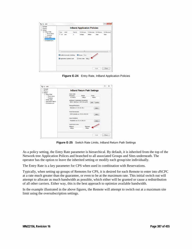
MN/22156, Revision 16 Page 387 of 455
Figure E‑24 Entry Rate, InBand Application Policies
Figure E‑25 Switch Rate Limits, InBand Return Path Settings
As a policy setting, the Entry Rate parameter is hierarchical. By default, it is inherited from the top of the Network tree Application Polices and branched to all associated Groups and Sites underneath. The operator has the option to leave the inherited setting or modify each group/site individually.
The Entry Rate is a key parameter for CPS when used in combination with Reservations.
Typically, when setting up groups of Remotes for CPS, it is desired for each Remote to enter into dSCPC at a rate much greater than the guarantee, or even to be at the maximum rate. This initial switch out will attempt to allocate as much bandwidth as possible, which either will be granted or cause a redistribution of all other carriers. Either way, this is the best approach to optimize available bandwidth.
In the example illustrated in the above figures, the Remote will attempt to switch out at a maximum site limit using the oversubscription settings.
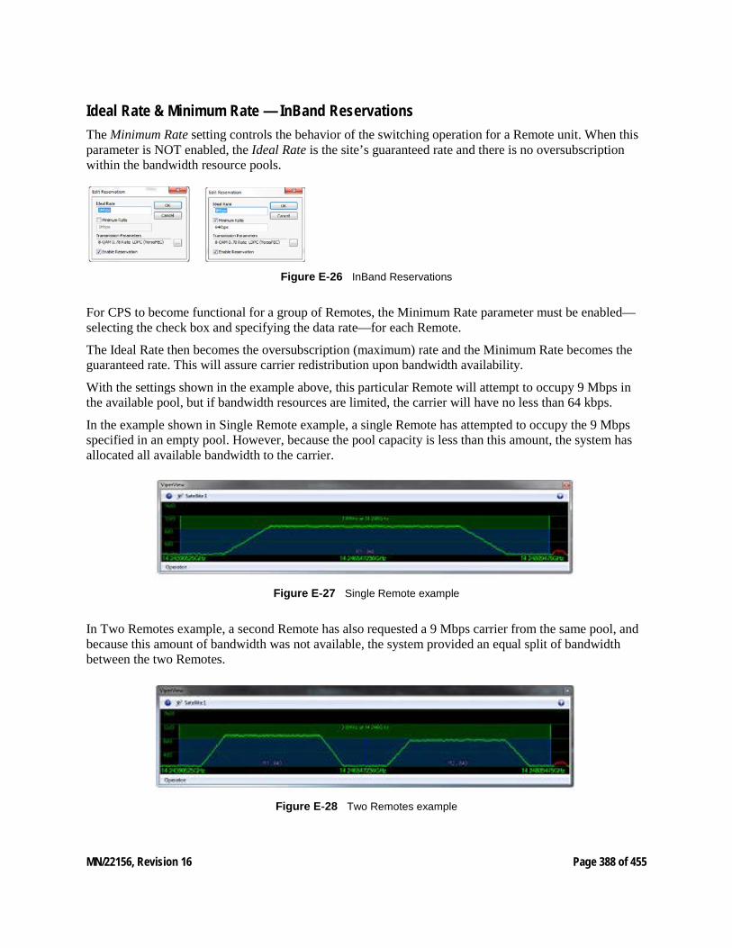
MN/22156, Revision 16 Page 388 of 455
Ideal Rate & Minimum Rate — InBand Reservations The Minimum Rate setting controls the behavior of the switching operation for a Remote unit. When this parameter is NOT enabled, the Ideal Rate is the site’s guaranteed rate and there is no oversubscription within the bandwidth resource pools.
Figure E‑26 InBand Reservations
For CPS to become functional for a group of Remotes, the Minimum Rate parameter must be enabled—selecting the check box and specifying the data rate—for each Remote.
The Ideal Rate then becomes the oversubscription (maximum) rate and the Minimum Rate becomes the guaranteed rate. This will assure carrier redistribution upon bandwidth availability.
With the settings shown in the example above, this particular Remote will attempt to occupy 9 Mbps in the available pool, but if bandwidth resources are limited, the carrier will have no less than 64 kbps.
In the example shown in Single Remote example, a single Remote has attempted to occupy the 9 Mbps specified in an empty pool. However, because the pool capacity is less than this amount, the system has allocated all available bandwidth to the carrier.
Figure E‑27 Single Remote example
In Two Remotes example, a second Remote has also requested a 9 Mbps carrier from the same pool, and because this amount of bandwidth was not available, the system provided an equal split of bandwidth between the two Remotes.
Figure E‑28 Two Remotes example
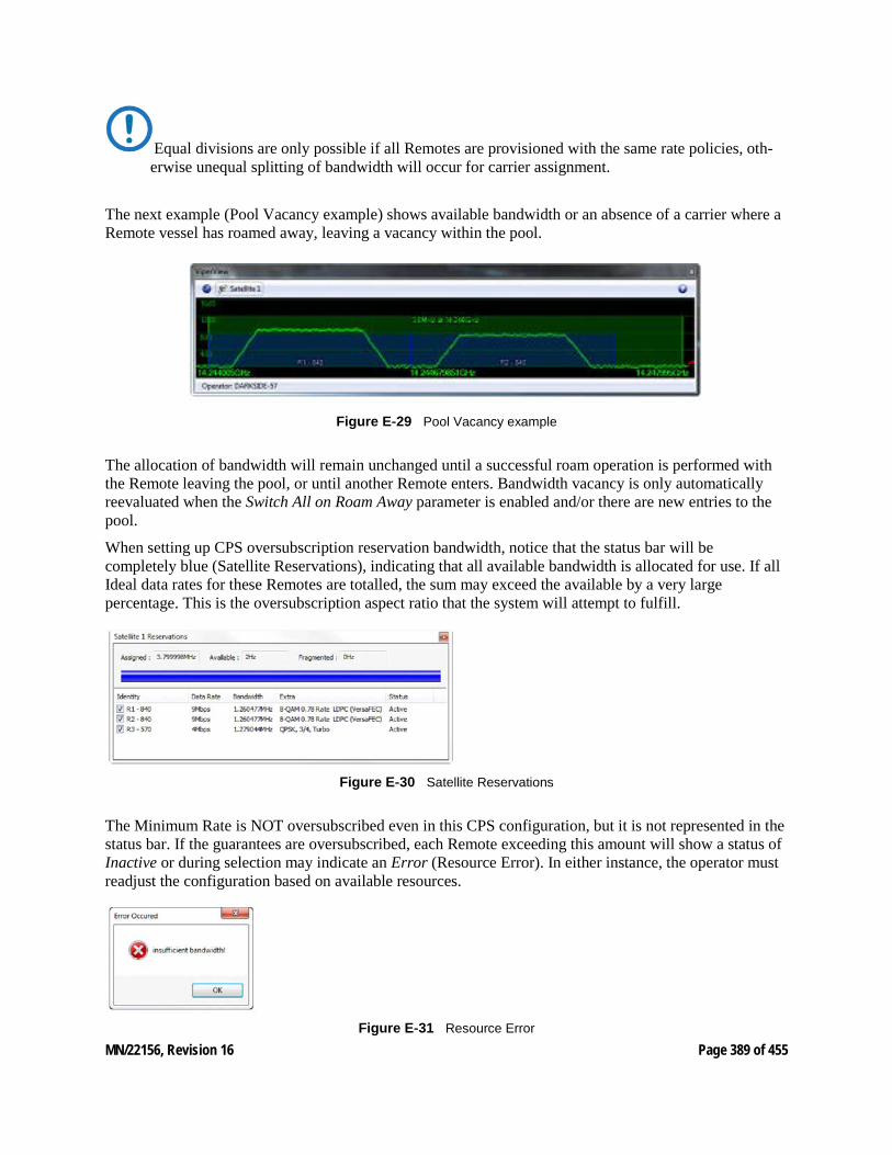
MN/22156, Revision 16 Page 389 of 455
Equal divisions are only possible if all Remotes are provisioned with the same rate policies, oth-erwise unequal splitting of bandwidth will occur for carrier assignment.
The next example (Pool Vacancy example) shows available bandwidth or an absence of a carrier where a Remote vessel has roamed away, leaving a vacancy within the pool.
Figure E‑29 Pool Vacancy example
The allocation of bandwidth will remain unchanged until a successful roam operation is performed with the Remote leaving the pool, or until another Remote enters. Bandwidth vacancy is only automatically reevaluated when the Switch All on Roam Away parameter is enabled and/or there are new entries to the pool.
When setting up CPS oversubscription reservation bandwidth, notice that the status bar will be completely blue (Satellite Reservations), indicating that all available bandwidth is allocated for use. If all Ideal data rates for these Remotes are totalled, the sum may exceed the available by a very large percentage. This is the oversubscription aspect ratio that the system will attempt to fulfill.
Figure E‑30 Satellite Reservations
The Minimum Rate is NOT oversubscribed even in this CPS configuration, but it is not represented in the status bar. If the guarantees are oversubscribed, each Remote exceeding this amount will show a status of Inactive or during selection may indicate an Error (Resource Error). In either instance, the operator must readjust the configuration based on available resources.
Figure E‑31 Resource Error
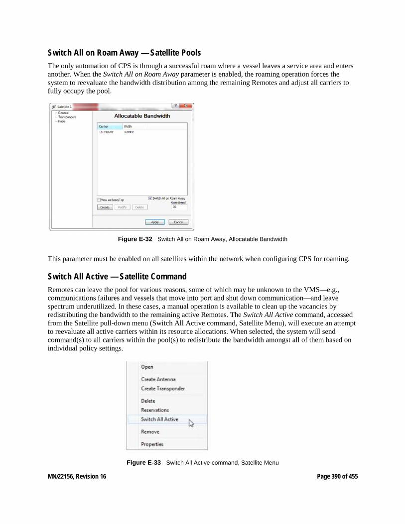
MN/22156, Revision 16 Page 390 of 455
Switch All on Roam Away — Satellite Pools The only automation of CPS is through a successful roam where a vessel leaves a service area and enters another. When the Switch All on Roam Away parameter is enabled, the roaming operation forces the system to reevaluate the bandwidth distribution among the remaining Remotes and adjust all carriers to fully occupy the pool.
Figure E‑32 Switch All on Roam Away, Allocatable Bandwidth
This parameter must be enabled on all satellites within the network when configuring CPS for roaming.
Switch All Active — Satellite Command Remotes can leave the pool for various reasons, some of which may be unknown to the VMS—e.g., communications failures and vessels that move into port and shut down communication—and leave spectrum underutilized. In these cases, a manual operation is available to clean up the vacancies by redistributing the bandwidth to the remaining active Remotes. The Switch All Active command, accessed from the Satellite pull-down menu (Switch All Active command, Satellite Menu), will execute an attempt to reevaluate all active carriers within its resource allocations. When selected, the system will send command(s) to all carriers within the pool(s) to redistribute the bandwidth amongst all of them based on individual policy settings.
Figure E‑33 Switch All Active command, Satellite Menu

MN/22156, Revision 16 Page 391 of 455
Issuing this command will switch all active carriers at once. Disruption of service on some carri-ers may not be desirable during working hours. If so, this operation should be executed only during a scheduled maintenance period.
MN/22156, Revision 16 Page 392 of 455
E9 Point-to-Point Switching In addition to dynamic SCPC (dSCPC) return channel capabilities the system provides a mode of operation that can pick from a pool of standby hub modulators and assign routing and carrier information establishing a separate forward path while still maintaining the return path dSCPC allocations. There are many applications that can benefit from this feature, e.g. disaster recovery, circuit restoral, video conferencing and mobility COMs on the pause requiring instantaneous dedicated bandwidth capacity.
Dynamic Switching Fundamentals The basic network architecture is star topology utilizing a common outbound with separate multiple dSCPC returns. All the remotes within the service connection of the outbound must share bandwidth resources relying on statistical multiplexing and queuing priorities to fairly divide and distribute outbound traffic amongst all receiving terminals.
The hub outbound transmission is the foundation from which all terminals receive their reference connection point. Without this reliable fixed frequency and bandwidth channel the terminals would not have a point origin losing management control, data access and the ability to return dynamic data connections. This places restrictions on the outbound whereby modifying any part of the carrier parameters becomes a major interruption of services during maintenance periods.
The autonomous operations on the remote return path provide carrier bandwidth flexibility without having to schedule any maintenance downtime to modify transmission. These dynamic allocations are managed through network control messaging that modify frequency and bandwidth on demand with a miniscule amount of interruption, typically measured as inter packet latency or jitter during each switch.
Remote transmission return path dynamics are designed to fulfill all request based on site policies and configurations. Bandwidth is distributed through requests beginning with initial entry and up to maximum terminal capacities. All remotes enter dSCPC at an ER and may remain at that rate unless conditions change requiring greater capacity. Each remote may request up to their MIR (terminal maximum) if bandwidth is available.
• Entry Rate - ER is the minimum SCPC entry rate. That is, a site with a minimum SCPC rate gets at least the ER allocation all the time.
• Maximum Information Rate - MIR is a true peak rate. That is, a site operating at MIR could potentially occupy up to the entire pool segment capacity, if no other site requires it.
• Committed Information Rate - CIR is a high-priority rate that a given site will be assured if requested.
Return path dynamic control involves modifying the remote modulator and a hub demodulator. The signaling to request bandwidth changes are proprietary network management packets destine to the VMS switching engine or bandwidth manager. These packets are initiated from the remote based on triggers that are defined configurations as part of the remotes packet classifier. Through these settings the remote can detect traffic patterns sending Automatic Switch Request (ASR) messages to switching engine. The engine compares the ASR information against remote site policies to determine how to appropriately modify the remotes return transmission.
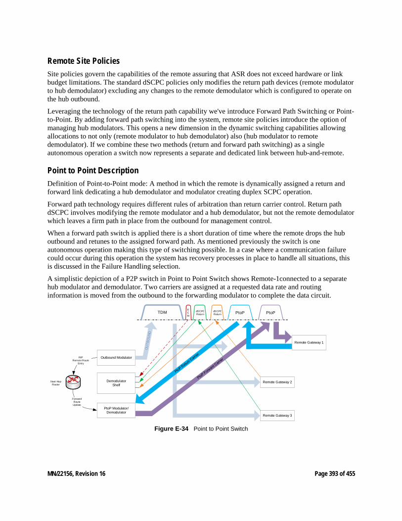
MN/22156, Revision 16 Page 393 of 455
Remote Site Policies Site policies govern the capabilities of the remote assuring that ASR does not exceed hardware or link budget limitations. The standard dSCPC policies only modifies the return path devices (remote modulator to hub demodulator) excluding any changes to the remote demodulator which is configured to operate on the hub outbound.
Leveraging the technology of the return path capability we've introduce Forward Path Switching or Point-to-Point. By adding forward path switching into the system, remote site policies introduce the option of managing hub modulators. This opens a new dimension in the dynamic switching capabilities allowing allocations to not only (remote modulator to hub demodulator) also (hub modulator to remote demodulator). If we combine these two methods (return and forward path switching) as a single autonomous operation a switch now represents a separate and dedicated link between hub-and-remote.
Point to Point Description Definition of Point-to-Point mode: A method in which the remote is dynamically assigned a return and forward link dedicating a hub demodulator and modulator creating duplex SCPC operation.
Forward path technology requires different rules of arbitration than return carrier control. Return path dSCPC involves modifying the remote modulator and a hub demodulator, but not the remote demodulator which leaves a firm path in place from the outbound for management control.
When a forward path switch is applied there is a short duration of time where the remote drops the hub outbound and retunes to the assigned forward path. As mentioned previously the switch is one autonomous operation making this type of switching possible. In a case where a communication failure could occur during this operation the system has recovery processes in place to handle all situations, this is discussed in the Failure Handling selection.
A simplistic depiction of a P2P switch in Point to Point Switch shows Remote-1connected to a separate hub modulator and demodulator. Two carriers are assigned at a requested data rate and routing information is moved from the outbound to the forwarding modulator to complete the data circuit.
Remote Gateway 1
Remote Gateway 2
Remote Gateway 3
Demodulator Shelf
Outbound Modulator
PtoP Modulator/Demodulator
TDMECM
dSCPC Return
dSCPC Return PtoP PtoP
RIPRemote Route
Entry
Next Hop Router
Forward Route
Update
Figure E‑34 Point to Point Switch
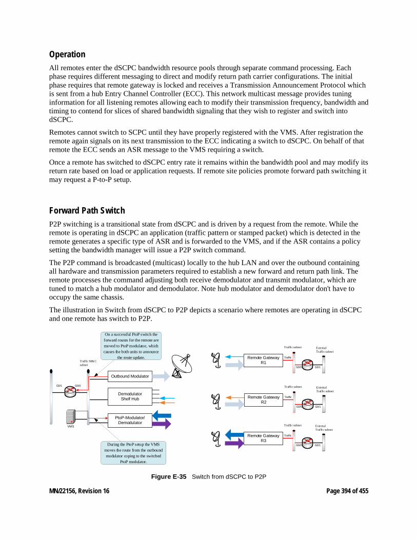
MN/22156, Revision 16 Page 394 of 455
Operation All remotes enter the dSCPC bandwidth resource pools through separate command processing. Each phase requires different messaging to direct and modify return path carrier configurations. The initial phase requires that remote gateway is locked and receives a Transmission Announcement Protocol which is sent from a hub Entry Channel Controller (ECC). This network multicast message provides tuning information for all listening remotes allowing each to modify their transmission frequency, bandwidth and timing to contend for slices of shared bandwidth signaling that they wish to register and switch into dSCPC.
Remotes cannot switch to SCPC until they have properly registered with the VMS. After registration the remote again signals on its next transmission to the ECC indicating a switch to dSCPC. On behalf of that remote the ECC sends an ASR message to the VMS requiring a switch.
Once a remote has switched to dSCPC entry rate it remains within the bandwidth pool and may modify its return rate based on load or application requests. If remote site policies promote forward path switching it may request a P-to-P setup.
Forward Path Switch P2P switching is a transitional state from dSCPC and is driven by a request from the remote. While the remote is operating in dSCPC an application (traffic pattern or stamped packet) which is detected in the remote generates a specific type of ASR and is forwarded to the VMS, and if the ASR contains a policy setting the bandwidth manager will issue a P2P switch command.
The P2P command is broadcasted (multicast) locally to the hub LAN and over the outbound containing all hardware and transmission parameters required to establish a new forward and return path link. The remote processes the command adjusting both receive demodulator and transmit modulator, which are tuned to match a hub modulator and demodulator. Note hub modulator and demodulator don't have to occupy the same chassis.
The illustration in Switch from dSCPC to P2P depicts a scenario where remotes are operating in dSCPC and one remote has switch to P2P.
Outbound Modulator
Remote Gateway R1
Demodulator Shelf Hub
G0/0 G0/1
Traffic subnet External Traffic subnet
G0/0
Traffic
Remote Gateway R2
G0/0 G0/1
Traffic subnet External Traffic subnet
Traffic
Remote Gateway R3
G0/0 G0/1
Traffic subnet External Traffic subnet
Traffic
PtoP-Modulator/Demodulator
Traffic M&C subnet
G0/1
VMS
On a successful PtoP switch the forward routes for the remote are moved to PtoP modulator, which causes the both units to announce
the route update.
During the PtoP setup the VMS moves the route from the outbound modulator coping to the switched
PtoP modulator.
Figure E‑35 Switch from dSCPC to P2P
MN/22156, Revision 16 Page 395 of 455
Route Update To complete the P2P switch, it is necessary to move routing information associated with the assigned remote. Route updates are managed through dynamic route tables configured in the VMS under the outbound modulator proprieties. This route table configuration applies remote routing entries on demand, which are added to the hub outbound modulator on boot or registration. Any route that is not fixed, i.e. default local next hop gateway or routes not part of the dynamics is added to this list.
While processing a P2P switch request a separate route update message is sent to both hub outbound and assigned forward path modulator. The outbound removes the route entries and the assigned modulator adds associated entries. Each modulator announces (RIP) to the next hop router updating the route tables.
When the P2P is no longer required the remote can send an ASR releasing the forward path modulator dropping back to dSCPC switching. The route updates follow the same process but in the reverse order.
During this P2P switch state all normal features function as normal.
Caveats associated with P2P Remotes operating in P2P have constrains that must be enforced to preserve link reliability. One of the main enforced rules is once the remote switches to P2P mode the two carriers must remain immobile. Moving or modifying the forward carrier is possible but risky because there is a potential that the hub to remote channel configuration is missed when applied and one or the other end of the link is out of sync breaking the M&C communication. If this should happen failure handling comes into effect which will reestablish communications.
Point-to-Point Switching only works in routed mode.
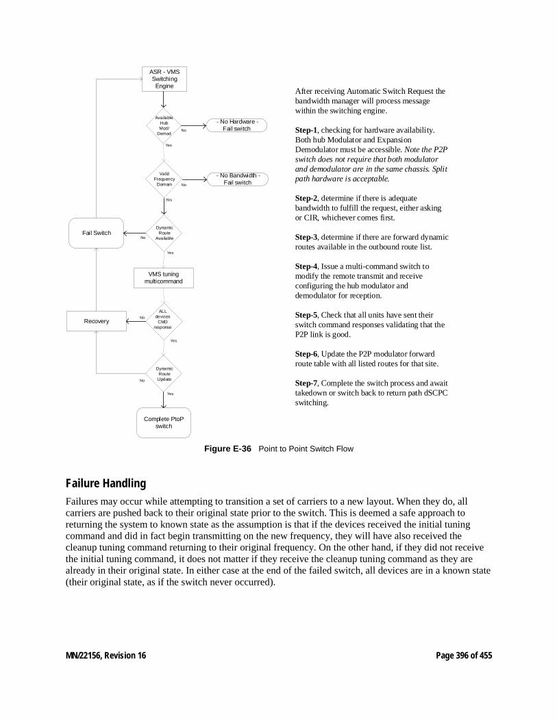
MN/22156, Revision 16 Page 396 of 455
ASR - VMS Switching
Engine
VMS tuning multicommand
Dynamic Route
Available
Available Hub Mod/
Demod
- No Hardware - Fail switch
Fail Switch
Dynamic Route
Update
ALL devices
CMD response
Recovery
Complete PtoP switch
No
Yes
No
Yes
No
Yes
No
Yes
Valid Frequency
Domain No
Yes
- No Bandwidth - Fail switch
After receiving Automatic Switch Request the bandwidth manager will process message within the switching engine.
Step-1, checking for hardware availability. Both hub Modulator and Expansion Demodulator must be accessible. Note the P2P switch does not require that both modulator and demodulator are in the same chassis. Split path hardware is acceptable.
Step-2, determine if there is adequate bandwidth to fulfill the request, either asking or CIR, whichever comes first.
Step-3, determine if there are forward dynamic routes available in the outbound route list.
Step-4, Issue a multi-command switch to modify the remote transmit and receive configuring the hub modulator and demodulator for reception.
Step-5, Check that all units have sent their switch command responses validating that the P2P link is good.
Step-6, Update the P2P modulator forward route table with all listed routes for that site.
Step-7, Complete the switch process and await takedown or switch back to return path dSCPC switching.
Figure E‑36 Point to Point Switch Flow
Failure Handling Failures may occur while attempting to transition a set of carriers to a new layout. When they do, all carriers are pushed back to their original state prior to the switch. This is deemed a safe approach to returning the system to known state as the assumption is that if the devices received the initial tuning command and did in fact begin transmitting on the new frequency, they will have also received the cleanup tuning command returning to their original frequency. On the other hand, if they did not receive the initial tuning command, it does not matter if they receive the cleanup tuning command as they are already in their original state. In either case at the end of the failed switch, all devices are in a known state (their original state, as if the switch never occurred).
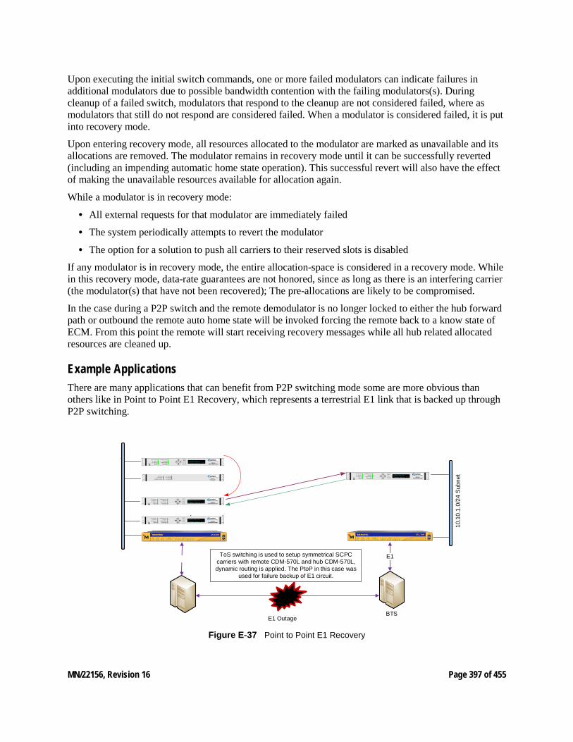
MN/22156, Revision 16 Page 397 of 455
Upon executing the initial switch commands, one or more failed modulators can indicate failures in additional modulators due to possible bandwidth contention with the failing modulators(s). During cleanup of a failed switch, modulators that respond to the cleanup are not considered failed, where as modulators that still do not respond are considered failed. When a modulator is considered failed, it is put into recovery mode.
Upon entering recovery mode, all resources allocated to the modulator are marked as unavailable and its allocations are removed. The modulator remains in recovery mode until it can be successfully reverted (including an impending automatic home state operation). This successful revert will also have the effect of making the unavailable resources available for allocation again.
While a modulator is in recovery mode:
• All external requests for that modulator are immediately failed
• The system periodically attempts to revert the modulator
• The option for a solution to push all carriers to their reserved slots is disabled
If any modulator is in recovery mode, the entire allocation-space is considered in a recovery mode. While in this recovery mode, data-rate guarantees are not honored, since as long as there is an interfering carrier (the modulator(s) that have not been recovered); The pre-allocations are likely to be compromised.
In the case during a P2P switch and the remote demodulator is no longer locked to either the hub forward path or outbound the remote auto home state will be invoked forcing the remote back to a know state of ECM. From this point the remote will start receiving recovery messages while all hub related allocated resources are cleaned up.
Example Applications There are many applications that can benefit from P2P switching mode some are more obvious than others like in Point to Point E1 Recovery, which represents a terrestrial E1 link that is backed up through P2P switching.
ToS switching is used to setup symmetrical SCPC carriers with remote CDM-570L and hub CDM-570L, dynamic routing is applied. The PtoP in this case was
used for failure backup of E1 circuit.
E1 Outage
10.1
0.1.
0/24
Sub
net
E1
BTS
o t to o t 5 0 [ 6 / ]
Figure E‑37 Point to Point E1 Recovery
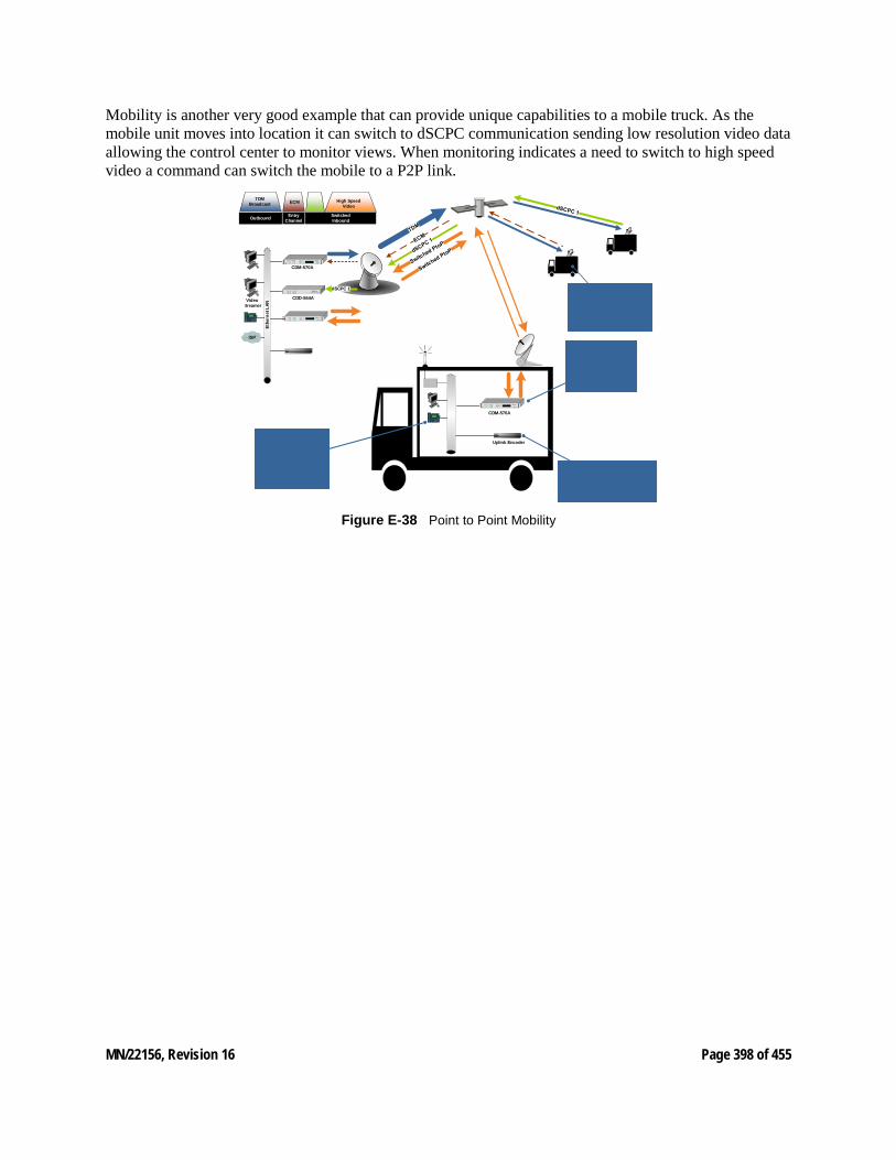
MN/22156, Revision 16 Page 398 of 455
Mobility is another very good example that can provide unique capabilities to a mobile truck. As the mobile unit moves into location it can switch to dSCPC communication sending low resolution video data allowing the control center to monitor views. When monitoring indicates a need to switch to high speed video a command can switch the mobile to a P2P link.
TDM Broadcast ECM
Outbound Entry Channel
High Speed Video
SwitchedInbound
Ethe
rnet
LAN
CDM-570A
CDD-564A
Video Streamer
1 2ABC
3DEF
4 5JKL
6MNOGHI
7 8TUV
9WXYZPQRS
* 0OPER
#
7960CISCO IP PHONE
imessages directories
settingsservices
ISP
dSCPC 1
1 2ABC
3DEF
4 5JKL
6MNOGHI
7 8TUV
9WXYZPQRS
* 0OPER
#
7960CISCO IP PHONE
imessages directories
settingsservices
Uplink Encoder
CDM-570A
Figure E‑38 Point to Point Mobility
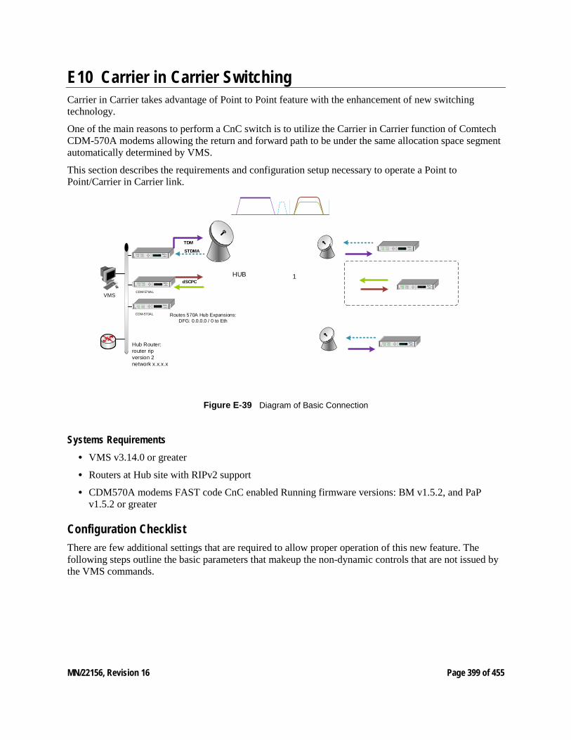
MN/22156, Revision 16 Page 399 of 455
E10 Carrier in Carrier Switching Carrier in Carrier takes advantage of Point to Point feature with the enhancement of new switching technology.
One of the main reasons to perform a CnC switch is to utilize the Carrier in Carrier function of Comtech CDM-570A modems allowing the return and forward path to be under the same allocation space segment automatically determined by VMS.
This section describes the requirements and configuration setup necessary to operate a Point to Point/Carrier in Carrier link.
TDM
STDMA
VMSCDM-570AL
HUB dSCPC
19
Routes 570A Hub Expansions:DFG: 0.0.0.0 / 0 to Eth
Hub Router:router ripversion 2network x.x.x.x
CDM-570AL
Figure E‑39 Diagram of Basic Connection
Systems Requirements • VMS v3.14.0 or greater
• Routers at Hub site with RIPv2 support
• CDM570A modems FAST code CnC enabled Running firmware versions: BM v1.5.2, and PaP v1.5.2 or greater
Configuration Checklist There are few additional settings that are required to allow proper operation of this new feature. The following steps outline the basic parameters that makeup the non-dynamic controls that are not issued by the VMS commands.
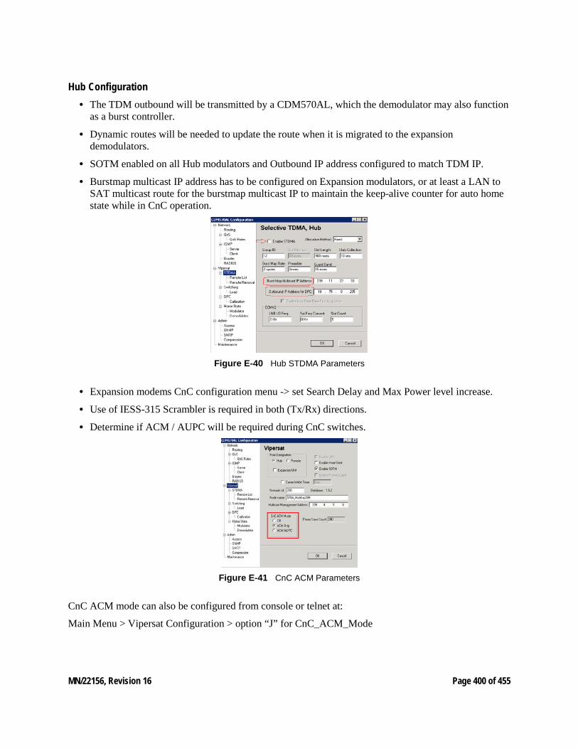
MN/22156, Revision 16 Page 400 of 455
Hub Configuration • The TDM outbound will be transmitted by a CDM570AL, which the demodulator may also function
as a burst controller.
• Dynamic routes will be needed to update the route when it is migrated to the expansion demodulators.
• SOTM enabled on all Hub modulators and Outbound IP address configured to match TDM IP.
• Burstmap multicast IP address has to be configured on Expansion modulators, or at least a LAN to SAT multicast route for the burstmap multicast IP to maintain the keep-alive counter for auto home state while in CnC operation.
Figure E‑40 Hub STDMA Parameters
• Expansion modems CnC configuration menu -> set Search Delay and Max Power level increase.
• Use of IESS-315 Scrambler is required in both (Tx/Rx) directions.
• Determine if ACM / AUPC will be required during CnC switches.
Figure E‑41 CnC ACM Parameters
CnC ACM mode can also be configured from console or telnet at:
Main Menu > Vipersat Configuration > option “J” for CnC_ACM_Mode
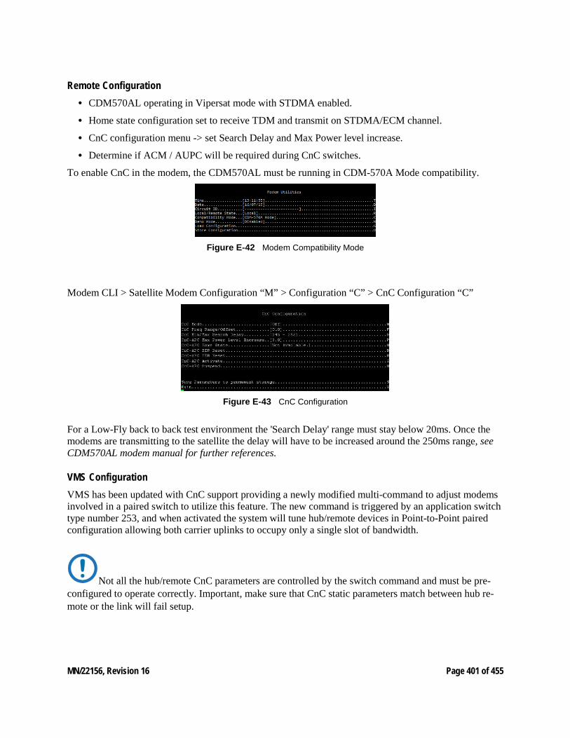
MN/22156, Revision 16 Page 401 of 455
Remote Configuration • CDM570AL operating in Vipersat mode with STDMA enabled.
• Home state configuration set to receive TDM and transmit on STDMA/ECM channel.
• CnC configuration menu -> set Search Delay and Max Power level increase.
• Determine if ACM / AUPC will be required during CnC switches.
To enable CnC in the modem, the CDM570AL must be running in CDM-570A Mode compatibility.
Figure E‑42 Modem Compatibility Mode
Modem CLI > Satellite Modem Configuration “M” > Configuration “C” > CnC Configuration “C”
Figure E‑43 CnC Configuration
For a Low-Fly back to back test environment the 'Search Delay' range must stay below 20ms. Once the modems are transmitting to the satellite the delay will have to be increased around the 250ms range, see CDM570AL modem manual for further references.
VMS Configuration VMS has been updated with CnC support providing a newly modified multi-command to adjust modems involved in a paired switch to utilize this feature. The new command is triggered by an application switch type number 253, and when activated the system will tune hub/remote devices in Point-to-Point paired configuration allowing both carrier uplinks to occupy only a single slot of bandwidth.
Not all the hub/remote CnC parameters are controlled by the switch command and must be pre-configured to operate correctly. Important, make sure that CnC static parameters match between hub re-mote or the link will fail setup.
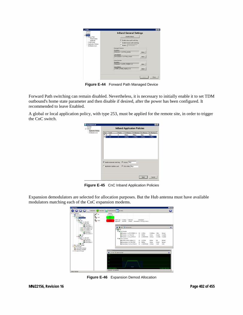
MN/22156, Revision 16 Page 402 of 455
Figure E‑44 Forward Path Managed Device
Forward Path switching can remain disabled. Nevertheless, it is necessary to initially enable it to set TDM outbound's home state parameter and then disable if desired, after the power has been configured. It recommended to leave Enabled.
A global or local application policy, with type 253, must be applied for the remote site, in order to trigger the CnC switch.
Figure E‑45 CnC Inband Application Policies
Expansion demodulators are selected for allocation purposes. But the Hub antenna must have available modulators matching each of the CnC expansion modems.
Figure E‑46 Expansion Demod Allocation
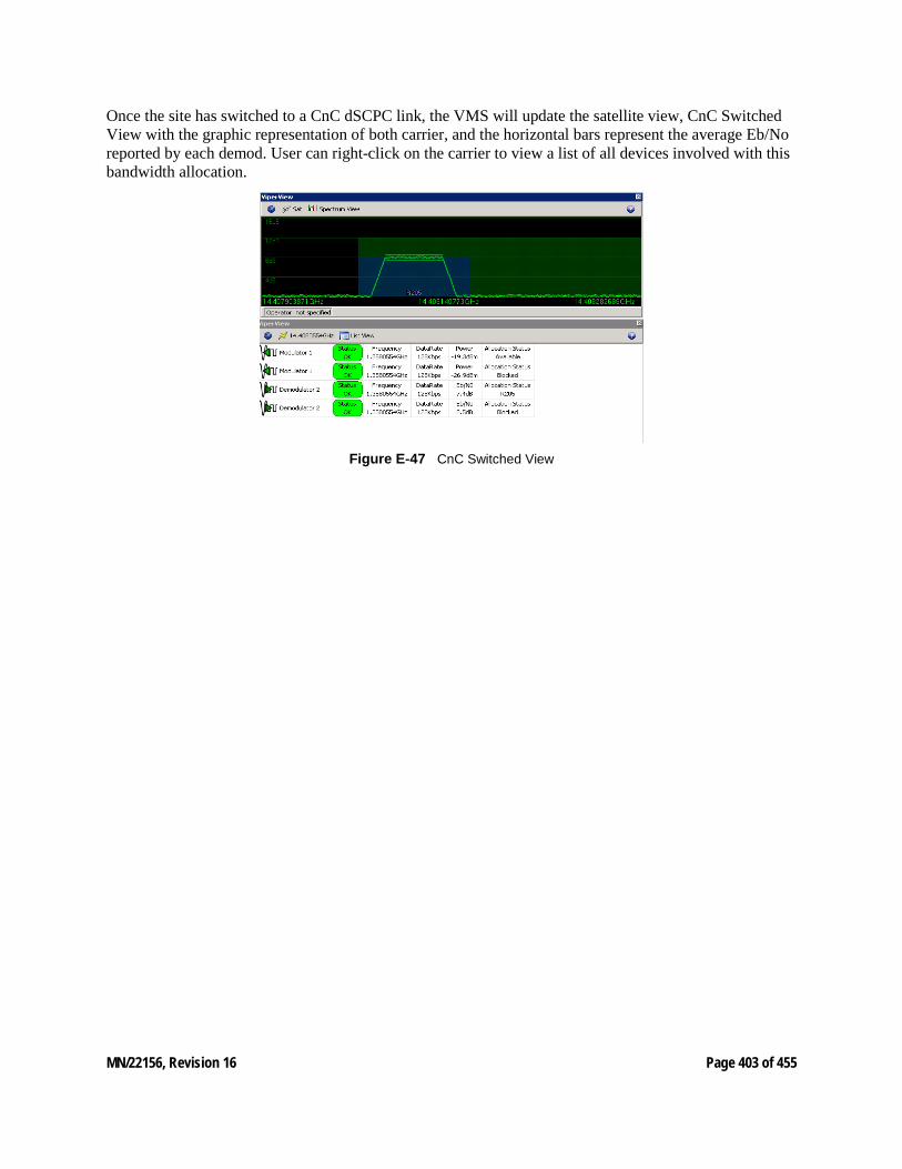
MN/22156, Revision 16 Page 403 of 455
Once the site has switched to a CnC dSCPC link, the VMS will update the satellite view, CnC Switched View with the graphic representation of both carrier, and the horizontal bars represent the average Eb/No reported by each demod. User can right-click on the carrier to view a list of all devices involved with this bandwidth allocation.
Figure E‑47 CnC Switched View
MN/22156, Revision 16 Page 404 of 455
E11 dSCPC Meshing, Single Hop on Demand Meshing allows Remote Gateway's to communicate with another Remote Gateway location without double hopping traffic through the hub. This type of connection minimizes delay and often is used for very high-quality voice and video conferencing applications.
Single satellite hop technology provides less delay, ensures higher quality voice communications and efficient use of the satellite space segment.
Single Hop On Demand (SHOD) switching technology offers IP packet circuit switching at the application level. SHOD provides significant and dynamic connectivity between latency connections without suffering the high costs associated with multiple carriers and/or 1:1 multi-receiver links.
Mechanisms SHOD deploys automatic application protocol traffic detectors and dynamic filter routing tables that eliminate double packet re-transmission.
The environment consists of three types of control mechanisms:
System Master Control - (SMC)
HUB VMS Switching Bandwidth Manager
SMC maintains the associated remote mesh subscriber list and mesh filter routing database information. Synchronizes and distributes connection setup information for all active nodes while maintaining distributed satellite resources.
Automatic Switch Request - (ASR)
Remote Gateway packet classifiers detect control protocols using Type of Service (ToS) IP header and manages switched application services in real-time. Each Remote Gateway with the ToS switching enabled locates packets with matching set values sending the ASR message to the hub initiating a bandwidth circuit change.
Destination Packet Filter - (DPF)
The SMC applies an IP DPF packet filter dynamically to the corresponding hub demodulator for each active switched meshed circuit. Packets that are destined for the hub network are passed through normally. This filtering type eliminates double packets received at the remote destination and additionally removes unnecessary traffic on the broadcast (outbound) transmission.
Functional Description The networks operate in star topology, where the Remote Gateway send data packets to the hub via the inbound transmissions. If the data is destined for another Remote Gateway, the packets are retransmitted on the hub outbound carrier redistributing the data to the destined Remote Gateway. This method of re-broadcasting the data constitutes a double hop condition multiplying the latency x2 (approx. 560ms one way) and using more outbound capacity. Normal data applications do not have any problem with the additional latency. However, applications requiring minimal jitter and low latency, namely VoIP (voice) or IPVC (video) or any other real time protocol applications that cannot tolerate long latency connections, make double hop unacceptable.
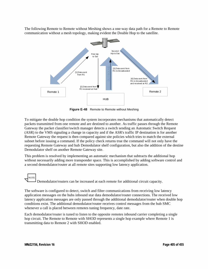
MN/22156, Revision 16 Page 405 of 455
The following Remote to Remote without Meshing shows a one-way data path for a Remote to Remote communication without a mesh topology, making evident the Double Hop to the satellite.
OU
TBO
UND
HUB
Remote 1 Remote 2
[1] Data sent from R1
[2] Data sent from R1 received at Hub
[3] Data sent from R1 re-broadcasted
[4] Data sent from R1 re-broadcasted and received at R2
First trip to Sat
Second trip to Sat
Figure E‑48 Remote to Remote without Meshing
To mitigate the double hop condition the system incorporates mechanisms that automatically detect packets transmitted from one remote and are destined to another. As traffic passes through the Remote Gateway the packet classifier/switch manager detects a switch sending an Automatic Switch Request (ASR) to the VMS signaling a change in capacity and if the ASR's traffic IP destination is for another Remote Gateway the request is then compared against site policies which tries to match the external subnet before issuing a command. If the policy check returns true the command will not only have the requesting Remote Gateway and hub Demodulator shelf configuration, but also the addition of the destine Demodulator shelf on another Remote Gateway site.
This problem is resolved by implementing an automatic mechanism that subtracts the additional hop without necessarily adding more transponder space. This is accomplished by adding software control and a second demodulator/router at all remote sites supporting low latency application.
NOTE
Demodulator/routers can be increased at each remote for additional circuit capacity.
The software is configured to detect, switch and filter communications from receiving low latency application messages on the hubs inbound star data demodulator/router connections. The received low latency application messages are only passed through the additional demodulator/router when double hop conditions exist. The additional demodulator/router receives control messages from the hub SMC whenever a call is placed between remotes tuning frequency, date rate.
Each demodulator/router is tuned to listen to the opposite remotes inbound carrier completing a single hop circuit. The Remote to Remote with SHOD represents a single hop example where Remote 1 is transmitting data to Remote 2 with SHOD enabled.
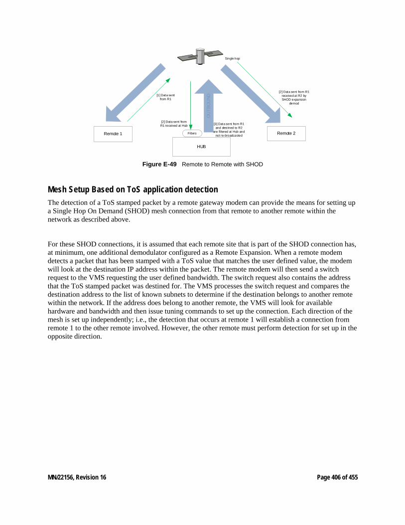
MN/22156, Revision 16 Page 406 of 455
OU
TBO
UND
HUB
Remote 1 Remote 2
[1] Data sent from R1
[2] Data sent from R1 received at Hub
[2] Data sent from R1 received at R2 by SHOD expansion
demod
[3] Data sent from R1 and dest ined to R2
are filtered at Hub and not re-broadcastedFilters
Single hop
Figure E‑49 Remote to Remote with SHOD
Mesh Setup Based on ToS application detection The detection of a ToS stamped packet by a remote gateway modem can provide the means for setting up a Single Hop On Demand (SHOD) mesh connection from that remote to another remote within the network as described above.
For these SHOD connections, it is assumed that each remote site that is part of the SHOD connection has, at minimum, one additional demodulator configured as a Remote Expansion. When a remote modem detects a packet that has been stamped with a ToS value that matches the user defined value, the modem will look at the destination IP address within the packet. The remote modem will then send a switch request to the VMS requesting the user defined bandwidth. The switch request also contains the address that the ToS stamped packet was destined for. The VMS processes the switch request and compares the destination address to the list of known subnets to determine if the destination belongs to another remote within the network. If the address does belong to another remote, the VMS will look for available hardware and bandwidth and then issue tuning commands to set up the connection. Each direction of the mesh is set up independently; i.e., the detection that occurs at remote 1 will establish a connection from remote 1 to the other remote involved. However, the other remote must perform detection for set up in the opposite direction.
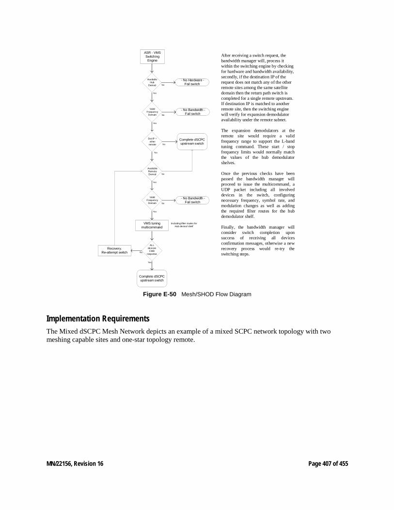
MN/22156, Revision 16 Page 407 of 455
ASR - VMS Switching
Engine
VMS tuning multicommand
Dst IP = other
remote
Available Hub
Demod
- No Hardware - Fail switch
Complete dSCPC upstream switch
Available Remote Demod
ALL devices
CMD response
Recovery.Re-attempt switch
Complete dSCPC upstream switch
Valid Frequency
Domain
Including filter routes for Hub demod shelf
No
Yes
No
Yes
No
Yes
No
Yes
- No Bandwidth - Fail switch
No
Yes
Valid Frequency
Domain No
Yes
- No Bandwidth - Fail switch
After receiving a switch request, the bandwidth manager will, process it within the switching engine by checking for hardware and bandwidth availability, secondly, if the destination IP of the request does not match any of the other remote sites among the same satellite domain then the return path switch is completed for a single remote upstream. If destination IP is matched to another remote site, then the switching engine will verify for expansion demodulator availability under the remote subnet.
The expansion demodulators at the remote site would require a valid frequency range to support the L-band tuning command. These start / stop frequency limits would normally match the values of the hub demodulator shelves.
Once the previous checks have been passed the bandwidth manager will proceed to issue the multicommand, a UDP packet including all involved devices in the switch, configuring necessary frequency, symbol rate, and modulation changes as well as adding the required filter routes for the hub demodulator shelf.
Finally, the bandwidth manager will consider switch completion upon success of receiving all devices confirmation messages, otherwise a new recovery process would re-try the switching steps.
Figure E‑50 Mesh/SHOD Flow Diagram
Implementation Requirements The Mixed dSCPC Mesh Network depicts an example of a mixed SCPC network topology with two meshing capable sites and one-star topology remote.
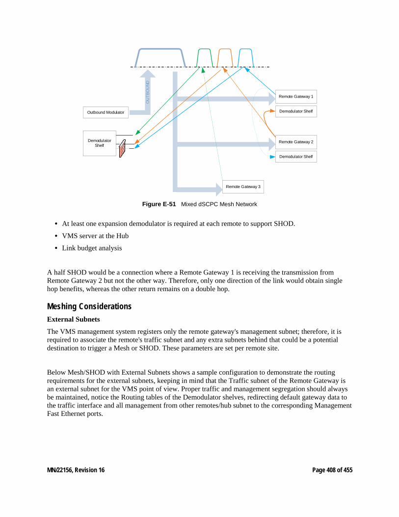
MN/22156, Revision 16 Page 408 of 455
OU
TBO
UND
Outbound Modulator
Remote Gateway 1
Remote Gateway 2
Remote Gateway 3
Demodulator Shelf
Demodulator Shelf
Demodulator Shelf
Figure E‑51 Mixed dSCPC Mesh Network
• At least one expansion demodulator is required at each remote to support SHOD.
• VMS server at the Hub
• Link budget analysis
A half SHOD would be a connection where a Remote Gateway 1 is receiving the transmission from Remote Gateway 2 but not the other way. Therefore, only one direction of the link would obtain single hop benefits, whereas the other return remains on a double hop.
Meshing Considerations External Subnets
The VMS management system registers only the remote gateway's management subnet; therefore, it is required to associate the remote's traffic subnet and any extra subnets behind that could be a potential destination to trigger a Mesh or SHOD. These parameters are set per remote site.
Below Mesh/SHOD with External Subnets shows a sample configuration to demonstrate the routing requirements for the external subnets, keeping in mind that the Traffic subnet of the Remote Gateway is an external subnet for the VMS point of view. Proper traffic and management segregation should always be maintained, notice the Routing tables of the Demodulator shelves, redirecting default gateway data to the traffic interface and all management from other remotes/hub subnet to the corresponding Management Fast Ethernet ports.
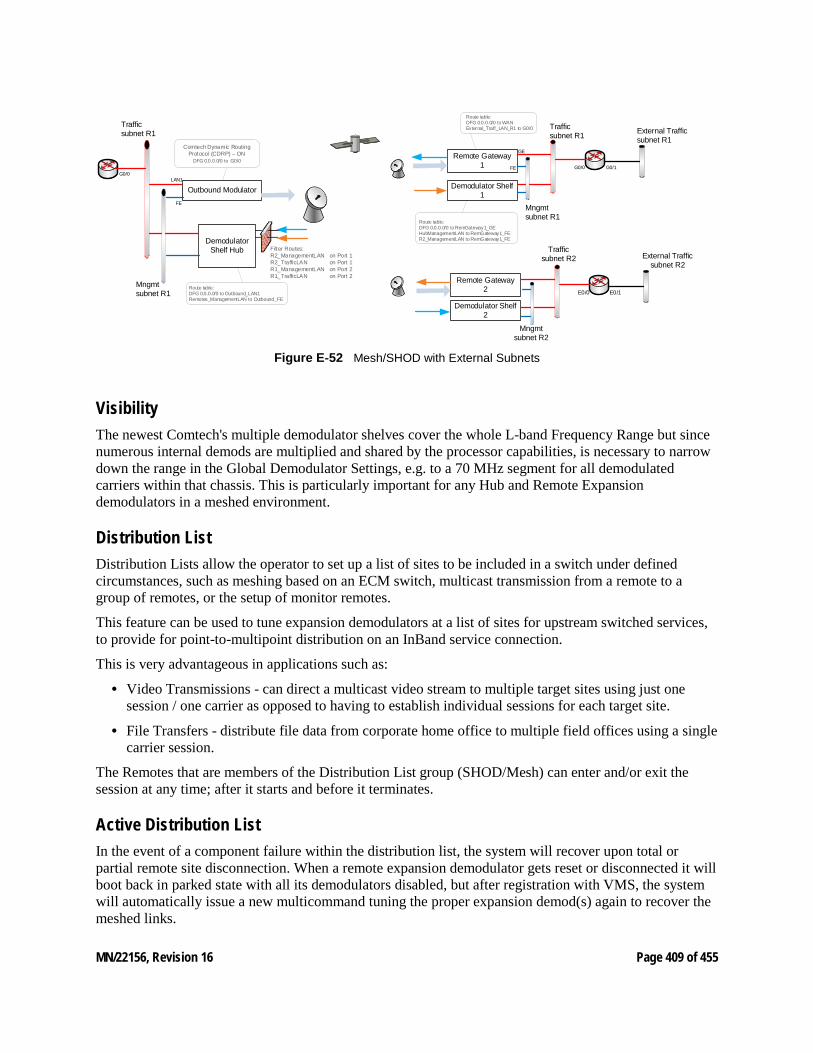
MN/22156, Revision 16 Page 409 of 455
Outbound Modulator
Remote Gateway 1
Remote Gateway 2
Demodulator Shelf 1
Demodulator Shelf 2
Demodulator Shelf Hub
G0/0 G0/1
Traffic subnet R1
Mngmt subnet R1
External Traffic subnet R1
E0/0 E0/1
Traffic subnet R2
Mngmt subnet R2
External Traffic subnet R2
Traffic subnet R1
Mngmt subnet R1
Route table:DFG 0.0.0.0/0 to WANExternal_Traff_LAN_R1 to G0/0
Route table:DFG 0.0.0.0/0 to RemGateway1_GEHubManagementLAN to RemGateway1_FER2_ManagementLAN to RemGateway1_FE
Route table:DFG 0.0.0.0/0 to Outbound_LAN1Remotes_ManagementLAN to Outbound_FE
Comtech Dynamic Routing Protocol (CDRP) – ON
DFG 0.0.0.0/0 to G0/0
G0/0
Filter Routes:R2_ManagementLAN on Port 1R2_TrafficLAN on Port 1R1_ManagementLAN on Port 2R1_TrafficLAN on Port 2
LAN1
FE
FE
GE
Figure E‑52 Mesh/SHOD with External Subnets
Visibility The newest Comtech's multiple demodulator shelves cover the whole L-band Frequency Range but since numerous internal demods are multiplied and shared by the processor capabilities, is necessary to narrow down the range in the Global Demodulator Settings, e.g. to a 70 MHz segment for all demodulated carriers within that chassis. This is particularly important for any Hub and Remote Expansion demodulators in a meshed environment.
Distribution List Distribution Lists allow the operator to set up a list of sites to be included in a switch under defined circumstances, such as meshing based on an ECM switch, multicast transmission from a remote to a group of remotes, or the setup of monitor remotes.
This feature can be used to tune expansion demodulators at a list of sites for upstream switched services, to provide for point-to-multipoint distribution on an InBand service connection.
This is very advantageous in applications such as:
• Video Transmissions - can direct a multicast video stream to multiple target sites using just one session / one carrier as opposed to having to establish individual sessions for each target site.
• File Transfers - distribute file data from corporate home office to multiple field offices using a single carrier session.
The Remotes that are members of the Distribution List group (SHOD/Mesh) can enter and/or exit the session at any time; after it starts and before it terminates.
Active Distribution List In the event of a component failure within the distribution list, the system will recover upon total or partial remote site disconnection. When a remote expansion demodulator gets reset or disconnected it will boot back in parked state with all its demodulators disabled, but after registration with VMS, the system will automatically issue a new multicommand tuning the proper expansion demod(s) again to recover the meshed links.
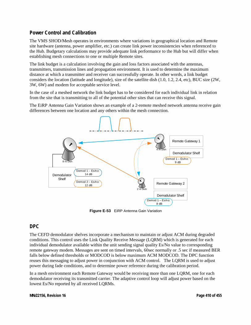
MN/22156, Revision 16 Page 410 of 455
Power Control and Calibration The VMS SHOD/Mesh operates in environments where variations in geographical location and Remote site hardware (antenna, power amplifier, etc.) can create link power inconsistencies when referenced to the Hub. Budgetary calculations may provide adequate link performance to the Hub but will differ when establishing mesh connections to one or multiple Remote sites.
The link budget is a calculation involving the gain and loss factors associated with the antennas, transmitters, transmission lines and propagation environment. It is used to determine the maximum distance at which a transmitter and receiver can successfully operate. In other words, a link budget considers the location (latitude and longitude), size of the satellite dish (1.0, 1.2, 2.4, etc), BUC size (2W, 3W, 6W) and modem for acceptable service level.
In the case of a meshed network the link budget has to be considered for each individual link in relation from the site that is transmitting to all of the potential other sites that can receive this signal.
The EiRP Antenna Gain Variation shows an example of a 2-remote meshed network antenna receive gain differences between one location and any others within the mesh connection.
Remote Gateway 1
Remote Gateway 2
Demodulator Shelf
Demodulator Shelf
Demodulator Shelf
2 m Dish
4 m Dish
8 m Dish
Demod 1 – Es/no: 14 dB
Demod 2 – Es/no: 12 dB
Demod 1 – Es/no: 9 dB
Demod 1 – Es/no: 8 dB
Figure E‑53 EiRP Antenna Gain Variation
DPC The CEFD demodulator shelves incorporate a mechanism to maintain or adjust ACM during degraded conditions. This control uses the Link Quality Receive Message (LQRM) which is generated for each individual demodulator available within the unit sending signal quality Es/No value to corresponding remote gateway modem. Messages are sent on timed intervals, 60sec normally or .5 sec if measured BER falls below defined thresholds or MODCOD is below maximum ACM MODCOD. The DPC function reuses this messaging to adjust power in conjunction with ACM control. The LQRM is used to adjust power during fade conditions, and to determine power reference during the calibration period.
In a mesh environment each Remote Gateway would be receiving more than one LQRM, one for each demodulator receiving its transmitted carrier. The adaptive control loop will adjust power based on the lowest Es/No reported by all received LQRMs.
MN/22156, Revision 16 Page 411 of 455
VMS has nothing to do with DPC, the modems will control their power based on the demods report, as explained above. The management system will be only a tool to monitor the power and to configure certain power related parameters.
Antenna Gain The receive gain compensation factor applies a power delta between any meshed Remote sites. The Hub is used as the reference value when calculating a power delta value between Remotes with smaller antennas.
This is accomplished through comparing it receive gain to the gain differences between Remotes. During a mesh switch setup, the VMS compares the delta values and modifies the power adjustments at each Remote site to compensate for differences in receive gain. If DPC is enabled, the system will then further fine tune power to the targeted configuration values.
If multiple Remotes are involved in a SHOD connection, the VMS uses the lowest Remote gain value for compensation control.
That if the gain is set on any antenna, it must be set on all antennas that belong to the same satel-lite. This includes all Hub and Remote antennas. Failure to do so will result in a network imbal-ance that may cause the satellite to overdrive a site that is set incorrectly.
User can define this value based on link budget and antenna manufacturer gain specifications or more practically, performing a manual calibration after the sites have been commissioned under clear sky conditions and adjusting to maintain baseline parameters.
SHOD Limits InBand management provides the SHOD Bit Rate Limit feature that can be used when configuring a remote site that will be utilized in SHOD/Mesh applications.
Use of this feature may be required to accommodate for varying link factors, such as disparity in antenna sizes and/or BUC specifications, which affect transmit power limitations. For example, a given data rate that is achievable when establishing a link with the hub may not be achievable when meshing with another Remote, due to differences in the respective link margins. The differences could be significant enough to prevent reliable communications for some mesh connections.
Both Transmit and Receive settings are presented for specifying minimum and maximum bit rates:
• The transmit setting defines the range limits for this remote's modulator when this Remote is sending to another remote or remotes.
• The Rx setting defines the range limits for any Remote's modulator when this Remote is receiving from that Remote.
• When a Remote with a defined transmit limit is transmitting to a remote with a defined receive limit, the lesser of the two SHOD limit values will govern the transmission rate.
These SHOD limitations may reduce and restrict application performance to the Hub during mesh connection allocations. There will be no provisions to block or notify applications that require greater bandwidth during mesh reductions.
MN/22156, Revision 16 Page 412 of 455
F NORTHBOUND INTERFACE F1 Northbound Interface General The VMS SNMP module Northbound Interface (NBI) available in version 3.10 or greater provides two services to external network management systems. First, it allows an external NMS to query the VMS for certain operational status. Second, it can operate as a proxy to Comtech EF Data networking hardware and fulfill certain requests with information collected via CEFD's proprietary management protocol, thus minimizing satellite bandwidth utilization for common queries.
Typically, all SNMP GET requests to a Remote are handled directly from the modem’s built-in SNMP v1/v2c agent through satellite communication links. To support statistical reporting and control, these messages travel over each established link, sharing a small portion of the end user’s bandwidth. Even though the total amount of link capacity per Remote is typically low, the aggregate bandwidth on both the outbound and all of the return links could potentially occupy much larger percentages, infringing on Service Level Agreement contracts. Considering the high cost of satellite space segments, which represent a large portion of the end customer’s SLA, SNMP's requirement for bi-directional and Basic Encoding Rule (BER) formatted message exchange has at least one disadvantage: inefficient bandwidth resource usage which, as previously stated, is multiplied by the number of Remotes.
MN/22156, Revision 16 Page 413 of 455
F2 NBI Feature Description In order to reduce the management overhead for typical device monitor queries, the new NBI feature of the VMS adds many advantages through caching techniques. Each of the devices (modems and gateway routers) in the network, by design, already report using an unsolicited message that contains most of the key parameters required by monitor systems. These Status Update Messages (SUM) are sent on 60 second intervals to the active VMS. These messages are encoded using a highly efficient “over the air” format that can reduce the data per variable to as little as 5 bits, as compared to a typical SNMP variable binding consuming hundreds of bits when considering the bi-directional nature of SNMP. Disregarding per packet overhead, a typical alarm query will require ~300 bits by SNMP, whereas the worst case for a SUM would be 9 bits, and for no alarm states it’s 5 bits. That's a 30x to 60x saving overall, and that is only one example.
Per packet overhead is also significant. A round trip SNMP message will use around 128 bytes just for headers within the UDP payload, whereas the SUM message has a per packet overhead of around 30 bytes. The content of these SUM messages is parsed and processed to support the UI, system events, and key internal processes. Some of these collected values are stored in volatile memory while others are stored to non-volatile memory. In either case, an active VMS can fulfill all standard queries directly while reducing overhead significantly.
The nomenclature behind Northbound refers to an interface that conceptualizes lower level details; e.g., modems and the VMS. It interfaces to higher level layers (managers) which are normally drawn at the top of an architectural network overview. With that said, the feature is an exposed single interface that accepts SNMP messages—GET, GET NEXT, etc.—parses packet data, and redistributes to internals and network agents. This interface acts as a Proxy to incoming SNMP requests forwarding to the appropriate handlers, providing a single point of entry for one or more managers.
The Proxy cache currently accepts MIB OIDs as read only for Series800, CDM-570, CDD-56X, and SLM-5650/A, and processes a subset of variables using a proprietary CEFD caching mechanism. All other requests that fall outside of the scope of the local caching are directly forwarded to the end agent for standard processing.
The following diagram (figure F-1) depicts a simplistic overview of the module flow. Note that the Proxy function is integral to the core software libraries of the VMS.
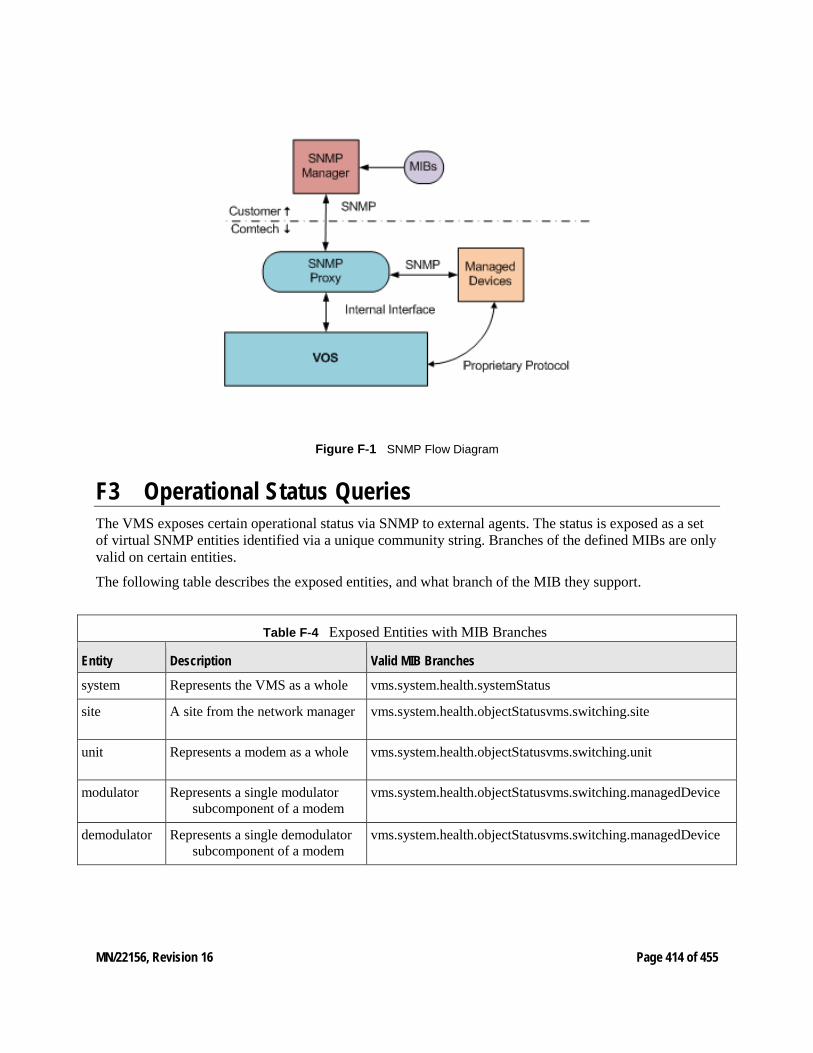
MN/22156, Revision 16 Page 414 of 455
Figure F‑1 SNMP Flow Diagram
F3 Operational Status Queries The VMS exposes certain operational status via SNMP to external agents. The status is exposed as a set of virtual SNMP entities identified via a unique community string. Branches of the defined MIBs are only valid on certain entities.
The following table describes the exposed entities, and what branch of the MIB they support.
Table F‑4 Exposed Entities with MIB Branches
Entity Description Valid MIB Branches
system Represents the VMS as a whole vms.system.health.systemStatus
site A site from the network manager vms.system.health.objectStatusvms.switching.site
unit Represents a modem as a whole vms.system.health.objectStatusvms.switching.unit
modulator Represents a single modulator subcomponent of a modem
vms.system.health.objectStatusvms.switching.managedDevice
demodulator Represents a single demodulator subcomponent of a modem
vms.system.health.objectStatusvms.switching.managedDevice
MN/22156, Revision 16 Page 415 of 455
Entity Identifiers
The unique identifier for the system entity is the community string “server”. The other identifiers are for the purpose of the SNMP agent, without format, and can only be obtained via queries to other entities. The exception is the unit which can also be referenced via the same community string used to perform a proxied request to the associated physical hardware.
As an example, the modulator identifier for the first modulator subcomponent of a modem with the IP address 172.18.100.1 can be obtained by querying the VMS for the “modulatorId” variable of the switching MIB, with an instance of 1 and a community string of “[email protected]”. The resulting octet string will be the entity identifier “moniker” to be used as the community when querying related MIB variables.
Hub Demodulator Eb/No
One of the main preferences is to correlate the Eb/No for the Hub demodulator of a switched Remote modulator, which can be obtained by querying the modem via the proxy for the “unitInbandReturnPathEbN0” variable in the switching MIB. This variable is designed to look like part of the Remote modem, when in reality the VMS intercepts the request and fills in the Eb/No of the currently allocated Hub demodulator. This allows for a very simple way of monitoring the quality of a dynamic link without the complexity of multiple queries involving different community strings.
For example, if the Remote data unit is a CDM-840 with an IP address of 172.18.100.1, the operator would use the VMS as a proxy by directing the SNMP requests to the VMS using a community string such as “[email protected]”. Along with querying the Remote modem for standard values like “cdm840TxFrequency” or “cdm840RxLock”, a request for “unitInbandReturnPathEbN0” can be included to get the Eb/No of the currently receiving Hub demodulator as well. This variable operates much like one of the cached modem parameters. To determine the value for this parameter, the VMS searches for an allocation associated with the specified unit's first modulator. If the modulator has an associated allocation, it queries the first allocated demodulator (which is always at the Hub) for its last known Eb/No value. If the modulator does not have an associated allocation, the value returned is null.
Tables Support
The current support for tables is limited. It is roughly equivalent to SNMP version 1. There is support for Get, Get Next, and Walk, but no support for GETBULK requests. The way to enumerate a table is to send Get Next or Table View.
MN/22156, Revision 16 Page 416 of 455
Proxy Caching Support When operating as a proxy on behalf of Comtech network equipment, the VMS will fulfill the requests for a subset of the MIB using data collected via proprietary protocols. When a request is made for one of these MIB variables, the VMS will report the last known value without forwarding the request to the end node. This data is collected at a frequency of at least once per minute.
To use the proxy/cache support, send SNMP queries for the modem to the VMS, and use a specially formatted community string to identify what device is being queried. The community string format is “community@ip-address”. For example, to target a device with the IP address of 172.16.128.1, using a read community of public, the community string sent to VMS would be “[email protected]”.
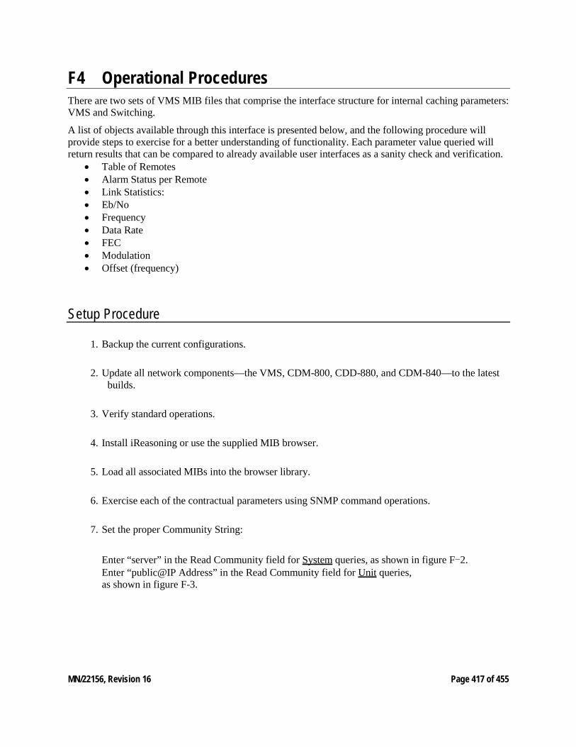
MN/22156, Revision 16 Page 417 of 455
F4 Operational Procedures There are two sets of VMS MIB files that comprise the interface structure for internal caching parameters: VMS and Switching.
A list of objects available through this interface is presented below, and the following procedure will provide steps to exercise for a better understanding of functionality. Each parameter value queried will return results that can be compared to already available user interfaces as a sanity check and verification.
• Table of Remotes • Alarm Status per Remote • Link Statistics: • Eb/No • Frequency • Data Rate • FEC • Modulation • Offset (frequency)
Setup Procedure
1. Backup the current configurations.
2. Update all network components—the VMS, CDM-800, CDD-880, and CDM-840—to the latest builds.
3. Verify standard operations.
4. Install iReasoning or use the supplied MIB browser.
5. Load all associated MIBs into the browser library.
6. Exercise each of the contractual parameters using SNMP command operations.
7. Set the proper Community String:
Enter “server” in the Read Community field for System queries, as shown in figure F-2. Enter “public@IP Address” in the Read Community field for Unit queries, as shown in figure F-3.
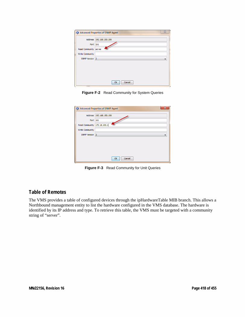
MN/22156, Revision 16 Page 418 of 455
Figure F‑2 Read Community for System Queries
Figure F‑3 Read Community for Unit Queries
Table of Remotes The VMS provides a table of configured devices through the ipHardwareTable MIB branch. This allows a Northbound management entity to list the hardware configured in the VMS database. The hardware is identified by its IP address and type. To retrieve this table, the VMS must be targeted with a community string of “server”.

MN/22156, Revision 16 Page 419 of 455
Figure F‑4 Table of Remotes
The example above used a Tree View or table get to poll all instances within the table. Get Next will step/walk the table. This option is not like network discovery where a manager will poll through a range of addresses for any MIBII devices connected to a network populating map view. These are local database entries that were either previously discovered or manually declared to the VMS only. Other devices outside the VMS database will not be listed.
Alarm Status per Remote Each of the structured devices forward SUM messages on interval containing not only parameter settings and status values, but also alarm information. What is presented through this call is an integer value representing a count of alarms set within the device, unit, modulator, demodulator, etc. To further evaluate the alarm information or type, the device’s MIB would be used to query alarm lists.
To query individual unit alarm status, set the community read string to the IP address of the device. Select the alarm Count OID for the result.
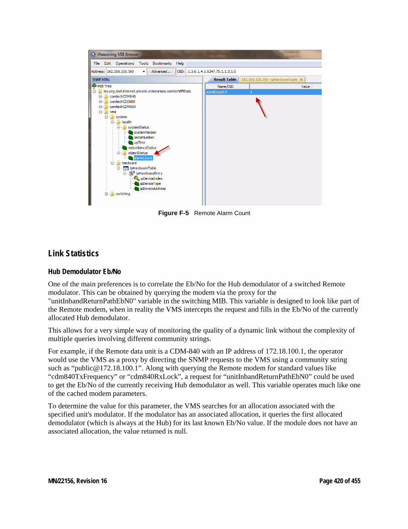
MN/22156, Revision 16 Page 420 of 455
Figure F‑5 Remote Alarm Count
Link Statistics
Hub Demodulator Eb/No One of the main preferences is to correlate the Eb/No for the Hub demodulator of a switched Remote modulator. This can be obtained by querying the modem via the proxy for the "unitInbandReturnPathEbN0" variable in the switching MIB. This variable is designed to look like part of the Remote modem, when in reality the VMS intercepts the request and fills in the Eb/No of the currently allocated Hub demodulator.
This allows for a very simple way of monitoring the quality of a dynamic link without the complexity of multiple queries involving different community strings.
For example, if the Remote data unit is a CDM-840 with an IP address of 172.18.100.1, the operator would use the VMS as a proxy by directing the SNMP requests to the VMS using a community string such as “[email protected]”. Along with querying the Remote modem for standard values like “cdm840TxFrequency” or “cdm840RxLock”, a request for “unitInbandReturnPathEbN0” could be used to get the Eb/No of the currently receiving Hub demodulator as well. This variable operates much like one of the cached modem parameters.
To determine the value for this parameter, the VMS searches for an allocation associated with the specified unit's modulator. If the modulator has an associated allocation, it queries the first allocated demodulator (which is always at the Hub) for its last known Eb/No value. If the module does not have an associated allocation, the value returned is null.
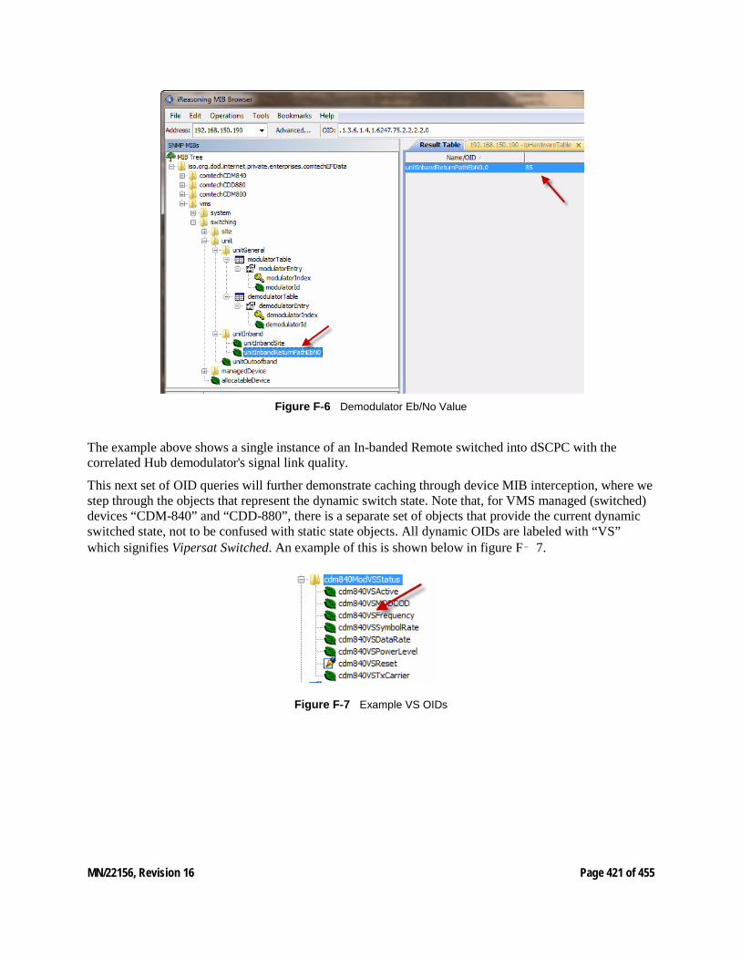
MN/22156, Revision 16 Page 421 of 455
Figure F‑6 Demodulator Eb/No Value
The example above shows a single instance of an In-banded Remote switched into dSCPC with the correlated Hub demodulator's signal link quality.
This next set of OID queries will further demonstrate caching through device MIB interception, where we step through the objects that represent the dynamic switch state. Note that, for VMS managed (switched) devices “CDM-840” and “CDD-880”, there is a separate set of objects that provide the current dynamic switched state, not to be confused with static state objects. All dynamic OIDs are labeled with “VS” which signifies Vipersat Switched. An example of this is shown below in figure F‑ 7.
Figure F‑7 Example VS OIDs
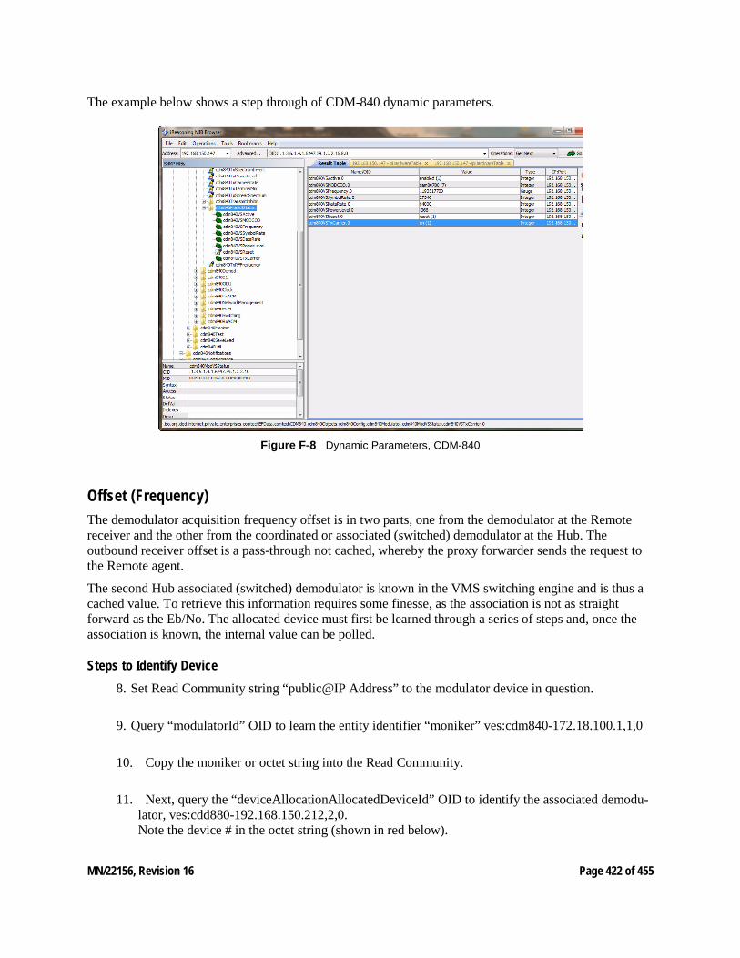
MN/22156, Revision 16 Page 422 of 455
The example below shows a step through of CDM-840 dynamic parameters.
Figure F‑8 Dynamic Parameters, CDM-840
Offset (Frequency) The demodulator acquisition frequency offset is in two parts, one from the demodulator at the Remote receiver and the other from the coordinated or associated (switched) demodulator at the Hub. The outbound receiver offset is a pass-through not cached, whereby the proxy forwarder sends the request to the Remote agent.
The second Hub associated (switched) demodulator is known in the VMS switching engine and is thus a cached value. To retrieve this information requires some finesse, as the association is not as straight forward as the Eb/No. The allocated device must first be learned through a series of steps and, once the association is known, the internal value can be polled.
Steps to Identify Device 8. Set Read Community string “public@IP Address” to the modulator device in question.
9. Query “modulatorId” OID to learn the entity identifier “moniker” ves:cdm840-172.18.100.1,1,0
10. Copy the moniker or octet string into the Read Community.
11. Next, query the “deviceAllocationAllocatedDeviceId” OID to identify the associated demodu-lator, ves:cdd880-192.168.150.212,2,0. Note the device # in the octet string (shown in red below).
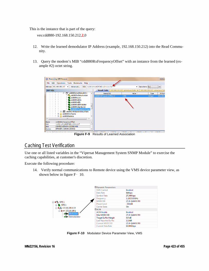
MN/22156, Revision 16 Page 423 of 455
This is the instance that is part of the query:
ves:cdd880-192.168.150.212,2,0
12. Write the learned demodulator IP Address (example, 192.168.150.212) into the Read Commu-nity.
13. Query the modem’s MIB “cdd880RxFrequencyOffset” with an instance from the learned (ex-ample #2) octet string.
Figure F‑9 Results of Learned Association
Caching Test Verification Use one or all listed variables in the “Vipersat Management System SNMP Module” to exercise the caching capabilities, at customer's discretion.
Execute the following procedure:
14. Verify normal communications to Remote device using the VMS device parameter view, as shown below in figure F‑ 10.
Figure F‑10 Modulator Device Parameter View, VMS
MN/22156, Revision 16 Page 424 of 455
15. Select the OID from the supported list.
16. Power off the Remote unit to disable it.
17. Query the selected OID.
During the time of communications failure, the caching will be valid for up to three minutes, with the connection state identified as “Disconnected”. After this period, the VMS will return a “Timeout” connection error.
This provides a simple method for determining whether caching is working correctly.

MN/22156, Revision 16 Page 425 of 455
Cached MIB Variables The specific MIB variables that are cached vary per supported modem, and potentially per revision of a specific modem. The following lists summarize what MIB variables are cached for supported modems at their latest release.
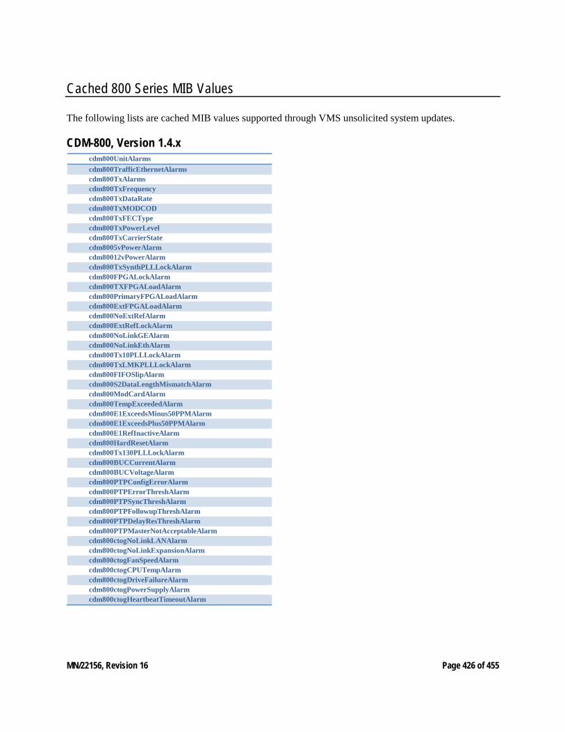
MN/22156, Revision 16 Page 426 of 455
Cached 800 Series MIB Values
The following lists are cached MIB values supported through VMS unsolicited system updates.
CDM-800, Version 1.4.x cdm800UnitAlarms cdm800TrafficEthernetAlarms cdm800TxAlarms cdm800TxFrequency cdm800TxDataRate cdm800TxMODCOD cdm800TxFECType cdm800TxPowerLevel cdm800TxCarrierState cdm8005vPowerAlarm cdm80012vPowerAlarm cdm800TxSynthPLLLockAlarm cdm800FPGALockAlarm cdm800TXFPGALoadAlarm cdm800PrimaryFPGALoadAlarm cdm800ExtFPGALoadAlarm cdm800NoExtRefAlarm cdm800ExtRefLockAlarm cdm800NoLinkGEAlarm cdm800NoLinkEthAlarm cdm800Tx10PLLLockAlarm cdm800TxLMKPLLLockAlarm cdm800FIFOSlipAlarm cdm800S2DataLengthMismatchAlarm cdm800ModCardAlarm cdm800TempExceededAlarm cdm800E1ExceedsMinus50PPMAlarm cdm800E1ExceedsPlus50PPMAlarm cdm800E1RefInactiveAlarm cdm800HardResetAlarm cdm800Tx130PLLLockAlarm cdm800BUCCurrentAlarm cdm800BUCVoltageAlarm cdm800PTPConfigErrorAlarm cdm800PTPErrorThreshAlarm cdm800PTPSyncThreshAlarm cdm800PTPFollowupThreshAlarm cdm800PTPDelayResThreshAlarm cdm800PTPMasterNotAcceptableAlarm cdm800ctogNoLinkLANAlarm cdm800ctogNoLinkExpansionAlarm cdm800ctogFanSpeedAlarm cdm800ctogCPUTempAlarm cdm800ctogDriveFailureAlarm cdm800ctogPowerSupplyAlarm cdm800ctogHeartbeatTimeoutAlarm
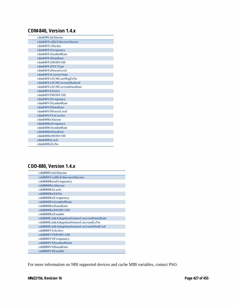
MN/22156, Revision 16 Page 427 of 455
CDM-840, Version 1.4.x cdm840UnitAlarms cdm840TrafficEthernetAlarms cdm840TxAlarms cdm840TxFrequency cdm840TxSymbolRate cdm840TxDataRate cdm840TxMODCOD cdm840TxFECType cdm840TxPowerLevel cdm840TxCarrierState cdm840TxACMLastMsgEsNo cdm840TxACMCurrentModcod cdm840TxACMCurrentDataRate cdm840VSActive cdm840VSMODCOD cdm840VSFrequency cdm840VSSymbolRate cdm840VSDataRate cdm840VSPowerLevel cdm840VSTxCarrier cdm840RxAlarms cdm840RxFrequency cdm840RxSymbolRate cdm840RxDataRate cdm840RxMODCOD cdm840RxLock cdm840RxEsNo
CDD-880, Version 1.4.x cdd880UnitAlarms cdd880TrafficEthernetAlarms cdd880BaseFrequency cdd880RxAlarms cdd880RxLock cdd880RxEbNo cdd880RxFrequency cdd880RxSymbolRate cdd880RxDataRate cdd880RxMODCOD cdd880RxEnable cdd880LinkAdaptionStatusCurrentDataRate cdd880LinkAdaptionStatusCurrentEsNo cdd880LinkAdaptionStatusCurrentModCod cdd880VSActive cdd880VSMODCOD cdd880VSFrequency cdd880VSSymbolRate cdd880VSDataRate cdd880VSEnable
For more information on NBI supported devices and cache MIB variables, contact PSO.
MN/22156, Revision 16 Page 428 of 455
G VMS CLIENT USERS G1 VMS Client Users Account Control General VMS v3.11.x (and later) offers user authentication, with the ability to create remote clients with either read-only or read-write access to the VMS server.
Administration of client user authorization for read/write privileges allows two levels of VMS access:
• Read and Write – Full access to all VMS features and functions with write authorization. Typically assigned to administrator-level operators who are authorized to perform system setup and maintenance, configuration changes, manual/diagnostic switching, etc.
• Read Only – Access restricted to viewing network settings and status. Typically assigned to users who will use the VMS for monitoring purposes.
This appendix details the steps required to set up the security and account policies between the Server and the Client machines through MS Windows. The assumption is made that the VMS servers are configured as work-group machines rather than as active-directory domain controllers, since the majority of VMS installations are configured this way. If the VMS servers are set up as part of a domain, policy configurations will be performed under active directory rather than local settings.
Configuration of the server is performed first, followed by configuration of the client workstation(s). These procedures are presented below.
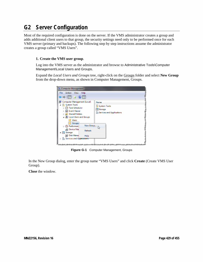
MN/22156, Revision 16 Page 429 of 455
G2 Server Configuration Most of the required configuration is done on the server. If the VMS administrator creates a group and adds additional client users to that group, the security settings need only to be performed once for each VMS server (primary and backups). The following step by step instructions assume the administrator creates a group called “VMS Users”.
1. Create the VMS user group.
Log into the VMS server as the administrator and browse to Administrative Tools\Computer Management\Local Users and Groups.
Expand the Local Users and Groups tree, right-click on the Groups folder and select New Group from the drop-down menu, as shown in Computer Management, Groups.
Figure G‑1 Computer Management, Groups
In the New Group dialog, enter the group name “VMS Users” and click Create (Create VMS User Group).
Close the window.
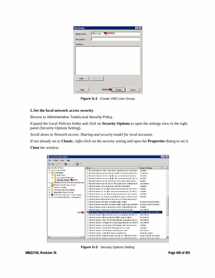
MN/22156, Revision 16 Page 430 of 455
Figure G‑2 Create VMS User Group
2. Set the local network access security.
Browse to Administrative Tools\Local Security Policy.
Expand the Local Policies folder and click on Security Options to open the settings view in the right panel (Security Options Setting).
Scroll down to Network access: Sharing and security model for local accounts.
If not already set to Classic, right-click on the security setting and open the Properties dialog to set it.
Close the window.
Figure G‑3 Security Options Setting
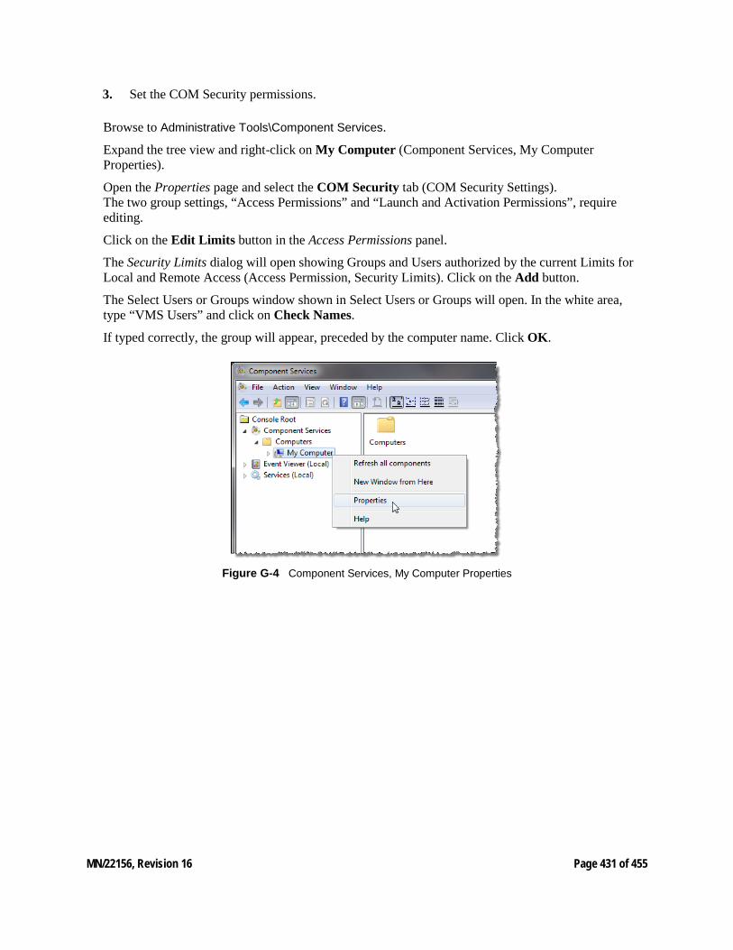
MN/22156, Revision 16 Page 431 of 455
3. Set the COM Security permissions.
Browse to Administrative Tools\Component Services.
Expand the tree view and right-click on My Computer (Component Services, My Computer Properties).
Open the Properties page and select the COM Security tab (COM Security Settings). The two group settings, “Access Permissions” and “Launch and Activation Permissions”, require editing.
Click on the Edit Limits button in the Access Permissions panel.
The Security Limits dialog will open showing Groups and Users authorized by the current Limits for Local and Remote Access (Access Permission, Security Limits). Click on the Add button.
The Select Users or Groups window shown in Select Users or Groups will open. In the white area, type “VMS Users” and click on Check Names.
If typed correctly, the group will appear, preceded by the computer name. Click OK.
Figure G‑4 Component Services, My Computer Properties
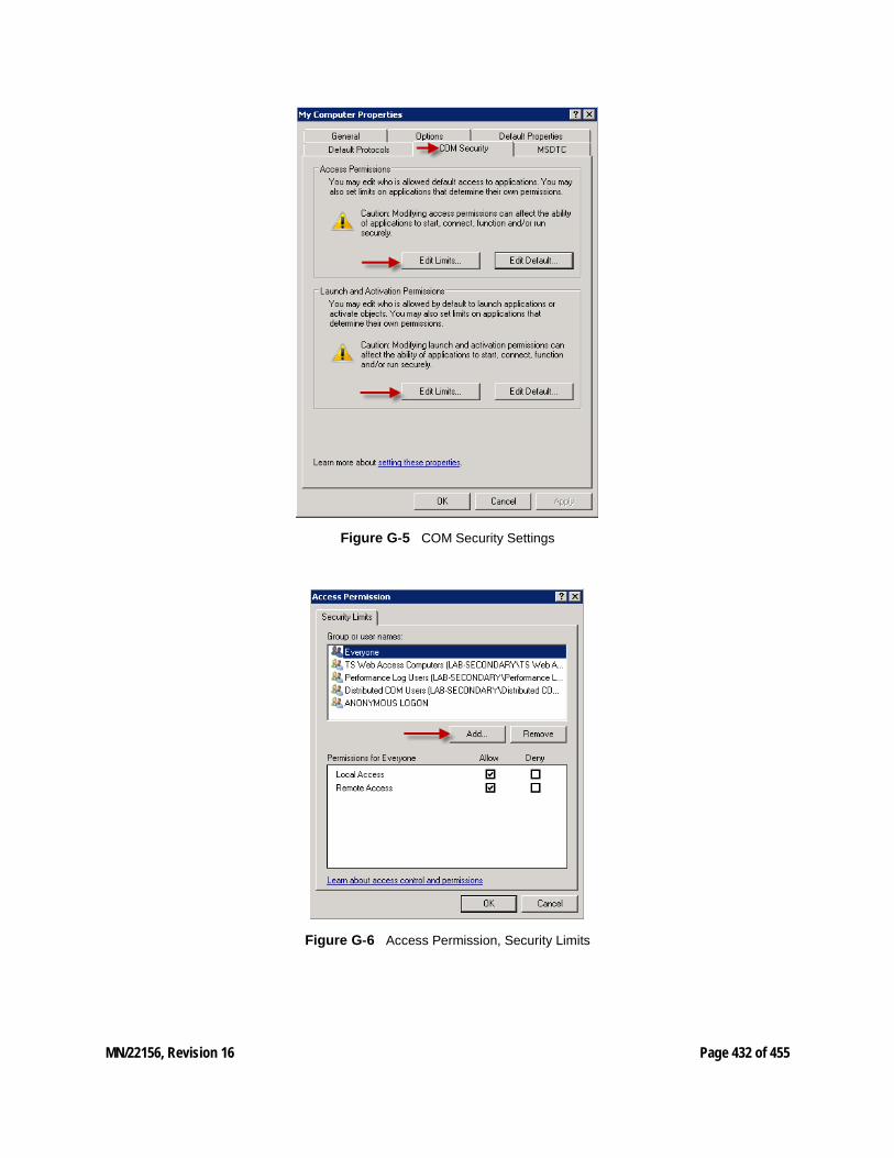
MN/22156, Revision 16 Page 432 of 455
Figure G‑5 COM Security Settings
Figure G‑6 Access Permission, Security Limits
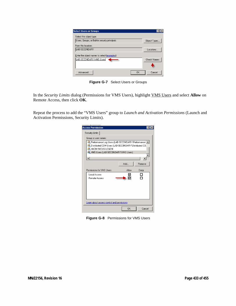
MN/22156, Revision 16 Page 433 of 455
Figure G‑7 Select Users or Groups
In the Security Limits dialog (Permissions for VMS Users), highlight VMS Users and select Allow on Remote Access, then click OK.
Repeat the process to add the “VMS Users” group to Launch and Activation Permissions (Launch and Activation Permissions, Security Limits).
Figure G‑8 Permissions for VMS Users
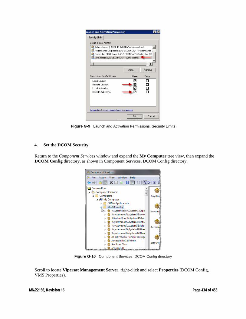
MN/22156, Revision 16 Page 434 of 455
Figure G‑9 Launch and Activation Permissions, Security Limits
4. Set the DCOM Security.
Return to the Component Services window and expand the My Computer tree view, then expand the DCOM Config directory, as shown in Component Services, DCOM Config directory.
Figure G‑10 Component Services, DCOM Config directory
Scroll to locate Vipersat Management Server, right-click and select Properties (DCOM Config, VMS Properties).
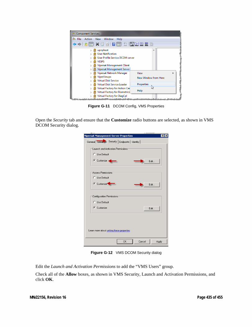
MN/22156, Revision 16 Page 435 of 455
Figure G‑11 DCOM Config, VMS Properties
Open the Security tab and ensure that the Customize radio buttons are selected, as shown in VMS DCOM Security dialog.
Figure G‑12 VMS DCOM Security dialog
Edit the Launch and Activation Permissions to add the “VMS Users” group.
Check all of the Allow boxes, as shown in VMS Security, Launch and Activation Permissions, and click OK.

MN/22156, Revision 16 Page 436 of 455
Repeat this procedure for Access Permissions (VMS Security, Access Permissions).
Figure G‑13 VMS Security, Launch and Activation Permissions
Figure G‑14 VMS Security, Access Permissions
5. Create the VMS user.
Browse to Administrative Tools\Computer Management\Local Users and Groups.

MN/22156, Revision 16 Page 437 of 455
Expand the Local Users and Groups tree, right-click on the Users folder and select New User from the drop-down menu, as shown in Computer Management, Users.
Figure G‑15 Computer Management, Users
In the New User dialog (Create new VMS Client User), enter the user name and password of the client account.
De-select the User must change password at next logon checkbox, then check the next two boxes.
Click Create.
Repeat this process to create additional client users, as required.
Close the window.
In the Computer Management window, select the Users folder to display the users in the center panel.
Right-click on the newly created user and select Properties from the pull-down menu.
Select the Member Of tab, as shown in New Client User Properties, Member Of tab.
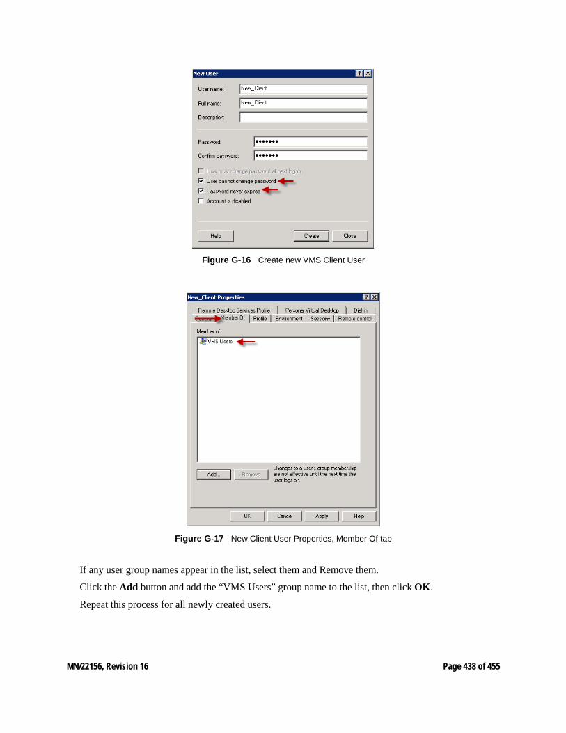
MN/22156, Revision 16 Page 438 of 455
Figure G‑16 Create new VMS Client User
Figure G‑17 New Client User Properties, Member Of tab
If any user group names appear in the list, select them and Remove them.
Click the Add button and add the “VMS Users” group name to the list, then click OK.
Repeat this process for all newly created users.
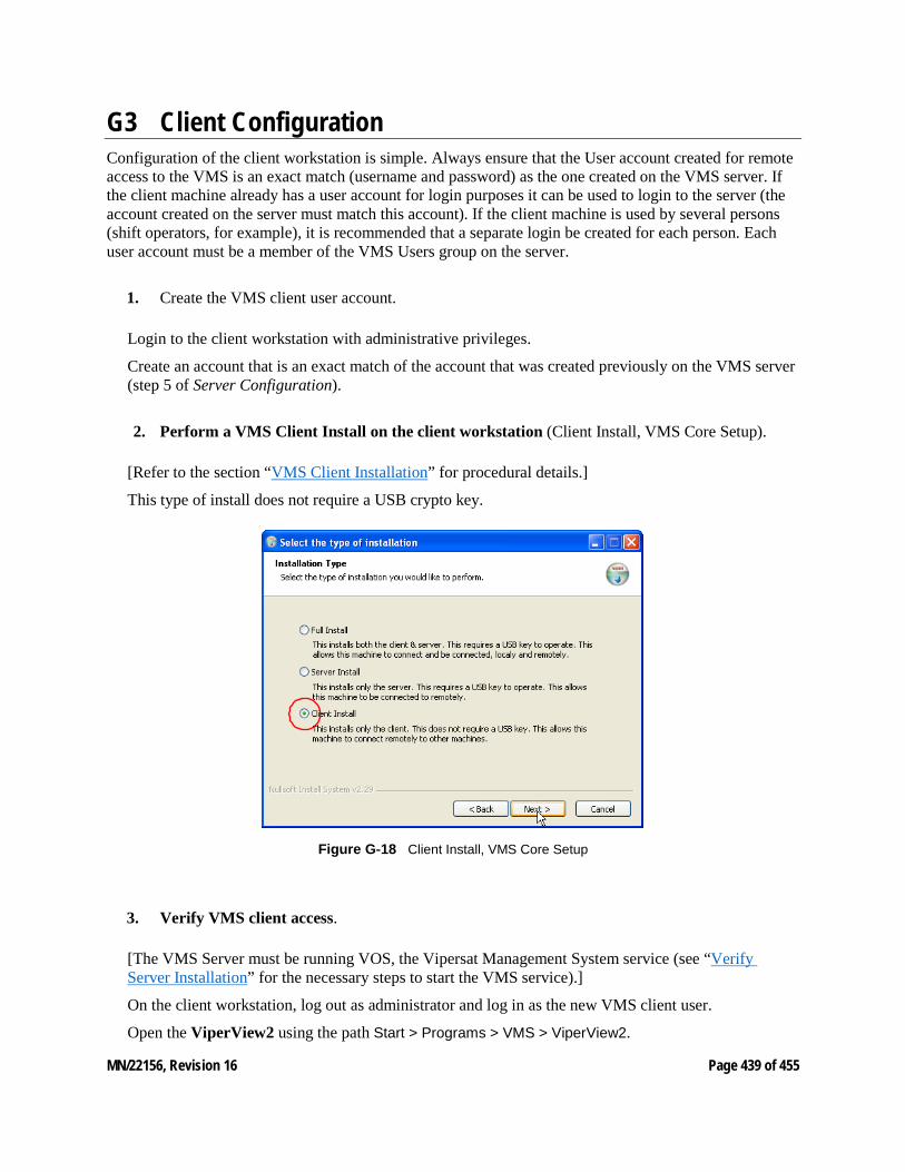
MN/22156, Revision 16 Page 439 of 455
G3 Client Configuration Configuration of the client workstation is simple. Always ensure that the User account created for remote access to the VMS is an exact match (username and password) as the one created on the VMS server. If the client machine already has a user account for login purposes it can be used to login to the server (the account created on the server must match this account). If the client machine is used by several persons (shift operators, for example), it is recommended that a separate login be created for each person. Each user account must be a member of the VMS Users group on the server.
1. Create the VMS client user account.
Login to the client workstation with administrative privileges.
Create an account that is an exact match of the account that was created previously on the VMS server (step 5 of Server Configuration).
2. Perform a VMS Client Install on the client workstation (Client Install, VMS Core Setup).
[Refer to the section “VMS Client Installation” for procedural details.]
This type of install does not require a USB crypto key.
Figure G‑18 Client Install, VMS Core Setup
3. Verify VMS client access.
[The VMS Server must be running VOS, the Vipersat Management System service (see “Verify Server Installation” for the necessary steps to start the VMS service).]
On the client workstation, log out as administrator and log in as the new VMS client user.
Open the ViperView2 using the path Start > Programs > VMS > ViperView2.
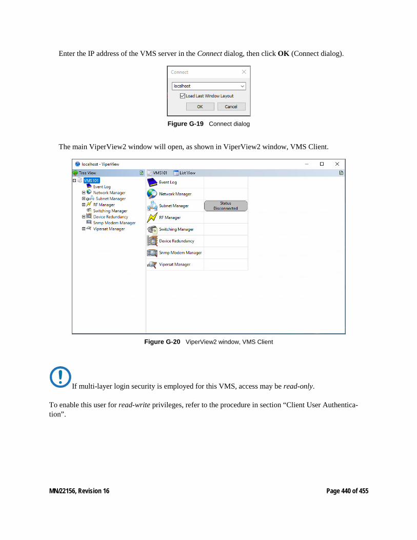
MN/22156, Revision 16 Page 440 of 455
Enter the IP address of the VMS server in the Connect dialog, then click OK (Connect dialog).
Figure G‑19 Connect dialog
The main ViperView2 window will open, as shown in ViperView2 window, VMS Client.
Figure G‑20 ViperView2 window, VMS Client
If multi-layer login security is employed for this VMS, access may be read-only. To enable this user for read-write privileges, refer to the procedure in section “Client User Authentica-tion”.
MN/22156, Revision 16 Page 441 of 455
H H1 Glossary
A
ACK A signal used in computing and other fields to indicate acknowledgement, such as a packet message used in TCP to acknowledge the receipt of a packet.
ACM Adaptive Coding and Modulation – A technique that optimizes throughput in a wireless data link by adapting the forward error correction code rate and the modulation order according to the noise conditions (or other impairments) on the link. A feature that is supported in CEFD modems such as the CDM-840 Remote Router.
ARP Address Resolution Protocol – A protocol for a LAN device to determine the MAC address of a locally connected device given its IP address. See also MAC.
ASR Automatic Switch Request – A switch request message generated by older CEFD modems (e.g., CDM-570/L) that is sent to the VMS to establish a new satellite link or adjust bandwidth between source and destination IP addresses.
B
Base Modem The main component in a satellite communications modem that consists of a circuit board with the modem hardware and firmware and the associated interfaces.
BER
MN/22156, Revision 16 Page 442 of 455
Bit Error Rate (sometimes Ratio) – A measure of the number of data bits received incorrectly compared to the total number of bits transmitted.
BPM Bridge Point-to-Multipoint – Routing mode option available in the SLM-5650A satellite modem.
bps bits per second – A measure of the bit rate or transmission speed of a digital communication link. See also kbps and Mbps.
BPSK Binary Phase Shift Keying – Sometimes referred to as 2-PSK. A digital modulation technique in which the carrier is phase shifted +/-180 degrees (two phases). The simplest and most robust of all PSKs, but unsuitable for high data-rate applications when bandwidth is limited due to encoding just one bit per symbol. See also QPSK and OQPSK.
BUC Block Up Converter – An upconverter so called because it converts a whole band or “block” of frequencies to a higher band. The IF is converted to final transmit frequency for satellite communications. The BUC is part of the satellite ODU/transceiver.
C
C-band A frequency band commonly used for satellite communications (and sometimes terrestrial microwave). For terrestrial earth stations, the receive frequency band is 3.7–4.2 GHz and the transmit frequency band is 5.925–6.425 GHz. See also Ku-band and L-band.
CDD Comtech Data Demodulator (CEFD model designator; e.g., CDD-564)
CDM Comtech Data Modem (CEFD model designator; e.g., CDM-570)
CEFD Comtech EF Data – Global leader in satellite bandwidth efficiency and link optimization, and supplier of advanced communication solutions. A subsidiary of Comtech Telecommunications Corporation.
CIR Committed Information Rate – A specified data rate up to which a remote terminal is always guaranteed to be granted service from reserved bandwidth in the shared pool.
CLI Character Line Interface – A mechanism for interacting with a computer operating system or software by typing commands to perform specific tasks.
Codecast
MN/22156, Revision 16 Page 443 of 455
A network coding based ad hoc multicast protocol well-suited for multimedia applications with low-loss, low-latency constraints. Because data is streamed with no verification, high delivery ratios are obtained with very low overhead.
CRC Cyclic Redundancy Check – A method of applying a checksum to a block of data to determine if any errors occurred during transmission over communications links.
CXR Carrier – A radio frequency transmission linking points and over which information may be carried.
D
DAMA Demand Assigned Multiple Access – A process whereby communications links are only activated when there is an actual demand.
dBm Decibel referenced to 1 milliwatt.
DES Data Encryption Standard – A federal standard method for encrypting information for secure transmission. The CEFD system offers 3xDES (Triple DES) for encrypting traffic.
DHCP Dynamic Host Configuration Protocol – An Internet protocol for automating the configuration of computers that use TCP/IP.
DLL Dynamic Link Library – The implementation of the shared library concept in the Microsoft Windows system.
DPC Dynamic Power Control
DSCP Differentiated Services Code Point – The 6-bit field in an IP packet header that is used for packet classification purposes and is the portion of ToS that is detected by CEFD modems.
DVB Digital Video Broadcasting – A suite of internationally accepted open standards for digital television. DVB-S, DVB-S2, and DVB-RCS are the standards utilized by satellite services.
DVP Digital Voice Processor – Used in packet voice applications.
MN/22156, Revision 16 Page 444 of 455
E
Eb/N0
The ratio of Eb (energy per bit) and N0 (noise power spectral density per Hz). This is a normalized signal-to-noise ratio (SNR) measure, also known as the “SNR per bit”. The bit error rate (BER) for digital data is a decreasing function of this ratio. Eb is the energy of an information bit measured in Joules or, equivalently, in Watts per Hertz.
Es/N0
The ratio of Es (energy per symbol) and N0 (noise power spectral density per Hz). This is closely approximate to the carrier-to-noise ratio (C/N). Es is the energy of a bit (not an information bit) measured in Joules or, equivalently, in Watts per Hertz. This measurement is typically used to quantify a DVB-S2 carrier.
ECM Entry Channel Mode – In a CEFD network, ECM provides a quick and reliable method for Remotes requiring SCPC access channels to enter/re-enter the network initially or after a power or other site outage.
F
FAST Code Fully Accessible System Topology Code – Designation for feature code used by Comtech EF Data for their satellite modems. The FAST method makes it easy to quickly upgrade the feature options of a modem while it is running live in the network, either on site or remotely.
FDMA Frequency Division Multiple Access – A technique where multiple users can access a common resource (e.g. satellite) by each being allocated a distinct frequency for operation. See also TDMA and STDMA.
FEC Forward Error Correction – A process whereby data being transmitted over a communications link can have error correction bits added which may be used at the receiving end to determine/correct any transmission errors which may occur.
Flash Non-volatile computer memory that can be electrically erased and reprogrammed.
Forward Path Transmission path from the Hub site to a Remote site.
FTP File Transfer Protocol – An application for transferring computer files over the Internet. See also TFTP.
MN/22156, Revision 16 Page 445 of 455
G
G.703 ITU-T standard for transmitting voice or data over digital carriers such as T1 and E1.
G.729 ITU standard for LD-CELP (Low Delay – Code Excited Linear Prediction) voice encoding at 8 kb/s.
GIR Guaranteed Information Rate
Group ID A number assigned to equipment which defines it as a member of a group when addressed by the VMS Hub Controller.
GUI Graphical User Interface – A form of graphical shell or user interface to a computer operating system or software application.
H
H.323 A protocol standard for multimedia communications designed to support real-time transfer of audio (such as voice over IP) and video data over packet networks. Quality of Service is a key feature of H.323. An alternative to SIP.
HCC Hub Channel Controller – A dedicated Hub demodulator that has been designated as the ECM (ECMv2) controller, and which provides the TAP multicast message to the Remotes.
HDLC High Level Data Link Control – A standard defining how data may be transmitted down a synchronous serial link.
HDNA Heights Dynamic Network Access - Ensures that bandwidth is instantly made available to users and sites across the network as the demand changes.
HRG Heights Remote Gateway – Remote modem, H-PRO, H-Plus, and H-Pico integrates with Heights hub components.
HPA High Power Amplifier – The amplifier used in satellite communications to raise the transmit signal to the correct power level prior to transmission to satellite.
MN/22156, Revision 16 Page 446 of 455
HTTP Hyper Text Transfer Protocol – The Internet standard for World Wide Web (WWW) operation.
HTO Heights Traffic Optimizer - Integrates Comtech’s point-to-multipoint HTX-450 Hub Modulator for Service Area outbound component of the Heights Networking Platform.
HRX Heights Multi Channel Receiver – In tandem with HTO-1 Heights Traffic Optimizer with HTX-450 Modulator, servers as the ‘Hub” or local site equipment component of Heights Networking Platform.
Hub The central site of a network which links to several satellite earth sites (Remotes).
I
ICMP Internet Control Message Protocol
IDU Indoor Unit – In a VSAT system, the satellite modem is referred to as the IDU.
IF Intermediate Frequency – In satellite systems, IF frequencies are usually centered around 70/140 MHz (video/TV), or 1200 MHz (L-band).
IFL Intra-Facility Link – The coaxial cabling used to connect the satellite ODU to the IDU. Carries the inbound and the outbound signals, and the 24 VDC for the LNB.
IGMP Internet Group Management Protocol – An IP communications protocol used by network hosts and adjacent routers to establish multicast group memberships.
Image A binary firmware file that provides the operational code for the processor(s) in a network unit.
IP Internet Protocol – A format for data packets used on networks accessing the Internet.
ISP Internet Service Provider – A company providing Internet access.
ITU International Telecommunications Union
MN/22156, Revision 16 Page 447 of 455
K
Kbps Kilo bits per second – 1000 bits/second. A measure of the bit rate or transmission speed of a digital communication link. See also bps and Mbps.
Ku-band A frequency band used for satellite communications. For terrestrial earth stations, the receive frequency band is in the range 10.95–12.75 GHz and the transmit frequency band is 13.75–14.5 GHz. See also C-band and L-band.
L
L-band A frequency band commonly used as an L-Band for satellite systems using block up/down conversion. Typically, 950–2150MHz Tx/Rx, See also C-band and Ku-band.
LAN Local Area Network
LLA Low Latency Application
LNA Low Noise Amplifier – An amplifier with very low noise temperature used as the first amplifier in the receive chain of a satellite system.
LNB Low Noise Block – A downconverter so called because it converts a whole band or “block” of frequencies to a lower band. The LNB (similar to an LNA) is part of the satellite ODU/transceiver.
LNC Low Noise Converter – A combined low noise amplifier and block downconverter, typically with an L-band IF.
LO Local Oscillator – A component used in upconverters, downconverters, and transponders for frequency translation (heterodyne) of the carrier signal.
MN/22156, Revision 16 Page 448 of 455
M
M&C Monitor & Control
MAC Media Access Control – A protocol controlling access to the physical layer of an Ethernet network.
Mbps Mega bits per second – 1 Million bits/second. A measure of the bit rate or transmission speed of a digital communication link. See also bps and kbps.
MIB Managed Information Base – A database used for managing the entities in a communications network. Typically associated with Simple Network Management Protocol (SNMP).
MIR Minimum Information Rate – A minimum level of service available to a remote terminal, ensuring the ability to enter a clear channel SCPC circuit or have a timeslot in STDMA.
Modem Modulator and demodulator units combined.
Multicast Transmitting a single message simultaneously to multiple destinations (group) on the IP network.
Multi-command A command that allows multiple input choices in a single command execution.
N
NAT Network Address Translation – An Internet standard that enables a LAN to use one set of IP addresses for internal (private) traffic and a second set of addresses for external (public) traffic.
NBI Northbound Interface – The SNMP interface offered by the VMS to extend services to an external network management system (NMS).
NIC Network Interface Controller – The network interface for a PC/workstation that provides Ethernet connectivity. Depending on the computer, the NIC can either be built into the motherboard, or be an expansion card. Some computers (e.g., servers) have multiple NICs, each identified by a unique IP address.
MN/22156, Revision 16 Page 449 of 455
NMS Network Management System
NOC Network Operations Center – The main control center for network operations. A NOC can interrogate, control, and log network activities for the satellite Hub as well as any Remote node.
NP Network Processor – Also referred to as the IP Module. An optional assembly for Comtech EF Data modems that provides the 10/100 BaseT Ethernet interface that is required when used in CEFD networks.
O
ODU Outdoor Unit – In a VSAT system, the RF components (transceiver) are usually installed outdoors on the antenna structure itself and are thus referred to as an ODU. The ODU typically includes the BUC and LNB and is connected to the IDU/modem by the IFL cabling.
OQPSK Offset Quadrature Phase Shift Keying – A variant of phase-shift keying using four different values of the phase to transmit. Offsetting the bit timing limits the phase shift and yields lower amplitude fluctuations as compared to QPSK and is sometimes preferred for communications systems. See also QPSK and BPSK.
OSPF Open Shortest Path First – An open standard interior gateway routing protocol used to determine the best route for delivering the packets within an IP network. OSPF routers use the Shortest Path First link state algorithm to calculate the shortest path to each node in the network. The CEFD OSPF feature in the Comtech SLM-5650A modem provides for dynamic routing functionality.
P
PIR Peak Information Rate – The bandwidth available for use by any remote terminal on best effort basis, categorized through multilevel prioritization.
PLDM Path Loss Data Message – A packet message that is sent by older CEFD modems (e.g., CDM-570/L) to the VMS every sixty seconds, providing status update and operating parameter information.
MN/22156, Revision 16 Page 450 of 455
PSK Phase Shift Keying – A digital modulation scheme that conveys data by changing the phase of a base reference signal, the carrier wave. Different PSKs are used, depending on the data rate required and the signal integrity. Examples are binary phase-shift keying (BPSK or 2-PSK) which uses two phases, and quadrature phase-shift keying (QPSK or 4-PSK) which uses four phases.
PSTN Public Switched Telephone Network – The world’s public circuit-switched telephone network, digital and analog, and includes mobile as well as land-line voice and data communications.
PUM Periodic Update Message – A packet message that is sent by newer CEFD modems (e.g., CDM-840) to the VMS every sixty seconds, providing either registration request or status update and operating parameter information (SUM).
Q
QAM Quadrature Amplitude Modulation – A digital modulation technique in which the amplitude of two carrier waves is changed to represent the data signal. These two waves are 90 degrees out of phase with each other.
QoS Quality of Service
QPSK Quadrature Phase Shift Keying – Sometimes referred to as 4-PSK, or 4-QAM. A modulation technique in which the carrier is phase shifted +/-90 or +/-180 degrees. With four phases, this modulation can encode two bits per symbol—twice the rate of BPSK. However, it also uses twice the power. See also OQPSK and BPSK.
R
Remote Satellite earth site that links to a central network site (Hub).
REST REpresentational State Transfer – An architectural style of large-scale networked software that takes advantage of the technologies and protocols of the World Wide Web. REST describes how distributed data objects, or resources, can be defined and addressed, stressing the easy exchange of information and scalability.
MN/22156, Revision 16 Page 451 of 455
RESTful The VMS RESTful interface is a Web Services API that adheres to the REST principles. This interface provides a high-level control of VMS element structures via document-addressable URL’s simplifying and standardizing on an external application interface, such as to/from a network management system (NMS).
Return Path Transmission path from a Remote site to the Hub site.
RF Radio Frequency – A generic term for signals at frequencies above those used for baseband or IF.
RFC Request For Comment – The official publication channel for Internet standards (such as communication protocols) issued by the Internet Engineering Task Force (IETF).
RIP Routing Information Protocol
RS-232 A common electrical/physical standard issued by the IEEE used for point to point serial communications up to approximately 115 kb/s.
RTP Real-time Transport Protocol – A standardized packet format for delivering real-time applications such as audio and video over the Internet. Frequently used in streaming media systems, videoconferencing, and VoIP.
Rx Receive
S
SCPC Single Channel Per Carrier – A satellite communications technique where an individual channel is transmitted to the designated carrier frequency. Some applications use SCPC instead of burst transmissions because they require guaranteed, unrestricted bandwidth.
SIP Session Initiation Protocol – A general purpose protocol for multimedia communications, commonly used for voice over IP (VoIP) signaling. An alternative to the H.323 protocol.
SLM Satellite Link Modem (CEFD model designator; e.g., SLM-5650A)
SNG
MN/22156, Revision 16 Page 452 of 455
Satellite News Gathering – A satellite uplink van/truck with television crew on location conducting a live report for a newscast.
SNMP Simple Network Management Protocol – A protocol defining how devices from different vendors may be managed using a common network management system.
SOTM SatCom-On-The-Move – The ability of a mobile remote terminal to roam across satellite beams to preserve link integrity and to automatically connect from one satellite and/or hub to another in a global network.
Star Topology A network topology which, if drawn as a logical representation, resembles a star with a hub at the center.
STDMA Selective Time Division Multiple Access – A multiple access technique where users time-share access to a common channel with variable-sized time slots allocated on usage.
Streamload Protocol A proprietary CEFD data streaming protocol.
SUM Status Update Message – A packet message that is sent by newer CEFD modems (e.g., SLM-5650A, Heights/HDNA) to the VMS every sixty seconds, providing status update and operating parameter information.
T
TAP Transmission Announcement Protocol – A proprietary multicast message sent out by the HCC to all associated Remotes in the group, specifying the relative start time and duration for each terminal to transmit while in Entry Channel mode (ECMv2).
TCP/IP Transmission Control Protocol / Internet Protocol – A standard for networking over unreliable transmission paths. See also UDP.
TDM Time Division Multiplexing – A method of multiplexing that provides the transmission of two or more signals on the same communication path or channel, but at different times by utilizing recurrent timeslots.
MN/22156, Revision 16 Page 453 of 455
TDMA Time Division Multiple Access – A multiple access technique where users contend for access to a common channel on a time-shared basis. See also FDMA and STDMA.
TFTP Trivial File Transfer Protocol – A simple file transfer protocol used over reliable transmission paths. See also FTP.
ToS Type of Service
Tx Transmit
U
UDP User Datagram Protocol – A standard for networking over reliable transmission paths.
UDP Multicast A multicast transmission using the UDP protocol.
Unicast Transmitting information/data packets to a single destination on the IP network.
V
VCM Variable Coding and Modulation – A technique that optimizes bandwidth utilization in a wireless data link by varying the forward error correction code rate and the modulation order within a single carrier. A feature of DVB-S2 that is supported in CEFD modems such as the CDM-800 Gateway Router.
VersaFEC Advanced forward error correction technology from CEFD that provides maximum coding gain with lowest possible latency to support latency-sensitive data applications, such as voice, video, and cellular backhaul.
VESP Vipersat External Switching Protocol – A switch-request protocol that allows external VPN equipment and Real-time proprietary applications to negotiate bandwidth requests between any two subnets on a
MN/22156, Revision 16 Page 454 of 455
CEFD network. VESP is used by newer CEFD modems (e.g., SLM-5650A) to send a switch request to the VMS to establish a new satellite link or adjust bandwidth for an existing link.
VFS Vipersat File Streamer – A file transfer application utilizing UDP and a proprietary Streamload protocol to transmit data across the CEFD network.
ViperView2 The graphical user interface for the client component of the VMS that provides the means to configure, control, and monitor CEFD satellite networks.
VLoad Vipersat Load Utility – A comprehensive tool for managing and distributing application, configuration, and identification information for the modems in CEFD satellite networks.
VMS Vipersat Management System – A comprehensive M&C tool providing rapid and responsive control of CEFD satellite networks. Comprised of client and server components.
VNO Virtual Network Operator – A provider of management services that does not own the telecommunication infrastructure. The Comtech Network Products’ VNO solution allows satellite space segment operators to selectively expose resources in their satellite network to other service providers, customers, or partners.
VoIP Voice over IP – The routing of voice communications over the Internet or through any IP-based network.
VOS Vipersat Object Service – The main software service of the VMS application.
W
Wizard A specialized program which performs a specific function, such as installing an application.
WRED Weighted Random Early Detection – A queue management algorithm with congestion avoidance capabilities and packet classification (QoS) providing prioritization.

MN/22156, Revision 16 Page 455 of 455
2114 WEST 7TH STREET TEMPE ARIZONA 85281 USA 480 • 333 • 2200 PHONE
480 • 333 • 2161 FAX
Related Documents


