SERVICE BULLETIN NON-MODIFICATION SERVICE BULLETIN — ENGINE — NO. 2 BEARING — BORESCOPE INSPECTION OF, M O D E L A P P L I C A T I O N V2522-A5, V2524-A5, V2527-A5, V2527E-A5, V2527M-A5, V2530-A5, V2533-A5, V2525-D5, V2528-D5 B U L L E T I N I S S U E S E Q U E N C E V2500 Series 72-0679 A T A N U M B E R 72-32-52 I A E P R O P R I E T A R Y I N F O R M A T I O N This document is the property of International Aero Engines (IAE). You may not possess, use, copy or disclose this document or any information in it, for any purpose, including without limitation to design, manufacture, or repair parts, or obtain FAA or other government approval to do so, without IAE’s express written permission. Neither receipt nor possession of this document alone, from any source, constitutes such permission. Possession, use, copying or disclosure by anyone without IAE’s express written permission is not authorized and may result in criminal and/or civil liability. Not subject to the EAR per 15 C.F.R. Chapter 1, Part 734.3(b)(3). C o m p l i a n c e C a t e g o r y 4 P & W D i s t r i b u t i o n C o d e V2500 April 3/17 V2500-ENG-72-0679 Page 1 of 22 © IAE International Aero Engines AG (date as above). All rights reserved.

Welcome message from author
This document is posted to help you gain knowledge. Please leave a comment to let me know what you think about it! Share it to your friends and learn new things together.
Transcript
SERVICE BULLETIN
NON-MODIFICATION SERVICE BULLETIN — ENGINE — NO. 2 BEARING— BORESCOPE INSPECTION OF,
MODEL APPLICATIONV2522-A5, V2524-A5, V2527-A5, V2527E-A5, V2527M-A5, V2530-A5,
V2533-A5, V2525-D5, V2528-D5
BULLETIN ISSUE SEQUENCE
V2500 Series 72-0679
ATA NUMBER
72-32-52
IAE PROPRIETARY INFORMATION
This document is the property of International Aero Engines (IAE). You may not possess, use, copyor disclose this document or any information in it, for any purpose, including without limitation todesign, manufacture, or repair parts, or obtain FAA or other government approval to do so, withoutIAE’s express written permission. Neither receipt nor possession of this document alone, from anysource, constitutes such permission. Possession, use, copying or disclosure by anyone without IAE’sexpress written permission is not authorized and may result in criminal and/or civil liability.
Not subject to the EAR per 15 C.F.R. Chapter 1, Part 734.3(b)(3).
Compliance Category
4
P&W Distribution Code
V2500
April 3/17 V2500-ENG-72-0679Page 1 of 22
© IAE International Aero Engines AG (date as above). All rights reserved.
Summary
The purpose of this Non-Modification Service Bulletin (NMSB) is to provide instructions to perform aborescope inspection of the No. 2 bearing in order to confirm that the No. 2 bearing was properlyinstalled during the last engine visit.
Planning Information
Effectivity Data
Engine Models Applicable
V2522-A5, V2524-A5, V2527M-A5, V2527-A5, V2527E-A5, V2530-A5, V2533-A5Engine Serial No. V10974Engine Serial No. V11530Engine Serial No. V11599Engine Serial No. V11726Engine Serial No. V11762Engine Serial No. V11764Engine Serial No. V12033Engine Serial No. V12040Engine Serial No. V12049Engine Serial No. V12076Engine Serial No. V12160Engine Serial No. V12215Engine Serial No. V12226Engine Serial No. V12475
V2525-D5, V2528-D5Engine Serial No. V20059Engine Serial No. V20068
Concurrent Requirements
There are no concurrent requirements.
Reason
1. Condition: The potential exists for engine serial numbers listed within Effectivity Datato have the No. 2 bearing outer race installed backwards at last shop visit.
2. Background: Engines V11572 and V11593 were found to have the No. 2 bearingouter race installed backwards.
3. Objective: To ensure all engines that were recently serviced within same repair facilityas Engines V11572 and V11593, had the No. 2 bearing outer race installed correctly.
4. Substantiation: The borescope inspection to the front bearing compartment hasshown the capability of identifying the orientation of the No. 2 bearing outer race.
5. Effects of Bulletin on:
Removal/Installation: Not Affected.
Disassembly/Assembly: Not Affected.
Cleaning: Not Affected.
Inspection/Check: Not Affected.
Repair: Not Affected.
April 3/17 V2500-ENG-72-0679Page 2
IAE PROPRIETARY INFORMATION© IAE International Aero Engines AG (date as above). All rights reserved.
Not Subject to the EAR per 15 C.F.R. Chapter 1, Part 734.3(b)(3).
Testing: Not Affected.
6. Supplemental Information
None.
Description
Inspect the No. 2 bearing outer race to identify if installed correctly.
Compliance
Category 4
Accomplish at the first visit of an engine or module to a maintenance base capable ofcompliance with the accomplishment instructions regardless of the planned maintenanceaction or the reason for engine removal.
NOTE: The borescope inspection can be conducted anytime between the issuance ofthis NMSB and the next scheduled shop visit. If the borescope inspection resultsshow that the No. 2 bearing outer race was installed correctly, no further action isrequired. If the borescope inspection results show that the No. 2 bearing outerrace was installed backwards, the engine can continue in service until the nextscheduled shop visit, but at that time the engine must be torn down and the No.2 bearing must be overhauled.
Approval Data
The compliance statement and the procedures described in this Service Bulletin havebeen shown to comply with the applicable Federal Aviation Regulations and areFAA-APPROVED for the engine model listed.
The aircraft Type Certificate (TC) holder has been informed of this inspection.
Manpower
1. In Service
To Gain Access ...................................................................................... 0.75 hours
To Perform Inspection .............................................................................. 2.0 hours
To Close Access .................................................................................... 0.75 hours
Total Necessary Man-hours ..................................................................... 3.5 hours
2. At Overhaul
To Perform Inspection .............................................................................. 2.0 hours
Total Necessary Man-hours ..................................................................... 2.0 hours
Weight and Balance
1. Weight Change
None.
2. Moment Arm
No Effect.
3. Datum
April 3/17 V2500-ENG-72-0679Page 3
IAE PROPRIETARY INFORMATION© IAE International Aero Engines AG (date as above). All rights reserved.
Not subject to the EAR per 15 C.F.R Chapter 1, Part 734.3(b)(3).
Engine Front Mount Centerline (Power Plant Station (PPS) 100).
Electrical Load Data
This Service Bulletin has no effect on the aircraft electrical load.
Software Accomplishment Summary
Not Applicable.
References
NOTE: In 2014 IAE converted the V2500 Technical Publications to a new system. As aresult of the conversion, some manuals were consolidated. All manuals receivednew P&W part numbers. To facilitate the use of this Service Bulletin, a TechnicalPublications conversion table is provided in the Appendix.
1. ATA Locator — 72-32-52.
2. Internal Reference No. — 16VC347.
3. V2500 Standard Practices and Processes, P&W Ref. PN 2A4414, Chapter/Section70-41-00.
4. V2500-A5 Series Illustrated Parts Catalog, P&W Ref. PN 2A4428, Chapter/Section79-22-49.
5. V2500-D5, Series Illustrated Parts Catalog, P&W Ref. PN 2A4426, Chapter/Section79-22-49.
6. V2500 A1/A5 Series Engine Manual, P&W Ref. PN 2A4407, Chapter/Section 72-32-52.
7. V2500-D5 Series Engine Manual, P&W Ref. PN 2A4416, Chapter/Section 72-32-52.
8. V2500-A1/A5 Series Aircraft Maintenance Manual, AMM, Chapter/Section 71-13-00.
9. V2500-D5 Series Aircraft Maintenance Manual, AMM, Chapter/Section 71-13-00.
Other Publications Affected
Not Applicable.
Interchangeability of Parts
Not Applicable.
Information in the Appendix
Alternate Accomplishment Instructions (No)
Progression Charts (No)
Added Data (Yes)
Revision to Table of Limits (No)
Inspection Procedures (No)
April 3/17 V2500-ENG-72-0679Page 4
IAE PROPRIETARY INFORMATION© IAE International Aero Engines AG (date as above). All rights reserved.
Not Subject to the EAR per 15 C.F.R. Chapter 1, Part 734.3(b)(3).
Material Information
Material — Price and Availability
1. Part prices were not available at the time of Service Bulletin publication. Contact IAESpares Management & Logistics for firm quotations.
2. There is no kit provided to do this Service Bulletin.
3. Part availability information is provided in material data Instructions — Disposition.
Industry Support Program
Not Applicable.
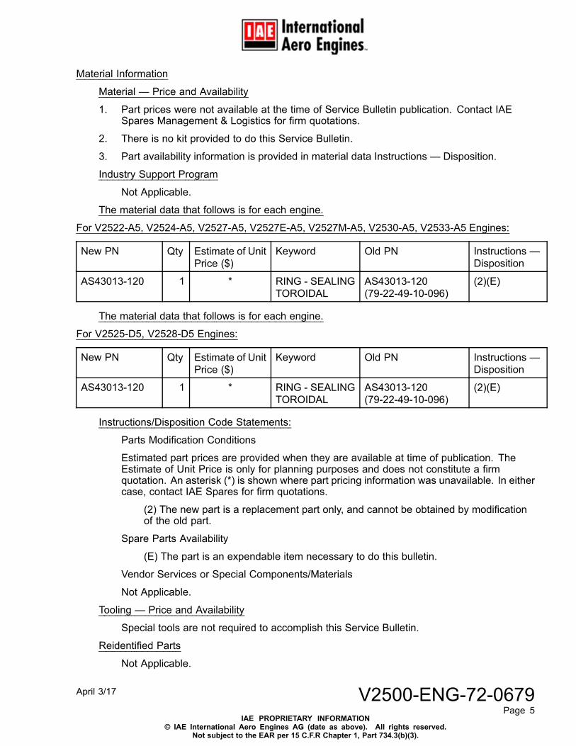
The material data that follows is for each engine.
For V2522-A5, V2524-A5, V2527-A5, V2527E-A5, V2527M-A5, V2530-A5, V2533-A5 Engines:
New PN Qty Estimate of UnitPrice ($)
Keyword Old PN Instructions —Disposition
AS43013-120 1 * RING - SEALINGTOROIDAL
AS43013-120(79-22-49-10-096)
(2)(E)
The material data that follows is for each engine.
For V2525-D5, V2528-D5 Engines:
New PN Qty Estimate of UnitPrice ($)
Keyword Old PN Instructions —Disposition
AS43013-120 1 * RING - SEALINGTOROIDAL
AS43013-120(79-22-49-10-096)
(2)(E)
Instructions/Disposition Code Statements:
Parts Modification Conditions
Estimated part prices are provided when they are available at time of publication. TheEstimate of Unit Price is only for planning purposes and does not constitute a firmquotation. An asterisk (*) is shown where part pricing information was unavailable. In eithercase, contact IAE Spares for firm quotations.
(2) The new part is a replacement part only, and cannot be obtained by modificationof the old part.
Spare Parts Availability
(E) The part is an expendable item necessary to do this bulletin.
Vendor Services or Special Components/Materials
Not Applicable.
Tooling — Price and Availability
Special tools are not required to accomplish this Service Bulletin.
Reidentified Parts
Not Applicable.
April 3/17 V2500-ENG-72-0679Page 5
IAE PROPRIETARY INFORMATION© IAE International Aero Engines AG (date as above). All rights reserved.
Not subject to the EAR per 15 C.F.R Chapter 1, Part 734.3(b)(3).
Other Material Information Data
Not Applicable.
April 3/17 V2500-ENG-72-0679Page 6
IAE PROPRIETARY INFORMATION© IAE International Aero Engines AG (date as above). All rights reserved.
Not Subject to the EAR per 15 C.F.R. Chapter 1, Part 734.3(b)(3).
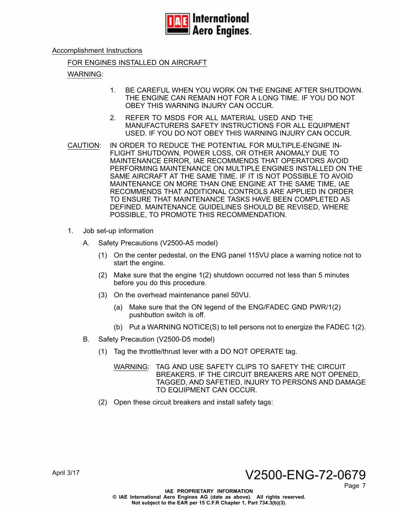
Accomplishment Instructions
FOR ENGINES INSTALLED ON AIRCRAFTWARNING:
1. BE CAREFUL WHEN YOU WORK ON THE ENGINE AFTER SHUTDOWN.THE ENGINE CAN REMAIN HOT FOR A LONG TIME. IF YOU DO NOTOBEY THIS WARNING INJURY CAN OCCUR.
2. REFER TO MSDS FOR ALL MATERIAL USED AND THEMANUFACTURERS SAFETY INSTRUCTIONS FOR ALL EQUIPMENTUSED. IF YOU DO NOT OBEY THIS WARNING INJURY CAN OCCUR.
CAUTION: IN ORDER TO REDUCE THE POTENTIAL FOR MULTIPLE-ENGINE IN-FLIGHT SHUTDOWN, POWER LOSS, OR OTHER ANOMALY DUE TOMAINTENANCE ERROR, IAE RECOMMENDS THAT OPERATORS AVOIDPERFORMING MAINTENANCE ON MULTIPLE ENGINES INSTALLED ON THESAME AIRCRAFT AT THE SAME TIME. IF IT IS NOT POSSIBLE TO AVOIDMAINTENANCE ON MORE THAN ONE ENGINE AT THE SAME TIME, IAERECOMMENDS THAT ADDITIONAL CONTROLS ARE APPLIED IN ORDERTO ENSURE THAT MAINTENANCE TASKS HAVE BEEN COMPLETED ASDEFINED. MAINTENANCE GUIDELINES SHOULD BE REVISED, WHEREPOSSIBLE, TO PROMOTE THIS RECOMMENDATION.
1. Job set-up information
A. Safety Precautions (V2500-A5 model)
(1) On the center pedestal, on the ENG panel 115VU place a warning notice not tostart the engine.
(2) Make sure that the engine 1(2) shutdown occurred not less than 5 minutesbefore you do this procedure.
(3) On the overhead maintenance panel 50VU.
(a) Make sure that the ON legend of the ENG/FADEC GND PWR/1(2)pushbutton switch is off.
(b) Put a WARNING NOTICE(S) to tell persons not to energize the FADEC 1(2).
B. Safety Precaution (V2500-D5 model)
(1) Tag the throttle/thrust lever with a DO NOT OPERATE tag.
WARNING: TAG AND USE SAFETY CLIPS TO SAFETY THE CIRCUITBREAKERS. IF THE CIRCUIT BREAKERS ARE NOT OPENED,TAGGED, AND SAFETIED, INJURY TO PERSONS AND DAMAGETO EQUIPMENT CAN OCCUR.
(2) Open these circuit breakers and install safety tags:
April 3/17 V2500-ENG-72-0679Page 7
IAE PROPRIETARY INFORMATION© IAE International Aero Engines AG (date as above). All rights reserved.
Not subject to the EAR per 15 C.F.R Chapter 1, Part 734.3(b)(3).
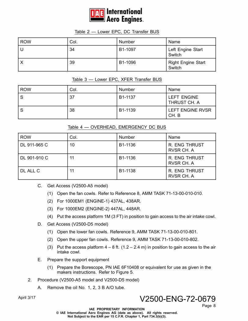
Table 2 — Lower EPC, DC Transfer BUS
ROW Col. Number Name
U 34 B1-1097 Left Engine StartSwitch
X 39 B1-1096 Right Engine StartSwitch
Table 3 — Lower EPC, XFER Transfer BUS
ROW Col. Number Name
S 37 B1-1137 LEFT ENGINETHRUST CH. A
S 38 B1-1139 LEFT ENGINE RVSRCH. B
Table 4 — OVERHEAD, EMERGENCY DC BUS
ROW Col. Number Name
DL 911-965 C 10 B1-1136 R. ENG THRUSTRVSR CH. A
DL 901-910 C 11 B1-1136 R. ENG THRUSTRVSR CH. A
DL ALL C 11 B1-1138 R. ENG THRUSTRVSR CH. A
C. Get Access (V2500-A5 model)
(1) Open the fan cowls. Refer to Reference 8, AMM TASK 71-13-00-010-010.
(2) For 1000EM1 (ENGINE-1) 437AL, 438AR.
(3) For 1000EM2 (ENGINE-2) 447AL, 448AR.
(4) Put the access platform 1M (3 FT) in position to gain access to the air intake cowl.
D. Get Access (V2500-D5 model)
(1) Open the lower fan cowls. Reference 9, AMM TASK 71-13-00-010-801.
(2) Open the upper fan cowls. Reference 9, AMM TASK 71-13-00-010-802.
(3) Put the access platform 4 – 8 ft. (1.2 – 2.4 m) in position to gain access to the airintake cowl.
E. Prepare the support equipment
(1) Prepare the Borescope, PN IAE 6F10408 or equivalent for use as given in themakers instructions. Refer to Figure 5.
2. Procedure (V2500-A5 model and V2500-D5 model)
A. Remove the oil No. 1, 2, 3 B A/O tube.
April 3/17 V2500-ENG-72-0679Page 8
IAE PROPRIETARY INFORMATION© IAE International Aero Engines AG (date as above). All rights reserved.
Not Subject to the EAR per 15 C.F.R. Chapter 1, Part 734.3(b)(3).
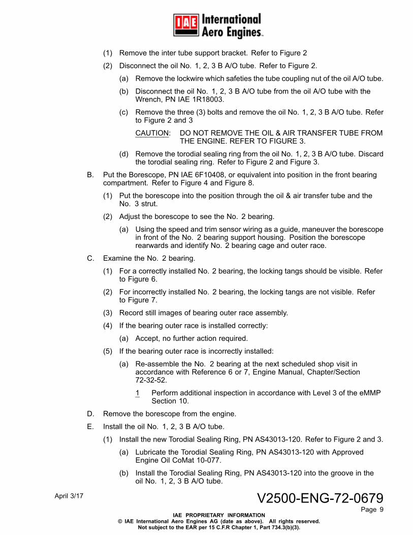
(1) Remove the inter tube support bracket. Refer to Figure 2
(2) Disconnect the oil No. 1, 2, 3 B A/O tube. Refer to Figure 2.
(a) Remove the lockwire which safeties the tube coupling nut of the oil A/O tube.
(b) Disconnect the oil No. 1, 2, 3 B A/O tube from the oil A/O tube with theWrench, PN IAE 1R18003.
(c) Remove the three (3) bolts and remove the oil No. 1, 2, 3 B A/O tube. Referto Figure 2 and 3
CAUTION: DO NOT REMOVE THE OIL & AIR TRANSFER TUBE FROMTHE ENGINE. REFER TO FIGURE 3.
(d) Remove the torodial sealing ring from the oil No. 1, 2, 3 B A/O tube. Discardthe torodial sealing ring. Refer to Figure 2 and Figure 3.
B. Put the Borescope, PN IAE 6F10408, or equivalent into position in the front bearingcompartment. Refer to Figure 4 and Figure 8.
(1) Put the borescope into the position through the oil & air transfer tube and theNo. 3 strut.
(2) Adjust the borescope to see the No. 2 bearing.
(a) Using the speed and trim sensor wiring as a guide, maneuver the borescopein front of the No. 2 bearing support housing. Position the borescoperearwards and identify No. 2 bearing cage and outer race.
C. Examine the No. 2 bearing.
(1) For a correctly installed No. 2 bearing, the locking tangs should be visible. Referto Figure 6.
(2) For incorrectly installed No. 2 bearing, the locking tangs are not visible. Referto Figure 7.
(3) Record still images of bearing outer race assembly.
(4) If the bearing outer race is installed correctly:
(a) Accept, no further action required.
(5) If the bearing outer race is incorrectly installed:
(a) Re-assemble the No. 2 bearing at the next scheduled shop visit inaccordance with Reference 6 or 7, Engine Manual, Chapter/Section72-32-52.
1 Perform additional inspection in accordance with Level 3 of the eMMPSection 10.
D. Remove the borescope from the engine.
E. Install the oil No. 1, 2, 3 B A/O tube.
(1) Install the new Torodial Sealing Ring, PN AS43013-120. Refer to Figure 2 and 3.
(a) Lubricate the Torodial Sealing Ring, PN AS43013-120 with ApprovedEngine Oil CoMat 10-077.
(b) Install the Torodial Sealing Ring, PN AS43013-120 into the groove in theoil No. 1, 2, 3 B A/O tube.
April 3/17 V2500-ENG-72-0679Page 9
IAE PROPRIETARY INFORMATION© IAE International Aero Engines AG (date as above). All rights reserved.
Not subject to the EAR per 15 C.F.R Chapter 1, Part 734.3(b)(3).
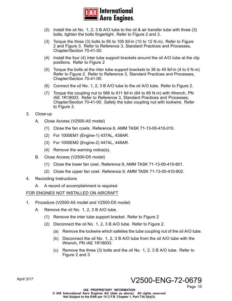
(2) Install the oil No. 1, 2, 3 B A/O tube to the oil & air transfer tube with three (3)bolts, tighten the bolts fingertight. Refer to Figure 2 and 3.
(3) Torque the three (3) bolts to 85 to 105 lbf-in (10 to 12 N.m). Refer to Figure2 and Figure 3. Refer to Reference 3, Standard Practices and Processes,Chapter/Section 70-41-00.
(4) Install the four (4) inter tube support brackets around the oil A/O tube at the clippositions. Refer to Figure 2
(5) Torque the bolts at the inter tube support brackets to 36 to 45 lbf-in (4 to 5 N.m)Refer to Figure 2. Refer to Reference 3, Standard Practices and Processes,Chapter/Section 70-41-00.
(6) Connect the oil No. 1, 2, 3 B A/O tube to the oil A/O tube. Refer to Figure 2.
(7) Torque the coupling nut to 566 to 611 lbf-in (64 to 69 N.m) with Wrench, PNIAE 1R18003. Refer to Reference 3, Standard Practices and Processes,Chapter/Section 70-41-00. Safety the tube coupling nut with lockwire. Referto Figure 2.
3. Close-up
A. Close Access (V2500-A5 model)
(1) Close the fan cowls. Reference 8, AMM TASK 71-13-00-410-010.
(2) For 1000EM1 (Engine-1) 437AL, 438AR.
(3) For 1000EM2 (Engine-2) 447AL, 448AR.
(4) Remove the warning notice(s).
B. Close Access (V2500-D5 model)
(1) Close the lower fan cowl. Reference 9, AMM TASK 71-13-00-410-801.
(2) Close the upper fan cowl. Reference 9, AMM TASK 71-13-00-410-802.
4. Recording Instructions
A. A record of accomplishment is required.
FOR ENGINES NOT INSTALLED ON AIRCRAFT
1. Procedure (V2500-A5 model and V2500-D5 model)
A. Remove the oil No. 1, 2, 3 B A/O tube.
(1) Remove the inter tube support bracket. Refer to Figure 2
(2) Disconnect the oil No. 1, 2, 3 B A/O tube. Refer to Figure 2.
(a) Remove the lockwire which safeties the tube coupling nut of the oil A/O tube.
(b) Disconnect the oil No. 1, 2, 3 B A/O tube from the oil A/O tube with theWrench, PN IAE 1R18003.
(c) Remove the three (3) bolts and the oil No. 1, 2, 3 B A/O tube. Refer toFigure 2 and 3
April 3/17 V2500-ENG-72-0679Page 10
IAE PROPRIETARY INFORMATION© IAE International Aero Engines AG (date as above). All rights reserved.
Not Subject to the EAR per 15 C.F.R. Chapter 1, Part 734.3(b)(3).
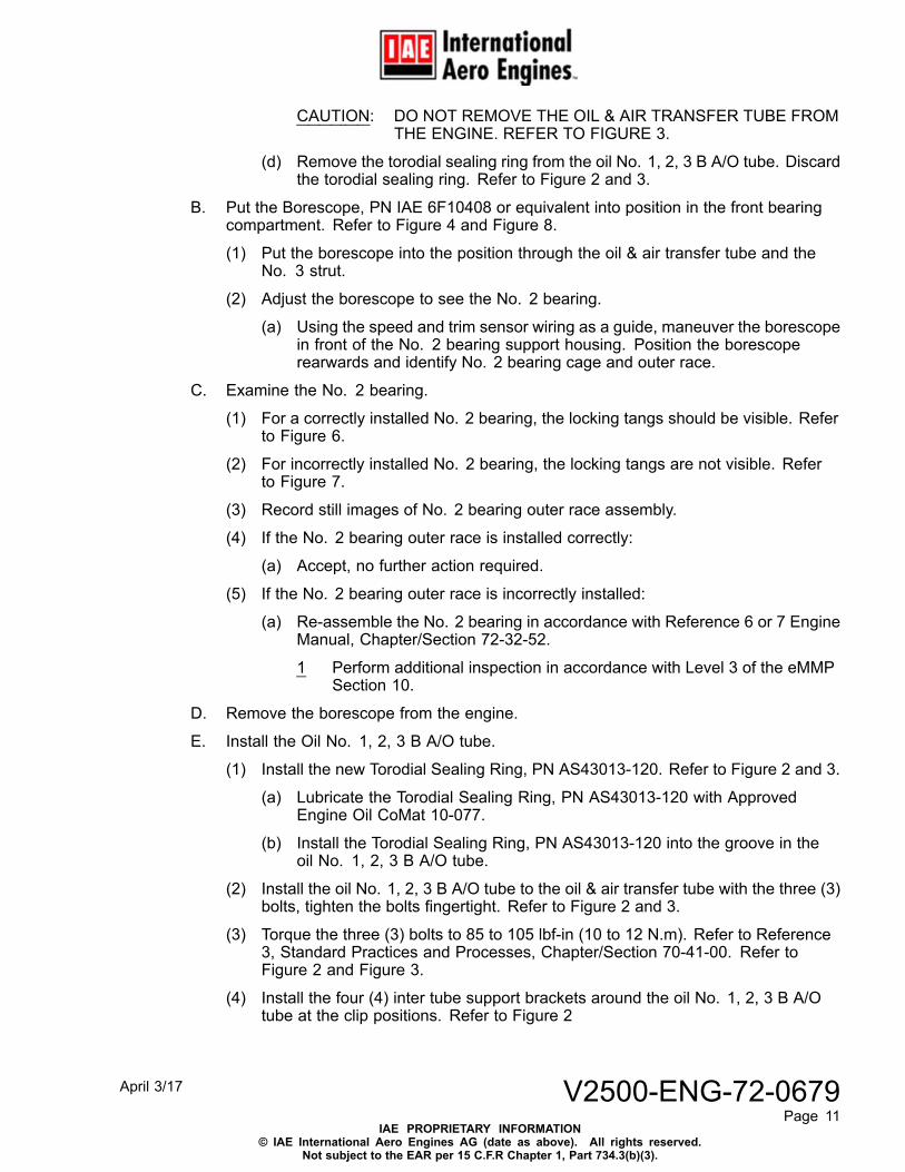
CAUTION: DO NOT REMOVE THE OIL & AIR TRANSFER TUBE FROMTHE ENGINE. REFER TO FIGURE 3.
(d) Remove the torodial sealing ring from the oil No. 1, 2, 3 B A/O tube. Discardthe torodial sealing ring. Refer to Figure 2 and 3.
B. Put the Borescope, PN IAE 6F10408 or equivalent into position in the front bearingcompartment. Refer to Figure 4 and Figure 8.
(1) Put the borescope into the position through the oil & air transfer tube and theNo. 3 strut.
(2) Adjust the borescope to see the No. 2 bearing.
(a) Using the speed and trim sensor wiring as a guide, maneuver the borescopein front of the No. 2 bearing support housing. Position the borescoperearwards and identify No. 2 bearing cage and outer race.
C. Examine the No. 2 bearing.
(1) For a correctly installed No. 2 bearing, the locking tangs should be visible. Referto Figure 6.
(2) For incorrectly installed No. 2 bearing, the locking tangs are not visible. Referto Figure 7.
(3) Record still images of No. 2 bearing outer race assembly.
(4) If the No. 2 bearing outer race is installed correctly:
(a) Accept, no further action required.
(5) If the No. 2 bearing outer race is incorrectly installed:
(a) Re-assemble the No. 2 bearing in accordance with Reference 6 or 7 EngineManual, Chapter/Section 72-32-52.
1 Perform additional inspection in accordance with Level 3 of the eMMPSection 10.
D. Remove the borescope from the engine.
E. Install the Oil No. 1, 2, 3 B A/O tube.
(1) Install the new Torodial Sealing Ring, PN AS43013-120. Refer to Figure 2 and 3.
(a) Lubricate the Torodial Sealing Ring, PN AS43013-120 with ApprovedEngine Oil CoMat 10-077.
(b) Install the Torodial Sealing Ring, PN AS43013-120 into the groove in theoil No. 1, 2, 3 B A/O tube.
(2) Install the oil No. 1, 2, 3 B A/O tube to the oil & air transfer tube with the three (3)bolts, tighten the bolts fingertight. Refer to Figure 2 and 3.
(3) Torque the three (3) bolts to 85 to 105 lbf-in (10 to 12 N.m). Refer to Reference3, Standard Practices and Processes, Chapter/Section 70-41-00. Refer toFigure 2 and Figure 3.
(4) Install the four (4) inter tube support brackets around the oil No. 1, 2, 3 B A/Otube at the clip positions. Refer to Figure 2
April 3/17 V2500-ENG-72-0679Page 11
IAE PROPRIETARY INFORMATION© IAE International Aero Engines AG (date as above). All rights reserved.
Not subject to the EAR per 15 C.F.R Chapter 1, Part 734.3(b)(3).
(5) Torque the bolts at the inter tube support brackets to 36 to 45 lbf-in (4 to 5 N.m).Refer to Reference 3, Standard Practices and Processes, Chapter/Section70-41-00. Refer to Figure 2.
(6) Connect the oil No. 1, 2, 3 B A/O tube to the oil A/O tube. Refer to Figure 2.
(7) Torque the tube coupling nut to 566 to 611 lbf-in (64 to 69 N.m) with Wrench,PN IAE 1R18003. Refer to Reference 3, Standard Practices and Processes,Chapter/Section 70-41-00. Safety the tube coupling nut with lockwire. Referto Figure 2.
2. Recording Instructions
A. A record of accomplishment is required.
April 3/17 V2500-ENG-72-0679Page 12
IAE PROPRIETARY INFORMATION© IAE International Aero Engines AG (date as above). All rights reserved.
Not Subject to the EAR per 15 C.F.R. Chapter 1, Part 734.3(b)(3).
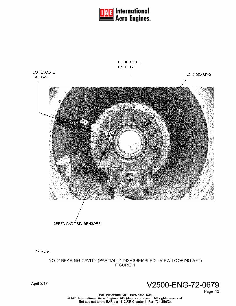
NO. 2 BEARING CAVITY (PARTIALLY DISASSEMBLED - VIEW LOOKING AFT)FIGURE 1
April 3/17 V2500-ENG-72-0679Page 13
IAE PROPRIETARY INFORMATION© IAE International Aero Engines AG (date as above). All rights reserved.
Not subject to the EAR per 15 C.F.R Chapter 1, Part 734.3(b)(3).
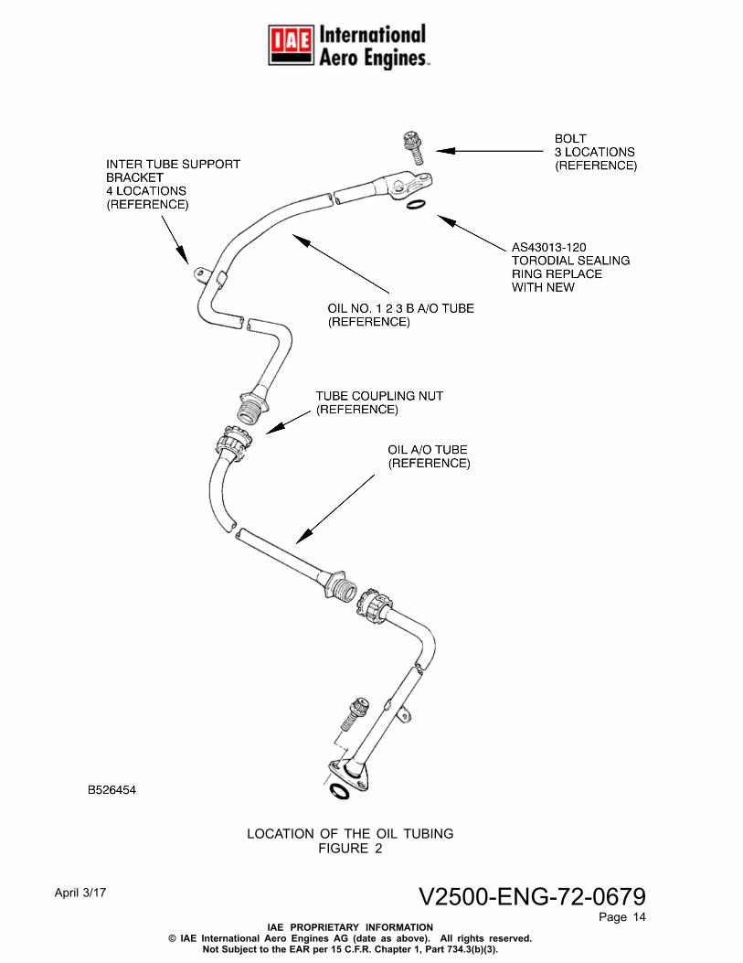
LOCATION OF THE OIL TUBINGFIGURE 2
April 3/17 V2500-ENG-72-0679Page 14
IAE PROPRIETARY INFORMATION© IAE International Aero Engines AG (date as above). All rights reserved.
Not Subject to the EAR per 15 C.F.R. Chapter 1, Part 734.3(b)(3).
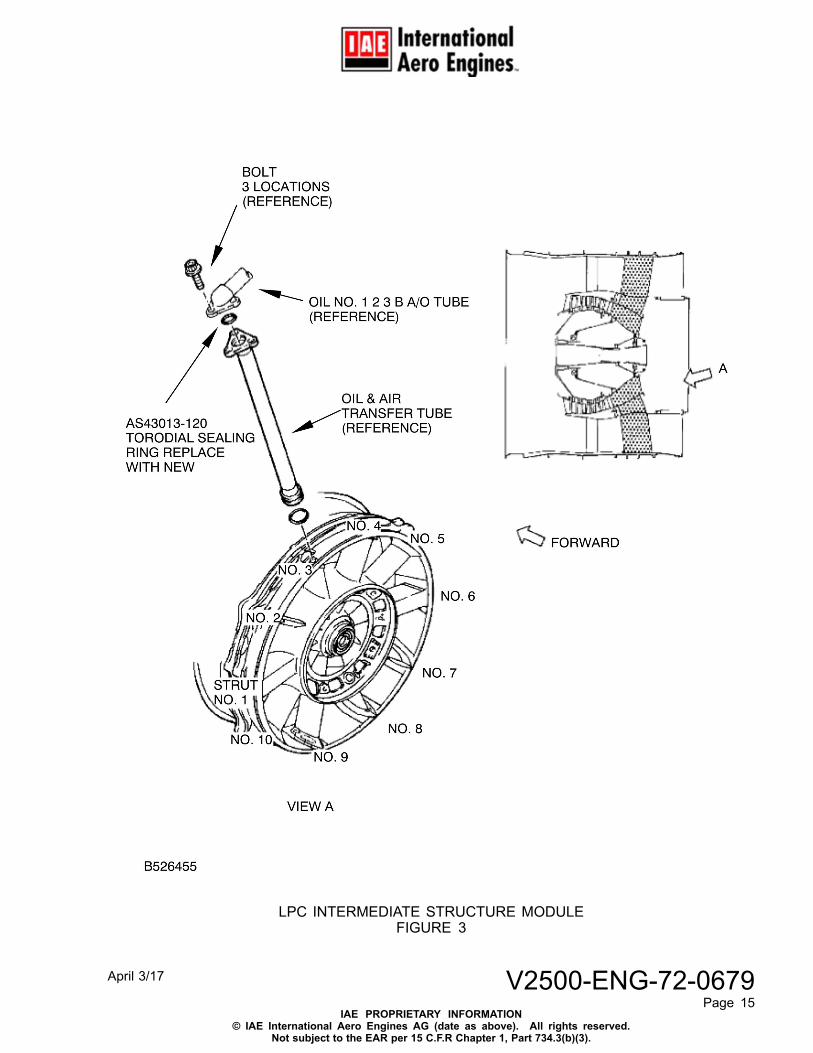
LPC INTERMEDIATE STRUCTURE MODULEFIGURE 3
April 3/17 V2500-ENG-72-0679Page 15
IAE PROPRIETARY INFORMATION© IAE International Aero Engines AG (date as above). All rights reserved.
Not subject to the EAR per 15 C.F.R Chapter 1, Part 734.3(b)(3).
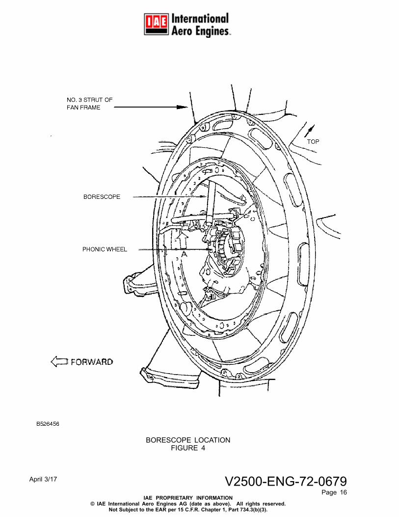
BORESCOPE LOCATIONFIGURE 4
April 3/17 V2500-ENG-72-0679Page 16
IAE PROPRIETARY INFORMATION© IAE International Aero Engines AG (date as above). All rights reserved.
Not Subject to the EAR per 15 C.F.R. Chapter 1, Part 734.3(b)(3).
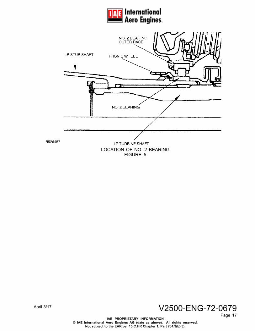
LOCATION OF NO. 2 BEARINGFIGURE 5
April 3/17 V2500-ENG-72-0679Page 17
IAE PROPRIETARY INFORMATION© IAE International Aero Engines AG (date as above). All rights reserved.
Not subject to the EAR per 15 C.F.R Chapter 1, Part 734.3(b)(3).
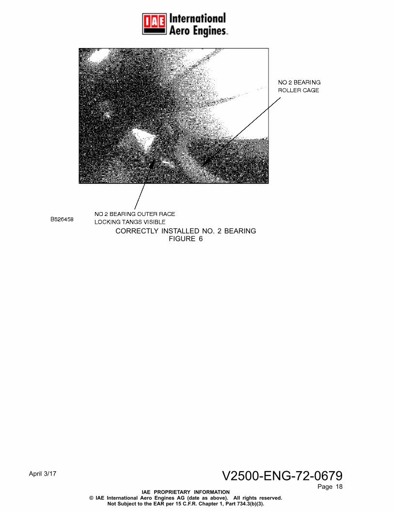
CORRECTLY INSTALLED NO. 2 BEARINGFIGURE 6
April 3/17 V2500-ENG-72-0679Page 18
IAE PROPRIETARY INFORMATION© IAE International Aero Engines AG (date as above). All rights reserved.
Not Subject to the EAR per 15 C.F.R. Chapter 1, Part 734.3(b)(3).
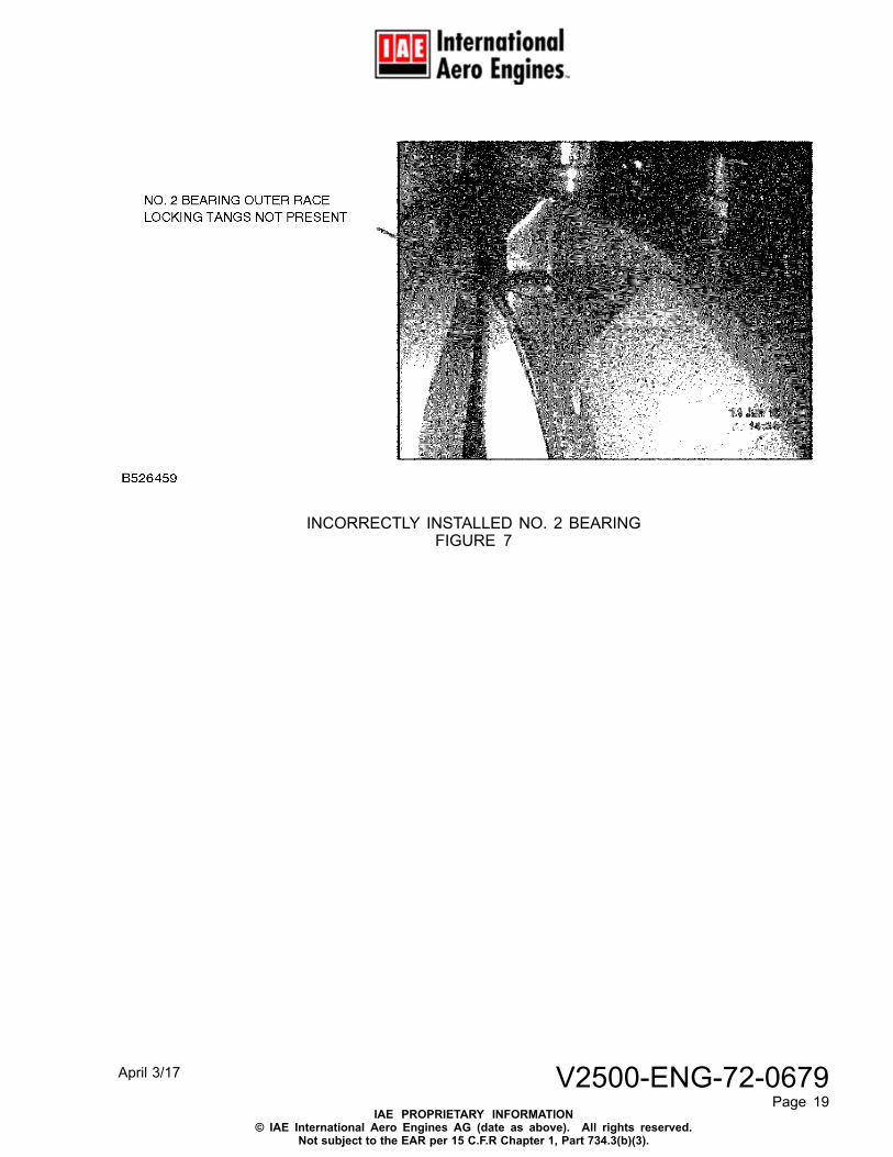
INCORRECTLY INSTALLED NO. 2 BEARINGFIGURE 7
April 3/17 V2500-ENG-72-0679Page 19
IAE PROPRIETARY INFORMATION© IAE International Aero Engines AG (date as above). All rights reserved.
Not subject to the EAR per 15 C.F.R Chapter 1, Part 734.3(b)(3).
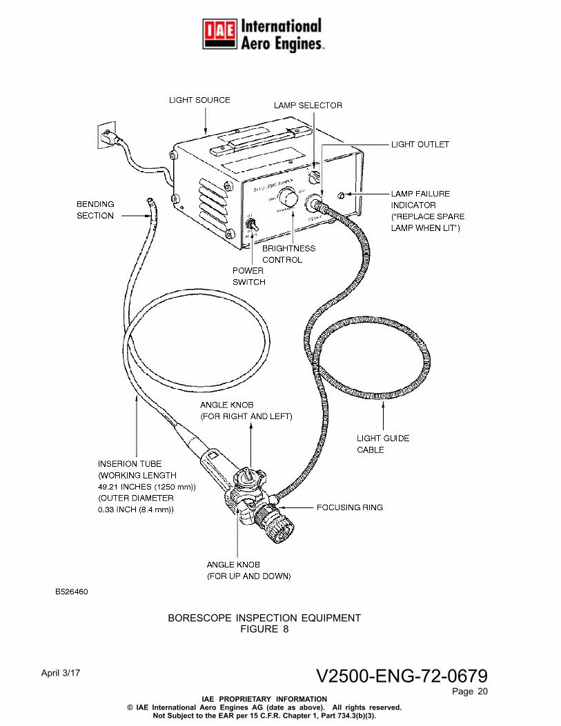
BORESCOPE INSPECTION EQUIPMENTFIGURE 8
April 3/17 V2500-ENG-72-0679Page 20
IAE PROPRIETARY INFORMATION© IAE International Aero Engines AG (date as above). All rights reserved.
Not Subject to the EAR per 15 C.F.R. Chapter 1, Part 734.3(b)(3).
Appendix
Added Data
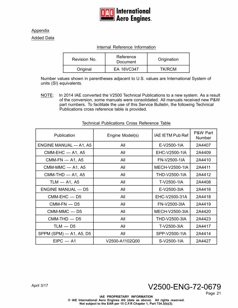
Internal Reference Information
Revision No. ReferenceDocument Origination
Original EA 16VC347 TK/RCM
Number values shown in parentheses adjacent to U.S. values are International System ofunits (SI) equivalents.
NOTE: In 2014 IAE converted the V2500 Technical Publications to a new system. As a resultof the conversion, some manuals were consolidated. All manuals received new P&Wpart numbers. To facilitate the use of this Service Bulletin, the following TechnicalPublications cross reference table is provided.
Technical Publications Cross Reference Table
Publication Engine Model(s) IAE IETM Pub Ref P&W PartNumber
ENGINE MANUAL— A1, A5 All E-V2500-1IA 2A4407
CMM-EHC — A1, A5 All EHC-V2500-1IA 2A4409
CMM-FN — A1, A5 All FN-V2500-1IA 2A4410
CMM-MMC — A1, A5 All MECH-V2500-1IA 2A4411
CMM-THD — A1, A5 All THD-V2500-1IA 2A4412
TLM — A1, A5 All T-V2500-1IA 2A4408
ENGINE MANUAL — D5 All E-V2500-3IA 2A4416
CMM-EHC — D5 All EHC-V2500-31A 2A4418
CMM-FN — D5 All FN-V2500-3IA 2A4419
CMM-MMC — D5 All MECH-V2500-3IA 2A4420
CMM-THD — D5 All THD-V2500-3IA 2A4423
TLM — D5 All T-V2500-3IA 2A4417
SPPM (SPM) — A1, A5, D5 All SPP-V2500-1IA 2A4414
EIPC — A1 V2500-A1102Q00 S-V2500-1IA 2A4427
April 3/17 V2500-ENG-72-0679Page 21
IAE PROPRIETARY INFORMATION© IAE International Aero Engines AG (date as above). All rights reserved.
Not subject to the EAR per 15 C.F.R Chapter 1, Part 734.3(b)(3).
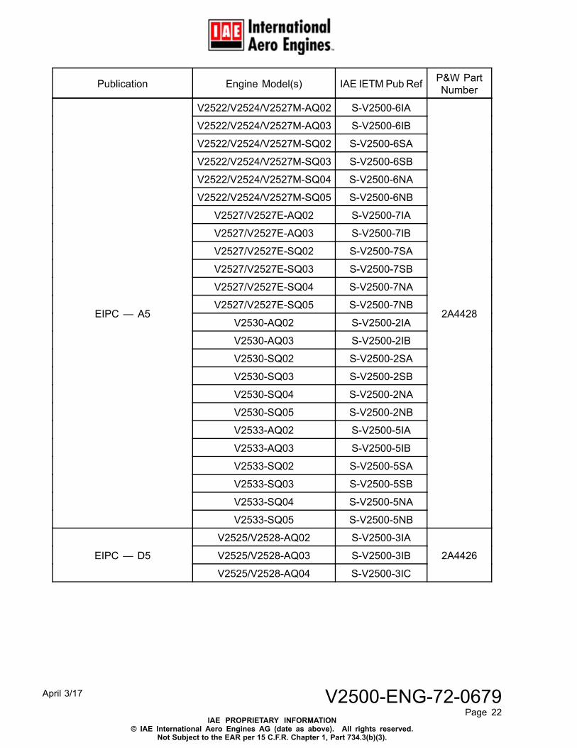
Publication Engine Model(s) IAE IETM Pub Ref P&W PartNumber
V2522/V2524/V2527M-AQ02 S-V2500-6IA
V2522/V2524/V2527M-AQ03 S-V2500-6IB
V2522/V2524/V2527M-SQ02 S-V2500-6SA
V2522/V2524/V2527M-SQ03 S-V2500-6SB
V2522/V2524/V2527M-SQ04 S-V2500-6NA
V2522/V2524/V2527M-SQ05 S-V2500-6NB
V2527/V2527E-AQ02 S-V2500-7IA
V2527/V2527E-AQ03 S-V2500-7IB
V2527/V2527E-SQ02 S-V2500-7SA
V2527/V2527E-SQ03 S-V2500-7SB
V2527/V2527E-SQ04 S-V2500-7NA
V2527/V2527E-SQ05 S-V2500-7NB
V2530-AQ02 S-V2500-2IA
V2530-AQ03 S-V2500-2IB
V2530-SQ02 S-V2500-2SA
V2530-SQ03 S-V2500-2SB
V2530-SQ04 S-V2500-2NA
V2530-SQ05 S-V2500-2NB
V2533-AQ02 S-V2500-5IA
V2533-AQ03 S-V2500-5IB
V2533-SQ02 S-V2500-5SA
V2533-SQ03 S-V2500-5SB
V2533-SQ04 S-V2500-5NA
EIPC — A5
V2533-SQ05 S-V2500-5NB
2A4428
V2525/V2528-AQ02 S-V2500-3IA
V2525/V2528-AQ03 S-V2500-3IBEIPC — D5
V2525/V2528-AQ04 S-V2500-3IC
2A4426
April 3/17 V2500-ENG-72-0679Page 22
IAE PROPRIETARY INFORMATION© IAE International Aero Engines AG (date as above). All rights reserved.
Not Subject to the EAR per 15 C.F.R. Chapter 1, Part 734.3(b)(3).
Related Documents