V200 POSITIONER www.vac.se 1 Datasheet

Welcome message from author
This document is posted to help you gain knowledge. Please leave a comment to let me know what you think about it! Share it to your friends and learn new things together.
Transcript

V200 POSITIONERwww.vac.se
1
Datasheet

V200 POSITIONERwww.vac.se
1 INTRODUCTION .................................................................................. 31.1 Principle of Operation .............................................................. 31.2 ProductIdentification ............................................................... 31.3 Air quality recommendations ................................................... 41.4 Safety Instructions ................................................................... 4
2 INSTALLATION .................................................................................... 5 2.1 Connections ............................................................................ 5
2.2 General mounting instructions ................................................ 62.2.1 Rotary actuators ...................................................................... 62.2.2 Linear actuators ...................................................................... 62.3 Installation instructions for rotary actuators ............................. 72.3.1 Double acting .......................................................................... 72.3.2 Single acting ............................................................................ 72.4 Installation instructions for linear actuators ............................. 82.4.1 Double acting .......................................................................... 82.4.2 Single acting ............................................................................ 8
2.5 Cam ......................................................................................... 9 2.5.1 Adjustments ............................................................................ 92.5.2 Camspecifications .................................................................. 9
3 SPECIFICATIONS............................................................................... 103.1 SpecificationsV200 ................................................................. 10
4 DIMENSION ........................................................................................ 124.1 V200P/Estd ........................................................................... 12
CONTENTS
92214r02
3.2 Ordering Codes....................................................................... 11

www.vac.se
V200 POSITIONER
1.1 Principle of Operation
TheV200incorporatestheforcebalanceprincipal of operation. The desired value, in theformofpressure,affectsthemembrane(1)with the force that is created and transferred to the balance arm(2). The opposing force, which represents the actual control value, is provided by the feedback spring(5) and creating force in the opposite direction on the balance arm(2).The feedback spring, resting on the feedback arm(3), is positioned by the shape and re-sponse of the cam. The cam(4) is connected to the cylinder’s (actuator) piston rod via the drive. The pilot valve(6) is connected to the balance
arm and follows the balance arm’s movement. The system is stable when the gold plated spool(7) is in the neutral position and the forces thataffectthebalancearmisinequilibrium.As soon as a signal change occurs or a change inthepositionofthevalve/actuatorpackageoccurs, the “force balance” is also changed and the spool responds. Air immediately begins toflowintothepartoftheactuator(C+orC-)which allows the feedback mechanism to return the spool to the neutral position.The system is self-stabilizing and searches for a steady state position.
1.2 Product identification
TheV200identificationtags,Serialnumbertag(1), product model tag(2) and feedback op-tion tags(3), are placed as shown. The product model tag contains information on control signal, maximum working pressure and temperature ranges. Other information can be shown depending on the model.
1 INTRODUCTION
4
5
21
6
7 3
92214r0 3

V200 POSITIONERwww.vac.se
CAUTION: Beware of moving parts when positioner is operated!
CAUTION: Beware of parts with live voltage!A voltage, which is normally not dangerous, is supplied to the
positioner.Avoid touching live parts and bare wires as well as short circuiting live parts and the housing.
CAUTION: Do not dismantle a pressurized positioner!Dismantling a pressurized positioner will result in uncontrolled pressure release. Always isolate the relevant part of the pipeline. Release the pres-
sure from the positioner and the pip- ing. Failure to do this may result in
damage or personal injury.
CAUTION: Do not exceed the positioner performance limitations!Exceeding the limitations marked on the positioner may cause damage tothe positioner, actuator and valve.Damage or personal injury may result.
1.3 Air quality recommendations
Poor air quality is one of the main causes of premature functional problems with pneumatic and electro pneumatic equipment. The pilot valve and IP-converter are precision instru-ments, and are therefore the most sensitive parts of the positioner.
a) Water in the supply air is a natural occur-rence. This happens when air is compressed.The compression heats the air and the naturaldegree of water in the air can remain as mois-ture. When the air cools in pipes etc.the moisture condenses and becomes liquidwater. Large quantities can build and some-timesfloodsmallwaterseparators.Thisex-cess water will eventually reach the controlvalve and positioner. This can cause corrosiondamage to the IP converter, causing theunit to malfunction.
We strongly recommend the use of water separators with adequate capacity. Coales-ingfiltersfromareputablemanufacturerisaninexpensive way to help prevent unit malfunc-tions or failures, and add life to the product. Thesefiltersremoveparticlesandmoisturefrom air lines.
b) Oil in the supply air usually is from the maincompressor. Oil can clog the small nozzlesanddisturbtheflapperintheIP-converter.Itcan also cause the gold plated spool to “drag”within the pilot valve. The result is poor controlor in the worst case, failure.
c) Particles in the air usually occur becauseof corrosion. Dirt and particles can block thesmall nozzles of the IP-converter.They can also cause the pilot valve to mal-function. The unit may completely fail.
ToensurenormaloperationalsafetywithVACpositioner products, we recommend that a wa-terseparatoranda<80micrometerfilteraremounted as close to the product as possible.If large amounts of oil are present an oil sepa-rator should be installed as well.
To further increase operational safety, we rec-ommend that the working air is clean, dry and free of moisture, water, oil, particles and other contaminants, in accordance with the standard ANSI/ISA–7.0.01–1996
1.4 Safety Instructions
92214r04

www.vac.se
V200 POSITIONER
Connection Back III.eps
2. INSTALLATION
2.1 Connections
S–SupplyairV200P:max.10bar/1MPa/145psiV200E:1,5-10bar/0,15-1MPA/23-145psi
I–Input,pressuresignalV200P:0,21bar/20-100kPa/3-15psiV200E:Plugged
IE–Input,currentsignalV200E:4-20mA(Rimax250ohm)V200P:Plugged
C+ -Actuatorconnection+strokeC- - Actuator connection - stroke
OUT - All air from the actuator, IP and positioner is vented through this port.Standardequippedwithabugscreen/silencer
Airconnectionsformale1/4”NPTorG1/4”.
Gaugeconnectionsformale1/8”NPTorG1/8”.
Cableentryformale1/2”NPTorM20cablefittings.
G threads are indicated by an engraved Gon the air connection side of the positioner.
GaugeportsI,C+,C-andSarefactoryplugged.Remove plugs and replace with gauges.
The IP connection must be plugged in V200E.The IE entrys should be plugged in V200P
92214r0 5
V200 POSITIONERwww.vac.se
Hole pattern II.eps
depth
depth
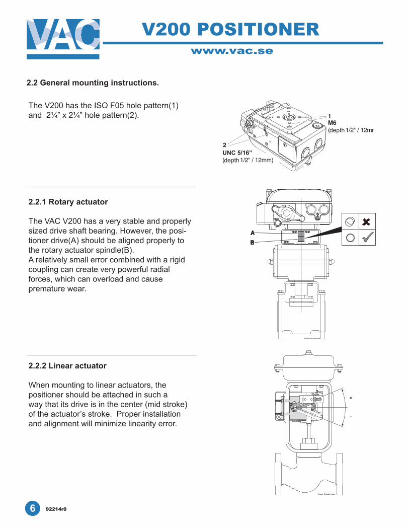
TheV200hastheISOF05holepattern(1)and 2¼” x 2¼” hole pattern(2).
2.2.1 Rotary actuator
TheVACV200hasaverystableandproperlysized drive shaft bearing. However, the posi-tioner drive(A) should be aligned properly to the rotary actuator spindle(B). A relatively small error combined with a rigid coupling can create very powerful radialforces, which can overload and cause premature wear.
2.2.2 Linear actuator
When mounting to linear actuators, thepositioner should be attached in such away that its drive is in the center (mid stroke)of the actuator’s stroke. Proper installation and alignment will minimize linearity error.
2.2 General mounting instructions.
92214r06

www.vac.se
V200 POSITIONER
RSPL
IT
RANGE90° D
0% 90°LIN100%
100%180°LIN
50%
0%
RSPL
IT
RANGE90° D
0% 90°LIN100%
100%180°LIN
50%
0%
RSPL
IT
RANGE90° D
0% 90°LIN100%
100%180°LIN
50%
0%
SPLITRANGE90°
D
R
0%50%
180°LIN100
%100%
90°LIN
0%
B
SPLITRANGE90°
D
R
0%50%
180°LIN100
%100%
90°LIN
0%
B
SPLITRANGE90°
D
R
0%50%
180°LIN100
%100%
90°LIN
0%
B
2.3 Installation instructions for rotary actuators
2.3.2 Single acting
2.3.1 Double acting
Signal closes
Signal opens
Direct (CCW)
Reverse (CW)
Spring closes Direct (CCW) Spring opens Reverse (CW)
Signal closes Signal opens
Spring opens Direct (CCW) Spring closes Reverse (CW)
Signal opens Signal closes
92214r0 7

V200 POSITIONERwww.vac.se
2.4 Installation instructions for linear actuators2.4.1 Double acting
2.4.2 Single acting
Direct (CCW)
Signal closes Signal opens
Reverse (CW)
Spring opens Spring closes
Direct (CCW)
Spring opens Spring closes
Reverse (CW)
Signal opens Signal closes
Signal closes Signal opens
Signal opens Signal closes92214r08

www.vac.se
V200 POSITIONER
RSPL
IT
RANGE90° D
0% 90°LIN100%
100%180°LIN
50%
0%0% 9
SPLITRANGE
90°D
R
0%
50%180°LIN100%
100%
90°L
IN0%
B
RSP
LITRANGE90°
D
0%90°LIN
100%
100%180°LIN
50%
0%
2.5 Cam
The V200 is standard shipped with the C1-cam, factory set for 90° ±1°, direct (CCW) turning.
2.5.1 Adjustments
Remove the front cover and indicator.(see page 15)
1. Loosen the locking screw(2) and the camnut(1).
2. Strokethevalve/actuatortothestop/endposition at 0% input.
3. Turn the cam(3) so that the index mark(5)for the selected curve aligns with the ballbearing(4). A small gap between the roller andthe cam tip is desirable.
4. Tighten the cam nut by hand(1).Check that the locking screw(2) is still loose.(if not, loosen the locking screw slightly andtighten the nut again).
5. Tighten the locking screw(2).Do not tighten cam nut with screw(2) down.
2.5.2 Cam specifications C1Indexmark/Startingpointofrotation*5. 90° Linear 0-100% CCW6. 180° Linear 0-100% CW6. 90° Linear 0-50% CW split range7. 90° Linear 50-100% CW split range8. 90° Linear 0-100% CW9. 180° Linear 0-100% CCW10. 90° Linear 0-50% CCW split range11. 90° Linear 50-100% CCW split range
*Increasingsignalrotation.MostvalvesrotateCWtoclose/CCWtoopen
When field reversing action of positioner tubing must be reversed as well (see page 7 and 8)
92214r0 9
www.vac.se
V200 POSITIONER
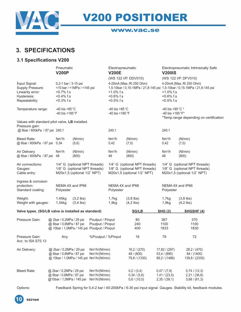
3. SPECIFICATIONS3.1 Specifications V200
10 92214r0
Electropneumatic V200E(WS122I/P.DDV010)
Electropneumatic Intrinsically SafeV200IS(WS122I/P.DFV010)
4-20mA(Max.:Ri250Ohm) 4-20mA(Max.:Ri250Ohm)1,5-10bar/0,15-1MPa/21,8-145psi 1,5-10bar/0,15-1MPa/21,8-145psi<1.0%f.s <1.0%f.s
<0.6%f.s
PneumaticV200P
0,2-1bar/3-15psi<10bar/<1MPa/<145psi<0.7%f.s <0.4%f.s <0.3%f.s
<0.6%f.s<0.5%f.s <0.5%f.s
InputSignal:SupplyPressure:Linearityerror:Hysteresis:Repeatability:
Temperaturerange: -40bis+85°C-40bis+185°F
-40bis+85°C-40bis+185°F
-40bis+85°C*-40bis+185°F**Temp.rangedependingoncertification
Valueswithstandardpilotvalve,LB installed.Pressuregain:@6bar/600kPa/87psi240:1 240:1 240:1
BleedRate: Nm3/h (Nl/min) Nm3/h (Nl/min) Nm3/h (Nl/min)@6bar/600kPa/87psi 0,34 (5,6) 0,42 (7,0) 0,42 (7,0)
Air Delivery Nm3/h (Nl/min) Nm3/h (Nl/min) Nm3/h (Nl/min)@6bar/600kPa/87psi 48 (800) 48 (800) 48 (800)
1/4”G(optionalNPTthreads) 1/4”G(optionalNPTthreads) 1/4”G(optionalNPTthreads)1/8”G(optionalNPTthreads) 1/8”G(optionalNPTthreads) 1/8”G(optionalNPTthreads)M20x1,5(optional1/2¨NPT)
NEMA4XandIP66Polyester
M20x1,5(optional1/2¨NPT)
NEMA4XandIP66Polyester
M20x1,5(optional1/2¨NPT)
NEMA4XandIP66Polyester
1,7kg (3,8lbs) 1,7kg (3,8lbs)
Airconnections:Gauges:Cableentry:
Ingress & corrosionprotection:Standardcoating:
Weight:Weightwithgauges:
1,45kg (3,2lbs)1,54kg (3,4lbs) 1,9kg (4,2lbs) 1,9kg (4,2lbs)
Valve types. (SG/LB valve is installed as standard) SG/LB SHG (3) SHGSHF (4)
@2bar/0,2MPa/29psi Poutput/Pinput 80 367 370@ 6bar/0,6MPa/87psi Poutput/Pinput 240 1100 1100@ 10bar/1,0MPa/145psi Poutput/Pinput 400 1833 1830
Any %Poutput/%Pinput 16 79 72
@2bar/0,2MPa/29psi Nm3/h/(Nl/min) 16,2/(270) 17,82/(297) 28,2/(470)@6bar/0,6MPa/87psi Nm3/h/(Nl/min) 48/(800) 53,4/(890) 84/(1400)@10bar/1,0MPa/145psi Nm3/h/(Nl/min) 79,8/(1330) 89,2/(1486) 139,8/(2330)
@2bar/0,2MPa/29psi Nm3/h/(Nl/min) 0,2/(3,4) 0,47/(7,9) 0,74/(12,3)@6bar/0,6MPa/87psi Nm3/h/(Nl/min) 0,34/(5,6) 1,41/(23,5) 2,21/(36,8)
@10bar/1,0MPa/145psi Nm3/h/(Nl/min) 0,6/(10,0) 2,35/(39,1) 3,68/(61,3)
PressureGain:
PressureGain:Acc. to ISA S75.13
AirDelivery:
BleedRate:
Options: FeedbackSpringfor0,4-2bar/40-200kPa/6-30psiinputsignal.Gauges.Stabilitykit,feedbackmodules.

V200 POSITIONERwww.vac.se
92214r0 11
V200P V200E V200EX V200ISV200FF
3.2 Ordering Codes
PneumaticElectropneumaticExplosionProofIntrinsicallySafeFailFreeze
Spindle D1 Namur (standard)Foradditionalspindleoptions,pleasecontactVACorvisitourwebsiteatwww.vac.se
Front Cover 90 degree rotation 90 60 degree rotation 60 45 degree rotation 45 30 degree rotation 30 Blank scale 00
Indicator Arrow A StandardBeacon/Raised(Black/Yellow) BOptionalBeacon/Raised(Red/Green) BRG
Cam (standard) 90° C1 (standard)Foradditionalcamoptions,pleasecontactVACorvisitourwebsiteatwww.vac.se
Spool Valve Options (shipped with standard spool)Standard (Low Bleed) SG/LB—Shipped as Standard Super High Gain SHG (3)Super High Gain Super High Flow SHGSHF (4)
OptionsExtra High Temp (Pneumatic only)(-40to+163°C/-40to+325°F) EHTLow Temp (Pneumatic only)(-50to+85°C/-58to+185°F) LT0/10VoltI/P(V200Eonly) 0/10VGas Approved GAATEX ATEXTufram®Coating(V200PandE) TUFNickelCoating(V200PandE) NIC40-200kPa/6-30psiSpring 6-30
Feedback Options FB2 SPDT Mechanical Switches M2 SPDT Reed Switches R2 SPDT Inductive Switches N4-20 mA Transmitter mAMechSwitchesw/transmitter MmAReedSwitchesw/transmitter RmA1 K potentiometer 1K10 K potentiometer 10K
Example:V200E-D1-90-B-C1Electropneumatic with namur spindle, 90 degree cover, raised indicator, 90 degree camExample:FB-MmA Mechanicalswitcheswith4/20mAtransmitter.

V200 POSITIONERwww.vac.se
13/3
2"10Hex s
ize
6 13/16"173,4
4 3/4"121
1 25/32"45
1 25/32"45
1 5/8"41
3/16"5
2 13/32"61
2 11
/16"
68
8 3/
16"
208
Gau
ges
1/8"
NPT
(4x)
(opt
iona
l)
1/2"
12,5
25/32"20
31/32"25
1 7/
8"47
,5C
ondu
it En
try1/
2" N
PT (2
x)1
19/3
2"40
,5
7/8"
22,5
1 9/
16"
39,5
2 1/16"52,5
1 3/16"30
3/16"5
1 3/8"35
Air c
onne
ctio
ns1/
4" N
PT (5
x)
5/8"15,5
2 15/32"62,53 27/32"
97,5
1/16
"1,
51 7/8"47,5
2 1/
4"57
31/3
2"25 2
7/32
"56 2
31/3
2"75
5 1/
4"13
3
5"127
Dom
e In
dica
tor(o
ptio
nal)
Con
duit
Entry
1/2"
NPT
(2x)
1 13
/32"
35,4
ISO
F05
Sqr
2 31
/32"
75,6
Sqr
2 15
/16"
754
1/4"
108
1 31/32"50
2 11/32"59,7
2 1/
4"57
,2
Wes
tlock
Sqr.
Wes
tlock
(4x)
UN
C 5
/16"
- 1/
2"[1
2mm
ISO
F05
(4x)
M6
- 1/2
"[12m
m]
Dim
ensi
onal
Dra
win
gVA
C P
ositi
oner
V20
0 P
and
E
4. DIMENSIONS4.1 V200P/E std
12 92214r0

www.vac.se
V200 POSITIONER
Designed and manufactured in Sweden by:
Related Documents