Two 12V 18 AH (AGM Rechargable Batteries) UL Reset Button Jog Switch OPTIONAL 30A FUSE Loop Rack OPTIONAL Steel housing Two layers protection Gold zinc Electrostatic Powder-Coating Gold plated automobile connectors through-out the system SOLAR MODE Switch to enable low power draw for solar mode Control Panel Solar Regulator 24V, 10A (Morning Star) 24V Solar Panel Output: 36V (max) - Open Circuit Wire solar panel terminals to solar regulator input Caution: polarity matters Solar Panel P S N www.max.us.com QUICK INSTALLATION GUIDE MAX SOLAR CONTROL BOX 1 2 3 4 Insert the included fuse into the empty fuse slot (no polarity) Turned ON the switch located directly underneath the fuses Leave the solar mode switch off and follow the included installation manual for standard installation and setup of limit switches DO NOT TURN ON THE SOLAR MODE SWITCH UNTIL INSTALLATION IS FINISHED V(+) GND

Welcome message from author
This document is posted to help you gain knowledge. Please leave a comment to let me know what you think about it! Share it to your friends and learn new things together.
Transcript
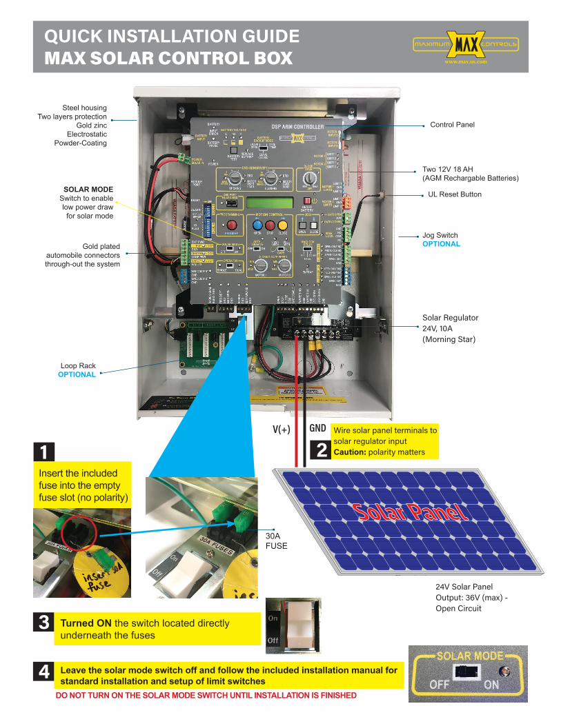
Two 12V 18 AH (AGM Rechargable Batteries)
UL Reset Button
Jog SwitchOPTIONAL
30AFUSE
Loop RackOPTIONAL
Steel housingTwo layers protection
Gold zinc Electrostatic
Powder-Coating
Gold plated automobile connectorsthrough-out the system
SOLAR MODESwitch to enable low power draw for solar mode
Control Panel
Solar Regulator24V, 10A(Morning Star)
24V Solar PanelOutput: 36V (max) - Open Circuit
Wire solar panel terminals to solar regulator inputCaution: polarity matters
EXIT PWR
ALARM
POWER /SOLAR IN
BATTERYINPUT
OPENING CLOSING
MOTOR 2MOTOR 1
ERD
OBD PORTBLACK BOX
PROGRAMMING
SOLAR MODE
MOTOROVERLOAD
ERD
MOTOROVERLOAD MIN MAX
OFF
MAXSENSE
MAXSENSE
BATTERYBACKUP MODE
ERD SENSITIVITY
MOTION CONTROL
OPEN
CLOSING GATE SPEED
MOTOR 2LIMITS
MAGLOCK
ULENTRAP
STOP CLOSE
CLOSETIMER
MAGLOCKDELAY
JOG
BATTERYTEST
BATTERY
INPUTERROR
BATTERYIN USE
POWER
REPLACEBATTERY
LEAVECLOSED
LEAVEOPEN
OPEN1 TIME
BATTERY VOLTAGEF1/2E
RESET
IDPLUG
MODULEPORT
GATE OPEN
GND
OPEN ONLY NC
OPEN ONLY 10K
PHOTO CLS NCOPEN / CLS NC
GND12VDC OUT
GND
GND
GND
GND
GND
JOG
CLOS
EJO
G OP
EN
TAMP
ER IN
TAMP
ER N
O
GATE
DISA
BLE
KEYP
AD/C
ARD
GND
GND
MAX
OPEN
FIRE
DEP
T
RADI
O GN
DRA
DIO
SIGN
AL
STRI
KE
CLOS
ECO
M
COM
STOP
OPEN
CLS ONLY 10KOPEN / CLS 10K
12VDC OUT
NOCOM
NC
COMGATE CLOSED
LIMIT 1GND
LIMIT 2
MOTOR 1LIMITS
MOTOR 1
MOTOR 2
LIMIT 1GND
LIMIT 2
LIMIT 1LIMIT 2LIMIT 1LIMIT 2
ID PLUGERROR
24VDC OUTPUT
12VDC OUTPUT
GND
GND
GND
LOOPLOOP PWR
LOOP
CENTER
SAFETY
OFF
SINGLE
OPEN
ON/OFFBATTERY
CLOSE
DUAL
ON
ANTI-TAILGATE
PUSHOPEN
PULLOPEN
GATEOFF
123456789
10OFF
123456
MIN MIN
MAX MAX
ON
OFF 2.5 sec1.5 sec
FAULTSOPERATOR
OFF
EXIT LOOP
16MIN
16MIN
3
1
14 12
9
7 3
1
14 12
9
7
UL S
ENSO
R 10
KUL
SEN
SOR
N.C.
MODE
AMO
DE B
PROGRAM
MOTOR 1INPUTS
[+][-]
[+][-]
MOTOR 2INPUTS
MAXIMUM CONTROLSDSP ARM CONTROLLER
Maximum Controls LLC. • 949.699.0220 • 10530 Lawson River Ave, Fountain Valley, CA 92708
MAX ACTUATOR CONTROL BOX Solar Application Guide/Wiring www.max.us.com
Rev April25
LOADBATTERYSOLAR+ - + - + -
Solar Regulator Terminal
Enclosure
NOTE: Cover solar panel from sunlight BEFORE wiring
to prevent a shock from occurring.
NOTE: For more information about solar panel wiring, see your chosen panel’s manual.
Use insulated tools and avoid placing metal objects near the batteries.
Suggested Solar Regulators:Morning Star SunSaver OR Morning Star SunSaver MPPT
Pos + RedNeg - Black
Polarity Matters!
12 Volt
Batteries wired in series
12 Volt
Batteries should be in a
well ventilated enclosure
or overheating will occur
and reduce battery life.
DANGERHAZARDOUS CURRENT
NEVER touch
positive and
negative battery
cables together!
Solar Panel
Connect solar panelto regulator
3
Connect batteries to regulator4Connect solar regulator toPower/ Solar IN DSP ARMCONTROLER
5
Install components in water resistant well ventilated enclosure.Properly Ground Enclosure.
Two 12 V Batteries (24V)Use AGM battery type.
POWER/SOLAR IN
9
7
Pos + RedNeg - Black
www.max.us.com
QUICK INSTALLATION GUIDEMAX SOLAR CONTROL BOX
1 2
3
4
Insert the included fuse into the empty fuse slot (no polarity)
Turned ON the switch located directly underneath the fuses
Leave the solar mode switch off and follow the included installation manual for standard installation and setup of limit switches
DO NOT TURN ON THE SOLAR MODE SWITCH UNTIL INSTALLATION IS FINISHED
V(+) GND

www.max.us.com
MAX ACTUATOR CONTROL BOXSolar Application Guide/Wiring
Turn SOLAR MODE ON
Radio Signal
Radio SignalRadio Gnd
4-WireRadio
3-WireRadio
NormalOpeningDevice
Recommended: Plug-In Loop Detectors
In-Ground Loop Connections
Loop Detector Rack
SAFETYCENTEREXIT
SAFETYCENTEREXIT
SAFETYCENTER
EXIT
In-Ground LoopsSafetyLoop
CenterLoopExitLoop
ON
12
34
56
78
5 = Optimum Sens.
= Increase Sens.
= Decrease Sens.
DEFLECTOMETER
POWERON = Normal Power
OFF= No Power
LED INDICATORSDETECTON = DetectOFF= No Detect
2 Hz Flash=Delay Timing
SW1 SW2 Frequency
ON ON = Low
ON OFF = Medium-Low
OFF ON = Medium-High
OFF OFF = HighSW4 SW5 Output B
ON ON = Pulse on Entry
ON OFF = B same as A
OFF ON = Pulse on Exit
OFF OFF = Loop Fault
SW3ON = Fail Secure
OFF = Fail Safe
SW6ON = 2 Second Delay
OFF = No Delay
SW7ON = Normal Presence
OFF = Infinite Presence
SW8ON = Sensitivity Boost
OFF = No Sensitivity Boost
Loop Fault1 Flash = Open Loop
2 Flashes= Shorted Loop
3 Flashes=25% change
of Inductance
Both LED’s Flashing=
Current Loop Fault
PWR LED Flashing=
Previous Loop Fault
EDITel: 480.968.6407
DEFLECTOMETER
SENS
RESET
POWER
DETECTEDI
SENSLMA1800-LP
OPTIONS
12
34
56
78
ON
ON
12
34
56
78
5 = Optimum Sens.
= Increase Sens.
= Decrease Sens.
DEFLECTOMETER
POWERON = Normal Power
OFF= No Power
LED INDICATORSDETECTON = DetectOFF= No Detect
2 Hz Flash=Delay Timing
SW1 SW2 Frequency
ON ON = Low
ON OFF = Medium-Low
OFF ON = Medium-High
OFF OFF = HighSW4 SW5 Output B
ON ON = Pulse on Entry
ON OFF = B same as A
OFF ON = Pulse on Exit
OFF OFF = Loop Fault
SW3ON = Fail Secure
OFF = Fail Safe
SW6ON = 2 Second Delay
OFF = No Delay
SW7ON = Normal Presence
OFF = Infinite Presence
SW8ON = Sensitivity Boost
OFF = No Sensitivity Boost
Loop Fault1 Flash = Open Loop
2 Flashes= Shorted Loop
3 Flashes=25% change
of Inductance
Both LED’s Flashing=
Current Loop Fault
PWR LED Flashing=
Previous Loop Fault
EDITel: 480.968.6407
DEFLECTOMETER
SENS
RESET
POWER
DETECTEDI
SENSLMA1800-LP
OPTIONS
12
34
56
78
ON
EDI LMA1800-LP
NOTE: While in low power mode, EXIT LOOP detector remains ON, CENTER & SAFETY LOOP detectors are turned OFF
Power radio receiver using 12V DC OUTPUTIn low power mode, 12V DC OUTPUT is left ON
EXIT PWR
ALARM
POWER /SOLAR IN
BATTERYINPUT
OPENING CLOSING
MOTOR 2MOTOR 1
ERD
OBD PORTBLACK BOX
PROGRAMMING
SOLAR MODE
MOTOROVERLOAD
ERD
MOTOROVERLOAD MIN MAX
OFF
MAXSENSE
MAXSENSE
BATTERYBACKUP MODE
ERD SENSITIVITY
MOTION CONTROL
OPEN
CLOSING GATE SPEED
MOTOR 2LIMITS
MAGLOCK
ULENTRAP
STOP CLOSE
CLOSETIMER
MAGLOCKDELAY
JOG
BATTERYTEST
BATTERY
INPUTERROR
BATTERYIN USE
POWER
REPLACEBATTERY
LEAVECLOSED
LEAVEOPEN
OPEN1 TIME
BATTERY VOLTAGEE F1/2
RESET
IDPLUG
MODULEPORT
GATE OPEN
GND
OPEN ONLY NC
OPEN ONLY 10K
PHOTO CLS NCOPEN / CLS NC
GND12VDC OUT
GND
GND
GND
GND
GND
JOG
CLOS
EJO
G OP
EN
TAMP
ER IN
TAMP
ER N
O
GATE
DISA
BLE
KEYP
AD/C
ARD
GND
GND
MAX
OPEN
FIRE
DEP
T
RADI
O GN
DRA
DIO
SIGN
AL
STRI
KE
CLOS
ECO
M
COM
STOP
OPEN
CLS ONLY 10KOPEN / CLS 10K
12VDC OUT
NOCOM
NC
GATE CLOSED
LIMIT 1
LIMIT 2
MOTOR 1LIMITS
MOTOR 1
MOTOR 2
LIMIT 1
LIMIT 2
LIMIT 1LIMIT 2LIMIT 1LIMIT 2
ID PLUGERROR
24VDC OUTPUT
12VDC OUTPUT
GND
GND
GND
LOOPLOOP PWR
LOOP
CENTER
SAFETY
OFF
SINGLE
OPEN
ON/OFFBATTERY
CLOSE
DUAL
ON
ANTI-TAILGATE
PUSHOPEN
PULLOPEN
GATEOFF
123456789
10OFF
123456
MIN MIN
MAX MAX
ON
OFF 2.5 sec1.5 sec
FAULTSOPERATOR
DSP ARM CONTROLLER
OFF
EXIT LOOP
16MIN
16MIN
3
1
14 12
9
7 3
1
14 12
9
7
UL S
ENSO
R 10
KUL
SEN
SOR
N.C.
MODE
AMO
DE B
PROGRAM
MOTOR 1INPUTS
[+][-]
[+][-]
MOTOR 2INPUTS
MAXIMUM CONTROLSDSP ARM CONTROLLER
EN
MOTOR 2LIMITS
STOP CLOSE
JOG GATE OPEN
GATE CLOS
LIMIT 1
LIMIT 2
T 2
OPEN
OFFBATTERY
CL
ANTI-TAILGATE
PUSHOPEN
P
OFF ONSOLAR MOD
ROAD MIN MAX
OFF
MOTION CONTROL
OPE
EMER
MOTOR 1LIMITS
MOTOR 2
LIMIT 1
LIM
LIMIT 1LIMIT 2LIMIT 1LIMIT 2
OF
ON/
PROGRAM
[-]
M CONTROLSRM CONTROLLER
SOLAR MODE
OFF ON
OD
O
ODE
O
ODE
ON
ODE
ON
DE
ON
DE
ON
DE
ON
DE
N
E
N
Turn SOLAR MODE ON .6
Select low power radio RECEIVER
7
Select Low PowerLoop Detectors
8
OPTIONAL Remove local 7A/Hr batteries from operator and TURN ON DIP Switch MODE A -1
9
Operator will go into low power mode 30 seconds after gate stops moving and loop detectors are not active. While in low power mode:- All LEDs will turn off except power LED and solar mode LED (blinking)- 12V DC OUTPUT and 12V DC OUT on 10K port will remain ON, all other power outputs will turn OFF- EXIT LOOP detector remains ON, CENTER & SAFETY LOOP detectors are turned OFF.
12V Power DC
AASDKLP
Low powerkeypad
Ground
www.max.us.com
QUICK INSTALLATION GUIDEMAX SOLAR CONTROL BOX
5
6
7
8
For OPTIONAL Loop Rack
www.max.us.com
PRO SERIES Solar Application Guide/Wiring
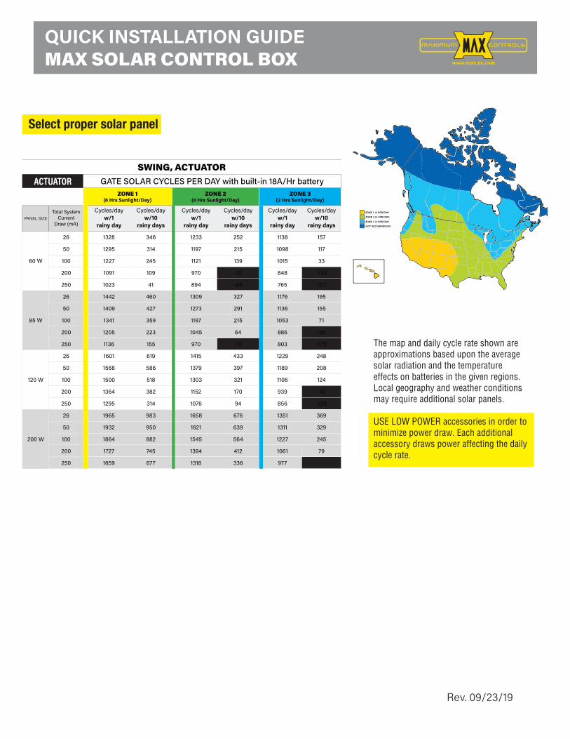
The map and daily cycle rate shown are approximations based upon the average solar radiation and the temperature effects on batteries in the given regions. Local geography and weather conditions may require additional solar panels.
USE LOW POWER accessories in order to minimize power draw. Each additional accessory draws power affecting the daily cycle rate.
Select proper solar panel and battery size1
33Ah 33Ahbatteries
50Ah 33Ah 50Ah50Ah batteries batteries batteries batteries batteries
19 20 11 12 4 55020
16 17 8 9 2 2100 14 16 7 8 1 1200 9 10 2 3 #NUM! #NUM!250
5020
100200250
5020
100200250
4 5 #NUM! #NUM! #NUM! #NUM!97 173 58 105 24 4492 169 54 101 21 419059
166 53 99 19 3925 67 #NUM! 13
68 #NUM! 14 #NUM! #NUM!
Gate solar cycles per dayZone 1
(6 Hrs Sunlight/Day)Zone 2
(4 Hrs Sunlight/Day)Zone 3
(2 Hrs Sunlight/Day)
60W* Solar Panel NOTE: Must Use 24V
Solar Panel
85W* Solar Panel NOTE: Must Use 24V
Solar Panel
Total System Current
Draw (mA)
173 58 105 24 44169 54 101 21 41166 53 99 19 39131
131
25 67 #NUM! 1368 #NUM! 14 #NUM! #NUM!
120W* Solar Panel NOTE: Must Use 24V
Solar Panel
MEGATRON PROGATE WEIGHT LESS THAN 1000 LBS
batteries
batteries batteries batteries batteries
batteries5 19 20 11 12 4 515 16 17 8 9 2 220 14 16 7 8 1 140 9 10 2 3 #NUM! #NUM!60 4 5 #NUM! #NUM! #NUM! #NUM!5 97 173 58 105 24 4415 92 169 54 101 21 4120 90 166 53 99 19 39100 59 131 25 67 #NUM! 13250 9 68 #NUM! 14 #NUM! #NUM!
Gate solar cycles per dayZone 1
(6 Hrs Sunlight/Day)Zone 2
(4 Hrs Sunlight/Day)Zone 3
(2 Hrs Sunlight/Day)
60W* Solar Panel NOTE: Must Use 24V
Solar Panel
85W* Solar Panel NOTE: Must Use 24V
Solar Panel
Total System Current
Draw (mA)
5 97 173 58 105 24 4415 92 169 54 101 21 4120 90 166 53 99 19 39100 59 131 25 67 #NUM! 13250 9 68 #NUM! 14 #NUM! #NUM!
120W* Solar Panel NOTE: Must Use 24V
Solar Panel
MEGATRON PROHEAVY GATE WEIGHT GREATER THAN 1000 LBS (LESS THAN MAX WEIGHT)
SWING PRO OPERATORS
33Ah 33Ah50Ah 33Ah 50Ah50Ah
9297
9059
www.max.us.com
PRO SERIES Solar Application Guide/Wiring
The map and daily cycle rate shown are approximations based upon the average solar radiation and the temperature effects on batteries in the given regions. Local geography and weather conditions may require additional solar panels.
USE LOW POWER accessories in order to minimize power draw. Each additional accessory draws power affecting the daily cycle rate.
Select proper solar panel and battery size1
33Ah 33Ahbatteries
50Ah 33Ah 50Ah50Ah batteries batteries batteries batteries batteries
19 20 11 12 4 55020
16 17 8 9 2 2100 14 16 7 8 1 1200 9 10 2 3 #NUM! #NUM!250
5020
100200250
5020
100200250
4 5 #NUM! #NUM! #NUM! #NUM!97 173 58 105 24 4492 169 54 101 21 419059
166 53 99 19 3925 67 #NUM! 13
68 #NUM! 14 #NUM! #NUM!
Gate solar cycles per dayZone 1
(6 Hrs Sunlight/Day)Zone 2
(4 Hrs Sunlight/Day)Zone 3
(2 Hrs Sunlight/Day)
60W* Solar Panel NOTE: Must Use 24V
Solar Panel
85W* Solar Panel NOTE: Must Use 24V
Solar Panel
Total System Current
Draw (mA)
173 58 105 24 44169 54 101 21 41166 53 99 19 39131
131
25 67 #NUM! 1368 #NUM! 14 #NUM! #NUM!
120W* Solar Panel NOTE: Must Use 24V
Solar Panel
MEGATRON PROGATE WEIGHT LESS THAN 1000 LBS
batteries
batteries batteries batteries batteries
batteries5 19 20 11 12 4 515 16 17 8 9 2 220 14 16 7 8 1 140 9 10 2 3 #NUM! #NUM!60 4 5 #NUM! #NUM! #NUM! #NUM!5 97 173 58 105 24 4415 92 169 54 101 21 4120 90 166 53 99 19 39100 59 131 25 67 #NUM! 13250 9 68 #NUM! 14 #NUM! #NUM!
Gate solar cycles per dayZone 1
(6 Hrs Sunlight/Day)Zone 2
(4 Hrs Sunlight/Day)Zone 3
(2 Hrs Sunlight/Day)
60W* Solar Panel NOTE: Must Use 24V
Solar Panel
85W* Solar Panel NOTE: Must Use 24V
Solar Panel
Total System Current
Draw (mA)
5 97 173 58 105 24 4415 92 169 54 101 21 4120 90 166 53 99 19 39100 59 131 25 67 #NUM! 13250 9 68 #NUM! 14 #NUM! #NUM!
120W* Solar Panel NOTE: Must Use 24V
Solar Panel
MEGATRON PROHEAVY GATE WEIGHT GREATER THAN 1000 LBS (LESS THAN MAX WEIGHT)
SWING PRO OPERATORS
33Ah 33Ah50Ah 33Ah 50Ah50Ah
9297
9059
SWING, ACTUATORACTUATOR GATE SOLAR CYCLES PER DAY with built-in 18A/Hr battery
ZONE 1(6 Hrs Sunlight/Day)
ZONE 2(4 Hrs Sunlight/Day)
ZONE 3(2 Hrs Sunlight/Day)
PANEL SIZETotal System
CurrentDraw (mA)
Cycles/dayw/1
rainy day
Cycles/dayw/10
rainy days
Cycles/dayw/1
rainy day
Cycles/dayw/10
rainy days
Cycles/dayw/1
rainy day
Cycles/dayw/10
rainy days
60 W
26 1328 346 1233 252 1138 157
50 1295 314 1197 215 1098 117
100 1227 245 1121 139 1015 33
200 1091 109 970 -12 848 -133
250 1023 41 894 -88 765 -217
85 W
26 1442 460 1309 327 1176 195
50 1409 427 1273 291 1136 155
100 1341 359 1197 215 1053 71
200 1205 223 1045 64 886 -95
250 1136 155 970 -12 803 -179
120 W
26 1601 619 1415 433 1229 248
50 1568 586 1379 397 1189 208
100 1500 518 1303 321 1106 124
200 1364 382 1152 170 939 -42
250 1295 314 1076 94 856 -126
200 W
26 1965 983 1658 676 1351 369
50 1932 950 1621 639 1311 329
100 1864 882 1545 564 1227 245
200 1727 745 1394 412 1061 79
250 1659 677 1318 336 977 -5
www.max.us.com
QUICK INSTALLATION GUIDEMAX SOLAR CONTROL BOX
Rev. 09/23/19
Related Documents


![GENRAL WIRING (GENRAL WIRING-1)...SPO NC NC NC NC NC SPE [EXT-SP] USB+ ... MFK GND MUDL SQLS GND MICI MICE 8V PSEND AFO GND GND W1 W2 W3 W4 To the MAIN UNIT To the MAIN UNIT To the](https://static.cupdf.com/doc/110x72/60914a252262130c3510d6e2/genral-wiring-genral-wiring-1-spo-nc-nc-nc-nc-nc-spe-ext-sp-usb-mfk.jpg)