MITSUBISHI ELECTRIC RESEARCH LABORATORIES http://www.merl.com UWB Systems for Wireless Sensor Networks Jinyun Zhang, Philip Orlik, Zafer Sahinoglu, Andreas Molisch, Patrick Kinney TR2009-007 March 2009 Abstract Wireless sensor networks are emerging as an important area for communications. They enable a wealth of new applications including surveillance, building control, factory automation, and in- vehicle sensing. The sensor nodes have to operate under severe constraints on energy consump- tion and form factor, and provide the ability for precise self-location of the nodes. These require- ments can be fulfilled very well by various forms of ultra wideband (UWB)transmission tech- nology. We discuss various techniques and trade-offs in UWB systems and indicate that time- hopping and frequency hopping impulse radio physical layers combined with simple multiple- access techniques like ALOHA are suitable designs. We also describe the IEEE 802.15.4a stan- dard, an important system that adopts UWB impulse radio to ensure robust data communica- tions and precision ranging. In order to accommodate heterogeneous networks, it uses specific modulation, coding and ranging waveforms that can be detected well by both coherent and non- coherent receivers. IEEE Proceedings This work may not be copied or reproduced in whole or in part for any commercial purpose. Permission to copy in whole or in part without payment of fee is granted for nonprofit educational and research purposes provided that all such whole or partial copies include the following: a notice that such copying is by permission of Mitsubishi Electric Research Laboratories, Inc.; an acknowledgment of the authors and individual contributions to the work; and all applicable portions of the copyright notice. Copying, reproduction, or republishing for any other purpose shall require a license with payment of fee to Mitsubishi Electric Research Laboratories, Inc. All rights reserved. Copyright c Mitsubishi Electric Research Laboratories, Inc., 2009 201 Broadway, Cambridge, Massachusetts 02139

Welcome message from author
This document is posted to help you gain knowledge. Please leave a comment to let me know what you think about it! Share it to your friends and learn new things together.
Transcript
MITSUBISHI ELECTRIC RESEARCH LABORATORIEShttp://www.merl.com
UWB Systems for Wireless Sensor Networks
Jinyun Zhang, Philip Orlik, Zafer Sahinoglu, Andreas Molisch, Patrick Kinney
TR2009-007 March 2009
Abstract
Wireless sensor networks are emerging as an important area for communications. They enable awealth of new applications including surveillance, building control, factory automation, and in-vehicle sensing. The sensor nodes have to operate under severe constraints on energy consump-tion and form factor, and provide the ability for precise self-location of the nodes. These require-ments can be fulfilled very well by various forms of ultra wideband (UWB)transmission tech-nology. We discuss various techniques and trade-offs in UWB systems and indicate that time-hopping and frequency hopping impulse radio physical layers combined with simple multiple-access techniques like ALOHA are suitable designs. We also describe the IEEE 802.15.4a stan-dard, an important system that adopts UWB impulse radio to ensure robust data communica-tions and precision ranging. In order to accommodate heterogeneous networks, it uses specificmodulation, coding and ranging waveforms that can be detected well by both coherent and non-coherent receivers.
IEEE Proceedings
This work may not be copied or reproduced in whole or in part for any commercial purpose. Permission to copy in whole or in partwithout payment of fee is granted for nonprofit educational and research purposes provided that all such whole or partial copies includethe following: a notice that such copying is by permission of Mitsubishi Electric Research Laboratories, Inc.; an acknowledgment ofthe authors and individual contributions to the work; and all applicable portions of the copyright notice. Copying, reproduction, orrepublishing for any other purpose shall require a license with payment of fee to Mitsubishi Electric Research Laboratories, Inc. Allrights reserved.
Copyright c©Mitsubishi Electric Research Laboratories, Inc., 2009201 Broadway, Cambridge, Massachusetts 02139

MERLCoverPageSide2
UWB Systems for Wireless Sensor Networks
Jinyun Zhang, Fellow, IEEE, Philip V. Orlik, Member, IEEE, Zafer
Sahinoglu, Senior Member, IEEE, Andreas F. Molisch, Fellow, IEEE, and Patrick Kinney, Member, IEEE
Invited paper
Abstract: Wireless sensor networks are emerging as an important area for communications. They enable a wealth of new applications including surveillance, building control, factory automation, and in-vehicle sensing. The sensor nodes have to operate under severe constraints on energy consumption and form factor, and provide the ability for precise self-location of the nodes. These requirements can be fulfilled very well by various forms of ultra wideband (UWB) transmission technology. We discuss various techniques and trade-offs in UWB systems and indicate that time-hopping and frequency hopping impulse radio physical layers combined with simple multiple-access techniques like ALOHA are suitable designs. We also describe the IEEE 802.15.4a standard, an important system that adopts UWB impulse radio to ensure robust data communications and precision ranging. In order to accommodate heterogeneous networks, it uses specific modulation, coding and ranging waveforms that can be detected well by both coherent and non-coherent receivers. Keywords: Ultra Wide Band (UWB), Time-Hopping Impulse Radio (TH-IR), Low Rate (LR), Precision Ranging (PR), Wireless Sensor Networks (WSNs), Wireless Personal Area Network (WPAN), Pulse Position Modulation (PPM), Line-of-Sight (LOS), Non-Line-of-Sight (NLOS), Physical layer (PHY), Modulation, Coding and Multiple Access (MCM), Multi Path Component (MPC).
1. Introduction In recent years, UWB technologies have drawn great interest in the wireless community [1]. The development of UWB has ushered in a new era in short-range wireless communications. Among various potential applications, one of the most promising is in wireless sensor networks (WSNs) [2, 3, 4], which requires both robust communications and high-precision ranging capabilities. There have been numerous research results in the literature to indicate that UWB is one of the enabling technologies for sensor network applications [5, 6, 7, 8, 9, 10]. In particular, impulse-radio-based UWB technology has a number of inherent properties that are well suited to sensor network applications. UWB systems have potentially low complexity and low cost, with noise-like signal properties that create little interference to other systems, are resistant to severe multi-path and jamming, and have very good time-domain resolution allowing for precise location and tracking. Various ultra-wideband wireless sensor network applications include locating and imaging of objects and environments [5], perimeter intrusion detection [6], video surveillance [7], in-vehicle sensing [8], outdoor sports monitoring [11], monitoring of
1
highways, bridges and other civil infrastructure [12] and so on. There have been also many reported devices and systems to demonstrate the feasibility of UWB technology for wireless sensor network applications including UWB chip and radio module design [13, 14, 15, 16, 17, 18, 19], and precision locating system designs [20]. Recognizing these interesting applications, a number of UWB-based sensor network concepts have been developed both in the industrial and the government/military domain. Of particular importance are systems based on the IEEE 802.15.4a standard [21], which provides a well-defined yet flexible PHY and MAC layer that is suitable for a wide variety of applications. Furthermore, it works together with the ZigBee networking standard [22], a dominant technology in WSN systems. In this paper, we first provide an overview of UWB communication and localization systems for wireless sensor networks, especially with regard to its suitability for heterogeneous sensor networks; and then give details of the IEEE 802.15.4a standard. Section 2 discusses the requirements of sensor networks and introduces appealing location-aware applications. Based on comparison of existing technologies, we suggest the suitability of UWB. Section 3 provides basic design considerations of UWB communication systems. After introducing global regulations on UWB transmissions and UWB channel characteristics, we discuss different transmission schemes and receiver design, and suggest various multiple medium access methods. Section 4 provides a detailed summary of the UWB specification in the IEEE 802.15.4a standard for both data communications and ranging. We show how the standardized modulation and multiple-access formats work well with both coherent and non-coherent receivers. We describe the MAC layer design and ranging methods in the standard. Furthermore we discuss methods that allow for "secure" or "private" ranging. A summary and conclusions in Section 5 wrap up this paper.
2. Sensor Network Requirements & Suitability of UWB
2.1 Sensor Network Overview In sensor networks [23, 24, 25, 26, 27, 28, and references therein], many spatially distributed radio transceivers with attached sensors are used to monitor environmental conditions, such as temperature, sound, vibration, pressure, motion, etc, at different locations. Usually these transceivers should be small and inexpensive so that they can be produced and deployed in large numbers. The main goal of the network is to communicate sensor data with given reliability and delay constraints. To achieve this, different nodes typically communicate with each other in an ad hoc fashion without a fixed infrastructure. The transmission of data from the source to the destination may occur in several hops, where some nodes in the network operate as relay for the transmission of the information. Such relaying makes it easier to transmit information cross a large network and transmission over various paths also increase the robustness with respect to an individual node failure [26-28]. The key requirements for transceivers in sensor networks are given in ZigBee [22]:
• Low cost: Since a large number of nodes are to be used, the cost of each node must be kept small. For example, the cost of a node should be less than 1% of the cost of the product it is attached to.
2
• Small form factor: Transceivers’ form factors (including power supply and antenna) must be small, so that they can be easily placed in locations where the sensing actually takes place. • Low energy consumption: A sensor usually has to operate for several years with no battery maintenance, requiring the energy consumption to be extremely low.
Some additional requirements are needed to make the wireless sensor network effective.
• Robustness: Reliability of data communication despite interference, small-scale fading, and shadowing is required so that high quality of service (e.g., with respect to delay and outage) can be guaranteed. • Variable data rate: Although the required data rate for sensor networks is not as high as multimedia transmissions, low data rates may be adequate for simple applications while some other applications require moderate data rates. • Heterogeneous networking: Most sensor networks are heterogeneous, i.e., there are nodes with different capabilities and requirements. Typically, the network has some full-function device (FFD) that collects data from different sensors, processes them, and forwards them to a central monitoring station. A FFD has fewer restrictions with respect to processing complexity (as there are few FFDs, cost is not such an important factor), and energy consumption (since an FFD is usually connected to a permanent power supply). The sensor nodes themselves, on the other hand, are usually reduced-function devices (RED) with extremely stringent limits on complexity and power consumption.
Apart from data communication, geo-location is another key aspect for many wireless sensor network applications. Normally, a number of nodes communicate their sensing (measurement) results to each other and/or a control center. In many cases, the control center or the receiving nodes need to know the exact location of the transmitter. For example, when a fire sensor detects the fire, the control center not only wants to know that there is a fire, but also wants to know at which location. In a building automation system, a large number of sensors will be deployed with building equipments. Any detected abnormal condition along with its location will help the effort of diagnosis and maintenance significantly. Although some applications with geo-location needs may elect to manually enter the device’s locations, many applications either cannot afford the time and cost associated with this practice. Location information is also important because monitoring and control systems often perform data analysis based on both spatial and temporal correlation from closely-spaced sensors [29-30].
2.2 Existing Technologies and Their Applications Until recently, most wireless sensor networks relied upon narrowband transmission schemes such as direct sequence or frequency hopping along with multiple access techniques such as carrier sense. For example, the narrowband direct-sequence spread spectrum (DSSS) PHY layer that is currently used in conjunction with the ZigBee networking standard in the 2.4GHz band1 employs a 2 Mchip per second code-shift 1 This narrowband DSSS PHY layer, together with a lower MAC layer, is the IEEE 802.15.4-2003 standard – not to be confused with the IEEE 802.15.4a ultrawideband standard that will be discussed in detail in Sec. 4.
3
keying modulation to provide 250 kbits/s. ZigBee can be used for wireless control and monitoring solutions without extensive infrastructure wiring. Wireless sensor networks using ZigBee can also be used to monitor logistics assets and track the objects. However, location estimation based on narrowband DSSS can achieve accuracy in the order of several meters, which is only slightly more accurate than traditional RFID. The main initial markets of ZigBee are home, building and industrial automation, such as monitoring and control of lights and HVAC, security in commercial buildings and home, industrial monitoring and control, automatic meter reading, medical and health monitoring of patients, equipments and facilities. Other candidate technologies for WSNs are the various forms of IEEE 802.11 or WiFi. The IEEE ratified the initial IEEE 802.11 specification in 1997 as a standard for wireless local area networks (WLAN). An early update of 802.11 (i.e. 802.11b) supports transmission up to 11Mbits/s. Subsequent mainstream WLAN standards are 802.11a and 802.11g, which achieve 54 Mbits/s. Most recently, the 802.11n standard is under development to achieve more than 100 Mbits/s for high data rate applications and IEEE 802.11s is developed for realizing mesh networking. WiFi is designed for fast and easy networking of PCs, printers and other devices in a local environment. It can provide much higher data rates than ZigBee with a longer communication distance per link. In addition, WiFi is a more mature technology and has been widely adopted in various applications. However, its complexity and energy consumption are much higher than that of ZigBee. For these reasons, WiFi technology has been applied only to perform some particular functions in wireless sensor networks. In many cases it is used to collect sensor data for transmission over longer distance with fixed power supply. In some industrial and hospital wireless network systems, WiFi have also be used to monitor and locate facilities with an accuracy of several meters. Compared to narrowband DSSS and WiFi, UWB offers significant advantages with respect to robustness, energy consumption and location accuracy, UWB spreads the transmit signal over a very large bandwidth (typically 500 MHz or more). By using a large spreading factor, higher robustness against interference and fading are achieved. The use of very short pulses in impulse radio transmission with careful signal and architecture design results in very simple transmitters and permits extreme low energy consumptions. The average power consumption for UWB transceiver is about 30mW [31, 32], which is similar to that of narrowband ZigBee of 20 - 40mW and much lower than 802.11g (500mW – 1W). The precision of ranging measurements, which form the basis of geo-location, is proportional to the bandwidth that can be employed. Therefore, UWB also offers considerable advantages for geo-location with sub-meter accuracy. Less than 15 cm ranging accuracy and less than 50 cm location accuracy are achievable [33]. Global regulatory agencies have specified UWB emission limits to ensure coexistence of UWB with existing systems with very low interference to other devices [see section 3.1 for details]. The following Table 1 provides a comparison among the three above-mentioned technologies.
Table 1. Comparison of Wireless Technologies
2.4GHz ZigBee 2.4 GHz WiFi UWB Data rate Low, 250kbps High, 11 Mbps for
802.11b and 100+ Mbps for 802.11n
Medium, 1 Mbit/s mandatory, and up to 27Mbps for 802.15.4a
Transmission distance Short, < 30 meters Long, up to 100 meters Short, < 30 meters
4
Location accuracy Low, several meters Low, several meters High, < 50cm Power consumption Low, 20mW – 40mW High, 500mW- 1W Low, 30mW Multipath performance Poor Poor Good Interference resilience Low Medium High with high
complexity receivers , low with simplest receivers
Interference to other systems
High High Low
Complexity and cost Low High Low – medium – high are possible
2.3 WSN Target Applications using UWB In general, WSNs can be adapted to many applications. The most important areas are identified in [5, 6, 7, 8, 9, 10] as:
• Consumer products • Healthcare • Industrial applications • Environment, infrastructure and buildings
Due to the characteristics of UWB, the market has shown special interests in the following application examples [34, 35].
• Hospital locating, tracking and communicating system. There are already various wireless systems adopted in hospitals using infra-red technology or some other technologies. However, current systems are to be further improved in terms of location accuracy, communication performance, cost and spatial coverage. The future systems are required to enable pervasive locating and tracking of all kind objects including facilities, equipments, nurses, doctors, and patients. The requirements of location accuracy are to place large equipment and personnel at least within a single room, and to place small but expensive equipment within a one meter range. Regarding communication aspect, the required data rate for such systems is moderate, (at most tens of megabits per second), the performance has to be robust and the system has to be low-cost. The mobile nodes and most of sensor nodes need to be battery-powered. UWB technology can provide the required communication, specified location accuracy, low cost and battery powered solution, therefore it is suitable for this kind of applications. With its ad hoc nature, the UWB based networks can also be easily expanded to cover large space. Several studies furthermore indicate that UWB does not noticeably interfere with other systems in hospital environments [36, 37, 38, 39, 40] because the low transmit power spectral densities inherently assure Electromagnetic Compatibility for medical equipment and patient-worn devices. To ensure risk-free operation, of course, extremely careful design and thorough tests should be used before mass deployment of such systems. • Factory floor equipment tracking. For some large factories, there is a need for the central office to track and log equipment location and status on the production floors. It is also required to track employees and visitors, usually with an accuracy of better than one meter. Current solutions employ WiFi for data communications and a separate system for locating equipment
5
and personnel. UWB system can solve both communication and locating needs, possibly as part of a hierarchical system in which UWB locating and communication system is installed for each floor and connected via WiFi for the whole factory.
3. Design Considerations of UWB Systems
3.1 Global Regulation on UWB The US regulatory agency, the Federal Communications Commission (FCC), defines UWB signals as having an absolute bandwidth larger than 500 MHz, or a relative bandwidth larger than 20 % [41]. The absolute bandwidth is calculated as the difference between the upper, fH, and lower, fL, frequencies of the -10dB emission
level . On the other hand, the fractional bandwidth is expressed asLH
LHfrac ff
ffB+−
=)(2
.
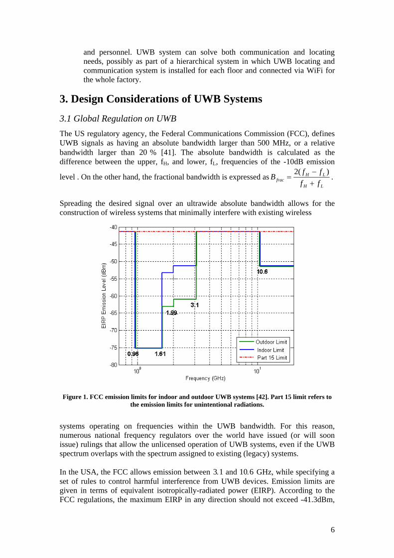
Spreading the desired signal over an ultrawide absolute bandwidth allows for the construction of wireless systems that minimally interfere with existing wireless
Figure 1. FCC emission limits for indoor and outdoor UWB systems [42]. Part 15 limit refers to the emission limits for unintentional radiations.
systems operating on frequencies within the UWB bandwidth. For this reason, numerous national frequency regulators over the world have issued (or will soon issue) rulings that allow the unlicensed operation of UWB systems, even if the UWB spectrum overlaps with the spectrum assigned to existing (legacy) systems. In the USA, the FCC allows emission between 3 1. and 10 6. GHz, while specifying a set of rules to control harmful interference from UWB devices. Emission limits are given in terms of equivalent isotropically-radiated power (EIRP). According to the FCC regulations, the maximum EIRP in any direction should not exceed -41.3dBm,
6
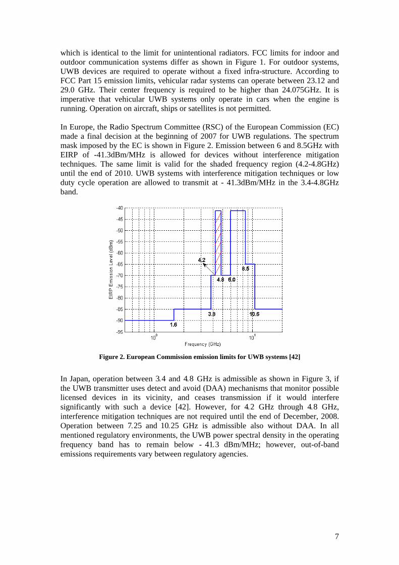
which is identical to the limit for unintentional radiators. FCC limits for indoor and outdoor communication systems differ as shown in Figure 1. For outdoor systems, UWB devices are required to operate without a fixed infra-structure. According to FCC Part 15 emission limits, vehicular radar systems can operate between 23.12 and 29.0 GHz. Their center frequency is required to be higher than 24.075GHz. It is imperative that vehicular UWB systems only operate in cars when the engine is running. Operation on aircraft, ships or satellites is not permitted. In Europe, the Radio Spectrum Committee (RSC) of the European Commission (EC) made a final decision at the beginning of 2007 for UWB regulations. The spectrum mask imposed by the EC is shown in Figure 2. Emission between 6 and 8.5GHz with EIRP of -41.3dBm/MHz is allowed for devices without interference mitigation techniques. The same limit is valid for the shaded frequency region (4.2-4.8GHz) until the end of 2010. UWB systems with interference mitigation techniques or low duty cycle operation are allowed to transmit at - 41.3dBm/MHz in the 3.4-4.8GHz band.
Figure 2. European Commission emission limits for UWB systems [42]
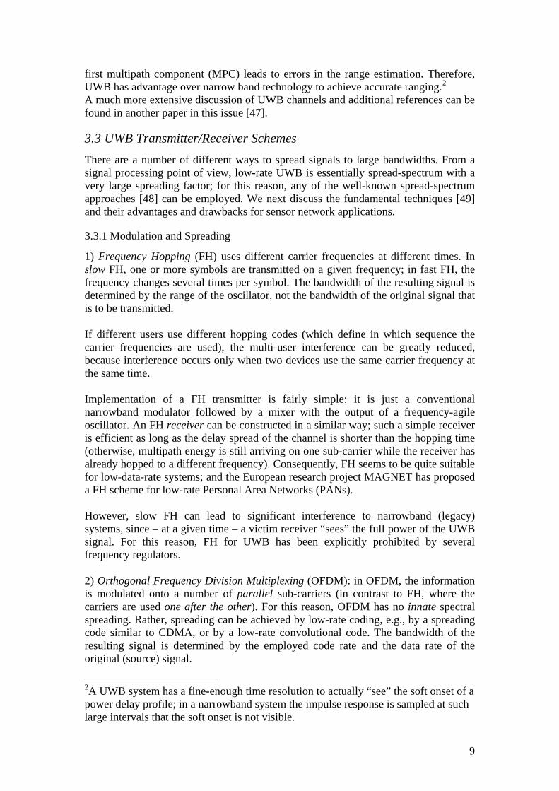
In Japan, operation between 3 4 and . 4 8. GHz is admissible as shown in Figure 3, if the UWB transmitter uses detect and avoid (DAA) mechanisms that monitor possible licensed devices in its vicinity, and ceases transmission if it would interfere significantly with such a device [42]. However, for 4 2. GHz through GHz, interference mitigation techniques are not required until the end of December, 2008. Operation between 7 2 and
4 8.
5. 10 25. GHz is admissible also without DAA. In all mentioned regulatory environments, the UWB power spectral density in the operating frequency band has to remain below - 41 3. dBm/MHz; however, out-of-band emissions requirements vary between regulatory agencies.
7
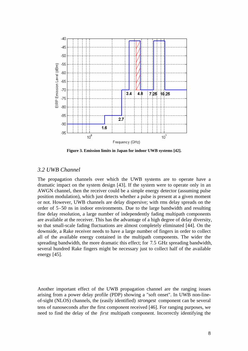
Figure 3. Emission limits in Japan for indoor UWB systems [42].
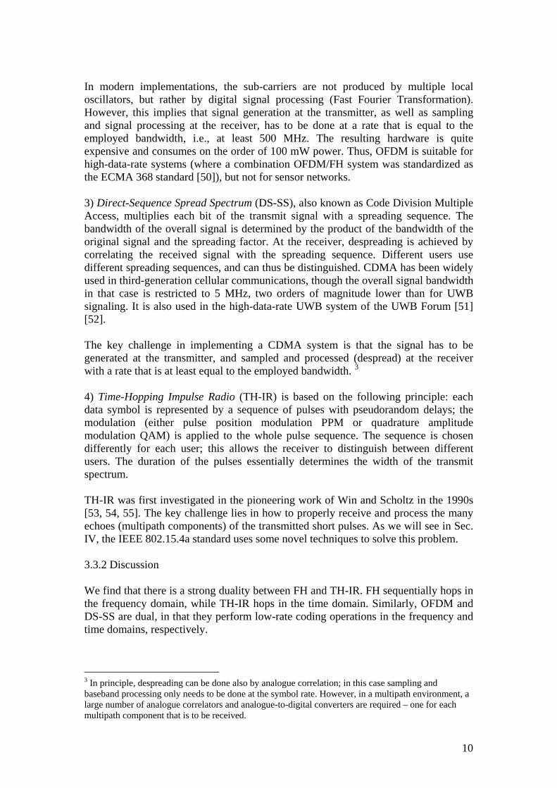
3.2 UWB Channel The propagation channels over which the UWB systems are to operate have a dramatic impact on the system design [43]. If the system were to operate only in an AWGN channel, then the receiver could be a simple energy detector (assuming pulse position modulation), which just detects whether a pulse is present at a given moment or not. However, UWB channels are delay dispersive; with rms delay spreads on the order of 5 - ns in indoor environments. Due to the large bandwidth and resulting fine delay resolution, a large number of independently fading multipath components are available at the receiver. This has the advantage of a high degree of delay diversity, so that small-scale fading fluctuations are almost completely eliminated [
50
44]. On the downside, a Rake receiver needs to have a large number of fingers in order to collect all of the available energy contained in the multipath components. The wider the spreading bandwidth, the more dramatic this effect; for 7 5. GHz spreading bandwidth, several hundred Rake fingers might be necessary just to collect half of the available energy [45]. Another important effect of the UWB propagation channel are the ranging issues arising from a power delay profile (PDP) showing a "soft onset". In UWB non-line-of-sight (NLOS) channels, the (easily identified) component can be several tens of nanoseconds after the first component received [
strongest46]. For ranging purposes, we
need to find the delay of the first multipath component. Incorrectly identifying the
8
first multipath component (MPC) leads to errors in the range estimation. Therefore, UWB has advantage over narrow band technology to achieve accurate ranging.2 A much more extensive discussion of UWB channels and additional references can be found in another paper in this issue [47].
3.3 UWB Transmitter/Receiver Schemes There are a number of different ways to spread signals to large bandwidths. From a signal processing point of view, low-rate UWB is essentially spread-spectrum with a very large spreading factor; for this reason, any of the well-known spread-spectrum approaches [48] can be employed. We next discuss the fundamental techniques [49] and their advantages and drawbacks for sensor network applications.
3.3.1 Modulation and Spreading
1) Frequency Hopping (FH) uses different carrier frequencies at different times. In slow FH, one or more symbols are transmitted on a given frequency; in fast FH, the frequency changes several times per symbol. The bandwidth of the resulting signal is determined by the range of the oscillator, not the bandwidth of the original signal that is to be transmitted. If different users use different hopping codes (which define in which sequence the carrier frequencies are used), the multi-user interference can be greatly reduced, because interference occurs only when two devices use the same carrier frequency at the same time. Implementation of a FH transmitter is fairly simple: it is just a conventional narrowband modulator followed by a mixer with the output of a frequency-agile oscillator. An FH receiver can be constructed in a similar way; such a simple receiver is efficient as long as the delay spread of the channel is shorter than the hopping time (otherwise, multipath energy is still arriving on one sub-carrier while the receiver has already hopped to a different frequency). Consequently, FH seems to be quite suitable for low-data-rate systems; and the European research project MAGNET has proposed a FH scheme for low-rate Personal Area Networks (PANs). However, slow FH can lead to significant interference to narrowband (legacy) systems, since – at a given time – a victim receiver “sees” the full power of the UWB signal. For this reason, FH for UWB has been explicitly prohibited by several frequency regulators. 2) Orthogonal Frequency Division Multiplexing (OFDM): in OFDM, the information is modulated onto a number of parallel sub-carriers (in contrast to FH, where the carriers are used one after the other). For this reason, OFDM has no innate spectral spreading. Rather, spreading can be achieved by low-rate coding, e.g., by a spreading code similar to CDMA, or by a low-rate convolutional code. The bandwidth of the resulting signal is determined by the employed code rate and the data rate of the original (source) signal.
2A UWB system has a fine-enough time resolution to actually “see” the soft onset of a power delay profile; in a narrowband system the impulse response is sampled at such large intervals that the soft onset is not visible.
9
In modern implementations, the sub-carriers are not produced by multiple local oscillators, but rather by digital signal processing (Fast Fourier Transformation). However, this implies that signal generation at the transmitter, as well as sampling and signal processing at the receiver, has to be done at a rate that is equal to the employed bandwidth, i.e., at least 500 MHz. The resulting hardware is quite expensive and consumes on the order of 100 mW power. Thus, OFDM is suitable for high-data-rate systems (where a combination OFDM/FH system was standardized as the ECMA 368 standard [50]), but not for sensor networks. 3) Direct-Sequence Spread Spectrum (DS-SS), also known as Code Division Multiple Access, multiplies each bit of the transmit signal with a spreading sequence. The bandwidth of the overall signal is determined by the product of the bandwidth of the original signal and the spreading factor. At the receiver, despreading is achieved by correlating the received signal with the spreading sequence. Different users use different spreading sequences, and can thus be distinguished. CDMA has been widely used in third-generation cellular communications, though the overall signal bandwidth in that case is restricted to 5 MHz, two orders of magnitude lower than for UWB signaling. It is also used in the high-data-rate UWB system of the UWB Forum [51] [52]. The key challenge in implementing a CDMA system is that the signal has to be generated at the transmitter, and sampled and processed (despread) at the receiver with a rate that is at least equal to the employed bandwidth. 3
4) Time-Hopping Impulse Radio (TH-IR) is based on the following principle: each data symbol is represented by a sequence of pulses with pseudorandom delays; the modulation (either pulse position modulation PPM or quadrature amplitude modulation QAM) is applied to the whole pulse sequence. The sequence is chosen differently for each user; this allows the receiver to distinguish between different users. The duration of the pulses essentially determines the width of the transmit spectrum. TH-IR was first investigated in the pioneering work of Win and Scholtz in the 1990s [53, 54, 55]. The key challenge lies in how to properly receive and process the many echoes (multipath components) of the transmitted short pulses. As we will see in Sec. IV, the IEEE 802.15.4a standard uses some novel techniques to solve this problem. 3.3.2 Discussion We find that there is a strong duality between FH and TH-IR. FH sequentially hops in the frequency domain, while TH-IR hops in the time domain. Similarly, OFDM and DS-SS are dual, in that they perform low-rate coding operations in the frequency and time domains, respectively.
3 In principle, despreading can be done also by analogue correlation; in this case sampling and baseband processing only needs to be done at the symbol rate. However, in a multipath environment, a large number of analogue correlators and analogue-to-digital converters are required – one for each multipath component that is to be received.
10
For low-rate sensor networks, neither OFDM nor DS-SS are suitable4, since they require sampling, analogue to digital conversion, and processing with a high rate, entailing high complexity and large energy consumption. Both FH and TH-IR offer much better performance/complexity tradeoffs. Since FH can create worse interference to legacy systems and is prohibited in several regulatory domains, TH-IR is the method of choice for UWB sensor network applications.
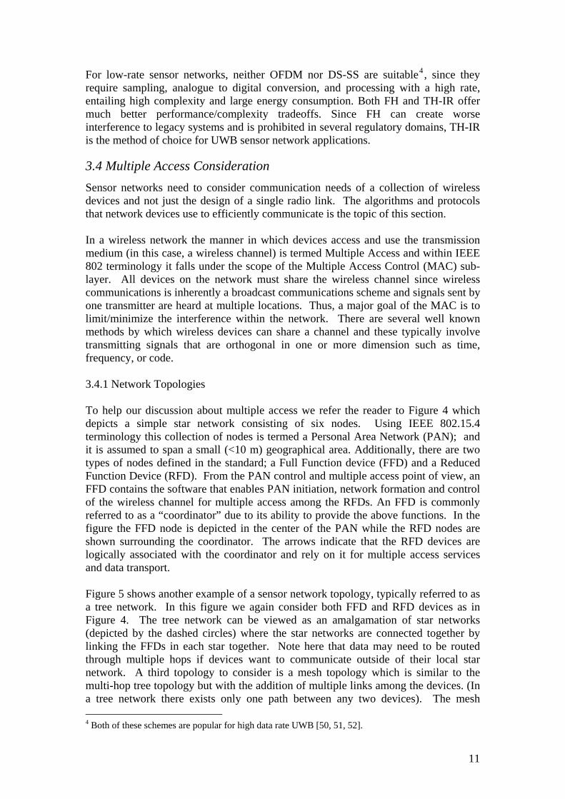
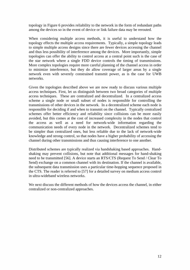
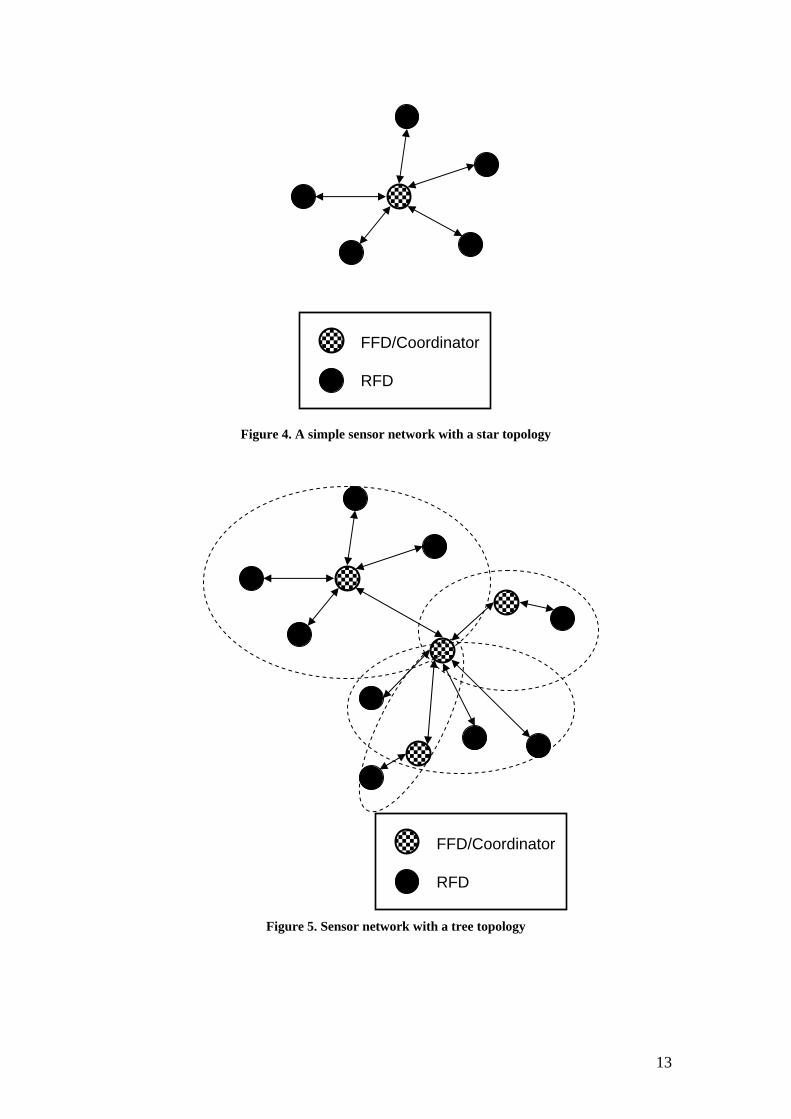
3.4 Multiple Access Consideration Sensor networks need to consider communication needs of a collection of wireless devices and not just the design of a single radio link. The algorithms and protocols that network devices use to efficiently communicate is the topic of this section. In a wireless network the manner in which devices access and use the transmission medium (in this case, a wireless channel) is termed Multiple Access and within IEEE 802 terminology it falls under the scope of the Multiple Access Control (MAC) sub-layer. All devices on the network must share the wireless channel since wireless communications is inherently a broadcast communications scheme and signals sent by one transmitter are heard at multiple locations. Thus, a major goal of the MAC is to limit/minimize the interference within the network. There are several well known methods by which wireless devices can share a channel and these typically involve transmitting signals that are orthogonal in one or more dimension such as time, frequency, or code. 3.4.1 Network Topologies To help our discussion about multiple access we refer the reader to Figure 4 which depicts a simple star network consisting of six nodes. Using IEEE 802.15.4 terminology this collection of nodes is termed a Personal Area Network (PAN); and it is assumed to span a small (<10 m) geographical area. Additionally, there are two types of nodes defined in the standard; a Full Function device (FFD) and a Reduced Function Device (RFD). From the PAN control and multiple access point of view, an FFD contains the software that enables PAN initiation, network formation and control of the wireless channel for multiple access among the RFDs. An FFD is commonly referred to as a “coordinator” due to its ability to provide the above functions. In the figure the FFD node is depicted in the center of the PAN while the RFD nodes are shown surrounding the coordinator. The arrows indicate that the RFD devices are logically associated with the coordinator and rely on it for multiple access services and data transport. Figure 5 shows another example of a sensor network topology, typically referred to as a tree network. In this figure we again consider both FFD and RFD devices as in Figure 4. The tree network can be viewed as an amalgamation of star networks (depicted by the dashed circles) where the star networks are connected together by linking the FFDs in each star together. Note here that data may need to be routed through multiple hops if devices want to communicate outside of their local star network. A third topology to consider is a mesh topology which is similar to the multi-hop tree topology but with the addition of multiple links among the devices. (In a tree network there exists only one path between any two devices). The mesh 4 Both of these schemes are popular for high data rate UWB [50, 51, 52].
11
topology in Figure 6 provides reliability to the network in the form of redundant paths among the devices so in the event of device or link failure data may be rerouted. When considering multiple access methods, it is useful to understand how the topology effects the multiple access requirements. Typically, a simple topology leads to simple multiple access designs since there are fewer devices accessing the channel and thus less possibility of interference among the devices. More importantly, simple topologies can offer the ability to control access at a central point such is the case of the star network where a single FDD device controls the timing of transmissions. More complex topologies require more careful planning of the channel access in order to minimize interference, but they do allow coverage of larger areas by a single network even with severely constrained transmit power, as is the case for UWB networks. Given the topologies described above we are now ready to discuss various multiple access techniques. First, let us distinguish between two broad categories of multiple access techniques. These are centralized and decentralized. In a centralized access scheme a single node or small subset of nodes is responsible for controlling the transmissions of other devices in the network. In a decentralized scheme each node is responsible for deciding if and when to transmit on the channel. Typically centralized schemes offer better efficiency and reliability since collisions can be more easily avoided, but this comes at the cost of increased complexity in the nodes that control the access as well as a need for network-wide information regarding the communication needs of every node in the network. Decentralized schemes tend to be simpler than centralized ones, but less reliable due to the lack of network-wide knowledge and strong control, so that nodes have a higher probability of accessing the channel during other transmissions and thus causing interference to one another. Distributed schemes are typically realized via handshaking based approaches. Hand-shaking may prevent collisions, but note that additional messages for hand-shaking need to be transmitted [56]. A device starts an RTS/CTS (Request To Send / Clear To Send) exchange on a common channel with its destination. If the channel is available, the subsequent data transmission uses a particular time-hopping sequence proposed in the CTS. The reader is referred to [57] for a detailed survey on medium access control in ultra-wideband wireless networks. We next discuss the different methods of how the devices access the channel, in either centralized or non-centralized approaches.
12
FFD/Coordinator
RFD
Figure 4. A simple sensor network with a star topology
FFD/Coordinator
RFD
Figure 5. Sensor network with a tree topology
13
FFD/Coordinator
RFD
Figure 6. Sensor network with a mesh topology
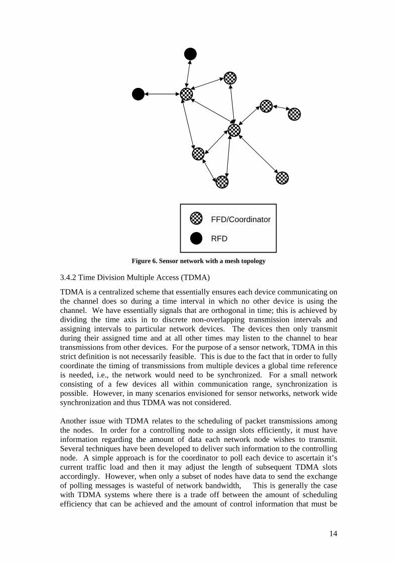
3.4.2 Time Division Multiple Access (TDMA)
TDMA is a centralized scheme that essentially ensures each device communicating on the channel does so during a time interval in which no other device is using the channel. We have essentially signals that are orthogonal in time; this is achieved by dividing the time axis in to discrete non-overlapping transmission intervals and assigning intervals to particular network devices. The devices then only transmit during their assigned time and at all other times may listen to the channel to hear transmissions from other devices. For the purpose of a sensor network, TDMA in this strict definition is not necessarily feasible. This is due to the fact that in order to fully coordinate the timing of transmissions from multiple devices a global time reference is needed, i.e., the network would need to be synchronized. For a small network consisting of a few devices all within communication range, synchronization is possible. However, in many scenarios envisioned for sensor networks, network wide synchronization and thus TDMA was not considered. Another issue with TDMA relates to the scheduling of packet transmissions among the nodes. In order for a controlling node to assign slots efficiently, it must have information regarding the amount of data each network node wishes to transmit. Several techniques have been developed to deliver such information to the controlling node. A simple approach is for the coordinator to poll each device to ascertain it’s current traffic load and then it may adjust the length of subsequent TDMA slots accordingly. However, when only a subset of nodes have data to send the exchange of polling messages is wasteful of network bandwidth, This is generally the case with TDMA systems where there is a trade off between the amount of scheduling efficiency that can be achieved and the amount of control information that must be
14
passed among the FFD and RFDs.
3.4.3 Carrier Sense Multiple Access (CSMA) & ALOHA
CSMA can be viewed as a distributed version of TDMA. In this scheme each node in the network attempts to avoid colliding with other transmissions. The basic idea is that each node senses the wireless channel prior to transmitting a packet to determine if the channel is in use. If the channel is idle the node can then transmit its packet, otherwise, the node waits a for a time period of random length and repeats the sensing and transmission. Thus CSMA attempts to arrange transmissions in orthogonal time intervals. The advantage of a CSMA scheme over TDMA is that is distributed. Additionally, each node will attempt to access the channel only when it has data ready for transmission. This eliminates the need for complex scheduling. However, CSMA suffers from some well known problems. First and foremost is the so called “hidden terminal” problem in which a node that senses the channel may not be within radio range of all nodes in the network. Thus even though a node may determine that the channel is idle and transmit, communication may be taking place elsewhere in the network. These transmissions have the potential to interfere. Additionally, CSMA relies on the ability of performing an accurate channel sensing. This seemingly simple operation can be quite difficult in UWB TH-IR systems. This difficulty arises from the fact that UWB transmission are extremely low-power and require knowledge of the spreading code for effective de-spreading. Thus a node would ideally check all possible spreading codes before declaring an idle channel. In large networks using many codes this may not be feasible. If we eliminate the requirement that a device sense the channel prior to transmission, then we arrive at an extremely simple protocol that allows a device to transmit whenever it has data to send. If a transmission collides with another one, the frame is retransmitted after a random back-off. This protocol is known as ALOHA. Achievable throughput η for this mechanism, assuming Poisson packet arrival rate λ , is [λλη 2−= e 58]. At high utilization (e.g., high arrival rates), its throughput becomes low. Recent papers have also suggested to combine ALOHA with incremental-redundancy retransmission for UWB networks [56].
3.4.4 Frequency Division Multiple Access (FDMA)
Analogously to TDMA, Frequency Division Multiple access (FDMA) assigns orthogonal frequency channels to various devices. This can be achieved by dividing the frequency spectrum into non-overlapping segments and assigning these segments to individual devices for their transmissions. Within the context of UWB systems this multiple access technique has several problems. Firstly, regulatory requirements require that UWB devices transmit signals with a bandwidth no smaller than 500 MHz. Thus in order to support N users the system bandwidth would need to be at least 500N MHz. So we see that in order to support multiple simultaneous users each device must be able to receive and process extremely wideband signals. Secondly, depending on the duplexing method, network wide synchronization may still be needed. This is the case when considering half-duplex communication where devices may be either transmitting or receiving. In this case the system must schedule which devices are to be transmitting and which are to be receiving during each time instant. This type of scheduling is difficult to achieve without some form of global time reference. Additionally, scheduling broadcast or multicast traffic becomes
15
problematic in FDMA networks with half-duplex devices. Full duplex devices mitigate the scheduling problem somewhat but these are intrinsically more costly as full duplex system require essentially two radios per device, and each radio would need to operate over a large system bandwidth. Still, usage of different frequency bands allows a very good separation of signals that would be difficult to separate, e.g., by CDMA. For the above reason FDMA is useful, e.g., to separate closely-spaced networks, and is used for this purpose also in IEEE 802.15.4a.
3.4.5 Code Division Multiple Access (CDMA)
CDMA assigns (quasi-) orthogonal spreading codes to individual devices which then multiply their symbol stream by the assigned code. In its most general form, CDMA encompasses all the spreading schemes discussed in Sec. 3.3.1. Receivers can differentiate among different devices by correlating the received signal with each user’s assigned code. CDMA networks do not have the scheduling issues associated with TDMA and FDMA techniques described above. Since they rely on signal processing at the receiver to separate transmissions from multiple users as described in 3.3.1 Modulation and Spreading, CDMA allows the simultaneous transmissions (in time and/or frequency). CDMA is also attractive for UWB sensor networks because the spreading factor in a UWB system is so large, theoretically, many simultaneous transmission can be supported. The IEEE 802.15.4a standard relies on this large spreading factor and the ability to resolve multiple users to enable reuse of frequency bands. That is, multiple networks may be deployed within a single frequency band. More detail is given in section 4.1.5 Preamble and Synchronization but we note here that each network is assigned a unique code. Thus every device on the network need only listen for packets that contain the correct code and then can processes synchronize their receivers to decode the subsequent data.
3.4.6 Discussion
UWB sensor networks need to support a wide variety of topologies, and channel access scheme should enable distributed algorithms so as to limit the need for costly synchronization. Based on these considerations, the IEEE 802.15.4a standard relies mainly on ALOHA-based channel access mechanism to separate users within a network. This is also coupled with a CDMA based technique to enable deployments of multiple networks within a single frequency band, and the use of multiple frequency bands to further separate networks.
4. IEEE802.15.4a UWB System Specifications In 2004, the IEEE established the standardization group IEEE 802.15.4a, with the mandate to develop a new physical layer for applications such as sensor networks5. The goal of the 802.15.4a standard 6 is to provide an enhanced communications
5 Generally, the standard is intended for "personal area networks", which refers to the range over which two nodes can communicate. 6 Strictly speaking, IEEE-802.15.4a is an amendment to the 802.15.4-2006 standard. For all practical purposes, it is a standard of its own (though with a large amount of backward compatibility especially the 802.15.4-2006 MAC layer. In the following, we will therefore call it a “standard”.
16
capability to the 802.15.4-2006 standard, and also provide device ranging to enable geolocation capability for a system. One option of this standard is based on UWB transmission techniques, namely time-hopping impulse radio (TH-IR). The group first developed application scenarios, from which the requirements for the capabilities of the physical layer and channel models were deduced. In March 2005, a baseline proposal [59] was approved, and in the subsequent months, a number of subgroups developed the details of the modulation/coding schemes, multiple access, ranging waveforms, and required modifications of the MAC layer. On March 22 of 2007, P802.15.4a was approved by the IEEE-SA Standards Board and was published in June 2007 [21].
4.1 PHY Layer Design
4.1.1 Design Highlights
Among two options within the 802.15.4a standard, the UWB LR-WPAN option is designed to provide robust performance for data communications over extended distances as well as precision ranging. The following enhancements are used to satisfy the requirements for data communications:
o Extremely wide bandwidth characteristics that can provide very robust performance under harsh multipath and interference conditions,
o Concatenated forward error correction (FEC) system to provide flexible and robust performance, and
o Optional UWB pulse control features to provide improved performance under some channel conditions while supporting reliable communications and precision ranging capabilities.
In addition to the 850 kb/s mandatory data rate, the UWB PHY provides variable data rates such as: 110 kb/s, 1.70 Mb/s, 6.81 Mb/s, 27.24 Mb/s. Data can be communicated between any UWB device and a coordinator or in a peer-to-peer fashion between coordinators. The UWB PHY design also enables heterogeneous networking. As discussed in Section 3.4, sensor networks are typically heterogeneous, i.e., the networks consist of nodes with different capabilities and requirements. The network will have at least one (but could have more) FFDs. Since an FFD is typically less cost sensitive (they are a minority of the network devices) they are often configured to handle higher processing complexity. Similarly, higher energy consumption is typically not a problem since an FFD is usually connected to a permanent power supply. The sensor nodes themselves, on the other hand, are usually reduced-function devices (RFD) with extremely stringent limits on complexity and energy consumption. In 802.15.4a, the UWB PHY layer, which includes Modulation, Coding, and Multiple access schemes (MCM), has been designed in such a way that it allows both FFDs and RFDs to achieve optimum performance, such as allowing the FFD devices to employ coherent reception (enhanced performance at the cost of energy consumption and complexity), while RFDs use simple energy detectors (non-coherent receivers) for reduced current drain and design simplicity. Furthermore, such a flexible MCM scheme does not deteriorate the possible performance of the FFDs, i.e., the performance of FFDs with flexible MCM is (almost) as good as with an MCM that is designed for homogeneous
17
coherent-receiver networks. The remainder of this section describes in greater detail some specific features/designs of the IEEE 802.15.4a standard. We note that, when given, numerical examples for symbol timing parameters are for the mandatory 850 kbps mode operating at a 16 MHz average pulse repetition frequency (PRF). Other mandatory and optional modes are specified in the standard and the reader is referred to [21] for a complete description.
4.1.2 Band-plan
As a first step, the frequency and bandwidth of the UWB signals must be selected. Since the regulatory environment dictates the power spectral , the total transmit power is a function of signal bandwidth. Increasing the signal bandwidth allows a higher transmit power and a higher degree of delay diversity.
density
On the other hand, receiver design considerations favor lower signal bandwidths. For non-coherent receivers, the bandwidth preferably should be less than the inverse of the channel delay spread, since the receiver cannot optimally combine the resolved multipath components. For a coherent receiver, there is a tradeoff between the delay diversity and the amount of signal energy that can be collected with a given number of Rake fingers [60]. We must also keep in mind that the bandwidth of the system determines the required clock speed and the speed of the receiver electronics in a coherent receiver. Cost requirements tend to restrain the bandwidth to be as low as possible.
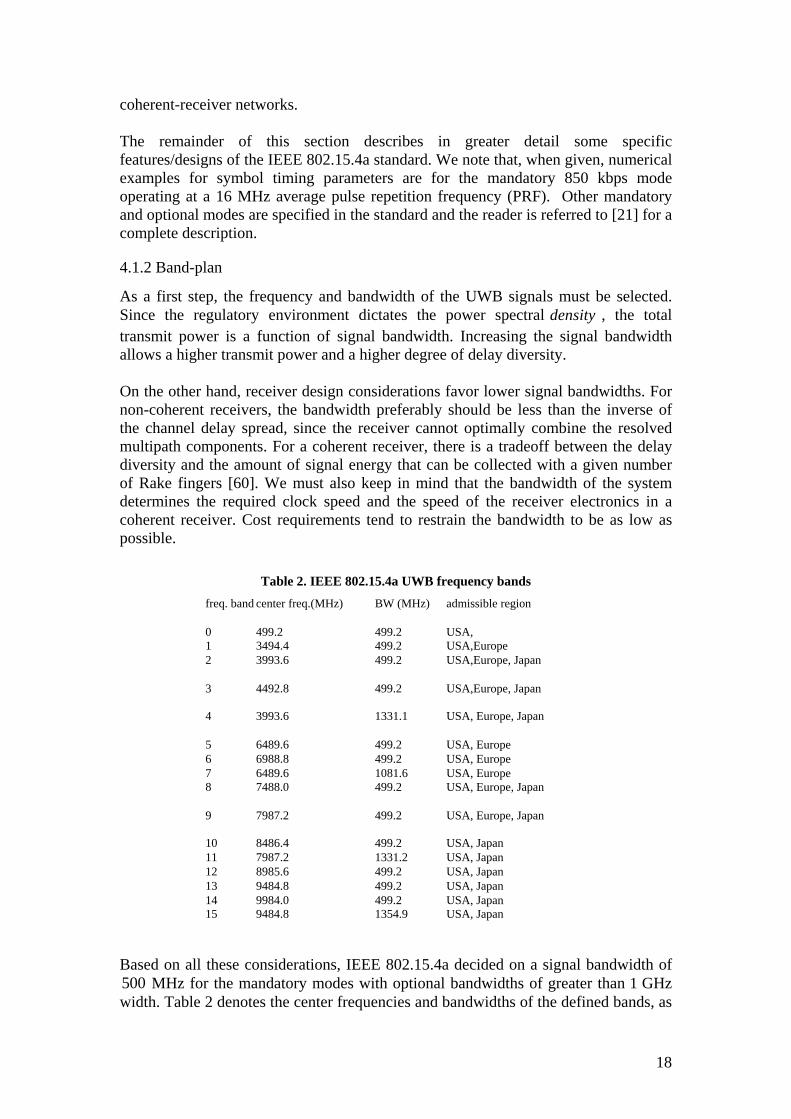
Table 2. IEEE 802.15.4a UWB frequency bands freq. band center freq.(MHz) BW (MHz) admissible region
0 499.2 499.2 USA, 1 3494.4 499.2 USA,Europe 2 3993.6 499.2 USA,Europe, Japan
3 4492.8 499.2 USA,Europe, Japan
4 3993.6 1331.1 USA, Europe, Japan
5 6489.6 499.2 USA, Europe 6 6988.8 499.2 USA, Europe 7 6489.6 1081.6 USA, Europe 8 7488.0 499.2 USA, Europe, Japan
9 7987.2 499.2 USA, Europe, Japan
10 8486.4 499.2 USA, Japan 11 7987.2 1331.2 USA, Japan 12 8985.6 499.2 USA, Japan 13 9484.8 499.2 USA, Japan 14 9984.0 499.2 USA, Japan 15 9484.8 1354.9 USA, Japan
Based on all these considerations, IEEE 802.15.4a decided on a signal bandwidth of MHz for the mandatory modes with optional bandwidths of greater than 1 GHz
width. 500
Table 2 denotes the center frequencies and bandwidths of the defined bands, as
18
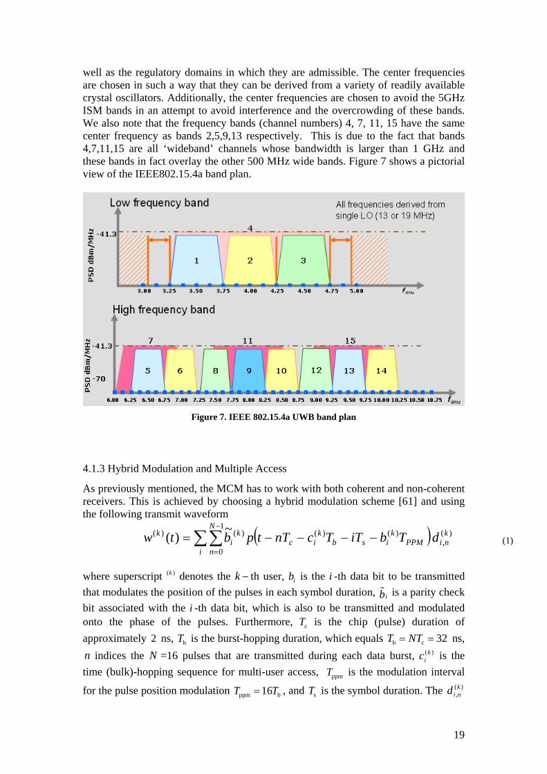
well as the regulatory domains in which they are admissible. The center frequencies are chosen in such a way that they can be derived from a variety of readily available crystal oscillators. Additionally, the center frequencies are chosen to avoid the 5GHz ISM bands in an attempt to avoid interference and the overcrowding of these bands. We also note that the frequency bands (channel numbers) 4, 7, 11, 15 have the same center frequency as bands 2,5,9,13 respectively. This is due to the fact that bands 4,7,11,15 are all ‘wideband’ channels whose bandwidth is larger than 1 GHz and these bands in fact overlay the other 500 MHz wide bands. Figure 7 shows a pictorial view of the IEEE802.15.4a band plan.
Figure 7. IEEE 802.15.4a UWB band plan
4.1.3 Hybrid Modulation and Multiple Access
As previously mentioned, the MCM has to work with both coherent and non-coherent receivers. This is achieved by choosing a hybrid modulation scheme [61] and using the following transmit waveform
( ) )(,
1
0
)()()()( ~)( kni
i
N
nPPM
kisb
kic
ki
k dTbiTTcnTtpbtw ∑∑−
=−−−−= (1)
where superscript ( denotes the )k k − th user, is the i -th data bit to be transmitted that modulates the position of the pulses in each symbol duration, is a parity check bit associated with the i -th data bit, which is also to be transmitted and modulated onto the phase of the pulses. Furthermore, is the chip (pulse) duration of approximately ns,
ib
ib%
cT2 bT is the burst-hopping duration, which equals ns,
indices the =16 pulses that are transmitted during each data burst, is the time (bulk)-hopping sequence for multi-user access,
b c 32T NT= =
n N )(kic
ppmT is the modulation interval
for the pulse position modulation ppm b16T T= , and is the symbol duration. The sT )(,knid
19
denote a pseudorandom scrambling sequence drawn from {-1,1}. The pulse is the "basis pulse" that is a raised-cosine pulse.
( )p t7
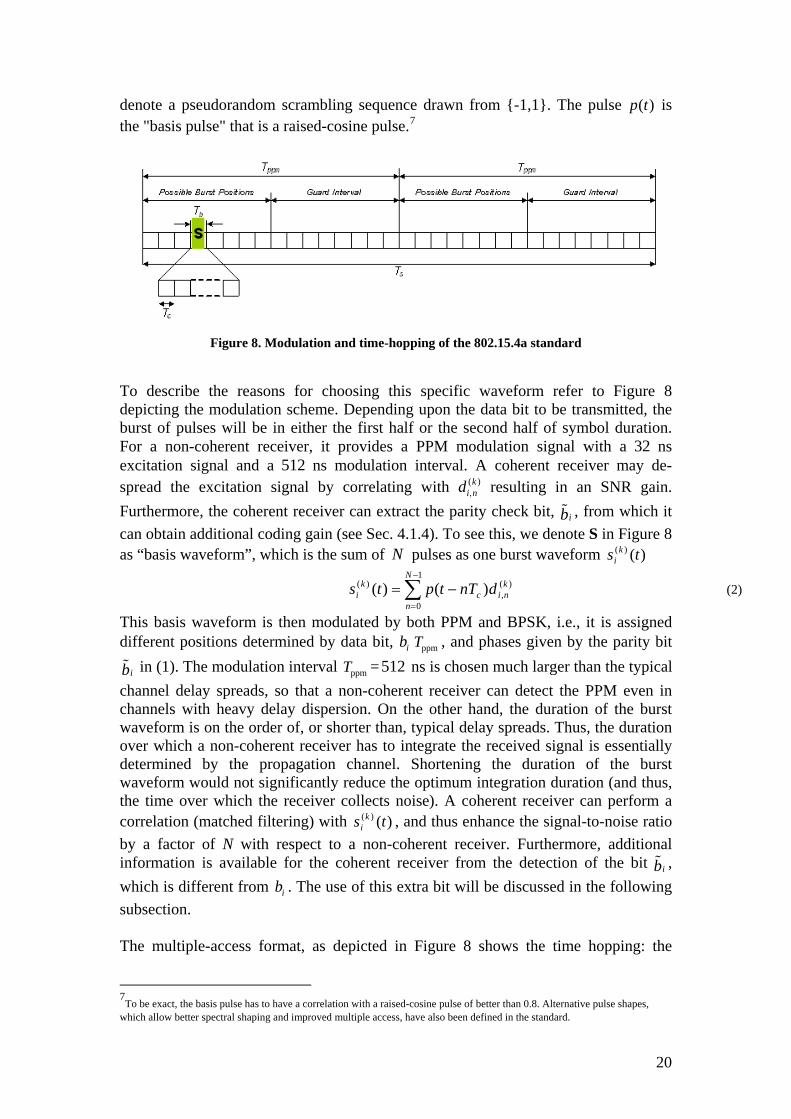
Figure 8. Modulation and time-hopping of the 802.15.4a standard
To describe the reasons for choosing this specific waveform refer to Figure 8 depicting the modulation scheme. Depending upon the data bit to be transmitted, the burst of pulses will be in either the first half or the second half of symbol duration. For a non-coherent receiver, it provides a PPM modulation signal with a 32 ns excitation signal and a 512 ns modulation interval. A coherent receiver may de-spread the excitation signal by correlating with ( )k
i nd , resulting in an SNR gain. Furthermore, the coherent receiver can extract the parity check bit, , from which it can obtain additional coding gain (see Sec. 4.1.4). To see this, we denote S in
ib%Figure 8
as “basis waveform”, which is the sum of pulses as one burst waveform N )()( ts ki
(2) )(,
1
0
)( )()( kni
N
nc
ki dnTtpts ∑
−
=
−=
This basis waveform is then modulated by both PPM and BPSK, i.e., it is assigned different positions determined by data bit, ib ppmT , and phases given by the parity bit
in (1). The modulation interval ib% ppmT =512 ns is chosen much larger than the typical channel delay spreads, so that a non-coherent receiver can detect the PPM even in channels with heavy delay dispersion. On the other hand, the duration of the burst waveform is on the order of, or shorter than, typical delay spreads. Thus, the duration over which a non-coherent receiver has to integrate the received signal is essentially determined by the propagation channel. Shortening the duration of the burst waveform would not significantly reduce the optimum integration duration (and thus, the time over which the receiver collects noise). A coherent receiver can perform a correlation (matched filtering) with , and thus enhance the signal-to-noise ratio by a factor of N with respect to a non-coherent receiver. Furthermore, additional information is available for the coherent receiver from the detection of the bit , which is different from . The use of this extra bit will be discussed in the following subsection.
)()( ts ki
ib%
ib
The multiple-access format, as depicted in Figure 8 shows the time hopping: the
7
To be exact, the basis pulse has to have a correlation with a raised-cosine pulse of better than 0.8. Alternative pulse shapes, which allow better spectral shaping and improved multiple access, have also been defined in the standard.
20
position of the burst waveform is shifted by multiples of ns in a pseudorandom way by ; the shifts are different for different users. For both non-coherent receiver and coherent receiver, the signal format provides time hopping. Note that the maximum possible shift is
)()( ts ki b 32T =
)(kic
b8T , while the time shift for the PPM is b16T . Thus, a duration of ns serves as a guard interval for channels with heavy delay dispersion.
b8 256T =
The coherent receiver obtains additional multiuser separation by the de-spreading of the burst waveform . As each user has a different burst waveform, the matched filtering at the receiver input provides multi-access interference suppression. The amount of suppression depends on the cross-correlation between the burst waveforms; it is noteworthy that the spreading sequence, and thus the burst waveform, changes from symbol to symbol
)()( ts ki
4.1.4 Coding for Hybrid Modulation
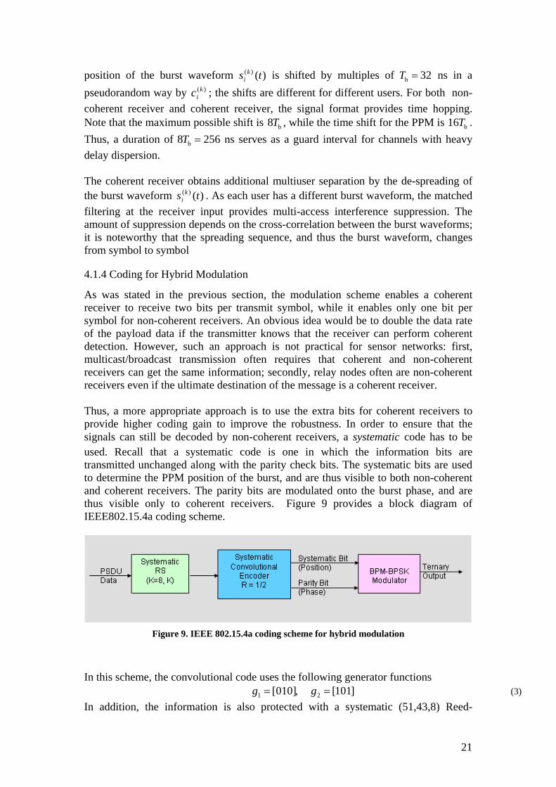
As was stated in the previous section, the modulation scheme enables a coherent receiver to receive two bits per transmit symbol, while it enables only one bit per symbol for non-coherent receivers. An obvious idea would be to double the data rate of the payload data if the transmitter knows that the receiver can perform coherent detection. However, such an approach is not practical for sensor networks: first, multicast/broadcast transmission often requires that coherent and non-coherent receivers can get the same information; secondly, relay nodes often are non-coherent receivers even if the ultimate destination of the message is a coherent receiver. Thus, a more appropriate approach is to use the extra bits for coherent receivers to provide higher coding gain to improve the robustness. In order to ensure that the signals can still be decoded by non-coherent receivers, a systematic code has to be used. Recall that a systematic code is one in which the information bits are transmitted unchanged along with the parity check bits. The systematic bits are used to determine the PPM position of the burst, and are thus visible to both non-coherent and coherent receivers. The parity bits are modulated onto the burst phase, and are thus visible only to coherent receivers. Figure 9 provides a block diagram of IEEE802.15.4a coding scheme.
Figure 9. IEEE 802.15.4a coding scheme for hybrid modulation
In this scheme, the convolutional code uses the following generator functions 1 2[010] [101]g g= , = (3)
In addition, the information is also protected with a systematic (51,43,8) Reed-
21
Solomon code. The structure of the coding scheme allows one to implement a variety of decoders that have different tradeoffs between complexity and performance. We list them in order of ascending performance
• No decoding: since the RS code is systematic, the receiver can just ignore the redundant bits of the RS (as well as the systematic convolutional) code, and decode the information bit by bit • Hard decoding of the RS code: using standard decoding of RS codes, the receiver can decode the signal without using the redundant information of the convolutional code • Hard decoding of convolutional code followed by hard decoding of RS code • Soft decoding of convolutional code followed by decoding of RS code • Turbo-decoding, i.e., exchange of soft information between convolutional code and RS code.
4.1.5 Preamble and Synchronization
Before data detection is performed by the receiver, it is necessary to acquire, synchronize, and perform channel estimation. In 802.15.4a, a specific preamble, detectable by both coherent and non-coherent receivers, is designed for these purposes,. The support for hybrid receivers is achieved by an ingenious scheme, first suggested in [62], [63], namely "perfectly balanced ternary sequences" (PBTS). For the PBTSs both the periodic autocorrelation function for coherent receivers k i mN
n j mACF c c+ − += k i jN∑∑∑ (4)
and the periodic autocorrelation function as observed by non-coherent receivers (2 1)i mN k i jNk
n j mc cACF + − += | | ⋅ | | −∑∑∑ (5)
are perfect, i.e., proportional to a delta comb k iNiδ +∑ . Note that the coherent receiver
has a 3 dB SNR advantage over the non-coherent receiver. The IEEE 802.15.4a preamble uses a large number of repetitions of the PBTS to improve signal-to-noise ratio (SNR) via processing gain; the resulting high SNR signal is thus well-suited both for channel estimation. Due to the perfect autocorrelation feature, it is very easy for a coherent receiver to obtain a (possibly noisy) impulse response of the propagation channel in an 802.15.4a system: just take the cross-correlation of the received signal with the PBTS. Similarly, a noncoherent receiver can obtain the absolute value of the impulse response by cross-correlating the (rectified) received signal with (2|c….|-1). The IEEE 802.15.4a standard foresees the use of either length-31, or length-127 PBTSs. Table 3 lists the 31-bit PBTSs adopted in the standard. Figure 10 is generated by repeating the PBTS sequence S1 by 3 times and correlating the resulting signal with S1 itself. The central part of the figure displays the periodic auto correlation peaks with no side-lobes between the peaks, while non-zero side-lobes at the beginning and end are due to transient effects. All devices in the same network are required to use the same preamble sequence. To support simultaneously operating multiple networks, the preamble sequence used in each network is different.
22
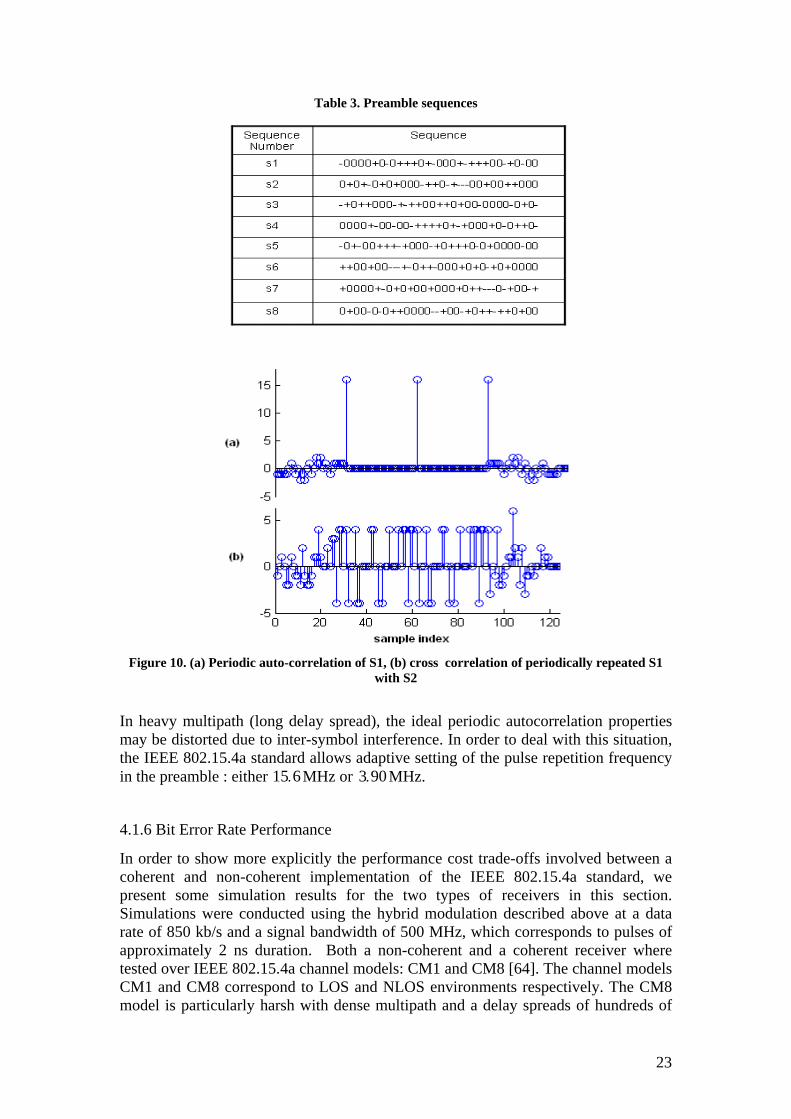
Table 3. Preamble sequences
Figure 10. (a) Periodic auto-correlation of S1, (b) cross correlation of periodically repeated S1
with S2
In heavy multipath (long delay spread), the ideal periodic autocorrelation properties may be distorted due to inter-symbol interference. In order to deal with this situation, the IEEE 802.15.4a standard allows adaptive setting of the pulse repetition frequency in the preamble : either 15 MHz or 3 96. 0. MHz.
4.1.6 Bit Error Rate Performance
In order to show more explicitly the performance cost trade-offs involved between a coherent and non-coherent implementation of the IEEE 802.15.4a standard, we present some simulation results for the two types of receivers in this section. Simulations were conducted using the hybrid modulation described above at a data rate of 850 kb/s and a signal bandwidth of 500 MHz, which corresponds to pulses of approximately 2 ns duration. Both a non-coherent and a coherent receiver where tested over IEEE 802.15.4a channel models: CM1 and CM8 [64]. The channel models CM1 and CM8 correspond to LOS and NLOS environments respectively. The CM8 model is particularly harsh with dense multipath and a delay spreads of hundreds of
23
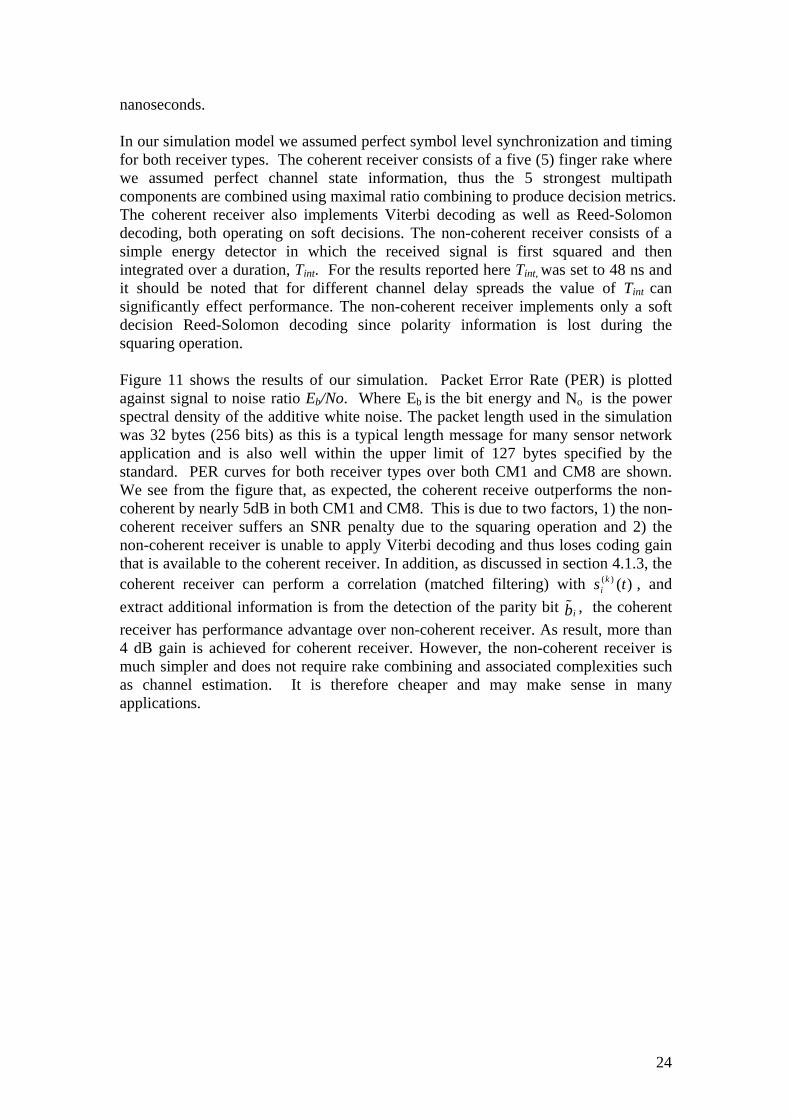
nanoseconds. In our simulation model we assumed perfect symbol level synchronization and timing for both receiver types. The coherent receiver consists of a five (5) finger rake where we assumed perfect channel state information, thus the 5 strongest multipath components are combined using maximal ratio combining to produce decision metrics. The coherent receiver also implements Viterbi decoding as well as Reed-Solomon decoding, both operating on soft decisions. The non-coherent receiver consists of a simple energy detector in which the received signal is first squared and then integrated over a duration, Tint. For the results reported here Tint, was set to 48 ns and it should be noted that for different channel delay spreads the value of Tint can significantly effect performance. The non-coherent receiver implements only a soft decision Reed-Solomon decoding since polarity information is lost during the squaring operation. Figure 11 shows the results of our simulation. Packet Error Rate (PER) is plotted against signal to noise ratio Eb/No. Where Eb is the bit energy and No is the power spectral density of the additive white noise. The packet length used in the simulation was 32 bytes (256 bits) as this is a typical length message for many sensor network application and is also well within the upper limit of 127 bytes specified by the standard. PER curves for both receiver types over both CM1 and CM8 are shown. We see from the figure that, as expected, the coherent receive outperforms the non-coherent by nearly 5dB in both CM1 and CM8. This is due to two factors, 1) the non-coherent receiver suffers an SNR penalty due to the squaring operation and 2) the non-coherent receiver is unable to apply Viterbi decoding and thus loses coding gain that is available to the coherent receiver. In addition, as discussed in section 4.1.3, the coherent receiver can perform a correlation (matched filtering) with , and extract additional information is from the detection of the parity bit , the coherent receiver has performance advantage over non-coherent receiver. As result, more than 4 dB gain is achieved for coherent receiver. However, the non-coherent receiver is much simpler and does not require rake combining and associated complexities such as channel estimation. It is therefore cheaper and may make sense in many applications.
)()( ts ki
ib%
24
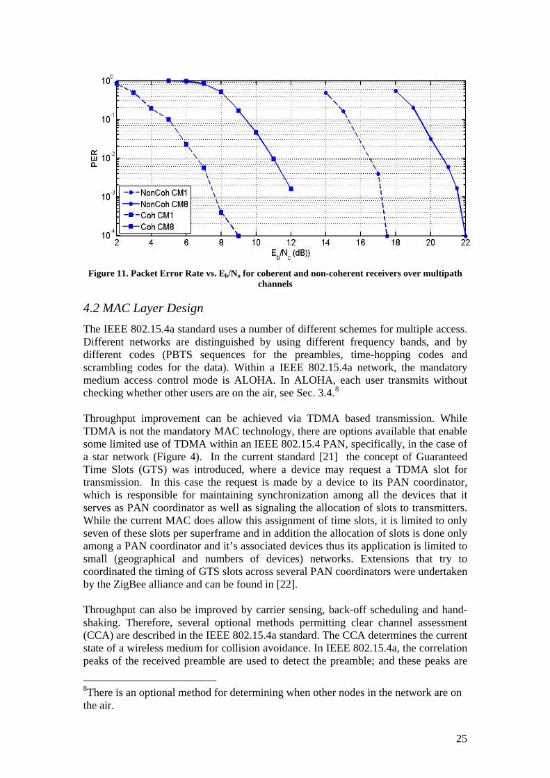
Figure 11. Packet Error Rate vs. Eb/No for coherent and non-coherent receivers over multipath
channels
4.2 MAC Layer Design The IEEE 802.15.4a standard uses a number of different schemes for multiple access. Different networks are distinguished by using different frequency bands, and by different codes (PBTS sequences for the preambles, time-hopping codes and scrambling codes for the data). Within a IEEE 802.15.4a network, the mandatory medium access control mode is ALOHA. In ALOHA, each user transmits without checking whether other users are on the air, see Sec. 3.4.8 Throughput improvement can be achieved via TDMA based transmission. While TDMA is not the mandatory MAC technology, there are options available that enable some limited use of TDMA within an IEEE 802.15.4 PAN, specifically, in the case of a star network (Figure 4). In the current standard [21] the concept of Guaranteed Time Slots (GTS) was introduced, where a device may request a TDMA slot for transmission. In this case the request is made by a device to its PAN coordinator, which is responsible for maintaining synchronization among all the devices that it serves as PAN coordinator as well as signaling the allocation of slots to transmitters. While the current MAC does allow this assignment of time slots, it is limited to only seven of these slots per superframe and in addition the allocation of slots is done only among a PAN coordinator and it’s associated devices thus its application is limited to small (geographical and numbers of devices) networks. Extensions that try to coordinated the timing of GTS slots across several PAN coordinators were undertaken by the ZigBee alliance and can be found in [22]. Throughput can also be improved by carrier sensing, back-off scheduling and hand-shaking. Therefore, several optional methods permitting clear channel assessment (CCA) are described in the IEEE 802.15.4a standard. The CCA determines the current state of a wireless medium for collision avoidance. In IEEE 802.15.4a, the correlation peaks of the received preamble are used to detect the preamble; and these peaks are
8There is an optional method for determining when other nodes in the network are on the air.
25
indicative of a signal presence for CCA. In [65], the authors develop a TDMA-type multiplexed preamble scheme that enables preamble-detection-based CCA for UWB systems. In this scheme, preamble symbols are multiplexed with the IEEE 802.15.4 packet, by periodically inserting them into the header and payload parts of the packet after every k-symbol-long interval as illustrated in Figure 12.
Figure 12. TDMA style multiplexing of a preamble symbol and packet payload to support CCA
[42].
4.3 Ranging UWB networks will typically use time-of-arrival for determining the range between different nodes; those ranges form the basis of the actual location estimation. In general, a standard defines transmitted signal waveform, frame structure and protocols between the transmitter and the receiver in a system. The algorithm and implementation of signal detection and ranging estimation are usually not specified. In the following, we will only highlight some special provisions in IEEE 802.15.4a to realize accurate ranging. For general discussions on ranging estimation techniques, we refer the reader to [66, 67, 68, 69].
4.3.1 Two-Way Ranging Protocol
According to the ranging protocol in IEEE 802.15.4a standard, an original ranging node A, RDEV A, first transmits a signal called range request packet (RFRAMEREQ) to a target ranging node B, RDEV B. After reception of the RFRAMEREQ, B prepares and sends an acknowledgment packet, also referred to as a range reply packet (RFRAMEREP), back to node A. In a separate packet B also reports to A the time interval which is the time duration between the arrival time of the RFRAMEtaT REQ and the departure time of the RFRAMEREP. Node A can then compute the range, since it knows the total round-trip time and the turn around time of the RFRAMEREP . (see Figure 13).
26
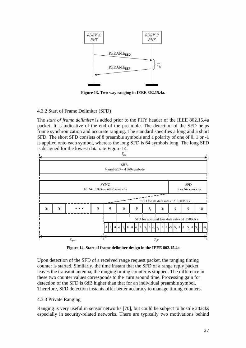
Figure 13. Two-way ranging in IEEE 802.15.4a.
4.3.2 Start of Frame Delimiter (SFD)
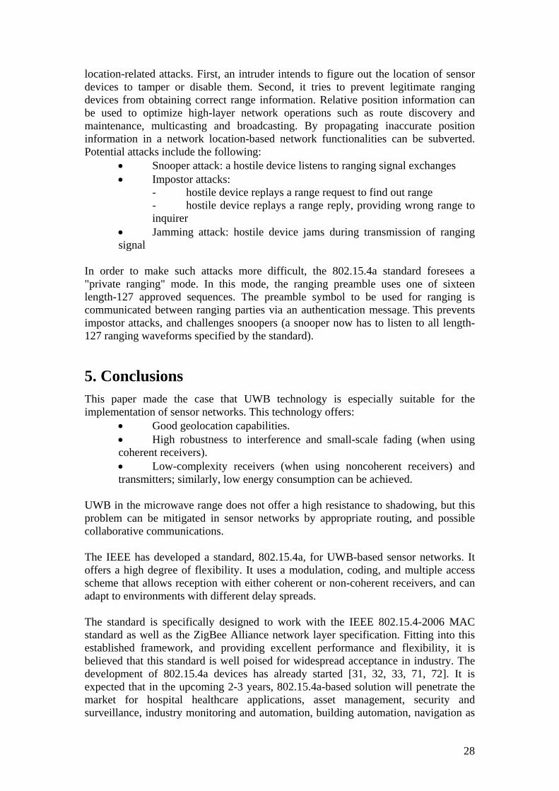
The start of frame delimiter is added prior to the PHY header of the IEEE 802.15.4a packet. It is indicative of the end of the preamble. The detection of the SFD helps frame synchronization and accurate ranging. The standard specifies a long and a short SFD. The short SFD consists of 8 preamble symbols and a polarity of one of 0, 1 or -1 is applied onto each symbol, whereas the long SFD is 64 symbols long. The long SFD is designed for the lowest data rate Figure 14.
Figure 14. Start of frame delimiter design in the IEEE 802.15.4a
Upon detection of the SFD of a received range request packet, the ranging timing counter is started. Similarly, the time instant that the SFD of a range reply packet leaves the transmit antenna, the ranging timing counter is stopped. The difference in these two counter values corresponds to the turn around time. Processing gain for detection of the SFD is 6dB higher than that for an individual preamble symbol. Therefore, SFD detection instants offer better accuracy to manage timing counters.
4.3.3 Private Ranging
Ranging is very useful in sensor networks [70], but could be subject to hostile attacks especially in security-related networks. There are typically two motivations behind
27
location-related attacks. First, an intruder intends to figure out the location of sensor devices to tamper or disable them. Second, it tries to prevent legitimate ranging devices from obtaining correct range information. Relative position information can be used to optimize high-layer network operations such as route discovery and maintenance, multicasting and broadcasting. By propagating inaccurate position information in a network location-based network functionalities can be subverted. Potential attacks include the following:
• Snooper attack: a hostile device listens to ranging signal exchanges • Impostor attacks:
- hostile device replays a range request to find out range - hostile device replays a range reply, providing wrong range to inquirer
• Jamming attack: hostile device jams during transmission of ranging signal
In order to make such attacks more difficult, the 802.15.4a standard foresees a "private ranging" mode. In this mode, the ranging preamble uses one of sixteen length-127 approved sequences. The preamble symbol to be used for ranging is communicated between ranging parties via an authentication message. This prevents impostor attacks, and challenges snoopers (a snooper now has to listen to all length-127 ranging waveforms specified by the standard).
5. Conclusions
This paper made the case that UWB technology is especially suitable for the implementation of sensor networks. This technology offers:
• Good geolocation capabilities. • High robustness to interference and small-scale fading (when using coherent receivers). • Low-complexity receivers (when using noncoherent receivers) and transmitters; similarly, low energy consumption can be achieved.
UWB in the microwave range does not offer a high resistance to shadowing, but this problem can be mitigated in sensor networks by appropriate routing, and possible collaborative communications. The IEEE has developed a standard, 802.15.4a, for UWB-based sensor networks. It offers a high degree of flexibility. It uses a modulation, coding, and multiple access scheme that allows reception with either coherent or non-coherent receivers, and can adapt to environments with different delay spreads. The standard is specifically designed to work with the IEEE 802.15.4-2006 MAC standard as well as the ZigBee Alliance network layer specification. Fitting into this established framework, and providing excellent performance and flexibility, it is believed that this standard is well poised for widespread acceptance in industry. The development of 802.15.4a devices has already started [31, 32, 33, 71, 72]. It is expected that in the upcoming 2-3 years, 802.15.4a-based solution will penetrate the market for hospital healthcare applications, asset management, security and surveillance, industry monitoring and automation, building automation, navigation as
28
well as many other areas.
References 1. M. G. diBenedetto, T. Kaiser, A. F. Molisch, I. Oppermann, C. Politano, and D.
Porcino (eds.), UWB Communications Systems: A Comprehensive Overview. EURASIP Publishing, 2005.
2. P. Martigne, “UWB for Low Data Rate Applications : Technology Overview and
Regulatory Aspects,” Circuits and Systems, ISCAS, in Proc. IEEE International Symposium, pp. 2425-2428, 2006.
3. K.D. Colling, P. Ciorciari, “Ultra Wideband Communications for Sensor
Networks,” in proc. IEEE Military Communications Conference (MILCOM), pp. 1-7, 2005.
4. S. Gezici, Z. Tian; G.B. Giannakis, H. Kobayashi, A.F. Molisch, H.V. Poor, Z.
Sahinoglu, “Localization via ultra-wideband radios: a look at positioning aspects for future sensor networks,” IEEE Signal Processing Magazine, Vol. 22, pp. 70-84, 2005.
5. R.S. Thoma, O. Hirsch, J. Sachs, Zetik, R., “UWB Sensor Networks for Position
Location and Imaging of Objects and Environments,” The Second European Conference on Antennas and Propagation (EuCAP), pp. 1-9, 2007.
6. L. Yuheng, L. Chao, Y. He, J. Wu, Z. Xiong, “A Perimeter Intrusion Detection
System Using Dual-Mode Wireless Sensor Networks,” Second International Conference on Communications and Networking in China, pp. 861-865, 2007.
7. X. Huang, E. Dutkiewicz, R. Gandia, D. Lowe, “Ultra-Wideband Technology for
Video Surveillance Sensor Networks,” IEEE International Conference on Industrial Informatics, pp. 1012-1017, 2006.
8. J. Li, T. Talty, “Channel Characterization for Ultra-Wideband Intra-Vehicle
Sensor Networks,” Military Communications conference (MILCOM), pp. 1-5, 2006.
9. F. Granelli, H. Zhang, X. Zhou, S. Maranò, “Research Advances in Cognitive
Ultra Wide Band Radio and Their Application to Sensor Networks,” Mobile Networks and Applications, Vol. 11, pp. 487-499, 2006.
10. L. Stoica, A. Rabbachin, H.O. Repo, T.S. Tiuraniemi, I. Oppermann, “An
Ultrawideband System Architecture for Tag Based Wireless Sensor Networks,” IEEE Transactions on Vehicular Technology, Vol. 54, pp. 1632-1645, 2005.
11. I. Oppenmann, L. Stoica, A. Rabbachin, Z. Shekby, and J. Haapola, “UWB
Wireless Sensor Networks: UWEN – a Practical Example,” IEEE Communications Magazine, pp. S27-S32, 2004.
29
12. V. Mehta, M. EI Zarki, “An Ultra Wide Band (UWB) Based Sensor Network for Civil Infrastructure Health Monitoring,” 1st European Workshop on Wireless Sensor Networks (EWSN), Berlin, Germany, January 19-21, 2004.
13. M. Shen et. Al, “UWB Radio Module Design for Wireless Sensor Networks”,
Proceedings of NORCHIP Conference, pp. 184-187, November 21-22, 2005. 14. M. Baghaei Nejad, et al, “UWB Radio Module Design for Wireless Sensor
Networks”, Analog Integrated Circuits and Signal Processing, Volume 50, Number 1, pp.47-57, January 2007.
15. M. Verhelst, W. Dehaene, “A Flexible, Ultra-Low Power 35pJ/Pulse Digital
Back-End for a QAC UWB Receiver,” ESSCIRC - 33rd European Solid-State Circuits Conference, pp. 236-239, 2007.
16. H. Nabil, A. Samir, M. Ali, F. Mostafa, M. Fathy; S. Sayed, H.F. Ragai, “CMOS
UWB-IR Energy Collection Based Receiver,” International Conference on Microelectronics, pp. 441-444, 2007.
17. T. Terada, S. Yoshizumi, M. Muqsith, Y. Sanada, T. Kuroda, “A CMOS Ultra-
Wideband Impulse Radio Transceiver for 1-Mb/s Data Communications and ± 2.5-cm Range Finding,” IEEE Journal of Solid-State Circuits, Vol. 41, pp. 891-898, 2006.
18. L. Stoica, S. Tiuraniemi, I. Oppermann, H. Repo, “An Ultra Wideband Low
Complexity Circuit Transceiver Architecture for Sensor Networks,” Circuits and Systems, ISCAS, IEEE International Symposium, pp. 364-367, 2005.
19. B.Q. Ruiz,; A.A.Vazquez, M.L. Rubio, J.L.G. Garcia, “Impulse Radio UWB
System Architecture for Smart Wireless Sensor Networks,” Networking with Ultra Wide Band and Workshop on Ultra Wide Band for Sensor Networks, Networking with UWB, pp. 35-39, 2005.
20. R. J. Fontana, E. Richley and J. Barney, “Commercialization of an Ultra
Wideband Precision Asset Location System”, IEEE Conference on Ultra Wideband Systems and Technologies, November 2003, Reston, VA.
21. IEEE Std 802.15.4a – 2007 (Amendment to IEEE Std 802.15.4), IEEE Computer
Society, 31 August 2007. 22. “ZigBee Specification Version 1.0,” available at http://www.zigbee.org. 23. V. Raghunathan, S. Ganeriwal, and M. Srivastava, “Emerging Techniques for
Long Lived Wireless Sensor Networks,” IEEE Communications Magazine, Vol. 44, No. 4, pp. 108-114, April 2006.
24. D. Puccinelli and M. Haenggi, “Wireless Sensor Networks: Applications and
Challenges of Ubiquitous Sensing,” IEEE Circuits and Systems Magazine, Vol. 5, No. 3, pp. 19-31, 2005.
30
25. I. F. Akyikdiz, W. Su, Y. Sankarasubramaniam, and E. Cayirci, “A Survey on Sensor Networks,” IEEE Communications Magazine, pp. 102-114, August 2002.
26. A. Mainwaring, D. Culler, J. Polastre, R. Szewczyk, J. Anderson, “Wireless
Sensor Networks for Habitat Monitoring”, Proceedings of the 1st ACM international workshop on Wireless sensor networks and applications Atlanta, Georgia, USA, pp. 88-97, 2002.
27. D. Estrin, L. Girod, G. Pottie, M. Srivastava, “Instrumenting the World with
Wireless Sensor Networks,” Acoustics, Speech, and Signal Processing, Proc. (ICASSP), IEEE International Conference on, Vol. 4, pp. 2033-2036, 2001.
28. K. Romer, F. Mattern, “The Design Space of Wireless Sensor Networks,”
Wireless Communications, IEEE, Vol. 11, pp. 54-61, 2004. 29. K. Bai, C. Tepedelenlioglu, “Distributed Detection in UWB Wireless Sensor
Networks,” IEEE International Conference on Acoustics, Speech and Signal Processing, pp. 2261-2264, 2008.
30. J.-F. Chamberland, V.V. Veeravalli, “Decentralized Detection in Sensor
Networks,” IEEE Transactions on Signal Processing, [see also IEEE Transactions on Acoustics, Speech, and Signal Processing], Vol. 51, pp. 407 – 416, 2003.
31. J. Ryckaert, G. Van der Plas, V. De Heyn, C. Desset, B. Van Poucke, J. Craninckx,
“A 0.65-to-1.4 nJ/Burst 3-to-10 GHz UWB All-Digital TX in 90 nm CMOS for IEEE 802.15.4a”, IEEE Journal of Solid-State Circuits, Vol. 42, No.12, pp. 2860-2869, 2007.
32. J. Ryckaert, M. Verhelst, M. Badaroglu, S. D'Amico, V. De Heyn, C. Desset, P.
Nuzzo, B. Van Poucke, P. Wambacq, A. Baschirotto, W. Dehaene, G. Van der Plas, “A CMOS Ultra-Wideband Receiver for Low Data-Rate Communication” IEEE Journal of Solid-State Circuits, Vol. 42, No. 11, pp. 2515-2527, 2007.
33. C. Duan, P. Orlik, Z. Sahinoglu and A. F. Molisch, “A Non-Coherent 802.15.4a
UWB Impulse Radio,” in proc. IEEE ICUWB 2007, Sept. 2007. 34. IEEE 802.15.4a Technical Contribution, “ 03266r0P802-
15_IG4a_Informal_Call_For_Applications_Response”, available at http://802wirelessworld.com.
35. IEEE 802.15.4a Technical Report, “15-03-0489-03-004a-application-
requirement-analysis-3”, available at http://802wirelessworld.com. 36. R. Merz, “Interference Management in Impulse-Radio Ultra-Wide Band
Networks”, Ph.D. thesis, EPFL Lausanne, 2008. 37. Y. Yoon, “Interference Analysis for Coexistence Between UWB System and
Portable Internet Service”, Proceedings of VTC-2006 Fall, pp. 1-5, September
31
2006. 38. M. Win et al, “Network Interference: Theory and Applications,” Proceedings of
the IEEE, this issue. 39. M. Young, B. I. Fox, “Wireless Communications in Health Systems: Is There a
Danger?”, Hospital Pharmacy, Vol. 40, No. 4, pp. 360-362, 2005. 40. “Tackling EMI Issues in Hospitals Is Only the Beginning”, Parco Health Update
Thursday, June 12, 2003. http://parcowireless.com/content.php?Action=Show&ID=24&content=Press_Releases
41. Federal Communications Commission, “First Report and Order 02-48,” 2002. 42. Z. Sahinoglu, S. Gezici, I. Guvenc, Ultra-wideband Positioning Systems:
Theoretical Limits, Ranging Algorithms and Protocols, Cambridge University Press, New York, August 2008
43. A. F. Molisch, “Ultrawideband Propagation Channels – Theory, Measurement,
and Modeling,” IEEE Trans. Veh. Tech., vol. 54, pp. 1528-1545, Sept. 2005. 44. M. Z. Win, and R. A. Scholtz, “On the Energy Capture of Ultra-Wide Bandwidth
Signals in Dense Multipath Environments,” IEEE Commun. Letters, vol. 2, pp. 245-247, Sept. 1998.
45. J. Karedal, S. Wyne, P. Almers, F. Tufvesson, and A. F. Molisch, “Statistical
Analysis of the UWB Channel in an Industrial Environment,” in Proc. IEEE Veh. Tech. Conf. (VTC-Fall), vol. 1, pp. 81-85, Sept. 2004, Los Angeles, CA, USA.
46. A. F. Molisch, D. Cassioli, C. C. Chong, S. Emami, A. Fort, B. Kannan, J.
Karedal, J. Kunisch, H. Schantz, K. Siwiak, and M. Z. Win, “A Comprehensive Model for Ultrawideband Propagation Channels”, IEEE Trans. Antennas Prop., 54, special issue on wireless propagation, 3151-3166 (2006).
47. A. F. Molisch, “Ultrawideband Propagation Channels”, Proc. IEEE, this issue. 48. M. K. Simon, J. K. Omura, R. A. Scholtz, and B. K. Levitt, Spread Spectrum
Communications Handbook. McGraw-Hill, Inc., 1994. 49. A. F. Molisch, “Wireless Communications”, IEEE Press – Wiley, 2005. 50. ECMA, “UWB: High Rate Ultra Wideband PHY and MAC Standard,” tech. rep.,
2005. www.ecma-international.org. 51. A. J. Viterbi, CDMA: Principles of Spread Spectrum Communications. New
York: Addison-Wesley, 1995. 52. J. McCorkle et al, “Xtreme Spectrum CPF Document,” 2003. Document IEEE
802.15-03/154r0.
32
53. R. A. Scholtz, “Multiple Access with Time-Hoping Impulse Modulation,” in Proc.
IEEE Military Commun. Conf. (MILCOM), vol. 2, pp. 447-450, Oct. 1993, Boston, MA, USA.
54. M. Z. Win, and R. A. Scholtz, “Impulse radio: How it works,” IEEE
Communication Letters, vol. 2, pp. 36-38, Feb. 1998. 55. M. Z. Win, and R. A. Scholtz, “Ultra-Wide Bandwidth Time-Hopping Spread-
Spectrum Impulse Radio for Wireless Multiple Access Communications,” IEEE Trans. Comm., vol. 48, pp. 679-691, April 2000.
56. F. Cuomo, C. Martello, A. Baiocchi and C. Fabrizio, “Radio Resource Sharing for
Ad-Hoc Networking with UWB,” IEEE J. Sel. Areas Commun., vol.20, no.9, pp.1722-1732, December 2002
57. X. Shen, W. Zhuang, H. Jiang, and J. Cai, ‘Medium Access Control in Ultra-
Wideband Wireless Networks,’ IEEE Trans. Veh. Technol., vol.54, no.5, pp.1663-1677, 2005.
58. D. Bertsakas and R. Gallager, Data Networks, 2nd Ed., Upper Saddle River, NJ,
Prentice Hall, 1992. 59. A. F. Molisch, et al, “UWB PHY proposal for IEEE 802.15.4a Alt-PHY Project,”
tech. rep., 2005. doc.: IEEE 802.15-05-0172-02-004a. 60. D. Cassioli, M. Z. Win, A. F. Molisch, and F. Vatelaro, “Performance of Selective
Rake Reception in a Realistic UWB Channel,” in proc. IEEE ICCC 2002, pp. 763-767, 2002.
61. S. Zhao, P. Orlik, A. F. Molisch, H. Liu, and J. Zhang, “Hybrid Ultrawideband
Modulations Compatible for both Coherent and Transmit-Reference Receivers,“ IEEE Trans. Wireless Comm., vol. 6, pp. 2552-2559, July 2007.
62. F. Chin, et al, “Impulse Radio Signaling for Communication and Ranging,” tech.
rep. IEEE P802.15-05-0231-03-004a, available at http://802wirelessworld.com. 63. I. Lakkis, “Pulse Compression,” tech. rep. IEEE P802.15-05-0456-02-004a,
available at http://802wirelessworld.com. 64. A. F. Molisch, K. Balakrishnan, C.-C. Chong, S. Emami, A. Fort, J. Karedal, J.
Kunisch, H. Schantz, U. Schuster, and K. Siwiak, “IEEE802.15.4a Channel Model - final report,” IEEE P802.15-04-0662-00-004a, Tech. Rep., Oct. 2004, available at http://802wirelessworld.com
65. Y. Qi, B. Zhen, H. B. Li, S. Hara and R. Kohno, “Optional MAC Protocol:
TDMA Type Multiplexed Preamble,” Nov. 2005, doc: IEEE-15-05-0698-00-004a. Online available: http:www.ieee802.org/15/pub/TG4a.html
66. S. Gezici, Z. Tian, G. B. Giannakis, H. Kobayashi, A. F. Molisch, H. V. Poor, and
33
Z. Sahinoglu, “Localization via Ultra-Wideband Radios: a Look at Positioning Aspects for Future Sensor Networks,” IEEE Signal Processing Magazine, vol. 22, pp. 70-84, July 2005.
67. I. Guvenc, Z. Sahinoglu, P. V. Orlik, “TOA Estimation for IR-UWB Systems with
Different Transceiver Types,” IEEE Trans. Microwave Theory and Tech., vol.54, no.4, pp.1876-1886, April 2006.
68. S. Gezici and H. V. Poor, “Position Estimation via Ultra-Wideband Signals”,
Proceedings of the IEEE, this issue. 69. D. Dardari et al., “Ranging with Ultrawide Bandwidth Signals in Harsh Multipath
Environments”, Proceedings of the IEEE, this issue. 70. Y. Zhang, W. Liu, Y. Fang, D. Wu, “Secure Localization and Authentication in
Ultra-Wideband Sensor Networks,” IEEE Journal on Selected Areas in Communications, Vol. 24, pp. 829-835, 2006.
71. IMEC launches first digital UWB transmitter IC for IEEE 802.15.4a, 15, February
2007,http://www.wirelessdesignasia.com/article-4467-imeclaunchesfirstdigitaluwbtransmittericforieee802154a-Asia.html.
72. TES Electronics Solutions: IP cores for UWB-LDR (IEEE 802.15.4a),
http://www.tesbv.com/index.php?site=TES_EN_IP_cores_for_UWB_LDR
34
Related Documents