Int. J. Computer Applications in Technology, Vol. 28, Nos. 2-3, 2007 169 Copyright © 2007 Inderscience Enterprises Ltd. Utilising enterprise knowledge with knowledge- based engineering C. Chapman* and S. Preston Knowledge Based Enterprise Centre, Technology Innovation Centre, University of Central England, Millennium Point, Curzon Street, Birmingham, B4 7XG, UK E-mail: [email protected] E-mail: [email protected] *Corresponding author M. Pinfold and G. Smith Warwick Manufacturing Group, University of Warwick, Coventry, UK E-mail: [email protected] E-mail: [email protected] Abstract: The need for enterprises to remain competitive within a growing international market place has seen the use of knowledge-based product development techniques being employed. Techniques such as Knowledge Based Engineering (KBE) allow for the capture, storage and reuse of the enterprises’ intellectual property and for reduction in the time to create products by the capture of company product and process knowledge and, more importantly, the use of that knowledge in automated or semi-automated KBE applications. This paper will introduce KBE, review from the literature the four dedicated KBE application development techniques employed, and make suggestions for further development to model a company’s best practices and the automation of those best practices allowing for the freeing up of a company’s human resource to have the time to consider a greater number of alternatives and search for more innovative solutions. Keywords: adaptive modelling language; AML; automation; best practice; knowledge based engineering; ICAD; KBE; KCM; rapid application development; knowledge modelling; KOMPRESSA; MOKA; RAD. Reference: to this paper should be made as follows: Chapman, C., Preston, S., Pinfold, M. and Smith, G. (2007) ‘Utilising enterprise knowledge with knowledge based engineering’, Int. J. Computer Applications in Technology, Vol. 28, Nos. 2-3, pp.169–179. Biographical notes: C. Chapman is Head of the Knowledge Based Enterprise Initiative within the Technology Innovation Centre, University of Central England. Craig has a long industrial and research track record working within various industrial sectors providing design engineering automation solutions in an international consulting environment. He joined the TIC after heading the Knowledge-Based Product Development Laboratory at WMG, University of Warwick after working on KBE development in the UK, USA and Europe in varied industrial sectors. He has actively participated in KBE development and research for over 15 years and now leads the KBE initiative at TIC. S. Preston is a Research Engineer undertaking an Engineering Doctorate at Warwick and is currently involved with research into rapid methods of knowledge acquisition, primarily concerning the Knowledge Based Engineering Systems (KBES) development process. Prior to joining Warwick, he obtained a BE honours degree and a Masters degree, both from Loughborough University, and has spent a number of years working as a production engineer within the garment manufacturing industry. M. Pinfold is a Senior Fellow who obtained his PhD in the area of the analysis of composite components, and has been involved in collaborative research for several years through EPSRC funded projects, and a European EUCAR funded project. Prior to joining the University, Martyn worked as Project Engineer for Mannesmann Demag Ltd, who manufacture cranes and conveyor systems.

Welcome message from author
This document is posted to help you gain knowledge. Please leave a comment to let me know what you think about it! Share it to your friends and learn new things together.
Transcript
Int. J. Computer Applications in Technology, Vol. 28, Nos. 2-3, 2007 169
Copyright © 2007 Inderscience Enterprises Ltd.
Utilising enterprise knowledge with knowledge-based engineering
C. Chapman* and S. Preston Knowledge Based Enterprise Centre, Technology Innovation Centre, University of Central England, Millennium Point, Curzon Street, Birmingham, B4 7XG, UK E-mail: [email protected] E-mail: [email protected] *Corresponding author
M. Pinfold and G. Smith Warwick Manufacturing Group, University of Warwick, Coventry, UK E-mail: [email protected] E-mail: [email protected]
Abstract: The need for enterprises to remain competitive within a growing international market place has seen the use of knowledge-based product development techniques being employed. Techniques such as Knowledge Based Engineering (KBE) allow for the capture, storage and reuse of the enterprises’ intellectual property and for reduction in the time to create products by the capture of company product and process knowledge and, more importantly, the use of that knowledge in automated or semi-automated KBE applications. This paper will introduce KBE, review from the literature the four dedicated KBE application development techniques employed, and make suggestions for further development to model a company’s best practices and the automation of those best practices allowing for the freeing up of a company’s human resource to have the time to consider a greater number of alternatives and search for more innovative solutions.
Keywords: adaptive modelling language; AML; automation; best practice; knowledge based engineering; ICAD; KBE; KCM; rapid application development; knowledge modelling; KOMPRESSA; MOKA; RAD.
Reference: to this paper should be made as follows: Chapman, C., Preston, S., Pinfold, M. and Smith, G. (2007) ‘Utilising enterprise knowledge with knowledge based engineering’, Int. J. Computer Applications in Technology, Vol. 28, Nos. 2-3, pp.169–179.
Biographical notes: C. Chapman is Head of the Knowledge Based Enterprise Initiative within the Technology Innovation Centre, University of Central England. Craig has a long industrial and research track record working within various industrial sectors providing design engineering automation solutions in an international consulting environment. He joined the TIC after heading the Knowledge-Based Product Development Laboratory at WMG, University of Warwick after working on KBE development in the UK, USA and Europe in varied industrial sectors. He has actively participated in KBE development and research for over 15 years and now leads the KBE initiative at TIC.
S. Preston is a Research Engineer undertaking an Engineering Doctorate at Warwick and is currently involved with research into rapid methods of knowledge acquisition, primarily concerning the Knowledge Based Engineering Systems (KBES) development process. Prior to joining Warwick, he obtained a BE honours degree and a Masters degree, both from Loughborough University, and has spent a number of years working as a production engineer within the garment manufacturing industry.
M. Pinfold is a Senior Fellow who obtained his PhD in the area of the analysis of composite components, and has been involved in collaborative research for several years through EPSRC funded projects, and a European EUCAR funded project. Prior to joining the University, Martyn worked as Project Engineer for Mannesmann Demag Ltd, who manufacture cranes and conveyor systems.
170 C. Chapman et al.
G. Smith is a Principal Fellow and Director of Research Projects the Warwick Manufacturing Group. His particular expertise is in the research of products usage with a particular emphasis on the design, manufacture and applications of advanced materials, originally developed for use in the aerospace and automotive industries. His commitment to retaining expert knowledge and its subsequent application has meant that many of the projects he has headed have included advanced knowledge-based engineering techniques.
1 Introduction Knowledge Based Engineering (KBE) represents a merge of object-oriented programming, artificial intelligence, and computer aided design (Chapman and Pinfold, 2001). KBE systems aim to capture the product and process information to allow businesses to model engineering or business processes, and then use the model to automate all or part of the process. A KBE model represents the engineering or business intent behind the product design, storing the how, why, and what of a design (Chapman and Pinfold, 1998). It is a computer representation and contains information on both the product and processes that are used to create the part or decision. A KBE model can also use information outside its environment, such as physics-based analysis, databases, spreadsheets, legacy programs, and cost models.
KBE systems provide far more power and flexibility in the development of design or business automation systems. These systems are designed to allow complex rules, heuristics, artificial intelligence, and agents to be embedded in the system. In addition, some KBE systems provide more direct control over geometry and topology as well as more advanced geometry introspection capabilities. KBE systems leverage the reuse of corporate knowledge to the maximum extent possible, eliminating mundane tasks within the complex process of transforming a product concept into production-ready details. The ultimate goal of a KBE system should be to capture the best design practices and engineering expertise into a shared corporate knowledge base.
2 A brief history of knowledge based engineering systems
In the mid 1980s businesses became interested in automating design engineering in order to reduce the design cycle and improve product quality. At that time we saw a transition of the traditional Knowledge Based Systems (KBS) into systems that more supported the needs of the engineering market place by integrating geometry modelling kernels or by having their own built in geometry systems and providing development libraries that supported engineering. These systems became known as KBES.
There are many KBES in the market place and the history of dedicated systems can be traced back to the commercial market in 1984 where we saw the emergence of the ICAD system by ICAD Inc. Others such as TechnoSoft Inc’s Adaptive Modelling Language (AML) formed in 1992 have been developed through the military sector and now give benefit to the traditional market place. There has been continuous development over the last decade from the
various vendors moving KBES forward. TechnoSoft Inc. (2003) for example has heterogeneous solutions running on mixed environments such as PC, UNIX and LINUX. We have seen the development of database structures in which to manage models, rules, etc. synchronous and asynchronous web based methods of working, real time dynamic development environments, and visual programming methods such as model creation and UI development sketchers. Tool integration environments allow the linking and management of KBE applications to external software tools, for example CAE programmes such as CAD, FEA systems and the traditional office applications, we use as engineers such as spreadsheets. Throughout the past decade, we have seen the vendors providing larger libraries of reusable classes that the developers can use and a move also to provide grouped libraries for activity based costing, wire-harness automation, operations modelling and provide the market with environments that support the requirements of specific domains yet remain open and extensible.
A number of basic features that should be supported in a KBES are:
• A single underlying object-oriented architecture, using one high level language such as IDL or AML has advantages over programming automation methods, which may need several languages to fully implement a problem.
• Full support for object oriented methods such as data abstraction, inheritance, encapsulation, sharing of data structures and behaviour and polymorphism.
• Support for KBS techniques such as forward and backward chaining.
• Dynamic modelling – values and formulas of properties can be changed after the model is instantiated and that objects and properties may be added or deleted after instantiation.
• Constraint mechanisms such as the support for demand-driven and dependency backtracking behaviours. Demand driven refers to the fact that the value of a property is not calculated until it is demanded. Dependency backtracking is the mechanism that propagates constraint changes throughout the part model, if a change is made in the model that change will effect all other parts of the model that depend on the changed property.
• The built-in use of geometry modellers and/or third party modellers such as those found within CAD systems and the support for geometric reasoning.
Utilising enterprise knowledge with knowledge based engineering 171
• User interface development methods.
• The ability to link to existing tools and programmes such as databases, CAD, FEA, spreadsheets, etc.
There are many examples of KBES being employed within industry at all stages of a product’s life cycle and in a wide range of applications from design analysis automation, cost modelling, intelligently linking CAE systems and in multiple sectors such as military, aerospace, automotive for example, (Blair, 1998; Nederbragt et al., 1998; Zweber and Hartong, 1998; Moses et al., 1999; Hale and Schueler, 2002; Schonning, Nayfeh and Zarda, 2002).
3 KBE application development There are a number of ways that KBE vendors and businesses work together; the critical aspects are the problem definition and the capture and modelling of the knowledge needed to solve the problem. A number of methods used within industry given below:
1 A business prepares a detailed requirements document containing the problem definition and statement of work; at this stage how the work is carried out from a software point of view is not included (this detail will be documented once a KBE vendor has been selected). A vendor selection process is entered and a vendor selected. In partnership with the vendor the business extends the initial requirements document to include the detail of how the application will be modelled to achieve the specification, once agreed by all parties a fixed price is set. The system is developed normally using Rapid Application Development (RAD) methods, tested, documented and put into production with considerations of updates and maintenance. In this case the development team consists of both the KBE vendor’s developers and businesses experts, the developers responsible for the KBE application framework and business experts responsible to provide their product and process knowledge in the form of rules and methods.
2 As the above except the knowledge of KBE application development are passed to the business experts through a training process. Normally after basic training the second training session will be built around the problem to be solved arming the trainees with the methods they will need to complete their task. This situation normally happens, when the business already has employees trained with object oriented programming techniques.
3 A business approaches a vendor based on their past work and asks them to develop an application in its entirety to their problem specification. In this case the vendor is responsible for not only the application development but also the knowledge and rules contained within the final application. A quote and statement of work will be drawn up and agreed and a complete work package delivered.
4 Knowledge modelling in KBE
The knowledge in KBE applications is key to the success of an application and here, we see a number of different methods and techniques being employed:
1 In the traditional method, the knowledge is directly coded within the application and delivered with a separate knowledge book (RAD).
2 The knowledge is modelled outside the application and manually or directly associated to attributes within the model. Methodology and Tools Oriented to Knowledge Based Engineering Applications (MOKA); Knowledge Capture Methodology (KCM); Knowledge-Oriented Methodology for the Planning and Rapid Engineering of Small-Scale Applications (KOMPRESSA).
3 The traditional method is employed and then the model is published by using XML, the rules are then separated and documented (RAD).
The various methods have been created to serve different needs. The traditional method allows the speedy development of applications within a RAD methodology creating high quality Return On Investment (ROI) applications and, where the KBES has been chosen. Although the rules are generally encoded within the application they can still be visualised, edited and created within the KBE system. The rules and knowledge collected tend to be directly associated with the model functionality and issues with knowledge traceability not considered outside the application. However, it is normal to document the What? How? Where? Who? When? Why? as suggested for viewing knowledge, when describing the Information System Architecture (ISA) as shown in Figure 1.
The externalisation of knowledge from the KBE application model follows Newell’s discussion on the knowledge level in that the knowledge needed to solve complex problems is independent of implementation detail (Newell, 1982). Here we see all the knowledge needed to satisfy the specification modelled outside the KBES in other modelling tools then transferred to the KBES, when certified, normally manually. Some methods apply techniques such as entity relationship diagrams. Other methods use rule templates to populate databases and then related to the attributes directly within the application. Although the extra endeavour of creating a separate knowledge model and then developing the KBES is time consuming it has an advantage of being able to be part of a larger Knowledge Management (KM) agenda. The final method has the advantages of both methods and yet not universally been used. We see XML schemas and knowledge publishing methods available in such systems as AML. By using this method the knowledge book and the real application are always in synchronisation and methods could be utilised to link the two together, editing in one would change the other.

172 C. Chapman et al.
Figure 1 Zachman information system architecture
Source: Zachman, 1987. There are no industrial standards for developing an application. Most successful industrial applications use RAD techniques based on their particular vendors’ preference of modelling. Other techniques have been developed through academic research. These various techniques are looked at below.
4.1 Rapid Application Development (RAD)
Building KBE systems within the iterative design environment has lead to the use of RAD techniques being employed, by KBE developers. A typical system will evolve over time (Chapman, 1999) within a controlled managed process.
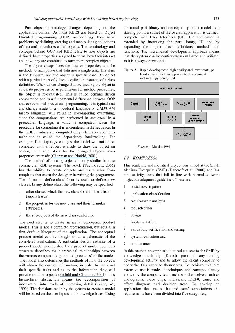
RAD is an approach to information systems development (Beynon-Davies et al., 1999) that is designed to give a faster and higher quality product, when structured within an appropriate methodology utilising the components shown in Figure 2, such as Martin (Martin, 1991) or the Dynamic Systems Development Method (DSDM). DSDM is based on the following nine principles (DSDM 2006).
1 Active user involvement is imperative. 2 The team must be empowered to make decisions. 3 The focus is on frequent delivery of products. 4 Fitness for business purpose is the essential criterion for
acceptance of deliverables. 5 Iterative and incremental development is necessary to
converge on an accurate business solution. 6 All changes during development are reversible.
7 Requirements are baselined at a high level.
8 Testing is integrated throughout the life-cycle.
9 Collaboration and co-operation between all stakeholders is essential.
Building a KBE application within the dynamic design environment using RAD techniques means that a typical application will evolve over time. The techniques advocate iterative programme enhancement, leading to an evolutionary life cycle. The KBE application starts with a skeletal system, with new modules added until a managed review stage is entered. From the initial prototype demonstration, the strengths and weaknesses are assessed and the program developed further.
The first step is to state the problem. The model is often used to ‘bring out’ full and open discussions between all the personnel involved (Chapman and Pinfold, 2001).
After stating the problem and identifying the information required by the model, key objects are created, to form a parts library. As each of the part objects is defined they are individually tested, by creating an instance of the object. Part objects created within the KBE applications form the building blocks of any model, often representing ‘real world’ objects. KBE parts are normally decomposed further, each stage of decomposition varying the intelligence of the objects. For example primitive objects might only know how to draw themselves, whereas higher level objects will use the knowledge base to make specific decisions regarding their shape, relationships, manufacturing process and cost.
Utilising enterprise knowledge with knowledge based engineering 173
Part object terminology changes depending on the application domain. As most KBES are based on Object Oriented Programming (OOP) methodology, they solve problems by defining, creating and manipulating collections of data and procedures called objects. The terminology and concepts behind OOP and KBE relate to how objects are defined, have properties assigned to them, how they interact and how they are combined to form more complex objects.
The object encapsulates the data or properties, and the methods to manipulate that data into a single unit. The class is the template, and the object is specific case. An object with a particular set of values is called an instance, of a class definition. When values change that are used by the object to calculate properties or as parameters for method procedures, the object is re-evaluated. This is called demand driven computation and is a fundamental difference between OOP and conventional procedural programming. It is typical that any change made to a procedural language or CAD/CAM macro language, will result in re-computing everything, since the computations are performed in sequence. In a procedural language, a value is computed, when the procedure for computing it is encountered in the sequence. In the KBES, values are computed only when required. This technique is called the dependency backtracking. For example if the topology changes, the model will not be re-computed until a request is made to draw the object on screen, or a calculation for the changed objects mass properties are made (Chapman and Pinfold, 2001).
The method of creating objects is very similar in most commercial KBE systems. The AML (TechnoSoft, 2006) has the ability to create objects and write rules from templates that assist the designer in writing the programme. The object or define-class form is used to define new classes. In any define-class, the following may be specified:
1 other classes which the new class should inherit from (superclasses)
2 the properties for the new class and their formulas (attributes)
3 the sub-objects of the new class (children).
The next step is to create an initial conceptual product model. This is not a complete representation, but acts as a first draft, a blueprint of the application. The conceptual product model can be thought of as a schematic of the completed application. A particular design instance of a product model is described by a product model tree. This structure describes the hierarchical relationships between the various components (parts and processes) of the model. The model also determines the methods of how the objects will obtain the correct information, in order to carry out their specific tasks and as to the information they will provide to other objects (Pinfold and Chapman, 2001). This hierarchical abstraction means the decomposition of information into levels of increasing detail (Zeiler, W., 1992). The decisions made by the system to create a model will be based on the user inputs and knowledge bases. Using
the initial part library and conceptual product model as a starting point, a subset of the overall application is defined, complete with User Interfaces (UI). The application is extended by increasing the part library, UI and by expanding the object class definitions, methods and functions. The incremental development approach means that the system can be continuously evaluated and utilised, as it is always operational.
Figure 2 Rapid development, high quality and lower costs go hand in hand with an appropriate development methodology being used
Source: Martin, 1991.
4.2 KOMPRESSA
This academic and industrial project was aimed at the Small Medium Enterprise (SME) (Bancroft et al., 2000) and has nine activity areas that fall in line with normal software project development guidelines. These are:
1 initial investigation
2 application classification
3 requirements analysis
4 tool selection
5 design
6 implementation
7 validation, verification and testing
8 system realisation and
9 maintenance.
In this method an emphasis is to reduce cost to the SME by knowledge modelling (Kmod) prior to any coding development activity and to allow the client company to undertake this exercise themselves. To achieve this aim extensive use is made of techniques and concepts already known by the company team members themselves, such as photographs, video clips, interviews, IDEF0, cause and effect diagrams and decision trees. To develop an application that meets the end-users’ expectations the requirements have been divided into five categories,
174 C. Chapman et al.
1 functionality
2 user interface
3 information
4 knowledge elicitation
5 performance (Bancroft et al., 2000).
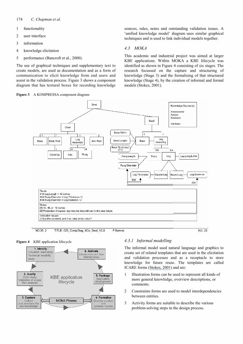
The use of graphical techniques and supplementary text to create models, are used as documentation and as a form of communication to elicit knowledge from end users and assist in the validation process. Figure 3 shows a component diagram that has textural boxes for recording knowledge
sources, rules, notes and outstanding validation issues. A ‘unified knowledge model’ diagram uses similar graphical techniques and is used to link individual models together.
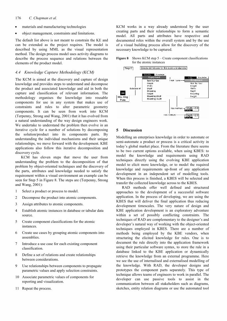
4.3 MOKA
This academic and industrial project was aimed at larger KBE applications. Within MOKA a KBE lifecycle was identified as shown in Figure 4 consisting of six stages. The research focussed on the capture and structuring of knowledge (Stage 3) and the formalising of that structured knowledge (Stage 4), by the creation of informal and formal models (Stokes, 2001).
Figure 3 A KOMPRESSA component diagram
Figure 4 KBE application lifecycle
4.3.1 Informal modelling The informal model used natural language and graphics to create set of related templates that are used in the elicitation and validation processes and as a receptacle to store knowledge for future reuse. The templates are called ICARE forms (Stokes, 2001) and are:
1 Illustration forms can be used to represent all kinds of more general knowledge, overview descriptions, or comments.
2 Constraints forms are used to model interdependencies between entities.
3 Activity forms are suitable to describe the various problem-solving steps in the design process.

Utilising enterprise knowledge with knowledge based engineering 175
4 Rule forms allow the modelling of control knowledge.
5 Entities are used to describe the product object classes (not only the physical ones but also functions, behaviours, etc.) as shown in Figure 5.
When developing large projects a great number of forms are generated. The relationships between these forms can be visualised through graphical means as shown in Figure 6.
Figure 5 MOKA entity form
Figure 6 A graphical representation of different ICARE forms and their interrelations
Source: The Ai are activity forms, related to one another by precedence relations; the Ei forms are entities, the Ci constraints, and the Ri rule forms (Klein, 2000).
4.3.2 Formal modelling
The second layer of representation is a formal model. A Knowledge Engineer (KE) studies the ICARE forms and manually converts this information into a MOKA Modelling Language (MML) style of representation and activity diagrams as shown in Figure 7. MML is intended to be an extension of the existing Unified Modelling Language (UML) although it is reported that it does not fulfil the Object Managements Groups (OMG) requirements (Abdullah et al., 2005). This formal model is meant to be readable by the coding developer, who will go on to develop the KBE application and not be the company knowledge holders.
Figure 7 MML product model and activity design process model diagrams
The formal model has two parts; they are the product model and the design process model. The product meta-model is flexible and aims to allow the KE to describe (Stokes, 2001):
• structural decomposition and assembly knowledge
• geometry and other issues concerning representation
• behaviour, under varying conditions
176 C. Chapman et al.
• materials and manufacturing technologies
• object management, constraints and limitations.
The default list above is not meant to constrain the KE and can be extended as the project requires. The model is described by using MML as the visual representation method. The design process model uses activity diagrams to describe the process sequence and relations between the elements of the product model.
4.4 Knowledge Capture Methodology (KCM)
The KCM is aimed at the discovery and capture of design knowledge and provides steps to understand and decompose the product and associated knowledge and aid in both the capture and classification of relevant information. The methodology organises the knowledge into reusable components for use in any system that makes use of constraints and rules to alter parametric geometry components. It can be seen from work into KCM (Terpenny, Strong and Wang, 2001) that it has evolved from a natural understanding of the way design engineers work. We undertake to understand the problem then evolve in an iterative cycle for a number of solutions by decomposing the solution/product into its components parts. By understanding the individual mechanisms and their unique relationships, we move forward with the development. KBE applications also follow this iterative decomposition and discovery cycle.
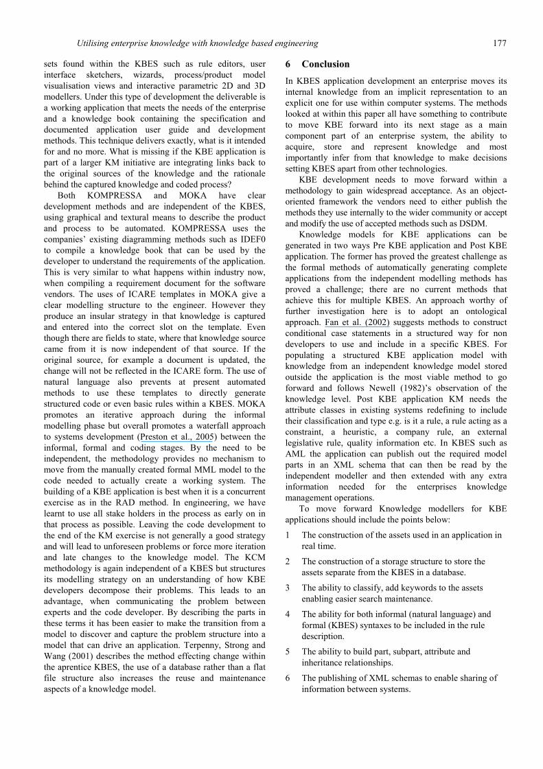
KCM has eleven steps that move the user from understanding the problem to the decomposition of that problem by object-oriented techniques and the discovery of the parts, attributes and knowledge needed to satisfy the requirement within a visual environment an example can be seen for Step 5 in Figure 8. The steps are (Terpenny, Strong and Wang, 2001):
1 Select a product or process to model.
2 Decompose the product into atomic components.
3 Assign attributes to atomic components.
4 Establish atomic instances in database or tabular data source.
5 Create component classifications for the atomic instances.
6 Create use cases by grouping atomic components into assemblies.
7 Introduce a use case for each existing component classification.
8 Define a set of relations and create relationships between considerations.
9 Use relationships between components to propagate parametric values and apply selection constraints.
10 Associate parametric values of components for reporting and visualization.
11 Repeat the process.
KCM works in a way already understood by the user creating parts and their relationships to form a semantic model. All parts and attributes have respective and documented roles within the overall system and by the use of a visual building process allow for the discovery of the necessary knowledge to be captured.
Figure 8 Shows KCM step 5 – Create component classifications for the atomic instances
5 Discussion Modelling an enterprises knowledge in order to automate or semi-automate a product or process is a critical activity in today’s global market place. From the literature there seems to be two current options available, when using KBES: to model the knowledge and requirements using RAD techniques directly using the evolving KBE application model to elicit more knowledge, or to model the required knowledge and requirements up-front of any application development in an independent set of modelling tools. When this process is finished, a KBES will be selected and transfer the collected knowledge across to the KBES.
RAD methods offer well defined and structured approaches to the development of a successful software application. In the process of developing, we are using the KBES that will deliver the final application thus reducing development timescales. The very nature of design and KBE application development is an exploratory adventure within a set of possibly conflicting constraints. The techniques of RAD are complementary to the designer’s and developer’s natural way of working with the object-oriented techniques employed in KBES. There are a number of methods being employed by the KBE vendors, when structuring the elicited knowledge for rules. One is to document the rule directly into the application framework using their particular software syntax, to store the rule in a database linked to the KBE application or dynamically retrieve the knowledge from an external programme. Here we see the use of internalised and externalised modelling of the knowledge. With RAD, the developer designs and prototypes the component parts separately. This type of technique allows teams of engineers to work in parallel. The developer can use passive tools to assist in the communication between all stakeholders such as diagrams, sketches, entity relation diagrams or use the automated tool
Utilising enterprise knowledge with knowledge based engineering 177
sets found within the KBES such as rule editors, user interface sketchers, wizards, process/product model visualisation views and interactive parametric 2D and 3D modellers. Under this type of development the deliverable is a working application that meets the needs of the enterprise and a knowledge book containing the specification and documented application user guide and development methods. This technique delivers exactly, what is it intended for and no more. What is missing if the KBE application is part of a larger KM initiative are integrating links back to the original sources of the knowledge and the rationale behind the captured knowledge and coded process?
Both KOMPRESSA and MOKA have clear development methods and are independent of the KBES, using graphical and textural means to describe the product and process to be automated. KOMPRESSA uses the companies’ existing diagramming methods such as IDEF0 to compile a knowledge book that can be used by the developer to understand the requirements of the application. This is very similar to what happens within industry now, when compiling a requirement document for the software vendors. The uses of ICARE templates in MOKA give a clear modelling structure to the engineer. However they produce an insular strategy in that knowledge is captured and entered into the correct slot on the template. Even though there are fields to state, where that knowledge source came from it is now independent of that source. If the original source, for example a document is updated, the change will not be reflected in the ICARE form. The use of natural language also prevents at present automated methods to use these templates to directly generate structured code or even basic rules within a KBES. MOKA promotes an iterative approach during the informal modelling phase but overall promotes a waterfall approach to systems development (Preston et al., 2005) between the informal, formal and coding stages. By the need to be independent, the methodology provides no mechanism to move from the manually created formal MML model to the code needed to actually create a working system. The building of a KBE application is best when it is a concurrent exercise as in the RAD method. In engineering, we have learnt to use all stake holders in the process as early on in that process as possible. Leaving the code development to the end of the KM exercise is not generally a good strategy and will lead to unforeseen problems or force more iteration and late changes to the knowledge model. The KCM methodology is again independent of a KBES but structures its modelling strategy on an understanding of how KBE developers decompose their problems. This leads to an advantage, when communicating the problem between experts and the code developer. By describing the parts in these terms it has been easier to make the transition from a model to discover and capture the problem structure into a model that can drive an application. Terpenny, Strong and Wang (2001) describes the method effecting change within the aprentice KBES, the use of a database rather than a flat file structure also increases the reuse and maintenance aspects of a knowledge model.
6 Conclusion In KBES application development an enterprise moves its internal knowledge from an implicit representation to an explicit one for use within computer systems. The methods looked at within this paper all have something to contribute to move KBE forward into its next stage as a main component part of an enterprise system, the ability to acquire, store and represent knowledge and most importantly infer from that knowledge to make decisions setting KBES apart from other technologies.
KBE development needs to move forward within a methodology to gain widespread acceptance. As an object-oriented framework the vendors need to either publish the methods they use internally to the wider community or accept and modify the use of accepted methods such as DSDM.
Knowledge models for KBE applications can be generated in two ways Pre KBE application and Post KBE application. The former has proved the greatest challenge as the formal methods of automatically generating complete applications from the independent modelling methods has proved a challenge; there are no current methods that achieve this for multiple KBES. An approach worthy of further investigation here is to adopt an ontological approach. Fan et al. (2002) suggests methods to construct conditional case statements in a structured way for non developers to use and include in a specific KBES. For populating a structured KBE application model with knowledge from an independent knowledge model stored outside the application is the most viable method to go forward and follows Newell (1982)’s observation of the knowledge level. Post KBE application KM needs the attribute classes in existing systems redefining to include their classification and type e.g. is it a rule, a rule acting as a constraint, a heuristic, a company rule, an external legislative rule, quality information etc. In KBES such as AML the application can publish out the required model parts in an XML schema that can then be read by the independent modeller and then extended with any extra information needed for the enterprises knowledge management operations.
To move forward Knowledge modellers for KBE applications should include the points below:
1 The construction of the assets used in an application in real time.
2 The construction of a storage structure to store the assets separate from the KBES in a database.
3 The ability to classify, add keywords to the assets enabling easier search maintenance.
4 The ability for both informal (natural language) and formal (KBES) syntaxes to be included in the rule description.
5 The ability to build part, subpart, attribute and inheritance relationships.
6 The publishing of XML schemas to enable sharing of information between systems.
178 C. Chapman et al.
7 A single unified model that has multiple views to suit the various stakeholder’s perspectives (no view should be an independent representation).
8 The use of templates where appropriate, to maintain consistent modelling.
9 The ability to handle 3D engineering models.
10 To link to other systems containing required information.
11 To have versioning and user management controls.
All the industrial case studies of successful KBE applications referenced in this paper follow the traditional RAD techniques adopted by the KBE vendors, development teams comprising of both company domain experts and KBES developers. Within the MOKA methodology an extra resource is included that of a knowledge engineer, who models the knowledge model then manually creates a formal model description to give to the developer, who codes the application. This is a deskilling of the traditional knowledge engineer, who also coded the KBS. One could argue, whether this extra resource is indeed necessary as a successful Kmod tools should be able to be used by the domain experts themselves and one should not isolate the developer, who can make a valuable contribution to any KBE application modelling development team.
References Abdullah, M.S., Evans, A., Benest, I. and Kimble, C. (2005)
‘Developing a UML Profile for Modelling Knowledge-Based Systems’, Lecture Notes in Computer Science, Springer-Verlag GmbH, Volume 3599/2005.
Bancroft, C.N., Crump, S.J., Lovett, P.J., Bone, D. and Kightley, N.J. (2000) ‘Taking KBE into the Foundry’, Paper presented in the Proceedings of the 7th ISPE International Conference On Concurrent Engineering, Vol. 24, pp.17–20.
Blair, M. (1998) ‘Enabling conceptual design in a technology-driven environment’, AIAA/USAF/NASA/ISSMO Symposium on Multidisciplinary Analysis and Optimization, 7th, St. Louis, MO, September 2–4, 1998, AIAA-1998-4741.
Chapman, C. (1999), ‘Design engineering – a need to rethink the solution using Knowledge Based Engineering (KBE)’, Int. J. Knowledge Based Systems, Elsevier, Vol. 12, pp.257–267.
Chapman, C. and Pinfold, M.K. (1998) ‘Design Engineering – a need to rethink the solution using KBE’, Paper presented in the Proceedings of the 18th Specialist Group on Expert Systems (SGES) Int. Conf. on Knowledge Based Systems and Applied Artificial Intelligence, 14-16th December 1998, Cambridge, UK: Pub in Applications and Innovations in Expert Systems VI (pp.112–131). London, UK: Springer-Verlag.
Chapman, C. and Pinfold, M.K. (2001) ‘The application of a knowledge based engineering approach to the rapid design and analysis of an automotive structure’ Advances in Engineering Software Journal, Vol. 32/12, pp.903–912.
Davies, B.P., Carne, C., Mackay, H. and Tudhope, D. (1999) ‘Rapid application development (RAD): an empirical review’, European Journal of Information Systems, Vol. 8, pp.211–223.
DSDM (2006) DSDM Consortium, Unit 7, Invicta Business Centre, Monument Way, Orbital Park, UK: Ashford, Kent TN24 0HB, Available at: www.dsdm.org.
Fan, I.S., Li, G., Lagos-Hernandez, M., Bermell-García, P. and Twelves, M. (2002) ‘A rule level knowledge management system for knowledge based engineering applications’, Paper presented in the Proceedings of the DETC’02, ASME International 22nd Computers and Information in Engineering (CIE) Conference September 29–October 2, Montreal, Canada.
Hale, R.D. and Schueler, K. (2002) ‘Object oriented design and analysis tools for fiber placed and fiber steered structures’, Paper presented in the Proceedings of the SAMPE 2002, May 13–16, 2002, Long Beach CA.
Martin, J. (1991) Rapid Application Development. New York: Macmillan Publishing Company.
Klein, R. (2000) ‘Towards an integration of engineering knowledge management and knowledge based engineering’, CIRP Paper presented in the Proceedings of the Conference on Advanced Engineering Information Systems, Haifa, Israel.
Moses, P.L., Bouchard, K.A., Vause, R.F., Pinckney, S.Z., Ferlemann, S.M., Leonard, C.P., Taylor lll, L.W., Robinson, J.S., Martin, J.G., Petley, D.H. and Hunt, J.L. (1999) ‘An airbreathing launch vehicle design with turbine-based low-speed propulsion and dual mode scramjet high-speed propulsion’, Paper presented in the Proceedings of the 9th International Space Planes and Hypersonic Systems and Technologies Conference and 3rd Weakly Ionized Gases Workshop November 1–5, 1999/Norfolk, VA: American Institute of Aeronautics and Astronautics.
Nederbragt, W., Robert, A., Shaw, F., Kaing, S., Sriram, R. and Zhang, Y. (1998) ‘The NIST design/process planning integration project’, Paper presented in the Proceedings of the Advanced Technology & Manufacturing: State-of-the-Art & State of Practice Workshop Workshop Proceedings, Atlanta, GA, August 31, 1998–September 2, 1998.
Newell, A. (1982) ‘The knowledge level’, Artificial Intelligence, Vol. 18, pp.87–127.
Pinfold, M.K. and Chapman, C. (2001) ‘The application of KBE techniques to the FE model creation of an automotive body structure’, Computers in Industry, Vol. 44, pp.1–10.
Preston, S., Chapman, C., Pinfold, M. and Smith, G. (2005) ‘Knowledge acquisition for knowledge based engineering systems’, Int. J. Information Technology and Management, Vol 4, pp.1–11.
Schonning, M.A., Nayfeh, J.F. and Zarda, P.R. (2003) ‘Utilization of a dependency-tracking language to reduce computational time during multidisciplinary design optimization’ Advances in Engineering Software, Vol. 34, pp.115–122.
Stokes, M. (Ed.) (2001) MOKA: Methodology For Knowledge Based Engineering Applications’, Bury St Edmunds, UK: Professional Engineering Publishing.
TechnoSoft Inc (2006), ‘The adaptive modelling language. A technical-perspective’, Available at: http://www.technosoft. com/docs/AML-Technical-Perspectives.pdf
Terpenny, J.P., Strong, S. and Wang, J. (2001) ‘A methodology for knowledge discovery and classification’, Paper presented in the Proceedings of the Tenth FAIM 2000 – Flexible Automation and Intelligent Manufacturing Conference, University of Maryland, College Park, Maryland, June 26–28, 2000.

Utilising enterprise knowledge with knowledge based engineering 179
Zachman, J.A. (1987) ‘A framework for information systems architecture’, IBM Systems Journal, Vol. 26, pp.276–292, IBM Publication, G321–5298.
Zeiler, W. (1992) ‘State of the art, object-oriented hybrid intelligent CAD Systems’, Computers in Industry, Vol. 20, pp.1–9, Elsevier, Amsterdam.
Zweber, J.V. and Hartong, A. (1998) ‘Structural and control surface design for wings using the adaptive modelling language’, Paper presented in the Proceedings of the AIAA-1998-4869, AIAA/USAF/NASA/ISSMO Symposium on Multidisciplinary Analysis and Optimization, 7th, St. Louis, MO, Sept.24.
Related Documents