UT Lift 1.2 Users Guide Developed at: The University of Texas at Austin Funded by the Texas Department of Transportation Project (0-5574) Spreadsheet Developed by: Jason C. Stith, PhD Project Advisors: Dr. Todd A. Helwig Dr. Karl H. Frank Dr. Michael D. Engelhardt Dr. Eric B. Williamson Send Comments to Dr. Todd Helwig [email protected]

Welcome message from author
This document is posted to help you gain knowledge. Please leave a comment to let me know what you think about it! Share it to your friends and learn new things together.
Transcript

UT Lift 1.2
Users Guide Developed at:
The University of Texas at Austin Funded by the Texas Department of Transportation Project (0-5574)
Spreadsheet Developed by: Jason C. Stith, PhD
Project Advisors: Dr. Todd A. Helwig Dr. Karl H. Frank
Dr. Michael D. Engelhardt Dr. Eric B. Williamson
Send Comments to Dr. Todd Helwig [email protected]

2
PURPOSE:
The purpose of this spreadsheet is to provide a tool and give information to an engineer when deciding the safety of lifting a horizontally curved steel I-girder with one crane and two lift clamps. This is a common lifting technique used in the construction of curved I-girder bridges as shown in Figure 1.
Figure 1: Lifting of a Horizontally Curved Steel I-Girder with 1 Crane & 2 Lift Clamps
The spreadsheet has been developed to indicate the necessary inputs and highlight the calculated results. The green colored cells allow for input to be given and the blue colored cells highlight the notable calculated results. The current spread sheet allows for the analysis of a girder segment with up to 8 different cross sections and 18 cross frames attached.
GIRDER INPUTS SHEET:
The first two pages are dedicated to the required geometric properties of the girder including:
1) the number of different cross sections along the girder, 2) the radius of curvature of the girder segment, 3) the plate dimensions for each cross section, 4) the arc length measured along the girder’s centerline of each cross section, 5) the number of cross frames attached to the girder segment during lifting, 6) the cross frame width, 7) the weight of a cross frame, 8) the location of the cross frames, and 9) whether the cross frame is on the inside of the curve, outside of the curve, or both sides.

3
Page 1: The project name and the name of the specific girder analyzed can be specified for record keeping purposes.
The girder scale factor is multiplied by the girder self weight. This scale factor allows the engineer to the match shipping weight if available or accounts for other auxiliary elements (shear studs, stiffeners etc.).
The sign convention for the radius of curvature is positive for a right curve looking ahead station from the girders beginning.
A “Clear Input” button is available. Once pressed it will prompt the user to confirm that they want all the input cells to be deleted and it will clear all user input cells.
The plate dimensions needed include:
1) top flange width (TFLW), 2) top flange thickness (TFLT), 3) web depth (DEPTH), 4) web thickness (WEBT), 5) bottom flange thickness (BFLT), and 6) bottom flange width (BFLW).
Figure 2: Plate Dimensions
Page 2:
The cross frame width is needed to determine the center of gravity of an individual cross frame. The cross frame center of gravity is assumed to be located midway between adjacent girders
Top Flange
Thickness
Bottom Flange
Thickness
Web
Depth
Top Flange
Width
Bottom
Flange Width
Web
Thickness

4
(girder spacing divide by 2). Therefore, the girder spacing should be specified as the cross frame width.
The weight of a cross frame should only include the weight of a single cross frame even if they are located on both sides of the girder for a given location. The cross frames need to be specified as either located on the inside of the curve, on the outside of the curve, or on both sides of the curve for a given cross frame location as shown in Figure 3. By selecting “I/O”, the weight will be multiplied by 2 for locations where cross frames are present on both sides of the girder. This is specified for each cross frame location and does not necessarily have to be consistent down the length of the girder. The cross frames locations must be specified in ascending order down the length of the girder.
Figure 3: Options of Cross Frame Location
For girders with a constant cross frame spacing the “Uniformly Spaced Cross Frame:” section allows the user to specify the cross frame spacing and the first cross frame location. Then the correct input will appear in the cells once the “Constant X-Frame Spacing” button is pressed.
There are three buttons: “All I”, “All O”, and “All I/O”. By pressing a button all the cross frames location cells will be propagated with the appropriate value. The program does not require uniform cross frame locations, but these buttons assist users with girders that have constant locations.
Once the number of cross sections and the number of cross frames are specified any input located in columns associated with cross sections or cross frames beyond this specified number will be ignored and can be deleted without affecting the analysis.
C.G. & IDEAL LIFT SHEET:
Page 1:
The spreadsheet calculates several useful pieces of information including:
Cross Frames on Both Sides: I/O
s
Cross Frames on the Inside: I
s
Cross Frames on the Outside: O
s

5
1) the total girder length, 2) the total girder weight, 3) location of the girder segment’s center of gravity, 4) the lift clamps location that results in zero rigid body rotation and equal lift clamp forces,
and 5) the reactions of the lift clamps for the zero rigid body rotation location.
The location of the girder segment’s center of gravity is given as the length along the girder and an offset from the girder centerline. The center of gravity offset is assumed to be on the inside of the curve and thus this direction is considered a positive offset. There are an infinite number of lines that intersect the curve at two points and pass through the center of gravity. However, there exists a lift clamp location that defines a line that results in equal minimized forces and the line passes through the center of gravity. This is optimum with regard to the girder’s rigid body rotation. The reaction for these lift clamps is equal to the total girder weight divided by two.
CALCULATED BEHAVIOR SHEET:
Page 1:
The fourth page allows for the behavior of the girder segment lifted at specified locations to be analyzed. This requires the lift clamp locations and the location of the axis of rotation above the top of the girder to be specified by the user.
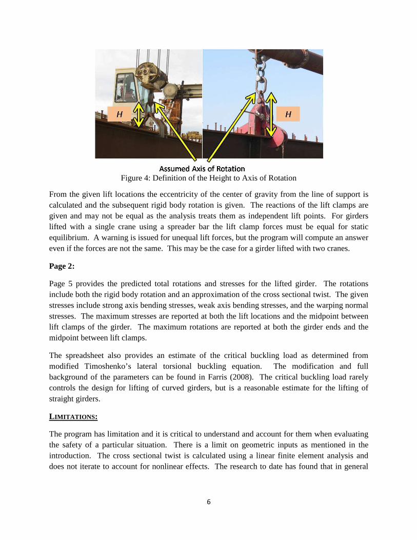
The axis of rotation is the location within the lifting apparatus where rotation is free to occur. For the case of a single crane with two lift clamps separated by a spreader bar this is the location on the lift clamp that will allow for rotation. Figure 4 is a pair of pictures with the assumed axis of rotation indicated for two different lift clamps. This height was approximately 30” and has been deemed a reasonable estimate. However, it should be noted that a smaller value will result larger calculated rigid body rotations or a more conservative estimate.
6
Figure 4: Definition of the Height to Axis of Rotation
From the given lift locations the eccentricity of the center of gravity from the line of support is calculated and the subsequent rigid body rotation is given. The reactions of the lift clamps are given and may not be equal as the analysis treats them as independent lift points. For girders lifted with a single crane using a spreader bar the lift clamp forces must be equal for static equilibrium. A warning is issued for unequal lift forces, but the program will compute an answer even if the forces are not the same. This may be the case for a girder lifted with two cranes.
Page 2:
Page 5 provides the predicted total rotations and stresses for the lifted girder. The rotations include both the rigid body rotation and an approximation of the cross sectional twist. The given stresses include strong axis bending stresses, weak axis bending stresses, and the warping normal stresses. The maximum stresses are reported at both the lift locations and the midpoint between lift clamps of the girder. The maximum rotations are reported at both the girder ends and the midpoint between lift clamps.
The spreadsheet also provides an estimate of the critical buckling load as determined from modified Timoshenko’s lateral torsional buckling equation. The modification and full background of the parameters can be found in Farris (2008). The critical buckling load rarely controls the design for lifting of curved girders, but is a reasonable estimate for the lifting of straight girders.
LIMITATIONS:
The program has limitation and it is critical to understand and account for them when evaluating the safety of a particular situation. There is a limit on geometric inputs as mentioned in the introduction. The cross sectional twist is calculated using a linear finite element analysis and does not iterate to account for nonlinear effects. The research to date has found that in general

7
the 2nd order effects are minimal if the analysis is limited to small total rotations ( < ~ 1.5 degrees). The specific allowable rotation limit should be controlled by the erectors preference.
DEVELOPMENT & DISCLAIMER
This spreadsheet was developed at the University of Texas at Austin for the Texas Department of Transportation as part of a funded research project (TxDOT 0-5574). The user is encouraged to verify the calculations by an independent source and use professional engineering judgment when evaluating the safety of lifting a horizontally curved I-girder. The developers of the spreadsheet have verified the accuracy for specific cases, but do not accept any legal responsibility for the accuracy of the calculated values or output. Use of the spreadsheet acknowledges the full understanding of this disclaimer and releases the right to proceed with any legal action against the University of Texas at Austin, the Texas Department of Transportation, or the developers of this program.
REFERENCES
Farris, Jamie. “Behavior of Horizontally Curved Steel I-Girders during Constructions,” Master’s Thesis, The University of Texas at Austin, December, 2008.
8
EXAMPLE PROBLEMS
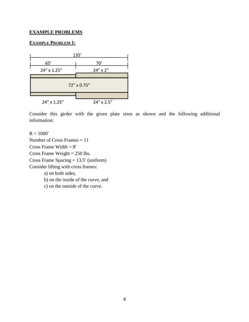
EXAMPLE PROBLEM 1:
Consider this girder with the given plate sizes as shown and the following additional information: R = 1000′ Number of Cross Frames = 11 Cross Frame Width = 8′ Cross Frame Weight = 250 lbs. Cross Frame Spacing = 13.5′ (uniform) Consider lifting with cross frames:
a) on both sides, b) on the inside of the curve, and c) on the outside of the curve.
72” x 0.75”
24” x 1.25” 24” x 2”
24” x 2.5”24” x 1.25”
65’ 70’
135’
9
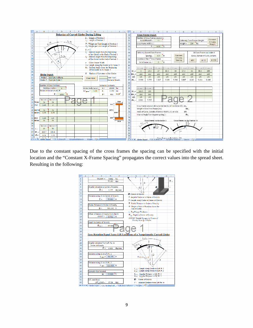
Due to the constant spacing of the cross frames the spacing can be specified with the initial location and the “Constant X-Frame Spacing” propagates the correct values into the spread sheet. Resulting in the following:
10
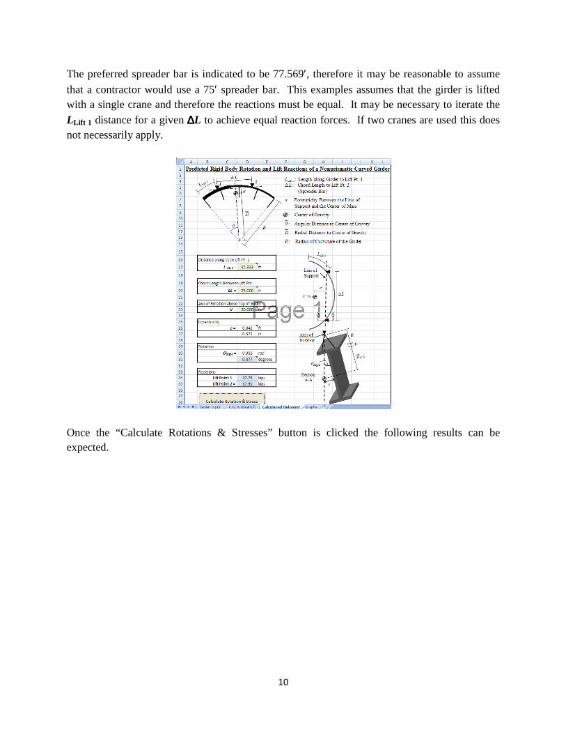
The preferred spreader bar is indicated to be 77.569′, therefore it may be reasonable to assume
that a contractor would use a 75′ spreader bar. This examples assumes that the girder is lifted with a single crane and therefore the reactions must be equal. It may be necessary to iterate the LLift 1 distance for a given ∆∆∆∆L to achieve equal reaction forces. If two cranes are used this does not necessarily apply.
Once the “Calculate Rotations & Stresses” button is clicked the following results can be expected.
11
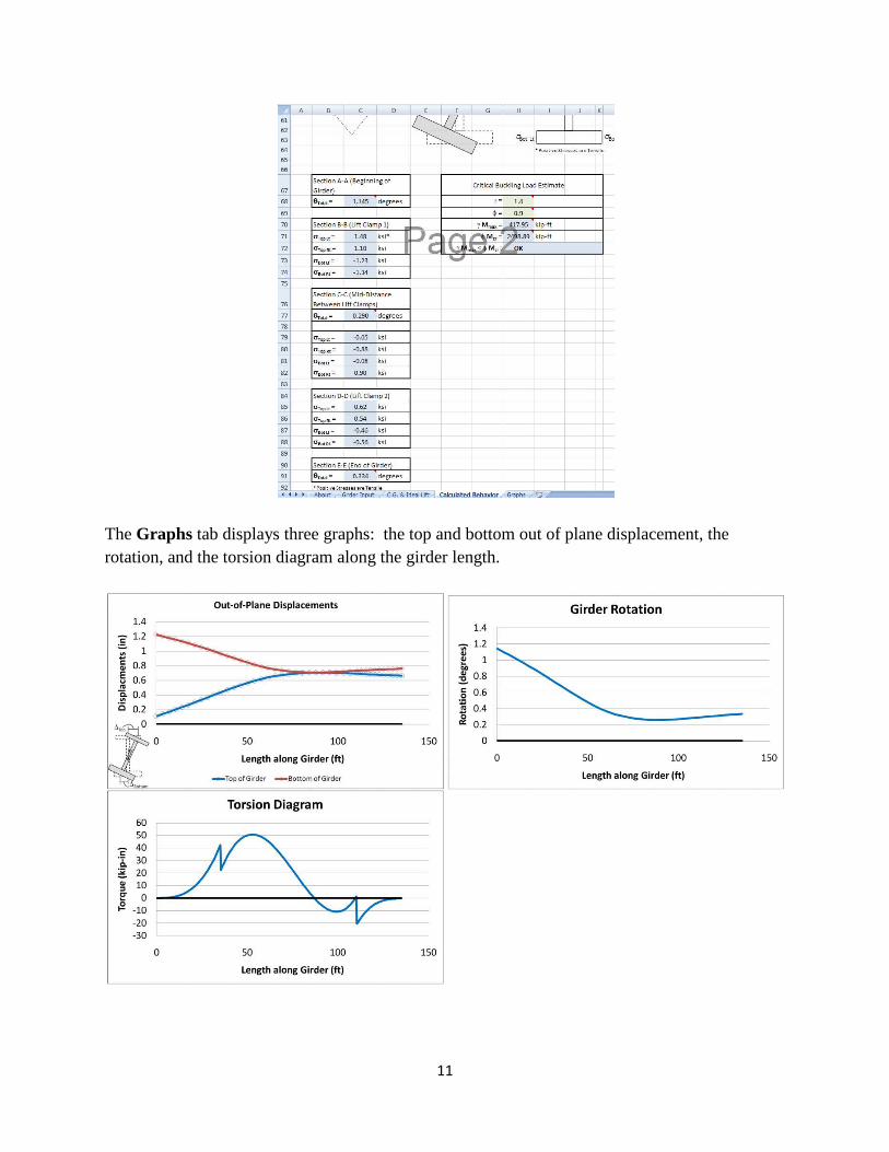
The Graphs tab displays three graphs: the top and bottom out of plane displacement, the rotation, and the torsion diagram along the girder length.
12
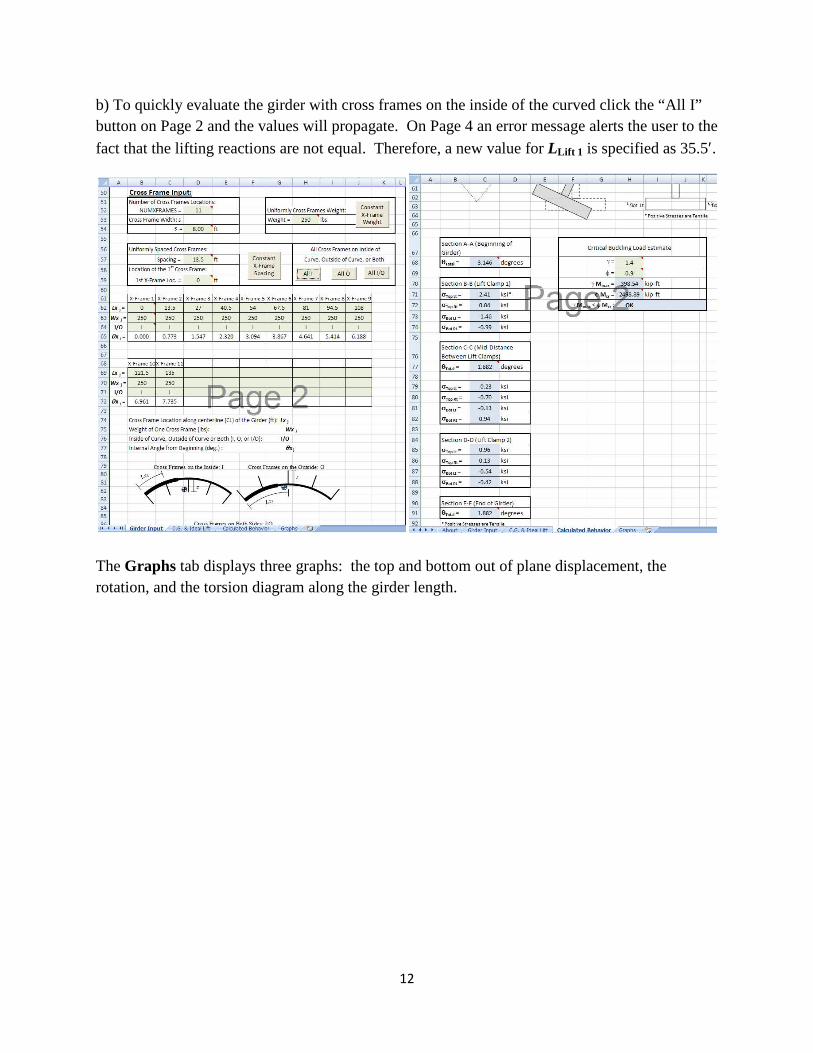
b) To quickly evaluate the girder with cross frames on the inside of the curved click the “All I” button on Page 2 and the values will propagate. On Page 4 an error message alerts the user to the
fact that the lifting reactions are not equal. Therefore, a new value for LLift 1 is specified as 35.5′.
The Graphs tab displays three graphs: the top and bottom out of plane displacement, the rotation, and the torsion diagram along the girder length.
13
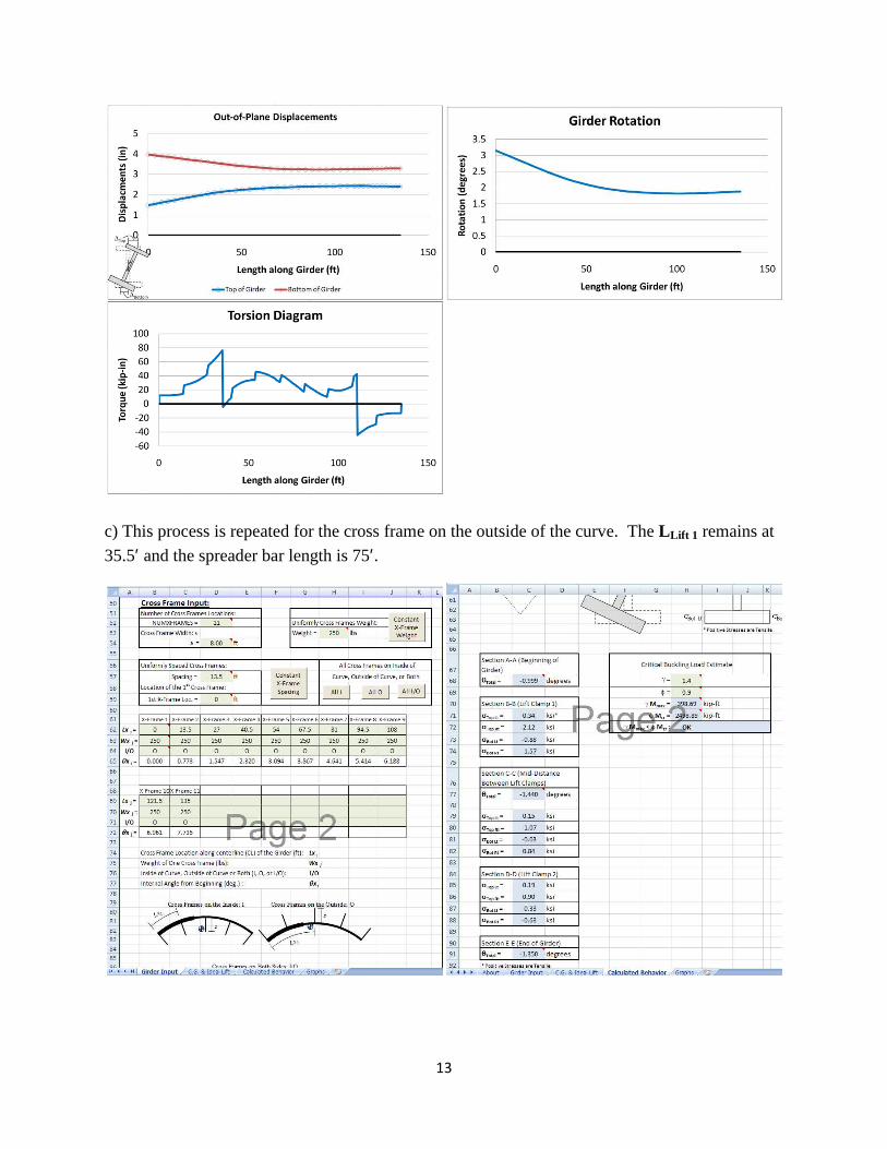
c) This process is repeated for the cross frame on the outside of the curve. The LLift 1 remains at
35.5′ and the spreader bar length is 75′.
14
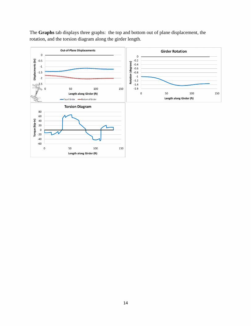
The Graphs tab displays three graphs: the top and bottom out of plane displacement, the rotation, and the torsion diagram along the girder length.
15
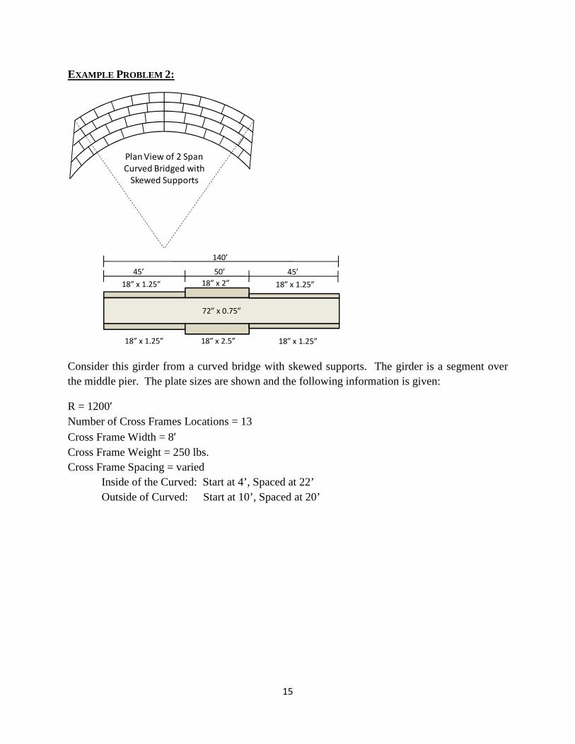
EXAMPLE PROBLEM 2:
Consider this girder from a curved bridge with skewed supports. The girder is a segment over the middle pier. The plate sizes are shown and the following information is given:
R = 1200′ Number of Cross Frames Locations = 13 Cross Frame Width = 8′ Cross Frame Weight = 250 lbs. Cross Frame Spacing = varied Inside of the Curved: Start at 4’, Spaced at 22’ Outside of Curved: Start at 10’, Spaced at 20’
Plan View of 2 Span
Curved Bridged with
Skewed Supports
72” x 0.75”
18” x 1.25” 18” x 2”
18” x 2.5”18” x 1.25”
45’ 50’
140’
18” x 1.25”
18” x 1.25”
45’
16
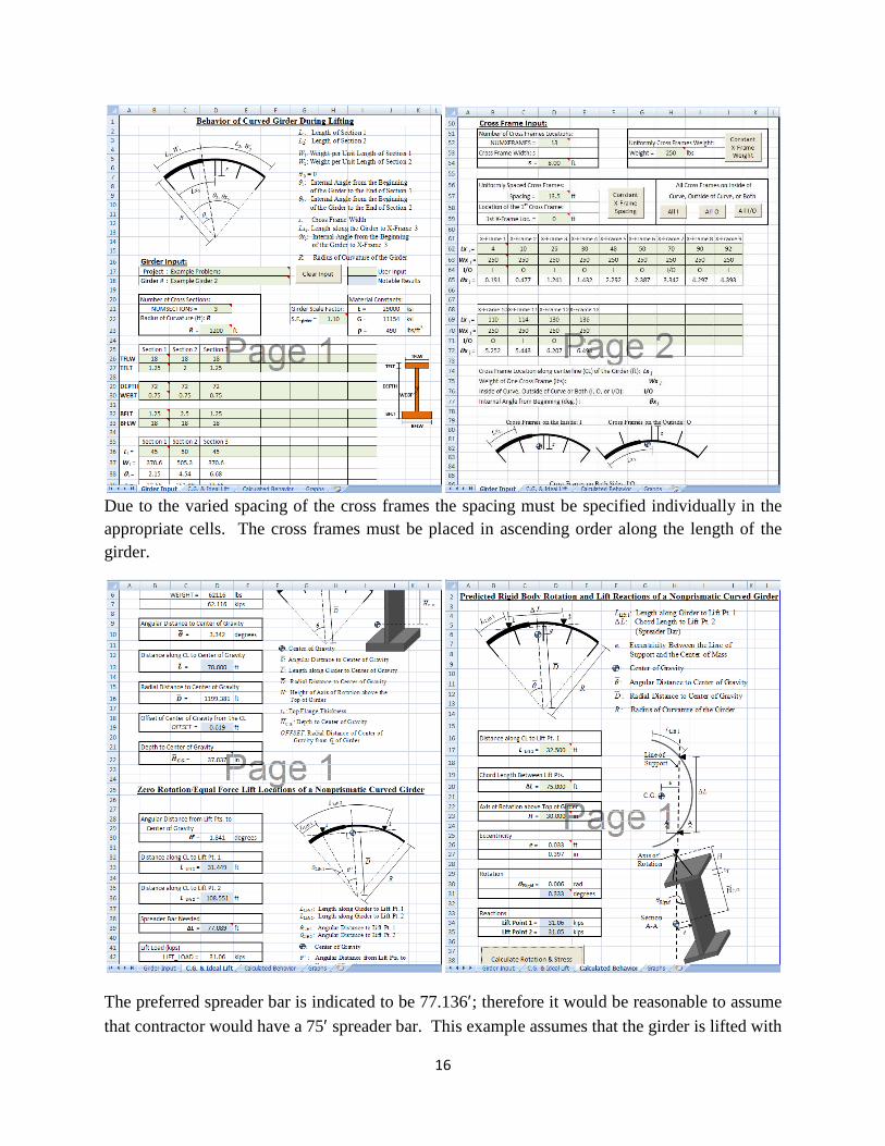
Due to the varied spacing of the cross frames the spacing must be specified individually in the appropriate cells. The cross frames must be placed in ascending order along the length of the girder.
The preferred spreader bar is indicated to be 77.136′; therefore it would be reasonable to assume
that contractor would have a 75′ spreader bar. This example assumes that the girder is lifted with
17
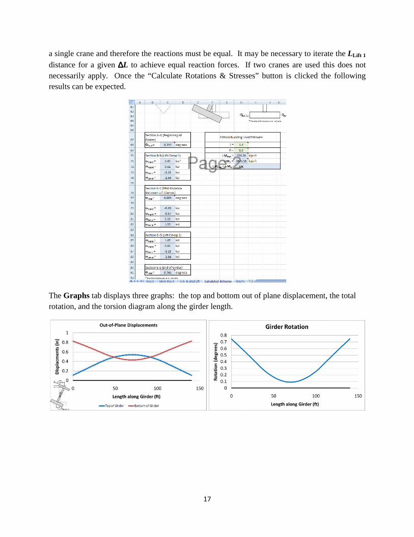
a single crane and therefore the reactions must be equal. It may be necessary to iterate the LLift 1 distance for a given ∆∆∆∆L to achieve equal reaction forces. If two cranes are used this does not necessarily apply. Once the “Calculate Rotations & Stresses” button is clicked the following results can be expected.
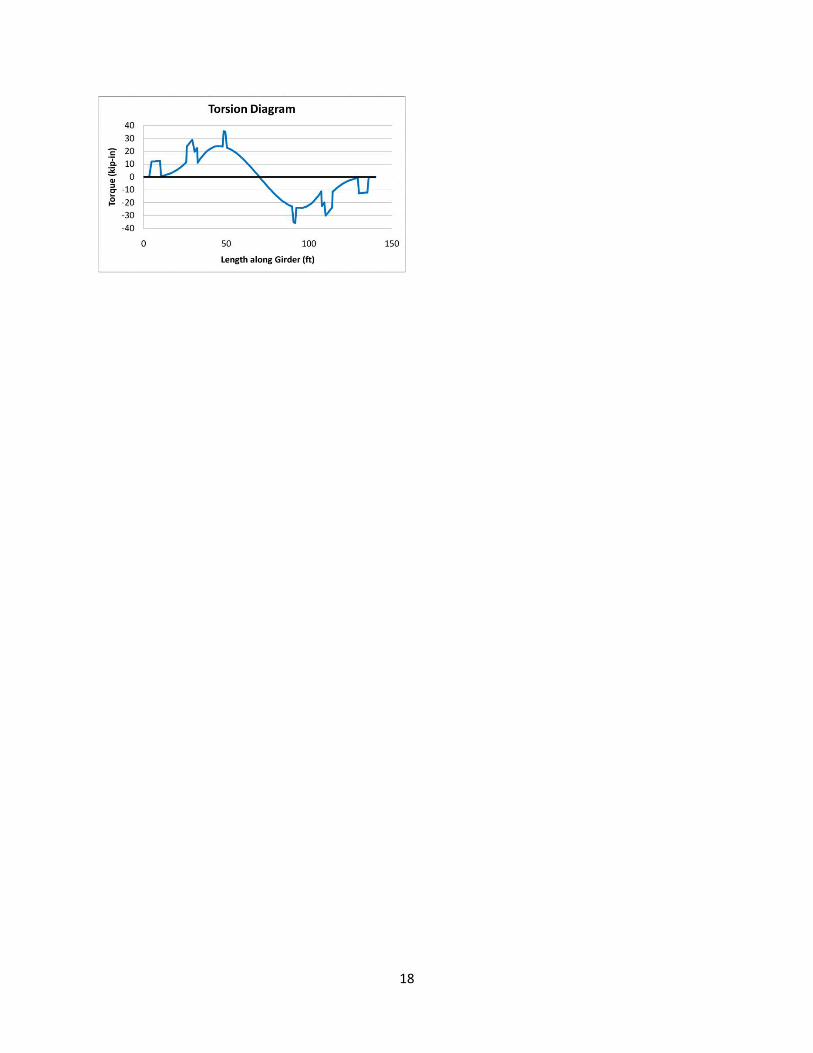
The Graphs tab displays three graphs: the top and bottom out of plane displacement, the total rotation, and the torsion diagram along the girder length.
18
Related Documents