USIXML: a User Interface Description Language Supporting Multiple Levels of Indepedence Quentin Limbourg, Jean Vanderdonckt, Benjamin Michotte, Laurent Bouillon, Murielle Florins 1 Université catholique de Louvain, School of Management (IAG), ISYS-BCHI Place des Doyens, 1 – B-1348 Louvain-la-Neuve, Belgium {limbourg,vanderdonckt,michotte, bouillon,florins}@isys.ucl.ac.be http://www.isys.ucl.ac.be/bchi Abstract. USer Interface eXtensible Markup Language (USIXML) consists of a User Interface Description Language (UIDL) allowing designers to apply a multi-directional development of user interfaces at multiple levels on independ- ence, and not only device independence. In this development paradigm, a user interface can be specified and produced at and from different, and possibly multiple, levels of abstraction while maintaining the mappings between these levels if required. Thus, the development process can be initiated from any level of abstraction and proceed towards obtaining one or many final user inter- faces for various contexts of use at other levels of abstraction. In this way, the model-to-model transformation which is the cornerstone of Model-Driven Ar- chitecture (MDA) can be supported in multiple configurations, based on com- position of three basic transformation types: abstraction, reification, and trans- lation. Keywords: context-sensitive user interface, development processes, device in- dependence, modality independence, model-driven architecture, model-to- model transformation, multi-directional development, rendering independence, user interface description language. 1 Introduction Due to the rapid changes of today’s organisations and their business, many infor- mation systems departments face the problem of quickly adapting the user interface (UI) of their interactive applications to these changes. These changes include, but are not limited to: task redefinition [4], task reallocation among workers [4], support of new computing platforms [10], migration from stationary platforms to mobile com- puting [17], evolution of users with more demands, increasing need for more usable UIs, transfer of task from one user to another one [7], redefinition of the organisation structure, adaptation to dynamic environments [16], change of the language, redesign due to obsolescence [3], evolution of the domain model [1]. All these changes change to some extent the context of use, which is hereby referred to as the complete envi- ronment where final users have to carry out their interactive tasks to fulfil the roles they are playing in their organisations.

Welcome message from author
This document is posted to help you gain knowledge. Please leave a comment to let me know what you think about it! Share it to your friends and learn new things together.
Transcript

USIXML: a User Interface Description Language Supporting Multiple Levels of Indepedence
Quentin Limbourg, Jean Vanderdonckt, Benjamin Michotte, Laurent Bouillon, Murielle Florins
1 Université catholique de Louvain, School of Management (IAG), ISYS-BCHI Place des Doyens, 1 – B-1348 Louvain-la-Neuve, Belgium
{limbourg,vanderdonckt,michotte, bouillon,florins}@isys.ucl.ac.be http://www.isys.ucl.ac.be/bchi
Abstract. USer Interface eXtensible Markup Language (USIXML) consists of a User Interface Description Language (UIDL) allowing designers to apply a multi-directional development of user interfaces at multiple levels on independ-ence, and not only device independence. In this development paradigm, a user interface can be specified and produced at and from different, and possibly multiple, levels of abstraction while maintaining the mappings between these levels if required. Thus, the development process can be initiated from any level of abstraction and proceed towards obtaining one or many final user inter-faces for various contexts of use at other levels of abstraction. In this way, the model-to-model transformation which is the cornerstone of Model-Driven Ar-chitecture (MDA) can be supported in multiple configurations, based on com-position of three basic transformation types: abstraction, reification, and trans-lation.
Keywords: context-sensitive user interface, development processes, device in-dependence, modality independence, model-driven architecture, model-to-model transformation, multi-directional development, rendering independence, user interface description language.
1 Introduction
Due to the rapid changes of today’s organisations and their business, many infor-mation systems departments face the problem of quickly adapting the user interface (UI) of their interactive applications to these changes. These changes include, but are not limited to: task redefinition [4], task reallocation among workers [4], support of new computing platforms [10], migration from stationary platforms to mobile com-puting [17], evolution of users with more demands, increasing need for more usable UIs, transfer of task from one user to another one [7], redefinition of the organisation structure, adaptation to dynamic environments [16], change of the language, redesign due to obsolescence [3], evolution of the domain model [1]. All these changes change to some extent the context of use, which is hereby referred to as the complete envi-ronment where final users have to carry out their interactive tasks to fulfil the roles they are playing in their organisations.

To address the challenges posed by these changes, the development processes used in these organisations are not always considered appropriate as they do not reflect the implication of any change throughout the complete development life cycle. As a mat-ter of fact, organisations react to changes in very different ways in their UI develop-ment processes. For instance, one organisation starts by recovering existing in-put/output screens, by redrawing them and by completing the functional core when the new UI is validated by the customer (bottom-up approach). Another organisation prefers to modify the domain model (e.g., a UML class diagram [12]) and the task model [20] to be mapped further to screen design (top-down approach). A third one tends to apply in parallel all the required adaptations where they occur (wide spread-ing approach). A fourth one relies on an intermediate model and proceeds simultane-ously to the task and domain models, and the final UI (middle-out approach) [15]. The UI development process has also been empirically observed as a ill-defined, in-complete, and incremental process [24] that is not well supported by rigid develop-ment methods and tools. Such methods and tools usually force developers to act in a way that remains peculiar to the method. The tool does not allow for more flexibility. For instance, SEGUIA [25] only supports a single fixed UI development path [11].
The variety of the approaches adopted in organisations and the rigidity of existing solutions provide ample motivations for a UI development paradigm that is flexible enough to accommodate multiple development paths and design situations while stay-ing precise enough to manipulate information required for UI development. To over-come these shortcomings, the development paradigm of multi-directional UI devel-opment is introduced that is characterised by the following principles: • Expressiveness of UI: any UI is expressed depending on the context of use thanks
to a suite of models [20] analysable, editable, and manipulable by a software [21]. • Central storage of models: each model is stored in a model repository where all
UI models are expressed according to the same UI Description Language (UIDL). • Transformational approach: each model stored in the model repository may be
subject to one or many transformations supporting various development steps. • Multiple development paths: development steps can be combined together to form
developments paths that are compatible with the organisation’s constraints, con-ventions, and context of use. For example, a series of transformations should be applied to progressively moves from a task model to a dialog model, to recover a domain model from a presentation model, to derive a presentation model from both the task and domain models.
• Flexible development approaches: development approaches (e.g., top-down, bot-tom-up, wide spreading, and middle-out) are supported by flexibly following al-ternate development paths and enable designers to freely shift between these paths depending on the changes imposed by the context of use [15].
The remainder of this paper is structured as follows: Section 2 reports on some sig-nificant pieces of work that are partially related to the multi-directional UI develop-ment. Section 3 introduces the reference representations that are used throughout this paper to address the principles of expressiveness and central storage of models based on USer Interface eXtensible Markup Language (USIXML). Section 4 shows how a transformational approach is represented and implemented thanks to graph grammars and graph transformations applied on model expressed in USIXML and stored in the

model repository. Three basic transformation types (i.e., abstraction, reification, and translation) are exemplified in Section 5 and executed in tools described in Section 6. Section 7 concludes by reporting on the main benefits and difficulties encountered so far with multi-directional UI development.
2 Related Work
The multi-directional UI development, as defined in Section 1, is at the intersec-tion of two mainstreams of research and development: on the one hand, UI modelling and design of multi-platform UIs represent significant advances in Human-Computer Interaction (HCI) and on the other hand, program transformation is considered prom-ising in Software Engineering (SE) and as a mean to bridge the gap between [4,23].
Teallach tool and method [11] exploit three models: a task model, a domain model as a class diagram, and a presentation model both at logical and physical levels. Teal-lach enables designers to start building a UI from any model and maps concepts from different models one to each other (e.g., map a widget to a domain concept, or map a task onto a domain concept). Teallach also provides rules to derive model elements using information contained in another model.
XWEB [25] produces UIs for several devices starting from a multi-modal descrip-tion of the abstract UI. This system operates on specific XWEB servers and browsers tuned to the interactive capacities of particular platforms, which communicate thanks to an appropriate XTP protocol. MORE [10] produce applications that are platform independent by relying on Platform Independent Application (PIA). A PIA can be created either by a design tool or by abstracting a concrete UI by a generalization process done by reverse engineering [17] the UI code.
UIML consists of a UIDL supporting the development of UIs for multiple comput-ing platforms by introducing a description that is platform-independent to be further expanded with peers once a target platform has been chosen [2]. The TIDE tool [2] transforms a basic task model into a final UI. XIML [21] is a more general UIDL than UIDL as it can specify any type of model, any model element, and relationships be-tween. Although some predefined models and relationships exist, one can expand the existing set to fit a particular context of use. XIML has been used in MANNA for plat-form adaptation [9], in VAQUITA and Envir3D [5] to support re-engineering [7] of web sites by applying a series of model transformations. SeescoaXML [21] is the base UIDL exploited in the SEESCOA project to support the production of UIs for multiple platforms and the run-time migration of the full UI across these platforms.
TERESA (Transformation Environment for inteRactivE Systems representAtions) [17] producing different UIs for multiple computing platforms by refining a general task model for the different platforms. Then, various presentation and dialogue tech-niques are used to map the refinenements into XHTML code adapted for each plat-form such as Web, PocketPC, and mobile phones. TERESA exploits TERESAXML, a UIDL that supports several types of transformations such as: task model into presen-tation task sets, task model into abstract UI, abstract UI to concrete UI, and genera-tion of the final UI. In [26], a very interesting example of a platform modulator [9] is provided that maps a hierarchical task model to a presentation model explicitly taking

into account platform characteristics such as screen resolution. The above pieces of work all represent an instance with some degree of coverage
and restrictions of the multi-directional UI development. Regarding the UI expres-siveness for multiple contexts of use, XTP of XWeb, UIML, XIML, TERESAXML and SeescoaXML are UIDLs that address the basic requirements of UI modelling and expressivity. XIML is probably the most expressive one as a new model, element or relationship can be defined internally. Yet, there is no systematic support of these re-lationships until they are covered by a specific software. Regarding the transforma-tional approach, Seescoa, Teallach, TERESA and TIDE include some transformation mechanism to map a model onto another one, but the logics and the definition of transformation rules are completely hard coded with little or no control by designers. In addition, the definition of these representations is not independent of the transfor-mation engine. Regarding multiple development paths, only Teallach explicitly ad-dresses the problem as models can be mapped one onto another according to different ways. Other typically apply top-down (e.g., TIDE), bottom-up (e.g., VAQUITA), mid-dle-out (e.g., MIDAS [15]), but none of them support all development approaches.
To satisfy the requirements subsumed by the four principles, Graph Transforma-tion (GT) technique [22] will be applied because substantive experience shows appli-cability in numerous fields of science (e.g., biology, operational research) and, nota-bly, to computer science (e.g., model checking, parallel computing, software engi-neering). GTs are operated in two steps: expressing abstract concepts in the form of a graph structure and defining operations producing relevant transformations on the graph structure. Sucrow [23] used GT techniques to formally describe UI dialog with dialog states (the appearance of a UI at a particular moment in time) and dialog tran-sitions (transformations of dialog states). An interesting edge typology is proposed to describe dialog states emphasises widget hierarchy, semantic feedback, and relation-ships with the functional core of the application. To support “a continuous specifica-tion process of graphical UIs”, two models are defined in the development process: abstract and concrete. GTs map one model to another, and vice versa, thus leading to reversibility. Furthermore, elements such as dialog patterns, style guides, and meta-phors are used to automate abstract to concrete transition. However, conceptual cov-erage and fundamental aspects of this work remains silent: presented concepts remain at the model level without going to any final UI and there is no description of the meta-level nor of the instance level. To structure the models involved in the UI de-velopment process and to characterise the model transformations to be expressed through GT techniques, a reference framework is now introduced.
3 The Reference Framework used for Multi-Directional UI Development
Multi-directional UI development is based on the Cameleon Reference Framework [6] which defines UI development steps for multi-context interactive applications. Its simplified version, reproduced in Fig. 1, structures development processes for two contexts of use into four development steps (each development step being able to ma-

nipulate any specific artefact of interest as a model or a UI representation) [5,6]: 1. Final UI (FUI): is the operational UI i.e. any UI running on a particular computing
platform either by interpretation (e.g., through a Web browser) or by execution (e.g., after compilation of code in an interactive development environment).
2. Concrete UI (CUI): concretises an abstract UI for a given context of use into Con-crete Interaction Objects (CIOs) [25] so as to define widgets layout and interface navigation. abstracts a FUI into a UI definition that is independent of any comput-ing platform. Although a CUI makes explicit the final Look & Feel of a FUI, it is still a mock-up that runs only within a particular environment. A CUI can also be considered as a reification of a AUI at the upper level and an abstraction of the FUI with respect to the platform.
3. Abstract UI (AUI): defines interaction spaces (or presentation units) by grouping subtasks according to various criteria (e.g., task model structural patterns, cognitive load analysis, semantic relationships identification), a navigation scheme between the interaction spaces and selects Abstract Interaction Objects (AIOs) [25] for each concept so that they are independent of any context of use. An AUI abstracts a CUI into a UI definition that is independent of any modality of interaction (e.g., graphi-cal interaction, vocal interaction, speech synthesis and recognition, video-based in-teraction, virtual, augmented or mixed reality). An AUI can also be considered as a canonical expression of the rendering of the domain concepts and tasks in a way that is independent from any modality of interaction. For example, in ARTStudio [5], an AUI is a collection of related workspaces. The relations between the work-spaces are inferred from the task relationships expressed at the upper level (task and concepts). An AUI is considered as an abstraction of a CUI with respect to modality.
4. Task & Concepts (T&C): describe the various tasks to be carried out and the do-main-oriented concepts as they are required by these tasks to be performed. These objects are considered as instances of classes representing the concepts manipu-lated.
Task & Concepts
Abstract UI (AUI)
Concrete UI (CUI)
Final UI (FUI)
Task & Concepts
Abstract UI (AUI)
Concrete UI (CUI)
Final UI (FUI)
Context of use A Context of use B
Reification TranslationAbstraction
Task & Concepts
Abstract UI (AUI)
Concrete UI (CUI)
Final UI (FUI)
Task & Concepts
Abstract UI (AUI)
Concrete UI (CUI)
Final UI (FUI)
Context of use A Context of use B
Reification TranslationAbstraction Figure 1: The Cameleon Reference Framework.
This framework exhibits three types of basic transformation types: (1,2) Abstrac-tion (respectively, Reification) is a process of elicitation of artefacts that are more ab-stract (respectively, concrete) than the artefacts that serve as input to this process. Ab-

straction is the opposite of reification. (3) Translation is a process that elicits artefacts intended for a particular context of use from artefacts of a similar development step but aimed at a different context of use. With respect to this framework, multi-directional UI development refers to a UI engineering method and tool that enables a designer to (1) start a development activity from any entry point of the reference framework (Fig. 1), (2) get substantial support in the performance of all basic trans-formation types and their combinations of Fig. 1. To enable such a development, the two most important requirements gathered from observations are: 1. A language that enables the expression and the manipulation (e.g., creation, modi-
fication, deletion) of the model at each development steps and for each context of use. For this purpose, USIXML is introduced and defined.
2. A mechanism to express design knowledge that would provide a substantial sup-port to the designer in the realisation of transformations. For this purpose, a GT techniques is introduced and defined based on USIXML.
4 Graph Transformation Specification with USIXML
Graph transformation techniques were chosen to formalize USIXML, the language designed to support multi-directional UI development, because it is (1) Visual: every element within a GT based language has a graphical syntax; (2) Formal: GT is based on a sound mathematical formalism (algebraic definition of graphs and category the-ory) and enables verifying formal properties on represented artefacts; (3) Seamless: it allows representing manipulated artefacts and rules within a single formalism. Fur-thermore, the formalism applies equally to all levels of abstraction of USIXML (Fig. 2). USIXML model collection is structured according to the four basic levels of ab-stractions defined in the Cameleon Reference Framework that is intended to express the UI development life cycle for context-sensitive interactive applications. Each level of Fig. 1 can be itself further decomposed into two sub-levels (Fig. 2):
• At the FUI level, the rendering materialises how a particular UI coded in one lan-guage (markup, programming or declarative) is rendered depending on the UI toolkit, the window manager and the presentation manager. For example, a push button programmed in HTML at the code sub-level can be rendered differently, here on MacOS X and Java Swing. Therefore, the code sub-level is materialised onto the rendering sub-level.
• Since the CUI level is assumed to abstract the FUI independently of any comput-ing platform, this level can be further decomposed into two sub-levels: platform-independent CIO and CIO type. For example, a HTML push-button belongs to the type “Graphical 2D push button”. Other members of this category include a Win-dows push button and XmButton, the OSF/Motif counterpart.

Final UserInterface (FUI)
Concrete UserInterface (CUI)
Abstract UserInterface (AUI)
Task &Concepts
Rendering
Code
Platform-independentCIO
Modality-independentAIO type
TaskClasses
Download
<input type=submit value=“Download" name=btnG>
HTML pushbutton
Graphical 2D push button
Software control AIO
Control AIO
Method triggered: download fileObject: computer file
OSF/MotifXmButton
Windowspush button
Download DownLoad
VRML97/X3Dbutton
Softwarekey
Functionkey
Graphical 3D push button Physical push buttonPlatform-independentCIO type
Physical control AIOModality-dependentAIO
Final UserInterface (FUI)
Concrete UserInterface (CUI)
Abstract UserInterface (AUI)
Task &Concepts
Rendering
Code
Platform-independentCIO
Modality-independentAIO type
TaskClasses
DownloadDownload
<input type=submit value=“Download" name=btnG>
HTML pushbutton
Graphical 2D push button
Software control AIO
Control AIO
Method triggered: download fileObject: computer file
OSF/MotifXmButton
Windowspush button
DownloadDownload DownLoad
DownLoad
VRML97/X3Dbutton
Softwarekey
Functionkey
Graphical 3D push button Physical push buttonPlatform-independentCIO type
Physical control AIOModality-dependentAIO
Figure 2: Example of transformations in USIXML.
• Since the AUI level is assumed to abstract the CUI independently of any modality of interaction, this level can be further decomposed into two sub-levels: modality-independent AIO and AIO type. For example, a software control (whether in 2D or in 3D) and a physical control (e.g., a physical button on a control panel or a function key) both belong to the category of control AIO.
• At the T&C level, a task of a certain type (here, download a file) is specified that naturally leads to AIO for controlling the downloading.
Thanks to the four abstraction levels, it is possible to establish mappings between instances and objects found at the different levels and to develop transformations that find abstractions or reifications or combinations. For example, if a Graphical User In-terface (GUI) needs to be virtualised, a series of abstractions is applied until the sub-level “Software control AIO” sub-level is reached. Then, a series of reification can be applied to come back to the FUI level to find out another object satisfying the same constraints, but in 3D. If the GUI needs to be transformed for a UI for augmented re-ality for instance, the next sub-level can be reached with an additional abstraction and so forth. The combinations of the transformations allow establishing development paths. Here, some first examples are given of multi-directional UI development. To face multi-directional development of UIs in general, USIXML is equipped with a collection of basic UI models (i.e., domain model, task model, AUI model, CUI model, context model and mapping model) (Fig. 4) and a so-called transformation model (Fig. 3) [13].
Figure 3: USIXML Model Collection

Beyond the AUI and CUI models that reflect the AUI and CUI levels, the other UI models are defined as follows:
• taskModel (Inherits from: uiModel): is a model describing the interactive task as viewed by the end user interacting with the system. A task model represents a de-composition of tasks into sub-tasks linked with task relationships. Therefore, the decomposition relationship is the privileged relationship to express this hierarchy, while temporal relationships express the temporal constraints between sub-tasks of a same parent task. A task model is here expressed according to the Concur-TaskTree notation [20].
• domainModel (Inherits from: uiModel): is a description of the classes of objects-manipulated by a user while interacting with a system [12].
• mappingModel (Inherits from: uiModel): is a model containing a series of related mappings between models or elements of models. A mapping model serves to gather a set of inter-model relationships that are semantically related.
• contextModel (Inherits from: uiModel): is a model describing the three aspects of a context of use in which a end user is carrying out an interactive task with a spe-cific computing platform in a given surrounding environment. Consequently, a context model consists of a user model, a platform model, and an environment model.
• uiModel: is the topmost superclass containing common features shared by all component models of a UI. A uiModel may consist of a list of component model sin any order and any number, such as task model, a domain model, an abstract UI model, a concrete UI model, mapping model, and context model. A user interface model needs not include one of each model component. Moreover, there may be more than one of a particular kind of model component.

Figure 4: Transformation model as defined in USIXML
Transformations are specified using transformation systems. Transformation sys-tems rely on the theory of graph grammars [22]. We first explain what a transforma-tion system is and then illustrate how they may be used to specify UI model transfor-mation. The proposed formalism to represent model-to-model transformation in USIXML is graph transformations. This formalism has been discussed in [13,14]. USIXML has been designed with an underlying graph structure. Consequently any graph transformation rule can be applied to a USIXML specification. Graph trans-formations have been shown convenient and efficient for our present purpose in [19].
A transformation system is composed of several transformation rules. Technically, a rule is graph rewriting rule equipped with negative application conditions and at-tribute conditions [19].
Fig. 5 illustrates how a transformation system applies to a USIXML specification: let G be a USIXML specification, when 1) a Left Hand Side (LHS) matches into G and 2) a Negative Application Condition (NAC) does not matches into G (note that several NAC may be associated with a rule) 3) the LHS is replaced by a Right Hand Side (RHS). G is resultantly transformed into G, a resultant USIXML specification. All elements of G not covered by the match are considered as unchanged. All ele-ments contained in the LHS and not contained in the RHS are considered as deleted (i.e., rules have destructive power). To add to the expressive power of transformation rules, variables may be associated to attributes within a LHS. Theses variables are ini-tialized in the LHS, their value can be used to assign an attribute in the expression of the RHS (e.g., LHS : button.name:=x, RHS : task.name:=x). An expression may also be de-

fined to compare a variable declared in the LHS with a constant or with another vari-able. This mechanism is called ‘attribute condition’.
Figure 5: Transformation system in USIXML
We detail hereafter a simplified scenario illustrating the three basic types of trans-formation (thus inducing directionalities) mentioned in Section 3.
Step 1 (Abstraction): a designer reverse engineers an HTML page with Rutabaga [3] in order to obtain a CUI model. Transformation 1 (Fig. 6) is an abstraction that takes a button at the concrete level and abstracts it away into an abstract interaction object. The LHS selects every button and the method they activate and create a corre-sponding abstract interaction object equipped with a control facet mapped onto the method triggered by its corresponding concrete interaction object. Some behavioural specification is preserved at the abstract level. Note that behaviour specification in USIXML is also done with graph transformations rules. It is out of the scope of this paper to explicit this mechanism. This is why rule 1 in transformation 1, in its LHS, embeds a fragment of transformation system specification. This may seem confusing at first sight but is very powerful at the end i.e., we dispose of a mechanism trans-forming a UI behavioural specification into another one! In the RHS, one also see that a relationship is abstracted into has been created. This relationship ensures trace-ability of rule application and helps in maintaining coherence among different levels of abstraction.
Transformation 1 : abstraction ... <abstraction id="AB1" name = "AbstractButtonWIthCon-trol" description = "this translation abstracts buttons into an AIO with an activation facet" <transformationSystem id = "TR2" name="Transfo2"...> <transformationRule id = "rule1" name "abstractsBut"> <lhs>
<button ruleSpecificID="1" mapID="2"> <behavior> <action> <transformationSystem> <transformationRule> <rhs> <method ruleSpecificID="3"
Transformation 2 : reification
... <reification id="Reif1" name = "ReifiesAioImgCtlrNav” description = " reifies a control AIO into an image Component with corresponding behavior template”
<transformationSystem id = "TRE1" name="TR2"...> <transformationRule id = "rule44" name "ReiFControl44">
<lhs>
<abstractIndividualComponent mapID="1"> <control activatedMethod=X/> <navigation target=Y/> </abstractIndividualComponent>
<lhs> <rhs>
<imageComponent ruleSpecificID="2">
mapID ="4" name=X /> <isTriggeredBy isFired="true"> <source sourceId="1"> <target targetId="3"> </isTriggeredBy> </rhs> </transformationRule> </transformationSystem> </action> </behaviour>
</button> </lhs>
<rhs>
<abstractIndividualComponent ruleSpecificId="5"> <control activatedMethod=X>
</abstractIndividualComponent> <isAbstractedInto>
<source sourceId="2"/> <target targetId="5"/>
<isAbstractedInto> <button ruleSpecificId="1" mapID="2">
<behavior> <transformationSystem> <transformationRule> <rhs> <method ruleSpecificID="3" mapID ="4"/> <isTriggeredBy isFired="true"> <source sourceId="1"> <target targetId="3"> </isTriggeredBy> </rhs> </transformationRule> </transformationSystem> </behaviour>
</button> </rhs> ... <nac.../> </transformationRule> </transformationSystem> </abstraction> ...
<behavior> <event type="doubleClick"/> <action> <transformationSystem> <transformationRule> <lhs/> <rhs> <method ruleSpecificID="3" name=X/> <isTriggeredBy isFired="true"> <source sourceId="2"> <target targetId="3"> </isTriggeredBy> </rhs> </transformationRule> </transformationSystem> </behaviour> <behavior> <event type="onMouseOver(self)"/> <action> <transformationSystem> <transformationRule> <lhs/> <rhs> <graphicalContainer id=Y visi ble=true/> </rhs> </transformationRule> </transformationSystem> </behaviour>
</imageComponent> <isReifiedInto>
<source sourceId="1"/> <target targetId="2"/>
</isReifiedInto> <abstractIndividualComponent mapID="1">
<control activatedMethod=X> </abstractIndividualComponent>
</rhs> <nac.../>
<transformationRule> </transformationSystem> </reification> ...
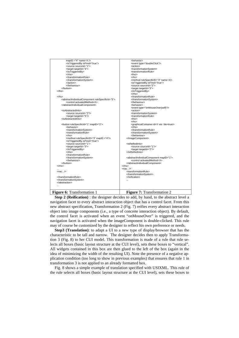
Figure 6: Transformation 1 Figure 7: Transformation 2
Step 2 (Reification) : the designer decides to add, by hand, to the abstract level a navigation facet to every abstract interaction object that has a control facet. From this new abstract specification, Transformation 2 (Fig. 7) reifies every abstract interaction object into image components (i.e., a type of concrete interaction object). By default, the control facet is activated when an event “onMouseOver” is triggered, and the navigation facet is activated when the imageComponent is double-clicked. This rule may of course be customized by the designer to reflect his own preference or needs.
Step3 (Translation): to adapt a UI to a new type of display/browser that has the characteristic to be tall and narrow. The designer decides then to apply Transforma-tion 3 (Fig. 8) to her CUI model. This transformation is made of a rule that rule se-lects all boxes (basic layout structure at the CUI level), sets these boxes to “vertical”. All widgets contained in this box are then glued to the left of the box (again in the idea of minimizing the width of the resulting UI). Note the presence of a negative ap-plication condition (too long to show in previous examples) that ensures that rule 1 in transformation 3 is not applied to an already formatted box.
Fig. 8 shows a simple example of translation specified with USIXML. This rule of the rule selects all boxes (basic layout structure at the CUI level), sets these boxes to

“vertical”. All widgets contained in this box are then glued to the left of the box (again in the idea of minimizing the width of the resulting UI). A negative application condition ensures that a rule is not applied to an already formatted box.
Transformation 3 : translation
... <translation id="TL1" name="squeezeDisplay" description= "this translations vertically aligns all widgets of a con-tainer"> <sourceModel type="cui"/> <targetModel type="cui"/> <transformationSystem id="TR1" name="Transfo1"...> <transformationRule id="rule1" name="squeeze1"> <lhs> <box mapID="1"> <graphicalIndividualComponent mapId="2" /> </box> </lhs> <rhs> <box mapID="1" type="vertical"> <graphicalIndividualComponent mapId="2" glueHorizontal="left"/> </box> </rhs> <nac> <box mapID="1" type="vertical"> <graphicalIndividualComponent mapId="2" glueHorizontal="left"/> </nac> </transformationRule> </transformationSystem> </translation> ...
Figure 8: Transformation 3
Alternatively to textual representation, transformation rules are easily expressed in a graphical syntax. Fig. 9 shows a graphical equivalent of the rule contained in Fig. 8. A general purpose tool for graph transformation called AGG (Attributed Graph Grammars) was used to specify this example. No proof the superiority of graphical formalism over textual ones, but at least USIXML designer has the choice between both.
LHSNAC RHS
::=
LHSNAC RHS
::=
Figure 9: Graphical representation of the transformation
Traceability (and as a side-effect reversibility) of model transformation is enabled
thanks to a set of ‘so-called’ interModelMappings (e.g., isAbstractedInto, IsReified-Into, isTranslatedInto) allowing to relate model elements belonging to different mod-els. As so it is possible to keep a trace of the application of rules i.e., when a new element is created a mapping indicates of what element it is an abstraction, a reifica-tion, a translation, etc. Another advantage of using these mappings is to support multi-directional development is that they explicitly connect the various levels of our

framework and realizes an seamless integration of the different models used to de-scribe the system. Knowing the mappings of a model increases dramatically the un-derstanding of the underlying structure of a UI. It enables to answer, at no cost, to question like: what task a interaction object enables?, what domain object attributes are updated by what interaction object? what interaction object triggers what method?
5 Tool Support
A tool support is provided at various levels of Fig. 2. • Reverse engineering of UI code: a specific tool, called Rutabaga [3], automati-
cally reverse engineers the presentation model of an existing HTML Web page at both the CUI and AUI levels, with or without intra-model, inter-model mappings. This tool allows developers to recuperate an existing UI so as to incorporate it again in the development process. In this case, a re-engineering can be obtained by combining two abstractions, one translation, and two reifications. This is par-ticularly useful for evolution of legacy systems.
• Model edition: as editing a new UI in USIXML directly can be considered as a tedious task, a specific editor called GrafiXML has been developed to face the de-velopment of USIXML models. USIXML being at first hand a textual language, an ad hoc XML editor was created. In this editor, the designer can draw in direct manipulation any graphical UI by directly placing CIOs where they need to be and editing their properties in the Composer, which are instantly reflected in the UI design (Fig. 10). At any time, the designer may want to see the corresponding USIXML specifications (Fig. 11) and edit it. Selecting a USIXML tag automati-cally displays possible values for this tag in a contextual menu. When the tag or the elements is modified, this change is propagated in the graphical representation. In this way, a bidirectional mapping is maintained between a UI and its USIXML specifications: each time a part is modified, the other one is updated accordingly.

Figure 10: Graphical Editing of a UI in GrafiXML.
Figure 11: USIXML equivalent of a UI edited in GrafiXML

Figure 12: Capabilities to generate a UI at different levels of abstraction
What distinguishes GrafiXML from other UI graphical editors is its capabilities to directly generate USIXML specifications at the different levels of abstractions represented in Fig. 2: FUI (here in rough text, in XHTML and Java AWT), CUI (with or without relationships), and AUI (with or without relationships). In addi-tion, a UI can be saved simultaneously with CUI and AUI specifications, while establishing and maintaining the inter-model relationships between.
• Transformation specification and application: an environment called AGG (Attributed Graph Grammars tool) is used for this experiment. AGG can be con-sidered as a genuine programming environment based on graph transformations [12]. It provides 1) a programming language enabling the specification of graph grammars 2) a customizable interpreter enabling graph transformations. AGG was chosen because it allows the graphical expression of directed, typed and at-tributed graphs (for expressing specifications and rules). It has a powerful library containing notably algorithms for graph transformation [14], critical pair analysis, consistency checking, positive and negative application condition enforcement. AGG user interface is described in Fig. 13. Frame 1 is the grammar explorer. Fig. 13 Frames 2, 3 and 4 enable to specify sub-graphs composing a production: a negative application (frame 2), a left hand side (frame 3) and a right hand side (frame 4). The host graph on which a production will be applied is represented in Frame 5.
• A tool for transformation application: several Application Programming Inter-face are available to perform model-to-model transformations (e.g., DMOF at http://www.dstc.edu.au/Products/CORBA/M-OF/ or Univers@lis at http://universalis. elibel.tm.fr/site/). We tested AGG API as this API proposes to transform model with graph transformations. This scenario is described in Fig. 14. An initial model along with a set of rules are transmitted to a Application Pro-gramming Interface that performs appropriate model transformations and provide a resulting model that can be edited.

Figure 13: AGG user interface
Initial USIXML model
Transformation API
Transformation Rules (in
Figure 14: Development process based on transformation application
Resulting USIXML model

6 Example produced by the tools
The following screen shots show the transformation of the above initial form (cap-
tured as a HTML web page), reverse engineering at the AUI level, then adapted by a series of translation, and finally reified into a CUI. From this stage, renderer and code generators produce respectively VRML, HTML for intelligent mobile phone, WML for simple mobile phone, and form for Visual Basic with tabbed dialog box.

7 Conclusion
Information systems are subject to a constant pressure toward change. UIs repre-sent an important and expensive software component of information system. Multi-directional UI development has been proposed to cope with the problem of UI adap-tation to an evolving context of use. Multi-directional UI development has been de-fined as an engineering method and tool that enables a designer to start a UI devel-opment by several entry points in the development cycle and from this entry point get

a substantial support to build a qualitative UI. Main features of multi-directional UI development are: 1. A flexible development process based on transformations 2. A unique formal language to specify UI related artefacts. So far, these concepts
have been hard coded in software tools, thus preventing anyone from reusing, re-defining or exchanging them. USIXML provides a mean to overcome these shortcomings. The core of this language is composed of a set of integrated mod-els expressed in a formal and uniform format, governed by a common meta-model definition, graphically expressible and a modular, modifiable and extensi-ble repository of executable design knowledge that is also represented with a graphical syntax. Furthermore, a definition of an XML notation supporting the exchange of models and executable design knowledge has been presented.
3. A transformational approach based on systematic rules that guarantee semantic equivalence when applied, some of them being reversible.
4. A tool supporting the expression and manipulation of models and design knowl-edge visually.
With increase of design experience, a copious catalogue of transformation rules can be assembled into meaningful grammars. The level of support provided to the accom-plishment of design steps varies from one transition to another. Indeed, some transi-tions are better known than others. For instance, the reification between physical and logical UI can be supported by hundreds of rules namely by widget selection rules. On the contrary, rules that enable the translation of a task model from a desktop PC to a handheld PC are, for now, understudied. Some transitions are intrinsically harder to support (e.g., abstraction transitions). For instance, retrieving a task model from the physical UI is not a trivial problem.
Acknowledgements
The authors would like to thank Cameleon partners who contributed to V1.2 of USIXML: Lionel Balme, Gaëlle Calvary, Cristina Chesta, Alexandre Demeure, Joëlle Coutaz, Jean-Thierry Lechein, Fabio Paternò, Stéphane Raymond, Carmen Santoro, and Youri Vanden Berghe. This paper is related to USIXML V1.4, an extension of USIXML V1.2 with dialog model, more inter-model mappings, a context model made up of user, platform, and environment, and the concrete user interface level. Laurent Bouillon is supported by Cameleon research project (http://giove.cnuce.cnr.it/ came-leon.html) under the umbrella of the European Fifth Framework Programme (FP5-2000-IST2). Benjamin Michotte is supported by the SIMILAR network of excellence (http://www.similar.cc), the European research task force creating human-machine in-terfaces similar to human-human communication of the European Sixth Framework Programme (FP6-2002-IST1-507609).

References
1. Agrawal, A., Karsai, G., Ledeczi, K.: An End-to-end Domain-Driven Software Develop-ment Framework. In: Companion of the 18th Annual ACM SIGPLAN Conference on Ob-ject-oriented Programming Systems, Languages, and Applications OOPSLA’2003 (Ana-heim, October 26-30, 2003). ACM Press, New York (2003) 8–15
2. Ali, M.F., Pérez-Quiñones M.A., Abrams M.: Building Multi-Platform User Interfaces with UIML. In: Seffah, A., Javahery, H. (eds.): Multiple User Interfaces: Engineering and Ap-plication Framework. John Wiley and Sons, New York (2003)
3. Bouillon, L., Vanderdonckt, J., Chow, K.C.: Flexible Re-engineering of Web Sites. In: Proc. of 8th ACM Int. Conf. on Intelligent User Interfaces IUI’2004 (Funchal, January 13-16, 2004). ACM Press, New York (2004) 132–139
4. Brown J.: Exploring Human-Computer Interaction and Software Engineering Methodolo-gies for the Creation of Interactive Software. SIGCHI Bulletin 29,1 (1997) 32–35
5. Calvary, G., Coutaz, J., Thevenin, D.: A Unifying Reference Framework for the Develop-ment of Plastic User Interfaces. In: Little, M.R., Nigay, L. (eds.): Proc. of IFIP WG2.7 (13.2) Working Conference EHCI’2001 (Toronto, May 11-13, 2001). Lecture Notes in Computer Science, Vol. 2254. Springer-Verlag, Berlin (2001) 173–192
6. Calvary, G., Coutaz, J., Thevenin, D., Limbourg, Q., Bouillon, L., Vanderdonckt, J.: A Unifying Reference Framework for Multi-Target User Interfaces. Interacting with Com-puters 15,3 (2003) 289–308
7. Chikofsky, E.J., Cross, J.H.: Reverse Engineering and Design Recovery: A Taxonomy. IEEE Software 1,7 (1990) 13–17
8. Constantine, L.: Canonical Abstract Prototypes for Abstract Visual and Interaction Design. In: Jorge, J., Nunes, N.J., Falcão e Cunha, J. (eds.), Proc. of 10th Int. Workshop on Design, Specification, and Verification of Interactive Systems DSVIS’2003 (Funchal, June 4-6, 2003). Lecture Notes in Computer Science, Vol. 2844. Springer-Verlag, Berlin (2003) 1–9
9. Eisenstein, J., Vanderdonckt, J., Puerta, A.: Model-Based User-Interface Development Techniques for Mobile Computing. In: Lester, J. (ed.), Proc. of 5th ACM Int. Conf. on In-telligent User Interfaces IUI’2001 (Santa Fe, January 14-17, 2001). ACM Press, New York (2001) 69–76
10. Gaeremynck, Y., Bergman, L.D., Lau, T.: MORE for Less: Model Recovery from Visual Interfaces for Multi-Device Application Design. In: Proc. of 7th ACM Int. Conf. on Intelli-gent User Interfaces IUI’2003 (Miami, January 12-15, 2003). ACM Press, New York (2003) 69–76
11. Griffiths, T., Barclay, P.J., Paton, N.W., McKirdy, J., Kennedy, J., Gray, P.D., Cooper, R., Goble, C.A., da Silva, P.P.: Teallach: A Model-Based User Interface Development Envi-ronment for Object Databases. Interacting with Computers 14, 1 (December 2001) 31–68
12. Larman, C.: Applying UML and Patterns: An Introduction to Object-Oriented Analysis and Design and the Unified Process. Prentice Hall, Englewood Cliffs (2001)
13. Limbourg, Q., Vanderdonckt, J., Michotte, B., Bouillon, B.: TOMATOXML, a General Pur-pose XML Compliant User Interface Description Language, TOMATOXML V1.2.0. Wor-king Paper n°105. Institut d’Administration et de Gestion (IAG), Louvain-la-Neuve (19 February 2004).
14. Limbourg, Q., Vanderdonckt, J.: Transformational Development of User Interfaces with Graph Transformations. In: Jacob, R., Limbourg, Q., Vanderdonckt, J. (eds.): Proc. of 5th Int. Conf. on Computer-Aided Design of User Interfaces CADUI’2004 (Madeira, January 14-16, 2004). Kluwer Academics Pub., Dordrecht (2004)
15. Luo, P.: A Human-Computer Collaboration Paradgim for Bridging Besign Conceptualiza-tion and Implementation. In: F. Paternò (ed.): Interactive Systems: Design, Specification, and Verification, Proc. of the 1st Eurographics Workshop on Design, Specification, and

Verification of Interactive Systems DSV-IS’94 (Bocca di Magra, June 8-10, 1994). Springer-Verlag, Berlin (1995) 129–147
16. Luyten, K., Van Laerhoven, T., Coninx, K., Van Reeth, F.: Runtime Transformations for Modal Independent User Interface Migration. Interacting with Computers 15,3 (2003) 329–347
17. Mori, G., Paternò, F., Santoro, C.: Tool Support for Designing Nomadic Applications. In: Proc. of 7th ACM Int. Conf. on Intelligent User Interfaces IUI’2003 (Miami, January 12-15, 2003). ACM Press, New York (2003)141–148
18. Olsen, D.R., Jefferies, S., Nielsen, T., Moyes, W., Fredrickson, P.: Cross Modal Interaction using XWEB. In: Proc. of the 13th Annual ACM Symposium on User Interface Software and Technology UIST’2000 (San Diego, November 5-8, 2000). ACM Press, New York (2000) 191–200
19. Partsch, H., Steinbruggen, R.: Program Transformation Systems. ACM Computing Surveys 15,3 (September 1983), 199–236
20. Paternò, F. Model-Based Design and Evaluation of Interactive Applications. Springer-Verlag, Berlin (2000)
21. Puerta, A., Eisenstein, J.: Developing a Multiple User Interface Representation Framework for Industry. In: Seffah, A., Javahery, H. (eds.): Multiple User Interfaces: Engineering and Application Framework. John Wiley and Sons, New York (2003)
22. Rozenberg, G. (ed.). Handbook of Graph Grammars and Computing by Graph Transforma-tion. World Scientific, Singapore (1997)
23. Sucrow, B.: On Integrating Software-Ergonomic Aspects in the Specification Process of Graphical User Interfaces. Transactions of the SDPS Journal of Integrated Design & Proc-ess Science. Society for Design & Process Science 2,2 (June 1998) 32–42
24. Sumner, T., Bonnardel, N., Kallak, B.H.: The Cognitive Ergonomics of Knowledge-Based Design Support Systems PAPERS: Intelligent Support. In: Proceedings of ACM Confer-ence on Human Factors in Computing Systems CHI’97 (Atlanta, April 1997). ACM Press, New York (1997) 83–90
25. Vanderdonckt, J., Berquin, P.: Towards a Very Large Model-Based Approach for User In-terface Development. In: Paton, N.W., Griffiths, T. (eds.): Proc. of 1st IEEE Int. Workshop on User Interfaces to Data Intensive Systems UIDIS’99 (Edinburgh, September 5-6, 1999). IEEE Computer Society Press, Los Alamitos (1999) 76–85
26. Wong, C., Chu, H.H., Katagiri, M.A., Single-Authoring Technique for Building Device-Independent Presentations. In: Proc. of W3C Workshop on Device Independent Authoring Techniques (St. Leon-Rot, 15-26 September 2002), accessible at http://www.w3.org/2002/ 07/DIAT/posn/docomo.pdf
Related Documents