HAL Id: hal-01306836 https://hal.archives-ouvertes.fr/hal-01306836 Submitted on 10 Feb 2017 HAL is a multi-disciplinary open access archive for the deposit and dissemination of sci- entific research documents, whether they are pub- lished or not. The documents may come from teaching and research institutions in France or abroad, or from public or private research centers. L’archive ouverte pluridisciplinaire HAL, est destinée au dépôt et à la diffusion de documents scientifiques de niveau recherche, publiés ou non, émanant des établissements d’enseignement et de recherche français ou étrangers, des laboratoires publics ou privés. Using the Generalized Inverted Pendulum to generate less energy-consuming trajectories for humanoid walking Sahab Omran, Sophie Sakka, Yannick Aoustin To cite this version: Sahab Omran, Sophie Sakka, Yannick Aoustin. Using the Generalized Inverted Pendulum to generate less energy-consuming trajectories for humanoid walking. Archives of civil and mechanical engineering, 2016. hal-01306836

Welcome message from author
This document is posted to help you gain knowledge. Please leave a comment to let me know what you think about it! Share it to your friends and learn new things together.
Transcript
HAL Id: hal-01306836https://hal.archives-ouvertes.fr/hal-01306836
Submitted on 10 Feb 2017
HAL is a multi-disciplinary open accessarchive for the deposit and dissemination of sci-entific research documents, whether they are pub-lished or not. The documents may come fromteaching and research institutions in France orabroad, or from public or private research centers.
L’archive ouverte pluridisciplinaire HAL, estdestinée au dépôt et à la diffusion de documentsscientifiques de niveau recherche, publiés ou non,émanant des établissements d’enseignement et derecherche français ou étrangers, des laboratoirespublics ou privés.
Using the Generalized Inverted Pendulum to generateless energy-consuming trajectories for humanoid walking
Sahab Omran, Sophie Sakka, Yannick Aoustin
To cite this version:Sahab Omran, Sophie Sakka, Yannick Aoustin. Using the Generalized Inverted Pendulum to generateless energy-consuming trajectories for humanoid walking. Archives of civil and mechanical engineering,2016. hal-01306836
ARCHIVE OF MECHANICAL ENGINEERING
Keywords: Inverted pendulum, pivot point, walking robots, energy consumption, joint torques
Using the Generalized Inverted Pendulum to generate lessenergy-consuming trajectories for humanoid walking
Sahab Omran∗, Sophie Sakka†, Yannick Aoustin‡
AbstractThis paper proposes an analysis of the effect of vertical position of the pivot point of the inverted pendulumduring humanoid walking. We introduce a new feature of the inverted pendulum by taking a pivot point underthe ground level allowing a natural trajectory for the center of pressure (CoP), like in human walking. Theinfluence of the vertical position of the pivot point on energy consumption is analyzed here. The evaluation ofa 3D Walking gait is based on the energy consumption. A sthenic criterion is used to depict this evaluation.A consequent reduction of joint torques is shown with a pivot point under the ground.
1 IntroductionThe linear inverted pendulum (LIP) was proposed by Kajita et al. to generate humanoid walking tra-jectories [Kaj01, Kaj91]. This model was widely applied to various bipedal robots like HRP-2 [Ais98],Asimo [Hon96], and UT-Theta [UT01]. The main advantage of this approach is the simplicity of the dynam-ics and the analytical solution.
The inverted pendulum has also been used for the modeling of human walking. The first pendulum modelof human walking considers that the zero moment point (ZMP) within the simple support is a fixed pointin the foot center [Zij97]. However, biomechanical research shows that the human ZMP moves forward,towards the big toe, during the single support [Har09]. To embed this feature of ZMP in the pendulummodel of human walking, Hayot et al. proposed a pendulum with a pivot point that moves during the singlesupport [Hay13]. This pendulum allows to reproduce the natural foot roll of human.
Rolling of feet in human walking consists in moving the supporting area during the support phase of eachfoot, from the heel, through the middle of foot to the toe. While human is rolling his/her feet, the ZMPfollows the supporting area in order to keep the equilibrium.
However, in the model of Hayot et al. the advancement of the ZMP in the single support requires a strictdefinition [Hay13]. Later, the Generalized Inverted Pendulum model (GIP) [Sak10] was suggested by Sakkaet al. for human walking modeling. The GIP has a pivot point under the ground level in opposition to allother inverted pendulum models (for robot control or human motion) with a pivot point at ground level. Itdescribes human normal walking from the external forces point of view, taking into account the mechanismof foot.
The contribution of this paper is to extend the GIP [Sak10] to generate a human inspired walking patternof humanoid robots. We analyze the influence of the pivot point depth on the geometric behavior of thependulum. We present the adopted constraints on the position of the pivot point, depending on the size ofthe robot feet. We study also the influence of the pivot point depth on joint torques. Finally, we analyzethe energy consumption of Romeo humanoid robot during walking using two criteria: sthenic criterion andenergy criterion. The influence of the step length was also introduced.
∗LUNAM, IRCCyN, CNRS, Ecole Centrale de Nantes, University of Nantes. 1, rue de la Noë BP 92101. 44321 Nantes,France. E-mail: [email protected]†IRCCyN, University of Poitiers, France. E-mail: [email protected]‡LUNAM, IRCCyN, CNRS, Ecole Centrale de Nantes, University of Nantes. 1, rue de la Noë BP 92101. 44321 Nantes,
France. E-mail: [email protected]
Acknowledgement : This work is supported by Région des Pays de la Loire, Project LMA and Gérontopôle AutonomieLongévité des Pays de la Loire.
1
This paper is organized as follows: In section 2, we show that the dynamics equations system does notchange if the pivot point is located under the ground or at ground level. The calculations of joint angles andjoint torques are given in section 3. The evaluation criteria are presented in section 4. Simulation setting andthe Romeo robot description are given in section 5. Results demonstrating the efficiency of the method fromthe joint torques viewpoint are displayed in section 6. Finally, we conclude and we show our perspectives insection 7.
2 Dynamics equation for an inverted pendulum with a pivot pointunder the ground
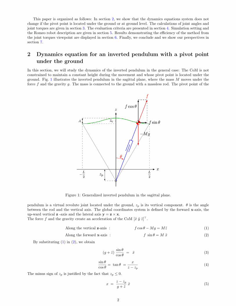
In this section, we will study the dynamics of the inverted pendulum in the general case: The CoM is notconstrained to maintain a constant height during the movement and whose pivot point is located under theground. Fig. 1 illustrates the inverted pendulum in the sagittal plane, where the mass M moves under theforce f and the gravity g. The mass is connected to the ground with a massless rod. The pivot point of the
Figure 1: Generalized inverted pendulum in the sagittal plane.
pendulum is a virtual revolute joint located under the ground, zp is its vertical component. θ is the anglebetween the rod and the vertical axis. The global coordinates system is defined by the forward x-axis, theup-ward vertical z -axis and the lateral axis y = z× x.The force f and the gravity create an acceleration of the CoM [x y z]>.
Along the vertical z-axis : f cos θ −Mg = Mz (1)
Along the forward x-axis : f sin θ = M x (2)
By substituting (1) in (2), we obtain
(g + z)sin θ
cos θ= x (3)
sin θ
cos θ= tan θ =
x
z − zp(4)
The minus sign of zp is justified by the fact that zp ≤ 0.
x =z − zpg + z
x (5)
2

In a similar manner, we obtain the motion equation in the frontal plane.
y =z − zpg + z
y (6)
The motion of the CoM is characterized by the second-order differential equations (5) and (6). Theseequations are very similar to those in the case where the pivot point is located at ground level. The onlydifference is that the term z is replaced by z−zp. In some previous works devoted to walking, the term zp wasused to express the vertical component of origin of the frame attached to the foot with respect to the globalcoordinate system and the pivot point was always in the foot. But now, zp expresses the vertical distancebetween the pivot point and the ground. The differential equations 5 and 6 can be solved analytically whenz = const. When z 6= const, these two equations are solved numerically.
3 ModelingLet us consider a humanoid robot composed of nact actuators to control its body movements in 3D. Let qand X denote the system generalized and operational coordinates vectors, respectively. We introduce thefollowing notations:
X (6× 1) Absolute position and ;orientation of the waist ;
Xfi (6× 1) Absolute position and ;orientation of foot i (i = 1, 2);
qlegi (nleg × 1) Actuated joints of legi ;(ankle, knee and hip joints);
q (n× 1) Vector grouping the controlled variables;(n = nact + 6).
The vector q contains the joint variables and the 3D position and orientation of the frame R0 fixed inthe left foot. The reference frame is defined such that x0 denotes the horizontal advancement direction, z0
is the vertical bottom-up direction, and y0 = z0 × x0 is the lateral direction.
3.1 Walking cycle – AssumptionsThe walking cycle is defined by two successive steps (right and left legs). One step is composed of a singlesupport phase (SS) on the stance leg, delimited by swinging foot takeoff and swinging foot strike, and adouble support phase (DS) where the body weight is distributed on both legs, delimited by swinging footstrike and other foot takeoff. In what follows, the following assumptions will be considered for the completemotion:
A1 There is no rotation of the swing foot and the pelvis of the biped with respect to the roll, pitch, andyaw axes.
A2 The stance foot has a flat contact on the ground;
A3 Feet velocity and acceleration are equal to zero at foot strike. Thus no impact is considered.
A4 The CoM and the waist segment have the same linear velocity and acceleration profiles;
As humanoid systems are highly redundant, these assumptions allow setting the control schemes while re-ducing the redundancy order by setting arbitrarily several parameters. The motion of the swinging foot isdefined as a polynomial function, where the polynomial coefficients were determined using initial and finalpositions, velocities, and accelerations.
3.2 KinematicsFor given desired Cartesian trajectories of the waist X and the feet Xfi (i = 1, 2), the inverse kinematicsmodel leads to the values of the desired joint variables as follows[
Vfi
ωfi
]=
[I3×3 −L03×3 I3×3
] [Vω
]+ Jlegi qlegi (i = 1, 2) (7)
3
where Xfi = [V>fi ω>fi
]>, X = [V> ω>]>, Jlegi (i = 1, 2) denotes the 6× nleg Jacobian matrix associated tothe i-th leg, L is the position vector between the waist and foot fi and L is the skewsymetric matrix of L.Due to assumption A1, ω = ωfi = 0, thus (7) becomes
qlegi = J−1legi
[Xfi − X
03×1
](i = 1, 2) (8)
The desired n× 1 controlled velocities vector q can be rebuilt as follows.
q =[qleg1 qleg2 qfree X
]>(9)
where qfree denotes joint velocities of trunk and arms which can be set freely.The rank of the Jacobian matrix of each leg was verified at each sampling period of motion to ensure that
there is no singularity.
3.3 DynamicsThe dynamics of the system may be described by the three following equations. Dq + Cq + G = BΓ + J>1 R1 if in single support on leg1
Dq + Cq + G = BΓ + J>2 R2 if in single support on leg2
Dq + Cq + G = BΓ + J>1 R1 + J>2 R2 if in double support(10)
The matrices D(q), C(q, q), and G(q) describe respectively the inertia, Coriolis and gravity forces actingon the system. Γ is the vector of the actuator torques Γi, i = 1, · · · , nact. Matrix B is the actuation matrix;it expresses the contribution of each joint torque in the virtual work δw:
δw = Γ1δq1 + Γ2δq2 + . . .+ Γnactδqnact
= δq>BΓ
where Γ =[Γ1 Γ2 . . . Γnact
]> and B =[0nact×6 Inact
]>. The vectors R1 and R2 are the ground reactionforces exerted on foot1 and foot2 respectively.
R1 =[R1x R1y R1z M1x M1y M1z
]>R2 =
[R2x R2y R2z M2x M2y M2z
]>In single support, there are n unknown variables which are the components of (Γ,R1) or (Γ,R2) dependingon which foot is in contact with the ground. So, the n independent equations in the two first lines of (10) aresufficient for solving. On the other hand, in double support there are n+ 6 unknown variables in (Γ,R1,R2)and only n equations available. In order to solve the problem in double support, six variables should bechosen and set to completely describe the system dynamics. The variables we choose are the six componentsof the ground reaction forces exerted on the foot that was supporting before the considered double support.Similarly to Omran et al. [Omr14], these components are defined as third-order polynomial functions of timeensuring the continuity of the ground reaction forces with the two single support phases around the considereddouble support.
In our simulation, we have tested many polynomial functions for the components of the ground reactionforces with different polynomial orders and we obtained almost the same behavior for the sthenic and theenergy criteria.
4 Energy consumptionMany criteria exist to evaluate energy consumption of a mechanical system, however to our best knowledgethere is no ideal criterion [Che08]. In this approach, we chose two criteria:
Sthenic criterion is defined by the integral of the quadratic actuators torques per unit of distance, asshown in (11). Its physical meaning is to be an image of the Joule effects if the actuators are DC motors.Furthermore, the torque amplitudes are decreased with the minimization of this criterion [Che01]. Then ifwe design an optimal walking gait with this criterion we can limit the weight of the needed motors.
CΓ =1
d
∫ tf
t0
Γ>Γdt (11)
4
where t0 and tf denote the beginning and ending instants of the total observed motion, d is the traveleddistance. The sthenic criterion is a quantity proportional to the energy consumed by actuators per unit ofdistance, while the quadratic torque deals with the squared norm of motor torques: E0(t) = Γ>Γ.
Energy criterion relates to the work done by the motors during motion. Soechting et al. [Soe95]proposed the minimization of work to predict the posture of the arm while moving the hand from one pointto another. They have shown that the movements performed by the arms are conducted so as to minimizethe energy expended to move the hand from the initial position to the final position. The cost function isgiven as follows
W =
∫ tf
t0
Γ Ω dt (12)
where Ω = dθ/dt is joint velocities vector.The minimization of work done by the joints is widely used in optimal trajectory generation [Ber08,
Che08, Haq12].
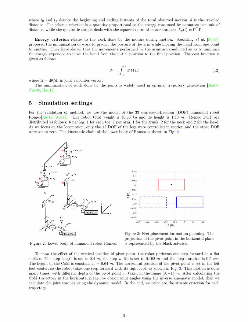
5 Simulation settingsFor the validation of method, we use the model of the 33 degrees-of-freedom (DOF) humanoid robotRomeo[Ald12, Ack12]. The robot total weight is 40.53 kg and its height is 1.43 m. Romeo DOF aredistributed as follows: 6 per leg, 1 for each toe, 7 per arm, 1 for the trunk, 2 for the neck and 2 for the head.As we focus on the locomotion, only the 12 DOF of the legs were controlled in motion and the other DOFwere set to zero. The kinematic chain of the lower body of Romeo is shown in Fig. 2.
Figure 2: Lower body of humanoid robot Romeo.
−0.5 −0.4 −0.3 −0.2 −0.1 0 0.1 0.2
−0.35
−0.3
−0.25
−0.2
−0.15
−0.1
−0.05
0
0.05
0.1
0.15
X [m]
Y [
m]
Figure 3: Feet placement for motion planning. Theprojection of the pivot point in the horizontal planeis represented by the black asterisk.
To show the effect of the vertical position of pivot point, the robot performs one step forward on a flatsurface. The step length is set to 0.4 m, the step width is set to 0.192 m and the step duration is 0.5 sec.The height of the CoM is constant zc = 0.64 m. The horizontal position of the pivot point is set in the leftfoot center, so the robot takes one step forward with its right foot, as shown in Fig. 3. This motion is donemany times, with different depth of the pivot point zp taken in the range [0,−1] m. After calculating theCoM trajectory in the horizontal plane, we obtain joint angles using the inverse kinematic model, then wecalculate the joint torques using the dynamic model. In the end, we calculate the sthenic criterion for eachtrajectory.
5

6 ResultsThe resulting trajectories for each zp are compared in terms of dynamic balance, joint torques and energyconsumption.
6.1 Horizontal trajectory of CoMThe motion described in Sec. 5 is realized by the robot Romeo in five cases corresponding to five values ofzp: [0, −0.25, −0.5, −0.75, −1] m. Fig. 4 shows the five resulting CoM trajectories in x and y directionsas a function of time. We note that the x component of the CoM comes closer to a straight line when |zp|increases. On the other hand, the oscillation amplitude of the y component decreases when the pivot pointgoes farther under the ground.
0 0.1 0.2 0.3 0.4 0.5−0.1
−0.05
0
0.05
0.1
0.15
time [s]
x [m
]
zp =0
zp = −0.25
zp =−0.5
zp =−0.75
zp =−1
a) Forward axis
0 0.1 0.2 0.3 0.4 0.50.06
0.065
0.07
0.075
0.08
0.085
0.09
0.095
0.1
0.105
time [s]
y [m
]
b) Lateral axis
Figure 4: Horizontal trajectory of CoM as a function of time for five values of zp
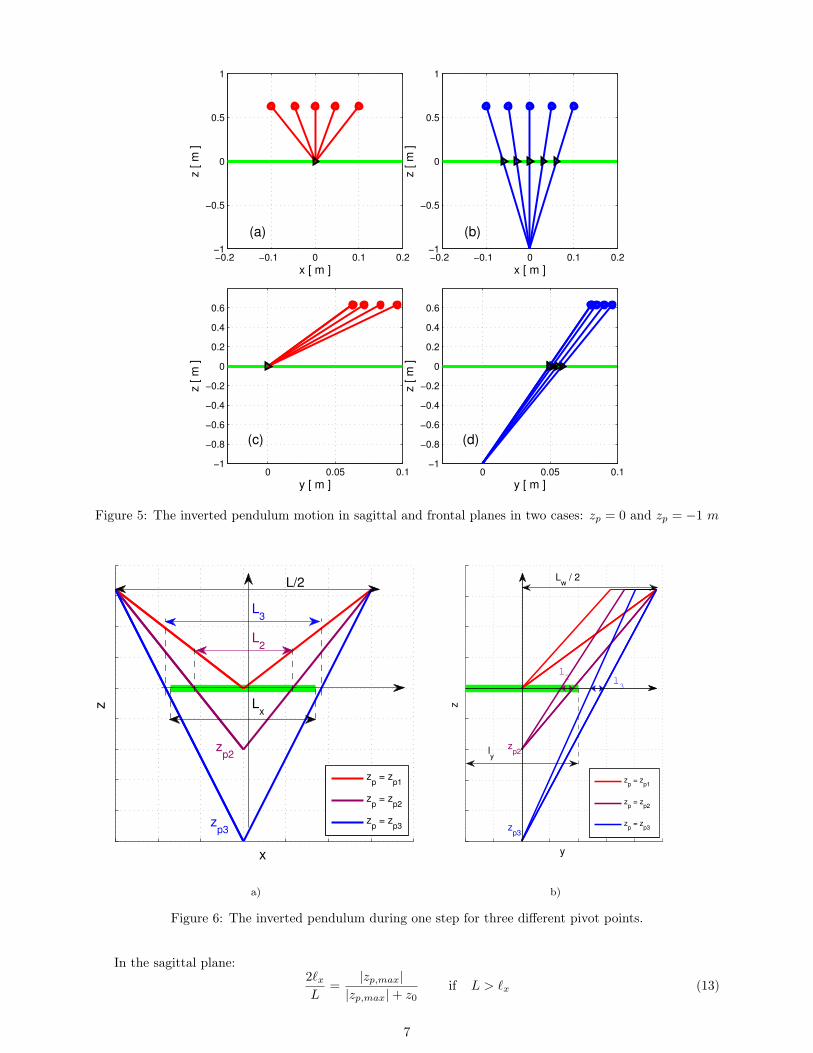
6.2 Trajectory of CoPFig. 5 represents two inverted pendulums. The first one with a pivot point at ground level (zp = 0), its motionin the sagittal and frontal planes is represented in Fig. 5(a) and Fig. 5(c) respectively. The second one witha pivot point under ground level (zp =−1 m), its motion in the sagittal and frontal planes is represented inFig. 5(b) and Fig. 5(d) respectively.
In Fig. 5, the CoM is represented by circles and the CoP is represented by triangle symbols. The groundlevel (z = 0) is represented by a green line. We notice that the CoP coincides with the pivot point whenzp = 0. In this case, the CoP is a fixed point. But when the pivot point is under the ground level, the CoPmoves in x and y directions as we can see in Fig. 5(b) and Fig. 5(d) respectively. For this reason, we mustverify that the distances traveled by the CoP in x and y directions are smaller than the robot foot dimensionsbefore applying the trajectory to a humanoid robot.
To describe the relation between the CoP trajectory and the depth of the pivot point, we consider threeinverted pendulums having the same parameters of step length L, step width Lw, and the CoM height zc.The pivot point depth for these pendulums are zp1 = 0, zp2 and zp3 such as 0 < |zp2| < |zp3|. These threependulums are illustrated in Fig. 6 in the sagittal and frontal planes. The foot is also represented in thisfigure by a bold green line.
We notice that the traveled distance by the CoP in x direction, increases when the pivot point depthincreases (L2 < L3). Along the y direction, the CoP does not move when the pivot point is at ground level,but it moves in a range when the pivot point is under the ground. The range of the CoP along the y axis isincreasingly far from the foot center when the |zp| increases. As we can see that l2 is closer to the foot centerthan l3.
For the bigger values of |zp|, the CoP trajectory may leave the foot. For example, in Fig. 6, the CoP ofthe pendulum corresponding to zp3 leaves the contact zone between the foot and the ground. Therefore, foreach foot size and step length and width, there is an upper limit of |zp| that keeps the CoP inside the foot.
For a robot with feet of length `x and width `y, performing a step of length L and width Lw, the upperlimit of |zp| respects the following relation:
6
−0.2 −0.1 0 0.1 0.2−1
−0.5
0
0.5
1
x [ m ]
z [ m
]
(a)
−0.2 −0.1 0 0.1 0.2−1
−0.5
0
0.5
1
x [ m ]
z [ m
]
(b)
0 0.05 0.1−1
−0.8
−0.6
−0.4
−0.2
0
0.2
0.4
0.6
y [ m ]
z [
m ]
(c)
0 0.05 0.1−1
−0.8
−0.6
−0.4
−0.2
0
0.2
0.4
0.6
y [ m ]
z [
m ]
(d)
Figure 5: The inverted pendulum motion in sagittal and frontal planes in two cases: zp = 0 and zp = −1 m
x
z
L2
L3
zp3
zp2
L/2
Lx
zp = z
p1
zp = z
p2
zp = z
p3
a)
y
z
l2
l3
zp3
zp2l
y
Lw / 2
zp = z
p1
zp = z
p2
zp = z
p3
b)
Figure 6: The inverted pendulum during one step for three different pivot points.
In the sagittal plane:2`xL
=|zp,max|
|zp,max|+ z0if L > `x (13)
7

In the frontal plane:`yLw
=|zp,max|
|zp,max|+ z0if Lw > `y (14)
From these two equations, we can deduce the limit of zp.
|zp,max,sagittal| =2 `x z0
L− 2 `x|zp,max,frontal| =
`y z0
Lw − `y(15)
The upper limit of |zp| is chosen as:
|zp,max| = min(|zp,max,sagittal|, |zp,max,frontal|) (16)
When we generate trajectories for experiments on a real robot, we should consider a security margin forCoP before calculating |zp,max|. The security margin can be defined as a percentage of foot dimensions. Insimulation, the security margin may be not considered.
The humanoid robot Romeo feet are 0.289 m in length and 0.121 m in width. By applying (16), weobtain: |zp,max| = 1.09 m. If we consider a margin of security of 50% of the foot, we obtain |zp,max| = 0.29 m.The robot foot with the security margin is illustrated in Fig. 7.
Figure 7: The foot and the CoP area.
6.3 Joint torqueIn this section, we consider three trajectories for humanoid robot Romeo. One was calculated using aninverted pendulum with a pivot point at ground level (zp=0). Another was calculated using an invertedpendulum with a pivot point under the ground (zp = −zp,max = −0.29 m). A third one with a pivot pointin the middle between zp,max and the ground, zp = −0.145 m).
The three inverted pendulums have the same parameters for step length, step width, step duration andCoM height as given in Sec. 5. We compare joint torques for these three trajectories.
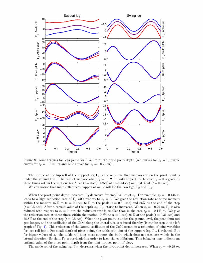
Fig. 8 shows the torques at the legs joints. The support leg contains six joints: ankle roll (Γ2), ankle pitch(Γ3), knee pitch (Γ4), hip pitch (Γ5), hip roll (Γ6), and hip yaw (Γ7). The swing leg contains six joints also:ankle roll (Γ13), ankle pitch (Γ12), knee pitch (Γ11), hip pitch (Γ10), hip roll (Γ9), and hip yaw (Γ8).
In global, the three trajectories show similar behavior. We can see that Γ5, Γ10, Γ11, and Γ12 are almostthe same. For these joints, the torque is a little reduced (between 1.8% and 5.2%) with zp = −0.29 m thanwith a pivot point at ground level.
For Γ3, Γ4, Γ7, Γ8, and Γ9, we can observe two or three peaks for each torque. The torque amplitudepeak-to-peak is reduced for zp = −zp,max compared to the case zp = 0 by 20%, 10.8%, 1.3%, 20.2% and 26%respectively.
8
−10
0
10
Γ2 A
nkle
roll
Support leg
−2.5
−2
−1.5
Swing leg
Γ13 A
nkle
roll
0
20
40
60
Γ3 A
nkle
pitch
−20
0
20
Γ1
2 A
nkle
pitch
−60
−40
−20
0
Γ4 K
nee p
itch
−40
−20
0
20
Γ11 K
nee p
itch
−10
0
10
20
30
Γ5 H
ip p
itch
−20
0
20
40
Γ10 H
ip p
itch
−38
−36
−34
−32
Γ6 H
ip r
oll
−1.5
−1
−0.5
0
0.5
Γ9 H
ip r
oll
0 0.1 0.2 0.3 0.4 0.5
−4
−2
0
2
4
Time [s]
Γ7 H
ip y
aw
0 0.1 0.2 0.3 0.4 0.5
−2
−1
0
1
Time [s]
Γ8 H
ip y
aw
Figure 8: Joint torques for legs joints for 3 values of the pivot point depth (red curves for zp = 0, purplecurves for zp = −0.145 m and blue curves for zp = −0.29 m).
The torque at the hip roll of the support leg Γ6 is the only one that increases when the pivot point isunder the ground level. The rate of increase when zp = −0.29 m with respect to the case zp = 0 is given atthree times within the motion: 6.22% at (t = 0sec), 1.97% at (t=0.31sec) and 6.39% at (t = 0.5sec).
We can notice that main differences happen at ankle roll for the two legs, Γ2 and Γ13.
When the pivot point depth increases, Γ2 decreases for small values of zp. For example, zp = −0.145 mleads to a high reduction rate of Γ2 with respect to zp = 0. We give the reduction rate at three momentwithin the motion: 87% at (t = 0 sec), 61% at the peak (t = 0.31 sec) and 86% at the end of the step(t = 0.5 sec). After a certain value of the depth zp, |Γ2| starts to increases. When zp = −0.29 m, Γ2 is alsoreduced with respect to zp = 0, but the reduction rate is smaller than in the case zp = −0.145 m. We givethe reduction rate at three times within the motion: 9.8% at (t = 0 sec), 91% at the peak (t = 0.31 sec) and58.8% at the end of the step (t = 0.5 sec). When the pivot point is under the ground level, the pendulum rodgets longer, and the oscillation of the CoM along the lateral axis is reduced thereby (It can be seen in the leftgraph of Fig. 4). This reduction of the lateral oscillation of the CoM results in a reduction of joint variablesfor legs roll joint. For small depth of pivot point, the ankle-roll joint of the support leg, Γ2, is relaxed. Butfor bigger values of zp, the ankle-roll joint must support the body which does not oscillate widely in thelateral direction. So that, Γ2 is overloaded in order to keep the equilibrium. This behavior may indicate anoptimal value of the pivot point depth from the joint torques point of view.
The ankle roll of the swing leg, Γ13, decreases when the pivot point depth increases. When zp = −0.29 m,
9

Γ13 is reduced with respect to zp = 0. We give the reduction rate at the three peaks: 29.4% at (t = 0.1 sec),21.6% at (t = 0.25 sec) and 29.5% at (t = 0.4 sec).
6.4 Energy evaluation6.4.1 Sthenic criterion
The profile of the quadratic torque E0 = Γ>Γ during one step is shown in Fig. 9. The simulations were runwith two values of the pivot point depth: zp = 0 and zp = −0.29 m.
0 0.1 0.2 0.3 0.4 0.53000
4000
5000
6000
7000
8000
9000
10000
11000
12000
13000
Time [ s ]
Γt .Γ
[N
2.m
2]
zp = 0
zp = −0.29
Figure 9: Quadratic torque
0 −0.2 −0.4 −0.6 −0.8 −1 −1.2 −1.41.44
1.46
1.48
1.5
1.52
1.54
1.56
1.58
1.6
1.62x 10
4
zp [m]
CΓ
[N2 m
s ]
Figure 10: Sthenic criterion as a function of zp.
Both graphs of Fig. 9 show a peak of value at the beginning of single supports followed by a valley atmidstance. Fig. 9 shows that E0 values at the beginning and at the end of the single support are lower witha pivot point under the ground level that with a pivot point at ground level. The evolution of the stheniccriterion as a function of the pivot point depth is shown in Fig. 10, for values of zp between [0 −1.09] m, whichis the maximum authorized in simulation. The situation zp = −0.718 m minimizes the sthenic criterion, withthe criterion value being reduced by 10.5% in comparison to the case zp = 0. When we consider a securitymargin of 50% of foot dimensions, zp,max = −0.29 m corresponds to 9 % reduction of the sthenic criterioncompared to the case zp = 0.
6.4.2 Energy criterion
The energy consumption of the robot as a function of pivot point depth is also evaluated using the energycriterion CE defined by equation (12). The energy criterion as a function of zp is shown in Fig. 11. Energy
0 −0.2 −0.4 −0.6 −0.8 −1 −1.2 −1.4315
320
325
330
335
340
345
350
355
360
365
zp [m]
CE
[ N
.ra
d ]
Figure 11: Energy criterion as a function of zp.
criterion decreases as the depth of the pivot point increases. When zp = −1.09 m, the energy criterion is
10

reduced by 12.6 % compared to the case of a pivot point at ground level. When we consider a security marginof 50% of foot dimensions, zp,max = −0.29 m corresponds to 7 % reduction of the energy criterion comparedto the case zp = 0.
Contrary to the sthenic criterion, the energy criterion does not have a local minimum, but it decreasesmonotonically as the pivot point depth increases.
6.4.3 Step length consideration
The purpose of this section is to analyze the behavior of the system in other parameters sets. In other words,we want to show that reducing the sthenic criterion for deeper pivot points, that we obtained for a set ofoperating parameters, is not a special case. For this, we consider six values of step length, taken in theinterval [0.2 0.4] m. For each step length, we examine the behavior of the sthenic and the energy criteria asa function of the pivot point depth.
Fig. 12 shows the evolution of the sthenic criterion for each considered step length. The overall behavior
0 0.2 0.4 0.6 0.8 1 1.2 1.41.4
1.5
1.6
1.7
1.8
1.9
2
2.1x 10
4
zp [m]
CΓ [
N2.m
.s]
L
pas=0.2
Lpas
=0.24
Lpas
=0.28
Lpas
=0.32
Lpas
=0.36
Lpas
=0.4
Figure 12: Sthenic criterion as a function of step size.
0 0.2 0.4 0.6 0.8 1 1.2 1.4100
150
200
250
300
350
400
zp [m]
CE
[ N
.ra
d ]
L
pas=0.2
Lpas
=0.24
Lpas
=0.28
Lpas
=0.32
Lpas
=0.36
Lpas
=0.4
Figure 13: Energy criterion as a function of step size.
is the same for all step lengths. The sthenic criterion decreases as the depth of the pivot point increases, itreaches a local minimum at certain value of zp, then it starts to increase.
For longer steps, the maximal reduction rate of sthenic criterion when zp increases, is more important.This rate is 10 %, 6 %, and 1 % for L = 0.4 m; 0.32 m; and 0.2 m respectively. Moreover, one can observethat the zp value that minimizes sthenic criterion is smaller for smaller steps. We also notice that the stheniccriterion is lower for the longest step of the same duration.
These findings concern the role of the step length without changing the step time, and may change in thecase where the step duration is adapted to the step length.
Fig. 13 shows the evolution of the energy criterion as a function of the pivot point depth for each consideredstep length. The overall behavior of the energy criterion is similar for the six studied step lengths: It decreasesmonotonically as the depth of the pivot point increases.
For longer steps, the reduction rate of the energy criterion when zp increases, is more important. Thisrate is 12.6 %, 10.6 %, and 8.6 % for L = 0.4 m; 0.32 m; and 0.2 m respectively. We also notice that theenergy criterion is lower for the smallest step of the same duration. This is due to the definition of the energycriterion which is proportional to the velocity.
11

7 ConclusionThis paper proposed an analysis of the effect of the vertical position of the pivot point on the energyconsumption for humanoid walking gait. A 3D simulation was carried out to compare the classical invertedpendulum with a pivot point on the ground level and an inverted pendulums with a pivot point under theground level. The dynamics analysis showed that the use of a pivot point under the ground reduced reasonablythe joint torques, especially in the beginning of the single support. Moreover, the sthenic criterion can beminimized for an optimal pivot point depth. The results can be included in walking pattern generators inorder to reduce energy consumption during walking.
In addition, the presented method allows the CoP to travel along the supporting foot. The advancementof the CoP from the heel to the foot tip, allows the robot to move the contact zone between the foot and theground within the single support to follow the CoP. In other words, this human-like trajectory of CoP canbe used in the future for the generation of rolling of feet.
References[Kaj91] S. Kajita, and K. Tani, Study of dynamic walk control of a biped robot on rugged terrain - Derivation
and application of the linear inverted pendulum mode. In Transactions of the Society of Instrumentand Control Engineers. 27:177–184, 1991.
[Che01] Ch. Chevallereau and Y. Aoustin. Optimal reference trajectories for walking and running of a bipedrobot. In Robotica, 19:557–569, 2001.
[Che08] Ch. Chevallereau, G. Bessonnet, G. Abba, and Y. Aoustin, Bipedal Robots. Wiley, 2008
[Kaj01] S. Kajita, F. Kanehiro, K. Kaneko, K. Yokoi, H. Hirukawa. The 3D Linear Inverted Pendulummode: A simple modelling biped walking pattern generation. In Proceedings of the 2001 IEEE/RSJInternational Conference on Intelligent Robots and Systems, Maui, Hawaii, USA 2001.
[Omr14] S. Omran, S. Sakka, Y. Aoustin. Effects of the vertical CoM motion on energy consumption forwalking humanoids. In Proceedings of the 17th International Conference on Climbing and WalkingRobots and the Support Technologies for Mobile Machines, 2014.
[Sak10] S. Sakka, Ch. Hayot, P. Lacouture. A generalized 3D inverted pendulum model to represent humannormal walking. In IEEE-RAS International Conference on Humanoid Robots, 2010.
[Ald12] Robotics Aldebaran. Romeo humanoid robot documentation, 2012.
[Ais98] AIST. HRP-2. http://global.kawada.jp/mechatronics/hrp2.html since 1998
[Har09] K. Harada, K. Miura, M. Morisawa, K. Kaneko, SH. Nakaoka, F. Kanehiro, T. Tsuji, and S. Kajita.Toward human-like walking pattern generator. In The 2009 IEEE/RSJ International Conference onIntelligent Robots and Systems, 2009.
[Hon96] Honda Motor Co. ASIMO. http://world.honda.com/ASIMO/ since 1996
[UT01] The University of Tokyo. UT-Theta. http://www.ynl.t.u-tokyo.ac.jp/research/ut_theta/ since 2001
[Haq12] A. Haq. Strategies for energy storage during a walking step of a bipedal robot. PHD thesis, Universitéde Nantes, 2012.
[Ber08] B. Berret, and C. Darlot, and F. Jean, and T. Pozzo, and C. Papaxanthis, and J. Gauthier. The in-activation principle: mathematical solutions minimizing the absolute work and biological implicationsfor the planning of arm movements. In PLoS Computational Biology, 4(10) doi: 10.1371, 2008.
[Ack12] E. Ackerman. Aldebaran Robotics Introduces Romeo, Finally. In IEEE Spectrum, 2012.
[Hay13] C. Hayot, and S. Sakka, and V. Fohanno, and P. Lacouture. Biomechanical modeling of the 3Dcenter of mass trajectory during walking. In Movement and Sport Sciences - Science and Motricité,2013.
[Soe95] J. F. Soechting, and Ch. A. Bunco, and U. Herrmann, and M. Flanders. Moving Effortlessly in ThreeApply to Arm Movement. In The Journal of Neuroscience, 15(9) 6271–6280, 1995.
[Zij97] W. Zijlstra and At L. Hof. Displacement of the pelvis during human walking : experimental data andmodel predictions. In Gait & Posture, 6(3) 249–262, 1997.
12
Related Documents